national crane series 1300a/media/files/mtw direct... · 2014-09-02 · national crane series 1300a...
TRANSCRIPT
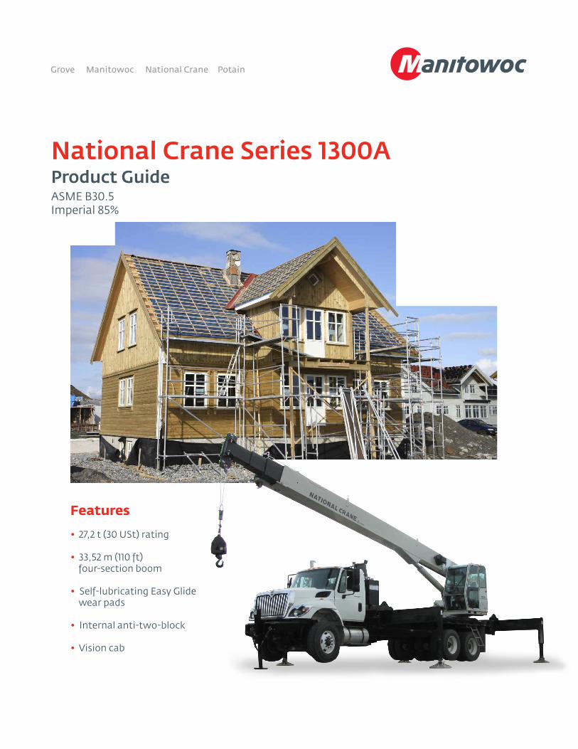
National Crane Series 1300AProduct GuideASME B30.5Imperial 85%
Features
• 27,2 t (30 USt) rating
• 33,52 m (110 ft) four-section boom
• Self-lubricating Easy Glide wear pads
• Internal anti-two-block
• Vision cab
Features
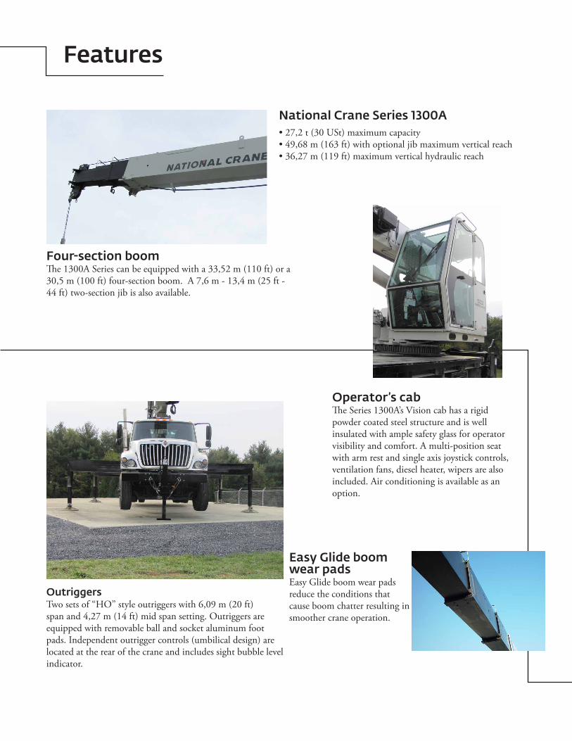
Four-section boomThe 1300A Series can be equipped with a 33,52 m (110 ft) or a 30,5 m (100 ft) four-section boom. A 7,6 m - 13,4 m (25 ft - 44 ft) two-section jib is also available.
OutriggersTwo sets of “HO” style outriggers with 6,09 m (20 ft) span and 4,27 m (14 ft) mid span setting. Outriggers are equipped with removable ball and socket aluminum foot pads. Independent outrigger controls (umbilical design) are located at the rear of the crane and includes sight bubble level indicator.
Easy Glide boom wear padsEasy Glide boom wear pads reduce the conditions that cause boom chatter resulting in smoother crane operation.
National Crane Series 1300A• 27,2 t (30 USt) maximum capacity• 49,68 m (163 ft) with optional jib maximum vertical reach• 36,27 m (119 ft) maximum vertical hydraulic reach
Operator’s cabThe Series 1300A’s Vision cab has a rigid powder coated steel structure and is well insulated with ample safety glass for operator visibility and comfort. A multi-position seat with arm rest and single axis joystick controls, ventilation fans, diesel heater, wipers are also included. Air conditioning is available as an option.
Features
Best in class performance and serviceability
• The stronger standard torsion box improves rigidity, reduces truck frame flex and reduces the need for counterweight
• Speedy-reeve boom tip and sheave blocks simplify rigging changes by decreasing the time needed to change line reeving
• Crane components painted before assembly reduce the chance of rust, improve serviceability and enhance the appearance of the crane
• Internal anti-two block wiring standard on the 1300A routes the wiring through the inside of the boom eliminating the possibility of snagging the wire on obstructions
• Bearings on the boom extend and retract cables can be greased through access holes in the boom side plates and a number of internal boom parts has been reduced improving serviceability
• The Series 1300A is supplied with 360° continuous rotation standard along with the “glide swing” feature allowing free swing during rotation and a manually applied foot brake
• Adjustable swing speed comes standard on the 1300A. A control knob located on the swing motor brake release valve can be easily adjusted to the crane operator’s swing speed preference
• Oil cooler-radiator mounted on top of front outriggers with electric fan is standard
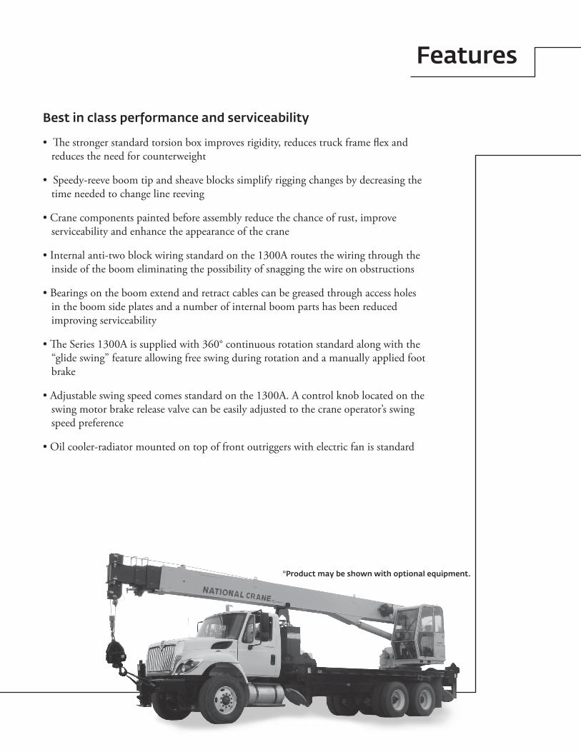
*Product may be shown with optional equipment.
4
Contents
Mounting configurations 5
Specifications 6
Capacities 8
Dimensions 10
Accessories 11
5Series 1300A
Mounting configuration
**Weight in excess of 4763 kg (10,500 lb) will require the addition of a front stabilizer or additional rear axle stability weight for over front stability. One-half of the front axle weight in excess of the maximum at the rear axle will maintain stability.
Example: A 4990 kg (11,000 lb) Bare Front Axle will maintain stability if the rear axle bare is 3969 kg (8750 lb) and 4649 kg (10,250 lb) with the additional optional bed weight.
***A single front stabilizer is not necessary for 360˚ stability if mounting dimensions are maintained and minimum rear axle and maximum front axle weights are not exceeded.
NOTE 1: Gross Vehicle Weight Rating (GVWR) is dependent on all components of the vehicle (axles, tires, springs, frame, etc.) meeting manufacturers’ recommendations; always specify GVWR when purchasing trucks.
NOTE 2: Diesel engines require a variable speed governor for smooth crane operation; electronic fuel injection is required.
NOTE 3: All mounting data is based on a National Crane Series 1300A with subbase and an 85% stability factor.
NOTE 4: The complete unit must be installed in accordance with factory requirements, and a test performed to determine actual stability and counterweight requirements; contact the factory for details.
NOTE 5: Transmission neutral safety interlock switch is required.
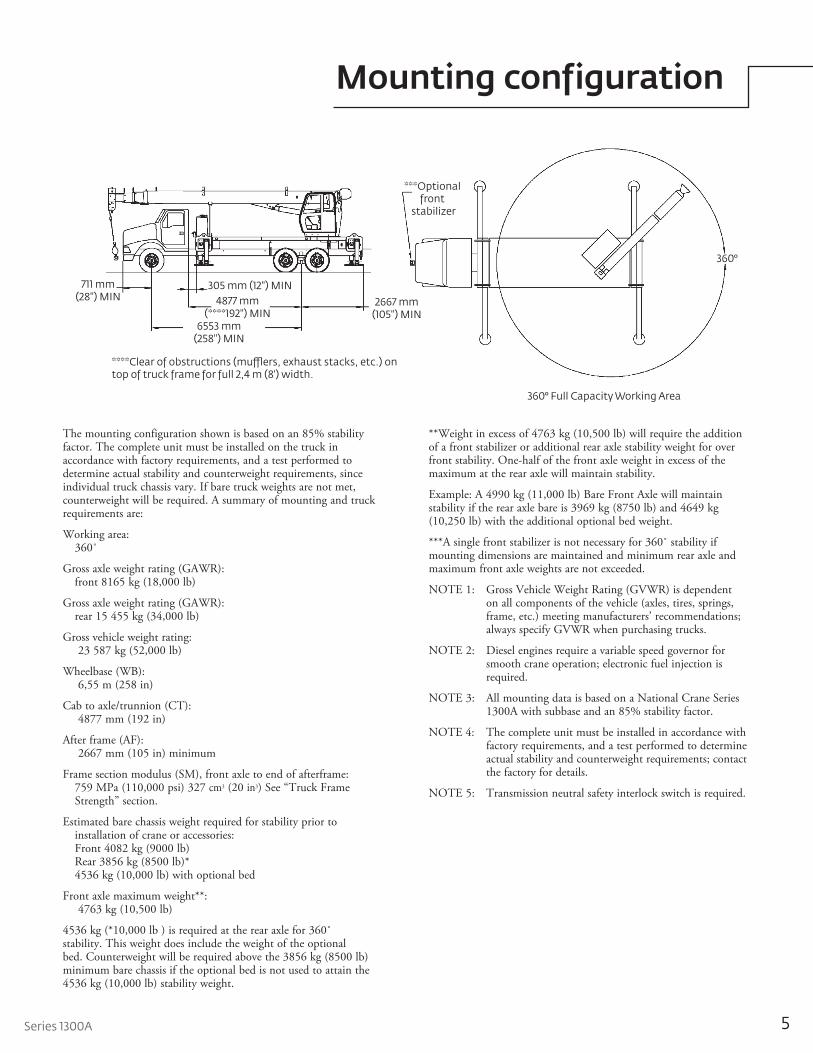
The mounting configuration shown is based on an 85% stability factor. The complete unit must be installed on the truck in accordance with factory requirements, and a test performed to determine actual stability and counterweight requirements, since individual truck chassis vary. If bare truck weights are not met, counterweight will be required. A summary of mounting and truck requirements are:
Working area: 360˚
Gross axle weight rating (GAWR): front 8165 kg (18,000 lb)
Gross axle weight rating (GAWR): rear 15 455 kg (34,000 lb)
Gross vehicle weight rating: 23 587 kg (52,000 lb)
Wheelbase (WB): 6,55 m (258 in)
Cab to axle/trunnion (CT): 4877 mm (192 in)
After frame (AF): 2667 mm (105 in) minimum
Frame section modulus (SM), front axle to end of afterframe: 759 MPa (110,000 psi) 327 cm3 (20 in3) See “Truck Frame Strength” section.
Estimated bare chassis weight required for stability prior to installation of crane or accessories:
Front 4082 kg (9000 lb) Rear 3856 kg (8500 lb)* 4536 kg (10,000 lb) with optional bed
Front axle maximum weight**: 4763 kg (10,500 lb)
4536 kg (*10,000 lb ) is required at the rear axle for 360˚ stability. This weight does include the weight of the optional bed. Counterweight will be required above the 3856 kg (8500 lb) minimum bare chassis if the optional bed is not used to attain the 4536 kg (10,000 lb) stability weight.
711 mm (28") MIN
6553 mm (258") MIN
4877 mm (****192") MIN
305 mm (12") MIN
2667 mm (105") MIN
***Optional front
stabilizer
360°
360° Full Capacity Working Area
****Clear of obstructions (mu�ers, exhaust stacks, etc.) on top of truck frame for full 2,4 m (8') width.
6
Specifications
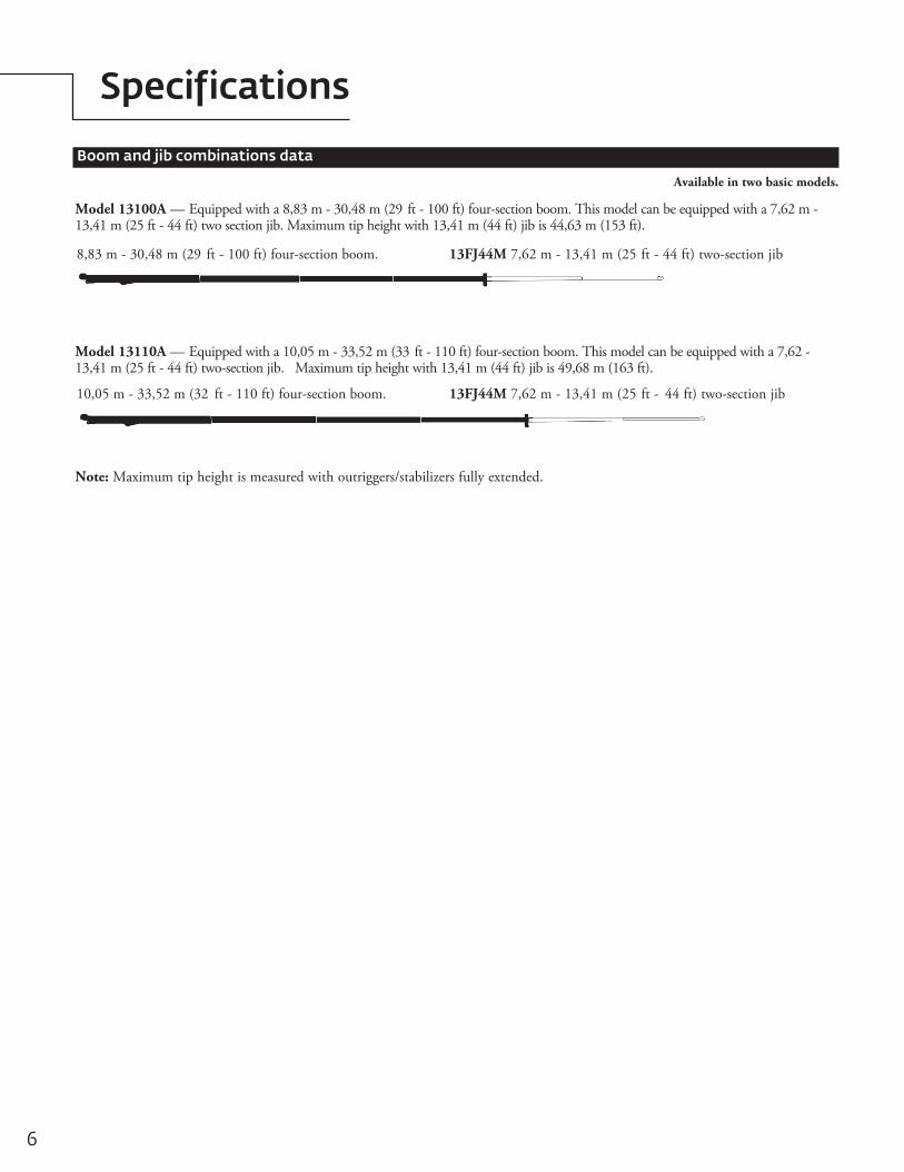
Boom and jib combinations data
Available in two basic models.
Model 13100A — Equipped with a 8,83 m - 30,48 m (29 ft - 100 ft) four-section boom. This model can be equipped with a 7,62 m - 13,41 m (25 ft - 44 ft) two section jib. Max i mum tip height with 13,41 m (44 ft) jib is 44,63 m (153 ft).
Model 13110A — Equipped with a 10,05 m - 33,52 m (33 ft - 110 ft) four-section boom. This model can be equipped with a 7,62 - 13,41 m (25 ft - 44 ft) two-section jib. Max i mum tip height with 13,41 m (44 ft) jib is 49,68 m (163 ft).
10,05 m - 33,52 m (32 ft - 110 ft) four-section boom. 13FJ44M 7,62 m - 13,41 m (25 ft - 44 ft) two-section jib
8,83 m - 30,48 m (29 ft - 100 ft) four-section boom. 13FJ44M 7,62 m - 13,41 m (25 ft - 44 ft) two-section jib
Note: Maximum tip height is measured with outriggers/stabilizers fully extended.
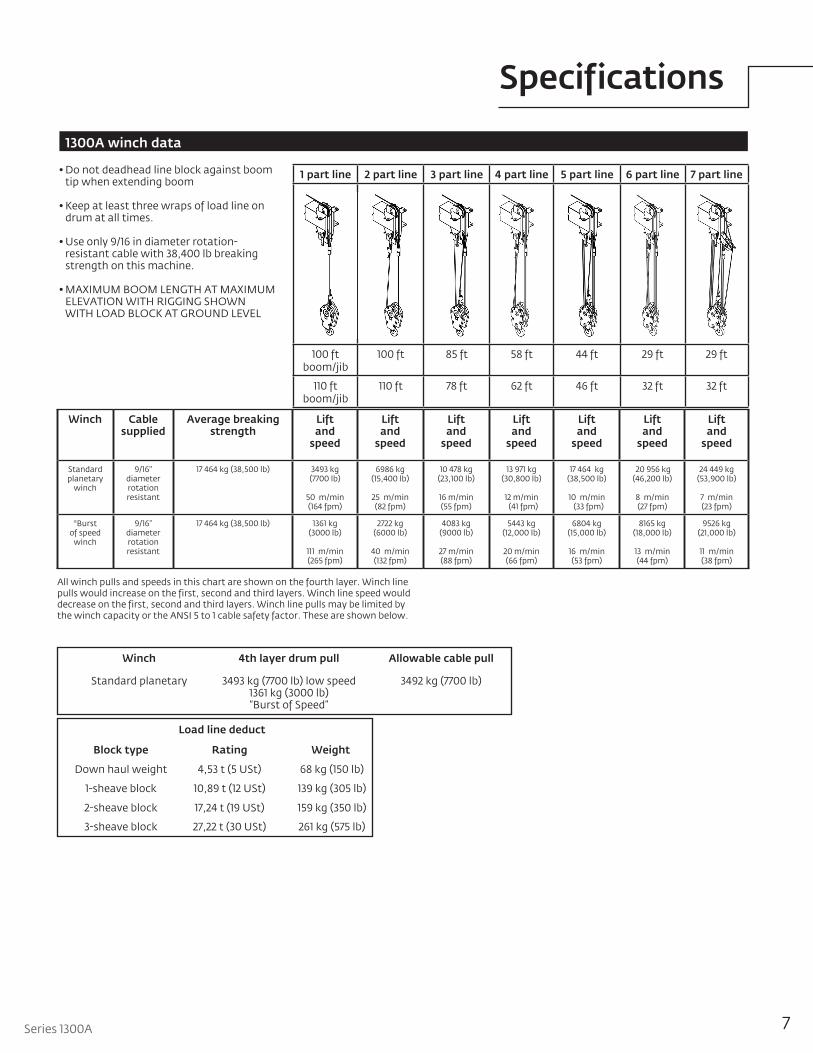
1 part line 2 part line 3 part line 4 part line 5 part line 6 part line 7 part line
100 ft boom/jib
100 ft 85 ft 58 ft 44 ft 29 ft 29 ft
110 ft boom/jib
110 ft 78 ft 62 ft 46 ft 32 ft 32 ft
7Series 1300A
Specifications
1300A winch data
Winch Cable supplied
Average breaking strength
Lift and
speed
Lift and
speed
Lift and
speed
Lift and
speed
Lift and
speed
Lift and
speed
Lift and
speed
Standard planetary
winch
9/16" diameter rotation resistant
17 464 kg (38,500 lb) 3493 kg (7700 lb)
50 m/min (164 fpm)
6986 kg (15,400 lb)
25 m/min (82 fpm)
10 478 kg (23,100 lb)
16 m/min (55 fpm)
13 971 kg (30,800 lb)
12 m/min (41 fpm)
17 464 kg (38,500 lb)
10 m/min (33 fpm)
20 956 kg (46,200 lb)
8 m/min (27 fpm)
24 449 kg (53,900 lb)
7 m/min (23 fpm)
*Burst of speed
winch
9/16” diameter rotation resistant
17 464 kg (38,500 lb) 1361 kg (3000 lb)
111 m/min (265 fpm)
2722 kg (6000 lb)
40 m/min (132 fpm)
4083 kg (9000 lb)
27 m/min (88 fpm)
5443 kg (12,000 lb)
20 m/min (66 fpm)
6804 kg (15,000 lb)
16 m/min (53 fpm)
8165 kg (18,000 lb)
13 m/min (44 fpm)
9526 kg (21,000 lb)
11 m/min (38 fpm)
Winch 4th layer drum pull Allowable cable pull
Standard planetary 3493 kg (7700 lb) low speed1361 kg (3000 lb) “Burst of Speed”
3492 kg (7700 lb)
Load line deduct
Block type Rating Weight
Down haul weight 4,53 t (5 USt) 68 kg (150 lb)
1-sheave block 10,89 t (12 USt) 139 kg (305 lb)
2-sheave block 17,24 t (19 USt) 159 kg (350 lb)
3-sheave block 27,22 t (30 USt) 261 kg (575 lb)
• Do not deadhead line block against boom tip when extending boom
• Keep at least three wraps of load line on drum at all times.
• Use only 9/16 in diameter rotation-resistant cable with 38,400 lb breaking strength on this machine.
• MAXIMUM BOOM LENGTH AT MAXIMUM ELEVATION WITH RIGGING SHOWN WITH LOAD BLOCK AT GROUND LEVEL
All winch pulls and speeds in this chart are shown on the fourth layer. Winch line pulls would increase on the first, second and third layers. Winch line speed would decrease on the first, second and third layers. Winch line pulls may be limited by the winch capacity or the ANSI 5 to 1 cable safety factor. These are shown below.
8THIS CHART IS ONLY A GUIDE AND SHOULD NOT BE USED TO OPERATE THE CRANE.
The individual crane’s load chart, operating instructions and other instructional plates must be read and understood prior to operating the crane.
Capacities
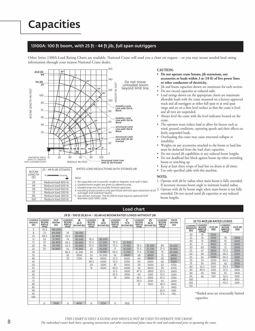
13100A: 100 ft boom, with 25 ft - 44 ft jib, full span outriggers
Load chart
Other Series 1300A Load Rating Charts are available. National Crane will send you a chart on request – or you may secure needed load rating information through your nearest National Crane dealer.
CAUTION:• Do not operate crane booms, jib extensions, any
accessories or loads within 3 m (10 ft) of live power lines or other conductors of electricity.
• Jib and boom capacities shown are maximum for each section.• Do not exceed capacities at reduced radii.• Load ratings shown on the appropriate charts are maximum
allowable loads with the crane mounted on a factory-approved truck and all outriggers at either full span or at mid span range and set on a firm level surface so that the crane is level and all tires are suspended.
• Always level the crane with the level indicator located on the crane.
• The operator must reduce load to allow for factors such as wind, ground conditions, operating speeds and their effects on freely suspended loads.
• Overloading this crane may cause structural collapse or instability.
• Weights on any accessories attached to the boom or load line must be deducted from the load chart capacities.
• Do not exceed jib capabilities at any reduced boom lengths.• Do not deadhead line block against boom tip when extending
boom or winching up.• Keep at least three wraps of load line on drum at all times.• Use only specified cable with this machine.
NOTE:1. Operate with jib by radius when main boom is fully extended.
If necessary increase boom angle to maintain loaded radius.2. Operate with jib by boom angle when main boom is not fully
extended. Do not exceed rated jib capacities at any reduced boom lengths.
0 20 40 60 80 100
RADIUS IN FEET
0
20
40
60
80
100
120
140
160
HEI
GH
TIN
FEET
1st Jib25'
2nd Jib44'
BO
OM
LEN
GTH
INFE
ET
58
86
100
72
29
44
CBA D
80°
70°
60°
50°
40°
44°
45°
30°
20°
10°
0°-10°
Structural LimitLine with 150 lbBlock
Structural LimitLine with 44' JibErected
Structural Limit Linewith 25' Jib Erected
Stability LimitLine with 150 lbBlock
Stability LimitLine with 150 lbBlock
Do not moveunloaded boom
beyond limit line.
Operating radiusfrom C/L rotation
with unloaded boom
3035404550556065707580859095100105110
RADIUS(ft)
LOADEDBOOMANGLE
25 ft JIB(lb)
LOADEDBOOMANGLE
44 ft JIB(lb)
25 TO 44 ft JIB RATED LOADS
5810121520253035404550556065707580859095100
LOADEDRADIUS
(ft)
LOADEDBOOMANGLE(deg) (deg) (deg) (deg) (deg) (deg)
(deg) (deg)
29 ftBOOM
(lb)
LOADEDBOOMANGLE
100 ftBOOM
(lb)
LOADEDBOOMANGLE
D86 ft
BOOM (lb)
LOADEDBOOMANGLE
C72 ft
BOOM (lb)
LOADEDBOOMANGLE
B58 ft
BOOM (lb)
LOADEDBOOMANGLE
A44 ft
BOOM (lb)
29 ft - 100 ft (8,83 m – 30,48 m) BOOM RATED LOADS WITHOUT JIB
7876757169676462595652.549.54542
510051004950445041503850355032002500210016501250900550
7876747270.568.566.564.56259.557.55552.548.545.5
2800265026002500250023502250215020501950165014001100850600
79.57368.565574629
0
*60,00044,00036,90031,90026,40020,10014,800
7900
7976.57469.562.55546.53622
0
29,10029,00028,60024,60019,00015,35012,30097007700
4100
78.575.570.56559534638.52915
0
28,60023,50018,05014,60012,15010,0008050650052004200
2250
79.575.57166.56257.552.54740.533.524.510
0
22,90017,45014,05011,70099008300670054504400360029502100
1100
78.575.571.5686460565247.54236.529.521
16,30013,70011,3509600825069005600460038003100255021001650
8077.575726966625955.551.547.54338.53326.517.5
10,65010,45010,000940080507000575047003900325027002200180014501100750
LOADED
Note:
1. All capacities are in pounds, angles in degrees, and radii in feet.2. Loaded boom angles are given as reference only.3. Shaded areas are structurally limited capacities.4. Handling of personnel is only permitted with full span extension of all
outrigger and stabilizer beams.* 5. See owners manuals. The 60,000 lb load requires optional 9/16"
diameter 6x25 IWRC cable.
RATED LOAD REDUCTIONS WITH STOWED JIB25 – 44 ft JIB STOWEDBOOM
LENGTH(ft)
2944587286
100
Reduce load 800 lbReduce load 600 lbReduce load 450 lbReduce load 350 lbReduce load 300 lbReduce load 250 lb
25 – 44 ft JIB STOWEDBOOM
LENGTH(ft)
3246627894110
Reduce load 800 lbReduce load 600 lbReduce load 450 lbReduce load 350 lbReduce load 300 lbReduce load 250 lb
Note:
1. All capacities are in pounds, angles in degrees, and radii in feet.2. Loaded boom angles are given as reference only.3. Shaded areas are structurally limited capacities.4. Handling of personnel is only permitted with full span extension of all
outrigger and stabilizer beams.* 5. See owners manuals. The 60,000 lb load requires optional 9/16"
diameter 6x25 IWRC cable.
*Shaded areas are structurally limited capacities.
9Series 1300A
Capacities
THIS CHART IS ONLY A GUIDE AND SHOULD NOT BE USED TO OPERATE THE CRANE. The individual crane’s load chart, operating instructions and other instructional plates must be read and understood prior to operating the crane.
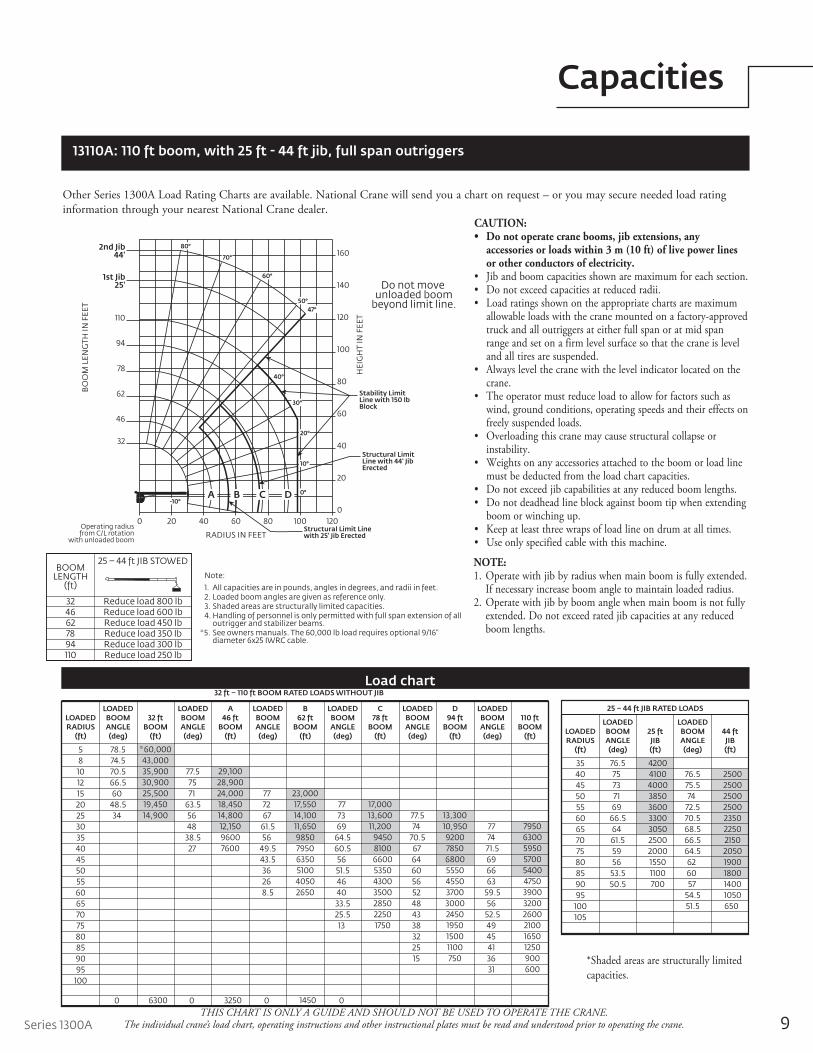
32 ft – 110 ft BOOM RATED LOADS WITHOUT JIB
32 ftBOOM
(ft)
LOADEDBOOMANGLE(deg)
A46 ft
BOOM(ft)
LOADEDBOOMANGLE(deg)
B62 ft
BOOM(ft)
LOADEDBOOMANGLE(deg)
C78 ft
BOOM(ft)
LOADEDBOOMANGLE(deg)
D94 ft
BOOM(ft)
LOADEDBOOMANGLE(deg)
110 ftBOOM
(ft)
LOADEDBOOMANGLE(deg)
LOADEDRADIUS
(ft)
5810121520253035404550556065707580859095
100
78.574.570.566.5
6048.5
34
0
77.5 75 7163.5
56 4838.5
27
0
77 72 6761.5
5649.543.5
36 26
8.5
0
77 73 6964.560.5
5651.5
46 40
33.525.5
13
0
77.5 7470.5
67 64 60 56 52
48 43 38 32 25 15
77 74
71.5 69 66 6359.5
5652.5
49 45 41 36 31
* 60,00043,00035,90030,90025,50019,45014,900
6300
29,10028,90024,00018,45014,80012,15096007600
3250
23,00017,55014,10011,650985079506350510040502650
1450
17,00013,60011,200
945081006600535043003500285022501750
13,30010,95092007850680055504550370030002450195015001100750
795063005950570054004750390032002600210016501250900600
25 – 44 ft JIB RATED LOADS
25 ftJIB(ft)
LOADEDBOOMANGLE(deg)
44 ftJIB(ft)
LOADEDBOOMANGLE(deg)
LOADEDRADIUS
(ft)
35404550556065707580859095
100105
76.5 75 73 71 6966.5
6461.5
59 5653.550.5
76.575.5
7472.570.568.566.564.5
62 60 5754.551.5
42004100400038503600330030502500200015501100700
250025002500250023502250215020501900180014001050650
Load chart
Other Series 1300A Load Rating Charts are available. National Crane will send you a chart on request – or you may secure needed load rating information through your nearest National Crane dealer.
*Shaded areas are structurally limited capacities.
13110A: 110 ft boom, with 25 ft - 44 ft jib, full span outriggers
CAUTION:• Do not operate crane booms, jib extensions, any
accessories or loads within 3 m (10 ft) of live power lines or other conductors of electricity.
• Jib and boom capacities shown are maximum for each section.• Do not exceed capacities at reduced radii.• Load ratings shown on the appropriate charts are maximum
allowable loads with the crane mounted on a factory-approved truck and all outriggers at either full span or at mid span range and set on a firm level surface so that the crane is level and all tires are suspended.
• Always level the crane with the level indicator located on the crane.
• The operator must reduce load to allow for factors such as wind, ground conditions, operating speeds and their effects on freely suspended loads.
• Overloading this crane may cause structural collapse or instability.
• Weights on any accessories attached to the boom or load line must be deducted from the load chart capacities.
• Do not exceed jib capabilities at any reduced boom lengths.• Do not deadhead line block against boom tip when extending
boom or winching up.• Keep at least three wraps of load line on drum at all times.• Use only specified cable with this machine.
NOTE:1. Operate with jib by radius when main boom is fully extended.
If necessary increase boom angle to maintain loaded radius.2. Operate with jib by boom angle when main boom is not fully
extended. Do not exceed rated jib capacities at any reduced boom lengths.
Note:
1. All capacities are in pounds, angles in degrees, and radii in feet.2. Loaded boom angles are given as reference only.3. Shaded areas are structurally limited capacities.4. Handling of personnel is only permitted with full span extension of all
outrigger and stabilizer beams.* 5. See owners manuals. The 60,000 lb load requires optional 9/16"
diameter 6x25 IWRC cable.
RATED LOAD REDUCTIONS WITH STOWED JIB25 – 44 ft JIB STOWEDBOOM
LENGTH(ft)
2944587286
100
Reduce load 800 lbReduce load 600 lbReduce load 450 lbReduce load 350 lbReduce load 300 lbReduce load 250 lb
25 – 44 ft JIB STOWEDBOOM
LENGTH(ft)
3246627894110
Reduce load 800 lbReduce load 600 lbReduce load 450 lbReduce load 350 lbReduce load 300 lbReduce load 250 lb
Note:
1. All capacities are in pounds, angles in degrees, and radii in feet.2. Loaded boom angles are given as reference only.3. Shaded areas are structurally limited capacities.4. Handling of personnel is only permitted with full span extension of all
outrigger and stabilizer beams.* 5. See owners manuals. The 60,000 lb load requires optional 9/16"
diameter 6x25 IWRC cable.
Do not move unloaded boom
beyond limit line.
Operating radiusfrom C/L rotation
with unloaded boom
0 20 40 60 80 100 120
RADIUS IN FEET
0
20
40
60
80
100
120
140
160
HEI
GH
T IN
FEE
T
1st Jib25'
2nd Jib44'
BO
OM
LEN
GTH
IN F
EET
62
94
110
78
32
46
CBA D
80°
70°
60°
40°
30°
20°
10°
0°-10°
50°47°
Structural LimitLine with 44' JibErected
Structural Limit Linewith 25' Jib Erected
Stability LimitLine with 150 lb Block
10
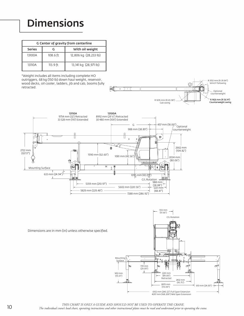
Dimensions
THIS CHART IS ONLY A GUIDE AND SHOULD NOT BE USED TO OPERATE THE CRANE. The individual crane’s load chart, operating instructions and other instructional plates must be read and understood prior to operating the crane.
Dimensions are in mm (in) unless otherwise specified.
G Center of gravity from centerline
Series G With oil weight
13100A 108.6 ft 12,806 kg (28,233 lb)
13110A 113.9 ft 13,141 kg (28,971 lb)
*Weight includes all items including complete HO outriggers, 68 kg (150 lb) down haul weight, reservoir, wood decks, oil cooler, ladders, jib and cab, booms fully retracted.
457 mm (18.00")
13110A9754 mm (32') Retracted
33 528 mm (110') Extended
2662 mm(104.82")
988 mm (38.89")
Mounting Surface
633 mm (24.94")
1590 mm (62.60") 1081 mm (42.56")
13100A8992 mm (29' 6") Retracted30 480 mm (100') Extended
2722 mm(107.17")
5359 mm (210.97")5602 mm (220.56")
5829 mm (229.48")7288 mm (286.92")
988 mm(38.88")1231 mm(48.47")
2034 mm(80.06")
Optionalcounterweight
1095 mm (43.09")
C/L Rotation
G
1312 mm(51.66")
2261 mm(89.00")
Retracted
6102 mm (240.22") Full Span Extension4297 mm (168.200") Mid Span Extension
1412 mm(55.61")
C/L Rotation
610 mm (24.00")
2432 mm(95.75")
2870 mm(113.00")
739 mm(29.09")
MountingSurface
R 1012 mm (R 39.84") Winch Tailswing
Optional counterweight
R 1426 mm (R 56.14") Counterweight swingR 1426 mm (R 56.14")
Counterweight swingR 1676 mm (R 65.98")
Cab swing

11Series 1300A
Accessories
12
Accessories
Radio Remote Controls – Eliminate the handling and maintenance concerns that accompany cabled remotes. Operate to a range of about 76 m (250 ft), varying with conditions. • NB4R
Heavy-duty Personnel Basket – 544 kg (1200 lb) capacity steel basket with safety loops for two passengers. Gravity leveling 183 cm x 107 cm (72 in x 42 in) platform. Fast attachment and secure locking • BSA-1systems. Load chart must show 1043 kg (2300 lb) minimum to operate this accessory. • BSA-R1 (provides rotation) • BSAY-2
Air Conditioning – Back of cab mounted, self contained modular unit with in cab cool air outlets. • ACRequires 130+ amp chassis alternator.
Outrigger Controls at operator’s seat in addition to ground controls. • ICORC
Single Front Outrigger – Center mount front stabilizer with a 25 in vertical stroke with first-up feature. • SFO
Open Seat Controls – Open seat controls with railing in lieu of cab. • SSC
Spanish-Language Danger Decals, Control Knobs, • SDD and Operators’ Manuals • SOM

13Series 1300A
Notes

14
Notes

Series 1300A
Notes
15

©2014 ManitowocForm No. 1300A PGPart No. 1300A/2M/0914 www.manitowoccranes.com
This document is non-contractual. Constant improvement and engineering progress make it necessary that we reserve the right to make specification, equipment, and price changes without notice. Illustrations shown may include optional equipment and accessories and may not include all standard equipment.
Regional offices
ChinaShanghai, China Tel: +86 21 6457 0066Fax: +86 21 6457 4955
Greater Asia-Pacific Singapore Tel: +65 6264 1188 Fax: +65 6862 4040
Europe, Middle East, Africa Dardilly, France Tel: +33 (0)4 72 18 20 20 Fax: +33 (0)4 72 18 20 00
Americas Manitowoc, Wisconsin, USA Tel: +1 920 684 6621 Fax: +1 920 683 6277
Shady Grove, Pennsylvania, USA Tel: +1 717 597 8121 Fax: +1 717 597 4062
Regional headquarters
Manitowoc Cranes
ChinaBeijingChengduGuangzhouXian
Greater Asia-PacificAustraliaBrisbaneMelbourneSydneyIndiaChennaiDelhiHyderabadPuneKoreaSeoulPhilippinesMakati CitySingapore
FactoriesBrazilPasso FundoChinaTaiAnZhangjiagangFranceCharlieuMoulinsGermanyWilhelmshavenIndiaPuneItalyNiella TanaroPortugalBaltarFânzeresUSAManitowoc Port WashingtonShady Grove
AmericasBrazilAlphavilleMexicoMonterreyChileSantiago
Europe, Middle East, AfricaFranceBaudemontCergyDecinesGermanyLangenfeldItalyLainateNetherlandsBredaPolandWarsawPortugalBaltarRussiaMoscowSouth AfricaJohannesburgU.A.E.DubaiU.K.Buckingham