national radio astronomy observatory green bank, … · bola is defined as the locus of points from...
TRANSCRIPT

NATIONAL RADIO ASTRONOMY OBSERVATORYGreen Bank, West Virginia
INTERNAL REPORT
A COMPARISON BETWEEN PRIME FOCUSAND CASSEGRAIN ANTENNAS
J. W. M. Baars
OCTOBER 1964

A COMPARISON BETWEEN PRIME FOCUS AND CASSEGRMN ANTENNAS
J. W. M. Baars
I. INTRODUCTION
This report deals with a comparison between radio telescopes with paraboloidal
reflectors and different ways of obtaining the desired aperture illumination. We shall
consider mainly the two most used feed systems:
10 The horn feed in the focal point of the paraboloid;
we call this the prime focus case.
2. The Cassegrain type where the feed system con-
sists of a horn close to the vertex of the paraboloid
and a hyperboloidal second reflector with its focal
point in the focus of the paraboloid. The horn is
placed in the other focal point of the hyperboloid.
The prime focus paraboloid is the most common antenna for radio astronomy in
the frequency range over 200 MHz. Generally the front end of the receiver is mounted
close to the feed behind the focal point of the paraboloid. This type of antenna is simple
and moreover it is theoretically fairly well understo*d.
In recent years another type of antenna has gained in interest, viz., the Casse-
grain type. Here again the paraboloid is used but a second reflector with hyperboloidal
shape is placed near the focus of the paraboloid. It reflects the radiation impinging
upon it towards the feed horn, which is now located near the vertex of the paraboloid.
The Cassegrain type has mainly been used for relatively sm 1 antennas for very
high frequencies (above 10 GHz). Its success there has caused a considerable quantity of
publications, whose main conclusion is that the Cassegrain is superior to the prime
focus antenna. However, many of these conclusions are based on guesses and a conclu-
sive experimental proof has not yet been given. The main feature of a Cassegrain is
said to be the lower spillover and the higher aperture efficiency.
It is the purpose of this report to compare the two types of antennas and to show
their specific characteristics with the help of computations and experimental results.
2
First we give the formulae for the geometry of the Cassegrain antenna and a discussion
of the so-called n minimum blocking condition" In the next section on the electrical
characteristics we deal with the effects of aperture blocking, F/D ratio and displace-
ment of the feed from the correct focal point on the radiation pattern. Further, the
aperture efficiency, spillover radiation, sidelobe level and feed design are investigated.
Then typical mechanical features of the Cassegrain are compared with the prime focus
antenna. An appendix with numerical results for three different antennas and curves of
different important characteristics complete the report.
II. THE GEOMETRY OF THE SYSTEM
. Basic Pro_p es
The basic property of the paraboloidal reflector follows directly from the defini-
tion of a parabola. It transforms spherical waves originated in the focal point into a
plane wavefront traveling parallel to the axis of rotation of the paraboloid. Or reasoning
the other way around, which is possible by virtue of the reciprocity relation, it focuses
a plane wave arriving on the reflector parallel to its axis of rotation into the focal point.
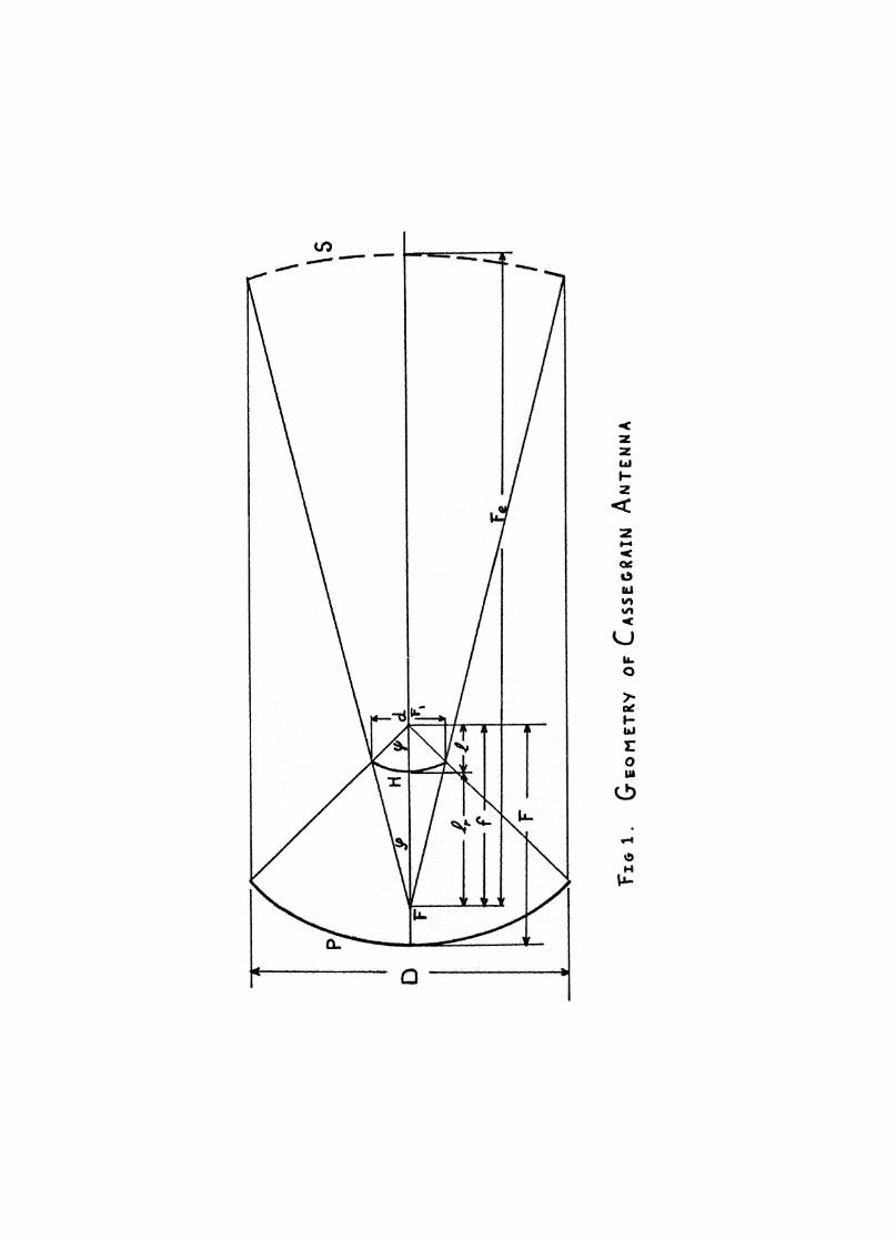
This property has to exist also in the case of a two reflector antenna. The hyper-
bola is defined as the locus of points from where the difference of the distances to two
points, the foci, is constant. With this in mind, it is easy to show that the path length of
a ray originating in point F (fig. 1) after reflection on the hyperboloid and the paraboloid
to the aperture plane of the paraboloid is constant. One of the foci of the hyperboloid is
F1,
which is also the focal point of the paraboloid; point F is the other focus of the hyper-
boloid, being the focus of the Cassegrain system also Hence, a combination of a
paraboloid with a hyperboloid, whose focal point coincides with that of the paraboloid,
focuses a plane wave coming parallel to the paraboloid's axis into the second focus of the
hyperboloid.
The system parabola/hyperbola can be replaced by an n equivalent parabola",
that is, the surface S in figure 1. S is the equivalent focusing surface for the combina-
tion parabola and h3rperbola0 It is the principal surface of the system and is defined as
the points of intersection of rays incoming parallel to the rotation axis of the parabola
main reflector P Dtan =2 4F
equivalent parabola S Dtan =2 4F
e(2)
2fcot co + cot = d
1/2 stn. 1/2__ (__°t- (Pi•ef/2 -,e - sin 1/2 - (P)
hyperbola H
eccentricity of H
(3)
(4)
3
and the extension of the r ys rriving in the foc point F. Thus the surface S will focus
a wave arriving from the left part. lel to the axis into point F. So we see that S is a
paraboloid with diameter D as the paraboloid P and focal length Fee
The ratio of the
focal length of the equivalent paraboloid S to the focal length of P is called the ma,gni-
fication of the Cassegrain system, denoted by in.
From simple geometry we can deduct the following formulae connecting the
different quantities of the Cassegrain (fig. 1):
F
e tan e + 1magnificationF tan cp/2 e 1
The prime focus paraboloid has only one free parameter, the ratio F/D. The
Cassegrain however has three free parameters. Having chosen the ratio F/D of the
primary reflector P we c chos,se the diameter d of the subreflector IP, this choice
depends on the maximum blocking area that we want to allow. Now we can still choose
the angle cp 9 or in other words the eccentricity e of the hyperbola,. Or we can cho•se
a certain magnification in and find from (5) the eccentricity e and from (4) the angle cp
So the Cassegrain system has three free parameters. From equation (2) we see that
(5)
4
the Cassegrain is equivalent to a prime focus paraboloid of focal length F
e' where
F m. F. This is the reason for calling m the magnification.
It should be noted that the magnification applies only to some characteristics
following from the geometry. In optical telescopes the magnification is defined in a
different way. There it is the ratio of the focal lengths of the objective and the eyepiece.
erture
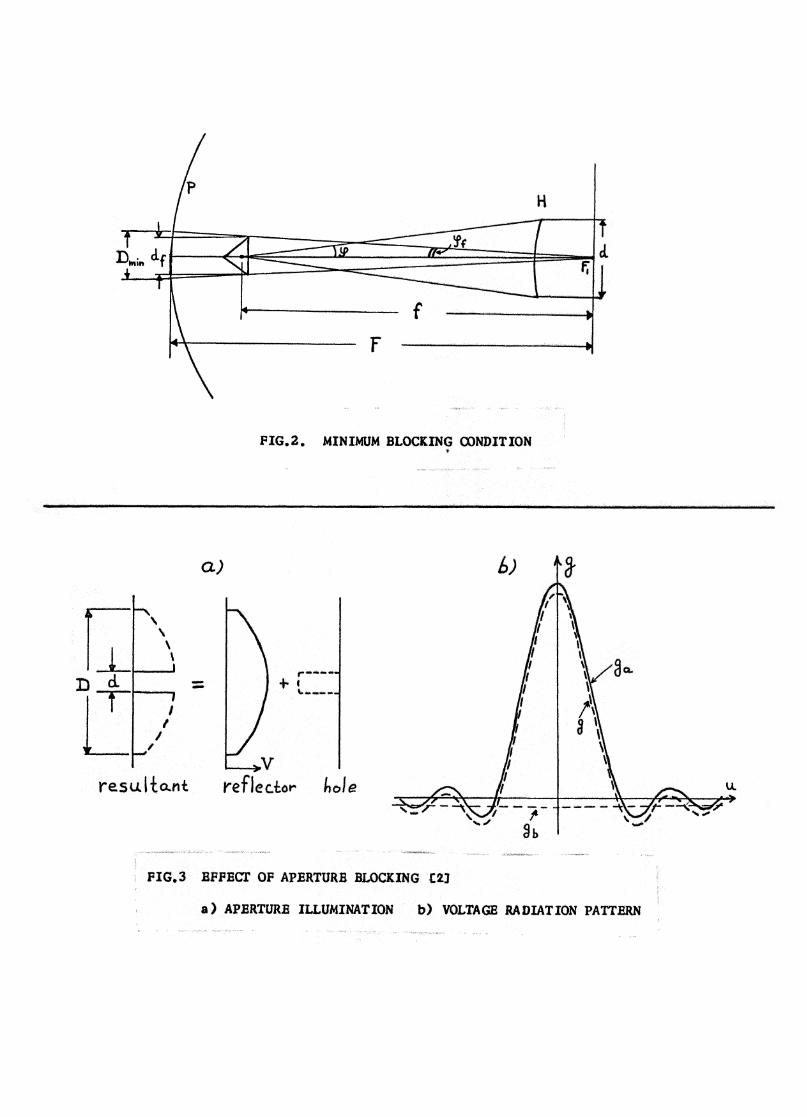
The subreflector in the Cassegrain will cause a certain aperture blocking, i.e. ,
part of the incoming radiation will be intercepted by the subdish and will not be focused
towards the feed in the focal point of the system. Hannan discusses the so-called
"minimum blocking condition." [2]. In that case the shadow of the hyperboloid on the main
reflector is just as big as the shadow of the aperture of the feed as seen from the focal
point of the paraboloid (fig. 2). From figure 2 we see that d 2cpf• When we denote the
feed aperture by df
and the angle under which it is seen from F as 2(pf9
the feed shadow
on the paraboloid is
PID R.,' 2 F rE ), dfmin ( °
f
It follows directly that with the feed in the vertex of the paraboloid the minimum blocking
condition is an equally large subdish and feed aperture.
With a 10 dB illuminaton taper on the edge of the subreflector we can take
2cp 1.4 —X
u Combining the different formulae we arrive at a rather simple approxima-Dtion for the minimum blocking area D min
Dmin
. (6)
This formula differs slightly from Hannan [2] since we have taken into account the illumi-
nation taper. Another way of writing the result (6) is:
(D3X -- 2 5 0 —
F
D2 A D (7)
where OA
is the half-p*wer beam width of the antenna.
5
These formulae are only approximations, but are useful to obtain first im-
pression on the btocking. We see from (7) that the minimum blocking area can be small
if the beamwidth is small, and further it turns out that a small ratio F/D for the para-
boloid is advanta,geous. H * wever, in mist cases the minimum blocking condition is not
fulfilled in an actual design because there are some other specifications on the size of the
subdish. We will deal with these in the section on the electrical characteristics.
A feed designed for a particular ratio VD can be used with any value of D as long
as the percentage blocking stays constant. The value of e reny ns also unchanged in
this case. If we want to use this feed on a reflector with another ratio VD, the value of
e for the subreflector has to be changed, because zp changes and (p stays constant. Keeping
the same blocking percentage we obtain a different value for f according to equation (3).
The position of the feed must be changed; in its new position it will see the subdish again
under an angle (p
With an invariant main reflector and a fl tter subdish this dish becomes larger,
the feed beamwidth larger and the axial dimension of the antenna shorter. With an in-
variant feed be mwidth and a subrefiector becoming more fiat the main reflector becomes
flatter and the axial dimension of the antenna increases.
III. ELECTRICAL CHARACTERISTICS
We shall now deal with the electrical properties of the two types of antennas and
point out their specific advantages and dis dvant es.cs,
A. Aperture Blockilig
Let us first consider the influence of aperture blocking on the gain and the side-
lobe level of the antenna. The large aperture blocking of a Cassegrain is often considered
to be a big disadvantage.
Two arguments set a lower limit in the dimensi, n of the subreflector. First there
is the fact th.t the subdish must be at least 10 wavelengths wide in order to prevent too
much spillover due to diffraction effects on the edge of the subdish. I ther words, the
6
subreffector must be sufficiently large so that we can use geometric optics in con-
sidering its effect. Secondly a very small subreflector would require a very narrow
primary paaern. This means a very long feed horn, which is undesirable from the
standpoint of manufacturing and sometimes also of available space. As a consequence
of these requirements the minimum blocking condition is in general not met; the sub
reflector is larger and the feed smaller.
We can calculate the influence of blocking on the gain and the sidelobe level of
an antenna as follows. The bit ckIng causes essentially a g p in the aperture illumina-
tion of the paraboloid. Analytically we can allow for aperture blocking by subtracting
the negative voltage pattern of the blocking area from the voltage illumination pattern
of the undisturbed aperture (fig. 3). We can take the illumination over the relatively
small blocking area uniform and so the voltage pattern of this region is:
d2 23. 1 (ub) d2 d24-7r -7 A i (ub) 4
g
b—4 1"
7rdwith d the diameter of the subdish, ub — sin O. Because A (u.
b ) hardly changes overX
the region of interest, we take the voltage pattern of the blocking area as a constant
negative voltage.
*The radiation pattern f the undisturbed aperture depends on the illumination.
For an illumination of the form (1 - r 2 )P the voltage radiation pattern IL.,s the form
A (u )D2a
ga = 7r 4 P
(8)
(9)
7rD where ua-- sin O.
Bearing in mind that A n(0) = 1 for any n the ratio f the peak voltages is
d2g (0) 7r —
b 4 d2ga(° ) D2
7(P + = (P ÷ —2--D
4
The peak voltage of the resultant pattern g(0) is, when we normalize it to the peak of
the undisturbed pattern ga
(10)
gs + +g(0)SLL(B) = 20 log
gs + gb20 log
1 - (p + 1)(13)
00 132 +O. 011 = 20 log [0. 1435] = -16. 85 dB.SLL = 20 log O. 99
7
d2g(0) = 1 - + ii°,2
Let the peak voltage of the first sidelobe, normalized to the mainlobe, in the un-
disturbed aperture be gs
o This is a negative voltage (fig. 3). Taking the blocking
into account, this level changes to (g s gb). The sidelobe level for the undisturbed
case in dB is
SLL(0) = 20 log g s (12)
This changes in the case with blocking into
N. B. Silver and his book [12] calculates, along the same line of reasoning, the
blocking of a line source. However, his final result (eq. 6.67, p. 191) for the side-
lobe intensity is in error. In fact, p ? should be replaced by 1/13'.
Examples. Uniform illumination of paraboloid, hence g = 7r
D2
A1 (u );a 4 a
theoretical sidelobe level is -17. 6 dB. With 1 percent blocking (d/D O. 1) we find
the gain g(0)1 d2 /D2
/ 1J = 0.99, or a decrease in the gain of O. 1 dB. The sidelobe
level is
So the sidelobe rises about 0.75 dB.
The same results for an illumination of the form (1 - r 2 ) have been drawn in
figure 4. In this figure also the sidelobe level for a 10 dB edge taper has been drawn.
This curve is calculated from radiation patterns given by Nihen and Kay [7] obtained
by machine computations. From the curves in figure 4 it is seen that a subreflector
An important considerati n in the design of a radio telescope is the spillover*
8
diamter d = 00 i D is a practical choice. The decrease in gain is small and the increase
in sidelobe level is a few dB. The theoretical sidelobe level stays under 20 dB, which
is generally accepted to be satisfactory in radio astronomy. Moreover the diameter of
the subdish will be more than 10 wavelengths in this case and the angle co will be of the
order of 10°. The construction of the feed horn is not too difficult and the length of the
feed stays in a convenient range.
Let us compare the subdish blocking of one percent with the blocking of a front
end box in a prime facus instrument. The pillbox of the NRAO 85-foot telescopes gives
a blocking of about 0.4 percent. Together with the feed support legs the blocking is
2 percent. As the physical size of the front end box hardly changes with frequency we
see that especially at relatively small telescopes (10-40 feet) the blocking of the subdish
is comparable with that of the pillbox. As the subdish can be light the support can be
less heavy than in a prime focus antenna, which diminishes the blocking area. The
support must be strong enough to meet the stability requirements. As we shall see
these are about as stringent as for the feed in a prime focus antenna. On the other hand,
for large telescopes, as the 300-foot, the subdish will be heavier than the pillbox and
the supports must be even stronger. In that case the blacking of the Cassegrain will be
more serious than that of the primary focus paraboloid.
B. Spillover and Efficiena
radiation, that is, the radiation which enters directly into the feed horn due to the fact
that the illumination pattern is not zero at the edge of the reflector.
In the case of a prime focus antenna, this radiation originates at the earth' s sur-
face; it is the thermal radiatian of the earth and the radiation temperature is about 300 °K.
In the Cassegrain, however, the feed looks into the sky and the radiation temperature of
the sky is very much lower than that of the earth. So the spillover radiation is much lawer.
Actually there is s* me radiation at the earth entering the feed via reflection at the sub-
reflector, but the contributian is very small. In any case where we are concerned with
low noise, as in measurements of the b ckground radiation of the galaxy, the Ca,ssegrain
type is superior to the conventianal par boloid one. The spillover depends on the F/D
9
ratio of the paraboloid; it increases from about 4 percent at F/D = 0.3 to 15 percent
for a value F/D = 1.
It has often been stated that the obtainable aperture efficiency of a Cassegrain is
higher than in the case of a primary focus paraboloid. There is, however, no experi-
mental clue as to the validity of this statement.
As the effect of spillover is less serious in the Cassegrain, it would be possible
to use a less heavy illumination taper on the paraboloid. This will increase the aperture
efficiency slightly. In fact this seems to be the case in some actual Cassegrains. But
the experimental proof of an increase in aperture efficiency has not been given in the
literature.
As an example, we mention here the efforts of the Jet Propulsion Laboratory to
optimize an 85-foot Cassegrain for aperture efficiency and low noise [8]. Taking as the
maximum theoretical aperture efficiency 0. 60, the efficiency of the prime focus instru-
ment derived from the published random errors [4] in the parabolic surface at the used
frequency of 960 MHz is about 0. 54. Using a special shaped subreflector in order to
optimize the aperture efficiency gave a calculated efficiency for the Cassegrain of 0. 59.
The measured value was 0. 50 ± 0. 08. It is clear that there is no big improvement. On
the other hand the zenith antenna temperature with the special shaped subreflector was
less than 10 °K, which is a real improvement compared to a typical value of 30 °K as
measured at NRAO for a prime focus telescope.
The influence of the random errors in the surfaces of the antenna is far more
important than the illumination. The aperture efficiency of a paraboloidal antenna with
random deviations of the best fitting paraboloid of the rms value d is given as
r/AN =
AO
exp -16 7r2 d2] (14)
where 71 A is the maximum theoretical efficiency of the undisturbed aperture and the—0
wavelength [6] [9]. In this respect the Cassegrain is even more sensitive than the prime
focus antenna because now we have two surfaces each with its own random error. As
these errors are independent their contribution to the phase error adds. If we allow the
- 10 -
subreflector to contribute 10 percent of the decrease in iri A. from the maximum value
A0 as a result of random errors, it follows that the surface accuracy of the subre-
flector has to be 3 times better than that of the paraboloid. For telescopes at very
high frequencies it may be necessary to use glass mirrors for the secondary reflector.
C FeedDesignandSide1obe Level
In designing a feed which will give a certain illumination taper the concept of
the equivalent paraboloid is very useful. One designs the feed for this paraboloid and
it will give the right illumination of the Cassegrain. The dimensions of the feed are
about m times as big as in the prime focus antenna. This can lead to rather clumsy feed
dimensions, with also a larger attenuation along the long horn. For example, a study
made by TRG for a multi:frequency Cassegrain feed system on the 300-foot telescope
yields a minimum feed length of 52 feet (16 m) and an aperture width of 12 feet (3. 6 m)
when used with a 20-foot diameter subdish. At the highest frequency of 1400 MHz the
phase error over the feed aperture is even half a wavelength. The use of a hornlens, a
short horn with a lens in the horn aperture to correct the phase front of the outcoming
waves, can be of advantage in some cases. The feed for our 3 mm radiometer is a horn-
lens may 5 cm long with a total loss of 0.35 dB. According to the manufacturer this loss
is less than that of a horn without a lens, which would have to be about 80 cm long in order
to obtain the same illumination.
Calculations have shown (especially [7] gives much information) that the sidelobe
level does not depend on the ratio F/D of the paraboloid nor on the choice of the distance
f, which determines the position of the feed. As to this last point, we have to mention
here that f has to be large enough in order that the subreflector is in the far field of the
feed. This means that f > 2D2
, where D is the aperture dimension of the feed horn. TheX
sidelobe level does depend on the illumination taper in the same way as the paraboloid with the
feed in its focus., For a ratio d/D = 0, 1 the sidelobe level for a 20 dB taper on the edge
is 2 dE lower than for a 10 dB taper.
D. FjD Ratio
In this section we deal with some properties of paraboloidal reflectors which
are a function of the F/D ratio. The cross polarization radiation which can harm
especially the sidelobe level, becomes less with increasing F/D ratio. This has al-
ready been noticed by Silver [12] and also by Kay. Because the paraboloid has a
curved surface, the polarization of the field of the feed (primary pattern) will be
affected by the reflection on the surface and the aperture field will have a different
polarization in different points. Analytically it is expressed by the plane wave boundary
condition on the surface
!X (e e 0—o
where n, and e i are unit vectors defining the normal on the surface, the polariza-
tion of the primary and secondary pattern, respectively. In words it means that the
tangential electrical field must be zero at the surface. We can resolve the electrical
aperture field into the principal polarization (parallel to E-plane) and cross polarization
(perpendicular to E-plane) components. The aperture distribution is indicated in
figure 5a. It is noted that by symmetry the cross polarization vanishes in the principal
planes. The cross polarization pattern has its maximum in the planes under 45° with the
principal plane (fig. 5b). It turns out that the maximum of the cross polarization lobe has
the same position as the first minimum of the main beam. So one sees that the main
beam can be deteriorated by the cross polarization radiation, especially in the directions
outside the principal planes. Calculations and measurements [3] indicate that the level
of the cross polarization lobe goes from -16 dB for F/D = 0.25 to -28 dB if F/D =-- 0. 60.
It is clear that a long focal length is of great advantage here. This is caused, of course,
by the smaller curvature of a paraboloid with longer focal length.
For the case where the feed is displaced in the radial direction the cross polariza-
tion is more serious because the symmetry in the illumination disappears.
A long focal length is also desirable if an off-axis feed has to be used. The side-
lobe level, especially the coma lobe, rises much slower for a long F/D ratio. We shall
deal with the off-axis characteristics in more detail later.
(15)
- 12 -
On the other side, however, we found already that the spillover radiation of a
long focal length antenna is larger than that of one with short focal length. In fact there
is an optimal F/D ratio as far as aperture efficiency is concerned which depends on the
illumination taper and lies between 0.35 and 0. 55 for a prime focus antenna. All NRAO
telescopes have an aperture angle of 60 0 , io e. , a F/D ratio of 0.43. The optimum taper
for this ratio gives sidelobes below -20 dB and the cross polarization is about -23 dB
below the maximum level of the main beam, which gives virtually no trouble. It has to
be noted that the spillover depends mainly on the F/D ratio of the paraboloid and hardly
on the magnification of the Cassegrain system.
We now turn to an investigation of the system characteristics in the case that
the feed is displaced from the correct focal point. We distinguish between axial and
radial defocusing. It is clear that any defocusing can be resolved in a radial and axial
component. It is not known analytically, however, whether the effects of the two com-
ponents can simply be added to obtain the influence of an arbitrary feed displacement.
The integrals needed for the computation are of the same type as those for the compu-
tation of the Fresnel field of a radially displaced feed and are being studied by the author
at the present time.
In the Cassegrain antenna we have to deal with a displacement of the feed and of
the subreflector.
E. Axial Defocusing
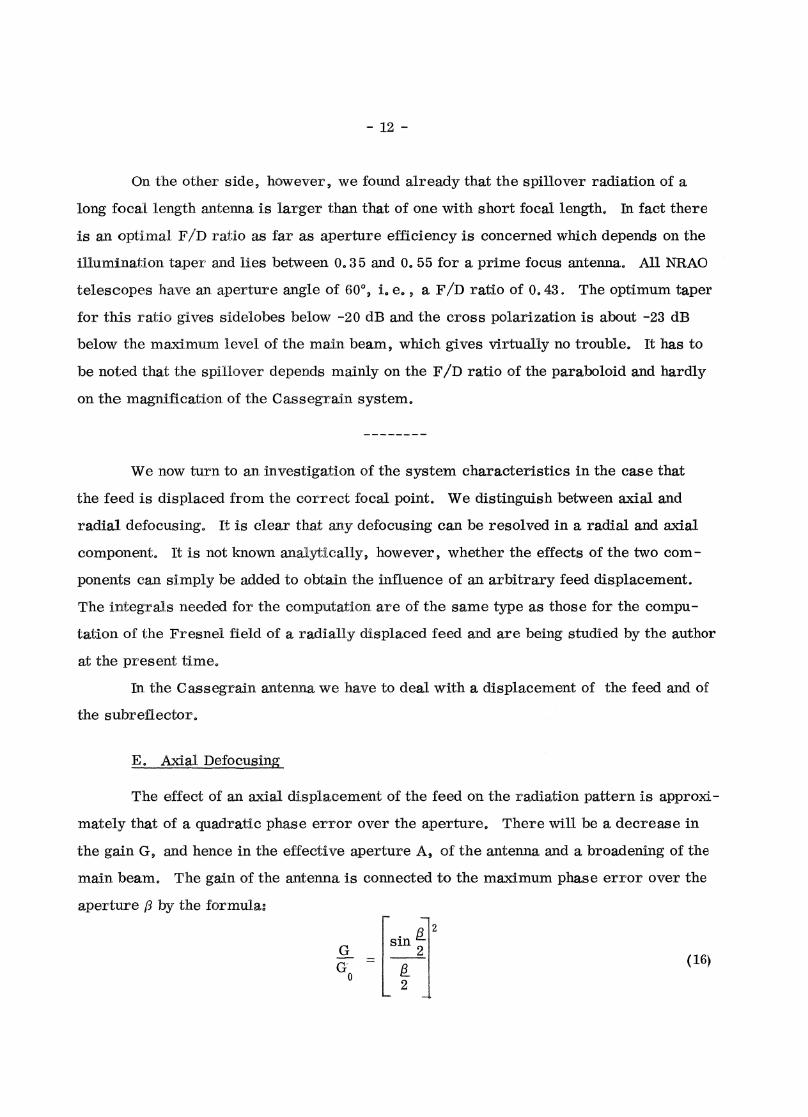
The effect of an axial displacement of the feed on the radiation pattern is approxi-
mately that of a quadratic phase error over the aperture. There will be a decrease in
the gain G, and hence in the effective aperture A, of the antenna and a broadening of the
main beam. The gain of the antenna is connected to the maximum phase error over the
aperture /3 by the formula:
sin g.
2G
o 2
(16)

- 13 -
where Go
is the gain without phase error and [3 is the maximum phase error over the
aperture (between vertex and edge). This formula is valid for uniform illumination.
The more difficult derivation of the formulae for the tapered illumination and the beam
broadening is dealt with in another report [1].
It is clear that 3 is proportional to the maximum change in path length difference
6, taken from the phase center of the feed to the aperture plane of the antenna, between
the edge ray and the vertex ray due to the axial defocusing. Let us calculate the values
of 6 for the different cases. When we move the feed of a prime focus antenna from the
focal point over a distance E 9 the vertex ray becomes E longer and the edge ray E cos 0.
By the definition of 6 we find
6 -E - COS 0) with zP the aperture angle. (17)
Thus given a maximum tolerable 6 we find the maximum tolerable E from (17).
In the Cassegrain we have two possibilities, communicated to us by Ruze:
L Displacement of the feed. Bearing in mind that the length
of the rays from subreflector to paraboloid stays constant
we easily find
-E (1 - cos co) , with co the (18)
aperture of the subdish at
the feed.
2. Displacement of the subreflector. A more tedious but other-
wise straightforward calculation yields
[(1 - cos b) + (1 - cos co)]. (19)
The corresponding phase difference [3 follows from (27r/A) 6, and the change
in gain can be found from (16).
We see that we would have found (18) by using the concept of the equivalent
paraboloid. In figure 6 the curves fr iun (16) are drawn using equations (17) - (19) for
a telescope with F/D 0.3 5, m = 11,, 5, the feed in the vertex (F = f) and a wavelength
of 9 mm.

rabol Id (eq. 17) E = 0. 09 5 A.:40! *
- 14 -
The following conclusions can be made:
L The position of the feed is not very critical in the
Cassegrain. In fact it is about m times less critical
than in the prime focus case.
2. The position of the subdish, however, is very critical,
even mire than the position of the feed in the primary
focus of the paraboloid. In general co is small (about
10 0) and so (1 - cos co) will be nearly zero, that is, the
situation where the position of the feed is not critical at
all and the position of the subdish is about as critical as
the feed position in the prime focus. The subdish posi-
tion is more critical for a higher eccentricity of the
hyperboloid.
Taking as an example a Cassegrain with F/D = 0.3 5, so b = 7 1° and co = 7°,
and allowing a value for 6 = A116, which means GIG () = 0. 99, we find for the toler-
able defocusing:
Cassegrain
feed displacement (eq. 18) E 833 A
subdish do. (eq. 19) E = O. 091
F. Radial Defocusipg
The effect of radial displacement of the feed has been studied by several
authors. Ruze [10] has investigated the defocusing of the prime focus case. A re-
port written by Nihen and Kay [7] de s with the Cassegrain and the Schwartzschild
antenna, as does the work of White and de Size [13].
The radial displacement of the feed causes a tilt of the beam, a decrease of
the gain, an increase in the half-power beam width and an enhancement of the side-
lobe level at the side of the axis of rotation of the system, that is, the so-called
- 15 -
Comalobe. These effects can be described by a linear and a cubic phase error over
the aperture. However, computations in this case are difficult and need in most cases
computer help. We shall only give a compilation of results as found in different re-
ports together with some curves.
The most striking characteristic of the Cassegrain system is the very low coma
aberration. This is due to the long effective focal length. We can define the scanning
range of an antenna as the number of half-power beam widths (HPBW) scanned off-axis
until a certain decrease in gain (e. g. , 1 dB) or rise in sidelobe level has been reached.
Generally (in the prime fecus case) the scanning range varies about as the square of the
ratio (F/D). However, in the Cassegrain the scanning range varies only little with the
F/D ratio; in fact, for F/D > O. 5 it decreases slowly due to the increasing spillover.
The large effective focal length makes the scanning range nevertheless much larger than
in prime focus antennas.
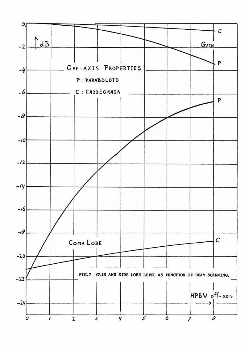
Figure 7 gives a comparison for the relation of gain and sidelobe level, respectively,
as a function of scanning angle for the Cassegrain and prime focus antenna with equal F/D
ratios of the paraboloid. For example, scanning 4 HPBW causes a drop in the gain of 1. 5
dB for the prime focus antenn and only 0.3 dB for the Cassegrain. The comalobe of the
prime focus is -10 dB which is an intoler ble high v ue. The Cassegrain gives -20 dB
where 1 percent blocking is included.
The increase in the HPBW gses slowly to a scan of about 4 beam widths; if the
scan is larger it increases faster. The scanning range has a maximum as a function
of the diameter of the subdish at the value d/D = 0.4. But this is not of practical impor-
tance, as in that case the aperture blocking is too high.
It is well known that the tilt of the beam in a radially defocused paraboloidal
antenna is smaller than the angular displacement of the feed. This is due to the fact
that the reflector surface is not flat and hence the reflection according to Snell's law is
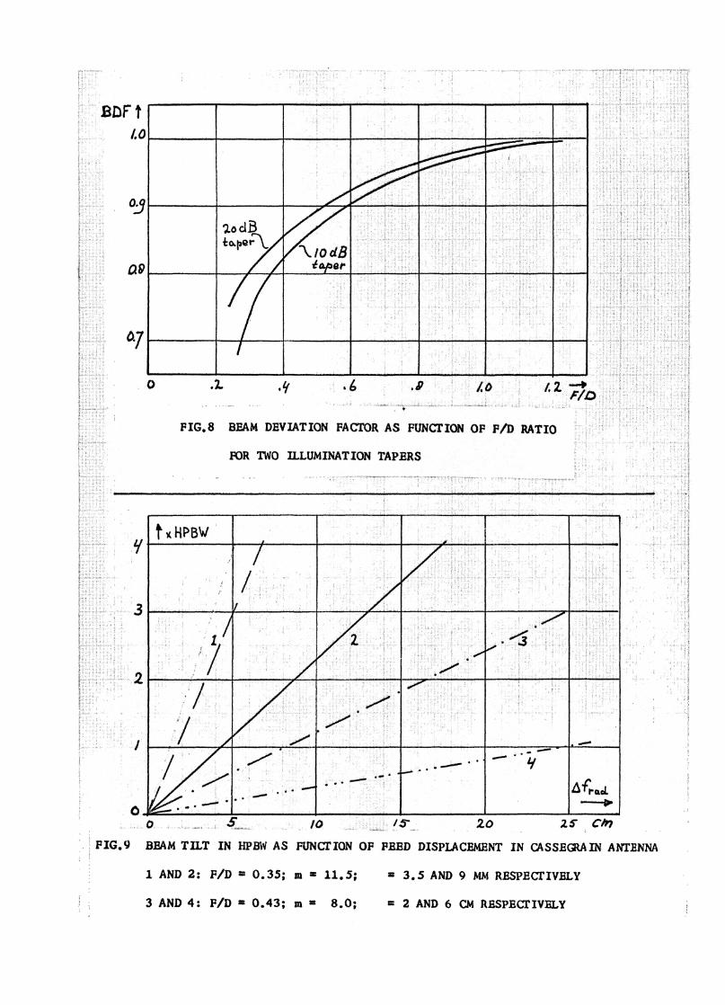
modified. The Beam Deviation Facter (BDF) connects the two quantities. Various authors
[5], [11], [12] have published calculations and curves of the BDF (fig. 8).
For F/D ratios larger than one the BDF approaches the value 1, i. e„ the reflec-
tion is essentially that on a plane mirror. In a Cassegrain antenna the effective F/D
- 16 -
ratio is gener.Ay much larger than one and so we can take BDF = 1. The radial feed
displacement Afrad
of the prim focus antenna gives, with a focal length F and BDF =19
a beam tilt of about At'.rad
/F. In a Cassegrain with the same F/D ratio for the paraboloid
and a magnification m the necessary feed displacement in order to obt n the same beam
tilt is m Afracr
In other words (fig. 1): displacement A of the feed in the Cassegrain
is equiv ent to a displacement A of the feed of the equivalent paraboloid (with focal
length Fe = m. F); it is also equivalent to a displacement A/m of the virtual feed in the
focal point F i of the paraboloid P.
We found alre,.'cly that the physical dimensi ns of the feed in the Cassegrain are
m times bigger than in the primary focus antenna. Two feeds located just beside each
other give the same angular distance between the beams in both cases.
The beamwidth to half-power for an illumination with about 18 dB taper (NRAO
feeds) is approximately O A 1.2 A/D. Taking the BDF = 1 we can find the radial de-
focusing per bea:m deviation of one HPBW from
Afrad
(1 HPBW) = 1. 2 m. X. (20)
For a prime focus par boloid m = 1„ Figure 9 gives the beam tilt as a function of the
radial displacement for .1 0.35 and 0.43 F/D rati with m = 11. 5 and 8. 0 9 respectively,
and wavel n.gths 3. 5 and 9 mm for the first and 2 and 6 cm for the second case.
Calculations have shown that the axial position of the feed in an off-axis posi-
tion is not critical. This is in accordance with the result on the influence of the axial
defocusing of the feed. The axis of the feed has to be directed towards the vertex of the
subreflector. We can define a depth of focus as the distance over which the feed can be
moved in axial direction to obtain a decrease in the gain of 0. 5 dB. The depth of focus is
found to be inversely prop rtional to two. In the region 10° the depth of focus is
about O. 1 D.
Another possibility to achieve a beam tilt is to rot te the subreflector. The
angle of tilt is about half the desired beam deviation. This will give the same effect as
feed displacement. We have to be careful that the axial position of the subreflector

- 17 -
stays focused because that is a very critical point as we saw in the last section. Rota-
tion around the point of the subdish on the mechanical axis of rotation of the antenna will
be necessary. Although no calculations have been made, it is estimated that for beam
tilts of the order of a few degrees the rotation of the subreflector around its vertex with-
out readjustment of the feed would give a beam deflection without deteriorating the beam
shape. It would be interesting to check this statement in an experiment. Also, we have
plans to perform calculations on this problem.
Subreflector tilt h s been suggested by Christiansen as a simple means of obtain-
ing scanning possibilities in a transit radio telescope. According to him this would be far
easier than moving the relatively 1 rge feed with its connections to the radiometer. On
the other hand, however, one has the problem of rotating the subreflector while accurately
controlling the axial position of its vertex. Especially at very large telescopes, and
these are most likely to be transit instruments, this can give severe mechanical problems.
One considers, for example, a 10 m subdish in the 300-foot antenna.
It has to be said finally that the radial displacement of the feed causes some
astigmatism in the plane perpendicular to the direction of scan. As a consequence the
beam will be broader in that plane. Calculations and experimental results have not been
found in the literature.
IV. MECHANICAL CHARACTERISTICS
As the preceding sections have shown, there are some advantages in the Casse-
grain type of radio telescope as far as the electrical characteristics are concerned. We
shall now point out some features in the field of mechanical construction which will show
that the Cassegrain will be of advantage in many cases over the primary focus antenna.
First of all there is the fact that the focal length of the paraboloid can be short, while
still the desired long effective focal length is achieved. It is clear that it is advantageous
as a short construction can be made more rigid.
In a relatively small antenna the support legs for the subreflector can be more
light as long as stability is preserved due to the smaller weight of the subdish as com-
pared to the sometimes quite heavy pillbox with front end of the radiometer. Making the

- 18 -
legs thinner diminishes the blocking and the scattering on the supports. We have to
mention here that the alignment of the system is harder in the case of the Cassegrain,
because both the feed and the subdish have to be put in the correct position with respect
to the axis of rotation of the system.
The feed in the Cassegrain is conveniently located close to the vertex of the
paraboloid. This means that it is possible to mount the front end of the radiometer
behind the reflector and make a very short connection to the feed horn. This is es-
pecially advantageous for bulky front ends as masers with the cooling equipment or, to
take an example outside radio astronomy, in the case of a radar transmitter with mono-
pulse feeds. As a disadvantage, on the mechanical side is the need for two reflecting sur-
faces with their tolerance requirements. Also the feed has to be much larger, which will
in some cases give more trouble to meet the specifications.
If theoretical and experimental results show the feasibility of tilting the subreflec
tor in order to obtain scanning possibilities with a transit telescope, this method is more
likely to be used than moving the feed. Although the mechanical requirements imposed on
the stability and accuracy of the tilted subreflector are quite severe, it seems that they
are easier to meet than the problems of moving the large and heavy feed together with the
attached equipment.
V. SUMMARY AND CONCLUSIONS
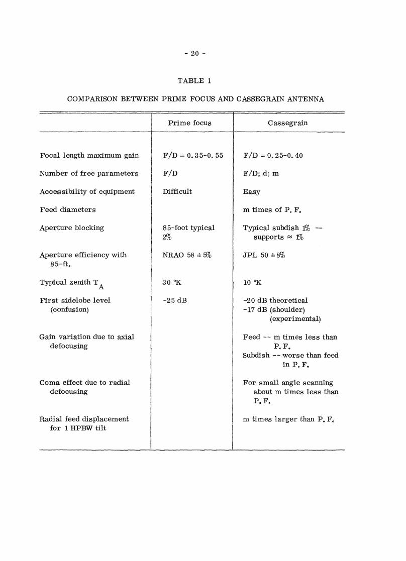
A comparison of the most important characteristics of the prime focus and the
Cassegrain antenna is made in Table 1. The table speaks for itself. The choice of
three free parameters makes it easier to combine electrical and mechanical specifica-
tions. The aperture blocking for relatively small antennas (< 50 feet diameter) is not
worse than that of the pillbox in a prime focus telescope. The choice of 1 percent
(d = O. 1 D) is good as the theoretical sidelobe level stays under -20 dB. In practice,
however, one finds sometimes a small shoulder on the main beam of about -17 dB.
One can keep the F/D ratio short to obtain rigidity and low spillover. Due to the magni-
fication the effective focal length is long and hence the coma lobe is weak and the cross
- 19 -
polarization unimportant. The possibility of achieving a long effective focal length
with a mechanically short antenna is one of the most interesting characteristics of the
Cass egrain
The aperture efficiency increase of a Cassegrain is only marginal. The illumi-
nation can be taken a little less tapered, but the random errors of the reflecting surfaces
are still the main cause of the final aperture efficiency. The surface accuracy of the
subreflector must be very high, about three times better than that of the main reflectcr.
For the feed design one can use the equivalent paraboloid; the feed has to be
designed to illuminate the equivaient paraboloid in the desired manner. The actual il-
lumination of the main reflector will be correct in that case. The feed dimension is m
times bigger than in the prime focus antenna.
The final conclusion of this investigation is that for normal applications in radio
astronomy the Cassegrain antenna is not definitely superior to the prime focus telescope.
For big telescopes (> 100 feet in diameter) it is inadvisable to use the Cassegrain; for
diameters less than 50 feet the Cassegrain can give a slightly better performance. Only
in special circumstances, as the need for very low noise and off-axis feeds, the Casse-
grain is in a favorable position.
Many of the characteristics of the Cassegrain antenna are only a result of
theoretical investigation. There is a definite need for experimental verification of
many points, as aperture efficiency, spillover radiation and off-axis characteristics.
Here the idea of rotating the subdish deserves a careful investigation.
The properties of prime focus paraboloids are at the moment fairly well under-
stood and we have gathered a considerable amount of experimental data. It would be very
interesting if the next 85-foot antenna at NRAO were a Cassegrain so we could make
experiments on the antenna, accurate comparison material for which is available.
In the appendix we have collected numerical material on three Cassegrain an-
tennas in order to illustrate their properties. The antennas are a 30-foot antenna
designed and built as a Cassegrain for mm-wave observations, a 85-foot antenna identical
to the NRAO telescopes but changed into a Cassegrain and to be used at wavelengths larger
than 2 cm, and the 300-foot modified in a Cassegrain.
AcknowIedg_. ment -- It is a pleasure to thank Drs. Mezger and Findlay for interesting
discussions.
- 20 -
TABLE 1
COMPARISON BETWEEN PRIME FOCUS AND CASSEGRAIN ANTENNA
Cassegrain
Focal length maximum gain
Number of free parameters
Accessibility of equipment
Feed diameters
Aperture blocking
Aperture efficiency with85-ft.
Typical zenith TA
First sidelobe level(confusion)
F/D = O. 25-0. 40
F/D; d; m
Easy
m times of P. F.
Typical subdish 1% --supports
JPL 50
10 °K
-20 dB theoretical-17 dB (shoulder)
(experimental)
F/D 0.35-0. 55
F/D
Difficult
85-foot typical2%
NRAO 58
30 °K
-25 dB
Feed — m times less thanP. F.
Subdish -- worse than feedin P. F.
For small angle scanningabout m times less thanP. F.
m times larger than P. F.
Gain variation due to axialdefocusing
Coma effect due to radialdefocusing
Radial feed displacementfor 1 HPBW tilt
- 21 -
VI. REFERENCES
[1] Baars, J. W. M. - P. G. Mezger. Characteristics of the 85-ft. Telescopes at
2 cm Wavelength, NRAO Electronics Division Report No. 36, October
1964.
[2] Hannan, P. W. Microwave Antennas Derived From the Cassegrain Telescope,
IRE Trans. Antennas and Prop. 9 (196 1), 140.
[3] Jones, E. M. T. Paraboloid Reflector and Hyperboloid Lens Antennas, IRE
Trans. Antennas and Prop. 2 (19 54), 119.
[4] Linnes, K. W. - W. D. Merrick - R. Stevens. Ground Antenna for Space
Communications Systems, IRE Trans. SET. 6 (1960), 45.
[5] Lo, Y. T. On the Beam Deviation Factor of a Parabolic Reflector, IRE Trans.
Antennas and Prop. 8 (1960), 347.
[6] Mezger, P. G. Application of Antenna Tolerance Theory to the NRAO 85-foot
and 300-foot Telescopes. NRAO Electronics Division Internal Report
No, 17, August 1963,
[7] Nihen, J. F. - A. F. Kay. Optimum Dual-Reflector Antenna Design Investigation,
TRG Report No. RADC-TDR-63-3 18, June 1963.
[8] Potter, P. Application Cassegrain Principle to Ground Antenna for Space
C•mmunications, IRE Trans. SET-8 (19 62), 19 54.
[9] Ruze, J. Physical Limitations on Antennas, Technical Report 248, Research Lab.
of Electronics, MIT, October 19 52.
[10] Ruze, J. Lateral Feed Displacement in a Paraboloid, paper given at the Int. Symp.
on Antennas and Propagation, IEEE, September 1964 9 New York.
[11] Sandier, S. S. Paraboloidal Reflector Patterns for Off-Axis Feed, IRE Trans.
Antennas and Prop. 8 (19 60), 3680
[121 Silver, S. Microwave Antenna Theory and Design, MIT Rad. Lab. Series, Vol. 12.
[13} White, W. D. - L. K. de Size. Scanning Characteristics of Two-Reflector
Antenna Systems, IRE Int. Convention Record, Part 1 (1962), 44.
- 22 -
APPENDIX
NUMERICAL RESULTS FOR THREE CASSEGRAIN TELESCOPES
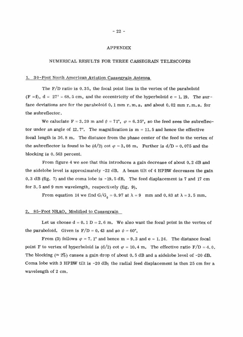
L 3 0-Foot North American Aviation Casse_rain Antenna
The F/D ratio is 0.3 5, the focal point lies in the vertex of the paraboloid
(F =f), d = 27 68. 5 cm, and the eccentricity of the hyperboloid e = 1. 19. The sur-
face deviations are for the paraboloid O. 1 mm r. m. se and about O. 02 mm r. m. s. for
the subreflector.
We caluclate F 3.20 m and b = 71°, ço = 6.3 5' 9 so the feed sees the subreflec-
tor under an angle of 12. 7'. The magnification is m 11. 5 and hence the effective
focal length is 36.8 m. The distance from the phase center of the feed to the vertex of
the subreflector is found to be (d/2) cot (p = 3.08 m. Further is d/D --- 0.075 and the
blocking is O. 563 percent.
From figure 4 we see that this introduces a gain decrease of about 0.2 dB and
the sidelobe level is approximately -22 dB. A beam tilt of 4 HPBW decreases the gain
0.3 dB (fig. 7) and the coma lobe is -19. 5 dB. The feed displacement is 7 and 17 cm
for 3. 5 and 9 mm wavelength, respectively (fig. 9).,
From equation 14 we find G/G 0 = 0,, 97 at A = 9 mm and 0.83 at X = 3. 5 mm.
2., 85-Foot NR,AO,LVI9dified to C_asstgrailL.
Let us choose d 0,, 1. D = 2. 6 m. We also want the focal point in the vertex of
the paraboloid. Given is 1 1/13 = 0.43 and so = 60%
From (3) follows ç, = 7. 1' and hence m = 9.3 and e = 1.24. The distance focal
point F to vertex of hyperboloid is (c1/2) cot (p = 10.4 m. The effective ratio F/D 4. 0.
The blocking 2%) causes a gain drop 4f about 0. 5 dB and a sidelobe level of -20 dB.
Coma lobe with 3 HPBW tilt is -20 dB; the radial feed displacement is then 25 cm for a
wavelength of 2 cm.
- 23 -
APPENDIX (CONTINUED)
30 300-Foot NRAO Modified After TRG Pro sosal
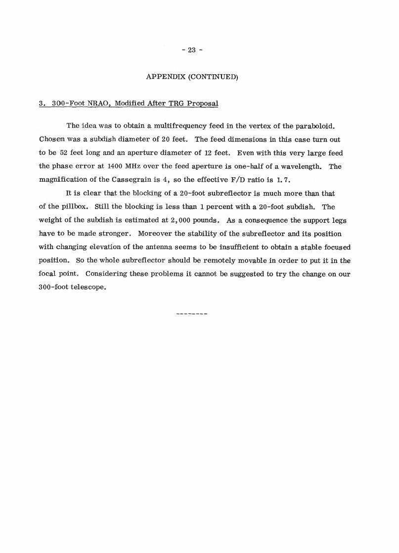
The idea was to obtain a multifrequency feed in the vertex of the paraboloid.
Chosen was a subdish diameter of 20 feet. The feed dimensions in this case turn out
to be 52 feet long and an aperture diameter of 12 feet. Even with this very large feed
the phase error at 1400 MHz over the feed aperture is one-half of a wavelength. The
magnification of the Cassegrain is 4, so the effective F/D ratio is 1.7.
It is clear that the Wicking of a 20-foot subreflector is much more than that
of the pillbox. Still the blocking is less than 1 percent with a 20-foot subdish. The
weight of the subdish is estimated at 2,000 pounds. As a consequence the support legs
have to be made stronger. Moreover the stability of the subreflector and its position
with changing elevation of the antenna seems to be insufficient to obtain a stable focused
position. So the whole subreflector should be remotely movable in order to put it in the
focal point. Considering these problems it cannot be suggested to try the change on our
300-foot telescope.
FIG
1G
EO
ME
TR
Y O
F C
AS
SE
GR
AIN
AN
TE
NN
A
esuRont reflector oI e
EFFECT OF APERTUR
APERTURE ILLUMINATION b) VOLTAGE RADIATION PATTERN
FIG.2, MINIMUM BLOCKING CONDITION

0.3 0.4 0.5
CIRCULAR APERTUREFOR p2)ILLUMINATION
ti/D
APERTURE BLOCKAGE EFFECT ON S DE OBE LEVEL AND DIRECTIVITY
Fl .4 GA INA AND IDE LOBE LEVEL AS A 11.ION OF APERTURE BLOCKING

E-PLANE
H-PLANE
FIG.5 CROSS POLARIZATION
FIG. 6 GUN AS FUNCfION OF AXIAL DEFOaJSING. 1) FEED IN C'ASSEGRAIN FOCUS
2) FEED IN PR IMARY roWS. 3) CASSBGRA IN SUBREFLECTOR
-2.
----..... ~
C
i'
~ d.B GAIN ~ ~ ~P
OFf-AXIS PROPERTIE'S
P : 'PA'RA'BOlOID
.. 6 C : CA55EG-RAIN
~ P
~
/' V
-8
:/ /
V -12.
/ V
-Ilf
/
V / COMA LO&E C
-----~ ~
~ .......
. PIG.t GAIN AND SII)15 LOBB LEVEL AS fUNctION OP BEAM SCANNING. -
-/6
-,9
-2.0
-22
I HPB W off- (lX'S
~
o 1 2 s 6 7
o .1. .If
flIG.8
20 2.5' Cln
1 flIG.9 B:8AM TILT IN HPBW AS flUNCfION OF FBBD DISPLACEMENT IN CASSBGtAIN ANTENNA i
1 AND 2: F/D. 0.35; m • 11.5; • 3.5 AND 9 MM RESPEcrIVELY
3 AND 4: P/D. 0.43; m. 8.0; • 2 AND 6 CM RESPEcr IVa y