national technical university of athens laboratory for earthquake...
TRANSCRIPT

NATIONAL TECHNICAL UNIVERSITY OF ATHENS LABORATORY FOR EARTHQUAKE ENGINEERING
Seismic design of bridges
Lecture 3
Ioannis N. Psycharis

I. N. Psycharis “Seismic design of bridges” 2
Capacity design
Purpose
To design structures of ductile behaviour ensuring the hierarchy of strengths of the various structural components necessary for leading to the intended configuration of plastic hinges and for avoiding brittle failure modes.
Design procedure
Use “capacity design effects”: ♦ For the design of all members intended to remain elastic ♦ Against all brittle modes of failure.
Definition
“Capacity design effects” result from equilibrium conditions at the intended plastic mechanism, when all flexural hinges have developed their flexural resistance including overstrength.

I. N. Psycharis “Seismic design of bridges” 3
Capacity design
Capacity design is applied:
● For the design of sections that must remain within the elastic range (e.g. deck).
● For the design of all members against non-ductile failure modes (shear of members and shear of joints adjacent to plastic hinges).
● For the design of the foundation (except of pile foundation, where plastic hinges are allowed).
● For the design of seismic stoppers and for bearings, links and holding-down devices used for securing structural integrity.
The capacity design effects need not be taken greater than those resulting from the design seismic combination where the design effects AEd are multiplied by the q factor used.

I. N. Psycharis “Seismic design of bridges” 4
Capacity design
Overstrength moment of a section
M0 = γ0MRd
where
γ0 = overstrength factor
for concrete members: γ0 = 1,35 (EC8 – part 2) = 1,40 (E39/99)
MRd = design flexural strength of the section, in the selected direction and sense, based on the actual section geometry and reinforcement
Piers with elastomeric bearings
In bridges intended to have ductile behaviour, in the case of piers with elastomeric bearings where no plastic hinges are intended to form, the capacity design effects shall be calculated on the basis of the maximum deformation of the elastomeric bearings and a 30% increase of the bearing stiffness.

I. N. Psycharis “Seismic design of bridges” 5
Calculation of capacity design effects
The following procedure shall be applied for each of the two horizontal directions of the design seismic action.
Step 1
Calculation of the design flexural strengths MRd and of the overstrength moments M0 of the sections of the intended plastic hinges, corresponding to the selected sense and direction of the seismic action (AE).
● The strengths shall be based on the actual dimensions of the cross-sections and the final amount of longitudinal reinforcement.
● The calculation shall consider the interaction with the axial force and eventually with the bending moment in the other direction, both resulting from the combination G "+“ AE where G is the sum of the permanent actions (gravity loads and post-tensioning) and AE is the design seismic action.

I. N. Psycharis “Seismic design of bridges” 6
Calculation of capacity design effects
Example
Permanent actions G:
top: Μx-x,t =-20 KNm My-y,t =-120 KNm Nt =3000 KN
bottom: Μx-x,b =30 KNm My-y,b =150 KNm Nb =3500 KN
shear: Vx =27 KN
Seismic action AE:
top: Μx-x,t =-300 KNm My-y,t =-1200 KNm Nt =40 KN
bottom: Μx-x,b =450 KNm My-y,b =1500 KNm Nb =40 KN
shear: Vx =270 KN
10,0
x
x
y
y
-120
150
-20
3000
30
3500
27
27
10,0
x
x
y
y
-1200
1500
-300
40
450
40
270
270
I. N. Psycharis “Seismic design of bridges” 7
Calculation of capacity design effects
Example (cont’d)
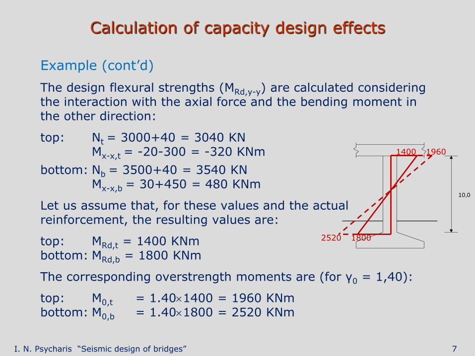
The design flexural strengths (ΜRd,y-y) are calculated considering the interaction with the axial force and the bending moment in the other direction:
top: Νt = 3000+40 = 3040 KN Mx-x,t = -20-300 = -320 KNm
bottom: Νb = 3500+40 = 3540 KN Mx-x,b = 30+450 = 480 KNm
Let us assume that, for these values and the actual reinforcement, the resulting values are:
top: MRd,t = 1400 KNm bottom: MRd,b = 1800 KNm
The corresponding overstrength moments are (for γ0 = 1,40):
top: M0,t = 1.401400 = 1960 KNm bottom: M0,b = 1.401800 = 2520 KNm
10,0
1400 1960
2520 1800

I. N. Psycharis “Seismic design of bridges” 8
Calculation of capacity design effects
Step 2
Calculation of the variation of action effects ΔAC of the plastic mechanism, caused by the increase of the moments of the plastic hinges (ΔM), from the values due to the permanent actions (MG) to the moment overstrength of the sections (M0).
ΔM = γ0MRd – MG
The effects ΔAC may in general be estimated from equilibrium conditions.
Example (cont’d):
top: ΔMt = 1960-120 = 1840 KNm bottom: ΔMb = 2520-150 = 2370 KNm
The corresponding variation of the shear force is:
KN421
10
23701840VΔ C

I. N. Psycharis “Seismic design of bridges” 9
Calculation of capacity design effects
Step 3
The final capacity design effects AC shall be obtained by super-imposing the variation ΔAC to the permanent action effects FG:
AC = AG + ΔAC
Example (cont’d):
Capacity design shear: VC = 27+421 = 448 KN
Simplification
When the bending moment due to the permanent actions at the plastic hinge is negligible compared to the moment overstrength of the section (MG << γ0MRd), the effects ΔAC can be directly estimated from the effects AE of the design earthquake action.
For example, for cantilever piers, the capacity design shear is:
EE
Rd0CC V
M
MγVΔV

I. N. Psycharis “Seismic design of bridges” 10
Earth pressure on abutments and retaining walls
Seismic coefficients
● Horizontal: kh = αS/r
● Vertical: kv = 0,5kh
where
α = ag/g (ag = design ground acceleration on ground type A)
S = soil coefficient
r = coefficient that depends on the amount of permanent displacement which is both acceptable and actually permitted by the adopted structural solution
Type of retaining structure r
Free gravity walls that can accept a displacement up to dr = 300 α⋅S (mm) 2,0
Free gravity walls that can accept a displacement up to dr = 200 α⋅S (mm) 1,5
Flexural reinforced concrete walls, anchored or braced walls, reinforced concrete walls founded on vertical piles, restrained basement walls and bridge abutments
1,0

I. N. Psycharis “Seismic design of bridges” 11
Earth pressure on abutments and retaining walls
Flexible abutments and walls
Total pressure (static + dynamic):
where
H = wall height
K = earth pressure coefficient. It may be computed from the Mononobe – Okabe formula
kv = vertical seismic coefficient
γs = specific weight of the soil
2vsd HK)k1(γ
2
1E
H
pd = γs(1kv)KH
The point of application is considered at height equal to 0,4H.

I. N. Psycharis “Seismic design of bridges” 12
Earth pressure on abutments and retaining walls
Rigid abutments and walls
According to Eurocode 8-part 5:
● Neutral static earth pressure
where K0 = 1 – sinφ
● Additional pressure (dynamic):
The point of application may be taken at mid-height
2sd HγSαEΔ
20s0 HKγ
2
1E
H
pst = γsK0H
H
pd = αSγsH
I. N. Psycharis “Seismic design of bridges” 13
Earth pressure on abutments and retaining walls
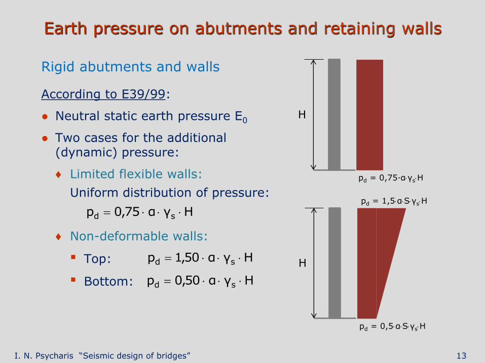
Rigid abutments and walls
According to E39/99:
● Neutral static earth pressure E0
● Two cases for the additional (dynamic) pressure:
♦ Limited flexible walls:
Uniform distribution of pressure:
♦ Non-deformable walls:
▪ Top:
▪ Bottom:
Hγα75,0p sd
H
H
pd = 0,5αSγsH
pd = 1,5αSγsH
pd = 0,75∙αγsH
Hγα50,1p sd
Hγα50,0p sd

I. N. Psycharis “Seismic design of bridges” 14
Abutments flexibly connected to the deck
The following actions, assumed to act in phase, should be taken into account:
● Earth pressures (flexible abutments)
When the earth pressures are determined on the basis of an acceptable displacement of the abutment (r>1), it should be ensured that this displacement can actually take place before a potential failure of the abutment itself occurs. For this reason, the body of the abutment is designed using the seismic part of the earth pressure increased by 30%.
● Inertia forces acting on the mass of the abutment and on the mass of earthfill lying over its foundation determined using the design ground acceleration ag.
● Actions from the bearings determined: ♦ From capacity design effects if a ductile behaviour has been
assumed for the bridge. ♦ From the reaction on the bearings resulting from the seismic
analysis if the bridge is designed for q = 1,0.

I. N. Psycharis “Seismic design of bridges” 15
Abutments rigidly connected to the deck
The following actions should be taken into account:
● Inertia forces acting on the mass of the structure which may be estimated using the Fundamental Mode Method. A behaviour factor q = 1,5 shall be used.
Abutments buried in strong soils for more than 80% of their height can be considered as fully locked-in. In that case, q = 1 shall be used and the inertia forces are determined on the basis of the design ground acceleration ag.
● Static earth pressures acting on both abutments (E0).
● Additional seismic earth pressures ΔEd = Ed – E0.
The pressures ΔEd are assumed to act in the same direction on both abutments.
Reactions on the passive side may be taken into account, estimated on the basis of horizontal soil moduli corresponding to the specific geotechnical conditions.

I. N. Psycharis “Seismic design of bridges” 16
Resistance verification of concrete sections
In general, verifications of shear resistance shall be carried out in accordance with par. 6.2 of EC 2 with some additional rules.
For the flexural resistance of sections, the following conditions shall be satisfied
Structures of limited ductile behaviour (q 1,5)
Ed ≤ Rd
Ed = the design action effect under the seismic load combination including second order effects
Rd = the design flexural resistance of the section.

I. N. Psycharis “Seismic design of bridges” 17
Resistance verification of concrete sections
Structures of ductile behaviour
● Flexural resistance of sections of plastic hinges:
MEd ≤ MRd
MEd = the design moment under the seismic load combination, including second order effects
MRd = the design flexural resistance of the section.
● Flexural resistance of sections outside the region of plastic hinges:
MC ≤ MRd
MC = the capacity design moment
MRd = the design resistance of the section, taking into account the interaction of the corresponding design effects (axial force and when applicable the bending moment in the other direction).
I. N. Psycharis “Seismic design of bridges” 18
Minimum overlap length
At supports, where relative displacement between supported and supporting members is intended under seismic conditions, a minimum overlap length, Lov, shall be provided, which may be estimated as:
Lov = Lm + deg + des
where:
Lm = the minimum support length securing the safe transmission of the vertical reaction with Lm 40 cm.
deg = the effective displacement of the two parts due to differential seismic ground displacement, which can be estimated from the procedure given in the following.
des = the effective seismic displacement of the support due to the deformation of the structure, which can be estimated from the procedure given in the following.
I. N. Psycharis “Seismic design of bridges” 19
Minimum overlap length
Calculation of deg
deg = Leff∙vg/ca 2∙dg
where:
Leff = the effective length of deck, taken as the distance from the deck joint in question to the nearest full connection of the deck to the substructure.
“full connection” means a connection of the deck to a substructure member, either monolithically or through fixed bearings or seismic links.
vg = peak ground velocity, estimated from the design ground acceleration ag using the relation: vg = 0,16∙S∙TC∙ag.
ca = apparent phase velocity of the seismic waves in the ground.
dg = design value of the peak ground displacement.
I. N. Psycharis “Seismic design of bridges” 20
Minimum overlap length
Calculation of des
● For decks connected to piers either monolithically or through fixed bearings, acting as full seismic links: des = dEd, where dEd is the total longitudinal design seismic displacement.
● For decks connected to piers or to an abutment through seismic links with slack equal to s: des = dEd + s.
In the case of an intermediate separation joint between two sections of the deck, Lov should be estimated by taking the square root of the sum of the squares of the values calculated for each of the two sections of the deck. In the case of an end support of a deck section on an intermediate pier, Lov should be estimated as above and increased by the maximum seismic displacement of the top of the pier dE.