national transportation safety board -...
TRANSCRIPT

t
PB85-910404
NATIONALTRANSPORTATIONSAFETYBOARD
WASHINGTON, D.C. 20594
AIRCRAFT ACCIDENT REPORT
ZANTOP INTERNATIONAL AIRLINES, INC.,‘.LOCKHEED L-l 88A ELECTRACHALKHILL, PENNSYLVANIAMAY 30, 1984
.
NTSB/AAR-85/.04
i UNITED STATES GOVERNMENT

I bY,II.amL I.&r “Ill uvuunut 8 n 1 A-.. . ,IYL
� l &~~~%~85/04 Z.Covernment Accession No. 3.Recipient’s Catalog No.PB85-910404
4 . T i t l e a n d S u b t i t l e Aircraft Accident Report- 5.R port Dat
Zentop International Airlines, Inc. Lockheed L-188Afiarch 19, e985
Electra ,Chalkhill, Pennsylvania, May 30, 1984. 6.Performing OrganizationCode
7. Author(s) B.Performing OrganizationReport No.
9. Performing Organization Name ‘and Address lO.Wo;~2~n~ No.National Transportation Safety BoardBureau of Accident Investigation ll.Contract or Grant No.Washington, D.C. 20594
13.Type of Report andPeriod Covered
12.Sponsoring Agency Name and Address Aircraft Accident ReportMay 30, 1984
NATIONAL TRANSPORTATION SAFETY BOARDWashington, 0. C. 20594 14.Sponsoring Agency Code
15,Supplementary Notes
16.AbstractOn May 30, 1984, Zentop International Airlines, Inc., Flight 931, a Lockheed
Electra L-188 (N5523) was a regularly scheduled cargo flight from Baltimore-WashingtonInternational Airport to Willow Run Airport, Ypsilanti, Michigan. There were three flightcrewmembers and a non-revenue passenger on board.
The airplane departed Baltimore-Washington International Airport at 0110 endclimbed to flight level 220. The cockpit voice recorder indicated that the flightcrewexperienced gyro problems during the climb to cruising altitude and that it had subsequentlyselected the No.1 vertical gyro to drive both approach horizons since there was an indicationof a malfunction in the No. 2 vertical gyro system. By 0136:32, Flight 931 was level at flightlevel 220. At 0143:09, Cleveland Air Route Traffic Control Center cleared Flight 931 toDryer VOR. Conversations on the cockpit voice recorder at 0144:11, include a commentwhich, although not clear, appeared to be 11altitude1f followed by the statements, “What’shappening here, *I ffYou got it,” end “No.ll The airplane entered a right descending spiral es theindicated airspeed increased from 205 knots to about 317 knots. There was a sound similar tostructural failure during inflight breakup on the cockpit voice recorder at 0144:24.9. Theairplane wreckage was scattered over an area 2 miles long by 1 mile wide.
17.Key Words 18.Distribution StatementVertical gyro; amplifier malfunction; This document is available
,structural failurs conflicting pitch and roll data; to the public throughinadequate instrument scan. the National TechnicalUer+ical guidiuwz I-0 11 Information Service,xe& attihde 3\Ico system Springfield, Virginiacoetrol- losso4 *&IQ& QdTol- I- 04
&?# 9-d-p.5 22161lg.Security C l a s s i f i c a t i o n 20.Security Classififation 21.No. o f P a g e s 22.Price
(of th is repor t ) (of this page)UNCLASSIFIED UNCLASSIFIED 54
N T S B F o r m 1 7 6 5 . 2 ( R e v . 9/74)

The National Transportation Safety Board determines that the probable causeof the accident was the airplane’s entry into an unusual attitude and the inability of theflightcrew to analyze the flight condition before there was a complete loss of control.Although the precise reason for the loss of control was not identified, an undeterminedfailure of a component in the No. 2 vertical gyro system, perhaps involving the amplifierand associated circuitry, probably contributed to the cause of the accident by incorrectlyprocessing data to the copilot’s approach horizon. The inflight structural failure of theairplane was due to overload.
i i
CONTENTS
SYNOPSIS. . . . . . . . . . . . . . . . . . . . . . . . . . 1
1. FACTUAL INFORMATION. . . . . . . . . . . . . . . . . . . 11.1 History of the Flight . . . . . . . . . . . . . . . . . . . . . 11.2 Injuries to Persons . . . . . . . . . . . . . . . . . . . . . . 31.3 Damage to Aircraft . . . . . . . . . . . . . . . . . . . . . . 41.4 Other Damage . . . . . . . . . . . . . . . . . . . . . . . . 41.5 Personnel Information . . . . . . . . . . . . . . . . . . . . . 41.6 Aircraft Information . . . . . . . . . . . . . . . . . . . . . 41.7 Meteorological Information. . . . . . . . . . . . . . . . . . . 41.8 Aids to Navigation . . . . . . . . . . . . . . . . . . . . . . 61.9 Communications . . . . . . . . . . . . . . . . . . . . . . . 71.10 Aerodrome Information . . . . . . . . . . . . . . . . . . . . 71.11 Flight Recorders . . . . . . . . . . . . . . . . . . . . . . . 71.12 Wreckage and Impact Information . . . . . . . . . . . . . . . . 71.13 Medical and Pathological Information . . . . . . . . . . . . . . 111.14 Fire . . . . . . . . . . . . . . . . . . . . . . . . . . . . . 121.15 Survival Aspects . . . . . . . . . . . . . . . . . . . . . . . 121.16 Tests and Research . . . . . . . . . . . . . . . . . . . . . . 121.16.1 Powerplants . . . . . . . . . . . . . . . . . . . . . . . . . 121.16.2 Metallurgical Examination . . . . . . . . . . . . . . . . . . . 131.16.3 Autopilot Examination. . . . . . . . . . . . . . . . . . . . . 151.16.4 Flight Instrument Teardown and Examination . . . . . . . . . . . 151.16.5 Airplane Performance . . . . . . . . . . . . . . . . . . . . . 161.17 Additional Information. . . . . . . . . . . . . . . . . . . . . 171.17.1 Approach Horizon . . . . . . . . . . . . . . . . . . . . . . . 171.17.2 Vertical Gyro Operation . . . . . . . . . . . . . . . . . . . . 171.17.3 L-188 In-flight Structural- Failure Accident History. . . . . . . . 191.17.4 Human Performance Data . . . . . . . . . . . . . . . . . . . 211.18 New Investigation Techniques. . . . . . . . . . . . . . . . . . 22
2. ANALYSIS. . . . . . . . . . . . . . . . . . . . . . . . . . 222.1 General . . . . . . . . . . . . . . . . . . . . . . . . . . . 222.2 Inflight Structural Failure and Fire . . . . . . . . . . . . . . . 222.3 Operational Interpretation of Flight Instruments . . . . . . . . . 232.4 Human Performance. . . . . . . . . . . . . . . . . . . . . . 28
3. CONCLUSIONS. . . . . . . . . . . . . . . . . . . . . . . . 313.1 Findings. . . . . . . . . . . . . . . . . . . . . . . . . . . 313.2 Probable Cause . . . . . . . . . . . . . . . . . . . . . . . . 32
4.0
5.
RECOMMENDATIONS. . . . . . . . . . . . . . . . . . . . . 32
APPENDIXES . . . . . . . . . . . . . . . . . ....... 35Appendix A-Investigation and Deposition Proceeding . . . . . . . 35Appendix B--Personnel Information . . . . . . . . . . . . . . . 36Appendix C--Aircraft Information . . . . . . . . . . . . . . . 37Appendix D--Transcript of Cockpit Voice Recorder . . . . . . . . 38Appendix E--Readout of Flight Data Recorder . . . . . . . . . . 49Appendix F--Wreckage Diagram . . . . . . . . . . . . . . . . 51Appendix G-Radar Data. . . . . . . . . . . . . . . . . . . . 53Appendix H-Whirl Mode . . . . . . . . . . . . . . . . . . . . 55
i i i


NATIONAL TRANSPORTATION SAFETY BOARDWASHINGTON, D.C. 20594
AIRCRAFT ACCIDENT REPORT
Adopted: March 19,198s
ZANTOP INTERNATIONAL AIRLINRS, INC.LOCKHEED L-188 ELECTRA, N5523
CHALKHILL, PENNSYLVANIAMAY 30,1984
SYNOPSIS
On May 30, 1984, Zantop International Airlines, Inc., Flight 931, a LockheedElectra L-188 (N5523) was a regularly scheduled cargo flight from Baltimore-WashingtonInternational Airport to Willow Run Airport, Ypsilanti, Michigan. ’ reflightcrew members and a non-revenue passenger on board. %
were three
The airplane departed Baltimore-Washington International Airport at 0110 andclimbed to flight level 220. The cockpit voice recorder indicated that the flightcrew \experienced gyro problems during the climb to cruising altitude and that it hadsubsequently selected the No.1 vertical gyro to drive both approach horizons since therewas an indication of a malfunction in the No. 2 vertical gyro system. By 0136:32,Flight 931 was level at flight level 220. At 0143:09, Cleveland Air Route Traffic ControlCenter cleared Flight 931 to Dryer VOR. Conversations on the cockpit voice recorder at0144:11, include a comment which, although not clear, appeared to be “altitude1 followedby the statements, “What’s happening here,” “You got it,” and “No.” The airplane entereda right descending spiral as the indicated airspeed increased from 205 knots to about 317knots. There, was a sound similar to structural failure during inflight breakup on thecockpit voice recorder at 0144:24.9. The airplane wreckage was scattered over an area 2miles long by 1 mile wide.
The National Transportation Safety Board determines that the probable causeof the accident was the airplane’s entry into an unusual attitude and the inability of theflightcrew to analyze the flight condition before there was a complete loss of control.Although the precise reason for the loss of control was not identified, an undeterminedfailure of a component in the No. 2 vertical gyro system, perhaps involving the amplifierand associated circuitry, probably contributed to the cause of the accident by incorrectlyprocessing data to the copilot’s approach horizon. The inflight structural failure of theairplane was due to overload.
. 1. FACTUAL INFORMATION
1.1 History of the Flight
On May 30, 1984, Zantop International Airlines, Inc., Flight 931, a LockheedL-188 Electra (N5523), was a regularly scheduled cargo flight from Baltimore-WashingtonInternational (BWI) Airport to Willow Run Airport, Ypsilanti, Michigan. The flightcrew,consisting of a captain, first officer, and flight engineer, had flown from Detroit,Michigan, on the day of the accident as passengers and had arrived at Baltimore,
-2-
Maryland, about 1818. l-/ They checked into a motel until they were alerted for Flight931 about 2300.
The f l ightcrew repor ted to the a i rpor t about 0010 for predepar turepreparations. The first officer prepared the flight plan and reviewed the dispatchinformation as the captain was briefed on a hazardous materials shipment. The flightengineer supervised the refueling of the airplane and completed the predepartureinspection. An in s t rumen t f l i gh t p l an was f i l ed fo r f l i gh t l eve l (FL) 220(22,000 feet). 2/ The weather forecast for the en route portion of the flight inPennsylvania was, in part, ceilings 2,000 feet to 3,000 feet broken, 10,000 feet broken toovercast, light rainshowers; freezing level 12,000 feet, winds aloft from the southwest at60 knots.
Zantop ground personnel began to load the airplane at 2300. The loading wascompleted at 0040. All cargo was bulk loaded and tied down on the right side of theairplane for the full length of the cargo compartment. The night shift supervisorinspected the loading distribution for security at 0050. There was one non-revenuepassenger onboard for the flight to Ypsilanti.
Flight 931 departed the gate at 0105 and took off on runway 28 at 0110. At0111:42, Flight 931 contacted Baltimore departure control and was cleared to 13,000 feet.At 0112:54, the captain, who was not flying the airplane, instructed the first officer tostop the climb and level the airplane. He stated, “Level it off for just a second, I want to.check this radar; I got the antenna full up, it looks like it is still painting the ground.” At0113:34, the climb was continued.
At 0115:58, the captain said ‘I. . .get your airspeed down to about 190 and we’llclimb up through this faster.” At 0116:20, Flight 931 contacted Washington Air TrafficControl Center (ARTCC) and reported climbing through 8,300 feet. A t 0116:34,Washington ARTCC cleared Flight 931 to climb to FL 220.
At 0116:44, the captain stated, “Climbing out like we are now, where you aregetting bounced around and you don’t know what you might hit, the last thing in the worldyou want to do is to have your airspeed high.” Throughout the climb, the captain and firstofficer discussed aircraft and air traffic control subjects, including an apparentadjustment problem with the airplane’s airborne radar set. At 0127:03, the captain said“Out of 18,000, 992.” At 0128:57, Washington ARTCC instructed Flight 931 to contactCleveland ARTCC. Flight 931 contacted Cleveland ARTCC at 0129:18 and verified FL220 as the assigned altitude.
At 0132:24, the first officer said, “*Kept turning---that’s at. . .I1 and thecaptain responded at 0132:35, “Gyro’s screwed up ---*.I’ The conversation about the gyrocontinued until 0136:07 and included a request by the first officer for the flight engineerto “switch it over to No. 1.” This was an apparent command to switch the Wilcoxswitching unit to drive the approach horizons from the No. 1 vertical gyro. Once they hadswitched to No. 1, the gyro problem appeared resolved, since the first officer and flightengineer commented that “its level now” and that it was ‘better.”
At 0136:32, the first officer called for the cruise checklist and the threecockpit crewmembers began a conversation about indications on the No. 2 engine. Theindications were that the horsepower was low while the temperature was high. The-----m---s---------_L/ All times herein are eastern daylight time based on the 24-hour clock.2/ All altitudes are mean sea level unless otherwise noted.

-3-
conversation continued until 0138:33. At 0!38:40, Cleveland ARTCC asked Flight 931about the cloud tops in the area, and at 0139:02, the first officer transmitted that theyhad climbed through the tops of the clouds at 14,000 feet or 15,000 feet.
Aside from a request by the flight engineer at 0141:27, for engine times andtemperatures, there was no cockpit conversation between 0139:02 and 0144:11, althoughthe cockpit voice recorder did indicate the sounds of paper pages being turned.
At 0143:09, Cleveland ARTCC cleared Flight 931 direct to the Dryer VOR andprovided a new radio frequency. The first officer responded at 0143:17, “One twenty-fiveone direct Dryer, Zantop 931, good night.” At 0143:29, the first officer contactedCleveland ARTCC on the new frequency and stated, “Zantop 931’s with you flight level220, we are going direct Dryer .I1 This was the last transmission from Flight 931.
At 0144:11, a comment was made by an unknown crewmember which may havebeen ffaltitudeff. The tape of the CVR was not clear that the word was actually f1altitude.ffHowever, the CVR investigation group came to a consensus that altitude was possibly thecomment. At 0144:13.3, the first officer said, ffWhatfs happening here,” followed by thesound of increasing wind noise at 0144:15. At 0144:15.2, the first officer asked, “You gotit?” and the captain answered at 0144:18.1, “No.~~ At 0144:21.1, the sound of the landinggear warning horn started, followed at 0144:22.7 by the sound of the overspeed warningclacker. The overspeed warning clacker continued until the end of the cockpit voicerecorder tape. The cockpit voice recorder indicated a sound similar to structural failureduring inflight breakup at 0144:24.9. At 0144:30, the cockpit voice recorder tape stopped.
The air traffic controller who was controlling Flight 931 stated that no otheraircraft had gone through his area in the 10 minutes preceding the accident. At 0145:03,when he noted that the transponder data block of Flight 931 had disappeared, heattempted to contact Flight 931.
Numerous persons in the area of the accident reported ‘loud, unusual noisesffwhich they attributed to an airplane in trouble. Witnesses reported a “terrific rumble andvibration,” while witnesses close to the accident site described continuing noises after theinitial ‘1boom.ff The noises were described as “different” engine noises, shrill, like anobject traveling, “arc welding,” and ffcrackle.ff There was general agreement that thenoises lasted 45 seconds to 1 l/2 minutes.
The airplane came apart in flight. The wreckage scattered over an area about2 miles long by 1 mile wide and oriented northeast by southwest on a line throughChalkhill, Pennsylvania. (See appendix F.) Falling wreckage damaged some houses;however, most of the wreckage felI in uninhabited, wooded areas.
The three crewmembers and the non-revenue passenger died in the accident.The accident occurred during the hours of darkness at coordinates 35’48’35” north latitudeand 79”37’32” west longitude. There was no moonlight at the time of the accident.
1.2 Injuries to Persons
Injuries Crew Passengers Others Total
Fatal 3 1 0 4Serious 0 0 0 0Minor/None 0 0 0 0Other 0 0 0 0Total 3 i ti ;i

-4-
1.3 Damage to Airplane
The airplane was destroyed.
1.4 Other Damage
Some private residences, the Chalkhill Post Office, and the parking lot of thepost office were damaged by sections of the airplane.
1.5 Personnel Information
The flightcrew was certificated and qualified for the flight and had receivedthe required training. (See appendix B.)
1.6 Aircraft Information
The airplane, a Lockheed L-188 Electra, N5523, (S/N1034) was operated byZantop International Airlines, Inc; and it had been maintained in accordance withapplicable regulations. The takeoff gross weight was 85,827 pounds, which included12,508 pounds of cargo and 14,000 pounds of jet fuel. The maximum allowable takeoffgross weight was 113,000 pounds. The center of gravity was within the prescribed limits.(See appendix C.)
The airplane was powered by four Allison Sol-D13 turbopropeller engines andfour Aeroproducts Model No. A6441FN-666 propellers. A review of the airplane recordsindicated compliance with all applicable airworthiness directives (AD) and LockheedService Bulletins. Additionally, there were no outstanding minimum equipment listdiscrepancies or deferred maintenance items. The airplane logbook pages for flightsthrough May 26, 1984, were available at Zantop International% main maintenance base. Areview of the logbook revealed no significant maintenance deficiencies or trends ofmaintenance deficiencies.
A first officer who had flown with the captain of Flight 931 in N5523 one weekbefore the accident stated that the autopilot “tripped ofP’ several times during the flight.On one occasion, a SOO-foot-per-minute (fpml descent resulted. He said that theautopilot switch tripping was indicated only by an annunicator light on the captain’sinstrument panel. He said that other pilots had reported to him unwanted altitude-holddisconnects. There were no logbook entries which related to any autopilot difficulties.
The flightcrew who operated N5523 for 2 l/2 days before the accident saidthey had encountered no serious problems with the airplane. They said that the radarantenna apparently was out of adjustment, the No. 2 engine instruments were slightlydifferent from the other three, and there had been two momentary “jerks” in the pitchaxis of the autopilot. The first officer characterized the jerks as “very minor.”
1.7 Meteorological Information G
The 2300, May 29, surface weather map showed a flat 1016-millibar low overthe eastern edge of Lake Huron and a frontal system lying along the Atlantic Coast fromMassachusetts through the Delmarva Peninsula with a weak low on the front oversoutheastern Virginia. Surface conditions over western Pennsylvania were characterizedby overcast skies and light westerly winds with areas of fog and haze. Stations in easternPennsylvania reported moderate steady rain and drizzle.

-5-
The following are the surface observations at Morgantown, West Virginia, thenearest reporting station to the accident site:
Time--0100; type--record special; ceiling--measured 1,900 feet broken,8,000 feet overcast; visibility--7 miles; temperature--46°F; dewpoint--42’ F; wind--260° 4 knots; altimeter--30.14 inches.
Time--0158; type--record special; c louds--2 ,000 feet sca t tered,ceiling--measured 3,600 feet overcast; visibility--7 miles;temperature--45’ F; dewpoint--42O F; wind--240° 5 knots;altimeter--30.13 inches.
The 0100 i n f r a r ed pho tog raph f rom the Geos t a t i ona ry Ope ra t i ona lEnvironmental Satellite (GOES) showed an area of higher clouds with the potential forconvective activity e a s t o f a l ine extending approximately nor th-nor theas t ,south-southwest through the vicinity of Cumberland, Maryland. West of this line, theclouds were predominantly low with a line of high clouds north-northeast south-southwestin the vicinity of the accident site. Based upon the infrared temperature scale, the highercloud tops were probably in the vicinity of 25,000 feet.
The following are the 1915 winds aloft at Pittsburgh from the surface to25,000 feet:
Altitude Direction(feet above sea level) (” true)
Speed(knots)
1,181 300 52,130 290 143,050 281 103,970 267 84,890 248 115,890 241 186,867 241 237,824 234 258,791 229 309,755 225 36
10,851 227 3511,880 226 4012,909 224 4013,693 220 4315,076 218 4716,189 217 5017,234 217 6018,273 213 7819,353 205 9020,411 203 9621,429 205 10122,433 206 10323,436 209 10025,456 208 104

-6-
Area Forecasts--The following area forecast, quoted in part, was issuedby the National Weather Service Advisory Unit of the National WeatherService on May 29, 1984, at 1940, and was valid beginning at 2000:
Turbulence valid until May 30, 0800.
From Caribou (ME) to St. Johns (N.B.1 to Nantucket (RI) to Parkersburg(WV) to Findlay (OH) to Quebec (Que) to Caribou (ME). Occasionalmoderate turbulence below 10,000 feet due to strong low level winds.Conditions improving southwestern portions by 0200, continuingelsewhere beyond 0800.
2,000 to 3,000 feet broken 10,000 feet broken to overcast. Occasionalceilings below 1,000 feet overcast, visibilities below 3 miles in light rainand fog with mountains obscured in clouds and precipitation. Isolatedembedded thunderstorms with light rain showers eastern quarter. Topslayered to 20,000 feet. Cumculnimbus tops to 30,000 feet. Outlook:IFR due to ceiling and rain showers northeastern quarter until 1200.Otherwise marginal VFR due to ceiling throughout.
At 1942, May 29, the following correction to the area forecast was issued.
Icing and freezing level valid until May 30, 0800.
Lake Erie, Ohio, West Virginia, Pennsylvania, correction.
From 80 miles northeast of Marquette (MI) to Buffalo (NY) to Beckley(WV) to Covington (KY) to Chicago (IL) to Green Bay (WI) to 80 milesnortheast of Marquette (MI).
Occasional moderate rime/mixed icing in clouds and in precipitationabove the freezing level to 12,000 feet. Conditions continuing beyond0800.
At 2000 the following correction to the area forecast was issued.
Turbulence valid until May 30, 0800
From Toronto font.1 to Buffalo (NY) to Bristol (TN) to Montgomery (AL)to Memphis (TN) to Fort Wayne (IN) to Toronto.
Occasional moderate turbulence 15,000 to 25,000 feet associated with windshear in upper trough. Conditions moving slowly eastward and contouring beyond 0800.
T h e r e w e r e n o SIGMETs, c o n v e c t i v e SIGMETs o r AIRMETs v a l i d f o rsouthwestern Pennsylvania at the time of the accident.
1.6 Aids to Navigation
Not applicable.
-7-
1.9 Communications
There were no known communication problems.
1.10 Aerockome Information
Not applicable.
1.11 PIight Recorders
The airplane was equipped with a Fairchild A-100 cockpit voice recorder(CVR), serial No. 1063. The exterior recorder case was damaged slightly in the accident;however, the tape transport survived and the quality of the recording was excellent. Theentire 32 minutes of the recording were transcribed in the Safety Board’s AudioLaboratory. (See appendix D.)
The last 5 minutes of the CVR tape was examined to determine if there wereany electrical system abnormalities during this time period. The 400 Hz aircraft a.c.power signature was printed on a Honeywell visacorder which showed amplitude versustime. There were no disturbances found until after the cockpit area microphone (CAM)picked up sounds associated with structural failure at 01:44:24.9.
The overspeed warning clacker which started at 01:44:22.7 and continued untilthe end of the tape was identified by measuring the frequency of the sounds it produced.The measured frequency was between 6.8 Hz and 7.0 Hz. The design frequency of theoverspeed warning clacker is about 7 Hz.
The airplane was equipped with a Fairchild Model 5426 flight data recorder(FDR), serial No. 1349. The FDR was removed from the airplane and taken to the SafetyBoard’s FDR laboratory in Washington, D.C., for examination and readout. (Seeappendix E.) The recorder was damaged mechanically in the accident, and it was cut opento remove the foil magazine. Although the foil magazine was warped, a large portion ofthe foil medium, including the accident flight record, was removed successfully from themagazine. The parameter and binary traces, except the magnetic heading trace, wererecorded in the prescribed manner. The magnetic heading trace was static at all timesand was positioned below the north/south binary trace.
1.12 Wreckage and Impact Information
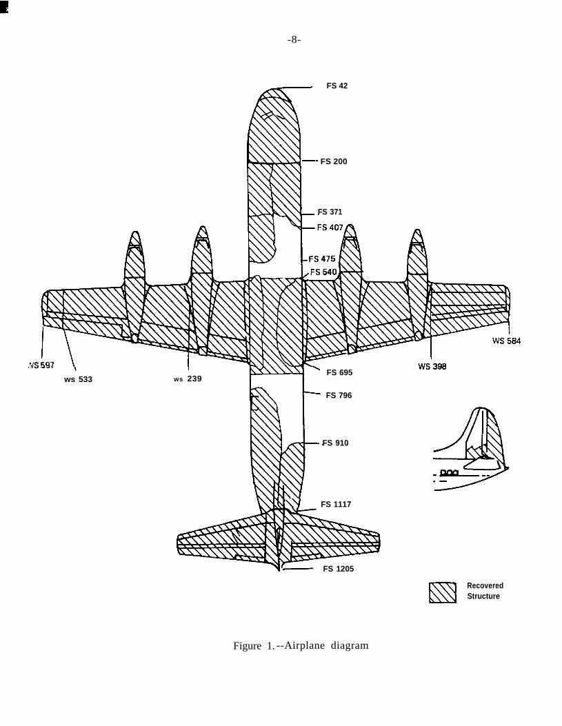
Fuselage.--The fuselage broke apart in flight, and the damage from fuselagestation (FS) 200 aft to FS 1117 was extensive. (See figure 1.) The main sections of thefuselage which were recovered were the nose and cockpit section from FS 42 to FS 200;the left forward fuselage section encompassing the four static ports and a portion of theforward entrance door frame; the left aft fuselage section (FS 796 to FS 1117) whichincluded a portion of the cabin floor and the main cargo door assembly; and the rightfuselage section from FS 540 to FS 695, including the bottom fwelage from FS 540 to FS715, which was fragmented into small pieces and unidentifiable sections.
The main cargo door was closed and locked. The fuselage skin and associatedsupport structure from the main cargo door aft to FS 1117 was folded in the forward andupward direction.
i
-8-
FS 42
- FS 200
FS 371
.YS --. \ws 533
I
ws 239’FS 695
FS 796
FS 910
\U FS 1117
r- FS 1205
9. IylQ-.-
RecoveredStructure
Figure 1. --Airplane diagram

-9-
.
The right fuselage section from FS 540 to FS 695 included the right winginboard panel, the No. 3 and No. 4 engine nacelles, the left wing inboard panel, and theNo. 2 engine, propeller assembly, and nacelle. The bottom fuselage structure was joinedto the right and left wing inboard panels.
Empennage.--The right horizontal stabilizer was attached to the fuselage, butthe elevator assembly had separated. The rudder and elevator boost packs were intactand attached to the fuselage. The stabilizer was bent upward at a point 5 feet inboardfrom the tip. The left horizontal stabilizer separated from the fuselage. The elevatorassembly separated from the stabilizer. Pieces of the left and right elevators wererecovered.
The vertical stabilizer was damaged severely and only two pieces wererecovered. A 2-foot by 2-foot section of the stabilizer center left side remained attachedto the fuselage. Another piece was attached to the right side of the rudder assembly, andthe rudder assembly separated from the vertical stabilizer. The trim tab was intact andattached.
Wings.--The tip of the left wing separated at wing station (WS) 533 outboardto WS 597. The left wing outboard panel section from WS 239 to WS 533 and the trailingedge flap and aileron separated along with the No. 1 engine and nacelle. The left wingoutboard upper extended surface panels between WS 329 and WS 221 exhibited severecompression buckling. Sections of the aileron assembly were recovered. The outboard tipof the left aileron was attached to the tip of the left wing outboard panel. The flapassembly was found near the wing structure. It had separated from the wing structure atground impact.
The right wing inboard panel from WS 398 inboard to the fuselage, includingthe nacelles for engines No. 3 and 4, remained attached to part of the right fuselage. Thearea of WS 398 showed indications of inflight fire and heat damage; there was no evidenceof ground fire. The leading edge of the right wing from WS 1398 inboard to WS 65 wasdamaged severely when it struck trees. ’ The right outboard panel had disintegrated andseparated at WS 398. Most pieces of the right wing were located and identified within theground impact area.
The inboard end of the first beam web in the right wing and the inboard end ofthe rear beam web from WS 398 outboard to WS 422 were bent aft. The outboard wingpanel front beam web and rear beam web fractures mated with the front and rear beamweb fractures at the fire and heat damaged area. There was no evidence of fire or heatdamage in the area of the outboard wing panel beam web fractures.
Most sections of the aileron were identified. The right wing flap assemblyremained intact and attached to the right wing structure. The flap was in the retractedposition. The nose landing gear assembly was retracted and was pushed upward into thecockpit structure. The left main landing gear assembly separated from the airplane atground impact. The right main landing gear assembly was retracted within the No. 3engine nacelle.
Propellers. --None of the propeller assemblies or engine power sections boreany evidence of pre-breakup or in-flight fire patterns, nor was there any evidence ofground fire in the areas adjacent to the propellers or the engine power sections. All ofthe propeller blades which remained attached to their respective propellers werepositioned at different angles. All propeller assemblies separated from their respectiveengine power sections. The No. 2 propeller was found beneath the No. 2 engine nacelle.The other propellers were between 600 feet and 2,400 feet from their respective enginepower sections.

-lO-
Blade Nos. 2, 3, and 4 remained attached to the hub of propeller No. 1. BladeNos. 2 and 4 remained attached to the hub of propeller No. 2. Blade Nos. 2, 3, 4 remainedattached to the hub of propeller No. 3. Blade Nos. 2 and 4 remained attached to the hubof propeller No. 4. The “as found” blade angles for the four propellers ranged from about5O’to 72’, while the blade impact angles ranged between about SO0 to 749
Damage to the four propellers consisted primarily of broken preload bearings,preload shims, blade bearing outer races and bent and distorted propeller blade hubsockets. All of the torque cylinders and fixed splines that were removed from the fourpropellers were intact and were not damaged except for the No. 2 blade fixed spline onthe No. 4 propeller. The four master gears were intact and undamaged except for thethree gear teeth that were integral to the No. 4 propeller’s master gear.
Engines.--The Nos. 1 and 2 engine power sections remained in their respectivenacelles; the No. 1 nacelle remained secured to the wing section, while the No. 2 nacellewas attached to the wing section by electrical wires only. The Nos. 3 and 4 engine powersections were separated from their respective nacelles and were buried almost totally in ahorizontal attitude; the craters in which these engine power sections were found were notaxially or laterally displaced.
The vertical split line flanges of the Nos. 1 and 2 engine power sections werenot separated. The No. 3 engine power section was partially opened at the compressordiffuser assembly/combustion chamber outer casing/turbine inlet casing vertical split lineflanges. The No. 4 engine power section was opened at the compressor diffuserassembly/outer combustion chamber casing vertical split line flanges; additionally, theturbine inlet casing/turbine rear bearing support vertical split line flanges were openedpartially.
The combustion casings of the No. 3 and 4 engine power sections were forcedradially inward to where the casings contacted the turbine coupling shaft. All of thereduction gear power section struts and the the torquemeter assemblies were found.
Fuel System. --The No. 1 fuel tank was intact, except for a rectangular-shapedtear-out section in the dome end cap of the tank. The No. 2 fuel tank was almostcompletely crushed and partially buried, and was broken open just inboard of the No. 2engine’s inboard mount. The No. 3 fuel tank was almost totally intact. The No. 4 fueltank had separated just outboard of the No. 4 engine nacelle and generally wasfragmented; about 80 percent of the tank was recovered. The fuel tanks were damaged byfire at the front wing beam and on the lower panels of the No. 4 fuel tank at the inboardside of the wing separation area.
Nearly all of the fuel valves and the fuel boost pumps were recoveredgenerally intact. Most of the fuel valves and the fuel boost pumps were in their installedpositions or were retained to broken sections of wing spar caps. None of the recoveredfuel valves or the fuel boost pumps showed any evidence of fire or overheat damage.
Airplane Systems. --The continuity of the flight control system could not beestablished because of extensive inflight breakup and ground impact. The engine controlsfor each pilot station were separated from each other and from the mechanical activationcontrols for the engine and propeller systems. The two transformer rectifier units, theemergency a.c. rotary inverter, and the lead acid battery were located in the proper areaunder the cockpit. The lead acid battery was shattered, and the battery cells werescattered around the cockpit areas. The forward load center at FS 175 was damagedseverely. The Nos. 1 and 2 directional gyros were mounted in this area; however, bothgyros were detached from their mounts and damaged severely by the impact.

-ll-
The Wilcox 732A switching unit was mounted behind the first officer’s station.The unit was damaged heavily, precluding a continuity check of the switching function.However, the vertical gyro switch was found in the Vapt and Pilot on VG No. 1,’ position.The compass and VHF NAV switches were in the NORMAL position. There was noevidence that safety wire had been installed on the three switches.
The airplane’s power generation and distribution systems and some componentsof the autopilot system were located in the electrical load center at FS 502. Thecomponents from the load center were found scattered within 200 feet of the cockpitarea. The Nos. 1 and 2 vertical gyros were mounted normally in the electrical loadcenter. Both gyros were found about 600 yards west of the cockpit area. Both gyros weredetached from the airplane structure. The No. 1 vertical gyro case was crushed anddamaged severely. The roll gimbal assembly was broken in five places, and all internalmounting studs were broken. The unit could not be tested functionally.
Electrical wiring near No. 4 engine.-- The electrical wiring in the inboard wingsection outboard of the No. 4 engine received intense local external heat damage in thevicinity of the engine fire wall d&connects. Only two firewall connectors were attachedto the inboard portion of the wing structure. The wiring was ripped from the connectorsthat had separated with the No. 4 engine. An inspection of the firewall connectors andwiring at the point of separation from the airplane structure indicated that the wire endshad frayed.
Other Components. --All major components of the hydraulic system werelocated and inspected. The aileron, rudder, and elevator booster assemblies were locatedand inspected; no preimpact discrepancies were noted. All four fire bottles were foundintact; each was charged fully. All eight fire control units were located and theassociated fire loop wiring for each quick engine change were intact with no signs ofdeterioration. The following relevant instrument readings were recorded:
Horizontal situation indicator
Radio magnetic directionindicator
Airspeed indicator
Captain
Heading 140°
Course 100’Compass heading 310°No. 2 needle - VOR andindicating 240’
\225 knots - Barberpole indicated 215 knots.
Drumpointer altimeter
Kollsman altimeter
Artificial horizon
14,800 ft; 29.92 in. hg.
3,500 ft; 29.92 in. hg.
1.13 Medical and Pathological Information
First Officer
Compass heading 70’No. 2 needleindicating 38’
Needle brokenBarber pole 290 knots.
3,150 ft; 29.96 inhg.
10’ left bank,full up pitch
There was no evidence of preexisting medical conditions which affected theflightcrew. All occupants received fatal multiple injuries. Post-mortem and toxicologicalexaminations were conducted and disclosed no evidence of alcohol or drugs.

-12-
1.14 Fire
There was an inflight fire in the right wing just outboard of the No. 4 enginenacelle. The fire primarily was between the front spar and the rear spar. The right wingseparated at the point where the fire damage was observed. There was no evidence offire on the piece of the wing which separated. There was no ground fire in the area wherethe piece of right wing, which had been exposed to inflight fire, was found.
1.15 survival Aspects
The accident was not survivable.
1.16 Tests and Research
1.16.1 Powerplants
The powerplants and propellers were disassembled and examined by the SafetyBoard at the Burbank Division of Aviall, Inc., Burbank, California, and the HamiltonStandard Group of United Technologies Corp., Long Beach, California, respectively. Theexamination of the components was conducted to the extent necessary to determine if anypie-impact breakup-associated damage or failure was present. None of the propellercomponents showed evidence of abnormal operating conditions. None of the blades whichremained attached to their respective propeller assemblies exhibited impact or strikemarks on the leading or trailing edges.
The thrust bearing retaining nut locks installed in the reduction gear fronthousings of the four engines were in their installed positions and appeared to be properlyinstalled. The bearings installed on the compressor extension shaft assemblies, and thecompressor side gears and their ball bearing assemblies that were installed in the Nos. 2,3, and 4 air inlet housings were intact and were not damaged. Some degree of roughnesswas felt while rotating the bearings installed on the No. 2 compressor extension shaft andthe compressor side gear. The No. 3 compressor extension shaft and compressor side gearbearings rotated freely. The No. 4 compressor side gear bearing rotated freely; however,the compressor extension shaft bearing could not be rotated. The bearings whichexhibited rotational roughness or could not be rotated were contaminated with impactassociated debris.
The No. 1 engine power section front and rear turbine bearings were intact,undamaged, and rotated freely. The compressor front bearing and the turbine rearbearings that were installed in the Nos. 2 and 4 engine power sections were i.ntact,undamaged, and rotated freely. The No. 3 power section front compressor bearing innerrace was in good condition; however, the outer race and bearing rollers were notrecovered.
Fresh, clean deposits of an aluminum-type material were found uniformlydistributed on the leading faces of the turbine inlet temperature thermocouples installedin the four engines.
A pattern of static-type compressor blade tip contact impressions wasembedded into the compressor case rotor path of the Nos. 2, 3, and 4 engine powerset tions. Compressor rotor blade tip rotational contact marks also were visible on amajority of the compressor case rotor paths of the Nos. 2, 3, and 4 engine power sections.

a-13-
None of the components of the four engines showed any evidence of beingsubjected to dynamic loading conditions, such as repeated multidirectional contacts orrepetitive opposite direction contact marks between adjacent components. Threeselected engine mounts were disassembled and found to be in normal condition except forsome engine discrepancies associated with inflight separation and impact. None of themount cushions showed any evidence of being subjected to repetitive compressivebottoming-out type loadings.
The No. 1 and 4 front spar mounted, manually actuated, normal and emergencyfuel shutoff valves were intact, were in their installed positions, and were not damaged.The motor-actuated fuel cross feed valve and the fuel scavenger pump were intact andremained in their installed positions.
A functional test of the Nos. 1 and 4 fuel tank float-actuated vent valvesusing a pneumatic test fixture showed that the No. 1 fuel tank float actuated vent valveunseated at less than 1 psi, which is within specified limits, while the No. 4 fuel tankfloat-actuated vent valve unseated at 5 l/2 psi, which is outside of specified limits. Itwas noted that the negative pressure port was clogged with mud from ground impact.
1.16.2 Metallurgical Examination
The metallurgical examination of the airplane was performed by a SafetyBoard metallurgist at the accident site and in Safety Board’s Metallurgical Laboratory.
Fuselage and Empennage Structure. --Fractures of the primary fittings for thefuselage and empennage structure were all typical of gross overstress separations. Noneof the components showed indications of inflight exterior penetrations or major impactfrom other parts of the airplane. Interior portions of the fuselage sections appeared cleanwith no evidence of explosions or penetrations from the inside.
Y-----The left wing section from the tip to just outboard of the No. 2engine was ound m two pieces at the Chalkhill Post Office. The inboard break in thewing was oriented chordwise, having characteristics typical of tension along the lowerskin and irregular compression features along the upper skin. Detailed visual examinationof this break disclosed areas indicative of fatigue cracking emanating from five fastenerholes in the lower skin.
Three of the fastener holes were in the area located about 19, 20, and21 inches forward of the rear spar. The holes appeared to be about 3/16 inch in diameterand were associated with the attachment of a repair plate to the lower skin surface.Cracking extended from both sides of the 19- and 20-inch positioned holes having amaximum extension ranging from l/16 inch to S/16 inch from the hole edge. Anapproximate l/8-inch-long fatigue crack emanated aft from the hole positioned 21 inchesforward of the rear spar.
’
The other two fastener holes exhibiting fatigue progression were at thepositions about 37 and 45 l/2 inches forward of the rear spar. A representative of ZantopAirlines indicated these holes were used to secure a skate angle of the skin forattachment of the No. 2 nacelle to the wing. Extension of fatigue was about l/16 inch aftand l/2 inch forward from the hole edges at the 37-inch position about l/2 inch aft andl/8 inch forward at the 45 l/2-inch position. AII of the remaining fractures on theinboard break exhibited features typical of gross overload separations. The amount offatigue cracking found at this location was small with respect to the net section of thewing.
-14-
The left wing tip was separated chordwise from the left wing section and alsowas located at the post office. This break was irregular and jagged, typical ofcompressive overstress along both the upper and lower wing skin surfaces. The proximityof the left wing tip to the left wing section indicates that the tip probably separatedduring ground impact. No fatigue or other type of progressive cracking was found on theleft wing tip break.
Right Wing.--The right wing tip had separated just outboard of the No. 4engine nacelle. The inboard break showed evidence of fire damage. This fire damage wasprimarily between the front and rear spar locations in the form of fibrous “broomstrawVtfractures and heavy soot. Fibrous fractures in aluminum alloys indicate the material washeated between 900’ to 1,200’ prior to being stressed. Both the upper and lower wingskins in this location were jagged, with spanwise splitting; the most irregularity was in thelower skin. When first viewed on June 3, 1984, tree branches covered the fractures thathad not been burned. The surrounding ground area showed no evidence of a ground fire.The front and rear spar breaks were representative of overstress.
A section of the wing plank in the area of the right wing inboard fibrous breakwas removed for laboratory examination. Metallographic examination of a longitudinalsection at one of the transverse breaks as well as hardness measurements (DPH 112 or122) confirmed that the fibrous fractures were produced in part by grain boundary meltingat temperatures exceeding 900’ F.
Pieces of the outboard right wing tip section mating to the inboard sectionwhich had been damaged by fire were recovered in pieces. There was no evidence of fireor heat distress on any of the recovered outboard pieces.
The outboard front and rear spar web sections on the outer right wingfragmented section were longitudinally split adjacent to the inboard separation, and theweb sections on the inboard side were deformed permanently aft relative to the upper andlower extremities of the spar caps. Numerous longitudinal splits of upper and lower wingskins also contributed to fragmenting these planks. The largest wing plank sectionrecovered was part of the lower skin and numerous sections were missing. The aileronwas fragmented into three almost equal size spanwise pieces, there being considerabledamage to the inboard piece. All fractures on these components, however, were typicalof gross overload separations.
The deformed inboard front spar section and a portion of the rib at wingstation 431 adjacent to the lower skin were removed in the field and sent to thelaboratory for more detailed examination. Bench binocular examination of thelongitudinal breaks of the web section disclosed what appeared to be mechanical smearingon the fractures. This smearing, however, was not continuous along the fracture, andsporatic areas of an original, undamaged fracture were found. Examination of theundamaged separations disclosed no evidence a preexisting crack. All fracture areas weretypical of overstress breaks.
A piece was removed from the wing station 431 rib. This piece contained ribdiagonal separations representative of, those found on most of the ribs between wingstations 398 and 516. Examination of the rib diagonals disclosed deformations indicativeof bending overstress, as if the diagonals were moving outboard relative to the bottom ribchannel.

-15-
1.16.3 Autopilot-Vertical Gyro Examination
The Safety Board examined the components of the Bendix PB-20 autopilotsystem at the Bendix West Coast Support Operations Facility. The autopilot componentswere damaged severely, and most could not be tested functionally.
Vertical Gyro No. 2.--The unit was installed on N5523 on April 11, 1984. Atthat time the time since overhaul was 1,151.8 hours (specified time between overhaul is3,000 hours). High pressure air was used to remove the cover off the gyro. The threeinternal mounting studs were broken. The E-l and E-4 slip ring assemblies were brokenand associated brushes were bent. Terminal board TB-4 was broken and the gyro motorbrake was broken. The resistance of the bank torquer was measured and the value waswithin specification. The pitch torquer could not be measured due to broken slip rings.There is no other major physical damage to the unit. Subsequent to the initial inspectionof the gyro, an attempt was made to operate the unit. This operation required replacingthe mounting studs, replacing the E-l and E-4 slip rings, repairing terminal board TB-4,and repairing brush block E-l (a wire was soldered directly onto the brush). A continuitycheck of the unit revealed no short circuits. Power was applied to the unit, the gyromotor ran, and the gyro erected normally. An electrical check of the gyro signalsrevealed that no gyro warning flag voltage was present (the absence of an electrical signalwould cause a warning flag to be displayed on the horizon indicator); however, the70-second time delay for routing the flag voltage to the indicator did operate. Inaddition, there was no pitch attitude signal for the horizon indicator, no roll signal for theautopilot, and no vertisyn (up elevator compensation for turning maneuver) signal for theautopilot. All other signals (horizon indicator roll signal, autopilot pitch signal, pitch androll signals, and autopilot interlock signal) were present. During subsequenttroubleshooting of the gyro, several wires in the gyro pigtail electrical cable were foundopen as a result of broken wires. The cable was replaced and all signals normally suppliedby the gyro were restored. After the unit had operated for about 7 minutes, the gyrodrifted about lS” noseup in the pitch axis. The drift exceeded the capability of thetorquer to keep the gyro level. The roll axis remained level. No determination could bemade as to whether this anomaly existed before the accident or was a result of impactdamage.
The following components were connected to a power source and tested:control surface position transmitters, elevator position transmitter, aileron positiontransmitter, rudder position transmitter, dynamic vertical sensor, and pitch trim servo.
The following components were damaged so severely that no test was possible:directional gyros, rate control unit, air data sensor, flux gate transmitter, autopilotcomputer amplifier, and the power junction box.
1.16.4 Flight Instrument Teardown and Examination
The Safety Board tore down the flight instruments and examined them at the‘facility of Rockwell International Collins Division. The following results were obtained:
Steering Computer.-- The unit was crushed and distorted severely and thecover had to be cut and pried away from the chassis. The chassis, on which all moduleswere mounted, was badly distorted. All of the magnetic amplifier modules and the powersupply module were found intact, with only dents and scratches on the covers. The majorcomputer components were found intact. Some of the interconnect wiring was damagedas a result of the unit’s cover being crushed against the chassis. No functional test of theunit was possible.
-16-
Instrument Amplifier.--The unit suffered heavy damage and was severelycrushed. The cover had to be cut away to reveal the internal components. The chassiswas distorted badly as a result of the unit’s being crushed. The three servo amplifiermodule mountings conformed to the distorted shape of the chassis; however, thecomponents of amplifiers remained intact. The flag amplifier module remained intact.One corner of the power supply module was crushed and conformed to the shape of thechassis. Some of the interconnect wiring was ripped from the chassis connectors, andsome wires were chafed as a result of the unit cover’s being crushed into the chassis. Nofunctional testing of the unit was possible.
The unit was crushed and deformed which necessitated cutting the case awayfrom the chassis. All three servo amplifier modules were crushed in conformance withthe shape of the distorted chassis. Most major components of each module remainedintact; however, some component leads were broken and the components shifted fromtheir normal mounting. The flag amplifier module remained intact. The power supplymodule was crushed in conformance to the shape of the chassis.
First Officer’s Approach Horizon.--The instrument front glass was shatteredand the bezel broken. The case was crushed severely and had to be cut away. The twocastings which form the chassis were broken and cracked in several places. The servomotors used to drive the bank and pitch displays mechanically remained in their mountingpositions; however, the motors were dented and scratched. The servo motors remainedconnected, through mechanical linkages, to the bank display mask and the pitch bar. Thedisplay was frozen indicating a 10’ left bank and full-up pitch condition. The steering flagwas in view in the lower right corner of the instrument. All other flags were destroyed.The trim knob, used to adjust the relative position of the pitch bar, was set to amid-range (12 o’clock) position.
1.16.5 Airplane Performance
National Track Analysis Program (NTAP) radar data was obtained from theCleveland ARTCC. The radar data provided position and altitude information every12 seconds. The last 8 minutes of the radar data were analyzed. Secondary radar returns( t r ansponde r -gene ra t ed ) i nd i ca t ed t ha t t he a i rp l ane was f l own a t a cons t an twest-northwest heading until about 0144:08. There was a secondary radar return at0144:08, at which point the radar data indicated the start of a right turn. The right turnincreased between 0144:08 and the next secondary radar return at 0144:20. In this period,the CVR recorded the conversations between the captain and the first officer whichincluded the question ttyou got it ?I1 and the sounds of increasing wind noise. The indicatedairspeed, which had been constant between 205 knots and 210 knots, increased to225 knots in about 4 seconds and then to 317 knots in the next 10 seconds. In the last21 seconds of the FDR operation, altitude data changed from about 2,700 feet (pressurealtitude) to about 15,300 feet. The FDR recorded g trace values which increased from1.0 g to 4.5 g when the recorder ceased operating.
About 0144:20, the last secondary radar return was recorded. Primary radardata were obtained for the next 3 minutes. Primary radar data are recorded when a radarimpluse is reflected off a physical object and the location of that object is observed onthe radarscope. Twenty separate primary radar returns were recorded between 0144~20and 0147:56. (See appendix G.) The scatter pattern of the primary radar returns ransouthwest-northeast.

-17-
1.17 Additional Information
1.17.1 Approach Horizon
The approach horizon is the primary attitude and steering instrument. (Seefigure 2.) It shows whether the wings are level or in a bank, and the position of the noserelative to the horizon. The vertical needle, or steering pointer, will point in thedirection to which the airplane should be turned. The bank pointer and the horizon baroperate together. The bank pointer indicates the amount of bank in 103 20°, 30°, and 45’graduations at the top of the horizon disc. The horizon bar indicates the roll or bankattitude in a forward view presentation. The horizon bar is not sensitive to pitch and willalways pivot about the center of the instrument. The pitch bar is the miniature airplaneviewed from behind. It moves vertically above and below the centerline of the instrumentto indicate changes in airplane pitch attitude. The steering pointer extends verticallyfrom the center of the instrument. The position of the pointer is an indication to a pilotof the turn that should be made. For example, a right deflection of the pointer is anindication to make a right turn. ,
1.17.2 Vertical Gyro Operation
The two vertical gyros installed in the accident airplane were not originallymanufactured under their current part numbers. Bendix Service Bulletin No. 6110-27-A,issued on November 7, 1961, and revised December 4, 1962, described a modification tothe unit. When originally manufactured, the unit contained a vertical circuit monitor,which monitored the ability of the gyro to remain erect. If the vertical monitor detectedprecession of the gyro of more than 7 l/2’ for a period of 110 to 220 seconds, a gyrowarning flag would be displayed on the horizon indicator and the autopilot woulddisengage. This feature was removed in compliance with Service Bulletin No. 6110-27-A.The gyro on N5523 was modified before Zantop acquired the airplane.
The captain and first officer each had an approach horizon which was theprimary display of the airplane’s roll and pitch attitudes. The instrument panel-mountedindicators consisted of a pictorial display (a mask which moves in the roll axis and a pitchbar which moves vertically in the pitch axis), a series of mechanical synchros and servomotors to operate the moveable display, and instrument lights. The indicator did notcontain the gyroscope used for attitude referencing. Two remotely mounted verticalgyroscopes supplied the attitude references for the indicators as well as for the weatherradar and autopilot. A vertical gyro assembly consists basically of a precisely controlledelectric motor operating as a stable gyroscope, a synchro transmitter which providedreference signals to the attitude indicator (the No. 2 vertical gyro additionally providedreference signals for the autopilot and weather radar system), and associated electronics.An instrument amplifier was used with each attitude indicator to process referencesignals from the vertical gyro and the resultant display position signals from the indicator.Each amplifier also provided signals necessary to drive mechanically the attitudeindicator display.
The Wilcox 732A switching unit allowed the flightcrew to select the source ofvertical gyro information which drove the approach horizons for the captain and firstofficer. (See figure 3.) Under normal flight operations, the No. 1 vertical gyro drove thecaptain’s approach horizon and the No. 2 vertical gyro drove the first officer’s approachhorizon. Additionally, the No. 2 vertical gyro provided stabilization for the airborne radarand the attitude reference signals for the autopilot.

-18-
Glide Slope Flag
Glide Slope Pointer
Gyro Flag
‘itch Trim Knob
Bank Indicator
Localizer Flag
Pitch Bar
Horizon Bar
Steering Pointer
Steering Flag
Figure 2. --Approach horizon.
L-19-
The Zantop L-188 Flight Manual states that the switches on the switching unitwere to be safe-tied to the normal position. Aside from the normal position, theflightcrew could select “Capt. h Pilot on VG No. 1” or “Capt h Pilot on VG NO. 2” in theevent of a vertical gyro failure. The manual states, “Their (switch positions) is to restorethe normal operation, within certain limitations of the Course Indicator and the ApproachHorizon in the’event of failure of the vertical gyro, compass, or VHF NAV system.”
A gyro failure is indicated by the appearance of a warning flag labeled“GYROrl on the face of the affected approach horizon and the illumination of anannunciator labeled “Horizon Failure.” The manual also notes that the GYRO flag canappear without the “Horizon Failure” annunicator illuminating. In that case, a failure inthe gyro amplifier or associated circuits is indicated, and the vertical gyro still functionsnormally. The manual states, “Under these circumstances, switching to the other VerticalGyro will not restore operation of the approach horizon.”
If the problem with the approach horizon as noted by the flightcrew was theresult of a malfunction of the vertical gyro, the flightcrew would see the gyro and horizonfailure indications. Use of the approach horizon would be regained by selecting adifferent position on the switching unit. With the vertical gyro switch moved from thenormal position to the “Capt & Pilot on V.G. No. 1” position, the No. 2 vertical gyro wouldno longer drive the first officer’s approach horizon. The No. 1 vertical gyro would providesignals to both approach horizons.
Upon switching positions, the signal from the No. 1 vertical gyro would godirectly to the amplifier of the first officer’s approach horizon where the signal would beprocessed to produce a mechanical indication in the face of the instrument. The captureof the first officer’s approach horizon by the No. 1 vertical gyro would be nearlyinstantaneous upon switching. The warning flags and indicators would disappear, and bothapproach horizons would be identical. However, the No. 2 vertical gyro would continue toprovide stabilization for the airborne radar and the attitude reference signals for theautopilot regardless of the position of the switching unit.
There is no written procedure in the Zantop L-188 manual which describes howto identify a malfunctioning approach horizon/vertical gyro if the instrument indicationsare obviously incorrect but no gyro or horizon failure warning appears. However,identification of unusual attitudes and instrument nonagreement situations was covered inZantop flight training on the L-188 flight manual and in all other phases of flightinstruction.
1.17.3 L-188 h-flight Structural-Failure Accident History
The Lockheed Electra L-188 was certificated by the Civil AeronauticsAdministration in 1958. There were two fatal accidents as a result of inflight structuralfailures in the 18 months after August 1958. The first accident involved a L-188 nearBuffalo, Texas, where the probable cause of the accident was the structural failure of theleft wing from forces generated by undampened propeller “whirl mode.” (See appendix H.)The second accident occurred March 17, 1960, near Cannelton, Indiana. The cause of theaccident was the separation of the right wing due to flutter induced by oscillations of theoutboard engine nacelles.

RADARVERTICALGYRO NO.1 AUTO PILOTI
VERTICALGYRO NO. 1
ANORMAL
CAPT V G NO. 1
‘&\ /ii
) (:
ON V G NO. 1
sLOTVGNO.2 >
ON V G NO. 2
VERT GYRO
F/OQ
NORMALCAPT COMP NO. 1 zPILOT COMPNO. 2 I
COMPASS
NORMALCAPT NAV NO. 1 Y PILOT NAV NO. 2
CAPT 81 PlLOT\n/CAPT & PILOTON NAV NO. 1
I vON NAV NO. 2
IVHFNAV
SWITCHING UNIT
Figure 3. Wilcox Switching Unit

-21-
As a result of these accidents, detailed studies were conducted of the damagepatterns present in “whirl mode” associated structural failures. In general, “whirl mode”evidence was found in the powerplant support structures which revealed signs of cycling inthe form of damage caused by repeated bottoming of the front mounts, curved scratcheson one of the swirl straighteners, and repeated interference of fracture surfaces. Theevidence, particularly the curved scratches on the swirl straightener, was indicative ofthe propellers having oscillated violently for a short period of time before overalldisplacement which accompanied the disintegration of the powerplant structure.
On May 3, 1968, a Lockheed Electra L-188 encountered an area of severethunderstorms near Dawson, Texas. The flightcrew lost control of the airplane and astructural failure occurred during the recovery attempt from the unusual attitude. Aspart of the investigation of this accident, the Safety Board requested the NationalAeronautics and Space Administration to perform simulator tests using FDR data fromthe accident airplane. The objective of the simulator test was to determine whether theairplane could be maneuvered to produce the variations of flight parameters exhibited onthe FDR tape. The simulator tests indicated that ‘Ia rational re-creation of the terminalflight recorder indications of altitude, airspeed, and total heading change could beproduced by maneuvering the simulated airplane to maintain an approximation of thenormal acceleration values recorded in the accident aircraft, and by rolling, at amoderate rate, from a moderately banked, right climbing turn to a right-bank ofapproximately 105°.V1
On November 18, 1979, a Transamerica L-188 crashed at Salt Lake City, Utah,when its flightcrew lost control of the airplane after a failure in the airplane’s electricalsystem. The flightcrew had requested no-gyro vectors to visual flight conditions. Duringthe descent, the airplane attained a high rate of speed which resulted in structuraldamage and an inflight separation. The Safety Board concluded that “the flightcrew couldnot resolve the instrument anomalies to determine proper aircraft attitude reference, andbecame disoriented and lost control of the aircraft.ff
As a result of this accident, on March 13, 1980, the Safety Board forwardedSafety Recommendation A-80-19 to the Federal Aviation Administration (FAA). Thesafety recommendation stated:
Amend 14 CFR 121.305(j) to extend its application to all large turbopropaircraft to require an additional attitude-indicating instrument, for bankand pitch, operating from a source of power independent of the normalelectrical generating system as is now required on all large turbojetaircraft.
The FAA rejected the safety recommendation on June 11, 1980, “due to thelack of flight control or electrical problems associated with this type of aircraft.” TheSafety Board continues to carry the recommendation in an llOpenll status. However, as aresult of the FAA’s inaction, the recommendation response .is classified “unacceptableaction.” The Safety Board continues to believe that the safety recommendation addressesan important safety issue, especially in view of the facts of this accident investigation.
1.17.4 Human Performance Data
Zantop’s pilot and training personnel were interviewed to obtain backgroundinformation on the flightcrew. The flightcrew were characterized as very competent.

-22-
A former Zantop first officer, who is now an FAA Operations Inspector, statedthat the captain often read books and newspapers while en route. He would turn thecockpit overhead lights “full bright” to facilitate reading. However, she said, “He didn’tget so wrapped up in reading that he couldn’t drop it. ” She had flown with the first officerwhen he was a flight engineer and had also flown with him off-duty in private airplanes.She characterized him as an excellent pilot. She believed the first officer would haveflown the airplane manually rather than have engaged the autopilot. She said, “Besides,those autopilot’s don’t work on most of the airplanes.” She estimated that she had flown3,000 hours with Zantop, yet used the autopilot only 200 of those hours. She said,“fishtailing” and “porpoising” were the most likely autopilot malfunctions.
She said it was routine for the flight engineer to switch the Wilcox switchingunit to other gyros when one of the attitude instruments provided erratic information.
1.18 New Investigative Techniques
None.
ANALYSIS
2.1 General
The flightcrew was properly certificated and each member had received thetraining and off-duty time prescribed by FAA regulations. There was no evidence thatmedical or psychological factors adversely affected the flightcrew’s performance.
The weather forecast available to the flightcrew was substantially correct.The airplane was likely between layers of clouds at FL 220. The lower level, as stated inthe CVR transcript, was about 14,000 feet when Flight 931 climbed to cruise altitude.The actual ceiling near Chalkhill, Pennsylvania, probably was about 9,000 feet. The base ’of the upper clouds near the accident site may have been as low as FL 220, with the cloudtops about FL 250. There was a potential for moderate or greater turbulence between16,000 feet and FL 190; however, there should not have been significant turbulence atFL 220, and this conclusion was supported by an analysis of the g trace on the FDR. Thewind near FL 220 was about 206Oat 103 knots.
The airplane was certificated, equipped, and maintained in accordance withapplicable regulations and procedures. The examination of the airplane’s maintenancerecords did not reveal a history of logbook entries which indicated powerplant, structural,flight instrument, autopilot, or systems deficiencies related to inflight structural failureor loss of airplane control while inflight. The observations of the FAA inspectorconcerning the “fishtailing” and “porpoising” characteristics of the autopilot were notsafety issues and were not considered to be factors in the accident. The weight andbalance and center of gravity of the cargo load and the airplane were within limits.
2.2 Inflight Structural Failure and Fire
The airplane structure and components were analyzed to determine if theinflight separation was caused by a component or structural failure under normal airloads,or after the airplane was exposed to excessive loads.
-23-
The examination of the break in the left wing outboard of the No. 2 engine diddisclose some small areas of fatigue. However, the fatigue was not considered significantto the ultimate separation of the wing. Examination of all parts of the left wing indicatedclearly that the separation of the wing resulted from a gross overstress and not from thefailure of a single member due to fatigue or from loads imposed by normal operatingconditions.
Examination of the right wing showed that the outboard wing section justoutboard of the No. 4 engine separated in flight and that inflight fire erupted after thisseparation. The longitudinal splitting of the web section and aft bending of the front andrear spar web sections suggested that the right wing tip folded aft while under internalpressure. The outboard wing most likely was damaged by centrifugal loading that movedfuel rapidly outboard toward the wing tip. This movement would cause an overpressure inthe wing outer section, which would break rib members, fragment wing planking, andlongitudinally split the spar web sections from the spar caps. The wing section could thenfold aft, separating the spar web sections from the spars. A violent roll and/or yawappeared to be the probable movement which indicated separation of the right wingoutboard section.
None of the four engines or propellers showed any evidence of pre-inflightseparation or damage. None of the engines was operating at impact as revealed by theexamination of the engines and propellers. The inflight breakup of the airplane severedthe fuel supply and later caused the engines to flame out. The engine mounts of eachengine were examined to detect signs of a “whirl mode.” None of the engines or themounts showed any evidence of having been subjected to dynamic loading conditions suchas repetitive multidirectional contacts, opposite directed contact marks, or repetitivecompressive bottoming out.
The fire in the right wing outboard of the No. 4 engine started after theoutboard right wing tip separated. There was no sign of fire or heat distress on any of theoutboard pieces. It is likely that ruptured fuel lines and electrical wires caused theinflight fire. However, the fire was extinguished at or before impact, since there was noground fire.
In summary, excessive aerodynamic loads were imposed on the airplane,ultimately causing the breakup of its structure. The left wing probably separated firstfrom excessive positive upload, followed by a violent roll and yaw which overpressurizedthe right wing tip tank. The violent movement could have separated the right wingengines and outboard wing section. After the right wing section separated, the stub endof the wing caught on fire at the separation. The fire burned itself out or nearly outbefore ground impact.
2.3 Operational Interpretation of Flight Instruments
The elimination of the possibility of inflight separation under normal operatingconditions led the Board to focus its analysis on flightcrew actions which could haveresulted in the excessive aerodynamic loads. The meterological and flight conditionsmandated that the flightcrew derive attitude information exclusively from cockpit flightinstruments, since there probably was no defined horizon visible. It was possible that theflightcrew had some ground reference, but the lower cloud layers would have made groundreference and the horizon indistinct. Consequently, the Safety Board examined and testedall flight instruments and components to the extent possible to determine if false orcontradictory flight instrument information was being presented to the flightcrew.
-24-
There was no information in the airplane records to indicate that flight orattitude instruments had malfunctioned frequently in the past. Additionally, flightcrewswho had operated N5523 previously had not experienced instrument problems, except forproblems with the airborne weather radar and the autopilot. Conversations on the CVRindicated that the crew of Flight 931 experienced difficulties with the tilt of the weatherradar and the approach horizon on the first officer’s instrument panel. At 0112:54, thecaptain indicated that even though the radar antenna had been set to the full up position,it actually ended up aimed at the ground. At 0120:28, he indicated again that he could notcontrol the tilt of the radar.
At 0132:24, the first officer states, “* Kept turnin’-- that’s ah,” and thecaptain said, “Gyros ah screwed up ---.I’ There was additional conversation, and at0132:41 the first officer stated, “Wings level now,” and “Chuck, could you switch it overto No. 1.” The first officer then confirmed that the attitude information had improved.The “switch” the first officer requested was to reposition the vertical gyro switch in theWilcox switching unit from the normal position to the No. 1 position, which resulted in thefirst officer’s approach horizon being powered from the No. 1 vertical gyro. This actionwas confirmed by the position of the gyro switch in the unit after the accident.Consequently, it is apparent that some malfunction or abnormality of the No. 2 verticalgyro system was recognized by the flightcrew, and the physical indication of the problemwas noted primarily in the first officer’s approach horizon. Although there was noindication in the CVR conversation that the “Gyro” or the “Horizon Failure” warningswere visible when the captain concluded that the gyro was malfunctioning, the comment“Gyros ah screwed up---” is indicative of pitch and roll irregularities in the No. 2 verticalgyro, since the flightcrew immediately switched to the No. 1 vertical gyro. There was nopostaccident evidence to indicate there was a malfunction in the vertical gyro (indicatedby a “Horizon Failure” warning), or in the amplifier and associated circuits (indicated bythe “Gyro” flag on the face of the first officer’s approach horizon). Nevertheless, it isconcluded that a malfunction in the No. 2 vertical gyro system had been identified by theflightcrew which caused the first officer to select the No. 1 vertical gyro at 0137:07 andthat the malfunction could have been in the gyro itself, in the amplifier, or in bothcomponents. The Safety Board could not determine whether the selection of the No. 1vertical gyro corrected the malfunction, since impact damage to the affected instrumentsand components precluded conclusive tests and analysis.
Had the problem been with the No. 2 vertical gyro, the selection of the No. 1vertical gyro at 0137:07 would have provided the flightcrew with accurate indications.However, if the problem was with the amplifier or associated circuits of the No. 2vertical gyro, selection of the No. 1 vertical gyro would not have eliminated the falseindications, since pitch and roll signals from the No. 1 vertical gyro would have beenprocessed through the defective amplifier. Furthermore, a malfunctioning amplifier orassociated circuits would cause the “Gyro” warning flag to appear only if there was apower interruption in the vertical gyro sytem. A malfunction not related to a powersource would not trigger an actual warning, as such, but the indications on the affectedapproach horizon and other pitch and roll instruments would be inconsistent. In otherwords, the first officer’s approach horizon would receive inaccurate inputs regardless ofwhich vertical gyro was selected. The Safety Board believes that this may have been thesituation on Flight 931, and that the captain’s approach horizon likely was the onlyaccurate pitch and roll data available to the flightcrew.
Examination and testing of other flight instruments and autopilot componentswere not conclusive because impact damage precluded meaningful tests. The No. 1vertical gyro could not be tested. The examination of the No. 2 vertical gyro did revealthat seven reference signals, including the ffGyro” warning flag voltage reference signal,

-25-
were inoperative. Additionally, several wires in the gyro “pigtail” electrical cable werebroken, and a metallurgical examination of the wires proved inconclusive. Therefore, thepossibility remains that no preimpact malfunction was present in the No. 2 vertical gyro,and that the deficiency which manifested itself in the first officer’s approach horizonstemmed from the amplifier and the associated circuits.
Given the lack of evidence concerning the preimpact status and reliability ofthe airplane flight instruments, the Safety Board, relying on CVR/FDR information,analyzed the sequence of events based on three scenarios, (1) that the first officer wasflying the airplane with the autopilot engaged, (2) that he was flying the airplanemanually, receiving incorrect pitch and roll data all the while; and (3) that the firstofficer was flying the airplane manually but misinterpreted the pitch and roll data after0144:ll.
Autopilot.-- After the Wilcox switching unit was switched to the No. 1 verticalgyro, both approach horizons were driven by the same vertical gyro. However, theairborne radar and the autopilot remained driven by the No. 2 vertical gyro. If the No. 2gyro had been precessing or otherwise malfunctioning, the erroneous signals would havecontinued to be supplied to the autopilot even after the switching unit had been switched.The first officer may have engaged the autopilot after leveling the airplane at FL 220 andswitching to the No. 1 gyro. As long as the airplane was not turned, the No. 2 verticalgyro would have sent signals to the autopilot indicating small pitch and roll changes, andthe airplane would have remained generally in the wings-level attitude first established bythe first officer. From 0135:45 until 0143:09, the airplane remained at a constant altitudeand the heading should not have varied. However, at 0143:09, the first officer started aright turn when Cleveland ARTCC cleared Flight 931 after the vertical gyros wereswitched to the Dryer VOR. This change of course was the first major course changeafter the vertical gyros were switched and would have caused signals for large pitch androll changes to be transmitted to the autopilot.
At this point, however, if the No. 2 vertical gyro itself was malfunctioning,incorrect signals would have been transmitted to the autopilot computer as the computerattempted to bank the airplane to achieve the commanded heading. Concurrent with thechange of heading, the first officer changed communications and navigation radiofrequencies, necessitating that he look away from the flight instruments. If the computerhad no roll reference signal from the vertical gyro because of a malfunction in the No. 2vertical gyro, the autopilot would have been capable of deflecting the flight controls tothe deflection limits because the vertical gyro roll reference signal also limited the bankangle the autopilot can command. Under such conditions, the airplane could be put intoan unusual attitude rapidly. Based on this scenario, the exclamation at 0144:ll and theconfusion which followed can be explained if the No. 2 vertical gyro provided faulty rollsignals to the autopilot which, in turn, resulted in the rapid development of an unusualattitude. The CVR indicated that between 0144:ll and 0144:18.5 the flightcrew appearednot to take control of the airplane during which time the airspeed increased to whererecovery may have been impossible. The inability to recognize the developing unusualattitude may have resulted from (1) the lack of outside visual cues, (2) brief doubt aboutthe validity of the first officer’s approach horizon because of the earlier vertical gyroproblem or (3) the malfunction in the vertical gyro system may have also affected thefirst officer’s approach horizon.
While this scenario is considered to be a feasible explanation for this accident,the consensus of opinion of Zantop pilots was that the first officer would not have usedthe autopilot. They stated that he preferred to fly the airplane manually and usually didso because the autopilots on the L-188 Electra frequently porpoised or fishtailed.

-26-
In summary, since most of the autopilot components were damaged too badlyto test and since the components which were tested exhibited no malfunction, it is likelythat if the upset of the airplane occurred while the autopilot was engaged it was startedby invalid pitch and roll commands from the No. 2 vertical gyro and not from an autopilotmalfunction. The evidence is insufficient to permit the drawing of a conclusion that theau top i lo t was engaged a t 0144:11, or tha t the autopi lo t malfunct ioned, e i therindependently or in concert with inaccurate signals from the No. 2 vertical gyro.However, based on the impressions of other Zantop pilots, it is likely that the autopilotwas not engaged by the first officer.
Flying Airplane Manually.--With the autopilot not in use, the selection of theNo. 1 vertical gyro at 0135:45 would have provided correct pitch and roll data to the firstofficer’s approach horizon unless the No. 2 vertical gyro amplifier had malfunctioned. If,however, the No.2 vertical gyro amplifier was malfunctioning, at 0143:09, when the firstofficer started a turn to the Dryer VOR, his approach horizon would have startedreceiving incorrect data. The airplane should have been turned soon after 0143:09 andshould have been established on course by 0143:35, or shortly thereafter. It is apparentf rom the lack of conversat ion or concern before 0144:11, when someone sa id“(altitude),f1 3/ that no problems had been recognized by the flightcrew. Moreover, theairspeed, alt<tude, and g trace data from the FDR showed no deviations until about0144:ll when the altitude and airspeed data reflect positive changes. About 0144:14, theg trace on the FDR showed an abrupt change to 1.17 g.
Since the onset of the right bank was as much as a minute after the airplanewas turned to a new heading, it is likely that the first officer had looked away from theflight instruments after turning to the Dryer VOR. During that time, he probably hadchanged communication radio frequencies, made two radio transmissions, and changednavigation radio frequencies. The flightcrew’s attention was directed back to the flightinstruments at 0144:ll as the airplane entered a right bank and the airspeed indicatorstarted to show increased airspeed. At that point, the flightcrew may have receivedconflicting pitch and roll information from the two approach horizons. Most likely, thefirst officer’s approach horizon differed significantly from the captain’s display, andprobably gave information which conflicted drastically from what was received from theother flight instruments. The Safety Board believes that the confusion which was evidentin the conversations on the CVR after 0144:ll may have been caused by a conflictbetween information presented on the approach horizons and the other flight instruments.
At 0144:11, when the flightcrew first was alerted to a problem, there was nocontrol input which indicated that the problem had been analyzed. The first controlmovement was about 0144:14, when a 1.17 g was evident. However, the developing rightbank and rate of descent was not corrected at 0144:14. Instead, the flight conditionappeared to worsen as the rate of descent increased rapidly. There was no headinginformation on the FDR, but the indication from the g trace and the airspeed dataindicated that the increasing airspeed was matched by increasing positive g forces.
37---AfFGij$i-ihe-EVR group believed that the word may have been “altitude,” thecomment “attitude” not only would have been consistent with the situation but also wouldbe similar in sound. Consequently, it is possible that the word “altitude” on the CVRrecording could have been “attitude.”

-27-
.
The Safety Board can only hypothesize but it is possible that the first officerattempted to stabilize the airplane by first attempting to level the wings. If his approachhorizon was incorrect, he could have applied the wrong control inputs as he reacted to theinformation before him. Had his approach horizon indicated a climbing left turn, it wouldhave caused him to correct the airplane’s altitude to the right and compound the actualproblem. This scenario would explain the rapid deterioration of the flightpath after0144:18.1. The CVR indicates that someone had recognized the rapidly increasingairspeed by 0144:21.1 and retarded the throttles. The activation of the landing gearwarning horn confirmed that this action occurred, even though by then the airspeed hadreached about 237 knots.
The third scenario considered by the Safety Board involved the first officerflying the airplane manually, selecting the No. 1 vertical gyro at 0137:07, eliminating thediscrepancy in the first officer’s approach horizon, and the flightcrew’s receiving correctpitch and roll data after 0137:07.
After 0139:02, there virtually was no conversation in the cockpit betweencrewmembers. The flight engineer was making engine log entries, as witnessed by hisrequest at 0141:27 for “times and temps.” It appeared that someone, presumably thecaptain, was reading, since the sound of pages being turned was recorded on the CVR at0142:43. The first officer was involved in flying the airplane and in making radiotransmissions. At 0143:09, Cleveland ARTCC cleared the flight direct to Dryer VOR andassigned a new frequency. The first officer switched frequencies and transmitted, “Goodevening Cleveland, Zantop nine thirty-one’s with you flight level two two zero, we aregoing direct Dryer.” Since there had been insufficient time to tune in Dryer VOR andsince he probably did not know the frequency without reference to the chart, he thenwould have diverted his attention from the flight instruments to the map and the radiotuner heads before focusing on the flight instruments again. About 36 seconds elapsedbetween the radio conversation and the comment of (“altitude”) at 01:44:11. If theairplane was not trimmed properly after the turn to Dryer VOR at 0143:29, it was possiblethat a right descending turn started during the 36-second period when the first officer’sattention was diverted to look up radio frequencies and tune the navigation radio. At0144:11, when some crewmember noted the altitude of the airplane, the obscure nighttimehorizon and the previous experience with the gyro malfunction may have resulted in theconfusion reflected by the conversations on the CVR tape, and allowed an unusual attitudeto develop before initial corrective action was taken. For whatever reason, thecorrective action was inadequate to regain control over the airplane and may have, infact, aggravated the spiral if only backpressure was applied to halt the rate of descent.
This third scenario assumes inattention and an inadequate instrument scan bythe captain and first officer, and the lack of proper response when the developing unusualattitude developed. As with the other possible scenarios, however, there was insufficientevidence to conclude that these events reflect the development of the accident.
In summary, the Safety Board believes that there is sufficient evidence toconclude that a malfunction occurred in the No. 2 vertical gyro system and that theflightcrew used the No. 1 vertical gyro to drive the approach horizons. About 0144:11,the airplane started an uncommanded right, descending turn which was not corrected bythe flightcrew. The most likely reason why the flightcrew was unable to react properlywas a failure in the first officer’s attitude indication system which gave him an incorrectindication of the pitch and roll condition of the airplane. Although a positive conclusioncannot be reached, the failure or malfunction probably was in the amplifier or associatedcircuits of the No. 2 vertical gyro. There was no evidence which indicated whether theautopilot was used in the flight.

-28-
The flightcrew should have recognized that a malfunction of the No. 2 verticalgyro would disable the autopilot. They appear to have concluded there was a problem inthe No. 2 vertical gyro since they had physical evidence of the gyro problem and shiftedthe first officer’s approach horizon to the No. 1 vertical gyro. However, it is not clearthey recognized that the failure could have been in the amplifier since they do not appearto have reached the conclusion. However, they should have anticipated that, in the eventof instrument conflicts, the captain’s approach horizon would be the reliable pitch and rolldisplay. Consequently, they should have assumed that the captain’s approach horizon wasthe only reliable pitch and roll display in the cockpit.
2.4 Human Performance
Reaction Time. --Although it was evident that there was an initial period ofconfusion at 0144:11, nevertheless, the flightcrew did have a discrete period in which toreact to the unusual attitude. Therefore, the issue of whether the reaction time of theflightcrew was appropriate for an attentive, professional flightcrew is important to theaccident. Unfortunately, the majority of information on human reaction time is derivedfrom laboratory studies *which necessarily take place under artificial, controlledconditions. Laboratory studies typically require simple responses to anticipated stimuliunder circumstances that do not resemble situations encountered by pilots during actualoperations. Consequently, data derived from laboratory studies usually “are notapplicable to unalerted responses or situations in which an operator must make a decisionbefore responding.” 4/ However, laboratory studies have been able to isolate theprocesses involved in reaction time, and this information is useful in analyzing thisaccident. Reaction time encompasses sensing time, decision time, and responsetime. z/ Sensing time is the time required for a pilot to detect a stimulus or “signal,”attend to the signal, and most importantly, interpret the signal. Decision time is the timerequired for the pilot to choose between alternative courses of action, and it increases inproportion to the complexity of the decision to be made. Response time is the timerequired for the pilot to make a flight control movement or activate an aircraft system.
In operational situations, sensing time can be quite lengthy. A factor thatsignificantly increases detection time under operational conditions is an unexpectedsignal. “Response to an un-anticipated or weak signal that is partially masked may takeupwards of a minute, if it is detected at all. Even strong signals may not be noticed if theoperator is attending very closely to his other duties. ‘I 6/ The complexity of signals is theprimary factor that increases interpretation time for a pilot. Sensory signals presented tothe crew of Flight 931 during the unusual attitude situation they encountered may haveincreased interpretation time to a degree that precluded their effecting a recovery.
Simulator studies have produced data on reaction times under conditions thatmore closely approximate actual operations. In one such study, reseachers recorded thetime required for pilots to initiate power reduction after experiencing the malfunction ofa primary flight control. The average time was 2.7 seconds (standard deviation
41 Van-Cott,x.P., and Kinkade, R.G., Editors. Human Engineering Guide to EquipmentDesign, Revised Edition, McGraw-Hill Company, 1972, p. 229.3/ Morgan, C.T., et. al, Editors. Human Engineering Guide to Equipment Design,McGraw Hill Book Company, Inc., 1963, p. 227.g/ Van Cott, op. cit. p. 299.
-29-
0.83 seconds). II/ In another study, researchers used a helicopter simulator and measuredthe response completion times of pilots experiencing unannounced, total engine failure. Inthis ease, the time averaged 3.08 seconds (standard deviation 0.94 seconds). It wasconcluded that: ‘IOn the basis of the available data, a realistic expectation for the timetaken by a pilot to respond to an emergency (even one of primary importance) is aboutthree seconds. Given the special conditions pertaining in a simulator exercise, when pilotstraditionally expect emergencies, this estimate is probably low rather than high.” 81
An unidentified crewmember on Flight 931 detected an altitude or attitudedeviation and brought it to the attention of the others, “*(altitude)*,” in a span ofapproximately 3 seconds. Considering the fact that the deviation was not expected, thisdetection time perhaps was short, and it indicates that at least one crewmember wasattentive to the altitude of the airplane. However, the time taken by the crew tointerpret their situation, decide on corrective action, and attempt to execute a recoveryis another matter.
Behavorial Factors.-- The Safety Board could not determine conclusively thatthe captain was reading at the onset of the accident sequence. Coworkers establishedthat it was his habit to read in flight with the cockpit thunderstorm lights set on bright.On the CVR transcript, the captain made a comment about lighting that may havereferred to adjusting cockpit lights for reading: ‘Well, you know I don’t think these lightsare going to do us a # bit of good tonight.” If the captain was reading, regardless of thenature of the material, he would have been distracted to some degree from monitoring theflight instruments. The Safety Board recognizes that operational material is read byflightcrew members during a flight. However, reading of nonoperational material is not agood practice because it detracts from the pilot’s primary duty, and therefore should notbe tolerated in an airplane cockpit. Although an unidentified crewmember made a rapidreaction to the emergency situation, it is possible that the captain was inattentive to theflight instruments and that his inattention was a factor in the accident.
Unusual Attitude Recovery.--Several factors may have affected adversely thecrew’s ability to recover successfully from the unusual attitude that they experienced.Under visual conditions, outside references can reduce interpretation and decision timesdramatically. In the case of Flight 931, however, the crew was flying at night, with nomoonlight, on top of cloud cover that impaired if not eliminated most ground references,and perhaps with interior lights set at a level that further obscured any remaining outsidereferences. Although detection of the unusual attitude may have been by means ofproprioceptive (“seat-of-the-pant@) cues or vestibular cues, the crew had to rely oninstruments almost exclusively to interpret the unusual attitude and to effect a recovery.
By referencing flight instruments alone, an unusual attitude may be detectedby the concurrent changes on several instruments: attitude indicator, airspeed indicator,altimeter, vertical speed indicator, and (often) heading indicator. The interrelationship ofthese indications is both relatively complex and critical to interpreting the spatialorientation of the aircraft. The instrument of primary importance to interpreting spatialorientation is the approach horizon, often referred to as an attitude direction indicator(ADI). The flight performance instruments are used to verify the existence and nature of
- - - - - -‘Ii-Green, R.G., and Skinner, R.J. (19811, An Experiment to Measure Response Times ofPilots to a Locked Elevator Condition at Rotation Speed. In: Report on the accident toBAe HS 748 G-BEKF at Sumburgh Airport, Shetland Islands, on 31 July 1979. Departmentof Trade Aircraft Accident Report No. l/81. London: HMSO81 Chappelow, J.W., An Investigation of the Time Taken to Respond to Double EngineFailure, The Royal Air Force Institute of Aviation Medicine.
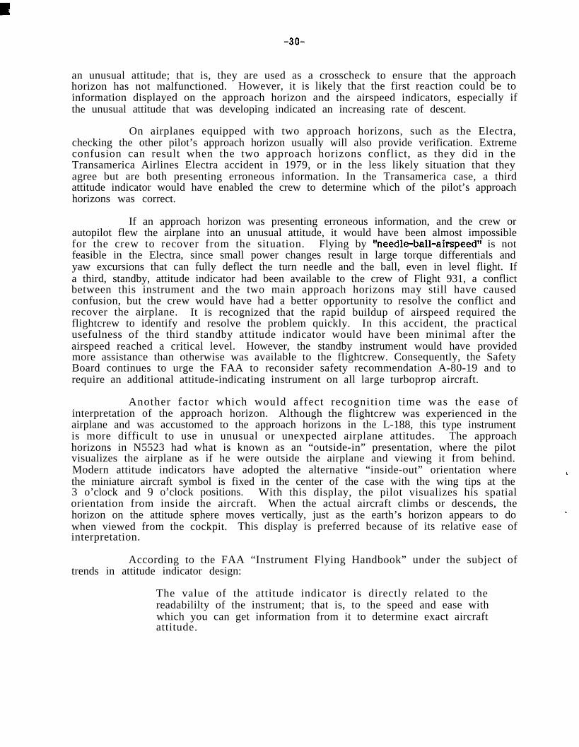
-3o-
an unusual attitude; that is, they are used as a crosscheck to ensure that the approachhorizon has not malfunctioned. However, it is likely that the first reaction could be toinformation displayed on the approach horizon and the airspeed indicators, especially ifthe unusual attitude that was developing indicated an increasing rate of descent.
On airplanes equipped with two approach horizons, such as the Electra,checking the other pilot’s approach horizon usually will also provide verification. Extremeconfusion can result when the two approach horizons conflict, as they did in theTransamerica Airlines Electra accident in 1979, or in the less likely situation that theyagree but are both presenting erroneous information. In the Transamerica case, a thirdattitude indicator would have enabled the crew to determine which of the pilot’s approachhorizons was correct.
If an approach horizon was presenting erroneous information, and the crew orautopilot flew the airplane into an unusual attitude, it would have been almost impossiblefor the crew to recover from the situation. Flying by %eedle-ball-airspeed1f is notfeasible in the Electra, since small power changes result in large torque differentials andyaw excursions that can fully deflect the turn needle and the ball, even in level flight. Ifa third, standby, attitude indicator had been available to the crew of Flight 931, a conflictbetween this instrument and the two main approach horizons may still have causedconfusion, but the crew would have had a better opportunity to resolve the conflict andrecover the airplane. It is recognized that the rapid buildup of airspeed required theflightcrew to identify and resolve the problem quickly. In this accident, the practicalusefulness of the third standby attitude indicator would have been minimal after theairspeed reached a critical level. However, the standby instrument would have providedmore assistance than otherwise was available to the flightcrew. Consequently, the SafetyBoard continues to urge the FAA to reconsider safety recommendation A-80-19 and torequire an additional attitude-indicating instrument on all large turboprop aircraft.
Another factor which would affect recognition time was the ease ofinterpretation of the approach horizon. Although the flightcrew was experienced in theairplane and was accustomed to the approach horizons in the L-188, this type instrumentis more difficult to use in unusual or unexpected airplane attitudes. The approachhorizons in N5523 had what is known as an “outside-in” presentation, where the pilotvisualizes the airplane as if he were outside the airplane and viewing it from behind.Modern attitude indicators have adopted the alternative “inside-out” orientation wherethe miniature aircraft symbol is fixed in the center of the case with the wing tips at the3 o’clock and 9 o’clock positions. With this display, the pilot visualizes his spatialorientation from inside the aircraft. When the actual aircraft climbs or descends, thehorizon on the attitude sphere moves vertically, just as the earth’s horizon appears to dowhen viewed from the cockpit. This display is preferred because of its relative ease ofinterpretation.
According to the FAA “Instrument Flying Handbook” under the subject oftrends in attitude indicator design:
The value of the attitude indicator is directly related to thereadabililty of the instrument; that is, to the speed and ease withwhich you can get information from it to determine exact aircraftattitude.

-31- 1
Although the older type attitude indicators are not difficult tointerpret in normal flight attitudes, reference to other instrumentsto confirm the indications observed on the attitude indicator isrecommended and particularly when abnormal flight attitudes areexperienced. The greater the divergence of the miniature aircraftfrom the horizon line, the more difficult exact interpretationbecomes, yet the extreme attitude is the condition requiringimmediate and accurate visual information.
The Safety Board must assume that the flightcrew was proficient in the use ofthe approach horizons in N5523. However, the unexpected flight attitude that wasencountered at 0144:ll certainly required visual confirmation from the other cockpitinstruments to provide an accurate interpretation. The few seconds required to make theconfirmation may have been significant in reducing the ability of the flightcrew tocorrect the airplane’s flightpath. It is possible that a more rapid assessment of the flightattitude would have been possible if the approach horizon had been easier to interpret. Inany case, a third, standby attitude indicator would have been easier to interpret under“abnormal flight attitudes” since these instruments use the inside-out spatial orientation.
3. CONCLUSIONS
3.1 Findings
1.
2.
3.
4.
5.
6.
7.
8.
9.
10.
The flightcrew was certified properly, and each crewmember hadreceived the t ra in ing and off-duty t ime prescr ibed by Federalregulations.
The airplane was maintained and equipped in accordance with Federalregulations. There was no history of maintenance deficiencies whichwould have caused an inflight structural failure.
The engines were operating when the inflight breakup started and flamedout as the fuel system was destroyed.
The engines, the engine mounts, and the nacelle structure had not beensubjected to “whirl mode effect.”
.There were no indications of structural failures other than those causedby excessive aerodynamic loads, fuel tank overpressure, and the groundimpact.
The fire in the right wing was caused by the inflight breakup and did notstart until after the right wing tip separated.
The flightcrew assumed that the No. 2 vertical gyro had malfunctioned.
The amplifier or associated circuits of the No. 2 vertical gyro wasprobably the source of the malfunction.
The first officer’s approach horizon may have displayed incorrect pitchand roll information after the turn to the Dryer VOR.
The flightcrew may have received conflicting pitch and roll informationfrom the two approach horizons as they attempted to recover from anunusual attitude.

-32-
11.
12.
13.
14.
15.
16.
The flightcrew was unable to recover from the unusual attitude becauseof conflicting or incorrect pitch and roll data, an inability to interpretthe attitude display, or a combination of these factors.
The prompt reac t ion t o t h e d e v e l o p i n g u n u s u a l a t t i t u d e b y acrewmember indicates one crewmember was abreast of flight instrumentindications. However, the flightcrew did not conduct an ensuing scan ofthe flight instruments adequate to discover the onset of the unusualattitude.
The flightcrew had to rely almost exclusively on flight instruments tointerpret the unusual attitude and to effect a recovery.
The actions of the flightcrew to recover from the unusual attitude mayhave aggravated the situation if they maneuvered the airplane inresponse to the incorrect approach horizon data on the first officer’sinstrument.
The flightcrew overstressed the airplane in an attempt to recover fromthe unusual attitude.
The airplane was not equipped, nor was it required to be equipped, withan independently powered standby attitude indicator.
3.2 Probable Cause
The National Transportation Safety Board determines that the probable causeof the accident was the airplane’s entry into an unusual attitude and the inability of theflightcrew to analyze the flight condition before there was a complete loss of control.Although the precise reason for the loss of control was not identified, an undeterminedfailure of a component in the No. 2 vertical gyro system, perhaps involving the amplifierand associated circuitry, probably contributed to the cause of the accident by incorrectlyprocessing data to the co-pilot’s approach horizon. The inflight structural failure of theairplane was due to overload.
4. RECOMMENDATIONS
A s a r e s u l t o f t h i s a c c i d e n t , t h e S a f e t y B o a r d r e i t e r a t e d S a f e t yRecommendation A-80-19 to the Federal Aviation Administration, as follows:
Amend 14 CFR 121.305(j) to extend its application to all large turbopropaircraft to require an additional attitude-indicating instrument, for bankand pitch, operating from a source of power independent of the normalelectrical generating system as is now required on all large turbojetaircraft.

-33-
BY THE NATIONAL TRANSPORTATION SAFETY BOARD
/s/ JIM BURNETTChairman
/s/ PATRICIA A. GOLDMANVice Chairman
/s/ EeEb,qPTRICK BURSLEY
March 19, 1985


-35-
5. APPENDIXES
APPENDIX A
INVESTIGATION AND DEPOSlTION PROCEEDING
1. Investigation
The National Transportation Safety Board was notified of the accident about0230 e.d.t., on May 30, 1984, and immediately dispatched an investigative team to thescene from its Washington, D.C., headquarters. Investigative groups were formed foroperations, air traffic control, structures, systems, powerplants, airplane performance,cockpit. voice recorder, and flight data recorder. Human performance, airplaneperformance, and meterological specialists participated in the investigation.
Parties to the investigation were the Federal Aviation Administration, ZantopInternational Airlines, Inc., the Bendix Corporation, Allison Division of General Motors,Hamilton Standard Propellers, and Aviall Turbine Service Division.
2. Deposition Proceeding
Two one-day deposition proceedings were conducted; one in Ypsilanti, Michigan, andthe other at Burbank, California.
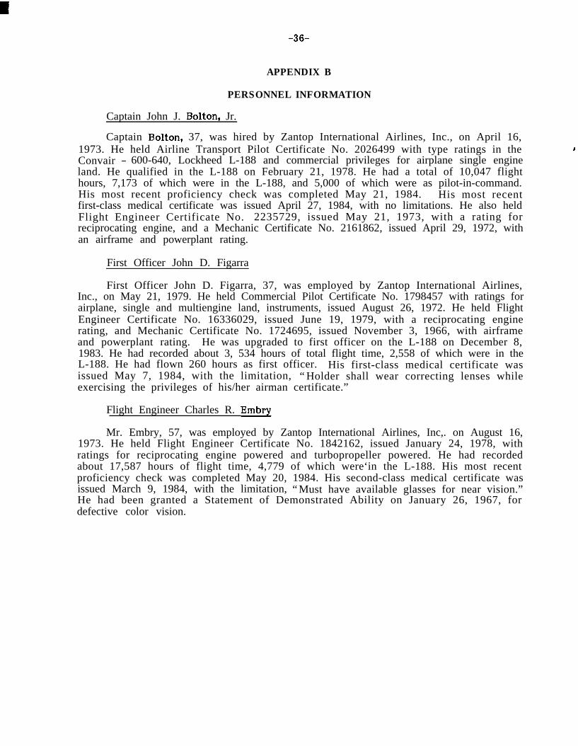
-36-
APPENDIX B
PERSONNEL INFORMATION
Captain John J. Bolton, Jr.
Captain Bolton, 37, was hired by Zantop International Airlines, Inc., on April 16,1973. He held Airline Transport Pilot Certificate No. 2026499 with type ratings in theConvair - 600-640, Lockheed L-188 and commercial privileges for airplane single engineland. He qualified in the L-188 on February 21, 1978. He had a total of 10,047 flighthours, 7,173 of which were in the L-188, and 5,000 of which were as pilot-in-command.His most recent proficiency check was completed May 21, 1984. His most recentfirst-class medical certificate was issued April 27, 1984, with no limitations. He also heldFlight Engineer Certificate No. 2235729, issued May 21, 1973, with a rating forreciprocating engine, and a Mechanic Certificate No. 2161862, issued April 29, 1972, withan airframe and powerplant rating.
First Officer John D. Figarra
First Officer John D. Figarra, 37, was employed by Zantop International Airlines,Inc., on May 21, 1979. He held Commercial Pilot Certificate No. 1798457 with ratings forairplane, single and multiengine land, instruments, issued August 26, 1972. He held FlightEngineer Certificate No. 16336029, issued June 19, 1979, with a reciprocating enginerating, and Mechanic Certificate No. 1724695, issued November 3, 1966, with airframeand powerplant rating. He was upgraded to first officer on the L-188 on December 8,1983. He had recorded about 3, 534 hours of total flight time, 2,558 of which were in theL-188. He had flown 260 hours as first officer. His first-class medical certificate wasissued May 7, 1984, with the limitation, “Holder shall wear correcting lenses whileexercising the privileges of his/her airman certificate.”
Flight Engineer Charles R. Embry
Mr. Embry, 57, was employed by Zantop International Airlines, Inc,. on August 16,1973. He held Flight Engineer Certificate No. 1842162, issued January 24, 1978, withratings for reciprocating engine powered and turbopropeller powered. He had recordedabout 17,587 hours of flight time, 4,779 of which were‘in the L-188. His most recentproficiency check was completed May 20, 1984. His second-class medical certificate wasissued March 9, 1984, with the limitation, “Must have available glasses for near vision.”He had been granted a Statement of Demonstrated Ability on January 26, 1967, fordefective color vision.

-37-
APPENDIX C
AIRPLANE INFORMATION
Lockheed Electra L-188, N5523
The airplane, manufacturer’s serial number 1034 , was ce r t i f i c a t ed onMarch 11, 1959, and was purchased by Zantop International Airlines, Inc., on December28, 1977. The airplane had 28,989 total hours and 33,879 cycles when acquired by Zantop.At the time of the accident, the airplane had recorded about 35,668 total hours and38,353 cycles.
The most recent routine check was completed May 13,1984. The last service checkand phase check were completed March 20, 1984, and October 3, 1983, respectively.
Powerplants
Engine No. 1 No. 2 No. 3 No. 4
Serial Number 500519 500625 501706 500793Date Installed 3-18-84 3-l 8-84 3-l 8-84 2-21-84Compressor TSO (hours) 8,546 6,255 7,455 5,894Turbine TSO (hours) 150 4,228 8,683 6,135Gearbox TSO (hours) 4,564 5,862 13,350 12,082
PropellersSerial NumberDate InstalledTSO (hours)
No. 1P8099-4-821,497
No. 2P6894-4-843,278
No. 3 No. 4P253 P29112-11-83 2-21-84435 3,774
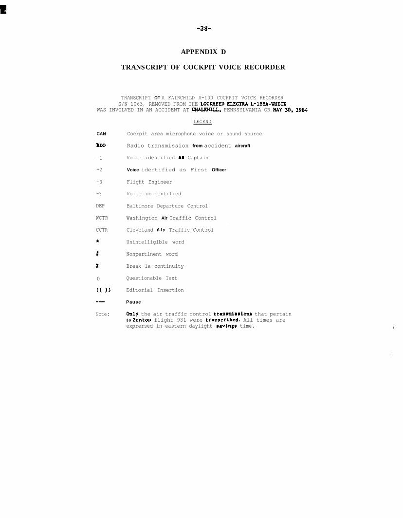
-38-
APPENDIX D
TRANSCRIPT OF COCKPIT VOICE RECORDER
TRANSCRIPT OF A FAIRCHILD A-100 COCKPIT VOICE RECORDERS/N 1063, REMOVED FROM THE LOCEREED ELBCTRA L-lSBA.WRICR
WAS INVOLVED IN AN ACCIDENT AT CBALKRILL, PENNSYLVANIA OR HAY 30, 1994
CAN
RDO
-1
-2
-3
-?
DEP
WCTR
CCTR
*
#
x
0
(( 1)
s-m
Note:
LEGEND
Cockpit area microphone voice or sound source
Radio transmission from accident aircraft
Voice identified aa Captain
Voice identified as First Officer
Flight Engineer
Voice unidentified
Baltimore Departure Control
Washington Air Traffic Control
Cleveland Air Traffic Control
Unintelligible word
Nonpertlnent word
Break la continuity
Questionable Text
Editorial Insertion
Pause
,
Only the air traffic control tranrmlmrlono that pertainto Zantop flight 931 were tranrcribed. All times areexprersed in eastern daylight saving6 time.

-39- APPENDIX D
INTKA-COCW lT
TIME 6SOURCE CONTENT
01:20:10CAM-1 I sa id i t’s possible
01:20:13CAM- 1 If we don’t switch to another frequency
by the time ah ue’rc up there ah ---
01:20:19CAM-2 That’s what we f i led for f i led for ,
twenty two unless (you want lower) *
01:20:28CAM-1 I don’t know what to say about this radar
w-e there it is zero (I don’t know what the# it’s “)
01: 20:40CAM-2 I think you got the ground tlicrr at zero
CAM-1 Sure the # looks like it
01:20:46CAM-2 There a lake or something out there
CAM-1 I think they wrote it up last week
01:20:53CAM-1 This is a finicky bugger when it comes
to radar
01:21:32CAM-2 What’s after ah this Martinsburg or
whatever
ALR-GROUND COl4MUNICATIONS
TIME bSOURCE CONTENT
CAM-1 Ah - - -
c

APPENDIX D -4o-
INTRA-COCKI’IT
TIME hSOUKCE CONTENT.-
01:21:43C A M - 2 .I something
01:21:45C A M - 1 J forty three to Uryer * Clevclil~d Victor
Lwenty six trip! 1’11 g:ct you directC;lrleton --- over Cleveland you should be ableto get direct C.lrleton dir&L Willow Hun --
0 1 : 2 2 : 0 3C A M - 2 Cumin’ back
CAM- 1 .I forty three
01:24:5?C A M - ? * *
AIK-CKOUNU CWUlUNlCA’~IONS
TIME 6SOIJKCE CONTENT
01:26:28KDO-3 Arinc Zantop nine thirty one
‘01:26:32AKINC Zantop ninrr three one San Francisco
go ahead
01:26:34 Yeah nine thirty one was out ofBaltimore Washington Internationalat zero five hundred slash one oneah fourteen t h o u s a n d p o u n d s of fuelon b o a r d
AKINC (Arinc six zero roger)
01:27:03CAM- I Out of eighteen nine nine two

-41- APPENDIX D
INTRA-COCKPIT
TIME 6SOURCE CONTENT
01;29:UOCAM-2 uu y o u w a n t t o v e r i f y t h a t - - -
CAM-1 sorry
CAM-2 One twenty four four is in
01:29:03CAM-1 Is that for us?
AIR-GROUND COM4UNLCATLONS
TII4K 6SOURCE CONTENT
01:28:57WCTR Zantop nine thirty one Cleveland
one one two four point four
.
RDO-2 One twenty four four Zantop ninethirty one
CAM-2 One twenty four four is in
01:29:08CAM-2 I j u s t w o n d e r e d , d o y o u w a n t me t o
ver i fy that that ' s ah - - -
CAn-1 Oh --- yeah01:29:18RDO-2 Cleveland Zantop nine thirty one
is w i t h you, ah, ver i fy we 'resuppose to, ah, we're cleared toflight level two two zero
01:29:27CCTR Zantop nine thirty one Roger. I
show you climbing to flight leveltwo two zero
01:29:31RDO-2 Nine thirty one thank you
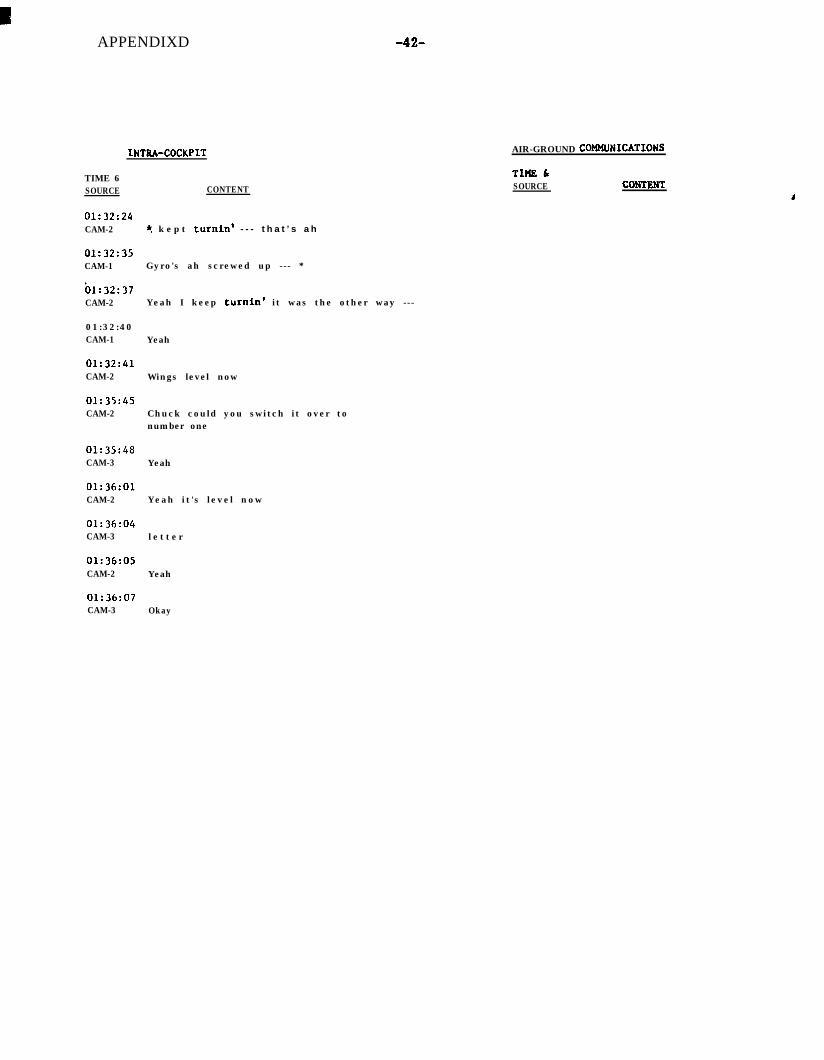
APPENDIXD -42-
INTRA-COCKPIT
TIME 6SOURCE CONTENT
01:32:24CAM-2 ? k e p t turnin' - - - t h a t ’s a h
01:32:35CAM-1 Gyro's ah screwed up --- *
bl:32:37CAM-2 Yeah I keep turnin' it was the other way ---
01:32:40CAM-1 Yeah
01:32:41CAM-2 Wings level now
01:35:45CAM-2 Chuck could you switch it over to
number one
01:35:48CAM-3 Yeah
01:36:01CAM-2 Yeah it's level now
01:36:04CAM-3 l e t t e r
01:36:05CAM-2 Yeah
AIR-GROUND COHMUNICATIONS
TLHELSOURCE CONTRNT
01:36:07CAM-3 Okay

INTRA-COCKPIT
TIHE 6SOURCE CONTENT
01:36:32CAn-2 Cruise
Uli38:UbCAM-2 Might be just ah ---
()1:38:13CAM-2 Horse power reads low on number two
-43- APPENDIX D
AIR-GROUND COMMUNICATIONS
TlklE 6SOURCE CONTENT
Y
01:36:41RUO ((Sound of static on radio))
01:37:42RDO ((Sound of static on radio))
01:38:18CAM-2 Horse power readin' low ---
CAM-1 Yeah
01:38:20CAM-2 Temperature's readin' high and the Euel
flow is normal01:38:23CCTR Eight six hotel alpha go ahead
01:38:26CAM-2 Are you set - - -
01:38:27CAM-1 They already changed the ah --- anti-ice
valve
01:38:30CAM-3 Ah wait a minute
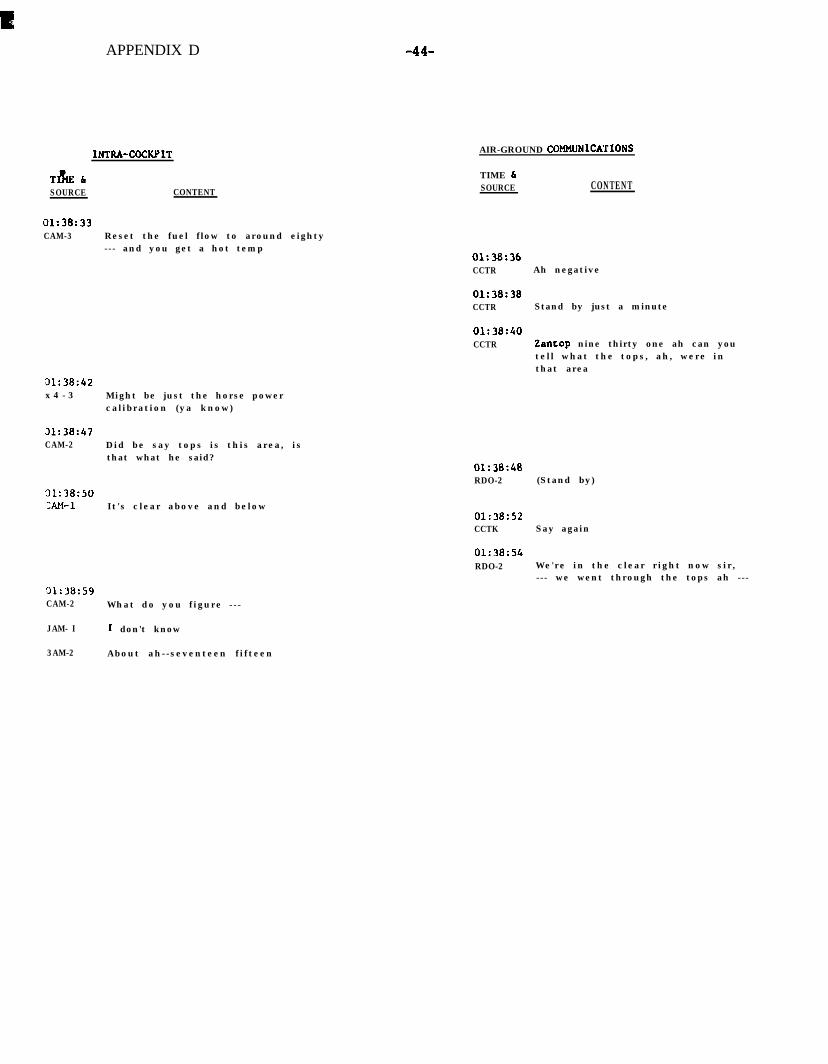
APPENDIX D
INTRA-COCKPIT
T&ELSOURCE CONTENT
01:38:33CAM-3 Reset the fuel flow to around eighty
--- and you get a hot temp
31:38:42x 4 - 3 Might be just the horse power
calibration (ya know)
31:38:47CAM-2 Did be say tops is this area, is
that what he said?
'31:38:50x4-1 It's clear above and below
31:38:59CAM-2 What do you figure ---
JAM- I I don't know
-44-
AIR-GROUND COUMJNICATLONS
TIME 6SOURCE CONTENT
01:38:36CCTR Ah negative
01:38:38CCTR Stand by just a minute
01:38:40CCTR Zantop nine thirty one ah can you
tell what the tops, ah, were inthat area
01:38:48RDO-2 (Stand by)
01:38:52CCTK Say again
01:38:54RDO-2 We're in the clear right now sir,
--- we went through the tops ah ---
3AM-2 About ah--seventeen fifteen

-45-
INTKA-COCKPIT
TIME hSOURCE CONTIZNT
01: 39:02CAM- 1 Yeah
01:41:27CAM-3 Times and tcmps (please)
01:42:43CAM ((Sound similar to a pnl’cr p.#Bcs II<,~II):
turned))
APPENDIX D
AIK-WOUND CM4MUNlCATIONS
TIME 6SOURCE CONTENT
01:39:02RDO-2 Oh on climbout, we were through
the tops at somewheres aroundfourteen or fifteen thousand
01:39:07CCTR Roger thank you
01:39:09CCTR And November eighty six hotel alpha
did you hear that?
01:39:15CCTK An aircraft, ah, climbing out of
Baltimore said that he ah climbedout of the tops at ah about fourteenthousand
01:39:28CCTR Welcome
01:4_1:09CCTK Zantop nine thirty one cleared direct
Dryer, contact Cleveland Center onah one two five point one
01:43:17HDO-2 One twenty five one direct Dryer
Zantop nine thirty one good niBht
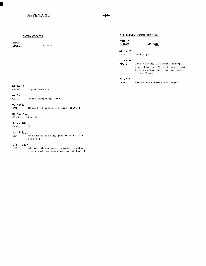
APPENDIXD -46-
AIK-GKOUNU COMMUNICATIONS
TIME 6SuUKCE CONTENT
TIME bSOUKCE
01:43:21CCTR Good night
01:43:29RDo-2 Good evening Cleveland, Zantop
nine thirty one'6 with you flightlevel two two zero, we are goingdirect Dryer
01:43:35CCTK Zantop nine thirty one roger
01:44:11CAM-? * ( a l t i t u d e ) *
01:44:13.3C M - 2 What's happening here
01:44:15CAM ((Sound of increasing wind noise))
01:44:15.2CAM-2 You got it
01:44:18.1CAM-1 No
01:44:21.1CAN ((Sound of landing gear warninK Irorll
s t a r t s ) )
OL:44:22.7CAM ((Sound of overspeed warning cL;Ickcr
starts and continues to end of t.~pe))

-41- APPENDIX D
INTRA-COCKPIT
TIME bSOURCE CONTENT
01:44:24.9CAM ('(Sound similar to structurirl failure
during inflight breakup))
01:44:26.5CAM-? We’re dead.
01:44:27.2CAM ((Sound of landing gear warning horn
s t o p s ) )
01:44:30 ( ( E n d o f t a p e ) )
AIR-GROUND COMMUNICATIONS
TIUE LSOURCE CONTENT


-55-
APPENDIX H
WHIRL MODE
A propeller behaves much like a gyroscope in that it will tend to remainin its plaxss of rotation even though it be loosely mounted. It will stay in thisplane unless it is disturbed by a strong external force. When this occurs,the propeller reacts in the same manner as a gyro, that is, the reaction is90 degrees out of phase with the applied force. Possible forces which couldact on the propeller in this manner include sudden aircraft maneuvers.atmospheric turbulence and gusts, sudden power changes, etc. When sucha force is applied to the propeller, it reacts in the following manner: If it i6displaced upward by some force, the structural stiffness of the mountingsystem resists the movement and applies a nose-down pitching moment.When viewed from the rear, this moment will cause the propeller disk toturn to the left due to gyroscopic precession. The yaw stiffness of thestructure in this direction acts in a like manner and causes the propellerdisk to pitch down. The structural resistance in this direction causes thepropeller disk to yaw to the right where the yaw stiffness in that directioncauses the propeller disk to pitch up, thus completing a cycle. This phenome-non has been ternied the “whirl mode”, and its,direction of rotation is oppositeto that of the propeller. Tests and analysCs pertaining to the ability of anoverspeeding propeller to cause and sustain the “whirl mode” proved conclu-sively that this could not occur within the speed range of the airplane at anyoverspeed as long as the engine and nacelle were undamaged. In a normalundamaged airplane, the “whirl mode” can operate only within the limits offlexibility of the engine mounts and is damped out very quickly. If somestructural element of the powerplant. the powerplant mounting system, or
the nacelle is in a damaged or weakened condition, and results in a loss ofstiffness in the propeller shaft mounting system, the whirl mode will notdamp out rapidly at high airplane speed.
Powerplant installation damage does not significantly change the conditionsunder which the whirl mode may be initiated. but it makes the phenomenon,which in itself is not hazardous, potentially dangerous in three ways. First,the greatbr flexibility of a weakened installation can allow the whirl modemore freedom and consequently it can become more violent. Normally,system stiffness increases rapidly as powerplant deflections approach themount limits. In a damaged installation, this characteristic may be altered.

APPENDIX H -56-
WHIRL MODE (cont’d)
Second, in a weakened installation, the strength level is reduced. This, incombinatiojr with the increased violence of the whirl mode, can result infurther damage which, as it progresses, further reduces structural stiffness.Third, and most important, is a condition where the frequency of the whirlmode in a damaged and overly flexible structure reduces from its naturalvalue (which is well above the fundamental natural frequency of the wing) tolower values approaching the wing natural frequencies.
As the whirl mode progresses in a damaged installation, its naturalfrequency can reduce to a point where it could drive the wing in both up anddown bending and torsional oscillations which could, in turn. both reinforceand perpetuate the whirl mode. The three oscillations, whirl mode, wingbending, .and wing torsion, would then be coupled at the same frequency. Thisis a form of induced flutter. It is forced to occur at a lower indicated airspeedthan that at which flutter in the classical sense can develop. A situation of thissort can quickly become disastrous through oscillatory divergency. As dampingdiminishes, each oscillation of the wing becomes greater than the previous oneuntil, finally, structural capabilities are exceeded and structural damage occurs.(The whirl mode can develop at any nacelle position; however, its ability toproduce wing oscillations Is greater at the outboard positions. )
In the early 1960’s, a detailed examination of the pre-LEAP wreckageprovided evidence that the whirl mode had been present in the outboard nacelleareas. Examination of the Lord mounts revealed that they had been bottomedout repeatedly. Additional evidence in the area of the structural failures inthe powerplant area confirmed repeated cyclic motions prior to completefailure. The number of cycles involved indicated a time period spanning anumber of seconds.
The investigation clearly showed that propeller whirl mode can occurwith reduced powerplant installation stiffness, at relatively high airplane-speeds, and that forces generated by the whirl mode can cause further damageand l dditibnal reduction in system stiffness. There is evidence that the whirlmode can reach a vibratory magnitude and frequency which, coupled with thewing natural frequency, can force severe wing oscillations.
c

RADAR DATA
a$.
Position of Chalkhill post office
CAM-l NoCAM-2 You got itCAM ((Sound of increasing wind noise))CAM-2 What’s happening hereCAM-? * (altitude) *
I-...,..,=.~ RDO-2 &~~c!v;~~:: Cleveland, Zantop nin; ;ti:rt; ;~xI:;with you flight level two two zero
d -.--o .A RDO-2’One twenty five one direct Dryer Zantop nine
Fl-‘4 ..\ thirty one goodnight.
‘..- --.__i;
----.-fs..-l.l.gA~: g; C -“-a,_
it
i
05;45:32QS:46:3205:47:44
'.-“605:4?:56 b 1---A- . ..%.
l-l3Note - Secondary beacon code returns are connected with a line. Other
points are primary skin paint returns.*‘-3.00 -1.11 I -0.53 I 0.70 1
1 I I I --.---I.-I I .94 3. 1 II 4.41 s.fl4 6 . 8 1 8. II 9.14 10.38 Il.81 13.05 14.28EAST RANGE IN N.M.

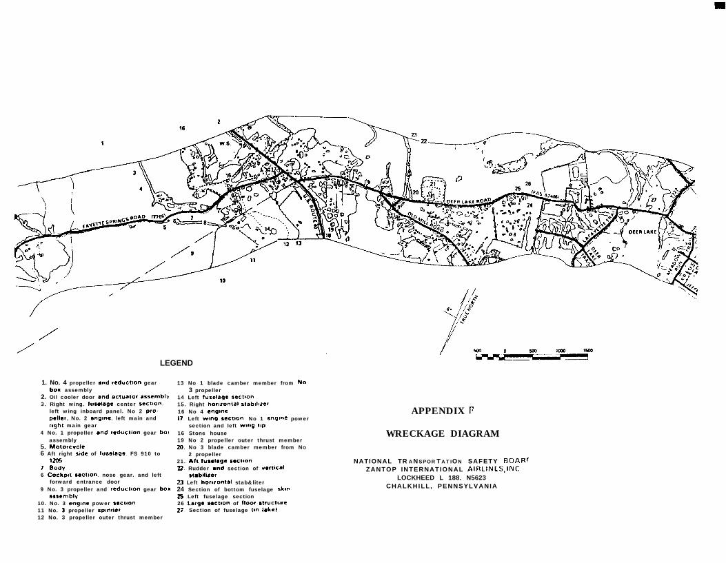
LEGEND
1. No. 4 propeller and reduction gearboa assembly
2. Oil cooler door and ectubtor rssemblv3. Right wing. fuselage center sectuon.
left wing inboard panel. No 2 pro.peller. No. 2 engme. left main andright main gear
4 No. 1 propeller and reduction gear bo,assembly
5. MotorcVclc6 Aft right stde of luselage. FS 910 to
12%7 Bodv6 Cockpit sectmn. nose gear. and left
forward entrance door9 No. 3 propeller and reductaon gear box
srsemblv10. No. 3 cngme power sectIon11 No. 3 propeller spinner12 No. 3 propeller outer thrust member
13 No 1 blade camber member from NO3 propeller
14 Left fuselage sectlo”15. Right horarontal stablllzer16 No 4 sngme17. Left wmg sectlo”. No 1 engone power
section and left wng ttp16 Stone house19 No 2 propeller outer thrust member20. No 3 blade camber member from NO
2 propeller21. At1 fuulage s.ctto”22 Rudder and section of uwt~cel
scmbilizer73 Left honrontal stab&liter24 Section of bottom fuselage skun26 Left fuselage section26 L,rge sectton of floor stfUctUrc2;. Section of fuselage lin lake)
APPENDIX I:
WRECKAGE DIAGRAM
NATIONAL TR A N SPOR T A T ION SAFETY BoAF~~ZANTOP INTERNATIONAL AIRLINkS,INC
LOCKHEED L 188. N5623CHALKHILL , PENNSYLVANIA