natural frequencies for flexural and torsional vibrations of beams on
TRANSCRIPT
H O S T E D B Y
Natural frequencies for flexural and torsional vibrations of beams onPasternak foundation
Joon Kyu Lee, Sangseom Jeongn, Jaehwan Lee
Dept. of Civil and Environmental Engineering, Yonsei University, 50 Yonsei-ro, Seodaemun-gu, Seoul 120-749, Republic of Korea
Received 6 January 2013; received in revised form 29 August 2014; accepted 7 September 2014Available online 11 December 2014
Abstract
This paper studies the free vibrations of prismatic beams resting on Pasternak foundation. Special attention is given to the consideration of thebending–twist deformations of the beams. The governing differential equations of the motion are derived by imposing the dynamic equilibrium ofa Timoshenko beam element. Differential equations are solved numerically using the combination of the Runge–Kutta and Regula–Falsi methods.The results of some cases are presented, and are analyzed to highlight the effects of the end constraint, rotatory and torsional inertias, aspect ratio,thickness ratio, beam stiffness, and foundation stiffness on the natural frequencies of the beams. The natural frequencies of the present model arevalidated by comparing to those from model tests.& 2014 The Japanese Geotechnical Society. Production and hosting by Elsevier B.V. All rights reserved.
Keywords: Natural frequency; Vibration; Beam; Pasternak foundation; Torsion; Soil–structure interaction
1. Introduction
Beams resting on a ground surface that include footings andpipelines present very common soil–structure interactionproblems encountered in geotechnical engineering. A goodknowledge of the natural frequencies in dynamic problems isessential in the design of such structures, especially in the caseof those subjected to dynamic loads generated by earthquakes,blasting waves and other sources (Morfidis, 2010; Allani andHoleyman, 2013; Ghazavi et al., 2013; Sapountzakis andKampitsis, 2013a, 2013b). Therefore, a free vibration analysisis an important part in the total investigation of the system.
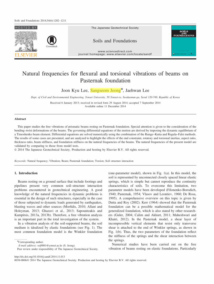
In a vibration analysis of the soil-supported beams, the soilmedium is idealized by elastic foundations (see Fig. 1). Themost common foundation model is the Winkler foundation
(one-parameter model), shown in Fig. 1(a). In this model, thesoil is represented by unconnected closely spaced linear elasticsprings, which is simple but cannot reproduce the continuitycharacteristics of soils. To overcome this limitation, twoparameter models have been developed (Filonenko-Borodich,1940; Pasternak, 1954; Vlasov and Leontiev, 1960; De Rosa,1995). A comprehensive overview on this topic is given byDutta and Roy (2002). Kerr (1964) showed that the Pasternakfoundation can be a possible mathematical model for thegeneralized foundation, which is also stated by other research-ers (Guler, 2004; Calim and Akkurt, 2011; Maheshwari andKhatri, 2012). In the Pasternak model, a shear layer ofincompressible vertical elements that resist only transverseshear is attached to the end of Winkler springs, as shown inFig. 1(b). Thus, the two parameters of the foundation reflectthe stiffness of the springs and the shear interaction betweenthe springs.Numerical studies have been carried out on the free
vibration of beams resting on elastic foundations. Particularly
The Japanese Geotechnical Society
www.sciencedirect.comjournal homepage: www.elsevier.com/locate/sandf
Soils and Foundations
http://dx.doi.org/10.1016/j.sandf.2014.11.0130038-0806/& 2014 The Japanese Geotechnical Society. Production and hosting by Elsevier B.V. All rights reserved.
nCorresponding author.E-mail address: [email protected] (S. Jeong).Peer review under responsibility of The Japanese Geotechnical Society.
Soils and Foundations 2014;54(6):1202–1211

for beams supported by the Pasternak foundation, Wang andStephens (1978) presented the general solution of naturalfrequencies for finite uniform beams with different endconstraints and investigated the impact of Pasternak foundationon natural frequencies. Wang and Brannen (1982) examinedthe effect of open angle of vibrating curved beams on thePasternak foundation. Yokoyama (1987) proposed a finiteelement method for analyzing the free vibration of shear andTimoshenko beams on Pasternak foundation. Eisenberger(1994) also applied the finite element method to find the exactvibration frequencies of cantilever beams on Pasternak foun-dation. Naidu and Rao (1995) highlighted the influence ofinitial stress on the vibration behavior of uniform beams onPasternak foundation. El-Mously (1999) derived explicit for-mulae for the fundamental frequencies for the vibration offinite beams on finite Pasternak foundation using the virtue ofRayleigh’s Principle. Matsunaga (1999) employed the one-dimensional higher order theory to compute the naturalfrequencies of beam–columns on Pasternak foundation. Chenet al. (2004) studied a mixed method that combines the statespace method and the differential quadrature method to the freevibration of Euler–Bernoulli beams on Pasternak foundation.Ying et al. (2008) reported the exact solutions of flexuralvibration of functionally graded beams on Pasternak founda-tion by two-dimensional elasticity theory. Zhu and Leung(2009) developed the hierarchical finite element for a nonlinearfree vibration analyses of non-uniform Timoshenko beams onPasternak foundation. The differential transform and dynamicstiffness matrix methods for a free vibration analysis ofPasternak foundation-supported beams were used by Balkayaet al. (2009) and Calio and Greco (2012), respectively. Li et al.(2012) dealt with transverse vibration of the shear beamscontaining rotatory inertia on Pasternak foundation. Most ofthe existing literature is devoted to capturing the flexuralvibration along the beam. However, one may recognize that atthe point of contact between beam and foundation, there is notonly flexural deformation but also torsional deformation underthe action of vibration. Few studies have been reported on the
flexural–torsional vibration characteristics of beam–foundationsystem where twist against the cross-section of beams is takeninto account, although there have been studies which con-sidered the bending and twisting of beams (Rao and Mirza,1988; Vo and Lee, 2009; de Borbon et al., 2011).In this study, the flexural–torsional free vibrations of finite
uniform beams resting on finite Pasternak foundation aredescribed. The governing equations of the motion are deducedby considering the dynamic equilibrium of a Timoshenkobeam element. A computer program coded in FORTRANcapable of calculating the natural frequencies of the systemwas developed. The results of several cases are presented andthe influences of the end constraint, the rotatory and torsionalinertias, the aspect ratio, thickness ratio, beam stiffness and thefoundation stiffness on the natural frequencies are discussed.The natural frequencies from physical model tests are used tovalidate the present calculations.
2. Analytical model
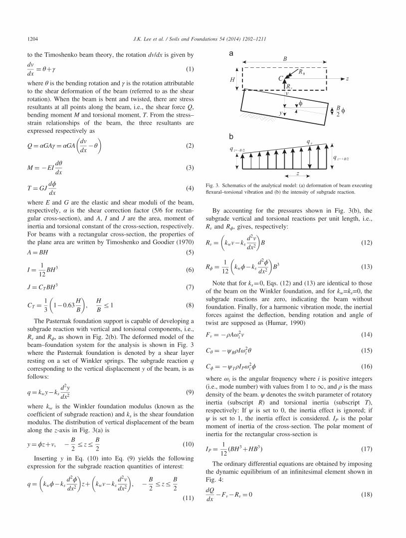
Fig. 2 shows a Timoshenko beam resting on Pasternakfoundation in a Cartesian coordinate system. As shown inFig. 2(a), the beam is assumed to be straight and uniform,having a rectangular cross-section with width B and height H,which is small relative to its length L. The x-axis is oriented inthe central axis of the beam, and the y and z-axes are in heightand width directions, respectively. Various end constraintssuch as free, hinged and clamped ends can be taken as the endconstraint of the beam. Fig. 2(b) shows a typical example ofthe vibrational mode shape for the beam. Under the action offree vibration, the beam deflects in the x–y plane, resulting inproducing deflection v and rotation dv/dx, which are positive inthe y direction and in the clockwise direction. Simultaneously,the beam also twists in the y–z plane, resulting in an angle oftwist ϕ, which is positive in the clockwise direction. According
Elastic spring
Elastic spring
Shear layer
Fig. 1. Displacement of (a) Winkler and (b) Pasternak foundation models(modified from Selvadurai (1979)).
L
L
y
y
x
x
xγθ
Pasternak foundation: k , kW s
Uniform rectangular beam: B Hfree /hinged /clamped
free /hinged /clamped
dv/dx
Rv
Rφ
φ
v
( )Q,M,T
Fig. 2. Beam on Pasternak foundation in (a) undeformed and (b) typicalmode shape.
J.K. Lee et al. / Soils and Foundations 54 (2014) 1202–1211 1203
to the Timoshenko beam theory, the rotation dv/dx is given by
dv
dx¼ θþγ ð1Þ
where θ is the bending rotation and γ is the rotation attributableto the shear deformation of the beam (referred to as the shearrotation). When the beam is bent and twisted, there are stressresultants at all points along the beam, i.e., the shear force Q,bending moment M and torsional moment, T. From the stress–strain relationships of the beam, the three resultants areexpressed respectively as
Q¼ αGAγ ¼ αGAdv
dx�θ
� �ð2Þ
M ¼ �EIdθ
dxð3Þ
T ¼GJdϕ
dxð4Þ
where E and G are the elastic and shear moduli of the beam,respectively, α is the shear correction factor (5/6 for rectan-gular cross-section), and A, I and J are the area, moment ofinertia and torsional constant of the cross-section, respectively.For beams with a rectangular cross-section, the properties ofthe plane area are written by Timoshenko and Goodier (1970)
A¼ BH ð5Þ
I ¼ 112
BH3 ð6Þ
J ¼ CTBH3 ð7Þ
CT ¼ 13
1�0:63H
B
� �;
H
Br1 ð8Þ
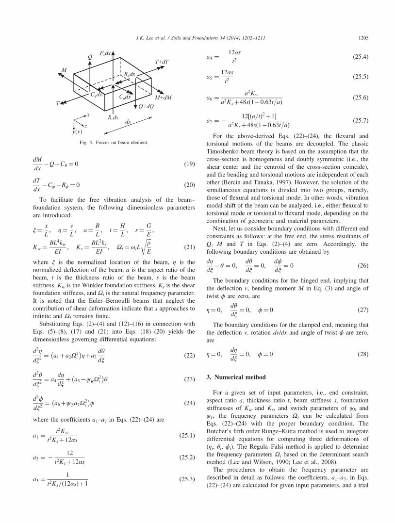
The Pasternak foundation support is capable of developing asubgrade reaction with vertical and torsional components, i.e.,Rv and Rϕ, as shown in Fig. 2(b). The deformed model of thebeam–foundation system for the analysis is shown in Fig. 3where the Pasternak foundation is denoted by a shear layerresting on a set of Winkler springs. The subgrade reaction qcorresponding to the vertical displacement y of the beam, is asfollows:
q¼ kwy�ksd2y
dx2ð9Þ
where kw is the Winkler foundation modulus (known as thecoefficient of subgrade reaction) and ks is the shear foundationmodulus. The distribution of vertical displacement of the beamalong the z-axis in Fig. 3(a) is
y¼ ϕzþv; � B
2rzr B
2ð10Þ
Inserting y in Eq. (10) into Eq. (9) yields the followingexpression for the subgrade reaction quantities of interest:
q¼ kwϕ�ksd2ϕ
dx2
� �zþ kwv�ks
d2v
dx2
� �; � B
2rzr B
2
ð11Þ
By accounting for the pressures shown in Fig. 3(b), thesubgrade vertical and torsional reactions per unit length, i.e.,Rv and Rϕ, gives, respectively:
Rv ¼ kwv�ksd2v
dx2
� �B ð12Þ
Rϕ ¼ 112
kwϕ�ksd2ϕ
dx2
� �B3 ð13Þ
Note that for ks¼0, Eqs. (12) and (13) are identical to thoseof the beam on the Winkler foundation, and for kw=ks=0, thesubgrade reactions are zero, indicating the beam withoutfoundation. Finally, for a harmonic vibration mode, the inertialforces against the deflection, bending rotation and angle oftwist are supposed as (Humar, 1990)
Fv ¼ �ρAω2i v ð14Þ
Cθ ¼ �ψRρIω2i θ ð15Þ
Cϕ ¼ �ψTρIPω2i ϕ ð16Þ
where ωi is the angular frequency where i is positive integers(i.e., mode number) with values from 1 to 1, and ρ is the massdensity of the beam. ψ denotes the switch parameter of rotatoryinertia (subscript R) and torsional inertia (subscript T),respectively: If ψ is set to 0, the inertia effect is ignored; ifψ is set to 1, the inertia effect is considered. IP is the polarmoment of inertia of the cross-section. The polar moment ofinertia for the rectangular cross-section is
IP ¼112
ðBH3þHB3Þ ð17Þ
The ordinary differential equations are obtained by imposingthe dynamic equilibrium of an infinitesimal element shown inFig. 4:
dQ
dx�Fv�Rv ¼ 0 ð18Þ
z
B
Rv
Rφ
φφ
v
H
B2
q z
q z= -B /2
q z=+B/2
C
y
z
Fig. 3. Schematics of the analytical model: (a) deformation of beam executingflexural–torsional vibration and (b) the intensity of subgrade reaction.
J.K. Lee et al. / Soils and Foundations 54 (2014) 1202–12111204
dM
dx�QþCθ ¼ 0 ð19Þ
dT
dx�Cϕ�Rϕ ¼ 0 ð20Þ
To facilitate the free vibration analysis of the beam–
foundation system, the following dimensionless parametersare introduced:
ξ¼ x
L; η¼ v
L; a¼ B
L; t¼ H
L; s¼ G
E;
Kw ¼ BL4kwEI
; Ks ¼BL2ksEI
; Ωi ¼ ωiL
ffiffiffiffiρ
E
rð21Þ
where ξ is the normalized location of the beam, η is thenormalized deflection of the beam, a is the aspect ratio of thebeam, t is the thickness ratio of the beam, s is the beamstiffness, Kw is the Winkler foundation stiffness, Ks is the shearfoundation stiffness, and Ωi is the natural frequency parameter.It is noted that the Euler–Bernoulli beams that neglect thecontribution of shear deformation indicate that s approaches toinfinite and Ωi remains finite.
Substituting Eqs. (2)–(4) and (12)–(16) in connection withEqs. (5)–(8), (17) and (21) into Eqs. (18)–(20) yields thedimensionless governing differential equations:
d2η
dξ2¼ a1þa2Ω
2i
� �ηþa3
dθ
dξð22Þ
d2θ
dξ2¼ a4
dη
dξþ a5�ψRΩ
2i
� �θ ð23Þ
d2ϕ
dξ2¼ a6þψTa7Ω
2i
� �ϕ ð24Þ
where the coefficients a1–a7 in Eqs. (22)–(24) are
a1 ¼t2Kw
t2Ksþ12αsð25:1Þ
a2 ¼ � 12t2Ksþ12αs
ð25:2Þ
a3 ¼1
t2Ks= 12αsð Þþ1ð25:3Þ
a4 ¼ � 12αst2
ð25:4Þ
a5 ¼12αst2
ð25:5Þ
a6 ¼ a2Kw
a2Ksþ48sð1�0:63t=aÞ ð25:6Þ
a7 ¼ � 12½ða=tÞ2þ1�a2Ksþ48sð1�0:63t=aÞ ð25:7Þ
For the above-derived Eqs. (22)–(24), the flexural andtorsional motions of the beams are decoupled. The classicTimoshenko beam theory is based on the assumption that thecross-section is homogenous and doubly symmetric (i.e., theshear center and the centroid of the cross-section coincide),and the bending and torsional motions are independent of eachother (Bercin and Tanaka, 1997). However, the solution of thesimultaneous equations is divided into two groups, namely,those of flexural and torsional mode. In other words, vibrationmodal shift of the beam can be analyzed, i.e., either flexural totorsional mode or torsional to flexural mode, depending on thecombination of geometric and material parameters.Next, let us consider boundary conditions with different end
constraints as follows: at the free end, the stress resultants ofQ, M and T in Eqs. (2)–(4) are zero. Accordingly, thefollowing boundary conditions are obtained by
dη
dξ�θ ¼ 0;
dθ
dξ¼ 0;
dϕ
dξ¼ 0 ð26Þ
The boundary conditions for the hinged end, implying thatthe deflection v, bending moment M in Eq. (3) and angle oftwist ϕ are zero, are
η¼ 0;dθ
dξ¼ 0; ϕ¼ 0 ð27Þ
The boundary conditions for the clamped end, meaning thatthe deflection v, rotation dv/dx and angle of twist ϕ are zero,are
η¼ 0;dη
dξ¼ 0; ϕ¼ 0 ð28Þ
3. Numerical method
For a given set of input parameters, i.e., end constraint,aspect ratio a, thickness ratio t, beam stiffness s, foundationstiffnesses of Kw and Ks, and switch parameters of ψR andψT, the frequency parameters Ωi can be calculated fromEqs. (22)–(24) with the proper boundary condition. TheButcher’s fifth order Runge–Kutta method is used to integratedifferential equations for computing three deformations of(ηi, θi, ϕi). The Regula–Falsi method is applied to determinethe frequency parameters Ωi based on the determinant searchmethod (Lee and Wilson, 1990; Lee et al., 2008).The procedures to obtain the frequency parameter are
described in detail as follows: the coefficients, a1–a7, in Eqs.(22)–(24) are calculated for given input parameters, and a trial
M
Q+dQ
Q
T
T+dTF dxv
M+dM
R dxφ
R dxv
C dxθC dxφ
dxx
y v( )z
Fig. 4. Forces on beam element.
J.K. Lee et al. / Soils and Foundations 54 (2014) 1202–1211 1205

value of Ωa for the frequency parameter is assumed to be zero.Since the governing ordinary differential equations areregarded as an initial value problem, Eqs. (22)–(24) areintegrated in conjunction with the three sets of boundaryconditions including virtual values at ξ=0, not defined inEqs. (26)–(28), by means of the Runge–Kutta method, and thesolutions of η, dη/dξ, θ, dθ/dξ, ϕ, and dϕ/dξ are obtained for0rξr1. As a boundary problem for finding the eigenfre-quency Ωi, the determinant Da is computed by ascertainingwhether the boundary conditions at ξ=1 estimated from thetrial solutions are consistent with the corresponding boundaryvalue conditions in Eqs. (26)–(28). If the trial value of Ωa isequal to a characteristic eigenvalue of the problem, Da=0; ifnot, Daa0. The convergence for Da is checked using thecriterion
jDajr1� 10�8 ð29ÞIf the convergence criterion is not satisfied, the above-
mentioned procedures are repeated after increasing the fre-quency parameter Ωb=ΩaþΔΩ with an increment of ΔΩ. Thevalue of ΔΩ is set to be three orders of magnitude smaller thanthe predetermined frequency parameter. During the trial anderror process, the change in sign for the resulting values of Da
and Db is checked because the sign change implies theexistence of the eigenvalue of Ωi between Ωa and Ωb,according to the intermediate value theorem. If so, i.e.,Da�Dbo0, the Regula–Falsi method is used to calculate anadvanced frequency parameter Ωadv as
Ωadv ¼ ΩajDbjþΩbjDajjDajþjDbj
ð30Þ
until convergence is achieved. A convergence ratio for thefrequency parameters is defined as���Ωb�Ωadv
Ωb
���r1� 10�5 for Dadv � Dbo0 ð31Þ
The first converged value obtained from the numericalprocedures is the frequency parameter of the first mode Ωi=1,and the next trial is performed for predicting frequencyparameters of higher modes by applying ΩiþΔΩ.
A series of convergence analyses were performed to assessthe feasibility of the Runge–Kutta method by varying the stepsize Δξ. Fig. 5 shows that for a given example, the methodexhibits good convergence and the results converged for1/Δξ430. Hence, Δξ¼1/50 is adopted for further numericalcomputations.
4. Results and discussion
A parametric study was carried out for variations of a, t, s,Kw, Ks and the first five values of frequency parametersΩi (i¼1,2,3,4,5) are computed. The parameters have thefollowing range: a¼0.05–0.5, t¼0.01–0.2, s¼0.3–0.5, Kw¼0–10,000, and Ks¼0–10, which were designed to simulatebeams resting on possible subgrade stiffness encountered inengineering practice.
Table 1 presents the frequency parameters Ωi for the beamson Pasternak foundation with different combinations of inertiasand end constraints. For the second to fourth modes of thefree–free beam, the consideration of rotatory inertia generallydecreases the frequency parameter but the torsional inertiadoes not affect the frequency parameter. For the first and fifthmodes of the free–free beam, when the effect of torsionalinertia is taken into account, there exists the frequencyparameter. As a result, the vibration characteristics of thesystem can be divided into two distinct categories, i.e., flexuraland torsional modes. In the flexural mode it is assumed that thebeam has sufficient rigidity to resist the twist so that, uponloading, the vibration response is primarily governed by thebending. In the torsional mode, the opposite is assumed: thevibration behavior is mainly controlled by the torsion. Simi-larly, the beams with other five end constraints vibrate in eitherflexural or torsional mode, depending on the mode number. Itis noted that at a given end constraint, the higher mode leads tohigher rate of reduction in the frequency parameter. Forexample, in case of the clamped–clamped beam, the reductionrate is 99.6% (¼0.9057/0.9098) for the first mode and is97.6% (¼3.1427/3.2192) for the fifth mode. Table 1 alsoindicates that at a given mode number, the highest frequencyparameters are achieved at the clamped–clamped, followed byhinged–clamped, hinged–hinged, free–clamped, free–hingedand free–free. It is apparent that the frequency parameterspresented here are the same as those for the reversed endconstraints (e.g., free–hinged versus hinged–free).Fig. 6 shows the effect of aspect ratio a on the frequency
parameters Ωi for a beam with free–free ends. Note that theaspect ratio varies from 0.1 to 0.5 considering the known valueof t¼0.1 and H/Br1 in Eq. (8). The vibration characteristicsof the beams with different mode numbers are as follows: thefirst mode vibrates in torsional mode; the second to forth
Fig. 5. Variation of frequency parameters with number of elements.
J.K. Lee et al. / Soils and Foundations 54 (2014) 1202–12111206
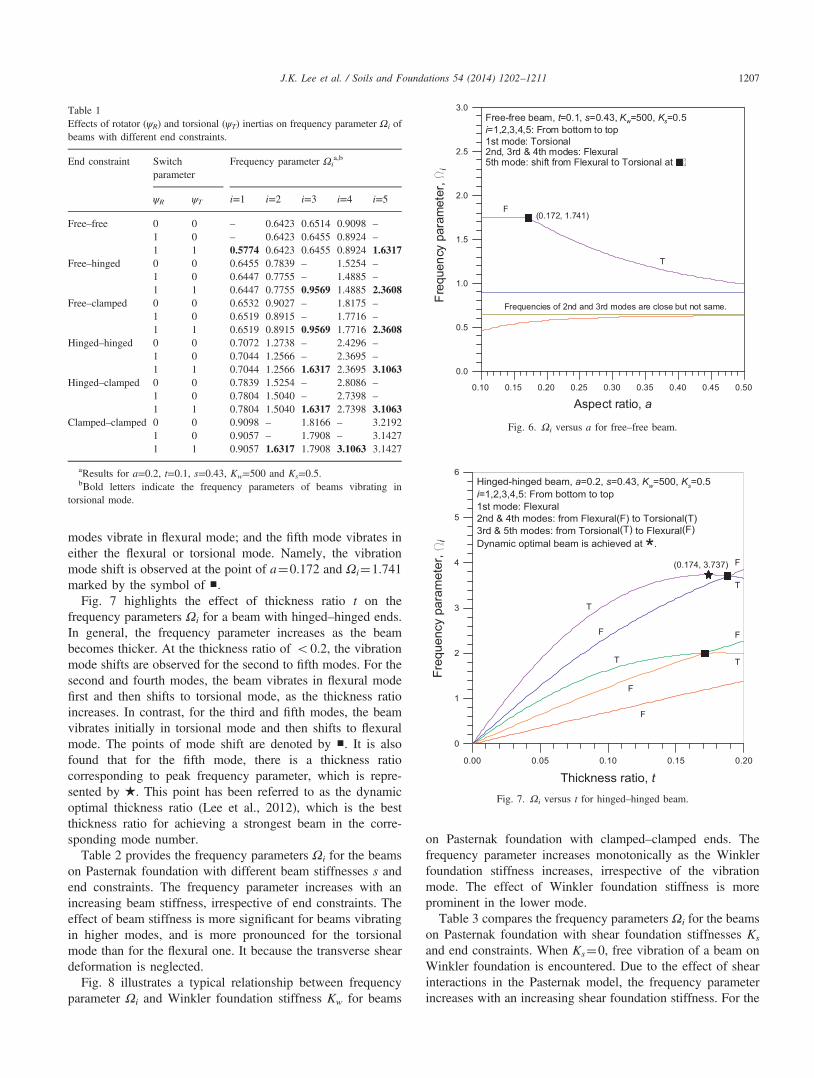
modes vibrate in flexural mode; and the fifth mode vibrates ineither the flexural or torsional mode. Namely, the vibrationmode shift is observed at the point of a¼0.172 and Ωi¼1.741marked by the symbol of ■.
Fig. 7 highlights the effect of thickness ratio t on thefrequency parameters Ωi for a beam with hinged–hinged ends.In general, the frequency parameter increases as the beambecomes thicker. At the thickness ratio of o0.2, the vibrationmode shifts are observed for the second to fifth modes. For thesecond and fourth modes, the beam vibrates in flexural modefirst and then shifts to torsional mode, as the thickness ratioincreases. In contrast, for the third and fifth modes, the beamvibrates initially in torsional mode and then shifts to flexuralmode. The points of mode shift are denoted by ■. It is alsofound that for the fifth mode, there is a thickness ratiocorresponding to peak frequency parameter, which is repre-sented by ★. This point has been referred to as the dynamicoptimal thickness ratio (Lee et al., 2012), which is the bestthickness ratio for achieving a strongest beam in the corre-sponding mode number.
Table 2 provides the frequency parameters Ωi for the beamson Pasternak foundation with different beam stiffnesses s andend constraints. The frequency parameter increases with anincreasing beam stiffness, irrespective of end constraints. Theeffect of beam stiffness is more significant for beams vibratingin higher modes, and is more pronounced for the torsionalmode than for the flexural one. It because the transverse sheardeformation is neglected.
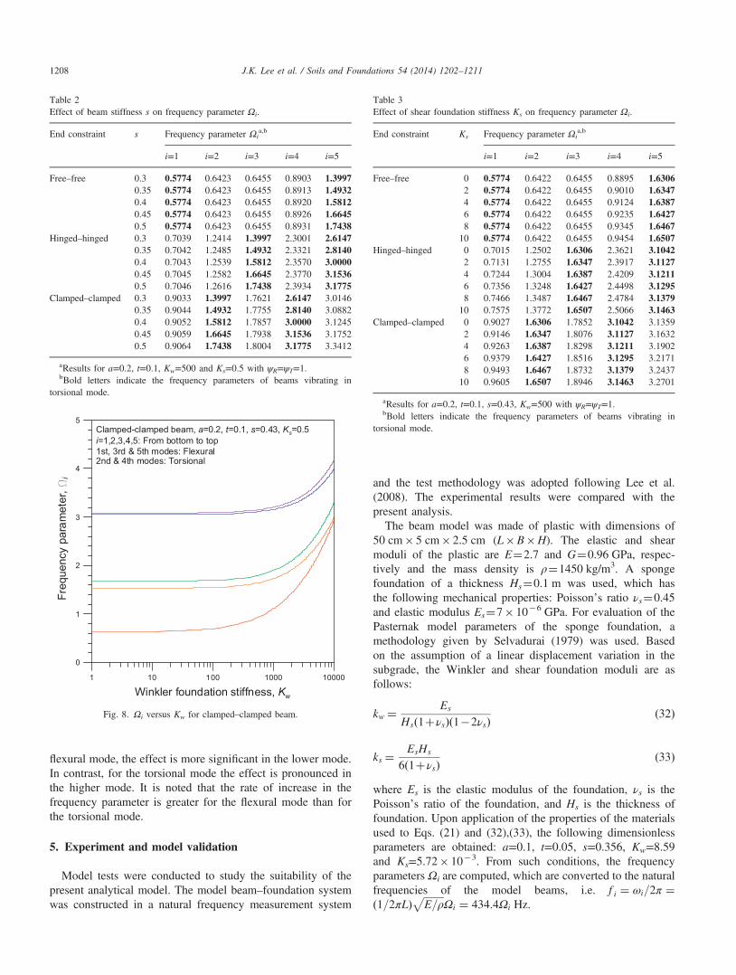
Fig. 8 illustrates a typical relationship between frequencyparameter Ωi and Winkler foundation stiffness Kw for beams
on Pasternak foundation with clamped–clamped ends. Thefrequency parameter increases monotonically as the Winklerfoundation stiffness increases, irrespective of the vibrationmode. The effect of Winkler foundation stiffness is moreprominent in the lower mode.Table 3 compares the frequency parameters Ωi for the beams
on Pasternak foundation with shear foundation stiffnesses Ks
and end constraints. When Ks¼0, free vibration of a beam onWinkler foundation is encountered. Due to the effect of shearinteractions in the Pasternak model, the frequency parameterincreases with an increasing shear foundation stiffness. For the
Table 1Effects of rotator (ψR) and torsional (ψT) inertias on frequency parameter Ωi ofbeams with different end constraints.
End constraint Switchparameter
Frequency parameter Ωia,b
ψR ψT i=1 i=2 i=3 i=4 i=5
Free–free 0 0 – 0.6423 0.6514 0.9098 –
1 0 – 0.6423 0.6455 0.8924 –
1 1 0.5774 0.6423 0.6455 0.8924 1.6317Free–hinged 0 0 0.6455 0.7839 – 1.5254 –
1 0 0.6447 0.7755 – 1.4885 –
1 1 0.6447 0.7755 0.9569 1.4885 2.3608Free–clamped 0 0 0.6532 0.9027 – 1.8175 –
1 0 0.6519 0.8915 – 1.7716 –
1 1 0.6519 0.8915 0.9569 1.7716 2.3608Hinged–hinged 0 0 0.7072 1.2738 – 2.4296 –
1 0 0.7044 1.2566 – 2.3695 –
1 1 0.7044 1.2566 1.6317 2.3695 3.1063Hinged–clamped 0 0 0.7839 1.5254 – 2.8086 –
1 0 0.7804 1.5040 – 2.7398 –
1 1 0.7804 1.5040 1.6317 2.7398 3.1063Clamped–clamped 0 0 0.9098 – 1.8166 – 3.2192
1 0 0.9057 – 1.7908 – 3.14271 1 0.9057 1.6317 1.7908 3.1063 3.1427
aResults for a=0.2, t=0.1, s=0.43, Kw=500 and Ks=0.5.bBold letters indicate the frequency parameters of beams vibrating in
torsional mode.
0.10 0.15 0.20 0.25 0.30 0.35 0.40 0.45 0.50
Aspect ratio, a
0.0
0.5
1.0
1.5
2.0
2.5
3.0
Freq
uenc
ypa
ram
eter
,i
Free-free beam, t=0.1, s=0.43, Kw=500, Ks=0.5i=1,2,3,4,5: From bottom to top
Frequencies of 2nd and 3rd modes are close but not same.
(0.172, 1.741)
1st mode: Torsional2nd, 3rd & 4th modes: Flexural5th mode: shift from Flexural to Torsional at
F
T
Fig. 6. Ωi versus a for free–free beam.
Fig. 7. Ωi versus t for hinged–hinged beam.
J.K. Lee et al. / Soils and Foundations 54 (2014) 1202–1211 1207
flexural mode, the effect is more significant in the lower mode.In contrast, for the torsional mode the effect is pronounced inthe higher mode. It is noted that the rate of increase in thefrequency parameter is greater for the flexural mode than forthe torsional mode.
5. Experiment and model validation
Model tests were conducted to study the suitability of thepresent analytical model. The model beam–foundation systemwas constructed in a natural frequency measurement system
and the test methodology was adopted following Lee et al.(2008). The experimental results were compared with thepresent analysis.The beam model was made of plastic with dimensions of
50 cm� 5 cm� 2.5 cm (L�B�H). The elastic and shearmoduli of the plastic are E¼2.7 and G¼0.96 GPa, respec-tively and the mass density is ρ¼1450 kg/m3. A spongefoundation of a thickness Hs¼0.1 m was used, which hasthe following mechanical properties: Poisson’s ratio νs¼0.45and elastic modulus Es¼7� 10�6 GPa. For evaluation of thePasternak model parameters of the sponge foundation, amethodology given by Selvadurai (1979) was used. Basedon the assumption of a linear displacement variation in thesubgrade, the Winkler and shear foundation moduli are asfollows:
kw ¼ Es
Hsð1þνsÞð1�2νsÞð32Þ
ks ¼EsHs
6ð1þνsÞð33Þ
where Es is the elastic modulus of the foundation, νs is thePoisson’s ratio of the foundation, and Hs is the thickness offoundation. Upon application of the properties of the materialsused to Eqs. (21) and (32),(33), the following dimensionlessparameters are obtained: a=0.1, t=0.05, s=0.356, Kw=8.59and Ks=5.72� 10�3. From such conditions, the frequencyparameters Ωi are computed, which are converted to the naturalfrequencies of the model beams, i.e. f i ¼ ωi=2π ¼ð1=2πLÞ
ffiffiffiffiffiffiffiffiE=ρ
pΩi ¼ 434:4Ωi Hz.
Table 2Effect of beam stiffness s on frequency parameter Ωi.
End constraint s Frequency parameter Ωia,b
i=1 i=2 i=3 i=4 i=5
Free–free 0.3 0.5774 0.6423 0.6455 0.8903 1.39970.35 0.5774 0.6423 0.6455 0.8913 1.49320.4 0.5774 0.6423 0.6455 0.8920 1.58120.45 0.5774 0.6423 0.6455 0.8926 1.66450.5 0.5774 0.6423 0.6455 0.8931 1.7438
Hinged–hinged 0.3 0.7039 1.2414 1.3997 2.3001 2.61470.35 0.7042 1.2485 1.4932 2.3321 2.81400.4 0.7043 1.2539 1.5812 2.3570 3.00000.45 0.7045 1.2582 1.6645 2.3770 3.15360.5 0.7046 1.2616 1.7438 2.3934 3.1775
Clamped–clamped 0.3 0.9033 1.3997 1.7621 2.6147 3.01460.35 0.9044 1.4932 1.7755 2.8140 3.08820.4 0.9052 1.5812 1.7857 3.0000 3.12450.45 0.9059 1.6645 1.7938 3.1536 3.17520.5 0.9064 1.7438 1.8004 3.1775 3.3412
aResults for a=0.2, t=0.1, Kw=500 and Ks=0.5 with ψR=ψT=1.bBold letters indicate the frequency parameters of beams vibrating in
torsional mode.
1 10 100 1000 10000
Winkler foundation stiffness, Kw
0
1
2
3
4
5
Freq
uenc
ypa
ram
eter
,
Clamped-clamped beam, a=0.2, t=0.1, s=0.43, Ks=0.5i=1,2,3,4,5: From bottom to top1st, 3rd & 5th modes: Flexural2nd & 4th modes: Torsional
Fig. 8. Ωi versus Kw for clamped–clamped beam.
Table 3Effect of shear foundation stiffness Ks on frequency parameter Ωi.
End constraint Ks Frequency parameter Ωia,b
i=1 i=2 i=3 i=4 i=5
Free–free 0 0.5774 0.6422 0.6455 0.8895 1.63062 0.5774 0.6422 0.6455 0.9010 1.63474 0.5774 0.6422 0.6455 0.9124 1.63876 0.5774 0.6422 0.6455 0.9235 1.64278 0.5774 0.6422 0.6455 0.9345 1.646710 0.5774 0.6422 0.6455 0.9454 1.6507
Hinged–hinged 0 0.7015 1.2502 1.6306 2.3621 3.10422 0.7131 1.2755 1.6347 2.3917 3.11274 0.7244 1.3004 1.6387 2.4209 3.12116 0.7356 1.3248 1.6427 2.4498 3.12958 0.7466 1.3487 1.6467 2.4784 3.137910 0.7575 1.3772 1.6507 2.5066 3.1463
Clamped–clamped 0 0.9027 1.6306 1.7852 3.1042 3.13592 0.9146 1.6347 1.8076 3.1127 3.16324 0.9263 1.6387 1.8298 3.1211 3.19026 0.9379 1.6427 1.8516 3.1295 3.21718 0.9493 1.6467 1.8732 3.1379 3.243710 0.9605 1.6507 1.8946 3.1463 3.2701
aResults for a=0.2, t=0.1, s=0.43, Kw=500 with ψR=ψT=1.bBold letters indicate the frequency parameters of beams vibrating in
torsional mode.
J.K. Lee et al. / Soils and Foundations 54 (2014) 1202–12111208
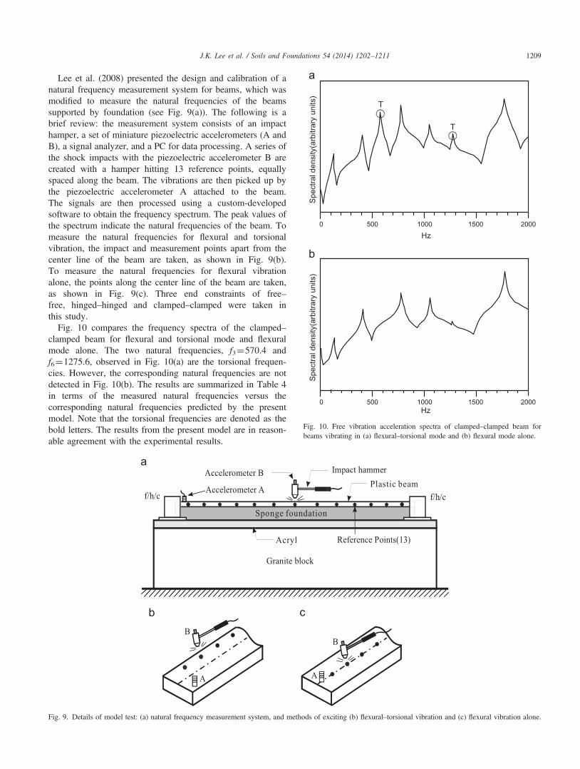
Lee et al. (2008) presented the design and calibration of anatural frequency measurement system for beams, which wasmodified to measure the natural frequencies of the beamssupported by foundation (see Fig. 9(a)). The following is abrief review: the measurement system consists of an impacthamper, a set of miniature piezoelectric accelerometers (A andB), a signal analyzer, and a PC for data processing. A series ofthe shock impacts with the piezoelectric accelerometer B arecreated with a hamper hitting 13 reference points, equallyspaced along the beam. The vibrations are then picked up bythe piezoelectric accelerometer A attached to the beam.The signals are then processed using a custom-developedsoftware to obtain the frequency spectrum. The peak values ofthe spectrum indicate the natural frequencies of the beam. Tomeasure the natural frequencies for flexural and torsionalvibration, the impact and measurement points apart from thecenter line of the beam are taken, as shown in Fig. 9(b).To measure the natural frequencies for flexural vibrationalone, the points along the center line of the beam are taken,as shown in Fig. 9(c). Three end constraints of free–free, hinged–hinged and clamped–clamped were taken inthis study.
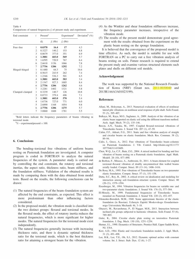
Fig. 10 compares the frequency spectra of the clamped–clamped beam for flexural and torsional mode and flexuralmode alone. The two natural frequencies, f3¼570.4 andf6¼1275.6, observed in Fig. 10(a) are the torsional frequen-cies. However, the corresponding natural frequencies are notdetected in Fig. 10(b). The results are summarized in Table 4in terms of the measured natural frequencies versus thecorresponding natural frequencies predicted by the presentmodel. Note that the torsional frequencies are denoted as thebold letters. The results from the present model are in reason-able agreement with the experimental results.
Granite block
Accelerometer A
Accelerometer B Impact hammer
Reference Points(13)
f/h/c f/h/cPlastic beam
Sponge foundation
Acryl
BB
AA
Fig. 9. Details of model test: (a) natural frequency measurement system, and methods of exciting (b) flexural–torsional vibration and (c) flexural vibration alone.
Spe
ctra
l den
sity
(arb
itrar
y un
its)
0 1000 2000
Hz500 1500
T
T
Spe
ctra
l den
sity
(arb
itrar
y un
its)
0 1000 2000Hz
500 1500
Fig. 10. Free vibration acceleration spectra of clamped–clamped beam forbeams vibrating in (a) flexural–torsional mode and (b) flexural mode alone.
J.K. Lee et al. / Soils and Foundations 54 (2014) 1202–1211 1209
6. Conclusions
The bending–torsional free vibrations of uniform beamsresting on Pasternak foundation are investigated. A computerprogram is coded in FORTRAN to analyze the naturalfrequencies of the system. A parameter study is carried outby controlling the end constraint, the rotatory and torsionalinertias, the aspect ratio, thickness ratio, beam stiffness, andthe foundation stiffness. Validation of the obtained results ismade by comparing them with the data obtained from modeltests. Based on the results, the following conclusions can bedrawn:
(1) The natural frequencies of the beam–foundation system areaffected by the end constraints, as expected. This effect ismore predominant than other influencing factorsconsidered.
(2) In the proposed model, the vibration mode is classified intothe two distinct groups: flexural and torsional modes. Inthe flexural mode, the effect of rotatory inertia reduces thenatural frequencies, which is more significant for highermodes. The natural frequencies for the torsional mode existindependently.
(3) The natural frequencies generally increase with increasingthickness ratio, and there is dynamic optimal thicknessratio for the torsional mode, which is the best thicknessratio for attaining a strongest beam for the vibration.
(4) As the Winkler and shear foundation stiffnesses increase,the frequency parameter increases, irrespective of thevibration mode.
(5) The results of the present model demonstrate good agree-ment with the results obtained from the experiment on theplastic beam resting on the sponge foundation.
It is believed that the convergence of the proposed model istime effective. As such, the model is suitable for use withFORTRAN on a PC to carry out a free vibration analysis ofbeams resting on soils. Future research is required to extendthe present study and examine various structural elements suchplates and shells on different soil models.
Acknowledgement
The work was supported by the National Research Founda-tion of Korea (NRF) (Grant nos. 2011-0030040 and2013R1A6A3A01023199).
References
Allani, M., Holeyman, A., 2013. Numerical evaluation of effects of nonlinearlateral pile vibrations on nonlinear axial response of pile shaft. Soils Found.53 (3), 395–407.
Balkaya, M., Kaya, M.O., Saglamer, A., 2009. Analysis of the vibration of anelastic beam supported on elastic soil using the different transform method.Arch. Appl. Mech. 79 (2), 135–146.
Bercin, A.N., Tanaka, M., 1997. Coupled flexural–torsional vibrations ofTimoshenko beams. J. Sound Vib. 207 (1), 47–59.
Calim, F.F., Akkurt, F.G., 2011. Static and free vibration analysis of straightand circular beams on elastic foundation. Mech. Res. Commun. 38 (2),89–94.
Calio, I., Greco, A., 2012. Free vibrations of Timoshenko beam–columnson Pasternak foundations. J. Vib. Control. http://dxdoi.org/10.1177/1077546311433609.
Chen, W.Q., Lu, C.F., Bain, Z.G., 2004. A mixed method for bending and freevibration of beams resting on a Pasternak elastic foundation. Appl. Math.Modell. 28 (10), 877–890.
de Borbon, F., Mirasso, A., Ambrosini, D., 2011. A beam element for coupledtorsional–flexural vibration of doubly unsymmetrical thin walled beamsaxially loaded. Comput. Struct. 89 (13–14), 1406–1416.
De Rosa, M.A., 1995. Free vibrations of Timoshenko beams on two-parameterelastic foundation. Comput. Struct. 57 (1), 151–158.
Dutta, S.C., Roy, R., 2002. A critical review on idealization and modeling forinteraction among soil–foundation–structure system. Comput. Struct. 80(20–21), 1579–1594.
Eisenberger, M., 1994. Vibration frequencies for beams on variable one- andtwo-parameter elastic foundations. J. Sound Vib. 176 (5), 577–584.
El-Mously, M., 1999. Fundamental frequencies of Timoshenko beamsmounted on Pasternak foundation. J. Sound Vib. 228 (2), 452–457.
Filonenko-Borodich, M.M., 1940. Some approximate theories of the elasticfoundation (in Russian). Uchenyie Zapiski Moskovskogo Gosudarstuen-nogo Universiteta Mechanik 46, 3–18.
Ghazavi, M., Ravanshenas, P., El Naggar, M.H., 2013. Interaction betweeninclined pile groups subjected to harmonic vibrations. Soils Found. 53 (6),789–803.
Guler, K., 2004. Circular elastic plate resting on tensionless Pasternakfoundation. J. Eng. Mech. 130 (10), 1251–1254.
Humar, J.L., 1990. Dynamics of Structures. Prentice Hall, Upper Saddle River,NJ, USA.
Kerr, A.D., 1964. Elastic and viscoelastic foundation models. J. Appl. Mech.31 (3), 491–498.
Lee, B.K., Lee, T.E., Oh, S.J., 2012. Dynamic optimal arches with constantvolume. Int. J. Struct. Stab. Dyn. 12 (6), 1–27.
Table 4Comparisons of natural frequencies fi of present study and experiment.
End constraint i Presenta Experimenta Deviationb (%)
Ωi fi (Hz) fi (Hz)
Free–free 1 0.0378 16.4 17 4.32 0.3227 140.2 153 8.83 0.8679 377.0 351 6.94 1.3881 603.0 569 5.75 1.6595 720.9 767 6.46 2.6618 1156 1066 7.87 2.7756 1206 1292 7.2
Hinged–hinged 1 0.1480 64.3 75 16.62 0.5615 243.9 262 7.43 1.2346 536.3 501 6.54 1.3881 603.0 583 3.45 2.1347 927.3 1005 8.46 2.7756 1206 1262 4.67 3.2281 1402 1321 5.8
Clamped–clamped 1 0.3239 140.7 126 10.82 0.8733 379.4 406 7.13 1.3881 603.0 570 5.44 1.6736 727.0 771 6.05 2.6890 1168 1054 9.86 2.7756 1206 1275 5.77 3.8860 1688 1781 5.5
aBold letters indicate the frequency parameters of beams vibrating intorsional mode.
b|1�experiment/present|� 100.
J.K. Lee et al. / Soils and Foundations 54 (2014) 1202–12111210

Lee, B.K., Oh, S.J., Mo, J.M., Lee, T.E., 2008. Out-of-plane free vibrations ofcurved beams with variable curvature. J. Sound Vib. 318 (1–2), 227–246.
Lee, B.K., Wilson, J.F., 1990. Free vibrations of arches with variablecurvature. J. Sound Vib. 136 (1), 75–89.
Li, X.F., Tang, G.J., Shen, Z.B., Lee, K.Y., 2012. Vibration of nonclassicalshear beams with Winkler–Pasternak-type restraints. Acta Mech. 223 (5),953–966.
Maheshwari, P., Khatri, S., 2012. Nonlinear analysis of infinite beams ongranular bed-stone column-reinforced earth beds under moving loads. SoilsFound. 52 (1), 114–125.
Matsunaga, H., 1999. Vibration and buckling of deep beam–columns on two-parameter elastic foundations. J. Sound Vib. 228 (2), 359–376.
Morfidis, K., 2010. Vibration of Timoshenko beams on three-parameter elasticfoundation. Comput. Struct. 88 (5–6), 294–308.
Naidu, N.R., Rao, G.V., 1995. Vibrations of initially stressed uniform beamson a two-parameter elastic foundation. Comput. Struct. 57 (5), 941–943.
Pasternak, P.L., 1954. On a New Method of Analysis of an Elastic Foundationby Means of two Foundation Constants (in Russian). GosudarstvennoIzdatefslvo Literaturi po Stroitelstvu i Arkhitekture, Moscow, U.S.S.R, 21.
Rao, C.K., Mirza, S., 1988. Free torsional vibrations of tapered cantileverI-beams. J. Sound Vib. 124 (3), 489–496.
Sapountzakis, E.J., Kampitsis, A.E., 2013a. Nonlinear dynamic analysis ofshear deformable beam–columns on nonlinear 3-parameter viscoelasticfoundation. I: Theory and numerical implementation. J. Eng. Mech. 139(7), 886–896.
Sapountzakis, E.J., Kampitsis, A.E., 2013b. Nonlinear dynamic analysis of sheardeformable beam–columns on nonlinear 3-parameter viscoelastic foundation.II: Applications and validation. J. Eng. Mech. 139 (7), 897–902.
Selvadurai, A.P.S., 1979. Elastic Analysis of Soil–Foundation Interaction. Devel-opments in Geotechnical Engineering, 17. Elsevier, Amsterdam, Netherlands.
Timoshenko, S.P., Goodier, J.N., 1970. Theory of Elasticity. McGraw-Hill,New-York, NY, USA.
Vlasov, V.Z., Leontiev, N.N., 1960. Beams, Plates and Shells on an ElasticFoundation (in Russian). Fizmatgiz, Moscow, U.S.S.R.
Vo, T.P., Lee, J., 2009. Flexural–torsional coupled vibration and buckling ofthin-walled open section composite beams using shear-deformable beamtheory. Int. J. Mech. Sci. 51 (9–10), 631–641.
Wang, T.M., Stephens, J.E., 1978. Natural frequencies of Timoshenko beamson Pasternak foundations. J. Sound Vib. 51 (2), 149–155.
Wang, T.M., Brannen, W.F., 1982. Natural frequencies of out-of-plane vibrationsof curved beams on elastic foundations. J. Sound Vib. 84 (2), 241–246.
Ying, J., Lu, C.F., Chen, W.Q., 2008. Two-dimensional elasticity solutions forfunctionally graded beams resting on elastic foundations. Compos. Struct.84 (3), 209–219.
Yokoyama, T., 1987. Vibrations and transient responses of Timoshenko beamsresting on elastic foundations. Ing. Arch. 57 (2), 81–90.
Zhu, B., Leung, A.Y.T., 2009. Linear and nonlinear vibration of non-uniformbeams on two-parameter foundations using p-elements. Comput. Geotech.36 (5), 743–750.
J.K. Lee et al. / Soils and Foundations 54 (2014) 1202–1211 1211