natural gas equipment tecnologies -...
TRANSCRIPT

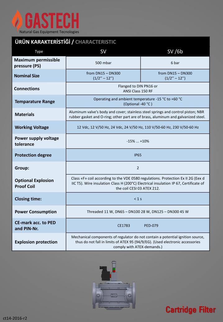
Type SV
N.Open Manually Reset
Solenoid Valves
N.Açık Elkurmalı Solenoid
Vanalar
The Manually Reset Solenoid Valves is made toguarantee the gas interception for gas dedector,fire control System, etc. Signal. According toPED97/23 EC
Elkurmalı Solenoid vanalar; gaz kaçakdedektörleri, yangın kontrol sistemleri vb.sistemlerden gelen sinyaller doğrultusunda gazırkapatır. PED97/23 CE direktiflerine uyguntasarlanmış ve üretilmiştir.
Natural Gas Equipment Tecnologies
ct14-2016-r2

Natural Gas Equipment Tecnologies
«SV» Serisi Elle Kurmalı Selenoid Vanalar ;Gaz kaçak alarm sistemi, yangın algılama sistemi veya elektrik sinyali üreten herhangi bir kaynaktan gelen sinyaller doğrultusunda gaz akışını kapat için tasarlanmıştır. Gaz borusuna montajlanır ve alarm sistemi ile irtibatlandırılır. Atmosfere açık ve kapalı alanlarda kullanılabilinir. Elektrik sinyali geldiğinde gaz akışı kapanır, tekrar gaz akışını sağlamak için kurma kolunu yukarı kaldırmak gerekir. PED97/23 CE direktiflerine uygun tasarlanmış ve üretilmiştir.
Type ‘’SV’’ Serie Solenoid valves have been designed to be combined with any gas detection system whichsets off a warning signal to shut off the main delivery when an emergency situation is detected. They havebeen installed at the gas piping and connected with a gas detector. Interrupt the gas flow in a dangersituation. The electro-valve is normally located after a filter, upstream of the regulation apparatus andpreferably outside the measurement zone. It has been installed with the arrow stamped on the body turnedtowards the user appliance. To reset the solenoid valve pull the reset knob/handle handle
Suitable for gaspressure regulator allsmall, medium andhigh capacity boilerplant (Hot water boiler,steam boiler, hot oilheaters, etc…)
Tüm küçük, orta veyüksek kapasiteli kazandaireleri uygulamalarıiçin uygundur (Sıcak sukazanları, buharkazanları, kızgın yağkazanları vb.)
Suitable for processcombustion system andall pre-burner gastrains
Proses yakmasistemleri ve tüm yakıcıöncesindeki gaz yollarıiçin uygundur.
Suitable for stations ingas transmission, LPG,LNG and CNG facilies.
Gaz Dağıtımistasyonları, LPG, LNGve CNG uygulamalarıiçin uygundur.
ct14-2016-r2
Cartridge Filter
ÜRÜN AÇIKLAMASI / PRODUCT DESCRIPTION
Natural Gas Equipment Tecnologies
Cartridge Filter
Type SV SV /6b
Maximum permissiblepressure (PS)
500 mbar 6 bar
Nominal Size from DN15 – DN300
(1/2’’ – 12’’)from DN15 – DN300
(1/2’’ – 12’’)
ConnectionsFlanged to DIN PN16 or
ANSI Class 150 RF
Temparature RangeOperating and ambient temperature -15 °C to +60 °C
(Optional -40 °C )
MaterialsAluminum valve's body and cover; stainless steel springs and control piston; NBR rubber gasket and O-ring; other part are of brass, aluminum and galvanized steel.
Working Voltage 12 Vdc, 12 V/50 Hz, 24 Vdc, 24 V/50 Hz, 110 V/50-60 Hz, 230 V/50-60 Hz
Power supply voltagetolerance
-15% ... +10%
Protection degree IP65
Group: 2
Optional ExplosionProof Coil
Class «F» coil according to the VDE 0580 regulations. Protection Ex II 2G (Eex d IIC T5). Wire insulation Class H (200°C) Electrical insulation IP 67, Certificate of
the coil CESI 03 ATEX 212.
Closing time: < 1 s
Power Consumption Threaded 11 W, DN65 – DN100 28 W, DN125 – DN300 45 W
CE-mark acc. to PED and PIN-Nr.
CE1783 PED-079
Explosion protectionMechanical components of regulator do not contain a potential ignition source,
thus do not fall in limits of ATEX 95 (94/9/EG). (Used electronic accessories comply with ATEX-demands.)
ct14-2016-r2
ÜRÜN KARAKTERİSTİĞİ / CHARACTERISTIC

Natural Gas Equipment Tecnologies
ct14-2016-r2
Cartridge Filter
BOYUT VE AĞIRLIKLAR / DIMENSIONS AND WEIGHT
SIZE DN ConnectionA
(mm)B
(mm)D
(mm)
SV 15 C 1/2’’ Threaded 64 125 0,5
SV 20 C 3/4‘’ Threaded 73 128 0,5
SV 25 C 1’’ Threaded 86 132 0,7
SV 15 1/2’’ Threaded 120 149 1,3
SV 20 3/4‘’ Threaded 120 149 1,3
SV 25 1’’ Threaded 120 149 1,3
SV 32 11/4’’ Threaded 160 196 2,1
SV 40 11/2’’ Threaded 160 196 2,1
SV 50 2’’ Threaded 160 216 2,4
SV 65 DN65 Flanged 246 415 6,5
SV 80 DN80 Flanged 265 415 6,9
SV 100 DN100 Flanged 350 360 11,6
SV 125 DN125 Flanged 480 455 25,9
SV 150 DN150 Flanged 480 470 27,7
SV 200 DN200 Flanged 600 540 61
SV 250 DN250 Flanged 670 630 87
SV 300 DN300 Flanged 737 760 107

Natural Gas Equipment Tecnologies
Correction Factor Fc at 15°C
Propane 0.64
Butane 0.55
Oxygen 0.76
Air 0.78
Nitrogen 0.81
Biogas 0.85
Towngas 1.23
Hydrogen 3.04
Akış ve Diğer Gazlar / Flow with Other Gases
Yandaki tablolarda, akış yoğunluğu 0.61 ve sıcaklık 15 ° C Nm3 / h doğal gaz debisini, aşağıdaki formül kullanılarak, diğer gaz akışına dönüştürmek için:In the tables above, the flow is in (n)m3/h natural gaswith a density 0.61 and temperature 15°C. To convert to othergas flow,using the following formula:
Q (Scm/h Naturalgas) x Fc = Q (Scm/h Xgas)
Örnek / Example:
Q (Scm/h Naturalgas) x 0.78 = Q (Scm/h Air)
1 Scm/h Naturalgas = 0.78 Scm/h Air
SV
125 D
N125
SV
80 D
N80
SV
32 -
40 1
1/4
’’ –
11/2
’’
SV
25 1
’’
SV
25 C
-1”
SV
15 –
20 1
/2’’ –
3/4
’’
SV
20 C
3/4
” –
1”
SV
65 D
N65
SV
300 D
N300
SV
200 D
N200
SV
50 2
’’
SV
15 C
1/2
”
SV
150 D
N150
500200 300 1000 2000 5000 10.000 20 30 100100503020105321 3000
200
100
50
30
20
10
5
3
1
0.5
0.1
0.2
ΔP
mb
ar
Debi Q (Stm3/h) / Flow Rate = Doğalgaz / Natural gas, Şartlar, Base: +15°C, 1013 mbar, kuru
KAPASİTE TABLOSU / CAPACITY TABLE
ct15-2016
GF Serie
SV
100 D
N100
SV
250 D
N250

Natural Gas Equipment Tecnologies
ct14-2016-r2Cartridge Filter
TYPE
SV
SIZE
DN15 C 15DN20 C 20DN25 C 25DN15 15DN20 20DN 25 25DN 32 32DN 40 40DN 50 50DN 65 65DN 80 80DN 100 100DN 125 125DN 150 150DN 200 200 DN 250 250DN 300 300
MAXIMUM WORKING PRESSURE
500 mbar 56 bar 6
FLANGED DESING
PN 16 16ANSI 150 150
WORKING VOLTAGE
10 12 Vdc11 12 V/50 Hz12 24 Vdc13 24 V/50 Hz14 110 V/50-60 Hz15 230 V/50-60 Hz
COIL TYPE
Standard Coil -Ex-Proof Coil (Ex II 2G (Eex d IIC T5) EX
SV / 25 / 5 / 16 / 15 / EXty
pe
size
max
imu
mw
ork
ing
pre
ssu
re
flan
ged
de
sin
g
Wo
rkin
gV
olt
age
Co
ilTy
pe
SİPARİŞ BİLGİLERİ / ORDERING DATA

Natural Gas Equipment Tecnologies
ct14-2016-r2
Cartridge FilterInlet Outlet
POSTER