natural resources wales permitting decisions · pdf filenatural resources wales permitting...
TRANSCRIPT
Grays Biogas Ltd EPR/AP3033HY Page 1 of 21
Natural Resources Wales permitting decisions
Substantial Variation – Mona Anaerobic Digestion Plant
We are minded to issue the variation for Mona Anaerobic Digestion Plant operated by Grays Biogas Limited.
The application number is EPR/AP3033HY/V005
The permit number is EPR/AP3033HY
We consider in reaching that decision we have taken into account all relevant considerations and legal requirements and that the permit will ensure that the appropriate level of environmental protection is provided.
Purpose of this document
This decision document:
Explains how the application has been determined
Provides a record of the decision-making process
Shows how all relevant factors have been taken into account
Justifies the specific conditions in the permit other than those in our generic permit template
Unless the decision document specifies otherwise we have accepted the applicant’s proposals.
Structure of this document
Key issues
Annex 1 the consultation
Grays Biogas Ltd EPR/AP3033HY Page 2 of 21
Key issues of the decision
Background and Competency The operator has applied for a substantial variation to their existing environmental permit. This is to allow for further digestate treatment once the material has been treated within the Anaerobic Digestion process. The site is situated approximately 3 miles west of Llangefni, Anglesey (National Grid Reference SH419 755) and is part of the Mona Industrial Estate. The site is located at the northern boundary of the industrial estate and is accessed via the estate road, which runs past the western site boundary. The site is located next to a poultry farm, a council run gritting yard, a waste transfer station (operated by Grays Waste Management Ltd) and RAF Mona Training Centre. There are also numerous residential properties within the vicinity of the plant and further afield. The treatment of the resulting digestate will involve the introduction of drying processes which will result in the production of compost, dried digestate and Ammonium Sulphate which can be used as a fertilizer. The anaerobic process takes place in the digesters and the biogas produced flows into the gas storage dome on top of the post-digester. Material from the post digester is then fed into a solid and liquid separation process. The plant comprises the following; the pasteurisation, separation, drying and evaporation processes along with the in-vessel composting process (including press screw separation). This equipment and processes forms the basis of this application. The digestate treatment operations being carried out consist of two drying systems (evaporator and belt dryer), each is equipped with a washing/scrubbing system which removes ammonia from the air flow leaving the dryer unit. To remove the ammonia the acid-base reaction principle is used by adding sulphuric acid to the ammonia washing system, which then leaves as an ammonium sulphate solution, which has properties similar to typical fertilizers. The dried material; dried digestate and compost will be stored within designated storage sheds. The liquid ammonium sulphate fertiliser will be pumped through sealed pipe work to a dedicated storage tank located within a fully bunded area. A full suite of technical specifications and drawings were provided as part of the application in Appendix N of the EMS. The operator has shown that they are technically competent to operate this facility. The operator has submitted a complete management system that takes into account all aspects of the operation of the plant. As part of the application odour, noise and air quality have been considered and technical assessments carried out. Within the environmental management system, the operator considers security, storage of waste and raw materials, a full list of operating techniques and procedures, health and safety, quality management procedures, point source and fugitive emissions, staff training and emergency procedures. This document (doc ref – 3407-819-A) shows competence to operate the AD plant and subsequent digestate treatment processes. An updated EMS was submitted on Monday 27th February 2017 to highlight the changes in the process.
Grays Biogas Ltd EPR/AP3033HY Page 3 of 21
The company that is building the plant, Agraferm, will supply an experienced plant supervisor to manage the start-up of the plant and then remain in place for a further 12 months after plant commissioning. All staff employed at the site will undergo a full training programme. Emissions to Air The odour control system operates by using chemical/biological principles. In the cleaning stage plastic filling material is washed with water. Ammonia (NH3) stripping involves the Ammonia being removed from the digestate liquor by stripping with air at increased temperature and pH. Air is contacted with the digestate to absorb the Ammonia which is less soluble at the operating conditions. The Ammonia is then recovered from the process air by acid scrubbing with Sulphuric Acid. Once the Ammonia has been recovered the air is returned to the start of the process. Heat from the process is provided by the CHP and pH adjustment of the digestate by the addition of the chemical. The application stated that there could be an Ammonia emission to air under certain abnormal conditions. This is not a continuous discharge and even though this is unlikely, we felt that it was necessary for the operator to model Ammonia emissions, mainly due to the installations proximity to numerous human receptors, a SSSI site and a number of European Protected Sites (SAC’s). We consulted internally with our Natural Resource Management (NRM) team regarding the need to carry out detailed dispersion modelling and the best critical level to apply to the model. It was found that Cors Bodwrog SSSI has mosses as part of the designated features, primarily in the M5 & M9 valley mires/nutrient poor fen/transition mires. The mosses were Calliergon cuspidatum, Sphagnum contortum, S. subnitens and S. squarrosum. All of these mosses require nutrient poor habitats (hence M5 & M9). However, they are also found in very wet, constantly damp to completely waterlogged situations. This suggests that these mosses are more at risk from nutrient run-off rather than aerial emissions. The mosses are indicators of nutrient poor habitats but by being covered by water they are given some protection from the aerial ammonia concentrations.
It was decided that the NH3 critical level should be set at 1µg/m3 due to the presence of the mosses but it was noted that the real risk to the habitat is from nutrient run off, which was not an issue with this site.
We concluded that if the applicant could meet the requirements based on critical levels and ELV’s for the protection of human health then the risk would be insignificant. To further support this, we checked the Site Management Statement (SMS) and the main issue is with water quality (fertilizers and waste spreading) and water management. There is a need for high water levels with low nutrient (N & P) inputs to maintain the diversity of the sensitive habitats. This is not an issue with this site as emissions are only aerial.
Based on advice from the NRM team a Schedule 5 notice was issued to the operator on the 22nd September 2016 requesting additional modelling. The operator requested an extension to complete the work until the 24th October 2016, this was agreed.
Grays Biogas Ltd EPR/AP3033HY Page 4 of 21
A response containing the Ammonia modelling was submitted to NRW on the 28th October 2016. A detailed assessment of potential emissions of ammonia arising from the operation of the Mona Anaerobic Digestion plant was carried out using AERMOD which is a steady state, next generation, dispersion model. The model included potential sources of ammonia as emission sources, these included the exhaust vents serving the digestate drying process. The report included an assessment of potential impacts on sensitive human and ecological receptors, with comparisons to Environmental Assessment Levels (EALs) and critical levels. Detailed dispersion modelling was undertaken to predict likely resulting ground level Ammonia concentrations surrounding the plant at sensitive receptor locations. Ammonia is reported to affect plants and vegetation at relatively low atmospheric concentrations. Critical atmospheric levels have been established by the United Nations Economic Commission for Europe UNECE, above which it is indicated that Ammonia can cause damage to ecological receptors. Short and long term Environmental Assessment Levels (EALs) are also in place for Ammonia for the protection of human health. The operator used a worst case critical level of 1μg.m3
as an annual mean Ammonia concentration. We felt that would be the most suitable assessment level considering the nearest statutory ecological receptor (Cors Bodwrog Site of Special Scientific Interest SSSI). Within the assessment, this conservative critical level was assigned for all ecological receptors considered within the assessment. Nitrogen deposition associated with Ammonia emissions was not assessed as the most conservative critical level of 1μg.m3
for annual mean Ammonia concentration is considered to be adequate for all critical loads. This means that if impacts can be screened or modelled as insignificant against the worst case critical level for Ammonia, impacts will therefore be insignificant on critical loads for acid and Nitrogen deposition. In relation to human health, a short term daily average EAL has been used. The short term EAL was obtained from the UK government website and stated as an hourly limit of 2500 µg.m3. The operator used 1-hour mean and 24-hour mean ammonia concentrations for completeness. The assessment identified 9 sensitive receptors, these include human and ecological receptors. Residential receptors assigned within the model are within vicinity of the plant. The ecological receptors considered within this assessment are;
Anglesey Fens SAC
Glan-traeth SAC
Anglesey Coast: Saltmarsh SAC
Aber.menai to Aberffraw Dunes SAC
Cors Bodwrog SSSI There are no emission limit values for Ammonia for this particular application. A potential source of ammonia emission at the proposed plant includes exhaust stacks associated with the air cleaning system on the drying shed. The technology provider has advised that this system will control ammonia emissions to a maximum residual ammonia concentration of 7.3mg/m3.
Grays Biogas Ltd EPR/AP3033HY Page 5 of 21
The operator considered the exhaust vents on the control units and assigned the relevant parameters to the dispersion model. These parameters include the point source diameter, exhaust flow rate, Ammonia emission rate, release height and release temperature. The surrounding structures within the vicinity of the release point were also considered in the model as they would affect the emission pathway. The integrated Building Profile Input Programme (BPIP) module within the AERMOD modelling software was used to assess the potential impact of building downwash upon predicted dispersion characteristics. This was used because building downwash can occur when turbulence is caused by nearby structures, this can potentially cause pollutants from the emissions source to be displaced and fall rapidly to the ground, whereby ground concentrations would increase. Real time meteorological data was used within the assessment and all of the data was obtained from Valley meteorological station which is located 11km from the site. Five years of meteorological data was used within the model. The operator looked at the surrounding land within a 10km x 10km grid to determine what was present. The land was predominantly covered by rural and cultivated land, with a small portion containing buildings and trees, based on this information and calculations a surface roughness value of 0.3 was assigned to the model. As the surrounding land was predominantly flat, no terrain module was applied to the model. As the site is not yet operational, the modelling assessment has used Ammonia emission rates based on the maximum ammonia concentration that the control system is designed to achieve. This means that real-time residual ammonia concentrations are likely to lower than the values used in the assessment. A series of conservative assumptions were used in the assessment which provide a high level of confidence that the Ammonia model predictions represent a highly conservative, worst case assessment. The operator has assumed in the assessment that;
Ammonia emission rates are based on worst case concentrations.
Worst case concentrations have been used across 5 years of met data.
There has been no inclusion of the effects of plume depletion as a result of wet and dry deposition.
It has been assumed that the plant will operate for 24 hours per day, 365 days per year with no rest period for maintenance.
The model results have been included as a series of tables showing the Maximum Modelled Process Contribution to 24-Hour Mean Ammonia Concentrations and the Maximum Modelled Process Contribution to 1-Hour Mean Ammonia Concentrations. Further to this the process contributions as a percentage of the EAL have been shown at the relevant sensitive receptors for both 1-hour mean and 24-hour mean Ammonia concentrations, for both human and ecological receptors. The modelling results show that the modelled process contribution is not predicted to exceed 1% of the critical level for annual mean ammonia concentration at statutory ecological receptors. In addition, the modelled process contribution to the short term EAL for ammonia as a 1-hour mean and 24-hour mean is predicted to be less than 10% at all locations surrounding the plant, including sensitive human receptors.
Grays Biogas Ltd EPR/AP3033HY Page 6 of 21
Given that the worst case critical level of 1μg.m3 as an annual mean Ammonia
concentration has been used this gives a high degree of confidence that the emissions of Ammonia will be insignificant to both human and ecological sensitive receptors. In addition given the series of conservative, worst case assumptions used in the assessment and highlighted above, this gives an addition level of confidence that the emissions can be deemed insignificant. Emissions to Water The site is served by 3 separate drainage systems to ensure only clean and uncontaminated rain water is released into the local watercourse; Uncontaminated Surface Water Drainage
Following the building of Phase 1 plant, deficiencies were identified in relation to the site drainage. We therefore requested that the operator investigate the surface water and leachate drainage systems and propose a modified system. We were not satisfied with the current drainage on-site as process effluents could potentially enter the surface water drainage system and lead to a pollution incident. Having discussed this at length with the operator they responded by email on the 22nd December 2016, and proposed to connect all of the currently ‘at risk’ manholes (drains that are in close proximity to either process areas or leachate drainage), in the yard area to the leachate system and also remove any linkage between the surface water system and the silage clamps via a valve arrangement. The surface water drainage will only consist of roof water and run-off from the site access road. A valve will be fitted to allow isolation from the attenuation lagoon and diversion to the leachate sump if required, for example if the attenuation lagoon was to become contaminated.
Based on the information provided by the operator we required additional details of the plans and therefore requested further information by Schedule 5 notice on the 23rd January 2017; requesting that the operator provide further information stating how they propose to ensure surface water manhole covers within the dirty yard areas between the silage clamps and hoppers etc. are suitably sealed to prevent ingress of contaminated water. We also required further details relating to how the concrete apron/yard would be re-instated following any cutting or excavation operations to re-lay the drainage system and how the operator will ensure there will be no future risk of ground contamination from operations. As the operator proposed to remove linkages between the surface water and leachate systems by valve arrangement we requested further information relating to the valves used on the system and sought confirmation that they are suitable for use and ensure effective sealing when closed. Finally we requested further information on how the redundant drainage legs between the silage clamps and the surface water drainage system will be sealed/isolated to prevent any future risk of surface water contamination. We received a response on the 24th January 2017 and the official Schedule 5 response
on the 20th February 2017, the operator has proposed that the entire surface water
system within the concrete loading apron will be rerouted and integrated into the
leachate drainage system, this will prevent any spilled or dropped substrate from being
washed into the surface water system by mistake.
Grays Biogas Ltd EPR/AP3033HY Page 7 of 21
To ensure that no surface water, possibly contaminated with leachate, flows into
manholes for the surface water system, the operator has proposed to replace the
manhole covers with new water tight covers, engineering drawings have been
provided with the official response and are satisfactory. This will allow the retained
surface water system to pass underneath the concrete loading apron, without risk of
contamination. In addition to give the flexibility to divert surface water, a new
connection between the surface water system and the leachate system has been
proposed. This alternative route gives a means to return surface water to the leachate
system and will be controlled by two supplementary valves. There is a risk to the
access road with leachate contamination from blown silage during the delivery
operations at harvest time in June/July (rye grass) and October (maize). Provision has
been made in the revised drainage system to divert the entire surface water system
into the leachate tank during these times if necessary, however the operator plans to
have rigorous procedures in place and the fact that silage will not be harvested during
rainfall, will mitigate the need to use this system. We asked the operator to explain
how the concrete apron would be re-instated once the necessary works had been
carried out. The operator responded by stating that; the concrete apron will be
reinstated with reinforced concrete slabs to the same specification as the original
construction; all new joints will be dowelled at 600mm centres and sealed with Fosroc
MS600 as specified. Full details were provided as part of the Schedule 5 response
with engineering drawings also supplied.
The Leachate Pump, located outside the main containment area housing the digestate tanks will now be inside a containment area, this area will comprise of concrete walls and floor. The area will be designed to contain any leakage from the flanges/gaskets/valves/pump, or non-welded pipe section. Any leakage of leachate will be collected within this area and transferred back into the underground leachate tank. Any non-welded connections will be equipped with flange guards, which will ensure that no leaks would spray beyond the walls of the bunded area.
We raised concerns about the attenuation pond and final effluent discharge point. The operator has confirmed that remedial work is required and will be carried out on the inspection chamber, this is located between the valve chamber and the hydro brake manhole, between the lagoon outlet and the drainage ditch. Water has been observed entering this manhole between the walls and the benching, and it is reasonable to assume that discharge water (conceivably leachate contaminated) could flow out of the manhole in the same way. The operator has proposed to excavate and expose the concrete surrounding the manhole and add an additional concrete surround to seal the chamber. The gate valve will be replaced with a butterfly valve downstream of the outlet, to give further assurance that this valve will not be impacted by debris causing leakage. At the same time, the pre-cast concrete outlet headwall will be excavated and investigated to confirm that the welded uPVC pond lining has been tied in to the concrete headwall. If the sealing of the lining to the headwall is found to be defective, this will be corrected before the area is back filled. In addition the two additional valves are to be installed to provide a means of diverting all surface water in to the leachate; these will also be butterfly valves.
Grays Biogas Ltd EPR/AP3033HY Page 8 of 21
As all of the yard area drainage is to be routed into the leachate system, the redundant drainage pipes between the silage clamps and the surface water system are to be filled with non-shrink concrete grout, the valves will be permanently closed and the valve chambers filled with concrete. This eliminates the risks to the surface water system. We have set a pre-operational condition in the permit stating that this work needs to be complete prior to the operation of the site. Leachate Drainage
Leachate is collected by a dedicated drainage system and held within an 80,000 litre storage tank. From here it is then pumped into the AD process to be used. All ‘at risk’ manholes as mentioned above are diverted into the leachate system. The dryer hall is serviced by a single, trapped gulley, this collects waste liquid and wash-down liquid. The gulley is connected to the leachate drainage system. The designated Sulphuric Acid storage tank drains to a trapped gulley which is diverted to the leachate storage tank.
Foul Water Drainage
Site welfare facilities (toilets, hand wash basins etc.) will drain to a septic tank which will be regularly emptied by the operator. Emissions to Land There will be no direct emissions to land. As a condition in the permit, the operator is required to carry out periodic monitoring at least once every 5 years for groundwater and 10 years for soil, unless such monitoring is based on a systematic appraisal of the risk of contamination. Containment The on-site storage containers are located on an impermeable pavement with sealed drainage, however there was no containment serving this area and patches of un-made ground within close proximity of this area. The containment tanks are to be alarmed to prevent overfilling. It is proposed that the treated digestate material will be stored on a concrete surface under cover to protect against degradation from moisture or light. The material will have a quick turnaround to minimise possible reduction in quality. We requested further information relating to the lack of containment on-site via Schedule 5 notice on the 22nd September. We received the response on the 22nd December 2016 and the areas were spilt into 2; The Dryer Hall and Process Separation Area.

Grays Biogas Ltd EPR/AP3033HY Page 9 of 21
Dryer Hall The operator proposed to install a 100mm galvanised steel upstand around the perimeter of the building and a sleeping policeman to the door entrance to provide containment of 110% of the largest tank at 17.6m3. The other significant tank in the building is the sulphuric acid tank which is 15m3. Based on the calculations and guidance for containment the proposed bunded capacity is adequate. The proposal is a reasonable solution to the issue and accepted by NRW, however the proposal lacked any significant detail and more information was required. We requested this by Schedule 5 notice on the 23rd January 2017. We specifically asked for;
a) Clarification as to the potential volume of any other stored liquids in addition to the tanks already considered within the dryer hall.
b) Clarification with respect to any potential further bund capacity
reductions for example any proposals to locate a small site office in the
building or the storage of additional materials etc.
c) Details and confirmation for the use of localised deflector plates to
prevent spillage from height etc.
d) Details of the sealant to be used with the upstands within the dryer hall. e) Details of the materials used for the proposed upstands, as they must
be resistant to acids
f) Clarification with regards to the drain located in the dryer hall within the
bunded area.
g) Details in regards to the proposed leak detection system/alarm to be
used.
We received the response on the 09th February 2017, the response explained the current containment arrangements for the Sulphuric Acid system. The applicant carried out a risk assessment of the system in the current location. As a result of this, a tank made of PE-100-RC-WK-S-800 is to be used. Additionally a secondary tank of the same material is mounted around the H2SO4 tank. This secondary tank can hold the net volume of the storage tank. The sulphuric acid tank has an aeration opening at the top. The tank contains a level gauge and a binary maximum level indicator. In case the maximum level is reached, an alarm horn / light inside and outside the dryer hall is activated. The sulphuric acid pipework that connects the tank with the treatment equipment are double skinned systems, this is designed to eliminate any possible spillage not only for environmental reasons but for health and safety reasons also. The pipes are connected to a PVC-U socket at the vacuum lifting station on the roof of the sulphuric acid tank. The double walled pipes are connected to the sulphuric acid pump. This pump is positioned directly next to the tank inside a stainless steel drip tray. At the pressure side of the pump, the pipe rises to cross the alleyway at a height of 3m. Underneath this pipe crossing there will be steel protection that could absorb potential impacts from outside. The applicant has stated that there will be a robust system in place to check this system fully. This was formally submitted on the 20th February 2017, in addition to the above information, the operator supplied a batch of documents from Brenntag who will be supplying the acid. The documents contained safety data sheets for the acids along with risk assessments and procedures for delivering/pumping the acid and inspection forms to be used by the driver.

Grays Biogas Ltd EPR/AP3033HY Page 10 of 21
A further formal response was received on the 20th February 2017 and addressed the points mentioned above;
a) The operator provided calculations within their response that provided the potential volumes of other stored liquids in the dryer hall in addition to the tanks. The operator has calculated additional liquid in the building from pipes/tanks etc. and concluded that an additional 7m3 of liquid could potentially be present during a worst case scenario. This gives a total spill volume of 23m3, the operator has proposed a 0.1m upstand to surround the building, based on the dimensions of the building there is a total containment capacity of 36.84m3, this is 50% greater than the total spillage volume so therefore deemed adequate. Due to this containment volume the operator has specified that a note will be added to the operating procedures that storing materials inside the dryer hall is to be minimised and shall not cover more than 40m2 of the ground.
b) The operator has confirmed that there are no proposals to locate site offices
within the dryer hall building and as stated above storage within the building will
be kept to a minimum.
c) The operator has confirmed that flange guards will be installed on all flanges
within 2.5m of the building cladding that have the potential to spill over the
containment walls, and any tank that would have the potential to spill over the
containment walls will be fitted with deflection plates. The hygienisation tank
will be partially screened to prevent jetting towards the doorway into the building
and towards the building cladding.
d) The operator has stated that Fosroc MS600 sealant will be used for the upstands within the dryer hall. Detailed engineering drawings have been provided with the response that show the overall proposal for sealing the dryer hall.
e) The operator has provided details on the materials to be used for the bunding
of the dryer hall, initially we requested acid resistant material, however since
the operator has shown that the risk of the acid leaking from the tank to be
negligible this is no longer required. The operator has proposed to install
concrete upstands on the 2 gable ends of the building with any voids being
sealed with non-shrinking grout. One gable end will be contained with by the
main containment bund wall, the opposite gable end will be contained by the
wall which will be formed as part of the external area containment. On the long
sides of the building the upstands are to be constructed from 100 x 100 Kedel
recycled plastic rail. Square plastic sections will be bolted to the floor and
sealed against the buildings stanchions and at an intermediate joint with a
proprietary process water resistant sealant. At the entrance to the building a
100 x 300 long rubber ramp strip is to be installed either side of the plastic bund.
Grays Biogas Ltd EPR/AP3033HY Page 11 of 21
f) The operator has clarified the use of the single drain located in the centre of the
dryer hall, this drain will be retained due to the fact that it is only linked to the
closed leachate drainage system. Any liquids that enter the drain will be routed
to the underground leachate storage tank.
g) The operator has provided detailed proposals for leak detection systems on-
site. The largest tank is the hygienisation tank and this will have a dedicated
leak detection system. There are 2 parts to this system, the first being that leaks
can be detected when filling the tank, by measuring the volume at specific
intervals once the pump has started to run, the computer measures whether
the actual volume meets the calculated volume based on flow, (if the leak is
small part 2 will be needed.) A worst case scenario will mean that the leak is
detected after 3 minutes and a maximum volume of 7m3 would have spilled
from the tank, this has been assessed in the containment volume calculations
above. This is fully automated with no human intervention needed. If an alarm
sounds then visual check from the plant operator will be necessary. With the
second part of the detection system, either liquid is pumped into the
evaporators or the final storage tank or it remains in the hygienisation tank, if
any of the levels drop within a 4 minute testing time the alarm will sound. In
addition to the above leak detection system, the response details the other leak
detection systems within the dryer hall; The Dryer buffer tank has an overflow
and level sensor present within the tank to prevent spillages. The inflow and
outflow are measured by flow meters, the levels are checked every time these
pumps start and stop. If the measured difference is >90% the alarms will sound
and inflow pumps stopped. The evaporators are also fitted with leak sensors,
these are fitted on the bottom of the main control unit, and if any damage to the
evaporators occur the sensors will detect any liquids on the ground. If any of
these alarms sound, pumping stops immediately.
All tanks within the building are isolated by control valves meaning that there are no hydraulically linked tanks so this does not need to be assessed further. Process Separation Area
For this area of Phase 2, the operator proposed to create a contained area using a
variable height steel upstand 300mm locally to the tanks and 100mm elsewhere. The
bund drains all liquids contained to a below ground open topped holding tank. The
holding tank capacity has been designed to receive 110% of the largest tank at 17.6m3.
However we noted that 25% of the total contents amounts to 15.5m3. We had
significant concerns with this proposal and considered it was not acceptable. A low
level (max 300mm) upstand set in very close proximity to the process tanks and
pipework is unlikely to be effective at containing a sudden tank failure or spills from a
height such as a jetting leak from a tank or pipework.
Grays Biogas Ltd EPR/AP3033HY Page 12 of 21
It is understood from the application documents that liquids will be pumped under
pressure in this area including to the double stacked shipping containers (IVC and
separator). So here a 300mm upstand would not contain spillages. We also had
concerns regarding the durability and maintenance of the upstand and therefore its
ability to effectively contain a spill long term. For the current proposal, a calculation
has been provided for a 1 in 10 (10% AEP) rainfall event over 3 days (assuming no
holding tank emptying) which amounts to 27.2m3. It is not clear why 3 days has been
assessed, presumably 24hr pre-incident (CIRIA recommendation) and 2 days for
incident response and clean up during ongoing rainfall event. This volume would fill
the containment tank. However, it appears that the holding tank capacity would not be
sufficient to receive the largest tank volume in addition to this rainfall. We carried out
our own calculations and presuming a 10% AEP rainfall over 24hrs with no holding
tank emptying, it would amount to 19.3m3, leaving 13m3 remaining capacity which
would not be adequate to contain the failure of the largest tank at 26m3, this shows
that the current scheme is inadequate. The guidance considers worst case scenario
with the holding tank full of water following a storm event coinciding with loss of primary
containment. Additional containment may be available within the bund but this is not
clear or accounted for and would likely submerge plant and equipment.
We were not happy with the proposal or detail provided so requested further
information by Schedule 5 notice on the 23rd January 2017, we requested that the
operator;
a) Provide an alternative proposal for bunding the Process Separation Area.
b) Clarify if the process tanks are hydraulically linked. CIRIA 736 recommends that hydraulically linked tanks are treated as a single tank and therefore require 110% containment. This would amount to total containment volume of 52m3. In the scenario proposed on the 22nd December 2016, the containment would be undersized. This will need to be factored in to any proposals submitted for the bunding.
c) Provide details for the use of spill alarms/leak detection and interlocks to stop
pumping of liquids to plant operating in the bund.
d) Confirm what tank overfill protection is in place and provide details of the system.
A formal response was received on the 20th February 2017 and addressed the points
mentioned above;
a) The operator has proposed to install flange guards to all of the flanges with this area to prevent jetting of liquids and thereby liquids will spill into the containment area. Spillages from the tanks will either be contained by construction of screening in close proximity to the tanks or by the newly positioned concrete containment wall. All of the spilled liquids plus the volume of potential rainwater will be routed to a new below ground tank formed from reinforced concrete or a pre-constructed tank (detailed engineering drawings have been supplied). It has been proposed that the Coll and Mixing tank will be partially screened to prevent liquids jetting over the containment wall, the adjacent hygienisation tanks are insulated so effectively have a second layer to prevent jetting. The process water and separation tanks will not be screened as the perimeter wall is positioned beyond the jetting distance.

Grays Biogas Ltd EPR/AP3033HY Page 13 of 21
The operator has calculated the total stored liquid volume to be 64m3. The total amount of liquid that could spill at any one time would be 28m3, therefore a 110% containment volume of 30.8m3 has been allowed for. The operator has also allowed for 1 day of continuous rainfall based on a 1 in 10 year event, using the flood estimates handbook a depth of 60.3mm was predicted, calculating the volume based on the areas of the containment area, the operator has calculated a total containment volume (rainfall + process liquid) of 55.9m3. A reinforced concrete wall will be constructed around the process area and tied & sealed into the existing slab extensions. Steps and guardrails will be constructed over the wall to allow access into the area. The height of the wall differs depending on location. Within the vicinity of the separators the wall is to be 0.3m high as the only function here is to route the liquid into the tank (no risk of jetting). Where there is a risk of liquids jetting and along the dryer hall perimeter the wall is to be 0.8m high. All of the gaps between the separator slab and process tank slab will be sealed with a connecting concrete slab. Any pipes/cables penetrating the wall will be sealed with a non-shrink concrete grout to prevent liquid spilling out. All joints between the slabs will be filled with non-shrink concrete grout. The below ground open-topped collection tank will naturally fill with water, this water will be assessed for quality and then either pumped into the surface water system if clean, if it is not clean it will either be pumped to the leachate system or collected for off-site treatment. b & c) On the process separation area, the largest tank is the collection and mixing tank, this tank is linked to the hygienisation tank in the dryer hall so shares the same leak detection system as explained above. There are other tanks within this area; the PW tank will be fitted with a level and overflow sensor, the actual levels inside the tank will be periodically compared with a calculated value, if the level difference is less than 90% an alarm sounds and the pumps are switched off. The pasteurisation tanks are fitted with a timed alarm; if the filling time is exceeded then an alarm is triggered and the system stopped. The separation buffer tank & separation PW tanks, the leak detection system again works on level changes within the tank. As liquids are moved between tanks the ratio of liquid is measured, if this falls below a certain value then an alarm is triggered and further investigation by a plant operator is required. To prevent overfilling of any of the tanks, once the alarm has been sounded the system automatically turns off the pump to prevent additional filling, all other pumps after this also switch off. Full procedures have been submitted by the operator. There are no hydraulically linked tanks within the process separation area, each in-fill and out-fill pipe that are connected to the tanks has a pump and automatic control valve fitted, these divide the system into separate tanks. d) The operator has stated that there will be an analogue level sensor and digital overfill protection on all of the tanks. The level sensor has 2 points, first the pump will stop when the level is reached when the 2nd level is reached the inlet pipe is closed. If this fails there is an overfill sensor mounted on the tanks, this will prevent any overfilling of the tanks by switching off the pump and closing the inlet valve. The analogue sensor works by measuring the hydrostatic pressure in the tank, the digital sensor swings and detects when liquid is reaching the top of the tank, if any of the sensors detect a leak/liquid then an alarm is sounded.
Grays Biogas Ltd EPR/AP3033HY Page 14 of 21
Odour The operator carried out odour modelling for the Phase 2 application. The assessment was carried out in-line with; How to Comply with your Environmental Permit, Additional Guidance for: H4 Odour Management, Natural Resources Wales, 2014; H4 Odour Management: How to Comply with your Environmental Permit, Environment Agency, 2011. The odour benchmark for a site of this nature is 3 odour units (for moderately offensive odours as described in H4). This is the value that was used as a benchmark when assessing the odour modelling. Within the assessment certain sensitive receptors were identified (residential receptors), and the report highlighted the most appropriate locations surrounding the site. The potential air quality impact that may arise through emissions of odour during operation of the AD facility were quantified in the modelling assessment using AERMOD, which is a steady state, next generation, dispersion model. The operator identified the potential sources of odour and assigned highly conservative emission rates to the sources. For this phase the exhaust vents serving the odour control units on the drying hall and the final compost storage building were assessed as potential odour sources. There is thought to be a low odour potential from the final compost product, the storage of the compost produced was been included as an emission source within the model. A report undertaken in support of a proposed AD facility near Kenninghall, Norfolk provided the operator with a conservative estimate of odour emissions arising from de-watered digestate, based on measurement data collected at other facilities of 10 OU.m-2.s-1. This was used in the model for the compost storage hall, which is considered to provide a worst case assessment. As a further conservative estimation, it was assumed that the entire surface area of the compost hall will contain compost at all times. In addition, the sides of the compost stockpile could also present a potential source of odour. It was assumed that the compost hall would be filled to half the maximum height, which is considered reasonably representative given that sometimes the hall may be less full, other times more full. Taking account of the above, the exposed surface area of the compost, including horizontal and vertical dimensions was assumed to be 378.8m2
in the model. The surrounding topography was also considered in the model, with the surrounding landscape considered. The associated buildings within the site boundary have also been considered as they would have an effect on the odour profile. The integrated Building Profile Input Programme (BPIP) module within the AERMOD model was used to assess the potential impact of building downwash upon predicted dispersion characteristics. Building downwash occurs when turbulence, induced by nearby structures, causes pollutants emitted from an elevated source to be displaced and dispersed rapidly towards the ground, resulting in elevated ground level concentrations. All building structures were input into the BPIP processor, to give a fully representative and accurate odour model. The meteorological data used for the odour model was taken from Valley meteorological station, this meteorological station is located around 11km from the site and is seen as the most appropriate data to use. The operator used 5 years’ worth of met data. Modelled scenarios were 98th percentile 1-hour mean odour concentrations.
Grays Biogas Ltd EPR/AP3033HY Page 15 of 21
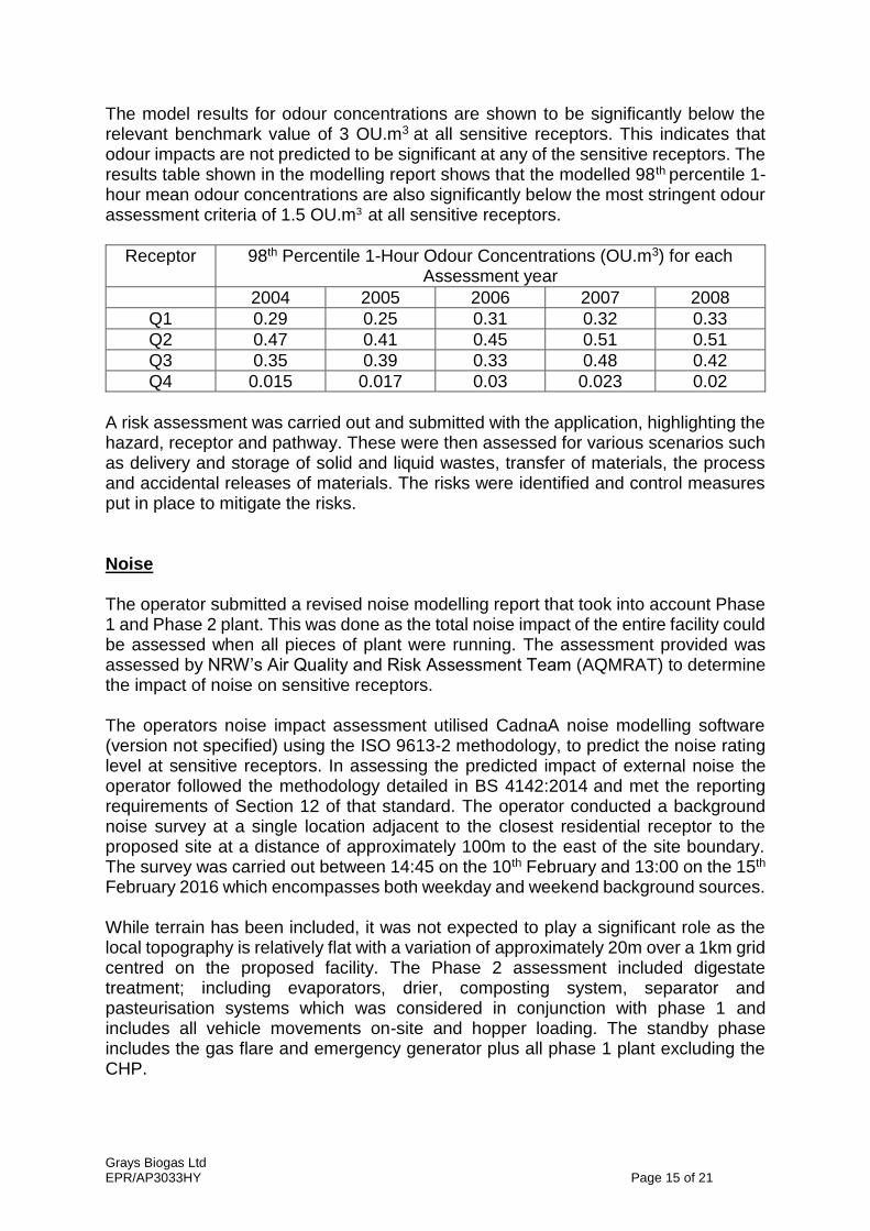
The model results for odour concentrations are shown to be significantly below the relevant benchmark value of 3 OU.m3
at all sensitive receptors. This indicates that odour impacts are not predicted to be significant at any of the sensitive receptors. The results table shown in the modelling report shows that the modelled 98th percentile 1-hour mean odour concentrations are also significantly below the most stringent odour assessment criteria of 1.5 OU.m3 at all sensitive receptors.
Receptor 98th Percentile 1-Hour Odour Concentrations (OU.m3) for each Assessment year
2004 2005 2006 2007 2008
Q1 0.29 0.25 0.31 0.32 0.33
Q2 0.47 0.41 0.45 0.51 0.51
Q3 0.35 0.39 0.33 0.48 0.42
Q4 0.015 0.017 0.03 0.023 0.02
A risk assessment was carried out and submitted with the application, highlighting the hazard, receptor and pathway. These were then assessed for various scenarios such as delivery and storage of solid and liquid wastes, transfer of materials, the process and accidental releases of materials. The risks were identified and control measures put in place to mitigate the risks. Noise The operator submitted a revised noise modelling report that took into account Phase 1 and Phase 2 plant. This was done as the total noise impact of the entire facility could be assessed when all pieces of plant were running. The assessment provided was assessed by NRW’s Air Quality and Risk Assessment Team (AQMRAT) to determine the impact of noise on sensitive receptors. The operators noise impact assessment utilised CadnaA noise modelling software (version not specified) using the ISO 9613-2 methodology, to predict the noise rating level at sensitive receptors. In assessing the predicted impact of external noise the operator followed the methodology detailed in BS 4142:2014 and met the reporting requirements of Section 12 of that standard. The operator conducted a background noise survey at a single location adjacent to the closest residential receptor to the proposed site at a distance of approximately 100m to the east of the site boundary. The survey was carried out between 14:45 on the 10th February and 13:00 on the 15th February 2016 which encompasses both weekday and weekend background sources. While terrain has been included, it was not expected to play a significant role as the local topography is relatively flat with a variation of approximately 20m over a 1km grid centred on the proposed facility. The Phase 2 assessment included digestate treatment; including evaporators, drier, composting system, separator and pasteurisation systems which was considered in conjunction with phase 1 and includes all vehicle movements on-site and hopper loading. The standby phase includes the gas flare and emergency generator plus all phase 1 plant excluding the CHP.
Grays Biogas Ltd EPR/AP3033HY Page 16 of 21
The assessment provided by the operator and check modelling carried out by AQMRAT included rating penalties as defined in BS 4142:2014 Section 9.2 (commentary on 9.2) and detailed in the submitted report as “acoustic feature correction” in Tables 13 & 14. BS 4142:2014 assesses the likelihood of significant adverse impact by subtracting the measured background noise level from the rating level:
A difference of around +10 dB or more is likely to be an indication of a significant adverse impact.
A difference of around +5 dB is likely to be an indication of an adverse impact.
The lower the rating level is relative to the measured background sound level, the less likely it is that the specific sound source will have an adverse impact or a significant adverse impact. Where the rating level does not exceed the background sound level, this is an indication of the specific sound source having a low impact.
From the previous application (Phase 1), it was determined that the modelling report indicates that, during daytime hours, noise originating from Phase 1 plant has a low impact at residential receptors while during night time hours, there is a low likelihood of adverse impacts at residential receptors. AQMRAT check modelling confirmed that during daytime hours, noise originating from Phase 1 plant had a low impact at residential receptors while during night time hours, the likelihood of adverse impacts was low. When the combined results are assessed (Phase 1 & Phase 2 plant) the submitted report indicated that, during daytime hours, the likelihood of adverse impact from combined sources (I.e. Phase 1 plant, Phase 2 plant and site traffic movements) at the residential receptors is low. However, during night time hours, there is potential for adverse impacts at the receptors with a predicted rating +5 dB greater than the measured background noise. Due to this potential impact we asked the operator to review the modelling input files, it was discovered that various input parameters had been omitted from the model, this was rectified and the model was re-submitted for assessment. The additional modelling files received from the consultant included revised details for Phase 2 plant (i.e. new sound source spectra for the CHP, additional sources located on the roof of the dryer building and a revised sound reduction index for an “enhanced CHP enclosure” with a panel construction of 16g steel with 100 mm of glass-fibre, covered by 22g perforated steel3). Combined source day rating (including penalties) dropped from +4 dB to +3 dB while combined source night rating (including penalties) dropped from +5 dB to +4 dB at the closest receiver. Based on the revised Phase 2 plant specifications, AQMRAT check modelling confirmed that during both daytime and night time hours, noise originating from combined sources had a low likelihood of adverse impact at residential receptors, there is a difference of less than 5 dB between the facility rating level and background at nearest receptor. The submitted report indicated that, during daytime hours, noise originating from the standby plant will have a low impact at residential receptors whilst during night time hours, there was a low likelihood of adverse impacts at residential receptors. AQMRAT check modelling confirmed that during daytime hours, noise originating from the standby plant had a low impact at residential receptors while during night time hours, the likelihood of adverse impacts was low.
Grays Biogas Ltd EPR/AP3033HY Page 17 of 21
A noise and vibration management plan (document ref: 3407/819/B) was submitted with the application, this plan explains the risks and potential noise sources and a comprehensive list of mitigation measures and controls to minimise the impact of noise and vibration. Fugitive Emissions The main concern with fugitive emissions for this phase is the vents serving the Odour Control Unit (OCU) on the drying hall and the storage of compost/digestate. A dust management plan (documents ref: 3407/819/DMP/1) was submitted with the application. A number of sources were identified with a potential to generate fugitive emissions, however with mitigation methods put in place the risk was low under normal operating conditions. The main concern is the storage and movement of digestate and compost however the operator has stated in the dust management plan that; The storage and movement of the dried digestate and compost will be carefully carried out. The material being stored within a building and the distances for transporting the material will be minimal as the storage buildings are located adjacent to the associated processing areas. There is a risk from vehicles moving in and out of the site creating dust on site roads in common with all premises. Good housekeeping to ensure the site yard areas are kept clean and regularly brushed. The management plan had a robust set of control measures and mitigation measures to reduce the fugitive emissions. Waste & Raw Material Acceptance There is no new waste to be accepted on to site, this variation adds the treatment of digestate from the currently permitted Anaerobic Digestion process. Sulphuric Acid will be brought on to site to be used for ammonia removal in the odour control unit serving the drying hall. The approximate annual usage will be 305 tonnes. The sulphuric acid will be stored in a double-skinned bunded tank with dedicated delivery point. We requested that this delivery point be protected by barriers, and this was formally requested via Schedule 5 issued to the operator on the 22nd September. The response received on the 22nd December 2016 confirmed the use of barriers. Materials stored on-site that are identified as being hazardous by the COSHH Regulations (grease and lubricating oils for example) will have Material Data Sheets and COSHH Assessments completed by the Site Manager. Copies will be held in the site office and will be accessible by the Site Manager/Director. Results will be communicated to staff as part of on-going training. Site Condition Report It has been noted that there are no recorded incidents of pollution to air, water or land within the area and no evidence of previous pollution. The site does not lie in an area at risk of flooding. As the Phase 2 equipment is in-place on the new piece of land added during the previous Phase 1 application, this document was fully assessed during the previous variation, this was acceptable and therefore does not need to be reassessed this time. The SCR template has been updated to reflect the activities that were applied for with this variation.
Grays Biogas Ltd EPR/AP3033HY Page 18 of 21
Accident Management Plan A comprehensive site accident management plan was submitted with the application. The plan covered plan references, inventories of tanks & stores, raw materials and emergency procedures. A list of potential accidents on the site are listed within a table and mitigation measures to be employed are also listed. A revised accident management plan that highlights the changes made was submitted on the 27th February 2017, this was accepted by NRW. Fire Prevention & Management Plan
The operator provided a comprehensive fire prevention plan with the previous Phase 1 application. The plan submitted covered general site introductions, potential fire hazards and receptors, monitoring and mitigation of fire risks, fire containments and infrastructure, fire response procedures, post-fire site recovery and various drawings/plans. All previous aspects of the plant (Phase 1 – Anaerobic Digestion Process) has been considered during the previous application and deemed satisfactory. The Fire Prevention Plan has now been updated to include all of the Phase 2 plant and processes. An appendix (Appendix A) has been added to the document with detailed drawings showing the location of the new plant. Within this appendix a list of sensitive receptors within 1km of the site has been compiled. To minimise the impact on the local area and associated receptors from an on-site fire, the document details mitigation measures which will decrease the likelihood of a fire occurring on-site and limit the size and duration if a fire does occur. These measures will ensure the potential impact on any of the surrounding land is as minimal as practically possible. No wastes will be burned on-site. External separation distances of 6m will be observed between plant and stored material when the site is not staffed. All mobile plant will be powered-down and completely shut off prior to cessation of operations on any given day.
Grays Biogas Ltd EPR/AP3033HY Page 19 of 21
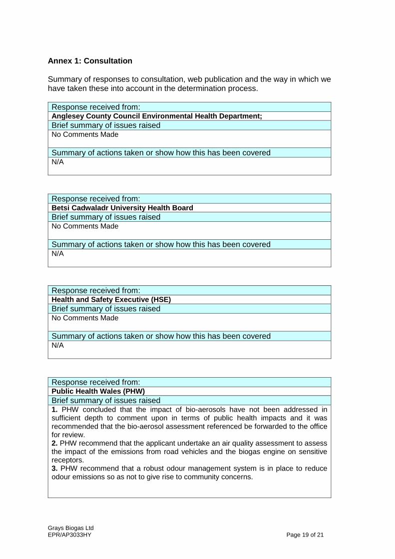
Annex 1: Consultation Summary of responses to consultation, web publication and the way in which we have taken these into account in the determination process.
Response received from: Anglesey County Council Environmental Health Department;
Brief summary of issues raised No Comments Made
Summary of actions taken or show how this has been covered N/A
Response received from: Betsi Cadwaladr University Health Board
Brief summary of issues raised No Comments Made
Summary of actions taken or show how this has been covered N/A
Response received from: Health and Safety Executive (HSE)
Brief summary of issues raised No Comments Made
Summary of actions taken or show how this has been covered N/A
Response received from: Public Health Wales (PHW)
Brief summary of issues raised 1. PHW concluded that the impact of bio-aerosols have not been addressed in sufficient depth to comment upon in terms of public health impacts and it was recommended that the bio-aerosol assessment referenced be forwarded to the office for review. 2. PHW recommend that the applicant undertake an air quality assessment to assess the impact of the emissions from road vehicles and the biogas engine on sensitive receptors. 3. PHW recommend that a robust odour management system is in place to reduce odour emissions so as not to give rise to community concerns.
Grays Biogas Ltd EPR/AP3033HY Page 20 of 21
4. PHW recommend that any consent granted be subject to conditions, specifically these should include robust emissions management plans (dust, odour, noise), strict waste acceptance and handling criteria and provision of an accredited environmental management system (EMS).
Summary of actions taken or show how this has been covered 1. Bio-aerosols were addressed and assessed during the Phase 1 application. The Phase 2 application does not change anything with reference to the bio-aerosol assessment. This was forwarded to PHW for assessment during the Phase 1 application. This was finalised in the Phase 1 application; ‘Bio-aerosol assessment submitted to PHW for assessment – PHW have subsequently received the bio aerosol evaluation. PHW commented that the operator commissioned a background survey of the bio-aerosols in the vicinity of the proposed plant. PHW recommended that a follow up evaluation of bio-aerosols be commissioned when the plant is operational. Further recommendations said where bio-aerosols are shown to exceed background concentrations the operator instigate a bio-aerosol management plan detailing how they will control emissions. There is a condition in the permit that requires the operator to take regular monthly samples for bio-aerosols at the locations used for the background study, this will be regularly reviewed by the operator and NRW, to determine future monitoring intervals and sample results.’ 2. The CHP engine is not part of this variation application. This was dealt with in the Phase 1 application and our previous comments from the Phase 1 application stand; ‘We don’t find it necessary to carry out another air quality assessment. The CHP engine is small at less than 5MW. During the initial permit application in 2010 an air quality assessment was carried out. This was found to be satisfactory and we are satisfied this time around. Emission from road vehicles doesn’t fall under our remit and is dealt with during the planning process.’ We are therefore satisfied with the emission limits set within the permit, and further modelling is not required. Environment Agency Guidance Document H1 Annex F suggests that; ‘As stand-alone units, they are not considered to be major sources of pollution but are subject to the requirements of the Clean Air Act. Whilst it is important that the environmental impact of these sources is estimated, it is considered that the risk from these sources will not often warrant detailed dispersion modelling to be undertaken as part of this assessment.’ 3. The operator has provided a comprehensive odour management plan with the application. This has been assessed by NRW and found to be satisfactory. The odour management plan and modelling assessment has also been assessed by NRW and has found to be satisfactory. 4. The permit covers all of the above aspects and requires that the operator adhere to the management plans submitted as part of their application. There is an improvement condition in the permit that requires the operator to review the effectiveness of the odour & noise management plan in preventing and minimising odours from all point and fugitive sources.
Response received from: Isle of Anglesey County Council – planning department
Brief summary of issues raised No Response Received
Summary of actions taken or show how this has been covered N/A

Grays Biogas Ltd EPR/AP3033HY Page 21 of 21
Response received from: North Wales Fire and Rescue Service
Brief summary of issues raised No Response Received
Summary of actions taken or show how this has been covered N/A