nautical vol. 59, no 4 winter 2014 - the nautical research ... 59-4 full version.pdf · research...
TRANSCRIPT


NAUTICALRESEARCH GUILD, INC.www.thenauticalresearchguild.org
HOME OFFICE
Nautical Research GuildJulie Hannon, Manager
20 Water Street, P.O. Box 7Cuba, NY 14727-1030
(585) [email protected]
EDITOR
Paul E. FontenoyNorth Carolina Maritime Museum
315 Front Street, Beaufort, NC28516
(252) [email protected]
OFFICERS
Kurt Van DahmChairman & Director
Marc MeijerSecretary
Jeff SillickTreasurer
DIRECTORSGreg HerbertToni Levine
Mike LonneckerMitch Michelson
Chuck PassaroPhillip Roach
Kurt Van Dahm
EDITORIAL ADVISORY BOARDRaymond Ashley
Maritime Museum Association of San Diego
Filipe Vieira de CastroTexas A&M University
Annalies CorbinThe PAST Foundation
Joe FlatmanUniversity College London
Paul F. JohnstonNational Museum of American History
Smithsonian Institution
I. Roderick MatherUniversity of Rhode Island
Waldemar OssowskiPolish Maritime Museum
Joseph K. SchwarzerNorth Carolina Maritime Museums
William H. ThiesenUnited States Coast Guard Historian’s Office
John A. TilleyEast Carolina University
Atilla J. TothNational Office of Cultural Heritage, Hungary
Spencer C. TuckerVirginia Military Institute
Dana M. WegnerNaval Surface Warfare Center
SUBSCRIPTIONSOne year is $38.00 US, $50.00 for all other countries. Contributions are welcomed, but contact theeditor before submitting anything. Books are accepted for review. The editor and the NauticalResearch Guild assume no responsibility for safe return of items sent. The Nautical Research Journal(ISSN 0738-7245) is published quarterly by the Nautical Reseach Guild Inc., 20 Water Street, P. O.Box 7, Cuba, NY 14727-1030. Periodicals postage paid at Cuba, NY, and at additional mailingoffices.POSTMASTER: Please send address changes to Nautical Research Journal, 20 Water Street, P. O. Box 7, Cuba, NY 14727-1030The Nautical Research Journal is available on microfilm from Bell and Howell Information andLearning, Ann Arbor, Michigan.
COPYRIGHT ©2014 BY THE NAUTICAL RESEARCH GUILD, INC. ALL RIGHTS RESERVED.PRINTED IN THE USA BY PERFECTION PRESS, LOGAN, IA
Vol. 59, No 4 WINTER 2014
EDITORIAL . . . . . . . . . . . . . . . . . . . . . . . . . . . . . . . . . . . . . . . . . . . . . . . 242
The Weedon Island Dugout: A 1,100 year-old Saltwater Canoe
by Irwin Schuster . . . . . . . . . . . . . . . . . . . . . . . . . . . . . . . . . . . . . . .243
The Blockade Runner Condor
by Jeneva Wright . . . . . . . . . . . . . . . . . . . . . . . . . . . . . . . . . . . . . . . .251
Scratch Building a United States Navy Anchor Hoy of circa 1819by Don Meadows . . . . . . . . . . . . . . . . . . . . . . . . . . . . . . . . . . . . . . .271
Trash to Treasure—A Restoration Projectby Bill Mitchell . . . . . . . . . . . . . . . . . . . . . . . . . . . . . . . . . . . . . . . . . 281
HMS Ardent: A King’s Ship, But Which King?by Ron Neilson . . . . . . . . . . . . . . . . . . . . . . . . . . . . . . . . . . . . . . . . .289
A Traditional 10-foot Wooden Dinghy Modelby Byron Rosenbaum . . . . . . . . . . . . . . . . . . . . . . . . . . . . . . . . . . . .305
COLUMNSSHOP NOTES
Simulated Deadeyes for Mini-Models
by Irwin Schuster . . . . . . . . . . . . . . . . . . . . . . . . . . . . . . . . . . . . . . . . 311
A Bonding Jig for Acrylic
by Irwin Schuster . . . . . . . . . . . . . . . . . . . . . . . . . . . . . . . . . . . . . . . . 311
MODELERS’ REVIEWS
Orange Hobby HMS Victorious (1966) Kit
by Mark Myers . . . . . . . . . . . . . . . . . . . . . . . . . . . . . . . . . . . . . . . . . . 313
Letters to the Editor. . . . . . . . . . . . . . . . . . . . . . . . . . . . . . . . . . . . . . . . . . . . . . . . . . . . . . .315
BOOK REVIEWS . . . . . . . . . . . . . . . . . . . . . . . . . . . . . . . . . . . . . . . . . . ..315
ADVERTISER INDEX . . . . . . . . . . . . . . . . . . . . . . . . . . . . . . . . . . . . . . . . 316
On the cover: Ron Neilson’s HMS Ardent. Photograph by the modeler.
FEATURES
241
“Advancing Ship Modeling Through Research”

develop very different techniques.For many of those who prefer to
“mix up” their modeling interests, itappears that its attraction combines theopportunity to build a subject that rarely, ifever, has been tackled elsewhere with thechance to learn new ways of tackling thehobby. Both feed into the concept that hastaken center stage in the approach to edu-cation of lifetime learning, buzzwords thatsome organizations seem to exploit to drawin more support but that appears to havesolid validity in light of longer lifeexpectancy and greater leisure time in themodern Western world.
In a broader perspective, researchingunfamiliar topics in order to build modelsthat are different from one’s norm unques-tionably provides significant learningopportunities. This process may also gen-erate surprising results; researchingAustro-Hungarian submarines, for exam-ple, revealed why the Germans were sokeen to recruit the Baron in The Sound ofMusic; Georg Ritter von Trapp (the fatherof all those children) was that navy’s sub-marine ace in World War I (and his latewife and their mother, oddly enough, wasthe grand-daughter of Robert Whitehead,the inventor of the automobile torpedo).
It would be extremely rash to deni-grate the benefits of specialization inmodel making. Nevertheless, it also mayjust possibly lead to a certain ennui aboutthe entire hobby. Should that happen,selecting some subject outside one’s usualfield of interest or style of constructionmay be exactly what is required to reviveone’s enthusiasm for this fascinating pas-time.
— Paul E. Fontenoy
Vol. 59, No 4 WINTER 2014
NAUTICAL RESEARCH JOURNAL
242
Trying Something New
Modelers, by and large, all seem tofall into two categories as far as theirapproach to their avocation goes: thosewho specialize exclusively in a single genreand those who take an eclectic approach.There is no doubt that those whose catalogis exclusive—eighteenth-century sailingvessels, vernacular watercraft, miniatureocean liners, radio-controlled twentieth-century steel warships, for example—oftenproduce some of the finest miniature repro-ductions of their subjects, especially aspractice very frequently does make thingsperfect (insofar as perfection may exist).On the other hand, those who prefer tochange their approaches with each newmodel, going from building a large-scalemodel of a racing dinghy to making aminiature aircraft carrier, for example, mayfind the constant change enhances theircraftsmanship by requiring them to varytheir methods constantly.
Recently, I have had opportunities toview quite a number of expositions by vari-ous clubs and have noticed a trend towardsgreater variety in the types of models onshow. One trend is manifested in the quan-tity of more exotic types modelers arebuilding, such as Chinese junks, Arabdhows, Inuit kayaks, Japanese or Koreansailing warships, or vessels from classicalantiquity. Their builders often state thatthe sheer volume of readily accessibleinformation about such more unusual ves-sels, thanks in large part to the internet,encourages them to look beyond subjectswith which they are more familiar. A sec-ond reveals itself in a greater variation inthe materials modelers use. Woods of vari-ous types still predominate, but there arean increasing number of very fine modelson show constructed from resins (eithercast or 3-D printed), various types of plas-tic, fiberglass, metal (mainly copper orbrass), and paper or card. All of these mate-rials require their users to learn their char-acteristics and limitations and to learn and

NAUTICAL RESEARCH JOURNAL 243
The Discovery, Recovery andDocumentation
In 2011, archaeologists and volunteersexcavated an ancient dugout canoe from theshoreline of Weedon Island Preserve. This pre-serve totals 3,200 acres of mangrove islands,hummocks and pine flatwoods. The canoe wasfirst discovered by a local resident, HaroldKoran, in 2001. Initial arrangements to docu-ment and investigate the find revealed a pinedugout canoe measuring 12.17 meters (39.9feet), from bow to broken stern. The WeedonIsland canoe is far longer than any otherdugout found in Florida and is the only one
directly associated with a saltwater environ-ment. The canoe has suffered damage frommangrove roots and oyster growth, and thesides are deteriorated. It is speculated thatalternate sun and tide eroded the exposedareas while mud in the bottom and outsidepreserved the remaining wood. After inspec-tion it was re-covered to preserve it untilarrangements could be made for proper techni-cal restoration. (Figure 1)
Radiocarbon testing yielded a date ofA.D. 690–1010. The makers of the canoe areconsidered to belong to the Manasota archeo-logical culture, a prehistoric Native Americanpeople who hunted and fished Tampa Bay,leaving shell mounds along the coast.
Friends of Weedon Island (FOWI) andthe Alliance for Weedon Island ArchaeologicalResearch and Education (AWIARE) are part-ners in the preservation of the canoe, a lengthyand expensive process. A specially-constructedconservation tank, funded by the FOWI andoverseen by AWIARE, holds the (four, inten-tionally sawn) sections of the canoe in a spe-cial bath of polyethylene glycol. Once the slowwood penetration treatment is complete (May2014), the canoe will be reassembled and puton display at the Weedon Island PreserveCultural and Natural History Center.
Jeff Moates, Director of the FloridaPublic Archaeology Network, West CentralRegional Center (FPAN), requested a modeland interpretation. This organization is dedi-cated to the protection of cultural resources,both on land and underwater, and to involvingthe public in the study of their past. Regionalcenters around Florida serve as clearinghousesfor information, institutions for learning andtraining, and headquarters for public participa-tion in archaeology.
The Weedon Island Dugout, an 1,100year-old Saltwater Canoe
. . . . .by Irwin N. Schuster
Figure 1. Jeff Moates of FPAN working to preserve the dugoutin 2011. Courtesy of AWIARE.

Vol. 59, No 4 WINTER 2014244
B.C.E. to 800 C.E., were located fromSarasota north to Tampa Bay. (The anthro-pology is tangential to our mission here,and is readily found.)
The 1,100 year-old artifact isextremely narrow, and may have been usedfor travel, trade, fishing or raiding. TampaBay is a natural harbor and estuary, roughlylobster shaped, about thirty-five miles longby ten miles in width, opening into theGulf of Mexico at the southwestern point.The Weedon Island Preserve is at the junc-tion of the body and larger, western claw.The Bay is reputed to be the thunderstormand lightning capital of the United States.It is generally shallow, but subject to sud-den violent weather. How did this slendervessel survive on these waters?
The forty-foot long but eleven inch-es wide remains suggest a log diameter ofnot over twelve to fourteen inches, or atleast, that the vessel’s beam was hewn tothat width. (Figures 2 and 3) Why such alimited beam? Because the upper parts ofthe hollowed log have not survived, the useof added structure for stabilization isentirely speculative. Nevertheless, evidencein the form of ancient toys and records ofexploration indicate that catamaran typeswere used in Florida’s coastal waters, buthow far back? Nothing similar that wasused in the Pacific ventured onto openwater without the stability provided by twinhulls or outrigger(s). It is fair to point out,however, that similarly narrow canoes are
The Weeden Island Cultures are agroup of related archaeological cultures thatexisted during the Late Woodland period ofthe North American Southeast. The namefor this group of cultures was derived fromthe Weedon Island site in Old Tampa Bayin Pinellas County (Weeden and Weedondenote the same entity. The site is calledWeedon after its original owner, Dr. LeslieWashington Weedon, and the culture is des-ignated as Weeden, simply due to an errorcarried forward). The Weeden Culturerange included Tampa Bay and north tosouthwest Georgia and southeasternAlabama. The Manasota, dating from 550
Figure 2. Cross section with overlay to determine approxi-mate log diameter. Courtesy of AWIARE.
Figure 3. Documentation of the artifact: plan by G. Leaker from field notes of M. Ayvaz, P. Kolianos and D. Ruhl. Courtesy ofAWIARE.

NAUTICAL RESEARCH JOURNAL 245
tion as well. And, perhaps, it was for speed.It is interesting to note that flatwater racingshells have a lenth-to-beam ratio of about30:1, and that Vikings were crossing theNorth Atlantic about this time. Typicalfreshwater canoes of the period had alength-to-beam ratio not over 14:1, whilethis artifact indicates a ratio of about 35-40:1.
The Model
The model, at a scale of 1 inch = 1 foot(1:12), was created essentially to “hold aplace” in the Cultural Center while the arti-fact was stabilized, and to illustrate what itmay have been used for, so that the momen-tum and public relations enthusiasm creat-ed by discovery and preservation would notbe dissipated. I have chosen to present thismodel iteration as a basic dugout some-where in the building process. I believe thatspeculation on outriggers, double canoe,decked platform, wash strakes, paddles, dec-oration and such should be left to support-ing graphic images, where warnings of theirconjectural nature can be integral. A photo-graph of a model with theoretical extrapola-tion can become detached from disclaimersand carry weight far beyond the evidence.(Figure 4)
Model Stagecraft
Framing is an important part of art.When you do not have much to show, youneed to put on a more elaborate presenta-tion. A figure is important to establish scaleand “humanize” the work.
The Vessel
The hull was carved of basswood,gouged with the usual small hand tools androughly sanded. To maintain control overthe (eventually) thin-walled hull, blocks of
paddled and poled to this day, from a stand-ing position, but they are not seen on largerbodies of salt water.
Attachment cross-members wouldallow a pole “deck” for sleeping or carryingsupplies, making the canoe a much moreversatile transport for hunting parties, fam-ily voyages, or trading excursions. Thelength of this vessel would allow a crew ofeight or nine adults, and the length-to-beam ratio suggests an easily driven, speedyvessel. To see a photograph of such a craft,entitled “Young Sea-lords of the AdmiraltyIslands,”visit ian.macky.net/secretmuse-um/page_5.23.html
It is also possible that the WeedonIsland dugout could have been rigged fordownwind sailing, with a spar seated on theunusual transverse hump toward the bow.This feature is debated; some see it andothers do not. In breaking news, however,as the hull now has been removed from thepolyethylene glycol solution, two holesabout two inches in diameter have beennoticed, at the bow and about eight feet aftof it, that may have seated spars.
Again, why so narrow? The energyrequired to hollow out a narrow log wouldbe considerably less than that for a largertree, as would the manpower to move itfrom its original site through swampy ter-rain, and beaching it would be a considera-
Figure 4. Preliminary plan for the project. All images by theauthor, except as noted.

Vol. 59, No 4 WINTER 2014246
material were left on the ends, to bescrewed to a support beam for clamping ina vise. This worked well to carve the out-side shape, which was then flipped to hol-low it. (Figures 5 and 6) When carving wascomplete, the blocks were sawed off andthe hull ends were sanded. Let’s faceit…that was all there was to it. The finishis Age-It EASY gray aging stain from Micro-Mark, with the interior painted black usingwater-based poster paint and artist’s char-coal sticks to simulate the burn and scrapemethod of removing the interior. The totalwas sprayed with matt fixative. The aginggray simulates a documented practice ofburying the felled logs in mud for about ayear, which tends to preserve them. Thereis no way of knowing when this practicestarted in a society with no existingrecords. The bow and stern configurationwas also created to mirror later practice,and extrapolated the minimal remainingshape of the artifact. (Figure 7)
Figure 5. Aft end of the model with supporting block still inplace.
Figure 6. The vessel mounted to its stiffening-clampingbeam.
Figure 7. Plan for hypothetical ends.
Figure 8. Plan for figure.
Figure 9. Armature for figure. Figure 10. Native figure of “fired” Sculpy.

NAUTICAL RESEARCH JOURNAL 247
Elmer’s Glue drops on thread, painted withacrylics. (Figures 8-11)
The Diorama
The beach, frame, backdrop andwater simulation were created separatelyand assembled with hardware to facilitatefinishing and later repair or alteration. Thebeach and underwater surface is ¼-inchMedium Density Fiberboard (MDF) paintedwith a variety of smooth and textured com-mercial canned spray paints. Texture wasadded with fine sand, ground peat moss,powdered pastel chalk and general debris.In painting, it is important not to allow amonotone field, as actual terrain varies sub-tly with clouds, wetness, content of vegeta-tion matter, and so on. Sea grass was madewith peat, dried (used) green and black tealeaves (Lipton!) and small bits of beachspindrift. The shells are actual shells, pro-vided by Mom Nature. I was raised on thebeach and, then, did not notice that bigshells start out as tiny shells. So, a trip tothe beach to pick up a couple of quarts anda lot of sifting and picking gets you perfectscale replicas. I have never found props asappropriate as these little shells scaled byNature. The prop log and figure’s staff were
The Figure
The native figure was created fromSculpy polymer clay over a wire armature,painted with acrylics and decorated withfabric, plaited thread and a desktop printedturkey feather photograph. Beads were
Figure 11. Figure painted and dressed.
Figure 12. Display base and backdrop in process.

248 Vol. 59, No 4 WINTER 2014
likewise selected found items. Detritus onthe beach was adhered with spray adhesive,and cyanoacrylate (CA) for larger items, alloversprayed with Krylon Matte Fixative.
The backboard was a painted pineplank from a home store, surfaced with aphotograph taken by wading out in shallowwaters close by Weedon Island, with cam-era held high overhead. Local waters arewell known to have stingrays, so that is ahazard not typical of most similar projects.I commemorated my personal courage byincluding a scale ray into the presentation.It was created by downloading a photo-graph, desktop printing it, and embossing itto shape with a wooden die set. The raisedshape was then filled with wood dough.Back to the mangrove photograph…it wasenhanced with a couple of wading birdsincluded with PhotoShop. This file wasprofessionally printed on banner vinyl andmounted with Golden Harvest Vinyl BorderWallpaper adhesive.
The case frame was yellow pinedimensional lumber from a home store fin-ished with Minwax Wipe-On Poly. (Figures12 and 13) The water was simulated with1/16-inch acrylic sheet with water ’s edgeshape cut on a jigsaw and that edge beveledtop and bottom. A two-part bar-top finish
was poured on for gentle wave effect andthe leading edge hand painted with thinnedwhite acrylic.
I specified a wedge-shaped acryliccover to avoid the corner of a conventionalrectilinear case, which would unfortunatelyfall in the line of sight with regard to thesubject. (Figure 14) The diorama resides atthe Weedon Island Preserve Cultural andNatural History Center, St. Petersburg,Florida.
Interpretation: The ModelPresentation and Speculation
There is something fascinating about sci-ence. One gets such wholesale returns ofconjecture out of such a trifling investmentof fact. Mark Twain
When asked to make a model of thiscanoe, I did some research on the type. Theexhaustive reference, Canoes of Oceania,provided the most specific information onsaltwater dugouts. Before seeing that, webresearch brought me to the notion that,because of its proportions, this was proba-bly a stabilized vessel for use on TampaBay, and, to my mind, very likely a “war”
Figure 13. Later stage of hull positioning hull, with paper figure.

NAUTICAL RESEARCH JOURNAL 249
lization. The cross members between anoutrigger (or two), or a twin hull can beused to support a pole deck to carry goodsor family for peaceful use. (Figure 15) It isof interest to note that the historic basicmilitary unit is eight to ten men, and thatis the number that can be carried by a slen-der canoe of this length. Canoes of thePacific often had wash strakes attachedatop the gunwales, usually stitched on.This one may have as well, but photo-graphs of the bow when originally exposeddo not seem to indicate that.
This is all speculation as our gun-wales are gone, so there is no way to see ifthere were holes for fastening cross mem-bers or strakes. You will recognize that asample of one unit can fall anywhere on thespectrum. It is universally agreed that theinsides were shaped by fire and scraping,and that, in Florida, char was left in, possi-bly adding to the life of the vessel (possiblyfewer splinters, too).
While my first thought was thatthese were primitive peoples, I soon real-ized they were modern men but withoutmetal. I understand that Polynesians arebelieved to have reached South America inroughly this period. Even today, with wide-spread coastal (over)development, wildlifein this region is plentiful: mammals, close-
canoe. While there may have been a secondhull making this a catamaran, swept awayor perhaps still under advancing man-groves, none has been uncovered. So wemust move on with what we have, a singlevery narrow hull, as determined by theradius of the bottom that remains.
Why a war canoe? Neglecting skindrag, displacement hull speed is generallydetermined by three factors: waterlinelength, weight and motive power. Considera racing shell. This is a narrow canoe. Ifyou want to carry goods, gathered or tobarter, you would likely choose more beam.If you want to do less work and go fast, youwould choose a slender log and add stabi-
Figure 14. Hypothetical stabilization scheme and downwindrigging plan for ancillary display panel.
Figure 15. Encased project at Weedon Island Preserve Cultural and Natural History Center.

Vol. 59, No 4 WINTER 2014250
to-shore fish, shellfish, birds, reptiles andedible plants, so Florida peoples did notneed to develop great saltwater skills.However, canoe stabilization and down-wind sailing are obvious. To my mind it iscondescending to believe that a people wholived so close to nature, making everythingthey had and used, would not come upwith these simple and useful concepts.
There is slight evidence of a trans-verse low “bulkhead” toward the bow. Onesource studied mentioned maintaining fireaboard while afloat by carrying a bed ofsand. That could be a function of this fea-ture. As a teen, I went gigging for mullet inthese waters with a gas lantern on the fore-deck. I can envision a fisherman usingembers to keep a firebrand or torch lit forthat purpose, for igniting arrows, or forheating lunch. (Figure 16)
Thanks to:Phyllis E. Kolianos, M.A., R.P.A,Manager for the Weedon Island PreserveCultural and Natural History Center, theprincipal archaeological investigator
Jeff Moates, M.A., R.P.A. Director of the Florida Public ArchaeologyNetwork, West Central Regional Center(FPAN), who requested this modelBrent R. Weisman, Ph.D.President of the Alliance for Weedon IslandArchaeological Research and Education(AWIARE), Professor of Anthropology,University of South Florida
ReferencesHaddon, A.C., and James Hornell, Canoesof Oceania. Honolulu: Bernice P. BishopMuseum, 1937.
Hartmann, Mark Joseph, “Development ofWatercraft in the Prehistoric SoutheasternU.S.” PhD. dissertation. Texas A&MUniversity, 1996.
The Weedon Island Story, Pinellas County Department of EnvironmentalManagement, Environmental LandsDivision, 2005.
Weedon Island Preserve Cultural andNatural History Center website: www.wee-donislandpreserve.org/ed-center.htm
Figure 16. Completed project as delivered.

NAUTICAL RESEARCH JOURNAL 251
Introduction
Just before the sun rose on themorning of October 1, 1864, a NorthCarolina sentry patrolled the beach in frontof Fort Fisher. The sea oats and soft sand infront of the raised earth mounds mighthave made a picturesque site, but for thehuddled form of a dead woman “tossed upon the beach like a bit of seaweed.” (TheSheffield & Rotherham Independent
1864:4) To Private J. J. Doc Connor, thecorpse was far less interesting than the bagof gold tied around her neck. Pocketingfour hundred gold sovereigns, the sentryshoved the woman back into the surf. Afterall, this was wartime. (Blackman2005:299)
Not long after, Thomas Taylor, acrewmember of the recently wrecked block-ade runner Night Hawk, rediscovered thebody, “A remarkable handsome woman shewas, with features which showed much
The Blockade Runner Condor. . . . .
by Jeneva Wright
Figure 1. The blockade runner Condor. Painting by Martin Peebles, courtesy of the North Carolina Underwater ArchaeologyBranch.

252 Vol. 59, No 4 WINTER 2014
character…there was no doubt that sheimagined herself in following such a profes-sion to be serving her country in the onlyway open to her.” (Taylor 1896:128-129)The woman was famed Confederate agentRose Greenhow, the only casualty from thewreck of the blockade runner Condor. Evenas Greenhow’s body was transported backto Fort Fisher, the rising sun illuminatedthe sleek shape of the ship, wedged on thesandbar only 300 yards from the beach—pursued by federal ships, protected by thefort’s batteries, and ruined by the treacher-ous shoals of Cape Fear.
Condor, a purpose-built blockaderunner, was considered one of the best andfastest vessels the trade could offer, carry-ing expensive military cargo, prominentConfederate passengers, and internationalintelligence for the war effort. (Wise1988:150) Condor faced the full might ofthe Union blockade at the height of itsstrength, and its destruction in the fall of1864 was a harbinger of the end of theConfederacy. Wilmington, one of the lastdeep-water ports still open, served as amajor artery to supply the South withmuch-needed goods and munitions; thetightening of the blockade further con-stricted that lifeline. As the blockadesquadron transitioned to a full-scaleamphibious Union assault in December of1864, Confederate forces were forced toremember a warning from General RobertE. Lee: if Wilmington fell, the Southerncause was lost. (Lamb 1893:35; Fonvielle1997:129)
Condor’s Background: Warfare,Economics, and the Blockade
Long before southern states everseriously planned for secession, they haddeveloped an economy centered on theexport of cotton and the import of goodsand military supplies. Prior to 1860, the
majority of these goods came from north-ern states, either produced in northern fac-tories, or imported from Europe andfunneled to the South via railroads, steam-boats, and merchant shipping. Rather thansymbiotically depending on the North topurchase cotton, southern wealth stemmedfrom the export of cotton to England tosupply British textile mills. England hadimported seventy-eight percent of southerncotton in 1859, and the South consideredthe English economy entirely dependent on“King Cotton.” (Wise 1988:11). Thus, atthe outbreak of the Civil War, southernershad supreme confidence in theConfederacy’s ability to replace northernmanufactured goods and war materialswith European imports. (Owsley 1959;Wise 1988)
The Union quickly responded to theConfederate strategy. On April 16, 1861,only four days after Southern forces firedon Fort Sumter, President AbrahamLincoln announced that a blockade of fed-eral ships would soon be in place along theSouthern coast, empowered to stop anyship from reaching the Confederacy.(Lincoln 1861:156-157) The concept of afederal blockade along the southernseaboard originated with General WinfieldScott’s Anaconda Plan, by which Scott, anative Virginian, determined, “to envelopthe insurgent States and bring them toterms with less bloodshed than by anyother plan.” (Scott 1861:369) The plan,based on the slow strangulation ofConfederate states, required both a greatdeal of patience and a powerful blockadeforce, but also presented a major difficulty:it acknowledged the Confederacy as a sepa-rate nationality according to internationallaw. Thus, argued Secretary of the NavyGideon Welles, foreign nations could con-ceivably extend diplomacy and trade to thesouthern states, as well as target the Unionfor interfering with international com-merce. (Welles 1862:79)

NAUTICAL RESEARCH JOURNAL 253
Welles’ argument was not withoutmerit, especially since there is aConstitutional argument that “Lincoln didnot have the legal power to close onlySouthern ports and leave the Northernones open. He would either have to shutevery port in the country, or declare thatNorthern ports were exempt from closuresince they were not part of the UnitedStates, which would have been absurd.”(Foreman 2010: 822; Jones 2010: 56)Lincoln managed to strike a small balanceagainst the recognition of the Confederacyas a foreign belligerent by declaring onApril 19, 1861 that captured Southern pri-vateers would not be treated as enemysailors, but rather as pirates, subject to exe-
cution. (McPherson 1988: 315) The block-ade could indeed have encouraged foreignrecognition of the Confederacy, but LordRichard Lyons, British minister to theUnited States, supported Lincoln’s action.Lyons hoped that the blockade signaled theNorth’s acceptance of Europe’s 1856 Treatyof Paris, which had established internation-al laws governing naval warfare, includingblockades. (Foreman 2010: 80; McPherson2012: 46)
According to the Treaty, in order tobe recognized, a blockade must be effective;when President Lincoln declared the block-ade, the Union had forty-two ships avail-able for immediate service (and only sevenon the Atlantic and Gulf coasts) to cover
Figure 2. General Winfield Scott’s plan to stop the southern states from “insurrection” was dubbed, “The Anaconda Plan.” Courtesy of the Library of Congress.

254 Vol. 59, No 4 WINTER 2014
approximately 3,500 miles of coastlinefrom the Chesapeake to Texas. (Secretaryof the Navy 1861:85-86; Watts 1997) TheUnion thus planned to focus warships on
major southern harbors, depending on thespeed of steamships to overtake sail-pow-ered Southern ships. As the Union Navybegan a rapid expansion of their fleet and
Figure 3. A Map of Cape Fear River and Its Vicinity from the Frying Pan Shoals to Wilmington, 1798. Courtesy of North CarolinaMap Collection, University of North Carolina.

NAUTICAL RESEARCH JOURNAL 255
France and England both declared theirneutrality in the conflict, a new commer-cial enterprise began to emerge: blockaderunning. (Wise 1988)
Though officially Britain had nodiplomatic relations with the newConfederacy, private companies quicklyassessed the vast potential for profit bybringing supplies—especially munitions—to the South. Confederate agents, author-ized to procure and ship anything tosupport the war effort, liaised with Britishmerchants and Confederate companieswith British offices. On September 18,1861, the screw-propelled Bermuda suc-cessfully completed the first run of theblockade by a steamer, with theCharleston-Liverpool based Fraser,Trenholm, and Company making, “a hugefortune by the Bermuda venture” Not onlywas running the blockade possible, but suc-cessful runs offered tremendous rewards.(Dudley 1861:510; Wise 1988:52)
Wilmington, North Carolina hadnot been a dominant southern shippingcenter before the war; New Orleans,Mobile, and Charleston far surpassedWilmington’s exports. (Wise 1988:227-229) As the federal blockade intensified,however, Wilmington’s deep harbor anddirect railroad connections to Virginia,Charleston, Columbia, and NorthCarolina’s interior made it an increasinglyimportant Confederate port. Two majorfeatures enhanced its desirability as ablockade running center: its natural defens-es and the protection of Fort Fisher.(Fonvielle 1997)
Wilmington rested twenty-sevenmiles from the mouth of Cape Fear River,protected from the Atlantic Ocean bySmith’s Island, and accessible from NewInlet at the north and Old Inlet at thesouth. (Figure 2) Additionally, Frying PanShoals, a twenty-five mile stretch of shal-lows that surrounded the inlets, madeapproaching the river mouth treacherous at
the best of times, and much more so whenpursuing a racing blockade runner.(Fonvielle 1997:20-21)
The best defenses of Cape Fearresided with Fort Fisher. Upon the arrivalof Colonel William Lamb to command thefort on July 4, 1862, he immediatelyordered the transformation of an assort-ment of earthworks into a formidablefortress. “I determined at once…to build awork of such magnitude that it could with-stand the heaviest fire of any guns in theAmerican Navy” The work had an imme-diate effect, and Lamb’s first combat orderwas to fire on a federal warship that hadstrayed within range of the fort’s guns. FortFisher steadily strengthened its hold onNew Inlet and, by 1864, covered the half-mile between the river and the ocean andstretched another mile down the beach,armed with more than forty pieces of heavyordnance. (Lamb 1893:2-5) By 1862,Union naval forces determined that federalships could not maintain stations withintwo and a half miles of the beach. (Scott1862:127)
These reinforcements were essentialto the survival of Wilmington. With the fallof Fort Macon on April 25, 1862, theUnited States Navy had secured a new baseof operations in Beaufort, allowing greaterfocus and capabilities for the Wilmingtonblockade. What had begun as a single fed-eral gunboat in 1861 had grown to six in1862, fifteen in January 1863, and twenty-one in May 1864. By September 1, fifty-two federal ships were stationed off NorthCarolina. (Lee 1862:257-258, 1863:438,1864a: 410-411; 720)
Blockade runners adapted to theincreased blockade. Capitalizing on the ele-ment of surprise, fast steamships could cutright through the blockade rather thanhugging the coast, timing their run undercover of darkness. The ships were “paintedlight gray, making them nearlyinvisible…funnels could be lowered to the

Vol. 59, No 4 WINTER 2014256
deck…smokeless [anthracite] coal wasused. No light was permitted to be visible.No animal likely to make a noise wasallowed on board.” (Lamb 1893:6-7)Ninety-four percent of the attempts to clearWilmington and Charleston in 1863 weresuccessful, and even those ships capturedwere relatively safe. Both vessel and cargowere prized as lucrative contraband ratherthan gun fodder. (Wise 1988:110) Thecrews of blockade runners were under strictinstructions to use no violence againstFederal ships: “nor is any resistance to cap-ture permitted, and a single blow or shot inhis own defense turns the blockade-runnerinto a pirate.” While some sailors might betaken as prisoners of war, others escapedwith little more than warnings. (Hobart-Hamden 1867; Taylor 1896:11)
This security, compounded withexceptionally high wages for captains andsailors from private companies, supple-mental trading items carried by individualofficers, and lucrative voyages that couldpay an owner for the cost of an entire shipin a single run meant that blockade run-ning was considered well worth the risk foreveryone involved. (Taylor 1896:64-93)Colonel Lamb of Fort Fisher recalled, “Onethousand pounds was paid to a captain fora successful trip. The pilots, who weremost essential to success, received as highas 750 pounds for the round trip. It wasusual to pay half the sum in advance.”(Lamb 1893:7)
Many of Wilmington’s first blockaderunners were sailing vessels. Coastingschooners could navigate shallow watersand maximize heavy winds to break CapeFear ’s early thinly stretched blockade. Asthe blockade strengthened in numbers andstrategy, blockade runners turned to steam-ers, the ratios of sail to steam vessels drop-ping from ten to one in 1861 to one toseven in 1864. (Watts 1997:101-110, 114)
The choice for early steamers wasoften based on availability, not vessel spec-
ifications. “One speculator went so far asto offer $75,000 for the steamer St. Marys,which was lying underwater in the St.Johns River.” (Wise 1988:70) The success-es of vessels with large cargo capacities andshallow drafts set the standard for thedesired vessel, especially Clyde steamerswith long iron hulls, narrow beams, andside paddlewheels. As profits increased,companies began to order vessels purposelybuilt for running the blockade:
Despite all losses the gains to thefortunate ones are so immense thatno misfortune, or series of misfor-tunes, seem to daunt them. Many ofour fast-sailing river steamers haveleft the Clyde to make, in somecases, a singular succession of fortu-nate runs…Nearly all our best riversteamers have disappeared in thisway, and were the many fine vesselsbuilt specially for this trade added tothem, the list would be a surprising-ly large one. The building of block-ade runners is now, indeed, a regularbranch of the work of our shipbuild-ing yards. (The Morning Post1864:3)
Condor’s History
On June 13, 1864, the Confederacy,acting through agent Colin J. McRae, set-tled on a contract with Alexander Collieand Company. Collie was to provide fournew steamers, 150,000 pounds sterling ofquartermaster ’s stores, and 50,000 poundssterling of ordnance and medical supplies,in exchange for full cargoes of cotton.(Collie and McRae 1864:529) Collie hadfour new sister steamers ready for the job,all built by Elder, Randolph, and Co. ofGovan, Scotland, one of the earliestadopters of compound engines. Falcon,Flamingo, Ptarmigan, and Condor hadbeen purpose-built for running the block-

NAUTICAL RESEARCH JOURNAL 257
ade, and were equipped with every desir-able feature: an eleven-to-one length-to-beam ratio promised exceptional speed anda shallow draft of twelve feet ensured opti-mal maneuverability for Cape Fear ’sshoals. Randolph, Elder, and Co. furtherinsured Condor’s shallow draft by the useof side paddlewheels, whose shaft connect-ed directly to two inverted oscillating cylin-der engines. Painted “elusive white” toblend into the horizon, the ship displayedthree raked stacks, the most distinctive ele-ment of its construction. In addition to along, slim profile, the ships were specifical-ly designed to be “capable of running atvery high speed, not for a great length oftime, but on occasions of emergency…theirboiler power was very great for their size,so as to provide the means of producingsteam with great rapidity and of high pres-sure when required…on oneoccasion…succeeded, by an alteration oftrim, in increasing her speed to 17 knots.”(Rankine 1871:51-52; Wise 1988:150;UAB 1975; US Naval History Division1966:214)
Condor, declared by United StatesConsul M. M. Jackson to be “a new andsuperior vessel of about 300 tons, built
expressly for running the blockade,”departed from Greenock, Scotland onAugust 10, 1864, leaving “East Harborwith a large and valuable assorted cargo,for a pleasure sail.” Registered at Glasgow,and insured by Douglas MacGregor ofLondon, Condor first headed for Ireland. AtLimerick, it received a large cargo of uni-forms from the factory of well-knownConfederate outfitter Peter Tait, who wasto provide £50,000 of clothing at lowerprices than Collie’s original contract. Afterrefueling, Condor made a final brief stop atGrangemouth, and departed for Bermudaon August 19 (Bangor Daily Whig andCourier 1864; Freeman’s Journal1864a,1864b; Glasgow Herald 1864;Jackson 1864:484; McRae 1864:526).
Captain William Nathan WrighteHewett captained Condor under theassumed name Samuel S. Ridge, as he wasalso a current Royal Navy officer. (Jackson1864:484). A distinguished naval com-mander, when only twenty years oldHewett became one of the earliest recipi-ents of the Victoria Cross, Britain’s highestaward for gallantry. (Dictionary of NationalBiography (26) 1885) Hewett was also anassumed name for another blockade run-
Figure 4. Contemporary sketch of blockade runners in Bermuda by Alfred R. Waud. The blockade runner onthe right is likely Condor.

Vol. 59, No 4 WINTER 2014258
ner and British officer, Augustus CharlesHobart-Hampden, which frequently hasled to confusion over which man really wasCondor’s commander. Hobart-Hampdenenjoyed many successes running theWilmington blockade with his ship Don“with the regularity of a packet boat.”
(Lamb 1893:7. Hobart-Hampden’s mem-oir, the familiarity of Fort Fisher’s ColonelLamb with both men, the repetition ofHewett’s name throughout consular andwar department correspondences, and con-firmation from Condor’s owner firmlyname Hewett as the ship’s captain.
Figure 5. Rose O’Neal Greenhow, 1817-1864, and her daughter. Photograph by Alexander Gardner for the Mathew BradyStudio, 1862. Courtesy of North Carolina Digital History, www.learnnc.org.

NAUTICAL RESEARCH JOURNAL 259
(Jackson 1864:484; Lamb 1864:743-745,1893; Hobart-Hampden 1867; Blackman2005)
In addition to a complement of fortymen, Condor also carried a passenger: thefamous Confederate spy, Rose O’NealeGreenhow. (Figure 3) Beautiful, charismat-ic, and a strong Southern patriot,Greenhow was the center of a spy ring inWashington. Her strategy for the deliveryof crucial information to ConfederateGeneral Beauregard in July 1861 enabledthe Confederates to face the Federal troopsat Manassas with two armies. (Blackman2005) President Davis specifically honoredher for the victory: “Our President and ourGeneral direct me to thank you. We relyupon you for further information. TheConfederacy owes you a debt. (Signed)Jordan, Adjutant-General.” (Greenhow1863b:18)
Learning to write in code, maximiz-ing her connections in Washington, andmanipulating the allure she held for manymen, Greenhow continued her work inespionage until her arrest and imprison-ment in the Old Capitol Prison for tenmonths with her young daughter.(Greenhow 1863b) She was released at theend of May 1862, exiled from Washingtonfor the South. Jefferson Davis soon had anew mission for Greenhow: to serve as anemissary for the southern cause in Europe.
On August 5, 1863, Greenhow andher daughter departed Wilmington on theblockade runner Phantom, switching toHarriet Pinckney in St. George’s.(Blackman 2005) While there, she wrote aquick letter to Colonel Alexander Boteler,advising him that she had made it toBermuda, and planned to report on“impressions of matters and things” uponarrival in Southampton. Once in Europe,Greenhow carried out her instructions,meeting ambassadors, prominent membersof British society, and French EmperorNapoleon III. After a year of effort,
Greenhow planned her departure home,coinciding with the end of the Britishsocial season. She met with AlexanderCollie and Captain Hewett, who shedeemed, “will not lose his vessel if courageand coolness will save it.” As Condordeparted for the South, Greenhow settledinto her room, perhaps hiding the dis-patches she was bringing to Secretary ofState Benjamin, as well as the royaltiesfrom her book, My Imprisonment and theFirst Year of Abolition Rule at Washington.(Greenhow 1864a, 1864b)
A second passenger, LieutenantJoseph D. Wilson, was also bound forWilmington. Wilson had been an officeraboard CSS Alabama at the famous battleoff Cherbourg. Captured and held inEngland as a prisoner following the battle,Alabama’s captain, Raphael Semmes, hadapproached Rose Greenhow in England toappeal for Wilson’s release. On July 11,Greenhow negotiated with United StatesMinister Charles Francis Adams, and, onJuly 13, her diary states, “Lt. Wilson hasjust been in. Poor fellow so happy andgrateful for his release. Winslow and hisofficers behaved very well.” (Greenhow1864:114) Anxious to be home, Wilsonsent a letter to Captain S. Barron of theConfederate States Navy, advising that hewould be on board Condor when it leftGreenock. (Barron 1864:818)
On September 1, Captain Hewettsigned the entrance register at St. George’s,Bermuda, declaring a complement of fortymen and “664 packages merchandise intransit,” paying £4.14.4 in dues, and duti-fully scratching out any mention of swear-ing before God while under an assumedname. He had arrived in the midst of a yel-low fever epidemic, the terror of sailors. Inaddition to the perils of disease, blockaderunners might be quarantined rather thanbring the deadly disease to Wilmington,which had been decimated by yellow fevercarried by the blockade runner Kate in

Vol. 59, No 4 WINTER 2014260
1862. Bermuda’s record keepers wereapologetic, “[craving] indulgence for anydiscrepancies which may occur during theprevalence of this unfortunate epidemic.”One result was that Condor’s clearance reg-ister is dated the same day as its arrival.(Bermuda Archives Customs Log 1864;Royal Gazette 1864; Hobart-Hampden1867; Sprunt 1916:286) What day the shipactually left is thus a mystery, but it seemsobvious that Hewett would not have lin-gered at St. George’s.
By September 12, Condor hadarrived at Halifax, Nova Scotia. Its appear-ance caught the attention of the UnitedStates Consul, who lost no time warningthe State Department and the Secretary ofthe Navy that the ship would, “leave forWilmington as soon as moon changes andthe night become dark” (Welles 1864:468).At Halifax, Condor was joined by JudgeJames P. Holcombe, a major proponent ofsecession who served in the ConfederateHouse of Representatives from 1862 to1864. (American National Biography 2000)On February 15, 1864, he was commis-sioned by Jefferson Davis to represent theConfederacy in legal cases in Canada.(Benjamin 1864:544-550) Holcombe’s offi-cial duties focused on the release ofConfederate prisoners held in Canadianprisons, but he also organized correspon-dences with the influential Union repre-sentative Horace Greeley, prominent editorof the New York Tribune. Thus occupied,Holcombe delayed his original Augustdeparture, opting instead to return to theConfederacy in September. (Holcombe1864:1152, 1188)
With all aboard eager to reach theConfederacy, on September 24 Condordeparted Halifax for Wilmington, makingexcellent time thanks to the speed prom-ised by Randolph, Elder, and Co. TheHalifax Consul had warned Welles thatCondor would make its run when the nightgrew dark, a common strategy for blockade
runners. Aided by Hewett’s extensive expe-rience, Condor approached Wilmington onSeptember 30 in complete blackness, per-fectly timing the run with a new moon.(Jackson 1864:468, 484; Wise 1988:100;NASA 2007)
The Wilmington blockade awaitedthem. Strengthened exponentially, onOctober 1, 1864, the North AtlanticBlockade Squadron, based in Beaufort, hadseventy-one vessels available, eleven ofthem centered on New Inlet. (Lee1864e:514-515) One of its most activeships was USS Niphon. Although onlydeployed for 18 months, Niphon assistedin the capture or destruction of at leasteight blockade runners, as well as the res-cue of fellow federal ships and attacks onConfederate batteries. (Dictionary ofAmerican Naval Fighting Ships 2004)
Niphon’s captain, Acting MasterEdmund Kemble, had only recentlyassumed command of the ship, transferredfrom Keystone State to relieve ActingVolunteer Lieutenant Breck, absent on sickleave. Kemble’s immediate successfuldestruction of the blockade runner Lynx onSeptember 26, 1864 gained the attentionand approval of Acting Rear Admiral Leeand Secretary of the Navy Gideon Welles,prompting discussion of an imminent pro-motion. (Lee 1864c:482; 1864d: 478-479)
On the night of September 29,another blockade runner was making itsway through the blockade. The Britishsteamer Night Hawk ran around, and wasin the process of extricating itself whenNiphon attacked. (Smiley 1864: 498-499)Niphon’s Ensign Semon led a boardingparty into what escalated into a diplomaticcrisis. Without requesting papers, Semonset the ship on fire, targeting areas knownto have gunpowder in place, in the face ofobjections from his own party. He thenproceeded to violently beat and threatenedto shoot Night Hawk’s crew; the captureand imprisonment of twenty-three British

NAUTICAL RESEARCH JOURNAL 261
men as prisoners of war, and the abandon-ment of fourteen others in the ship’sdestruction outraged the British consul.Both parties declared that the crew of NightHawk had shown no resistance, hadreceived no protection from Fort Fisher,and all declared that the ship could havebeen salvaged with little effort, if only tobecome contraband of war. (Archibald1864:495-498)
The loss of Night Hawk itself wasonly the beginning of the vessel’s misad-ventures. At 3:50 am on the morning ofOctober 1, Niphon began to pursue a dou-ble stack, two-masted steamer, movednortheast, and fired five shots, with onehit. (Kemble 1864:532). Perhaps takingadvantage of Niphon’s preoccupation,Condor appeared. Hewett had passedthrough the outer line of the blockade, andchose this chaotic moment to make thefinal run into New Inlet. It almost worked.
As Condor steamed towards the pro-tection of Fort Fisher, Niphon noticed theship racing from its southeast and gavechase. Condor, piloted by Cape Fear localThomas Brinkman, made for the NewInlet passage but was forced to swerve hardto starboard to avoid another ship, a recentaddition to the shoals—the remains ofNight Hawk. Condor struck hard aground,wedged fast only a hundred yards fromNight Hawk, as Niphon closed in for thekill. Just as Niphon approached closeenough to shell the trapped Condor,Kemble reported that, “the batteriesopened fire upon me with shot and fell,falling in close proximity to us.” Threehundred yards from the shore, Condor hadreached the safety of Fort Fisher ’s gunsafter all. With night growing short, Niphonretreated. (Kemble 1864:532; Taylor1896:125; Wise 1988:197; McNeil2003:61)
Figure 6. Lithograph of Niphon. Courtesy of Naval History and Heritage Command.

Vol. 59, No 4 WINTER 2014262
funeral. ((Lamb 2000; Wilmington Sentinel1864) The loss of the military dispatchesshe carried meant over three months ofsilence between Richmond andConfederate commanders in Liverpool,sparking frantic requests for more informa-tion from the Confederate Secretary of theNavy, Stephen Mallory: “I am anxiouslylooking for dispatches from you, havingreceived nothing later than the 6th ofAugust. The Condor’s dispatches which areunderstood to have been in the hands ofMrs. Greenhow were lost...” (Mallory1864:767)
Meanwhile, Confederate crewsslowly salvaged Condor’s cargo. On thenight of October 7, a small fleet of block-aders pursued another runner, Annie.When Annie sent boats to Condor, Lamb’sguard fired on them, presuming them to beenemies. This alerted Fort Fisher to activi-ty around the grounded ship, and the fortfired around the two blockade runners,striking and sinking one federal gunboat,USS Aster. Union records describe theirbewilderment at this sequence; as Asterhad already grounded and had a small firebreak out, they assumed that the flameshad given away their position to the fort.The Confederates, however, saw this as anattempt to destroy or reclaim the still-valu-able remains of both Condor and Annie,and the hit on Aster was declared merely a“chance shot.” (Whiting 1864:782; Kemble1864b:543)
Crews from Fort Fisher continued toretrieve Condor’s cargo as the hull, bat-tered by constant wave action, began tobreak up. Captain Hewett remained incontact with Fort Fisher ’s Colonel Lamb,stopping to visit on November 17, andsending Christmas gifts for Lamb’s smallchildren via the blockade runner Hansa onDecember 4. Meanwhile, Lamb releasedthe remains of Rose Greenhow’s recoveredmoney and property to William A. Wright,the attorney in charge of her estate. (Lamb
Hewett, knowing that the worst wasprobably over, suddenly faced a panickedRose Greenhow, terrified at the prospect ofcapture and return to a Washington prison.She demanded to be put ashore, andHewett, “most energetic in his efforts todissuade her…at last manned a boat forher.” (Taylor 1896:128) Greenhow, her fel-low Confederates James Holcombe and Lt.Joseph Wilson, the pilot Brinkman, andtwo sailors boarded a lifeboat. (Wise1988:197; McNeil 2003:61) Greenhow,wearing heavy silks, carried on her persondispatches for Secretary of State Benjamin,and four hundred gold British sovereignsintended as a personal donation to theConfederate war effort. (Blackman2005:299) When a heavy swell hit the boatbroadsides, it immediately overturned. Themen clung to the keel of the little craft or,as described by Brinkman’s nephew, were“compelled to swim for life. Uncle hadwith him a Newfoundland puppy, which,though a few months old, swam ashorethrough the breakers with master.” (Price1896: 340) Although a puppy may havemade it through the waves, the combina-tion of heavy sodden silks and approxi-mately seven pounds weight in gold costGreenhow her life. “In the darkness andamid the deafening thunder of breakers,nothing was seen or heard of poor Mrs.Greenhow” until the discovery of her bodyon shore. (The Sheffield & RotherhamIndependent 1864:4)
The rest of the crew, including themen who had accompanied Greenhow inthe lifeboat, survived the night. ColonelLamb of Fort Fisher sent out boats toretrieve the men and cargo, placing eight-een of his soldiers on board as guard.(Whiting 1864:781) After Thomas Taylorhad delivered Greenhow’s remains to FortFisher, Lamb’s wife, Daisy, took responsi-bility for preparing the body. RoseGreenhow’s remains were delivered toWilmington and honored by a military

NAUTICAL RESEARCH JOURNAL 263
remains of the blockade runner ModernGreece with much of its cargo present.Massive salvage efforts ensued and, in part-nership with the Government of NorthCarolina, divers recovered more than10,000 artifacts from the wreck site. (Wattsand Lawrence 2001:40) With revived inter-est in other Civil War-era shipwrecks, theNavy began to investigate the wreck ofCondor. (Watts and Bright 1973)
North Carolina soon moved to regu-late salvage activities, establish a permit-ting system, and initiate state managementof underwater wreck sites through legisla-tion in 1967. In the Cape Fear region, agroup of state-permitted sport divers, theNautical Archaeological Associates (NAA),conducted dive surveys of Condor in 1974,1975, and 1976. (UAB 1974-1976; Wattsand Lawrence 2001:42) The protection andhistorical significance of Condor, plustwenty other Civil War-era wrecks, wereformalized in 1985 with the addition of theCape Fear Civil War ShipwreckDiscontiguous District to the NationalRegister of Historic Places. (Figure 4) TheState’s Underwater Archaeology Unit con-ducted magnetometer surveys in 1980 and1983, and completed two reconnaissanceand recovery projects in 1983 and 1984.(UAB 1984)
In 1994-1997, the National ParkService awarded the UnderwaterArchaeology Branch (UAB) an AmericanBattlefield Protection Program (NPS ABPP)grant to conduct thorough surveys of theCape Fear Civil War Shipwreck District.The primary goals were to record the loca-tion and material remains of the ship-wrecks historically associated with FortFisher. The data recovered from this fieldresearch in 1994, 1995, and 1997 wasintended to aid in vessel identification andthe development of management plans,specifically to evaluate potential for the cre-ation of an underwater park. These threefield seasons resulted in updated magne-
1864:743, 745)On December 3, Colonel Lamb
decided to sink the wreck’s remains, usingit as target practice for Fort Fisher ’s 150-pound Armstrong rifles. (Lamb 1864:745)Just before Christmas, Lamb received acommand to station lookouts on thewreck; his superior, Major General W. H. CWhiting feared an attack through NewInlet. Lamb responded immediately that itwas now impossible for a lookout toremain on Condor at high tide. (Whiting1864b:1299; Lamb 1864b:1300)
Archaeology and Condor
The wreck of Condor and the loss ofone of the Confederacy’s most vivaciousheroines has remained a dramatic elementof the Cape Fear’s Civil War history, so thevessel’s archaeological significance hasbeen the focus of surveys since the 1960s.Condor’s use of side paddlewheel propul-sion, exceptionally large boilers, andtremendous length-to-beam hull ratio allspeak to its construction as a purpose-builtblockade runner (Rankine 1871:57-58).The depositional proximity of both federaland blockade running vessels to Condor’swreck (including USS Aster, sunk whileinteracting with Condor’s guards) brings tolife Union ships pursuing daring blockaderunners through risky waters, overshad-owed by the indomitable Fort Fisher.Finally, the addition of Condor to theNational Register of Historic Places in1985 officially confirmed the value of thewreck site. (Wilde-Ramsing and Angley1985)
Local recreational divers enthusiasti-cally explored and retrieved artifacts fromNew Inlet wreck sites in the 1950s and1960s, some even manufacturing basicconservation facilities in their backyards.(Wilde-Ramsing and Angley 1985:8) In1962, Navy divers from the ExplosiveOrdnance Disposal Unit discovered the

Vol. 59, No 4 WINTER 2014264
mapping the exposed remains, which wererecorded using triangulation and detailedmeasured drawings. (Watts and Lawrence2001:63-68) These remains include hullstructure, boilers, and engine roommachinery. (Figure 5) The 1995-1997 fieldseasons report indicates that the wreck iscomposed of five main components run-ning the length of the vessel from bow tostern. Condor’s diagnostic remains includedual oscillating engines, triple boilers (forthe vessel’s distinctive three-stack silhou-ette), and paddlewheel shaft and port pad-dlewheel hub. Additionally, deck planking,cargo holds, coal bunkers, keelson, rudder,sternpost, and fantail are exposed, andmuch of the hull structure survives belowthe turn of the bilge. (Watts and Lawrence2001:63-68)
In 2012 and 2013, UAB again wasawarded an NPS ABPP grant for the identi-fication, documentation, and assessment of40,000 acres encompassing the Cape FearCivil War Shipwreck DiscontiguousDistrict. State archaeologists continue thedocumentation of newly uncovered arti-facts, site mapping, and photography. Thisinformation will supplement the site filesand database housed by UAB, and the dataretrieved should be instrumental in fulfill-ing the goals of the original ABPP sitereport, specifically the creation of manage-ment plans for the wrecks. (NC UAB 2012)
tometer and side scan sonar surveys ofCondor, as well as site mapping and docu-mentation in conjunction with EastCarolina students and archaeologists fromSouthern Oceans Archaeological Research.(Watts and Lawrence 2001:43-48)
On-site investigation of Condorexpanded to include detailed mapping anddocumentation. A baseline, extending fromthe box to the forward boiler, across thehull to a reference point outside the portpaddle wheel, back into the hull to a pointon the bulkhead aft of the engineeringspace and along the keelson to the stern-post, provided a frame of reference for
Figure 4. Map of the Cape Fear Civil War Shipwreck District,New Inlet Unit. From Wilde-Ramsing and Angley 1985.
Figure 5. Condor site plan, 1995. Courtesy of the North Carolina Underwater Archaeology Branch.

NAUTICAL RESEARCH JOURNAL 265
Conclusion
Within the discussion of blockaderunners in the Civil War, Condor’s dramat-ic voyage stands out as a particularly fasci-nating narrative. Its distinctiveconstruction as a purpose-built blockaderunner highlights both the economics ofAnglo-Confederate commerce during theCivil War, and evolution and innovation inship construction at the time. The dramat-ic personalities aboard, from a female espi-onage agent to the shell-shocked survivorof CSS Alabama to a Victoria Cross-hold-ing Royal Navy captain, all seem elementsof a fantastic novel. Condor’s end, ofcourse, epitomized the risks of running theblockade through Cape Fear ’s shoals, andthe power of Fort Fisher to defend incom-ing ships.
The subsequent archaeologicalstudy of Condor has resulted in a deeperunderstanding of the vessel, and its era.One of the earliest formal site reportsdeclares the wreck, “an excellent subjectfor an archaeological study of constructiontechniques.” Condor’s significance, formal-ized by entry into the National Register ofHistoric Places, also declares the value ofthe wreck site, and the 2012 award of aNational Park Service grant to research thesite more thoroughly reflects the sustainedinterest in the project. (Wilde-Ramsing andAngley 1985; NC UAB 1972, 2012)
Although the study of Condor’s his-
tory and archaeology is ongoing and fasci-nating, one major element remains absent.A reoccurring theme throughout the surveyreports of the New Inlet Civil War wrecksites has been their potential to serve asinterpretation and outreach vehicles(Wilde-Ramsing and Angley 1985:33;Watts and Lawrence 2001: 105-115; UAB2012:2-5). The data recovered from thefield research in 1994, 1995, and 1997 wasintended to aid in vessel identification andthe development of management plans,specifically to evaluate potential for the cre-ation of an underwater park. The conclu-sion of that report cited the value andsuccess of underwater parks in state under-water archaeology programs across thecountry, as well as the development of pub-lic access in federally managed submergedresource sites. The project identifiedCondor as one of three wrecks that “wouldmake excellent underwater parks.” (Wattsand Lawrence 2001:115)
The importance of developing publicoutreach for underwater heritage manage-ment is widely acknowledged within thediscipline of underwater archaeology andemphasized in guidelines set forth in theAbandoned Shipwreck Act (1987).Additionally, Fort Fisher itself, touted as“N.C.’s most visited historic site” (NorthCarolina Department of Commerce 2013),attracts locals and visitors alike to learnand experience Civil War history. Thus, thetraffic, interest, and value placed on thebattlefield and surrounding shipwrecks by
Figure 6. Wreck of Condor as it appeared in 1996. Courtesy of J. W. Morris

Vol. 59, No 4 WINTER 2014266
members of the public offers an immenseopportunity for public engagement. Todate, however, little action has been takento provide a construct for the public tointeract with these sites.
To accomplish increased public out-reach for Condor, future managementplans must balance public access witharchaeological study and preservation.Recognition of developing public steward-ship for these wreck sites should featureprominently within that discussion, asshould interpretation of varied historicalnarratives. The rich and gripping history ofCondor is a story waiting to be told, illus-trating a powerful element of Cape Fear ’spast.
References
American National Biography2000 “Holcombe, James Philemon”, con-tributed by Ethan S. Rafuse. AmericanNational Biography Online,h t t p : / / w w w. a n b . o r g / a r t i c l e s / 0 4 / 0 4 -00517.html, accessed 26 October 2013.
Archibald, E. M., Lord Lyons1864 Letter from the British minister to theSecretary of State, 22 November. In OfficialRecords of the Union and ConfederateNavies in the War of the Rebellion. Series I(10): 495-498. Naval War Records Office,United States.
Bangor Daily Whig & Courier1864 A Swift Blockade Runner. BangorDaily Whig & Courier 16 September (Issue65). Bangor, ME.
Barron, S.1864 Diary from 1863-1865 of Captain S.Barron, C.S. Navy, entry 13 August. InOfficial Records of the Union andConfederate Navies in the War of theRebellion. Series II (2): 818. Naval WarRecords Office, United States.
Benjamin, J. P.1864 Letter of instruction from theSecretary of State of the Confederate Statesto Hon. J. P. Holcombe, in view of hisappointment as special commissioner to rep-resent the Confederacy in the affair of thesteamer Chesapeake, 15 February. In OfficialRecords of the Union and ConfederateNavies in the War of the Rebellion. Series I(2): 544-550. Naval War Records Office,United States.Bermuda National Archives1864 Customs log, Bermuda Archives CU13 22 and CU 10 9, Hamilton, Bermuda.
Blackman, Ann2005 Wild Rose: Rose O’Neal Greenhow,Civil War Spy. Random House, New York.
Collie, Alexander and Colin J. McRae1864 Memorandum of Agreement betweenAlexander Collie, of London, on the one part,and Colin J. McRae, as representing theGovernment of the Confederate States ofAmerica, on the other part, 13 June. In TheWar of the Rebellion: A Compilation of theOfficial Records of the Union andConfederate Armies. Series 4(3): 529. WarDepartment, United States.
Dictionary of American Naval Fighting Ships2004 USS Niphon. Naval History andHeritage Command, Department of theNavy, Washington Navy Yard, WashingtonDC.
Dictionary of National Biography, Volume 261885 Hewett, William Nathan Wrighte.Smith, Elder, and Co., London, England.
Dudley, Thomas H.1861 Report of US Consulate, Liverpool,England, 6 December. In Official Records ofthe Union and Confederate Navies in theWar of the Rebellion. Series I (6): 510. NavalWar Records Office, United States.

NAUTICAL RESEARCH JOURNAL 267
Farb, Roderick1991 Shipwrecks: Diving the Graveyard ofthe Atlantic. Manasha Ridge Press,Birmingham, AL.
Fonvielle, Jr., Chris E.2007 Historic Wilmington & the LowerCape Fear: An Illustrated History. HistoricalPublishing Network, San Antonio, TX. 1997 The Wilmington Campaign: Last Raysof Departing Hope. Savas PublishingCompany, Campell, CA.Foreman, Amanda2010 A World on Fire: Britain’s Crucial Rolein the American Civil War. Random House,New York.
Freeman’s Journal and Daily CommercialAdvertiser1864a Blockade Runners on the Clyde.Freeman’s Journal and Daily CommercialAdvertiser 15 August. Dublin, Ireland. TheBritish Library.1864b Letters Received. Freeman’s Journaland Daily Commercial Advertiser 9September. Dublin, Ireland. The BritishLibrary.
The Glasgow Herald1864 Grangemouth: Arrived. The GlasgowHerald, 22 September, Issue 7709. Glasgow.
Greenhow, Rose O’Neal1863a Letter to Alexander Boteler, August13. Rose Greenhow Papers, SpecialCollections Library, Duke University,Durham, NC.1863b My Imprisonment and the First Yearof Abolition Rule at Washington. RichardBentley, London.1864a Letter to Alexander Boteler, 17February. Jefferson Davis Papers, SpecialCollections Library, Duke University,Durham, NC.1864b European Diary and Address Book 5August 1863- 10 August 1864. Rose O’NealGreenhow Papers, North Carolina StateArchives, P.C. 1226.1. Transcribed by JohnW. O’Neale, II and Beverly Ann Crowe,2005.
Hobart-Hampden, C. Augustus (aliasCaptain Roberts)1867 Never Caught: Personal AdventuresConnected with Twelve Successful Trips inBlockade-Running During the AmericanCivil War, 1863-1864. Reprinted 1967 byBlockade Runner Museum, Wilmington,NC.Holcombe, James P.1864 Letters to J. P. Benjamin, Secretary ofState, C. S. A., 16 June and 11 August. InOfficial Records of the Union andConfederate Navies in the War of theRebellion. Series II (3): 1152, 1188. NavalWar Records Office, United States.
Jackson, M. M.1864 Letter from the U.S. Consul atHalifax, Nova Scotia, to W. H. Seward,Secretary of State 26 September. In OfficialRecords of the Union and ConfederateNavies in the War of the Rebellion. Series I(10): 484. Naval War Records Office, UnitedStates.
Jones, Howard2010 Blue and Gray Diplomacy: A Historyof the Union and Confederate ForeignRelations. University of North CarolinaPress, Chapel Hill.
Kemble, Edmund1864 Report of Acting Master Kemble, U.S.Navy, commanding U.S.S. Niphon, 1October. In Official Records of the Union andConfederate Navies in the War of theRebellion. Series I (10): 532. Naval WarRecords Office, United States.1864b Report of Acting Master Kemble, U.S.Navy, commanding U.S.S. Niphon, 8October. In Official Records of the Union andConfederate Navies in the War of theRebellion. Series I (10): 543. Naval WarRecords Office, United States.
Lamb, William1864 Extract from the official diary ofColonel Lamb, C.S. Army, commanding the

268 Vol. 59, No 4 WINTER 2014
defenses of Federal Point, with headquarters atFort Fisher, 17 November and 4 December. InOfficial Records of the Union and ConfederateNavies in the War of the Rebellion. Series I(11): 743, 745. Naval War Records Office,United States.1864b Letter to General Whiting, 23December. In The War of the Rebellion: ACompilation of the Official Records of theUnion and Confederate Armies. Series 1 (42)Part 3: 1300. War Department, United States.1893 Colonel Lamb’s Story of Fort Fisher.Original address carried in the WilmingtonMessenger, 15 June. Published 1966 byBlockade Runner Museum, Inc.,Wilmington, NC.2000 The Life and Times of Col. WilliamLamb, 1835-1909. Original letters andpapers compiled and privately published byWilliam Lamb, 2000.
Lee, S. P.1862 Report of Acting Rear-Admiral Lee, U.S. Navy, 1 December. In Official Records ofthe Union and Confederate Navies in theWar of the Rebellion. Series I (8): 257-258.Naval War Records Office, United States.1863 Report of Acting Rear-Admiral Lee, U.S. Navy, 1 January. In Official Records of theUnion and Confederate Navies in the War ofthe Rebellion. Series I (8): 438. Naval WarRecords Office, United States.1864a Report of Acting Rear-Admiral Lee, U.S. Navy, 1 May. In Official Records of theUnion and Confederate Navies in the War ofthe Rebellion. Series I (9): 720. Naval WarRecords Office, United States.1864b Report of Acting Rear-Admiral Lee, U.S. Navy, 1 September. In Official Records ofthe Union and Confederate Navies in theWar of the Rebellion. Series I (10): 410-411.Naval War Records Office, United States.1864c Endorsement of Acting MasterEdmund Kemble, USS Niphon, U. S. Navy,28 September. In Official Records of theUnion and Confederate Navies in the War ofthe Rebellion. Series I (10): 482. Naval WarRecords Office, United States.1864d Report of Acting Rear-Admiral Lee, U.
S. Navy, 30 September. In Official Records ofthe Union and Confederate Navies in theWar of the Rebellion. Series I (10): 478.Naval War Records Office, United States1864e Report of Acting Rear-Admiral Lee, U.S. Navy, 1 October. In Official Records of theUnion and Confederate Navies in the War ofthe Rebellion. Series I (10): 514-515. NavalWar Records Office, United States.
Lincoln, Abraham1861 By the President of the United Statesof America.—A Proclamation. In OfficialRecords of the Union and ConfederateNavies in the War of the Rebellion. Series I(4): 156-157. Naval War Records Office,United States.
Mallory, S. R.1864 Letter to Commander James D.Bulloch, C.S. Navy, Liverpool, 17 November.In Official Records of the Union andConfederate Navies in the War of theRebellion. Series II (2): 767. Naval WarRecords Office, United States.
McNeil, Jim2003 Masters of the Shoals: Tales of CapeFear Pilots Who Ran the Union Blockade. DaCapo Press, Cambridge, MA.
McPherson, James M.2012 War on the Waters: The Union andConfederate Navies, 1861-1865. Universityof North Carolina Press, Chapel Hill.1988 Battle Cry of Freedom: The Civil WarEra. Oxford University Press, New York.
McRae, Colin J.1864 Letter to James A. Seddon, Secretaryof War, C.S.A., 4 July. In The War of theRebellion: A Compilation of the OfficialRecords of the Union and ConfederateArmies. Series 4(3): 526. War Department,United States.
The Morning Post1864 Blockade Running from the Clyde.The Morning Post 19 October, Issue 28344:

269NAUTICAL RESEARCH JOURNAL
3. London, England. 19th Century BritishLibrary Newspapers: Part II.
National Aeronautics and SpaceAdministration2007 Phases of the Moon: 1801 to 1900.NASA 2007.http://eclipse.gsfc.nasa.gov/phase/phases1801.html. Accessed 2 November 2013.
Naval History Division1966 Civil War Naval Chronology, 1861-1865: Part VI- Special Studies andCumulative Index. US Government PrintingOffice, Washington DC.
North Carolina Department of Commerce2013 Fort Fisher State Historic Site, NorthCarolina Department of Commerce,Division of Tourism, Film and SportsDevelopment. <http://www.visitnc.com/list-ing/ fort- f isher-state-historic-site-1>.Accessed 14 October 2013.
North Carolina Historic Sites2013 Map: Federal Blockade of Cape Fear,ca Autumn 1864, created by Mark A. Moore.North Carolina Historic Sites, Fort Fisher,N C .http://www.nchistoricsites.org/fisher/block-ade-remote2.htm. Accessed 2 November2013.
North Carolina State Archives1798 A Map of Cape Fear River and ItsVicinity from the Frying Pan Shoals toWilmington, created by Price and Strother.North Carolina Maps Collection, Universityof North Carolina at Chapel Hill.http://dc.lib.unc.edu/cdm/ref/collection/ncmaps/id/5348, accessed 2 November 2013.
North Carolina Department of CulturalResources, Underwater Archaeology Branch1972-1997 Archaeological Site Files0006NEI, Condor. Underwater ArchaeologyBranch, Kure Beach, NC.2012 Commerce Under Fire: Identifyingand Assessing Civil War Submerged Heritage.
United States Department of the Interior,National Park Service, American BattlefieldProtection Program 2012 Battlefield GrantApplication. Kure Beach, NC.
Owsley, Frank Lawrence1959 King Cotton Diplomacy: ForeignRelations of the Confederate States ofAmerica. 2nd Edition, University of ChicagoPress, Chicago.Price, James Eastus1896 “What a North Carolina Boy Saw ofthe Civil War.” In Under Both Flags: APanorama of the Great Civil War, asRepresented in Story, Anecdote, Adventure,and the Romance of Reality, edited by GeorgeMorley Vickers. Veteran PublishingCompany.
Rankine, W. J. Macquorn1871 A Memoir of John Elder, Engineer andShip-builder. Blackwood, Edinburgh.
The Royal Gazette1864 Customs. The Royal Gazette, 6September, 20 September, 27 September.Bermuda National Library, Hamilton,Bermuda.
Scott, G. H.1862 Letter to Acting Rear-Admiral S. P.Lee, North Atlantic Blockading Squadron, 11October. In Official Records of the Union andConfederate Navies in the War of theRebellion. Series I (8): 127. Naval WarRecords Office, United States.
Scott, Winfield1861 Letter to Major General George B.McClellan, 3 May. In The War of theRebellion: A Compilation of the OfficialRecords of the Union and ConfederateArmies. Series 1 (51) Part 1: 369. WarDepartment, United States.
Secretary of the Navy1862 Report of the Secretary of the Navy.Navy Department, 4 July 1861. United StatesGovernment Documents, Washington DC.

Vol. 59, No 4 WINTER 2014270
The Sheffield & Rotherham Independent.1864 An Incident of the WilmingtonBlockade. The Sheffield & RotherhamIndependent, Supplement 7 November,(Issue 3145):4. Sheffield, England. 19thCentury British Library Newspapers: Part II.
Smiley, Uriah Francis1864 Affidavit of U. F. Smiley, commanderof British steamer Night Hawk, 22November. In Official Records of the Unionand Confederate Navies in the War of theRebellion. Series I (10): 498-499. Naval WarRecords Office, United States.
Sprunt, James1916 Chronicles of the Cape Fear River,1660-1916. Edwards & Broughton PrintingCompany, Cape Fear Valley, NC.
Taylor, Thomas E.1896 Running the Blockade: A PersonalNarrative of Adventures, Risks, and EscapesDuring the American Civil War. JohnMurray, London.
Watts, Gordon P.1997 Phantoms of Anglo-ConfederateCommerce: An Historical and ArchaeologicalInvestigation of American Civil War BlockadeRunning. Doctoral dissertation, University ofSt. Andrews, Scotland.
Watts, Gordon P. and Leslie S. Bright1973 “Progress in Underwater Archaeologyin North Carolina, 1962-1972,”International Journal of NauticalArchaeology 2/1: 131-136
Watts, Gordon P. and Richard Lawrence2001 An Investigation and Assessment ofCivil War Shipwrecks off Fort Fisher, NorthCarolina. United States Department of theInterior, National Park Service, AmericanBattlefield Protection Program. WashingtonD.C.
Welles, Gideon1864 Letter from the Secretary of the Navyto Acting Rear-Admiral Lee, U.S. Navy, for-warding information from the U.S. consul atHalifax, Nova Scotia, regarding the move-ments of blockade runners, 18 September. InOfficial Records of the Union andConfederate Navies in the War of theRebellion. Series I(10): 468. Naval WarRecords Office, United States.
1911 Diary of Gideon Welles, Secretary ofthe Navy under Lincoln and Johnson. Entry15 October, 1862: 174. Houghton Mifflin,New York.
Whiting, William H. C.1864 Report of Major-General Whiting,C.S. Army, 11 October. In Official Records ofthe Union and Confederate Navies in theWar of the Rebellion. Series I(10): 781. NavalWar Records Office, United States.1864b Letter to Colonel Lamb, Fort Fisher,23 December. In The War of the Rebellion: ACompilation of the Official Records of theUnion and Confederate Armies. Series 1 (42)Part 3: 1299. War Department, UnitedStates.
Wilde-Ramsing, Mark and Wilson Angley. 1985 Cape Fear Civil War ShipwreckNomination. National Register of HistoricPlaces Nomination.
The Wilmington Sentinel1864 Newsclipping. The WilmingtonSentinel, 1 October. Alexander RobinsonBoteler Papers, Special Collections Library,Duke University, Durham, NC.
Wise, Stephen R.1988 Lifeline of the Confederacy: BlockadeRunning During the Civil War. University ofSouth Carolina Press, Columbia.

NAUTICAL RESEARCH JOURNAL 271
I had never built a wooden modelship, but always had wanted to do so.Expense and fear kept me from attempt-ing kits. I would read that this kit hadthis problem or that kit lacked somethingor another. With twenty years and moreof experience researching all manner ofsailing ships for my scrimshaw, I finallyfelt ready to give ship building a try. Whatdid I have to lose? So began my plan tobuild my first wooden ship model.
While searching for a whaling ship
to build, I came across plans for theanchor hoy. I was hooked at first sight.This strange vessel begged to be built. Ijust hoped I could pull it off.
I had three goals for this project:
1. Start and finish no matter what itlooked like.
2. Build it the same size as it is in thebook (I do not have a lot of display area athome). I read in books and on plans how
Scratch Building a United States Navy
Anchor Hoy of circa. 1819
. . . . .by Don Meadows
Figure 1. Profile traced and glued to the block of bass wood. All photographs by the author.

Vol. 59, No 4 WINTER 2014272
duty the hoy engaged in resupply, anddispatch.
As insignificant a craft as it seems,this hoy has quite the pedigree. It wasdesigned by noted naval constructorFrancis Grice, who also designed andbuilt the 44-gun frigate Guerrière (1814)and, later, the well-known side-wheelerPowhatan.
The Build
Not due to its small size butbecause of my lacking experience, I decid-
some model details had to be omitted ormodified because this grate or that cleatwas just too small to worry with. Ha! I’llshow you!
3. Have it cost less than $50.
What is an Anchor Hoy?
The odd appearance was due to thespecial purpose for which it was built.Anchor hoys placed and retrieved anchorsof large warships in narrow or restrictedwaters. When not employed on anchor
Figure 2. Overhead view; ready for the band saw. Figure 3. White oak simulated with weathering pigments.
Figure 4. Stem, keel, and stern post installed.

NAUTICAL RESEARCH JOURNAL 273
ed I would build the hoy with a solid hull.I traced and cut station templates fromheavy card, as I did also for the profileand plan view. I transferred the lines to ascrap piece of basswood I had left overfrom a recent carving. (Figure 1) Once thelines were to my liking, I used my bandsaw to free the ship’s hull of extra wood.(Figure 2) Using the templates, I carvedthe hull to shape. Shaping the hull wastricky at the stern. Thankfully, I studiedthe plan for a few days before I proceeded.
Once I had the hull carved andsanded, I prepared the deck. It was atough decision not to plank the deck;however, I kept telling myself, “babysteps.” I used one-millimeter basswoodsheet for the deck. The planking seamswere scribed, as were the butt joints. Thedowel holes were drilled with #79 bits.
The hoy was a working boat, so Imade its deck greasy, dirty, scratched,bumped, dinged, and gouged. To accom-plish this, and to bring out the deckcaulking, I use weathering pigments usu-ally marketed to armor modelers. Usingdry pigments, I was able not only to sim-ulate caulking, but also to represent dif-ferent species of wood. I used earth oxideburnt umber, as I wanted to simulatewhite oak and dark caulking. Once thepigment was rubbed in and the excessremoved by gentle wiping with a softcloth I turned the pigment into paintwith a careful application of Danish rub-bing oil. When dry, I followed up with afew gentle passes of 0000 steel wool.(Figure 3)
A small rabbet was cut around theedge of the deck to provide greater surfacearea for gluing my one-millimeter bul-warks and to add more support for them.Once this was cut, I turned to the keel,stem, and stern post. I would like to tellyou how easy it was to make these, but I
cannot. My first attempt resulted in abeautiful graceful keel and stem, and thestern post was a work of art in bass-wood—that broke instantly. I triedtongue depressor wood. The only thingthat this depressed was me, as it also col-lapsed. In desperation I carefully cut aslot into the bottom where the keel,stem, and sternpost would fit. I used
Figure 5. The trimmed and painted transom.
Figure 6. Deck and bulwarks installed. Note remains of myfailed gratings.
Figure 7. The finished cherry wood companion way beingtest fitted, along with the tiller and the after capstan.

Vol. 59, No 4 WINTER 2014274
I had read the horror stories aboutcarving bulwarks of solid hull models. Toavoid those problems, I soaked a four-mil-limeter strip of basswood in hot water.After five minutes the softened wood wascarefully bent around a jar of paint. It washeld in place by rubber bands until itdried. Once dry it was time to attemptthe dreaded fitting. Talk about anti-cli-matic! The strip seemed to just fall intoplace. When the glue was set, I faired thebulwarks/ log rail to the angle of the tran-som. (Figure 6) The lower rail was next.This was just a simple scarf-joined unitof basswood cut to shape. I rounded the
plastic card shaped appropriately for thekeel, stem, and stern post. This “false”keel was glued to the hull with cyanoacry-late glue. Feeling like a big cheater, I thensanded some basswood until it was paperthin and used spray-on contact cement toattach this veneer to the plastic card.After a little filling and sanding, you can-not tell the difference. (Figure 4)
The transom was the next item tobe made and fitted. This went in perfect-ly. I added trim to the transom by usingstyrene rod softened by a pass over a can-dle, then held to the shape until it cooled.(Figure 5)
Figure 8. Parts to the hoy’s anchor. Figure 9. Completed anchor.
Figure 10. Deck hatches built and in place.

NAUTICAL RESEARCH JOURNAL 275
outer edge with a small file. Since thiswas a work boat, I do not think the railswould have had a profile other thanrounded over.
I took a break from the hull tobuild deck items. I knew that after thestanchions and monkey rails wereinstalled it would be a major feat to get toanything on deck. The companionwaywas made of antique cherry. I scribed thehatch line and added tiny brass hinges.This was then attached at the deck. Thecapstans would have caused me to loosemy hair if I were not already bald. I wouldfabricate one that looked great but couldnot make the other to match it, so Iwimped out and purchased the capstans.(Figure 7) With a further blow to my con-fidence I also purchased a pre-madeanchor, (the large one on the large cat-head),
I was determined to build theanchor for the hoy itself. This would bevery small, but fun to build. The shankand fluke were from plastic card, thestock was cherry, and the iron bands werepaper. (Figure 8) The ring I cut from brasstubing, sanded until it was in scale.(Figure 9)
I tried my hand at making gratingsfor the two hatches. That turned into a“grate” mistake, not because of their size,but because I did not understand what I
was doing. I made hatch covers instead.They then were painted and fitted withring bolts. Note: I now have a great tech-nique for making gratings.(Figure 10)
The bottom of the hoy was thenpainted off white. I made the paint bycombining lemon juice, buttermilk, whitepigment and a touch of charcoal.Buttermilk paint flows nicely and lastsforever. These paints are also controllableand cheap to make. Above the waterlinethe hull was finished black and ocher,also using buttermilk paints. (Figure 11)
I had to double check the locationof the tiller. In the plans the tiller isuncomfortably close to the companion-way. However it turned out to be correct.I drilled the hole for the tiller, then, usingvery fine files, I shaped the hole to theproper trapezoid shape. The tiller wasmade of cherry.
Each capstan sits on an iron basemade from rectangles of basswood. Thesewere painted an iron color. When dry thebases were secured to the deck using scalebolts. The undersides of the capstanswere drilled to receive a small dowel, thenpainted and mated to holes in the ironbases. (Figure 12)
I had to keep in mind that buildingin this small scale would require thinkingmany steps ahead and careful measuring.I created mock ups in card of the large cat
Figure 12. Iron bases for the capstans.Figure 11. Buttermilk paint applied to the hull bottom.

Vol. 59, No 4 WINTER 2014276
at the bow, the bowsprit, riding bitts andthe forward pin rail. The hoy is slooprigged, with the exception of thebowsprit. Unlike a sloop, the hoy’sbowsprit is retractable (this is to avoiddamage while handling anchors), Theretracting gear is a gun tackle rigged tothe peak and riding bitts, so I had to planthe run of lines from the jib to the for-ward pin rail, and lines that form thebobstay. Satisfied with the fit, I markedthe deck with light pencil marks whereeverything was to go. Just about every-thing on this project was a once chanceshot, so it had to be right.
With everything built or planned, Imade the upper bow piece from one-mil-limeter basswood soaked in hot water,formed, and allowed to dry. After it haddried I realized I should have pre-drilled
holes for the bowsprit, hawsehole, andthe rigging lines that pass through. Ishaped a small piece of basswood to thecurvature of the back of this piece to pro-vide support as I drilled the necessaryholes. The bow piece was then attachedto the rail. This still remained very deli-cate, so I had to watch my clumsy fingers.(Figure 13)
While the glue on the bow piecewas setting, I began forming my mastsand booms. I have no lathe, so I chuckedthe wood in my drill and went to workwith tapering templates made from theplans. I broke three bowsprits before I gotthe “feel” for what I was doing. There areactually two masts on the hoy. The main-mast is very heavy and features a knuckleto support shrouds that brace the mastwhile lifting multi-ton anchors. Since the
Figure 13. Upper bow piece installed. Figure 14. The main mast with the knuckle.
Figure 15. My block profile scraper. Figure 16. Block scraper in use.

277NAUTICAL RESEARCH JOURNAL
an article about making moldings usingscrapers. I know scraping is old school tomany, but not me. I cut three block pro-files with my motor tool into a piece ofstainless steel. (Figure 15) After someadjusting, I was able to make a nice 1.5-millimeter blocks. These were thendrilled and shaped. I also made the largeblocks for the anchor messengers and the
purpose of the mainmast is handlinganchors, there is a second lighter mastdirectly behind the main called the“spencer.” It is this mast that carries themainsail, and related spars. Again Ichucked wood in my drill and, after threehours, I had the most wonderful pile ofsplinters ever made.
In my model tank parts bin I founda bearing I had forgotten about. I cut ahole in some ¼-inch ply, then used epoxyto fix the bearing in the hole. Anotherpiece of ply was made into a stand. I usedhose clamps and more ply to make astand for my drill. I formed temporary“crosshairs” on the bearing with blackthread. I then taped my laser pointer tomy waterline marker and placed it behindthe bearing. I adjusted and shimmed thestand with the bearing until the laserlight was split into four equal sectionswith a tiny dark area in the center of mydrill’s chuck. Again I chucked somedowel. The other end was placed insidethe bearing. Somehow this worked. I wasable to sand the masts to the neededshape with ease. (Figure 14) The spencermast was fitted with a saddle for the gaffboom jaws.
Maple was used to make the boomjaws, as these would have been too fragilein basswood. The mainmast was paintedblack. The spencer, gaff, boom, andbowsprit were finished with Danish oil. Ialso used maple to form the variouswooden cleats. Cleats were formed in onelong section of maple, then sliced intoindividual cleats. When finished, thecleats were fitted at the boom, on the rid-ing bits, on the transom, and on deck.
I next turned my attention to theblocks, deadeyes, ring bolts, eye bolts,and belaying pins. Making the blocksnearly sent me over the edge. Nothing Itried gave me the result I wanted. I found
Figure 17. “Damaged” bow.
Figure 18. Bowsprit shipped and pinned to the bitts.
Figure 19. The anchor cat.

278 Vol. 59, No 4 WINTER 2014
cat block on deck. (Figure 16) I was notvery happy that no two blocks looked thesame. I decided to try something I heardabout. The little blocks went into myson’s rock tumbler along with a packet offine tumbling grit. After thirty minutes of
going round the little blocks looked great.Ring bolts, and eye bolts were
photo-etched. My skills failed me when itcame to making deadeyes. Belaying pinsalmost cost me a trip to the emergencyroom; little shards of brass really hurtwhen they embed themselves in the face.I elected at this point again to make apurchase of the necessary parts. When allthe items I needed were made or deliv-ered, they were fitted to the model.
Now that the bow piece had dried,it was painted. I noticed the work boatwas looking too “new,” so I dinged up thestarboard bow just under where theanchor cat was to be. I changed the shadeof the “repair” so it would appear as if ahasty coat of paint had been thrown on. Iam a retired sailor, so I have been thereand done that. (Figure 17)
The after end of the bowsprit wassquared and painted white. When dry itwas shipped in place between the ridingbitts and pinned. (Figure 18)
The large bow mounted cat causedme some concern, not due to anything todo with the model, but because the plansdid not make sense. At full size, the catwas so long that an anchor broaching thesurface would have had enough swingingroom to allow a fluke to smash into thehoy’s hull. With a shorter cat theanchor ’s stock would swing into the hull,keeping the flukes at bay. I also found thelonger length would have placed a greatdeal more stress on the keelson (the catruns through the deck and bolts to thekeelson in its own iron step). I decided Iwould depict the short cat, although Icould be wrong. I made the cat from oakand cut a sheave slot at the end. I madethe sheave from two N-scale railroad carwheels glued front to front. The cat andsheave were painted and installed. (Figure 19)
Using the smallest brass tubing I
Figure 20. Main mast stepped and the shrouds going up.
Figure 21. The main and the spencer masts.
Figure 22. Mast caps and cheeks.

279NAUTICAL RESEARCH JOURNAL
mainmast. Being this close would havecaused a number of problems on a busywork boat. Moving it back the scaleequivalent of eight inches would havemade for a lot better, safer work environ.(Figure 21)
Next I stepped the topmast andinstalled the caps. The cheeks were bass-wood and the caps were plastic card.Small thumb cleats were added to holdthe stays were they belonged. (Figure 22)
Rope coils were made off the modelusing the form and glue technique. I usedwhite line for the halyards, since I founda reference to white being used for thatapplication, and it set off the other rig-ging. (Figure 23)
could find and my 10X optical loop, Iformed small rings by slicing and sandingthe brass. I then used copper wire strandsto form ring bolts to hold the inboardblocks for the bobstays.
The mast steps were drilled, usinga jig purpose-made for the hoy. Themainmast went in first. Next I set theshrouds. All the standing rigging on thehoy is surgical suture silk. This stuff issuper tough and can replicated cordage orwire. An eye was formed in one end ofthe 2.0 suture and seized with 4.0 suture.The shrouds were passed over the mastand nestled at the knuckle. The bitterend was passed through eye bolts securedto the port and starboard waterways. Thebitter end was then brought to tensionand glued and seized. (Figure 20) I thensecured the anchor block pendant to themainmast above the shrouds. Note: Atthis time period most blocks werestropped with rope.
Once the shrouds were set, Istepped the spencer. Again, I did somethinking about the location of the mast. Ibelieve the plans depict it too close to the
Figure 23. White line used for halyards.
Figure 24. Parts of the ensign.
Figure 25. Deck details.

280 Vol. 59, No 4 WINTER 2014
The flag was a challenge. I wantedto make it, not buy it. It is harder to drawthan you think. After about fifteenattempts I finally had one that lookeddecent. This I scanned and copied, andreversed one of the images. The flag wasthen printed on white decal paper. I cutbrass shim to size and gave it a light coatof white primer. When it was dry, Iformed the folds. I soaked the decals forten seconds in tepid water, blotted themlightly with a paper towel, and, workingfast, applied a thin coat of decal settingsolution. The flag decal was then set ontothe shim. The setting solution softenedthe decal just enough to allow me tobrush it into the folds with little trouble.(Figure 24)
I seemed to be missing something,but could not figure out what it was.Then one night, while in bed, at thatpoint when I was almost asleep, it hit mehard; there was no rudder! The nextmorning that detail was added.
As I stated earlier, this was a work
boat that wore many hats. To give it thefeel of a boat with lots to get done and lit-tle time to do it, I added barrels of tar andwater. Anchor line was faked and bound,and the messenger line left with threepasses around the whelps of the capstan.(Figure 25)
With the inboard detail completed, Idrilled holes in the rail for belaying pins.Braces were then added to the outside ofthe hull.
The total cost thus far was $32.85.(Figure 26) I found an acrylic display casemeant for a basketball or soccer ball onsale. I have no router, so in addition to thedisplay case, I picked up a pine plaque for$0.97. I made the model’s pedestals frombrass tube. With the last few dollars I hada small nameplate made to read: “AnchorHoy 1819.”
To finish the display and bring it alltogether I added one of the anchors I woreas a Chief Petty Officer. To me, those whocrewed these little boats lived up to thatideal, and it is to them, and all my brotherand sister sailors, that this model is dedi-cated. No matter how insignificant youthink your job may be, it plays a role in thebig picture. (Figure 27)
Figure 26. The completed anchor hoy.
Figure 27. Name plate and my anchor.
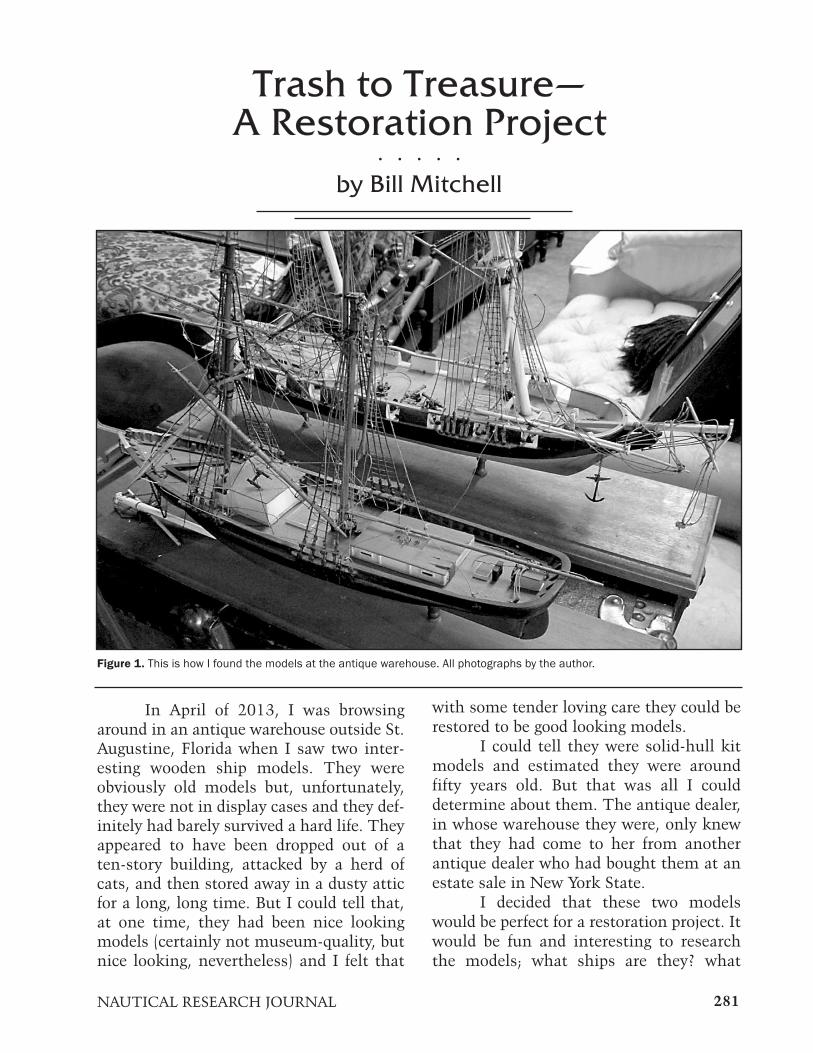
281NAUTICAL RESEARCH JOURNAL
In April of 2013, I was browsingaround in an antique warehouse outside St.Augustine, Florida when I saw two inter-esting wooden ship models. They wereobviously old models but, unfortunately,they were not in display cases and they def-initely had barely survived a hard life. Theyappeared to have been dropped out of aten-story building, attacked by a herd ofcats, and then stored away in a dusty atticfor a long, long time. But I could tell that,at one time, they had been nice lookingmodels (certainly not museum-quality, butnice looking, nevertheless) and I felt that
with some tender loving care they could berestored to be good looking models.
I could tell they were solid-hull kitmodels and estimated they were aroundfifty years old. But that was all I coulddetermine about them. The antique dealer,in whose warehouse they were, only knewthat they had come to her from anotherantique dealer who had bought them at anestate sale in New York State.
I decided that these two modelswould be perfect for a restoration project. Itwould be fun and interesting to researchthe models; what ships are they? what
Trash to Treasure—A Restoration Project
. . . . .
by Bill Mitchell
Figure 1. This is how I found the models at the antique warehouse. All photographs by the author.

282 Vol. 59, No 4 WINTER 2014
company made the kits? when were theybuilt? who built them? Even if I could notfind the answers to those questions, I felt Icould still restore them to be nice lookingmodels, because I could tell they weremade of quality materials and must havelooked really good when they were firstbuilt. And, I rationalized that if all elsefailed, their parts were worth more thanwhat the models cost.
I purchased the two models and putthem in the back seat of my car to bringthem home. I did not have to worry aboutprotecting them in the car because I cer-tainly could not make their condition anyworse than it already was. After unloadingthem at home, I took a much closer look atwhat I had to work with and determinedthat, although there were a lot of broken
parts, peeling paint and detached pieces,both models were pretty much complete.Since I did not know what ships they were,I designated the lower model in Figure 1 asModel #1 and the other as Model #2.
The next thing I wanted to do wasfind out what ships these were so I couldstart researching specific documentationand materials that might be available fortheir restoration. By searching around onthe internet, I was able to determine thatModel #1 was Newsboy, a merchant shipfrom the 1850s, but I could not figure outwhat the other ship was.
I am a member of a maritime modelclub that meets in Beaufort, NorthCarolina and I decided to take the shipswith me to the next meeting. I could pres-ent them to the club members during
Figure 2. Model #1 showing the damaged bow.

NAUTICAL RESEARCH JOURNAL 283
“show and tell” and, hopefully, one of themcould help me identify Model #2. And thatis exactly what happened—as soon as theclub president, John Tilley, saw it, he said,“Oh, that’s the Roger B. Taney, a U.S.Revenue Cutter.”
So with both ships now identified, Igathered as much information and docu-mentation about them as I could. Bothmodels were produced by Model Shipwaysin the 1950s. The Newsboy kit has sincebeen updated and reissued along with
redrawn plans, but the model I had wasone of the originals from the 1950s. One ofthe validating documents I found whilescanning the internet was a ModelShipways catalog from 1952 that illustrat-ed both models for sale; the Newsboy kitfor $15.25 and the Taney kit for $12.50.The catalog pictures of the completed mod-els were very helpful.
After feeling that I had gathered allthe information I could about the models, Ineeded to decide how I wanted the restored
Figure 3. Model #2 showing a damaged mast with peeling paint.

284 Vol. 59, No 3 AUTUMN 2014
models to look. My options were:
• completely disassemble the models andrebuild them so they looked new.• use my own judgment and “artisticlicense” to make the models look the way Ithink they would look the best.• restore the models to look exactly theway they did when they were initially com-pleted by the original builder.
I decided on option (c) because I feltthat, if they were going to be resurrected,they should be returned to their originalstate. I thought this would somehow pleasethe original builder because I did feel badlyfor him—whoever he was. I know what hewent through to build the models, andwhat he would feel like if he could see whathad happened to them after investing so
much time and creativity into his work.It appeared that the restoration
effort required for each model would beabout the same, so I opted to restoreNewsboy first because I had more docu-mentation to refer to than for Taney.
The following information describesthe process I went through for this restora-tion project. It is not intended as a step-by-step manual for how a restoration shouldbe done, but more a description of how Irestored these two models, challenges thatI encountered, and decisions I had to makealong the way.
The first step in any restorationprocess is to take pictures of the model—many, many pictures. Even when youthink you have all that you could possiblyneed, take a few more. There will always besome little nook, cranny or view for which
Figure 4. Some of the parts removed from Newsboy..

285NAUTICAL RESEARCH JOURNAL
you will later wish you had a better shot.Both models were covered with dust.
To remove the dust, after first blowing withall my might, I used water-moistenedcloths and then water-moistened cottonswabs to clean everything.
A determination of how much of themodel needs to be disassembled in order toclean, re-paint or re-stain the parts needsto be made. In some cases that is alreadypartially determined for you, because theparts are already broken off or otherwiseseparated from the model. The more partsthat can be kept together, the better—itmeans less work and there is less chance ofgetting parts mixed or out of position.
As each part was removed from amodel, I labeled it using a strip of paperattached to the piece with Scotch Tape. Inaddition to noting where the piece camefrom, the labels contained informationsuch as whether it came from the port orstarboard side (since some pieces seem
identical except for that location) and howthey had been attached. One wonderfulthing that I discovered during disassemblywas that super glue had not been used! Themodels were built before super glue cameinto common use for model shipbuilding. Ihad to pry some parts loose, but mostcould be separated by hand twisting andpulling and none were damaged during sep-aration.
In keeping with my goal of option(c), I used as many of the original parts as Ipossibly could. A few missing parts had tobe made or replaced by manufactured parts.
Everything was either re-painted orre-stained with the original colors. Nothingwas painted a color different from what ithad originally been painted. And althoughI re-painted and re-stained practicallyeverything on the models, I tried not tooverdo it—I wanted whatever patina exist-ed to remain. I did not want the finishedproducts to look like newly-made models—
Figure 5. Taney stripped and ready for reconstruction.

286 Vol. 59, No 4 WINTER 2014
I wanted them to look like old models thathad been restored.
Waterlines were re-drawn since theoriginals needed a little re-definition (thatis; straightening).
No lettering (for example, ship’sname), flags or other accessories wereapplied because none had existed on themodels originally and, again, I wanted thefinished products to look the way they didwhen they were originally built.
Even though the rigging was old, itwas in good shape. I re-waxed and reusedas much of it as I could. I had to cut someof the lines in order to remove masts orspars, so I replaced any cut lines or originallines that were unstable with new lines.
Any new lines I used were chosen to matchthe original lines in size, color and texture.
I removed all masts and remainingportions of the bowsprits that were notalready broken off. In removing the masts,I kept the shrouds and ratlines attached tothe mast—I certainly did not want to re-rigthe ratlines if I could help it. To detach theshrouds, I cut the lines between the pairsof deadeyes along the channels. During re-assembly, I was able to just replace thoselines and draw the shrouds taut—I mostlikely would have had to do this anyhow,even if I had not removed the masts.
While the masts were detached, asmuch work as possible was done on thembefore they were re-attached. As much of
Figure 6. Finished Newsboy.

287NAUTICAL RESEARCH JOURNAL
the old, peeling paint as possible wasscraped or sanded off and the previouslypainted areas were re-painted. Previouslystained areas were re-stained with match-ing stain. Any tightening up or re-gluing ofyards, jackstays, footropes, and so on wasdone.
The original modeler had done anexcellent job of tying off the lines on thebelaying pins. Actually, the lines had beenjust tied on but covered over with separate‘figure-eight’ loops of line to make it appearthat one long length of line had been used.So when I needed to remove the lines fromthe belaying pins, I was able just to pull thebelaying pins out of the pin rails, separatethe ‘figure-eight’ loops, and then re-usethem when I re-attached the lines.
Several masts and spars had beencompletely snapped in half. Whenever Ineeded to re-join two parts of a mast or
spar, I hand-drilled a small hole into eachof the ends that needed to be re-joined. Alength of brass rod was then super-gluedinto the hole in each end as the two endswere pushed back together. In oneinstance, the repair line was still visibleafter the two pieces had been re-joined.Fortunately, this was at a point where amast band appeared appropriate, so I addedone to cover the repair line.
The decks of both models had waterstains (I said they were in rough shape). Ilightly sanded the decks but could notremove the water stains without really dig-ging into the decking or replacing it. Since Idid not want to do either, the water stainsare still lightly visible but I rationalize thatthis provides ‘character ’ and is clear evi-dence that this is a restored model—not anew one.
I made one exception to using as
Figure 7. Finished Taney.

288 Vol. 59, No 4 WINTER 2014
many original parts as possible. Severallarge eyebolts were replaced with smallerones. I assume the original eyebolts werewhat was available at the time the modelwas originally built but they were way toomuch out of scale for me to live with.
Pertaining only to the Taney model,the port top rail (two long strips of wood)was very warped. It was removed, soakedin water, then pressed overnight betweentwo boards, and this straightened them outjust fine. In keeping with the mantra ofoption (c), although there were some areasthat were not technically accurate onTaney, I did not try to change or improvethem. As examples, the one-piece cannon,carriages and trucks were originally paint-ed all black, so I re-painted them all black.
There was no cannon rigging so I did notadd any. The gunports are oversized andthere are no gunport lids but I did notchange either of those.
Both stands were lightly sanded andre-stained. The brass pedestals were pol-ished and covered with a layer ofpolyurethane varnish to prevent future tar-nishing.
The restoration project took aboutseven months and, now that the modelsare restored, I am building display cases forthem—I do not want them to revert totheir previous state. And my next projectwill be trying to convince my wife thatthere must be somewhere in our housewhere they could be displayed.
Figure 8. And finally, both finished models together.

289NAUTICAL RESEARCH JOURNAL
HMS Ardent: A King’s Ship, ButWhich King?
. . . . .by Ron Neilson
The Historical Perspective
HMS Ardent was a 64-gun, third-rate ship-of-the-line of the Royal Navy,launched on August 13, 1764. The warshipwas built under contract at Hull, Englandaccording to the plans of Royal Navy archi-tect, Sir Thomas Slade. Ordered nearlythree years earlier, in December 1761,Ardent was one of Slade’s lesser known
nautical design achievement; for periodsailing ship modelers he is most famous forhis design of HMS Victory.
Slade also designed Ardent’s progen-itor, Asia, the first true 64-gun warship.The Royal Navy abandoned earlier 60-gunships and commissioned additional 64’sthat incorporated alterations learned fromtrials with Asia. Subsequent ships werelarger; the first of the new 64’s being
Figure 1. Starboard view, full broadside. The model is 54 inches long. All photographs by the author.

290 Vol. 59, No 4 WINTER 2014
Ardent, the lead ship of its class.Slade’s Ardent Class used the lines
of a captured French 64-gun ship, LeFougueux, a prize taken in 1747. Ardentwas built to incorporate important ele-ments of the French ship’s design, particu-larly the increased tumblehome of the hull.As the weight and total number of arma-ments escalated during the mid-eighteenth-century, so did the need to pay closerattention to a warship’s center of gravityvis-à-vis its sailing qualities.
The renowned English frigate,Indefatigible, also built to the identical 64-gun plans as Ardent, was not launcheduntil twenty years later in 1784. Slade’ssuccessful design was revived in 1777 forfive further Ardent-class ships:Raisonnable, Agamemnon, Stately,Belliqueux, and Nassau, for a total of sevenships built to his plans. Slade himself haddied six years earlier, in 1771. The basicArdent-class specifications were:
Length on keel: 144 feetBeam: 44 feet 6 inchesDisplacement: 1,376 tonsCrew complement: 500Armament upon commissioning:Main gun deck: twenty-six 24-poundersUpper gun deck: twenty-six 18-poundersQuarterdeck: ten 4-poundersForecastle: two 9-pounders
Ship and armaments technology wasescalating rapidly by the 1780s. As a conse-quence, the mid-century 64-gun third rateswere underpowered to stand in the line.Additionally, most captains preferredsmaller, faster ships (including the razéefrigates cut-down from 64’s) over the “oldschool 64” that was much too slow and dif-ficult to maneuver against the faster war-ships of England’s adversaries. The frigatewas fast becoming a marauder of choice for
Figure 2. The starboard stern view.

291NAUTICAL RESEARCH JOURNAL
many types of naval engagements.As noted, the 64 had become an
underpowered warship and 74-gun capitalships had taken their place as the preferredthird rate ships-of-the-line. The 74’s (andmany frigates) could throw a heavierweight of ordnance than the outmoded 64.The technological development and rapiddeployment of the carronade—a devastat-ing, close-range naval weapon—quicklytipped the scales in favor of the fast frigateand the 74’s as fleet “staples.” Increasingly,close-action battles, “cutting out” boardingactions and prize captures favored this newarmament technology, too, as resources forboth shipbuilding and manning the RoyalNavy were being depleted rapidly.
By the close of the eighteenth century,third rate 64’s consequently served otherimportant roles, such as deployment oncolonial expeditions and blockading duty.Indeed, by the beginning of the NapoleonicWars in 1803, the notional total number ofships-of-the-line in seagoing condition wasapproximately one hundred and eleven,according to noted British naval historian,Brian Lavery. Of this total, there were noless than thirty-eight commissioned 64’sstill in service in the Royal Navy. The 64’swere particularly well suited for intimida-tion, especially in far-flung colonial ports.They helped immensely in warding offpesky privateers. They also became a rou-
tine military escort ship for convoys,accompanying the Indiamen of the lucra-tive East India Company.
Ardent had a somewhat tumultuouscareer. The ship was captured by theFrench in 1779 in the English Channel andthen re-captured by Britain in April 1782 atthe Battle of the Saintes in the West Indies.My research was unable to uncoverArdent’s service background for its first tenyears of life; the period from its launchingin 1764 to 1774 remains a mystery. Theonly known fact from this period is thatArdent was one of the first 64-gun shipsput into commission as a consequence ofconflicts with Spain over possession of theFalkland Islands.
We do know that Ardent wasdeployed to the North American station,based at Halifax, Nova Scotia, in October1774 under Captain Sir George Douglas.This appears to be the first record of itsservice. In 1778, under the command ofCaptain George Keppel, Ardent was postedto Admiral Lord Howe’s squadron off NewYork, defending the British colonial cityfrom a larger French fleet attack under thecommand of Admiral le Comte d’Estaing.The two forces engaged in battle off RhodeIsland on August 11, 1778, though bothfleets were scattered by a storm over thefollowing two days. Ardent returned hometo Portsmouth, England and was paid off in
Figure 3. The starboard bow view. Figure 4. The forecastle and partial bow. Anchors areshipped and chained for action.

292 Vol. 59, No 4 WINTER 2014
January 1779.Six months later, in June 1779, fol-
lowing storm repairs, Ardent was quicklyre-commissioned under the command ofCaptain Phillip Boteler, sailing fromPlymouth to join Sir Charles Hardy in theEnglish Channel by August. NeitherBoteler nor the captain of Marlborough(74), in whose company Ardent was sail-ing, were aware that a French fleet had putto sea. Ardent encountered this enemy fleetonly two days after sailing into theChannel. After receiving correct replies tocoded signals, the two English capital shipsran down to meet the others they assumedwere also English. The fleet they encoun-tered was, in fact, a combined Franco-Spanish fleet, in possession of the RoyalNavy signal codebook that permitted thedeception; a correct response to Ardent’s“who are you?” signals.
With Ardent within range, the
French frigate Junon fired two broadsidesbefore raising the colors to reveal its trueallegiance. Three further French frigates,and the Spanish ship of the line, Princesa,joined the action shortly afterward. Inresponse, Ardent offered sporadic and inac-curate return fire before striking its colorsto the vastly superior enemy force. HMSMarlborough escaped unscathed and beat acourse back to England.
At his subsequent court martial,Captain Boteler blamed his failure toreturn fire on an inadequate supply of gun-powder for Ardent’s cannons, a statementstrongly denied by the ship’s gunner, whopresented evidence there was enough pow-der for fifty minutes of vigorous engage-ment. The court martial rejected Boteler ’sclaims, finding instead that the inexperi-ence of the crew was the principal cause ofArdent’s failure to respond to the attack.According to ship’s logs, in 1779 as much
Figure 5. Midships and fore chains. One can see the belfry and galley stack.

293NAUTICAL RESEARCH JOURNAL
as eighty percent of Ardent’s crew com-prised pressed landsmen. Boteler was dis-missed from the Navy for his failureadequately to defend his ship.
Little is known of Ardent’s careerwhile flying the flag of Bourbon Francebefore the English re-captured the ship lessthan three years later, on April 12, 1782, atthe Battle of the Saintes, a large navalaction in the West Indies that took placeover four days, April 9 – 12, during theAmerican War of Independence. It was adecisive victory for the British fleet underAdmiral Sir George Rodney over the Frenchled by Admiral Comte de Grasse; the out-come forced the French and Spanish toabandon a planned invasion of Jamaica, aBritish stronghold. The battle is namedafter a small group of islands betweenGuadeloupe and Dominica in the WestIndies. Ironically, the French fleet was thevery same that, several months earlier, hadblockaded the British army, facilitating
George Washington’s victory overLieutenant General William Cornwallis atthe siege of Yorktown.
The following lines of poetry salut-ing the English victory at the Saintes areattributed to Charles Cornwallis, captain ofHMS Canada at the battle. He was thebrother of the same William Cornwalliswho surrendered to Washington atYorktown on October 19, 1781.
de Grasse in his flagship, crowded bynine,Strikes Ville de Paris colours o’er thebrine,HMS Barfleur, Hood’s flagship takesthe fame,De Grasse offered his sword, theAd’mril’s shame,Ardent, Glorieux, Hector soon fol-lowed suit,César blew up; a sad final salute,Thus four ships captured, an Ad’mril
Figure 6. Midships; anchors hauled and shipped, pinnace hoisted from the skids.

294 Vol. 59, No 4 WINTER 2014
as well,Rodney’s fame and fortune made;tales to tell,His dogged tenacity in pursuit,Showered forth prize money,Vict’ry’sfair loot.
Following its recapture, Ardent wasrecommissioned under Captain RichardLucas. On August 28, 1783, the ship wasrenamed Tiger. It was sold out of service inJune, 1784.
The Model: The Best of Kit and Scratch
For my build of Ardent, I drew inspi-ration from visits to the National MaritimeMuseum in London and the MaritimeHistory Museum in Sweden during thesummer of 2013. Added to this was mydesire to challenge my modeling skills andknowledge by taking a readily available,good quality ship kit to a higher level;much higher. My work proceeded over aperiod of approximately eight months fromthe fall of 2013 to the spring of 2014. Iestimate that I put in approximately 900hours into my project.
My model of Ardent is a hybrid, aquite substantial kit-bash that began witha Caldercraft Agamemnon kit’s plank-on-bulkhead keelformer and bulkheads. Thekit is to 1:64 scale, my personal favorite.
I used the kit’s quite well-docu-mented full-scale plans to extensively mod-ify and, in most circumstances,scratch-build the balance of the ship’swood components, which included all theplanking, deck furniture, and bow andstern components. All non-visible skeletalwood—bulwarks framing, deck beams,hanging knees amidships, and the like—was basswood, while the principal hullplanking was crafted from Swiss pear that Ipurchased in precision-milled wood strips
and multiple-thickness sheets fromHobbyMill USA. Throughout the project Iworked in metric units of measurement,which I find easier.
For both aesthetic and practical rea-sons, I chose to employ thin walnut stripwood for the planking below the main waledown to the waterline. The painted blackwale itself was made from pear strips. Ifound it unnecessary to spile or employtedious bending techniques for the visibleplanked area of the hull. Neither stealersnor drop planks were required at eitherbow or stern, partially owing to the verythin (0.020-inch) walnut strips I used toform the severe tucks at the stem and atthe transom line. Beneath the ship’s fullwaterline-to-keel coppering is a single layerof basswood planking. Although the kitprovided for a customary European double-planked plank-on-bulkhead approach, Ifound this was not necessary. With properbeveling of bulkheads, adding a carved rab-bet and a nicely tapered bearding line, asingle run of basswood strips yielded asmooth, graceful shape to skin the ship’sstructure. The false keel, attached to thebottom of the basswood keelformer, wasmade from boxwood strip. HobbyMill USAalso supplied all the model’s boxwood, wal-nut and cherry.
On almost every plank-on-bulkheadmodel I have built, I have used balsa fillerblocks at the bow and stern. Ardent was noexception. Getting these added scratch-made filler pieces properly shaped andplaced contributed immensely to makingone of the most difficult aspects of plankingthe stem and stern plank tucks a little eas-ier to do with any plank-on-bulkhead -stylebuild.
I used the copper plates providedwith the kit to complete the hull’s exterior.The tedious and fiddly process took a fulltwo week’s work and required 2,300 of thethin copper plates. Once finished, I used acommercial-grade etching solution to

295NAUTICAL RESEARCH JOURNAL
accelerate the aging of the shiny plateletsso they would present a desirable brown-hued patina that over time will continue tolook even more attractive. Following someexperimentation with my aging solution’sdilution proportions and after cleaning thecopper free of residual glue and finger oils, I
simply brushed the solution on with a ½-inch-wide brush and had plenty of wipingrags nearby.
Typically, I finish the woods on mymodels with a natural oil-based stain. Onmost components, I use it full-strength,right out of the can. This was the case for
Figure 8. The lower yard chain slings and platform swivel guns hauled up to the fighting tops.
Figure 7. Quarter and poop deck towards the stern. The ship’s wheel and binnacle was tucked under the foremost supportbeam for the poop deck, just ahead of the officer’s movable bulkheads.

the majority of the visible woods forArdent. However, I also used mixtures ofacrylic paints on some wood pieces where Ihad to match the colors of the paintedpewter or photo-etched brass decorativecomponents so they would better blendvisually against the tone of the adjacentpear planking. For example, on the stem, Icolored the pear headrails and carvings tomatch the lion figurehead and decorativetrailboard castings provided in the kit.
I used a multi-color, layered paintingtechnique to make both the cast pewterand brass pieces provided in a kit lookmore like wood carvings. This was espe-cially important in the stern area. I usedprimary paint colors, as well as metallicgold leaf color, very sparingly. Gold (andany hue of red) does tweak the retina, so-to-speak. I used my preferred dark-huedcrimson red acrylic for the inner bul-warks—gun deck and quarterdeck—theedges (only) of all gunport lids and portopenings, the background for King GeorgeIII’s cameo profile and, rather profusely, onthe officers’ pinnace.
I used a black acrylic (typically, twoor three coats) on the main wale and allother areas that were painted (flat) black oneighteenth-century warships: yards, tops,timbers, cap rails, lower stem area, and soon. I always use non-reflective flat acrylicpaints. Once dry, the black-painted woodwas given a thin coat of Minwax Wipe-Onpolyurethane finish to it a subtle sheen.
In keeping with my understandingof color painting standards for the eigh-teenth-century English capital warships, Ipainted all the outer planks of the gunports in black too. Warships of the eraloved to advertise their potency; the moregun ports spotted by a lookout or visible inthe watch officer ’s telescope, the better. Toscare-off pirates, merchant ships oftendeployed a canvas disguise that draped overthe sides of their ships upon which were
296 Vol. 59, No 4 WINTER 2014
painted black false gun ports.A careful study of the ship’s plans
while gearing-up for the build led me to adecision to construct the model’s bulwarksfrom scratch; this allowed me to frame allthe ship’s gun ports more accurately whilealso yielding a thin, and scale-accurate,cross section to all the ship’s bulwarks. Ihave learned from past experience that thisarea of a kit build can be especially prob-lematic; bulwarks (especially those withsignificant tumblehome) can be challeng-ing to execute properly; it is frustrating torealize too late that a series of small butcumulative building errors in this criticalarea can result in a quite irregular sheerline from stem to stern. Rather than usinga paper template to locate and drill holesarbitrarily through planked sides thatwould have been built much too thickly, Ichose to build up the extensive bulwarkframing so that, when the interior andexterior planking was applied I had a quitereasonable replication of the actual full-sizebuilding practice, with sills, lintels and ver-ticals. As well as much better looking top-sides symmetry, a much stronger overallconstruction resulted from this worthwhileeffort.
This is a good time to mention that,mid-way through my build, I acquired anexcellent reproduction print of Ardent’soriginal 1761 plans from the NationalMaritime museum (to 1:48 scale and 84inches long). I used this document exten-sively to compare with the kit’s hull andsheer lines, and also for a multitude ofother hull construction details. This printwill be suitably framed and displayedbehind my completed model. This sameoriginal plan was used to build Ardent’s sixsiblings in later years—includingAgamemnon and even the razée frigateIndefatigible two decades after Ardent’slaunch in 1764.

297NAUTICAL RESEARCH JOURNAL
At The Bow: Of Hawse Bucklers,
Gripes and Cant Washes
In the stem and beakhead area Iused various thicknesses of pear and box-wood for scratch-building the beakheaditself, all headrail, cheeks and hawse pieces,timbers, roundhouses, seats of ease, cat-heads, bumpkins and other decorativewood elements. The lion figurehead how-ever, was a pewter casting I purchased froman Italian manufacturer.
After doing some research in JamesLees’s and Brian Lavery’s tomes, I decidedto add hawse bucklers (basically, removablehole plugs) to the normally open anchorhawse holes. Because I was attempting toshow my model in an action-ready configu-ration, it made sense to secure the anchorsto frame timbers (with chains) and close up
Figure 9. The mass of rigging.
the large anchor cable openings at the bow.Hawse bucklers had a mechanism thatwould permit a sailor (inside or topside) topull a chain and quickly open them toready the anchor cables.
Additionally, I added a layer of pro-tection to the leading edge of the stem’scutwater; this was called a gripe. The gripewas made from a sheet of lead. It protectedthe stem from several sea-going hazards,especially during action when all mannerof debris could hit and foul the stem area.
Another important detail rarelyshown on contemporary models of this erais the cant wash. This angled piece, locat-ed just below the lowest cheeks on thestem, helped to minimize the intake of sea-water through the hawse holes and alsoenhanced the stem’s thrusting action inrough seas.
I took creative license and sourcedsome attractive, micro-thin green abalone(mother-of-pearl shell), cut small pieces,

298 Vol. 59, No 4 WINTER 2014
and affixed them to the fronts and rears ofboth catheads and the headrail supporttimbers, starboard and port. I highly doubtthis embellishment was added in full-sizeshipbuilding practice. but I liked the resulton my model, particularly after seeing asimilar treatment on more than one his-toric model at the National MaritimeMuseum.
Stern Details
All the wood components of thestern were scratch built from pear: mainstern facings, transom, galleries, rails, anddecorative moldings. I used the kit’s galleryrailings, balustrades, columns, and finishpieces—virtually all of the kit’s decorativepewter pieces (which were quite nicelycast). In addition, I included a small hand-ful of decorative carvings (brass photo-etched items) from other kits that wereleftovers from previous builds.
The kit provided three sternlanterns but I decided to mount only two,purely for aesthetic reasons. My engineer-ing-oriented, historical accuracy sensibili-ties are continuously doing battle with myartistic ones. On balance, I lean toward artbecause, at the end of the day, I believethat, as a modeler—and not an engineer orcontract builder pitching a project to anAdmiralty Board—the properly propor-tioned, visually-attractive ship modelshould be an objet d’art.
In addition to rudder chains, I creat-ed emergency fall lines seized to the endsof the chains and tied them off to cleats onthe poop deck. It was a good thing to beable to quickly retrieve an unshipped rud-der, particularly during a battle!
Some may notice the canvas bootsurrounding the rudder where it passesthrough the transom. This is a very impor-tant detail that I have rarely seen on con-temporary sailing model warships. A lot ofwater passes across and around the stern,
not to mention what happens in a follow-ing sea. Without a well-sealed rudder boot,a ship’s captain would be taking non-stopbaths from seawater spouting up andthrough his stern cabin’s rudder trunk.
Last, but not least, there wasArdent’s badge. Most likely it would havebeen painted in 1764; I chose to affixphoto-etched brass letters in a creme colorthat matched that of the stern and quartergalleries mullions. I like the appearance ofraised typography, the precise letters cast-ing a slight shadow on the transom’s wood.
The Masts and Rigging
I crafted all masts and yards fromsquare stock boxwood. I followed the eigh-teenth-century conventions described byJames Lees and gleaned modeling tech-niques from David Antscherl’s excellentSwan series. I made all other wooden rig-ging components from pear (all channels,bees, bibs, fids, mastcaps, crosstrees,planked tops, hounds, mastheads).
I used a combination of kit-suppliedphoto-etched brass pieces and variousscratch built items to create the yard stir-rups, boom irons, straps, and platform railstanchions for all the tops. Although I usedthe kit’s deadeyes for all shrouds, I exclu-sively used pear blocks in several sizesfrom Syren Ship Model Company for allthe rigging, which was based on Lees’s rig-ging plans for third rate vessels. All of therope on the model also came from SyrenShip Models. I used ten different sizes forboth the standing and running rigging.
Concerning rope, I chose to usedark brown rather than black for all stand-ing rigging (this is particularly evident withthe wouldings on all the lower masts,including the bowsprit). I was fortunatethat this more accurate color rope wasmade available just a few weeks before Ineeded it. Created from three strands ofhigh-quality cotton linen, I found Syren

299NAUTICAL RESEARCH JOURNAL
rope, in all sizes, consistently to be of highquality. Because this genuine rope is virtu-ally fuzz-free it was unnecessary to use abeeswax coating. The Syren rope made thevery fiddly detail work of making the morethan one hundred coiled rope hanks toposition on pins and other rigging belayingpoints much easier. The sheer volume ofrope visible on a square-rigged eighteenth-century warship means that their colorsand size fidelity are critical aspects for anaccurate portrayal of the real thing.
While working on Ardent’s rigging,my research revealed that the Royal Navyused lighter, more efficient blocks on theirships from the 1790s onward. This advan-tage reduced the total weight of the blocksand cordage, so their ships had consider-ably less top hamper than equivalentFrench vessels. Often overlooked, a numberof these small but significant riggingimprovements gave the Royal Navy a tech-nological advantage over their adversaries.
Figure 10. Hawse bucklers, the gripe, the cant wash and mother-of-pearl embellishments.
After more research regarding a war-ship’s preparations for action, I decided torig iron chain slings for the two lower yards(fore and mainmast). These chains provid-ed additional insurance against cripplingdamage in this sensitive area of the riggingfrom direct hits by an enemy’s gunners.The iron chain slings were either usedalone, or in combination with heavy rope,to support the weight of the spars.
The Cannon and the Fighting Tops:64 + 8 Still Equals 64!
Sixty-four turned brass cannon weresupplied in the kit and I finished themwith the chemical solution BiOx312 fromElectrochemical Products, Inc. A full soak-ing in this solution for only a few minutesimparts an attractive, low luster, darkishgrey pewter-like look; the result makesbrass appear aged after drying and burnish-

300 Vol. 59, No 4 WINTER 2014
ing. A simple rag was used to rub each can-non after five to seven minutes of soaking.Nothing more was done to finish the can-non barrels. To my eye, results of thischemical aging technique look superior tosimply painting cast or turned cannon flatblack—or using the ubiquitous “Blacken-It” chemical.
In keeping with my decision todepict the ship ready for action whenever Icould, I mounted four turned brass swivelguns to each of the fore and main fightingtops. The mini-cannons were finishedusing the same BiOx312. The support stir-rups were fashioned from brass rod and flatstock.
Hammock Cranes For 500 – More “BiOx”
I used the kit’s supplied photo-etched brass—hammock cranes, quartergallery lights, ship’s wheel—and some ofthe pewter castings (mostly for the stern).Specifically, I also used the same BiOxsolution described above on all hammockcranes to match the antiqued look achievedon the brass cannon barrels.
Modelers have known about tullefabric—a finely knit synthetic fabric that isused in women’s fashion, especially bridalveils. I was fortunate to locate tulle in a
Figure 11. Midships quarterdeck close up.

301NAUTICAL RESEARCH JOURNAL
ing. Asimple rag
Figure 12. The stern with French Bourbon ensign beneath the Union Jack.

302 Vol. 59, No 4 WINTER 2014
light brown color and I used it to make theship’s extensive hammock netting. Tullewas also used to fabricate the safety nettingon the aft sides of the fighting tops and onthe forward headrails near the heads. In allinstances I tied off small attachment ropesto the hammock and safety nettings inaddition to using Allene’s fabric glue—astaple for securing rigging.
The Plinth and the Pegasus
To display my completed model Iwanted something that was, in itself, acomplementary work of art. Fancy, but notover-the-top. I am fortunate to have hadseveral opportunities to view numeroushistoric models in world-class maritimemuseums and paid close attention to thematerials and methods used to displaythem.
For HMS Ardent, I decided to designmy own plinth; a slightly elevated plat-
form. The plinth’s complex routed profilewas made from six-quarter cherry. Thebaseboard within the cherry rails is half-inch Baltic birch plywood covered with aglossy paper print of Aegean marble. I cre-ated a high-resolution digital photographicfile of real marble and generated a docu-ment large enough to cover the entire base-board. By substituting a mounted printover the plywood base for the real thing,the large baseboard was a tiny fraction ofthe weight had I employed genuine marble(not to mention a small fraction of thecost!). The cherry rails were stained natu-ral and then given three coats of semi-glossMinWax Wipe-On polyurethane finish.The “French provincial profiled” cherryrails had their inner perimeter edges insetwith 1/16-inch-thick polished brass. Thiswas done to achieve a visual accent to thedarker marble base piece and separate itslightly from the lighter cherry rails.
Four serpent-tailed Pegasus cast
Figure 13. You can judge a ship by its boats. Here, the officers’ 32-foot pinnace is hauled up. A protective web of overheadrope netting was spread across the skids to protect the gun crews from falling overhead objects—and to hinder potentialenemy boarding actions. Sharp weapons—like cutlasses and pikes—were at the ready and could thrust up through the netting.

303NAUTICAL RESEARCH JOURNAL
Figure 14. The bow of the National Maritime Museum print from the 1761 Ardent-class original plans. Seven 64-gun thirdrates in total were built to these plans.

304 Vol. 59, No 4 WINTER 2014
brass pedestals support the model. Iacquired these from a modeling colleagueand fashioned the keel support mountingblocks below them. I believe thesepedestals still can be purchased fromEuropean model ship resellers. Oncesecured to Ardent’s Aegean marble base-board, the equine pedestals hold the modelquite securely.
Flags: A Tricolor Becomes a Bourbon Surmounted
by the Union Jack.
Early on in my model’s “life,” I haddecided to show it recaptured by theEnglish as a result of the Battle of theSaintes, with the Union Jack flying proud-ly above the French Tricolor. Only afterposting some preliminary photographs ofmy Ardent on the Internet forum, ModelShip World, did I discover that I had hoist-ed the wrong French flag at the stern. Anexpatriate Englishman living in Swedenpointed out to me, via the forum, that thecorrect French naval ensign of 1782 wouldhave been a variation of the plain vanilla-white, fleur de Lis-checkered Bourbon flagof Louis XVI. I immediately went back tothe Internet for flag research and, subse-quently, to my computer drawing board. Iprinted out the correct French flag (onpaper) and crafted its folds to replace theNapoleon-era tricolor that fluttered overthe nation’s ships several years later, fol-lowing the French Revolution.
C’est La Guerre!
AcknowledgementsCaldercraftAgamemnon kit, from the manufacturer ’s“Nelson’s Navy” range.
Model Ship World Forum www.modelship-world.com
National Maritime Museum, Greenwich,England
Swedish Maritime Museum (Sjøhistoriskamuseet) Stockholm, Sweden
SourcesAntscherl, David, Rigging A Sixth Rate
Sloop of 1767-1780. (Florence, Oregon:
SeaWatchBooks, 2010).
Lavery, Brain, The Arming & Fitting ofEnglish Ships of War 1600-1815.(Annapolis: Naval Institute Press, 1987).
——-Nelson’s Navy. (Annapolis: NavalInstitute Press, 1989).
——-Empire of The Seas. (London: ConwayMaritime Press, 2009).
James Lees, The Masting & Rigging ofEnglish Ships of War, 1625-1860.(Annapolis: Naval Institute Press, 1984).
Darcy Lever, Darcy, The Young SeaOfficer’s Sheet Anchor. (New York: DoverPublications, 1998).
Rodgers, N.A.M., Command of the Ocean:A Naval History of Britain 1649-1815.(New York: W.W. Norton & Company,2006).
Winfield, Rif, British Warships in the Age ofSail, 1714-1792 Design, Construction,Careers & Fates. (Barnsley: SeaforthPublishing, 2005).
Electrochemical Products, Inc.Industrial Chemicals Manufacturerwww.epi.com
HobbyMillCustom Wood Millingwww.hobbymillusa.com
Syren Ship Model Company

305NAUTICAL RESEARCH JOURNAL
This ten-foot dinghy was specifical-ly designed as a tender or powered pushboat to aid in maneuvering a forty-footschooner without setting its sails. Theschooner had no engine. The dinghy wasalso fitted with a sailing rig, oars, and atransom mounted 9 horsepower outboardmotor. When it was lashed alongside thelarger hull, with the motor set at full throt-tle, sufficient way was gained to maneuverthe schooner in a crowded harbor.
The model is a 1:16 scale represen-tation. The method used to build themodel required a wooden plug carvedsmaller than the lines to compensate foradding the ribs and the thickness of theplanking and marked with the locations ofthe ribs and keel. The piece cut off the topof the wooden hull block when shaping thesheer was retained, creating a flat-surfacedfiller to mount between the hull plug and
the plywood base. The ¼-inch thick ply-wood base was pierced with holes slightlysmaller than the cross-section of the ribsto hold the ends in place after they werebent around the hull plug. (Figure 1) Ablock was made up to attach beneath theplywood base in order to mount the assem-bly in a vice during construction, and allfour pieces screwed together.
The solid wood transom wasscrewed to the wood hull plug. The outershape of the transom later was trimmedafter the ribs were in place and faired withthe rib shape for applying planks. A lengthof lead solder was bent along the hull cen-terline to create an accurate pattern forforming the keel and stem shape. The sol-der retained its shape after it was removed,so its shape could be traced accurately ontoa piece of paper as a pattern. (This methodcould be very useful for taking off curvesinside a hull when fitting ribs, bulkheads,or interior cabinet work.) The keel waswidened amidships to accommodate a slotfor the daggerboard. The keel also was
A Traditional 10-footWooden Dinghy Model
. . . . .by Byron Rosenbaum
Figure 1. The jig components. All images by the author. Figure 2. The jig mounted in a vice with the transom, keel and stem in posi-tion.

and stem assembly first was removed andreplaced after the ribs were inserted. Theribs and transom then were trimmed andfaired to receive the planking. (Figure 3)Notice the wax paper strip running fulllength under the keel and stem to preventglue from adhering the framing to the hullplug. Also, note how the keel was cut forthe daggerboard slot, and side pieces addedand faired to reduce drag around the void.
The hull has ten planks per side.Figure 4 shows the pattern for a typicalplank shape. Patterns were created by tak-ing measurements along each rib stationlocation from sheer to keel, divided by 10,and marking them straddling a centerlinebase line. To allow for the overlap of theclinker planks, 1/16-inch was added alongone long side.
The stock used for planks wasstraight grained pine, ½-inch thick, 8 inch-es long, and 3 ½-inches wide, so that twen-ty planks could be ripped from the width.The pattern was traced onto the timber,aligned on the two opposing sides, then thestock is shaped to the pattern. (Figure 5)
The planks were marked with acommon station location amidships. Ends
306 Vol. 59, No 4 WINTER 2014
notched to align with the riblocations. I cut a notch in thetransom for the keel, andbored another hole in the ply-wood base to hold the top ofthe stem in place. (Figure 2)
The hull was nowrough framed. Ribs were wetbent over the form andpushed through the holes inthe plywood base plate to holdthem in alignment. The keel
Figure 3. The framing.
Figure 5. 1/16-inch thick planks were ripped from thisshaped stock using a miniature bench saw.Figure 4. A plank pattern drawing.

307NAUTICAL RESEARCH JOURNAL
that extended beyond the transom weretrimmed flush after all the planks werelaid. The forward plank ends were trimmed
as required to fit into a rabbet cut on thestem post. Each plank was glued to eachrib, being careful to avoid gluing the frame
Figure 6. Trimming plank bevels.
Figure 7. The basic planked hull removed from the jig.

308 Vol. 59, No 4 WINTER 2014
Figure 8. The mast, boom, gaff, daggerboard, and rudder.

309NAUTICAL RESEARCH JOURNAL
to the wood plug to permit later removal.Rubber bands were used as clamps. Whenthe location required greater pressure toforce the plank home, an extra block ofwood was used under the rubber band.After each plank was secured, the edge wasbeveled to receive the next plank. (Figure 6)
After the last plank was laid, theassembly was lifted off the mold and theinterior fitted out to complete the model.(Figure 7) Mast, boom, gaff, daggerboard,and rudder were made. They were carriedwithin the empty hull, as this model wasintended to show the boat on a trailer onits way to our summer bungalow. (Figure 8)
I built a matching trailer for thedinghy. (Figure 9) The trailer frame wasmade of wood. The axle was from brasstube, springs from brass plate, and thetrailer fittings were fabricated in copperand fastened with scale nuts and bolts. The
keel rollers were turned brass and paintedand the bilge bunks were made from wood.Tires were rubber items. The fenders weremade from bent ice cream sticks with stepsadded at each end. The inner and outershells were 1/8-inch thick pieces glued tothe curved top piece, then sanded to shape.(Figures 10 and 11)
A 1952 Volkswagen Beetle plastickit by Revell was my automobile of choice
Figure 9. The drawing for the custom trailer to carry this 10-foot long dinghy model.
Figure 10. Fender construction.

310 Vol. 59, No 4 WINTER 2014
to pull this rig. It may have been short onpower, and I may have had to down shiftgoing up steep hills, but this was my car in
when I was in Europe in 1952 and 1953, soI have always wanted a model of the ‘52Bug. (Figure 12)
Figure 12. Our ‘52 Beetle in London in 1953 to witness the coronation of Queen Elizabeth.
Figure 11. The finished dinghy on its trailer.

311NAUTICAL RESEARCH JOURNAL
The model requiring miniature rig-ging is a 1:96 scale Gulf Coast Butt HeadScow Schooner following drawings byHoward Chapelle from his book, AmericanSmall Sailing Craft, Their Design,Development, and Construction. The lineswere taken off at Galveston in 1947. It isbeyond my capability to create and reevedeadeyes of this size, so I sought to simu-late them.
This shows my method. The wireused is marked 34 Gauge (0.0063-inch)soft iron from a craft store. The actualmicrometer measurement varies from0.007-inch to 0.009-inch within a coupleof inches along its length. A two-pin jigwas made with nails of appropriate diame-ter. I then extracted them, clipped theheads, deburred the edges, and re-insertedthem in the wood block “fixture.” Thatterm kind of glorifies the doodad, but I amdoing technical writing here.
I wound the wire figures and, need-ing eight, made a dozen and a half forculling the best and the inevitable droppedand lost items. These are about 0.2-inchover the deadeye extremes. There isenough strength in the wire to resist themild forces trying to undo it so that no sol-der or cyanoacrylate glue was needed. The
outer wires simulate the extremes of thelanyard and the shroud represents the cen-ter part.
In rigging these and all the otherthread-weight lines, I found myself makingup dilute white glue for seizing. Eventually,I mixed a batch I keep in a little “artificialtears” polyethylene bottle. This gives muchbetter control of the proportions than one-drop-at-a-time mixing. I apply the mixturewith toothpicks or dental tools.
SHOP NOTESSimulated Deadeyes for Mini-Models
. . . . .by Irwin Schuster
A Bonding Jig for Acrylic. . . . .
by Irwin Schuster
To square up 0.093-inch acrylic pan-els for bonding an 8½-inch by 6-inch by3¼-inch case, I created a scrap wood jigwith relief at the juncture of the planks.The rough rabbets in the planks were made
on a table saw, as were the notches in thestands.
The rabbeted reliefs are to allow anybonding solvent or, in my case, cyanoacry-late glue to leak through and not puddle or
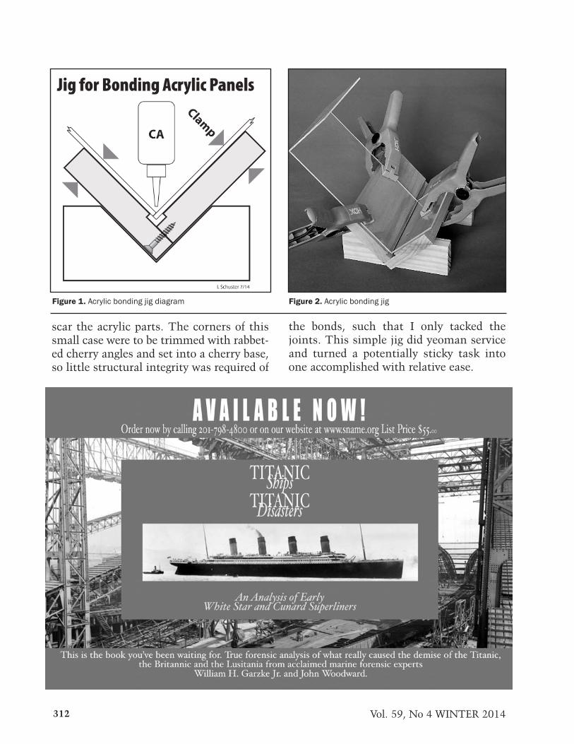
312 Vol. 59, No 4 WINTER 2014
Figure 1. Acrylic bonding jig diagram Figure 2. Acrylic bonding jig
scar the acrylic parts. The corners of thissmall case were to be trimmed with rabbet-ed cherry angles and set into a cherry base,so little structural integrity was required of
the bonds, such that I only tacked thejoints. This simple jig did yeoman serviceand turned a potentially sticky task intoone accomplished with relative ease.

313NAUTICAL RESEARCH JOURNAL
MODELERS’ REVIEWS
HMS Victorious was one of the group ofBritish carriers with armored flight decks that wereordered just before the outbreak of World War II.The ship had a stellar career during that war, partic-ipating in the hunt for the German battleshipBismarck, fighting vital convoys through to Maltaand Murmansk, operating in the Solomons withthe carrier USS Saratoga in 1943 as one of only twoAllied carriers then operational in the Pacific,launching successful attacks against the Germanbattleship Tirpitz in Norway, and in the forefront ofthe action with the British Pacific Fleet at Okinawa.After the war, Victorious was the only example ofthe class to be reconstructed as an up-to-date carri-
er with angled flight deck, modern arresting gearand mirror landing aids, steam catapults, and three-dimensional radar, much like the contemporaryAmerican Essex class ships. In fact, the cost of thisreconstruction was so great that the idea of a simi-lar effort with the others in the class was abandonedas cost-prohibitive, but Victorious successfully oper-ated worldwide, especially “East of Suez,” until theBritish government terminated that mission andthe ship was sold and scrapped in 1969.
Orange Hobby is a Korean manufacturerthat has gained quite a reputation for producing1:700 scale kits of subject somewhat out of themainstream, especially current amphibious warfare
Figure 1.
Figure 2.
Orange Hobby HMS Victorious (1966) Kit. . . . .
by Mark Myers
Figure 3.
Figure 4.
Figure 5.

314 Vol. 59, No 4 WINTER 2014
ships from around the world. This new kit for HMSVictorious as reconstructed and refitted in 1966 is aspectacular example of the firm’s output. The bulkof this kit is pressure-cast resin, which is supple-mented with photo-etched brass for fine details anda set of CNC turned brass gun barrels.
The most spectacular piece in the entire setundoubtedly is the hull. This single-piece castingincluded virtually every detail from the waterline tothe flight deck, and is hollow-cast to obviate distor-tion. The detail incorporated is phenomenal, as the
figures show.The main superstructure components,
weapons, ship’s boats, and most other details alsoare superbly cast resin. There is absolutely no dis-tortion in any of them and the manufacturer’s care-ful packing meant that only one piece, a 26-footwhaler, was detached from its molding sprue.
Orange Hobby also uses resin for the maincomponents of the aircraft in the ship’s air group:Sea Vixen fighters, Buccaneer strike aircraft, Gannetearly warning machines, and Wessex anti-subma-
Figure 6.
Figure 7.
Figure 8.
Figure 9.
Figure 10.
Figure 11.
Figure 12.
Figure 13.
Figure 14.
Figure 15.
Figure 16.

rine and air-sea rescue helicopters. The kit alsoincludes Gannet anti-submarine aircraft, which isinaccurate for the period (since the type was nolonger used in that role) but they can be embarkedas carrier-on-deck machines instead, since severalwere so converted and deployed on Victorious. Allthe aircraft models offer the option of folded wingsor rotors, as appropriate. The kit is available in twoforms; one with a few examples of these aircrafttypes and the other more-expensive version with afull air wing.
The multiple sheets of photo-etched brassthat provide the finest details are equally impres-sive. There are small sets for each of the various air-craft types and two large frets containing all thestructural details for the ship itself, such as the lat-tice mast, folding communications antennae,cranes, auxiliary radar masts, light anti-aircraftdetails, crash barriers, ladders and safety railings.These too are very crisp, although possibly a tadthicker than the finest examples of this material.The final provision is a very nice decal sheet thatincludes pennant numbers, deck markings andnational markings for the embarked aircraft.
To assist the modeler in putting this kittogether, Orange Hobby provides twelve –pages ofinstruction all in the keyed diagrammatic form wehave come to expect. In general, these are very clear
315NAUTICAL RESEARCH JOURNAL
Figure 17.
Figure 18.
Figure 19
Figure 20.
Figure 22.
Figure 23.
and well detailed, though a little greater clarity inexplaining the assembly process for some of themasts would be helpful. Nevertheless, the instruc-tions are adequate for guiding moderately experi-enced modelers through the process—this is not akit for novices!
The instructions include painting guidance,which is not wholly accurate. Colors called out aregeneric, which is not very helpful and requires addi-tional research. Furthermore, the colors designatedfor the aircraft are sometimes erroneous; all FleetAir Arm fixed wing aircraft of the period were paint-ed Extra Dark Sea Grey on the topsides and Whitebelow, with the exception of the AEW Gannets,which used Sky for undersurfaces, and CODGannets, which were Extra Dark Sea Grey overall.
This Orange Hobby kit for HMS Victoriousas reconstructed is a shining example of gooddesign and superb execution. There is another1:700 scale kit for Victorious in the configurationon the market, from MT Miniatures. This hasnothing like the finesse of Orange Hobby’s render-ing and it costs about half as much again, so therereally is no logical choice other than this new kit.From experience, I know that Orange Hobby’s prod-ucts fit well, so I can only heartily recommend thisnew offering.

316 Vol. 59, No 4 WINTER 2014
Ages of Sail..............................IFCAmerican Marine Model Gallery . .IFC
A S M A . . . . . . . . . . . . . . . . . . . . . . . . IFCBlueJacket. . . . . . . . . . . . . . . . . IBCB o n h a m s . . . . . . . . . . . . . . . . OBCFiddler’s Green. . . . . . . . . .316J. Tuttle Maritime Books . . . . .316
Sea Watch Books . . . . . . . . . InsertModel Expo . . . . . . . . . . . . . . 319
Power Ships . . . . . . . . . . . . . . IBCSea History . . . . . . . . . . . . . . 318Sherline Products . . . . . . . . . . 316S n a m e . . . . . . . . . . . . . . . . . . . 312Warner Woods West. . . . . . . . 319
Advertiser Index

317NAUTICAL RESEARCH JOURNAL
To the Editor
Mr. William Sproul, in “Making a Mouse-on-a Stay” (NRJ 59:3), notes there is little in the lit-erature about making such a mouse. Chas. LSpencer ’s book, Knots, Splices and Fancy Work,describes a mouse made by winding small stuff on aline to the required diameter, then covering it with a“pineapple knot”, which is really a form of coach-whipping or cross-pointing. The result is a raised“lump” in the middle of a line.
My copy of the book is the 1938 edition (itwas my father’s), and much of what I learnedabout marlinspike seamanship came from thisbook. Most knots and splices are described with
both text and easy-to-follow diagrams. The bookprogresses from the construction of rope, throughmany knots used aboard ship, to fancy knotting(turk’s heads and star knots are just two examples),to various kinds of splices—both in cordage andwire rope. There have been many editions, thelater ones with more content than mine, and thereare a fair number of copies available at reasonableprices from Amazon.com, eBay, and ABEbooks,among others. I have pulled out my copy manytimes and I certainly recommend it.
Steve WheelerRacine, Wisconsin
LETTERS TO THE EDITOR
BOOK REVIEWS
Scantlings of Royal Navy Ships, 1719-1805:Comparisons of 1719, 1745 Establishments, Ship
Builders Repository and Steel’s Elements &Practice of Naval Architecture
By Allan YedlinskyFlorence, Oregon: SeaWatchBooks, 2014
14-1/2” x 8-3/4”, spiral bound softcovers, iv + 271pages
Tables, notes, indices, drawings. $45.00ISBN: 9780983753292
Conventional wisdom, remarkably, oftenstill holds that wooden warship construction tech-nology stabilized around the middle of the seven-teenth century and remained essentially static forthe next two hundred years. In this matter, as in somany others, conventional wisdom is much mis-taken, because this two-hundred-year period wit-nessed considerable changes in the shapes, framingsystems, scantlings, constructional elements, andrigs that together belie the oft-repeated statementthat a sailor of Nelson’s time would have been per-fectly at home aboard a Restoration warship.
Research over the past century to uncoverthe physical characteristics of English warshipsbetween 1650 and 1850 probably began with thework of R.C. Anderson and his colleagues on the
changes in rigging, based primarily on a handful ofcontemporary treatises and the rich resource ofmodels from the period. It expanded into uncover-ing the evolution of structural changes asresearchers rediscovered the shipbuilding treatisesof the time, and also as nautical archaeologistsuncovered more and more wrecks from the period.By the 1960s, many researchers were familiar withthe Establishments of the eighteenth century asresources for warship dimensions and scantlings,and the ready availability of facsimile editions ofSteel’s Elements & Practice of Naval Architecturemade it a standard source for the later years of thecentury.
For modelers, in particular, the appearanceof facsimiles of several eighteenth-century shipbuilding treatises opened the door to constructingrecreations of many more ships from the vast troveof extant drafts, most of which provided accuratedata for their shapes but very little information ontheir structures. Nevertheless, a tendency persistedof relying on the most readily available source,Steel, even for vessels of an earlier period, simplybecause of the dead hand of conventional wisdom.
Yedlinsky’s new book probably will notoverturn that tendency completely—humans often

are creatures of habit—but it will substantially easethe work required of the modeler aspiring accurate-ly to recreate, in miniature, warships of the differ-ent periods of the eighteenth century. His majoreffort in tabulating data from four principal sourcesinto a format so readily accessible relieves modelersof the burden of developing the information them-selves for each individual project, allowing them tomove forward more expeditiously.
Scantlings of Royal Navy Ships will alsobecome a valuable tool for those researching thedevelopment of warship construction during theeighteenth century. The tabular format lends itselfto easy comparison of sets of characteristics overtime; an essential foundation for understanding theprocess.
There are some limitations to this materi-al’s utility. The author himself seems to be aware ofsome of these: errors in the data due to miscalcula-tions, potential mistakes in transcription on hispart, and the fact that designers did not alwayswholly comply with the rules. Some other factorsalso need to be kept in mind: several other treatisesexist that may present slightly different data, thereare multiple editions of Steel (Witt’s bibliography ofhis works runs to over 150 pages) and, if using afacsimile, not all such editions are complete, and,above all, there is substantial evidence that buildersfollowed their own paths well into the century, as
evidenced particularly by Blaise Ollivier ’s report onEnglish and Dutch ship building from 1736.
With Scantlings of Royal Navy Ships AllanYedlinsky has done researchers and modelers ofeighteenth-century English warships an enormousservice. His presentation makes complex materialrelatively easy to access, and this data is at the coreof the research and modeling questions practition-ers will ask. It is hard to imagine anyone seriouslyinterested in the subject omitting it from his or herbookshelves.
Henry FarrarBaltimore, Maryland
The Masting of American Merchant Sail in the1850s: An Illustrated Study
By William L. CrothersJefferson, North Carolina: McFarland & Company,
20148-1/2” x 11”, softcover, vii + 180 pages
Diagrams, sketches, tables, glossary, references,index. $55.00
ISBN: 9780786493999
The Masting of American Merchant Sail inthe 1850s is the concluding volume of Crothers’smonumental trilogy devoted to the physical struc-ture of American wooden merchant vessels in the1850s, following on from The American-BuiltClipper Ship and American-Built Packets andFreighters of the 1850s. The two earlier worksexplored in minute details the construction of thehulls and their outfitting; this volume addresses, inequal detail, their masts, spars and ironwork.
Describing this volume as exhaustive doesit scant justice. Crothers presents details of dimen-sions and methods of construction, using tables anda series of detailed sketches that explain preciselythe processes use to create the vessels’ spars. He fol-lows this with a series of specifications for no lessthan seventy-five separate spar plans for individualvessels, each of which epitomizes the practices ofthe era. He also offers, as an introduction, one ofthe clearest and most concise descriptions of theevolution of the three-masted ship rig that anyreader could desire.
Crothers himself admits to one limitationto his work: the fact that limited source materialobliged him to rely heavily on British material asthe basis of his work. Nevertheless, his carefulcross-referencing substantially diminishes this situ-
318 Vol. 59, No 4 WINTER 2014

ation’s deleterious impact on his study’s overallreliability.
By itself, The Masting of AmericanMerchant Sail in the 1850s is an indispensablesource for all researchers and modelers interested inthe topic of the American merchant marine of theperiod. When conjoined with the two earlier tomes,what Crothers has given us has to be one of themost important studies of the glory days ofAmerican merchant sail ever published.
Christopher VossSan Francisco, California
Warship 2014Edited by John Jordan and Stephen DentLondon: Conway Maritime Press, 2014
8” x 10-3/4”, hardcover, 208 pagesPhotographs, drawings, maps, tables, notes.
$45.00ISBN: 9781844862368
Distributed in the United States by Naval InstitutePress, Annapolis, Maryland
The contents and format of the thirty-sixthedition of this annual publication contains no sur-prises for its many enthusiasts: a plethora ofdetailed scholarly articles concerning variousaspects of the technological and operational historyof steel warships supplemented with book reviews,notes, and a gallery of photographs; in this case ofthe construction of the French battleship Liberté.As also is customary, readers can rely on viewingclearly-reproduced imagery and overall high qualityproduction values.
This particular edition should be of specialinterest to those interested in the history of aircraftcarriers. Hans Lengerer, a long-time contributor tothe series, presents a stunning article on the designand construction of the Japanese light carrier Ryujoand its two later rebuilds. The photographs illus-trating this piece are very nice indeed, but are over-shadowed by the superb scale drawings and detailsketches of the ship’s configurations, which wouldbe of immense use to any modeler of the vessel.There is also an equally excellent study of theItalian fleet’s multi-role carrier Cavour, again wellillustrated with photographs, line drawings andsketches (although the drawings are reproduced atrather a small scale). The third carrier articleaddresses the abortive CVA-01 project (given thename of Queen Elizabeth before its cancellation) for
the Royal Navy in the mid-1960s. Ian Sturton, itsauthor, delves into the design development processand the rationale for its demise. Once again, this iswell illustrated with line drawings of the concept atvarious stages, most of which would be sufficientfor developing a small-scale model.
The other main focus of attention in thisedition are warships from the later nineteenth andearly twentieth centuries. These include French andJapanese armored cruisers, German pre-dread-noughts, and Russian turret frigates from the1860s. there are also useful articles on fire controlin the Royal Navy after World War II and the escapeof the French battleship Jean Bart from Saint-Nazaire in 1940.
The Warship series have been consistentproviders of interesting and important informationabout steel warships. This particular edition, in thisreviewer’s opinion, is exceptional.
Kevin O’MaraSan Francisco, California
319NAUTICAL RESEARCH JOURNAL

320 Vol. 59, No 4 WINTER 2014
Many more significant new books on naval and maritime history and technology, containingvaluable information for researchers and modelers, appear than the Journal’s review pages canaccommodate. To improve the Journal’s service to its readers, additional book reviews are onthe Nautical Research Guild’s website here:http://www.thenrg.org/nrg-book-reviews.php
More Book Reviews
Dictionary of British Naval BattlesBy John D. Grainger
Woodbridge, Suffolk: The Boydell Press, 20126-1/2” x 9-1/2”, hardcover, xiv + 588 pagesMaps, glossary, bibliography, index. $90.00
ISBN: 9781843837046Caitlin Zant
East Carolina University
The Battle of the Denmark Strait: A CriticalAnalysis of the Bismarck’s Singular Triumph
By Robert J. WinklarethPhiladelphia: Casemate Publishing, 2012
6-1/4” x 9-1/4”, hardcover, 336 pagesPhotographs, maps, appendices, bibliography,
index. $32.95ISBN: 9781612001234
Jennifer E. JonesEast Carolina University
Ireland and the War at Sea 1641-1653By Elaine Murphy
Woodbridge, Suffolk: The Boydell Press, 20126-1/2” x 9-1/2”, hardcover, xii + 253 pagesMaps, glossary, tables, notes, appendices,
bibliography, index. $90.00ISBN: 9780861933181
Alyssa ReisnerEast Carolina University
America’s Black Sea Fleet: The U.S. Navy AmidstWar and Revolution, 1919-1921
By Robert ShenkAnnapolis: Naval Institute Press, 2012
6-1/4” x 9-1/4”, hardcover, xviii + 366 pagesPhotographs, maps, notes, bibliography, index.
$34.95ISBN: 9781612510538
Chelsea FreelandEast Carolina University
Naval Leadership and Management 1650-1950:Essays in Honour of Michael Duffy
Edited by Helen Doe and Richard HardingWoodbridge, Suffolk: The Boydell Press, 20126-1/4” x 9-1/2”, hardcover, xiv + 206 pagesTables, notes, bibliography, index. $99.00
ISBN: 9781843836957Stephanie S. Croatt
East Carolina University
Britain and Colonial Maritime War in the EarlyEighteenth Century: Silver, Seapower and the
AtlanticBy Shinsuke Satsuma
Woodbridge, Suffolk: The Boydell Press, 20136-1/2” x 9-1/2”, hardcover, xii + 284 pages
Illustrations, notes, bibliography, index. $115.00ISBN: 9781843838623
Heather HatchTexas A&M University
Passage to the World: The Emigrant Experience1807-1940
By Kevin BrownBarnsley: Seaforth Publishing, 2013
6-1/4” x 9-1/2”, hardcover, xii + 243 pagesIllustrations, notes, bibliography, index. $45.95
ISBN: 9781848321366Distributed in the United States by Naval Institute
Press, Annapolis, MarylandSara C. Kerfoot
East Carolina University
Voices of the Confederate Navy: Articles, Letters,Reports and Reminiscences
Edited by R. Thomas CampbellJefferson, North Carolina: McFarland & Co., 2008
7” x 10”, softcover, 366 pagesPhotographs, maps, bibliography, index. $35.00
ISBN: 9780786477241Andrew Duppstadt
NC State Historic Sites

