navair non contact in-process inspection - jteg |...
TRANSCRIPT

Gabe Draguicevich
N42 FRC-SW
NAVAIR NI
Aug 25th, 2015
NAVAIR
Non Contact In-Process Inspection

Overview
• Background on Navy 3D Model Status • (3MS / MBD)
• Proposed System Examples
• Definition of Digital Product Definition and Model-
Based Definition (MBD)
• Model-Based GD&T for Inspection
• Challenges
• Resources

F/A-18 IWP CLOSURE RIB
74A324336
Former Y462.500
74A324304
Former Y478.500 74A324206
Bulkhead Y488.000
74A324306
Former Y497.000
74A324703
Skin
74A324701
Skin
74A110000
Inner Wing Panel
Assy.74A324213
Bulkhead Y470.500
AA
74A110781
IWP Closure Rib
Detail AA

Scanned Part from AircraftPart from 2D Blue Print
Part Superimposed
Areas of Interest
CLOSURE RIB COMPARAISON

0.057
0.030
CLOSURE RIB ADVANCED MEASUREMENT
FaroArm®
Verisurf Build
0
1000
2000
3000
4000
-3s -2s 0 2s 3s
Bell Curve 6σ
-0.1500
-0.1000
-0.0500
0.0000
0.0500
0.1000
Model Deviation Graph

Modified the B/P To Reflect the PartPart Drafted per B/P
CLOSURE RIB ML DEFININTION PER B/P

AA
74A314653-2011/-2019/-2027 74A314626-2003/-2005A
74A314654-2027
74R310035-2005
NLG ActuatorFWD
NLG ACTUATOR SUPPORTS

74A310035-2005
Superimposed
74R310035-2005
Manufacturing Model
Comparing Manufacturing & Engineering 3D CAD Models
74R310035-2005
Engineering Model
Critical Spot 2:
Smaller Radius Critical Spot 1:
Smaller Thickness
Δ=0.040”

0.244”0.222”
0.203”
0.259”
Engineering ModelManufacturing Model
Engineering ModelManufacturing Model
Differences between Manufacturing & EngineeringCritical Spot #1 74R310035-2005

Engineering CAD Model
Manufactured Parts Do Not Conform to B/P
74A314626-2003/74A314626-2005A
AA
Step
Manufactured Part

Comparing Manufacturing & Engineering 3D Models
Critical Spot 1
Critical Spot 2
74A314653-2011
Manufacturing Model
74A314653-2011
Engineering Model
74A314653-2011A
74A314653-2011
Superimposed

74A314653 Engineering Model
(Silver)
74A314653 Manufacturing Model
(Red)
Manufacturing & Engineering 3D Models Overlapping
Critical Spot 2
74A314653-2011A

Traditional CMM’s Approach

Capital Improvement Project (CIP)
• Approx $36M total investment across three fleet
readiness centers• FRC-SW - San Diego, CA
• FRC-SE – Jacksonville, FL
• FRC-E – New Bern, NC
• In Process Inspection System• $800K Y16 / Y17 Project

Measuring Large Structure Manufacturing Parts

ATOS Scanbox

Cognitens 360 SIMS

Model-Based Inspection SolutionsQA Reporting to MBD

WHAT IS A MBD?

MODEL BASED DEFINITIONMBD

3D SOLID MODEL BASE DEFINITION

• The Model Based Enterprise (MBE) is made
up of many related processes. At its core is
the product definition which we refer to as the
Model Based Definition (MBD). Another way
to define MBD is an annotated 3D CAD
Model that contains all the information
needed to define a product. This annotated
model replaces a traditional drawing. Thus, a
drawing is created by exception not as a
standard process.

MBD at the center of Product Lifecycle Management

• With authority bestowed on the model, MBD will:
• Eliminate errors that result from referencing an incorrect
source.
• Make processes more efficient—no more searching to
determine correct revision levels.
• Eliminate outdated drawings floating around the
manufacturing floor.
• Eliminate discrepancy between the CAD model and 2D
documentation.
Value of MBD

• Complex surface profiles
• Complex products with large bills of materials
• Mission critical components with high liability
• Long product lives
• Global supply chains
• Stringent regulatory requirements
Where MBD Is Best Applied

Product Structure in a MBD Environment
tolerances manually entered
dra
win
gs
pro
du
ced
Product Definitions
Product Definition
(2D authority)
Digital Product Definition
(DPD - 3D authority)
Model Based Definition
(MBD)
3D Master
(drawing allowed)
Product Manufacturing Information
(PMI)
Geometric Dimensioning & Tolerancing
(3D GD&T)
Representation
(semantic)
Presentation
(display)
Model-Based GD&T
Tolerance
Analysis Simulation
Manufacture Inspection
Geometric Dimensioning & Tolerancing
(2D GD&T)

Model-Based GD&T Annotations

Model-Based Enterprise Broken
Design
3D Modeling
Engineering
3D Simulation
Manufacturing
3D Tool Paths
Model Based Definition
• 3D Solid Models
• CAD Intelligence Utilized
• Automated Digital Processes
Model Based Definition Broken
•Productivity Barrier
•Quality Data Loop Broken
•Statistical Improvement Impeded
Drawing Based Definition
• 2D Drawings
• CAD Intelligence Lost
• Manual Analog Hand Tools

Model-Based Enterprise Applied
Design
3D
Modeling
Engineering
3D
Simulation
Manufacturing
3D
Tool Paths
Inspection
3D Measurements
3D Quality Improvement
Model Based Definition
• 3D Solid Models
• CAD Intelligence Utilized
• Automated Digital Processes
Model Based Definition Extended
•Productivity Improved
•No 2D Drawing Waste
•3D Quality Data Loop Closed
Model Based Inspection
• 3D Profile with Tolerances
• CAD Intelligence Utilized
• Automated Digital Process

Benefits of Model-Based Measurement and Inspection
• No 2D Drawings
• Cost and time eliminated
• Contradictions removed
• Automated inspection
planning
• Automated report formatting
• Accuracy
• All features included in plan
• No interpretation errors
• GD&T rule checking
• No data entry errors
• Prompted inspection
procedures
• Live, graphical measurement
display
• Automated reporting
• No data entry
• No manual calculations
• Only basic skills needed
• Eliminate CMM overhead
(PCMM)
• No fixtures
• No part set-up
• No programming
• No manual data recording

Model-Based Large Volume Measurement Applications
Tooling Fabrication and Validation Large volume Inspection
Real time Model-Based InspectionsAutomated high precision
inspection and R&R studies

• CATIA – Dassault
• UG - Siemens
• Pro/ENGINEER - PTC
• SolidWorks - Dassault
• Inventor - Autodesk
• SolidEdge - Siemens
Model-Based Inspection SolutionsImport 3D CAD & MBD

Model-Based Inspection SolutionsConnect To Metrology Devices
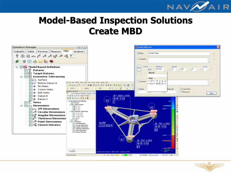
Model-Based Inspection Solutions Create MBD

Model-Based Inspection Solutions Automated Inspection Plans to MBD

Model-Based Inspection SolutionsAnalyze & Display Inspection Data

MBD Implementation Levels
Courtesy of Model Based Enterprise

• CATIA – Dassault
• UG - Siemens
• Pro/ENGINEER - PTC
• SolidWorks - Dassault
• Inventor - Autodesk
• SolidEdge - Siemens
ChallengesInteroperability

ChallengesEliminating Drawings

ChallengesLegacy Data

ChallengesCAD Translation & Validation
When Boeing DPD data containing 3D geometry is
received in translated format (e.g., IGES, STEP), the
supplier must verify their translation of each dataset or
have a process to verify and validate translation
software (per Section 3.), in order to maintain authority
status.

Boeing Standard D6-51991
QUALITY ASSURANCE STANDARD FOR DIGITAL PRODUCT DEFINITION
AT BOEING SUPPLIERS, D6-51991, REV J, September 17, 2010
9.2 Translations - Suppliers are responsible for all dataset translations used for
manufacturing and inspection, and must have a clear documented process for each. The
documented process must include a method to verify the accuracy of translations. (See
definitions for description of “translation”.)
9.2.1. Acceptance criteria for accuracy of translated surface profile/geometry, (tolerance)
must be determined by the supplier, and must ensure the end product will be within
engineering tolerance/specification. Objective evidence of translation validation must be
retained. (Typical allowable deviation tolerance is .0001 to .001 inch)
9.2.2. Suppliers must be able to demonstrate the CAD translation process, including
verification/interrogation methods used, and the ability to identify known discrepancies.
9.2.3. The verification process for translation of datasets containing 3D annotation, i.e.
feature control frames, dimensions, text, and/or surface geometry must ensure that all
intended entities are accounted for in the translated dataset.

ChallengesChanging Process
Design
3D Modeling
Engineering
3D Simulation
Manufacturing
3D Tool Paths

ChallengesChanging People

Predictions

Predictions
• 3D Global Supply Chains
• Elimination of 2D Drawings
• STEP AP242 Will Enhance Interoperability
• Increased Noncontact Inspection & 3D Scanning
• Cloud Based Inspection Databases
• SPC of Key Characteristics
• 3D Maintenance Repair Overhaul

Additional Information
• STEP AP242 - Managed Model Based 3D
Engineering
• ISO 10303 - STEP Standard for the Exchange of
Product model data
• Quality Information Framework (QIF)
• Aerospace Industries Association (AIA)
Engineering Data Interoperability Group (EDIG)
• Automotive Industry Action Group (AIAG)
• Model Based Enterprise

Thank You!

Reverse Engineering, 3D Scanning &
Tolerancing
Review & Wrap-Up
25 August 2015

Next JTEG Technology Forum
Cold Spray Repair
29 September 2015