naval postgraduate school ca p … jicuamry classification o; this page report documentation page la...
TRANSCRIPT

D-A184 863 A PROTOTYPE RAY TRACER(U) NAVAL POSTGRADUATE SCHOOL 1/2
MONTEREY CA P 6 SMITH JUN 87
UNCLASSIFIED F/G 20/6 ULEhuhmmhmhEmhhEEIhlllElllIIIIEEhhhEEEEmnnhmhEmhhmhmhEEEIJmnEEIIIIIIIIIhIIElEElllllllllEE

LLI I N' L2. 2
I1.811111125 liI .4 111111.6
MICROCOPY RESOLUTION TEST CHARTNArINAL BUREAU OF STANDARDS 1961 A
- - - - - - - - - - -
Op 'v-ez

00 NAVAL POSTGRADUATE SCHOOLwo Monterey, California
DTICQ7, LECTE
0071"0 2 1987
as: D I Crel~r~d'ictt5 at1,be in bla a
* THESISA PROTOTYPE RAY TRACER
by
Paul Gerard Smith
June 1987
-hes:z; Advxr'sor: 'Iichael 7. Qfda
Approved for public release; distribution is unlimited.
11 " 111 lie
unclassifiedJICUAmrY CLASSIFICATION O; THIS PAGE
REPORT DOCUMENTATION PAGEla REPORT SECURITY CLASSIFICATION lb RESTRICTIVE MARKINGS
unclassified2a SECURITY CLASSIFICATION AUTHORITY 3 OISTRIBUTION/ AVAILABILITY OF REPORT
b OWApproved for public release;. WEC-SSFICAON/DOWNGRAONG SCHEDULE distribution is unli mited.4 PERFORMING ORGANIZATION REPORT NUMBER(S) S MONITORING ORGANIZATION REPORT NUMBER(S)
6& NAME OF PERFORMING ORGANIZATION 6b OFFICE SYMBOL 7a NAME OF MONITORING ORGANIZATION
Naval Postgraduate School ( (iVicable) Naval Postgraduate School
6C ADDRESS (City. Stare. and ZIPCode) 7b AOORESS(Cty. State, and ZP Code)
Monterey, California 93943-5000 Monterey, California 93943-5000
Sa NAME OF FUNOINGi SPONSORING Bb OFFICE SYMBOL 9 PROCUREMENT INSTRUMENT IDENTIFICATION NUMBERORGANIZATION (If a4plicable)
8c ADORESS (City. Stare. and ZiPCode) 10 SOURCE Of FUNDING NUMBERS
PROGRAM PROJECT TASK WORK JNIrELEMENT NO NO NO ACCESSION NO
11 T TLE (Include Security Classjicarion)
A PROTOTYPE RAY TRACER
PERSONA, AUTHOR(S) Smith, Paul Gerard
A' '~( O EP~ is 1i3b 'iME COVERED 114l?~F RIPORT Wetar Month Day) [175 PAGE COUNT
'6 S ,LP EMNTARY NOTATION
COSATI CODES I IS SUBJECT lERMS I (COnTinue On 'evefl* if necessar, and idlentfy by block ntumber)',LD GROUP SUeBGROUP illumination models, rendering, lighting and
_____________________shading, and ray tracing
9 A-SlTR.ACT (Continue on 'everie if neceuary and ,identify by blOck number)
The ability to make computer images more realistic is becoming more impor-tant as the hardware for producing such images is becoming less expensiveand hence more available. The key to producingrealistic images lies inthe algorithms that can take full advantage of the hardware to produce
* . te. "n >>:i study, . 'e )i~k it i r ota tv'e ?f i ruv r:c. r, . :2:,,SI-d,: .. :n 2 . " . <a. ract ., :n ;omb-aat )n •.*Lta L *Li):i" L>a: l: ina
, , .....K ,urM rv c -:"2 .nos ":a I2t image .at 2ani ?eo:et'Ion general purpose computing hardware. The prototype was successfullyI. implemented on an IBM AT clone.
i00YR3uTONAVAILABILITY OP ABSTRACT2I1 ABSTRACT SECURITY CL.ASSIFICATIONj-. X ... NCLASSFIE/iJNL'MITED 0] SAME AS RPT rCOTIC USERS !unclassified
fl ,ME OP RESPONSIBLE NOIVIDUAL JbTELEPHONE (IncludIe Area Code) 22c O~P'(E SYMBOL"" Prof. Michael J. Zyda ( 408) 646-2305 Code ,52Zk
All OtMer editOns 4are Ob)tolete ucls fie
iii
. . . . " , ' , . . ' ; . - _- _ _ - , ' 1 7 . 1 . - . . - ." ' . . - ' . . , . . , . . ' . j .

Approved for public release; distribution is unlimited.
A Prototype Ray Tracer
by
Paul Gerard SmithCaptain, United States Marine Corps
B. A., The Citadel, 1978
Submitted in partial fulfillment of therequirements for the degree of
MASTER OF SCIENCE IN COMPUTER SCIENCE
from theNAVAL POSTGRADUATE SCHOOL
June 1987
Author: imllQau .Sith
Approved by: I.da,_,_.__-Micd da. hesis A !visor
C. jo as .u, Second Reader _
"Vincent Y./ um, Chairman,
Departmen f Computer Science
Knel T.Mrhl,
Dean of Information and Policy"Sciienc-e
2
I- 1W - r**.--.A--.

ABSTRACT
The ability to make computer images more realistic is becoming more
important as the hardware for producing such images is becoming less expensive
and hence more available. The key to producing realistic images lies in the
algorithms that can take full advantage of the hardware to produce them. In this
study, we look at a prototype of atray tracere as presented in [Ref. 1]. Ray tracing,
in combination with a global illumination model, currently provides the most
realistic images that can be generated on general purpose computing hardware.
The prototype was succesfully implemented on an IBM AT clone.
f]
N U 1' ...L ' J
3 .
-7,.
.4

TABLE OF CONTENTS
INTRODUCTION .................................... 9
A. DEFINITION AND OVERVIEW ............................... 10
B. ORGANIZATION ................................................. 14
I. DATA REQUIREMENTS............................................. 17
A. OVERVIEW OF THE DATA REQUIREMENTS............ 17
1. Object Data ..................................................... 17
a. Polygon Data................................................. 18
b. Bounding Volume Data .................................... 19
2. View Data ....................................................... 22
3. Light Data ...................................................... 22
B. DATA STRUCTURE FOR A RAY TRACER ................ 23
1. Picture........................................................... 23
2. Lights ............................................................ 23
3. Objects........................................................... 25
r4. -1;ibobjects........................................................ .25
5. Common Parts.................................................. 27
6. Polygons......................................................... 27
7. Vertex Array .................................................... 27
4

II. RAY TRACING INTERSECTION CONSIDERATIONS ..... 29
A. RAY TRACING MECHANICS ................................. 29
1. The Ray Direction Problem .................................. 29
2. The Intersection Problem .................................... 32
B. THE RAY DATA STRUCTURE ............................... 35
1. Ray Type........................................................ 36
I. Ray Origin ...................................................... 36
3. Ray Vector ...................................................... 36
4. Source Ray Type............................................... 36
5. Intersection Flag................................................ 36
6. Object Index .................................................... 37
7. Subobject Index ................................................ 37
8. Common Part Index ........................................... 37
9. Polygon Index................................................... 37
10. Intersection Point ............................................. 37
11. Distance........................................................ 37
12. 2zansxitted 1ncensitv...................................... 7
13. Specular Intensity............................................. 38
C. INTERSECTION METHODOLOGY........................... 38
1. Intersecting a Planar Polygon................................ 38
5
PIP; .

a. Generating the Initial Ray................................. 38
b. Intersecting the Bounding Volumes....................... 38
c. Intersecting the Polygon.................................... 40
2. Intersection of a Sphere........................................ 44
IV. THE INTENSITY PROBLEM ...................................... 45
A. LOCAL ILLUMINATION MODEL............................. 45
1. Diffuse Reflection Model....................................... 45
2. Specular Reflection Model .................................... 46
3. Combined Model................................................ 48
B. GLOBAL ILLUMINATION MODEL........................... 49
V. RAY TRACING ALGORITHM ..................................... 52
A. TRACING THE RAYS ........................................... 52
B. DETERMINING THE INTENSITY ........................... 57
VI. IMPLEMENTATION.................................................. 62
A. INPUT............................................................... 63
B. OUTPUT............................................................ 65
ILI. kOCSIONS...................................................... A
A. AREAS OF FUTURE RESEARCH ............................ 66
B. CONCLUSIONS.................................................... 66
APPENDIX A - SOURCE LISTINGS....................................... 68
5

APPENDIX B -INPUT FILE ............................................... 131
LIST OF REFERENCES ..................................................... 136
INITIAL DISTRIBUTION LIST ............................................. 137
7

ACKNOWLEDGEMENTS
The author wishes to express his gratitude to a number of people who helped
him throughout this study. To my advisor, Dr. Michael Zyda, who provided
me with the knowledge, insight, and encouragement necessary to complete the
project. I also wish to express my appreciation for his patience and assistance in
the writing of this study.
The following people provided the insight and knowledge which were
incorporated into the project:
- LCDR John Falby, USN, for the data structure used in this study;
- Dr. Maurice D. Wier for help in understanding the fundamentals of vectorcalculus.
I also want to express special thanks to LT Dale Streyle, USCG, and CAPT
Douglas Smith, USMC, for their help and support throughout my education at
the Naval Postgraduate School. I appreciate the help they rendered from the very
first project to running off the final copy of this thesis.
Last but not least I want to express my gratitude to my wife, Terri, and to
my son, Joshua for their patience and support throughout my education at the
Naval Postgraduate School. I thank them for enduring the long hours of study
* Lflmrnd m ",ife -or .vit in my writinr.
I,8
?.8
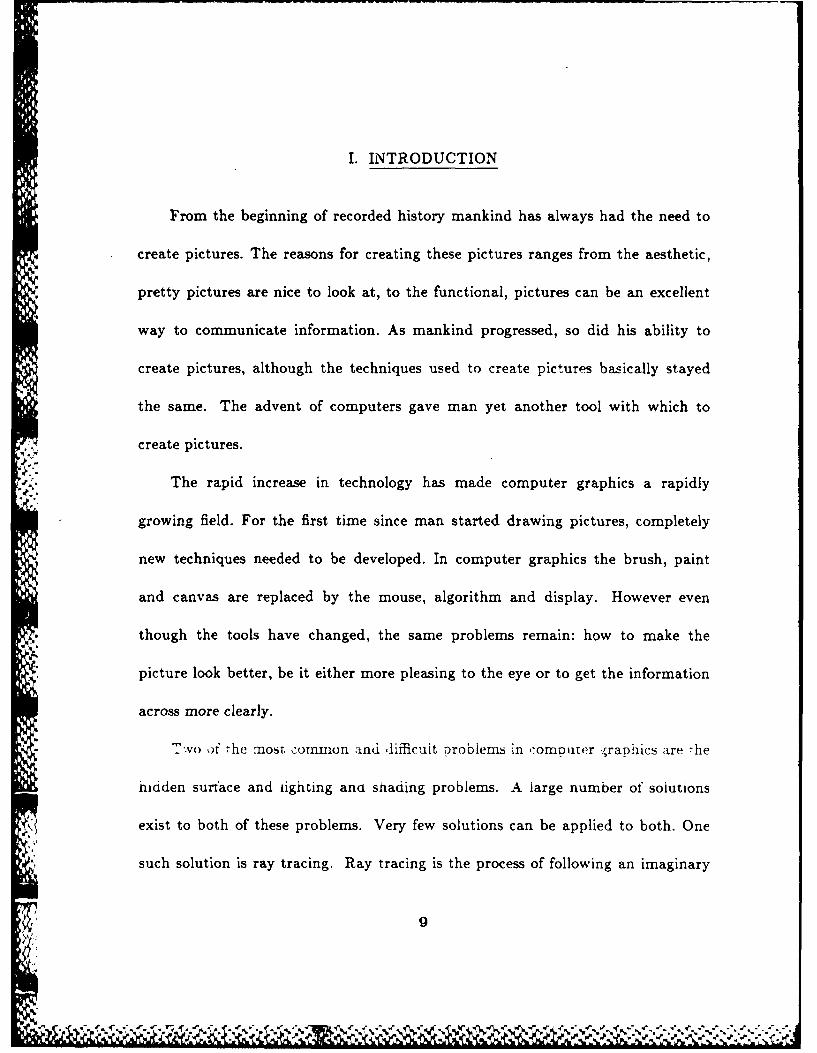
I. INTRODUCTION
From the beginning of recorded history mankind has always had the need to
create pictures. The reasons for creating these pictures ranges from the aesthetic,
pretty pictures are nice to look at, to the functional, pictures can be an excellent
way to communicate information. As mankind progressed, so did his ability to
create pictures, although the techniques used to create pictures basically stayed
the same. The advent of computers gave man yet another tool with which to
create pictures.
The rapid increase in technology has made computer graphics a rapidly
growing field. For the first time since man started drawing pictures, completely
new techniques needed to be developed. In computer graphics the brush, paint
and canvas are replaced by the mouse, algorithm and display. However even
though the tools have changed, the same problems remain: how to make the
picture look better, be it either more pleasing to the eye or to get the information
across more clearly.
-'NO of -he most. :ommon and difficuit -orobiems in -omputor rapilics are ,he
hidden surface and iighting and shading problems. A large number of solutions
exist to both of these problems. Very few solutions can be applied to both. One
*i such solution is ray tracing. Ray tracing is the process of following an imaginary
iW7! A
; 4 ?.\9 .~fv ,1C~V~WI >* ~
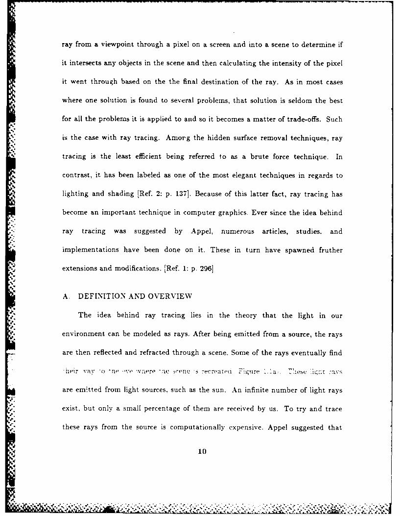
ray from a viewpoint through a pixel on a screen and into a scene to determine if
it intersects any objects in the scene and then calculating the intensity of the pixel
it went through based on the the final destination of the ray. As in most cases
where one solution is found to several problems, that solution is seldom the best
for all the problems it is applied to and so it becomes a matter of trade-offs. Such
is the case with ray tracing. Amorg the hidden surface removal techniques, ray-5
tracing is the least efficient being referred to as a brute force technique. In
contrast, it has been labeled as one of the most elegant techniques in regards to
lighting and shading [Ref. 2: p. 137]. Because of this latter fact, ray tracing has
become an important technique in computer graphics. Ever since the idea behind
ray tracing was suggested by Appel, numerous articles, studies, and
implementations have been done on it. These in turn have spawned fruther
extensions and modifications. [Ref. 1: p. 296]
A. DEFINITION AND OVERVIEW
The idea behind ray tracing lies in the theory that the light in our
environment can be modeled as rays. After being emitted from a source, the rays
are then reflected and refracted through a scene. Some of the rays eventually find
f1ler vav -o ....e rier( -l scene i 7ecrealeu -- yure
are emitted from light sources, such as the sun. An infinite number of light rays
exist, but only a small percentage of them are received by us. To try and trace
these rays from the source is computationally expensive. Appel suggested that
410
.5 .5 5. . . . . .

Light Source
Fiur 11
%
VPt
-4C
ViewRay
View Position
FLight Sourc
Trcn RasBakadsfo-Ve7osto
-y-.. .. p
'i.

instead of tracing the rays from the source that they should be traced backwards
from the viewer, thus dealing with only those rays that actually contribute to the
scene (Figure 1.1b). [Ref. 1: p. 2961
The basic ray tracing algorithm is a very simple one and not difficult to
implement. The basic algorithm is a hidden surface algorithm. All hidden surface
algorithms can be classified based on the coordinate system or space in which they
are implemented. These are either in object space or in image space. The ray
tracing algorithm falls under the category of image space. This category of
algorithm is implemented in the screen coordinate system in which the objects are
viewed. Unfortunately, the calculations are performed only to the precision of the
scene representation, which generally provides poor resolution. The image space
algorithms work by comparing every object in the scene with every pixel. Such an
algorithm is computationally expensive. Ray tracing algorithms have three parts:
a viewpoint, a raster screen, and a set of objects (Figure 1.2). In the algorithm,
the viewpoint is along the positive z axis. From this point, a ray is shot into the
scene through the center of every pixel on the raster. Each of these rays is then
traced and compared against every object in the scene to determine if there is an
intersection with any of them. It is in the determination of a possible intersection
')Mi -'ar L -ay -racer ipenm(s :,,nywere :romi 7,- o 95 pfercent 4 It- -Me. I
there is an intersection, then the intensity at the pixel is determined using the
intersected object's attributes and an appropriate illumination model. If there is
no intersection, then the pixel intensity is determined by the background
12

Obj ect
Pixel
Raster Screen
Rays
View Point
Figure 1.2Layout of Ray Tracing Scene [Ref. 1: p.2 9 7]
13

intensity. This procedure is then repeated for every pixel on the raster. When
the ray tracer is used as a hidden surface algorithm, intersection testing stops
after the first intersection. Extensions to the basic ray tracing algorithm, that
showed its usefulness in implementing a global illumination model, were originally
implemented by Whitted [Ref. 4] and Kay [Ref. 5 and 61. In these extensions of
ray tracing, additional rays are calculated, specifically the reflected and refracted
rays, and then tested to see if they intersect with any objects in the scene. This
process of generating new rays and tracing them to check for possible intersections
is continued until the rays either leave the scene or stack space is exceeded. In
such a case, the remaining rays are treated as if they had left the scene. This
process, illustrated in Figure 1.3a, for a single ray with intersections is easily
represented using the tree structure shown in Figure 1.3b. Here each node of the
tree represents a ray surface intersection. At each node, at least one and
m. sometimes two subbranches are generated. One branch of each of the reflected
and refracted rays is generated from the point. [Ref. 1: pp. 190-296]
B. ORGANIZATION
This study is broken into three areas: data requirements, ray tracing
-xierHouoiogy. n(i -he nrensirv :rooietl. ersr. ecion reviews The dara :ieeied
for a lighting and shading modeler, hereafter referred to as a renderer, of which a
ray tracer is an integral part. The second section reviews the actual process of
tracing a ray through a scene to be rendered. The third section looks briefly at the
14
¢%

r5 p
Figure 1r4
ri p
r2 r3
Figure 1. 3a
Global ef Dat Tre[e.3 6 2
vp..
illumination problem and how it relates to the ray tracer. The concluding
chapters present the implementation, and known limitations of the model along
with areas of future research.

II. DATA REQUIREMENTS
A. OVERVIEW OF THE DATA REQUIREMENTS
The importance of the intersection routines in the ray tracer is apparent in
the fact that a ray tracer spends 75 to 95 percent of its time determining
intersections [Ref. 1: p. 297]. The key to determining intersections, however, lies
in large part on the data used to describe the scene that is being rendered.
Information is needed not only to describe the entire scene that is being rendered
but more importantly to describe each object in the scene. Scene data is that
information needed to completely describe a picture, i.e., the number, kind, shape,
and color of any objects in the picture along with the background intensity and
light source information. This information must be properly ordered and broken
down. Falby [Ref. 3] suggested that a scene be broken into three categories:
object, view, and light. Each of these areas is examined below in the context of a
ray tracing algorithm.
1. Object Data
The data nertaining to each object in the scene ean be qronped into t wo
categories: poiygon and bounding voiume. The reason for his breakdown .s
twofold. First, each object in the scene is composed of polygons. They are the
basic building blocks of the scene. Second, in order to reduce the number of
17

intersection checks, it is necessary to set up a boundary around each object so
that the ray tracer only performs the intersection checks in the regions that
actually contain an object. Such a boundary is called a bounding volume. We
examine the polygon data first.
a. Polygon Data
Since the main focus of the ray tracing algorithm lies in determining
the intersections between the rays shot into a scene and the objects that make up
a scene, and since each object is comprised of polygons, the problem is really one
of determining the intersection points between the rays and the polygons. From
the fundamentals of vector calculus, it is known that in order to determine the
intersection between a ray and a polygon only the vertices of the polygon are
needed as well as the direction of the ray and a point on the ray. Since the object
is to be constructed of polygons, its vertices are known. Therefore, it is only
necessary to ensure that these points are stored in some manner, such as a record,
so as to be accessible to the ray tracer. In order to determine what the intensity
of the pixel is through which the ray passes, it is essential that the characteristics
of the object whose polygon was intersected be available. Since an object is made
of polygons, they inherit the characteristics of the object. These characteristics
Aiso aed -,o ')- eaily wcessibe tili. ertor.. itedi -o -)e -torei In oine
manner. The following is a list of the basic object characteristics that need to be
available: (1) the specular, diffuse, and transmission coefficients; (2) the Phong
specular exponent; and (3) the index of refraction, see Table 2.1. [Ref. 3: p. 68]
18

TABLE 2.1: OBJECT DATA
FIELD NAME VARIABLE NAME VALUEPolygon Vertices z, Y, z realDiffuse Coefficient Kd.,, real 0-1)Specular Coefficient Ksrgb real (0-1)Transmission Coefficient Ktr ~ ~ real (0-1)
Unit Surface Normal z, Y, z real (0-1)Phong Specular Exponent n integer (0-200)Index of Refraction n2 real
b. Bounding Volume Data
The major disadvantage of ray tracing is that it takes so much time.
This is hard to avoid since it is so computationally expensive. It is essential,
therefore, that more efficient techniques be developed to assist in reducing the
number of calculations. Several techniques already exist with the bounding
volume being the most effective [Ref. 1: p. 298]. In the description of ray tracing
given so far, it has been stated that a ray is checked to see if it intersects with any
object. Upon dissecting this statement further, a better understanding of the
intersection problem can be realized. Unless some optimization is done, the ray
tracing algorithm is forced to do the following. Each ray must be checked for a
possible intersection with each object. Since each object is made up of polygons,
then the ray must be checked for a possible intersection with each polygon. For a
,ornplicared objecr. such aS a 7eapot. .his requires a 'arge number .f ,fnecxs and
must be done for each object. The purpose for establishing the bounding volume
lies in two facts. The first is that generally scenes are mostly background with
just a few objects, hence very few of the rays actually hit anything. Therefore,
1g

most of the intersection tests done are a waste of time. Second, a ray can only hit
one object at a time. To have it process through the entire list of objects, when
intersections with most of them can be eliminated, is needless. A bounding
volume is, therefore, a method of enclosing each object in the scene in a simple
containment vessel, which in effect creates a boundary around the object. Once
this boundary is established, the number of overall intersection tests can be
greatly reduced, as in the example of a teapot, which might easily have over a
hundred polygons. If it is surrounded by a bounding box consisting of just six
polygons, the number of intersection tests can be significantly reduced. In this
situation, instead of having to test each ray against each polygon of the object,
only those rays that penetrate the bounding volume need to be checked. Thus
the bounding volume is a way to filter out unnecessary intersection tests by
limiting the tests to those rays that are most likely to intersect an object.
Just as the use of a bounding volume greatly increases the efficiency
of the ray tracing algorithm, the use of the right kind of a bounding volume can
improve upon that even more. In Rogers [Ref. 11, the bounding volumes
suggested are a bounding box and a bounding sphere (Figure 2.1), each of which
has advantages and disadvantages. The bounding sphere is much easier to
.:rnpierneniithoug i : 's !e-s ,fficient fn -c:ing -he -arget area-han it.trhe
bounding box, see Figure 2.1. The bounding box, on the other hand, is
computationally expensive to implement. The data needed to establish a
bounding sphere is minimal. It only requires a center point for the object and a
20

/
Figure 2.la
Obiect Surrounded by Bounding Sphere rRef. 1: p.2981Figure 2.1b
Figure 2.1b
Object Surrounded by Bounding Box [Ref. 1: p.29 8]
21

radius that encompasses every point of the object. The bounding box, on the
other hand, requires far more data in that the polygons that make up the box
must be described.
2. View Data
In rendering any scene, certain information can be applied to the scene
. as a whole. This information is grouped together to form the view data. This
data consists of the viewpoint position, a constant to prevent division by zero, a
refraction index for the global medium, the ambient light intensity, the
background color, and the scene dimensions, see Table 2.2. [Ref. 3: pp. 74-75]
3. Light Data
To support a lighting and shading model, it is necessary to include
certain information on the light source for the scene. That information must
include the position of the light source, its intensity, its type, geometry, and
dimension, see Table 2.3.
TABLE 2.2: VIEW DATA
FIELD NAME VARIABLE NAME VALUESI Viewooint -. . real
No Zero t,onstant X0 real -Giobai Refraction Index 1/1 reai
Ambient Light Iar,g,b real (0-1)Background Light Ibgb real (0-1)Scene Size z, y integers
22

TABLE 2.3: LIGHT DATA
FIELD NAME VARIABLE NAME VALUE
Light Position z, y, z realntensity I real (0-1)
Type type enumerated (point,distributed)Shape shape enumerated (circular, rectangular)Dimensions z, y real
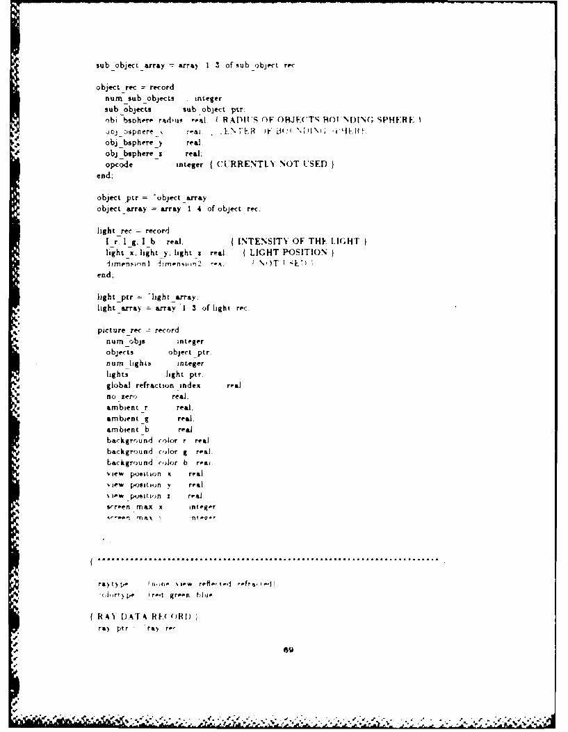
B. DATA STRUCTURE FOR A RAY TRACER
Falby [Ref. 3] suggested a data structure for a multi-illumination model
renderer. That data structure, with minor variations, has been used in this study.
In [Ref. 3] a complete derivation of the data is presented, so for the purposes of
this study only a brief description is given here. Figure 2.2 illustrates the layout
of the data structure as used in this study. This data structure essentially consists
of arrays of records layed out in a hierarchical organization. Starting from the
highest level it consists of the following: a picture record, an array of light records,
an array of objects, an array of subobjects, an array of common part records, an
array of polygons, and three arrays for the vertices. Each of these is now
examined.
1. Picture
Picture is a single record which contains the view data mentioned earlier.
. t . S
The lights array is an array of records, with one record for each light
source in the scene. Each record contains the light data mentioned above.
23
~4'. ~< -

e. ) U x XU uZ 1 4 )
W) 0 M M .-
1.4. 4) 4.) 444) 4 4- 4 .
14.44 14.44 1. 14 1o 4 0 w 0
0z- b. 4) r4 4) X~
x6) UUZ b 00
.0 4 r. Q = : -4 -4~
N42 C,- 3 CC 0
En ~ xNf- CH) U 1 )
0. Cd
14 4)
~1 * - ~ U 4 4 4.Q ) 4.) 4)-0 u : 3 U U 14 U )
El 0 44 ~ ) 4 )E
H .) b 4.) H) r4
~~~ 04 14 0 U
b) U)- - 4 4- 4- 0.
0 u 4.) _ 4.) r. r. -04) 0.0M
H x xI11Ir1- -a > ~ >
24
..4 % N

3. Objects
The objects array is an array of records, with one record for each object
in the scene. In this study, an object is the highest order item in a scene. Just as
the scene is divided up into objects, each with its own bounding volume, so is
each object broken down into subobjects, each with its own bounding volume.
4. Subobjects
The subobjects array is an array of records, with each array belonging to
one object record. For example Figure 2.3a shows one object, a barbell, that is
divided into three subobjects which are: the left weight, the right weight, and the
bar. The record layout for this is as illustrated in Figure 2.3c. A subobject is the
. smallest item in the scene. Each object has at least one subobject. A subobject is
composed of polygons or it is a sphere. Using 'Tigure 2.3a as an example again,
the left and right weights are spheres and the bar, instead of being a perfect
4cylinder, is composed of polygons and actually has an octagonal shape, Figure
2.3b. Aside from containing a pointer to the common part record, examined next,
and data for its bounding volume, it also contains information on the subobject
type. This subobject type field indicates the geometry of the subobject, i.e., it is
either a sphere or a polygonal object, which is an object composed of polygons.
.21- ":Aor::1rv.()tL .ur,,r ":i;1$e e10A1 1 '' orl !i'f)!lr:e ,LrE Iff, :or ;Lca
object type. Currently a 1 indicates that planar intersection routines should be
used and a 0 indicates spherical intersection routines should be used.
25
.s N

I " ect
6 )i. ......,
SubobJ ects
Figure 2.3a Figure 2.3b
Subobjects [Ref. 7] Polygonal Object
SUBOBJECTSPICTURE -B.OBJECTS
"4
Figure 2.3c
Record Layout for Figure 23
26
rba
CPRT
weight

5. Common Parts
A good illustration of common parts is found in an ordinary
checkerboard. Figure 2.4a. In this figure one object exists--the checkerboard. This
4 in turn has one subobject, itself. This subobject has two common parts: the white
squares and the black squares. Table 2.1 listed the characteristics of an object
and it is in the common parts record that these characteristics are stored. Each of
these common parts records contains a pointer to an array of polygon records. It
is through this arrangement that the polygons inherit the characteristics of the
object. Therefore, the common parts array, also called the Cparts array, is an
array of records, with one array per subobject, and each common parts record
points to its own set of polygons, Figure 2.4b.
6. Polygons
The polygons array, too, is an array of records with one array for each
subobject. This is the smallest physical item in the scene and the one against
which the actual intersections are determined.
7. Vertex Array
The vertex array is an array of points that define the polygons that
compose the subobject.
This data structure as presented by Falby [Ref. 3] proved itself to be both
flexible and easy to use. An example of a data base that used this structure and
which was used in testing this ray tracer can be seen in Appendix B.
27I'

Figure 2.4a, - Example of Object with Two Common Parts
PICTURE OJCSOYOq
blac
Figure 2.4b -Record Layout of 2.4a.
28
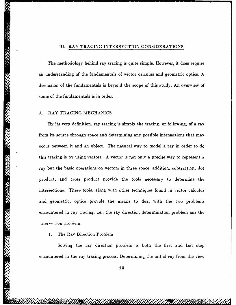
III. RAY TRACING INTERSECTION CONSIDERATIONS
The methodology behind ray tracing is quite simple. However, it does require
an understanding of the fundamentals of vector calculus and geometric optics. A
discussion of the fundamentals is beyond the scope of this study. An overview of
some of the fundamentals is in order.
A. RAY TRACING MECHANICS
By its very definition, ray tracing is simply the tracing, or following, of a ray
from its source through space and determining any possible intersections that may
occur between it and an object. The natural way to model a ray in order to do
this tracing is by using vectors. A vector is not only a precise way to represent a
ray but the basic operations on vectors in three space, addition, subtraction, dot
product, and cross product provide the tools necessary to determine the
intersections. These tools, along with other techniques found in vector calculus
and geometric, optics provide the means to deal with the two problems
encountered in ray tracing, i.e., the ray direction determination problem ans the
.tersection orobiem.
1. The Ray Direction Problem
Solving the ray direction problem is both the first and last step
encountered in the ray tracing process. Determining the initial ray from the view
29
i)

position, usually referred to as the view ray, is the simplest to solve. Every point
in a coordinate system can be associated with a ray, and determining the direction
of a ray between two points can be solved by using vector subtraction. The last
*: step in the ray tracing process is determining what takes place when a ray
intersects an object. This requires the application of the laws of geometric optics.
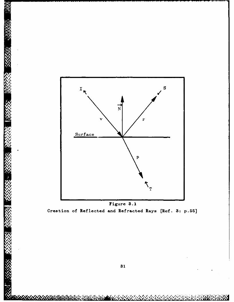
Once a ray strikes an object, either one or two additional rays will be generated.
These new rays are referred to as the reflected and refracted rays, Figure 3.1. The
three basic laws of reflection and refraction are listed as [Ref. 8: pp: 32-33]
1. The incident, reflected, and transmitted rays all reside in a plane, known
as the plane of incidence, which is normal to the surface of the object.
2. The angle of incidence is equal to the angle of reflection E) = (r.
3. The incident and transmitted ray directions are related by Snells' law:
nsinE) = ntsinG t.
An illustration of these laws is shown in Figure 3.1. Rogers [Ref. 1: p. 3671
provides a method for determining the direction of the reflected and refracted
rays. The direction of r, the reflection ray, and p, the refraction ray are given as:
r = v' + 2r
where
V
~I
30
-,C r .
I /S
N
V r
Surface \
Ip
* T
Figure 3.1
* Creation of Reflected and Refracted Rays [Ref. 3: p.55)
31

-1
k = (k v - I v + iI)
r72
k1
Here k n is the ratio of refractive indices, k! is the Fresnel coefficient, v is the
normal vector in the direction of the incoming ray, v' is the unit normal vector in
the direction of the incoming ray, i is the unit surface normal, and , and 72 are
the refraction coefficients for mediums the rays pass through. This is illustrated
in Figure 3.2.
2. The Intersection Problem
As stated above the intersection computation is the most time
consuming part of the ray tracing process. It is not that the process itself is so
difficult but because several steps need to be done for each iteration. Two types
of intersection computations are required to be performed: determining the
intersection between a line and a sphere and determining the intersection between
a line and a polygon. The first type is the simplest to solve and is why the sphere
is generally used as the bounding volume. The calculation of the intersection
point between a line and a sphere involves solving the equation for the line and
-o ero - iriit alo u V. - i ro i enie )v riv - iari.oi
(x - _)2 ( - 3)2 + (Z _ 6)2 = r (3.1)
where (a, 3, 6) is the center point, r is the radius, and (x, y, z) is a point on the
sphere. The line is defined by the parametric equations
32
[' '
IA . v.J

vI + 2N
N
-4,
eSurface
-4 -
-N
p
k f(v ' + N) 'T
Figure 3.2
Direction of Reflected and Refracted Rays [Ref. 3: p.57])
33

z = at + z o y = bt + yo z = Ct + zo (3.2)
where (z0, Y0, z0 ) is a known point on the line, and a, b, and c are coefficients
from 'he vector a- - 5- - ek which is parallel to the line. These equations must
first be solved for t. The solution to this provides two answers. First, it indicates
whether or not an intersection actually takes place. Second, if there is one, it
indicates how many intersections, either one, in the case where the line is tangent
to the sphere, or two, in the case where it actually enters the sphere. In the case
of two intersection points, a check must be done to determine which is closer to
the origin of the ray.
The intersection between a line and a polygon is more involved. This
problem is comprised of two parts: determining the intersection point between a
line and a plane, and determining whether or not the intersection point lies within
the polygon. Like the line-sphere intersection problem, this one also involves the
solving of two equations simultaneously. The first of these is the equation for a
plane which is defined as
d Ax + By + Cz = D (3.3)
where A, B, C, and D are constants and (X, y, z) is a point on the plane. The
" ec (cII .,,Iation iese(i j -), paramerric equation -hat ,ieines a line. Zu. 2.2. T]e
solution of this requires first substituting the equations for the line into the
equation of the plane. The result is an equation in t, which when solved and
substituted back into the equations for the line, provides the intersection point
34
.' ' I -I ,. .-- "

between the line and the plane. Once this point is calculated, it is then necessary
to determine whether or not it lies within the polygon. A general way of solving
this is to simply determine the relationship between the intersection point and
each edge of the polygon. The point that lies on the inside of each edge also lies
within the polygon. If it fails the test for any edge, then it lies outside the
polygon. The drawback to this approach, is that it only works for convex
polygons. In this study we assume all polygons are convex. [Ref. 9].
B. THE RAY DATA STRUCTURE
Rogers [Ref. 1] suggests a data structure for a ray in a ray tracer. It is that
data structure which is used in this study. Table 3.1 lists the data used to model
each ray. We examine each item of this structure as adapted from Rogers [Ref. 1:
p. 373].
TABLE 3.1 -RAY DATA
FIELD NAME VARIABLE NAME VALUE
Ray Type type enumerated or codedRay Origin z, y, z realRay Vector z, y, z realSource Ray Type Stype enumerated or codedIntersection Flag flag boolean or codedObject Index obj idx integer-iibobjoet Tndex :Zubobi 'dx .nteTer
,;rnmon -ixrr 'nuex .-part :Ax nreerPolygon index poiygon iax integerIntersection Point z, y, z realDistance d realTransmitted Intensity realSpecular Intensity real
35

1. Ray Type
The ray type field identifies a ray as either a view ray, a reflected ray, or
a refracted ray. The values put in this field are generally of an enumerated type
and consist of reflected, refracted, view, and none.
2. Ray Origin
The ray origin field contains the point that identifies the position from
which the ray originated. For instance, if it is the view ray, its point of origin is
the view position. If it is a reflected or refracted ray, its origin is the intersection
point that it originated from.
3. Ray Vector
The ray vector field contains the vector heading of the ray.
4. Source Ray Type
The source ray type field contains the ray type of the source ray for this
paricular ray. For instance, a view ray does not have any source ray as it is the
starting ray for the process. Hence, none is in the type field. If the view ray
intersects an object and both a reflected and refracted ray are generated, then the
source ray for both of them is the view ray. Likewise if the reflected or refracted
ray hits an object and creates further rays then it becomes the source ray for
-as rays :r crs-ates.
5. Intersection Flag
Originally the intersection flag is set to false and it is only set to true
when there is an intersection between this ray and an object.
36
,. . G o % % ° . - ° % r. , . ,, ..,, ., . .,r , .,, . . ,, ,r- ., - a .-: ¢ , ' - "* " -€ q

6. Object Index
The object index provides an index into the array of object records
making it possible to select any object easily.
7. Subobject Index
The subobject index provides an index into the array of subobject
records and helps uniquely identify each subobject.
8. Common Part Index
The common part index provides the index into the array of common
part records uniquely identifying each common part record.
9. Polygon Index
The polygon index provides the index into the array of polygon records
and uniquely identifies each polygon.
* 10. Intersection Point
The intersection point field holds the position of the intersection point
between the current ray and an object.
11. Distance
The distance field contains the distance between the current ray's point
of origin and its point of intersection.
'2 7. Tanst-ittedi:test
The transmitted intensity field contains the red, green, and blue
intensity values, in a range between 0 and 1, of the light that is incoming along
any refracted ray that this ray produces.
, 37
A.' Ak'A - - -,- A A

, 13. Specular Intensity
The specular intensity field contains the red, green, and blue intensity
values, in a range between 0 and 1, of the light that is incoming along any
specular ray that this ray produces.
C. INTERSECTION METHODOLOGY
1. Intersecting a Planar Polygon
a. Generating the Initial Ray
The generation of the initial or view ray is shown in Figure 3.3.
This ray, p - v, is calculated using vector subtraction. The two vectors used are
the ones associated with the points for the view position, v, and the pixel through
which the ray passes, p. The ray associated with the view position is to be
subtracted from the ray associated with the pixel.
b. Intersecting the Bounding Volumes
After each ray is generated, each object in the object list is checked,
one at a time, to determine whether or not the ray strikes any of the bounding
containers of the objects in the scene. In our implementation, the bounding
container is the sphere, which is reduced to a bounding circle, C, see Figure 3.4.
- .n.-*.rci 1- :1a1iu( .s -nrlIle "I " ie rauiis ,i "i, )'unding -;piere. ,mu :t -es
on the plane, P, which c,.ntains the center point, q, of the bounding sphere. The
inverse of the incoming ray, i, is the surface normal of this plane. It is not
necessary to determine where on the bounding sphere a ray hits since at this stage
38
m.i"Jd

-YZ
Figure 3.3- Determining the Ray View
TOP VIEW
-. :. bounding sphereS
C -z C bounding
q circle
Pixe
/V view ra~y
:
view position
++
Figure 3.4 - The Bounding Circle
39
T% VE

we are only interested in just finding out whether or not it hits it. Because we are
not concerned with where the ray strikes the bounding sphere, a bounding circle is
used. Determining the intersection with a circle requires less work than
determining the intersection with a sphere.
The first step in tracing the ray begins by taking each object and
constructing a bounding circle. Once this circle is constructed, the intersection
point of the view ray with it is calculated. Then the distance between the
intersection point and the center point is determined and compared to the radius
of the bounding circle to see if it falls within the circle. If it does fall within the
circle, this indicates that the ray intersected the bounding volume. This process
then needs to be repeated for each object. If an object's bounding circle is hit,
this process must then be repeated for each subobject of that object.
c. Intersecting the Polygon
Once a particular subobject is identified by the bounding volume
tests, the common parts list is processed, one record at a time. Each one of these
common parts records contains a pointer to those polygons that make up the
object being rendered. This list of polygon records is then processed after the
bounding volume processing is completed. The entire list needs only to beV;.
roce se1 linrii in esecon M jif(j Th 1processing Tnvoivedt :n his s -he
most computationally expensive part of the entire ray tracing algorithm. This
computation consists of three steps: determining the orientation of the polygon,
calculating the intersection point between the ray and the plane that contains the
40
Ai 6W -,

polygon, and determining whether or not the intersection point lies on the
polygon.
(1) Establishing the Orientation. First. each polygon needs to be
checked for a correct orientation. This is a straightforward step carried out by
calculating the angle between the surface normal of that polygon and the inverse
of the view ray. If it is 90 degrees or greater, it is facing in the wrong direction to
be intersected. If it is less than 90 degrees, the next step is to determine whether
the ray intersects the particular plane that that particular polygon lies on. The
first step in doing this is to determine the equation for the plane in which that
polygon lies.
(2) Intersecting a Plane. If the correct orientation exists for a
polygon to be intersected, the next step is to define the plane containing the
44 polygon of interest. The equation for a plane was given earlier as
Ax-, By + Cz = D
where A, B, C, and D are constants and can be calculated by the following
equation.
A = y,(z - z,) y,(z, z,) - ( - Z )
C X, I(Y' - Y3) X 2(Y3 -') - (, - Y,)
D = -z 1 (y 2z 3 - Y3 Z2 ) - X2 (Y 3z 1 - I) - X3 (IYl'Z Y,-1)
where (xi. Y Z1), (£2, y 2, z2). and (x3. Y3, z3) are points of the vertices of the
41

polygon. Once the equation for the plane is known, it must then be solved
simultaneously with the equation of the line representing the ray.
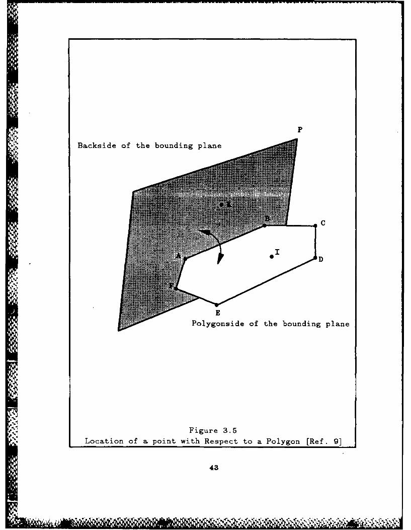
(3) Location of a point with respect to a polygon. Once the
intersection point is determined, it needs to be checked to see whether or not it
lies within the polygon. This is the most computationally expensive part of the
process. This process, see Figure 3.5, requires that a plane, P, called the bounding
plane, containing two vertices, for example A and B, of an edge and another
arbitrary point, K, not on the polygon or its plane, be constructed. This must be
done for each edge. Once the bounding plane is constructed, the point in question
must then be checked to see whether or not it lies to the polygon's side of the
plane that now contains the edge of the polygon. This is done by plugging in'.4.
A' another vertex of the polygon into the equation for the plane that was just
constructed, and then plugging in the intersection point. If the results from these-a
two equations have the same relationship, i.e. if the sign is the same, then the
intersection point lies on the polygon side of the bounding plane. This check
must then be repeated for each edge of the polygon. In order for the intersection
point to lie on the face itself, it must be found to lie on the polygon's side of each
ed. A, this noint. it is determined whether or not the ray strikes the object. If
S:':v ' -' , :,t, . r. "he ")O1 tnr " UiS polygon l ust oe stored 'n .he
ray structure along with the intersection point. This information is needed later
a ".on when determining the direction of reflected and refracted rays as well as the
intensity of the light that is reflected from this position.
', 42
441
In
P
Backside of the bounding plane
D
UE
9-1
Polygonside of the bounding plane
Figure 3.5
Location of a point with Respect to a Polygon [Ref. 9]
43

2. Intersection of a Sphere
The sphere is the easiest object to work with in a ray tracer. Since the
sphere can act as its own bounding volume, the center point and radius are
already available in the subobject record. This eliminates the need for the polygon
array. The center point and radius are the only information necessary to model a
sphere for a ray tracer. Determining the intersection of a line and a sphere is
nothing more than the simultaneous solving of their equations for the variable t .
The solution to this gives a quadratic equation in t which can then easily be
solved.
1
_ oj.,44
4.
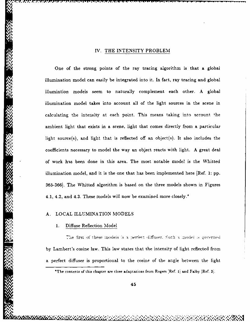
IV. THE INTENSITY PROBLEM
One of the strong points of the ray tracing algorithm is that a global
illumination model can easily be integrated into it. In fact, ray tracing and global
illumintion models seem to naturally complement each other. A global
illumination model takes into account all of the light sources in the scene in
calculating the intensity at each point. This means taking into account *he
ambient light that exists in a scene, light that comes directly from a particular
light source(s), and light that is reflected off an object(s). It also includes the
coefficients necessary to model the way an object reacts with light. A great deal
of work has been done in this area. The most notable model is the Whitted
illumination model, and it is the one that has been implemented here [Ref. 1: pp.
365-3661. The Whitted algorithm is based on the three models shown in Figures
?. .4.1, 4.2, and 4.3. These models will now be examined more closely.*
A. LOCAL ILLUMINATION MODELS
1. Diffuse Reflection Model
,ie first ot these rnodeis :s a 9er-ect diffuser. --;ca : ::odei .6 ,oxvrrwu
by Lambert's cosine law. This law states that the intensity of light reflected from
a perfect diffuser is proportional to the cosine of the angle between the light
*The contents of this chapter are close adaptations from Rogers [Ref. ii and Falby [Ref. 31.
45
- ---. - ..................................................... - ~ IN...-n-

direction and the normal to the surface. This can be expressed mathematically as
III = 11kdcosE 0 < 0 <-
~2
where ,s the rerlected intensity, i l ,s the Incident nensity from a point .igit
source, kd is the diffuse reflection constant, unique to each object, and E is the
angle between the light direction and the surface normal, see Figure 4.1. Since the
diffuse reflection coefficient kd varies from material to material and is also a
function of the wavelength of the light, it is often easier to just assume it a
constant for simple illumination models. rRef. 2: p. 312!
2. Specular Reflection Model
The second model illustrates the characteristics of specular reflection
which is directional, unlike diffuse reflection. This means that the greatest
intensity of the specularly reflected light can only be seen if the view angle
coincides with the reflection angle, Figure 4.2. The further off the viewing angle is
from the reflection angle, the dimmer the intensity becomes. Because of the
complex physical characteristics of specularly reflected light, an empirical model
due to Bui-Tuong Phong is usually used for simple illumination models [Ref. 10].
This is expressed mathematically as
where w(O, A). the reflection curve, gives the ratio of the specularly reflected
light to the incident light as a function of the incidence angle EO and the
wavelength A. Because w(6, A) is such a complex function, it is frequently
46
AOL
.1

Light Source Light Source
0 0
nn
-ni -nT t
Figure 4.1 Figure 4.2
Diffuse Reflection Specular ReflectionRef. 1: p.3121 rRef. 1: p.3141
Light Source
0View position
-n e
Figure 4.3
Global Illumination Model
47

replaced by an aesthetically or experimentally determined constant k. which then
yields
i'L~l = r~kCos
Also, n is a power that approximates the spatial distribution of the specularly
reflected light. Typically a value of 200 for n is used to model a very shiny
surface and a value of 10 is used for a dull surface [Ref. 3: p. 72]. [Ref. 1: pp. 313-
315)
,:! 3. Combined Model
If just point sources are assumed, as in the two models just discussed,
any object not receiving light directly from the source appears black. In order to
properly render a scene, it is also necessary to take into account ambient light, the
light that is reflected off other surfaces. Including a model for ambient light into
the intensity calculations is not feasible. Ambient light represents a distributed
light source and as such is a very complex function. Therefore it is treated as a
constant diffuse term and linearly combined with the other terms. Also not
included in the above model is the effect that distance has on light. It is well
known that the farther away an object or light source is, the dimmer it gets. The
:tc .Ia :ormuia -o produce that propler attenuation is - wriere rne intensitv )f
light decreases as the square of the distance from the source increases. However it
has been shown that linear attenuation can actually produce more realistic results.
With these two additions the complete model now looks like:
48

I = I.k. + I (kcos + kcosna)
d +K
where 1 is the incident ambient light intensity, ka is the ambient diffuse
reflection constant and K is an arbitrary constant that can be used to adjust the
results. [Ref. 1: p. 313]
The complete model just presented can now be modified to better fit in
with a ray tracer. Recalling the formula for the dot product of two vectors allows
writing the cosE as ri'L and writing cosa as RiS which gives us:
I = Ik, + [kd(r.)+ k (ig)ld+K
So far we have only examined the case where just one light source is present. If
there are several light sources, the effects are added linearly, and the equation now
becomes:
m L
I= I,,k + [kd(ri'- L,) + k, (R;S) n1• , .j=1 d + K
This then is the complete local illumination model. [Ref. 1: pp. 312-316]
B. GLOBAL ILLUMINATION MODEL
_Iie oripiete 'ocai !ilumination -nodei Jist Dresented "orms -ie basis -or -die
algorithm that was implemented for this study [Ref. 1: pp. 363-378] see Figure
4.3.
49
".",4 * ," " ," "4 't r ,' ¢'i '' "'q ,

I
I1= k, I +1 JA- L,)n + k, I4S A) + kI 5 + k, I,3 3
In the above equation ka, kd, ks, and kt are the ambient, diffuse, specular
reflection, and transmission coefficients, all of which have values between 0 and 1.
,, I, It, and Ii are the intensities of the ambient light, the specularly reflected
light, the transmitted light, and the light directly from a light source. These also
hold values between 0 and 1. The remaining variables i, Lj, S, and R i are the
surface normal at the intersection point, the direction of the jth light source, the
local sight vector, and the local reflection vector from the jth light source. A
careful comparison between this model and the complete local illumination model
reveals that the only new terms are the Iand I, terms. These are the terms used
to account for the light that comes in along the reflected and refracted rays that
J, originated at this point. I holds the intensity for the reflected ray and It holds
the intensity for the refracted ray. These two values in turn are calculated using
the exact same model. For the last intersection point in the scene, the one whose
reflected and refracted rays do not intersect anything, Is and I, are set to 0. The
k. and k, terms are coefficients included to better model the way this object reacts
" with the light incoming along the reflected and refracted rays.
-his then Is -he cornpie-, gio)ai illumination model used in this 6tudv. it Is
the simplicity of this algorithm that makes it so easy to understand and
implement. In essence, it is saying that the output intensity is nothing more than
50
% . *

a sum of all possible light sources with the coefficients determining the intensity of
light that comes from a particular object.
,
tt )
51
?. --A

V. RAY TRACING ALGORITHM
Rogers suggested an algorithm for ray tracing [Ref. 1: pp. 374-377]. It is that
algorithm that has been the basis for this study. The following is a description of
that algorithm as it has been implemented here.
A. TRACING THE RAYS
To begin the ray tracing process, the first thing done is the determination of
the direction of the view ray.* The ray data, mentioned in chapter III, is then
initialized. After the view ray is generated and the ray data initialized, the ray,
which is represented by this ray data, is pushed onto the stack, which is used to
implement the ray tracing tree. The process then moves into the actual ray
tracing loop.
Once in the loop, the stack is checked to see if it is empty. If it is not empty,
the stack is then popped to access the ray information. The first thing checked is
whether or not the intersection flag is set. If it is, that indicates that that
particular ray has already been terminated (by hitting an object), and the process
4)" ieterminin "he itensities -),-is.
*Each ray, is modeled as a vector, and is converted to a unit vector immediately after its
determination.
52,'S.'p
S *-----*% .* l

If the intersection flag is not set, a new ray has been generated, either a new
view ray or a new reflected or refracted ray. All of these rays are grouped under
the more general title of a shooting ray. At this stage, the ray must be sent
through the intersection procedures to determine whether or not it intersects any
object. The intersection routines start at the highest level of the picture and step
through the linked list of objects, subobjects, and common parts to the actual
polygons.
At the top level of the intersection routines, each one of the objects is
checked. First, they are checked to see if there is an intersection with the object's
bounding circle. If there is an intersection, the distance between the intersection
point and the origin of the ray is calculated and placed in the ray data. Second, a
check is done to insure that the objects lie in front of the ray's origin. In front
refers to those objects that lie in the direction of the shooting ray from its point of
origin. Since the ray is being modeled by a vector, which only indicates direction,
every object along the line described by the vector and the origin of the ray is
considered, see Figure 5.1. The way to test for this is to generate a test vector
between the origin of the ray and any intersection points of the shooting ray,
eliminating the intersection noints that lie in the orm)osite direction f:om the
As each object is processed, the objects whose bounding volumes are
intersected by the shooting ray are processed further to see if any of their
subobjects are also intersected. The same basic procedure for finding an
53
-) ' .", ", " ", ' 1,." ." , '- -,. , .. ... . . -,* -.- . . S " .. A .-. P . ... -..... . .

-'I
-Z .7 .i
Origin
of v 3
~Origin
of v2
/BShooting
/ %% A
-X +X
'Back of v 3 Back of v3 N
/
+Z
SView PositionOriginof v
Figure 5.1 - Object Locations
54
.,. , . . , ,.,. .,. .../ .. , .-.. ., ..,.,.., ....... ,...,.,. ,,,, v. ,,%

intersection is used here as is used for finding an intersection for the objects. If the
object and the subobject are one and the same, this check need not be done.
For each subobject whose bounding volume is intersected, the next step is to
check the type of geometric object, i.e., a sphere or a polygonal object. This needs
to be done in order to determine which intersection routines are needed. In the
case of a sphere, it becomes just a matter of solving two simultaneous equations,
discussed earlier--one for a line, the other for the sphere. When dealing with a
*. polygonal object, it becomes more complicated because each face of the polygon
must be checked. The first thing that needs to be done is to check the orientation
of the face in question. When the polygon does have the right orientation, the
intersection process continues. The first step is to determine the equation of the
plane that contains the polygon. This plane is calculated from any three vertices
of the face in question. Once the plane has been established, the intersection point
between it and the shooting ray is calculated. With the intersection point thus
established, the next step is to determine whether or not the point lies on the face
of the polygon. If the intersection point is found to lie on the face of the polygon.
then this point is saved and placed in the ray data.
If no intersection is found and the shooting ray is either a reflecting or
5'
the shooting ray is a view ray, then the intensity is set to the background
intensity which is then displayed and the next ray is generated
,5 55
'U,,.1. :-. . :; : " : . ..- . .-.- , . : . . . : . ./ . . . ... : . . . . . ... . . . . ..

When there is an intersection, the first thing to be checked is whether or not
there is enough room on the stack. Since the stack holds only part of the ray tree
at any one time, it need only be long enough to contain the longest anticipated
branch. A particular branch of the ray tree is terminated when both the reflected
and refracted rays at an object intersection leave the scene or when the available
stack length is exceeded. When both rays leave the scene, their contribution to
the illumination at the source ray is zero. When the available stack length is
exceeded, the algorithm calculates the illumination at the source ray using only
the ambient, diffuse, and specular reflection components at the source ray
intersection. An extension algorithm is given in Rogers whereby the algorithm can
be extended one additional depth in the tree without exceeding the maximum
stack depth. However, the implementation of that was not necessary here. When
the stack does get full, it becomes a matter of calculating the intensity at that
intersection point and setting the appropriate value It or I in the source ray.
'Ref, 1: p. 372]
When the stack is not full. then the distance between the source point of the
shooting ray and the intersection point is determined and placed in the ray data.
The ray is then placed back on the stack. Once that is done. any reflecting and/or
- " .'':,;I;I;t 7 ' " Tl.
,taia initialized, and then placed on the stack as new rays with the reflecting ray
being placed1 ,)n first. It is irnportant to keep this, order of rays in mind because it
ii, nercPsarv to know the nuirnher of rays to pop when etting the intensities of the
56

source rays. With these new rays in place on the stack, the program returns to
the beginning of the ray tracing cycle. In the absence of reflecting or refracting
rays. then the first ray popped is the view ray. Now since this ray already has its
intersection flag set, the intensity at the point of its intersection is calculated and
displayed. If the ray popped is a reflective or refractive ray, then it becomes the
new shooting ray. This cycle continues until either no more reflecting or
refracting rays are produced or until the stack becomes full. This process is
summarized by the pseudocode description in Figure 5.2.
B. DETERMINING THE INTENSITY
If a ray's intersection flag is found set at the beginning of the ray tracing
.process, that ray is sent into the intensity processing part of the ray tracer. The
first step in this process is to take the ray data and to determine the intensity at
that ray's intersection point. This intensity is then divided by the distance
between the ray's point of origin and its intersection point in order to properly
attenuate it. This process is done for each of the primary colors -- red, green, and
is blue. If a view ray is being considered, that means that it was the last ray on the
stack. Therefore, it is the final intensity to be calculated and hence is the actual
)ne jjfri. f :t ,-fracr':ei -ay. ,IelI -he intensity 'ist ,aicultate,, becoines
the It intensity in the source ray for the ray currently being examined. If it is a
reflected ray, then the intensity just calculated becomes the / intensity in the
source ray for the ray currently being examined. The stack is set up so that the
57
NN

READ IN DATA FILE
.or Y:= I to MAX ROWS do
for X:= 1 to MAX COLUMNS doINITIALIZE VIEW RAYPUSH RAY ONTO STACK
.repeatPOP RAY FROM STACK
if INTERSECTION FLAG SET thenCALCULATE INTENSITY
elseCHECK FOR INTERSECTIONif INTERSECTION FLAG SET then
if STACK EXCEEDED thenCALCULATE INTENSITY
elsePUSH RAY BACK ON STACKCALCULATE REFLECTED RAYCALCULATE REFRACTED RAYif REFLECTED RAY EXISTS then
INITIALIZE REFLECTED RAYPUSH REFLECTED RAY ON STACK
end ifif REFRACTED RAY EXISTS then
INITIALIZE REFRACTED RAYPUSH REFRACTED RAY ON STACK
end ifend else
elseif (CURRENT RAY TYPE = VIEW RAY) then
SET INTENSITY TO BACKGROUND COLORend else
intil - NTACK ZMPTYD[SPLAY TIEL
end FOR-Xend FOR-Y
Figure 5.2 - Pseudocode Description of the Ray Tracing Process
58

source ray is on the bottom of the ray tuple with the reflected ray above it and
the refracted ray above that. In order to set these values, it is necessary to pop
the stack to gain access to the source ray. Once these values are set in the source
ray, the program returns to the beginning of the loop and pops the next ray off
the stack discarding the last ray as it is no longer needed. [Ref. 1: p. 377]
The intensity algorithm [Ref. 1: p. 377] although very simple in design,
depending on the number of light sources in the picture, can also become a time
intensive part of the ray tracing program. The entire ray data set, listed in Table
3.1, is sent into this routine as well as the pointers to the object and light source
list. As in the intersection routine, rays are generated here. In Rogers, they are
referred to as shadow feelers and the same term is used in this study. These
shadow feelers are those rays represented as the vectors from the point of
intersection to the light source, see Figure 5.3. They are used to determine the
intensity contributed to that point from that light source. Once these rays are
generated, they also pass through the intersection routines in order to determine
which objects, if any, the light rays pass through en route to the intersection
point. The first test that must be done is to determine if any of the objects passed
through are opaque. If any are opaque. then no light reaches the intersection
DOui :ron -hat 'ighIt -ioorce. T .ai : :- fleti .s !11urPi ( )-, ., in .leep
shadow with respect to that light source. If none of the objects intersected by the
light ray is opaque, then the light intensity needs to be attenuated accordingly for
each of them. This attenuation entails multiplying the intensity at each point by
V5gV.

-Shadow-Feelers
_1
, I 3
r1 13
Shadow Feelers
~F igure 5.3
~Shadow Feelers [Ref. 3: p64]
60

the transmission coefficient of the object. This process then needs to be repeated
for each light source. A running total of the intensities is maintained to be
included in the final calculation. The calculation takes into account the ambient
light and the light that comes in along the reflection and refraction rays. This
process then produces the final intensity. If the input ray type is a view ray then
it is displayed. If it is a reflected ray, it becomes the I. value in the source ray. If
it is a refracted ray, it becomes the I, value in the source ray. [Ref. 1: pp. 376-377]
IP0
611
D6

VI. IMPLEMENTATION
The prototype was written in BORLAND's Turbo Pascal and implemented
on an IBM AT clone. The program is 2500 lines long and takes two hours to
generate a scene of 200x200 pixels. The scenes generated on the AT were then
displayed using the RGB monitor of a Silicon Graphics IRIS 2400 graphics
workstation.
The main focus of this study was to develop a prototype ray tracer, which by
itself is just a hidden surface removal technique. The secondary consideration was
to integrate an illumination model into the ray tracer. Because of this focus,
more time was spent examining the ray tracing algorithm than any of the global
illumination models that could have been integrated along with it.
The top three scenes in Figure 6.1 tested the ability of the prototype to
perform as a hidden surface remover. The program proved successful in this area.
For these scenes, a stub was used in place of the illumination model and each
scene was lit using only ambient light. From left to right the scenes show: An
unobstructed -.iew of the "hree objects. described In a !ater ection: the cube and
sphere zuspended above Lhe dour Out with zhe cuoe partiaily blocking the sphere;
the cube and the sphere sunk part way into the floor with the cube still in front.*
*These were the only scenes generated to test for hidden surface removal. The remainder ofthe tests were done trying to integrate a global illumination model.
62'5-

The testing of the global illumination model integrated into the ray tracer
unveiled some problems. The two bottom scenes in Figure 6.1 are representative
of the successful results. The first problem discovered was that attenuating the
intensity by the full distance between the origin of the view ray and its
intersection point produced totally blackened objects. The results shown in
Figure 6.1, the bottom row, were obtained by either dividing the intensity by two,
see the scene on the left, or by not dividing it at all, see the scene on the bottom
right of the object. The second problem can be clearly seen by the black line that
runs up the center of the floor on the bottom right scene. This result along with
those test that generated shadows, not shown, indicated that the intensities for
the floor were reversed. The black line, clearly seen in color Figure 5 and just
vaguely visible in color Figure 4, is actually specular reflection and should be
much brighter than the rest of the floor. In those scenes where shadows were
generated the shadows were also brighter than the rest of the floor--just the
reverse of what it should have been.
A. INPUT
The test data used in this study produced the scenes shown in Figure 6.1.
_is "est tatLa was ;n :he 'orm of a iequentiai -ile with -,he iaa rricTure ourfineq
in Figure 2.2. The data had in it one picture record, one light in the lights array,
and three objects in the objects array. The first object is a cube which contains
'one subobject. This subobject has one common part. The common parts record
.;..-,63I .-

- - - - - -. - -.. . - . .
I,
'4,
I.,
S
cfl
cfl
I-
*1~*, . -I
*1'
-4
I
4~
4'.
U

then points to the six polygon records that where used to construct the cube.
Each one of these records has its own vertex arrays. The second object is a
sphere. This object has one subobject, and the subobject has one common part.
Since a sphere can be its own bounding volume and since it is not constructed of
polygons, then the object chain for the sphere need go no further than the
common parts array. The third object is the floor.* This consists of one
subobject, one common part and one polygon. All objects in the scene are opaque
and have a highly reflective surface.
B. OUTPUT
The output generated by the ray tracer is in the form of a bitmap, with
Ivalues for each of the red, green, and blue components. These values range from
0 to 1. To display these on the RGB monitor of the IRIS, each red, green, and
blue component is then multiplied by 255 and assigned an index in the color
table.
h° '*The floor is at a 10 degree angle to the screen to provide a better perspective.
65

VII. CONCLUSIONS
A. AREAS OF FUTURE RESEARCH
The ray tracer is a powerful tool in computer graphics. In its original design,
it produced the finest rendered pictures at that time. Since then there have been
numerous extensions, among the most widely known are the ones by Phong, Blinn
and Newell. Kay, and Whitted each of which have further enhanced the
performance of the ray tracer (Ref. 2: pp. 343-344. There are two main areas for
future research: global illumination models, and intersection algorithms. Both of
the areas are of great interest in the graphics world. Since ray tracers and global
illumination models can be integrated so easily, working on either problem would
undoubtedly lead to insight into the other. This would also be very easy to do
*because ray tracing naturally lends itself to a modular design making it easy to
establish hooks for the testing of a large number of algorithms, both illumination
and intersection.
B. CONCLUSIONS
iave -xamirie(i tie -nre :naor ireas ) t r'cinl: ::' -cenl 't ra
needed, the intersection problem, and the intensity problem. The data structure
used was adapted from [Ref. 3[ and proved to be useful. The intersection
problem, although involved, is not complex. The algorithms used in this
s - -66
0

implementation are simple. The inclusion of a simple global illumination model,
was easy to integrate and provided fair results. The ray tracer provides an
excellent test bed program and implemented can provide a useful tool to study
numerous problems, not only in lighting and shading but also in intersection
determination.
41
;..'..
.,
4d.'
UN::
g::67
• s

APPENDIX A - SOURCE LISTINGS
DECLARATIONS
const{ THIS IS THE CONSTANTS DECLARATION SECTION }
maximum size of stack = 100;initial pixelz _= 0-;
,ype{ TYPES DECLARATION AREA }
vertices-array = array [1..41 of real;
polygonrec = recordnum vertices : integer;vertice x, verticey, vertice z verticesarray;surfacenormalx, surfacenormal-y, surface normal z : real
end;
polygonptr = -polygon array;
polygon-array = array [1-6[ of polygon-rec;
common part rec = recordK ar, Kag, K ab: real; { AMBIENT DIFFUSE COEFFICIENT }K dr, K dg, K-db: real; { DIRECT DIFFUSE COEFFICIENT }K_sr, Ksg, K sb: real; { SPECULAR COEFFICIENT }K_tr, K tg, K-tb: real; { TRANSMISSION COEFFICIENT }objrefraction-index: real; { OBJECTS REFRACTION COEFFICIENTobj phong exp : integer; { PHONG'S SPECULAR EXPONENT }num._polygons : integer;polygons : polygonptr
end;
common.partptr = ^commonpartarray;common part array = array [..31 of common _part _rec;
sub object rec = record,ur "ommon carts .nte,-r:'ommon )arts :lomnun )art 4r:
3,,0 b:phere radius: r[ ,-aiI B( :H.- " 7 )I RA)D' SH1 -: ;subbsphere_x real: { CENTER OF BOUNDING SPHEREsubbspherey real;subbsphere z real;subobj type integer; 0 SPHERE. I PLANAR-POLYGON
end;
sub objectptr ^subobject _array;
68
sub _object array = array 1 3 of sub object rec.
object rec = recordnum subobjects integersub objects sub object ptr;obi bsoherp radiu' real I RADIUS OF OHJE('TK ROt NING SPHEREiuj .)spnere_, r-,at. E"E:FR I"/ ' ", l\ -iH- ._obj _bsphere y real.
obj _bspherez real,opcode integer { CURRENTLY NOT USED
end;
object _ptr = ^object _array.objectarray = array 1 4 of object rec.
light _rec = recordI _r. I , Ib real, INTENSITY OF THE LIGHTlight x. light y, light z real LIGHT POSITIONlimerrnn llmensoi,',2 -.X, )T E7
end,
light ptr = -light _array.ight array = array 1 3 of light rec.
picture rec = recordnum objs integerobjects object ptr.num _lights integer
lights light ptr.global _ refraction index real
no zero real.ambient r real.ambient _g real,ambient b real.background color r realbackground coor g real.background c-olor b real
ivew position x real'iIPw position y real"I ew psition z real
screen max x integer
{ .. . ...........................................
ray t) pp fn,rip ipw re,,fli,, r-fr ,'1-1I
,l,,r ) pe (rod green bluei
RAY DATA RF.((Rl)ray ptr ray r,-
a.
'
":6¢f-,i,',,,.% ' ,,o. ;' . -, . ;.. / " -'-": . -...-" •. ""-"- - •- .. -"-"'6-9

ray re - record
ray type ray t v p-.
ray origin i real { )RIGIN OF RAYray origin ) real.
ra) origin i real,
ra-, vowtor x epal. DIRECTION (F R AY
raN v.ort,jr z realra) it)pe rayt) pe TYPE OF S(l R(E RANinterection flag ..jlean,)bj idx integer I PATH DECSRIBIN(; OBJECT INTERSECTED
,-part idx integer
pai vg,,n idx integer
,ntersltiin x real INTERSECTION POINTinter -et,n ) realiflte'mect'i)n I real
I)iTlA\,(', BVI E.N RA)i S ORIGIN AND INTERSECTION POINT
ITEI' , 4 LI(;HT ((MING IN ALONG THE REFRACTED RAY GENERATED BY THIS
' r ; tg I :: r-aj
I\'lI'lT (!- LIGHT gMING IN ALONG THE REFLECTED RAY GENERATED BY THISR N~
I r .ig I 0 real
ra ink ra- ptr
-nd 1 ra, pir
.......... 0 .. . .... ... % li .....
~at* . If I tP'L t#I ~ l0 10 S * $ * I * * $
) b I1 N 1'0\ LRI ING; AILL RA NS VL(TtRS To I NIT VECTORSa I real
FI) k - -i0PH 1rll.\l) HF.( k' 1. 'Tl.t. THIIOBJECT -GET LONGpart pa h a -I ri part pir
qt,,,r. pal t, , t r, I t pir
70

{ USED TO IMPLEMENT THE STACK }ray _top,ray _current,ray _next rayptr;
intensity red,inLensity _green,intensityblue : real:
pixel_x,pixel_y,pixelz -integer:
ray _generation _number: integer;
intersection _point x,intersection pointy,intersection _point _z : real;
old intersection point x,old intersection point _y,old intersection _pointz : real;
tempintegeri,temp _integer2.tempintegerS : integer;
reflected _ray _x,reflected ray _y,reflectedrayz : real;
refracted _ray _x,refracted _ray _y,refractedray_& real;
surface normal x.surface -normal y,surface normal z : real;
USED TO INITIALIZE RAYSinitial ray _type : raytype;,nitial rav origin x. initial ray origin v. initial rav origin z real:
ir i v Plr v. nr ngitat ",'r n ht)- i a V" . t',r '-at:
initial iniersectionriag . oouiean,
initial obj idx integer
initial subobj idx integer;initial _cpart idx :integer:initial _polygon _idx integer;initial intersection _x,initial intersection y,initial intersection y real;
7'
initial5,p -itescto 2 e l

initial d : real;initial I tr, initialI tg, initialI _tb real;initialla2r, initialI1ag, initialI-ab real;
{HOLDS CURRENT RAY WHILE IN ACTUAL RAY TRACING LOOPcurrent _ray _type :raytype:current ray-origti-x, current ray origin y, current ra)y )rlgin £ real;current-ray-vector-x, current -ray _vector-y, current -ray -vector a z real;current-ray -stype raytype;current intersection -flag :boolean;current obj-idx integer;current subobj idx !integer:current _cpart -idi integer;current-polygon -idx integer;current intersection x,current intersect ion -ylcurrent intersection s real;current Ad real;
*current -I - r. current -1 _tg, current 1 itb real:current _I-ar, current I _sg, current I sb real;
reflected ray boolean;refracted ray boolean;
source ray _num integer;source ray-type: raytype;
{POINTER TO PICTURE RECORD ]picture : picture-rec;
USED TO ESTABLISH LINKED LIST OF OBJ, SUBOBJ, LIGHTS, CPARTS, ANDPOLYGONS.
light _cntr : integer;light-current : light ptr;,
obj _cntr :integer;obj _curr: object _ptr;
s ubobj _cntr :integer;iubobj cr sub -object -ttr:
,"part fltr fljp-ger:
cpart _curr : common -part -ptr;
poly _cntr ;integer;
poly _next,poly _curr polygon _ptr;
vertice cntr integer;
72
'p%- 7 ..- .... ... .-.. .-. *-N

(USED WHEN READING IN DATApoiy loop_ cut integer;ligkt loop-cnt: integer;c pat_loop_ cut integer;subobj _lo)op -cut integer;object _loup _cnt integer;vertice .ouo cnt inmeger;
intersectionX intersection Y, intersection Z :real-,
{USED TO IDENTIFY INTERSECTED OBJECTS)object idx.subobi idx,cpart-idax,polygon _idx integer;
intersection _-Rag: boolean;-
73

INTERSECTION PROCEDURES
* * *eSg ii Si~iC505INTPRCS6. PAS " 'Ge *sS***,i**isiggg
*Thewe are the intem-ction procedures used in the ray tracer protram
....... ....... ....... ........ . . . . . .
* ~ ccc..OSPHERE INTERSECTION
" CALLELD FORM C7HECK-FOR SUBOBJ- INTERSECTION" rkLL. To N\F" DESC CALCULATES THE INTERSECTION POINT BETWEEN A RAY/VECTOR AND A" SPHERE" INPUT The centerpoint of the sphere and it's radius. The direction of
* the ray and a known p()int on the ray -- %ii ch would be it'sorigin
*OUTPUT A flat indicating whether or not there was an intersection anid: 'ner- * as I h tc tu a jn trersow I nw n i n t * if
.. .... ............................ *5 ...........
pr...cdtaro %phere intersection (Px Pv, Ps reai,\ v Vsx reali.
8x'. I real,r real
war intersection 6ag bou~lan'.ar S;phere %. 'Aphere Sphere t real
'at
a b r tl t2 realXi YI Zl realX2 N7. 12 real1,tanrel fi%(anre2 realradical re-al
fif' fiffv itre
'W11111~
S *4r T*'' 'i
* *I'.%

c (sqr(Cx) 4- sqr(Cy) + sqr(Cs) +sqr(Px) + sqr(Py) + sqr(Ps) -
(2 * Cx * Px) - (2 * Cy * Py) - (2 * Cs * Pz) - sqr(r));
radical - (sqrt ( sqr(b) - (4 * a * c)));
START COMPUTATIONS ON QUADRATIC EQUATION Iif (radical < 0) then begin
writeln('WARNING - imagionary number possible in SPHERE INTERSECTION');o intersection fl-ag := false
endelse begin
N if (radical = 0) then begin
IF 0 THEN JUST ONE INTERSECTION POINT(THE LINE IS TANGENT TO THE SPHERE)}
ti := (-b / 2 * a); ( SOLVE FOR t }Sphere_x:= Px + (Vx * tl); ( CALCULATE POINT USING t}Sphere Y = Pv - (.v tillSpheres := Ps + tVs ti);
o intersection flag .= trueend-
else begin
THERE WERE TWO INTERSECTION POINTS - ONE ENTERANCE POINT AND ONE EXITPOINT SOLVE FOR BOTH tis'
tI = (-b - (sqrt ( sqr(b) - (4 a a c)))) / 2 *;t2= (-b- (sqrt (sqr(b) - (4 a c)))) '2 * a;
Xi =Px (Vx tli).YI = Py - (Vy * tl;
ZI = Pa + (Vs tLi);
CALCULATE DISTANCE FOR BOTH INTERSECTION POINTS FROM THE POINT OF ORIGIN
distancel (sqrt (sqr(XI - Px) + sqr(YI - Py) sqr(Z1 - Pa)));
X2 - Px - (Vx a t2),N2 = Py - (Vy " t2),72 P z - 'V% 2)
it.t;in- 2 ,irt .r \*-' i'x) - .qr N '' -' r,
COMPARE DISTANCES AND SELECT THE INTERSECTION POINT THAT IS CLOSERif dtstancel distance2 then begin
Sphere x Xi,Sphere y : YI,Sphere - ZI,
endelse begin
7S

Spherex X2;Spherey Y2;Spheres: Z2;
end;
o intersection _flag := trueend: , ELSE I
diffx : Px - Spherex;diffy : Py - Spherey;diffs Ps - Sphere s;
{A CHECK TO INSURE THAT THE POINT SELECTED ISN'T THE RAYS POINT OF ORIGIN}
if ((diffx <= 0.0000) and (diffy <= 0.0000) and (diffs <= 0.0000)) theno intersection _flag := false;
end:, ELSE Iend; (' SPHERE iNTERSECTIONS "}
I PA}
................. CALCULATE PLANE EQUATION *:-CALLED FROM: FIND INTERSECTED POLY'GON• CALLS TO: NONE* DESC ' Calculates the constants of the equation of a plane when given* three point on the plane.
INPUT Three vertices of a planar polygon.OUTPUT: The A, B, C, and D constants for the equation of a plane
• •O*••.******•* ••s*s••*e*o••°seee*~aseaooa°*eeeoeao*o00• •o*o.**°•°•.
procedure calculate plane _equation(Xl, YI, ZI real;X2, Y2, Z2 - real.X3, Y3, Z3 real,
var A,B,C,D real),
begin
A NA f Z2 3- Y2 " 1Z3 - I I Y3 (Z I Z2).
,' Al ~V.- V,.-
(X3 ((Y I Z 2)- (Y2 Z 71))),
end. { calculate plane equation
76

aaaaaaaa~aaaa*FIND INTERSECTION POINT a a a *
*CALLED FROM: FIND INTERSECTED POLYGON,*CHECK FOR SUBOBJ INTERSECTION
CHECK FOR INTERSIECTIONCALLS TO : NON E -
*DESC :Calculates the intersection point between a ray/vector anda plane.
aINPUT : Ray direction and a known point on the ray, i.e., it'spoint of origin. The constants (A,B,C,D) of the equation
* of a plane.*OUTPUT: The intersection point.
procedur- find -intersection_point (iA, iB, iC, iD :real;_-ray-x, i-ray_y, i -ray - : real;i-source -x, i -source_y, i source 3: real;
var o intersection -point -x,*o-intersection -point _y.I* _intersection -point -z real);
v srt : real;-
begin
{SET UP FOR FINDING t FROM THE EQUATION FOR A LINE AND A PLANE)t := (i-D - ((iA * isource-x) +(iB *i-source-y) +(iC i source-s)))!
((i _A ai -ray _x) +.(iB13 i-ray-y) +(i-C ai-rzy _a));
SUBSTITUTE t BACK INTO THE EQUATION FOR A LINE TO GET THE INTERSECTIONPOINT.
o -intersection _ point -x := (i _ ray _ x at) + i -source -x;ointersection _point-y := (i-ray _y *t) + i _source-y;o intersection _point _s := (i _ray _a t) + i source a;
end;, { find -intersection -pointPVl
................... "ALEQ ...............................
*CALLED FROM: FIND INTERSECTED PCIL GON* CHECK -FOR -SUBOBJ -INTERSECTION
CHECK FOR INTERSECTION*CALLS TO: NON4E -
DESC :This calculates the constants A,B,C,D of the equation of a plane* given only a point on the plane and the surface normal of the* plane.
*INPUT A point and the surface normal of the plane whose equation you
77
111 11 Jil .% . .. .& .

are trying to figure out.
OUTPUT: The constants A,B,C,D of the equation of a plane.
procedure caleq(bspherex, bspherey, bspheres,vector x, vector y, vector s : real;
va - , B. C. D :real);
begin
A := vector x;B vector y:C : vector s;D (vectorx * bspherex) -
(vectory * bapherey) +(vectors a bspheres);
end; { caleq }
•** .... *** *...a~aaaaaa POLYGON ORIENTATION ***s***************s********
* CALLED FORM: FIND INTERSECTED POLYGON. CALLS TO NONE* DESC : This checks to see if the incoming ray will hit the front face of* this polygon It does this by comparing the angle between the* surface normal of the polygon and the inverse of the incoming ray* If the angle is greater than 90 degrees then the ray is• approaching the back of the polygon* INPUT The direction of the incoming ray The surface normal of hte* object" OUTPUT A boolean value TRUE FALSE depending on whether or not the* polygon is facing the right direction**.**..*.**.o**..**** oe***t***e****t**tS*o*oeS*e**e*te*t**u**t*e *******
procedure polygon orentation (view vector x view vector v view vector a reasurface normal %, qurface normal y. qurface normal s real,
var o good orientation boolean)
v ar
wiNine ihota real
t t rI 'i -
... ,f '1 ir** rm itg*D
TAI. I l),)T P'O)PI )(T 01i l\l.RSI• t. IHIF \i.VA \I iuH k\l) THF ! IF k, IFNORM~tl.OF T HI. ['()I N;()% IN W VSxrIO\
7L%

dot-product (-view vector-x) *surface -normal -x(view vector y) *surface normal y +~(view-vector-S) surface -normalI -;
{CALCULATE THE MAGNITUDE OF THE VECTORS}length _view -vector :=sqrt (sqr(. view -vector -x) +
sqrt- view _vector-y) -
sqr(- view -vec tor-z));
length -surface -normal :=sqrt(sqr( surface _normalIx) +sqr( surface -normal -y) +sqr( surface normal _z)):
{CALCULATE THE COSINE OF THE ANGLE BETWEEN THE RAYScosine-theta :=dot-_product / (length -view -vector *length _surface -norms]).
if (cosine-theta > 0) theno -good _orient at ion true
eiseo_good -orientation false;
end, ( polygon _orientation
N {PAJ
~ FIND INTERSECTED POLYGON .............*
:*CA*LLED FROM CHECK FOR St'BOBJ INTERSFCTION*CALLS TO POLYGON ORIENT 4T10N
CCALEQ
* FIND INTERSECTION POINT* CALCULATE PLANE EQt ATIC14
D DES C This determines if there is an intersection between a line ra,,* and a polygon If there is it calculates what it is
*INPt*T The dire.ction of the shooting ray. a known point on that -ik%it 4 origin, and the object path identifyintg the outkbbr t ,examine
*OUTPI'T A flail indicating whether or not a pihgon was hit If .,no. w a-* hit the path identifing which mne it wca, and the actual
intereert ion poitnt itqff.................................... *.....
0%.'~1 integer
% ,~ ar n nto~rjowti-
N 1 ar 1-l'
* '.,J e.Pje~~ ntot. ee
JR.

type
THIS IS SET UP TO HANDLE 8 SIDE[D POL'NGONS AS EACH SIDE OF THE POL'i(I)\IS TESTED TO SEE V% HETHER THE INTERSECTIO\ POINT LIES INSIDE (-R QI. TilD 44IT THE CORRESPONDING ELEMENT IN THE ARRAY IS SET EITHER TRUE OR FA4LSE A&NARRAY OF ALL TRUE MEANS THAT THE INTERSECTION\ POINT ILIES WITHIN THE
intersction arrav - £tT&) 6 4I
point outside~ p<,Ie~n ho.Apoknintersections intersction l &rrs
-part cntp..'hgon -nt'.pr~ir, -nt inep
1,t r'a e, n . rni pat
-a r , n S - ,
S. "49 4 ..
w-,d

-paJrt _cntpolygon cnt = 1vertice cnt =1;intersection found := false;good orientation := false;cpart path := picture.objects^ i obj idxl.sub -objects' isubobj idxl.
omflln : arts.polygon path := cpart_path "[cpart _cnt, polygons;
THIS CHECKS EACH COMMON PART FOR AN INTERSECTION WITH ONE OF IT'SPOLYGONS
repeat
THIS LOOP CHECKS EACH POLYGON OF A COMMON PART FOR INTERSECTION }repeat
point _outside polygon := false;-ivgn orientationji ray x. i ray y, i ray z,
polygon path ipolygoncntj.surface normalx,polygon _path ^[polygon c nt ].surface normal_y,polygon _path ^[polygon cnt].surface normalz,
good _orientation);
f good orientation then begin
caleq(polygon _path "[polygoncnti.vertice_xt1],polygon_path "polygoncntJ.vertice y 1j,polygonpath ^Ipolygon _cnt.vertice zlll,polygonpath ^I polygon cnt ].surfacenormal x,
S polygon path'[polygon cnt].surface normal y,-. polygon _path ILpolygon cnt].surface normal z,
A. B,C, D);
find intersection _point(A, B, C, D,i -ray x,i-rayy,Liray z,i source x, i sourcey, i sourcez,polygonX, polygonY, polygonZ);
5.
!F ( 'K \.AKE SIRE YOF %RE NOT CONSIDERING THE SOURCE POINT(ORIGIN) )Fi'HtE A.k'l
,liffx i source x - polygonX;diffy i - source-y - polygonY;diffz i source z - polygonZ;
THIS SETS A FLAG IF YOU DO CONSIDER THE SAME POINT, THE CHECKS IN THEOTHER PROCEDURE SHOULD PREVENT THIS BUT JUST IN CASE.
4&g
[.':;.::81
I..

if ((diffx <= 0.000) and (diffy < = 0.000) and (d iff: < = 0 000))then begin
{ writeln(sysout,'set trip-wire');}intersections I I false
endelse begin
THIS LOOP CHECKS EACH EDGE OF THE POLYGON TO SEE IF THE INTERSECTIONPOINT LIES INSIDE OR OUTSIDE OF IT.
repeat* { THIS SELECTS THE FIRST VERTEX OF A POLYGON)
xI polygon path ^[polygon, cnt}.vertice -xlvertice -cntl;yl polygon -path ^ [polygon -cnti.vertice -ylvertice -cnt];51 polygon-Path ^I polygon _cnt1. vert ice _Zlvertice-cnt1;
* if (vertice _cn (polygon _path 'polygon _cnt';.num -vertices-
WHEN YOU PICK THE NEXT TO LAST VERTEX YOU CAN SELECT THE NEXTCONSECUTIVE VERTEX TO ESTABLISH THE EDGE THROUGH WHICH YOU WANT THEBOUNDING PLANE TO PASS. YOU THEN MUST PICK ONE OF THE OTHER VERTICES (ANDIT DOES NOT MAKE ANY DIFFERENCE WHICH ONE. I PICK THE FIRST ONE.) TO BEUSED TO PUT INTO THE EQUATION OF THE PLANE THE RESULT OF WHICH IS COMPAREDAGAINST THE RESULT THAT COMES FROM PLUGGING THE INTERSECTION POINT INTOTHE EQUATION OF THE BOUNDING PLANE.
then beginx2 :=polygon path jpolygon cnt}.
vertice -xFVertice cnt +~ IT,y:=polygon_path ^polygon-cnti.
vertice -y[vertice-cnt + 1];z2 :=polygon path^jpolygon cnt].
vertice-z~vertice-cnt +~ I;
x3 polygon _'path ^ Ipolygon -cntl.vertice -x[ 'I;y3 polygon -path ) polygon -cnti.vertice y[ 11;
z3 polygon-Path ^1polygon-cnt.vertice-z1lend,!lse begin
1F Yol: Do NOT HAETHE NEXT TO LAST EDGE THENI~S SELECT THE NEXTCONSECUTIVE VERTICE TO ESTABLISH THE EDGE FOR THE BOUNDING PLANE A NDTHE ONE AFTER THAT TO PLUG INTO THE EQUATON OF THE PLANE.
x2 :=polygon _path i polygon _cntl.vertice -x~verticecnt + 11;
y2 :=polygon_path [polygon-cntl.vertice -ylvertice-cnt + 11;
z2 :=polygon_pathlpolygon-cnt).
82

vertice £a vertice cnt *
x3 = polygon _path polygon ntverticex vertice cnt - 2
y$ = polygon _path" polygon _-nt
verice yler kc cu *
z. - p ioyg,)n..paLn pulq. , n ntvertice s vertice cnt - 2
end;
if (vertice cnt = polygon _path -,polygon cnt num vertices ){
IF THE VERTICE SELECTED IS THE LAST ONE THEN JUST PICK THE FIRST VERTICETO ESTABLISH YOUR BOUNDING EDGE AND THE SECOND ',ERTICE TO PLUG INTO THEEQUATION OF THE PLANE.I
then beginx2 := polygon _path ^'polygon cnt vertice x Iy2 poiygon path' pvjion .-nt ertic, s
z2 polygon path "kpolygon cnL vertices I
x3 polygon _path -polygon _cnt..vertice x 2y3 polygon _path' polygon _cnt vertice y 2
z3 polygonpath 'poiygn _cnt vertice z,2end;
~{
ESTABLISH THE ARBITRARY POLNT THROUGH WHICH THE PLANE WILL PASS
anchor x ((x2 xl) / 2) + 10;*., anchor-y := ((y2 - yl)/ 2) + 10;
anchor : ((s2 + z1) /2) +1 0;
calculate _plane _equation( xi, yl, ll,x2, y2, z2,
anchor x, anchory, anchor a," A, B, C, D);
THE RESULT OF PLUGGING IN THE VERTICE OF THE POLYGON INTO THE EQUATIONOF THE PLANE.
Sn;rkerL) A\"l B A ' - C * :J
THE RESULT OF PLLGGING IN 'HE iNTERSECII., POINT iNTO HE L 41A [rION UkTHE PLANE.I
check pointD := (A * polygonX) +(B * polygonY) +(C * polygonZ);
if ((markerD <= -D) and (checkpoint_D <= -D)) then
83
................................................

IF THE RESULTS HAVE THE SAME SIGN THEN THEY BOTH LIE ON THE SAME SIDE OFTHE B0VNDING PLANE HENCE THE INTERSECTION POINT LIES WITHIN THE POLYGON'AITH RESPECT To rHAT EDGE
intemr~t ions vertice ent =trute
IF THE RESULTS DON'T HAVE THE SAME SIGN TqEN THEY LIE ON OPPOSITE SIDESOF THE BOUNDING PLANE AT THIS POINT THE INTERSECTION POINT HAS BEENPROVEN TO LIE OUTSIDE THE POLYGON.
if ((markerD >= -Dj and (check point D >= -D)) thenintersections verticecnt .= true
elseintersectionsivertice cnt := false;
vertice cnt = vertice cat - I
i n' i .'rt it, ni puklgon path polygon (rnt .nim vertices'l.
endend
CHECK THE POLYGON INTERSECTION ARRAY TO SEE IF THE INTERSECTION POINTFAILED THE INSIDE TEST FOR ANY OF THE EDGES.
for loop _cnt = I to polygon path "polygon _cnt,.num vertices dod not(intersections loop cnt:) then
point _outside _polygon:= true;
if point _outside polygon thenintersection found false
elseintersection found true;
polygon cnt = polygoncnt + 1;' until ((polygon _cnt > cpartpath -,cpartcntl.num _polygons) or
(intersection -found)),
cpart cnt := cpart cnt-i- 1;until ((cpart cnt > picture.objectsliobjidx].subobjectsjli subobjidxi .
., nura ')mmon parts) or (intersection found)):
-ET QP F )JTP1T FOR THE PROCEDI'REo_cpartidx := (cpart _cnt - 1);
opolygonidx := (polygon cnt- 1);opolygon _intersection _x := polygonX;o -polygon _intersection _y polygonY;o_polygon _intersectionz := polygonZ;
S_intersectionflag intersection _found;
84
U%

end, { find -intersected -polygon
{.PA}
*e*66Cae* ~S ~CHECK FOR SUBOBJ INTERSECTION**5 ******5**S
CALLED FROM: CHECK FOR_-INTERS ETIO N6CALLS TO: CALEQ
FIND INTERSECTION POINT* SPHERE INTERSECT16N POINT* FINDN4TERSECTIONPOINT
*DESC :(Check to find out if the shooting ray intersects this* subobject's bounding volume.
*INPUT : The object whose bounding volume has been hit.* The direction of the shooting ray.* The origin of the shooting ray.
*OUTPUT : A flag indicating whether or not there has been an intersection.6The intersection point -- if there is one.* The path t~o the intersected object.
procedure check -for _subobj -intersection (i _object _idx : integer;iray _x, i _ray _y, _-rays: real;isource-x,s ource-y,
isource z : real;va~r o intersection x,
o-intersection-y,o intersection z : real;
var o subobj idx,N o-cpart-idx,
o_.polygon -idx : integer;var a-intersection-flag : boolean);
varclosest-_object: real;
{VECTOR BETWEEN THE RAYS ORIGIN AND INTERSECTION POINT}view polygon -vector -x,view _polygon-vector-y,view -nolygon -vector zi real:
iistanct 'rom _ncerseciion.d istance-from _v iew-posit ion :real;
subobj _path : sub object _ptr;obj _path : object _ptr;
cpart _cnt,polygon-cnt,subobj cnt : integer; {USED TO GO INTO RESPECTIVE ARRAYS}
85

A, B, C, D : real; {CONSTANTS FOR EQUATION OF A PLANE
INTERSECTION POINT BETWEEN THE RAY AND PLANE THE BOUNDING CIRCLE ISINSCRIBED ON.
bplane-intersection x,bplane -intersection y,bplane-intersection z: real;
INTERSECTION POINT BETWEEN THE RAY AND A POLYGON.
polygonX, polygonY, polygonZ :real;
intersection -flag : boolean;
begin
o-subobj-idx := 0;o-cpart-idx := 0;o_polygon idx := 0;o -intersection -flag := false;o -intersection _x := 0.0;o-intersection-y: 0.0;o -intersection _z := 0.0;
ESTABLISH A DEFAULT DISTANCE WITH WHICH THE ACTUAL DISTANCES WIL BECOMPARED.
closest object := 10000.0;subobj _path := picture. objects^ I i object -idx I.sub -objects;objpath := picture. objects,
( THIS LOOP CHECKS EACH SUBOBJECT OF AN OBJECT)for subobj cnt :=I to obj-path ^ti object idxl. nun -sub -objects do begin
* { FIRST ESTABLISH THE PLANE ON WHICH TO DRAW THE BOUNDING CIRCLE)caleq(subobj _path ^'subobj rnt .sub _bsphere _x.
Miubobi path -subobi _rmntib bsphiere v.subobJ -path -subobj -rnt .sub _bsphere -Z.
iray-x, i-ray-y, i-ray_5,A, B, C, D)-?
{FIND THE INTERSECTION POINT ON THAT PLANE)
find -intersection -point (A,B,C,D,_-ray -x, i -ray -y, i -ray -z,_ source x, i source-y, isource-z,
b;plane_intersection_x,

bplane internp.-fbplane intersertionirl
DETERMINE THE DISTANCE HE-T%4EEN THr E INTEKSECTION PIiANI)THE CE'%'T+HPOINT OF' THE BOI*NDIN%(; SPHEH ('I('I
distance from intersect ionsqrt(sqr(subobj _path 'subobj cnt sub baphere x
bplane ikntersetion x) -
sqr(subobj _path - subobj cnt sub baphere y
sqr(subobj path - subKobj cnt sub baphere a-bplaae intersection 2) )
IF THE DISTANCE IS LESS THAN OR EQUAL TO THEN YOU HAVE AN INTERSECTIONif (distance -from -intersection <=subobj path -subobj cnt sub bspheri. radius) then begin
af (subobj -path -subobj _cnt subobj -type = U) then begin
IF SUBOBJECT TYPE IS A SPHERE THEN YOU NEED TO USE THIS INTERSECTION
PROCEDURE.
sphere -intersection (i -source_ x, a source _y, i source a,a _ray _x, a _ray _y, a _ray a,subobj _path *!subobj _cnt'.sub bsphere _x,subobj _path ':subobj cnt'.sub -baphere _ y,subobj _path ^'subobj _cnt:,sub _baphere _a,subobj _path ' suboibj _cnt !.sub _baphere -radius,in tersec tio n _8lag,polygonX, polygonY, polygonZ);
CPart _cnt := 1polygon _cnt :=0;
endIFelse begin
FIT ISN'T A SPHERE THEN USE THESE)find -intersected -polygon (i -ray _x, i_ray_y, i_ray _a,
isource _x, i _source-y, a source _z,iobject _idx,
subobi -nt.ii, )oiYi~oflX, poivqon ' poivgonZ.
oart *nt.polygon cnt,intersec tion _flag);
end; {ELSE *
if intersection -flag thei. begin
IF THERE HAS BEEN AN INTERSECTION THE ESTABLISH THE VECTOR BETWEEN THEORIGIN OF THE RAY AND THE INTERSECTION POINT.
87

14t a ji [fg..m Ie. $-r I I'' sqr p~ *f rrlv iew v ~iv
iet V. d p .l on vec I , r il
if1 .(a11 r IT~ Ir If I i 1"11 , *sest b. v, t t he i w g n
\( 1 Ai'HF i -1 I1 1, ~H E [H11F I I lA E N'I IN VI IT [III-11. (', JI.I V~
I, let bjrf I fist anc, fr",rn % .r 'A P, 01t 1,1
4116a'tj 1,1 % ut-ftj nt
,,Rr I % ' r
intersctw~n xla Irtit,. gf X.t l
* ntIe tiwtn '~) 'a
end
endJ
enki{ FOR *
end, check for obhject lflter~ect ion
PA~
.....(HECK FOR INTERSECTION ....CA4LLED) FROM MAIN ANI) CALCVLATE INTENSITY
*CALLS TO CALEQFIND INTERSECTION POINT
* CHECK FOR SUBOBJECT INTERSECTION*DESC: DETERMINES IF THERE IS AN INTERSECTION BETWEEN THE SHOOTING RAY
* AND THE BOUNDING VOLUME OF AN OBJECT.INPU"T Direction of the ihootin rav
*)rIrII )I- he nlom inig rav
Iter~Z flu, he mfert IrtIv
OUTPUT : flag indicating wnetner or not, Ltlere was an Intersection.* If there was an intersection then then the intersection point.
The path to the intersected polygon.
procedure check -for-intersection (i _ ray _ x,i _ ray _ y, i _ray _z :real;isource x, i source _y, i source z :real;
88

i -picture objects o)bject ptrivat o intersect ion x.
o-intersection y,o intersection a . real;
var o _object _idx,
o subobj idx,
) ,p&rt idx,o _poly _idx integer;
var o intersection -la boolean),
vat
object cnt,object idx,
subobj cnt,cpart cnt,
po)lygon cnt integer.
distance from viewposition,distance from intersection real
INTERSECTION POINT BETWEEN SHOOTING RAY AND THE PLANE HE BOUNDING CIRCLE
IS INSCRIBED ON.
bplane intersection x,bplane intersection _y,bplane intersection a real;
view bplane vector x,view bplane vector y.view _bplane vector az real;
5. INTERSECTION POINT BETWEEN THE SHOOTING RAY AND A POLYGON.}
polygonX, polygonY, polygonZ :real;
{CONSTANTS FOR THE EQUATION OF A PLANE.
found intersection boolean;
distance : real;
begin
o_object idx 0;o subobjidx 0;
89

0 cpart idx .=O;,
o-poly idx =0;o-intersection M : 0.0,o interec~ioa _y 0.0;o-intersect ion a 0.0;o -intersection -Hlg= false:
found -intersection :=false;,
object _cnt :=1;
LOOP TO CHECK EACH OBJECT IN THE OBJECT ARRAY.
repeat
if (((picture. objec ts objectcnt.obj _bsphere-z > i-source-s) andI -ray -z 0 )) or
((picture.objects 1 object cnL1.obj bsphere_a < _-source-zj and(ijay _a < 0 ))) then begin
ESTABLISH PLANE ON WHICH TO DRAW BOUNDING CIRCLE.
c aleq ( pic ture.objects 1object -cntj .obj _bsphere-x,picture.objects ^object -cntl.obj bsphere-y,picture. objects -I object cnt'.obj bpeea
_-ray _x, i-ray _y, i-ray _a,A, B, C, D);
FIND INTERSECTION POINT BETWEEN THAT PLANE AND THE SHOOTING RAY.
find -intersection _point (A, B, C,D,iray _x, i-ray_y, i -ray - ,isource x, i-source-y, i-source-z,
bplane intersection-x,bplane intersect ion J,bplane-intersection _a);
flETERMENE DISTANCE BETWEEN THE CENTER OF THE CIRCLE AND THEINTERSECTION POINT
d ist ance -from -intersectionsqrt (sqr(pict ure. objects - object cnt1.obj _bsphere x -
bplane -intersectionAx +sqr(picture.objects j1object-cnt1.obj _bsphere-y -
bplane intersection y) +sqr (picture. objects ^[object _cntl.obj _bsphere a -
bplane-intersection-z) )
90

IF INTERSECTION POINT LIES WITHIN CIRCLE THEN START CHECKING THESUBOBJECTS THAT MAKE UP THE OBJECT.
if distance from intersection <=picture.objectslTobject _cnthobj _bsphere -radius then begin
check for subobj -intersection (object _ cnt.iray _x, i-ray _y, i-ray _ax,isource-x, _-source-y, i-source-z,
polygonX, polygonY, polygonZ,subobj _ tnt.cpart cnit,polygon _cnt,found _intersection);
DETERMINE THE DISTANCE BETWEEN THE ORIGIN AND INTERSECTION POINT OFOF THE RANX
if found intersection then beginview -bplane -vector -x: isource x - bplane -intersection _x;view _bplane -vector _y i-source _y - bplane -intersection _y;view-bplane vectorz i source z - bplane intersection z;,
d istance -from -view position :=sqrt(sqr(view-bplane-vector-x) +sqr (view _bplane -vec tor-y) +sqr (view _bplane-vector-z));
SELECT ONE CLOSEST TO RAY'S ORIGIN.
if distance from viewposition < closest-object then beginclosest -object_: distance from -viewposition;o -object-idx object-cnit;o-subobj idx subobj-cnt;o-cpart idx cpart-cnt;o -poly -idx polygon-cnt;o -intersection x =polygonX;
o -intersection-y= polygonY;o -intersection a polygonZ;,) intersection -flag :=found -intersection
-ndend;
end;object cnt :=object cnit + 1;
until (object _cnt > picture.num _obis);
end; { check -for in tersect ion}

INTENSITY PROCEDURES
.............. STACK EMIPTY ***CALLED FROM MAIN an4I POPCALLi 7G \t)NE
*DESC CHECKS TO SEE IF STACK EMPTYINPUT :POINTER TO TOP OF STACK
*OUTPUT BOOLEAN VALUE - TRUE, FALSE00*0*00~*.ges..s0*000e000ses000es0*s0n0s...*00e0...se.....ee....se...
function stack-_emnpty (input _ray _top .ray _ptr) :boolean;begin
STACK-EMPTY :=input ray top = nil;
end; [ STACK-EMPTY
* ***88 **** 88****488*STACK EXCEEDED 8*8* 8*4*88*88*88*
*CALLED FROM: MAIN8 CALLS TO : NONE8DESC CHECKS TO SEE IF STACK IS FULLINPUT :CURRENT SIZE OF STACK and MAXIMUM SIZE OF STACK
oOUTPUT : BOOLEAN VALUE TRUE/FALSE
}function stack -exceeded (input _t1,input t2 : integer) :boolean;
beginif inputl > input t2 then
stack-exceeded trueelse
stack-exceeded :=false;
-n , ':TACK EXCEEDED
{.PA}
4**48************CALCULATE REFRACTED RAY
" CALLED FROM: MAIN" CALLS TO : NONE" DESC :This calculates the direction of a refracted ray.
92

*ho t~p- ni.. 4 -- (a ' -i IN 4,0a -
1111~ T A 4%g %*t -,e ti'r false -. r .' '( '
I ra% Vecto.r N
L bj surface normai
i .)bj surface normas al
i *bj ridit realiglobai ridA real
ar 0 refracted ra~ N* refracted raN* -refracted ra) s real
ir , 1 ra I- --t a. IA
N, artest Kf,
test Kf.Kf rea,.Kn real,
abs -dot _prod uc t real.length _of ray real.vit _x, vJ,vlI _z. real.
begin
THIS PRODUCES THE ABSOLUTE VALUE OF THE DOT PRODUCT OF THE INCOMING RAYAND THE SURFACE NORMAL OF THE INTERSECTED SURFACE
abs dotpt duct := Abs((i _obj _surface normal x *iray _vector _x)-(i _obj _surface _normal-y i _ray _vector y
I'(i _obj -surface -norm al z i -ray -vector _ z));
if abs dot _product =0 then begin
~HIS :SJS 11 ' REk' %1\l:TIN
o reiractea _ ray _ndag .= faise;o -refracted _ray _x 0;o refracted _ray _y 0;o -refracted _ray _z 0
endelse begin
THIS PRODUCES THE UNIT NORMAL VECTOR IN THE DIRECTION OF THE INCOMING
93

T" ill'-,;%I, If I k rHEt,) F H E K R ACRtLTI\ E I)DIC -S
,, 17HE t ki.('1 1 iTlO\ o++l FH1. FRE'SNEL ('0EFFICIENT IS DIVIDED UP THIS WAYi 1\0111.4 Ht T'kCHECK 1, .TFR F')R %N IMAGINARY* DENOMINATOR WHICH INDICATES
[rST.. INT.RNAL REFLECTIO)N
(est(Kf sqr(Kn) * sqr(length of ra)),i. teit Kf" sqr(!%qrttsqr(i obi surface -normal _x .I-lx)
-,lr,: ,[+j ur;, ace n,,rT& ) r M' A,' %
,' sqrtk ooi surface norma z - v1 zJ)J,
f ltetKf - testKf2• --,r ) then gin
1N RINR -,Ri L*HEN I1.NTr FR- T0T.-\L INTERNAL REFLECTION IS OCCURINGA
0 refracted ra% flag .- false,
o refracted ray _x mOr
o refracted_ ray _Y - no refracted ra) u n= 0
end
elIse begino_ refracted ray flag : true,Kf r sqrt(testKf- testKf);
o refracted ray _x :- = Kf * (i0obj;surface-normal-x - vl-x)) -
i obj _surfac e-norm al-x;o refracted _ray_y .= (Kf (I obj surfacenormal J vly)) -
io obj surface normal J
o refracted ray x := (Kf * (i _obj _surface normal x -z- vl_z)) -
i-objsurface normal zend
end.
1,n1. I ralrulate refracted ray
CALCULATE REFLECTED RAY " ''*''"'""
" CALLED FROM MAIN and CALCULATEINTENSI-TY" CALLS TO NONE
" DESC CALCULATES THE DIRECTION OF A REFLECTED RAY" INPUT : Direction of the source ray and surface normal of intersected* object." OUTPUT ' Flag indicating existance of reflected ray If one exists
94
.4

* then it's direction is given.
procedure calculate-reflected-ray (i-ray-vector-x,iray-vector-y,i ray -vector _z real:iobj surt .ace aormai K.
i o bj -surface -normal yv,i-obj -surface -normal z :real;
var a reflected -ray _x,o reflected ray y,o reflected ray z-real:
var o -reflected -ray -flag :boolean )
varabs -dot-product :real;length-of-ray :real;vi _x, vi _y, vi z :real;Ri _x, RIJ_. RI _z : real:
begin
ABSOLUTE VALUE OF THE DOT PRODUCT OF THE OBJECTS SURFACE NORMIAL ANDOF THE INCOING LIGHT RAY.
abs-dot -product :=Abs((i-obj-surface normal x * i ray vector-x) +~(i-obj-surface-normal-y i-ray-vector-y) +(i -obj -surface -normal _z *i-ray _vector-z));
vi x :=i-ray-vector x /abs-dot -product;v1l-y =i-ray-vector y /abs-dot -product;vi_z :=i ray vector-z /abs-dot -product;
{CALCULATE UNIT NORMAL VECTOR IN THE DIRECTION OF THE INCOMING RAY.)Ri_x :vl_ +-s (2 *i-obj-surface-normal-x);
Ri _ y vi_y + (2 *i-obj-surface-normal-y);
RI_z vi z + (2 *i-obj-surface-normal-z);
length-of-ray := (sqrt(sqr(R1 _x) + sqr(Ri _y) + sqr(RI z)));
f CALCULATE REFLECTED RN YI
_redectreu -ray I'll R x length t ay;-edeered -ray 13. 1 Y enihot7av:
o -reliectedj-ray-z =R12 i / length oi .ay;a-reflected-ray-flag := true;
end; ( calculate-reflected-ray}
{.PA)
95

-A184 863 A PROTOTYPE RAY TRACER(U) NAVAL POSTGRADUATE SCHOOL 212I MONTEREY CA P G SMITH JUN 87
I UNCL AS 7 FG2 8
16 N
EDEhhh~h

Ii1.0 atoLIM,3
(liI I 2.8
11'.25 11111 li 6
MICROCOPY RESOLUTION TEST CHARTNATIONAL BLJR[A(. Of STANE AR(l 1 9b, A

{** ********* CALCULATE INTENSITY ** CALLED FROM : 12 and 16* CALLS TO : CHECK FOR INTERSECTION and CALCULATE REFLECTED RAY* DESC Calculates the intensity at any given point.
* INPUT Color component being calculated, current ray data.pointer to object data, and pointer to [ight data.
* OUTPUT : Intensity at a given point, either to be displayed or* set in the appropriate source ray.
}procedure C ALCULATE_-INTENSITY (inputcolor colortype;
input-ray d real;input_ambient : real;input rayI t :real;input rayI s :real;input ray vector x,input-rayvectory,input _ray vector z : real;inputnumber of-lights : integer;inputobj_K a : real;input obj_Ks : real;input _obj _K t real;input-objK d real;input objphong-exp : integer;input intersection x real;input-intersection-y : real;inputintersection a : real;input obj surface-normal x real;input obj surface normal-y : real;input obj surface normal s :real;input _picture-object : object ptr;inputlight top : lightptr;
var io intensity :real );
V.&r
ans char;I d real;I -1 :real;j, i integer;distance : real;sight ray x..ignt r*.Vignt a_.v ! 7pai:
unit sight x,unit sighty,unit sightz real;light ray x,light _ray _y,lightray -z real;unitlight x,unit lighty,
96

unitlight z : real;unit reflected.x,unit reflectedy,unit reflectedz : real;intersectionx,intersection _y.intersection z : real;reflectedlight ray x,reflected light ray y,reflectedlight rayz : real;
source x,source y,source s real;check x,check .y,check z real;obj_idx, subobj-idx, cpartidx, polygon-idx : integer;intersection flag : boolean;obj -light _distance : real;reflected ray : boolean;intersectedobj_Kt : real;
begin
{ THIS ELIMINATES THE SAME INTERSECTION POINT FROM BEING SELECTED AGAIN.)if input ray d > 0.1 then begin
I l := 0.0;iointensity := 0.0;reflected-ray := false;intersection flag := false;
THIS SETS UP THE SIGHT RAY }sight ray x :=-input ray vectorx;sightray_y :=-input-ray vector y;sight ray z : -input ray vectorz;distance := sqrt(sqr(sight ray_x) +
sqr(sight-ray y) +
sqr(sight rayz));
unitsight x sight rayx / distance;!init sight y : sight ray y distance,nit _ightz : ight ray-z distance:
for i := I to (input number of lights + 1) do begin{ THIS GENERATES THE SHADOW FEELERS}
lightrayx picture.lights [ii.lightx - input intersectionx;lightfray y picture.lights^Ii].light-y - input-intersectiony;lightfray z picture.lights ^[i.light z - input _intersection _z;
distance := (sqrt(sqr(light ray _x) +sqr(light-ray_y) +
97

sqr(light ray _zl));
- CONVERTS IT TO A UNIT VECTOR }unit light x:= light ray x / distance;unit light_y := light-rayy / distance;unit light _z light _ray_ / distance;
source x:= picture.lights"ii.light x;sourcey picture.lights [iJ.lighty;sourcez picture.lights^[i].light_z;
{CHECK TO SEE IF ANY OF THE SHADOW FEELERS INTERSECT ANYTHING.
}check for intersection(-unit, light_x, -unit light_y, -unit lightz,
sourcex,source_y,sourcez,input _pictureobject.intersectionx,intersectiony,intersectionz,objidx, subobjidx, cpart idx, polygon-idx,in tersection-flag);
{CHECK flO INSURE THAT THE SAME POINT IS NOT CONSIDERED AGAIN, WHICH CANHAPPEN.
check x intersectionx - input intersectionx;check x= intersection y - input intersectiony;
checkz intersection_- - inputintersection_z;
{PULL THE PROPER CHARACTERISTICS OF THE OBJECT OUT TO DEAL WITH THE
APPROPRIATE COMPONENT OF LIGHT THAT IS BEING CURRENTLY DEALT WITH
if color = red thenII := picture.lights lil.Ir;intersected _obj Kt := picture.
objects 'Iobjiidx].sub objects 'isubobj idxl.:ommon parts "',:part _Idxi.K -rr:
if color = green thenI I:= picture.lights'[i.I__g;intersected _obj _Kt := picture.
objects "[obj idx].sub-objects Isubobj idxj.commonparts "{cpart-idxJ.K_tg;
if color blue then
98

II := picture.lights[il.I_b;intersectedobjKt := picture.
objects ^[obj idxl.sub-objects lsubobjidx.common parts ^(cprtidxl.K _tb:
obj _light distance := (sqrt(sqr(intersection.x -picture.lights [i].light x) +
sqr(intersectiony -picture.lights ^[i].light y) +
sqr(intersection _z -picture, lights [i]. light-z)));
{IF THERE HAS BEEN AN INTERSETION AND THE POINT BEING CONSIDERED IS NOT
THE ORIGIN OF THE RAY THEN CHECK TO SEE IF THE OBJECT IS OPAQUE. IF IT ISTHEN RETURN TO BEGINNING OF LOOP AND CHECK NEXT SHADOW FEELER. IF IT ISNOT OPAQUE THEN CALCULA4TE INTENSITY AT THAT POINT AND CONTINUE FOLLOWINGTHE RAY TO SEE IF IT INTERSECTS ANYTHING ELSE. CONTINUE THIS LOOPEITHER UNTIL NO MORE OBJECTS ARE LEFT OR UNTIL AN OPAQUE ONE ISINTERSECTED.I{
THIS PART OF THE CODE HAS NEVER BEEN TESTED. I JUST CODED IT AS ITHOUGHT IT SHOULD BE FROM THE ALGORITHM IN ROGERS BOOK PP. 377.QUITE FRANKLY I STILL DON'T FULLY UNDERSTAND WHAT IS SUPPOSE TO TAKE PLACEHERE.
if intersection flag then beginwhile ((intersectionflag) and
((check x > 0) or(check_y > 0) or(check z > 0))) do begin
intersectionflag:= false;
if not( intersected _obj _Kt = 0) then beginif (inputcolor = red) then begin
I_I := picture.lights [i.Ir *intersected obi Kt:
-f 'input _:o)or = grPen) hln ergin
I 1 := picture.lights [i].I_gintersected _obj _Kt;
end;if (input-color = blue) then begin
I_I := picture.lights [i.lIb *
intersected objKt;
99
Un

end;
calculate reflected _ray (input -ray _vector_x,input rayvectory,input rayvectorz,input _obj -surface normal x,input _obj surface-rormaiinput-obj-surface-_normal-_z,reflected ray x,reflected ray y,reflected ray s,reflected -ray);
distance := sqrt(sqr(reflected ray x) +sqr(reflected-ray_y) +sqr(reflected ray z));
unit reflected x :- reflected ray x / distance;unit -reflected _y reflected rayy / distance:unit reflected z reflected ray z / distance;
io-intensity := io intensity -((I_1 * inputobj_K_d)((input obj -surface normal x * unitlightx) +(inputobjsurface_-normal-y * unitlighty) +(input obj surfacenormal z * unitlightz))) +
((II * inputobj Ks) *
((unit sight x * unit reflected x) +(unitsight-y * unit-reflected-y) +(unit sight z * unit reflected z)));
source x : intersectionx;source-y intersectiony;source z intersectionz;
check for intersection(-unit-light _x,-unit light-y,-unit lightz,sourcex,source y,3ource z.input _-icture _ bject.intersection _x,
intersectiony,intersection _z,obj idx, subobjidx,cpart__idx, polygon-idx,intersectionflag);
check x intersection x - input-intersection x;check-y := intersectiony - input _intersection _y;
100
IL. ~* --- , ~ $~ 'p

check z :=intersection z - input intersection z;
end {if}end {while)
end (if)else begin
caic uiae -rerected _-ayv(input -ray -vector _x.input-ray-vector-y,input ray-vector-z,input-obj_surface-normal-x,input-obj-surface-norn'al-y,input _ obj _ surface -normal _z,reflected ray x,reflected ray y,reflected ray_2,reflected ray);,
distance sqrL (sqr (reflected -ray _x) +iqrfreflected -ray _y)sqr(retiected ray_z)),
unit -reflected x reflected-ray-x /distance;unit -reflected-y reflected _ray-y /distance;unit -reflected _z redected _ray-z /distance;
io intensity :=jo-intensity +((I_1 * input_cbjK_d)((input-obj-surface-normal-x * unit-light-x) +(input -obj-surface-normaliy * unit-light_y) +(input -obj -surface -normal _z * unit light:z))) +i
((I- I' input-objK s)*((unit-sight-x *unit reflected x) +(unit-sight-y unit reflected-y) +(unit -sights - unit _reaected _z)));
end { *ELSE ~end;, * FOR }
THIS IS THE STUB TO JUST HAVE EVERY OBJECT ILLUTMINATED BY AMBIENT LIGHTio-intensity :=input-objK-a *input-ambient;
'HIS iS WHERE '7HE INAL [NTENSlT't IS CAkLC1_L.\TED
io-intensity :=((input-objK a * input-ambient) +io-intensity +((input -obj K -s * input -rayI I s) +(input _obj-Kt * input _ray _J-_))
{/input _ray _d or /2 or /1)
101

THIS IS JUST TO KEEP ALL VALUES WITHIN A RANGE WHERE THEY CAN BE DISPLAYED
if io intensity > 1.00 thenio-intensity := 1.00;
if io-intensity < 0.00 thenio-intensity :=0.00;
endelse begin
IF THE INPUT RAY DISTANCE IS LESS THEN ONE THAN YOU ARE CONSIDERING THESAME POINT AND HENCE THE INTENSITY THERE SHOULD BE 0.
io_Jitensity: 0.0end;
end; I CAL CUL ATE_-INTENSITY)
a***Sa************DISPLAY-PIXEL
*CALLED FROM: MAINCALLS TO : NONE
*DESC : WRITES OUTPUT TO FILE
INPUT: THE VALUES FOR THE RED, GREEN, AND BLUE COMPONENTS OF LIGHT.OUTPUT:NONE
procedure DISPLAY_-PIXEL ( input -intensity-red,input -intensity -green,input intensity _blue : real;input-pixel-x,input pixel y,input-pixel-z :real )
begin
write (outfile,input -intensity _ red:3:2);write (outfile,' ',input -intensity _green:3:2);writeln (outfle,' '',input -intensity -blue -3:2);
'l:DlSPLA'I' ,)IXEL
a * CALLED FROM : MAIN, 12, 16CALLS TO : NONE
SDESC : Removes a ray from the top of the stack.aINPUT : Pointer to the current top top of stack.aOUTPUT :The ray just popped from the stack and a pointer to the new top
102
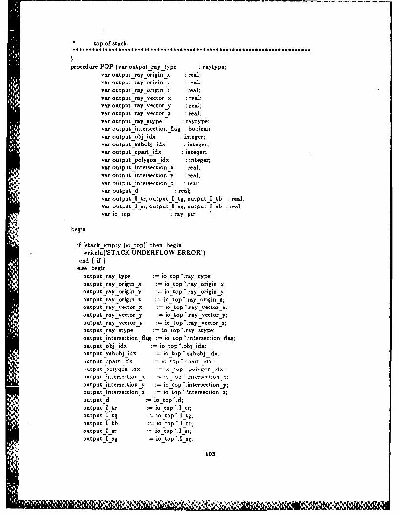
top of stack.
procedure POP (var output-ray_type : raytype;var output ray origin x :real;var output _ray _originy relvar output -ray -origin-z :real;var output -ray -vector x real;var output -ray -vector-y real;var output -ray -vector z real;var output raystype raytype;var output -intersect ion_-Rag boolean;var output obj idx integer;var output -subobj _idx integer;var output -cpart-idx integer;var output-polygon idx :integer;var output-intersection x real;var output _intersection _y :real;var output intersection -7 real:var output d real;var output_-I -tr, output _I-tg, outputI-tb :real;var output -I -sr, outputI-sg, output _ I -sb real;vario top :ray ptr )
begin
if (stack empiy (io top)) then beginwriteln('STACK UNDERFLOW ERROR')
end ( if )else begin
output-ray-type io-top ^.ray-type;output -ray -origin _x io-top ^ray-origin-x;output -ray -origin J io-top ^.ray origin-y;output-ray-origin-z io-top ^.ray-origin_2;output -ray -vector x io top^.ray vector x;output -ray -vector-y io top ^.ray-vector-y;output -ray _v ector 2 io top ^.ray-vector-z;output -ray -stype io top^.ray-stype;,output-intersection -flag io top ^intersection -flag;output-obj-idx :=io top ^obj idx;output -subobj -idx :io top^.subobj-idx;)IutU -,:Part idx - o -too --oart -idx:
,atput _poiygon idx io op .oivg0l _Ax:
uAtpuL -intersection _x iou .ntersevtion_ :
output _intersection _y io-top^ intersection _y;output intersection z :=io-top. .intersection _z;output-d :io-top ^d;output _I tr :=io-top ^.I-tr;outputI_tg io-top^.I-tg;outputI-tb io-top ^.I-tb;outputI-sr :=io-top ^.I-sr;outputI-sg jo-top~.~g
* 103

output_I_sb := io_-top ._sb;raynext := 10 top-.ray link;
{ remove old pointer }dispose(iotop);
{ set top of stack pointer to new top of stack )io top := ray next;
end; eiseend; { POP }
{.PA){
*************************** PUSH ** CALLED FROM: MAIN, 12, 16
* CALLS TO: NONE* DESC : Places a ray on the top of the stack.* INPUT: The current top of the stack, and the data for a new ray
* OUTPUT: The pointer to th new top of stack.
}procedure PUSH ( input ray type : raytype;
input ray origin x :real;input-rayorigin _y real;input _ray _origin _z :real;input-ray _vector x reai;input ray vectory :real;input ray vectorz :real;
Ninput ray stype : raytype;input-intersection flag : boolean;input obj idx : integer;input-subobj idx :integer;input-cpart idx : integer;input polygonidx : integer;input intersection x :real;input-intersectiony : real;input-intersection _z : real;inputd : real;input_Itr, input_Itg, input_I tb : real;inputI-sr, inputIsg, inputI sb : real;
var iotop :ray ptr );
begin
-ewlrav :urr-nti:7av ,-urrenE ray ,yV :- input rziy tvyDe:raycurrent .rayoriginx := inputray_origin_x;raycurrent .ray. originy := input-rayoriginy;raycurrent .rayorigin_z := input-ray origin_z;ray _current .ray_vector x := input ray vector x;ray-current .ray_vector_y := input ray vectory;ray current ^.rayvectorz := input ray vector z;ray._current ^.ray stype := input ray -type;ray current ^.intersection flag := input intersection _flag;
104

rav current ^.obj idx input obi idx;ray-current ^.subobj idx input _subobj _idx;ray -current ^.cpart _idx input-c part _idx;ray-current ^.polygon-idx input -polygon _idx;ray -current ^.intersection _x input -intersection _x;ray currpnt ^.intersection Yv input _intersection _v:ray -current intersection z input -intersectionray -current -.d input-d;ray -current ^.1_tr input I tr;ray _current ^.I _tg inputI tg;ray-Current ^.I-tb inputI-tb;ray ',urrent '.T sr input _I sr:ray -current ^.I -sg inputI1sg;ray _ current ^.1 sb inputI1sb;ray-current ^.ray-link := o top;Jo-top ray-current,
end; {PUSH}
105

MAIN
PROGRAM RAYTRACER;{
.**. * . ..***. * . .*** . *** ..*..*.** .** ..... *.*.......
PROG RAY.PAS** AUTHOR : Paul G. Smith
* DATE :11 May 1987** DESC A ray tracing prototype with a global illumination model
integrated into it.** INPUT : A sequential scene file under PICTURE.PAS.** OUTPUT : A bitmap file containing the red, green, and blue color
color components. Their values range from 0-1 and need to** be converted for display on an RGB color monitor.
{ * INCLUDE FILES * }
{$I declare6.pasl - { DECLARATION SECTION }{.PA}{$1 intprcso.pas} - { INTERSECTION PROCEDURES }{.PA}{I procs6.pas} _ { INTENSITY and UTILITY PROCEDURES }
{.PA}.J. {
*********************************** 12 ********************************
* CALLED FROM: MAIN* CALLS TO: PUSH, POP, CALCULATE INTENSITY* DESC : Calculates the light intensity at a given intersection point* INPUT : A complete ray data record, the pointer to the light array* and the pointer to the object array* OUTPUT : The intensity at a given intersection point. If the input* was a view ray then this intensity will be the intensity* displayed. If the input ray is a reflected ray then this
intensity is assigned to the I s field in the source ray.If the input ray is a refracted ray then this intensity isassigned to the I t 9eld in the source ray.
procedure 12 (id : real;I _tr, i_I tg, i _I _tb real;
iIsr, iI sg,i _I sb real;i number of light _sources : integer;i-ambient r, i ambient g, i ambient b reaLi-K ar,i K ag, iKab real;i K sr,i _K sg,i _K sb :real;
106

iK tr, i K _tg, iK tb : real;i-Kdr, I_dg, ik- db -.real-,i-ray-type raytype;iray-top :ray-ptr;_-light-top light-ptr;i obj _ptr object _ptr:iobjphong-exp : nceger:
i-ray-vector-x,_-ray-vector-y,i-ray-vector z real;Sintersection x,iintersection _y.iintersection z :real;s~urface -normal -x,
i~raenormal z real;
varic - ay-gnoraion -number : integer-,
vro-intensity-red,Ao -intensity -green.
o-intensity-blue :real )
SE PTEMPORARY AREA TO HOLD RAYS POPPED FROM STACKtep rytp raytype;
tempi ray _origin x,tempt _ray origin _y,tempt _ ray _ origin z : real;tempt-ray-vector-x,tempi _ ray -vector-y,tempi _ ray _ vector z : real;tempi _ray stype : raytype;temp 1 _intersection -flag : boolean;tempi obj idx,tempi -subobj-idx,tempt _ cpart-idx,temp I polygon -idx : integer;tempi _ intersection _x,tempi intersection y,tempi Iintersection _Z : real;tempt _d : real;tempt _I -tr, tempi _ I -tg, tempI_I_tb :real;temol I sr. tempi _I _sg, tempi I :,b real:
eMD2 'ay pe av"Wtvpe:temp2 ray-origin -x,temp2_-ray _origin -y,temp2 _ ray _ origin _z : real;temp2_ray _vector-x,temp2_-ray _ vector-y,temp2_-ray _ vector z : real;temp2_ray stype : raytype;temp2_in tersection -flag : boolean;
107

temp2_obj idx,temp2_-subobj. idx,temp2_c partjidx,temp2_-polygon idx integer;temp2_intersection x,temp2 intersection _Y.
cemp2_incerseccion z real;temp2_d :real;temp2_I -tr, temp2_I_tg, temp2_1_tb real;temp2__sr, temp2_I_sg, temp2 I sb real;
begin
{CALCULATE INTENSITY OF THE RED COMPONENT OF LIGHT)}calculate-in tensity( red,
iambient _r,iI tr,i -1-r._-ray _vector-x, i _ray _vector_y, i-ray vector z,inumber of -light sources,iK -ar,i K sr,i Ktr,
u.i-K-dr,
i ob _phong exp,_ -intersection-x,i_intersection -y,_ intersection _2,isurface-normal-x,
i surface -normal-y,isurface-normal-z,
i-obj-ptr,i-light-top,o intensity-red )
{CALCULATE INTENSITY OF THE GREEN COMPONENT OF LIGHTc alc ulate in tensity( green,
_ d,i-ambient_g,S-I -tg,I Tg
_ray _vec.tor _x. ray -vector , -rav -vpctor
i umoer r ijght Jokirres.
i-K ag,i K sg,i-Ktg,iK dgp
i -obj-phong-exp,i-intersection x,i-intersection _y,iintersection _z,
108

i surface -normal _x.isurface-normal-y,i surface -normal _z.iobj _ptr,
ihlght-top,n -intensity -green 1;
CALCULATE INTENSITY OF THE BLUE COM1PONENT OF LIGHT}calculate -ntensity( blue,
i d,i ambient b,
I Ttb,I lsb,
i ray-vector-x, i-ray _vector-y, i-ray vector z,i-number -of -light-sources,
i K ab,i K -sb,i K _tb,
iobj-phong-exp,iintersection _x,i intersection _J,
i !ntersection Z.isurface normal x,isurface-normal-y,
i -surface -norma & z,iobj-ptr,
a-light-top,o -intensity -blue )
if (i ray _type = view) then begin
THE VIEW RAY IS ALWAYS THE LAST RAY ON THE STACK WHEN IT IS POPPED THEINTENSITY DETERMINED FOR IT IS PASSED BACK INTO MAIN FOR DISPLAY.
{nothing}end
else begin
df (i _ray _type = reflected) then begin
-'NaTHIS !S TH-E REFLECT7ED) RA'Y THEN ]UST ).NE RAky' \EEDS TO BE POPPED T0kl% rNX2 o) TH1E SOURCE RAY0
POP (tempi _ray _ type,tempi Iray _origin _x, tempi _ray _origin _y, tempt _ray _origin _z,tempi _ ray _VectorX, tempi ray _vector _y, tempt _ray _vector _z,tempi _ray-stype,templ -intersection -flag,tempt _obj _idx,tempt _subobj _idx,
109
* -. . *-I -'-,

tempI _cpart idx,temptpolygonidx,temp 1 intersection x, tempt -intersection y. tempt -intersection _z,tempi-d,templ._I_tr, templI_tg, templl tb,tempi _sr. tempt _ sg, tempt_I _sb.-ay _op );
{ SET INTENSITY IN SOURCE RAY }tempiI sr o intensity-red;tempt I_sg ointensitygreen;tempiI_sb o intensity blue;
RESTORE STACK )push( tempi ray type,
tempi _rayoriginx, tempirayoriginy, templray_origin z,tempi _rayvectorx, tempi -ray vector y, tempi ray vectorz,tempi ray _stype,tempt intersection _flag,tempt-obj idx,tempt_subobj-idx,templ_cpartidx,tempi _poLygon idx,tempIintersection _x, tempi _intersection _y, tempi_intersection z,temptld,templ_I_tr, templ_I tg, templ_I_tb,tempt _Isr, tempt_I sg, tempiI Isb,ray_top
endelse begin0 {
SINCE THIS IS THE REFRACTED RAY TWO RAYS MUST BE POPPED TO GAIN ACCESSTO THE SOURCE RAY.
pop (tempiraytype,
tempirayorigin__x, tempi ray origin_y, tempt ray origin z,temptlrayvectorx, templ ray vector y, templrayvectorz,templraystype,tempt-intersection flag,tempi obj idx,temp I _subobj _idx.rempt 7part _dx,rempt _polygon dx.
tempi _intersectionx, tempi _intersection _y, templintersection z,tempi d,templ_Itr, templ_I_tg, temptlI_tb,templ_I_sr, templI_sg, tempt _Isb,ray-top );
pop (temp2 ray type,temp2 ray origin _x, temp2 ray _origin y, temp2 ray origin _z,
110

temp2_ray-vector-x, temp2 ral' vector y. temp2_ray-vector z,temp2_ray-stype,temp2_intersection-flag,temp2_obj_idx,temp2_subobj_idx,temp2 _cpart _idx,temp2_poiygon-idx,temp2_-intersection _x, temp2_intersection-y, tem p2 intersect ion 2.temp2_d,temp2_I-tr, temp2_1_tg, temp2_I tb,temp2_-I -sr, temp2_I_sg, temp2_I sb,ray-top )
{SET INTENSITY IN THE SOURCE RAY.temp2 I tr a-intensity-red;temp2_I-tg o-intensity -green;9emp2_I_tb o-intensity-blue;
RESTORE STACK. }push( temp2_ray-type,
temp2_ray-origin-x, temp2_-ray -origin y, temp2_-ray -origin _z,temp2_ray-vector-x, temp2_ray_vector-y, temp2_ray vector-z,temp2_ray stype,temp2 intersection -flag,temp2_obj-idx,temp2-subobj-idx,temp2_-cpart-idx,temp2 polygon-idx,temp2 -intersection _x, temp2_-intersection _y, temp2 intersection z,temp2_d,temnp2_I 'tr, temp2_I_tg, temp2_I_tb,temp2_I-sr, temp2_I_sg, temp2_I-sb,ray-top
push( templ 1_ray-type,tempi -ray -origin -x, tempi _ ray -origin-y, tempi -ray -origin _z,tempi-ray-vector-x, tempi _ray-vector-y, tempi-ray-vector-z,ternpl-ray-stype,tempI -intersection -flag,tempi-obj-idx,tempi -subobj-idx,teMDi - part -idx..'empi __,ohygon _ Idx,
empi nmtersecron _x. ,empl ;ntersection J, trempi Jntersection .
tempi-d,tempi _I -tr, tempi _I tg, temp _I _tb,ternpl _I-r, tempi _I2g, tempiI-sb,ray -top
end;
SINCE THE RAY SENT INTO THIS PROCEDURE IS NO LONGER NEEDED IT IS

DISCARDED, HENCE THE RAY COUNT NEEDS TO BE DECREMENTED.
io ray -generation -number :=io -ray -generation -number - 1;end;
end;
{.PAJ
*CALLED FROM: MAIN*CALLS TO : PUSH, POP, CALCULATEINTENSITY*DESC : Used to calculate intensity at node of stack storage is
* exceeded.*INPUT : Incomplete ray data record, this ray can not be continued
* because there is no room on the stack for it. Also pointers* to the fight array and object array.
*OUTPUT : Intensity, I t or I s, is set in source ray.
procedure 16 (i d :real;i I tr, i I _tg, iI tb :real;ilIsr, i I sg, i _I _sb :real:_ -num ber-of-light -sources : integer;
i ambient-r, i-ambient _g, i _ambient b :real;iK-ar, iK-ag, iK-ab :real;iK-sr, iK-sg, iK-sb :real;iK-tr, iK-tg, i_K_tb :real;iK-dr, iK-dg, iK-db : real;iray-type :raytype;_ ray_t op :ray-ptr;_-light-top :light_ptr;iobj ptr :object_ptr;
i-objphong-exp :integer;iray-vector x,iray-vector-y,_ -ray _vector z :real;S-intersection-x,Sintersection y,Sintersection z :real;_surface -normal -x,i surface -normal Y,i _uri ace iormai z el
var, - ntensitv -red.o -intensity-green,o intensity -blue : real )
v axSTORAGE FOR POPPED RAYS}
'Ntempi _ray type : raytype;tempi _ray _origin -x,tempi Iray -origin y,
112

temnpi _ray _o-rigin _z :real:tempi _ ray -vector-x,tempi _ ray -vector-y,tempi -ray -vector z : real;tempi _ray -stype :raytype;temil intersection flag -boolean:tempi _ bj idx.tempi -subobj-idx,tempi _cpart -idx,temp I_plygon idx : integer;tempi -intersection_x,Lemp I -intersection _y,tempi1 intersection z :real;tempi _d :real;tempi_-I -tr, tempiI-tg, tempi _I-tb :real;templi Isr, tempi _I2g, tempiI _sb :real;
temp2 _ray _type : raytype;emp2 _ ray _')rigin _x.
temp2_ray origin y,temp2_ray -origin _z : real;temp2_-ray _ vector-x,temp2 _ ray _ vector v,temp2_-ray -vector z : real;temp2_ray -stype : raytype;temp2_-intersection-flag :boolean;temp2_obj idx,temp2_-subobj-idx,temp2_-cpart-idx,temp2_-polygon-idx :integer;temp2_-intersection _x,temp2_intersection-y,temp2_intersection z :real;temp2_d :real;temp2 _ I tr, temp2_I-tg, temp2_I_tb :real;temp2_I-sr, temp2_I_sg, temp2_I_sb real;
begin
{~COULD INSERT TREE EXTENSION PROCEDURE ~
CALCULATE RED COMPONENT OF LIGHT kA caiculiate Jnterlsicv( red.
iambient-r,I-1tr,
1i1-sr,iray-vector-xi-ray _vector-y, i-ray _vector-z,inumber-of-light _sources,
i-Kar,i-K-sr,
113
.- 'L

i K dr.i -obj-phong-exp,i intersection _x,
i - ntersection-y,_intersection-z,i surface -normal1_x.isurf ace normai v.
i-surface -norml & z.i-obj-ptr,i light-top,o-intensity-red )
{CALCULATE GREEN COMPONENT OF LIGHT}calc ulate-in tensity( green,
id,iambientjg,
i I tg,ilIsg,i ray -vector _x. i -ray -vector Y, i -ray -vector _z.inumber -of -light -sources,
i K ag,
i -K tg,i Kdg,i -obj-phong-exp,iintersection-x,i-intersection-Y,_-intersection-z,isurface normal x,isurface-normal-y,isurface normal-a,
i-obj_ptr,i-light-top,o -intensity green);
CALCULATE BLUE COMPONENT OF LIGHT)calculate-intensity( blue,
i-d,iambient b,
i I tb,ils2b,iray vector x. i av vector v,. ray vector z,t iumoer d light _,ources.
r\ ib.
i K sb,i K tb,i-Kdb,i -obj-phong-exp,i-intersection _x,i-intersection-y,i intersection _z,i surface -norma & x,
114

isurface-normal-y,s-urface-normal-z,
i-obj _ptr,i-light-top,o intensity -blue);
if (i-ray-type = reflected) then begin
IF INPUT RAY IS A REFLECTED RAY THEN ONE RAY MUST BE POPPED TO GAINACCESS TO IT'S SOURCE RAY.
pop (tempI -ray _type,tempi _ray_origin-x, tempi -ray _origin -y, tempi _ray-origin-z,tempi _ray_vector-x, tempi-ray-vector y, tempi-ray-vector-z,tempi-ray~stype,tempi -intersection -flag,tempi obj _idx,tempi _subobj idx.tempi-cpart-idx,tempi _polygon -idx,tempI -intersection -x, tempi -intersection _y, tempi Iintersection -z,tempi _d,tempi _I-tr, tempi _I-tg, tempi _I-tb,tempiI-sr, tempi _I-sg, tempi _I2b,iray-top )
(SET Is IN SOURCE RAY}tempi _I-sr := o-intensity-red;tempi _ I - g o -intensity -green;tempi _I-sb a-intensity -blue;
{RETORE STACK. Ipush( tempi -ray Wtype,
tempi _ ray -origin x, tempi ray-origin-y, tem pi-ray -origin 2,tempi _ ray -vector x, tempi-ray-vector-y, tempi-ray-vector-z,tempi ray~stype,tempt-intersection-flag,tempi-obj-idx,tempi -subobj-idx,tempi _cpart _idx,tempt nolvgon _idx.:emD i ntersertion _v, tempt I fltersection z, .eMDL tersection J.
temnpi d.tempt _ I -tr, tempi _I-tg, tempi _I-tb,tempt _I-sr, tempi _I-sg, tempt _I-sb,ray-top
endelse begin
115

IF INPUT RAY IS A REFRACTED RAY THEN TWO RAYS MUST BE POPPED FROM THESTACK TO GAIN ACCESS TO IT'S SOURCE RAY.
POP (tempi -ray -type,tempi ray -origin -x, tempi _ ray _ origin _ y, tempi _ray _origin z,tempi -ray _vector x. tempi -ray _vector _y. tempi -ray _vectu. _z.CeM~ji._raystype,tempi -intersection -flag,tempi obj idx,tempil-subobj-idx,templ-cpart-idx,tempt-polygon -idx.tempi _ntersection x, tempi _intersection y, tempi intersection z,tempi-d,tempi _I-tr, tempt _I-tg, tempt _I-tb,tempt _ I -ar, tempt _I-sg, tempt _I-sb,ray-top )
pop I temD2 _ray -type.texnp2_-ray -origin-x, temp2_-ray _origin J, tem p2_-ray -origin _z,temp2_-ray -vector-x, ternp2_ray-vector_y, temp2_ray_vector-z,temp2_ray-stype,temp2_-intersection _flag,temp2 obj idx,temp2 -subobj-idx,temp2_cpart_idx,temp2_-polygon -idx,temp2_intersection-x, temp2_intersection-y, temp2 intersection _z,temp2_d,temp2_I-tr, temp2_I_tg, temp2_I_tb,temp2_I_sr, temp2 _I_sg, temp2_I_sb,rvy _top )
{SET THE It FIELD IN THE SOURCE RAY}temp2_I tr o intensity _red;temp2_I tg o intensity _green;temp2_I _tb o-in tensity -blue;
RESTORE THE STACK}push( temp2_ray-type,
temp2_-ray -origin -x, temp2_-ray -origin _y, temp2_-ray _ origin _ z,emp2 -av v.ector x. ternt)2 avvecror .''eMD2 7&V Vector
* pemr)2 nrterserion .Iav.
temp2 obj idx,temp2_subobj idx,temp2_cpart _idxtemp2 _polygon _idx,temp2 _intersection x, tem p2 -intersection y, temp2 -intersection _z,temp2_d,temp2 _I_tr, temp2 _I tig, temp2 1 tb,temp2 _I sr, temp2_ I sg, temp2 I -sb,
V1
*-e wr ee d e e*~*j4~,~ ~ "oc! Z ' &%4

ray-_Lop
push( tempi _ray type,tempi-ray-origin-x, templ-ray-origin-y, temp1 Iray _origin _z,tempi _ray-origin-x, tempi Iray -origin y, tempi 1_ray _origin _z,tempi _ray -stype.rempi fitersection _lag,tempilobj _idx,temipi subobj -idx,temp I-epart-idx,tempi polygon -idx,tempi :ntersection Xc, tempi intersection v, cempi _intersection z.tempi-d,tenpil Itr, tempiI-tg, tempi _I-tb,temipl Isr, tempiI-sg, ternpl _I sb,ray-top
end;
And:
(.PA)
.. .. WSSS MAIN Sfl**S4*S4tEs*z.*}
begin{INPUT FILE)}
assign (sysin, 'picture5.pas');reset (sysin);
{OUTPUT FILE}assign (outfile, 'picO.dta');rewrite (outfile);
SET UP COUNTERSobj cntr 1subobj cntr 1light _cntr 1;'Dart, _ ntr t:-)oiv -ntr = I
{CREATE POINTERS TO RECORDS}new(obj curr);new(subobj -curr);new(cpart -curr);new (light -current);new (poly-curr);
117
dip~

.. READ IN DATA FILE..
{READ IN PICTURE RECORD}readin (sysin, picture.view position _x);readin (sysin, picture.view _position _y);readin (sysin. picture.view -Position _z):7eadin sysin, Picture. .oackgrouna -oiorr!readln (sysin. Dict ure. background _color Y);readin (sysin, picture. background -color-b);readIn (sysin, picture.screen max -X);readin (sysin, picture.screen-rnax-y);readln Isvsin. picture.ambient _r'):readIn (sysin, picture. am bient-g);readIn (sysin, picture.ambient b);readin (sysin, pictureno zero);readIn (sysin, picture. global-refraction _index);readin (sysin, picture.num -lights);picture.lights :=light-current;
while picture.n um-lights > 0 do begin
{READ IN LIGHT DATA)}readin (sysin~light _current ^Ihight _cntr '.I _r);readir i sysin, light -current "ilighL _cntr;.Ig;readln (sysin,light current ^[light _cntr!.1_b);readin (sysin,light current ^[light _cntrj.li:gh t _x);readin (sysin,light -current ^[light -cntrj. light _y);readin (sysin,light current '[light_cntrl.light_z);readin (sysin,light -current ^[light _cntrl dimension 1);readin (sysin,light -current Ilight -cntr] .dimension2);light _ cntr :=- light _cntr + 1)
picture.num-lights := picture.num -lights - 1;end;,readin (sysin, picturenum _objs);object _ loop -cnit := picture. num _objs;pictureobjects := obj _curr;
while object loop cnt > 0 do begin{READ IN OBJECT DATA )
readin (sysin, obj-curr^[obj cntrJ.opcode);roadln (svsin. cobj _curr ^obj crntr'.obj _bsphere -radius):-pauln 'zvsin. )61 tjrr )n itr:_ubj 6spn*ere 'c):
-,fl vsin. orj :irr )j -ntr' )rj -)sDhere v!readin (sysin, opojcurr oo[o I cntr,.ooj Ospniere_z);readln (sysin, obj -curr '[obj -cntrl. num -sub -objects);subobj _ loop -cnit := obj _ curr'J[obj cntri.numn-sub-objects;picture Objects ^[obj entri-sub-objects :=subobj curr;
while -subobj _loop cnt > 0 do begin{READ IN SUBOBJECT DATA )
readln (sysin, subobj-curr^ [subobj _cntrJ .subobj -type);
118
. . . . ...... .... k

readin (sysin, subobj curr -subobj _cntrI.sub bsphere -radius);readin (sysin, subobj -curr-Isubobj cntrj -sub bsphere x);readln (sysin, subobj -curr -[subobj -cntrl .sub _bsphere _y);readin (sysin, subobj Curr- subobj c ntrj .su b osphere2z);readin (sysin, subobj curr-[subobj cntrl .nurn common parts);cpart _loop-cnt :=sbobj _currifsbobj _cntrj.-numco onprspicrureobjeccs - obj _cntr,.sub _ bjects s uobj -,,ntr'. common -:arcs
cpart-curr;
while-cpart loop cnt > 0 do begin( READ IN COMON ~fPART DATA I
readln(sysin, cpart _ curr - cpart cntrl.K an,;readln(sysin, cpart -curr - cpart cntri.K ag);readln(sysin, cpart _ curr - cpart -cntrl.K -ab);readln(sysin, cpart-curr -cprt-cntrJ.K-dr);readln(sysin, cpart -curr 1cpart -cntr].K -dg);readln(sysin, cpa~rt _curr -cpart-cntr.K-db);readln(sysin, cpa~rt-curr [cpart-cntrJ.K-sr);readln(sysin, cpart _curr I cpart _cntr>.K sg);readlntsysin, cpart -curr 'jcpart -cncrj.K -sb);readln (sysin, cpart -curr ^ Icpart -cntrj .K-tr);readln(sysin, cpart-curr fecpart cntr1.K-tg);readln(sysin, cpart _curr ^'cpart-cntr.K _tb);readln(sysin, cpart -curr ̂ cpart cntri.obj -refraction -index);readln(sysin, epart-curr -cpart cntrf .obj _phong-exp);
{CHECK TO SEE IF SUBOBJECT IS A SPHERE OR A POLYGONAL OBJECT}if (subobj-c urr ^[subobj -cntrl.subobj -type = 1) then begin
readln(sysin, cpart -curr ^[cpart -cntr] n um _polygons);poly-loop-cnt :=cpart-cu" -[cpart-cnitri -num -polygons;picture.objects ^ obi cntrj sub -objects -[subobj -cntr].
common parts -[cpart cntri. polygons := poly-curr;
while poly loop cnt > 0 do begin{READ IN POLYGON DATA }
readin (sysin, poly -curr ^[poly cntr]. n urn -vertices);vertice-loop-cnt :=poly -curr ^Ipoly-cntr. num -vertices;
while vertice loop cnt > 0 do begin{READ IN VERTICE DATA -)
readln(sysin. poly -curr ̂ polv ':ntr1.vPrtice Xcvertice -cntri);7eaulnisvsin. Doiy p-urr poly _:fltr!.vertlce y ertice -r)-eadinisysin. -)oiv .2lirr poty - nir,.vortice jverticc -cntr-;verice cntr :=vercice cntr -r- 1;vertice-loop-cnt := vertice loop cnit - 1;9
end;vertice cntr :=1;readln(sysin, poly _ curr [poly -cntr] .surface -normal _ x);readln(sysin, poly _curr ^poly -cntrj .surface -normal _ y);readln(sysin, poly _ curr ^[poly -cntrj .surface-normal-z);poly _cntr poly-cntr + 1;

polyloop cnt := polyloop cnt - I
end;polycntr 1;new(polycurr);
end;IFI,. cpart-cntr := cpart cntr - ;
cpart-loop-cnt := cpartloopcnt - I
end;cpartcntr 7= 1:new(cpartcurr);subobj-cntr := subobjcntr + 1;subobj-loop-cnt := subobjloopcnt - I
end;new(subobj-curr);subobj _cntr = :obj _cntr := obj cntr -r 1;objectloopcnt := objectloopcnt - 1
end;
{.PA}
{ SET RAY STACK POINTER }ray top := nil;
pixel z := initial pixel z;
{ RASTER SCAN LOOP }for pixel y := I to picture.screen max._y do begin
for pixel x := I to picture.screen max _x do begin
{ DETERMINE VIEW RAY DIRECTION }x pixel_x - picture.view _position _x;y pixely - picture.view-position _y;z pixel _z - picture.view _position _z;dist := sort(sor(x - sqr(y) - or z) :
N)'3NVERT I T TO \ 'NI 'ECTORinltx X x ist:
unity y / dist;unitz z / dist;
{INITIALIZE VIEW RAY}initialraytype := view;
initialrayorigin _x pixel x;initialray-originy pixely;
initialray _origin _z pixel z;
120
46 ks *%C ~~*/N-

initial ray vector x unitx:initial -ray vector v := unity:initial _ray _vector z unitz;initialray _stype := none;initial intersection _flag := false;initial -obi idx := 0:initiai _uoobj dx =):
initial 2:part idx 0;initial polygonidx := 0;initial intersection x 0.0;initial -intersection-_y := 0.0;:nitial ntersection z 0.0:
initial-d 0.0;initial-I tr 0.0;initialI tg =0.0;initial I tb = 0.0;initial I sr 0.0;initial I sg = 0.0;nttiaij _i = 0.0:
ray generation number := 0;
pusht initial ray type,inuaitilray _origin _x,initiai -ray _origin _y,inital ray _origin _z,initial ray vector x,initial ray vector y,initial ray vector z,initial ray _stype,
initial intersection flag,initial obj _idx,initial subobj _idx,initial cpart idx,initial polygon _idx,initial intersection x,initial intersection _y,initial in tersect ion _Z,initial-d,initialI tr, initial_Itg, initial_Itb,initial I sr, initial I sg, initial _Isb,ray-top
{ BEGIN RAY TRACING LOOP }9 n)eat
-op ,urrenr :xy *ype.
current _ray _origin _x,current _ray _origin _y,current ray _origin.z,current _ray _vector x,current ray vector y,current -ray _vector z,
currentraystype,current intersection -flag,current obj idx,current-subobj idx,current cpaxt_idx,current _polygonidx,
121
n" ,_ran

current intersection X.current intersection _y.current intersection Z,current-d,current _tr, current I tg, current I tb,'urrent 1 sr. current I -9, current I sb.
V -top
if (current._intersection-flag) then begin{
IF THIS FLAG IS SET THEN THIS RAY HAS ALREADY BEEN THROUGH THE RAYTRACING PROCESS AND HAS HIT AN OBJECT.
cprtpath := picture.objects I[current obj idx].subobjects ^[current subobj _idx[.common_parts;
subobj path - picture.objects ^[current _obj _idxj.sub-objects;
if subobj _path " current _subobj _idxi.subobj _type = 0 then begin{
IF THE SUBOBJECT TYPE IS A SPHERE THEN THE SURFACE NORMAL AT THE POINTOF INTERSECTION MUST BE CALCULATED SINCE IT CAN NOT BE STORED. THE SURFACENORMAL IS DETERMINED FOR THE PLANE TANGENT TO THE SPHERE AT THEINTERSECTION POINT.I
surface normal x := current intersection x-subobj path [currentsubobj idx[.sub-bspherex;
surface normal y := current intersection y-subobjpath "[currentsubobj idx].sub-bspherey;
surface normal z := current intersection z-subobj path "[current_subobj idx.sub-bsphere z;
list - crtf sor(surface normal xl -
-qrl surface format :i -
icmr surface _normal _ i)):
{ THIS RAY IS THEN CONVERTED INTO A UNIT VECTOR }surface normal x surface normal x / dist;surface-normal-y surfacenormaly / dist;surface normal z := surface normal _z / dist;
endelse begin
122
• ., ,, . .. . . . ,,, •,. . . - , , :,, . . -,:-, -. ,. .. - ,, . ,....-... -,. .. . ., .- %

IF THE SUBOBJECT IS A POLYGONAL OBJECT THEN THE SURFACE NORMALS FOR EACHOF THE POLYGONS OF WHICH IT IS COMPOSED IS RETRIEVED FROM IT'S RECORD.
surface -norma & x :=cpart pach jcurrent _cpart _idx,polygons ^ [current -polygon idx).surface -normal _x:
surface-normal-y :=cpart _path^jcurrent _c part _idxpolygons ^[current -polygon idxi.surface-normal-y;
surface normal z :=cpart path ^Icurrent _cpart _idx,.
polygons -[current -polygon idx[.surface normal z;
end;
PROCEDURE FOR DETERMINING THE INTENSITY OF LIGHT AT EACH INTERSECTIONPOINT.
12 (current -d,current- _I tr, currentI -tg, current _ I -tb,current-I _ sr, current I _g, current I tb,picture.num -lights,picture.ambient r, picture.ambient _g, picture.ambient b,
N-..' cpart path^[current cpart _idx].K &r,cpart path [ current cpart _idxj. K-ag,cpart path ^[current -cpart _idx.K_ab,cpart -path ^[current -cpart -idx] .K -dr,cpart path ^[current_cpart_idx[.K_dg,cpart path '[current -cpart -idx.K-db,cpart -path ^[current -cpart -idxl.K sr,cpart-path ^1current-cpart_idx[.K-sg,cpart -path ^[current - part -idx].K -sb,
cpa pahIcurrent-cpart-idx[.Ktr,cpart -path ^[current _ cpart -idx[.K -tg,
cpr pat Icurrent -cpart-idx[.~ bcurrent -ray-type,ray top,picture.lights,picture.objects,cpart _ path ^ current _ecpart -idx'.obj Dhong -,xro.
urrenc _-av -,ecior <
*urrent. -av -,P~-rorcurrent-ray-vector-z,current -intersection _x,current -intersection _y,current -in tersec tion _z,surface -normal _x, surface -normal _y, surface normal z,ray generation number,intensity-_red,intensity _green,
123

intensity -blue),
endelse begin
{CHECK FOR POSSIBLE INTERSECTIONS OF CURRENT RAY WITH OBJECTS IN SCENE}*check -for Linterseccion(currenc -ray _veccor,,
current -ray _vector _y,* current -ray -vector-z,
current -ray -origin -x,current-ray-origin-y,current _ray _origin _z,picture.objects,current intersection x,current _intersect ion-y ,current intersection z,current~obj-idx,current subobj idx,current CDart .;dx,currenE-polygon -idx,current -intersection flag);
SET UP PATHNAMES TO USE AS SHORTHANDsubobj-path :=picture.
objects ^[current-obj _idxj.sub-objects;
cpart-path :=picture.objects ^[current -obj _ idxj.
* sub-objects^[current subobj -idx[.common-parts;
if subobj _path^ [current - ubobj-idxl.subobj -type =0 then beginsurface -normal -x :=current -intersection x X
subobj path [Icurrent -subobj -idx[.Ssub bsphere x;
*surface -normal-y :=current -intersection -
subobj -path ^[current -subobj -idxj.sub -bsphere-y;
*surface -normal -z :=current -intersection -z-subobj _ path '-current _subobj -idxl,
116 -sDhere ,
list = r i "Irtl qrsurt .ace riormai <) -
sqrtsurface normaily)sqr (surface -normal Az));
surface normal x :=surface normal x /dist;surface normal y surface normnal y /dist;surface -norm al Z surface normal z /dist;
endelse begin
124

iurface -normal -x :=cpart _path 'current _c part _idx!.polygons - fcurrent -polygon _idxl.surface -normal -x.
surface -normal -y :=cpart-path ^[current -cpart -idx}.polygons Mfcurrent -polygon -idxl.:surface -norm ai -y;
surface normal z :=cpart_path ^[current-cpart-idxl.polygons ^[current _polygon -idxj.surface-normal-z;
if (current intersection flag) then beginIF THERE HAS BEEN AN INTERSECTION THEN CONTINUE TRACING THE RAY)}
if (stack-exceeded( ray -generation _number,maximum -size _of -stack)) then begin
[F THE STACK IS ALREADY FULL THEN C ALCULATE INTENSITY AT LAST NODE
16 (current -d,current _I tr, current _I tg, current I _tb,current I sr, current I _sg, current I tb.picture. n um -lights,picture.ambient r,picture. ambient g,picture. ambient -b,cpart path ^[current-cpart-idxj.K-ar,cpart__path -[current -cpart idxl .K -ag,cpart path ^[current-cpart-idx].K-ab,cpart path ^Icurrent -cpart-idx].K -dr,cpart pah*cren~pr~dx].K dg,
_prtpath ^[current -Cprtidx1 Kdbcpart path ^[current -cpart -idxl.Ksr d,cpart path ^[current-cpart-idxj.K-sr,cpart-path ^1current-cpart-idxl.K-sb,cpart path ^[current-cpart-idxl.K-tr,
cpart-path ^current-cpart-idx].K-tg,cpart path ^[current-cpart-idxl.K-tb,current -ray _type,ray _top,oicture. lights.
-Dart -)a~n ourrent p-Tarr Ax,.o u :j ng -xp.
current -ray _vector-x,current _ray _vector-y,current _ray _vector-z,current -intersection -x,curn -itreciny
current intersection _y,
surface normal x,surface -normal -y,
125
9%

surface normal z.intensity red,intensity _green,intensityblue)
endelse begin
IF THERE WAS AN INTERSECTION AND THE STACK WAS NOT FULL THEN CALCULATETHE DISTANCE BETWEEN THE RAY'S ORIGIN AND POINT OF INTERSECTION AND PLACETHE RAY BACK ON THE STACK.}
current d := (sqrt(sqr(current _intersection x -current ray originx)) -r
(sqr(current intersection x -current rayoriginx)) +
(sqr(current _intersection x -
current _ray _origin _x));
push( current ray-type,current ray origin-x,current ray origin-y,current _ray _origin _z.
current _ray _vectorx,current _ray vector, y,current _ray vectorz,current ray stype,current intersection flag,
current obj idx,currentsubobj idx,current cpart-idx,currentpolygon idx,current intersection x,current -intersection-y,
current intersectionz,currentd,currentI tr,currentI tg,current I tb,current I sr,current _Itg,current I 2b.-ay r~oo
{ DETERMINE IF A REFLECTED RAY WAS CREATED AND IF SO CALCULATE IT }calculate reflected ray (current _rayvector x,
current _ray _vector y,current ray vector_z,surface normal x,surface-normal-y,
surface normal z,reflectedrayx-
126
• • ' *, , " S ,' , • '' S ' " . . . . ' • " *" " - -" "

reflectedrayy,reflected -ray z,
reflected-ray );
{ DETERMINE IF A REFRACTED RAY W kS CREATED AND IF SO CALCULATE IT }calcuiate refrac ted ray (current ray vector _x.
current ray vectory,current ray vector z,surfacenormal x,
surface-normal-y,surface normal z,cpart_path"[current-cpart_idx].objrefraction index,
picture.global refraction index,refracted -ray -x,refracted _ray y,refracted _ray z,refracted ray
raygeneration number := ray generation number + 1;
if reflectedray then begin
{IF A REFLECTED RAY WAS CREATED THEN INITIALIZE IT AND PUSH IT ON THE
STACK.)
sourceray._type := current ray -type;
dist ( sqrt(sqr(reflected _ray _x) +sqr(reflected ray.y) +sqr(reflected ray z)));
{ CONVERT REFLECTED RAY TO A UNIT VECTOR }unitx reflected ray x / dist;
unity reflected ray y / dist;unitz reflected_ray_z / dist;
initial ay _type := reflected;initial ray origin x current intersection _x;initial ray -origin v- current intersection
initial ray origin :urrenc .nrersection- initial ray ¢ector'< inhit:
initial ray vector y unity;initial ray _vector z unitz;initial raystype source -ray _type;initial._intersection -flag := false;initial-objidx 0;initial subobj idx 0;initialcpartidx := 0;initialpolygon idx : 0;
127
a. 1-I"

initial -intersection x O.0:initial intersection y 0.0;initial _intersection z 0.0;initial d 0.0;initialI tr 0.0;initial _I _tg :~0.0:ifliciai I tb J.0
initial I sr :~0.0;initialI sg :~0.0;initialI-sb 0.0;
push( initial ray-ty pe,initial-ray -origin _x,initial -ray-ori gin y,initial-ray -origin _z,initial-ray-vector-x,init ial -ray _vector J,initial -ray _ vector _z,initial -ray i3tvpe.initial -intersection -flag,initial obj idx,initial -subobj -idx,initial-cpart _idx,initial -polygon -idx,initial -intersection _x,initial intersection-y,initial -intersection _z,initial-d,initial I tr, initial I tg, initial _I-tb,initiall1sr, initial-lsg, initialI1sb,ray-top
end;
if refracted-ray then begin
IF A REFRACTED RAY WAS CREATED THEN INITIALIZE IT AND PUSH IT ON THESTACK.
souirce rav type :=current rav tvTe:
iisL ;qIrt~swrrpfracred -ray -x!
sqr(refracted _ray y) +isqr(rerracted _ray _z)));
{CONVERT IT TO A UNIT VECTOR )unitx refracted ray _x /dist;unity :~refracted -ray_y /dist;unit: : refracted _ray _z /dist;
128

initial _ray type refracted;initial -ray _origin _x current -intersection x;initial -ray -origin _ y current -intersection _y;iflitial _ray _origin z current intersection-z;initial -ray -vector x unitx;initial _ray _vector Y unity;initiai rav vector == initzinitial _ ray _sitype source -ray _type;initial -intersection -flag :=false;initial obj idx .0;
initial-Subobj-idx 0;initial -cpart -idx 0:initial polygon idx 0;initial -intersection x 0.0;initial -intersection -y 0.0;initial intersection Z 0.0;initial d 0.0;initialI _tr 0.0;initial _I tg 0. 0;initiaii-Lb J.O;initialI_-sr 0.0;initialI -s g 0.0;initial I -S' 0.0;
push( initial-ray _type,init ial ray -origin _x,init ial-ray -origin y,initia &-ray -origin _z,initial ray-vector-x,initied -ray -vector J,initial ray-vector-z,
'Vinitial ray _stype,initial -intersection -flag,initial obj-idx,initial subobj _idx,initial -cpa~rt idx,initial polygon idx,
initil intrsecton xinitial -intersection _y,initial intersection y,
initial d,initial I _r. initial 1 _tg, initial -1 _tb.nitiat . r. nital -i i nitiat i i.
-av 'or)
end;
erd;end
else begin
129
- - -- .A

if (c urre n t '' '2. vo ie% f h n ,Pli
IF THERE WAS NO INTf;RSECTIo\ kN1) V'HF CI H RENT V AN IS THE %VIEWk RAY, THEN SETTHE OUTPUT INTENSITY TO EIlE BACK.RUI \D) INTENSIT\i
intensity r-d ,icturo- beick~rrnlr )Ir r.nt sirl N vre )wfrurp -4, Kgzr'inli ''' wr
intensivy blue picture bacKground -oior b
end;end;
end;
until (stack empty (ray _top));{OUTPUT THE FINAL INTENSITY)}
display _pixel( intensity-_red,intensity _green,.intensity -blue.
pixel-x,pixel y,pixel _z
endend:
close (sysin);,close (output);
end. { MAIN}
130 *'

APPENDIX B - INPUT FILE
100 ,.xi view position PICTURE100 /y/1000 /z/0.0 /red/ background light0.0 /green/1.0 /blue/200 /x/ screen200 /y/1.0 /red/ ambient intensity1.0 /green/1.0 /blue/1.0 /global refraction index/1 num lights/1.0 /red/ intensity of light source1.0 /green/1.0 /blue/0.0 /x/ position of light source20.0 /y/
0.0 /z/0.0 /dimension1/0.0 /dimension2/3 /num objects/9999 /opcode/ { OBJECT 1 }35.0 /radius of object's bounding sphere/110.0 /x/ center of bounding sphere0.0 /y/-50.0 /z/1 /number of subobjects/1 /subobject type/ {SUBOBJECT 1}35.0 /radius of subobjects bounding sphere/110.0 /x/ center of bounding sphere0.0 /y/-50.0 /z/1 /num-common-parts/ ( COMMON PART 1 }0.8 /Ka-red/ ambient coefficient
' 0.0 /Ka-green/). (. Ka-oiieJA Kdi-re(i iiffuse 'oefficient
J.0 , Kd-green,0.0 /Kd-blue/0.8 /Ks-red/ specular coefficient0.8 /Ks-green/0.8 /Ks-blue/0.0 /Kt-red/ transmission coefficient0.0 /Kt-green/0.0 /Kt-blue/
131

0.0 /obj-refracItilon- index/200 /obj-phong-spec uhIr-exponent,'6 /nurn-polygons/4 /num-vertices/ {POLYGON I}90.0 /polyl ptl/20.0-3.90.0 /polyl pt2/-20.0-30.0130.0 /polyl pt3/-20.0-30.0130.0 /polyl pt4/20.0-30.00.0 /polyl surface normal/0.01.04 /num-vertices/ {POLYOGN 290.0 /poly2 ptl/-20.0-30.090.0 /poly2 pt2/-20.0-70.0130.0 /poly2 pt3/-20.0-70.0130.0 /poly2 pt4/-20.0-70.00.0 /poly2 surface normal/-1.00.04 /num-vertices/ {POLYGON 3)130.0 /poly3 ptl/20.0-70.0130.0 /polyS pt2/-20.0-70.0)0.U poly:; pt3
-70.090.0 /poly 3 pt4/20.0-70.00.0 /poly3 surface normal/0.0-1.04 /num-vertices/ {POLYGON 4}
132

130.0 polv4 ptL'20.0
-30.0130.0 , poiy4 pt2/20.0-70 0)0.0 poiy4 pG3.
20.0-70.090.0 /poly4 pt4/20.0-30.00.0 i'poly 4 surface normal/1.00.04 /num-vertices/ { POLYGON 5 }130.0 /poly5 ptl/20.0-:10. 0
130.0 /poiy5 pL2,-20.0-30.0130.0 ,poiy5 pL3J-20.0
-70.0130.0 /poly5 pt4/
20.0-70.01.0 /poly5 surface normal/0.00.04 /num-vertices/ { POLYGON 6 }90.0 /poly6 ptl/20.0-70.0
90.0 /poly6 pt2/-20.0-70.090.0 /poly6 ptS/-20.0-30.090.0 poly6 Ot4
-1.0 /poiyo surface normail0.00.09999 /opcode/ * OBJECT 2 *175 /radius of the objects bounding sphere/
100.0 /x/ center point of the bounding sphere-100.0 /y/-100.0 /z/
133

I num-subobjectsj I I subobject-type! { SUBOBJECT I }
175 radius of subobjects bounding sphere'100.0 /x, center of bounding sphere-100.0 /y!-100.0 'z'
numoer .ommon parts, I ,,)MM(O N ? kR ' r -0. 0 red, Ka ambient coefficient0.7 /green/0.0 /blue/0.0 /red/ Kd diffuse coefficient
S% !." '- reen% 0.0 /blue
0.8 / red/ Ks specular coefficient0.8 /green./0.8 /blue/0.0 /'red/ Kt transmission coefficient0.0 /green/1).0 blue,
0.0 /objects refraction index/
200 /Phong's specular exponent/1 /number of polygons/4 number of vertices' POLYGON I0.0 poiyl ptL,20.0-200.00.0 /polyI pt2/0.00.0200.0 /polyl pt3/0.00.0200.0 /polyl pt4/20.0-200.00.0 /polyl surface normal/0.990.19999 /opcode/ * OBJECT 3 *40 ,radius of objects bounding sphere/140 /x/ center of bounding sphere
- i.51j
iimOer )f tiOoo!pies,
0 /subobject type/40 /'radius of subobjects bounding sphere/
140 /x/ center of boundint. sphere
30 /y/-150 /z/I /number of common parts/ { COMMON PART 1 }0.5 /red/ Ka ambient coefficient0.0 /green/
134
- - '.0

0.5 /blue/0.5 'red'/ Kd diffuse coefficient0.0 /green,/0.5 /blue/0.8 /red/ Ks specular coefficient0.8 /green
0.8 , blue0.0 /red/ Kt transmission coefficient0.0 /green/0.0 /blue/0.0 /refraction index for object/200 'Phong's specular exponent'
M
.°
.
135
L AS
- 4 4-

LIST OF REFERENCES
1. Rogers, David F., Procedural Elements for Computer Graphics, McGraw-Hill,1985.
2. Cook, Robert L., Porter, Thomas, and Carpenter, Loren, "Distributed RayTracing," Computer Graphics, v. 18, no. 3, pp. 137-145, July 1984.
3. Falby, John S., A Data Structure for a Multi-Illumination Model Renderer,Master's Thesis, Naval Postgraduate School, Monterey, California, December1986.
4. Whitted, Turner, "An Illumination Model for Shaded Display,"Communi,'ations of the AC.'vf. v. 23. no.6. pp. 343-349. June 1980.
5. Kay, Douglas S., Transparency, Refraction and Ray Tracing for ComputerSynthesized Images. Master's Thesis. Cornell University, Ithaca. New York.January 1979.
6. Kay, Douglas S., "Transparency for Computer Synthesized Images,"Computer Graphics, v. 13, pp. 158-164, July 1979.
7. Falby, John S., Personal Communication, 1-30 November 1986.
8. Hecht, Eugene, Schaum's Outline Series Theory and Problems of OpticsMcGraw-Hill, 1975.
9. Wier Maurice D., Personal Communication, 10 April - 8 May 1987.
10. Bui-Tuong, Phong, Illumination for Computer Generated Images, DoctoralThesis. University of TUtah. Salt Lake City. 1973.
~136

INITIAL DISTRIBUTION LIST
No. Copies
1. Defense Technical Information CenterCameron StationAlexandria, Virginia 22304-6145
2. Chief of Naval Operations 2Director, Information Systems (OP-945)Navy DepartmentWashington, DC 20350-2000
. S Superintendent 2Attn: Library (Code 0142)Naval Postgraduate School.Monterey, California 93943-5002
4. Chairman (Code 52)Department of Computer ScienceNaval Postgraduate SchoolMonterey, California 93943
5. Computer Technology Curricular Officer (Code 37)Naval Postgraduate SchoolMonterey, California 93943
6. Michael J. Zyda (Code 52Zk) 2Department of Computer ScienceNaval Postgraduate SchoolMonterey, California 93943
7. Paul G. Smith2i R. 3. =--
3irier. ?nnsvivania ,6001
137
- -|~~ V

~a~asnaraa.~. fl Sfl .tran ar. T 1 Wi warn. -'
a~I
~ ~ 9 W~ ~W' ~W - - ~ W~ *. W" ~?~: ~..