navedtra 14104 fireman
TRANSCRIPT

DISTRIBUTION STATEMENT A: Approved for public release; distribution is unlimited.
NONRESIDENT
TRAININGCOURSE
February 1992
FiremanNAVEDTRA 14104

DISTRIBUTION STATEMENT A: Approved for public release; distribution is unlimited.
Although the words “he,” “him,” and“his” are used sparingly in this course toenhance communication, they are notintended to be gender driven or to affront ordiscriminate against anyone.

i
PREFACE
By enrolling in this self-study course, you have demonstrated a desire to improve yourself and the Navy.Remember, however, this self-study course is only one part of the total Navy training program. Practicalexperience, schools, selected reading, and your desire to succeed are also necessary to successfully roundout a fully meaningful training program.
COURSE OVERVIEW: By successfully completing this nonresident training course, you willdemonstrate mastery of the following subject areas: engineering administration, and engineeringfundamentals, the basic steam cycle, boilers, steam turbines, gas turbines, internal-combustion engines, shippropulsion, auxiliary machinery and equipment, instruments, shipboard electrical equipment, andenvironmental controls.
THE COURSE: This self-study course is organized into subject matter areas, each containing learningobjectives to help you determine what you should learn along with text and illustrations to help youunderstand the information. The subject matter reflects day-to-day requirements and experiences ofpersonnel in the rating or skill area. It also reflects guidance provided by Enlisted Community Managers(ECMs) and other senior personnel, technical references, instructions, etc., and either the occupational ornaval standards, which are listed in the Manual of Navy Enlisted Manpower Personnel Classificationsand Occupational Standards, NAVPERS 18068.
THE QUESTIONS: The questions that appear in this course are designed to help you understand thematerial in the text.
VALUE: In completing this course, you will improve your military and professional knowledge.Importantly, it can also help you study for the Navy-wide advancement in rate examination. If you arestudying and discover a reference in the text to another publication for further information, look it up.
1992 Edition Prepared byEMC(SW) E. Charles Santeler
Published byNAVAL EDUCATION AND TRAINING
PROFESSIONAL DEVELOPMENTAND TECHNOLOGY CENTER
NAVSUP Logistics Tracking Number0504-LP-026-7720

ii
Sailor’s Creed
“I am a United States Sailor.
I will support and defend theConstitution of the United States ofAmerica and I will obey the ordersof those appointed over me.
I represent the fighting spirit of theNavy and those who have gonebefore me to defend freedom anddemocracy around the world.
I proudly serve my country’s Navycombat team with honor, courageand commitment.
I am committed to excellence andthe fair treatment of all.”

CONTENTS
CHAPTER Page
1.
2.
3.
4.
5.
6.
7.
8.
9.
Engineering Administration . . . . . . . . . . . . . . . . . . . . . . . 1-1
Engineering Fundamentals . . . . . . . . . . . . . . . . . . . . . . . 2-1
Basic Steam Cycle . . . . . . . . . . . . . . . . . . . . . . . . . . 3-1
Boilers . . . . . . . . . . . . . . . . . . . . . . . . . . . . . . . . .. 4-1
Steam Turbines . . . . . . . . . . . . . . . . . . . . . . . . . . . . . 5-1
Gas Turbines . . . . . . . . . . . . . . . . . . . . . . . . . . . . . . 6-1
Internal-Combustion Engines . . . . . . . . . . . . . . . . . . . . . . 7-1
Ship Propulsion . . . . . . . . . . . . . . . . . . . . . . . . . . . . . 8-1
Pumps, Valves, and Piping . . . . . . . . . . . . . . . . . . . . . . . . 9-1
10. Auxiliary Machinery and Equipment . . . . . . . . . . . . . . . . . 10-1
11. Instrumcnts . . . . . . . . . . . . . . . . . . . . . . . . . . . . . . . 11-1
12. Shipboard Electrical Equipment . . . . . . . . . . . . . . . . . . . 12-1
13. Environmental Controls . . . . . . . . . . . . . . . . . . . . . . . . 13-1
APPENDIX
I. Glossary . . . . . . . . . . . . . . . . . . . . . . . . . . . . . . . . AI-1
II. References . . . . . . . . . . . . . . . . . . . . . . . . . . . . . . AII-I
INDEX . . . . . . . . . . . . . . . . . . . . . . . . . . . . . . . . . . INDEX-1
iii

iv
INSTRUCTIONS FOR TAKING THE COURSE
ASSIGNMENTS
The text pages that you are to study are listed atthe beginning of each assignment. Study thesepages carefully before attempting to answer thequestions. Pay close attention to tables andillustrations and read the learning objectives.The learning objectives state what you should beable to do after studying the material. Answeringthe questions correctly helps you accomplish theobjectives.
SELECTING YOUR ANSWERS
Read each question carefully, then select theBEST answer. You may refer freely to the text.The answers must be the result of your ownwork and decisions. You are prohibited fromreferring to or copying the answers of others andfrom giving answers to anyone else taking thecourse.
SUBMITTING YOUR ASSIGNMENTS
To have your assignments graded, you must beenrolled in the course with the NonresidentTraining Course Administration Branch at theNaval Education and Training ProfessionalDevelopment and Technology Center(NETPDTC). Following enrollment, there aretwo ways of having your assignments graded:(1) use the Internet to submit your assignmentsas you complete them, or (2) send all theassignments at one time by mail to NETPDTC.
Grading on the Internet: Advantages toInternet grading are:
• you may submit your answers as soon asyou complete an assignment, and
• you get your results faster; usually by thenext working day (approximately 24 hours).
In addition to receiving grade results for eachassignment, you will receive course completionconfirmation once you have completed all the
assignments. To submit your assignmentanswers via the Internet, go to:
https://courses.cnet.navy.mil
Grading by Mail: When you submit answersheets by mail, send all of your assignments atone time. Do NOT submit individual answersheets for grading. Mail all of your assignmentsin an envelope, which you either provideyourself or obtain from your nearest EducationalServices Officer (ESO). Submit answer sheetsto:
COMMANDING OFFICERNETPDTC N3316490 SAUFLEY FIELD ROADPENSACOLA FL 32559-5000
Answer Sheets: All courses include one“scannable” answer sheet for each assignment.These answer sheets are preprinted with yourSSN, name, assignment number, and coursenumber. Explanations for completing the answersheets are on the answer sheet.
Do not use answer sheet reproductions: Useonly the original answer sheets that weprovide—reproductions will not work with ourscanning equipment and cannot be processed.
Follow the instructions for marking youranswers on the answer sheet. Be sure that blocks1, 2, and 3 are filled in correctly. Thisinformation is necessary for your course to beproperly processed and for you to receive creditfor your work.
COMPLETION TIME
Courses must be completed within 12 monthsfrom the date of enrollment. This includes timerequired to resubmit failed assignments.
v
PASS/FAIL ASSIGNMENT PROCEDURES
If your overall course score is 3.2 or higher, youwill pass the course and will not be required toresubmit assignments. Once your assignmentshave been graded you will receive coursecompletion confirmation.
If you receive less than a 3.2 on any assignmentand your overall course score is below 3.2, youwill be given the opportunity to resubmit failedassignments. You may resubmit failedassignments only once. Internet students willreceive notification when they have failed anassignment--they may then resubmit failedassignments on the web site. Internet studentsmay view and print results for failedassignments from the web site. Students whosubmit by mail will receive a failing result letterand a new answer sheet for resubmission of eachfailed assignment.
COMPLETION CONFIRMATION
After successfully completing this course, youwill receive a letter of completion.
ERRATA
Errata are used to correct minor errors or deleteobsolete information in a course. Errata mayalso be used to provide instructions to thestudent. If a course has an errata, it will beincluded as the first page(s) after the front cover.Errata for all courses can be accessed andviewed/downloaded at:
https://www.advancement.cnet.navy.mil
STUDENT FEEDBACK QUESTIONS
We value your suggestions, questions, andcriticisms on our courses. If you would like tocommunicate with us regarding this course, weencourage you, if possible, to use e-mail. If youwrite or fax, please use a copy of the StudentComment form that follows this page.
For subject matter questions:
E-mail: [email protected]: Comm: (850) 452-1001, Ext. 1826
DSN: 922-1001, Ext. 1826FAX: (850) 452-1370(Do not fax answer sheets.)
Address: COMMANDING OFFICERNETPDTC N3146490 SAUFLEY FIELD ROADPENSACOLA FL 32509-5237
For enrollment, shipping, grading, orcompletion letter questions
E-mail: [email protected]: Toll Free: 877-264-8583
Comm: (850) 452-1511/1181/1859DSN: 922-1511/1181/1859FAX: (850) 452-1370(Do not fax answer sheets.)
Address: COMMANDING OFFICERNETPDTC N3316490 SAUFLEY FIELD ROADPENSACOLA FL 32559-5000
NAVAL RESERVE RETIREMENT CREDIT
If you are a member of the Naval Reserve,you may earn retirement points for successfullycompleting this course, if authorized undercurrent directives governing retirement of NavalReserve personnel. For Naval Reserve retire-ment, this course is evaluated at 9 points. (Referto Administrative Procedures for NavalReservists on Inactive Duty, BUPERSINST1001.39, for more information about retirementpoints.)

vii
Student Comments
Course Title: Fireman
NAVEDTRA: 14104 Date:
We need some information about you:
Rate/Rank and Name: SSN: Command/Unit
Street Address: City: State/FPO: Zip
Your comments, suggestions, etc.:
Privacy Act Statement: Under authority of Title 5, USC 301, information regarding your military status isrequested in processing your comments and in preparing a reply. This information will not be divulged withoutwritten authorization to anyone other than those within DOD for official use in determining performance.
NETPDTC 1550/41 (Rev 4-00


CHAPTER 1
ENGINEERING ADMINISTRATION
The Navy has many programs that will affectyou at some time in your Navy career. In thischapter you will learn the basics of some of theprograms that will affect you as a Fireman. Thischapter is not designed to make you an expert inany of these programs, rather it will make youaware of their existence and advise you where toseek more in-depth information. Programs wediscuss include only those you will need to knowabout while carrying out your assigned duties.
After studying this chapter, you should be ableto identify the organizational structure of theengineering department, have a general under-standing of each engineering rating, and be ableto incorporate general safety precautions toperform your day-to-day tasks. You should beable to discuss with some accuracy the variousprograms pertinent to you as an engineer; that is,the planned maintenance system (PMS), theequipment tag-out program, and the engineeringoperational sequencing system (EOSS).
STANDARD SHIP ORGANIZATION
The responsibility for organization of theofficers and crew of a ship belongs to thecommanding officer by U.S. Navy regulations.The executive officer is responsible, under thecommanding officer, for organization of thecommand. The department heads are responsiblefor the organization of their departments forreadiness in battle and for assigning individualsto stations and duties within their respectivedepartments. The Standard Organization andRegulations of the U.S. Navy manual (SORM),OPNAVINST 3120.32B, prescribes this admin-istrative organization for all types of ships.
ORGANIZATION OF THEENGINEERING DEPARTMENT
The SORM organizes the engineering depart-ment for the efficient operation, maintenance, and
repair of the ship’s propulsion plant, auxiliarymachinery, and piping systems. The engineeringdepartment is responsible for (1) damage control,(2) operation and maintenance of electricgenerators and distribution systems, (3) repair tothe ship’s hull, and (4) general shipboard repairs.
The organization of each engineering depart-ment varies according to the size of the ship andthe engineering plant. For example, forces afloat,such as repair ships and tenders, have a separaterepair department with many engineering ratingsresponsible for off-ship repair and maintenance.These ships also have a standard ship’s forceengineering department. Smaller ships, becauseof the smaller number of engineering ratingsaboard, combine many ratings into one division.
Figure 1-1 is an example of the organizationalstructure of the engineering department aboardany large ship. Note that the administrativeassistant and the special assistants are aides tothe engineer officer. These responsibilities areoften assigned as additional duties to officersfunctioning in other capacities.
The three main assistants to the engineerofficer are the main propulsion assistant (MPA),the electrical officer, and the damage controlassistant (DCA). Each assistant is assigned thedivision(s) shown on the organization chart.
The division officers are responsible for thevarious divisions. The organization of eachdivision by sections is set up by the watch, quarter,and station bill.
ENGINEER OFFICER
The engineer officer is the head of theengineering department. Besides the dutiesas a department head, the engineer officer isresponsible for the following areas:
. Operation, care, and maintenance of allpropulsion and auxiliary machinery
. Control of damage
1-1
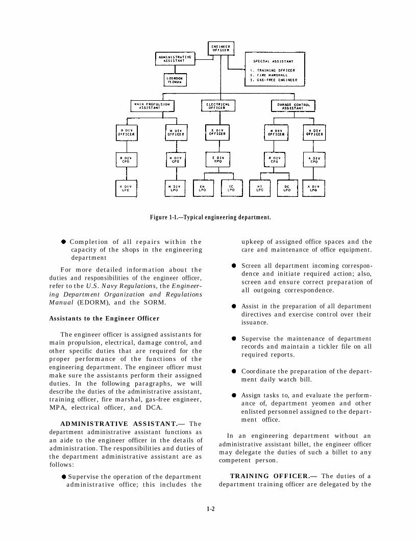
Figure 1-1.—Typical engineering department.
l Completion of all repairs within thecapacity of the shops in the engineeringdepartment
For more detailed information about theduties and responsibilities of the engineer officer,refer to the U.S. Navy Regulations, the Engineer-ing Department Organization and RegulationsManual (EDORM), and the SORM.
Assistants to the Engineer Officer
The engineer officer is assigned assistants formain propulsion, electrical, damage control, andother specific duties that are required for theproper performance of the functions of theengineering department. The engineer officer mustmake sure the assistants perform their assignedduties. In the following paragraphs, we willdescribe the duties of the administrative assistant,training officer, fire marshal, gas-free engineer,MPA, electrical officer, and DCA.
ADMINISTRATIVE ASSISTANT.— Thedepartment administrative assistant functions asan aide to the engineer officer in the details ofadministration. The responsibilities and duties ofthe department administrative assistant are asfollows:
l Supervise the operation of the departmentadministrative office; this includes the
upkeep of assigned office spaces and thecare and maintenance of office equipment.
Screen all department incoming correspon-dence and initiate required action; also,screen and ensure correct preparation ofall outgoing correspondence.
Assist in the preparation of all departmentdirectives and exercise control over theirissuance.
Supervise the maintenance of departmentrecords and maintain a tickler file on allrequired reports.
Coordinate the preparation of the depart-ment daily watch bill.
Assign tasks to, and evaluate the perform-ance of, department yeomen and otherenlisted personnel assigned to the depart-ment office.
In an engineering department without anadministrative assistant billet, the engineer officermay delegate the duties of such a billet to anycompetent person.
TRAINING OFFICER.— The duties of adepartment training officer are delegated by the
1-2
engineer officer to an assistant. Some of theseduties include the followmg:
Develop a department training program insupport of the training objectives of theship.
Carry out approved training plans andpolicies within the department.
Coordinate and assist in the administrationof division training programs within thedepartment. This includes supervision ofthe preparation of training materials andreview of curricula, training courses, andlesson plans. It also includes assisting inthe selection and training of instructors,observation of instruction given at drills,on watch, on station, and in the classroom.It further includes procurement of requiredtraining aids and devices.
Maintain department training records andtraining reports.
Disseminate information concerning theavailability of fleet and service schools.
Requisition training supplies andmaterials.
FIRE MARSHAL.— The fire marshal worksunder the engineer officer and the DCAand is responsible for the maintenance andreadiness of the ship’s fire-fighting equipment.The fire marshal is also responsible for theprevention and elimination of fire hazards on theship.
GAS-FREE ENGINEER.— The duties andresponsibilities of the gas-free engineer aredescribed in Naval Ships’ Technical Manual,chapter 074, volume 3, “Gas-Free Engineering.”Briefly, the gas-free engineer tests and analyzesthe air in sealed compartments or voids thatare being opened for inspection. The engineerdetermines whether such spaces are safe forpersonnel to enter without danger of poisoningor suffocation. The engineer also determineswhether it is safe to perform welding or cuttingwithin or in the vicinity of such spaces. Such hotwork is dangerous and can cause fires andexplosions.
MAIN PROPULSION ASSISTANT.— Theresponsibilities of the MPA are as follows:
Operation, care, and maintenance of theship’s propulsion machinery and relatedauxiliaries
Care, stowage, and use of fuels andlubricating oils
Preparation and care of the EngineeringLog and the Engineer’s Bell Book
Preparation of operation and maintenancerecords and procedures
The MPA also has the responsibility asdivision officer for the boiler and machinerydivisions. These divisions are discussed in thefollowing paragraphs.
Boiler (B) Division.— The B division operatesthe boilers and the fireroom auxiliary machinery.If you are assigned to this division, your workstation may be in a fireroom. The firerooms areusually located midships on the lower level. Theremay be as many as eight firerooms, depending onthe size and type of ship. Ships with onlyone fireroom will have two boilers. They areinstalled either facing each other or side by side.The boilers are arranged so any number of themsupply steam to the ship’s engines. The fireroomsare separated by watertight bulkheads. This allowsany fireroom to be sealed off in case of a casualty.The ship can operate on the remaining boilers.
On your first trip through the fireroom, youwill notice many sizes of pipes and valves. Theselines (pipes) carry steam, water, fuel oil, and air.You will become familiar with a few of them ata time. Gradually, you will learn all their purposesand functions.
The lines that carry steam or water are coveredby insulation and lagging. This is done to ensurepersonnel safety and to prevent heat loss andcondensation. Stencils on the lines show the fluidcarried and the direction of flow.
During your training, you will trace these linesfrom one unit to another throughout each system.The ship’s blueprints and drawings will help youtrace out systems in the engineering plant.
Machinery (M) Division.— The M division isresponsible for the safe operation of the mainengines, reduction gears, shafting, bearings, andall associated auxiliary machinery that supports
1-3

this equipment. When assigned to this division,you will work in one of the engine rooms. Theengine rooms are generally located immediatelyaft of the firerooms that supply them with steam.
ELECTRICAL OFFICER.— The electricalofficer is designated E division officer andelectrical safety officer. The electrical officer isresponsible to the engineer officer. The follow-ing are the specific duties and responsibilities ofthe electrical officer:
l
c
l
Routinely observe the performance ofpersonnel and equipment to ensureefficiency and safety and take action tocorrect deficiencies
Administer and execute the ship’s electricalsafety program using the most up-to-dateinstructions and notices
Provide training to the crew routinely onelectrical safety
The E division has charge of enforcing theelectrical safety program for both personal andshipboard electrical equipment. It maintainsgenerators, power and lighting distribution,gyrocompasses, intercommunications, and otherelectrical equipment throughout the ship. Ifassigned to this division, you may work in themain motor rooms, the engine rooms, theelectric repair shop, or in the interior communica-tions (IC) rooms.
DAMAGE CONTROL ASSISTANT.— TheDCA is responsible for the prevention andcontrol of damage. This includes control ofstability, list, and trim. Material conditions ofreadiness, watertight integrity, and compartmenttesting are carried out under the supervision ofthe DCA. The DCA administers various trainingfor ship’s personnel. This training includesdamage control, fire fighting, emergency repairwork, and nonmedical defensive measures forchemical, biological, and radiological (CBR)defense.
The DCA is in charge of the hull maintenance(R division) and the auxiliary machinery (Adivision) shops. In these shops repairs to the ship’shull and the ship’s boats, which are within theship’s capabilities, are made by the assignedpersonnel. These divisions are described in thefollowing paragraphs.
Repair (R) Division.— The R division isresponsible for keeping the ship watertight. The
R division operates the hull maintenance shops.This division maintains damage control and fire-fighting equipment and assists in damage-controltraining for shipboard personnel.
Auxiliary (A) Division.— The A divisionoperates the refrigeration plant, air compressors,emergency fire pumps, emergency diesel genera-tors, and the ventilation, heating, and air-conditioning systems. They are the boat engineersin small boats. They also maintain the ship’ssteering engines. If assigned to this division, youmay work in the auxiliary spaces or parts of theship under A division’s authority. The equipmentassigned to A division is found throughout theship.
Division Officer
The duties of a division officer are describedin the U.S. Navy Regulations and the SORM. Thefollowing are specific duties and responsibilitiesof the division officer:
l
l
l
l
l
l
l
l
Direct the division through work centersupervisors.
Assign watches and duties within thedivision.
Ensure that division personnel receiveindoctrination and military and professionaltraining.
Prepare enlisted performance evaluationsheets for personnel of the division.
Maintain a division notebook containingpersonnel data cards, training data, a spaceand equipment responsibility log, and thewatch and battle stations requirements.The notebook also has data useful forready reference and for the orientation ofa relief officer.
Account for all forms, reports, andcorrespondence originated or maintainedby the division.
Establish and maintain a division organiza-tion manual and other directives necessaryfor the administration of the division.
Ensure that prescribed security measuresare strictly observed by division personnel.
1-4

l
l
l
l
Recommend to the department headpersonnel transfers and changes in thedivision allowance.
Forward requests for leave, liberty, andspecial privileges. This includes makingrecommendations for their disposition.
Conduct periodic inspections, exercises,and musters.
Evaluate the performance and disciplineof the division.
The division chief petty officer (CPO) anddivision leading petty officer (LPO) are assignedto aid the division officer in the administrative,organizational, and disciplinary duties. Theirfunction within the division is discussed in thefollowing paragraphs.
DIVISION CHIEF PETTY OFFICER.— Thefunction of a division CPO is to assist thedivision officer in coordinating and administeringthe division. The duties, responsibilities, andauthority of the division CPO depends on thedivision organization. The division CPO may berequired to perform the following tasks:
l
l
l
l
l
l
l
l
l
Supervise the preparation and maintenanceof the watch, quarter, and station bill.
Formulate and implement policies andprocedures for the operation of thedivision.
Supervise the division in the performanceof its daily routine and conduct inspections.
Administer discipline within the division.
Complete Enlisted Performance Evalua-tion Reports (NAVPERS 1616/24) afterevaluating individual performances. TheLPO assists the CPO in this task.
Provide counsel and guidance to divisionpersonnel.
Ensure routine logs and records aremaintained correctly and required divisionreports are prepared properly.
Act as the division officer in his or herabsence.
Perform other duties assigned by thedivision officer.
DIVISION LEADING PETTY OFFICER.—The LPO appointed by the division officer orCPO is usually the senior petty officer in thedivision. The LPO will assist in the administration,supervision, training, and watch standing qualifi-cations of division personnel.
ENLISTED PERSONNEL
Besides the general ratings, some specificbillets or assignments require special mention.Two of these billets are the oil and water king andthe boat engineer.
Oil and Water King
On large ships, the billet for oil and water kingis divided into two billets—one for fuel oil andthe other for potable (fresh) water and feedwater.
On steam-driven ships, the oil and water kingcould be either a Boiler Technician or aMachinist’s Mate. On diesel- and gas turbine-driven ships, the oil and water king is anEngineman or a Gas Turbine Systems Technician.The responsibilities of an oil and water king areas follows:
l
l
l
l
l
l
Supervise the operation of all valves in thefuel oil and transfer system and thefreshwater system, as prescribed by thecasualty control bills for those systems.
Properly maintain fuel oil service tanksand shift suction among service tanks.
Maintain the distribution of fuel oil andwater so the ship can remain on an evenkeel and in proper trim.
Prepare fuel and water reports.
Test and record the pH, phosphate,chloride content, hardness, and otherproperties of feed and boiler water.
Test and record fuel oil samples. Fordetailed information on these tests, referto Naval Ships’ Technical Manual, chapter541, “Petroleum Fuel Stowage, Use, andTesting,” and chapter 220, volume 2,“Boiler Water/Feedwater Tests andTreatment.”
Refer to Basic Military Requirements,NAVEDTRA 10054-F, chapter 19, for informa-tion on safety precautions to be observed whenhandling fuel oil.
1-5

Small Boat Engineer following paragraphs we will describe theseratings:
Firemen, Enginemen, or Machinist’s Matesfrom the A division are detailed as boat engineers.Boat engineers operate, clean, and inspect thesection of the boats assigned to them. Boatengines are repaired by Enginemen.
When a ship is at anchor, the officers and crewusually travel to and from the shore in smallboats. As a Fireman, you may be assigned as anengineer on one of these boats. You will beresponsible for operating the boat’s engine(s).A coxswain will be in charge of the overalloperation of the boat. On some boats, two seamenmay act as bow and stern hooks, or one seamanmay act as bowhook and the engineer may act assternhook.
For additional information on small boats andboat safety, refer to Basic Military Requirements,NAVEDTRA 10054-F, and Seaman, NAVED-TRA 10120-J.
ENGINEERING DEPARTMENTRATINGS
In general, the engineering department ratingsrequire (1) an aptitude for mechanical knowledge,(2) a degree of skill in mathematics and physics,and (3) some experience in repair work. Aknowledge of mechanical drawing is alsodesirable. Training manuals (TRAMANs) andnonresident training courses (NRTCs) coveringmany aspects of basic engineering are availableto help you.
Schools for engineering ratings are availableto those who qualify. You can find a list of allschools and their requirements in the Catalog ofNavy Training Courses (CANTRAC), NAVED-TRA 10500.
In this section we will describe the titles andjobs of the various engineering ratings. Theengineering ratings are classified into two occupa-tional fields—marine engineering and shipmaintenance.
MARINE ENGINEERINGOCCUPATIONAL FIELD
The marine engineering occupational fieldincludes the Machinist’s Mate, Engineman,Boiler Technician, Electrician’s Mate, InteriorCommunications Electrician, Gas TurbineSystems Technician (Electrical), and Gas TurbineSystems Technician (Mechanical) ratings. In the
Machinist’s Mate (MM)
MACHINIST’S MATES operate and main-tain ship propulsion machinery, reduction gears,condensers, and air ejectors. They are alsoresponsible for miscellaneous auxiliary equip-ment. This includes pumps, air compressors,turbine-driven generators, distilling units, valves,oil purifiers, oil and water heaters, governors,air-conditioners, refrigeration, propeller shafts,potable water systems, and ship’s steering andvarious other hydraulic systems.
Engineman (EN)
E N G I N E M E N work primarily withreciprocating engines (diesel and gasoline). Theyoperate, maintain, and repair diesel propulsionplants and diesel engines used for ship’s servicegenerators, and supporting auxiliary equipment.Such equipment includes refrigeration and air-conditioning systems, pumps, air compressors,auxiliary boilers, distillers, and various kinds ofhydraulic equipment.
Boiler Technician (BT)
BOILER TECHNICIANS operate, maintain,test, and repair marine boilers, heat exchangers,pumps, and forced draft blowers. They alsotransfer, test, and take soundings and inventoryof fuel and feedwater tanks.
1-6
Electrician’s Mate (EM)
ELECTRICIAN’S MATES stand watch ongenerators and switchboards. They maintain andrepair power and lighting circuits, electricalfixtures, motors, generators, distribution switch-boards, and other electrical equipment. They testfor grounds, or other casualties, and repair orrebuild electrical equipment in the electrical shop.They also maintain motion-picture equipmentaboard ship.
Interior Communications Electrician (IC)
INTERIOR COMMUNICATIONS ELEC-TRICIANS operate, maintain, and repair ICsystems. These systems include gyrocompass,voice interior communications, alarm, warning,ship’s control, entertainment, and plotting. Theyalso stand watches on related equipment.
Gas Turbine Systems Technician (GS)
The GAS TURBINE SYSTEMS TECHNI-CIAN rating is divided into two groups: the GasTurbine Systems Technician (Electrical) (GSE)and the Gas Turbine Systems Technician(Mechanical) (GSM).
The GSEs operate, repair, and performpreventive and corrective maintenance on theelectrical components of gas turbine engines,main propulsion machinery, auxiliary equipment,propulsion control systems, electrical and electroniccircuitry in the engineering spaces, and alarm andwarning circuits.
The GSMs operate, repair, and performpreventive and corrective maintenance on
mechanical components of gas turbine engines,main propulsion machinery (gears, shafts, andcontrollable pitch propellers), auxiliary equipmentin the engineering spaces, and propulsion controlsystems.
SHIP MAINTENANCEOCCUPATIONAL FIELD
The ship maintenance occupational fieldincludes the Hull Maintenance Technician,Damage Controlman, Machinery Repairman,Molder, Instrumentman, Opticalman, and Pattern-maker ratings. In the following paragraphs we willdescribe these ratings:
Hull Maintenance Technician (HT)
HULL MAINTENANCE TECHNICIANSplan, supervise, and perform tasks to fabricate,install, and repair various structures, shipboardand shore-based plumbing, and piping systems.
Damage Controlman (DC)
DAMAGE CONTROLMEN are qualified inthe skills and techniques of damage control, firefighting, and CBR defense. They must be able totake all measures required to maintain the water-tight integrity of the ship. They must also be ableto coordinate damage-control efforts and instructother ratings in damage-control procedures.
Machinery Repairman (MR)
MACHINERY REPAIRMEN make all typesof machine shop repairs on shipboard machinery.This work requires skill in using lathes, millingmachines, boring mills, grinders, power hacksaws,drill presses, and other machine tools. It alsorequires skill in using hand tools and measuring
1-7

instruments usually found in a machine shop. Thejob of restoring machinery to good working ordermay range from making a simple pin or link tothe complete rebuilding of an intricate gearsystem. Often, without dimensional drawings orother design information, a Machinery Repair-man must depend on ingenuity and know-how tomachine a repair part successfully.
Molder (ML)
MOLDERS operate foundries aboard shipand at shore stations. They make molds and cores,rig flasks, prepare heats, and pour castings offerrous, nonferrous, and alloy metals. They alsoshake out and clean castings and pour bearings.
Instrumentman (IM)
INSTRUMENTMEN perform preventive andcorrective maintenance and calibration onmechanical instruments and standards and Navytimepieces. They use Navy or mechanicalinstrument repair and calibration shop (MIRCS)procedures.
Opticalman (OM)
OPTICALMEN perform preventive andcorrective maintenance on small navigationalinstruments, binoculars, gun sights, range finders,submarine and turret periscopes, night visionsights, and other optical instruments.
Patternmaker (PM)
PATTERNMAKERS make wooden, plastic,plaster, and metal patterns used by Molders in aNavy foundry. They mount patterns on match-board/match plates for production molding.Patternmakers make master patterns, full-scalelayouts of wooden patterns, coreboxes, andtemplates. They also index and store patterns.
SAFETY PROGRAM
The objective of the Navy’s Safety Programis to enhance operational readiness by reducingthe frequency and severity of on- and off-dutymishaps to personnel and the cost of material andproperty damage attributed to accidental causes.The use of the term safety program in this chaptersignifies both occupational safety and health.
Operating and maintenance personnel must befamiliar with technical manuals and other publica-tions concerning equipment they are workingwith. Personnel must continuously exercise goodjudgment and common sense in the setting-up andoperation of all equipment to prevent damage tothe equipment and injury to personnel.
Personnel can prevent damage to machineryby properly preparing and operating the equip-ment by following instructions and proceduresoutlined in the EOSS (which is discussed later inthis chapter) and by being completely familiarwith all parts and functions of the machinery.
You can prevent damage to the ship byoperating the machinery so no loss of poweroccurs at an inopportune time, by keeping enginesready for service in any emergency, and bypreventing hazardous conditions that may causefire or explosion. Always maintain fire-fightingequipment in a “ready to use” state.
You can prevent injury to personnel by havinga thorough knowledge of duties, by knowing howto properly handle tools and operate equipment,by observing normal precautions around movingparts, and by receiving constant training.
Other everyday safety habits you shouldfollow include (1) preventing the accumulation ofoil in the bilges or other pockets or foundationsand subbases; (2) taking care, particularly whenon an uneven keel, that water in the bilges does
1-8
not reach electrical machinery or wiring; and(3) ensuring that safety guards are provided atpotential danger points, such as rotating andreciprocating equipment.
For personnel and machinery safety, you mustadhere to the following safety precautionsspecifically related to the engineering department:
Do not attempt to operate equipmentby overriding automatic shutdown orwarning devices.
Tag-out and disconnect batteries or othersources of electrical power before per-forming maintenance. This preventsinjuries from short circuits and accidentalstart-up of equipment.
Avoid holding or touching spark plugs,ignition units, or high-tension leads whilethey are energized.
Do not use oxygen to pressure test fuellines and equipment.
Take precautions to avoid inhaling vaporsof lacquer thinner, trichlorethylene, andsimilar solvents.
Do not wear jewelry or watches whileworking in machinery spaces.
Take precautions to avoid touchingexposed hot parts of an engine. Do notperform maintenance work until the enginehas been shut down and cooled.
Wear proper ear protection in all mainmachinery spaces.
It is the responsibility of supervisory personnelto ensure that their subordinates are instructed inand carry out the applicable safety precautions.Each individual is responsible for knowing andobserving all safety precautions applicable to theirliving or working spaces. Refer to Navy SafetyPrecautions for Forces Afloat, OPNAVINST5100.19.
SHIPS’ MAINTENANCE ANDMATERIAL MANAGEMENT
(3-M) SYSTEMS
The Ships’ Maintenance and Material Manage-ment (3-M) Manual, OPNAVINST 4790.4,describes in detail the Ships’ 3-M Systems. The
primary objective of the Ships’ 3-M Systems isto provide for managing maintenance and mainte-nance support in a way to ensure maximumequipment operational readiness. The Ships’ 3-MSystems is divided into two subsystems. They arethe planned maintenance system (PMS) and themaintenance data system (MDS).
PURPOSES OF PMS
The PMS was established for the followingpurposes:
To reduce complex maintenance to sim-plified procedures that are easily identifiedand managed at all levels
To define the minimum planned mainte-nance required to schedule and controlPMS performances
To describe the methods and tools to beused
To provide for the detection and preventionof impending casualties
To forecast and plan personnel andmaterial requirements
To plan and schedule maintenance tasks
To estimate and evaluate materialreadiness
To detect areas requiring additional orimproved personnel training and/orimproved maintenance techniques orattention
To provide increased readiness of the ship
BENEFITS OF PMS
The PMS is a tool of command. By usingPMS, the commanding officer can readilydetermine whether the ship is being properlymaintained. Reliability and availability areimproved. Preventive maintenance reduces theneed for major corrective maintenance, increaseseconomy, and saves the cost of repairs.
The PMS assures better records because theshipboard maintenance manager has more usefuldata. The flexibility of the system allows forprogramming of inevitable changes in employ-ment schedules. This helps to better planpreventive maintenance.
1-9
The PMS helps leadership and managementreduce frustrating breakdowns and irregular hoursof work, and thus improves morale. It enhancesthe effectiveness of all hands.
LIMITATIONS OF PMS
The PMS is not self-starting; it does notautomatically produce good results. It requiresconsiderable professional guidance and con-tinuous direction at each level of the system’soperation. One individual must have both theauthority and the responsibility at each level ofthe system’s operation.
Training in the maintenance steps as well asin the system is necessary. No system is asubstitute for the actual technical ability requiredof the petty officers who direct and perform theupkeep of the equipment. Because of rapidchanges in the Ships’ 3-M Systems, always referto a current copy of the 3-M Manual.
EQUIPMENT TAG-OUT PROGRAM
An effective tag-out program is necessarybecause of the complexity of modern ships as wellas the cost, delay, and hazard to personnel thatcould result from the improper operation ofequipment. The equipment tag-out program is aprocedure to prevent improper operation of acomponent, equipment, system, or part of asystem that is isolated or in an abnormalcondition. This procedure is also used when safetydevices, such as blank flanges on piping, areinstalled for testing, maintenance, or casualtyisolation.
The use of DANGER or CAUTION tags isnot a substitute for other safety measures, suchas locking valves or pulling fuses. Tags appliedto valves, switches, or other components shouldindicate restrictions on their operation. Never usetags for identification purposes.
The procedures in this program are mandatoryto standardize tag-out procedures used by all shipsand repair activities. The program also providesa procedure for use when an instrument isunreliable or is not in normal operating condition.It is similar to the tag-out procedure. However,labels instead of tags are used to indicateinstrument status. The tag-out program must beenforced during normal operations as well asduring construction, testing, repair, or mainte-nance. Strict enforcement of tag-out procedures
is required by both you and any repair activitythat may be working on your equipment.
RESPONSIBILITY
The commanding officer is responsible for thesafety of the entire command. It is the duty ofthe commanding officer to ensure that allpersonnel know all applicable safety precautionsand procedures and to ensure compliance with theprogram. The engineer officer is responsibleto the commanding officer for ensuring thatpersonnel assigned to the engineering departmentunderstand and comply with this program.
When repairs are done by a repair activity(other than ships’ personnel), a dual responsibilityexists for the safety of the personnel makingrepairs. The ship tended is responsible forcontrolling the tag-out program and ensuring thatthe systems that require work are properly tagged-out. The repair activity is responsible forensuring that this is done properly. They verifythis by signing the appropriate space on thetag-out sheet and the tag.
PROCEDURES
After identifying the need to tag-out an itemor a system, you must get permission from anauthorizing officer. The authorizing officer forthe engineering department is the engineeringofficer of the watch (EOOW) while under way orthe engineering duty officer (EDO) while in port.If the item or system tagged is placed out ofcommission, the authorizing officer must getpermission from the engineer officer and thecommanding officer. When permission has beenreceived, the authorizing officer then directsyou to prepare the tag-out record sheet andtags.
Normally, the petty officer in charge of thework fills out and signs the record sheet andprepares the tags. The record sheet is filled outfor a stated purpose. All tags for that purpose arenormally listed on one record sheet. Each sheetis assigned a log serial number. All tags associatedwith it are given the same log serial number anda sequential number is entered on the record sheet.For example, tag E107-4 is the fourth tag issuedon the record sheet with the log serial number 107for engineering.
1-10

Figure 1-2.—Danger tag.
The record sheet includes reference to anydocuments that apply—such as PMS, technicalmanuals, and other instructions, the reason forthe tag-out, the hazards involved, any amplifyinginstructions, and the work necessary to clear thetags. Use enough tags to completely isolate theitem or system being worked on. This willprevent operation from any and all stations thatcould exercise control. Indicate the location andcondition of the tagged item by the simplest means(for example, FOS-11A, closed).
When attaching the tags, you must ensure thatthe item is in the position or condition indicatedon the tag. As you attach each tag, you then mustsign the tag and initial the record sheet. After alltags are attached, a second qualified personensures the items are in the position andcondition indicated, and verifies proper tagplacement. That person also signs the tags andinitials the record sheet.
TYPES OF TAGS
The following sections describe the varioustags and the applications required to be used fromtime to time.
Figure 1-3.—Caution tag.
Danger Tag
A danger tag is a RED tag (fig. 1-2) used toprohibit the operation of equipment that couldjeopardize the safety of personnel or endangerequipment. Under no circumstances should equip-ment be operated when tagged with DANGERtags.
Caution Tag
A caution tag is a YELLOW tag (fig. 1-3)used as a precautionary measure to providetemporary special instructions or to indicate thatunusual caution must be exercised to operateequipment. These instructions must give thespecific reason that the tag was installed. Theuse of such phrases as DO NOT OPERATEWITHOUT EOOW PERMISSION is NOTAPPROPRIATE since equipment or systems arenot operated unless permission has been grantedby responsible authority. A CAUTION tag isNOT used any time personnel or equipment canbe endangered while performing evolutions usingnormal operating procedures; a DANGER tag isused in this case.
1-11
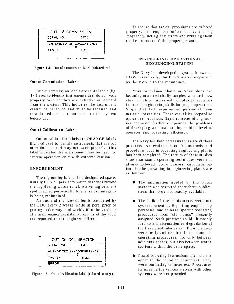
Figure 1-4.—Out-of-commission label (colored red).
Out-of-Commission Labels
Out-of-commission labels are RED labels (fig.1-4) used to identify instruments that do not workproperly because they are defective or isolatedfrom the system. This indicates the instrumentcannot be relied on and must be repaired andrecalibrated, or be reconnected to the systembefore use.
Out-of-Calibration Labels
Out-of-calibration labels are ORANGE labels(fig. 1-5) used to identify instruments that are outof calibration and may not work properly. Thislabel indicates the instrument may be used forsystem operation only with extreme caution.
ENFORCEMENT
The tag-out log is kept in a designated space,usually CCS. Supervisory watch standers reviewthe log during watch relief. Active tag-outs arespot checked periodically to ensure tag integrityis being maintained.
An audit of the tag-out log is conducted bythe EDO every 2 weeks while in port, prior togetting under way, and weekly if in the yards orat a maintenance availability. Results of the auditare reported to the engineer officer.
Figure 1-5.—Out-of-calibration label (colored orange).
To ensure that tag-out procedures are enforcedproperly, the engineer officer checks the logfrequently, noting any errors and bringing themto the attention of the proper personnel.
ENGINEERING OPERATIONALSEQUENCING SYSTEM
The Navy has developed a system known asEOSS. Essentially, the EOSS is to the operatoras the PMS is to the maintainer.
Main propulsion plants in Navy ships arebecoming more technically complex with each newclass of ship. Increased complexity requiresincreased engineering skills for proper operation.Ships that lack experienced personnel havematerial casualties. These casualties jeopardizeoperational readiness. Rapid turnover of engineer-ing personnel further compounds the problemsof developing and maintaining a high level ofoperator and operating efficiency.
The Navy has been increasingly aware of theseproblems. An evaluation of the methods andprocedures used in operating engineering plantshas been completed. The results of these studiesshow that sound operating techniques were notalways followed. Some unusual circumstancesfound to be prevailing in engineering plants areas follows:
l
l
l
The information needed by the watchstander was scattered throughout publica-tions that were not readily available.
The bulk of the publications were notsystems oriented. Reporting engineeringpersonnel had to learn specific operatingprocedures from “old hands” presentlyassigned. Such practices could ultimatelylead to misinformation or degradation ofthe transferred information. These practiceswere costly and resulted in nonstandardoperating procedures, not only betweenadjoining spaces, but also between watchsections within the same space.
Posted operating instructions often did notapply to the installed equipment. Theywere conflicting or incorrect. Proceduresfor aligning the various systems with othersystems were not provided.
1-12
. The light-off and securing schedules wereprepared by each ship and were notstandardized between ships. The scheduleswere written for general, rather thanspecific, equipment or systems. They didnot include alternatives between all theexisting modes of operation.
Following these studies, NAVSEA developedthe EOSS. It is designed to help eliminateoperational problems. The EOSS involves theparticipation of all personnel from the departmenthead to the watch stander. The EOSS is a set ofsystematic and detailed written procedures. TheEOSS uses charts, instructions, and diagramsdeveloped specifically for the operational andcasualty control function of a specific ship’sengineering plant.
The EOSS is designed to improve theoperational readiness of the ship’s engineeringplant. It does this by increasing its operationalefficiency and providing better engineering plantcontrol. It also reduces operational casualties andextends the equipment life. These objectives areaccomplished first by defining the levels ofcontrol; second, by operating within the engineer-ing plant guidelines; and last, by providing eachsupervisor and operator with the informationneeded. This is done by putting these objectivesin words they can understand at their watchstation.
The EOSS is composed of three basic parts.
l The User’s Guide
. The engineering operational procedures(EOP)
. The engineering operational casualty con-trol (EOCC)
EOSS USER’S GUIDE
The User’s Guide is a booklet that explainsthe EOSS package and how to use it to theship’s best advantage. It has document samplesand explains how they are used. It providesrecommendations for training the ship’s person-nel using the specified procedures.
The EOSS documentation is developed usingwork-study techniques. All existing methods andprocedures for plant operation and casualtycontrol procedures are documented. These includethe actual ship procedures as well as those pro-cedures contained in available reference sources.
Each action is subjected to a serious reviewto measure the completeness of the presentmethods. At the completion of this analytic phase,new procedural steps are developed into anoperational sequencing system. Step-by-step,time-sequenced procedures and configurationdiagrams are prepared to show the plant layoutin relation to operational components. The finalstep in the development phase of an EOSS is avalidation on board ship. This is done to verifytechnical accuracy and adequacy of the preparedsequencing system. All required corrections aremade. They are then incorporated into thepackage before installation aboard ship.
The resulting sequencing system provides thebest tailored operating and casualty controlprocedures available that apply to a particularship’s propulsion plant. Each level is designedwith the information required to enable theengineering plant to respond to any demandsplaced upon it.
ENGINEERING OPERATIONALPROCEDURES
The EOP has all the information necessary forthe proper operation of a ship’s engineering plant.It has guides for scheduling, controlling, anddirecting plant evolutions through operationalmodes. This includes receiving shore services, tovarious modes of in-port auxiliary plant steaming,to underway steaming.
The EOP documentation exists for specificallydefined operational stages. These are defined asstages I, II, and III.
Stage I deals with the total engineering plantunder the direct responsibility of the plantsupervisor (EOOW). The EOOW coordinates theplacing in operation and securing of all systemsand components normally controlled by thevarious space supervisors. This person alsosupervises those functions that affect conditionsinternal to the engineering plant, such as jacking,testing, and spinning main engines. The EOPdocumentation helps the plant supervisorguarantee optimum plant operating efficiency,proper sequencing of events in each evolution, andthe training of newly assigned personnel. Duringa plant evolution, the EOOW appoints controland operation of the following systems andcomponents:
. Systems that interconnect one or moreengineering plant machinery spaces andelectrical systems.
1-13
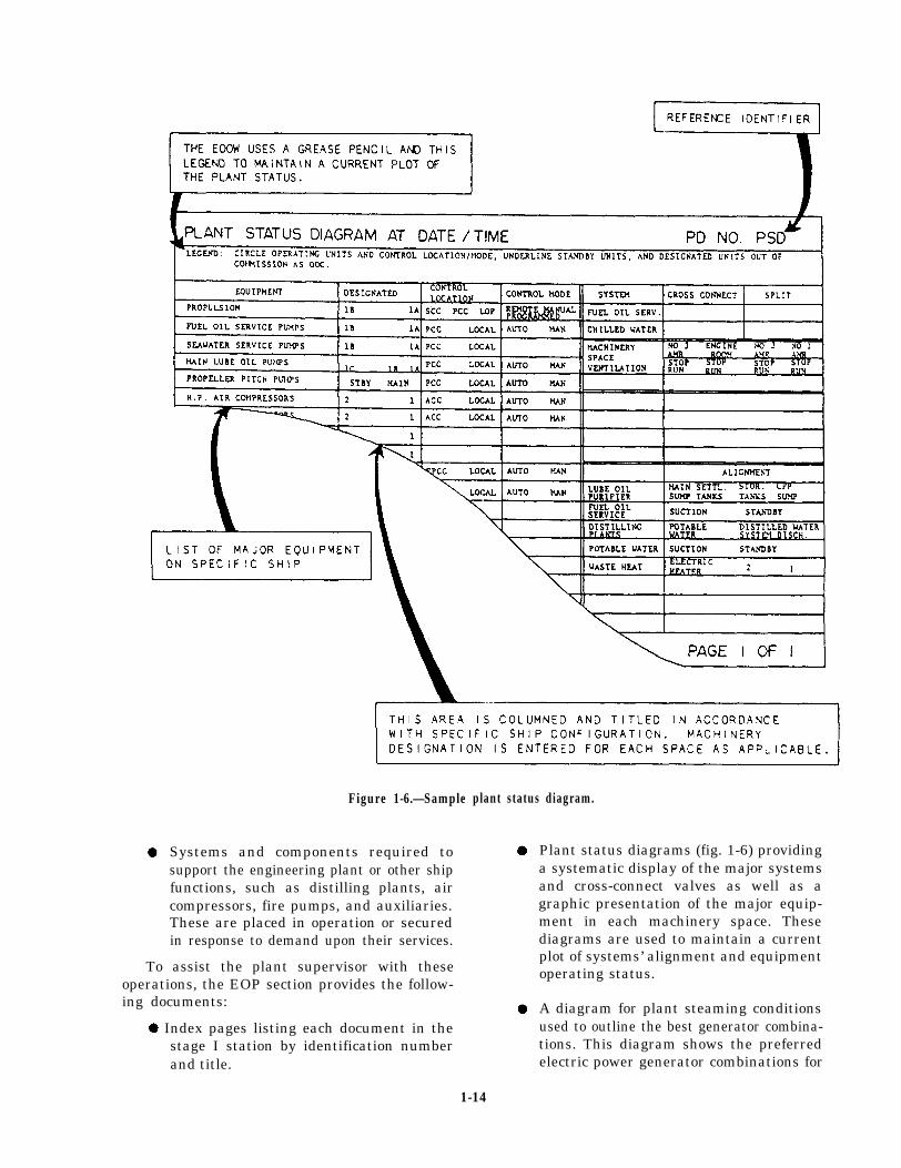
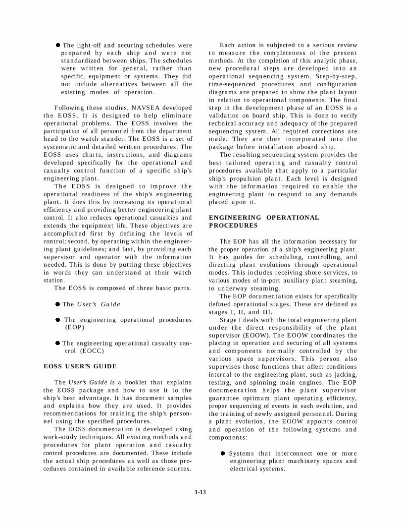
Figure 1-6.—Sample
Systems and components required tosupport the engineering plant or other shipfunctions, such as distilling plants, aircompressors, fire pumps, and auxiliaries.These are placed in operation or securedin response to demand upon their services.
To assist the plant supervisor with theseoperations, the EOP section provides the follow-ing documents:
l Index pages listing each document in thestage I station by identification numberand title.
plant status diagram.
Plant status diagrams (fig. 1-6) providinga systematic display of the major systemsand cross-connect valves as well as agraphic presentation of the major equip-ment in each machinery space. Thesediagrams are used to maintain a currentplot of systems’ alignment and equipmentoperating status.
A diagram for plant steaming conditionsused to outline the best generator combina-tions. This diagram shows the preferredelectric power generator combinations for
1-14
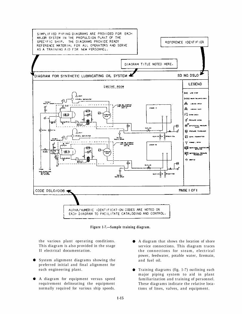
Figure 1-7.—Sample training diagram.
the various plant operating conditions. lThis diagram is also provided in the stageII electrical documentation.
System alignment diagrams showing thepreferred initial and final alignment foreach engineering plant. l
A diagram for equipment versus speedrequirement delineating the equipmentnormally required for various ship speeds.
A diagram that shows the location of shoreservice connections. This diagram tracesthe connections for steam, electricalpower, feedwater, potable water, firemain,and fuel oil.
Training diagrams (fig. 1-7) outlining eachmajor piping system to aid in plantfamiliarization and training of personnel.These diagrams indicate the relative loca-tions of lines, valves, and equipment.
1-15
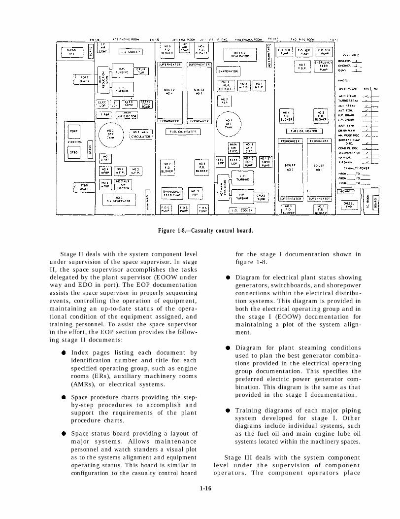
Figure 1-8.—Casualty control board.
Stage II deals with the system component level for the stage I documentation shown inunder supervision of the space supervisor. In stageII, the space supervisor accomplishes the tasksdelegated by the plant supervisor (EOOW underway and EDO in port). The EOP documentationassists the space supervisor in properly sequencingevents, controlling the operation of equipment,maintaining an up-to-date status of the opera-tional condition of the equipment assigned, andtraining personnel. To assist the space supervisorin the effort, the EOP section provides the follow-ing stage II documents:
l
l
l
Index pages listing each document byidentification number and title for eachspecified operating group, such as enginerooms (ERs), auxiliary machinery rooms(AMRs), or electrical systems.
Space procedure charts providing the step-by-step procedures to accomplish andsupport the requirements of the plantprocedure charts.
Space status board providing a layout ofmajor systems. Allows maintenancepersonnel and watch standers a visual plotas to the systems alignment and equipmentoperating status. This board is similar inconfiguration to the casualty control board
figure 1-8.
Diagram for electrical plant status showinggenerators, switchboards, and shorepowerconnections within the electrical distribu-tion systems. This diagram is provided inboth the electrical operating group and inthe stage I (EOOW) documentation formaintaining a plot of the system align-ment.
Diagram for plant steaming conditionsused to plan the best generator combina-tions provided in the electrical operatinggroup documentation. This specifies thepreferred electric power generator com-bination. This diagram is the same as thatprovided in the stage I documentation.
Training diagrams of each major pipingsystem developed for stage I. Otherdiagrams include individual systems, suchas the fuel oil and main engine lube oilsystems located within the machinery spaces.
Stage III deals with the system componentlevel under the supervision of componentoperators. The component operators place
1-16

Figure 1-9.—Component/system alignment diagram.
equipment in and out of operation, align systems, land monitor and control their operation. StageIII documents include the following:
Index pages listing each document byl
identification number and title for eachspecific system, such as the fuel oil and llube oil service systems.
1-17
Component procedure cards providingstep-by-step procedures for systems’ align-ment or component operation.
Component procedure cards as required tosupport each operation or alignment.
Alignment diagrams (fig. 1-9) amplifying thewritten procedure to assist the component

l Probable effectsoperator in proper systems’ alignment. Analignment diagram is used whenever twoor more alignment conditions exist for agiven system or component.
The operational use of EOP documentation isof primary importance at all levels in controlling,supervising, and operating the engineering plant.
ENGINEERING OPERATIONALCASUALTY CONTROL
The EOCC is the casualty control portion ofthe EOSS. It contains information relevant to therecognition of casualty symptoms and theirprobable causes and effects. Also, it hasinformation on actions taken to prevent acasualty. It specifies procedures for controllingsingle- and multiple-source casualties.
Casualty prevention must be the concern ofeveryone on board. Proper training of allpersonnel must provide an adequate knowledgeand experience in effective casualty prevention.The EOCC manual has efficient, technicallycorrect casualty control and prevention pro-cedures. These procedures relate to all phases ofan engineering plant. The EOCC documentspossible casualties that may be caused by humanerror, material failure, or battle. The EOCCmanual describes proven methods for the controlof a casualty. It also provides information forprevention of further damage to the component,the system, or the engineering plant.
The EOCC manuals (books) are available ateach watch station for self-indoctrination. Themanuals contain documentation to assist engineer-ing personnel in developing skills in controllingcasualties to the ship’s propulsion plant.
Skill in EOCC procedures is maintainedthrough a well-administered training program.Primary training concentrates on the control ofsingle-source casualties. These are casualties thatmay be attributed to the failure or malfunctionof a single component or the failure of piping ata specific point in a system. Advanced trainingconcentrates on controlling multiple casualties oron conducting a battle problem. An effective,well-administered watch-stander training programwill contain, as a minimum, the followingelements:
. Recognition of the symptoms
l Probable causes
. Preventive actions that may be taken toreduce, eliminate, or control casualties
An EOSS package is not intended to beforgotten once it is developed and installed aboarda ship. It offers many advantages to the ship’soperational readiness capabilities. It also providesdetailed step-by-step sequencing of events for allphases of the engineering plant operation. Becauseit is work studied and system oriented, the EOSSprovides the basic information for the optimumuse of equipment and systems. It does this byspecifying correct procedures tailored for aspecific plant configuration.
The EOSS is not intended to eliminate theneed for skilled plant operators. No program orsystem can achieve such a goal. The EOSS is atool for better use of personnel and skillsavailable. Although the EOSS is an excellent toolfor shipboard training of personnel, it is primarilya working system for scheduling, controlling, anddirecting plant operations and casualty controlprocedures.
WATCH-STANDING DUTIESAND RESPONSIBILITIES
As a Fireman, you maybe assigned to one ofmany different types of ships. On these ships, theengineering spaces vary in size and appearance.On a steam-driven ship, the boilers, the mainengines, and their associated equipment may bein one space; or the boilers and their equipmentmay be in one space and the main engines andtheir equipment in another. Regardless of thenumber of boilers and main engines, the watcheson most ships are basically the same. Therefore,this information is general in nature and does notapply to a specific class of ship.
When working with a variety of propulsion,auxiliary, and electrical equipment, you will standvarious watches that range from main switch-boards to security watches or other watches,depending on your ship’s organization. Whenstanding these watches, you will be requiredto perform many tasks. These include loggingmeter readings, inspecting equipment for leaks,and preventing fire hazards. This section hasinformation on watches and duties that you maybe required to perform. As you progress andbecome better acquainted with the fireroom andengine room, you will stand watches under the
1-18
supervision and instruction of a petty officer. Youwill learn to operate equipment using EOSS byfollowing the ship’s EOP and EOCC procedures.
In the following paragraphs we will discuss theEOOW, the watch stander from whom you willtake your directions. We will also describe thevarious watches that pertain directly to you.
ENGINEERING OFFICEROF THE WATCH
The EOOW is the officer on watch in chargeof the main propulsion plant and of the associatedauxiliaries. On some types of ships, the EOOWis normally a senior petty officer. The EOOW isprimarily responsible for the safe and efficientperformance of the engineering departmentwatches (except damage control) associated withthe equipment in his or her charge. The engineerofficer determines if an officer or petty officerof the engineering department is qualified toperform the duties of the EOOW. When theengineer officer considers the officer or pettyofficer qualified in all respects, he or she assignsthat person to the watch. The engineer officer or,in his or her absence, the MPA is authorized todirect the EOOW concerning the duties of thewatch when such action is considered necessary.
DAMAGE CONTROLCENTRAL WATCH
Damage control central (DCC) on most shipsis manned around the clock when the shipis in port and under way. The DCC watch isresponsible for the supervision and maintenanceof the material condition of readiness in effect onthe ship at all times. As a watch stander in DCC,you will be required to maintain the DamageControl Closure Log. You will also be responsiblefor the damage control log. On this log you willmake entries of the firemain pressure, the numberof pumps on the firemain, and several otherentries. You will also make hourly status reportsto the officer of the deck (OOD).
SOUNDING AND SECURITY
As a Fireman, you will be required to standsounding and security watches. While on this typeof watch, you are the ship’s first line of defensein maintaining watertight integrity. Your primarymission is to look for fire and flooding hazards.On some ships, this watch is set from the end ofthe working day until 0800 the next morning. It
is also in effect during holiday routine. The watchis particularly needed at these times because fewerpersonnel are working aboard the ship; certainspaces that require frequent observation arenot under the normal observation of personnelworking in or near them. On most ships,sounding and security watches are stood aroundthe clock. When standing this watch, besideslooking for fire and flooding hazards, you maytake readings on the air-conditioning andrefrigeration plants. You may also have to ensureno freshwater spigots are leaking or have been leftrunning in heads, laundries, galleys, and pantries.Another of your responsibilities is to maintain theproper material readiness conditions by checkingall watertight air ports, doors, hatches, scuttles,and other damage-control fittings. You mustreport any irregular condition (change insoundings, violations of material condition, firehazards, and so forth) to your watch supervisor.
You will use a sounding tape to takesoundings. The sounding tape is a steel tape coiledon a reel suitable for being held while the tapeis lowered. The tape is weighted at the end so thatit can be lowered into the sounding tube.
When taking a sounding, you will notice thatwater is relatively hard to see on a brass or bronzesounding rod. If you have problems reading thelevel, dry the rod or tape thoroughly and coat itwith white chalk or indicating paste before youtake a sounding. When the chalk becomes wet,it turns to a light-brown color. For example, ifthere are 6 inches of water in a tank when youtake a sounding, the light-brown color of thechalk will be distinctly visible up to the 6-inchmark. The remainder of the sounding rod will stillbe covered with the white chalk.
NOTE: The chalk method is used only wherewater may be present. Water-indicating paste willnot change color with fuel oil and is often usedby the oil king to determine if there is water atthe bottom of a fuel tank. Always remember neverto use the same sounding tape in a fresh watertank sounding that had been used for fuel, oil,or any other purpose other than fresh water.
MESSENGER OF THE WATCH
The messenger of the watch performs anumber of important duties that involve greatresponsibility. The messenger is usually assignedas the sound-powered telephone talker. Thisoccurs when the ship is undergoing closemaneuvering conditions with other ships, entering
1-19

or leaving port, or refueling or replenishing fromanother ship. Since the sound-powered telephonesprovide communications between all the engineer-ing spaces, you must know the proper procedures.When you talk, speak slowly and distinctly.Pronounce the syllables of each word very clearly.When you receive a message, or are given amessage to transmit, repeat it word for word,exactly as it was given to you. Do not engage inany idle chatter.
As the messenger of the watch, you will alsoperform other duties as assigned by the pettyofficer of the watch. These duties includechecking operating machinery and recordingtemperature and pressure readings in theappropriate logs.
The operating log is an hourly record ofoperating pressures and temperatures of almostall operating machinery. The log readings includelube oil and boiler pressures and temperatures,pump suction and discharge pressures, and otheritems needed to operate the engineering plant.You will have to write and print legibly. You alsohave to spell common Navy terms correctly andmaintain your logs neatly and accurately. Youshould know the proper operating and limitingor danger pressures and temperatures of yourequipment. This allows you to know when a pieceof machinery or equipment is not operatingproperly.
COLD-IRON WATCH
When a ship stops operating its own plant andis receiving services from shore or other ships, theship is considered to be in a cold iron status. Asecurity and fire watch is usually set by eachdepartment. This watch is called the cold-ironwatch.
Each cold-iron watch makes frequent inspec-tions of the assigned area and looks for firehazards, flooding, or other unusual conditionsthroughout the area. The watch sees that nounauthorized persons are in the watch area; thatall spaces are cleaned; and that no tools, rags,gear, and the like are left adrift. The watch alsokeeps the bilges reasonably free of water. (NOTE:You must get permission to pump water from theduty engineer officer and the OOD.)
The watch makes hourly reports to the OODor the DCC watch on all existing conditions.Any unusual conditions are reported to theOOD or DCC immediately. They can notify thedepartment responsible to take the necessarycorrective measures.
When hot work is done in the watch area, thecold-iron watch ensures that a fire watch isstationed. The fire watch stands by with a C02
extinguisher. If a fire watch has not beenstationed, the cold-iron watch stops all workuntil a fire watch can be stationed. The cold-ironwatch then carries out all pertinent orders.
If the ship is in dry dock, the cold-ironwatch will check all sea valves after workinghours. This is to ensure that the valves are secureor blanked off. The cold-iron watch also ensuresthat no oil is pumped into the dry docks at anytime. The watch will not allow any weights, suchas fuel oil or feedwater, to be shifted withoutpermission of the engineer officer or DCA.
BURNERMAN
The burnerman is responsible for cuttingburners “in” and “out” as directed by the boilertechnician of the watch (BTOW). The burnermanmust keep a close check for dirty atomizers andchange them when authorized by the BTOW. Theburnerman must always be assisted by anotherwatch stander when lighting fires or cutting inadditional burners. This procedure will ensure thatfires are safely lit and are burning properly, thatno fuel leaks, and that fires can be quickly securedif a casualty occurs.
CHECKMAN/UPPER-LEVEL WATCH
On ships that do not have automatic feedwatercontrols, the checkman is responsible foroperating the feed check valve and maintainingthe proper water level in the steam drum. Thisis the checkman’s only responsibility. On shipsthat have automatic feedwater controls, acheckman is not needed unless the control isshifted from automatic to manual. The respon-sibilities of the upper-level watch include (1) theoperation of the forced draft blowers, deaeratingfeed tank, and all boiler-related equipment on theupper level; (2) surface blowing; (3) starting andstopping machinery; (4) opening and closingvalves; (5) monitoring gauges; and (6) aligningsystems.
FIREROOM LOWER-LEVEL
The fireroom watch is responsible for starting,stopping, and maintaining proper levels andpressures on all boiler-related equipment on thelower level. This equipment will normally includethe main feed booster pumps and the fuel oil
1-20
service pumps. The fireroom watch may also assistthe burnerman in lighting fires in the boiler. Thiswatch may also assist in shifting suction tanks onfuel oil, fresh water, feedwater, and shiftingcooling water strainers and fuel oil strainers.
THROTTLE WATCH
The tasks of a throttleman at the main enginesare critical. Orders from the bridge concerning themovement of the propellers must be complied withimmediately. To make correct adjustments for therequired speed, you must keep a close watch onthe revolutions-per-minute (rpm) indicator on thethrottle board. You have to open or close thethrottle, as required, to achieve or maintain thenecessary rpm. Besides handling the throttle itself,you may also have to operate a variety ofassociated valves; accurately log all speed changesin the Engineer’s Bell Book; visually check allgauges (pressure, temperature, vacuum, and soforth) installed on the throttle board; and keepthe petty officer in charge informed of anyabnormal gauge readings.
You should become thoroughly familiar withall the gauges, instruments, and indicators on thethrottle board to know what the normal readingsare. Some of these include the steam, feedwater,and cooling water pressure gauges, steamtemperature thermometers, the rpm indicator, theEOT, gauges indicating the vacuum obtained inthe main engine low-pressure turbine, and others.Whenever an opportunity presents itself, study thethrottle board and ask questions. Do not hesitateto ask the operator which readings are normal.Ask which readings are appropriate for steamingconditions. After learning the difference betweena normal reading and an abnormal reading, youwill be able to help prevent a major casualty, Youwill recognize an abnormal reading and can reportit to the petty officer in charge of the watch.
ENGINE ROOMUPPER-LEVEL WATCH
When you are assigned to the duties of theupper-level watch in the engine room, you willhave to perform the following tasks:
. Record periodic temperature and pressurereadings from various gauges on, orconnected to, the upper-level machinery.
. Make required valve adjustments tocorrect conditions indicated by slight
variations from the normal readings, andreport unusual conditions to the pettyofficer in charge.
. Maintain a normal water level in thedeaerating tank, if it is located in theengine room, by adjusting the excess andmakeup feed valves.
l Light off and secure turbogenerators andother upper-level machinery, as ordered.
. Maintain an adequate gland seal pressureon the turbogenerator.
ENGINE ROOMLOWER-LEVEL WATCH
You will be assigned to the engine room lowerlevel to assist the lower-level watch (pumpman).You will be involved with a number of pumps andother auxiliary machinery. Some of the pumpsand equipment with which you will work are themain lube oil pumps and lube oil coolers; the maincondensate pumps and main condenser; the mainfeed pumps; the main feed booster pumps; thefire pumps; and when they are installed in theengine room, air compressors.
Besides learning the proper procedures forstarting, operating, and stopping the pumps andequipment, you must make various checks of theoperating machinery. Some of the checks for themain feed pump, the lube oil pump, and the maincondensate pump are described in the sections thatfollow.
Main Feed Pump
You will have to comply with the postedinstructions and safety precautions for themachinery and equipment at the main feed pumpstation. When assisting the pumpman, you willalso perform the following duties:
. Maintain the main feed pump dischargepressure at a predetermined value byadjusting the constant pressure governor.
. Keep the main feed pump bearings at theproper temperature by regulating the flowof water through the feed pump lube oilcooler.
. Check to ensure the lube oil pressure to thebearings is correct.
1-21

l
l
l
l
l
l
Keep the shaft packing glands adjustedproperly. A small amount of leakage isnecessary to prevent burning out thepacking, but excessive leakage wastesboiler feedwater.
Check and maintain the proper lube oillevel in the main feed pump sump tank.
Keep the valve packing glands tightenedto prevent leakage.
Keep the watch station clean; remove firehazards by wiping up oil and picking uprags and other stray gear.
Keep alert for unusual sounds, vibrations,temperatures, and pressures from operatingequipment.
Keep the standby pump ready for instantuse.
Lube Oil Pump
The following are duties you will performwhile assisting the pumpman at the lube oil pumpstation:
l
l
l
l
l
l
Maintain the proper lube oil pumpdischarge pressure and the proper lube oiltemperature.
Keep the standby pump on automaticstandby.
Shift and clean the main lube oil strainersat least once each watch.
Check the lube oil system for leaks, andmaintain the proper oil level in the mainengine sump tank.
Operate the lube oil purifier as directed.
Regulate the cooling water flow throughthe lube oil cooler to maintain the correctoil outlet temperature.
Main Condensate Pump
The following are duties you will performwhile assisting the pumpman at the maincondensate pump station:
. Keep the condensate in the condenser hotwell at the proper level.
Frequently check the exhaust trunk andmain condenser overboard for abnormaltemperatures.
Check the main condensate pump bearingsfor proper oil pressure and temperature.
Start or secure an additional pump, asrequired, to keep the condensate level atthe correct height.
Constantly check for unusual conditions(vibrations, sounds, and high or lowtemperatures or pressures) of operatingequipment.
All watch standers should be constantly alertfor signs of leakage in all parts of the steam andwater systems. The following are some of themore common causes of feedwater waste:
. Leaks in pipe fittings, flanges, valve andpump packing glands, pump housings, andrelief valves
l Excessive gland sealing steam
Remember, a poorly operated plant reflectson the ability of the watch stander.
SHAFT ALLEY WATCH
Another main engine duty is that of keepingwatch on the bearings of the propeller shaftsleading from the reduction gears (or motorsof a turboelectric-driven ship) to the ship’spropellers. As a shaft alley watch stander, youmay perform the following duties:
Check all spring bearings for properlubrication. This includes correct oil level,condition of the oil, proper operation ofself-oiling devices (ring or chain), andbearing temperature.
Check and adjust the stern tube gland forthe correct amount of leak-off.
Pump the shaft alley bilge, as authorizedby the EOOW and OOD.
During high speed, keep alert and observeany abnormal rise in bearing temperature.
Report hourly, by phone, to the controlengine room under normal conditions andif abnormal conditions develop.
Operate the main thrust bearing when itis located in the shaft alley.
1-22
EVAPORATOR WATCH
A ship requires a large amount of pure freshwater daily for use as boiler feedwater, forcorrosion control (freshwater wash down), andfor the crew’s consumption. However, a ship canonly store enough water to last a few days.Therefore, proper and careful watches must bemaintained on the evaporators whenever they arein operation. An evaporator watch has toconstantly check on pressures, temperatures,vacuum, and salt content of the distilled water.A ship cannot operate if the distilled water forfeedwater contains more than the maximumallowable amount of salt.
WATCH, QUARTER, ANDSTATION BILL
Each division officer prepares a watch,quarter, and station bill for his or her division.You will generally find the following informationon this bill:
l
l
l
l
Organization of the division (sections andwatches).
A listing of each person as to billetnumber, locker number, bunk number,compartment number, name, rating, andrate (actual and allowance).
Watch assignments for each person undervarious conditions of battle readiness.
The station and job each person will havein emergency situations, such as fire,rescue and assistance, and general emer-gency.
. The special duties and stations eachperson will have. The special duties mayinclude visit and search party, landingforce, special sea detail, and other specialduties.
The watch, quarter, and station bill tells youwhere you fit into the ship’s organizationalpicture. Check it frequently; it is your duty toknow where you belong under all conditions.THERE IS NO EXCUSE FOR NOT KNOWING.The bills may be designed differently for differentships, but the stations and duties are always aboutthe same. The bill assignments are for actualemergencies and drills. Billets are assignedaccording to the skills and the qualifications ofthe personnel in the division. Refer to BasicMilitary Requirements, NAVEDTRA 10054-F,for more information about the watch, quarter,and station bill.
SUMMARY
This chapter has covered information onstandard ship and engineering organizationand engineering administration, ratings, andprograms, such as safety, PMS, tag-out, andEOSS. You have learned about the variouswatches of the engineering department. Do notbecome overwhelmed by the many things youmust learn to be an effective watch stander. Keepyour ears and eyes open, and above all, ASKQUESTIONS. If you desire to advance in theNavy, you should study the publications mentionedin the Advancement Handbook for Apprentice-ships, NAVEDTRA 71700, and the AdvancementHandbook for Petty Officers (the NAVEDTRAnumber is rate specific; ask your division trainingofficer for assistance).
1-23

CHAPTER 2
ENGINEERING FUNDAMENTALS
You are about to become acquainted with thefascinating world of PHYSICS. You will learnabout the various natural and physical laws andphenomena. Physics is concerned with thoseaspects of nature which can be understoodin a fundamental way in terms of elementaryprinciples and laws. The forces of physics and thelaws of nature are at work in every piece ofmachinery and equipment. It is by these forcesand laws that the machinery and equipmentproduce work.
In the following paragraphs you will learnabout matter, magnetism, electricity, motion,properties of mass, temperature, pressure, variouslaws and principles of physics dealing withmotion, gases, hydraulics and pneumatics, andbasic information on metals. After studying thischapter, you will have the fundamental, basicknowledge to understand what electrical andmechanical devices are all about and how theywork.
MATTER
If western science has roots, they probably liein the rubble that was once ancient Greece.Except for the Greeks, ancient people had littleinterest in the structure of materials. Theyaccepted a solid as being just that—a continuous,uninterrupted substance. One Greek school ofthought believed that if a piece of matter, suchas copper, were subdivided, it could be subdividedindefinitely and still only that material would befound. Others reasoned that a limit exists to thenumber of subdivisions that could be made andhave the material still retain its originalcharacteristics. They held fast to the idea thatall substances are built upon a basic particle.Experiments have revealed that, indeed, severalbasic particles, or building blocks, are within allsubstances.
Matter cannot be created nor destroyed. Thislaw holds within the experimental error of the
most precise chemical reactions. This theory ofthe conservation of energy will be discussed laterin this chapter. Matter is defined as anything thatoccupies space and has weight; that is, the weightand dimensions of matter that can be measured.Examples of matter are air, water, clothing, andeven our own bodies. So, we can say matter isfound in any one of three states: GASEOUS,LIQUID, and SOLID.
In the following paragraphs we will describehow substances are classified as elements andcompounds and how they are made up ofmolecules and atoms. We will then learn aboutprotons, electrons, and the physics of electricity.
ELEMENTS AND COMPOUNDS
An element is a substance that cannot bereduced to a simpler substance by chemical means.Examples of elements with which you are in everyday contact are iron, gold, silver, copper, andoxygen. Over 100 known elements are in existence.All the different substances we know about arecomposed of one or more of these elements.
When two or more elements are chemicallycombined, the resulting substance is called aCOMPOUND. A compound is a chemicalcombination of elements that can be separatedby chemical means. Examples of commoncompounds are water, which consists of hydrogenand oxygen, and table salt, which consists ofsodium and chlorine. A MIXTURE, on the otherhand, is a combination of elements andcompounds, not chemically combined, that canbe separated by physical means. Examples ofmixtures are air, which is made up of nitrogen,oxygen, carbon dioxide, and small amounts ofrare gases, and sea water, which consists chieflyof salt and water.
MOLECULES
A MOLECULE is a chemical combination oftwo or more atoms, (atoms are described in the
2-1

next paragraph). In a compound the molecule isthe smallest part that has all the characteristicsof the compound. Consider water, for example.Depending on the temperature, it may exist as aliquid (water), a solid (ice), or a gas (steam).Regardless of the temperature, it will still havethe same composition. If we start with a quantityof water, divide this and pour out one half, andcontinue this process enough times, we will endup with a quantity of water that cannot befurther divided without ceasing to be water. Thisquantity is called a molecule of water. If thismolecule of water is divided, instead of two partsof water, we will have one part of oxygen and twoparts of hydrogen (H2O).
ATOMS
Molecules are made up of smaller particlescalled ATOMS. An atom is the smallest particleof an element that retains the characteristics ofthat element. The atom of one element, however,differs from the atoms of all other elements, Sinceover 100 elements are known, there must be over100 different atoms, or a different atom for eachelement. Just as thousands of words are made bya combination of the proper letters of thealphabet, so thousands of different materialsare made by the chemical combination of theproper atoms. Any particle that is a chemicalcombination of two or more atoms is called amolecule. The oxygen molecule has two atoms ofoxygen, and the hydrogen molecule has twomolecules of hydrogen. Sugar, on the other hand,
is a compound composed of atoms of carbon,hydrogen, and oxygen. These atoms are combinedinto sugar molecules. Since the sugar moleculescan be broken down by chemical means intosmaller and simpler units, we cannot have sugaratoms.
In figure 2-1 you will see that the atoms ofeach element are made up of electrons, protons,and, in most cases, neutrons, which arecollectively called subatomic particles. Further-more, the electrons, protons, and neutrons of oneelement are identical to those of any otherelement. The reason there are different elementsis that the number and arrangement of electronsand protons within the atom are different for thedifferent elements.
The electron is considered to be a smallnegative charge of electricity. The proton has apositive charge of electricity equal and oppositeto the charge of the electron. Scientists havemeasured the mass and size of the electron andproton. They know how much charge each has.The electron and proton each have the samequantity of charge, although the mass of theproton is about 1837 times that of the electron.In some atoms, a neutral particle exists called aneutron. The neutron is a mass about equal tothat of a proton, but it has no electrical charge.According to a popular theory, the electrons,protons, and neutrons of the atoms are thoughtto be arranged in a manner similar to a miniaturesolar system. The protons and neutrons form aheavy nucleus with a positive charge, aroundwhich the very light electrons revolve.
Figure 2-1.—Structure of simple atoms.
2-2
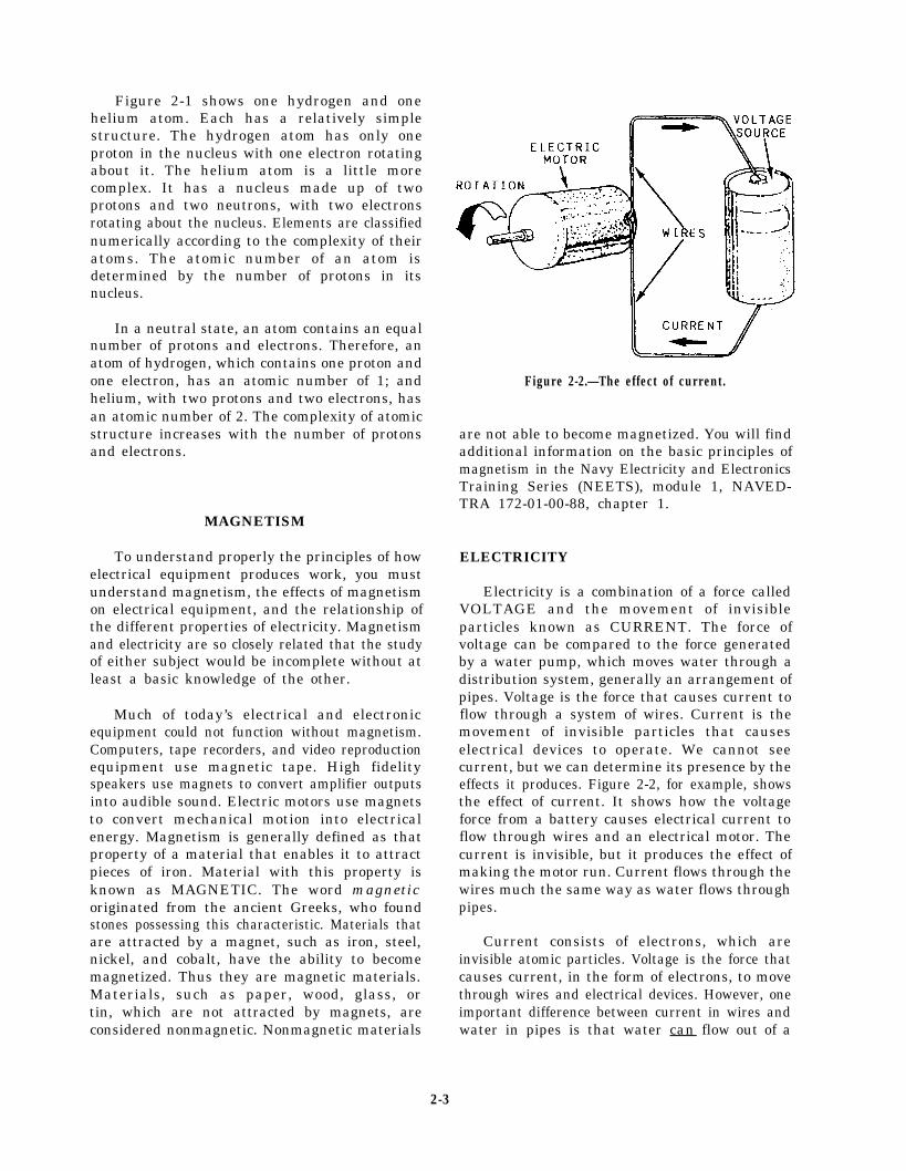
Figure 2-1 shows one hydrogen and onehelium atom. Each has a relatively simplestructure. The hydrogen atom has only oneproton in the nucleus with one electron rotatingabout it. The helium atom is a little morecomplex. It has a nucleus made up of twoprotons and two neutrons, with two electronsrotating about the nucleus. Elements are classifiednumerically according to the complexity of theiratoms. The atomic number of an atom isdetermined by the number of protons in itsnucleus.
In a neutral state, an atom contains an equalnumber of protons and electrons. Therefore, anatom of hydrogen, which contains one proton andone electron, has an atomic number of 1; andhelium, with two protons and two electrons, hasan atomic number of 2. The complexity of atomicstructure increases with the number of protonsand electrons.
MAGNETISM
To understand properly the principles of howelectrical equipment produces work, you mustunderstand magnetism, the effects of magnetismon electrical equipment, and the relationship ofthe different properties of electricity. Magnetismand electricity are so closely related that the studyof either subject would be incomplete without atleast a basic knowledge of the other.
Much of today’s electrical and electronicequipment could not function without magnetism.Computers, tape recorders, and video reproductionequipment use magnetic tape. High fidelityspeakers use magnets to convert amplifier outputsinto audible sound. Electric motors use magnetsto convert mechanical motion into electricalenergy. Magnetism is generally defined as thatproperty of a material that enables it to attractpieces of iron. Material with this property isknown as MAGNETIC. The word magneticoriginated from the ancient Greeks, who foundstones possessing this characteristic. Materials thatare attracted by a magnet, such as iron, steel,nickel, and cobalt, have the ability to becomemagnetized. Thus they are magnetic materials.Materials, such as paper, wood, glass, ortin, which are not attracted by magnets, areconsidered nonmagnetic. Nonmagnetic materials
Figure 2-2.—The effect of current.
are not able to become magnetized. You will findadditional information on the basic principles ofmagnetism in the Navy Electricity and ElectronicsTraining Series (NEETS), module 1, NAVED-TRA 172-01-00-88, chapter 1.
ELECTRICITY
Electricity is a combination of a force calledVOLTAGE and the movement of invisibleparticles known as CURRENT. The force ofvoltage can be compared to the force generatedby a water pump, which moves water through adistribution system, generally an arrangement ofpipes. Voltage is the force that causes current toflow through a system of wires. Current is themovement of invisible particles that causeselectrical devices to operate. We cannot seecurrent, but we can determine its presence by theeffects it produces. Figure 2-2, for example, showsthe effect of current. It shows how the voltageforce from a battery causes electrical current toflow through wires and an electrical motor. Thecurrent is invisible, but it produces the effect ofmaking the motor run. Current flows through thewires much the same way as water flows throughpipes.
Current consists of electrons, which areinvisible atomic particles. Voltage is the force thatcauses current, in the form of electrons, to movethrough wires and electrical devices. However, oneimportant difference between current in wires andwater in pipes is that water can flow out of a
2-3

Figure 2-3.—Different characteristics of current and water.
broken pipe, but current cannot flow out of abroken wire. When a wire is broken, the forceof the voltage is removed from the motor,as shown in figure 2-3. The circulating pumpin the working system creates a force thatmoves hot water through the pipes and radiator.The battery creates a force that moves currentthrough the wires and causes the motorto run. The wire and pipe are broken openin the broken system. In these instances,the circulating pump forces water to flowout of the pipe, but even though the batterystill creates a voltage force, current doesnot flow out of the wire. You will findadditional information on the basic principles ofelectricity in the NEETS, module 1, NAVEDTRA172-01-00-88, chapter 1.
OHM’S LAW
In the early part of the 19th century, GeorgeSimon Ohm proved by experiment that a preciserelationship exists between current, voltage, and
resistance. This relationship is called Ohm’s lawand is stated as follows:
I = E/R,
where: I = current in amperes,
E = voltage in volts, and
R = resistance in ohms.
As stated in Ohm’s law, current is inverselyproportional to resistance. This means, as theresistance in a circuit increases, the currentdecreases proportionately. In the equationI = E/R, if any two quantities are known, thethird one can be determined.
NEWTON’S LAWS
Sir Isaac Newton was an English philosopherand mathematician who lived from 1642 to 1727A.D. He was the formulator of the basic laws of
2-4

modern philosophy concerning gravity andmotion. Before we discuss motion and otherrelated factors, you should be familiar withNewton’s laws. These laws are the bases for thetheories of physics that we describe in thefollowing sections.
NEWTON’S FIRST LAW
Newton’s first law states that a body at resttends to remain at rest. A body in motion tendsto remain in motion. This law can be demon-strated easily in everyday use. For example, aparked automobile will remain motionless untilsome force causes it to move—a body at rest tendsto remain at rest. The second portion of the law—a body in motion tends to remain in motion—canbe demonstrated only in a theoretical sense. Thesame car placed in motion would remain inmotion (1) if all air resistance were removed,(2) if no friction were in the bearings, and (3) ifthe surface were perfectly level.
NEWTON'S SECOND LAW
Newton’s second law states that an imbalanceof force on a body tends to produce an accelera-tion in the direction of the force. The acceleration,if any, is directly proportional to the force. It isinversely proportional to the mass of the body.This law can be explained by throwing a commonsoftball, The force required to accelerate the ballto a rate of 50 ft/sec2 would have to be doubledto obtain an acceleration rate of 100 ft/sec2.However, if the mass of the ball were doubled,the original acceleration rate would be cut in half.You would have 50 ft/sec2 reduced to 25 ft/sec2.
NEWTON'S THIRD LAW
Newton’s third law states that for every actionthere is an equal and opposite reaction. You havedemonstrated this law if you have ever jumpedfrom a boat up to a dock or a beach. The boatmoved opposite to the direction you jumped. Therecoil from firing a shotgun is another exampleof action-reaction. Figure 2-4 depicts theseexamples.
In an airplane, the greater the mass of airhandled by the engine, the more it is acceleratedby the engine. The force built up to thrust theplane forward is also greater. In a gas turbine,
Figure 2-4.—Newton’s third law of motion.
the thrust velocity can be absorbed by the turbinerotor and converted to mechanical energy. Thisis done by the addition of more and progressivelylarger power turbine wheels.
SPEED, VELOCITY,AND ACCELERATION
SPEED is defined as the distance covered perunit of time, such as a car traveling at 60 mph.VELOCITY is speed in a certain direction, suchas a car traveling due north at 60 mph.ACCELERATION is the rate at which velocityincreases. If, for example, the propeller shaft rateof rotation increases from stop to 100 rpm in20 minutes, the acceleration is 5 rpm per minute.In other words, the velocity has increased 5revolutions per minute, during each minute, fora total period of 20 minutes. A body moving at
2-5
a constant speed has no acceleration. When thevelocity of an object increases by the same amounteach second or minute, you have uniformacceleration. Uniform deceleration is when thedecrease in velocity is the same each second orminute.
MASS, WEIGHT, FORCE,AND INERTIA
Very few terms are used in physics with greaterfrequency and assurance than mass, and few aremore difficult to define. Mass is often confusedwith weight. This is a mistake not helped sincethe unit of measurement for both mass and weightis the gram. The MASS of an object is thequantity of matter that the object contains.The WEIGHT of the object is equal to thegravitational force with which the object isattracted to the earth. FORCE is what makes anobject start to move, speed up, slow down, orkeep moving against resistance. Force may beeither a push or a pull. You exert a force whenyou push against a truck, whether you move thetruck or only try to move it. You also exert a forcewhen you pull on a heavy piano, whether youmove the piano or only try to move it. Forces canproduce or prevent motion.
A tendency to prevent motion is the frictionalresistance offered by an object. This frictionalresistance is called frictional force. While it cannever cause an object to move, it can check orstop motion. Frictional force wastes power,creates heat, and causes wear. Although frictionalforce cannot be entirely eliminated, it can bereduced with lubricants.
INERTIA is the property that causes objectsat rest to remain at rest and objects in motion toremain in motion until acted upon by an outsideforce. An example of inertia is one body that hastwice as much mass as another body of the samematerial offering twice as much force inopposition to the same acceleration rate.
Inertia in a body depends on its motion. Thephysical principles of mass and inertia areinvolved in the design and operation of the heavymachinery that is to be placed into motion, suchas an engine’s flywheel and various gears that areat work in the ship’s engineering plant. The greatmass of the flywheel tends to keep it rotating onceit has been set in motion. The high inertia of theflywheel keeps it from responding to smallfluctuations in speed and thus helps keep theengine running smoothly.
ENERGY
Can you define energy? Although everyonehas a general idea of the meaning of energy, agood definition is hard to find. Most commonly,perhaps, energy is defined as the capacity fordoing work. This is not a very completedefinition. Energy can produce other effects whichcannot possibly be considered work. For example,heat can flow from one object to another withoutdoing work; yet heat is a form of energy, and theprocess of heat transfer is a process that producesan effect. A better definition of energy, therefore,states that energy is the capacity for producingan effect.
Energy exists in many forms. For convenience,we usually classify energy according to the sizeand nature of the bodies or particles with whichit is associated. Thus we say that MECHANICALENERGY is the energy associated with largebodies or objects—usually, things that are bigenough to see. THERMAL ENERGY is energyassociated with molecules. CHEMICAL ENERGYis energy that arises from the forces that bind theatoms together in a molecule. Chemical energyis demonstrated whenever combustion or anyother chemical reaction takes place. Electricalenergy (light, X rays, and radio waves) isassociated with particles that are even smaller thanatoms.
Mechanical energy, thermal energy, andchemical energy must also be classified as beingeither stored energy or energy in transition.
STORED ENERGY can be thought of asenergy that is actually contained in or stored ina substance or system. There are two kinds ofstored energy: (1) potential energy and (2) kineticenergy. When energy is stored in a substance orsystem because of the relative POSITIONS of twoor more objects or particles, we call it potentialenergy. When energy is stored in a substance orsystem because of the relative VELOCITIES oftwo or more objects or particles, we call it kineticenergy.
Mechanical energy in transition is called work.Thermal energy in transition is called heat. In thenext section we will discuss mechanical andthermal energy and energy transformations.
If you do not completely understand thisclassification, come back to it from time totime as you read the following sections onmechanical energy and thermal energy. Theexamples and discussion given in the followingsections will probably help you understand thisclassification.
2-6
MECHANICAL ENERGY
Let’s consider the two stored forms ofmechanical energy. Mechanical POTENTIALenergy exists because of the relative positions oftwo or more objects. For example, a rock restingon the edge of a cliff in such a position that itwill fall freely if pushed has mechanicalpotential energy. Water at the top of a dam hasmechanical potential energy. A sled that is beingheld at the top of an icy hill has mechanicalpotential energy.
Mechanical KINETIC energy exists becauseof the relative velocities of two or more objects.If you push that rock, open the gate of the dam,or let go of the sled, something will move. Therock will fall; the water will flow; the sled willslide down the hill. In each case the mechanicalpotential energy will be changed to mechanicalkinetic energy. Another way of saying this is thatthe energy of position will be changed to theenergy of motion.
In these examples, you will notice that anexternal source of energy is used to get thingsstarted. Energy from some outside source isrequired to push the rock, open the gate of thedam, or let go of the sled. All real machines andprocesses require this kind of boost from anenergy source outside the system. For example,a tremendous amount of chemical energy is storedin fuel oil; but this energy will not turn the powerturbine until you have expended some energy tostart the oil burning. Similarly, the energy in anyone system affects other energy systems.However, it is easier to learn the basic principlesof energy if we forget about all the energy systemsthat might be involved in or affected by eachenergy process. In the examples given in thischapter, therefore, we will consider only oneenergy process or energy system at a time,disregarding both the energy boosts that may bereceived from outside systems and the energytransfers that may take place between the systemwe are considering and other systems.
Notice that both mechanical potential energyand mechanical kinetic energy are stored formsof energy. It is easy to see why we regardmechanical potential energy as being stored, butit is not so easy to see the same thing aboutmechanical kinetic energy. Part of the troublecomes about because mechanical kinetic energyis often referred to as the energy of motion, thusleading to the false conclusiontransition is somehow involved.case, however. Work is the
that energy inThis is not theonly form of
mechanical energy that can be properly consideredas energy in transition.
If you have trouble with the idea thatmechanical kinetic energy is stored, rather thanin transition, think of it like this: A bullet thathas been fired from a gun has mechanical kineticenergy because it is in motion. The faster the bulletis moving, the more kinetic energy it has. Thereis no doubt in anybody’s mind that the bullet hasthe capacity to produce an effect, so we may safelysay that it has energy. Although the bullet is notin transition, the energy of the bullet is nottransferred to any other object or system until thebullet strikes some object that resists its passage.When the bullet strikes against a resisting object,then, and only then, can we say that energy intransition exists, in the form of heat and work.
In this example, we are ignoring the fact thatsome work is done against the resistance of theair and that some heat results from the passageof the bullet through the air. But this does notchange the basic idea that kinetic energy is storedenergy rather than energy in transition. The airmust be regarded as a resisting object, whichcauses some of the stored kinetic energy of thebullet to be converted into energy in transition(heat and work) while the bullet is passing throughthe air. However, the major part of the storedkinetic energy does not become energy intransition until the bullet strikes an object firmerthan air that resists its passage.
Mechanical potential energy is measured infoot-pounds (ft-lb). Consider, for example, therock at the top of the cliff. If the rock weighs5 pounds and if the distance from the rock to theearth at the base of the cliff is 100 feet, 500 ft-lbof mechanical potential energy exists because ofthe relative positions of the rock and the earth.Another way of expressing this idea is by thefollowing formula:
P E = W x D ,
where:
PE = total potential energy of the object(in ft-lb),
W = total weight of the object (inpounds), and
D = distance between the earth and theobject (in feet).
2-7

Mechanical kinetic energy is also measured inft-lb. The amount of kinetic energy present at anyone time is directly related to the velocity of themoving object and to the weight of the movingobject.
Mechanical potential energy can be changedinto mechanical kinetic energy. If you push that5-pound rock over the edge of the 100-foot cliff,it begins to fall, and as it falls, it loses potentialenergy and gains kinetic energy. At any givenmoment, the total mechanical energy (potentialplus kinetic) stored in the system is the same—500ft-lb. But the proportions of potential energy andkinetic energy are changing all the time as the rockis falling. Just before the rock hits the earth, allthe stored mechanical energy is kinetic energy. Asthe rock hits the earth, the kinetic energy ischanged into energy in transition—that is, workand heat.
Mechanical kinetic energy can likewise bechanged into mechanical potential energy. Forexample, suppose you throw a baseball straightup in the air. The ball has kinetic energy whileit is in motion, but the kinetic energy decreasesand the potential energy increases as the balltravels upward. When the ball has reached itsuppermost position, just before it starts its fallback to earth, it has only potential energy. Then,as it falls back toward the earth, the potentialenergy is changed into kinetic energy again.
Mechanical energy in transition is calledWORK. When an object is moved through adistance against a resisting force, we say that workhas been done. The formula for calculating workis
W = F × D ,
where:
W = work,
F = force, and
D = distance.
As you can see from this formula, you needto know how much force is exerted and thedistance through which the force acts before youcan find how much work is done. The unit offorce is the pound. When work is done againstgravity, the force required to move an object isequal to the weight of the object. Why? Becauseweight is a measure of the force of gravity or, inother words, a measure of the force of attraction
between an object and the earth. How much workwill you do if you lift that 5-pound rock from thebottom of the 100-foot cliff to the top? You willdo 500 ft-lb of work—the weight of the object(5 pounds) times the distance ( 100 feet) that youmove it against gravity.
We also do work against forces other than theforce of gravity. When you push an object acrossthe deck, you are doing work against friction. Inthis case, the force you work against is not onlythe weight of the object, but also the forcerequired to overcome friction and slide theobject over the surface of the deck.
Notice that mechanical potential energy,mechanical kinetic energy, and work are allmeasured in the same unit, ft-lb. One ft-lb of workis done when a force of 1 pound acts through adistance of 1 foot. One ft-lb of mechanicalpotential energy or mechanical kinetic energy isthe amount of energy that is required toaccomplish 1 ft-lb of work.
The amount of work done has nothing at allto do with how long it takes to do it. When youlift a weight of 1 pound through a distance of1 foot, you have done 1 ft-lb of work, regardlessof whether you do it in half a second or half anhour. The rate at which work is done is calledPOWER. The common unit of measurement forpower is the HORSEPOWER (hp). By definition,1 hp is equal to 33,000 ft-lb of work per minuteor 550 ft-lb of work per second. Thus a machinethat is capable of doing 550 ft-lb of work persecond is said to be a 1-hp machine. (As you cansee, your horsepower rating would not be veryimpressive if you did 1 ft-lb of work in half anhour. Figure it out. It works out to be just a littlemore than one-millionth of a horsepower. )
THERMAL ENERGY
Earlier in this chapter we discussed molecules.You should remember that all substances arecomposed of very small particles called molecules.The energy associated with molecules is calledthermal energy. Thermal energy, like mechanicalenergy, exists in two stored forms and in onetransitional form. The two stored forms ofthermal energy are (1) internal potential energyand (2) internal kinetic energy. Thermal energyin transition is called HEAT.
Although molecules are too small to be seen,they behave in some ways pretty much like thelarger objects we considered in the discussion ofmechanical energy. Molecules have energy ofposition (internal potential energy) because of the
2-8

forces that attract molecules to each other. In thisway, they are somewhat like the rock and the earthwe considered before. Molecules have energy ofmotion (internal kinetic energy) because they areconstantly in motion. Thus, the two stored formsof thermal energy—internal potential energy andinternal kinetic energy—are in some ways similarto mechanical potential energy and mechanicalkinetic energy, except everything is on a smallerscale.
For most purposes, we will not need todistinguish between the two stored forms ofthermal energy. Therefore, instead of referringto internal potential energy and internal kineticenergy, from now on we will simply use the terminternal energy. By internal energy, then, we willmean the total of all internal energy stored in thesubstance or system because of the motion of themolecules and because of the forces of attractionbetween molecules. Although the term may beunfamiliar to you, you probably know moreabout internal energy than you realize. Becausemolecules are constantly in motion, they exert apressure on the walls of the pipe, cylinder, or otherobject in which they are contained. Also, thetemperature of any substance arises from, and isdirectly proportional to, the activity of themolecules. Therefore, every time you readthermometers and pressure gauges you are findingout something about the amount of internalenergy contained in the substance. High pressuresand temperatures indicate that the molecules aremoving rapidly and that the substance thereforehas a lot of internal energy.
Heat is a more familiar term than internalenergy, but may actually be more difficult todefine correctly. The important thing to rememberis that heat is THERMAL ENERGY INTRANSITION—that is, it is thermal energy thatis moving from one substance or system toanother.
An example will help to show the differencebetween heat and internal energy. Suppose thereare two equal lengths of pipe made of identicalmaterials and containing steam at the samepressure and temperature. One pipe is wellinsulated; the other is not insulated at all. Fromeveryday experience you know that more heat willflow from the uninsulated pipe than from theinsulated pipe. When the two pipes are firstfilled with steam, the steam in one pipe containsexactly as much internal energy as the steam inthe other pipe. We know this is true because thetwo pipes contain equal volumes of steam at thesame pressure and at the same temperature. After
a few minutes, the steam in the uninsulated pipewill contain much less internal energy than thesteam in the insulated pipe, as we can tell bymeasuring the pressure and the temperature of thesteam in each pipe. What has happened? Storedthermal energy—internal energy—has movedfrom one system to another, first from the steamto the pipe, then from the uninsulated pipe to theair. This MOVEMENT or FLOW of thermalenergy from one system to another is called heat.
A good deal of confusion exists concerning theuse of the word heat. For example, you will hearpeople say that a hot object contains a lot of heatwhen they really mean that it contains a lotof internal energy. Or you will hear that heat isadded to or removed from a substance. Since heatis the FLOW of thermal energy, it can no morebe added to a substance than the flow of watercould be added to a river. (You might add water,and this addition might increase the flow, but youcould hardly say that you added flow. ) The onlythermal energy that can in any sense be added toor removed from a substance is INTERNALENERGY.
ENERGY TRANSFORMATIONS
The machinery and equipment in the engineer-ing plant aboard ship are designed either to carryenergy from one place to another or to changea substance from one form to another. Theprinciples of energy transformations and some ofthe important energy changes that occur in theshipboard propulsion cycle are discussed in thefollowing paragraphs.
Conservation of Energy
The basic principle dealing with the transfor-mation of energy is the PRINCIPLE OF THECONSERVATION OF ENERGY. This principlecan be stated in several ways. Most commonly,perhaps, it is stated that energy can be neitherdestroyed nor created, but only transformed.Another way to state this principle is that the totalquantity of energy in the universe is always thesame. Still another way of expressing thisprinciple is by the equation, Energy in = Energyout,
The energy out may be quite different in formfrom the energy in, but the total amount of energyinput must always equal the total amount ofenergy output.
2-9
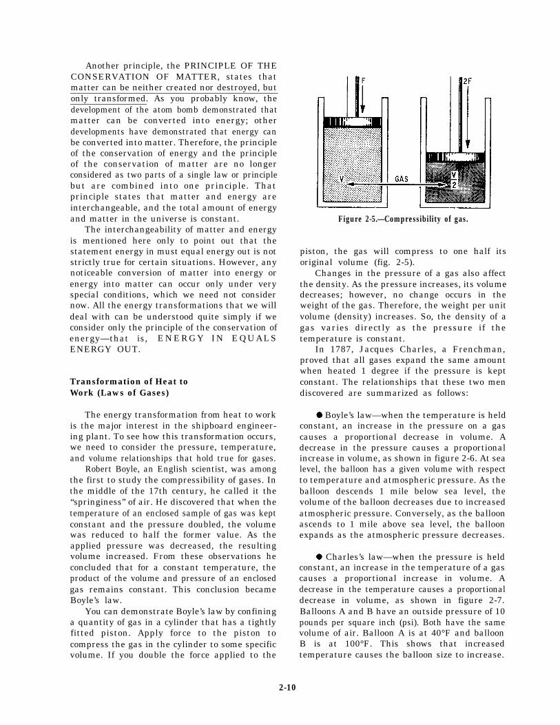
Another principle, the PRINCIPLE OF THECONSERVATION OF MATTER, states thatmatter can be neither created nor destroyed, butonly transformed. As you probably know, thedevelopment of the atom bomb demonstrated thatmatter can be converted into energy; otherdevelopments have demonstrated that energy canbe converted into matter. Therefore, the principleof the conservation of energy and the principleof the conservation of matter are no longerconsidered as two parts of a single law or principlebut are combined into one principle. Thatprinciple states that matter and energy areinterchangeable, and the total amount of energyand matter in the universe is constant.
The interchangeability of matter and energyis mentioned here only to point out that thestatement energy in must equal energy out is notstrictly true for certain situations. However, anynoticeable conversion of matter into energy orenergy into matter can occur only under veryspecial conditions, which we need not considernow. All the energy transformations that we willdeal with can be understood quite simply if weconsider only the principle of the conservation ofenergy—that is, ENERGY IN EQUALSENERGY OUT.
Transformation of Heat toWork (Laws of Gases)
The energy transformation from heat to workis the major interest in the shipboard engineer-ing plant. To see how this transformation occurs,we need to consider the pressure, temperature,and volume relationships that hold true for gases.
Robert Boyle, an English scientist, was amongthe first to study the compressibility of gases. Inthe middle of the 17th century, he called it the“springiness” of air. He discovered that when thetemperature of an enclosed sample of gas was keptconstant and the pressure doubled, the volumewas reduced to half the former value. As theapplied pressure was decreased, the resultingvolume increased. From these observations heconcluded that for a constant temperature, theproduct of the volume and pressure of an enclosedgas remains constant. This conclusion becameBoyle’s law.
You can demonstrate Boyle’s law by confininga quantity of gas in a cylinder that has a tightlyfitted piston. Apply force to the piston tocompress the gas in the cylinder to some specificvolume. If you double the force applied to the
Figure 2-5.—Compressibility of gas.
piston, the gas will compress to one half itsoriginal volume (fig. 2-5).
Changes in the pressure of a gas also affectthe density. As the pressure increases, its volumedecreases; however, no change occurs in theweight of the gas. Therefore, the weight per unitvolume (density) increases. So, the density of agas varies directly as the pressure if thetemperature is constant.
In 1787, Jacques Charles, a Frenchman,proved that all gases expand the same amountwhen heated 1 degree if the pressure is keptconstant. The relationships that these two mendiscovered are summarized as follows:
l Boyle’s law—when the temperature is heldconstant, an increase in the pressure on a gascauses a proportional decrease in volume. Adecrease in the pressure causes a proportionalincrease in volume, as shown in figure 2-6. At sealevel, the balloon has a given volume with respectto temperature and atmospheric pressure. As theballoon descends 1 mile below sea level, thevolume of the balloon decreases due to increasedatmospheric pressure. Conversely, as the balloonascends to 1 mile above sea level, the balloonexpands as the atmospheric pressure decreases.
l Charles’s law—when the pressure is heldconstant, an increase in the temperature of a gascauses a proportional increase in volume. Adecrease in the temperature causes a proportionaldecrease in volume, as shown in figure 2-7.Balloons A and B have an outside pressure of 10pounds per square inch (psi). Both have the samevolume of air. Balloon A is at 40°F and balloonB is at 100°F. This shows that increasedtemperature causes the balloon size to increase.
2-10

Figure 2-6.—Pressure differential in respect to sea level.
Figure 2-8.—Interaction of gases in respect to temperatureand pressure.
Suppose we have a boiler in which steam hasbeen formed. With the steam stop valves stillclosed, the volume of the steam remains constantwhile the pressure and the temperature are bothincreasing. When operating pressure is reachedand the steam stop valves are opened, the highpressure of the steam causes the steam to flow tothe turbines. The pressure of the steam thusprovides the potential for doing work. The actualconversion of thermal energy to work is done inthe turbine section.
Steam
Steam is water to which enough heat has been
Figure 2-7.—Pressure differential in respect to temperature.
l Charles’s law is also stated—when thevolume is held constant, an increase in thetemperature of a gas causes a proportionalincrease in pressure. A decrease in the temperaturecauses a proportional decrease in pressure, asshown in figure 2-8. Tanks A and B are of thesame size and have an equal volume of gas. TankA has a pressure of 10 psi when heated to 40°F.Tank B has a pressure of 12 psi when heated to100°F. Unlike the balloons, the steel tanks do notexpand to accommodate the changes in tempera-ture and pressure. This shows that changes intemperature are inversely proportional to changesin gas pressure when the volume is held constant.
added to convert it from the liquid to the gaseousstate. When heat is added to water in an opencontainer, steam forms. However, it quickly mixeswith air and cools back to water that is dispersedin the air, making the air more humid. If you addthe heat to water in a closed container, the steambuilds up pressure. If you add exactly enough heatto convert all the water to steam at thetemperature of boiling water, you get saturatedsteam. SATURATED STEAM is steam saturatedwith all the heat it can hold at the boilingtemperature of water.
The boiling temperature of water becomeshigher as the pressure over the water becomeshigher. Steam hotter than the boiling temperatureof water is called SUPERHEATED STEAM.When steam has 250 °F of superheat, the actualtemperature is the boiling temperature plus 250 °F.At 600 psi the boiling temperature of water is489 °F. So if steam at 600 psi has 250°F ofsuperheat, its actual temperature is 739°F. WETSTEAM is steam at the boiling temperature thatstill contains some water particles. DESUPER-HEATED STEAM is steam that has been cooledby being passed through a pipe extending through
2-11

the steam drum. In the process, the steam losesall but 20°F to 30°F of its superheat. Theadvantage of desuperheated steam is that it iscertain to be dry, yet not so hot as to requirespecial alloy steels for the construction of thepiping that carries the desuperheated steam aboutthe ship.
Steam use will be discussed later in chapters3 and 4 of this textbook. We will describe thesteam cycle and typical boilers used on navalships.
Combustion
Combustion refers to the rapid chemical unionof oxygen with fuel. Perfect combustion of fuelwould result in carbon dioxide, nitrogen, watervapor, and sulphur dioxide. The oxygen requiredto burn the fuel is obtained from the air. Air isa mechanical mixture containing by weight21 percent oxygen, 78 percent nitrogen, and1 percent other gases. Only oxygen is used incombustion. Nitrogen is an inert gas that has nochemical effect upon combustion.
The chemical combination obtained duringcombustion results in the liberation of heatenergy. A portion of this energy is used topropel the ship. Actually, what happens is arearrangement of the atoms of the chemicalelements into new combinations of molecules. Inother words, when the fuel oil temperature (in thepresence of oxygen) is increased to the ignitionpoint, a chemical reaction occurs. The fuel beginsto separate and unite with specific amounts ofoxygen to form an entirely new substance. Heatenergy is given off in the process. A good fuelburns quickly and produces a large amount ofheat.
Perfect combustion is the objective. However,this has been impossible to achieve as yet in eithera boiler or the cylinders of an internal-combustionengine. Theoretically, it is simple. It consists ofbringing each particle of the fuel (heated to itsignition temperature) into contact with thecorrect amount of oxygen. The following factorsare involved:
l Sufficient oxygen must be supplied.
l The oxygen and fuel particles must bethoroughly mixed.
. Temperatures must be high enough tomaintain combustion.
. Enough time must be allowed to permitcompletion of the process.
Complete combustion can be achieved. This.is accomplished by more oxygen being suppliedto the process than would be required if perfectcombustion were possible. The result is that someof the excess oxygen appears in the combustiongases.
Units of Heat Measurement
Both internal energy and heat is measuredusing the British thermal unit (Btu). For mostpractical engineering purposes, 1 Btu is thethermal energy required to raise the temperatureof 1 pound of pure water to 1°F. Burning awooden kitchen match completely will produceabout 1 Btu.
When large amounts of thermal energy areinvolved, it is usually more convenient to usemultiples of the Btu. For example, 1 kBtu is equalto 1000 Btu, and 1 MBtu is equal to 1 million Btu.
Another unit in which thermal energy maybemeasured is the calorie. The calorie is the amountof heat required to raise the temperature of 1 gramof pure water 1°C. One Btu equals 252 calories.
Sensible Heat and Latent Heat
Sensible heat and latent heat are terms oftenused to indicate the effect that the flow of heathas on a substance. The flow of heat from onesubstance to another is normally reflected in atemperature change in each substance—the hottersubstance becomes cooler, the cooler substancebecomes hotter. However, the flow of heat is notreflected in a temperature change in a substancethat is in the process of changing from onephysical state (solid, liquid, or gas) to another.When the flow of heat is reflected in a temperaturechange, we say that sensible heat has been addedto or removed from the substance (heat that canbe sensed or felt). When the flow of heat is notreflected in a temperature change, but is reflectedin the changing physical state of a substance, wesay that latent heat has been added or removed.
Does anything bother you in this lastparagraph? It should. Here we are talking aboutsensible heat and latent heat as though we hadtwo different types of heat to consider. This iscommon (if inaccurate) engineering language. Sokeep the following points clearly in mind: (1) heatis the movement (flow) of thermal energy;(2) when we talk about adding and removing heat,we really mean that we are providing temperaturedifferentials so thermal energy can flow from onesubstance to another; and (3) when we talk about
2-12
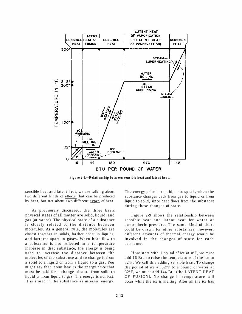
Figure 2-9.—Relationship between sensible heat and latent heat.
sensible heat and latent heat, we are talking about The energy price is repaid, so to speak, when thetwo different kinds of effects that can be producedby heat, but not about two different types of heat.
As previously discussed, the three basicphysical states of all matter are solid, liquid, andgas (or vapor). The physical state of a substanceis closely related to the distance betweenmolecules. As a general rule, the molecules areclosest together in solids, farther apart in liquids,and farthest apart in gases. When heat flow toa substance is not reflected in a temperatureincrease in that substance, the energy is beingused to increase the distance between themolecules of the substance and to change it froma solid to a liquid or from a liquid to a gas. Youmight say that latent heat is the energy price thatmust be paid for a change of state from solid toliquid or from liquid to gas. The energy is not lost.It is stored in the substance as internal energy.
substance changes back from gas to liquid or fromliquid to solid, since heat flows from the substanceduring these changes of state.
Figure 2-9 shows the relationship betweensensible heat and latent heat for water atatmospheric pressure. The same kind of chartcould be drawn for other substances; however,different amounts of thermal energy would beinvolved in the changes of state for eachsubstance.
If we start with 1 pound of ice at 0°F, we mustadd 16 Btu to raise the temperature of the ice to32°F. We call this adding sensible heat. To changethe pound of ice at 32°F to a pound of water at32°F, we must add 144 Btu (the LATENT HEATOF FUSION). No change in temperature willoccur while the ice is melting. After all the ice has
2-13
melted, however, the temperature of the water willbe raised as additional heat is supplied. If we add180 Btu—that is, 1 Btu for each degree oftemperature between 32°F and 212°F—thetemperature of the water will be raised to theboiling point. To change the pound of water at212°F to a pound of steam at 212°F, we must add970 Btu (the LATENT HEAT OF VAPORIZA-TION). After all the water has been converted tosteam, the addition of more heat will cause anincrease in the temperature of the steam. If weadd about 44 Btu to the pound of steam that isat 212°F, we can super heat it to 300°F.
The same relationships apply when heat isbeing removed. The removal of 44 Btu from thepound of steam that is at 300°F will cause thetemperature to drop to 212°F. As the pound ofsteam at 212°F changes to a pound of water at212°F, 970 Btu are given off. When a substanceis changing from a gas or vapor to a liquid, theheat that is given off is LATENT HEAT OFCONDENSATION. Notice, however, that thelatent heat of condensation is exactly the same asthe latent heat of vaporization. The removal ofanother 180 Btu of sensible heat will lower thetemperature of the pound of pure water from212°F to 32°F. As the pound of water at 32°Fchanges to a pound of ice at 32°F, 144 Btu aregiven off without any accompanying change intemperature. Further removal of heat causes thetemperature of the ice to decrease.
TEMPERATURE
The temperature of an object is a measure ofthe heat level of that object. This level can bemeasured with a thermometer.
The temperature scales employed to measuretemperature are the Fahrenheit (F) scale andthe Celsius (C) scale. In engineering and forpractically all purposes in the Navy, theFahrenheit scale is used. You may, however, haveto convert Celsius readings to the Fahrenheit scale,so both scales are explained here.
The Fahrenheit scale has two main referencepoints—the boiling point of pure water at 212°Fand the freezing point of pure water at 32°F. Themeasure of a degree of Fahrenheit is 1/180 of thetotal temperature change from 32°F to 212°F. The
scale can be extended in either direction—tohigher temperatures without any limits and tolower temperatures (by minus degrees) down tothe lowest temperature theoretically possible,absolute zero. This temperature is – 460°F, or492°F below the freezing point of water.
In the Celsius scale, the freezing point of purewater is 0°C and the boiling point of pure wateris 100°C. Therefore, 0°C and 100°C areequivalent to 32°F and 212°F, respectively. Eachdegree of Celsius is larger than a degree ofFahrenheit. Only 100° Celsius are between thefreezing and boiling points of water, while thissame temperature change requires 180° on theFahrenheit scale. Therefore, the degree of Celsiusis 180/100 or 1.8° Fahrenheit. In the Celsius scale,absolute zero is – 273°C. To convert from onetemperature scale to another, use the followingalgebraic equations:
From Fahrenheit to Celsius
0C = 5/9 X (0F – 32)
From Celsius to Fahrenheit
°F = (9/5 x °C) + 32
Figure 2-10 shows the two temperature scalesin comparison. It also introduces the simplest ofthe temperature measuring instruments, theliquid-in-glass thermometer. The two thermom-eters shown are exactly alike in size and shape.The only difference is the outside markings orscales on them. Each thermometer is a hollowglass tube that is sealed at the top and has amercury-filled bulb at the bottom. Mercury, likeany liquid, expands when heated and will rise inthe hollow tube. View A of figure 2-10 shows theFahrenheit thermometer with its bulb standing inmelting ice (32°F), and view B shows the Celsiusthermometer with its bulb standing in boilingwater (100°C).
The main point to remember is that the levelof the mercury in a thermometer depends only onthe temperature to which the bulb is exposed. Ifyou were to exchange the thermometers, themercury in the Celsius thermometer would dropto the level that the mercury now stands in theFahrenheit thermometer. Likewise, the mercuryin the Fahrenheit thermometer would rise tothe level that the mercury now stands in the
2-14

Figure 2-10.—Temperature scales. A. Fahrenheit. B. Celsius.
Celsius thermometer. The temperatures wouldbe 0°C for the ice water and 212°F for theboiling water.
If you place both thermometers in watercontaining ice, the Fahrenheit thermometer willread 32°F and the Celsius thermometer willread 0°C. Heat the water slowly. The temperaturewill not change until the ice in the water hascompletely melted (a great deal of heat is requiredjust to melt the ice). Then both mercury columnswill begin to rise. When the mercury level is atthe +10° mark on the Celsius thermometer, it willbe at the +50° mark on the Fahrenheitthermometer. The two columns will rise togetherat the same speed and, when the water finallyboils, they will stand at 100°C and 212°F,respectively. The same temperature change—that
is, the same amount of heat transferred to thewater—has raised the temperature 100° Celsiusand 180° Fahrenheit, but the actual change in heatenergy is exactly the same.
PRESSURE DEFINITIONS
Pressure, like temperature, is one of the basicengineering measurements and one that must befrequently monitored aboard ship. As withtemperature readings, pressure readings provideyou with an indication of the operating conditionof equipment. PRESSURE is defined as theforce per unit area.
The simplest pressure units are the ones thatindicate how much force is applied to an area ofa certain size. These units include pounds persquare inch, pounds per square foot, ounces persquare inch, newtons per square millimeter, anddynes per square centimeter, depending upon thesystem you use.
You also use another kind of pressure unit thatinvolves length. These units include inches ofwater (in. H2O), inches of mercury (in.Hg), andinches of some other liquid of a known density.Actually, these units do not involve length as afundamental dimension. Rather, length is takenas a measure of force or weight. For example, areading of 1 in.H2O means that the exertedpressure is able to support a column of water 1inch high, or that a column of water in a U-tubewould be displaced 1 inch by the pressure beingmeasured. Similarly, a reading of 12 in. Hg meansthat the measured pressure is sufficient tosupport a column of mercury 12 inches high.What is really being expressed (even though it isnot mentioned in the pressure unit) is that acertain quantity of material (water, mercury, andso on) of known density exerts a certain definiteforce upon a specified area. Pressure is still forceper unit area, even if the pressure unit refers toinches of some liquid.
In interpreting pressure measurements, a greatdeal of confusion arises because the zero pointon most pressure gauges represents atmosphericpressure rather than zero absolute pressure.Thus, it is often necessary to specify thekind of pressure being measured under any givenconditions. To clarify the numerous meanings of
2-15

Figure 2-11.—Relationships among gauge pressure, atmos-pheric pressure, vacuum, and absolute pressure.
the word pressure, the relationships among gauge,atmospheric, vacuum, and absolute pressures areshown in figure 2-11.
GAUGE PRESSURE is the pressure actuallyshown on the dial of a gauge that registerspressure relative to atmospheric pressure. Anordinary pressure gauge reading of zero doesnot mean there is no pressure in the absolutesense; rather, it means there is no pressure inexcess of atmospheric pressure.
ATMOSPHERIC PRESSURE is the pressureexerted by the weight of the atmosphere. At sealevel, the average pressure of the atmosphere issufficient to hold a column of mercury at theheight of 76 centimeters or 29.92 inches. Since acolumn of mercury 1 inch high exerts a pressureof 0.49 pound per square inch (psi) at its base,a column of mercury 29.92 inches high exerts apressure that is equal to 29.92 x 0.49 or about 14.7psi. Since we are dealing now in absolute pressure,we say that the average atmospheric pressure atsea level is 14.7 pounds per square inch absolute(psia). It is zero on the ordinary pressure gauge.
Notice, however, that the figure of 14.7 psiarepresents the average atmospheric pressure at sealevel; it does not always represent the actualpressure being exerted by the atmosphere at themoment a gauge is being read. Since fluctuationsfrom this standard are shown on a barometer(an instrument used to measure atmosphericpressure), the term barometric pressure is used to
Figure 2-12.—Typical barometer.
describe the atmospheric pressure that exists atany given moment. Figure 2-12 shows theoperating principle of a typical barometer.
BAROMETRIC PRESSURE is the term usedto describe the actual atmospheric pressure thatexists at any given moment. Barometric pressuremay be measured by a simple mercury column orby a specially designed instrument called ananeroid barometer.
A space in which the pressure is less thanatmospheric pressure is said to be under partialvacuum. The vacuum is expressed in terms of thedifference between the absolute pressure in thespace and the pressure of the atmosphere. Mostcommonly, vacuum is expressed in inches ofmercury, with the vacuum gauge scale markedfrom 0 to 30 in.Hg. When a vacuum gauge readszero, the pressure in the space is the same asatmospheric pressure—or, in other words, thereis no vacuum. A vacuum gauge reading of 29.92in. Hg would indicate a perfect (or nearly perfect)vacuum. In actual practice a perfect vacuum isimpossible to obtain even under laboratoryconditions. A reading between 0 and 29.92 in.Hgis a partial vacuum.
ABSOLUTE PRESSURE is atmosphericpressure plus gauge pressure, or absolute pressureminus vacuum. For example, a gauge pressure of300 pounds per square inch gauge (psig) equalsan absolute pressure of 314.7 psia (300 + 14.7).Or, for example, consider a space in which themeasured vacuum is 10 in. Hg; the absolute
2-16
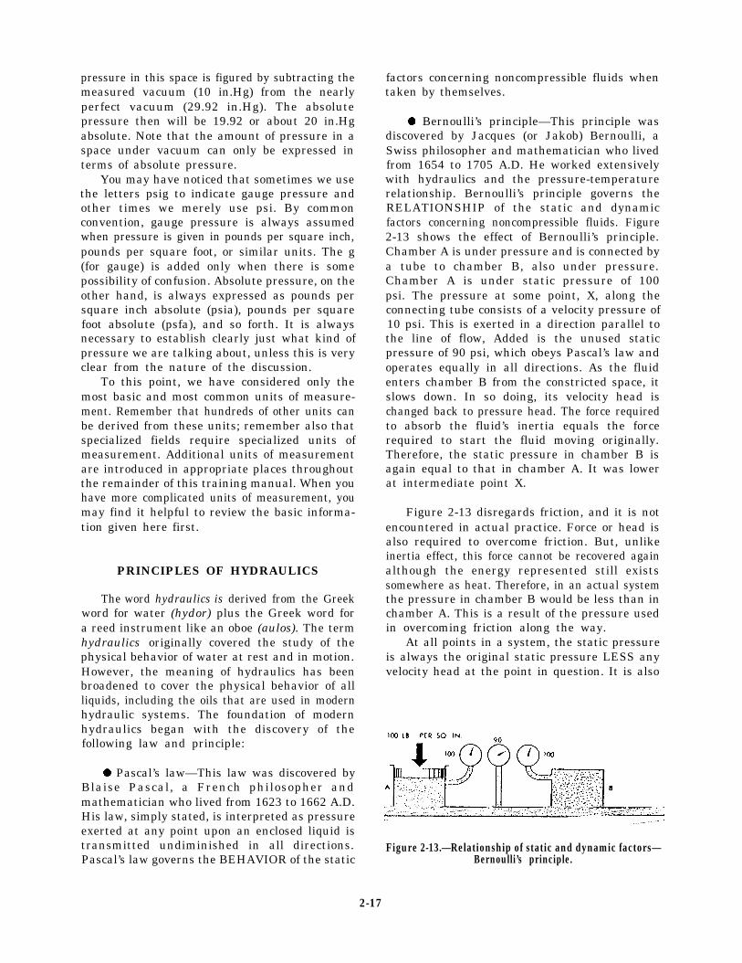
pressure in this space is figured by subtracting themeasured vacuum (10 in.Hg) from the nearlyperfect vacuum (29.92 in.Hg). The absolutepressure then will be 19.92 or about 20 in.Hgabsolute. Note that the amount of pressure in aspace under vacuum can only be expressed interms of absolute pressure.
You may have noticed that sometimes we usethe letters psig to indicate gauge pressure andother times we merely use psi. By commonconvention, gauge pressure is always assumedwhen pressure is given in pounds per square inch,pounds per square foot, or similar units. The g(for gauge) is added only when there is somepossibility of confusion. Absolute pressure, on theother hand, is always expressed as pounds persquare inch absolute (psia), pounds per squarefoot absolute (psfa), and so forth. It is alwaysnecessary to establish clearly just what kind ofpressure we are talking about, unless this is veryclear from the nature of the discussion.
To this point, we have considered only themost basic and most common units of measure-ment. Remember that hundreds of other units canbe derived from these units; remember also thatspecialized fields require specialized units ofmeasurement. Additional units of measurementare introduced in appropriate places throughoutthe remainder of this training manual. When youhave more complicated units of measurement, youmay find it helpful to review the basic informa-tion given here first.
PRINCIPLES OF HYDRAULICS
The word hydraulics is derived from the Greekword for water (hydor) plus the Greek word fora reed instrument like an oboe (aulos). The termhydraulics originally covered the study of thephysical behavior of water at rest and in motion.However, the meaning of hydraulics has beenbroadened to cover the physical behavior of allliquids, including the oils that are used in modernhydraulic systems. The foundation of modernhydraulics began with the discovery of thefollowing law and principle:
. Pascal’s law—This law was discovered byBlaise Pascal, a French philosopher andmathematician who lived from 1623 to 1662 A.D.His law, simply stated, is interpreted as pressureexerted at any point upon an enclosed liquid istransmitted undiminished in all directions.Pascal’s law governs the BEHAVIOR of the static
factors concerning noncompressible fluids whentaken by themselves.
. Bernoulli’s principle—This principle wasdiscovered by Jacques (or Jakob) Bernoulli, aSwiss philosopher and mathematician who livedfrom 1654 to 1705 A.D. He worked extensivelywith hydraulics and the pressure-temperaturerelationship. Bernoulli’s principle governs theRELATIONSHIP of the static and dynamicfactors concerning noncompressible fluids. Figure2-13 shows the effect of Bernoulli’s principle.Chamber A is under pressure and is connected bya tube to chamber B, also under pressure.Chamber A is under static pressure of 100psi. The pressure at some point, X, along theconnecting tube consists of a velocity pressure of10 psi. This is exerted in a direction parallel tothe line of flow, Added is the unused staticpressure of 90 psi, which obeys Pascal’s law andoperates equally in all directions. As the fluidenters chamber B from the constricted space, itslows down. In so doing, its velocity head ischanged back to pressure head. The force requiredto absorb the fluid’s inertia equals the forcerequired to start the fluid moving originally.Therefore, the static pressure in chamber B isagain equal to that in chamber A. It was lowerat intermediate point X.
Figure 2-13 disregards friction, and it is notencountered in actual practice. Force or head isalso required to overcome friction. But, unlikeinertia effect, this force cannot be recovered againalthough the energy represented still existssomewhere as heat. Therefore, in an actual systemthe pressure in chamber B would be less than inchamber A. This is a result of the pressure usedin overcoming friction along the way.
At all points in a system, the static pressureis always the original static pressure LESS anyvelocity head at the point in question. It is also
Figure 2-13.—Relationship of static and dynamic factors—Bernoulli’s principle.
2-17

LESS the friction head consumed in reaching thatpoint. Both velocity head and friction representenergy that came from the original static head.Energy cannot be destroyed. So, the sum of thestatic head, velocity head, and friction at anypoint in the system must add up to the originalstatic head. This, then, is Bernoulli’s principle;more simply stated, if a noncompressible fluidflowing through a tube reaches a constriction, ornarrowing of the tube, the velocity of fluidflowing through the constriction increases, andthe pressure decreases.
When we apply a force to the end of acolumn of confined liquid, the force is trans-mitted not only straight through to the otherend but also equally in every direction through-out the column. This is why a flat fire hosetakes on a circular cross section when it isfilled with water under pressure. The outwardpush of the water is equal in every direction.Water will leak from the hose at the samevelocity regardless of where the leaks are inthe hose.
Let us now consider the effect of Pascal’slaw in the systems shown in figure 2-14,views A and B. If the total force at theinput piston is 100 pounds and the area ofthe piston is 10 square inches, then eachsquare inch of the piston surface is exerting10 pounds of force. This liquid pressure of10 psi is transmitted to the output piston, whichwill be pushed upward with a force of 10 psi.In this example, we are merely consideringa liquid column of equal cross section so theareas of these pistons are equal. All we havedone is to carry a 100-pound force around abend. However, the principle shown is the basisfor almost all mechanical hydraulics.
The same principle may be applied where thearea of the input piston is much smaller than thearea of the output piston or vice versa. In viewB of figure 2-14, the area of the input piston is2 square inches and the area of the output pistonis 20 square inches. If you apply a pressure of 20pounds to the 2 square-inch piston, the pressurecreated in the liquid will again be 10 psi. Theupward force on the larger piston will be 200pounds—10 pounds for each of its 20 squareinches. Thus, you can see that if two pistons areused in a hydraulic system, the force acting oneach piston will be directly proportional to itsarea.
A. EQUAL INPUT AND OUTPUT AREA
B . UNEQUAL INPUT AND OUTPUT AREA
Figure 2-14.—Principle of mechanical hydraulics. A. Equalinput and output area. B. Unequal input and outputarea.
PRINCIPLES OF PNEUMATICS
PNEUMATICS is that branch of mechanicsthat deals with the mechanical properties of gases.Perhaps the most common application of theseproperties in the Navy today is the use ofcompressed air. Compressed air is used totransmit pressure in a variety of applications. Forexample, in tires and air-cushioned springs,compressed air acts as a cushion to absorb shock.Air brakes on locomotives and large truckscontribute greatly to the safety of railroad andtruck transportation. In the Navy, compressed airis used in many ways, For example, tools suchas riveting hammers and pneumatic drills are airoperated. Automatic combustion control systems
2-18

use compressed air for the operation of theinstruments. Compressed air is also used indiving bells and diving suits. Our followingdiscussion on the use of compressed air as an aidin the control of submarines will help you under-stand the theory of pneumatics.
Submarines are designed with a number oftanks that may be used for the control of the ship.These tanks are flooded with water to submerge,or they are filled with compressed air to surface.
The compressed air for the pneumatic systemis maintained in storage tanks (called banks) ata pressure of 4500 psi. During surfacing, thepneumatic system delivers compressed air to thedesired control tanks (the tanks filled with water).Since the pressure of the air is greater than thepressure of the water, the water is forced out ofthe tank. As a result, the weight of the shipdecreases. It becomes more buoyant and rises tothe surface.
METALS
As you look around, you see not only thatyour ship is constructed of metal, but also thatthe boilers, piping system, machinery, and evenyour bunk and locker are constructed of sometype of metal. No one type of metal can serve allthe needs aboard ship. Many types of metals ormetal alloys must be used. A strong metal mustbe used for some parts of a ship, while alightweight metal is needed for other parts. Someareas require special metal that can be shaped orworked very easily.
The physical properties of some metals ormetal alloys make them more suitable for one usethan for another. Various terms are used indescribing the physical properties of metals. Bystudying the following explanations of theseterms, you should have a better understanding ofwhy certain metals are used on one part of theship’s structure and not on another part.
BRITTLENESS is a property of a metal thatwill allow it to shatter easily. Metals, such as castiron or cast aluminum and some very hard steels,are brittle.
DUCTILITY refers to the ability of a metalto stretch or bend without breaking. Soft iron,soft steel, and copper are ductile metals.
HARDNESS refers to the ability of a metalto resist penetration, wear, or cutting action.
MALLEABILITY is a property of a metalthat allows it to be rolled, forged, hammered, orshaped without cracking or breaking. Copper isa very malleable metal.
STRENGTH refers to the ability of a metalto maintain heavy loads (or force) withoutbreaking. Steel, for example, is strong, but leadis weak.
TOUGHNESS is the property of a metal thatwill not permit it to tear or shear (cut) easily andwill allow it to stretch without breaking.
Metal preservation aboard ship is a continuousoperation, since the metals are constantly exposedto fumes, water, acids, and moist salt air. All ofthese elements will eventually cause corrosion. Thecorrosion of iron and steel is called rusting. Thisresults in the formation of iron oxide (iron andoxygen) on the surface of the metal. Iron oxide(or rust) can be identified easily by its reddishcolor. (A blackish hue occurs in the first stage ofrusting but is seldom thought of as rust.)Corrosion can be reduced or prevented by use ofbetter grades of alloyed metals. Chromium andnickel are commonly used. Coating the surfacewith paint or other metal preservatives also helpsprevent rust.
Metals and alloys are divided into twogeneral classes: ferrous and nonferrous. Ferrousmetals are those composed primarily of iron.Nonferrous metals are those composed primarilyof some element or elements other than iron.One way to tell a common ferrous metal from anonferrous metal is by using a magnet. Mostferrous metal is magnetic, and nonferrous metalis nonmagnetic.
Elements must be alloyed (or mixed) togetherto obtain the desired physical properties of ametal. For example, alloying (or mixing)chromium and nickel with iron produces a metalknown as special treatment steel (STS). An STShas great resistance to penetrating and shearingforces. A nonferrous alloy that has many usesaboard ship is copper-nickel. It is used extensivelyin saltwater piping systems. Copper-nickel is amixture of copper and nickel. Many otherdifferent metals and alloys are used aboard shipthat will not be discussed here.
2-19

With all the different types of metals usedaboard ship, some way must be used to identifythese metals in the storeroom. The Navy uses twosystems to identify metals: the continuousidentification marking system and the color mark-ing system. These systems have been designedso even after a portion of the metal has beenremoved, the identifying marks are still visible.
In the continuous identification markingsystem, the identifying information is actuallypainted on the metal with a heavy ink. Thismarking appears at specified intervals over thelength of the metal. The marking contains theproducer’s trademark and the commercialdesignation of the metal. The marking alsoindicates the physical condition of the metal, suchas cold drawn, cold rolled, and seamless.
In the color marking system, a series of colorsymbols with a related color code is used toidentify metals. The term color symbol refers toa color marking actually painted on the metal. Thesymbol is composed of one, two, or three colorsand is painted on the metal in a conspicuous place.These color symbols correspond to the elementsof which the metal is composed.
For further information on the metals usedaboard ship, their properties and identificationsystems, refer to the TRAMAN, Hull Mainte-nance Technician 3 & 2, NAVEDTRA 10571-1,chapter 4.
SUMMARY
In this chapter we have discussed someof the basic laws and principles of physicsas they apply to the engineering ratings. Wecovered matter, magnetism, electricity, Ohm’slaw, Newton’s laws, and mass and its differentproperties. Mechanical energy, thermal energy,and topics of energy transformations weredescribed. We also provided you informationon temperature, pressure definitions, principlesof hydraulics, principles of pneumatics, andmetals.
This chapter was provided to give you onlythe basis on which to expand your knowledge ofelectrical and mechanical fundamentals. It isimportant that you have a sound understandingof these laws and principles. The complexelectrical and mechanical systems and theinternal pressure-temperature relationships in anengineering plant make it imperative that youunderstand the material presented. If you haveproblems understanding this material, you shouldreread the pertinent portions until you haveabsorbed the basic concepts. You will use thisinformation throughout your naval career.Study this information so you will have agood foundation of understanding within theengineering department of your ship.
2-20
CHAPTER 3
BASIC STEAM CYCLE
To understand steam generation, you mustknow what happens to the steam after it leavesthe boiler. A good way to learn the steam planton your ship is to trace the path of steam andwater throughout its entire cycle of operation. Ineach cycle, the water and the steam flow throughthe entire system without ever being exposed tothe atmosphere. The four areas of operation ina main steam system are generation, expansion,condensation, and feed. After studying thischapter, you will have the knowledge and ablityto describe the main steam cycle and the functionsof the auxiliary steam systems.
MAIN STEAM SYSTEM
The movement of a ship through the water isthe result of a number of energy transformations.Although these transformations were mentionedin the last chapter, we will now discuss thesetransformations as they occur. Figure 3-1 showsthe four major areas of operation in the basicsteam cycle and the major energy transformationsthat take place. These areas are A—generation,B—expansion, C—condensation, and D—feed.
GENERATION—The first energy transfor-mation occurs in the boiler furnace when fueloil burns. By the process of combustion,the chemical energy stored in the fuel oilis transformed into thermal energy. Thermalenergy flows from the burning fuel to thewater and generates steam. The thermal energyis now stored as internal energy in steam,as we can tell from the increased pressureand temperature of the steam.
EXPANSION—When steam enters the turbinesand expands, the thermal energy of the steamconverts to mechanical energy, which turns theshaft and drives the ship.
For the remainder of the cycle, energy isreturned to the water (CONDENSATION andFEED) and back to the boiler where it is againheated and changed into steam. The energy usedfor this purpose is the thermal energy of theauxiliary steam.
The following paragraphs will explain the fourmajor areas of operation in the basic steam cycleshown in figure 3-1.
GENERATION
When a liquid boils, it generates a vapor.Some or all of the liquid changes its physical statefrom liquid to gas (or vapor). As long as the vaporis in contact with the liquid from which it isbeing generated, it remains at the sametemperature as the boiling liquid. In thiscondition, the liquid and its vapors are inequilibrium contact with each other. Area A offigure 3-1 shows the GENERATION area of thebasic steam cycle.
The temperature at which a boiling liquidand its vapors may exist in equilibrium contactdepends on the pressure under which theprocess takes place. As the pressure increases,the boiling temperature increases. As thepressure decreases, the boiling temperaturedecreases. Determining the boiling point dependson the pressure.
When a liquid is boiling and generatingvapor, the liquid is a SATURATED LIQUID andthe vapor is a SATURATED VAPOR. Thetemperature at which a liquid boils under agiven pressure is the SATURATION TEM-PERATURE, and the corresponding pressure isthe SATURATION PRESSURE. Each pressurehas a corresponding saturation temperature, andeach temperature has a corresponding saturation
3-1
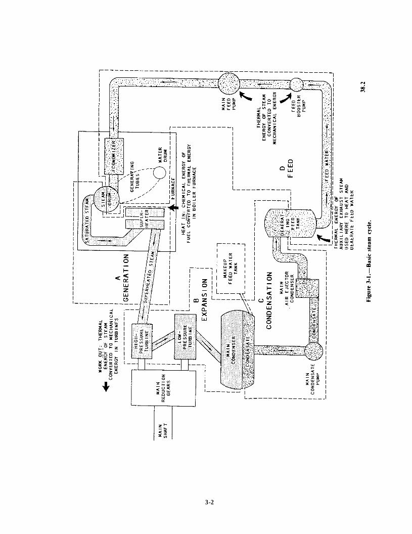
Figure 3-1.
3-2
pressure. A few saturation pressures andtemperatures for water are as follows:
Pounds Per Square Inch DegreesAbsolute (psia) Fahrenheit (°F)
11 . . . . . . . . . . . . . . . . . . . . . . .198
14.7 . . . . . . . . . . . . . . . . . . . . . . .212
110 . . . . . . . . . . . . . . . . . . . . . . . .335
340 . . . . . . . . . . . . . . . . . . . . . . . .429
630 . . . . . . . . . . . . . . . . . . . . . . . .567
1200 . . . . . . . . . . . . . . . . . . . . . .. .596
2000 . . . . . . . . . . . . . . . . . . . . . . . .636
3000 . . . . . . . . . . . . . . . . . . . . . . . .695
3206.2 . . . . . . . . . . . . . . . . . . . . . . . .705.40
We know that atmospheric pressure is 14.7psia at sea level and lesser at higher altitudes.Boiling water on top of a mountain takes a lotlonger than at sea level. Why is this? As notedbefore, temperature and pressure are indicationsof internal energy. Since we cannot raise thetemperature of boiling water above the saturationtemperature for that pressure, the internal energyavailable for boiling water is less at higheraltitudes than at sea level. By the same lines ofreasoning, you should be able to figure out whywater boils faster in a pressure cooker than in anopen kettle.
A peculiar thing happens to water and steamat an absolute pressure of 3206.2 psia and thecorresponding saturation temperature at705.40°F. At this point, the CRITICAL POINT,the vapor and liquid are indistinguishable. Nochange of state occurs when pressure increasesabove this point or when heat is added. At thecritical point, we no longer refer to water orsteam. At this point we cannot tell the waterersteam apart. Instead, we call the substance afluid or a working substance. Boilers designed tooperate at pressures and temperatures above thecritical point are SUPERCRITICAL boilers.Supercritical boilers are not used, at present, inpropulsion plants of naval ships; however, someboilers of this type are used in stationary steampower plants.
If we generate steam by boiling water in anopen pan at atmospheric pressure, the water andsteam that is in immediate contact with the water
will remain at 212°F until all the water evaporates.If we fit an absolutely tight cover to the pan sono steam can escape while we continue to addheat, both the pressure and temperature inside thevessel will rise. The steam and water will bothincrease in temperature and pressure, and eachfluid will be at the same temperature and pressureas the other.
In operation, a boiler is neither an open vesselnor a closed vessel. It is a vessel designed withrestricted openings allowing steam to escape at auniform rate while feedwater is brought in at auniform rate. Steam generation takes place in theboiler at constant pressure and constant tem-perature, less fluctuations. Fluctuations inconstant pressure and constant temperature arecaused by changes in steam demands.
We cannot raise the temperature of the steamin the steam drum above the temperature of thewater from which it is being generated until thesteam is removed from contact with the waterinside the steam drum and then heated. Steam thathas been heated above its saturation temperatureat a given pressure is SUPERHEATED STEAM.The vessel in which the saturated steam issuperheated is a SUPERHEATER.
The amount by which the temperatureof superheated steam exceeds the temperatureof saturated steam at the same pressure isthe DEGREE OF SUPERHEAT. For example,if saturated steam at 620 psia with a corre-sponding saturation temperature of 490°F issuperheated to 790°F, the degree of superheat is300°F (790 – 490 = 300).
Most naval propulsion boilers have super-heaters. The primary advantage is that super-heating steam provides a greater temperaturedifferential between the boiler and the condenser.This allows more heat to be converted to workat the turbines. We will discuss propulsion boilersand component parts more extensively in the nextchapter. Another advantage is that superheatedsteam is dry and therefore causes relatively littlecorrosion or erosion of machinery and piping.Also, superheated steam does not conduct or loseheat as rapidly as saturated steam. The increasedefficiency which results from the use of super-heated steam reduces the fuel oil requiredto generate each pound of steam. It alsoreduces the space and weight requirements for theboilers.
3-3

Most auxiliary machinery operates on saturatedsteam. Reciprocating machinery, in particular,requires saturated steam to lubricate internalmoving parts of the steam end. Naval boilers,therefore, produce both saturated steam andsuperheated steam.
EXPANSION
The EXPANSION area of the main steamsystem is that part of the basic steam cycle inwhich steam from the boilers to the main turbinesis expanded. This removes the heat energy storedin the steam and transforms that energy intomechanical energy of rotation.
The main turbines usually have a high-pressure(HP) turbine and a low-pressure (LP) turbine. Thesteam flows into the HP turbine and on into theLP turbine. Area B of figure 3-1 shows theexpansion area of the main steam system. Thisportion of the main steam system contains HPand LP turbines.
CONDENSATION
Each ship must produce enough feedwater forthe boilers and still maintain an efficientengineering plant. Therefore, feedwater is usedover and over again.
As the steam leaves or exhausts from the LPturbine, it enters the CONDENSATE system. Thecondensate system is that part of the steam cyclein which the steam is condensed back to water.Then it flows from the main condenser towardthe boilers while it is being prepared for use asfeedwater.
The components of the condensate system are(1) the main condenser, (2) the main condensatepump, (3) the main air ejector condenser, and(4) the top half of the deaerating feed tank (DFT).These components are shown in area C of figure3-1.
The main condenser receives steam from theLP turbine. It condenses the steam into water. Wewill explain this process in the next chapter onboilers. The main condensate pump takes suctionfrom the main condenser hot well. It delivers thecondensate into the condensate piping system andthrough the main air ejector condenser. As itsname implies, the air ejector removes air andnoncondensable gases from the main condenserthat leak or are discharged into it during normaloperation. The condensate is used as a coolingmedium for condensing the steam in the inter andafter condensers of the main air ejector.
FEED
The DFT (fig. 3-2) is the dividing line betweencondensate and feedwater. The condensate entersthe DFT through the spray nozzles and turnsinto feedwater in the reservoir section of the DFT.The DFT has three basic functions:
l To remove dissolved oxygen and non-condensable gases from the condensate
. To preheat the water
. To act as a reservoir to store feedwater totake care of fluctuations in feedwaterdemand or condensate supply
The condensate enters the DFT through thecondensate inlet. There it is sprayed into the domeof the tank by nozzles. It is discharged in a finespray throughout the steam-filled top. The finespray and heating of the condensate releasestrapped air and oxygen. The gas-free condensatefalls to the bottom of the tank through the watercollecting cones, while the air and oxygen areexhausted from the tank vent.
The collected condensate in the storagesection of the DFT is now called feedwater andbecomes a source of supply for the main feedbooster pump. The main feed booster pump takessuction from the DFT and maintains a constantdischarge pressure to the main feed pump.
The main feed pump receives the water(delivered from the booster pump) and dischargesit into the main feed piping system. Area D offigure 3-1 shows the path of the water from theDFT to the economizer. The discharge pressureof the main feed pump is maintained at 100 to150 psig above boiler operating pressure on600-psi plants. On 1200-psi plants, it is maintainedat 200 to 300 psig above boiler operating pressure.The discharge pressure is maintained throughoutthe main feed piping system. However, thequantity of water discharged to the economizeris controlled by a feed stop and check valve orautomatic feedwater regulator valve.
The economizer is positioned on the boiler toperform one basic function. It acts as a preheater.The gases of combustion flow around theeconomizer tubes and metal projections thatextend from the outer tube surfaces. The tubesand projections absorb some of the heat ofcombustion and heat the water that is flowingthrough the economizer tubes. As a result, thewater is about 100 °F hotter as it flows out of theeconomizer to the boiler.
3-4

38.17
Figure 3-2.—Deaerating feed tank.
AUXILIARY STEAM SYSTEM
Auxiliary steam systems supply steam at thepressures and temperatures required cooperatemany systems and machinery, both insideand outside engineering spaces. As discussedpreviously, auxiliary steam is often calledsaturated steam or desuperheated steam.
Many steam systems and machinery receivetheir steam supply from auxiliary steam systemson most steam-driven ships. Some typical examples
are constant and intermittent service steamsystems, steam smothering systems, ships’whistles, air ejectors, forced draft blowers, anda wide variety of pumps. Some newer ships usemain steam instead of auxiliary steam for theforced draft blowers and for some pumps.Aboard some ships, turbine gland sealing systemsreceive their steam supply from an auxiliary steamsystem. Other ships may receive their supply fromthe auxiliary exhaust system. Gland sealing steamis supplied to the shaft glands of propulsion and
3-5
generator turbines to seal the shaft glands againstleakage. This leakage includes air leaking into theturbine casings and steam leaking out of theturbine casings. More use of electrically driven(rather than turbine-driven) auxiliaries hassimplified auxiliary steam systems on newer ships.
SUMMARY
In this chapter, you have learned about themain steam system, the auxiliary steam system,
and the use of steam after it leaves the boiler.Remember, steam and feedwater are recycled overand over again to provide heat and power tooperate machinery. It is important that youunderstand the terminology associated with steamand feedwater systems. You will use these termsin your day-to-day routine aboard ship. Some ofthe subjects will be discussed in greater detail inlater chapters. All of these areas are importantin their own right. As you learn this information,you will become a more proficient and reliabletechnician.
3-6
CHAPTER 4
BOILERS
The function of a boiler in the steam cycle isto convert water into steam. Reliability inoperating naval boilers and associated equipmentis important for the power plant to operate atmaximum efficiency. The complex design of navalboilers requires a high degree of technicalknowledge and skill on the part of the fireroompersonnel responsible for boiler operations. Allengineers should have some knowledge of theprinciples of combustion, how combustion occursin a boiler, and the combustion requirements foroperating a boiler more efficiently. You may wantto review combustion in chapters 2 and 3 of thistextbook.
This chapter describes boilers commonly usedin propulsion plants of naval steam-drivensurface ships. This information is general innature and does not relate to any one class of ship.Chapter 221 of the Naval Ships’ Technical Manualis the basic doctrine reference on boilers. Fordetailed information on the boilers in anyparticular ship, consult the manufacturer’stechnical manuals furnished with the boilers.
Upon completion of this chapter, you willhave the knowledge to be able to identify andunderstand boiler terminology, the basic types ofnaval boilers and their operating principles,interpret gauges and indicators that aid inmonitoring operating parameters of naval boilers,and understand boiler construction. You shouldbe able to identify the major parts of a boiler andits functions. Also, you will learn about safetyprecautions that must be observed during boilerlight-off.
BOILER TERMINOLOGY
Before studying the types of boilers used inpropulsion plants aboard Navy ships, you needto know the boiler terms and definitions used mostfrequently by shipboard personnel. In this sectionwe have listed some of the terms used in this
chapter and by fireroom personnel on the job. Itis not an all-inclusive list, but it will help forma basis for your understanding of the informationpresented on boilers.
Fireroom— The fireroom is a compartmentcontaining boilers and the operating stationfor firing the boilers.
Boiler room— The boiler room is acompartment containing boilers but notcontaining the station for firing oroperating the boiler.
Main machinery room— The mainmachinery room is a compartment con-taining boilers and the station for firing oroperating the boilers and main propulsionengines.
Boiler operating station— The boileroperating station is a station from whicha boiler or boilers are operated, applyingparticularly to the compartment fromwhich the boilers are operated.
Steaming hours— Steaming hours is thetime during which the boilers have fireslighted until fires are secured.
Boiler full-power capacity— Boiler full-power capacity is specified in the contractspecifications of a ship. It is expressed asthe number of pounds of steam generatedper hour at the pressure and temperaturerequired for all purposes to develop con-tract shaft hp of the ship divided by thenumber of boilers installed. Boiler full-power capacity is listed in the design datasection of the manufacturer’s technicalmanual for the boilers in each ship. Itmay be listed either as the capacity at fullpower or as the designed rate of actualevaporation per boiler at full power.
4-1

Boiler overload capacity— Boiler overloadcapacity is specified in the design of theboiler. It is usually 120 percent of boilerfull-power capacity, for either steamingrate or firing rate, as specified for theindividual installation.
Superheater outlet pressure— Superheateroutlet pressure is the actual pressure at thesuperheater outlet at any given time.
Steam drum pressure— Steam drumpressure is the actual pressure carried inthe boiler steam drum at any given time.
Operating pressure— Operating pressure isthe constant pressure at which the boileris being operated. This pressure may becarried at either the steam drum or thesuperheater outlet, depending on thedesign feature of the boiler. Operatingpressure is specified in the manufacturer’stechnical manual.
Design pressure— Design pressure is themaximum pressure specified by the boilermanufacturer as a criterion for boilerdesign. Design pressure is not the same asoperating pressure. It is somewhat higherthan operating pressure. Design pressureis given in the manufacturer’s technicalmanual for the particular boiler.
Design temperature— Design temperatureis the maximum operating temperature atthe superheater outlet at some specifiedrate of operation. For combatant ships thespecified rate of operation is normally full-power capacity.
Operating temperature— Operating tem-perature is the actual temperature at thesuperheater out let. Operating temperatureis the same as design temperature ONLYwhen the boiler is operating at ratespecified in the definition of designtemperature.
Boiler efficiency— The efficiency of aboiler is the Btu’s per pound of fuelabsorbed by the water and steam dividedby the Btu’s per pound of fuel fired. Inother words, boiler efficiency is outputdivided by input, or heat used dividedby heat available. Boiler efficiency isexpressed as a percent.
Superheater surface— The superheatersurface is that portion of the total heatingsurface where the steam is heated afterleaving the boiler steam drum.
Economizer surface— The economizersurface is that portion of the total heatingsurface where the feed water is heatedbefore it enters the boiler steam drum.
Total heating surface— The total heatingsurface area is the area of the generating,economizer, and superheater tube banksexposed in the boiler furnace. These tubesare that part of the heat transfer thatexposes one side to combustion gases andthe other side to the water or steam beingheated.
BOILER CLASSIFICATION
Boilers vary considerably in detail and design.Most boilers may be classified and described interms of a few basic features or characteristics.Some knowledge of the methods of classificationprovides a useful basis for understanding thedesign and construction of the various types ofnaval boilers.
In the following paragraphs, we haveconsidered the classification of naval boilersaccording to intended service, location of fire andwater spaces, type of circulation, arrangement ofsteam and water spaces, number of furnaces,burner location, furnace pressure, type of super-heaters, control of superheat, and operatingpressure.
INTENDED SERVICE
A good place to begin in classifying boilersis to consider their intended service. By thismethod of classification, naval boilers aredivided into two classes, PROPULSION BOILERSand AUXILIARY BOILERS. Propulsion boilersare used to provide steam for ships’ propulsionand for vital auxiliaries’ services. Auxiliary boilersare installed in diesel-driven ships and in manysteam-driven combatant ships. They supply thesteam and hot water for galley, heating, and otherhotel services and for other auxiliary requirementsin port.
4-2
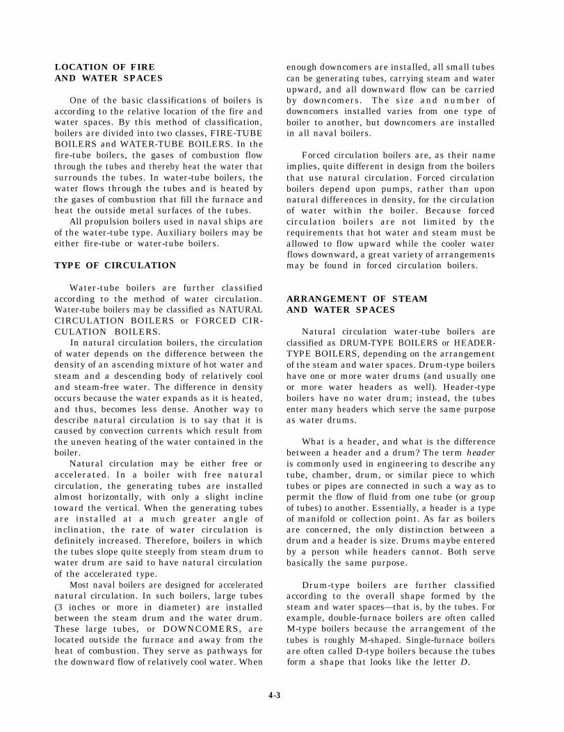
LOCATION OF FIREAND WATER SPACES
One of the basic classifications of boilers isaccording to the relative location of the fire andwater spaces. By this method of classification,boilers are divided into two classes, FIRE-TUBEBOILERS and WATER-TUBE BOILERS. In thefire-tube boilers, the gases of combustion flowthrough the tubes and thereby heat the water thatsurrounds the tubes. In water-tube boilers, thewater flows through the tubes and is heated bythe gases of combustion that fill the furnace andheat the outside metal surfaces of the tubes.
All propulsion boilers used in naval ships areof the water-tube type. Auxiliary boilers may beeither fire-tube or water-tube boilers.
TYPE OF CIRCULATION
Water-tube boilers are further classifiedaccording to the method of water circulation.Water-tube boilers may be classified as NATURALCIRCULATION BOILERS or FORCED CIR-CULATION BOILERS.
In natural circulation boilers, the circulationof water depends on the difference between thedensity of an ascending mixture of hot water andsteam and a descending body of relatively cooland steam-free water. The difference in densityoccurs because the water expands as it is heated,and thus, becomes less dense. Another way todescribe natural circulation is to say that it iscaused by convection currents which result fromthe uneven heating of the water contained in theboiler.
Natural circulation may be either free oraccelerated. In a boiler with free naturalcirculation, the generating tubes are installedalmost horizontally, with only a slight inclinetoward the vertical. When the generating tubesare installed at a much greater angle ofinclination, the rate of water circulation isdefinitely increased. Therefore, boilers in whichthe tubes slope quite steeply from steam drum towater drum are said to have natural circulationof the accelerated type.
Most naval boilers are designed for acceleratednatural circulation. In such boilers, large tubes(3 inches or more in diameter) are installedbetween the steam drum and the water drum.These large tubes, or DOWNCOMERS, arelocated outside the furnace and away from theheat of combustion. They serve as pathways forthe downward flow of relatively cool water. When
enough downcomers are installed, all small tubescan be generating tubes, carrying steam and waterupward, and all downward flow can be carriedby downcomers. The size and number ofdowncomers installed varies from one type ofboiler to another, but downcomers are installedin all naval boilers.
Forced circulation boilers are, as their nameimplies, quite different in design from the boilersthat use natural circulation. Forced circulationboilers depend upon pumps, rather than uponnatural differences in density, for the circulationof water within the boiler. Because forcedcirculation boilers are not limited by therequirements that hot water and steam must beallowed to flow upward while the cooler waterflows downward, a great variety of arrangementsmay be found in forced circulation boilers.
ARRANGEMENT OF STEAMAND WATER SPACES
Natural circulation water-tube boilers areclassified as DRUM-TYPE BOILERS or HEADER-TYPE BOILERS, depending on the arrangementof the steam and water spaces. Drum-type boilershave one or more water drums (and usually oneor more water headers as well). Header-typeboilers have no water drum; instead, the tubesenter many headers which serve the same purposeas water drums.
What is a header, and what is the differencebetween a header and a drum? The term headeris commonly used in engineering to describe anytube, chamber, drum, or similar piece to whichtubes or pipes are connected in such a way as topermit the flow of fluid from one tube (or groupof tubes) to another. Essentially, a header is a typeof manifold or collection point. As far as boilersare concerned, the only distinction between adrum and a header is size. Drums maybe enteredby a person while headers cannot. Both servebasically the same purpose.
Drum-type boilers are further classifiedaccording to the overall shape formed by thesteam and water spaces—that is, by the tubes. Forexample, double-furnace boilers are often calledM-type boilers because the arrangement of thetubes is roughly M-shaped. Single-furnace boilersare often called D-type boilers because the tubesform a shape that looks like the letter D.
4-3

NUMBER OF FURNACES CONTROL OF SUPERHEAT
All boilers commonly used in the propulsion A boiler that provides some means ofplants of naval ships may be classified as either controlling the degree of superheat independentlySINGLE-FURNACE BOILERS or DOUBLE- of the rate of steam generation is said to haveFURNACE BOILERS. The D-type boiler is a CONTROLLED SUPERHEAT. A boiler insingle-furnace boiler; the M-type boiler is a which such separate control is not possible is saiddouble-furnace (divided-furnace) boiler. to have UNCONTROLLED SUPERHEAT.
Normally, the term superheat control boiler
BURNER LOCATION is used to identify a double-furnace boiler. Theterm uncontrolled superheat boiler is used to
Naval boilers are also classified on the basis identify a single-furnace boiler.
of where their burners are located. Most burnersin naval propulsion plants are located at the frontof the boiler. These are called FRONT-FIRED OPERATING PRESSURE
BOILERS. Other ships, such as the AO-177 andLKA-113 class ships, have their burners on thetop of the boilers. These are called TOP-FIREDBOILERS.
FURNACE PRESSURE
Another convenient boiler classification isbased on the air pressure used in the furnace. Mostboilers in use in naval propulsion plants operatewith a slight air pressure (seldom over 5 psig) inthe boiler furnace. This slight pressure is notenough to justify calling these boilers pressurized-furnace boilers. However, some boilers installedon naval ships are truly pressurized-furnaceboilers. They are called PRESSURE-FIRED orSUPERCHARGED BOILERS. These furnacesare maintained under a positive air pressure ofabout 65 psia (about 50 psig) when operated atfull power. The air pressure in these boilerfurnaces is maintained by special air compressorscalled superchargers.
TYPE OF SUPERHEATERS
On almost all boilers used in the propulsionplants of naval ships, the superheater tubes areprotected from radiant heat by water screen tubes.The water screen tubes absorb the intense radiantheat of the furnace, and the superheater tubes areheated by convection currents rather than bydirect radiation. These superheaters are calledCONVECTION-TYPE SUPERHEATERS.
In a few older ships, the superheater tubes arenot screened by water screen tubes but are exposeddirectly to the radiant heat of the furnace.Superheaters of this design are called RADIANT-TYPE SUPERHEATERS.
For some purposes, it is convenient to classifyboilers according to operating pressure. Mostclassification of this type are approximate ratherthan exact. Header-type boilers and some olderdrum-type boilers are often called 400-PSIBOILERS even though their operating pressuresrange from about 435 psi to 700 psi.
The term high-pressure boiler is at present usedrather loosely to identify any boiler that operatesat a substantially higher pressure than the so-called 600-PSI BOILERS. In general, we will con-sider any boiler that operates at 751 psi or aboveas a high-pressure boiler. Many boilers in navalships operate at about 1200 psi. These boilers arereferred to as 1200-PSI BOILERS.
As you can see, classifying boilers by operatingpressure is not very precise since actual operatingpressure may vary widely within any one group.Also, any classification based on operatingpressure may easily become obsolete. What is calleda high-pressure boiler today may well be calleda low-pressure boiler tomorrow.
BOILER COMPONENTS
Boilers used onboard naval ships haveessentially the same components: steam and waterdrums, generating and circulating tubes, super-heaters, economizers, and accessories and fittingsfor controlling steam pressure and temperatureand other aspects of boiler control and operation.
Figure 4-1 shows a cutaway view of a D-typeboiler. You should refer to this figure as a guideto the arrangement of the boiler components. Aswe discuss the boiler and its components, imaginethat you are assembling a similar boiler. As you
4-4

Figure 4-1.—Cutaway view of a D-type boiler.
add each part to your boiler, follow the linedrawings introduced in the following paragraphsthat describe the position of each component.
STEAM DRUM
The steam drum is a cylinder located at thetop of the boiler. It runs lengthwise (fig. 4-1) fromthe front to the back of the boiler. The steamdrum provides a space for the saturated steamgenerated in the tubes and for the separation ofmoisture from the steam. (Remember, saturated
steam is steam that has not been heated above thetemperature of the water from which it wasgenerated). The steam drum also serves as astorage space for boiler water, which is distributedfrom the steam drum to the downcomer tubes.During normal operation, the steam drum is keptabout half full of water. The steam drum eithercontains or is connected to many of the importantcontrols and fittings required for the operationof the boiler.
At the bottom right side of the boiler you willfind the water drum, and on the bottom left side
4-5

Figure 4-3.—Downcomer tubes.Figure 4-2.—Steam drum, water drum, and header.
and sidewall header. These tubes are theis the sidewall header (fig. 4-2). Notice the headeris smaller than the water drum. Most boilers havemore than one header. They are identified by theirlocation. For example, a header at the back ofthe boiler is called a rear wall header. A headeron a screen wall is called a screen wall header.
WATER DRUM
The water drum is larger than the header, butboth are smaller than the steam drum. The waterdrum equalizes the distribution of water to thegenerating tubes. Both the water drum and theheader collect the deposits of loose scale and othersolid matter present in the boiler water. Both thedrum and the header have bottom blowdownvalves. When these valves are opened, some ofthe water is forced out of the drum or header andcarries any loose particles with it. DO NOT OPENTHE BOTTOM BLOWDOWN VALVES ON ASTEAMING BOILER. Opening these valves willinterrupt the circulation of the steam cycle.
DOWNCOMER TUBES
At each end of the steam drum are a numberof large tubes (fig. 4-3) that lead to the water drum
downcomers through which water flows down-ward from the steam drum to the water drum andthe header. The downcomers range in diameterfrom 3 to 8 inches.
GENERATING TUBES
Many tubes link the steam drum to thewater drum and to the header. The tubesthat lead from the water drum to the steamdrum are the generating tubes (fig. 4-4).They are arranged in the furnace so thegases and the heat of combustion can flowaround them. The large arrows in figure 4-4show the direction of flow of the combustiongases.
The generating tubes are made of steel thatis strong enough to withstand the high pressuresand temperatures within the boiler. In mostboilers these tubes are usually 1 to 2 inchesin diameter, but some may be 3 inches. Thesesmall tubes present a large surface area toabsorb furnace heat. A 2-inch tube has twicethe surface area of a 1-inch tube but fourtimes the volume. A 3-inch tube has three
4-6
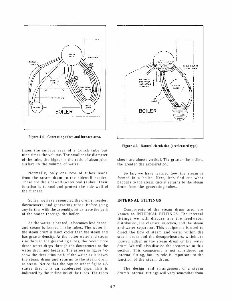
Figure 4-4.—Generating tubes and furnace area.
Figure 4-5.—Natural circulation (accelerated type).
nine times the volume. The smaller the diameterof the tube, the higher is the ratio of absorptionsurface to the volume of water.
times the surface area of a 1-inch tube but
shown are almost vertical. The greater the incline,the greater the acceleration.
Normally, only one row of tubes leadsfrom the steam drum to the sidewall header.These are the sidewall (water wall) tubes. Theirfunction is to cool and protect the side wall ofthe furnace.
So far, we have assembled the drums, header,downcomers, and generating tubes. Before goingany further with the assembly, let us trace the pathof the water through the boiler.
As the water is heated, it becomes less dense,and steam is formed in the tubes. The water inthe steam drum is much cooler than the steam andhas greater density. As the hotter water and steamrise through the generating tubes, the cooler moredense water drops through the downcomers to thewater drum and headers. The arrows in figure 4-5show the circulation path of the water as it leavesthe steam drum and returns to the steam drumas steam. Notice that the caption under figure 4-5states that it is an accelerated type. This isindicated by the inclination of the tubes. The tubes
So far, we have learned how the steam isformed in a boiler. Next, let’s find out whathappens to the steam once it returns to the steamdrum from the generating tubes.
INTERNAL FITTINGS
Components of the steam drum area areknown as INTERNAL FITTINGS. The internalfittings we will discuss are the feedwaterdistribution, the chemical injection, and the steamand water separator. This equipment is used todirect the flow of steam and water within thesteam drum and the desuperheaters, which arelocated either in the steam drum or the waterdrum. We will also discuss the economize in thissection. This component is not considered aninternal fitting, but its role is important to thefunction of the steam drum.
The designdrum’s internal
and arrangement of a steamfittings will vary somewhat from
4-7
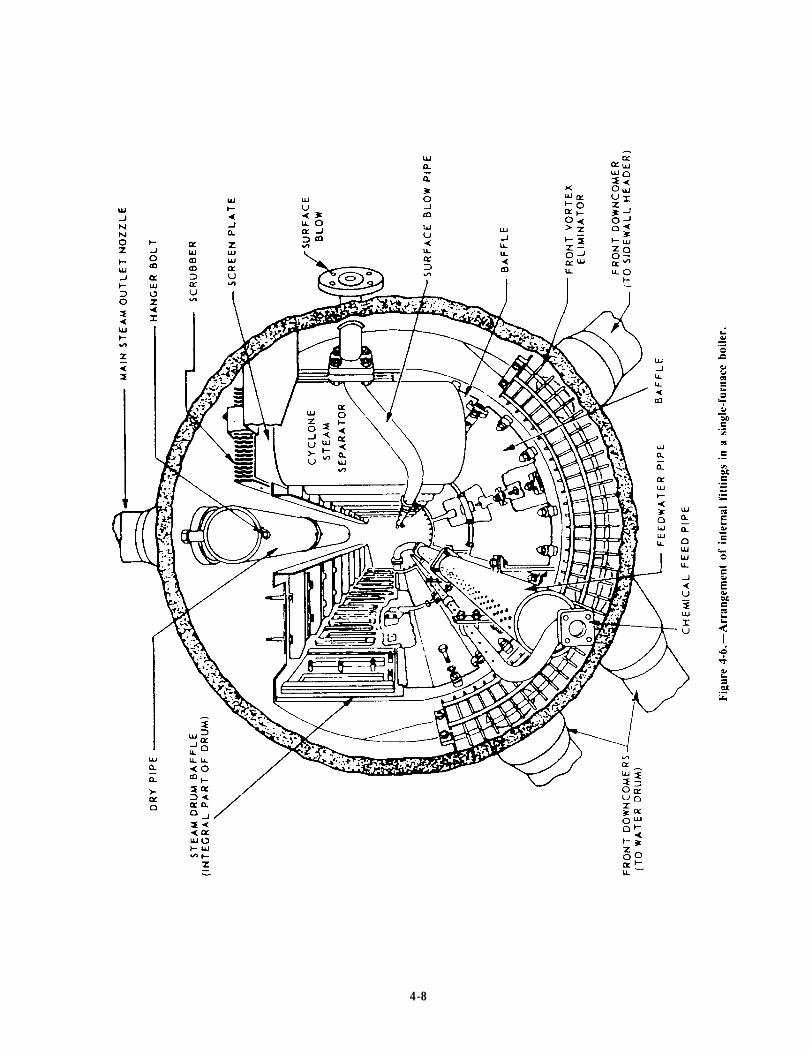
Figure 4-6.
4-8

Figure 4-7.—Diagram of a superheater.
one type of boiler to another and from one boilermanufacturer to another. Figure 4-6 shows thearrangement of the steam drum internal fittingsin a single-furnace boiler.
. The feedwater pipe receives feedwaterfrom the economizer and distributes it throughoutthe length of the steam drum.
. The chemical feed pipe is used to injectchemicals into the boiler to maintain the properpH and phosphate balance in the boiler water.
l The surface blow pipe is used to removesuspended solid matter that floats on top of thewater and to lower the steam drum water level,when necessary. The surface blow pipe is also usedto blow water out to lower the chemical level inthe boiler when it becomes too high.
. The dry pipe is used to direct the steam tothe steam drum outlet nozzle after it leaves thescrubbers.
. The vortex eliminators are used to reducethe swirling motion of the water as it enters thedowncomers.
l The baffle plates are used to direct thesteam to the steam separators.
l The cyclone steam separators removemoisture from the steam. This is accomplished bythe steam spinning or changing direction. Thewater drains back into the steam drum while thesteam continues upward through a screen andscrubber that removes still more moisture.
After the steam leaves the scrubbers, it goesto the dry pipe (fig. 4-6). From there it leaves thesteam drum through the steam drum outlet.Figure 4-7, view A, shows the steam going to theinlet header of the superheater and passingthrough the U-shaped tubes of the superheater tothe next header (fig. 4-7, view B). This header iscalled the first pass or intermediate header. Steammay pass through the U-shaped tubes severaltimes before passing to the outlet header. Eachtime the steam goes from one header to the nextheader it is called a pass. The number of passesthe steam makes in a superheater varies withdifferent boilers and the degree of superheat thatis required for a particular ship.
4-9
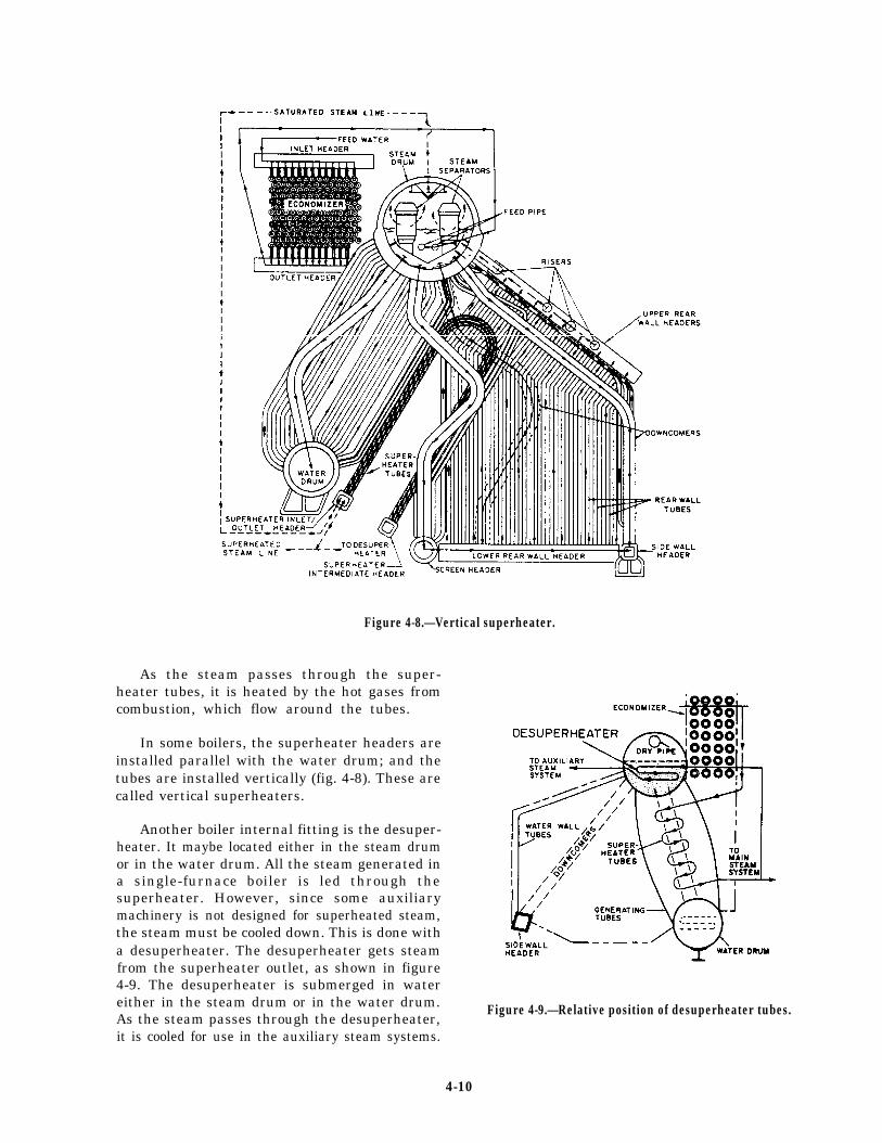
Figure 4-8.—Vertical superheater.
As the steam passes through the super-heater tubes, it is heated by the hot gases fromcombustion, which flow around the tubes.
In some boilers, the superheater headers areinstalled parallel with the water drum; and thetubes are installed vertically (fig. 4-8). These arecalled vertical superheaters.
Another boiler internal fitting is the desuper-heater. It maybe located either in the steam drumor in the water drum. All the steam generated ina single-furnace boiler is led through thesuperheater. However, since some auxiliarymachinery is not designed for superheated steam,the steam must be cooled down. This is done witha desuperheater. The desuperheater gets steamfrom the superheater outlet, as shown in figure4-9. The desuperheater is submerged in watereither in the steam drum or in the water drum.As the steam passes through the desuperheater,
Figure 4-9.—Relative position of desuperheater tubes.
it is cooled for use in the auxiliary steam systems.
4-10
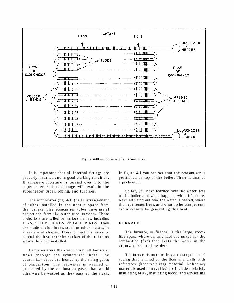
Figure 4-10.—Side view of an economizer.
It is important that all internal fittings areproperly installed and in good working condition.If excessive moisture is carried over into thesuperheater, serious damage will result in thesuperheater tubes, piping, and turbines.
The economizer (fig. 4-10) is an arrangementof tubes installed in the uptake space fromthe furnace. The economizer tubes have metalprojections from the outer tube surfaces. Theseprojections are called by various names, includingFINS, STUDS, RINGS, or GILL RINGS. Theyare made of aluminum, steel, or other metals, ina variety of shapes. These projections serve toextend the heat transfer surface of the tubes onwhich they are installed.
Before entering the steam drum, all feedwaterflows through the economizer tubes. Theeconomizer tubes are heated by the rising gasesof combustion. The feedwater is warmed orpreheated by the combustion gases that wouldotherwise be wasted as they pass up the stack.
In figure 4-1 you can see that the economizer ispositioned on top of the boiler. There it acts asa preheater.
So far, you have learned how the water getsto the boiler and what happens while it’s there.Next, let’s find out how the water is heated, wherethe heat comes from, and what boiler componentsare necessary for generating this heat.
FURNACE
The furnace, or firebox, is the large, room-like space where air and fuel are mixed for thecombustion (fire) that heats the water in thedrums, tubes, and headers.
The furnace is more or less a rectangular steelcasing that is lined on the floor and walls withrefractory (heat-resisting) material. Refractorymaterials used in naval boilers include firebrick,insulating brick, insulating block, and air-setting
4-11

Figure 4-11.—Refactory-lined furnace.
Figure 4-12.—Combustion air and gas flow.
4-12
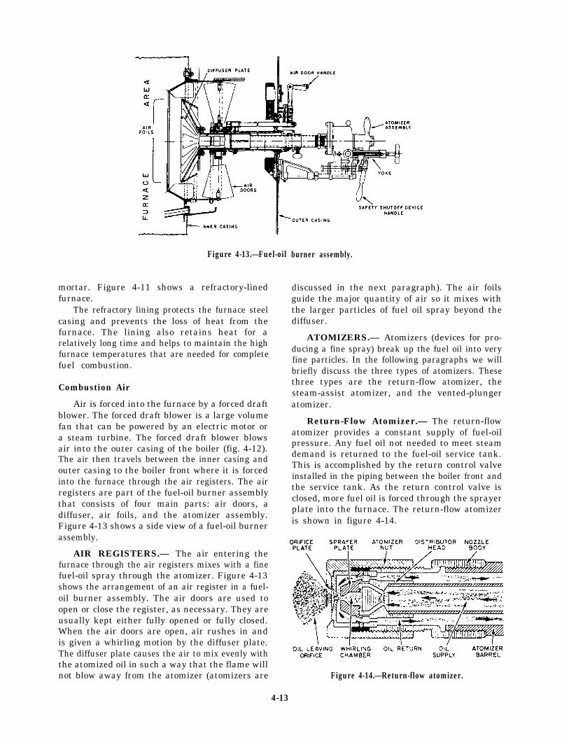
Figure 4-13.—Fuel-oil
mortar. Figure 4-11 shows a refractory-linedfurnace.
The refractory lining protects the furnace steelcasing and prevents the loss of heat from thefurnace. The lining also retains heat for arelatively long time and helps to maintain the highfurnace temperatures that are needed for completefuel combustion.
Combustion Air
Air is forced into the furnace by a forced draftblower. The forced draft blower is a large volumefan that can be powered by an electric motor ora steam turbine. The forced draft blower blowsair into the outer casing of the boiler (fig. 4-12).The air then travels between the inner casing andouter casing to the boiler front where it is forcedinto the furnace through the air registers. The airregisters are part of the fuel-oil burner assemblythat consists of four main parts: air doors, adiffuser, air foils, and the atomizer assembly.Figure 4-13 shows a side view of a fuel-oil burnerassembly.
AIR REGISTERS.— The air entering thefurnace through the air registers mixes with a finefuel-oil spray through the atomizer. Figure 4-13shows the arrangement of an air register in a fuel-oil burner assembly. The air doors are used toopen or close the register, as necessary. They areusually kept either fully opened or fully closed.When the air doors are open, air rushes in andis given a whirling motion by the diffuser plate.The diffuser plate causes the air to mix evenly withthe atomized oil in such a way that the flame willnot blow away from the atomizer (atomizers are
burner assembly.
discussed in the next paragraph). The air foilsguide the major quantity of air so it mixes withthe larger particles of fuel oil spray beyond thediffuser.
ATOMIZERS.— Atomizers (devices for pro-ducing a fine spray) break up the fuel oil into veryfine particles. In the following paragraphs we willbriefly discuss the three types of atomizers. Thesethree types are the return-flow atomizer, thesteam-assist atomizer, and the vented-plungeratomizer.
Return-Flow Atomizer.— The return-flowatomizer provides a constant supply of fuel-oilpressure. Any fuel oil not needed to meet steamdemand is returned to the fuel-oil service tank.This is accomplished by the return control valveinstalled in the piping between the boiler front andthe service tank. As the return control valve isclosed, more fuel oil is forced through the sprayerplate into the furnace. The return-flow atomizeris shown in figure 4-14.
Figure 4-14.—Return-flow atomizer.
4-13
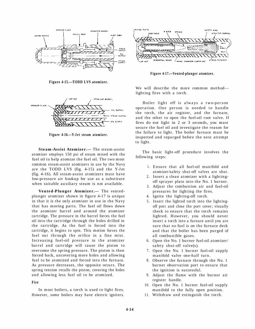
Figure 4-15.—TODD LVS atomizer.
Figure 4-17.—Vented-plunger atomizer.
We will describe the more common method—lighting fires with a torch.
Figure 4-16.—Y-Jet steam atomizer.
Steam-Assist Atomizer.— The steam-assistatomizer employs 150 psi of steam mixed with thefuel oil to help atomize the fuel oil. The two mostcommon steam-assist atomizers in use by the Navyare the TODD LVS (fig. 4-15) and the Y-Jet(fig. 4-16). All steam-assist atomizers must havelow-pressure air hookup for use as a substitutewhen suitable auxiliary steam is not available.
Vented-Plunger Atomizer.— The vented-plunger atomizer shown in figure 4-17 is uniquein that it is the only atomizer in use in the Navythat has moving parts. The fuel oil flows downthe atomizer barrel and around the atomizercartridge. The pressure in the barrel forces the fueloil into the cartridge through the holes drilled inthe cartridge. As the fuel is forced into thecartridge, it begins to spin. This motion forces thefuel out through the orifice in a fine mist.Increasing fuel-oil pressure in the atomizerbarrel and cartridge will cause the piston toovercome the spring pressure. The piston is thenforced back, uncovering more holes and allowingfuel to be atomized and forced into the furnace.As pressure decreases, the opposite occurs. Thespring tension recalls the piston, covering the holesand allowing less fuel oil to be atomized.
Fire
In most boilers, a torch is used to light fires.However, some boilers may have electric igniters.
Boiler light off is always a two-personoperation. One person is needed to handlethe torch, the air register, and the furnace,and the other to open the fuel-oil root valve. Iffires do not light in 2 or 3 seconds, you mustsecure the fuel oil and investigate the reason forthe failure to light. The boiler furnace must beinspected and repurged before the next attemptto light.
The basic light-off procedure involves thefollowing steps:
1.
2.
3.
4.5.
6.
7.
8.
9.
10.
11.
Ensure that all fuel-oil manifold andatomizer/safety shut-off valves are shut.Insert a clean atomizer with a lighting-off sprayer plate into the No. 1 burner.Adjust the combustion air and fuel-oilpressures for lighting the fires.Ignite the lighting-off torch.Insert the lighted torch into the lighting-off port and close the port cover; visuallycheck to ensure that the torch remainslighted. However, you should neverinsert a torch into a furnace until you aresure that no fuel is on the furnace deckand that the boiler has been purged ofall combustible gases.Open the No. 1 burner fuel-oil atomizer/safety shut-off valve(s).Open the No. 1 burner fuel-oil supplymanifold valve one-half turn.Observe the furnace through the No. 1burner observation port to ensure thatthe ignition is successful.Adjust the flame with the burner airregister handle.Open the No. 1 burner fuel-oil supplymanifold to the fully open position.Withdraw and extinguish the torch.
4-14

For specific lighting-off instructions, alwaysrefer to your ship’s EOSS.
The following are a few simple suggestions tomake your job easier and safer:
. Do not operate any valves or startequipment until you have permission fromthe EOOW or EDO, and always refer tothe EOSS.
. Always clean up any spills or debris.
. Report to your supervisor any conditionthat you think may be abnormal.
on auxiliary boilers, refer to Naval Ships’Technical Manual, S9086-GY-STM-000, chapter221, section 5.
WASTE-HEAT BOILERS
On some classes of ships, you may find waste-heat boilers. Waste-heat boilers are used by theSpruance class and Ticonderoga class CGs. Theseboilers supply the steam for ship’s services byusing the hot exhaust gases from the gas turbinegenerator sets (GTGSs). For further informationon waste-heat boilers, refer to GSM 3 & 2,NAVEDTRA 10548-2, chapter 6.
. Do not be afraid to ask questions!
SUMMARY
AUXILIARY BOILER
An auxiliary boiler is a small boiler thatsupplies steam for distilling plants, space heating,oil heating, water heating, galley, and laundry.These boilers have all the auxiliaries, accessories,and controls to form a unit assembly. They arearranged to operate as complete self-contained,steam-generating plants. For further information
In this chapter we have discussed boilerterminology, construction, types, components,and function. To help you understand this infor-mation, go down to the fireroom on your shipand ask a BT to show and explain to you thethings you have just read about. This should helpyour retention of the information you havestudied and perhaps provide you with additionalknowledge on boilers.
4-15


CHAPTER 5
STEAM TURBINES
In previous chapters we discussed the basicsteam cycle and various types of naval boilers. Atthis point, we will bring together all you havelearned by discussing the components inside theturbine casing.
In the following paragraphs we will discussturbine theory, types and classifications ofturbines, and turbine construction.
Upon completion of this chapter you willunderstand how stored energy (heat) in steam istransformed to mechanical energy (work).
TURBINE THEORY
The first documented use of steam poweris credited to a Greek mathematician, Heroof Alexandria, almost 2000 years ago. Herobuilt the first steam-powered engine. Histurbine design was the forerunner of thejet engine and demonstrated that steam powercould be used to operate other machinery.Hero’s turbine (aeolipile) (fig. 5-1) consistsof a hollow sphere and four canted nozzles.The sphere rotates freely on two feed tubesthat carry steam from the boiler. Steamgenerated in the boiler passes through thefeed tubes, into the sphere, and out throughthe nozzles. As the steam leaves the nozzles,the sphere rotates rapidly.
Down through the ages, the application ofthe turbine principle has been used in manydifferent types of machines. The water wheelthat was used to operate the flour mills incolonial times and the common windmill usedto pump water are examples of the turbineprinciple. In these examples, the power comesfrom the effect of the wind or a stream ofwater acting on a set of blades. In a steam
Figure 5-1.—Hero’s turbine (aeolipile).
turbine, steam serves the same purposewind or the flowing water.
as the
Two methods are used in turbine design andconstruction to get the desired results from aturbine. These are the impulse principle and thereaction principle. Both methods convert thethermal energy stored in the steam into usefulwork, but they differ somewhat in the way theydo it. In the following paragraphs we will discussthe two basic turbine principles, the impulse andreaction.
5-1

Figure 5-2.—Impulse turbine.
Figure 5-3.—Simple impulse turbine principle.
IMPULSE PRINCIPLE
The impulse turbine (fig. 5-2) consists basicallyof a rotor mounted on a shaft that is free to rotatein a set of bearings. The outer rim of the rotorcarries a set of curved blades, and the wholeassembly is enclosed in an airtight case. Nozzlesdirect steam against the blades and turn therotor.
The energy to rotate an impulse turbine isderived from the kinetic energy of the steamflowing through the nozzles. The term impulsemeans that the force that turns the turbine comes
from the impact of the steam on the blades.The toy pinwheel (fig. 5-3) can be used tostudy some of the basic principles of turbines.When you blow on the rim of the wheel,it spins rapidly. The harder you blow, thefaster it turns. The steam turbine operateson the same principle, except it uses thekinetic energy from the steam as it leaves asteam nozzle rather than air.
Steam nozzles (hereafter referred to as nozzlesor stationary blades) are located at the turbineinlet. As the steam passes through a nozzle,potential energy is converted to kinetic energy.This steam is directed toward the turbine bladesand turns the rotor. The velocity of the steam isreduced in passing over the blades. Some of itskinetic energy has been transferred to the bladesto turn the rotor.
Impulse turbines may be used to drive forceddraft blowers, pumps, and main propulsionturbines.
Figure 5-2 shows an impulse turbine as steampasses through the nozzles.
REACTION PRINCIPLE
The ancient turbine built by Hero operated onthe reaction principle. Hero’s turbine was inventedlong before Newton’s time, but it was a workingmodel of Newton’s third law of motion, whichstates: “For every action there must bean equaland opposite reaction.”
If you set an electric fan on a roller skate, theroller skate will take off across the room (fig. 5-4).The fan pushes the air forward and sets up abreeze (velocity). The air is also pushing backwardon the fan with an equal force, but in anopposite direction.
If you try to push a car, you will pushback with your feet as hard as you wouldpush forward with your hands. Try it sometimewhen you are standing on an icy road. Youwill not be able to move the car unless youcan dig in with your feet to exert the backwardforce. With some thought on your part, youcould come up with examples to prove toyourself that Newton’s third law of motionholds true under all circumstances.
5-2

Figure 5-4.—Demonstration of the velocity of the reaction principle.
Figure 5-5.—Demonstration of the kickback of the reaction principle.
The reaction turbine uses the reaction of a In the reaction turbine,steam jet to drive the rotor. You learned that an attached to the turbine casing act as nozzles and
stationary blades
impulse turbine increases the velocity of steam andtransforms that potential energy under pressureinto kinetic energy in a steam jet through nozzles.A forward force is applied to the steam to increaseits velocity as it passes through the nozzle. FromNewton’s third law of motion, you see that thesteam jet exerts a force on the nozzle and an equalreactive force on the turbine blades in the oppositedirection. THIS IS THE FORCE THAT DRIVESTHE TURBINE.
direct the steam to the moving blades. Themoving blades mounted on the rotor act asnozzles. Most reaction turbines have severalalternating rows of stationary and movingnozzle blades.
You can use a balloon to demonstrate thekickback or reaction force generated by thenozzle blades (fig. 5-5). Blow up the balloon andrelease it. The air will rush out through the
5-3
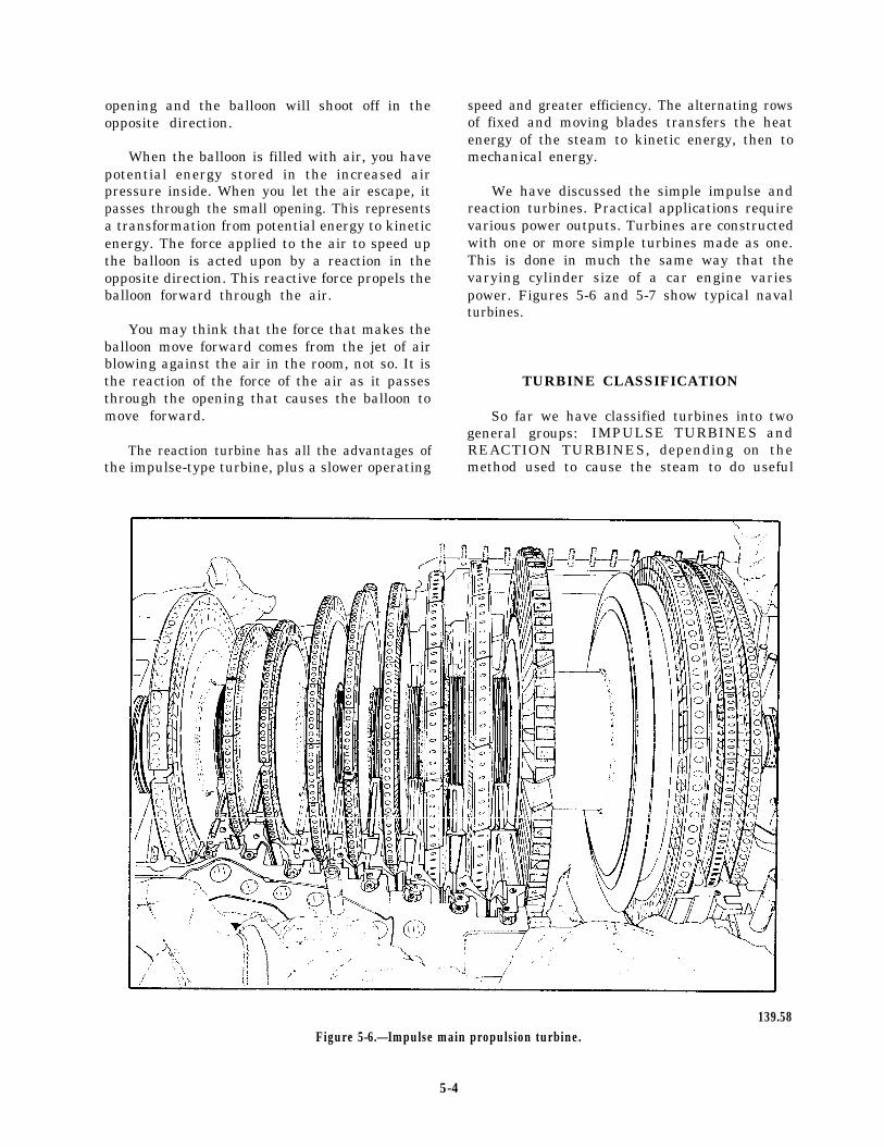
opening and the balloon will shoot off in theopposite direction.
When the balloon is filled with air, you havepotential energy stored in the increased airpressure inside. When you let the air escape, itpasses through the small opening. This representsa transformation from potential energy to kineticenergy. The force applied to the air to speed upthe balloon is acted upon by a reaction in theopposite direction. This reactive force propels theballoon forward through the air.
You may think that the force that makes theballoon move forward comes from the jet of airblowing against the air in the room, not so. It isthe reaction of the force of the air as it passesthrough the opening that causes the balloon tomove forward.
The reaction turbine has all the advantages ofthe impulse-type turbine, plus a slower operating
speed and greater efficiency. The alternating rowsof fixed and moving blades transfers the heatenergy of the steam to kinetic energy, then tomechanical energy.
We have discussed the simple impulse andreaction turbines. Practical applications requirevarious power outputs. Turbines are constructedwith one or more simple turbines made as one.This is done in much the same way that thevarying cylinder size of a car engine variespower. Figures 5-6 and 5-7 show typical navalturbines.
TURBINE CLASSIFICATION
So far we have classified turbines into twogeneral groups: IMPULSE TURBINES andREACTION TURBINES, depending on themethod used to cause the steam to do useful
139.58Figure 5-6.—Impulse main propulsion turbine.
5-4

work. Turbines may be further classified accordingto the following:
Foundations
. Type and arrangement of staging
. Direction of steam flow
. Repetition of steam flow
. Division of steam flow
A turbine may also be classified by whetherit is a condensing unit (exhaust to a condenser ata pressure below atmospheric pressure) or a non-condensing unit (exhausts to another system suchas the auxiliary exhaust steam system at a pressureabove atmospheric pressure).
CONSTRUCTION OF TURBINES
Other than the operating and controllingequipment, similarity exists in both the impulseand reaction turbines. These include foundations,casings, nozzles, rotors, bearings, and shaftglands.
Turbine foundations are built up from astructural foundation in the hull to provide a rigidsupporting base. All turbines are subjected tovarying degrees of temperature—from thatexisting during a secured condition to that existingduring full-power operation. Therefore, means areprovided to allow for expansion and contraction.
At the forward end of the turbine, there arevarious ways to give freedom of movement.Elongated bolt holes or grooved sliding seats areused so that the forward end of the turbine canmove fore and aft as either expansion orcontraction takes place. The forward end of theturbine may also be mounted with a flexibleI-beam that will flex either fore or aft.
Casings
The materials used to construct turbines willvary somewhat depending on the steam and powerconditions for which the turbine is designed.Turbine casings are made of cast carbon steel fornonsuperheated steam applications. Superheated
Figure 5-7.—Turbine assembly in a machine shop.
5-5
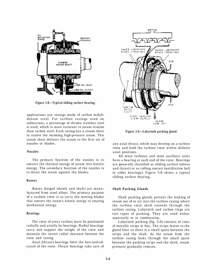
.
Figure 5-8.—Typical sliding surface bearing.
applications use casings made of carbon molyb-denum steel. For turbine casings used onsubmarines, a percentage of chrome stainless steelis used, which is more resistant to steam erosionthan carbon steel. Each casing has a steam chestto receive the incoming high-pressure steam. Thissteam chest delivers the steam to the first set ofnozzles or blades.
Nozzles
The primary function of the nozzles is toconvert the thermal energy of steam into kineticenergy. The secondary function of the nozzles isto direct the steam against the blades.
Rotors
Rotors (forged wheels and shaft) are manu-factured from steel alloys. The primary purposeof a turbine rotor is to carry the moving bladesthat convert the steam’s kinetic energy to rotatingmechanical energy.
Bearings
The rotor of every turbine must be positionedradially and axially by bearings. Radial bearingscarry and support the weight of the rotor andmaintain the correct radial clearance between therotor and casing.
Axial (thrust) bearings limit the fore-and-afttravel of the rotor. Thrust bearings take care of
Figure 5-9.—Labyrinth packing gland.
any axial thrust, which may develop on a turbinerotor and hold the turbine rotor within definiteaxial positions.
All main turbines and most auxiliary unitshave a bearing at each end of the rotor. Bearingsare generally classified as sliding surface (sleeveand thrust) or as rolling contact (antifriction ballor roller bearings). Figure 5-8 shows a typicalsliding surface bearing.
Shaft Packing Glands
Shaft packing glands prevent the leaking ofsteam out of or air into the turbine casing wherethe turbine rotor shaft extends through theturbine casing. Labyrinth and carbon rings aretwo types of packing. They are used eitherseparately or in combination.
Labyrinth packing (fig. 5-9) consists of rowsof metallic strips or fins. The strips fasten to thegland liner so there is a small space between thestrips and the shaft. As the steam from theturbine casing leaks through the small spacebetween the packing strips and the shaft, steampressure gradually reduces.
5-6
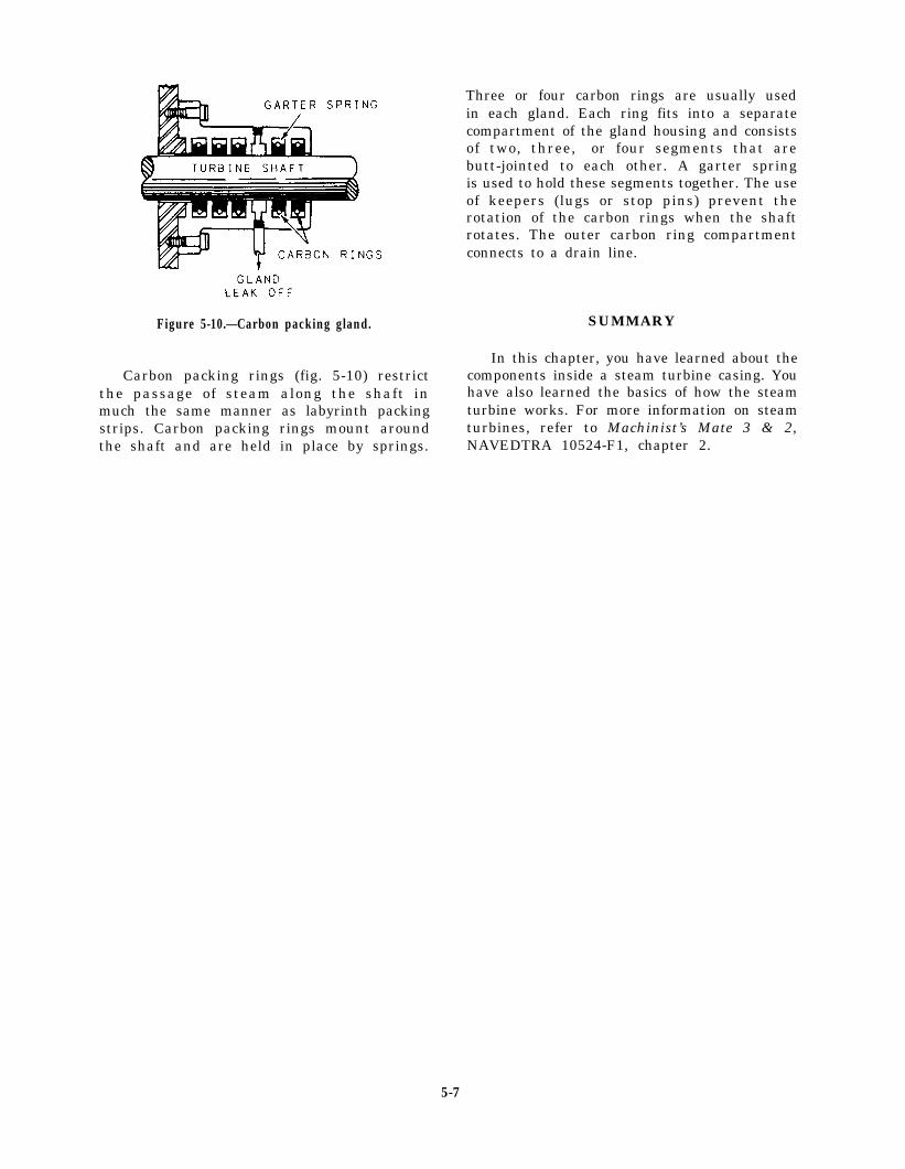
Figure 5-10.—Carbon packing gland. SUMMARY
Carbon packing rings (fig. 5-10) restrictthe passage of steam along the shaft inmuch the same manner as labyrinth packingstrips. Carbon packing rings mount aroundthe shaft and are held in place by springs.
Three or four carbon rings are usually usedin each gland. Each ring fits into a separatecompartment of the gland housing and consistsof two, three, or four segments that arebutt-jointed to each other. A garter springis used to hold these segments together. The useof keepers (lugs or stop pins) prevent therotation of the carbon rings when the shaftrotates. The outer carbon ring compartmentconnects to a drain line.
In this chapter, you have learned about thecomponents inside a steam turbine casing. Youhave also learned the basics of how the steamturbine works. For more information on steamturbines, refer to Machinist’s Mate 3 & 2,NAVEDTRA 10524-F1, chapter 2.
5-7

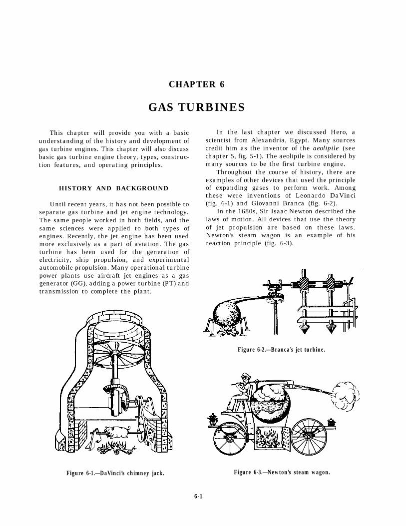
CHAPTER 6
GAS TURBINES
This chapter will provide you with a basicunderstanding of the history and development ofgas turbine engines. This chapter will also discussbasic gas turbine engine theory, types, construc-tion features, and operating principles.
HISTORY AND BACKGROUND
Until recent years, it has not been possible toseparate gas turbine and jet engine technology.The same people worked in both fields, and thesame sciences were applied to both types ofengines. Recently, the jet engine has been usedmore exclusively as a part of aviation. The gasturbine has been used for the generation ofelectricity, ship propulsion, and experimentalautomobile propulsion. Many operational turbinepower plants use aircraft jet engines as a gasgenerator (GG), adding a power turbine (PT) andtransmission to complete the plant.
Figure 6-1.—DaVinci’s chimney jack.
In the last chapter we discussed Hero, ascientist from Alexandria, Egypt. Many sourcescredit him as the inventor of the aeolipile (seechapter 5, fig. 5-1). The aeolipile is considered bymany sources to be the first turbine engine.
Throughout the course of history, there areexamples of other devices that used the principleof expanding gases to perform work. Amongthese were inventions of Leonardo DaVinci(fig. 6-1) and Giovanni Branca (fig. 6-2).
In the 1680s, Sir Isaac Newton described thelaws of motion. All devices that use the theoryof jet propulsion are based on these laws.Newton’s steam wagon is an example of hisreaction principle (fig. 6-3).
Figure 6-2.—Branca’s jet turbine.
Figure 6-3.—Newton’s steam wagon.
6-1
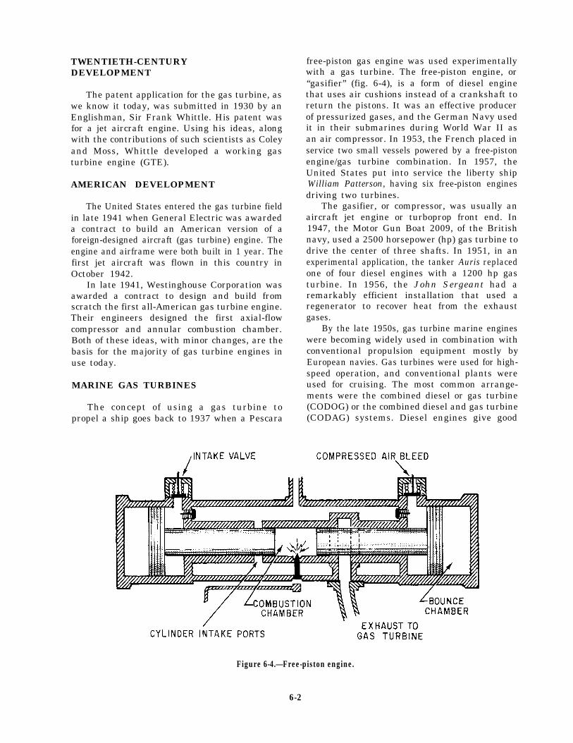
TWENTIETH-CENTURYDEVELOPMENT
The patent application for the gas turbine, aswe know it today, was submitted in 1930 by anEnglishman, Sir Frank Whittle. His patent wasfor a jet aircraft engine. Using his ideas, alongwith the contributions of such scientists as Coleyand Moss, Whittle developed a working gasturbine engine (GTE).
AMERICAN DEVELOPMENT
The United States entered the gas turbine fieldin late 1941 when General Electric was awardeda contract to build an American version of aforeign-designed aircraft (gas turbine) engine. Theengine and airframe were both built in 1 year. Thefirst jet aircraft was flown in this country inOctober 1942.
In late 1941, Westinghouse Corporation wasawarded a contract to design and build fromscratch the first all-American gas turbine engine.Their engineers designed the first axial-flowcompressor and annular combustion chamber.Both of these ideas, with minor changes, are thebasis for the majority of gas turbine engines inuse today.
MARINE GAS TURBINES
The concept of using a gas turbine topropel a ship goes back to 1937 when a Pescara
free-piston gas engine was used experimentallywith a gas turbine. The free-piston engine, or“gasifier” (fig. 6-4), is a form of diesel enginethat uses air cushions instead of a crankshaft toreturn the pistons. It was an effective producerof pressurized gases, and the German Navy usedit in their submarines during World War II asan air compressor. In 1953, the French placed inservice two small vessels powered by a free-pistonengine/gas turbine combination. In 1957, theUnited States put into service the liberty shipWilliam Patterson, having six free-piston enginesdriving two turbines.
The gasifier, or compressor, was usually anaircraft jet engine or turboprop front end. In1947, the Motor Gun Boat 2009, of the Britishnavy, used a 2500 horsepower (hp) gas turbine todrive the center of three shafts. In 1951, in anexperimental application, the tanker Auris replacedone of four diesel engines with a 1200 hp gasturbine. In 1956, the John Sergeant had aremarkably efficient installation that used aregenerator to recover heat from the exhaustgases.
By the late 1950s, gas turbine marine engineswere becoming widely used in combination withconventional propulsion equipment mostly byEuropean navies. Gas turbines were used for high-speed operation, and conventional plants wereused for cruising. The most common arrange-ments were the combined diesel or gas turbine(CODOG) or the combined diesel and gas turbine(CODAG) systems. Diesel engines give good
Figure 6-4.—Free-piston engine.
6-2
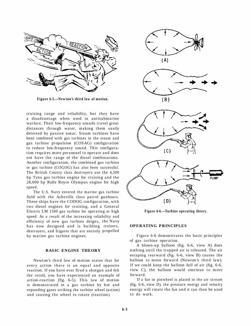
Figure 6-5.—Newton’s third law of motion.
cruising range and reliability, but they havea disadvantage when used in antisubmarinewarfare. Their low-frequency sounds travel greatdistances through water, making them easilydetected by passive sonar. Steam turbines havebeen combined with gas turbines in the steam andgas turbine propulsion (COSAG) configurationto reduce low-frequency sound. This configura-tion requires more personnel to operate and doesnot have the range of the diesel combinations.Another configuration, the combined gas turbineor gas turbine (COGOG) has also been successful.The British County class destroyers use the 4,500hp Tyne gas turbine engine for cruising and the28,000 hp Rolls Royce Olympus engine for highspeed.
The U.S. Navy entered the marine gas turbinefield with the Asheville class patrol gunboats.These ships have the CODOG configuration, withtwo diesel engines for cruising, and a GeneralElectric LM 1500 gas turbine for operating at highspeed. As a result of the increasing reliability andefficiency of new gas turbine deigns,has now designed and is buildingdestroyers, and frigates that are entirelyby marine gas turbine engines.
BASIC ENGINE THEORY
the Navycruisers,
propelled
Newton’s third law of motion states that forevery action there is an equal and oppositereaction. If you have ever fired a shotgun and feltthe recoil, you have experienced an example ofaction-reaction (fig. 6-5). This law of motionis demonstrated in a gas turbine by hot andexpanding gases striking the turbine wheel (action)and causing the wheel to rotate (reaction).
Figure 6-6.—Turbine operating theory.
OPERATING PRINCIPLES
Figure 6-6 demonstrates the basic principlesof gas turbine operation.
A blown-up balloon (fig. 6-6, view A) doesnothing until the trapped air is released. The airescaping rearward (fig. 6-6, view B) causes theballoon to move forward (Newton’s third law).If we could keep the balloon full of air (fig. 6-6,view C), the balloon would continue to moveforward.
If a fan or pinwheel is placed in the air stream(fig. 6-6, view D), the pressure energy and velocityenergy will rotate the fan and it can then be usedto do work.
6-3
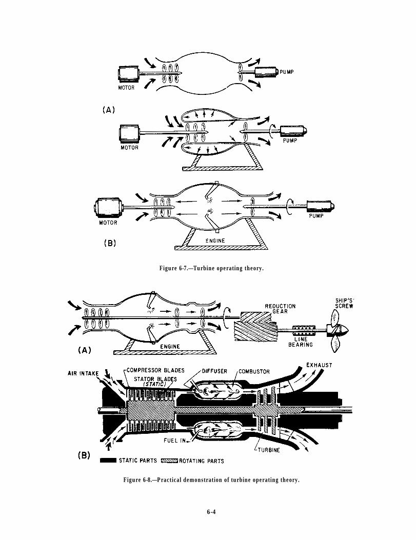
Figure 6-7.—Turbine operating theory.
Figure 6-8.—Practical demonstration of turbine operating theory.
6-4
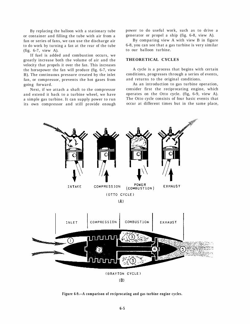
By replacing the balloon with a stationary tubeor container and filling the tube with air from afan or series of fans, we can use the discharge airto do work by turning a fan at the rear of the tube(fig. 6-7, view A).
If fuel is added and combustion occurs, wegreatly increase both the volume of air and thevelocity that propels it over the fan. This increasesthe horsepower the fan will produce (fig. 6-7, viewB). The continuous pressure created by the inletfan, or compressor, prevents the hot gases fromgoing forward.
Next, if we attach a shaft to the compressorand extend it back to a turbine wheel, we havea simple gas turbine. It can supply power to runits own compressor and still provide enough
power to do useful work, such as to drive agenerator or propel a ship (fig. 6-8, view A).
By comparing view A with view B in figure6-8, you can see that a gas turbine is very similarto our balloon turbine.
THEORETICAL CYCLES
A cycle is a process that begins with certainconditions, progresses through a series of events,and returns to the original conditions.
As an introduction to gas turbine operation,consider first the reciprocating engine, whichoperates on the Otto cycle. (fig, 6-9, view A).The Otto cycle consists of four basic events thatoccur at different times but in the same place,
Figure 6-9.—A comparison of reciprocating and gas turbine engine cycles.
6-5
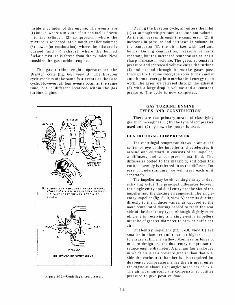
inside a cylinder of the engine. The events are(1) intake, where a mixture of air and fuel is drawninto the cylinder; (2) compression, where themixture is squeezed into a much smaller volume;(3) power (or combustion), where the mixture isburned; and (4) exhaust, where the burnedfuel/air mixture is forced from the cylinder. Nowconsider the gas turbine engine.
The gas turbine engine operates on theBrayton cycle (fig. 6-9, view B). The Braytoncycle consists of the same four events as the Ottocycle. However, all four events occur at the sametime, but in different locations within the gasturbine engine.
Figure 6-10.—Centrifugal compressor.
During the Brayton cycle, air enters the inlet(1) at atmospheric pressure and constant volume.As the air passes through the compressor (2), itincreases in pressure and decreases in volume. Inthe combustor (3), the air mixes with fuel andburns. During combustion, pressure remainsconstant, but the increased temperature causes asharp increase in volume. The gases at constantpressure and increased volume enter the turbine(4) and expand through it. As the gases passthrough the turbine rotor, the rotor turns kineticand thermal energy into mechanical energy to dowork. The gases are released through the exhaust(5), with a large drop in volume and at constantpressure. The cycle is now completed.
GAS TURBINE ENGINETYPES AND CONSTRUCTION
There are two primary means of classifyinggas turbine engines: (1) by the type of compressorused and (2) by how the power is used.
CENTRIFUGAL COMPRESSOR
The centrifugal compressor draws in air at thecenter or eye of the impeller and accelerates itaround and outward. It consists of an impeller,a diffuser, and a compressor manifold. Thediffuser is bolted to the manifold, and often theentire assembly is referred to as the diffuser. Forease of understanding, we will treat each unitseparately.
The impeller may be either single entry or dualentry (fig. 6-10). The principal differences betweenthe single entry and dual entry are the size of theimpeller and the ducting arrangement. The single-entry impeller (fig. 6-10, view A) permits ductingdirectly to the inducer vanes, as opposed to themore complicated ducting needed to reach the rearside of the dual-entry type. Although slightly moreefficient in receiving air, single-entry impellersmust be of greater diameter to provide sufficientair.
Dual-entry impellers (fig. 6-10, view B) aresmaller in diameter and rotate at higher speedsto ensure sufficient airflow. Most gas turbines ofmodern design use the dual-entry compressor toreduce engine diameter. A plenum (an enclosurein which air is at a pressure greater than that out-side the enclosure) chamber is also required fordual-entry compressors, since the air must enterthe engine at almost right angles to the engine axis.The air must surround the compressor at positivepressure to give positive flow.
6-6

The compressor draws in air at the hub of theimpeller and accelerates it radially outward bycentrifugal force through the impeller. It leavesthe impeller at high speed and low pressure andflows through the diffuser (fig. 6-10, view A). Thediffuser converts the high-speed, low-pressure airto low-speed, high-pressure air. The compressormanifold diverts the low-speed, high-pressure airfrom the diffuser into the combustion chambers.In this design, the manifold has one outlet portfor each combustion chamber.
The outlet ports are bolted to an outlet elbowon the manifold. The outlet ports ensure thatthe same amount of air is delivered to eachcombustion chamber.
The outlet elbows (known by a variety ofnames) change the airflow from radial to axialflow. The diffusion process is completed afterthe turn. Each elbow contains from two to fourturning vanes that perform the turning processand reduce air pressure losses by providing asmooth turning surface.
AXIAL-FLOW COMPRESSOR
In the axial-flow engine, the air is compressedwhile continuing its original direction of flow
Figure 6-11.—Stator and rotor components of an axial-flowcompressor.
parallel to the axis of the compressor rotor. Thecompressor is located at the very front of theengine. The purpose of the axial compressor isto take in ambient air, increase the speed andpressure, and discharge the air through thediffuser into the combustion chamber.
The two main elements of an axial-flowcompressor are the rotor and stator (fig. 6-11).The rotor is the rotating element of thecompressor. The stator is the fixed element of thecompressor. The rotor and stator are enclosed inthe compressor case.
The rotor has fixed blades that force the airrearward much like an aircraft propeller. In frontof the first rotor stage are the inlet guide vanes(IGVs). These vanes direct the intake air towardthe first set of rotor blades. Directly behindeach rotor stage is a stator. The stat or directs theair rearward to the next rotor stage (fig. 6-12).Each consecutive pair of rotor and stator bladesconstitutes a pressure stage.
Figure 6-12.—Operating principle of an axial-flow com-pressor.
6-7

Figure 6-13.—Single-shaft gas turbine.
Figure 6-14.—Split-shaft gas turbine.
6-8

The action of the rotor increases aircompression at each stage and accelerates the airrearward. By virtue of this increased velocity,energy is transferred from the compressor to theair in the form of velocity energy.
The number of stages required is determinedby the amount of air and total pressure riserequired. The greater the number of stages, thehigher the compression ratio. Most present-dayengines have 8 to 16 stages.
CLASSIFICATION BY POWER USAGE
There are basically three types of gas turbinesin use. They are the single shaft, split shaft, andtwin spool. Of these, the single shaft and splitshaft are the most common in naval vessels. Wemention the twin-spool type because the U.S.Coast Guard Hamilton class cutters use the twin-spool gas turbine.
In current U.S. Navy service, the single-shaftengine is used primarily for driving ship’s servicegenerators. The split-shaft engine is used for mainpropulsion.
Figure 6-13 is a block diagram of a single-shaftgas turbine. The power output shaft is connecteddirectly to the same turbine rotor that drives thecompressor. In most cases, there is a speeddecreaser or reduction gear between the rotor andthe power output shaft. However, there is still a
mechanical connection throughout the entireengine. The arrangement shown is typical for thegas turbine generator sets aboard DD-963 andCG-47 class ships.
In the split-shaft gas turbine (fig. 6-14), thereis no mechanical connection between the gas-generator turbine and the power turbine. Thepower turbine is the component that does theusable work. The gas-generator turbine providesthe power to drive the compressor and accessories.With this type of engine, the output speed can bevaried by varying the gas generator speed. Also,under certain conditions, the gas generator canrun at a reduced rpm and still provide maximumpower turbine rpm. This greatly improves fueleconomy and also extends the life of the gas-generator turbine. The arrangement shown infigure 6-15 is typical for propulsion gas turbinesaboard the DD-963, FFG-7, CG-47, and PHM-1class ships.
ENGINE CONSTRUCTION
Recall that a gas turbine engine is composedof four major sections (fig. 6-15): (1) compressor,(2) combustor, (3) turbine, and (4) accessory. Wewill briefly discuss the construction and functionof each of these sections. We will use the LM2500gas turbine as an example. The LM2500 is a split-shaft gas turbine.
Figure 6-15.—Typical gas turbine.
6-9
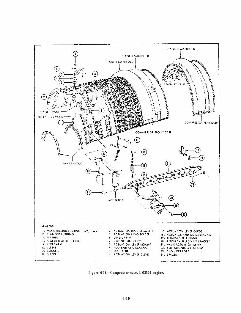
Figure 6-16.—Compressor case, LM2500 engine.
6-10
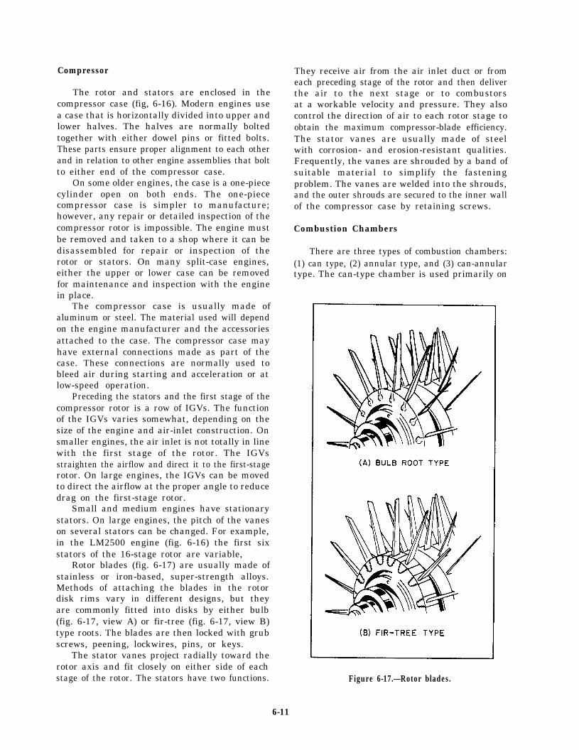
Compressor
The rotor and stators are enclosed in thecompressor case (fig, 6-16). Modern engines usea case that is horizontally divided into upper andlower halves. The halves are normally boltedtogether with either dowel pins or fitted bolts.These parts ensure proper alignment to each otherand in relation to other engine assemblies that boltto either end of the compressor case.
On some older engines, the case is a one-piececylinder open on both ends. The one-piececompressor case is simpler to manufacture;however, any repair or detailed inspection of thecompressor rotor is impossible. The engine mustbe removed and taken to a shop where it can bedisassembled for repair or inspection of therotor or stators. On many split-case engines,either the upper or lower case can be removedfor maintenance and inspection with the enginein place.
The compressor case is usually made ofaluminum or steel. The material used will dependon the engine manufacturer and the accessoriesattached to the case. The compressor case mayhave external connections made as part of thecase. These connections are normally used tobleed air during starting and acceleration or atlow-speed operation.
Preceding the stators and the first stage of thecompressor rotor is a row of IGVs. The functionof the IGVs varies somewhat, depending on thesize of the engine and air-inlet construction. Onsmaller engines, the air inlet is not totally in linewith the first stage of the rotor. The IGVsstraighten the airflow and direct it to the first-stagerotor. On large engines, the IGVs can be movedto direct the airflow at the proper angle to reducedrag on the first-stage rotor.
Small and medium engines have stationarystators. On large engines, the pitch of the vaneson several stators can be changed. For example,in the LM2500 engine (fig. 6-16) the first sixstators of the 16-stage rotor are variable,
Rotor blades (fig. 6-17) are usually made ofstainless or iron-based, super-strength alloys.Methods of attaching the blades in the rotordisk rims vary in different designs, but theyare commonly fitted into disks by either bulb(fig. 6-17, view A) or fir-tree (fig. 6-17, view B)type roots. The blades are then locked with grubscrews, peening, lockwires, pins, or keys.
The stator vanes project radially toward therotor axis and fit closely on either side of eachstage of the rotor. The stators have two functions.
They receive air from the air inlet duct or fromeach preceding stage of the rotor and then deliverthe air to the next stage or to combustorsat a workable velocity and pressure. They alsocontrol the direction of air to each rotor stage toobtain the maximum compressor-blade efficiency.The stator vanes are usually made of steelwith corrosion- and erosion-resistant qualities.Frequently, the vanes are shrouded by a band ofsuitable material to simplify the fasteningproblem. The vanes are welded into the shrouds,and the outer shrouds are secured to the inner wallof the compressor case by retaining screws.
Combustion Chambers
There are three types of combustion chambers:(1) can type, (2) annular type, and (3) can-annulartype. The can-type chamber is used primarily on
Figure 6-17.—Rotor blades.
6-11
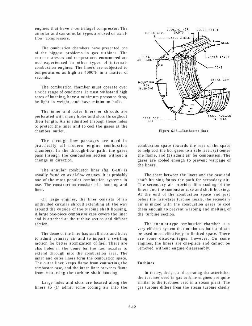
engines that have a centrifugal compressor. Theannular and can-annular types are used on axial-flow compressors.
The combustion chambers have presented oneof the biggest problems in gas turbines. Theextreme stresses and temperatures encountered arenot experienced in other types of internal-combustion engines. The liners are subjected totemperatures as high as 4000°F in a matter ofseconds.
The combustion chamber must operate overa wide range of conditions. It must withstand highrates of burning, have a minimum pressure drop,be light in weight, and have minimum bulk.
The inner and outer liners or shrouds areperforated with many holes and slots throughouttheir length. Air is admitted through these holesto protect the liner and to cool the gases at thechamber outlet.
The through-flow passages are used inpractically all modern engine combustionchambers. In the through-flow path, the gasespass through the combustion section without achange in direction.
The annular combustor liner (fig. 6-18) isusually found on axial-flow engines. It is probablyone of the most popular combustion systems inuse. The construction consists of a housing andliner.
On large engines, the liner consists of anundivided circular shroud extending all the wayaround the outside of the turbine shaft housing.A large one-piece combustor case covers the linerand is attached at the turbine section and diffusersection.
The dome of the liner has small slots and holesto admit primary air and to impart a swirlingmotion for better atomization of fuel. There arealso holes in the dome for the fuel nozzles toextend through into the combustion area. Theinner and outer liners form the combustion space.The outer liner keeps flame from contacting thecombustor case, and the inner liner prevents flamefrom contacting the turbine shaft housing.
Large holes and slots are located along theliners to (1) admit some cooling air into the
Figure 6-18.—Combustor liner.
combustion space towards the rear of the spaceto help cool the hot gases to a safe level, (2) centerthe flame, and (3) admit air for combustion. Thegases are cooled enough to prevent warpage ofthe liners.
The space between the liners and the case andshaft housing forms the path for secondary air.The secondary air provides film cooling of theliners and the combustor case and shaft housing.At the end of the combustion space and justbefore the first-stage turbine nozzle, the secondaryair is mixed with the combustion gases to coolthem enough to prevent warping and melting ofthe turbine section.
The annular-type combustion chamber is avery efficient system that minimizes bulk and canbe used most effectively in limited space. Thereare some disadvantages, however. On someengines, the liners are one-piece and cannot beremoved without engine disassembly.
Turbines
In theory, design, and operating characteristics,the turbines used in gas turbine engines are quitesimilar to the turbines used in a steam plant. Thegas turbine differs from the steam turbine chiefly
6-12
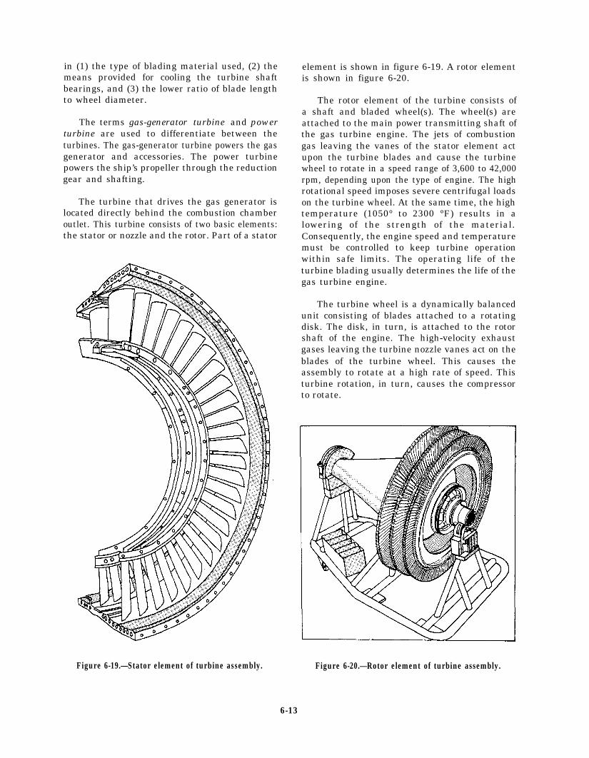
in (1) the type of blading material used, (2) themeans provided for cooling the turbine shaftbearings, and (3) the lower ratio of blade lengthto wheel diameter.
The terms gas-generator turbine and powerturbine are used to differentiate between theturbines. The gas-generator turbine powers the gasgenerator and accessories. The power turbinepowers the ship’s propeller through the reductiongear and shafting.
The turbine that drives the gas generator islocated directly behind the combustion chamberoutlet. This turbine consists of two basic elements:the stator or nozzle and the rotor. Part of a stator
Figure 6-19.—Stator element of turbine assembly.
element is shown in figure 6-19. A rotor elementis shown in figure 6-20.
The rotor element of the turbine consists ofa shaft and bladed wheel(s). The wheel(s) areattached to the main power transmitting shaft ofthe gas turbine engine. The jets of combustiongas leaving the vanes of the stator element actupon the turbine blades and cause the turbinewheel to rotate in a speed range of 3,600 to 42,000rpm, depending upon the type of engine. The highrotational speed imposes severe centrifugal loadson the turbine wheel. At the same time, the hightemperature (1050° to 2300 °F) results in alowering of the strength of the material.Consequently, the engine speed and temperaturemust be controlled to keep turbine operationwithin safe limits. The operating life of theturbine blading usually determines the life of thegas turbine engine.
The turbine wheel is a dynamically balancedunit consisting of blades attached to a rotatingdisk. The disk, in turn, is attached to the rotorshaft of the engine. The high-velocity exhaustgases leaving the turbine nozzle vanes act on theblades of the turbine wheel. This causes theassembly to rotate at a high rate of speed. Thisturbine rotation, in turn, causes the compressorto rotate.
Figure 6-20.—Rotor element of turbine assembly.
6-13
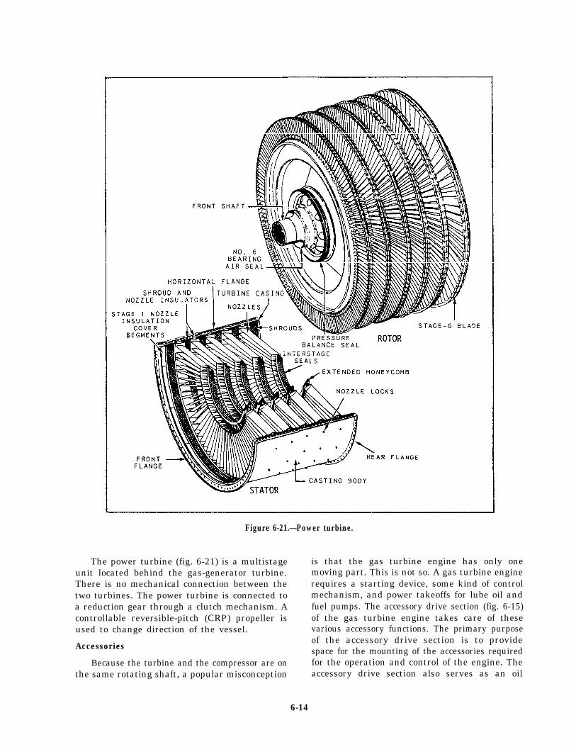
s
Figure 6-21.—Power turbine.
The power turbine (fig. 6-21) is a multistage is that the gas turbine engine has only oneunit located behind the gas-generator turbine.There is no mechanical connection between thetwo turbines. The power turbine is connected toa reduction gear through a clutch mechanism. Acontrollable reversible-pitch (CRP) propeller isused to change direction of the vessel.
Accessories
Because the turbine and the compressor are onthe same rotating shaft, a popular misconception
moving part. This is not so. A gas turbine enginerequires a starting device, some kind of controlmechanism, and power takeoffs for lube oil andfuel pumps. The accessory drive section (fig. 6-15)of the gas turbine engine takes care of thesevarious accessory functions. The primary purposeof the accessory drive section is to providespace for the mounting of the accessories requiredfor the operation and control of the engine. Theaccessory drive section also serves as an oil
6-14
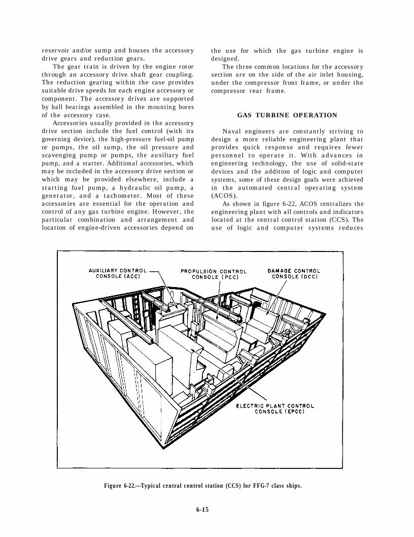
reservoir and/or sump and houses the accessorydrive gears and reduction gears.
The gear train is driven by the engine rotorthrough an accessory drive shaft gear coupling.The reduction gearing within the case providessuitable drive speeds for each engine accessory orcomponent. The accessory drives are supportedby ball bearings assembled in the mounting boresof the accessory case.
Accessories usually provided in the accessorydrive section include the fuel control (with itsgoverning device), the high-pressure fuel-oil pumpor pumps, the oil sump, the oil pressure andscavenging pump or pumps, the auxiliary fuelpump, and a starter. Additional accessories, whichmay be included in the accessory drive section orwhich may be provided elsewhere, include astarting fuel pump, a hydraulic oil pump, agenerator, and a tachometer. Most of theseaccessories are essential for the operation andcontrol of any gas turbine engine. However, theparticular combination and arrangement andlocation of engine-driven accessories depend on
the use for which the gas turbine engine isdesigned.
The three common locations for the accessorysection are on the side of the air inlet housing,under the compressor front frame, or under thecompressor rear frame.
GAS TURBINE OPERATION
Naval engineers are constantly striving todesign a more reliable engineering plant thatprovides quick response and requires fewerpersonnel to operate it. With advances inengineering technology, the use of solid-statedevices and the addition of logic and computersystems, some of these design goals were achievedin the automated central operating system(ACOS).
As shown in figure 6-22, ACOS centralizes theengineering plant with all controls and indicatorslocated at the central control station (CCS). Theuse of logic and computer systems reduces
Figure 6-22.—Typical central control station (CCS) for FFG-7 class ships.
6-15
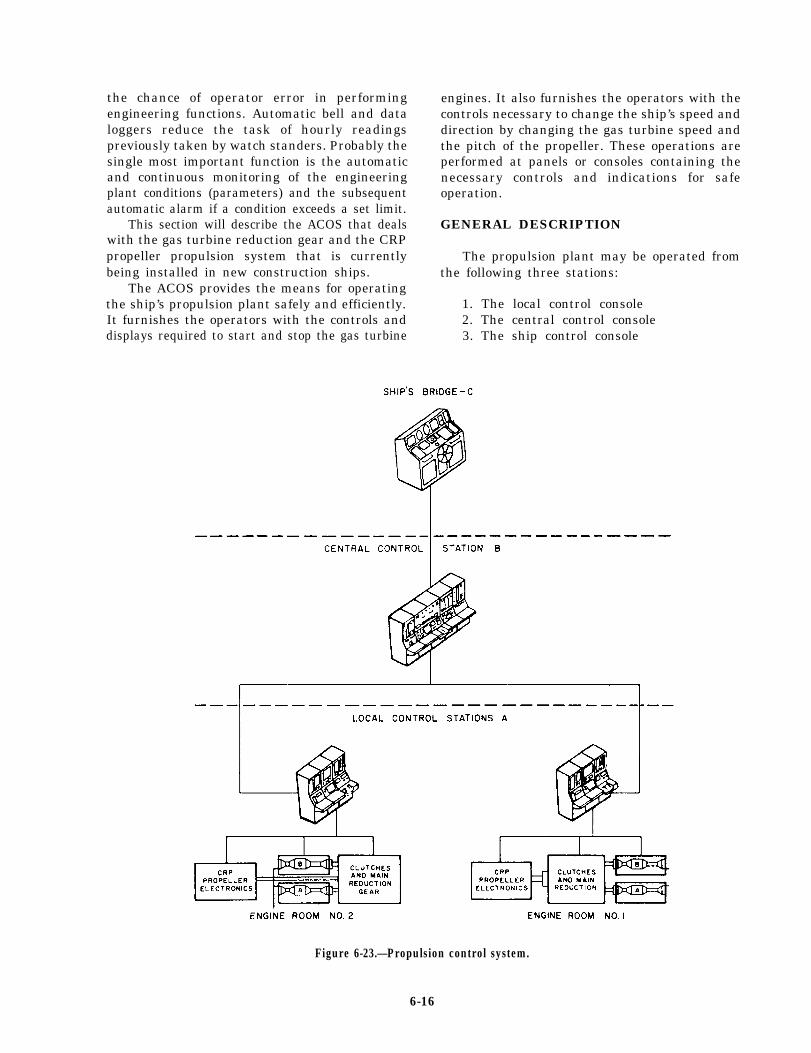
the chance of operator error in performingengineering functions. Automatic bell and dataloggers reduce the task of hourly readingspreviously taken by watch standers. Probably thesingle most important function is the automaticand continuous monitoring of the engineeringplant conditions (parameters) and the subsequentautomatic alarm if a condition exceeds a set limit.
This section will describe the ACOS that dealswith the gas turbine reduction gear and the CRPpropeller propulsion system that is currentlybeing installed in new construction ships.
The ACOS provides the means for operatingthe ship’s propulsion plant safely and efficiently.It furnishes the operators with the controls anddisplays required to start and stop the gas turbine
engines. It also furnishes the operators with thecontrols necessary to change the ship’s speed anddirection by changing the gas turbine speed andthe pitch of the propeller. These operations areperformed at panels or consoles containing thenecessary controls and indications for safeoperation.
GENERAL DESCRIPTION
The propulsion plant may be operated fromthe following three stations:
1. The local control console2. The central control console3. The ship control console
Figure 6-23.—Propulsion control system.
6-16

Figure 6-23 is a simplified diagram of theentire propulsion control system.
LOCAL CONTROL CONSOLE
The local control console is a secondaryoperating station. It is located in the engine roomnear the propulsion equipment. It controls andcontains the necessary controls and indicators topermit direct local (manual) control of thepropulsion equipment. The direct local mode of
control, although still electronic, permits opera-tion of the equipment in a manual mode. Thelocal control console provides facilities for localcontrol of plant starting, normal operation,monitoring, and stopping. Figure 6-24 showspropulsion control stations including the localoperating console. The two main controls on thisconsole are the remote throttle control and thepitch control. The remote throttle providescontrol of the power produced by the gas turbineengine. This control is graduated in percent of gas
Figure 6-24.—Propulsion control console (local).
6-17
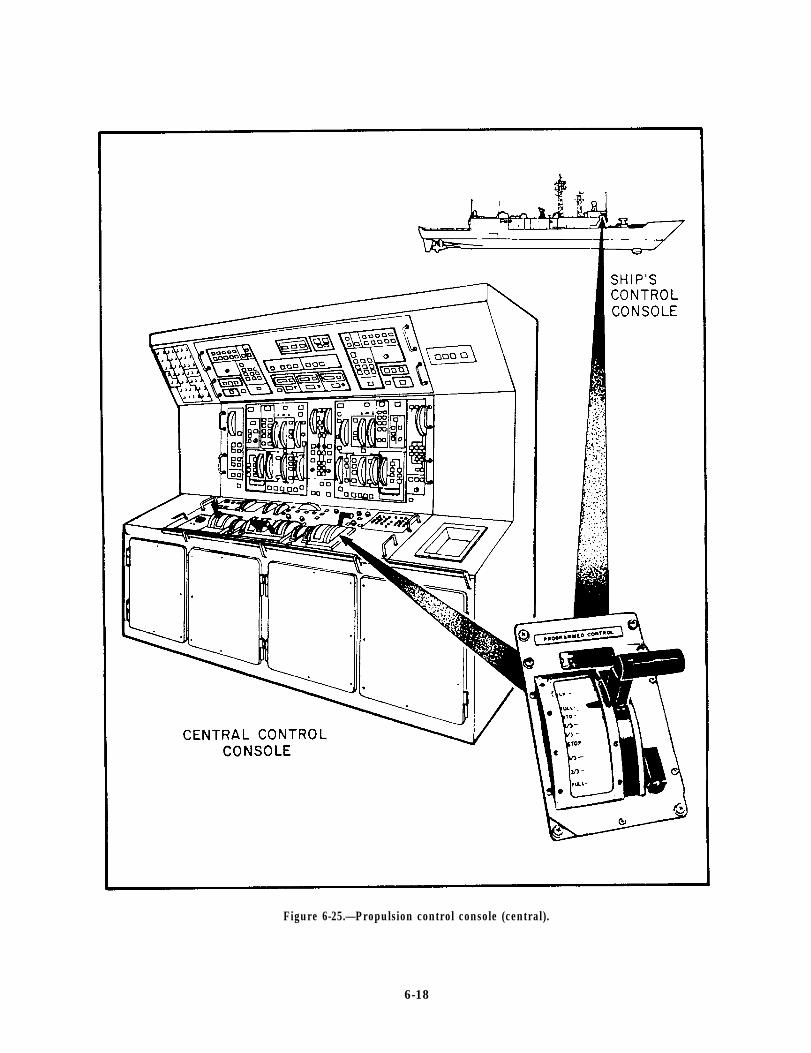
Figure 6-25.—Propulsion control console (central).
6-18
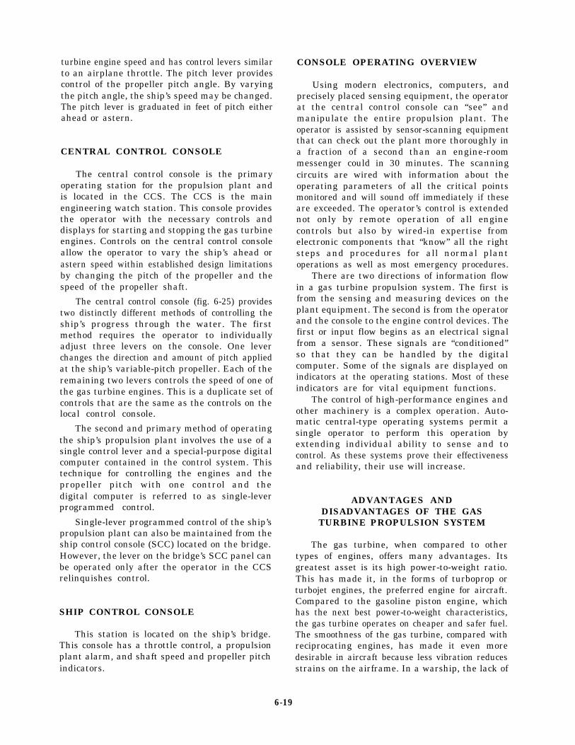
turbine engine speed and has control levers similarto an airplane throttle. The pitch lever providescontrol of the propeller pitch angle. By varyingthe pitch angle, the ship’s speed may be changed.The pitch lever is graduated in feet of pitch eitherahead or astern.
CENTRAL CONTROL CONSOLE
The central control console is the primaryoperating station for the propulsion plant andis located in the CCS. The CCS is the mainengineering watch station. This console providesthe operator with the necessary controls anddisplays for starting and stopping the gas turbineengines. Controls on the central control consoleallow the operator to vary the ship’s ahead orastern speed within established design limitationsby changing the pitch of the propeller and thespeed of the propeller shaft.
The central control console (fig. 6-25) providestwo distinctly different methods of controlling theship’s progress through the water. The firstmethod requires the operator to individuallyadjust three levers on the console. One leverchanges the direction and amount of pitch appliedat the ship’s variable-pitch propeller. Each of theremaining two levers controls the speed of one ofthe gas turbine engines. This is a duplicate set ofcontrols that are the same as the controls on thelocal control console.
The second and primary method of operatingthe ship’s propulsion plant involves the use of asingle control lever and a special-purpose digitalcomputer contained in the control system. Thistechnique for controlling the engines and thepropeller pitch with one control and thedigital computer is referred to as single-leverprogrammed control.
Single-lever programmed control of the ship’spropulsion plant can also be maintained from theship control console (SCC) located on the bridge.However, the lever on the bridge’s SCC panel canbe operated only after the operator in the CCSrelinquishes control.
SHIP CONTROL CONSOLE
This station is located on the ship’s bridge.This console has a throttle control, a propulsionplant alarm, and shaft speed and propeller pitchindicators.
CONSOLE OPERATING OVERVIEW
Using modern electronics, computers, andprecisely placed sensing equipment, the operatorat the central control console can “see” andmanipulate the entire propulsion plant. Theoperator is assisted by sensor-scanning equipmentthat can check out the plant more thoroughly ina fraction of a second than an engine-roommessenger could in 30 minutes. The scanningcircuits are wired with information about theoperating parameters of all the critical pointsmonitored and will sound off immediately if theseare exceeded. The operator’s control is extendednot only by remote operation of all enginecontrols but also by wired-in expertise fromelectronic components that “know” all the rightsteps and procedures for all normal plantoperations as well as most emergency procedures.
There are two directions of information flowin a gas turbine propulsion system. The first isfrom the sensing and measuring devices on theplant equipment. The second is from the operatorand the console to the engine control devices. Thefirst or input flow begins as an electrical signalfrom a sensor. These signals are “conditioned”so that they can be handled by the digitalcomputer. Some of the signals are displayed onindicators at the operating stations. Most of theseindicators are for vital equipment functions.
The control of high-performance engines andother machinery is a complex operation. Auto-matic central-type operating systems permit asingle operator to perform this operation byextending individual ability to sense and tocontrol. As these systems prove their effectivenessand reliability, their use will increase.
ADVANTAGES ANDDISADVANTAGES OF THE GAS
TURBINE PROPULSION SYSTEM
The gas turbine, when compared to othertypes of engines, offers many advantages. Itsgreatest asset is its high power-to-weight ratio.This has made it, in the forms of turboprop orturbojet engines, the preferred engine for aircraft.Compared to the gasoline piston engine, whichhas the next best power-to-weight characteristics,the gas turbine operates on cheaper and safer fuel.The smoothness of the gas turbine, compared withreciprocating engines, has made it even moredesirable in aircraft because less vibration reducesstrains on the airframe. In a warship, the lack of
6-19
low-frequency vibration in gas turbines makesthem preferable to diesel engines because there isless noise for a submarine to pick up at longrange. Modern production techniques have madegas turbines economical in terms of horsepower-per-dollar on initial installation, and theirincreasing reliability makes them a cost-effectivealternative to steam turbine or diesel engineinstallation. In terms of fuel economy, modernmarine gas turbines can compete with dieselengines and may be superior to boiler/steamturbine plants when these are operating ondistillate fuel.
However, there are some disadvantages to gasturbines. Since they are high-performance engines,many parts are under high stress. Impropermaintenance and lack of attention to details ofprocedure will impair engine performance andmay ultimately lead to engine failure. A pencilmark on a compressor turbine blade or a finger-print in the wrong place can cause failure of thepart. The turbine takes in large quantities of airthat may contain substances or objects that canharm the engine. Most gas turbine propulsioncontrol systems are complex because severalfactors have to be controlled, and numerousoperating conditions and parameters must bemonitored. The control systems must reactquickly to turbine operating conditions to avoidcasualties to the equipment. Gas turbines produceloud, high-pitched noises that can damage thehuman ear. In shipboard installations, special
soundproofing is necessary. This adds to thecomplexity of the installation and makes accessfor maintenance more difficult.
From a tactical standpoint, there are twomajor drawbacks to the gas turbine engine. Thefirst is the large amount of exhaust heat producedby the engines. Most current antiship missiles areheat-seekers, and the infrared signature of a gasturbine engine makes it an easy target.Countermeasures, such as exhaust gas cooling andinfrared decoys, have been developed to reducethis problem.
The second tactical disadvantage is the require-ment for depot maintenance and repair of majorcasualties. The turbines cannot be repaired inplace on the ship and must be removed andreplaced by rebuilt engines if anything goes wrong.Here too, design has reduced the problem; anengine change can be accomplished wherevercrane service or a Navy tender is available, andthe replacement engine can be obtained.
SUMMARY
This chapter has given you some basicinformation on gas turbine engines and gasturbine control systems. For a more in-depth lookat gas turbines, refer to Gas Turbine SystemsTechnician (Mechanical) 3 & 2, NAVEDTRA10548-2.
6-20

CHAPTER 7
INTERNAL-COMBUSTION ENGINES
Internal-combustion engines are used exten-sively in the Navy. They serve as propulsion unitsin a variety of ships and boats. Internal-combustion engines are also used as prime movers(drive units) for auxiliary machinery. Because theyhave pistons that employ a back-and-forthmotion, gasoline and diesel engines are alsoclassified as reciprocating engines.
This chapter provides you with the generalconstruction features and operating principles ofvarious types of internal-combustion engines.After reading this chapter, you will have a basicunderstanding of the components that make upan internal-combustion engine and how thesecomponents work together to develop power.
RECIPROCATING ENGINES
The internal-combustion engines (diesel andgasoline) are machines that convert heat energyinto mechanical energy. The transformation ofheat energy to mechanical energy by the engineis based on a fundamental law of physics. Gaswill expand when heat is applied. The law alsostates that when a gas is compressed, thetemperature of the gas will increase. If the gas isconfined with no outlet for expansion, thepressure of the gas will be increased when heatis applied. In the internal-combustion engine, theburning of a fuel within a closed cylinder resultsin an expansion of gases. The pressure created ontop of a piston by the expanding gases causes itto move.
The back-and-forth motion of the pistons inan engine is known as reciprocating motion. Thisreciprocating motion (straight-line motion) mustbe changed to rotary motion (turning motion) toperform a useful function, such as propelling aboat or ship through the water or driving agenerator to provide electricity. A crankshaft anda connecting rod change this reciprocatingmotion to rotary motion (fig. 7-1).
Figure 7-1.—Cylinder, piston, connecting rod, and crank-shaft for one cylinder of an engine.
All internal-combustion engines are basicallythe same. They all rely on three things—air, fuel,and ignition.
Fuel contains potential energy for operatingthe engine; air contains the oxygen necessary forcombustion; and ignition starts combustion. Allare fundamental, and an engine will not operatewithout all of them. Any discussion of enginesmust be based on these three factors and the stepsand mechanisms involved in delivering them tothe combustion chamber at the proper time.
GASOLINE VERSUSDIESEL ENGINES
There are two main differences betweengasoline and diesel engines. They are the methodsof getting the fuel into the cylinders and ofigniting the fuel-air mixtures. In the gasolineengine, the air and gasoline are mixed togetheroutside the combustion chamber. The mixture
7-1
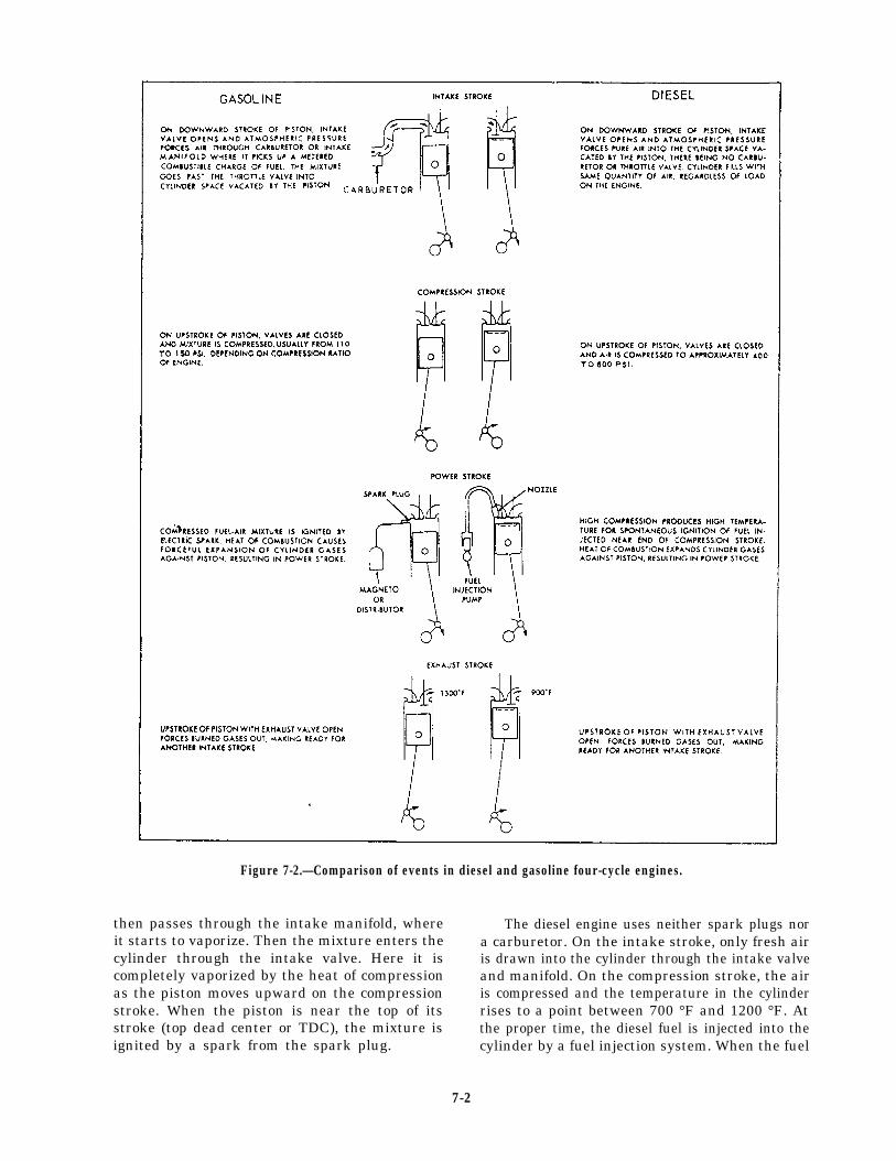
Figure 7-2.—Comparison of events in diesel and gasoline four-cycle engines.
then passes through the intake manifold, where The diesel engine uses neither spark plugs norit starts to vaporize. Then the mixture enters the a carburetor. On the intake stroke, only fresh aircylinder through the intake valve. Here it is is drawn into the cylinder through the intake valvecompletely vaporized by the heat of compression and manifold. On the compression stroke, the airas the piston moves upward on the compression is compressed and the temperature in the cylinderstroke. When the piston is near the top of its rises to a point between 700 °F and 1200 °F. Atstroke (top dead center or TDC), the mixture is the proper time, the diesel fuel is injected into theignited by a spark from the spark plug. cylinder by a fuel injection system. When the fuel
7-2

enters the cylinder, it ignites. Figure 7-2 shows thecomparison of the four strokes of four-cycle dieseland gasoline engines.
The speed of a diesel or gasoline engine iscontrolled by the amount of fuel-air mixture thatis burned in the cylinders. The primary differenceis the method in which the fuel and air enter thecombustion chamber. In a diesel engine, the fuelis injected directly into the combustion chamber,where it mixes with air. In a gasoline engine, thefuel and air are mixed in the intake manifold andthen drawn into the combustion chamber.
Mechanically, the diesel engine is similar tothe gasoline engine. The intake, compression,power, and exhaust strokes occur in the sameorder. The arrangement of the pistons, connectingrods, crankshaft, and engine valves are also thesame.
DEVELOPMENT OF POWER
The power of an internal-combustion enginecomes from the burning of a mixture of fuel andair in a small, enclosed space. When this mixtureburns, it expands greatly. The push or pressurecreated is used to move the piston. The piston thenrotates the crankshaft. The rotating crankshaftis then used to perform the desired work.
Since the same actions occur in all cylindersof an engine, we will discuss only one cylinder andits related parts. The four major parts consist ofa cylinder, piston, crankshaft, and connecting rod(fig. 7-1).
First we must have a cylinder that is closedat one end. The cylinder is stationary within theengine block.
Inside this cylinder is the piston (a movablemetal plug) that fits snugly into the cylinder butcan still slide up and down easily. Movement ofthe piston is caused by the burning fuel-airmixture in the cylinder.
You have already learned that the back-and-forth movement of the piston is called recipro-cating motion, which must be changed to rotarymotion. This change is accomplished by a throwon the crankshaft and a connecting rod thatconnects the piston and the crank throw.
The number of piston strokes occurringduring any one series of operations (cycles) islimited to either two or four, depending on thedesign of the engine.
When the piston of the engine slides down-ward because of the pressure of the expandinggases in the cylinder, the upper end of the
Figure 7-3.—Piston stroke.
connecting rod moves downward with the pistonin a straight line. The lower end of the connectingrod moves down and in a circular motion at thesame time. This moves the crank throw and, inturn, rotates the shaft. This rotation is thedesired result. So remember, the crankshaft andconnecting rod combination is a mechanism forthe purpose of changing back-and-forth (recipro-cating) motion to circular (rotary) motion.
BASIC ENGINE STROKES
Each movement of the piston from top tobottom or from bottom to top is called a stroke.The piston takes two strokes (an upstroke anda downstroke) as the crankshaft makes onecomplete revolution. When the piston is at the topof a stroke (fig. 7-3, view A), it is said to be attop dead center (TDC). When the piston is at thebottom of a stroke (fig. 7-3, view B), it is saidto be at bottom dead center (BDC).
In the basic engine you have studied so far,we have not considered provisions for getting thefuel-air mixture into the cylinder or burned gasesout of the cylinder. There are two openings in theenclosed end of a cylinder. One of the openings,
7-3

Figure 7-4.—Four-stroke diesel engine.
7-4

or ports, permits an intake of air, or anintake of a mixture of fuel and air, intothe combustion area of the cylinder (intakevalve). The other opening, or port, permitsthe burned gases to escape from the cylinder(exhaust valve). The two ports have valvesin them. These valves close off either oneor the other of the ports, or both of them,during various stages of engine operation. Thecamshaft (a shaft with a number of camlobes along its length) opens the valves andholds them open for short periods duringthe piston stroke. The camshaft is driven bythe crankshaft through timing gears or bya timing chain. On a four-stroke engine,the camshaft turns at one-half crankshaftspeed. This permits each valve to open andclose once for every two turns of the crank-shaft.
The following sections give a simplifiedexplanation of the action that takes placewithin the engine cylinder. For the purpose ofexplanation, we will show the action of a four-stroke diesel engine. This type of engine isreferred to as a four-stroke engine because itrequires four complete piston strokes to completeone cycle. These strokes are known as the intakestroke, the compression stroke, the power stroke,and the exhaust stroke.
In a four-stroke engine, each piston goesthrough four strokes, and the crankshaft makestwo revolutions to complete one cycle. Eachpiston delivers power during one stroke in four,or each piston makes one power stroke for eachtwo revolutions of the crankshaft.
We will take one cylinder and trace its opera-tion through the four strokes that make up acycle (fig. 7-4). The engine parts shown in thisfigure include a cylinder, a crankshaft, a pistonconnecting rod, and the intake and exhaust valves.The valve-operating mechanism and the fuelsystem have been omitted.
During the intake stroke shown in view A, theintake valve is open and the exhaust valve isclosed. The piston is moving downward anddrawing a charge of air into the cylinder throughthe intake valve.
When the crankshaft has rotated to the posi-tion shown in view B, the piston moves upward
to almost the top of the cylinder. Both the intakeand exhaust valves are closed during this stroke.The air that entered the cylinder during theintake stroke is compressed into the small spaceabove the piston. This is called the compressionstroke.
The high pressure, which results from thecompression stroke, raises the temperature of theair far above the ignition point of the fuel. Whenthe piston nears the top of the compression stroke,a charge of fuel is forced into the cylinder throughthe injector, as shown in view C. The air, whichhas been heated by compression, ignites thefuel.
NOTE: The injection portion of a cycle is notconsidered a stroke.
During the power stroke (view D), the intakeand exhaust valves are both closed. The increasein temperature resulting from the burning fuelgreatly increases the pressure on top of the piston.This increased pressure forces the pistondownward and rotates the crankshaft. This is theonly stroke in which power is furnished to thecrankshaft.
During the exhaust stroke (view E), theexhaust valve is open and the intake valve remainsclosed. The piston moves upward, forcing theburned gases out of the combustion chamberthrough the exhaust valve. This stroke, whichcompletes the cycle, is followed immediately bythe intake stroke of the next cycle, and thesequence of events continues.
The four-stroke gasoline engine operates onthe same mechanical, or operational, cycle as thediesel engine. In the gasoline engine, the fuel andair are mixed in the intake manifold; and themixture is drawn into the cylinders through theintake valve. The fuel-air mixture is ignited nearthe top of the compression stroke by an electricspark that passes between the terminals of thespark plug.
Two-stroke diesel engines are widely used bythe Navy. Every second stroke of a two-strokecycle engine is a power stroke. The strokesbetween are compression strokes. The intake andexhaust functions take place rapidly near thebottom of each power stroke. With this arrange-ment, there is one power stroke for each
7-5

Figure 7-5.—Two-stroke diesel engine.
revolution of the crankshaft, or twice as many as In view C, the piston is moving downward onin a four-stroke cycle engine.
NOTE: A two-stroke engine does not haveintake valves. It has intake ports (fig. 7-5).
The steps in the operation of a two-strokediesel engine are shown in figure 7-5. In view A,the piston is moving upward on the compressionstroke. The exhaust valve and the intake ports areclosed, and the piston is compressing the airtrapped in the combustion chamber. At the topof the stroke, with the piston in the positionshown in view B, fuel is injected (sprayed) intothe cylinder and ignited by the hot compressed air.
the power stroke: The exhaust valves are stillclosed; and the increased pressure, resulting fromthe burning fuel, forces the piston downward androtates the crankshaft.
As the piston nears the bottom of the powerstroke (view D), the exhaust valves open and thepiston continues downward to uncover the intakeports. Air is delivered under pressure by a blowerfor two-stroke diesel engines. In a two-strokegasoline engine, air comes from the crankcasethrough the intake ports; and the burned gasesare carried out through the exhaust valve.This operation (referred to as scavenging air)takes place almost instantly and corresponds to
7-6

Figure 7-6.—A two-stroke diesel engine cylinder with thepiston at the bottom of the power stroke.
the intake and exhaust strokes of the four-stroke cycle.
You might expect a two-stroke engine todevelop twice as much power as a four-strokeengine of the same size and to operate at the samespeed. However, this is not true. With two-strokediesel engines, some of the power is used to drivea blower (fig. 7-6) that forces the air charge intothe cylinder under pressure. Also, the burnedgases are not completely cleared from the cylinder,reducing combustion efficiency. Additionally,because of the much shorter period the intakeports are open (as compared to the period theintake valve in a four-stroke cycle is open), asmaller amount of air is admitted. Therefore, withless air being mixed with the fuel, less power-per-power stroke is produced. Nevertheless, two-stroke diesel engines give excellent service.
VALVE MECHANISM
The valve mechanism of a two-stroke dieselcylinder head is shown in figure 7-7. This cylinderhead has two exhaust valves that are opened atthe same time by the action of a single cam. Theymake a tight fit in the exhaust openings (ports)in the cylinder head and are held in the closedposition by the compression of the valve springs.The rocker arm and bridge transmit thereciprocating motions of the cam roller to thevalves.
Figure 7-7.—A two-stroke diesel cylinder head, showing thevalve-operating mechanism.
In figure 7-7, view A, the cam roller is ridingon the base circle of the cam, and the valves areclosed. As the camshaft rotates, the cam lobe ornose rides under the roller and raises it to theposition shown in view B. When the roller is lifted,the arm rotates around the rocker shaft; and theopposite end of the arm is lowered. This actionpushes the bridge and valves down against thepressure of the valve springs and opens the valvepassages.
On some types of engines, the camshaft islocated near the crankshaft. In these designs, theaction of the cam roller is transmitted to therocker arm by a pushrod.
The camshaft must be timed with the crank-shaft so that the lobes will open the valves in eachcylinder at the correct instant in the operatingcycle. In the two-stroke engine, the camshaftrotates at the same speed as the crankshaft.
The four-stroke engine has an intake valve andan exhaust valve in every cylinder. Each valve is
7-7

Figure 7-8.—The fuel supply system of a typical diesel engine.
operated by a separate cam. The intake valve isheld open during the intake stroke, and theexhaust valve is opened during the exhaust stroke.Since two revolutions of the crankshaft arenecessary to complete a cycle, the camshaft ofthese engines turns only half as fast as thecrankshaft.
COMPRESSION IGNITION SYSTEM
In the four-stroke cycle engine, air enters thecylinders through intake valves. As each pistonmoves downward on the intake stroke, the volumein the combustion chamber increases and the
pressure decreases. The normal atmosphericpressure then forces the air into the cylinderthrough the intake valve.
Since the two-stroke cycle engine does not gothrough an intake stroke, a means must beprovided to force air into the cylinders. The airenters through intake ports (uncovered when thepiston approaches the bottom of the powerstroke). (See fig. 7-5.) Since the exhaust valves areopen when the intake ports are being uncovered,the incoming air forces the burned gases outthrough the exhaust valves and fills the cylinderwith a supply of fresh air.
7-8

Figure 7-9.—Mounting of the unit injector in the cylinder head.
On the compression stroke, the exhaust valves You can find more detailed information onare closed, the intake ports are covered, and theair is trapped in the cylinder. The rising pistoncompresses the air and raises its temperature. Bythe time the piston reaches the top of the stroke,the volume of the combustion chamber has beengreatly reduced. The relation between the volumeof the cylinder with the piston at the bottomof its stroke and the cylinder volume with thepiston at the top of its stroke is called theCOMPRESSION RATIO.
As the compression ratio is increased, thetemperature of the air in the cylinder increases.Current gasoline engines operate at compressionratios between 6:1 and 11:1, but compressionratios of diesel engines range between 12:1 and19:1. Remember, that on the compression strokeof a diesel engine the air is compressed to a rangeof 400 to 600 psi, which results in a temperatureranging from 700°F to 1200°F. However, whenthe fuel is injected into the cylinder and beginsto burn, the pressure may increase to more than1500 psi and the temperature may rise as high as1800°F.
compression ignition systems in Engineman 3,NAVEDTRA 10539.
FUEL SYSTEM
The fuel system of a diesel engine draws fuelfrom the service tank and injects it into the enginecylinders. Figure 7-8 shows the units found in atypical unit-injector fuel system. The fuel pumpdraws the fuel from the tank through a primarystrainer and delivers it under low pressure to theinjector by way of the secondary filter. Theinjector is operated by a rocker arm. It meters,pressurizes, and atomizes the fuel as it is injectedinto the combustion chamber. The outlet linecarries the excess fuel from the injector back tothe fuel tank. In some units, a transfer pump isinstalled between the tank and the strainer. Inother units, the injection pump and injectionnozzles are separate units instead of a combinedunit, as shown in figure 7-9.
A diesel engine will not operate efficientlyunless clean fuel is delivered to the injector or
7-9
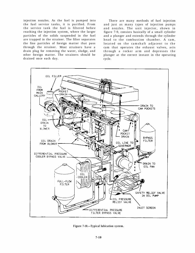
injection nozzles. As the fuel is pumped intothe fuel service tanks, it is purified. Fromthe service tank the fuel is filtered beforereaching the injection system, where the largerparticles of the solids suspended in the fuelare trapped in the strainer. The filter separatesthe fine particles of foreign matter that passthrough the strainer. Most strainers have adrain plug for removing the water, sludge, andother foreign matter. The strainers should be
There are many methods of fuel injectionand just as many types of injection pumpsand nozzles. The unit injector, shown infigure 7-9, consists basically of a small cylinderand a plunger and extends through the cylinderhead to the combustion chamber. A cam,located on the camshaft adjacent to thecam that operates the exhaust valves, actsthrough a rocker arm and depresses theplunger at the correct instant in the operating
drained once each day. cycle.
Figure 7-10.—Typical lubication system.
7-10
When the injector plunger is depressed, a finespray of fuel is discharged into the cylinderthrough small holes in the nozzle. The smoothoperation of the engine depends, to a largeextent, on the accuracy with which the plungersinject the same amount of fuel into everycylinder.
The amount of fuel injected into the cylinderson each stroke is controlled by rotating theplungers of a unit injector. The throttle, whichregulates the speed of the engine, is connected tothe injectors through a suitable linkage. A changein the throttle setting rotates the plungers andvaries the amount of fuel injected into thecylinders on each stroke.
LUBRICATION SYSTEM
The lubrication system of an internal-combus-tion engine is very important. If the lubricatingsystem should fail, not only will the engine stop,but many of the parts are likely to be damagedbeyond repair. Therefore, when lubrication failureoccurs, the engine can seldom be run againwithout a major overhaul.
The lubricating system delivers oil to themoving parts of the engine to reduce friction andto assist in keeping the parts cool. Most diesel andgasoline engines are equipped with a pressurelubricating system that delivers the oil underpressure to the bearings and bushings and alsolubricates the gears and cylinder walls. The oilusually reaches the bearings through passagesdrilled in the framework of the engine. Thelubricating system of a typical diesel engine isshown in figure 7-10.
All of the engine parts are lubricated with oildelivered by a gear-type oil pump. This pumptakes suction through a screen from an oil panor sump. From the pump, the oil is forced throughthe oil filter and the oil cooler into the main oilgallery. The oil is fed from the main gallery,through individual passages, to the main crank-shaft bearings and one end of the hollowcamshaft. All the other moving parts andbearings are lubricated by oil drawn from thesetwo sources. The cylinder walls and the teeth ofmany of the gears are lubricated by oil spraythrown off by the rotating crankshaft. After theoil has served its purpose, it drains back to thesump to be used again.
The oil pressure in the line leading from thepump to the engine is indicated on a pressuregauge. A temperature gauge in the return lineprovides an indirect method for indicating
variations in the temperature of the engine parts.Any abnormal drop in pressure or rise intemperature should be investigated at once. It isadvisable to secure (shut down) the engine untilthe trouble has been located and corrected.
Constant oil pressure, throughout a widerange of engine speeds, is maintained by the oilpressure relief valve that allows the excess oil toflow back into the sump. All of the oil from thepump passes through the filter unless the oil iscold and heavy or if the filter (or oil cooler) isclogged. In such cases, the bypass valve (filterbypass valve or cooler bypass valve) is forcedopen; and the oil flows directly to the engine. Partof the oil fed to the engine is returned throughthe bypass filter, which removes flakes of metal,carbon particles, and other impurities.
COOLING SYSTEM
Marine engines are equipped with a water-cooling system to carry away the excess heatproduced in the engine cylinders. Fresh water(coolant) is circulated through passages in thecylinder walls and in the cylinder head, where itbecomes hot from absorbing engine heat. The hotcoolant then passes through a heat exchanger,where it gives up its heat to a cooling medium,becomes cool, and returns to the engine to removemore heat. The cooling medium may be either airor seawater.
A heat exchanger using air as the coolingmedium works like an automobile radiator. Aheat exchanger using seawater as the coolingmedium may be mounted either on the engineor on the ship’s hull. Engine-mounted heatexchangers require seawater to be pumped toand from them; whereas, hull-mounted heatexchangers (keel coolers) are in constant contactwith seawater and require the fresh water (coolant)to be pumped through the cooler.
STARTING SYSTEMS
There are three types of starting systems usedin internal-combustion engines—electric,hydraulic, and compressed air.
As a Fireman, you will probably have morecontact with the electric starting system than youwill with the other two types. Lifeboats aboardships use an electric starter to start the engine.
Electric starting systems use direct currentbecause electrical energy in this form can be storedin batteries and drawn upon when needed. Thebattery’s electrical energy can be restored by
7-11

Figure 7-11.—Electric starting system.
charging the battery with an engine-drivengenerator.
The main components of the electric startingsystem, as shown in figure 7-11, are the battery,cranking motor, and associated control andprotective devices.
Electric Starting Systems
The starting motor for diesel and gasolineengines operates on the same principle as a directcurrent electric motor. The motor is designed tocarry extremely heavy loads but, because it drawsa high current (300 to 665 amperes), it tends tooverheat quickly. To avoid overheating, NEVERallow the motor to run more than the specifiedamount of time, usually 30 seconds at a time.Then allow it to cool for 2 or 3 minutes beforeusing it again.
To start a diesel engine, you must turn it overrapidly to obtain sufficient heat to ignite the fuel.The starting motor is located near the flywheel,and the drive gear on the starter is arranged sothat it can mesh with the teeth on the flywheelwhen the starting switch is closed. The drivemechanism must function to (1) transmit theturning power to the engine when the startingmotor runs, (2) disconnect the starting motorfrom the engine immediately after the engine hasstarted, and (3) provide a gear reduction ratiobetween the starting motor and the engine.
The drive mechanism must disengage thepinion from the flywheel immediately afterthe engine starts. After the engine starts, itsspeed may increase rapidly to approximately1,500 rpm. If the drive pinion remained meshedwith the flywheel and also locked with the shaftof the starting motor at a normal engine speed
(1,500 rpm), the shaft would be spun at a rapidrate (22,500 to 30,000 rpm). At such speeds, thestarting motor would be badly damaged.
Hydraulic Starting Systems
There are several types of hydraulic startingsystems in use. In most installations, the systemconsists of a hydraulic starting motor, a piston-type accumulator, a manually operated hydraulicpump, an engine-driven hydraulic pump, and areservoir for the hydraulic fluid.
Hydraulic pressure is provided in the accumu-lator by the manually operated hand pump orfrom the engine-driven pump when the engine isoperating.
When the starting lever is operated, thecontrol valve allows hydraulic oil (under pressureof nitrogen gas) from the accumulator to passthrough the hydraulic starting motor, therebycranking the engine. When the starting lever isreleased, spring action disengages the startingpinion and closes the control valve. This stops theflow of hydraulic oil from the accumulator. Thestarter is protected from the high speeds of theengine by the action of an overrunning clutch.
The hydraulic starting system is used onsome smaller diesel engines. This system canbe applied to most engines now in service withoutmodification.
Air Starting Systems
Starting air comes directly from the ship’smedium-pressure (MP) or high-pressure (HP) airservice line or from the starting air flasks whichare included in some systems for the purpose ofstoring starting air. From either source, the air,
7-12
on its way to the starting air system, must bypassthrough a pressure-reducing valve, which reducesthe higher pressure to the operating pressurerequired to start a particular engine.
A relief valve is installed in the line betweenthe reducing valve and the starting system. Therelief valve is normally set to open at 12 percentabove the required starting air pressure. If the airpressure leaving the reducing valve is too high,the relief valve will protect the system by releasingair in excess of a preset value and permit air onlyat safe pressure to reach the starting system ofthe engine.
START AIR MOTOR SYSTEM.— Someengines, usually gas turbine types, are designedto crank over by starting motors that usecompressed air. Air-starting motors are usuallydriven by air pressures varying from 90 to 200 psi.
COMPRESSED AIR ADMISSION SYSTEM.—Most large diesel engines are started whencompressed air is admitted directly into the enginecylinders. Compressed air at approximately 200to 300 psi is directed into the cylinders to forcethe piston down and thereby, turn the crankshaftof the engine. This air admission process continuesuntil the pistons are able to build up sufficientheat from compression to cause combustion tostart the engine.
GASOLINE ENGINES
The main parts of the gasoline engine are quitesimilar to those of the diesel engine. The twoengines differ principally in that the gasolineengine has a carburetor and an electrical ignitionsystem.
The induction system of a gasoline enginedraws gasoline from the fuel tank and air fromthe atmosphere, mixes them, and delivers themixture to the cylinders. The induction systemconsists of the fuel tank, the fuel pump, thecarburetor, and the necessary fuel lines and airpassages. Flexible tubing carries the fuel from thetank to the carburetor, while the intake manifoldcarries the fuel-air mixture from there to theindividual cylinders. The fuel-air mixture is ignitedby an electric spark.
The carburetor is a device used to send a finespray of fuel into a moving stream of air as itmoves to the intake valves of the cylinders. Thespray is swept along, vaporized, and mixed withthe moving air. The carburetor is designed to
maintain the same mixture ratio over a wide rangeof engine speeds. The mixture ratio is the numberof pounds of air mixed with each pound ofgasoline vapor. A rich mixture is one in which thepercentage of gasoline vapor is high, while a leanmixture contains a low percentage of gasolinevapor.
The electrical ignition system is designed todeliver a spark in the combustion chamber of eachcylinder at a specific point in that cylinder’scycle of operation. A typical ignition systemincludes a storage battery, an ignition coil, breakerpoints, a condenser, a distributor, a spark plugin each cylinder, a switch, and the necessarywiring.
There are two distinct circuits in the ignitionsystem—the primary and the secondary. Theprimary circuit carries a low-voltage current. Thesecondary circuit is high voltage. The battery, theignition switch, the ignition coil, and the breakerpoints are connected in the primary circuit. Thesecondary circuit, also connected to the ignitioncoil, includes the distributor and the spark plugs.
The storage battery is usually 6, 12, or 24 volts.One terminal is grounded to the engine frame,while the other is connected to the ignition system.
The ignition coil, in many respects, is similarto an electromagnet. It consists of an iron coresurrounded by primary and secondary coils. Theprimary coil is made up of a few turns of heavywire, while the secondary coil has a great manyturns of fine wire. In both coils, the wire isinsulated and the coils are entirely separate fromeach other.
The breaker points form a mechanical switchconnected to the primary circuit. They are openedby a cam that is timed to break the circuit at theexact instant that each cylinder is due to fire. Acondenser is connected across the breaker pointsto prevent arcing and to provide a better high-voltage spark.
The distributor, connected to the secondaryor high-voltage circuit, serves as a selector switchthat channels electric current to the individualcylinders. Although the breaker points areconnected in the primary circuit, they are oftenlocated in the distributor case. The same driveshaft operates both the breaker points and thedistributor.
The spark plugs, which extend into thecombustion chambers of the cylinders, areconnected by heavily insulated wires to thedistributor. A spark plug consists essentially ofa metal shell that screws into the spark plug holein the cylinder, a center electrode embedded in
7-13

porcelain, and a side electrode connected to theshell. The side electrode is adjusted so thatthere is a small space (gap) between it andthe center electrode. This gap varies dependingon the engine. When the plug fires, an electricspark jumps across the gap between theelectrodes.
When the engine is running, the electriccurrent in the primary circuit flows from thebattery through the switch, the primary windingin the ignition coil, the breaker points, and thenback to the battery. The high voltage is producedin the secondary winding in the ignition coil, thenflows through the distributor to the individualspark plugs and back to the ignition coil throughthe engine frame. It is interesting to note that thehigh voltage that jumps the gap in the spark plugsdoes not come from the battery but is producedin the ignition coil.
The ignition coil and the condenser are theonly parts of the ignition system that require anexplanation. The soft iron core and the primarywindings function as an electromagnet. Thecurrent flowing through the primary windingsmagnetizes the core. The same core and thesecondary windings function as a transformer.Variations in the primary current change themagnetism of the core, which in turn produceshigh voltage in the secondary windings.
With the engine running and the breakerpoints closed, low-voltage current flows throughthe primary circuit. When the breaker pointsopen, this current is interrupted and produces highvoltage in the secondary circuit. The electricity,which would otherwise arc across the breakerpoints as they are separating, now flows into thecondenser.
The principal purpose of the condenser is toprotect the breaker points from being burned.The condenser also aids in obtaining a hotterspark.
The contact-point ignition system is an oldertype. The electronic ignition system is of the newertype. The basic difference between the contact-point and the electronic ignition systems is in theprimary circuit. The primary circuit in the contact-point system is opened and closed by contactpoints. In the electronic system, the primarycircuit is opened and closed by the electroniccontrol unit.
The secondary circuits are practically the samefor the two systems. The difference is that thedistributor, ignition coil, and wiring are alteredto handle the higher voltage that the electronicignition system produces.
One advantage of this higher voltage ofapproximately 47,000 volts is that spark plugs withwider gaps can be used. This results in a longerspark, which can ignite leaner fuel-air mixtures.As a result, engines can run on leaner mixturesfor better fuel economy and lower emissions.
Another difference is that some electronicignition systems have no mechanical advancemechanisms—centrifugal or vacuum. Instead, thespark timing is adjusted electronically.
The starting system of the gasoline engine isbasically the same as that of the diesel engine. Thegenerator keeps the battery charged and providesthe current to operate the lights and otherelectrical equipment. The starter motor drawscurrent from the battery and rotates the flywheeland crankshaft for starting.
SUMMARY
This chapter was designed to give you a briefunderstanding of diesel and gasoline internal-combustion engines. You will find these engineson all ships in the Navy. It will be of great valueto you to learn more about them by reading thereferenced material given throughout this chapter.
7-14

CHAPTER 8
SHIP PROPULSION
The primary function of any marine engineer-ing plant is to convert the chemical energy of afuel into useful work and to use that work in thepropulsion of the ship. A propulsion unit consistsof the machinery, equipment, and controls thatare mechanically, electrically, or hydraulicallyconnected to a propulsion shaft. After reading thischapter, you will have a basic understanding ofhow a ship’s propulsion unit works. You will learnabout the three main types of propulsion unitsused in the Navy. You will also learn how poweris transmitted from the propulsion unit to theship’s propeller through the use of gears, shafts,and clutches.
PRINCIPLES OFSHIP PROPULSION
A ship moves through the water by propellingdevices, such as paddle wheels or propellers.These devices impart velocity to a column ofwater and move it in the direction oppositeto the direction in which it is desired tomove the ship. A force, called reactive forcebecause it reacts to the force of the columnof water, is developed against the velocity-imparting device. This force, also called thrust,is transmitted to the ship and causes the ship tomove through the water.
The screw-type propeller is the propulsiondevice used in almost all naval ships. The thrustdeveloped on the propeller is transmitted to theship’s structure by the main shaft through thethrust bearing (fig. 8-1).
The main shaft extends from the mainreduction gear shaft of the reduction gear to thepropeller. It is supported and held in alignmentby the spring bearings, the stern tube bearings,and the strut bearing. The thrust, acting on thepropulsion shaft as a result of the pushing effectof the propeller, is transmitted to the ship’sstructure by the main thrust bearing. In mostships, the main thrust bearing is located at theforward end of the main shaft within the mainreduction gear casing. In some very large ships,however, the main shaft thrust bearing is locatedfarther aft in a machinery space or a shaft alley.
The main reduction gear connects the primemover (engine) to the shaft. The function ofthe main reduction gear is to reduce the highrotational speeds of the engine and allow thepropeller to operate at lower rotation speeds. Inthis way, both the engine and the propeller shaftrotate at their most efficient speeds.
TYPICAL PROPULSION UNITS
Various types and designs of prime movers arecurrently in use on naval ships. The prime movers
Figure 8-1.—General principle of geared ship propulsion.
8-1

Figure 8-2.—Geared steam turbine drive.
may be either a geared turbine (steamdiesel engine.
STEAM TURBINE GEAR DRIVE
or gas) or
In the steam turbine gear drive, the individualpropulsion units consist of the main turbines andthe main reduction gear (fig. 8-2). These types ofturbine drives are used on most types of navalships. They provide a high power-to-weight ratioand are ruggedly constructed. When repairs are
needed, they can usually be completed withoutremoving the turbines from the ship. Steamturbine gear drives consist of one high-pressureturbine and one low-pressure turbine. Theyprovide ahead propulsion. Smaller and simplerturbine elements inside the low-pressure turbineprovide astern propulsion (fig. 8-2).
DIESEL GEAR DRIVE
In the diesel gear drive engine, the parts thatmake up the unit consist of the diesel engine, thereduction gear, and either the controllable-pitchpropeller unit or the dc motor/generator driveunit. The diesel gear drive engine is used onauxiliary ships, minesweepers, fleet tugs, patrolcrafts, and numerous other yard craft and smallboats. Standardization of fuels, cheaper fuel, andreduction in fire hazards are the chief factors whythe Navy favors diesel engines.
Some diesel engines are directly reversible. Thepropeller shaft is connected directly to the dieselengine so that the speed of the propeller shaft iscontrolled by the speed of the diesel engine. Whenit becomes necessary to reverse the direction ofrotation of the propeller shaft, the diesel engineis stopped, the cam shaft of the engine is shiftedfor reverse rotation, and then the engine is
Figure 8-3.—Diesel engine and reduction gear.
8-2

Figure 8-4.—Typical gas turbine reduction
restarted. This allows the engine to operate in theopposite direction. This operation takes time andpresents a difficult situation if sudden changes indirection are required.
To eliminate this stopping-starting situationand to make a smoother transition from forwardto reverse in less time, reverse-reduction gears,clutches, and controllable-pitch propellers areused. Figure 8-3 shows a typical diesel engine.
GAS TURBINE DRIVE
Gas turbines are used on patrol craft,destroyers, cruisers, frigates, amphibious craft,and auxiliary oilers. Compared to other propul-sion units, they offer a high power-to-weightratio.
Gas turbine gear drive units consist of gasturbines, reduction gears, and controllable-pitchpropeller units. Figure 8-4 shows a typical gasturbine reduction gear arrangement.
gear module arrangement.
CONVERTING POWER TO DRIVE
The basic characteristics of a propulsion unitusually make it necessary for the drive mechanismto change both the speed and the direction of shaftrotation. The engine in many installations includesa device that permits a speed reduction from theengine to the propeller shaft so that both theengine and the propeller may operate efficiently.This device is a combination of gears and iscalled a reduction gear.
REDUCTION GEARS
Engines must operate at relatively high speedsfor maximum efficiency. Propellers must operateat lower speeds for maximum efficiency.Therefore, reduction gears are used to allow boththe engine and the propeller to operate within theirmost efficient revolutions per minute (rpm)
8-3

Figure 8-5.—Locked-train-type gearing.
ranges. A typical steam turbine reduction gear isshown in figure 8-5.
The use of reduction gears is by no meanslimited to ship propulsion. Other machinery, suchas ship’s service generators and various pumps,also have reduction gears. In these units, as wellas in shipboard propulsion units, engine operatingefficiency requires a higher rpm range than thatsuitable for the driven unit.
Reduction gears are classified by the numberof steps used to bring about the speed reductionand the arrangement of the gearing. A gearmechanism consisting of a pair of gears or a smallgear (pinion) driven by the engine shaft, whichdirectly drives a large (bull) gear on the propellershaft, is called a single-reduction gear. In this typeof arrangement, the ratio of speed reduction isproportional to the diameter of the pinion andthe gear. For example, in a 2-to-1 single-reductiongear, the diameter of the driven gear is twice thatof the driving pinion. In a 10-to-1 single-reductiongear, the diameter of the driven gear is 10 timesthat of the driving pinion.
Steam propulsion-type ships built since 1935have double-reduction propulsion gears. In thistype of gear, a high-speed pinion, connected tothe turbine shaft by a flexible coupling, drives anintermediate (first reduction) gear. This gear isconnected by a shaft to the low-speed pinion that,in turn, drives the bull gear (second reduction)mounted on the propeller shaft. A 20-to-1 speedreduction might be accomplished by having a ratioof 2-to-1 between the high-speed pinion and thefirst-reduction gear, and a ratio of 10-to-1
between the low-speed pinion and the second-reduction gear on the propeller shaft.
For a typical example of a double-reductionapplication, let us consider the main-reductiongear shown in figure 8-6. The high-pressureand low-pressure turbines are connected to thepropeller shaft through a locked-train type ofdouble-reduction gear.
NOTE: This type of reduction gear is usedaboard many naval combatant ships.
First-reduction pinions are connected byflexible couplings to the turbines. Each of thefirst-reduction pinions drives two first-reductiongears. A second-reduction (slow speed) pinion isattached to each of the first-reduction gears bya quill shaft and flexible couplings. These fourpinions drive the second-reduction (bull) gear thatis attached to the propeller shaft.
CLUTCHES AND REVERSE GEARS
Clutches are normally used on direct-drivepropulsion engines to provide a means of dis-connecting the engine from the propeller shaft.In small engines, clutches are usually combinedwith reverse gears and are used for maneuveringthe ship. In large engines, special types ofclutches are used to obtain special coupling orcontrol characteristics and to prevent torsional(twisting) vibration.
Diesel-propelling equipment on a boat or aship must be capable of providing backing-downpower as well as forward power. There are afew ships and boats in which backing down isaccomplished by reversing the pitch of thepropeller. Most ships, however, back down byreversing the direction of rotation of the propellershaft. In mechanical drives, reversing thedirection of rotation of the propeller shaft maybe accomplished in one of two ways. You canreverse the direction of engine rotation or use thereverse gears.
Reverse gears are used on marine engines toreverse the rotation of the propeller shaft duringmaneuvering without reversing the rotation of theengine. They are normally used on smallerengines. If a high-output engine has a reverse gear,the gear is used for low-speed operation only anddoes not have full-load and full-speed capacity.For maneuvering ships with large direct-propulsion engines, the engines are reversed.
The drive mechanism of a ship or a boat isrequired to do more than reduce speed and reverse
8-4
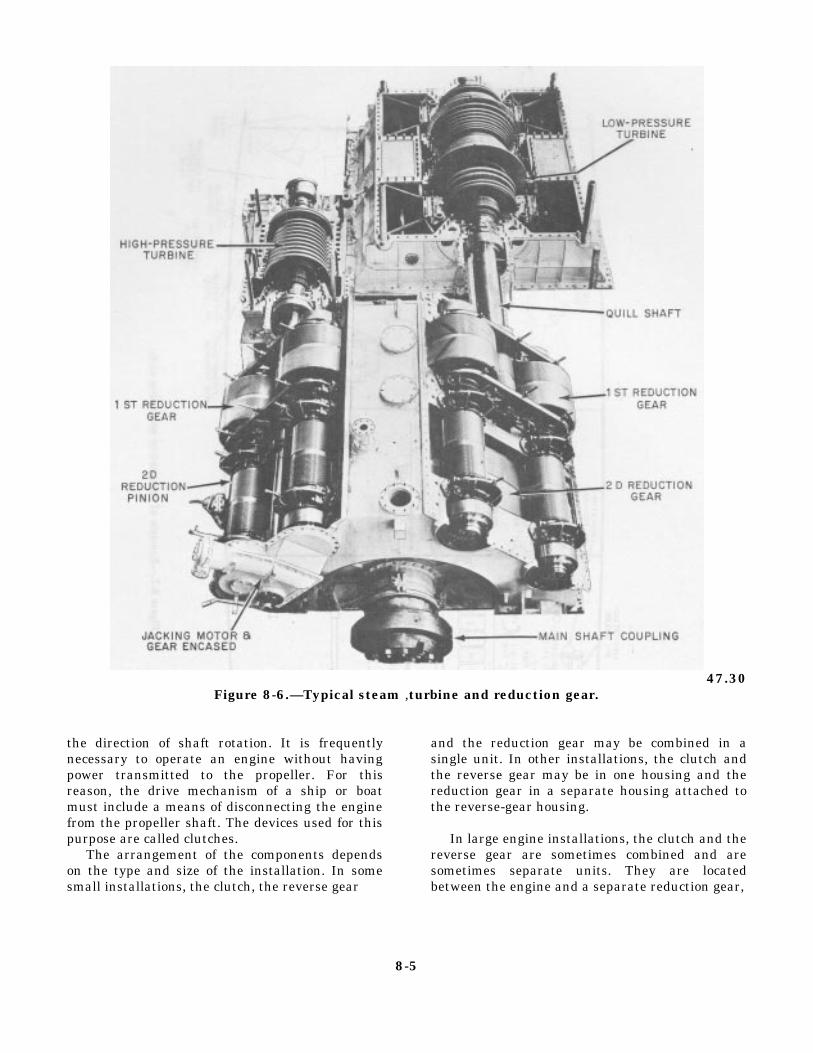
47.30Figure 8-6.—Typical steam ,turbine and reduction gear.
the direction of shaft rotation. It is frequentlynecessary to operate an engine without havingpower transmitted to the propeller. For thisreason, the drive mechanism of a ship or boatmust include a means of disconnecting the enginefrom the propeller shaft. The devices used for thispurpose are called clutches.
The arrangement of the components dependson the type and size of the installation. In somesmall installations, the clutch, the reverse gear
and the reduction gear may be combined in asingle unit. In other installations, the clutch andthe reverse gear may be in one housing and thereduction gear in a separate housing attached tothe reverse-gear housing.
In large engine installations, the clutch and thereverse gear are sometimes combined and aresometimes separate units. They are locatedbetween the engine and a separate reduction gear,
8-5

Figure 8-7.
8-6
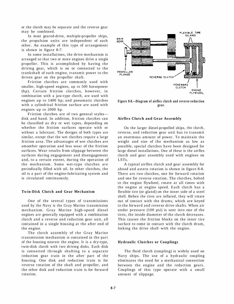
or the clutch may be separate and the reverse gearmay be combined.
In most geared-drive, multiple-propeller ships,the propulsion units are independent of eachother. An example of this type of arrangementis shown in figure 8-7.
In some installations, the drive mechanism isarranged so that two or more engines drive a singlepropeller. This is accomplished by having thedriving gear, which is on or connected to thecrankshaft of each engine, transmit power to thedriven gear on the propeller shaft.
Friction clutches are commonly used withsmaller, high-speed engines, up to 500 horsepower(hp). Certain friction clutches, however, incombination with a jaw-type clutch, are used withengines up to 1400 hp; and pneumatic clutcheswith a cylindrical friction surface are used withengines up to 2000 hp.
Friction clutches are of two general styles—disk and band. In addition, friction clutches canbe classified as dry or wet types, depending onwhether the friction surfaces operate with orwithout a lubricant. The designs of both types aresimilar, except that the wet clutches require a largefriction area. The advantages of wet clutches aresmoother operation and less wear of the frictionsurfaces. Wear results from slippage between thesurfaces during engagement and disengagementand, to a certain extent, during the operation ofthe mechanism. Some wet-type clutches areperiodically filled with oil. In other clutches, theoil is a part of the engine-lubricating system andis circulated continuously.
Twin-Disk Clutch and Gear Mechanism
One of the several types of transmissionsused by the Navy is the Gray Marine transmissionmechanism. Gray Marine high-speed dieselengines are generally equipped with a combinationclutch and a reverse and reduction gear unit, allcontained in a single housing at the after end ofthe engine.
The clutch assembly of the Gray Marinetransmission mechanism is contained in the partof the housing nearest the engine. It is a dry-type,twin-disk clutch with two driving disks. Each diskis connected through shafting to a separatereduction gear train in the after part of thehousing. One disk and reduction train is forreverse rotation of the shaft and propeller, andthe other disk and reduction train is for forwardrotation.
Figure 8-8.—Diagram of airflex clutch and reverse-reductiongear.
Airflex Clutch and Gear Assembly
On the larger diesel-propelled ships, the clutch,reverse, and reduction gear unit has to transmitan enormous amount of power. To maintain theweight and size of the mechanism as low aspossible, special clutches have been designed forlarge diesel installations. One of these is the airflexclutch and gear assembly used with engines onLSTs.
A typical airflex clutch and gear assembly forahead and astern rotation is shown in figure 8-8.There are two clutches, one for forward rotationand one for reverse rotation. The clutches, boltedto the engine flywheel, rotate at all times withthe engine at engine speed. Each clutch has aflexible tire (or gland) on the inner side of a steelshell. Before the tires are inflated, they will rotateout of contact with the drums, which are keyedto the forward and reverse drive shafts. When airunder pressure (100 psi) is sent into one of thetires, the inside diameter of the clutch decreases.This causes the friction blocks on the inner tiresurface to come in contact with the clutch drum,locking the drive shaft with the engine.
Hydraulic Clutches or Couplings
The fluid clutch (coupling) is widely used onNavy ships. The use of a hydraulic couplingeliminates the need for a mechanical connectionbetween the engine and the reduction gears.Couplings of this type operate with a smallamount of slippage.
8-7
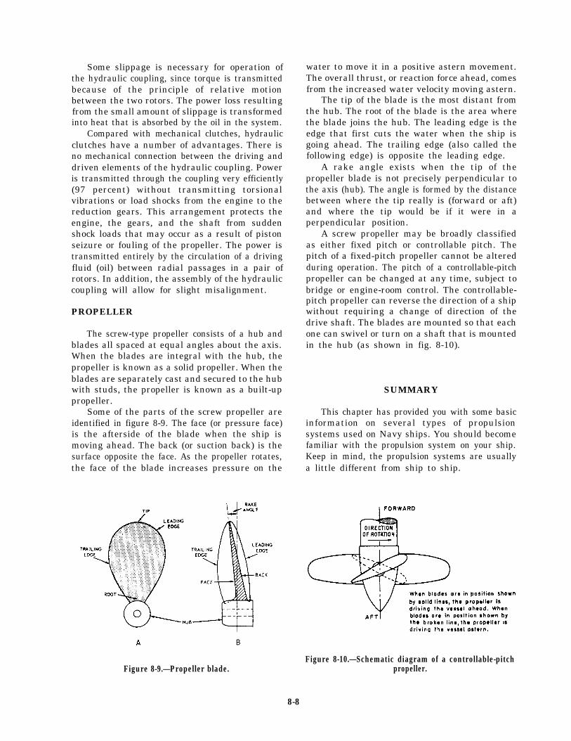
Some slippage is necessary for operation ofthe hydraulic coupling, since torque is transmittedbecause of the principle of relative motionbetween the two rotors. The power loss resultingfrom the small amount of slippage is transformedinto heat that is absorbed by the oil in the system.
Compared with mechanical clutches, hydraulicclutches have a number of advantages. There isno mechanical connection between the driving anddriven elements of the hydraulic coupling. Poweris transmitted through the coupling very efficiently(97 percent) without transmitting torsionalvibrations or load shocks from the engine to thereduction gears. This arrangement protects theengine, the gears, and the shaft from suddenshock loads that may occur as a result of pistonseizure or fouling of the propeller. The power istransmitted entirely by the circulation of a drivingfluid (oil) between radial passages in a pair ofrotors. In addition, the assembly of the hydrauliccoupling will allow for slight misalignment.
PROPELLER
The screw-type propeller consists of a hub andblades all spaced at equal angles about the axis.When the blades are integral with the hub, thepropeller is known as a solid propeller. When theblades are separately cast and secured to the hubwith studs, the propeller is known as a built-uppropeller.
Some of the parts of the screw propeller areidentified in figure 8-9. The face (or pressure face)is the afterside of the blade when the ship ismoving ahead. The back (or suction back) is thesurface opposite the face. As the propeller rotates,the face of the blade increases pressure on the
Figure 8-9.—Propeller blade.
water to move it in a positive astern movement.The overall thrust, or reaction force ahead, comesfrom the increased water velocity moving astern.
The tip of the blade is the most distant fromthe hub. The root of the blade is the area wherethe blade joins the hub. The leading edge is theedge that first cuts the water when the ship isgoing ahead. The trailing edge (also called thefollowing edge) is opposite the leading edge.
A rake angle exists when the tip of thepropeller blade is not precisely perpendicular tothe axis (hub). The angle is formed by the distancebetween where the tip really is (forward or aft)and where the tip would be if it were in aperpendicular position.
A screw propeller may be broadly classifiedas either fixed pitch or controllable pitch. Thepitch of a fixed-pitch propeller cannot be alteredduring operation. The pitch of a controllable-pitchpropeller can be changed at any time, subject tobridge or engine-room control. The controllable-pitch propeller can reverse the direction of a shipwithout requiring a change of direction of thedrive shaft. The blades are mounted so that eachone can swivel or turn on a shaft that is mountedin the hub (as shown in fig. 8-10).
SUMMARY
This chapter has provided you with some basicinformation on several types of propulsionsystems used on Navy ships. You should becomefamiliar with the propulsion system on your ship.Keep in mind, the propulsion systems are usuallya little different from ship to ship.
Figure 8-10.—Schematic diagram of a controllable-pitchpropeller.
8-8

CHAPTER 9
PUMPS, VALVES, AND PIPING
As a Fireman, you must have a generalknowledge of the basic operating principles ofvarious types of pumps and supporting com-ponents, such as the different types of valves andpiping used aboard ships.
Aboard ship, pumps, valves, and piping areused for a number of essential services. Theysupply water to the boilers, draw condensate fromthe condensers, supply seawater to the firemain,circulate cooling water for coolers and condensers,pump out bilges, transfer fuel oil, supply seawaterto the distilling plants, and are used for manyother purposes. The operation of the ship’spropulsion plant and of almost all the auxiliarymachinery depends on the proper operation ofpumps. Although most plants have two pumps,a main pump and a standby pump, pump failuremay cause failure of an entire power plant.
With the knowledge gained in this chapter,you should be able to describe pumps, valves, andpiping systems in terms of their construction,function, and operation. The information in thischapter, as it is throughout the book, is of abroad and general nature. You should refer to theappropriate manufacturer’s technical manualsand/or ship’s plans, information books, and plantor valve manuals for specific problems withindividual equipment. By studying this material,you should be able to relate to the specificequipment found on your ship.
PUMPS
Pumps are vitally important to the operationof your ship. If they fail, the power plant theyserve also fails. In an emergency, pump failurescan prove disastrous. Maintaining pumps in anefficient working order is a very important taskof the engineering department. As a Fireman, youmust have a general knowledge of the basic
operating principles of the various types of pumpsused by the Navy.
It is not practical or necessary to mention allof the various locations where pumps are foundaboard ship. You will learn their location andoperation as you perform your duties. The pumpswith which you are primarily concerned are usedfor such purposes as
. providing fuel oil to the prime mover,
. circulating lubricating (lube) oil to thebearings and gears of the MRG,
. supplying seawater for the coolers inengineering spaces,
. pumping out the bilges, and
. transferring fuel oil to various storage andservice tanks.
CLASSIFICATION OF PUMPS
Pumps aboard ship outnumber all otherauxiliary machinery units. They include such typesas centrifugal, rotary, and jet pumps. In thefollowing section we discuss these different pumpsand their application to the engineering plant.
Centrifugal Pumps
Aboard gas turbine ships, centrifugal pumpsof various sizes are driven by electric motors tomove different types of liquid. The fire pump andseawater service pump are two examples of thistype of pump.
A basic centrifugal pump has an impellerkeyed to a drive shaft, which is rotated by anelectric motor. The drive shaft is fitted inside acasing, which has a suction inlet and a discharge
9-1

Figure 9-1.—Centrifugal pump.
outlet. Figure 9-1 shows the arrangement ofcomponents in a centrifugal pump.
CENTRIFUGAL PUMP CLASSIFICATION.—Centrifugal pumps may be classified in severalways. For example, they may be either single-stageor multistage. A single-stage pump has only oneimpeller; a multistage pump has two or moreimpellers housed together in one casing. In amultistage pump, each impeller usually actsseparately, discharging to the suction of the next-stage impeller. Centrifugal pumps are alsoclassified as horizontal or vertical, depending onthe position of the pump shaft.
Impellers used in centrifugal pumps may beclassified as single-suction or double-suction,depending on the way in which liquid enters theeye of the impeller. Figure 9-2 shows single-suction and double-suction arrangements ofcentrifugal pump impellers. The single-suctionimpeller (view A) allows liquid to enter the eyefrom one side only; the double-suction impeller(view B) allows liquid to enter the eye from bothsides. The double-suction arrangement has theadvantage of balancing the end thrust in onedirection with the end thrust in the otherdirection.
Impellers are also classified as CLOSED orOPEN. A closed impeller has side walls thatextend from the eye to the outer edge of the vanetips; an open impeller does not have side walls.Most centrifugal pumps used in the Navy haveclosed impellers.
CONSTRUCTION.— As a rule, the casing forthe liquid end of a pump with a single-suctionimpeller is made with an end plate that can beremoved for inspection and repair of the pump.A pump with a double-suction impeller is generally
made so one-half of the casing may be liftedwithout disturbing the pump.
Since an impeller rotates at high speed, it mustbe carefully machined to minimize friction. Animpeller must be balanced to avoid vibration. Aclose radial clearance must be maintained between
Figure 9-2.—Centrifugal pump impellers. A. Single-suction.B. Double-suction.
9-2

the outer hub of the impeller and that part ofthe pump casing in which the hub rotates. Thepurpose of this is to minimize leakage from thedischarge side of the pump casing to the suctionside.
Because of the high rotational speed of theimpeller and the necessarily close clearance, therubbing surfaces of both the impeller hub and thecasing at that point are subject to stress, causingrapid wear. To eliminate the need for replacingan entire impeller and pump casing solely becauseof wear in this location, most centrifugal pumpsare designed with replaceable casing wearing rings.
In most centrifugal pumps, the shaft is fittedwith a replaceable sleeve. The advantage ofusing a sleeve is that it can be replaced moreeconomically than the entire shaft.
Mechanical seals and stuffing boxes are usedto seal between the shaft and the casing. Mostpumps are now furnished with mechanical seals;mechanical seals do not result in better pumpoperation; but, they do provide a better environ-ment, keep bilges dry, and preserve the liquidbeing pumped.
Seal piping (liquid seal) is installed to cool themechanical seal. Most pumps in saltwater servicewith total head of 30 psi or more are also fittedwith cyclone separators. These separators usecentrifugal force to prevent abrasive material(such as sand in the seawater) from passingbetween the sealing surfaces of the mechanicalseal. There is an opening at each end of theseparator. The opening at the top is for “clean”water, which is directed though tubing to themechanical seals in the pump. The high-velocity“dirty” water is directed through the bottom ofthe separator, back to the inlet piping for thepump.
Figure 9-3.—Centrifugal pump flow.
Bearings support the weight of the impellerand shaft and maintain the position of theimpeller—both radially and axially. Some bearingsare grease-lubricated with grease cups to allow forperiodic relubrication.
The power end of the centrifugal pump youare to work with has an electric motor that ismaintained by your ship’s Electrician’s Mate.
OPERATION.— Liquid enters the rotatingimpeller on the suction side of the casing andenters the eye of the impeller (fig. 9-3). Liquidis thrown out through the opening around theedge of the impeller and against the side of thecasing by centrifugal force. This is where thepump got its name. When liquid is thrown outto the edge of the casing, a region of low pressure(below atmospheric) is created around the centerof the impeller; more liquid moves into the eyeto replace the liquid that was thrown out. Liquidmoves into the center of the impeller with a highvelocity (speed). Therefore, liquid in the centerof the impeller has a low pressure, but it ismoving at a high velocity.
Liquid moving between the blades of theimpeller spreads out, which causes the liquid toslow down. (Its velocity decreases.) At the sametime, as the liquid moves closer to the edge of thecasing, the pressure of the liquid increases. Thischange (from low pressure and high velocity atthe center to high pressure and low velocity at theedge) is caused by the shape of the openingbetween the impeller blades. This space has theshape of a diffuser, a device that causes thevelocity-pressure relationship of any fluid thatmoves through it to change.
A centrifugal pump is considered to be anonpositive-displacement pump because thevolume of liquid discharged from the pumpchanges whenever the pressure head changes. Thepressure head is the combined effect of liquidweight, fluid friction, and obstruction to flow. Ina centrifugal pump, the force of the dischargepressure of the pump must be able to overcomethe force of the pressure head; otherwise, thepump could not deliver any liquid to a pipingsystem. The pressure head and the dischargepressure of a centrifugal pump oppose each other.When the pressure head increases, the dischargepressure of the pump must also increase. Sinceno energy can be lost, when the discharge pressureof the pump increases, the velocity of flow mustdecrease. On the other hand, when the pressurehead decreases, the volume of liquid dischargedfrom the pump increases. As a general rule, a
9-3
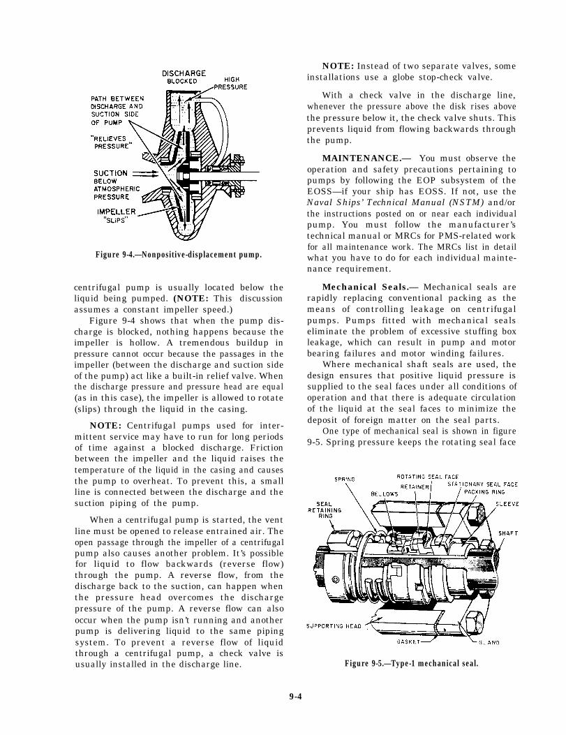
Figure 9-4.—Nonpositive-displacement pump.
centrifugal pump is usually located below theliquid being pumped. (NOTE: This discussionassumes a constant impeller speed.)
Figure 9-4 shows that when the pump dis-charge is blocked, nothing happens because theimpeller is hollow. A tremendous buildup inpressure cannot occur because the passages in theimpeller (between the discharge and suction sideof the pump) act like a built-in relief valve. Whenthe discharge pressure and pressure head are equal(as in this case), the impeller is allowed to rotate(slips) through the liquid in the casing.
NOTE: Centrifugal pumps used for inter-mittent service may have to run for long periodsof time against a blocked discharge. Frictionbetween the impeller and the liquid raises thetemperature of the liquid in the casing and causesthe pump to overheat. To prevent this, a smallline is connected between the discharge and thesuction piping of the pump.
When a centrifugal pump is started, the ventline must be opened to release entrained air. Theopen passage through the impeller of a centrifugalpump also causes another problem. It’s possiblefor liquid to flow backwards (reverse flow)through the pump. A reverse flow, from thedischarge back to the suction, can happen whenthe pressure head overcomes the dischargepressure of the pump. A reverse flow can alsooccur when the pump isn’t running and anotherpump is delivering liquid to the same pipingsystem. To prevent a reverse flow of liquidthrough a centrifugal pump, a check valve isusually installed in the discharge line.
NOTE: Instead of two separate valves, someinstallations use a globe stop-check valve.
With a check valve in the discharge line,whenever the pressure above the disk rises abovethe pressure below it, the check valve shuts. Thisprevents liquid from flowing backwards throughthe pump.
MAINTENANCE.— You must observe theoperation and safety precautions pertaining topumps by following the EOP subsystem of theEOSS—if your ship has EOSS. If not, use theNaval Ships’ Technical Manual (NSTM) and/orthe instructions posted on or near each individualpump. You must follow the manufacturer’stechnical manual or MRCs for PMS-related workfor all maintenance work. The MRCs list in detailwhat you have to do for each individual mainte-nance requirement.
Mechanical Seals.— Mechanical seals arerapidly replacing conventional packing as themeans of controlling leakage on centrifugalpumps. Pumps fitted with mechanical sealseliminate the problem of excessive stuffing boxleakage, which can result in pump and motorbearing failures and motor winding failures.
Where mechanical shaft seals are used, thedesign ensures that positive liquid pressure issupplied to the seal faces under all conditions ofoperation and that there is adequate circulationof the liquid at the seal faces to minimize thedeposit of foreign matter on the seal parts.
One type of mechanical seal is shown in figure9-5. Spring pressure keeps the rotating seal face
Figure 9-5.—Type-1 mechanical seal.
9-4
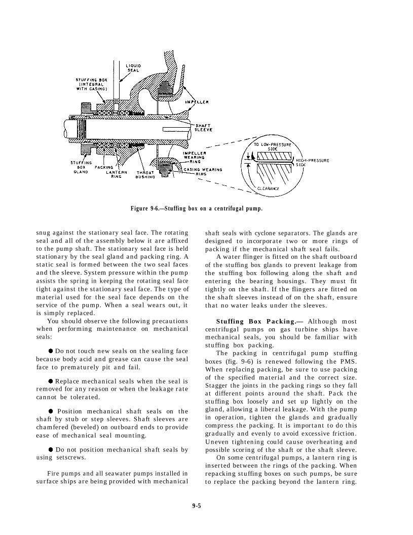
Figure 9-6.—Stuffing box on a centrifugal pump.
snug against the stationary seal face. The rotatingseal and all of the assembly below it are affixedto the pump shaft. The stationary seal face is heldstationary by the seal gland and packing ring. Astatic seal is formed between the two seal facesand the sleeve. System pressure within the pumpassists the spring in keeping the rotating seal facetight against the stationary seal face. The type ofmaterial used for the seal face depends on theservice of the pump. When a seal wears out, itis simply replaced.
You should observe the following precautionswhen performing maintenance on mechanicalseals:
. Do not touch new seals on the sealing facebecause body acid and grease can cause the sealface to prematurely pit and fail.
. Replace mechanical seals when the seal isremoved for any reason or when the leakage ratecannot be tolerated.
. Position mechanical shaft seals on theshaft by stub or step sleeves. Shaft sleeves arechamfered (beveled) on outboard ends to provideease of mechanical seal mounting.
. Do not position mechanical shaft seals byusing setscrews.
Fire pumps and all seawater pumps installed insurface ships are being provided with mechanical
shaft seals with cyclone separators. The glands aredesigned to incorporate two or more rings ofpacking if the mechanical shaft seal fails.
A water flinger is fitted on the shaft outboardof the stuffing box glands to prevent leakage fromthe stuffing box following along the shaft andentering the bearing housings. They must fittightly on the shaft. If the flingers are fitted onthe shaft sleeves instead of on the shaft, ensurethat no water leaks under the sleeves.
Stuffing Box Packing.— Although mostcentrifugal pumps on gas turbine ships havemechanical seals, you should be familiar withstuffing box packing.
The packing in centrifugal pump stuffingboxes (fig. 9-6) is renewed following the PMS.When replacing packing, be sure to use packingof the specified material and the correct size.Stagger the joints in the packing rings so they fallat different points around the shaft. Pack thestuffing box loosely and set up lightly on thegland, allowing a liberal leakage. With the pumpin operation, tighten the glands and graduallycompress the packing. It is important to do thisgradually and evenly to avoid excessive friction.Uneven tightening could cause overheating andpossible scoring of the shaft or the shaft sleeve.
On some centrifugal pumps, a lantern ring isinserted between the rings of the packing. Whenrepacking stuffing boxes on such pumps, be sureto replace the packing beyond the lantern ring.
9-5
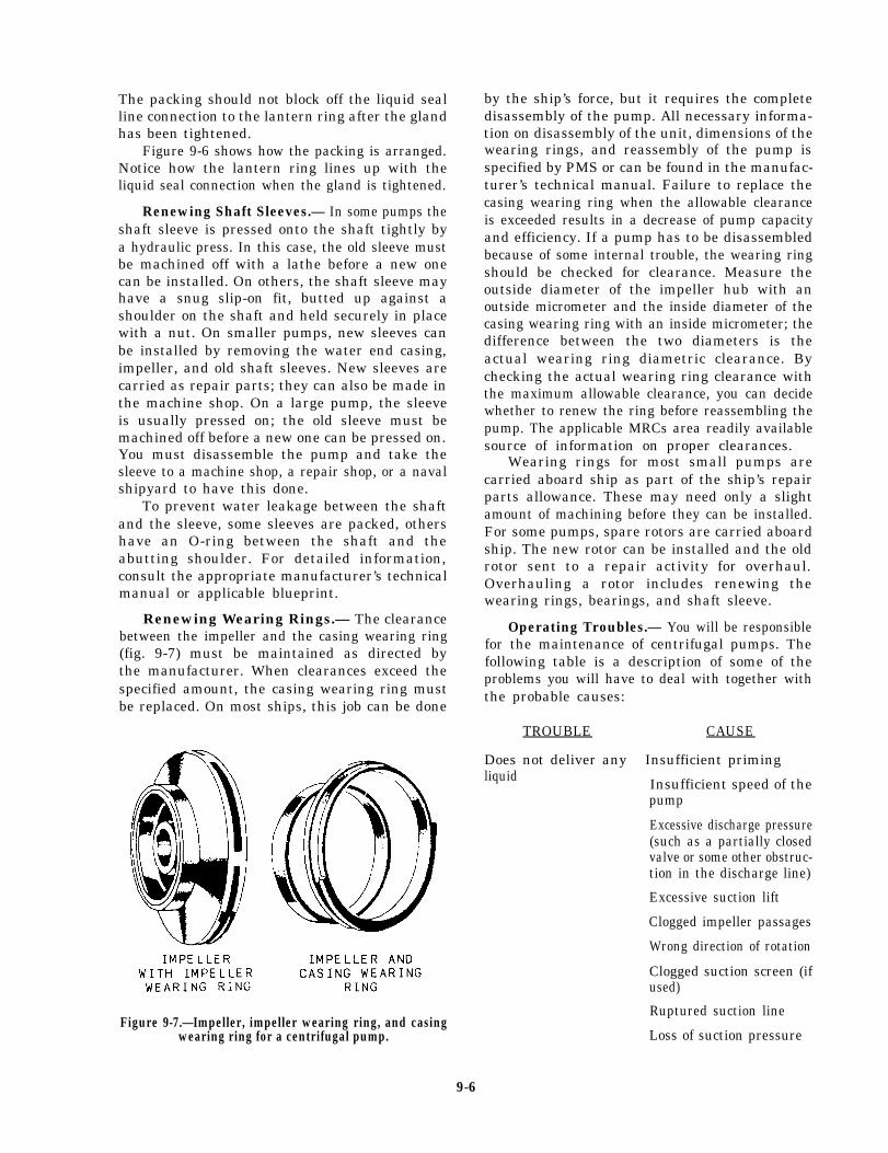
The packing should not block off the liquid sealline connection to the lantern ring after the glandhas been tightened.
Figure 9-6 shows how the packing is arranged.Notice how the lantern ring lines up with theliquid seal connection when the gland is tightened.
Renewing Shaft Sleeves.— In some pumps theshaft sleeve is pressed onto the shaft tightly bya hydraulic press. In this case, the old sleeve mustbe machined off with a lathe before a new onecan be installed. On others, the shaft sleeve mayhave a snug slip-on fit, butted up against ashoulder on the shaft and held securely in placewith a nut. On smaller pumps, new sleeves canbe installed by removing the water end casing,impeller, and old shaft sleeves. New sleeves arecarried as repair parts; they can also be made inthe machine shop. On a large pump, the sleeveis usually pressed on; the old sleeve must bemachined off before a new one can be pressed on.You must disassemble the pump and take thesleeve to a machine shop, a repair shop, or a navalshipyard to have this done.
To prevent water leakage between the shaftand the sleeve, some sleeves are packed, othershave an O-ring between the shaft and theabutting shoulder. For detailed information,consult the appropriate manufacturer’s technicalmanual or applicable blueprint.
Renewing Wearing Rings.— The clearancebetween the impeller and the casing wearing ring(fig. 9-7) must be maintained as directed bythe manufacturer. When clearances exceed thespecified amount, the casing wearing ring mustbe replaced. On most ships, this job can be done
by the ship’s force, but it requires the completedisassembly of the pump. All necessary informa-tion on disassembly of the unit, dimensions of thewearing rings, and reassembly of the pump isspecified by PMS or can be found in the manufac-turer’s technical manual. Failure to replace thecasing wearing ring when the allowable clearanceis exceeded results in a decrease of pump capacityand efficiency. If a pump has to be disassembledbecause of some internal trouble, the wearing ringshould be checked for clearance. Measure theoutside diameter of the impeller hub with anoutside micrometer and the inside diameter of thecasing wearing ring with an inside micrometer; thedifference between the two diameters is theactual wearing ring diametric clearance. Bychecking the actual wearing ring clearance withthe maximum allowable clearance, you can decidewhether to renew the ring before reassembling thepump. The applicable MRCs area readily availablesource of information on proper clearances.
Wearing rings for most small pumps arecarried aboard ship as part of the ship’s repairparts allowance. These may need only a slightamount of machining before they can be installed.For some pumps, spare rotors are carried aboardship. The new rotor can be installed and the oldrotor sent to a repair activity for overhaul.Overhauling a rotor includes renewing thewearing rings, bearings, and shaft sleeve.
Operating Troubles.— You will be responsiblefor the maintenance of centrifugal pumps. Thefollowing table is a description of some of theproblems you will have to deal with together withthe probable causes:
TROUBLE CAUSE
Does not deliver any Insufficient primingliquid Insufficient speed of the
pump
Excessive discharge pressure(such as a partially closedvalve or some other obstruc-tion in the discharge line)
Excessive suction lift
Clogged impeller passages
Wrong direction of rotation
Clogged suction screen (ifused)
Figure 9-7.—Impeller, impeller wearing ring, and casingwearing ring for a centrifugal pump.
Ruptured suction line
Loss of suction pressure
9-6
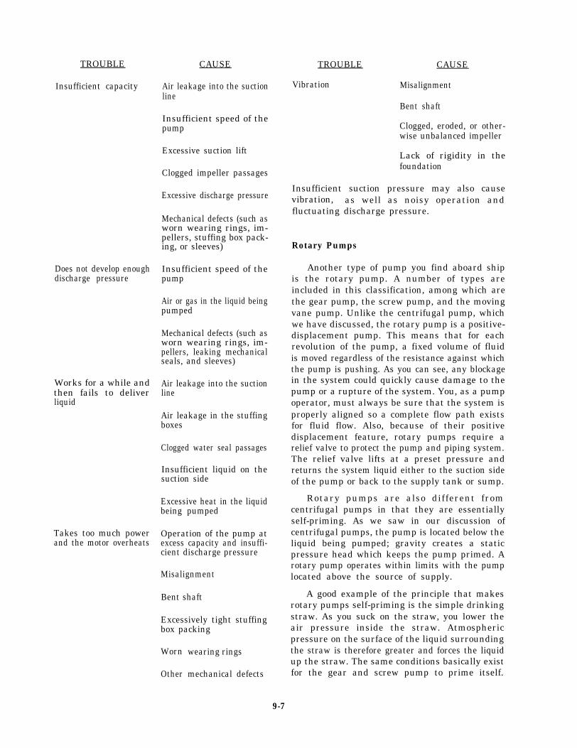
TROUBLE
Insufficient capacity
Does not develop enoughdischarge pressure
Works for a while andthen fails to deliverliquid
Takes too much powerand the motor overheats
CAUSE
Air leakage into the suctionline
Insufficient speed of thepump
Excessive suction lift
Clogged impeller passages
Excessive discharge pressure
Mechanical defects (such asworn wearing rings, im-pellers, stuffing box pack-ing, or sleeves)
Insufficient speed of thepump
Air or gas in the liquid beingpumped
Mechanical defects (such asworn wearing rings, im-pellers, leaking mechanicalseals, and sleeves)
Air leakage into the suctionline
Air leakage in the stuffingboxes
Clogged water seal passages
Insufficient liquid on thesuction side
Excessive heat in the liquidbeing pumped
Operation of the pump atexcess capacity and insuffi-cient discharge pressure
Misalignment
Bent shaft
Excessively tight stuffingbox packing
Worn
Other
wearing rings
mechanical defects
TROUBLE CAUSE
Vibration Misalignment
Bent shaft
Clogged, eroded, or other-wise unbalanced impeller
Lack of rigidity in thefoundation
Insufficient suction pressure may also causevibration, as well as noisy operation andfluctuating discharge pressure.
Rotary Pumps
Another type of pump you find aboard shipis the rotary pump. A number of types areincluded in this classification, among which arethe gear pump, the screw pump, and the movingvane pump. Unlike the centrifugal pump, whichwe have discussed, the rotary pump is a positive-displacement pump. This means that for eachrevolution of the pump, a fixed volume of fluidis moved regardless of the resistance against whichthe pump is pushing. As you can see, any blockagein the system could quickly cause damage to thepump or a rupture of the system. You, as a pumpoperator, must always be sure that the system isproperly aligned so a complete flow path existsfor fluid flow. Also, because of their positivedisplacement feature, rotary pumps require arelief valve to protect the pump and piping system.The relief valve lifts at a preset pressure andreturns the system liquid either to the suction sideof the pump or back to the supply tank or sump.
Rotary pumps are also different fromcentrifugal pumps in that they are essentiallyself-priming. As we saw in our discussion ofcentrifugal pumps, the pump is located below theliquid being pumped; gravity creates a staticpressure head which keeps the pump primed. Arotary pump operates within limits with the pumplocated above the source of supply.
A good example of the principle that makesrotary pumps self-priming is the simple drinkingstraw. As you suck on the straw, you lower theair pressure inside the straw. Atmosphericpressure on the surface of the liquid surroundingthe straw is therefore greater and forces the liquidup the straw. The same conditions basically existfor the gear and screw pump to prime itself.
9-7

Figure 9-8.—Gear pump located above the tank.
Figure 9-8 shows a gear pump located above thetank. The tank must be vented to allow air intothe tank to provide atmospheric pressure on thesurface of the liquid. To lower the pressure onthe suction side of the pump, the clearancesbetween the pump parts must be close enough topump air. When the pump starts, the air ispumped through the discharge side of the pumpand creates the low-pressure area on the suctionside, which allows the atmospheric pressure toforce the liquid up the pipe to the pump. Tooperate properly, the piping leading to the pumpmust have no leaks or it will draw in air and canlose its prime.
Rotary pumps are useful for pumping oil andother heavy viscous liquids. In the engine room,rotary pumps are used for handling lube oil andfuel oil and are suitable for handling liquids overa wide range of viscosities.
Rotary pumps are designed with very smallclearances between rotating parts and stationaryparts to minimize leakage (slippage) from thedischarge side back to the suction side. Rotarypumps are designed to operate at relatively slowspeeds to maintain these clearances; operation athigher speeds causes erosion and excessive wear,which result in increased clearances with asubsequent decrease in pumping capacity.
Classification of rotary pumps is generallybased on the types of rotating element. In thefollowing paragraphs, the main features of somecommon types of rotary pumps are described.
GEAR PUMPS.— The simple gear pump(fig. 9-9) has two spur gears that mesh togetherand revolve in opposite directions. One is thedriving gear, and the other is the driven gear.Clearances between the gear teeth (outsidediameter of the gear) and the casing and betweenthe end face and the casing are only a fewthousandths of an inch. As the gears turn, thegears unmesh and liquid flows into the pocketsthat are vacated by the meshing gear teeth. Thiscreates the suction that draws the liquid into thepump. The liquid is then carried along in thepockets formed by the gear teeth and the casing.On the discharge side, the liquid is displaced bythe meshing of the gears and forced out throughthe discharge side of the pump.
One example of the use of a gear pump is inthe LM2500 engine fuel pump. However, gearpumps are not used extensively on gas turbineships.
Figure 9-9.—Simple gear pump.
9-8

pumps are used aboard ship to pump fuel and lubeoil and to supply pressure to the hydraulic system.In the double-screw pump, one rotor is driven bythe drive shaft and the other by a set of timinggears. In the triple-screw pump, a central rotormeshes with two idler rotors.
In the screw pump, liquid is trapped andforced through the pump by the action of rotatingscrews. As the rotor turns, the liquid flows inbetween the threads at the outer end of each pairof screws. The threads carry the liquid alongwithin the housing to the center of the pumpwhere it is discharged.
Most screw pumps are now equipped withmechanical seals. If the mechanical seal fails, thestuffing box has the capability of accepting tworings of conventional packing for emergency use.
Figure 9-10.—Double-screw, low-pitch pump.
Figure 9-11.—Triple-screw, high-pitch pump.
SCREW PUMPS.— Several different types ofscrew pumps exist. The differences between thevarious types are the number of intermeshingscrews and the pitch of the screws. Figure 9-10shows a double-screw, low-pitch pump; and figure9-11 shows a triple-screw, high-pitch pump. Screw
SLIDING VANE PUMPS.— The sliding-vanepump (fig. 9-12) has a cylindrically bored housingwith a suction inlet on one side and a dischargeoutlet on the other side. A rotor (smaller indiameter than the cylinder) is driven about an axisthat is so placed above the center line of thecylinder as to provide minimum clearance betweenthe rotor and cylinder at the top and maximumclearance at the bottom.
The rotor carries vanes (which move in andout as the rotor rotates) to maintain sealed spacesbetween the rotor and the cylinder wall. The vanestrap liquid on the suction side and carry it to thedischarge side, where contraction of the spaceexpels liquid through the discharge line. The vanesslide on slots in the rotor. Vane pumps are usedfor lube oil service and transfer, tank stripping,bilge, aircraft fueling and defueling and, ingeneral, for handling lighter viscous liquids.
Figure 9-12.—Sliding vane pump.
9-9
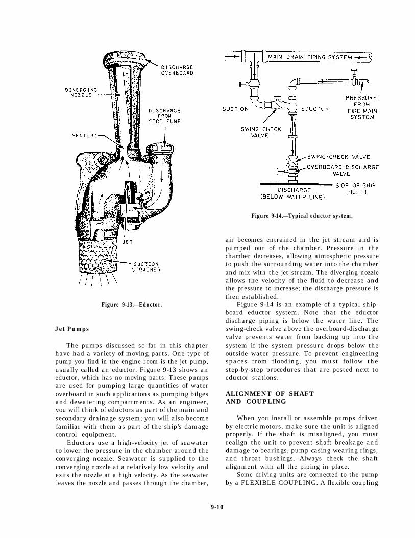
Figure 9-13.—Eductor.
Jet Pumps
The pumps discussed so far in this chapterhave had a variety of moving parts. One type ofpump you find in the engine room is the jet pump,usually called an eductor. Figure 9-13 shows aneductor, which has no moving parts. These pumpsare used for pumping large quantities of wateroverboard in such applications as pumping bilgesand dewatering compartments. As an engineer,you will think of eductors as part of the main andsecondary drainage system; you will also becomefamiliar with them as part of the ship’s damagecontrol equipment.
Eductors use a high-velocity jet of seawaterto lower the pressure in the chamber around theconverging nozzle. Seawater is supplied to theconverging nozzle at a relatively low velocity andexits the nozzle at a high velocity. As the seawaterleaves the nozzle and passes through the chamber,
Figure 9-14.—Typical eductor system.
air becomes entrained in the jet stream and ispumped out of the chamber. Pressure in thechamber decreases, allowing atmospheric pressureto push the surrounding water into the chamberand mix with the jet stream. The diverging nozzleallows the velocity of the fluid to decrease andthe pressure to increase; the discharge pressure isthen established.
Figure 9-14 is an example of a typical ship-board eductor system. Note that the eductordischarge piping is below the water line. Theswing-check valve above the overboard-dischargevalve prevents water from backing up into thesystem if the system pressure drops below theoutside water pressure. To prevent engineeringspaces from flooding, you must follow thestep-by-step procedures that are posted next toeductor stations.
ALIGNMENT OF SHAFTAND COUPLING
When you install or assemble pumps drivenby electric motors, make sure the unit is alignedproperly. If the shaft is misaligned, you mustrealign the unit to prevent shaft breakage anddamage to bearings, pump casing wearing rings,and throat bushings. Always check the shaftalignment with all the piping in place.
Some driving units are connected to the pumpby a FLEXIBLE COUPLING. A flexible coupling
9-10

Figure 9-15.—Grid-type flexible coupling.
(fig. 9-15) is intended to take care of only a slightmisalignment. Misalignment should never exceedthe amount specified by the pump manufacturer.If the misalignment is excessive, the coupling partsare subjected to severe punishment, necessitatingfrequent replacement of pins, bushings, andbearings. It is absolutely necessary to have the
rotating shafts of the driver and driven units inproper alignment. Figure 9-16 shows couplingalignment.
You should check the shaft alignment whenthe pump is opened for repair or maintenance,or if a noticeable vibration occurs. You mustrealign the unit if the shafts are out of lineor inclined at an angle to each other. Wheneverpracticable, check the alignment with all pipingin place and with the adjacent tanks and pipingfilled.
When the driving unit is connected to thepump by a FLANGE COUPLING, the shaftingmay require frequent realignment, which may beindicated by high temperatures, noises, and wornbearings or bushings.
Wedges, or shims, are sometimes placed underthe bases of both the driven and driving units (fig.9-16, view A) for ease in alignment when themachinery is installed. When the wedges or otherpacking have been adjusted so the outsidediameters and faces of the coupling flanges runtrue as they are manually revolved, the chocks arefastened, the units are securely bolted to thefoundation, and the coupling flanges are boltedtogether.
The faces of the coupling flanges should bechecked at 90-degree intervals. This method isshown in figure 9-16, view B. Find the distancesbetween the faces at point a, point b (on the
Figure 9-16.—Coupling alignment.
9-11
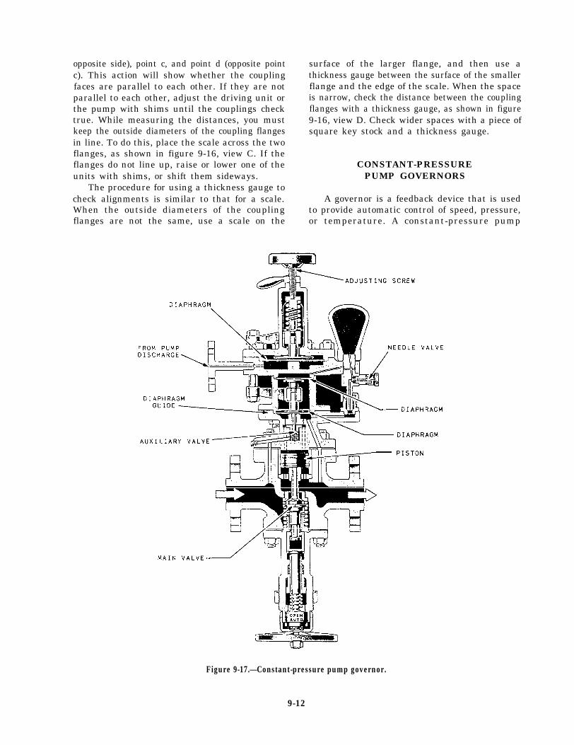
opposite side), point c, and point d (opposite pointc). This action will show whether the couplingfaces are parallel to each other. If they are notparallel to each other, adjust the driving unit orthe pump with shims until the couplings checktrue. While measuring the distances, you mustkeep the outside diameters of the coupling flangesin line. To do this, place the scale across the twoflanges, as shown in figure 9-16, view C. If theflanges do not line up, raise or lower one of theunits with shims, or shift them sideways.
The procedure for using a thickness gauge tocheck alignments is similar to that for a scale.When the outside diameters of the couplingflanges are not the same, use a scale on the
surface of the larger flange, and then use athickness gauge between the surface of the smallerflange and the edge of the scale. When the spaceis narrow, check the distance between the couplingflanges with a thickness gauge, as shown in figure9-16, view D. Check wider spaces with a piece ofsquare key stock and a thickness gauge.
CONSTANT-PRESSUREPUMP GOVERNORS
A governor is a feedback device that is usedto provide automatic control of speed, pressure,or temperature. A constant-pressure pump
Figure 9-17.—Constant-pressure pump governor.
9-12

governor maintains a constant discharge pressure,regardless of pump capacity or output. Mostconstant-pressure pump governors used in theNavy control steam-driven pumps, both rotaryand centrifugal types.
The constant-pressure pump governor (some-times referred to as pressure-regulating) consistsessentially of an automatic throttling valveinstalled in the steam supply line to the pump’sdriving unit. A pipeline connects the governor tothe pump’s discharge line. Variations in dischargepressure, or in pressure differential, actuatethe governor, causing it to regulate the pumpspeed by varying the flow of steam to the drivingunit.
A constant-pressure pump governor for alubricating oil service pump is shown in figure9-17. The governors used on fuel oil servicepumps and on main feed pumps are of the sametype. The size of the upper diaphragm and theamount of spring tension vary on governorsused for different services. You will finddetailed information concerning the operation andadjustment of governors in chapter 503 of theNSTM.
VALVES
A valve is any device used to control fluidsin a closed system. In this section we will discussvalve construction and the most common typesof valves you will use in the day-to-day operationand maintenance of the various shipboardengineering systems. Valves are typed or classifiedaccording to their use in a system.
VALVE CONSTRUCTION
Valves are usually made of bronze, brass,cast or malleable iron, or steel. Steel valvesare either cast or forged and are made of eitherplain steel or alloy steel. Alloy steel valves areused in high-pressure, high-temperature systems;the disks and seats (internal sealing surfaces) ofthese valves are usually surfaced with a chromium-cobalt alloy known as Stellite. Stellite is extremelyhard.
Brass and bronze valves are never used insystems where temperatures exceed 550°F. Steel
valves are used for all services above 550°F andin lower temperature systems where internal orexternal conditions of high pressure, vibration,or shock would be too severe for valves madeof brass or bronze. Bronze valves are usedalmost exclusively in systems that carry saltwater. The seats and disks of these valvesare usually made of Monel, a metal thathas excellent corrosion- and erosion-resistantqualities.
Most submarine seawater valves are made ofan alloy of 70 percent copper to 30 percent nickel(70/30).
VALVE TYPES
Although many different types of valves areused to control the flow of fluids, the basic valvetypes can be divided into two general groups: stopvalves and check valves.
Besides the basic types of valves, manyspecial valves, which cannot really be classifiedas either stop valves or check valves, arefound in the engineering spaces. Many of thesevalves serve to control the pressure of fluidsand are known as pressure-control valves. Othervalves are identified by names that indicatetheir general function, such as thermostaticrecirculating valves. The following sectionsdeal first with the basic types of stop valvesand check valves, then with some of the morecomplicated special valves.
Stop Valves
Stop valves are used to shut off or, insome cases, partially shut off the flow of fluid.Stop valves are controlled by the movement ofthe valve stem. Stop valves can be divided intofour general categories: globe, gate, butterfly, andball valves. Plug valves and needle valves may alsobe considered stop valves.
GLOBE VALVES.— Globe valves are probablythe most common valves in existence. The globevalve derives its name from the globular shape ofthe valve body. However, positive identificationof a globe valve must be made internally becauseother valve types may have globular appearingbodies. Globe valve inlet and outlet openingsare arranged in several ways to suit varying
9-13
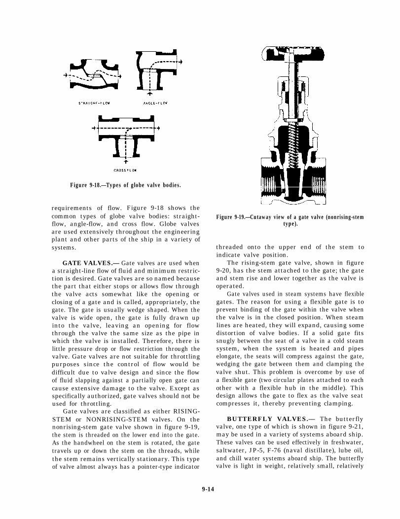
Figure 9-18.—Types of globe valve bodies.
requirements of flow. Figure 9-18 shows thecommon types of globe valve bodies: straight-flow, angle-flow, and cross flow. Globe valvesare used extensively throughout the engineeringplant and other parts of the ship in a variety ofsystems.
GATE VALVES.— Gate valves are used whena straight-line flow of fluid and minimum restric-tion is desired. Gate valves are so named becausethe part that either stops or allows flow throughthe valve acts somewhat like the opening orclosing of a gate and is called, appropriately, thegate. The gate is usually wedge shaped. When thevalve is wide open, the gate is fully drawn upinto the valve, leaving an opening for flowthrough the valve the same size as the pipe inwhich the valve is installed. Therefore, there islittle pressure drop or flow restriction through thevalve. Gate valves are not suitable for throttlingpurposes since the control of flow would bedifficult due to valve design and since the flowof fluid slapping against a partially open gate cancause extensive damage to the valve. Except asspecifically authorized, gate valves should not beused for throttling.
Gate valves are classified as either RISING-STEM or NONRISING-STEM valves. On thenonrising-stem gate valve shown in figure 9-19,the stem is threaded on the lower end into the gate.As the handwheel on the stem is rotated, the gatetravels up or down the stem on the threads, whilethe stem remains vertically stationary. This typeof valve almost always has a pointer-type indicator
Figure 9-19.—Cutaway view of a gate valve (nonrising-stemtype).
threaded onto the upper end of the stem toindicate valve position.
The rising-stem gate valve, shown in figure9-20, has the stem attached to the gate; the gateand stem rise and lower together as the valve isoperated.
Gate valves used in steam systems have flexiblegates. The reason for using a flexible gate is toprevent binding of the gate within the valve whenthe valve is in the closed position. When steamlines are heated, they will expand, causing somedistortion of valve bodies. If a solid gate fitssnugly between the seat of a valve in a cold steamsystem, when the system is heated and pipeselongate, the seats will compress against the gate,wedging the gate between them and clamping thevalve shut. This problem is overcome by use ofa flexible gate (two circular plates attached to eachother with a flexible hub in the middle). Thisdesign allows the gate to flex as the valve seatcompresses it, thereby preventing clamping.
BUTTERFLY VALVES.— The butterflyvalve, one type of which is shown in figure 9-21,may be used in a variety of systems aboard ship.These valves can be used effectively in freshwater,saltwater, JP-5, F-76 (naval distillate), lube oil,and chill water systems aboard ship. The butterflyvalve is light in weight, relatively small, relatively
9-14

Figure 9-20.—Cutaway view of a gate valve (rising-stemtype).
Figure 9-21.—Butterfly valve.
quick-acting, provides positive shut-off, and canbe used for throttling.
The butterfly valve has a body, a resilient seat,a butterfly disk, a stem, packing, a notchedpositioning plate, and a handle. The resilient seat
is under compression when it is mounted in thevalve body, thus making a seal around theperiphery of the disk and both upper and lowerpoints where the stem passes through the seat.Packing is provided to form a positive seal aroundthe stem for added protection in case the sealformed by the seat should become damaged.
To close or open a butterfly valve, turn thehandle only one quarter turn to rotate thedisk 90°. Some larger butterfly valves mayhave a handwheel that operates through a gearingarrangement to operate the valve. This methodis used especially where space limitation preventsuse of a long handle.
Butterfly valves are relatively easy to maintain.The resilient seat is held in place by mechanicalmeans, and neither bonding nor cementing isnecessary, Because the seat is replaceable, thevalve seat does not require lapping, grinding, ormachine work.
BALL VALVES.— Ball valves, as the nameimplies, are stop valves that use a ball to stop orstart the flow of fluid. The ball (fig. 9-22)performs the same function as the disk in theglobe valve. When the valve handle is operatedto open the valve, the ball rotates to a point wherethe hole through the ball is in line with the valvebody inlet and outlet. When the valve is shut,which requires only a 90-degree rotation of thehandwheel for most valves, the ball is rotated so
Figure 9-22.—Typical seawater ball valve.
9-15
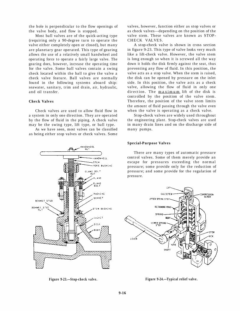
the hole is perpendicular to the flow openings ofthe valve body, and flow is stopped.
Most ball valves are of the quick-acting type(requiring only a 90-degree turn to operate thevalve either completely open or closed), but manyare planetary gear operated. This type of gearingallows the use of a relatively small handwheel andoperating force to operate a fairly large valve. Thegearing does, however, increase the operating timefor the valve. Some ball valves contain a swingcheck located within the ball to give the valve acheck valve feature. Ball valves are normallyfound in the following systems aboard ship:seawater, sanitary, trim and drain, air, hydraulic,and oil transfer.
Check Valves
Check valves are used to allow fluid flow ina system in only one direction. They are operatedby the flow of fluid in the piping. A check valvemay be the swing type, lift type, or ball type.
As we have seen, most valves can be classifiedas being either stop valves or check valves. Some
valves, however, function either as stop valves oras check valves—depending on the position of thevalve stem. These valves are known as STOP-CHECK VALVES.
A stop-check valve is shown in cross sectionin figure 9-23. This type of valve looks very muchlike a lift-check valve. However, the valve stemis long enough so when it is screwed all the waydown it holds the disk firmly against the seat, thuspreventing any flow of fluid. In this position, thevalve acts as a stop valve. When the stem is raised,the disk can be opened by pressure on the inletside. In this position, the valve acts as a checkvalve, allowing the flow of fluid in only onedirection. The m a x i m u m lift of the disk iscontrolled by the position of the valve stem.Therefore, the position of the valve stem limitsthe amount of fluid passing through the valve evenwhen the valve is operating as a check valve.
Stop-check valves are widely used throughoutthe engineering plant. Stop-check valves are usedin many drain lines and on the discharge side ofmany pumps.
Special-Purpose Valves
There are many types of automatic pressurecontrol valves. Some of them merely provide anescape for pressures exceeding the normalpressure; some provide only for the reduction ofpressure; and some provide for the regulation ofpressure.
Figure 9-23.—Stop-check valve. Figure 9-24.—Typical relief valve.
9-16
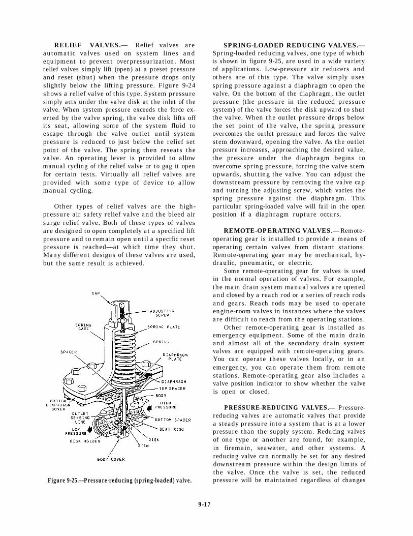
RELIEF VALVES.— Relief valves areautomatic valves used on system lines andequipment to prevent overpressurization. Mostrelief valves simply lift (open) at a preset pressureand reset (shut) when the pressure drops onlyslightly below the lifting pressure. Figure 9-24shows a relief valve of this type. System pressuresimply acts under the valve disk at the inlet of thevalve. When system pressure exceeds the force ex-erted by the valve spring, the valve disk lifts offits seat, allowing some of the system fluid toescape through the valve outlet until systempressure is reduced to just below the relief setpoint of the valve. The spring then reseats thevalve. An operating lever is provided to allowmanual cycling of the relief valve or to gag it openfor certain tests. Virtually all relief valves areprovided with some type of device to allowmanual cycling.
Other types of relief valves are the high-pressure air safety relief valve and the bleed airsurge relief valve. Both of these types of valvesare designed to open completely at a specified liftpressure and to remain open until a specific resetpressure is reached—at which time they shut.Many different designs of these valves are used,but the same result is achieved.
Figure 9-25.—Pressure-reducing (spring-loaded) valve.
SPRING-LOADED REDUCING VALVES.—Spring-loaded reducing valves, one type of whichis shown in figure 9-25, are used in a wide varietyof applications. Low-pressure air reducers andothers are of this type. The valve simply usesspring pressure against a diaphragm to open thevalve. On the bottom of the diaphragm, the outletpressure (the pressure in the reduced pressuresystem) of the valve forces the disk upward to shutthe valve. When the outlet pressure drops belowthe set point of the valve, the spring pressureovercomes the outlet pressure and forces the valvestem downward, opening the valve. As the outletpressure increases, approaching the desired value,the pressure under the diaphragm begins toovercome spring pressure, forcing the valve stemupwards, shutting the valve. You can adjust thedownstream pressure by removing the valve capand turning the adjusting screw, which varies thespring pressure against the diaphragm. Thisparticular spring-loaded valve will fail in the openposition if a diaphragm rupture occurs.
REMOTE-OPERATING VALVES.— Remote-operating gear is installed to provide a means ofoperating certain valves from distant stations.Remote-operating gear may be mechanical, hy-draulic, pneumatic, or electric.
Some remote-operating gear for valves is usedin the normal operation of valves. For example,the main drain system manual valves are openedand closed by a reach rod or a series of reach rodsand gears. Reach rods may be used to operateengine-room valves in instances where the valvesare difficult to reach from the operating stations.
Other remote-operating gear is installed asemergency equipment. Some of the main drainand almost all of the secondary drain systemvalves are equipped with remote-operating gears.You can operate these valves locally, or in anemergency, you can operate them from remotestations. Remote-operating gear also includes avalve position indicator to show whether the valveis open or closed.
PRESSURE-REDUCING VALVES.— Pressure-reducing valves are automatic valves that providea steady pressure into a system that is at a lowerpressure than the supply system. Reducing valvesof one type or another are found, for example,in firemain, seawater, and other systems. Areducing valve can normally be set for any desireddownstream pressure within the design limits ofthe valve. Once the valve is set, the reducedpressure will be maintained regardless of changes
9-17

in the supply pressure (as long as the supplypressure is at least as high as the reduced pressuredesired) and regardless of the amount of reducedpressure fluid that is used.
Various designs of pressure-reducing valvesare in use. Two of the types most commonlyfound on gas turbine ships are the spring-loadedreducing valve (already discussed) and the air-pilotoperated diaphragm reducing valve.
Air-pilot operated diaphragm control valvesare used extensively on naval ships. The valvesand pilots are available in several designs tomeet different requirements. They may beused to reduce pressure, to increase pressure,as unloading valves, or to provide continuousregulation of pressure. Valves and pilots ofvery similar design can also be used forother services, such as liquid-level control andtemperature control.
The air-operated control pilot may beeither direct acting or reverse acting. A direct-acting, air-operated control pilot is shown infigure 9-26. In this type of pilot, the con-trolled pressure—that is, the pressure fromthe discharge side of the diaphragm controlvalve—acts on top of a diaphragm in thecontrol pilot. This pressure is balanced bythe pressure exerted by the pilot adjustingspring. If the controlled pressure increasesand overcomes the pressure exerted by thepilot adjusting spring, the pilot valve stemis forced downward. This action causes thepilot valve to open, thereby increasing theamount of operating air pressure going fromthe pilot to the diaphragm control valve.A reverse-acting pilot has a lever that re-verses the pilot action. In a reverse-actingpilot, therefore, an increase in controlledpressure produces a decrease in operating airpressure.
Figure 9-26.—Air-operated control pilot.
9-18

Figure 9-27.—Diaphragm control valve, downward-seatingtype.
In the diaphragm control valve, operating airfrom the pilot acts on the valve diaphragm. Thesuperstructure, which contains the diaphragm, isdirect acting in some valves and reverse acting inothers. If the superstructure is direct-acting, theoperating air pressure from the control pilot isapplied to the TOP of the valve diaphragm. Ifthe superstructure is reverse-acting, the operatingair pressure from the pilot is applied to theUNDERSIDE of the valve diaphragm.
Figure 9-27 shows a very simple type of direct-acting diaphragm control valve with operating airpressure from the control pilot applied to the topof the valve diaphragm. Since the valve in thefigure is a downward-seating valve, any increasein operating air pressure pushes the valve stemdownward toward the closed position.
Now look at figure 9-28. This is also a direct-acting valve with operating air pressure from thecontrol pilot applied to the top of the valve
Figure 9-28.—Diaphragm control valve,type.
upward-seating
diaphragm. Note that the valve shown in figure9-28 is more complicated than the one shown infigure 9-27 because of the added springs underthe seat. The valve shown in figure 9-28 is anupward-seating valve rather than a downward-seating valve. Therefore, any increase in operatingair pressure from the control pilot tends to OPENthis valve rather than to close it.
As you have seen, the air-operated controlpilot may be either direct acting or reverse acting.The superstructure of the diaphragm control valvemay be either direct acting or reverse acting. And,the diaphragm control valve may be either upwardseating or downward seating. These three factors,as well as the purpose of the installation,determine how the diaphragm control valve andits air-operated control pilot are installed inrelation to each other.
To see how these factors are related, let’sconsider an installation in which a diaphragmcontrol valve and its air-operated control pilot areused to supply controlled steam pressure.
9-19
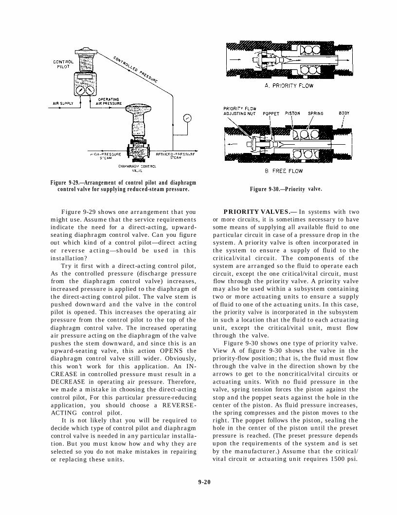
Figure 9-29.—Arrangement of control pilot and diaphragmcontrol valve for supplying reduced-steam pressure.
Figure 9-29 shows one arrangement that youmight use. Assume that the service requirementsindicate the need for a direct-acting, upward-seating diaphragm control valve. Can you figureout which kind of a control pilot—direct actingor reverse acting—should be used in thisinstallation?
Try it first with a direct-acting control pilot,As the controlled pressure (discharge pressurefrom the diaphragm control valve) increases,increased pressure is applied to the diaphragm ofthe direct-acting control pilot. The valve stem ispushed downward and the valve in the controlpilot is opened. This increases the operating airpressure from the control pilot to the top of thediaphragm control valve. The increased operatingair pressure acting on the diaphragm of the valvepushes the stem downward, and since this is anupward-seating valve, this action OPENS thediaphragm control valve still wider. Obviously,this won’t work for this application. An IN-CREASE in controlled pressure must result in aDECREASE in operating air pressure. Therefore,we made a mistake in choosing the direct-actingcontrol pilot, For this particular pressure-reducingapplication, you should choose a REVERSE-ACTING control pilot.
It is not likely that you will be required todecide which type of control pilot and diaphragmcontrol valve is needed in any particular installa-tion. But you must know how and why they areselected so you do not make mistakes in repairingor replacing these units.
Figure 9-30.—Priority
PRIORITY VALVES.— In
valve.
systems with twoor more circuits, it is sometimes necessary to havesome means of supplying all available fluid to oneparticular circuit in case of a pressure drop in thesystem. A priority valve is often incorporated inthe system to ensure a supply of fluid to thecritical/vital circuit. The components of thesystem are arranged so the fluid to operate eachcircuit, except the one critical/vital circuit, mustflow through the priority valve. A priority valvemay also be used within a subsystem containingtwo or more actuating units to ensure a supplyof fluid to one of the actuating units. In this case,the priority valve is incorporated in the subsystemin such a location that the fluid to each actuatingunit, except the critical/vital unit, must flowthrough the valve.
Figure 9-30 shows one type of priority valve.View A of figure 9-30 shows the valve in thepriority-flow position; that is, the fluid must flowthrough the valve in the direction shown by thearrows to get to the noncritical/vital circuits oractuating units. With no fluid pressure in thevalve, spring tension forces the piston against thestop and the poppet seats against the hole in thecenter of the piston. As fluid pressure increases,the spring compresses and the piston moves to theright. The poppet follows the piston, sealing thehole in the center of the piston until the presetpressure is reached. (The preset pressure dependsupon the requirements of the system and is setby the manufacturer.) Assume that the critical/vital circuit or actuating unit requires 1500 psi.
9-20

Figure 9-31.—Valve manifold showing cutaway view of thevalves and typical combination of suction and dischargevalves.
When the pressure in the valve reaches 1500 psi,the poppet reaches the end of its travel. As thepressure increases, the piston continues to moveto the right, which unseats the poppet and allowsflow through the valve, as shown in view A offigure 9-30. If the pressure drops below 1500 psi,the compressed spring forces the piston to the left,the poppet seats, and flow through the valvestops.
Figure 9-30, view B, shows the priority valvein the free-flow position. The flow of fluid movesthe poppet to the left, the poppet springcompresses, and the poppet unseats. This allowsfree flow of fluid through the valve.
VALVE MANIFOLDS
Sometimes suction must be taken from one ofmany sources and discharged to another unit orunits of either the same or another group. A valvemanifold is used for this type of operation. Anexample of such a manifold (fig. 9-31) is the fueloil filling and transfer system where provisionmust be made for the transfer of oil from any tankto any other tank, to the service system, or toanother ship. If, for example, the purpose is totransfer oil from tank No. 1 to tank No. 4, thedischarge valve for tank No. 4 and the suctionvalve from tank No. 1 are opened, and all othervalves are closed. Fuel oil can now flow from tankNo. 1, through the suction line, through thepump, through the discharge valve, and into tankNo. 4. The manifold suction valves are often ofthe stop-check type to prevent draining of pumpswhen they are stopped.
VALVE HANDWHEEL IDENTIFICA-TION AND COLOR CODING
Valves are identified by markings inscribed onthe rims of the handwheels, by a circular labelplate secured by the handwheel nut, or by labelplates attached to the ship’s structure or to theadjacent piping.
Piping system valve handwheels and operatinglevers are marked for training and casualtycontrol purposes with a standardized color code.Color code identification is in conformance withthe color scheme of table 9-1. Implementation of
Table 9-1.—Valve Handwheel Color Code
9-21
this color scheme provides uniformity among allnaval surface ships and shore-based trainingfacilities.
MAINTENANCE
Preventive maintenance is the best way toextend the life of valves and fittings. Always referto the applicable portion of the Standard NavyValve Technical Manual, NAVSEA 0948-LP-012-5000, if possible. When making repairs onmore sophisticated valve types, use the availablemanufacturer’s technical manuals. As soon as youobserve a leak, determine the cause, and thenapply the proper corrective maintenance. Mainte-nance may be as simple as tightening a packingnut or gland. A leaking flange joint may need onlyto have the bolts tightened or to have a new gasketor O-ring inserted. Dirt and scale, if allowed tocollect, will cause leakage. Loose hangers permitsections of a line to sag, and the weight of thepipe and the fluid in these sagging sections maystrain joints to the point of leakage.
Whenever you are going to install a valve, besure you know the function the valve is going toperform—that is, whether it must start flow,stop flow, regulate flow, regulate pressure, orprevent backflow. Inspect the valve body for theinformation that is stamped upon it by themanufacturer: type of system (oil, water, gas),operating pressure, direction of flow, and otherinformation.
You should also know the operating character-istics of the valve, the metal from which it is made,and the type of end connection with which it isfitted. Operating characteristics and the materialare factors that affect the length and kind ofservice that a valve will give; end connectionsindicate whether or not a particular valve is suitedto the installation.
When you install valves, ensure they arereadily accessible and allow enough headroom forfull operation. Install valves with stems pointingupward if possible. A stem position betweenstraight up and horizontal is acceptable, but avoidthe inverted position (stem pointing downward).If the valve is installed with the stem pointingdownward, sediment will collect in the bonnet andscore the stem. Also, in a line that is subject tofreezing temperatures, liquid that is trapped in thevalve bonnet may freeze and rupture it.
Since you can install a globe valve withpressure either above the disk or below the disk(depending on which method will be best for theoperation, protection, maintenance, and repair of
the machinery served by the system), you shoulduse caution. The question of what would happenif the disk became detached from the stem is amajor consideration in determining whetherpressure should be above the disk or below it. Ifyou are required to install a globe valve, be SUREto check the blueprints for the system to see whichway the valve must be installed. Very seriouscasualties can result if a valve is installed withpressure above the disk when it should be belowthe disk, or below the disk when it should beabove.
Valves that have been in constant servicefor a long time will eventually require glandtightening, repacking, or a complete overhaul ofall parts. If you know that a valve is not doingthe job for which it was intended, dismantle thevalve and inspect all parts. You must repair orreplace all defective parts.
The repair of globe valves (other than routinerenewal of packing) is limited to refinishing theseat and/or disk surface. When doing this work,you should observe the following precautions:
. When refinishing the valve seat, do notremove more material than is necessary.You can finish valves that do not havereplaceable valve seats only a limitednumber of times.
l Before doing any repair to the seat anddisk of a globe valve, check the valve diskto make certain it is secured rigidly to andis square on the valve stem. Also, checkto be sure that the stem is straight. If thestem is not straight, the valve disk cannotseat properly,
l Carefully inspect the valve seat and valvedisk for evidence of wear, for cuts on theseating area, and for improper fit of thedisk to the seat. Even if the disk and seatappear to be in good condition, you shouldperform a spot-in check to find outwhether they actually are in good condition.
Figure 9-32 shows a standard checkoffdiagram for performing a routine inspection andminor maintenance of a valve.
Spotting-In Valves
The method used to visually determine whetherthe seat and the disk of a valve make goodcontact with each other is called spotting-in. To
9-22
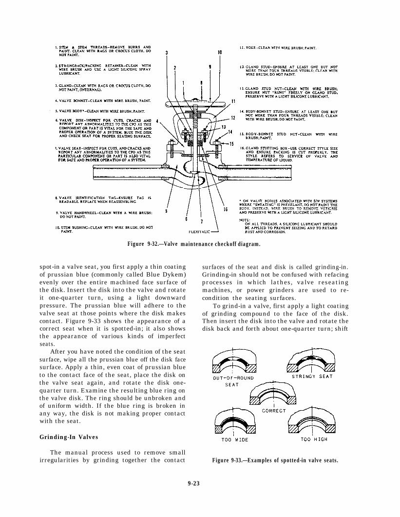
Figure 9-32.—Valve
spot-in a valve seat, you first apply a thin coatingof prussian blue (commonly called Blue Dykem)evenly over the entire machined face surface ofthe disk. Insert the disk into the valve and rotateit one-quarter turn, using a light downwardpressure. The prussian blue will adhere to thevalve seat at those points where the disk makescontact. Figure 9-33 shows the appearance of acorrect seat when it is spotted-in; it also showsthe appearance of various kinds of imperfectseats.
After you have noted the condition of the seatsurface, wipe all the prussian blue off the disk facesurface. Apply a thin, even coat of prussian blueto the contact face of the seat, place the disk onthe valve seat again, and rotate the disk one-quarter turn. Examine the resulting blue ring onthe valve disk. The ring should be unbroken andof uniform width. If the blue ring is broken inany way, the disk is not making proper contactwith the seat.
Grinding-In Valves
maintenance checkoff diagram.
surfaces of the seat and disk is called grinding-in.Grinding-in should not be confused with refacingprocesses in which lathes, valve reseatingmachines, or power grinders are used to re-condition the seating surfaces.
To grind-in a valve, first apply a light coatingof grinding compound to the face of the disk.Then insert the disk into the valve and rotate thedisk back and forth about one-quarter turn; shift
The manual process used to remove smallirregularities by grinding together the contact Figure 9-33.—Examples of spotted-in valve seats.
9-23

the disk-seat relationship from time to time so thedisk will be moved gradually, in increments,through several rotations. During the grindingprocess, the grinding compound will gradually bedisplaced from between the seat and disk surfaces;therefore, you must stop every minute or so toreplenish the compound. When you do this, wipeboth the seat and the disk clean before applyingthe new compound to the disk face.
When you are satisfied that the irregularitieshave been removed, spot-in the disk to the seatin the manner previously described.
Grinding-in is also used to follow up allmachining work on valve seats or disks. When thevalve seat and disk are first spotted-in after theyhave been machined, the seat contact will be verynarrow and will be located close to the bore.Grinding-in, using finer and finer compounds asthe work progresses, causes the seat contact tobecome broader. The contact area should be aperfect ring covering about one-third of theseating surface.
Be careful to avoid overgrinding a valve seator disk. Overgrinding will produce a groove in theseating surface of the disk; it will also roundoff the straight, angular surface of the disk.Machining is the only process by which over-grinding can be corrected.
Lapping Valves
When a valve seat contains irregularities thatare slightly larger than can be satisfactorilyremoved by grinding-in, the irregularities can beremoved by lapping. A cast-iron tool (lap) ofexactly the same size and shape as the valve diskis used to true the valve seat surface. Thefollowing are some precautions you should followwhen lapping valves:
l Do not bear heavily on the handle of thelap.
l Do not bear sideways on the handle of thelap.
l Change the relationship between the lapand the valve seat occasionally so that thelap will gradually and slowly rotate aroundthe entire seat circle.
l Keep a check on the working surface ofthe lap. If a groove develops, have the laprefaced.
l Always use clean compound for lapping.
. Replace the compound frequently.
. Spread the compound evenly and lightly.
l Do not lap more than is necessary toproduce a smooth even seat.
. Always use a fine grinding compound tofinish the lapping job.
. Upon completion of the lapping job, spot-inand grind-in the disk to the seat.
You should use only approved abrasivecompounds for reconditioning valve seats anddisks. Compounds for lapping valve disks andseats are supplied in various grades. Use acoarse grade compound when you find extensivecorrosion or deep cuts and scratches on the disksand seats. Use a medium grade compound as afollow-up to the coarse grade; you may also useit to start the reconditioning process on valves thatare not too severely damaged. Use a fine gradecompound when the reconditioning process nearscompletion. Use a microscopic-fine grade forfinish lapping and for all grinding-in.
Refacing Valves
Badly scored valve seats must be refaced ina lathe, with a power grinder, or with a valvereseating machine. However, the lathe, ratherthan the reseating machine, should be used forrefacing all valve disks and all hard-surfaced valveseats. Work that must be done on a lathe or witha power grinder should be turned over to shoppersonnel.
Repacking Valves
If the stem and packing of a valve are in goodcondition, you can normally stop packing glandleaks by tightening up on the packing. You mustbe careful, however, to avoid excessive threadengagement of the packing gland studs (if used)and to avoid tightening old, hardened packing,which will cause the valve to seize. Subsequentoperation of such a valve may score or bend thestem.
Coils, rings, and corrugated ribbon are thecommon forms of packing used in valves. Theform of packing to be used in repacking aparticular valve will depend on the valvesize, application, and type. Packing materialswill be discussed in more detail later in thischapter.
9-24

Figure 9-34.—Bucket-type steam trap.
STEAM TRAPS
Steam traps are installed in steam lines to draincondensate from the lines without allowing theescape of steam. There are many different designsof steam traps; some are suitable for high-pressureuse and others for low-pressure use.
TYPES OF STEAM TRAPS
Some types of steam traps that are used in theNavy are the mechanical steam traps, bimetallicsteam traps, and orifice-type steam traps.
Mechanical Steam Traps
Mechanical steam traps in common useinclude bucket-type traps and ball-float traps.
The operation of the bucket-type steam trap,shown in figure 9-34, is controlled by thecondensate level in the trap body. The bucketvalve is connected to the bucket in such a waythat the valve closes as the bucket rises. Ascondensate continues to flow into the trap body,the valve remains closed until the bucket is full.When the bucket is full, it sinks and thus opensthe valve. The valve remains open until enoughcondensate has blown out to allow the bucket tofloat, thus closing the valve.
Figure 9-35.—Ball-float steam trap.
Figure 9-35 shows a ball-float steam trap. Thistrap works much in the same way as the buckettrap. Condensate and steam enter the body of thetrap, and the condensate collects at the bottom.As the condensate level rises, the ball float risesuntil it is raised enough to open the outlet valveof the trap. When the outlet valve opens, thecondensate flows out of the trap into the drainsystem, and the float level drops, shutting off thevalve until the condensate level rises again.
Bimetallic Steam Traps
Bimetallic steam traps of the type shown infigure 9-36 are used in many ships to drain
Figure 9-36.—Bimetallic steam trap.
9-25
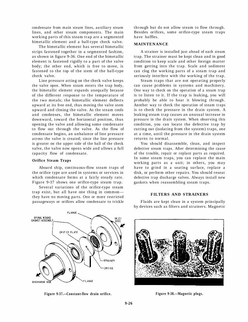
condensate from main steam lines, auxiliary steamlines, and other steam components. The mainworking parts of this steam trap are a segmentedbimetallic element and a ball-type check valve.
The bimetallic element has several bimetallicstrips fastened together in a segmented fashion,as shown in figure 9-36. One end of the bimetallicelement is fastened rigidly to a part of the valvebody; the other end, which is free to move, isfastened to the top of the stem of the ball-typecheck valve.
Line pressure acting on the check valve keepsthe valve open. When steam enters the trap body,the bimetallic element expands unequally becauseof the different response to the temperature ofthe two metals; the bimetallic element deflectsupward at its free end, thus moving the valve stemupward and closing the valve. As the steam coolsand condenses, the bimetallic element movesdownward, toward the horizontal position, thusopening the valve and allowing some condensateto flow out through the valve. As the flow ofcondensate begins, an unbalance of line pressureacross the valve is created; since the line pressureis greater on the upper side of the ball of the checkvalve, the valve now opens wide and allows a fullcapacity flow of condensate.
Orifice Steam Traps
Aboard ship, continuous-flow steam traps ofthe orifice type are used in systems or services inwhich condensate forms at a fairly steady rate.Figure 9-37 shows one orifice-type steam trap.
Several variations of the orifice-type steamtrap exist, but all have one thing in common—they have no moving parts. One or more restrictedpassageways or orifices allow condensate to trickle
through but do not allow steam to flow through.Besides orifices, some orifice-type steam trapshave baffles.
MAINTENANCE
A strainer is installed just ahead of each steamtrap. The strainer must be kept clean and in goodcondition to keep scale and other foreign matterfrom getting into the trap. Scale and sedimentcan clog the working parts of a steam trap andseriously interfere with the working of the trap.
Steam traps that are not operating properlycan cause problems in systems and machinery.One way to check on the operation of a steam trapis to listen to it. If the trap is leaking, you willprobably be able to hear it blowing through.Another way to check the operation of steam trapsis to check the pressure in the drain system. Aleaking steam trap causes an unusual increase inpressure in the drain system. When observing thiscondition, you can locate the defective trap bycutting out (isolating from the system) traps, oneat a time, until the pressure in the drain systemreturns to normal.
You should disassemble, clean, and inspectdefective steam traps. After determining the causeof the trouble, repair or replace parts as required.In some steam traps, you can replace the mainworking parts as a unit; in others, you mayhave to grind in a seating surface, replace adisk, or perform other repairs. You should reseatdefective trap discharge valves. Always install newgaskets when reassembling steam traps.
FILTERS AND STRAINERS
Fluids are kept clean in a system principallyby devices such as filters and strainers. Magnetic
Figure 9-37.—Constant-flow drain orifice.
9-26
Figure 9-38.—Magnetic plugs.

plugs (fig. 9-38) also are used in some strainersto trap iron and steel particles carried by fluid.Studies have indicated that even particles as smallas 1 to 5 microns have a degrading effect, causingfailures and hastening deterioration in many cases.
There will always be controversy over the exactdefinitions of filters and strainers. In the past,many such devices were named filters buttechnically classed as strainers. To minimize thecontroversy, the National Fluid Power Associa-tion gives us these definitions:
FILTER - A device whose primary functionis the retention, by some porous medium, ofinsoluble contaminants from a fluid.
STRAINER - A coarse filter.
To put it simply, whether the device is a filteror a strainer, its function is to trap contaminantsfrom fluid flowing through it. The term porousmedium simply refers to a screen or filteringmaterial that allows fluid flow through it but stopsvarious other materials.
MESH AND MICRON RATINGS
Filters, which may be made of many materialsother than wire screen, are rated by MICRONsize. A micron is 1-millionth of a meter or39-millionths of an inch. For comparison, a grainof salt is about 70 microns across. The smallestparticle visible to the naked eye is about 40microns. Figure 9-39 shows the relationship of
Figure 9-39.—Relationship of micron sizes.
9-27

Figure 9-40.—Inlet line filter.
Figure 9-41.—Inlet strainer.
the various micron sizes with mesh and standardsieve sizes.
A simple screen or a wire strainer is rated forfiltering fineness by a MESH number or its nearequivalent, STANDARD SIEVE number. Thehigher the mesh or sieve number, the finer thescreen.
When a filter is specified as so many microns,it usually refers to the filter’s NOMINAL rating.A filter nominally rated at 10 microns, forexample, would trap most particles 10 microns insize or larger. The filter’s ABSOLUTE rating,however, would be a somewhat higher size,perhaps 25 microns. The absolute rating is the sizeof the largest opening or pore in the filter.Absolute rating is an important factor only whenit is mandatory that no particles above a givensize be allowed to circulate in the system.
FILTER/STRAINER LOCATION
There are three general areas in a system forlocating a filter: the inlet line, the pressure line,
or a return line. Both filters and strainers areavailable for inlet lines. Filters are normallyused in other lines.
Inlet Filters and Strainers
Figure 9-40 shows the location of an inlet linefilter. An inlet line filter is usually a relativelycoarse mesh filter. A fine mesh filter (unless it isvery large) creates more pressure drop than canbe tolerated in an inlet line.
Figure 9-41 shows a typical strainer of the typeinstalled on pump inlet lines inside a reservoir.It is relatively coarse as filters go, beingconstructed of fine mesh wire. A 100-meshstrainer protects the pump from particles about150 microns in size.
Pressure Line Filters
A number of filters are designed for installa-tion right in the pressure line (fig. 9-42) andcan trap much smaller particles than inlet line
Figure 9-42.—Pressure line filter.
Figure 9-43.—Return line filter.
9-28

filters. Such a filter might be used where systemcomponents, such as valves, are less dirt-tolerantthan the pump. The filter thus would trap this finecontamination from the fluid as it leaves thepump. Pressure line filters must be able to with-stand the operating pressure of the system.
Return Line Filters
Return line filters (fig. 9-43) also can trap verysmall particles before the fluid returns to thereservoir/tank. They are particularly useful insystems that do not have large reservoirs/tanksto allow contaminants to settle out of the fluid.A return line filter is nearly a must in a systemwith a high-performance pump, which has veryclose clearances and usually cannot be sufficientlyprotected by an inlet line filter.
FILTER/STRAINER MATERIALS
The materials used in filters and strainers areclassified as mechanical, absorbent, or adsorbent.Most strainer material is of the mechanical type,which operates by trapping particles betweenclosely woven metal screens and/or disks, andmetal baskets. The mechanical type of materialis used mostly where the particles removed fromthe medium are of a relatively coarse nature.
Absorbent filters are used for most minute-particle filtration in fluid systems. They are madeof a wide range of porous materials, includingpaper, wood pulp, cotton, yarn, and cellulose.
Figure 9-44.—Filter assembly using a surface-type element.
Paper filters are usually resin-impregnated forstrength.
Adsorbent (or active) filters, such as charcoaland fuller’s earth, are used mostly in gaseous orvapors systems. This type of filter material shouldnot be used in hydraulic systems since they removeessential additives from the hydraulic fluid.
CONSTRUCTION OFFILTER ELEMENTS
Filter elements are constructed in variousways. The three most common filter elementconstruction types are the surface type (mostcommon), the depth type, and the edge type.
Surface-type filter elements (fig. 9-44) aremade of closely woven fabric or treated paper withpores to allow fluid to flow through. Veryaccurate control of the pore size is a feature ofthe surface-type elements.
A depth-type filter element (fig. 9-45) iscomposed of layers of a fabric or fibers, whichprovide many tortuous paths for the fluid to flowthrough. The pores or passages vary in size, andthe degree of filtration depends on the flow rate.Increases in flow rate tend to dislodge trappedparticles. This filter is limited to low-flow, lowpressure-drop conditions.
Figure 9-45.—Depth-type filter element.
9-29

Figure 9-46.—Edge-type filter element.
An edge-type filter element (fig. 9-46)separates particles rom fluids passing betweenfinely spaced plates. The filter shown featuresstationary cleaner blades that scrape out thecollected contaminants when the handle is twistedto turn the element.
TYPES OF FILTERS
In this section we will discuss the various filters(simplex, duplex, full flow, proportional flow,and indicator) that you will most frequently findinstalled in equipment.
Simplex Filter
The simplex filter has one or more cylindricallyshaped fine mesh screens or perforated metalsheets. The size of the opening in the screens orthe perforated metal sheets determines the size ofparticles filtered out of the fluid. The design ofthis type of filter is such that total flow must passthrough a simplex filter.
Duplex Filters
Duplex filters are similar to simplex filtersexcept in the number of elements and in provisionfor switching the flow through either element. Aduplex filter may consist of a number of singleelement filters arranged in parallel operation, orit may consist of two or more filters arranged
within a single housing. The full flow can bediverted, by operation of valves, through anysingle element. The duplex design is mostcommonly used in fuel or hydraulic systemsbecause the ability to shift to an off-line filterwhen the elements are cleaned or changed isdesirable without the system being secured.
Full-Flow Filters
The term full-flow applied to a filter meansthat all the flow into the filter inlet port passesthrough the filtering element. In most full-flowfilters, however, there is a bypass valve preset toopen at a given pressure drop and divert flow pastthe filter element. This prevents a dirty elementfrom restricting flow excessively. Figure 9-47shows a full-flow filter. Flow, as shown, is out-to-in; that is, from around the element, throughit to its center. The bypass opens when total flowcan no longer pass through the contaminatedelement without raising the system pressure. Theelement is replaceable after removing a single bolt.
Proportional-Flow Filters
A proportional-flow filter (fig. 9-48) may usethe venturi effect to filter a portion of the fluidflow. The fluid can flow in either direction. Asit passes through the filter body, a venturi throatcauses an increase in velocity and a decrease in
Figure 9-47.—Full-flow filter.
9-30

Figure 9-48.—Proportional-flow filter,
pressure. The pressure difference forces some ofthe fluid through the element to rejoin the mainstream at the venturi. The amount of fluid filteredis proportional to the flow velocity. Hence, thename proportional-flow filter.
Indicating Filters
Indicating filters are designed to signal theoperator when the element needs cleaning.There are various types of indicators, suchas color-coded, flag, pop-up, and swing arm.Figure 9-49 shows a color-coded indicatingfilter. The element is designed so it beginsto move as the pressure increases due to dirtaccumulation, One end is linked to an indicatorthat shows the operator just how clean ordirty the element is. Another feature of thistype of filter is the ease and speed withwhich the element can be removed and replaced.Most filters of this kind are designed forinlet line installation.
Figure 9-49.—Color-coded indicating filter.
9-31
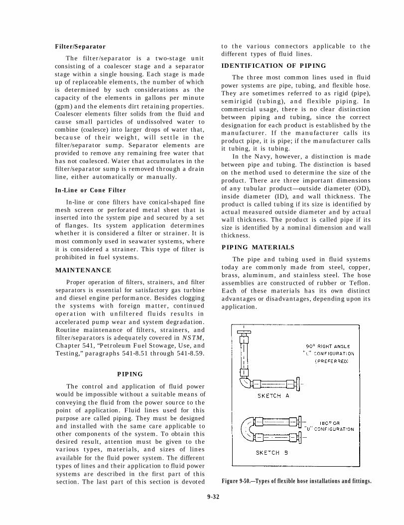
Filter/Separator
The filter/separator is a two-stage unitconsisting of a coalescer stage and a separatorstage within a single housing. Each stage is madeup of replaceable elements, the number of whichis determined by such considerations as thecapacity of the elements in gallons per minute(gpm) and the elements dirt retaining properties.Coalescer elements filter solids from the fluid andcause small particles of undissolved water tocombine (coalesce) into larger drops of water that,because of their weight, will settle in thefilter/separator sump. Separator elements areprovided to remove any remaining free water thathas not coalesced. Water that accumulates in thefilter/separator sump is removed through a drainline, either automatically or manually.
In-Line or Cone Filter
In-line or cone filters have conical-shaped finemesh screen or perforated metal sheet that isinserted into the system pipe and secured by a setof flanges. Its system application determineswhether it is considered a filter or strainer. It ismost commonly used in seawater systems, whereit is considered a strainer. This type of filter isprohibited in fuel systems.
MAINTENANCE
Proper operation of filters, strainers, and filterseparators is essential for satisfactory gas turbineand diesel engine performance. Besides cloggingthe systems with foreign matter, continuedoperation with unfiltered fluids results inaccelerated pump wear and system degradation.Routine maintenance of filters, strainers, andfilter/separators is adequately covered in NSTM,Chapter 541, “Petroleum Fuel Stowage, Use, andTesting,” paragraphs 541-8.51 through 541-8.59.
PIPING
The control and application of fluid powerwould be impossible without a suitable means ofconveying the fluid from the power source to thepoint of application. Fluid lines used for thispurpose are called piping. They must be designedand installed with the same care applicable toother components of the system. To obtain thisdesired result, attention must be given to thevarious types, materials, and sizes of linesavailable for the fluid power system. The differenttypes of lines and their application to fluid powersystems are described in the first part of thissection. The last part of this section is devoted
to the various connectors applicable to thedifferent types of fluid lines.
IDENTIFICATION OF PIPING
The three most common lines used in fluidpower systems are pipe, tubing, and flexible hose.They are sometimes referred to as rigid (pipe),semirigid (tubing), and flexible piping. Incommercial usage, there is no clear distinctionbetween piping and tubing, since the correctdesignation for each product is established by themanufacturer. If the manufacturer calls itsproduct pipe, it is pipe; if the manufacturer callsit tubing, it is tubing.
In the Navy, however, a distinction is madebetween pipe and tubing. The distinction is basedon the method used to determine the size of theproduct. There are three important dimensionsof any tubular product—outside diameter (OD),inside diameter (ID), and wall thickness. Theproduct is called tubing if its size is identified byactual measured outside diameter and by actualwall thickness. The product is called pipe if itssize is identified by a nominal dimension and wallthickness.
PIPING MATERIALS
The pipe and tubing used in fluid systemstoday are commonly made from steel, copper,brass, aluminum, and stainless steel. The hoseassemblies are constructed of rubber or Teflon.Each of these materials has its own distinctadvantages or disadvantages, depending upon itsapplication.
Figure 9-50.—Types of flexible hose installations and fittings.
9-32
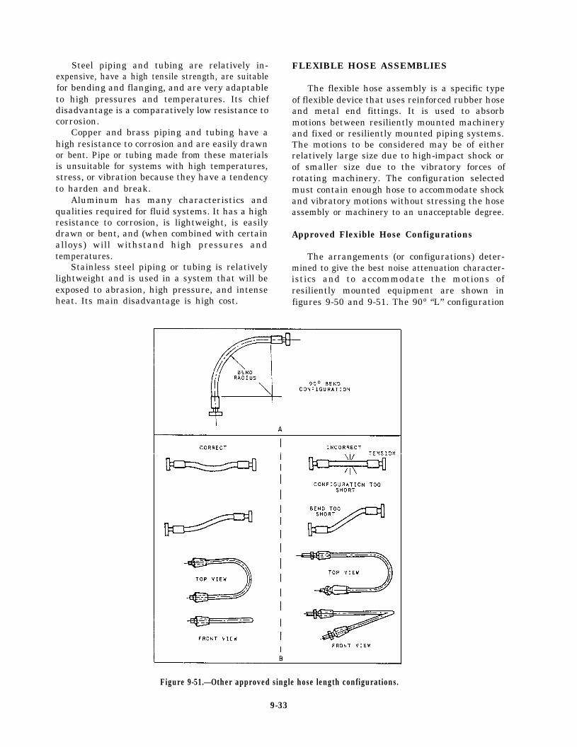
Steel piping and tubing are relatively in-expensive, have a high tensile strength, are suitablefor bending and flanging, and are very adaptableto high pressures and temperatures. Its chiefdisadvantage is a comparatively low resistance tocorrosion.
Copper and brass piping and tubing have ahigh resistance to corrosion and are easily drawnor bent. Pipe or tubing made from these materialsis unsuitable for systems with high temperatures,stress, or vibration because they have a tendencyto harden and break.
Aluminum has many characteristics andqualities required for fluid systems. It has a highresistance to corrosion, is lightweight, is easilydrawn or bent, and (when combined with certainalloys) will withstand high pressures andtemperatures.
Stainless steel piping or tubing is relativelylightweight and is used in a system that will beexposed to abrasion, high pressure, and intenseheat. Its main disadvantage is high cost.
FLEXIBLE HOSE ASSEMBLIES
The flexible hose assembly is a specific typeof flexible device that uses reinforced rubber hoseand metal end fittings. It is used to absorbmotions between resiliently mounted machineryand fixed or resiliently mounted piping systems.The motions to be considered may be of eitherrelatively large size due to high-impact shock orof smaller size due to the vibratory forces ofrotating machinery. The configuration selectedmust contain enough hose to accommodate shockand vibratory motions without stressing the hoseassembly or machinery to an unacceptable degree.
Approved Flexible Hose Configurations
The arrangements (or configurations) deter-mined to give the best noise attenuation character-istics and to accommodate the motions ofresiliently mounted equipment are shown infigures 9-50 and 9-51. The 90° “L” configuration
Figure 9-51.—Other approved single hose length configurations.
9-33

(dogleg) is the preferred configuration; however,where space and piping arrangement prohibit theuse of the “L” configuration, a 180° or “U”configuration may be used. The 90° “L” and180° “U” configurations are shown as sketchesA and B of figure 9-50.
A configuration that uses a single length ofhose bent to about 90° is approved where the hosedoes not bend below its specified minimumbending radius when the equipment moves to themaximum limits allowed by its mounts (view Aof fig. 9-51). The straight single hose configura-tion and the 180° single hose bend (view B of fig.9-51) are also approved for use where the hosesize is less than 1 inch ID.
Flexible connections that use rubber hose arenot used in systems where the maximumcontinuous operating temperature is in excess of200°F.
Hose Identification
Hose is identified by the manufacturer’s partnumber and the size or dash number. The dashnumber is the nominal hose inside diameter insixteenths of an inch. Hose built to militaryspecification (MILSPEC) requirements have thenumber of the specification and, where applicable,the class of hose, the quarter and year of manu-facture, and the manufacturer’s trademark. Thisinformation is molded or otherwise permanentlyrepeated periodically on the hose cover (sometimesreferred to as the “lay line marking”). Otherinformation permanently marked on the hosecover is the manufacturer’s code and the date ofmanufacture. For interpretations of commerciallay line markings, refer to the appropriatemanufacturer’s catalog or manual.
Fitting Identification
Use special care in identifying hose fittingsbecause their designation is more complex thanhose. A fitting suitable for connecting to a givenhose size can end in more than one size and typeof connection to the piping. A fitting, therefore,must be identified by the manufacturer’s partnumber, the size of the end connection that joinsthe piping system, and the dash size to show thesize hose to which it makes up. For interpreta-tion of manufacturer markings, consult theappropriate manufacturer’s manual. Fittingsmeeting military specification requirements havethe specification number, class of fitting (whereapplicable), type, size, and manufacturer’strademark.
A cross index between the manufacturers’designations and military specifications andinformation to correctly identify approved hosesand fittings can be found in Piping Devices,Flexible Hose Assemblies, volume 1, NAVSEAS6430-AE-TED-010.
Inspection of Hose andFittings Prior To Make-Up
The basic inspection methods for hose andfittings are listed as follows:
1.
2.
3.
4.
5.
6.
Ensure that the hose and couplings are thecorrect ones for the intended use and thatthe age of the rubber hose does not exceeda shelf life of 4 years. Teflon and metalhose have no limiting shelf life.Inspect for signs that the hose has beentwisted. Use the hose lay line for a guideto determine whether or not any twist ispresent. If twisted, reject.Inspect for signs that the hose has beenkinked or bent beyond its minimum bendradius. If suspect, reject.Inspect for signs of loose inner liner. Iffound, cut the hose to see if this conditionexists throughout the entire length. If.suspect, reject.Visually check the inner liner and outerrubber cover of the hose for breaks,hairline cuts, or severe abrasions. If anysuspect areas are found, reject.Inspect the fittings for defects, such ascracked nipples and damaged threads.If suspect, or if defects are found, reject.
Procedures for making up hoses and fittingscan also be found in the NSTM, chapter 505, orthe appropriate manufacturer’s catalog ormanual, and are not covered here due to the manytypes available.
Visual Inspection
After assembling the hose and fittings, visuallyinspect the entire configuration to ensure thefollowing:
1.
2.
The hose inner liner and outer cover isintact and contains no cuts or harmfulabrasions.The hose has not been twisted (check thelay line).
9-34

3.
4.
The circumferential chalk line on the hosenext to the coupling has been drawn beforethe hydrostatic test.
The internal spring (if installed) is evenlyspaced and flat against the inner liner.Ensure a gap exists between one of the endfittings and the end of the spring.
Hydrostatic Test
Upon completion of visual inspection, hydro-statically shop test the hose assembly with freshwater. For each style and size of hose, test thepressure to ensure that it is twice the maximumallowable pressure shown in chapter 505 of theNSTM. When you test pressure, hold for notmore than 5 minutes nor less than 60 seconds.When test pressure is reached, visually inspect thehose assembly for the following defects:
1. Leaks or signs of weakness
2. Twisting of the hose (this indicates thatsome twist existed before pressure wasapplied)
3. Slippage of the hose out of the coupling(a circumferential chalk line can help deter-mine this)
If any of these defects occur, reject theassembly.
CAUTION
Do not confuse hose elongation underpressure with coupling slippage. If thechalk line returns to near its originalposition, no slippage has occurred and theassembly is satisfactory. If there is anydoubt, perform a second test. If doubtpersists after the second test, reject theassembly.
Air Test
Hose assemblies intended for gas or airservice must also be tested with air or nitrogenat 100 psi and the assembly immersed in water.Random bubbles may appear over the hose and
in the fitting area when the assembly is firstpressurized. Do not construe this as a defect.However, if the bubbles persist in forming at asteady rate at any particular point on the hose,reject the assembly.
Installation of Flexible Hose Assemblies
After completion of tests, proceed as follows:
1.
2.
3.
4.
Install as soon as possible.
Do not leave the hose assembly around ondecks or on docks where they can be sub-jected to any form of abuse.
Make up hose assemblies as late aspossible during the availability schedule tominimize the chances of damage while theship is being overhauled.
Install plastic dust caps, plugs, or tape endsto protect threaded areas until the hoseassembly is installed.
When installing flexible base connections,observe the following requirements:
1.
2.
3.
4.
5.
6.
Ensure each leg of hose is free of twistbetween end fittings.
Ensure the fixed piping near the flexibleconfiguration is properly supported so thatit does not vibrate from the resilientlymounted equipment.
Ensure the configurations are clear of allsurrounding structures and remain so whenresiliently mounted equipment movesthrough its maximum excursion undershock.
Locate flexible connections as close aspossible to the sound-mounted unit.
Support the free elbow of the configura-tion with an approved pipe hanger so asnot to sag or otherwise unduly stress ordistort the configuration.
Do not appreciably change the alignmentof the hose configuration between the un-pressurized and pressurized conditions. Ifyou do, you could cause misalignment orimproper support at the fixed end.
9-35
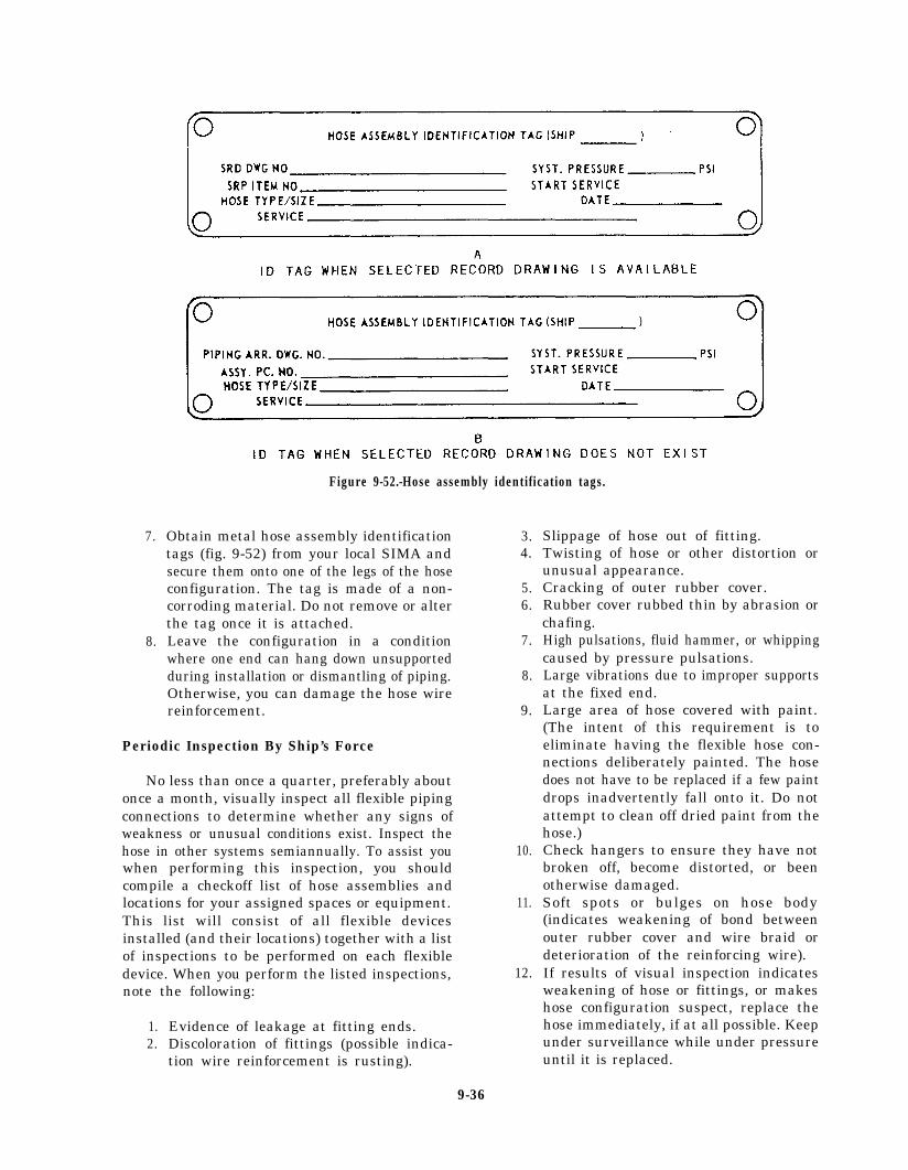
Figure 9-52.-Hose assembly identification tags.
7.
8.
Obtain metal hose assembly identificationtags (fig. 9-52) from your local SIMA andsecure them onto one of the legs of the hoseconfiguration. The tag is made of a non-corroding material. Do not remove or alterthe tag once it is attached.Leave the configuration in a conditionwhere one end can hang down unsupportedduring installation or dismantling of piping.Otherwise, you can damage the hose wirereinforcement.
Periodic Inspection By Ship’s Force
No less than once a quarter, preferably aboutonce a month, visually inspect all flexible pipingconnections to determine whether any signs ofweakness or unusual conditions exist. Inspect thehose in other systems semiannually. To assist youwhen performing this inspection, you shouldcompile a checkoff list of hose assemblies andlocations for your assigned spaces or equipment.This list will consist of all flexible devicesinstalled (and their locations) together with a listof inspections to be performed on each flexibledevice. When you perform the listed inspections,note the following:
1.2.
Evidence of leakage at fitting ends.Discoloration of fittings (possible indica-tion wire reinforcement is rusting).
9-36
3.4.
5.6.
7.
8.
9.
10.
11.(indicates weakening of bond betweenouter rubber cover and wire braid ordeterioration of the reinforcing wire).
12.
Slippage of hose out of fitting.Twisting of hose or other distortion orunusual appearance.Cracking of outer rubber cover.Rubber cover rubbed thin by abrasion orchafing.High pulsations, fluid hammer, or whippingcaused by pressure pulsations.Large vibrations due to improper supportsat the fixed end.Large area of hose covered with paint.(The intent of this requirement is toeliminate having the flexible hose con-nections deliberately painted. The hosedoes not have to be replaced if a few paintdrops inadvertently fall onto it. Do notattempt to clean off dried paint from thehose.)Check hangers to ensure they have notbroken off, become distorted, or beenotherwise damaged.Soft spots or bulges on hose body
If results of visual inspection indicatesweakening of hose or fittings, or makeshose configuration suspect, replace thehose immediately, if at all possible. Keepunder surveillance while under pressureuntil it is replaced.
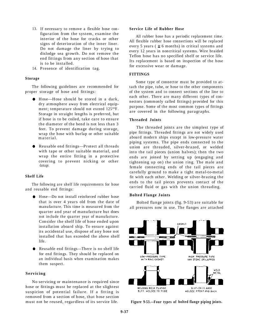
13.
14.
If necessary to remove a flexible hose con-figuration from the system, examine theinterior of the hose for cracks or othersigns of deterioration of the inner liner.Do not damage the liner by trying todislodge sea growth. Do not remove theend fittings from any section of hose thatis to be installed.Presence of identification tag.
Storage
The following guidelines are recommended forproper storage of hose and fittings:
Hose—Hose should be stored in a dark,dry atmosphere away from electrical equip-ment; temperature should not exceed 125°“F.Storage in straight lengths is preferred, butif hose is to be coiled, take care to ensurethe diameter of the bend is not less than 3feet. To prevent damage during storage,wrap the hose with burlap or other suitable
Reusable end fittings—Protect all threads
material.
damage.
with tape or other suitable material, andwrap the entire fitting in a protectivecovering to prevent nicking or other
Shelf Life
The following are shelf life requirements for hoseand reusable end fittings:
Hose—Do not install reinforced rubber hosethat is over 4 years old from the date ofmanufacture. This time is measured from thequarter and year of manufacture but doesnot include the quarter year of manufacture.Consider the shelf life of hose ended uponinstallation aboard ship. To ensure againstits accidental use, dispose of any hose notinstalled that has exceeded the above shelflife.
Reusable end fittings—There is no shelf lifefor end fittings. They should be replaced onan individual basis when examination makesthem suspect.
Servicing
No servicing or maintenance is required sincehose or fittings must be replaced at the slightestsuspicion of potential failure. If a fitting isremoved from a section of hose, that hose sectionmust not be reused, regardless of its service life.
Service Life of Rubber Hose
All rubber hose has a periodic replacement time.All flexible rubber hose connections will be replacedevery 5 years ( * 6 months) in critical systems andevery 12 years in noncritical systems. Wire braidedTeflon hose has no specified shelf or service life.Its replacement is based on inspection of the hosefor excessive wear or damage.
FITTINGS
Some type of connector must be provided to at-tach the pipe, tube, or hose to the other componentsof the system and to connect sections of the line toeach other. There are many different types of con-nectors (commonly called fittings) provided for thispurpose. Some of the most common types of fittingsare covered in the following paragraphs.
Threaded Joints
The threaded joints are the simplest type ofpipe fittings. Threaded fittings are not widely usedaboard modern ships except in low-pressure waterpiping systems. The pipe ends connected to theunion are threaded, silver-brazed, or weldedinto the tail pieces (union halves); then the twoends are joined by setting up (engaging andtightening up on) the union ring. The male andfemale connecting ends of the tail pieces arecarefully ground to make a tight metal-to-metalfit with each other. Welding or silver-brazing theends to the tail pieces prevents contact of thecarried fluid or gas with the union threading.
Bolted Flange Joints
Bolted flange joints (fig. 9-53) are suitable forall pressures now in use. The flanges are attached
Figure 9-53.—Four types of bolted flange piping joints.
9-37

Figure 9-54.—Various types of welded joints.
to the piping by welding, brazing, screw threads(for some low-pressure piping), or rolling andbending into recesses. Those shown in figure 9-53are the most common types of flange joints used.Flange joints are manufactured for all standardfitting shapes, such as the tee, cross, elbow, andreturn bend. The Van Stone and the welded-neckflange joints are used extensively where piping issubjected to high pressures and heavy expansionstrains. The design of the Van Stone flange makesit easier to line up the fastening holes in the twoparts of the flange.
Welded Joints
The majority of joints found in subassembliesof piping systems are welded joints, especiallyin high-pressure piping. The welding is doneaccording to standard specifications, which definethe material and techniques. Three general classesof welded joints are fillet-weld, butt-weld, andsocket-weld (fig. 9-54).
Silver-Brazed Joints
Silver-brazed joints (fig. 9-55) are commonlyused for joining nonferrous piping when thepressure and temperature in the lines make theiruse practicable—temperatures must not exceed425°F; for cold lines, pressure must not exceed3000 psi. The alloy is melted by heating the jointwith an oxyacetylene torch. This causes the moltenmetal to fill the few thousandths of an inchannular space between the pipe and the fitting.
Unions
The union fittings are provided in pipingsystems to allow the piping to be taken down for
Figure 9-55.—Silver-brazed joints.
9-38

Figure 9-56.—Unions/threaded pipe connectors.
Figure 9-57.-Flared-tube fittings.repairs and alterations. Unions are available inmany different materials and designs to withstanda wide range of pressures and temperatures.Figure 9-56 shows some commonly used types ofunions/threaded pipe connectors. The union ismost commonly used for joining piping up to 2inches in size.
Flared Fittings
Flared fittings are commonly used in tubinglines. These fittings provide safe, strong,dependable connections without the necessity ofthreading, welding, or soldering the tubing. Flaredfittings are made of steel, aluminum alloy, orbronze. Do not mix materials when using thesefittings. For example, for steel tubing use onlysteel fittings and for copper or brass tubing useonly bronze fittings, Figure 9-57 shows the mostcommon types of flared fittings.
Figure 9-58.-Double-male flareless fitting.
Flareless Fittings
Flareless fittingssuitable for use in
(figs. 9-58 and 9-59) arehydraulic service and air Figure 9-59.—Typical flareless fitting.
9-39
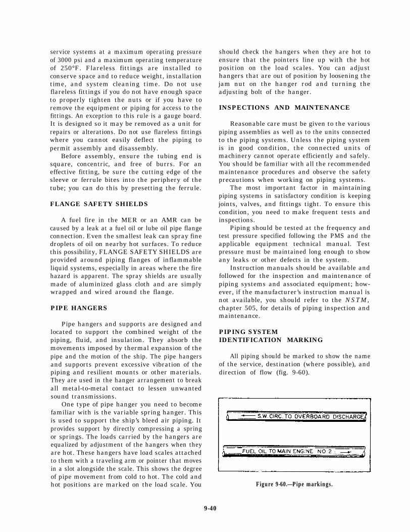
service systems at a maximum operating pressureof 3000 psi and a maximum operating temperatureof 250°F. Flareless fittings are installed toconserve space and to reduce weight, installationtime, and system cleaning time. Do not useflareless fittings if you do not have enough spaceto properly tighten the nuts or if you have toremove the equipment or piping for access to thefittings. An exception to this rule is a gauge board.It is designed so it may be removed as a unit forrepairs or alterations. Do not use flareless fittingswhere you cannot easily deflect the piping topermit assembly and disassembly.
Before assembly, ensure the tubing end issquare, concentric, and free of burrs. For aneffective fitting, be sure the cutting edge of thesleeve or ferrule bites into the periphery of thetube; you can do this by presetting the ferrule.
FLANGE SAFETY SHIELDS
A fuel fire in the MER or an AMR can becaused by a leak at a fuel oil or lube oil pipe flangeconnection. Even the smallest leak can spray finedroplets of oil on nearby hot surfaces. To reducethis possibility, FLANGE SAFETY SHIELDS areprovided around piping flanges of inflammableliquid systems, especially in areas where the firehazard is apparent. The spray shields are usuallymade of aluminized glass cloth and are simplywrapped and wired around the flange.
PIPE HANGERS
Pipe hangers and supports are designed andlocated to support the combined weight of thepiping, fluid, and insulation. They absorb themovements imposed by thermal expansion of thepipe and the motion of the ship. The pipe hangersand supports prevent excessive vibration of thepiping and resilient mounts or other materials.They are used in the hanger arrangement to breakall metal-to-metal contact to lessen unwantedsound transmissions.
One type of pipe hanger you need to becomefamiliar with is the variable spring hanger. Thisis used to support the ship’s bleed air piping. Itprovides support by directly compressing a springor springs. The loads carried by the hangers areequalized by adjustment of the hangers when theyare hot. These hangers have load scales attachedto them with a traveling arm or pointer that movesin a slot alongside the scale. This shows the degreeof pipe movement from cold to hot. The cold andhot positions are marked on the load scale. You
should check the hangers when they are hot toensure that the pointers line up with the hotposition on the load scales. You can adjusthangers that are out of position by loosening thejam nut on the hanger rod and turning theadjusting bolt of the hanger.
INSPECTIONS AND MAINTENANCE
Reasonable care must be given to the variouspiping assemblies as well as to the units connectedto the piping systems. Unless the piping systemis in good condition, the connected units ofmachinery cannot operate efficiently and safely.You should be familiar with all the recommendedmaintenance procedures and observe the safetyprecautions when working on piping systems.
The most important factor in maintainingpiping systems in satisfactory condition is keepingjoints, valves, and fittings tight. To ensure thiscondition, you need to make frequent tests andinspections.
Piping should be tested at the frequency andtest pressure specified following the PMS and theapplicable equipment technical manual. Testpressure must be maintained long enough to showany leaks or other defects in the system.
Instruction manuals should be available andfollowed for the inspection and maintenance ofpiping systems and associated equipment; how-ever, if the manufacturer’s instruction manual isnot available, you should refer to the NSTM,chapter 505, for details of piping inspection andmaintenance.
PIPING SYSTEMIDENTIFICATION MARKING
All piping should be marked to show the nameof the service, destination (where possible), anddirection of flow (fig. 9-60).
Figure 9-60.—Pipe markings.
9-40

The name of the service and destination shouldbe painted on by stencil or hand lettering, or byapplication of previously printed, stenciled, orlettered adhesive-backed tape. Lettering will be1 inch high for a 2-inch or larger OD bare pipeor insulation. For smaller sizes, lettering size maybe reduced or label plates attached by wire orother suitable means.
Direction of flow will be indicated by anarrow 3 inches long pointing away from the let-tering. For reversible flow, arrows are to be shownon each end of the lettering.
Black is used for lettering and arrows.However, on dark-colored pipe (including oxygenpiping), white is used.
Markings will be applied to piping inconspicuous locations, preferably near thecontrol valves and at suitable intervals so everyline will have at least one identification markingin each compartment through which it passes.Piping in cabins and officers’ wardrooms will notnormally be marked.
PACKING AND GASKETMATERIAL
Packing and gasket materials are required toseal joints in steam, water, gas, air, oil, and otherlines and to seal connections that slide or rotateunder normal operating conditions. There aremany types and forms of packing and gasketmaterials available commercially.
PACKING AND GASKET SELECTION
To simplify the selection of packing and gasketmaterials commonly used in naval service, theNaval Sea Systems Command has prepared apacking and gasket chart, Mechanical StandardDrawing B-153. It shows the symbol numbers andthe recommended applications for all types andkinds of packing and gasket materials.
The symbol number used to identify each typeof packing and gasket has a four-digit number.The first digit shows the class of service withrespect to fixed and moving joints; the numeral1 shows a moving joint (moving rods, shafts, valvestems), and the numeral 2 shows a fixed joint(flanges, bonnets). The second digit shows thematerial of which the packing or gasket isprimarily composed—asbestos, vegetable fibre,
rubber, metal, and so forth. The third and fourthdigits show the different styles or forms of thepacking or gasket made from the material.
Practically all shipboard packing and gasketproblems can be solved by selection of thecorrect material from the listings on the packingand gasket chart. The following examples showthe kind of information that you can get from thepacking and gasket chart.
Suppose you are required to repack andinstall a valve in a 150-psi seawater service system.Under the subhead Symbols and Specificationsfor Equipments, Piping and Independent Systems,you find that symbol 1103 indicates a suitablematerial for repacking the valve. Notice that thefirst digit is the numeral 1, indicating that thematerial is for use in a moving joint. Under theList of Materials, you find the packing is asbestosrod, braided.
For installing the valve, you need propergaskets. By use of the same subhead, you find thatsymbols 2150, 2151 type II, 2152, and 2290 typeII are all suitable for installing the valve. Noticethat the first digit is the numeral 2, which indicatesthat it is designed for fixed joints. Again, byreferring to the List of Materials, you candetermine the composition of the gasket.
Besides the Naval Ship Systems Commanddrawing, most ships have a packing and gasketchart made up specifically for each ship. The ship-board chart shows the symbol numbers and thesizes of packing and gaskets required in the ship’spiping system, machinery, and hull fittings.
PACKING OF MOVING JOINTS
Valves are components used to control thetransfer of liquids and gases through fluidpiping systems. Most valves have moving jointsbetween the valve stem and the bonnet. Whenfluid is on one or both sides of a moving joint,the joint may leak. Sealing the joint prevents thisleakage. Sealing a moving joint presents aproblem because the seal must be tight enoughto prevent leakage, yet loose enough to let thevalve stem turn without binding. Packing is themost common method of sealing a moving joint.
Packing is a sealing method that uses bulkmaterial (packing) that is reshaped by compression
9-41
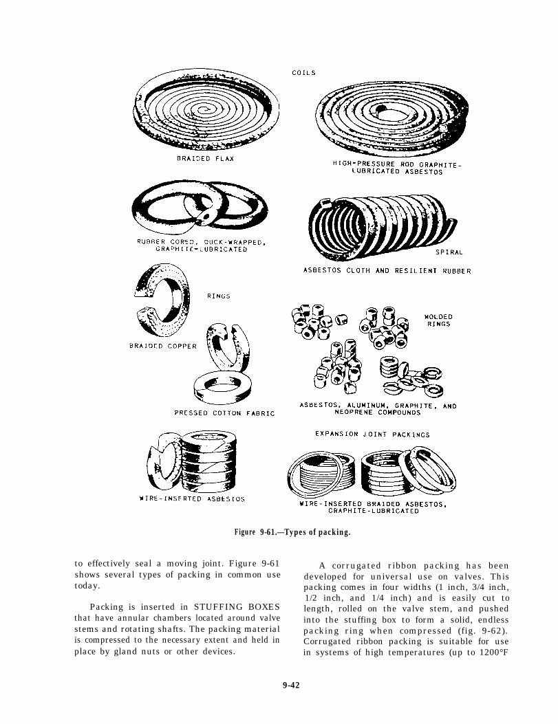
Figure
to effectively seal a moving joint. Figure 9-61shows several types of packing in common usetoday.
Packing is inserted in STUFFING BOXESthat have annular chambers located around valvestems and rotating shafts. The packing materialis compressed to the necessary extent and held inplace by gland nuts or other devices.
9-61.—Types of packing.
A corrugated ribbon packing has beendeveloped for universal use on valves. Thispacking comes in four widths (1 inch, 3/4 inch,1/2 inch, and 1/4 inch) and is easily cut tolength, rolled on the valve stem, and pushedinto the stuffing box to form a solid, endlesspacking ring when compressed (fig. 9-62).Corrugated ribbon packing is suitable for usein systems of high temperatures (up to 1200°F
9-42

Figure 9-62.—Corrugated ribbon packing.
and 2000 psi). It is easily removed since it doesnot harden.
PACKING OF FIXED JOINTS
Figure 9-63 shows gasket material used forfixed joints. At one time, fixed joints could besatisfactorily sealed with gaskets of compressed
asbestos sheet packing (view A of fig. 9-63).Today the 15 percent rubber content of thepacking makes it unsatisfactory for modern, high-temperature, high-pressure equipment. Two typesof gaskets (metallic or semimetallic) are in use inpresent day high-temperature and high-pressureinstallations. Gaskets of corrugated copper or ofasbestos and copper are sometimes used on low-and medium-pressure lines.
Serrated-face metal gaskets (view B of fig.9-63) made of steel, Monel, or soft iron haveraised serrations to make a better seal at thepiping flange joints. These gaskets have resiliency.Line pressure forces the serrated faces tighteragainst the adjoining flange. The gaskets shownare of two variations.
Spiral-wound, metallic-asbestos gaskets (viewC of fig. 9-63) are made of interlocked strandsof preformed corrugated metal and asbestosstrips, spirally wound together (normally calledthe FILLER), and a solid metal outer or centering
Figure 9-63.—Fixed-joint gaskets. A. Sheet asbestos gaskets. B. Serrated-face metal gaskets. C. Spiral-wound, metallic-asbestosgaskets.
9-43

ring (normally called the RETAINING RING).The centering ring is used as a reinforcement toprevent blowouts. The filler piece is replaceable.When renewing a gasket, you should remove thispiece from the retaining metal ring and replaceit with a new filler. Do not discard the solid metalretaining outer or centering ring unless it isdamaged. You can compress the gaskets to thethickness of the outer or centering ring.
When renewing a gasket in a flange joint, youmust exercise special precautions when breakingthe joint, particularly in steam and hot water lines,or in saltwater lines that have a possibility of directconnection with the sea. Be sure to observe thefollowing precautions:
1.2.
3.4.
5.
6.
No pressure is on the line.The line pressure valves, including thebypass valves, are firmly secured, wiredclosed, and tagged.The line is completely drained.At least two flange-securing bolts and nutsdiametrically opposite remain in place untilthe others are removed, then slackened toallow breaking of the joint, and removedafter the line is clear.Precautions are taken to prevent explosionsor fire when breaking joints of flammableliquid lines.Proper ventilation is ensured before jointsare broken in closed compartments.
These precautions may prevent serious ex-plosions, severe scalding of personnel, or floodingof compartments. You should thoroughly cleanall sealing and bearing surfaces for the gasketreplacement. Check the gasket seats with asurface plate, and scrape as necessary. Thisaffords uniform contact. Replace all damagedbolt studs and nuts. In flange joints with raisedfaces, the edges of gaskets may extend beyond theedge of the raised face.
O-RINGS
Another method of preventing leakage in fluidsystems is by use of O-ring seals. Figure 9-64shows an O-ring seal with two cross-sectionalviews. An O-ring is a doughnut-shaped, circularseal (view A of fig. 9-64) that is usually a moldedrubber compound. An O-ring seal has an O-ringmounted in a groove or cavity (usually called agland).
Figure 9-64.—O-ring seal with two cross-sectional views.
When the gland is assembled (view B of fig.9-64), the O-ring cross section is compressed.When installed, the compression of the O-ringcross section enables it to seal low fluid pressures.The greater the compression, the greater is thefluid pressure that can be sealed by the O-ring.The pressure of the O-ring against the glandwalls equals the pressure caused by the recoveryforce of the compressed O-ring plus the fluidpressure.
The fluid pressure against the walls of thegland and the stiffness of the O-ring prevent fluidfrom leaking past the O-ring. If the downstreamclearance is large, the O-ring is forced into thisclearance (view C of fig. 9-64). The stiffness ofthe O-ring material prevents the O-ring frombeing forced completely through the downstreamclearance unless that clearance is abnormally largeor the pressure is excessive.
O-rings are commonly used for sealing becauseof their simplicity, ruggedness, low cost, ease ofinstallation, ease of maintenance, and effective-ness over wide pressure and temperature ranges.
9-44

Failure of an O-ring can sometimes begin withthe removal of an old O-ring. If you incorrectlyremove an O-ring with pointed or sharp tools, youcan scratch or dent critical surface finishes thatcan result in seal failure.
Before installing a new O-ring, inspect thesealing surfaces for any abrasions and wipe themfree of any dust, dirt, or other contaminants.Before installation, inspect the O-ring for anydamage. If faulty, discard it.
When you install the O-ring, lubricate it. Inmost cases it is already coated with the systemfluid or petrolatum grease. Do not stretch theO-ring more than twice its original size duringinstallation, and do not roll or twist it intoplace. This may leave a permanent twist in theO-ring and reduce its effectiveness and shortenits life.
When installing an O-ring, take extremecare to avoid forcing it over sharp edges,corners, and threaded sections. You should usesome type of sleeve or cover to avoid damagingthe O-ring.
FASTENERS
The proper use of fasteners is very importantand cannot be overemphasized. Many shipboardmachinery casualties have resulted from fastenersthat were not properly installed. Machineryvibration, thermal expansion, and thermalcontraction will loosen the fasteners. At sea,loosening effects are increased by the pitch androll of the ship. You are familiar with suchstandard fasteners as nuts, bolts, washers,wingnuts, and screws. In this section we willdiscuss some of the new developments in fastenertechnology, such as the various types of locknuts,which you may not be familiar with.
THREADED LOCKING DEVICES
An important part of fastener technology hasincluded the development of several methods forlocking mated threads of fasteners. Many of thelatest methods include the locking device ormethod as an integral part of the fastenerassembly and are referred to as self-lockingnuts or bolts. Self-locking fasteners are more
expensive than some older methods but comparefavorably in cost with pin or wiring methods.
Length of Protrusion
Male threads on threaded fasteners, wheninstalled and tightened, will protrude the distanceof at least one thread length beyond thetop of the nut or plastic locking ring. Excessiveprotrusion is a hazard, particularly wherenecessary clearances, accessibility, and safety areimportant. Where practicable, the number ofthreads protruding should not exceed five. In nocase should thread protrusion exceed 10 threadsunless specifically approved by the work super-visor. (This is the 1-to-10 rule.)
Where screw threads are used for setting oradjusting (such as valve stem packing glands andtravel stops) or where installed threaded fastenersdo not strictly follow the 1-to-10 rule but havegiven satisfactory service, the rule does notapply. An example of an acceptable existinginstallation would be where a male thread is flushwith the top of a nut or where more than 10threads protruding is of no foreseeable con-sequence.
Repair of Damaged Threads
You can remedy damaged external threads byreplacing the fastener. In large equipment castingsyou must repair damaged internal threads to savethe part. You can repair internal threads byredrilling the damaged thread; clean and eitherinstall a solid wall insert or tap for a helical coilinsert. These inserts, in effect, return the tappedhole to its original size so it takes the originalmating fastener.
LOCKNUTS
Locknuts are used in special applicationswhere you want to ensure that the componentsjoined by the fasteners will not loosen. Two typesof locknuts are in common use. The first typeapplies pressure to the bolt thread and can beused where frequent removal may be required.The second type deforms the bolt thread and isused only where frequent removal is unnecessary.The first type includes plastic ring nuts, nyloninsert nuts, jam nuts, spring nuts, and springbeam nuts. The second type includes distortedcollar nuts and distorted thread nuts; they are notcommonly found in gas turbine equipment andwill not be covered in this section.
9-45
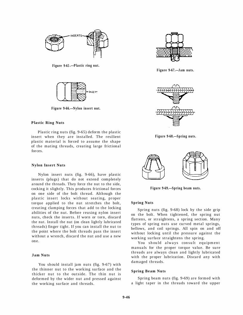
Figure 9-65 .—Plastic ring nut.Figure 9-67.—Jam nuts.
Figure 9-66.—Nylon insert nut.
Plastic Ring Nuts
Plastic ring nuts (fig. 9-65) deform the plasticinsert when they are installed. The resilientplastic material is forced to assume the shapeof the mating threads, creating large frictionalforces.
Nylon Insert Nuts
Nylon insert nuts (fig. 9-66), have plasticinserts (plugs) that do not extend completelyaround the threads. They force the nut to the side,cocking it slightly. This produces frictional forceson one side of the bolt thread. Although theplastic insert locks without seating, propertorque applied to the nut stretches the bolt,creating clamping forces that add to the lockingabilities of the nut. Before reusing nylon insertnuts, check the inserts. If worn or torn, discardthe nut. Install the nut (on clean lightly lubricatedthreads) finger tight. If you can install the nut tothe point where the bolt threads pass the insertwithout a wrench, discard the nut and use a newone.
Jam Nuts
You should install jam nuts (fig. 9-67) withthe thinner nut to the working surface and thethicker nut to the outside. The thin nut isdeformed by the wider nut and pressed againstthe working surface and threads.
Figure 9-68.—Spring nuts.
Figure 9-69.—Spring beam nuts.
Spring Nuts
Spring nuts (fig. 9-68) lock by the side gripon the bolt. When tightened, the spring nutflattens, or straightens, a spring section. Manytypes of spring nuts use curved metal springs,bellows, and coil springs. All spin on and offwithout locking until the pressure against theworking surface straightens the spring.
You should always consult equipmentmanuals for the proper torque value. Be surethreads are always clean and lightly lubricatedwith the proper lubrication. Discard any withdamaged threads.
Spring Beam Nuts
Spring beam nuts (fig. 9-69) are formed witha light taper in the threads toward the upper
9-46

portion of the nut. Slots are cut in the outerportion, forming segments that can be forcedoutward when the nut is installed. Elasticreaction causes the segments to push inward,gripping the bolt. Like the nylon insert nut, thisnut does not deform the bolt threads and can beused on frequently removed items. If you canthread the nut past the deflection segmentswithout a wrench, discard the nut and replace itwith a new one.
LOCKWASHERS
Many installations on board naval ships stilluse lockwashers to prevent threaded fastenersfrom loosening. If loosening has not been aproblem, you may replace worn lockwashers withan identical type; however, if loosening has beena problem, you should use self-locking fastenersinstead of lockwashers.
The most common lockwasher used is thehelical spring washer. Other types are the conicaland toothed tab.
Helical Spring Lockwashers
The helical spring lockwasher (split ring) (fig.9-70) is flattened when the bolt is torqued down,When torqued, it acts as a flat washer contributingnormal friction for locking the screw or bolt andthe working surface; it also maintains the tensionon the bolt. Because of the helical springlockwasher’s small diameter, it is usually notused on soft materials or with oversized orelongated holes.
Curved or Conical Spring Lockwashers
Curved or conical spring lockwashers havealmost the same properties as the helical springlockwasher. They provide a constant tension onthe bolt or screw when loosened. The tensionproduced is usually less than that produced by thehelical spring lockwasher. Like any locking devicerelying on tension, spring lockwashers may loosenon shock loading. When the bolt stretches more
Figure 9-70.—Helical spring lockwasher.
Figure 9-71.—Toothed lockwashers.
than the spring distortion from the shock loading,the washer serves no further purpose. Recheck thewasher, where possible, when shock is sufficientto suspect loosening. Some spring lockwashershave teeth on the outer edge. These teeth do notaid in locking, but they prevent side slippage andturning.
Toothed Lockwashers
Toothed lockwashers (fig, 9-71) have teeth thatare twisted or bent to prevent loosening. Cuttingedges engage both working surfaces on the nutand bolt or screw. Some have teeth on the innerdiameter for applications where teeth projectingbeyond the nut are not desired, The most commontype have teeth on the outer diameter. Washerswith teeth on both inside and outside diametersare used for soft materials and oversize holes.The teeth are twisted, so as the nut is installed andtorqued down, the rim of the washer supports thepressure. Any backing off of the nut or boltreleases tension that allows the teeth to dig intothe working surfaces of the nut and bolt.
INSULATION
The purpose of insulation is to retard thetransfer of heat FROM piping that is hotter thanthe surrounding atmosphere or TO piping thatis cooler than the surrounding atmosphere.Insulation helps to maintain the desired temper-atures in all systems. In addition, it preventssweating of piping that carries cool or cold fluids.Insulation also serves to protect personnel frombeing burned by coming in contact with hotsurfaces. Piping insulation represents the com-posite piping covering, which consists of theinsulating material, lagging, and fastening. TheINSULATING MATERIAL offers resistance tothe flow of heat; the LAGGING, usually ofpainted canvas, is the protective and confiningcovering placed over the insulating materials; and
9-47

the FASTENING attaches the insulating materialto the piping and to the lagging.
Insulation covers a wide range of temper-atures, from the extremely low temperatures ofthe refrigerating plants to the very high temper-atures of the ship’s waste heat boilers. No onematerial could possibly be used to meet all theconditions with the same efficiency.
INSULATION MATERIALS
The following QUALITY REQUIREMENTSfor the various insulating materials are taken intoconsideration by the Navy in the standardizationof these materials:
1. Low heat conductivity2. Noncombustibility3. Lightweight4. Easy molding and installation capability5. Moisture repellant6. Noncorrosive, insoluble, and chemically
inactive7. Composition, structure, and insulating
properties unchanged by temperatures at which it is to be used
8. Once installed, should not cluster, becomelumpy, disintegrate, or build up in massesfrom vibration
9. Verminproof10. Hygienically safe to handle
Insulating material is available in preformedpipe coverings, blocks, batts, blankets, and felts.Refer to NSTM, Chapter 635, “Thermal, Fire,and Acoustic Insulation,” for detailed informa-tion on insulating materials, their application, andsafety precautions.
The insulating cements are comprised of avariety of materials, differing widely amongthemselves as to heat conductivity, weight, andother physical characteristics. Typical of thesevariations are the asbestos substitute cements,diatomaceous cements, and mineral and slag woolcements. These cements are less efficient thanother high-temperature insulating materials, butthey are valuable for patchwork emergency repairsand for covering small irregular surfaces (valves,flanges, joints, and so forth). Additionally, thecements are used for a surface finish over blockor sheet forms of insulation, to seal jointsbetween the blocks, and to provide a smoothfinish over which asbestos substitute or glass clothlagging may be applied.
REMOVABLE INSULATION
Removable insulation will be found on thebleed air systems and waste heat boiler systems.Removable insulation is also installed in thefollowing locations:
. Flange pipe joints adjacent to machineryor equipment that must be broken whenunits are opened for inspection or overhaul
. Valve bonnets of valves larger than 2inches internal pipe size (IPS) that operateat 300 psi and above or at 240°F and above
. All pressure-reducing and pressure-regu-lating valves, pump pressure governors,and strainer bonnets
GENERAL INSULATIONPRECAUTIONS
You should observe the following generalprecautions relative to the application andmaintenance of insulation:
1. Fill and seal all air pockets and cracks.Failure to do this will cause large losses inthe effectiveness of the insulation.
2. Seal the ends of the insulation and taperoff to a smooth, airtight joint. At jointends or other points where insulation isliable to be damaged, use sheet metallagging over the insulation. You shouldcuff flanges and joints with 6-inch lagging.
3. Keep moisture out of all insulation work.Moisture is an enemy of heat insulation justas much as it is in electrical insulation. Anydampness increases the conductivity of allheat-insulating materials.
4. Insulate all hangers and other supports attheir point of contact from the pipe orother unit they are supporting; otherwise,a considerable quantity of heat will be lostvia conduction through the support.
5. Keep sheet metal covering bright andunpainted unless the protective surface hasbeen damaged or has worn off. The radia-tion from bright-bodied and light-coloredobjects is considerably less than fromrough and dark-colored objects.
6. Once installed, heat insulation requirescareful inspection, upkeep, and repair.Replace lagging and insulation removed tomake repairs as carefully as when originally
9-48

installed. When replacing insulation, makecertain that the replacement material is ofthe same type as had been used originally.
7. Insulate all flanges with easily removableforms. These forms are made up as padsof insulating material, wired or bound inplace, and the whole covered with sheetmetal casings, which are in halves.
8. Asbestos control: Inhalation of excessivequantities of asbestos fibre or filler canproduce severe lung damage in the form ofdisabling or fatal fibrosis of the lungs.Asbestos has also been found to be a casualfactor in the development of cancer of themembrane lining the chest and abdomen.Lung damage and disease usually developslowly and often do not become apparentuntil years after the initial exposure. Ifyour plans include a long and healthyNavy retirement, you have no businessdoing asbestos lagging rip-out withoutproper training, protective clothing, and
supervision. Most systems of today’smodern Navy have been purged of asbestosand an asbestos substitute material installedin its place. Some of the older class vesselsmay still have some asbestos insulationinstalled. Use caution when handlinglagging and insulation from these vessels.If in doubt, contact your supervisor andrequest the medical department conduct asurvey of the material in question.
SUMMARY
This chapter has given you general informa-tion on pumps, valves, and piping. It would bea good idea to get some hands-on experienceaboard your ship. Trace various systems out andsee how they are set up. Ask your LPO to explainthe systems and how each part in the systemworks. The key phrase here is ASK QUESTIONS!
9-49

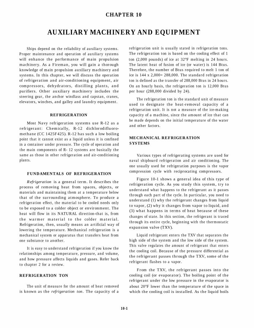
CHAPTER 10
AUXILIARY MACHINERY AND EQUIPMENT
Ships depend on the reliability of auxiliary systems.Proper maintenance and operation of auxiliary systemswill enhance the performance of main propulsionmachinery. As a Fireman, you will gain a thoroughknowledge of main propulsion auxiliary machinery andsystems. In this chapter, we will discuss the operationof refrigeration and air-conditioning equipment, aircompressors, dehydrators, distilling plants, andpurifiers. Other auxiliary machinery includes thesteering gear, the anchor windlass and capstan, cranes,elevators, winches, and galley and laundry equipment.
REFRIGERATION
Most Navy refrigeration systems use R-12 as arefrigerant: Chemically, R-12 dichlorodifluoro-methane (CC 1425F425). R-12 has such a low boilingpoint that it cannot exist as a liquid unless it is confinedin a container under pressure. The cycle of operation andthe main components of R- 12 systems are basically thesame as those in other refrigeration and air-conditioningplants.
FUNDAMENTALS OF REFRIGERATION
Refrigeration is a general term. It describes theprocess of removing heat from spaces, objects, ormaterials and maintaining them at a temperature belowthat of the surrounding atmosphere. To produce arefrigeration effect, the material to be cooled needs onlyto be exposed to a colder object or environment. Theheat will flow in its NATURAL direction-that is, fromthe warmer material to the colder material.Refrigeration, then, usually means an artificial way oflowering the temperature. Mechanical refrigeration is amechanical system or apparatus that transfers heat fromone substance to another.
It is easy to understand refrigeration if you know therelationships among temperature, pressure, and volume,and how pressure affects liquids and gases. Refer backto chapter 2 for a review.
REFRIGERATION TON
The unit of measure for the amount of heat removedis known as the refrigeration ton. The capacity of a
refrigeration unit is usually stated in refrigeration tons.The refrigeration ton is based on the cooling effect of 1ton (2,000 pounds) of ice at 32°F melting in 24 hours.The latent heat of fusion of ice (or water) is 144 Btus.Therefore, the number of Btus required to melt 1 ton ofice is 144 x 2,000= 288,000. The standard refrigerationton is defined as the transfer of 288,000 Btus in 24 hours.On an hourly basis, the refrigeration ton is 12,000 Btusper hour (288,000 divided by 24).
The refrigeration ton is the standard unit of measureused to designate the heat-removal capacity of arefrigeration unit. It is not a measure of the ice-makingcapacity of a machine, since the amount of ice that canbe made depends on the initial temperature of the waterand other factors.
MECHANICAL REFRIGERATIONSYSTEMS
Various types of refrigerating systems are used fornaval shipboard refrigeration and air conditioning. Theone usually used for refrigeration purposes is the vaporcompression cycle with reciprocating compressors.
Figure 10-1 shows a general idea of this type ofrefrigeration cycle. As you study this system, try tounderstand what happens to the refrigerant as it passesthrough each part of the cycle. In particular, you need tounderstand (1) why the refrigerant changes from liquidto vapor, (2) why it changes from vapor to liquid, and(3) what happens in terms of heat because of thesechanges of state. In this section, the refrigerant is tracedthrough its entire cycle, beginning with the thermostaticexpansion valve (TXV).
Liquid refrigerant enters the TXV that separates thehigh side of the system and the low side of the system.This valve regulates the amount of refrigerant that entersthe cooling coil. Because of the pressure differential asthe refrigerant passes through the TXV, some of therefrigerant flashes to a vapor.
From the TXV, the refrigerant passes into thecooling coil (or evaporator). The boiling point of therefrigerant under the low pressure in the evaporator isabout 20°F lower than the temperature of the space inwhich the cooling coil is installed. As the liquid boils
10-1
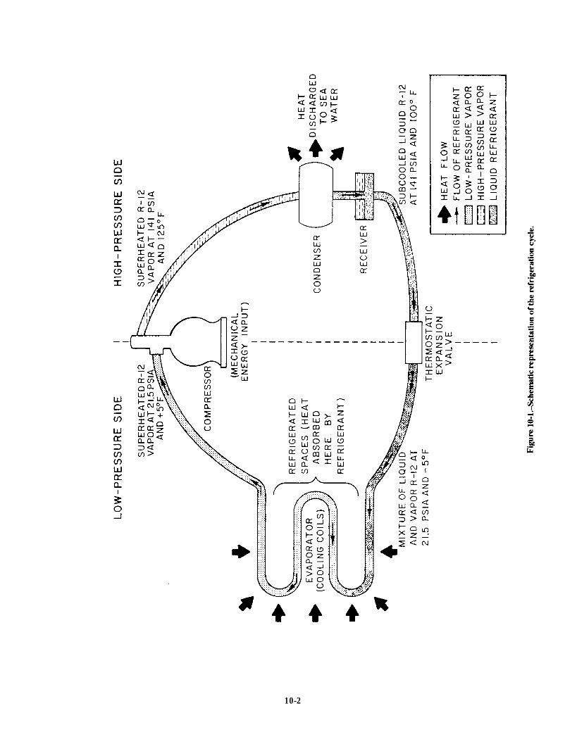
Figure 10-1.
10-2

and vaporizes, it picks up latent heat of vaporizationfrom the space being cooled. The refrigerantcontinues to absorb latent heat of vaporization untilall the liquid has been vaporized. By the time therefrigerant leaves the cooling coil, it has not onlyabsorbed this latent heat of vaporization. It has alsopicked up some additional heat; that is, the vaporhas become superheated. As a rule, the amount ofsuperheat is 4° to 12°F.
The refrigerant leaves the evaporator as low-pressure superheated vapor. The remainder of thecycle is used to dispose of this heat and convert therefrigerant back into a liquid state so that it canagain vaporize in the evaporator and absorb the heatagain.
The low-pressure superheated vapor is drawn outof the evaporator by the compressor, which alsokeeps the refrigerant circulating through the system.In the compressor cylinders, the refrigerant iscompressed from a low-pressure, low-temperaturevapor to a high-pressure vapor, and its temperaturerises accordingly.
The high-pressure R-12 vapor is discharged fromthe compressor into the condenser. Here therefrigerant condenses, giving up its superheat(sensible heat) and its latent heat of condensation.The condenser may be air or watercooled. Therefrigerant, still at high pressure, is now a liquidagain. From the condenser, the refrigerant flows intoa receiver, which serves as a storage place for theliquid refrigerant in the system. From the receiver,the refrigerant goes to the TXV and the cycle beginsagain.
This type of refrigeration system has twopressure sides. The LOW-PRESSURE SIDE extendsfrom the TXV up to and including the intake side ofthe compressor cylinders. The HIGH-PRESSURESIDE extends from the discharge valve of thecompressor to the TXV. Figure 10-2 shows most ofthe components on the high-pressure side of an R- 12system as it is installed aboard ship.
MAIN PARTS OF THE R-12 SYSTEM
The main parts of an R- 12 refrigeration systemare shown diagrammatically in figure 10-3. Thesix primary components of the system includethe
1. TXV,
2. evaporator,
3. capacity control system,
4. compressor,
5. condenser, and
6. receiver.
47.92Figure 10-2.-High-pressure side of an R-12
installation aboard ship.
Additional equipment required to complete theplant includes piping, pressure gauges,thermometers, various types of control switches andcontrol valves, strainer, relief valves, sight-flowindicators, dehydrators, and charging connections.
In this chapter, we will deal with the R-12 systemas though it had only one evaporator, onecompressor, and one condenser. As you can see fromfigure 10-3, however, a refrigeration system usuallyhas more than one evaporator, and it may include anadditional compressor and condenser units.
Thermostatic Expansion Valve (TXV)
Earlier, you learned that the TXV regulates theamount of refrigerant to the cooling coil. The amountof refrigerant needed in the coil depends, of course,on the temperature of the space being cooled.
The thermal control bulb, which controlsthe opening and closing of the TXV, is clampedto the cooling coil near the outlet. The substancein the thermal bulb varies, depending on therefrigerant used. The expansion and contraction(because of temperature change) transmit apressure to the diaphragm. This causes thediaphragm to be moved downward, opening
10-3
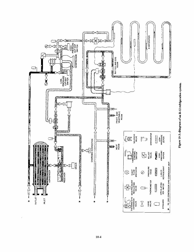
Figure 10-3.
10-4
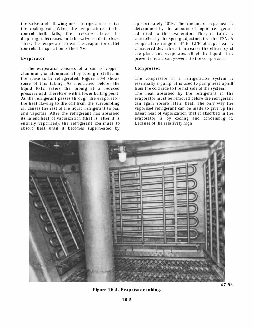
the valve and allowing more refrigerant to enterthe cooling coil. When the temperature at thecontrol bulb falls, the pressure above thediaphragm decreases and the valve tends to close.Thus, the temperature near the evaporator outletcontrols the operation of the TXV.
Evaporator
The evaporator consists of a coil of copper,aluminum, or aluminum alloy tubing installed inthe space to be refrigerated. Figure 10-4 showssome of this tubing. As mentioned before, theliquid R-12 enters the tubing at a reducedpressure and, therefore, with a lower boiling point.As the refrigerant passes through the evaporator,the heat flowing to the coil from the surroundingair causes the rest of the liquid refrigerant to boiland vaporize. After the refrigerant has absorbedits latent heat of vaporization (that is, after it isentirely vaporized), the refrigerant continues toabsorb heat until it becomes superheated by
approximately 10°F. The amount of superheat isdetermined by the amount of liquid refrigerantadmitted to the evaporator. This, in turn, iscontrolled by the spring adjustment of the TXV. Atemperature range of 4° to 12°F of superheat isconsidered desirable. It increases the efficiency ofthe plant and evaporates all of the liquid. Thisprevents liquid carry-over into the compressor.
Compressor
The compressor in a refrigeration system isessentially a pump. It is used to pump heat uphillfrom the cold side to the hot side of the system.The heat absorbed by the refrigerant in theevaporator must be removed before the refrigerantcan again absorb latent heat. The only way thevaporized refrigerant can be made to give up thelatent heat of vaporization that it absorbed in theevaporator is by cooling and condensing it.Because of the relatively high
47.93Figure 10-4.-Evaporator tubing.
10-5

temperature of the available cooling medium, the onlyway to make the vapor condense is to compress it.
When we raise the pressure, we also raise thetemperature. Therefore, we have raised its condensingtemperature, which allows us to use seawater as acooling medium in the condenser. In addition to thisprimary function, the compressor also keeps therefrigerant circulating and maintains the requiredpressure difference between the high-pressure andlow-pressure sides of the system.
Many different types of compressors are used inrefrigeration systems. The designs of compressors varydepending on the application of the refrigerants used inthe system. Figure 10-5 shows a motor-driven,single-acting, two-cylinder, reciprocating compressor,such as those commonly used in naval refrigerationplants.
Compressors used in R-12 systems may belubricated either by splash lubrication or by pressure
lubrication. Splash lubrication, which depends onmaintaining a fairly high oil level in the compressorcrankcase, is usually satisfactory for smallercompressors. High-speed or large-capacitycompressors use pressure lubrications systems.
Capacity Control System
Most compressors are equipped with anoil-pressure-operated automatic capacity controlsystem. This system unloads or cuts cylinders out ofoperation following decreases in the refrigerant loadrequirements of the plant. A cylinder is unloaded by amechanism that holds the suction valve open so that nogas can be compressed.
Since oil pressure is required to load or put cylindersinto operation, the compressor will start with allcontrolled cylinders unloaded. But as soon as thecompressor comes up to speed and full oil pressure isdeveloped, all cylinders will become operative. After
Figure 10-5.-Reciprocating compressor.
10-6

the temperature pulldown period, the refrigeration load cooling coils are supplied by one compressor, the
imposed on the compressor will decrease, and the capacity control system will prevent the suction
capacity control system will unload cylinders pressure from dropping to the low-pressure cutout
accordingly. The unloading will result in reduced power setting. This will prevent stopping the compressor
consumption. On those applications where numerous before all solenoid valves are closed.
Figure 10-6.-Capacity control system.
10-7

Several designs of capacity control systems are inuse. One of the most common is shown in figure 10-6.The capacity control system consists of a power elementand its link for each controlled cylinder, a step controlhydraulic relay, and a capacity control valve.
The system’s components are all integrally attachedto the compressor. The suction or crankcase pressure ofthe refrigeration plant is sensed by the capacity controlvalve to control the system. In other words, a change inthe refrigeration load on the plant will cause a change insuction pressure. This change in suction pressure willthen cause the capacity control system to reactaccording to whether the suction pressure increased ordecreased. The working fluid of the system iscompressor oil pump pressure. Compressor oil pumppressure is metered into the system through an orifice.Once the oil passes the orifice, it becomes the systemcontrol oil and does work.
Locate the following components on figure 10-6,and refer to them as you read the next two paragraphs.
(A)
(B)
(C)
(D)
(E)
(M)
(G)
(H)
(O)
(J )
(K)
Compressor oil pump pressure tap-off
Control oil strainer
Hydraulic relay
Hydraulic relay piston
Unloader power element
Unloader power element piston
Lifting fork
Unloader sleeve
Suction valve
Capacity control valve
Crankcase (suction) pressure sensing point
The following functions take place when thecompressor is started with a warm load on therefrigeration system.
Compressor oil (A) is pumped through the controloil strainer (B) into the hydraulic relay (C). There the oilflow to the unloader power elements is controlled insteps by the movement of the hydraulic relay piston (D).As soon as pump oil pressure reaches a power element(E), the piston (F) rises, the lifting fork (G) pivots, andthe unloader sleeve (H) lowers, permitting the suctionvalve (1) to seat. The system is governed by suctionpressure, which actuates the capacity control valve (J).This valve controls the movement of the hydraulic relaypiston by metering the oil bleed from the control oil sideof the hydraulic relay back to the crankcase.
Suction pressure increases or decreases accordingto increases or decreases in the refrigeration loadrequirements of the plant. After the temperaturepulldown period with a subsequent decrease in suctionpressure, the capacity control valve moves to increasethe control oil bleed to the crankcase from the hydraulicrelay. There is a resulting decrease in control oil pressurewithin the hydraulic relay. This decrease allows thepiston to be moved by spring action. This actionsuccessively closes oil ports and prevents compressoroil pump pressure from reaching the unloader powerelements. As oil pressure leaves a power element, thesuction valve rises and that cylinder unloads. With anincrease in suction pressure, this process is reversed, andthe controlled cylinders will load in succession. Theloading process is detailed in steps 1 through 7 in figure10-6.
Condenser
The compressor discharges the high-pressure,high-temperature refrigerant vapor to the condenser,where it flows around the tubes through which seawateris being pumped. As the vapor gives up its superheat(sensible heat) to the seawater, the temperature of thevapor drops to the condensing point. The refrigerant,now in liquid form, is subcooled slightly below itscondensing point. This is done at the existing pressureto ensure that it will not flash into vapor.
A water-cooled condenser for an R- 12 refrigerationsystem is shown in figure 10-7. Circulating water isobtained through a branch connection from the fire mainor by means of an individual pump taking suction fromthe sea. The purge connection (fig. 10-7) is on therefrigerant side. It is used to remove air and othernoncondensable gases that are lighter than the R-12vapor.
Most condensers used for naval refrigeration plantsare of the water-cooled type. However, some small unitshave air-cooled condensers. These consist of tubingwith external fins to increase the heat transfer surface.Most air-cooled condensers have fans to ensure positivecirculation of air around the condenser tubes.
Receiver
The receiver (fig. 10-8) acts as a temporary storagespace and surge tank for the liquid refrigerant. Thereceiver also serves as a vapor seal to keep vapor out ofthe liquid line to the expansion valve. Receivers areconstructed for either horizontal or vertical installation.
10-8

Dehydrator
Figure 10-7.-Water-cooled condenser for an R-12 refrigera-tion system.
ACCESSORIES
In addition to the five main components of arefrigeration system, a number of controls andaccessories are required. The most important of theseare described briefly in the following paragraphs.
Figure 10-8.-Receiver.
A dehydrator, or dryer, containing silica gel oractivated alumina, is placed in the liquid refrigerant linebetween the receiver and the TXV. In older installations,bypass valves allow the dehydrator to be cut in or out ofthe system. In newer installations, the dehydrator isinstalled in the liquid refrigerant line without any bypassarrangement. A dehydrator is shown in figure 10-9.
Moisture Indicator
A moisture indicator is located either in the liquidrefrigerant line or built into the dehydrator. The moistureindicator contains a chemically treated element thatchanges color when there is an increase of moisture inthe refrigerant. The color change is reversible andchanges back to a DRY reading when the moisture isremoved from the refrigerant. Excessive moisture orwater will damage the moisture indicator element andturn it gray, which indicates it must be replaced.
Solenoid Valve and Thermostatic ControlSwitch
A solenoid valve is installed in the liquid lineleading to each evaporator. Figure 10-10 shows asolenoid valve and the thermostatic control switch thatoperates it. The thermostatic control switch is connectedby long flexible tubing to a thermal control bulb locatedin the refrigerated space. When the temperature in therefrigerated space drops to the desired point, the thermalcontrol bulb causes the thermostatic control switch to
Figure 10-9.-Refrigeration dehydrator.
10-9

Figure 10-10.-Solenoid valve and thermostatic control switch.
open. This action closes the solenoid valve and shuts offall flow of liquid refrigerant to the TXV. When thetemperature in the refrigerated space rises above thedesired point, the thermostatic control switch closes, thesolenoid valve opens, and liquid refrigerant once againflows to the TXV.
The solenoid valve and its related thermostaticcontrol switch maintain the proper temperature in therefrigerated space. You may wonder why the solenoidvalve is necessary if the TXV controls the amount ofrefrigerant admitted to the evaporator. Actually, thesolenoid valve is not necessary on units that have onlyone evaporator. In systems that have more than one
evaporator and where there is wide variation in load, thesolenoid valve provides additional control to prevent thespaces from becoming too cold at light loads.
In addition to the solenoid valve installed in the lineto each evaporator, a large refrigeration plant usually hasa main liquid line solenoid valve installed just after thereceiver. If the compressor stops for any reason exceptnormal suction pressure control, the main liquidsolenoid valve closes. This prevents liquid refrigerantfrom flooding the evaporator and flowing to thecompressor suction. Extensive damage to thecompressor can result if liquid is allowed to enter thecompressor suction.
Evaporator Pressure Regulating Valve
In some ships, several refrigerated spaces of varyingtemperatures are maintained by one compressor. Inthese cases, an evaporator pressure regulating valve isinstalled at the outlet of each evaporator EXCEPT theevaporator in the space in which the lowest temperatureis to be maintained. The evaporator pressure regulatingvalve is set to keep the pressure in the coil from fallingbelow the pressure corresponding to the lowestevaporator temperature desired in that space. Theevaporator pressure regulating valve is used
l on water coolers,
l on units where high humidity is required (suchas fruit and vegetable stow spaces), and
l in installations where two or more rooms aremaintained at different temperatures by the useof the same refrigeration unit.
A cross section of a common evaporator pressureregulating valve (commonly called the EPR valve) isshown in figure 10-11. The tension of the spring abovethe diaphragm is adjusted so that when the evaporatorcoil pressure drops below the desired minimum, thespring will shut the valve.
The EPR valve is not really a temperature control;that is, it does not regulate the temperature in the space.It is only a device to prevent the temperature frombecoming too low.
Low-Pressure Cutout Switch
The low-pressure cutout switch is also known as asuction pressure control switch. This switch is thecontrol that causes the compressor to go on or off asrequired for normal operation of the refrigeration plant.
10-10
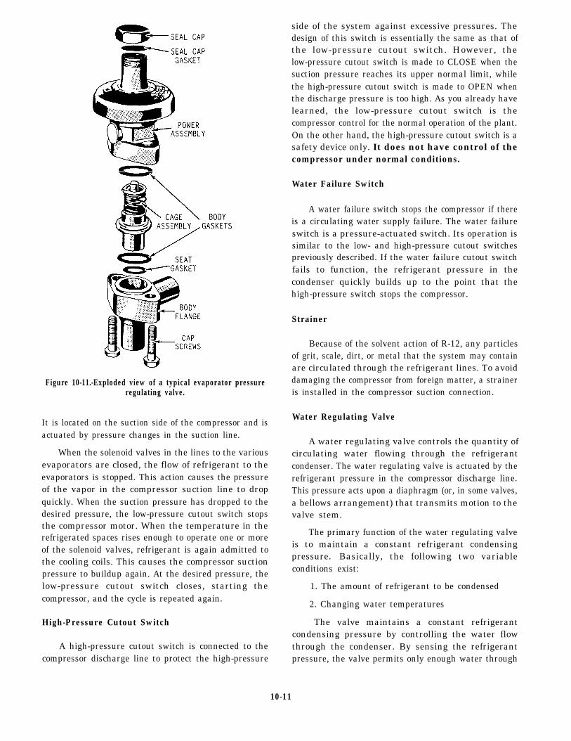
Figure 10-11.-Exploded view of a typical evaporator pressureregulating valve.
It is located on the suction side of the compressor and isactuated by pressure changes in the suction line.
When the solenoid valves in the lines to the variousevaporators are closed, the flow of refrigerant to theevaporators is stopped. This action causes the pressureof the vapor in the compressor suction line to dropquickly. When the suction pressure has dropped to thedesired pressure, the low-pressure cutout switch stopsthe compressor motor. When the temperature in therefrigerated spaces rises enough to operate one or moreof the solenoid valves, refrigerant is again admitted tothe cooling coils. This causes the compressor suctionpressure to buildup again. At the desired pressure, thelow-pressure cutout switch closes, starting thecompressor, and the cycle is repeated again.
High-Pressure Cutout Switch
A high-pressure cutout switch is connected to thecompressor discharge line to protect the high-pressure
side of the system against excessive pressures. Thedesign of this switch is essentially the same as that ofthe low-pressure cutout switch. However, thelow-pressure cutout switch is made to CLOSE when thesuction pressure reaches its upper normal limit, whilethe high-pressure cutout switch is made to OPEN whenthe discharge pressure is too high. As you already havelearned, the low-pressure cutout switch is thecompressor control for the normal operation of the plant.On the other hand, the high-pressure cutout switch is asafety device only. It does not have control of thecompressor under normal conditions.
Water Failure Switch
A water failure switch stops the compressor if thereis a circulating water supply failure. The water failureswitch is a pressure-actuated switch. Its operation issimilar to the low- and high-pressure cutout switchespreviously described. If the water failure cutout switchfails to function, the refrigerant pressure in thecondenser quickly builds up to the point that thehigh-pressure switch stops the compressor.
Strainer
Because of the solvent action of R-12, any particlesof grit, scale, dirt, or metal that the system may containare circulated through the refrigerant lines. To avoiddamaging the compressor from foreign matter, a straineris installed in the compressor suction connection.
Water Regulating Valve
A water regulating valve controls the quantity ofcirculating water flowing through the refrigerantcondenser. The water regulating valve is actuated by therefrigerant pressure in the compressor discharge line.This pressure acts upon a diaphragm (or, in some valves,a bellows arrangement) that transmits motion to thevalve stem.
The primary function of the water regulating valveis to maintain a constant refrigerant condensingpressure. Basically, the following two variableconditions exist:
1. The amount of refrigerant to be condensed
2. Changing water temperatures
The valve maintains a constant refrigerantcondensing pressure by controlling the water flowthrough the condenser. By sensing the refrigerantpressure, the valve permits only enough water through
10-11
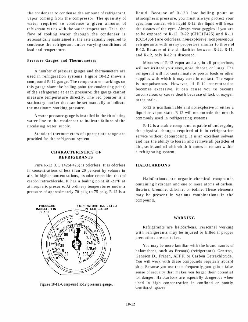
the condenser to condense the amount of refrigerantvapor coming from the compressor. The quantity ofwater required to condense a given amount ofrefrigerant varies with the water temperature. Thus, theflow of cooling water through the condenser isautomatically maintained at the rate actually required tocondense the refrigerant under varying conditions ofload and temperature.
Pressure Gauges and Thermometers
A number of pressure gauges and thermometers areused in refrigeration systems. Figure 10-12 shows acompound R-12 gauge. The temperature markings onthis gauge show the boiling point (or condensing point)of the refrigerant at each pressure; the gauge cannotmeasure temperature directly. The red pointer is astationary marker that can be set manually to indicatethe maximum working pressure.
A water pressure gauge is installed in the circulatingwater line to the condenser to indicate failure of thecirculating water supply.
Standard thermometers of appropriate range areprovided for the refrigerant system.
CHARACTERISTICS OFREFRIGERANTS
Pure R-12 (CC 1425F425) is colorless. It is odorlessin concentrations of less than 20 percent by volume inair. In higher concentrations, its odor resembles that ofcarbon tetrachloride. It has a boiling point of -21°F atatmospheric pressure. At ordinary temperatures under apressure of approximately 70 psig to 75 psig, R-12 is a
liquid. Because of R-12’s low boiling point atatmospheric pressure, you must always protect youreyes from contact with liquid R-12; the liquid will freezethe tissues of the eyes. Always wear goggles if you areto be exposed to R-12. R-22 (CHC1F425) and R-11(CC1435F) are colorless, nonexplosive, nonpoisonousrefrigerants with many properties similar to those ofR-12. Because of the similarities between R-22, R-11,and R-12, only R-12 is discussed.
Mixtures of R-12 vapor and air, in all proportions,will not irritate your eyes, nose, throat, or lungs. Therefrigerant will not contaminate or poison foods or othersupplies with which it may come in contact. The vaporis nonpoisonous. However, if R-12 concentrationbecomes excessive, it can cause you to becomeunconscious or cause death because of lack of oxygento the brain.
R-12 is nonflammable and nonexplosive in either aliquid or vapor state. R-12 will not corrode the metalscommonly used in refrigerating systems.
R-12 is a stable compound capable of undergoingthe physical changes required of it in refrigerationservice without decomposing. It is an excellent solventand has the ability to loosen and remove all particles ofdirt, scale, and oil with which it comes in contact withina refrigerating system.
HALOCARBONS
HaloCarbons are organic chemical compoundscontaining hydrogen and one or more atoms of carbon,fluorine, bromine, chlorine, or iodine. These elementsmay be present in various combinations in thecompound.
WARNING
Refrigerants are halocarbons. Personnel workingwith refrigerants may be injured or killed if properprecautions are not taken.
Figure 10-12.-Compound R-12 pressure gauge.
You may be more familiar with the brand names ofhalocarbons, such as Freon(s) (refrigerants), Gentron,Gension D., Frigen, AFFF, or Carbon Tetrachloride.You will work with these compounds regularly aboardship. Because you use them frequently, you gain a falsesense of security that makes you forget their potentialfor danger. Halocarbons are especially dangerous whenused in high concentration in confined or poorlyventilated spaces.
10-12

PERSONAL SAFETY PRECAUTIONS
R-12 is a powerful freezing agent. Even a very smallamount can freeze the delicate tissues of the eye, causingpermanent damage. All personnel must wear goggleswhen working in spaces were they maybe exposed to arefrigerant, particularly in its liquid form. If refrigerantdoes get into someone’s eyes, get that personI M M E D I A T E medical treatment to avoidpermanent damage. In the meantime, put drops ofclean olive oil, mineral oil, or other nonirritating oil inthe eyes. Make sure that the person does not rubhis/her eyes.
CAUTION
Do NOT use anything except clean, nonirritating oilfor this type of eye injury.
If R- 12 comes in contact with the skin, it may causefrostbite. This injury should be treated as any other causeof frostbite. Immerse the affected part in a warm bathfor about 10 minutes, then dry carefully. Do not rub ormassage the affected area.
Know, understand, and use these safety precautions,and you can safely operate and maintain refrigerationplants.
HANDLING OF REFRIGERANTCYLINDERS (BOTTLES)
Refrigerants are furnished in cylinders for use inshipboard refrigeration systems. The followingprecautions MUST BE OBSERVED in the handling,use, and storage of these cylinders:
NOTE: Before handling refrigerant bottles, readOPNAVINST 5100.19.
1. NEVER drop cylinders nor permit them to strikeeach other violently.
2. NEVER use a lifting magnet or a sling (rope orchain) when you handle cylinders. A crane maybe usedif a safe cradle or platform is provided to hold thecylinders.
3. Keep the caps provided for valve protection oncylinders except when the cylinders are being used.
4. When refrigerant is discharged from a cylinder,weigh the cylinder immediately. Record the weight ofthe refrigerant remaining in the cylinder.
5. NEVER attempt to mix gases in a cylinder.
6. NEVER PUT THE WRONG REFRIGERANTINTO A REFRIGERATION SYSTEM! N OREFRIGERANT EXCEPT THE ONE FORWHICH A SYSTEM WAS DESIGNED SHOULDEVER BE INTRODUCED INTO THE SYSTEM.Check the equipment nameplate or the manufacturer’stechnical manual to determine the proper refrigeranttype and charge. Putting the wrong refrigerant into asystem may cause a violent explosion.
7. When a cylinder is empty, close the cylindervalve immediately to prevent the entrance of air,moisture, or dirt. Also, replace the valve protection cap.
8. NEVER use cylinders for other than theirintended purpose. Do NOT use them as rollers andsupports.
9. Do NOT tamper with the safety devices in thevalves or cylinders.
10. Open cylinder valves slowly. NEVER usewrenches or other tools except those provided by themanufacturer.
11. Be sure the threads on regulators or otherconnections are the same as those on the cylinder valveoutlets. NEVER force connections that do not fit.
12. Regulators and pressure gauges provided for usewith a particular gas must NOT be used on cylinderscontaining other gases.
13. NEVER attempt to repair or alter cylinders orvalves.
14. NEVER fill R-12 cylinders beyond 85 percentcapacity.
15. Store cylinders in a cool, dry place, in anUPRIGHT position. If the cylinders are exposed toexcessive heat, a dangerous increase in pressure willoccur. If cylinders must be stored in the open, protectthem against extremes of weather. NEVER store acylinder in an area where the temperature will be above125°F.
16. NEVER ALLOW R-12 TO COME INCONTACT WITH A FLAME OR RED-HOTMETAL! When exposed to excessively hightemperatures, R-12 breaks down into phosgene gas, anextremely poisonous substance.
AIR CONDITIONING
Air conditioning is a field of engineering that dealswith the design, construction, and operation ofequipment used to establish and maintain desirable
10-13
indoor air conditions. It is used to maintain theenvironment of an enclosure at any requiredtemperature, humidity, and purity. Simply stated, airconditioning involves the cooling, heating,dehumidifying, ventilating, and purifying of air.
One of the chief purposes of air conditioning aboardship is to keep the crew comfortable, alert, andphysically fit. None of us can long maintain a high levelof efficiency under adverse environmental conditions.We have to maintain a variety of compartments at aprescribed temperature with proper circulation. Thesecompartments must have the proper moisture content,the correct proportion of oxygen, and an acceptablelevel of air contamination (dust, airborne dirt, etc.). Wealso have to provide mechanical cooling or ventilationin ammunition spaces to prevent deterioration ofammunition components. We have to provide them ingas storage spaces to prevent excessive pressure buildupin containers and contamination in the space caused bygas leaks. Finally, we must provide cooling andventilation in electrical/electronic equipment spaces.his is done to maintain the ambient temperature andhumidity, as specified for the equipment.
To properly air-condition a space, the humidity, heatof the air, temperature, body heat balance, the effect ofair motion, and the sensation of comfort is considered.
HEAT OF AIR
The heat of air is considered from three standpoints–sensible, latent, and total heat.
SENSIBLE HEAT is the amount of heat, which,when added to or removed from air, changes thetemperature of the air. Sensible heat changes can bemeasured by the common (dry-bulb) thermometer,
Air always contains some water vapor. Any watervapor in the air contains the LATENT HEAT OFVAPORIZATION. (The amount of latent heat presenthas no effect on temperature and it cannot be measuredwith a dry-bulb thermometer.)
Any mixture of dry air and water vapor containsboth sensible and latent heat. The sum of the sensibleheat and the latent heat in any sample of air is called theTOTAL HEAT of the air.
TEMPERATURES
To test the effectiveness of air-conditioningequipment and to check the humidity of a space, youmust consider two different temperatures-the dry-bulband wet-bulb temperature.
Measurement of Temperatures
The DRY-BULB TEMPERATURE is thetemperature of sensible heat of the air, as measured byan ordinary thermometer. In air conditioning, such athermometer is known as a dry-bulb thermometerbecause its sensing bulb is dry.
The WET-BULB TEMPERATURE is bestexplained by a description of a wet-bulb thermometer.It is an ordinary thermometer with a loosely woven clothsleeve or wick placed around its bulb and which is thenwet with distilled water. The water in the sleeve or wickis evaporated by a current of air at high velocity (seenext paragraph). This evaporation withdraws heat fromthe thermometer bulb, lowering the temperature byseveral degrees. The difference between the dry-bulband the wet-bulb temperatures is called the wet-bulbdepression. when the wet-bulb temperature is the sameas the dry-bulb, the air is said to be saturated; that is,evaporation cannot take place. The condition ofsaturation is unusual, however, and a wet-bulbdepression is normally expected.
The wet-bulb and dry-bulb thermometers areusually mounted side by side on a frame that has ahandle and a short chain attached. This allows thethermometers to be whirled in the air, providing ahigh-velocity air current to promote evaporation. Sucha device is known as a SLING PSYCHROMETER (fig.10- 13). When using the sling psychrometer, whirl itrapidly-at least four times per second. Observe thewet-bulb temperature at intervals. The Point at whichthere is no further drop in temperature is the wet-bulbtemperature for that space.
MOTORIZED PSYCHROMETERS (fig. 10- 14)are provided with a small motor-driven fan and dry-cellbatteries. Motorized psychrometer are generallypreferred and are gradually replacing slingpsychrometer.
Relationships Between Temperatures
You should clearly understand the definiterelationships of the three temperatures-dry-bulb,wet-bulb, and dew-point.
When air contains some moisture but is notsaturated, the dewpoint temperature is lower than thedry-bulb temperature; the wet-bulb temperature liesbetween them. As the amount of moisture in the airincreases, the difference between the dry-bulbtemperature and the wet-bulb temperature becomes less.
10-14

Figure 1O-13.-A standard sling Psychrometer.
Figure 10-14.-Exposed view of motorized psychrometer.
When the air is saturated, all three temperatures are thesame.
By using both the wet-bulb and the dry-bulb
temperature readings, you can find the relative humidityand the dew-point temperature on a psychometric chart(fig, 10-15).
DEW-POINT TEMPERATURE.– The wet-bulbtemperature lines are angled across the chart (see fig.
10-15). The dew-point temperature lines are straightacross the chart (indicated by the arrows for wet bulband dew point). Find where the wet-bulb and dry-bulblines cross, interpolate the relative humidity from thenearest humidity lines to the temperature-line crossingpoint. Then, to find the dew point, follow the straightdew-point line closest to the intersection across to theright of the chart and read the dew-point temperature.For example, find the wet-bulb temperature of 70°F.Next, trace the line angling down to the right to thedry-bulb temperature of 95°F. Finally, to find thedew-point temperature, follow the dew-pointtemperature lines nearest the intersection straight acrossto the right of the chart. The dew-point line falls aboutone-third of the way between the 55°F mark and the 60°mark. You can see that the dew-point temperature isabout 57°F.
RELATIVE HUMIDITY.– To find the relativehumidity (see fig. 10- 15), first find the dry-bulbtemperature. Read across the bottom, find 95°F andfollow straight up to the intersection of the wet- anddry-bulb readings. The relative humidity arc nearest theintersection is 30 percent. However, the intersecting lineis below 30 percent and higher than 20 percent. You cansee that the relative humidity is about 28 percent.
BODY HEAT BALANCE
Ordinarily, the body remains at a fairly constanttemperature of 98.6°F. It is important to maintain thisbody temperature. Since there is a continuous heat gainfrom internal body processes, there must be acontinuous loss to maintain body heat balance. Excessheat must be absorbed by the surrounding air or lost byradiation. As the temperature and humidity of the
10-15
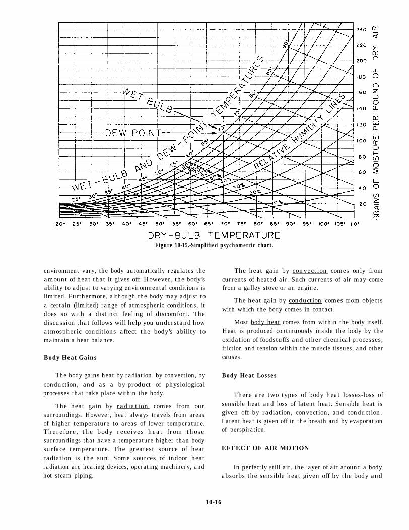
Figure 10-15.-Simplified psychometric chart.
environment vary, the body automatically regulates theamount of heat that it gives off. However, the body’sability to adjust to varying environmental conditions islimited. Furthermore, although the body may adjust toa certain (limited) range of atmospheric conditions, itdoes so with a distinct feeling of discomfort. Thediscussion that follows will help you understand howatmospheric conditions affect the body’s ability tomaintain a heat balance.
Body Heat Gains
The body gains heat by radiation, by convection, byconduction, and as a by-product of physiologicalprocesses that take place within the body.
The heat gain by radiation comes from oursurroundings. However, heat always travels from areasof higher temperature to areas of lower temperature.Therefore, the body receives heat from thosesurroundings that have a temperature higher than bodysurface temperature. The greatest source of heatradiation is the sun. Some sources of indoor heatradiation are heating devices, operating machinery, andhot steam piping.
The heat gain by convection comes only fromcurrents of heated air. Such currents of air may comefrom a galley stove or an engine.
The heat gain by conduction comes from objectswith which the body comes in contact.
Most body heat comes from within the body itself.Heat is produced continuously inside the body by theoxidation of foodstuffs and other chemical processes,friction and tension within the muscle tissues, and othercauses.
Body Heat Losses
There are two types of body heat losses-loss ofsensible heat and loss of latent heat. Sensible heat isgiven off by radiation, convection, and conduction.Latent heat is given off in the breath and by evaporationof perspiration.
EFFECT OF AIR MOTION
In perfectly still air, the layer of air around a bodyabsorbs the sensible heat given off by the body and
10-16

increases in temperature. The layer of air also absorbssome of the water vapor given off by the body, thusincreasing its relative humidity. This means the body issurrounded by an envelope of moist air that is at a highertemperature and relative humidity than the ambient air.Therefore, the amount of heat that the body can lose tothis envelope is less than the amount it can lose to theambient air. When the air is set in motion past the body,the envelope is continuously being removed andreplaced by the ambient air. This movement increasesthe rate of heat loss from the body. When the increasedheat loss improves the heat balance, the sensation of abreeze is felt; when the increase is excessive, the rate ofheat loss makes the body feel cool and the sensation ofa draft is felt.
SENSATION OF COMFORT
From what you have just learned, you know thatthree factors are closely interrelated in their effects uponthe comfort and health of personnel aboard ship. Thesefactors are temperature, humidity, and air motion. Infact, a given combination of temperature, humidity, andair motion produces the same feeling of warmth orcoolness as a higher or lower temperature along with acompensating humidity and air motion. The term givento the net effect of these three factors is known as theEFFECTIVE TEMPERATURE. Effective temperaturecannot be measured by an instrument, but can be foundon a special psychometric chart when the dry-bulbtemperatures and air velocity are known.
The combinations of temperature, relativehumidity, and air motion of a particularly effectivetemperature may produce the same feeling of warmth orcoolness. However, they are NOT all equallycomfortable. Relative humidity below 15 percentproduces a parched condition of the mucous membranesof the mouth, nose, and lungs, and increasessusceptibility to disease germs. Relative humidity above70 percent causes an accumulation of moisture inclothing. For best health conditions, you need a relativehumidity ranging from 40 percent to 50 percent for coldweather and from 50 percent to 60 percent for warmweather. An overall range from 30 percent to 70 percentis acceptable.
VENTILATION EQUIPMENT
Proper circulation is the basis for all ventilating andair-conditioning systems and related processes.Therefore, we must first consider methods used aboardship to circulate air. In the following sections, you will
find information on shipboard equipment used tosupply, circulate, and distribute fresh air and to removeused, polluted, and overheated air.
In Navy ships, the fans used with supply andexhaust systems are divided into two generalclasses-axial flow and centrifugal.
Most fans induct systems are of the axial-flow typebecause they generally require less space forinstallation.
Centrifugal fans are generally preferred for exhaustsystems that handle explosive or hot gases. Because themotors of these fans are outside the air stream, theycannot ignite the explosive gases. The drive motors forcentrifugal fans are less subject to overheating to a lesserdegree than are motors of vane-axial fans.
VANE-AXIAL FANS
Vane-axial fans (fig. 10-16) are high-pressure fans,generally installed in duct systems. They have vanes atthe discharge end to straighten out rotational air motioncaused by the impeller. The motors for these fans arecooled by the flow of air in the duct from the fan bladesacross the motor. The motor will overheat if it is allowedto operate while the supply air to the fan is shut off.
TUBE-AXIAL FANS
Tube-axial fans are low-pressure fans, usuallyinstalled without duct work. However, they do havesufficient pressure for a short length of duct.
CENTRIFUGAL FANS
Centrifugal fans (fig. 10-17, view A) are usedprimarily to exhaust explosive or hot gases. However,they may be used in lieu of axial-flow fans if they workbetter with the arrangement or if their pressure-volumecharacteristics suit the installation better than anaxial-flow fan. Centrifugal fans are also used in somefan-coil assemblies, which are discussed later in thischapter.
PORTABLE FANS
Portable axial fans (fig. 10-17, view B) with flexibleair hoses are used aboard ship for ventilating holds andcofferdams. They are also used in unventilated spacesto clear out stale air or gases before personnel enter andfor emergency cooling of machinery.
10-17

47.106 Figure 10-16.-Vane-axia1 fan: A. Exterior view. B. Cutaway view. C. Cutaway view of the fan motor.
Most portable fans are of the axial-flow type,driven by electric, explosionproof motors. On shipscarrying gasoline, a few air turbine-drivencentrifugal fans are normally provided. You canplace greater confidence in the explosionproofcharacteristics of these fans.
CAUTION
Never use a dc-driven fan to exhaust air thatcontains explosive vapor.
EXHAUSTSMany local exhausts are used to remove heat
and odors. Machinery spaces, laundries, andgalleys are some of the shipboard spaces wherelocal exhausts are used.
Most exhausts used on Navy ships aremechanical (contain an exhaust fan), althoughnatural exhausts are sometimes used in ship’sstructures and on small craft.
10-18

47.107Figure 10-17.-Miscellaneous ventilation fans: A. Centrifugal fan. B. Portable axial fan.
MECHANICAL COOLING EQUIPMENT
Almost all working and living spaces on newerships are air conditioned. The equipment used on theseships was carefully tested to see which types would bestdehumidify and cool ship compartments. Two basictypes of equipment have been found most effective andare now in general use. They are chilled watercirculating systems and self-contained air conditioners.
CHILLED WATER CIRCULATINGSYSTEMS
TWO basic types of chilled water air-conditioningsystems are now in use. They are a vapor compression
unit and a lithium bromide absorption unit. In the vapor
compression unit, the primary refrigerant cools thesecondary refrigerant (chilled water) that is used to cool
the spaces. This type uses the vapor compression cycleand R-11 or R-114 as the primary refrigerant. The type
of primary refrigerant depends on the size and type of
compressor. The lithium bromide unit operates on the
absorption cycle and uses water as the primary
refrigerant. Lithium bromide is used as an absorbent.
Vapor compression plants are used in most ships.
However, lithium bromide plants are used in submarinesbecause they require no compression, which means a
quieter operation.
10-19
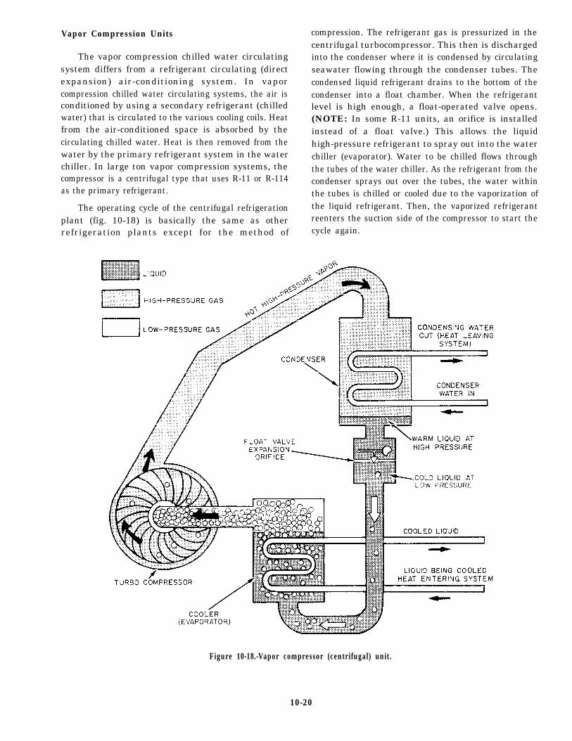
Vapor Compression Units
The vapor compression chilled water circulatingsystem differs from a refrigerant circulating (directexpansion) air-conditioning system. In vaporcompression chilled water circulating systems, the air isconditioned by using a secondary refrigerant (chilledwater) that is circulated to the various cooling coils. Heatfrom the air-conditioned space is absorbed by thecirculating chilled water. Heat is then removed from thewater by the primary refrigerant system in the waterchiller. In large ton vapor compression systems, thecompressor is a centrifugal type that uses R-11 or R-114as the primary refrigerant.
The operating cycle of the centrifugal refrigerationplant (fig. 10-18) is basically the same as otherrefrigeration plants except for the method of
compression. The refrigerant gas is pressurized in thecentrifugal turbocompressor. This then is dischargedinto the condenser where it is condensed by circulatingseawater flowing through the condenser tubes. Thecondensed liquid refrigerant drains to the bottom of thecondenser into a float chamber. When the refrigerantlevel is high enough, a float-operated valve opens.(NOTE: In some R-11 units, an orifice is installedinstead of a float valve.) This allows the liquidhigh-pressure refrigerant to spray out into the waterchiller (evaporator). Water to be chilled flows throughthe tubes of the water chiller. As the refrigerant from thecondenser sprays out over the tubes, the water withinthe tubes is chilled or cooled due to the vaporization ofthe liquid refrigerant. Then, the vaporized refrigerantreenters the suction side of the compressor to start thecycle again.
Figure 10-18.-Vapor compressor (centrifugal) unit.
10-20

The load on the air-conditioning plant is determinedby the desired chilled water temperature. Thecompressor load is changed by either an increased ordecreased demand of the chilled water temperature.Upon demand, the load is changed by the use ofadjustable prerotation vanes. The vanes are located onthe suction side of the compressor. The vanes act asdampers to increase or decrease the flow of refrigerantvapor into the suction of the compressor. This throttlingaction at the compressor suction allows an increase ordecrease of the capacity of the compressor withoutchanging the compressor speed.
Figure 10-19 shows a centrifugal compressor withthe inlet piping removed. Note that the prerotation vanesare in the fully open position. The vane position isnormally controlled automatically through anelectropneumatic control system. The control systemsenses and maintains the chilled water outlettemperature of the chiller at a preset value by varyingthe position of the vanes.
In some plants, the electric motor used In some
plants, the electric motoerrive the compressor ishermetically sealed and is cooled by a flow of refrigerantthrough it. The compressor is lubricated by a force-feedlubrication system. This system normally consists of anauxiliary oil pump, an attached oil pump (integral withcompressor), an oil cooler, and a set of oil filters. The
auxiliary oil pump is used for starting and securing theplant.
Several automatic controls are built into thecentrifugal compressor control system. These devicesincrease the self-operating ability of the plant byautomatically shutting down the compressor if ahazardous condition develops. Some of these conditions
are high condenser pressure, low compressor lube oilpressure, seawater loss to the condenser, loss of chilledwater, low refrigerant temperature, low chilledtemperature, and high discharge temperature.
water
Figure 10-19.-Suction end of a centrifugal compressor showing prerotation vanes.
10-21

An oil heater keeps the oil warm in the oil sump ofthe compressor during plant shutdown. If the oil is notkept heated, it absorbs large amounts of refrigerant. Thisresults in excessive oil foaming when the unit is started.The heaters in most plants are connected so that they areautomatically turned on when the compressor is off, andoff when the compressor is on..
Figure 10-20 shows a centrifugal compressorair-conditioning unit. This particular plant has a 150-toncapacity and uses R-114 as the refrigerant. The gaugesand controls for the plant are on the other side of the unit.
Lithium Bromide Absorption Unit
Water is used as a refrigerant in the lithium bromideabsorption cycle. The absorption system differs from thecompression-type refrigeration machines. Theabsorption cycle uses heat energy instead of mechanicalenergy to cause the change in conditions necessary fora complete refrigeration cycle. In other words, thecompressor is replaced by steam heat.
The following are the two principles that form thebasis for the lithium bromide absorption refrigerationcycle:
1. Lithium bromide has the ability to absorb largequantities of water vapor.
2. When under a high vacuum,(vaporizes) at a low temperature and,absorbs heat.
water boilsin doing so,
To understand the lithium bromide absorptioncycle, follow along on figure 10-21 during as you readthe following explanation. Notice that theEVAPORATOR and ABSORBER sections are in acommon shell. The sections are separated by therefrigerant tray and baffles. This shell is under a highvacuum of about 29.8 in.Hg. Water boils at 35°F (1.7°C)at this pressure. (Note that this is only 3°F above thefreezing point of water.) The refrigerant pumpcirculates the refrigerant (water) through the evaporator.The water is sprayed out over 88the chilled water tubesthrough a spray header. This causes the water tovaporize (or flash) more readily. As the water vaporizesaround the chilled water tubes, it removes heat from thecirculating chilled water. The water vapor is floatingabout in the evaporator/absorber shell. Now, theabsorber comes into play.
Lithium bromide solution is sprayed out from aspray header in the absorber. The absorber pumpprovides the driving head for the spray. As the lithiumbromide solution is sprayed out, it absorbs the watervapor, which is in the shell from the evaporationprocess. As the lithium bromide absorbs more and morewater vapor, its ability to absorb decreases. This is
47.217Figure 10-20.-R-114 centrifugal air-conditioning plant.
10-22

Figure 10-21.-Basic absorption cycle.
known as a WEAK solution. Here, in the generatorsection of the plant, the weak solution is rejuvenated forreuse as a STRONG solution. The generator pumppumps the weak solution from the weak solution sectionof the absorber up to the generator.
In the generator, the weak lithium bromide solutionis sprayed out over steam tubes that heat the solution anddrive the water vapor out of the solution. The strongsolution thus produced flows back into the absorber forreuse. The water vapor driven out of the solution flowsfrom the generator into the condenser where it iscondensed by circulating seawater for reuse as arefrigerant. The condensed vapor flows into theevaporator and down to the refrigerant tray.
A regenerative heat exchanger is provided in thesystem for the lithium bromide solution. The weaksolution must be heated to drive out the water vapor; thestrong solution must be cooled to absorb water vapor.
The regenerative heat exchanger aids in this process bycooling the strong solution and preheating the weaksolution in the cycle.
Seawater (condensing) flow is provided through theabsorber section. It cools the strong solution returningfrom the generator and removes the heat produced as thelithium bromide solution absorbs the water vapor. Theoutlet seawater from the absorber is the inlet water forthe condenser.
The absorber pump and the generator pump aredriven by a common electric motor. Therefore, the twopumps are referred to cumulatively as theabsorber/generator pump.
A purge system (not shown) consists of a pump, aneductor, and a purge tank. The system is provided withthe lithium bromide absorption system to keep air andnoncondensables out of the evaporator/absorber shell.
10-23

The maintenance of the high vacuum within the shell isimportant to the proper operation of the plant.
Fan-Coil Assemblies
Fan-coil assemblies (fig. 10-22) use chilled water toair-condition spaces. These assemblies are known asspot coolers. The chilled water is piped through thecooling coils of the units, and a fan forces air over thecoils. Note the chilled water connections, the vent cockat the top, and the condensate collection tray at thebottom of the unit.
The condensate collection tray collects the moisturecondensed out of the air. The condensate is generallypiped to the bilge or a waste water drain system. It isimportant that the drain for the collection tray be keptclear. If the condensate cannot drain out of the tray, itcollects and evaporates, leaving impurities that canrapidly cause the tray to corrode.
SELF-CONTAINED AIR CONDITIONERS
Ships without central air conditioning may useself-contained air-conditioning units. Naval SeaSystems Command (NAVSEASYSCOM) approval isrequired. A self-contained air-conditioning unit issimply the type of air conditioner you see installed inthe windows of many homes. All that is required forinstallation is to mount the proper brackets for the unitcase and provide electrical power.
These units use nonaccessible hermetically sealedcompressors (motor and compressor are contained in awelded steel shell). For this reason, shipboardmaintenance of the motor-compressor unit isimpractical. The thermal expansion valve used in theseunits is preset and nonadjustable. However, a thermostatand fan speed control are normally provided for comfortadjustment.
AIR COMPRESSORS
The air compressor is the heart of any compressedair system. It takes in atmospheric air, compresses it tothe desired pressure, and moves it into supply lines orinto storage tanks for later use. Air compressors comein different designs and configurations and havedifferent methods of compression. Some of the mostcommon types used on gas turbine ships are discussedin this chapter.
Before describing the various types of aircompressors, you need to know about the compositionof air and some of the things air may contain. Thisdiscussion should help you understand why aircompressors have special features that prevent water,dirt, and oil vapor from getting into compressed airpiping systems.
Air is mostly composed of nitrogen and oxygen. Atatmospheric pressure (within the range of temperaturesfor the earth’s atmosphere), air is in a gaseous form. The
Figure 10-22.-Fan-coil assembly.
10-24
earth’s atmosphere also contains varying amounts ofwater. Depending on weather conditions, water willappear in a variety of forms, such as rain (liquid water),snow crystals, ice (solid water), and vapor. Vapor iscomposed of tiny drops of water that are light enough tostay airborne. Clouds are an example of the existence ofwater vapor.
Since air is a gas, it expands when heated.Consequently, heating air causes a given amount ofair2routed through to expand, take up more space(volume), and hold more water vapor. When a givenamount of air at a given temperature and pressure is nolonger able to soak up water vapor, the air is saturated,and the humidity is 100 percent.
When air cools, its density increases; however, itsvolume and ability to hold water decrease, Whentemperature and pressure conditions cause the air to cooland to reach the dew point, any water vapor in the aircondenses into a liquid state (water). In other words, onemethod of drying air out is to cool it until it reaches thedew point.
Besides nitrogen, oxygen, and water vapor, aircontains particles of dust and dirt that are so tiny andlightweight that they remain suspended in the air. Youmay wonder how the composition of air directly affectsthe work of an air compressor. Although one cubic footof air will not hold a tremendous amount of water or dirt,you should realize that air compressors have capacitiesthat are rated in hundreds of standard cubic feet perminute (cfm). This is a very high rate of flow. When ahigh flow rate of dirty, moisture-laden air is allowed toenter and pass through an air compressor, the result israpid wear of the seals and load-bearing parts, internalcorrosion (rust), and early failure of the unit. Thereliability and useful life of any air compressor isextended by the installation of filters. Filters removemost of the dirt and dust from the air before it enters theequipment. On the other hand, most of the water vaporin the air at the intake passes directly through the filtermaterial and is compressed with the air. When air iscompressed, it becomes very hot. As you know, hot airis capable of holding great amounts of water. The wateris removed as the compressed air is routed through thecoolers. The coolers remove the heat from the airstreamand cause some of the water vapor to condense intoliquid (condensate). The condensate must beperiodically drained from the compressor.
Although the coolers will remove some of the waterfrom the air, simple cooling between the stages ofcompression (intercooling) and cooling of the airstreamafter it leaves the compressor (aftercooling) will not
make the air dry.pneumatic controlrequired air from
When clean dry air suitable forand other shipboard systems arethe compressor is routed through
air-drying units. Many air-drying units are capable ofremoving enough water vapor from the airstream tocause the dew point to be as low as -60°F. Some of themore common devices used to remove water vapor fromthe airstream, such as dehydrators, are discussed later inthis chapter.
CLASSIFICATION OF AIR COMPRESSORS
An air compressor may be classified according topressure (low, medium, or high), type of compressingelement, and whether the discharged air is oil free.
Because of our increasing need for oil-free airaboard ship, the oil-free air compressor is graduallyreplacing most of the standard low-pressure andhigh-pressure air compressors. For this reason, most ofthis discussion is focused on the features of oil-free aircompressors.
The Naval Ships’ Technical Manual (NSTM),chapter 551, lists compressors in three classifications:
1. Low-pressure air compressors (LPACs), whichhave a discharge pressure of 150 psi or less
2. Medium-pressure compressors, which have adischarge pressure of 151 psi to 1,000 psi
3. High-pressure air compressors (HPACs), whichhave a discharge pressure above 1,000 psi
Low-Pressure or Ship’s Service AirCompressors
The two types of LPACs that are used on naval shipsare the screw type and the reciprocating type.
SCREW TYPE.– The helical-screw type ofcompressor is a relatively new design of oil-free aircompressor. This low-pressure air compressor is asingle-stage, positive-displacement, axial-flow,helical-screw type of compressor. It is often referred toas a screw-type compressor. Figure 10-23 shows thegeneral arrangement of the LPAC unit.
In the screw-type LPAC, compression is caused bythe meshing of two helical rotors (a male and a femalerotor, as shown in fig. 10-24) located on parallel shaftsand enclosed in a casing. Air inlet and outlet ports arelocated on opposite sides of the casing. Atmospheric airis drawn into the compressor through thefilter-silencer. The air passes through the aircylinder-operated unloader (butterfly) valve and into the
10-25

Figure 1O-23.-LPAC unit (screw type.)
Figure 10-24.-LPAC, compressor section.
inlet part of the compressor when the valve is in the open 2. It seals the running clearances to minimize air
(load) position. Fresh water is injected into the airstream leak.
as it passes through the inlet port of the compressor Most of the injected water is entrained into thecasing. The injected fresh water serves two purposes: airstream as it moves through the compressor.
1. It reduces the air discharge temperature caused The compression cycle starts as the rotors unmeshby compression. at the inlet port. As rotation continues, air is drawn into
10-26

the cavity between the male rotor lobes and into thegrooves of the female rotor. The air is trapped in thesegrooves, or pockets, and follows the rotative directionof each rotor. As soon as the inlet port is closed, thecompression cycle begins as the air is directed to theopposite (discharge) end of the compressor. The rotorsmesh, and the normal free volume is reduced. Thereduction in volume (compression) continues with aresulting increase in pressure, until the closing pocketreaches the discharge port.
The entrained water is removed from the dischargedair by a combined separator and water holding tank. Thewater in the tank passes through a seawater-cooled heatexchanger. The cooled water then recirculates to thecompressor for reinfection.
During rotation and throughout the meshing cycle,the timing gears maintain the correct clearancesbetween the rotors. Since no contact occurs between therotor lobes and grooves, between the rotor lobes andcasing, or between the rotor faces and end walls, nointernal oil lubrication is required. This design allowsthe compressor to discharge oil-free air.
For gear and bearing lubrication, lube oil from aforce-feed system is supplied to each end of thecompressor. Mechanical seals serve to keep the oilisolated from the compression chamber.
RECIPROCATING TYPE.– All reciprocating aircompressors are similar to each other in design andoperation. The following discussion describes the basiccomponents and principles of operation of alow-pressure reciprocating air compressor.
The LPAC is a vertical, two-stage single-actingcompressor that is belt-driven by an electrical motor.Two first-stage cylinders and one second-stage cylinderare arranged in-line in individual blocks mounted to thecrankcase (frame) with a distance piece (frameextension). The crankcase is mounted on a subbase thatsupports the motor, moisture separators, and a rackassembly. The intercooler, aftercooler, freshwater heatexchanger, and freshwater pump are mounted on therack assembly. The subbase serves as the oil sump.Figure 10-25 shows the general arrangement of thereciprocating-type compressor.
Figure 10-25.—LPAC (reciprocating type).
10-27

The compressor is of the crosshead design. Figure10-26 shows cross-sectional views of the LPAC. Theframe extension houses the crossheads and crossheadguides and is open to the atmosphere. It separates thecylinders, which are not oil lubricated, from thecrankcase. Oil wiper assemblies (seals) are located inthe frame extension to scrape lubricating oil off thepiston rods when the compressor is in operation. Oildeflector plates are attached to the piston rods to preventany oil that creeps through the scrapers from enteringthe cylinders. Oil that is scraped from the piston rodsdrains back to the sump. Air leak along the piston rods
is prevented by full floating packing assemblies boltedto the underside of the cylinder blocks.
During operation, ambient air is drawn into thefirst-stage cylinders through the inlet filter silencers andinlet valves during the downstroke. When the pistonreaches the bottom of its stroke, the inlet valve closesand traps the air in the cylinder. When the piston movesupward, the trapped air is compressed and forced out ofthe first-stage cylinders, through the first-stage coolerand the first-stage moisture separator. When thesecond-stage piston starts its downstroke, the air isdrawn into the second-stage cylinder. Then, it is further
Figure 10-26.—LPAC, cross-sectional views (reciprocating type.)
10-28

compressed, followed by a cooling and moistureremoval process similar to the first stage.
High-Pressure Air Compressors
The HPAC is a vertical, five-stage, reciprocating aircompressor. It is driven by being directly connected toan electrical motor. Refer to figures 10-27 and 10-28 aswe describe the compressor.
The subbase supports the compressor assembly, theelectric drive motor, and the coolers and rack assembly.The crankcase is bolted directly to the subbase and ismade up of the frame and frame extension. The framehouses the crankshaft and oil pump. The frameextension is open to the atmosphere and isolates theconventionally lubricated frame from the oil-freecylinders. The crosshead guides are machined in theframe extension. A uniblock casting contains the firstthree-stage cylinders and is mounted on the frameextension (fig. 10-28). The cylinders are arranged inline. The first stage is in the center, the second stage isat the motor end, and the third stage is outboard. Thefourth stage is mounted above the second stage, and thefifth stage is above the third stage. The fourth- and
fifth-stage pistons are tandem mounted to the second-and third-stage pistons, respectively.
During operation, ambient air is drawn into thefirst-stage cylinder through the inlet falter and inletvalves. The first stage is double acting, and air is drawninto the lower cylinder area as the piston is movingupward. At the same time, air in the upper cylinder isbeing compressed and forced out the upper dischargevalve. As the piston moves downward, air is drawn intothe upper cylinder; likewise, air in the lower cylinder isbeing compressed and forced out the lower dischargevalve. Compressed air leaves the first-stage dischargevalves and flows through the first-stage intercooler, andinto the first-stage moisture separator.
The first-stage separator has a small tank mountedon the side of the compressor frame below the gaugepanel and a holding tank mounted below the cooler rack.The separators for the remaining stages handle smallervolumes of air due to compression; as a result, theseparators and holding chambers are smaller and areintegrated into one tank. Condensate is removed fromthe air as it collides with the internal tank baffles andcollects in the holding chamber.
Figure 10-27.—HPAC.
10-29
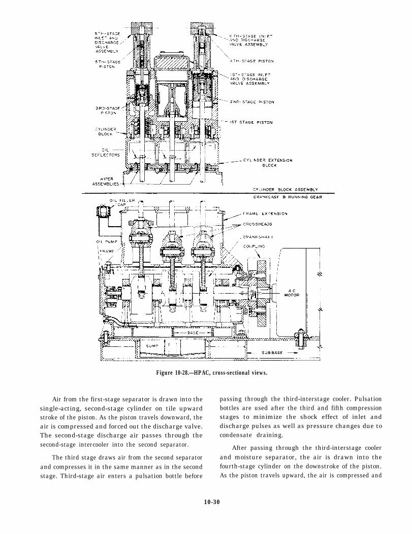
Figure 10-28.—HPAC, cross-sectional views.
Air from the first-stage separator is drawn into thesingle-acting, second-stage cylinder on tile upwardstroke of the piston. As the piston travels downward, theair is compressed and forced out the discharge valve.The second-stage discharge air passes through thesecond-stage intercooler into the second separator.
The third stage draws air from the second separatorand compresses it in the same manner as in the secondstage. Third-stage air enters a pulsation bottle before
passing through the third-interstage cooler. Pulsationbottles are used after the third and fifth compressionstages to minimize the shock effect of inlet anddischarge pulses as well as pressure changes due tocondensate draining.
After passing through the third-interstage coolerand moisture separator, the air is drawn into thefourth-stage cylinder on the downstroke of the piston.As the piston travels upward, the air is compressed and
10-30
forced out the discharge valve. Then it passes throughthe fourth-stage intercooler and moisture separator.
Air is drawn into the fifth-stage cylinder on thepiston downstroke and is compressed and discharged onthe upstroke. The discharge air passes through thefifth-stage pulsation bottle, the aftercooler, the moistureseparator, a back-pressure valve, and a check valvebefore entering the ships’ HP piping.
SAFETY PRECAUTIONS
Many hazards are associated with pressurized air,particularly air under high pressure. Dangerousexplosions have occurred in high-pressure air systemsbecause of DIESEL EFFECT. If a portion of anunpressurized system or component is suddenly andrapidly pressurized with high-pressure air, a largeamount of heat is produced. If the heat is excessive, theair may reach the ignition temperature of the impuritiespresent in the air and piping (oil, dust, and so forth).When the ignition temperature is reached, a violentexplosion will occur as these impurities ignite. Ignitiontemperatures may also result from other causes. Someare rapid pressurization of a low-pressure dead-endportion of the piping system, malfunctioning ofcompressor aftercoolers, and leaky or dirty valves.
Air compressor accidents have also been caused byimproper maintenance procedures. These accidents canhappen when you disconnect parts under pressure,replace parts with units designed for lower pressures,and install stop valves or check valves in improperlocations. Improper operating procedures have resultedin air compressor accidents with serious injury topersonnel and damage to equipment.
You must take every possible step to minimize thehazards inherent in the process of compression and inthe use of compressed air. Strictly follow all safetyprecautions outlined in the manufacturer’s technicalmanuals and in the NSTM, chapter 551. Some of thesehazards and precautions are as follows:
1. Explosions can be caused by dust-laden air or byoil vapor in the compressor or receiver if abnormallyhigh temperatures exist. Leaky or dirty valves,excessive pressurization rates, or faulty cooling systemsmay cause these high temperatures.
2. NEVER use distillate fuel or gasoline as adegreaser to clean compressor intake filters, cylinders,or air passages. These oils vaporize easily and will forma highly explosive mixture with the air undercompression.
3. Secure a compressor immediately if you observethat the temperature of the air being discharged from anystage exceeds the maximum temperature specified.
4. NEVER leave the compressor station afterstarting the compressor unless you are sure that thecontrol and unloading devices are operating properly.
5. Before working on a compressor, make sure thecompressor is secured. Make sure that it cannot startautomatically or accidentally. Completely blow downthe compressor, and then secure all valves (including thecontrol or unloading valves) between the compressorand the receiver. Follow the appropriate tag-outprocedures for the compressor control valves and theisolation valves. When the gauges are in place, leave thepressure gauge cutout valves open at all times.
6. Before disconnecting any part of an air system,be sure the part is not under pressure. Always leave thepressure gauge cutout valves open to the sections towhich they are attached.
7. Avoid rapid operation of manual valves. Theheat of compression caused by a sudden flow ofhigh-pressure air into an empty line or vessel can causean explosion if oil or other impurities are present.Slowly crack open the valves until flow is noted, andkeep the valves in this position until pressure on bothsides has equalized. Keep the rate of pressure riseunder 200 psi per second.
DEHYDRATORS
The removal of moisture from compressed air is animportant feature of compressed air systems. As youhave learned, some moisture is removed by theintercoolers and aftercoolers. Air flasks and receiversare provided with low-point drains so any collectedmoisture may drain periodically. However, manyshipboard uses for compressed air require air with aneven smaller moisture content than is obtained throughthese methods. Water vapor in air lines can create otherpotentially hazardous problems. Water vapor can causecontrol valves and controls to freeze. These conditionscan occur when air at very high pressure is throttled toa low-pressure area at a high-flow rate. The venturieffect of the throttled air produces very lowtemperatures that cause any moisture in the air to freezeinto ice. Under these conditions, a valve (especially anautomatic valve) may become very difficult orimpossible to operate. Also, moisture in any air systemcan cause serious water hammering (a banging sound)within the system. For these reasons, air dehydrators or
10-31
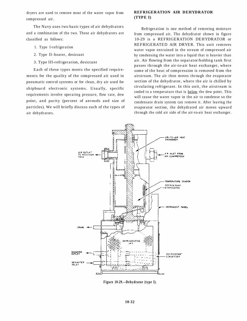
dryers are used to remove most of the water vapor from
compressed air.
The Navy uses two basic types of air dehydrators
and a combination of the two. These air dehydrators are
classified as follows:
1. Type I-refrigeration
2. Type II–heater, desiccant
3. Type III-refrigeration, desiccant
Each of these types meets the specified require-
ments for the quality of the compressed air used in
pneumatic control systems or for clean, dry air used for
shipboard electronic systems. Usually, specific
requirements involve operating pressure, flow rate, dew
point, and purity (percent of aerosols and size of
particles). We will briefly discuss each of the types ofair dehydrators.
REFRIGERATION AIR DEHYDRATOR(TYPE I)
Refrigeration is one method of removing moisturefrom compressed air. The dehydrator shown in figure10-29 is a REFRIGERATION DEHYDRATOR orREFRIGERATED AIR DRYER. This unit removeswater vapor entrained in the stream of compressed airby condensing the water into a liquid that is heavier thanair. Air flowing from the separator/holding tank firstpasses through the air-to-air heat exchanger, wheresome of the heat of compression is removed from theairstream. The air then moves through the evaporatorsection of the dehydrator, where the air is chilled bycirculating refrigerant. In this unit, the airstream iscooled to a temperature that is below the dew point. Thiswill cause the water vapor in the air to condense so thecondensate drain system can remove it. After leaving theevaporator section, the dehydrated air moves upwardthrough the cold air side of the air-to-air heat exchanger.
Figure 10-29.—Dehydrator (type I).
10-32
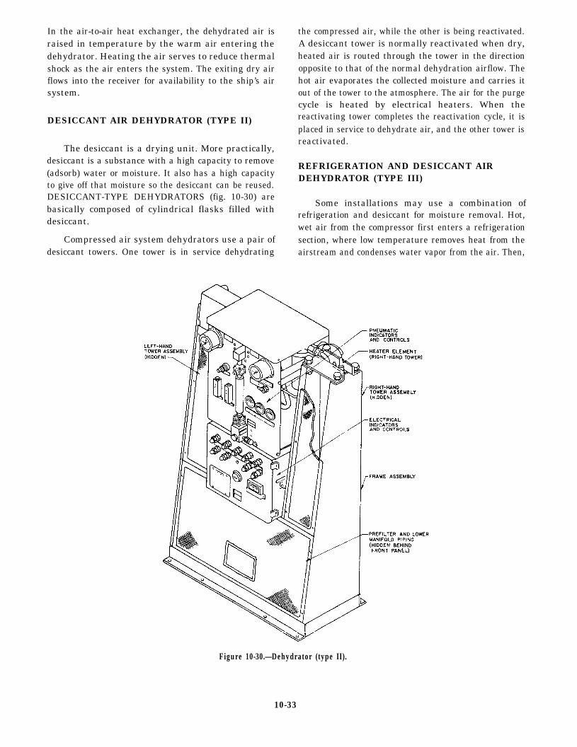
In the air-to-air heat exchanger, the dehydrated air israised in temperature by the warm air entering thedehydrator. Heating the air serves to reduce thermalshock as the air enters the system. The exiting dry airflows into the receiver for availability to the ship’s airsystem.
DESICCANT AIR DEHYDRATOR (TYPE II)
The desiccant is a drying unit. More practically,desiccant is a substance with a high capacity to remove(adsorb) water or moisture. It also has a high capacityto give off that moisture so the desiccant can be reused.DESICCANT-TYPE DEHYDRATORS (fig. 10-30) arebasically composed of cylindrical flasks filled withdesiccant.
Compressed air system dehydrators use a pair ofdesiccant towers. One tower is in service dehydrating
the compressed air, while the other is being reactivated.A desiccant tower is normally reactivated when dry,heated air is routed through the tower in the directionopposite to that of the normal dehydration airflow. Thehot air evaporates the collected moisture and carries itout of the tower to the atmosphere. The air for the purgecycle is heated by electrical heaters. When thereactivating tower completes the reactivation cycle, it isplaced in service to dehydrate air, and the other tower isreactivated.
REFRIGERATION AND DESICCANT AIRDEHYDRATOR (TYPE III)
Some installations may use a combination ofrefrigeration and desiccant for moisture removal. Hot,wet air from the compressor first enters a refrigerationsection, where low temperature removes heat from theairstream and condenses water vapor from the air. Then,
Figure 10-30.—Dehydrator (type II).
10-33

the cold, partially-dried air flows into a desiccantsection, where the desiccant absorbs additional moisturefrom the air.
DISTILLING PLANTS
Distilling plants are used to supply fresh water andboiler feedwater. Distillers use either steam, hot water,or electrical energy to boil seawater.
The majority of Navy ships have steam-heateddistilling plants. There are three types of steam-heateddistilling plants–submerged tube, flash, and vaporcompression. Of these types, the submerged-tube heatrecovery and flash are the most widely used.
Heat recovery units are used in vessels with enginepropulsion or auxiliary engines. Two variations of theheat recovery types are used; both use the heat fromengine cooling systems for evaporization of seawater.
In one model of a heat recovery plant, the heat ofthe diesel engine jacket water is transferred to theseawater in a heat exchanger. The heated seawater isthen flashed to freshwater vapor as in the flash-typedistilling unit. In the second variation, the hot dieselengine jacket water is circulated through a tube bundlethat is submerged in seawater. The seawater is boiled in
a chamber that is under vacuum as in the submerged tubedistilling unit.
Refer to figure 10-31, which shows a simplifiedflow diagram for a 12,000 gpd (gallons per day), ModelS500ST, submerged-tube recovery unit. In this recoveryunit, jacket water from the ship’s main propulsiondiesels is fed to a tube bundle. The tube is submerged inthe seawater that will be evaporated. The jacket waterimparts its heat to the seawater surrounding the tubes,which induces seawater evaporation. The vapor createdby the evaporating seawater is drawn through vaporseparators to the distillate condensing tube bundle. Thetemperature of evaporation is maintained below thenormal 212°F boiling point by a feedwater-operated aireductor. The eductor mechanically evacuates air andgases entrained in the vapor formed in the evaporatingprocess and creates an internal shell pressure as low as2 1/2 psia.
The flash-type distilling plant (fig. 10-32) haspreheater that heat seawater to a high temperature.Then, the seawater is admitted to a vacuum chamberwhere some of it flashes to vapor. The remainingseawater is directed to another vacuum chambermaintained at an even lower vacuum. Here, moreseawater flashes to vapor. At this point, the remaining
Figure 10-31.—Simplified flow diagram-heat recovery unit.
10-34

Figure 10-32.—Two-stage flash-type evaporator.
seawater is pumped overboard. Some flash-typedistilling plants have as many as five flash chambersthrough which the seawater passes before being pumpedoverboard. The vapor is condensed and routed to theship’s freshwater tanks.
Distilling plants range in capacity from 2,000 to100,000 gpd. The size depends on shipboard needs andspace available. Some ships have only one distillingunit, while others have two or more.
PURIFIERS
When you operate and maintain a purifier, youshould refer to the detailed instructions that come witheach purifier. These manufacturers’ technical manualscontain information on the construction, operation, andmaintenance of the specific purifier. You need to followthese instructions carefully. This section of theTRAMAN contains a discussion and generalinformation on the methods of purification and the
principles of operation of centrifugal purifiers.Centrifugal purifiers are used to purify both lube oil andfuel. However, we will discuss lube oil only since theprinciples are the same for both.
A purifier may remove both water and sediment, orit may remove sediment only. When water is involvedin the purification process, the purifier is usually calleda SEPARATOR. When the principal contaminant is dirtor sediment, the purifier is used as a CLARIFIER.Purifiers are generally used as separators for thepurification of fuel. When used for purification of a lubeoil, a purifier may be used as either a separator or aclarifier. Whether a purifier is used as a separator or aclarifier depends on the water content of the oil that isbeing purified.
The following general information will help youunderstand the purification process, the purposes andprinciples of purifier operation, and the basic types ofcentrifugal purifiers used by the Navy.
10-35

PURIFIER OPERATION
Centrifugal force is the fundamental operatingprinciple used in the purification of fluid. Centrifugalforce is that force exerted on a body or substance byrotation. Centrifugal force impels the body or substanceout ward from the axis of rotation.
Essentially, a centrifugal purifier is a containerrotated at high speed. As it rotates, contaminated lubeoil is forced through, and rotates with, the container.Only materials that are in the lube oil are separated bycentrifugal force. For example, water is separated fromlube oil because water and lube oil are immiscible,which means they are incapable of being mixed. Also,there must be a difference in the specific gravities of thematerials before they can be separated by centrifugalforce. You cannot use a centrifugal purifier to separateJP-5 or naval distillate from lube oil because it is capable
of being mixed; likewise, you cannot remove salt fromseawater by centrifugal force.
When a mixture of lube oil, water, and sedimentstands undisturbed, gravity tends to form an upper layerof lube oil, an intermediate layer of water, and a lowerlayer of sediment. The layers form because of thespecific gravities of the materials in the mixture. If thelube oil, water, and sediment are placed in a containerthat is revolving rapidly around a vertical axis, the effectof gravity is negligible in comparison with that of thecentrifugal force. Since centrifugal force acts at rightangles to the axis of rotation of the container, thesediment with its greater specific gravity assumes theoutermost position, forming a layer on the inner surfaceof the container. Water, being heavier than lube oil,forms an intermediate layer between the layer ofsediment and the lube oil, which forms the innermostlayer. The separated water is discharged as waste, and
Figure 10-33.—Disc-type centrifugal purifier.
10-36
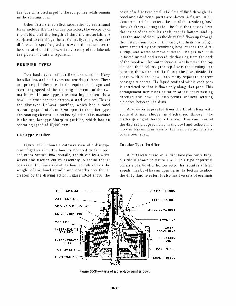
the lube oil is discharged to the sump. The solids remainin the rotating unit.
Other factors that affect separation by centrifugalforce include the size of the particles, the viscosity ofthe fluids, and the length of time the materials aresubjected to centrifugal force. Generally, the greater thedifference in specific gravity between the substances tobe separated and the lower the viscosity of the lube oil,the greater the rate of separation.
PURIFIER TYPES
Two basic types of purifiers are used in Navyinstallations, and both types use centrifugal force. Thereare principal differences in the equipment design andoperating speed of the rotating elements of the twomachines. In one type, the rotating element is abowl-like container that encases a stack of discs. This isthe disc-type DeLaval purifier, which has a bowloperating speed of about 7,200 rpm. In the other type,the rotating element is a hollow cylinder. This machineis the tubular-type Sharples purifier, which has anoperating speed of 15,000 rpm.
Disc-Type Purifier
Figure 10-33 shows a cutaway view of a disc-typecentrifugal purifier. The bowl is mounted on the upperend of the vertical bowl spindle, and driven by a wormwheel and friction clutch assembly. A radial thrustbearing at the lower end of the bowl spindle carries theweight of the bowl spindle and absorbs any thrustcreated by the driving action. Figure 10-34 shows the
parts of a disc-type bowl. The flow of fluid through thebowl and additional parts are shown in figure 10-35.Contaminated fluid enters the top of the revolving bowlthrough the regulating tube. The fluid then passes downthe inside of the tubular shaft, out the bottom, and upinto the stack of discs. As the dirty fluid flows up throughthe distribution holes in the discs, the high centrifugalforce exerted by the revolving bowl causes the dirt,sludge, and water to move outward. The purified fluidis forced inward and upward, discharging from the neckof the top disc. The water forms a seal between the topdisc and the bowl top. (The top disc is the dividing linebetween the water and the fluid.) The discs divide thespace within the bowl into many separate narrowpassages or spaces. The liquid confined within each passis restricted so that it flows only along that pass. Thisarrangement minimizes agitation of the liquid passingthrough the bowl. It also forms shallow settlingdistances between the discs.
Any water separated from the fluid, along withsome dirt and sludge, is discharged through thedischarge ring at the top of the bowl. However, most ofthe dirt and sludge remains in the bowl and collects in amore or less uniform layer on the inside vertical surfaceof the bowl shell.
Tubular-Type Purifier
A cutaway view of a tubular-type centrifugalpurifier is shown in figure 10-36. This type of purifierconsists of a bowl or hollow rotor that rotates at highspeeds. The bowl has an opening in the bottom to allowthe dirty fluid to enter. It also has two sets of openings
Figure 10-34.—Parts of a disc-type purifier bowl.
10-37
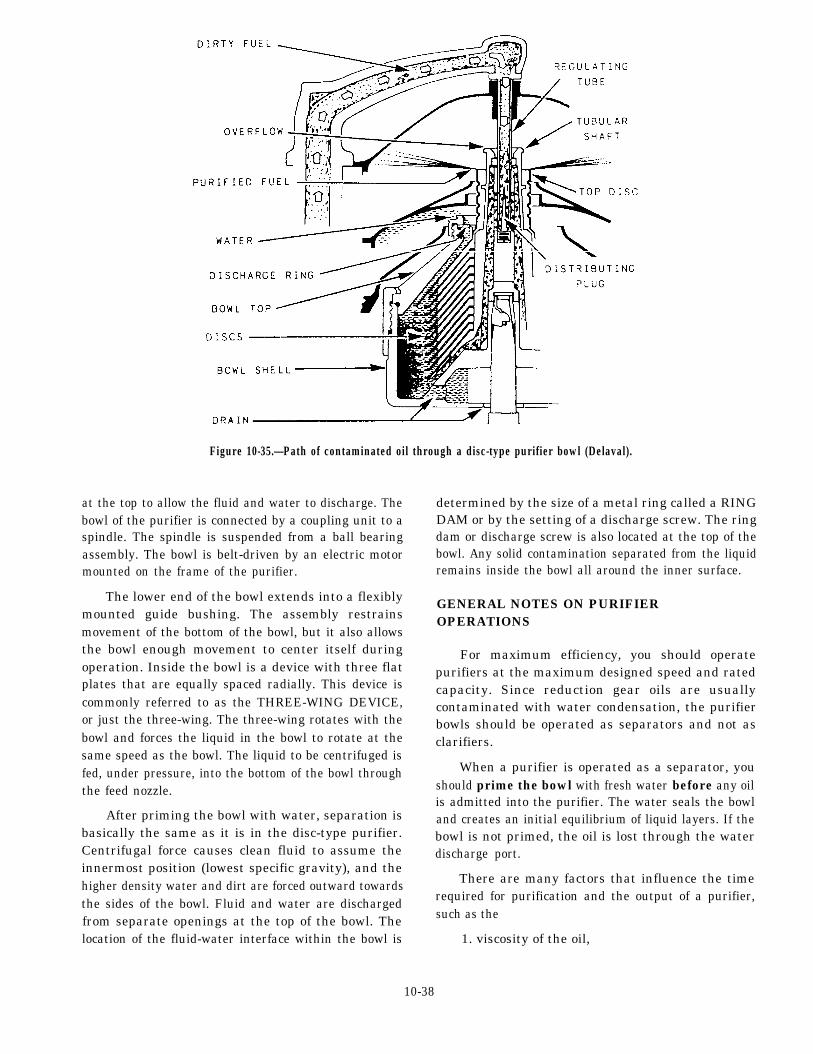
Figure 10-35.—Path of contaminated oil through a disc-type purifier bowl (Delaval).
at the top to allow the fluid and water to discharge. Thebowl of the purifier is connected by a coupling unit to aspindle. The spindle is suspended from a ball bearingassembly. The bowl is belt-driven by an electric motormounted on the frame of the purifier.
The lower end of the bowl extends into a flexiblymounted guide bushing. The assembly restrainsmovement of the bottom of the bowl, but it also allowsthe bowl enough movement to center itself duringoperation. Inside the bowl is a device with three flatplates that are equally spaced radially. This device iscommonly referred to as the THREE-WING DEVICE,or just the three-wing. The three-wing rotates with thebowl and forces the liquid in the bowl to rotate at thesame speed as the bowl. The liquid to be centrifuged isfed, under pressure, into the bottom of the bowl throughthe feed nozzle.
After priming the bowl with water, separation isbasically the same as it is in the disc-type purifier.Centrifugal force causes clean fluid to assume theinnermost position (lowest specific gravity), and thehigher density water and dirt are forced outward towardsthe sides of the bowl. Fluid and water are dischargedfrom separate openings at the top of the bowl. Thelocation of the fluid-water interface within the bowl is
determined by the size of a metal ring called a RINGDAM or by the setting of a discharge screw. The ringdam or discharge screw is also located at the top of thebowl. Any solid contamination separated from the liquidremains inside the bowl all around the inner surface.
GENERAL NOTES ON PURIFIEROPERATIONS
For maximum efficiency, you should operatepurifiers at the maximum designed speed and ratedcapacity. Since reduction gear oils are usuallycontaminated with water condensation, the purifierbowls should be operated as separators and not asclarifiers.
When a purifier is operated as a separator, youshould prime the bowl with fresh water before any oilis admitted into the purifier. The water seals the bowland creates an initial equilibrium of liquid layers. If thebowl is not primed, the oil is lost through the waterdischarge port.
There are many factors that influence the timerequired for purification and the output of a purifier,such as the
1. viscosity of the oil,
10-38
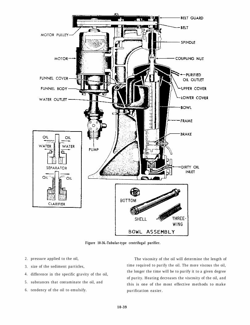
2.
3.
4.
5.
6.
Figure 10-36.-Tubular-type centrifugal purifier.
The viscosity of the oil will determine the length ofpressure applied to the oil,
size of the sediment particles, time required to purify the oil. The more viscous the oil,
difference in the specific gravity of the oil,the longer the time will be to purify it to a given degree
of purity. Heating decreases the viscosity of the oil, andsubstances that contaminate the oil, and this is one of the most effective methods to maketendency of the oil to emulsify. purification easier.
10-39
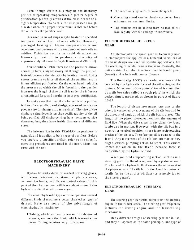
Even though certain oils may be satisfactorilypurified at operating temperatures, a greater degree ofpurification generally results if the oil is heated to ahigher temperature. To do this, the oil is passed througha heater where the proper temperature is obtained beforethe oil enters the purifier bowl.
Oils used in naval ships maybe heated to specifiedtemperatures without adverse effects. However,prolonged heating at higher temperatures is notrecommended because of the tendency of such oils tooxidize. Oxidation results in rapid deterioration.Generally, heat oil to produce a viscosity ofapproximately 90 seconds Saybolt universal (90 SSU).
You should NEVER increase the pressure abovenormal to force a high-viscosity oil through the purifier.Instead, decrease the viscosity by heating the oil. Usingexcess pressure to force oil through the purifier resultsin less efficient purification. On the other hand, reducingthe pressure at which the oil is forced into the purifierincreases the length of time the oil is under the influenceof centrifugal force and results in improved purification.
To make sure that the oil discharged from a purifieris free of water, dirt, and sludge, you need to use theproper size discharge ring (ring dam). The size of thedischarge ring depends on the specific gravity of the oilbeing purified. All discharge rings have the same outsidediameter; but, they have inside diameters of differentsizes.
The information in this TRAMAN on purifiers isgeneral, and it applies to both types of purifiers. Beforeyou operate a specific purifier, refer to the specificoperating procedures contained in the instructions thatcome with the unit.
ELECTROHYDRAULIC DRIVEMACHINERY
Hydraulic units drive or control steering gears,windlasses, winches, capstans, airplane cranes,ammunition hoists, and distant control valves. In thispart of the chapter, you will learn about some of thehydraulic units that will concern you.
The electrohydraulic type of drive operates severaldifferent kinds of machinery better than other types ofdrives. Here are some of the advantages ofelectrohydraulic machinery.
l Tubing, which can readily transmit fluids aroundcorners, conducts the liquid which transmits theforce. Tubing requires very little space.
l
l
l
The machinery operates at variable speeds.
Operating speed can be closely controlled fromminimum to maximum limits.
The controls can be shifted from no load to fullload rapidly without damage to machinery.
ELECTROHYDRAULIC SPEEDGEAR
An electrohydraulic speed gear is frequently usedin electrohydraulic applications. Different variations ofthe basic design are used for specific applications, butthe operating principles remain the same. Basically, theunit consists of an electric motor-driven hydraulic pump(A-end) and a hydraulic motor (B-end).
The B-end (fig. 10-37) is already on stroke and isrotated by the hydraulic force of the oil acting on thepistons. Movement of the pistons’ A-end is controlledby a tilt box (also called a swash plate) in which thesocket ring is mounted, as shown in part A of figure10-37.
The length of piston movement, one way or theother, is controlled by movement of the tilt box and bythe amount of angle at which the tilt box is placed. Thelength of the piston movement controls the amount offluid flow. When the drive motor is energized, the A-endis always in motion. However, with the tilt box in aneutral or vertical position, there is no reciprocatingmotion of the pistons. Therefore, no oil is pumped to theB-end. Any movement of the tilt box, no matter howslight, causes pumping action to start. This causesimmediate action in the B-end because force istransmitted by the hydraulic fluid.
When you need reciprocating motion, such as in asteering gear, the B-end is replaced by a piston or ram.The force of the hydraulic fluid causes the movement ofthe piston or ram. The tilt box in the A-end is controlledlocally (as on the anchor windlass) or remotely (as onthe steering gear).
ELECTROHYDRAULIC STEERINGGEAR
The steering gear transmits power from the steeringengine to the rudder stock. The steering gear frequentlyincludes the driving engine and the transmittingmechanism.
Many different designs of steering gear are in use,and they all operate on the same principle. One type of
10-40
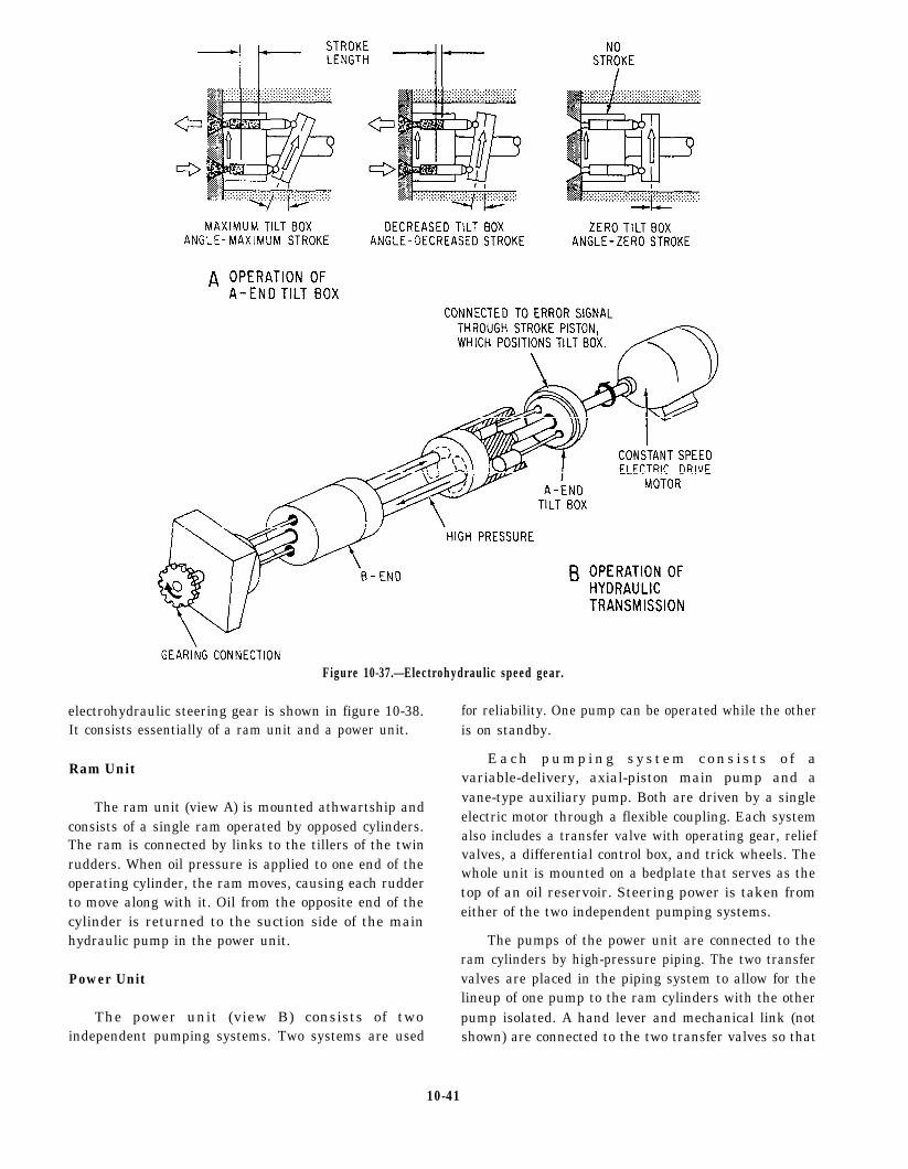
Figure 10-37.—Electrohydraulic speed gear.
electrohydraulic steering gear is shown in figure 10-38.It consists essentially of a ram unit and a power unit.
Ram Unit
The ram unit (view A) is mounted athwartship andconsists of a single ram operated by opposed cylinders.The ram is connected by links to the tillers of the twinrudders. When oil pressure is applied to one end of theoperating cylinder, the ram moves, causing each rudderto move along with it. Oil from the opposite end of thecylinder is returned to the suction side of the mainhydraulic pump in the power unit.
Power Unit
The power unit (view B) consists of twoindependent pumping systems. Two systems are used
for reliability. One pump can be operated while the otheris on standby.
E a c h p u m p i n g s y s t e m c o n s i s t s o f avariable-delivery, axial-piston main pump and avane-type auxiliary pump. Both are driven by a singleelectric motor through a flexible coupling. Each systemalso includes a transfer valve with operating gear, reliefvalves, a differential control box, and trick wheels. Thewhole unit is mounted on a bedplate that serves as thetop of an oil reservoir. Steering power is taken fromeither of the two independent pumping systems.
The pumps of the power unit are connected to theram cylinders by high-pressure piping. The two transfervalves are placed in the piping system to allow for thelineup of one pump to the ram cylinders with the otherpump isolated. A hand lever and mechanical link (notshown) are connected to the two transfer valves so that
10-41

Figure 10-38.
10-42

both valves are operated together. This allows rapidshifting from the on-service pumping unit to the standbyunit; it prevents lining up both pumps to the ram at thesame time. The hand lever is usually located betweenthe trick wheels. It has three positions marked P, N, andS. P denotes the port pump is connected to the ram; Ndenotes neutral (neither pump connected to the ram);and S denotes the starboard pump is connected to theram. Also, the hand lever is usually connected to motorswitches. This lets the operator connect the selectedpump to the ram and start the pump drive motor in onequick operation. In most ships this valve is electricallycontrolled by the motor controller and by pressureswitches.
Principles of Operation
The on-service hydraulic pump is running at alltimes and is a constant-speed pump. Unless steering isactually taking place, the tilt box of the main hydraulicpump is at zero stroke, and no oil is being moved withinthe main system. The auxiliary pump provides controloil and supercharge flows for the system.
To understand the operation of the pump, let’sassume that a steering order signal comes into thedifferential control box. It can come from either theremote steering system in the ship’s wheelhouse or thetrick wheel. The control box mechanically positions thetilt box of the main hydraulic pump to the required angleand position.
NOTE: Remember that direction of fluid and flowmay be in either direction in a hydraulic speed gear. Itdepends on which way the tilt box is angled. For thisreason, the constant-speed, unidirectional motor can beused to drive the main hydraulic pump. The pump willstill have the capability to drive the ram in eitherdirection.
With the main hydraulic pump now pumping fluidinto one of the ram cylinders, the ram moves, movingthe rudders. A rack and gear are attached to the rudderyoke between the rudder links. As the ram and the ruddermove, the rack gear moves, driving the follow-up piniongear. The pinions drive follow-up shafts that feed intothe differential box. This feedback or servo system tellsthe differential control box when the steering operationis complete. As the ordered rudder angle is approached,the differential control box begins realigning the tilt boxof the main hydraulic pump. By the time the desiredrudder angle is reached, the tilt box is at zero stroke. Thismeans that the ordered signal (from the pilot house ortrick wheel) and the actual signal (from the follow-up
shafts) are the same. If either of these change, thedifferential control box reacts accordingly; the mainhydraulic unit pumps oil to one end or the other of theram.
The trick wheels provide local-hydraulic control ofthe steering system of the remote steering system fails.A hand pump and associated service lines are alsoprovided for local-manual operation of the ram if bothhydraulic pump units fail.
Operation and Maintenance
The Machinist’s Mate watch stander usuallyoperates the steering equipment only in abnormal andemergency situations. For this reason, you should bethoroughly familiar with all emergency procedures,such as local-hydraulic steering with the trick wheel andlocal-manual steering with the hand pump. Operatinginstructions and system diagrams are normally postednear the steering gear. The diagrams describe the variousprocedures and lineups for operation of the steeringgear. Be sure that the standby equipment is ready forinstant use.
General maintenance of the steering gear requiresthat you clean, inspect, and lubricate the mechanicalparts and maintain the hydraulic oil at the proper leveland purity. The Planned Maintenance System (PMS)lists the individual requirements for the equipment. Theelectricians maintain the electrical portion of thesteering system, including the control system.
ANCHOR WINDLASSES
In a typical electrohydraulic mechanism, oneconstant -speed e lec tr i c motor dr ives twovariable-stroke pumps through a coupling and reductiongear. Other installations include two motors, one fordriving each pump. Each pump normally drives onewildcat. However, if you use a three-way plug cock-typevalve, either pump may drive either of the two wildcats.The hydraulic motors drive the wildcat shafts with amultiple-spur gearing and a locking head. The lockinghead allows you to disconnect the wildcat shaft andpermits free operation of the wildcat, as when droppinganchor.
Each windlass pump is controlled either from theweather deck or locally. The controls are handwheels onshafting that lead to the pump control. The hydraulicsystem requires your attention. Make sure the hydraulicsystem is always serviced with the specified type ofclean oil.
10-43
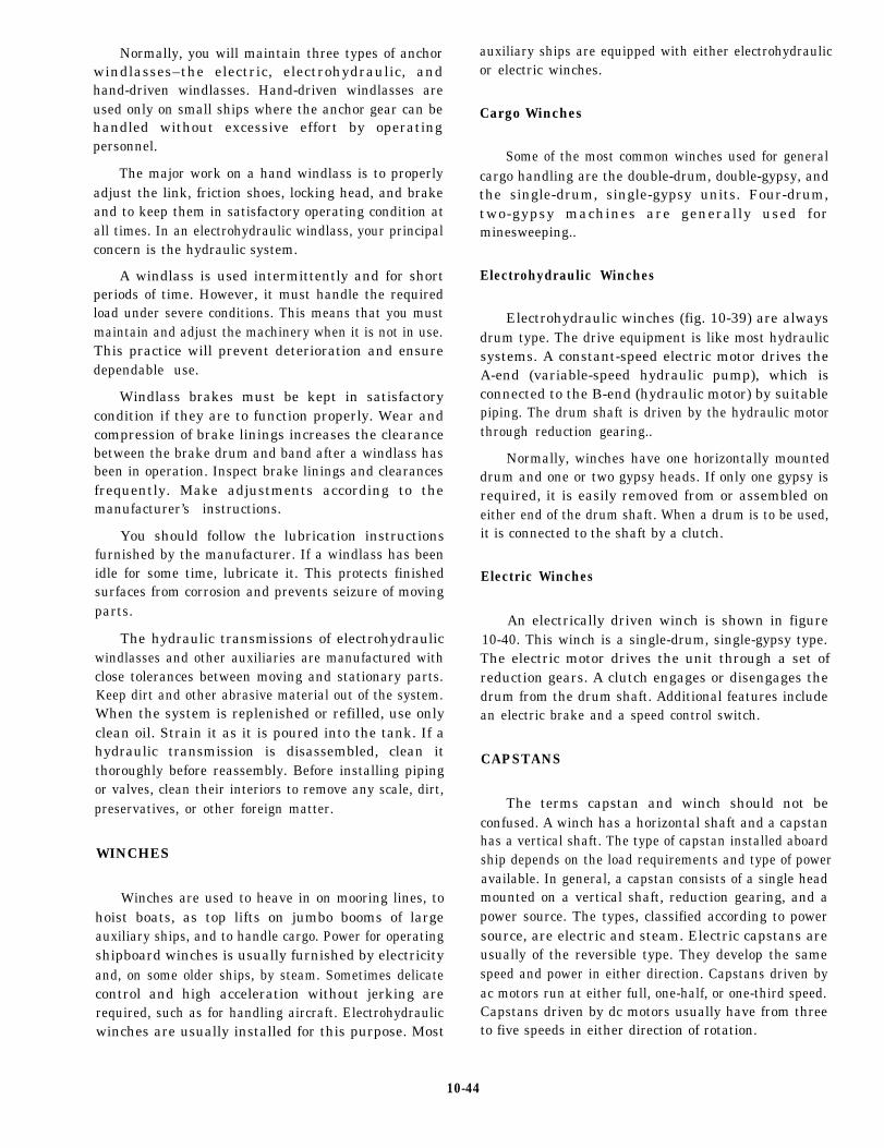
Normally, you will maintain three types of anchorwindlasses–the electric, electrohydraulic, andhand-driven windlasses. Hand-driven windlasses areused only on small ships where the anchor gear can behandled without excessive effort by operatingpersonnel.
The major work on a hand windlass is to properlyadjust the link, friction shoes, locking head, and brakeand to keep them in satisfactory operating condition atall times. In an electrohydraulic windlass, your principalconcern is the hydraulic system.
A windlass is used intermittently and for shortperiods of time. However, it must handle the requiredload under severe conditions. This means that you mustmaintain and adjust the machinery when it is not in use.This practice will prevent deterioration and ensuredependable use.
Windlass brakes must be kept in satisfactorycondition if they are to function properly. Wear andcompression of brake linings increases the clearancebetween the brake drum and band after a windlass hasbeen in operation. Inspect brake linings and clearancesfrequently. Make adjustments according to themanufacturer’s instructions.
You should follow the lubrication instructionsfurnished by the manufacturer. If a windlass has beenidle for some time, lubricate it. This protects finishedsurfaces from corrosion and prevents seizure of movingparts.
The hydraulic transmissions of electrohydraulicwindlasses and other auxiliaries are manufactured withclose tolerances between moving and stationary parts.Keep dirt and other abrasive material out of the system.When the system is replenished or refilled, use onlyclean oil. Strain it as it is poured into the tank. If ahydraulic transmission is disassembled, clean itthoroughly before reassembly. Before installing pipingor valves, clean their interiors to remove any scale, dirt,preservatives, or other foreign matter.
WINCHES
Winches are used to heave in on mooring lines, tohoist boats, as top lifts on jumbo booms of largeauxiliary ships, and to handle cargo. Power for operatingshipboard winches is usually furnished by electricityand, on some older ships, by steam. Sometimes delicatecontrol and high acceleration without jerking arerequired, such as for handling aircraft. Electrohydraulicwinches are usually installed for this purpose. Most
auxiliary ships are equipped with either electrohydraulicor electric winches.
Cargo Winches
Some of the most common winches used for generalcargo handling are the double-drum, double-gypsy, andthe single-drum, single-gypsy units. Four-drum,two-gypsy machines are generally used forminesweeping..
Electrohydraulic Winches
Electrohydraulic winches (fig. 10-39) are alwaysdrum type. The drive equipment is like most hydraulicsystems. A constant-speed electric motor drives theA-end (variable-speed hydraulic pump), which isconnected to the B-end (hydraulic motor) by suitablepiping. The drum shaft is driven by the hydraulic motorthrough reduction gearing..
Normally, winches have one horizontally mounteddrum and one or two gypsy heads. If only one gypsy isrequired, it is easily removed from or assembled oneither end of the drum shaft. When a drum is to be used,it is connected to the shaft by a clutch.
Electric Winches
An electrically driven winch is shown in figure10-40. This winch is a single-drum, single-gypsy type.The electric motor drives the unit through a set ofreduction gears. A clutch engages or disengages thedrum from the drum shaft. Additional features includean electric brake and a speed control switch.
CAPSTANS
The terms capstan and winch should not beconfused. A winch has a horizontal shaft and a capstanhas a vertical shaft. The type of capstan installed aboardship depends on the load requirements and type of poweravailable. In general, a capstan consists of a single headmounted on a vertical shaft, reduction gearing, and apower source. The types, classified according to powersource, are electric and steam. Electric capstans areusually of the reversible type. They develop the samespeed and power in either direction. Capstans driven byac motors run at either full, one-half, or one-third speed.Capstans driven by dc motors usually have from threeto five speeds in either direction of rotation.
10-44
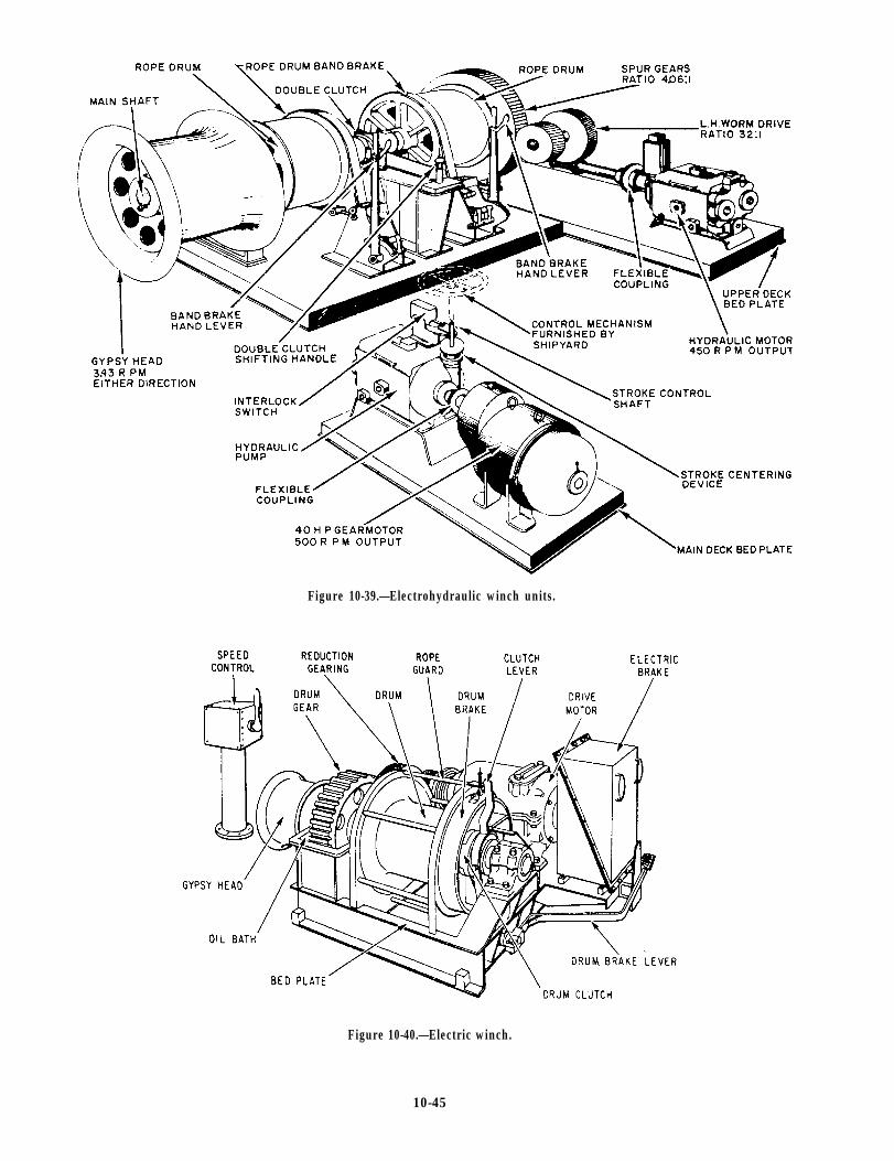
Figure 10-39.—Electrohydraulic winch units.
Figure 10-40.—Electric winch.
10-45

Maintenance of Winches and Capstans
You will maintain the winch or capstan similarly.Where band brakes are used on the drums, inspect thefriction linings regularly and replace them whennecessary. Take steps to prevent oil or grease fromaccumulating on the brake drums. Check the operationof brake-actuating mechanisms, latches, and pawlsperiodically.
Inspect winch drums driven by friction clutchesfrequently for deterioration in the friction material.Check also to see if oil and grease are preventing properoperation. Lubricate the sliding parts of positiveclutches properly. Check the locking device on theshifting gear to see if it will hold under load.
CRANES
Cranes are designed to meet the following criteria:
1. Hoist, lower, top, and rotate a rated load at thespecified speed and against a specified list of the ship.
2. Handle 150 percent of rated load at no specifiedspeed.
3. Withstand a static, suspended load of 200percent of rated load without dam or distortion to anypart of the crane or structure.
The types of cranes installed on ships varyaccording to the equipment handled.
The crane equipment generally includes the boom,king post, king post bearings, sheaves, hook and rope,machinery platforms, rotating gear, drums, hoisting,topping and rotating drives, and controls. Some of thecomponents of cranes include booms, king postbearings, sheaves and ropes, machinery platforms,rotating gear and pinions, and drums.
Booms
A boom, used as a mechanical shipboard appliance,is a structural unit used to lift, transfer, or support heavyweights. A boom is used with other structures orstructural members that support it, and various ropes andpulleys, called blocks, which control it.
King Post Bearings
Bearings on stationary king posts take both verticalload and horizontal strain at the collar, located at the topof the king post. On rotating king posts, bearings take
both vertical and horizontal loads at the base andhorizontal reactions at a higher deck level.
Sheaves and Ropes
The hoisting and topping ropes are led from thedrums over sheaves to the head of the boom. Thesheaves and ropes are designed according torecommendations by NAVSEASYSCOM. Thiscommand sets the criteria for selection of sheavediameter, size, and flexibility of the rope. Sufficientfair-lead sheaves are fitted to prevent fouling of the rope.A shock absorber is installed in the line, hoisting block,or sheave at the head of the boom to take care of shockstresses.
Machinery Platforms
Machinery platforms carry the power equipmentand operator’s station. These platforms are mounted onthe king post above the deck.
Rotating Gear and Pinions
Rotation of the crane is accomplished by verticalshafts with pinions engaging a large rotating gear.
Drums
The drums of the hoisting and topping winches aregenerally grooved for the proper size wire rope. Thehoisting system uses single or multiple part lines asrequired. The topping system uses a multiple purchaseas required.
Operation and Maintenance of Cranes
The hoisting whips and topping lifts of cranes areusually driven by hydraulic variable-speed gearsthrough gearing of various types. This provides the widerange of speed and delicate control required for loadhandling. The cranes are usually rotated by an electricmotor connected to worm and spur gearing. They mayalso be rotated by an electric motor and hydraulicvariable-speed gear connected to reduction gearing.
Some electrohydraulic cranes have automatic slackline take-up equipment. This consists of an electrictorque motor geared to the drum. These cranes are usedto lift boats, aircraft, or other loads from the water. Thetorque motor assists the hydraulic motor drive to reel inthe cable in case the load is lifted faster by the water thanit is being hoisted by the crane.
10-46

Electrohydraulic equipment for the crane consistsof one or more electric motors running at constant speed.E a c h m o t o r d r i v e s o n e o r m o r e A - e n dvariable-displacement hydraulic pumps. The pumpstrokes are controlled through operating handwheels.START, STOP, and EMERGENCY RUN pushbuttonsat the operator’s station control the electric motors.Interlocks prevent starting the electric motors when thehydraulic pumps are on stroke. B-end hydraulic motorsare connected to the A-end pumps by piping. They drivethe drums of the hoisting and topping units or therotating machinery.
Reduction gears are located between the electricmotor and the A-end pump and between the B-endhydraulic motor and the rotating pinion. Each hoisting,topping, and rotating drive has an electric brake on thehydraulic motor output shaft. This brake is interlockedwith the hydraulic pump control. It will set when thehydraulic control is on neutral or when electric power islost. A centering device is used to find and retain theneutral position of the hydraulic pump.
Relief valves protect the hydraulic system. Thesevalves are set according to the requirements of chapter556 of the NSTM.
Cranes usually have a rapid slack take-up deviceconsisting of an electric torque motor. This motor isconnected to the hoist drum through reduction gearing.This device works in conjunction with the pressurestroke control on the hydraulic pump. It provides fastacceleration of the hook in the hoisting direction underlight hook conditions. Thus, slack in the cable isprevented when hoisting is started.
Some cranes have a light-hook paying-out devicemounted on the end of the boom. It pays out the heistingcables when the weight of the hook and cable beyondthe boom-head sheave is insufficient to overhaul thecable as fast as it is unreeled from the hoisting drum.
When the mechanical hoist control is in neutral, thetorque motor is not energized and the cable is grippedlightly by the action of a spring. Moving the hoist controlto LOWER energizes the torque motor. The sheavesclamp and pay out the cable as it is unreeled from thehoist drum. When the hoist control is moved to HOIST,the torque motor is reversed and unclamps the sheaves.Alimit switch opens and automatically de-energizes thepaying-out device.
Maintain cranes according to the PMS requirementsor the manufactured instructions. Keep the oil in thereplenishing tanks at the prescribed levels. Keep thesystem clean and free of air. Check the limit stop and
other mechanical safety devices regularly for properoperation. When cranes are not in use, secure them intheir stowed positions. Secure all electric power to thecontrollers.
ELECTROHYDRAULIC ELEVATORS
Some of the hydraulic equipment that you maintainis found in electrohydraulic elevator installations.Modern carriers use elevators of this type. The elevatorsdescribed in this chapter are now in service in some ofthe ships of the CV class. These ships are equipped withfour, deck-edge airplane elevators having a maximumlift capacity of 79,000 to 105,000 pounds. The cable liftplatform of each elevator projects over the side of theship and is operated by an electrohydraulic plant.
Electrohydraulic Power Plant
The electrohydraulic power plant for the elevatorsconsists of the following components:
1.
2.
3.
4.
5.
6.
7.
8.
9.
A horizontal plunger-type hydraulic engine
Multiple variable-delivery parallel piston-typepumps
Two high-pressure tanks
One low-pressure tank
A sump tank system
Two constant-delivery vane-type pumps (sumppumps)
An oil storage tank
A piping system and valves
A nitrogen supply
The hydraulic engine is operated by pressuredeveloped in a closed hydraulic system. Oil is suppliedto the system in sufficient quantity to cover the baffleplates in the high-pressure tanks and allow for pistondisplacement. Nitrogen is used because air and oil incontact under high pressure form an explosive mixture.Air should not be used except in an emergency.Nitrogen, when used, should be kept at 97 percent purity.
The hydraulic engine has a balanced piston-typevalve with control orifices and a differential control unit.This control assembly is actuated by an electric motorand can be operated by hand. To raise the elevator, movethe valve off center to allow high-pressure oil to enterthe cylinder. High-pressure oil entering the cylindermoves the ram. The ram works through a system ofcables and sheaves to move the platform upward. The
10-47

speed of the elevator is controlled by the amount ofpressure in the high-pressure tank and the control valve.
When the elevator starts upward, the pressure in thehigh-pressure tank drops. The pressure dropautomatically starts the main pumps. These pumpstransfer oil from the low-pressure tank to thehigh-pressure system until the pressure is restored. Anelectrical stopping device automatically limits thestroke of the ram and stops the platform at the properposition at the flight deck level.
To lower the elevator, move the control valve in theopposite direction. This lets oil in the cylinder flow intothe exhaust tank. As the platform descends, oil isdischarged to the low-pressure tank (exhaust tank). Theoriginal oil levels and pressures, except for leaks, arereestablished. The lowering speed is controlled by thecontrol valve and the cushioning effect of the pressurein the exhaust tank. Leak is drained to the sump tanks.It is then automatically transferred to the pressuresystem by the sump pumps. An electrically operatedstopping device automatically slows down the ram andstops the platform at its lower level (hangar deck).
Safety Features
The following list contains some of the major safetyfeatures incorporated into modem deck-edge elevators:
1. If the electrical power fails while the platform isat the hangar deck, there will be enough pressure in thesystem to move the platform to the flight deck one timewithout the pumps running.
2. Some platforms have serrated safety shoes. If allthe hoisting cable should break on one side, the shoeswill wedge the platform between the guide rails. Thiswill stop the platform with minimum damage.
3. A main pump may have a pressure-actuatedswitch to stop the pump motors when the dischargepressure is excessive. They may also have to relieve thepressure when the pressure switch fails to operate.
4. The sump pump system has enough capacity toreturn the unloaded platform from the hangar deck tothe flight deck.
5. The oil filter system maybe used continuouslywhile the engine is running. This allows part of the oilto be cleaned with each operation of the elevater.
ELECTROMECHANICAL ELEVATORS
Electromechanical elevators are used for freight,bombs, and stores. In this type of elevator, the platform
is raised and lowered by one or more wire ropes thatpass over pulleys and wind or unwind on hoistingdrums. Hoisting drums are driven through a reductiongear unit by an electric motor. An electric brake stopsand holds the platform. The motor has two speeds, fullspeed and low, or one-sixth, speed. Controlarrangements allow the elevator to start and run on highspeed. Low speed is used for automatic deceleration asthe elevator approaches the selected level. The platformtravels on two or four guides. Hand-operated orpower-operated lock bars, equipped with electricalinterlocks, hold the platform in position.
LUBRICATING SYSTEMS
Most equipment is provided with a lubricatingsystem that supplies oil under pressure to the bearings.The system consists of a sump or reservoir for storingthe oil, an oil pump, a strainer, a cooler, temperature andpressure gauges, and the necessary piping to carry theoil to the bearings and back to the sump. The locationand arrangement of these parts vary with each piece ofequipment. This system allows the lube-oil system toperform the following functions:
l Supply lubrication to the bearings
. Cool the bearings
. Flush any wear products from the bearings
The lube-oil pump is generally a gear-type pump. Adefinite pressure is maintained in the oil feed lines. Apressure relief valve allows excess oil to recirculate tothe suction side of the pump.
Quite often, dual strainers are connected in the lineso that the system can operate on one strainer while theother one is being cleaned. The tube-in-shell type ofcooler is generally used with seawater circulatingthrough the tubes and the oil flowing around them. Thetemperature of the oil is controlled by adjusting thevalve that regulates the amount of seawater flowingthrough the tubes.
Oil must be supplied to the bearings at theprescribed pressure and within certain temperaturelimits. A pressure gauge installed in the feed line and athermometer installed in the return line indicate oilsystem functioning. Thermometers are often installed inthe bearings to serve as a warning against overheating.If there is a decided drop in oil pressure, shut down theequipment immediately. You should investigate even amoderate rise in the oil temperature. An oil-level floatgauge indicates the amount of oil in the sump. Somebearings do not require a lot of cooling or flushing of
10-48

wear products, so they are grease lubricated (likeautomobile steering joints). These bearings are usuallyfitted with a zerk fitting (grease fitting), but some mayhave grease cups installed.
FUNCTIONS OF LUBRICATION
Lubrication reduces friction between moving partsby substituting fluid friction for sliding friction. Mostlubricants are oils or greases; but other units, such aswater, can be used for lubrication. When a rotatingjournal is set in motion, a wedge of oil is formed. Thiswedge (layer of oil) supports the rotor and substitutesfluid friction for sliding friction. The views shown infigure 10-41 represent a rotor (journal) rotating in a solidsleeve-type bearing. The clearances are exaggerated inthe drawing so you can see the formation of the oil film.The shaded portion represents the clearance filled withoil. While the journal is stopped, the oil is squeezed frombetween the rotor and the bearing, As the rotor starts toturn, oil adhering to the rotor surfaces is carried into thearea between the rotor and the bearing. This oil increasesthe thickness of the oil film, tending to raise and supportthe rotor. Thus, sliding friction has been replaced byfluid friction.
LUBRICATING OILS AND GREASES
Many different kinds of lubricating materials are inuse, each of them filling the requirements of a particularset of conditions. Animal and vegetable oils and evenwater have good lubricating qualities, but they cannotwithstand high temperatures. Mineral oils, similar to theoils used in an automobile engine, are the best type of
Figure 10-41.—Rotating journals in sleeve-type bearings.
lubricant for modern machinery operating at highspeeds and high temperatures.
Mineral lubricating oils are derived from crude oilin the same process that produces gasoline, kerosene,and fuel oil. They vary according to the type of crude oiland the refining methods used. The same type of oil isusually made in several grades or weights. These gradescorrespond to the different weights of oil for anautomobile, varying from light to heavy.
Oils used in the Navy are divided into nine classes,or series, depending on their use. Each type of oil has asymbol number that indicates its class and viscosity. Forexample, symbol 2190 oil is a number 2 class of oil witha viscosity of 190 SSU. The viscosity number representsthe time in seconds that is required for 60 cubiccentimeters (cc) of oil, at a temperature of 130°F, to flowthrough a standard size opening in a Sayboltviscosimeter (fig. 10-42).
A 2190TEP oil is used for all propulsion turbinesand reduction gears. The letters TEP indicate that theoil contains additive materials that increase its ability todisplace water from steel and inhibit oxidation.
Internal combustion engines (gasoline and diesel)use symbol 9110, 9170, 9250, or 9500 lubricating oils.
Figure 10-42.—Viscosimeter tube.
10-49

These oils have been developed for lubrication ofhigh-speed, high-output diesel engines.
Grease lubrication is used in locations where theretention of lube oil would be difficult. Some of theselocations include throttle links, pump bearings, smallboat steering links, laundry equipment, etc. Grease isgraded according to its intended use and the additives itmay contain. Always be sure that you are using thespecified lubricant for the individual machinery part,unit, or system you are responsible for operating ormaintaining.
The manufacturer’s technical manual for each unitof machinery is the basic reference for the correct lubeoil, if no lubrication chart (based on manufacturer’sinstructions) is available. In addition, the table ofrecommended oils can be found in NSTM, chapter 262.
GALLEY AND LAUNDRY EQUIPMENT
The Navy uses a variety of galley and laundryequipment. The type of equipment depends on the sizeof the ship, the availability of steam, and other factors.You will need the equipment manufacturer’s technicalmanual for each different piece of gear aboard. Scheduleand perform preventive maintenance according to the3-M systems.
GALLEY EQUIPMENT
In the following paragraphs, we will discuss someof the types of galley equipment with which you willdeal.
Steam-Jacketed Kettles
Steam-jacketed kettles (fig. 10-43) come in sizesfrom 5 to 80 gallons. The kettles are made ofcorrosion-resisting steel. They operate at a maximumsteam pressure of 45 psi. A relief valve in the steam lineleading to the kettles is set to lift at 45 psi. Maintenanceon these units is normally limited to the steam lines andvalves associated with the kettles.
Other steam-operated cooking equipment includessteamers (fig. 10-44) and steam tables (fig. 10-45).Steamers use steam at a pressure of 5 to 7 psi; steamtables use steam at a pressure of 40 psi or less.
Dishwashing Equipment
Dishwashing machines used in the Navy areclassified as one-, two-, or three-tank machines. Thethree-tank machine is a fully automatic, continuous
Figure 10-43.—Steam-jacketed kettles
racking machine. It scrapes, brushes, and provides tworinses. It is used at large activities.
Bacteria in these tanks must be controlled at asatisfactory level. This is done by controlling thetemperature of the water. The temperature ranges willvary in one-, two- and three-tank machines.
SINGLE TANK.– Single-tank machines (fig.10-46) are used on small ships, where larger models arenot feasible.
The temperature of the washwater must be at least140°F and no greater than 160°F. Lower temperatureswill not control bacteria and higher temperatures are notefficient at removing some foods. These temperaturesare controlled by a thermostat. The washing time is 40seconds in the automatic machines.
For rinsing, hot water is sprayed on the dishes froman external source. It is controlled by an adjustableautomatic steam-mixing valve that maintains the rinsewater between 180°F and 195°F. To conserve freshwater, the rinse time interval is usually limited to 10seconds. When water supply is not a problem, a rinse of20 seconds is recommended.
Wash and rinse sprays are controlled separately byautomatic, self-opening and closing valves in theautomatic machine.
DOUBLE TANK.– Double-tank machines (fig.10-47) are available in several capacities. They are usedwhen more than 150 persons are to be served at one
10-50
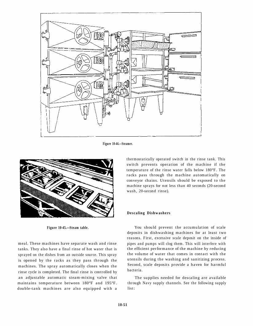
Figure 10-44.—Steamer.
Figure 10-45.—Steam table.
meal. These machines have separate wash and rinsetanks. They also have a final rinse of hot water that issprayed on the dishes from an outside source. This sprayis opened by the racks as they pass through themachines. The spray automatically closes when therinse cycle is completed. The final rinse is controlled byan adjustable automatic steam-mixing valve thatmaintains temperature between 180°F and 195°F.double-tank machines are also equipped with a
thermostatically operated switch in the rinse tank. Thisswitch prevents operation of the machine if thetemperature of the rinse water falls below 180°F. Theracks pass through the machine automatically onconveyor chains. Utensils should be exposed to themachine sprays for not less than 40 seconds (20-secondwash, 20-second rinse).
Descaling Dishwashers
You should prevent the accumulation of scaledeposits in dishwashing machines for at least tworeasons. First, excessive scale deposit on the inside ofpipes and pumps will clog them. This will interfere withthe efficient performance of the machine by reducingthe volume of water that comes in contact with theutensils during the washing and sanitizing process.Second, scale deposits provide a haven for harmfulbacteria.
The supplies needed for descaling are availablethrough Navy supply channels. See the following supplylist:
10-51
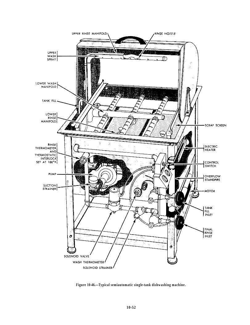
Figure 10-46.—Typical semiautomatic single-tank dishwashing machine.
10-52
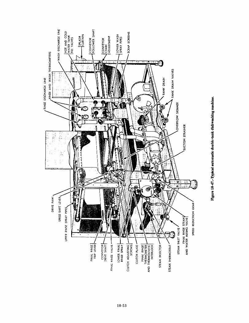
Figure 10-47.
10-53

9G6810-00-264-6722 Orthophosphoric acid85 percent technical,7-pound bottle
9Q7930-00-282-9699 Detergent, general-purpose, 1-gallon can
9Q7930-00-985-6911 Detergent, general-purpose, 5-gallon pail
You should know the capacity of the dishwashingmachine tanks. Measure (in inches) the insidedimensions of each tank and apply the followingformula: length X width X depth (to water line) 231 =capacity in gallons. Steps and key points in descaling themachine:
Steps and key points in descaling the machine.
1.
2.
3.
4.
5.
6.
Fill the tanks halfway to the overflow level withhot, clean water. If tanks do not have water levelindicators, remove a section of the scrap tray ineach tank so that you can see the overflow pipe.
Add the required amount of acid and detergentto the water to prepare the cleaning solution.Measure amounts carefully. Use 7 fluid ouncesof orthophosporic acid 85 percent plus 1/2 fluidounce detergent, general purpose. Use thismeasure for each gallon capacity of the tankwhen it is filled to the overflow level.
Complete filling the tanks. Fill to the overflowlevel.
Put scrap screens, spray pipes, and splashcurtains in place. Remove scale deposits on allattachments.
Turn on the machine. Operate the machine at thehighest permissible operating temperature for60 minutes.
Turn off and drain the machine. Open the drainvalves and allow all the cleaning solution todrain from the tanks.
7. Refill. Use fresh hot water.
8. Turn on the machine. Operate the machine at thehighest temperature for 5 minutes.
Repeat steps 7 and 8 several times. Repeat the entiremethod at such intervals as may be required foroperation of the dishwashing machine.
LAUNDRY EQUIPMENT
Equipment used to clean, dry, and press clothingincludes washers, extractors, dryers, dry-cleaningmachines, and various types of presses. Most of themaintenance on this equipment is concerned withinspecting and lubricating the various parts.
Most laundry equipment is equipped with a numberof safety devices. If disabled, these safety devices canand have caused shipboard fires and damage toequipment, clothing, and personnel. Pay specialattention to these safety devices during preventive andcorrective maintenance. Pay extra special attention tothose devices designed to protect operator personnel.
SUMMARY
This chapter covered refrigeration equipment,cooling systems, air compressors, purifiers, andlubrication, electrohydraulic drive machinery, andweight-handling equipment. It also covered galleyequipment, including steam kettles and dishwashers.Laundry equipment was covered briefly since most ofyour work is limited to inspection and lubrication.
Think back over these broad areas. If you feel thatyou do not have a general understanding of your rate asit relates to a specific type of equipment, go back nowand review that section.
10-54
CHAPTER 11
INSTRUMENTS
As a watch stander, you observe or monitoroperating equipment and take the necessary steps todetect malfunctions and prevent damage to theequipment. The word monitor means to observe, record,or detect an operation or condition using instruments.Measurement, in a very real sense, is the language ofengineers. The shipboard engineering plant has manyinstruments that indicate existing conditions within apiece of machinery or a system. By reading andinterpreting the instruments, you can determine whetherthe machinery or the system is operating within theprescribed range.
Recorded instrument readings are used to make surethe plant is operating properly. They are also used todetermine the operating efficiency of the plant. Theinstruments provide information for hourly, daily, andweekly entries for station operating records and reports.The data entered in the records and reports must beaccurate since they are used to determine the conditionof the plant over a period of time. Remember, foraccurate data to be entered on the records and reports ofan engineering plant, you must read the instrumentscarefully.
In this chapter, we describe various types ofindicating instruments that you, as a Fireman, come incontact with while working and standing watch on anengineering plant. Upon completion of this chapter, youshould be able to describe the various types oftemperature and pressure measuring instruments,indicators, alarms, and the functions for which they areused.
Engineering measuring instruments are typicallyclassified into the following groups:
l
l
l
l
l
l
Pressure gauges
Temperature detectors
Temperature measuring devices
Electrical indicating instruments
Liquid-level indicators
Revolution counters and indicators
. Salinity indicators
. Torque wrenches
We will discuss each of these categories in thefollowing sections.
PRESSURE GAUGES
The types of pressure gauges used in an engineeringplant include Bourdon-tube gauges, bellows, diaphragmgauges, and manometers. Bourdon-tube gauges aregenerally used for measuring pressures above and belowatmospheric pressure. Bellows and diaphragm gaugesand manometers are generally used to measurepressures below 15 pounds-per-square-inch gauge(psig). They are also used for low vacuum pressure. Lowvacuum pressure is slightly less than 14.7pounds-per-square-inch absolute (psia). Often, pressuremeasuring instruments have scales calibrated in inchesof water (in. H2O) to allow greater accuracy.
NOTE: On dial pressure gauges, set the adjustablered hand (if installed) at or slightly above the maximumnormal operating pressure, or at or slightly below theminimum normal operating pressure, (Refer to NavalShips’ Technical Manual, chapter 504, for specificinstructions.)
BOURDON-TUBE GAUGES
The device usually used to indicate temperaturechanges by its response to volume changes or to pressurechanges is called a Bourdon tube. A Bourdon tube is aC-shaped, curved or twisted tube that is open at one endand sealed at the other (fig. 11-1). The open end of thetube is fixed in position, and the scaled end is free tomove. The tube is more or less elliptical in cross section;it does not form a true circle. The tube becomes morecircular when there is an increase in the volume or theinternal pressure of the contained fluid. The springaction of the tube metal opposes this action and tends tocoil the tube. Since the open end of the Bourdon tube isrigidly fastened, the sealed end moves as the pressure ofthe contained fluid changes.
11-1

Figure 11-1.—C-shaped Bourdon tube.
There are many types of Bourdon-tube gauges usedin the Navy. The most common ones are the simplex,duplex, vacuum, compound, and differential pressuregauges. They operate on the principle that pressure in acurved tube has a tendency to straighten out the tube.This curved tube is made of bronze for pressure under200 psi and of steel for pressures over 200 psi.
Simplex Bourdon-tube Gauge
Figure 11-2 shows a simplex Bourdon tube installedin a gauge case. Notice that the Bourdon tube is in theshape of the letter C and is welded or silver-brazed to
the stationary base. The free end of the tube is connectedto the indicating mechanism by a linkage assembly. Thethreaded socket, welded to the stationary base, is thepressure connection. When pressure enters the Bourdontube, the tube tends to straighten out. The tubemovement through linkage causes the pointer to moveproptionally to the pressure applied to the tube. Thesimplex gauge is used for measuring the pressure ofsteam, air, water, oil, and similar fluids or gases.
Duplex Bourdon-tube Gauge
The duplex Bourdon-tube gauge (fig. 11-3) has twotubes and two separate gear mechanisms within thesame case. As shown in view B, a pointer is connectedto the gear mechanism of each tube. Each pointeroperates independently. Duplex gauges are normallyused to show pressure drops between the inlet and outletsides of lube oil strainers. If the pressure reading for theinlet side of a strainer is much greater than the pressurereading for the outlet side, you may assume that thestrainer is likely to be dirty and is restricting the flow oflube oil through the strainer.
Bourdon-tube Vacuum Gauge, CompoundGauge, and Differential Pressure Gauge
Bourdon-tube vacuum gauges are marked off ininches of mercury (fig. 11-4). When a gauge is designedto measure both vacuum and pressure, it is called acompound gauge. Compound gauges are marked offboth in inches of mercury (in.Hg) and in psig (fig. 11-5).
Figure 11-2.—Simplex Bourdon-tube pressure gauge.
11-2
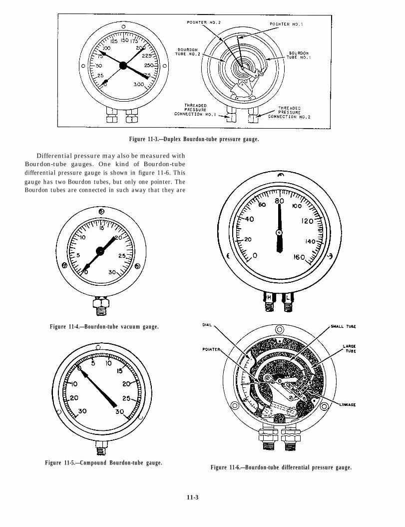
Figure 11-3.—Duplex Bourdon-tube pressure gauge.
Differential pressure may also be measured withBourdon-tube gauges. One kind of Bourdon-tubedifferential pressure gauge is shown in figure 11-6. Thisgauge has two Bourdon tubes, but only one pointer. TheBourdon tubes are connected in such away that they are
Figure 11-4.—Bourdon-tube vacuum gauge.
Figure 11-5.—Compound Bourdon-tube gauge.Figure 11-6.—Bourdon-tube differential pressure gauge.
11-3
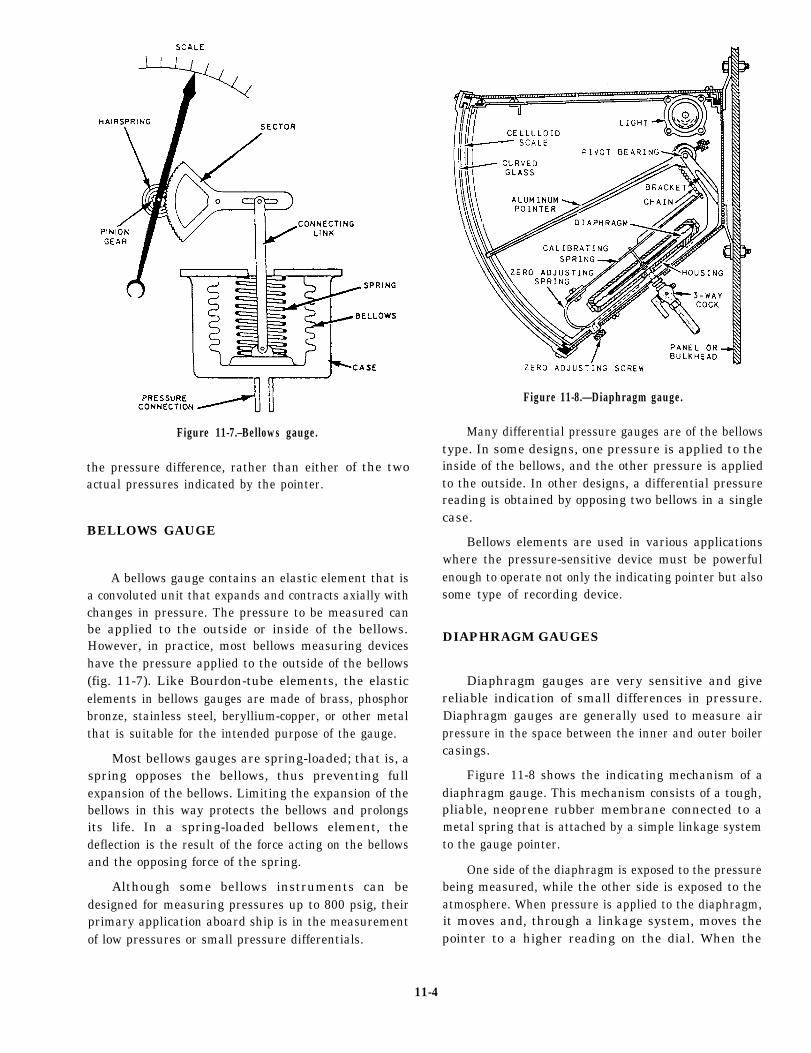
Figure 11-7.–Bellows gauge.
the pressure difference, rather than eitheractual pressures indicated by the pointer.
BELLOWS GAUGE
of the two
A bellows gauge contains an elastic element that isa convoluted unit that expands and contracts axially withchanges in pressure. The pressure to be measured canbe applied to the outside or inside of the bellows.However, in practice, most bellows measuring deviceshave the pressure applied to the outside of the bellows(fig. 11-7). Like Bourdon-tube elements, the elasticelements in bellows gauges are made of brass, phosphorbronze, stainless steel, beryllium-copper, or other metalthat is suitable for the intended purpose of the gauge.
Most bellows gauges are spring-loaded; that is, aspring opposes the bellows, thus preventing fullexpansion of the bellows. Limiting the expansion of thebellows in this way protects the bellows and prolongsits life. In a spring-loaded bellows element, thedeflection is the result of the force acting on the bellowsand the opposing force of the spring.
Although some bellows instruments can bedesigned for measuring pressures up to 800 psig, theirprimary application aboard ship is in the measurementof low pressures or small pressure differentials.
Figure 11-8.—Diaphragm gauge.
Many differential pressure gauges are of the bellowstype. In some designs, one pressure is applied to theinside of the bellows, and the other pressure is appliedto the outside. In other designs, a differential pressurereading is obtained by opposing two bellows in a singlecase.
Bellows elements are used in various applicationswhere the pressure-sensitive device must be powerfulenough to operate not only the indicating pointer but alsosome type of recording device.
DIAPHRAGM GAUGES
Diaphragm gauges are very sensitive and givereliable indication of small differences in pressure.Diaphragm gauges are generally used to measure airpressure in the space between the inner and outer boilercasings.
Figure 11-8 shows the indicating mechanism of adiaphragm gauge. This mechanism consists of a tough,pliable, neoprene rubber membrane connected to ametal spring that is attached by a simple linkage systemto the gauge pointer.
One side of the diaphragm is exposed to the pressurebeing measured, while the other side is exposed to theatmosphere. When pressure is applied to the diaphragm,it moves and, through a linkage system, moves thepointer to a higher reading on the dial. When the
11-4
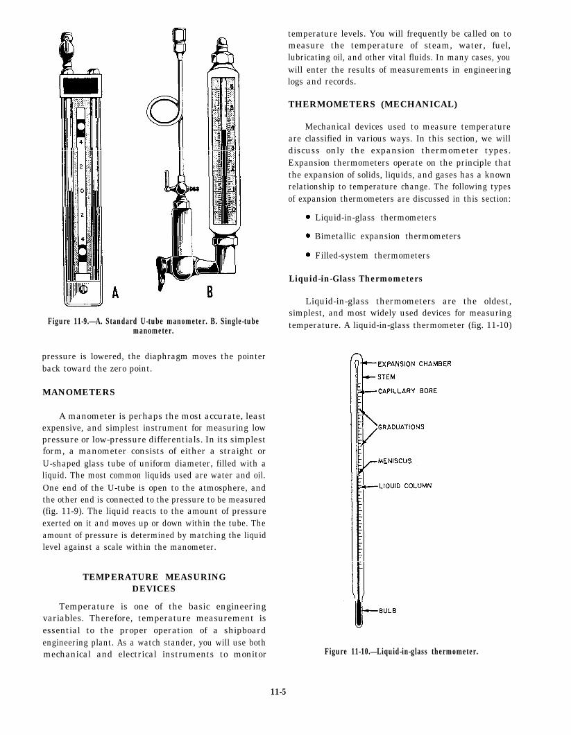
Figure 11-9.—A. Standard U-tube manometer. B. Single-tubemanometer.
pressure is lowered, the diaphragm moves the pointerback toward the zero point.
MANOMETERS
A manometer is perhaps the most accurate, leastexpensive, and simplest instrument for measuring lowpressure or low-pressure differentials. In its simplestform, a manometer consists of either a straight orU-shaped glass tube of uniform diameter, filled with aliquid. The most common liquids used are water and oil.One end of the U-tube is open to the atmosphere, andthe other end is connected to the pressure to be measured(fig. 11-9). The liquid reacts to the amount of pressureexerted on it and moves up or down within the tube. Theamount of pressure is determined by matching the liquidlevel against a scale within the manometer.
TEMPERATURE MEASURINGDEVICES
Temperature is one of the basic engineeringvariables. Therefore, temperature measurement isessential to the proper operation of a shipboardengineering plant. As a watch stander, you will use bothmechanical and electrical instruments to monitor
temperature levels. You will frequently be called on tomeasure the temperature of steam, water, fuel,lubricating oil, and other vital fluids. In many cases, youwill enter the results of measurements in engineeringlogs and records.
THERMOMETERS (MECHANICAL)
Mechanical devices used to measure temperatureare classified in various ways. In this section, we willdiscuss only the expansion thermometer types.Expansion thermometers operate on the principle thatthe expansion of solids, liquids, and gases has a knownrelationship to temperature change. The following typesof expansion thermometers are discussed in this section:
. Liquid-in-glass thermometers
s Bimetallic expansion thermometers
. Filled-system thermometers
Liquid-in-Glass Thermometers
Liquid-in-glass thermometers are the oldest,simplest, and most widely used devices for measuringtemperature. A liquid-in-glass thermometer (fig. 11-10)
Figure 11-10.—Liquid-in-glass thermometer.
11-5

Figure 11-11.—Effect of unequal expansion of a bimetallic strip.
has a bulb and a very fine-bore capillary tube. The tubecontains alcohol or some other liquid that uniformlyexpands or contracts as the temperature rises or falls.The selection of liquid is based on the temperature rangefor which the thermometer is to be used.
Almost all liquid-in-glass thermometers are sealed
so atmospheric pressure does not affect the reading. Thespace above the liquid in this type of thermometer maybe a vacuum, or this space maybe filled with an inert
gas, such as nitrogen, argon, or carbon dioxide.
The capillary bore may be round or elliptical. In
either case, it is very small; therefore, a relatively small
expansion or contraction of the liquid causes a relativelylarge change in the position of the liquid in the capillary
tube. Although the capillary bore has a very small
diameter, the walls of the capillary tube are quite thick.Most liquid-in-glass thermometers have an expansion
chamber at the top of the bore to provide a margin of
safety for the instrument if it should accidentally
overheat.
Liquid-in-glass thermometers may havegraduations etched directly on the glass stem or placed
on a separate strip of material located behind the stem.Many thermometers used in shipboard engineering
plants have the graduations marked on a separate strip
because this type is generally easier to read.
You will find liquid-in-glass thermometers in use in
the oil and water test lab for analytical tests on fuel, oil,
and water.
Bimetallic Expansion Thermometers
Bimetallic expansion thermometers make use ofdifferent metals having different coefficients of linearexpansion. The essential element in a bimetallicexpansion thermometer is a bimetallic strip consistingof two layers of different metals fused together. Whensuch a strip is subjected to temperature changes, onelayer expands or contracts more than the other, thustending to change the curvature of the strip.
Figure 11-11 shows the basic principle of abimetallic expansion thermometer. One end of a straightbimetallic strip is fixed in place. As the strip is heated,the other end tends to curve away from the side that hasthe greater coefficient of linear expansion.
When used in thermometers, the bimetallic strip isnormally wound into a flat spiral (fig. 11-12), a singlehelix, or a multiple helix. The end of the strip that is notfixed in position is fastened to the end of a pointer thatmoves over a circular scale. Bimetallic thermometersare easily adapted for use as recording thermometers; apen is attached to the pointer and positioned so that itmarks on a revolving chart.
Filled-System Thermometers
Generally, filled-system thermometers are used inlocations where the indicating part of the instrumentmust be placed some distance away from the pointwhere the temperature is to be measured. For this reason,they are often called distant-reading thermometers.However, this is not true for filled-systemthermometers. In some designs, the capillary tubing isvery short or nonexistent. Generally, however,filled-system thermometers are distant-readingthermometers. Some distant-reading thermometershave capillaries as long as 125 feet.
Figure 11-12.—Bimetallic thermometer (flat, spiral strip).
11-6
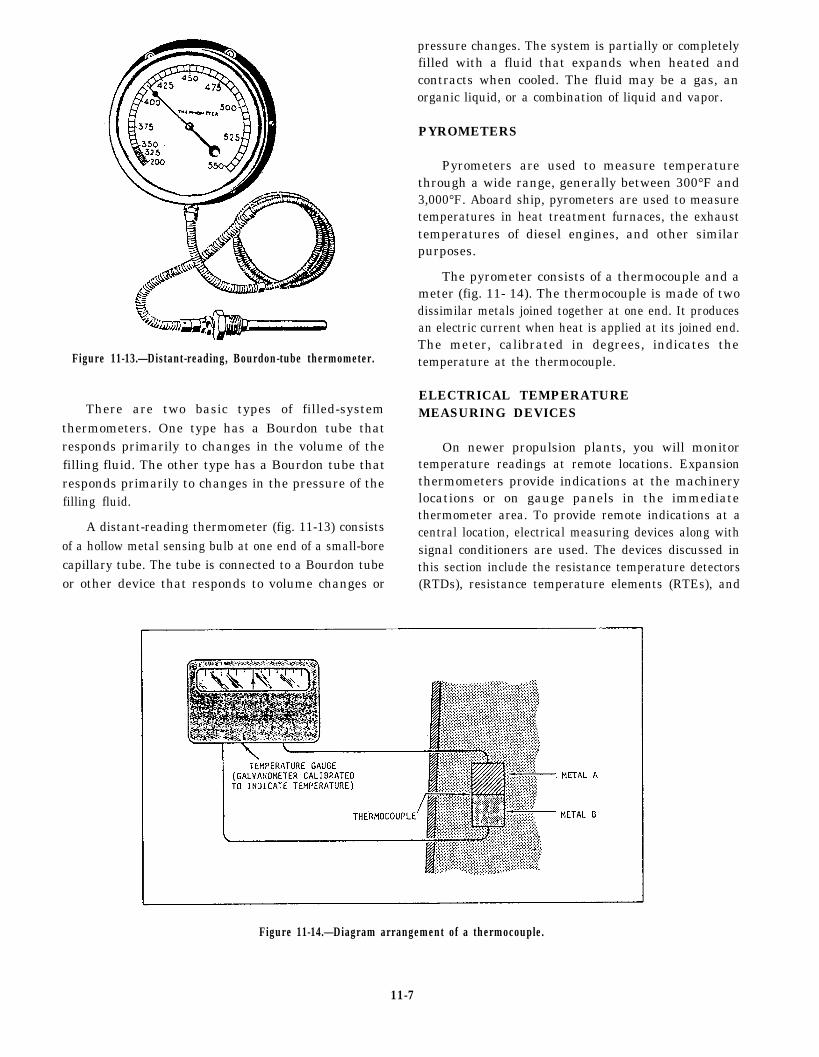
Figure 11-13.—Distant-reading, Bourdon-tube thermometer.
There are two basic types of filled-systemthermometers. One type has a Bourdon tube thatresponds primarily to changes in the volume of thefilling fluid. The other type has a Bourdon tube thatresponds primarily to changes in the pressure of thefilling fluid.
A distant-reading thermometer (fig. 11-13) consistsof a hollow metal sensing bulb at one end of a small-borecapillary tube. The tube is connected to a Bourdon tubeor other device that responds to volume changes or
pressure changes. The system is partially or completelyfilled with a fluid that expands when heated andcontracts when cooled. The fluid may be a gas, anorganic liquid, or a combination of liquid and vapor.
PYROMETERS
Pyrometers are used to measure temperaturethrough a wide range, generally between 300°F and3,000°F. Aboard ship, pyrometers are used to measuretemperatures in heat treatment furnaces, the exhausttemperatures of diesel engines, and other similarpurposes.
The pyrometer consists of a thermocouple and ameter (fig. 11- 14). The thermocouple is made of twodissimilar metals joined together at one end. It producesan electric current when heat is applied at its joined end.The meter, calibrated in degrees, indicates thetemperature at the thermocouple.
ELECTRICAL TEMPERATUREMEASURING DEVICES
On newer propulsion plants, you will monitortemperature readings at remote locations. Expansionthermometers provide indications at the machinerylocations or on gauge panels in the immediatethermometer area. To provide remote indications at acentral location, electrical measuring devices along withsignal conditioners are used. The devices discussed inthis section include the resistance temperature detectors(RTDs), resistance temperature elements (RTEs), and
Figure 11-14.—Diagram arrangement of a thermocouple.
11-7
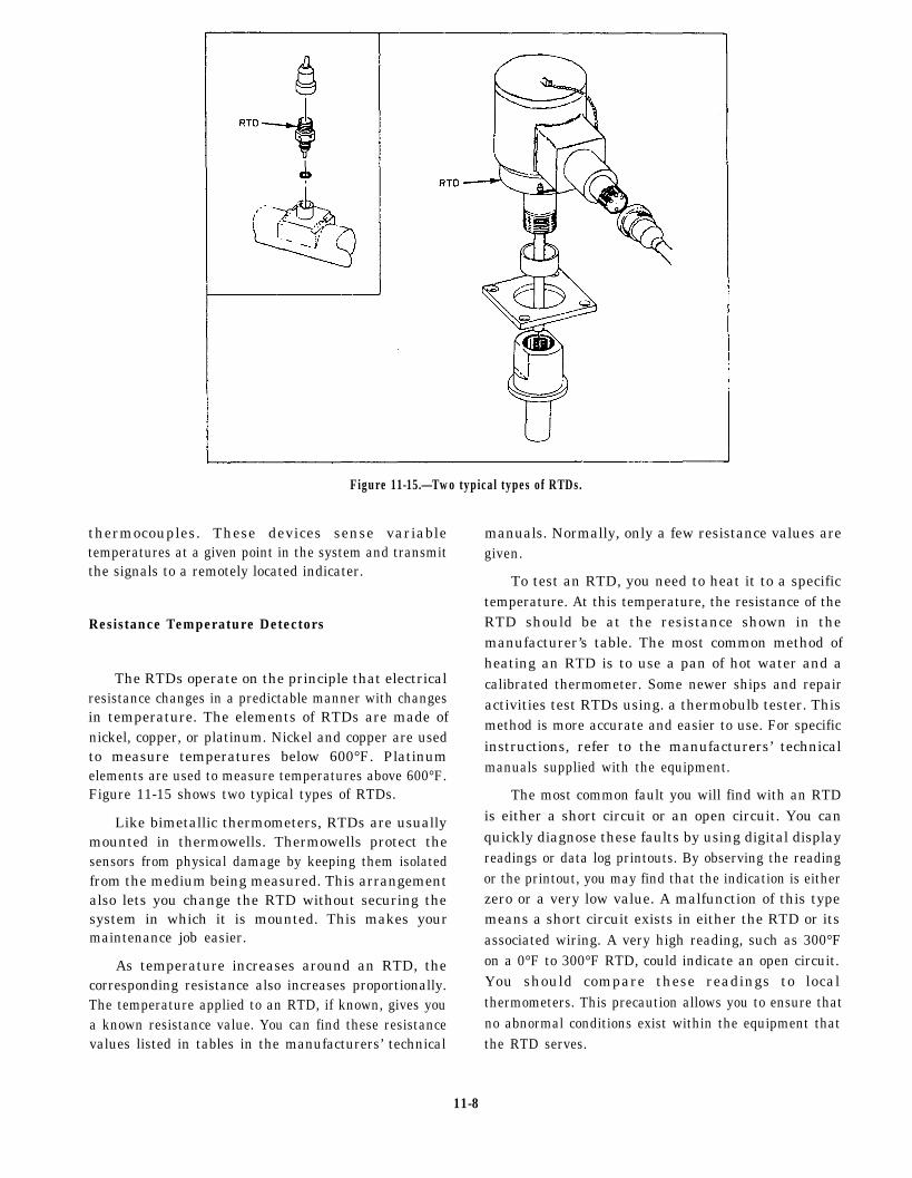
Figure 11-15.—Two typical types of RTDs.
thermocouples. These devices sense variabletemperatures at a given point in the system and transmitthe signals to a remotely located indicater.
Resistance Temperature Detectors
The RTDs operate on the principle that electricalresistance changes in a predictable manner with changesin temperature. The elements of RTDs are made ofnickel, copper, or platinum. Nickel and copper are usedto measure temperatures below 600°F. Platinumelements are used to measure temperatures above 600°F.Figure 11-15 shows two typical types of RTDs.
Like bimetallic thermometers, RTDs are usuallymounted in thermowells. Thermowells protect thesensors from physical damage by keeping them isolatedfrom the medium being measured. This arrangementalso lets you change the RTD without securing thesystem in which it is mounted. This makes yourmaintenance job easier.
As temperature increases around an RTD, thecorresponding resistance also increases proportionally.The temperature applied to an RTD, if known, gives youa known resistance value. You can find these resistancevalues listed in tables in the manufacturers’ technical
manuals. Normally, only a few resistance values aregiven.
To test an RTD, you need to heat it to a specifictemperature. At this temperature, the resistance of theRTD should be at the resistance shown in themanufacturer’s table. The most common method ofheating an RTD is to use a pan of hot water and acalibrated thermometer. Some newer ships and repairactivities test RTDs using. a thermobulb tester. Thismethod is more accurate and easier to use. For specificinstructions, refer to the manufacturers’ technicalmanuals supplied with the equipment.
The most common fault you will find with an RTDis either a short circuit or an open circuit. You canquickly diagnose these faults by using digital displayreadings or data log printouts. By observing the readingor the printout, you may find that the indication is eitherzero or a very low value. A malfunction of this typemeans a short circuit exists in either the RTD or itsassociated wiring. A very high reading, such as 300°Fon a 0°F to 300°F RTD, could indicate an open circuit.You should compare these readings to localthermometers. This precaution allows you to ensure thatno abnormal conditions exist within the equipment thatthe RTD serves.
11-8

If an RTD is faulty, you should replace it. Internalrepairs cannot be made at the shipboard level. Until youcan replace the faulty RTD, inform the watch standersthat the RTD is unreliable. THe engine-room watchstanders should take local readings periodically to makesure the equipment is operating normally.
Resistance Temperature Elements
The RTEs are the most common type of temperaturesensor found in gas turbine propulsion plants. The RTEsoperate on the same principle as the RTDs. As thetemperature of the sensor increases, the resistance of theRTE increases proportionally. All RTEs that youencounter have a platinum element. They have anelectrical resistance of 100 ohms at a temperature of32°F. Four different temperature ranges of RTEs arecommonly used, and you will find that the probe sizesvary. The four temperature ranges and theircorresponding probe sizes are as follows:
TEMPERATURE RANGE RTE PROBE LENGTH(Degree Fahrenheit) (Inches)
-20 to +150 6
0 to +400 2, 4, and 10
0 to +1,000 2
-60 to +500 6
You may find some RTEs connected to remotemounted signal conditioning modules. These modulesconvert the ohmic value of the RTE to an output rangeof 4 to 20 mA dc. However, most RTEs read their valuedirectly into the propulsion electronics as an ohmicvalue.
The RTEs with temperature ranges from 0°F to+400°F and from -60° to +500°F are commonlymounted in thermowells. Since you can change an RTEwithout securing the equipment it serves, maintenanceis simplified.
ELECTRICAL INDICATINGINSTRUMENTS
Electrical indicating instruments (meters) are usedto display information that is measured by some type ofelectrical sensor. Although meters display units such aspressure or temperature, the meters on the controlconsole are, in fact, dc voltmeters. The signal beingsensed is conditioned by a signal conditioner. This is
Figure 11-16.—An ac voltmeter.
then converted to 0 to 10 volts dc, which is proportional
to the parameters being sensed.
Electrical values, such as power and current, aremeasured and displayed at ship’s service switchboards.
Normally, shipboard repair is not done on switchboardmeters. If you suspect the switchboard meters are out of
calibration or broken, you should have them sent to arepair facility. You can find more information on the
theory of operation of these meters in the NavyElectricity and Electronics Training Series (NEETS),
Module 3, Introduction to Circuit Protection, Control,
and Measurement, NAVEDTRA 172-03-00-79.
VOLTMETERS
Both dc and ac voltmeters determine voltage the
same way. They both measure the current that thevoltage is able to force through a high resistance. Thisresistance is connected in series with the indicating
mechanism or element. Voltmeters installed inswitchboards and control consoles (fig. 11-16) all have
a fixed resistance value. Portable voltmeters, used as test
equipment, usually have a variable resistance.
For both installed and portable voltmeters,
resistances are calibrated to the different ranges that themeters will display. The normal range for the
switchboard and electric plant meters is 0 to 600 volts.
11-9
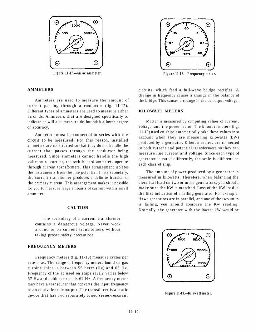
Figure 11-17.—An ac ammeter. Figure 11-18.—Frequency meter.
AMMETERS
Ammeters are used to measure the amount ofcurrent passing through a conductor (fig. 11-17).Different types of ammeters are used to measure eitherac or dc. Ammeters that are designed specifically toindicate ac will also measure dc, but with a lower degreeof accuracy.
Ammeters must be connected in series with thecircuit to be measured. For this reason, installedammeters are constructed so that they do not handle thecurrent that passes through the conductor beingmeasured. Since ammeters cannot handle the highswitchboard current, the switchboard ammeters operatethrough current transformers. This arrangement isolatesthe instruments from the line potential. In its secondary,the current transformer produces a definite fraction ofthe primary current. This arrangement makes it possiblefor you to measure large amounts of current with a smallammeter.
CAUTION
The secondary of a current transformercontains a dangerous voltage. Never workaround or on current transformers withouttaking proper safety precautions.
FREQUENCY METERS
Frequency meters (fig. 11-18) measure cycles perrate of ac. The range of frequency meters found on gasturbine ships is between 55 hertz (Hz) and 65 Hz.Frequency of the ac used on ships rarely varies below57 Hz and seldom exceeds 62 Hz. A frequency metermay have a transducer that converts the input frequencyto an equivalent dc output. The transducer is a staticdevice that has two separately tuned series-resonant
circuits, which feed a full-wave bridge rectifier. Achange in frequency causes a change in the balance ofthe bridge. This causes a change in the dc output voltage.
KILOWATT METERS
Matter is measured by computing values of current,voltage, and the power factor. The kilowatt meters (fig.11-19) used on ships automatically take these values intoaccount when they are measuring kilowatts (kW)produced by a generator. Kilowatt meters are connectedto both current and potential transformers so they canmeasure line current and voltage. Since each type ofgenerator is rated differently, the scale is different oneach class of ship.
The amount of power produced by a generator ismeasured in kilowatts. Therefore, when balancing theelectrical load on two or more generators, you shouldmake sure the kW is matched. Loss of the kW load isthe first indication of a failing generator. For example,if two generators are in parallel, and one of the two unitsis failing, you should compare the Kw reading.Normally, the generator with the lowest kW would be
Figure 11-19.—Kilowatt meter.
11-10

the failing unit. There is one case, however, where thisis not true. During an overspeed condition, both unitsincrease in frequency, but the failing unit is the one withthe higher load.
SYNCHROSCOPES
Before connecting a three-phase generator to busbars already connected to one or more generators, youmust make sure that certain conditions prevail. Asynchroscope is the device you use to find out if thefollowing required conditions have been met: Figure 11-20.—Synchroscope.
1.
2.
3.
4.
5.
Phase sequence for the both generator and busbars must be the same.
The generator and the bus-bar voltages must bethe same.
The generator and bus-bar frequency must be thesame.
The generator frequency must be practicallyconstant for an appreciable period of time.
The generator and bus-bar voltages must be inphase. They must reach their maximum voltagesat the same time; therefore, when connected,they will oppose excessive circulation of currentbetween the two machines.
Figure 11-20 shows a synchroscope. It is basicallya power factor meter connection to measure the phaserelationship between the generator and bus-bar voltages.The moving element is free to rotate continuously. Whenthe two frequencies are exactly the same, the movingelement holds a fixed position. This shows the constantphase relationship between the generator and bus-barvoltages. When the frequency is slightly different, thephase relationship is always changing. When thishappens, the moving element of the synchroscoperotates constantly. The speed of rotation is equal to thedifference infrequency; the direction shows whether thegenerator is fast or slow. The generator is placed on linewhen the pointer slowly approaches a mark. This markshows that the generator and bus-bar voltages are inphase.
PHASE-SEQUENCE INDICATORS
A phase-sequence indicator (fig. 11-21) is used todetermine the sequence in which the currents of athree-phase system reach their maximum values.
Ships have phase-sequence indicators installed inswitchboards that may be connected to shore power.These instruments indicate whether shore power is in
the correct phase sequence with the ship beforeshipboard equipment is connected to shore power.Three-phase motors, when connected to incorrectphase-sequence power, rotate in the opposite direction.
The phase-sequence indicator has three neon lampsthat light when all three phases are energized. A meterconnected to a network of resistors and condensersshows correct or incorrect sequence on a marked scale.
LIQUID-LEVEL INDICATORS
As a watch stander, you monitor systems and tanksfor liquid levels. Sometimes, you are only required toknow if a level exceeds or falls below a certain presetparameter. At other times, you need to know the exactlevel. If only a predetermined limit is needed, you canuse a float switch. When the set point is reached the floatswitch will make contact and sound an alarm. If youneed to know a specific level, you must use a variablesensing device. The sensor used to indicate a tank levelis commonly called a tank level indicator (TLI). Thissensor tells you the exact amount of liquid in a tank. Inthe following paragraphs, we will describe the operation
Figure 11-21.—A phase-sequence indicator.
11-11

Figure 11-22.—Magnetic float switch.
of each of these sensors and their applications. Refer to necessary. When multiple sections are used, they arethe manufacturers’ technical manuals for moreinformation on the procedures you should use to adjusteach type of device.
TANK LEVEL INDICATORS
Many tank levels are monitored to provide the exactliquid level contained. For example, fuel tanks aremonitored to make sure they do not overflow. They arealso monitored to let the engineer officer know theamount of fuel aboard ship. The sensors used to monitorthese levels are TLIs. Each of the level-monitored tankscontains a level transmitter. A typical transmitter sectioncontains a voltage divider resistor network that extendsthe length of the section. Magnetic reed switches aretapped at 1-inch intervals along the resistor network.The reed switches are sequentially connected throughseries resistors to a common conductor. This network isenclosed in a stem that is mounted vertically in the tank.A float containing bar magnets rides up and down thestem as the liquid level changes.
In many tanks, you may have to use more than onetransmitter section to measure the full range. Thephysical arrangement of some tanks makes this
electrically connected as one continuous dividernetwork.
Two types of floats are used. In noncompensatedtanks, the float is designed to float at the surface of thefuel or JP-5. For seawater-compensated tanks, the floatis designed to stay at the seawater/fuel interface.
CONTACT LEVEL SENSORS
Many times, you do not have to know the exact levelof a tank until it reaches a preset level. When this typeof indication is needed, you can use a contact or floatswitch. Two types of float level switches are used on gasturbine ships.
One type of float level switch is the lever-activatedswitch, which is activated by a horizontal lever attachedto a float. The float on this switch is located inside thetank. When the liquid level reaches a preset point, thelever activates the switch.
The other type o f l eve l switch has amag-net-equipped float that slides on a vertical stem. Thestem contains a hermetically sealed, reed switch. Thefloat moves up and down the stem with the liquid level.
11-12
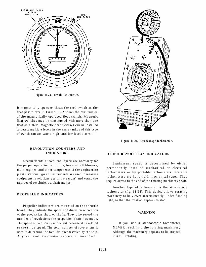
Figure 11-23.—Revolution counter.
It magnetically opens or closes the reed switch as thefloat passes over it. Figure 11-22 shows the constructionof the magnetically operated float switch. Magneticfloat switches may be constructed with more than onefloat on a stem. Magnetic float switches can be installedto detect multiple levels in the same tank; and this typeof switch can activate a high- and low-level alarm.
Figure 11-24.—stroboscope tachometer.
REVOLUTION COUNTERS ANDINDICATORS
Measurements of rotational speed are necessary forthe proper operation of pumps, forced-draft blowers,main engines, and other components of the engineeringplants. Various types of instruments are used to measureequipment revolutions per minute (rpm) and count thenumber of revolutions a shaft makes.
PROPELLER INDICATORS
Propeller indicators are mounted on the throttleboard. They indicate the speed and direction of rotationof the propulsion shaft or shafts. They also record thenumber of revolutions the propulsion shaft has made.The speed of rotation is important because it is relatedto the ship’s speed. The total number of revolutions isused to determine the total distance traveled by the ship.A typical revolution counter is shown in figure 11-23.
OTHER REVOLUTION INDICATORS
Equipment speed is determined by eitherpermanently installed mechanical or electricaltachometers or by portable tachometers. Portabletachometers are hand-held, mechanical types. Theyrequire access to the end of the rotating machinery shaft.
Another type of tachometer is the stroboscopetachometer (fig. 11-24). This device allows rotatingmachinery to be viewed intermittently, under flashinglight, so that the rotation appears to stop.
WARNING
If you use a stroboscopic tachometer,NEVER reach into the rotating machinery.Although the machinery appears to be stopped,it is still rotating.
11-13
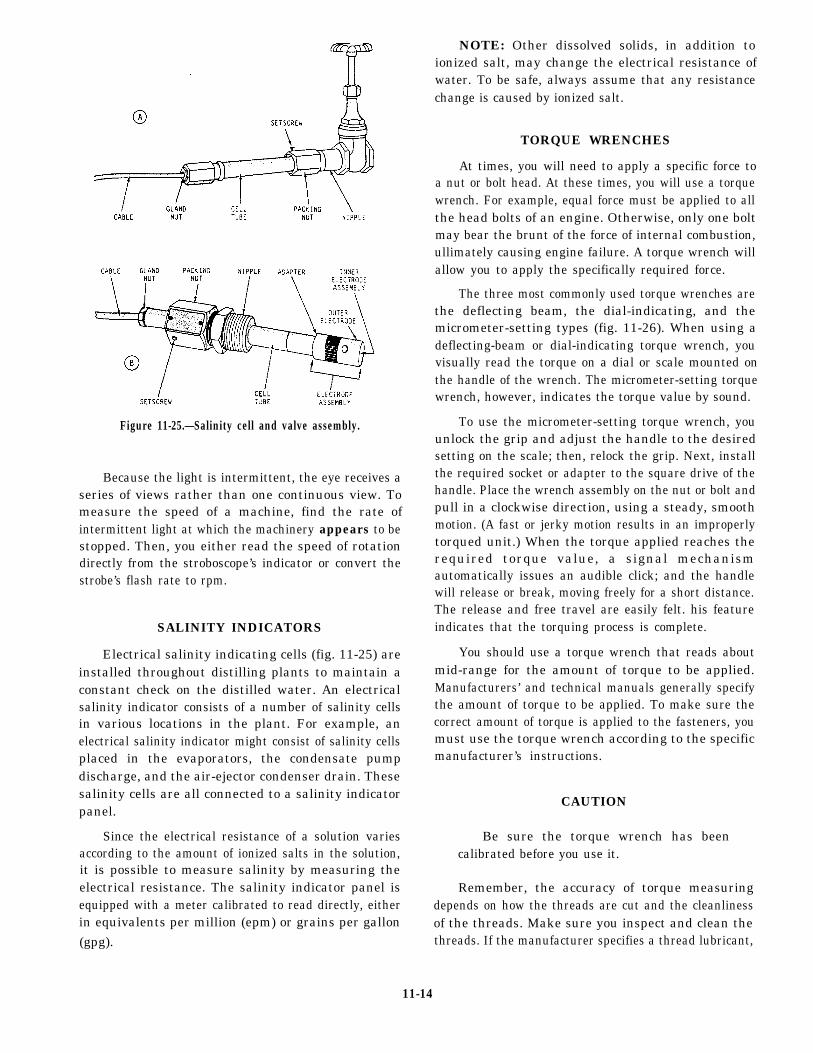
Figure 11-25.—Salinity cell and valve assembly.
Because the light is intermittent, the eye receives aseries of views rather than one continuous view. Tomeasure the speed of a machine, find the rate ofintermittent light at which the machinery appears to bestopped. Then, you either read the speed of rotationdirectly from the stroboscope’s indicator or convert thestrobe’s flash rate to rpm.
SALINITY INDICATORS
Electrical salinity indicating cells (fig. 11-25) areinstalled throughout distilling plants to maintain aconstant check on the distilled water. An electricalsalinity indicator consists of a number of salinity cellsin various locations in the plant. For example, anelectrical salinity indicator might consist of salinity cellsplaced in the evaporators, the condensate pumpdischarge, and the air-ejector condenser drain. Thesesalinity cells are all connected to a salinity indicatorpanel.
Since the electrical resistance of a solution variesaccording to the amount of ionized salts in the solution,it is possible to measure salinity by measuring theelectrical resistance. The salinity indicator panel isequipped with a meter calibrated to read directly, eitherin equivalents per million (epm) or grains per gallon(gpg).
NOTE: Other dissolved solids, in addition toionized salt, may change the electrical resistance ofwater. To be safe, always assume that any resistancechange is caused by ionized salt.
TORQUE WRENCHES
At times, you will need to apply a specific force toa nut or bolt head. At these times, you will use a torquewrench. For example, equal force must be applied to allthe head bolts of an engine. Otherwise, only one boltmay bear the brunt of the force of internal combustion,ullimately causing engine failure. A torque wrench willallow you to apply the specifically required force.
The three most commonly used torque wrenches arethe deflecting beam, the dial-indicating, and themicrometer-setting types (fig. 11-26). When using adeflecting-beam or dial-indicating torque wrench, youvisually read the torque on a dial or scale mounted onthe handle of the wrench. The micrometer-setting torquewrench, however, indicates the torque value by sound.
To use the micrometer-setting torque wrench, youunlock the grip and adjust the handle to the desiredsetting on the scale; then, relock the grip. Next, installthe required socket or adapter to the square drive of thehandle. Place the wrench assembly on the nut or bolt andpull in a clockwise direction, using a steady, smoothmotion. (A fast or jerky motion results in an improperlytorqued unit.) When the torque applied reaches therequired torque value, a signal mechanismautomatically issues an audible click; and the handlewill release or break, moving freely for a short distance.The release and free travel are easily felt. his featureindicates that the torquing process is complete.
You should use a torque wrench that reads aboutmid-range for the amount of torque to be applied.Manufacturers’ and technical manuals generally specifythe amount of torque to be applied. To make sure thecorrect amount of torque is applied to the fasteners, youmust use the torque wrench according to the specificmanufacturer’s instructions.
CAUTION
Be sure the torque wrench has beencalibrated before you use it.
Remember, the accuracy of torque measuringdepends on how the threads are cut and the cleanlinessof the threads. Make sure you inspect and clean thethreads. If the manufacturer specifies a thread lubricant,
11-14

Figure 11-26.—Torque wrenches.
use it. When using deflecting-beam or dial-indicatingwrenches, hold the torque at the desired value until thereading is steady.
Torque wrenches are delicate and expensive tools.When using them, always follow these precautions:
l
l
l
l
l
l
When you use the micrometer-setting type, donot move the setting handle below the lowesttorque setting. However, place it at its lowestsetting before you return it to storage.
Do not use the torque wrench to apply greateramounts of torque than its rated capacity.
Do not use the torque wrench to break loose boltsthat have been previously tightened.
Do not drop the wrench. If a torque wrench isdropped, its accuracy will be affected.
Do not apply a torque wrench to a nut that hasbeen tightened. Back off the nut one turn with anontorque wrench and retighten it to the correcttorque with the indicating-torque wrench.
Calibration intervals have been established for alltorque tools used in the Navy. When a tool iscalibrated by a qualified calibration activity at ashipyard, tender, or repair ship, a label showing
the next calibration due date is attached to thehandle. Before you use a torque tool, check thisdate to make sure the tool is not overdue forcalibration.
SUMMARY
Only a few of the many types of instruments usedby Navy personnel have been covered in this chapter.For the operating principle of individual systems, youshould consult the specific equipment technical manualsand the NSTM, chapter 504.
Just as we monitor automobile instruments (oilpressure gauge/light, fuel tank level indicator, watertemperature gauge, and so forth) to determine how anautomobile is operating, we use instruments todetermine how the engineering plant is operating. Inaddition to the use of visual indicating equipment in anengineering plant, audible alarms warn operatingpersonnel of actions required or of unsafe conditionsthat are approaching. You may avoid machinerydamage, personnel injury, and expensive andtime-consuming repairs by taking proper operatoraction. However, proper operator actions can take placeonly when the instruments (temperature indicators,pressure gauges, and so forth) are properly calibratedand properly interpreted by operating personnel.
11-15


CHAPTER 12
SHIPBOARD ELECTRICAL EQUIPMENT
Aboard modern naval ships, most auxiliarymachinery and equipment is run by electricity.Regardless of rate or rating, all personnel assignedto a ship will operate some electric devices in theperformance of their duties. Electrical equipmentis dangerous if handled incorrectly; therefore,you must observe all applicable safety pre-cautions when working with or around electricalequipment.
In this chapter, we will discuss basic conceptsof electricity, electrical terms, electrical equip-ment, and applicable safety precautions. You willfind additional information on the basic principlesof electricity in the Navy Electricity andElectronics Training Series (NEETS), modules 1and 2, NAVEDTRA 172-01-00-79 and NAVED-TRA 172-02-00-79.
INTRODUCTION TO ELECTRICITY
Some materials will conduct electricity, andsome offer more resistance than others. Metalssuch as silver, copper, aluminum, and iron offerlittle resistance and are called conductors. Incontrast to conductors, some materials such aswood, paper, porcelain, rubber, mica, and plasticsoffer high resistance to an electric current and areknown as insulators. Electric circuits throughoutthe ship are made of copper wires coveredwith rubber or some other insulator. The wireconductors offer little resistance to the current,while the insulation keeps the current from passingto the steel structure of the ship.
Definite units have been established so we canmeasure the electrical properties of conductors.Also, there are terms used to describe thecharacteristics of electric currents. A brief reviewof these fundamentals is given in the followingsections.
ELECTRIC CURRENT
The flow of current through a wire can becompared to the flow of water through a pipe.
Current is the rate at which electricity flowsthrough a conductor or circuit. The practical unit,called the ampere, specifies the rate at which theelectric current is flowing. Ampere is a measureof the intensity or the number of electrons passinga point in a circuit each second.
ELECTROMOTIVE FORCE
Before water will flow through a pipe, theremust be water pressure; before an electric currentcan flow through a circuit, there must be a sourceof electric pressure. The electric pressure is knownas electromotive force (emf) or voltage (E). Thesource of this force may be a generator or abattery.
If you increase the pressure on the electronsin a conductor, a greater current will flow, justas an increased pressure on water in a pipe willincrease the flow.
RESISTANCE
Electrical resistance (R) is that property of anelectric circuit that opposes the flow of current.The unit of resistance is known as the ohm (S2).
WATT
Power (P) is the rate of doing work. In a dccircuit, power is equal to the product of thecurrent times the voltage, or P = I x E. Thepractical unit of power is the watt (W) or kilowatt(kW) (1,000 watts). Power in an ac circuit iscomputed in a slightly different way. If you areinterested in how ac power is computed, seechapter 4 of Introduction to Alternating Currentand Transformers, NAVEDTRA 172-02-00-85.
GENERATOR TYPES AND DRIVES
A large amount of electricity is requiredaboard ship to power machinery that supplies air,
12-1
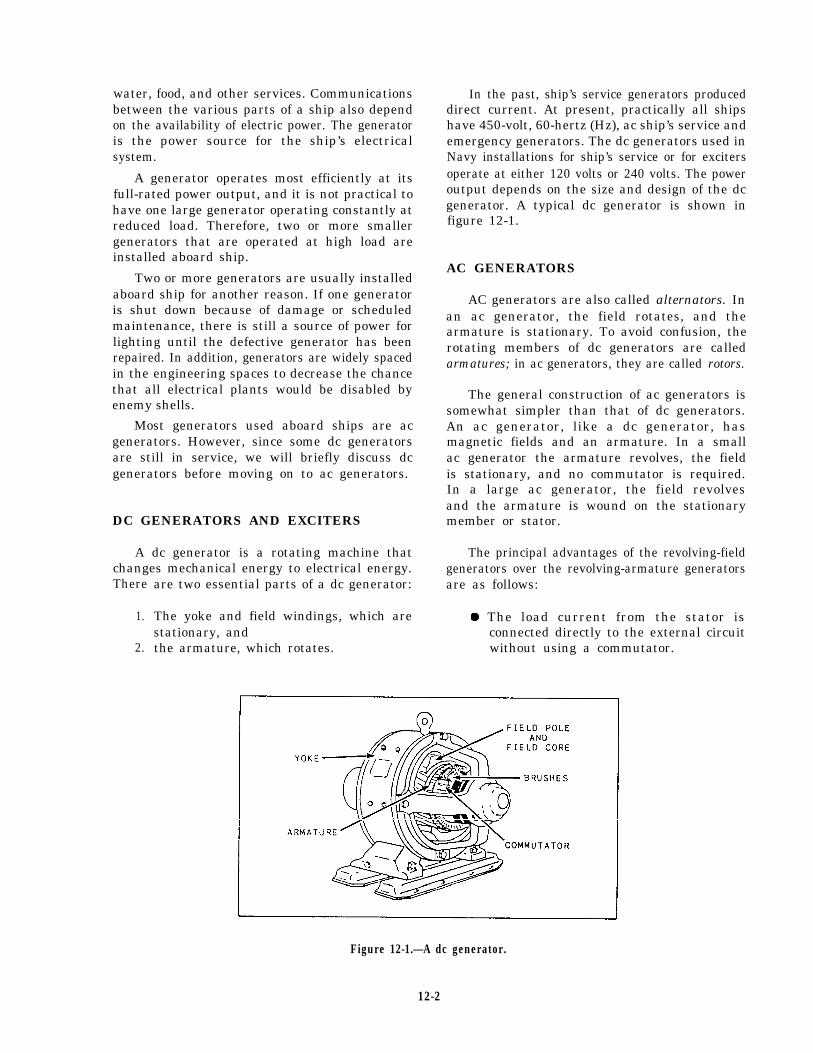
water, food, and other services. Communicationsbetween the various parts of a ship also dependon the availability of electric power. The generatoris the power source for the ship’s electricalsystem.
A generator operates most efficiently at itsfull-rated power output, and it is not practical tohave one large generator operating constantly atreduced load. Therefore, two or more smallergenerators that are operated at high load areinstalled aboard ship.
Two or more generators are usually installedaboard ship for another reason. If one generatoris shut down because of damage or scheduledmaintenance, there is still a source of power forlighting until the defective generator has beenrepaired. In addition, generators are widely spacedin the engineering spaces to decrease the chancethat all electrical plants would be disabled byenemy shells.
Most generators used aboard ships are acgenerators. However, since some dc generatorsare still in service, we will briefly discuss dcgenerators before moving on to ac generators.
DC GENERATORS AND EXCITERS
A dc generator is a rotating machine thatchanges mechanical energy to electrical energy.There
1.
2.
In the past, ship’s service generators produceddirect current. At present, practically all shipshave 450-volt, 60-hertz (Hz), ac ship’s service andemergency generators. The dc generators used inNavy installations for ship’s service or for excitersoperate at either 120 volts or 240 volts. The poweroutput depends on the size and design of the dcgenerator. A typical dc generator is shown infigure 12-1.
AC GENERATORS
AC generators are also called alternators. Inan ac generator, the field rotates, and thearmature is stationary. To avoid confusion, therotating members of dc generators are calledarmatures; in ac generators, they are called rotors.
The general construction of ac generators issomewhat simpler than that of dc generators.An ac generator, like a dc generator, hasmagnetic fields and an armature. In a smallac generator the armature revolves, the fieldis stationary, and no commutator is required.In a large ac generator, the field revolvesand the armature is wound on the stationarymember or stator.
The principal advantages of the revolving-fieldgenerators over the revolving-armature generators
are two essential parts of a dc generator: are as follows:
The yoke and field windings, which are l The load current from the stator isstationary, and connected directly to the external circuitthe armature, which rotates. without using a commutator.
Figure 12-1.—A dc generator.
12-2
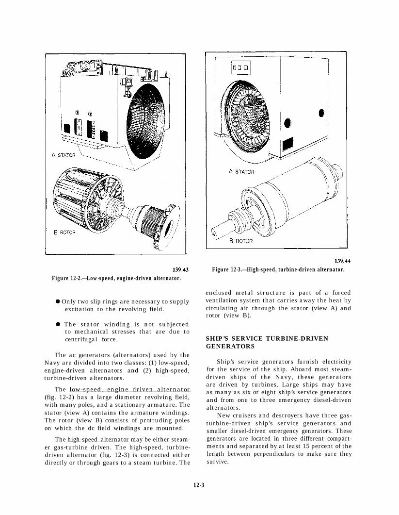
Figure 12-2.—Low-speed, engine-driven alternator.
l Only two slip rings are necessary to supplyexcitation to the revolving field.
l The stator winding is not subjectedto mechanical stresses that are due tocentrifugal force.
The ac generators (alternators) used by theNavy are divided into two classes: (1) low-speed,engine-driven alternators and (2) high-speed,turbine-driven alternators.
The low-speed, engine driven alternator(fig. 12-2) has a large diameter revolving field,with many poles, and a stationary armature. Thestator (view A) contains the armature windings.The rotor (view B) consists of protruding poleson which the dc field windings are mounted.
The high-speed alternator may be either steam-er gas-turbine driven. The high-speed, turbine-driven alternator (fig. 12-3) is connected eitherdirectly or through gears to a steam turbine. The
Figure 12-3.—High-speed, turbine-driven alternator.
enclosed metal structure is part of a forcedventilation system that carries away the heat bycirculating air through the stator (view A) androtor (view B).
SHIP’S SERVICE TURBINE-DRIVENGENERATORS
Ship’s service generators furnish electricityfor the service of the ship. Aboard most steam-driven ships of the Navy, these generatorsare driven by turbines. Large ships may haveas many as six or eight ship’s service generatorsand from one to three emergency diesel-drivenalternators.
New cruisers and destroyers have three gas-turbine-driven ship’s service generators andsmaller diesel-driven emergency generators. Thesegenerators are located in three different compart-ments and separated by at least 15 percent of thelength between perpendiculars to make sure theysurvive.
12-3

Figure 12-4.—750-kW turbine generator set.
The type of ship’s service generator commonlyused aboard ships in the Navy is shown infigure 12-4. Although generator sets (turbo-generators) are built differently, all have the samearrangement of major parts.
Turbines used for driving the ship’s servicegenerators differ from other auxiliary turbines;they usually operate on superheated steam. Theservice generator turbine exhausts to a separateauxiliary condenser that has its own circulatingpumps, condensate pumps, and air ejectors.Cooling water for the condenser is provided bythe auxiliary circulating pump through separateinjection and overboard valves.
Superheated steam is supplied to the ship’sservice generator turbine from either the mainsteam line or a special turbogenerator linethat leads directly from the boiler. Aboard someships, the turbine—in the event of condenser
casualty—may be discharged directly to theatmosphere or to the main condenser when themain plant is in operation.
The ship’s service generator must supplyelectricity at a constant voltage and frequency(hertz), which requires the turbine to run at aconstant speed even when loads vary. Constantspeed is maintained by a speed-regulatinggovernor. The turbine also has overspeed andback-pressure trips, which automatically close thethrottle if the turbine exceeds acceptable operatingconditions. A manual trip is used to close thethrottle quickly if there is damage to the turbineor to the generator. The shaft glands of the ship’sservice generator turbine are supplied with gland-sealing steam. The system is similar to that usedfor main propulsion turbines. Other auxiliaryturbines in naval use are seldom, if ever, providedwith gland-sealing systems.
12-4
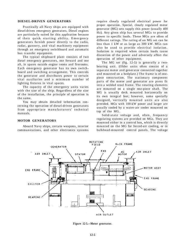
DIESEL-DRIVEN GENERATORS
Practically all Navy ships are equipped withdiesel-driven emergency generators. Diesel enginesare particularly suited for this application becauseof their quick starting ability. Emergencygenerators furnish power directly to the radio,radar, gunnery, and vital machinery equipmentthrough an emergency switchboard and automaticbus transfer equipment.
The typical shipboard plant consists of twodiesel emergency generators, one forward and oneaft, in spaces outside engine rooms and firerooms.Each emergency generator has its own switch-board and switching arrangement. This controlsthe generator and distributes power to certainvital auxiliaries and a minimum number oflighting fixtures in vital spaces.
The capacity of the emergency units varieswith the size of the ship. Regardless of the sizeof the installation, the principle of operation isthe same.
You may obtain detailed information con-cerning the operation of diesel-driven generatorsfrom appropriate manufacturers’ technicalmanuals.
MOTOR GENERATORS
Aboard Navy ships, certain weapons, interiorcommunications, and other electronics systems
require closely regulated electrical power forproper operation. Special, closely regulated motorgenerator (MG) sets supply this power (usually 400Hz). Any given ship has several MGs to providepower to specific loads. These MGs are often ofdifferent ratings. The rating of an MG set can beless than 1 kW or as large as 300 kW. MGs canalso be used to provide electrical isolation.Isolation is required when certain loads causedistortion of the power and adversely affect theoperation of other equipment.
The MG set (fig. 12-5) is generally a two-bearing unit. (Older units often consist of aseparate motor and generator connected togetherand mounted on a bedplate.) The frame is of one-piece construction. The stationary componentparts of the motor and generator are press fitinto a welded steel frame. The rotating elementsare mounted on a single one-piece shaft. TheMG is usually deck mounted horizontally onits own integral feet; however, some speciallydesigned, vertically mounted units are alsoprovided. MGs with 100-kW power and larger areusually cooled by a water-air cooler mounted ontop of the MG.
Solid-state voltage and, often, frequencyregulating systems are provided on MGs. They aremounted either in a control box, which is directlymounted on the MG for forced-air cooling, or inbulkhead-mounted control panels. The voltage
Figure 12-5.—Motor generator.
12-5

Figure 12-6.—3O-kW motor generator.
12-6

regulator (fig. 12-6) controls the voltage outputof the generator portion of the MG. This voltagemay be either 450 volts or 120 volts, dependingon the application. The frequency regulatorcontrols the speed of the MG motor, and thereforethe output frequency of the MG. Voltage- andfrequency-sensing circuits continuously sample theoutput of the MG and provide feedback to theirrespective regulators. By doing this, they maintainthe output voltage and frequency at the requiredlevel (usually to plus or minus one-half percentof the rated value). A magnetic controller isprovided to start and stop the unit. It alsoprotects the MG from operating at continuousoverload and removes power to the MG if thereis an undervoltage condition.
STATIC FREQUENCY CHANGERS
Frequency changers step up and refine thefrequency of the ship’s 60-Hz electrical power to400 Hz. Most of the frequency changers installedon board combat ships are static frequencychangers. Static frequency changers have norotating parts—they are all solid state. Staticfrequency changers are reliable and efficient; theyare the only ones that provide the high-qualitypower demanded by modern weapon systems.
A static frequency changer usually consists ofa three-phase rectifier and a three-phase inverter.The rectifier changes the 60-Hz ac incomingpower. The inverter converts the dc powerdelivered by the rectifier into 400-Hz output powerthrough the use of many input filters andtransformers.
SHIPBOARD POWERDISTRIBUTION
Most ac power distribution systems in navalships are 450-volt, three-phase, 60-Hz, three-wiresystems. The ship’s service generator anddistribution switchboards are interconnected bybus ties. This arrangement makes it possible toconnect any switchboard to feed power from itsgenerators to one or more of the other switch-boards. The bus ties also connect two or moreswitchboards so that the generator plants can beoperated in parallel. In large installations (fig.12-7), distribution to loads is from the generatorand distribution switchboards or switchgeargroups to load centers, distribution panels, andthe loads, or directly from the load centers tosome loads.
On some ships, such as large aircraft carriers,zone control of the ship’s service and emergencydistribution is provided. A load center switch-board supplies power to the electrical loads withinthe electrical zone in which it is located. Thus,zone control is provided for all power within theelectrical zone. Emergency switchboards maysupply more than one zone.
GENERATOR ANDDISTRIBUTION SWITCHBOARDS
Ship’s service 450-volt, ac switchboards aregenerally of the dead-front type (no live con-nections exposed). These switchboards are builtto provide efficient and safe operation of theelectrical system. A typical power distributionsystem in a destroyer consists of four generators(two forward and two aft) and two distributionswitchboard. The distribution switchboards areset up so that each one controls two generators.All the necessary apparatus for generator controland power distribution is incorporated in itsassociated switchboard (fig. 12-8).
The ship’s forward distribution switchboardis also used as the control switchboard. Thisswitchboard has instruments and controls for theaft generators. These instruments and controls arenecessary to parallel the generators to equalize theload. An automatic voltage regulator is mountedon each switchboard to control the generator fieldexcitation and to maintain a constant ac generatorvoltage during normal changes in load.
Two emergency diesel generator sets provideelectric power for limited lighting and forvital auxiliaries if the ship’s service powershould fail. These units are located in the forwardand aft emergency generator rooms. The forwardemergency switchboard is normally energizedfrom the forward ship’s service switchboard. Theaft emergency switchboard is normally energizedfrom the aft ship’s service switchboard.
Dc power distribution systems are in use onsome older ships that have large deck machineryloads. These systems, which consist of the ship’sservice generator and distribution switchboards,are similar to the ac systems. On newer ships, dcpower is provided at the load with rectifiers thatchange the ac power to dc power, when required.
COMPONENTS OF A SWITCHBOARD
Each switchboard includes one or more units,such as a bus tie unit, a power distribution unit,lighting distribution units or transformers, and
12-7

Figure 12-7.
12-8
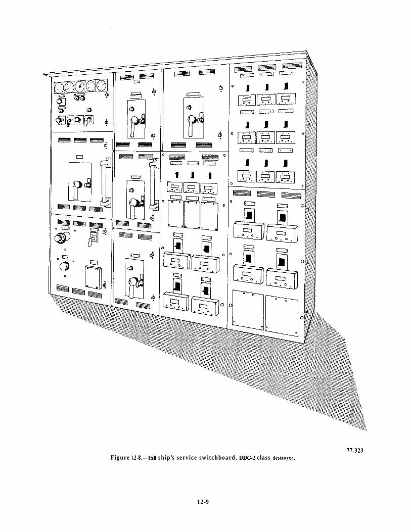
Figure 12-8.—1SB ship’s service switchboard, DDG-2 class destruyer.
12-9
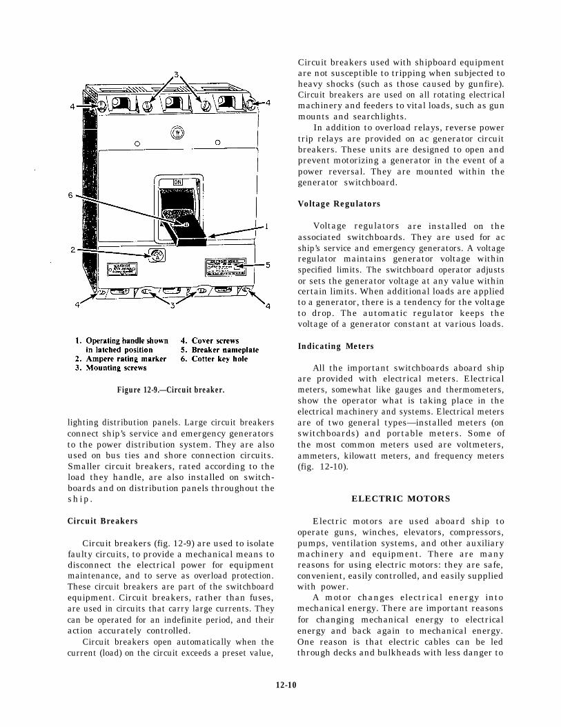
Figure 12-9.—Circuit breaker.
lighting distribution panels. Large circuit breakersconnect ship’s service and emergency generatorsto the power distribution system. They are alsoused on bus ties and shore connection circuits.Smaller circuit breakers, rated according to theload they handle, are also installed on switch-boards and on distribution panels throughout theship .
Circuit Breakers
Circuit breakers (fig. 12-9) are used to isolatefaulty circuits, to provide a mechanical means todisconnect the electrical power for equipmentmaintenance, and to serve as overload protection.These circuit breakers are part of the switchboardequipment. Circuit breakers, rather than fuses,are used in circuits that carry large currents. Theycan be operated for an indefinite period, and theiraction accurately controlled.
Circuit breakers open automatically when thecurrent (load) on the circuit exceeds a preset value,
Circuit breakers used with shipboard equipmentare not susceptible to tripping when subjected toheavy shocks (such as those caused by gunfire).Circuit breakers are used on all rotating electricalmachinery and feeders to vital loads, such as gunmounts and searchlights.
In addition to overload relays, reverse powertrip relays are provided on ac generator circuitbreakers. These units are designed to open andprevent motorizing a generator in the event of apower reversal. They are mounted within thegenerator switchboard.
Voltage Regulators
Voltage regulatorsassociated switchboards.
are installed on theThey are used for ac
ship’s service and emergency generators. A voltageregulator maintains generator voltage withinspecified limits. The switchboard operator adjustsor sets the generator voltage at any value withincertain limits. When additional loads are appliedto a generator, there is a tendency for the voltageto drop. The automatic regulator keeps thevoltage of a generator constant at various loads.
Indicating Meters
All the important switchboards aboard shipare provided with electrical meters. Electricalmeters, somewhat like gauges and thermometers,show the operator what is taking place in theelectrical machinery and systems. Electrical metersare of two general types—installed meters (onswitchboards) and portable meters. Some ofthe most common meters used are voltmeters,ammeters, kilowatt meters, and frequency meters(fig. 12-10).
ELECTRIC MOTORS
Electric motors are used aboard ship tooperate guns, winches, elevators, compressors,pumps, ventilation systems, and other auxiliarymachinery and equipment. There are manyreasons for using electric motors: they are safe,convenient, easily controlled, and easily suppliedwith power.
A motor changes electrical energy intomechanical energy. There are important reasonsfor changing mechanical energy to electricalenergy and back again to mechanical energy.One reason is that electric cables can be ledthrough decks and bulkheads with less danger to
12-10

Figure 12-10.—Switchboard indicating meters.
watertight integrity than steam pipes or MOTORmechanical shafts. Another reason is that damageto a steam line can cause steam to escape,resulting in personnel injury. If an electriccable is used and a fault occurs, the circuitbreaker protecting the cable opens automatically.The ac motor is used extensively by the Navybecause it is smaller and requires less maintenancethan the dc motor.
Most ac motors used aboard ship use three-phase, 60-Hz, 450-volt power. Although most acmotors operate at a single speed, some motors,such as the prime movers for fuel oil pumps, lubeoil pumps, and ventilation fan motors, have twooperating speeds.
CONTROLLERS
Controlling devices are used to start, stop,speed up, or slow down motors. In general,these controllers are standard equipment aboardship and are operated either manually, semi-automatically, or automatically. They are drip-proof and shock resistant. In some installations,the controllers are operated by remote control,with the switch at a convenient location.
Motor control devices (controllers, masterswitches, and electric brakes) protect the equip-ment to which they are connected. Controllersprovide protective and governing features forevery type of shipboard auxiliary. Varioustypes of master switches are used to govern the
12-11

controllers. Electric brakes are used to bring aload to rest, or to hold it at rest, when electricpower to the motor is cut off. Aboard ship,electric brakes are used primarily on hoisting andlowering equipment such as cranes, winches, andwindlasses.
Most controllers function simply to start orto stop auxiliary machinery; but, some controllersalso provide for reversal of direction or multispeedoperation. Motor controllers, sometimes calledstarters, have overload protective devices toprevent burning out the motor. Most controllerscut out automatically when the electric powerfails, and they have to be restarted manually. Thistype of motor controller is called a low-voltageprotection (LVP) controller. Another type ofmotor controller, which is used primarily withvital loads, is called a low-voltage release (LVR)controller. The LVR controller disconnects themotor from the supply voltage if the supplyvoltage drops below a predetermined level. Whenthe supply voltage returns to a normal level, theLVR controller automatically restarts the motor.
BATTERIES
Aboard ship, batteries are one of the sourcesfor emergency and portable power. Storagebatteries are used to power emergency equipment,ship’s boats, and forklifts. The storage battery isalso used as a source of energy for emergencydiesel generators, gyrocompasses, and emergencyradios.
You should be familiar with safety precautionsyou must follow when you work around batteries.Batteries must be protected from salt water, whichcan mix with the electrolyte (the acid solution)and release poisonous gases. Salt water in theelectrolyte also sets up a chemical reaction thatwill ruin the battery. If a battery is exposed to saltwater, notify the electric shop immediately.
Storage batteries, when being charged, give offa certain amount of hydrogen gas. Batterycompartments should be well ventilated todischarge this gas to the atmosphere.
WARNING
Flames or sparks of any kind, includinglighted cigarettes, should never be allowedin the vicinity of any storage battery thatis being charged.
When the battery is in a low or dischargedstate and does not perform properly, you shouldnotify the Electrician’s Mate (EM).
PORTABLE ELECTRICALEQUIPMENT
Aboard ship, you will perform many jobsusing small, portable electrical tools. Becauseportable electrical tools are commonly used undera variety of conditions, they are subject to damageand abuse.
The Navy has a good electrical tool safetyprogram. This program is carried out by qualifiedEMs. However, EMs can only make safety checkson tools that are brought to their attention.Electrical handtools should be inspected beforeeach use to make sure the power cord is not nickedor cut, and the plug is connected properly.Electrical handtools should be turned in to theelectricians as prescribed by the electrical safetyprogram.
BATTLE LANTERNS
Relay-operated hand lanterns (fig. 12-11, viewA), usually called battle lanterns, are powered bydry-cell batteries. Hand lanterns are provided togive emergency light when the ship’s service andemergency/alternate lighting systems fail. Theselanterns are placed in spaces where continualillumination is necessary, such as machineryspaces, control rooms, essential watch stations,battle dressing stations, and escape hatches. Allauxiliary machinery with gauge boards should beprovided with a battle lantern to illuminate thegauge board in the event of a casualty. Thebattle lantern should not be removed from itsmounting bracket except in an emergency. Do notuse it as a flashlight in nonemergency situations.
The relay control boxes for battle lanterns areconnected to the emergency lighting supplycircuit (or to the ship’s service lighting circuit) inwhich the lantern is installed. If power in thecircuit fails, the relay opens and the batteriesenergize the lantern.
Relay-operated battle lanterns are capable ofoperating for a minimum of 10 hours before thelight output ceases to be useful.
Similar hand lanterns (fig. 12-11, view B),which are not connected to relays, are installedthroughout the ship to provide light in stations
12-12

77.47Figure 12-11.—Special lights.
that are occasionally manned. These lanterns aremanually operated. If used in an emergency, themanually operated hand lanterns should ALWAYSBE RETURNED TO THEIR ORIGINALLOCATION.
SEALED-BEAM LIGHTS
Sealed-beam lights are a type of flood lantern(fig. 12-11, view C). These lanterns are used togive high-intensity illumination in damage controlor other emergency repair work. These unitsconsist of a sealed-beam light similar to that
used for automobiles. The sealed-beam light,powered by four small wet-cell storage batteries,is mounted in the battery case and fitted with ahandle for convenient carrying. A sealed-beamlamp will operate for 3 hours before the batteriesrequire recharging. When the batteries are at fullcharge, the beam has an intensity similar to thatof the headlight on an automobile. At the end of3 hours, the light output will gradually drop toabout one-half its original brilliance. These sealed-beam lights are normally stored in the damagecontrol repair lockers.
12-13
SHIPBOARD ELECTRICALSYSTEMS AND CONNECTIONS
As a Fireman, you should be familiar with thepower and lighting distribution systems, and shorepower connections. You will find greater detailon this and other shipboard electrical equipmentin chapter 320, Naval Ships’ Technical Manual.
POWER DISTRIBUTION SYSTEMS
A power distribution system carries powerfrom the generator switchboards to every part ofthe ship. This system consists of feeders, mains,submains, load center panels, and distributionboxes. The most important auxiliaries are suppliedwith normal, alternate, and emergency feedersthrough automatic bus transfer units, each witha separate source of power. Casualty powersystems are installed aboard ship to provideelectrical connections when both ship’s service andemergency electrical systems are damaged.
LIGHTING DISTRIBUTION SYSTEMS
Lighting distribution systems are necessary tolight the ship and to assist personnel in controllingdamage. Two lighting systems are installed aboardcombatant ships. These are ship’s service lightingand emergency lighting. The ship’s service lightingnormally supplies all lighting fixtures. Emergencylighting circuits are supplied to vital machineryspaces, the radio room, the combat informationcenter, and other vital spaces. The emergencylighting system receives power from the ship’sservice generators; but if normal power is lost,the emergency system is automatically poweredby the emergency generators. Lighting distributionsystems are similar to power distribution systemsexcept for the following differences:
1. They are more numerous.2. They have lower voltages (120 volts).3. They have smaller panels and cables.
If an emergency power system is not installed,alternate supplies from another ships’ servicesource can provide for services selected accordingto the basic principles of an emergency lightingsystem.
SHORE POWER CONNECTIONS
Shore power connections are installed at ornear suitable weather deck locations. At these
locations, portable cables from the shore, or froma ship alongside, are connected. Power can besupplied through these connections to the switch-board when ship’s service generators are not inoperation.
ELECTRICAL SAFETYPRECAUTIONS
There are certain safety precautions youshould observe when working with or aroundelectrical appliances and equipment. The followingare some of the most common electrical safetyprecautions all shipboard personnel are requiredto follow:
Do not attempt toelectrical equipmentelectrical work toelectricians.
maintain or repairyourself. Leave thethe EMs and IC
Check personal electrical equipmentthrough the EMs to see if it can be usedaboard ship.
Observe and follow all pertinent instruc-tions and electric warning signs aboardship.
Observe all safety precautions regardingportable electric lights and tools. (Userubber gloves and goggles.)
Remember, 120-volt electricity isdangerous, especially aboard ship.
Do not touch or operate any devicehas a danger or caution tag attachedwithout first contacting the EOOW.
very
thatto it
Do not go behind electrical switchboards.
Do not touch bare electric wires orconnections; assume all circuits to beALIVE.
Do not remove steamtight globes fromlighting fixtures.
Do not remove battle lanterns from theirlocations.
Do not use manually operated hand battlelanterns for unauthorized purposes. Eachperson should have his/her own flashlight.
12-14
Do not use electric cable runs to hoist orsupport any weight.
Do not use the wireways for storage.
Do not permit water to get into electricalequipment.
Remember, a flame, spark, or lightedcigarette can cause a disastrous batteryexplosion.
Remember, electrolyte from a storagebattery can cause severe burns and candamage equipment and clothing.
When you repair equipment that is drivenby a motor, have an electrician disconnectthe circuit and tag it as out of commission.
Do not start or operate electrical equip-ment when flammable vapors are present.
Learn the electrical safety precautionsapplicable to your assigned duties and dutystation. By thoroughly understanding elec-trical safety precautions, you will helpprevent injury to yourself and damage toequipment.
If YOU are ever in doubt about theoperating condition of electrical equip-ment, CALL AN ELECTRICIAN.
SUMMARY
This chapter has introduced you to shipboardelectrical equipment and systems. It has givenyou information about electricity, generators,shipboard power distributions, electric motors,controllers, batteries, port able electrical equip-ment, shipboard electrical systems and con-nections, and electrical safety precautions. Youshould pay particular attention to the safetyprecautions that have been included within thischapter and in all other chapters. Even thoughelectricity has made our lives easier, it can kill youin an instant if it is not used properly.
12-15


CHAPTER 13
ENVIRONMENTAL CONTROLS
Many materials and situations aboard ship candamage personnel and the environment. Continuedemphasis and direction on combating environmentalpollution by federal agencies is contained in presidentialexecutive orders and congressional legislation. Allfacilities owned by, or leased to, the federal governmentmust be designed, operated, maintained, and monitoredto conform to applicable air, water, and noise standardsestablished by federal, state, and local authorities.
The Navy actively participates in a program toprotect and enhance the quality of the environment. TheNavy adheres to all applicable regulatory standards andinitiates actions to conserve natural resources, protecthistorical and cultural properties, and prevent or controlpollution caused by Navy facilities. This chaptercontains information dealing with some of the moreserious problems that threaten the environment. It alsocovers the controls that are used to reduce the risks.
HEAT STRESS
On board ship, certain kinds of working spaces maybe hot and humid. Some examples of hot and humidspaces are firerooms (boiler rooms), sculleries withautomatic dishwashing machines, and galleys.
Heat stress is the basic inability of an individual’sbody to cope with the effects of a high-temperature andhigh-humidity environment. When a person works in ahot, humid environment, such as a boiler, heat builds upwithin his/her body. When the body’s capability to coolitself is exceeded, heat stress can occur. The human bodytries to cool itself automatically through sweating.Sweating is the mechanism by which the body gets ridof excess heat through evaporation. The sweatevaporates, thereby cooling the body and reducing bodytemperature. Although the sweating mechanism is anormal body function, the sweating process depletes thebody of water and salts and changes the body’schemistry. If liquid volume and salts are not replaced,several heat illnesses or injuries can occur.
HEAT CRAMPS
Heat cramps are simply painful muscle contractionsor spasms. They are normally caused by the loss of bodyfluids through sweating. It is also possible for a person
who is overheated to induce muscle cramps by drinkingcold liquids too quickly or in large quantities. Heatcramps are often an early warning of heat exhaustion. Ifyou ever experience heat cramps, go to a cooler place,drink plenty of cool (not cold) water, and massage thecramping muscles.
NOTE: Administering salt in any form, even indrinking water, is POOR health care for victims of heatcramps. The loss of body fluids through sweating resultsin a HIGHER concentration of salts within the body. Ifthe body’s heat load builds up, the muscles will absorbincreased amounts of salts. This absorption causes themuscles to cramp.
HEAT EXHAUSTION
Heat exhaustion is a more serious threat to healththan heat cramps. Heat exhaustion usually occurs whenpersonnel work or exercise in hot environments. Thebody’s sweating mechanism is overloaded and cannotcope with the heat buildup within the body. Since theblood flow is disturbed, the victim may feel dizzy,headachy, and nauseated. The signs and symptoms ofheat exhaustion are similar to those of shock and shouldbe treated as such. When a person suffers from heatexhaustion, the skin is gray in color and feels cold andclammy. To help the heat exhaustion victim, remove thevictim to a cool area and loosen his/her clothing. Youshould apply cool wet cloths to the head, groin, andankles and lightly fan the victim. If the victim isconscious, give him/her cool water to drink. If vomitingoccurs, do NOT administer any more fluids. Transportthe victim to a medical facility as soon as possible.
HEATSTROKE
Heatstroke is a less common but far more seriousthreat to health than heat exhaustion. In about 20 percentof heatstroke cases, heatstroke is fatal. In heatstroke, thesweating mechanism breaks down completely; the bodyis unable to rid itself of excess body heat. The body’stemperature may rise as high as 105°F. Prolonged, highbody temperatures can cause failure of the brain,kidneys, and liver.
13-1
The early symptoms of heatstroke are similar tothose of heat exhaustion–headache, nausea, anddizziness. At first, the victim’s breathing is deep andrapid; but, as the symptoms progress, breathingbecomes shallow, almost absent. The skin appearsflushed, dry, and very hot. The pupils are constricted toa pinpoint; the pulse is fast and strong. It is extremelyimportant that you recognize the differences betweenheat exhaustion and heatstroke. HEATSTROKE IS ATRUE LIFE-AND-DEATH EMERGENCY.
The most important first-aid treatment for aheatstroke victim is to lower the victim’s body heat.Move the victim to a cool place. Douse the victim withcold water. Remove as much of the victim’s clothing aspossible to allow free flow of air over the body topromote cooling. If the victim is conscious, give him/hercool water to drink. Transport the victim to a medicalfacility as quickly as possible.
So far, we have discussed heat-related problems andthe first-aid treatment for heat stress. However, you willbe much better off if you learn what you can do toprevent heat stress.
PREVENTION
In spaces where heat stress is likely to occur, it isdifficult to lower temperatures. Therefore, preventingheat stress-related conditions is the goal. Monitoringconditions that bring about heat stress and controllingthe crew’s exposure to high-heat and high-humidityconditions reduces the chances of heat stress.
Some of the factors that cause heat stress are asfollows:
l Unnecessary heat and humidity sources
l Steam leaks
. Damaged insulation
Report these types of conditions so they can becorrected. Vents and exhaust blowers should be adjustedto maintain proper air circulation.
On board ship, spaces are ventilated by ductworkconnected to supply (intake) and exhaust blowers. Theseblowers (or fans) are driven by two-speed electricmotors. Exhaust fans have a greater air-moving capacitythan supply fans. Unless personnel are otherwisedirected, supply and exhaust ventilation fans are set tothe SAME speed. It is important that you understand theneed to MAINTAIN FLOW. If you do not MAINTAINFLOW, the following could happen to you. A watch
stander in a hot space sets the supply blower to highspeed and then stands under the outlet.
Usually, you can tell whether the speed of the ventblowers for a space is set correctly by how hard it is foryou to open or shut the doors to the space. For example,if a door opens outward and it is hard to close, then thespace has a POSITIVE pressure. This means that thesupply vent is probably set on high speed, and theexhaust vent is set on low speed.
Another common problem with shipboardventilation systems is improper care of system filters.Filters are installed at the intake of the supply blowersto prevent dust and dirt from entering the ship. Cleaningthese falters is considered to be routine maintenance. If,however, filter cleaning is neglected or is poorly done,the temperature of shipboard working and living spacesincreases because there is a reduced flow of coding air.Spaces considered to be heat-stress areas should containa heat-stress monitor to measure the heat-stressconditions.
On an individual level, wear clothing so there issome air circulation between the clothing and your body.Whenever you perform heavy physical labor, eat lightlyand take a rest period before resuming heavy exertion.
The Navy has established strict spaceenvironmental monitoring requirements for heat-stressconditions. These heat-stress surveys, together withstrict exposure limit standard tables, control the amountof time a person may remain in certain high-temperatureand high-humidity conditions before being REQUIREDto go to a cool place and rest. For more informationabout heat injury, you should refer to Shipboard HeatStress Control and Personnel Protection, OPNAVINST5100.20 (series), and Navy Occupational Safety andHealth (NAVOSH) program Manual for Forces Afloat,OPNAVINST 5100.19 (series).
Heat illnesses and injuries are primarily caused bythe loss of body fluids and salts. Preventing theseillnesses and injuries centers on replacing body fluidsand salts, monitoring the environment, and controllingexposure. For example, in a hot environment, fluidsmust be replaced ounce for ounce. Therefore, when youare sweating heavily, increase your water intakeproportionately. Meals provide salts to replace those lostthrough sweating. Therefore, if you work in a high-heatand high-humidity environment, you should eatwell-balanced meals at regular intervals, salted to taste.You should get at least 6 hours of sleep every 24 hours.Wear clean clothing made from at least 35 percentcotton. Do NOT wear starched clothing. Do NOT
13-2
drink commercially prepared electrolytesupplements in place of water. Do NOT take salttablets unless specified by medical personnel. DoNOT drink alcoholic beverages, because alcoholdepletes the level of fluids in the body.
Remember, the effects of heat stress are cumulative(add up). Once you have heat cramps, heat exhaustion,or heatstroke, you are twice as likely to experience a heatstress-related incident; your body has an increasedsensitivity to heat. Your awareness of the factors thatcontribute to heat stress and their prevention, as well asyour strict adherence to established exposure limits, willhelp prevent your becoming a victim of heat stress.
POLLUTION
Before understanding how pollution affects youpersonally, you must take a realistic look at pollution.Pollutants, whether airborne or waterborne, adverselyaffect the food chain and often are directly harmful tohumans. As Navy personnel, our primary concern is tocontrol the pollutants aboard ship to minimize thepollution risk to ourselves and the environment.
OIL AND CHEMICAL POLLUTION
Fuel oil and chemical cleaning solvents are oftenused aboard Navy ships, and the possibility exists for aspill. These pollutants collect in the ship’s bilges. Fromthe ship’s bilges, the pollutants are pumped into a wasteoil collecting can.
Oily wastes behave just as their definition suggests:an oily waste is any solid or liquid substance that, aloneor in a solution, can produce a surface film or sheenwhen it is discharged in clean water. Most oily wastesare derived (come) from petroleum or havecharacteristics of petroleum products. Waste oil is anoily waste that cannot be reused by the ship, and itcontains only small amounts of water. Any mixture thatcauses a sludge or emulsion to be deposited beneath thesurface oil and chemical pollution of the water isconsidered to be an oily waste.
Oily wastes frequently present a shipboard pollutionproblem. (Refer to the Naval Ships’ Technical Manual(NSTM), chapter 593.) Oily wastes derived fromlubricating oils are caused by tank cleaning operations,leakage and drainage from equipment and systems,stripping from contaminated oil-settling tanks, andballast water from fuel tanks of noncompensated fuelsystems during the ship’s defueling, refueling, orinternal transfer operations.
You may think that if a small amount of oil ispumped overboard, it cannot really cause much damage.Or can it? Remember, oil is less dense than water. Itfloats on the surface of the water and is carried by theaction of winds and tides. Oily wastes can containappreciable amounts of volatile petroleum or fuelproducts. When these wastes are confined in spaces,such as tanks and bilge compartments, they become asource of floating flammables or vapors that arepotentially hazardous to personnel and equipment. Ifthese vapors collect in a confined area, such as a pocketunderneath a pier, they could explode if exposed to anopen flame, such as from a welding operation or from aspark from a grinding wheel. Remember, YOU mightbe the person who is operating the torch, welder, orgrinding wheel.
Besides being harmful to the environment and topeople, oil and chemical discharge is also against thelaw. The Oil Pollution Act of 1961 prohibits thedischarge of oil and oily waste products into the seawithin 50 miles (150 miles in some cases) of land. Amore recent law, the Federal Water Pollution ControlAct of 1970, prohibits the discharge of oil by any personor agency from any vessel or facility into the navigablewaters of the United States inside the 12-mile limit. Alloil spills or sheens within the 50-mile prohibited zoneof the United States must be reported immediately.
Oil Spill Prevention
Shipboard oil pollution is controlled by the efficientuse of the oily waste control system that is incorporatedinto your ship. Oil pollution control systems reduce oilywaste generation, store waste oil and oily wastes,monitor oil and oily wastes, and transfer waste oil andoily wastes to shore facilities. Effective use of yourship’s oil pollution control system depends on operators’knowledge of the ship’s pollution abatement system. Touse your ship’s oil pollution control system effectively,operating personnel are trained and plans are made sothat oil and oily waste are handled properly. Otherrequirements for your ship include ensuring thatequipment functions properly and that bilges are keptdry and free of oil. The minimum use of detergents isrecommended when bilges and equipment are cleaned.Also, always give proper attention to preventivemaintenance requirements.
The best prevention method any vessel can useagainst oil or chemical pollution is not to dischargepollutants into the sea. However, spills do occur duringrefueling operations. For example, to keep a ship “on aneven keel,” fuel oil maybe transferred from one tank to
13-3

another. Fuel storage tanks are connected by pipes andvalves, some of which discharge overboard. All it takesis ONE human error, ONE valve to be open or shutthrough a vent pipe, and your ship has ONE spill inprogress. The simplest solution is to have the peoplewho operate the system do so in a conscientious manner.The people who operate and maintain the pollutioncontrol equipment should always be professionallytrained and fully qualified.
Oil Spill Removal
If an accident occurs and oil is spilled, your shipshould take prompt action to contain the oil and clean itup. A quick reaction by your ship’s trained crew resultsin containment and often collection of the entire spillwithout the assistance of shore-based personnel.
Every ship should have an Oil Spill Containmentand Cleanup Kit (O. S. C. C. K). Instructions for its usecan be found in U.S. Navy Oil Spill Containment andCleanup Kit, Mark 1, NAVSEA 0994-LP-013-6010.This manual describes applicable safety precautions forthe use of the kit.
The kit consists of various sizes of porous mats, boathooks, grappling hooks, plastic bags, and an instructionbook for their use. If there is a spill, these absorbent matsare used by ship’s personnel to soak up the spilled oil.First, soak the porous mats in diesel fuel and wring themout, which causes the mats to soak up the oil instead ofwater. After they are prepared, throw the mats on the oilspill to soak it up. Then, retrieve the porous mats usingthe boat hooks and grappling hooks. Next, wring the oilout of the mats into suitable containers. Then, throw themats back onto the oil spill to soak up more oil. Afterthe oil spill is removed, store the porous mats in plasticbags for disposal at a shore-based facility.
Additionally, containment trawlers can be riggedaround a ship in port anytime the ship is engaged infueling activities. Trawlers are floating fences made upof linked, buoyant pillows that confine any spilled oil tothe vicinity of the hull.
NOISE POLLUTION AND CONTROL
Another type of pollution, which is often notthought of as pollution, is noise. Prolonged exposure toloud noises is not only psychologically taxing but alsoa cause of hearing loss. Continued exposure to noiselevels of 85 decibels (dB) or greater and impact orimpulse noise of 140 dB can cause severe hearing loss.You need to be aware of this problem because spaces inthe engineering department can easily have average
Figure 13-1.-Circumaural (Mickey Mouse) type of earprotection.
noise levels within the danger range. The Navy hasimplemented an occupational noise and hearingconservation program. The goal of this program is toeliminate all noise hazards to personnel.
Wherever possible, noise is being reduced by designand insulation. When there are no other practical meansavailable, personal protective hearing devices MUST beworn. Furthermore, anyone who works in spaces wherenoise levels exceed 104 dB must wear a combination ofinsert-type ear plugs and circumaural-type ear muffs(fig. 13-1).
In addition, each person assigned to duties indesignated hazardous noise areas are included in thehearing conservation program and receive the requiredhearing tests within 90 days of that assignment. Thisprocedure serves to determine if a significant hearingloss has occurred. Hazardous noise areas are identifiedand labeled by either the ship’s medical personnel or anindustrial hygienist. Audiometric hearing tests arerequired annually to monitor ship’s personnel who areexposed to noise hazards. (Refer to Navy OccupationalSafety and Health (NAVOSH) Program Manual,OPNAVINST 5100.23 [series].
ASBESTOS POLLUTION AND CONTROL
The inhalation of asbestos fibers can, after a periodof years, cause a crippling respiratory condition calledasbestosis. Exposure to asbestos can also cause severalforms of cancer. All personnel who work aroundasbestos, and who smoke, should be aware that theirchance of contracting lung cancer is increasedninetyfold.
13-4

The most prevalent use of asbestos materials aboardship is in the fabrication and repair of pipe and boilerinsulation. The greatest hazard is present when asbestosparticles (dust) are in the air.
In the interest of personnel safety, the Navy hasimplemented an asbestos control program. Theobjective is to eventually replace the asbestos insulatingmaterials with nontoxic materials. In the meantime, theasbestos control program identifies asbestos hazardsand implements stringent safety requirements to befollowed by personnel working with materials thatcontain asbestos. Ship personnel are not authorized toremove or repair insulation containing asbestos, exceptin an operational emergency certified by thecommanding officer. Repair and removal work shouldbe referred to the local intermediate maintenanceactivity (IMA) or contractor.
As you know, the greatest danger from asbestosexists when particles of asbestos are in the air, such asduring rip-out of old insulation. Rip-out is normallyperformed by shipyard personnel; however, you mayhave to enter a space where there are asbestos particles.If you are ripping out old insulation or staying in thespace where rip-out is in progress, you MUST wearprotective clothing, use a pressure-demand supplied-airrespirator (fig. 13-2), and be formally trained onasbestos-handling procedures. After completing yourtasks, you MUST proceed to the designateddecontamination center to remove the coveralls andrespirator and to take a shower. These precautionsshould remove any asbestos particles and prevent thespread of asbestos dust to other sections of the ship.
You should wet down contaminated disposablecoveralls. Wet down is a procedure that reduces thepossibility of dust being blown off of the coveralls.Then, dispose of the contaminated coveralls inheavy-duty plastic bags. Clearly mark the plastic bagswith caution labels to warn personnel of the asbestoshazard.
Insulation materials other than asbestos pose healthhazards. For additional information on safe workingpractices involving these materials, consult the NSTM,chapter 635. REMEMBER, where safety is concerned,take nothing for granted. Your actions can have apositive or negative effect on you and your shipmates.
REFRIGERANTS AND SAFETYPRECAUTIONS
The refrigerants commonly used are fluids, and theyare affected by heat, temperature, and pressure in a
Figure 13-2.-Disposable protective coveralls and type Crespirator.
manner similar to water. Many different fluids are used
as refrigerants; their selection is based on low boilingpoints and other desirable characteristics. The following
refrigerants are the most commonly used on U.S. Navyships:
R-11, trichlorofluoromethane. R-11 is a colorless
liquid or gas. At room temperature, R-11 has a slight
ethereal odor (smells like ether or dry-cleaning fluid,
tetrachloroethylene).
R-12, dichlorodifluoromethane. R-12 is a colorless
and odorless gas at room temperature. In highconcentration, it has a slight ethereal odor.
NOTE: Dichlorodifluoromethane (formerly F-12),is now called R-12.
R-22, monochlorodifluoromethane. R-22 is a
colorless and odorless gas, which, at room temperaturein high concentration, has a slight ethereal odor.
R-114, dichlorotetrafluoroethane. R-114 is a
colorless and odorless gas, which, at room temperature
in high concentration, has a slight ethereal odor.
13-5
R-113, trichlorotrifluoroethane. R-113 is a heavycolorless liquid, which, at room temperature, has a slightethereal odor. R-113 is only used as a solvent, degreaser,and flushing agent. It is not used as a shipboardrefrigerant.
These refrigerants, liquid and vapor, arenonflammable and nonexplosive. Air mixtures of theserefrigerants are not capable of producing a flame. Theproducts of decomposition have a pungent odor and arevery irritating in minute quantities. They give amplewarning before dangerous concentrations are reached.
R-12, R-22, and R-114 are shipped under pressurein steel cylinders. R-11 and R-113 are normally shippedin drums, although some R-11 is shipped in cylindersfor submarine use. The refrigerant cylinders are easilyidentified by their orange-colored bodies. In addition,the following markings are made on the cylinder tominimize the possibility of misidentification of the gas:
l The name of the gas is stenciled longitudinallyon two diametrically opposite sides of thecylinder.
. A decal bearing the name of the gas may beattached to the shoulder of the cylinder 90degrees from the stenciling.
WARNING
Do not smoke, braze, or weld when refrigerantvapors are present. Vapors decompose tophosgene, acid vapors, and other products whenexposed to an open flame or a hot surface.
The following safety precautions and warningsapply to all of the refrigerants listed in the previousparagraphs.
l Exposure to large concentrations of fluorocarbonrefrigerants can be fatal. Vapors displace air (oxygen) ina space and result in asphyxia. In high concentrations,these vapors have an anesthetic effect, causingstumbling, shortness of breath, irregular or missingpulse, tremors, convulsions, and death. Fluorocarbonrefrigerants and solvents should, therefore, be treated astoxic gases.
. Initial adverse anesthetic effects of R-113 can beexperienced at much lower levels than those of otherrefrigerants, even though all refrigerants listed here havea threshold limit value (TLV) of 1,000 parts ofrefrigerant per million parts of air (ppm).
l Personnel overcome by inhalation offluorocarbon vapors may develop cardiac problems.Remove exposed personnel to fresh air immediately. Ifbreathing has stopped, apply artificial respiration. Donot permit affected personnel to exert themselves orto exercise.
TLVs refer to airborne concentrations of substancesand represent conditions under which it is believed thatnearly all workers may be repeatedly exposed for an8-hour day, 40 hours per week without adverse effects.In addition to the precautions previously stated, there areother safety measures that should be followed. A few ofthese methods and precautions are as follows:
. Because refrigerants R-12 and R-22 boil at suchlow temperatures, they may freeze if they are splashedinto the eyes or onto the skin. Always wear chemicalsafety goggles or a full face shield when you work withany refrigerant. Wear along-sleeved shirt and protectivegloves.
l Vapors of fluorocarbon refrigerants are four tofive times heavier than air and tend to collect in lowplaces. Perform refrigerant detection within 2 feet of thedeck and in possible air pockets.
. Refrigeration machinery spaces should be wellventilated, especially when personnel are servicingmachinery. Use portable blowers if necessary to keepthe refrigerant vapor levels below the TLV of 1,000ppm.
. Always have two people present when work isbeing done on refrigeration systems. Use a halidemonitor with an alarm so you can be sure refrigerantvapor concentrations in a space do not exceed safelimits.
SEWAGE SYSTEM
In a continuing effort to control pollution of inlandand coastal waters, the Navy is installing sewagetreatment systems on board naval ships. These marinesanitation systems are composed of three subsystems:
l
l
l
Flushing water system (provides flushing water)
Collection system (collects waste)
Treatment disposal system (treats and disposesof waste)
Sewage discharged by naval ships into rivers,harbors, and coastal waters and the environmentaleffects of sewage pollution are of great concern to theNavy. In fact, the Navy is required to control sewage
13-6
discharge under regulations issued by the Secretary ofDefense.
In the past, shipboard sewage has been dischargedoverboard as a matter of routine design and operation.Studies have shown that concentrations of sewage ininland waters, ports, harbors, and coastal waters of theUnited States is detrimental to the environment. TheNavy has installed marine sanitation devices (MSDs) onships. The MSDs allow ships to comply with the sewagedischarge standards without compromising missioncapability.
In 1972, the Chief of Naval Operations (CNO) madethe policy decision to install the sewage collection,holding, and transfer (CHT) system aboard naval ships.The CHT system is designed to hold all shipboardsewage that is generated over a 12-hour period. On largeships, this goal can usually be achieved. For smallerships, the maximum capacity would limit holding timeto 3 hours or less, an insufficient time for the ship totransit the 3-mile restricted zone.
The Jered sewage treatment plant and the LHAsewage treatment plant are other types of MSD systems.The Jered sewage treatment plant is designed for a zeroliquid discharge. It is capable of using the vacuum-burnprinciple. Sewage is first collected by a vacuum and thendisposed of by incineration. Sewage can be dischargedoverboard when the ship is at sea or pumped to shorevia a connection facility. The LHA sewage treatmentplant is a biological sewage treatment process in whichsewage and activated sludge can be mixed and aerated.The activated sludge is separated from the treatedsewage by sedimentation and discharged or returned tothe process as needed.
There are distinct hazards to personnel associatedwith all sewage systems. These hazards includeexplosive gases, toxic vapors, and biologicalcontaminants. When operating a CHT system, forexample, personnel must be extremely careful so spillsdo not occur. ALL SPILLS CAN BE EXTREMELYHAZARDOUS TO PERSONNEL.
In addition to the removal of CHT contaminants,CHT spills are sanitized with disinfectants so thatresidual bacteria are eliminated. Medical departmentpersonnel must be notified of any CHT black waterspills. Medical department personnel must alsosupervise cleanup and sanitation operations in spillareas.
For further information on sanitation systems, referto Hull Maintenance Technician 3 & 2, volume I,NAVEDTRA 10571 (series), chapter 15, and NSTM,chapter 593.
SUMMARY
This chapter introduced you to environmentalhazards and control. Remember, pollution takes manyshapes and forms. Pollution attacks the environment anddirectly or indirectly affects each of us. Consequently,we must protect the environment by preventingpollution.
On board ship, certain forms of pollution aresometimes difficult to control, such as heat and noise.In these cases, the first line of defense is PROTECTION.In all other cases, we must be concerned withPREVENTION. Keep in mind that prevention ofpollution, in any form, is everybody’s business. Polluteyour environment, and your environment will polluteyou.
13-7

APPENDIX I
GLOSSARY
AUTOMATIC COMBUSTION CONTROL (ACC)SYSTEM–A system that automatically controls thefuel and air mixture in a boiler.
AUXILIARY MACHINERY–Any system or unit ofmachinery that supports the main propulsion unitsor helps support the ship and the crew; for example,pump, evaporator, steering engine, air-conditioningand refrigeration equipment, laundry and galleyequipment, and deck winch.
BACK PRESSURE–The pressure exerted on theexhaust side of a pump or engine.
BALLASTING–The process of filling empty tankswith seawater to protect the ship from underwaterdamage and to increase its stability SeeDEBALLAST-ING.
BLOW TUBES–Use of steam to remove soot andcarbon from the tubes of steaming boilers.
BLUEPRINT–Reproduced copy of a drawing (usuallyhaving white lines on a blue background).
BOTTOM DEAD CENTER (BCD)–The position of areciprocating piston at its lowest point of travel.
BOILER–A strong metal tank or vessel, composed oftubes, drums, and headers, in which water is heated.
BOILER CENTRAL CONTROL STATION–Acentrally located station for directing the control ofall boilers in the fireroom.
BOILER DESIGN PRESSURE–Pressure specifiedby the manufacturer, usually about 103 percent ofnormal steam drum operating pressure.
BOILER INTERNAL FITTINGS–All parts inside theboiler that control the flow of steam and water.
BOILER OPERATING PRESSURE–The pressure atwhich a boiler is maintained while in service.
BOILER OPERATING STATION–A location fromwhich a boiler is operated.
BOILER RECORD SHEET–A NAVSHIPS formmaintained for each boiler, which serves as amonthly summary of operation.
BOILER REFRACTORIES–Materials used in theboiler furnace to protect the boiler from heat.
BOILER ROOM–A compartment containing boilers
but not containing a station for operating or firingthe boilers Refers specifically to bulkhead-enclosedboiler installations.
BOILER TUBE CLEANER–A cylindrical brush that
is used to clean the insides of boiler tubes.
BOILER WATER–The water actually contained in theboiler.
BOTTOM DEAD CENTER (BCD)–The position of areciprocating piston at its lowest point of travel.
BOURDON TUBE–A thin-walled tube bent into the
shape of a letter C, which tends to straighten out—when pressure is exerted. As the tube straightens, itmoves a pointer around a gauge dial.
BRAZING–A method of joining two metals at hightemperature with a molten alloy.
BRINE–A highly concentrated solution of salt in water,normally associated with the overboard discharge
of distilling plants.
BRITTLENESS–A property of a material that causesit to break or snap suddenly with little or no priorsign of deformation.
BULL GEAR–The largest gear in a reduction geartrain The main gear, as in a geared turbine drive.
BURNERMAN–Person in the fireroom who tends the
burners in the boilers.
BUSHING–A renewable lining for a hole through
which a moving part passes.
BYPASS–To divert the flow of gas or liquidAlso, theline that diverts the flow.
CALIBRATION–The comparison of any measuringinstrument with a set standard of a greater accuracy.
CANTILEVER–A projecting arm or beam supportedonly at one end.
CAPILLARY TUBE–A slender, thin-walled,small-bored tube used with remote-readingindicators.
AI-1
CARBON DIOXIDE–A colorless, colorless gas used asa fire-extinguishing agent and for inflating life raftsand life jackets.
CARBON PACKING–Pressed segments of graphiteused to prevent steam leakage around shafts.
CASUALTY POWER SYSTEM–Portable cables thatare rigged to transmit power to vital equipment inan emergency.
CENTRAL CONTROL STATION (CCS)–The CCSis the main operating station from which a majorityof the engineering plant machinery can becontrolled and monitored on modern naval ships.
CHECK VALVE–A valve that permits the flow of aliquid in one direction only.
CIRCUIT BREAKER–An electrical device thatprovides circuit overload protection.
CLUTCH–A form of coupling designed to connect ordisconnect a driving or driven member.
COLD IRON–The condition of an idle engineeringplant when all port services are received from anexternal source such as shore or tender.
CONDENSATE–Water produced in the coolingsystem, of the steam cycle, from steam that hasreturned from the turbine or from steam that hasreturned from various heat exchangers.
CONDENSER–A heat-transfer device in which steamor vapor is condensed to water.
CONDUCTION–A method of heat transfer from onebody to another when the two bodies are in physicalcontact.
CONSTANT PRESSURE GOVERNOR–A devicethat maintains a constant pump discharge pressureunder varying loads.
C O N T R O L L A B L E R E V E R S I B L E - P I T C HPROPELLER (CRPP)–A propeller whose bladepitch can be varied to control the amount of thrustin both ahead and astern directions.
CONTROLLER–A device used to stop, start, andprotect motors from overloads while the motors arerunning.
COOLER–Any device that removes heat.
CORROSION–The process of being eaten awaygradually by chemical action, such as rusting.
COUNTERSINK–A cone-shaped tool used to enlargeand bevel one end of a drilled hole.
CREEP-RESISTANT ALLOY–A metal that resiststhe slow plastic deformation that occurs at hightemperatures when the material is under constantstress.
CROSS-CONNECTED PLANT–A method ofoperating two or more systems as one unit.
CURTIS STAGE–A velocity-compounded impulseturbine stage that has one pressure drop in thenozzles and two velocity drops in the blading.
DEAERATING FEED TANK (DFT or DA tank)–Adevice used in the waste-heat boiler system toremove dissolved oxygen and noncondensablegases from the feedwater.
DEBALLASTING–The process by which seawater isemptied from tanks to protect the ship fromunderwater damage and to increase its stabilitySeeBALLASTING.
DEGREE OF SUPERHEAT–The amount by whichthe temperature of steam exceeds the saturationtemperature.
DIESEL FUEL MARINE–A fuel oil.
DIRECT CURRENT (dc)–current that moves in onedirection only.
DIRECT DRIVE–One in which the drive mechanismis coupled directly to the driven member.
DISTILLATE–Water produced in distilling plants.
DISTILLING PLANT–A system that convertsseawater into fresh water commonly calledevaporators (evaps).
DRAWING–An illustrated plan that shows fabricationand assembly details.
DRUM, STEAM–The large tank at the top of the boilerin which the steam collects.
DRUM, WATER–A tank at the bottom of a boiler.
DUCTILITY–The property possessed by metals thatallows them to be drawn or stretched.
ECONOMIZER–A heat-transfer device on a boilerthat uses the gases of combustion to preheat thefeedwater.
EDUCTOR–A jet pump that uses water to emptyflooded spaces.
EFFICIENCY–The ratio of the output to the input.
ELASTICITY–The ability of a material to return to itsoriginal size and shape.
AI-2
ELECTRODE–A metallic rod (welding rod) used inelectric weldingIt melts when current is passedthrough it.
ELECTROHYDRAULIC STEERING–A systemhaving a motor-driven hydraulic pump that createsthe force needed to position the ship’s rudder.
ELECTROLYSIS–A chemical action that takes placebetween unlike metals in systems using salt water.
ELECTROMOTIVE FORCE (emf)–A force thatcauses electrons to move through a closed circuit,expressed in volts.
ELEMENT–A substance that consists of chemicallyunited atoms of one kind.
ENERGY–The capacity for doing work.
ENGINE ORDER TELEGRAPH (EOT)–A deviceon the ship’s bridge that is used to give orders to theengine roomAlso called annunciator.
ENGINEER’S BELL BOOK–A legal record of allordered main engine speed changes.
ENGINEERING OFFICER OF THE WATCH(EOOW)–officer on duty in the engineeringspaces.
ENGINEERING OPERATING STATION (EOS)–
EQUIVALENTS PER MILLION (EPM)–Thenumber of equivalent parts of a substance permillion parts of another substanceThe wordequivalent refers to the equivalent chemical weightof a substance.
EROSION–A gradual wearing away, such as a gullythat is eroded by water.
EVAPORATOR–A distilling device that producesfresh water from seawater.
EXPANSION JOINT–A junction that allows forexpansion and contraction.
FATIGUE–The tendency of a material to break underrepeated strain.
FEED HEATER–A heat-transfer device that heats thefeedwater before it goes to the boiler.
FEEDWATER–Water of the highest possible level ofpurity made in evaporators for use in boilers.
FERROUS METAL–Metal with a high iron content.
FIREBOX–The section of a ship’s boiler where fuel oilcombustion takes place.
FIRE MAIN–The saltwater line that providesfire-fighting water and flushing water throughoutthe ship.
FIRE TUBE BOILER–A boiler in which the gases ofcombustion pass through the tubes and heat thewater surrounding them.
FLAREBACK–A backfire of flame and hot gases intoa ship’s fireroom from the fireboxCaused by a fueloil explosion in the firebox.
FLASH POINT OF OIL–The temperature at which oilvapor will flash into tire, although the main body ofthe oil will not ignite.
FLEXIBLE I-BEAM–An I-shaped steel beam onwhich the forward end of a turbine is mounted; itallows for longitudinal expansion and contraction.
FLOOR (DECK) PLATES—The removable deckplating of a fireroom or engine room aboard ship.
FLUID–A substance that tends to flow or conform tothe shape of a container.
FLUX–A chemical agent that retards oxidation of thesurface, removes oxides already present, and aidsfusion.
FORCE–Anything that tends to produce or modifymotion.
FORCED DRAFT–Air under pressure supplied to theburners in a ship’s boiler.
FORCED-DRAFT BLOWERS–Turbine-driven fansthat supply air to the boiler furnace.
FORCED-FEED LUBRICATION–A lubricationsystem that uses a pump to maintain pressure.
FORGING–The forming of metal by heating andhammering.
FRESHWATER SYSTEM–A piping system thatsupplies fresh water throughout the ship.
FUEL OIL MICROMETER VALVE–A valve,installed at the burner manifold, that controls thefuel oil pressure to the burners.
FUEL OIL SERVICE TANKS–Tanks that providesuction to the fuel oil service pumps for use in thefuel oil service system.
FUSE–A protective device that will open a circuit if thecurrent flow exceeds a predetermined value.
GALLONS PER MINUTE (GPM or gpm)–A unit ofmeasurement.
AI-3

GAS FREE–A term used to describe a space that hasbeen tested and found safe for hot work (weldingand cutting).
GAS GENERATION (GG)–The high-pressure sectionof the main propulsion gas turbineIt includes thecompressor, combustor, high-pressure turbine,front frame, compressor rear frame, turbine midframe, transfer gearbox, and the controls andaccessories.
GAUGE (SIGHT) GLASS–A device that indicates theliquid level in a tank.
GEARED-TURBINE DRIVE–A turbine that drives apump, generator, or other machinery throughreduction gears.
GROUNDED PLUG–A three-pronged electrical plugused to ground portable tools to the ship’s structureItis a safety device that must always be checkedbefore portable electrical tools are used.
HALIDE LEAK DETECTOR–A device used tolocate leaks in refrigeration systems.
HANDHOLE–An opening large enough for the handand arm to enter for making slight repairs and forinspection purposes.
HARDENING–The heating and rapid cooling(quenching) of metal to induce hardness.
HEADER–A large pipe to which smaller pipes areconnected so that the liquid may pass freely fromone pipe to the other(s).
HEAT EXCHANGER–Any device that allows thetransfer of heat from one fluid (liquid or gas) toanother.
HERTZ–A unit of frequency that equals 1 cycle persecond.
HYDROGEN–A highly explosive, light, invisible,nonpoisonous gas.
HYDROMETER–An instrument used to determine thespecific gravity of liquids.
HYDROSTATIC TEST–A pressure test that useswater to detect leaks in closed systems.
IGNITION, COMPRESSION–The heat generated bycompression in an internal combustion engine thatignites the fuel (as in a diesel engine).
IGNITION SPARK–The electric spark that ignites themixture of air and fuel in an internal combustionengine (as in a gasoline engine).
IMPELLER–An encased, rotating element providedwith vanes that draws in fluid at the center andexpels it at a high velocity at the outer edge.
IMPULSE TURBINE–A turbine in which the majorpart of the driving force is received from the impulseof incoming steam. See REACTION TURBINE.
INDIRECT DRIVE–A drive mechanism coupled tothe driven member by gears or belts.
INERT–Inactive.
INJECTOR–A device that forces a fluid into an area.Injectors are used in the diesel engine to deliver fuelinto the cylinders and in boilers to force water intothe boilers.
INSULATION–A material used to retard heat transfer.
INTERCOOLER–An intermediate heat transfer unitbetween two successive stages, as in an aircompressor.
JACKBOX–A receptacle, usually secured to abulkhead, into which telephone plugs or jacks areinserted.
JOB ORDER––An order issued by a repair activity toits own subdivision to perform a repair job inresponse to a work request.
JP5–A fuel oil similar to DFM.
JUMPER-Any connecting pipe, hose, or wire normallyused in emergencies aboard ship to bypass damagedsections of a pipe, a hose, or a wireSee BYPASS.
JURY RIG–Any temporary or makeshift device.
LABYRINTH PACKING–Rows of metallic strips orfins that minimize steam leakage along the shaft ofa turbine.
LAGGING–A protective and confining cover placedover insulating material.
LIGHT OFF–To start a tire, as in light off a boiler.
LINE UP–To align a system for operation.
LOGBOOK–Any chronological record of events, suchas an engineering watch log.
LOG, ENGINEERING–A legal record of importantevents and data concerning the machinery of a ship.
LOGROOM–The engineer’s office aboard ship.
LUBE OIL PURIFIER-A unit that removes waste andsediment from lubricating oil by centrifugal force.
AI-4

MACHINABILITY–The ease with which a metal maybe turned, planed, milled, or otherwise shaped.
MAIN CONDENSER–A heat exchanger that convertsexhaust steam to feedwater.
MAIN DRAIN SYSTEM–A system used for pumpingbilges; consists of pumps and associated piping.
MAIN INJECTION (SCOOP INJECTION)–Anopening in the skin of a ship through which coolingwater is delivered to the main condenser and mainlube oil cooler by the forward motion of the ship.
MAKEUP FEED–Water of required purity for use inship’s boilers This water is needed to replace waterlost in the steam cycle.
MALLEABILITY–That property of a material thatenables it to be stamped, hammered, or rolled intothin sheets.
MANIFOLD–A fitting with numerous branches thatdirects fluids between a large pipe and severalsmaller pipes.
MANUAL BUS TRANSFER (MBT)–A device thatwill transfer electrical power from the normalpower supply to an alternate power supply,manually.
MECHANICAL ADVANTAGE (MA)–The advantage(leverage) gained by the use of devices, such as awheel to open a large valve, chain falls and blockand tackle to lift heavy weights, and wrenches totighten nuts on bolts.
MECHANICAL CLEANING–A method of cleaningthe fire sides of boilers by scraping and wirebrushing.
MICROMHOS–Electrical units used with salinityindicators to measure the conductivity of water.
MICRON–A unit of length equal to 1 millionth of ameter.
MOTOR GENERATOR SET–A machine thatconsists of a motor mechanically coupled to agenerator and usually mounted on the same base.
NIGHT ORDER BOOK–A notebook containingstanding and special instructions from theengineering officer to the night engineering officersof the watch.
NITROGEN-An inert gas that will not support life orcombustion.
NONFERROUS METALS–Metals that are composedprimarily of some element or elements other thaniron (usually nonmagnetic).
OIL KING–A petty officer who receives, transfers,discharges, and tests fuel oil and maintains fuel oilrecords; certified to test and treat boiler water andfeedwater.
OIL POLLUTION ACTS–The Oil Pollution Act of1924 (as amended), the Oil Pollution Act of 1961,and the Federal Water Pollution Control Act of 1970prohibit the overboard discharge of oil or water thatcontains oil, in port, in any sea area within 50 milesof land, and in special prohibited zones.
ORIFICE–A small opening that restricts flow, such asan orifice plate in a water piping system.
OVERLOAD RELAY–An electrical protective devicethat automatically trips when a circuit drawsexcessive current.
OXIDATION–The process of various elements andcompounds combining with oxygenThe corrosionof metals is generally a form of oxidation; forexample, rust on iron is due to oxidation.
PANT, PANTING–A series of pulsations caused byminor, recurrent explosions in the firebox of a ship’sboilerUsually caused by a shortage of air.
PARTS PER MILLION (PPM)–Comparison of thenumber of parts of a substance with a million partsof another substanceUsed to measure the saltcontent of water.
PITOMETER LOG–Device that indicates the speed ofa ship and the distance traveled by measuring waterpressure on a tube projected outside the ship’s hull.
PLASTICITY–A property that enables a material to beexcessively and permanently deformed withoutbreaking.
PREHEATING–The application of heat to the basemetal before it is welded or cut.
PRIME MOVER–The source of motion, such as aturbine or an automobile engine.
PUNCHING TUBES–Process of cleaning the interiorsof tubes.
PURPLE-K POWDER (PKP)–A fire - extinguish-ing agent.
PYROMETER–An instrument used for measuringtemperatures.
AI-5
RADIATION, HEAT–Heat emitted in the form of heatwaves.
REACH RODS–A length of pipe used as an extensionon valve stems.
REACTION TURBINE–A turbine in which the majorpart of the driving force is received from the reactiveforce of steam as it leaves the bladingSee IMPULSETURBINE.
REDUCE–Any coupling or fitting that connects alarge opening to a smaller pipe or hose.
REDUCING VALVES–Automatic valves that providea steady pressure lower than the supply pressure.
REDUCTION GEAR–A set of gears that transmit therotation of one shaft to another at a slower speed.
REEFER–A refrigerated compartmental authorizedabbreviation for refrigerator.
REFRACTORY–Various types of heat-resistant,insulating material used to line the insides of boilerfurnaces.
REFRIGERANT 12 (R-12)–A nonpoisonous gas usedin air-conditioning and refrigeration systems.
REGULATOR (GAS)–An instrument that controls theflow of gases from compressed gas cylinders.
REMOTE OPERATING GEAR–Flexible cablesattached to valve wheels so that the valves can beoperated from another compartment.
RISER–A vertical pipe leading off a large horizontalpipe; for example, a fire main riser.
ROTARY SWITCH–An electrical switch that closesor opens the circuit by a rotating motion.
ROTOR–The rotating part of a turbine, pump, electricmotor, or generator.
SAE–Abbreviation for the Society of AutomotiveEngineers.
SAFETY VALVE–An automatic, quick opening andclosing valve that has a reset pressure lower than thelift pressure.
SALINITY–Relative salt content of water.
SALINOMETER–A hydrometer that measures theconcentration of salt in a solution (brine density).
SATURATION PRESSURE–The pressurecorresponding to the saturation temperature.
SATURATION TEMPERATURE–The temperatureat which a liquid boils under a given pressureFor
any given saturation temperature, there is acorresponding saturation pressure.
SCALE–An undesirable deposit, mostly calciumsulfate, that forms in the tubes of boilers anddistilling plants.
SECURE–To make fast or safe-the order given oncompletion of a drill or exercise. The procedurefollowed when any piece of equipment is to be shutdown.
SENTINEL VALVES–Small relief valves usedprimarily as a warning device.
propeller shafts pass through.SHAFT ALLEY–The compartment of a ship that
SKETCH–A rough drawing indicatingof an object.
major features
SLIDING FEET–A mounting for turbines and boilersthat allows for expansion and contraction.
SLUDGE–The sediment left in fuel oil tanks, lube oilsumps, and boiler water drums.
SOLID COUPLING–A device that joins two shaftsrigidly.
SOOT BLOWER–A soot removal device that uses asteam jet to clean the fire sides of a boiler.
SPECIFIC HEAT–The amount of heat required toraise the temperature of 1 pound of a substance1$FAll substances are compared to water that has aspecific heat of 1 Btu/lb/°F.
SPEED-LIMITING GOVERNOR–A device thatlimits the rotational speed of a prime mover.
SPEED-REGULATING GOVERNOR–A device thatmaintains a constant speed on a piece of machinerythat is operating under varying load conditions.
SPLIT PLANT–A method of operating an electrical orpropulsion plant so that it is divided into two or moreseparate and complete units.
SPRING BEARINGS–Bearings positioned at varyingintervals along a propulsion shaft to help keep it inalignment and to support its weight.
STANDBY EQUIPMENT–Two identical auxiliariesthat perform one functionWhen one auxiliary isrunning, the standby is connected so that it maybestarted if the first fails.
STATIC–A force exerted by reason of weight alone asrelated to bodies at rest or in balance.
AI-6
STEAMING WATCH–Watches stood when the mainengines are in use and the ship is underway.
STEAM LANCE–A device that uses low-pressuresteam to remove soot from inside boilers and toremove carbon from boiler tubes.
STEERING ENGINE–The machinery that turns therudder.
STERN TUBE–A watertight enclosure for thepropeller shaft.
STRAIN–The deformation, or change in shape, of amaterial that results from the weight of an appliedload.
STRENGTH–The ability of a material to resist strain.
STRESS–A force that produces or tends to producedeformation in a metal.
STUFFING BOX–A cavity in which packing is placedto prevent leakage between a moving shaft and afixed part of a valve or pump.
STUFFING TUBE–A packed tube that makes awatertight fitting for a cable or small pipe passingthrough a bulkhead.
SUMP–A container, compartment, or reservoir used asa drain or receptacle for fluids.
SUPERHEATER–A unit in the boiler that dries thesteam and raises its temperature.
SWASHPLATES–Metal plates in the lower part of thesteam drum that prevent the surging of boiler waterwith the motion of the ship.
SWITCHBOARD–A panel or group of panels thatdistribute electrical power throughout the ship,normally with automatic protective devices.
TAKE LEADS–A method of determining bearingclearance.
TANK TOP–The top side of tank section or doublebottom of a ship.
TOP DEAD CENTER (TDC)–The position of areciprocating piston at its uppermost point of travel.
TEMPERING–The heating and controlled cooling ofa metal to produce the desired hardness.
THIEF SAMPLE–A sample of oil or water taken foranalysis.
THROTTLEMAN–The person in the engine roomwho operates the throttles to control the mainengines.
THRUST BEARING–A bearing that limits the endplay and absorbs the axial thrust of a shaft.
TOP OFF–To fill up a tankA ship tops off its tanks withfuel oil before leaving port.
TORQUE–The force that produces or tends to producerotation.
TOUGHNESS–The property of a material that enablesit to withstand shock as well as to be deformedwithout breaking.
TRANSFORMER–An electrical device used to step upor step down an ac voltage.
TRICK WHEEL–A steering wheel in the steeringengine room or emergency steering station of a ship.
TUBE EXPANDER–A tool that expands replacementtubes into their seats in boiler drums and headers.
TURBINE–A multibladed rotor driven by steam,gas, or water.
TURBINE STAGE–One set of nozzles andsucceeding row or rows of moving blades.
hot
the
TURBINE TURNING GEAR–A motor-driven gear
arrangement that Slowly rotates idle propulsionshafts, reduction gears, and turbines.
UPTAKES (EXHAUST TRUNKS)–Large enclosedpassages that direct the flow of exhaust gases to thestacks.
VACUUM–A space that has less than atmosphericpressure in it.
VENT–A valve in a tank or compartment that primarilypermits air to escape.
VISCOSITY–A liquids resistance to flow.
VOID–An empty, watertight compartment separatingother compartments.
VOLATILE–The term that describes a liquid thatvaporizes quickly.
VOLTAGE–Electric potential (emf).
VOLTAGE TESTER–A portable instrument thatdetects electricity.
WATER TUBE BOILER–Boilers in which the waterflows through the tubes and is heated by the gasesof combustion.
WATER WASHING–A method of cleaning to removecontaminants.
AI-7

WELDING LEAD–The conductor through whichelectrical current is transmitted from the powersource to the electrode holder and welding rod.
WIPED BEARINGS–A bearing in which the babbitthas melted because of excess heat.
WIREWAYS–Passageways between decks and on theoverheads of compartments that contain electriccables.
WORK REQUEST–Request issued to a navalshipyard, tender, or repair ship for repairs.
ZERK FITTING–A small fitting that can be applied toa grease gun to force lubricating grease intobearings or moving parts of machinery.
ZINC–A cheap, renewable metal placed in saltwatersystems so that electrolysis will act upon the zincrather than the ship’s structure.
AI-8
APPENDIX II
REFERENCES
Chapter 1
Fireman, NAVEDTRA 10520-H, Naval Education and Training ProgramDevelopment Center, Pensacola, Florida, 1987.
Standard Organization and Regulations of the U.S. Navy, OPNAVINST3120.32B, Department of the Navy, Office of the Chief of Naval Operations,Washington, D.C., 1986.
Chapter 2
Fireman, NAVEDTRA 10520-H, Naval Education and Training ProgramDevelopment Center, Pensacola, Florida, 1987.
Hull Maintenance Technician 3 & 2, Vol. 1, NAVEDTRA 10571-1, NavalEducation and Training Program Development Center, Pensacola, Florida, 1984.
Chapter 3
Fireman, NAVEDTRA 10520-H, Naval Education and Training ProgramDevelopment Center, Pensacola, Florida, 1987.
Chapter 4
Fireman, NAVEDTRA 10520-H, Naval Education and Training ProgramDevelopment Center, Pensacola, Florida, 1987.
Naval Ships’ Technical Manual, S9086-HY-STM-000, Chapter 254,“Condensers, Heat Exchangers, and Air Ejectors,” Naval Sea Systems Command,Washington, D.C., 1979.
Chapter 5
Fireman, NAVEDTRA 10520-H, Naval Education and Training ProgramDevelopment Center, Pensacola, Florida, 1987.
Naval Ships’ Technical Manual, S9086-GY-STM-008, Chapter 221, “Boilers,”Naval Sea Systems Command, Washington, D. C., 1977.
Chapter 6
Naval Ships’ Technical Manual, S9086-G9-STM-000, Chapter 231,“Propulsion Turbine (Steam),” Naval Sea Systems Command, Washington, D. C.,1982.
Naval Ships’ Technical Manual, S9086-HY-STM-000, Chapter 254,“Condensers, Heat Exchangers, and Air Ejectors,” Naval Sea Systems Command,Washington, D.C., 1979.
AII-1
Fireman, NAVEDTRA 10520-H, Naval Education and Training ProgramDevelopment Center, Pensacola, Florida, 1987.
Chapter 7
Fireman, NAVEDTRA 10520-H, Naval Education and Training ProgramDevelopment Center, Pensacola, Florida, 1987.
Chapter 8
Fireman, NAVEDTRA 10520-H, Naval Education and Training ProgramDevelopment Center, Pensacola, Florida, 1987.
Naval Ships’ Technical Manual, S9086-H7-STM-000, Chapter 262,“Lubricating Oil, Greases, Hydraulic Fluids, and Lubrication Systems,” Naval SeaSystems Command, Washington, D.C., 1983.
Naval Ships’ Technical Manual, S9086-SN-STM-000, Chapter 541, “PetroleumFuel, Storage, Use and Testing,” Naval Sea Systems Command, Washington, D.C.,1982.
Chapter 9
Fireman, NAVEDTRA 10520-H, Naval Education and Training ProgramDevelopment Center, Pensacola, Florida, 1987.
Naval Ships’ Technical Manual, S9086-RH-STM-000, Chapter 503, “Pumps,”Naval Sea Systems Command, Washington, D.C., 1981.
Chapter 10
Fireman, NAVEDTRA 10520-H, Naval Education and Training ProgramDevelopment Center, Pensacola, Florida, 1987.
Naval Ships’ Technical Manual, S9086-RH-STM-000, Chapter 503, “Pumps,”Naval Sea Systems Command, Washington, D. C., 1981.
Naval Ships’ Technical Manual, 0901-LP-480-0001, Chapter 9480, “PipingSystems,” Naval Sea Systems Command, Washington, D.C., 1973.
Chapter 11
Fireman, NAVEDTRA 10520-H, Naval Education and Training ProgramDevelopment Center, Pensacola, Florida, 1987.
Standard Organization and Regulations of the U.S. Navy, OPNAVINST3120.32B, Department of the Navy, Office of the Chief of Naval Operations,Washington, D.C., 1986.
Navy Occupational Safety and Health (NAVOSH) Program, OPNAVINST5100.23B, Department of the Navy, Office of the Chief of Naval Operations,Washington, D. C., 1983.
Chapter 12
Fireman, NAVEDTRA 10520-H, Naval Education and Training ProgramDevelopment Center, Pensacola, Florida, 1987.
AII-2

Naval Ships’ Technical Manual, S9086-H7-STM-000, Chapter 262,“Lubricating Oil, Greases, Hydraulic Fluids, and Lubrication Systems,” Naval SeaSystems Command, Washington, D C., 1983.
Naval Ships ‘Technical Manual, S9086-RJ-STM-000, Chapter 504, “Pressure,Temperature, and Other Mechanical and Electromechanical MeasuringInstruments,” Naval Sea Systems Command, Washington, D.C., 1980.
Chapter 13
Fireman, NAVEDTRA 10520-H, Naval Education and Training ProgramDevelopment Center, Pensacola, Florida, 1987.
AII-3


INDEX
A
AC generators, 12-2
Accessories, 10-9 to 10-12
dehydrator, 10-9
evaporator pressure regulating valve, 10-10
high-pressure cutout switch, 10-11
low-pressure cutout switch, 10-10
moisture indicator, 10-9
pressure gauges and thermometers, 10-12
solenoid valve and thermostatic control10-9
strainer, 10-11
water failure switch, 10-11
water regulating valve, 10-11
Air compressors, 10-24 to 10-31
classification of, 10-25
high-pressure, 10-29
low-pressure (ship’s service), 10-25
safely precautions, 10-31
Air conditioning, 10-13 to 10-17
air motion, 10-16
body heat, 10-15
comfort, 10-17
heat of air, 10-14
Ammeters, 11-10
Anchor windlasses, 10-43
Asbestos pollution and control, 13-4
Atoms, 2-2
Auxiliary boiler, 4-15
switch,
Auxiliary machinery and equipment, 10-1 to 10-54
air compressors, 10-24
air conditioning, 10-13
characteristics of, 10-12
dehydrators, 10-31
Auxiliary machinery and equipment-Continued
distilling plants, 10-34
electrohydraulic drive machinery, 10-40
galley and laundry equipment, 10-50
lubricating systems, 10-48
mechanical cooling equipment, 10-19
purifiers, 10-35
refrigeration, 10-1
ventilation equipment, 10-17
Auxiliary steam system, 3-5
B
Basic gas turbine engine theory, 6-3
operating principles, 6-3
theoretical cycles, 6-5
Basic steam cycle, 3-1 to 3-6
auxiliary steam system, 3-5
main steam system, 3-1
Batteries, 12-12
Battle lanterns, 12-12
Bellows gauge, 11-4
Body heat balance, 10-45
Boilers, 4-1 to 4-15
auxiliary, 4-15
classification, 4-2
components, 4-4
terminology, 4-15
waste-heat, 4-15
Boilers, classification of, 4-2
steam and water spaces, arrangement of, 4-3
burner location, 4-4
superheat, control of, 4-4
furnace pressure, 4-4
intended service, 4-2
INDEX-1

Boilers, classification of–Continued
fire and water spaces, location of, 4-3
operating pressure, 4-4
circulation, types of, 4-3
superheaters, types of, 4-4
Boilers, components of, 4-4
downcomer tubes, 4-6
furnace, 4-11
generating tubes, 4-6
internal fittings, 4-7
steam drum, 4-5
water drum, 4-6
Bourdon-tube gauges, 11-1
vacuum, compound, and differential, 11-2
duplex, 11-2
simplex, 11-2
Burner location, 4-4
Burnerman, 1-20
C
Capstans, 10-44
Central control console, 6-19
Centrifugal compressor, 6-6
Centrifugal fans, 10-17
Centrifugal pumps, 9-1
Checkman/upper-level watch, 1-20
Chilled water circulating systems, 10-19
fan-coil assemblies, 10-24
lithium bromide absorption unit, 10-22
vapor compression units, 10-20
Clutches and reverse gears, 8-4
airflex clutch and gear assembly, 8-7
hydraulic clutches or couplings, 8-7
twin-disk clutch and gear mechanism, 8-7
Cold-iron watch, 1-20
Constant-pressure pump governors, 9-12
Contact level sensors, 11-12
Converting power to drive, 8-3
reduction gears, 8-3
Cooling system, 7-11
Cranes, 10-46
D
Damage control central watch, 1-19
DC generators and exciters, 12-2
Dehydrators, 10-31 to 10-34
type I, 10-32
type II, 10-33
type III, 10-33
Diaphragm gauges, 11-4
Diesel-driven generators, 12-5
Diesel gear drive, 8-2
Distilling plants, 10-34
Downcomer tubes, 4-6
E
Electrical indicating instruments, 11-9
ammeters, 11-10
contact level sensors, 11-12
frequency meters, 11-10
kilowatt meters, 11-10
liquid-level indicators, 11-11
phase-sequence indicators, 11-11
synchroscopes, 11-11
tank level indicators, 11-12
voltmeters, 11-9
Electrical temperature measuring devices, 11-7
resistance temperature detectors, 11-8
resistance temperature elements, 11-7
Electric current, 12-1
Electric motors, 12-10
Electricity, 2-3, 12-1
Electrohydraulic drive machinery, 10-40 to 10-48
anchor windlasses, 10-43
INDEX-2

Electrohydraulic drive machinery–Continued
capstans, 10-44
cranes, 10-46
elevators, 10-47, 10-48
speed gear, 10-40
steering gear, 10-40
winches, 10-44
Electrohydraulic elevators, 10-47
Electrohydraulic speed gear, 10-40
Electrohydraulic steering gear, 10-40
power unit, 10-41
ram unit, 10-41
Electrohydraulic elevators, 10-47
Electromechanical elevators, 10-48
Electromotive force, 12-1
Elements and compounds, 2-1
Engine construction, 6-9
accessories, 6-14
combustion chambers, 6-11
compressor, 6-11
turbines, 6-12
Energy, 2-6 to 2-14
energy transformations, 2-9
mechanical, 2-7
thermal, 2-8
Energy transformations, 2-9
combustion, 2-12
conservation of energy, 2-9
sensible heat and latent heat, 2-12
transformation of heat to work, 2-10
units of heat measurement, 2-12
steam, 2-11
Engineering administration , 1-1 to 1-23
engineering department, 1-1
engineering department ratings, 1-6
EOSS 1-12
Engineering administration–Continued
safety program, 1-8
tag-out program, 1-10
3-M systems, 1-9
watch standing, 1-18
watch, quarter, and station bills, 1-23
Engineering department organization, 1-1
engineer officer, 1-1
enlisted personnel, 1-5
Engineering department ratings, 1-6
marine engineering occupational field, 1-6
ship maintenance occupational field, 1-7
Engineering fundamentals, 2-1 to 2-20
energy, 2-6
hydraulics, principles of, 2-17
magnetism, 2-3
mass, weight, force, and inertia, 2-6
matter, 2-1
metal, 2-17
pneumatics, principles of, 2-18
pressure, 2-15
speed, velocity, and acceleration, 2-5
temperature, 2-1
Engineering officer of the watch, 1-19
Engineer officer, 1-1
assistants, 1-2
division officer, 1-4
Engine room lower-level watch, 1-21
Engine room upper-level watch, 1-21
Engine strokes, basic, 7-3
compression ignition system, 7-8
cooling system, 7-10
fuel system, 7-9
lubrication system, 7-10
starting systems, 7-10
INDEX-3

Engine strokes, basic–Continued
valve mechanism, 7-7
Enlisted personnel, 1-5
oil and water king, 1-5
small boat engineer, 1-6
Environmental controls, 13-1 to 13-7
heat stress, 13-1
pollution, 13-3
refrigerants, 13-5
sewage System, 13-6
Exhausts, 10-18
F
Fasteners, 9-45 to 9-47
locknuts, 945
lockwashers, 9-47
threaded locking devices, 9-45
Filter/strainer location, 9-28
Filter/strainer materials, 9-29
Filters and strainers, 9-26 to 9-32
construction of, 9-29
location of, 9-28
materials, 9-29
maintenance of, 9-32
mesh and micron ratings, 9-27
types of, 9-30
Fire and water spaces, location of, 4-3
Fittings, 9-37
bolted flange joints, 9-37
flared fittings, 9-39
flareless fittings, 9-39
silver-brazed joints, 9-38
threaded joints, 9-37
unions, 9-38
welded joints, 9-38
Fixed joints, packing of, 9-43
Flange safety shields, 9-40
Flexible hose assemblies, 9-33
air test, 9-35
configurations of, 9-33
fitting identification, 9-34
hose identification, 9-34
hydrostatic test, 9-35
installation of, 9-35
inspection by ship’s force of, 9-36
service life of rubber hose, 9-37
servicing, 9-37
shelf life, 9-37
storage, 9-37
visual inspection of, 9-34
Frequency meters, 11-10
Fuel system, 7-9
Furnace, 4-11
combustion air, 4-13
fire, 4-14
G
Galley and laundry equipment, 10-50 to 10-54
galley equipment, 10-50
laundry equipment, 10-54
Galley equipment, 10-50
Gasoline engines, 7-13
Gas turbines, 6-1 to 6-20
advantages and disadvantages of, 6-19
American development, 6-2
basic engine theory, 6-3
types and construction of, 6-6
operation of, 6-15
history and background, 6-1
marine gas turbines, 6-2
twentieth-century development, 6-2
Gas turbine drive, 8-3
Gas turbine engine, types and construction of, 6-6
axial-flow compression, 6-7
INDEX-4

Continued
centrifugal compressor, 6-6
classification by power usage, 6-9
engine construction, 6-19
Gas turbine operation, 6-15
central control console, 6-19
console operation overview, 6-19
general description of, 6-16
local control console, 6-17
ship control console, 6-19
Generating tubes, 4-6
Generator and distribution system, 12-7
Generator types and drives, 12-1
ac generators, 12-2
dc generators and exciters, 12-2
diesel-driven generators, 12-5
motor generators, 12-5
ship’s service turbine-driven generators, 12-3
static frequency changers, 12-7
H
Halocarbons, 10-12
Heat cramps, 13-1
Heat exhaustion, 13-1
Heat stress, 13-1
Heatstroke, 13-1
Hydraulics, principles of, 2-17
I
Inspections and maintenance, 9-22, 9-25, 9-32, 9-34,9-36
Instruments, 11-1 to 11-15
electrical indicating, 11-9
pressure gauges, 11-1
revolution counters and indicators, 11-13
salinity indicators, 11-14
temperature measuring devices, 11-5
Instrumcnts–Continued
torque wrenches, 11-14
Insulation, 9-47
Internal-combustion engines, 7-1 to 7-14
basic engine strokes, 7-3
development of power, 7-3
gasoline engines, 7-13
gasoline versus diesel engines, 7-1
reciprocating engines, 7-1
Internal-combustion engine, starting systems of, 7-11
air-starting, 7-12
electronic, 7-12
hydraulic, 7-12
K
Kilowatt meters, 11-10
L
Laundry equipment, 10-54
Lighting distribution systems, 12-14
Liquid-level indicators, 11-11
Local control console, 6-17
Locknuts, 9-45
Lockwashers, 9-47
Lubricating systems, 10-48 to 10-50, 7-11
functions of, 10-49
lubricating oils and greases, 10-49
M
Magnetism, 2-1 to 2-3
electricity, 2-3
Ohm’s law, 2-4
Main steam system, 3-1
condensation, 3-4
expansion, 3-4
feed, 34
generation, 3-1
INDEX-5

Manometers, 11-5
Marine gas turbines, 6-2
Mass, weight, force, and inertia, 2-6
Matter, 2-1 to 2-3
atoms, 2-2
elements and compounds, 2-1
molecules, 2-1
Mechanical cooling equipment, 10-19 to 10-24
chilled water circulating systems, 10-19
self-contained air conditioners, 10-24
Mechanical energy, 2-7
Mechanical refrigeration systems, 10-1
Mesh and micron ratings, 9-27
Messenger of the watch, 1-19
Metals, 2-19
Molecules, 2-1
Motor controllers, 12-11
Motor generators, 11-5
Moving joints, packing of, 9-41
N
Noise pollution, 13-4
O
Ohm’s law, 2-4
Oil and chemical pollution, 13-3
oil spill prevention, 13-3
oil spill removal, 13-4
O-rings, 9-44
Packing and gasket material, 9-41 to 9-45
Packing and gasket selection, 9-41
Packing and gasket material, 9-41
selection of, 9-41
fixed joints, 9-43
moving joints, 9-41
Phase-sequence indicators, 11-11
Piping, 9-32 to 9-41
fittings, 9-37
flange safety shields, 9-40
flexible hose assemblies, 9-33
identification of, 9-32,9-40
inspections and maintenance of, 9-40
materials of, 9-32
O-rings, 9-44
pipe hangers, 9-40
Pipe hangers, 9-40
Piping identification marking, 9-32
Piping. materials, 9-32
Pneumatics, principles of, 2-18
Pollution, 13-3
asbestos pollution and control, 13-4
noise pollution and control, 13-4
oil and chemical pollution, 13-3
Portable fans, 10-19
Portable electric equipment, 12-12
battle lanterns, 12-12
sealed-beam lights, 12-13
Power, development of, 7-3
Power distribution systems, 12-14
Pressure, definitions of, 2-15
Pressure gauges, 11-1
bellows gauge, 11-4
Bourdon-tube gauges, 11-1
diaphragm gauges, 11-4
manometers, 11-5
Propeller, 8-8
Propeller indicators, 11-13
Propulsion units, 8-1
diesel gear drive, 8-1
gas turbine drive, 8-2
steam turbine gear drive, 8-2
INDEX-6

Pumps, 9-1 to 9-12
alignment of shaft and coupling, 9-10
classification of, 9-10
centrifugal pumps, 9-1
jet pumps, 9-10
rotary pumps, 9-7
Pumps, valves, and piping, 9-1 to 9-49
constant-pressure pump governors, 9-12
fasteners, 9-45
filters and strainers, 9-26
insulation, 9-47
packing and gasket material, 9-41
piping, 9-32
pumps, 9-1
steam traps, 9-25
valves, 9-13
Purifiers, 10-35 to 10-40
operation of, 10-36, 10-38
types of, 10-37
Pyrometers, 11-7
R
Reciprocating engines, 7-1
Reduction gears, 8-3
R-12 system, 10-3
capacity control system, 10-6
compressor, 10-5
condenser, 10-8
evaporator, 10-5
receiver, 10-8
thermostatic expansion valve (TXV), 10-3
Refrigerants, 10-12, 13-5
halocarbons, 10-12
cylinders, handling of, 10-13
safety, 10-13
Refrigeration, 10-1 to 10-12
accessories, 10-9
Refrigeration-Continued
fundamentals of, 10-1
mechanical systems, 10-1
refrigeration ton, 10-1
R-12 system, 10-3
Refrigeration air dehydrator (type I), 10-32
Refrigeration and desiccant air dehydrator (type III),10-33
Refrigeration ton, 10-1
Resistance, 12-1
Revolution counters and indicators, 11-13
S
Safety Program, 1-8
Salinity indicators, 11-11
Self-contained air conditioners, 10-24
Sealed-beam lights, 12-13
Sewage system, 13-6
Shaft alley watch, 1-22
Shaft and coupling, alignment of, 9-10
Ship control console, 6-19
Shipboard electrical equipment, 12-1 to 12-13
batteries, 12-12
electric motors, 12-10
electrical safety precautions, 12-14
generator and distribution system, 12-7
generator types and drives, 12-1
introduction to, 12-1
motor controllers, 12-11
portable electric equipment, 12-12
shipboard electrical systems and connections, 12-15
shipboard power distribution, 12-7
Shipboard electrical systems and connections, 12-14
Shipboard power distribution, 12-7
Ship maintenance occupational field, 1-7
Ships’ Maintenance and Material Management (3-M)Systems, 1-9
INDEX-7

Shore power connections, 12-14
Ship propulsion, 8-1 to 8-8
converting power to drive, 8-1
principles of, 8-1
propulsion units, 8-3
Ship propulsion, principles of, 8-1
Ship’s service turbine-driven generators, 12-3
Sounding and security, 1-19
Speed, velocity, and acceleration, 2-5
Standard ship organization, 1-1
Static frequency changers, 12-7
Steam and water spaces, arrangement of, 4-3
Steam drum, 4-5
Steam traps, 9-25
Steam turbines, 5-1 to 5-7
classification of, 54
theory of, 5-1
Steam turbine gear drive ,8-2
Switchboard, components of, 12-7
Superheat, control of, 4-4
Synchroscopes, 11-11
T
Tags, types of, 1-11
caution tag, 1-11
danger tag, 1-11
out-of-commission labels, 1-11
out-of-calibration labels, 1-12
Tank level indicators, 11-12
Temperature, 2-1, 10-14
Temperature-measuring devices, 11-5
thermometers (mechanical), 11-5
electrical, 11-17
filled-system thermometers, 11-6
pyrometers, 11-7
Thermometers (mechanical), 11-5
bimetallic expansion thermometers, 11-6
Thermometers (mechanical)-Continued
liquid-in-glass thermometers, 11-5
filled system, 11-6
Thermal energy, 2-8
Threaded locking devices, 9-45
Throttle watch, 1-21
Torque wrenches, 11-14
Tube-axial fans, 10-17
Turbines, construction of, 5-4
bearings, 5-6
casings, 5-5
foundations, 5-5
nozzles, 5-6
rotors, 5-6
shaft packing glands, 5-6
Turbine theory, 5-1
impulse principle, 5-2
reaction principle, 5-2
V
Valve construction, 9-13
Valve handwheel identification and color coding, 9-21
Valve manifolds, 9-21
Valves, types of, 9-13
check valves, 9-16
special-purpose valves, 9-16
stop valves, 9-13
Valves, 9-13 to 9-25
construction of, 9-1
handwheel identification and color coding of, 9-21
maintenance of, 9-22
manifolds of, 9-21
types of, 9-13
Vane-axial fans, 10-17
Ventilation equipment, 10-17 to 10-24
Voltmeters, 11-9
INDEX-8

W
Waste-heat boilers, 4-15
Watch, quarter, and station bills, 1-23
Watch-standing duties and responsibilities, 1-18 to 1-23
burnerman, 1-20
checkman/upper level watch, 1-20
cold-iron watch, 1-20
damage control central watch, 1-19
engineering officer of the watch, 1-19
engine room lower-level watch, 1-21
Watch-standing duties and responsibilities-Continued
engine room upper-level watch, 1-21
evaporator watch, 1-23
fireroom lower-level, 1-20
messenger of the watch, 1-19
shaft alley watch, 1-22
sounding and security, 1-19
throttle watch, 1-21
Watt, 12-1
Winches, 10-44
INDEX-9


Assignment Questions
Information: The text pages that you are to study areprovided at the beginning of the assignment questions.


A S S I G N M E N T 1
Textbook Assignment: “Engineering Administration,” Chapter 1, pages 1-2 through 1-23.
IN ANSWERING QUESTIONS 1-1 THROUGH 1-7,SELECT FROM COLUMN B THE ENGINEERINGDEPARTMENT OFFICERS RESPONSIBLE FOR THEDUTIES IN COLUMN A. RESPONSES FROM COLUMN BMAY BE USED MORE THAN ONE TIME.
A. DUTIES B. OFFICERS
1-1.
1-2.
1-3.
1-4.
1-5.
1-6.
Directs the 1. Engineerdivision through officerwork centersupervisors 2. Training
officer
Responsible for 3. Electri-the completion calof all repairs officerwithin thecapacity of the 4. Divisionshops in the officerengineeringdepartment
Administers andexecutes the ship’selectrical safetyprogram
Responsible fordeveloping adepartment trainingprogram in supportof the trainingobjectives of the ship
Responsible for theoperation, care, andmaintenance of allpropulsion andauxiliary machinery
Maintains the department’straining records andtraining reports
1-7. Assigns watches andduties within thedivision
1-8. The three main assistants to theengineer officer are the mainpropulsion assistant, the electricalofficer, and the
1. damage control assistant2. training officer3. division chief petty officer4. small boat engineer
1-9. Which of the following personnel isresponsible for screening theengineering department’s incomingcorrespondence and initiating therequired action?
1. The administrative assistant2. The training officer3. The damage control assistant4. The division chief petty officer
1-10. A list of all Navy schools and theirrequirements can be found in which ofthe following publication?
1. NSTM, chapter 5412. NAVEDTRA 10120-J3. NAVEDTRA 105004. NAVEDTRA 10054-F
1-11. The duties and responsibilities ofthe gas-free engineer are describedin what chapter of the Naval Ships’Technical Manual?
1. 2212. 0743. 2624. 504
1-12. What division operates the boilersand fireroom auxiliary machinery?
1. B division2. M division3. E division4. R division
1

1-13. What division is responsible forkeeping the ship watertight?
1. A division2. B division3. M division4. R division
1-14. On steam-driven ships, the oil andwater king is either a BT or a/an
1. ML2. MM3. EM4. IC
1-15. What instruction describes the 3-MSystems in detail?
1. OPNAVINST 5100.20-C2. SECNAVINST 5215.1C3. OPNAVINST 3120.32B4. OPNAVINST 4790.4
1-16. What rating is responsible for makingwooden, plastic, plaster, and metalpatterns?
1. MR2. IM3. OM4. PM
1-17. What is OPNAVINST 5100.19?
1. The 3-M Manual2. The SORM3. The NSTM4. Navy Safety Precautions for Forces
Afloat
1-18. Firemen, Enginemen, or Machinist’sMates are detailed as boat engineersfrom what division?
1. B division2. A division3. M division4. R division
1-19. Which of the following ratings isresponsible for operating,maintaining, and repairingreciprocating engines?
1. EN2. IC3. MR4. OM
1-20. What officer is responsible for thesafety of the entire command?
1. The engineering officer of thewatch
2. The engineer officer3. The executive officer4. The commanding officer
1-21. DANGER tags are what color?
1. Orange2. Black3. Red4. Yellow
1-22. CAUTION tags are what color?
1. Green2. Yellow3. Red4. Purple
1-23. OUT-OF-CALIBRATION labels are whatcolor?
1. Orange2. Red3. Yellow4. Brown
1-24. OUT-OF-COMMISSION labels are whatcolor?
1. Orange2. Yellow3. White4. Red
1-25. When a Ship is in port, an audit ofthe tag-out log should be conductedby the EDO at least how often?
1. Every week2. Every 2 weeks3. Every 3 weeks4. Every month
2
1-26. When a ship is in the yards, an auditof the tag-out log should be conductedby the EDO at least how often?
1. Every week2. Every 2 weeks3. Every 3 weeks4. Every month
1-27. The EOSS was developed by which of thefollowing commands?
1. OPNAV2. NMPC3. NAVSEA4. CNET
1-28. The EOSS involves the participation ofwhich of the following personnel?
1. Department heads only2. Watch standers only3. Enginemen only4. All personnel from the department
head to the watch stander
1-29. The EOSS was designed for which of thefollowing purposes?
1. To improve the operationalreadiness of the ship’s engineeringplant
2. To increase operational efficiencyand provide better engineeringplant control
3. To reduce operational casualtiesand extend equipment life
4. All of the above
1-30. The EOSS is composed of which of thefollowing parts?
1. The User’s Guide2. The engineering operational
procedures3. The engineering operational
casualty control4. All of the above
1-31. The administrative organization forall types of ships is prescribed inwhich of the following instruction?
1. OPNAVINST 5100.23B2. OPNAVINST 3120.32B3. OPNAVINST 4790.4B4. SECNAVINST 5216.5C
1-32.
1-33.
1-34.
1-35.
The ultimate responsibility fororganization of the officers and crewof a ship belongs to which of thefollowing officers?
1. The administrative officer2. The engineer officer3. The executive officer4. The commanding officer
Which of the following ratings isresponsible for operating,maintaining, and repairinggyrocompasses, alarms, and voiceinterior communication systems?
1. EM2. EN3. IC4. IM
The GS rating is divided into howmany groups?
1. One2. Two3. Three4. Four
Which of the following ratings isresponsible for performing preventiveand corrective maintenance on Navytimepieces?
1. IM2. IC3. EM4. OM
3
IN ANSWERING QUESTIONS 1-36 THROUGH 1-42,SELECT FROM COLUMN B THE PERSONNELRESPONSIBLE FOR THE DUTIES IN COLUMN A.RESPONSES FROM COLUMN B MAY BE USED MORETHAN ONE TIME.
B. PERSONNELA. DUTIES RESPONSIBLE
1-36. Assists the 1. Damage controldivision asaistantofficer incoordinating 2. Administrativeand adminis- asstsiatanttering thedivision 3. Main propulsion
assistant
1-37. Functions as 4. Division CPOan aid tothe engineerofficer in thedetails ofadministration
1-38. Responsible forcontrol of theship’s stability,list, and trim
1-39. In charge ofthe A and Rdivision shops
1-40. Responsible forthe preparationand care of theEngineering Logand Engineer’sBell Book
1-41. Responsible forthe care, stowage,and use of fuelsand lubricatingoils
1-42. Supervises themaintenance ofdepartment recordsand maintains atickler file onall requiredreports
1-43. The planned maintenance system wasestablished for which of thefollowing purposes?
1. To describe the methods and toolsto be used on a job
2. To plan and schedule maintenancetasks
3. To estimate and evaluate materialreadiness
4. All of the above
1-44. What is the primary objective of theShips’ 3-M Systems?
1. To provide for managingmaintenance and maintenancesupport in a way to ensure maximumequipment operational readiness
2. To ensure that hazardousconditions do not exist in aworking area
3. To ensure 100% availability of allshipboard systems
4. To ensure that all ships areproperly manned with theappropriate ratings
1-45. The use of DANGER or CAUTION tags isNOT a substitute for other safetymeasures, such as locking valves orpulling fuses.
1. True2. False
1-46. Normally, which of the followingpersonnel fills out and signs therecord sheet and prepares the tags?
1. The commanding officer2. The executive officer3. The petty officer in charge of the
work4. The engineer officer
1-47. What type of tag or label is used toprohibit the operation of equipmentthat could jeopardize the safety ofpersonnel or endanger equipment?
1. A red DANGER tag2. A yellow CAUTION tag3. An OUT-OF-CALIBRATION label4. An OUT-OF-COMMISSION label
4

1-48. AS a Fireman, you will NOT be requiredto stand watches in engineeringspaces.
1. True2. False
1-49. Which of the following watches is incharge of the main propulsion plantand associated auxiliaries?
1. The throttle watch2. The EOOW3. The DCC watch4. The cold-iron watch
1-50. A burnerman is responsible for allEXCEPT which of the following duties?
1. Cutting burners in and out asdirected by the BTOW
2. Changing atomizers when authorizedby the BTOW
3. Lighting fires or cutting inadditional burners
4. Changing the speed of the ship’spropellers
1-51. Which of the following watchesconstantly checks the pressures,temperatures, vacuum, and salt contentof the distilled water aboard theship?
1. The evaporator watch2. The shaft alley watch3. The cold-iron watch4. The messenger of the watch
1-52. Who is responsible for preparing thewatch, quarter, and station bill for adivision?
1. The commanding officer2. The executive officer3. The command duty officer4. The division officer
IN ANSWERING QUESTIONS 1-53 THROUGH 1-58,SELECT FROM COLUMN B THE ENGINEERINGWATCHES RESPONSIBLE FOR THE DUTIES INCOLUMN A. RESPONSES FROM COLUMN B MAY BEUSED MORE THAN ONE TIME.
B. ENGINEERINGA. DUTIES WATCHES
1-53. Checks all 1. Throttle watchsea valvesafter working 2. Sounding andhours when the security watchship is in drydock 3. Messenger of the
watch
1-54. Usually 4. Cold-iron watchassigned asthe sound-powered tele-phone talkerwhen the shipis undergoingclose maneuveringconditions withother ships,entering orleaving port,or refueling orreplenishing fromanother ship
1-55. Functions as theship’s firstline of defensein maintainingwatertightintegrity whileon watch
1-56. Complies with ordersfrom the bridgeconcerning themovement of theship’s propellers
1-57. Primary mission is tolook for fire andflooding hazards
1-58. Ensures that weights,such as fuel oil orfeedwater, are NOT shiftedwithout permission of theengineer officer or DCA
5

1-59. Which of the following publicationswill provide you with informationabout the watch, quarter, and stationbill?
1. Naval Ships’ Technical Manual,chapter 541
2. Catalog of Training Courses3. Basic Military Requirements4. The Advancement Handbook for Petty
Officers
1-60. You will generally find which of thefollowing information on the watch,quarter, and station bill?
1. Watch assignments for each personunder various conditions ofreadiness
2. The station and job each personwill have in emergency situations
3. A listing of each person as tobillet number, locker number, bunknumber, compartment number, name,rating, and rate
4. All of the above
6

A S S I G N M E N T 2
Textbook Assignment: “Engineering“Basic Steam
Fundamentals,” chapter 2, pages 2-1 through 2-20, andCycle,” chapter 3, pages 3-1 through 3-6.
2-1. Matter is defined as anything thatoccupies space and has
1. color2. weight3. motion4. electrical energy
2-2. Which of the following substancesCANNOT be reduced to a simplersubstance by chemical means?
1. An element2. A compound3. A gas4. A molecule
2-3. When two or more elements arechemically combined, what iS theresulting substance called?
1. An atom2. A solid3. A mixture4. A compound
2-4. A combination of elements andcompounds that are not chemicallycombined and can be separated byphysical means is known as a
1. compound2. molecule3. mixture4. gas
2-5. A molecule is a chemical combinationof which of the following parts?
1. Two or more atoms2. Two or more compounds3. A liquid and a solid4. An element and a compound
2-6. The smallest particle of an elementthat retains the characteristic ofthat element is known by what term?
1. A compound2. A molecule3. A mixture4. An atom
2-7. The electron and proton each have thesame quantity of charge, although themass of the proton is about how manytimes that of the electron?
1. 10282. 15003. 18374. 3000
2-8. An atom of hydrogen, which containsone proton and one electron, has whatatomic number?
1. One2. Two3. Three4. Four
2-9. Which of the following equipmentuse(s) magnetic tape?
1. Computers2. Tape recorders3. Video reproduction equipment4. All of the above
2-10. Electric motors use magnets toconvert mechanical energy into whatother type of energy?
1. Heat energy2. Solar energy3. Electrical energy4. Chemical energy
7

2-11. Which of the following materials iS 2-17.magnetic?
1. Cobalt2. Tin3. Glass4. Wood
2-12. On the Fahrenheit scale, what is theboiling point of pure water? 2-18.
1. 32°F2. 100°F3. 102°F4. 212°F
2-13. On the Celsius scale, what is thefreezing point of pure water?
2-19.1. 0°C
2. 32°C
3. 100°C4. 212°C
2-14. What Celsius temperature is equivalentto 212°F?
1. 32°C 2-20.2. 100°C3. 180°C4. 212°C
2-15. On the Celsius scale, what is absolutezero?
1. -100°C2. -212°C 2-21.3. -273°C4. -300°C
2-16. What type of pressure is actuallyshown on the dial of a gauge thatregisters pressure relative toatmospheric pressure?
2-22.1. Absolute pressure2. Barometric pressure3. Atmospheric pressure4. Gauge pressure
At sea level, what is the averageatmospheric pressure in inches ofmercury?
1. 29.92 in.Hg2. 30.00 in.Hg3. 39.92 in.Hg4. 40.12 in.Hg
What term is used to describe theactual atmospheric pressure thatexists at any given moment?
1. Absolute pressure2. Positive pressure3. Gauge pressure4. Barometric pressure
Which of the following vacuum gaugereadings would indicate a nearlyperfect vacuum?
1. 28.92 in.Hg2. 29.92 in.Hg3. 30.00 in.Hg4. 31.92 in.Hg
What is absolute pressure?
1. Atmospheric pressure minus gaugepressure
2. Atmospheric pressure plus gaugepressure
3. Absolute pressure plus vacuum4. Gauge pressure plus vacuum
A gauge pressure of 300 psig equalsapproximately what absolute pressure?
1. 314.7 psia2. 324.7 psia3. 330.7 psia4. 344.7 psia
What term refers to the property of ametal that allows It to shattereasily?
1. Toughness2. Brittleness3. Strength4. Hardness
8
2-23. What term refers to the property of ametal that will NOT permit it to tearor shear easily?
1. Toughness2. Brittleness3. Strength4. Hardness
2-24. What term refers to the ability of ametal to stretch or bend withoutbreaking?
1. Toughness2. Brittleness3. Strength4. Ductility
2-25. What term refers to the ability of ametal to maintain heavy loads withoutbreaking?
1. Toughness2. Strength3. Hardness4. Ductility
2-26. What term refers to the property of ametal that allows it to be rolled,forged, hammered, or shaped withoutcracking or breaking?
1. Malleability2. Ductility3. Strength4. Toughness
2-27. Metals and alloys are divided intowhich of the following generalclasses?
1. Light and heavy2. Hard and soft3. Smooth and rough4. Ferrous and nonferrous
2-28. What are the two systems used by theNavy to identify metals?
1. The color marking system and theweight system
2. The numbering system and theweight system
3. The continuous identificationmarking system and the colormarking system
4. The continuous identificationmarking system and the weightsystem
2-29. Which of the following referencescontains information on the metalsused aboard ship, their properties,and their identification systems?
1. NAVEDTRA 10571-12. NAVEDTRA 120613. NAVEDTRA 10792-E4. NAVEDTRA 10925
2-30. Electricity is a combination of aforce called voltage and the movementof invisible particles known as
1. resistance2. friction3. mass4. current
2-31. In reference to current, which of thefollowing statements is NOT true?
1. Current is the movement ofinvisible particles
2. Current causes electrical devicesto operate
3. Current cannot be seen4. Current can flow out of a broken
wire
2-32. Ohm’s law is stated as I = E/R, Whatdoes I refer to?
1. Voltage in volts2. Current in amperes3. Resistance in ohms4. Pressure in pounds
9
2-33. Who is the formulator of the basiclaws of modern philosophy concerninggravity and motion?
1. Sir Isaac Newton2. Blaise Pascal3. George Simon Ohm4. Jacques Bernoulli
2-34. What does Newton’s third law state?
1. For every action there is an equaland opposite reaction
2. An imbalance of force on a bodytends to produce an acceleration inthe direction of force
3. A body in motion tends to remain inmotion
4. Work is done when an object ismoved through a distance against aresisting force
2-35. What term refers to the rate at whichvelocity increases?
1. Speed2. Inertia3. Acceleration4. Potential energy
2-36. Frictional forces can cause which ofthe following problems?
1. Waste power2. Create heat3. Cause wear4. All of the above
2-37. Mechanical energy in transition iscalled
1. heat2. work3. motion4. potential energy
2-38. A sled that is being held at the topof an icy hill has what form ofenergy?
1. Mechanical potential energy2. Chemical energy3. Thermal energy4. Mechanical kinetic energy
2-39. Which of the following formulas isused to calculate work?
1 . P E = W X D2 . I = E/R3 . W = F X D4 . F = W X D
2-40. In reference to energy, which of thefollowing statements is true?
1. Energy can be destroyed2. Energy can be created3. Energy can be transformed4. The total amount of energy input
does not always equal the totalamount of energy output
2-41. Steam hotter than the boilingtemperature of water is known bywhich of the following terms?
1. Wet steam2. Superheated steam3. Saturated steam4. Latent heat of fusion
2-42. Thermal energy in transition iscalled
1. work2. motion3. potential energy4. heat
2-43. What does 32°F equal in Celsius?
1. 0°C2. 20°C3. 30°C4. 32°C
2-44. When the mercury level is at the +10°mark on the Celsius thermometer, itwill be at what mark on theFahrenheit thermometer?
1. +50°2. +20°3. +30°4. +40°
10
2-45. Whose law, simply stated, iSinterpreted as pressure exerted at anypoint upon an enclosed liquid istransmitted undiminished in alldirections?
1. Charles’s law2. Pascal’s law3. Boyle’s law4. Newton’s law
2-46. What branch of mechanics deals withthe mechanical properties of gases?
1. Hydraulics2. Thermal flow3. Pneumatics4. Mechanical potential energy
2-41. What are the four areas of operationin a main steam system?
1. Generation, expansion,condensation, and feed
2. Expansion, condensation, power, andexhaust
3. Generation, expansion, rotation,and feed
4. Condensation, expansion, feed, andpressure
2-48. By the process of combustion in aboiler furnace, the chemical energystored in the fuel oil is transformedinto what other type of energy?
1. Mechanical energy2. Electrical energy3. Steam energy4. Thermal energy
2-49. In the basic steam cycle, when steamenters the turbines and expands, thethermal energy of the steam convertsto what other type of energy?
1. Steam energy2. Mechanical energy3. Electrical energy4. Potential energy
2-50. The temperature at which a liquidboils under a given pressure is knownby which of the following terms?
1. Saturation pressure2. Equilibrium contact3. Saturation temperature4. Critical point
2-51. The amount by which the temperatureof superheated steam exceeds thetemperature of saturated steam at thesame pressure is known by which ofthe following terms?
1. Degree of saturated vapor2. Degree of superheat3. Degree of saturated pressure4. Degree of expansion
2-52. As the steam leaves or exhausts fromthe LP turbine, what system does itenter?
1. The auxiliary exhaust system2. The condensate system3. The HP turbine system4. The main steam system
2-53. The main condenser, the maincondensate pump, the main air ejectorcondenser, and the top half of theDFT are components of what system?
1. The HP turbine system2. The LP turbine system3. The condensate system4. The auxiliary steam system
2-54. The main condenser receives steamfrom the
1. LP turbine2. HP turbine3. main feed pump4. economizer
2-55. The main feed pump receives the water(delivered from the booster pump) anddischarges it into what system?
1. The condensate system2. The saturated steam system3. The auxiliary steam system4. The main feed piping system
11

2-56. The temperature at which a boiling 2-59. The expansion area of the main steam
liquid and its vapors may exist in system is that part of the basicequilibrium contact depends on which steam cycle in which steam from theof the following factors? boilers to the main turbines is
1. The pressure under which the 1. expandedprocess takes place 2. cooled
2. The time of day the process takes 3. reversed in directionplace 4. condensed
3. The type of container used to holdthe boiling liquid 2-60. The DFT serves which of the following
4. The percent of humidity in the air functions?
2-57. Naval boilers produce which of thefollowing types of steam?
1. Saturated steam2. Superheated steam3. Both 1 and 2 above4. Contaminated steam
2-58. The economizer is positioned on aboiler to perform what basic function?
1. It removes dissolved oxygen andnoncondensable gases from thecondensate
2. It preheats the water3. It acts as a reservoir to store
feedwater to take care offluctuations in feedwater demandor condensate supply
4. All of the above
1. It acts as a cooler2. It reverses the flow of water3. It acts as a preheater4. It converts the HP steam into LP
steam
12
ASSSIGNMENT 3
Textbook Assignment: “Boilers,” chapter 4, pages 4-1 through 4-15, and “Steam Turbines,”chapter 5, pages 5-1 through 5-1.
3-1. What is the function of a boiler inthe steam cycle?
1. To convert water into steam2. To convert steam into water3. To convert thermal energy into
chemical energy4. To convert mechanical energy into
thermal energy
3-2. Which of the following NSTM chapterscontains information on boilers?
1. Chap 0792. Chap 0903. Chap 2214. Chap 554
3-3. What compartment contains the boilers,the station for firing or operatingthe boilers, and the main propulsionengines?
1. The boiler room2. The main machinery room3. The fireroom4. The boiler operating station
3-4. What term refers to the time duringwhich the boilers have fires lighteduntil the fires are secured?
1. Steam drum pressure2. Design temperature3. Superheater outlet pressure4. Steaming hours
3-5. Boiler overload capacity is usuallywhat percent of boiler full-powercapacity?
1. 100%2. 110%3. 120%4. 130%
3-6. Which of the following terms refersto the actual temperature at thesuperheater outlet?
1. Design temperature2. Operating temperature3. Total heating ’surface temperature4. Economizer surface temperature
3-7. As far as boilers are concerned, whatis the only distinction between adrum and a header?
1. Size2. Color3. Headers may be entered by a person4. Drums may not be entered by a
person
3-8. Which of the following componentsbe found on boilers used onboardnaval ships?
can
1.2.3.4.
Steam and water drumsGenerating and circulating tubesSuperheaters and economizersAll of the above
3-9. During normal operation, the water inthe steam drum is kept atapproximately what level?
1. Full2. 1/2 full3. 1/3 full4. 1/4 full
13

3-10. In reference to the water drum, whichof the following statements isaccurate?
1. The water drum is the same size asthe header
2. The water drum is larger than thesteam drum
3. The water drum is smaller than theheader
4. The water drum is larger than theheader
3-11. Downcomers range in diameter from 3inches to
1. 9 inches2. 8 inches3. 6 inches4. 4 inches
3-12. Generating tubes are made of what typeof metal?
1. Steel2. Copper3. Brass4. Tin
3-13. The surface blow pipe is used forwhich of the following purposes?
1. To remove suspended solid matterthat floats on top of the water
2. To lower the steam drum water level3. To blow water out to lower the
chemical level in the boiler whenit becomes too high
4. All of the above
3-14. How many people are required duringboiler light off?
1. One2. Two3. Three4. Four
3-l5. In reference to boiler designpressure, which of the followingstatements is accurate?
1. Design pressure is the same asoperating pressure
2. Design pressure is lower thanoperating pressure
3. Design pressure iS not given inthe manufacturer’s technicalmanual for a particular boiler
4. Design pressure is the maximumpressure specified by the boilermanufacturer as a criterion forboiler design
3-16. Why are single-furnace boilers oftenreferred to as D-type boilers?
1. They are manufactured by the DeltaManufacturing Company
2. The tubes form a shape that lookslike the letter D
3. The steam and water always flowdown
4. The D indicates a double boiler-wall thickness
3-17. In naval propulsion plants, where arethe burners usually located?
1. At the front of the boiler2. At the back of the boiler3. On the right side of the boiler4. On the left side of the boiler
3-18. On almost all boilers used in thepropulsion plants of naval ships,what protects the superheater tubesfrom radiant heat?
1. Water screen baffles2. Insulating block3. Air tubes4. Water screen tubes
3-1. What is the approximate operatingpressure range for header-typeboilers?
1. 300 to 425 psi2. 435 to 700 pal3. 700 to 825 pal4. 825 to 925 psi
14
3-20. What tubes lead from the water drum tothe steam drum?
1. Generating tubes2. Sidewall tubes3. Superheater tubes4. Water wall tubes
3-21. Which of the following are used toreduce the swirling motion of thewater as it enters the downcomers?
1. Scrubbers2. Screen plates3. Vortex eliminators4. Steam separators
3-22. Where does the steam go after itleaves the scrubbers?
1. To the cyclone steam separator2. To the front vortex eliminator3. To the surface blow pipe4. To the dry pipe
3-23. Which of the following devices breakup the fuel into very fine particles?
1. Atomizers2. Diffuser plates3. Air foils4. Baffles
3-24. Hero designed and built which of thefollowing types of engines?
1. Gas-powered2. Electric-powered3. Steam-powered4. Solar-powered
3-25. Hero’s turbine (aeolipile) consists ofa hollow sphere with a total of howmany canted nozzles?
1. One2. Two3. Three4. Four
3-26. The water wheel that was used tooperate the flour mills in colonialtimes and the common windmill used topump water are examples of whatprinciple?
1. The turbine principle2. The reciprocating engine principle3. The solar energy principle4. The gravity flow principle
3-27. What two methods are used in turbinedesign and construction to get thedesired results from a turbine?
1. Steam and rotary principles2. Rotary and reciprocating3. Impulse and reaction principles4. Reaction and rotary principles
3-28. The energy to rotate an impulseturbine is derived from what source?
1. The potential energy of the heatflowing through the nozzles
2. The kinetic energy of the steamflowing through the turbine shaft
3. The mechanical energy of theturbine shaft derived from theatomizers
4. The kinetic energy of the steamflowing through the nozzles
3-29. As the steam passes through a nozzle,potential energy is converted intowhat other type of energy?
1. Mechanical potential energy2. Kinetic energy3. Thermal energy4. Chemical energy
3-30. Impulse turbines may be used to drivewhich of the following equipment?
1. Forced draft blowers2. Pumps3. Main propulsion turbines4. All of the above
15

3-31. Hero’s turbine was invented longbefore Newton’s time, but It was aworking model of Newton’s
1. first law of motion2. second law of motion3. third law of motion4. fourth law of motion
3-32. What does a reaction turbine use todrive the rotor?
1. The reaction of a steam jet2. The reaction of a gas when
converted to a solid3. The reaction of a water jet4. The reaction of a rapid change in
steam temperature
3-33. What is generally stated in Newton’sthird law of motion?
1. For every action there must be anequal and opposite reaction
2. Matter can be neither created nordestroyed
3. The total quantity of energy in theuniverse is always the same
4. At the molecular or submolecularlevel, heat transfer takes placethrough both the processes ofconduction and radiation
3-34. In a reaction turbine, the stationaryblades attached to the turbine casingact as nozzles and direct the steam tothe
1. shaft2. bearings3. baffles4. moving blades
3-35. When you let the air escape throughthe small opening in a balloon, whatenergy transformation is taking place?
1. Kinetic energy to potential energy2. Potential energy to kinetic energy3. Thermal energy to chemical energy4. Mechanical energy to kinetic energy
3-36. A reaction turbine has all theadvantages of an Impulse-typeturbine, plus which of the followingfeatures?
1. A slower operating speed2. Greater efficiency3. Both 1 and 2 above4. A faster operating speed
3-37. For nonsuperheated applications,turbine casings are made from whichof the following materials?
1. Cast carbon steel2. Brass3. Tin4. Plastic
3-38. For superheated applications, turbinecasings are made from which of thefollowing materials?
1. Carbon molybdenum steel2. Cast carbon steel3. Brass4. Cast iron
3-39. What is the primary purpose of aturbine rotor?
1. To carry the moving blades thatconvert the steam’s kinetic energyto rotating mechanical energy
2. To convert mechanical energy topotential energy
3. To carry the stationary bladesthat convert the steam’s kineticenergy to chemical energy
4. To convert kinetic energy tohydraulic energy
3-40. The rotor of every turbine must bepositioned radially and axially bywhat means?
1. Brushes2. Wedges3. Spaces4. Bearings
16
3-41. Bearings are generally classified in 3-47.
which of the following ways?
1. Rotating or stationary2. Stationary surface or rotating3. Sliding surface or rolling contact4. Hard or soft
3-42. Which of the following devices areused to prevent the leaking of steamout of or air into the turbine casingwhere the turbine rotor shaft extends 3-48.through the turbine casing?
1. Rubber gaskets2. Baffles3. Steam deflectors4. Shaft packing glands
3-43. Carbon packing rings mount around theturbine shaft and are held in place bywhich of the following devices? 3-49.
1. Springs2. Spacers3. Washers4. Bolts
3-44. Normally, what does the term“superheat control boiler” identify?
1. A single-furnace boiler2. A double-furnace boiler 3-50.3. An auxiliary boiler4. A natural-circulation boiler
The bottom blowdown valves shouldnever be opened on a steaming boilerfor which of the following reasons?
1. The circulation of the steam cyclewill be interrupted
2. The insulating firebrick will bedamaged
3. The baffle material will warp4. The air casing will crack
At each end of the steam drum are anumber of large tubes that lead tothe water drum and sidewall header.What are these tubes called?
1. Sidewall tubes2. Generating tubes3. Bottom blow tubes4. Downcomers
The sidewall (water wall) tubes in aboiler serve what function?
1. They heat the side wall of thefurnace
2. They cool and protect the aidewall of the furnace
3. They cool and protect the sootblower
4. They heat the plastic chrome ore
The cyclone steam separators removemoisture from the steam, how is thisaccomplished?
3-45. The steam drum is a cylinder located 1. By the steam flowing in a straightat what boiler position? path
2. By an internal fan or blower1. At the top of the boiler 3. By the up and down movement of the2. At the bottom of the boiler separators3. On the left side of the boiler 4. By the steam spinning or changing4. On the right side of the boiler direction
3-46. How are headers on a boiler 3-51. In some boilers, the superheateridentified? headers are installed parallel with
the water drum and the tubes are1. By their shape installed vertically, What are these2. By their size superheaters called?3. By their location4. By their color 1. Parallel superheaters
2. Horizontal superheaters3. Vertical superheater4. Modified superheaters
17

3-52. As steam passes through thedesuperheater, it is cooled for use inwhich of the following systems?
1. The economizer2. The auxiliary steam systems3. The main steam system4. The water wall tubes
3-53. The desuperheater may be locatedeither in the steam drum or what otherlocation?
1. The water drum2. The economizer3. The registers4. The ductwork
3-54. The furnace, or firebox, is the largespace where air and fuel are mixed forthe fire that heats the water in whichof the following components?
1. Drums2. Tubes3. Headers4. All of the above
3-55. A forced draft blower is a largevolume fan that can be powered by anelectric motor or what other source?
1. A gas-driven engine2. A two-stage hydraulic motor3. A steam turbine4. An auxiliary
3-56. The return-flow atomizer provides aconstant supply of fuel-oil pressure.Any fuel oil not needed to meet steamdemand is returned to what location?
3-57. The vented-plunger atomizer is uniquein that it is the only atomizer inuse in the Navy that has which of thefollowing features?
1. Moving parts2. Stationary parts3. A steam supply4. An oil supply
3-58. In most boilers, what is used tolight fires?
1. A firing cap2. Flint3. A torch4. Friction igniters
3-59. For specific instructions on boilerlight-off procedures, what should yourefer to?
1. NSTM, Chap 5552. Your ship’s EOSS3. NSTM, Chap 5054. NAVOSH Program Manual
3-60. For information on auxiliary boilers,you should refer to which of thefollowing publications?
1. NSTM, Chap 5552. NSTM, Chap 5053. NSTM, Chap 2544. NSTM, Chap 221
1. The whirling chamber2. The fuel-oil service tank3. The economizer4. The desuperheater
18

ASSIGNMENT 4
Textbook Assignment: “Gas Turbines,” chapter 6, pages 6-1 through 6-20, and “InternalCombustion Engines,” chapter 7, pages 7-1 through 7-14.
4-1. The patent application for the gasturbine, as we know it today, wassubmitted in 1930 by what person?
1. Sir Frank Whittle2. Christian Huygens3. Thomas Young4. Augustin Fresnel
4-2. The United States entered the gasturbine field in what year?
1. 19102. 19413. 19534. 1961
4-3. The first jet aircraft was flown inthe United States in what year?
1. 19102. 19203. 19314. 1942
4-4. The U.S. Navy entered the marine gasturbine field with which of thefollowing types of ships?
1. Aircraft carriers2. Battleships3. Patrol gunboats4. Destroyers
4-5. What is basically stated in Newton’sthird law of motion?
1. For every reaction there is anequal and opposite action
2. For every action there is anunequal and opposite reaction
3. For every unequal action there isan unequal reaction
4. For every action there is an equaland opposite reaction
4-6. The Otto cycle consists of how manybasic events?
1. One2. Two3. Three4. Four
4-7. What are the two primary means ofclassifying gas turbine engines?
1. By the type of compressor used andhow the power is used
2. By the type of pistons used andhow the power is used
3. By the type of fuel used and theweight
4. By the length of the engines andtheir rated horsepower
4-8. Most gas turbines of modern designuse what type of compressor?
1. Single-entry2. Dual-entry3. Triple-entry4. Single-stage
4-9. In the axial-flow engine, where isthe compressor located?
1. On the side of the engine2. At the rear of the engine3. At the front of the engine4. On top of the engine
4-10. What are the three basic types of gasturbines in use?
1. Dual shaft, twin spool, and splitend
2. Single spool, common shaft, andsplit shaft
3. Single shaft, split end, and twinspool
4. Single shaft, split shaft, andtwin spool
19

4-11. In current U.S. Navy service, thesingle-shaft turbine engine is usedprimarily for what purpose?
1. Driving ship’s service generator2. Propelling aircraft carrier3. Driving auxiliary steam compressors4. Propelling small boats
4-12. What are the four major sections of agas turbine engine?
1. Compressor, igniter, turbine, andhydraulic
2. Compressor, auxiliary, combustor,and turbine
3. Compressor, combustor, turbine, andaccessory
4. Turbine, auxiliary, hydraulic, andcompressor
4-13. What are the three types of combustionchambers?
1. Hot air, forced draft, andstationary
2. Can, annular, and can-annular3. Closed, open, and stationary4. Dual shaft, twin spool, and annular
4-14. The annular combustion liner isusually found on what type of engines?
1. Dual-compressor2. Axial-flow3. Single-stage4. Dual-stage
4-15. In theory, design, and operatingcharacteristics, the turbines used ingas turbine engines are quite similarto the turbines used in
1. an electrical power generatingsystem
2. a reciprocating power plant3. an emergency generator4. a steam plant
4-16. The ship’s propulsion plant can beoperated from which of the followingstations?
4-17. When compared to other engines, whatis the gas turbine’s greatest asset?
1. Its low fuel consumption2. Its high power-to-weight ratios3. Its low maintenance cost4. It ability to resist corrosion
4-18. Internal combustion engines convertheat energy into what other type ofenergy?
1. Mechanical energy2. Hydraulic energy3. Electrical energy4. Potential energy
4-19. The back-and-forth motion of thepistons in an engine is known as
1. combustion motion2. mechanical motion3. reciprocating motion4. rotary motion
4-20. In the internal combustion engine,what changes reciprocating motion torotary motion?
1. A crankshaft2. A connecting rod3. Both 1 and 2 above4. A piston
4-21. Which of the following parts will NOTbe found on a diesel engine?
1. Pistons2. Valves3. Spark plugs4. Connecting rods
4-22. In the internal combustion engine,what are the four basic strokes?
1. Intake, extension, power, andexhaust
2. Intake, compression, power, andexhaust
3. Intake, reduction, expansion, andexhaust
4. Compression, expansion, extension,and power
1. The local control console2. The central control console3. The ship control console4. All of the above
20

4-23. On a four-stroke engine, the camshaft turns at one-half
1. piston speed 2. push rod speed 3. timing gear speed 4. crankshaft speed
1. One 2. Two 3. Three 4. Four
4-25. In a four-stroke engine, how many piston strokes are required to complete one cycle?
1. One 2. Two 3. Three 4. Four
4-26. In a four-stroke engine, each piston makes one power stroke for each
1. revolution of the crankshaft 2. two revolutions of the crankshaft 3. three revolutions of the crankshaft 4. four revolutions of the crankshaft
4-27. In a four-stroke engine, the intake valve is open and the exhaust valve is closed during what piston stroke?
1. Intake 2. Compression 3. Power 4. Exhaust
4-28. In a diesel engine, a charge of fuel is forced into the cylinder when the piston nears the top of what stroke?
1. Intake 2. Compression 3. Power 4. Exhaust
4-29. In a gasoline engine, the fuel air mixture is ignited by a spark plug near the top of what piston stroke?
1. Intake 2. Compression 3. Power 4. Exhaust
4-30. In a two-stroke diesel engine, how often in the cycle does the power stroke occur?
1. Every stroke 2. Every second stroke 3. Every third stroke 4. Every fourth stroke
4-31. Which of the following parts will NOT be found in a two-stroke engine?
1. Pistons 2. Exhaust valves 3. Intake valves 4. Cylinders
4-32. In a four-stroke engine, how fast does the camshaft turn in relation to the crankshaft?
1. l/2 as fast as the crankshaft 2. l/3 as fast as the crankshaft 3. l/4 as fast as the crankshaft 4. l/8 as fact as the crankshaft
4-33. The relation between the volume of the cylinder with the piston at the bottom of its stroke and the cylinder volume with the piston at the top of its stroke is called the
1. displacement ratio 2. travel ratio 3. stroke length 4. compression ratio
4-34. As the compression ratio is increased, what, if anything, happens to the temperature of the air in the cylinder?
1. It decreases 2. It increases 3. It decreases rapidly, then
increases 4. Nothing
21
4-35. Current gasoline engines operate atwhich of the following compressionratios?
1. Between 6:1 and 11:12. Between 11:1 and 12:53. Between 12:5 and 13:14. Between 13:1 and 14:5
4-36. Current diesel engines operate atwhich of the following compressionratios?
1. Between 10:1 and 11:12. Between 11:1 and 12:13. Between 12:1 and 19:14. Between 19:1 and 20:5
4-37. The lubricating system of an enginedelivers oil to the moving parts forwhich of the following purposes?
1. To reduce friction2. To assist in keeping the parts cool3. To prevent serious damage to engine
parts4. All of the above
4-38. Most diesel and gasoline engines areequipped with what type of lubricatingsystem?
1. Splash2. Pressure3. Gravity feed4. Immersion
4-39. To carry away the excess heat producedin the engine cylinders, marineengines are equipped with what type ofcooling system?
1. Oil2. Water3. Alcohol4. Air
4-40. Which of the following types ofstarting systems are used in internalcombustion engines?
1. Electric2. Hydraulic3. Compressed air4. All of the above
4-41. Electric starting systems in internalcombustion engines use which of thefollowing types of current?
1. Direct current2. Alternating current3. Magnetic current4. All of the above
4-42. What are the two distinct circuits inthe ignition system of a gasolineengine?
1. Alternating and direct2. Mechanical and electric3. Primary and secondary4. Hot and cold
4-43. Which of the following events happensat the exact instant that a cylinderis due to fire in a gasoline engine?
1. The ignition breaker points open2. The ignition breaker points close3. Fuel is injected directly into the
cylinder4. The intake valve closes
4-44. On a gasoline engine, the distributoris connected to what circuit?
1. Primary2. Secondary3. Low-voltage4. Mechanical
4-45. In a gasoline engine, the highvoltage that jumps the gap in thespark plugs comes from what source?
1. The battery2. The generator3. The starter4. The ignition coil
4-46. In an operating gasoline enginesystem, which of the followinghappens when the breaker points open?
1. High voltage is produced in theprimary circuit
2. Low voltage is produced in thesecondary circuit
3. High voltage is produced in thesecondary circuit
4. Low voltage is produced in thegenerator circuit
22

4-47. In a gasoline engine ignition circuit,what is the primary purpose of thecondenser?
1. To protect the breaker points frombeing burned
2. To produce high-voltage current3. To reduce the moisture content in
the distributor4. To aid in producing a colder spark
4-48. In electronic ignition systems, whatopens and closes the primary circuit?
1. Breaker points2. A can3. A mechanical switch4. An electronic control unit
4-49. What type of energy is contained infuel for operating engines?
1. Kinetic2. Potential3. Pneumatic4. Hydraulic
4-50. In a diesel engine, which of thefollowing is drawn into the cylinderson the intake stroke?
1. Fresh air2. Fuel3. Both 2 and 3 above4. Oil
4-51. Which of the following controls thespeed of a diesel or gasoline engine?
1. The ignition timing2. The carburetor discharge pressure3. The valve overlap setting4. The amount of fuel and air mixture
burned in the cylinders
4-52. The push or pressure created in anengine cylinder to move the piston isa result of what action?
4-53. As the piston nears the bottom of thepower stroke in a two-stroke dieselengine, the exhaust valves open andthe piston continues downward to
1. uncover the intake ports2. cover the intake ports3. uncover the fuel regulator valve4. cover the exhaust ports
4-54. In many respects, an ignition coil ona gasoline engine ignition system issimilar to
1. a battery2. a condenser3. an electromagnet4. a spark plug
4-55. In a gasoline engine ignition system,what prevents arcing across thebreaker points?
1. A high tension coil2. A low tension coil3. An insulated distributor cap4. A condenser
4-56. On the compression stroke in a dieselengine, the air is compressed and thetemperature in the cylinder will riseto what maximum temperature?
1. 1,200°F2. 1,100°F3. 1,000°F4. 700°F
4-57. Each movement of the piston in anengine from top to bottom or frombottom to top is known by what term?
1. Event2. Stroke3. Cycle4. Transaction
1. The reciprocating motion of theconnecting rod
2. The rotary motion of the camshaft3. Burning of a mixture of fuel and
air4. The governor drive assembly
23
4-58. On some types of engines, the camshaft 4-60. You can find detailed information on is located near the crankshaft. In compression ignition systems in which these designs, the action of the cam of the following publications? roller is transmitted to the rocker arm by what means? 1. NSTM, chap 422
2. NAVEDTRA 10539 1. A spring 2. A lever 3. A push rod 4. A crankshaft
3. OPNAVINST 4790.4 4. OPNAVINST 1500.22
4-59. In the two-stroke engine, the camshaft rotates at what speed in relation to the crankshaft?
1. The camshaft rotates at one-half the speed of the crankshaft
2. The camshaft rotates at twice the speed of the crankshaft
3. The camshaft rotates at four times the speed of the crankshaft
4. The camshaft rotates at the same speed as the crankshaft
24

ASSIGNMENT 5
Textbook Assignment: “Ship Propulsion,” chapter 8, pages 8-1 through 8-8, “Pump, Valves,and Piping,” chapter 9, pages 9-1 through 9-49, and “AuxiliaryMachinery and Equipment,” chapter 10, pages 10-1 through 10-54.
5-1. The primary function of any marineengineering plant is to convertthe chemical energy of a fuel intouseful work and use that work forwhat purpose?
1. Propulsion of the ship2. Decontamination of the ship3. Operation of hydraulic
clutches4. Production of steam
5-2. What type of propeller is used inmost naval ships?
1. Gear
2. Paddle3. Thrust4. Screw
5-3. Steam propulsion-type ships builtsince 1935 have what type ofpropulsion gears?
1. Single reduction2. Double reaction3. Double reduction4. High-speed reaction
5-4. Pneumatic clutches with acylindrical friction surface areused with engines up to whatmaximum horsepower?
1. 1,000 hp2. 2,000 hp3. 3,000 hp4. 4,000 hp
5-5. What are the two general styles offriction clutches?
1. hydraulic and2. Disk and band3. Hard and soft4. Gear and rod
mechanical
5-6. What are the two general types offriction clutches?
1. Dry and wet2. Hard and soft3. Disk and band4. Air and hydraulic
5-7. A screw propeller may be broadlyclassified by which of thefollowing terms?
1. Single pitch or double pitch2. Stationary angle or variable
angle3. Fixed pitch or controllable
pitch4. Stationary pitch or variable
rotation
5-8. Classification of centrifugalpumps is based on which of thefollowing factors?
1.2.3.4.
5-9. The
Self-priming abilityPositive displacementNumber of impellersPosition of moving vanes
sidewalls of a closed impellerextend from what point to whatother point?
1. (a) The eye(b) outer edge of vane tips
2. (a) Suction line(b) wearing rings
3. (a) Stuffing box(b) the eye
4. (a) The water seal(b) discharge line
25
5-10. High-speed impellers must bebalanced to avoid vibration. Whatis the purpose of a close radialclearance between the outer huband the pump casing?
1. To decrease friction2. To decrease axial thrust3. To minimize leakage from the
suction side4. To minimize leakage from the
discharge side
5-11. What is the function of mechanicalseals and stuffing boxes?
1. To improve pump operation2. To seal between the shaft and
the casing3. To clean bilges4. To prevent liquid from being
pumped
5-12. What type of pump is considered tobe nonpositive displacement?
1. Sliding vane2. Rotary3. Centrifugal4. Jet
5-13. A pump that does not developenough discharge pressure couldhave which of the followingproblems?
1. Clogged impeller passages2. A bent shaft3. Excessive suction lift4. Insufficient pump speed
5-14. Which of the following statementsabout a centrifugal pump is true?
1. It is essentially self-priming2. It loses no energy3. It is a positive-displacement
pump4. It requires a relief valve
5-15. What type of pump has no movingparts?
1. Screw2. Jet3. Gear4. Sliding vane
5-16. What device uses feedback to
5-17.
5-18.
5-19.
5-20.
provide automatic control ofspeed, pressure, or temperature?
1. Regulating valve2. Flange coupling3. Proportional-flow filter4. Governor
What is the purpose of a valve ina closed system?
1. To sample fluids2. To control fluids3. To increase fluid pressure4. To decrease fluid pressure
Brass and bronze valves are neverused in systems that exceed whatmaximum temperature?
1. 450°F2. 550°F3. 650°F4. 750°F
There are many different types ofvalves that can be used to controlfluid flow. What are the twobasic groups of valves?
1. Globe and check2. Check and gate3. Stop and check4. Gate and globe
Due to valve design, gate valvesare not used for throttlingpurposes for which of thefollowing reasons?
1. They make it difficult tocontrol fluid flow and candamage valves
2. They make it difficult tocontrol fluid flow and are toolightweight
3. They can damage valves and aretoo lightweight
4. They make it difficult tocontrol fluid flow and areexcessively expensive
26

5-21.
5-22.
5-23.
5-24.
5-25.
5-26.
In how many directions will acheck valve allow fluid to flow?
1. One2. Two3. Three4. Four
What type of valve requires a90-degree turn to operate thevalve in either the completelyopen or closed position?
1. Check valve2. Gate valve3. Ball valve4. Butterfly valve
If a constant-pressure pumpgovernor is attached to a gearpump, to which of the followingparts is the governor connected?
1. The driving gear2. The driven gear3. The suction line4. The discharge line
You can close a butterfly valve byusing which of the followingprocedures?
1. Depress a push button2. Lift up on a handle3. Turn the handle one-fourth
turn4. Turn the handle one-half turn
Whether a stop-check valve acts asa stop valve or as a check valveis determined by which of thefollowing factors?
1. The position of the controllever
2. The direction of the flow3. The type of disk installed4. The position of the valve stem
In a piping system, relief valvesautomatically open when whatfactor has been exceeded?
1. The temperature2. The pressure3. The flow4. The circulation
5-27. Reducing valves in reducedpressure systems are designed tobe used for which of the followingpurposes?
1. To prevent damage to the linesdue to excessive pressure
2. To provide a steady pressurelower than the supply pressure
3. To vary the operating pressureand the supply pressure
4. Each of the above
5-28. Fuel oil suction may be taken fromone of many sources and dischargedto another unit or units of thesame group by what device?
1. Priority valve2. Globe valve3. Valve manifold4. Operating lever
A. STEAM
B. SEWAGE
c. POTABLE WATER
D. HELIUM/OXYGEN
Figure 5A
IN ANSWERING QUESTIONS 5-29THROUGH 5-31, REFER TO FIGURE 51AND SELECT THE FLUID THATCORRESPONDS TO THE COLOR CODE FORVALVE HANDWHEELS AND OPERATINGLEVERS .
5-29. Gold.
1. A2. B3. C4. D
5-30. Striped buff/green.
1. A2. B3. C4. D
27
5-31. Dark blue.
1. A2. B3. C4. D
5-32. What method is used to visuallydetermine whether the seat and thedisk of a valve make good contact?
1. Seating-in2. Spotting-in3. Grinding-in4. Lapping
5-33. What manual process should you useto remove small valve seat anddisk irregularities?
1. Seating-in2. Spotting-in3. Grinding-in4. Lapping
5-34. Which of the following devices aredesigned to drain condensate fromsteam lines without allowing steamto escape?
1. Steam stops2. Condensate drain valves3. Filters and strainers4. Steam traps
5-35. What device has the function ofretaining insoluble contaminantsby use of some porous medium?
1. A strainer2. A filter3. A trap4. An element
5-36. To determine the size of tubing,which of the followingmeasurements is used?
5-37. Resistance to corrosion and theability to withstand high pressureand temperature are importantfactors in choosing a material fora piping system. Which of thefollowing types of tubing shouldbe used?
1. Steel alloy2. Copper alloy3. Aluminum alloy4. Brass alloy
5-38. Flexible hose is identified by themanufacturer’s part number and thesize or dash number. Which of thefollowing is the best descriptionof the dash number?
1. The outside diameter ineighth-inch increments
2. The inside diameter insixteenth-inch increments
3. The outside circumference ineighth-inch increments
4. The inside circumference insixteenth-inch increments
5-39. Gaskets in flange joints of a pipeare used for what purpose?
1. To allow for misalignment2. To allow for expansion3. To serve as a spacer4. To prevent leakage
5-40. Packing material used for sealingis placed in or on which of thefollowing areas?
1. In the stuffing box2. On the outside of the stuffing
box3. In the revolving shaft4. On top of the valve stem
1. The actual inside diameter2. The nominal outside diameter3. The nominal outside
circumference4. The nominal inside
circumference
28

5-41. Upon completion of visualinspection of a flexible hoseassembly, a hydrostatic test isdone to ensure what allowablemaximum pressure?
1. Rated pressure for 1 hour2. Twice the rated pressure for 1
hour3. Rated pressure for not less
than 1 minute4. Twice the rated pressure for
not less than 1 minute
5-42. Hose assemblies intended for gasor air service must be tested with
1. compressed air at 1 psi2. hydrogen at 10 psi3. nitrogen at 100 psi4. oxygen at 1,000 psi
5-43. Fittings are used to connect pipe,tube, or hose to systemcomponents. One type of fittingis the bolted flange joint, whichis used in systems operating atwhich of the following pressures?
1. 100 psi2. 1,000 psi3. 10,000 psi4. All pressures now in use
5-44. The use of flange safety shieldsreduces the possibility of whichof the following problems?
1. Fuel oil leaks2. MER flooding3. AMR fuel fires4. Lube oil pooling
5-45. Many shipboard machinerycasualties have resulted fromfasteners that were not properlyinstalled. Which of the followingreasons can cause fasteners toloosen?
1. Machinery vibration2. Thermal expansion3. Thermal contraction4. Each of the above
5-46. When installed and tightened, malethreaded fasteners protrude atleast one thread length beyond thetop of the nut or plastic lockingring. The number of threadsshould not exceed five and in nocase should thread protrusionexceed ten threads. This is the 1to 10 rule.
1. True2. False
5-47. Which of the following phrasesbest describe the refrigerationeffect?
A. Heat will flow from a colderto a warmer object orenvironment
B. Heat will flow from a warmerto a colder object orenvironment
c. An artificial way of loweringthe temperature
D. A mechanical transformation ofthe surrounding atmosphere
1. A and D2. B and C3. A and D4. C and D
5-48. What is the unit of measurementfor the amount of heat removed ina refrigeration system?
1. Btu2. SAE3. Latent heat4. Refrigeration ton
5-49. Which of the following is/are themain part(s) of the R-12 system?
1. TXV2. Capacity control system3. Receiver4. All of the above
5-50. What device maintains a constantrefrigerant condensing pressure?
1. Evaporator2. Capacity control system3. Water regulating valve4. Compressor
29

5-51. At what temperature will R-12 boilat atmospheric pressure?
1. 12°F2. 0°F3. -12°F4. -21°F
5-52. Which of the following fans isgenerally preferred for exhaustsystems that handle explosive orhot gases?
1. Centrifugal2. Vane-axial3. Tube axial
5-53. The vapor compression chilledwater circulating system differsfrom a refrigerant circulatingair-conditioning system in whatway?
1. Method of evaporation2. Method of compression3. Method of condensing
5-54. Air compressors may be classifiedaccording to
1. make, model, and oil-freedischarge
2. pressure, oil-free discharge,and type of compressingelement
3. pressure, model, and oil-freedischarge
4. type of compressing element,make, and model
5-55. Which of the following primemovers is directly connected tothe vertical, five-stage,reciprocating high-pressure aircompressor?
1. Steam turbine2. Diesel engine3. Electric motor4. Pneumatic turbine
5-56. Medium-pressure air compressorshave a discharge pressure rangebetween
1. 51 and 100 psi2. 101 and 150 psi3. 151 and 1000 psi4. 1001 and 1200 psi
5-57. Dehydrators are used for which ofthe following purposes?
1. To compress air2. To cool compressed air3. To add moisture to compressed
air4. To remove moisture from
compressed air
5-58. Condensed vapor that is producedby a distilling plant is pumped towhich of the following locations?
1. The firemain system2. The condensate system3. The ship’s freshwater tank4. The overboard discharge tank
5-59. What is the purpose of the threewings on the tubular-type oilpurifier?
1. They keep the oil rotating atthe speed of the bowl
2. They collect the sediment orother impurities
3. They separate the oil intothree layers
4. They help accelerate therotation of the bowl
5-60. The direction of fluid flow in theelectrohydraulic steering gearsdepends on which of the followingfactors?
1. Hydraulic ram2. Tilt box angle3. Power unit4. Axial piston
5-61. What component is used for heavingin heavy mooring lines?
1. Winches2. Windlasses3. Wild cats4. Whelps
30
5-62. The gypsy head on an electro-hydraulic winch is connected tothe shaft by what means?
1. By adjusting the stroke of itshydraulic pump
2. By using a clutch3. By adjusting the clearance
between the friction surfacesof its brake
4. By regulating the operatingvoltage of its ac motor
5-63. If the hoisting cables shouldbreak on one side of an electro-hydraulic elevator, which of thefollowing devices will prevent theelevator from falling?
1. The guide rails2. The special control valves3. The mechanical locks4. The serrated safety shoes
5-64. To prevent excessive pressure inthe oil feed lines of a lube oilpump system, which of thefollowing types of valves shouldbe used?
1. Governor2. Relief3. Throttle4. Reducing
5-65. To get the desired temperature ofoil leaving a tube-in-shell typeof oil cooler, which of thefollowing cooling actions isregulated?
1. The oil flow2. The airflow3. The seawater flow4. The freshwater flow
5-66. Under ideal conditions, what kindof friction, if any, occurs when amain shaft rotates in a properlylubricated main journal bearing?
1. Fluid2. Sliding3. Rolling4. None
5-67. Mineral lubricating oils canwithstand the effects of hightemperature and high speeds betterthan either animal or vegetableoils.
1. True2. False
5-68. Main propulsion turbines andreduction gears use which of thefollowing types of oillubrication?
1. 91102. 32903. 3190 TEP4. 2190 TEP
31
ASSIGNMENT 6
Textbook Assignment: “Instruments,” Shipboard Electrical Equipment,”Controls,” chapters 11, 12, and 13, pages 11-1
6-1.
6-2.
6-3.
6-4.
In a shipboard engineering plant,the instruments let operatingpersonnel perform which of thefollowing tasks?
1. Determine if machinery isoperating within a prescribedrange
2. Determine the operatingefficiency of the plant
3. Provide data for reports andrecords
4. Each of the above
On a pressure gauge, the red hand(if installed) should be set atwhat point?
1. Zero2. Slightly above the maximum
normal operating pressure only3. Slightly below the minimum
normal operating pressure only4. Slightly above or slightly
below the maximum or minimumnormal operating pressure
A Bourdon-tube gauge operates onwhat principal?
1. Volume changes in a straighttube tend to expand the tube
2. Volume changes in a coiled tubetend to collapse the tube
3. Pressure in a straight tubetends to bend the tube
4. Pressure in a curved tube tendsto straighten the tube
If a curved Bourdon tube is used tomeasure pressure that exceeds 200psi, it is made from what metal?
1. Copper2. Bronze3. Steel4. Lead
and “Environmentalthrough 13-7.
6-5. In a simplex gauge, the free end ofthe Bourdon tube is attached to theindicating mechanism by a
1. linkage assembly2. wire3. cam4. bellows assembly
6-6. You would use a simplex Bourdon-tube gauge if you were taking whichof the following measurements?
1. The water depth in a freshwatertank
2. The amount of fuel oil flowingthrough a valve
3. The pressure in a compressedair system
4. The pressure drop between theinlet and the outlet side of alube oil strainer
6-7. Vacuum gauges, which are used toindicate pressures belowatmospheric pressure, have which ofthe following units of measurement?
1. Inches of water2. Inches of mercury3. Pressure per inch4. Pressure per square inch
6-8. What Bourdon-tube gauge should youuse to take pressure and vacuummeasurements?
1. Duplex2. Simplex3. Compound4. Differential
6-9. What type of gauge should beinstalled to check the pressurebetween the inlet and outlet sidesof
1.2.3.4.
lube oil strainers?
DuplexSimplexCompoundDiaphragm
32

6-10.
6-11.
6-12.
6-13.
6-14.
A bellows gauge can be used to takewhich of the followingmeasurements?
1. Pressure up to 800 psig2. Low pressures3. Small pressure differentials4. Each of the above
To measure pressure in the spacebetween the inner and outer boilercasings, which of the followingtypes of gauges is generally used?
1. A compound Bourdon-tube gauge2. A duplex Bourdon-type gauge3. A diaphragm gauge4. A bellows gauge
A U-tube that is open to theatmosphere at one end and connectedto a pressure source at the otherend is known as a
1. bellows2. manometer3. diaphragm4. Bourdon tube
The liquid in the capillary bore ofa liquid-in-glass thermometerresponds to a change in temperatureby expanding or contracting, whichcauses what type of change, if any,in the thermometer graduations?
1. Relatively large2. Relatively small3. Inversely proportional4. None
The element of a bimetallicexpansion thermometer responds to arise in temperature in what way?
1. By2. By3. By4. By
risingcontractingchanging colorschanging the curvature
6-15. Which of the following is NOT acomponent of a distant-readingthermometer?
1. Bulb2. Capillary tube3. Thermocouple4. Bourdon tube
6-16. Aboard ship, the exhausttemperature of diesel engines andheat-treatment furnaces is measuredusing what instrument?
1. A distant-reading thermometer2. A bimetallic thermometer3. A resistance thermometer4. A pyrometer
6-17. The metals that make up theactuating element of a pyrometerrespond to a rise in temperature byproducing a/an
1. chemical reaction2. electrical current3. mechanical change
6-18. In the newer propulsion plants,temperatures are remotelymonitored. Thermocoupletemperature detectors are used withwhat other components to provideindications and alarms to thevarious engineering consoles?
1. Signal conditioners2. Signal multipliers3. Signal processors4. Signal reversers
6-19. A resistive temperature detector(RTD) with a nickel element Is usedto measure temperatures in which ofthe following ranges?
1. 400° to 600°F2. 600° to 800 °F3. 800° to 1,000°F4. 1,000° to 1,200°F
33
6-20. The RTD elements designed for 600°For greater service are made of whatmetal?
1. Copper2. Nickel3. Platinum4. Silver
6-21. As temperature increases around anRTD, what will happen to thecorresponding resistance of theRTD?
1. It remains the same2. It increases by a proportional
value3. It decreases by a proportional
value4. It fluctuates erratically
6-22. You are troubleshooting an RTDcircuit. What is indicated by avery low or zero meter reading?
1. A short circuit2. An open circuit3. An abnormal reading; but not an
immediate problem condition4. A normal reading; circuit
malfunction is not indicated
6-23. If the RTD of a 0° to 300°F meterwere to open, you would expect toreceive which of the followingindications?
1. 100°F2. 200°F3. 300 °F4. 0°F
6-24. At the shipboard level, whatcorrective maintenance should youperform on a defective RTD?
1. Remove the RTD and repair it inthe shop
2. Remove the RTD and replace itwith a new one
3. Repair the RTD in place
6-25. Meters on control consoles displayunits of pressure or temperature;but, they are actually what type ofmeter?
1. Ohmmeter2. Ammeter3. Dc voltmeter4. Wattmeter
6-26. Voltmeters installed inswitchboards (SWBD) and controlconsoles all have what type ofresistive value?
1. Adjustable2. Variable3. Fixed4. Indefinite
6-27. To allow an ammeter to handle highSWBD current, what component isinstalled with it?
1. A current transformer2. A potential transformer3. A step-down transformer4. A step-up transformer
6-28. A failing generator is beingoperated in parallel with a goodgenerator. Normally, the loss ofwhich of the following outputsindicates this condition?
1. Voltage2. Amperage3. Frequency4. Kilowatt load
6-29. You are observing a synchroscope,and the output frequency of theoncoming generator and the on-linegenerator is the same. Whatindication will you receive fromthe moving element (pointer)?
1. It holds a fixed position2. It rotates slow in the fast
direction3. It rotates fast in the slow
direction4. It oscillates erratically
between the fast and slowdirections
34
6-30. What condition is indicated whenthe three neon lamps located on theface of the phase-sequenceindicators are lit?
1. Three cables are connected tothe bus
2. The phase-sequence is correct3. All three phases are energized4. One of the three fuses has
blown
6-31. Which of the following sensors isused to determine the specificlevel in a fuel tank at any giventime ?
1. Tank level indicator (TLI)2. Liquid level indicator (LLI)3. Float level4. Contact level
6-32. A typical TLI transmitter sectioncontains what type of voltagenetwork?
1. Multiplier resistor2. Multiplier inductor3. Divider resistor4. Divider inductor
6-33. In a seawater-compensated fueltank, the float of the TLI isdesigned to stay at what location?
1. At the top of the fuel2. At the seawater/fuel interface3. At the bottom of the seawater4. Between the seawater/full
interface and the top of thetank
6-34. To measure the rotational speed ofa shaft, what instrument iscommonly used?
1. A hydrometer2. A tachometer3. A manometer4. A barometer
The propeller indicator mounted on6-35.
6-36.
6-37.
6-38.
6-39.
the propulsion shaft can give whichof the following information aboutthe shaft rotation?
1. The direction of rotation2. The number of revolutions3. The speed of rotation4. All of the above
What tachometer has a flashinglight that determines the speed ofa rotating shaft?
1. Hand-held mechanical2. Resonant reed3. Stroboscope4. Chronometric
What instrument is used to indicatethe salt content of the ship’sdistilled water?
1. A liquid level indicator2. A salinity indicator3. A pressure indicator4. A chemical indicator
To apply a specific, predeterminedamount of torsion to a bolt on themain engine, you should use whattype of wrench?
1. Torque2. Rachet3. Crescent4. Combustion
While using a micrometer-settingtorque wrench, the user knows thedesired torque has been reachedwhen
1. a predetermined setting iniatesan audible click
2. the needle reaches the desiredtorque on the dial indicator
3. the deflecting beam reaches thedesired torque
4. the pointer reaches the torqueindicator
35
6-40.
6-41.
6-42.
6-43.
6-44.
Before using a torque wrench, youshould check which of the followinglabels?
1. Safety2. Adjustment3. Collimation4. Calibration
Which of the following substancesoffers resistance to electriccurrent?
1. Iron2. Copper3. Aluminum4. Mica
What term defines the rate at whichcurrent passes through a circuit?
1. Ampere2. volt3. ohm4. Watt
A unit of electrical resistance isknown as a/an
1. watt2. ampere3. ohm4. volt
A soldering iron is rated at 100watts. This statement provideswhich of the following informationabout the soldering iron?
1. The power consumed by thesoldering iron
2. The emf of the iron3. The resistance of the iron4. The rate at which current flows
through the soldering iron
6-45. A shipboard generator operates atmaximum efficiency under which ofthe following conditions?
1. At full-rated load2. With all batteries fully
charged3. At periods of minimum power
demand4. When in series with other
generators of the same ratedoutput
6-46. The rotating member of a dcgenerator is known as the
1. field winding2. armature3. rotor4. yoke
6-47. Most emergency generators installedon ships operate at what voltageand frequency, respectively?
1. 450 volts, 60 hertz2. 220 volts, 50 hertz3. 450 volts, 50 hertz4. 110 volts, 60 hertz
6-48. Revolving-field generators aresuperior to revolving-armaturegenerators for which of thefollowing reasons?
1.
2.
3.
4.
The load current from thestator is connected to theexternal circuit without theuse of a commutatorOnly two slip rings arerequired to supply excitationThe stator windings are notsubjected to mechanicalstressesAll of the above
36
6-49. A high-speed, turbine-drivenalternator is prevented fromoverheating by which of thefollowing safety provisions?
1. An alternator used with otheralternators that automaticallygoes off when it becomes warm
2. A forced air ventilation systemthat circulates air through thestator and rotor
3. A heat-limiting governor thatcontrols the temperature
4. A metal structure surrounded bycold water that encases thealternator parts
6-50. Turbines that drive the shipsservice generators receive theirenergy from what source?
1. Batteries2. Diesel engines3. Saturated steam4. Superheated steam
6-51. Ships generators supply electricityat a constant voltage andfrequency. For this to happen,what condition must be met?
1. A high-frequency output2. A low-frequency output3. The turbines must operate at a
variable speed to meet demandsof variable loads
4. The turbines must operate at aconstant speed under variableloads
6-52. Emergency generators are driven bydiesel power rather than steamturbine power because dieselengines have what advantage?
1. They generate more power thanturbines
2. They start faster than turbines3. They are easier to operate than
turbines4. They are less of a fire hazard
than turbines
6-53. Special, closely regulatedelectrical power used for specificloads is furnished by which of thefollowing power suppliers?
1. Turbine generator2. Diesel generator3. Motor generator4. Ship’s service switchboard
6-54. Ship’s service-generating units and
6-55.
6-56.
6-57.
6-58.
their associated distributionswitchboards are interconnected toother distribution switchboards bywhat circuit?
1. Short2. Bypass3. Bus tie4. Alternator
During load changes, the automaticvoltage regulator maintains aconstant voltage by varying the
1. armature resistance2. field excitation3. generator speed4. governor speed
What device is used to isolate afaulty circuit?
1. A resistor2. A rectifier3. A circuit breaker4. A voltage regulator
What device maintains the generatorvoltage to within specified limits?
1. A voltmeter2. A voltage regulator3. A circuit generator4. A resistor regulator
An ac motor has which of thefollowing advantages over a dcmotor?
1. It is larger2. It is smaller3. It requires less power4. It rotates at a faster speed
37
6-59. Shipboard motor controllers areused for which of the followingpurposes?
1. To start and to stop motors2. To increase or decrease motor
speed3. To reverse the direction of a
rotating shaft4. Each of the above
6-60. Which of the following pieces ofequipment may be equipped withelectric brakes?
1. Anchor windlasses2. Auxiliary pumps3. Switchboards4. Generators
6-61. When supply voltage has beenrestored, what type of motorcontroller will (a) automaticallyrestart the motor and (b) requiremanual startup?
1. (a) High-voltage release(b) low-voltage protection
2. (a) High-voltage release(b) high-voltage protection
3. (a) Low-voltage release(b) low-voltage protection
4. (a) Low-voltage release(b) high-voltage protection
6-62. You should protect batteries fromsalt water for which of thefollowing reasons?
1. To prevent release of poisonousgases
2. To prevent the battery frombeing ruined
3. Both 1 and 2 above
6-63. In which of the following ways arethe power and lighting distributionsystems different?
1. The systems have differentpower sources
2. The power distribution systemcarries higher voltage
3. The power distribution system’scables are more numerous
4. The lighting distributionsystems have larger cables
6-64. As required by shipboard electricsafety programs, all personallyowned electrical equipment must bechecked before being used aboardship.
1. True2. False
6-65. Before repairs can be made to anelectric motor, which of thefollowing precautions must be met?
1. The controller must be taggedout
2. The circuit must bedisconnected
3. Both 1 and 2 above4. The pump end of the motor must
be disconnected
6-66. Heat stress is the body’s inabilityto cope with a high-temperature andhigh-humidity environment. Theterm “heat stress” is a generalterm used to describe which of thefollowing physical problems?
1. Heat cramps2. Heatstroke3. Heat exhaustion4. All of the above
6-67. What type of heat stress is lifethreating?
1. Heat exhaustion2. Heat cramps3. Heatstroke
6-68. When administering first aid to aheatstroke victim, what step shouldyou take first?
1. Lower the victim’s bodytemperature
2. Administer a salty, cool liquid3. Cover the victim with a blanket
and elevate the head4. Cover the victim with a blanket
and elevate the feet
38
6-69. You should NOT take which of the
following actions when working inconditions that could cause heatstress?
1. Drink commercially preparedelectrolyte supplements
2. Wear starched clothes3. Take salt tablets4. Each of the above
6-70. The ships Oil Spill Containment andCleanup Kit (O.S.C.C.K.) consistsof which of the followingmaterials?
1. Porous mats, grappling hooks,boat hooks, metal containers,and a fire retardant
2. Porous mats, a chemical fireretardant, grappling hooks,plastic bags, and aninstruction book
3. Porous mats, grappling hooks,boat hooks, plastic bags, andan instruction book
4. A chemical fire retardant,grappling hooks, plastic bags,porous mats, and an instructionbook
6-71. Continued exposure to impulse orimpact noise greater than 140decibels can cause which of the
following hearing losses?
1. Normal2. Severe3. Slight4. Intermittent
6-72. Personnel who work with asbestosand smoke should be aware thattheir chances of contracting lungcancer are increased by which ofthe following rates?
1. Tenfold2. Twentyfold3. Fiftyfold4. Ninetyfold
6-73. When work is being done onrefrigeration systems, the areashould be monitored with which ofthe following devices?
1. A low-pressure gauge2. A flame safety lamp3. A halide monitor4. A TLV detector
6-74. To alleviate the detrimentaleffects of shipboard sewage on theenvironment, which of the followingdevices are installed on Navyships?
1. High-concentration sewagedevices
2. Chemical sanitation devices3. Marine sanitation devices4. Pier-side devices
6-75. Zero liquid discharge is a designfeature of which of the followingMSD systems?
1. LHA2. Jered3. LPA4. Jiffy
39
