navigation book
TRANSCRIPT

8/8/2019 Navigation Book
http://slidepdf.com/reader/full/navigation-book 1/44

8/8/2019 Navigation Book
http://slidepdf.com/reader/full/navigation-book 2/44
Amendment List Date Amended by Incorporated
No Date
1
2
3
4
5
6
7
8
9
10
11
12
13
14
15
16

8/8/2019 Navigation Book
http://slidepdf.com/reader/full/navigation-book 3/44
CONTENTS
ii
ISSUED 2000
ACP 32NAVIGATION
Volume 1 ................. Map Reading
Volume 2 ................. Basic Navigation
Volume 3 ................ Air Navigation
Volume 4 ................. Pilot Navigation
Volume 3
Air Navigation
Chapter 1 ................ Distance speed and time
Chapter 2 ................ The triangle
Chapter 3 ................ The 1 in 60 rule
Chapter 4 ................ Compasses
Chapter 5 ................ Weather
Instructors’ Guide

8/8/2019 Navigation Book
http://slidepdf.com/reader/full/navigation-book 4/44
iii
8/8/2019 Navigation Book
http://slidepdf.com/reader/full/navigation-book 5/44
DISTANCE/SPEED/TIME
CHAPTER 1
32.3.1-1
DISTANCE/SPEED/TIME
Introduction
1. Aircrew will always need to know how long it will take for an aircraft to fly from
A to B, maybe just to deliver passengers or payload on time but also because
aircraft, unlike cars, cannot afford to run out of fuel. Regular checks have to be
made that the time of arrival will occur before the fuel has all been used. To do this,
it is necessary to know how far the aircraft has left to fly and how fast it is going over
the ground.
Distance On The Earth
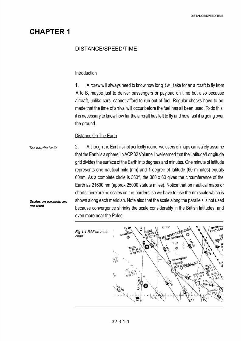
2. Although the Earth is not perfectly round, we users of maps can safely assume
that the Earth is a sphere. In ACP 32 Volume 1 we learned that the Latitude/Longitude
grid divides the surface of the Earth into degrees and minutes. One minute of latitude
represents one nautical mile (nm) and 1 degree of latitude (60 minutes) equals
60nm. As a complete circle is 360°, the 360 x 60 gives the circumference of the
Earth as 21600 nm (approx 25000 statute miles). Notice that on nautical maps or
charts there are no scales on the borders, so we have to use the nm scale which is
shown along each meridian. Note also that the scale along the parallels is not used
because convergence shrinks the scale considerably in the British latitudes, and
even more near the Poles.
The nautical mile
Scales on parallels are
not used
Fig 1-1 RAF en-route
chart
8/8/2019 Navigation Book
http://slidepdf.com/reader/full/navigation-book 6/44
3. In the example above, measure the distance between Shawbury and
Birmingham, using the nm scale printed on the 02°
West Meridian. This can bedone with a ruler, a pair of dividers, or if you do not have any equipment, using the
marks on the edge of any piece of paper.
Change Of Latitude
4. If two places are on the same meridian then it is possible to calculate the
distance between them rather than having to measure it; this is much simpler if
several map sheets are involved. For example Torrejon airfield (near Madrid in
Spain) is due south of RAF St Athan. The two latitudes are N40°29’ and N51°24’.Subtracting one latitude figure from the other gives a change of latitude of 10°55’.
Multiply 10° by 60 and add the 55’ to find that Torrejon and St Athan are 655nm
apart. However, very few air journeys are made along meridians so to find out how
far apart other airfields are, we either have to measure the distance on a suitable
small-scale chart or allow our navigational computer to do the calculation for us
using spherical trigonometry.
Aircraft Speed
5. We measure the speed of land-based vehicles (eg cars, bicycles) in miles
per hour (mph). In aviation, as we use nm to measure distances, it follows that
speed is measured in nm per hour (known as knots from the days of the sailing
ships). The other difference from land-based vehicles is that as aircraft are not on
the ground, the speed of rotation of the wheels cannot be used to drive a
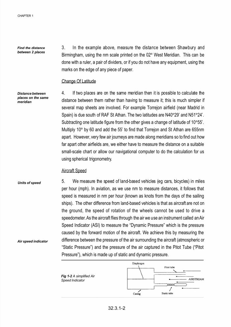
speedometer. As the aircraft flies through the air we use an instrument called an Air
Speed Indicator (ASI) to measure the “Dynamic Pressure” which is the pressure
caused by the forward motion of the aircraft. We achieve this by measuring the
difference between the pressure of the air surrounding the aircraft (atmospheric or
“Static Pressure”) and the pressure of the air captured in the Pitot Tube (“Pitot
Pressure”), which is made up of static and dynamic pressure.
32.3.1-2
CHAPTER 1
Find the distancebetween 2 places
Distance between
places on the same
meridian
Units of speed
Air speed indicator
Fig 1-2 A simplified Air
Speed Indicator

8/8/2019 Navigation Book
http://slidepdf.com/reader/full/navigation-book 7/44
32.3.1-3
DISTANCE/SPEED/TIME
A simplified ASI is shown in the diagram. In forward flight the pressure above the
diaphragm will consist of dynamic and static pressure whilst the pressure below ispurely static pressure. The two static pressures cancel out and the diaphragm will
move due to the dynamic pressure, this movement is amplified and displayed on
the instrument as Indicated Air Speed (IAS), reading in knots.
Corrections
6. The reading on the ASI can be in error because of two errors, namely Pressure
Error and Instrument Pressure. Pressure Error previously known as position error
is caused by sensing incorrect values for Pitot and Static pressure due to their position relative to the airflow around the aircraft. Instrument error is caused by
poor manufacturing tolerances when the instrument was built. Both errors can be
measured by testing the aircraft under controlled conditions and a calibration card
with the combined errors is displayed in the cockpit next to the instrument. Once
the two errors have been accounted for, we are left with Calibrated Air Speed (CAS).
IAS + Pressure Error + Instrument Error = CAS
Thus, an IAS of 118 kts with a correction on the calibration card of +2 kts would give
a CAS of 120kts.
7. A pilot flies using Calibrated Air Speed because it represents the force of the
airflow around the aircraft. The higher an aircraft flies, the less dense the air becomes
and the faster the aircraft has to fly through the air to achieve the same force and
therefore the same CAS. A navigator however, needs to know the actual speed that
the aircraft is flying through the air so that he can compare it with his speed over the
ground and hence estimate the wind.
8. Therefore to obtain True Air Speed (TAS) from CAS you need to correct for
air density changes caused by changes in temperature and altitude. This can be
done either calculation or by a navigation computer. In additrion of you are flying at
speeds greater than 300 kts then you need to apply a correction for compressibility
error which is caused by air becoming compressed in the Pitot Tube.
CAS + Density Error + Compressibility Error = TAS
8/8/2019 Navigation Book
http://slidepdf.com/reader/full/navigation-book 8/44
Units of Time
9. Time is probably the only example of a scientific measurement where every
nation uses the same units. Everyone is familiar with days, hours and minutes; it is
only necessary to ensure that you use hours when working with knots as this speed
is actually nautical miles per hour. In military and commercial aviation the 24 hour
clock is used, set to Greenwich Mean Time (GMT) or Universal Time (UT) as it is
now known. In other words, Summer time or Daylight Saving Time is always ignored.
Calculation of Time of Flight (Still Air)
10. If a car travels 120 miles at 60 mph, it will take 2 hours to complete the
journey. This is found by the DST formula:
TIME (T) = = = 2
SPEED = DISTANCE = SPEED X TIME
11. This same Formula can be used for an aircraft flying in still air. For example,
a Nimrod flying at a TAS of 400 kts over an 1800 nm sector will take 41/2 hours in still
air.
SPEED =
12. The formula can also be re-arranged to find distance or speed if the other
two quantities are known; thus:
13. This example is done for you. How fast must we go to cover 1500nm in 5
hours?
DISTANCE (D)
SPEED (S)
120
60
DISTANCE
TIME
DISTANCE
TIME
The DST formula
32.3.1-4
CHAPTER 1
Which time do we use?

8/8/2019 Navigation Book
http://slidepdf.com/reader/full/navigation-book 9/44
1500
5
Using:
s = = 300 kts
Manipulation of equations
Simple equations can be easily manipulated using cross multiplication. That is,
numbers on one side of an equation can cross the equals sign to the other side
provided that, if the number is below the line (division) when it changes side, it
comes above the line (Multiply) and visa-versa. For example:
DISTANCE = SPEED x TIME = SPEED
DISTANCE = SPEED x TIME = TIME
32.3.1-5
DISTANCE/SPEED/TIME
DISTANCE
TIME
DISTANCE SPEED

8/8/2019 Navigation Book
http://slidepdf.com/reader/full/navigation-book 10/44
32.3.1-6
CHAPTER 1
Do not mark the paper in
any way - write your
answers on a separate
piece of paper.
Self Assessment Questions
1. One degree of latitude represents:
a. 1 nm
b. 6 nm
c. 60 nm
d. 360 nm
2. Glasgow is due north of Plymouth (approximately on the same meridian). If Glasgow is latitude 55°50’ and Plymouth is latitude 50°25’ what distance are the
two places apart?
a. 525 nm
b. 275 nm
c. 450 nm
d. 325 nm
3. In the RAF, aircraft speeds are generally expressed in:
a. metres per second
b. miles per hour
c. nautical miles per second
d. knots
4. An ASI has an instrument correction factor of +3 kts and a pressure correction
factor of -1 kts. If the instrument reads 130 kts what is the RAS?
a. 130 kts
b. 132 kts
c. 133 kts
d. 134 kts
5. A Tornado is flying at a TAS of 400 kts. How far will it travel in 2 hrs?
a. 200 nm
b. 200 km
c. 800 nm
d. 800 km
8/8/2019 Navigation Book
http://slidepdf.com/reader/full/navigation-book 11/44
32.3.2-1
TRIANGLE OF VELOCITIES
CHAPTER 2
Representing vectors
Vectors can be added
together
THE TRIANGLE OF VELOCITIES
Introduction
1. So far, we have talked about flying in still air conditions. It is now necessary
to consider the wind, which is simply air that is moving.
Vectors and Velocity
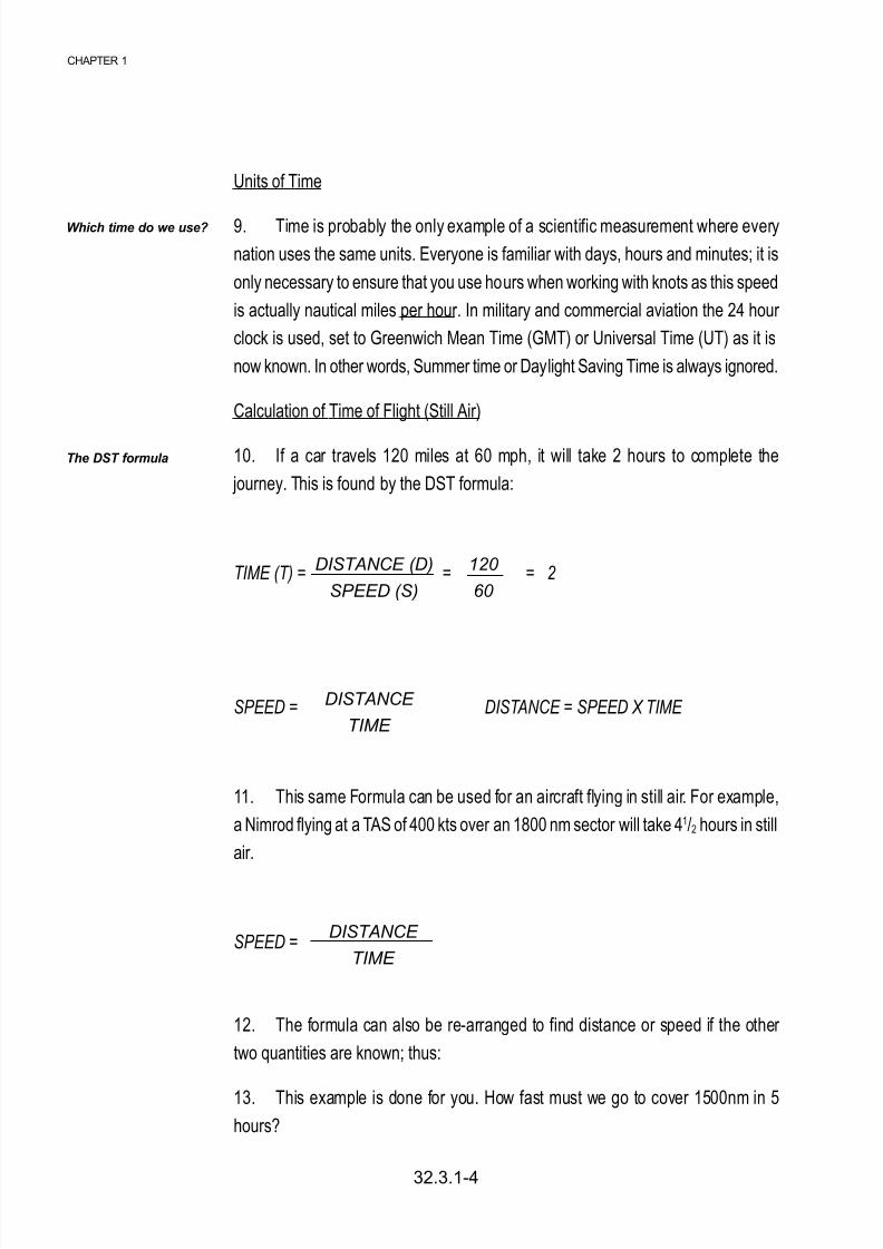
2. Whenever we talk about aircraft or wind movement, we must always give
both the direction and speed of the movement. Direction and speed together are
called a velocity. A velocity can be represented on a piece of paper by a line called
a vector. The bearing of the line (usually relative to true north) represents the direction
of the movement, and the length of the line represents the speed.
The Vector Triangle
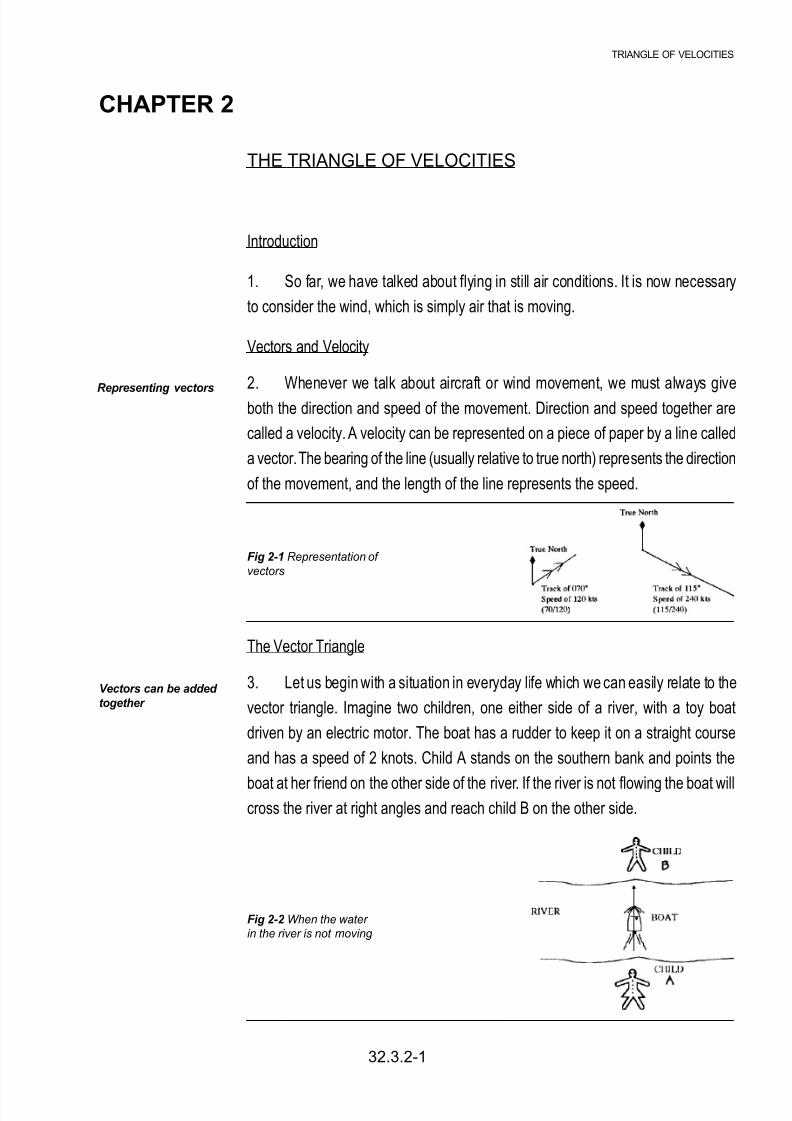
3. Let us begin with a situation in everyday life which we can easily relate to the
vector triangle. Imagine two children, one either side of a river, with a toy boat
driven by an electric motor. The boat has a rudder to keep it on a straight course
and has a speed of 2 knots. Child A stands on the southern bank and points the
boat at her friend on the other side of the river. If the river is not flowing the boat willcross the river at right angles and reach child B on the other side.
Fig 2-1 Representation of
vectors
Fig 2-2 When the water in the river is not moving
8/8/2019 Navigation Book
http://slidepdf.com/reader/full/navigation-book 12/44
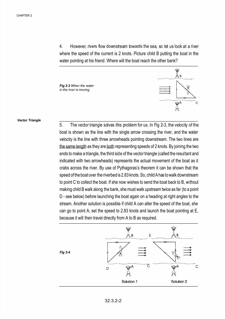
4. However, rivers flow downstream towards the sea, so let us look at a river
where the speed of the current is 2 knots. Picture child B putting the boat in thewater pointing at his friend. Where will the boat reach the other bank?
5. The vector triangle solves this problem for us. In Fig 2-3, the velocity of the
boat is shown as the line with the single arrow crossing the river, and the water
velocity is the line with three arrowheads pointing downstream. The two lines are
the same length as they are both representing speeds of 2 knots. By joining the two
ends to make a triangle, the third side of the vector triangle (called the resultant and
indicated with two arrowheads) represents the actual movement of the boat as it
crabs across the river. By use of Pythagoras’s theorem it can be shown that thespeed of the boat over the riverbed is 2.83 knots. So, child A has to walk downstream
to point C to collect the boat. If she now wishes to send the boat back to B, without
making child B walk along the bank, she must walk upstream twice as far (to a point
D - see below) before launching the boat again on a heading at right angles to the
stream. Another solution is possible if child A can alter the speed of the boat, she
can go to point A, set the speed to 2.83 knots and launch the boat pointing at E,
because it will then travel directly from A to B as required.
Fig 2-3 When the water in the river is moving
Vector Triangle
Fig 2-4
32.3.2-2
CHAPTER 2

8/8/2019 Navigation Book
http://slidepdf.com/reader/full/navigation-book 13/44
The Air Triangle
6. Exactly the same triangle can be used to show the motion of an aircraft through
the air which itself is moving. There are two differences. The first is that we label the
triangle with new names (eg wind instead of current).
The second is that as the aircraft speed is normally a lot more than the wind speed,
the triangle will be much longer and thinner than the squat triangle which represents
the movement of the toy boat. There are 6 components of the air triangle, and they
are described in the next 3 paragraphs.
Heading and TAS
7. The heading of the aircraft is the direction that the aircraft is pointing (ie what
is on the compass). The TAS is the speed of the aircraft through the air, taking into
account all the corrections mentioned in Chapter 1. This vector, shown by a line of
scale length, carries one arrow. Remember, the vector represents 2 components,
HDG and TAS.
Wind Velocity
8. This is a scale line with three arrows; it represents 2 more components, the
wind strength and the direction FROM which it is blowing (northerly in the diagram).
Track and Groundspeed
9. The remaining 2 components in the air triangle are the direction and speed
that the aircraft is actually moving over the ground. This vector has two arrows, and
it is the resultant of the other two vectors. note that the number of arrows put on
each vector is simply a convention that is used, to avoid confusing one with another.
Fig 2-5 Air triangle of
velocities
The air triangle of velocities
Some definitions
32.3.2-3
TRIANGLE OF VELOCITIES

8/8/2019 Navigation Book
http://slidepdf.com/reader/full/navigation-book 14/44
Drift
10. Drift is the angle between the heading and track vectors and represents the
angle at which the aircraft is being blown sideways. It is labelled Port or Starboard,
depending on which way the aircraft is blown. Of course, if you fly directly into wind
or directly downwind, heading will be the same as track and there will be no drift.
The TAS and GS will in this case differ by exactly the value of the wind speed.
The Real World
11. All this theory is very well but what happens in the real world? There are
three possible occasions when we have to solve the vector triangle. One is at the
planning stage of a flight, when we know where we want to go, in which case we
know what the track and distance is to the destination. We also know the performance
of the aircraft (TAS) and the Met Office can forecast the W/V for us. Given 4 of the
6 elements in the triangle (TAS, TK, W/V) it is now possible to solve for the other
two quantities (GS & HDG) and then use the DST formula to calculate how long the
flight will take. The second occasion on which we solve the triangle is in the air
when we know the TAS and HDG, and we can measure our TK and GS by watchingour changing position over the ground. From these 4 items, the W/V can be
calculated. Finally, when you know your heading and TAS and have a reliable W/V
but are over a featureless area such as the sea and are unable to take any form of
fix, then by applying the W/V to your Heading and TAS you can calculate your Track
and Groundspeed. Once you have your G/S and TK you can produce a deduced
reckoning position (DR position) by applying the time from your last known position
to the G/S to give you a distance along the TK.
Computers
12. So far we have only talked about drawing vectors on paper. This is fine in the
office or classroom but impossible in the cramped confines of a small aircraft. For
many years, navigators have been using the Dalton hand held computer and these
are still used in the private flying world. The fast jet navigator in the RAF solves the
triangle using a simplified mental calculation which is beyond the scope of this
course. In civil airliners an onboard electronic computer continually solves the triangle
and many other things besides.
32.3.2-4
CHAPTER 2

8/8/2019 Navigation Book
http://slidepdf.com/reader/full/navigation-book 15/44
32.3.2-5
TRIANGLE OF VELOCITIES
Magic Number
13. All aviators, no matter how much help they have from electronics, have to do
a lot of mental arithmetic. This can be made much easier if magic numbers are
used. The number in question is the ground speed in nautical miles per minutes;
some examples are shown in the table below. It does not matter if you are flying in
a Bulldog or a Tornado, the method works equally well.
GS nm/min GS nm/min
60 1 210 31/2
80 11/3 240 4
90 11/2 300 5
100 12/3 360 6
120 2 420 7
150 21/2 480 8
180 3 540 9
Examples
14. Your are in a Tornado at low level over Wales, doing 420 knots GS and you
have 49 miles to run to the next turning point. Divide 49 by 7 and the answer is 7
minutes to go.
15. You are on a cross country exercise in a Bulldog, heading into wind at 80
knots GS. How long will a 20 mile leg take? To divide 20 by 11/3, is the same as
dividing by 4/3 or multiplying by 3/4. However, there is a much easier method in thisexample. As the distance is 1/4 of the speed, it must take one quarter of an hour.
Magic numbers
Fig 2-6 The RAF’s Dalton computer
8/8/2019 Navigation Book
http://slidepdf.com/reader/full/navigation-book 16/44
Six Minute Magic
16. With the slower speeds it is often easier to think in terms of how far do we go
in 6 minutes (1 tenth of an hour). This simply is the ground speed with the last zero
removed. So the Bulldog above doing 80 knots, will travel 8 miles in 6 minutes. For
short legs this is a much more useful calculation.
Time Of Arrival
17. A by-product of solving the triangle is that by making the DST calculation
using GS and Distance To Go, we can calculate the time that it will take to reachthe next turning point or the destination. This time is called Estimated Time of
Arrival (ETA) and is important both for fuel calculations and for Air Traffic Control
purposes. A particular application of this is the ETA for the destination. If you do not
arrive on time, Air Traffic will have to take overdue action; very similar to the way a
search party goes out to find a group of walkers who have not returned from a
mountain trek.
Conclusion
18. Hopefully this chapter will have convinced you that despite all the computers,
some mental arithmetic is essential, whether you plan to join the RAF as aircrew,
become an airline pilot, obtain a PPL, or simply make the most of the available air
experience and passenger flying opportunities. The starting point is the 6 times
table; no one in their right mind would dream of aviating without this knowledge.
32.3.2-6
CHAPTER 2
Six minute magic
ETA

8/8/2019 Navigation Book
http://slidepdf.com/reader/full/navigation-book 17/44
TRIANGLE OF VELOCITIES
Do not mark the paper in
any way - write your
answers on a separate
piece of paper.
Self Assessment Questions
1. What do the initials TAS stand for?
a. True Air Speed
b. Track Air Space
c. Track Aviation Speed
d. True Air Space
2. The 4 vectors shown represent the movement of 4 aircraft. Which aircraft istravelling due south?
a. W
b. X
c. Y
d. Z
3. In the diagram above which aircraft is travelling the fastest?
a. W
b. X
c. Y
d. Z
4. In an Air Triangle vector diagram the 3 vectors are:
a. Heading and TAS - Drift angle - Wind speed and direction
b. Track and ground speed - Wind speed and direction - Drift velocity
c. Wind speed and direction - Track and ground speed - Heading and TAS
d. Wind speed and direction - TAS and heading - Drift speed and direction
5. A Bulldog when travelling at a GS of 90 kts will cover 11/2 nm in one minute. How
long will it take to cover 30 nm?
a. 20 mins
b. 30 mins
c. 45 mins
d. 60 mins
32.3.2-7

8/8/2019 Navigation Book
http://slidepdf.com/reader/full/navigation-book 18/44
32.3.3-1
CHAPTER 3
CHAPTER 3
THE 1 IN 60 RULE
Introduction
1. In modern aircraft it is often necessary to do quick mental calculations to
check that the navigational computer is still making sense and that we have not
fallen into the “garbage in, garbage out” trap. The previous chapter looked at progress
along track (DST and ETA); we now need to consider our position across track.
First though, a couple of definitions.
Track Required
2. The track required is normally the line drawn on the map between the
departure airfield and the destination, or from one turning point to another on the
route.
Track Made Good
3. If for some reason the aircraft drifts off track and we can establish our position
overhead some unique feature (a pinpoint), then the line joining the departure airfield
and the pinpoint is known as Track Made Good (TMG).
Revised Track
4. From a pinpoint which is off the track required we have 2 options. One would
be to regain the required track, but more normally we would draw a line from the
pinpoint to the next turning point. This is called the revised track.
1 In 60 Rule
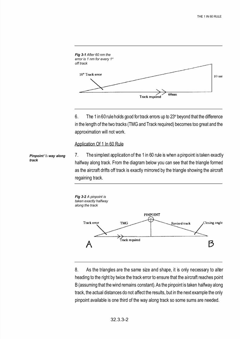
5. The 1 in 60 rule states that if an aircraft flies a TMG 1° in error from the
required track, then after 60 miles of flying the aircraft will be one mile off the required
track. This can be proved with trigonometry but all you need to know is how to use
the triangle. The example in the diagram shows that with a 10° track error, after 60
nm the aircraft would be 10nm off track.
The 1 in 60 rule
Some definitions
8/8/2019 Navigation Book
http://slidepdf.com/reader/full/navigation-book 19/44
THE 1 IN 60 RULE
32.3.3-2
6. The 1 in 60 rule holds good for track errors up to 23°
beyond that the differencein the length of the two tracks (TMG and Track required) becomes too great and the
approximation will not work.
Application Of 1 In 60 Rule
7. The simplest application of the 1 in 60 rule is when a pinpoint is taken exactly
halfway along track. From the diagram below you can see that the triangle formed
as the aircraft drifts off track is exactly mirrored by the triangle showing the aircraft
regaining track.
8. As the triangles are the same size and shape, it is only necessary to alter
heading to the right by twice the track error to ensure that the aircraft reaches point
B (assuming that the wind remains constant). As the pinpoint is taken halfway along
track, the actual distances do not affect the results, but in the next example the only
pinpoint available is one third of the way along track so some sums are needed.
Fig 3-1 After 60 nm the
error is 1 nm for every 1°
off track
Fig 3-2 A pinpoint is
taken exactly halfway along the track
Pinpoint 1 / 2 way along
track

8/8/2019 Navigation Book
http://slidepdf.com/reader/full/navigation-book 20/44
8/8/2019 Navigation Book
http://slidepdf.com/reader/full/navigation-book 21/44
THE 1 IN 60 RULE
32.3.3-4
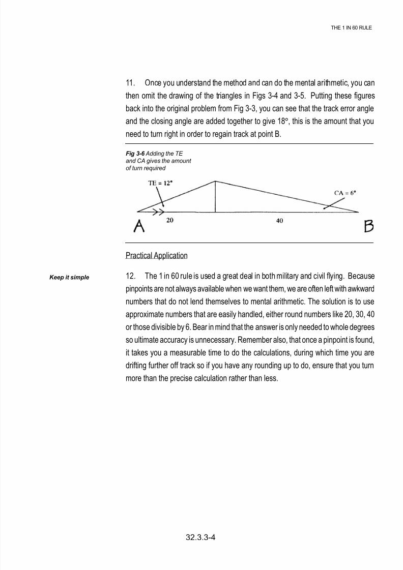
11. Once you understand the method and can do the mental arithmetic, you can
then omit the drawing of the triangles in Figs 3-4 and 3-5. Putting these figuresback into the original problem from Fig 3-3, you can see that the track error angle
and the closing angle are added together to give 18°, this is the amount that you
need to turn right in order to regain track at point B.
Practical Application
12. The 1 in 60 rule is used a great deal in both military and civil flying. Because
pinpoints are not always available when we want them, we are often left with awkward
numbers that do not lend themselves to mental arithmetic. The solution is to use
approximate numbers that are easily handled, either round numbers like 20, 30, 40
or those divisible by 6. Bear in mind that the answer is only needed to whole degrees
so ultimate accuracy is unnecessary. Remember also, that once a pinpoint is found,
it takes you a measurable time to do the calculations, during which time you are
drifting further off track so if you have any rounding up to do, ensure that you turn
more than the precise calculation rather than less.
Keep it simple
Fig 3-6 Adding the TE
and CA gives the amount
of turn required

8/8/2019 Navigation Book
http://slidepdf.com/reader/full/navigation-book 22/44

8/8/2019 Navigation Book
http://slidepdf.com/reader/full/navigation-book 23/44
COMPASSES
32.3.4-1
CHAPTER 4
COMPASSES
Introduction
1. Earlier in your Navigation training, you will have learned about the difference
between True North and Magnetic North and how to use a simple hand held compass
such as the Silva. To understand aircraft compasses, their strengths and weaknesses
we need to look into the subject a little deeper. The first thing you need to understand
is the shape of the magnetic field around a magnet. An experiment at school with
a magnet and iron filings, will produce a pattern similar to that shown in Fig 4-1
below.
I have included a circle round the magnet in Fig 4-1 to signify the Earth and you will
note that the lines of force are only parallel to the surface of the Earth at the Equator.
Indeed, at the poles the lines of force are vertical! A compass needle will try to
follow the lines of force but is restrained by the construction of the compass and is
forced to stay horizontal. The end result of this is that the directional force that
makes the compass needle point North gets weaker the closer you get to the Earth’s
Magnetic Poles. At our latitude, the lines of force point down at an angle (known as
the angle of Dip) of 65°; once the angle exceeds 75° (which occurs about 1200
miles from the Poles) the driving force becomes so weak as to render magnetic
compasses virtually useless.
Fig 4-1 Magnetic Lines of force round a bar magnet

8/8/2019 Navigation Book
http://slidepdf.com/reader/full/navigation-book 24/44
32.3.4-2
CHAPTER 4
2. In an aircraft, the simplest form of compass is the direct indicating compass,
which looks very similar to the car compass, which can be bought from accessory
shops.
The Direct Indicating Compass
3. The Direct Indicating Compass (DIC), like the hand held Silva compass, has
a magnet suspended in a thick liquid, which helps to dampen the movements.
However, it looks very different, having the appearance of a squash ball inside a
very small goldfish bowl. The points of the compass are printed around the equator
of the ball and the heading is shown against the index mark on the bowl. The
magnet is hidden inside the ball.
Limitations of the DIC
4. The DIC has several serious limitations, so in most aircraft it is only used asa standby. These limitations are:
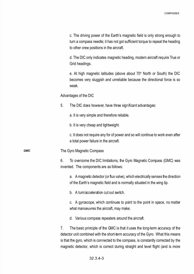
a. The suspended magnet will only give a correct reading in straight and
level un-accelerated flight. During turns and accelerations the magnet is
swung to one side and thus gives false readings.
b. The DIC is located in the cockpit, and there it is affected by the magnetic
fields emanating from the metal the aircraft is made from and from the various
electrical circuits in the aircraft. These other magnetic fields badly affect the
accuracy of the DIC.
Fig 4-2 The direct indicating compass (DIC)
in a Viking
DIC
Limitations and advantages
8/8/2019 Navigation Book
http://slidepdf.com/reader/full/navigation-book 25/44
8/8/2019 Navigation Book
http://slidepdf.com/reader/full/navigation-book 26/44
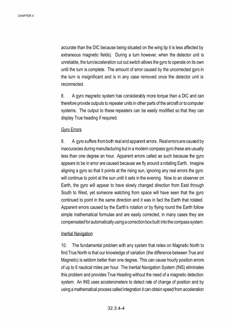
accurate than the DIC because being situated on the wing tip it is less affected by
extraneous magnetic fields). During a turn however, when the detector unit isunreliable, the turn/acceleration cut out switch allows the gyro to operate on its own
until the turn is complete. The amount of error caused by the uncorrected gyro in
the turn is insignificant and is in any case removed once the detector unit is
reconnected.
8. A gyro magnetic system has considerably more torque than a DIC and can
therefore provide outputs to repeater units in other parts of the aircraft or to computer
systems. The output to these repeaters can be easily modified so that they can
display True heading if required.
Gyro Errors
9. A gyro suffers from both real and apparent errors. Real errors are caused by
inaccuracies during manufacturing but in a modern compass gyro these are usually
less than one degree an hour. Apparent errors called as such because the gyro
appears to be in error are caused because we fly around a rotating Earth. Imagine
aligning a gyro so that it points at the rising sun, ignoring any real errors the gyrowill continue to point at the sun until it sets in the evening. Now to an observer on
Earth, the gyro will appear to have slowly changed direction from East through
South to West, yet someone watching from space will have seen that the gyro
continued to point in the same direction and it was in fact the Earth that rotated.
Apparent errors caused by the Earth’s rotation or by flying round the Earth follow
simple mathematical formulae and are easily corrected, in many cases they are
compensated for automatically using a correction box built into the compass system.
Inertial Navigation
10. The fundamental problem with any system that relies on Magnetic North to
find True North is that our knowledge of variation (the difference between True and
Magnetic) is seldom better than one degree. This can cause hourly position errors
of up to 6 nautical miles per hour. The Inertial Navigation System (INS) eliminates
this problem and provides True Heading without the need of a magnetic detection
system. An INS uses accelerometers to detect rate of change of position and by
using a mathematical process called integration it can obtain speed from acceleration
32.3.4-4
CHAPTER 4
8/8/2019 Navigation Book
http://slidepdf.com/reader/full/navigation-book 27/44
and distance from speed. Therefore providing you accurately know your start point
you can ascertain your position at any moment in time. It is essential that theplatform to which the accelerometers are attached is accurately aligned and
absolutely level to achieve this high quality gyros are employed. When an INS is
set up prior to flight, it automatically aligns the platform to True North by detecting
the Earth’s rotation; the platform will then provide an output of True Heading. An
accurate INS will provide positional information to an accuracy of less than one
nautical mile per hour.
The Future
11. Older Inertial navigation Systems used mechanical accelerometers, Gyros
and integrators and a complicated system of gimbals to keep the platform level and
aligned. These systems though accurate were prone to break down and took an
enormous amount of time to service. Modern advances have cured most of this
and a modern INS uses solid-state integrators and accelerometers, and Ring Laser
Gyros. Even the platform can be dispensed with now and instead a fast modern
digital computer carries all the details of the aircraft’s direction and attitude. These
changes do not have a dramatic effect on the accuracy of the system; however,
they greatly enhance the reliability and reduce the servicing overheads. Combining
the INS with a modern satellite navigation system will provide a very powerful and
accurate navigation/attack system, which can be used world-wide and which is
very resistant to jamming.
COMPASSES
32.3.4-5

8/8/2019 Navigation Book
http://slidepdf.com/reader/full/navigation-book 28/44
Self Assessment Questions
1. The initials DIC stand for:
a. Dual Identification Compass.
b. Direct Identification Compass.
c. Direct Indicating Compass.
d. Dual Indicating Compass.
2. Having a simple magnetic compass in the cockpit of an aircraft has both
advantages and disadvantages. One such advantage may be:
a. Reads only magnetic headings.
b. Simple in operation but reliable.
c. May be affected by other instruments close by.
d. Swings about during aircraft manoeuvres.
3. The flux valve of a GMC is situated:
a. In the wing tip.
b. In the cockpit.
c. Inside the compass housing.
d. On the outside of the fuselage.
4. An Inertial Navigation System (INS) works by:
a. Frequent checks on position from satellites.
b. Using computers to keep a record of the aircraft’s movement from a known
starting point.
c. Using computers to continually work out the error in the magnetic readings
and compensate accordingly.
d. Frequent checks on position using ground based radar stations.
Do not mark the paper in
any way - write your answers on a separate
piece of paper.
32.3.4-6
CHAPTER 4
8/8/2019 Navigation Book
http://slidepdf.com/reader/full/navigation-book 29/44
WEATHER
32.3.5-1
CHAPTER 5
VMC and IMC
Conditions affecting
flying
WEATHER
Introduction
1. You will have previously studied the weather as it relates to walking in the
hills. It is the same weather that affects aircraft operations but with one major
difference; icing is a far more serious problem for an aircraft than it is for a walker.
Meteorological Conditions
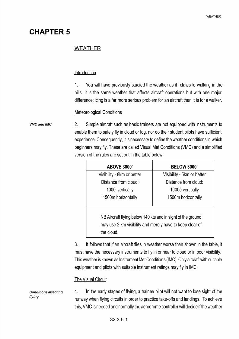
2. Simple aircraft such as basic trainers are not equipped with instruments to
enable them to safely fly in cloud or fog, nor do their student pilots have sufficient
experience. Consequently, it is necessary to define the weather conditions in which
beginners may fly. These are called Visual Met Conditions (VMC) and a simplified
version of the rules are set out in the table below.
ABOVE 3000’ BELOW 3000’
Visibility - 8km or better Visibility - 5km or better
Distance from cloud: Distance from cloud:
1000’ vertically 1000é vertically
1500m horizontally 1500m horizontally
NB Aircraft flying below 140 kts and in sight of the ground
may use 2 km visibility and merely have to keep clear of
the cloud.
3. It follows that if an aircraft flies in weather worse than shown in the table, it
must have the necessary instruments to fly in or near to cloud or in poor visibility.
This weather is known as Instrument Met Conditions (IMC). Only aircraft with suitable
equipment and pilots with suitable instrument ratings may fly in IMC.
The Visual Circuit
4. In the early stages of flying, a trainee pilot will not want to lose sight of the
runway when flying circuits in order to practice take-offs and landings. To achieve
this, VMC is needed and normally the aerodrome controller will decide if the weather
8/8/2019 Navigation Book
http://slidepdf.com/reader/full/navigation-book 30/44
is good enough. If the circuit height is 1000’ then the lowest cloudbase will need to
be above this (usually 1500’) and the visibility will need to be good enough to beable to see the runway from anywhere in the circuit (usually 5 km).
Surface Wind
5. In earlier chapters on navigation you will have learned how we deal with wind
and drift when transitting from A to B. At the aerodrome we still have to take account
of drift but the surface wind is of greater concern. If the conditions are not completely
calm, we need to take note of the wind direction and arrange to take-off and land as
closely as possible, directly into wind. This is because the airspeed of the aircraftdetermines when it can safely lift off the runway. In strong winds this can make a
big difference to the time and distance it takes to get airborne. Into a strong wind an
aircraft reaches flying speed very quickly and can therefore use a shorter runway. If
we make the mistake of trying to take-off downwind we could well reach the end of
the runway before reaching flying speed and this could be disastrous.
Wind Component
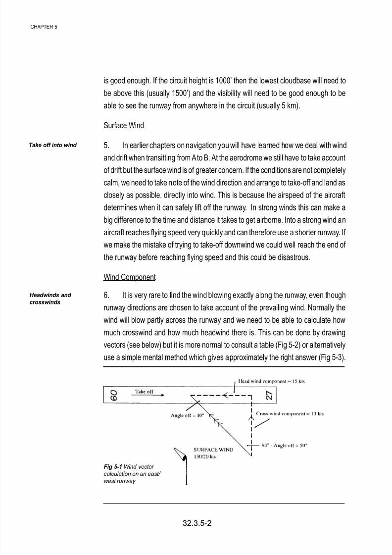
6. It is very rare to find the wind blowing exactly along the runway, even though
runway directions are chosen to take account of the prevailing wind. Normally the
wind will blow partly across the runway and we need to be able to calculate how
much crosswind and how much headwind there is. This can be done by drawing
vectors (see below) but it is more normal to consult a table (Fig 5-2) or alternatively
use a simple mental method which gives approximately the right answer (Fig 5-3).
Take off into wind
Headwinds and
crosswinds
Fig 5-1 Wind vector
calculation on an east/
west runway
32.3.5-2
CHAPTER 5

8/8/2019 Navigation Book
http://slidepdf.com/reader/full/navigation-book 31/44
How to use the table
From Fig 5-1 the angle between the runway heading and the wind direction = 40°
(angle off). To obtain the crosswind component use the top row of angles and find
the 40° colum - follow it down until you meet the correct windspeed row, in this case
20 kts. This gives the cross wind component as 13 kts. For the headwind use the
angles at the bottom of the table.
Fig 5-2 Table showing headwind and crosswind components
Fig 5-3 The quick approximate method
WEATHER
32.3.5-3

8/8/2019 Navigation Book
http://slidepdf.com/reader/full/navigation-book 32/44

8/8/2019 Navigation Book
http://slidepdf.com/reader/full/navigation-book 33/44

8/8/2019 Navigation Book
http://slidepdf.com/reader/full/navigation-book 34/44
Do not mark the paper in
any way - write your
answers on a separate
piece of paper.
Self Assessment Questions
1. What do the initials VMC stand for?
a. Visual Meteorological Conditions
b. Verbal Meteorological Conditions
c. Visual Metric Conditions
d. Verbal Metric Conditions
2. An aircraft should always take off into wind to:
a. Increase the length of take off run
b. Decrease the length of take off run
c. Increase ground speed at take off
d. Reduce air speed at take off
3. While attempting to land on runway 09 (heading of 90°) a pilot is informed of a
surface wind blowing at 25 kts on a heading of 140°. Using the table in Fig 5-2 find
the strength of the cross wind.
a. 16 kts
b. 19 kts
c. 22 kts
d. 23 kts
4. Why is icing such a problem for aircraft?
a. De-icing is expensive and time consuming
b. The aerofoil shape of wings is spoiled - decreasing lift
c. The aircraft has to fly slower due to poor visibility
d. More power is required to keep the inside of the aircraft warm
4. Rain, sleet, snow and hail are collectively known as:
a. Participation
b. IMC
c. Precipitation
d. VMC
32.3.5-6
CHAPTER 5

8/8/2019 Navigation Book
http://slidepdf.com/reader/full/navigation-book 35/44
8/8/2019 Navigation Book
http://slidepdf.com/reader/full/navigation-book 36/44
Aircraft speed is normally measured in the maritime tradition using the knot, although at speeds
approaching, or beyond, the speed of sound another important units needs to be added. This unit
is the “Mach” number.
9. The mach number relates the aircraft’s speed to the local speed of sound. It may be more
precisely defined as the ratio of the speed of the aircraft through the air, to the speed of sound in
the aircraft’s vicinity.
This is shown in the following formula:
Mach Number = True Air Speed
Speed of Sound
10. Simply, if an aircraft is flying at half the speed of sound, then it will have a mach number of
0.5.
11. The speed of sound varies according to the temperature surrounding the aircraft. At high
level, where temperature is low, the speed of sound is less than at sea level, so that the mach
meter is designed to take care of two variables - the variation of aircraft speed, and the variation of
the speed of sound.
1° = 60 nm
therefore
10° x 60 = 600 nm
1’ = 1 nm
so 55’ = 55 nm
TOTAL = 655 nm
AERONAUTICAL CHARTS
A map, or chart, is primarily intended to portray sections of the Earth’s surface on a flat sheet of
paper. The manner in which meridians and parallels are drawn, and the information overprinted on
the surface depends on the purpose of the map. An atlas for example may need to portray largeareas with the locality of certain features clearly indicated. Its purpose is usually to give geographical
information, and to do this, the cartographer may show parallels and meridians as straight parallel
lines which lie at right angles to one another, or, he may show meridians as converging straight
lines and parallels as arcs of concentric circles centred on the nearer pole. If the atlas fails to
accurately represent angles correctly over the whole area, then, quite apart from the small scale
being used, it would not form a suitable projection of the Earth’s surface to be useful for navigational
purposes. The requirements of navigational charts vary however according to their particular
application.
It is important now to distinguish clearly between the words “projection”, “chart”, and “map”, since
these words are frequently used in this chapter and elsewhere.
A projection is an arrangement on a flat sheet of paper, of a graticule of meridians and parallelswhich are assumed to be on the Earth’s surface. All maps and charts are therefore projections of
one sort or another.
32.3.1b NOTES
CHAPTER 1
CHAPTER 1

8/8/2019 Navigation Book
http://slidepdf.com/reader/full/navigation-book 37/44
A chart is a projection which carries very little topographical detail and which is mainly used for
navigational plotting.
A map is a projection over which are printed details of topography, culture and other geographical
information.
THE KNOT
The unit of measurement of a vessel’s speed, corresponding to one nautical mile per hour. The
knot originated from sailing ships who measured their speed by attaching a float to the end of a
rope which had knots tied every 7 fathoms (12.8m) along its length. The float was then lowered into
the water and the number of knots paid out in 30 seconds was the speed of the ship.
INSTRUCTOR’S GUIDE
32.3.1c NOTES
CHAPTER 1

8/8/2019 Navigation Book
http://slidepdf.com/reader/full/navigation-book 38/44
8/8/2019 Navigation Book
http://slidepdf.com/reader/full/navigation-book 39/44

8/8/2019 Navigation Book
http://slidepdf.com/reader/full/navigation-book 40/44
Answer: Track made good is 251(T), and ground speed 264 knots.
The navigation computer
In the previous chapters the graphical construction of the triangle of velocities was described in
order to solve some of the fundamental problems presented in air navigation. In practice however,
a navigator should avoid wherever possible carrying out time wasting calculations, and in order to
do this he is helped by a purpose-built mechanical aid known as a Navigation Computer. The
navigation computer is virtually standardized in design, and is used to solve more than simply the
triangle of velocities. On the reverse of the computer there is a circular slide rule capable of solving
general arithmetical problems, and in particular those which are directly concerned with the general
business of navigation. There are a variety of different navigation computers on the market, but
they all fall fundamentally into the same physical appearance with minor modifications or additions
to suit particular aircraft requirements.
Page 32.3.2-6 Para 18
32.3.2c NOTES
CHAPTER 2
CHAPTER 2

8/8/2019 Navigation Book
http://slidepdf.com/reader/full/navigation-book 41/44

8/8/2019 Navigation Book
http://slidepdf.com/reader/full/navigation-book 42/44

8/8/2019 Navigation Book
http://slidepdf.com/reader/full/navigation-book 43/44
ANSWER SHEET
Self Assessment Questions - Answer Sheet
Chapter 1 Page 32.3.1-6
1. c
2. d
3. d
4. b
5. c
Chapter 2 Page 32.3.2-7
1. a
2. c
3. b
4. c
5. a
Chapter 3 Page 32.3.3-5
1. c
2. c
3. b
4. c
32.3.4b ANSWER SHEET
8/8/2019 Navigation Book
http://slidepdf.com/reader/full/navigation-book 44/44
Self Assessment Questions - Answer Sheet cont....
Chapter 4 Page 32.3.4-6
1. c
2. b3. a
4. b
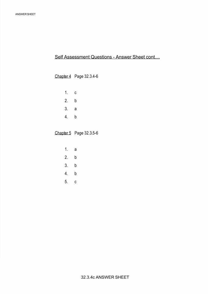
Chapter 5 Page 32.3.5-6
1. a
2. b
3. b
4. b
5. c
ANSWER SHEET