nbs standard frequency time services - … time intervals seconds pulses at precise intervals are...
TRANSCRIPT
M I SC ELLAN EO US PU B LI CAT1 0 N 236 1967 EDITION
NBS STANDARD FREQUENCY AND TIME SERVICES
Radio Stations WWV WWVH WWVB WWVL
U.S. DEPARTMENT OF COMMERCE National Bureau of Standards
NBS STANDARD FREQUENCY
TIME SERVICES AND
Radio Stations WWV WWVH WWVB WWVL
U.S. DEPARTMENT OF COMMERCE Alexander B. Trowbridge, Acting Secretary
NATIONAL BUREAU OF STANDARDS A. V. Astin, Director
MISCELLANEOUS PUBLICATION 236 - 1967 EDITION Issued 1967
For sale by the Superlntendent of Documents, US. Government Prlntlng Office Washington, D.C., 20402 -Price 15 Cents
Services Provided by NBS Standard Frequency Stations
Station
WWV WWVH WWVB WWVL
WWV, WWVH, WWVB, and WWVL
0)
(I) L FI .- $ n
192: 194t 196: 196:
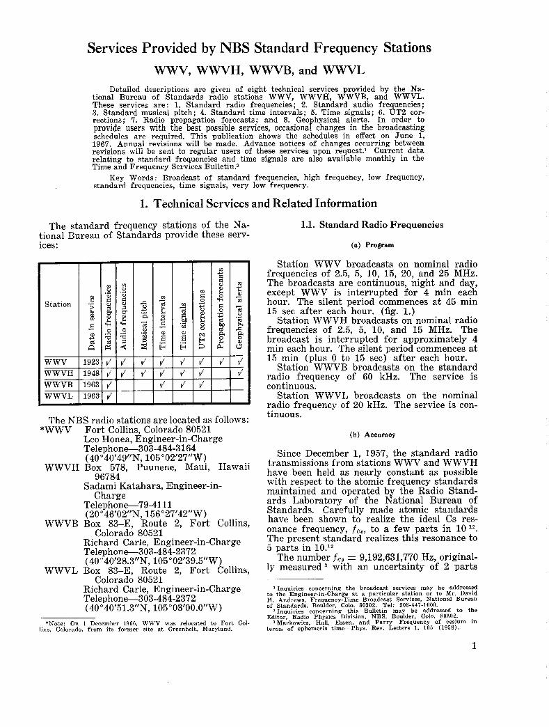
Detailed descriptions are given of eight technical services provided by the Na- tional Bureau of Standards radio stations WWV, WWVH, WWVB, and WWVL. These services are: 1. Standard radio frequencies; 2. Standard audio frequencies ; 3. Standard musical pitch; 4. Standard time intervals; 5. Time signals; 6. UT2 cor- rections; 7. Radio propagation forecasts; and 8. Geophysical alerts. In order to provide users with the best possible services, occasional changes in the broadcasting schedules are required. This publication shows the schedules in effect on June 1, 1967. Annual revisions will be made. Advance notices of changes occurring between revisions will be sent to regular users of these services upon request.1 Current data relating to standard frequencies and time signals are also available monthly in the Time and Frequency Services Bulletin.2
Key Words : Broadcast of standard frequencies, high frequency, low frequency, standard frequencies, time signals, very low frequency.
1. Technical Services and Related Information
The standard frequency stations of the Na- tional Bureau of Standards provide these serv- ices:
(I)
&~~ .* 4 .* Ld
a
E s 4 4
4
The NBS radio stations are located as follows: “WWV Fort Collins, Colorado 80521
Leo Honea, Engineer-in-Charge Telephone-303-484-3164 (40 “40’49”N, 105 “02’27”W)
WWVH Box 578, Puunene, Maui, Hawaii
Sadami Katahara, Engineer-in-
Telephone-79-41 11 (20 O 46’02”N, 156 ” 27’42” W)
WWVB Box 83-E, Route 2, Fort Collins, Colorado 80521
Richard Carle, Engineer-in-Charge Telephone-303-484-2372 ( 4Oo40’28.3”N, 105”02’39.5”W)
Richard Carle, Engineer-in-Charge Telephone-303-484-2372 (40 O 40’51.3”N, 105 003’00.0’’W)
96784
Charge
WWVL Box 83-E, Route 2, Fort Collins, Colorado 80521
‘Note: On 1 December 1966, WWV was relocated to Fort Col- lins, Colorado, from its former site at Greenbelt, Maryland.
1.1. Standard Radio Frequencies
(a) Program
Station WWV broadcasts on nominal radio frequencies of 2.5, 5, 10, 15, 20, and 25 MHz. The broadcasts are continuous, night and day, except WWV is interrupted for 4 min each hour. The silent period commences at 45 min 15 see after each hour. (fig. 1.)
Station WWVH broadcasts on nominal radio frequencies of 2.5, 5, 10, and 15 MHz. The broadcast is interrupted for approximately 4 min each hour. The silent period commences at 15 min (plus 0 to 15 see) after each hour.
Station WWVB broadcasts on the standard radio frequency of 60 kHz. The service is continuous.
Station WWVL broadcasts on the nominal radio frequency of 20 kHz. The service is con- tinuous.
(b) Accuracy
Since December 1, 1957, the standard radio transmissions from stations WWV and WWVH have been held as nearly constant as possible with 1-espect to the atomic frequency standards maintained and operated by the Radio Stand- ards Laboratory of the National Bureau of Standards. Carefully made atomic standards have been shown to realize the ideal Cs res- onance frequency, f C s , to a few parts in The present standard realizes this resonance to 5 parts in 10.l2
The number fcs = 9,192,631,770 Hz, original- ly measured with an uncertainty of 2 parts
1 Inquiries concerning the broadcast services may be addressed to the Engineer-in-Charge at a particular station or to Mr. David H. Andrews, Frequency-Time Broadcast Services, National Bureau of Standards, Boulder, Colo. 80302. Tel: 303-447-1000.
ZInquiries concerning this Bulletin may be addressed to the Editor, Radio Physics Division, NBS, Boulder, Colo. 80302.
Markowitz, Hall, Essen. and Parry-Frequency of cesium in terms of ephemeris time-Phys. Rev. Letters 1. 105 (1958) .
1
in l o g , is now defined as the exact value as- signed to the atomic frequency standard to be used temporarily for the physical measure of time. This was officially announced by the In- ternational Committee of Weights and Meas- ures at the XIIth General Conference in Octo- ber 1964.
On January 1, 1960 the NBS standard was brought into agreement with f c 8 as quoted above by arbitrarily increasing its assigned value by 74.5 parts in 10 lo. Frequencies measured in terms of the NBS standard between December 1, 1957 and January 1, 1960 may be referred to the above value of f o 8 and to the Ephemeris second by means of this relative correction 4.
The frequencies transmitted by WWV are held stable to 2 parts in 10 l1 at all times. Deviations at WWV are normally less than 1 part in 10 l1 from day to day. Incremental fre- quency adjustments not exceeding 1 part in lo1’ are made at WWV as necessary. Fre- quency adjustments made at WWVH do not exceed 5 parts in lolo.
Changes in the propagation medium (causing Doppler effect, diurnal shifts, etc.) result at times in fluctuations in the carrier frequencies as received which may be very much greater than the uncertainties described above.
WWVB and WWVL frequencies are normal- ly stable to 2 parts in lot1. Deviations from day to day are within 1 part in 10 ll.
The effects of the propagating medium on the received frequencies are much less at L F and VLF. The full transmitted accuracy may be obtained using appropriate receiving tech- niques.
( c ) Corrections
All carrier and modulation frequencies at WWV are derived from cesium controlled oscillators and a t WWVH are derived from pre- cision quartz oscillators. These frequencies are intentionally offset from standard frequency by a small but precisely known amount to reduce departure between the time signals as broad- cast and astronomical time, UT2. The offset for 1960 was -150 parts in 10 lo ; in 1962 and 1963 -130 parts in 10 lo; in 1964 and 1965 -150 parts in 10 lo; and in 1966 and 1967 -300 parts in 10 lo. Although UT2 is subject to un- predictable changes readily noted at this level of precision, a particular off set from standard frequency will remain in effect for the entire calendar year.
Corrections to the transmitted frequency are continuously determined with respect to the NBS standard and are published monthly in the Proceedings of the IEEE. These commenced in
May 1958 and included data from December 1, 1957.5
The carrier frequency at WWVL (20 kHz) is also offset from standard frequency by the same amount noted above.
While WWVB (60 kHz) initially transmitted with the offset frequency, sin& January 1, 1965 the frequency transmitted has been with- out offset. Thus, one of the NBS transmissions makes available to the users the standard of frequency so that absolute frequency compari- sons may be made directly. This frequency will not be subject to annual offset change as are the other stations’ frequencies.
1.2. Standard Audio Frequencies (a) Program
Standard audio frequencies of 440 Hz and 600 Hz are broadcast on each radio carrier fre- quency at WWV and WWVH. The audio fre- quencies are transmitted aIternately at 5-min intervals starting with 600 Hz on the hour (fig. 1). The first tone period at WWV (600 Hz) is of 3-min duration. The remaining periods are of 2-min duration. At WWVH all tone periods are of 3-min duration.
WWVB and WWVL do not transmit stand- ard audio frequencies.
(b) Accuracy The accuracy of the audio frequencies, as
transmitted, is the same as that of the carrier. The frequency offset mentioned under 1.1. (c) applies. Changes in the propagation medium will sometimes result in fluctuations in the audio frequencies as received.
While 1000 Hz is not considered one of the standard audio frequencies, the time code which is transmitted 10 times an hour from WWV does contain this frequency and may be used as a standard with the same accuracy as the audio frequencies. The audio tones used for code information prior to the voice announcements are not standard frequencies.
1.3. Standard Musical Pitch The frequency 440 Hz for the note A, above
middle C, is the standard in the music industry in many countries and has been in the United States since 1925. The radio broadcast of this standard was commenced by the National Bureau of Standards in 1937. The periods of transmission of 440 Hz from WWV and WWVH are shown in figure 1. With this broad- cast the standard pitch is maintained, and musi- cal instruments are manufactured and adjusted in terms of this practical standard. The ma- jority of musical instruments manufactured can be tuned to this frequency. Music listeners are thus benefited by the improvement in tuning accuracy.
‘National standards of time and frequency in the United States, Proc. IRE 48, 105 (1960).
2
6 W. D. George, WWV standard frequency transmissions. Proe, IRE 46, 910 (1958) and subsequent issues.
~
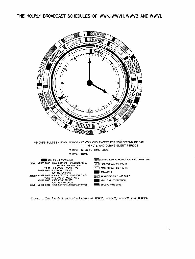
THE HOURLY BROADCAST SCHEDULES OF WWV, WWVH, WWVB AND W W V L
SECONDS PULSES - WWV, WWVH - CONTINUOUS EXCEPT FOR 59@ SECOND OF EACH MINUTE AND DURING SILENT PERIODS
WWVB - SPECIAL TIME CODE WWVL - NONE
STATION ANNOUNCEMENT 100 PPS loo0 H t MODULATION WWV TIMING CODE w- MORSE CODE- CALL LETTERS, UNIVERSAL TIME, TONE MODULATION 600 Hz
0 TONE MODULATION 440 H t PROPAGATION FORECAST
VOICE - GREENWICH MEAN TIME
GEOALERTS
lDENTIFICATION w A ~ ~ s H l ~ ~ UT-2 TIME CORRECTION
MORSE CODE - FREOUENCY OFFSET (ON THE HOUR ONLY1
VOICE - GREENWICH MEAN TIME m- MORSE CODE- CALL LETTERS, UNIVERSAL TIME,
MORSE CODE - FREOUENCY OFFSET (ON THE HOUR ONLY I m- MORSE CODE- CALL LETTERS, FREOUENCY OFFSET 6 SPECIAL TIME CODE
FIGURE 1. The hourly broadcast schedules of WWV, WWVH, WWVB, and WWVL.
3
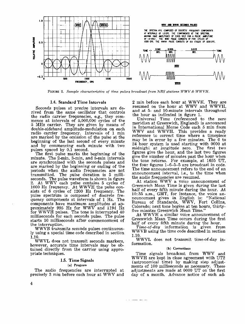
WWV AND W m SECONDS PULSES
THE SPECTRA ARE COMPOSED OF DISCRETE FREQUENCY CMRMlENTS AT IMTERVALS OF I.0CPS. THE COMPONENTS AT THE SECTPAL MAXIMA HAVE AMPLITUDES OF 0.005 VOLT FOR A WLSE AMPLITUDE OF 1.0 U T . THE WWV PUSE CONSISTS OF FNE CYCLES OF loo0 CPS. THE WWVH WLSE CONSISTS OF SIX CYCLES OF 12OOCPS.
0.025 SEC. TONE
FIGURE 2. Sample characteristics of t ime pulses broadcast from NBS stations WWV & WWVH.
1.4. Standard Time Intervals Seconds pulses a t precise intervals are de-
rived from the same oscillator that controls the radio carrier frequencies, e.g., they com- mence at intervals of 5,000,000 cycles of the 5 MHz carrier. They are given by means of double-sideband amplitude-modulation on each radio carrier frequency. Intervals of 1 min are marked by the omission of the pulse at the beginning of the last second of every minute and by commencing each minute with two pulses spaced by 0.1 second.
The first pulse marks the beginning of the minute. The 2-min, 3-min, and 5-min intervals are synchronized with the seconds pulses and are marked by the beginning or ending of the periods when the audio frequencies are not transmitted. The pulse duration is 5 milli- seconds. The pulse waveform is shown in figure 2. At WWV each pulse contains 5 cycles of 1000 Hz frequency. At WWVH the pulse con- sists of 6 cycles of 1200 Hz frequency. The pulse spectrum is composed of discrete fre- quency components at intervals of 1 Hz. The components have maximum amplitudes at ap- proximately 995 Hz for WWV and 1194 Hz for WWVH pulses. The tone is interrupted 40 milliseconds for each seconds pulse. The pulse starts 10 milliseconds after commencement of the interruption.
WWVB transmits seconds pulses continuous- ly using a special time code described in section 1.10.
WWVL does not transmit seconds markers, however, accurate time intervals may be ob- tained directly from the carrier using appro- priate techniques.
1.5. Time Signals (a) Program
The audio frequencies are interrupted at precisely 3 min before each hour a t WWV and
2 min before each hour at WWVH. They are resumed on the hour at WWV and WWVH, and at 5- and 10-minute intervals throughout the hour as indicated in figure 1.
Universal Time (referenced to the zero meridian at Greenwich, England) is announced in International Morse Code each 5 min from WWV and WWVH. This provides a ready reference to correct time where a timepiece may be in error by a few minutes. The 0 to 24 hour system is used starting with 0000 at midnighi at longitude zero. The first two figures give the hour, and the last two figures give the number of minutes past the hour when the tone returns. For example, at 1655 UT, the four figures 1-6-5-5 are broadcast in code. The time announcement refers to the end of an announcement interval, Le., to the time when the audio frequencies are resumed.
At station WWV a voice announcement of Greenwich Mean Time is given during the last half of every fifth minute during the hour. At 10:35 a.m., GMT, for instance, the voice an- nouncement given in English is: "National Bureau of Standards, WWV, Fort Collins, Colorado; next tone begins at ten hours, thirty- five minutes Greenwich Mean Time."
At WWVH a similar voice announcement of Greenwich Mean Time occurs during the first half of every fifth minute during the hour.
Time-of-day information is given from WWVB using the time code described in section 1.10.
WWVL does not transmit time-of-day in- formation.
(b) Corrections
Time signals broadcast from WWV and WWVH are kept in close agreement with UT2 (astronomical time) by making step adjust- ments of 100 milliseconds as necessary. These adjustments are made at 0000 UT on the first day of a month. Advance notice of such ad-
4
justrrlents is given to the public upon advice by the Bureau International de 1’Heure in Paris that an adjustment is to be made. De- cision to adjust the time signals is based upon observations by a network of internationaS ob- servatories and is made by an international committee. Corrections to the time signals are published periodically by the U.S. Naval Ob- servatory.
Seconds pulses broadcast from WWVB will depart from UT2 at a different rate due to the fact that WWVB broadcasts 60 kHz with no offset (see l . l ( c ) ) . Step time adjustments of 200 milliseconds will be made at 0000 UT on the first day of a month with appropriate ad- vance notice. The Bureau International de l’Heure advises when such adjustments are to be made in order to maintain the secoads pulses within about 100 milliseconds of UT2.
1.6. UT2 Corrections
Since a majority of time users do not require UT2 information to better than 100 millisec- onds the systems described in 1.5. (b) are quite satisfactory. An additional service is provided in cooperation with the U S . Naval Observatory which makes available the best values of UT2 on a daily basis. Corrections t o be applied to the time signals as broadcast are given in In- ternational Morse Code during the last half of the 19th min of each hour from WWV and during the last half of the 49th min of each hour from WWVH. Similar information is in- corporated in the WWVB Time Code.
The symbols which are broadcast are as fol- lows:
“UT2” then “AD” o r “SU” followed by a three digit number. This num- ber is the correction ih milliseconds. To obtain UT2, add the correction to the time indicated by the Time Signal pulse if “AD” is broadcast. Subtract if “SU” is broadcast. Thus, a clock keeping step with the time signals being broad- cast will be fast with respect to UT2 if “SU” is the symbol used.
The corrections necessary to obtain UT2 are derived from extrapolated data furnished by the U.S. Naval Observatory which indicate the variation in UT2 with respect to broadcast time. The probable error is -+ 3 milliseconds. Final data, with a probable error of -+ 1 milli- second, are published in the Time Service Bul- letins of the Naval Observatory. These cor- rections will be revised daily, the new value ap- pearing for the first time during the hour after OOOOUT, and will remain unchanged for the fol- lowing 24 hour period.
1.7. Propagation Forecasts
A forecast of radio propagation conditions is
broadcast in International Morse Code during the last half of every fifth minute of each hour on each of the standard frequencies from WWV. Propagation notices were first broadcast from WWV in 1946. The five-minute announcement was commenced on November 15, 1963. The present type of propagation forecast has been broadcast from WWV since July 1952 and was broadcast from WWVH from January 1954 until November 1964.
The forecast announcement tells users the condition of the ionosphere at the regular time of issue and the radio quality to be expected during the next six hours. The NBS forecasts are based on data obtained from a worldwide network of geophysical and solar observatories. These data include radio soundings of the upper atmosphere, short wave reception data, obser- vations of the geomagnetic field, solar activity and similar information. Trained forecasters evaluate the information and formulate the forecasts using known sun-earth relationships.
The forecast announcements from WWV re- fer to propagation along paths in the North Atlantic Area, such as Washington, D.C. to London or New York City t o Berlin. The an- nouncements are the short term forecasts pre- pared by the ESSA, Telecommunications Space Disturbance Service Center, Box 178, Fort Belvoir, Virginia 22060. The regular times of issue of the forecasts are 0500, 1200 (1100 in summer), 1700 and 2300 UT.
The forecast announcement is broadcast as a letter and a number. The letter portion identi- fies the radio quality a t the time the forecast is made. The letters denoting quality are “N,” “U,” and “W” signifying, respectively, that radio propagation conditions are either normal, unsettled or disturbed. The number portion of the forecast announcement from WWV is the forecast of radio propagation quality on a typical North Atlantic path during the six hours after the forecast is issued. Radio quality is based on the ITSA 1 to 9 scale which is de- fined as follows:
Disturbed Unsett led Normal grades (W) grade (U) grades (N)
1. useless 5. fa i r 6. fair-to-good 2. verypoor 7. good 3. poor 8. verygood 4. poor-to-fair 9. excellent
If, for example, propagation conditions are normal a t the time the forecast is issued but are expected to become “poor-to-fair” during the next six hours, the forecast announcement would be broadcast as N4 in International Morse Code.
1.8. Geophysical Alerts
A letter symbol indicating the current geo-
5
z
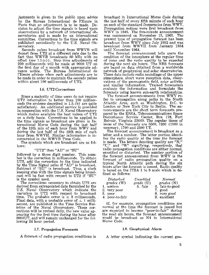
100 P P S C O D E l L i P A N D L 0 T I M E S C A L E 1 I
38 B I N A R Y DIGIT, 100 P P S C O D E (1000 C P S C A R R I E R ) I W l T " 0 " T oc V D I 8*@EI U A R K l l S I
FIGURE 3. Chart of time code transmissions f r o m NBS radio station WWV.
physical alert (Geoalert) as declared by the World Warning Agency of the International Ursigram and World Days Service (IUWDS) is broadcast in very slow International Morse Code from WWV and WWVH on each of the standard radio carrier frequencies. These broadcasts are made from WWV during the first half of the 19th min of each hour and from WWVH during the first half of the 49th min of each hour. Such notices have been broadcast since the International Geophysical Year, 1957-58, and have continued by interna- tional agreement.
The symbol indicates to experimenters and researchers in radio, geophysical and solar sci- ences the content of the IUWDS Geoalert mes- sage which is issued daily at 0400 UT to iden- tify days on which outstanding solar or geophysical events are expected or have oc- curred in the preceding 24-hour period. There are five types of Geoalerts which may be used and thus there are five letter symbols used to identify them plus a sixth symbol to signify that there is no Geoalert. The various letter symbols used and the type of Geoalert to which each refers are as follows:
C-Cosmic event M-Magnetic storm S-Soflare proton flare W-Stratwarm N-Soflare flares E-No geoalert The Geoalert broadcast is identified by the
letters GEO in International Morse Code pre- ceding one of the above letter symbols. The letter symbol is repeated 5 times to insure proper identification. If, for example, soflare proton flares are expected or have been ob-
served, the Geoalert broadcast would be GEO SSSSS to signify this fact. If a significant magnetic storm is expected or exists the broad- cast would be GEO MMMMM. The no alert symbol, sent as GEO EEEEE signifies that any preceding Geoalert may be considered finished and that there is no alert in progress. Since it is possible that two types of Geoalerts could be in effect a t the same time, the symbols will be broadcast in the following priority order :
C, M, S, W, N or E.
1.9. WWV Time Code
On January 1,1961 WWV commenced broad- casting the time code shown in figure 3 for one minute out of each five, ten times an hour, as shown in figure 1.
This time code provides a standardized tim- ing base for use when scientific observations are made simultaneously at widely separated locations. It may be used, for instance, where signals telemetered from a satellite are re- corded along with the time code; subsequent analysis of the data is then aided by having unambiguous time markers accurate to a thousandth of a second. Astronomical observa- tions may also benefit by the increased timing potential provided by the pulse-coded signals.
The code format being broadcast is generally known as the NASA 36-Bit Time Code. The code is produced at a 100 pps rate and is car- ried on 1000 Hz modulation.
The code contains time-of-year information (Universal Time) in seconds, minutes, hours and day of year. The code is synchronous with the frequency and time signals.
6
The binary coded decimal (BCD) system is used. Each second contains 9 BCD groups in this order: 2 groups for seconds. 2 groups for minutes, 2 groups for hours, and 3 groups for day of year. The code digit weighting is 1-2- 4-8 for each BCD group multiplied by 1, 10, or 100 as the case may be.
A complete time frame is 1 second. The binary groups follow the 1 second reference marker.
“On time” occurs at the leading edge of all pulses.
The code contains 100 /second clocking rate, 10/second index markers, and a l/second refer- ence marker. The 1000 Hz is synchronous with the code pulses so that millisecond resolution is obtained readily.
The 10/second index markers consist of “binary one” pulses preceding each code group except a t the beginning of the second where a “binary zero” pulse is used.
The l/second reference marker consists of five “binary one” pulses followed by a “binary zero” pulse. The second begins at the leading edge of the “binary zero” pulse.
The code is a spaced code format, that is, a binary group follows each of the 10/second in- dex markers. The last index marker is followed by an unused 4-bit group of “binary zero” pulses just preceding the l/second reference marker.
A “binary zero” pulse consists of 2 cycles of 1000 Hz amplitude modulation, and the “binary one” pulse consists of 6 cycles of 1000 Hz amplitude modulation. The leading edges of the time code pulses coincide with positive- going zero-axis-crossings of the 1000 Hz modu- lating frequency.
1.10. WWVB Time Code
(a) Code and Carrier
On July 1, 1965, Radio Station WWVB, Fort Collins, Colorado, began broadcasting time in- formation using a level-shift carrier time code. The code, which is binary coded decimal (BCD), is broadcast continuously and is synchronized with the 60 kHz carrier signal. The new system replaces the method whereby seconds pulses of uniform width obtained by level-shift carrier keying were broadcast. The carrier is no longer interrupted for keyed sta- tion identification, since the characteristic phase advance by 45” at 10 minutes after every hour followed by a similar phase retardation 5 minutes later continues to serve to identify the station.
(b) Marker Generation
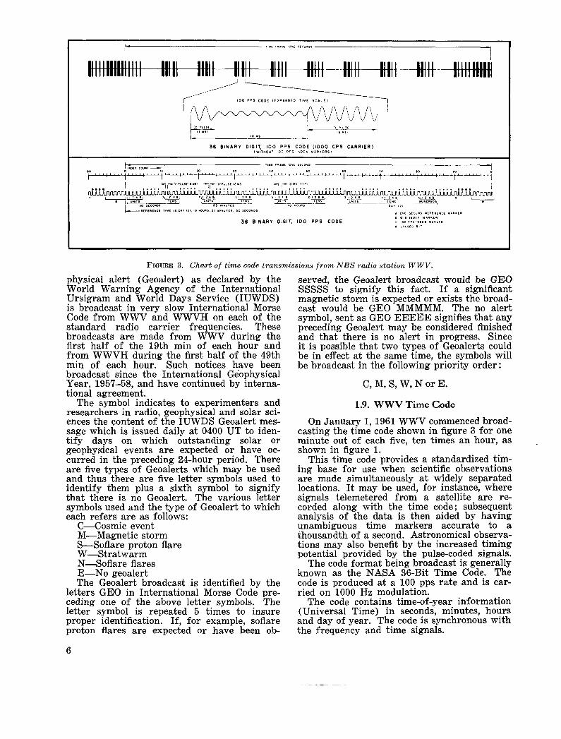
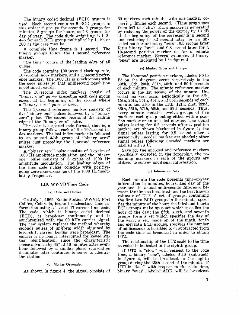
As shown in figure 4, the signal consists of
60 markers each minute, with one marker oc- curring during each second. (Time progresses from left to right.) Each marker is generated by reducing the power of the carrier by 10 dB a t the beginning of the corresponding second and restoring it 0.2 second later for an un- coded marker or binary “zero”, 0.5 second later for a binary “one”, and 0.8 second later for a ‘10-second position marker or for a minute reference marker. Several examples of binary “ones” are indicated by I in figure 4.
(c) Marker Order and Groups
The 10-second position markers, labeled PO t o P5 on the diagram, occur respectively in the 60th, loth, 20th, 30th, 40th, and 50th seconds of each minute. The minute reference marker occurs in the 1st second of the minute. Un- coded markers occur periodically in the 5th, 15th, 25th, 35th, 45th, and 55th seconds of each minute, and also in the l l t h , 12th, 21st, 22nd, 36th, 56th, 57th, 58th, and 59th seconds. Thus, every minute contains twelve groups of five markers, each group ending either with a posi- tion marker or an uncoded marker. The signal pulses lasting for 0.2 seconds after a position marker are shown blackened in figure 4 ; the signal pulses lasting for 0.8 second after a periodically uncoded marker are shaded ; other signal pulses following uncoded markers are labelled with a U.
Save for the uncoded and reference markers specifically excepted in the foregoing, the re- maining markers in each of the groups are utilized to convey additional information.
(d) Information Sets
Each minute the code presents time-of-year information in minutes, hours, and day of the year and the actual milliseconds difference be- tween the time as broadcast and the best known estimate of UT2. A set of groups, containing the first two BCD groups in the minute, speci- fies the minute of the hour; the third and fourth BCD groups make up a set which specifies the hour of the day; the fifth, sixth, and seventh groups form a set which specifies the day of the year; a set, made up of the ninth, tenth and eleventh BCD groups, specifies the number of milliseconds to be added to or subtracted from the code time as broadcast in order to obtain UT2.
The relationship of the UT2 scale t o the time as coded is indicated in the eighth group.
If UT2 is “slow” with respect t o the code time, a binary “one”, labeled SUB (subtract) in figure 4, will be broadcast in the eighth group during the 38th second of the minute. If UT2 is “fast” with respect to the code time, binary “ones”, labeled ADD, will be broadcast
7
TIME- TIME FRAME I MINUTE (INDEX COUNT I SECOND)
-l
u u lmUU m r P2 I I I P 3 I I P 4
2 0 0 1 0 0 80 4 0 2 0 10 8 4 2 1 A D D ~ ~ ~ . A D D
/---REFERENCE TIME
,
REFERENCE MARKER FOR MINUTES 0 .2 SECOND -BINARY "ZERO" i k (TYPICAL)
I P I I I P2 40 2 0 10 8 4 2 I 2 0 1 0 8 4 2 1
U U l.llHA tlUULll U U I I P 5
8 0 4 0 2 0 1 0 8 4 2 I p4 400 100
800 200
HOURS SET ~- MINUTES SET --
W A J u U u U u U ' I PO
TIME - - 1 -l
DAYS SET UT2 TIME AT THIS POINT EQUALS -. 2 5 8 - DAYS, 18 /// HOURS, RELATIONSHIP
4 2 MINUTES, 35 SECONDS. TO OBTAIN THE CORRESPONDING UT2 SCALE READING, SUBTRACT 41 MILLISECONDS.
-TIME- 7
40 5 0 60 I 1 I l i I l l I 1 I 1 1 1 I 1 1 1 I
0.8 SECOND POSITION IDENTIFIER i t (TY PlCAL )
UT2 SET GROUP 2 -- DIFFERENCE OF UT2 FROM
CODED TIME IN MILLISECONDS
MARKER i
UNCODED MARKER POSITION MARKER PERIODIC UNCODED AND PULSE MARKER AND PULSE AND PULSE
L BINARY "ONE" BINARY "ZERO"
FIGURE 4. Chart of time code transmissions from NBS station WWVB.
8
in the eighth group during the 37th and 39th seconds of the minute.
The twelfth group is not used to convey infor- mation.
(e) Digital Information
When used to convey numerical information, the four coded markers used as digits in a BCD group are indexed 8-4-2-1 in that order. Some- times only the last two or three of the coded markers in a group are needed, as in the first groups in the minutes, hours, and days sets. In these cases the markers are indexed 2-1, or 4-2-1, accordingly. The indices of the first group in each set which contains two groups are multiplied by 10, those of the second group of such a set are multiplied by 1. T’he indices of the first group in each set which contains three groups are multiplied by 100, those of the second group by 10, and those of the third group by 1.
Example
A specific example is inaicated in figure 4. The occurrence of two binary “ones” in the “minutes set” indicates that the minute con- templated is the 40 + 2 = 42nd minute. Simi- larly, the two binary “ones” in the “hours set” indicate the 10 + 8 = 18th hour of the day, while the four binary “ones” in the “days set” indicate the 200 + 40 + 10 + 8 = 258th day of the year. It is seen from the “UT2 Relation- ship” group and the “UT2 set” that one should sub t rac t , from any second in this minute, 40 + 1 = 41 milliseconds to get the best estimate of UT2. For example, the 35th UT2 interval would end 41 milliseconds later than the end of the 35th second; or, in other words, the TJT2 scale reading for the end of the 35th second would be 18 42 ”’ 34. 959 since 35.000-0.041 = 34.959.
1.11. Offset Frequencies
WWV, WWVH, and WWVL transmit re- minders of the fact that all transmitted fre- quencies are offset from nominal by a fixed amount. International Morse Code symbols for M300 are transmitted from WWV and WWVH immediately following the “on-the-hour” voice announcement. WWVL transmits International Morse Code for Minus 300 following the station call sign repeated three times. This is trans- mitted during the lst, 21st, and 41st min of each hour.*
Since WWVB is transmitting standard fre- quency no offset reminder is given.
1.12. Station Identification
WWV and WWVH identify by International Morse Code and voice (in English) every five minutes.
WWVL identifies by International Morse Code durinq the l s t , 21st, and 41st min of each hour.* WWVB identifies by its unique Time Code (see section 1.10) and by advancing the carrier phase 45” a t 10 min after each hour and returning to normal phase at 15 min after each hour.
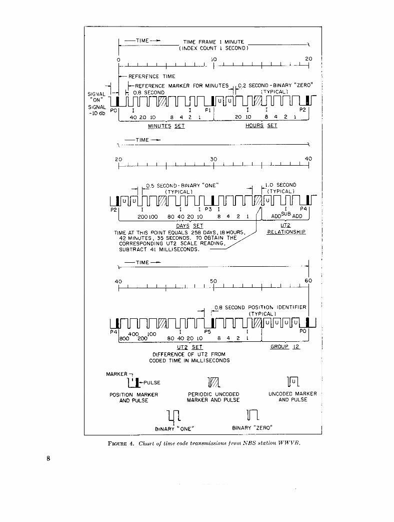
1.13. Radiated Power, Antennas and Modulation
(a) Radiated Power
-
Freauencv. I Radiated Dower. kw “ ,
MHz 0.020 0.060 2.5 5
10 15 20 25
WWV - - 2.5
10 10 10 2.5 2.5
WWVH - - 1 2 2 2 - -
(b) Transmitting Antennas
The broadcasts on 2.5 and 5 MHz from WWVH are from vertical quarter-wave an- tennas. The broadcasts on all other frequencies from WWV and WWVH are from vertical half- wave dipoles. The antennas are omnidirectional.
The antennas used by WWVB and WWVL are 400-foot high vertical antennas with capac- ity toploading.
( 0 ) Modulation
At WWV and WWVH all modulation is double sideband amplitude, with 75 percent on the steady tones and 100 percent peak for seconds pulses and voice.
WWVB employs 10 dB carrier-level reduction for transmitting time information (see section 1.10).
WWVL uses no amplitude modulation. Vari- ous experimental techniques are being studied in an attempt to develop a good timing system at Very Low Frequencies.
-A WWVL frequently alternates between 20.0 kHz and 19.9 or 20.5 kHz, the change being made every 10 seconds. During these ex- periments the code transmissions are not given.
9
c'
10
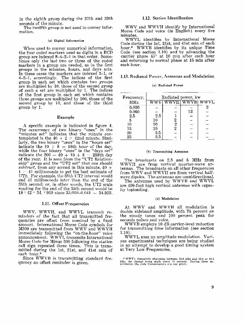
2. How NBS Controls the Transmitted Frequencies
In f igure 5 a simplified diagram of the NBS frequency control system is shown. The entire system depends upon the basic f r e q u e n c y ref- erence shown in this diagram as the Cesium (Cs) Beam. This s t a n d a r d is used to calibrate the oscillators, d iv iders and clocks which gen- erate the controlled frequency a n d the NBS time scales. Information from this reference is provided to receivers which monitor the WWVB transmissions and compare the re- ceived phase with the standard phase. If an error exists between the reference and received phases a signal is then transmitted by a 50 MHz transmitter to the transmitting site at Fort Collins which in turn operates automatic phase correction equipment to correct the transmitted phase.
The control of the signals transmitted from WWVH is performed manually at present based upon signals from WWVB and WWVL which are received by LF and VLF phase-lock re- ceivers. The oscillator controlling the trans- m i t t e d f requencies and time signals is continu- ously compared with the LF and VLF signals. Adjustments are then made to the controlling oscillator manually which compensate for the characteristic drift of crystal oscillators. To as- sure that systematic errors do not enter into the system the NBS time scale is compared with the transmitting station clocks by the use of a very precise portable clock. With these clocks time synchronization to a few millionths of a second can be attained.
THE NATIONAL BUREAU OF STANDARDS
The National Bureau of Standards1 provides measurement and technical information services essential to the efficiency and effectiveness of the work of the Nation’s scientists and engineers. The Bureau serves also as a focal point in the Federal Government for assuring maximum application of the physical and engineering sciences to the advancement of technology in industry and commerce. To accomplish this mission, the Bureau is organized into three institutes covering broad program areas of research and services : THE INSTITUTE FOR BASIC STANDARDS . . . provides the central basis within the United States for a complete and consistent system of physical measurements, coordinates that system with the measurement systems of other nations, and furnishes essential services leading to accurate and uniform physical measurements throughout the Nation’s scientific community, industry, and commerce. This Institute comprises a series of divisions, each serving a classical subject matter area:
-Applied Mathematics-Electricity-Metrology-Mechanics-Heat-Atomic Physics-Physical Chemistry-Radiation Physics-Laboratory Astrophysics2-Radio Standards Laboratory,’ which includes Radio Standards Physics and Radio Standards Engineering-Office of Standard Refer- ence Data.
THE INSTITUTE FOR MATERIALS RESEARCH . . . conducts materials research and provides associated materials services including mainly reference materials and data on the properties of ma- terials. Beyond its direct interest to the Nation’s scientists and engineers, this Institute yields services which are essential to the advancement of technology in industry and commerce. This Institute is or- ganized primarily by technical fields :
-Analytical Chemistry-Metallurgy-Reactor Radiations-Polymers-Inorganic Materials-Cry- ogenics2-Office of Standard Reference Materials.
THE INSTITUTE FOR APPLIED TECHNOLOGY . . . provides technical services to promote the use of available technology and to facilitate technological innovation in industry and government. The principal elements of this Institute are:
-Building Research-Electronic Instrumentation-Technical Analysis-Center for Computer Sci- ences and Technology-Textile and Apparel Technology Center-Office of Weights and Measures -Office of Engineering Standards Services-Office of Invention and Innovation-Office of Vehicle Systems Research-Clearinghouse for Federal Scientific and Technical Information3-Materials Evaluation Laboratory-NBS/GSA Testing Laboratory.
1 Headquarters and Laboratories a t Gaithersburg, Maryland, unless otherwise noted; mailing address Washington, D. C.,
2 Located at Boulder, Colorado, 80302. 3 Located at 5285 Port Royal Road, Springfield, Virginia 22151.
20234.
11
GPO : 1967 0 - 265-984
US. DEPARTMENT OF COMMERCE WASHINGTON, D.C. 20230
POSTAGE AND FEES PAID
U.S. DEPARTMENT OF COMMERCE
OFFICIAL BUSINESS
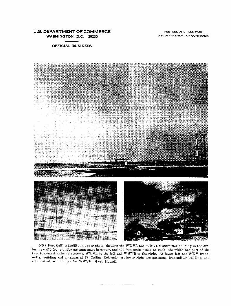
NBS Fort Collins facility in upper photo, showing the WWVB and WWVL transmitter building in the cen- ter, new 470-foot standby antenna mast in center, and 400-foot main masts on each side which are part of the two, four-mast antenna systems, WWVL to the left and WWVB to the right. At lower left are WWV trans- mitter building and antennas at Ft. Collins, Colorado. At lower right are antennas, transmitter building, and administrative buildings for WWVH, Maui, Hawaii.