ncc multilayer ceramic capacitors metal oxid varistors tnr ... · ncc multilayer ceramic capacitors...
TRANSCRIPT
Meckenloher Str. 11
D-91126 Rednitzhembach
Tel.: +49 9122 97 96 0
Fax: +49 9122 97 96 50
www.alfatec.de
NCC
Mult ilayer Ceramic Capacitors
Metal Oxid Varistors TNR
Film Capacitors
Amorphous / Dust Choke Coils2015/2016 CAT.NO.E1002U / E1006X / E1003R E1008P
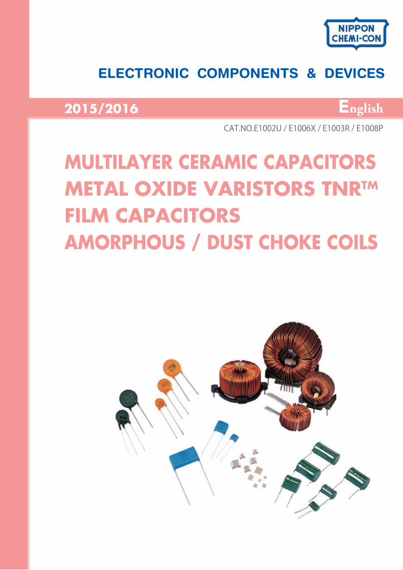
MULTILAYER CERAMIC CAPACITORS
METAL OXIDE VARISTORS TNRTM
FILM CAPACITORS
AMORPHOUS / DUST CHOKE COILS
ELECTRONIC COMPONENTS & DEVICES
2015/2016
CAT.NO.E1002U / E1006X / E1003R / E1008P
English
MUL TILA YER CERAMIC CAPACITORS
Production Guide P4-12
P12-28
P29
Product Specifications
Characteristics Data
Series Table
Part Numbering System
Packaging
Minimum order quantity
Precautions and Guidelines
Standardization
P4
P5
P6
P7
P8
P12
P13
P17
P20
P23
P26
NTS Series / NTF Series
KVF Series
NTJ Series
NTD Series
KVD Series
3 CAT. No. E1002U
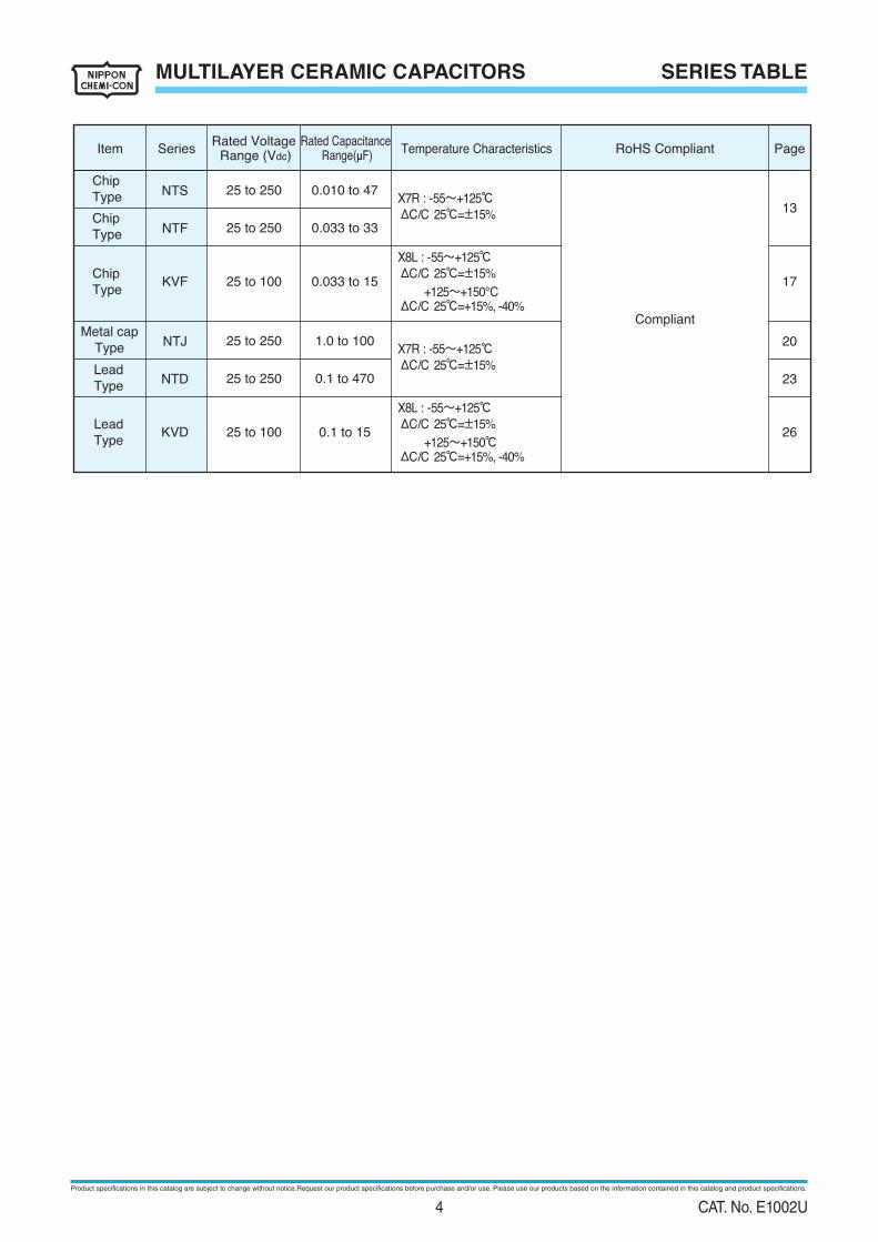
SERIES TABLEMULTILAYER CERAMIC CAPACITORS
Item Series
0.010 to 47
0.033 to 33
0.033 to 15
1.0 to 100
0.1 to 470
0.1 to 15
25 to 250
25 to 250
25 to 100
25 to 250
25 to 250
25 to 100
NTS
NTF
KVF
NTJ
NTD
KVD
13
20
17
23
26
Rated Voltage Range (Vdc)
Temperature Characteristics
Lead
Type
Lead
Type
Metal cap
Type
Chip
Type
Chip
Type
Chip
Type
Rated Capacitance Range(µF)
X7R : -55~+125℃ΔC/C 25℃=±15%
X8L : -55~+125℃ΔC/C 25℃=±15%
+125~+150℃ΔC/C 25℃=+15%, -40%
X8L : -55~+125℃ΔC/C 25℃=±15%
+125~+150℃ΔC/C 25℃=+15%, -40%
X7R : -55~+125℃ΔC/C 25℃=±15%
RoHS Compliant Page
Compliant
Product specifications in this catalog are subject to change without notice.Request our product specifications before purchase and/or use. Please use our products based on the information contained in this catalog and product specifications.
4 CAT. No. E1002U
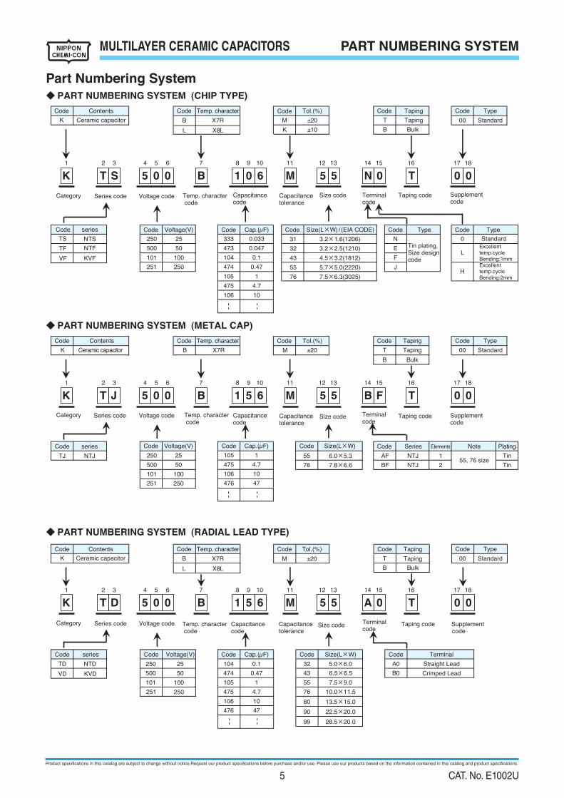
MULTILAYER CERAMIC CAPACITORS PART NUMBERING SYSTEM
◆ PART NUMBERING SYSTEM (CHIP TYPE)
◆ PART NUMBERING SYSTEM (METAL CAP)
◆ PART NUMBERING SYSTEM (RADIAL LEAD TYPE)
Part Numbering System
1 2 3 4 5 6 7 8 9 10 11 12 13 14 15 16 17 18
31
32
43
76
Type
Excellenttemp.cycleBending:1mm
Standard
Type
Excellenttemp.cycleBending:2mm
55
TF
VF
10
104
105
4.7
474
0.1
0.47
1
0.047
Code
TS
K Ceramic capacitor
Contents
Code Code
333
CodeCode
250
475
106
0
L
H
Code Code
E
0.033Tin plating,Size designcode4.5×3.2(1812)
N
Size(L×W)/ (EIA CODE)
Code
M
BulkK
F
3.2×1.6(1206)
3.2×2.5(1210)473
250251
500
101
±20
Tol.(%)
±10
Temp. character
X7R
Code
B
X8LL
7.5×6.3(3025)
5.7×5.0(2220)
Taping
B
Code
00
Voltage(V)
25
50
100
Type
Standard
Code
T
Taping
Category Series code Capacitancecode
Temp. character code
Taping codeVoltage code
Voltage code
Capacitancetolerance
Size code Supplementcode
Terminalcode
M ±20
Code CodeCode Code Tol.(%)Contents
K Ceramic capacitor
Code
B
BF
Code
AF
251
106
Plating
NTJ 2
Tin
Elements
Tin55, 76 size
Taping
T 00Taping
1
Voltage(V)
B Bulk
Code Code Code NoteSize(L×W) Series
NTJTJ 250
475
101
series
NTJ 105
50500
1
4.7
Code
55
476250
Temp. character
X7R
Type
Standard
Category Series code Temp. character code
Capacitancecode
Capacitancetolerance
Size code Terminalcode
Taping code Supplementcode
106
475
105
474
100
250
104TD NTD
VD KVD
Code series Code Code
B Bulk
Taping
00TapingT±20
Contents
500
250
101
Ceramic capacitor
476
10
4.7
1
0.47
47
Code Tol.(%)CodeCode
B
L
K
Temp. character
X7R
X8L
6.5×6.5
Cap.(µF)
7.5×9.0
10.0×11.5
0.1
Type
Standard
Voltage(V)
25
M
Code Code
55
Code
76
13.5×15.080
22.5×20.090
28.5×20.099
43
32
251
Terminal
Straight Lead
Crimped Lead
Size(L×W)
50
Code
A0
B0
Category Series code Voltage code Terminalcode
Temp. character code
Capacitancecode
Capacitancetolerance
Size code Taping code Supplementcode
5.0×6.0
NTS
series
NTF
KVF
Cap.(µF)
J
6.0×5.3
76 7.8×6.6
10
47
Cap.(µF)
100
25
K T 5M 05 T5 0 1 0 60S B N 0 0
1 2 3 4 5 6 7 8 9 10 11 12 13 14 15 16 17 18
K T 5M 05 T5 0 1 5 60J B B F 0
1 2 3 4 5 6 7 8 9 10 11 12 13 14 15 16 17 18
K T 5M 05 T5 0 1 5 60D B A 0 0
Product specifications in this catalog are subject to change without notice.Request our product specifications before purchase and/or use. Please use our products based on the information contained in this catalog and product specifications.
5 CAT. No. E1002U
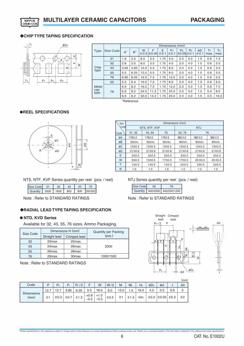
MULTILAYER CERAMIC CAPACITORS PACKAGING
NTS, NTF, KVF Series quantity per reel (pcs. / reel)
Note : Refer to STANDARD RATINGS
Note : Refer to STANDARD RATINGS
● NTD, KVD Series
Available for 32, 43, 55, 76 sizes. Ammo Packaging.
◆CHIP TYPE TAPING SPECIFICATION
23max.
24max.
26max.
29max.
25max.
26max.
28max.
30max.
2000
32
43
55
76
Dimensions H (mm)
Straight lead Crimped lead
Quantity per Packing
(pcs.)Size Code
1000/1500
16.0
min.
6.35
±1.3
13.0 1.5
±1.5
9.0
±0.5
3.85
±0.7
12.7
±0.3
5.0
+0.8–0.2
18.0
+1.0–0.5
0.5
±0.05
0.6
±0.2
0
±2
4.0
±0.2
12.7
±1 ±1
Code P P0 WP1 P0 / 2 φD0 φd t ΔhF W / 2 M M0 H0
Dimensions(mm)
(mm)
Straight
lead
Crimped
lead
P
P1 F
P0φd
φD0
P0 / 2
F
H
H
t
H0
M0
M
W
W/2
Δh
t
W
EF
P1 P2T2
T1
P0
A
φD0
B
31
32
43
55
76
55
Dimensions (mm)
Dimensions (mm)
A
*Reference
B* * P1W±0.3
F±0.05 ±0.05
T2
max.E
±0.1 ±0.1 ±0.1 ±0.1P2 P0 φD T1
max.Size CodeType
Metalcaptype
Chiptype
●REEL SPECIFICATIONS
E
R
φC
φD
φA
WT
φB
Size
Code NTS, NTF, KVF
Code
φA
φB
φC
φD
E
W
T
R
178±2 178±2 178±2 382±2
50min.
13±0.5 13±0.5 13±0.5 13±0.5
21±0.8 21±0.8 21±0.8 21±0.8
2±0.5 2±0.5 2±0.5 2±0.5
9±0.5 13±0.5 17±0.5 17±0.5
1±0.5 1±0.5 1±0.5 2±0.5
1.0
50min.
1.0
50min.
1.0
80min.
1.0
31, 32
NTJ Series quantity per reel (pcs. / reel)
Note : Refer to STANDARD RATINGS
Size Code
Quantity
31
3000
32
1600
43
800
76
300/500
55
800
Size Code
Quantity
55
400/2000
76
400/500/1200
◆RADIAL LEAD TYPE TAPING SPECIFICATION
55, 76
382±2
13±0.5
21±0.8
2±0.5
25±0.5
2±0.5
80min.
1.0
NTJ
76
382±2
13±0.5
21±0.8
2±0.5
33±0.5
2±0.5
80min.
1.0
7643, 55
76
1.9
2.8
3.65
5.5
6.85
5.3
6.9
6.9
6.9
3.5
3.5
4.95
6.25
8.05
6.4
8.2
8.2
8.2
8.0
8.0
12.0
12.0
16.0
16.0
16.0
24.0
32.0
3.5
3.5
5.5
5.5
7.5
7.5
7.5
11.5
14.2
1.75
1.75
1.75
1.75
1.75
1.75
1.75
1.75
1.75
4.0
4.0
8.0
8.0
12.0
8.0
12.0
24.0
24.0
2.0
2.0
2.0
2.0
2.0
2.0
2.0
2.0
2.0
4.0
4.0
4.0
4.0
4.0
4.0
4.0
4.0
4.0
1.5
1.5
1.5
1.5
1.5
1.5
1.5
1.5
1.5
0.6
0.6
0.6
0.6
0.6
0.6
0.6
0.4
0.5
1.5
2.5
3.5
3.5
5.5
6.0
7.5
8.5
10.0
Product specifications in this catalog are subject to change without notice.Request our product specifications before purchase and/or use. Please use our products based on the information contained in this catalog and product specifications.
6 CAT. No. E1002U
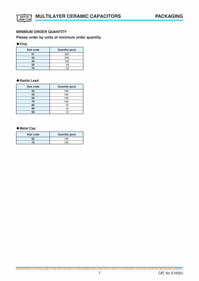
MULTILAYER CERAMIC CAPACITORS
◆Chip
MINIMUM ORDER QUANTITY
Please order by units of minimum order quantity.
300
200
100
50
50
31
32
43
55
76
Size code Quantity (pcs)
◆Radial Lead
◆Metal Cap
100
100
100
100
32
43
55
76
1080
1090
1099
Size code Quantity (pcs)
10055
10076
Size code Quantity (pcs)
PACKAGING
Product specifications in this catalog are subject to change without notice.Request our product specifications before purchase and/or use. Please use our products based on the information contained in this catalog and product specifications.
7 CAT. No. E1002U
PRECAUTIONS AND GUIDELINES MULTILAYER CERAMIC CAPACITORS
CodeSize Code
a
b
c
d
2.2 to 2.5
4.2 to 5.8
1.2 to 1.6
0.4 to 0.8
2.2 to 2.5
4.2 to 5.8
1.8 to 2.5
0.5 to 1.0
3.5 to 3.7
5.5 to 6.1
2.3 to 3.2
0.6 to 1.1
4.5 to 4.7
6.7 to 8.3
3.5 to 5.0
0.7 to 1.2
5.0 to 5.2
8.8 to 10.8
4.7 to 6.3
0.8 to 1.3
31 32 43 55 76
(mm)
CodeSize Code 55
a
b
c
d
3.5 to 4.5
6.5 to 7.5
4.0 to 5.0
0.5 to 1.5
76
5.5 to 6.5
8.8 to 9.8
5.5 to 6.5
0.8 to 1.8
(mm)●Chip type Metal Cap type
CChip Capacitor Land
Solder resist
ad
b
(1) Conirming the installation and operating environment of capacitors, use them within the rated performance limits prescribedin their catalog or product speciications. Otherwise, excessive use conditions cause the capacitors to have catastrophic
failure such as short circuit, open circuit or iring.
(2) Do not apply a DC voltage which exceeds the full rated voltage. The peak voltage of a superimposed AC voltage (ripple
voltage) on the DC voltage must not exceed the full rated voltage.
(3) By considering the temperature characteristic and the DC bias characteristic of the ceramic capacitors, please determine
the right capacitance. The capacitance of the capacitors changes in low and high temperature ambiences and depends
on the applied bias voltages. The capacitance change (i.e. reduction) may affect the performance of the circuit which is
containing the capacitors. Therefore, please examine the capacitors in the actual operational conditions to verify that they
are right ones.
(4) The common failure mode of multilayer ceramic capacitors is contingent insulation breakdown or short circuit. When the
capacitors are used in a high-power circuit, they may damage the surroundings of the capacitors when failed. Therefore, the
high-power circuit should have protective device/protective devices to shut down the circuit from the capacitor/capacitors.
The reliability of the capacitors improves when the ambient temperatures are in the normal temperature range and the
applied voltages are low.
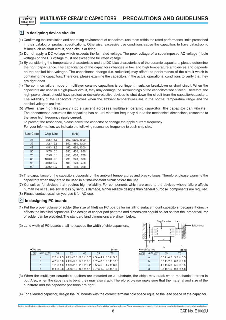
(5) When large high frequency ripple current acrosses multilayer ceramic capacitor, the capacitor can vibrate.
The phenomenon occurs as the capacitor, has natural vibration frequency due to the mechanical dimensions, resonates to
the large high frequency ripple current.
To prevent the resonance, please select the capacitor or change the ripple current frequency.
For your information, we indicate the following resonance frequency to each chip size.
(6) The capacitance of the capacitors depends on the ambient temperatures and bias voltages. Therefore, please examine the
capacitors when they are to be used in a time-constant circuit before the use.
(7) Consult us for devices that requires high reliability. For components which are used to the devices whose failure affects
(8) Please contact us,when you use it for AC use.human life or causes social loss by serious damage, higher reliable designs than general purpose components are required.
(1) Put the proper volume of solder (the size of illet) on PC boards for installing surface mount capacitors, because it directly
affects the installed capacitors. The design of copper pad patterns and dimensions should be set so that the proper volume
of solder can be provided. The standard land dimensions are shown below.
(2) Land width of PC boards shall not exceed the width of chip capacitors.
(3) When the multilayer ceramic capacitors are mounted on a substrate, the chips may crack when mechanical stress is
put. Also, when the substrate is bent, they may also crack. Therefore, please make sure that the material and size of the
substrate and the capacitor positions are right.
(4) For a leaded capacitor, design the PC boards with the correct terminal hole space equal to the lead space of the capacitor.
Size Code
3.2× 1.6
3.2× 2.5
4.5× 3.2
5.7× 5.0
650, 1200, 1600650, 850, 1200450, 650, 1200350, 450, 850
7.5× 6.3 350, 600, 750 10.0× 9.0 230, 320, 620
32
31
43
55
76
80
20.0×12.7 100, 170, 45090
25.0×12.7 80, 160, 25099
Chip Size (kHz)
1 In designing device circuits
2 In designing PC boards
●
Product specifications in this catalog are subject to change without notice.Request our product specifications before purchase and/or use. Please use our products based on the information contained in this catalog and product specifications.
8 CAT. No. E1002U
PRECAUTIONS AND GUIDELINESMULTILAYER CERAMIC CAPACITORS
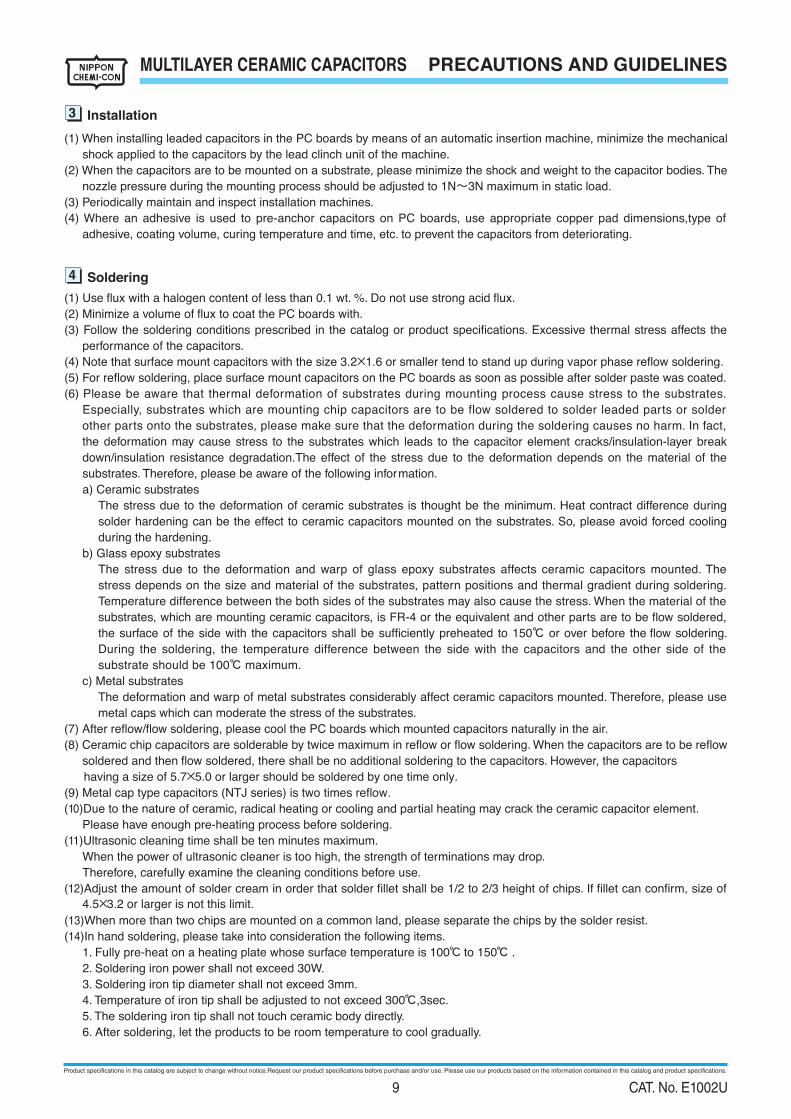
(1) When installing leaded capacitors in the PC boards by means of an automatic insertion machine, minimize the mechanical
shock applied to the capacitors by the lead clinch unit of the machine.
(2) When the capacitors are to be mounted on a substrate, please minimize the shock and weight to the capacitor bodies. The
nozzle pressure during the mounting process should be adjusted to 1N~3N maximum in static load.
(3) Periodically maintain and inspect installation machines.
(4) Where an adhesive is used to pre-anchor capacitors on PC boards, use appropriate copper pad dimensions,type of
adhesive, coating volume, curing temperature and time, etc. to prevent the capacitors from deteriorating.
(1) Use flux with a halogen content of less than 0.1 wt. %. Do not use strong acid flux.
(2) Minimize a volume of flux to coat the PC boards with.
(3) Follow the soldering conditions prescribed in the catalog or product speciications. Excessive thermal stress affects the
performance of the capacitors.
(4) Note that surface mount capacitors with the size 3.2×1.6 or smaller tend to stand up during vapor phase reflow soldering.(5) For reflow soldering, place surface mount capacitors on the PC boards as soon as possible after solder paste was coated.
(6) Please be aware that thermal deformation of substrates during mounting process cause stress to the substrates.
Especially, substrates which are mounting chip capacitors are to be flow soldered to solder leaded parts or solder
other parts onto the substrates, please make sure that the deformation during the soldering causes no harm. In fact,
the deformation may cause stress to the substrates which leads to the capacitor element cracks/insulation-layer break
down/insulation resistance degradation.The effect of the stress due to the deformation depends on the material of the
substrates. Therefore, please be aware of the following infor mation.
a) Ceramic substrates
The stress due to the deformation of ceramic substrates is thought be the minimum. Heat contract difference during
solder hardening can be the effect to ceramic capacitors mounted on the substrates. So, please avoid forced cooling
during the hardening.
b) Glass epoxy substrates
The stress due to the deformation and warp of glass epoxy substrates affects ceramic capacitors mounted. The
stress depends on the size and material of the substrates, pattern positions and thermal gradient during soldering.
Temperature difference between the both sides of the substrates may also cause the stress. When the material of the
substrates, which are mounting ceramic capacitors, is FR-4 or the equivalent and other parts are to be flow soldered,
the surface of the side with the capacitors shall be suficiently preheated to 150℃ or over before the flow soldering.
During the soldering, the temperature difference between the side with the capacitors and the other side of the
substrate should be 100℃ maximum.
c) Metal substrates
The deformation and warp of metal substrates considerably affect ceramic capacitors mounted. Therefore, please use
metal caps which can moderate the stress of the substrates.
(7) After reflow/flow soldering, please cool the PC boards which mounted capacitors naturally in the air.
(8) Ceramic chip capacitors are solderable by twice maximum in reflow or flow soldering. When the capacitors are to be reflow
soldered and then flow soldered, there shall be no additional soldering to the capacitors. However, the capacitors
having a size of 5.7×5.0 or larger should be soldered by one time only.
(10)Due to the nature of ceramic, radical heating or cooling and partial heating may crack the ceramic capacitor element.
(9) Metal cap type capacitors (NTJ series) is two times reflow.
Please have enough pre-heating process before soldering.
(11)Ultrasonic cleaning time shall be ten minutes maximum.
When the power of ultrasonic cleaner is too high, the strength of terminations may drop.
Therefore, carefully examine the cleaning conditions before use.
(12)Adjust the amount of solder cream in order that solder illet shall be 1/2 to 2/3 height of chips. If illet can conirm, size of
4.5×3.2 or larger is not this limit.
(13)When more than two chips are mounted on a common land, please separate the chips by the solder resist.
(14)In hand soldering, please take into consideration the following items.
1. Fully pre-heat on a heating plate whose surface temperature is 100℃ to 150℃ .
2. Soldering iron power shall not exceed 30W.
3. Soldering iron tip diameter shall not exceed 3mm.
4. Temperature of iron tip shall be adjusted to not exceed 300℃,3sec.
5. The soldering iron tip shall not touch ceramic body directly.
6. After soldering, let the products to be room temperature to cool gradually.
3 Installation
4 Soldering
Product specifications in this catalog are subject to change without notice.Request our product specifications before purchase and/or use. Please use our products based on the information contained in this catalog and product specifications.
9 CAT. No. E1002U
PRECAUTIONS AND GUIDELINESMULTILAYER CERAMIC CAPACITORS
(1) In the case that the assembly boards are washed, choose the appropriate cleaning agent for the washing purpose.
(2) To determine the cleaning conditions, make sure by means of the actual washing equipment that the performance of the
capacitors is not affected.
(3) In the case that water-soluble flux was used, suficiently wash the assembly boards.
(1) When ceramic capacitors are to be resin coated or molded, please pay enough attention. Ceramic capacitors molded in
resin, and please do not use it. There is fear to destroy a capacitor by stress to occur by the expansion / the shrinkage
when resin stiffens. When a thermal expansion shrinkage coeficient in hardening uses big resin, coating in the resin
which is soft with capacitors, please make that stress is added to capacitors small as much as possible.
(2) Conirm that harmful resolution or formation gasses are not generated from the coating materials during the curing
process or by spontaneously leaving the coated assembly boards.
(3) If a coating material is cured at higher temperatures than the Category temperature of the capacitor, the exterior resin will
deteriorate resulting in the capacitor damage.
(1) When cutting off a multi-board to make individual units, curving or twisting the board may crack the capacitors. Appropriate
tools should be used to cut it off.
(2) Excessive mechanical shock to capacitors or their assembly boards may make the capacitors crack.
(3) Use leaded capacitors without bending their lead wires as much as possible.
(4) When ceramic capacitors are stored with no load, the capacitance reduces during the storage (named "aging
character istic"). As for the product that capacitance decreased, capacity recovers in an initial value by heat-treating it.
(5) When the electrodes of the ceramic capacitors are made of silver, needle crystals may form on the electrodes in an
ambience containing sulfur compounds.
(1) Do not store and use capacitors in the following environment. Water or salt water splashes, dew wets or toxic gasses
(hydrogen sulide, sulfurous acid,chlorine, ammonium) ills, Vibration or mechanical shock exceeding the limits prescribed
in the catalog or product speciications.
(2) Do not store capacitors in places that direct sunlight pours down or dewy places.
(3) Avoid high temperature and humidity.
The storage conditions should be : Temperature=Lower than 40℃
Humidity=Lower than 70% RH
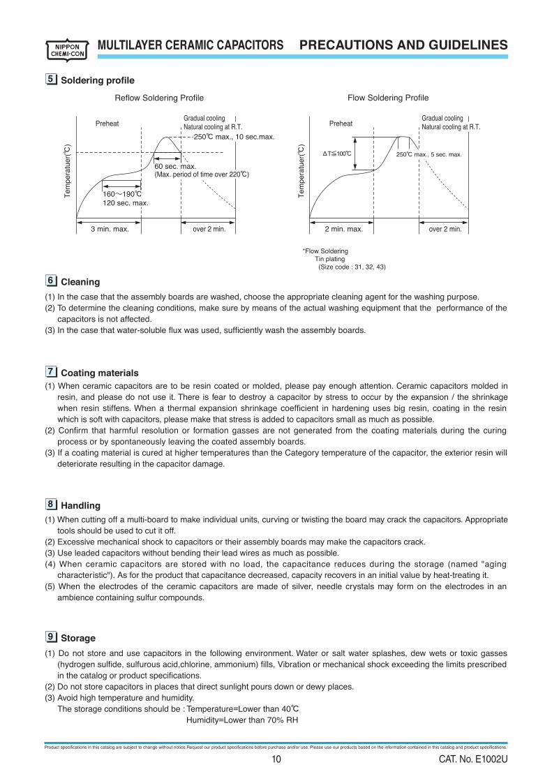
Preheat
Tem
pera
tuer(
℃)
Tem
pera
tuer(
℃)
3 min. max. over 2 min.
250℃ max., 10 sec.max.
2 min. max. over 2 min.
ΔT≦100℃
Gradual coolingNatural cooling at R.T. Preheat
Gradual coolingNatural cooling at R.T.
*Flow Soldering
Tin plating
(Size code : 31, 32, 43)
60 sec. max.(Max. period of time over 220℃)
250℃ max., 5 sec. max.
Reflow Soldering Proile Flow Soldering Proile
7 Coating materials
8 Handling
5 Soldering profile
6 Cleaning
9 Storage
160~190℃120 sec. max.
Product specifications in this catalog are subject to change without notice.Request our product specifications before purchase and/or use. Please use our products based on the information contained in this catalog and product specifications.
10 CAT. No. E1002U
PRECAUTIONS AND GUIDELINES MULTILAYER CERAMIC CAPACITORS
Product specifications in this catalog are subject to change without notice.
Please request and make sure our product specifications before purchase and/or use.
Any safety concern arising out regarding our products,please contact our sales office immediately.
For the details, refer to Guideline of notabilia for ixed multilayer ceramic capacitors for use in electronic equipment,
EIAJ RCR-2335 issued by Electronic Industries Association of Japan.
11 Catalogs
10 About AEC-Q200
12 Regarding compliance for EU REACH Regulation
(1) According to the content of REACH handbook (Guidance on requirements for substances in articles which is published
on May 2008), our electronic components are "articles without any intended release". Therefore they are not applicable
for "Registration" for EU REACH Regulation Article 7 (1).
Reference: Electrolytic Condenser Investigation Society
"Study of REACH Regulation in EU about Electrolytic Capacitor" (publicized on 13 March 2008)
(2) Nippon Chemi-Con develops the products without substance of very high concern(SVHC).
DEHP(CASNo.117-81-7) was contained as some covering material, Nippon Chemi-Con abolished use of DEHP totally
at June, 2011.
The Automotive Electronics Council (AEC) was originally established by American major automotive manufactures. Today,
the committees are composed of representatives from the sustaining Members of manufacturing companies in automotive
electrical components. It has standardized the criteria for ”stress test qualification” and ”reliability test” for the electronic
components.
AEC-Q200 is the reliability test standard for approval of passive components, it has been specified test subjects and quantity
etc. for each components. Criteria of reliability tests such as our main products ”Multilayer Ceramic Capacitors” are also
described in this.
As customer requirement, Chemi-Con has submits the test results according to AEC-Q200 for the Multilayer Ceramic
Capacitors used in automotive applications to increase in recent years.
AEC-Q200 compliant product is the product which we evaluated by AEC-Q200 standard.
Please contact us for more information.
Please obtain and verify our product specification sheet before you use our product.
Product specifications in this catalog are subject to change without notice.Request our product specifications before purchase and/or use. Please use our products based on the information contained in this catalog and product specifications.
11 CAT. No. E1002U
PRECAUTIONS AND GUIDELINES MULTILAYER CERAMIC CAPACITORS
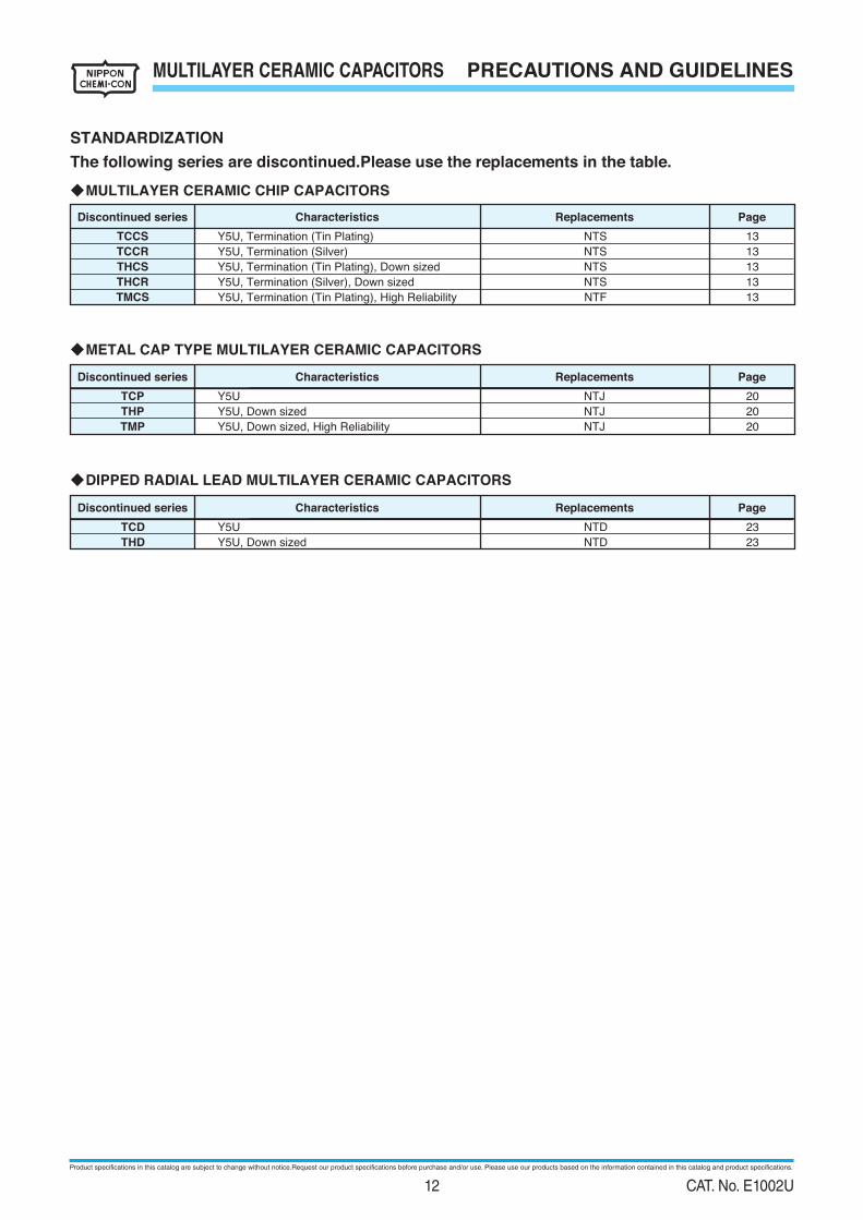
◆MULTILAYER CERAMIC CHIP CAPACITORS
STANDARDIZATION
The following series are discontinued.Please use the replacements in the table.
◆METAL CAP TYPE MULTILAYER CERAMIC CAPACITORS
◆DIPPED RADIAL LEAD MULTILAYER CERAMIC CAPACITORS
Discontinued series Characteristics Replacements Page
Y5U, Termination (Tin Plating)
Y5U, Termination (Silver)
Y5U, Termination (Tin Plating), Down sized
Y5U, Termination (Silver), Down sized
Y5U, Termination (Tin Plating), High Reliability
NTS
NTS
NTS
NTS
NTF
13
13
13
13
13
TCCS
TCCR
THCS
THCR
TMCS
Y5U
Y5U, Down sized
Y5U, Down sized, High Reliability
NTJ
NTJ
NTJ
20
20
20
TCP
THP
TMP
Y5U
Y5U, Down sized
NTD
NTD
23
23
TCD
THD
Discontinued series Characteristics Replacements Page
Discontinued series Characteristics Replacements Page
Product specifications in this catalog are subject to change without notice.Request our product specifications before purchase and/or use. Please use our products based on the information contained in this catalog and product specifications.
12 CAT. No. E1002U
MULTILAYER CERAMIC CHIP CAPACITORS
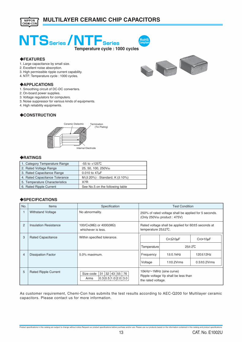
◆RATINGS
-55 to +125℃1. Category Temperature Range
25, 50, 100, 250Vdc2. Rated Voltage Range
0.010 to 47µF3. Rated Capacitance Range
M (±20%) : Standard, K (±10%) 4. Rated Capacitance Tolerance
5. Temperature Characteristics
6. Rated Ripple Current
X7R
See No.5 on the following table
◆SPECIFICATIONS
No abnormality. 250% of rated voltage shall be applied for 5 seconds.
(Only 250Vdc product : 475V)
Withstand Voltage1
3 Rated Capacitance Within specified tolerance.
4 Dissipation Factor 5.0% maximum.
2 Insulation Resistance 100/CR(MΩ) or 4000(MΩ)
whichever is less.
Rated voltage shall be applied for 60±5 seconds at
temperature 25±2℃.
Test ConditionSpecificationItemsNo.
5 Rated Ripple Current 10kHz~1MHz (sine curve)
Ripple voltage Vp shall be less than
the rated voltage.
Size code 31 32 43 55
0.3 0.5 1.0 2.0Arms
Temperature
Frequency
Voltage
1±0.1kHz
1±0.2Vrms
25±2℃
120±12Hz
0.5±0.2Vrms
CR≦10µF CR>10µF
◆FEATURES1. Large capacitance by small size.
2. Excellent noise absorption.
3. High permissible ripple current capability.
4. NTF: Temperature cycle : 1000 cycles.
◆APPLICATIONS1. Smoothing circuit of DC-DC converters.
2. On-board power supplies.
3. Voltage regulators for computers.
3. Noise suppressor for various kinds of equipments.
4. High reliability equipments.
◆CONSTRUCTION
Ceramic Dielectric Termination(Tin Plating)
Internal Electrode
Temperature cycle : 1000 cycles
RoHSCompliantNTSSeries /NTFSeries
76
3.0
As customer requirement, Chemi-Con has submits the test results according to AEC-Q200 for Multilayer ceramic
capacitors. Please contact us for more information.
Product specifications in this catalog are subject to change without notice.Request our product specifications before purchase and/or use. Please use our products based on the information contained in this catalog and product specifications.
13 CAT. No. E1002U
MULTILAYER CERAMIC CHIP CAPACITORS
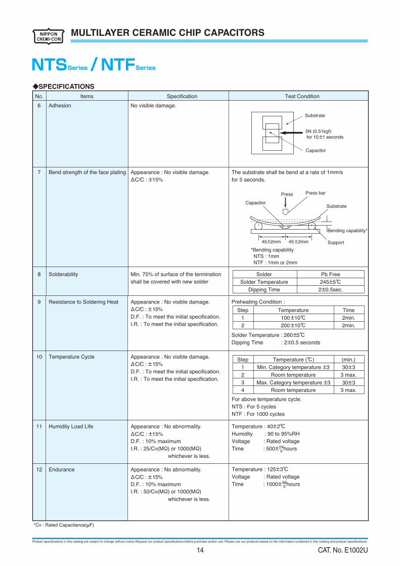
◆SPECIFICATIONS
8 Solderability Min. 75% of surface of the termination
shall be covered with new solder
*Bending capability
NTS : 1mm
NTF : 1mm or 2mm
6
7
Adhesion
Bend strength of the face plating
No visible damage.
Appearance : No visible damage.
ΔC/C : ±15%
ΔC/C : ±15%
ΔC/C : ±15%
ΔC/C : ±15%
ΔC/C : ±15%
The substrate shall be bend at a rate of 1mm/s
for 5 seconds.
Substrate
5N (0.51kgf)
for 10±1 seconds
Capacitor
Bending capability*
Substrate
Press Press bar
Capacitor
Support45±2mm 45±2mm
10 Temperature Cycle Appearance : No visible damage.
D.F. : To meet the initial specification.
I.R. : To meet the initial specification.
9 Resistance to Soldering Heat Appearance : No visible damage.
D.F. : To meet the initial specification.
I.R. : To meet the initial specification.
11 Humidity Load Life
12 Endurance
Appearance : No abnormality.
D.F. : 10% maximum
I.R. : 25/CR(MΩ) or 1000(MΩ)
I.R. : 50/CR(MΩ) or 1000(MΩ)
whichever is less.
Appearance : No abnormality.
D.F. : 10% maximum
whichever is less.
Temperature : 40±2℃
Humidity : 90 to 95%RH
Voltage : Rated voltage
Time : 500±24hours
Temperature : 125±3℃
Voltage : Rated voltage
Time : 1000±48hours
For above temperature cycle.
NTS : For 5 cycles
NTF : For 1000 cycles
Step
1
2
Temperature (℃)
Min. Category temperature ±3
Max. Category temperature ±3
Room temperature
(min.)
30±3
30±3
3 max.
3
4 Room temperature 3 max.
0
0
Step
1
2
Temperature
100±10℃
200±10℃
Time
2min.
2min.
Solder
Solder Temperature
Dipping Time
Pb Free
245±5℃
2±0.5sec.
Preheating Condition :
Solder Temperature : 260±5℃
Dipping Time : 2±0.5 seconds
*CR : Rated Capacitance(µF)
Test ConditionSpecificationItemsNo.
NTSSeries / NTFSeries
Product specifications in this catalog are subject to change without notice.Request our product specifications before purchase and/or use. Please use our products based on the information contained in this catalog and product specifications.
14 CAT. No. E1002U
MULTILAYER CERAMIC CHIP CAPACITORS
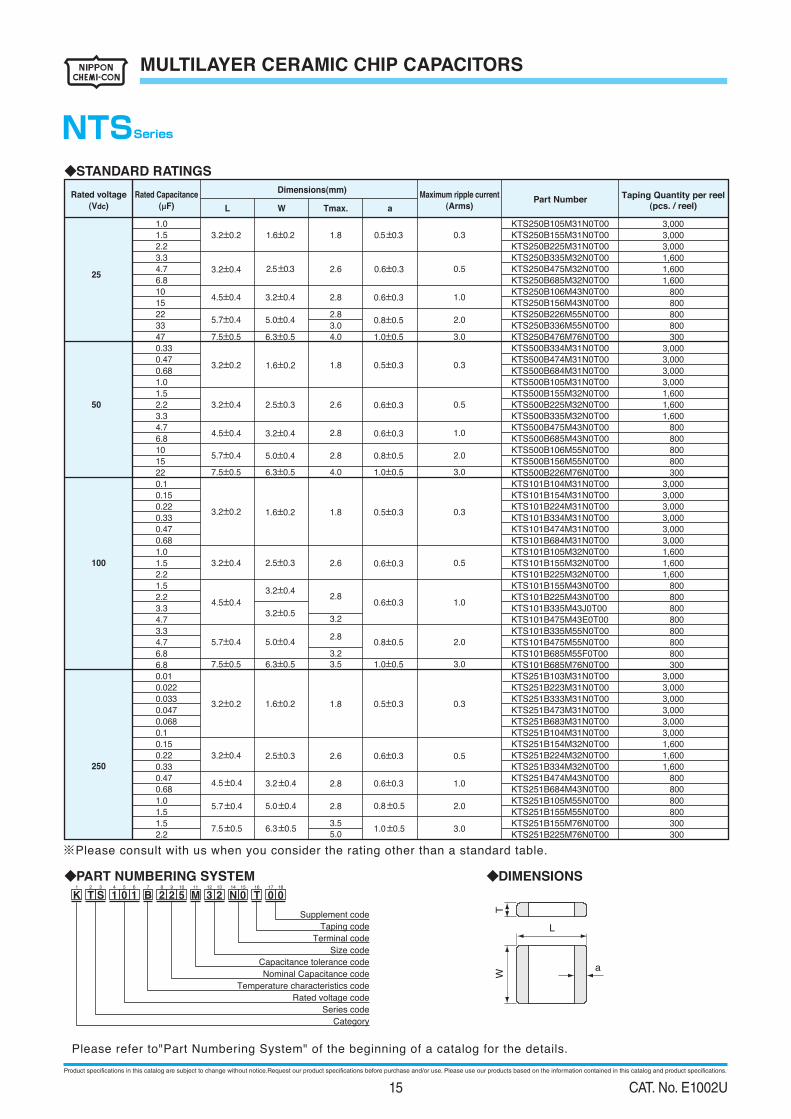
◆STANDARD RATINGS
Rated voltage
(Vdc)
Taping Quantity per reel
(pcs. / reel)Part Number
Maximum ripple current
(Arms)
Rated Capacitance
(µF)
Dimensions(mm)
L W Tmax. a
NTSSeries
Please refer to"Part Numbering System" of the beginning of a catalog for the details.
◆PART NUMBERING SYSTEM
Supplement code
Taping code
Terminal code
Size code
Capacitance tolerance code
Nominal Capacitance code
Temperature characteristics code
Rated voltage code
Series code
Category
K T S 1 0 1 B 2 2 5 M 3 2 0 T 0 0N1 3 42 6 7 8 9 10 13125 18171611 1514
a
TW
L
◆DIMENSIONS
※Please consult with us when you consider the rating other than a standard table.
25
50
100
250
KTS250B105M31N0T00
KTS250B155M31N0T00
KTS250B225M31N0T00
KTS250B335M32N0T00
KTS250B475M32N0T00
KTS250B685M32N0T00
KTS250B106M43N0T00
KTS250B156M43N0T00
KTS250B226M55N0T00
KTS250B336M55N0T00
KTS250B476M76N0T00
KTS500B334M31N0T00
KTS500B474M31N0T00
KTS500B684M31N0T00
KTS500B105M31N0T00
KTS500B155M32N0T00
KTS500B225M32N0T00
KTS500B335M32N0T00
KTS500B475M43N0T00
KTS500B685M43N0T00
KTS500B106M55N0T00
KTS500B156M55N0T00
KTS500B226M76N0T00
KTS101B104M31N0T00
KTS101B154M31N0T00
KTS101B224M31N0T00
KTS101B334M31N0T00
KTS101B474M31N0T00
KTS101B684M31N0T00
KTS101B105M32N0T00
KTS101B155M32N0T00
KTS101B225M32N0T00
KTS101B155M43N0T00
KTS101B225M43N0T00
KTS101B335M43J0T00
KTS101B475M43E0T00
KTS101B335M55N0T00
KTS101B475M55N0T00
KTS101B685M55F0T00
KTS101B685M76N0T00
KTS251B103M31N0T00
KTS251B223M31N0T00
KTS251B333M31N0T00
KTS251B473M31N0T00
KTS251B683M31N0T00
KTS251B104M31N0T00
KTS251B154M32N0T00
KTS251B224M32N0T00
KTS251B334M32N0T00
KTS251B474M43N0T00
KTS251B684M43N0T00
KTS251B105M55N0T00
KTS251B155M55N0T00
KTS251B155M76N0T00
KTS251B225M76N0T00
0.3
0.5
1.0
2.0
0.3
0.5
1.0
2.0
3.0
3.0
0.3
0.5
1.0
2.0
3.0
0.3
1.0
2.0
3.0
1.0
1.5
2.2
3.3
4.7
6.8
10
15
22
33
47
0.33
0.47
0.68
1.0
1.5
2.2
3.3
4.7
6.8
10
15
22
0.1
0.15
0.22
0.33
0.47
0.68
1.0
1.5
2.2
1.5
2.2
3.3
4.7
3.3
4.7
6.8
6.8
0.01
0.022
0.033
0.047
0.068
0.1
0.15
0.22
0.33
0.47
0.68
1.0
1.5
1.5
2.2
3.2±0.2 1.6±0.2 0.5±0.3
3.2±0.4 2.5±0.3 0.6±0.3
4.5±0.4 3.2±0.4 0.6±0.3
5.7±0.4
7.5±0.5
7.5±0.5
7.5±0.5
5.0±0.4 0.8±0.5
1.0±0.5
1.0±0.5
1.0±0.5
3.2±0.2 1.6±0.2 0.5±0.3
3.2±0.4 2.5±0.3 0.6±0.3
4.5±0.4
4.5±0.4
5.7±0.4
3.2±0.4
3.2±0.4
3.2±0.5
5.0±0.4
0.6±0.3
5.7±0.4
5.7±0.4
7.5±0.5
5.0±0.4
6.3±0.5
6.3±0.5
6.3±0.5
5.0±0.4
6.3±0.5
0.8±0.5
0.8±0.5
1.0±0.5
3.2±0.2 1.6±0.2
1.6±0.2
0.5±0.3
0.5±0.3
3.2±0.4
4.5±0.4
2.5±0.3
3.2±0.4
0.6±0.3
0.6±0.3
0.6±0.3
0.8±0.5
3.2±0.2
2.6
1.8
2.8
2.8
3.0
4.0
4.0
1.8
2.6
2.8
2.8
1.8
2.6
2.8
3.2
2.8
3.23.5
1.8
2.8
0.53.2±0.4 2.5±0.3 0.6±0.32.6
2.8
3.5
5.0
3,000
3,000
3,000
1,600
1,600
1,600
800
800
800
800
300
3,000
3,000
3,000
3,000
1,600
1,600
1,600
800
800
800
800
300
3,000
3,000
3,000
3,000
3,000
3,000
1,600
1,600
1,600
800
800
800
800
800
800
800
300
3,000
3,000
3,000
3,000
3,000
3,000
1,600
1,600
1,600
800
800
800
800
300
300
Product specifications in this catalog are subject to change without notice.Request our product specifications before purchase and/or use. Please use our products based on the information contained in this catalog and product specifications.
15 CAT. No. E1002U
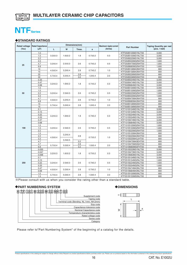
◆PART NUMBERING SYSTEM
Supplement code
Taping code
Terminal code (Bending NL:1mm, NH:2mm)
Size code
Capacitance tolerance code
Nominal Capacitance code
Temperature characteristics code
Rated voltage code
Series code
Category
K T F 1 0 1 B 2 2 5 M 3 2 H T 0 0N1 3 42 6 7 8 9 10 13125 18171611 1514
a
TW
L
◆DIMENSIONS
Please refer to"Part Numbering System" of the beginning of a catalog for the details.
※Please consult with us when you consider the rating other than a standard table.
MULTILAYER CERAMIC CHIP CAPACITORS
◆STANDARD RATINGS
NTFSeries
Rated voltage
(Vdc)
Taping Quantity per reel
(pcs. / reel)Part Number
Maximum ripple current
(Arms)
Rated Capacitance
(µF)
Dimensions(mm)
L W Tmax. a
25
50
100
250
1.0
1.5
2.2
3.3
4.7
6.8
10
15
22
33
0.33
0.47
0.68
1.0
1.5
2.2
3.3
4.7
6.8
10
15
0.1
0.15
0.22
0.33
0.47
0.68
1.0
1.5
2.2
1.5
2.2
3.3
4.7
4.7
6.8
0.033
0.047
0.068
0.1
0.15
0.22
0.33
0.47
0.68
1.0
1.5
0.3
0.5
1.0
2.0
0.3
0.5
1.0
2.0
0.3
0.5
1.0
2.0
0.3
0.5
1.0
2.0
3.2±0.3
3.2±0.4
4.5±0.4
5.7±0.4
3.2±0.3
3.2±0.4
4.5±0.4
5.7±0.4
3.2±0.3
3.2±0.4
4.5±0.4
5.7±0.4
3.2±0.3
3.2±0.4
4.5±0.4
5.7±0.4
1.6±0.2
2.5±0.3
3.2±0.4
5.0±0.4
1.6±0.2
2.5±0.3
3.2±0.4
5.0±0.4
1.6±0.2
2.5±0.3
3.2±0.4
3.2±0.5
5.0±0.4
1.6±0.2
2.5±0.3
3.2±0.4
5.0±0.4
1.8
2.6
2.8
2.8
3.0
1.8
2.6
2.8
2.8
1.8
2.6
2.8
3.2
2.8
3.2
1.8
2.6
2.8
2.8
0.7±0.2
0.7±0.2
0.7±0.2
1.0±0.4
0.7±0.2
0.7±0.2
0.7±0.2
1.0±0.4
0.7±0.2
0.7±0.2
0.7±0.2
1.0±0.4
0.7±0.2
0.7±0.2
0.7±0.2
1.0±0.4
KTF250B105M31NLT00
KTF250B155M31NLT00
KTF250B225M31NLT00
KTF250B335M32NHT00
KTF250B475M32NHT00
KTF250B685M32NHT00
KTF250B106M43NHT00
KTF250B156M43NHT00
KTF250B226M55NHT00
KTF250B336M55NHT00
KTF500B334M31NLT00
KTF500B474M31NLT00
KTF500B684M31NLT00
KTF500B105M31NLT00
KTF500B155M32NHT00
KTF500B225M32NHT00
KTF500B335M32NHT00
KTF500B475M43NHT00
KTF500B685M43NHT00
KTF500B106M55NHT00
KTF500B156M55NHT00
KTF101B104M31NLT00
KTF101B154M31NLT00
KTF101B224M31NLT00
KTF101B334M31NLT00
KTF101B474M31NLT00
KTF101B684M31NLT00
KTF101B105M32NHT00
KTF101B155M32NHT00
KTF101B225M32NHT00
KTF101B155M43NHT00
KTF101B225M43NHT00
KTF101B335M43JHT00
KTF101B475M43EHT00
KTF101B475M55NHT00
KTF101B685M55FHT00
KTF251B333M31NLT00
KTF251B473M31NLT00
KTF251B683M31NLT00
KTF251B104M31NLT00
KTF251B154M32NLT00
KTF251B224M32NLT00
KTF251B334M32NLT00
KTF251B474M43NLT00
KTF251B684M43NLT00
KTF251B105M55NLT00
KTF251B155M55NLT00
3,000
3,000
3,000
1,600
1,600
1,600
800
800
800
800
3,000
3,000
3,000
3,000
1,600
1,600
1,600
800
800
800
800
3,000
3,000
3,000
3,000
3,000
3,000
1,600
1,600
1,600
800
800
800
800
800
800
3,000
3,000
3,000
3,000
1,600
1,600
1,600
800
800
800
800
Product specifications in this catalog are subject to change without notice.Request our product specifications before purchase and/or use. Please use our products based on the information contained in this catalog and product specifications.
16 CAT. No. E1002U
MULTILAYER CERAMIC CHIP CAPACITORS
◆RATINGS
-55~+150℃1. Category Temperature Range
25, 50, 100 Vdc2. Rated Voltage Range
0.033~15μF3. Rated Capacitance Range
M(±20%)4. Rated Capacitance Tolerance
5. Temperature Characteristics
6. Rated Ripple Current
X8L
See No.5 on the following table
◆SPECIFICATIONS
No abnormality. 250% of rated voltage shall be applied for 5 seconds.
(Only 250Vdc product : 475V)
Withstand Voltage1
3 Rated Capacitance Within specified tolerance.
4 Dissipation Factor 5.0% maximum.
2 Insulation Resistance 100/CR(MΩ) or 4000(MΩ)
whichever is less.
Rated voltage shall be applied for 60±5 seconds at
temperature 25±2℃.
Test ConditionSpecificationItemsNo.
5 Rated Ripple Current 10kHz~1MHz (sine curve)
Ripple voltage Vp shall be less than
the rated voltage.
The surface temperature MLCC must not exceed the
maximum category temperature when the ripple current
is applied.
Size code 31 32 43 55
0.3 0.5 1.0 2.0Arms
Temperature
Frequency
Voltage
1±0.1kHz
1±0.2Vrms
25±2℃
120±12Hz
0.5±0.2Vrms
CR≦10µF CR>10µF
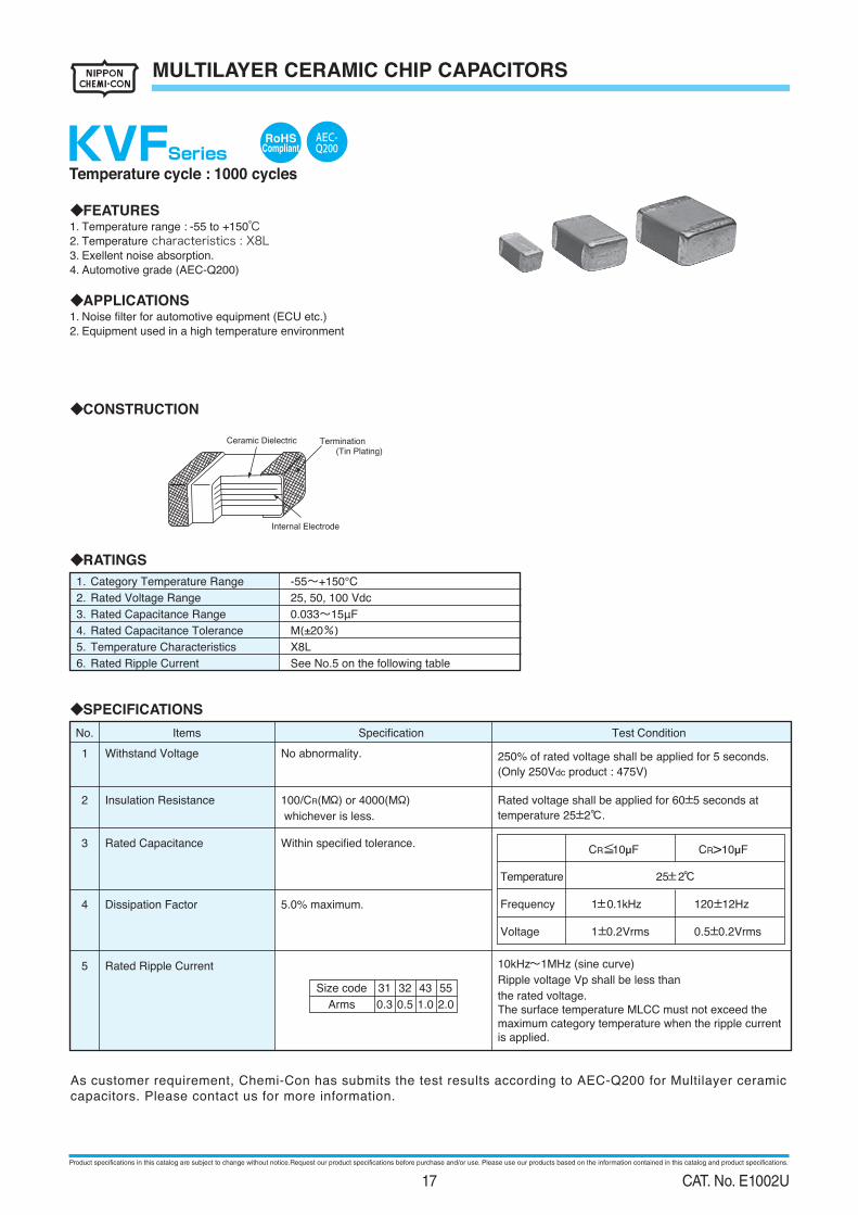
◆FEATURES1. Temperature range : -55 to +150℃
2. Temperature characteristics : X8L
3. Exellent noise absorption.
4. Automotive grade (AEC-Q200)
◆APPLICATIONS1. Noise filter for automotive equipment (ECU etc.)2. Equipment used in a high temperature environment
◆CONSTRUCTION
Ceramic Dielectric Termination(Tin Plating)
Internal Electrode
Temperature cycle : 1000 cycles
RoHSCompliantKVFSeries
As customer requirement, Chemi-Con has submits the test results according to AEC-Q200 for Multilayer ceramic capacitors. Please contact us for more information.
AEC-Q200
Product specifications in this catalog are subject to change without notice.Request our product specifications before purchase and/or use. Please use our products based on the information contained in this catalog and product specifications.
17 CAT. No. E1002U
MULTILAYER CERAMIC CHIP CAPACITORS
KVFSeries
◆SPECIFICATIONS
No. Items Speciication Test Condition
6
High TemperatureExposure(Storage)
Appearance : No abnormality.ΔC/C : ±20%
D.F. : 10% maximumI.R. : 50/CR(MΩ) or 1000(MΩ)whichever is less.
Temperature : Max. category temperature±3℃Time:1000±48
0 hours
7 Temperature Cycle
Appearance : No visible damage.ΔC/C : ±15%D.F. : To meet the initial speciication.I.R. : To meet the initial speciication.
Step Temperature (℃) (min.)1 Min.Category temperature±3 30±3
2 Room temperature 3 max.3 Max. Category temperature±3 30±3
4 Room temperature 3 max.(Epoxy resin PCB t=1.6mm)For 1000 cycles
8 Biased Humidity
Appearance : No abnormality.ΔC/C : ±20%
D.F. : 10% maximumI.R. : 25/CR(MΩ) or 1000(MΩ)
whichever is less.
Temperature : 85℃±3℃Humidity : 80 ~ 85%RH
Voltage : Rated voltageTime:1000±48
0 hours
9 Operational Life
Appearance : No abnormality.ΔC/C : ±20%
D.F. : 10% maximumI.R. : 50/CR(MΩ) or 1000(MΩ)
whichever is less.
Temperature : Max. category temperature±3℃Voltage : Rated voltageTime:1000±48
0 hours
10 Mechanical Shock
Appearance : No abnormality.ΔC/C :To meet the initial speciication.D.F. : To meet the initial speciication.
MIL-STD-202 Method213 Condition FPeak value : 1,500 GNormal duration : 0.5 ms
Velocity change : 15.4 ft/sec (4.7m/s)Direction and time : 3 times each in
X,Y, Z axis. Total 18 times
11 Resistance toSoldering Heat
Appearance : No visible damage.ΔC/C : ±15%D.F. : To meet the initial speciication.I.R. : To meet the initial speciication.
Preheating temperature : 150±10℃Preheating time : 1 to 2 minuteSolder temp. : 260±5℃Dipping Time : 10±1s
12 ESD
Appearance : No abnormality.ΔC/C :To meet the initial speciication.D.F. : To meet the initial speciication.I.R. : To meet the initial speciication.
AEC-Q200-002Connection : Between terminalsDirect Contact : 8kV (150pF 2000Ω)Times : ±1time
13 SolderabilityMin. 75% of surface of the terminationshall be covered with new solder.
Solder Pb FreeSolder Temperature 245±5℃Dipping Time 2±0.5s
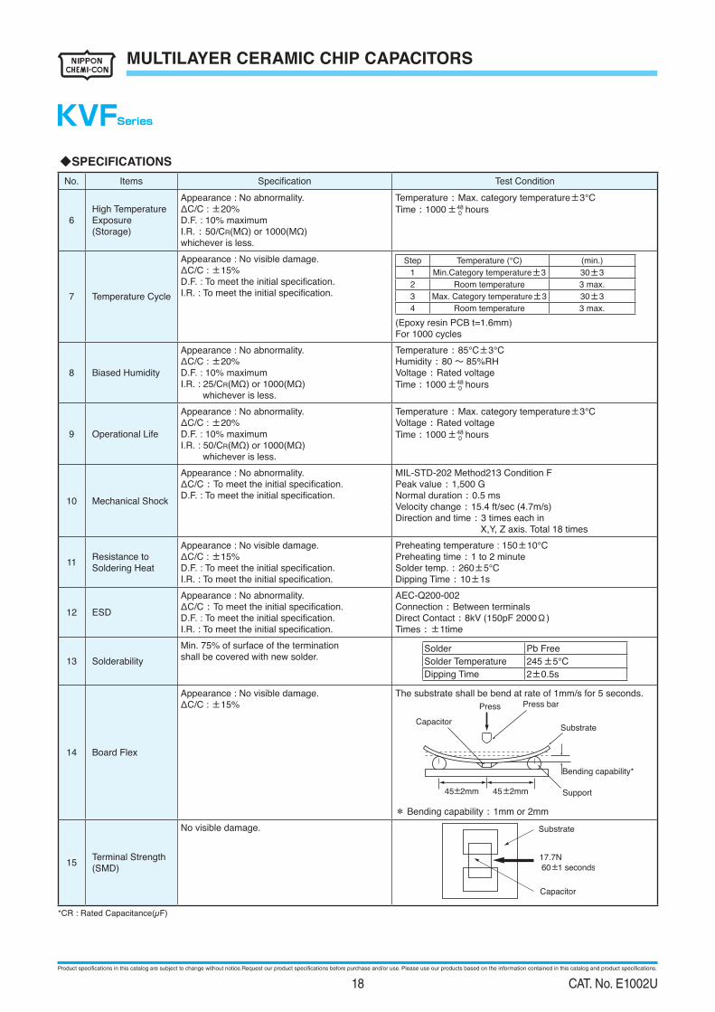
14 Board Flex
Appearance : No visible damage.ΔC/C : ±15%
The substrate shall be bend at rate of 1mm/s for 5 seconds.
Bending capability*
Substrate
Press Press bar
Capacitor
Support45±2mm 45±2mm
* Bending capability : 1mm or 2mm
15 Terminal Strength(SMD)
No visible damage. Substrate
17.7N
60±1 seconds
Capacitor
*CR : Rated Capacitance(µF)
Product specifications in this catalog are subject to change without notice.Request our product specifications before purchase and/or use. Please use our products based on the information contained in this catalog and product specifications.
18 CAT. No. E1002U
MULTILAYER CERAMIC CHIP CAPACITORS
KVFSeries
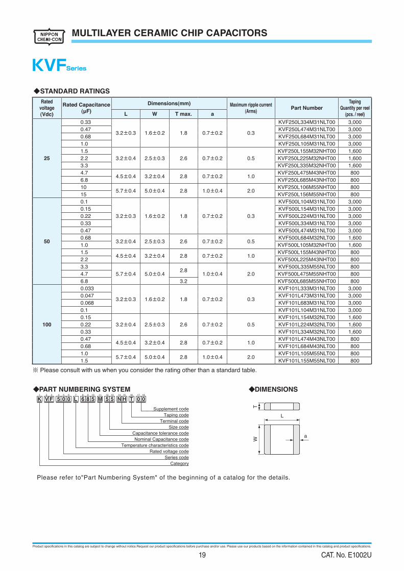
Please refer to"Part Numbering System" of the beginning of a catalog for the details.
◆PART NUMBERING SYSTEM
Supplement code
Taping code
Terminal code
Size code
Capacitance tolerance code
Nominal Capacitance code
Temperature characteristics code
Rated voltage code
Series code
Category
K V F 5 0 0 L 6 8 5 M 5 5 H T 0 0N1 3 42 6 7 8 9 10 13125 18171611 1514
a
TW
L
◆DIMENSIONS
◆STANDARD RATINGS
Rated
voltage
(Vdc)
Rated Capacitance
(μF)Dimensions(mm) Maximum ripple current
(Arms)Part Number
Taping
Quantity per reel
(pcs. / reel)L W T max. a
25
0.33
3.2±0.3 1.6±0.2 1.8 0.7±0.2 0.3
KVF250L334M31NLT00 3,0000.47 KVF250L474M31NLT00 3,0000.68 KVF250L684M31NLT00 3,0001.0 KVF250L105M31NLT00 3,0001.5
3.2±0.4 2.5±0.3 2.6 0.7±0.2 0.5
KVF250L155M32NHT00 1,6002.2 KVF250L225M32NHT00 1,6003.3 KVF250L335M32NHT00 1,6004.7
4.5±0.4 3.2±0.4 2.8 0.7±0.2 1.0 KVF250L475M43NHT00 800
6.8 KVF250L685M43NHT00 800
105.7±0.4 5.0±0.4 2.8 1.0±0.4 2.0
KVF250L106M55NHT00 800
15 KVF250L156M55NHT00 800
50
0.1
3.2±0.3 1.6±0.2 1.8 0.7±0.2 0.3
KVF500L104M31NLT00 3,0000.15 KVF500L154M31NLT00 3,0000.22 KVF500L224M31NLT00 3,0000.33 KVF500L334M31NLT00 3,0000.47 KVF500L474M31NLT00 3,0000.68
3.2±0.4 2.5±0.3 2.6 0.7±0.2 0.5 KVF500L684M32NLT00 1,600
1.0 KVF500L105M32NHT00 1,6001.5
4.5±0.4 3.2±0.4 2.8 0.7±0.2 1.0 KVF500L155M43NHT00 800
2.2 KVF500L225M43NHT00 800
3.3
5.7±0.4 5.0±0.42.8 1.0±0.4 2.0
KVF500L335M55NLT00 800
4.7 KVF500L475M55NHT00 800
6.8 3.2 KVF500L685M55NHT00 800
100
0.033
3.2±0.3 1.6±0.2 1.8 0.7±0.2 0.3
KVF101L333M31NLT00 3,0000.047 KVF101L473M31NLT00 3,0000.068 KVF101L683M31NLT00 3,0000.1 KVF101L104M31NLT00 3,0000.15
3.2±0.4 2.5±0.3 2.6 0.7±0.2 0.5
KVF101L154M32NLT00 1,6000.22 KVF101L224M32NLT00 1,6000.33 KVF101L334M32NLT00 1,6000.47
4.5±0.4 3.2±0.4 2.8 0.7±0.2 1.0 KVF101L474M43NLT00 800
0.68 KVF101L684M43NLT00 800
1.05.7±0.4 5.0±0.4 2.8 1.0±0.4 2.0
KVF101L105M55NLT00 800
1.5 KVF101L155M55NLT00 800
※ Please consult with us when you consider the rating other than a standard table.
Product specifications in this catalog are subject to change without notice.Request our product specifications before purchase and/or use. Please use our products based on the information contained in this catalog and product specifications.
19 CAT. No. E1002U
METAL CAP TYPE MULTILAYER CERAMIC CAPACITORS
◆RATINGS
1. Category Temperature Range -55~+125℃
25, 50, 100, 250Vdc
1.0 to 100µF
M(±20%)
X7R
See No.5 on the following table
2. Rated Voltage Range
3. Rated Capacitance Range
4. Rated Capacitance Tolerance
5. Temperature Characteristics
6. Rated Ripple Current
◆SPECIFICATIONS
(Only 250Vdc products : 475V)
Withstand Voltage1
3
4
2
5
Insulation Resistance
Rated Ripple Current
5.0% maximumDissipation Factor
Rated Capacitance Within specified tolerance.
100/CR(MΩ) or 4000(MΩ) whichever
No abnormality. 250% of rated voltage shall be applied for 5 seconds.
is less.
Rated voltage shall be applied for 60±5 seconds at
temperature 25±2℃.
10kHz~1MHz (sine curve)
Ripple voltage Vp shall be less than
the rated voltage.
Test ConditionSpecificationItemsNo.
Size
Element
Arms
55 76
1
2.0
2
3.0
1
3.0
2
4.0
Temperature
Frequency
Voltage
1±0.1kHz
1±0.2Vrms
25±2℃
120±12Hz
0.5±0.2Vrms
CR>10µFCR≦10µF
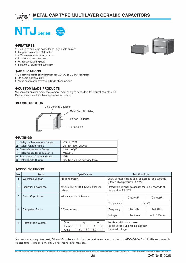
◆FEATURES1. Small size and large capacitance, high ripple current.
2. Temperature cycle: 1000 cycles.
3. X7R temperature characteristics.
4. Excellent noise absorption.
5. For reflow soldering use.
6. Suitable for aluminum substrate.
◆APPLICATIONS1. Smoothing circuit of switching mode AC-DC or DC-DC converter.
2. On-board power supply.
3. Noise suppressor for various kinds of equipments.
◆CONSTRUCTION
◆CUSTOM MADE PRODUCTSWe can offer custom made one element metal cap type capacitors for request of customers.
Please contact us if you have questions for details.
Chip Ceramic Capacitor
Metal Cap, Tin plating
Pb-free Soldering
Termination
RoHSCompliantNTJ Series
As customer requirement, Chemi-Con has submits the test results according to AEC-Q200 for Multilayer ceramic
capacitors. Please contact us for more information.
Product specifications in this catalog are subject to change without notice.Request our product specifications before purchase and/or use. Please use our products based on the information contained in this catalog and product specifications.
20 CAT. No. E1002U
METAL CAP TYPE MULTILAYER CERAMIC CAPACITORS
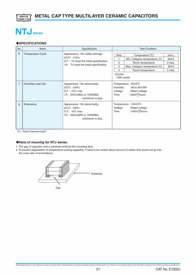
◆Note of mountig for NTJ series.
1. The gap of capacitor and a substrate shall be the mounting face.
2. To prevent degredation of temperature cycling capability, if need to be careful about amount of solder that would not go into
the inner side of terminations.
Substrate
Gap
◆SPECIFICATIONS
8
6
7
Temperature Cycle Appearance : No visible damage.
ΔC/C : ±15%
D.F. : To meet the initial specification.
I.R. : To meet the initial specification.
Humidity Load Life
Endurance
Appearance : No abnormality.
ΔC/C : ±20%
D.F. : 10% max.
I.R. : 25/CR(MΩ) or 1000(MΩ)
whichever is less.
Appearance : No abnormality.
ΔC/C : ±20%
D.F. : 10% max.
I.R. : 50/CR(MΩ) or 1000(MΩ)
whichever is less.
Temperature : 40±2℃
Humidity : 90 to 95%RH
Voltage : Rated voltage
Time : 500± hours24
Temperature : 125±3℃
Voltage : Rated voltage
Time : 1000± hours48
<Cycle>
1000 cycles
Step
1
2
Temperature (℃)
Min. Category temperature ±3
Room temperature
(min.)
30±3
3 max.
3
4
Max. Category temperature ±3
Room temperature
30±3
3 max.
0
0
*CR : Rated Capacitance(µF)
Test ConditionSpecificationItemsNo.
NTJSeries
Product specifications in this catalog are subject to change without notice.Request our product specifications before purchase and/or use. Please use our products based on the information contained in this catalog and product specifications.
21 CAT. No. E1002U
Rated voltage
(Vdc)
Taping
Quantity per reel
(pcs. / reel)Element Part Number
Maximum ripple current
(Arms)
Rated Capacitance
(µF)
Dimensions(mm)
L W Tmax. a
METAL CAP TYPE MULTILAYER CERAMIC CAPACITORS
◆STANDARD RATINGS
25
50
100
250
KTJ250B336M55AFT00
KTJ250B336M55BFT00
KTJ250B476M55BFT00
KTJ250B476M76AFT00
KTJ250B686M76BFT00
KTJ250B107M76BFT00
KTJ500B156M55AFT00
KTJ500B156M55BFT00
KTJ500B226M55BFT00
KTJ500B226M76AFT00
KTJ500B336M76BFT00
KTJ500B476M76BFT00
KTJ101B475M55AFT00
KTJ101B685M55BFT00
KTJ101B106M55BFT00
KTJ101B685M76AFT00
KTJ101B156M76BFT00
KTJ251B105M55AFT00
KTJ251B155M55BFT00
KTJ251B225M55BFT00
KTJ251B225M76AFT00
KTJ251B335M76BFT00
400
2,000
2,000
1,200
500
400
400
2,000
2,000
1,200
500
500
400
2,000
2,000
1,200
500
400
2,000
2,000
1,200
5003.0
3.0
3.0
2.0
4.0
3.0
3.0
2.0
4.0
3.0
3.0
2.0
4.0
3.0
3.0
2.033
33
47
47
68
100
15
15
22
22
33
47
4.7
6.8
10
6.8
15
1.0
1.5
2.2
2.2
3.3 7.8±0.5
7.8±0.5
6.0±0.4
6.0±0.4
7.8±0.5
7.8±0.5
6.0±0.4
6.0±0.4
7.8±0.5
7.8±0.5
6.0±0.4
6.0±0.4
7.8±0.5
7.8±0.5
6.0±0.4
6.0±0.4
6.6±0.5
6.6±0.5
5.3±0.4
5.3±0.4
6.6±0.5
6.6±0.5
5.3±0.4
5.3±0.4
6.6±0.5
6.6±0.5
5.3±0.4
5.3±0.4
6.6±0.5
6.6±0.5
5.3±0.4
5.3±0.4
8.5
5.5
6.5
5.53.8
8.5
5.5
5.5
3.8
8.5
5.5
5.5
3.8
9.5
8.5
5.5
5.5
3.8
1.5±0.3
1.5±0.3
1.3±0.3
1.3±0.3
1.5±0.3
1.5±0.3
1.3±0.3
1.3±0.3
1.5±0.3
1.5±0.3
1.3±0.3
1.3±0.3
1.5±0.3
1.5±0.3
1.3±0.3
1.3±0.3
2
1
2
1
2
1
2
1
2
1
2
1
2
1
2
1
NTJSeries
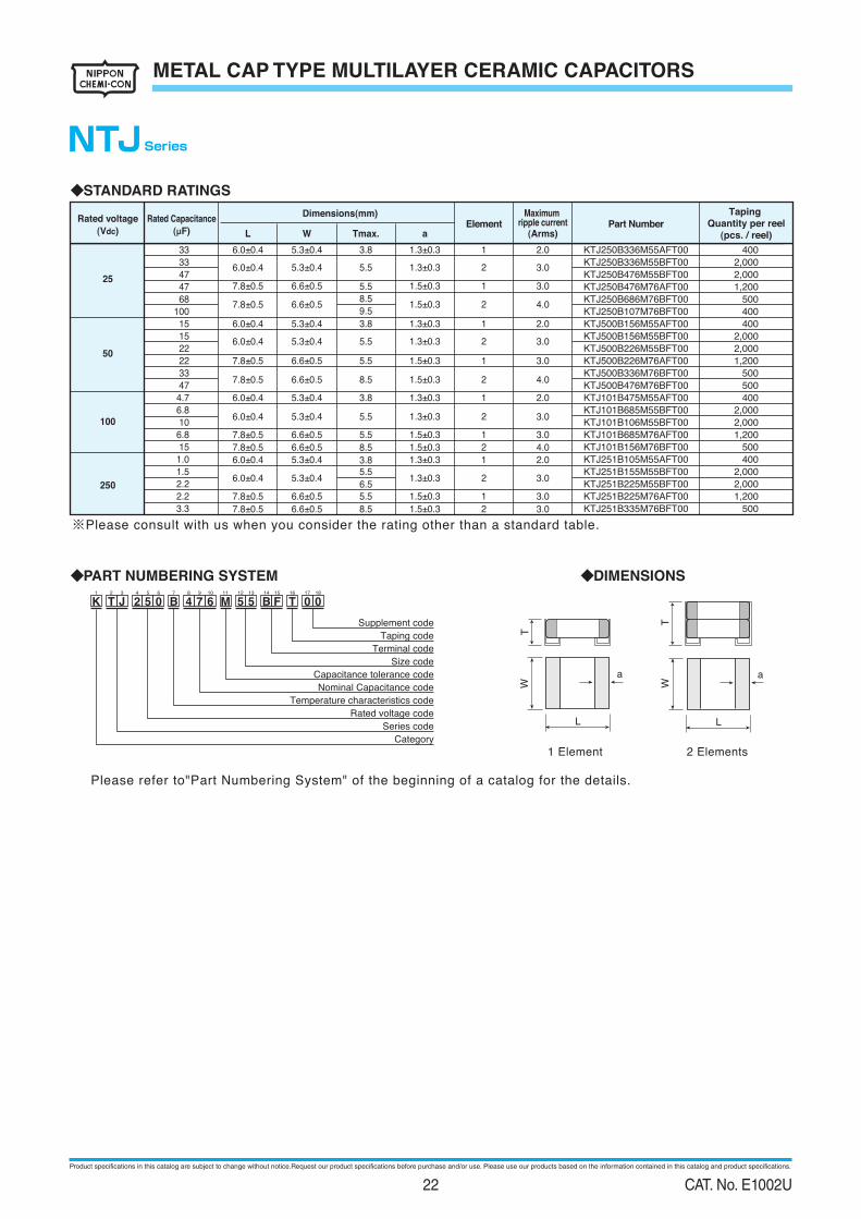
※Please consult with us when you consider the rating other than a standard table.
◆DIMENSIONS◆PART NUMBERING SYSTEM
Supplement code
Taping code
Terminal code
Size code
Capacitance tolerance code
Nominal Capacitance code
Temperature characteristics code
Rated voltage code
Series code
Category
K T J 2 5 0 B 4 7 6 M 5 5 F T 0 0B1 3 42 6 7 8 9 10 13125 18171611 1514
L
aW
T
Please refer to"Part Numbering System" of the beginning of a catalog for the details.
1 Element 2 Elements
L
a
WT
Product specifications in this catalog are subject to change without notice.Request our product specifications before purchase and/or use. Please use our products based on the information contained in this catalog and product specifications.
22 CAT. No. E1002U
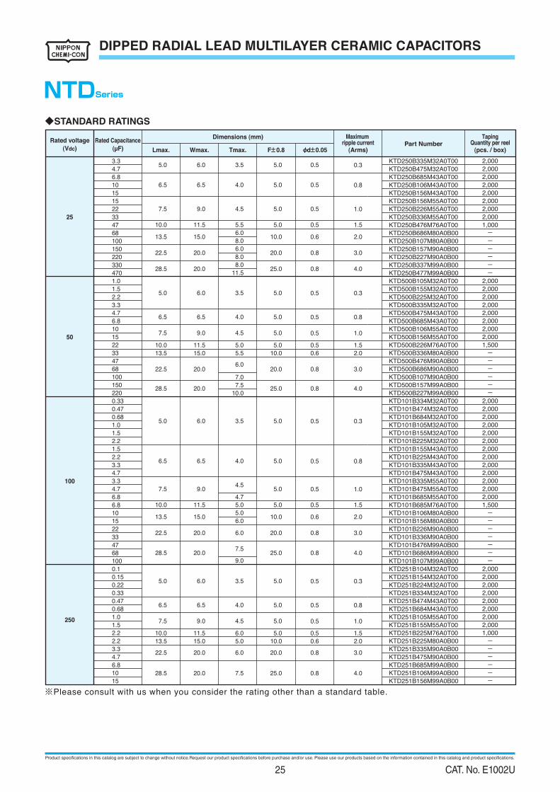
DIPPED RADIAL LEAD MULTILAYER CERAMIC CAPACITORS
◆RATINGS
-55 to +125℃1. Category Temperature Range
25, 50, 100, 250 Vdc2. Rated Voltage Range
0.1 to 470µF3. Rated Capacitance Range
M(±20%)4. Rated Capacitance Tolerance
5. Temperature Characteristics
6. Rated Ripple Current
X7R
See No.5 on the following table
◆SPECIFICATIONS
Between
Terminals
250% of rated voltage shall be applied for 5 seconds.No abnormality.
dc products : 475V)(Only 250Vdc products : 475V)
Withstand
Voltage
1
Terminals to
Coating Resin
3 Rated Capacitance Within specified tolerance.
2 Insulation Resistance 100/CR(MΩ) or 4000(MΩ)
whichever is less.
Rated voltage shall be applied for 60±5 seconds at
temperature 25±2℃.
Test ConditionSpecificationItemsNo.
4 Dissipation Factor 5.0% maximum.
Temperature
Frequency
Voltage
1±0.1kHz
1±0.2Vrms
25±2℃
120±12Hz
0.5±0.2Vrms
CR≦10µF CR>10µF
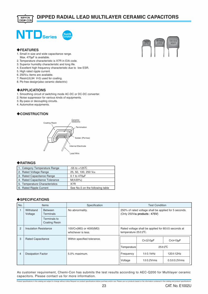
◆FEATURES1. Small in size and wide capacitance range.
Max. 470µF is available.
2. Temperature characteristic is X7R in EIA code.
3. Superior humidity characteristic and long life.
4. Excellent high frequency characteristic due to low ESR.
5. High rated ripple current.
6. 250Vdc items are available.
7. Resin(UL94 V-0) used for coating.
8. Pb-free design(also ceramic dielectric)
◆APPLICATIONS1. Smoothing circuit of switching mode AC-DC or DC-DC converter.
2. Noise suppressor for various kinds of equipments.
3. By-pass or decoupling circuits.
4. Automotive equipments.
◆CONSTRUCTION
Coating Resin
CeramicDielectric
Termination
Solder (Pb-free)
Internal Electrode
Lead Wire
RoHSCompliantNTDSeries
As customer requirement, Chemi-Con has submits the test results according to AEC-Q200 for Multilayer ceramic
capacitors. Please contact us for more information.
Product specifications in this catalog are subject to change without notice.Request our product specifications before purchase and/or use. Please use our products based on the information contained in this catalog and product specifications.
23 CAT. No. E1002U
DIPPED RADIAL LEAD MULTILAYER CERAMIC CAPACITORS
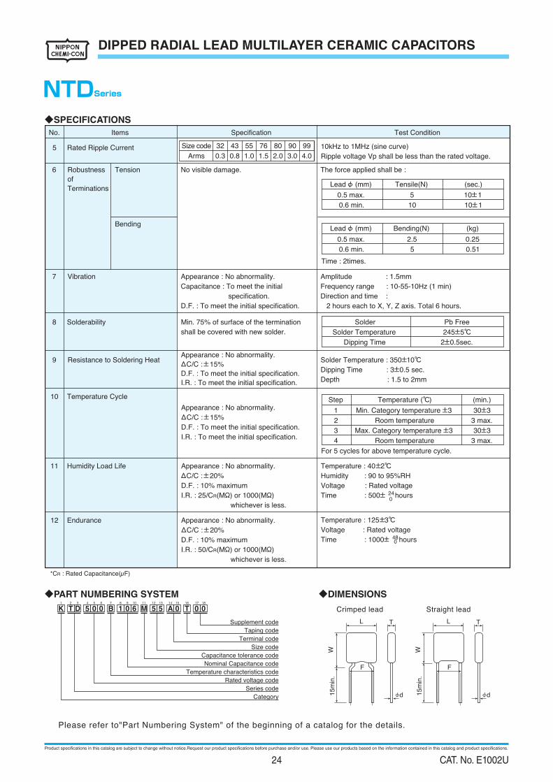
◆SPECIFICATIONS
10 Temperature Cycle
For 5 cycles for above temperature cycle.
11 Humidity Load Life
12 Endurance
Appearance : No abnormality.
ΔC/C :±20%
D.F. : 10% maximum
I.R. : 25/CR(MΩ) or 1000(MΩ)
whichever is less.
Appearance : No abnormality.
ΔC/C :±15%
D.F. : To meet the initial specification.
I.R. : To meet the initial specification.
Appearance : No abnormality.
ΔC/C :±20%
D.F. : 10% maximum
I.R. : 50/CR(MΩ) or 1000(MΩ)
whichever is less.
Temperature : 40±2℃
Humidity : 90 to 95%RH
Voltage : Rated voltage
Time : 500± hours24
Temperature : 125±3℃
Voltage : Rated voltage
Time : 1000± hours48
Step
1
2
Temperature (℃)
Min. Category temperature ±3
Room temperature
(min.)
30±3
3 max.
3
4
Max. Category temperature ±3
Room temperature
30±3
3 max.
0
0
*CR : Rated Capacitance(µF)
5 Rated Ripple Current 10kHz to 1MHz (sine curve)
Ripple voltage Vp shall be less than the rated voltage.
Test ConditionSpecificationItemsNo.
8 Solderability
shall be covered with new solder.
Solder Temperature : 350±10℃Resistance to Soldering Heat9
Dipping Time : 3±0.5 sec.
Depth : 1.5 to 2mm
Tension
Bending
6
7
Robustness
of
Terminations
Vibration
No visible damage.
Appearance : No abnormality.
Capacitance : To meet the initial
specification.
D.F. : To meet the initial specification.
Time : 2times.
The force applied shall be :
Amplitude : 1.5mm
Frequency range : 10-55-10Hz (1 min)
Direction and time :
2 hours each to X, Y, Z axis. Total 6 hours.
Leadφ (mm)
0.5 max.
Tensile(N)
5
(sec.)
10±1
0.6 min. 10 10±1
Leadφ (mm)
0.5 max.
Bending(N)
2.5
(kg)
0.25
0.6 min. 5 0.51
Solder
Solder Temperature
Dipping Time
Pb Free
245±5℃
2±0.5sec.
NTDSeries
Please refer to"Part Numbering System" of the beginning of a catalog for the details.
◆DIMENSIONS
Crimped lead Straight lead
L
F
W15m
in.
T
d
L
F
W15m
in.
T
d
◆PART NUMBERING SYSTEM
Supplement code
Taping code
Terminal code
Size code
Capacitance tolerance code
Nominal Capacitance code
Temperature characteristics code
Rated voltage code
Series code
Category
K T D 5 0 0 B 1 0 6 M 5 5 0 T 0 0A1 2 3 4 5 6 7 8 9 10 11 12 13 14 15 16 17 18
Min. 75% of surface of the termination
Size code
0.3
43
0.8
55
1.0
8076
2.0
90
3.0
99
4.01.5Arms
32
Appearance : No abnormality.
ΔC/C :±15%
D.F. : To meet the initial specification.
I.R. : To meet the initial specification.
Product specifications in this catalog are subject to change without notice.Request our product specifications before purchase and/or use. Please use our products based on the information contained in this catalog and product specifications.
24 CAT. No. E1002U
DIPPED RADIAL LEAD MULTILAYER CERAMIC CAPACITORS
◆STANDARD RATINGS
Rated voltage
(Vdc)Part Number
KTD250B335M32A0T00
KTD250B475M32A0T00
KTD250B685M43A0T00
KTD250B106M43A0T00
KTD250B156M43A0T00
KTD250B156M55A0T00
KTD250B226M55A0T00
KTD250B336M55A0T00
KTD250B476M76A0T00
KTD250B686M80A0B00
KTD250B107M80A0B00
KTD250B157M90A0B00
KTD250B227M90A0B00
KTD250B337M99A0B00
KTD250B477M99A0B00
KTD500B105M32A0T00
KTD500B155M32A0T00
KTD500B225M32A0T00
KTD500B335M32A0T00
KTD500B475M43A0T00
KTD500B685M43A0T00
KTD500B106M55A0T00
KTD500B156M55A0T00
KTD500B226M76A0T00
KTD500B336M80A0B00
KTD500B476M90A0B00
KTD500B686M90A0B00
KTD500B107M90A0B00
KTD500B157M99A0B00
KTD500B227M99A0B00
KTD101B334M32A0T00
KTD101B474M32A0T00
KTD101B684M32A0T00
KTD101B105M32A0T00
KTD101B155M32A0T00
KTD101B225M32A0T00
KTD101B155M43A0T00
KTD101B225M43A0T00
KTD101B335M43A0T00
KTD101B475M43A0T00
KTD101B335M55A0T00
KTD101B475M55A0T00
KTD101B685M55A0T00
KTD101B685M76A0T00
KTD101B106M80A0B00
KTD101B156M80A0B00
KTD101B226M90A0B00
KTD101B336M90A0B00
KTD101B476M99A0B00
KTD101B686M99A0B00
KTD101B107M99A0B00
KTD251B104M32A0T00
KTD251B154M32A0T00
KTD251B224M32A0T00
KTD251B334M32A0T00
KTD251B474M43A0T00
KTD251B684M43A0T00
KTD251B105M55A0T00
KTD251B155M55A0T00
KTD251B225M76A0T00
KTD251B225M80A0B00
KTD251B335M90A0B00
KTD251B475M90A0B00
KTD251B685M99A0B00
KTD251B106M99A0B00
KTD251B156M99A0B00
2,000
2,000
2,000
2,000
2,000
2,000
2,000
2,000
1,000
------
2,000
2,000
2,000
2,000
2,000
2,000
2,000
2,000
1,500
------
2,000
2,000
2,000
2,000
2,000
2,000
2,000
2,000
2,000
2,000
2,000
2,000
2,000
1,500
-------
2,000
2,000
2,000
2,000
2,000
2,000
2,000
2,000
1,000
------
25
50
100
250
Maximum ripple current
(Arms)
TapingQuantity per reel
(pcs. / box)
0.3
0.8
1.0
0.3
0.8
1.0
0.3
0.8
1.0
0.3
0.8
1.0
Rated Capacitance
(µF)
3.3
4.7
6.8
10
15
15
22
33
47
68
100
150
220
330
470
1.0
1.5
2.2
3.3
4.7
6.8
10
15
22
33
47
68
100
150
220
0.33
0.47
0.68
1.0
1.5
2.2
1.5
2.2
3.3
4.7
3.3
4.7
6.8
6.8
10
15
22
33
47
68
100
0.1
0.15
0.22
0.33
0.47
0.68
1.0
1.5
2.2
2.2
3.3
4.7
6.8
10
15
Dimensions (mm)
Lmax.
5.0
6.5
7.5
5.0
6.5
7.5
5.0
6.5
7.5
5.0
6.5
7.5
Wmax.
6.0
6.5
9.0
6.0
6.5
9.0
6.0
6.5
9.0
6.0
6.5
9.0
Tmax.
3.5
4.0
4.5
3.5
4.0
4.5
3.5
4.0
4.5
4.7
3.5
4.0
4.5
F±0.8
5.0
5.0
5.0
5.0
5.0
5.0
5.0
5.0
5.0
5.0
5.0
5.0
φd±0.05
0.5
0.5
0.5
1.510.0 11.5 5.5 5.0 0.5
6.02.013.5 15.0
22.5 20.0
28.5 20.0
8.0
6.0
8.0
8.0
11.5
10.0 0.6
3.020.0 0.8
4.025.0 0.8
1.510.0 11.5 5.0 5.0 0.5
2.013.5 15.0
22.5 20.0
28.5 20.0
5.5 10.0 0.6
6.03.020.0 0.8
7.0
4.07.5
25.0 0.810.0
1.510.0 11.5 5.0 5.0 0.5
2.013.5 15.0
22.5 20.0
28.5 20.0
5.010.0 0.6
3.020.0 0.8
4.025.0 0.8
6.0
6.0
7.5
9.0
0.5
0.5
0.5
0.5
0.5
0.5
0.5
0.5
0.5
2.013.5 15.0 5.0 10.0 0.6
3.022.5 20.0 6.0 20.0 0.8
4.028.5 20.0 7.5 25.0 0.8
1.510.0 11.5 6.0 5.0 0.5
NTDSeries
※Please consult with us when you consider the rating other than a standard table.
Product specifications in this catalog are subject to change without notice.Request our product specifications before purchase and/or use. Please use our products based on the information contained in this catalog and product specifications.
25 CAT. No. E1002U
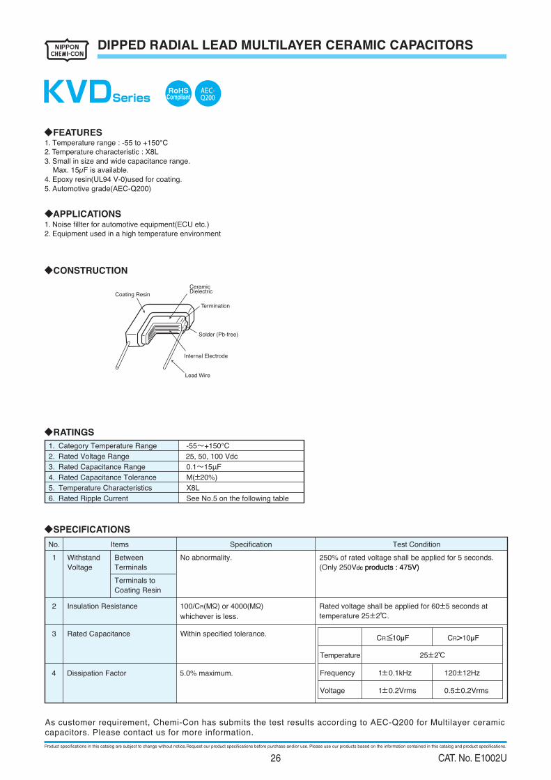
DIPPED RADIAL LEAD MULTILAYER CERAMIC CAPACITORS
◆RATINGS
-55~+150℃1. Category Temperature Range
25, 50, 100 Vdc2. Rated Voltage Range
0.1~15μF3. Rated Capacitance Range
M(±20%)4. Rated Capacitance Tolerance
5. Temperature Characteristics
6. Rated Ripple Current
X8L
See No.5 on the following table
◆SPECIFICATIONS
Between
Terminals
250% of rated voltage shall be applied for 5 seconds.No abnormality.
dc products : 475V)(Only 250Vdc products : 475V)
Withstand
Voltage
1
Terminals to
Coating Resin
3 Rated Capacitance Within specified tolerance.
2 Insulation Resistance 100/CR(MΩ) or 4000(MΩ)
whichever is less.
Rated voltage shall be applied for 60±5 seconds at
temperature 25±2℃.
Test ConditionSpecificationItemsNo.
4 Dissipation Factor 5.0% maximum.
Temperature
Frequency
Voltage
1±0.1kHz
1±0.2Vrms
25±2℃
120±12Hz
0.5±0.2Vrms
CR≦10µF CR>10µF
◆FEATURES1. Temperature range : -55 to +150℃2. Temperature characteristic : X8L
3. Small in size and wide capacitance range.
Max. 15µF is available.4. Epoxy resin(UL94 V-0)used for coating.
5. Automotive grade(AEC-Q200)
◆APPLICATIONS1. Noise fillter for automotive equipment(ECU etc.)2. Equipment used in a high temperature environment
◆CONSTRUCTION
Coating Resin
CeramicDielectric
Termination
Solder (Pb-free)
Internal Electrode
Lead Wire
RoHSCompliantKVDSeries
As customer requirement, Chemi-Con has submits the test results according to AEC-Q200 for Multilayer ceramic capacitors. Please contact us for more information.
AEC-Q200
Product specifications in this catalog are subject to change without notice.Request our product specifications before purchase and/or use. Please use our products based on the information contained in this catalog and product specifications.
26 CAT. No. E1002U
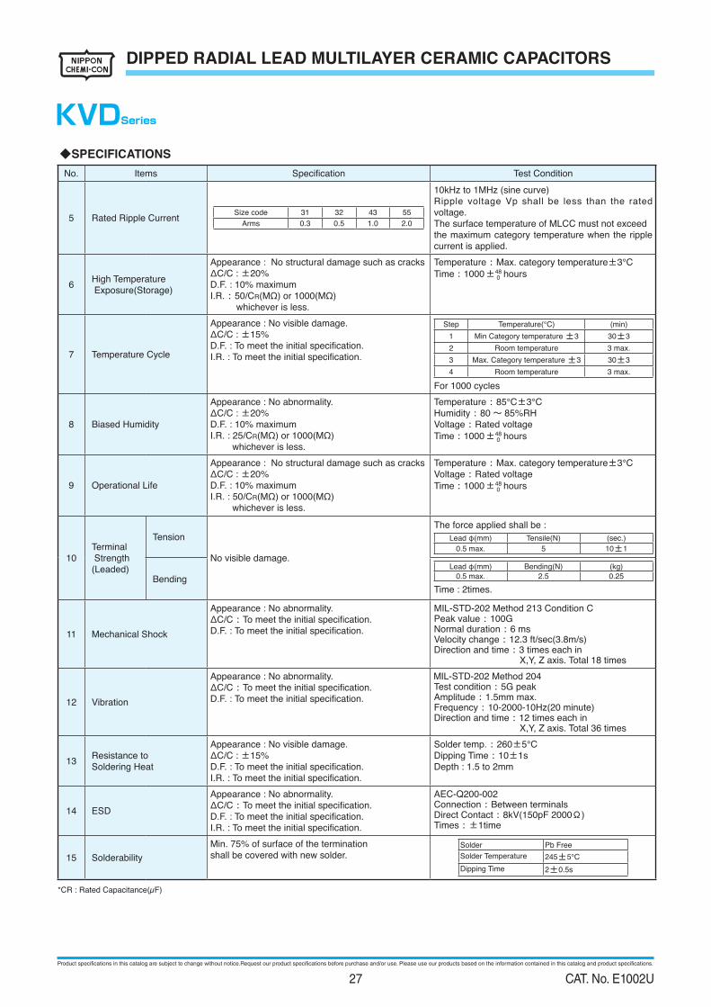
DIPPED RADIAL LEAD MULTILAYER CERAMIC CAPACITORS
KVDSeries
◆SPECIFICATIONS
No. Items Speciication Test Condition
5 Rated Ripple Current Size code 31 32 43 55
Arms 0.3 0.5 1.0 2.0
10kHz to 1MHz (sine curve)Ripple voltage Vp shall be less than the rated voltage.The surface temperature of MLCC must not exceedthe maximum category temperature when the ripple current is applied.
6High Temperature Exposure(Storage)
Appearance : No structural damage such as cracksΔC/C : ±20%
D.F. : 10% maximumI.R. : 50/CR(MΩ) or 1000(MΩ) whichever is less.
Temperature : Max. category temperature±3℃Time:1000±48
0 hours
7 Temperature Cycle
Appearance : No visible damage.ΔC/C : ±15%D.F. : To meet the initial speciication.I.R. : To meet the initial speciication.
Step Temperature(℃) (min)1 Min Category temperature ±3 30±3
2 Room temperature 3 max.3 Max. Category temperature ±3 30±3
4 Room temperature 3 max.For 1000 cycles
8 Biased Humidity
Appearance : No abnormality.ΔC/C : ±20%
D.F. : 10% maximumI.R. : 25/CR(MΩ) or 1000(MΩ)
whichever is less.
Temperature : 85℃±3℃Humidity : 80 ~ 85%RH
Voltage : Rated voltageTime:1000±48
0 hours
9 Operational Life
Appearance : No structural damage such as cracksΔC/C : ±20%
D.F. : 10% maximumI.R. : 50/CR(MΩ) or 1000(MΩ)
whichever is less.
Temperature : Max. category temperature±3℃Voltage : Rated voltageTime:1000±48
0 hours
10Terminal Strength(Leaded)
Tension
No visible damage.
The force applied shall be :Lead φ(mm) Tensile(N) (sec.)
0.5 max. 5 10±1
BendingLead φ(mm) Bending(N) (kg)
0.5 max. 2.5 0.25
Time : 2times.
11 Mechanical Shock
Appearance : No abnormality.ΔC/C :To meet the initial speciication.D.F. : To meet the initial speciication.
MIL-STD-202 Method 213 Condition CPeak value : 100GNormal duration : 6 msVelocity change : 12.3 ft/sec(3.8m/s)Direction and time : 3 times each in X,Y, Z axis. Total 18 times
12 Vibration
Appearance : No abnormality.ΔC/C :To meet the initial speciication.D.F. : To meet the initial speciication.
MIL-STD-202 Method 204Test condition : 5G peakAmplitude : 1.5mm max.Frequency : 10-2000-10Hz(20 minute)Direction and time : 12 times each in X,Y, Z axis. Total 36 times
13 Resistance to Soldering Heat
Appearance : No visible damage.ΔC/C : ±15%D.F. : To meet the initial speciication.I.R. : To meet the initial speciication.
Solder temp. : 260±5℃Dipping Time : 10±1sDepth : 1.5 to 2mm
14 ESD
Appearance : No abnormality.ΔC/C :To meet the initial speciication.D.F. : To meet the initial speciication.I.R. : To meet the initial speciication.
AEC-Q200-002Connection : Between terminalsDirect Contact : 8kV(150pF 2000Ω)Times : ±1time
15 SolderabilityMin. 75% of surface of the terminationshall be covered with new solder.
Solder Pb FreeSolder Temperature 245±5℃Dipping Time 2±0.5s
*CR : Rated Capacitance(µF)
Product specifications in this catalog are subject to change without notice.Request our product specifications before purchase and/or use. Please use our products based on the information contained in this catalog and product specifications.
27 CAT. No. E1002U
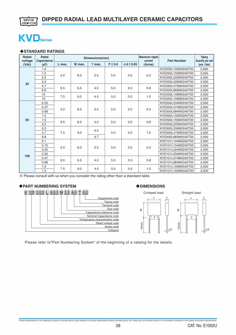
DIPPED RADIAL LEAD MULTILAYER CERAMIC CAPACITORS
KVDSeries
Please refer to"Part Numbering System" of the beginning of a catalog for the details.
◆DIMENSIONS
Crimped lead Straight lead
L
F
W15m
in.
T
d
L
F
W15m
in.
T
d
◆PART NUMBERING SYSTEM
Supplement code
Taping code
Terminal code
Size code
Capacitance tolerance code
Nominal Capacitance code
Temperature characteristics code
Rated voltage code
Series code
Category
K V D 5 0 0 L 6 8 5 M 5 5 0 T 0 0A1 2 3 4 5 6 7 8 9 10 11 12 13 14 15 16 17 18
◆STANDARD RATINGS
Rated
voltage
(Vdc)
Rated
Capacitance
(μF)
Dimensions(mm) Maximum ripple
current
(Arms)
Part Number
Taping
Quantity per reel
(pcs. / box)L max. W max. T max. F±0.8 φd±0.05
25
1.0
5.0 6.0 3.5 5.0 0.5 0.3
KVD250L105M32A0T00 2,0001.5 KVD250L155M32A0T00 2,0002.2 KVD250L225M32A0T00 2,0003.3 KVD250L335M32A0T00 2,0004.7
6.5 6.5 4.0 5.0 0.5 0.8 KVD250L475M43A0T00 2,000
6.8 KVD250L685M43A0T00 2,00010
7.5 9.0 4.5 5.0 0.5 1.0 KVD250L106M55A0T00 2,00015 KVD250L156M55A0T00 2,000
50
0.33
5.0 6.0 3.5 5.0 0.5 0.3
KVD500L334M32A0T00 2,0000.47 KVD500L474M32A0T00 2,0000.68 KVD500L684M32A0T00 2,0001.0 KVD500L105M32A0T00 2,0001.5
6.5 6.5 4.0 5.0 0.5 0.8 KVD500L155M43A0T00 2,000
2.2 KVD500L225M43A0T00 2,0003.3
7.5 9.04.5
5.0 0.5 1.0 KVD500L335M55A0T00 2,000
4.7 KVD500L475M55A0T00 2,0006.8 4.7 KVD500L685M55A0T00 2,000
100
0.1
5.0 6.0 3.5 5.0 0.5 0.3
KVD101L104M32A0T00 2,0000.15 KVD101L154M32A0T00 2,0000.22 KVD101L224M32A0T00 2,0000.33 KVD101L334M32A0T00 2,0000.47
6.5 6.5 4.0 5.0 0.5 0.8KVD101L474M43A0T00 2,000
0.68 KVD101L684M43A0T00 2,0001.0
7.5 9.0 4.5 5.0 0.5 1.0 KVD101L105M55A0T00 2,0001.5 KVD101L155M55A0T00 2,000
※ Please consult with us when you consider the rating other than a standard table.
Product specifications in this catalog are subject to change without notice.Request our product specifications before purchase and/or use. Please use our products based on the information contained in this catalog and product specifications.
28 CAT. No. E1002U
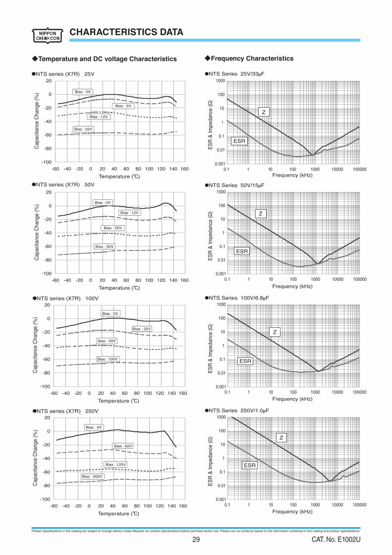
CHARACTERISTICS DATA
◆Temperature and DC voltage Characteristics
●NTS series (X7R) 25V
●NTS series (X7R) 100V
-100
-80
-60
-40
-20
0
20
Temperature (℃)
Capaci
tance
Change (
%)
Bias : 0V
Bias : 25V
Bias : 50V
Bias : 100V
-100
-80
-60
-40
-20
0
20
Temperature (℃)
Capaci
tance
Change (
%)
-60 -40 -20 0 20 40 60 80 100 120 140 160
-60 -40 -20 0 20 40 60 80 100 120 140 160
●NTS series (X7R) 250V
-100
-80
-60
-40
-20
0
20
Temperature (℃)
Capaci
tance
Change (
%)
Bias : 0V
Bias : 200V
-60 -40 -20 0 20 40 60 80 100 120 140 160
Bias : 0V
Bias : 5V
Bias : 12V
Bias : 25V
●NTS series (X7R) 50V
-100
-80
-60
-40
-20
0
20
Temperature (℃)
Capaci
tance
Change (
%) Bias : 0V
Bias : 12V
Bias : 25V
Bias : 50V
-60 -40 -20 0 20 40 60 80 100 120 140 160
Bias : 62V
Bias : 125V
●NTS Series 100V/6.8µF
●NTS Series 250V/1.0µF
0.001
0.01
0.1
1
10
100
1000
0.1 1 10 100 1000 10000 100000
Frequency (kHz)
ES
R &
Im
pe
da
nce
(Ω)
0.001
0.01
0.1
1
10
100
1000
0.1 1 10 100 1000 10000 100000
0.001
0.01
0.1
1
10
100
1000
0.1 1 10 100 1000 10000 100000
Frequency (kHz)
ES
R &
Im
pe
da
nce
(Ω)
Frequency (kHz)
ES
R &
Im
pe
da
nce
(Ω)
Z
ESR
Z
ESR
Z
ESR
0.001
0.01
0.1
1
10
100
1000
0.1 1 10 100 1000 10000 100000
Frequency (kHz)
ES
R &
Im
pe
da
nce
(Ω) Z
ESR
◆Frequency Characteristics
●NTS Series 25V/33µF
●NTS Series 50V/15µF
Product specifications in this catalog are subject to change without notice.Request our product specifications before purchase and/or use. Please use our products based on the information contained in this catalog and product specifications.
29 CAT. No. E1002U

30 CAT. No. E1002U

Distributed or Represented by
Notes on Safety■ Always read "Notes on Use" before using the product in order to enable you to use the product correctly and prevent any faults and accidents from occurring.■ Request the Product Specification on the product of NIPPON CHEMI-CON CORPORATION to refer to it as well as this brochure prior to the order of the products. Some specific notes on use of the ordered product may be described in the specifications.
The electronic components described in this catalogue were designed and developed for use in general electronic equipment, such as ; general household appliances, office and AV equipment, information and communication equipment, etc.We ask you, therefore, to appraise, examine and judge the suitability of these electronic components very carefully, or contact us, for designs that require higher levels of safety and reliability, such as ; medical or aerospace equipment, equipment related to nuclear power, safety devices for automotive products, or disaster prevention equipment.When using these components for circuits in general electronic equipment that also require higher levels or safety and reliability, we recommend that you carry out a thorough appraisal of the component's intended use in the application and add any necessary protection networks during the design phase.
ELECTRONICCOMPONENTS & DEVICES
CAT.No.
Aluminum Electrolytic Capacitors 1001
Multilayer Ceramic Capacitors 1002
Film Capacitors 1003
Metal Oxide Varistors TNRTM 1006
Amorphous / Dust Choke Coils 1008
Electric Double Layer Capacitors 1009
Electro-Mechanical Products
PRODUCTS
NIPPON CHEMI-CON CORPORATIONhttp://www.chemi-con.co.jp/e/
'15.07