nchrp report 612 – safe and aesthetic design of urban
TRANSCRIPT
Safe and Aesthetic Design ofUrban Roadside Treatments
NATIONALCOOPERATIVE HIGHWAYRESEARCH PROGRAMNCHRP
REPORT 612
TRANSPORTATION RESEARCH BOARD 2008 EXECUTIVE COMMITTEE*
OFFICERS
CHAIR: Debra L. Miller, Secretary, Kansas DOT, Topeka VICE CHAIR: Adib K. Kanafani, Cahill Professor of Civil Engineering, University of California, Berkeley EXECUTIVE DIRECTOR: Robert E. Skinner, Jr., Transportation Research Board
MEMBERS
J. Barry Barker, Executive Director, Transit Authority of River City, Louisville, KYAllen D. Biehler, Secretary, Pennsylvania DOT, HarrisburgJohn D. Bowe, President, Americas Region, APL Limited, Oakland, CALarry L. Brown, Sr., Executive Director, Mississippi DOT, JacksonDeborah H. Butler, Executive Vice President, Planning, and CIO, Norfolk Southern Corporation, Norfolk, VAWilliam A.V. Clark, Professor, Department of Geography, University of California, Los AngelesDavid S. Ekern, Commissioner, Virginia DOT, RichmondNicholas J. Garber, Henry L. Kinnier Professor, Department of Civil Engineering, University of Virginia, CharlottesvilleJeffrey W. Hamiel, Executive Director, Metropolitan Airports Commission, Minneapolis, MNEdward A. (Ned) Helme, President, Center for Clean Air Policy, Washington, DCWill Kempton, Director, California DOT, SacramentoSusan Martinovich, Director, Nevada DOT, Carson CityMichael D. Meyer, Professor, School of Civil and Environmental Engineering, Georgia Institute of Technology, AtlantaMichael R. Morris, Director of Transportation, North Central Texas Council of Governments, ArlingtonNeil J. Pedersen, Administrator, Maryland State Highway Administration, BaltimorePete K. Rahn, Director, Missouri DOT, Jefferson CitySandra Rosenbloom, Professor of Planning, University of Arizona, TucsonTracy L. Rosser, Vice President, Corporate Traffic, Wal-Mart Stores, Inc., Bentonville, ARRosa Clausell Rountree, Executive Director, Georgia State Road and Tollway Authority, AtlantaHenry G. (Gerry) Schwartz, Jr., Chairman (retired), Jacobs/Sverdrup Civil, Inc., St. Louis, MOC. Michael Walton, Ernest H. Cockrell Centennial Chair in Engineering, University of Texas, AustinLinda S. Watson, CEO, LYNX–Central Florida Regional Transportation Authority, OrlandoSteve Williams, Chairman and CEO, Maverick Transportation, Inc., Little Rock, AR
EX OFFICIO MEMBERS
Thad Allen (Adm., U.S. Coast Guard), Commandant, U.S. Coast Guard, Washington, DCJoseph H. Boardman, Federal Railroad Administrator, U.S.DOTRebecca M. Brewster, President and COO, American Transportation Research Institute, Smyrna, GAPaul R. Brubaker, Research and Innovative Technology Administrator, U.S.DOTGeorge Bugliarello, Chancellor, Polytechnic University of New York, Brooklyn, and Foreign Secretary, National Academy of Engineering,
Washington, DCSean T. Connaughton, Maritime Administrator, U.S.DOTLeRoy Gishi, Chief, Division of Transportation, Bureau of Indian Affairs, U.S. Department of the Interior, Washington, DCEdward R. Hamberger, President and CEO, Association of American Railroads, Washington, DCJohn H. Hill, Federal Motor Carrier Safety Administrator, U.S.DOTJohn C. Horsley, Executive Director, American Association of State Highway and Transportation Officials, Washington, DCCarl T. Johnson, Pipeline and Hazardous Materials Safety Administrator, U.S.DOTJ. Edward Johnson, Director, Applied Science Directorate, National Aeronautics and Space Administration, John C. Stennis Space Center, MSThomas J. Madison, Jr., Administrator, Federal Highway Administration, U.S.DOT William W. Millar, President, American Public Transportation Association, Washington, DCNicole R. Nason, National Highway Traffic Safety Administrator, U.S.DOTJames S. Simpson, Federal Transit Administrator, U.S.DOTRobert A. Sturgell, Acting Administrator, Federal Aviation Administration, U.S.DOTRobert L. Van Antwerp (Lt. Gen., U.S. Army), Chief of Engineers and Commanding General, U.S. Army Corps of Engineers, Washington, DC
*Membership as of September 2008.
TRANSPORTAT ION RESEARCH BOARDWASHINGTON, D.C.
2008www.TRB.org
N A T I O N A L C O O P E R A T I V E H I G H W A Y R E S E A R C H P R O G R A M
NCHRP REPORT 612
Subject Areas
Safety and Human Performance
Safe and Aesthetic Design ofUrban Roadside Treatments
Karen K. DixonMichael Liebler
Hong ZhuOREGON STATE UNIVERSITY
Corvallis, OR
Michael P. HunterBerry Mattox
GEORGIA INSTITUTE OF TECHNOLOGY
Atlanta, GA
Research sponsored by the American Association of State Highway and Transportation Officials in cooperation with the Federal Highway Administration

NATIONAL COOPERATIVE HIGHWAYRESEARCH PROGRAM
Systematic, well-designed research provides the most effective
approach to the solution of many problems facing highway
administrators and engineers. Often, highway problems are of local
interest and can best be studied by highway departments individually
or in cooperation with their state universities and others. However, the
accelerating growth of highway transportation develops increasingly
complex problems of wide interest to highway authorities. These
problems are best studied through a coordinated program of
cooperative research.
In recognition of these needs, the highway administrators of the
American Association of State Highway and Transportation Officials
initiated in 1962 an objective national highway research program
employing modern scientific techniques. This program is supported on
a continuing basis by funds from participating member states of the
Association and it receives the full cooperation and support of the
Federal Highway Administration, United States Department of
Transportation.
The Transportation Research Board of the National Academies was
requested by the Association to administer the research program
because of the Board’s recognized objectivity and understanding of
modern research practices. The Board is uniquely suited for this
purpose as it maintains an extensive committee structure from which
authorities on any highway transportation subject may be drawn; it
possesses avenues of communications and cooperation with federal,
state and local governmental agencies, universities, and industry; its
relationship to the National Research Council is an insurance of
objectivity; it maintains a full-time research correlation staff of
specialists in highway transportation matters to bring the findings of
research directly to those who are in a position to use them.
The program is developed on the basis of research needs identified
by chief administrators of the highway and transportation departments
and by committees of AASHTO. Each year, specific areas of research
needs to be included in the program are proposed to the National
Research Council and the Board by the American Association of State
Highway and Transportation Officials. Research projects to fulfill these
needs are defined by the Board, and qualified research agencies are
selected from those that have submitted proposals. Administration and
surveillance of research contracts are the responsibilities of the National
Research Council and the Transportation Research Board.
The needs for highway research are many, and the National
Cooperative Highway Research Program can make significant
contributions to the solution of highway transportation problems of
mutual concern to many responsible groups. The program, however, is
intended to complement rather than to substitute for or duplicate other
highway research programs.
Published reports of the
NATIONAL COOPERATIVE HIGHWAY RESEARCH PROGRAM
are available from:
Transportation Research BoardBusiness Office500 Fifth Street, NWWashington, DC 20001
and can be ordered through the Internet at:
http://www.national-academies.org/trb/bookstore
Printed in the United States of America
NCHRP REPORT 612
Project 16-04ISSN 0077-5614ISBN: 978-0-309-11753-1Library of Congress Control Number 2008909154
© 2008 Transportation Research Board
COPYRIGHT PERMISSION
Authors herein are responsible for the authenticity of their materials and for obtainingwritten permissions from publishers or persons who own the copyright to any previouslypublished or copyrighted material used herein.
Cooperative Research Programs (CRP) grants permission to reproduce material in thispublication for classroom and not-for-profit purposes. Permission is given with theunderstanding that none of the material will be used to imply TRB, AASHTO, FAA, FHWA,FMCSA, FTA, or Transit Development Corporation endorsement of a particular product,method, or practice. It is expected that those reproducing the material in this document foreducational and not-for-profit uses will give appropriate acknowledgment of the source ofany reprinted or reproduced material. For other uses of the material, request permissionfrom CRP.
NOTICE
The project that is the subject of this report was a part of the National Cooperative HighwayResearch Program conducted by the Transportation Research Board with the approval ofthe Governing Board of the National Research Council. Such approval reflects theGoverning Board’s judgment that the program concerned is of national importance andappropriate with respect to both the purposes and resources of the National ResearchCouncil.
The members of the technical committee selected to monitor this project and to review thisreport were chosen for recognized scholarly competence and with due consideration for thebalance of disciplines appropriate to the project. The opinions and conclusions expressedor implied are those of the research agency that performed the research, and, while they havebeen accepted as appropriate by the technical committee, they are not necessarily those ofthe Transportation Research Board, the National Research Council, the AmericanAssociation of State Highway and Transportation Officials, or the Federal HighwayAdministration, U.S. Department of Transportation.
Each report is reviewed and accepted for publication by the technical committee accordingto procedures established and monitored by the Transportation Research Board ExecutiveCommittee and the Governing Board of the National Research Council.
The Transportation Research Board of the National Academies, the National ResearchCouncil, the Federal Highway Administration, the American Association of State Highwayand Transportation Officials, and the individual states participating in the NationalCooperative Highway Research Program do not endorse products or manufacturers. Tradeor manufacturers’ names appear herein solely because they are considered essential to theobject of this report.

CRP STAFF FOR NCHRP REPORT 612
Christopher W. Jenks, Director, Cooperative Research ProgramsCrawford F. Jencks, Deputy Director, Cooperative Research Programs Charles W. Niessner, Senior Program OfficerEileen P. Delaney, Director of PublicationsEllen M. Chafee, Assistant Editor
NCHRP PROJECT 16-04 PANELField of Design—Area of Roadside Development
James Buchan, Georgia DOT, Atlanta, GA (Chair)Richard B. Albin, Washington State DOT, Olympia, WANancy Alexander, New York State DOT, Albany, NYRonald K. Faller, University of Nebraska—Lincoln, Lincoln, NEMark S. Mathews, HNTB Corporation, Austin, TXKirk G. McClelland, Maryland State Highway Administration, Baltimore, MDKeith Robinson, California DOT, Sacramento, CAHarry W. Taylor, Jr., Taylor Consulting, Washington, DCDonald Yue, STV Incorporated, New York, NYNicholas A. Artimovich, II, FHWA LiaisonStephen F. Maher, TRB Liaison
AUTHOR ACKNOWLEDGMENTS
The research reported herein was performed under NCHRP Project 16–04 by the Georgia ResearchInstitute and faculty and staff in the Department of Civil and Environmental Engineering at the GeorgiaInstitute of Technology (Georgia Tech). The School of Civil and Construction Engineering at Oregon StateUniversity (OSU) also participated substantially in this research effort. Georgia Tech served as the pri-mary contractor for this study while OSU served as a subcontractor for the project. In addition, Glatting Jackson served as a subconsultant during the early project stages.
Dr. Karen K. Dixon, P.E., Associate Professor at OSU, was the project director and co-principal inves-tigator. Dr. Michael P. Hunter, Assistant Professor at Georgia Tech, served as co-principal investigator.The other authors of this report are Michael Liebler and Hong Zhu, Graduate Research Assistants at OSU,and Berry Mattox, Graduate Research Assistant at Georgia Tech. In addition, Dr. Eric Dumbaugh of TexasA&M contributed to the literature review portion of this report.
The authors would like to acknowledge agencies that provided data and case study material for this research effort. These include the cities of Phoenix, Arizona; Sacramento, California; Eden Prairie,Minnesota; Billings, Montana; Charlotte, North Carolina; Bend, Oregon; Portland, Oregon; and Salt LakeCity, Utah. In addition, the Georgia Department of Transportation, the Oregon Department of Trans-portation, and the Federal Highway Administration also provided data for this project.
C O O P E R A T I V E R E S E A R C H P R O G R A M S

This report presents the findings of a research project to develop recommended designguidelines for safe and aesthetic roadside treatments in urban areas and a toolbox of effec-tive roadside treatments that balance pedestrian, bicyclist, and motorist safety and mobility.The report will be of particular interest to designers and safety practitioners responsible forthe design of arterial and collector-type facilities in urban areas.
Many challenges are encountered when designing highway projects that pass throughurban areas. Arterial and collector highways are typically designed to move vehicles asquickly and efficiently as possible. However, many times these highways are the centers ofcommunities that have developed around them. Increasingly, citizens of these communi-ties have requested that these highways be redesigned using roadside solutions that enhancethe appearance and, in many cases, the functional use of the highway.
Many of the solutions involve introducing roadside treatments such as trees, sculptures,and signs. In addition to enhancing the appearance of these highways, these treatments areoften also intended to slow or “calm” traffic to enhance safety. However, many of thesetreatments are considered fixed objects, as defined in the AASHTO Roadside Design Guide,and they will often be located within the design clear zone. Recommended clear zonedimensions generally represent minimum lateral offset distances. Thus, reducing existing,wider clear zones by introducing fixed objects, even at these minimum distances, reducesthe recovery distance. In addition, slowing traffic may cause changes in traffic operations.Therefore, it is crucial that the impacts of these designs be understood so that decisions canbe based on facts. There is also a need to identify designs that have performed acceptablyand a need to develop new design guidelines that enhance the roadside environment whilebeing forgiving to errant vehicles.
Under NCHRP Project 16-04, “Design Guidelines for Safe and Aesthetic Roadside Treat-ments in Urban Areas,” researchers at Oregon State University and the Georgia Institute ofTechnology developed recommended design guidelines for roadside treatments in urbanareas and a toolkit that includes strategies for placing roadside objects with respect to drive-ways, intersections, merge lanes, and so forth. They also developed a draft of Chapter 10 forthe AASHTO Roadside Design Guide.
Two analysis approaches were used in developing the guidelines. First, a corridor assess-ment of urban roadside conditions was performed and contrasted with 6 years of historiccrash data. The goal was to identify potential configurations that posed a greater risk usingcluster crash analysis. By contrast, assessment of locations with similar features but withoutthese crashes provided insight into prospective alternative treatments for roadside safety inurban environments.
F O R E W O R D
By Charles W. NiessnerStaff OfficerTransportation Research Board

In the second analysis approach, the researchers assembled case studies in which jurisdic-tions had performed roadside enhancement or “beautification” projects without compan-ion major road reconstruction. A simplified before-after crash analysis, crash summaries,and project descriptive information were assembled to help determine the safety influenceof the enhancement projects. The results of this case study task varied, but can be used byagencies to estimate the potential safety implications of their future roadside enhancementprojects.
C O N T E N T S
1 Summary
3 Chapter 1 Background3 Problem Statement and Research Objective3 Scope of Study
5 Chapter 2 State-of-the-Art Summary5 Overview of Roadside Crash Statistics5 Roadside Safety: Current Practices7 Examining Roadside Safety in Urban Environments8 Preventing Vehicles from Leaving the Travelway
11 Safety of Urban Roadside Elements36 Literature Review Conclusion
37 Chapter 3 Findings and Applications37 Urban Control Zone Assessment46 Case Study Task and Summary of Findings49 General Recommendations
50 Chapter 4 Conclusions and Suggested Research50 Conclusions51 Suggested Research
52 References
56 Appendix A Urban Control Zone Corridor Study Reports
57 Appendix B Case Study Reports
58 Appendix C Toolkit for Urban Roadside Design
64 Appendix D Draft Chapter 10 for AASHTO Roadside Design Guide

S U M M A R Y
Roadside safety in rural environments has been the focus of considerable study, but directapplication of this knowledge to the urban environment is challenging because the urbanenvironment is constrained in ways that the rural environment isn’t. In urban environments,restricted right-of-way, with a greater demand for functional use of the space adjacent toroads, makes the maintenance of a wide clear zone impractical. This report summarizeswork performed under NCHRP Project 16-04 to identify urban roadside safety issues andseek solutions for mitigating hazards where possible.
The objectives of NCHRP Project 16-04 were to develop (1) design guidelines for safeand aesthetic roadside treatments in urban areas and (2) a toolbox of effective roadsidetreatments that can balance the safety and mobility of pedestrians, bicyclists, andmotorists and accommodate community values. The guidelines that were developed arebased on an evaluation of the effects of roadside treatments such as trees, landscaping, andother features on vehicle speed and overall safety. The guidelines generally focus on arte-rial and collector-type facilities in urban areas with speed limits between 40 and 80 km/h(25 and 50 mph).
The research included two analysis approaches. In the first approach, the authors assessedroadside conditions in various urban corridors, performed a cluster crash analysis to identifylocations with an overrepresentation of fixed-object crashes during a 6-year period, andidentified fixed-object crash features for each location. This analysis enabled the authors toidentify the road and roadside configurations that posed the most risk for fixed-objectcrashes. These higher risk road and roadside configurations were referred to as urbancontrol zones.
The road and roadside configurations most commonly associated with fixed-objectcrashes included those with the following:
• Obstacles in close lateral proximity to the curb face or lane edge;• Roadside objects placed near lane merge points;• Lateral offsets not appropriately adjusted for auxiliary lane treatments;• Objects placed inappropriately in sidewalk buffer treatments;• Driveways that interrupt positive guidance and have objects placed near them;• Three kinds of fixed-object placement at intersections;• Unique roadside configurations associated with high crash occurrence; and• Roadside configurations commonly known to be hazardous.
In the second approach, the authors assembled case studies in which jurisdictions had per-formed roadside enhancement projects (often known as beautification projects) without
Safe and Aesthetic Design of Urban Roadside Treatments
1

2
companion major road reconstruction. For these case studies, a simplified before-after crashanalysis, crash summaries, and project descriptive information were assembled to helpdetermine the safety influence of the enhancement projects. The results of this case studytask varied, but can be used by agencies to estimate the potential safety implications of theirfuture roadside enhancement projects.
3
Problem Statementand Research Objective
Many challenges are encountered when designing highwayprojects that pass through urban areas. Arterial and collectorhighways are typically designed for moving vehicles as quicklyand efficiently as possible. However, many times these high-ways are at the center of a community that has developedaround them. Increasingly, citizens of these communitieshave requested that highway corridors be redesigned usingroadside solutions that enhance the appearance and, in manycases, the functional use of the highway roadside.
Many of these solutions involve introducing roadsidetreatments such as trees, street furniture, and signs. In addi-tion to enhancing the appearance of these highways, someroadside treatments are intended to slow or “calm” traffic.However, many of these same features are considered fixedobjects and will likely be located within the design clear zone.Recommended clear zone dimensions vary based on sideslope,design speed, and traffic volume; however, the generally widerroad widths that are needed to include roadside treatments areusually difficult to achieve and impractical in constrainedurban settings. As a result, designers often use minimum lateraloffset distances that simply enable operational use of the road.Thus, introducing fixed objects—which can result in the re-duction of existing wider lateral offsets—can potentially havea direct impact on roadside safety. In addition, slowing trafficmay cause changes in traffic operations. Therefore, it is crucialto informed decision making that the impacts of roadsideenhancement designs be understood. There is also a need toidentify designs that have performed in an acceptable mannerand to develop new design guidelines that will lead to enhancedroadside environments and be forgiving to errant vehicles.These guidelines will provide the American Association ofState Highway and Transportation Officials (AASHTO) Tech-nical Committee for Roadside Safety with critical informationfor the update of Chapter 10 of the Roadside Design Guide (1).
The objectives of NCHRP Project 16-04, therefore, wereto develop (1) design guidelines for safe and aestheticallypleasing roadside treatments in urban areas and (2) a toolboxof effective roadside treatments that can balance the safetyand mobility needs of pedestrians, bicyclists, and motoristsand accommodate community values. The guidelines devel-oped in this project were based on an evaluation of the effectsof treatments such as poles, trees, landscaping, and otherroadside features on vehicle speed and overall safety. Theguidelines generally focus on arterial and collector-type facil-ities in urban areas with speed limits between 40 and 80 km/h(25 and 50 mph).
Scope of Study
This study includes two approaches for identifying thepotential influence of urban roadside features on system-wide safety. The first approach was a corridor analysis ofover 241 km/h (150 mi) of urban roadways, in which the re-search team examined historic crash information to identifycommon roadside crash conditions. Crashes were displayedon spot maps and also summarized individually for addi-tional analysis. The research team then used video to recordthe corridors and the placement of roadside features. Theresult of this corridor analysis is proposed urban controlzones where the likelihood of crashes is significantly greater.This information has then been used to develop recom-mended guidelines for enhancing roadside safety in the urbanenvironment.
The second approach to evaluating the roadside safetyproblem was the assembly of case studies with crash type,crash severity, and before-after safety assessments. Ideally,a candidate case study would include the change of only oneroadside feature so that the direct influence of that change onsafety could be evaluated; however, such unique improve-ment projects are limited, so this case study task includedgeneral beautification projects with roadside enhancements
C H A P T E R 1
Background

and excluded projects with major reconstruction. The resultsof these case study evaluations were mixed, but an agencyseeking to perform a similar project can use the results to helpunderstand the general safety performance that can be ex-pected following the completion of the project.
Chapter 2 of this report summarizes current knowledgefrom literature on the urban roadside and objects commonlyplaced in the urban roadside environment. Chapter 3 sum-marizes the analysis procedures and subsequent findings foreach task. Chapter 4 provides general research conclusions as
well as future research needs identified during this researcheffort. In addition, this report includes four appendices.Appendix A provides detailed information about the urbancontrol zone corridor sites. Appendix B includes the sum-mary statistics for the case study sites. Appendix C includesan urban roadside design toolbox, and Appendix D providesdraft language for the urban chapter in the AASHTO Road-side Design Guide (1). Appendixes A, B, and D are availableon the TRB website at http://trb.org/news/blurb_detail.asp?id=9456. Appendix C is appended to this report.
4
5
Urban areas present unique challenges to the roadway de-signer. Urban and regional stakeholders need a transportationnetwork that allows them to accomplish their travel objec-tives with a minimum amount of travel delay and to havethese travel demands met on a road network that is bothoperationally efficient and safe.
While the transportation profession has made dramaticadvancements toward meeting safety and mobility mandates,it is critical that the function of the street system complementthe adjacent land use and balance the needs of all users whilemaintaining the safest possible transportation facility. Of par-ticular interest is the design of roadsides—the area betweenthe shoulder (or curb) and the edge of the right-of-way (1).The roadside is a common location for pedestrian activity,utility placement, landscaping, transit stops, driveway place-ment, mailbox placement, and placement of a variety of otherroadside features typical of the urban environment. Urbanroadside environments can range from dense downtownzones with on-street parking to high-speed zones with motorvehicle operational priorities.
Given the importance of the roadside environment to thequality of urban life, it is unsurprising that urban residentsand stakeholders often seek to have the roadside designed ina manner that enhances the quality of the urban environment.Commonly requested functional roadside elements includesidewalks, street trees, and street amenities such as seating.Requested aesthetic elements include public art and specialpaving materials. Placing these roadside elements in a waythat enhances urban roadside safety is the focus of this liter-ature review.
Overview of Roadside Crash Statistics
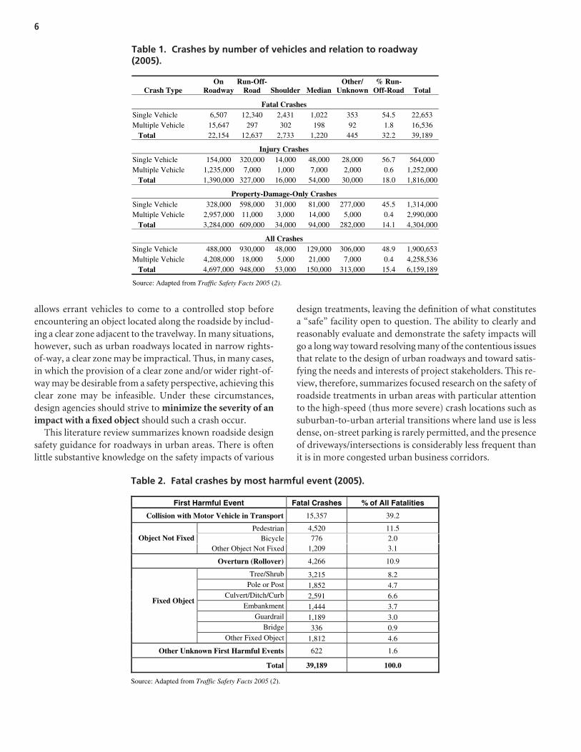
In 2005, over 6.2 million crashes occurred on U.S. roadways.Almost 1.9 million of these crashes involved an injury, and39,189 people were fatally injured (2). Of particular concern
are crashes that involve a vehicle that leaves the roadway.Of the 6.2 million crashes in 2005, run-off-road crashesaccounted for 0.95 million, or about 15 percent of the total.While run-off-road crashes happen less frequently than othertypes of crashes, they are often severe. Although run-off-roadcrashes accounted for only 15 percent of all crashes in 2005,they accounted for 32.2 percent of the total fatal crashes inthat year (see Table 1).
Examining fatal crashes by the first harmful event illustratesthe magnitude of specific roadside hazards. Of the fatal crashesoccurring in 2005, 39 percent involved collisions betweenmotor vehicles. Rollover crashes and collisions with fixedobjects—two kinds of crashes that are associated with theroadside environment—made up 11 percent and 32 percent,respectively, of fatal crashes in 2005. The highest percentageof fixed-object crashes was in the category of tree/shrub, withtree or shrub impacts accounting for slightly more than 3,200crashes, or roughly 8 percent of all fatal crashes. Poles andposts accounted for a little less than 5 percent of all fatal crashes(see Table 2).
Roadside Safety: Current Practices
The literature on roadside safety establishes three roadsidecrash strategies that can be considered when seeking to im-prove run-off-road crash statistics (1). First, the ideal scenariois to prevent vehicles from leaving the travelway, therebyeliminating the crash entirely. Preventing the conditions thatlead to run-off-road crashes (conditions such as driving whileimpaired or fatigued) and alerting a driver that he or she isleaving the travelway would be potential countermeasuresincluded in this category.
The second strategy, which is based on the idea that run-off-road events are impossible to prevent entirely, is to designa roadside that is “forgiving.” In other words, a roadsideshould be designed to minimize the consequences of a run-off-road event. Under current practice, the ideal roadside
C H A P T E R 2
State-of-the-Art Summary
allows errant vehicles to come to a controlled stop beforeencountering an object located along the roadside by includ-ing a clear zone adjacent to the travelway. In many situations,however, such as urban roadways located in narrow rights-of-way, a clear zone may be impractical. Thus, in many cases,in which the provision of a clear zone and/or wider right-of-way may be desirable from a safety perspective, achieving thisclear zone may be infeasible. Under these circumstances,design agencies should strive to minimize the severity of animpact with a fixed object should such a crash occur.
This literature review summarizes known roadside designsafety guidance for roadways in urban areas. There is oftenlittle substantive knowledge on the safety impacts of various
design treatments, leaving the definition of what constitutesa “safe” facility open to question. The ability to clearly andreasonably evaluate and demonstrate the safety impacts willgo a long way toward resolving many of the contentious issuesthat relate to the design of urban roadways and toward satis-fying the needs and interests of project stakeholders. This re-view, therefore, summarizes focused research on the safety ofroadside treatments in urban areas with particular attentionto the high-speed (thus more severe) crash locations such assuburban-to-urban arterial transitions where land use is lessdense, on-street parking is rarely permitted, and the presenceof driveways/intersections is considerably less frequent thanit is in more congested urban business corridors.
6
Crash Type On
Roadway Run-Off-
Road Shoulder Median Other/
Unknown% Run-
Off-Road Total
Fatal Crashes Single Vehicle 6,507 12,340 2,431 1,022 353 54.5 22,653 Multiple Vehicle 15,647 297 302 198 92 1.8 16,536 Total 22,154 12,637 2,733 1,220 445 32.2 39,189
Injury Crashes Single Vehicle 154,000 320,000 14,000 48,000 28,000 56.7 564,000 Multiple Vehicle 1,235,000 7,000 1,000 7,000 2,000 0.6 1,252,000 Total 1,390,000 327,000 16,000 54,000 30,000 18.0 1,816,000
Property-Damage-Only Crashes Single Vehicle 328,000 598,000 31,000 81,000 277,000 45.5 1,314,000Multiple Vehicle 2,957,000 11,000 3,000 14,000 5,000 0.4 2,990,000 Total 3,284,000 609,000 34,000 94,000 282,000 14.1 4,304,000
All Crashes Single Vehicle 488,000 930,000 48,000 129,000 306,000 48.9 1,900,653Multiple Vehicle 4,208,000 18,000 5,000 21,000 7,000 0.4 4,258,536 Total 4,697,000 948,000 53,000 150,000 313,000 15.4 6,159,189
Source: Adapted from Traffic Safety Facts 2005 (2).
Table 1. Crashes by number of vehicles and relation to roadway(2005).
First Harmful Event Fatal Crashes % of All Fatalities
Collision with Motor Vehicle in Transport 15,357 39.2
Pedestrian 4,520 11.5 Bicycle 776 2.0 Object Not Fixed
Other Object Not Fixed 1,209 3.1
Overturn (Rollover) 4,266 10.9
Tree/Shrub 3,215 8.2 Pole or Post 1,852 4.7
Culvert/Ditch/Curb 2,591 6.6 Embankment 1,444 3.7
Guardrail 1,189 3.0 Bridge 336 0.9
Fixed Object
Other Fixed Object 1,812 4.6
Other Unknown First Harmful Events 622 1.6
Total 39,189 100.0
Source: Adapted from Traffic Safety Facts 2005 (2).
Table 2. Fatal crashes by most harmful event (2005).
In the first volume (and subsequent volumes) of NCHRPReport 500, prospective engineering countermeasures andtheir associated effectiveness are classified as “Tried,” “Exper-imental,” or “Proven” (3, pp. V-2 through V-3). This classi-fication permits readers to understand the level of testingperformed on a specific countermeasure perceived to beeffective for a safety improvement program. Summarizedversions of the definitions given in the first volume of theNCHRP Report 500 series for “Tried,” “Experimental,” and“Proven” are given below (3, pp. V-2 through V-3):
• Tried (T)—Strategies that have been implemented at anumber of locations but for which valid safety evaluationshave not been identified. As a result, these strategies shouldbe used with caution until information about their effec-tiveness can be accumulated and they can be reclassified asProven strategies.
• Experimental (E)—Strategies that appear sufficientlypromising so that application and testing appear feasiblefor a small-scale evaluation. These strategies do not haveany valid safety evaluations or large-scale applications andwarrant pilot studies to help elevate them to the categoryof Proven strategies.
• Proven (P)—Strategies that have been used in more thanone location and for which properly designed evaluationswere conducted to show their level of effectiveness. A usercan apply a proven strategy with some level of confidence,but is also aware of appropriate applications as a result ofthese previous studies.
The roadside-object literature review included in this re-port focuses on proven safety strategies for urban roadsidesafety; however, Tried and Experimental strategies are alsoincluded in an effort to provide a comprehensive listing ofknown or perceived applications. In addition, this chapter re-views the following:
• Roadside crash statistics, in an effort to identify the specificnature of roadside crashes in urban areas;
• The various strategies currently in use in urban environ-ments to keep vehicles from leaving the travelway; and
• General information, safety research, and proposed safetystrategies for a variety of potential roadside objects com-mon to the urban environment.
Although this review targets the design of roadsides in urbanareas, much of the literature on roadside design has been basedon studies of rural environments. As a result, the literature onrural roadside safety is included when it is applicable.
Finally, this review focuses specifically on those roadwaysclassified as urban arterials, collectors, and local streets becauseurban stakeholders are most vocal about wanting roadside
treatments that balance the demands of agencies, stakeholders,and users on these roadways. While highways, freeways, andother high-speed, limited-access roadways may have impor-tant roadside safety issues, the design of such roadways is out-side the scope of this study.
Examining Roadside Safetyin Urban Environments
The majority of travel undertaken in the United Statesoccurs on urban roadways. Of the 2.9 trillion miles of travelin 2003, roughly 1.8 trillion—62 percent—occurred in urbanareas (4). Urban roadways experience higher levels of trafficcongestion, particularly during morning and evening peakperiods, and are much more likely to incorporate multi-modal travel, including transit, bicycling, and walking. Tripcharacteristics differ as well. While rural roadways experiencemore freight and long-distance, inter-regional trips, mosturban travel is characterized by intra-regional travel, partic-ularly household-related travel, such as work or shoppingtrips. Thus, it is not surprising that the nature of urban road-side crashes may also differ from the nature of rural roadsidecrashes.
When one compares fatal crash frequency in rural areaswith crashes in urban areas, it is clear that fatal rural roadwaycrashes occur more often than fatal urban roadway crashes.While on-roadway crashes are slightly more frequent in ruralareas, off-roadway crashes, which include rollover as well asfixed-object crashes, are considerably more frequent in ruralareas. In the categories of fixed-object and rollover crashesonly, fatal crashes are still more frequent in rural environ-ments. Approximately 60 percent of fatal fixed-object crashesand 77 percent of fatal rollover crashes occurred in ruralenvironments.
Although focusing solely on fatal crashes risks underesti-mating the likelihood of a roadside crash for urban areas,fatality crash information is dependably reported and doesprovide some indication regarding crash trends. Table 3 showsfatal crash conditions for common roadway classes for urbanand rural environments. Fatal fixed-object crashes for theroadway classes shown are more pronounced in rural areas.
Pedestrian and bicycle fatalities, on the other hand, are muchmore of an urban problem. For the road classes under con-sideration, fatal pedestrian crashes are almost twice as likelyto occur in urban environments as in rural ones. Pedestrianand bicycle activity is more common in urban environments,and the increased presence of pedestrians and bicyclists in-creases the possibility that such a crash will occur.
In general, fatal crashes with most types of fixed objectsoccur more often in rural environments than in urban ones(see Table 4). When one considers specific roadway classes,however, several exceptions emerge, particularly on roadways
7

classified as minor arterials. As depicted in Table 4, principalarterials in urban areas have fatal crashes involving utilitypoles, light poles, and sign poles more often than their ruralcounterparts.
Preventing Vehicles from Leavingthe Travelway
The logic behind keeping vehicles on the travelway issimple: if a vehicle does not leave the travelway, it cannotbe involved in a roadside crash. The difficulty posed by strate-gies aimed at keeping vehicles on the roadway is that, unlikeproviding appropriate clear zones or effective impact attenu-ators, these strategies are oriented toward the driver ratherthan the vehicle.
The literature on roadside safety shows that, of the strate-gies identified in this report, knowledge on the design factorsthat may help prevent vehicles from leaving the roadway is theleast developed. Typically, research has focused on the geo-metric characteristics of locations where vehicles leave thetravelway and has found that a disproportionate share of thesecrashes is associated with shifts in the horizontal curvature ofthe roadway, particularly an isolated, sharp, horizontal curve.Approximately 45 percent of all fixed-object crashes (5) andup to 77 percent of tree-related crashes (6, 7) are due to vehiclestraveling off the roadway on the outside of a horizontal curve.
Because of such findings, the principal design strategy forkeeping vehicles on the roadway is to address horizontal shiftsin the roadway. While eliminating the isolated sharp curve isperhaps the most effective treatment, such applications areoften prohibitively costly for mitigating safety problems onexisting roads. As an alternative, designers have adopted asecondary strategy, which is to delineate potentially hazardousenvironments, such as curves, using traffic control devicessuch as posted advisory speeds, chevrons, and other markingsor strategies to more clearly indicate the edge of the travelway.Another secondary strategy that is commonly employed toalert drivers before their vehicle leaves the travelway is toplace rumble strips on the shoulder of the roadway.
Delineate Potentially Hazardous Roadside Environments
A common practice in minimizing run-off-road crashes isto use signs to delineate potentially hazardous roadside con-ditions. Signs and other indicators are used to increase thedriver’s awareness of changes to the operating characteristicsof the roadway. Under conventional practice, the delineationof hazardous roadside conditions is limited almost exclusivelyto the use of signs to denote shifts in the horizontal curvatureof the roadway or other oncoming hazards. Other features,such as the physical characteristics of the surrounding roadway,
8
Rural Urban
Crash Condition Principal Arterial
Minor Arterial Collector Local
Total Rural
Principal Arterial
Minor Arterial Collector Local Total Urban
Motor Vehicle Collision 2,256 1,912 2,211 891 7,270 2,262 1,442 447 877 5,028 Ped/Bike 269 221 377 322 1,189 1,353 865 257 748 3,223 Overturn (Rollover) 472 420 905 560 2,357 153 116 57 184 510 Fixed Object 821 1,088 2,740 1,811 6,460 805 851 442 1,058 3,156 Other Causes 119 154 271 270 814 145 148 66 266 625
Total 3,937 3,795 6,504 3,854 18,090 4,718 3,422 1,269 3,133 12,542
Source: Fatality Analysis Reporting System (118).
Table 3. Fatal crash conditions on arterial, collector, and local roads (2005).
Rural Urban
Fixed Object Principal Arterial
Minor Arterial Collector Local
Total Rural
Principal Arterial
Minor Arterial Collector Local
Total Urban
Tree/Shrub 184 247 835 650 1,916 121 185 113 334 753 Utility Pole 39 73 181 138 431 103 116 59 119 397 Culvert/Ditch/Curb 143 237 583 401 1,364 240 239 111 242 832 Embankment 151 182 491 191 1,015 30 45 27 54 156 Guardrail 123 116 147 56 442 53 54 26 28 161 Building/Fence/Wall 30 50 160 110 350 40 46 26 82 194 Light/Sign Poles 86 84 139 95 404 108 81 36 72 297 Bridge 13 23 65 39 140 21 28 6 15 70
Other Fixed Object 52 76 139 131 398 89 57 38 112 296
Total 821 1,088 2,740 1,811 6,460 805 851 442 1,058 3,156
Source: Fatality Analysis Reporting System (118).
Table 4. Fatal fixed-object crashes on arterial, collector, and local roads(2005).
also may give drivers cues as to safe operating behavior. Manygoverning jurisdictions consider the design of the street andthe surrounding environment collectively, thus taking advan-tage of environmental characteristics to alert the driver of safeoperating behavior.
Identifying Hazardous Conditions Using Signage
A common practice aimed at keeping vehicles on the road-way is to post advisory speeds or other signage applications todenote potentially hazardous conditions. While such a prac-tice makes sense, the inconsistency of the practice of postingadvisory speeds (8) and the variability of posted speed limitpractices (9, 10, 11, 12) have led drivers to regularly disregardspeed signs.
Further limiting the effectiveness of the signage practice isthe fact that drivers are not merely disregarding signs; they arefailing to notice them. Studies have found that drivers typi-cally comprehend only 56 percent of the signs posted alongthe roadway (13). Further, even when drivers are conscientiousin their attempts to adhere to factors such as posted speeds,they naturally increase speeds toward the roadway’s designspeed when they begin to shift their concentration away frommonitoring the speedometer (14). This has implications forboth geometric design and broader design practice, as it in-dicates that violations of driver expectations may, to someextent, be directly associated with the design speed of the spe-cific road. Overall, these findings suggest that signage andother similar applications may have only a moderate effect onpreventing run-off-road events.
Enhancing Lane Delineation
Run-off-road crashes often occur during reduced visibilityconditions (e.g., at dusk, dawn, and night, and during rain).Thus, enhanced lane delineation may help keep an alert driverfrom departing the road unexpectedly. There are severalmethods for improving lane delineation in urban areas. Thesemay include curb lines, edge striping, street lighting, reflec-tive pavement markers, and pavement texture and/or colortreatments.
The location of a concrete curb adjacent to an asphalt roadis common for many urban regions. The contrasting lightcolor of the curb helps define the edge of the travelway. In re-gions where both roads and curbs are made of concrete, theface of the curb may sometimes be painted to create a con-trast. One disadvantage to using the curb line as the solemethod for lane edge delineation is that frequent curb cuts ordisruptions (at driveways or pedestrian crossing locations)may misdirect drivers who are fatigued or impaired. Infor-mation about the curb condition as a common urban road-side feature is included later in this chapter.
In rural and select urban environments where roadways donot have curb lines, a common method for lane edge delin-eation is edge striping (using reflective paint for low-volumeroads and thermoplastic stripes for more densely traveledfacilities). The use of edge striping in the urban environmentvaries. Many jurisdictions elect to use edge striping for majorfacilities only and allow the standard center striping combinedwith the curb line to delineate lane edges for lower speed localroads.
A common strategy for enhancing roadway visibility onurban streets is the use of street lighting. This not only illu-minates the travelway, but also provides safety and securityfor adjacent pedestrian facilities. Lighting is further discussedlater in this chapter.
The use of reflective pavement markers (raised or snow-plowable) can also help delineate the vehicle travelway. Thesepavement markers often require regular maintenance (for lensreplacement or replacement of missing markers), so extensiveuse of reflective pavement markers is generally reserved forhigh-volume locations or for locations that are perceived tobe high risk.
Finally, many jurisdictions are experimenting with alter-native pavement treatments. The use of skid-resistant pavementsurfaces has been a common recommendation for minimizingrun-off-road crashes during inclement weather (1); however,an additional strategy is to change actual pavement color orpavement type at critical locations such as pedestrian cross-walks (for transverse delineation) and pavement edge (for lon-gitudinal delineation). The City of Charleston, South Carolina,has maintained several cobblestone roads in their historicpeninsula district. These roads serve to clearly identify themotor vehicle space from the adjacent pedestrian space andalso provide the added benefit of dramatically slowing motorvehicle operating speeds on these roads. The rough cobble-stone pavement treatment is not conducive, however, to safebicycle activity. In Denmark, the road surface treatments helproad users to clearly define who is to use a specific area of theroad system. These road surface treatments also help to de-fine transitions from public to private space (15). Variationsin road surface can be achieved by using patterns, textures,and similar treatments.
Taking Advantage of Characteristicsof the Surrounding Environment
While signage is most typically used to delineate hazardousconditions, the FHWA scan of European practice suggests thatsignage is only one means of informing the driver of changesin appropriate driving behavior (16). Drivers are monitoringboth traffic signs and the physical environment as part of thedriving task. While adequate signage is important for encour-aging safe driver behavior under changing environmental
9

conditions, environmental hazards are signaled by more thanjust the signs posted adjacent to the travelway. The geometricdesign of the roadway and the characteristics of the surround-ing environment provide the driver with cues regarding safeoperating behavior.
One observation from the previously mentioned scanningtour was that Europeans try to make the entire roadway senda clear and consistent message regarding safe operating be-havior. Thus, design speeds are related to the physical envi-ronments in which the roadways are located, and the postedspeed is meaningfully related to both. Typically, Europeandesign guidance specifies tight design ranges for each road-way class, with a range of typically not more than 20 km/h(approximately 12 mph) for any single road type in the urbanenvironment. By narrowly specifying an appropriate designspeed range, designers are able to minimize the instances—suchas an isolated sharp curve—that may be a potential hazard.
An important aspect of this European practice is that it isadopted for the purposes of enhancing the safety of the road-way. Agencies adopting such practices typically aim to achieve,at a minimum, a 40-percent reduction in crashes over a 5-yearperiod, and, in many cases, agencies aim to have zero fatalitiesover a 10-year period (16).
In a study of how people conceptualize urban environments,Kevin Lynch found that features such as architecturally uniquebuildings, key viewsheds, and other environmental stimuliserve as central reference points by which individuals orientthemselves and cognitively map their travel progress (17). Theobservation that such features figure prominently in the wayindividuals visualize their travel activity suggests that environ-mental features provide drivers with important cues regard-ing appropriate driving behavior. The use of environmentalfactors to help inform drivers of safe operating conditions hasreceived little attention in the literature (18), although thefield of traffic psychology has begun to strongly encourage theuse of environmental features as a key strategy for enhancingtransportation system safety (19). Transit New Zealand’sGuidelines for Highway Landscaping encourages agencies touse highway planting to help drivers understand the roadahead (20). Plantings are recommended to help with curvedelineation, headlight glare reduction, visual containment,and speed awareness and stimulation.
In 2001, the City of Las Vegas, Nevada, developed a guidefor neighborhood traffic management. For this effort, theyperformed a community survey in which respondents ratedpictures of various street cross sections (21). The most popularimages were tree-lined streets in residential areas and com-mercial buildings placed close to the road in business districts.Both the trees and buildings provide a sense of enclosure thatframes the street and narrows the driver’s field of vision. TheLas Vegas guide further suggests that when the buildings areset farther back from the street, the roadway appears to be wide
and conducive to excessive speeds. The enclosed environmenthelps to mitigate speeding. In New Zealand, this enclosedenvironment is captured using a vertical elements techniquein which the heights of vertical features are designed to begreater than the width of the street to provide the optical ap-pearance of a narrow street (22). These vertical elements caninclude trees, light poles, and other elements as long as thehuman-made objects are frangible, and trees or shrubs havenarrower trunks and do not interfere with sight lines.
Rumble Strips
Physical rumble strips are grooves placed into the roadwayor paved shoulder and are aimed at alerting the driver ofpotentially hazardous conditions (see Figure 1). A similaralert can also be achieved using thermoplastic rumble stripswhich are generally placed on the surface of the road in con-junction with lane edge delineation. While transverse rumblestrips are often used for purposes such as alerting the driverof a downstream stop condition such as a toll booth or a stop-controlled intersection, longitudinal rumble strips are alsoeffective for alerting the driver that he or she is leaving thetravelway. Although rumble strips do not have speed-reducingcapabilities (23), they cause a vehicle to vibrate and make noisewhen it crosses over them, thereby signaling to the driver thatgreater attention to the traveling environment is warranted.The sound made by a vehicle crossing rumble strips typicallydoes not exceed that of the ambient sound experienced by thedriver (24); thus, the ability of rumble strips to alert drivers
10
Photo reprinted from “New Focus for Highway Safety.” (119)
Figure 1. Rumble strips.
to hazardous conditions is largely restricted to the vibrationthe rumble strips produce. This vibration is nevertheless asubstantial cue for increasing the driver’s awareness of theroadway environment. Several studies of the effectiveness ofrumble strips have determined that placement of rumblestrips can decrease the number of run-off-road crashes be-tween 30 and 85 percent (25, 26).
Applicability of Shoulder Rumble Stripsto Low-Speed Urban Roadways
While shoulder-based rumble strips have proven effectivein reducing run-off-road crashes on interstates and freeways(particularly in rural environments), their applicability tolower-speed roadways may be limited. The use of physical(grooved) shoulder rumble strips assumes the existence of alevel, paved shoulder. In many urban environments, raisedcurb is used in lieu of shoulders. This prevents the possibilityof introducing physical rumble strips as a potential treatmentfor eliminating run-off-road urban crashes; however, ther-moplastic rumble strips may be used in the urban setting toachieve a similar result.
Another issue affecting use of shoulder rumble strips inurban areas is that when a shoulder is available in urban areas,in many cases it serves as a travelway for bicyclists (27). Beyondthe physical unpleasantness that rumble strips may pose forthe bicyclist, the application of rumble strips can potentiallyresult in the loss of control of the bicycle (28). Given thepotentially negative influence on bicycle use in urban areas,as well as the frequent use of raised curb, the use of shoulderrumble strips is typically not appropriate on low-speed urbanroadways.
Finally, a common complaint about rumble strips in urbanenvironments is that the noise they generate disrupts thepeaceful environment of the adjacent land and the residentsof the area (particularly during the quieter night hours). Thisperceived adverse affect on adjacent property owners result-ing from the use of rumble strips also limits their use in urbanareas.
Mid-Lane Rumble Strips
A potential rumble strip treatment that may be more appli-cable to urban roadways—particularly urban arterials—is theuse of mid-lane rumble strips. In this treatment, rather thanapplying rumble strips to the shoulder of the road, rumblestrips are placed in the center of the vehicle travel lane. In thisapplication, as vehicles leave their travel lane, their tires crossover the rumble strips, thereby producing the sound andvibration associated with shoulder rumble strips, without re-quiring a shoulder-based treatment (25). While mid-lanerumble strips are largely untested, they nevertheless present
possibilities for improving roadside safety in urban areas.Placing a mid-lane rumble strip in the outside travel lane canbe used to produce the same effect on the vehicle as a shoulder-based treatment (i.e., sound and vibration) without necessi-tating a roadside treatment.
The use of a mid-lane treatment raises two potentially im-portant questions. First, what is the appropriate location ofsuch a treatment for a curbed urban roadway? Second, whatare the impacts of such a treatment on motorcyclists? In thecase of roadways where the shoulders are curbed, or wherethere is a limited operational offset, the mid-lane rumble stripcan be oriented to correspond to the expected location ofthe left tire of the roadway’s design vehicle. In these cases, thenarrowest vehicle—a passenger vehicle—is the appropriatedesign vehicle for the treatment. Thus, the left tire of passen-ger vehicles will be used to delineate the appropriate positionof mid-lane rumble strip treatments (or the right tire, assum-ing a treatment oriented toward preventing a crash into themedian). While such an application will do little to addressthe safety needs of larger design vehicles, it should, nevertheless,have an effect on decreasing the rates of passenger-vehiclerun-off-road crashes.
Addressing the needs of motorcyclists is more difficult.While it has been demonstrated that motorcyclists can safelynavigate rumble strips (24), the vibration associated withrumble strips can create discomfort when the rider is forcedto travel over them for prolonged periods. An assumed min-imum motorcycle tire width of approximately 13 cm (5 in.)can reasonably be accommodated with a left- or right-tireoffset on a 3-m (10-ft) travel lane. Nevertheless, such an appli-cation should be further researched before being employed inpractice.
While the use of mid-lane rumble strips seems promising,it is important to consider the longer-term behavioral impactsthat may result from a widespread use of mid-lane rumblestrips. In urban areas, travel is often characterized by frequentlane changing. Where mid-lane rumble strips are common,drivers may become acclimated to the sound and vibrationthey produce and cease to treat them as special events that re-quire increased attention to the driving task. In addition, theplacement of mid-lane rumble strips should not occur atlocations of heavy pedestrian activity, such as mid-blockpedestrian crossings. Both the raised and grooved rumblestrips create a potential tripping hazard for pedestrians by in-troducing an uneven walking surface.
Safety of Urban Roadside Elements
An urban environment is characterized by many potentialroadside hazards. To improve roadside safety, many of theseobjects can be removed or relocated; however, it is probablethat numerous prospective roadside hazards must be retained
11

to facilitate the needs of the community or the road users. Asa result, this chapter reviews known roadside objects andstrategies that may help improve the safety of their place-ment. Table 5 provides an overview of common urban road-side features and features often sought by local stakeholdersto increase the aesthetic quality of urban roadsides. Each ofthese items is reviewed in greater detail in this chapter.
Removal/Relocation/Placementof Roadside Objects
Engineers are encouraged to identify potentially danger-ous objects adjacent to the travelway and remove them,ideally through the use of a clear zone. The recommendedstandard practice for higher-speed roadways is the provi-sion of a lateral clear zone that will enable at least 80 per-cent of errant vehicles to stop or return to their travel lanesafely. The appropriate width of clear zones is ultimatelybased on the slope of the roadside, daily traffic volumes,and speed (1).
The opportunities for providing a clear zone in urban areasare often limited due to the restricted width of the existingright-of-way and the density of adjacent roadside develop-ment. Use of the available right-of-way includes many com-peting demands. Further, many communities seek to providea physical buffer zone adjacent to the travelway to encour-age pedestrian activity or to enhance the aesthetic quality ofthe roadway. Often, this involves the planting of trees or in-clusion of landscaping in a buffer area between the sidewalkand the vehicle travelway. Placement of mature street trees inclose proximity to the road can present a hazard to themotorist. Minor departures from the travelway under theseconditions can result in a potentially serious fixed-objectcrash, particularly at high speeds. Often, a configuration withrigid objects located immediately adjacent to the travelway is aresult of a road-widening project where the only way toaccommodate increasing vehicle capacity demands within theconstraints of the current transportation infrastructure wasby further encroaching on the existing roadside (29).
Under current urban roadside design guidelines, engineersare provided with a special designation, the operational offset,which effectively permits the location of fixed objects 0.5-m(1.5-ft) from the curb face (1, 30). This offset value is a min-imum suggested distance associated with avoiding such op-erational issues as car-door and vehicle mirror conflicts withroadside objects and minimizing the impact to traffic opera-tions; it is not provided for safety purposes (31). The opera-tional offset should not be considered as an acceptable clearzone, but simply as a minimum value to ensure eliminationof traffic operational conflicts. Where a clear zone cannot beachieved, the individual road should be tailored for the con-ditions at a specific site. The influence of supplemental factorssuch as crash history, future traffic, and heavy vehicle pres-ence should be included in the decision process.
For evaluation of changes to the roadside such as removalof potential hazards, an engineer must determine whetherthe benefits associated with relocating a hazardous objectoutweigh the cost of doing so. The “cost” may take manyforms, such as societal impacts or actual removal dollars, soelaborate cost-benefit methodologies have been developedto estimate the relative benefits of removing these objects(29, 32, 33, 34, 35).
If a potentially hazardous object must be located adja-cent to the travelway, the principal means of addressingrun-off-road crashes where adequate clear zones cannot beprovided is to ensure that any object placed in the clearzone is “crashworthy,” that is, any object located in theclear zone is designed to minimize the severity of a potentialcrash. NCHRP Report 350 (36) provides specific standardsand test conditions, such as soil and vehicle specifications,that are used for evaluating the crashworthiness of roadsidefixtures such as guardrails, utility poles, and light supports.The reader is referred to NCHRP Report 350 for a full con-sideration of the test specifications used in the evaluationof crashworthiness.
Two strategies exist, both of which are subject to the testconditions contained in NCHRP Report 350. The first is toincorporate frangible roadside objects and hardware into the
12
Features Immediately Adjacent to the Travelway Safety Barriers
Curbs Barriers and Guardrails Shoulders Bridge Railings Channelization Crash Cushions and End Terminals Medians Roadside Grading
Static Roadside Objects Dynamic Roadside Features Mailboxes Bicycle Facilities Landscaping, Trees, and Shrubs Parking Street Furniture Sidewalks and Pedestrian Facilities Utility Poles, Luminaires, and Sign Posts/Hardware
Table 5. Common urban roadside features.
design of the roadside environment, and the second is to shieldor cushion potentially hazardous objects and environments.
A more detailed description of known safety strategies forthe various urban roadside elements previously identified inTable 5 is presented in the following sections.
Features Immediately Adjacentto the Travelway
Physical features immediately adjacent to the travelway arethe first objects encountered when an errant vehicle exits theroad. These features can include curbs, shoulders, channelizedislands, medians, and roadside grading. This section reviewseach feature and known safety issues regarding each item.
Curbs
General information. Much of the rural research re-garding pavement edge treatments evaluates the influence ofgraded or paved shoulders on safety performance at the timea vehicle enters the roadside environment. In an urban envi-ronment, very few road edge treatments include roadwayshoulders as a transition from the travel lanes to the adjacentroadside environment. Instead, curb is commonly used inurban environments as it can help direct storm drainage(thereby reducing the need for roadside ditches and widerright-of-ways) and provides visual channelization to helpdelineate the pavement edge. There is, therefore, a need tounderstand the safety of curbs in the urban environment.
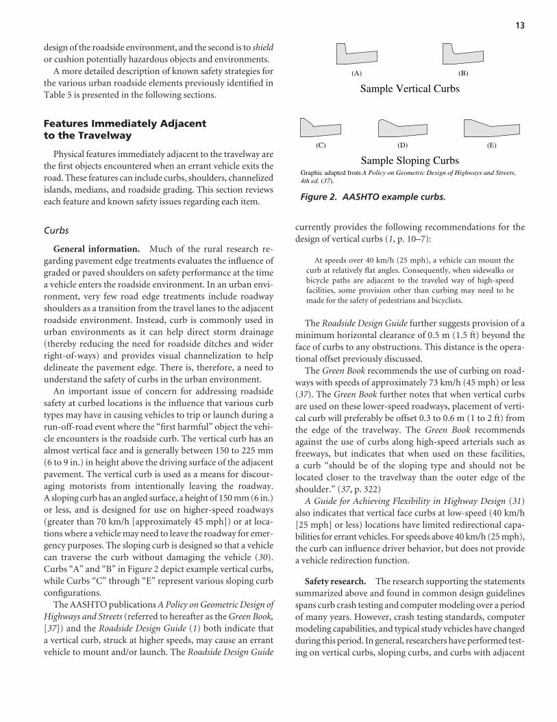
An important issue of concern for addressing roadsidesafety at curbed locations is the influence that various curbtypes may have in causing vehicles to trip or launch during arun-off-road event where the “first harmful” object the vehi-cle encounters is the roadside curb. The vertical curb has analmost vertical face and is generally between 150 to 225 mm(6 to 9 in.) in height above the driving surface of the adjacentpavement. The vertical curb is used as a means for discour-aging motorists from intentionally leaving the roadway.A sloping curb has an angled surface, a height of 150 mm (6 in.)or less, and is designed for use on higher-speed roadways(greater than 70 km/h [approximately 45 mph]) or at loca-tions where a vehicle may need to leave the roadway for emer-gency purposes. The sloping curb is designed so that a vehiclecan traverse the curb without damaging the vehicle (30).Curbs “A” and “B” in Figure 2 depict example vertical curbs,while Curbs “C” through “E” represent various sloping curbconfigurations.
The AASHTO publications A Policy on Geometric Design ofHighways and Streets (referred to hereafter as the Green Book,[37]) and the Roadside Design Guide (1) both indicate thata vertical curb, struck at higher speeds, may cause an errantvehicle to mount and/or launch. The Roadside Design Guide
currently provides the following recommendations for thedesign of vertical curbs (1, p. 10–7):
At speeds over 40 km/h (25 mph), a vehicle can mount thecurb at relatively flat angles. Consequently, when sidewalks orbicycle paths are adjacent to the traveled way of high-speedfacilities, some provision other than curbing may need to bemade for the safety of pedestrians and bicyclists.
The Roadside Design Guide further suggests provision of aminimum horizontal clearance of 0.5 m (1.5 ft) beyond theface of curbs to any obstructions. This distance is the opera-tional offset previously discussed.
The Green Book recommends the use of curbing on road-ways with speeds of approximately 73 km/h (45 mph) or less(37). The Green Book further notes that when vertical curbsare used on these lower-speed roadways, placement of verti-cal curb will preferably be offset 0.3 to 0.6 m (1 to 2 ft) fromthe edge of the travelway. The Green Book recommendsagainst the use of curbs along high-speed arterials such asfreeways, but indicates that when used on these facilities,a curb “should be of the sloping type and should not belocated closer to the travelway than the outer edge of theshoulder.” (37, p. 322)
A Guide for Achieving Flexibility in Highway Design (31)also indicates that vertical face curbs at low-speed (40 km/h[25 mph] or less) locations have limited redirectional capa-bilities for errant vehicles. For speeds above 40 km/h (25 mph),the curb can influence driver behavior, but does not providea vehicle redirection function.
Safety research. The research supporting the statementssummarized above and found in common design guidelinesspans curb crash testing and computer modeling over a periodof many years. However, crash testing standards, computermodeling capabilities, and typical study vehicles have changedduring this period. In general, researchers have performed test-ing on vertical curbs, sloping curbs, and curbs with adjacent
13
Graphic adapted from A Policy on Geometric Design of Highways and Streets,4th ed. (37).
Sample Sloping Curbs
Sample Vertical Curbs
(C) (E)(D)
(B)(A)
Figure 2. AASHTO example curbs.

barriers such as guard rails. In 1972, Dunlap et al. (38) per-formed several roadside curb evaluations including tests forfive standard curbs and eight curb/guardrail combinations.In 1974, Olson et al. (39) evaluated curbs using crash testingcombined with computer simulation. These two researchstudies were among the first to suggest the following commonlyaccepted concepts regarding curb safety:
• Curbs 150 mm (6 in.) tall or less do not redirect vehicles atspeeds above 73 km/h (45 mph) and should therefore notbe used for high-speed roads,
• Impacting curbs 150 mm (6 in.) tall or less will generallyresult in either no injury or minor injuries only, and
• Combinations of lower speeds and small approach anglesproduce the greatest effect on vehicle path correction.
A study performed in the 1970s at the Texas TransportationInstitute evaluated curb placement in conjunction with trafficbarriers and sloped medians (40). The researchers concludedthat the traffic barriers should not be immediately adjacent tocurbs as vehicles may vault or underride the barrier. They alsoconcluded that grading the median or roadside level with thetop of the curb will help reduce problems with barriers andguardrail interactions near curbs.
An evaluation performed for the Nebraska Department ofRoads (NDOR) included crash tests as well as simulations ofsloping curbs and curb-guardrail combinations (41). The re-searchers’ evaluation included various degrees of impact andvehicle trajectory. They concluded that the three slopingcurbs tested (two NDOR standard curbs and one AASHTOstandard curb) were traversable for a wide range of impactconditions and had very little likelihood of causing vehiclerollovers. The researchers further determined that the chancethat a vehicle could underride a guardrail was slight, and thechance that a vehicle would be vaulted by the curb-guardrailcombination was greatest when the barrier was located any-where from 0.45 to 3.7 m (1.5 to 12.1 ft) behind the curb. Thisrange of offset values applied to both a small and a large testvehicle.
A report commissioned by the Florida Department of Trans-portation (42) simulated the trajectories of three design vehi-cles hitting sloped (125 mm [5 in.] tall) and vertical (150 mm[6 in.] tall) curbs at approach speeds of approximately 57, 73,and 90 km/h (35, 45 and 55 mph) and impact angles rang-ing from 3 to 15 deg. The model results found that the verti-cal curbs would deflect the Ford Festiva test vehicle for allapproach speeds at angles of impact up to 12 deg. For a ChevyC2500 pickup, the vertical curb would deflect vehicles oper-ating at 90 km/h (55 mph), but only when the angle of impactwas 3 deg or less. The sloping curb was not shown to redirectthe vehicle under any combination of approach speed orangle. None of the impacts were shown to result in a rollover
or substantial vertical displacement of the vehicle, nor werethe events shown to result in more than minor damage to thevehicle.
The AASHTO Highway Safety Design and OperationsGuide (30) indicates that the potential for vehicle vaulting orrollover for curbs higher than 100 mm (4 in.) is a factor of thevehicle’s weight, speed, suspension system, angle of impact,and vehicle lane tracking. As a result, small cars are generallyoverrepresented in serious curb-related crashes. The poten-tial for a vehicle to vault precludes the exclusive use of a curbas sufficient protection for pedestrian facilities or roadsideelements.
In 2005, Plaxico and colleagues published NCHRP Report537: Recommended Guidelines for Curb and Curb-Barrier In-stallations in which they evaluated roads with operating speedsof 60 km/h (40 mph) or greater and the potential influence ofcurb or curb-barrier combinations at these locations (43).They determined that the most significant factor influencingvehicle trajectory is curb height. As a result, shorter curbs withflatter sloping faces should be used at higher speed locations.They also determined that a lateral distance of approximately2.5 m (8.2 ft) is needed for a traversing vehicle to return to its predeparture vehicle suspension state. As a result, guard-rails should not be placed closer than 2.5 m (8.2 ft) behindcurbs on roads where vehicle speeds are greater than 60 km/h (40 mph). As the research performed by Plaxico and col-leagues did not focus on low-speed roads, the placement of guardrails behind curbs for speeds lower than 60 km/h(40 mph) is not known.
In summary, curbs can provide positive (visual) guidancefor drivers, but curbs do not have the ability to redirect errantvehicles upon impact (unless the vehicle speed is quite low andthe vehicle impact angle is extremely small). If an errant vehi-cle approaches the curb at a small deflection angle, the impactof the curb is unlikely to be the cause of serious injury to thevehicle occupants; however, the curb may affect a vehicle’s tra-jectory, resulting in impact with a second, more substantialroadside hazard. A barrier or guardrail must be placed behindthe curb in such a way as to avoid vaulting the errant vehicle.
Strategy summary. A variety of strategies have been pro-posed, applied, and/or tested for safe application of curbtreatments. Common strategies are as follows:
Purpose Strategy
Prevent curb from vault- • Use appropriate curb heights with ing vehicles known influences on vehicle
trajectories (P)• Locate barriers behind curbs an
appropriate distance to improve curb-barrier interactions (P)
• Grade adjacent terrain flush with the top of the curb (P)
14

Shoulders
General information. The common edge treatment forurban roads is a curb or curb with gutter; however, manyroads exist in urban environments with a graded or pavedshoulder instead of a curb located immediately adjacent to thetravelway. The purpose of a shoulder is to provide a smoothtransition from the travelway to the adjacent roadside whilefacilitating drainage and promoting various other shoulderfunctions (as listed in Table 6). The shoulder width is includedas part of the clear zone width; therefore, the values shown inTable 6 should not be confused with clear zone requirements.There are many recommendations regarding appropriateshoulder widths for lower speed roads. These widths varydepending on the function of the shoulders as well as theavailable right-of-way. Table 6 shows suggested shoulderwidths from the AASHTO publication A Guide for AchievingFlexibility in Highway Design (31). This information was firstcompiled for a 1982 NCHRP study (44). These widths arerecommended for shoulder functional use and do not reflectidentified widths for safety purposes.
Because right-of-way costs are high in urban environments,the use of paved or graded shoulders in these environmentsoften is the result of previously rural roads being incorpo-rated into urbanized land use without the companion road-way improvements. Often the road with a shoulder will havea drainage ditch located parallel to the road, so care must betaken to maintain traversable conditions in the event that anerrant vehicle exits the road, travels across the shoulder, andthen encounters the roadside grading.
There are many research studies that have evaluated thesafety benefits of shoulders and companion shoulder widths.Several of these studies are included in the safety research sec-tion that follows.
Safety research. The research regarding shoulder safetyhas been generally divided into three categories—safe shoulderwidth, pavement edge treatments, and safety of paved versusgraded shoulders. The research regarding these three areas ofshoulder safety is summarized in the following:
• Safe shoulder width. Much of the research into the appro-priate width of shoulders focuses on the high-speed ruralcondition. Early research indicated that crash frequencytended to increase with shoulder width. For example,Belmont published a paper on rural shoulder widths in 1954and a subsequent paper in 1956 (extending the study tolower volume rural roads) and suggested that wider shoul-ders for higher speed, high-volume rural roads resulted inincreased crash rates, while the trend appeared reversed forlower volume, high-speed roads (45, 46). Subsequent tothese early studies, numerous researchers have studied theshoulder width question. In an unpublished critical reviewof research in this area (47), Hauer re-evaluated many of theoriginal shoulder width studies using the original data andconcluded that shoulder width safety is a sum of severalopposing tendencies. These can be summarized as follows:– The shoulder is even and obstacle free and available for
drivers of errant vehicles to use to regain control of theirvehicles, correct for their error, and resume normal travel;
15
Functional Classification
Shoulder Function Arterial
m (ft) Collector and Local
m (ft) Drainage of Roadway and Shoulder 0.3 (1) 0.3 (1) Lateral Support of Pavement 0.45 (1.5) 0.3 (1) Encroachment of Wide Vehicles 0.6 (2) 0.6 (2) Off-tracking of Wide Vehicles 0.6 (2) 0.6 (2) Errant Vehicles (Run-off-road) 0.9 (3) 0.6 (2) Bicycles 1.2 (4) 1.2 (4) Pedestrians 1.2 (4) 1.2 (4) Emergency Stopping 1.8 (6) 1.8 (6) Emergency Vehicle Travel 1.8 (6) 1.8 (6) Garbage Pickup 1.8 (6) 1.8 (6) Mail and Other Deliveries 1.8 (6) 0.6 (2) Emergency Call Box Services 2.4 (8) 1.8 (6) Law Enforcement 2.4 (8) 1.8 (6) Parking, Residential 2.4 (8) 2.1 (7) Routine Maintenance 2.4 (8) 1.8 (6) Major Reconstruction and Maintenance 2.7 (9) 2.7 (9) Parking, Commercial 3.0 (10) 2.4 (8) Parking, Trucks 3.0 (10) N/A Slow-Moving Vehicles 3.0 (10) 2.7 (9) Turning and Passing at Intersections 3.0 (10) 2.7 (9)
Sources: Adapted from A Guide for Achieving Flexibility in Highway Design (31) andNCHRP Report 254: Shoulder Geometrics and Use Guidelines (44).
Table 6. Acceptable shoulder widths for shoulder functions.

– Wide shoulders may induce voluntary stopping andtherefore place a hazard immediately adjacent to thetravelway;
– Wide shoulders may entice drivers to use them as addi-tional lanes or for passing maneuvers on the right; and
– Wider shoulders may encourage higher operating speeds.Evaluation of crash data without comprehensively consider-ing these four contrasting tendencies may permit researchersto arrive at a variety of conclusions regarding shoulderwidth safety. In general, on roads with wider shoulders,travel speeds are higher and crashes are more severe. How-ever, wider shoulders result in fewer run-off-road crashes,and therefore this benefit must be included.
• Pavement edge treatments. A common problem withroadway shoulders is that they may not be flush either withthe travelway pavement surface (for the case of gradedshoulders) or with the adjacent roadside grading (for thecase of paved shoulders). There are many reasons thatpavement drop-offs may develop in the shoulder region.Erosion of the soil next to the pavement, rutting by frequenttire wear, and pavement overlay maintenance are examplesof how, over time, a pavement drop-off may develop.When a drop-off is encountered by an errant vehicle, thevehicle’s tires may have difficulty mounting the extra pave-ment lip, causing the vehicle to further lose control.
In the late 1970s and early 1980s, researchers at TexasA&M University performed a series of evaluations on pave-ment edge drop-offs (48, 49). They determined that ver-tical drop-offs as small as 7.6 cm (3 in.) could result in asevere crash if encountered by an errant vehicle. The TexasA&M researchers developed pavement edge shapes to pro-vide a more beveled edge and determined that for speedsup to 90 km/h (55 mph), a 45-deg angle could be appliedto the drop-off. This sloped edge would then enable errantvehicles to regain access to the travelway safely. Currently,the Federal Highway Administration promotes a pavementedge treatment called the safety edge that uses a similar45-deg angle with construction standards that permit com-paction to provide pavement edge stability.
• Safety of paved versus graded shoulder. The safety ofpaved versus graded shoulders is less controversial than thepavement width consideration. Several studies have indi-cated that the addition of any paved shoulder will help withcrash reduction. Zegeer, Deen, and Mayes concluded thatincreasing the width of a paved shoulder for rural roads by0.3 m (1 ft) would reduce crashes by approximately 6 per-cent (50). They also concluded that paving at least 0.3 m(1 ft) of a shoulder would reduce crashes by 2 percent.More recently, McLean found that for Australian roads theapplication of sealed shoulders with widths from 1.5 to 2 m(5 to 6.6 ft) would result in a decrease in crash rates and,therefore, be a cost-effective treatment (124).
Strategy summary. Common shoulder treatment strate-gies are as follows:
Purpose Strategy
Discourage run-off-road Provide wider shoulders suitable crashes for shoulder function (P)
Provide traversable • Eliminate pavement drop-offs (P)transition for errant • Add a pavement safety edge (T) vehicles • Provide a paved or sealed
shoulder (P)
Channelization/Medians
General information. The separation of traffic move-ments by the use of a raised median or turning island is oftenreferred to as channelization. For the purposes of this review,a flush or traversable median or island is considered part ofthe roadway, while a raised median and raised turn island areconsidered part of the roadside.
Channelized islands are generally used to reduce the areaof pavement at an intersection while providing positive guid-ance to turning vehicles. Channelized islands can be used forpedestrian refuge and traffic control device placement, andthey can also be planted with landscaping treatments thatcontribute to an improved visual environment (15). For araised island to be visible, it should have a minimum size of5 m2 (50 ft2) for urban conditions (37). The orientation of thecurb on a raised island should be slightly skewed to the adja-cent travel lane to give an illusion of directing vehicles intothe travel lane. Other cross-sectional characteristics of raisedislands are similar to those of raised medians.
The raised median provides the primary function of sep-arating opposing directions of vehicle travel. This physicalseparation has the added benefit of improving access man-agement (restricting frequent left turns into driveways), pro-viding a location for pedestrian refuge (assuming the medianhas adequate width), and providing road edge delineationduring inclement weather conditions (particularly snow).A median may simply be raised using a vertical or slopedcurb. In urban regions, median width can vary dramatically de-pending on the proposed function of the median. As sug-gested in the Maryland publication, When Main Street Is aState Highway: Blending Function, Beauty and Identity, the useof a median can dramatically improve the visual quality of afacility (51).
Safety research. Many of the recent research studiesabout raised median safety focus on the influence of themedian on access management and the resulting reduction ofcrashes due to restricted left-turn movements. Although thiscrash reduction strategy falls outside the scope of this litera-ture review, it is worth noting that the median conditionhas added safety benefits that should be considered in a
16
comprehensive crash evaluation. In this review, however, theevaluation will be focused on median crashworthiness for thepurposes of roadside safety.
In general, median research (excluding access managementstudies) has focused on the crash condition with specific atten-tion to the following questions:
• Do medians prevent pedestrian cross-median crashes?What is the influence of a median barrier that completelyprohibits pedestrian crossing?
• Do medians reduce the number of crashes and crashseverity?
• Can landscaping and trees be safely located in medians?• Should median barriers be used to improve median safety?
A median barrier review is included later in this chap-ter in the section on safety issues, so this section focuses onthe influence of a median on crashes and landscaping treat-ments. Several researchers have weighed the merits of araised median (divided highway) versus no median or aflush median. Unfortunately, in most of the before-after re-search studies, a jurisdiction was implementing a medianimprovement in conjunction with other improvements,such as road widening, lane narrowing, and so forth. As aresult, the influence of divided versus undivided has re-sulted in a wide variety of crash observations. Harwood (52)studied several median conversion configurations from un-divided to divided operations. After controlling for a vari-ety of variables, he concluded that the influence of themedian on safety was small. Many studies have resulted insimilar observations, that is, that raised medians have a neg-ligible effect on crash frequency. Crash severity varies de-pending upon the median width (wider medians reduce thechance for head-on collisions), the use of median barrier(to be discussed later), and the placement of rigid objects inthe median area.
The issue of landscaping and the specific evaluation oftree placement are further discussed in the landscapingsection; however, a recent three-phase study performed atCalifornia Polytechnic State University (53) specificallyevaluated the placement of large trees in raised medians onurban and suburban highways. They evaluated sites withand without large trees and determined that at a 95-percentlevel of statistical confidence, an increased number of fatalor injury crashes were associated with the presence ofmedian trees. The association between median tree crashesand left-side-only crashes, however, was only marginallysignificant. The three-phase study also indicated that me-dian trees on urban and suburban highways were associatedwith an increase in collision frequency. Study researcherswere not able to identify any systematic relationships be-tween the left-side crash rates and median widths or tree
setbacks. They also found that with the increase in fixed-object collisions came a decrease in head-on and broadsidecollisions. Finally, the researchers found non-intersectionlocations with median trees were positively associated withhit-pedestrian collision.
Another common application for raised medians is asone element in a gateway treatment at transition locationsbetween rural and urban areas. The raised median studiesfor the purpose of use as gateway strategies are reviewedlater in this chapter in the section discussing traffic calm-ing applications.
Research into appropriate median widths for safety pur-poses are focused primarily on the high-speed rural condi-tion. Similar median width studies for urban environmentsare not available.
Strategy summary. Common channelized island andmedian strategies are as follows:
Purpose Strategy
Reduce likelihood of Widen median (T)run-off-road collision
Reduce crash severity • Place only frangible items in channelized island or median (P)
• Shield rigid objects in median (P)
Roadside Grading
General information. The terrain adjacent to an urbanroad should be relatively flat and traversable. In general, theplacement of common urban roadside features such as side-walks and utilities tends to create a flatter urban roadside. Theprimary risk for irregular terrain adjacent to the travelway isthat an errant vehicle will either impact a rigid obstacle or thatthe terrain will cause the vehicle to roll over. Rollovers wereresponsible for 20 percent of the fatal crashes in 2002, and thelargest number of rollovers occurred after a vehicle impactedan embankment or a ditch (25, 54). The principal cause ofrollovers is a vehicle “tripping” on an element of the roadsideenvironment, such as a ditch or an embankment; neverthe-less, sharp pavement drop-off on the shoulder may also leadto vehicle tripping for roads without a curb. To prevent vehi-cle tripping, the grade of ditches, slopes, and embankmentsshould be minimized as much as possible, and pavementdrop-offs must be kept to a minimum.
These strategies are potentially more relevant to rural andsuburban environments than to urban ones, however. In urbanareas, the roadside is typically characterized not by shouldersand embankments, but by curb and gutter applications and byadjacent roadside development. This is evidenced when onecompares the absolute number of rollover crashes in urbanenvironments with the number of rollover crashes in rural
17

environments. In 2002, there were roughly 1,800 rollovercrashes in urban areas, compared with over 6,200 for rural re-gions. Accounting for exposure, roughly one rollover per billionmiles of travel occurs in urban areas whereas almost sixrollovers per billion miles of travel occur in rural environments.
While the conditions that lead to rollover crashes are notclear, crash data analyses indicate that these crash types aregenerally associated with high-speed travel. Of the roughly8,000 rollovers that occurred in 2002, only about 600 occurredon roadways classified as urban minor arterials, collectors,and locals.
The sideslope of an urban road should, in general, slopefrom the edge of the right-of-way toward the curb of the road.This slope will prevent any road drainage from encroachingon adjacent property and enables the drainage to be containedwithin a closed drainage system. As a result, the slope is oftenquite flat (1V:6H typically) for curbed urban roads. For roadswithout a curb, the design guidelines for rural roadside con-ditions should be applied. That is, the terrain, includingdrainage channels, should be safely traversable by a motorvehicle, and the placement of obstacles such as headwalls mustbe flush with the ground surface and designed to be navigatedby an errant vehicle.
Safety research. The research team was not able to locateresearch specific to the urban roadside slope and safetyimplications associated with this terrain. Most of the studiesapplicable to the urban condition focused on the presence ofroadside obstacles rather than the companion roadside slope.
Strategy summary. Common grading strategies are asfollows:
Purpose Strategy
Minimize crash likeli- Maintain traversable grades that arehood free of rigid obstacles (P)
Minimize crash severity • Flatten grades to reduce chance of vehicle rollover (P)
• Create an object setback policy (T)
Static Roadside Treatments
Mailboxes
General information. The Roadside Design Guide (1) de-tails the preferred specifications for the design and installa-tion of mailboxes. In general, AASHTO recommends the useof a 100-mm by 100-mm (4-in. by 4-in.) wooden post or a38-mm (1.5-in.) light-gauge pipe for mounting mailboxes,with these posts embedded no deeper than 600 mm (24 in.)in the ground. Mailboxes should further be mounted to theirsupports to prevent the mailbox from separating from thepost during a crash event. Also of concern is the potential
hazard associated with larger mail collection boxes, a commonfeature in urban environments, as well as neighborhood de-livery units, which are associated with apartment complexes.Crash tests of these features have shown them to fail safetyrequirements, and the Roadside Design Guide recommendsplacing them outside of clear recovery areas.
While making mailboxes crashworthy will satisfy safetyassociated with mailbox-related crashes, it is important torecognize that the placement of mailboxes may have animportant impact on the overall safety of the roadway. Mail-boxes should not obstruct intersection sight distance, norshould they be located directly on higher-speed roadways,where stopping associated with mail delivery and collectioncan lead to substantial speed differentials between vehicles onthe travelway, thereby increasing the possibility of a rear-endcollision. Where such conditions exist, the Roadside DesignGuide recommends the use of a 2.4-m (8-ft) mailbox turnoutlane adjacent to the travelway to allow vehicles to leave thetravelway for mail collection and delivery purposes. Thisturnout concept does not apply to urban curbed streets. Atcurbed residential locations, the Roadside Design Guide rec-ommends that the minimum distance from the roadsideface of the mailbox to the face of the curb should be 150 mm(6 in.), with a preferred offset ranging from 200 to 300 mm(8 to 12 in.).
A common issue regarding the placement of mailboxes inan urban environment is that the governing jurisdiction(often a city or county) may not adopt the guidelines com-monly accepted by state departments of transportation. Manyurban jurisdictions allow home owners to construct a mailboxof their choosing. In areas in which mailbox vandalism iscommon, home owners have begun to erect increasingly rigid(less forgiving) mailbox units. A rigid brick mailbox is a com-mon site along many urban residential roadways. The problemof rigid mailbox units is compounded by the general place-ment of such mailboxes adjacent to a driveway (to make iteasy for the home owner to retrieve mail). Since the curb hasa secondary function of delineating the edge of the roadway,a mailbox placed on the departure side of a driveway (where acurb cut interrupts the roadway delineation) is particularlyvulnerable to errant vehicles that exit the road to the right.
Safety research. NCHRP Report 350 provides recom-mended procedures to ensure roadside features such as mail-boxes are crashworthy (36). Since mailboxes are a commonfixed object adjacent to urban streets (particularly residential),they warrant particular attention when reviewing urban road-side safety. Many urban jurisdictions do not require crash-worthy mailboxes. There are several yielding mailbox designsapproved for the National Highway System (NHS) that couldbe incorporated in an urban setting. Chapter 11 of the Road-side Design Guide (1) provides a comprehensive summary of
18

the safe placement of mailboxes. The use of yielding mail-boxes is promoted in the Roadside Design Guide. This permitsconvenient mailbox placement adjacent to the road. Mailboxplacement for urban commercial locations is not included inthe chapter and is a less common problem. In addition toyielding mailbox support design, some jurisdictions promotethe placement of reflective object markers on the mailbox orpost to improve nighttime visibility (55).
Strategy summary. Common mailbox safety strategiesare as follows:
Purpose Strategy
Minimize crash likeli- • Remove or relocate mailboxes tohood safe locations (P)
• Add reflective object markers toimprove nighttime visibility (T)
Minimize crash severity • Develop policies to requirecrashworthy mailboxes in urbanenvironments (P)
• Shield rigid mailboxes wherepractical (P)
Landscaping, Trees, and Shrubs
General information. Several types of roadside land-scaping are commonly employed to enhance the aestheticsof roadside environments. These treatments may includethe placement of shrubs, street trees, or alternative treat-ments such as landscape berms. In addition to the concernof traversability in the event that an errant vehicle encoun-ters roadside landscaping, a common safety issue of adjacentlandscape treatments is sight distance and the impact land-scape treatments may have for intersection, driveway, andstopping sight distance considerations. Regional jurisdic-tions often have landscaping design guidelines, landscapingpolicies, and street tree master plans. These documentsaddress a variety of landscaping issues including plant type,maintenance, and plant placement. Since trees, in particu-lar, can vary from small, flexible species up to more rigidvarieties, the careful selection of tree species is critical. Inaddition, different tree species can have substantially differ-ent root systems. Species selection should also focus onthe potential for the tree system to adversely impact road
surface and pedestrian facilities due to pavement heave andcracking.
Placement criteria, in some cases, is based on the func-tional purpose or posted speed limits of adjacent roads. Com-mon landscape placement issues addressed in jurisdictionplans include the following:
• Proximity to intersections,• Proximity to driveways,• Maintaining a clear vision space,• Lateral offset placement of trees and landscaping,• Longitudinal placement of trees and landscaping,• Median planting strategies, and• Strategic placement strategies for visual perception.
These specific placement strategies are further described inthe following:
• Proximity to intersections. Sight distance should be main-tained in the proximity of intersections. As a result, manylandscape guidelines restrict tree placement in the imme-diate vicinity of intersections. The North Carolina Tradi-tional Neighborhood Development (TND) Guidelines (56)and the City of Seattle Street Tree Planting Procedures (57),for example, recommend that trees should be locatedno closer than 9 m (30 ft) from intersection corners. Land-scape Design Guidelines for the City of Simi Valley (58)requires a clearance distance of 10.7 m (35 ft) from the ex-tended curb at the near side of the cross street curb.
Another approach to intersection clearance is based onstreet type and intersection configuration. For example, theMontgomery, Alabama, Street Tree Master Plan (59) usesstreet type and traffic control to determine tree offsets fromintersections. Example minimum tree placement guidelinesat intersections for Montgomery are depicted in Table 7.
Figure 3 is based on an FHWA publication and demon-strates the sight triangle that is required to be free of treesat an example intersection (60). Higher-speed vehicles thatdo not stop at the intersection require more sight distancethan stopped vehicles, as shown.
Guidelines for Tree Planting and Maintenance on UrbanRoads, published by the Traffic Authority of New SouthWales, further recommends that skewed intersections,
19
Intersection Control Major Street Neighborhood Street Traffic Light 9.1 m (30 ft) -- Four-Way Stop 9.1 m (30 ft) 4.6 m (15 ft) Major Street Two-Way Stop 12.2 m (40 ft) -- Neighborhood Street Two-Way Stop
9.1 m (30 ft) 4.6 m (15 ft)–Stops 9.1 m (30 ft)—Does Not Stop
Source: Adapted from Montgomery Street Tree Master Plan (59).
Table 7. Guidelines for minimum tree placement offsetsat intersections for Montgomery, AL.

locations with high turning speeds, or locations where fast-approaching vehicles veer into the left lane to avoidimpacting right-turning vehicles are all locations wherecluster run-off-road crashes can be expected and whereadditional space free of roadside objects such as treesshould be provided (61).
• Proximity to driveways. The placement of trees near drive-ways poses similar sight distance issues as those identifiedfor intersections. As an example, the City of Simi Valleyguidelines requires a 1.5-m (5-ft) clearance between treesand driveway edges (58). By contrast, the Montgomeryrecommendations indicate that trees should not be placedwithin 4.6 m (15 ft) of driveways (59). The City of Seattle,in Street Tree Planting Procedures, requires maintaining aminimum distance between trees and driveways of 2.3 m(7.5 ft) with a recommended distance of 3.0 m (10 ft) (57).
Many landscape policies do not directly stipulate treeplacement near driveways, but use an approach similar tothe New South Wales guidelines, which simply state thatdrivers exiting driveways should be able to see approachingtraffic and pedestrians (61). As an example, the attractivelandscaping depicted in Figure 4 seems reasonable upon
initial inspection; however, at this location the intersectingroadway is characterized by a horizontal curve. With thelandscaping placement close to the driveway, the driver ofan exiting vehicle cannot detect approaching vehicles with-out edging into the active travel lane; therefore, these road-side treatments encroach on the required sight distance. Ascan be viewed in the photo, the adjacent property owneralso positioned large “ornamental” rocks at the corner,thereby adding a rigid obstacle in the immediate vicinity ofthe roadway.
• Maintaining a clear vision space. Traditional Neighbor-hood Development (TND) Guidelines recommends thatvertical space ranging from 0.6 to 2.1 m (2 to 7 ft) aboveground be maintained to preserve lines of sight (56). TheAASHTO publication Highway Safety Design and Opera-tions Guide (30) recommends that the vertical “clearvision space” range from 1 to 3 m (3.3 to 10 ft) to ensureclear sight distance for drivers in low-riding sports cars aswell as drivers in high trucks and buses. This vertical clearspace is common to many regional landscaping plans. The“clear vision space” is essentially the space above shrubgrowth and below tree overhang. A low tree overhang canalso create an obstacle for pedestrian access, as shown inFigure 5.
Figure 6 depicts another type of encroachment into thevertical clear vision space. Often landscape berms are usedto screen adjacent parking from the roadway. The photoon the left shows a longitudinal landscape berm and theeffect it has on horizontal sight distance. At the locationshown, the road has a horizontal curve to the right (in thedirection the vehicle shown is traveling) and has numer-ous driveways that are not easily visible due to the bermheight. The photo on the right depicts the same locationbut more clearly shows that the height of the berm exceedsthe height of a typical passenger car. This type of landscapetreatment is a common roadside treatment in many urbanareas.
• Lateral offset placement of trees and landscaping. Tra-ditional Neighborhood Development (TND) Guidelines
20
Photo by Karen Dixon.
Figure 4. Landscaping in sight triangle for driveway.
Graphic adapted from Trees in Hazardous Locations (60).
Figure 3. Intersection sight triangles.

recommends that planting strips located between the curband sidewalk should be at least 1.8 m (6 ft) wide (56). Thisresource further suggests that for streets with design speedsat or below 32 km/h (20 mph) or for streets that permiton-street parking, small street trees can be planted within0.9 m (3 ft) of the back of curb or along the approximatecenterline of the planting strip. The Seattle planting proce-dures permit tree planting 1.1 m (3.5 ft) from the face ofcurb (57). The Montgomery, Alabama, plan recommendsthat at neighborhood street locations trees should be in-stalled at a point equidistant between the pavement edgeand the right-of-way limits or, for residential neighborhoods,
equidistant between the pavement edge and the edge of thesidewalk (59). For major street locations, trees should notbe located closer to the edge of pavement than two-thirdsof the distance from the pavement edge to the right-of-waylimits. The Georgia Department of Transportation OnlinePolicy and Procedure System (62) recommends that in anurban environment, trees with diameters less than 100mm (4 in.) should be laterally positioned 1.2 m (4 ft) forposted or design speeds of 56 km/h (35 mph) or less, 2.4 m(8 ft) for posted or design speeds of 64 to 72 km/h (40 to45 mph), and outside the clear zone for speeds greater than72 km/h (45 mph). For larger trees, the minimum lateral
21
Photos by Karen Dixon.
Figure 6. Landscape berm that blocks horizontal sight distance.
Graphic reprinted fromVegetation Control for Safety. A Guide for Street and Highway Maintenance Personnel, FHWA-RT-90-003 (120).
Figure 5. Overhead object hazard.
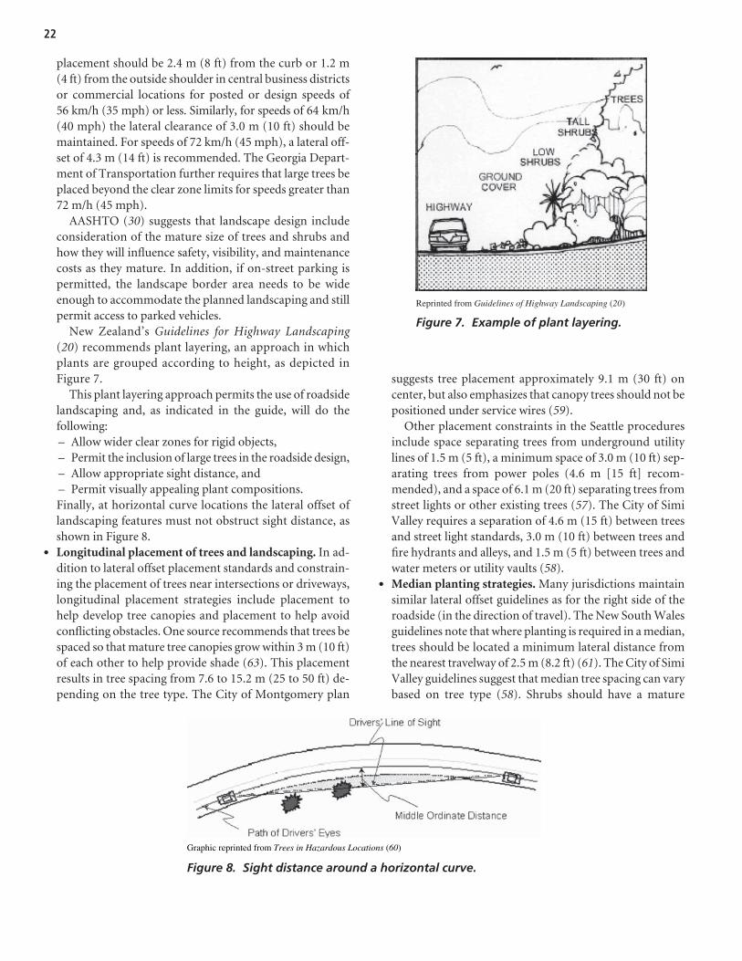
placement should be 2.4 m (8 ft) from the curb or 1.2 m(4 ft) from the outside shoulder in central business districtsor commercial locations for posted or design speeds of56 km/h (35 mph) or less. Similarly, for speeds of 64 km/h(40 mph) the lateral clearance of 3.0 m (10 ft) should bemaintained. For speeds of 72 km/h (45 mph), a lateral off-set of 4.3 m (14 ft) is recommended. The Georgia Depart-ment of Transportation further requires that large trees beplaced beyond the clear zone limits for speeds greater than72 m/h (45 mph).
AASHTO (30) suggests that landscape design includeconsideration of the mature size of trees and shrubs andhow they will influence safety, visibility, and maintenancecosts as they mature. In addition, if on-street parking ispermitted, the landscape border area needs to be wideenough to accommodate the planned landscaping and stillpermit access to parked vehicles.
New Zealand’s Guidelines for Highway Landscaping(20) recommends plant layering, an approach in whichplants are grouped according to height, as depicted inFigure 7.
This plant layering approach permits the use of roadsidelandscaping and, as indicated in the guide, will do thefollowing:– Allow wider clear zones for rigid objects,– Permit the inclusion of large trees in the roadside design,– Allow appropriate sight distance, and– Permit visually appealing plant compositions.Finally, at horizontal curve locations the lateral offset oflandscaping features must not obstruct sight distance, asshown in Figure 8.
• Longitudinal placement of trees and landscaping. In ad-dition to lateral offset placement standards and constrain-ing the placement of trees near intersections or driveways,longitudinal placement strategies include placement tohelp develop tree canopies and placement to help avoidconflicting obstacles. One source recommends that trees bespaced so that mature tree canopies grow within 3 m (10 ft)of each other to help provide shade (63). This placementresults in tree spacing from 7.6 to 15.2 m (25 to 50 ft) de-pending on the tree type. The City of Montgomery plan
suggests tree placement approximately 9.1 m (30 ft) oncenter, but also emphasizes that canopy trees should not bepositioned under service wires (59).
Other placement constraints in the Seattle proceduresinclude space separating trees from underground utilitylines of 1.5 m (5 ft), a minimum space of 3.0 m (10 ft) sep-arating trees from power poles (4.6 m [15 ft] recom-mended), and a space of 6.1 m (20 ft) separating trees fromstreet lights or other existing trees (57). The City of SimiValley requires a separation of 4.6 m (15 ft) between treesand street light standards, 3.0 m (10 ft) between trees andfire hydrants and alleys, and 1.5 m (5 ft) between trees andwater meters or utility vaults (58).
• Median planting strategies. Many jurisdictions maintainsimilar lateral offset guidelines as for the right side of theroadside (in the direction of travel). The New South Walesguidelines note that where planting is required in a median,trees should be located a minimum lateral distance fromthe nearest travelway of 2.5 m (8.2 ft) (61). The City of SimiValley guidelines suggest that median tree spacing can varybased on tree type (58). Shrubs should have a mature
22
Graphic reprinted from Trees in Hazardous Locations (60)
Figure 8. Sight distance around a horizontal curve.
Reprinted from Guidelines of Highway Landscaping (20)
Figure 7. Example of plant layering.

height of 0.8 m (2.5 ft), and ground cover should be setback from the curb edge a minimum of 0.5 m (1.5 ft).
• Strategic placement strategies for visual perception. Onereport from Denmark suggests that the traffic-related featureof roadside plantings may be due to the visual narrowing ofthe driver’s field of view, which results in speed reductions(15). This speed reduction hypothesis is echoed in other lit-erature, but it has not yet been empirically substantiated.
Safety research. There is considerable anecdotal infor-mation in the literature that supports the potential benefits ofroadside landscaping placement for health and driver well-being. Similarly, impact with a rigid object, such as a largetree, is a known hazard, and this danger has been consistentlyreinforced in rural roadside research. While shrubs are oftenclassified with trees for the purposes of analyzing crash data,it is important to consider the safe placement of shrubs sep-arately from that of trees and other landscaping elements, asmany types of landscaping elements are considered frangible.
The majority of roadside landscape safety literature hasfocused on the safety condition of street trees. The placementor removal of street trees is often one of the most contentiouselements with respect to the design of roadsides in urban areas.Urban stakeholders often seek to incorporate street trees in thedesign of urban roadsides; however, when trees are placed ad-jacent to the travelway, they can become rigid, fixed-objecthazards. Current practice discourages the placement of treeswith mature-tree caliper widths greater than 100 mm (4 in.)along the roadside (1, 37). This maximum tree size is based onthe crash tests of 100 by 100 mm (4 by 4 in.) wooden signposts.A tree, unlike a wood signpost, has a root system; however, thewood post used for sign supports has long been the referencefor tree size on the assumption that if the wooden signpost issafe, then a tree of a similar size should also be safe (64, 65).
In 1986, the FHWA commissioned a study to reduce haz-ards due to trees (66). Although the study focused generally onthe rural environment, the researchers found that for fatal treecrashes, the median tree diameter at breast height was 508 mm(20 in.), whereas the median tree diameter for nonfatal treecrashes was 381 mm (15 in.). FHWA’s Roadside Improvementsfor Local Roads and Streets further notes that trees with multi-ple trunks, groups of small trees, or a combination of a smalltree and another fixed object can act as a potential hazard andshould be considered collectively (67). For combined effects,the cross section should not exceed 83.87 sq cm (13 sq in.).
A 1990 study performed by Turner and Mansfield evaluatedurban tree safety in Huntsville, Alabama, based on a study oftree crashes (7). The study presents aggregate information onthe characteristics of urban run-off-road crashes into trees, butdid not include information on the specific road characteris-tics of the environments in which these crashes occurred. Theauthors concluded that mature trees with diameters larger than
10 cm (4 in.) should not be permitted within a roadside clearzone region. The authors further suggested that if the trees areneeded for aesthetics or environmental reasons, the tree loca-tion should be behind a barrier, ditch, or retaining wall.
A 1999 study conducted in Washington State examinedboth rural and urban environments and developed modelsfor both conditions as well as models combining the urbanand rural data (68). The researchers determined that the vari-able representing the number of isolated trees in a section hada negative sign (indicating a decrease in accident frequency)for urban areas. This same variable had a positive sign(indicating an increase in accident frequency) for rural loca-tions. The authors also evaluated crash severity. The modelsthey developed predicted that in an urban environmentisolated trees can be expected to result in possible injurywhile the presence of tree groups can be expected to result indisabling injuries or fatalities. The authors had a similar findingfor tree groups in rural environments. The authors attributedthe reduction of accident frequency due to isolated trees inurban environments to the fact that there are fewer trees inurban environments than in rural ones.
In 1999, Kloeden and colleagues published a study ofcrashes that occurred between 1985 and 1996 in SouthernAustralia (69). The researchers did not separate the crashesinto urban and rural categories; however, they did performevaluations based on the speed zones associated with thecrash locations. Table 8 depicts the distance to roadside haz-ards for fatalities that occurred during the study period forspeed zones of 80 km/h (50 mph) or less. The offset valuesshown in this table are rounded to the closest meter. ThisAustralian study found that 58.6 percent of roadside hazardfatalities were due to vehicle impacts into trees.
A study published in 2003 evaluated five arterial roadwaysin downtown Toronto and sought to understand the safetyimpacts of placing landscape elements, such as mature trees,adjacent to the travelway. The sites were selected becauseall five sites were undergoing various environmental andaesthetic improvements due to community concerns associ-ated with major road reconstruction projects. The sites weretracked from 1992 to 1995 as they underwent these improve-ments. This study found a statistically significant reductionin mid-block crashes from the pre- to post-test conditions,although the authors did not elaborate on the nature ofthe crashes that were investigated as part of the study (70).These results, however, cannot be uniquely attributed to treessince the projects involved major reconstruction.
Researchers from Monash University Accident ResearchCentre in Australia published a study in 2003 that evaluatedroadside safety issues in Victoria from 1996 to 2000 (71). Theydetermined that 4.1 percent of collisions with roadside treesresulted in a fatality, compared with only 2.3 percent of otherroadside object crashes. They also noted that the likelihood of
23

a fatality is greater for collisions at higher speeds and that themost frequently impacted roadside hazards were trees, poles,fences, and embankments.
A study published in 2005 by Bratton and Wolf performedan analysis using national crash data and concluded thatcrash frequency is generally higher and injury level moresevere in higher speed rural areas (72). They also noted thatcrashes involving trees are more injurious than all crashes ingeneral. Bratton and Wolf were not able to identify a signifi-cant difference between tree collision rates in urban and ruralareas. Although they noted that trees, as fixed objects, statis-tically increase the likelihood of injury in accidents, trees areinvolved in a small overall percentage of these crash events.The authors went on to note that since the clear zone conceptdoes not appear to be a feasible notion for the urban envi-ronment, designers should develop a way of safely integrat-ing trees into the urban roadside environment.
Researchers at California Polytechnic State Universityperformed a three-phase study completed in 2004 (with in-terim reports in 2002 and 2003) in which they evaluated thestreet tree application specifically for the urban median con-dition (53). In the initial stages of the research, the re-searchers performed a literature review and noted the widevariety of anecdotal evidence and conflicting empirical evi-dence produced for previous studies into the roadside safetyof the urban street tree. They noted that there are a varietyof clearance standards used throughout the United Statesfor recommended offset values to roadside hazards such aslarge trees (defined as trees with diameters greater than 100mm [4 in.] for their study) and very little direction regard-ing appropriate placement of trees in medians. As a result,Phases 2 and 3 of the study were focused on evaluating
urban street trees in curbed urban and suburban highwaymedians with a variety of median widths, including narrowmedians. The researchers concluded that large trees locatedin medians are associated with more total crashes as well asmore fatal and injury crashes. The presence of median treeswas statistically significant for the severity model developedfor the study. The researchers also found a positive rela-tionship between median trees and hit-pedestrian crashes atnon-intersection locations. The median width results wereinconclusive.
Strategy summary. A variety of strategies have been pro-posed, applied, and/or tested for safe application of landscap-ing and tree placement adjacent to the roadside. The safety ofthese strategies in some cases is well known; in other cases,strategies hold promise but their exact influence on safety isunknown. Common strategies are as follows:
Purpose Strategy
Prevent large trees from • Restrict/Refine plantinggrowing in hazardous guidelines regarding tree andlocations landscaping placement (T)
• Implement plant layeringstrategies (T)
Eliminate hazardous • Remove or shield isolated largetree conditions trees (diameter of 100 mm [4 in]
or more) (P)• Shield tree groups (P)• Establish urban lateral offset
guidelines for large trees (T)• Delineate hazardous trees to
improve visibility (E)
Minimize level of Reduce travel speed on adjacentseverity road (P)
24
Distance of Roadside Hazard
from Road (m)(ft)
Number of Crashes
Percentage (%)
CumulativePercentage
(%) 0 (0) 34 22.2 22.2 1 (3) 38 24.8 47.1 2 (7) 30 19.6 66.7
3 (10) 18 11.8 78.4 4 (13) 12 7.8 86.3 5 (16) 5 3.3 89.5 6 (20) 3 2.0 91.5 7 (23) 1 0.7 92.2 8 (26) 3 2.0 94.1 9 (30) 1 0.7 94.8
10 (33) 3 2.0 96.7 14 (46) 2 1.3 98.0 15 (49) 2 1.3 99.3 16 (52) 1 0.7 100.0 Total 153 100.0
Source: Adapted from Severe and Fatal Car Crashes Due to Roadside Hazards (69).Note: Crashes involving multiple fatalities are only counted once in this table.
Table 8. Offsets to roadside hazards in fatalities.
Street Furniture
General information. In many urban areas, the use ofstreet furniture is a common approach to improving the aes-thetic quality of a street. Street furniture includes items placedadjacent to the road that are there to improve the adjacentland use or to improve the transportation operations. In somejurisdictions, street lights and signs are included in the cate-gory of street furniture; however, for the purposes of thisreview, street furniture is considered to be supplementalitems such as benches, public art, trash receptacles, phonebooths, planters, bollards, fountains, kiosks, transit shelters,bicycle stands, and so forth. Often the placement of these de-vices can obscure sight distance, so their location should notoccur in the sight triangles of intersections or driveways.Many street furniture items are placed along the right-of-wayby property owners, as in the case of the placement of a side-walk cafe in front of a restaurant, and are thus largely outsidethe engineer’s control. Transit shelters are provided to protecttransit riders from inclement weather and must be locatedclose to the curb to facilitate short bus dwell times.
One interesting way that some jurisdictions manage theplacement of street furniture by land owners is by a permit-ting process that requires vendors or property owners toacquire liability insurance for street furniture located adja-cent to the road. Seattle is one city with this insurancerequirement. Other jurisdictions restrict the placement ofprivate street furniture by a permitting process comple-mented by a tax for each square meter or square foot of pub-lic right-of-way used. Dublin, Ireland, is one city that usesthis approach.
Safety research. The research team for this project wasnot able to locate any research evaluating the relative hazardthat may be posed by street furniture. Nevertheless, streetfurniture can potentially create sight distance obstructionswhen located near an intersection, particularly when largenumbers of people congregate as a result of the street furni-ture. It is also important that the sight distance of pedestriansbe maintained when placing street furniture proximate to theroadway.
Strategy summary. Common street furniture safety strate-gies are as follows:
Purpose Strategy
Minimize likelihood of • Locate street furniture as farcrash from street as possible (P)
• Restrict street furniture placementto avoid sight distance issuesfor road user (P)
Minimize crash severity Develop street furniture that meetsbasic crashworthy standards (E)
Utility Poles, Luminaires, and Signposts/Hardware
General information. In both the national and interna-tional literature, the placement of utility poles, light poles, andsimilar vertical roadside treatments and companion hard-ware is frequently cited as an urban roadside hazard. Forexample, Haworth and Bowland have noted that while im-pacts with trees were more common outside the Melbourne,Australia, metropolitan area, single-vehicle crashes withpoles or posts were more common within the metropolitanregion (73). A 1998 study by the European Transport SafetyCouncil identified collisions with utility poles or posts as oneof the top two roadside hazards for Finland, Germany, GreatBritain, and Sweden (74).
Safety research. This section discusses the research litera-ture for utility poles, lighting supports, and signposts/roadsidehardware.
• Utility poles. Utility poles are prevalent in urban environ-ments and can pose a substantial hazard to errant vehiclesand motorists. A study of utility pole crashes, for example,found that crash frequency increases with daily trafficvolume and the number of poles adjacent to the travel-way (33). Utility poles are more prevalent adjacent to urbanroadways than rural highways, and demands for opera-tional improvements coupled with limited street right-of-way often lead to placing these poles proximate to theroadway edge (see Figure 9).
The absolute number of fatalities related to utilitypoles has remained around 1,200 since the mid 1980s(see Figure 10) (75). Utility poles are involved in the sec-ond highest number of fixed-object fatalities (trees areinvolved in the highest number of fixed-object fatalities).In a statistical study performed by Washington StateDepartment of Transportation researchers, utility poleswere identified as one of the roadside features that cansignificantly affect the injury level or severity of run-off-road crashes (68).
The literature regarding crashes related to utility poleshas identified utility poles as being principally an urbanhazard, with urban areas experiencing 36.9 pole crashesper 161 km (100 mi) of roadway, compared with 5.2 polecrashes per 161 km (100 mi) of roadway for rural areas(76). Zegeer and Parker found that the variable that hadthe greatest ability to explain crashes related to utility poleswas the average daily traffic (ADT) along the roadway (33).The significance of ADT as the critical variable explains theimportance of vehicle exposure to understanding run-off-road crashes with utility poles.
A common recommendation for addressing the utilitypole safety issue is to place utilities underground andthereby remove the hazardous poles. The removal of all
25

poles in the urban roadside environment is not practical asthese poles often function as the supports for street lightsand other shared utilities. There are, however, severalknown utility pole hazardous locations that should beavoided when feasible. In general, utility poles should beplaced in the following locations:– As far as possible from the active travel lanes,– Away from access points where the pole may restrict
sight distance,– Inside a sharp horizontal curve (as errant vehicles tend
to continue straight toward the outside of curves), and– On only one side of the road (66, 77).
State of the Art Report 9: Utilities and Roadside Safetysummarizes categories for utility pole safety solutions asthe following: changing the pole position; using safety de-vices (crash cushions, safety poles, guardrail, and barriers);
or warning motorists of the obstacles (78). The report in-cludes several initiatives in which pole relocation or re-moval is currently targeted as a safety strategy.
Additional ways to minimize utility pole crashes are plac-ing utilities underground (where feasible), using sharedpoles to reduce pole density, and relocating poles to less vul-nerable locations. The delineation of poles using reflectivetape or buttons may also help an alert driver identify a util-ity pole and avoid it; however, this delineation treatmentmay also act as an attractor for impaired drivers who are at-tempting to guide their vehicles by road edge delineation.The Land Transport Safety Authority in New Zealand rec-ommends that utility poles and large trees be highlightedusing a uniform method that cannot be removed, such asreflectorized markers or paint markings (79).
Increasing the lateral distance of utility poles from thetravel lanes appears to be a promising improvement strategy.Many jurisdictions maintain an operational offset of 0.5 m(1.5 ft), but several agencies are seeking to increase the poleplacement offset in urban regions. Haworth and colleagues(80) observed that in metropolitan Melbourne, Australia,poles involved in fatal crashes were most often less than 2m (6.6 ft) from the edge of the road. The Clear RoadsideCommittee established by the Georgia Utilities Coordinat-ing Council suggests that for curbed sections, poles shouldbe placed as far as is practical from the face of the outercurbs, with the following goals:– Lateral clearance of 3.6 m (12 ft) from the face of the
curb to the face of the pole.– For speed limits greater than 56 km/h (35 mph) but
not exceeding 72 km/h (45 mph), a lateral clearance of2.4 m (8 ft).
26
Photos by NCHRP Project 16-04 research team.
Figure 9. Road widening resulting in utility pole hazards.
Graphic reprinted from State of the Art Report 9: Utilities and RoadsideSafety (75).
Figure 10. Fatalities related to crashes withutility poles (1980–2000).
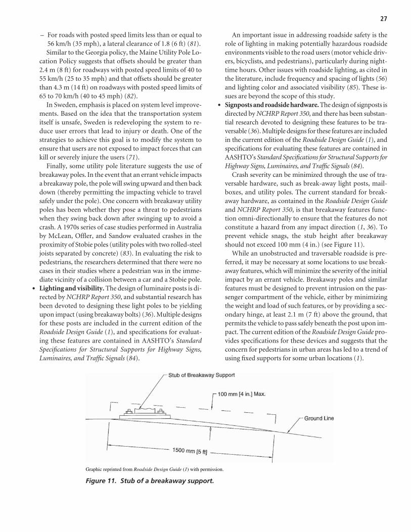
– For roads with posted speed limits less than or equal to56 km/h (35 mph), a lateral clearance of 1.8 (6 ft) (81).Similar to the Georgia policy, the Maine Utility Pole Lo-
cation Policy suggests that offsets should be greater than2.4 m (8 ft) for roadways with posted speed limits of 40 to55 km/h (25 to 35 mph) and that offsets should be greaterthan 4.3 m (14 ft) on roadways with posted speed limits of65 to 70 km/h (40 to 45 mph) (82).
In Sweden, emphasis is placed on system level improve-ments. Based on the idea that the transportation systemitself is unsafe, Sweden is redeveloping the system to re-duce user errors that lead to injury or death. One of thestrategies to achieve this goal is to modify the system toensure that users are not exposed to impact forces that cankill or severely injure the users (71).
Finally, some utility pole literature suggests the use ofbreakaway poles. In the event that an errant vehicle impactsa breakaway pole, the pole will swing upward and then backdown (thereby permitting the impacting vehicle to travelsafely under the pole). One concern with breakaway utilitypoles has been whether they pose a threat to pedestrianswhen they swing back down after swinging up to avoid acrash. A 1970s series of case studies performed in Australiaby McLean, Offler, and Sandow evaluated crashes in theproximity of Stobie poles (utility poles with two rolled-steeljoists separated by concrete) (83). In evaluating the risk topedestrians, the researchers determined that there were nocases in their studies where a pedestrian was in the imme-diate vicinity of a collision between a car and a Stobie pole.
• Lighting and visibility. The design of luminaire posts is di-rected by NCHRP Report 350, and substantial research hasbeen devoted to designing these light poles to be yieldingupon impact (using breakaway bolts) (36). Multiple designsfor these posts are included in the current edition of theRoadside Design Guide (1), and specifications for evaluat-ing these features are contained in AASHTO’s StandardSpecifications for Structural Supports for Highway Signs,Luminaires, and Traffic Signals (84).
An important issue in addressing roadside safety is therole of lighting in making potentially hazardous roadsideenvironments visible to the road users (motor vehicle driv-ers, bicyclists, and pedestrians), particularly during night-time hours. Other issues with roadside lighting, as cited inthe literature, include frequency and spacing of lights (56)and lighting color and associated visibility (85). These is-sues are beyond the scope of this study.
• Signposts and roadside hardware. The design of signposts isdirected by NCHRP Report 350, and there has been substan-tial research devoted to designing these features to be tra-versable (36). Multiple designs for these features are includedin the current edition of the Roadside Design Guide (1), andspecifications for evaluating these features are contained inAASHTO’s Standard Specifications for Structural Supports forHighway Signs, Luminaires, and Traffic Signals (84).
Crash severity can be minimized through the use of tra-versable hardware, such as break-away light posts, mail-boxes, and utility poles. The current standard for break-away hardware, as contained in the Roadside Design Guideand NCHRP Report 350, is that breakaway features func-tion omni-directionally to ensure that the features do notconstitute a hazard from any impact direction (1, 36). Toprevent vehicle snags, the stub height after breakawayshould not exceed 100 mm (4 in.) (see Figure 11).
While an unobstructed and traversable roadside is pre-ferred, it may be necessary at some locations to use break-away features, which will minimize the severity of the initialimpact by an errant vehicle. Breakaway poles and similarfeatures must be designed to prevent intrusion on the pas-senger compartment of the vehicle, either by minimizingthe weight and load of such features, or by providing a sec-ondary hinge, at least 2.1 m (7 ft) above the ground, thatpermits the vehicle to pass safely beneath the post upon im-pact. The current edition of the Roadside Design Guide pro-vides specifications for these devices and suggests that theconcern for pedestrians in urban areas has led to a trend ofusing fixed supports for some urban locations (1).
27
Graphic reprinted from Roadside Design Guide (1) with permission.
Figure 11. Stub of a breakaway support.
Strategy summary. Common strategies for utility poles,lighting supports, and signposts/roadside hardware are asfollows:
Purpose Strategy
Treat individual high • Remove or relocate poles (P) risk pole locations • Place poles on inside of horizontal
curves and avoid placement onoutside of roudabouts or too close to intersection corners (P)
• Use breakaway or yieldingpoles (T)
• Shield poles (P)• Improve pole visibility (E)
Treat multiple poles in • Establish urban clear zone offset high risk locations guidelines for pole setback
distances from curb (P)• Place utilities underground while
maintaining appropriatenighttime visibility (P)
• Combine utilities/signs ontoshared poles (reduce numberof poles) (P)
• Replace poles with building-mounted suspended lighting(where suitable) (E) (86)
Minimize level of Reduce travel speed on adjacentseverity road (P)
Safety Barriers
Roadside barriers are subject to NCHRP Report 350 testingcriteria (36). There are several types of safety barriers thatmay be present in an urban environment. These include thefollowing:
• Barriers (flexible, semi-rigid, and rigid);• Bridge railings; and• End treatments (crash cushions and end terminals).
Generally, most of the research on safety barriers has beenoriented toward the design of barriers and their placement toshield vehicles from hazardous roadside conditions. TheRoadside Design Guide and NCHRP Report 350 provide con-siderable information on placement and design of safe bar-rier systems (1, 36). FHWA maintains a roadside hardwarewebsite that provides information about specific roadsidehardware that has been tested (see http://safety.fhwa.dot.gov/roadway_dept/road_hardware/index.htm).
In the urban environment, many of the safety barrierscommon to rural environments may not be suitable due toconstraints regarding space available for flared end treatments,the constraining influence of safety barriers on pedestrianactivity, and the potential obstruction of sight distance at themany intersections and driveways in the urban environment.
Also, in locations with bicycle activity, safety barriers locatedimmediately adjacent to the road may expose cyclists to un-necessary risks because the barriers may give a sensation of“squashing” the cyclist between the barrier and an adjacentmotor vehicle (79).
Safety research. Considerable research has been per-formed on a variety of traffic barriers. NCHRP Report 490: In-Service Performance of Traffic Barriers includes an extensiveliterature review that discusses the evolution of traffic barriercrashworthiness (87). The following summaries briefly re-view the application of these tested barriers (barriers, bridgerails, and end treatments) in an urban environment.
• Barriers. Barriers can be categorized as flexible (cable barri-ers and W-beam guardrail with weak post), semi-rigid (thriebeam and W-beam guardrail with strong post), and rigid(concrete barrier system such as the New Jersey barrier).
Because guardrails are most typically associated withrural and higher speed environments, the use of guardrailsin urban environments is often restricted to protection ofbridge approaches and departures. In fact, the conventionaluse of guardrail is to shield roadside objects from impactthat pose a greater threat than impact to the guardrail it-self. Since the placement of guardrails at locations withfrequent driveways is problematic due to the numerousbreaks in the barrier treatment and the adverse effect ofthe guardrail on driveway and intersection sight distance,the use of conventional guardrail is minimal in urbanlow-speed corridors. AASHTO indicates that for very lowtraffic volume locations, traffic barriers are not generallycost-effective (32). This recommendation is confirmed byresearch performed by Stephens (88) and Wolford andSicking (89). In the event that an engineer does endorse theuse of a barrier in an urban environment, factors in addi-tion to the lateral offset, deflection distance, terrain effects,flare rate, and length of need (common to rural placementdesign) must be supplemented by consideration of cornersight distance, pedestrian activity (with particular atten-tion to the needs of persons with disabilities), and bicycleactivity (1).
When the use of a protective barrier is warranted in theurban environment, the application of aesthetic barrier treat-ments may be considered. These treatments perform thesame general function as a guardrail (shield hazardous envi-ronments) while enhancing the aesthetics of a roadway.
The use of barriers in an urban environment can be toshield roadside obstacles (such as rigid utility poles), sepa-rate motorized and nonmotorized traffic, and provide aphysical separation between the active travel lanes and pe-destrian activity. For barriers with a shielding objective, sev-eral different barriers may be considered. For example, the
28

California Department of Transportation published a reportin 2002 with a focus on suitable aesthetic barriers (90). Thisreport includes the status of crash testing as well as theadvantages and disadvantages of each treatment. Candidatebarriers for urban environments include concrete barrierswith textured and patterned surfaces, timber guardrail, pre-cast concrete guardwall, and stone masonry guardwall.
The placement of barrier in the vicinity of a median is acommon strategy in rural environments to help preventhead-on collisions by errant vehicles. Washington State, forexample, performed an evaluation of median treatments formulti-lane, divided state highways with full access con-trol (91). The researchers determined that the placement ofa barrier for medians up to a width of 15 m (50 ft) is cost-effective. In an urban environment, the median width is nar-row and often serves the combined functions of separatingopposing directions of travel and acting as pedestrian refugeat certain locations. Currently, concrete Jersey barriers areused most commonly for medians in urban locations.
The placement of barriers adjacent to the road intro-duces a new roadside hazard. For example, use of rigid bar-riers tends to result in a greater number of minor crashes,but dramatically reduces the number of serious or fatalhead-on and run-off-road crashes (92). Lee and Manner-ing (68) determined that for urban environments, guard-rails are significantly associated with an increase in crashfrequency, but the severity of these crashes is likely to re-sult in possible injury only.
In locations where aesthetics are important and a bar-rier is required, jurisdictions may develop crash-testedoptions such as the Vermont-approved stone masonrysystem shown in Figure 12 (in addition to the various aes-thetic barriers identified in the California report previ-ously indicated [90]).
• Bridge rails. In both urban and rural environments, bridgesshould be equipped with rails that do not permit vehiclesto penetrate the space beyond the rail (i.e., structural ade-
quacy). Transitions to guardrails must be located at boththe approach and departure end of all bridge rails. Bridgerails must be designed to retain a large passenger car atthe legal driving speed for local streets and roads (94). Thebridge rails must, therefore, be structurally designed andmaintain their structural integrity after impact.
• End treatments. For locations where the end of the barri-ers cannot be adequately flared or protected, it is necessaryto use an end treatment such as a barrier terminal or crashcushion. Aesthetic enhancements to end treatments havenot received much attention, so conventional treatmentsare necessary in the urban environment. These treatmentsshould not allow a vehicle to penetrate, vault, or roll uponimpact. They should have the strength and redirectionalqualities of a standard barrier.
Dynamic Roadside Conditions
Bicycle Facilities
General information. Bicycle facilities consist of roadand roadside features intended for bicycle operation. Thesefacilities may include standard lanes, wide outside lanes,bicycle lanes, and off-road bicycle paths. Accompanying bicy-cle facilities may be bicycle hardware located along the road-side, such as bicycle racks. In general, the literature regardingthe relationship between bicycle facilities and roadside safetyis limited. Wide shoulders and bicycle lanes provide an addi-tional “clear” area adjacent to the travelway, so these featurescould potentially provide a secondary safety benefit formotorists, provided bicycle volumes are low. These bicyclefacilities will also further separate the motor vehicle from anyroadside obstructions and improve the resulting sight distancefor motor vehicle drivers at intersecting driveways and streets.
A second area of consideration is the placement of bicycle-supportive hardware, such as bicycle racks, adjacent to thetravelway. Bicycle racks are commonly made of steel or othermetals and are typically bolted to the ground to secure lockedbicycles from potential theft. These features are not designed tobe yielding should a run-off-road event occur. To date, therehas been little evaluation of the potential roadside hazard posedby such treatments, although they can clearly present a poten-tial fixed-object hazard. Making such features yielding wouldpotentially minimize the core function of these features—providing a secure location for locking up bicycles. Thus,a potentially more desirable alternative may be to encouragethe placement of these features outside of the clear zone.
Safety research. Most of the bicycle research focuses onspecific bicycle safety issues such as safety helmets and train-ing. Several studies have developed and reviewed previousbicycle suitability or compatibility criteria (95, 96). The crite-ria for determining bicycle suitability include available lanewidth, traffic volume, and vehicle speeds. One best practices
29
Photo reprinted from Guardrail Study (93).
Figure 12. Stone masonry barrier.

review has suggested that road safety for cyclists could be en-hanced by increased law enforcement to ensure that cyclistsdo not ride in the wrong direction (against traffic) or at nightwithout adequate lighting (97). This best practices review alsonoted that the use of extruded curbs to separate a bike lanefrom traffic should be avoided.
Since the focus of this research effort is roadside safety forthe urban environment, it is helpful to understand the mag-nitude of the safety risk to cyclists as they encounter roadsideenvironments. One FHWA report using hospital emergencydepartment data noted that 70 percent of reported bicycleinjury events did not involve a motor vehicle and 31 percentoccurred in non-roadway locations. For bicycle-only crashes,a total of 23.3 percent of the recorded crashes occurred atsidewalk, driveway, yard, or parking lot locations (98). Stuttsand Hunter (99) evaluated bicycle–motor vehicle crashes anddetermined that some factors associated with the crash werevariables such as age, gender, impairment, and time of day.Roadside variables (sidewalk, parking lot, and driveways)were not statistically significant in their model.
Strategy summary. Common strategies to improve bi-cycle safety as well as bicycle–motor vehicle interactions areas follows:
Purpose Strategy
Reduce likelihood • Use wider curb lanes (P)of crash • Increase bicycle enforcement (T)
• Increase operational offsets (P)
Reduce severity of crash Locate bicycle racks as far away from road as possible (T)
Parking
General Information. In many urban environments, lim-ited off-street parking often necessitates the use of on-streetparking to address the needs of local businesses and stakehold-ers. As noted in the Green Book (37), cars typically park 150 to305 mm (6 to 12 in.) from the curb and have a normal width ofroughly 2.1 m (7 ft). Thus, approximately 2.4 m (8 ft) areneeded to comfortably accommodate on-street parking. Onecommon strategy in larger cities is to design wider outside park-ing lanes, such as 3 m (10 ft), and convert them to travel lanesduring peak periods and anticipated high-volume conditions.
On-street parking can potentially have mixed results on aroadway’s safety performance. On the one hand, these fea-tures narrow the effective width of the roadway and mayresult in speed reductions, thereby leading to a reduction incrash severity. Conversely, on-street parking may also lead toan increase in collisions associated with vehicles attemptingto pull in or out of an on-street parking space.
In addition to vehicle conflicts, on-street parking servesas a physical buffer between the motor vehicle path andpedestrian facilities. The added safety buffer provided to the
pedestrian, however, can be countered by the pedestrian whoelects to cross the street mid-block in areas not designated forpedestrian crossing. The parked vehicles may act as a shieldto prevent proper sight distance for the drivers of adjacentmotor vehicles, often resulting in new conflicts betweenmotor vehicles and pedestrians stepping between parked cars.Similarly, there is an inherent conflict between the motor ve-hicle and drivers exiting or entering their parked vehicles onthe traffic side of the roadway.
An additional concern often cited regarding on-streetparking is the effect it may have on reducing emergency serv-ices’ response rate. Often the narrowing effect of on-streetparking can be compounded by illegal parking too close tocritical locations such as intersections. The Local Govern-ment Commission released a publication called EmergencyResponse Traffic Calming and Traditional NeighborhoodStreets (100) that suggests that the adverse effects of on-streetparking can be mitigated by implementing the followingstrategies:
• Placing a double set of driveways periodically (per firedepartment recommendation) to enable local access;
• Placing alleys on short blocks across from each other;• Placing mailbox clusters, curb extensions, or similar treat-
ments where residents will find it inappropriate to park; and• Enforcing parking criteria to minimize illegal parking.
Finally, the severity of a roadside hazard constituted by acollision between a parked vehicle and a moving vehicle isminimal. Since on-street parking is generally parallel to themoving vehicles, the impact by a moving vehicle is likely to bea sideswipe crash. This is one of the less severe crash types. Forlocations with head-in or reverse-in parking, the crash severitylikelihood is increased as the moving vehicle may impact a ve-hicle in reverse. Proper sight distance and separation of parkedvehicles from the active travel lane (often by the use of a bulb-out at the intersection) will help minimize safety risks betweenmoving and parked or parking vehicles. As indicated in the pre-vious section, curb extensions or bulb-outs can pose a hazard tobicyclists by forcing them into the active travel lane. In the eventthat the parking lanes are not occupied, the extension could alsocreate a hazard for drivers unfamiliar with it. On-street parkingis generally not considered appropriate for higher speed roadssuch as suburban to urban transitional arterials.
Strategy summary. Common on-street parking strate-gies are as follows:
Purpose Strategy
Reduce likelihood of Restrict on-street parking to low-crash speed roads (P)
Reduce crash severity Where parking is appropriate, use parallel parking rather than angularparking (P)
30

Sidewalks and Pedestrian Facilities
General information. Sidewalks and pedestrian facili-ties, in general, do not pose a particular hazard to motorists.The safety concern about locating these facilities adjacent tothe road is the risk to the pedestrians using the facilities. Pro-viding safe facilities for pedestrians is an obvious strategy forincreasing pedestrian safety. While shared streets may beappropriate if vehicle speeds and volumes are kept extremelylow (see Figure 13), for most roads in urban areas, vehiclespeeds warrant the use of sidewalks (21, 101, 102). The GreenBook (37) recommends the use of sidewalks on urban streets,with sidewalk widths ranging between 1.2 and 2.4 m (4 and 8 ft)depending on the roadway classification and nearby land usecharacteristics (see Table 9).
Of the roughly 75,000 pedestrian-related crashes thatoccur each year, almost half occur while the pedestrian was ata non-intersection, on-roadway location (see Table 10).
The conventional approach to examining pedestrian andbicycle safety is to examine crash records to determine thenon-motorized user’s action prior to a crash event. Completeand accurate motor vehicle crash data for pedestrian crashescan be difficult to find. Stutts and Hunter evaluated police-reported pedestrian crashes and compared these to hospitalemergency room records (99). They found that crash eventsthat occurred in parking lots, driveways, and other off-roadlocations were reported less frequently than those occurringin the roadway. A 1999 FHWA study (98) also reviewed hos-pital emergency room records and determined that 11 percentof the pedestrian–motor vehicle events recorded occurred atroadside locations (sidewalk, parking lot, and driveway).
Of the data for which pre-crash action is known, impropercrossings were the largest single crash category, accounting for20 percent of the total crashes. The categories that have themost direct relationship to the roadside fell into the four cate-gories most strongly related to the design of roadsides: jogging,walking with and against traffic, and miscellaneous activity.
As shown in Table 11, approximately 13,600 crashes wereclassified as “darting into road” crashes, which is where apedestrian rushes into the street and is struck by a motorvehicle. The majority of individuals involved in “darting-into-road” crashes were children between the ages of 5 and 9,who may have been using the street for play activities (103).As Whyte has indicated, the street is often the preferred playlocation for children, even when parks and other recreationalamenities may be available (104).
An additional feature of the roadside environment is apedestrian buffer area. The pedestrian buffer is a physicaldistance separating the sidewalk and the vehicle travelway.Buffer areas typically serve a host of secondary purposes aswell—they provide locations for on-street parking, transitstops, street lighting, and planting areas for landscape mate-rials, as well as a location for a host of street appurtenances, suchas seating and trash receptacles. Buffer strips may be eitherplanted or paved. The Green Book supports the use of bufferstrips on urban arterials, collectors, and local streets (37).
31
Photo reprinted from walkinginfo.org (121).
Figure 13. Low-speed shared street.
Road Class Side of Street Specification Urban Arterials Both Border area (buffer plus
sidewalk) should be a mi ni mu m of 2.4 m (8 ft) and preferably 3.6 m (12 ft) or mo re.
Collector Both sides of street for access to schools, parks, and shopping. Both sides of streets desirable in residential areas.
1.2 m (4 ft) mi ni mu m in residential areas. 1.2 to 2.4 m (4 to 8 ft) in co mme rcial areas.
Local Both sides of street for access to schools, parks, and shopping. Both sides of streets desirable in residential areas.
1.2 m (4 ft) mi ni mu m in residential areas. 1.2 to 2.4 m (4 to 8 ft) in co mme rcial areas, although additional width may be desirable if roadside appurtenances are present.
Source: Developed from A Policy on Geometric Design of Highways and Streets, 4th ed. (37).
Table 9. Green Book sidewalk specifications (37).

Safety research. Several studies have evaluated potentialcountermeasures to improve pedestrian safety. Generally, thesestudies were based on case studies, statistical models, or subjec-tive evaluation. Landis and colleagues (105) modeled severalroadside walking environment variables to evaluate the pedes-trian’s perception of risk versus actual risk. The researchersexpected that as the number of driveways increased they wouldobserve a decrease in pedestrian safety, but this hypothesis wasdetermined not to be statistically significant. They did find thatmotor vehicle volume and vehicle speeds were significant fac-tors in pedestrian safety. Corben and Duarte evaluated the highnumber of pedestrian injuries along Melbourne’s arterial roadsand recommended the adoption of three practices:
• Reduce traffic volumes,• Reduce road widths, and• Reduce vehicle speeds (106).
Corben and Duarte further suggested that strategies forreducing the vehicle speed can include public awareness andenforcement campaigns; gateway treatments (such as roadnarrowing, changing pavement texture, and implementingroundabouts); and streetscape improvements (106). Gatewaytreatments are addressed in the traffic calming section of thisdocument, which follows this section. Cottrell reviewed a
variety of options for improving pedestrian safety in the Stateof Utah (107). Many of his recommendations are similar tothose already reviewed; however, he also included improvingsidewalk security and visibility with street lights as an impor-tant issue. Cottrell further noted that the failure to removesnow from sidewalks during winter conditions may result inpedestrians entering the street either to cross it or to walkalong the cleared road. The document that to date most ex-haustively summarizes strategies for improving pedestriansafety is NCHRP Report 500: Guidance for Implementation ofthe AASHTO Strategic Highway Safety Plan—Volume 10:A Guide for Reducing Collisions Involving Pedestrians (123).This document includes methods for enhancing pedestriansafety in the road as well as adjacent to the road. The recom-mendations in the document are consistent with those of theresearch studies summarized in this review.
Strategy summary. Common strategies for eliminatingor minimizing motor vehicle–pedestrian crashes at roadsidelocations are as follows:
Purpose Strategy
Reduce motor vehicle- • Provide continuous pedestrian pedestrian crash facilities (P) likelihood at roadside • Install pedestrian refuge medians locations or channelized islands (see
previous section on medians andislands) (P)
• Offset pedestrian locations away from travelway with pedestrian buffers (P)
• Physically separate pedestriansfrom travelway at high-risklocations (P)
• Improve sight distance byremoving objects that obscure driver or pedestrian visibility (T)
• Maintain pedestrian facilities freeof leaves, snow, or tree roots (T)
• Improve visibility by installingillumination for nighttimeconditions (T)
• Enforcement and publicawareness campaigns (T)
Reduce severity of Reduce roadway design speed/motor vehicle- operating speed in high pedestrianpedestrian crashes at volume locations (T)roadside locations
Traffic Calming Applications—GatewayTreatments
Although traffic calming applications have been prevalentthroughout Europe for several decades, traffic calming isrelatively new in the United States, first emerging in thelate 1990s as a strategy for addressing community livability
32
Pedestrian Crash Type No. of Crashes PercentNo Action 23,502 31.6 Darting into Road 13,594 18.3 Improper Crossing 15,344 20.6 Inattentive 521 0.7 Jogging 211 0.3 Pushing Vehicle 103 0.1 Walking with Traffic 1,746 2.3 Walking against Traffic 1,184 1.6 Playing, Working, etc. in Roadway 8,074 10.8 Other 5,964 8.0 Unknown 4,249 5.7 Total 74,492 100.0
Source: General Estimates System. (122).
Table 11. Pedestrian crashes by type (2002).
Pedestrian Location Number PercentIntersection - In Crosswalk 14,674 19.7 Intersection - On Roadway 15,319 20.6 Intersection - Other 1,391 1.9 Intersection - Unknown Location 810 1.1 Non-intersection - In Crosswalk 381 0.5 Non-intersection - On Roadway 35,785 48.0 Non-intersection - Other 3,518 4.7 Non-intersection - Unknown Location 173 0.2 In Crosswalk - Unknown if Intersection 16 0.0 Other Location 1,830 2.5 Unknown Location 595 0.8 Total 74,492 100.0
Source: General Estimates System (122).
Table 10. Pedestrian location during a crash(2002).
concerns associated with high vehicle traffic volumes andspeeds. The practice of traffic calming applications hassparked a substantial debate regarding the safety and appro-priateness of these applications, particularly when applied toroadways intended for higher volumes and/or higher operat-ing speeds, such as minor arterial roadways (23, 108, 109).
Traffic calming applications come in a variety of forms,including partial and full road closures and alterations in the de-sign of intersections and curb lines. This report is specifically fo-cused on traffic calming strategies deployed at arterial transitionsfrom higher speed rural conditions to locations with lower speedarterial characteristics. This transitional traffic calming strategyis known as a gateway and is reviewed in the following summary.
General information. The traffic calming strategy knownas a gateway is defined by Burden as “a physical or geometriclandmark on an arterial street which indicates a change inenvironment from a major road to a lower speed residentialor commercial district (110).” Burden goes on to suggest thatgateways can be a combination of street narrowings, medians,signs, arches, roundabouts, or other features. The objective ofa gateway treatment is to make it clear to a motorist that heor she is entering a different road environment that requiresa reduction in speed.
Drivers need a certain transitional speed zone with theexplicit guidance and roadway features to inform and encour-age them to gradually slow down before they reach the urbanresidential area for a safe entry. A transitional speed zone canalso help drivers to speed up within a certain timeframe whenleaving an urban area. This transition area is extremely im-portant for drivers who are not familiar with the urban area.They rely on the roadway features to indicate changes in sur-roundings that require an adjustment in their driving speedand behavior.
The gateway concept was presented in a 1998 paper byGreg Pates in which he depicted the region between a ruralarea and a fringe area (transitioning into urban use) as thegateway location where travel speed should be reduced andmotorists should become more alert (111).
Safety research. Little information exists on the safetyperformance of gateway treatments. At present, such treat-ments have not been subject to extensive crash testing,undoubtedly because of the large degree of variation inthe design and materials used in the construction of suchfeatures. Nevertheless, as noted in Skene, such features areoften used by Canadian and British transportation profes-sionals in speed transition zones to provide the driverwith visual cues of a forthcoming change in safe operatingconditions (108). In the United States, these gateway treat-ments are typically aimed at delineating the boundaries ofspecific communities.
Most of the research regarding gateway treatments focuseson their influence on operating speed or road users’ percep-tions of gateway treatments and their understanding that theyare, in fact, transitioning into a different and slower speedenvironment.
In a 1997 study in the United Kingdom, researchers at theTransport Research Laboratory performed a before-afterevaluation of a series of traffic calming strategies on majorroads (112). The traffic volume on candidate roads was greaterthan 8,000 vehicles per day, and at least 10 percent of the traf-fic was composed of heavy vehicles. Speeds at inbound gate-ways were reduced at eight out of nine locations tested. Meanspeed reductions ranged from 5 to 21 km/hr (3 to 13 mph).The study evaluated a variety of treatments, including speedreduction signage, narrowings, dragon teeth marking, speedcushions, colored pavement, and advanced signing. The re-searchers determined that the signing provided a high visualimpact and resulted in large speed reductions. Physical de-vices such as the speed cushions resulted in a greater level ofspeed reduction than signing alone. The use of colored bandsplaced laterally across the road and placed in a series seemedto result in some speed reduction, but did not result in largedecreases in speed. The researchers did not test the speed re-duction signs and so could not comment on the effectivenessof these devices. Dragon-teeth marking, identified as one ofthe strategies, is depicted as a schematic and a photograph inFigure 14.
33
Photo and graphic reprinted from Traffic Calming on Major Roads (112) under the terms of the Click-Use License.
Figure 14. Dragon-teeth marking.

34
Berger and Linauer describe the operating speed influenceof five raised island configurations used as gateway treatmentsfrom high-speed rural locations in Austrian villages (113).The five gateway island configurations are shown in Figure 15.The most dramatic influence on speeds occurred for IslandNumber 5, where the path of the approach lane was shifteddramatically. Table 12 demonstrates the range of speed re-ductions observed in this Austrian study, and Figure 16 showsthe speed profile for Island Number 5.
A study performed for traffic calming strategies deployedfrom 1993 to 1996 in Ireland evaluated the transition zone asthe area between a high-speed and low-speed road (114). Theresearchers evaluated the gateway transition from rural tourban environments in two phases:
• From the “Traffic Calming Ahead” sign to the “Do NotPass” sign and
• From the “Do Not Pass” sign to the gateway treatments inthe form of raised islands.
In the first phase, the researchers observed that the “Traf-fic Calming Ahead” sign at the beginning of the transitionzone reduced inbound traffic speed. They determined thisby comparing the speed reduction results in the transitionzone with and without a “Traffic Calming Ahead” sign.With the “Traffic Calming Ahead” sign present, the 85thpercentile speeds ranged between 90 and 100 km/hr (56 and62 mph) at the start of the transition zone. The 85th percentilespeeds at the “Do Not Pass” signs were reduced by 6 to 8 km/hr(4 to 5 mph). At locations without the traffic calming signs,the 85th percentile speeds were observed to be reduced byonly 2 to 3 km/hr (1.2 to 1.9 mph) at the same approachlocation.
In the second phase, the speed reduction analysis resultsindicated that the gateway with raised traffic islands was aneffective traffic calming treatment. They found that speedreductions of approximately 14 km/hr (9 mph) relative to thespeed recorded at “Do Not Pass” signs were achieved at gate-ways with raised islands compared with a reduction of only10 km/hr (6 mph) at gateways without raised islands.
A case study performed in Canada evaluated traffic calm-ing strategies on an arterial road connecting two residentialareas (115). Mohawk Road is a two-lane road with a50-km/hr (31-mph) speed limit and was originally designedto service rural conditions. Speeding is very common on thisroad, and the test data showed that about 67 percent of thevehicles were exceeding the speed limit at the test location.After evaluating several alternatives, the jurisdiction finallyelected to implement a series of landscaped speed control
medians of various dimensions to help slow traffic down.Based on a before-after site evaluation, the speed reduction atcontrol sections (where the strategies were not deployed)ranged from 85 percent to 88 percent for initially observedspeeds, while the speeding percentage reduction in test sectionsranged from 47 percent to 67 percent of the original speeds.This 20-percent speeding reduction was determined to bestatistically significant at a 99-percent confidence level. Theresearchers were not able to compare corresponding crashdata for the site.
Ewing reviewed a highway reconstruction project deployedin Saratoga Springs, New York (116). The case road transi-tioned from a four-lane, semi-rural highway with a flush,painted median and a speed limit of 88 km/hr (55 mph) to athree-lane urban road with a raised median and a postedspeed limit of 48 km/hr (30 mph). The length of road avail-able for this transition was 550 m (1,800 ft). Because the roadpasses the Saratoga Spa State Park, the Lincoln Baths, and theMuseum of Dance, local representatives wanted a gateway forthe transition of the road. The three photos shown in Fig-ure 17 depict the gateway transition ultimately constructedfor this facility.
Roundabouts are another commonly recommended gate-way treatment. Pates has discussed how Norwegian trialprojects using roundabouts experienced average speed re-ductions of 10 km/hr (6 mph) (111). Ewing (23) and Zeinand Montufar (92) identify roundabouts as safe traffic calm-ing alternatives to conventional intersections that can serveas both psychological and physical indicators of a transitionfrom a rural high-speed environment to the lower speedurban street. Ewing also indicates that the center islands ofthe roundabouts can be landscaped and possibly includesculptures or monuments. Although the research team wasunable to locate published research regarding the use ofstreet art in roundabout medians, they did speak with re-searchers from both the United Kingdom and Australia.Representatives from both countries suggested that the ap-plication of street art in roundabouts is generally hazardousif these items are placed in the center of the first roundaboutencountered by the driver on a rural road. The use of a seriesof roundabouts as a transition, with the street art located in the subsequent roundabouts, however, is a common prac-tice and appears to be a safe strategy for these transitionalregions.
The evaluation of gateway treatments is a new area of re-search for transportation and, as a result, very little is knownabout crashworthiness issues. As reviewed in this summary,the focus in using gateway treatments has been on the re-sulting speed reduction (thereby reducing ultimate crashseverity).
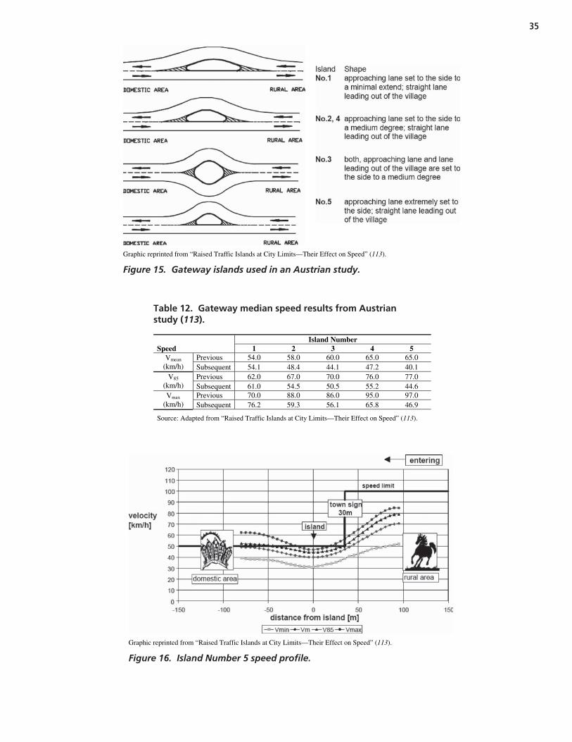
35
Graphic reprinted from “Raised Traffic Islands at City Limits—Their Effect on Speed” (113).
Figure 15. Gateway islands used in an Austrian study.
Island Number Speed 1 2 3 4 5
Previous 54.0 58.0 60.0 65.0 65.0 Vmean (km/h) Subsequent 54.1 48.4 44.1 47.2 40.1
Previous 62.0 67.0 70.0 76.0 77.0 V85 (km/h) Subsequent 61.0 54.5 50.5 55.2 44.6
Previous 70.0 88.0 86.0 95.0 97.0 Vmax (km/h) Subsequent 76.2 59.3 56.1 65.8 46.9
Source: Adapted from “Raised Traffic Islands at City Limits—Their Effect on Speed” (113).
Table 12. Gateway median speed results from Austrianstudy (113).
Graphic reprinted from “Raised Traffic Islands at City Limits—Their Effect on Speed” (113).
Figure 16. Island Number 5 speed profile.

Strategy summary. Common traffic calming gatewaystrategies are as follows:
Purpose Strategy
Reduce likelihood of Apply speed reduction signs,run-off-road crash pavement markings, and other
gateway treatments (T)
Reduce severity of run- • Construct gateway raised medianoff-road crash treatments (T)
• Construct roundabouts withtraversable island centers in initial islands (T)
Literature Review Conclusion
This review has examined the knowledge and practice ofroadside safety as they relate to the design of roadsides inurban areas. A brief review of roadside crash statistics demon-strates that roads in the urban environment, although gen-erally lower speed facilities than their rural counterparts,nevertheless suffer from run-off-road collisions with roadsidehazards. The operational offset concept for curbed urbanroadways should, therefore, not be mistaken as a safety stan-dard, and urban setback policies should be considered forfuture adoption.
Although they are not the focus of this research, the strate-gies used in urban environments to help prevent errant vehiclesfrom leaving the travelway and encountering a fixed roadsideobject are briefly reviewed in this report.
Finally, this review has summarized common urban road-side objects and known safety issues associated with theseroadside objects. A collection of safety strategies (experi-mental, tried, and proven) for each set of roadside hazards isincluded.
In general, this review makes it clear that the safety impli-cations of many roadside features (such as curbs, signs, andutility poles) are well understood; however, there are signifi-cant gaps in understanding how many urban roadside features(such as landscape buffers, trees, and lighting) should beaddressed for safe urban roadside development.
36
Photos courtesy of Reid Ewing © (116)
Figure 17. Example of gateway transitionin Saratoga Springs, NY.

37
The goals of this research effort are to develop design guide-lines for safe and aesthetic urban roadside treatments andultimately to develop a toolbox of effective treatments thatbalance the needs of all roadway users while accommodatingcommunity values. Of particular interest is the design ofurban roadways that carry substantial volumes of traffic andare designed for higher operating speeds, thus often raisingadditional roadside safety concerns.
To accomplish these goals, the research team performedtwo specific tasks. These two research tasks were as follows:
• Developing a systematic analysis approach (referred to asan Urban Control Zone Assessment) to enable jurisdictionsto better target hazardous urban roadside locations and
• Developing before-after case studies for a variety of urbanroadside treatments.
These two tasks are described in detail in the sections thatfollow, with specific case information included in Appen-dixes A and B, available online at http://trb.org/news/blurb_detail.asp?id=9456. Appendix C (included herein) includes atoolbox that generally summarizes the safe application ofroadside elements in an urban environment. A supplementalproduct of this research effort is draft language for possible in-clusion in the urban roadside chapter of the AASHTO Road-side Design Guide. This document is included in Appendix C.
Urban Control Zone Assessment
Experimental Design
Many urban roadside environments are crowded withpotential hazards. The task of identifying which objects posethe greatest risk to users of the road can be daunting for ajurisdiction with limited resources. In 1999, the Florida De-partment of Transportation (FDOT) developed a documentcalled the Utility Accommodation Manual (117). This docu-ment’s purpose was to provide direction for ways to reasonably
accommodate utilities in state transportation facility rights-of-way. FDOT included a concept in this document called“Control Zones” for consideration at facilities with limitedor no access control. Although the emphasis of FDOT’s doc-ument was utility pole placement, the concept of controlzones can be expanded and is a promising approach forevaluating an urban roadside environment in its entirety.FDOT’s Utility Accommodation Manual defines control zonesas the following:
Areas in which it can be statistically shown that accidents aremore likely to involve departure from the roadway with greaterfrequency of contact with above ground fixed objects. (117)
Example control zones include those that contain objectshit more than two times within three consecutive years,objects located within the return radii and object horizontaloffset distance at an intersecting street, objects located within1 m (3 ft) of a driveway flare, and objects located along theoutside edge of a horizontal curve for roads with operatingspeeds greater than 56 km/h (35 mph).
The research team performed a systematic evaluation ofcrash data to define common control zones for urban road-side environments. To accomplish this task, the research teamevaluated urban crash data for four different locations. Studyareas included urban corridors located in Atlanta, Georgia;Orange County and San Diego County, California; Chicago,Illinois; and Portland, Oregon. Although not all sites werewithin the same city limits for a regional study, they were allcharacterized by urban corridors where fixed-object crashesoccurred along the corridor (often in cluster configurations).The sources of the crash data varied. The Georgia Departmentof Transportation (GDOT) provided Atlanta crash dataand road characteristic information. The Oregon Depart-ment of Transportation (ODOT) provided Portland crashdata and road information. For corridors located in Illinoisand California, the research team used data from the High-way Safety Information System (HSIS) database maintained
C H A P T E R 3
Findings and Applications
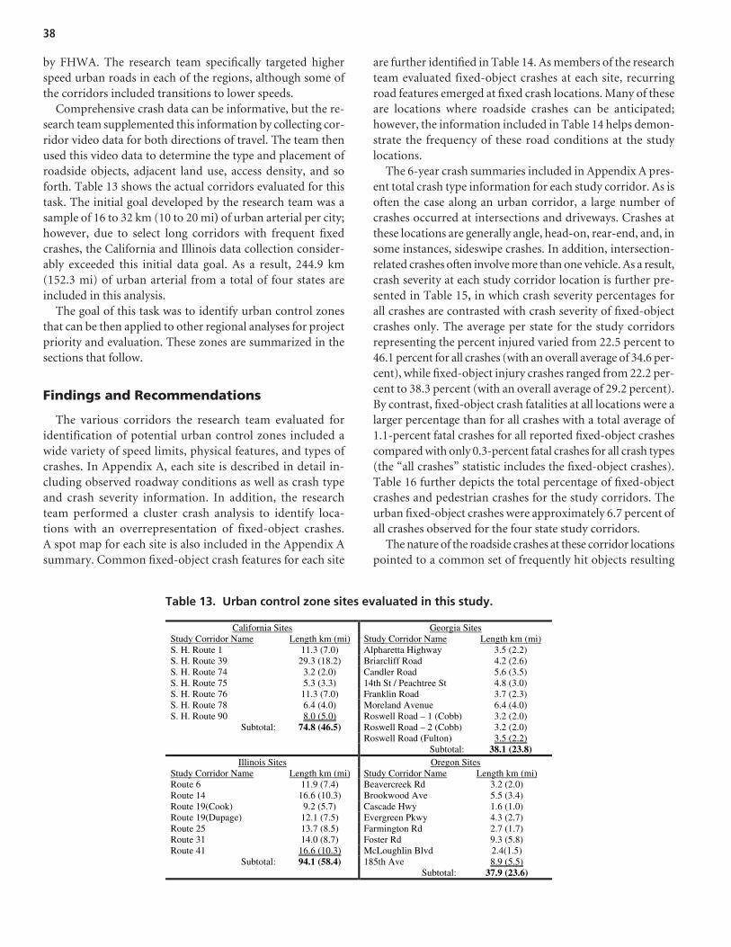
by FHWA. The research team specifically targeted higherspeed urban roads in each of the regions, although some ofthe corridors included transitions to lower speeds.
Comprehensive crash data can be informative, but the re-search team supplemented this information by collecting cor-ridor video data for both directions of travel. The team thenused this video data to determine the type and placement ofroadside objects, adjacent land use, access density, and soforth. Table 13 shows the actual corridors evaluated for thistask. The initial goal developed by the research team was asample of 16 to 32 km (10 to 20 mi) of urban arterial per city;however, due to select long corridors with frequent fixedcrashes, the California and Illinois data collection consider-ably exceeded this initial data goal. As a result, 244.9 km(152.3 mi) of urban arterial from a total of four states areincluded in this analysis.
The goal of this task was to identify urban control zonesthat can be then applied to other regional analyses for projectpriority and evaluation. These zones are summarized in thesections that follow.
Findings and Recommendations
The various corridors the research team evaluated foridentification of potential urban control zones included awide variety of speed limits, physical features, and types ofcrashes. In Appendix A, each site is described in detail in-cluding observed roadway conditions as well as crash typeand crash severity information. In addition, the researchteam performed a cluster crash analysis to identify loca-tions with an overrepresentation of fixed-object crashes.A spot map for each site is also included in the Appendix Asummary. Common fixed-object crash features for each site
are further identified in Table 14. As members of the researchteam evaluated fixed-object crashes at each site, recurringroad features emerged at fixed crash locations. Many of theseare locations where roadside crashes can be anticipated;however, the information included in Table 14 helps demon-strate the frequency of these road conditions at the studylocations.
The 6-year crash summaries included in Appendix A pres-ent total crash type information for each study corridor. As isoften the case along an urban corridor, a large number ofcrashes occurred at intersections and driveways. Crashes atthese locations are generally angle, head-on, rear-end, and, insome instances, sideswipe crashes. In addition, intersection-related crashes often involve more than one vehicle. As a result,crash severity at each study corridor location is further pre-sented in Table 15, in which crash severity percentages forall crashes are contrasted with crash severity of fixed-objectcrashes only. The average per state for the study corridorsrepresenting the percent injured varied from 22.5 percent to46.1 percent for all crashes (with an overall average of 34.6 per-cent), while fixed-object injury crashes ranged from 22.2 per-cent to 38.3 percent (with an overall average of 29.2 percent).By contrast, fixed-object crash fatalities at all locations were alarger percentage than for all crashes with a total average of1.1-percent fatal crashes for all reported fixed-object crashescompared with only 0.3-percent fatal crashes for all crash types(the “all crashes” statistic includes the fixed-object crashes).Table 16 further depicts the total percentage of fixed-objectcrashes and pedestrian crashes for the study corridors. Theurban fixed-object crashes were approximately 6.7 percent ofall crashes observed for the four state study corridors.
The nature of the roadside crashes at these corridor locationspointed to a common set of frequently hit objects resulting
38
California Sites Georgia SitesStudy Corridor Name Length km (mi) Study Corridor Name Length km (mi)S. H. Route 1 11.3 (7.0) Alpharetta Highway 3.5 (2.2) S. H. Route 39 29.3 (18.2) Briarcliff Road 4.2 (2.6) S. H. Route 74 3.2 (2.0) Candler Road 5.6 (3.5) S. H. Route 75 5.3 (3.3) 14th St / Peachtree St 4.8 (3.0) S. H. Route 76 11.3 (7.0) Franklin Road 3.7 (2.3) S. H. Route 78 6.4 (4.0) Moreland Avenue 6.4 (4.0) S. H. Route 90 8.0 (5.0) Roswell Road – 1 (Cobb) 3.2 (2.0)
Subtotal: 74.8 (46.5) Roswell Road – 2 (Cobb) 3.2 (2.0) Roswell Road (Fulton) 3.5 (2.2)
Subtotal: 38.1 (23.8) Illinois Sites Oregon Sites
Study Corridor Name Length km (mi) Study Corridor Name Length km (mi)Route 6 11.9 (7.4) Beavercreek Rd 3.2 (2.0) Route 14 16.6 (10.3) Brookwood Ave 5.5 (3.4) Route 19(Cook) 9.2 (5.7) Cascade Hwy 1.6 (1.0) Route 19(Dupage) 12.1 (7.5) Evergreen Pkwy 4.3 (2.7) Route 25 13.7 (8.5) Farmington Rd 2.7 (1.7) Route 31 14.0 (8.7) Foster Rd 9.3 (5.8) Route 41 16.6 (10.3) McLoughlin Blvd 2.4(1.5)
Subtotal: 94.1 (58.4) 185th Ave 8.9 (5.5) Subtotal: 37.9 (23.6)
Table 13. Urban control zone sites evaluated in this study.

from these crashes, with varying severity levels. Commonlyhit fixed objects included the following:
• Poles and posts,• Light standards,• Traffic signals,• Trees and landscaping,• Mailboxes,• Walls and fences,
• Barrier or guardrail, and• Embankment.
In addition, roadside furniture may have been impacted,but the crash databases classified this type of roadside objectas “other unidentified object.”
As shown in Table 14, the primary locations for fixed-objectcrashes were characterized by several common road and road-side configurations. Often, locations with these configurations
39
Case No. Corridor Description L an
e m
erge
with
obj
ect o
ffse
ts
2 –6
ft
L an
e m
erge
with
obj
ect o
ffse
ts
> 6
f t
C ha
nnel
izat
ion
isla
nd v
ery
s m
all w
ith p
oles
D ri
vew
ay /
inte
rsec
tion
with
o b
stac
les
loca
ted
on f
ar s
ide
M ed
ian
at h
oriz
onta
l cur
ve
w ith
obs
tacl
e of
fset
s 4–
6 ft
R oa
dsid
e at
hor
izon
tal c
urve
w
ith o
bsta
cles
4–6
ft
N um
erou
s ro
adsi
de o
bsta
cles
w
ithi
n 1–
2 ft
(on
tang
ent)
Roa
dsid
e di
tch
with
non
-tr
aver
sabl
e he
adw
alls
U ne
ven
road
side
with
o b
stac
les
(off
set v
arie
s)
C or
rido
r cl
ear
zone
not
m
aint
aine
d at
rig
h t -t
urn
lane
s
G ua
rdra
il w
rapp
ed a
roun
d
c urb
ret
urn
L on
gitu
dina
l bar
rier
/gua
rdra
il
o ffs
et 2
–6 f
t
S ce
nic
/ tou
rist
loca
tion
with
c l
ose
obst
acle
s
UCZ-CA-1 SH 1, Orange County, CA x x x x UCZ-CA-2 SH 39, Orange County, CA x x UCZ-CA-3 SH 74, Orange County, CA x x UCZ-CA-4 SH 75, San Diego County, CA x x x x UCZ-CA-5 SH 76, San Diego County, CA x x UCZ-CA-6 SH 78, San Diego County, CA x x x UCZ-CA-7 SH 90, Orange County, CA x x x UCZ-GA-1 Alpharetta Highway, Fulton
County, GA x
UCZ-GA-2 Briarcliff Rd., DeKalb County, GA
x x x x
UCZ-GA-3 Candler Rd., DeKalb County, GA
x x x
UCZ-GA-4 14th St./Peachtree St., Fulton County, GA
x x
UCZ-GA-5 Franklin Rd., Cobb County, GA x x UCZ-GA-6 Moreland Dr., DeKalb County,
GA x x x
UCZ-GA-7 Roswell Rd. (1), Cobb County, GA
x x
UCZ-GA-8 Roswell Rd. (2), Cobb County, GA
x
UCZ-GA-9 Roswell Rd., Fulton County, GA x x x UCZ-IL-1 Route 6, Will County, IL x x UCZ-IL-2 Route 14, Cook County, IL x x UCZ-IL-3 Route 19, Cook County, IL x x x UCZ-IL-4 Route 19, DuPage County, IL x x UCZ-IL-5 Route 25, Kane County, IL x x x x UCZ-IL-6 Route 31, Kane County, IL x x x x UCZ-IL-7 Route 41, Cook County, IL x x x x x x x UCZ-OR-1 Beavercreek Rd., Clackamas
County, OR x x
UCZ-OR-2 Brookwood Pkwy., Washington County, OR
x x x x
UCZ-OR-3 Cascade Hwy., Clackamas County, OR
x x x x
UCZ-OR-4 Evergreen Pkwy, Washington County, OR
x x
UCZ-OR-5 Farmington Rd., Washington County, OR
x x x
UCZ-OR-6 Foster Rd., Multnomah County, OR
x x x x
UCZ-OR-7 McLoughlin Blvd., Clackamas County, OR
x x x
UCZ-OR-8 185th Ave., Washington County, OR
x
Table 14. Urban control zone corridor overview.

experienced clustered crashes while much of the roadside alongthe corridor remained free of crashes. The road and roadsideconfigurations that are often involved in fixed-object crashescan be generally grouped into the following:
• Obstacles in close lateral proximity to the curb face or laneedge;
• Roadside objects placed near lane merge points;• Lateral offsets not appropriately adjusted for auxiliary lane
treatments;• Objects placed inappropriately in sidewalk buffer
treatments;• Driveways that interrupt positive guidance and have objects
placed near them;• Three kinds of fixed-object placement at intersections;• Unique roadside configurations associated with high crash
occurrence; and• Roadside configurations commonly known to be hazardous.
Each of these potential Urban Control Zones is discussedin the sections that follow.
Obstacles in Close Lateral Proximity to the Curb Face or Lane Edge
Historically, a lateral offset (referred to as an operationaloffset) of 0.5 m (1.5 ft) has been considered the absoluteminimum lateral (or perpendicular) distance between theedge of an object and the curb face. As previously indicated,this offset value enabled vehicle access, that is, a personcould open a car door if the vehicle were stopped adjacentto the curb. This operational offset was never intended torepresent an acceptable safety design standard, althoughit was sometimes misinterpreted as being one. The urbanenvironment limits lateral offset distances simply becauseof the restricted right-of-way widths common to an urbansetting.
40
All Crashes Fixed-Object Crashes
Case No. Percent
No Injuryor
Unknown
PercentInjured
PercentFatal
PercentNo Injury
orUnknown
PercentInjured
PercentFatal
UCZ-CA-1 57.27 42.48 0.26 77.66 21.32 1.02 UCZ-CA-2 55.28 44.13 0.59 74.66 24.80 0.54 UCZ-CA-3 70.30 29.70 0.00 64.29 35.71 0.00 UCZ-CA-4 66.39 33.33 0.28 62.30 37.70 0.00 UCZ-CA-5 29.79 69.09 1.12 56.52 39.13 4.35 UCZ-CA-6 31.72 66.42 1.87 56.41 41.03 2.56 UCZ-CA-7 62.64 37.21 0.14 76.62 23.38 0.00 Average (CA) 53.34 46.05 0.61 66.92 31.87 1.21 UCZ-GA-1 79.48 20.47 0.05 75.00 23.61 1.39 UCZ-GA-2 81.46 18.48 0.06 73.86 26.14 0.00 UCZ-GA-3 75.63 24.25 0.12 74.63 24.63 0.75 UCZ-GA-4 80.23 19.72 0.05 64.02 35.37 0.61 UCZ-GA-5 72.76 27.16 0.08 76.79 23.21 0.00 UCZ-GA-6 75.46 24.43 0.11 71.69 28.31 0.00 UCZ-GA-7 78.33 21.52 0.15 86.49 13.51 0.00 UCZ-GA-8 73.11 26.78 0.11 84.21 15.79 0.00 UCZ-GA-9 80.56 19.31 0.13 72.09 27.91 0.00 Average (GA) 77.45 22.46 0.10 75.42 24.28 0.31 UCZ-IL-1 72.75 26.95 0.30 79.07 18.60 2.33 UCZ-IL-2 79.09 20.64 0.27 78.57 19.05 2.38 UCZ-IL-3 71.63 28.12 0.25 75.68 22.52 1.80 UCZ-IL-4 74.37 25.51 0.12 75.81 24.19 0.00 UCZ-IL-5 68.69 30.78 0.54 72.09 25.58 2.33 UCZ-IL-6 74.35 25.51 0.14 84.00 15.00 1.00 UCZ-IL-7 73.20 26.32 0.49 67.28 30.51 2.21 Average (IL) 73.44 26.26 0.30 76.07 22.21 1.72 UCZ-OR-1 55.91 44.09 0.00 60.00 40.00 0.00 UCZ-OR-2 55.26 44.74 0.00 70.59 29.41 0.00 UCZ-OR-3 46.20 53.80 0.00 50.00 50.00 0.00 UCZ-OR-4 53.90 45.35 0.74 50.00 44.44 5.56 UCZ-OR-5 61.49 38.30 0.21 69.23 30.77 0.00 UCZ-OR-6 58.40 41.13 0.47 44.44 51.85 3.70 UCZ-OR-7 56.79 43.21 0.00 73.33 26.67 0.00 UCZ-OR-8 61.82 38.03 0.15 66.67 33.33 0.00 Average (OR) 56.22 43.58 0.2 60.53 38.31 1.16 Average (4 States) 65.11 34.59 0.30 69.74 29.17 1.10
Table 15. Summary of crash severity distributions for study corridors.

The research team for this project observed several objectslocated within inches of the edge of the road for the selectedstudy corridors. In general, these items were utility poles,light standards, street signposts, and trees. Evaluation of therole of trees in crashes was difficult because the types oftrees in the selected study corridors varied dramatically andincluded mature rigid trees as well as small-caliper orna-mental trees. Due to the varying nature of the tree placementalong the corridors (and the wide range of their frangibletendencies), the research team often could not identify aspecific tree involved in the crashes recorded in the crashdatabase. Actual crash reports were not available for most ofthe locations, so unless a tree exhibited scars, it was not feasi-ble to determine actual tree types involved in crashes.
Poles, posts, and light standards, however, were easier toevaluate. The lateral placement of these items was generallyconsistent along short corridor segments. The research team,therefore, further evaluated crash locations on the basisof crash records for crashes involving poles, posts, and lightstandards to determine common lateral offsets and crash
frequency. Posts (which could, in some instances, be classifiedas breakaway) were included in this assessment because theseitems are often coded as “poles or posts,” so posts could notalways be evaluated separately in the analysis.
To evaluate fixed-object crashes associated with poles,posts, and light standards, the research team viewed the cor-ridor videos (for both travel directions) and for each locationrecorded data for the characteristics listed in Table 17.
For the study corridors extending over the 6-year period,a total of 503 crashes into poles, posts, or light standardsoccurred. Of these, 389 occurred during dry weather, 78 dur-ing wet weather, 4 during ice, 4 during fog, 19 during snow,and 9 during unknown weather conditions. Table 18 depictsthe distribution of these weather-related crashes on the basisof corridor speed limit. Most crashes occurred during dry andwet conditions on roads with posted speed limits of 48 to72 km/h (30 to 45 mph).
To evaluate lateral offset to the objects that were hit, Table 19further shows these crashes aggregated by the posted speedlimit and lateral distance category. (The lateral offset was the
41
Case No. Percent Fixed-Object
CrashesPercent Pedestrian
CrashesPercent Others
UCZ-CA-1 10.1 1.1 88.8 UCZ-CA-2 5.4 2.6 92.0 UCZ-CA-3 8.5 1.2 90.3 UCZ-CA-4 17.1 0.8 82.1 UCZ-CA-5 6.4 0.7 92.9 UCZ-CA-6 14.6 3.0 82.4 UCZ-CA-7 5.5 0.9 93.6 Average (CA) 9.7 1.5 88.9 UCZ-GA-1 1.9 0.5 97.6 UCZ-GA-2 2.6 0.4 97.0 UCZ-GA-3 3.9 1.5 94.6 UCZ-GA-4 2.8 1.0 96.2 UCZ-GA-5 4.7 1.3 94.0 UCZ-GA-6 5.9 1.6 92.5 UCZ-GA-7 5.6 0.8 93.6 UCZ-GA-8 10.7 0.0 89.3 UCZ-GA-9 2.9 1.6 95.5 Average (GA) 4.6 1.0 94.5 UCZ-IL-1 6.4 1.6 92.0 UCZ-IL-2 3.8 1.3 94.9 UCZ-IL-3 4.7 0.8 94.5 UCZ-IL-4 3.6 0.5 95.9 UCZ-IL-5 6.6 2.1 91.3 UCZ-IL-6 4.8 0.4 94.8 UCZ-IL-7 14.8 1.8 83.4 Average (IL) 6.4 1.2 92.4 UCZ-OR-1 2.7 0.0 97.3 UCZ-OR-2 14.9 0.0 85.1 UCZ-OR-3 7.6 0.0 92.4 UCZ-OR-4 6.7 1.1 92.2 UCZ-OR-5 2.8 1.3 95.9 UCZ-OR-6 3.2 1.6 95.2 UCZ-OR-7 9.3 0.0 90.7 UCZ-OR-8 1.8 1.4 96.8 Average (OR) 6.1 0.7 93.2 Average (4 States) 6.7 1.1 92.3
Table 16. Summary of crash type distributions.

distance from the curb face or lane edge [at locations withoutcurb].) Only a small subset of these urban crashes occurred atlocations where curb was not present. As a result, Table 20 de-picts the 456 sites where curb was present at the pole, post, orlight-standard crash location. The cumulative percentagedemonstrates that, for curb locations, 93.4 percent of allfixed-object pole/post/light standard crashes occurred within1.8 m (6 ft) of the curb face while 82.5 percent of these oc-curred within 1.2 m (4 ft) of the curb.
This observation, combined with a tendency for clusteredcrashes (for poles, these occurred along short road segmentswith objects laterally positioned close to the road), suggeststhat in an urban environment the placement of rigid objectsshould ideally be more than 1.8 m (6 ft) from the curb face andno closer than 1.2 m (4 ft) wherever possible.
In addition, the frequency of object impact was greater atlocations where objects were in close proximity to the road andlocated on the outside of a horizontal curve. These crashes oc-curred at locations where objects were placed on the right edgeof the road and at locations where objects were placed on me-dians. This suggests that the lateral offset placement of objectsat horizontal curves should be increased wherever possible.
Roadside Objects Placed Near Lane Merge Points
The placement of roadside objects in the vicinity of lanemerge points increases the likelihood of vehicle impactwith these objects. The research team identified severalcluster crashes at these lane merge locations: lane drop lo-cations, acceleration taper ends, and bus bay exit transi-tions. As shown in Table 14, six sites included clustercrashes at taper point locations where fixed objects werelaterally located less than 1.8 m (6 ft) from the curb face orlane edge (for locations where curb was not present). Clus-ter crashes occurred at two additional sites where theseobjects were located more than 1.8 m (6 ft) laterally. Lon-gitudinal placement of objects within approximately 6.1 m(20 ft) of the taper point increased the frequency of thesecrashes. Figure 18 shows two example crash locations witha pole located at lane merge tapers. This increased likeli-hood of fixed-object crashes at lane merge tapers suggeststhat an object-free buffer zone at taper points on urbanroadways would eliminate or reduce roadside crashes atthese locations and allow drivers to focus solely on merginginto the traffic stream.
42
Description Available Options Curb: Yes or No Continuous Edge line Present: Yes or No Bike Lane Present: Yes or No Driveway Immediately Upstream of Object Hit: Yes or No Night Hours (10 p.m. to 6 a.m.): Yes or No Weather at Time of Crash: Dry
Wet Ice Fog Snow Other or Not Stated
Lateral Distance from Curb Face (when present) or Lane Edge (when no curb):
Less than 1’ 1’ – 2’ 2’ – 4’ 4’ – 6’ 6’ – 8’ 8’ – 10’ 10’ – 15’ 15’ – 20’ Greater than 20’
Table 17. Pole/post/light-standard variables.
Speed Limit km/h (mph)
Weather 40
(25) 48
(30) 56
(35) 64
(40) 72
(45) 80
(50) 89
(55) Total
Dry 0 72 152 29 104 19 13 389 Wet 1 18 26 7 22 2 2 78 Ice 0 0 3 0 1 0 0 4 Fog 0 2 0 0 2 0 0 4 Snow 1 2 1 0 4 1 0 9 Other or Not Stated 1 8 6 2 2 0 0 19
Total: 3 102 188 38 135 22 15 503
Table 18. Poles/post/light-standard crashes for speed limitthresholds.
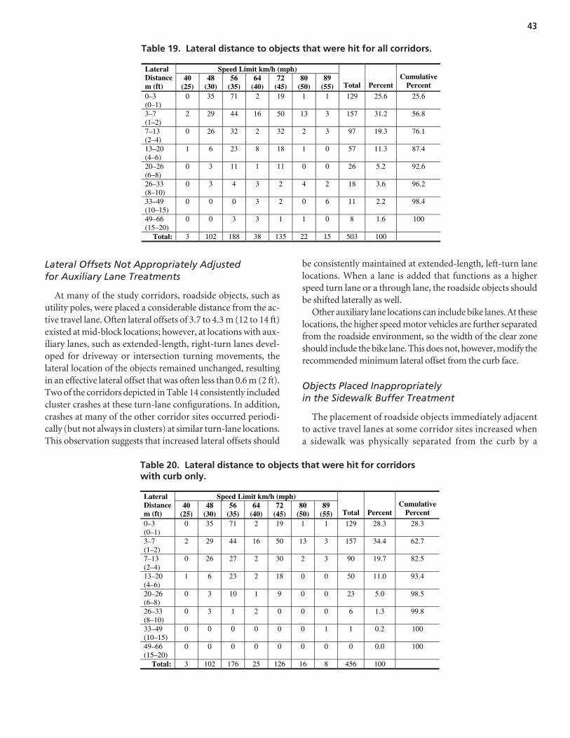
Lateral Offsets Not Appropriately Adjustedfor Auxiliary Lane Treatments
At many of the study corridors, roadside objects, such asutility poles, were placed a considerable distance from the ac-tive travel lane. Often lateral offsets of 3.7 to 4.3 m (12 to 14 ft)existed at mid-block locations; however, at locations with aux-iliary lanes, such as extended-length, right-turn lanes devel-oped for driveway or intersection turning movements, thelateral location of the objects remained unchanged, resultingin an effective lateral offset that was often less than 0.6 m (2 ft).Two of the corridors depicted in Table 14 consistently includedcluster crashes at these turn-lane configurations. In addition,crashes at many of the other corridor sites occurred periodi-cally (but not always in clusters) at similar turn-lane locations.This observation suggests that increased lateral offsets should
be consistently maintained at extended-length, left-turn lanelocations. When a lane is added that functions as a higherspeed turn lane or a through lane, the roadside objects shouldbe shifted laterally as well.
Other auxiliary lane locations can include bike lanes. At theselocations, the higher speed motor vehicles are further separatedfrom the roadside environment, so the width of the clear zoneshould include the bike lane. This does not, however, modify therecommended minimum lateral offset from the curb face.
Objects Placed Inappropriately in the Sidewalk Buffer Treatment
The placement of roadside objects immediately adjacentto active travel lanes at some corridor sites increased whena sidewalk was physically separated from the curb by a
43
Speed Limit km/h (mph) Lateral Distance m (ft)
40 (25)
48 (30)
56 (35)
64 (40)
72 (45)
80 (50)
89 (55) Total Percent
CumulativePercent
0–3 (0–1)
0 35 71 2 19 1 1 129 25.6 25.6
3–7 (1–2)
2 29 44 16 50 13 3 157 31.2 56.8
7–13 (2–4)
0 26 32 2 32 2 3 97 19.3 76.1
13–20 (4–6)
1 6 23 8 18 1 0 57 11.3 87.4
20–26 (6–8)
0 3 11 1 11 0 0 26 5.2 92.6
26–33 (8–10)
0 3 4 3 2 4 2 18 3.6 96.2
33–49 (10–15)
0 0 0 3 2 0 6 11 2.2 98.4
49–66 (15–20)
0 0 3 3 1 1 0 8 1.6 100
Total: 3 102 188 38 135 22 15 503 100
Table 19. Lateral distance to objects that were hit for all corridors.
Speed Limit km/h (mph) Lateral Distance m (ft)
40 (25)
48 (30)
56 (35)
64 (40)
72 (45)
80 (50)
89 (55) Total Percent
CumulativePercent
0–3 (0–1)
0 35 71 2 19 1 1 129 28.3 28.3
3–7 (1–2)
2 29 44 16 50 13 3 157 34.4 62.7
7–13 (2–4)
0 26 27 2 30 2 3 90 19.7 82.5
13–20 (4–6)
1 6 23 2 18 0 0 50 11.0 93.4
20–26 (6–8)
0 3 10 1 9 0 0 23 5.0 98.5
26–33 (8–10)
0 3 1 2 0 0 0 6 1.3 99.8
33–49 (10–15)
0 0 0 0 0 0 1 1 0.2 100
49–66 (15–20)
0 0 0 0 0 0 0 0 0.0 100
Total: 3 102 176 25 126 16 8 456 100
Table 20. Lateral distance to objects that were hit for corridorswith curb only.

buffer strip that contained fixed objects. Interestingly,crashes varied dramatically at these locations. At locationswith buffer strips 0.9 m (3 ft) wide or narrower, objectswere systematically hit. Wider buffer strips containing ma-ture trees with large-diameter trunks placed within 0.9 to1.2 m (3 to 4 ft) of the curb showed a significant increase inthe number of severe crashes with the trees. At locationswith smaller, ornamental trees located in the center of abuffer strip, the number of severe crashes into trees wasdramatically reduced. By contrast, utility poles and lightstandards were frequently hit at locations where theseobjects were placed in the center of the buffer strip. At sev-eral sites, however, the research team observed smaller,more forgiving objects, such as landscaping with small-caliper trees, positioned near the center of the buffer stripand the more rigid poles and light standards positionedimmediately adjacent to the sidewalk and as far from theactive travel lane as possible. The crash analysis at these staggered-object-placement buffer strips showed very fewroadside crashes.
This research suggests that the placement of rigid objectson sidewalk buffer strips 1.2 m (4 ft) wide or narrowershould be avoided. For wider buffer strips, placement of themore forgiving roadside items close to the road and place-ment of the more rigid objects at a greater lateral offset of1.2 m (4 ft) or more from the curb face is recommended.Figure 19 depicts recommended buffer strip object place-ment scenarios.
Driveways Interrupt Positive Guidance/ObjectsPlaced Near Driveways
Many rural roads have a white edge line delineating the rightedge of the travelway. In urban environments, a continuous
white line is often not included at locations with a curb as thecurb itself functions to delineate the edge of the road. Duringnighttime or inclement weather conditions, the need forpositive guidance along the right edge of the road may beheightened due to reduced visibility. In addition, impaired orfatigued drivers may depend more heavily on this delineationto help them keep their vehicle within the boundaries of thetravelway. For a few of the observed corridors, a continuouswhite line occurred either at the edge of the gutter pan or a fewfeet from the gutter pan to delineate a separate bicycle lane.When this white line was not present, single-vehicle crashestended to occur more frequently at driveway locations. In par-ticular, objects positioned on the far side of driveways were hitmore often than objects located away from driveways orobjects that were located on the near side of driveways. Thisobservation is not a surprise because the curb line may nolonger provide positive guidance to vehicles at drivewayentry points, and the driveway configuration certainly doesnot provide a re-direction function when a vehicle driftsfrom the road. Figure 20 shows an example crash locationwith a pole located at the far side of a driveway. The place-ment of the pole within the sidewalk is, of course, also notrecommended.
Of the 456 pole/post/light crashes that occurred at loca-tions with curb (see Table 20), 181 occurred at driveways,so this location accounted for approximately 40 percent of allof these crashes. Of the 181 driveway-associated, fixed-objectcrashes, 155 occurred at locations with no supplementalpositive guidance such as a white edge line, approximately86 percent of these crashes. This percentage of the crashesassociated with driveways that did not provide additionalpositive guidance could simply be an artifact of how manysites did not have an edge line, but this high a number ofcrashes certainly warrants future research. Regardless, avoiding
44
Photo by Karen Dixon.
Figure 18. Pole placed at lane merge.
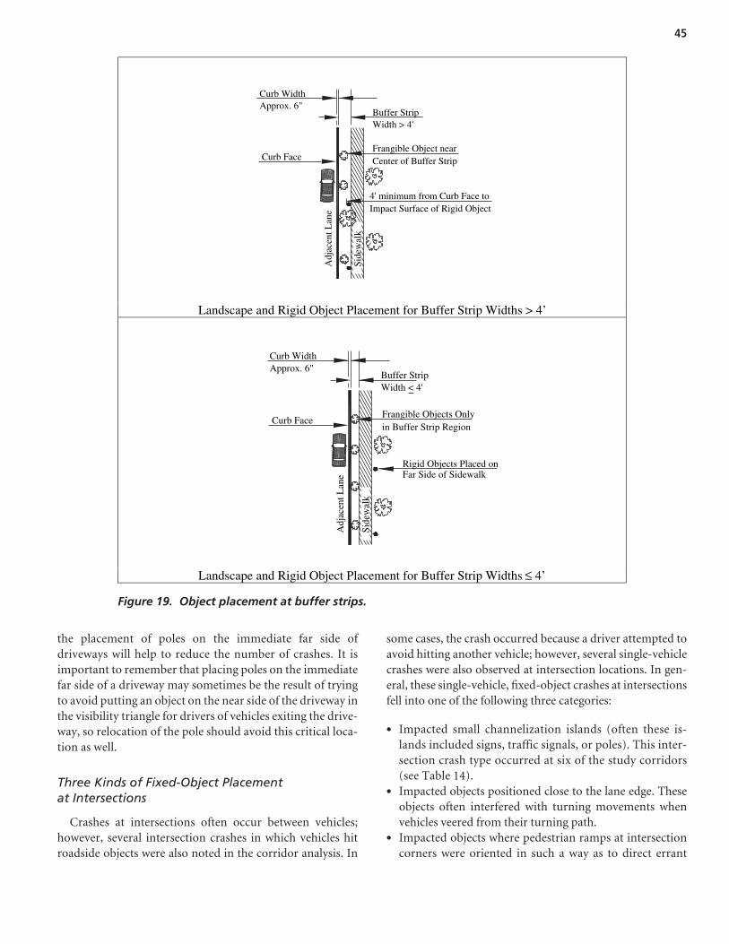
the placement of poles on the immediate far side ofdriveways will help to reduce the number of crashes. It isimportant to remember that placing poles on the immediatefar side of a driveway may sometimes be the result of tryingto avoid putting an object on the near side of the driveway inthe visibility triangle for drivers of vehicles exiting the drive-way, so relocation of the pole should avoid this critical loca-tion as well.
Three Kinds of Fixed-Object Placementat Intersections
Crashes at intersections often occur between vehicles;however, several intersection crashes in which vehicles hitroadside objects were also noted in the corridor analysis. In
some cases, the crash occurred because a driver attempted toavoid hitting another vehicle; however, several single-vehiclecrashes were also observed at intersection locations. In gen-eral, these single-vehicle, fixed-object crashes at intersectionsfell into one of the following three categories:
• Impacted small channelization islands (often these is-lands included signs, traffic signals, or poles). This inter-section crash type occurred at six of the study corridors(see Table 14).
• Impacted objects positioned close to the lane edge. Theseobjects often interfered with turning movements whenvehicles veered from their turning path.
• Impacted objects where pedestrian ramps at intersectioncorners were oriented in such a way as to direct errant
45
Curb Face
4' minimum from Curb Face toImpact Surface of Rigid Object
Side
wal
k
Frangible Object nearCenter of Buffer Strip
Curb WidthApprox. 6"
Buffer StripWidth > 4'
Adj
acen
t Lan
e
Landscape and Rigid Object Placement for Buffer Strip Widths > 4’
Curb Face
Rigid Objects Placed onFar Side of Sidewalk
Side
wal
k
Frangible Objects Onlyin Buffer Strip Region
Curb WidthApprox. 6"
Adj
acen
t Lan
e
Buffer StripWidth < 4'
Landscape and Rigid Object Placement for Buffer Strip Widths ≤ 4’
Figure 19. Object placement at buffer strips.

vehicles toward roadside objects. Figure 21 shows one crashlocation where this occurred. This crash condition is similarto the driveway crash condition with no positive guidancediscussed previously.
Unique Roadside Configurations Associatedwith High Crash Occurrence
Several of the study corridors were characterized by highcrash numbers at a specific location. Often this peak in crashstatistics resulted from a physical road feature unique to thesite. For example, at corridor UCZ-IL-1 a disproportionatelylarge number of crashes involved an underpass structure.When members of the research team inspected the site, theydetermined that sometime in its past, a two-way road withone lane under each side of the underpass wall had beenconverted into a two-lane, one-way road. This modificationoccurred at two separate locations due to the creation of aone-way pair configuration. As a result, the approach to theunderpass required vehicles to shift in an effort to avoid thewall now located between the lanes in the same direction oftravel. The crashes occurred when a vehicle did not safelynavigate this required lane shift. This crash cause was evidentdue to a scarred underpass wall.
Locations of this type are unique and should be consideredindividually for crash mitigation treatments. The creation ofsimple crash spot maps (as shown in Appendix A) can enablean agency to quickly identify cluster crash locations of thisnature.
Roadside Configurations Commonly Knownto Be Hazardous
Several roadside crashes occurred at locations where theywould be expected. These sites exhibited characteristics knownto result in potentially hazardous conditions. For example,locations with roadside ditches, nontraversable headwalls andculverts (often at driveways), or uneven roadside grading werecommon roadside crash locations. In addition, crashesoccurred at high-speed locations where sloping curb delin-eated the roadside edge, but adequate clear zone was notavailable. Finally, three of the corridors were located in thevicinity of scenic or tourist attractions. At these locations,roadside objects were hit more frequently even when lateraloffsets to the objects were similar to those at other crash-freesites. Regardless of the cause, additional lateral offset toobjects in these or similar locations seems prudent to mini-mize the risk of hazardous run-off-road crashes for unfamiliardrivers.
Case Study Task and Summary of Findings
Experimental Design
The individual projects selected as part of this case studytask were used to identify strategies where safety and aes-thetics were incorporated into the roadway’s design. Theresearch team identified several recent beautification orroadside improvement projects to use as indicators for the
46
Photo by Karen Dixon.
Figure 20. Lack of positive guidance at a driveway.
Photo by Karen Dixon.
Figure 21. Object orientation with access ramp.

influence of improvements on crash conditions. Ideally,a project where only one item is changed (such as movingtrees to the far side of sidewalks) would be perfect for thistask; however, the research team could not identify projectsof this nature because, in general, transportation agenciesimplement multiple improvements in each project. As a re-sult, the data analysis for this case study task can providegeneral indications about the safety impacts of beautifica-tion or roadside improvement projects, but cannot be usedto explicitly evaluate individual features and their associatedhazards.
Initially, the research team proposed two levels of casestudies (one with comparison sites); however, the NCHRPProject 16-04 panel requested the stand-alone case studies(locations without comparison sites) so as to evaluate asmany projects as possible. The stand-alone case studies in-clude crash type summaries, crash severity summaries, andbefore-after crash analysis for a specific improvementcorridor with data developed and provided by local juris-dictions. The research team attempted to solicit candi-date projects from a variety of geographically distributedjurisdictions.
Inclusion of a case study project required that the projecthave a focus on median or roadside improvements as well ashaving available most, if not all, of the requested data. Theresearch team attempted to collect crash data for 3-yearperiods before and after the project was implemented. Thislevel of crash information was not available for all sites.In select cases, projects with a minimum of 1 year of datawere included; projects with less than 1-year’s worth ofpost-reconstruction data were excluded. The constructionperiod is indicated in the case study summaries included inAppendix B.
More specifically, the research team collected data in thefollowing five areas for the case study analysis:
1. Crash frequency—the absolute number of crashes occur-ring before and after the context-sensitive improvement.
2. Crash rates—raw crash volumes considered in relation tothe traffic volume carried by the roadway.
3. Crash severity—the proportion of crashes involving seri-ous injury or death compared with property-damage-only(PDO) crashes.
4. Crash type—changes in specific types of crashes that haveoccurred as a result of the improvement.
5. Average daily traffic (ADT)—the average number of ve-hicles per day using the roadway.
In addition to crash type summary information and crashseverity summary information, Appendix B includes a simplebefore-after crash summary comparison for each site. Oftenbefore-after analyses are limited because researchers studycorridors where safety issues are prominent and so the re-sulting improvements can be dramatic; however, for the beau-tification and roadside enhancement projects the focus is noton operations and safety but rather on aesthetics and livability.As a result, the before-after analysis can provide a useful in-dication about possible safety implications of a change to theroad environment. Table 21 demonstrates the basic type ofdata included in the before-after analysis for each case studyincluded in Appendix B.
Findings and Recommendations
Table 22 illustrates the individual case study elements in-cluded in Appendix B as well as the general observed safetytrend for each project. The research team attempted to excludeprojects in which entire lanes were added as the observedsafety results because these types of projects provide con-founding information; nonetheless, a few of the projects hadsome lane widening (often due to realignment) and are sonoted in the table. The crash trends identified in Table 22show (1) when crash frequency increased by more than onecrash per year (or by more than 5 percent), (2) when crashfrequency decreased by more than one crash per year (or bymore than 5 percent), or (3) when change in crash frequencywas minimal (within one crash per year on average or within5 percent of the original crash rate). These crash trends are asummary of the before-after analysis documented in Table 21and the individual case studies included in Appendix B.
47
Comparison
Analysis Category
Candidate Street --Before
Candidate Street -- After
Crash Reductions
Standard Deviation
Crash Frequency Crash Rate Severe and Fatal Crash Frequency
Single-Vehicle Crash Frequency
ADT
Table 21. Evaluation matrix for case study sites.

In Table 22, the before-after crash trends are representedby the four statistics:
• Frequency of all crashes at a site,• Crash rate,• Frequency of severe crashes at a site, and• Frequency of single-vehicle crashes.
Ideally, a reduction in all four trend statistics would beobserved, clearly demonstrating enhanced safety at a site;however, in many cases, an increase occurred for one before-after crash trend statistic while others remained constant ordecreased. For all candidate improvement projects, a designerseeks to reduce the number of severe crashes at a site. Severecrashes, for the purposes of the values shown in the case studytables, generally include incapacitating injuries or fatalities.
Only three of the case study sites exhibited an increase greaterthan one additional severe crash per year. All three of thesecase study sites included sidewalk improvements with bufferstrips, but several similar improvement projects resulted inlittle change to a reduction in severe crashes.
Since the focus of this research effort is roadside crashes,and these frequently are single-vehicle crashes, an increase inthese kinds of crashes may be of concern. Single-vehiclecrashes increased by more than one crash at eight of the sites.In general, these sites included pedestrian enhancement im-provements; however, as was the case with the sites of severecrashes discussed above, there were many pedestrian enhance-ment projects that resulted in reduced single-vehicle crashes.
Since inspection of the individual before-after crash trendsprovides confounding results, a more effective approach maybe to examine all four before-after crash trends collectively.
48
Streetscape Project Elements Before-After Crash Trends*
Case No. C ur
b &
Gut
te r
Cur
b E
xten
sion
s
Side
wal
k A
dditi
ons
/ Im
prov
emen
ts
L an
dsca
pe B
uffe
r
Nex
t to
Roa
d &
Si
dew
alk
Add
Lan
dsca
ping
/ Stre
et T
rees
T
rees
Rem
oval
/
Rel
ocat
ion
Impr
ove
Roa
dsid
e G
radi
ng/D
itch
R
emov
al
Rel
ocat
e U
tility
Pol
es
A dd
or
Enh
ance
Str
eet
L ig
hts
Bus
Sto
ps /
Bay
s
E nh
ance
d Pe
dest
rian
C
ross
ings
/ A
cces
s
M ed
ian
Isla
nds
/
R ai
sed
Isla
nds
Bic
ycle
Lan
es
Wid
enin
g of
Roa
d >
8’
Freq
uenc
y of
All
C
rash
es
Cra
sh R
ate
Freq
uenc
y of
Sev
ere
C
rash
es
Freq
uenc
y of
Sin
gle-
V
ehic
le C
rash
es
CS-AZ-1 x x x x x x x ⇓CS-AZ-2 x x x x x x x ⇑ CS-AZ-3 x x x x ⇓
CS-CA-1 x x x x x ⇑ CS-CA-2 x x x x ⇑ CS-CA-3 x x x x x x x x ⇓CS-MN-1 x x x x x x ⇓CS-MT-1 x x x ⇑ CS-MT-2 x x x x x ⇑
CS-NC-1 x x x x x ⇓ CS-NC-2 x x x x x x x x ⇓CS-NC-3 x x x ⇓ CS-NC-4 x x x x x x x ⇓ CS-NC-5 x x x x x ⇓ CS-NC-6 x x x x x x x ⇓CS-NC-7 x x x ⇓
CS-OR-1 x x x x x ⇑ CS-OR-2 x x x x x x x ⇑ CS-OR-3 x x x ⇓ CS-OR-4 x x ⇓ CS-OR-5 x x x x x x ⇓ CS-OR-6 x x x x ⇓ CS-OR-7 x x x x x ⇓
CS-UT-1 x x x ⇓ CS-UT-2 x x ⇓ CS-UT-3 x x x ⇓ CS-UT-4 x x x ⇑
⇓⇑⇔⇑⇔⇓⇓⇑⇑⇓⇓⇓⇔⇓⇓⇑⇑⇑⇓⇓⇓⇓⇓⇓⇓⇓⇑
⇓⇔⇑⇔⇔⇔⇔⇔⇔⇔⇓⇓⇔⇔⇔⇔⇑⇑⇔⇔⇔⇔⇔⇔⇓⇔⇔
⇔⇑⇔⇑⇔⇔⇓⇔⇑⇑⇓⇑⇔⇔⇓⇓⇔⇔⇔⇑⇔⇓⇑⇔⇑⇓⇔
*Before-After symbols depict the following: � Crash frequencies increased by more than one crash per year; crash rates increased by more than 5 percent. ⇑
⇓ � Crash frequencies decreased by more than one crash per year; crash rates decreased by more than 5 percent.
⇔ � Crash frequencies for the “After” condition were within one crash per year of the “Before” condition; crash rates for the “After” condition were within 5 percent of the “Before” condition crash rates.
Table 22. Case study project elements versus before-after crash trends.

At 10 of the sites, crashes were reduced or remained constant.At nine additional sites, three of the four crash trends werereduced or remained similar during the “after” period. Thisresults in 19 of the 27 sites having a general trend of crash re-duction. None of the sites exhibited an increase in all fourcrash trend statistics, and only five sites exhibited an increasein three of the four crash trends evaluated. As a result, specificcase study assessments (see Table 22 and Appendix B) pro-vided inconclusive results and should be used simply as indi-cators of the expected outcomes for similar improvementprojects.
General Recommendations
The use of corridor video analysis combined with historiccrash statistics provided meaningful insight into urban road-side crash conditions and locations where roadside objectsshould not be located, if possible. Conversely, the use ofroadside improvement or beautification case studies did notdirectly help to address specific roadside safety issues, butthese case studies can be used by an agency proposing similarprojects to determine expected overall safety performance ofthese improvements.
This research clearly shows that there are specific locationsprone to roadside crashes where agencies should avoid theplacement of rigid objects. For jurisdictions with limitedroadside safety improvement funds, urban control zones canbe used to help agencies establish spending priorities for
incremental roadside safety improvement on their urban cor-ridors. The research suggests the following:
• Avoid locating rigid obstacles in close proximity to a curbface or lane edge (at curb locations where it is possible, in-crease the lateral offset to rigid objects to 1.8 m [6 ft] fromthe face of the curb and do not allow the distance of thisoffset to be less than 1.2 m [4 ft]);
• Restrict the placement of rigid objects at lane merge loca-tions (avoid placing rigid objects within 3.0 m (10 ft) lon-gitudinally of the taper point, which will provide a 6.1-m(20-ft), object-free length);
• Maintain offsets at selected higher speed auxiliary lanelocations, such as extended-length, right-turn lanes (main-tain the lateral offset from the curb face at these locations);
• Maintain careful object placement within the sidewalkbuffer treatment (avoid rigid objects in buffers 0.9 m (3 ft)in width or less and strategically position objects in widerbuffers); and
• Avoid placing rigid objects in the proximity of driveways(avoid placing rigid objects on the immediate far side of thedriveway and do not place any objects within the requiredsight triangle for the driveway).
In addition, roadside crashes occurred frequently at inter-sections; at unique configurations (e.g., a one-way lane split atan underpass); and known hazardous roadside conditions, suchas roadside ditches, non-traversable headways, and so forth.
49

50
Conclusions
The urban roadside environment is complex. Due to theconstrained nature of this built environment, it is difficult fora designer to achieve an acceptable clear zone, free of objects.As a result, a lateral offset that enhances roadway operationsmay be used, but this offset does not represent a safe place-ment for rigid roadside objects.
This research identified known safety characteristicsand placement strategies for urban roadside objects bymeans of a comprehensive literature review. Followingthis state-of-the-practice identification, the research teamfurther evaluated roadside safety conditions using twoapproaches.
First, the research team videotaped over 241 km (150 mi)of urban corridors and compared their 6-year crash historyand crash locations to the various roadside features observedon these corridors. The result of this assessment was the iden-tification of several potential urban control zones. Theselocations are shown to have a greater likelihood of crashesand, as a result, should be kept free of rigid objects wheneverpossible. These urban control zones include locations withthe following:
• Obstacles in close lateral proximity to the curb face or laneedge;
• Roadside objects placed near lane merge points;• Lateral offsets not appropriately adjusted for auxiliary lane
treatments;• Objects placed inappropriately in sidewalk buffer treatments;• Driveways that interrupt positive guidance and have ob-
jects placed near them;• Three kinds of fixed-object placement at intersections;• Unique roadside configurations associated with high crash
occurrence; and• Roadside configurations commonly known to be hazardous.
Each of these urban control zones is reviewed in detail inChapter 3. The recommendations that are the result of thisresearch effort are the following:
• Where possible at curb locations, provide a lateral offset torigid objects of at least 1.8 m (6 ft) from the face of the curband maintain a minimum lateral offset of 1.2 m (4 ft).
• At lane merge locations, do not place rigid objects in an areathat is 3.0 m (10 ft) longitudinally from the taper point. Thiswill result in a 6.1-m (20-ft), object-free length at the taperpoint. The lateral offset for this 6.1-m (20-ft) section shouldbe consistent with the lane width, typically 3.7 m (12 ft).
• Although many auxiliary lanes, such as bus lanes or bicy-cle lanes, have low volumes and may be included as part ofa clear zone in the urban environment, higher speed aux-iliary lane locations, such as extended length right-turnlanes, are common locations for run-off-road crashes.A lateral offset of 1.8 m (6 ft) from the curb face to rigid ob-jects is preferred, and 1.2-m (4-ft) minimum lateral offsetshould be maintained.
• At locations where a sidewalk buffer is present, rigid ob-jects should not be located in the buffer area when it hasa width of 0.9 m (3 ft) or less. For buffer widths greaterthan 0.9 m (3 ft), lateral offsets from the curb face to rigidobjects should be maintained with a minimum offset of1.2 m (4 ft). At these wider buffer locations, other frangi-ble objects can be strategically located to help shield anyrigid objects.
• Rigid objects should not be located in the proximity ofdriveways, and care should be taken to avoid placing rigidobjects on the immediate far side of a driveway. In addi-tion, objects should not be located within the requiredsight triangle for a driveway.
A second component of this research included a case studyassessment for roadside enhancement or beautification
C H A P T E R 4
Conclusions and Suggested Research
51
projects. At these locations, the governing agencies incor-porated a variety of urban roadside changes to improve theaesthetic quality of the roadside and enhance the functionaluse of the space, often with particular emphasis on pedes-trian facilities. Although the findings of this task were in-conclusive, the individual case studies can be used by agenciesto help determine general safety trends for similar futureprojects.
Suggested Research
This research effort creates a foundation for better under-standing on how urban roadside configurations can influencesafety. As with any such effort, the questions answered by thisresearch also help to identify knowledge gaps. The gaps couldsubstantially benefit from future research efforts.
Specifically, the research team identified five specific issuesthat merit additional research. The first issue is the influenceof positive guidance at driveway and intersection locations.This issue appeared to contribute to crash conditions; how-ever, the disproportionate number of sites where positiveguidance in the form of a white edge line was not present pro-hibited the researchers from drawing definitive conclusionsregarding this issue.
The second issue of interest is the evaluation of auxiliarylanes and their role in roadside safety. In some instances, theinclusion of a bicycle lane provided an additional offset toroadside objects. At these locations, the number of roadsidecrashes appeared to be reduced. This observation suggeststhat the bicycle lane can be included as part of the availableclear zone and that at locations where this occurs, the whitestripe that separates the motor vehicle lane from the bicyclelane could serve as the edge of the clear zone. Alternatively,some of the sites studied included what appeared to be analmost continuous right-turn lane (referred to in the reportas an extended right-turn lane). At these locations, turnmovements were channelized by pavement markings only.A large number of crashes occurred when these auxiliary turnlanes functioned similarly to through lanes, yet lateral offsetswere not increased. At locations where upstream or down-stream lateral offsets were approximately 4.3 m (14 ft), theseoffsets were reduced to less than 0.6 m (2 ft) adjacent to theturn lanes. The number of roadside crashes dramatically in-creased as a result. Future research should investigate whenan auxiliary lane should be treated as another motor vehiclelane. For example, could a short right-turn pocket be treatedlike a bicycle lane and this width be included in the clear zoneor should any lane designed for motor vehicles, regardless ofits function, be treated similarly?
A third issue for future research is the definition of a haz-ardous tree. Although this study identified some recommendedtree placement strategies, the concept of a tree as a rigid objectrequires further definition. Historically, a tree with a caliperwidth of 4 in. or more has been considered a rigid object, butthe literature review indicated that this dimension was basedon wooden pole crash tests. The influence of tree type (softwood versus hard wood), tree size, root system configuration,and similar issues merits further consideration.
A fourth issue for further research resulting from this eval-uation is the influence of moving light standards farther fromthe travel lane and how this change in location might affectnighttime visibility. At the study corridors, numerous lightstandards located close to the road were hit by vehicles, sothe recommendation to move these lights closer to the nearside of the sidewalk or even to the far side of the sidewalkwould probably improve safety as it relates to roadside haz-ards. The effect of this relocation of the street lights on safetyas it relates to visibility merits further evaluation for lightpedestals that do not include mast arm configurations thatcan be easily lengthened.
The fifth issue for further research is roadside improvementsat intersections where pedestrian access ramps appear to directan errant motor vehicle toward a rigid object (often a signalpole). It seems like a minor issue to shift the pole so that thisconflict is minimized; however, often a pedestrian button islocated on the pole, and this relocation could adversely affectoperations for the pedestrian. As a result, the placement oftraffic signal poles in relation to access ramps, roadside safety,and pedestrian usability should be assessed.
Finally, the research team identified one additional itemthat is not included in the five research issues but appears towarrant further evaluation. For the corridor analysis task, theresearch team attempted to identify corridors with relativelyhigh operating speeds (as higher speed crashes generally resultin greater injury severity). A few of these corridors transi-tioned into lower speed corridors with on-street parking andcurb extensions. The curb extensions generally were posi-tioned to help define intersections and to enable shorterpedestrian crossing distances. Since the number of sites withthis lower speed configuration was limited, the research teamcould not comprehensively evaluate these curb extensionlocations. However, at the few locations where the researchteam did observe these extensions, roadside crashes appearedto peak during nighttime hours, presumably when on-streetparking was limited. Due to the small sample size, the re-search team could not draw any definitive conclusions; there-fore, the team strongly recommends that roadside safety atcurb extensions be the subject of future research.

52
1. American Association of State Highway and Transportation Offi-cials. Roadside Design Guide. Washington, DC (2002).
2. National Highway Traffic Safety Administration. Traffic SafetyFacts 2005: A Compilation of Motor Vehicle Crash Data from theFatality Analysis Reporting System and the General Estimates System.DOT HS 810 631. U.S. DOT, Washington, DC (2006).
3. Neuman, T. R., Pfefer, R., Slack, K. L., Raub, R., Lucke, R., andWark, R. NCHRP Report 500: Guidance for Implementation of theAASHTO Strategic Highway Safety Plan—Volume 1: A Guide forAddressing Aggressive-Driving Collisions. Transportation Board ofthe National Academies, Washington, DC (2003).
4. Bureau of Transportation Statistics. National Transportation Sta-tistics 2005. U.S. DOT, Washington, DC (2005).
5. Bryer, T. E. “Safety Management.” The Traffic Safety Toolbox: APrimer on Traffic Safety. Institute of Transportation Engineers,Washington, DC (1993) pp. 11–23.
6. Zeigler, A. J. Guide to Management of Roadside Trees. Users Manual.FHWA-IP-86-17. Michigan DOT, FHWA, U.S. DOT, Washington,DC (1986).
7. Turner, D. S. and Mansfield, E. R. “Urban Trees and RoadsideSafety.” ASCE Journal of Transportation Engineering, Vol. 16,No. 1 (1990) pp. 90–103.
8. Chowdhury, M. A., Warren, D. L., Bissell, H., and Taori, S. “Arethe Criteria for Setting Advisory Speeds on Curves Still Relevant?”ITE Journal (February 1998) pp. 32–45.
9. Kubilins, M. A. “Designing Functional Streets That Contribute toOur Quality of Life.” Transportation Research E-Circular E-C019:Urban Street Symposium Conference Proceedings. TransportationResearch Board, National Research Council (December 2000).http://onlinepubs.trb.org/Onlinepubs/circulars/ec019/ec019.pdf.
10. Fitzpatrick, K., Carlson, P., Brewer, M., and Wooldridge, M. D.“Design Speed, Operating Speed, and Posted Speed Limit Prac-tices.” Transportation Research Board 82nd Annual Meeting Com-pendium of Papers (CD-ROM). Transportation Research Board ofthe National Academies, Washington, DC (2003).
11. Fitzpatrick, K., Shamburger, B., and Fambro, D. “Design Speed,Operating Speed, and Posted Speed Survey.” Transportation Re-search Record 1523. Transportation Research Board, National Re-search Council, Washington, DC (1996) pp. 55–60.
12. Tarris, J. P., Mason, Jr., J. M., and Antonucci, N. “Geometric Designof Low-Speed Urban Streets.” Transportation Research Record:Journal of the Transportation Research Board, No. 1701. Transporta-tion Research Board, National Research Council, Washington,DC (2000) pp. 95–103.
13. Al-Madani, H. and Al-Jahani, A. R. “Assessment of Drivers’ Com-prehension of Traffic Signs Based on Their Traffic, Personal, andSocial Characteristics.” Transportation Research Part F: TrafficPsychology and Behaviour, Vol. 5, No. 1 (2002) pp. 63–76.
14. Recarte, M. A. and Nunes, L. “Mental Load and Loss of ControlOver Speed in Real Driving. Towards a Theory of AttentionalSpeed Control.” Transportation Research Part F: Traffic Psychologyand Behaviour, Vol. 5, No. 2 (2002) pp. 111–122.
15. Herrstedt, L., Kjemtrup, K., Borges, P., and Anderson, P. An Im-proved Traffic Environment, a Catalogue of Ideas. Report 106. RoadData Laboratory, Road Standards Division, Road Directorate,Denmark Ministry of Transport (1993).
16. Brewer, J., German, J., Krammes, R., Movassaghi, K., Okamoto, J.,Otto, S., Ruff, W., Sillan, S., Stamatiadis, N., and Walters, R. Geo-metric Design Practices for European Roads. FHWA-PL-01-026.FHWA, U.S. DOT, Washington, DC (2001).
17. Lynch, K. The Image of the City. MIT Press, Cambridge, MA(1960).
18. Sivak, M. “Recent Psychological Literature on Driving Behaviour:What, Where, and by Whom?” Applied Psychology: An InternationalReview, Vol. 46, No. 3 (1997) pp. 303–310.
19. Groeger, J. A. and Rotherngatter, J. A. “Traffic Psychology and Be-havior.” Transportation Research Part F: Traffic Psychology and Be-haviour, Vol. 1, No. 1 (1998) pp. 1–9.
20. Transit New Zealand. Guidelines for Highway Landscaping.SP/M/020. Version 2. (PDF). (2006). www.transit.govt.nz/technical/view_manual.jsp?content_type=manual&=edit&primary_key=31&action=edit#about.
21. City of Las Vegas. “Streets: A Users’ Manual—Your Guide to theLas Vegas Neighborhood Traffic Management Program.” LasVegas, NV (2001).
22. Land Transport Safety Authority. Guidelines for Urban-RuralSpeed Thresholds: RTS 15. Wellington, NZ (2002).
23. Ewing, R. Traffic Calming: State of the Practice. Institute of Trans-portation Engineers, Washington, DC (1999).
24. FHWA. Synthesis of Shoulder Rumble Strip Practices and Policies(2000). http://safety.fhwa.dot.gov/fourthlevel/exec_summary.htm.Accessed May 17, 2004.
25. Neuman, T. R., Pfefer, R., Slack, K. L., Hardy, K. K., Council, F.,McGee, H., Prothe, L., and Eccles, K. NCHRP Report 500: Guid-ance for Implementation of the AASHTO Strategic Highway SafetyPlan—Volume 6: Guide for Addressing Run-Off-Road Collisions.Transportation Research Board of the National Academies,Washington, DC (2003).
References

53
26. FHWA. “Boosting Roadway Safety with Rumble Strips.” Focus:Accelerating Infrastructure Innovations (May 2002). www.tfhrc.gov/focus/may02/rumble.htm. Accessed May 29, 2004.
27. American Association of State Highway and Transportation Offi-cials. Guide for the Development of Bicycle Facilities. Washington,DC (1999).
28. Moeur, R. C. “Analysis of Gap Patterns in Longitudinal RumbleStrips to Accommodate Bicycle Travel.” Transportation ResearchRecord: Journal of the Transportation Research Board, No. 1705.Transportation Research Board, National Research Council,Washington, DC (2000) pp. 93–98.
29. Mak, K. K., Bligh, R. P., and Ross, Jr., H. E. “Clear Zone Require-ments for Suburban Highways.” Transportation Research Record1500. Transportation Research Board, National Research Council,Washington, DC (1995) pp. 119–126.
30. American Association of State Highway and Transportation Offi-cials. Highway Safety Design and Operations Guide. Washington,DC (1997).
31. American Association of State Highway and TransportationOfficials. A Guide for Achieving Flexibility in Highway Design.Washington, DC (2004).
32. American Association of State Highway and TransportationOfficials. Guidelines for Design of Very Low-Volume Local Roads(ADT ≤ 400). Washington, DC (2001).
33. Zegeer, C. V. and Parker Jr., M. R. “Effect of Traffic and RoadwayFeatures on Utility Pole Accidents.” Transportation ResearchRecord 970. Transportation Research Board, National ResearchCouncil, Washington, DC (1984) pp. 65–76.
34. Benekohal, R. B. and Lee, M. H. “Comparison of Safety Effects ofRoadside versus Road Improvements on Two-Lane Rural High-ways.” Transportation Research Record 1303. Transportation Re-search Board, National Research Council, Washington, DC (1991)pp. 92–102.
35. Zegeer, C. V. and Cynecki, M. J. “Determination of Cost-EffectiveRoadway Treatments for Utility Pole Accidents.” TransportationResearch Record 970. Transportation Research Board, NationalResearch Council, Washington, DC (1984) pp. 52–64.
36. Ross, Jr., H. E., Sicking, D. L., Zimmer, R. A., and Michie, J. D.NCHRP Report 350: Recommended Procedures for the Safety Per-formance Evaluation of Highway Features. Transportation ResearchBoard, National Research Council, Washington, DC (1993).
37. American Association of State Highway and Transportation Offi-cials. A Policy on Geometric Design of Highways and Streets, 4th ed.Washington, DC (2004).
38. Dunlap, D. F., Grote, P., Fram, D. M., and Mashinter, W. Investi-gation of the Dynamic Impact Characteristics of Roadside Struc-tures. UM-HSRI-PF-72-5. Highway Safety Research Institute,University of Michigan, Ann Arbor, MI (1972).
39. Olson, R. M., Weaver, G. D., Ross, Jr., H. E., and Post, E. R.NCHRP Report 149: Effect of Curb Geometry and Location on Ve-hicle Behavior. Transportation Research Board, National ResearchCouncil, Washington, DC (1974).
40. Ross, H. E., and Post, E. R. Dynamic Behavior of an AutomobileTraversing Selected Curbs and Medians. Research Report 140-6.Texas Transportation Institute, Texas A&M University, CollegeStation, TX (1975).
41. Holloway, J. C., Sickling, D. L., and Rossen, B. T. PerformanceEvaluation of NDOR Mountable Curbs. TRP-03-37-94. MidwestRoadside Safety Facility, University of Nebraska-Lincoln (1994).
42. Wezeker, J. and Nkunga, A. Vehicle Trajectories Resulting fromTraversing FDOT Street Curbs. B-C352. Florida Department ofTransportation (January 2003).
43. Plaxico, C. A., Ray, M. H., Weir, J. A., Orengo, F., Tiso, P.,McGee, H., Council, F., and Eccles, K. NCHRP Report 537: Rec-ommended Guidelines for Curb and Curb-Barrier Installations.Transportation Research Board, National Research Council,Washington, DC (2005).
44. Downs, H. G., Jr. and Wallace, D. W. NCHRP Report 254: Shoul-der Geometrics and Use Guidelines. Transportation ResearchBoard, National Research Council, Washington, DC (1982).
45. Belmont, D. M. “Effect of Shoulder Width on Accidents on Two-Lane Tangents.” Highway Research Board Bulletin 91. HighwayResearch Board, National Research Council (1954) pp. 29–32.
46. Belmont, D. M. “Accidents versus Width of Paved Shoulders onCalifornia Two-Lane Tangents—1951 and 1952.” Highway Re-search Board Bulletin 120. Highway Research Board, NationalResearch Council (1956) pp. 1–16.
47. Hauer, E. “Shoulder Width, Shoulder Paving and Safety.”http://roadsafetyresearch.com (2000). Accessed May 17, 2004.
48. Zimmer, R. A. and Ivey, D. L. Pavement Edges and Vehicle Stability:A Basis for Maintenance Guidelines. Texas Transportation Insti-tute, College Station, TX (1982).
49. Olson, P. L., Zimmer, R. A., and Pezoldt, V. Pavement Edge Drop.Final Report. UMTRI-86-33. University of Michigan Transporta-tion Research Institute, Ann Arbor, MI (1986).
50. Zegeer, C. V., Deen, R. C., and Mayes, J. G. “Effect of Lane andShoulder Widths on Accident Reduction on Rural, Two-LaneRoads.” Transportation Research Record 806. Transportation Re-search Board, National Research Council, Washington, DC(1981) pp. 33–43.
51. Maryland Department of Transportation. When Main Street is aState Highway: Blending Function, Beauty and Identity—A Hand-book for Communities and Designers. MD (2003).
52. Harwood, D. W. NCHRP Report 282: Multilane Design Alterna-tives for Improving Suburban Highways. Transportation ResearchBoard, National Research Council, Washington, DC (1986).
53. Sullivan, E. C. Safety of Median Trees with Narrow Clearances onUrban Conventional Highways. Applied Research and DevelopmentFacility, Cal Poly State University, San Luis Obispo, CA (2004).
54. Viner, J. G. “Risk of Rollover in Ran-Off-Road Crashes.” Trans-portation Research Record 1500. Transportation Research Board,National Research Council, Washington, DC (1995) pp. 112–118.
55. Iowa Highway Research Board. Iowa Traffic Control Devices andPavement Markings: A Manual for Cities and Counties. Center forTransportation Research and Education, Iowa State University,Ames, IA (2005).
56. North Carolina Department of Transportation. Traditional Neigh-borhood Development (TND) Guidelines. Raleigh, NC (August 2000).
57. City of Seattle. Street Tree Planting Procedures. www.ci.seattle.wa.us/transportation/treeplanting.htm. Accessed 2007.
58. City of Simi Valley. City of Simi Valley Landscape Design Guide-lines. Simi Valley, CA (January 2002).
59. City of Montgomery. Montgomery Street Tree Master Plan.Montgomery, AL. www.montgomeryal.gov/media/1473969/street%20tree%20master%20plan%20document%20-%20final.pdf. Accessed 2007.
60. FHWA. Trees in Hazardous Locations. NCHRP 17-18(3). http://safety.transportation.org/htmlguides/trees/. Accessed May 7, 2007.
61. Traffic Authority of New South Wales. Guidelines for Tree Plant-ing and Maintenance on Urban Roads. New South Wales, Australia(May 1987).
62. Georgia Department of Transportation. Online Policy and Proce-dure System. www.dot.state.ga.us/doingbusiness/PoliciesManuals/Pages/topps.aspx. Accessed May 7, 2007.
54
63. Oregon Department of Transportation and Oregon Departmentof Land Conservation and Development. Main Street . . . When aHighway Runs through It: A Handbook for Oregon Communities.(1999).
64. Neuman, T. R., Pfefer, R., Slack, K. L., Hardy, K. K., Lacy, K., andZeeger, C. NCHRP Report 500: Guidance for Implementation of theAASHTO Highway Safety Plan—Volume 3: A Guide for AddressingCollisions with Trees in Hazardous Locations. Transportation Re-search Board, National Research Council, Washington DC (2003).
65. Iowa State University. Vegetation Control for Safety. A Guide forStreet and Highway Maintenance Personnel. FHWA-RT-90-003.Office of Highway Safety, FHWA, U.S. DOT, Washington, DC(1992).
66. Zeigler, A. J. Guide to Management of Roadside Trees. UsersManual. FHWA-IP-86-17. Michigan DOT, FHWA, U.S. DOT,Washington, DC (1986).
67. FHWA. Roadside Improvements for Local Roads and Streets.U.S. DOT, Washington, DC (October 1986).
68. Lee, J. and Mannering, F. Analysis of Roadside Accident Frequencyand Severity and Roadside Safety Management. Washington StateDepartment of Transportation, Olympia, WA (December 1999).
69. Kloeden, C. N., McLean, A. J., Baldock, M. R. J., and Cockington,A. J. T. Severe and Fatal Car Crashes Due to Roadside Hazards: AReport to the Motor Accident Commission. NHMRC Road Acci-dent Research Unit, University of Adelaide, Australia (1999).
70. Naderi, J. R. “Landscape Design in Clear Zone: Effect of Land-scape Variables on Pedestrian Health and Driver Safety.” Trans-portation Research Record: Journal of the Transportation ResearchBoard, No. 1851. Transportation Research Board of the NationalAcademies, Washington, DC (2003) pp. 119–130.
71. Delaney, A., Langford, J., Corben, B., Newstead, S., and Jacques, N.Roadside Environment Safety (Report to RACV). Monash Univer-sity Accident Research Centre, Melbourne, Australia (2003).
72. Bratton, N. J. and Wolf, K. L. “Trees and Roadside Safety in U.S.Urban Settings.” Transportation Research Board 84th AnnualMeeting Compendium of Papers (CD-ROM). Transportation Re-search Board of the National Academies, Washington, DC (2005).
73. Haworth, N. and Bowland, L. Serious Injury Single VehicleCrashes. Report No. 175. Monash University Accident ResearchCentre, Victoria, Australia (2000).
74. European Transport Safety Council. Forgiving Roadsides. EuropeanTransport Safety Council, Brussels. www.etsc.be/documents/bri_road5.pdf. Accessed June 15, 2005.
75. Transportation Research Board Committee on Utilities. State ofthe Art Report 9: Utilities and Roadside Safety. Transportation Re-search Board of the National Academies, Washington, DC (2004).
76. Mak, K. K. and Mason, R. L. Accident Analysis—Breakaway andNon-Breakaway Poles Including Sign and Light Standards alongHighways. DOT-HS-805-605. FHWA, U.S. DOT, Washington,DC (August 1980).
77. Lacy, K., Srinivasan, R., Zegeer, C., Pfefer, R., Neuman, T. R.,Slack, K. L., and Hardy, K. K. NCHRP Report 500: Guidance forImplementation of the AASHTO Strategic Highway Safety Plan—Volume 8: A Guide for Reducing Collisions Involving Utility Poles.Transportation Research Board of the National Academies,Washington, DC (2004).
78. Transportation Research Board Committee on Utilities. State ofthe Art Report 9: Utilities and Roadside Safety. Transportation Re-search Board of the National Academies, Washington, DC (2004).
79. Land Transport Safety Authority. Urban Roadside Barriers andAlternative Treatments RTS11. Wellington, New Zealand, 1995(republished in 2001).
80. Haworth, N., Vulcan, P., Bowland, L., and Pronk, N. Fatal SingleVehicle Crashes Study: Summary Report. Report No. 122. MonashUniversity Accident Research Centre, Victoria, Australia (1997).
81. Dixon, K., Wu, C., Geary, G., Wang, J., and Coley, M. Analysis ofFatal Crashes at Utility Pole Locations in Georgia for 1997 and 1998.Georgia Institute of Technology, Atlanta, GA (2000).
82. Marquis, B. Utility Pole Crash Modeling. Maine Department ofTransportation, Augusta, ME (2001).
83. McLean, A. J., Offler, W. J., and Sandow, B. L. Adelaide In-DepthAccident Study: 1975–1979: Part 7: Road and Traffic Factors. RoadAccident Research Unit, University of Adelaide, Australia (1981).
84. American Association of State Highway and Transportation Offi-cials. Standard Specifications for Structural Supports for HighwaySigns, Luminaires, and Traffic Signals, 4th ed. Washington, DC(2002).
85. Lewin, I., Box, P. and Stark, R. Roadway Lighting: An Investigationand Evaluation of Three Different Light Sources—Final Report 522.Arizona Department of Transportation, FHWA, U.S. DOT(May 2003).
86. Nilsson, G. and Wenäll, J. “Fixed Roadside Objects Cause 100Fatalities Each Year.” Nordic Road and Transport Research, No. 1,Swedish National Road and Transport Research Institute (1998)pp. 13–15.
87. Ray, M. H., Weir, J., and Hopp, J. NCHRP Report 490: In-ServicePerformance of Traffic Barriers. Transportation Research Board ofthe National Academies, Washington, DC (2003).
88. Stephens, L. B. “Guardrail Warrants for Low-Volume Roads.”Transportation Research Circular 416: Issues Surrounding Highwayand Roadside Safety Management. Transportation Research Board,National Research Council, Washington, DC (October 1993)pp. 74–84.
89. Wolford, D. and Sicking, D. L. “Guardrail Need: Embankmentsand Culverts.” Transportation Research Record 1599. Transporta-tion Research Board, National Research Council, Washington,DC (1997) pp. 48–56.
90. California Department of Transportation. California HighwayBarrier Aesthetics. (June 2002).
91. Glad, R. W., Albin, R. B., McIntosh, D. M., and Olson, D. K.Median Treatment Study on Washington State Highways. WA-RD516.1. Washington State Department of Transportation, Olympia,WA (2002).
92. Zein, S. R. and Montufar, J. Roadway Safety Benchmarks OverTime. Report TP 14328 E. Transport Canada, Ottawa, ON (2003).
93. Vermont Agency of Transportation. Guardrail Study. (2002).94. Office of Highway Safety. Improving Highway Safety at Bridges on
Local Roads and Streets. FHWA, U.S. DOT, Washington, DC(1998).
95. Turner, S. M., Shafer, C. S., and Stewart, W. P. Bicycle SuitabilityCriteria for State Roadways in Texas. Report No. TX-97/3988-S.Texas Transportation Institute, College Station, TX (1997).
96. Harkey, D. L., Reinfurt, D. W., Knuiman, M., Steward, J. R., andSorton, A. Development of the Bicycle Compatibility Index: ALevel of Service Concept. FHWA-RD-98-072. FHWA, U.S. DOT,Washington, DC (1998).
97. Litman, T., Blair, R., Demopoulos, B., Eddy, N., Fritzel, A.,Laidlaw, D., Maddox, H., and Forster, K. Pedestrian and BicyclePlanning: A Guide to Best Practices. Victoria Transport PolicyInstitute, Victoria, BC (2005).
98. Sutts, J. C. and Hunter, W. W. Injuries to Pedestrians and Bicyclists:An Analysis Based on Hospital Emergency Department Data.FHWA-RD-99-078. Federal Highway Administration, U.S. DOT,Washington, DC (1999).

99. Stutts, J. C. and Hunter, W. W. Police-Reporting of Pedestrian andBicyclists Treated in Hospital Emergency Rooms. University ofNorth Carolina, Highway Safety Research Center, Chapel Hill,NC (1998).
100. Burden, D. and Zykofsky, P. Emergency Response Traffic Calmingand Traditional Neighborhood Streets. Local Government Com-mission, Sacramento, CA (December 2000).
101. Polus, A. and Craus. J. “Planning and Geometric Aspects ofShared Streets.” Transportation Research Record 1523. Transporta-tion Research Board, National Research Council, Washington,DC (1996) pp. 29–33.
102. Gunnarsson, S. O. “Traffic Planning.” The Traffic Safety Toolbox:A Primer on Traffic Safety. Institute of Transportation Engineers,Washington, DC (1999) pp. 15–37.
103. Zegeer, C. V. and Seiderman, C. B. “Designing for Pedestrians.”The Traffic Safety Toolbox: A Primer on Traffic Safety. Institute ofTransportation Engineers, Washington, DC (1999) pp. 177–196.
104. Whyte, W. H. The Social Life of Small Urban Spaces. The Conser-vation Foundation, Washington, DC (1980).
105. Landis, B. W., Vattikuti, V. R., Ottenberg, R. M., LcLeod, D. S.,and Guttenplan, M. “Modeling the Roadside Walking Environ-ment: A Pedestrian Level of Service.” Transportation ResearchRecord: Journal of the Transportation Research Board, No. 1773,Transportation Research Board, National Research Council(2001) pp. 82–88.
106. Corben, B. F. and Duarte, A. Injury Reduction Measures in AreasHazardous to Pedestrians—Stage 1: Countermeasure Options.Report No. 169. Monash University Accident Research Centre,Victoria, Australia (2000).
107. Cottrell, W. D. UDOT Report No. UT-02.10: Evaluating and Im-proving Pedestrian Safety in Utah. Prepared by the University ofUtah for the Utah Department of Transportation, Salt Lake City,UT (2002).
108. Skene, M. “‘Traffic Calming’ on Arterial Roadways?” Paper Pre-sented at the 69th Annual Meeting of the Institute of Transporta-tion Engineers. Las Vegas, Nevada (August 1–4, 1999).
109. Robinson, C. C. “Traffic Calming on Arterials–Con.” Paper Pre-sented at the 69th Annual Meeting of the Institute of Transporta-tion Engineers. Las Vegas, Nevada (August 1–4, 1999).
110. Burden, D. Streets and Sidewalks, People and Cars: The Citizens’Guide to Traffic Calming. Local Government Commission, Centerfor Livable Communities, Sacramento, CA (2000).
111. Pates, G. “Improving Small City Highways: New Techniques forImproving Safety and Livability Through Technology Transfer.”Proceedings of the Sixth National Conference on TransportationPlanning for Small and Medium-Sized Communities. WashingtonState Department of Transportation, Olympia, WA (1999).
112. Wheeler, A. H., Abbott, P. G., Godfrey, N. S., Phillips, S. M., andStait, R. TRL Report 238: Traffic Calming on Major Roads: The A47Trunk Road at Thorney, Cambridgeshire. Transport Research Lab-oratory, London, UK (1997).
113. Berger, W. J. and Linauer, M. “Raised Traffic Islands at CityLimits—Their Effect on Speed.” Proceedings of ICTCT Work-shop 1998. Lund Institute of Technology, Budapest, Hungary(1999).
114. Crowley, F. and MacDermott, A. Evaluation of Traffic CalmingSchemes Constructed on National Roads 1993–1996. Road SafetyEngineering, R460. National Roads Authority, Dublin, Ireland(2002).
115. Forbes, G. and Gill, T. “Arterial Speed Calming, Mohawk RoadCase Study.” Transportation Research E-Circular E-C019: UrbanStreet Symposium Conference Proceedings. Transportation Re-search Board, National Research Council (December 2000)pp. I-2/1–I-2/7. http://onlinepubs.trb.org/Onlinepubs/circulars/ec019/Ec019_i2.pdf.
116. Ewing, R. “From Highway to My Way.” Journal of Planning,Vol. 67(1), American Planning Association, Chicago, IL (January2001) pp. 22–26.
117. Florida Department of Transportation. Utility AccommodationManual. Document No. 710-020-001-d. Tallahassee, FL (1999).
118. Fatality Analysis Reporting System (FARS). (Database). NationalCenter for Statistics and Analysis (NCSA) and NHTSA. www-fars.nhtsa.dot.gov/Main/index.aspx.
119. Ostensen, A. G. “New Focus for Highway Safety.” Public Roads,Vol. 68, No. 5 (2005) pp. 2–7.
120. Iowa State University Technology Transfer Center. VegetationControl for Safety. A Guide for Street and Highway MaintenancePersonnel, FHWA-RT-90-003. Prepared under the Rural Trans-portation Assistance Program Project 70, Office of HighwaySafety, FHWA, U.S. DOT, Ames, IA (1990).
121. Walkinginfo.org: Pedestrian and Bicycle Information Center(website). “Shared Street (Green Street).” www.walkinginfo.org/engineering/calming-street.cfm.
122. NCSA and NHTSA General Estimates System. (Database).123. Zeeger, C. V., Stutts, J., Huang, H., Cynecki, M. J., Van Houten, R. V.
Alberson, B. Neuman, T. R., Pfefer, R., Slack, K. L., Hardy, K. K.NCHRP Report 500: Guidance for Implementation of the AASHTOHighway Safety Plan—Volume 10: A Guide for Reducing CollisionsInvolving Pedestrians. Transportation Research Board, NationalResearch Council, Washington DC (2004).
124. McLean, J. Effects of Sealed Shoulders on Road User Costs. ProjectReport for Austroads Project No. BS. E. N. 042. Austroads Pub-lication No. AP-R188/01. Sydney, Australia (2001).
55
56
Appendix A: Control Zone Corridor Study Reports from the contractor’s final report for NCHRP Project 16-04 is availableon the TRB website at http://trb.org/news/blurb_detail.asp?id=9456.
A P P E N D I X A
Urban Control Zone Corridor Study Reports
57
Appendix B: Case Study Reports from the contractor’s final report for NCHRP Project 16-04 is available on the TRB websiteat http://trb.org/news/blurb_detail.asp?id=9456.
A P P E N D I X B
Case Study Reports
58
Introduction
It is a challenge to design an urban roadside environmentthat balances the often conflicting demands of land owners,road users, and local jurisdictions to effectively use this valu-able space without dramatically compromising safety. Thoughthere is still much to learn about how the urban roadside con-figuration influences the functional operation and safety of aroadway corridor, some basic design concepts can help assurethe placement of roadside objects that minimize potentiallyhazardous conditions. This toolkit provides placement strate-gies, referred to as urban control zones, for a variety of urbanconditions. The primary focus of this summary is roadsideobject placement for high speed urban roads. Roads charac-terized by twenty-four hour on-street parking or low speedlocal roads are not directly addressed in this toolkit. Follow-ing the urban control zone section are treatment details forknown objects common to the urban roadside environment.
Urban Control Zones
An urban control zone is a roadside location that can beshown to pose a greater hazard for errant vehicles and as suchshould be given special attention regarding object placementstrategies. Key urban control zones include lateral placementstrategies, lane merge locations, driveways, intersections, andsidewalk configurations. In addition high crash locations andcommon roadside crash locations can also be identified aspotential urban control zones for roadside safety.
Lateral Placement of Objects
Description. Where possible, achieve the clear zone asrecommended by the AASHTO Roadside Design Guide. Inconstrained urban areas where clear zones are not feasible,the recommended lateral offset to roadside objects may varydepending on specific road features.
Object placement strategies. Object placement strategiesinclude the following:
• Roads on tangent with vertical curb – recommend lateraloffset of 6 ft (absolute minimum of 4 ft) from curb face torigid objects [these values also apply to median locations].Frangible objects should be positioned no closer than 1.5 ftto curb face.
• Roads at horizontal curves with vertical curb – recommendlateral offsets to objects a minimum of 6 ft from the curbface on the outside of curve face and a recommended lat-eral offset of 4 ft for the inside of curve locations (absoluteminimum of 1.5 ft for frangible items only) from curb face[these values also apply to median locations]. For sharpcurvature locations, determine an object free zone basedon sight distance criteria (see Figure C-1).
• Roads on tangent or curve with shoulder (no curb) – adhereto clear zone guidelines where possible. If infeasible, thenlocate objects immediately adjacent to the right-of-wayboundary to maximize lateral offset.
• Auxiliary lanes that function as higher speed lanes such asextended right-turn lanes must meet the tangent and curvecriteria.
• Auxiliary lanes such as bicycle lanes can include the widthof the bicycle lane in the clear zone; however, it is stillrecommended that lateral offset from the curb face exceed1.5 ft where possible at these locations.
Lane Merge Locations
Description. Often acceleration lanes, lane merges, andbus bay exit points transition to the through travel lane at ataper point. At this location, the driver of the vehicle needs tofocus on merging into the active traffic stream. If the driverdoes not judge the merge correctly, he or she may run off theroad at this location. As a result, lane merge locations shouldbe free of roadside objects where possible.
A P P E N D I X C
Toolkit for Urban Roadside Design

59
Object placement strategies. Object placement strate-gies include the following:
• Lateral offset of rigid objects should be as large as possible.Since the presumption is that a vehicle unable to traverse thelane merge will continue along its current path, a lateral off-set equivalent to a standard lane width should be kept free ofrigid objects. Where feasible, therefore, objects should beplaced at least 12 ft from the curb face so that errant vehiclesunable to merge and that continue straight will not impactthe object. Breakaway objects should be located 4 to 6 ft fromthe curb face as a minimum at the taper point locations.
• Longitudinal placement of rigid objects should not occurwithin 10 ft upstream or downstream of the taper point fora total length of 20 ft where feasible (see Figure C-2).Where this placement is infeasible, priority should be givento keeping the upstream roadside area object free.
Driveways
Description. The placement of roadside objects in thevicinity of driveways should occur in such a way as not tocompromise available sight distance or provide a clear pathfor errant vehicles to impact a rigid object on the far side of adriveway entry.
Object placement strategies. Object placement strate-gies include the following:
• Downstream (far side) placement of objects should be located10 to 15 ft from the driveway throat edge (see Figure C-3).
• Upstream (near side) placement of objects should be lo-cated so as to provide adequate sight distance for drivers ofexiting vehicles.
Intersections
Description. Though intersections are common crashlocations for multiple vehicle collisions, numerous singlevehicle roadside crashes can also be expected at intersections.These collisions can occur because of the use of small islands
Required Sight Distance alongDrivers' Line of Sight
Curb Face
4'
6'
4'
4'
4'
Lateral Offset
Lateral Offsetat Inside of Curve
Std. RecommendedLateral Offset
LEGEND
Figure C-1. Lateral placement of objects at horizontal curves.
Lateral Offset configuration applies to Lane Merges,Acceleration Lanes, and Bus Bay Returns
Curb Face
4'
4'
12'
Lateral Offsetat Taper Point
Std. RecommendedLateral Offset
LEGEND
10'
4'
Offset extended toIntersect where feasible
10'
Figure C-2. Object-free zone at merge points.
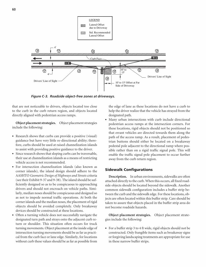
60
that are not noticeable to drivers, objects located too closeto the curb in the curb return region, and objects locateddirectly aligned with pedestrian access ramps.
Object placement strategies. Object placement strategiesinclude the following:
• Research shows that curbs can provide a positive (visual)guidance but have very little re-directional ability; there-fore, curbs should be used at raised channelization islandsto assist with providing positive guidance to the driver.
• Since research shows that sloping curbs can be traversable,their use at channelization islands as a means of restrictingvehicle access is not recommended.
• For intersection channelization islands (also known ascorner islands), the island design should adhere to theAASHTO Geometric Design of Highways and Streets criteria(see their Exhibit 9-37 and 9-38). The island should be suf-ficiently designed so as to be conspicuous to approachingdrivers and should not encroach on vehicle paths. Simi-larly, median noses should be conspicuous and designed soas not to impede normal traffic operations. At both thecorner islands and the median noses, the placement of rigidobjects should be avoided completely. Only breakawaydevices should be constructed at these locations.
• Often a turning vehicle does not successfully navigate thedesignated turn path and strays onto the adjacent curb re-turn or shoulder. This situation often occurs for truckturning movements. Object placement at the inside edge ofintersection turning movements should be as far as practi-cal from the curb face or lane edge. Similarly, for locationswithout curb these values should be as far as possible from
the edge of lane as these locations do not have a curb tohelp the driver realize that the vehicle has strayed from thedesignated path.
• Many urban intersections with curb include directionalpedestrian access ramps at the intersection corners. Forthese locations, rigid objects should not be positioned sothat errant vehicles are directed towards them along thepath of the access ramp. As a result, placement of pedes-trian buttons should either be located on a breakawaypedestal pole adjacent to the directional ramp where pos-sible rather than on a rigid traffic signal pole. This willenable the traffic signal pole placement to occur furtheraway from the curb return region.
Sidewalk Configurations
Description. In urban environments, sidewalks are oftenattached directly to the curb. When this occurs, all fixed road-side objects should be located beyond the sidewalk. Anothercommon sidewalk configuration includes a buffer strip be-tween the curb and the sidewalk edge. For these locations, ob-jects are often located within this buffer strip. Care should betaken to assure that objects placed in the buffer strip area donot become roadside hazards.
Object placement strategies. Object placement strate-gies include the following:
• For a buffer strip 3 to 4 ft wide, rigid objects should not beconstructed. Only frangible items such as breakaway signsor forgiving landscaping treatments are appropriate for usein these narrow buffer strips.
Curb Face
4'
4'
Lateral Offsetdue to Driveway
Std. RecommendedLateral Offset
LEGEND
10' to 15' Offset at FarSide of Driveway
Drivers' Line of Sight
Drivers' Line of Sight
15'10' to
Figure C-3. Roadside object-free zones at driveways.
• Buffer strips that are 5 ft wide or greater should includesmaller roadside items such as forgiving landscaping treat-ments or ornamental trees (with canopies that do not impedeon sight distance) in the region adjacent to the curb but be-yond recommended lateral offsets. If it is infeasible to locatemore rigid objects such as light standards or utility polesbeyond the sidewalk, then their placement should be imme-diately adjacent to the sidewalk so as to place them as far fromthe active travelway as possible. Under no circumstances,however, should these objects be located within the sidewalkboundaries as this space must be kept completely object freeso that pedestrians can remain on their designated path.
High Crash Locations and Common Urban Roadside Crash Locations
Description. Many urban corridors are characterized byunique physical features that may directly contribute to aroadside crash. Though the urban control zones previouslyidentified capture most of the high roadside crash locations,a specific design or operational characteristic for a road mayalso be a location that merits roadside crash mitigation. Theselocations can be identified by creating spot maps that demon-strate cluster crash locations that do not fall within thebounds of the previously identified urban control zones.
Object placement strategies. Each high crash location thatfits the above description will have roadside safety improve-ment strategies unique to the specific feature contributing to the high crash numbers. As a result, placement strategies can in-clude increased lateral offset, shielding, or reconstruction forextreme cases. This must be evaluated on a case by case basis.
Roadside Treatment Details
Several roadside treatments common to an urban environ-ment can become roadside hazards if not properly positioned.The following summaries identify these common urban road-side features and placement strategies that may help enhancesafety at these locations.
Landscaping, Trees, Shrubs,and Plant Layering
General information. Several types of roadside land-scaping are commonly employed to enhance the aesthetics ofroadside environments. These treatments may include theplacement of shrubs, street trees, or alternative treatmentssuch as landscape berms. In addition to the concern of tra-versability in the event that an errant vehicle encountersroadside landscaping, a common issue regarding the safety ofadjacent landscape treatments is sight distance and the impact
landscape treatments may have for intersection, driveway,and stopping sight distance considerations.
Strategy summary. The placement criteria, in some cases,is based on the functional purpose or posted speed limits ofadjacent roads. Common landscape placement issues includethe following:
• Avoid placement in proximity to intersections as discussedin the urban control zone section.
• Avoid placement in proximity to driveways as discussed inthe urban control zone section.
• At locations with isolated hazardous trees, consider re-moving these trees.
• At locations with known hazardous trees that cannotbe relocated, shield the trees with safety barrier wherepossible.
• Lateral offset placement of trees and landscaping as dis-cussed in the urban control zone section. Where practical,use plant layering in front of the more rigid items. In theevent of an errant vehicle, this initial landscaping will func-tion as an energy dissipation device and slow down thevehicle prior to impact with the more rigid tree.
• Implement median planting strategies as discussed in thelateral placement urban control zone section.
• Maintaining a clear vision space, which is a space aboveground that preserves the lines of sight for drivers, bicy-clists, and pedestrians. In general, this space should extendvertically 1 to 3 m [3.3 to 10 ft]. These dimensions will as-sure clear sight distance for drivers in low-riding sportscars as well as drivers in high trucks and buses. The “clearvision space” then is essentially the space above shrubgrowth and below tree overhang. A low tree overhang canalso create an obstacle for pedestrian access.
• Longitudinal placement of trees and landscaping will helpkeep landscaping growth from encroaching on other func-tions of the roadside environment. In addition to longitu-dinal placement strategies discussed in the urban controlzone section, it is advisable to prohibit landscape place-ment at a variety of other locations. One jurisdiction, forexample, recommends that these placement strategies couldinclude the separation of trees from underground utilitylines by 1.5 m [5 ft] and a placement a minimum of 3.0 m[10 ft] from utility poles with 4.6 m [15 ft] recommended.In addition, trees could be separated from street lights by6.1 m [20 ft], from fire hydrants and alleys a distance of3.0 m [10 ft], and 1.5 m [5 ft] from water meters or utilityvaults. Additional longitudinal placement strategies maybe implemented to try and achieve uniform tree spacing.This spacing will depend on the specific tree characteristicsbut could range from 7.6 to 15.2 m [25 to 50 ft]. Treecanopies should not be positioned under service wires.
61

• The strategic placement of landscaping to influence the vi-sual perception of a driver is a relatively new technique.Landscaping can be used to help visually delineate thedownstream road and geometric features of that road. Theuse of landscaping for visual perception purposes can alsohelp create visual narrowing of the driver’s field by gradu-ally tapering a tree line towards the road.
Utility Poles, Posts, Light Standards
General information. Utility poles, posts, light poles,and similar vertical roadside treatments are some of the mostcommon urban roadside hazards. The urban environment,by its very nature, can be expected to include these commonroadside objects.
Strategy summary (for utility poles). Several potentialstrategies can be considered for addressing roadside safety forutility pole placement. These include the following:
• Place utilities completely underground and remove the haz-ardous poles. The removal of all poles in the urban roadsideenvironment may not be practical, but the placement of util-ities underground, where feasible, will minimize this hazard.
• Place poles as far as possible from the active travel lanes. Rec-ommended goals include specific pole lateral clearance basedon speed limits. One jurisdiction suggested a pole offset strat-egy with a target goal of 3.6 m [12 ft] from face of curb to faceof pole for all locations where possible. For speed limitsgreater than 56 km/h [35 mph] but not exceeding 72 km/h[45 mph], a lateral clearance of 2.4 m [8 ft] is acceptable. Forroads with posted speed limits less than or equal to 56 km/h[35 mph], a lateral clearance of 1.8 [6 ft] is acceptable. A sec-ond jurisdiction recommends an offset greater than 2.4 m[8 ft] for roads with speed limits of 40 to 55 km/h [25 to35 mph] and a lateral offset of 4.3 m [14 ft] for roads withspeed limits of 65 to 70 km/h [40 to 45 mph].
• Locate poles away from access points where the pole mayrestrict sight distance or be easily impacted.
• Place poles on the inside of sharp horizontal curves (as errant vehicles tend to continue straight towards the out-side of curves), but be sure pole placement conforms with theurban control zone recommendations previously shown.
• Locate poles on only one side of the road and place sharedutilities on poles where possible.
• Use breakaway poles at select hazardous locations or shieldthem with safety barrier.
Mailboxes
General information. The placement of mailboxes inurban environments can result in new hazardous roadside
objects if jurisdictions do not enforce guidelines about mailboxtype and placement. There are several crashworthy mailboxesthat have been tested including standard boxes mounted on a100 mm by 100 mm [4 in by 4 in] wooden post or a 38 mm[11/2 in] light-gauge pipe for mounting mailboxes, with theseposts embedded no deeper than 600 mm [24 in] into theground. Mailboxes should further be mounted to their supportsto prevent the mailbox from separating from the post during acrash event. Standard cluster mailboxes (as approved by U.S.Postal Service Standards) can also be used in urban regions.Many of the larger mail collection boxes fail safety requirementsand should be placed outside of clear recovery areas.
Strategy summary. While making mailboxes crashwor-thy will satisfy safety associated with mailbox-related crashes,it is important to recognize that the placement of mailboxesmay have an important impact on the overall safety of theroadway. The following recommendations detail appropriateplacement of mailboxes:
• Mailboxes should not obstruct intersection sight distance.• Mailboxes should not be located directly on higher-speed
roadways, where stopping associated with mail deliveryand collection can lead to substantial speed differentialsbetween vehicles on the travelway, thereby increasing thepossibility of a rear-end collision. For higher-speed urbanroads without curb where mailboxes are present, one optionis to provide a 2.4 m [8 ft] mailbox turnout lane adjacentto the travelway that will permit vehicles to leave the trav-elway for mail collection and delivery purposes. Alterna-tively, a minimum shoulder width for these higher-speedroads of 1.8 m [6 ft] should be maintained at these locations.
• At curbed residential locations, mailboxes should be posi-tioned so that the minimum distance from the roadside faceof the mailbox to the face of the curb is 150 mm [6 in], witha preferred offset ranging from 200 to 300 mm [8 to 12 in].
• Mailbox placement at driveways should be compatiblewith the urban control zones previously defined.
• Shield rigid mailboxes.• Add reflective object markers to improve nighttime visi-
bility of mailboxes.
Safety Barriers
General information. Roadside barriers are subject toNCHRP Report 350 testing criteria. There are several types ofsafety barriers that may be present in an urban environment.These include the following:
• Barriers (flexible, semi-rigid, and rigid),• Bridge Railings, and• End Treatments (crash cushions and end terminals).
62
63
Generally, most of the research on safety barriers has beenoriented towards the design of barriers and their placement toshield vehicles from hazardous roadside conditions. The Fed-eral Highway Administration maintains a roadside hardwarewebsite that provides information about specific roadside hard-ware that has been tested. This information is available at: http://safety. fhwa.got.gov/roadway_dept/road_hardware/index.htm.
Strategy summary. In the urban environment, it may bechallenging to construct roadside barriers in the confinedroadside space available. In locations with bicycle activity, forexample, safety barriers located immediately adjacent to theroad may expose cyclists to unnecessary risks as the barriermay result in a sensation of “squashing” the cyclist betweenthe barrier and an adjacent motor vehicle. Similarly, barriersimmediately adjacent to motor vehicle lanes cause vehicles toshy away from the barrier, thereby adversely impacting traf-fic operations. Finally, traffic barrier restricts pedestrian ac-tivity in an urban environment and requires careful design ofopenings for pedestrian crossings that include crashworthybarrier end treatments. Due to the wide variety of potentialsafety barriers that may be selected for use, the two referencesidentified above should be consulted for specific applicationsfor each barrier type.
Street Furniture
General information. In many urban areas the use ofstreet furniture is a common approach to improving the aes-thetic and functional quality of a street. Street furniture
includes items placed adjacent to the road that are there toimprove the adjacent land use or to improve transportationoperations. In some jurisdictions, street lights and signs areincluded in the category of street furniture; however, for thepurposes of this review street furniture is considered to besupplemental items such as benches, public art, trash recep-tacles, phone booths, planters, bollards, fountains, kiosks,transit shelters, bicycle stands, etc. Often the placement ofthese devices can obscure sight distance, so their locationshould not occur in the sight triangles of intersections ordriveways. Many street furniture items are placed along theright-of-way by the property-owners themselves, as in thecase of the placement of a sidewalk cafe in front of a restau-rant, and are thus largely outside the engineer’s control.
Strategy summary. Little is known about the safe place-ment of street furniture. The following general recommen-dations should enhance roadside safety in these locations:
• While maintaining its functional purpose, locate street fur-niture as far from the street as possible.
• Restrict street furniture placement to avoid sight distanceissues for road users. The Urban Control Zones previouslyidentified should be applied to all street furniture.
• Where possible, deploy street furniture that meets basiccrashworthy standards; however, concern for pedestrianshas led to the use of fixed supports in some urban areas.Examples of sites where breakaway supports may beimprudent are sites adjacent to bus shelters or in areas ofextensive pedestrian concentration.
64
APPENDIX D: Draft Chapter 10 for AASHTO Roadside Design Guide from the contractor’s final report for NCHRP Project 16-04 is available on the TRB website at http://trb.org/news/blurb_detail.asp?id=9456.
A P P E N D I X D
Draft Chapter 10 for AASHTO Roadside Design Guide

Abbreviations and acronyms used without definitions in TRB publications:
AAAE American Association of Airport ExecutivesAASHO American Association of State Highway OfficialsAASHTO American Association of State Highway and Transportation OfficialsACI–NA Airports Council International–North AmericaACRP Airport Cooperative Research ProgramADA Americans with Disabilities ActAPTA American Public Transportation AssociationASCE American Society of Civil EngineersASME American Society of Mechanical EngineersASTM American Society for Testing and MaterialsATA Air Transport AssociationATA American Trucking AssociationsCTAA Community Transportation Association of AmericaCTBSSP Commercial Truck and Bus Safety Synthesis ProgramDHS Department of Homeland SecurityDOE Department of EnergyEPA Environmental Protection AgencyFAA Federal Aviation AdministrationFHWA Federal Highway AdministrationFMCSA Federal Motor Carrier Safety AdministrationFRA Federal Railroad AdministrationFTA Federal Transit AdministrationIEEE Institute of Electrical and Electronics EngineersISTEA Intermodal Surface Transportation Efficiency Act of 1991ITE Institute of Transportation EngineersNASA National Aeronautics and Space AdministrationNASAO National Association of State Aviation OfficialsNCFRP National Cooperative Freight Research ProgramNCHRP National Cooperative Highway Research ProgramNHTSA National Highway Traffic Safety AdministrationNTSB National Transportation Safety BoardSAE Society of Automotive EngineersSAFETEA-LU Safe, Accountable, Flexible, Efficient Transportation Equity Act: A Legacy for Users (2005)TCRP Transit Cooperative Research ProgramTEA-21 Transportation Equity Act for the 21st Century (1998)TRB Transportation Research BoardTSA Transportation Security AdministrationU.S.DOT United States Department of Transportation