ncr 7197 thermal receipt printer release 1.0 owner's … · ncr 7197 thermal receipt printer...
TRANSCRIPT

NCR 7197 Thermal Receipt Printer Release 1.0 Owner's Manual
B005-000-1409 Revision C November, 2002

ii
The product described in this book is a licensed product of NCR Corporation.
NCR is the registered trademark of NCR Corporation. Other trademarks and registered trademarks are the property of their respective holders.
It is the policy of NCR Corporation (NCR) to improve products as new technology, components, software, and firmware become available. NCR, therefore, reserves the right to change specifications without prior notice.
All features, functions, and operations described herein may not be marketed by NCR in all parts of the world. In some instances, photographs are of equipment prototypes. Therefore, before using this document, consult with your NCR representative or NCR office for information that is applicable and current.
To maintain the quality of our publications, we need your comments on the accuracy, clarity, organization, and value of this book.
Address correspondence to:
Retail Systems Group−Atlanta NCR Corporation 2651 Satellite Blvd. Duluth, GA 30136
Copyright © 2002 By NCR Corporation Dayton, Ohio U.S.A. All Rights Reserved

iii
Important Information to the User
In order to ensure compliance with the Product Safety, FCC and CE marking requirements, you must use the power supply, power cord, and interface cable which were shipped with this product or which meet the following parameters:
Power Supply
UL Listed (QQGQ), Class 2 power supply with SELV (Secondary Extra Low Voltage), non-energy hazard output, limited energy source, input rated 100-240 Vac, 1.5/0.8 A, 50/60 Hz, output rated 24 Vdc, 2.3 A. or 3.15A
Use of this product with a power supply other than the NCR power supply will require you to test this power supply and NCR printer for FCC and CE mark certification.
Interface Cable
A shielded (360 degree) interface cable must be used with this product. The shield must be connected to the frame or earth ground connection or earth ground reference at EACH end of the cable.
Use of a cable other than described here will require that you test this cable with the NCR printer and your system for FCC and CE mark certification.
Power Cord
A UL listed, detachable power cord must be used for this product. For applications where the power supply module may be mounted on the floor, a power cord with Type SJT marking must be used. For applications outside the US, power cords which meet the particular country’s certification and application requirements should be used.
Use of a power cord other than described here may result in a violation of safety certifications which are in force in the country of use.
iv
Federal Communications Commission (FCC) Radio Frequency Interference Statement
Warning: Changes or modifications to this unit not expressly approved by the party responsible for compliance could void the user’s authority to operate the equipment.
Note: This equipment has been tested and found to comply with the limits for a Class A digital device, pursuant to Part 15 of the FCC Rules. These limits are designed to provide reasonable protection against harmful interference when the equipment is operated in a commercial environment. This equipment generates, uses, and can radiate radio frequency energy and, if not installed and used in accordance with the instruction manual, may cause harmful interference to radio communications. Operation of this equipment in a residential area is likely to cause harmful interference in which case the user will be required to correct the interference at his own expense.
Communication Cables
Shielded communication cables must be used with this unit to ensure compliance with the Class A FCC limits.
Information to User
This equipment must be installed and used in strict accordance with the manufacturer's instructions. However, there is no guarantee that interference to radio communications will not occur in a particular commercial installation. If this equipment does cause interference, which can be determined by turning the equipment off and on, the user is encouraged to contact NCR immediately.
The NCR company is not responsible for any radio or television interference caused by unauthorized modification of this equipment or the substitution or attachment of connecting cables and equipment other than those specified by NCR. The correction of interferences caused by such unauthorized modification, substitution or attachment will be the responsibility of the user.
Industry Canada (IC) Radio Frequency Interference Statement
This Class A digital apparatus meets all requirements of the Canadian Interference-Causing Equipment Regulations.
Cet appareil numérique de la classe A respecte toutes les exigences du Règlement sur le matériel brouilleur du Canada.

v
Quick Reference This Quick Reference will direct you to key areas of the Owner’s Manual. For a complete listing of topics, consult the Table of Contents or the Index.
Setting Up the Printer .................................................... page 7 Basic requirements for unpacking and installation, connecting the printer, turning it on, and running the print test.
Running the Data Scope Mode ................................... page 45 Instructions for running the data scope mode.
Troubleshooting ............................................................ page 37 Information on correcting problems with the printer.

vi
How to Use this Book Use this book as a general and technical reference manual and as a guide when replacing parts on the printer. The service guide is intended as a guide for service representatives, field engineers, and those who will be installing and learning about the 7197 printer. It can also be used as a reference for service courses.
See the Quick Reference page, the Contents, or the Index for detailed listings of what is contained in this book.
Who Should Use this Book? You must be a trained service representative to service the 7197 Thermal Receipt printer.
How to Obtain More Information For more information see the following documents: • 7197 Receipt Printer: Service Manual (B005-000-1410) • 7197 Receipt Printer: Parts Identification Manual (B005-000-1411)
For this and additional copies of the Owner’s Manual, contact your sales representative.
Revision Record Issue Date Remarks
A Apr 2002 First printing B May 2002 Update to reflect first
production configuration.

7197 Owner’s Manual Contents
November 2002 ix
Contents
Quick Reference ..........................................................................................................v How to Use this Book.........................................................................................vi Who Should Use this Book? ..............................................................................vi How to Obtain More Information ....................................................................vi
Revision Record .........................................................................................................vi Contents ......................................................................................................................ix
Chapter 1: About the 7197 Printer 1 Features and Options ................................................................................................. 2
Receipt Station...................................................................................................... 2 General Features .................................................................................................. 3 Options.................................................................................................................. 3
Thermal Print Head.................................................................................................... 3 Ordering Paper and Supplies.................................................................................... 4
Ordering Thermal Receipt Paper....................................................................... 4 Ordering Other Supplies .................................................................................... 5 Ordering Documentation ................................................................................... 5
Cleaning the Printer.................................................................................................... 6 Cleaning the Cabinet ........................................................................................... 6 Cleaning the Thermal Print Head ..................................................................... 6
Chapter 2: Setting Up and Using the Printer 8 What Is in the Box? ..................................................................................................... 8
Removing the Packing Material......................................................................... 9 Repacking the Printer........................................................................................ 10
Choosing a Location ................................................................................................. 10 Wall mounted..................................................................................................... 11 Wall mounted Power Supply (Option)........................................................... 11
Setting Switches ........................................................................................................ 12 Connecting the Cables.............................................................................................. 13 About the Universal Serial Bus ............................................................................... 15
Advantages of USB connections ...................................................................... 15 Advantages of the NCR USB Solution............................................................ 15
Checking for USB Support on the Host Computer .............................................. 16 Host Configuration............................................................................................ 16
Configuring the Printer............................................................................................ 17 Installing the USB Printer Drivers .......................................................................... 20 Checking the Installation ......................................................................................... 30 Configuring Serial Port Number Assignments..................................................... 33
Running the Edgeport Utility .......................................................................... 33 Serial Port Configuration Methods ................................................................. 34 Uninstalling the Drivers ................................................................................... 34
Using the Printer ....................................................................................................... 36

Contents 7197 Owner’s Guide
September 1998 x
Loading and Changing the Receipt Paper............................................................. 37 Removing the Paper Roll .................................................................................. 37 Loading the Paper Roll ..................................................................................... 39 Advancing Paper ............................................................................................... 40
Chapter 3: Solving Problems 39 Green LED Does Not Come On/Printer Will Not Print...................................... 40 Green LED Blinking (Slow) ..................................................................................... 40 Green LED Blinking (Fast)....................................................................................... 40 Receipt Printing is Light or Spotty ......................................................................... 41 Other Serious Problems ........................................................................................... 42 Contacting a Service Representative ...................................................................... 42
Chapter 4: Diagnostics 44 Level 0 Diagnostics ................................................................................................... 44 Level 1 Diagnostics ................................................................................................... 45
Printer Configuration........................................................................................ 45 Configuring the Printer..................................................................................... 46 Communication Interface Modes .................................................................... 49 Diagnostic Modes .............................................................................................. 51 Emulation/Software Options .......................................................................... 53 Hardware Options............................................................................................. 56 Default Code Page ............................................................................................. 58 EEPROM to Default Settings............................................................................ 60
Level 2 Diagnostics ................................................................................................... 61 Level 3 Diagnostics ................................................................................................... 62
Chapter 5: Communication 61 Communication Overview ...................................................................................... 61
Interface............................................................................................................... 61 Sending Commands .......................................................................................... 61
RS-232C Interface...................................................................................................... 62 Print Speed and Timing .................................................................................... 62 XON/XOFF Protocol......................................................................................... 63 DTR/DSR Protocol ............................................................................................ 63 RS-232C Technical Specifications .................................................................... 63 Setting Extra RS-232C Options ........................................................................ 67
Chapter 6: Commands 67 Command Conventions ........................................................................................... 67 Introduction............................................................................................................... 67 List of Commands and Location............................................................................. 67
By Command Code ........................................................................................... 68 By Function......................................................................................................... 72 Printer Function Commands............................................................................ 72 Vertical Positioning and Print.......................................................................... 72 Horizontal Positioning Commands ................................................................ 73 Print Characteristic Commands....................................................................... 73
7197 Owner’s Manual Contents
November 2002 xi
Graphics Commands......................................................................................... 74 Status Commands.............................................................................................. 74 Real Time Commands....................................................................................... 74 Auto Status Back Commands........................................................................... 75 Barcode Commands .......................................................................................... 75 Page Mode Commands..................................................................................... 75 Macro Commands ............................................................................................. 75 User Data Storage Commands......................................................................... 76 Asian Character Commands ............................................................................ 76 Flash Download Commands............................................................................ 76 Comparison Chart ............................................................................................. 77
Command Descriptions ........................................................................................... 79 Printer Function Commands............................................................................ 80 Vertical Positioning and Print Commands .................................................... 86 Horizontal Positioning Commands ................................................................ 92 Print Characteristic Commands..................................................................... 100 Graphics Commands....................................................................................... 116 Status Commands............................................................................................ 126 Real Time Commands..................................................................................... 137 Auto Status Back Commands......................................................................... 143 Bar Code Commands ...................................................................................... 146 Page Mode Commands................................................................................... 152 Macro Commands ........................................................................................... 160 User Data Storage Commands....................................................................... 162 Asian Character Commands .......................................................................... 170 Flash Download Commands.......................................................................... 174
Chapter 7: Reflashing the Printer Firmware 181 Flash Utility Information ................................................................................ 181 File Configurations .......................................................................................... 181 Printer Languages Cross Reference............................................................... 182
Appendix A: Specifications 199 Printing Specifications............................................................................................ 199 Power Requirements .............................................................................................. 200 Environmental Conditions .................................................................................... 200 Reliability ................................................................................................................. 201 Dimensions and Weight......................................................................................... 201 Density of Receipt Print Lines............................................................................... 201 Duty Cycle Restrictions (Printing Solid Blocks) ................................................. 201
Appendix B: Print Characteristics 203 Character Size.......................................................................................................... 203
Receipt Station.................................................................................................. 203 Print Zones............................................................................................................... 204
Receipt Station.................................................................................................. 204 Character Sets .......................................................................................................... 206

Contents 7197 Owner’s Guide
September 1998 xii
Index ......................................................................................................................... 259

7197 Owner’s Manual Chapter 1: About the 7197 Printer
November 2002 1
Chapter 1: About the 7197 Printer
The 7197 printer is a fast, quiet, relatively small and very reliable multiple- function printer. It prints receipts and two color printing.
The industry-standard RS-232C communication interface allows the 7197 to be connected to any host computer that uses RS-232C or USB communication interface.
Receipt Cover
LED
Paper Feed Button
Receipt
Top Cover

Chapter 1: About the 7197 Printer 7197 Owner’s Guide
February 2002 2
Features and Options The 7197 printer comes with several features and options.
Receipt Station • Thermal printing • Standard pitch (host selectable): 15.2 characters per inch, 44 columns • Compressed pitch (host selectable): 19.0 characters per inch, 56 columns • Resident bar codes
• Code 39 • Code 93 • Code 128 • UPC-A • UPC-E • JAN8 (EAN) • JAN13 (EAN) • Interleaved 2 of 5 • Codabar • PDF417
• Drop-in paper loading requiring no spindle or threading paper • Paper low indicator • Paper exhaust indicator • Variety of print modes: double high, double wide, upside down, and rotated • 14 resident character language Code Pages:
• PC Code Page 437 (US English) • PC Code Page 850 (Multilingual) • PC Code Page 852 (Slavic) • PC Code Page 858 (with Euo symbol) • PC Code Page 860 (Portuguese) • PC Code Page 862 (Hebrew) • PC Code Page 863 (French Canadian) • PC Code Page 864 (Arabic) • PC Code Page 865 (Nordic) • PC Code Page 866 (Cyrillic) • PC Code Page 1252 (Windows Latin #1) • PC Code Page Katakana • PC Code Page 874 (Thai) • Space Page
• 16K RAM for downloaded character sets or bit-mapped graphics (such as
logos)

7197 Owner’s Manual Chapter 1: About the 7197 Printer
November 2002 3
General Features • Knife • Cover open sensors • One cash drawer connector (supports 2 cash drawers) • Industry standard RS-232C and USB communication interface • History EEROM for custom settings • Audible tone (controlled by application)
Note: The 7197 does not have a paper journal. The journal is kept electronically by the host computer.
Options • Remote power supply • Communication cables
Thermal Print Head The 7197 Receipt Station uses a thermal print head for printing receipts, and is extremely fast and quiet. Since it uses heat to print directly on paper, there is no cassette or ribbon to change, eliminating soiled fingers and paper dust.
There is no regularly scheduled maintenance for the print head and it does not need to be regularly cleaned. However, if it does appear dirty, wipe it with cotton swabs and rubbing alcohol. If spotty or light printing problems persist after the thermal print head has been cleaned, see “Chapter 3: Solving Problems” for more information.
Note: The thermal print head does not normally require cleaning if the recommended paper is used. If non-recommended paper has been used for an extended period of time, cleaning the print head with cotton swabs and rubbing alcohol will not be of much benefit. See “Ordering Receipt Paper” on the next page for the recommended paper.
The print head is designed for a very long life, but it may be replaced if needed. Only a trained service representative may replace the print head. See “Chapter 3: Solving Problems” to determine if the print head needs to be replaced.

Chapter 1: About the 7197 Printer 7197 Owner’s Guide
February 2002 4
Ordering Paper and Supplies Thermal receipt paper, ribbon cassettes, and forms can be ordered. Documentation is also available.
Ordering Thermal Receipt Paper The 7197 requires NCR qualified thermal paper to be used on the thermal receipt print station to insure proper operation of the printer. In addition the paper rolls must be have the following dimension.
Diameter Length Width 80 mm max. (3.15 in.) 83 meters (273 ft.) 80 mm ± .5 mm (3.15 ± .008 in.)
The paper must not be attached at the core. Otherwise the receipt station will be damaged when the paper is exhausted.
Paper grades available from NCR
Paper Stock Paper Grade Description
856911 Economy (for text printing)
856966 Standard Sensitivity (for text and simple graphics)
878559 High Sensitivity (for text, bar codes & detailed graphics)
856380 For improved archiveability and added resistance to incompatible substances
856461 Red/Black 856458 Blue/Black
The paper must not be attached at the core. Otherwise the receipt station will be damaged when the paper is exhausted.
To order thermal receipt paper, contact your sales representative or order from NCR at the following address or toll free number:
NCR Media Products Division 9995 Washington Church Road Miamisburg, OH 45342 Voice: 1(800)543-8130 (toll free), or local listing of The NCR Media Products sales office
7197 Owner’s Manual Chapter 1: About the 7197 Printer
November 2002 5
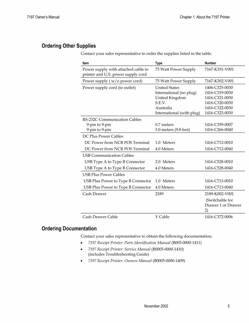
Ordering Other Supplies Contact your sales representative to order the supplies listed in the table.
Item Type Number Power supply with attached cable to printer and U.S. power supply cord
75 Watt Power Supply 7167-K331-V001
Power supply ( w/o power cord) 75 Watt Power Supply 7167-K302-V001 Power supply cord (to outlet) United States
International (no plug) United Kingdom S.E.V. Australia International (with plug)
1406-C325-0030 1416-C319-0030 1416-C321-0030 1416-C320-0030 1416-C322-0030 1416-C323-0030
RS-232C Communication Cables 9-pin to 9-pin 9-pin to 9-pin
0.7 meters 3.0 meters (9.8 feet)
1416-C359-0007 1416-C266-0040
DC Plus Power Cables DC Power from NCR POS Terminal DC Power from NCR POS Terminal
1.0 Meters 4.0 Meters
1416-C712-0010 1416-C712-0040
USB Communication Cables USB Type A to Type B Connector USB Type A to Type B Connector
2.0 Meters 4.0 Meters
1416-C528-0010 1416-C528-0040
USB Plus Power Cables USB Plus Power to Type B Connector USB Plus Power to Type B Connector
1.0 Meters 4.0 Meters
1416-C713-0010 1416-C713-0040
Cash Drawer 2189 2189-K002-V001 (Switchable for Drawer 1 or Drawer 2)
Cash Drawer Cable Y Cable 1416-C372-0006
Ordering Documentation Contact your sales representative to obtain the following documentation: • 7197 Receipt Printer: Parts Identification Manual (B005-0000-1411) • 7197 Receipt Printer: Service Manual (B0005-0000-1410)
(includes Troubleshooting Guide) • 7197 Receipt Printer: Owners Manual (B0005-0000-1409)

Chapter 1: About the 7197 Printer 7197 Owner’s Guide
February 2002 6
Cleaning the Printer Cleaning the Cabinet
The external cabinet materials and finish are durable and resistant to these items: • Cleaning solutions • Lubricants • Fuels • Cooking oils • Ultraviolet light
There is no scheduled maintenance required for the 7197.
Clean the cabinet as needed to remove dust and finger marks. Use any household cleaner designed for plastics, but test it first on a small unseen area. If the receipt bucket is dirty, wipe it with a clean, damp cloth.
Cleaning the Thermal Print Head Caution: Do not spray or try to clean the thermal print head or the inside of the printer with any kind of cleaner as this may damage the thermal print head and electronics.
If the thermal print head appears dirty, wipe it with cotton swabs and isoprophl alcohol.
If spotty or light printing problems persist after the thermal print head has been cleaned, see “Chapter 3: Solving Problems” for more information.
Note: The thermal print head does not normally require cleaning if the recommended paper grades are used. If non-recommended paper has been used for an extended period of time, cleaning the print head with cotton swabs and rubbing alcohol will not be of much benefit. See “Ordering Paper and Supplies” earlier in this manual for recommended paper.

Chapter 2: Setting Up and Using the Printer 7197 Owner’s Guide
February 2002 8
Chapter 2: Setting Up and Using the Printer
What Is in the Box?
The following items are packed in the shipping box:
• Printer enclosed in a plastic bag and foam pack
• Thermal receipt paper roll
These items may be ordered as options from NCR and will be shipped separately:
• Communication cable (from host computer to printer)
• DC Power Cable
• Remote Power Supply
• Cash drawer with cables (may be ordered from other equipment suppliers: see “Ordering Other Supplies” in chapter 1)

7197 Owner’s Manual Chapter 2: Setting Up and Using the Printer
9 November 2002
Removing the Packing Material
1. Remove the printer from the foam pack and plastic bag.
2. Remove the receipt paper roll and cables from the foam packing material.
3. Save all packing materials for future storing, moving, or shipping the printer.
Note: If the printer is wall mounted the paper low switch must be disable.
Receipt Cover

Chapter 2: Setting Up and Using the Printer 7197 Owner’s Guide
February 2002 10
Repacking the Printer Review the illustrations on the previous two pages to pack the printer.
1. Place receipt paper between the receipt cover and the print head for protection.
2. Place the printer in the plastic bag and foam pack, place the packed printer in the box, and secure the box with packing tape.
3. If you are sending the printer to NCR for repair, call your NCR-authorized service representative for instructions on where to send the printer.
Be prepared to answer questions concerning shipping and billing.
Choosing a Location The 7197 printer takes up relatively little counter space and may be set on or near the host computer. Make sure there is enough room to open the receipt cover to change the paper. The illustration shows the actual dimensions of the printer, but leave several inches around the printer for connecting and accessing the cables.
182.40 mm (7.30 in.)
145.50 mm (5.80 in.)
154.90 mm (6.20 in.)

7197 Owner’s Manual Chapter 2: Setting Up and Using the Printer
11 November 2002
Wall mounted
The 7197 printer may be mounted on a vertical wall by using the keyhole slot at the bottom of the printer base. Make sure there is enough room to open the receipt cover to change the paper. Mount the screws on the wall using the following recommended mount dimensions. Use a #8 wood screw which is to be securely fastened to a wall stud or using a “Molly” fastener (not provided).
Note: Paper low must be disabled when printer is wall mounted
Wall mounted Power Supply (Option)
The 75 watt power supply may be mounted on a vertical wall by using the holes on the cover. Mount the screws on the wall using the following recommended mount dimensions. Use a #8 wood screw which is to be securely fastened to a wall stud or using “Molly” fasteners.
3.5 ~ 4 mm (.138 – .160 in.)
Screw
128 mm (5.04 in..)
121mm (4.75 in.)
Wall
175mm (6.89 in)
75mm (2.95 in)
10mm (.39 in)

Chapter 2: Setting Up and Using the Printer 7197 Owner’s Guide
February 2002 12
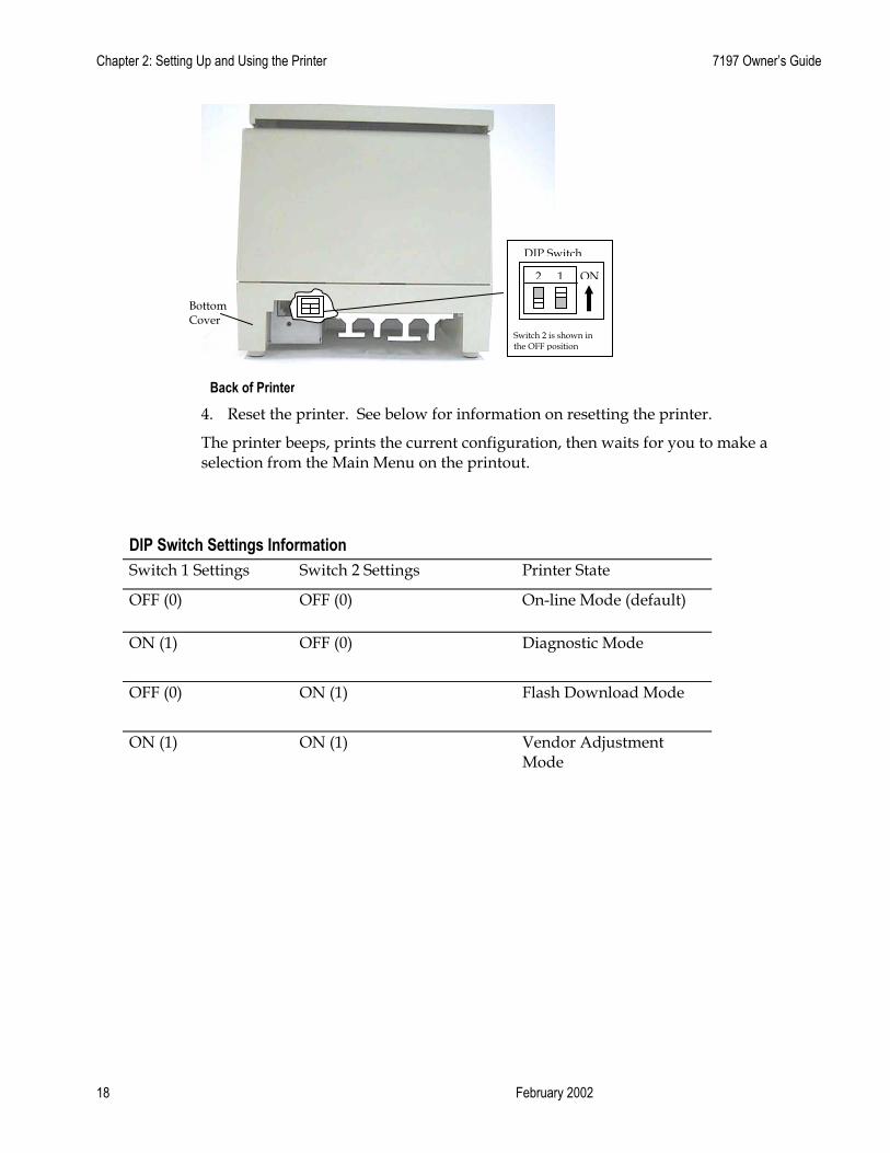
Setting Switches The DIP switches, located at the back of the printer, are used for two purposes:
• To set variables for several printer functions (see the sections for the various printer functions in “Level 1 Diagnostics” in “Chapter 4: Diagnostics” for Setting Up the Printer)
• To perform diagnostic tests (see the sections for the various diagnostic tests in “Level 1 Diagnostics” in “Chapter 4: Diagnostics” for Setting Up the Printer)
Caution: The DIP switches are set at the factory to predetermined settings and should not be changed unless to change parameters or to reflash the firmware.
Note: Switch 1 is shown in the Off position for reference.
Use a paper clip or other pointed object to set the switches.
1. Set the switches to the desired settings shown in the table.
2. Reset the printer by disconnecting and reconnecting the power to the printer.
DIP Switch
Switch 1 is shown in the OFF position
1 2 ON
Back of Printer
Bottom Cover

7197 Owner’s Manual Chapter 2: Setting Up and Using the Printer
13 November 2002
Resetting the Printer
The printer is reset by disconnecting/reconnecting the DC power.
Connecting the Cables There are three different types of cables that connect to the printer:
• Power supply cable supplying power from the power supply
• Communication cable (RS-232 or USB) connecting the printer to the host computer
• Cash drawer cable connecting the printer to one or two cash drawers
Caution: Disconnect the power before connecting the cables. Always connect the communication cable and cash drawer cables before connecting power to the power supply. Always disconnect power to the power supply before disconnecting the communication and cash drawer cables.
Follow these steps to connect the cables. See the illustration on the next page.
1. Unplug the power supply from its power source.
2. Connect the power and communication cables to their respective connectors under the printer as shown in the illustration.
For the RS232 Cable, be sure to screw the communication cable to the communication connector.
3. Route the cables through the cable strain relief on the bottom of the printer, then through the two slots in the cable access cover as shown in the illustration.
4. Connect the communication cable to the appropriate host computer connector.
5. Connect the cash drawer cable to the printer and cash drawer.
The connectors is a standard phone jack located at the rear of the printer.
6. Plug the power cord into the power supply for remote power supply installation, then plug the power supply into an outlet.

Chapter 2: Setting Up and Using the Printer 7197 Owner’s Guide
February 2002 14
At this point, the printer receives power. If the On Line LED (green) is on, the printer is on-line. Otherwise, the printer is off-line.
7. For Host powered installation plug the DC cable into the POS terminal.
Cash Drawer Connector
DIP Switch Power Cable
Communication Cable
USB Cable
Power Connector
Communication Connector
USB Connector
Bottom of the Printer
RS-232 Cable Connection
USB Cable Connection
Power Cable
Power Connector
Cash Drawer Cable
Cash Drawer Connector
DIP Switch Cash Drawer Cable

7197 Owner’s Manual Chapter 2: Setting Up and Using the Printer
15 November 2002
About the Universal Serial Bus The Universal Serial Bus (USB) is a peripheral bus for personal computers that was first released in January 1996. Since that time, virtually all Intel Architecture personal computers have the hardware to support USB, and a large number of computers exist that have both the hardware and software support required to interface with USB peripherals.
Advantages of USB connections USB has a number of advantages over legacy connection schemes (e.g., serial RS-232). These advantages include:
• High Speed: up to 12 MB/second for high-speed devices.
• Plug and Play: Devices are automatically recognized and configured at installation.
• Hot plug: Bus supports installation and removal of devices with the power applied.
• Up to 127 devices: One host can support up to 127 devices with the use of hubs.
• “Free ports”: Most PC architecture machines contain two USB ports in the base hardware.
These advantages have become attractive to the POS industry for a couple of reasons.
Additional POS devices. Some POS systems are required to host more peripherals than can be supported by two RS-232 ports typical in a platform. With the addition of one (or two) USB connectors, the platform can now support the additional devices that had previously required a serial port expander card.
Higher bandwidths. New devices coming into use have bandwidth requirements that are higher than the bandwidth that can be supported on legacy interfaces. These devices include image scanners and printers. As the speed and capability of POS printers increases, the performance of the printer in an application can become limited by the speed of the communications interface. USB provides ample bandwidth to support current and future POS printer requirements.
Advantages of the NCR USB Solution NCR has eliminated any cost associated with porting applications to USB by implementing a USB solution that simulates standard serial communications in Windows 98 (SR2), Windows 98 USB Hot Patch, ID: Q236934, and NT 4.0 (Service Pack 3 or higher) and Windows 2000. Application developers need only redirect their software to the virtual serial ports created by the NCR USB solution to use the printer.

Chapter 2: Setting Up and Using the Printer 7197 Owner’s Guide
February 2002 16
Checking for USB Support on the Host Computer If USB interface communications is required, the host computer must be equipped and setup properly. If it is not, you need to install a USB interface card. With the required hardware in place, Windows 98 (SR2), Windows 98 USB Hot Patch, ID: Q236934, NT 4.0 (Service Pack 4.0 or higher) and Windows 2000 (Service Pack 2.0 or higher) natively support plug-and-play USB with a built-in driver; Windows NT does not, and the NCR windows NT USB driver needs to be installed.
IMPORTANT: You need to have internet access to download the USB drivers from the NCR Web site://www.NCR.com.
Host Configuration Verify that the proper hardware has been installed in the host PC.
Windows 98:
1. Open the Control Panel.
2. Click on System (Windows 98).
3. Click the Device Manager tab.
4. In the Device Manager window, scroll down the list of installed hardware devices until you find an entry for “Universal serial bus controller.”
If this entry exists, your host computer is set up for USB operation. If this entry does not appear:
• Consult your computer documentation to see if USB must be enabled in the BIOS setup.
Windows NT: To see if your POS terminal is USB-compliant, look at the back.
• If it has a USB connector port, your hardware is all set.
Note: Even though the host may have a USB port, Windows NT does not natively support plug-and-play USB because it does not have a built-in driver. You will need to load the NCR Windows NT USB driver (see “Installing the USB Printer Drivers”).
• If the connector port is missing, you need to install a third-party USB card, according to the manufacturer’s instructions.
Note: For Windows NT units requiring the installation of a card, a Windows 98 USB card can be used with the NCR Windows NT driver.
Windows 2000:
1. Open the Control Panel.
2. Click on System.

7197 Owner’s Manual Chapter 2: Setting Up and Using the Printer
17 November 2002
3. Click the Device Manager tab.
4. In the Device Manager window, scroll down the list of installed hardware devices until you find an entry for “Universal serial bus controller.”
If this entry exists, your host computer is set up for USB operation. If this entry does not appear:
• Consult your computer documentation to see if USB must be enabled in the BIOS setup.
Configuring the Printer USB is a plug-and-play environment. As such, neither the printer nor the host requires user configuration to work. However, since the NCR solution simulates a serial communication interface, you must configure “handshaking” on the printer for proper operation. The printer can be configured to use hardware flow control (using DTR/DSR) or software flow control (using XON/XOFF). All other serial communication parameters (i.e., baud rate, parity, stop bits, and data bits) are ignored.
To define software or hardware handshaking: 1. Open the Receipt Cover and check whether there is paper in the printer. If there
isn’t, insert the paper roll, as described in the Owner’s Manual.
2. Turn the printer so the back is facing you.
3. Set DIP switch 1 to the On position (up).
Receipt cover Receipt
Chapter 2: Setting Up and Using the Printer 7197 Owner’s Guide
February 2002 18
4. Reset the printer. See below for information on resetting the printer.
The printer beeps, prints the current configuration, then waits for you to make a selection from the Main Menu on the printout.
DIP Switch Settings Information Switch 1 Settings Switch 2 Settings Printer State
OFF (0) OFF (0) On-line Mode (default)
ON (1) OFF (0)
Diagnostic Mode
OFF (0) ON (1)
Flash Download Mode
ON (1) ON (1)
Vendor Adjustment Mode
Back of Printer
Bottom Cover
DIP Switch
Switch 2 is shown in the OFF position
1 2 ON

7197 Owner’s Manual Chapter 2: Setting Up and Using the Printer
19 November 2002
Follow the instructions on the scrolling menu, pressing the Paper Feed button to make selections. Indicate Yes with a long click, and No with a short click.
*** Diagnostics Form *** Model number Serial number Boot Firmware Revision CRC Flash Firmware Revision CRC Hardware Flash Memory Size Flash Logos Size Flash Fonts Size Flash User Storage Communication Interface Interface Type Parameters Baud Rate Data Bits Stop Bits Parity Flow Control Reception Errors Receive Buffer Diagnostic Mode Emulation/Software Printer Emulation Printer ID Mode Default LPI Carriage Return Asian Mode
*** Printer Config Menu *** The config menu allows you to set general printer parameters. Sub-menus are entered and selections are made using the Paper Feed Button:
- Short Click : Feed Button is quickly depressed then released.
- Long Click : Feed Button is held
down more than 1sec then released.
CAUTION !! The settings are predetermined in factory and should generally not be changed to avoid changing other functions. **************
************* Main Menu ************* ***************************************** Select a sub –menu: - EXIT 1 Click - Print Current Configuration 2 Clicks - Set Communication Interface 3 Clicks - Set Diagnostics Modes 4 Clicks - Set Emulation/Software 5 Clicks - Set Hardware Options 6 Clicks - Set Default Code Page 7 Clicks - Set EEPROM To Default 8 Clicks Enter code, then hold button down at least 1 second to validate
Important: Ensure that the configuration settings match your host computer, if not, enter the Configuration Menu to make changes.
: : : : : : : : : : : : : : : : : : : : : : : : :
7197-1005-9001 01000011 V00.17 9592 V01.62 17A5 2Mbytes 256Kbytes 64Kbytes 64Kbytes RS232/USB 9600 8 1 None DTR/DSR Print ‘?’ 4K Off, Normal Mode 7194 Native Mode 7194 Native ID 7.52 Used as Print Cmd Off
To enter Printer Configure Menu: 1) Flip DIP switch #1 on 2) Reset the printer by pressing
and holding Receipt Feed switch down while disconnecting and reconnecting the power

Chapter 2: Setting Up and Using the Printer 7197 Owner’s Guide
February 2002 20
• Press and hold the Paper Feed button for at least one second for a long click.
• Press the Paper Feed button quickly for a short click.
5. Select Set Communication Interface from the Main Menu.
The printer scrolls to the first question.
6. Select RS232/USB.
7. Skip through the parameters with short clicks until Set Flow Control Method is displayed.
8. Follow the instructions to select either XON/OFF or DTR/DSR, then skip the remaining communications parameters.
9. When you have finished, set DIP switch 1 to Off (down).
10. Reset the printer.
The printer resets with the new selection. You can verify the new setting by pressing the Paper Feed button to print out a diagnostics form or by holding the Paper Feed button while closing the Top Cover.
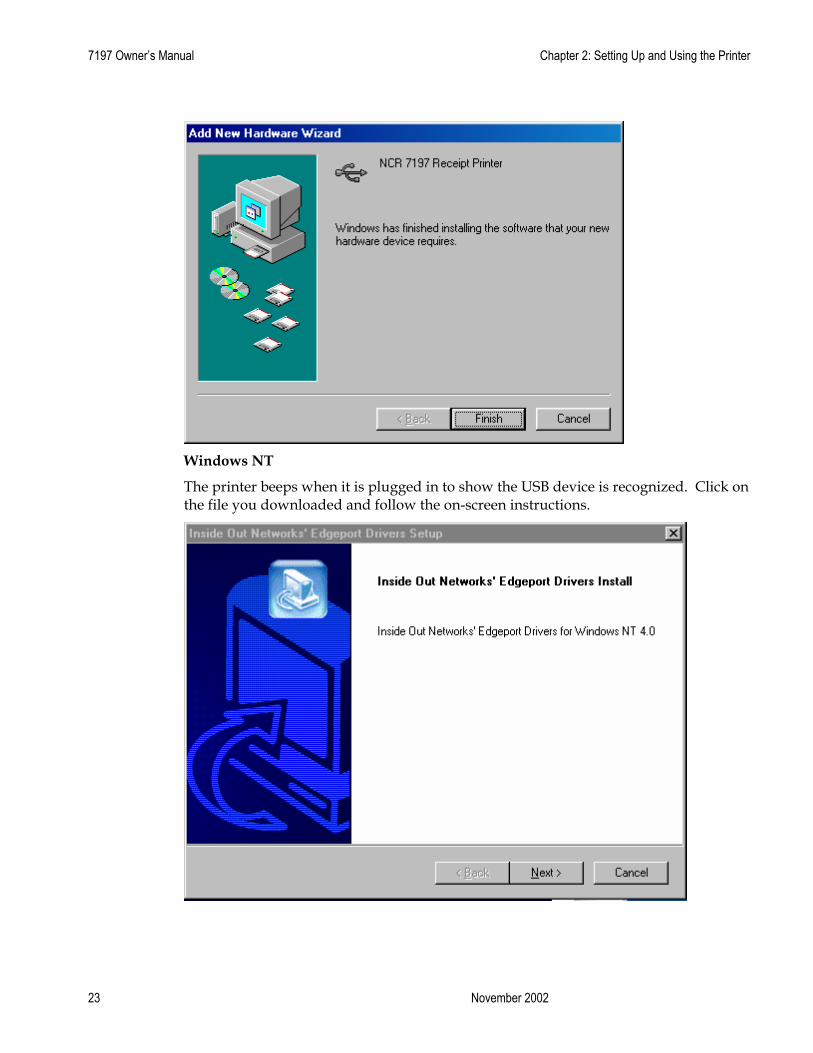
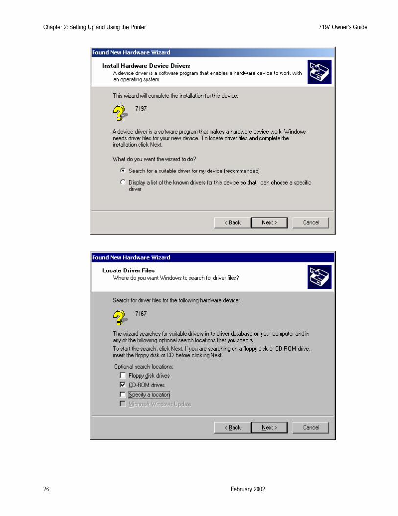
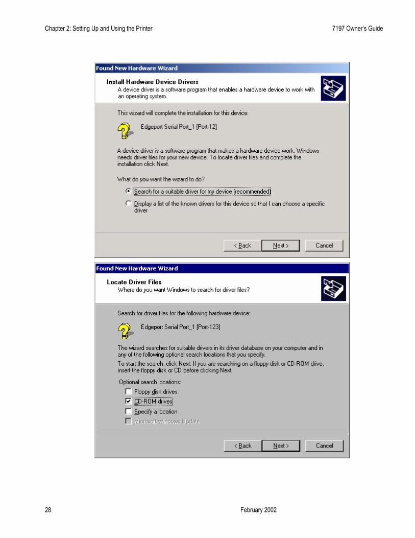
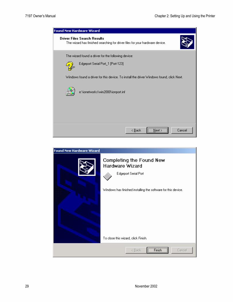
Installing the USB Printer Drivers Windows NT users need to run Service Pak 3 or higher for a successful installation and should exit all Windows programs before starting.
1. Verify that the printer is plugged in and the power is on.
2. The installation varies depending on the operating system.
Windows 98
Follow the on-screen instructions. The printer beeps when the USB device is recognized. Go to the location where you downloaded the drivers and double click the file.

7197 Owner’s Manual Chapter 2: Setting Up and Using the Printer
21 November 2002

Chapter 2: Setting Up and Using the Printer 7197 Owner’s Guide
February 2002 22
Note: Location of the IONetworks files on the CD-ROM may very depending on the version of the CD that is being used.
7197 Owner’s Manual Chapter 2: Setting Up and Using the Printer
23 November 2002
Windows NT
The printer beeps when it is plugged in to show the USB device is recognized. Click on the file you downloaded and follow the on-screen instructions.

Chapter 2: Setting Up and Using the Printer 7197 Owner’s Guide
February 2002 24

7197 Owner’s Manual Chapter 2: Setting Up and Using the Printer
25 November 2002
Windows 2000
Follow the on-screen instructions. The printer beeps when the USB device is recognized. Go to the location where you downloaded the drivers and double click the file.
Chapter 2: Setting Up and Using the Printer 7197 Owner’s Guide
February 2002 26

7197 Owner’s Manual Chapter 2: Setting Up and Using the Printer
27 November 2002
Note: Location of the IONetworks files on the CD-ROM may very depending on the version of the CD that is being used.
Chapter 2: Setting Up and Using the Printer 7197 Owner’s Guide
February 2002 28
7197 Owner’s Manual Chapter 2: Setting Up and Using the Printer
29 November 2002
Chapter 2: Setting Up and Using the Printer 7197 Owner’s Guide
February 2002 30
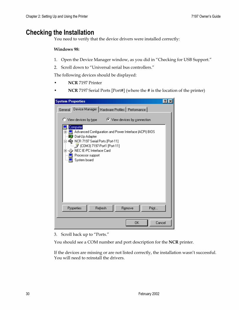
Checking the Installation You need to verify that the device drivers were installed correctly:
Windows 98:
1. Open the Device Manager window, as you did in “Checking for USB Support.”
2. Scroll down to “Universal serial bus controllers.”
The following devices should be displayed:
• NCR 7197 Printer
• NCR 7197 Serial Ports [Port#] (where the # is the location of the printer)
3. Scroll back up to “Ports.”
You should see a COM number and port description for the NCR printer.
If the devices are missing or are not listed correctly, the installation wasn’t successful. You will need to reinstall the drivers.

7197 Owner’s Manual Chapter 2: Setting Up and Using the Printer
31 November 2002
Windows NT:
Go the Windows Start button and select Programs > InsideOut Networks Utilities > Edgeport Configuration Utility. A window opens that contains the name of the printer, and the port assignment.
If this information is not listed, then the installation was not successful. You will need to reinstall the drivers.
Windows 2000:
1. Open the Device Manager window, as you did in “Checking for USB Support.”
2. Scroll down to “Universal serial bus controllers.”

Chapter 2: Setting Up and Using the Printer 7197 Owner’s Guide
February 2002 32
3. Scroll back up to “Ports.”
If the devices are missing or are not listed correctly, the installation wasn’t successful. You will need to reinstall the drivers.
If this information is not listed, then the installation was not successful. You will need to reinstall the drivers.
7197 Owner’s Manual Chapter 2: Setting Up and Using the Printer
33 November 2002
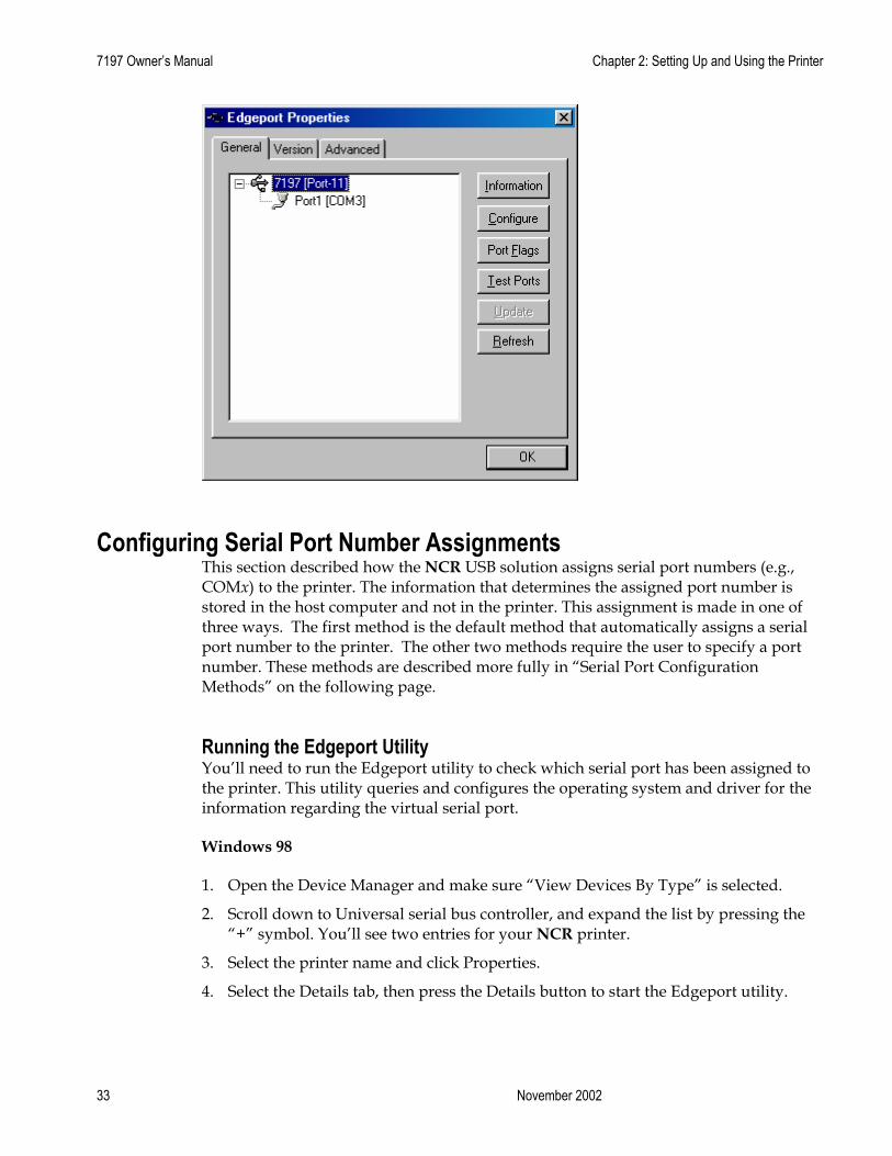
Configuring Serial Port Number Assignments This section described how the NCR USB solution assigns serial port numbers (e.g., COMx) to the printer. The information that determines the assigned port number is stored in the host computer and not in the printer. This assignment is made in one of three ways. The first method is the default method that automatically assigns a serial port number to the printer. The other two methods require the user to specify a port number. These methods are described more fully in “Serial Port Configuration Methods” on the following page.
Running the Edgeport Utility You’ll need to run the Edgeport utility to check which serial port has been assigned to the printer. This utility queries and configures the operating system and driver for the information regarding the virtual serial port.
Windows 98
1. Open the Device Manager and make sure “View Devices By Type” is selected.
2. Scroll down to Universal serial bus controller, and expand the list by pressing the “+” symbol. You’ll see two entries for your NCR printer.
3. Select the printer name and click Properties.
4. Select the Details tab, then press the Details button to start the Edgeport utility.

Chapter 2: Setting Up and Using the Printer 7197 Owner’s Guide
February 2002 34
Windows NT 4.0
From the Windows Start menu, select Programs > Inside Out Networks Utilities > Edgeport Configuration Utility.
Serial Port Configuration Methods Automatic (Default). When the printer is plugged into the USB port of the host and the drivers are loaded, the printer will default to the next available serial port number. In many cases this is exactly what is desired. You can check the assigned serial port by clicking the General tab in the Edgeport utility. You’ll see an entry for the NCR printer. Expand the list to see which serial port has been assigned to the printer.
Assigning a serial port to the printer. If the default assignment does not meet the requirements of the installation, you can assign a different serial port to the printer. From the General tab of the Edgeport utility, select the printer and press Configure. Follow the directions on the resulting form to assign a new port to the printer.
Associating a serial port with a specific USB port. (Windows 98 and NT) In certain installations it is desirable to associate a serial port number with a specific USB port. This is particularly important if multiple identical printers are installed on one host. Select the Advanced tab in the Edgeport utility, and follow the instructions for configuring the serial port number based on the physical USB port.
Uninstalling the Drivers Windows 98:
1. Open the Device Manager and make sure “View Devices By Type” is selected.
2. Scroll down to Universal serial bus controller, and expand the list by pressing the “+” symbol. You’ll see two entries for your NCR printer.
3. Select the printer name and click Properties.
4. Select the Details tab, then press the Details button to start the Edgeport utility.
5. Click the Advanced tab.
6. Click the Uninstall button and follow the on-screen instructions.

7197 Owner’s Manual Chapter 2: Setting Up and Using the Printer
35 November 2002
Windows NT:
Windows NT users will need to run the Edgeport Configuration Utility to uninstall the drivers.
1. Press Windows Start Menu button.
2. Choose Programs, then Inside Out Networks Utilities.
3. Choose Edgeport Configuration Utility.
4. Click the Advanced tab.
5. Click the Uninstall button and follow the on-screen instructions.
Windows 2000:
1. Open the Device Manager and make sure “View Devices By Type” is selected.
2. Scroll down to Universal serial bus controller, and expand the list by pressing the “+” symbol. You’ll see two entries for your NCR printer.
3. Select the printer name and click Properties.
4. Select the Details tab, then press the Details button to start the Edgeport utility.
5. Click the Advanced tab.
6. Click the Uninstall button and follow the on-screen instructions.

Chapter 2: Setting Up and Using the Printer 7197 Owner’s Guide
February 2002 36
Using the Printer
Note: See “Setting Switches” earlier in this book for instructions on setting the DIP switches.
1. Connect the power supply to the printer and turn on the power source.
The printer goes through a self-test routine to ensure everything is working properly then “beeps.” After the printer has completed its “startup” cycle, it is ready to receive data.
If the LED blinks, or the host computer indicates that there is a problem, see “Chapter 3: Solving Problems” for more information.
2. To perform a Configuration check (optional), reset the printer while holding the Paper Feed Button, or open the receipt door and while pressing the paper feed button close the receipt door, let go of the Paper Feed Button once the printing begins.
Note: The printer receives power when the power supply is on even if the printer is off-line. To completely remove power, unplug the power supply from the outlet, or turn the POS terminal off.
LED
Paper Feed Button
7197 Owner’s Manual Chapter 2: Setting Up and Using the Printer
37 November 2002
Loading and Changing the Receipt Paper Although the illustrations show a used roll being removed, the instructions apply to loading paper for the first time.
Change the paper when either of the following two conditions occurs:
• LED blinks (slow): the paper is low
There are approximately 1 ½ to 7 ½ meters (5-25 feet) of paper remaining on the roll. Change the paper as soon as possible to avoid running out part way through a transaction.
Depending on the application program, the host computer may alert you when the paper is low.
• LED blinks (fast): the paper is out
Change the paper immediately or data may be lost.
Caution: Do not operate the printer or host computer if the printer runs out of paper. The printer will not operate without paper, but it may continue to accept data from the host computer. Because the printer cannot print any transactions, the data may be lost.
Removing the Paper Roll 1. Open the receipt cover.
2. Remove the used roll.

Chapter 2: Setting Up and Using the Printer 7197 Owner’s Guide
February 2002 38
Receipt cover

7197 Owner’s Manual Chapter 2: Setting Up and Using the Printer
39 November 2002
Loading the Paper Roll Note: Tear off the end of the new roll so that the edge is loose.
1. Place the new roll in the bin with a little extra paper extending over the front.
Be sure the paper unrolls from the bottom of the roll. Otherwise the paper will not be printed on because the thermal coating will be on the wrong side.
2. Close the receipt cover.
3. Remove the excess paper by tearing it against the tear-off blade.
1
2
Chapter 2: Setting Up and Using the Printer 7197 Owner’s Guide
February 2002 40
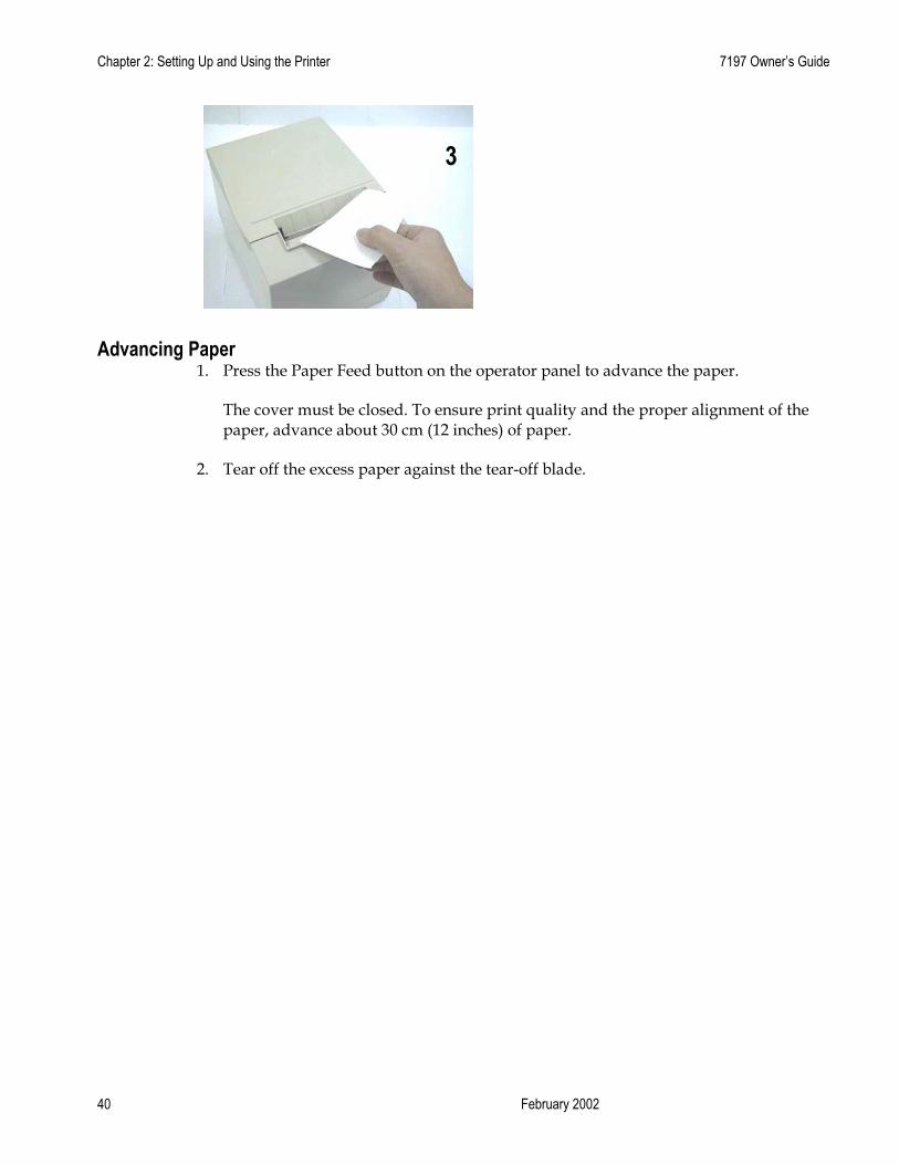
Advancing Paper 1. Press the Paper Feed button on the operator panel to advance the paper.
The cover must be closed. To ensure print quality and the proper alignment of the paper, advance about 30 cm (12 inches) of paper.
2. Tear off the excess paper against the tear-off blade.
3
7197 Owner’s Manual Chapter 3: Solving Problems
November 2002 39
Chapter 3: Solving Problems
The 7197 printer is a simple, generally trouble-free printer, but from time to time minor problems may occur. For example, the power supply may be interrupted or the thermal print head may overheat.
A green LED on the operator panel signals that something may be wrong.
For some problems, the printer communicates the information to the host computer and relies on the application to indicate what the problem is.
The information on the following pages describes some problems that you may encounter: problems that you can easily fix, and others that you will need to contact a service representative for.
You may be able to correct many of the conditions or problems without calling for service. However, if a problem persists, contact a service representative. See “Contacting a Service Representative” at the end of this chapter.

Chapter 3: Solving Problems 7197 Owner’s Guide
DFebruary 2002 40
Green LED Does Not Come On/Printer Will Not Print
Problem What to Do Where to Go Cables may not be connected properly
Check all cable connections. Check that the host computer and power supply are both on (the power supply is turned on by plugging it into an outlet).
See “Connecting the Cables” in chapter 2.
Power supply may be defective If the power supply is plugged in, but does not come on, you will need to order a new power supply.
See “Ordering Other Supplies” in chapter 1.
Green LED Blinking (Slow)
Problem What to Do Where to Go Receipt paper is low* There are about 4 ½ meters, ± 3 meters, (15
feet, ± 10 feet) of paper left. Change the paper soon to avoid running out of paper part way through a transaction.
See “Loading and Changing the Receipt Paper” in chapter 2.
Green LED Blinking (Fast)
Problem What to Do Where to Go Receipt paper is out Change the paper now. Do not run a
transaction without paper as the data may be lost.
See “Loading and Changing the Receipt Paper” in chapter 2.
Receipt cover is open Close the cover. The printer will not operate with the cover open.
Knife failure Open the receipt cover and check the knife. Clear any jammed paper you can see. Tear off any excess paper against the tear-off blade. Contact a service representative if this does not resolve the problem.
See “Contacting a Service Representative” later in this chapter.
AC supply voltage is out of range
If paper is not low and no conditions indicate that the thermal print head is too hot, then it is likely that the power supply voltage is out of range. Contact a service representative if this does not resolve the problem.
See “Contacting a Service Representative” later in this chapter.
7197 Owner’s Manual Chapter 3: Solving Problems
November 2002 41
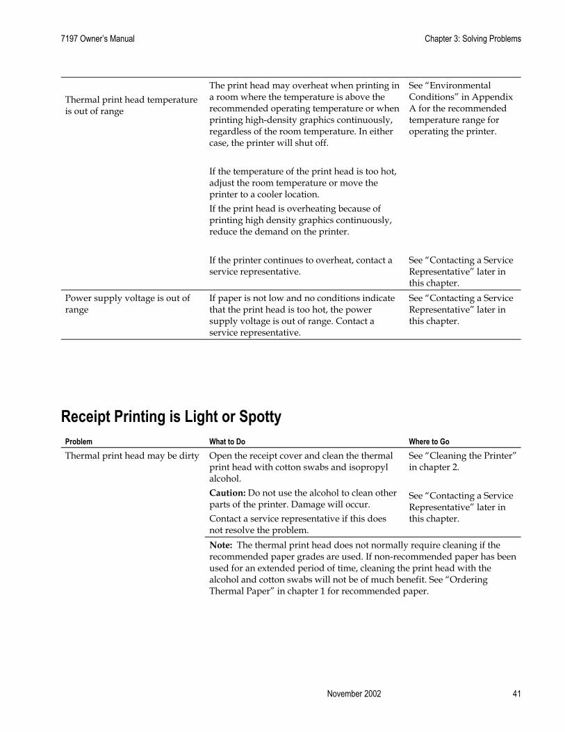
Thermal print head temperature is out of range
The print head may overheat when printing in a room where the temperature is above the recommended operating temperature or when printing high-density graphics continuously, regardless of the room temperature. In either case, the printer will shut off. If the temperature of the print head is too hot, adjust the room temperature or move the printer to a cooler location.
See “Environmental Conditions” in Appendix A for the recommended temperature range for operating the printer.
If the print head is overheating because of printing high density graphics continuously, reduce the demand on the printer. If the printer continues to overheat, contact a service representative.
See “Contacting a Service Representative” later in this chapter.
Power supply voltage is out of range
If paper is not low and no conditions indicate that the print head is too hot, the power supply voltage is out of range. Contact a service representative.
See “Contacting a Service Representative” later in this chapter.
Receipt Printing is Light or Spotty
Problem What to Do Where to Go Thermal print head may be dirty Open the receipt cover and clean the thermal
print head with cotton swabs and isopropyl alcohol. Caution: Do not use the alcohol to clean other parts of the printer. Damage will occur. Contact a service representative if this does not resolve the problem.
See “Cleaning the Printer” in chapter 2. See “Contacting a Service Representative” later in this chapter.
Note: The thermal print head does not normally require cleaning if the recommended paper grades are used. If non-recommended paper has been used for an extended period of time, cleaning the print head with the alcohol and cotton swabs will not be of much benefit. See “Ordering Thermal Paper” in chapter 1 for recommended paper.

Chapter 3: Solving Problems 7197 Owner’s Guide
DFebruary 2002 42
Other Serious Problems The following problems all need to be corrected by a qualified service representative. See the next section, “Contacting a Service Representative.” • Printer will not cycle or stop when required • Illegible characters • Paper will not feed • Knife will not cycle or cut • Printer will not communicate with Host
Contacting a Service Representative For serious problems, such as the printer not printing, not communicating with the host computer, or not turning on, contact your NCR-authorized service organization to arrange for a service call. In addition to the service guide listed below, other service-related materials may be available. Contact your NCR-authorized service representative to obtain the service guide. • 7197 Thermal Receipt Printer: Service Manual (B005-000-1410)
(includes the Troubleshooting Guide and the Preventative Maintenance Guide) • 7197 Thermal Receipt Printer: Parts Identification Manual (B005-000-1411) • 7197 Thermal Receipt Printer: Owners Manual (B005-000-1409)

7197 Owner’s Manual Chapter 3: Solving Problems
November 2002 43

Chapter 4: Diagnostics 7197 Owner’s Guide
DFebruary 2002 44
Chapter 4: Diagnostics
The following diagnostic tests are available for the 7197: • Level 0 Diagnostics (Startup)
Performed during the startup cycle. • Level 1 Diagnostics (Printer Configuration)
Allows configuration of the printer using a Configuration Menu that is printed on a receipt.
• Level 2 Diagnostics (Runtime) The printer checks the status of these conditions during normal operation.
• Level 3 Diagnostics (Remote) The printer keeps track of counters during normal operation.
• Vendor Adjustment Performed in off-line mode. Allows to change settings for mechanical and perform printer test. Modifications of these settings are to be made by service personnel only.
Level 0 Diagnostics The printer automatically performs level 0 diagnostics when it is put on-line. Level 0 diagnostics comprise the following actions: • Motors are turned off. • Microprocessor timing is checked, CRC check of the firmware ROM is performed,
external RAM is read. • The green LED flashes once if this action succeeds. • Level 0 diagnostics stop if this action fails. Failure is indicated by the printer going
dead: knife and print head do not home, LEDs are not lit, the printer is unable to communicate with the host computer.
• Knife is homed. A fault condition is caused if this action fails. • The status of all sensors is checked, and the status bytes are updated.
If the printer has not been turned on before the default values for the printer functions will be loaded into the non volatile memory during level 0 diagnostics. These values can be changed in level 1 diagnostics. See “Level 1 Diagnostics” for the functions and their settings.
When the last step is complete, the Paper Feed button is enabled and the printer is ready for normal operation. Information about the tests is available to the communication interface through the commands.
7197 Owner’s Guide Chapter 4: Diagnostics
November 2002 45
Level 1 Diagnostics Level 1 diagnostics (setup mode) allow you to change the settings for various printer functions and run certain tests.
Keep the following information in mind when changing the settings: • The settings can only be changed when the printer is in level 1 diagnostics (setup
mode): Switch 1 must be set to On and Switch 2 must be set to Off. • The default options are set at the factory and are stored in the history non volatile
memory. • Once the settings have been changed and stored in the non volatile memory, the
diagnostic setup is exited which saves the settings.
Caution: If you are changing the printer settings, be sure they are the correct settings for that particular function or test to avoid accidentally changing the settings for another function or test. If the settings are accidentally changed you must reenter the setup mode and reenter the correct settings. If you need assistance, contact a service representative. See “Contacting a Service Representative” in chapter 3.
Printer Configuration Printers are generally shipped with all appropriate configuration settings pre-set at the factory. The only time the user should need to change the printer configuration is if a new option is installed, communication baud rate or the firmware is changed. It is also possible the user may need to run certain tests using the Configuration Menu.
The user configures the printer using a convenient Configuration Menu that is printed on receipt paper. The Configuration Menu prints instructions and setting options interactively as the user goes through the configuration process. The following functions and parameters can be changed with the scrolling Configuration Menu: • Configuring the Printer • Communication Interface
• Interface Type • Baud Rate • Number of Data Bits • Number of Stop Bits • Parity • Flow Control • Data Reception Errors • Receive Buffer
• Setting Diagnostic Modes • Off, Normal Mode • Datascope Mode • Receipt Test Mode

Chapter 4: Diagnostics 7197 Owner’s Guide
DFebruary 2002 46
• Setting Emulation/Software Options
• Emulation • Printer ID • Default Lines Per Inch • Carriage Return Usage • Asian Mode • Receipt Synchronization
• Setting Hardware Options • Print Density • Maximum Power Option • Paper Low Sensor • Paper Width • Set Knife Option • Color Paper Option
• Setting Default Code Page • Setting EEPROM to default settings
Configuring the Printer Use the Configuration Menu to select functions or change various settings as indicated in the preceding sections. The Configuration Menu prints instructions and setting options interactively as the user goes through the configuration process.
Caution: Be extremely careful in changing any of the printer settings to avoid changing settings that might affect the performance of the printer.
1. Set DIP Switch 1 to On, Switch 2 to Off.
2. Reset the printer while holding the Paper Feed Button, the printer will print the current configuration, then cuts the paper to print the Configuration Menu.
Bottom Cover

7197 Owner’s Guide Chapter 4: Diagnostics
November 2002 47
Press the paper feed for the configuration you want.
Defaults are marked with asterisk (*).
******** Main Menu ******** ******************************* Select a sub-menu: - EXIT -> 1 Click - Print Current Configuration -> 2 Clicks - Set Communication Interface -> 3 Clicks - Set Diagnostics Modes -> 4 Clicks - Set Emulation/Software Options -> 5 Clicks - Set Hardware Options -> 6 Clicks - Set Default Code page -> 7 Clicks - Set EEPROM To Default Settings -> 8 Clicks Enter code, then hold Button DOWN at least 1 second to validate
Chapter 4: Diagnostics 7197 Owner’s Guide
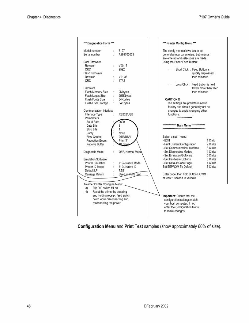
DFebruary 2002 48
Configuration Menu and Print Test samples (show approximately 60% of size).
*** Diagnostics Form *** Model number Serial number Boot Firmware Revision CRC Flash Firmware Revision CRC Hardware Flash Memory Size Flash Logos Size Flash Fonts Size Flash User Storage Communication Interface Interface Type Parameters Baud Rate Data Bits Stop Bits Parity Flow Control Reception Errors Receive Buffer Diagnostic Mode Emulation/Software Printer Emulation Printer ID Mode Default LPI Carriage Return
To enter Printer Configure Menu: 3) Flip DIP switch #1 on 4) Reset the printer by pressing
and holding receipt feed switch down while disconnecting and reconnecting the power.
*** Printer Config Menu *** The config menu allows you to set general printer parameters. Sub-menus are entered and selections are made using the Paper Feed Button:
- Short Click : Feed Button is quickly depressed then released.
- Long Click : Feed Button is held
Down more than 1sec then released.
CAUTION !! The settings are predetermined in factory and should generally not be changed to avoid changing other functions. **************
************* Main Menu ************* ***************************************** Select a sub –menu: - EXIT 1 Click - Print Current Configuration 2 Clicks - Set Communication Interface 3 Clicks - Set Diagnostics Modes 4 Clicks - Set Emulation/Software 5 Clicks - Set Hardware Options 6 Clicks - Set Default Code Page 7 Clicks Set EEPROM To Default 8 Clicks Enter code, then hold Button DOWM at least 1 second to validate
Important: Ensure that the configuration settings match your host computer, if not, enter the Configuration Menu to make changes.
: : : : : : : : : : : : : : : : : : : : : : :
7197 A991703053 V00.17 9592 V01.36 17A5 2Mbytes 256Kbytes 64Kbytes 64Kbytes RS232/USB 9600 8 1 None DTR/DSR Print ‘?’ 4K bytes OFF, Normal Mode 7194 Native Mode 7194 Native ID 7.52 Used as Print Cmd
7197 Owner’s Guide Chapter 4: Diagnostics
November 2002 49
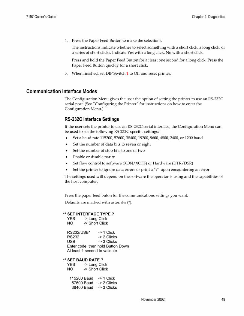
4. Press the Paper Feed Button to make the selections.
The instructions indicate whether to select something with a short click, a long click, or a series of short clicks. Indicate Yes with a long click, No with a short click.
Press and hold the Paper Feed Button for at least one second for a long click. Press the Paper Feed Button quickly for a short click.
5. When finished, set DIP Switch 1 to Off and reset printer.
Communication Interface Modes The Configuration Menu gives the user the option of setting the printer to use an RS-232C serial port. (See “Configuring the Printer” for instructions on how to enter the Configuration Menu.)
RS-232C Interface Settings If the user sets the printer to use an RS-232C serial interface, the Configuration Menu can be used to set the following RS-232C specific settings: • Set a baud rate 115200, 57600, 38400, 19200, 9600, 4800, 2400, or 1200 baud • Set the number of data bits to seven or eight • Set the number of stop bits to one or two • Enable or disable parity • Set flow control to software (XON/XOFF) or Hardware (DTR/DSR) • Set the printer to ignore data errors or print a “?” upon encountering an error
The settings used will depend on the software the operator is using and the capabilities of the host computer.
Press the paper feed buton for the communications settings you want.
Defaults are marked with asterisks (*).
** SET INTERFACE TYPE ?
YES -> Long Click NO -> Short Click RS232/USB* -> 1 Click RS232 -> 2 Clicks USB -> 3 Clicks Enter code, then hold Button Down At least 1 second to validate
** SET BAUD RATE ?
YES -> Long Click NO -> Short Click
115200 Baud -> 1 Click 57600 Baud -> 2 Clicks 38400 Baud -> 3 Clicks

Chapter 4: Diagnostics 7197 Owner’s Guide
DFebruary 2002 50
19200 Baud -> 4 Clicks More -> 5 Clicks Enter code, then hold Button DOWN
At least 1 second to validate 9600 Baud* -> 1 Clicks 4800 Baud -> 2 Clicks 2400 Baud -> 3 Clicks 1200 Baud -> 4 clicks Enter code, then hold Button DOWN At least 1 second to validate
** SET NUMBER OF DATA BITS ?
YES -> Long Click NO -> Short Click 8 Data Bits* -> Long Click 7 Data Bits -> Short Click
** SET NUMBER OF STOP BITS ? YES -> Long Click NO -> Short Click 1 Stop Bits* -> Long Click 2 Stop Bits -> Short Click
** SET PARITY ?
YES -> Long Click NO -> Short Click No Parity* -> 1 Click Even Parity -> 2 Clicks Odd Parity -> 3 Clicks Enter code, then hold Button DOWN At least 1 second to validate
** SET FLOW CONTROL METHOD ?
YES -> Long Click NO -> Short Click Software (XON/XOFF) -> Long Click Hardware (DTR/DSR)* -> Short Click
** SET DATA RECEPTION ERRORS OPTION ? YES -> Long Click NO -> Short Click Ignore Errors -> Long Click Print ‘?’* -> Short Click Note: Press the Paper Feed Button for at least one second to validate the selection.

7197 Owner’s Guide Chapter 4: Diagnostics
November 2002 51
Receive Buffer Size Option This function allows the user to set the buffer size to a single line or a 4 K buffer.
Press the Paper Feed Button for the option you want. ** SET RECEIVE BUFFER SIZE ? YES -> Long Click NO -> Short Click 4K Buffer* -> Long Click One Line -> Short Click
Note: Press the Paper Feed Button for at least one second to validate the selection.
Save Parameters This function allows to save the selected communication settings or return to the communication settings to select additional options.
Press the Paper Feed Button for the option you want. Save new parameters ? YES -> Long Click
NO, MODIFY -> Short Click
Diagnostic Modes This function allows the user to put the printer into the following diagnostic modes: � OFF, Normal Mode: this is the normal operating mode of the printer. � Datascope Mode: the receipt printer prints incoming commands and data in
hexadecimal format. � Receipt Test Mode: the receipt printer prints two code pages.
The diagnostic modes are enabled or disabled by using the Configuration Menu. See “Configuration the Printer,” for instructions on how to enter the Configuration Menu.
Press the Paper Feed Button for the diagnostic mode you want. ** SET DIAGNOSTICS MODE ?
YES -> Long Click NO -> Short Click OFF, Normal Mode* -> 1 Click Data Scope Mode -> 2 Clicks Receipt Test Mode -> 3 Clicks Enter code, then hold Button DOWN At least 1 second to validate Enter code, then hold Button DOWN At least 1 second to validate

Chapter 4: Diagnostics 7197 Owner’s Guide
DFebruary 2002 52
Datascope Mode Datascope Mode allows the user to test the printer’s communications. When in Datascope Mode the printer receives all communications, but instead of executing the commands it prints them out on receipt paper as hexadecimal numbers in the order received. For example, the ASCII character “A” is printed as the hexadecimal number 41 an so on.
To run the Datascope Mode:
1. After you have enabled the Datascope Mode through the Configuration Menu, exit the Configuration Menu.
2. Run a transaction from the host computer.
All commands and data sent from the host computer will be printed as hexadecimal numbers as shown in the illustration.
30 31 32 33 34 35 36 37 38 39 40 41 : 0 1 2 3 4 5 6 7 8 9 @ A 41 42 43 44 45 46 47 48 49 50 51 52 : A B C D E F G H I J K L
To exit the Datascope Mode:
1. Enter the Configuration Menu again
2. Disable the Datascope Mode
3. Exit the Configuration Menu
The printer is in Normal Mode and can communicate with the host computer.
Receipt Test Mode To run the Receipt Test Mode:
1. Enable the Receipt Test Mode through the Configuration Menu. See “Configuring the Printer,” for instructions on how to enter the Configuration Menu.
2. Push Paper Feed Button and the receipt station will print all code pages.
3. The test ends with a cut.
4. Go to step 2 again to repeat this test.
To exit the Receipt Test Mode:
1. Enter the Configuration Menu again.
2. Disable the Receipt Test Mode
3. Exit the Configuration Menu
The printer is in Normal Mode and can communicate with the host computer. Save Parameters
This function allows to save the selected diagnostics modes or return to the diagnostics mode to select additional options.
Press the Paper Feed Button for the option you want.

7197 Owner’s Guide Chapter 4: Diagnostics
November 2002 53
Save Parameters This function allows to save the selected communication settings or return to the communication settings to select additional options.
Press the Paper Feed Button for the option you want. Save new parameters ? YES -> Long Click
NO, MODIFY -> Short Click
Emulation/Software Options
Printer Emulations Printer emulations determine the commands that are available to the printer. They are set by using the Configuration Menu. (See “Configuring the Printer,” for instructions on how to enter the Configuration Menu.). The available options are: • 7194 Mode • 7193 Mode • 7197 Native Mode
Press the Paper Feed Button for the emulation you want. ** SET EMULATION ? YES -> Long Click NO -> Short Click
7194 Mode* -> 1 Click 7193 Mode -> 2 Click 7197 Mode -> 3 Click Enter code, then hold Button DOWN At least 1 second to validate
Note: Press the Paper Feed Button for at least one second to validate the selection.
Printer ID Selections Printer ID Selections determines the print ID that is returned from the printer. This is set by using the Configuration Menu. (See “Configuring the Printer,” for instructions on how to enter the Configuration Menu.). The available options are:
• 7197 Native ID • Emulated Print ID • 7197 Native ID
Press the Paper Feed Button for the emulation you want.

Chapter 4: Diagnostics 7197 Owner’s Guide
DFebruary 2002 54
** SET PRINTER ID MODE ? YES -> Long Click NO -> Short Click
7194 Native ID* -> 1 Click Emulated Printer ID -> 2 Clicks 7167 Native ID -> 3 Clicks Enter code, then hold Button DOWN At least 1 second to validate
Note: Press the Paper Feed Button for at least one second to validate the selection
Default Lines Per Inch This function allows the user to set the default lines per inch printed by the thermal printer to 6, 7.52 or 8.13. (See “Configuring the Printer” for instructions on how to enter the Configuration Menu to change this setting.)
Press the Paper Feed Button for the lines per inch you want.
** SET DEFAULT LINES PER INCH ?
YES -> Long Click NO -> Short Click 8.13 Lines per Inch -> 1 Click 7.52 Lines per Inch* -> 2 Clicks 6 Lines per Inch -> 3 Clicks Enter code, then hold Button DOWN At least 1 second to validate
Note: Press the Paper Feed Button for at least one second to validate the selection.
Carriage Return Usage This function allows the printer to ignore or use the Carriage Return (hexadecimal 0D) command depending on the application. Some applicatons expect the command to be ignored while others use the command as a print command. (See “Configuring the Printer” for instructions on how to enter the Configuration Menu to change this setting.)
Press the Paper Feed Button for the carriage return usage you want. ** SET CARRIAGE RETURN USAGE ? YES -> Long Click NO -> Short Click Ignore CR -> Long Click Use CR as Print Cmd* -> Short Click Note: Press the Paper Feed Button for at least one second to validate the selection.

7197 Owner’s Guide Chapter 4: Diagnostics
November 2002 55
Asian Mode This function makes it possible for the user to select an Asian character for the printer. (See “Configuring the Printer” for instructions on how to enter the Configuration Menu to change this setting.)
Note: For Asian code pages, only one (either 932, 936, 949 or 950) will exist in the firmware.
Press the Paper Feed Button for the asian mode you want. ** SET ASIAN MODE ? YES -> Long Click NO -> Short Click Asian Mode On -> Long Click Asian Mode Off* -> Short Click Note: Press the Paper Feed Button for at least one second to validate the selection.
Receipt Synchronization Mode The standard mode for synchronization allows for verification of each line printed to the host. When the receipt synchronization is disabled the printer will allow for maximum print speed and ignore the verificaiton of each line printed.
Press the Paper Feed Button for the receipt synchronization mode option you want. ** SET RECEIPT SYNCHRONIZATON MODE ? YES -> Long Click NO -> Short Click Enable Receipt Sync.* -> Long Click Disable Receipt Sync. ->Short Click Note: Press the Paper Feed Button for at least one second to validate the selection.
Save Parameters This function allows to save the selected emulations/software settings or return to the emulations/software settings to select additional options.
Press the Paper Feed Button for the option you want. Save new parameters ? YES -> Long Click NO, MODIFY -> Short Click

Chapter 4: Diagnostics 7197 Owner’s Guide
DFebruary 2002 56
Hardware Options
Print Density This function makes it possible to adjust the energy level of the print headto darken the printout. An adjustment should only be made when necessary. The factory setting is 100%.
Warning: Choose an energy level no higher than necessary to achieve a dark printout.
Failure to observe this rule may result in a printer service call or voiding of the printer warranty. Consult your NCR technical support specialist if you have any questions.
Press the Paper Feed Button for the print density you want. ** SET PRINT DENSITY ? YES -> Long Click NO -> Short Click 100 %* -> 1 Click 110 % -> 2 Clicks 120 % -> 3 Clicks Enter code, then hold Button DOWN At least 1 second to validate Note: Press the Paper Feed Button for at least one second to validate the selection.
Maximum Power Option This function allows the user to set the maximum power for the printer to 75W or 55W.
Press the Paper Feed Button for the option you want. ** SET MAX POWER OPTION ? YES -> Long Click NO -> Short Click 55W Power Supply* -> Long Click 75W Power Supply -> Short Click Note: Press the Paper Feed Button for at least one second to validate the selection.

7197 Owner’s Guide Chapter 4: Diagnostics
November 2002 57
Paper Low Sensor Paper Low Sensor makes it possible to enable or disable the paper low sensor for particular printer configurations.
Press the Paper Feed Button for the option you want. ** SET PAPER LOW SENSOR OPTION ? YES -> Long Click NO -> Short Click Enable Paper Low Sensor* -> Long Click Disable Paper Low Sensor -> Short Clicks Note: Press the Paper Feed Button for at least one second to validate the selection.
Paper Width This function allows the user to set the default paper width for the receipt thermal printer to 58mm or 80mm wide.
Press the Paper Feed Button for the paper width option you want. ** SET PAPER WIDTH ? YES -> Long Click NO -> Short Click Paper Width = 80 mm* -> 1 Click Paper Width = 58 mm -> 2 Clicks Enter code, then hold Button DOWN At least 1 second to validate Note: Press the Paper Feed Button for at least one second to validate the selection.
Set Knife Option
Set the Knife option using the configuration menu. Answer No to the questions printed on the receipt until you come to the instructions for knife option.
Caution: Be extremely careful changing any of the printer settings to avoid inadvertently changing other settings that might affect the performance of the printer.
Press the Paper Feed Button for the option you want.
** SET KNIFE OPTION ? YES -> Long Click NO -> Short Click Enable Knife* -> Long Disable Knife -> Short

Chapter 4: Diagnostics 7197 Owner’s Guide
DFebruary 2002 58
Color Paper Option This function allows the user to set the color paper option to Monochrome or Color Paper.
Press the Paper Feed Button for the option you want. ** SET MAX POWER OPTION ? YES -> Long Click NO -> Short Click Monochrome* -> Long Click Color Paper -> Short Click Note: Press the Paper Feed Button for at least one second to validate the selection.
Save Parameters This function allows to save the selected hardware settings or return to the hardware options to select additional options.
Press the Paper Feed Button for the option you want. Save new parameters ? YES -> Long Click
NO, MODIFY -> Short Click
Default Code Page This function makes it possible to select the default code page.
These are the code pages available for printing: • Code page 437 (US English) • Code page 850 (Multilingual) • Code page 852 (Slavic) • Code page 858 (with Euo symbol) • Code page 860 (Portuguese) • Code page 862 (Hebrew) • Code page 863 (French Canadian) • Code page 864 (Arabic) • Code page 865 (Nordic) • Code page 866 (Cyrillic) • Code page 874 (Thai) • Code page 1252 (Windows Latin #1) • Code page Katakana • Code page 932 (MS Japan) • Space page
Note: For Asian code pages, code page 936, 949, or 950 replaces code page 932. Only one Asian code page (either 932, 936, 949, 950) will exist in firmware.
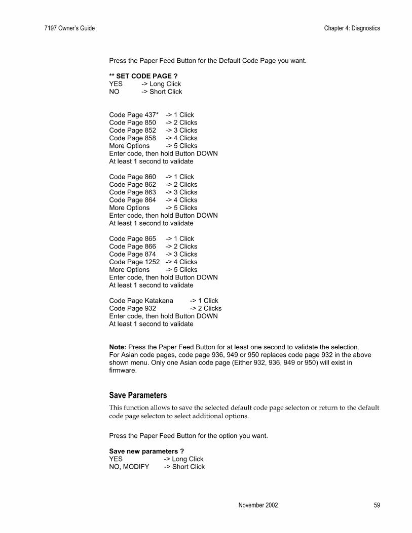
7197 Owner’s Guide Chapter 4: Diagnostics
November 2002 59
Press the Paper Feed Button for the Default Code Page you want. ** SET CODE PAGE ? YES -> Long Click NO -> Short Click Code Page 437* -> 1 Click Code Page 850 -> 2 Clicks Code Page 852 -> 3 Clicks Code Page 858 -> 4 Clicks More Options -> 5 Clicks Enter code, then hold Button DOWN At least 1 second to validate Code Page 860 -> 1 Click Code Page 862 -> 2 Clicks Code Page 863 -> 3 Clicks Code Page 864 -> 4 Clicks More Options -> 5 Clicks Enter code, then hold Button DOWN At least 1 second to validate Code Page 865 -> 1 Click Code Page 866 -> 2 Clicks Code Page 874 -> 3 Clicks Code Page 1252 -> 4 Clicks More Options -> 5 Clicks Enter code, then hold Button DOWN At least 1 second to validate Code Page Katakana -> 1 Click Code Page 932 -> 2 Clicks Enter code, then hold Button DOWN At least 1 second to validate Note: Press the Paper Feed Button for at least one second to validate the selection. For Asian code pages, code page 936, 949 or 950 replaces code page 932 in the above shown menu. Only one Asian code page (Either 932, 936, 949 or 950) will exist in firmware.
Save Parameters This function allows to save the selected default code page selecton or return to the default code page selecton to select additional options.
Press the Paper Feed Button for the option you want. Save new parameters ? YES -> Long Click NO, MODIFY -> Short Click

Chapter 4: Diagnostics 7197 Owner’s Guide
DFebruary 2002 60
EEPROM to Default Settings This selection resets the configuration to the Default Settings.
Caution: Be extremely careful changing any of the printer settings to avoid inadvertently changing other settings that might affect the performance of the printer.
** RESET EEPROM TO DEFAULT VALUES ?
YES -> Long Click
NO -> Short Click
Note: Press the Paper Feed Button for at least one second to validate the selection.
Save Parameters This function allows to save the selected default code page selecton or return to the default code page selecton to select additional options.
Press the Paper Feed Button for the option you want. Save new parameters ? YES -> Long Click
NO, MODIFY -> Short Click
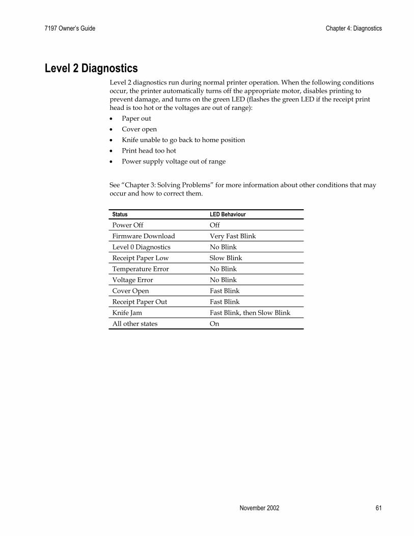
7197 Owner’s Guide Chapter 4: Diagnostics
November 2002 61
Level 2 Diagnostics Level 2 diagnostics run during normal printer operation. When the following conditions occur, the printer automatically turns off the appropriate motor, disables printing to prevent damage, and turns on the green LED (flashes the green LED if the receipt print head is too hot or the voltages are out of range): • Paper out • Cover open • Knife unable to go back to home position • Print head too hot • Power supply voltage out of range
See “Chapter 3: Solving Problems” for more information about other conditions that may occur and how to correct them.
Status LED Behaviour
Power Off Off Firmware Download Very Fast Blink Level 0 Diagnostics No Blink Receipt Paper Low Slow Blink Temperature Error No Blink Voltage Error No Blink Cover Open Fast Blink Receipt Paper Out Fast Blink Knife Jam Fast Blink, then Slow Blink All other states On
Chapter 4: Diagnostics 7197 Owner’s Guide
DFebruary 2002 62
Level 3 Diagnostics Level 3 diagnostics keeps track of the following tallies and prints them on the receipt during the receipt test. • Serial number • Model number • CRC number • Number of receipt lines printed • Number of knife cuts • Number of hours printer is on • Number of flash cycles • Maximum temperature reached • Number of cutter jams • Number of times the door is open

7197 Owner’s Guide Chapter 4: Diagnostics
November 2002 63
7197 Owner’s Manual Chapter 5: Communications
November 2002 61
Chapter 5: Communication
Communication Overview In order for a receipt to be printed, a program must be in place that translates the data from the host computer into a language that the printer can understand. This program must tell the printer exactly how to print each character. This chapter describes how to create such a program or modify an existing one.
Interface In order for the printer to communicate with the host, a communication link must be set up. The 7197 supports the industry standard RS-232C communication interface. This interface has a protocol associated with it that the host computer must understand and adhere. The priner also supports USB communications.
Only when the interface parameters are matched and the proper protocol is used will the host and the printer be able to communicate. See the section, “RS-232C Interface” on the next page for a description of the protocol associated with the RS-232C interface.
Sending Commands Once the communication link is established, commands can be sent to the printer. This section describes how to send commands to the printer using DOS and BASIC. This section does not take into account the necessary protocol, but is meant as a general introduction to how the printer functions.
Using DOS to Send Commands One way of getting commands to the printer is to send them directly from DOS. For example, the command COPY CON: COM1:
This sets the computer up such that the Hex code corresponding to any key that was pressed would be sent to the RS-232C communication port COM1 when the COPY mode is exited. If the printer is connected to COM1, then the data will go to the printer.
Exit the COPY mode by typing CTRL Z
and then pressing the ENTER key. This directs the data from any print command to the proper port, commands can be sent from any software program.

Chapter 5: Communications 7197 Owner’s Guide
February 2002 62
Using BASIC to Send Commands In BASIC, printer commands are sent as a string of characters preceded by the LPRINT command. For example, LPRINT CHR$(&H0A)
sends the hexadecimal number 0A to the printer, which causes the printer to print the contents of its print buffer. Previously sent commands tell the printer exactly how this data should appear on the paper. For example, LPRINT CHR$(&H12); "ABC"; CHR$(&H0A)
sends the Hex numbers 12 41 42 43 0A to the printer. This causes the printer to set itself to double wide mode (12), load the print buffer with “ABC” (41 42 43), and finally, print (0A). Again, the communication link that the BASIC program outputs to must be matched to that of the printer.
RS-232C Interface The RS-232C interface uses either XON/XOFF or DTR/DSR protocol. For XON/XOFF, a particular character is sent back and forth between the host and the printer to regulate the communication. For DTR/DSR, changes in the DTR/DSR signal coordinate the data flow.
The RS-232C version of the 7197 offers the standard options which are selectable in the Diagnostic mode. See “Diagnostics: Communications Interface Settings” later in this book.
Print Speed and Timing The fast speed of the printer requires the application to send data to the printer at least as fast as it is printed. This application must also allow receipt lines to be buffered ahead at the printer, so the printer can print each line immediately after the preceding line, without stopping to wait for more data. Ideally, the application will send all the data for an entire receipt without pausing between characters or lines transmitted.
If the application sends data at 9600 baud and pauses between lines for as little as 50 milliseconds, the printer will never be able to print at full speed. But, if the application sends data at 19.2 K baud and does not pause between lines, the printer will be able to print at its full speed of 1020 lines/minute.
The table shows that with a pause of 50 milliseconds after each line, the transmit time equals or exceeds the print time, slowing down the printer, regardless of the baud rate.
Char./Line Lines/Receipt Transmit Time: (9600 Baud) Transmit Time: (19.2 K Baud) Print Time 20 20 1.4 Seconds 1.2 Seconds 1.2 Seconds 20 40 2.8 Seconds 2.4 Seconds 2.4 Seconds 44 20 1.88 Seconds 1.44 Seconds 1.2 Seconds 44 40 3.76 Seconds 2.88 Seconds 2.4 Seconds
The next table shows that with no delay between lines, the transmit time is much less than the print time, allowing the printer to print at full speed.
Char./Line Lines/Receipt Transmit Time: (9600 Baud) Transmit Time: (19.2 K Baud) Print Time 20 20 0.4 Seconds 0.2 Seconds 1.2 Seconds 20 40 0.8 Seconds 0.4 Seconds 2.4 Seconds 44 20 0.88 Seconds 0.44 Seconds 1.2 Seconds 44 40 1.76 Seconds 0.88 Seconds 2.4 Seconds

7197 Owner’s Manual Chapter 5: Communications
November 2002 63
XON/XOFF Protocol The XON/XOFF characters coordinate the information transfer between the printer and the host computer. The printer sends an XON character when it is ready to receive data and it sends an XOFF character when it cannot accept any more data. The software on the host computer must monitor the communication link as shown in the following flowchart in order to send data at the appropriate times.
If XON/XOFF has been selected, the printer also toggles the DTR signal, as described in the next section, but it does not look at the DSR signal to transmit data.
XON character = Hex 11.
XOFF character = Hex 13.
DTR/DSR Protocol The DTR signal is used to control data transmission to the printer. It is driven low when the printer is ready to recieve data and driven high when it cannot accept any more data. Data is transmitted from the printer after it confirms that the DSR signal is low.
RS-232C Technical Specifications This section describes the pin settings for the connectors and the RS-232C interface parameters. The RS-232C parameters are selectable in the Diagnostic mode. See “Diagnostics: Communications Interface Settings” in chapter 4 for the position of the DIP switches. The RS-232C parameters must match those of the host.

Chapter 5: Communications 7197 Owner’s Guide
February 2002 64
RS 232 Connector The illustration shows the RS-232C communication connector and pin assignments. The connector is a 9-pin male D-shell connector and is located in the hollow cavity under the printer at the rear.
DC Power Connector The illustration shows the power cable connector and pin assignments. The power cable connector is a 3-pin DIN plug and is located in the hollow cavity under the printer at the rear.
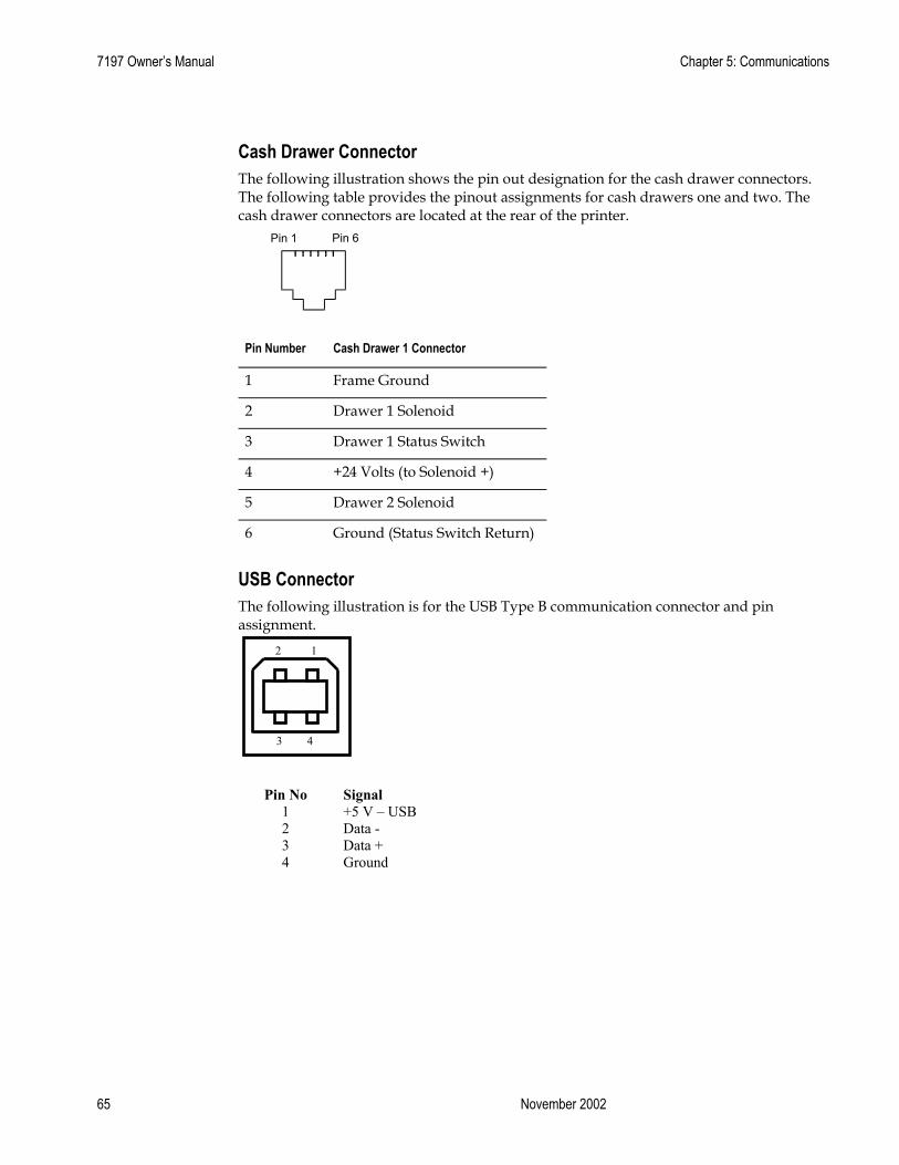
7197 Owner’s Manual Chapter 5: Communications
November 2002 65
Cash Drawer Connector The following illustration shows the pin out designation for the cash drawer connectors. The following table provides the pinout assignments for cash drawers one and two. The cash drawer connectors are located at the rear of the printer.
Pin 1 Pin 6
Pin Number Cash Drawer 1 Connector
1 Frame Ground
2 Drawer 1 Solenoid
3 Drawer 1 Status Switch
4 +24 Volts (to Solenoid +)
5 Drawer 2 Solenoid
6 Ground (Status Switch Return)
USB Connector The following illustration is for the USB Type B communication connector and pin assignment.
Pin No Signal
1 +5 V – USB 2 Data - 3 Data + 4 Ground
1 2
3 4

Chapter 5: Communications 7197 Owner’s Guide
February 2002 66
Switch Settings The DIP switches are located on the PC board at the back of the printer as shown in the illustration in “Level 1 Diagnostics” in chapter 4.
The switches are used to put the printer into various modes for printer configuration set up.
Use a paper clip or other pointed object to set the switches.
1. Set the switches to the desired settings shown in the table.
Caution: Do not set switch 1 to On. Setting switch 1 to On puts the printer in level 1 diagnostics (setup mode) where other functions and tests can be changed.
DIP Switch Settings Switch 1 Setting
Switch 2 Setting Printer State
OFF (0) OFF (0)
On-line Mode (default)
ON(1) OFF (0)
Diagnostic Mode
OFF (0) ON (1)*
Flash Download Mode
ON (1) ON (1)
Vendor Adjustment Mode
* It is optional to set this switch to ON when reflashing the IPL firmware.
Printer End View
7197 Owner’s Manual Chapter 5: Communications
November 2002 67
Setting Extra RS-232C Options The following extra options are available for the RS-232C Interface: • Data errors
• Print “?” for data errors (default) • Ignore data errors

Chapter 5: Communications 7197 Owner’s Guide
February 2002 68


7197 Owner’s Guide Chapter 6: Commands
November 2002 67
Chapter 6: Commands
Command Conventions
Introduction The different features and functions provided by the printer are controlled by sending commands from the host computer to the printer. This section describes the commands that are supported by the printer. The printer commands are made up of one or more bytes of data starting with a command control code followed by its supporting parameters.
Commands control all operations and functions of the printer. This includes selecting the size and placement of characters and graphics on the receipt or the slip and feeding and cutting the paper. Unless otherwise noted, any of the commands may be used in any combination to communicate with the printer from a program in a host computer.
In order to allow the graceful handling of commands that may be available in other printers but are not available in this printer, some commands will be listed and described but identified as "not implemented." If the printer receives one of these "not implemented" commands, the command and its supporting operands will be discarded. Any other data bytes, including unrecognized commands, are sent to the print buffer as data, and the printer will attempt to print the data when it is instructed to print the buffer.
List of Commands and Location This section presents groups of lists of the hexadecimal command codes, parameters, and the command names. A page reference is provided for the page on which the command is more fully described. If this document is being viewed online, the page reference will be linked to the actual page and may clicked to go to that page.
The first section lists all of the commands. The following lists are separated into functional category groupings.
All commands listed in bold are new or have additional functionality when compared to the NCR 7193.

Chapter 6: Commands 7197 Owner’s Guide
February 2002 68
By Command Code All items in BOLD are new or have additional functionality when compared to the 7193. Code (Hexadecimal) Command Page 09 (HT) Horizontal Tab 92
0A (LF) Print and Feed Paper One Line 86
0C (FF) Print and Return to Standard Mode 152
0D (CR) Print and Carriage Return 86
10 Clear Printer 80
10 04 n Real Time Status Transmission (DLE Sequence) 139
10 05 n Real Time Request to Printer (GS Sequence) 141
11 n1... nk Print Raster Graphics 80
12 Select Double-Wide Characters 100
13 Select Single-Wide Characters 100
14 n Feed n Print Lines 87
15 n Feed n Dot Rows 87
16 n Add n Extra Dot Rows 88
17 Print 88
18 Cancel Print Data in Page Mode 153
19 Perform Full Knife Cut 81
1A Perform Partial Knife Cut 81
1B (+ *.bmp) Download BMP Logo 116
1B 07 Generate Tone 82
1B 0C Print Data in Page Mode 153
1B 12 Select 90 Degree Counter-Clockwise Rotated Print
100
1B 14 n Set Column 92
1B 16 n Select Pitch (Column Width) 101
1B 20 n Set Character Right-Side Spacing 102
1B 21 n Select Print Modes 103
1B 24 n1 n2 Set Absolute Starting Position 93
1B 25 n Select or Cancel User-Defined Character Set 104
1B 26 3 c1 c2…dn Define User-Defined Characters 104
1B 27 m a0 a1 a2 d1 … dm
Write to User Data Storage 162
1B 2A m n1 n2
d1 … dn
Select Bit Image Mode 116

7197 Owner’s Guide Chapter 6: Commands
November 2002 69
Code (Hexadecimal) Command Page 1B 2D n Select or Cancel Underline Mode 105
1B 2E m n rl rh d1…dn Print Advanced Raster Graphics 119
1B 32 Set Line Spacing to 1/6 Inch 89
1B 33 n Set Line Spacing 89
1B 34 m a0 a1 a2 Read from User Data Storage 162
1B 3A 30 30 30 Copy Character Set from ROM to RAM 106
1B 3F n Cancel User-defined Characters 106
1B 40 Initialize Printer 82 1B 44 [n] k 00 Set Horizontal Tabs 94 1B 45 n Select or Cancel Emphasized Mode 107 1B 47 Select Double Strike (7193 Emulation) 107 1B 49 n Set or Cancel Italic Print 108 1B 4A n Print and Feed Paper 90 1B 4C Select Page Mode 154 1B 52 n Select International Character Set 109 1B 53 Select Standard Mode 155 1B 54 n Select Print Direction in Page Mode 156 1B 56 n Select or Cancel 90 Degrees Clockwise Rotated 110 1B 57 n1, n2,…n8 Set Printing Area in Page Mode 157 1B 59 n1 n2 d1…dn Select Double Density Graphics 119 1B 5B 7D Switch to Flash Download Mode 174 1B 5C n1 n2 Set Relative Print Position 95 1B 61 n Select Justification 96 1B 63 34 n Select Sensors to Stop Printing 83 1B 63 35 n Enable or Disable Panel Buttons 83 1B 64 n Print and Feed n Lines 91 1B 69 Perform Full Knife Cut 81 1B 6A k Read from Non-Volatile Memory 163 1B 6D Perform Partial Cut 81 1B 70 n p1 p2 Generate Pulse to Open Cash Drawer 84 1B 72 n Select Print Color 110 1B 73 n1 n2 k Write to Non-Volatile Memory (NVRAM) 163 1B 74 n Select International Character Set 109 1B 75 0 Transmit Peripheral Device Status 127 1B 76 Transmit Paper Sensor Status 127 1B 7B n Select or Cancel Upside Down Printing Mode 110 1C 21 n Select print modes for Kanji characters 170 1C 2D n Turn underline mode ON/OFF for Kanji 171 1C 32 c1 c2 d1…dn Define user-defined Kanji characters 171

Chapter 6: Commands 7197 Owner’s Guide
February 2002 70
Code (Hexadecimal) Command Page
1C 53 n1 n2 Set Kanji character spacing 172 1c 57 n Set quadruple mode ON/OFF for Kanji 173 1D 00 Request Printer ID 174 1D 01 Return Segment Number Status of Flash
Memory 175
1D 02 n Select Flash Memory Sector to Download 175 1D 03 n Real Time Request to Printer (DLE Sequence) 141 1D 04 n Real Time Status Transmission (GS Sequence) 139 1D 05 Real Time Printer Status Transmission 142 1D 06 Get Firmware CRC 176 1D 07 Return Microprocessor CRC 176 1D 0E Erase the Flash Memory 177 1D 0F Return Main Program Flash CRC 177 1D 10 n Erase Selected Flash Sector 178 1D 11 al ah cl ch d1…dn Download to Active Flash Sector 179 1D 21 n Select Character Size 111 1D 22 n Select Memory Type (SRAM/Flash) Where to
Save Logos or User-Defined Fonts 164
1D 22 55 n1 n2 Flash Allocation 165 1D 23 n Select the Current Logo (Downloaded Bit
Image) 121
1D 24 nL nH Set Absolute Vertical Print Position in Page Mode
158
1D 2A n1 n2 d1…dn] Define Downloaded Bit Image 122 1D 2F m Print Downloaded Bit Image 123 1D 3A Start or End Macro Definition 160 1D 40 n Erase User Flash Sector 166 1D 42 n Select or Cancel White/Black Reverse Print
Mode 113
1D 48 n Select Printing Position for HRI Characters 146 1D 49 n Transmit Printer ID 129 1D 49 40 n Transmit Printer ID, Remote Diagnostics
Extension 130
1D 4C nL nH Set Left Margin 97 1D 50 x y Set Horizontal and Vertical Minimum Motion
Units 91
1D 56 m Select Cut Mode and Cut Paper 84 1D 56 m n Select Cut Mode and Cut Paper 84 1D 57 nL nH Set Printing Area Width 98 1D 5C nL nH Set Relative Vertical Print Position in Page
Mode 159
1D 5E r t m Execute Macro 161

7197 Owner’s Guide Chapter 6: Commands
November 2002 71
Code (Hexadecimal) Command Page
1D 61 n Select or Cancel Automatic Status Back 143 1D 66 n Select Pitch for HRI Characters 147 1D 68 n Select Bar Code Height 147 1D 6B m d1… Print Bar Code 148 1D 6B m n d1…dn Print Bar Code 148 1D 72 n Transmit Status 131 1D 77 n Select Bar Code Width 151 1D FF Reboot the Printer 180 1F 04 n Convert 6 Dots/mm Bitmap to 8 Dots/mm
Bitmap 125
1F 05 n Select Superscript or Subscript Modes 113 IF 11 [m n],[m n]…[m n] 0FFH
Printer Setting Change 167
1F 56 Send Printer Software Version 135 1F 74 Print Test Form 85

Chapter 6: Commands 7197 Owner’s Guide
February 2002 72
By Function All items in BOLD are new or have additional functionality when compared to the 7193.
Printer Function Commands
Code (Hexadecimal) Command Page 10 Clear Printer 80
19 or 1B 69 Perform Full Knife Cut 81
1A or 1B 6D Perform Partial Knife Cut 81
1B 07 Generate Tone 82
1B 40 Initialize Printer 82
1B 63 34 n Select Sensors to Stop Printing 83
1B 63 35 n Enable or Disable Panel Buttons 83
1B 70 n p1 p2 Generate Pulse to Open Cash Drawer 84
1D 56 m Select Cut Mode and Cut Paper 84
1D 56 m n Select Cut Mode and Cut Paper 84
1F 74 Print Test Form 85
Vertical Positioning and Print
Code (Hexadecimal) Command Page 0A Print and Feed Paper One Line 86
0D Print and Carriage Return 86
14 n Feed n Print Lines 87
15 n Feed n Dot Rows 87
16 n Add n Extra Dot Rows 88
17 Print 88
1B 32 Set Line Spacing to 1/6 Inch 89
1B 33 n Set Line Spacing 89
1B 4A n Print and Feed Paper 90
1B 64 n Print and Feed n Lines 91
1D 50 x y Set Horizontal and Vertical Minimum Motion Units
91

7197 Owner’s Guide Chapter 6: Commands
November 2002 73
Horizontal Positioning Commands
Code (Hexadecimal) Command Page 09 Horizontal Tab 92
1B 14 n Set Column 92
1B 24 n1 n2 Set Absolute Starting Position 93
1B 44 [n] k 00 Set Horizontal Tabs 94
1B 5C n1 n2 Set Relative Print Position 95
1B 61 n Select Justification 96
1D 4C nL nH Set Left Margin 97
1D 57 nL nH Set Printing Area Width 98
Print Characteristic Commands
Code (Hexadecimal) Command Page 12 Select Double-Wide Characters 100
13 Select Single-Wide Characters 100
1B 12 Select 90 Degree Counter-Clockwise Rotated Print 100
1B 16 n Select Pitch (Column Width) 101
1B 20 n Set Character Right-Side Spacing 102
1B 21 n Select Print Modes 103
1B 25 n Select or Cancel User-Defined Character Set 104
1B 26 s c1 c2 d1…dn Define User-Defined Characters 104
1B 2D n Select or Cancel Underline Mode 105
1B 3A 30 30 30 Copy Character Set from ROM to RAM 106
1B 3F n Cancel User-Defined Characters 106
1B 45 n Select or Cancel Emphasized Mode 107
1B 47 n Select Double Strike 107
1B 49 n Select or Cancel Italic Print 108
1B 52 n Select International Character Set 109
1B 56 n Select or Cancel 90 Degrees Clockwise Rotated Print
110
1B 72 n Select Print Color 110
1B 74 n Select International Character Set 109
1B 7B n Select or Cancel Upside Down Printing Mode 110
1D 21 n Select Character Size 111

Chapter 6: Commands 7197 Owner’s Guide
February 2002 74
Code (Hexadecimal) Command Page 1D 42 n Select or Cancel White/Black Reverse Print
Mode 113
1F 05 n Select Superscript or Subscript Modes 113
Graphics Commands
Code (Hexadecimal) Command Page 11 n1 ... nk Print Raster Graphics 116
1B (+*.bmp) Download BMP Logo 116
1B 2A m n1 n2 d1…dn Select Bit Image Mode 116
1B 2E m n rl rh d1…dn Advanced Raster Graphics 119
1B 4B n1 n2 d1…dn Select Single-Density Graphics 119
1B 59 n1 n2 d1…dn Select Double-Density Graphics 119
1D 23 n Select Current Logo (Downloaded Bit Image) 121
1D 2A n1 n2 d1…dn] Define Downloaded Bit Image 122
1D 2F m Print Downloaded Bit Image 123
1F 04 n Convert 6 Dots/mm Bitmap to 8 Dots/mm Bitmap
125
Status Commands Batch Mode
Code (Hexadecimal) Command Page 1B 75 0 Transmit Peripheral Device Status 127 1B 76 Transmit Paper Sensor Status 127 1D 49 n Transmit Printer ID 129 1D 49 40 n Transmit Printer ID, Remote Diagnostics
Extension 130
1D 72 n Transmit Status 131 1F 56 n Send Printer Software Version 135
Real Time Commands
Code (Hexadecimal) Command Page 10 04 n Real Time Status Transmission (DLE Sequence) 139
10 05 n Real Time Request to Printer (GS Sequence) 141
1D 03 n Real Time Request to Printer (DLE Sequence) 141

7197 Owner’s Guide Chapter 6: Commands
November 2002 75
1D 04 n Real Time Status Transmission (GS Sequence) 139
1D 05 Real Time Printer Status Transmission 142
Auto Status Back Commands
Code (Hexadecimal) Command Page 1D 61 n Select or Cancel Auto Status Back 142
Barcode Commands
Code (Hexadecimal) Command Page 1D 48 n Select Printing Position for HRI Characters 146
1D 66 n Select Pitch for HRI Characters 147
1D 68 n Select Bar Code Height 147
1D 6B m d1…dk 00
or
1D 6B m n d1…dn
Print Bar Code 148
1D 77 n Select Bar Code Width 151
Page Mode Commands Code (Hexadecimal) Command Page 0C Print and Return to Standard Mode 152
18 Cancel Print Data in Page Mode 153
1B 0C Print Data in Page Mode 153
1B 4C Select Page Mode 154
1B 53 Select Standard Mode 155
1B 54 n Select Print Direction in Page Mode 156
1B 57 n1, n2…n8] Set printing Area in Page Mode 157
1D 24 nL nH Set Absolute Vertical Print Position in Page Mode
158
1D 5C nL nH Set Relative Vertical Print Position in Page Mode
159
Macro Commands Code (Hexadecimal) Command Page 1D 3A Start or End Macro Definition 160
1D 5E r t m Execute Macro 161

Chapter 6: Commands 7197 Owner’s Guide
February 2002 76
User Data Storage Commands Code (Hexadecimal) Command Page 1B 27 m addr d1…dm Write to User Data Storage 162
1B 34 m addr Read from User Data Storage 162
1B 6A k Read from Non-Volatile Memory 163
1B 73 n1 n2 k Write to Non-Volatile Memory (NVRAM) 163
1D 22 n Select Memory Type (SRAM/Flash) Where to Save Logos or User-Defined Fonts
164
1D 22 55 n1 n2 Flash Allocation 165
1D 40 n Erase User Flash Sector 166
IF 11 [m n],[m n]…[m n] 0FFH
Printer Setting Change 167
Asian Character Commands Code (Hexadecimal) Command Page
1C 21 n Select print modes for Kanji characters 170
1C 2D n Turn underline mode ON/OFF for Kanji 171
1C 32 c1 c2 d1…dn
Define user-defined Kanji characters 171
1C 53 n1 n2 Set Kanji character spacing 172
1c 57 n Set quadruple mode ON/OFF for Kanji 173
Flash Download Commands Code (Hexadecimal) Command Page 1B 5B 7D Switch to Flash Download Mode 174
1D 00 Request Printer ID 174
1D 01 Return Segment Number Status of Flash Memory 175
1D 02 n Select Flash Memory Sector to Download 175
1D 06 Get Firmware CRC 176
1D 07 Return Microprocessor CRC 176
1D 0E Erase the Flash Memory 177
1D 0F Return Main Program Flash CRC 177
1D 10 n Erase Selected Flash Sector 178
1D 11 aL aH cL cH d1…dn
Download to Active Flash Sector 179
1D FF Reboot the Printer 180

7197 Owner’s Guide Chapter 6: Commands
November 2002 77
Comparison Chart The following table details the list of commands whose behavior differs from the 7193 and the 7197 because of the physical differences of a 6 dots/mm head (7193) versus an 8 dots/mm head (7197).
Command Description Difference between 7193 and 7197
configured in 7193 Emulation Mode.
15 n Feed n Dot Rows This command will move the paper on the receipt in n/203 inch steps instead of n/152 inch steps.
16 n Add n Extra Dot Rows The dot rows will be measured in n/203 inches versus n/152 inches.
1B 20 n Set Right-Side Character Spacing
This command sets the right side spacing to “n” horizontal motion units. By default, these units are in terms of 1/203 inches versus 1/152 inches.
1B 24 n1 n2 Set Absolute Starting Position For graphics commands, the position is scaled to best 7193. In text mode, the equivalent character position is calculated.
1B 26 s c1 c2 n1 d1...nn dn]
Define User-Defined Character Set
Since the dots on the 7197 print head are smaller, user-defined characters that were used on the previous printer will appear smaller on the 7197 printer.
1B 2A m n1 n2 d1...dn Select Bit Image Mode In 7193 Emulation Mode, graphics are scaled to best match the size of the graphic in the 7193 printer.
1B 33 n Set Line Spacing This command uses n in terms of n/360 inches. Since the 7193 had a fundamental step of 1/152 inch and the 7197 has a fundamental step of 1/203 inch, the actual line spacing will not exactly match the requested spacing.
1B 4A n Print and Feed Paper (Same as above) 1B 59 n1 n2 d1...dn Select Double-Density In 7193 Emulation Mode, the

Chapter 6: Commands 7197 Owner’s Guide
February 2002 78
Command Description Difference between 7193 and 7197 configured in 7193 Emulation Mode.
Graphics printer scales the graphics to provide the best match.
1B 5C n1 n2 Set Relative Print Position The parameter to this command is in units of dots. However, the command moves and aligns to character positions. In 7193 Emulation Mode, this command calculates how many character positions to move based on the 7193 character width in dots (10) versus the 7197 (13).
1B 61 n Select Justification This command does true dot resolution alignment for centering versus character-aligned centering.
1D 2A n1 n2 d1...dn] Define Downloaded Bit Image
In 7193 Emulation Mode, this command scales the incoming data to provide a best match to the size of the image as it printed on 7193.
1D 2F m Print Downloaded Bit Image (Same as above)

7197 Owner’s Guide Chapter 6: Commands
November 2002 79
Command Descriptions This section provides the detailed description of the commands. These commands are separated into groups according to their function or use. The previous sections can be used as an index for the following sections.
The following lists and describes the headings used to present the elements of the commands in the descriptions in this section. Each command code is presented in three formats: ASCII, hexadecimal, and decimal. Choose the format that best suits the programming implementation. The printer interprets the 8-bit bytes it gets through its communication interface; it does not care what format the program lists them in.
Name: Name of Command
ASCII: The ASCII representation of the command control code followed by its operands.
Hexadecimal: The hexadecimal representation of the command control code followed by its operands.
Decimal: The decimal representation of the command control code followed by its operands.
Operand n: A description of the command operand. Other command operands may be m, p1, p2, x, or y.
Range of n: The upper and lower limits or list of possible values of the command operand. The values are listed as decimal values unless specified otherwise.
Default of n: The command operand default value after printer reset or startup.
Description: A brief description of the use of the command.
Formulas: Any formulas used for this command.
Example: Coding example of how to send the command in Visual Basic. This code assumes we are doing output to an opened and ready device called "MSCOMM1." The examples use the hexadecimal command code formats; the ASCII or decimal formats could also be used in VB. In commands that use an operand, a specific value is used, and the result of using the selected value for the operand is described.
Exceptions: Describes any exceptions to this command, e.g., incompatible

Chapter 6: Commands 7197 Owner’s Guide
February 2002 80
commands.
Related Information:
Describes related information for this command, e.g., bit information.
Printer Function Commands The printer function commands control the following basic printer functions and are described in order of their hexadecimal codes:
1. Resetting the printer
2. Cutting the paper
3. Opening the cash drawers
Clear Printer ASCII: DLE
Hexadecimal: 10
Decimal: 16
Clears the print line buffer without printing and sets the printer to the following condition:
1. Double-Wide command (0x12) is cancelled
2. Line Spacing, Pitch, and User-Defined Character Sets are maintained at current selections (RAM is not affected)
3. Single-Wide, Single-High, Non-Rotated, and Left-Aligned characters are set
4. Printer is restarted and error status is cleared if a fault condition existed
5. Printing position is set to column one
6. Knife is homed • Example: • MSComm1.Output = Chr$(&H10) Exceptions: A DLE command followed by an 04 or 05 is interpreted as a “real time command”. (See Real Time commands)
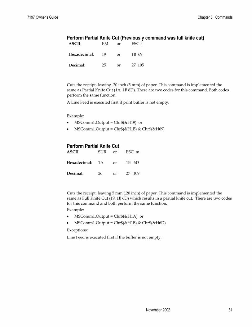
7197 Owner’s Guide Chapter 6: Commands
November 2002 81
Perform Partial Knife Cut (Previously command was full knife cut) ASCII: EM or ESC i
Hexadecimal: 19 or 1B 69
Decimal: 25 or 27 105
Cuts the receipt, leaving .20 inch (5 mm) of paper. This command is implemented the same as Partial Knife Cut (1A, 1B 6D). There are two codes for this command. Both codes perform the same function.
A Line Feed is executed first if print buffer is not empty.
Example: • MSComm1.Output = Chr$(&H19) or • MSComm1.Output = Chr$(&H1B) & Chr$(&H69)
Perform Partial Knife Cut ASCII: SUB or ESC m
Hexadecimal: 1A or 1B 6D
Decimal: 26 or 27 109
Cuts the receipt, leaving 5 mm (.20 inch) of paper. This command is implemented the same as Full Knife Cut (19, 1B 6D) which results in a partial knife cut. There are two codes for this command and both perform the same function. Example: • MSComm1.Output = Chr$(&H1A) or • MSComm1.Output = Chr$(&H1B) & Chr$(&H6D)
Exceptions:
Line Feed is executed first if the buffer is not empty.

Chapter 6: Commands 7197 Owner’s Guide
February 2002 82
Generate Tone ASCII: ESC BEL
Hexadecimal: 1B 07
Decimal: 27 7
Generates an audible tone. This allows the application to provide an audiable tone to the operator. Example: • MSComm1.Output = Chr$(&H1B) & Chr$(&H07)
Initialize Printer ASCII: ESC @
Hexadecimal: 1B 40
Decimal: 27 64
Default:
Character Pitch 15.6 CPI
Column Width 44 characters (80mm) 32 characters (58mm)
Extra Dot Rows 2
Character Set Code Page 437
Printing Position Column One
Clears the print line buffer and resets the printer to the default settings for the startup configuration (refer to Default settings above.)
Single-Wide, Single-High, Non-Rotated, and Left-Aligned characters are set and User-defined characters or logo graphics are cleared (Flash Memory is not affected). Tabs reset to default.
Example: • MSComm1.Output = Chr$(&H1B) & Chr$(&H40)

7197 Owner’s Guide Chapter 6: Commands
November 2002 83
Select Sensors to Stop Printing ASCII: ESC c 4 n
Hexadecimal: 1B 63 34 n
Decimal: 27 99 52 n
Value of n :
Bit Function 0, 1 Stop Receipt on Receipt Low
2 - 7 Undefined
Default: 0
Determines which sensor stops printing on the receipt station. The command does not affect the paper out sensor on the receipt station, which will automatically stop the printer when the paper is depleted. Example: • MSComm1.Output = Chr$(&H1B) & Chr$(&H63) & Chr$(&H34) & Chr$(n)
Enable or Disable Panel Buttons ASCII: ESC c 5 n
Hexadecimal: 1B 63 35 n
Decimal: 27 99 53 n
Value of n : 0 = Enable
1 = Disable
Default: 0 (Enable)
Enables or disables the Paper Feed Button. If the last bit is 0, the Paper Feed Button is enabled. If the last bit is 1, the Paper Feed Button is disabled so pressing the paper feed button will result in no response. Example: • MSComm1.Output = Chr$(&H1B) & Chr$(&H63) & Chr$(&H35) & Chr$(n)
Related Information:
Functions that require using the Paper Feed Button (except for the Execute Macro [1D 5E] command) cannot be used when it is disabled with this command.
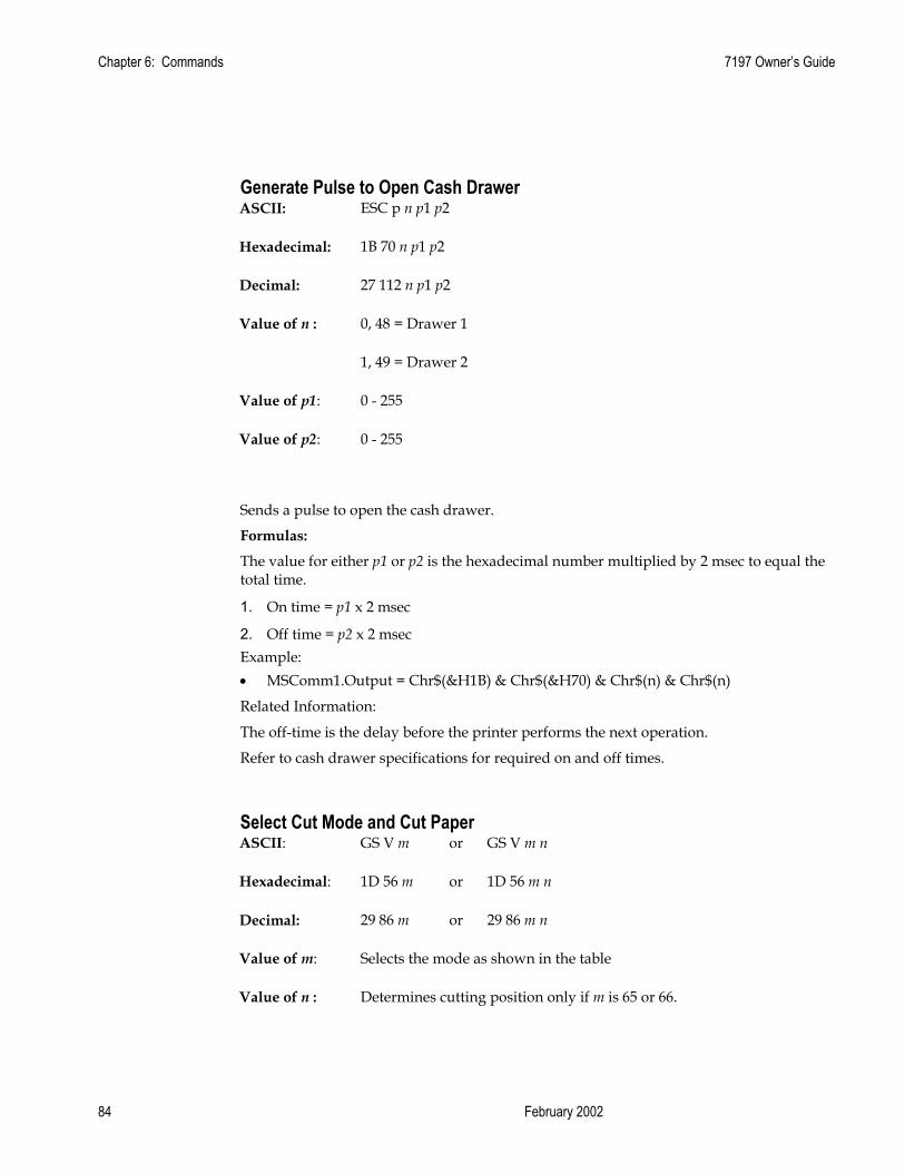
Chapter 6: Commands 7197 Owner’s Guide
February 2002 84
Generate Pulse to Open Cash Drawer ASCII: ESC p n p1 p2
Hexadecimal: 1B 70 n p1 p2
Decimal: 27 112 n p1 p2
Value of n : 0, 48 = Drawer 1
1, 49 = Drawer 2
Value of p1: 0 - 255
Value of p2: 0 - 255
Sends a pulse to open the cash drawer.
Formulas:
The value for either p1 or p2 is the hexadecimal number multiplied by 2 msec to equal the total time.
1. On time = p1 x 2 msec
2. Off time = p2 x 2 msec Example: • MSComm1.Output = Chr$(&H1B) & Chr$(&H70) & Chr$(n) & Chr$(n)
Related Information:
The off-time is the delay before the printer performs the next operation.
Refer to cash drawer specifications for required on and off times.
Select Cut Mode and Cut Paper ASCII: GS V m or GS V m n
Hexadecimal: 1D 56 m or 1D 56 m n
Decimal: 29 86 m or 29 86 m n
Value of m: Selects the mode as shown in the table
Value of n : Determines cutting position only if m is 65 or 66.
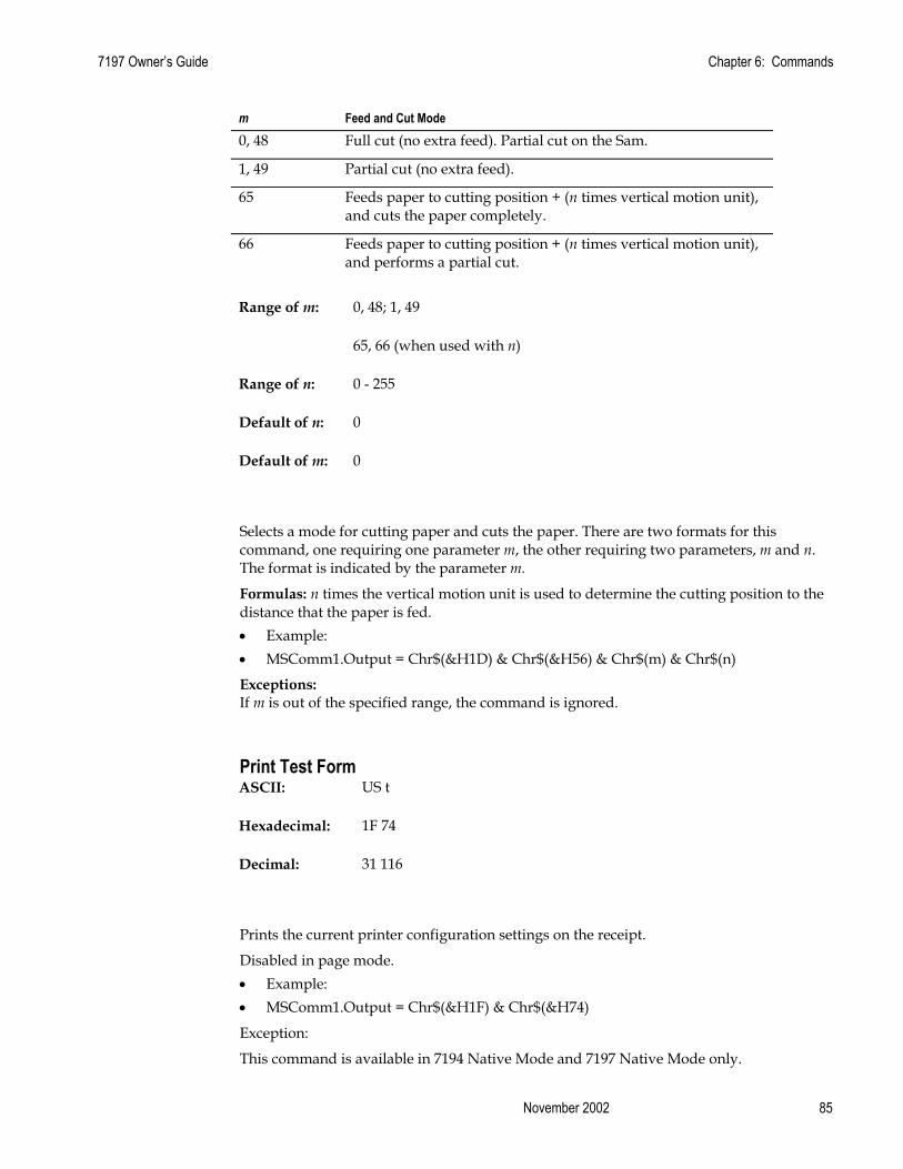
7197 Owner’s Guide Chapter 6: Commands
November 2002 85
m Feed and Cut Mode 0, 48 Full cut (no extra feed). Partial cut on the Sam.
1, 49 Partial cut (no extra feed).
65 Feeds paper to cutting position + (n times vertical motion unit), and cuts the paper completely.
66 Feeds paper to cutting position + (n times vertical motion unit), and performs a partial cut.
Range of m: 0, 48; 1, 49
65, 66 (when used with n)
Range of n: 0 - 255
Default of n: 0
Default of m: 0
Selects a mode for cutting paper and cuts the paper. There are two formats for this command, one requiring one parameter m, the other requiring two parameters, m and n. The format is indicated by the parameter m.
Formulas: n times the vertical motion unit is used to determine the cutting position to the distance that the paper is fed. • Example: • MSComm1.Output = Chr$(&H1D) & Chr$(&H56) & Chr$(m) & Chr$(n)
Exceptions: If m is out of the specified range, the command is ignored.
Print Test Form ASCII: US t
Hexadecimal: 1F 74
Decimal: 31 116
Prints the current printer configuration settings on the receipt.
Disabled in page mode. • Example: • MSComm1.Output = Chr$(&H1F) & Chr$(&H74)
Exception:
This command is available in 7194 Native Mode and 7197 Native Mode only.

Chapter 6: Commands 7197 Owner’s Guide
February 2002 86
Vertical Positioning and Print Commands The vertical positioning and print commands control the vertical print positions of characters on the receipt.
Print and Feed Paper One Line ASCII: LF
Hexadecimal: 0A
Decimal: 10
Prints one line from the buffer and feeds paper one line. Example: • MSComm1.Output = Chr$(&H0A)
Related Information:
Carriage Return + Line Feed, prints and feeds only one line.
Print and Carriage Return ASCII: CR
Hexadecimal: 0D
Decimal: 13
Prints one line from the buffer and feeds paper one line. The printer can be set through the configuration menu to ignore or use this command. Some applications expect the command to be ignored while others use it as print command. • Example: • MSComm1.Output = Chr$(&H0D)
Related Information:
See Ignoring/Using the Carriage Return in Diagnostics for more information.
Carriage Return + Line Feed, prints and feeds only one line.
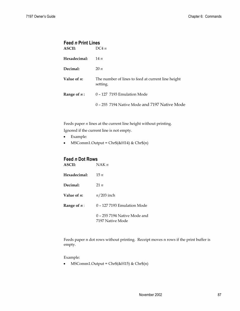
7197 Owner’s Guide Chapter 6: Commands
November 2002 87
Feed n Print Lines ASCII: DC4 n
Hexadecimal: 14 n
Decimal: 20 n
Value of n: The number of lines to feed at current line height setting.
Range of n : 0 – 127 7193 Emulation Mode
0 – 255 7194 Native Mode and 7197 Native Mode
Feeds paper n lines at the current line height without printing.
Ignored if the current line is not empty. • Example: • MSComm1.Output = Chr$(&H14) & Chr$(n)
Feed n Dot Rows ASCII: NAK n
Hexadecimal: 15 n
Decimal: 21 n
Value of n: n/203 inch
Range of n : 0 – 127 7193 Emulation Mode
0 – 255 7194 Native Mode and 7197 Native Mode
Feeds paper n dot rows without printing. Receipt moves n rows if the print buffer is empty.
Example: • MSComm1.Output = Chr$(&H15) & Chr$(n)

Chapter 6: Commands 7197 Owner’s Guide
February 2002 88
Add n Extra Dot Rows ASCII: SYN n
Hexadecimal: 16 n
Decimal: 22 n
Value of n: n/203 inch
Range of n: 0 - 12
Default: 3
Adds n extra dot rows to the character height to increase space between print lines or decrease number of lines per inch.
Formulas:
The following table shows the relationship between the number of lines per inch and each extra dot row(s) added:
Receipt Station
Extra Rows Lines Per Inch
Dot Rows
0 8.47 24
1 8.13 25
2 7.81 26
3 7.52 27
4 7.25 28
5 7.00 29
6 6.77 30
7 6.55 31
8 6.35 32
9 6.16 33
10 5.98 34
11 5.81 35
12 5.64 36
Example: • MSComm1.Output = Chr$(&H16) & Chr$(n)

7197 Owner’s Guide Chapter 6: Commands
November 2002 89
Print ASCII: ETB
Hexadecimal: 17
Decimal: 23
Prints one line from the buffer and feeds paper one line. Executes LF on receipt. Example: • MSComm1.Output = Chr$(&H17)
Set Line Spacing to 1/6 Inch ASCII: ESC 2
Hexadecimal: 1B 32
Decimal: 27 50
Default: 0.13 Inch (3.33 mm)
Sets the default line spacing to 1/6 of an inch (4.25 mm). Example: • MSComm1.Output = Chr$(&H1B) & Chr$(&H32)
Set Line Spacing ASCII: ESC 3 n
Hexadecimal: 1B 33 n
Decimal: 27 51 n
Value of n: n/406 inches in 7194 Native Mode and 7197 Native Mode
n/360 inches in 7193 Emulation Mode
Range of n: 0 – 255
Default: .13 inch (3.37 mm or 7.52 lines per inch, 3 extra dot rows.).
Sets the line spacing to n/406 inches. The minimum line spacing is 8.5 lines per inch. The line spacing equals the character height when n is too small.
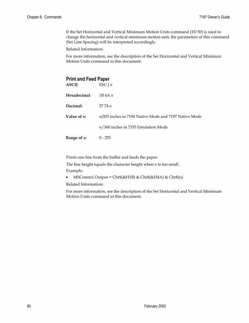
Chapter 6: Commands 7197 Owner’s Guide
February 2002 90
If the Set Horizontal and Vertical Minimum Motion Units command (1D 50) is used to change the horizontal and vertical minimum motion unit, the parameters of this command (Set Line Spacing) will be interpreted accordingly.
Related Information:
For more information, see the description of the Set Horizontal and Vertical Minimum Motion Units command in this document.
Print and Feed Paper ASCII: ESC J n
Hexadecimal: 1B 4A n
Decimal: 27 74 n
Value of n: n/203 inches in 7194 Native Mode and 7197 Native Mode
n/360 inches in 7193 Emulation Mode
Range of n: 0 - 255
Prints one line from the buffer and feeds the paper.
The line height equals the character height when n is too small. Example: • MSComm1.Output = Chr$(&H1B) & Chr$(&H4A) & Chr$(n)
Related Information:
For more information, see the description of the Set Horizontal and Vertical Minimum Motion Units command in this document.
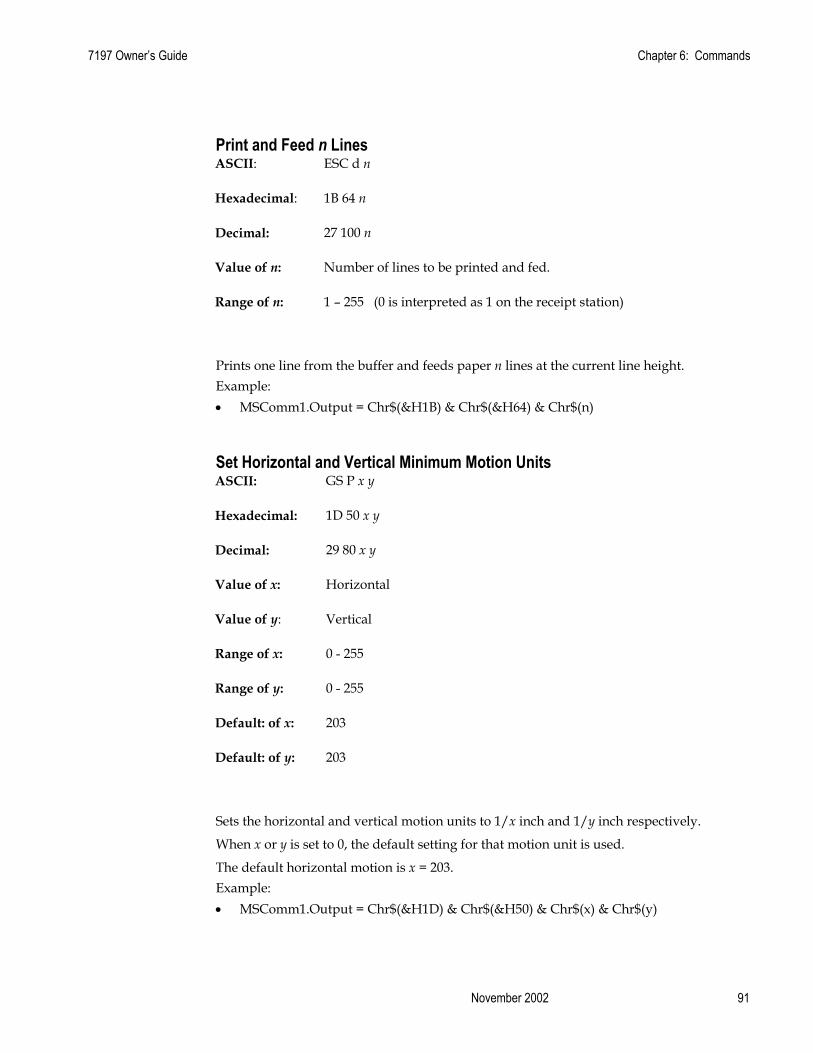
7197 Owner’s Guide Chapter 6: Commands
November 2002 91
Print and Feed n Lines ASCII: ESC d n
Hexadecimal: 1B 64 n
Decimal: 27 100 n
Value of n: Number of lines to be printed and fed.
Range of n: 1 – 255 (0 is interpreted as 1 on the receipt station)
Prints one line from the buffer and feeds paper n lines at the current line height. Example: • MSComm1.Output = Chr$(&H1B) & Chr$(&H64) & Chr$(n)
Set Horizontal and Vertical Minimum Motion Units ASCII: GS P x y
Hexadecimal: 1D 50 x y
Decimal: 29 80 x y
Value of x: Horizontal
Value of y: Vertical
Range of x: 0 - 255
Range of y: 0 - 255
Default: of x: 203
Default: of y: 203
Sets the horizontal and vertical motion units to 1/x inch and 1/y inch respectively.
When x or y is set to 0, the default setting for that motion unit is used.
The default horizontal motion is x = 203. Example: • MSComm1.Output = Chr$(&H1D) & Chr$(&H50) & Chr$(x) & Chr$(y)

Chapter 6: Commands 7197 Owner’s Guide
February 2002 92
Horizontal Positioning Commands The horizontal positioning commands control the horizontal print positions of characters on the receipt.
Horizontal Tab ASCII: HT
Hexadecimal: 09
Decimal: 9
Moves the print position to the next tab position set by the Set Horizontal Tab Positions (1B 44 n1 n2 ... 00) command. The print position is reset to column one after each line.
Tab treats the left margin as column one, therefore changes to the left margin will move the tab positions.
When there are no tabs defined to the right of the current position, or if the next tab is past the right margin, line feed is executed . HT has no effect in page mode. Printer initialization sets 32 tabs at column 9, 17, 25, … (Every 8 characters) Example: • MSComm1.Output = Chr$(&H09)
Set Column ASCII: ESC DC4 n
Hexadecimal: 1B 14 n
Decimal: 27 20 n
Value of n: 1-44 (Standard, 80 mm) 1-32 (Standard, 58 mm)
1-56 (Compressed, 80 mm)
1-42 (Compressed, 58 mm)
Default of n: 1
Prints the first character of the next print line in column n. It must be sent for each line not printed at column one. The value of n is set to one after each line. Example: • MSComm1.Output = Chr$(&H1B) & Chr$(&H14) & Chr$(n)
Exceptions:
The command cannot be used with Single- or Double-Density graphics.

7197 Owner’s Guide Chapter 6: Commands
November 2002 93
Set Absolute Starting Position ASCII: ESC $ n1 n2
Hexadecimal: 1B 24 n1 n2
Decimal: 27 36 n1 n2
Value of n: Number of dots to be moved from the beginning of the line.
Value of n1: Remainder after dividing n by 256.
Value of n2: Integer after dividing n by 256.
The values for n1 and n2 are two bytes in low byte, high byte word orientation.
Sets the print starting position to the specified number of dots (up to the right margin) from the beginning of the line. The print starting position is reset to the first column after each line.
Formulas:
Determine the value of n by multiplying the column for the absolute starting position by 10 (standard pitch) or 8 (compressed pitch). The example shows how to calculate column 29 (10 dots per column) as the absolute starting position.
28 x 10 = 280 dots (beginning of column 29) 280/256 = 1, remainder of 24 n1 = 24 n2 = 1 Example: • MSComm1.Output = Chr$(&H1B) & Chr$(&H24) & Chr$(n1) & Chr$(n2)
Related Information:
This command is also used in the graphics mode. See Graphics Commands in this chapter for more information.
If the Set Horizontal and Vertical Minimum Motion Units command (1D 50) is used to change the horizontal and vertical minimum motion unit, the parameters of this command (Set Absolute Print Position) will be interpreted accordingly. For more information, see the description of the Set Horizontal and Vertical Minimum Motion Units command (1D 50) in this document.

Chapter 6: Commands 7197 Owner’s Guide
February 2002 94
Set Horizontal Tabs ASCII: ESC D [n] k NUL
Hexadecimal: 1B 44 [n] k 00
Decimal: 27 68 [n] k 0
Value of n: Column for tab minus one.
n is always less than or equal to the current selected column width.
Value of k: 0 - 32
Default: Every 8 characters from column. 1 (9, 17, 25, etc.) for normal print.
Sets up to 32 horizontal tab positions n columns from column one, but does not move the print position. See the Horizontal Tab (09) command.
The tab positions remain unchanged if the character widths are changed after the tabs are set. This command ends with hexadecimal 00; hexadecimal 1B 44 00 clears all tabs. Tabs assumed to be in strictly ascending order. A tab out of order terminates the command string as if it were 00, and remaining tab values are taken as normal data.
Formulas:
Set the tab positions in ascending order and put Hex 00 at the end.
Hex 1B 44 00 (number of tabs not specified) clears all tab positions. Example: • MSComm1.Output = Chr$(&H1B) & Chr$(&H44) & Chr$(&H00)
Exceptions:
The tabs cannot be set higher than the column width of the current pitch.
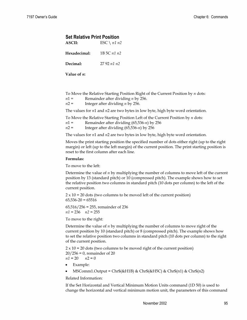
7197 Owner’s Guide Chapter 6: Commands
November 2002 95
Set Relative Print Position ASCII: ESC \ n1 n2
Hexadecimal: 1B 5C n1 n2
Decimal: 27 92 n1 n2
Value of n:
To Move the Relative Starting Position Right of the Current Position by n dots: n1 = Remainder after dividing n by 256. n2 = Integer after dividing n by 256.
The values for n1 and n2 are two bytes in low byte, high byte word orientation.
To Move the Relative Starting Position Left of the Current Position by n dots: n1 = Remainder after dividing (65,536-n) by 256 n2 = Integer after dividing (65,536-n) by 256
The values for n1 and n2 are two bytes in low byte, high byte word orientation.
Moves the print starting position the specified number of dots either right (up to the right margin) or left (up to the left margin) of the current position. The print starting position is reset to the first column after each line.
Formulas:
To move to the left:
Determine the value of n by multiplying the number of columns to move left of the current position by 13 (standard pitch) or 10 (compressed pitch). The example shows how to set the relative position two columns in standard pitch (10 dots per column) to the left of the current position.
2 x 10 = 20 dots (two columns to be moved left of the current position) 65,536-20 = 65516
65,516/256 = 255, remainder of 236 n1 = 236 n2 = 255
To move to the right:
Determine the value of n by multiplying the number of columns to move right of the current position by 10 (standard pitch) or 8 (compressed pitch). The example shows how to set the relative position two columns in standard pitch (10 dots per column) to the right of the current position.
2 x 10 = 20 dots (two columns to be moved right of the current position) 20/256 = 0, remainder of 20 n1 = 20 n2 = 0 • Example: • MSComm1.Output = Chr$(&H1B) & Chr$(&H5C) & Chr$(n1) & Chr$(n2)
Related Information:
If the Set Horizontal and Vertical Minimum Motion Units command (1D 50) is used to change the horizontal and vertical minimum motion unit, the parameters of this command

Chapter 6: Commands 7197 Owner’s Guide
February 2002 96
(Set Relative Print Position) will be interpreted accordingly. For more information, see the description of the Set Horizontal and Vertical Minimum Motion Units command (1D 50) in this document.
Compatibility Information (7194 Native Mode and 7197 Native Mode receipt vs. 7193 receipt)
There is a difference in the normal behavior of this command in 7194 Native Mode and 7197 Native Mode as compared to the original 7193. The difference exists when the command is used to move to the left. The 7193 processes the whole print string prior to putting it in the buffer for the print head. This method of processing allows the 7193 to backup in the print string and replace characters and their associated attributes when a “Set Relative Print Position” command instructs the printer to move the print position to the left.
In order to improve the speed of printing, the 7197 moves the data into a buffer for the print head when it receives it. When the “Set Relative Print Position” command contains a move to the left, this causes the new data to overstrike the previous data. This behavior can be used to an application’s advantage to provide the ability to create compound characters on the receipt station.
Select Justification ASCII: ESC a n
Hexadecimal: 1B 61 n
Decimal: 27 97 n
Value of n: 0, 48 = Left Aligned
1, 49 = Center Aligned
2, 50 = Right Aligned
Range of n: 0 – 2, 48-50
Default: 0 (Left aligned)
Specifies the alignment of the characters, graphics, logos, and bar codes on the receipt station. Example: • MSComm1.Output = Chr$(&H1B) & Chr$(&H61) & Chr$(n)
Exceptions:
The command is valid only when input at the beginning of a line.

7197 Owner’s Guide Chapter 6: Commands
November 2002 97
Set Left Margin ASCII: GS L nL nH
Hexadecimal: 1D 4C nL nH
Decimal: 29 76 nL nH
Range of nL: 0 - 255
Range of nH: 0 - 255
Default: 80 mm width 576 dots (the maximum printable area)
58 mm width 424 dots (the maximum printable area)
Sets the left margin of the printing area. The left margin is set to (((nH X 256) + nL) times horizontal motion unit) inches. The horizontal motion units are set by the Set Horizontal and Vertical Minimum Motion Units command (1D 50), described in this manual.
The width of the printing area is set by the Set Printing Area Width command (1D 57), which follows this command. See the Set Printing Area Width command (1D 57) in this document for a description of that command.
If the setting exceeds the printable area, the maximum value of the printable area is used. The maximum printable area is 576 dots. See the illustration.
Formulas:
To set the left margin to one inch at the default horizontal motion unit of 1/203 inches, send the four-byte string: GS L 203 0
Or, to set the left margin to two inches at the default horizontal motion unit of 1/203 units per inch, send the four-byte string: GS L 150 1
Where 2 inches = 406/203, and 406 = (1 X 256) + 150.
←- Printable area: 576 dots for 80 mm width, 424 dots for 58 mm width → ←Left margin→ ←Printing area width→
Example: • MSComm1.Output = Chr$(&H1D) & Chr$(&H4C) & Chr$(nL) & Chr$(nH)
Exceptions:
The command is effective only at the beginning of a line.
This command is ignored if the line buffer is not empty.

Chapter 6: Commands 7197 Owner’s Guide
February 2002 98
Set Printing Area Width ASCII: GS W nL nH
Hexadecimal: 1D 57 nL nH
Decimal: 29 87 nL nH
Range of nL: 0 – 255
Range of nH: 0 - 255
Default: 80 mm width 576 dots (the maximum printable area)
58 mm width 424 dots (the maximum printable area)
Sets the width of the printing area. If the setting exceeds the printable area, the maximum value of the printable area is used.
The width of the printing area is set to (((nH X 256) + nL) times horizontal motion unit) inches. The horizontal motion units are set by the Set Horizontal and Vertical Minimum Motion Units command (1D 50).
The width of the printing area follows the Set Left Margin command (1D 4C). See the Set Left Margin command (1D 4C…) earlier in this document for a description.
Formulas:
To set the width of the printing area to one inch at the default horizontal motion unit of 1/203 inches, send the four-byte string: GS W 203 0
Or, to set the width of the printing area to two inches at the default horizontal motion unit of 1/203 units per inch, send the four-byte string: GS W 150 1
Where 2 inches = 406/203, and 406 = (1 X 256) + 150.
← Printable area 576 dots→ ←Left margin→ ←Printing area width→
Example: • MSComm1.Output = Chr$(&H1D) & Chr$(&H57) & Chr$(nL) & Chr$(nH)
Exceptions:
This command is effective only at the beginning of a line.
This command is ignored if the line buffer is not empty, and only effects the Receipt interface.

7197 Owner’s Guide Chapter 6: Commands
November 2002 99
If the setting exceeds the printable area, the maximum value of the printable area is used. The maximum printable area is 576 dots for 80 mm paper width and 424 dots for 58 mm paper width. See the illustration in the Set Left Margin command (1D 4C).

Chapter 6: Commands 7197 Owner’s Guide
February 2002 100
Print Characteristic Commands These commands control what the printed information looks like: selection of character sets, definition of custom-defined characters, and setting of margins. The commands are described in order of their hexadecimal codes
Select Double-Wide Characters ASCII: DC2
Hexadecimal: 12
Decimal: 18
Prints double-wide characters. The printer is reset to single-wide mode after a line has been printed or the Clear Printer (0x10) command is received. Double-wide characters may be used in the same line with single-wide characters. Example: • MSComm1.Output = Chr$(&H12)
Select Single-Wide Characters ASCII: DC3
Hexadecimal: 13
Decimal: 19
Prints single-wide characters. Single-wide characters may be used in the same line with double-wide characters. Example: • MSComm1.Output = Chr$(&H13)
Select 90 Degree Counter-Clockwise Rotated Print ASCII: ESC DC2
Hexadecimal: 1B 12
Decimal: 27 18
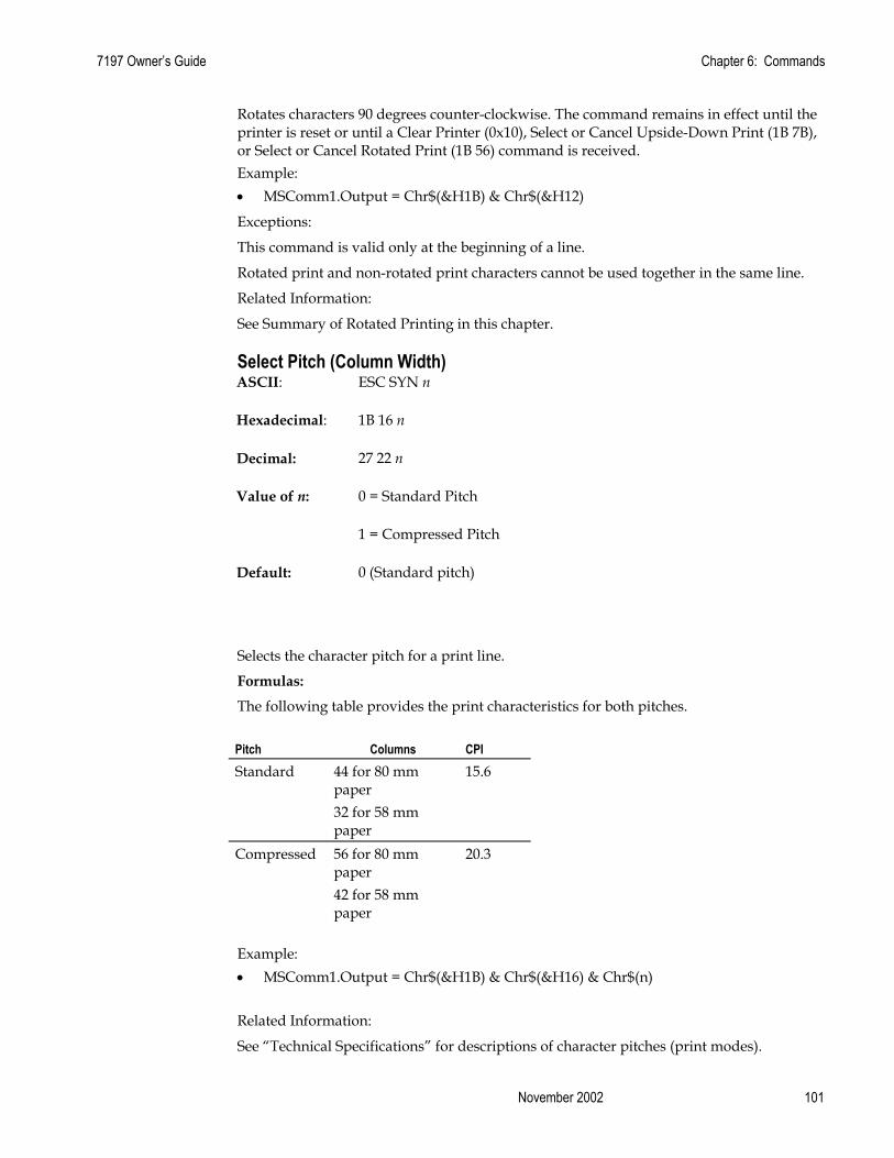
7197 Owner’s Guide Chapter 6: Commands
November 2002 101
Rotates characters 90 degrees counter-clockwise. The command remains in effect until the printer is reset or until a Clear Printer (0x10), Select or Cancel Upside-Down Print (1B 7B), or Select or Cancel Rotated Print (1B 56) command is received. Example: • MSComm1.Output = Chr$(&H1B) & Chr$(&H12)
Exceptions:
This command is valid only at the beginning of a line.
Rotated print and non-rotated print characters cannot be used together in the same line.
Related Information:
See Summary of Rotated Printing in this chapter.
Select Pitch (Column Width) ASCII: ESC SYN n
Hexadecimal: 1B 16 n
Decimal: 27 22 n
Value of n: 0 = Standard Pitch
1 = Compressed Pitch
Default: 0 (Standard pitch)
Selects the character pitch for a print line.
Formulas:
The following table provides the print characteristics for both pitches.
Pitch Columns CPI Standard 44 for 80 mm
paper 15.6
32 for 58 mm paper
Compressed 56 for 80 mm paper
20.3
42 for 58 mm paper
Example: • MSComm1.Output = Chr$(&H1B) & Chr$(&H16) & Chr$(n)
Related Information:
See “Technical Specifications” for descriptions of character pitches (print modes).
Chapter 6: Commands 7197 Owner’s Guide
February 2002 102
Set Character Right-Side Spacing ASCII: ESC SP n
Hexadecimal: 1B 20 n
Decimal: 27 32 n
Range of n: 0 - 32
Default: 0
Sets the right side character spacing to [n x horizontal or vertical motion units]. Values for this command are set independently in Standard and Page Mode.
The units of horizontal and vertical motion are specified by the Set Horizontal and Vertical Minimum Motion Units (1D 50…) command. Changes in the horizontal or vertical units do not affect the current right side character spacing. When the horizontal or vertical motion unit is changed by the Set Horizontal and Vertical Minimum Motion Units (1D 50…) command the value must be in even units and not less than the minimum amount of horizontal movement.
In Standard Mode the horizontal motion unit is used.
In Page Mode the horizontal or vertical motion unit differs and depends on the starting position of the printable area. When the starting printing position is the upper left or lower right of the printable area (set by Select Print Direction in Page Mode, 1B 54 n) the horizontal motion unit (x) is used. When the starting printing position is the upper right or lower left of the printable area (set by Select Print Direction in Page Mode, 1B 54 n) the vertical motion unit (y) is used. Example: • MSComm1.Output = Chr$(&H1B) & Chr$(&H20) & Chr$(n)
Exception:
This command is ignored in 7193 Emulation Mode and is only valid on the receipt station.
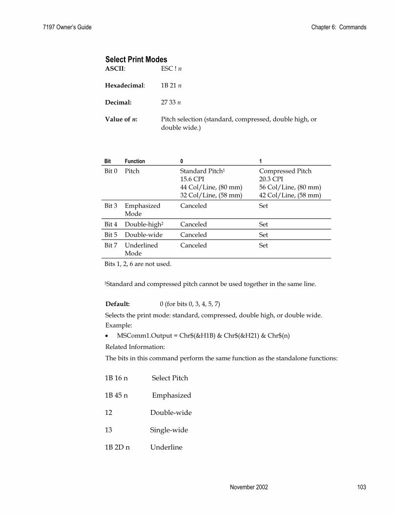
7197 Owner’s Guide Chapter 6: Commands
November 2002 103
Select Print Modes ASCII: ESC ! n
Hexadecimal: 1B 21 n
Decimal: 27 33 n
Value of n: Pitch selection (standard, compressed, double high, or double wide.)
Bit Function 0 1 Bit 0 Pitch Standard Pitch1
15.6 CPI 44 Col/Line, (80 mm) 32 Col/Line, (58 mm)
Compressed Pitch 20.3 CPI 56 Col/Line, (80 mm) 42 Col/Line, (58 mm)
Bit 3 Emphasized Mode
Canceled Set
Bit 4 Double-high2 Canceled Set Bit 5 Double-wide Canceled Set Bit 7 Underlined
Mode Canceled Set
Bits 1, 2, 6 are not used. 1Standard and compressed pitch cannot be used together in the same line.
Default: 0 (for bits 0, 3, 4, 5, 7)
Selects the print mode: standard, compressed, double high, or double wide. Example: • MSComm1.Output = Chr$(&H1B) & Chr$(&H21) & Chr$(n)
Related Information:
The bits in this command perform the same function as the standalone functions:
1B 16 n Select Pitch
1B 45 n Emphasized
12 Double-wide
13 Single-wide
1B 2D n Underline
Chapter 6: Commands 7197 Owner’s Guide
February 2002 104
Select or Cancel User-Defined Character Set ASCII: ESC % n
Hexadecimal: 1B 25 n
Decimal: 27 37 n
Value of n: 0= Code Page 437
1= User-defined (RAM character set)
2= Code Page 850
Range: 0 - 2
Default:
0 (Code Page 437)
Selects the character set. When an undefined RAM character is selected, the Code Page 437 character is used. See the Printing Specification Guide for the character sets. Example: • MSComm1.Output = Chr$(&H1B) & Chr$(&H25) & Chr$(n)
Define User-Defined Characters Receipt
ASCII: ESC & 3 c1 c2 n1 d1 ... nn dn
Hexadecimal: 1B 26 3 c1 c2 n1 d1 ... nn dn
Decimal: 27 38 3 c1 c2 n1 d1 ... nn dn
Defines and enters downloaded characters into RAM or Flash. The command may be used to overwrite single characters. User-defined characters are available until power is turned off or the Initialize Printer command (1B 40) is received.
Any invalid byte (s, c1, c2, n1) aborts the command.
The command clears bit image logo data from RAM. The illustration below provides a sample of a character cell.
Defining User-Defined Characters Defines and enters downloaded characters into RAM.
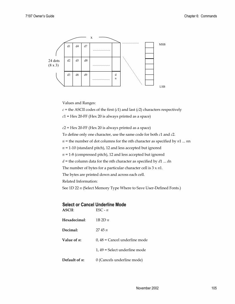
7197 Owner’s Guide Chapter 6: Commands
November 2002 105
Values and Ranges:
c = the ASCII codes of the first (c1) and last (c2) characters respectively
c1 = Hex 20-FF (Hex 20 is always printed as a space)
c2 = Hex 20-FF (Hex 20 is always printed as a space)
To define only one character, use the same code for both c1 and c2.
n = the number of dot columns for the nth character as specified by n1 ... nn
n = 1-10 (standard pitch), 12 and less accepted but ignored
n = 1-8 (compressed pitch), 12 and less accepted but ignored
d = the column data for the nth character as specified by d1 ... dn
The number of bytes for a particular character cell is 3 x n1.
The bytes are printed down and across each cell.
Related Information:
See 1D 22 n (Select Memory Type Where to Save User-Defined Fonts.)
Select or Cancel Underline Mode ASCII: ESC - n
Hexadecimal: 1B 2D n
Decimal: 27 45 n
Value of n: 0, 48 = Cancel underline mode
1, 49 = Select underline mode
Default of n: 0 (Cancels underline mode)
d1 d4 d7
d2 d5 d8
d3 d6 d9
MSB
LSB
d n
x
24 dots (8 x 3)

Chapter 6: Commands 7197 Owner’s Guide
February 2002 106
Turns underline mode on or off. Underlines cannot be printed for spaces set by the Horizontal Tab, Set Absolute Start Position, or Set Relative Print Position commands.
This command and the Select Print Mode(s) command (1B 21) turn underline on and off in the same way. Example: • MSComm1.Output = Chr$(&H1B) & Chr$(&H2D) & Chr$(n)
Exceptions:
This command is ignored if n is out of the specified range.
This command is only available in 7194 Native Mode and 7197 Native Mode.
Copy Character Set from ROM to RAM ASCII: ESC : 0 0 0
Hexadecimal: 1B 3A 30 30 30
Decimal: 27 58 48 48 48
Default: Code Page 437
Copies characters in the active ROM set to RAM. Use this command to re-initialize the User-Defined Character Set. Code Page 437 is copied by default at initialization.
The command is ignored if current font is the user font.
Example: • MSComm1.Output = Chr$(&H1B) & Chr$(&H3A) & Chr$(&H30) & Chr$(&H30) • & Chr$(&H30)
Related Information:
To modify characters in one of the character set variations, such as Rotated Print, select one of the Rotated Print commands, copy to RAM, then use the Define User-Defined Character Set command (1B 26).
Cancel User-Defined Characters ASCII: ESC ? n
Hexadecimal: 1B 3F n
Decimal: 27 63 n
Value of n: Specified character code
Range of n: 32 - 255

7197 Owner’s Guide Chapter 6: Commands
November 2002 107
Cancels the pattern defined for the character code specified by n. After the user-defined character is canceled, the corresponding pattern from Code Page 437 is printed. Example: • MSComm1.Output = Chr$(&H1B) & Chr$(&H3F) & Chr$(n)
Exceptions:
This command is ignored if n is out of range or if the user-defined character is not defined.
Select or Cancel Emphasized Mode ASCII: ESC E n
Hexadecimal: 1B 45 n
Decimal: 27 69
Value of n: 0 (bit 0), not selected
1 (bit 0), selected
Range of n: 0 - 255
Default: 0 (bit 0)
Starts or stops emphasized printing. Example: • MSComm1.Output = Chr$(&H1B) & Chr$(&H45) & Chr$(n)
Exceptions:
Only the lowest bit of n is effective.
Emphasized printing cannot be used with bit-images or downloaded bit-images.
Related Information:
This command and the Select Print Mode(s) command (1B 21) function identically.
Select or Cancel Double Strike ASCII: ESC G n
Hexadecimal: 1B 47 n
Decimal: 27 71 n
Value of n: 0 = Off
1 = On

Chapter 6: Commands 7197 Owner’s Guide
February 2002 108
Turns double strike mode on or off. Identical to Emphasized mode command. The printer is reset to the standard print mode after a line has been printed or after a Clear Printer (0x10) command is received. Example: • MSComm1.Output = Chr$(&H1B) & Chr$(&H47) & Chr$(n)
Exceptions:
These settings do not apply in Page Mode. However they can be set or cleared in Page Mode.
Double-strike printing cannot be used with bit-images or downloaded bit-images.
Related Information:
This command and the Select Print Mode(s) comand (1B 21) functionidentically. They should have the same setting when used together.
In 7193 Emulation, this command is unrecognized and the parameter byte is put in to the printer buffer.
Select or Cancel Italic Print ASCII: ESC I n
Hexadecimal: 1B 49 n
Decimal: 27 73 n
Value of n: 0 = Off
1 = On
(When 0 and 1 are the Least Significant Bit, LSB)
Default: 0 (Off)
Turns Italic print mode on or off. This command is only available in 7194 Native Mode and 7197 Native Mode. Italic print mode is available for built-in, user-defined characters. Example: • MSComm1.Output = Chr$(&H1B) & Chr$(&H49) & Chr$(n)
Exceptions:
Only the lowest bit of n is valid. This command is only valid for the receipt station in 7194 Native Mode and 7197 Native Mode.

7197 Owner’s Guide Chapter 6: Commands
November 2002 109
Select International Character Set ASCII: ESC R n or ESC t n
Hexadecimal: 1B 52 n or 1B 74 n
Decimal: 27 82 n or 27 116 n
Value of n: 0 = Code Page 437 US English
1 = Code Page 850 Multilingual
2 = Code Page 852 Slavic
3 = Code Page 860 Portuguese
4 = Code Page 863 French Canadian
5 = Code Page 865 Nordic
6 = Code Page 858 Multilingual with Euro Symbol
7 = Code Page 866 Cyrillic
8 = Code Page 1252 Windows Latin I
9 = Code Page 862 Hebrew
20 = Code Page Katakana
21 = Code Page 874 Thailand
22 = Code Page 864 Arabic
128 = Code Page 932
129 = Code Page 936
130 = Code Page 949
131 = Code Page 950
Default: 0 (Code Page 437)
Selects the character set to be used. See Print Specifications for the character sets.
There are two codes for this command. Both codes perform the same function. Example: • MSComm1.Output = Chr$(&H1B) & Chr$(&H52) & Chr$(n)

Chapter 6: Commands 7197 Owner’s Guide
February 2002 110
Related Information:
This command may also be known as Select Character Code Table.
Select Character Code Table See the previous command, Select International Character Set.
Select or Cancel 90 Degrees Clockwise Rotated Print ASCII: ESC V n
Hexadecimal: 1B 56 n
Decimal: 27 86 n
Value of n: 0 = Cancel
1 = Set
Default: 0 (Cancel)
Rotates characters 90 degrees clockwise. The command remains in effect until the printer is reset or the Clear Printer (0x10) command is received. See Summary of Rotated Printing in this chapter.
Example: • MSComm1.Output = Chr$(&H1B) & Chr$(&H56) & Chr$(n)
Select Print Color ASCII: ESC r n
Hexadecimal: 1B 72 n
Decimal: 27 114 n
Value of n: 0 = Monochrome
1 = 2nd Color
Default: 0 (Monochrome)
Selects color printing. Color printing is valid for character, graphics, logo and barcode. Example: • MSComm1.Output = Chr$(&H1B) & Chr$(&H72) & Chr$(n)

7197 Owner’s Guide Chapter 6: Commands
November 2002 111
Select or Cancel Upside Down Printing Mode ASCII: ESC { n
Hexadecimal: 1B 7B n
Decimal: 27 123 n
Value of n: 0 = Cancel
1 = Set
Default: 0 (Cancel)
Prints upside-down characters. The character order is inverted in the buffer so text is readable. The command remains in effect until the Rotated Print (1B 12) command is received. Only bit 0 is used. Bits 1-7 are not used. See Summary of Rotated Printing in this document for more information. Example: • MSComm1.Output = Chr$(&H1B) & Chr$(&H7B) & Chr$(n)
Exceptions:
The command is valid only at the beginning of a line. The Rotated Print command (1B 12) cancels this command.
Select Character Size ASCII: GS ! n
Hexadecimal: 1D 21 n
Decimal: 29 33 n
Value of n: 1 - 8 = vertical number of times normal font
1 – 8 = horizontal number of times normal font
Range of n: 00 – 07, 10 – 17, … 70 – 77
Default of n: 0

Chapter 6: Commands 7197 Owner’s Guide
February 2002 112
Selects the character height using bits 0 to 2 and selects the character width using bits 4 to 7, as follows:
Character Width Selection Hex Decimal Width 00 0 1 (normal) 10 16 2 (two times width) 20 32 3 (three times width) 30 48 4 (four times width) 40 64 5 (five times width) 50 80 6 (six times width) 60 96 7 (seven times width) 70 112 8 (eight times width)
Character Height Selection Hex Decimal Height 00 0 1 (normal) 01 1 2 (two times height) 02 2 3 (three times height 03 3 4 (four times height) 04 4 5 (five times height) 05 5 6 (six times height) 06 6 7 (seven times height) 07 7 8 (eight times height)
This command is effective for all characters (except for HRI characters).
In Standard Mode, the vertical direction is the paper feed direction, and the horizontal direction is perpendicular to the paper feed direction. However, when character orientation changes in 90 degree clockwise-rotation mode, the relationship between vertical and horizontal directions is reversed.
In Page Mode, vertical and horizontal directions are based on the character orientation. When characters are enlarged with different sizes on one line, all the characters on the line are aligned at the baseline.
The Select Print Mode (1B 21 n) command can also select or cancel double-width and double-height modes. However, the setting of the last received command is effective. Example: • MSComm1.Output = Chr$(&H1D) & Chr$(&H21) & Chr$(n)
Exceptions:
If n is out of the defined range, this command is ignored.
This is only available in 7194 Native Mode and 7197 Native Mode.

7197 Owner’s Guide Chapter 6: Commands
November 2002 113
Select or Cancel White/Black Reverse Print Mode ASCII: GS B n
Hexadecimal: 1D 42 n
Decimal: 29 66 n
Value of n: 0 = Off
Range of n: 1 = On(Only the lowest bit is used.)
Default of n: 0 – 255
0 (Off)
Turns on White/Black reverse printing mode. This command is only available in 7194 Native Mode and 7197 Native Mode. In White/Black reverse printing mode, print dots and non-print dots are reversed, which means that white characters are formed by printing a black background. When the White/Black reverse printing mode is selected it is also applied to character spacing which is set by Right-Side Character Spacing (1B 20).
This command can be used with built-in characters and user-defined characters, but does not affect the space between lines.
White/Black Reverse Print Mode does not affect bit image, downloaded bit image, bar code, HRI characters, and spacing skipped by Horizontal Tab (09), Set Absolute Starting Position (1B 24…), and Set Relative Print Position (1B 5C).
White/Black reverse mode has a higher priority than Underline Mode. When Underline Mode is on and White/Black Reverse Print Mode is selected, Underline Mode is disabled, but not canceled. Example: • MSComm1.Output = Chr$(&H1D) & Chr$(&H42) & Chr$(n)
Exceptions:
This is only available in 7194 Native Mode and 7197 Native Mode.
Select or Cancel Smoothing Mode ASCII: GS b n
Hexadecimal: 1D 62 n
Decimal: 29 98 n
This command is ignored. Example:
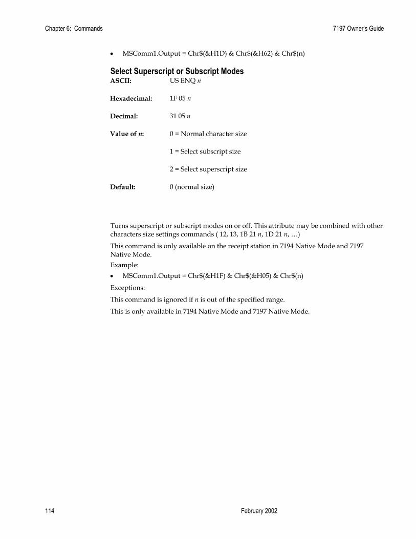
Chapter 6: Commands 7197 Owner’s Guide
February 2002 114
• MSComm1.Output = Chr$(&H1D) & Chr$(&H62) & Chr$(n)
Select Superscript or Subscript Modes ASCII: US ENQ n
Hexadecimal: 1F 05 n
Decimal: 31 05 n
Value of n: 0 = Normal character size
1 = Select subscript size
2 = Select superscript size
Default: 0 (normal size)
Turns superscript or subscript modes on or off. This attribute may be combined with other characters size settings commands ( 12, 13, 1B 21 n, 1D 21 n, …)
This command is only available on the receipt station in 7194 Native Mode and 7197 Native Mode. Example: • MSComm1.Output = Chr$(&H1F) & Chr$(&H05) & Chr$(n)
Exceptions:
This command is ignored if n is out of the specified range.
This is only available in 7194 Native Mode and 7197 Native Mode.

7197 Owner’s Guide Chapter 6: Commands
November 2002 115
Summary of Rotated Printing The table shows the combinations of Set/Cancel Upside-Down Print, Set/Cancel Rotated Print (clockwise), and Rotated Print (counterclockwise). Rotated CCW is mutually exclusive with the other two commands. Unintended consequences may result when rotated CCW is mixed with other commands.
The samples of the print show only the normal size characters. Double-wide and double-high characters are printed in the same orientation. They may also be mixed on the same line.
Upside Down (1B 7B n)
Rotated CW (1B 56 n)
Rotated CCW (1B 12)
Resulting Output
Canceled Canceled Cleared A B C
Canceled Set X CBA
Set Canceled X ABC
Set Set X C B A
X X Set A B C
Note: The following print modes cannot be mixed on the same line:
1. Standard and compressed pitch
2. Vertical (normal) and rotated
3. Right-side up and upside down
4. Single high (normal) and double high

Chapter 6: Commands 7197 Owner’s Guide
February 2002 116
Graphics Commands These commands are used to enter and print graphics data and are described in order of their hexadecimal codes.
Print Raster Graphics ASCII: DC1 n1 … nk
Hexadecimal: 11 n1 … nk
Decimal: 17 n1 … n72
Value of n: n1 … nk = Data bytes
Range of n: 0 - 255
Value of k: k = 72 : 80mm, k = 53 : 58mm
Prints one row of data. N1 … nk : bytes describing the line to print.
Example: • MSComm1.Output = Chr$(&H11) & Chr$(05) & Chr$(255)
Exceptions:
Raster graphcs is not avalable in Page Mode
This is only available in 7194 Native Mode and 7197 Native Mode.
Download BMP Logo ASCII: ESC (+*.BMP file data)
Hexadecimal: 1B (+*.BMP file data)
Decimal: 27 (+*.BMP file data)
Value: Maximum width = 576
Maximum height = 512
Enters a BMP file data into RAM or Flash.
This command is used by sending the file data of a monochrome BMP file preceded by a 0 x 1B. The bit map is stored in the printer in the same manner as a down loaded bit image.

7197 Owner’s Guide Chapter 6: Commands
November 2002 117
The downloaded BMP file can be printed by using the Print Downloaded Bit Image (1D 2F m) command. Example:
1. MSComm1.Output = Chr$(&H1B)
2. Open bitmapfile For Binary As filehandle
3. filecontent = Input(LOF(filehandle), filehandle)
4. MSComm1.Output = filecontent & vbLf
5. This last step is to use the print downloaded image command to print Exceptions:
BMP file images that are not monochrome are ignored. This command is only valid for the receipt station.
This is only available in 7194 Native Mode and 7197 Native Mode.
Related Information:
See 1D 22 n (Select Memory Type to save logos.)
Select Bit Image Mode ASCII: ESC * m n1 n2 d1 ... dn
Hexadecimal: 1B 2A m n1 n2 d1 ... dn
Decimal: 27 42 m n1 n2 d1 ... dn
Sets the print resolution and enters one line of graphics data into the print buffer. Excess data is accepted but ignored. Any print command is required to print the data, after which the printer returns to normal processing mode.
See the illustration graphic representation of the bit image.
Values:
Value of m
Mode No. of Dots (Vertical)
No. of Dots (Horizontal) Number of Dots/Line
0 8 Dot Single Density
8 (68 DPI) 0-288 (101DPI, 80mm) 0-212 (101DPI, 58mm)
8x288 (80mm) 8x212 (58mm)
1 8 Dot Double Density
8 (68 DPI) 0-576 (101DPI, 80mm) 0-424 (101DPI, 58mm)
8x576 (80mm) 8x424 (58mm)
32 24 Dot Single Density
24 (203 DPI) 0-288 (101DPI, 80mm) 0-212 (101DPI,
24x288 (80mm) 24x212

Chapter 6: Commands 7197 Owner’s Guide
February 2002 118
58mm) (58mm) 33 24 Dot
Double Density
24 (203 DPI) 0-576 (101DPI, 80mm) 0-424 (101DPI, 58mm)
24x576 (80mm) 24x424 (58mm)
Formulas:
8 Dot Single Density n1 + (256 x n2) 24 Dot Single Density 3 x [n1 + (256 x n2)]
dn
MSB
LSB
Top of Bit Image
SlipReceipt8-Dot Single-Density Mode—Receipt
Most SignificantBit Is Not Printed
In A756 Emulation
d4d3d2d1 dn dn
MSB
LSB
Top of Bit Image
24-Dot Single-Density Mode—Receipt Only
dn
MSB
LSB
d1
d2
d3
d4 d7
d5
d6 dn

7197 Owner’s Guide Chapter 6: Commands
November 2002 119
Print Advanced Raster Graphics ASCII: ESC . m n rl rh d1 … dn
Hexadecimal: 1B 2E m n rl rh d1 … dn
Decimal: 27 46 m n rl rh d1 … dn
Value of m: Horizontal offset from left margin = 8 x n dots
Value of n: Number of data bytes that compose the raster
Value of r: Number of times the raster has to be printed = 256 x rh + rl
Value of d: d1 … dn = Data bytes
Range: 0 ≤ m, n ≤ 72 (80mm), 0 ≤ m, n ≤ 53 (58mm)
0 ≤ r ≤ 65536
0 ≤ d1 … dn ≤ 255
Prints a horizontal raster of graphics data one or multiple times.
Horizontal offset and number of data bytes are variable and specified by parameters. Example: • MSComm1.Output = Chr$(&H1B) & Chr$(&H2E) & Chr$(10) & Chr$(100) & Chr$(2)
& Chr$(10) & Chr$(&HFF). . . & Chr$(&HFF)
Exceptions:
Advanced Raster graphics is not available in Page Mode.
Select Single-Density Graphics ASCII: ESC K n1 n2 d1 … dn Hexadecimal: 1B 4B n1 n2 d1 ... dn Decimal: 27 75 n1 n2 d1 ... dn
Value of n:
Value of n (8-Dot Single Density Mode)
Value of n (24-Dot Single Density Mode)
Value of d
n1 + (256 x n2) 3 x [n1 + (256 x n2)] Number of Bytes of Data (Printed Down, Then Across)
Enters one line of 8-dot single-density graphics into the print buffer. Any print command is required to print the line, after which the printer returns to normal processing mode. The number of bytes sent is represented by the formulas in the table.

Chapter 6: Commands 7197 Owner’s Guide
February 2002 120
Each bit corresponds to one horizontal dot. Compare to Set Bit Image Mode (1B 2A, m=1) earlier in this document. Example: • MSComm1.Output = Chr$(&H1B) & Chr$(&H4B) & Chr$(10) & Chr$(100)
Chr$(&HFF). . . & Chr$(&HFF)
Select Double-Density Graphics ASCII: ESC Y n1 n2 d1 … dn Hexadecimal: 1B 59 n1 n2 d1 ... dn Decimal: 27 89 n1 n2 d1 ... dn
Value of n:
Value of n (8-Dot Single Density Mode)
Value of n (24-Dot Single Density Mode)
Value of d
n1 + (256 x n2) 3 x [n1 + (256 x n2)] Number of Bytes of Data (Printed Down, Then Across)
Enters one line of 8-dot double-density graphics into the print buffer. Any print command is required to print the line, after which the printer returns to normal processing mode. The number of bytes sent is represented by the formulas in the table.
Each bit corresponds to one horizontal dot. Compare to Set Bit Image Mode (1B 2A, m=1) earlier in this document. Example: • MSComm1.Output = Chr$(&H1B) & Chr$(&H59) & Chr$(10) & Chr$(100)
Chr$(&HFF). . . & Chr$(&HFF)

7197 Owner’s Guide Chapter 6: Commands
November 2002 121
Select the Current Logo (Downloaded Bit Image) ASCII: GS # n
Hexadecimal: 1D 23 n
Decimal: 29 35 n
Range of n: 0 – 255
Selects a logo to be defined or printed. The active logo n remains in use until this command is sent again with a different logo n.
When this command precedes a logo definition, that definition is stored in Flash Memory as logo n. If there is already a different definition in Flash Memory for logo n, the first is inactivated and the new definition is used. The inactive definition is not erased from Flash and continues to take up space in Flash Memory.
When this command precedes a logo print command and n is different from the previously active logo selected, the printer retrieves the logo definition for n from Flash Memory and prints it. If there is no definition for logo n, then no logo is printed.
In the case of a previously existing application that expects only one possible logo, the printer will not receive the Select Current Logo (1D 23 n) command. In this case, the printer assigns 0 as the active logo identifier. It automatically stores any new logo definition in Flash Memory as logo 0, inactivating any previous logo 0 definition. If the Flash Memory space available for logos fills up with inactive logo 0 definitions, the firmware erases the old definitions at the next power cycle. This is the only case in which the printer erases Flash Memory without an application command.
In the case of a new application using multiple logos, the Select Current Logo (1D 23 n) command is used. After that, the printer no longer automatically erases the logo definition Flash Memory page when it fills with multiple definitions. A new application using multiple logos, writing a user-defined character set into Flash Memory, or both, is responsible for erasing the logo and user-defined character set Flash Memory page when the logo area is full or before a new character set is defined. Example: • MSComm1.Output = Chr$(&H1D) & Chr$(&H23) & Chr$(n)
By default, 7193 Emulation loads downloaded bit image to SRAM, while 7194 Native Mode and 7197 Native Mode loads them to Flash.

Chapter 6: Commands 7197 Owner’s Guide
February 2002 122
Define Downloaded Bit Image ASCII: GS * n1 n2 d1 ... dn]
Hexadecimal: 1D 2A n1 n2 d1 ... dn]
Decimal: 29 42 n1 n2 d1 ... dn
Value of n1: See the following table.
Value of n2: See the following table.
Value of d: See the following table.
Value of n1 Value of n2 Value of d 1-72 (8 x n1 = Number of Horizontal Dot Columns)
1-64 (Number of Vertical Bytes)*
Bytes of Data (Printed Down Then Across)
*The number of bytes sent is represented by the following formula: n = 8 x n1 x n2 (n1 x n2 must be less than or equal to 4608).
Enters a downloaded bit image (such as a logo) into RAM or Flash with the number of dots specified by n1 and n2, unless loaded into Flash. The downloaded bit image is available until power is turned off, another bit image is defined, or either Initialize Printer (1B 40), or Define User-Defined Character Set (1B 26), command is received.
See the illustration on the following page for a graphic representation of the downloaded bit image.

7197 Owner’s Guide Chapter 6: Commands
November 2002 123
d1
d2
dn d
Top of Graphic
dn
MSB
LSB
Column Column One 72 x 8 Max.
RowOne
Row 64Max. 64
65 d
Exceptions:
See the illustration for the Print Downloaded Bit Image command (1D 2F) for a representation of the bit image.
Related Information:
See 1D 22 n (Select Memory Type to store logos) and 1D 23 n (Select the Current Logo.)
For the 7194 Native Mode and 7197 Native Mode of operation, if multiple logos are to be defined and used, this command should b preceded by the select current logo command to define the number by which this downloaded logo is to be reference.

Chapter 6: Commands 7197 Owner’s Guide
February 2002 124
Print Downloaded Bit Image ASCII: GS / m
Hexadecimal: 1D 2F m
Decimal: 29 47 m
Value and Range of m:
Value of m Print Mode Vertical DPI1 Horizontal DPI* 0 1 2 3
Normal Double Wide Double High Quadruple
203 203 101 101
203 101 203 101
1Dot density measured in dots per inch
Prints a downloaded bit image in RAM or Flash on the receipt station at a density specified by m. It is ignored if any data is in the print buffer, if the downloaded bit image is undefined, or if the data defined exceeds one line.
See the illustration for a representation of the bit image.
d1
d2
dn d
Top of Graphic
dn
MSB
LSB
Column Column One 72 x 8 Max.
RowOne
Row 64Max. 64
65 d
Example: • MSComm1.Output = Chr$(&H1D) & Chr$(&H2F) & Chr$(m)
Related Information:
See 1D 22 n (Select Memory Type to store logos) and 1D 23 n (Select the Current Logo.)
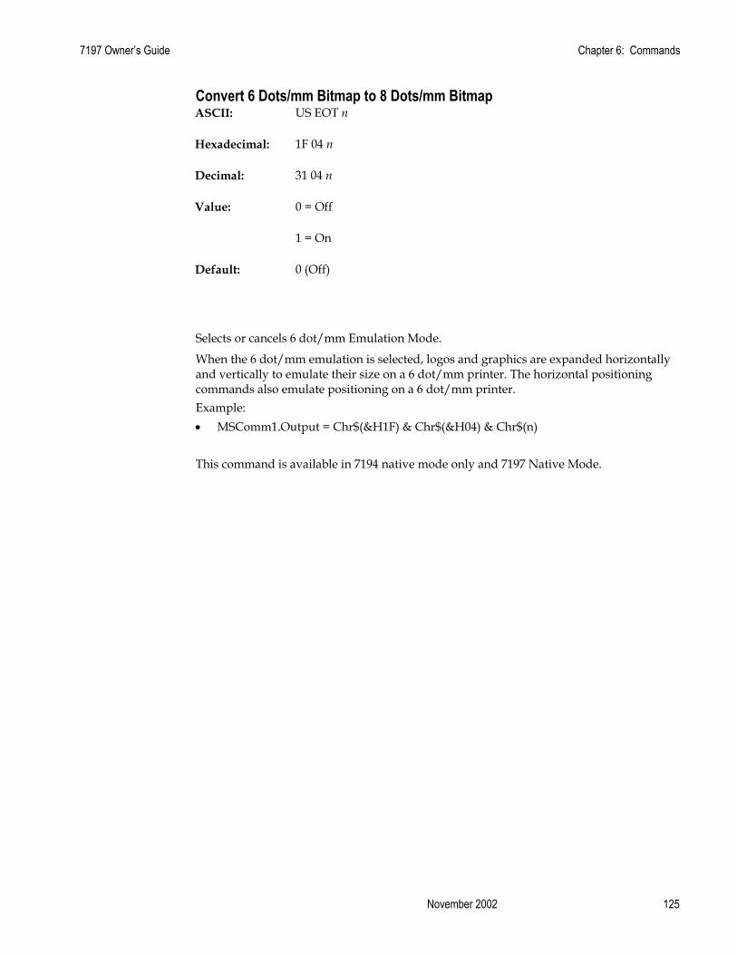
7197 Owner’s Guide Chapter 6: Commands
November 2002 125
Convert 6 Dots/mm Bitmap to 8 Dots/mm Bitmap ASCII: US EOT n
Hexadecimal: 1F 04 n
Decimal: 31 04 n
Value: 0 = Off
1 = On
Default: 0 (Off)
Selects or cancels 6 dot/mm Emulation Mode.
When the 6 dot/mm emulation is selected, logos and graphics are expanded horizontally and vertically to emulate their size on a 6 dot/mm printer. The horizontal positioning commands also emulate positioning on a 6 dot/mm printer. Example: • MSComm1.Output = Chr$(&H1F) & Chr$(&H04) & Chr$(n) This command is available in 7194 native mode only and 7197 Native Mode.

Chapter 6: Commands 7197 Owner’s Guide
February 2002 126
Status Commands
Status Command Introduction The 7197 has three methods of providing status to the application. These methods are through Batch Status Commands, Real Time Status Commands, and Auto Status Back. An application may use one or more of these methods to understand the current status of the printer. A brief description of each of these methods follows.
Batch Status Commands – These commands are sent to the printer and stored in the printer’s buffer. Once the printer has processed all the previous commands these commands are processed and the proper status is returned to the application. In the event a condition causes the printer to go BUSY, it stops processing commands from the printer buffer. If a Batch Status Command remained in the buffer during this busy condition, it would not be processed. In fact, no Batch Commands are processed while the printer is in this state.
Real-Time Commands – These commands are sent to the printer and are NOT stored in the printer’s buffer. Instead, they are acted on immediately (regardless of the printer’s BUSY status) and their response (if any) is returned to the application. This gives the application the ability to query the printer when it is in a busy state in order to correct whatever fault has occurred.
Auto Status Back – This mechanism allows the application developer to program the printer to automatically respond with a four byte status when certain conditions in the printer change.
Please see the subsequent sections for a more detailed description of these status commands. At the end of this Status Commands section is a page entitled “Recognizing Data from the Printer”. This describes how to interpret what command or setting (in the case of Auto Status Back) triggered a response from the printer.
Batch Mode For RS-232C printers, these commands enable the printer to communicate with the host computer following the selected handshaking protocol, either DTR/DSR or XON/XOFF. They are stored in the printer's data buffer as they are received, and are handled by the firmware in the order in which they are received.
When a fault occurs, the printer will go busy at the RS-232C interface and not respond to any of the Batch Mode Printer Status commands. If the fault causing the busy condition can be cleared, such as by loading paper, or letting the thermal print head cool down, the printer will resume processing the data in its receive buffer.

7197 Owner’s Guide Chapter 6: Commands
November 2002 127
Transmit Peripheral Device Status ASCII: ESC u 0
Hexadecimal: 1B 75 0
Decimal: 27 117 0
Bit 0 Bit 1
Return Value: 1 = Drawer 1 closed 1 = Drawer 2 closed
0 = Drawer 1 open 0 = Drawer 2 open
(Bits 2-7 are not used)
Transmits current status of the cash drawers. One byte is sent to the host computer. In DTR/DSR protocol the printer waits for DSR = SPACE. If a drawer is not connected, the status will indicate it is closed. Example: • MSComm1.Output = Chr$(&H1B) & Chr$(&H75) & Chr$(&H0)
Transmit Printer Status ASCII: ESC v
Hexadecimal: 1B 76
Decimal: 27 118
Sends status data to the host computer. The printer sends one byte to the host computer when it is not busy or in a fault condition. In DTR/DSR protocol, the printer waits for DSR = SPACE.

Chapter 6: Commands 7197 Owner’s Guide
February 2002 128
Status Byte (RS-232C) Bit Function 0 Signifies 1 Signifies 0 Receipt Paper Ok Low 1 Receipt Cover or Front Cover Closed Open 2 Receipt Paper Ok Out 3 Knife Position Ok Jam 4 Not Used Fixed to Zero Fixed to Zero 5 Temperature In valid range Too hot or too cold 6 Voltage In valid range Too high or too
low 7 Not Used Fixed to Zero Fixed to Zero
Example: • MSComm1.Output = Chr$(&H1B) & Chr$(&H76)
Related Information:
See Real Time Commands, in this document for details about fault condition reporting.
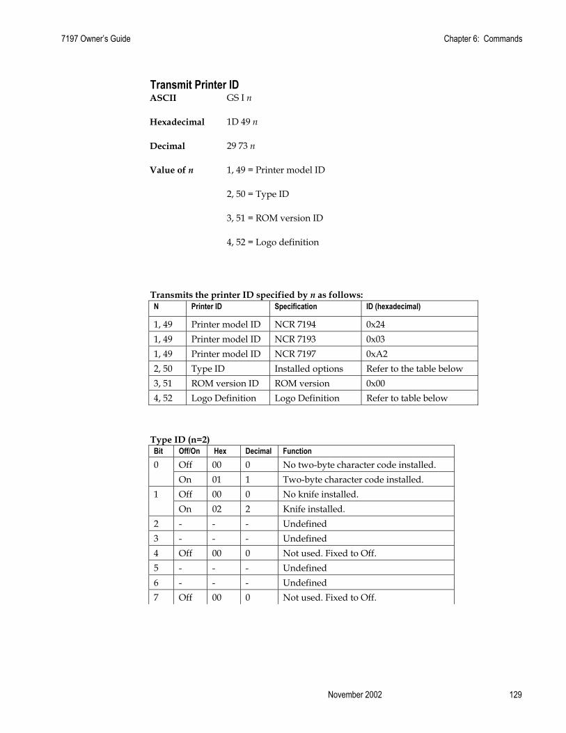
7197 Owner’s Guide Chapter 6: Commands
November 2002 129
Transmit Printer ID ASCII GS I n
Hexadecimal 1D 49 n
Decimal 29 73 n
Value of n 1, 49 = Printer model ID
2, 50 = Type ID
3, 51 = ROM version ID
4, 52 = Logo definition
Transmits the printer ID specified by n as follows: N Printer ID Specification ID (hexadecimal)
1, 49 Printer model ID NCR 7194 0x24 1, 49 Printer model ID NCR 7193 0x03 1, 49 Printer model ID NCR 7197 0xA2 2, 50 Type ID Installed options Refer to the table below 3, 51 ROM version ID ROM version 0x00 4, 52 Logo Definition Logo Definition Refer to table below
Type ID (n=2) Bit Off/On Hex Decimal Function 0 Off 00 0 No two-byte character code installed. On 01 1 Two-byte character code installed. 1 Off 00 0 No knife installed. On 02 2 Knife installed. 2 - - - Undefined 3 - - - Undefined 4 Off 00 0 Not used. Fixed to Off. 5 - - - Undefined 6 - - - Undefined 7 Off 00 0 Not used. Fixed to Off.

Chapter 6: Commands 7197 Owner’s Guide
February 2002 130
Type ID (n=4) Bit Off/On Hex Decimal Function 0 Off 00 0 No logo definition loaded by application. On 01 1 Logo loaded by application. 1 - - - Undefined 2 - - - Undefined 3 - - - Undefined 4 Off 00 0 Not used. Fixed to Off. 5 - - - Undefined 6 - - - Undefined 7 Off 00 0 Not used. Fixed to Off.
Example: • MSComm1.Output = Chr$(&H1D) & Chr$(&H49) & Chr$(n)
Transmit Printer ID, Remote Diagnostics Extension ASCII: GS I @ n
Hexadecimal: 1D 49 40 n
Decimal: 29 73 64 n
Values of n: Refer to table
Range of n: 32 – 255
(not all defined but reserved)
Performs the remote diagnostic function specified by n.
Eighteen remote diagnostic items are defined: eight printer ID items and ten printer tally items. A group of four remote diagnostic functions is assigned to each diagnostic item. Most of the diagnostic items are maintained in non-volatile memory (NVRAM), but some are maintained in read-only memory (ROM).
The table that follows describes the variables.
The first item group in the table includes an example of data to send and to receive. Data sent from the host to write to NVRAM must contain all digits required by the remote diagnostic item. All data must be ASCII. The printer returns all ASCII data. It is preceded by the parameter n to identify the diagnostic item and is followed by a Carriage Return (0D) to signify the end of the data.

7197 Owner’s Guide Chapter 6: Commands
November 2002 131
The command performs the remote diagnostic function specified by n as described in the following table. Value of n Remote Diagnostic Item Function ASC Hex Dec Space 20 32 Serial #,
10 digit ASCII Write to NVRAM Example, send 14 bytes to printer: GS I @ 0x20 1234567890
! 21 33 Serial # , 10 digit ASCII
Write to NVRAM, and print on receipt to verify Example, send 14 bytes to printer: GS I @ ! 1234567890 This will print on receipt: Serial # written: 1234567890
“ 22 34 Serial # Not available, cannot clear Serial # item # 23 35 Serial # Return Serial #, preceded by n to identify
Printer returns 12 bytes in above example: #1234567890<CR>
$ 24 36 Class/model #, 15 digit ASCII
Write to NVRAM
% 25 37 Class/model # Write to NVRAM, and print on receipt to verify
‘ 27 39 Class/model # Return Class/model #, returns 17 bytes + 2B 43 Boot firmware part
#, 12 digit ASCII Return Boot firmware part #, returns 14 bytes
/ 2F 47 Boot firmware CRC, 4 digit ASCII
Return Boot firmware CRC, returns 6 bytes
3 33 51 Flash firmware part #, 12 digit ASCII
Return Flash firmware part #, returns 14 bytes
7 37 55 Flash firmware CRC, 4 digit ASCII
Return Flash firmware CRC, returns 6 bytes
Ç 80 128 Receipt lines tally, 8 digit ASCII numeric, max 99,999,999
Write to NVRAM Example, send 12 bytes to printer: GS I @ Ç00010000 To set receipt lines tally to 10,000
ü 81 129 Receipt lines tally Write to NVRAM, and print on receipt to verify Example, send 12 bytes to printer: GS I @ ü00010000 This will print on receipt: Receipt tally written: 10,000
é 82 130 Receipt lines tally Clear receipt lines tally to 0 â 83 131 Receipt lines tally Return receipt lines tally, preceded by n
to identify Printer returns 10 bytes in above example: â00010000<CR>
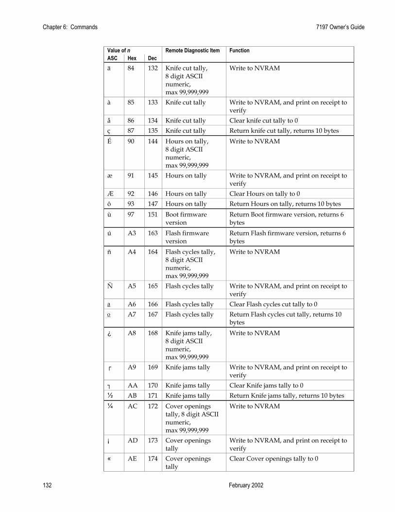
Chapter 6: Commands 7197 Owner’s Guide
February 2002 132
Value of n Remote Diagnostic Item Function ASC Hex Dec ä 84 132 Knife cut tally,
8 digit ASCII numeric, max 99,999,999
Write to NVRAM
à 85 133 Knife cut tally Write to NVRAM, and print on receipt to verify
å 86 134 Knife cut tally Clear knife cut tally to 0 ç 87 135 Knife cut tally Return knife cut tally, returns 10 bytes É 90 144 Hours on tally,
8 digit ASCII numeric, max 99,999,999
Write to NVRAM
æ 91 145 Hours on tally Write to NVRAM, and print on receipt to verify
Æ 92 146 Hours on tally Clear Hours on tally to 0 ô 93 147 Hours on tally Return Hours on tally, returns 10 bytes ù 97 151 Boot firmware
version Return Boot firmware version, returns 6 bytes
ú A3 163 Flash firmware version
Return Flash firmware version, returns 6 bytes
ñ A4 164 Flash cycles tally, 8 digit ASCII numeric, max 99,999,999
Write to NVRAM
Ñ A5 165 Flash cycles tally Write to NVRAM, and print on receipt to verify
a A6 166 Flash cycles tally Clear Flash cycles cut tally to 0 ο A7 167 Flash cycles tally Return Flash cycles cut tally, returns 10
bytes ¿ A8 168 Knife jams tally,
8 digit ASCII numeric, max 99,999,999
Write to NVRAM
┌ A9 169 Knife jams tally Write to NVRAM, and print on receipt to verify
┐ AA 170 Knife jams tally Clear Knife jams tally to 0 ½ AB 171 Knife jams tally Return Knife jams tally, returns 10 bytes ¼ AC 172 Cover openings
tally, 8 digit ASCII numeric, max 99,999,999
Write to NVRAM
¡ AD 173 Cover openings tally
Write to NVRAM, and print on receipt to verify
« AE 174 Cover openings tally
Clear Cover openings tally to 0
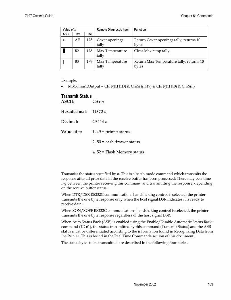
7197 Owner’s Guide Chapter 6: Commands
November 2002 133
Value of n Remote Diagnostic Item Function ASC Hex Dec » AF 175 Cover openings
tally Return Cover openings tally, returns 10 bytes
█ B2 178 Max Temperature tally
Clear Max temp tally
| B3 179 Max Temperature tally
Return Max Temperature tally, returns 10 bytes
Example: • MSComm1.Output = Chr$(&H1D) & Chr$(&H49) & Chr$(&H40) & Chr$(n)
Transmit Status ASCII: GS r n
Hexadecimal: 1D 72 n
Decimal: 29 114 n
Value of n: 1, 49 = printer status
2, 50 = cash drawer status
4, 52 = Flash Memory status
Transmits the status specified by n. This is a batch mode command which transmits the response after all prior data in the receive buffer has been processed. There may be a time lag between the printer receiving this command and transmitting the response, depending on the receive buffer status.
When DTR/DSR RS232C communications handshaking control is selected, the printer transmits the one byte response only when the host signal DSR indicates it is ready to receive data.
When XON/XOFF RS232C communications handshaking control is selected, the printer transmits the one byte response regardless of the host signal DSR.
When Auto Status Back (ASB) is enabled using the Enable/Disable Automatic Status Back command (1D 61), the status transmitted by this command (Transmit Status) and the ASB status must be differentiated according to the information found in Recognizing Data from the Printer. This is found in the Real Time Commands section of this document.
The status bytes to be transmitted are described in the following four tables.

Chapter 6: Commands 7197 Owner’s Guide
February 2002 134
Printer Status (n = 1 or n = 49) Bit Off/On Hex Decimal Status for Transmit Status 0
Off On
00 01
0 1
Paper present Paper exhausted.
1
Off On
00 02
0 2
Cover closed Cover open
2
Off On
00 04
0 4
Paper present Paper exhausted.
3 - - - Undefined 4 Off 00 0 Not used. Fixed to off. 5 - - - Undefined 6 - - - Undefined 7 Off 00 0 Not used. Fixed to off.
Cash Drawer Status (n = 2 or n = 50) Bit Off/On Hex Decimal Status for Transmit Status 0
Off On
00 01
0 1
One or both cash drawers open. Both cash drawers closed.
1
Off On
00 02
0 2
One or both cash drawers open. Both cash drawers closed.
2 - - - Undefined 3 - - - Undefined 4 Off 00 0 Not used. Fixed to off. 5 - - - Undefined 6 - - - Undefined 7 Off 00 0 Not used. Fixed to off.
Flash Memory Status (n = 4 or n = 52) Bit Off/On Hex Decimal Status for Transmit Status 0 Off 00 0 Undefined. Fixed to off. 1 Off 00 0 Undefined. Fixed to off. 2 Off 00 0 Not used. Fixed to off. 3 Off
On 00 08
0 8
Flash logo area adequate. Definition stored. Flash logo area not adequate for recent definition.
4 Off 00 0 Not used. Fixed to off. 5 Off
On 00 20
0 32
No thermal user-defined characters written to Flash Thermal user-defined characters written to Flash.
6 Off 00 0 Not used. Fixed to off. 7 Off 00 0 Not used. Fixed to off.

7197 Owner’s Guide Chapter 6: Commands
November 2002 135
Range of n: 1 – 4 49 - 52
Example: • MSComm1.Output = Chr$(&H1D) & Chr$(&H72) & Chr$(n)
Exceptions:
When n is out of the specified range, the command is ignored.
Send Printer Software Version ASCII: US V
Hexadecimal: 1F 56
Decimal: 31 86
The printer returns 8 bytes containing the boot and Flash software version. The first 4 bytes returned are an ASCII string for the boot version. The second 4 bytes are an ASCII string for the boot version. Example: for 1.234.56(8bytes), the boot version is 1.23 and the Flash version is 4.56. Example: • MSComm1.Output = Chr$(&H1F) & Chr$(&H56)
Recognizing Data from the Printer An application sending various Real Time and non-Real Time commands to which the printer responds can determine which command a response belongs to by the table below.
Responses to Transmit Peripheral Device Status (1B 75) and Transmit Paper Sensor Status (1B 76) are non-Real Time responses and will arrive in the order in which they were solicited.
Batch Mode Response Response Recognized By:
ASCII HEX
ESC u 0 1B 75 0 0 0 0 0 0 0 x x Binary ESC v 1B 76 0 0 0 0 0 x x x Binary GS I n 1D 49 n 0 x x 0 x x x x Binary GS r n 1D 72 n 0 x x 0 x x x x Binary Real-Time Response
Response Recognized By:
ASCII HEX
GS EOT n 1D 04 n 0 x x 1 x x 1 0 Binary DLE EOT n
10 04 n 0 x x 1 x x 1 0 Binary
GS ENQ 1D 05 1 x x x x x x x Binary

Chapter 6: Commands 7197 Owner’s Guide
February 2002 136
XON 0 0 0 1 0 0 0 1 Binary XOFF 0 0 0 1 0 0 1 1 Binary Auto Status Back (ASB)
Response Recognized By:
ASB Byte 1 0 x x 1 x x 0 0 Binary ASB Bytes 2-4 0 x x 0 x x x x Binary
7197 Owner’s Guide Chapter 6: Commands
November 2002 137
Real Time Commands These commands provide an application interface to the printer even when the printer is not handling other commands (RS-232C communication interface only):
1. Real Time Status Transmission (GS Sequence and DLE Sequence)
2. Real Time Request to Printer (GS Sequence and DLE Sequence)
3. Real Time Printer Status Transmission
The Batch Mode Printer Status commands are placed in the printer’s data buffer as they are received and handled by the firmware in the order in which they are received. If the paper exhausts while printing data that was in the buffer ahead of the status command, the printer goes busy at the RS-232C interface and suspends processing the data in the buffer until paper is reloaded. This is true for all error conditions: knife home error, thermal print head overheat, etc.
The Real Time commands are implemented in two ways to correct these problems. Both implementations offer the same functionality; which one you choose depends on the current usage of your application.
Preferred Implementation For a new application the GS (1D) sequences are recommended to avoid possible misinterpretation of a DLE (0x10) sequence as a Clear Printer (0x10 0, ASCII DLE NUL) command.
An application using these GS (1D) sequences, does not need to distinguish for the printer between the new real time commands and the Clear Printer command. This implementation is ideal for an existing 7193 application that already uses the Clear Printer command or for a new application being developed.
Alternate Implementation The alternate implementation uses the DLE (0x10) sequences as implemented on other printers. An application using these DLE (0x10) sequences and the original 7193 Clear Printer command (0x10) must distinguish for the printer between the new real time commands and the Clear Printer command by adding a NUL (0x00) to the Clear Printer command.
An application using these DLE (0x10) sequences must also send the second byte of the sequence within 100 milliseconds of the first, to prevent the first byte being mistaken for a Clear Printer command.
Rules for Using Real Time Commands Three situations must be understood when using real time commands.
First, the printer executes the Real Time command upon receiving it and will transmit status regardless of the condition of the DSR signal.
Second, the printer transmits status whenever it recognizes a Real Time Status Transmission command sequence, even if that sequence happens to occur naturally within the data of another command, such as graphics data.
In this case the sequence will also be handled correctly as the graphics data it is intended to be when the graphics command is executed from the buffer.

Chapter 6: Commands 7197 Owner’s Guide
February 2002 138
Third, care must be taken not to insert a Real Time command into the data sequence of another command that consists of two or more bytes.
In this case the printer will use the real time command sequence bytes instead of the other command’s parameter bytes when finally executing that other command from the buffer; the other command will NOT be executed correctly.
These three situations generally preclude use of standard DOS drivers for the serial communication ports when using real time commands.
Moving Data Through the Buffer Another consideration is that an application should take care not to let the buffer fill up with real time commands when the printer is busy at the RS-232C interface. A busy condition at the RS-232C interface can be determined by bit 3 of the response to 1D 05 or 1D 04 1 or 10 04 1. The reason for a particular busy condition can be determined by other responses to 1D 04 n or 10 04 n.
Although the printer responds to Real Time commands when it is busy, it will place them into the buffer behind any other data there, and flush them out in the order in which they were received. When the printer is busy due simply to buffer full (that is, it can’t print data as fast as it can receive it), then data continues to be processed out of the buffer at approximately print speed and the Real Time commands will eventually get flushed out.
When the printer is busy due to an error condition, then data stops being processed out of the buffer until the condition clears one way or another. In either case, but more quickly in the case of an error condition, the buffer can fill with real time commands.
When the DLE sequences are being used, the last byte stored when the buffer fills up could be the DLE code, with no room for the subsequent EOT or ENQ. When this lone DLE byte is finally processed out of the buffer it will be interpreted as a Clear Printer command.
Similarly, when the GS sequences are being used, the last byte stored when the buffer fills up could be the GS code, with no room for the subsequent EOT or ETX or ENQ. When this lone GS byte is finally processed out of the buffer it will use the next byte, whatever it is, as the second byte in its GS sequence.
To guard against this situation, an application should determine the cause of a busy condition and take appropriate action or pace further real time commands to avoid filling the buffer. There are a minimum of 256 bytes available in the printer’s buffer when it goes busy.

7197 Owner’s Guide Chapter 6: Commands
November 2002 139
Real Time Status Transmission GS Sequence DLE Sequence
ASCII: GS EOT n DLE EOT n
Hexadecimal: 1D 04 n 10 04 n
Decimal: 29 4 n 16 4 n
Value of n: GS/DLE Sequence
1 = Transmit printer status
2 = Transmit RS-232C busy status
3 = Transmit error status
4 = Transmit receipt paper status
Transmits the selected one byte printer status specified by n in Real Time according to the following parameters. This command includes two sequences: GS and DLE and using either or will produce the same result. Example: • MSComm1.Output = Chr$(&H1D) & Chr$(&H04) & Chr$(n)
Exceptions:
The command is ignored if n is out of range.
An application using the DLE sequence must send EOT within 100 milliseconds of DLE or the printer will misinterpret the DLE and execute a Clear Printer command. Avoid this possibility by using the 1D 04 n sequence, which is handled exactly the same as 10 04 n.
Related Information: 1 = Transmit Printer Status
Bit Status Hex Decimal Function 0 Off 00 0 Fixed to Off 1 On 02 2 Fixed to On 2 Off
On 00 04
0 4
One or both cash drawers open Both cash drawers closed
3 Off On
00 08
0 8
Not busy at the RS-232C interface Printer is Busy at the RS-232C interface
4 On 10 16 Fixed to On 5 - - - Undefined 6 - - - Undefined 7 Off 00 0 Fixed to Off
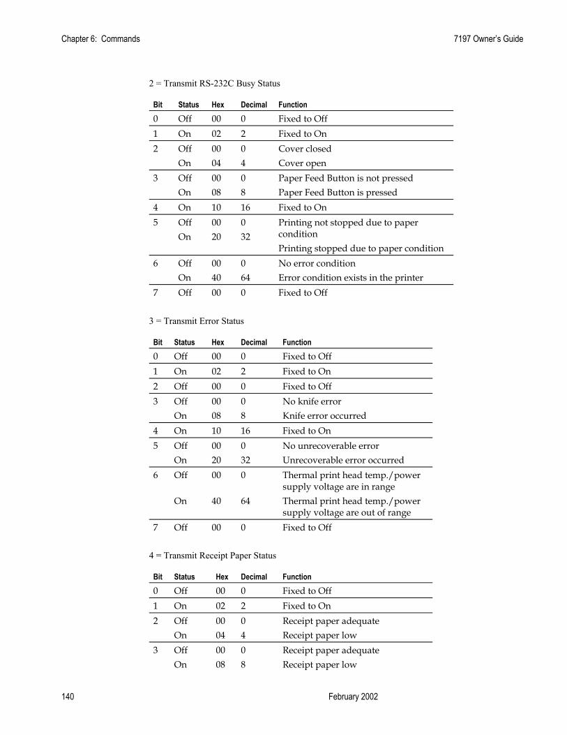
Chapter 6: Commands 7197 Owner’s Guide
February 2002 140
2 = Transmit RS-232C Busy Status
Bit Status Hex Decimal Function 0 Off 00 0 Fixed to Off 1 On 02 2 Fixed to On 2 Off
On 00 04
0 4
Cover closed Cover open
3 Off On
00 08
0 8
Paper Feed Button is not pressed Paper Feed Button is pressed
4 On 10 16 Fixed to On 5 Off
On 00 20
0 32
Printing not stopped due to paper condition Printing stopped due to paper condition
6 Off On
00 40
0 64
No error condition Error condition exists in the printer
7 Off 00 0 Fixed to Off
3 = Transmit Error Status
Bit Status Hex Decimal Function 0 Off 00 0 Fixed to Off 1 On 02 2 Fixed to On 2 Off 00 0 Fixed to Off 3 Off
On 00 08
0 8
No knife error Knife error occurred
4 On 10 16 Fixed to On 5 Off
On 00 20
0 32
No unrecoverable error Unrecoverable error occurred
6 Off On
00 40
0 64
Thermal print head temp./power supply voltage are in range Thermal print head temp./power supply voltage are out of range
7 Off 00 0 Fixed to Off
4 = Transmit Receipt Paper Status
Bit Status Hex Decimal Function 0 Off 00 0 Fixed to Off 1 On 02 2 Fixed to On 2 Off
On 00 04
0 4
Receipt paper adequate Receipt paper low
3 Off On
00 08
0 8
Receipt paper adequate Receipt paper low

7197 Owner’s Guide Chapter 6: Commands
November 2002 141
4 On 10 16 Fixed to On 5 Off
On 00 20
0 32
Receipt paper present Receipt paper exhausted
6 Off On
00 40
0 64
Receipt paper present Receipt paper exhausted
7 Off 00 0 Fixed to Off
Real Time Request to Printer
GS Sequence DLE Sequence
ASCII: GS ETX n or DLE ENQ n
Hexadecimal: 1D 03 n or 10 05 n
Decimal: 29 3 n or 16 5 n
Value of n: 1 = Recover and restart
2 = Recover and clear buffers
The printer responds to a request from the host specified by n. This command includes two sequences: GS and DLE. The operations performed depend on the value of n, according to the following parameters.
n = 1:
Restarts printing from the beginning of the line where an error occurred, after recovering from the error. Print settings that are normally preserved from line to line, such as character height and width, are still preserved with this command. This sequence is ignored except when the printer is busy due to an error condition.
If the receipt is selected, this command will attempt recovery from a knife error. Other errors associated with the receipt, such as paper out or print head overheating, can be recovered from only by clearing the specific condition, such as loading paper or letting the print head cool down.
n = 2:
Recovers from an error after clearing the receive and print buffers. Print settings that are normally preserved from line to line, such as character height and width, are still preserved with this command. This sequence is ignored except when the printer is busy due to an error condition.
Example: • MSComm1.Output = Chr$(&H1D) & Chr$(&H03) & Chr$(n)
Exceptions:
The command is ignored if n is out of range

Chapter 6: Commands 7197 Owner’s Guide
February 2002 142
An application using the DLE sequence must send ENQ within 100 milliseconds of DLE or the printer will misinterpret the DLE and execute a Clear Printer command. Avoid this possibility by using the 1D 03 n sequence that is handled exactly the same as 10 05 n.
Real Time Printer Status Transmission ASCII: GS ENQ
Hexadecimal: 1D 05
Decimal: 29 5
Transmits one byte status of the printer in real time.
Value of Byte: Bit Status Hex Decimal Function 0 Off
On 00 01
0 1
Receipt paper adequate Receipt paper low
1 Off On
00 02
0 2
Receipt paper adequate Receipt paper low
2 Off On
00 04
0 4
Cover closed Cover open
3 Off On
00 08
0 8
Not busy at the RS-232C interface Printer is busy at the RS-232C interface
4 Off On
00 1
0 16
One or both cash drawers open Both cash drawers closed
5 Off 00 0 Fixed to off 6 Off
On 00 40
0 64
No error condition Error condition exists in the printer
7 On 00 0 Fixed to on
Example: • MSComm1.Output = Chr$(&H1D) & Chr$(&H05)

7197 Owner’s Guide Chapter 6: Commands
November 2002 143
Auto Status Back Commands
Select or Cancel Automatic Status Back ASCII: GS a n
Hexadecimal: 1D 61 n
Decimal: 29 97 n
Value of n: Status of ASB
Enables or disables automatic status back (ASB) and specifies the status items. This command is a batch mode command; that is, it is processed after all prior data in the receive buffer has been processed. There may be a time lag between the printer receiving this command and changing the ASB response, depending on the receive buffer status.
If any of the status items listed are selected, ASB is enabled and the printer automatically transmits 4 status bytes whenever the selected status changes. If no status is selected, ASB is disabled. All four status bytes are transmitted without checking DSR.
If the error status is enabled, a change in the following conditions will trigger the ASB:
1. Cash Drawer
2. Receipt Cover
3. Knife Error
4. Out-of-Range Print head Temperature
5. Out-of-Range Voltage
6. Paper Exhaust Status
The bits of n are defined in the table. Bit Off/On Hex Decimal Status for ASB 0
Off On
00 01
0 1
Cash drawer status disabled. Cash drawer status enabled.
1
Off On
00 02
0 2
RS-232C Busy status disabled. RS-232C Busy status enabled.
2
Off On
00 04
0 4
Error status disabled. Error status enabled.
3
Off On
00 08
0 8
Receipt paper roll status disabled. Receipt paper roll status enabled.
4 - - - Undefined 5 - - - Undefined 6 - - - Undefined 7 - - - Undefined

Chapter 6: Commands 7197 Owner’s Guide
February 2002 144
Default: 0 (ASB disabled) Example: • MSComm1.Output = Chr$(&H1D) & Chr$(&H61) & Chr$(n)
Exceptions
If n = 0, ASB is disabled.
Related Information
When Auto Status Back (ASB) is enabled using this command, the status transmitted by other commands and the ASB status are differentiated according to the information found in Recognizing Data from the printer, (in the Real Time Commands section in this chapter). The status bytes to be transmitted are described in the following four tables.
Byte 1 = printer information Byte 2 = error information Byte 3 = paper sensor information Byte 4 = paper sensor information
First Byte (Printer Information) Bit Off/On Hex Decimal Status for ASB 0 Off 00 0 Not used. Fixed to off. 1 Off 00 0 Not used. Fixed to off. 2
Off On
00 04
0 4
One or both cash drawers open. Both cash drawers closed.
3
Off On
00 08
0 8
Not Busy at the RS232C interface. Printer is Busy at the RS232C interface.
4 On 10 16 Not used. Fixed to on. 5
Off On
00 20
0 32
Receipt cover closed. Receipt cover open.
6
Off On
00 40
0 64
Paper Feed Button is not pressed. Paper Feed Button is pressed.
7 Off 00 0 Not used. Fixed to off.

7197 Owner’s Guide Chapter 6: Commands
November 2002 145
Second Byte (Error information) Bit Off/On Hex Decimal Status for ASB 0 - - - Undefined 1 - - - Undefined 2 - - - Undefined 3
Off On
00 08
0 8
No knife error. Knife error occurred.
4 Off 00 0 Not used. Fixed to off. 5
Off On
00 20
0 32
No unrecoverable error. Unrecoverable error occurred.
6
Off On
00 40
0 64
No recoverable error occurred Recoverable error occurred: Cover open, paper out, tempeature, Voltage is out of range.
7 Off 00 0 Not used. Fixed to off.
Third Byte (Paper Sensor Information)
Bit Off/On Hex Decimal Status for ASB 0 Off
On 00 01
0 1
Receipt paper adequate Receipt paper low
1 Off On
00 02
0 2
Receipt paper adequate Receipt paper low
2
Off On
00 04
0 4
Receipt paper present. Receipt paper exhausted.
3 Off On
00 08
0 8
Receipt paper present Receipt paper exhausted
4 Off 00 0 Not used. Fixed to off. 5 Off 00 0 Undefined. Fixed to off. 6 Off 00 0 Undefined. Fixed to off. 7 Off 00 0 Not used. Fixed to off.
Fourth Byte (Paper Sensor Information) Bit Off/On Hex Decimal Status for ASB 0 - - - Undefined 1 - - - Undefined 2 - - - Undefined 3 - - - Undefined 4 Off 00 0 Not used. Fixed to off. 5 - - - Undefined 6 - - - Undefined 7 Off 00 0 Not used. Fixed to off.

Chapter 6: Commands 7197 Owner’s Guide
February 2002 146
Bar Code Commands These following describes the commands for the printing of bar codes and described in the order of their hexadecimal codes. Note: 7193 firmware can be set for module widths in bar codes ranging from 2 dots to 4 dots per module (DPM) for the narrow modules. The default is 3 DPM. 7167 firmware ranges from 1 dot per module to 5 dots per module (DPM) printed on the receipt. The default is 2 DPM.
Select Printing Position for HRI Characters ASCII: GS H n
Hexadecimal: 1D 48 n
Decimal: 29 72 n
Value of n: Printing position
0 = Not printed
1 = Above the bar code
2 = Below the bar code
3 = Both above and below the bar code
Default: 0 (Not printed)
Prints HRI (Human Readable Interface) characters above or below the bar code. Example: • MSComm1.Output = Chr$(&H1D) & Chr$(&H48) & Chr$(n)

7197 Owner’s Guide Chapter 6: Commands
November 2002 147
Select Pitch for HRI Characters ASCII: GS f n
Hexadecimal: 1D 66 n
Decimal: 29 102 n
Value of n: Pitch
0 = Standard Pitch at 15.2 CPI on receipt
1 = Compressed Pitch at 19 CPI on receipt
Default: 0 (Standard Pitch at 15.2 CPI)
Selects standard or compressed font for printing Bar Code characters. Example: • MSComm1.Output = Chr$(&H1D) & Chr$(&H66) & Chr$(n)
Select Bar Code Height ASCII: GS h n
Hexadecimal: 1D 68 n
Decimal: 29 104 n
Value of n: Number of dots
Range of n: 1 - 255
Default: 162
Sets the bar code height to n dots or n/8 mm (n/203 inch) for receipt. Example: • MSComm1.Output = Chr$(&H1D) & Chr$(&H68) & Chr$(n)

Chapter 6: Commands 7197 Owner’s Guide
February 2002 148
Print Bar Code First Variation Second Variation
ASCII: GS k m d1…dk NUL or GS k m n d1…dn
Hexadecimal: 1D 6B m d1…dk 00 or 1D 6B m n d1…dn
Decimal: 29 107 m d1…dk 0 or 29 107 m n d1…dn
0 = End of command.
Values:
First Variation: String terminated with NUL Character
m = 0 – 6, 10
d = 32 - 126 (see the table)
n = 1 - 255 (see the table)
Selects the bar code type and prints a bar code for the ASCII characters entered. If the width of the bar code exceeds one line, the barcode is not printed.
There are two variations to this command. The first variation uses a NUL character to terminate the string; the second uses a length byte at the beginning of the string to compensate for the Code 128 bar code, which can accept a NUL character as part of the data. With the second variation the length of byte is specified at the beginning of the string.
Fixed-length codes can be aligned left, center, or right using the Align Positions command (1B 61). Variable-length codes are always center aligned in 7193 Emulation.
The check digit is calculated for UPC and JAN (EAN) codes if it is not sent from the host computer. Six-character zero-suppressed UPC-E tags are generated from full 11 or 12 characters sent from the host computer according to standard UPC-E rules. Start/Stop characters are added for Code 39 if they are not included.

7197 Owner’s Guide Chapter 6: Commands
November 2002 149
m Bar Code D n, Length
0 UPC-A 48- 57 (ASCII numerals) Fixed Length: 11, 12 1 UPC-E 48- 57 Fixed Length: 11, 12 2 JAN13 (EAN13) 48- 57 Fixed Length: 12, 13 3 JAN8 (EAN8) 48- 57 Fixed Length: 7, 8 4 Code 39 48- 57,
65- 90 (ASCII alphabet), 32, 36, 37, 43, 45, 46, 47 (ASCII special characters) d1 = dk = 42 (start/stop code is supplied by printer if necessary)
Variable Length
5 Interleaved 2 of 5 (ITF)
48- 57 Variable Length (Even Number)
6 CODABAR (NW-7)
65- 68, start code 48- 57, 36, 43, 45, 46, 47, 58
Variable Length
10 PDF 417 (7194 Native Mode and 7197 Native Mode)
1-255 Variable Length 7194 Native Mode and 7197 Native Mode
Second Variation: Length of Byte Specified at Beginning of String m = 65 - 73, 75 (see the table)
d = 0 - 127 (see the table)
n = 1 - 255 (see the table)
The value of m selects the bar code system as described in the table. When data is present in the print buffer, the printer processes the data following m as normal data.
The variable d indicates the character code to be encoded into the specified bar code system. See the table. If character code d cannot be encoded, the printer prints the bar code data processed so far, and the following data is treated as normal data.

Chapter 6: Commands 7197 Owner’s Guide
February 2002 150
M Bar Code D n, Length 65 UPC-A 48- 57 (ASCII numerals) Fixed Length: 11, 12 66 UPC-E 48- 57 Fixed Length: 11, 12 67 JAN13 (EAN13) 48- 57 Fixed Length: 12, 13 68 JAN8 (EAN8) 48- 57 Fixed Length: 7, 8 69 CODE 39 48- 57, 65- 90 (ASCII
alphabet), 32, 36, 37, 43, 45, 46, 47 (ASCII special characters) d1 = dn = 42 (start/stop code is supplied by printer if necessary)
Variable
70 Interleaved 2 of 5 (ITF)
48- 57 Variable (Even Number)
71 CODABAR (NW-7)
65- 68, start code 48- 57, 36, 43, 45, 46, 47, 58
Variable
72 Code 93 0 - 127 Variable (A748 Native Mode only)
73 Code 128 0-105 d1 = 103-105 (must be a Start code) d2 = 0-102 (data bytes) (Stop code is provided by the printer)
Variable
75 PDF417 0 – 255 Variable Length (A748 Native Mode only)
MSComm1.Output = Chr$(&H1D) & Chr$(&H6B) & Chr$(m) & "123456789012" & Chr$(0)
The above command will print the number above or below the bar code, depending on which parameter for m that specify.
Exceptions:
Illegal data cancels this command.
The command is valid only at the beginning of a line.
PDF417 and Code 93 are only available in 7194 Native Mode.

7197 Owner’s Guide Chapter 6: Commands
November 2002 151
Select Bar Code Width ASCII: GS w n
Hexadecimal: 1D 77 n
Decimal: 29 119 n
Value of n: 1, 2, 3, 4, 5
Default: 3 for receipt
Sets the bar code width to n dots.
Formulas:
n + 1/8 mm (n + 1/203 inch) for receipt. Example: • MSComm1.Output = Chr$(&H1D) & Chr$(&H77) & Chr$(n)
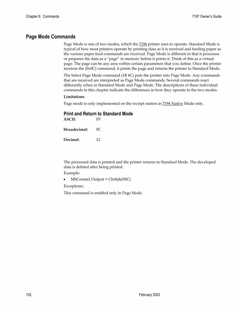
Chapter 6: Commands 7197 Owner’s Guide
February 2002 152
Page Mode Commands Page Mode is one of two modes, which the 7194 printer uses to operate. Standard Mode is typical of how most printers operate by printing data as it is received and feeding paper as the various paper feed commands are received. Page Mode is different in that it processes or prepares the data as a “page” in memory before it prints it. Think of this as a virtual page. The page can be any area within certain parameters that you define. Once the printer receives the (0x0C) command, it prints the page and returns the printer to Standard Mode.
The Select Page Mode command (1B 4C) puts the printer into Page Mode. Any commands that are received are interpreted as Page Mode commands. Several commands react differently when in Standard Mode and Page Mode. The descriptions of these individual commands in this chapter indicate the differences in how they operate in the two modes.
Limitations
Page mode is only implemented on the receipt station in 7194 Native Mode only.
Print and Return to Standard Mode ASCII: FF
Hexadecimal: 0C
Decimal: 12
The processed data is printed and the printer returns to Standard Mode. The developed data is deleted after being printed. Example: • MSComm1.Output = Chr$(&H0C)
Exceptions:
This command is enabled only in Page Mode.

7197 Owner’s Guide Chapter 6: Commands
November 2002 153
Cancel Print Data in Page Mode ASCII: CAN
Hexadecimal: 18
Decimal: 24
Deletes all the data to be printed in the “page” area. Any data from the previously selected “page” area that is also part of the current data to be printed is deleted.
This command has the same code as the Open Form command, which is performed when the printer is not in Page Mode. Example: • MSComm1.Output = Chr$(&H18)
Exceptions:
This command is only used in Page Mode.
Print Data in Page Mode ASCII: ESC FF
Hexadecimal: 1B 0C
Decimal: 27 12
Collectively prints all buffered data in the printing area.
After printing, the printer does not clear the buffered data and sets values for Select Print Direction in Page Mode (1B 54 n) and Set Print Area in Page Mode (1B 57…), and sets the position for buffering character data. Example: • MSComm1.Output = Chr$(&H1B) & Chr$(&H0C)
Exceptions:
This command enabled only in Page Mode.

Chapter 6: Commands 7197 Owner’s Guide
February 2002 154
Select Page Mode ASCII: ESC L
Hexadecimal: 1B 4C
Decimal: 27 76
Switches from Standard Mode to Page Mode. After printing has been completed either by the Print and Return to Standard Mode (FF) command or Select Standard Mode (1B 53) the printer returns to Standard Mode. The developed data is deleted after being printed.
This command sets the position where data is buffered to the position specified by Select Print Direction in Page Mode (1B 54) within the printing area defined by Set Print Area in Page Mode (1B 57).
This command switches the settings for the following commands (which values can be set independently in Standard Mode and Page Mode) to those for Page Mode.
1. Set Right-Side Character Spacing (1B 20)
2. Select 1/6-Inch Line Spacing (1B 32)
3. Set Line Spacing (1B 33)
It is possible only to set values for the following commands in Page Mode. These commands are not executed.
4. Select or Cancel 90 Degree Clockwise Rotation (1B 56)
5. Select Justification (1B 61)
6. Select or Cancel Upside Down Printing (1B 7B).
7. Set Left Margin (1D 4C)
8. Set Print Area Width (1D 57) Example: • MSComm1.Output = Chr$(&H1B) & Chr$(&H4C)
Exceptions:
The command is enabled only when input at the beginning of a line. The command has no effect if Page Mode has previously been selected. In 7193 Emulation Mode, (1B 4C…) is used for double density graphics.

7197 Owner’s Guide Chapter 6: Commands
November 2002 155
Select Standard Mode ASCII: ESC S
Hexadecimal: 1B 53
Decimal: 27 83
Switches from Page Mode to Standard Mode. In switching from Page Mode to Standard Mode, data buffered in Page Mode is cleared, the printing area set by Set Print Area in Page Mode (1B 57) is initialized and the print position is set to the beginning of the line.
This command switches the settings for the following commands (the values for these commands can be set independently in Standard Mode and Page Mode) to those for Standard Mode:
1. Set Right-Side Character Spacing (1B 20)
2. Select 1/6 Inch Line Spacing (1B 32)
3. Set Line Spacing (1B 33)
Standard Mode is automatically selected when power is turned on, the printer is reset, or the Initialize Printer command (1B 40) is used. Example: • MSComm1.Output = Chr$(&H1B) & Chr$(&H53)
Exceptions:
This command is effective only in Page Mode.

Chapter 6: Commands 7197 Owner’s Guide
February 2002 156
Select Print Direction in Page Mode ASCII: ESC T n
Hexadecimal: 1B 54 n
Decimal: 27 84 n
Value of n: Start position
0 Upper left corner proceeding across page to the right (A)
1 Lower left corner proceeding up the page (B)
2 Lower right corner proceeding across page to the left (upside down) (C)
3 Upper right corner proceeding down page (D)
A, B, C and D note the direction of of print. See illustration.
Selects the printing direction and start position in Page Mode. See the illustration.
The command can be sent multiple times so that several different print areas, aligned in different print directions, can be developed in the printer’s page buffer before being printed by the Print and Return to Standard mode command (0C).
A
D
B
Default: 0 (Upper left corner proceeding across page to the right) Example: • MSComm1.Output = Chr$(&H1B) & Chr$(&H54) & Chr$(n)
Exceptions:
This command is valid only in Page Mode.
This command is ignored if the value of n is out of the specified range.
7197 Owner’s Guide Chapter 6: Commands
November 2002 157
Set Printing Area in Page Mode ASCII: ESC W n1, n2 ...n8.]
Hexadecimal: 1B 57 n1, n2 ...n8]
Decimal: 27 87 n1,n2 ...n8]
Range: 0 - 255
Default: n1-4 = 0
n5 = 64
n6 = 2
n7 = 64
n8 = 2
Sets the position and size of the printing area in Page Mode.
The command can be sent multiple times so that several different print areas, aligned in different print directions, can be developed in the printer’s page buffer before being printed by the Print and Return to Standard mode command (0C).
Defaults equal an origin of 0,0 and a size of 576x576. This command is allowed in any mode.
Formulas:
The starting position of the print area is the upper left of the area to be printed (x0, y0). The length of the area to be printed in the y direction is set to dy inches. The length of the area to be printed in the x direction is set to dx inches. Use the equations to determine the Value of x0, y0, dx, and dy.
See the illustration for a graphic representation of the printing area. For more information about the fundamental calculation pitch, see the Set Fundamental Calculation Pitch command (1D 50).
1. x0 = [(n1 + n2 x 256) x (horizontal direction of the fundamental calculation pitch)]
2. y0 = [(n3 + n4 x 256) x (vertical direction of the fundamental calculation pitch)]
3. dx = [(n5 + n6 x 256) x (horizontal direction of the fundamental calculation pitch)]
4. dy = [(n7 + n8 x 256) x (vertical direction of the fundamental calculation pitch)]
Keep the following notes in mind for this command.
5. The fundamental calculation pitch depends on the vertical or horizontal direction.
6. The maximum printable area in the x direction is 576/203 inches.
7. The maximum printable area in the y direction is 2000/203 inches.
First the printer must be set to page mode, then the following command should be sent. Example:

Chapter 6: Commands 7197 Owner’s Guide
February 2002 158
• MSComm1.Output = Chr$(&H1B) & Chr$(&H57) & Chr$(&H40) & Chr$(&H0) & Chr$(&H40) & Chr$(&H0) & Chr$(&H40) & Chr$(&H1) & Chr$(&H40) & Chr$(&H1)
Exception:
This command is effective only in Page Mode.
Set Absolute Vertical Print Position in Page Mode ASCII: GS $ nL nH
Hexadecimal: 1D 24 nL nH
Decimal: 29 36 nL nH
Formulas:
[(nL + nH X 256) x (vertical or horizontal motion unit)] inches.
Sets the absolute vertical print starting position for buffer character data in Page Mode.
The vertical or horizontal motion unit for the paper roll is used and the horizontal starting buffer position does not move.
The reference starting position is set by Select Print Direction in Page Mode (1B 54). This sets the absolute position in the vertical direction when the starting position is set to the upper left or lower right; and sets the absolute position in the horizontal direction when the starting position is set to the upper right or lower left. The horizontal and vertical motion unit are specified by the Set Horizontal and Vertical Minimum Motion Units (1D 50) command.
The Set Horizontal and Vertical Minimum Motion Units (1D 50) command can be used to change the horizontal and vertical motion unit. However, the value cannot be less than the minimum horizontal movement amount, and it must be in even units of the minimum horizontal movement amount. Example: • MSComm1.Output = Chr$(&H1D) & Chr$(&H24) & Chr$(nL) & Chr$(nH)
Exceptions:
This command is effective only in Page Mode.
If the [(nL + nH x 256) x (vertical or horizontal motion unit)] exceeds the specified printing area, this command is ignored.

7197 Owner’s Guide Chapter 6: Commands
November 2002 159
Set Relative Vertical Print Position in Page Mode ASCII: GS \ nL nH
Hexadecimal: 1D 5C nL nH
Decimal: 29 92 nL nH
Sets the relative vertical print starting position from the current position. This command can also change the horizontal and vertical motion unit. The unit of horizontal and vertical motion is specified by this command.
This command functions as follows, depending on the print starting position set by Select Print Direction in Page Mode (1B 54): • When the starting position is set to the upper left or lower left of the printing area, the
vertical motion unit (y) is used. • When the starting position is set to the upper right or lower left of the printing area,
the horizontal motion unit (x) is used.
Value:
The value for the horizontal and vertical movement cannot be less than the minimum horizontal movement amount, and must be in even units of the minimum horizontal movement amount.
Formulas:
The distance from the current position is set to [(nL + nH x 256) x vertical or horizontal motion unit] inches. The amount of movement is calculated only for the receipt.
When pitch n is specified to the movement downward: nL + nH x 256 = n
When pitch n is specified to the movement upward (the negative direction), use the complement of 65536.
When pitch n is specified to the movement upward: nL + nH x 256 – 65536 – N
Exceptions:
This command is used only in Page Mode, otherwise it is ignored.
Any setting that exceeds the specified printing area is ignored. • Example: • MSComm1.Output = Chr$(&H1D) & Chr$(&H5C) & Chr$(nL) & Chr$(nH)
Chapter 6: Commands 7197 Owner’s Guide
February 2002 160
Macro Commands These commands are used to select and perform a user-defined sequence of printer operations.
Start or End Macro Definition ASCII: GS :
Hexadecimal: 1D 3A
Decimal: 29 58
Starts or ends macro definition. Macro definition begins when this command is received during normal operation and ends when this command is received during macro definition. The macro definition is cleared, during definition of the macro, when the Execute Macro (1D 5E) command is received.
Normal printing occurs while the macro is defined. When the power is turned on the macro is not defined.
The defined contents of the macro are not cleared by the Initialize Printer (1B 40), thus, the Initialize Printer (1B 40) command may be used as part of the macro definition.
If the printer receives a second Select or Cancel Macro Definition (1D 3A) command immediately after previously receiving a Select or Cancel Macro Definition (1D 3A) the printer remains in the macro undefined state.
Formulas:
The contents of the macro can be defined up to 2048 bytes. Example: • MSComm1.Output = Chr$(&H1D) & Chr$(&H3A)
Exceptions:
If the macro definition exceeds 2048 bytes, excess data is not stored.
This command is available in 7194 Native Mode only.
7197 Owner’s Guide Chapter 6: Commands
November 2002 161
Execute Macro ASCII: GS ^ r t m
Hexadecimal: 1D 5E r t m
Decimal: 29 94 r t m
Value of r: The number of times to execute the macro.
Value of t: The waiting time for executing the macro.
Value of m: Macro executing mode
0 (Bit0): The Macro executes r times continuously with waiting time specified by t.
1 (Bit0): The printer waits for feed button to be pressed after waiting for the period specified by t. If the button is pressed, the printer executes the macro once. The printer repeats the operation r times.
Executes a macro. After waiting for a specified period the LED indicators blink and the printer waits for the Paper Feed Button to be pressed. After the button is pressed, the printer executes the macro once. The printer repeats this operation the number of specified times.
When the macro is executed by pressing the Paper Feed Button (m = 1), paper cannot be fed by using the Paper Feed Button.
Formulas:
The waiting time is t x 100 msec for every macro execution.
m specifies macro executing mode when the LSB (Least significant bit) m = 0
The macro executes r times continuously at the interval specified by t when the LSB (Least significant bit) of m = 1. Example: • MSComm1.Output = Chr$(&H1D) & Chr$(&H5E) & Chr$(r) & Chr$(t) & Chr$(m)
Exceptions:
If this command is received while a macro is being defined, the macro definition is aborted and the definition is cleared.
If the macro is not defined or if r is 0, nothing is executed.
This command is available in 7194 Native Mode only.

Chapter 6: Commands 7197 Owner’s Guide
February 2002 162
User Data Storage Commands
Write to User Data Storage ASCII: ESC ‘ m a0 a1 a2 d1 ... dm
Hexadecimal: 1B 27 m a0 a1 a2 d1 ... dm
Decimal: 27 39 m a0 a1 a2 d1 ... dm
Value of m: 0 – 255
Writes m bytes of data to the User Data Storage Flash Page at the address specified. The printer waits for m bytes of data following the 3-byte address, addr.
If any of the memory locations addressed by this command are not currently erased, the command is not executed. Example: • MSComm1.Output = Chr$(&H1B) & Chr$(&H27) & Chr$(&H5) & Chr$(&H0) &
Chr$(&H0) & Chr$(&H0) & "Hello"
The above command writes the word ‘Hello’ to the User Data Storage Flash Page.
Read from User Data Storage ASCII: ESC 4 m a0 a1 a2
Hexadecimal: 1B 34 m a0 a1 a2
Decimal: 27 52 m a0 a1 a2
Value of m: 0 – 255
Reads m bytes of data from the User Data Storage Flash Page at the address specified. Example: • MSComm1.Output = Chr$(&H1B) & Chr$(&H34) & Chr$(&H5) & Chr$(&H0) &
Chr$(&H0) & Chr$(&H0)

7197 Owner’s Guide Chapter 6: Commands
November 2002 163
Read from Non-Volatile Memory ASCII: ESC j k
Hexadecimal:
1B 6A k
Decimal: 27 106 k
Range of k: 20 – 63 (decimal)
Reads a two-byte word from location k in the history EEROM. The printer returns the word at the next available opportunity. Example: • MSComm1.Output = Chr$(&H1B) & Chr$(&H6A) & Chr$(k)
Write to Non-Volatile Memory (NVRAM) ASCII: ESC s n1 n2 k
Hexadecimal: 1B 73 n1 n2 k
Decimal: 27 115 n1 n2 k
Value of n1 : 1st Byte
Value of n2 : 2nd Byte
Range of k : 20 - 63 (decimal)
Writes the two-byte word, n1 n2, to location k in history EEROM. Example: • MSComm1.Output = Chr$(&H1B) & Chr$(&H73) & Chr$(n1) & Chr$(&Hn2k)

Chapter 6: Commands 7197 Owner’s Guide
February 2002 164
Select Memory Type (SRAM/Flash) Where to Save Logos or User-Defined Fonts ASCII: GS " n
Hexadecimal: 1D 22 n
Decimal: 29 34 n
Value of n: 48 - 51
Specifies whether to load the logos or user-defined characters to Flash Memory or to RAM (volatile memory). The selection remains in effect until it is changed via this command or until the power cycles.
n = 48 (ASCII n = 0)
Loads active logo to RAM only. This is used to print a special logo but not have it take up Flash Memory. A logo defined following this command is not preserved over a power cycle.
n = 49 (ASCII n = 1)
Loads active logo to Flash Memory. This is the default condition for logo Flash storage. A logo defined following this command is stored in Flash Memory.
n = 50 (ASCII n = 2)
Loads user-defined characters to RAM only. This is the default condition for user-defined character storage. Any user-defined characters defined following this command are not preserved over a power cycle.
n = 51 (ASCII n = 3)Loads user-defined characters to Flash Memory. An application must use this command to store user-defined characters in Flash Memory. Any user-defined characters defined following this command are stored in Flash Memory. A user-defined character cannot be redefined in Flash Memory. The Flash Memory page must be erased by an application before redefining user-defined characters. For more information, see the Erase User Flash Sector (1D 40 n) command. Example: • MSComm1.Output = Chr$(&H1D) & Chr$(&H22) & Chr$(n)

7197 Owner’s Guide Chapter 6: Commands
November 2002 165
Flash Allocation ASCII: GS " U n1 n
Hexadecimal: 1D 22 55 n1 n2
Decimal: 29 34 85 n1 n2
Default Value of n1:
1 (see below)
Default Value of n2:
1 (see below)
n1 is the number of 64k sectors used for logos and user-defined characters. n2 is the number of 64k sectors used for user data storage.
This command sets the allocation of Flash sectors between user data storage and logos/user-defined characters. This allocation is saved in the EEPROM of the printer and is therefore saved across power cycles.
n1 + n2 <= 6 (3M)
The 7194 has been configured at the factory with 512K, 1M or 2M of Flash memory. If n1 + n2 is greater than the maximum number of sectors available, the command is ignored. Reissuing this command with different parameters will erase all sectors. Example: • MSComm1.Output = Chr$(&H1D) & Chr$(&H22) & Chr$(&H55) & Chr$(&Hn1) &
Chr$(Hn2)
Exception:
This is command is available only in 7194 Native Mode

Chapter 6: Commands 7197 Owner’s Guide
February 2002 166
Erase User Flash Sector ASCII: GS @ n
Hexadecimal: 1D 40 n
Decimal: 29 64 n
Value of n: 49 - 50
Erases a page of Flash Memory and sends a carriage return when the operation is complete.
n = 49 (ASCII n = 1)
This command erases all sectors available for user-defined characters and multiple logos. The page should be erased in two situations: when the logo definition area is full and an application is attempting to define new logos, and when an application wants to replace one user-defined character set with another. In both cases, all logos and character set definitions are erased and must be redefined.
n = 50 (ASCII n = 2)
This command erases all sectors available for user data storage.
Important: While erasing Flash Memory, the printer disables all interrupts, including communications. To provide feedback to the application, the printer responds to the application when the erase is complete. After sending the Erase User Flash Sector (1D 40 n) command, an application should wait for the response from the printer before sending data. Otherwise, data will be lost. If an application is unable to receive data, it should wait a minimum of five seconds after sending the Erase User Flash Sector (1D 40 n) command before sending data. Example: • MSComm1.Output = Chr$(&H1D) & Chr$(&H40) & Chr$(n)

7197 Owner’s Guide Chapter 6: Commands
November 2002 167
Printer Setting Change ASCII: US DC1 [m n], [m n], … [m n] 0FFH
Hexadecimal: 1F 11 [m n], [m n], … [m n] 0FFH
Decimal: 31 17 [m n], [m n], … [m n] 0FFH
Value of m, n:
m (Hex)
Function n (Hex)
Function
10 Interface type 00 01 02
USB/RS232C RS232C USB
11 Baud rate 00 01 02 03 04 05 06 07
115200 bps 57600 bps 38400 bps 19200 bps 9600 bps 4800 bps 2400 bps 1200 bps
12 Number of data bit 00 01
8 data bits 7data bits
13 Number of stop bit 00 01
1 stop bits 2 stop bits
14 Parity 00 01
No parity Even parity Odd parity
15 Flow control 00 01
Software (XON/XOFF) Hardware (DTR/DSR)
16 Data reception errors option
00 01
Ignore errors Print “?”
17 One Line Buffer 00 01
4 K Buffer Single Line Buffer (64 bytes)
19 Printer ID Mode 00 01 02
7197 Native ID Emulated Printer ID 7197 Native ID
20 Emulation 00 01 02
7194 Mode 7193 mode 7197 Native Mode

Chapter 6: Commands 7197 Owner’s Guide
February 2002 168
m (Hex)
Function n (Hex)
Function
21 Default lines per inch 00 01 02
8.13 lines per inch 7.52 lines per inch 6 lines per inch
22 Carriage return usage 00 01
Ignore CR Use CR as Print cmd.
23 Asian mode 00 01
Asian mode on Asian mode off
25 Receipt synchronization 00 01
Enabled Disabled
30 Print Density 00 01 02
100% 110% 120%
31 Paper Low sensor option 00 01
Paper low sensor enable Paper low sensor disable
32 Paper width 00 01
80 mm 58 mm
33 Knife option 00 01
Enable knife Disable knife
36 Max Power 00 01
55 W 75 W
37 Color Paper Option 00 01
One color paper Two color paper
40 Default Code page 00 01 02 03 04 05 06 07 08 09 0A 0B 0C 0D
437 850 852 858 860 862 863 864 865 866 874 1252 Katakana 932 (or 936, 949, 950)
50 EEPROM default setting 00 EEPROM default setting

7197 Owner’s Guide Chapter 6: Commands
November 2002 169
Set the printer configuration specified by m and n. The printer is reset after receiving this command to activate the configuration setting. If m or n is out of range, this command is ignored. But the printer waits the data until terminator code “0FFH”.
Example: • MSComm1.Output = Chr$(&H1F) & Chr$(&H06)

Chapter 6: Commands 7197 Owner’s Guide
February 2002 170
Asian Character Commands
Select print modes for Kanji characters ASCII: FS ! n
Hexadecimal: 1C 21 n
Decimal: 28 33 n
Value of n: The character attribute for Asian character
Bit Off/On Hex Decimal Function 0 - - - Select font 1 Off 00 0 Undefined 2 Off
On 00 01
0 1
Double width mode is not selected Double width mode is selected
3 Off On
00 01
0 1
Double height mode is not selected Double height mode is selected
4 - - - Undefined 5 - - - Undefined 6 - - - Undefined 7 Off
On 00 01
0 1
Underline mode is not selected Underline mode is selected
Default of n: 0
Selects character attribute for Asian character.
The underline mode can be turned on or off by using FS – or ESC – also.
The thickness of underline is defined by FS – or ESC -, it does not relate to character size.
Example: • MSComm1.Output = Chr$(&H1C) & Chr$(&H21) & Chr$(n)

7197 Owner’s Guide Chapter 6: Commands
November 2002 171
•
FS – Turn underline mode ON/OFF for Kanji ASCII: FS - n
Hexadecimal: 1C 2D n
Decimal: 28 45 n
Value of n: 0 = Cancel
1 = 1 dot height underline
2 = 2 dot height underline
Default n: 0 (Cancel)
Turn underline mode on or off for Asian character.
All characters could be underlined, including character right side spacing.
Underline can be selected by FS ! and ESC – also, the last received command is effective.
Example: • MSComm1.Output = Chr$(&H1C) & Chr$(&H2D) & Chr$(n)
Define user-defined Kanji characters ASCII: FS 2 c1 c2 d1 … dn
Hexadecimal: 1C 32 c1 c2 d1 … dn
Decimal: 28 50 c1 c2 d1 … dn
Value of c1: Specified the beginning Asian character code
Value of c2: Specified the end Asian character code
Value of d: Image data
Range of c1,c2: Japanese (CP932)
F0 ≤ c1 ≤ F9, 40 ≤ c2 ≤ 7E and 80 ≤ c2 ≤ FC
Simplified Chinese (CP936)
A1 ≤ c1 ≤ A7, 40 ≤ c2 ≤ 7E and 80 ≤ c2 ≤ A0, AA ≤ c1 ≤ AF, A1 ≤ c2 ≤ FE, F8 ≤ c1 ≤ FE, A1 ≤ c2
Chapter 6: Commands 7197 Owner’s Guide
February 2002 172
≤ FE
Korean (CP949)
c1 = C9 and c1 = FE, A1 ≤ c2 ≤ FE
Traditional Chinese (CP950)
81 ≤ c1 ≤ A0 and FA ≤ c1 ≤ FE, 40 ≤ c2 ≤ 7E and 80 ≤ c2 ≤ FE C7 ≤ c1 ≤ C8, A1 ≤ c2 ≤ FE
Defines and enters downloaded characters into RAM. The user-defined character will be cleared by ESC @ or power off of printer. Each character requires 72 bytes for character definition.
The maximum number of user-defined character is 100.
Example: • MSComm1.Output = Chr$(&H1C) & Chr$(&H32) & Chr$(&HF0) & Chr$(&H40) &
Chr$(d1) & Chr$(dn)
Set Kanji character spacing ASCII: FS S n1 n2
Hexadecimal: 1C 53 n1 n2
Decimal: 28 83 n1 n2
Value of n1: Ignored (0)
Value of n2: Character right side spacing dots (1/203 inch)
Default of n2: 1 for 1 byte character, 2 for 2 bytes character
Sets the character right side spacing for characters in Asian character.
The underline is valid on the space set by this command. ESC SP command is not valid for Asian character code pages. Therefore, this command is used to set the character right side spacing for characters in Asian code page.
Example: • MSComm1.Output = Chr$(&H1C) & Chr$(&H53) & Chr$(0) & Chr$(100)
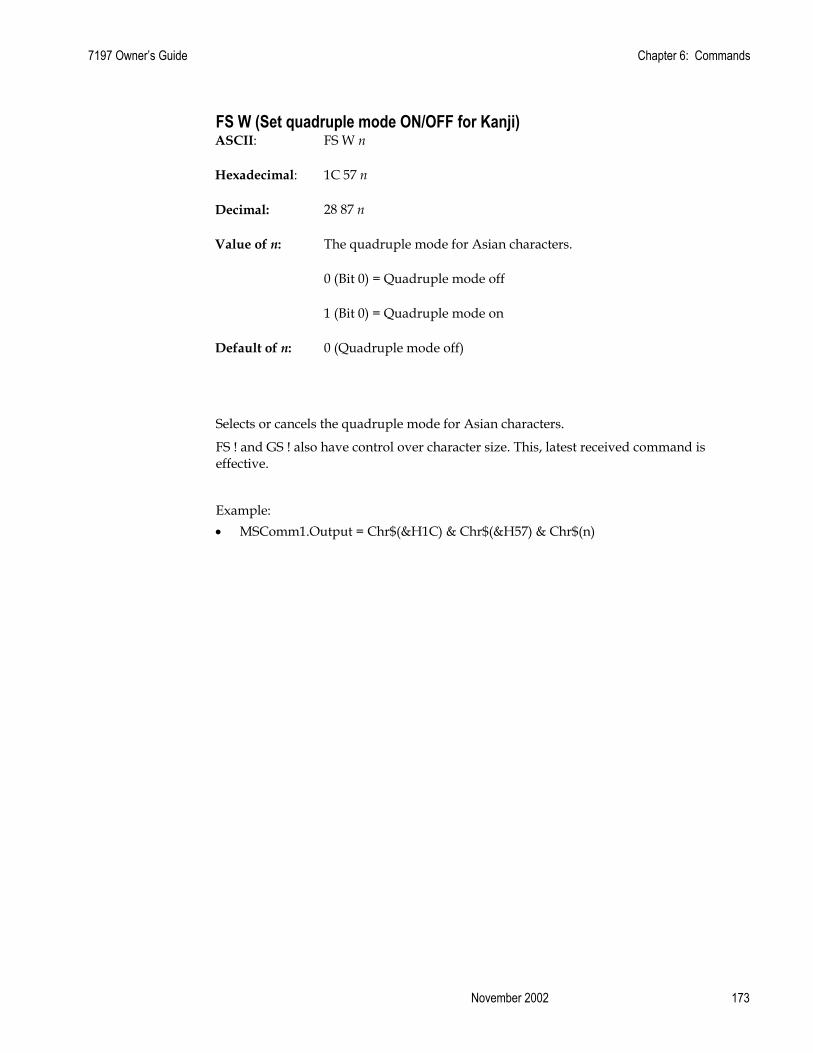
7197 Owner’s Guide Chapter 6: Commands
November 2002 173
FS W (Set quadruple mode ON/OFF for Kanji) ASCII: FS W n
Hexadecimal: 1C 57 n
Decimal: 28 87 n
Value of n: The quadruple mode for Asian characters.
0 (Bit 0) = Quadruple mode off
1 (Bit 0) = Quadruple mode on
Default of n: 0 (Quadruple mode off)
Selects or cancels the quadruple mode for Asian characters.
FS ! and GS ! also have control over character size. This, latest received command is effective.
Example: • MSComm1.Output = Chr$(&H1C) & Chr$(&H57) & Chr$(n)

Chapter 6: Commands 7197 Owner’s Guide
February 2002 174
Flash Download Commands These commands are used to load firmware into the printer.
The commands are listed in numerical order according to their hexadecimal codes. Each command is described and the hexadecimal, decimal, and ASCII codes are listed.
There are three ways to enter the Download Mode.
1. Powering the printer up with DIP Switch 2 up.
2. While the printer is running normally, use the command Switch to Flash Download Mode, to leave normal operation and enter the Download Mode.
3. If the Flash if found corrupted during Level 0 diagnostics the Download Mode is automatically entered after the printer has reset.
The printer never goes directly from the Download Mode to normal printer operation. To return to normal printer operation either the operator must turn the power off and then on to reboot or the application must send a command to cancel Download Mode and reboot.
Switch to Flash Download Mode ASCII: ESC [ }
Hexadecimal: 1B 5B 7D
Decimal: 27 91 125
Puts the printer in Flash Download Mode in preparation to receive commands controlling the downloading of objects into Flash Memory. When this command is received, the printer leaves normal operation and can no longer print transactions until the Reboot the Printer command (1D FF) is received or the printer is rebooted.
This command does not affect the current communication parameters. Once the printer is in Flash Download Mode, this command is no longer available. Example: • MSComm1.Output = Chr$(&H1B) & Chr$(&H5B) & Chr$(&H7D)
Request Printer ID ASCII: GS NUL
Hexadecimal: 1D 00
Decimal: 29 0
Returns ACK (06 hex) + 12 bytes ASCII string describing the Flash Memory Boot Sector Firmware part number. Ex : 189-1234567A Example: • MSComm1.Output = Chr$(&H1D) & Chr$(&H00)

7197 Owner’s Guide Chapter 6: Commands
November 2002 175
Return Segment Number Status of Flash Memory ASCII: GS SOH
Hexadecimal: 1D 01
Decimal: 29 1
Returns the size of the Flash used. There may be 8, 16, or 32 sectors (64K each) in Flash Memory. This command assures that the firmware to be downloaded is the appropriate size for Flash Memory. The value returned is the maximum sector number that can be accepted by the Select Sector to Download (1D 02 n) command. Example: • MSComm1.Output = Chr$(&H1D) & Chr$(&H01)
Exceptions:
Available only in Download Mode.
Select Flash Memory Sector to Download ASCII: GS STX n
Hexadecimal: 1D 02 n
Decimal: 29 2 n
Value of n: The Flash sector to which the next download operation applies
Range of n: 0 – 7 (512K)
0 – 15 (1 mB)
0 – 31 (2 mB)
Selects the Flash sector (nn) for which the next download operation applies. The values of the possible sector are restricted, depending upon the Flash part type. The printer transmits an ACK if the sector number is acceptable or an NAK if the sector number is not acceptable. Sector numbers start at 0.
Example: • MSComm1.Output = Chr$(&H1D) & Chr$(&H02) & Chr$(n)
Exceptions:
Available only in Download Mode.

Chapter 6: Commands 7197 Owner’s Guide
February 2002 176
Get Firmware CRC ASCII: GS ACK
Hexadecimal: 1D 06
Decimal: 29 6
Causes the printer to calculate the CRC for the currently selected sector and transmits the result. This is performed normally after downloading a sector to verify that the downloaded firmware is correct. The printer also calculates the CRC for each sector during power up and halts the program if any sector is erroneous.
The printer transmits ACK if the calculated CRC is correct for the selected sector; NAK if the CRC is incorrect or if no sector is selected. Example: • MSComm1.Output = Chr$(&H1D) & Chr$(&H06)
Return Microprocessor CRC ASCII: GS BEL
Hexadecimal: 1D 07
Decimal: 29 7
Returns the CRC calculated over the boot sector code space.
Formulas: ACK <low byte> <high byte> Example: • MSComm1.Output = Chr$(&H1D) & Chr$(&H07)

7197 Owner’s Guide Chapter 6: Commands
November 2002 177
Erase the Flash Memory ASCII: GS SO
Hexadecimal: 1D 0E
Decimal: 29 14
Causes the entire Flash Memory (except the boot) to be erased. The printer returns ACK if the command is successful; NAK if it is unsuccessful. Example: • MSComm1.Output = Chr$(&H1D) & Chr$(&H0E)
Exceptions:
Available only in Download Mode.
Return Main Program Flash CRC ASCII: GS SI
Hexadecimal: 1D 0F
Decimal: 29 15
Returns the CRC calculated over the Flash firmware code space. The format of the response is ACK <low byte> <high byte>. Example: • MSComm1.Output = Chr$(&H1D) & Chr$(&H0F)

Chapter 6: Commands 7197 Owner’s Guide
February 2002 178
Erase Selected Flash Sector ASCII: GS DLE n
Hexadecimal: 1D 10 n
Decimal: 29 16 n
Value and Range of n: 0 – 7 = 512K bytes Flash
0 – 15 = 1M bytes Flash
0 – 31 = 2M bytes Flash
Erases the previously selected sector. The printer transmits ACK when the sector has been erased. If the previous sector is not successfully erased, or if no sector was selected, the printer transmits NAK. Example: • MSComm1.Output = Chr$(&H1D) & Chr$(&H10) & Chr$(n)
Exceptions:
Available only in Download Mode.

7197 Owner’s Guide Chapter 6: Commands
November 2002 179
Download to Active Flash Sector ASCII: GS DC1 al ah cl ch d1…dn
Hexadecimal: 1D 11 al ah cl ch d1…dn
Decimal: 29 17 al ah cl ch d1…dn
Value of al: low byte of the address
Value of ah: high byte of the address
Value of cl: low byte of the count
Value of ch: high byte of the count
Value of d: data bytes, from 1 to n
Contains a start address (ah * 256 + al) and count (ch * 256 + cl) of binary bytes to load into the selected sector, followed by that many bytes. The start address is relative to the start of the sector. Addresses run from 0 to 64K.
The printer may return one of several responses. ACK means that the data was written correctly and the host should transmit the next block. NAK means that, for some reason, the data was not written correctly. This could mean that communications failed or that the write to Flash failed. The alternatives seem to be to retry the block or halt loading and assume a hardware failure.
Value of n (for number of data bytes) Range of Address (al ah) Range of Count (cl ch) ((ch * 256) + cl) 2000-FFFF (hexadecimal) 0001-0400 (hexadecimal)
Range: Addresses run from 0 to 64K.
Related Information:
Available only in Download Mode.

Chapter 6: Commands 7197 Owner’s Guide
February 2002 180
Reboot the Printer ASCII: GS (SPACE)
Hexadecimal: 1D FF
Decimal: 29 255
Ends the load process and reboots the printer. Before executing this command, the printer should have firmware loaded and external switches set to the runtime settings. Application software for downloading should prompt the user to set the external switches and confirm before sending this command. If the downloading was started from a diagnostic, the reboot will cause the printer to reenter download state unless the external switches are changed. Example: • MSComm1.Output = Chr$(&H1D) & Chr$(&HFF)

7197 Owner’s Guide Chapter 7: Reflashing the Printer Firmware
November 2002 181
Chapter 7: Reflashing the Printer Firmware
Flash Utility Information
The following instructions provide information on how to use the Flash Utilities provided for the 7167, 7197, and 7401-K590 printers. These instructions cover the utilities provided for Windows 9x/NT/2000 GUI, Windows Command Line, and DOS. The following are the files which comprise the utilities: TseFlash.exe – Windows GUI version of the Flash Utility TseFlash.com – Windows Command Line Flash Utility Aflash.exe – DOS Command Line Flash Utility help.bat – Batch file that causes TseFlash.com to display command line options. msvcrt.dll – Windows system DLL used by TseFlash utility and distributed with it. mfc42.dll – Microsoft Foundation Class Library DLL used by TseFlash utility and distributed with it.
File Configurations
There are several different kinds of firmware loads that can be sent to the printer: 1. Boot Firmware 2. Main Firmware 3. Single Byte Font 4. Two Byte Receipt Font 5. Two Byte Slip Font The Single Byte Font file has a file extension of .sfn. It is the font used for OEM Codepages such as 437, 850, 858, etc. which require only a single byte of data to define the character to be printed. The Two Byte Font files ( Separately Defined for Slip & Receipt ) have a file extension .dfn. These are used to define Code Pages 932 – Japanese, 936 – Simplified Chinese, 949 – Korean, 950 – Traditional Chinese. If is very rare for the Single Byte Font to have to be updated. Since there is only enough memory in the printer for one of the Two Byte Fonts to be loaded at any time, the Two Byte Font will typically need to be loaded prior to installation in the appropriate country. The Font files both Single and Two byte should be loaded into the printer after the Boot and Main firmware have been loaded.

Chapter 7: Reflashing the Printer Firmware 7197 Owner’s Guide
February 2002 182
Printer Languages Cross Reference
FILENAME PRINT STATION
Non Asian A0106.sfn 7167 Receipt & Slip A0106.sfn 7197 Receipt ANK.sfn K590
Japanese A0106.sfn 7167 Receipt & Slip J0104.dfn Receipt J0106_s.dfn Slip SamJ0100.dfn 7197 Receipt ANK.sfn K590 J0103.dfn
Korean A0106.sfn 7167 Receipt & Slip K0103.dfn Receipt K0101_s.dfn Slip A0106.sfn 7197 Receipt K0103.dfn ANK.sfn K590 K0103.dfn
Simple Chinese A0106.sfn 7167 Receipt & Slip S0102.dfn Receipt S0101_s.dfn Slip A0106.sfn 7197 Receipt S0102.dfn Receipt ANK.sfn K590 S0102.dfn
Traditional Chinese A0106.sfn 7167 Receipt & Slip T0102.dfn Receipt TC0101_s.dfn Slip A0106.sfn 7197 Receipt T0102.dfn Receipt ANK.sfn K590 T0102.dfn
Note: A0106.sfn contains receipt and slip ANK fonts.
The noted font files are include on LPIN A370-0050-0000 or are available from the NCR web site under Retail Solution Specific Printer Firmware.

7197 Owner’s Guide Chapter 7: Reflashing the Printer Firmware
November 2002 183
DOS Flash Utility
The DOS flash utility is intended for use from a DOS Boot only. It is mainly provided for remote flash capabilities by providing a way to create a DOS Boot Image that will automatically load and flash update the printer firmware without user intervention. If you type AFLASH.EXE without any parameters you will get the following screen that describes the parameter usage: Flash Memory Writer V2.02 Usage: AFLASH.EXE <model> <type> <port> <baud rate> <filename> Options: <model> : K590, 7167, 7197 <type> -m : Download main firmware program -i : Download ipl firmware program -a : Download ANK single byte font -s : Download ASIAN two byte font -rs : Download receipt ASIAN two byte
font -ss : Download slip ASIAN two byte font <port> : COM1, COM2 <baud rate>: 1200, 2400, 4800, 9600, 19200, 38400, 57600,
115200 <filename> : *.mfw | *.ipl | *.sfn | *.dfn An example of a command line for updating the Main Firmware on a 7167 printer is as follows: AFLASH.EXE 7167 –m COM2 115200 BV0293.MFW NOTE: The DOS version of the Flash Utility can only be used for printers that are connected on COM1 or COM2. The current version of the utility does not function for COM ports higher than 2. If an error is encountered, the Usage information will be dumped to the screen followed by a status line that displays information along such as: Error : Unable to open data file! Error : Invalid parameter <com>!

Chapter 7: Reflashing the Printer Firmware 7197 Owner’s Guide
February 2002 184
Windows Command Line Firmware Update Utility
The Windows Command Line version of the Flash Utility is provided to allow batch mode of operation in a Windows 95/98/NT4/2000 environment. If you issue a call to TseFlash.com with the /? parameter you will get the following out put that explains the parameters. NOTE: This utility requires the TseFlash.exe to be in the same directory. TseFlash.com is just a shell that sends the command line options to TseFlash.exe to process.
*** TseFlash.com Ver 1.03 *** Thank you for using TseFlash Flash Memory Writer command line interface utility! Please wait... Status: /? detected! TseFlash [model] [download type] [COM] [baudrate] [parity] [stop] [filename] /K590 Select K590 printer. /7167 Select 7167 printer. /7197 Select 7197 printer. Selections for the download type: /m Download firmware main program. /i Download firmware IPL program. /a Download ANK sigle byte font. /s Download ASIAN two byte font. /rs Download receipt ASIAN two byte font. /ss Download slip ASIAN two byte font. Selections for the COM port: /COMX Where X is any valid integer within 1~20. Selections for the baud rate: /[115200] | [57600] | [38400] | [19200] | [9600] | [4800] | [2400] | [1200]
Selections for the parity bit: /[none] | [even] | [odd] Selections for the stop bit: /[1] | [2] Selections for the filename:
Any valid binary file with extension *.mfw | *.sfn | *.dfn | *.ipl.
If you fail to use the correct parameters an error message will be displayed similar to the one below.
Error : Too few / many command line parameters! The following is an example of a command line:

7197 Owner’s Guide Chapter 7: Reflashing the Printer Firmware
November 2002 185
TseFlash.com /7167 /m /COM8 /115200 /none /1 BV0293.MFW
This invokes the GUI interface shown in the next section, and displays a progress bar indicator as you would see if you had run the program through the GUI.Windows GUI Printer Firmware Update Utility The printer firmware can be updated from the host terminal, a laptop, or a PC by executing the TSEFlash.exe utility. There are two file formats for the flash firmware, IPL which is for the Initial Program Load (Boot) and the MFW, Main FirmWare. Examples of the firmware are:
BI0016.ipl 7167 boot firmware BVO2.93mfw 7167 firmware
As noted this is an example and firmware version will vary as updates are provided.
These instruction show how to reflash a 7167 printer. However the same instructions can be used for reflashing the 7197 or 7401-K590 printers as well by selection the appropriate printer in the Change Mode button.
Unzip the flash utility (Flash311) and the flash files that you will be using into a directory on your hard disk.

Chapter 7: Reflashing the Printer Firmware 7197 Owner’s Guide
February 2002 186
Using TseFlash.exe Utility
On the host terminal or PC running Windows, execute the utility TSEFlash.exe to start the program. A window similar to the example below will appear on the screen.

7197 Owner’s Guide Chapter 7: Reflashing the Printer Firmware
November 2002 187
Click on the button indicated by the red arrow to display the dropdown box. From the list, click on the printer type to be flashed. Select K590 from the list for this printer.
Next, click on the "Select" button indicated by the red arrow. This will permit you to continue by making the remaining options available.

Chapter 7: Reflashing the Printer Firmware 7197 Owner’s Guide
February 2002 188
At this point, any of the properties in the red box can be changed. Clicking on the button to the right of the property (red arrow) will display the drop-down box with options available for the associated property.
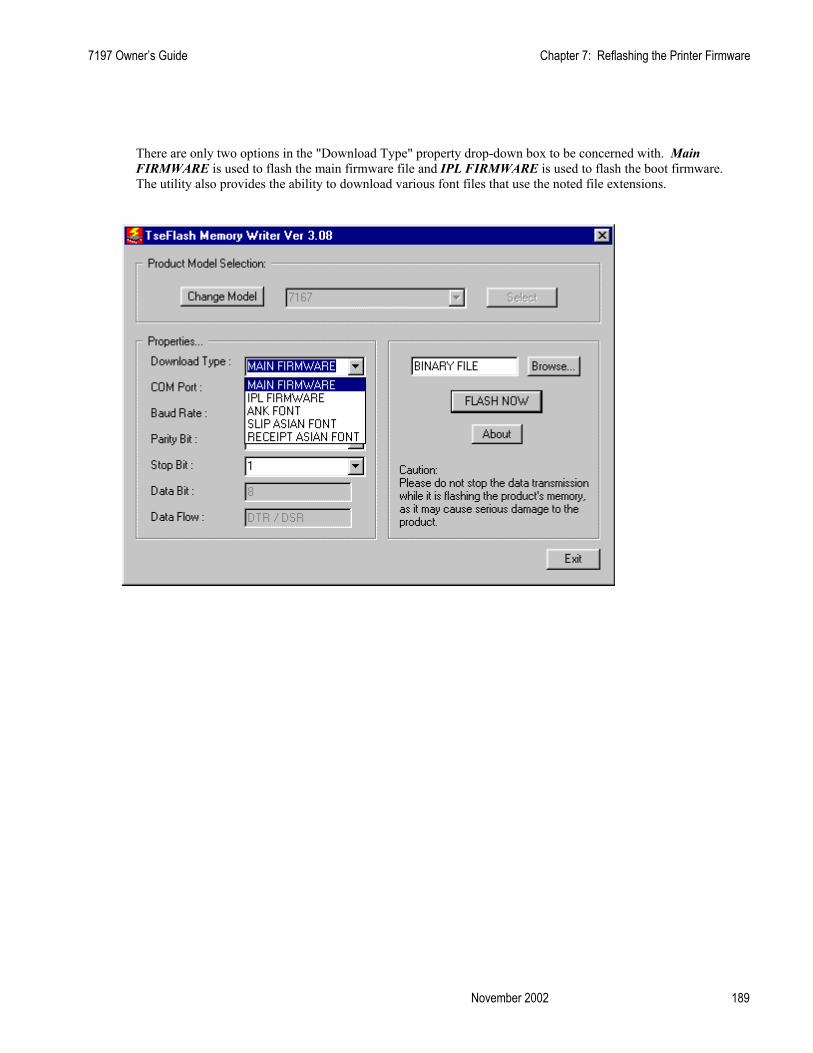
7197 Owner’s Guide Chapter 7: Reflashing the Printer Firmware
November 2002 189
There are only two options in the "Download Type" property drop-down box to be concerned with. Main FIRMWARE is used to flash the main firmware file and IPL FIRMWARE is used to flash the boot firmware. The utility also provides the ability to download various font files that use the noted file extensions.

Chapter 7: Reflashing the Printer Firmware 7197 Owner’s Guide
February 2002 190
Select the COM port being used on the PC or host device to flash the printer. The flash utility will be running on this PC.

7197 Owner’s Guide Chapter 7: Reflashing the Printer Firmware
November 2002 191
Select the printer baud rate setting. Make certain that that the COM port selected on the host device will support 115,200 baud. The utility will reset the printer baud rate to 115,200 baud flash the printer and then reset the baud rate back to the baud rate that was originally selected.

Chapter 7: Reflashing the Printer Firmware 7197 Owner’s Guide
February 2002 192
From the Parity type, select None, Odd, or Even to match this setting on the printer.

7197 Owner’s Guide Chapter 7: Reflashing the Printer Firmware
November 2002 193
Again, match this property to this setting in the printer.
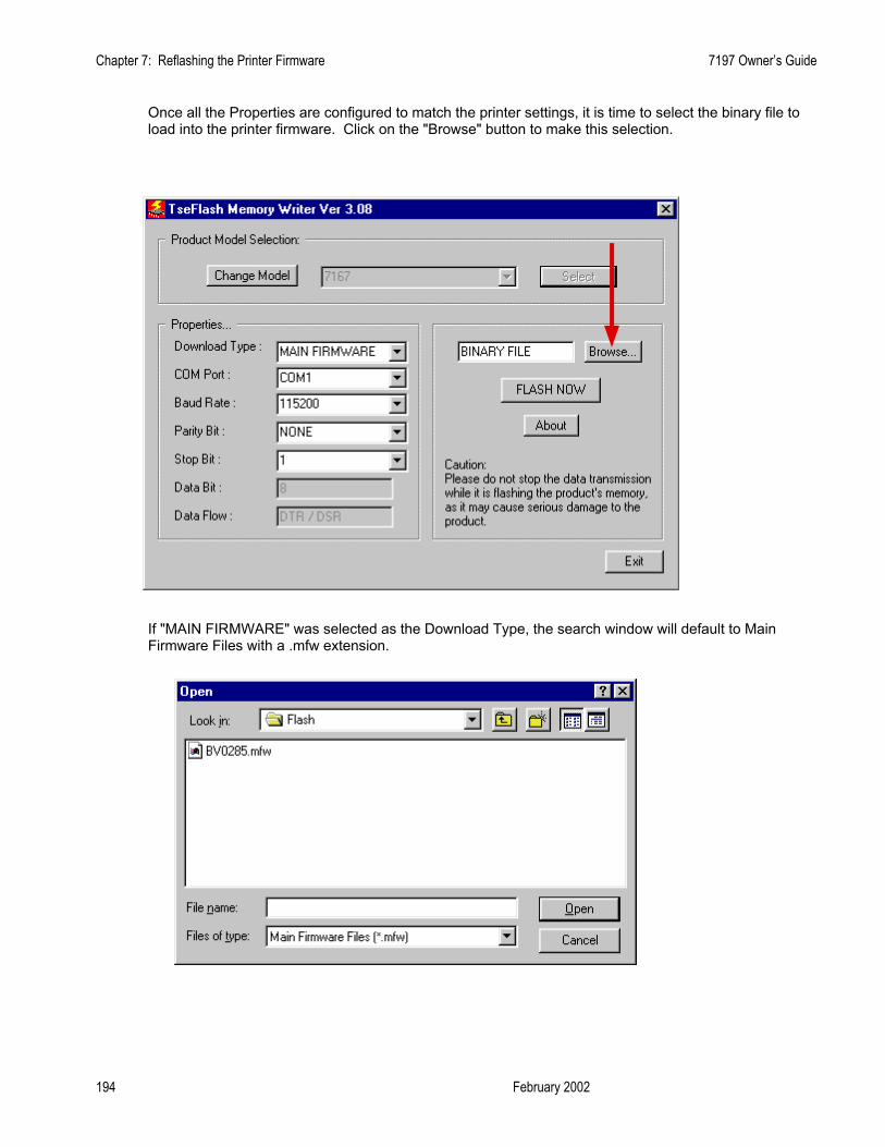
Chapter 7: Reflashing the Printer Firmware 7197 Owner’s Guide
February 2002 194
Once all the Properties are configured to match the printer settings, it is time to select the binary file to load into the printer firmware. Click on the "Browse" button to make this selection.
If "MAIN FIRMWARE" was selected as the Download Type, the search window will default to Main Firmware Files with a .mfw extension.

7197 Owner’s Guide Chapter 7: Reflashing the Printer Firmware
November 2002 195
If "IPL FIRMWARE" was selected as the Download Type, the search window will default to IPL Program Files with a .ipl extension. Select the desired file from the list and click on the "Open" button.
With the desired file selected and all properties set to the correct values, click on the "FLASH NOW" button to start the download process.
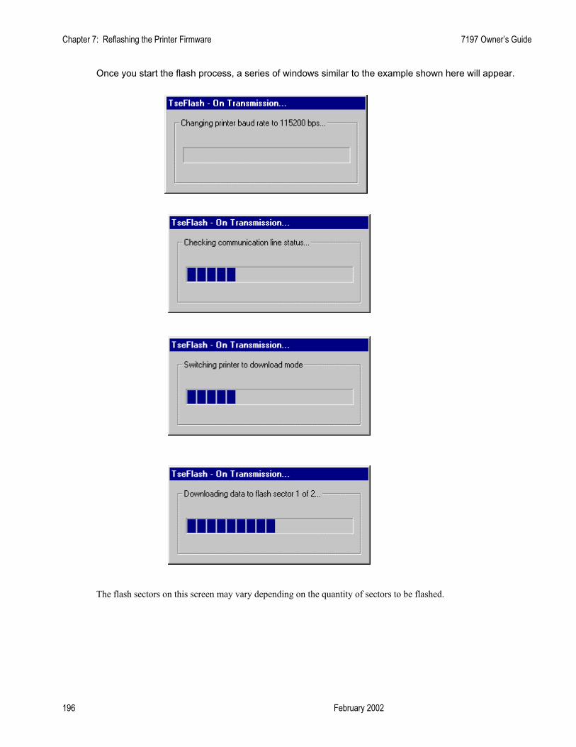
Chapter 7: Reflashing the Printer Firmware 7197 Owner’s Guide
February 2002 196
Once you start the flash process, a series of windows similar to the example shown here will appear.
The flash sectors on this screen may vary depending on the quantity of sectors to be flashed.
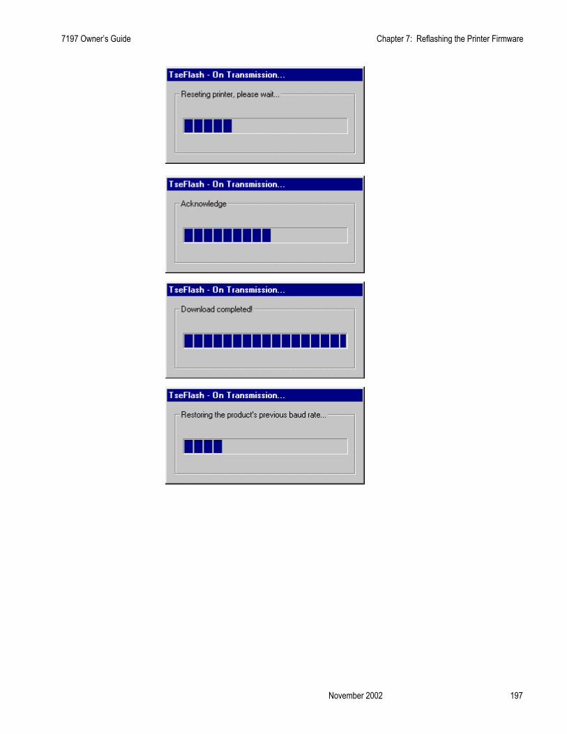
7197 Owner’s Guide Chapter 7: Reflashing the Printer Firmware
November 2002 197
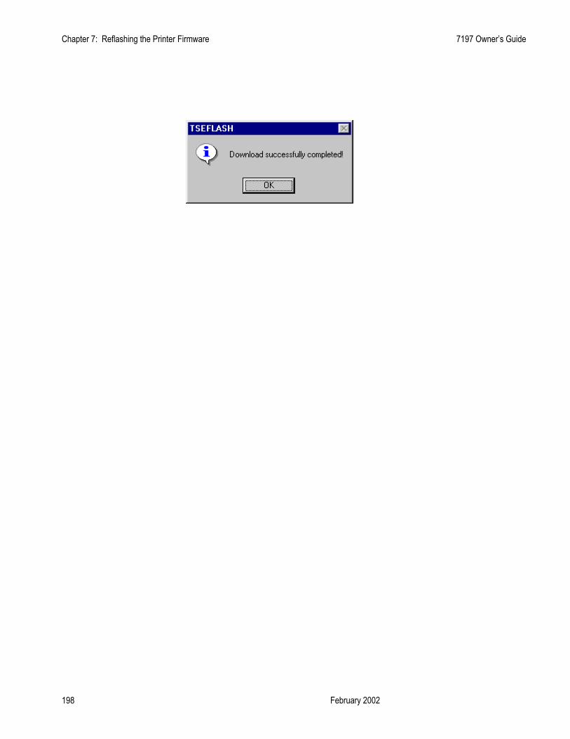
Chapter 7: Reflashing the Printer Firmware 7197 Owner’s Guide
February 2002 198

7197 Owner’s Guide Appendix A: Specifications
November 2002 199
Appendix A: Specifications
Printing Specifications
Thermal Receipt Station
Print head Fixed 576 Print Elements Direct Thermal Fixed Head Line of Dots
Character Cell Standard: 13 x 24 Dots Compressed: 10 x 24 Dots
Character Size .0525" Wide by .092" High Character Spacing 15.25 Characters per Inch (horizontal) Character Pitch 15.6 Characters/Inch (Standard)
20.3 Characters/Inch (Compressed) Columns (maximum) For 80 mm paper:
44 Columns (Standard) 56 Columns (Compressed) For 58 mm paper: 32 Columns (Standard) 42 Columns (Compressed)
Print Mode Standard, Compressed, Double High, Double Wide, Upside Down, Rotated, Underline, Scalable, Bold, Superscript, Italic, Subscript
Resident Fonts Code Page 437, 850, 852, 860, 863, 865, 858, 866, 1252, Katakana, 874, 862, 864, and Space page
Speed 3019 Lines / Minute (44 columns) maximum, Depend on Line Spacing
Print Order Descending Line Spacing 7.52 Lines per Inch ( default )
8.47, 8.13, 7.81, 7.25, 7.00, 5.98 Lines / Inch and variable lines per inch.
Slew Speed 6.7 Inches per Second Print Zone 2.83 Inches Maximum
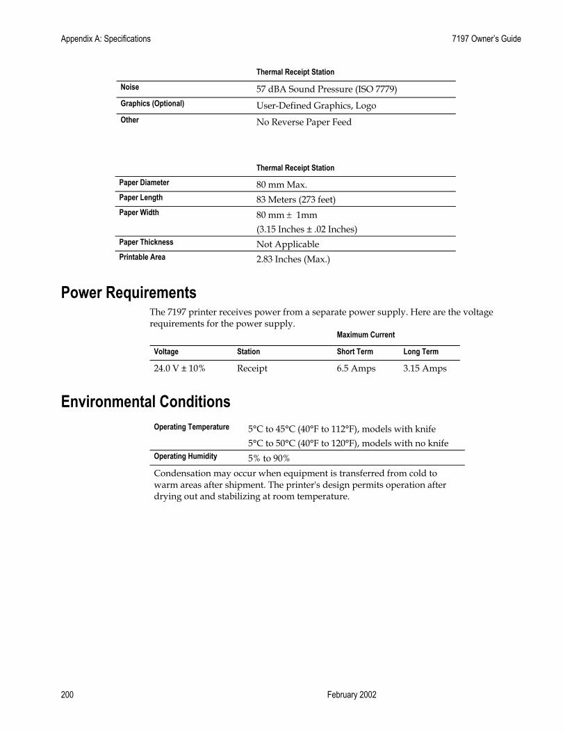
Appendix A: Specifications 7197 Owner’s Guide
February 2002 200
Thermal Receipt Station
Noise 57 dBA Sound Pressure (ISO 7779) Graphics (Optional) User-Defined Graphics, Logo Other No Reverse Paper Feed
Thermal Receipt Station Paper Diameter 80 mm Max. Paper Length 83 Meters (273 feet) Paper Width 80 mm ± 1mm
(3.15 Inches ± .02 Inches) Paper Thickness Not Applicable Printable Area 2.83 Inches (Max.)
Power Requirements The 7197 printer receives power from a separate power supply. Here are the voltage requirements for the power supply.
Maximum Current
Voltage Station Short Term Long Term
24.0 V ± 10% Receipt 6.5 Amps 3.15 Amps
Environmental Conditions
Operating Temperature 5°C to 45°C (40°F to 112°F), models with knife 5°C to 50°C (40°F to 120°F), models with no knife
Operating Humidity 5% to 90% Condensation may occur when equipment is transferred from cold to warm areas after shipment. The printer's design permits operation after drying out and stabilizing at room temperature.
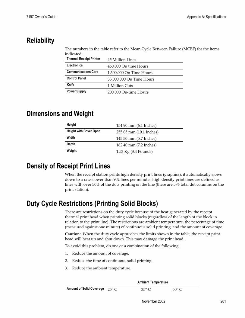
7197 Owner’s Guide Appendix A: Specifications
November 2002 201
Reliability The numbers in the table refer to the Mean Cycle Between Failure (MCBF) for the items indicated.
Thermal Receipt Printer 45 Million Lines Electronics 460,000 On time Hours Communications Card 1,300,000 On Time Hours Control Panel 33,000,000 On Time Hours Knife 1 Million Cuts Power Supply 200,000 On-time Hours
Dimensions and Weight
Height 154.90 mm (6.1 Inches) Height with Cover Open 255.05 mm (10.1 Inches) Width 145.50 mm (5.7 Inches) Depth 182.40 mm (7.2 Inches) Weight 1.53 Kg (3.4 Pounds)
Density of Receipt Print Lines When the receipt station prints high density print lines (graphics), it automatically slows down to a rate slower than 902 lines per minute. High density print lines are defined as lines with over 50% of the dots printing on the line (there are 576 total dot columns on the print station).
Duty Cycle Restrictions (Printing Solid Blocks)
There are restrictions on the duty cycle because of the heat generated by the receipt thermal print head when printing solid blocks (regardless of the length of the block in relation to the print line). The restrictions are ambient temperature, the percentage of time (measured against one minute) of continuous solid printing, and the amount of coverage.
Caution: When the duty cycle approches the limits shown in the table, the receipt print head will heat up and shut down. This may damage the print head.
To avoid this problem, do one or a combination of the following:
1. Reduce the amount of coverage.
2. Reduce the time of continuous solid printing.
3. Reduce the ambient temperature.
Ambient Temperature Amount of Solid Coverage 25° C 35° C 50° C
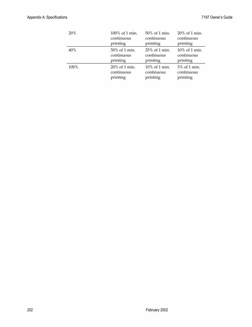
Appendix A: Specifications 7197 Owner’s Guide
February 2002 202
20% 100% of 1 min. continuous printing
50% of 1 min. continuous printing
20% of 1 min. continuous printing
40% 50% of 1 min. continuous printing
25% of 1 min. continuous printing
10% of 1 min. continuous printing
100% 20% of 1 min. continuous printing
10% of 1 min. continuous printing
3% of 1 min. continuous printing

7197 Owner’s Guide Appendix B: Print Characteristics
November 2002 203
Appendix B: Print Characteristics
Character Size This section shows the dot pattern for characters printed on the receipt station.
Receipt Station The following two illustrations show the dot patterns of sample characters for standard pitch (15.6 CPI) and compressed pitch (20.3 CPI). Note that compressed pitch uses fewer dots horizontally than standard pitch.
Standard Pitch
11 Dots 1.38 mm .054 in.
19 Dots 2.38 mm .094 in.
13 Dots 1.63 mm .064 in.
24 Dots 3.00 mm .118 in.
203 DPI, 15.6 CPI Pitch (Standard)

Index 7197 Owner’s Guide
February 2002 204
Compressed Pitch
Print Zones This section shows the printable area for the receipt station.
Receipt Station
For 80 mm Paper The receipt station centers characters (standard pitch and compressed pitch) and graphics on an 80 mm wide (3.15 inches) receipt. • Standard pitch: 13 x 24 dots in character cell, 44 characters (columns) per line • Compressed pitch: 10 x 24 dots in character cell, 56 characters (columns) per line • Double byte character: 24 x 24 dots in character cell, 24 characters (columns) per line • Graphics: 576 addressable bits
The minimum print line height is 24 dots for characters and 24 dots for graphics. The standard print line height is 27 dots (3.38 mm, .133 inches) for characters (with three extra dot rows). See the following illustration (not to scale).
10 Dots 1.25 mm .049 in.
8 Dots 1.00 mm .039 in.
19 Dots 2.38 mm .094 in.
203 DPI, 19 CPI Pitch (Compressed)
24 Dots 3.00 mm .118 in.
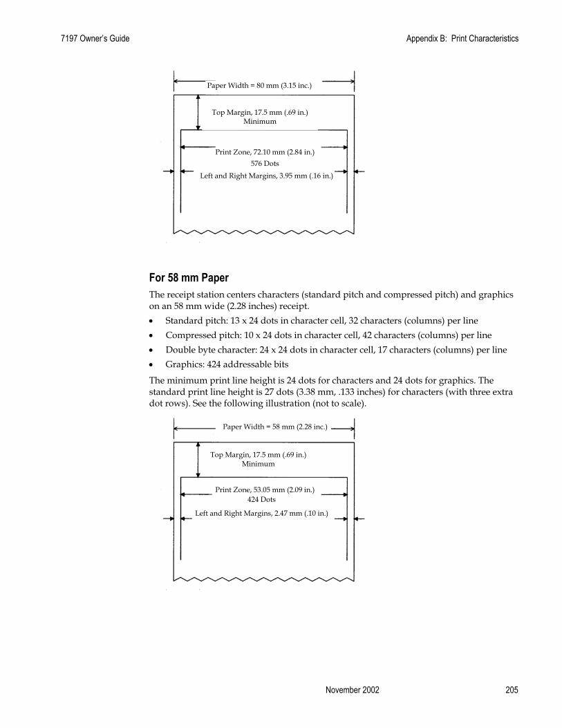
7197 Owner’s Guide Appendix B: Print Characteristics
November 2002 205
For 58 mm Paper The receipt station centers characters (standard pitch and compressed pitch) and graphics on an 58 mm wide (2.28 inches) receipt. • Standard pitch: 13 x 24 dots in character cell, 32 characters (columns) per line • Compressed pitch: 10 x 24 dots in character cell, 42 characters (columns) per line • Double byte character: 24 x 24 dots in character cell, 17 characters (columns) per line • Graphics: 424 addressable bits
The minimum print line height is 24 dots for characters and 24 dots for graphics. The standard print line height is 27 dots (3.38 mm, .133 inches) for characters (with three extra dot rows). See the following illustration (not to scale).
Top Margin, 17.5 mm (.69 in.) Minimum
Print Zone, 72.10 mm (2.84 in.) 576 Dots
Left and Right Margins, 3.95 mm (.16 in.)
Paper Width = 80 mm (3.15 inc.)
Top Margin, 17.5 mm (.69 in.) Minimum
Print Zone, 53.05 mm (2.09 in.) 424 Dots
Left and Right Margins, 2.47 mm (.10 in.)
Paper Width = 58 mm (2.28 inc.)
Index 7197 Owner’s Guide
February 2002 206
Character Sets The following pages show the character sets.
• PC Code Page 437 (US)
• PC Code Page 850 (Multilingual)
• PC Code Page 852 (Slavic)
• PC Code Page 860 (Portuguese)
• PC Code Page 862 (Hebrew)
• PC Code Page 863 (French-Canadian)
• PC Code Page 864 (Arabic)
• PC Code Page 865 (Nordic)
• PC Code Page 866 (Cyrillic)
• PC Code Page 1252 (Windows Latin #1)
• PC Code Page Katakana
• PC Code Page 874 (Thai)
• Space Page
• Code Page 932
• Code Page 936
• Code Page 949
• Code Page 950

7197 Owner’s Guide Appendix B: Print Characteristics
November 2002 207
Code Page 950 Code Page 437, 850, 852 and 858
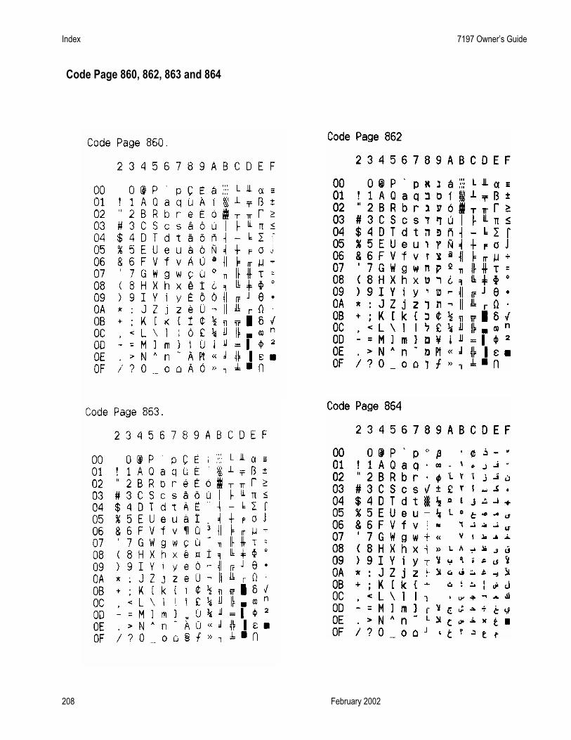
Index 7197 Owner’s Guide
February 2002 208
Code Page 860, 862, 863 and 864

7197 Owner’s Guide Appendix B: Print Characteristics
November 2002 209
Code Page 865, 866, 874 and 1252

Index 7197 Owner’s Guide
February 2002 210
Code Page Katakana

7197 Owner’s Guide Appendix B: Print Characteristics
November 2002 211
Code Page 932
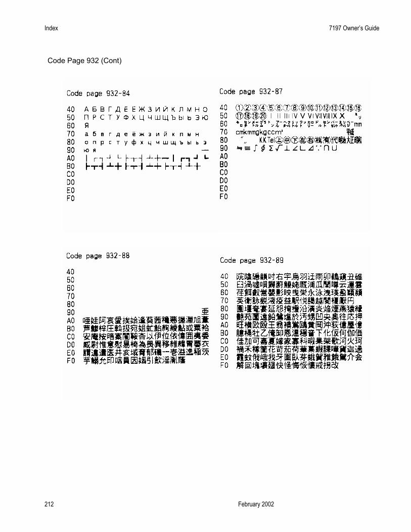
Index 7197 Owner’s Guide
February 2002 212
Code Page 932 (Cont)

7197 Owner’s Guide Appendix B: Print Characteristics
November 2002 213
Code Page 932 (Cont)
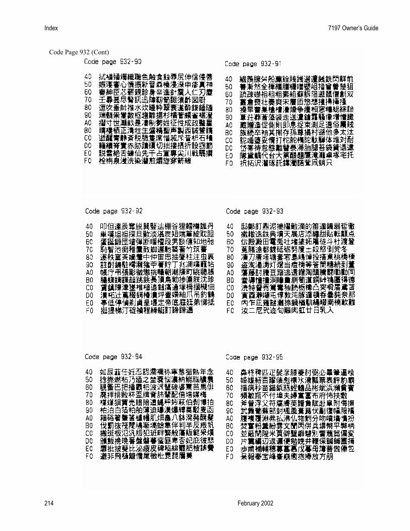
Index 7197 Owner’s Guide
February 2002 214
Code Page 932 (Cont)

7197 Owner’s Guide Appendix B: Print Characteristics
November 2002 215
Code Page 932 (Cont)

Index 7197 Owner’s Guide
February 2002 216
Code Page 932 (Cont)

7197 Owner’s Guide Appendix B: Print Characteristics
November 2002 217
Code Page 932 (Cont)

Index 7197 Owner’s Guide
February 2002 218
Code Page 932 (Cont)

7197 Owner’s Guide Appendix B: Print Characteristics
November 2002 219
Code Page 932 (Cont)

Index 7197 Owner’s Guide
February 2002 220
Code Page 936 Simple Chinese

7197 Owner’s Guide Appendix B: Print Characteristics
November 2002 221
Code Page 936 Simple Chines1e (Cont.)
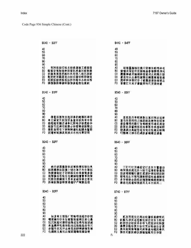
Index 7197 Owner’s Guide
February 2002 222
Code Page 936 Simple Chinese (Cont.)

7197 Owner’s Guide Appendix B: Print Characteristics
November 2002 223
Code Page 936 Simple Chinese (Cont.)

Index 7197 Owner’s Guide
February 2002 224
Code Page 936 Simple Chinese (Cont.)
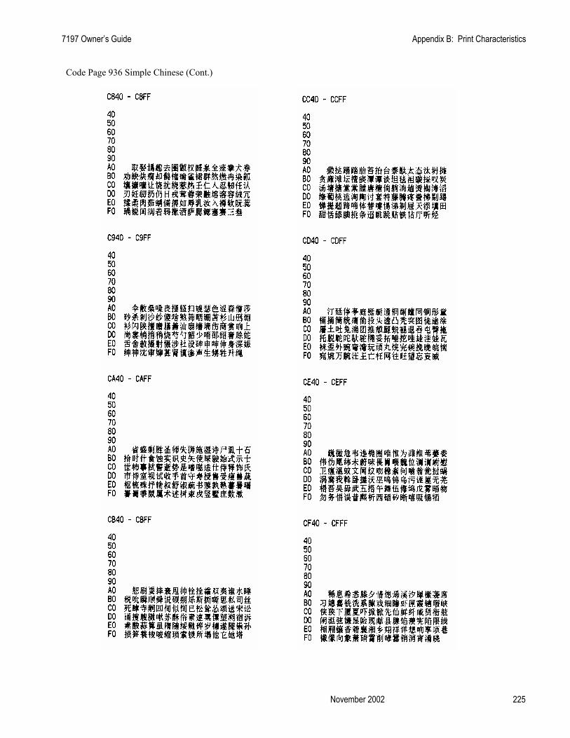
7197 Owner’s Guide Appendix B: Print Characteristics
November 2002 225
Code Page 936 Simple Chinese (Cont.)

Index 7197 Owner’s Guide
February 2002 226
Code Page 936 Simple Chinese (Cont.)

7197 Owner’s Guide Appendix B: Print Characteristics
November 2002 227
Code Page 936 Simple Chinese (Cont.)

Index 7197 Owner’s Guide
February 2002 228
Code Page 936 Simple Chinese (Cont.)

7197 Owner’s Guide Appendix B: Print Characteristics
November 2002 229
Code Page 936 Simple Chinese (Cont.)
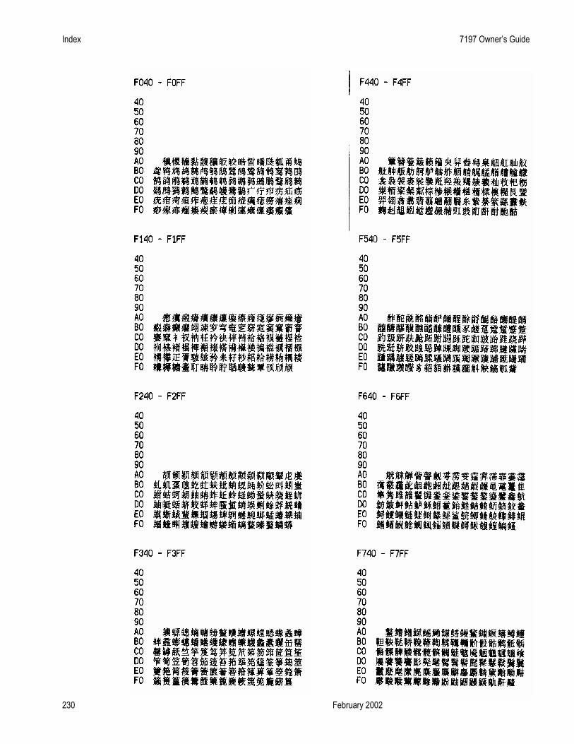
Index 7197 Owner’s Guide
February 2002 230
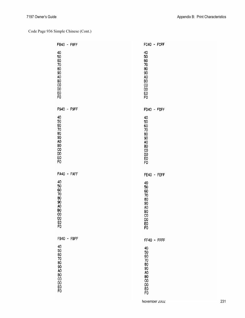
7197 Owner’s Guide Appendix B: Print Characteristics
November 2002 231
Code Page 936 Simple Chinese (Cont.)

Index 7197 Owner’s Guide
February 2002 232
Code Page 949 Korean

7197 Owner’s Guide Appendix B: Print Characteristics
November 2002 233
Code Page 949 Korean (Cont.)

Index 7197 Owner’s Guide
February 2002 234
Code Page 949 Korean (Cont.)

7197 Owner’s Guide Appendix B: Print Characteristics
November 2002 235
Code Page 949 Korean (Cont.)

Index 7197 Owner’s Guide
February 2002 236
Code Page 949 Korean (Cont.)

7197 Owner’s Guide Appendix B: Print Characteristics
November 2002 237
Code Page 949 Korean (Cont.)

Index 7197 Owner’s Guide
February 2002 238
Code Page 949 Korean (Cont.)
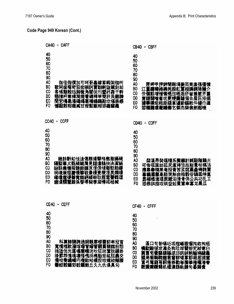
7197 Owner’s Guide Appendix B: Print Characteristics
November 2002 239
Code Page 949 Korean (Cont.)
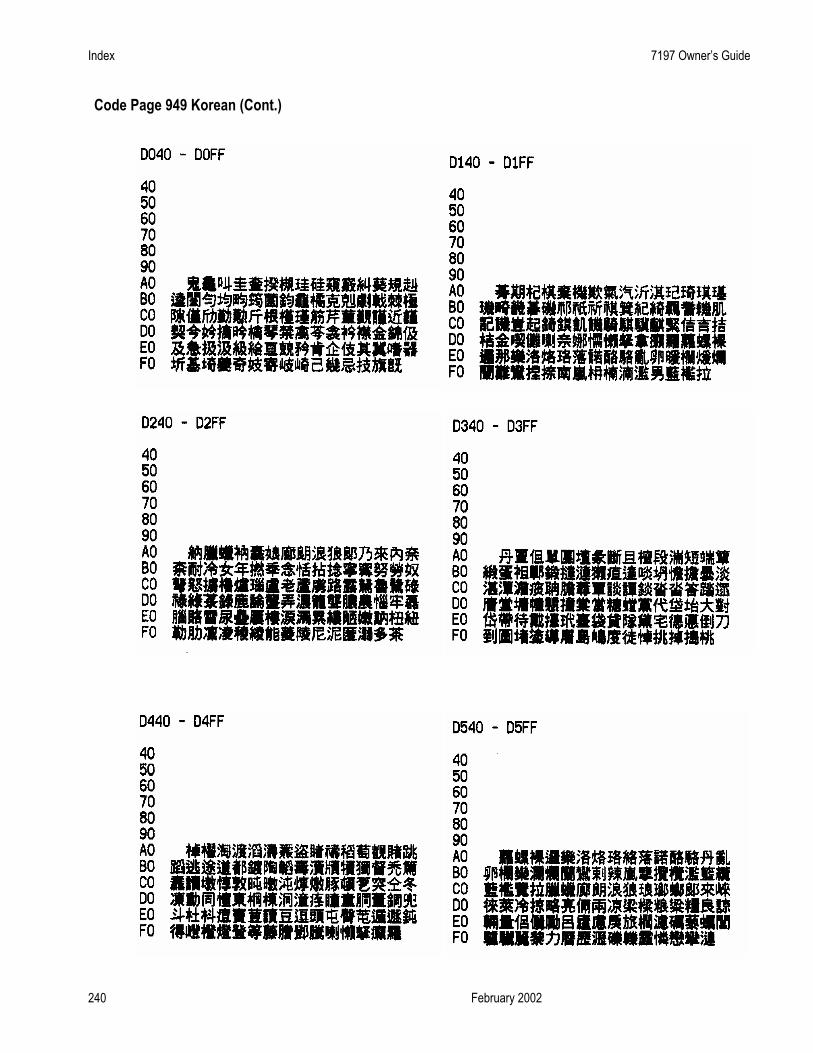
Index 7197 Owner’s Guide
February 2002 240
Code Page 949 Korean (Cont.)
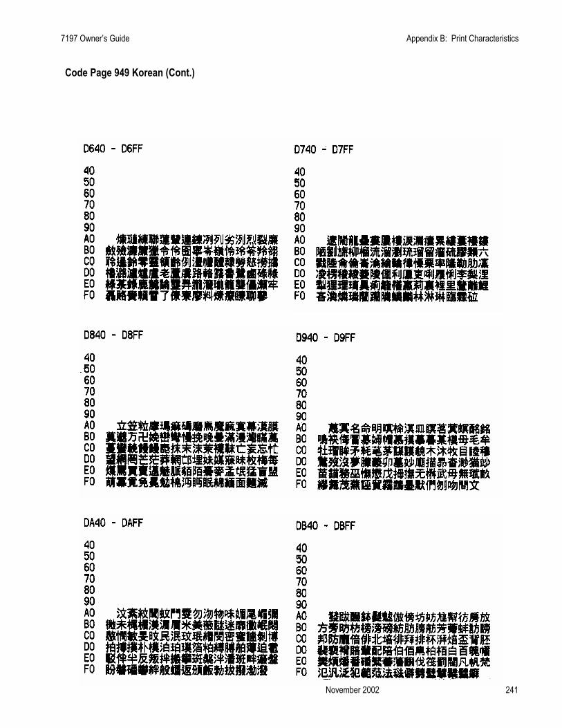
7197 Owner’s Guide Appendix B: Print Characteristics
November 2002 241
Code Page 949 Korean (Cont.)
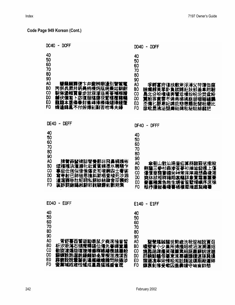
Index 7197 Owner’s Guide
February 2002 242
Code Page 949 Korean (Cont.)

7197 Owner’s Guide Appendix B: Print Characteristics
November 2002 243
Code Page 949 Korean (Cont.)
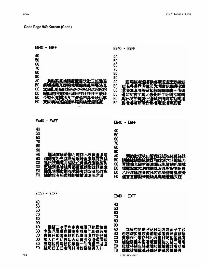
Index 7197 Owner’s Guide
February 2002 244
Code Page 949 Korean (Cont.)

7197 Owner’s Guide Appendix B: Print Characteristics
November 2002 245
Code Page 949 Korean (Cont.)

Index 7197 Owner’s Guide
February 2002 246
Code Page Traditional Chinese (Cont.)
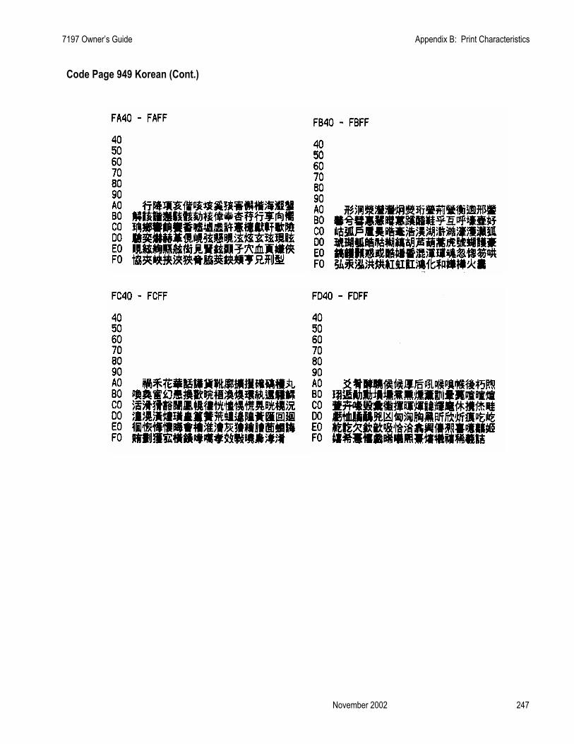
7197 Owner’s Guide Appendix B: Print Characteristics
November 2002 247
Code Page 949 Korean (Cont.)

Index 7197 Owner’s Guide
February 2002 248
Code Page 950 Traditional Chinese

7197 Owner’s Guide Appendix B: Print Characteristics
November 2002 249
Code Pare 949 Traditional Chinese (Cont.)

Index 7197 Owner’s Guide
February 2002 250
Code Pare 980 Traditional Chinese (Cont.)

7197 Owner’s Guide Appendix B: Print Characteristics
November 2002 251
Code Pare 950 Traditional Chinese (Cont.)

Index 7197 Owner’s Guide
February 2002 252
Code Pare 949 Traditional Chinese (Cont.)

7197 Owner’s Guide Appendix B: Print Characteristics
November 2002 253
Code Pare 980 Traditional Chinese (Cont.)
Index 7197 Owner’s Guide
February 2002 254
Code Pare 980 Traditional Chinese (Cont.)

7197 Owner’s Guide Appendix B: Print Characteristics
November 2002 255
Code Pare 950 Traditional Chinese (Cont.)

Index 7197 Owner’s Guide
February 2002 256
Code Pare 950 Traditional Chinese (Cont.)

7197 Owner’s Guide Appendix B: Print Characteristics
November 2002 257
Code Pare 950 Traditional Chinese (Cont.)

Index 7197 Owner’s Guide
February 2002 258
Code Pare 950 Traditional Chinese (Cont.)

7197 Owner’s Guide Index
Index 259 November 2002
Index
—7— 7156 printer
printer specifications, 199 7197 printer
clearance, 10 dimensions, 10, 201 environmental conditions, 200 features, 2 location, 10 ordering supplies, 4 power requirements, 200 power supply, ordering, 5 reliability, 201 sending in for repair, 10 turning on, 36
—A— Accessories. See Supplies Asian character
commands, 170 Asian character commands, 170 Asian mode
setting, 55
—B— Bar code commands, 146 Bar codes
commands, 146 BASIC
sending commands, 62
—C— Cabinet
cleaning, 6 Cables
cash drawer, 8 communication, 8 connecting, 13
Carriage return usage setting, 54
Cash drawer ordering, 5
Cash drawer cables connecting, 13
Changing paper, 37 Character set
code page 437, 207 code page 850, 208 code page 852, 210 code page 863, 212 code page 865, 209, 211, 212, 213, 214
Character sets, 206 Characters, receipt station
dot patterns, 203 Cleaning the printer, 6 Clearance around printer, 10 Code page 437
character set, 206 Code Page 437, 207 Code page 850
character set, 206 Code Page 850, 208 Code Page 852, 210 Code Page 863, 212 Code Page 865, 209, 211, 212, 213, 214 Color paper
setting, 51, 52, 53, 55, 58, 59, 60 Commands
Asian character, 170 bar code, 146 flash download, 174 graphics, 116 horizontal positioning, 92 listing, 67 macro, 160 page mode, 152 print, 86 print characteristics, 100 printer function, 80 printer status, 126 real time, 137 real time,rules for using, 137 realtime, moving data through the buffer, 138 sending, 61 user data storage, 162 vertical positioning, 86
Commands, printer function set horizontal and vertical minimum motion
units, 91 Commands, real time
alternate implementation, 137 first implementation, 137

Index 7197 Owner’s Guide
February 2002 260
real time request to printer, GS sequence, 141 recognizing data from the printer, 135
Commands, sending using BASIC, 62 using DOS, 61
Communication, 61 Communication cables, 8
connecting, 13 ordering, 5
Communication interface. See RS-232C interface Communication interface modes, 49 Configuring the printer, 46 Connecting cables
cash drawer, 13 communication, 13 power, 13
Connector cash drawer, 65 RS-232C communication, 64
Consumables. See Paper Contacting a service representative, 42
—D— Data
moving through buffer, 138 Datascope modes
setting, 52 Default code page, 58 Default lines per inch
setting, 54 Density, of print, 201 Diagnostic modes, 51 Diagnostics, 44
knife failure, 40 level 0, 44 level 1, 45 level 2, 61 level 3, 62 paper jam, 40 paper out, 40 printhead over/under temperature, 41 startup, 44
Dimensions, of printer, 10, 201 DIP switches. See Switch settings Documentation
ordering, 5 DOS
sending commands, 61 DOS Flash Utility, 183 Dot patterns, of characters, 203 DTR/DSR protocol, 63 Duty cycle
limitations, 201
—E— EEPROM to default settings, 60 Emulation/software options, 53 Environmental conditions, 200 Errors. See Problems
—F— Features, 2 Flash download
commands, 174 Flash download commands, 174
—G— Graphics
commands, 116 Graphics commands, 116
—H— Hardware options, 56 Horizontal positioning commands, 92
—I— Installation
choosing location, 10 connecting cables, 13 loading paper, 37 setting switches, 12 turning on the printer, 36
Interface. See RS-232C interface
—K— Knife
failure of, 40
—L— LED (green) blinking (fast)
what to do, 40 LED (green) blinking (slow)
what to do, 40 LED (green) does not come on
what to do, 40 Level 0 diagnostics, 44 Level 1 diagnostics, 45
asian mode, 55 carriage return usage, 54 color paper option, 51, 52, 53, 55, 58, 59, 60 communication interface modes, 49
7197 Owner’s Guide Index
Index 261 November 2002
configuring the printer, 46 datascope modes, 52 default code page, 58 default lines per inch, 54 diagnostic modes, 51 EEPROM to default settings, 60 emulation/software options, 53 hardware options, 56 maximum power option, 56 paper low sensor, 57 paper width, 57 print density, 56 printer configuration, 45 printer emulations, 53 receipt test modes, 52 RS 232 interface, 49 set extra RS-232C options, 67
Level 2 diagnostics, 61 Level 3 diagnostics, 62 Location
choosing, 10 clearance, 10
—M— Macro
commands, 160 Macro commands, 160 Maintenance
cleaning the printer, 6 Maximum power
setting, 56 Modes
datascope, 52 receipt test, 52
—O— Operator panel, 61 Options
asian mode, 55 carriage return usage, 54 color paper, 51, 52, 53, 55, 58, 59, 60 default lines per inch, 54 maximum power, 56 paper low sensor, 57 paper width, 57 print density, 56 printer emulations, 53
Ordering cash drawer, 5 communication cables, 5 documentation, 5 paper, 4
power supply, 5 supplies, 4
—P— Packing material
repacking printer, 10 Page mode
commands, 152 Page mode commands, 152 Paper
advancing, 40 changing, 37 low, 37, 40 ordering, 4 out, 37 putting in the paper roll, 39 removing, 37 requirements, 4 suppliers, 4
Paper jam, 40 Paper low sensor
setting, 57 Paper out, 40 Paper width
setting, 57 Power
turning on the printer, 36 Power cables
connecting, 13 Power requirements, 200 Power supply
ordering, 5 Print characterisitics commands, 100 Print characteristics
commands, 100 Print commands, 86 Print density
receipt, 201 setting, 56
Print problems, 41 Print speed, 62 Print timing, 62 Print zones
receipt station, 204 Printer
configuration, 45 Printer configuration
setting, 45 Printer emulations
setting, 53 Printer function commands, 80 Printer status

Index 7197 Owner’s Guide
February 2002 262
commands, 126 Printer status commands, 126 Printhead
thermal, 3 Printhead, thermal
cleaning, 6 over/under temperature, 41
Printing, continuous limitations of, 201
Problems, 39 contacting a service representative, 42 knife failure, 40 paper jam, 40 paper out, 40 print is light or spotty, 41 printhead over/under temperature, 41
Protocol, RS-232C DTR/DSR, 63 XON/XOFF, 63
—R— Real time
commands, 137 Real time commands, 137
alternate implementation, 137 preferred implementation, 137 using, 137
Receipt station character dot patterns, 203 print zones, 204
Receipt test modes setting, 52
Reliability, 201 Repacking printer, 10 Reset, 13 Rotated printing
summary, 115 RS 232 interface
setting, 49 RS 232 interface settings, 49 RS-232C interface, 62
cash drawer connector, 65 communication connector, 64 DTR/DSR protocol, 63 parameters, 66 setting extra options, 67 technical specifications, 63 XON/XOFF protocol, 63
—S— Setting switches, 12
RS-232C parameters, 66 Setup mode. See Level 1 diagnostics Specifications, 199
RS-232C interface, 63 Speed, 62 Supplies
cash drawer, 5 communication cables, 5 paper, 4 power cord, 5 power supply, 5 shipped separately, 8
Switch settings, 12 Switch Settings
RS-232C parameters, 66
—T— Technical specifications
RS-232C interface, 63 Thermal paper
ordering, 4 requirements, 4 suppliers, 4
Thermal printhead. See Printhead cleaning, 6 print density, 201
Timing, 62 Troubleshooting. See Problems Turning on the printer, 36
—U— User data storage
commands, 162 User data storage commands, 162 Using real time commands, 137
—V— Vertical Positioning Commands, 86
—W— Weight, of printer, 201
—X— XON/XOFF protocol, 63