ncsx vacuum vessel pl goranson thermal insulation final design review july 31, 2006 wbs12 ncsx
TRANSCRIPT
NCSX VACUUM VESSELPL Goranson
Thermal Insulation Final Design Review July 31, 2006
WBS12
NCSX
NCSXTalk Overview
• SCOPE• CHARGE • DOCUMENTATION STATUS• INSULATION MODIFICATIONS• ISSUES• CONCLUSION
NCSXScope
The FDR covers all remaining design details for the vacuum vessel through field period assembly. This includes the modifications to the insulation system since the last FDR and the needed sequence of assembly drawings through the field period assembly.
NCSXCharge
1. Does the final insulation and boot seal design meet all performance requirements and satisfy questions raised at the last review?
2. Have potential failure modes been adequately addressed in
the design? 3. Are the assembly sequence drawings adequate and all parts
called out on the drawings? 4. Is the design documentation adequate?
NCSXStatus-Drawings & Other Design Req.
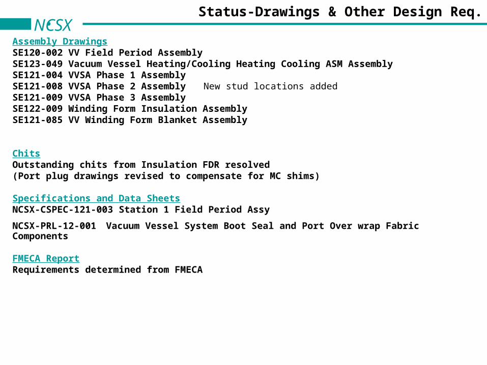
Assembly DrawingsSE120-002 VV Field Period AssemblySE123-049 Vacuum Vessel Heating/Cooling Heating Cooling ASM AssemblySE121-004 VVSA Phase 1 AssemblySE121-008 VVSA Phase 2 Assembly New stud locations addedSE121-009 VVSA Phase 3 AssemblySE122-009 Winding Form Insulation AssemblySE121-085 VV Winding Form Blanket Assembly
ChitsOutstanding chits from Insulation FDR resolved(Port plug drawings revised to compensate for MC shims)
Specifications and Data SheetsNCSX-CSPEC-121-003 Station 1 Field Period Assy
NCSX-PRL-12-001 Vacuum Vessel System Boot Seal and Port Over wrap Fabric Components
FMECA ReportRequirements determined from FMECA
NCSX Port Plug Concept
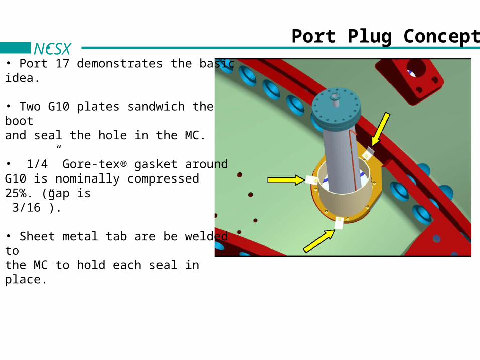
• Port 17 demonstrates the basic idea. • Two G10 plates sandwich the boot and seal the hole in the MC.
• 1/4” Gore-tex® gasket around G10 is nominally compressed 25%. (gap is 3/16”).
• Sheet metal tab are be welded to the MC to hold each seal in place.
2
3
1
NCSXPlug Types
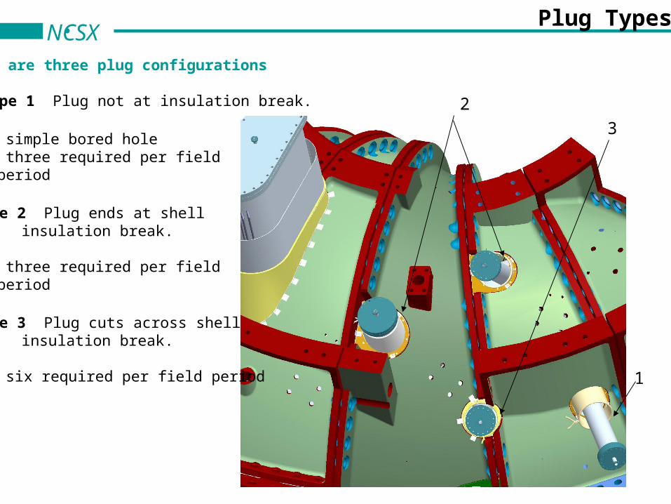
There are three plug configurations
• Type 1 Plug not at insulation break.
- simple bored hole- three required per field period
• Type 2 Plug ends at shell insulation break.
- three required per field period
• Type 3 Plug cuts across shellinsulation break.
- six required per field period
3
2
1
3
NCSXLocal Shimming of Shell Affects Type 3
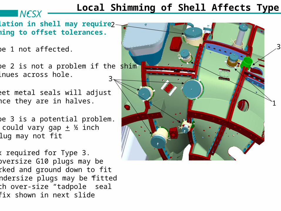
Insulation in shell may requireshimming to offset tolerances.
• Type 1 not affected.
• Type 2 is not a problem if the shimcontinues across hole.
• Sheet metal seals will adjust since they are in halves.
• Type 3 is a potential problem.- could vary gap + ½ inch- plug may not fit
• Fix required for Type 3.- oversize G10 plugs may bemarked and ground down to fit- undersize plugs may be fittedwith over-size “tadpole” seal - fix shown in next slide
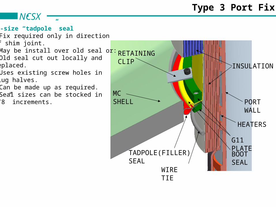
PORT WALL
HEATERS
G11 PLATEBOOT SEAL
RETAINING CLIP
WIRE TIE
TADPOLE(FILLER) SEAL
MC SHELL
INSULATION
NCSXType 3 Port Fix
Over-size “tadpole” seal • Fix required only in directionof shim joint.• May be install over old seal or:• Old seal cut out locally and replaced.• Uses existing screw holes in plug halves.• Can be made up as required.• Seal sizes can be stocked in 1/8” increments.
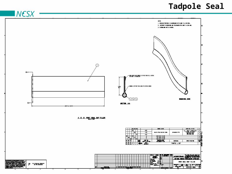
NCSXTadpole Seal
NCSXVV Fill Insulation
Cabot Nanogel is material of choice
• Heat-treated product will be made available by Cabot Corp for operation above 250 C.
- calcined version of standard
- hot air through product burns off volatiles
- test runs already completed
- sample to be procured near term
- insulating and mechanical characteristics believed to be unchanged
NCSXMC Face Insulation
• Made up with many identical pieces.
- typical size detailed but length may be modified to fit
- lap around three sides
• Daisy chained together.
lap and stapled together through upstanding hems on Nomex
- periodically fastened by studs and washers
- laced
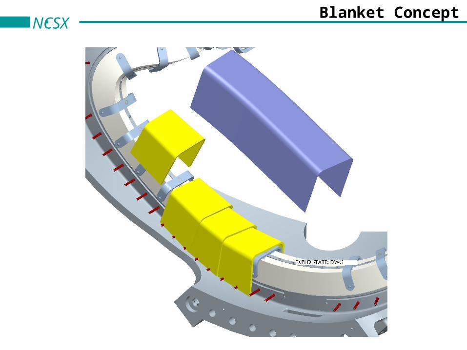
NCSXBlanket Concept
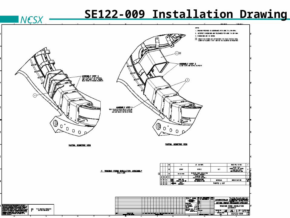
NCSX SE122-009 Installation Drawing
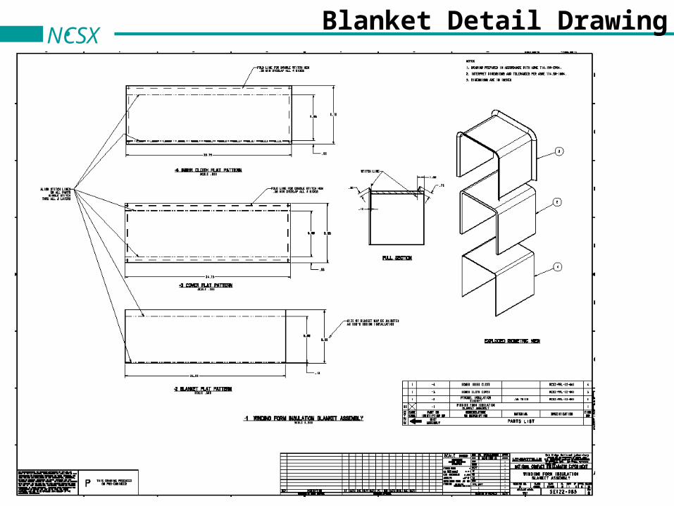
NCSXBlanket Detail Drawing
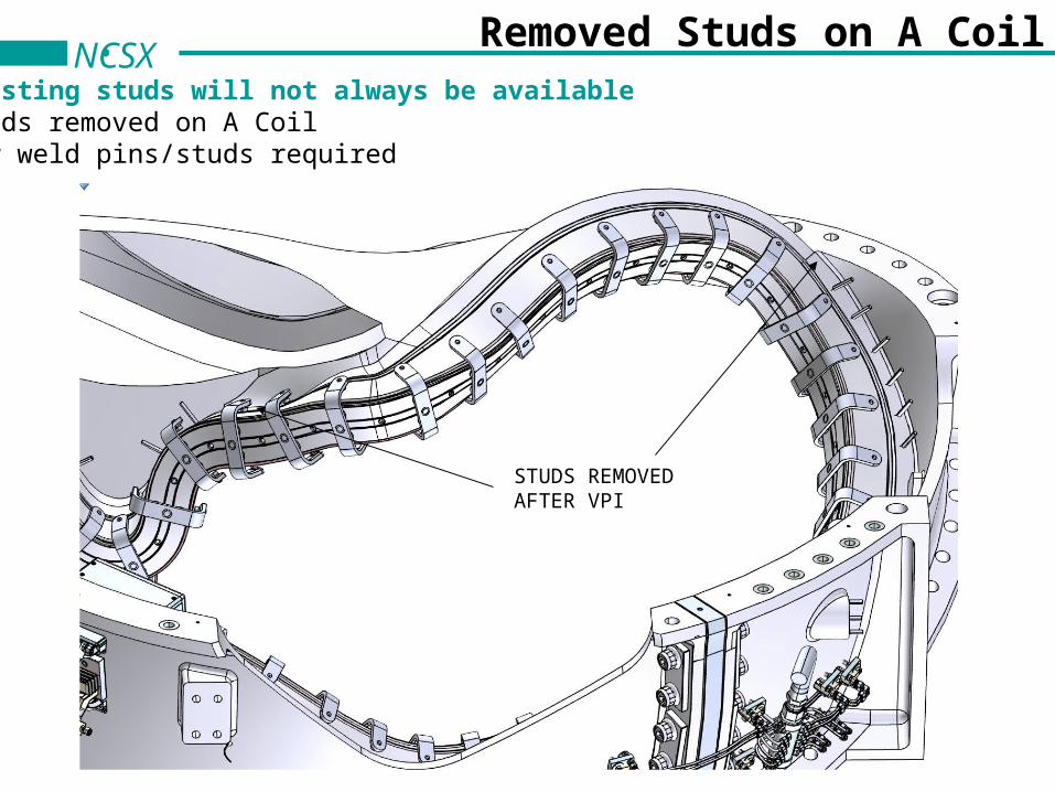
NCSXRemoved Studs on A Coil
Existing studs will not always be availableStuds removed on A CoilNew weld pins/studs required
STUDS REMOVEDAFTER VPI
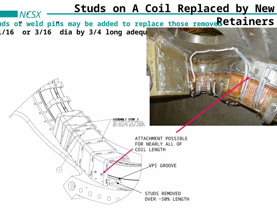
NCSXStuds on A Coil Replaced by New Retainers
Studs or weld pins may be added to replace those removed- 1/16” or 3/16” dia by 3/4 long adequate
ATTACHMENT POSSIBLEFOR NEARLY ALL OFCOIL LENGTH
STUDS REMOVEDOVER ~50% LENGTH
VPI GROOVE
NCSXFailure Mode Report
• Report summarizes recommendations and requirements stemming from FMECA
- identifies components required to detect faults and alert operator
- identifies critical events and operator appropriate responses
- identifies corrective action/repair
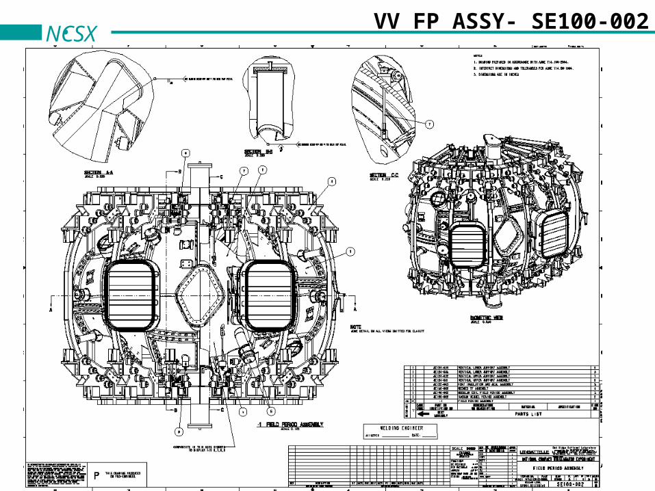
NCSXVV FP ASSY- SE100-002
NCSXIssues
• No issues remain except confirmation of Nanogel acceptability and its procurement.
• Needs blessing from Cabot.
NCSXConclusion
• Boot seals modifications have been made to assure fit with MC shims.
• Design/Material for MC coil insulation has been chosen and may be procured.- design uses yard goods and bulk product and does not require detailed drawings. - the installation method is shown in example drawings.
• Candidate for backfill insulation tentatively identified.
• Preparation of drawings is complete but several need check and/or promoting.