ndarc nasa design and analysis of rotorcraft inputan iterative solution. from the design flight...
TRANSCRIPT

NASA/TP–2015-218751
NDARC NASA Design and Analysis of Rotorcraft Input Appendix 2 Release 1.10 March 2016 Wayne Johnson NASA Ames Research Center, Moffett Field, CA
March 2016
https://ntrs.nasa.gov/search.jsp?R=20160012473 2020-08-04T09:02:02+00:00Z

The NASA STI Program Office . . . in Profile
Since its founding, NASA has been dedicated to the advancement of aeronautics and space science. The NASA Scientific and Technical Information (STI) Program Office plays a key part in helping NASA maintain this important role. The NASA STI Program Office is operated by Langley Research Center, the Lead Center for NASA’s scientific and technical information. The NASA STI Program Office provides access to the NASA STI Database, the largest collection of aeronautical and space science STI in the world. The Program Office is also NASA’s institutional mechanism for disseminating the results of its research and development activities. These results are published by NASA in the NASA STI Report Series, which includes the following report types: • TECHNICAL PUBLICATION. Reports of
completed research or a major significant phase of research that present the results of NASA programs and include extensive data or theoreti-cal analysis. Includes compilations of significant scientific and technical data and information deemed to be of continuing reference value. NASA’s counterpart of peer-reviewed formal professional papers but has less stringent limita-tions on manuscript length and extent of graphic presentations.
• TECHNICAL MEMORANDUM. Scientific and technical findings that
are preliminary or of specialized interest, e.g., quick release reports, working papers, and bibliographies that contain minimal annotation. Does not contain extensive analysis.
• CONTRACTOR REPORT. Scientific and tech-nical findings by NASA-
sponsored contractors and grantees. • CONFERENCE PUBLICATION. Collected papers from scientific and
technical conferences, symposia, seminars, or other meetings sponsored or cosponsored by NASA.
• SPECIAL PUBLICATION. Scientific, technical, or historical information from NASA programs, projects, and missions, often concerned with subjects having substantial public interest.
• TECHNICAL TRANSLATION. English-
language translations of foreign scientific and technical material pertinent to NASA’s mission.
Specialized services that complement the STI Program Office’s diverse offerings include creating custom thesauri, building customized databases, organizing and publishing research results . . . even providing videos. For more information about the NASA STI Program Office, see the following: • Access the NASA STI Program Home Page at http://www.sti.nasa.gov • E-mail your question via the Internet to [email protected] • Fax your question to the NASA Access Help Desk at (301) 621-0134 • Telephone the NASA Access Help Desk at (301) 621-0390 • Write to: NASA Access Help Desk NASA Center for AeroSpace Information 7115 Standard Drive Hanover, MD 21076-1320

NASA/TP–2015-218751
NDARC NASA Design and Analysis of Rotorcraft Input Wayne Johnson NASA Ames Research Center, Moffett Field, CA National Aeronautics and Space Administration Ames Research Center Moffett Field, California 94035-1000
March 2016

Available from: NASA Center for AeroSpace Information National Technical Information Service 7115 Standard Drive 5285 Port Royal Road Hanover, MD 21076-1320 Springfield, VA 22161 (301) 621-0390 (703) 487-4650

Contents
1. Data Structures and Input . . . . . . . . . . . . . . . . . . . . . . . . . . . . . . . . . . . . . . . . . . . . . . . . . . . . . . . . . . . . . . . . . . . . . . . . . . . . . . . . . . . . . . . . . . . . . . . . . . . . . . . . . . . . . . . . . . . . . . . . . . 1
2. Input Based on Configuration . . . . . . . . . . . . . . . . . . . . . . . . . . . . . . . . . . . . . . . . . . . . . . . . . . . . . . . . . . . . . . . . . . . . . . . . . . . . . . . . . . . . . . . . . . . . . . . . . . . . . . . . . . . . . . . . . . . . . . . 13
3. Parameters and Constants . . . . . . . . . . . . . . . . . . . . . . . . . . . . . . . . . . . . . . . . . . . . . . . . . . . . . . . . . . . . . . . . . . . . . . . . . . . . . . . . . . . . . . . . . . . . . . . . . . . . . . . . . . . . . . . . . . . . . . . . . . 21
4. Job . . . . . . . . . . . . . . . . . . . . . . . . . . . . . . . . . . . . . . . . . . . . . . . . . . . . . . . . . . . . . . . . . . . . . . . . . . . . . . . . . . . . . . . . . . . . . . . . . . . . . . . . . . . . . . . . . . . . . . . . . . . . . . . . . . . . . . . . . . . . . . 25
5. Design . . . . . . . . . . . . . . . . . . . . . . . . . . . . . . . . . . . . . . . . . . . . . . . . . . . . . . . . . . . . . . . . . . . . . . . . . . . . . . . . . . . . . . . . . . . . . . . . . . . . . . . . . . . . . . . . . . . . . . . . . . . . . . . . . . . . . . . . . . . 31
6. Cases . . . . . . . . . . . . . . . . . . . . . . . . . . . . . . . . . . . . . . . . . . . . . . . . . . . . . . . . . . . . . . . . . . . . . . . . . . . . . . . . . . . . . . . . . . . . . . . . . . . . . . . . . . . . . . . . . . . . . . . . . . . . . . . . . . . . . . . . . . . . 32
7. Size . . . . . . . . . . . . . . . . . . . . . . . . . . . . . . . . . . . . . . . . . . . . . . . . . . . . . . . . . . . . . . . . . . . . . . . . . . . . . . . . . . . . . . . . . . . . . . . . . . . . . . . . . . . . . . . . . . . . . . . . . . . . . . . . . . . . . . . . . . . . . 37
8. SizeParam . . . . . . . . . . . . . . . . . . . . . . . . . . . . . . . . . . . . . . . . . . . . . . . . . . . . . . . . . . . . . . . . . . . . . . . . . . . . . . . . . . . . . . . . . . . . . . . . . . . . . . . . . . . . . . . . . . . . . . . . . . . . . . . . . . . . . . . . 38
9. OffDesign . . . . . . . . . . . . . . . . . . . . . . . . . . . . . . . . . . . . . . . . . . . . . . . . . . . . . . . . . . . . . . . . . . . . . . . . . . . . . . . . . . . . . . . . . . . . . . . . . . . . . . . . . . . . . . . . . . . . . . . . . . . . . . . . . . . . . . . . 44
10. OffParam . . . . . . . . . . . . . . . . . . . . . . . . . . . . . . . . . . . . . . . . . . . . . . . . . . . . . . . . . . . . . . . . . . . . . . . . . . . . . . . . . . . . . . . . . . . . . . . . . . . . . . . . . . . . . . . . . . . . . . . . . . . . . . . . . . . . . . . 45
11. Performance . . . . . . . . . . . . . . . . . . . . . . . . . . . . . . . . . . . . . . . . . . . . . . . . . . . . . . . . . . . . . . . . . . . . . . . . . . . . . . . . . . . . . . . . . . . . . . . . . . . . . . . . . . . . . . . . . . . . . . . . . . . . . . . . . . . . 46
12. PerfParam . . . . . . . . . . . . . . . . . . . . . . . . . . . . . . . . . . . . . . . . . . . . . . . . . . . . . . . . . . . . . . . . . . . . . . . . . . . . . . . . . . . . . . . . . . . . . . . . . . . . . . . . . . . . . . . . . . . . . . . . . . . . . . . . . . . . . . . 47
13. MapEngine . . . . . . . . . . . . . . . . . . . . . . . . . . . . . . . . . . . . . . . . . . . . . . . . . . . . . . . . . . . . . . . . . . . . . . . . . . . . . . . . . . . . . . . . . . . . . . . . . . . . . . . . . . . . . . . . . . . . . . . . . . . . . . . . . . . . . 48
14. MapAero . . . . . . . . . . . . . . . . . . . . . . . . . . . . . . . . . . . . . . . . . . . . . . . . . . . . . . . . . . . . . . . . . . . . . . . . . . . . . . . . . . . . . . . . . . . . . . . . . . . . . . . . . . . . . . . . . . . . . . . . . . . . . . . . . . . . . . . 51
15. FltCond . . . . . . . . . . . . . . . . . . . . . . . . . . . . . . . . . . . . . . . . . . . . . . . . . . . . . . . . . . . . . . . . . . . . . . . . . . . . . . . . . . . . . . . . . . . . . . . . . . . . . . . . . . . . . . . . . . . . . . . . . . . . . . . . . . . . . . . . 54
16. Mission . . . . . . . . . . . . . . . . . . . . . . . . . . . . . . . . . . . . . . . . . . . . . . . . . . . . . . . . . . . . . . . . . . . . . . . . . . . . . . . . . . . . . . . . . . . . . . . . . . . . . . . . . . . . . . . . . . . . . . . . . . . . . . . . . . . . . . . . . 59
17. MissParam . . . . . . . . . . . . . . . . . . . . . . . . . . . . . . . . . . . . . . . . . . . . . . . . . . . . . . . . . . . . . . . . . . . . . . . . . . . . . . . . . . . . . . . . . . . . . . . . . . . . . . . . . . . . . . . . . . . . . . . . . . . . . . . . . . . . . . 60
18. MissSeg . . . . . . . . . . . . . . . . . . . . . . . . . . . . . . . . . . . . . . . . . . . . . . . . . . . . . . . . . . . . . . . . . . . . . . . . . . . . . . . . . . . . . . . . . . . . . . . . . . . . . . . . . . . . . . . . . . . . . . . . . . . . . . . . . . . . . . . . 67
19. FltState . . . . . . . . . . . . . . . . . . . . . . . . . . . . . . . . . . . . . . . . . . . . . . . . . . . . . . . . . . . . . . . . . . . . . . . . . . . . . . . . . . . . . . . . . . . . . . . . . . . . . . . . . . . . . . . . . . . . . . . . . . . . . . . . . . . . . . . . . 76
20. FltAircraft . . . . . . . . . . . . . . . . . . . . . . . . . . . . . . . . . . . . . . . . . . . . . . . . . . . . . . . . . . . . . . . . . . . . . . . . . . . . . . . . . . . . . . . . . . . . . . . . . . . . . . . . . . . . . . . . . . . . . . . . . . . . . . . . . . . . . . . 77

Contents ii
21. FltFuse . . . . . . . . . . . . . . . . . . . . . . . . . . . . . . . . . . . . . . . . . . . . . . . . . . . . . . . . . . . . . . . . . . . . . . . . . . . . . . . . . . . . . . . . . . . . . . . . . . . . . . . . . . . . . . . . . . . . . . . . . . . . . . . . . . . . . . . . . 94
22. FltGear . . . . . . . . . . . . . . . . . . . . . . . . . . . . . . . . . . . . . . . . . . . . . . . . . . . . . . . . . . . . . . . . . . . . . . . . . . . . . . . . . . . . . . . . . . . . . . . . . . . . . . . . . . . . . . . . . . . . . . . . . . . . . . . . . . . . . . . . . 95
23. FltRotor . . . . . . . . . . . . . . . . . . . . . . . . . . . . . . . . . . . . . . . . . . . . . . . . . . . . . . . . . . . . . . . . . . . . . . . . . . . . . . . . . . . . . . . . . . . . . . . . . . . . . . . . . . . . . . . . . . . . . . . . . . . . . . . . . . . . . . . . . 96
24. FltWing . . . . . . . . . . . . . . . . . . . . . . . . . . . . . . . . . . . . . . . . . . . . . . . . . . . . . . . . . . . . . . . . . . . . . . . . . . . . . . . . . . . . . . . . . . . . . . . . . . . . . . . . . . . . . . . . . . . . . . . . . . . . . . . . . . . . . . . . . 102
25. FltTail . . . . . . . . . . . . . . . . . . . . . . . . . . . . . . . . . . . . . . . . . . . . . . . . . . . . . . . . . . . . . . . . . . . . . . . . . . . . . . . . . . . . . . . . . . . . . . . . . . . . . . . . . . . . . . . . . . . . . . . . . . . . . . . . . . . . . . . . . . 105
26. FltTank . . . . . . . . . . . . . . . . . . . . . . . . . . . . . . . . . . . . . . . . . . . . . . . . . . . . . . . . . . . . . . . . . . . . . . . . . . . . . . . . . . . . . . . . . . . . . . . . . . . . . . . . . . . . . . . . . . . . . . . . . . . . . . . . . . . . . . . . . 106
27. FltProp . . . . . . . . . . . . . . . . . . . . . . . . . . . . . . . . . . . . . . . . . . . . . . . . . . . . . . . . . . . . . . . . . . . . . . . . . . . . . . . . . . . . . . . . . . . . . . . . . . . . . . . . . . . . . . . . . . . . . . . . . . . . . . . . . . . . . . . . . 108
28. FltEngn . . . . . . . . . . . . . . . . . . . . . . . . . . . . . . . . . . . . . . . . . . . . . . . . . . . . . . . . . . . . . . . . . . . . . . . . . . . . . . . . . . . . . . . . . . . . . . . . . . . . . . . . . . . . . . . . . . . . . . . . . . . . . . . . . . . . . . . . . 110
29. FltJet . . . . . . . . . . . . . . . . . . . . . . . . . . . . . . . . . . . . . . . . . . . . . . . . . . . . . . . . . . . . . . . . . . . . . . . . . . . . . . . . . . . . . . . . . . . . . . . . . . . . . . . . . . . . . . . . . . . . . . . . . . . . . . . . . . . . . . . . . . . 113
30. FltChrg . . . . . . . . . . . . . . . . . . . . . . . . . . . . . . . . . . . . . . . . . . . . . . . . . . . . . . . . . . . . . . . . . . . . . . . . . . . . . . . . . . . . . . . . . . . . . . . . . . . . . . . . . . . . . . . . . . . . . . . . . . . . . . . . . . . . . . . . . 116
31. Solution . . . . . . . . . . . . . . . . . . . . . . . . . . . . . . . . . . . . . . . . . . . . . . . . . . . . . . . . . . . . . . . . . . . . . . . . . . . . . . . . . . . . . . . . . . . . . . . . . . . . . . . . . . . . . . . . . . . . . . . . . . . . . . . . . . . . . . . . 119
32. Cost . . . . . . . . . . . . . . . . . . . . . . . . . . . . . . . . . . . . . . . . . . . . . . . . . . . . . . . . . . . . . . . . . . . . . . . . . . . . . . . . . . . . . . . . . . . . . . . . . . . . . . . . . . . . . . . . . . . . . . . . . . . . . . . . . . . . . . . . . . . . 123
33. CostCTM . . . . . . . . . . . . . . . . . . . . . . . . . . . . . . . . . . . . . . . . . . . . . . . . . . . . . . . . . . . . . . . . . . . . . . . . . . . . . . . . . . . . . . . . . . . . . . . . . . . . . . . . . . . . . . . . . . . . . . . . . . . . . . . . . . . . . . . 125
34. Emissions . . . . . . . . . . . . . . . . . . . . . . . . . . . . . . . . . . . . . . . . . . . . . . . . . . . . . . . . . . . . . . . . . . . . . . . . . . . . . . . . . . . . . . . . . . . . . . . . . . . . . . . . . . . . . . . . . . . . . . . . . . . . . . . . . . . . . . . 127
35. Aircraft . . . . . . . . . . . . . . . . . . . . . . . . . . . . . . . . . . . . . . . . . . . . . . . . . . . . . . . . . . . . . . . . . . . . . . . . . . . . . . . . . . . . . . . . . . . . . . . . . . . . . . . . . . . . . . . . . . . . . . . . . . . . . . . . . . . . . . . . 129
36. XAircraft . . . . . . . . . . . . . . . . . . . . . . . . . . . . . . . . . . . . . . . . . . . . . . . . . . . . . . . . . . . . . . . . . . . . . . . . . . . . . . . . . . . . . . . . . . . . . . . . . . . . . . . . . . . . . . . . . . . . . . . . . . . . . . . . . . . . . . . 145
37. Systems . . . . . . . . . . . . . . . . . . . . . . . . . . . . . . . . . . . . . . . . . . . . . . . . . . . . . . . . . . . . . . . . . . . . . . . . . . . . . . . . . . . . . . . . . . . . . . . . . . . . . . . . . . . . . . . . . . . . . . . . . . . . . . . . . . . . . . . . 147
38. WFltCont . . . . . . . . . . . . . . . . . . . . . . . . . . . . . . . . . . . . . . . . . . . . . . . . . . . . . . . . . . . . . . . . . . . . . . . . . . . . . . . . . . . . . . . . . . . . . . . . . . . . . . . . . . . . . . . . . . . . . . . . . . . . . . . . . . . . . . . 154
39. WDeIce . . . . . . . . . . . . . . . . . . . . . . . . . . . . . . . . . . . . . . . . . . . . . . . . . . . . . . . . . . . . . . . . . . . . . . . . . . . . . . . . . . . . . . . . . . . . . . . . . . . . . . . . . . . . . . . . . . . . . . . . . . . . . . . . . . . . . . . . . 156
40. Fuselage . . . . . . . . . . . . . . . . . . . . . . . . . . . . . . . . . . . . . . . . . . . . . . . . . . . . . . . . . . . . . . . . . . . . . . . . . . . . . . . . . . . . . . . . . . . . . . . . . . . . . . . . . . . . . . . . . . . . . . . . . . . . . . . . . . . . . . . . 157
41. AFuse . . . . . . . . . . . . . . . . . . . . . . . . . . . . . . . . . . . . . . . . . . . . . . . . . . . . . . . . . . . . . . . . . . . . . . . . . . . . . . . . . . . . . . . . . . . . . . . . . . . . . . . . . . . . . . . . . . . . . . . . . . . . . . . . . . . . . . . . . . 161
42. WFuse . . . . . . . . . . . . . . . . . . . . . . . . . . . . . . . . . . . . . . . . . . . . . . . . . . . . . . . . . . . . . . . . . . . . . . . . . . . . . . . . . . . . . . . . . . . . . . . . . . . . . . . . . . . . . . . . . . . . . . . . . . . . . . . . . . . . . . . . . . 164
43. LandingGear . . . . . . . . . . . . . . . . . . . . . . . . . . . . . . . . . . . . . . . . . . . . . . . . . . . . . . . . . . . . . . . . . . . . . . . . . . . . . . . . . . . . . . . . . . . . . . . . . . . . . . . . . . . . . . . . . . . . . . . . . . . . . . . . . . . 165
44. AGear . . . . . . . . . . . . . . . . . . . . . . . . . . . . . . . . . . . . . . . . . . . . . . . . . . . . . . . . . . . . . . . . . . . . . . . . . . . . . . . . . . . . . . . . . . . . . . . . . . . . . . . . . . . . . . . . . . . . . . . . . . . . . . . . . . . . . . . . . . 167

Contents iii
45. WGear . . . . . . . . . . . . . . . . . . . . . . . . . . . . . . . . . . . . . . . . . . . . . . . . . . . . . . . . . . . . . . . . . . . . . . . . . . . . . . . . . . . . . . . . . . . . . . . . . . . . . . . . . . . . . . . . . . . . . . . . . . . . . . . . . . . . . . . . . . 168
46. Rotor . . . . . . . . . . . . . . . . . . . . . . . . . . . . . . . . . . . . . . . . . . . . . . . . . . . . . . . . . . . . . . . . . . . . . . . . . . . . . . . . . . . . . . . . . . . . . . . . . . . . . . . . . . . . . . . . . . . . . . . . . . . . . . . . . . . . . . . . . . . 169
47. PRotorInd . . . . . . . . . . . . . . . . . . . . . . . . . . . . . . . . . . . . . . . . . . . . . . . . . . . . . . . . . . . . . . . . . . . . . . . . . . . . . . . . . . . . . . . . . . . . . . . . . . . . . . . . . . . . . . . . . . . . . . . . . . . . . . . . . . . . . . . 185
48. PRotorPro . . . . . . . . . . . . . . . . . . . . . . . . . . . . . . . . . . . . . . . . . . . . . . . . . . . . . . . . . . . . . . . . . . . . . . . . . . . . . . . . . . . . . . . . . . . . . . . . . . . . . . . . . . . . . . . . . . . . . . . . . . . . . . . . . . . . . . . 188
49. PRotorTab . . . . . . . . . . . . . . . . . . . . . . . . . . . . . . . . . . . . . . . . . . . . . . . . . . . . . . . . . . . . . . . . . . . . . . . . . . . . . . . . . . . . . . . . . . . . . . . . . . . . . . . . . . . . . . . . . . . . . . . . . . . . . . . . . . . . . . 191
50. DRotor . . . . . . . . . . . . . . . . . . . . . . . . . . . . . . . . . . . . . . . . . . . . . . . . . . . . . . . . . . . . . . . . . . . . . . . . . . . . . . . . . . . . . . . . . . . . . . . . . . . . . . . . . . . . . . . . . . . . . . . . . . . . . . . . . . . . . . . . . 193
51. IRotor . . . . . . . . . . . . . . . . . . . . . . . . . . . . . . . . . . . . . . . . . . . . . . . . . . . . . . . . . . . . . . . . . . . . . . . . . . . . . . . . . . . . . . . . . . . . . . . . . . . . . . . . . . . . . . . . . . . . . . . . . . . . . . . . . . . . . . . . . . 195
52. WRotor . . . . . . . . . . . . . . . . . . . . . . . . . . . . . . . . . . . . . . . . . . . . . . . . . . . . . . . . . . . . . . . . . . . . . . . . . . . . . . . . . . . . . . . . . . . . . . . . . . . . . . . . . . . . . . . . . . . . . . . . . . . . . . . . . . . . . . . . . 197
53. Wing . . . . . . . . . . . . . . . . . . . . . . . . . . . . . . . . . . . . . . . . . . . . . . . . . . . . . . . . . . . . . . . . . . . . . . . . . . . . . . . . . . . . . . . . . . . . . . . . . . . . . . . . . . . . . . . . . . . . . . . . . . . . . . . . . . . . . . . . . . . 199
54. AWing . . . . . . . . . . . . . . . . . . . . . . . . . . . . . . . . . . . . . . . . . . . . . . . . . . . . . . . . . . . . . . . . . . . . . . . . . . . . . . . . . . . . . . . . . . . . . . . . . . . . . . . . . . . . . . . . . . . . . . . . . . . . . . . . . . . . . . . . . . 208
55. WWing . . . . . . . . . . . . . . . . . . . . . . . . . . . . . . . . . . . . . . . . . . . . . . . . . . . . . . . . . . . . . . . . . . . . . . . . . . . . . . . . . . . . . . . . . . . . . . . . . . . . . . . . . . . . . . . . . . . . . . . . . . . . . . . . . . . . . . . . . 211
56. WWingTR . . . . . . . . . . . . . . . . . . . . . . . . . . . . . . . . . . . . . . . . . . . . . . . . . . . . . . . . . . . . . . . . . . . . . . . . . . . . . . . . . . . . . . . . . . . . . . . . . . . . . . . . . . . . . . . . . . . . . . . . . . . . . . . . . . . . . . 212
57. Tail . . . . . . . . . . . . . . . . . . . . . . . . . . . . . . . . . . . . . . . . . . . . . . . . . . . . . . . . . . . . . . . . . . . . . . . . . . . . . . . . . . . . . . . . . . . . . . . . . . . . . . . . . . . . . . . . . . . . . . . . . . . . . . . . . . . . . . . . . . . . 214
58. ATail . . . . . . . . . . . . . . . . . . . . . . . . . . . . . . . . . . . . . . . . . . . . . . . . . . . . . . . . . . . . . . . . . . . . . . . . . . . . . . . . . . . . . . . . . . . . . . . . . . . . . . . . . . . . . . . . . . . . . . . . . . . . . . . . . . . . . . . . . . . 218
59. Wtail . . . . . . . . . . . . . . . . . . . . . . . . . . . . . . . . . . . . . . . . . . . . . . . . . . . . . . . . . . . . . . . . . . . . . . . . . . . . . . . . . . . . . . . . . . . . . . . . . . . . . . . . . . . . . . . . . . . . . . . . . . . . . . . . . . . . . . . . . . . 220
60. FuelTank . . . . . . . . . . . . . . . . . . . . . . . . . . . . . . . . . . . . . . . . . . . . . . . . . . . . . . . . . . . . . . . . . . . . . . . . . . . . . . . . . . . . . . . . . . . . . . . . . . . . . . . . . . . . . . . . . . . . . . . . . . . . . . . . . . . . . . . 221
61. WTank . . . . . . . . . . . . . . . . . . . . . . . . . . . . . . . . . . . . . . . . . . . . . . . . . . . . . . . . . . . . . . . . . . . . . . . . . . . . . . . . . . . . . . . . . . . . . . . . . . . . . . . . . . . . . . . . . . . . . . . . . . . . . . . . . . . . . . . . . . 224
62. Propulsion . . . . . . . . . . . . . . . . . . . . . . . . . . . . . . . . . . . . . . . . . . . . . . . . . . . . . . . . . . . . . . . . . . . . . . . . . . . . . . . . . . . . . . . . . . . . . . . . . . . . . . . . . . . . . . . . . . . . . . . . . . . . . . . . . . . . . . 226
63. WDrive . . . . . . . . . . . . . . . . . . . . . . . . . . . . . . . . . . . . . . . . . . . . . . . . . . . . . . . . . . . . . . . . . . . . . . . . . . . . . . . . . . . . . . . . . . . . . . . . . . . . . . . . . . . . . . . . . . . . . . . . . . . . . . . . . . . . . . . . . 231
64. EngineGroup . . . . . . . . . . . . . . . . . . . . . . . . . . . . . . . . . . . . . . . . . . . . . . . . . . . . . . . . . . . . . . . . . . . . . . . . . . . . . . . . . . . . . . . . . . . . . . . . . . . . . . . . . . . . . . . . . . . . . . . . . . . . . . . . . . . 232
65. DEngSys . . . . . . . . . . . . . . . . . . . . . . . . . . . . . . . . . . . . . . . . . . . . . . . . . . . . . . . . . . . . . . . . . . . . . . . . . . . . . . . . . . . . . . . . . . . . . . . . . . . . . . . . . . . . . . . . . . . . . . . . . . . . . . . . . . . . . . . . 241
66. WEngSys . . . . . . . . . . . . . . . . . . . . . . . . . . . . . . . . . . . . . . . . . . . . . . . . . . . . . . . . . . . . . . . . . . . . . . . . . . . . . . . . . . . . . . . . . . . . . . . . . . . . . . . . . . . . . . . . . . . . . . . . . . . . . . . . . . . . . . . 242
67. JetGroup . . . . . . . . . . . . . . . . . . . . . . . . . . . . . . . . . . . . . . . . . . . . . . . . . . . . . . . . . . . . . . . . . . . . . . . . . . . . . . . . . . . . . . . . . . . . . . . . . . . . . . . . . . . . . . . . . . . . . . . . . . . . . . . . . . . . . . . 243
68. DJetSys . . . . . . . . . . . . . . . . . . . . . . . . . . . . . . . . . . . . . . . . . . . . . . . . . . . . . . . . . . . . . . . . . . . . . . . . . . . . . . . . . . . . . . . . . . . . . . . . . . . . . . . . . . . . . . . . . . . . . . . . . . . . . . . . . . . . . . . . . 249
69. WJetSys . . . . . . . . . . . . . . . . . . . . . . . . . . . . . . . . . . . . . . . . . . . . . . . . . . . . . . . . . . . . . . . . . . . . . . . . . . . . . . . . . . . . . . . . . . . . . . . . . . . . . . . . . . . . . . . . . . . . . . . . . . . . . . . . . . . . . . . . 250
70. ChargeGroup . . . . . . . . . . . . . . . . . . . . . . . . . . . . . . . . . . . . . . . . . . . . . . . . . . . . . . . . . . . . . . . . . . . . . . . . . . . . . . . . . . . . . . . . . . . . . . . . . . . . . . . . . . . . . . . . . . . . . . . . . . . . . . . . . . . 251
Contents iv
71. DChrgSys . . . . . . . . . . . . . . . . . . . . . . . . . . . . . . . . . . . . . . . . . . . . . . . . . . . . . . . . . . . . . . . . . . . . . . . . . . . . . . . . . . . . . . . . . . . . . . . . . . . . . . . . . . . . . . . . . . . . . . . . . . . . . . . . . . . . . . . 256
72. WChrgSys . . . . . . . . . . . . . . . . . . . . . . . . . . . . . . . . . . . . . . . . . . . . . . . . . . . . . . . . . . . . . . . . . . . . . . . . . . . . . . . . . . . . . . . . . . . . . . . . . . . . . . . . . . . . . . . . . . . . . . . . . . . . . . . . . . . . . . 257
73. EngineModel . . . . . . . . . . . . . . . . . . . . . . . . . . . . . . . . . . . . . . . . . . . . . . . . . . . . . . . . . . . . . . . . . . . . . . . . . . . . . . . . . . . . . . . . . . . . . . . . . . . . . . . . . . . . . . . . . . . . . . . . . . . . . . . . . . . 258
74. EngineParam . . . . . . . . . . . . . . . . . . . . . . . . . . . . . . . . . . . . . . . . . . . . . . . . . . . . . . . . . . . . . . . . . . . . . . . . . . . . . . . . . . . . . . . . . . . . . . . . . . . . . . . . . . . . . . . . . . . . . . . . . . . . . . . . . . . . 262
75. EngineTable . . . . . . . . . . . . . . . . . . . . . . . . . . . . . . . . . . . . . . . . . . . . . . . . . . . . . . . . . . . . . . . . . . . . . . . . . . . . . . . . . . . . . . . . . . . . . . . . . . . . . . . . . . . . . . . . . . . . . . . . . . . . . . . . . . . . 265
76. RecipModel . . . . . . . . . . . . . . . . . . . . . . . . . . . . . . . . . . . . . . . . . . . . . . . . . . . . . . . . . . . . . . . . . . . . . . . . . . . . . . . . . . . . . . . . . . . . . . . . . . . . . . . . . . . . . . . . . . . . . . . . . . . . . . . . . . . . . 267
77. CompressorModel . . . . . . . . . . . . . . . . . . . . . . . . . . . . . . . . . . . . . . . . . . . . . . . . . . . . . . . . . . . . . . . . . . . . . . . . . . . . . . . . . . . . . . . . . . . . . . . . . . . . . . . . . . . . . . . . . . . . . . . . . . . . . . 271
78. MotorModel . . . . . . . . . . . . . . . . . . . . . . . . . . . . . . . . . . . . . . . . . . . . . . . . . . . . . . . . . . . . . . . . . . . . . . . . . . . . . . . . . . . . . . . . . . . . . . . . . . . . . . . . . . . . . . . . . . . . . . . . . . . . . . . . . . . . 273
79. JetModel . . . . . . . . . . . . . . . . . . . . . . . . . . . . . . . . . . . . . . . . . . . . . . . . . . . . . . . . . . . . . . . . . . . . . . . . . . . . . . . . . . . . . . . . . . . . . . . . . . . . . . . . . . . . . . . . . . . . . . . . . . . . . . . . . . . . . . . 276
80. FuelCellModel . . . . . . . . . . . . . . . . . . . . . . . . . . . . . . . . . . . . . . . . . . . . . . . . . . . . . . . . . . . . . . . . . . . . . . . . . . . . . . . . . . . . . . . . . . . . . . . . . . . . . . . . . . . . . . . . . . . . . . . . . . . . . . . . . . 279
81. SolarCellModel . . . . . . . . . . . . . . . . . . . . . . . . . . . . . . . . . . . . . . . . . . . . . . . . . . . . . . . . . . . . . . . . . . . . . . . . . . . . . . . . . . . . . . . . . . . . . . . . . . . . . . . . . . . . . . . . . . . . . . . . . . . . . . . . . 281
82. BatteryModel . . . . . . . . . . . . . . . . . . . . . . . . . . . . . . . . . . . . . . . . . . . . . . . . . . . . . . . . . . . . . . . . . . . . . . . . . . . . . . . . . . . . . . . . . . . . . . . . . . . . . . . . . . . . . . . . . . . . . . . . . . . . . . . . . . . 283
83. Location . . . . . . . . . . . . . . . . . . . . . . . . . . . . . . . . . . . . . . . . . . . . . . . . . . . . . . . . . . . . . . . . . . . . . . . . . . . . . . . . . . . . . . . . . . . . . . . . . . . . . . . . . . . . . . . . . . . . . . . . . . . . . . . . . . . . . . . . 285
84. Weight . . . . . . . . . . . . . . . . . . . . . . . . . . . . . . . . . . . . . . . . . . . . . . . . . . . . . . . . . . . . . . . . . . . . . . . . . . . . . . . . . . . . . . . . . . . . . . . . . . . . . . . . . . . . . . . . . . . . . . . . . . . . . . . . . . . . . . . . . 287

1
Chapter 1
Data Structures and Input
1–1 Overview
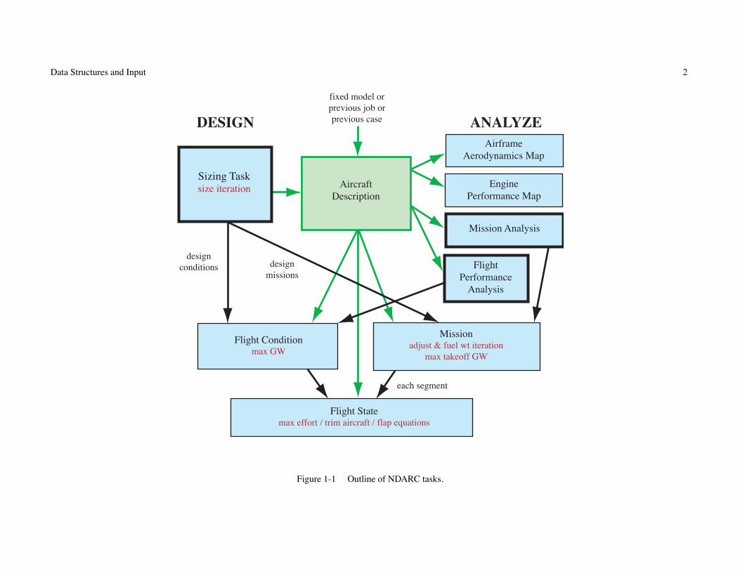
The NDARC code performs design and analysis tasks. The design task involves sizing the rotorcraft to satisfy specified design conditions and missions. The analysis taskscan include off-design mission performance analysis, flight performance calculation for point operating conditions, and generation of subsystem or component performancemaps. Figure 1-1 illustrates the tasks. The principal tasks (sizing, mission analysis, flight performance analysis) are shown in the figure as boxes with heavy borders. Heavyarrows show control of subordinate tasks.
The aircraft description (figure 1-1) consists of all the information, input and derived, that defines the aircraft. The aircraft consists of a set of components, including fuselage,rotors, wings, tails, and propulsion. This information can be the result of the sizing task; can come entirely from input, for a fixed model; or can come from the sizing task ina previous case or previous job. The aircraft description information is available to all tasks and all solutions (indicated by light arrows).
The sizing task determines the dimensions, power, and weight of a rotorcraft that can perform a specified set of design conditions and missions. The aircraft size is characterizedby parameters such as design gross weight, weight empty, rotor radius, and engine power available. The relations between dimensions, power, and weight generally requirean iterative solution. From the design flight conditions and missions, the task can determine the total engine power or the rotor radius (or both power and radius can be fixed),as well as the design gross weight, maximum takeoff weight, drive system torque limit, and fuel tank capacity. For each propulsion group, the engine power or the rotorradius can be sized.
Missions are defined for the sizing task, and for the mission performance analysis. A mission consists of a number of mission segments, for which time, distance, and fuelburn are evaluated. For the sizing task, certain missions are designated to be used for design gross weight calculations; for transmission sizing; and for fuel tank sizing. Themission parameters include mission takeoff gross weight and useful load. For specified takeoff fuel weight with adjustable segments, the mission time or distance is adjustedso the fuel required for the mission (burned plus reserve) equals the takeoff fuel weight. The mission iteration is on fuel weight or energy.
Flight conditions are specified for the sizing task, and for the flight performance analysis. For the sizing task, certain flight conditions are designated to be used for design grossweight calculations; for transmission sizing; for maximum takeoff weight calculations; and for antitorque or auxiliary thrust rotor sizing. The flight condition parametersinclude gross weight and useful load.
For flight conditions and mission takeoff, the gross weight can be maximized, such that the power required equals the power available.
A flight state is defined for each mission segment and each flight condition. The aircraft performance can be analyzed for the specified state, or a maximum effort performancecan be identified. The maximum effort is specified in terms of a quantity such as best endurance or best range, and a variable such as speed, rate of climb, or altitude. Theaircraft must be trimmed, by solving for the controls and motion that produce equilibrium in the specified flight state. Different trim solution definitions are required forvarious flight states. Evaluating the rotor hub forces may require solution of the blade flap equations of motion.
Data Structures and Input 2
Sizing Tasksize iteration Engine
Performance Map
Mission Analysis
Flight Performance
Analysis
Missionadjust & fuel wt iteration
max takeoff GW
Flight Conditionmax GW
Flight Statemax effort / trim aircraft / flap equations
Airframe Aerodynamics Map
Aircraft Description
DESIGN ANALYZE
fixed model or previous job or previous case
design conditions design
missions
each segment
Figure 1-1 Outline of NDARC tasks.

Data Structures and Input 3
design
geometry
performance
airframe aerodynamics
engine performance
design and performance
aircraft description
solution
input
additional outputadditional cases
INTERFACE FILES
NDARC
COMPREHENSIVE ANALYSIS
STRUCTURAL DESIGNLAYOUT DESIGN
COMPREHENSIVE ANALYSIS
Figure 1-2 NDARC Interfaces.

Data Structures and Input 4
&JOB INIT_input=0,INIT_data=0,&END&DEFN action=’ident’,created=’time-date’,title=’standard input’,&END!########################################################################&DEFN action=’read file’,file=’engine.list’,&END&DEFN action=’read file’,file=’helicopter.list’,&END!========================================================================&DEFN quant=’Cases’,&END&VALUE title=’Helicopter’,TASK_size=0,TASK_mission=1,TASK_perf=1,&END&DEFN quant=’Size’,&END&VALUE nFltCond=0,nMission=0,&END!========================================================================&DEFN quant=’OffDesign’,&END&VALUE title=’mission analysis’,nMission=1,&END&DEFN quant=’OffMission’,&END&VALUE
(one mission, mission segment parameters as arrays)&END!========================================================================&DEFN quant=’Performance’,&END&VALUE title=’performance analysis’,nFltCond=2,&END&DEFN quant=’PerfCondition’,&END&VALUE
(one condition)&END&DEFN quant=’PerfCondition’,&END&VALUE
(one condition)&END!========================================================================&DEFN action=’endofcase’,&END!########################################################################&DEFN action=’endofjob’,&END
Figure 1-3a Illustration of NDARC input (primary input).

Data Structures and Input 5
&DEFN action=’ident’,created=’time-date’,title=’Helicopter’,&END!########################################################################! default helicopter&DEFN action=’configuration’,&END&VALUE config=’helicopter’,rotate=1,&END!========================================================================&DEFN quant=’Cases’,&END&VALUE title=’Helicopter’,FILE_design=’helicopter.design’,&END&DEFN quant=’Size’,&END&VALUE
title=’Helicopter’,SIZE_perf=’none’,SET_rotor=’radius+Vtip+sigma’,’radius+Vtip+sigma’,FIX_DGW=1,SET_tank=’input’,SET_SDGW=’input’,SET_WMTO=’input’,
&END&DEFN quant=’Solution’,&END&VALUE &END!========================================================================&DEFN quant=’Aircraft’,&END&VALUE (Aircraft parameters) &END&DEFN quant=’Geometry’,&END&VALUE (geometry) &END&DEFN quant=’Rotor 1’,&END&VALUE (Rotor 1 parameters) &END!========================================================================
(other parameters in other structures)!========================================================================&DEFN quant=’TechFactors’,&END&VALUE (technology factors) &END!########################################################################&DEFN action=’endoffile’,&END
Figure 1-3b Illustration of NDARC input (secondary input file).

Data Structures and Input 6
1–2 NDARC Input and Output
Figure 1-2 illustrates the input and output environment of NDARC. Table 1-1 lists the possible input and output files. A job reads input from one or more files. The primaryinput is obtained from standard input (perhaps redirected to a file). The primary input can direct the code to read other files, identified by file name or logical name. Theinput data are read in namelist format. Unit numbers are part of the job input. Output file names are part of the case input. Input files names are defined in the input itself.
Table 1-1. Input and output files.
file logical name unit number (and default)
INPUTPrimary Input standard input nuin = 5Secondary Input File FILE nufile = 40Aircraft Description FILE nufile = 40Solution FILE nufile = 40
OUTPUTOutput standard output nuout = 6Design DESIGNn nudesign = 41Performance PERFn nuperf = 42Airframe Aerodynamics AEROn nuaero = 43Engine Performance ENGINEn nuengine = 44Geometry GEOMETRYn nugeom = 45Aircraft Description AIRCRAFTn nuacd = 46Solution SOLUTIONn nusoln = 47Sketch SKETCHn nusketch = 48Errors ERRORn nuerror = 49
1-2.1 Input
Figure 1-3 illustrates NDARC input. The primary input starts with a JOB namelist, then DEFN namelists are read to define the action and contents of the subsequentinformation. The job parameters include initialization control, error action, and input/output unit numbers. Job parameters can be read during case input using QUANT=’Job’.The initialization takes place before case input, so changed initialization parameters in QUANT=’Job’ input take effect for the next case. The DEFN namelist has the followingparameters.

Data Structures and Input 7
a) ACTION: character string (length = 32; case independent).
b) QUANT: character string (length = 32, case independent); corresponds to data structure in input; string includes structurenumber (1 or next condition/mission if absent).
c) SOURCE: integer; for copy action.
d) PARENT: integer; engine model number for QUANT=’EngineParam’; value is 1 if absent; input variable can be PARENT orENGINEMODEL.
e) FILE: file name or logical name (length = 256).
f) CREATED: character string of creation time and date (length = 20).
g) TITLE: character string of title identifying input file (length = 80).
h) VERSION: code version number as character string (length = 6).
i) MODIFICATION: character string of code modification (length = 32).
Table 1-2 describes the options for the ACTION variable in the DEFN namelist. The code searches for the keyword in the ACTION character string. A solution file (text orbinary) can be written by an NDARC job and then read by a subsequent job, restoring the solution to the state that existed when the file was created. Then additional outputand additional cases can be obtained. An aircraft description file can be written by an NDARC job and then read by a subsequent job, restoring the aircraft model (but not thesolution). A secondary input file has DEFN namelists to define action and contents. When ACTION=’end’ (or EOF) is encountered in a secondary input file, the file is closedand the code returns to primary input.
A DEFN namelist with ACTION=’ident’ identifies the file; probably there is only one identification per file, and only the last occurrence is stored. The identification consistsof the CREATED, TITLE, VERSION, MODIFICATION variables. CREATED and TITLE are written when a file is created by NDARC, and read and stored for each input file.If present, VERSION and MODIFICATION are compared with the version and modification of the code, and input continues only if they match.
The parameter QUANT identifies the data structure to be read (namelist format), initialized, or copied. Table 1-3 describes the options. The input corresponds to the datastructures of the analysis. The QUANT string includes the structure number; if absent, the number is 1, or the next condition or mission. Parent structures may be required:engine model number for QUANT=’EngineParam’; the parent number is 1 if PARENT is absent. Note that each mission, with the mission segment parameters as arrays, isinput with QUANT=’SizeMission’ or QUANT=’OffMission’; and each condition is input with QUANT=’SizeCondition’ or QUANT=’PerfCondition’.
A case inherits input for flight conditions and missions from the previous case if INIT_input = last-case-input (default). A DEFN namelist with ACTION=’delete’ deletesthis input as specified by QUANT=’SizeCondition n’, QUANT=’SizeMission n’, QUANT=’OffMission n’, or QUANT=’PerfCondition n’. ACTION=’delete all’ deletes all (ignorestructure number); ACTION=’delete one’ deletes structure n (all if number absent); ACTION=’delete last’ deletes structure n and subsequent structures (all if number absent).
For ACTION=’nosize’, input variables in the Size structure are set for no size iteration: SIZE_perf=’none’, SIZE_jet=’none’, SIZE_charge=’none’, SET_rotor=’radius+Vtip+sigma’,SET_wing=’area+span’, FIX_DGW=1, SET_tank=’input’, SET_limit_ds=’input’, SET_SDGW=’input’, SET_WMTO=’input’.

Data Structures and Input 8
Table 1-2. ACTION options.ACTION keyword QUANT function
Primary Input Onlyblank — blank open and read secondary input file, name = FILE
’open file’ file, open open and read secondary input file, name = FILE
’load aircraft’ aircraft, desc load aircraft description file, name = FILE
’read solution’ solution ’text’ read complete solution file, name = FILE (text)’read solution’ solution not ’text’ read complete solution file, name = FILE (binary)’end of case’ end+case stop case input, execute case’end of job’ end+job, quit stop job input, execute case, exit code
Primary or Secondary Inputblank — ’structure’ read VALUE namelist’read namelist’ list ’structure’ read VALUE namelist’copy input’ copy ’structure’ copy input from source (same structure), SOURCE=SRCnumber
’initialize’ init ’structure’ set structure variables to default values’delete all’ del+all ’structure’ delete all conditions or missions’delete one’ del+one ’structure’ delete one condition or mission’delete last’ del+last ’structure’ delete last conditions or missions’configuration’ config set input based on aircraft configuration’nosize’ nosize set input for no size iteration’identification’ ident identify file’end’ end (or EOF) Secondary: close file, return to primary input’end’ end (or EOF) Primary: same as ACTION=’endofjob’

Data Structures and Input 9
Table 1-3. QUANT options.QUANT data structures read maximum n PARENT
’Job’ Job’Cases’ Cases
’Size’ SizeParam’SizeCondition n’ one FltCond+FltState nFltCond’SizeMission n’ one MissParam, MissSeg+FltState as array nMission’OffDesign’ OffParam’OffMission n’ one MissParam, MissSeg+FltState as array nMission’Performance’ PerfParam’PerfCondition n’ one FltCond+FltState nFltCond’MapEngine’ MapEngine’MapAero’ MapAero
’Solution’ Solution
’Cost’ Cost, CostCTM’Emissions’ Emissions’Aircraft’ Aircraft’Systems’ Systems, WFltCont, WDeIce’Fuselage’ Fuselage, AFuse, WFuse’LandingGear’ LandingGear, AGear, WGear’Rotor n’ Rotor, PRotorInd, PRotorPro, PRotorTab, IRotor, DRotor, WRotor nRotor’Wing n’ Wing, AWing, WWing, WWingTR nWing’Tail n’ Tail, ATail, WTail nTail’FuelTank n’ FuelTank, WTank nTank’Propulsion n’ Propulsion, WDrive nPropulsion’EngineGroup n’ EngineGroup, DEngSys, WEngSys nEngineGroup’JetGroup n’ JetGroup, DJetSys, WJetSys nJetGroup’ChargeGroup n’ ChargeGroup, DChrgSys, WChrgSys nChargeGroup
’EngineModel n’ EngineModel, EngineParam nEngineModel’EngineParamN n’ EngineParam nspeed EngineModel number’EngineTable n’ EngineTable nEngineTable’RecipModel n’ RecipModel nRecipModel’CompressorModel n’ CompressorModel nCompressorModel’MotorModel n’ MotorModel nMotorModel’JetModel n’ JetModel nJetModel’FuelCellModel n’ FuelCellModel nFuelCellModel’SolarCellModel n’ SolarCellModel nSolarCellModel’BatteryModel n’ BatteryModel nBatteryModel
’TechFactors’ all TECH_xxx’Geometry’ all Location
Data Structures and Input 10
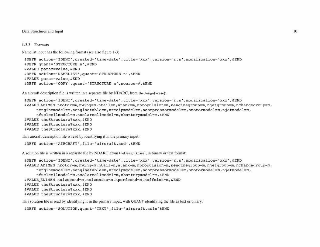
1-2.2 Formats
Namelist input has the following format (see also figure 1-3).
&DEFN action=’IDENT’,created=’time-date’,title=’xxx’,version=’n.n’,modification=’xxx’,&END&DEFN quant=’STRUCTURE n’,&END&VALUE param=value,&END&DEFN action=’NAMELIST’,quant=’STRUCTURE n’,&END&VALUE param=value,&END&DEFN action=’COPY’,quant=’STRUCTURE n’,source=#,&END
An aircraft description file is written in a separate file by NDARC, from theDesign(kcase):
&DEFN action=’IDENT’,created=’time-date’,title=’xxx’,version=’n.n’,modification=’xxx’,&END&VALUE_ADIMEN nrotor=m,nwing=m,ntail=m,ntank=m,npropulsion=m,nenginegroup=m,njetgroup=m,nchargegroup=m,
nenginemodel=m,nenginetable=m,nrecipmodel=m,ncompressormodel=m,nmotormodel=m,njetmodel=m,nfuelcellmodel=m,nsolarcellmodel=m,nbatterymodel=m,&END
&VALUE theStructure%xxx,&END&VALUE theStructure%xxx,&END&VALUE theStructure%xxx,&END
This aircraft description file is read by identifying it in the primary input:
&DEFN action=’AIRCRAFT’,file=’aircraft.acd’,&END
A solution file is written in a separate file by NDARC, from theDesign(kcase), in binary or text format:
&DEFN action=’IDENT’,created=’time-date’,title=’xxx’,version=’n.n’,modification=’xxx’,&END&VALUE_ADIMEN nrotor=m,nwing=m,ntail=m,ntank=m,npropulsion=m,nenginegroup=m,njetgroup=m,nchargegroup=m,
nenginemodel=m,nenginetable=m,nrecipmodel=m,ncompressormodel=m,nmotormodel=m,njetmodel=m,nfuelcellmodel=m,nsolarcellmodel=m,nbatterymodel=m,&END
&VALUE_SDIMEN nsizecond=m,nsizemiss=m,nperfcond=m,noffmiss=m,&END&VALUE theStructure%xxx,&END&VALUE theStructure%xxx,&END&VALUE theStructure%xxx,&END
This solution file is read by identifying it in the primary input, with QUANT identifying the file as text or binary:
&DEFN action=’SOLUTION,quant=’TEXT’,file=’aircraft.soln’&END

Data Structures and Input 11
1-2.3 Conventions
Each flight condition (FltCond and FltState variables) is input in a separate SizeCondition or PerfCondition namelist.
Each mission (MissParam, MissSeg, and FltState variables) is input in a separate SizeMission or OffMission namelist. All mission segments are defined inthis namelist, so MissSeg and FltState variables are arrays. Each variable gets one more dimension, with the first array index always segment number.
Geometry input includes Location variables, which are read as elements of the data structure (for example, loc_rotor%SL).
Variables can appear in more than one namelist. Specifically there are separate namelists for all technology factors (all TECH_xxx variables), and all geometry (all Location
variables), with corresponding options for output. A variable that is a scalar in the Rotor, Wing, Tail, Propulsion, EngineGroup, JetGroup, or ChargeGroupinput becomes an array in the TechFactors or Geometry input. Note that it is the Location variable that is the array (for example, loc_rotor(1)%SL).
Case is not important in character string input. Character string input consists of keywords; the code searches for the keywords in the string.
Default values are specified in the dictionary (blank implies a default of zero); all elements of arrays have the same default value.
Tasks, aircraft, and components have title variables. There are also notes variables (long character string) to record information about the input.
1–3 Software Tool
All information about data structures is contained in a dictionary file. This information includes the parameter name, dimension, type, default value, description, identificationas input, and formats for write of the parameter. A software tool was created to manage the data, including construction of the module of data structures. The software toolreads this dictionary file and creates subroutines for the input process: namelist read, copy, print of input, initialization, set to default. This software tool is a program thatmanipulates character strings, to produce compilable module and subroutines for NDARC.
1–4 Data Structures
Table 1-4 outlines the data structures used for NDARC. The following chapters describe the contents of each structure. Note that a ”+” sign in the column between the typeand description identifies input variables. Input variables can be changed by the analysis, so may not be the same at the end of a case as at the beginning. All variables, inputand other, are initialized to zero or blank. If default values exist (only for input variables), they supersede that initialization.

Data Structures and Input 12
Table 1-4. NDARC data structures.
Design Fuselage FuelTank(ntankmax) FltState(nfltmax)
Cases [Location]loc_fuselage [Location]loc_auxtank(nauxtankmax) FltAircraft
Size AFuse Weight FltFuse
SizeParam Weight WTank FltGear
FltCond(nfltmax) WFuse Propulsion(npropmax) FltRotor(nrotormax)
FltState(nfltmax) LandingGear Weight FltWing(nwingmax)
Mission(nmissmax) [Location]loc_gear WDrive FltTail(ntailmax)
MissParam AGear EngineGroup(nengmax) FltTank(ntankmax)
MissSeg(nsegmax) Weight [Location]loc_engine FltProp(npropmax)
FltState(nsegmax) WGear DEngSys FltEngn(nengmax)
OffDesign Rotor(nrotormax) Weight FltJet(njetmax)
OffParam [Location]loc_rotor WEngSys FltChrg(nchrgmax)
Mission(nmissmax) [Location]loc_pylon JetGroup(njetmax)
MissParam [Location]loc_pivot [Location]loc_jet
MissSeg(nsegmax) [Location]loc_nac DJetSys
FltState(nsegmax) PRotorInd Weight
Performance PRotorPro WJetSys
PerfParam PRotorTab ChargeGroup(nchrgmax)
FltCond(nfltmax) IRotor [Location]loc_charger
FltState(nfltmax) DRotor DChrgSys
MapEngine Weight Weight
MapAero WRotor WChrgSys
Solution Wing(nwingmax) EngineModel(nengmax)
Cost [Location]loc_wing [EngineParam]Param
CostCTM AWing [EngineParam]ParamN(nspeedmax)
Emissions Weight EngineTable(nengmax)
Aircraft WWing RecipModel(nengmax)
[Location]loc_cg WWingTR CompressorModel(nengmax)
Weight Tail(ntailmax) MotorModel(nengmax)
XAircraft [Location]loc_tail JetModel(njetmax)
Systems ATail FuelCellModel(nchrgmax)
Weight Weight SolarCellModel(nchrgmax)
WFltCont WTail BatteryModel(ntankmax)
WDeIce
13
Chapter 2
Input Based on Configuration
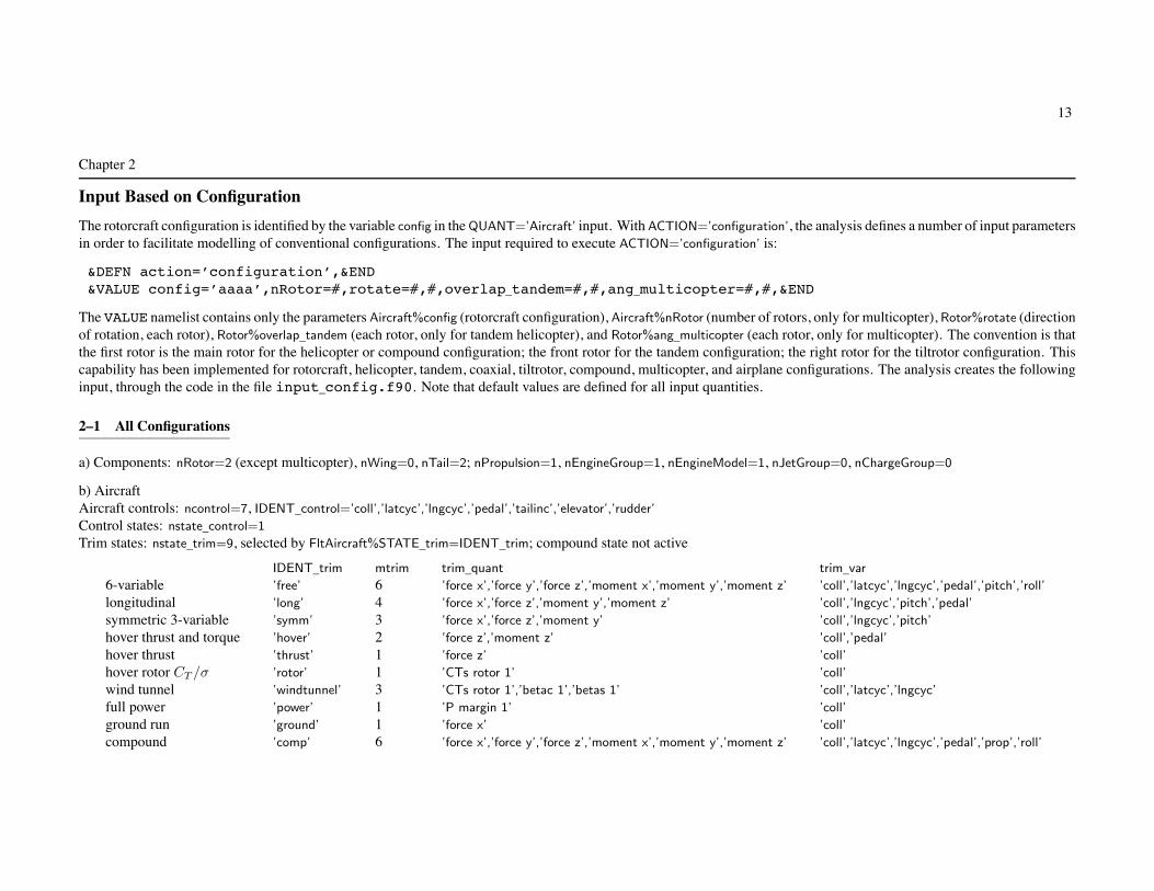
The rotorcraft configuration is identified by the variable config in the QUANT=’Aircraft’ input. With ACTION=’configuration’, the analysis defines a number of input parametersin order to facilitate modelling of conventional configurations. The input required to execute ACTION=’configuration’ is:
&DEFN action=’configuration’,&END&VALUE config=’aaaa’,nRotor=#,rotate=#,#,overlap_tandem=#,#,ang_multicopter=#,#,&END
The VALUE namelist contains only the parameters Aircraft%config (rotorcraft configuration), Aircraft%nRotor (number of rotors, only for multicopter), Rotor%rotate (directionof rotation, each rotor), Rotor%overlap_tandem (each rotor, only for tandem helicopter), and Rotor%ang_multicopter (each rotor, only for multicopter). The convention is thatthe first rotor is the main rotor for the helicopter or compound configuration; the front rotor for the tandem configuration; the right rotor for the tiltrotor configuration. Thiscapability has been implemented for rotorcraft, helicopter, tandem, coaxial, tiltrotor, compound, multicopter, and airplane configurations. The analysis creates the followinginput, through the code in the file input_config.f90. Note that default values are defined for all input quantities.
2–1 All Configurations
a) Components: nRotor=2 (except multicopter), nWing=0, nTail=2; nPropulsion=1, nEngineGroup=1, nEngineModel=1, nJetGroup=0, nChargeGroup=0
b) AircraftAircraft controls: ncontrol=7, IDENT_control=’coll’,’latcyc’,’lngcyc’,’pedal’,’tailinc’,’elevator’,’rudder’
Control states: nstate_control=1
Trim states: nstate_trim=9, selected by FltAircraft%STATE_trim=IDENT_trim; compound state not active
IDENT_trim mtrim trim_quant trim_var
6-variable ’free’ 6 ’force x’,’force y’,’force z’,’moment x’,’moment y’,’moment z’ ’coll’,’latcyc’,’lngcyc’,’pedal’,’pitch’,’roll’
longitudinal ’long’ 4 ’force x’,’force z’,’moment y’,’moment z’ ’coll’,’lngcyc’,’pitch’,’pedal’
symmetric 3-variable ’symm’ 3 ’force x’,’force z’,’moment y’ ’coll’,’lngcyc’,’pitch’
hover thrust and torque ’hover’ 2 ’force z’,’moment z’ ’coll’,’pedal’
hover thrust ’thrust’ 1 ’force z’ ’coll’
hover rotor CT /σ ’rotor’ 1 ’CTs rotor 1’ ’coll’
wind tunnel ’windtunnel’ 3 ’CTs rotor 1’,’betac 1’,’betas 1’ ’coll’,’latcyc’,’lngcyc’
full power ’power’ 1 ’P margin 1’ ’coll’
ground run ’ground’ 1 ’force x’ ’coll’
compound ’comp’ 6 ’force x’,’force y’,’force z’,’moment x’,’moment y’,’moment z’ ’coll’,’latcyc’,’lngcyc’,’pedal’,’prop’,’roll’

Input Based on Configuration 14
c) Systems: MODEL_FWfc=0, MODEL_CVfc=0 (no fixed wing flight controls, no conversion controls)
d) Landing Gear: KIND_LG=0 (fixed gear), Wgear%nLG=3
e) Fuel Tank: place=1 (internal tank), Mauxtanksize=1, WTank%ntank_int=1, WTank%nplumb=2
f) RotorFirst rotor is primary: kPropulsion=1, KIND_xmsn=1
Second and other rotors are dependent: kPropulsion=1, KIND_xmsn=0, INPUT_gear=1 (input quantity is tip speed)Configuration: direction=’main’
Drag: SET_aeroaxes=1 (helicopter), Idrag=0. (not tilt); DRotor%SET_Dspin=1, DRotor%DoQ_spin=0. (no spinner drag)Weight: WRotor%MODEL_config=1 (rotor), WRotor%KIND_rotor=2 (not tilting)Control:
INPUT_coll=0, INPUT_latcyc=0, INPUT_lngcyc=0, INPUT_incid=0, INPUT_cant=0, INPUT_diam=0 (no connection to aircraft controls)T_coll=0., T_latcyc=0., T_lngcyc=0., T_incid=0., T_cant=0., T_diam=0. (all controls, all states)KIND_control=1 (1 for thrust and TPP command)KIND_coll=2 (1 for thrust, 2 for CT /σ)KIND_lngcyc=1, KIND_latcyc=1 (1 for TPP tilt, 2 for hub moment, 3 for lift offset)KIND_tilt=0 (fixed shaft)
g) WingControl:
INPUT_flap=0, INPUT_flaperon=0, INPUT_aileron=0, INPUT_incid=0 (no connection to aircraft controls)T_flap=0., T_flaperon=0., T_aileron=0., T_incid=0. (all controls, all states, all panels)
Drag: Idrag=0. (not tilt)
h) TailFirst tail is horizontal tail: KIND_tail=1, WTail%MODEL_Htail=1 (helicopter)Second tail is vertical tail: KIND_tail=2, WTail%MODEL_Vtail=1 (helicopter)Configuration: KIND_TailVol=2, TailVolRef=1 (rotor reference)Control:
INPUT_cont=1 (tail control connection to aircraft controls), INPUT_incid=0 (no connection of tail incidence to aircraft controls)T_cont=0., T_incid=0. (all controls, all states)
i) Propulsion: nGear=1, STATE_gear_wt=1, INPUT_DN=0

Input Based on Configuration 15
j) Engine GroupConfiguration: kPropulsion=1, INPUT_gear=1 (gear ratio from N_spec), SET_power=0 (sized), fPsize=1., direction=’x’, SET_geom=0 (standard position)Drag: MODEL_drag=1, Idrag=0. (not tilt)
k) Engine Group, Jet Group, Charge GroupControl:
INPUT_amp=0, INPUT_incid=0, INPUT_yaw=0 (no connection to aircraft controls)T_amp=0., T_incid=0., T_yaw=0. (all controls, all states)
2–2 Helicopter
a) RotorFirst rotor is main rotor: config=’main’, fDGW=1., fArea=1., SET_geom=’standard’
rotation: r = 1; if (Rotor(1)%rotate < 0) r = −1control: INPUT_coll=1, INPUT_latcyc=1, INPUT_lngcyc=1 (rotor control connection to aircraft controls)control: T_coll(1,1)=1., T_latcyc(2,1)= − r, T_lngcyc(3,1)=-1.
Second rotor is tail rotor: config=’tail+antiQ’, fThrust=1., fArea=0., SET_geom=’tailrotor’, mainRotor=1
direction=’tail’, WRotor%MODEL_config=2 (tail rotor)rotation: r = 1; if (Rotor(1)%rotate < 0) r = −1control: KIND_control=2 (thrust and NFP command); INPUT_coll=1, T_coll(4,1)= − r (rotor collective connection to aircraft control ’pedal’)
Performance: PRotorInd%MODEL_twin=’none’
Drag: SET_Sspin=1, Swet_spin=0., DRotor%SET_Dspin=1, DRotor%DoQ_spin=0., DRotor%CD_spin=0. (no spinner drag)
b) TailControl: INPUT_incid=1 (tail incidence connection to aircraft controls)Horizontal tail: T_incid(5,1)=1. (incidence connection to aircraft control ’tailinc’), T_cont(6,1)=1. (elevator direct control)Vertical tail: T_cont(7,1)=1. (rudder direct control)
c) Propulsion: WDrive%ngearbox=2, WDrive%ndriveshaft=1, WDrive%fShaft=0.1, WDrive%fTorque=0.03, WDrive%fPower=0.15
2–3 Tandem
a) Components: nTail=0 (no tail)
b) Fuel Tank: place=2 (sponson)

Input Based on Configuration 16
c) RotorConfiguration: config=’main+tandem’, fDGW=.5, SET_geom=’tandem’, fRadius=1.
fArea=1 − m/2, from m = (2/π)(cos−1 h − h√
1 − h2), h = 1 − overlap_tandem
First rotor is front rotor: otherRotor=2
rotation: r = 1, if (Rotor(1)%rotate < 0) r = −1control: INPUT_coll=1, INPUT_latcyc=1 (rotor control connection to aircraft controls)control: T_coll(1,1)=1., T_coll(3,1)=-1., T_latcyc(2,1)= − r, T_latcyc(4,1)= − r
Second rotor is aft rotor: otherRotor=1, rotate=-Rotor(1)%rotate
rotation: r = 1, if (Rotor(1)%rotate < 0) r = −1; r = −rcontrol: INPUT_coll=1, INPUT_latcyc=1 (rotor control connection to aircraft controls)control: T_coll(1,1)=1., T_coll(3,1)= 1., T_latcyc(2,1)= − r, T_latcyc(4,1)=r
Performance: PRotorInd%MODEL_twin=’tandem’, PRotorInd%Kh_twin=1., PRotorInd%Kf_twin=0.85, IRotor%MODEL_int_twin=2
Drag: SET_Sspin=1, Swet_spin=0., DRotor%SET_Dspin=1, DRotor%DoQ_spin=0., DRotor%CD_spin=0. (no spinner drag)
d) Propulsion: WDrive%ngearbox=2, WDrive%ndriveshaft=1, WDrive%fShaft=0.1; WDrive%fTorque=0.6, WDrive%fPower=0.6
2–4 Coaxial
a) RotorConfiguration: config=’main+coaxial’, fDGW=.5, fArea=.5, SET_geom=’coaxial’, fRadius=1.
First rotor is lower rotor: otherRotor=2
rotation: r = 1, if (Rotor(1)%rotate < 0) r = −1control: INPUT_coll=1, INPUT_latcyc=1, INPUT_lngcyc=1 (rotor control connection to aircraft controls)control: T_coll(1,1)=1., T_coll(4,1)=r, T_latcyc(2,1)= − r, T_lngcyc(3,1)=-1.
Second rotor is upper rotor: otherRotor=1, rotate=-Rotor(1)%rotate
rotation: r = 1, if (Rotor(1)%rotate < 0) r = −1; r = −rcontrol: INPUT_coll=1, INPUT_latcyc=1, INPUT_lngcyc=1 (rotor control connection to aircraft controls)control: T_coll(1,1)=1., T_coll(4,1)=r, T_latcyc(2,1)= − r, T_lngcyc(3,1)=-1.
Performance: PRotorInd%MODEL_twin=’coaxial’, PRotorInd%Kh_twin=1., PRotorInd%Kf_twin=0.85, IRotor%MODEL_int_twin=2
Drag: SET_Sspin=1, Swet_spin=0., DRotor%SET_Dspin=1, DRotor%DoQ_spin=0., DRotor%CD_spin=0. (no spinner drag)
b) TailHorizontal tail: T_cont(6,1)=1. (elevator direct control)Vertical tail: T_cont(7,1)=1. (rudder direct control)
c) Propulsion: WDrive%ngearbox=1, WDrive%ndriveshaft=0, WDrive%fShaft=0.1; WDrive%fTorque=0.6, WDrive%fPower=0.6

Input Based on Configuration 17
2–5 Tiltrotor
a) Components: nWing=1, nEngineGroup=2 (engine at each nacelle)
b) AircraftAircraft controls: ncontrol=10, IDENT_control=’coll’,’latcyc’,’lngcyc’,’pedal’,’tilt’,’flap’,’flaperon’,’elevator’,’aileron’,’rudder’
Control states: nstate_control=2 (state 1 for helicopter mode, state 2 for airplane mode)Control state in conversion: kcont_hover=1, kcont_conv=1, kcont_cruise=2
Drive state in conversion: kgear_hover(1)=1, kgear_conv(1)=1, kgear_cruise(1)=1
c) Systems: MODEL_FWfc=1, MODEL_CVfc=1 (fixed wing flight controls, conversion control)
d) Landing Gear: KIND_LG=1 (retractable)
e) Fuel Tank: place=3 (wing), fFuelWing(1)=1.
f) RotorConfiguration: config=’main+tiltrotor’, fDGW=.5, fArea=1.; SET_geom=’tiltrotor’, KIND_TRgeom=1 (from clearance), fRadius=1., WingForRotor=1
First rotor is right rotor: otherRotor=2
helicopter mode control: INPUT_coll=1, INPUT_lngcyc=1 (rotor control connection to aircraft controls)helicopter mode control: T_coll(1,1)=1., T_coll(2,1)=-1., T_lngcyc(3,1)=-1., T_lngcyc(4,1)=1.
Second rotor is left rotor: otherRotor=1, rotate=-Rotor(1)%rotate; INPUT_gear=2 (input quantity is gear ratio)helicopter mode control: INPUT_coll=1, INPUT_lngcyc=1 (rotor control connection to aircraft controls)helicopter mode control: T_coll(1,1)=1., T_coll(2,1)=1., T_lngcyc(3,1)=-1., T_lngcyc(4,1)=-1.
Airplane mode control state: T_coll(1,2)=1. (collective connection to aircraft control ’coll’)Tilt: KIND_tilt=1 (shaft control = incidence), incid_ref=90. (helicopter mode reference), SET_Wmove=1, fWmove=1. (wing tip weight move)
control: INPUT_incid=1, T_incid(5,1)=1., T_incid(5,2)=1. (incidence connection to aircraft control ’tilt’)Performance: PRotorInd%MODEL_twin=’tiltrotor’, PRotorInd%Kh_twin=1., PRotorInd%Kf_twin=1., IRotor%MODEL_int_twin=2
Weight: WRotor%KIND_rotor=1 (tilting)Drag: SET_aeroaxes=2 (tiltrotor), Idrag=90. (tiltrotor)
DRotor%SET_Dhub=1, DRotor%DoQ_hub=0., DRotor%CD_hub=0., DRotor%SET_Vhub=1, DRotor%DoQV_hub=0., DRotor%CDV_hub=0. (no hub drag)
g) WingConfiguration: fDGW=1., nRotorOnWing=2, RotorOnWing(1)=1, RotorOnWing(2)=2, SET_ext=0
Control: KIND_flaperon=3 (independent), nVincid=1
INPUT_flap=1, INPUT_flaperon=1, INPUT_aileron=1 (wing control connection to aircraft controls)T_aileron(2,2)=-1. (airplane mode aileron connection to aircraft control ’latcyc’)

Input Based on Configuration 18
T_flap(6,1)=1., T_flap(6,2)=1. (flap direct control)T_flaperon(7,1)=1., T_flaperon(7,2)=1. (flaperon direct control)T_aileron(9,1)=1., T_aileron(9,2)=1. (aileron direct control)
Weight: WWing%MODEL_wing=3 (tiltrotor)
h) TailConfiguration: KIND_TailVol=1, TailVolRef=1 (wing reference); Wtail%MODEL_Htail=2, Wtail%MODEL_Vtail=2 (tiltrotor)Horizontal tail control: nVincid=1
T_cont(3,2)=1. (airplane mode elevator connection to aircraft control ’lngcyc’)T_cont(8,1)=1., T_cont(8,2)=1. (elevator direct control)
Vertical tail control: nVincid=1
T_cont(4,2)=1. (airplane mode rudder connection to aircraft control ’pedal’)T_cont(10,1)=1., T_cont(10,2)=1. (rudder direct control)
i) Propulsion: WDrive%ngearbox=2, WDrive%ndriveshaft=1, WDrive%fShaft=0.1; WDrive%fTorque=0.6, WDrive%fPower=0.6
j) Engine GroupConfiguration: fPsize=0.5, SET_geom=1 (tiltrotor)First engine group: RotorForEngine=1
Second engine group: RotorForEngine=2
Control: INPUT_incid=1; T_incid(5,1)=1., T_incid(5,2)=1. (nacelle incidence connection to aircraft control ’tilt’)Drag: SET_Swet=1, Swet=0., MODEL_drag=0, Idrag=90. (no engine nacelle drag)
DEngSys%SET_drag=1, DEngSys%DoQ=0., DEngSys%CD=0.; DEngSys%SET_Vdrag=1, DEngSys%DoQV=0., DEngSys%CDV=0.
2–6 Compound
a) Components: nRotor=3, nWing=1
b) AircraftAircraft controls: ncontrol=10, IDENT_control=’coll’,’latcyc’,’lngcyc’,’pedal’,’tailinc’,’elevator’,’rudder’,’prop’,’aileron’,’flap’
Trim states: nstate_trim=10; compound state active
c) RotorFirst rotor is main rotor: config=’main’, fDGW=1., fArea=1., SET_geom=’standard’
rotation: r = 1; if (Rotor(1)%rotate < 0) r = −1control: INPUT_coll=1, INPUT_latcyc=1, INPUT_lngcyc=1 (rotor control connection to aircraft controls)

Input Based on Configuration 19
control: T_coll(1,1)=1., T_latcyc(2,1)= − r, T_lngcyc(3,1)=-1.
Second rotor is tail rotor: config=’tail+antiQ’, fThrust=1., fArea=0., SET_geom=’tailrotor’, mainRotor=1
direction=’tail’, WRotor%MODEL_config=2 (tail rotor)rotation: r = 1; if (Rotor(1)%rotate < 0) r = −1control: KIND_control=2 (thrust and NFP command); INPUT_coll=1, T_coll(4,1)= − r (rotor collective connection to aircraft control ’pedal’)
Third rotor is propeller: config=’prop+auxT’, fThrust=1., fArea=0., SET_geom=’standard’
direction=’prop’, WRotor%MODEL_config=3 (auxiliary thrust)control: KIND_control=2 (thrust and NFP command); INPUT_coll=1, T_coll(8,1)=1. (rotor collective connection to aircraft control ’prop’)
Performance: PRotorInd%MODEL_twin=’none’
Drag: SET_Sspin=1, Swet_spin=0., DRotor%SET_Dspin=1, DRotor%DoQ_spin=0., DRotor%CD_spin=0. (no spinner drag)
d) WingConfiguration: fDGW=1.
Control: nVincid=1
INPUT_flap=1, INPUT_flaperon=1, INPUT_aileron=1 (wing control connection to aircraft controls)T_aileron(9,1)=1. (aileron direct control)T_flap(10,1)=1. (flap direct control)
Weight: WWing%MODEL_wing=2 (parametric)
e) TailControl: INPUT_incid=1 (tail incidence connection to aircraft controls)Horizontal tail: T_incid(5,1)=1. (incidence connection to aircraft control ’tailinc’), T_cont(6,1)=1. (elevator direct control)Vertical tail: T_cont(7,1)=1. (rudder direct control)
f) Propulsion: WDrive%ngearbox=3, WDrive%ndriveshaft=1, WDrive%fShaft=0.1, WDrive%fTorque=0.03, WDrive%fPower=0.15
2–7 Multicopter
a) Components: nTail=0 (no tail)
b) RotorConfiguration: config=’main’, fDGW=1/nRotor, fArea=1., SET_geom=’multicopter’
Control: KIND_control=2 (thrust and NFP command); INPUT_coll=1
rotation: r = 1; if (rotate < 0) r = −1; a =ang_multicopter
T_coll(1,1)=1., T_coll(2,1)=− sin(a), T_coll(3,1)=cos(a), T_coll(4,1)=r (rotor collective connection to aircraft controls)

Input Based on Configuration 20
Performance: PRotorInd%MODEL_twin=’none’
Drag: SET_Sspin=1, Swet_spin=0., DRotor%SET_Dspin=1, DRotor%DoQ_spin=0., DRotor%CD_spin=0. (no spinner drag)
c) Propulsion: WDrive%ngearbox=nRotor, WDrive%ndriveshaft=nRotor-1, WDrive%fShaft=0.1; WDrive%fTorque=0.6, WDrive%fPower=0.6
2–8 Airplane
a) Components: nRotor=1, nWing=1
b) Solution: KIND_Lscale=2 (wing span reference)
c) AircraftGeometry: INPUT_geom=2, KIND_scale=2, kScale=1 (geometry scaled with wing span); KIND_Ref=2, kRef=1 (wing reference)Aircraft controls: ncontrol=9, IDENT_control=’coll’,’latcyc’,’lngcyc’,’pedal’,’tailinc’,’elevator’,’rudder’,’aileron’,’flap’
coll = propeller, latcyc = lateral stick, lngcyc = longitudinal stick
d) Systems: MODEL_FWfc=1 (fixed wing flight controls)
e) RotorPropeller: config=’prop+auxT’, fThrust=1., fDGW=0., SET_geom=’standard’
direction=’prop’, WRotor%MODEL_config=3 (auxiliary thrust)Control: KIND_control=2 (thrust and NFP command); INPUT_coll=1, T_coll(1,1)=1. (rotor collective connection to aircraft control ’coll’)
f) WingConfiguration: fDGW=1.
Control: nVincid=1
INPUT_flap=1, INPUT_aileron=1 (wing control connection to aircraft controls)T_aileron(2,1)=1. (lateral stick), T_aileron(8,1)=1. (aileron direct control)T_flap(9,1)=1. (flap direct control)
Weight: WWing%MODEL_wing=2 (parametric)
g) Tail: KIND_TailVol=1, TailVolRef=1 (wing reference)Control: INPUT_incid=1 (tail incidence connection to aircraft controls)Horizontal tail: T_incid(5,1)=1. (incidence connection to aircraft control ’tailinc’), T_cont(3,1)=1. (longitudinal stick), T_cont(6,1)=1. (elevator direct control)Vertical tail: T_cont(4,1)=1. (pedal), T_cont(7,1)=1. (rudder direct control)
h) Propulsion: WDrive%ngearbox=1, WDrive%ndriveshaft=1, WDrive%fShaft=0.1

21
Chapter 3
Parameters and Constants
Parameters Value
ncasemax 10 nsegmax 20 mpsimax 36nfilemax 40 nfltmax 21 npanelmax 5nrotormax 8 ndesignmax 41 nauxtankmax 4npropmax 4 ncontmax 20 ngearmax 8nengmax 8 nsweepmax 200 nratemax 20njetmax 4 qsweepmax 4 nengtmax 10nchrgmax 4 ntrimstatemax 20 nengkmax 6nstatemax 10 mtrimmax 16 nengrmax 40nwingmax 8 nvelmax 20 nspeedmax 5ntailmax 6 ntablemax 16 nrowmax 4000ntankmax 4 nrmax 51 naeromax 100nmissmax 20 mrmax 40
Constants Value
ACTION_error 0 SET_takeoff_liftoff 4 TRIM_QUANT_tank 19ACTION_file 1 SET_takeoff_rotation 5 TRIM_QUANT_Bmargin 20ACTION_ident 2 SET_takeoff_transition 6 TRIM_QUANT_rotorL 21ACTION_list 3 SET_takeoff_climb 7 TRIM_QUANT_rotorfL 22ACTION_copy 4 SET_takeoff_brake 8 TRIM_QUANT_CLs 23ACTION_init 5 MAX_QUANT_none 0 TRIM_QUANT_rotorV 24ACTION_delete 6 MAX_QUANT_end 1 TRIM_QUANT_rotorX 25ACTION_delone 7 MAX_QUANT_range 2 TRIM_QUANT_rotorfX 26ACTION_dellast 8 MAX_QUANT_rangelow 3 TRIM_QUANT_CXs 27ACTION_config 9 MAX_QUANT_range100 4 TRIM_QUANT_XoQ 28ACTION_nosize 10 MAX_QUANT_climb 5 TRIM_QUANT_CTs 29

Parameters and Constants 22
ACTION_desc 11 MAX_QUANT_angle 6 TRIM_QUANT_Tmargs 30ACTION_soln 12 MAX_QUANT_power 7 TRIM_QUANT_Tmargt 31ACTION_endfile 13 MAX_QUANT_PoV 8 TRIM_QUANT_betac 32ACTION_endcase 14 MAX_QUANT_alt 9 TRIM_QUANT_betas 33ACTION_endjob 15 MAX_QUANT_Pmargin 10 TRIM_QUANT_hubMx 34STATE_newcase 1 MAX_QUANT_Qmargin 11 TRIM_QUANT_hubMy 35STATE_onecase 2 MAX_QUANT_PQmargin 12 TRIM_QUANT_hubQ 36STATE_endofjob 3 MAX_QUANT_Jmargin 13 TRIM_QUANT_wingL 37STATE_init 1 MAX_QUANT_PJmargin 14 TRIM_QUANT_wingfL 38STATE_size 2 MAX_QUANT_QJmargin 15 TRIM_QUANT_CL 39STATE_miss 3 MAX_QUANT_PQJmargin 16 TRIM_QUANT_Lmargin 40STATE_perf 4 MAX_QUANT_Bmargin 17 TRIM_QUANT_tailL 41STATE_maps 5 MAX_QUANT_Lmargin 18 TRIM_VAR_not_found 0STATE_out 6 MAX_QUANT_Tmargs 19 TRIM_VAR_pitch -1SIZE_perf_engine 1 MAX_QUANT_Tmargt 20 TRIM_VAR_roll -2SIZE_perf_rotor 2 MAX_VAR_none 0 TRIM_VAR_ROC -3SIZE_perf_none 3 MAX_VAR_vel -1 TRIM_VAR_side -4SIZE_jet_jet 1 MAX_VAR_ROC -2 TRIM_VAR_speed -5SIZE_jet_none 2 MAX_VAR_side -3 TRIM_VAR_turn -6SIZE_charge_chrg 1 MAX_VAR_alt -4 TRIM_VAR_pullup -7SIZE_charge_none 2 MAX_VAR_turn -5 TRIM_VAR_Vtip -8SIZE_rotor_none 1 MAX_VAR_pullup -6 TRIM_VAR_Nspec -9SIZE_rotor_radius 2 MAX_VAR_xaccF -7 AERO_VAR_none 0SIZE_rotor_thrust 3 MAX_VAR_yaccF -8 AERO_VAR_not_found -1SET_rotor_radius 1 MAX_VAR_zaccF -9 AERO_VAR_alpha -2SET_rotor_DL 2 MAX_VAR_xaccI -10 AERO_VAR_beta -3SET_rotor_ratio 3 MAX_VAR_yaccI -11 RCCONFIG_rotorcraft 0SET_rotor_scale 4 MAX_VAR_zaccI -12 RCCONFIG_helicopter 1SET_rotor_not_radius 5 MAX_VAR_xaccG -13 RCCONFIG_tandem 2SET_wing_area 1 MAX_VAR_yaccG -14 RCCONFIG_coaxial 3SET_wing_WL 2 MAX_VAR_zaccG -15 RCCONFIG_tiltrotor 4SET_wing_not_area 3 MAX_VAR_pitch -16 RCCONFIG_compound 5SET_wing_span 4 MAX_VAR_roll -17 RCCONFIG_multicopter 6SET_wing_ratio 5 MAX_VAR_Vtip -18 RCCONFIG_airplane 7

Parameters and Constants 23
SET_wing_radius 6 MAX_VAR_Nspec -19 ROTORCONFIG_main 1SET_wing_width 7 SET_vel_general 1 ROTORCONFIG_tail 2SET_wing_hub 8 SET_vel_hover 2 ROTORCONFIG_prop 3SET_wing_panel 9 SET_vel_vert 3 ROTORCONFIG_tandem 4SET_wing_not_span 10 SET_vel_right 4 ROTORCONFIG_coaxial 5SET_tank_input 1 SET_vel_left 5 ROTORCONFIG_tiltrotor 6SET_tank_miss 2 SET_vel_rear 6 ROTORCONFIG_not_twin 7SET_tank_misspower 3 SET_vel_Vfwd 7 SET_geom_standard 0SET_tank_fmiss 4 SET_vel_Vmag 8 SET_geom_tiltrotor 1SET_SDGW_input 1 SET_vel_climb 9 SET_geom_coaxial 2SET_SDGW_fDGW 2 SET_vel_takeoff 10 SET_geom_tandem 3SET_SDGW_fWMTO 3 SET_vel2_TAS 1 SET_geom_tailrotor 4SET_SDGW_maxfuel 4 SET_vel2_CAS 2 SET_geom_multicopter 5SET_SDGW_perf 5 SET_vel2_Mach 3 MODEL_twin_none 0SET_WMTO_input 1 SET_atmos_input -1 MODEL_twin_sidebyside 1SET_WMTO_fDGW 2 SET_atmos_dens -2 MODEL_twin_coaxial 2SET_WMTO_fSDGW 3 SET_atmos_notair -3 MODEL_twin_tandem 3SET_WMTO_maxfuel 4 SET_atmos_std 1 MODEL_twin_multirotor 4SET_WMTO_perf 5 SET_atmos_std_dtemp 2 tablevar_none 0SET_limit_input 1 SET_atmos_std_temp 3 tablevar_mu 1SET_limit_Ratio 2 SET_atmos_polar 4 tablevar_muz 2SET_limit_Pav 3 SET_atmos_polar_dtem 5 tablevar_alpha 3SET_limit_Preq 4 SET_atmos_polar_temp 6 tablevar_muTPP 4SET_GW_DGW 1 SET_atmos_trop 7 tablevar_muzTPP 5SET_GW_SDGW 2 SET_atmos_trop_dtemp 8 tablevar_alphaTPP 6SET_GW_WMTO 3 SET_atmos_trop_temp 9 tablevar_CTs 7SET_GW_fDGW 4 SET_atmos_hot 10 tablevar_Mx 8SET_GW_fSDGW 5 SET_atmos_hot_dtemp 11 tablevar_Mat 9SET_GW_fWMTO 6 SET_atmos_hot_temp 12 SET_panel_free 0SET_GW_input 7 SET_atmos_hot_table 13 SET_panel_span 1SET_GW_maxP 8 SET_Vtip_input 1 SET_panel_bratio 2SET_GW_maxQ 9 SET_Vtip_ref 2 SET_panel_edge 3SET_GW_maxPQ 10 SET_Vtip_speed 3 SET_panel_station 4SET_GW_maxJ 11 SET_Vtip_conv 4 SET_panel_radius 5
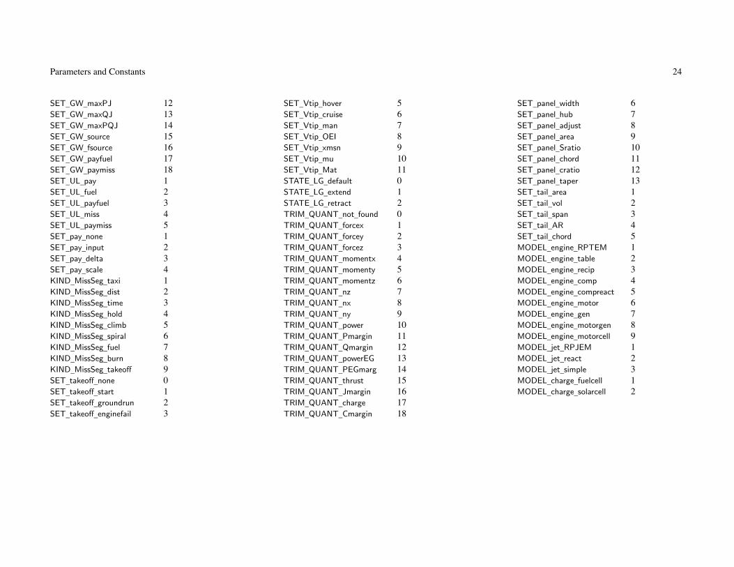
Parameters and Constants 24
SET_GW_maxPJ 12 SET_Vtip_hover 5 SET_panel_width 6SET_GW_maxQJ 13 SET_Vtip_cruise 6 SET_panel_hub 7SET_GW_maxPQJ 14 SET_Vtip_man 7 SET_panel_adjust 8SET_GW_source 15 SET_Vtip_OEI 8 SET_panel_area 9SET_GW_fsource 16 SET_Vtip_xmsn 9 SET_panel_Sratio 10SET_GW_payfuel 17 SET_Vtip_mu 10 SET_panel_chord 11SET_GW_paymiss 18 SET_Vtip_Mat 11 SET_panel_cratio 12SET_UL_pay 1 STATE_LG_default 0 SET_panel_taper 13SET_UL_fuel 2 STATE_LG_extend 1 SET_tail_area 1SET_UL_payfuel 3 STATE_LG_retract 2 SET_tail_vol 2SET_UL_miss 4 TRIM_QUANT_not_found 0 SET_tail_span 3SET_UL_paymiss 5 TRIM_QUANT_forcex 1 SET_tail_AR 4SET_pay_none 1 TRIM_QUANT_forcey 2 SET_tail_chord 5SET_pay_input 2 TRIM_QUANT_forcez 3 MODEL_engine_RPTEM 1SET_pay_delta 3 TRIM_QUANT_momentx 4 MODEL_engine_table 2SET_pay_scale 4 TRIM_QUANT_momenty 5 MODEL_engine_recip 3KIND_MissSeg_taxi 1 TRIM_QUANT_momentz 6 MODEL_engine_comp 4KIND_MissSeg_dist 2 TRIM_QUANT_nz 7 MODEL_engine_compreact 5KIND_MissSeg_time 3 TRIM_QUANT_nx 8 MODEL_engine_motor 6KIND_MissSeg_hold 4 TRIM_QUANT_ny 9 MODEL_engine_gen 7KIND_MissSeg_climb 5 TRIM_QUANT_power 10 MODEL_engine_motorgen 8KIND_MissSeg_spiral 6 TRIM_QUANT_Pmargin 11 MODEL_engine_motorcell 9KIND_MissSeg_fuel 7 TRIM_QUANT_Qmargin 12 MODEL_jet_RPJEM 1KIND_MissSeg_burn 8 TRIM_QUANT_powerEG 13 MODEL_jet_react 2KIND_MissSeg_takeoff 9 TRIM_QUANT_PEGmarg 14 MODEL_jet_simple 3SET_takeoff_none 0 TRIM_QUANT_thrust 15 MODEL_charge_fuelcell 1SET_takeoff_start 1 TRIM_QUANT_Jmargin 16 MODEL_charge_solarcell 2SET_takeoff_groundrun 2 TRIM_QUANT_charge 17SET_takeoff_enginefail 3 TRIM_QUANT_Cmargin 18

25
Chapter 4
Common: Job
Variable Type Description Default
NDARCVersion (set by main program)
version c*6 number n.nmodification c*32 modificationversionout c*64 string for headers (Version n.n, modification "xxx")
+ InitializationINIT_input int + input parameters (0 default, 1 last case input, 2 last case solution) 1
INIT_data int + other parameters (0 default, 1 start of last case, 2 end of last case) 0
INIT_input:if default, all input variables set to default valuesif last-case-input, then case inherits input at beginning of previous caseif last-case-solution, then case inherits input at end of previous case
use INIT_input=2 to analyze case #1 design in subsequent casesINIT_data: if always start-last-case, then case starts from default
if default, all other variables set to default values
+ ErrorsACT_error int + action on error (0 none, 1 exit) 1
ACT_version int + action on version mismatch in input (0 none, 1 exit) 0
+ File openOPEN_status int + status keyword for write (0 unknown, 1 replace, 2 new, 3 old) 2

Common: Job 26
+ Input/output unit numbers+ input
nuin int + standard input 5
nufile int + secondary file input 40
+ outputnuout int + standard output 6
nudesign int + design (DESIGNn) 41
nuperf int + performance (PERFn) 42
nuaero int + airframe aerodynamics (AEROn) 43
nuengine int + engine performance (ENGINEn) 44
nugeom int + geometry output (GEOMETRYn) 45
nuacd int + aircraft description (AIRCRAFTn) 46
nusoln int + solution (SOLUTIONn) 47
nusketch int + sketch output (SKETCHn) 48
nuerror int + errors (ERRORn) 49
default input/output unit numbers usually acceptabledefault OPEN_status can be changed as appropriate for computer OS
Analysiskcase int current case numberncase int number of cases (maximum ncasemax)case_state int case statejob_state int job stateout_design_state int design output state (1 file open)out_perf_state int performance output state (1 file open)out_geom_state int geometry output state (1 file open)out_error_state int errors output state (1 file open)nuinit int nuout or nuerrorfscratch FltState scratch structure
Inputkind_input int file input status (0 for primary file, 1 for secondary file, 2 for aircraft or solution file)nread int unit number for input (nuin for primary file, nufile for secondary file)

Common: Job 27
Input file identification (stored from action=IDENT data)ninputfile int number of identifications (maximum nfilemax; first is standard input)input_title(nfilemax) c*80 titleinput_created(nfilemax) c*20 creation date
theDesign(ncasemax) Design DesigntheInput Design InputtheLastCaseInput Design Input from last case
system data = Job + theDesign(ncase) + theInput + theLastCaseInput
all data structure parameters = input (can be changed by analysis) or other (generated by analysis)theInput used for input (not changed by analysis)theLastCaseInput used to print only what changed from last caseafter case input concluded, kcase incremented and theInput copied to theDesign(kcase)
CPU timeCPUtime_case_start(ncasemax)
real case startCPUtime_case_end(ncasemax) real case endCPUtime_case(ncasemax) real caseCPUtime_job real job
Clock timeDateTime_case_start(8,ncasemax)
int case startDateTime_case_end(8,ncasemax)
int case endElapsedTime_case(ncasemax) real caseElapsedTime_job real job
Case dimensionsnrotor_case int number of rotors (Aircraft)nwing_case int number of wings (Aircraft)ntail_case int number of tails (Aircraft)

Common: Job 28
ntank_case int number of fuel tank systems (Aircraft)npropulsion_case int number of propulsion groups (Aircraft)nenginegroup_case int number of engine groups (Aircraft)njetgroup_case int number of jet groups (Aircraft)nchargegroup_case int number of charge groups (Aircraft)nenginemodel_case int number of engine models (Aircraft)nenginetable_case int number of engine tables (Aircraft)nrecipmodel_case int number of reciprocating engine models (Aircraft)ncompressormodel_case int number of compressor models (Aircraft)nmotormodel_case int number of motor models (Aircraft)njetmodel_case int number of jet models (Aircraft)nfuelcellmodel_case int number of fuel cell models (Aircraft)nsolarcellmodel_case int number of solar cell models (Aircraft)nbatterymodel_case int number of bettery models (Aircraft)ncontrol_case int number of controls (Aircraft)nstate_control_case int number of control states (Aircraft)npanel_case(nwingmax) int number of wing panels (Wing)mauxtanksize_case(ntankmax)
int number of aux tank sizes (FuelTank)ngear_case(npropmax) int number of drive system states (Propulsion)nstate_trim_case int number of trim states (Aircraft)mtrim_case(ntrimstatemax) int number of trim variables (Aircraft)nwoful_case int number of other fixed useful load categories (System)nrate_case int number of engine ratings (for EngineParam output)
Job constantspi real πtwopi real 2πhalfpi real π/2degrad real degree/radian = 180/πraddeg real radian/degree = π/180
Case constantsgravity real gravity g (ft/sec2 or m/sec2)density_sls real SLS density ρ0 (slug/ft3 or kg/m3)

Common: Job 29
csound_sls real SLS speed of sound cs (ft/sec or m/sec)Conversion factors
powerconv real power (hp from ft-lb/sec; kW from m-N/sec)knotsconv real speed (knots from ft/sec or m/sec)nmconv real range (nm from ft or m)weightconv real weight (lb from lb; kg from N)massconv real mass (slug from lb; kg from kg)volumeconv real volume (gal from ft3; liter from m3)
Conversion factors for scaled D/qDoQconv23 real D/q = kW 2/3 (ft2 from k=m2/kg2/3; m2 from k=ft2/lb2/3; depending on Units_Dscale)DoQconv12 real D/q = kW 1/2 (ft2 from k=m2/kg1/2; m2 from k=ft2/lb1/2; depending on Units_Dscale)
Conversion factors for mission and flight condition inputuconv_vel real velocity (knots from input)uconv_alt real altitude (ft or m from input)uconv_pay real payload (lb or kg from input)uconv_time real time (minutes from input)uconv_dist real distance (nm from input)uconv_drag real drag (ft2 or m2 from input)uconv_ROC real rate of climb (ft/sec or m/sec from input)
Conversion factors for weight equationswtconv_hp real power (hp from hp or kW)wtconv_lb real weight (lb from lb or kg)wtconv_frc real force (lb from lb or N)wtconv_ft real length (ft from ft or m)wtconv_ft2 real area (ft2 from ft2 or m2)wtconv_gal real fuel (gal from gal or liter)wtconv_slug real slug (slug/lb or kg/kg)wtconv_in real inches (in/ft or m/m)wtconv_kW real power (kW from hp or kW)wtconv_m real meter (m from ft or m)
Conversion factors for energyEconv_kg real weight (kg from lb or kg)Econv_L real volume (liter from gal or liter)Econv_dE real energyflow (MJ/hr from hp or kW)

Common: Job 30
Conversion factorsDLconv real disk loading (lb/ft2 from lb/ft2 or kg/m2)tonconv real ton (from lb or kg)rangeconv real range for fuel=1%GW (nm from 1/(lb/hp-hr) or 1/(kg/kW-hr), times ln(1/.99))endconv real endurance for fuel=1%GW (min from hr, times ln(1/.99))
OutputWRITEenergy_case int write fuel energy for burn weight
Units for outputUwrite int analysis units (from Cases)Uwrite_temp int mission units, temperature (from Cases)Ukts c*10 speed (knots, mph, kph, ft/sec, m/sec); uconv_vel
UROC c*10 rate of climb (ft/min, ft/sec, m/sec); uconv_ROC
Udist c*10 distance (nm, mile, km); uconv_dist
Utime c*10 time (min, hr); uconv_time
UDoQ c*10 drag (ft2, m2); uconv_drag
Upay c*10 payload (lb, kg); uconv_pay
Ualt c*10 altitude (ft, m); uconv_alt
Ulen c*10 lengthUarea c*10 areaUvel c*10 velocityUtemp c*10 temperatureUwt c*10 weightUpwr c*10 powerUfuelflow c*10 fuel flowUmassflow c*10 mass flowUsfc c*10 sfcUtsfc c*10 thrust sfcUspecrange c*10 specific rangeUfueleff c*10 fuel efficiencyUproductivity c*10 productivityUfrc c*10 forceUmom c*10 momentUque c*10 dynamic pressureUdens c*10 density

31
Chapter 5
Structure: Design
Variable Type Description Default
Cases Cases CasesSize Size Size Aircraft for Design Conditions and MissionsOffDesign OffDesign Mission AnalysisPerformance Performance Flight Performance AnalysisMapEngine MapEngine Map of Engine PerformanceMapAero MapAero Map of Airframe AerodynamicsSolution Solution Solution ProceduresCost Cost CostEmissions Emissions EmissionsAircraft Aircraft AircraftSystems Systems SystemsFuselage Fuselage FuselageLandingGear LandingGear Landing GearRotor(nrotormax) Rotor RotorsWing(nwingmax) Wing WingsTail(ntailmax) Tail TailsFuelTank(ntankmax) FuelTank Fuel Tank SystemsPropulsion(npropmax) Propulsion Propulsion GroupsEngineGroup(nengmax) EngineGroup Engine GroupsJetGroup(njetmax) JetGroup Jet GroupsChargeGroup(nchrgmax) ChargeGroup Charge GroupsEngineModel(nengmax) EngineModel Engine ModelsEngineTable(nengmax) EngineTable Engine TablesRecipModel(nengmax) RecipModel Reciprocating Engine ModelsCompressorModel(nengmax) CompressorModelCompressor ModelsMotorModel(nengmax) MotorModel Motor ModelsJetModel(njetmax) JetModel Jet ModelsFuelCellModel(nchrgmax) FuelCellModelFuel Cell Models

Structure: Design 32
SolarCellModel(nchrgmax) SolarCellModelSolar Cell ModelsBatteryModel(ntankmax) BatteryModelBattery Models

33
Chapter 6
Structure: Cases
Variable Type Description Default
+ Case Descriptiontitle c*100 + titlesubtitle1 c*100 + subtitlesubtitle2 c*100 + subtitlesubtitle3 c*100 + subtitlenotes c*1000 + notesident c*32 + identificationtimedate c*20 time-date identification
+ Case Tasks (0 for none)TASK_Size int + size aircraft for design conditions 1
TASK_Mission int + mission analysis 1
TASK_Perf int + flight performance analysis 1
TASK_Map_engine int + map of engine performance 0
TASK_Map_aero int + map of airframe aerodynamics 0
Turn off all tasks to just initialize and check the model, including geometry and weights
+ Write Input ParametersWRITE_input int + selection (0 none, 1 all, 2 first case) 2
WRITE_input_TechFactors int + TechFactors (0 for none) 1
WRITE_input_Geometry int + Geometry (0 for none) 1

Structure: Cases 34
+ Output+ selection (0 for none)
OUT_design int + design file 0
OUT_perf int + performance file 0
OUT_geometry int + geometry file 0
OUT_aircraft int + aircraft description file 0
OUT_solution int + solution file (1 text, 2 binary) 0
OUT_sketch int + sketch file 0
OUT_error int + errors file 0
+ file name or logical name (blank for default logical name)FILE_design c*256 + design file (DESIGNn) ’ ’
FILE_perf c*256 + performance file (PERFn) ’ ’
FILE_geometry c*256 + geometry file (GEOMETRYn) ’ ’
FILE_aircraft c*256 + aircraft description file (AIRCRAFTn) ’ ’
FILE_solution c*256 + solution file (SOLUTIONn) ’ ’
FILE_sketch c*256 + sketch file (SKETCHn) ’ ’
FILE_engine c*256 + engine performance file (ENGINEn) ’ ’
FILE_aero c*256 + airframe aerodynamics file (AEROn) ’ ’
FILE_error c*256 + errors file (ERRORn) ’ ’
+ formatsWRITE_page int + page control (0 none, 1 form feed, 2 extended Fortran) 1
WRITE_design int + design (1 first case only, 2 all cases) 2
WRITE_wt_level int + weight statement, max level (1 to 5) 5
WRITE_wt_long int + weight statement, style (0 omit zero lines, 1 all lines) 0
WRITE_wt_comp int + weight statement, component (0 for none) 1
WRITE_energy int + fuel energy for burn weight (0 for none) 0
WRITE_flight int + flight state, component loads (0 for none) 1
WRITE_files int + design, performance, or geometry (1 single file of all cases) 0
WRITE_sketch_load int + sketch component forces (0 none) 1
WRITE_sketch_cond int + sketch flight condition (0 none, 1 design, 2 performance) 0
ksketch int + flight condition number 0

Structure: Cases 35
selected files are generated for each case (n = case number in default name)option single file of all cases for design, performance, or geometry (form feed between cases)
size and analysis tasks can produce design and performance filessame information as in standard output, in tab-delimited form
aircraft or solution file can be read by subsequent case or jobgeometry file has information for graphics and other analysessketch file has information to check geometry and solution (DXF format)
flight condition required to use Euler angles, control and incidence, component forcesengine map task (TASK_Map_engine) produces engine performance fileairframe aerodynamics map task (TASK_Map_aero) produces airframe aerodynamics fileerror messages to standard output (OUT_error=0) or separate file (OUT_error=1)
+ GravitySET_grav int + specification (0 standard, 1 input) 0
grav real + input gravitational acceleration g+ Environment
density_ref real + reference density (0. for air at SLS) 0.
csound_ref real + reference speed of sound (0. for air at SLS) 0.
+ UnitsUnits int + analysis units (1 English, 2 SI) 1
+ units for input of missions and flight conditionsUnits_miss int + override default units (0 no, 1 yes) 0
Units_vel int + velocity units (0 knots; 1 mile/hr, 2 km/hr, 3 ft/sec, 4 m/sec) 0
Units_alt int + altitude units (0 ft or m; 1 ft, 2 m) 0
Units_pay int + payload units (0 lb or kg; 1 lb, 2 kg) 0
Units_time int + time units (0 minutes; 1 hours) 0
Units_dist int + distance units (0 nm; 1 miles; 2 km) 0
Units_temp int + temperature (0 F or C; 1 F, 2 C) 0
Units_drag int + drag units (0 ft2 or m2; 1 ft2, 2 m2) 0
Units_ROC int + rate of climb units (0 ft/min; 1 ft/sec, 2 m/sec) 0

Structure: Cases 36
+ units for parametersUnits_Dscale int + input D/q scaled with gross weight (0 analysis default, 1 English, 2 SI) 0
Analysis units: must be same for all cases in jobEnglish: ft-slug-sec-F; weights in lb, power in hp (internal units)SI: m-kg-sec-C; weights in kg, power in kW (internal units)
Weight in the design description is actually masspounds converted to slugs using reference gravitational acceleration
Default units for flight condition and mission: override with Units_xxx
speed in knots, time in minutes, distance in nm, ROC in ft/min
Input for caseinCases int CasesinSize int SizeinSizeCondition(nfltmax) int SizeConditioninSizeMission(nmissmax) int SizeMissioninOffDesign int OffDesigninOffMission(nmissmax) int OffMissioninPerformance int PerformanceinPerfCondition(nfltmax) int PerfConditioninMapEngine int MapEngineinMapAero int MapAeroinSolution int Solution
Last inputlastSizeCondition int SizeConditionlastSizeMission int SizeMissionlastOffMission int OffMissionlastPerfCondition int PerfCondition
case input of other structures recorded in Aircraft structurethere must be input for systems, fuselage, landing gear, fuel tankthere must be input for all structures used

37
Chapter 7
Structure: Size
Variable Type Description Default
Size Aircraft for Design Conditions and MissionsSizeParam SizeParam Parameters
Sizing Flight ConditionsFltCond(nfltmax) FltCond conditionsFltState(nfltmax) FltState conditions
Design MissionsMission(nmissmax) Mission missions

38
Chapter 8
Structure: SizeParam
Variable Type Description Default
+ Size Aircraft for Design Conditions and Missionstitle c*100 + titlenotes c*1000 + notes
+ Sizing MethodSIZE_perf(npropmax) c*16 + quantity sized from performance ’engine’
SIZE_jet(njetmax) c*16 + jet group sized from performance ’jet’
SIZE_charge(nchrgmax) c*16 + charge group sized from performance ’none’
SIZE_param int + parameter iteration (0 not required) 0
SET_rotor(nrotormax) c*32 + rotor parameters ’DL+Vtip+CWs’
SET_wing(nwingmax) c*16 + wing parameters ’WL+aspect’
FIX_DGW int + design gross weight (0 calculated, 1 fixed) 0
FIX_WE int + weight empty (0 calculated, 1 fixed) 0
SET_tank(ntankmax) c*16 + fuel tank capacity ’miss’
SET_SDGW c*16 + structural design gross weight ’f(DGW)’
SET_WMTO c*16 + maximum takeoff weight ’f(DGW)’
SET_limit_ds(npropmax) c*16 + drive system torque limit ’ratio’
size task (Cases%TASK_Size=1): at least one nFltCond or nMission
no size task (Cases%TASK_Size=0): size input specifies how fixed aircraft determined
SIZE_perf:’engine’ = power from maximum of power required for all designated conditions and missions’rotor’ = radius from maximum of power required for all designated conditions and missions’none’ = power required not used to size engine/rotor
flight conditions and missions (max GW, max effort, or trim)that have zero power margin are not used to size engine or rotorthat have zero torque margin are not used to size transmission

Structure: SizeParam 39
SIZE_jet:’jet’ = thrust from maximum of thrust required for all designated conditions and missions’none’ = thrust required not used to size jet group
flight conditions and missions (max GW, max effort, or trim)that have zero thrust margin are not used to size jet group
SIZE_charge:’charge’ = power from maximum of power required for all designated conditions and missions’none’ = power required not used to size charge group
’SIZE_param’: use to force parameter iteration
SET_rotor, rotor parameters: required for each rotorrotor parameters: input three or two quantities, others derived
SET_rotor = input three of (’radius’ or disk loading ’DL’ or ’ratio’), ’CWs’, ’Vtip’, ’sigma’
except if SIZE_perf=’rotor’: SET_rotor = input two of ’CWs’, ’Vtip’, ’sigma’ for one or more main rotorsSET_rotor = ’ratio+XX+XX’ to calculate radius from radius of another rotortip speed is Vtip_ref for drive state #1
rotor parameters for an antitorque or aux thrust rotor:SET_rotor = input three of (’radius’ or ’DL’ or ’ratio’ or ’scale’), ’CWs’, ’Vtip’, ’sigma’
SET_rotor = ’scale+XX+XX’ to calculate tail rotor radius from parametric equation,using main rotor radius and disk loading
thrust from designated sizing conditions and missions (DESIGN_thrust)
SET_wing, wing parameters: for each wing; input two quantities, other two derivedSET_wing = input two of (’area’ or wing loading ’WL’), (’span’ or ’ratio’ or ’radius’or ’width’ or ’hub’ or ’panel’),
’chord’, aspect ratio ’aspect’
SET_wing = ’ratio+XX’ to calculate span from span of another wingSET_wing = ’radius+XX’ to calculate span from rotor radiusSET_wing = ’width+XX’ to calculate span from rotor radius, fuselage width, and clearance (tiltrotor)SET_wing = ’hub+XX’ to calculate span from rotor hub position (tiltrotor)SET_wing = ’panel+XX’ to calculate span from wing panel widths
FIX_DGW: input DGW restricts SIZE_perf, SET_GW parametersFIX_WE: fixed weight empty obtained by adjusting contingency weight

Structure: SizeParam 40
SET_tank, fuel tank sizing: usable fuel capacity Wfuel_cap (weight) or Efuel_cap (energy)’input’ = input Wfuel_cap or Efuel_cap
’miss’ = calculate from mission fuel usedWfuel_cap or Efuel_cap = max(fFuel_cap*(maximum mission fuel), (maximum mission fuel)+(reserve fuel))
’miss+power’ = calculate from mission fuel used and mission battery discharge power’f(miss)’ = function of mission fuel used
Wfuel_cap or Efuel_cap = dFuel_cap + fFuel_cap*((maximum mission fuel)+(reserve fuel))
SET_SDGW, structural design gross weight:’input’ = input’f(DGW)’ = based on DGW; WSD=dSDGW+fSDGW*WD
’f(WMTO)’ = based on WMTO; WSD=dSDGW+fSDGW*WMTO
’maxfuel’ = based on fuel state; WSD=dSDGW+fSDGW*WG, WG = WD–Wfuel_DGW+fFuelSDGW*Wfuel−cap
’perf’ = calculated from maximum gross weight at SDGW sizing conditions (DESIGN_sdgw)Aircraft input parameters: dSDGW, fSDGW, fFuelSDGW
SET_WMTO, maximum takeoff weight:’input’ = input’f(DGW)’ = based on DGW; WMTO=dWMTO+fWMTO*WD
’f(SDGW)’ = based on SDGW; WMTO=dWMTO+fWMTO*WSD
’maxfuel’ = based on maximum fuel; WMTO=dWMTO+fWMTO*WG, WG = WD–Wfuel_DGW+Wfuel−cap
’perf’ = calculated from maximum gross weight at WMTO sizing conditions (DESIGN_wmto)Aircraft input parameters: dWMTO, fWMTO
SET_limit_ds, drive system torque limit: input (use Plimit_xx) or calculate (from fPlimit_xx)’input’ = Plimit_ds input’ratio’ = from takeoff power, fPlimit_ds
∑(NengPeng)
’Pav’ = from engine power available at transmission sizing conditions and missions (DESIGN_xmsn)fPlimit_ds(Ωref/Ωprim)
∑(NengPav)
’Preq’ = from engine power required at transmission sizing conditions and missions (DESIGN_xmsn)fPlimit_ds(Ωref/Ωprim)
∑(NengPreq)
engine shaft limit also uses EngineGroup%SET_limit_es
rotor shaft limit also uses Rotor%SET_limit_rs, rotor limits only use power required (or input)convergence may be improved if do not apply drive system limits to power available (FltState%SET_Plimit=off)
for transmission sizing conditions and mission segments (DESIGN_xmsn)

Structure: SizeParam 41
input required to transmit sized rotorcraft to another job (through aircraft description file) or to following case:turn off sizing: Cases%TASK_size=0, Cases%TASK_mission=1, Cases%TASK_perf=1
fix aircraft: use ACTION=’nosize’, orSIZE_perf=’none’, SIZE_jet=’none’, SIZE_charge=’none’
SET_rotor=’radius+Vtip+sigma’, SET_wing=’area+span’, FIX_DGW=1
SET_tank=’input’, SET_limit_ds=’input’, SET_SDGW=’input’, SET_WMTO=’input’
with wing panels: SET_wing=’WL+panel’, Wing%SET_panel=’width+taper’,’span+taper’
SpecificationiSIZE_perf(npropmax) int performance (SIZE_perf_engine, rotor, param, none)iSIZE_jet(njetmax) int performance (SIZE_jet_jet, param, none)iSIZE_charge(nchrgmax) int performance (SIZE_charge_chrg, param, none)iSIZE_rotor(nrotormax) int rotor sized (SIZE_rotor_radius, thrust, none)iSET_rotor_radius(nrotormax)
int rotor radius (SET_rotor_radius, DL, ratio, scale, not_radius)FIX_rotor_CWs(nrotormax) int rotor CW /σ (1 fixed, 0 not)FIX_rotor_Vtip(nrotormax) int rotor Vtip (1 fixed, 0 not)FIX_rotor_sigma(nrotormax) int rotor σ (1 fixed, 0 not)iSET_wing_area(nwingmax) int wing area (SET_wing_area, WL, not_area)iSET_wing_span(nwingmax) int wing span (SET_wing_span, ratio, radius, width, hub, panel, not_span)FIX_wing_chord(nwingmax) int wing chord (1 fixed, 0 not)FIX_wing_AR(nwingmax) int wing aspect ratio (1 fixed, 0 not)iSET_tank(ntankmax) int fuel tank (SET_tank_input, miss, misspower, fmiss)iSET_SDGW int SDGW (SET_SDGW_input, fDGW, fWMTO, maxfuel, perf)iSET_WMTO int WMTO (SET_WMTO_input, fDGW, fSDGW, maxfuel, perf)iSET_limit_ds(npropmax) int drive system torque limit (SET_limit_input, ratio, Pav, Preq)
Number of conditions and missionsnSIZE_engine(npropmax) int conditions and missions for size engine or rotornSIZE_jet(njetmax) int conditions and missions for size jet groupnSIZE_charge(nchrgmax) int conditions and missions for size charge groupnDESIGN_GW int design conditions and missions for DGWnDESIGN_xmsn(npropmax) int design conditions and missions for transmission

Structure: SizeParam 42
nDESIGN_sdgw int design conditions for SDGWnDESIGN_wmto int design conditions for WMTOnDESIGN_tank int design missions for fuel tanknDESIGN_thrust int design conditions and missions for rotor thrust
Size aircraftkind_iter_size int kind iteration, performance (0 none, 1 size engine or radius or jet group or charge group)kind_iter_param int kind iteration, parameters (0 none, 1 calculate parameters)issizeconv int converged (0 not)count_size int number of iterations, performance loopcount_param int number of iterations, parameter loopcount_total int total number of iterationserror_engine(nengmax) real error ratio, engineerror_jet(njetmax) real error ratio, jeterror_charge(nchrgmax) real error ratio, chargeerror_rotor(nrotormax) real error ratio, rotorerror_DGW real error ratio, DGWerror_xmsn(npropmax) real error ratio, Plimit
error_sdgw real error ratio, structural design gross weighterror_wmto real error ratio, maximum takeoff weighterror_tank real error ratio, Wfuelcap
error_thrust(nrotormax) real error ratio, thrusterror_WE real error ratio, WE
Pratio(npropmax) real ratio PreqPG/PavPG (max all sizing conditions and missions)PratioEG(nengmax) real ratio PreqEG/PavEG (max all sizing conditions and missions)Jratio(njetmax) real ratio TreqJG/TavJG (max all sizing conditions and missions)Cratio(nchrgmax) real ratio PreqCG/PavCG (max all sizing conditions and missions)nFltCond_out int number of conditions for outputnMission_out int number of missions for output
+ Sizing Flight ConditionsnFltCond int + number of conditions (maximum nfltmax) 0
+ Design MissionsnMission int + number of missions (maximum nmissmax) 0

Structure: SizeParam 43
input one condition (FltCond and FltState variables) in SizeCondition namelist
input one mission (MissParam, MissSeg, and FltState variables) in SizeMission namelistall mission segments are defined in this namelist, so MissSeg and FltState variables are arrayseach variable gets one more dimension, first array index is always segment number

44
Chapter 9
Structure: OffDesign
Variable Type Description Default
Mission AnalysisOffParam OffParam ParametersMission(nmissmax) Mission Missions

45
Chapter 10
Structure: OffParam
Variable Type Description Default
+ Mission Analysistitle c*100 + titlenotes c*1000 + notes
Analyze missionnMission_out int number of missions for output
+ MissionsnMission int + number of missions (maximum nmissmax) 0
mission analysis input required if Cases%TASK_Mission=1
input one mission (MissParam, MissSeg, and FltState variables) in OffMission namelistall mission segments are defined in this namelist, so MissSeg and FltState variables are arrayseach variable gets one more dimension, first array index is always segment number

46
Chapter 11
Structure: Performance
Variable Type Description Default
Flight Performance AnalysisPerfParam PerfParam Parameters
Performance Flight ConditionsFltCond(nfltmax) FltCond conditionsFltState(nfltmax) FltState conditions

47
Chapter 12
Structure: PerfParam
Variable Type Description Default
+ Flight Performance Analysistitle c*100 + titlenotes c*1000 + notes
Analyze performancenFltCond_out int number of conditions for output (including sweeps)nsweep_total int total number of sweep conditions
+ Performance Flight ConditionsnFltCond int + number of conditions (maximum nfltmax) 0
flight performance analysis input required if Cases%TASK_Perf=1
input one condition (FltCond and FltState variables) in PerfCondition namelist

48
Chapter 13
Structure: MapEngine
Variable Type Description Default
+ Map of Engine Performancetitle c*100 + titlenotes c*1000 + notes
+ IdentificationkEngineGroup int + engine group 1
KIND_map int + Kind (1 performance, 2 model) 1
engine map only available for RPTEM model and reciprocating engine model (performance only)
engine map input required if Cases%TASK_Map_engine=1
only performance parameters or only model parameters used
+ Performance+ independent variables (0 none, 1 altitude, 2 temperature, 3 flight speed, 4 engine speed, 5 power)
SET_var(5) int + first set 0
SET_var2(5) int + second set 0
WRITE_header int + output format (1 single header, 2 header for inner variable) 2
SET_atmos c*12 + atmosphere specification ’std’
+ altitude h (Units_alt)altitude_min real + minimum 0.
altitude_max real + maximum 20000.
altitude_inc real + increment 1000.
altitude_base real + baseline 0.

Structure: MapEngine 49
+ temperature τ or temperature increment ΔT (Units_temp)temp_min real + minimum 0.
temp_max real + maximum 100.
temp_inc real + increment 10.
temp_base real + baseline 0.
+ flight speed V (TAS, Units_vel)Vkts_min real + minimum 0.
Vkts_max real + maximum 200.
Vkts_inc real + increment 50.
Vkts_base real + baseline 0.
SET_rpm int + engine speed N (1 rpm, 2 percent) 2
Nturbine_min real + minimum 90.
Nturbine_max real + maximum 110.
Nturbine_inc real + increment 5.
Nturbine_base real + baseline 100.
SET_power int + power required (1 power, 2 fraction of power available (0. to 1.+) 2
power_min real + minimum .1
power_max real + maximum 1.
power_inc real + increment .1
power_base real + baseline 1.
STATE_IRS int + IR suppressor system state (0 off, hot exhaust; 1 on, suppressed exhaust) 0
KIND_loss int + installation losses (0 for none) 0
independent variables: 1 to 5 variables, last is innermost loop; outer loop is always ratingquantities not identified as independent variables fixed at baseline values
SET_atmos, atmosphere specification:determines whether temp_xxx is temperature or temperature increment’std’ = standard day at specified altitude (use altitude_xxx)’temp’ = standard day at specified altitude, and specified temperature (use altitude_xxx, temp_xxx)’dtemp’ = standard day at specified altitude, plus temperature increment (use altitude_xxx, temp_xxx)see FltState%SET_atmos for other options (polar, tropical, and hot days)

Structure: MapEngine 50
+ Model+ flight speeds V (TAS, Units_vel)
nV_model int + number (maximum 10) 1
V_model(10) real + values 0.
V_min real + minimum 0.
V_max real + maximum 400.
V_inc real + increment 50.
+ temperature ratio T/T0
ntheta_model int + number (maximum 10) 1
theta_model(10) real + values 1.
theta_min real + minimum .8
theta_max real + maximum 1.1
theta_inc real + increment .02
+ engine speed, N/Nspec (percent)fN_min real + minimum 90.
fN_max real + maximum 110.
fN_inc real + increment 5.
+ fraction static MCP power, P/P0C
fP_min real + minimum .1
fP_max real + maximum 2.
fP_inc real + increment .1
RPTEM modelperformance: fuel flow, mass flow, net jet thrust, optimum turbine speed
vs power fraction and airspeed (use fP and V_model)turbine speed: power ratio vs turbine speed and airspeed (use fN and V_model)power available: specific power, mass flow, power, fuel flow
vs temperature ratio (use theta and V_model)vs airspeed (use V and theta_model)
SpecificationkEngineModel int engine modeliSET_atmos int atmosphere (SET_atmos_xxx)nSET_var int number of independent variable sets

51
Chapter 14
Structure: MapAero
Variable Type Description Default
+ Map of Airframe Aerodynamicstitle c*100 + titlenotes c*1000 + notes
+ TablesKIND_table int + kind (1 one-dimensional, 2 multi-dimensional) 1
+ aerodynamic loads (0 for components off)SET_fuselage int + fuselage and landing gear 1
SET_tail int + tails 1
SET_wing int + wings 1
SET_rotor int + rotors 1
SET_engine int + engines and fuel tank 1
airframe aerodynamics map input required if Cases%TASK_Map_aero=1
multi-dimensional: generate 6 files of three-dimensional tablesone file for each load=DRAG, SIDE, LIFT, ROLL, PITCH, YAWfilename=FILE_aero//load or AEROn//load
one-dimensional: generate 1 file of all six loadsfunction of single independent variable = var_lift(1)
+ Operating ConditionSTATE_control int + aircraft control state 1
STATE_LG c*12 + landing gear state ’retract’
Nauxtank(nauxtankmax,ntankmax)
int + number of auxiliary fuel tanks Nauxtank (each aux tank size) 0

Structure: MapAero 52
SET_extkit int + wing extension kit on aircraft (0 none, 1 present) 1
KIND_alpha int + angle of attack and sideslip angle representation (1 conventional, 2 reversed) 1
SET_comp_control int + use component control (0 for c = TcAC ; 1 for c = TcAC + c0) 0
control(ncontmax) real + aircraft controls 0.
tilt real + tilt 0.
alpha real + angle of attack α 0.
beta real + sideslip angle β 0.
landing gear state: STATE_LG=’extend’, ’retract’ (keyword = ext, ret)
+ Independent variablesvar_lift(3) c*16 + liftvar_drag(3) c*16 + dragvar_side(3) c*16 + side forcevar_pitch(3) c*16 + pitch momentvar_roll(3) c*16 + roll momentvar_yaw(3) c*16 + yaw moment
+ Variable range+ angle of attack and sideslip variation
angle_lowinc real + low range increment (deg) 2.
angle_highinc real + high range increment (deg) 5.
angle_low real + low range value (deg) 40.
angle_max real + maximum value (deg) 180.
+ control variationcontrol_lowinc real + low range increment (deg) 2.
control_highinc real + high range increment (deg) 2.
control_low real + low range value (deg) 45.
control_max real + maximum value (deg) 90.
+ third independent variablegamma_lowinc real + low range increment (deg) 20.
gamma_highinc real + high range increment (deg) 20.
gamma_low real + low range value (deg) 60.
gamma_max real + maximum value (deg) 60.

Structure: MapAero 53
var_load identify independent variablesonly var_lift(1) used for KIND_table=one-dimensionalvalues: ’alpha’, ’beta’, IDENT_control(ncontrol)
var_load(2) blank for 1D table, var_load(3) blank for 2D tablealpha/beta/controls/tilt fixed if not independent variable (tilt replace control(ktilt))assume control system defined so aircraft controls connected to flaperon, elevator, aileron, rudder
angle, control, gamma variation: by lowinc for -low to +low; by highinc to -max and +max
maximum total values = naeromax
Operating ConditioniSTATE_LG int landing gear state (STATE_LG_extend, retract)
Independent variables (AERO_VAR_none, alpha, beta, or control number)nvar(6) int number of independent variablesivar(3,6) int variables (drag, side, lift, roll, pitch, yaw)
Tablesnang int number of angles (maximum naeromax)ang(naeromax) real angle valuesncnt int number of controls (maximum naeromax)cnt(naeromax) real control valuesngam int number of gamma (maximum naeromax)gam(naeromax) real gamma values
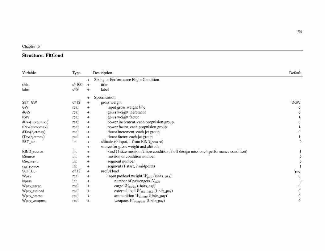
54
Chapter 15
Structure: FltCond
Variable Type Description Default
+ Sizing or Performance Flight Conditiontitle c*100 + titlelabel c*8 + label
+ SpecificationSET_GW c*12 + gross weight ’DGW’
GW real + input gross weight WG 0.
dGW real + gross weight increment 0.
fGW real + gross weight factor 1.
dPav(npropmax) real + power increment, each propulsion group 0.
fPav(npropmax) real + power factor, each propulsion group 1.
dTav(njetmax) real + thrust increment, each jet group 0.
fTav(njetmax) real + thrust factor, each jet group 1.
SET_alt int + altitude (0 input, 1 from KIND_source) 0
+ source for gross weight and altitudeKIND_source int + kind (1 size mission, 2 size condition, 3 off design mission, 4 performance condition) 1
kSource int + mission or condition number 0
kSegment int + segment number 0
seg_source int + segment (1 start, 2 midpoint) 1
SET_UL c*12 + useful load ’pay’
Wpay real + input payload weight Wpay (Units_pay) 0.
Npass int + number of passengers Npass 0
Wpay_cargo real + cargo Wcargo (Units_pay) 0.
Wpay_extload real + external load Wext−load (Units_pay) 0.
Wpay_ammo real + ammunition Wammo (Units_pay) 0.
Wpay_weapons real + weapons Wweapons (Units_pay) 0.

Structure: FltCond 55
+ fuel tank systemdFuel(ntankmax) real + fuel weight or energy increment 0.
fFuel(ntankmax) real + fuel capacity factor 1.
SET_auxtank(ntankmax) int + auxiliary fuel tanks (1 adjust Nauxtank, 2 only increase, 0 no change) 1
mauxtank(ntankmax) int + tank size changed (–1 first, –2 first size already used, m for m-th size) -1
dNauxtank(ntankmax) int + number tanks added or dropped 1
Nauxtank(nauxtankmax,ntankmax)
int + number of auxiliary fuel tanks Nauxtank (each aux tank size)+ fixed useful load
dWcrew real + crew weight increment 0.
dNcrew int + number of crew increment δNcrew 0
dWoful(10) real + other fixed useful load increment (nWoful categories) 0.
dWequip real + equipment weight increment 0.
dNcrew_seat int + crew seat increment δNcrew−seat 0
dNpass_seat int + passenger seat increment δNpass−seat 0
+ kits on aircraft (0 none, 1 present)SET_foldkit int + folding kit 1
SET_extkit(nwingmax) int + wing extension kit 1
SET_wingkit(nwingmax) int + wing kit on aircraft 1
SET_otherkit int + other kit on aircraft 0
DESIGN_engine int + design condition for power (1 to use for engine sizing) 1
DESIGN_jet int + design condition for jet thrust (1 to use for jet group sizing) 1
DESIGN_charge int + design condition for charge power (1 to use for charge group sizing) 1
DESIGN_GW int + design condition for DGW (1 to use for DGW calculation) 1
DESIGN_xmsn int + design condition for transmission (1 to use for transmission sizing) 1
DESIGN_sdgw int + design condition for SDGW (1 to use for SDGW calculation) 1
DESIGN_wmto int + design condition for WMTO (1 to use for WMTO calculation) 1
DESIGN_thrust int + design condition for antitorque or aux thrust (1 to use for rotor sizing) 1
label is short description for outputsizing flight condition: use all parameters except sweep
fixed gross weight conditions not used to determine DGW, SDGW, WMTO(set DESIGN_GW=0, DESIGN_sdgw=0, DESIGN_wmto=0)
condition not used to size engine or rotor if power margin fixed (max GW, max effort, or trim)

Structure: FltCond 56
condition not used to size transmission if zero torque margin (max GW, max effort, or trim)performance flight condition: not use DESIGN_xx
SET_GW, SET_UL values determine which input parameters used
SET_GW, set gross weight WG:’DGW’ = design gross weight WD; input (FIX_DGW) or calculated’SDGW’ = structural design gross weight WSD (may depend on DGW)’WMTO’ = maximum takeoff gross weight WMTO (may depend on DGW)’f(DGW)’ = function DGW: fGW*WD+dGW
’f(SDGW)’ = function SDGW: fGW*WSD+dGW
’f(WMTO)’ = function WMTO: fGW*WMTO+dGW
’input’ = input (use GW)’source’ = gross weight from specified mission segment or flight condition (KIND_source)’f(source)’ = function of source: fGW*Wsource+dGW
’maxP’, ’max’ = maximum GW for power required equal specified power: Preq = fPavPav + dPav
min((fPavPG + d) − PreqPG) = 0, over all propulsion groups’maxQ’ = maximum GW for transmission torque equal limit: zero torque margin
min(Plimit − Preq) = 0, over all propulsion groups, engine groups, and rotors’maxPQ’, ’maxQP’ = maximum GW for power required equal specified power and transmission torque equal limit
most restrictive of power and torque margins’maxJ’ = maximum GW for jet thrust required equal specified thrust: Treq = fTavTav + dTav
min((fTavJG + d) − TreqJG) = 0, over all jet groups’maxPJ’, ’maxQJ’, ’maxPQJ’ = maximum GW for most restrictive of power, torque, and thrust margins’pay+fuel’ = input payload and fuel weights; gross weight fallout
SET_UL, set useful load: with fixed useful load adjustments in fallout weight’pay’ = input payload weight (Wpay); fuel weight fallout’fuel’ = input fuel weight (dFuel, fFuel, Nauxtank); payload weight fallout’pay+fuel’ = input payload and fuel weights; gross weight fallout
if SET_GW=’pay+fuel’, assume SET_UL same (actual SET_UL ignored)
KIND_source, source for gross weight or altitude: source must be solved before this conditioncalculation order: size missions, size conditions, off design missions, performance conditions
input fuel weight: Wfuel = min(dFuel+fFuel∗Wfuel−cap, Wfuel−cap) +∑
Nauxtank∗Waux−cap

Structure: FltCond 57
auxiliary fuel tanks: SET_auxtank used for fallout fuel weight (SET_UL=’pay’)adjust Nauxtank for first fuel tank system with SET_auxtank > 0otherwise number of auxiliary fuel tanks fixed at input value
payload: only Wpay used if SET_Wpayload = no detailscrew: only dWcrew used if SET_Wcrew = no detailsequipment: dNcrew_seat and dNpass_seat require non-zero weight per seat
+ Parameter sweepSET_sweep int + sweep (0 for none, 1 from list, 2 from range) 0
INIT_sweep int + initialize trim (0 for not) 0
nquant_sweep int + number of swept quantities (1 to qsweepmax) 1
nsweep int + list, number of values (maximum nsweepmax)quant_sweep(qsweepmax) c*12 + quantity (parameter name)
+ rangesweep_first(qsweepmax) real + first parameter valuesweep_last(qsweepmax) real + last parameter valuesweep_inc(qsweepmax) real + parameter increment
+ listsweep(nsweepmax,qsweepmax) real + parameter values
Parameter sweep: only for performance flight conditions, not sizing flight conditionsmaximum total number of values for all conditions is nsweepmax
Single sweep, simultaneously varying nquant_sweep quantitiesSweeps executed from sweep_last to sweep_first
sweep analyzed using single data structure, only solution for sweep_first saved (last value executed)sweep_last (first value executed) should be condition that will convergesign of parameter step determined by sign of (sweep_last-sweep_first); sign of sweep_inc ignoredsweep_inc of first quantity determines number of values, sweep_inc of other quantities not used
INIT_sweep: control/pitch/roll values of trim iteration initialized from previous condition of sweepAvailable parameters: quant_sweep = parameter name
GW, dGW, fGW, dPavn, fPavn, dTavn, fTavn, Wpay, dFueln, fFueln, dWcrew, dWequip

Structure: FltCond 58
Vkts, Mach, ROC, climb, side, pitch, roll, rate_turn, nz_turn, bank_turn, rate_pullup, nz_pullup
ax_linear, ay_linear, az_linear, nx_linear, ny_linear, nz_linear
altitude, dtemp, temp, density, csound, viscosity, HAGL
controln, coll, latcyc, lngcyc, pedal, tilt, Vtipn, Npecn, fPower, fThrust, fCharge
DoQ_pay, fDoQ_pay, DoQV_pay, dSLcg, dBLcg, dWLcg, trim_targetn
n = propulsion group (Vtip, Nspec, dPav, fPav), jet group (dTav, fTav), fuel tank system, control number, or trim quantity;1 if absentfor fPower, value is factor on input fPower for all engine groups, all propulsion groupsfor fThrust, value is factor on input fThrust for all jet groupsfor fCharge, value is factor on input fCharge for all charge groups
parent int parent (1 Size, 2 Performance)kFltCond int FltCond numberkcol_out int performance output column (first for sweep)
SpecificationiSET_GW int gross weight (SET_GW_xxx)iSET_maxGW int max gross weight (0 no iteration; SET_GW_maxP, maxQ, maxPQ, maxJ, maxPJ, maxQJ, maxPQJ)iSET_UL int useful load (SET_UL_pay, fuel, payfuel)iSETPmargin(npropmax) int power margin as quantity (3 max GW, 2 max effort, 1 trim); not used to size engine or rotoriSETQmargin(npropmax) int torque margin as quantity (3 max GW, 2 max effort, 1 trim); not used to size transmissioniSETJmargin(njetmax) int jet thrust margin as quantity (3 max GW, 2 max effort, 1 trim); not used to size jet groupiSETCmargin(nchrgmax) int charger power margin as quantity (1 trim); not used to size charge groupiSETBmargin(ntankmax) int battery power margin as quantity (2 max effort, 1 trim); not used to size fuel tankisFIX_GW int fixed gross weight; DESIGN_GW=0, DESIGN_sdgw=0, DESIGN_wmto=0
Parameter sweepkquant_sweep(qsweepmax) int quantity numberlabel_sweep c*8 quantity column labelvsweep(nsweepmax,qsweepmax)
real parameter valuesfPower_original(nengmax) real fraction of rated engine power availablefThrust_original(njetmax) real fraction of rated jet thrust availablefCharge_original(nchrgmax) real fraction of rated charger power available

59
Chapter 16
Structure: Mission
Variable Type Description Default
Mission ProfileMissParam MissParam Parameters
Mission SegmentsMissSeg(nsegmax) MissSeg mission segmentsFltState(nsegmax) FltState flight conditions

60
Chapter 17
Structure: MissParam
Variable Type Description Default
+ Mission Profiletitle c*100 + titlelabel c*8 + label
+ SpecificationSET_GW c*16 + mission takeoff gross weight WG ’pay+miss’
GW real + input gross weight 0.
dGW real + gross weight increment 0.
fGW real + gross weight factor 1.
SET_UL c*16 + useful load ’pay+miss’
Wpay real + input takeoff payload weight Wpay (Units_pay) 0.
Npass int + number of passengers Npass 0
Wpay_cargo real + cargo Wcargo (Units_pay) 0.
Wpay_extload real + external load Wext−load (Units_pay) 0.
Wpay_ammo real + ammunition Wammo (Units_pay) 0.
Wpay_weapons real + weapons Wweapons (Units_pay) 0.
SET_pay c*16 + payload changes ’delta’
+ fuel tank systemsFIX_missfuel(ntankmax) int + mission fuel weight (0 calculated, 1 fixed) 0
dFuel(ntankmax) real + fuel weight or energy increment 0.
fFuel(ntankmax) real + fuel capacity factor 1.
SET_auxtank(ntankmax) int + auxiliary fuel tanks (1 adjust Nauxtank, 2 only increase, 3 increase at start and drop, 0 no change) 1
mauxtank(ntankmax) int + tank size changed (–1 first, –2 first size already used, m for m-th size) -1
dNauxtank(ntankmax) int + number tanks added or dropped 1
Nauxtank(nauxtankmax,ntankmax)
int + number of auxiliary fuel tanks Nauxtank (each aux tank size)+ fixed useful load
SET_foldkit int + folding kit on aircraft (0 none, 1 present) 1

Structure: MissParam 61
SET_reserve int + fuel reserve (1 fraction mission fuel, 2 fraction fuel capacity, 3 only mission segments) 1
fReserve real + fuel reserve fraction fres 0.
+ split segmentsdist_inc real + distance increment (Units_dist) 100.
time_inc real + time increment (Units_time) 30.
alt_inc real + altitude increment (Units_alt) 2000.
VTO_inc real + takeoff velocity increment 10.
hTO_inc real + takeoff height increment 10.
DESIGN_engine int + design mission for power (1 to use for engine sizing) 1
DESIGN_jet int + design mission for jet thrust (1 to use for jet group sizing) 1
DESIGN_charge int + design mission for charge power (1 to use for charge group sizing) 1
DESIGN_GW int + design mission for DGW (1 to use for DGW calculation) 1
DESIGN_xmsn int + design mission for transmission (1 to use for transmission sizing) 1
DESIGN_tank int + design mission for fuel tank (1 to use for fuel tank capacity) 1
DESIGN_thrust int + design mission for antitorque or aux thrust (1 to use for rotor sizing) 1
label is short description for outputsizing mission: use all parameters
fixed gross weight missions not used to determine DGW (set DESIGN_GW=0)mission segment not used to size engine or rotor if power margin fixed (max GW, max effort, or trim)mission segment not used to size transmission if zero torque margin (max GW, max effort, or trim)mission segment not used for sizing if set MissSeg%SizeZZZ=0
off design mission: not use DESIGN_xx
SET_GW, SET_UL values determine which input parameters used
SET_GW, set mission takeoff gross weight WG:’DGW’ = design gross weight WD; input (FIX_DGW) or calculated’SDGW’ = structural design gross weight WSD (may depend on DGW)’WMTO’ = maximum takeoff gross weight WMTO (may depend on DGW)’f(DGW)’ = function DGW: fGW*WD+dGW
’f(SDGW)’ = function SDGW: fGW*WSD+dGW
’f(WMTO)’ = function WMTO: fGW*WMTO+dGW
’input’ = input (use GW)

Structure: MissParam 62
’maxP’, ’max’ = maximum GW for power required equal specified power: Preq = fPavPav + dPav
at mission segment MaxGW, minimum gross weight of designated segmentsmin((fPavPG + d) − PreqPG) = 0, over all propulsion groups
’maxQ’ = maximum GW for transmission torque equal limit: zero torque marginat mission segment MaxGW, minimum gross weight of designated segmentsmin(Plimit − Preq) = 0, over all propulsion groups, engine groups, and rotors
’maxPQ’, ’maxQP’ = maximum GW for power required equal specified power and transmission torque equal limitat mission segment MaxGW, minimum gross weight of designated segmentsmost restrictive of power and torque margins
’maxJ’ = maximum GW for jet thrust required equal specified thrust: Treq = fTavTav + dTav
at mission segment MaxGW, minimum gross weight of designated segmentsmin((fTavJG + d) − TreqJG) = 0, over all jet groups
’maxPJ’, ’maxQJ’, ’maxPQJ’ = maximum GW for most restrictive of power, torque, and thrust margins’pay+fuel’ = input payload and fuel weights; gross weight fallout’pay+miss’ = input payload, fuel weight from mission; gross weight fallout
SET_UL, set useful load:’pay’ = input payload weight (Wpay); fuel weight fallout’fuel’ = input fuel weight (dFuel, fFuel, Nauxtank); initial payload weight fallout’miss’ = fuel weight from mission; initial payload weight fallout’pay+fuel’ = input payload and fuel weights; gross weight fallout’pay+miss’ = input payload, fuel weight from mission; gross weight fallout
if SET_GW=’pay+fuel’ or ’pay+miss’, assume SET_UL same (actual SET_UL ignored)FIX_missfuel only used for SET_UL=’miss’ or ’pay+miss’, with more than one fuel tank system
SET_pay, set payload changes: mission segment payload (use of MissSeg%xWpay)’none’ = no changes’input’ = value; payload = xWpay (not use Wpay)’delta’ = increment; payload = (initial payload weight)+(xWPay–xWpay(seg1))’scale’ = factor; payload = (initial payload weight)*(xWPay/xWpay(seg1))
when SET_GW=’max’ and SET_UL=’fuel’ or ’miss’ (so payload is fallout), payload (from SET_pay and xWpay) mustnot be zero at the maximum GW segments
payload: only Wpay and xWpay used if SET_Wpayload = no details

Structure: MissParam 63
input fuel weight: Wfuel = min(dFuel+fFuel∗Wfuel−cap, Wfuel−cap) +∑
Nauxtank∗Waux−cap
for fallout fuel weight, this is the initial value for the mission iteration
auxiliary fuel tanks:SET_auxtank options: fixed; or adjust Nauxtank for each segment; or
increase at mission start, then constant; or increase at start, then dropfor input fuel (SET_UL = ’fuel’ or ’pay+fuel’), start with input Nauxtank, then dropfor mission fuel (SET_UL = ’miss’ or ’pay+miss’), fixed Wfuel or Efuel at startfor fallout (SET_UL = ’pay’), adjust Wfuel with change in Nauxtank (fixed WG − Wpay = WO + Wfuel)for all SET_UL, adjust WO with change in Nauxtank
fuel tank design mission: Nauxtank=0, allow Wfuel or Efuel to exceed tank capacity
SET_reserve: maximum of fuel for designated reserve mission segmentsand fraction of fuel (fresWburn or fresEburn) or fraction of fuel capacity (fresWfuel−cap or fresEfuel−cap)
+ Segment integrationKIND_SegInt int + method (0 segment start, 1 segment midpoint, 2 trapezoidal) 1
+ Mission iteration (supersede Solution input if nonzero)relax_miss real + relaxation factor (mission fuel) 0.
relax_range real + relaxation factor (range credit) 0.
relax_gw real + relaxation factor (max takeoff GW) 0.
toler_miss real + tolerance (fraction reference) 0.
trace_miss int + trace iteration (0 for none) 0
+ Mission SegmentsnSeg int + number of mission segments (maximum nsegmax) 1
input all mission segments as arrays in single mission namelist
parent int parent (1 Size, 2 OffDesign)kMission int Mission numberkcol_out int performance output column

Structure: MissParam 64
SpecificationiSET_GW int gross weight (SET_GW_xxx)iSET_maxGW int max gross weight (SET_GW_maxP, maxQ, maxPQ, maxJ, maxPJ, maxQJ, maxPQJ)nSET_maxGW int number max gross weight segmentsiSET_UL int useful load (SET_UL_pay, fuel, payfuel, miss, paymiss)iSET_pay int payload changes (SET_pay_none, input, delta, scale)iSETPmargin(npropmax) int power margin as quantity (all mission segments); not used to size engine or rotoriSETQmargin(npropmax) int torque margin as quantity (all mission segments); not used to size transmissioniSETJmargin(njetmax) int jet thrust margin as quantity (all mission segments); not used to size jet groupiSETCmargin(nchrgmax) int charger power margin as quantity (all mission segments); not used to size charge groupiSETBmargin(ntankmax) int battery power margin as quantity (all mission segments); not used to size fuel tankisFIX_GW int fixed gross weight; DESIGN_GW=0
Segmentsnreserve int number reserve segmentsnadjust int number adjustable segmentskind_adjust int kind adjustable (0 none, 1 distance, 2 time)kind_range int kind range credit (0 none, 1 all forward, 2 all backward, 3 both)ntakeoff int number takeoff segments
Iterationkind_iter int kind iteration (0 none, 1 calculate mission fuel, 2 adjust mission, 3 only range credit or integration)ismissconv int converged (0 not)count_miss int number of iterationserror_miss(3) real error ratio (Wfuel, range credit, takeoff GW)
Mission quantitiesisFirstSol int first solution (initialize GW_to and Wfuel_to)GW_to real takeoff gross weight (start of mission)GW_endmiss real gross weight (end of mission, excluding reserve segments; last non-reserve segment)GW_end real gross weight (end of mission; last segment)Wfuel_to(ntankmax) real takeoff fuel weight (start of mission)Wfuel_add(ntankmax) real added fuel weight (fill/add/drop during mission)Wfuel_endmiss(ntankmax) real fuel weight (end of mission, excluding reserve segments; last non-reserve segment)Wfuel_end(ntankmax) real fuel weight (end of mission; last segment)Wburn(ntankmax) real weight fuel burned Wburn

Structure: MissParam 65
Wres(ntankmax) real weight reserve fuel Wres (maximum of fraction or reserve segments)Wfuel_miss(ntankmax) real calculated mission fuel weight (Wburn + Wres)Efuel_to(ntankmax) real takeoff fuel energy (start of mission)Efuel_add(ntankmax) real added fuel energy (fill/add/drop during mission)Efuel_endmiss(ntankmax) real fuel energy (end of mission, excluding reserve segments; last non-reserve segment)Efuel_end(ntankmax) real fuel energy (end of mission; last segment)Eburn(ntankmax) real energy fuel burned Eburn
Eres(ntankmax) real energy reserve fuel Eres (maximum of fraction or reserve segments)Efuel_miss(ntankmax) real calculated mission fuel energy (Eburn + Eres)exceedP int exceed power available: any mission segment PreqPG > (1 + ε)PavPG
exceedQ int exceed torque available: any mission segment PreqPG > (1 + ε)PDSlimit
exceedJ int exceed jet thrust available: any mission segment TreqJG > (1 + ε)TavJG
exceedC int exceed charger power available: any mission segment PreqCG > (1 + ε)PavCG
exceedWf int exceed fuel capacity: any mission segment Wfuel > (1 + ε)Wfuel−cap or Efuel > (1 + ε)Efuel−cap
exceedB int exceed battery power: any mission segment |Ebatt| > (1 + ε)Pmax
Total mission, excluding reserve segmentsendurance real endurance E, block time (min)range real range R (nm)airdist real air distance (nm)blockspeed real block speed (kts; range/endurance)range_factor real range factor RF = R/ ln(Wto/(Wto − Wburn)) (nm)end_factor real efficiency factor EF = E/2
((Wto/(Wto − Wburn))3/2 − 1
)(min)
fuel_eff real fuel efficiency e = WpayR/Wburn (ton-nm/lb or ton-nm/kg)productivity_o real productivity p = WpayV/WO (ton-kt/lb or ton-kt/kg)productivity_f real productivity p = WpayV/Wburn (ton-kt/lb or ton-kt/kg)
CostASM real available seat milesDOC real direct operating cost
Emissions Trading Scheme (kg CO2, per mission)ETS real totalETS_fuel real fuel burnedETS_energy real energy used
Weight of emissions (kg, per mission)W_CO2 real carbon dioxide

Structure: MissParam 66
W_NOx real NOx
W_H2O real water vaporW_soot real sootW_SO4 real sulphates
Average Temperature Response (deg C)ATR real totalATR_noAIC real total without AICATR_CO2 real carbon dioxideATR_CH4 real NOx - methaneATR_O3L real NOx - ozone (long life)ATR_O3S real NOx - ozone (short life)ATR_H2O real water vaporATR_soot real sootATR_SO4 real sulphatesATR_AIC real aviation induced cloudiness
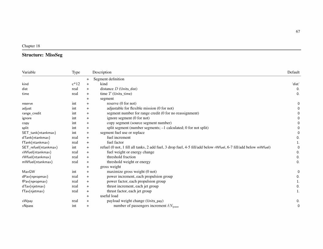
67
Chapter 18
Structure: MissSeg
Variable Type Description Default
+ Segment definitionkind c*12 + kind ’dist’
dist real + distance D (Units_dist) 0.
time real + time T (Units_time) 0.
+ segmentreserve int + reserve (0 for not) 0
adjust int + adjustable for flexible mission (0 for not) 0
range_credit int + segment number for range credit (0 for no reassignment) 0
ignore int + ignore segment (0 for not) 0
copy int + copy segment (source segment number) 0
split int + split segment (number segments; –1 calculated; 0 for not split) 0
SET_tank(ntankmax) int + segment fuel use or replace 0
dTank(ntankmax) real + fuel increment 0.
fTank(ntankmax) real + fuel factor 1.
SET_refuel(ntankmax) int + refuel (0 not, 1 fill all tanks, 2 add fuel, 3 drop fuel, 4-5 fill/add below rWfuel, 6-7 fill/add below mWfuel) 0
xWfuel(ntankmax) real + fuel weight or energy change 0.
rWfuel(ntankmax) real + threshold fraction 0.
mWfuel(ntankmax) real + threshold weight or energy 0.
+ gross weightMaxGW int + maximize gross weight (0 not) 0
dPav(npropmax) real + power increment, each propulsion group 0.
fPav(npropmax) real + power factor, each propulsion group 1.
dTav(njetmax) real + thrust increment, each jet group 0.
fTav(njetmax) real + thrust factor, each jet group 1.
+ useful loadxWpay real + payload weight change (Units_pay) 0.
xNpass int + number of passengers increment δNpass 0

Structure: MissSeg 68
+ fixed useful loaddWcrew real + crew weight increment 0.
dNcrew int + number of crew increment δNcrew 0
dWoful(10) real + other fixed useful load increment (nWoful categories) 0.
dWequip real + equipment weight increment 0.
dNcrew_seat int + crew seat increment δNcrew−seat 0
dNpass_seat int + passenger seat increment δNpass−seat 0
+ kits on aircraft (0 none, 1 present)SET_extkit(nwingmax) int + wing extension kit 1
SET_wingkit(nwingmax) int + wing kit 1
SET_otherkit int + other kit 0
SET_alt int + altitude at start of segment (0 input, 1 from previous segment, 2 from kSeg_alt) 0
kSeg_alt int + source of altitude 0
SET_wind int + wind specification (0 none, 1 headwind, 2 tailwind) 0
dWind real + wind increment, knots (dWind+fWind*altitude) 0.
fWind real + wind gradient, knots (dWind+fWind*altitude) 0.
+ design mission (0 to not use segment for sizing)SizeEngine int + power 1
SizeJet int + jet thrust 1
SizeCharge int + charger power 1
SizeGW int + DGW 1
SizeXmsn int + transmission 1
SizeThrust int + antitorque or aux thrust 1
segment kind
kind=’taxi’, ’idle’: taxi/warm-up mission segment (use time)kind=’dist’: fly segment for specified distance (use dist)kind=’time’: fly segment for specified time (use time)kind=’hold’, ’loiter’: fly segment for specified time (use time), fuel burned but no distance added to rangekind=’climb’: climb/descend from present altitude to next segment altitudekind=’spiral’: climb/descend from present altitude to next segment altitude, fuel burned but no dist added to rangekind=’fuel’: use or replace specified fuel amount, calculate time and distancekind=’burn’, ’charge’: use or replace specified fuel amount, calculate time but no distance added to rangekind=’takeoff’, ’TO’: takeoff distance calculation

Structure: MissSeg 69
only one of reserve, adjust, range_credit designations for each segmentreserve: time and distance not included in block time and rangerange credit: to facilitate specification of range
range calculated for this segment credited to segment = range_credit
range_credit segment must be kind=’dist’, specified distance is for group of segmentsactual distance flown in range_credit segment is specified dist less distances from other segments
if credit to earlier segment, iteration requiredadjustable: for SET_UL not ’miss’, can adjust one or more segments
if more than one segment adjusted, must be all kind=’dist’ or all kind=’time’/’hold’
adjust time or distance based on fuel burn (proportional to initial values)
split segment: number specified, or calculated from MissParam%dest_inc, time_inc, alt_inc
ignore segment: removed from input; segments using MaxGW, range_credit, FltCond%KIND_source can not be ignored
SET_tank: segment fuel use or replace for kind=’fuel’ or ’burn’
SET_tank = 0: no requirementSET_tank = 1: target dTank+fTank*Wfuel−cap or dTank+fTank*Efuel−cap
SET_tank = 2: target dTank+fTank*Wfuel or dTank+fTank*Efuel
SET_tank = 3: increment dTank+fTank*Wfuel−cap or dTank+fTank*Efuel−cap
SET_tank = 4: increment dTank+fTank*Wfuel or dTank+fTank*Efuel
charge if E < 0 (not based on keyword, increment always positive)target limited by capacity, if target already achieved then no requirementincrement limited by current fuel (use) or capacity minus current fuel (replace)
SET_refuel, refuel: change at start of segment; weight or energySET_refuel = 1: fill all tanks (including any auxiliary tanks installed)SET_refuel = 2: add fuel xWfuel
SET_refuel = 3: drop fuel xWfuel
SET_refuel = 4: if below fraction rWfuel of fuel capacity (including auxiliary tanks), fill all tanksSET_refuel = 5: if below fraction rWfuel of fuel capacity (including auxiliary tanks), add xWfuel
SET_refuel = 6: if below mWfuel, fill all tanksSET_refuel = 7: if below mWfuel, add xWfuel
added fuel limited by capacity; not used for first segmentxWfuel positive (add or drop determined by SET_refuel)

Structure: MissSeg 70
maximize gross weight: MaxGW designate segments if SET_GW=’maxP’ or ’maxQ’ or ’maxPQ’
climb/descend or spiral segment: end altitude is that of next segment; last segment kind can not be climb or spiralbegin altitude is that input for this segment (SET_alt=0), or altitude of previous segment (SET_alt=1),
payload: only Wpay and xWpay used if SET_Wpayload = no detailsxNpass is change from MissParam%Npass
crew: only dWcrew used if SET_Wcrew = no detailsequipment: dNcrew_seat and dNpass_seat require non-zero weight per seat
+ Takeoff distance calculationSET_takeoff c*12 + takeoff segment kind ’none’
Vkts_takeoff real + ground speed or climb speed (knots, CAS) 0.
climb_takeoff real + climb angle relative ground γ (deg) 0.
height_takeoff real + height during climb h (ft or m) 0.
slope_ground real + slope of ground γG (+ for uphill; deg) 0.
friction real + friction coefficient μ 0.04
t_decision real + decision delay after engine failure t1 (sec) 1.5
t_rotation real + rotation time tR (sec) 2.0
nz_transition real + transition load factor nTR 1.2
takeoff distance calculation: set of consecutive kind=’takeoff’ segmentsfirst segment identified by SET_takeoff=’start’ (V = 0)last segment if next segment is not kind=’takeoff’, or is SET_takeoff=’start’
takeoff segment kindSET_takeoff=’start’, ’ground run’ (keyword = ground or run), ’engine fail’ (keyword = eng or fail)SET_takeoff=’liftoff’, ’rotation’, ’transition’, ’climb’, ’brake’
each segment requires appropriate configuration, trim option, max effort specificationnot use dist, time, reserve, adjust, range_credit, SET_refuel, MaxGW, SET_alt
max_var=’alt’ not allowed in maximum effortvelocity specification (SET_vel) and HAGL superseded; SET_turn=SET_pullup=0
can split segment (except start, rotation, transition): split height for climb, velocity for otherssplitting liftoff or engine failure segment produces additional ground run segments

Structure: MissSeg 71
separate definition of multiple ground run, climb, brake segments allows configuration variationsdefine takeoff profile in terms of velocities
integrate acceleration vs velocity to obtain time and distancesegments correspond to ends of integration intervalsanalysis checks for consistency of input velocity and calculated accelerationanalysis checks for consistency of input height and input/calculated climb angle
takeoff distance definition: includes SET_takeoff=’liftoff’ segmentorder: start, ground run, engine failure, ground run, liftoff, rotation, transition, climbonly one liftoff; only one engine failure, rotation, transition (or none)engine failure before liftoff; all ground run before liftoff, all climb after liftoff
accelerate-stop distance definition: does not have SET_takeoff=’liftoff’ segmentorder: start, ground run, engine failure, brakeonly one engine failure (or none)
engine failure segment (if present) identifies point for decision delayuntil t_decision after engine failure segment, use engine rating, fPower, fraction of engine failure segmentso engine failure segment corresponds to conditions before failure
number of inoperative engines specified by nEngInop for each segmentif engine failure segment present, nEngInop specification must be consistent
parent int parent (1 Size, 2 OffDesign)kMission int Mission numberkMissSeg int MissSeg numberkcol_out int performance output column
Specificationikind int kind (MissSeg_kind_taxi, dist, time, hold, climb, spiral, fuel, burn)SET_foldkit int folding kit on aircraft (0 none, 1 present)

Structure: MissSeg 72
Segmentskind_range int this segment receives range credit (0 not, 1 source forward, 2 source backward, 3 both)fadjust real adjustment ratio (initial time or dist ratio)wassplit int split segment (number segments; 0 for not split)ksplit_first int first segment after splitksplit_last int last segment after splitdWpay real payload increment (xWpay–xWpay(seg1)) or factor (xWpay/xWpay(seg1))iSET_maxGW int max gross weight (0 no iteration; SET_GW_maxP, maxQ, maxPQ, maxJ, maxPJ, maxQJ, maxPQJ + maxGW)iSETPmargin(npropmax) int power margin as quantity (3 max GW, 2 max effort, 1 trim)iSETQmargin(npropmax) int torque margin as quantity (3 max GW, 2 max effort, 1 trim)iSETJmargin(njetmax) int jet thrust margin as quantity (3 max GW, 2 max effort, 1 trim)iSETCmargin(nchrgmax) int charger power margin as quantity (1 trim)iSETBmargin(ntankmax) int battery power margin as quantity (2 max effort, 1 trim)
Maximum gross weightismaxgwconv int converged (0 not)count_maxgw int number of iterationserror_maxgw real error ratioGW_inc real gross weight increment
Takeoff distance calculationiSET_takeoff int takeoff segment kind (SET_takeoff_xxx)VCAS_TO real ground speed or climb speed (CAS)V_TO real ground speed (ft/sec or m/sec)climb_TO real angle relative ground (deg)isConsistent_TO int consistent acc and V change, climb and h changeFxG_TO real net force T − D (ground axes)FzG_TO real net force W − L (ground axes)FzGmu_TO real friction drag μFzG
acc_TO real acceration (ground axes)h_TO real height (ft or m)t_TO real time (sec)s_TO real distance (ft or m)time_TO real cumulative time (sec)dist_TO real cumulative distance (ft or m)

Structure: MissSeg 73
original value for engine failure decision (from FltAircraft)rating_original(nengmax) c*12 engine ratingkrate_original(nengmax) int engine ratingfPower_original(nengmax) real fraction of rated engine power availablerating_jet_original(njetmax)
c*12 jet ratingkrate_jet_original(njetmax)
int jet ratingfThrust_original(njetmax) real fraction of rated jet thrust availablerating_charge_original(nchrgmax)
c*12 charger ratingkrate_charge_original(nchrgmax)
int charger ratingfCharge_original(nchrgmax) real fraction of rated charger power availablefriction_original real friction coefficientkSegEF_TO int engine failure segment (0 for none)
Performance (from FltState; at start or midpoint)speed real horizontal speed Vh (knots)Vclimb real climb velocity Vc (ft/sec or m/sec)fuelflow(ntankmax) real fuel flow w (lb/hr or kg/hr)energyflow(ntankmax) real energy flow E (MJ/hr)
trapezoidal integrationspeed_start real horizontal speed Vh
Vclimb_start real climb velocity Vc
fuelflow_start(ntankmax) real fuel flow wenergyflow_start(ntankmax) real energy flow Espeed_end real horizontal speed Vh
Vclimb_end real climb velocity Vc
fuelflow_end(ntankmax) real fuel flow wenergyflow_end(ntankmax) real energy flow Ealt_start real altitude h at start of segment (ft or m)alt_end real altitude h at end of segment (from start of next segment, only used for kind=’climb’ or ’spiral’)Wind real Headwind Vw (knots)groundspeed real Ground speed (Vh − Vw) (knots)

Structure: MissSeg 74
Mission segment quantitiesT real time T (minutes)D real ground distance D (nm)otherDpast real distance from past range credit (nm)otherDfuture real distance from future range credit (nm)dR real range contribution dR (nm)airdist real air distance (nm)Wburn(ntankmax) real fuel burned Wburn (lb or kg)Wfuel_add(ntankmax) real fuel added at start of segmentWfuel_start(ntankmax) real fuel weight Wfuel (segment start)Eburn(ntankmax) real fuel burned Eburn (MJ)Efuel_add(ntankmax) real fuel added at start of segmentEfuel_start(ntankmax) real fuel energy Efuel (segment start)GW_start real gross weight WG (segment start)
Emissions Trading Scheme (kg CO2, per mission)ETS real totalETS_fuel real fuel burnedETS_energy real energy used
Weight of emissions (kg, per mission)W_CO2 real carbon dioxideW_NOx real NOx
W_H2O real water vaporW_soot real sootW_SO4 real sulphates
Average Temperature Response (deg C)ATR real totalATR_noAIC real total without AICATR_CO2 real carbon dioxideATR_CH4 real NOx - methaneATR_O3L real NOx - ozone (long life)ATR_O3S real NOx - ozone (short life)ATR_H2O real water vaporATR_soot real sootATR_SO4 real sulphates

Structure: MissSeg 75
ATR_AIC real aviation induced cloudinessEI_NOx(ntankmax) real EINOx
=∑
EIw/∑
w, input or turboshaft calculated, weighted for engine groupfPto(nengmax) real fP = Pq/Pto for w

76
Chapter 19
Structure: FltState
Variable Type Description Default
Flight StateFltAircraft FltAircraft Aircraft
ComponentsFltFuse FltFuse fuselageFltGear FltGear landing gearFltRotor(nrotormax) FltRotor rotorsFltWing(nwingmax) FltWing wingsFltTail(ntailmax) FltTail tailsFltTank(ntankmax) FltTank fuel tank systemsFltProp(npropmax) FltProp propulsion groupsFltEngn(nengmax) FltEngn engine groupsFltJet(njetmax) FltJet jet groupsFltChrg(nchrgmax) FltChrg charge groups

77
Chapter 20
Structure: FltAircraft
Variable Type Description Default
+ Flight State+ Specification
SET_max int + maximum effort performance (maximum 2, 0 to analyze specified condition) 0
max_quant(2) c*12 + quantity ’ ’
max_var(2) c*12 + variable ’ ’
max_limit(2) int + switch quantity if exceed limit (0 not, 1 power margin, 2 torque margin, 3 both) 0
fVel(2) real + flight speed factor 1.
SET_vel c*12 + flight speed ’general’
Vkts real + horizontal velocity Vh (TAS or CAS, Units_vel) 0.
Mach real + horizontal velocity M (Mach number) 0.
ROC real + vertical rate of climb Vc (Units_ROC) 0.
climb real + climb angle θV (deg) 0.
side real + sideslip angle ψV (deg) 0.
+ aircraft motionSET_pitch int + pitch motion specification (0 Aircraft value, 1 FltState input) 1
SET_roll int + roll motion specification (0 Aircraft value, 1 FltState input) 1
pitch real + pitch θF 0.
roll real + roll φF 0.
SET_turn int + turn specification (0 zero, 1 turn rate, 2 load factor, 3 bank angle) 0
rate_turn real + turn rate ψF (deg/sec) 0.
nz_turn real + load factor n (g) 1.
bank_turn real + bank angle φF (deg) 0.
SET_pullup int + pullup specification (0 zero, 1 pitch rate, 2 load factor) 0
rate_pullup real + pitch rate θF (deg/sec) 0.
nz_pullup real + load factor n (g) 1.
SET_acc int + linear acceleration specification (0 zero, 1 acceleration, 2 load factor) 0
ax_linear real + x-acceleration aACx (ft/sec2 or m/sec2) 0.
ay_linear real + y-acceleration aACy (ft/sec2 or m/sec2) 0.

Structure: FltAircraft 78
az_linear real + z-acceleration aACz (ft/sec2 or m/sec2) 0.
nx_linear real + x-load factor increment nLx (g) 0.
ny_linear real + y-load factor increment nLy (g) 0.
nz_linear real + z-load factor increment nLz (g) 0.
altitude real + altitude h (Units_alt) 0.
SET_atmos c*12 + atmosphere specification ’std’
temp real + temperature τ (Units_temp)dtemp real + temperature increment ΔT (Units_temp) 0.
density real + density ρcsound real + speed of sound cs
viscosity real + viscosity μSET_GE int + ground effect (0 OGE, 1 IGE) 0
HAGL real + height of landing gear above ground level hLG 999.
STATE_LG c*12 + landing gear state ’default’
STATE_control int + aircraft control state 1
SET_control(ncontmax) int + control specification (0 Aircraft value, 1 FltState input) 1
SET_coll int + collective stick 1
SET_latcyc int + lateral cyclic stick 1
SET_lngcyc int + longitudinal cyclic stick 1
SET_pedal int + pedal 1
SET_tilt int + tilt (0 Aircraft value, 1 FltState input, 2 Aircraft conversion schedule) 1
control(ncontmax) real + aircraft controlscoll real + collective stick cAC0 0.
latcyc real + lateral cyclic stick cACc 0.
lngcyc real + longitudinal cyclic stick cACs 0.
pedal real + pedal cACp 0.
tilt real + tilt αtilt 0.
SET_comp_control int + use component control (0 for c = TcAC ; 1 for c = TcAC + c0) 1
SET_cg int + center of gravity specification (0 baseline plus increment, 1 input) 0
dSLcg real + stationline 0.
dBLcg real + buttline 0.
dWLcg real + waterline 0.

Structure: FltAircraft 79
+ Specification, each propulsion groupSET_Vtip(npropmax) c*12 + rotor tip speed specification ’hover’
Vtip(npropmax) real + tip speedmu_Vtip(npropmax) real + tip speed from μMat_Vtip(npropmax) real + tip speed from Mat
Nspec(npropmax) real + engine speed (rpm)STATE_gear(npropmax) int + drive system state 1
rating_ds(npropmax) c*12 + drive system rating ’ ’
SET_Plimit(npropmax) int + drive system limit (0 not applied to power available) 1
SET_Qlimit_rs(npropmax) int + rotor shaft limit (0 not used for torque margin) 1
dPacc(npropmax) real + accessory power increment dPacc 0.
+ Specification, each engine grouprating(nengmax) c*12 + engine rating ’MCP’
fPower(nengmax) real + fraction of rated engine power available fP (0. to 1.+) 1.
nEngInop(nengmax) int + number of inoperative engines Ninop 0
SET_Preq(nengmax) int + power required (1 distributed, 2 fixed A, 3 fixed APav , 4 fixed APeng) 1
STATE_IRS(nengmax) int + IR suppressor system state (0 off, hot exhaust; 1 on, suppressed exhaust) 0
+ Specification, each jet grouprating_jet(njetmax) c*12 + jet rating ’MCT’
fThrust(njetmax) real + fraction of rated jet thrust available fT (0. to 1.+) 1.
nJetInop(njetmax) int + number of inoperative jets Ninop 0
SET_Jreq(njetmax) int + thrust required (1 from component, 2 fixed A, 3 fixed ATav , 4 fixed ATjet) 2
STATE_IRS_jet(njetmax) int + IR suppressor system state (0 off, hot exhaust; 1 on, suppressed exhaust) 0
+ Specification, each charge grouprating_charge(nchrgmax) c*12 + charger rating ’MCP’
fCharge(nchrgmax) real + fraction of rated charger power available fC (0. to 1.+) 1.
nChrgInop(nchrgmax) int + number of inoperative chargers Ninop 0
SET_Creq(nchrgmax) int + power required (2 fixed A, 4 fixed APchrg) 2
dPeq(ntankmax) real + Equipment power increment dPeq, each fuel tank 0.
+ Specification, each fuel tank (battery)ffade(ntankmax) real + battery capacity fade factor 1.
Tcell(ntankmax) real + cell temperature (deg C) 20.
fcurrent(ntankmax) real + maximum current (fraction xmbd or xCCmax) 1.
STATE_deice int + Deice system state (0 off) 0

Structure: FltAircraft 80
+ PerformanceDoQ_pay real + payload forward flight drag increment D/q (Units_drag) 0.
fDoQ_pay real + payload drag increment scaling with weight Δ(D/q)/Wpay (Units_drag, Units_pay) 0.
DoQV_pay real + payload vertical drag increment D/q (Units_drag) 0.
+ Rotor (nonzero to supersede rotor model)Ki(nrotormax) real + induced power factor κ 0.
cdo(nrotormax) real + profile power mean cd 0.
MODEL_Ftpp(nrotormax) int + inplane forces, tip-path plane axes (1 neglect, 2 blade-element theory) 0
MODEL_Fpro(nrotormax) int + inplane forces, profile (1 simplified, 2 blade element theory) 0
KIND_control(nrotormax) int + control mode (1 thrust and TPP, 2 thrust and NFP, 3 pitch and TPP, 4 pitch and NFP) 0
+ Trim solutionSTATE_trim c*12 + aircraft trim state (match IDENT_trim, ’none’ for no trim) ’none’
trim_target(mtrimmax) real + trim quantity targets+ Iterations (supersede Solution input if nonzero)+ relaxation factor
relax_rotor real + all rotors 0.
relax_trim real + trim 0.
relax_fly(2) real + maximum effort 0.
relax_maxgw real + maximum gross weight 0.
+ tolerance (fraction reference)toler_rotor real + all rotors 0.
toler_trim real + trim 0.
toler_fly(2) real + maximum effort 0.
toler_maxgw real + maximum gross weight 0.
+ reinitialize aircraft controls (0 no, 1 force retrim)init_trim int + trim 0
init_fly int + maximum effort 0
+ variable perturbation amplitude (fraction reference, 0. for no limit)perturb_trim real + trim 0.
perturb_fly(2) real + maximum effort 0.
perturb_maxgw real + maximum gross weight 0.
+ maximum derivative amplitude (0. for no limit)maxderiv_fly(2) real + maximum effort 0.
maxderiv_maxgw real + maximum gross weight 0.

Structure: FltAircraft 81
+ maximum increment fraction (0. for no limit)maxinc_fly(2) real + maximum effort 0.
maxinc_maxgw real + maximum gross weight 0.
+ solution methodmethod_flymax(2) int + maximum effort 0
+ trace iteration (0 for none)trace_rotor int + all rotors 0
trace_trim int + trim (2 for component controls) 0
trace_fly(2) int + maximum effort 0
trace_maxgw int + maximum gross weight 0
maximum effort performance: one or two quantity/variable identified; first is inner looptwo variables must be uniquetwo variables can be identified for same maximized quantity (endurance, range, climb)
ROC or altitude can be outer loop quantity only if it is also inner loop variablefVel is only used for max_var=’speed’ or ’ROC’
ceiling calculation should use ’Pmargin’/’alt’ as inner loop, ’power’/’speed’ as outer loopbest range calculation often requires maxinc_fly=0.1 for convergenceROC for zero power margin initialized based on level flight power margin if input ROC=0
max_quant=’rotor(s) n’ uses Rotor%CTs_steady, max_quant=’rotor(t) n’ uses Rotor%CTs_tran
if energy burned (not weight) or multiple fuels, use equivalent fuel flow obtained from weighted energy flowmax_var=’Vtip’ or ’Nspec’: requires FltAircraft%SET_Vtip=’input’
if trailing “n” is absent, use first component (n=1)
max_limit: switch quantity to power and/or torque margin if margin negative; useful for best range
description max_quant
endurance ’end’ maximum (1/fuelflow)range (high side) ’range’ 0.99 maximum (V/fuelflow)range ’range(100)’ maximum (V/fuelflow)range (low side) ’range(low)’ 0.99 maximum (V/fuelflow), low sideclimb or descent rate ’climb’ maximum (ROC)

Structure: FltAircraft 82
description max_quant
climb rate (power) ’power’ maximum (1/Power)climb or descent angle ’angle’ maximum (ROC/V)climb angle (power) ’power/V’ maximum (V/Power)ceiling ’alt’ maximum (altitude)power margin ’P margin’ min(Pav − Preq) = 0 (all propulsion groups)torque margin ’Q margin’, min(Qlimit − Qreq) = 0 (all limits)jet thrust margin ’J margin’, min(Tav − Treq) = 0 (all jet groups)power and torque margin ’PQ margin’, most restrictivepower and thrust margin ’PJ margin’, most restrictivetorque and thrust margin ’QJ margin’, most restrictivepower, torque, thrust margin ’PQJ margin’, most restrictivebattery power margin ’B margin’ min(Pmax − |Ebatt|) = 0 (all fuel tanks)rotor thrust margin ’rotor(t) n’ (CT /σ)max − CT /σ = 0 (transient)rotor thrust margin ’rotor(s) n’ (CT /σ)max − CT /σ = 0 (sustained)wing lift margin ’stall n’ CLmax − CL = 0
description max_var
horizontal velocity ’speed’ times fVel
vertical rate of climb ’ROC’ times fVel
aircraft velocity ’side’ sideslip anglealtitude ’alt’
aircraft angular rate ’pullup’, ’turn’ Euler angle ratesaircraft acceleration ’xacc’, ’yacc’, ’zacc’ linear, airframe axesaircraft acceleration ’xaccI’, ’yaccI’, ’zaccI’ linear, inertial axesaircraft acceleration ’xaccG’, ’yaccG’, ’zaccG’ linear, ground axesaircraft control match IDENT_control
aircraft orientation ’pitch’, ’roll’ body axes relative inertial axespropulsion group tip speed ’Vtip n’
propulsion group engine speed ’Nspec n’

Structure: FltAircraft 83
SET_vel, velocity specification:’general’ = general (use Vkts=horizontal, ROC, side)’hover’ = hover (zero velocity)’vert’ = hover or VROC (use ROC; Vkts=0, climb=0/+90/–90)’right’ = right sideward (use Vkts, ROC; side=90)’left’ = left sideward (use Vkts, ROC; side=–90)’rear’ = rearward (use Vkts, ROC, side=180)’Vfwd’ = general (use Vkts=forward velocity, ROC, side)’Vmag’ = general (use Vkts=velocity magnitude, ROC, side)’climb’ = general (use Vkts=velocity magnitude, climb, side)’+Mach’ = use Mach not Vkts
’+CAS’ = Vkts is CAS not TASvelocities: forward Vf = Vh cos(side), side Vs = Vh sin(side), climb Vc = Vh tan(climb)
aircraft motion:orientation velocity relative inertial axes defined by climb and sideslip angles (θV , ψV )
sideslip positive aircraft moving to right, climb positive aircraft moving upspecify horizontal velocity, vertical rate of climb, and sideslip angle
orientation body relative inertial axes defined by Euler angles, yaw/pitch/roll (ψF , θF , φF )yaw positive to right, pitch positive nose up, roll positive to right
SET_PITCH and SET_roll, pitch and roll motion specification:Aircraft values (perhaps function speed) or flight state inputinitial values specified if motion is trim variable; otherwise fixed for flight state
SET_turn, bank angle and load factor in turn: use turn rate, load factor, or bank angletan(roll) =
√n2 − 1 = (turn)V/g; calculated using input Vkts for flight speed
SET_pullup, load factor in pullup: use pullup rate or load factorn = 1 + (pullup)V/g; calculated using input Vkts for flight speed
SET_acc, linear acceleration: use acceleration or load factor
SET_atmos, atmosphere specification:’std’ = standard day at specified altitude (use altitude)’polar’ = polar day at specified altitude (use altitude)’trop’ = tropical day at specified altitude (use altitude)’hot’ = hot day at specified altitude (use altitude)’xxx+dtemp’ = specified altitude, plus temperature increment (use altitude, dtemp)

Structure: FltAircraft 84
’xxx+temp’ = specified altitude, and specified temperature (use altitude, temp)’hot+table’ = hot day table at specified altitude (use altitude)’dens’ = input density and temperature (use density, temp)’input’ = input density, speed of sound, and viscosity (use density, csound, viscosity)’notair’ = input, not air on earth (use density, csound, viscosity)
SET_GE: use HAGL; out-of-ground-effect (OGE) if rotor more than 1.5Diameter above groundheight rotor = landing gear above ground + hub above landing gear = HAGL + (WL_hub–WL_gear+d_gear)
STATE_LG: ’default’ (based on retraction speed), ’extend’, ’retract’ (keyword = def, ext, ret)
STATE_control, aircraft control state: identifies control matrixSTATE_control=0 to use conversion schedule, STATE_control=n (1 to nstate_control) to use state#n
SET_control, control specification: Aircraft values (perhaps function speed) or flight state inputcoll/latcyc/lngcyc/pedal/tilt specification and values put in SET_control and control, based on IDENT_control
initial values specified if control is trim variable; otherwise fixed for flight stateSET_control=0 to use Aircraft%cont and Aircraft%Vcont; 1 to use FltState%control
SET_tilt: 0 to use Aircraft%tilt and Aircraft%Vtilt; 1 to use FltState%tilt
2 to use conversion speeds Aircraft%Vconv_hover and Aircraft%Vconv_cruise
SET_cg, center of gravity position: input for this flight state; orbaseline cg position plus shift due to nacelle tilt, plus input cg increment
tip speed, engine, transmission: for each propulsion groupSET_Vtip, primary rotor tip speed: for primary rotor of propulsion group
’input’ = use input Vtip for this flight state’ref’ = use Vtip_ref (for drive state STATE_gear)’speed’ = use default Vtip(speed)
’conv’ = use conversion schedule (Vtip_hover or Vtip_cruise)’hover’ = use default Vtip_hover = Vtip_ref(1)
’cruise’, ’man’, ’OEI’, ’xmsn’ = use default Vtip_cruise, Vtip_man, Vtip_oei, Vtip_xmsn
’mu’ = use tip speed from μ (mu_Vtip)’Mat’ = use tip speed from Mat (Mat_Vtip)’xxx+Mat’ = for tip speed limited by Mat (Mat_Vtip)’xxx+diam’ = for variable diameter rotor, scale Vtip with radius ratiowithout rotors, specify engine group speed by SET_Vtip=’input’ (use input Nspec) or ’ref’

Structure: FltAircraft 85
STATE_gear, drive system state: identifies gear ratio set for multiple speed transmissionsstate=0 to use conversion schedule, state=n (1 to nGear) to use gear ratio #n
drive system rating: match rating designation in propulsion group; blank for same as rating of first engine groupif Propulsion%nrate_ds≤ 1, drive system rating not used
engine rating: match rating designation in engine model; e.g. ’ERP’,’MRP’,’IRP’,’MCP’
or rating=’idle’ or rating=’takeoff’
fPower reduces engine group power available (fPower = 0 to 1; > 1 is an acceptable input)the engine model gives the power available, accounting for installation losses and mechanical limits
then the power available is reduced by the factor fPower
next torque limits are applied (unless SET_Plimit=off), first engine shaft limit and then drive system limitfor SET_GW=’maxP’ or ’maxPQ’ (flight condition or mission), the gross weight is determinedsuch that PreqPG = fPavPG + d
either fPower or fPav can be used to reduce the available powerwith identical results, unless the engine group is operating at a torque limit
nEngInop, number inoperative engines: 1 for one engine inoperative (OEI), maximum nEngine
SET_Preq: distribution of propulsion group power required among engine groupsdistributed (SET_Preq=1): PreqEG from PreqPG, proportional Peng
except for reaction drive, PreqEG equals rotor power requiredfixed options use engine group amplitude control variable A, for each operable engineengine group that consumes shaft power (generator or compressor) only uses fixed optionengine group that produces no shaft power (converted to turbo jet or reaction drive) only uses fixed optionEngineGroup%SET_Power, fPsize defines power distribution for sizing
jet rating: match rating designation in jet model; or rating_jet=’idle’ or rating_jet=’takeoff’
fThrust reduces jet group thrust available (fThrust = 0 to 1; > 1 is an acceptable input)nJetInop, number inoperative jets: 1 for one jet inoperative (OEI), maximum nJet
SET_Jreq: fixed options use jet group amplitude control variable A, for each operable jetfrom component (SET_Jreq=1): only for reaction drive, TreqJG = Freact of rotor
charger rating: match rating designation in charger model; or rating_charge=’idle’ or rating_charge=’takeoff’
fCharge reduces charger group power available (fCharge = 0 to 1; > 1 is an acceptable input)nChrgInop, number inoperative chargers: 1 for one charger inoperative (OEI), maximum nCharge
SET_Creq: use charge group amplitude control variable A, for each operable charger

Structure: FltAircraft 86
STATE_trim, aircraft trim state: match IDENT_trim, ’none’ for no trimidentifies trim variables and quantitiesACTION=’configuration’ defines trim states with following identification:
IDENT_trim=’free’, ’symm’, ’hover’, ’thrust’, ’rotor’, ’windtunnel’, ’power’, ’ground’, ’comp’
requirement for trim_target depends on designation of Aircraft%trim_quant
parent int parent (1 SizeCond, 2 SizeMiss, 3 OffMiss, 4 PerfCond)kMission int Mission numberkMissSeg int MissSeg numberkFltState int FltState numberkcol_out int performance output column
Maximum effortimax_quant(2) int quantity (MAX_QUANT_xxx)imax_quantn(2) int quantity structure numberimax_isslope(2) int quantity is slope (maximize)imax_var(2) int variable (MAX_VAR_xxx, or control number)imax_varn(2) int variable structure number
SpecificationiSET_vel int velocity (SET_vel_xxx)iSET_vel2 int velocity (SET_vel2_TAS, SET_vel2_CAS, SET_vel2_Mach)isSideward int sideward flight (1 for sideward flight)iSET_atmos int atmosphere (SET_atmos_xxx)iSTATE_LG int landing gear state (STATE_LG_default, extend, retract)iSTATE_trim int aircraft trim state (number, 0 for no trim)
Specification, each propulsion groupiSET_Vtip(npropmax) int rotor tip speed (SET_Vtip_input, ref, speed, conv, hover, cruise, man, OEI, xmsn, mu, Mat)iSET_Vtip_Mat(npropmax) int rotor tip speed limited by Mat
iSET_Vtip_VarDiam(npropmax)
int rotor tip speed for variable diameter rotor (1 to scale Vtip with radius ratio)iSETPmargin(npropmax) int power margin as quantity (2 maximum effort, 1 trim)iSETQmargin(npropmax) int torque margin as quantity (2 maximum effort, 1 trim)krate_ds(npropmax) int drive system rating number

Structure: FltAircraft 87
Specificationkrate(nengmax) int engine rating numberkrate_jet(njetmax) int jet rating numberkrate_charge(nchrgmax) int charger rating numberiSETJmargin(njetmax) int jet thrust margin as quantity (2 maximum effort, 1 trim)iSETCmargin(nchrgmax) int charger power margin as quantity (1 trim)iSETBmargin(ntankmax) int battery power margin as quantity (2 maximum effort, 1 trim)
WeightGW real gross weight WG
Wfuel_total real usable fuel weight Wfuel
Wfuel(ntankmax) real usable fuel weightWfuel_std(ntankmax) real standard tanksWfuel_aux(ntankmax) real auxiliary tanksWpayload real payload weight Wpay
Wpay_pass real passengers Wpass
Wpay_cargo real cargo Wcargo
Wpay_extload real external load Wext−load
Wpay_ammo real ammunition Wammo
Wpay_weapons real weapons Wweapons
Wpay_other real other Wother
WFixUL real fixed useful load WFUL
dW_fixUL real fixed useful load increment (relative weight statement W_fixUL)Wcrew real crew (replace weight statement W_fixUL_crew)Wauxtank real auxiliary fuel tanks (replace weight statement W_fixUL_auxtank)W_fixUL_other real other fixed useful load (replace weight statement W_fixUL_other)Woful(10) real categoriesWequip real equipment increment (replace weight statement W_fixUL_equip)Wfoldkit real folding kit (replace weight statement W_fixUL_foldkit)Wextkit real wing extension kit (replace weight statement W_fixUL_extkit)Wwingkit real wing kit (replace weight statement W_fixUL_wingkit)Wotherkit real other kit (replace weight statement W_fixUL_otherkit)WO real operating weight WO
Ncrew int number of crewNpass int number of passengers
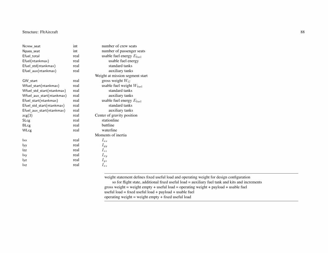
Structure: FltAircraft 88
Ncrew_seat int number of crew seatsNpass_seat int number of passenger seatsEfuel_total real usable fuel energy Efuel
Efuel(ntankmax) real usable fuel energyEfuel_std(ntankmax) real standard tanksEfuel_aux(ntankmax) real auxiliary tanks
Weight at mission segment startGW_start real gross weight WG
Wfuel_start(ntankmax) real usable fuel weight Wfuel
Wfuel_std_start(ntankmax) real standard tanksWfuel_aux_start(ntankmax) real auxiliary tanksEfuel_start(ntankmax) real usable fuel energy Efuel
Efuel_std_start(ntankmax) real standard tanksEfuel_aux_start(ntankmax) real auxiliary tankszcg(3) real Center of gravity positionSLcg real stationlineBLcg real buttlineWLcg real waterline
Moments of inertiaIxx real Ixx
Iyy real Iyy
Izz real Izz
Ixy real Ixy
Iyz real Iyz
Ixz real Ixz
weight statement defines fixed useful load and operating weight for design configurationso for flight state, additional fixed useful load = auxiliary fuel tank and kits and increments
gross weight = weight empty + useful load = operating weight + payload + usable fueluseful load = fixed useful load + payload + usable fueloperating weight = weight empty + fixed useful load

Structure: FltAircraft 89
Atmospherealt real altitude htmp real temperature τdtmp real temperature increment ΔTsigma real density ratio ρ/ρ0
theta real temperature ratio T/T0
delta real pressure ratio p/p0
kinvis real kinematic viscosity ν = μ/ρaltdens real density altitude hd
altpress real pressure altitude hp
Flight conditionradius(nrotormax) real rotor radius R
rotational speedsVtip_trim(nrotormax) real rotor tip speed ΩRrpm_trim(nrotormax) real rotor rpm ΩrN_trim_rotor(nrotormax) real rotor Ω/Ωref
N_trim(nengmax) real engine rpm NrN_trim_eng(nengmax) real engine N/Nspec
rN_trim_ref(npropmax) real propulsion group reference speed ratioflight speed
speed real horizontal speed Vh (knots)Vclimb real climb velocity Vc (ft/sec or m/sec)side_trim real sideslip angle ψV (deg)
derivedVhoriz real horizontal velocity Vh (ft/sec or m/sec)Mhoriz real horizontal Mach number Vh/cs
climb_trim real climb angle θV (deg)Vside real sideward velocity Vs (ft/sec or m/sec)Vmag real velocity magnitude |V |Vfwd real forward velocity Vf (ft/sec or m/sec)VCAS real calibrated airspeed Vcal (knots) (V
√σf(δ, M))
VAC(3) real velocity vAC in F axesed(3) real drag vector, −vAC/|vAC | in F axesqAC real dynamic pressure qAC

Structure: FltAircraft 90
angular velocityturn_trim real turn ψF (yaw rate)pullup_trim real pullup θF (pitch rate)turnRadius real turn radius RT
wAC(3) real ωAC in F axesacceleration
aAC(3) real aAC in F axes (linear)nAC(3) real load factor nAC (linear acc and angular rate)KIND_alpha int angle of attack and sideslip angle representation (1 conventional, 2 reversed)
orientation of body axes relative inertial axespitch_trim real pitch angle θF (deg)roll_trim real roll angle φF (deg)
rotation matricesCFI(3,3) real CFI , velocity axes relative inertial axesCVI(3,3) real CV I , body axes relative inertial axesCFV(3,3) real CFV , body axes relative velocity axescontrol_trim(ncontmax) real aircraft controlsNauxtank(nauxtankmax,ntankmax)
int number of auxiliary fuel tanks Nauxtank (each aux tank size), from FltCond or MissSeg
SET_extkit(nwingmax) int wing extension kit on aircraft (0 none, 1 present)SET_wingkit(nwingmax) int wing kit on aircraft (0 none, 1 present)Wfuel_cap(ntankmax) real total fuel capacity Wfuel−cap, including auxiliary tanksEfuel_cap(ntankmax) real total fuel capacity Efuel−cap, including auxiliary tanksslope_ground real slope of ground γG (+uphill; deg), from MissSeg
SET_sweep int parameter sweep, from FltCond
angle of attack and sideslip angle representation: from Aircraft and isSideward
orientation body relative inertial axes defined by Euler angles, with yaw/pitch/roll sequence (ψF , θF , φF )yaw positive to right, pitch positive nose up, roll positive to rightCFI = XrollYpitchZyaw, yaw angle = (turn)*time
orientation velocity relative inertial axes defined by climb and sideslip angles (θV , ψV )sideslip positive aircraft moving to right, climb positive aircraft moving upCV I = YclimbZsideZyaw

Structure: FltAircraft 91
orientation body relative velocity axes: CFV = XrollYpitchZ−sideY−climb
Trim (last)istrimconv int converged (0 not)count_trim int number of iterationserror_trim(mtrimmax) real error ratiogain_trim(mtrimmax,mtrimmax)
real gain matrixMaximum effort (principal iteration, 99% range iteration; inner, outer loops)
isflyconv(2,2) int converged (0 not)count_fly(2,2) int number of iterationserror_fly(2,2) real error ratioisSwitched(2) int quantity switched (1 P margin, 2 Q margin, 3 both)
Maximum gross weight (flight condition or mission takeoff)ismaxgwconv int converged (0 not)count_maxgw int number of iterationserror_maxgw real error ratio
Rotor flap equation (all converged or any not converged)isrotorconv int converged (0 not, –1 no iteration)
Solution statecount_control int count of solution (0 at start, get aircraft controls)trim_deriv_exist int trim derivative matrix exist (0 for not)
Loadsforces (F axes, about cg)
Faero(3) real aerodynamic FFaero (fuselage, rotor, wing, tail, tank, engine, jet, charger)
Frotor(3) real rotor FFrotor
Fengine(3) real engine groups FFeng (jet thrust, momentum drag)
Fjet(3) real jet groups FFjet
Fchrg(3) real charge groups FFcharge
Fgrav(3) real gravitational FFgrav
Finertia(3) real inertial FFinertial (turn)
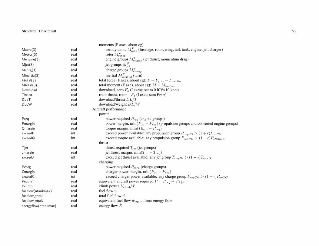
Structure: FltAircraft 92
moments (F axes, about cg)Maero(3) real aerodynamic MF
aero (fuselage, rotor, wing, tail, tank, engine, jet, charger)Mrotor(3) real rotor MF
rotor
Mengine(3) real engine groups MFengine (jet thrust, momentum drag)
Mjet(3) real jet groups MFjet
Mchrg(3) real charge groups MFcharge
Minertia(3) real inertial MFinertial (turn)
Ftotal(3) real total force (F axes, about cg); F + Fgrav − Finertia
Mtotal(3) real total moment (F axes, about cg); M − Minertia
Download real download, aero Fz (I axes); set to 0 if V>10 knotsThrust real rotor thrust, rotor −Fz (I axes; sum Fvert)DLoT real download/thrust DL/TDLoW real download/weight DL/W
Aircraft performancepower
Preq real power required Preq (engine groups)Pmargin real power margin, min(Pav − Preq) (propulsion groups and converted engine groups)Qmargin real torque margin, min(Plimit − Preq)exceedP int exceed power available: any propulsion group PreqPG > (1 + ε)PavPG
exceedQ int exceed torque available: any propulsion group PreqPG > (1 + ε)PDSlimit
thrustTjet real thrust required Tjet (jet groups)Jmargin real jet thrust margin, min(Tav − Treq)exceedJ int exceed jet thrust available: any jet group TreqJG > (1 + ε)TavJG
chargingPchrg real power required Pchrg (charge groups)Cmargin real charger power margin, min(Pav − Preq)exceedC int exceed charger power available: any charge group PreqCG > (1 + ε)PavCG
Pequiv real equivalent aircraft power required P = Preq + V Tjet
Pclimb real climb power, VclimbWfuelflow(ntankmax) real fuel flow wfuelflow_total real total fuel flow wfuelflow_equiv real equivalent fuel flow wequiv, from energy flowenergyflow(ntankmax) real energy flow E

Structure: FltAircraft 93
energyflow_total real total energy flow EexceedWf int exceed fuel capacity: Wfuel > (1 + ε)Wfuel−cap or Efuel > (1 + ε)Efuel−cap
batteryBmargin real battery power margin, min(Pmax − |Ebatt|) (MJ/hr)exceedB int exceed battery power: any fuel tank |Ebatt| > (1 + ε)Pmax
sfc real sfc, Pequiv/wequiv
spec_range real specific range, V/wequiv
Performance indicesFM real aircraft figure of merit FM = W
√W/(2ρAref)/P
LoDe real aircraft effective lift-to-drag ratio L/De = WV/PDrage real aircraft effective drag De = P/VDragAC real aircraft drag DAC
DoQAC real aircraft drag area D/q = DAC/qAC ; set to 0 if V<10 knotsWoP real power loading W/Prange_onepcW real range for fuel=1%GW (nm)fuel_eff real fuel efficiency e = WpayV/wequiv (ton-nm/lb or ton-nm/kg)productivity real productivity p = WpayV/WO (ton-kt/lb or ton-kt/kg)
Operating sizelength_op real lengthwidth_op real widtharea_op real area

94
Chapter 21
Structure: FltFuse
Variable Type Description Default
Flight State - Fuselageaerodynamics
VintR(3,nrotormax) real interference velocity vFint, from rotors (F axes)
Vaero(3) real total velocity relative air vF (F axes)VB(3) real total velocity relative air vB (B axes)alpha real angle of attack α (deg)beta real sideslip angle β (deg)CBA(3,3) real CBA
Vmag real velocity magnitudeq real dynamic pressureDoQ_pay real payload D/qDoQ_cont real contingency D/qCL real lift coefficient CL
CM real pitch moment coefficient CM
CD real drag coefficient CD
CY real side force coefficient CY
CN real yaw moment coefficient CN
L real liftM real pitch momentD real dragY real side forceN real yaw moment
loadsFaero(3) real aerodynamic force FF
aero (F axes, about cg)Maero(3) real aerodynamic moment MF
aero (F axes, about cg)Drag real drag eT
d FFaero
Download real download, aero Fz (I axes)

95
Chapter 22
Structure: FltGear
Variable Type Description Default
Flight State - Landing Gearaerodynamics
iSTATE_LG int landing gear state (STATE_LG_extended, retracted)Vaero(3) real total velocity relative air vF (F axes)Vmag real velocity magnitudeq real dynamic pressureed(3) real drag vector, −v/|v| in F axesFaero(3) real aerodynamic force FF
aero (F axes, about cg)Maero(3) real aerodynamic moment MF
aero (F axes, about cg)Drag real drag eT
d FFaero
Download real download, aero Fz (I axes)

96
Chapter 23
Structure: FltRotor
Variable Type Description Default
Flight State - Rotorcontrol mode
KIND_control_coll int collective control mode (1 thrust command, 2 pitch command)KIND_control_cyc int cyclic control mode (1 TPP command, 2 NFP command)Scoll real collective T matrix scale factor S (1, a/6, ρV 2
tipAbladea/6)Scyc real cyclic T matrix scale factor S (–1 TPP command, 1 NFP command)
controlscoll real collectivelngcyc real longitudinal cycliclatcyc real lateral cyclicincid real incidencecant real cantdiam real diameterfgear real gear ratio factor
geometryCcont(3,3) real shaft control, Ccont
CSF(3,3) real shaft relative airframe, CSF
zhub(3) real hub position, zhub
zpylon(3) real pylon position, zpylon
znac(3) real nacelle cg position, znac
CBF(3,3) real pylon relative airframe, CBF
conditionradius real radius RVtip real tip speed Vtip = ΩROmega real rotational speed ΩMtip real tip Mach number Mtip
Mat real maximum Mach number Mat (advancing tip or helical)sigma real solidity σ (thrust weighted)

Structure: FltRotor 97
gamma real Lock number γIblade real blade moment of inertia Iblade
flapfreq real flap frequency νconefreq real coning frequency νKhub real hub stiffness Khub
performanceshaft axis loads
T real thrustH real drag forceY real side forceMx real roll momentMy real pitch momentQ real torqueCT real thrust coefficient CT
CH real drag force coefficient CH
CY real side force coefficient CY
CMx real roll moment coefficient CMx
CMy real pitch moment coefficient CMy
CQ real torque coefficient CQ
control and motiontheta75 real collective pitch θ0.75 (0.75R)thetas real longitudinal cyclic pitch θs
thetac real lateral cyclic pitch θc
beta0 real coning β0
betac real longitudinal flapping βc
betas real lateral flapping βs
lambda0 real inflow λ0 = κλi
CPS(3,3) real tip-path plane relative shaft, CPS
velocity and inflowVoVtip real V/Vtip
VF(3) real total velocity relative air vF (F axes)VS(3) real total velocity relative air vS (S axes)mux real μx
muy real μy

Structure: FltRotor 98
muz real μz
omegaS(3) real angular velocity ωS (S axes)dax real αx
day real αy
mu real μ =√
μ2x + μ2
y
alphas real α = tan−1(μz/μ)fDuctA real ducted fan area ratio fA
fDuctT real ducted fan thrust ratio fT
fDuctW real ducted fan far wake ratio fW
zg real height rotor hub above ground, zg/Dzge real effective height, zgCg/(D cos ε)fg real ground effect inflow ratio fg
CTe real CT for inflow solutionlambdah real reference λh =
√CT /2
lambda_ideal real ideal induced velocity λi
CPideal real ideal induced power CP ideal = CT λi
kappax real inflow gradient κx
kappay real inflow gradient κy
kappam real inflow gradient κm = (σa/8)fm/UCTs real thrust coefficient/solidity, |CT /σ|FPpro real profile power factor FP
FHpro real profile drag factor FH
VintWn(3,nwingmax) real interference velocity vFint from wings, normal (F axes)
VintWp(3,nwingmax) real interference velocity vFint from wings, inplane (F axes)
inplane forcesCHtpp real drag force CH , tppCYtpp real side force CY , tppCHo real drag force CH , profileCYo real side force CY , profile
rotor flap equationsisrotorconv int converged (0 not, –1 no iteration)count_rotor int iteration counterror_rotor(3) real error ratio (Et, Ec, Es)rotor_deriv_exist int rotor derivative matrix exist (0 for not)
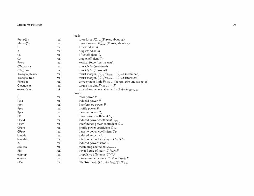
Structure: FltRotor 99
loadsFrotor(3) real rotor force FF
rotor (F axes, about cg)Mrotor(3) real rotor moment MF
rotor (F axes, about cg)L real lift (wind axis)X real drag (wind axis)CL real lift coefficient CL
CX real drag coefficient CX
Fvert real vertical force (inertia axes)CTs_steady real max CT /σ (sustained)CTs_tran real max CT /σ (transient)Tmargin_steady real thrust margin, (CT /σ)max − CT /σ (sustained)Tmargin_tran real thrust margin, (CT /σ)max − CT /σ (transient)Plimit_rs real drive system limit PRSlimit (at rpm_trim and rating_ds)Qmargin_rs real torque margin, PRSlimit − PexceedQ_rs int exceed torque available: P > (1 + ε)PRSlimit
powerP real rotor power PPind real induced power Pi
Pint real interference power Pt
Ppro real profile power Po
Ppar real parasite power Pp
CP real rotor power coefficient CP
CPind real induced power coefficient CPi
CPint real interference power coefficient CPt
CPpro real profile power coefficient CPo
CPpar real parasite power coefficient CPp
lambda real induced velocity λlambdat real interference velocity λt = CPt/CF
Ki real induced power factor κcdmean real mean drag coefficient cdmean
FM real hover figure of merit, TfDv/Petaprop real propulsive efficiency, TV/Petamom real momentum efficiency, T (V + fDv)/PCDe real effective drag, (CPi + CPo)/(V/Vtip)

Structure: FltRotor 100
LoDe real effective lift-to-drag, CL/CDe
shaft power and reaction drivePshaft real shaft power Pshaft
Preact real reaction drive power Preact
Freact real reaction drive net force Freact = Preact/Ωrreact
rOmegareact real blade velocity Ωrreact
aerodynamicshub
Vaero_hub(3) real total velocity relative air vF (F axes)Vmag_hub real velocity magnitudeq_hub real dynamic pressureed_hub(3) real drag vector, −v/|v| in F axesVB_hub(3) real total velocity relative air vB (B axes)alpha_hub real angle of attack α (deg)
pylonVaero_pylon(3) real total velocity relative air vF (F axes)Vmag_pylon real velocity magnitudeq_pylon real dynamic pressureed_pylon(3) real drag vector, −v/|v| in F axesVB_pylon(3) real total velocity relative air vB (B axes)alpha_pylon real angle of attack α (deg)CDhub real drag coefficient, hub CDhub
CDpylon real drag coefficient, pylon CDpylon
CDduct real drag coefficient, duct CDduct
Dhub real drag, hub Dhub
Dpylon real drag, pylon Dpylon
Dduct real drag, duct Dduct
Dspin real drag, spinner Dspin
loadsFaero(3) real aerodynamic force FF
aero (F axes, about cg)Maero(3) real aerodynamic moment MF
aero (F axes, about cg)Drag real drag eT
d FFaero
Download real download, aero Fz (I axes)

Structure: FltRotor 101
interferencelambda_int real ideal induced velocity λi (from CT )vind(3) real induced velocity vF
ind (F axes)chi_wake real wake angle χFint_fus real interference factor fW fzfrft at fuselageFint_wingLp(nwingmax,npanelmax)
real interference factor fW fzfrft at wing, left panelFint_wingRp(nwingmax,npanelmax)
real interference factor fW fzfrft at wing, right panelFint_tail(ntailmax) real interference factor fW fzfrft at tailisInWake_fus int fuselage inside wakeisInWake_wingLp(nwingmax,npanelmax)
int wing inside wake, left panelisInWake_wingRp(nwingmax,npanelmax)
int wing inside wake, right panelisInWake_tail(ntailmax) int tail inside wakeftwin real twin rotor factor ft
Aint_wing(nwingmax) real induced power interference at wing αint

102
Chapter 24
Structure: FltWing
Variable Type Description Default
Flight State - Wingcontrols
flap(npanelmax) real flap δF
flaperon(npanelmax) real flaperon δf
aileron(npanelmax) real aileron δa
incid(npanelmax) real incidence i
aerodynamicsVintR_Lp(3,nrotormax,npanelmax)
real interference velocity vFint at left wing panel, from rotors (F axes)
VintR_Rp(3,nrotormax,npanelmax)
real interference velocity vFint at right wing panel, from rotors (F axes)
VintR(3,nrotormax) real interference velocity vFint (panel area weighted), from rotors (F axes)
VintW(3,nwingmax) real interference velocity vFint, from other wings (F axes)
AintW(nwingmax) real interference angle αint, from other wingsAintR(nrotormax) real induced power interference αint, from rotors
with mean interferenceVaero(3) real total velocity relative air vF (F axes)VB(3) real total velocity relative air vB (B axes)alpha real angle of attack α (deg)beta real sideslip angle β (deg)CBA(3,3) real CBA
Vmag real velocity magnitudeq real dynamic pressurealpha_int real angle of attack α, with interference (deg)CDV real vertical drag coefficient CDV

Structure: FltWing 103
left panelVaero_Lp(3,npanelmax) real total velocity relative air vF (F axes)VB_Lp(3,npanelmax) real total velocity relative air vB (B axes)alpha_Lp(npanelmax) real angle of attack α (deg)beta_Lp(npanelmax) real sideslip angle β (deg)CBA_Lp(3,3,npanelmax) real CBA
Vmag_Lp(npanelmax) real velocity magnitudeq_Lp(npanelmax) real dynamic pressureCL_Lp(npanelmax) real lift coefficient CLp
CDp_Lp(npanelmax) real drag coefficient, parasite CDpp
CM_Lp(npanelmax) real pitch moment coefficient CMp
CR_Lp(npanelmax) real roll moment coefficient C�p
L_Lp(npanelmax) real liftDp_Lp(npanelmax) real drag, parasiteM_Lp(npanelmax) real pitch momentR_Lp(npanelmax) real roll moment
right panelVaero_Rp(3,npanelmax) real total velocity relative air vF (F axes)VB_Rp(3,npanelmax) real total velocity relative air vB (B axes)alpha_Rp(npanelmax) real angle of attack α (deg)beta_Rp(npanelmax) real sideslip angle β (deg)CBA_Rp(3,3,npanelmax) real CBA
Vmag_Rp(npanelmax) real velocity magnitudeq_Rp(npanelmax) real dynamic pressureCL_Rp(npanelmax) real lift coefficient CLp
CDp_Rp(npanelmax) real drag coefficient, parasite CDpp
CM_Rp(npanelmax) real pitch moment coefficient CMp
CR_Rp(npanelmax) real roll moment coefficient C�p
L_Rp(npanelmax) real liftDp_Rp(npanelmax) real drag, parasiteM_Rp(npanelmax) real pitch momentR_Rp(npanelmax) real roll momentqS real qS (sum over panels)qeff real (qS)/S (weighted by panel area)

Structure: FltWing 104
dCLda3D real compressible 3D lift curve slope CLα
AoA_max real αmax
CL real lift coefficient CL
CDp real drag coefficient, parasite CDp
CDi real drag coefficient, induced CDi
CM real pitch moment coefficient CM
CR real roll moment coefficient C�
CLmax real maximum lift coefficient CLmax
L real liftDp real drag, parasiteDi real drag, inducedD real dragM real pitch momentR real roll momentLmargin real stall margin, CLmax − CL
loadsFaero(3) real aerodynamic force FF
aero (F axes, about cg)Maero(3) real aerodynamic moment MF
aero (F axes, about cg)Drag real drag eT
d FFaero
Download real download, aero Fz (I axes)
interferenceVint_tail(3,ntailmax) real velocity at tail vF
int (F axes)vind(3) real induced velocity vF
ind (F axes)Vint_wing(3,nwingmax) real velocity at other wing vF
int (F axes)Aint_wing(nwingmax) real angle at other wing (αint = vint/vB = Kintvind/vB)Vintn_rotor(3,nrotormax) real velocity at rotor vF
int, normal (F axes)Vintp_rotor(3,nrotormax) real velocity at rotor vF
int, inplane (F axes)

105
Chapter 25
Structure: FltTail
Variable Type Description Default
Flight State - Tailcontrols
cont real control δincid real incidence i
aerodynamicsVintR(3,nrotormax) real interference velocity vF
int, from rotors (F axes)VintW(3,nwingmax) real interference velocity vF
int, from wings (W axes)Vaero(3) real total velocity relative air vF (F axes)VB(3) real total velocity relative air vB (B axes)alpha real angle of attack α (deg)beta real sideslip angle β (deg)CBA(3,3) real CBA
Vmag real velocity magnitudeq real dynamic pressuredCLda3D real compressible 3D lift curve slope CLα
AoA_max real αmax
CL real lift coefficient CL
CDp real drag coefficient, parasite CDp
CDi real drag coefficient, induced CDi
CLmax real maximum lift coefficient CLmax
L real liftD real drag
loadsFaero(3) real aerodynamic force FF
aero (F axes, about cg)Maero(3) real aerodynamic moment MF
aero (F axes, about cg)Drag real drag eT
d FFaero
Download real download, aero Fz (I axes)

106
Chapter 26
Structure: FltTank
Variable Type Description Default
Flight State - Fuel Tank Systemsall tanks (standard plus auxiliary)
Wfuel real usable fuel weightEfuel real usable fuel energyWfuel_cap real fuel weight capacityEfuel_cap real fuel energy capacityrWfuel real fraction weight capacityrEfuel real fraction energy capacity = state-of-charge = 1 - depth-of-discharge
battery (E > 0 discharge, E < 0 charge; power and current positive)Pfuel_cap real power capacity Pcap = xmbdEfuel−cap (MJ/hr)state int state (1 discharging, -1 CC charge, -2 CV charge)x real current x (1/hr)xi real current ξ = x/xmbd
V real voltage VEdotcomp real component energy flow Ecomp (MJ/hr)etabatt real battery efficiency ηbatt
Ploss real power loss Ploss (MJ/hr)Edotbatt real battery energy flow Ebatt (MJ/hr)dcrit real effective capacity factor dcrit
Edoteff real effective energy flow Eeff (MJ/hr)xmax real maximum current xmax (1/hr)Pmax real maximum power (for xmax) (MJ/hr)Bmargin real battery power margin Pmax − |Ebatt| (MJ/hr)exceedB int exceed battery power: |Ebatt| > (1 + ε)Pmax
equipment powerPeq real power loss Peq
fuelflow real fuel flow w

Structure: FltTank 107
energyflow real energy flow Efuelflow_equiv real equivalent fuel flow wequiv, from energy flow
auxiliary tanksaerodynamics
Vaero(3,nauxtankmax) real total velocity relative air vF (F axes)Vmag(nauxtankmax) real velocity magnitudeq(nauxtankmax) real dynamic pressureed(3,nauxtankmax) real drag vector, −v/|v| in F axesD(nauxtankmax) real drag DDL(nauxtankmax) real download, aero Fz (I axes)
loadsFaero(3) real aerodynamic force FF
aero (F axes, about cg)Maero(3) real aerodynamic moment MF
aero (F axes, about cg)Drag real drag eT
d FFaero
Download real download, aero Fz (I axes)

108
Chapter 27
Structure: FltProp
Variable Type Description Default
Flight State - Propulsion GroupSTATE_gear int drive system state
controlDN_trim real rotational speed increment, primary rotor or primary engine (rpm)
powerPcomp real power required Pcomp, all componentsPcomp_rotor real rotorPcomp_eng real engine groupsPxmsn real transmission losses Pxmsn
Pacc real accessory power Pacc
PreqPG real power required PreqPG = Pcomp + Pxmsn + Pacc, propulsion groupPavPG real power available PavPG, propulsion group (sum all engine groups producing shaft power)PavEIsum real engine installed power available PavEI (sum all engine groups producing shaft power)PavEGsum real engine group power available PavEG (sum all engine groups producing shaft power)Pratio real PreqPG/PavPG, propulsion groupPlimit_ds real drive system limit PDSlimit (at rpm_trim(primary) and rating_ds)atPlimit_ds int at drive system limit (PavPG limited by PDSlimit)Qmargin_ds real torque margin, PDSlimit − PreqPG
Pmargin real power margin, PavPG − PreqPG
exceedP int exceed power available: PreqPG > (1 + ε)PavPG
exceedQ_ds int exceed torque available: PreqPG > (1 + ε)PDSlimit
Qmargin real torque margin, min(propulsion group, engine groups, rotors)exceedQ int exceed torque available: any propulsion group, engine groups, rotors
propulsion group enginesfuelflow(ntankmax) real fuel flow wfuelflow_total real total fuel flow wfuelflow_equiv real equivalent fuel flow wequiv, from energy flowenergyflow(ntankmax) real energy flow E

Structure: FltProp 109
energyflow_total real total energy flow Esfc real specific fuel consumption sfc = wequiv/Preq
Fprop(3) real jet thrust and momentum drag force FFprop (F axes, about cg)
Mprop(3) real jet thrust and momentum drag moment MFprop (F axes, about cg)
Faero(3) real aerodynamic force FFaero (F axes, about cg)
Maero(3) real aerodynamic moment MFaero (F axes, about cg)
Drag real drag eTd FF
aero
Download real download, aero Fz (I axes)

110
Chapter 28
Structure: FltEngn
Variable Type Description Default
Flight State - Engine Groupcontrols
amp real amplitude Amode real mode Bincid real incidence iyaw real yaw ψfgear real gear ratio factor fgear
geometryCBF(3,3) real engine relative airframe, CBF
ef(3) real engine direction, ef
enginePq real uninstalled power required, Pq
Plossq real installation loss Ploss
etalossq real installation efficiency ηloss
Preq_eng real installed power required, Preq−eng
N_trim real engine rpm Nmdot real mass flow mwdot real fuel flow wEdot real energy flow EFG real gross installed jet thrust FG
Fmom real momentum thrust Fmom
FN real net installed jet thrust FN
Daux real momentum drag of auxiliary air flow Daux
Pa real uninstalled power available, Pa
Plossa real installation loss Ploss
etalossa real installation efficiency ηloss
Pav_eng real installed power available, Pav−eng

Structure: FltEngn 111
Pmech real engine mechanical limit Pmech (at N_trim)atPmech int at mechanical limit (Pav−eng limited by Pmech)etamotor real motor/generator efficiency ηmotor
etacell real fuel cell efficiency ηcell
engine groupReactionMode int reaction drive mode (MODEL_engine_compreact or converted)Converted int converted (KIND=RPTEM with mode=1; 0 shaft power, 1 reaction, 2 jet)ProducePower int shaft power (0 consumed (generator or compressor), 1 produced)Pcomp real component power Pcomp (generator or compressor); (Nengine–NEngInOp)PqKffd
Preq real power required PreqEG
PavEI real engine installed power available PavEI ; (Nengine–NEngInOp)Pav−eng
Pav real power available, PavEG; fPower(Nengine–NEngInOp)Pav−eng
Qreq real torque required Qreq (at N_trim)Pratio real PreqEG/PavEG
Pmargin real power margin, PavEG − PreqEG
Plimit_es real drive system limit PESlimit (at N_trim and rating_ds)atPlimit_es int at drive system limit (PavEG limited by PESlimit)Qmargin_es real torque margin, PESlimit − PreqEG
exceedQ_es int exceed torque available: PreqEG > (1 + ε)PESlimit
fuelflow real fuel flow w (negative if generated)energyflow real energy flow E (negative if generated)fuelflow_equiv real equivalent fuel flow wequiv, from energy flowsfc real specific fuel consumption sfc = wequiv/Preq
FNEG real net installed jet thrust FN
DauxEG real momentum drag of auxiliary air flow Daux
Fjet(3) real jet thrust force FFjet (F axes, about cg)
Mjet(3) real jet thrust moment MFjet (F axes, about cg)
Faux(3) real momentum drag force FFaux (F axes, about cg)
Maux(3) real momentum drag moment MFaux (F axes, about cg)
aerodynamicsVaero(3) real total velocity relative air vF (F axes)Vmag real velocity magnitudeq real dynamic pressureed(3) real drag vector, −v/|v| in F axes

Structure: FltEngn 112
VB(3) real total velocity relative air vB (B axes)alpha real angle of attack α (deg)CD real drag coefficient CD
D real dragload
Faero(3) real aerodynamic force FFaero (F axes, about cg)
Maero(3) real aerodynamic moment MFaero (F axes, about cg)
Drag real drag eTd FF
aero
Download real download, aero Fz (I axes)

113
Chapter 29
Structure: FltJet
Variable Type Description Default
Flight State - Jet Groupcontrols
amp real amplitude Amode real mode Bincid real incidence iyaw real yaw ψ
geometryCBF(3,3) real jet relative airframe, CBF
ef(3) real jet direction, ef
jetTq real uninstalled thrust required, Tq
Tlossq real installation loss Tloss
etalossq real installation efficiency ηloss
Treq_jet real installed thrust required, Treq−jet
mdot real mass flow mwdot real fuel flow wEdot real energy flow EFG real gross installed jet thrust FG
Fmom real momentum thrust Fmom
FN real net installed jet thrust FN
Daux real momentum drag of auxiliary air flow Daux
Ta real uninstalled thrust available, Ta
Tlossa real installation loss Tloss
etalossa real installation efficiency ηloss
Tav_jet real installed thrust available, Tav−jet
Tmech real jet mechanical limit Tmech
atTmech int at mechanical limit (Tav−jet limited by Tmech)

Structure: FltJet 114
jet groupReactionMode int reaction drive mode (MODEL_jet_react or converted)Converted int converted (RPJEM with mode=1; 0 jet, 1 reaction)Treq real thrust required TreqJG
TavJI real jet installed thrust available TavJI ; (Njet–NJetInOp)Tav−jet
Tav real thrust available, TavJG; fThrust(Njet–NJetInOp)Tav−jet
Jratio real TreqJG/TavJG
Jmargin real thrust margin, TavJG − TreqJG
exceedJ int exceed thrust available: TreqJG > (1 + ε)TavJG
fuelflow real fuel flow w (negative if generated)energyflow real energy flow E (negative if generated)fuelflow_equiv real equivalent fuel flow wequiv, from energy flowsfc real specific fuel consumption sfc = wequiv/Treq
FNJG real net installed jet thrust FN
DauxJG real momentum drag of auxiliary air flow Daux
Fjet(3) real jet thrust force FFjet (F axes, about cg)
Mjet(3) real jet thrust moment MFjet (F axes, about cg)
Faux(3) real momentum drag force FFaux (F axes, about cg)
Maux(3) real momentum drag moment MFaux (F axes, about cg)
loadsF(3) real force FF
jet (F axes)M(3) real moment MF
jet (F axes)
aerodynamicsVaero(3) real total velocity relative air vF (F axes)Vmag real velocity magnitudeq real dynamic pressureed(3) real drag vector, −v/|v| in F axesVB(3) real total velocity relative air vB (B axes)alpha real angle of attack α (deg)CD real drag coefficient CD
D real dragload
Faero(3) real aerodynamic force FFaero (F axes, about cg)
Maero(3) real aerodynamic moment MFaero (F axes, about cg)

Structure: FltJet 115
Drag real drag eTd FF
aero
Download real download, aero Fz (I axes)

116
Chapter 30
Structure: FltChrg
Variable Type Description Default
Flight State - Charge Groupcontrols
amp real amplitude Amode real mode Bincid real incidence iyaw real yaw ψ
geometryCBF(3,3) real charger relative airframe, CBF
ef(3) real charger direction, ef
chargerPacell real cell power available Eacell = P0
Edotacell real cell energy flow available Eacell = P0
Edotqcell real cell energy flow required Eqcell = Ereq/ηchrg
Pqcell real cell power required Eqcell = Ereq/ηchrg
etachrg real charger efficiency ηchrg
Preq real installed power required Ereq = EreqCGKffd/(Ncharge–NChrgInOp)charger, fuel cell
mdot_burn real mass flow mwdot_burn real fuel flow wFG real gross installed jet thrust FG
Fmom real momentum thrust Fmom
FN real net installed jet thrust FN
Daux real momentum drag of auxiliary air flow Daux
charge groupPchrg real power required PreqCG = EreqCG
Edotchrg real energy flow required PreqCG = EreqCG
Preqtotal real total cell power required Preqtotal; (Ncharge–NChrgInOp)Eqcell

Structure: FltChrg 117
Pavtotal real total cell power available Pavtotal; fCharge(Ncharge–NChrgInOp)Eacell
Cratio real Preqtotal/Pavtotal
Cmargin real power margin, Pavtotal − Preqtotal
exceedC int exceed power available: Preqtotal > (1 + ε)Pavtotal
energyflow real energy flow E (negative if generated)fuelflow_equiv real equivalent fuel flow wequiv, from energy flow
charge group, fuel cellfuel burn
fuelflow_burn real fuel flow wenergyflow_burn real energy flow Efuelflow_equiv_burn real equivalent fuel flow wequiv, from energy flowsfc real specific fuel consumption sfc = wequiv/Preq
FNCG real net installed jet thrust FN
DauxCG real momentum drag of auxiliary air flow Daux
Fjet(3) real jet thrust force FFjet (F axes, about cg)
Mjet(3) real jet thrust moment MFjet (F axes, about cg)
Faux(3) real momentum drag force FFaux (F axes, about cg)
Maux(3) real momentum drag moment MFaux (F axes, about cg)
loadsF(3) real force FF
chrg (F axes)M(3) real moment MF
chrg (F axes)
aerodynamicsVaero(3) real total velocity relative air vF (F axes)Vmag real velocity magnitudeq real dynamic pressureed(3) real drag vector, −v/|v| in F axesVB(3) real total velocity relative air vB (B axes)alpha real angle of attack α (deg)CD real drag coefficient CD
D real dragload
Faero(3) real aerodynamic force FFaero (F axes, about cg)
Maero(3) real aerodynamic moment MFaero (F axes, about cg)
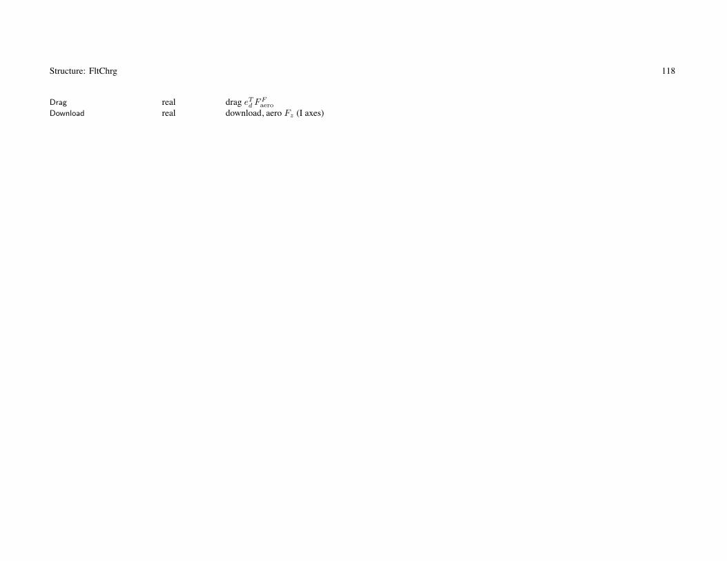
Structure: FltChrg 118
Drag real drag eTd FF
aero
Download real download, aero Fz (I axes)

119
Chapter 31
Structure: Solution
Variable Type Description Default
+ Solution Procedurestitle c*100 + titlenotes c*1000 + notes
+ Rotor+ convergence control
niter_rotor(nrotormax) int + maximum number of iterations 40
toler_rotor(nrotormax) real + tolerance (deg) .01
relax_rotor(nrotormax) real + relaxation factor .5
deriv_rotor(nrotormax) int + derivative (1 first order, 2 second order) 1
maxinc_rotor(nrotormax) real + maximum increment amplitude (0. for no limit) 4.
trace_rotor(nrotormax) int + trace iteration (0 for none) 0
+ Trim+ convergence control
niter_trim int + maximum number of iterations 40
toler_trim real + tolerance (fraction reference) .001
relax_trim real + relaxation factor .5
+ perturbation identification of derivative matrixderiv_trim int + perturbation (1 first order, 2 second order) 1
mpid_trim int + number of iterations between identification (0 for never recalculated) 0
perturb_trim real + variable perturbation amplitude (fraction reference) .002
init_trim int + reinitialize aircraft controls (0 no, 1 force retrim) 0
trace_trim int + trace iteration (0 for none, 2 for component controls) 0
+ Maximum effortmethod_fly int + method (1 secant, 2 false position) 1
method_flymax int + maximization method (1 secant, 2 false position, 3 golden section search, 4 curve fit) 3

Structure: Solution 120
+ convergence controlniter_fly int + maximum number of iterations 80
toler_fly real + tolerance (fraction reference) .002
relax_fly real + relaxation factor .5
perturb_fly real + variable perturbation amplitude (fraction reference) .05
maxderiv_fly real + maximum derivative amplitude (0. for no limit) 0.
maxinc_fly real + maximum increment fraction (0. for no limit) 0.
rfit_fly real + extent of curve fit (fraction maximum) .98
nfit_fly int + order of curve fit (2 quadradic, 3 cubic) 3
init_fly int + reinitialize aircraft controls (0 no, 1 force retrim) 0
trace_fly int + trace iteration (0 for none) 0
+ Maximum gross weight (flight condition or mission takeoff)method_maxgw int + method (1 secant, 2 false position) 1
+ convergence controlniter_maxgw int + maximum number of iterations 40
toler_maxgw real + tolerance (fraction reference) .002
relax_maxgw real + relaxation factor .5
perturb_maxgw real + variable perturbation amplitude (fraction reference) .02
maxderiv_maxgw real + maximum derivative amplitude (0. for no limit) 0.
maxinc_maxgw real + maximum increment fraction (0. for no limit) 0.
trace_maxgw int + trace iteration (0 for none) 0
+ Mission+ convergence control
niter_miss int + maximum number of iterations 40
toler_miss real + tolerance (fraction reference) .01
relax_miss real + relaxation factor (mission fuel) 1.
relax_range real + relaxation factor (range credit) 1.
relax_gw real + relaxation factor (max takeoff GW) 1.
trace_miss int + trace iteration (0 for none) 0
+ Size aircraft+ convergence control
niter_size int + maximum number of iterations (performance loop) 40
niter_param int + maximum number of iterations (parameter loop) 40

Structure: Solution 121
toler_size real + tolerance (fraction reference) .01
+ relaxation factorsrelax_size real + power or radius 1.
relax_DGW real + gross weight 1.
relax_xmsn real + drive system limit 1.
relax_wmto real + WMTO and SDGW 1.
relax_tank real + fuel tank capacity 1.
relax_thrust real + rotor thrust 1.
+ maximum increment fraction (0. for no limit)maxinc_size real + power or radius 0.
maxinc_DGW real + gross weight 0.
maxinc_xmsn real + drive system limit 0.
maxinc_wmto real + WMTO and SDGW 0.
maxinc_tank real + fuel tank capacity 0.
maxinc_thrust real + rotor thrust 0.
trace_size int + trace iteration (0 for none, 2 for power) 0
with niter_param=1, parameter iteration is part of performance loop (can be faster than niter_param > 1)
+ Casetrace_case int + trace operation (0 for none, 1 trace, 2 for all iterations) 1
trace_start int + counter at start trace of iterations 0
trace_count int counter
use trace_case=2 to identify point at which analysis divergescounter written if trace_case=1 or 2; trace of iterations suppressed until counter > trace_start
then turn on trace selectively for mission/segment/condition
+ Flight condition and mission segmenttoler_check real + check Preq, Qlimit, Wfuel (fraction reference) .005

Structure: Solution 122
+ Tolerance and perturbation scalesKIND_Wscale int + weight scale (1 design gross weight, 2 nominal CT /σ) 1
KIND_Pscale int + power scale (1 aircraft power, 2 derived from weight scale) 1
KIND_Lscale int + length scale (1 rotor radius, 2 wing span, 3 fuselage length) 1
scaleRotor int + rotor number 1
scaleWing int + wing number 1
Derived tolerance and perturbation scalesWscale real weight scalePscale real power scaleLscale real length scaleAscale real angle scaleFscale real force scaleMscale real moment scaleVscale real horizontal velocity scaleRscale real vertical velocity scaleOscale real angular velocity scaleTscale real CT /σ scaleCscale real CL scaleHscale real altitude scaleGscale real acceleration scaleXscale real range scale

123
Chapter 32
Structure: Cost
Variable Type Description Default
+ Costtitle c*100 + titlenotes c*1000 + notes
+ InflationMODEL_inf int + model (1 only input factor; 2 CPI; 3 DoD) 3
year_inf int + year for internal inflation factor 1994
inflation real + inflation factor (per cent, relative 1994 or year_inf) 100.00
EXTRAP_inf int + year beyond CPI/DoD table data (0 error, 1 extrapolate factor) 1
inflation: Fi multiplies airframe purchase price and maintenance costfactor inflation always used, even with internal tableCPI or DoD table: Fi = inflation
(Ftable(year_inf)/Ftable(1994)
)input factor: Fi = inflation (relative 1994)
cost factors and rates include technology and inflation, correspond to year_inf
+ CostMODEL_cost int + model (1 CTM) 1
CostCTM CostCTM CTM cost modelFuelPrice(ntankmax) real + fuel price Gfuel ($/gallon or $/liter) 5.0
EnergyPrice(ntankmax) real + energy price Genergy ($/MJ) 0.04
EnergyCredit(ntankmax) real + credit for generated energy ($/MJ) 0.
Npass int + number of passengers Npass 100
equivalent energy price for fuel burned: $/MJ∼=($/gal)/126.2 (based on 42.8 MJ/kg and 6.5 lb/gal of JP-4/JP-8)EnergyCredit=0. if no credit for generated energy

Structure: Cost 124
+ Direct Operating CostBlockHours real + available block hours per year B 3751.
NonFlightTime real + non-flight time per trip TNF (min) 12.
DepPeriod real + depreciation period D (years) 15.
LoanPeriod real + loan period L (years) 15.
IntRate real + interest rate i (%) 8.
ResidValue real + residual value V (%) 10.
Spares real + spares per aircraft S (% purchase price) 25.
+ Technology FactorsTECH_cost_af real + airframe χAF 0.87
TECH_cost_maint real + maintenance χmaint 1.0

125
Chapter 33
Structure: CostCTM
Variable Type Description Default
+ CTM rotorcraft cost model+ Purchase Price
MODEL_aircraft int + aircraft (1 rotorcraft, 2 turboprop airliner) 1
KIND_engine int + engine (1 turbine, 2 piston) 1
+ airframerComp real + additional cost rate rcomp for composite construction ($/lb or $/kg) 0.0
fWcomp_body real + composite weight in body (fraction body weight) 0.0
fWcomp_tail real + composite weight in tail (fraction tail weight) 0.0
fWcomp_pylon real + composite weight in pylon (fraction pylon weight) 0.0
fWcomp_wing real + composite weight in wing (fraction wing weight) 0.0
+ systems (fixed useful load)rFCE real + cost factor rFCD, flight control electronics ($/lb or $/kg) 10000.
rMEP real + cost factor rMEP, mission equipment package ($/lb or $/kg) 10000.
cost factors and rates include technology and inflation, correspond to year_inf
rComp negative for cost reduction
+ MaintenanceMODEL_maint int + maintenance cost estimate (1 total only, 2 separate components) 2
rLabor real + labor rate ($ per hour) 160.
MMHperFH real + maintenance man hours per flight hour 0.
Mlabor real + MMH/FH factor Mlabor 0.0017
Mparts real + parts factor Mparts 34.
Mengine real + engine overhaul factor Mengine 1.45
Mmajor real + major periodic maintenance factor Mmajor 18.

Structure: CostCTM 126
labor rate includes inflation, corresponds to year_inf
current best practice: Mlabor=0.0017, Mparts=34, Mengine=1.45, Mmajor=18
current average practice: Mlabor=0.0027, Mparts=56, Mengine=1.74, Mmajor=28
maintenance man hours per flight hour calculated from sum of fixed term (MMHperFH) and term scaling with weightempty (Mlabor)
+ Direct Operating CostMODEL_doc int + crew+depreciation+insurance estimate (1 total only, 2 separate components) 2
Kcdi real + crew+depreciation+insurance factor Kcdi 1.0
Kcrew real + crew cost factor Kcrew 1.0

127
Chapter 34
Structure: Emissions
Variable Type Description Default
+ Emissionstitle c*100 + titlenotes c*1000 + notes
+ Emissions Trading Scheme (ETS)Kfuel(ntankmax) real + CO2 emissions from fuel used, Kfuel (kg/kg) 3.75
Kenergy(ntankmax) real + CO2 emissions from energy used, Kenergy (kg/MJ) 0.14
+ Average Temperature Response (ATR)H real + aircraft operating lifetime H (yr) 30.
U real + aircraft utilization rate U (missions/yr) 350.
r real + ATR discount rate r 0.03
tmax real + ATR integration period tmax (yr) 500.
+ emission index (kg/kg)EI_CO2(ntankmax) real + carbon dioxide, EICO2 3.16
EI_H2O(ntankmax) real + water vapor, EIH2O 1.26
EI_SO4(ntankmax) real + sulphates, EISO4 0.0002
EI_soot(ntankmax) real + soot, EIsoot 0.00004
EI_NOx(ntankmax) real + nitrogen oxides, EINOx0.01
MODEL_NOx(ntankmax) int + turboshaft engine NOx emission model (0 input EINOx, 1 DLR, 2 Swiss) 1
KIND_NOx(ntankmax) int + model parameters (0 input, 1 low emissions, 2 high emissions) 1
KEI0(ntankmax) real + DLR model, KEI0 0.0036739
KEI1(ntankmax) real + DLR model, KEI1 0.00748
KEIs(ntankmax) real + Swiss model, KEIs 0.004
fAIC real + aviation induced cloudiness factor, fAIC 1.0
+ energy emission factor (kg/MJ)K_CO2(ntankmax) real + carbon dioxide, KCO2 0.14
K_H2O(ntankmax) real + water vapor, KH2O 0.
K_SO4(ntankmax) real + sulphates, KSO4 0.

Structure: Emissions 128
K_soot(ntankmax) real + soot, Ksoot 0.
K_NOx(ntankmax) real + nitrogen oxides, KNOx0.
SET_credit int + Emissions credit for energy generated (0 for none) 1
EI default values are for turboshaft engine
emission index (EI and Kfuel) only used for tanks that store and use fuel as weight (SET_burn=1)energy emission factor (K and Kenergy) only used for tanks that store and use fuel as energy (SET_burn=2)
ATR discount rate: r ≥ 100000 evaluated as r = ∞
ATR factorsZCO2 real CO2
ZNOx real NOx (CH4 and O3L)Zs real short life
turboshaft NOx modelfPower(11,nengmax) real power factor, Pq = fP Pto
wdot(11,nengmax) real fuel flow, w

129
Chapter 35
Structure: Aircraft
Variable Type Description Default
+ Aircrafttitle c*100 + titlenotes c*1000 + notesconfig c*16 + Configuration ’helicopter’
RCconfig int configuration (RCconfig_rotorcraft, helicopter, tandem, coaxial, tiltrotor, compound, multicopter, airplane)nRotor_main int number of main rotors
config: identifies rotorcraft configurationconfig = ’rotorcraft’, ’helicopter’, ’tandem’, ’coaxial’, ’tiltrotor’, ’compound’, ’multicopter’, ’airplane’
+ Aircraft Controlsncontrol int + number of aircraft controls (maximum ncontmax) 4
IDENT_control(ncontmax) c*16 + labels of aircraft controlsnstate_control int + number of control states (maximum nstatemax) 1
pilot’s controls (control number)kcoll int collective stickklatcyc int lateral cyclic stickklngcyc int longitudinal stickkpedal int pedalktilt int tilt
+ control values (function speed)nVcont(ncontmax) int + number of speeds (0 zero value; 1 constant; ≥ 2 piecewise linear, maximum nvelmax)nVcoll int + collective stick 0
nVlatcyc int + lateral cyclic stick 0
nVlngcyc int + longitudinal stick 0

Structure: Aircraft 130
nVpedal int + pedal 0
nVtilt int + tilt 0
cont(nvelmax,ncontmax) real + valuescoll(nvelmax) real + collective stick cAC0
latcyc(nvelmax) real + lateral cyclic stick cACc
lngcyc(nvelmax) real + longitudinal cyclic stick cACs
pedal(nvelmax) real + pedal cACp
tilt(nvelmax) real + tilt αtilt
Vcont(nvelmax,ncontmax) real + speeds (CAS or TAS)Vcoll(nvelmax) real + collective stickVlatcyc(nvelmax) real + lateral cyclic stickVlngcyc(nvelmax) real + longitudinal cyclic stickVpedal(nvelmax) real + pedalVtilt(nvelmax) real + tilt
control system: set of aircraft controls cAC definedaircraft controls connected to individual controls of each component, c = TcAC + c0
for each component control, define matrix T (for each control state) and value c0
flight state specifies control state, or that control state obtained from conversion schedulec0 can be zero, constant, or function of flight speed (CAS or TAS, piecewise linear input)
use of component control c0 can be suppressed for flight state using SET_comp_control
aircraft controls: identified by IDENT_control
typical aircraft controls are pilot’s controls; default IDENT_control=’coll’,’latcyc’,’lngcyc’,’pedal’,’tilt’
available for trim (flight state specifies trim option)initial values specified if control is trim variable; otherwise fixed for flight state
each aircraft control can be zero, constant, or function of flight speed (CAS or TAS, piecewise linear input)coll/latcyc/lngcyc/pedal/tilt input put in appropriate nVcont-cont-Vcont, based on IDENT_control
flight state input can overrideby connecting aircraft control to component control, flight state can specify component control value
sign conventions for pilot’s controls: collective + up, lat cyclic + right, long cyclic + forward, pedal + nose rightrotor controls are positive Fourier series, with azimuth measured in direction of rotation

Structure: Aircraft 131
+ Aircraft Motion+ aircraft pitch angle θF
nVpitch int + number of speeds (0 zero value; 1 constant; ≥ 2 piecewise linear, maximum nvelmax)pitch(nvelmax) real + valuesVpitch(nvelmax) real + speeds (CAS or TAS)
+ aircraft roll angle φF
nVroll int + number of speeds (0 zero value; 1 constant; ≥ 2 piecewise linear, maximum nvelmax)roll(nvelmax) real + valuesVroll(nvelmax) real + speeds (CAS or TAS)
aircraft motionavailable for trim (depending on flight state)each motion can be zero, constant, or function of flight speed (CAS or TAS, piecewise linear input)flight state input can override; initial value if trim variable
+ ConversionVconv_hover real + maximum speed for hover and helicopter mode (CAS or TAS)Vconv_cruise real + minimum speed for cruise (CAS or TAS)
+ control statekcont_hover int + hover and helicopter mode (V ≤ Vconv−hover) 1
kcont_conv int + conversion mode (Vconv−hover < V < Vconv−cruise) 1
kcont_cruise int + cruise mode (V ≥ Vconv−cruise) 1
+ drive system state (each propulsion group)kgear_hover(npropmax) int + hover and helicopter mode (V ≤ Vconv−hover) 1
kgear_conv(npropmax) int + conversion mode (Vconv−hover < V < Vconv−cruise) 1
kgear_cruise(npropmax) int + cruise mode (V ≥ Vconv−cruise) 1
conversion control: use depends on STATE_control, SET_tilt, SET_Vtip of FltState
hover and helicopter mode (V ≤ Vconv−hover): use tilt=90, Vtip_hover, kgear_hover, kcont_hover
cruise mode (V ≥ Vconv−cruise): use tilt=0, Vtip_cruise, kgear_cruise, kcont_cruise
conversion mode: tilt linear with V , use Vtip_hover, kgear_conv, kcont_conv
nacelle tilt angle: 0 for cruise, 90 deg for helicopter mode flight

Structure: Aircraft 132
SET_Vschedule int + Velocity schedules (1 CAS, 2 TAS) 1
velocity schedules: all described as function CAS or TASconversion, controls and motion, rotor tip speed, landing gear retraction, trim targets
+ Trim statesnstate_trim int + number of trim states (maximum ntrimstatemax) 1
IDENT_trim(ntrimstatemax) c*12 + label of trim statemtrim(ntrimstatemax) int + number of trim variables (maximum mtrimmax) 0
trim_quant(mtrimmax,ntrimstatemax)
c*16 + trim quantity nametrim_var(mtrimmax,ntrimstatemax)
c*16 + trim variable nametrim_target(mtrimmax,ntrimstatemax)
int + target source (1 FltState, 2 component) 1
Derived trim statesitrim_quant(mtrimmax,ntrimstatemax)
int trim quantity name (TRIM_QUANT_xxx)itrim_quantn(mtrimmax,ntrimstatemax)
int trim quantity structure numberitrim_quantk(mtrimmax,ntrimstatemax)
int trim quantity kind (0 other, 1 rotor, 2 rotor lift, 3 rotor prop, 4 wing, 5 wing lift)itrim_var(mtrimmax,ntrimstatemax)
int trim variable name (TRIM_VAR_xxx, or control number)itrim_varn(mtrimmax,ntrimstatemax)
int trim variable structure number
trim state: one or more set of quantities and variables for trim iterationFltState identifies trim state (STATE_trim match IDENT_trim),

Structure: Aircraft 133
trim quantity:
description trim_quant target
aircraft total force ’force x’, ’force y’, ’force z’ zeroaircraft total moment ’moment x’, ’moment y’, ’moment z’ zeroaircraft load factor ’nx’, ’ny’, ’nz’ FltState%trim_targetpropulsion group power ’power n’ FltState%trim_targetpower margin ’P margin n’ FltState%trim_targettorque margin ’Q margin n’ FltState%trim_targetengine group power ’power EG n’ FltState%trim_targetpower margin ’PEG margin n’ FltState%trim_targetjet group thrust ’jet n’ FltState%trim_targetjet thrust margin ’J margin n’ FltState%trim_targetcharge group power ’charge n’ FltState%trim_targetcharge power margin ’C margin n’ FltState%trim_targetfuel tank energy flow ’tank n’ FltState%trim_targetbattery power margin ’B margin n’ FltState%trim_targetrotor lift ’lift rotor n’, ’flift rotor n’ FltState%trim_target, Rotor%Kliftrotor lift ’CLs rotor n’, ’vert rotor n’ FltState%trim_target, Rotor%Kliftrotor propulsive force ’prop rotor n’, ’fprop rotor n’ FltState%trim_target, Rotor%Kproprotor propulsive force ’CXs rotor n’, ’X/q rotor n’ FltState%trim_target, Rotor%Kproprotor thrust ’CTs rotor n’ FltState%trim_target, Rotor%Kliftrotor thrust margin ’T margin n’, ’T margin tran n’ FltState%trim_targetrotor flapping ’betac n’, ’lngflap n’ FltState%trim_targetrotor flapping ’betas n’, ’latflap n’ FltState%trim_targetrotor hub moment ’hub Mx n’, ’roll n’ FltState%trim_targetrotor hub moment ’hub My n’, ’pitch n’ FltState%trim_targetrotor torque ’hub Mz n’, ’torque n’ FltState%trim_targetwing lift ’lift wing n’, ’flift wing n’ FltState%trim_target, Wing%Kliftwing lift coefficient ’CL wing n’ FltState%trim_target, Wing%Kliftwing lift margin ’L margin n’ FltState%trim_targettail lift ’lift tail n’ FltState%trim_target

Structure: Aircraft 134
trim variable:
description trim_var
aircraft control match IDENT_controlaircraft orientation ’pitch’, ’roll’ body axes relative inertial axesaircraft velocity ’speed’, ’ROC’ horizontal, vertical flight speedaircraft velocity ’side’ sideslip angleaircraft angular rate ’pullup’, ’turn’ Euler angle ratespropulsion group tip speed ’Vtip n’propulsion group engine speed ’Nspec n’
if trim_target=1, trim quantity target value is FltState%trim_target; otherwise component Klift or Kprop usedif trailing “n” is absent, use first component (n=1)
trim_quant=’flift rotor n’ or trim_quant=’flift wing n’: target is fraction total aircraft lift (GW*nAC(3))trim_quant=’fprop rotor n’: target is fraction total aircraft drag (qAC*DoQ)trim_quant=’T margin n’ uses Rotor%CTs_steady, trim_quant=’T margin tran n’ uses Rotor%CTs_tran
trim_var=’Vtip’ or ’Nspec’: requires FltAircraft%SET_Vtip=’input’
+ GeometryINPUT_geom int + input (1 fixed, SL/BL/WL; 2 scaled, from XoL/YoL/ZoL) 2
+ scaled geometry+ reference length
KIND_scale int + kind (1 rotor radius, 2 wing span, 3 fuselage length) 1
kScale int + identification (component number) 1
+ reference pointKIND_Ref int + kind (0 input, 1 rotor, 2 wing, 3 fuselage, 4 center of gravity) 0
kRef int + identification (component number) 1
SL_Ref real + stationlineBL_Ref real + buttlineWL_Ref real + waterline

Structure: Aircraft 135
calculated reference point (input or component)SLref real stationlineBLref real buttlineWLref real waterlineloc_cg Location + baseline center of gravity location
Geometry: Location for each componentfixed geometry input (INPUT_geom = 1): dimensional SL/BL/WL
stationline + aft, buttline + right, waterline + up; arbitary origin; units = ft or mscaled geometry input (INPUT_geom = 2): divided by reference length (KIND_scale, kScale)
XoL + aft, YoL + right, ZoL + up; from reference pointoption to fix some geometry (FIX_geom in Location override INPUT_geom)option to specify reference length (KIND_scale in Location override this global KIND_scale)
reference point: KIND_Ref, kRef; input dimensional XX_Ref, or position of identified componentcomponent reference must be fixed
certain Locations can be calculated from other parameters (configuration specific)center of gravity: baseline is for nacelle angle = 90
flight state has calculated or input actual cg location
+ Takeoff flight conditionSET_atmos c*12 + atmosphere specification ’std’
temp real + temperature τdtemp real + temperature increment ΔT 0.
density real + density ρcsound real + speed of sound cs
viscosity real + viscosity μaltitude real + altitude
Derived takeoff flight conditioniSET_atmos int atmosphere (SET_atmos_xxx)density_to real density ρsigma_to real density ratio ρ/ρ0
theta_to real temperature ratio T/T0
delta_to real pressure ratio p/p0

Structure: Aircraft 136
takeoff condition (density) used for CT /σ in rotor sizingSET_atmos, atmosphere specification:
’std’ = standard day at specified altitude (use altitude)’dtemp’ = standard day at specified altitude, plus temperature increment (use altitude, dtemp)’temp’ = standard day at specified altitude, and specified temperature (use altitude, temp)’dens’ = input density and temperature (use density, temp)’input’ = input density, speed of sound, and viscosity (use density, csound, viscosity)’notair’ = input, not air on earth (use density, csound, viscosity)see FltState%SET_atmos for other options (polar, tropical, and hot days)
Sizediskload real aircraft disk loadingAref real reference rotor areawingload real aircraft wing loadingSref real reference wing areaPav real total takeoff power availablepowerload real aircraft power loadingTav real total takeoff thrust availablethrustload real aircraft weight-to-thrust
aircraft disk loading = WD/Aref , Aref =∑
fAA; rotor disk loading = fW WD/Aaircraft wing loading = WD/Sref , Sref =
∑S; individual wing loading = fW WD/S
aircraft power loading = WD/Pav , Pav =∑
NengPeng (each engine group at takeoff rating)aircraft thrust-to-weight = WD/Tav , Tav =
∑NjetTjet (each jet group at takeoff rating)
ConfigurationnWingExt int wing extensions (0 for none)nWingExtKit int wing extension kits (0 for none)nWingKit int wing kits (0 for none)nWotherkit int other kit (0 for none)SET_fold int folding (0 none, 1 fold weights, 2 with kit) (from Systems)

Structure: Aircraft 137
Neutral pointSLna real stationline SLna
Operating size (hover; controls = 0 except tilt = 90)length_op real lengthwidth_op real widtharea_op real area
Fuel tank systemburnweight int first fuel tank that burns weight (0 none)eref real reference specific energy (MJ/kg)
CostCAC real aircraft CAC
CAC_nokit real aircraft CAC , folding kit not installedCmaint real maintenance Cmaint
Cmaint_nokit real maintenance Cmaint, folding kit not installedfactor_inf real inflation factor Fi (year_inf relative 1994, including factor inflation)factor_inf2011 real inflation factor Fi (2011 relative 1994, CPI)Ccomp real composite cost increment Ccomp
CMEP real mission equipment package cost CMEP
CFCE real flight control electronics cost CFCE
Wcomp real composite weight increment Wcomp
WMEP real mission equipment package weight WMEP
WFCE real flight control electronics weight WFCE
Kconfig real configuration factor, KET KENKLGKR
rAF real airframe CAF /WAF ($/lb or $/kg)rAC real total aircraft CAC/WEK ($/lb or $/kg)WAFcost real airframe weight WAF
WEKcost real WEK = weight empty + airframe kits = WAF + WMEP + WFCE
Pcost real rated takeoff power PClabor real labor cost Clabor
Cparts real parts cost Cparts
Cengine real engine overhaul cost Cengine
Cmajor real major periodic maintenance cost Cmajor
MMHperFH real maintenance man hours per flight hour

Structure: Aircraft 138
+ WeightDGW real + design gross weight WD
Wfuel_DGW real + mission fuel Wfuel corresponding to DGWWpay_DGW real + payload Wpay corresponding to DGW
+ structural design gross weightSDGW real + structural design gross weight WSD
dSDGW real + gross weight increment 0.
fSDGW real + gross weight factor 1.
fFuelSDGW real + fraction main fuel tanks filled at SDGW 1.
+ maximum takeoff weightWMTO real + maximum takeoff weight WMTO
dWMTO real + gross weight increment 0.
fWMTO real + gross weight factor 1.
nz_ult real + design ultimate flight load factor nzult at SDGW 6.0
input or calculated: design gross weight WD (FIX_DGW), structural design gross weight WSD (SET_SDGW), maximumtakeoff weight WMTO (SET_WMTO), weight empty WE (FIX_WE)
if calculated, then input parameter is initial valuefixed weight empty (FIX_WE=1): adjust contingency weight to achieve
DGW, design gross weight: used for rotor disk loading and blade loading, wing loading, power loading, thrust loadingto obtain aircraft moments of inertia from radii of gyrationfor tolerance and perturbation scales of the solution proceduresoptionally to define structural design gross weight and maximum takeoff weightoptionally to specify the gross weight for missions and flight conditions
Wfuel_DGW and Wpay_DGW usually calculated (identified as input so inherited by next case)
SET_SDGW, structural design gross weight:’input’ = input’f(DGW)’ = based on DGW; WSD=dSDGW+fSDGW*WD
’f(WMTO)’ = based on WMTO; WSD=dSDGW+fSDGW*WMTO
’maxfuel’ = based on fuel state; WSD=dSDGW+fSDGW*WG, WG = WD–Wfuel_DGW+fFuelSDGW*Wfuel−cap
’perf’ = calculated from maximum gross weight at SDGW sizing conditions (DESIGN_sdgw)

Structure: Aircraft 139
SET_WMTO, maximum takeoff weight:’input’ = input’f(DGW)’ = based on DGW; WMTO=dWMTO+fWMTO*WD
’f(SDGW)’ = based on SDGW; WMTO=dWMTO+fWMTO*WSD
’maxfuel’ = based on maximum fuel; WMTO=dWMTO+fWMTO*WG, WG = WD–Wfuel_DGW+Wfuel−cap
’perf’ = calculated from maximum gross weight at WMTO sizing conditions (DESIGN_wmto)SDGW used for weights (fuselage, rotor, wing)WMTO used for cost, drag (scaled aircraft and hub drag), and weights (system, fuselage, landing gear, engine group)nz_ult, design ultimate flight load factor at SDGW: used for weights (fuselage, rotor, wing)
+ WeightWeight Weight aircraft weight statement (operating weight, without payload and usable fuel)WO real operating weight WO
WE real + weight empty WE
growth_factor real growth factor = WD/(WD − Wscaled − Wfuel)+ moments of inertia (based on design gross weight, scaled with reference length)
kx real + roll radius of gyration kx/Lky real + pitch radius of gyration ky/Lkz real + yaw radius of gyration kz/L
Derived moments of inertia (corresponding to aircraft weight statement)Ixx real Ixx
Iyy real Iyy
Izz real Izz
Ixy real Ixy
Iyz real Iyz
Ixz real Ixz
weight empty = structure + propulsion + systems and equipment + vibration + contingencyoperating weight = weight empty + fixed useful loadweight statement defines fixed useful load and operating weight for design configuration
so for flight state, additional fixed useful load = auxiliary fuel tank and kits and incrementsflight state can also increment crew weight or equipment weight

Structure: Aircraft 140
flight state: gross weight, useful load (payload, usable fuel, fixed useful load), operating weightgross weight = weight empty + useful load = operating weight + payload + usable fueluseful load = fixed useful load + payload + usable fuel
+ DragFIX_drag int + total aircraft D/q (0 calculated; 1 fixed, input D/q; 2 scaled, input CD; 3 scaled, from k) 0
DoQ real + area D/q 0.
CD real + coefficient CD (based on rotor area, D/q = ArefCD) 0.008
kDrag real + k = (D/q)/(WMTO/1000)2/3 (Units_Dscale) 2.5
FIX_DL int + total aircraft download (0 calculated; 1 fixed, input D/qV ; 2 scaled, from kDL) 0
DoQV real + area (D/q)V 0.
kDL real + kDL = (D/q)V /Aref 0.05
fixed drag or download: obtained by adjusting contingency D/q or (D/q)V
FIX_drag: minimum drag, excludes drag due to lift and angle of attackuse only one of input DoQ, CD, kDrag (others calculated)Aref = reference rotor area; units of kDrag are ft2/klb2/3 or m2/Mg2/3
CD = 0.02 for old helicopter, 0.008 for current low drag helicopterskDrag = 9 for old helicopter, 2.5 for current low drag helicopters,
1.6 for current tiltrotors, 1.4 for turboprop aircraft (English units)FIX_DL, download: Aref = reference rotor area, kDL ∼ DL/T
use only one of DoQV, kDL (other calculated)
+ AerodynamicsKIND_alpha int + angle of attack and sideslip angle representation (1 conventional, 2 reversed for sideward flight) 2
angle of attack and sideslip angle: reversed definition best for sideward flight

Structure: Aircraft 141
Derived aircraft dragDoQC_comp real sum component cruise drag, area (D/q)comp (without contingency)DoQH_comp real sum component helicopter drag, area (D/q)comp (without contingency)DoQV_comp real sum component vertical drag, area (D/q)comp (without contingency)DoQC_AC real total cruise drag, area (D/q)AC
DoQH_AC real total helicopter drag, area (D/q)AC
DoQV_AC real total vertical drag, area (D/q)AC
CDC_AC real total cruise (D/q)AC/Aref
CDH_AC real total helicopter (D/q)AC/Aref
kDragC_AC real total cruise (D/q)/(WMTO/1000)2/3
kDragH_AC real total helicopter (D/q)/(WMTO/1000)2/3
kDL_AC real total vertical (D/q)V /Aref
DoQwet_AC real total cruise wetted drag, area (D/q)wet
Swet_AC real total wetted area Swet
CD_AC real total cruise (D/q)wet/Swet
+ Number of ComponentsnRotor int + rotors (maximum nrotormax) 2
nWing int + wings (maximum nwingmax) 0
nTail int + tails (maximum ntailmax) 1
nTank int + fuel tank systems (maximum ntankmax) 1
nPropulsion int + propulsion groups (maximum npropmax) 1
nEngineGroup int + engine groups (maximum nengmax) 1
nJetGroup int + jet groups (maximum njetmax) 0
nChargeGroup int + charge groups (maximum nchrgmax) 0
nEngineModel int + engine models (maximum nengmax) 1
nEngineTable int + engine tables (maximum nengmax) 0
nRecipModel int + reciprocating engine models (maximum nengmax) 0
nCompressorModel int + compressor models (maximum nengmax) 0
nMotorModel int + motor models (maximum nengmax) 0
nJetModel int + jet models (maximum njetmax) 0
nFuelCellModel int + fuel cell models (maximum nchrgmax) 0
nSolarCellModel int + solar cell models (maximum nchrgmax) 0
nBatteryModel int + battery models (maximum ntankmax) 0

Structure: Aircraft 142
propulsion group is set of components and engine groups, connected by drive systemengine model or engine table or reciprocating engine or motor model describes particular engine,
used in one or more engine groupsjet model describes particular jet, used in one or more jet groupsfuel cell model or solar cell model describes particular charger, used in one or more charge groupsbattery model describes particular batter, used in one or more fuel tanks
Aircraft Input for caseinAircraft int AircraftinSystems int SystemsinFuselage int FuselageinLandingGear int LandingGearinRotor(nrotormax) int RotorinWing(nwingmax) int WinginTail(ntailmax) int TailinFuelTank(ntankmax) int FuelTankinPropulsion(npropmax) int PropulsioninEngineGroup(nengmax) int EngineGroupinJetGroup(njetmax) int JetGroupinChargeGroup(nchrgmax) int ChargeGroupinEngineModel(nengmax) int EngineModelinEngineParamN(nspeedmax,nengmax)
int ParamNinEngineTable(nengmax) int EngineTableinRecipModel(nengmax) int RecipModelinCompressorModel(nengmax) int CompressorModelinMotorModel(nengmax) int MotorModelinJetModel(njetmax) int JetModelinFuelCellModel(nchrgmax) int FuelCellModelinSolarCellModel(nchrgmax) int SolarCellModelinBatteryModel(ntankmax) int BatteryModel

Structure: Aircraft 143
inCost int CostinEmissions int Emissions
Design specification (from Size)iSIZE_perf(npropmax) int performance (SIZE_perf_engine, rotor, param, none)iSIZE_jet(njetmax) int performance (SIZE_jet_jet, param, none)iSIZE_charge(nchrgmax) int performance (SIZE_charge_chrg, param, none)iSIZE_rotor(nrotormax) int rotor sized (SIZE_rotor_radius, thrust, none)iSET_rotor_radius(nrotormax)
int rotor radius (SET_rotor_radius, DL, ratio, scale, not_radius)FIX_rotor_CWs(nrotormax) int rotor CW /σ (1 fixed, 0 not)FIX_rotor_Vtip(nrotormax) int rotor Vtip (1 fixed, 0 not)FIX_rotor_sigma(nrotormax) int rotor σ (1 fixed, 0 not)iSET_wing_area(nwingmax) int wing area (SET_wing_area, WL, not_area)iSET_wing_span(nwingmax) int wing span (SET_wing_span, ratio, radius, width, hub, panel, not_span)FIX_wing_chord(nwingmax) int wing chord (1 fixed, 0 not)FIX_wing_AR(nwingmax) int wing aspect ratio (1 fixed, 0 not)FIX_DGW int design gross weight (0 calculated, 1 fixed)FIX_WE int weight empty (0 calculated, 1 fixed)iSET_tank(ntankmax) int fuel tank (SET_tank_input, miss, misspower, fmiss)iSET_SDGW int SDGW (SET_SDGW_input, fDGW, fWMTO, maxfuel, perf)iSET_WMTO int WMTO (SET_WMTO_input, fDGW, fSDGW, maxfuel, perf)iSET_limit_ds(npropmax) int drive system torque limit (SET_limit_input, ratio, Pav, Preq)kind_iter_size int kind iteration, performance (0 none, 1 size engine or radius or jet group or charge group)kind_iter_param int kind iteration, parameters (0 none, 1 calculate parameters)nSIZE_engine(npropmax) int conditions and missions for size engine or rotornSIZE_jet(njetmax) int conditions and missions for size jet groupnSIZE_charge(nchrgmax) int conditions and missions for size charge groupnDESIGN_GW int design conditions and missions for DGWnDESIGN_xmsn(npropmax) int design conditions and missions for transmissionnDESIGN_wmto int design conditions for WMTOnDESIGN_tank int design missions for fuel tanknDESIGN_thrust int design conditions and missions for antitorque or aux thrust rotor
Design data (from sizing)DGW_source int design gross weight source (1 condition, 2 mission)

Structure: Aircraft 144
DGW_kState int design gross weight source numberDGW_kSeg int design gross weight segment numbernDesignState int number design of conditions and missions (maximum ndesignmax)XAircraft(ndesignmax) XAircraft design data
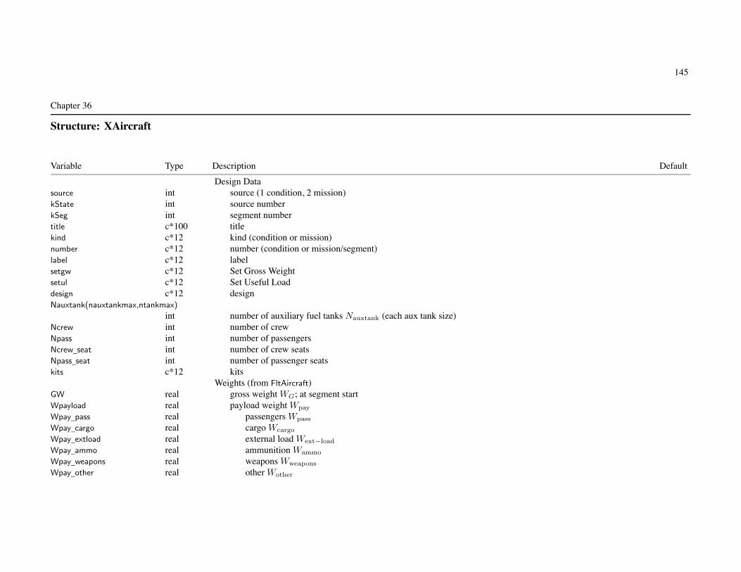
145
Chapter 36
Structure: XAircraft
Variable Type Description Default
Design Datasource int source (1 condition, 2 mission)kState int source numberkSeg int segment numbertitle c*100 titlekind c*12 kind (condition or mission)number c*12 number (condition or mission/segment)label c*12 labelsetgw c*12 Set Gross Weightsetul c*12 Set Useful Loaddesign c*12 designNauxtank(nauxtankmax,ntankmax)
int number of auxiliary fuel tanks Nauxtank (each aux tank size)Ncrew int number of crewNpass int number of passengersNcrew_seat int number of crew seatsNpass_seat int number of passenger seatskits c*12 kits
Weights (from FltAircraft)GW real gross weight WG; at segment startWpayload real payload weight Wpay
Wpay_pass real passengers Wpass
Wpay_cargo real cargo Wcargo
Wpay_extload real external load Wext−load
Wpay_ammo real ammunition Wammo
Wpay_weapons real weapons Wweapons
Wpay_other real other Wother

Structure: XAircraft 146
Wfuel_total real usable fuel weight Wfuel; at segment startWfuel(ntankmax) real usable fuel weightWfuel_std(ntankmax) real standard tanksWfuel_aux(ntankmax) real auxiliary tanksWO real operating weight WO
WE real weight empty WE (from Aircraft)WFixUL real fixed useful load WFUL
Wcrew real crewW_fixUL_fluid real fluids (from Aircraft%Weight)Wauxtank real auxiliary fuel tanksW_fixUL_other real other fixed useful loadWoful(10) real catagoriesWequip real equipment incrementWfoldkit real folding kitWextkit real wing extension kitWwingkit real wing kitWotherkit real other kitWUL real useful load WUL
WML real military loadEnergy (from FltAircraft)
Efuel_total real usable fuel energy Efuel; at segment startEfuel(ntankmax) real usable fuel energyEfuel_std(ntankmax) real standard tanksEfuel_aux(ntankmax) real auxiliary tanks

147
Chapter 37
Structure: Systems
Variable Type Description Default
+ Systemstitle c*100 + titlenotes c*1000 + notes
+ WeightWeight Weight weight statement (systems)SET_Wpayload int + payload (1 no details; 2 all terms) 1
Upass real + weight per passenger+ fixed useful load
SET_Wcrew int + crew weight (1 no details; 2 all terms) 1
Wcrew real + weight or adjustmentUcrew real + weight per crewNcrew int + number of crewWtrap real + trapped fluids and engine oil weight 0.
+ other fixed useful loadnWoful int + number of categories (0 for one value without name; maximum 10) 0
Woful_name(10) c*24 + category name ’ ’
Woful(10) real + baseline weight 0.
Wotherkit real + other kit 0.
SET_Wpayload: payload specified by flight condition or missionSET_Wcrew: no details (only Wcrew) or all terms (Ucrew*Ncrew+Wcrew)
other fixed useful load: can include baggage, gun installations, weapons provisions, aircraft survivability equipment,survival kits, life rafts, oxygen

Structure: Systems 148
SET_fold int + folding (0 none, 1 fold weights, 2 with kit) 0
+ folding weight in kit ffoldkit (fraction wing/rotor/tail/body fold weight)fWfoldkitW(nwingmax) real + wing 0.5
fWfoldkitR(nrotormax) real + rotor 0.5
fWfoldkitT(ntailmax) real + tail 0.5
fWfoldkitFw real + body (wing and rotor fold) 0.5
fWfoldkitFt real + body (tail fold) 0.5
SET_Wvib int + vibration treatment weight (1 fraction weight empty, 2 input) 1
Wvib real + weight Wvib
fWvib real + fraction weight empty fvib
SET_Wcont int + contingency weight (1 fraction weight empty, 2 input) 1
Wcont real + weight Wcont
fWcont real + fraction weight empty fcont
WE = (structure + propulsion group + systems and equipment) + Wvib + Wcont
SET_Wvib: Wvib input or Wvib = fvibWE
SET_Wcont: Wcont input or Wcont = fcontWE , or adjust Wcont for input WE (FIX_WE=1)
SET_fold, folding:set component dWxxfold=0 and fWxxfold=0 for no rotor/wing/tail/body fold weightfraction fWfoldkit of fold weight in fixed useful load as kit, remainder kept in component weightkit weight removable, absent for specified flight conditions and missions
+ systems and equipmentWauxpower real + auxiliary power group (APU) 0.
Winstrument real + instruments group 0.
Wpneumatic real + pneumatic group 0.
Wenviron real + environmental control group 0.
SET_Welectrical int + electrical group (1 no details; 2 all terms) 1
Welectrical real + aircraft 0.
Welect_supply real + power supply 0.

Structure: Systems 149
Welect_conv real + power conversion 0.
Welect_distrib real + power distribution and controls 0.
Welect_lights real + lights and signal devices 0.
Welect_support real + equipment supports 0.
SET_WMEQ int + avionics group (1 no details; 2 all terms) 1
WMEQ real + avionics 0.
Wavionics_com real + communications 0.
Wavionics_nav real + navigation 0.
Wavionics_ident real + identification 0.
Wavionics_disp real + control and display 0.
Wavionics_survive real + aircraft survivability 0.
Wavionics_mission real + mission system equipment 0.
+ armament groupSET_Warmor int + armor (1 no details; 2 all terms) 1
Warmor real + armor 0.
Uarmor_floor real + cabin floor armor weight per areaUarmor_wall real + cabin wall armor weight per areaUarmor_crew real + armor weight per crewSET_Warmprov int + armament provisions (1 no details; 2 all terms) 1
Warmprov real + armament provisions 0.
Warmprov_gun real + gun provisions 0.
Warmprov_turret real + turret systems 0.
Warmprov_expend real + expendable weapons provisions 0.
Warm_elect real + armament electronics (avionics group) 0.
SET_Wfurnish int + furnishings and equipment group (1 no details; 2 all terms) 1
Wfurnish real + furnishings and equipment 0.
+ accommodations for personnelUseat_crew real + each crew seatUseat_pass real + each passenger seatUaccom_crew real + miscellaneous accommodation per crew seatUaccom_pass real + miscellaneous accommodation per passenger seatUox_crew real + oxygen system per crew seatUox_pass real + oxygen system per passenger seatWfurnish_misc real + miscellaneous equipment 0.

Structure: Systems 150
+ furnishingsWfurnish_trim real + trim 0.
Uinsulation real + acoustic and thermal insulation weight per cabin area+ emergency equipment
Wemerg_fire real + fire detection and extinguishing 0.
Wemerg_other real + other emergency equipment 0.
SET_Wload int + load and handling group (1 no details; 2 all terms) 1
Wload real + load and handling 0.
Whandling_aircraft real + aircraft handling 0.
+ load handlingUhandling_cargo real + cargo handling weight per cabin floor areaWload_hoist real + hoist 0.
Wload_extprov real + external load provisions 0.
+ systems and equipmentNcrew_seat int + number of crew seats 0
Npass_seat int + number of passenger seats 0
Ucrew_seat_inc real + equipment weight increment per crew seat (0. for default) 0.
Upass_seat_inc real + equipment weight increment per passenger seat (0. for default) 0.
SET_Welectrical=1: only Welectrical+WDIelect
SET_WMEQ=1: only WMEQ; equipment weights include installationSET_Warmor=1: only Warmor
SET_Warmprov=1: only Warmprov
SET_Wfurnish=1: only Wfurnish
miscellaneous accommodation includes galleys and toiletsmiscellaneous equipment includes cockpit displaystrim includes floor covering, partitions, crash padding, acoustic and thermal insulation
excluding vibration absorbersother emergency equipment includes first aid, survival kit, life raft
SET_Wload=1: only Wload
equipment weight increment is for flight condition and mission; default (if SET_furnish=2 and SET_armor=2):Ucrew_seat_inc=Useat_crew+Uaccom_crew+Uox_crew+Uarmor_crew
Upass_seat_inc=Useat_pass+Uaccom_pass+Uox_pass

Structure: Systems 151
Derived weightsfixed useful load, fold kit
W_fixUL_foldkit_fus real fuselageW_fixUL_foldkit_rotor real rotorsW_fixUL_foldkit_wing real wingsW_fixUL_foldkit_tail real tails
armament groupWarmor_floor real cabin floor armor weightWarmor_wall real cabin wall armor weightWarmor_crew real crew armor weight
furnishings and equipment groupWseat real seatsWaccom real miscellaneous accommodationWox real oxygen systemWinsulation real acoustic and thermal insulation weightWhandling_cargo real cargo handling weightUcrewseatinc real equipment weight increment per crew seatUpassseatinc real equipment weight increment per passenger seatWtip(nrotormax) real weight on wing tip
+ Weight+ systems and equipment+ flight control group and hydraulic group
MODEL_fc int + model (0 input, 1 NDARC, 2 custom) 1
MODEL_RWfc int + rotary wing flight controls (0 not present, 1 global, 2 for each rotor) 1
refRotor int + reference rotor number for global 1
MODEL_FWfc int + fixed wing flight controls (0 for not present) 1
MODEL_CVfc int + conversion controls (0 for not present) 1
+ flight control weight incrementdWRWfc_b real + rotary wing, boosted 0.
dWRWfc_mb real + rotary wing, control boost mechanisms 0.
dWRWfc_nb real + rotary wing, non-boosted 0.
dWFWfc_mb real + fixed wing, control boost mechanisms 0.
dWFWfc_nb real + fixed wing, non-boosted 0.

Structure: Systems 152
dWCVfc_mb real + conversion, boosted 0.
dWCVfc_nb real + conversion, control boost mechanisms 0.
+ fixed flight controlsWfc_cc real + cockpit controls 0.
Wfc_afcs real + automatic flight control system 0.
+ hydraulic weight incrementdWRWhyd real + rotary wing 0.
dWFWhyd real + fixed wing 0.
dWCVhyd real + conversion 0.
WEQhyd real + equipment hydraulics 0.
WFltCont WFltCont NDARC model+ anti-icing group
MODEL_DI int + model (0 input, 1 NDARC, 2 custom) 1
+ weight incrementdWDIelect real + electrical system 0.
dWDIsys real + anti-ice system 0.
WDeIce WDeIce NDARC model
weight model result multiplied by technology factor and increment added:Wxx = TECH_xx*Wxx_model + dWxx; for fixed (input) weight use MODEL_xx=0 or TECH_xx=0.
MODEL_RWfc: global option is based on just main rotors“for each rotor” option sums separate contributions from all rotors
tiltrotor wing weight model requires weight on wing tip: distributed to designated rotor;sum rotary wing and conversion flight controls, hydraulic group, trapped fluids
+ Technology Factors+ rotary wing flight control weight
TECH_RWfc_b real + boosted χRWb 1.0
TECH_RWfc_mb real + control boost mechanisms χRWmb 1.0
TECH_RWfc_nb real + non-boosted χRWnb 1.0

Structure: Systems 153
+ fixed wing flight control weightTECH_FWfc_mb real + control boost mechanisms χFWmb 1.0
TECH_FWfc_nb real + non-boosted χFWnb 1.0
+ conversion flight control weightTECH_CVfc_mb real + control boost mechanisms χCV mb 1.0
TECH_CVfc_nb real + non-boosted χCV nb 1.0
+ flight control hydraulicsTECH_RWhyd real + rotary wing χRWhyd 1.0
TECH_FWhyd real + fixed wing χFWhyd 1.0
TECH_CVhyd real + conversion χCV hyd 1.0
+ anti-icingTECH_DIelect real + electrical system χDIelect 1.0
TECH_DIsys real + anti-ice system χDIsys 1.0
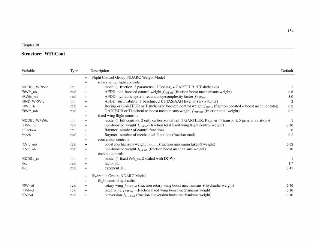
154
Chapter 38
Structure: WFltCont
Variable Type Description Default
+ Flight Control Group, NDARC Weight Model+ rotary wing flight controls
MODEL_WRWfc int + model (1 fraction, 2 parametric, 3 Boeing, 4 GARTEUR, 5 Tishchenko) 1
fRWfc_nb real + AFDD: non-boosted control weight fRWnb (fraction boost mechanisms weight) 0.6
xRWfc_red real + AFDD: hydraulic system redundancy/complexity factor fRW red 3.0
KIND_WRWfc int + AFDD: survivability (1 baseline, 2 UTTAS/AAH level of survivability) 2
fRWfc_b real + Boeing or GARTEUR or Tishchenko: boosted control weight fRWb (fraction boosted + boost mech, or total) 0.2
fRWfc_mb real + GARTEUR or Tishchenko: boost mechanisms weight fRWmb (fraction total weight) 0.2
+ fixed wing flight controlsMODEL_WFWfc int + model (1 full controls, 2 only on horizontal tail, 3 GARTEUR, Raymer (4 transport, 5 general aviation)) 1
fFWfc_nb real + non-boosted weight fFWnb (fraction total fixed wing flight control weight) 0.10
nfunction int + Raymer: number of control functions 6
fmech real + Raymer: number of mechanical functions (fraction total) 0.2
+ conversion controlsfCVfc_mb real + boost mechanisms weight fCV mb (fraction maximum takeoff weight) 0.02
fCVfc_nb real + non-boosted weight fCV nb (fraction boost mechanisms weight) 0.10
+ cockpit controlsMODEL_cc int + model (1 fixed Wfc_cc, 2 scaled with DGW) 1
Kcc real + factor Kcc 1.7
Xcc real + exponent Xcc 0.41
+ Hydraulic Group, NDARC Model+ flight control hydraulics
fRWhyd real + rotary wing fRWhyd (fraction rotary wing boost mechanisms + hydraulic weight) 0.40
fFWhyd real + fixed wing fFWhyd (fraction fixed wing boost mechanisms weight) 0.10
fCVhyd real + conversion fCV hyd (fraction conversion boost mechanisms weight) 0.10

Structure: WFltCont 155
flight controls = non-boosted (do not see aero surface or rotor loads) + boost mechanisms (actuators) + boosted
MODEL_WRWfc = fraction: parametric except for non-boosted controls (from fRWfc_nb)
typically fRWfc_nb = 0.6 (data range 0.3 to 1.8), fRWhyd = 0.4xRWfc_red = 1.0 to 3.0
+ Custom Weight ModelWtParam_fc(8) real + parameters 0.

156
Chapter 39
Structure: WDeIce
Variable Type Description Default
+ Anti-Icing Group, NDARC Weight ModelkDeIce_elec(nrotormax) real + weight factor for electrical system Kelec (lb/ft2 or kg/m2) 0.25
kDeIce_rotor(nrotormax) real + weight factor for main rotor Krotor (lb/ft2 or kg/m2) 0.25
kDeIce_wing(nwingmax) real + weight factor for wing Kwing (lb/ft or kg/m) 0.0
kDeIce_air(nengmax) real + weight factor for engine air intake Kair (lb/lb or kg/kg) 0.006
kDeIce_jet(njetmax) real + weight factor for jet air intake Kjet (lb/lb or kg/kg) 0.006
+ Custom Weight ModelWtParam_DI(8) real + parameters 0.

157
Chapter 40
Structure: Fuselage
Variable Type Description Default
+ Fuselagetitle c*100 + titlenotes c*1000 + notes
+ Geometryloc_fuselage Location + fuselage locationSET_length int + fuselage length (1 input, 2 calculated, 3 from rotor and tail only, 4 from rotor only) 1
Length_fus real + length �fus
SET_nose int + nose length (distance forward of hub; 1 input, 2 calculated) 1
Length_nose real + nose length �nose
fLength_nose real + nose length (fraction reference length)SET_aft int + aft length (distance aft of hub; 1 input, 2 calculated) 1
Length_aft real + aft length �aftfLength_aft real + aft length (fraction reference length)fRef_fus real + fuselage SL location relative nose fref (fraction fuselage length)Length_rotors real rotor-rotor longitudinal separationLength_tail real tail length (wing to horizontal tail)Width_fus real + fuselage width wfus
SET_Swet int + fuselage wetted area (1 input, 2 input plus boom, 3 from nose length, 4 from fuselage length) 2
Swet real + wetted area Swet
Sproj real + projected area Sproj
fSwet real + factor for wetted area fwet 1.
fSproj real + factor for projected area fproj 1.
Height_fus real + fuselage height hfus
Circum_boom real + tail boom effective circumference Cboom
Width_boom real + tail boom effective width wboom
Swet_in real input wetted area Swet
Sproj_in real input projected area Sproj
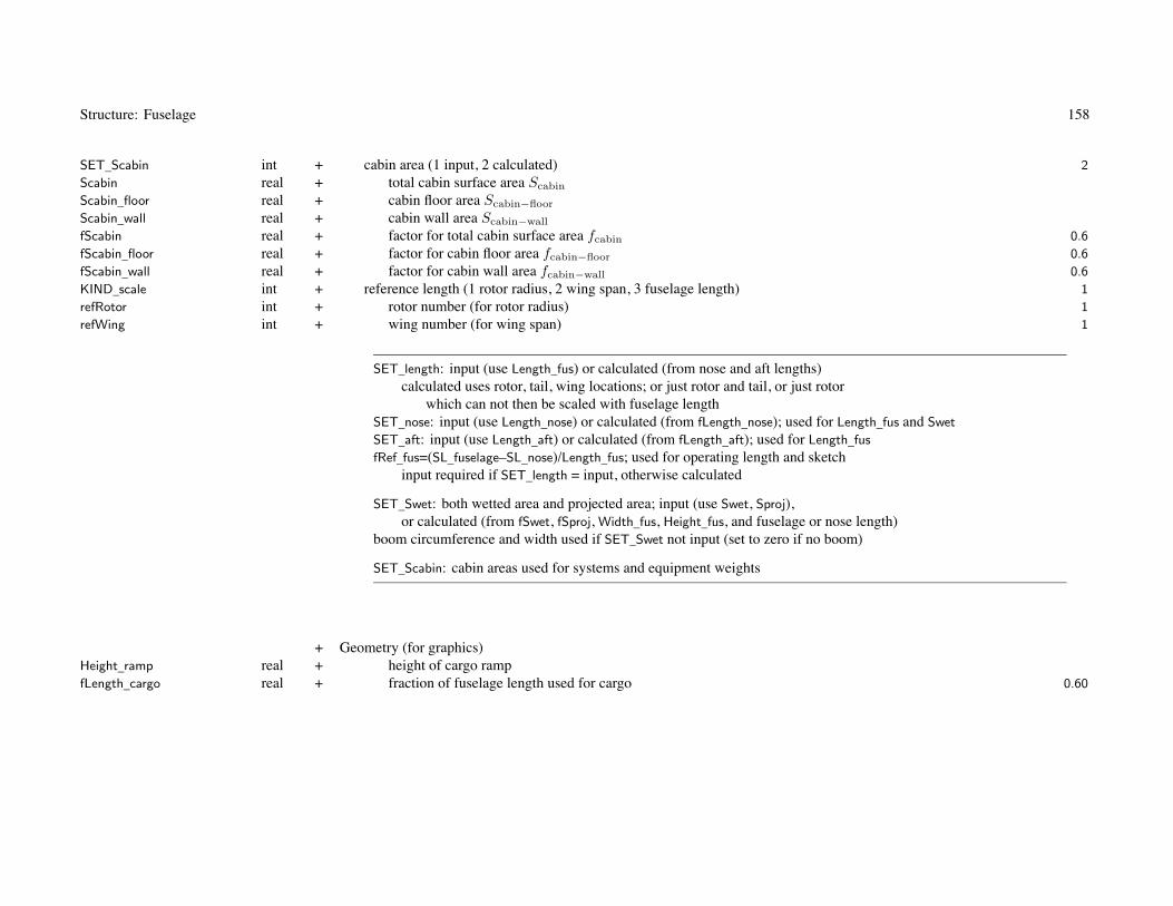
Structure: Fuselage 158
SET_Scabin int + cabin area (1 input, 2 calculated) 2
Scabin real + total cabin surface area Scabin
Scabin_floor real + cabin floor area Scabin−floor
Scabin_wall real + cabin wall area Scabin−wall
fScabin real + factor for total cabin surface area fcabin 0.6
fScabin_floor real + factor for cabin floor area fcabin−floor 0.6
fScabin_wall real + factor for cabin wall area fcabin−wall 0.6
KIND_scale int + reference length (1 rotor radius, 2 wing span, 3 fuselage length) 1
refRotor int + rotor number (for rotor radius) 1
refWing int + wing number (for wing span) 1
SET_length: input (use Length_fus) or calculated (from nose and aft lengths)calculated uses rotor, tail, wing locations; or just rotor and tail, or just rotor
which can not then be scaled with fuselage lengthSET_nose: input (use Length_nose) or calculated (from fLength_nose); used for Length_fus and Swet
SET_aft: input (use Length_aft) or calculated (from fLength_aft); used for Length_fus
fRef_fus=(SL_fuselage–SL_nose)/Length_fus; used for operating length and sketchinput required if SET_length = input, otherwise calculated
SET_Swet: both wetted area and projected area; input (use Swet, Sproj),or calculated (from fSwet, fSproj, Width_fus, Height_fus, and fuselage or nose length)
boom circumference and width used if SET_Swet not input (set to zero if no boom)
SET_Scabin: cabin areas used for systems and equipment weights
+ Geometry (for graphics)Height_ramp real + height of cargo rampfLength_cargo real + fraction of fuselage length used for cargo 0.60

Structure: Fuselage 159
+ AerodynamicsMODEL_aero int + model (0 none, 1 standard) 1
AFuse AFuse standard modelDoQ_cont real + contingency drag, area (D/q)cont 0.
DoQV_cont real + contingency vertical drag, area (D/q)V cont 0.
Derived dragDoQ_fus real fuselage drag, area (D/q)fus
DoQV_fus real fuselage vertical drag, area (D/q)V fus
DoQ_fit real fittings and fixtures drag, area (D/q)fit
DoQ_rb real rotor-body interference drag, area (D/q)rb
DoQ_cont calculated if total drag fixed (Aircraft FIX_drag); otherwise inputDoQV_cont calculated if total download fixed (Aircraft FIX_DL); otherwise input
+ WeightWeight Weight weight statement (component)
+ fuselage groupMODEL_weight int + fuselage group model (0 input, 1 NDARC, 2 custom) 1
+ weight incrementdWbody real + basic body 0.
dWmar real + body marinization 0.
dWpress real + pressurization 0.
dWcrash real + body crashworthiness 0.
dWftfold real + tail fold 0.
dWfwfold real + wing fold 0.
WFuse WFuse AFFD model+ Technology Factors
TECH_body real + basic body χbasic 1.0
TECH_mar real + body marinization χmar 1.0
TECH_press real + pressurization χpress 1.0
TECH_crash real + body crashworthiness χcw 1.0
TECH_ftfold real + tail fold χtfold 1.0
TECH_fwfold real + wing fold χwfold 1.0

Structure: Fuselage 160
weight model result multiplied by technology factor and increment added:Wxx = TECH_xx*Wxx_model + dWxx; for fixed (input) weight use MODEL_xx=0 or TECH_xx=0.

161
Chapter 41
Structure: AFuse
Variable Type Description Default
+ Aerodynamics, Standard ModelAoA_zl real + zero lift angle of attack αzl (deg) 0.
AoA_max real + angle of attack for maximum lift αmax (deg) 10.
+ liftSET_lift int + specification (1 fixed, L/q; 2 scaled, CL) 2
dLoQda real + lift slope, d(L/q)/dα (per rad) 0.
dCLda real + lift slope, CLα = dCL/dα (per rad; based on wetted area, L/q = SCL) 0.
+ pitch momentSET_moment int + specification (1 fixed, M/q; 2 scaled, CM ) 2
MoQ0 real + moment at zero lift, (M/q)0 0.0
CM0 real + moment at zero lift, CM0 (based on wetted area and fuselage length, M/q = S�CM ) 0.0
dMoQda real + moment slope, d(M/q)/dα (per rad) 0.0
dCMda real + moment slope, CMα = dCM/dα (per rad; based on wetted area and fuselage length, M/q = S�CM ) 0.0
SS_zy real + sideslip angle for zero side force βzy (deg) 0.
SS_max real + sideslip angle for maximum side force βmax (deg) 10.
+ side forceSET_side int + specification (1 fixed, Y/q; 2 scaled, CY ) 2
dYoQdb real + side force slope, d(Y/q)/dβ (per rad) 0.
dCYdb real + side force slope, CY β = dCY /dβ (per rad; based on wetted area, Y/q = SCY ) 0.
+ yaw momentSET_yaw int + specification (1 fixed, N/q; 2 scaled, CN ) 2
NoQ0 real + moment at zero lift, (N/q)0 0.0
CN0 real + moment at zero lift, CN0 (based on wetted area and fuselage length, N/q = S�CN ) 0.0
dNoQdb real + moment slope, d(N/q)/dβ (per rad) 0.0
dCNdb real + moment slope, CNβ = dCN/dβ (per rad; based on wetted area and fuselage length, N/q = S�CN ) 0.0

Structure: AFuse 162
SET_xxx: fixed (use XoQ) or scaled (use CX); other parameter calculated
+ Drag, Standard Model+ forward flight drag
SET_drag int + specification (1 fixed, D/q; 2 scaled, CD) 2
DoQ real + area (D/q)0CD real + coefficient CD0 (based on wetted area, D/q = SCD) 0.005
+ fixtures and fittingsSET_Dfit int + specification (1 fixed, D/q; 2 scaled, CD) 2
DoQ_fit real + area (D/q)fit
CD_fit real + coefficient CDfit (based on wetted area, D/q = SCD) 0.
+ rotor-body interferenceSET_Drb int + specification (1 fixed, D/q; 2 scaled, CD) 2
DoQ_rb(nrotormax) real + area (D/q)rb
CD_rb(nrotormax) real + coefficient CDrb (based on wetted area, D/q = SCD) 0.
CD_rb_total real total rotor-body interference drag, CDrb
+ vertical dragSET_Vdrag int + specification (1 fixed, D/q; 2 scaled, CD) 2
DoQV real + area (D/q)V
CDV real + coefficient CDV (based on projected area, D/q = SprojCD) 0.
CDVs real CDV Sproj/Swet
+ sideward dragSET_Sdrag int + specification (1 fixed, D/q; 2 scaled, CD) 2
DoQS real + area (D/q)S
CDS real + coefficient CDS (based on wetted area, D/q = SCD) 0.
+ drag variation with angle of attackMODEL_drag int + model (0 none, 1 general, 2 quadratic) 2
AoA_Dmin real + angle of attack for fuselage minimum drag CDmin (deg) 0.0
Kdrag real + drag increment Kd, ΔCD = CD0Kd|αe|Xd 0.0
Xdrag real + drag increment Xd, ΔCD = CD0Kd|αe|Xd 2.

Structure: AFuse 163
+ transition from forward flight drag to vertical dragMODEL_trans int + model (1 input transition angle of attack, 2 calculate for quadratic) 1
AoA_tran real + angle of attack for transition αt (deg) 25.
at real angle of attack for transition αt (deg) (derived)Xd real exponent Xd (derived)

164
Chapter 42
Structure: WFuse
Variable Type Description Default
+ Fuselage Group, NDARC Weight ModelMODEL_body int + model (1 AFDD84, 2 AFDD82, 3 other) 1
MODEL_other int + model (1 Boeing, GARTEUR (2 airplane, 3 helicopter), 4 Tishchenko, 5 Torenbeek, Raymer (6 transport, 7 gen av))KIND_ramp int + AFDD: rear cargo ramp (0 none) 0
fLength_crg real + Boeing: cabin length + ramp length + cg range (fraction fuselage length) 0.6
Vdive real + Boeing or Torenbeek or Raymer: design dive speed Vdive (knots) 200.
ndoor int + Raymer: number of cargo doors 0
Pdelta real + Raymer: cabin pressure differential (psi) 8.
fWbody_mar real + body weight for marinization fmar (fraction basic body weight) 0.0
fWbody_press real + body weight for pressurization fpress (fraction basic body weight) 0.0
fWbody_crash real + body weight for crashworthiness fcw (fraction body weight) 0.0
fWbody_tfold real + tail fold weight ftfold (fraction tail (AFDD84 or other) or body (AFDD82) weight) 0.0
fWbody_wfold real + wing fold weight fwfold (fraction wing+tip (AFDD84 or other) or body+tailfold (AFDD82) weight) 0.0
AFDD84 (UNIV) is universal body weight model, for tiltrotor and tiltwing as well as for helicoptersAFDD82 (HELO) is helicopter body weight model, should not be used for tiltrotor or tiltwingdive speed: Vmax = SLS max speed, Vdive = 1.25Vmax
fLength_crg = (�c + �r + ΔCG)/�body∼= 1.0 for tandem, 0.3-0.6 for single main rotor (0.7-0.8 with ramp)
typically fWbody_crash = 0.06typically fWbody_tfold = 0.30 (AFDD84 or other) or 0.05 (AFDD82) for folding tail
+ Custom Weight ModelWtParam_fuse(8) real + parameters 0.

165
Chapter 43
Structure: LandingGear
Variable Type Description Default
+ Landing Geartitle c*100 + titlenotes c*1000 + notes
+ Geometryloc_gear Location + landing gear locationd_gear real + distance from bottom of landing gear to WL_gear dLG 0.
place int + placement (1 located on body, 2 located on wing) 1
KIND_LG int + retraction (0 fixed, 1 retracts) 1
speed real + retraction speed (CAS or TAS, knots)
landing gear location: with HAGL (FltState) determines rotor height above ground levelheight rotor = landing gear above ground + hub above landing gear = HAGL + (WL_hub–WL_gear+d_gear)
place: used for weight (fuselage and wing)
+ AerodynamicsMODEL_aero int + model (0 none, 1 standard) 1
AGear AGear standard modelDerived drag
DoQC_LG real landing gear cruise drag, area D/q (0 for retractable gear)DoQH_LG real landing gear helicopter drag, area D/q

Structure: LandingGear 166
+ WeightWeight Weight weight statement (component)
+ alighting gear groupMODEL_weight int + alighting gear group model (0 input, 1 NDARC, 2 custom) 1
+ weight incrementdWLG real + basic landing gear 0.
dWLGret real + retraction 0.
dWLGcrash real + crashworthiness 0.
WGear WGear AFFD model+ Technology Factors
TECH_LG real + basic landing gear χLG 1.0
TECH_LGret real + retraction χLGret 1.0
TECH_LGcrash real + crashworthiness χLGcw 1.0
weight model result multiplied by technology factor and increment added:Wxx = TECH_xx*Wxx_model + dWxx; for fixed (input) weight use MODEL_xx=0 or TECH_xx=0.

167
Chapter 44
Structure: AGear
Variable Type Description Default
+ Drag, Standard ModelDoQ real + drag area extended, D/q

168
Chapter 45
Structure: WGear
Variable Type Description Default
+ Landing Gear Group, NDARC Weight ModelMODEL_LG int + model (1 fraction, 2 parametric rotary wing, 3 parametric fixed wing) 2
nLG int + number of landing gear assemblies NLG 3
fWLG_basic real + basic landing gear weight fLG (fraction maximum takeoff weight) 0.0325
fWLG_ret real + landing gear weight for retraction fLGret (fraction basic weight) 0.08
fWLG_crash real + landing gear weight for crashworthiness fLGcw (fraction basic+retraction weight) 0.14
only MODEL_LG=fraction uses fWLG_basic
typically fWLG_basic = 0.0325 (fraction method)typically fWLG_ret = 0.08, fWLG_crash = 0.14
+ Custom Weight ModelWtParam_gear(8) real + parameters 0.

169
Chapter 46
Structure: Rotor
Variable Type Description Default
+ Rotortitle c*100 + titlenotes c*1000 + notesconfig c*32 + Configuration ’main’
rotorconfig int configuration (ROTORCONFIG_main, tail, prop)isMainRotor int main rotor (0 not)isAntiQRotor int antitorque rotor (0 not)isAuxTRotor int auxiliary thrust rotor (0 not)isVariableDiam int variable diameter rotor (0 not)isDuctedFan int ducted fan (0 not)isReactionDrive int reaction drive (0 not)isMultiRotor int multiple rotors (0 not)twinrotor int configuration (ROTORCONFIG_tandem, coaxial, tiltrotor, not_twin)
configuration designation: principal designation required, rest identify special characteristicsprincipal designation = ’main’, ’tail’, ’prop’
antitorque = ’antiQ’, ’auxT’
twin rotor = ’coaxial’, ’tandem’, ’tiltrotor’ (keyword = tan, coax, tilt)others = ’variable diameter’, ’ducted fan’, ’reaction drive’, ’multirotor’ (keyword = var, duct, react, multi)
principal designation determines where weight put in weight statement, and designates main rotors (isMainRotor)separately specify appropriate performance and weight models
multiple rotor configurations have special options for geometry and performanceoptions defined by variables SET_geom, MODEL_twin, MODEL_int_twin
antitorque or aux thrust rotor has special options for sizingoptions defined by variables SET_rotor, fThrust, Tdesign
reaction drive still requires propulsion group

Structure: Rotor 170
kRotor int rotor number
+ Propulsion groupkPropulsion int + group number 1
KIND_xmsn int + drive system branch (1 primary, 0 dependent) 1
Vtip_ref(ngearmax) real + reference tip speedrVtip_ref(ngearmax) real ratio to state #1Omega_ref real reference rotational speed (state #1)INPUT_gear int + gear ratio input for dependent branch (1 Vtip_ref, 2 gear) 1
gear(ngearmax) real + gear ratio r = Ωdep/Ωprim (ratio rpm to rpm of primary rotor) 1.0
+ Reaction driver_react real + effective radial station of force (fraction Radius) 1.0
prop_react(3) int propulsion for reaction drive (group (1 engine, 2 jet), number, model)
drive system branch: only one primary rotor per propulsion grouptip speed and gear ratio required for each drive system stateprimary: specify Vtip_ref and default tip speeds; Vtip−hover = Vtip_ref(1)
dependent: specify gear ratio, or specify Vtip_ref and calculate gear (depend on rotor radius)can not specify gear ratio if sizing changes dependent rotor Vtip (SET_rotor)
if size task changes Vtip_ref(1), then rVtip_ref used to change Vtip_ref(n) for n>1variable speed transmission: for drive system state STATE_gear_var, gear ratio factor fgear (control) included
when evaluate rotational speed of dependent rotor
reaction drive requires one and only one propulsion system (engine group or jet group)
+ Default rotor tip speeds (primary rotor)INPUT_Vtip int + input form (1 tip speed, 2 hover Vtip and rpm ratio) 1
+ function of flight speednVrpm int + number of speeds (1 constant; ≥ 2 piecewise linear, maximum nvelmax) 1
Vrpm(nvelmax) real + speeds (CAS or TAS)+ tip speed
Vtip_cruise real + cruiseVtip_man real + maneuvering flight

Structure: Rotor 171
Vtip_oei real + OEIVtip_xmsn real + transmission sizingVtip(nvelmax) real + function of flight speed
+ rpm ratio (Vtip/Vtip−hover)fRPM_cruise real + cruise 1.
fRPM_man real + maneuvering flight 1.
fRPM_oei real + OEI 1.
fRPM_xmsn real + transmission sizing 1.
fRPM(nvelmax) real + function of flight speed 1.
default rotor tip speeds (including conversion): selectable by SET_Vtip of FltState
only for primary rotor; Vtip calculated from gear(state) for dependent branch
+ Drive system torque limitSET_limit_rs int + rotor shaft (0 input, 1 fraction power, 2 fraction drive system limit) 1
Plimit_rs real + rotor shaft power limit PRSlimit
fPlimit_rs real + rotor shaft power limit factor 1.
Qlimit_rs real rotor shaft torque limit (PRSlimit at Ωref )
drive system torque limit: Size%SET_limit_ds = input (use Plimit_rs) or calculated (from fPlimit_rs)SET_limit_ds=’input’: Plimit_rs inputSET_limit_ds�=’input’: from rotor power required at transmission sizing flight conditions (DESIGN_xmsn)
rotor shaft: options for SET_limit_ds�=’input’
SET_limit_rs=0: Plimit_rs
SET_limit_rs=1: fPlimit_rs × (rotor Preq)SET_limit_rs=2: fPlimit_rs ×PDSlimit
rotor shaft power limit: corresponds to one rotorcan be used for max effort in flight state (max_quant=’Q margin’)can be used for max gross weight in flight condition or mission (SET_GW=’maxQ’ or ’maxPQ’)always check and print whether exceed torque limit

Structure: Rotor 172
+ Parametersdiskload real + disk loadingfArea real + fraction rotor area for reference disk area fA
fDGW real + fraction DGW fW (for disk loading and blade loading)fThrust real + thrust factor (antitorque or aux thrust rotor) 1.0
Radius real + radius RCWs real + blade loading CW /σ (thrust-weighted)sigma real + solidity σ = Nc/πR (thrust-weighted)Tdesign real + thrust for antitorque or aux thrust rotorPdesign real + power for antitorque or aux thrust rotorNdesign real + rotor speed (rpm) at Pdesign
SET_thrust int + rotor thrust for disk loading and blade loading (0 default; 1 fDGW*DGW, 2 fThrust*Tdesign) 0
iSET_thrust int rotor thrust for disk loading and blade loading (1 from DGW, 2 from Tdesign)
rotor disk loading = T/A; aircraft disk loading = WD/Aref , Aref =∑
(fAA)W = fW WD (main rotor) or fThrust*Tdesign (antitorque or aux thrust rotor); can specify using SET_thrust
Tdesign and Pdesign obtained from thrust design conditions and missions (DESIGN_thrust)if rotor sized from disk loading (SET_rotor=’DL+xx+xx’), area = T /diskload
if SET_rotor specify ’Vtip’, use Vtip_ref(1)
if SET_rotor not specify ’Vtip’, calculate Vtip_ref(1), and then Vtip_ref for dependent rotorsif SET_rotor=’CWs+xx+xx’, then CW /σ from fDGW*DGW, takeoff condition, Vtip_ref, and thrust-weighted solidity
for antitorque or aux thrust rotor, need design conditions and missions (DESIGN_thrust) to identify Tdesign
otherwise use fDGW and design gross weightTdesign and Pdesign generally calculated (identified as input so inherited by next case)
+ GeometrySET_geom c*12 + position (standard, tiltrotor, coaxial, tandem, tailrotor, multicopter) ’std’
KIND_TRgeom int + tiltrotor (1 from clearance, 2 at wing tip, 3 at wing panel edge) 0
+ twin rotorsfRadius real + ratio rotor radius to that of other rotor 1.0
otherRotor int + other rotor numberWingForRotor int + wing number 1

Structure: Rotor 173
PanelForRotor int + wing panel number 1
clearance_fus real + tiltrotor clearance between rotor and fuselage dfus 0.6
fclearance_fus real + tiltrotor clearance factor 1.0
sep_coaxial real + coaxial rotor separation s (fraction Diameter) 0.08
overlap_tandem real + tandem rotor overlap o (fraction Diameter) 0.25
derivediSET_geom int position (SET_geom_standard, tiltrotor, coaxial, tandem, tailrotor, multicopter)clearance_calc real clearance between rotor and fuselage dfus
Hsep_twin real horizontal separation � (fraction Diameter)Vsep_twin real vertical separation s (fraction Diameter)overlap_twin real overlap o (1 – separation/Diameter)m_twin real overlap area fraction m
+ tail rotormainRotor int + main rotor number 1
fRadius_tr real + radius scale factor 1.0
clearance_tr real + clearance between tail rotor and main rotor dtr 0.5
+ multicopterang_multicopter real + angle ψ (clockwise from forward, deg) 0.
len_multicopter real + arm length � (fraction Radius) 1.5
+ variable diameter rotorSET_VarDiam int + set diameter (1 conversion schedule, 2 function speed)fRcruise real + ratio cruise radius to hover radius (variable diameter only)
SET_geom: calculation override part of location inputSET_geom=’tiltrotor’: calculate lateral position (BL)
KIND_TRgeom=clearance: from WingForRotor, Width_fus, clearance_fus, fclearance_fus
KIND_TRgeom=wing tip: from WingForRotor, wing spanKIND_TRgeom=wing panel edge: from WingForRotor, PanelForRotor, panel edge and wing spansame WingForRotor for otherRotor, first rotor is rightBL or YoL in loc_pylon, loc_pivot, loc_naccg is relative calculated loc_rotor BL
SET_geom=’coaxial’: calculate position from sep_coaxial
same sep_coaxial for otherRotor, first rotor is lowerloc_rotor (SL,BL,WL or XoL,YoL,ZoL) is midpoint between hubsloc_pylon (SL,BL,WL or XoL,YoL,ZoL) is relative calculated loc_rotor

Structure: Rotor 174
SET_geom=’tandem’: calculate longitudinal position (SL) from overlap_tandem
same overlap_tandem for otherRotor, first rotor is frontloc_rotor (SL or XoL only) is midpoint between hubsloc_pylon SL or XoL is relative calculated loc_rotor
SET_geom=’tailrotor’: calculate longitudinal position (SL) from clearance_tr, mainRotor
loc_pylon SL or XoL is relative calculated loc_rotor
SET_geom=’multicopter’: calculate longitudinal and lateral position from ang_multicopter, len_multicopter
loc_rotor (SL,BL or XoL,YoL) is center of rotorsloc_pylon (SL,BL,WL or XoL,YoL,ZoL) is relative calculated loc_rotor
ang_multicopter also used for Aircraft%config=’multicopter’ to define controlsizing:
if SET_rotor=’ratio’, Radius=fRadius*Radius(otherRotor); otherRotor not SET_rotor=’ratio’
twin rotors: config identify as twin rotorantitorque: config identify as antitorque rotor
if SET_rotor=’scale’, Radius=fRadius_tr*(main rotor Radius)*function(DiskLoad)variable diameter: Radius is hover or reference radius; can be commanded by aircraft controls
conversion schedule: R =Radius in hover and helicopter mode (V ≤ Vconv−hover)R =Radius*fRcruise in cruise mode (V ≥ Vconv−cruise); linear with V in conversion mode
function of speed: use nVdiam, fdiam, Vdiam to calculate R
+ Geometryrotate int + direction of rotation (1 counter-clockwise, –1 clockwise) 1
nBlade int + number of blades N+ planform and twist
SET_chord int + chord distribution (1 linear from fTWsigma, 2 linear from taper, 3 nonlinear from fchord) 1
fTWsigma real + ratio thrust-weighted solidity to geometric solidity σt/σg 1.
taper real + taper ratio t (tip chord/root chord) 1.
SET_twist int + twist distribution (1 linear from twistL, 2 nonlinear from twist) 1
twistL real + linear twist θL (deg, root to tip) -10.
nprop int + number of radial stations (maximum nrmax) 2
rprop(nrmax) real + radial stations (rroot/R)fchord(nrmax) real + chord distribution c(r)/cref 1.
twist(nrmax) real + twist θtw(r) (deg)

Structure: Rotor 175
+ flap dynamicsKIND_hub int + hub type (1 articulated, 2 hingeless) 1
flapfreq real + first flapwise natural frequency ν (per-rev at hover tip speed) 1.04
conefreq real + coning natural frequency ν (0. to use flapfreq) 0.
gamma real + blade Lock number γ 8.
precone real + precone βp (deg) 0.
delta3 real + pitch-flap coupling δ3 (deg) 0.
+ aerodynamicsdclda real + blade section 2D lift-curve slope a = c�α (per-rad) 5.7
tiploss real + tip loss factor B (lift zero from BR to tip) 0.97
xroot real + root cutout (rroot/R) 0.1
fBlockage real + blockage factor (force increment fBT ) 0.0
SET_chord: use one of fTWsigma, taper, or fchord(r); others calculatedfor nonlinear distribution, scale input fchord to unit thrust-weighted chord
fTWsigma = sigma_tw/sigma_geom; for linear taper f = c(.75R)/c(.5R) = (1 + 3taper)/(2 + 2taper)equivalent linear taper = c(tip)/c(root) = (2f − 1)/(3 − 2f)for linear taper fc = c/cref = 1 + (r − 0.75)4(taper − 1)/(1 + 3taper)
SET_twist: use one of twistL or twist(r); other calculatedfor nonlinear distribution, twist relative 0.75R obtained from input
flap frequency and Lock number are used for flap dynamics and hub moments due to flapspecified for hover radius and rotational speedKIND_hub determines how flap frequency and hub moment spring vary with rotor speed and Rweight models can have separate blade and hub values for flap frequency
blade Lock number gamma: for SLS density, a = 5.7, thrust-weighted chordSET_Iblade determines whether Lock number input or calculated
blockage factor: force acting on aircraft is (1–fBlockage)*thrust
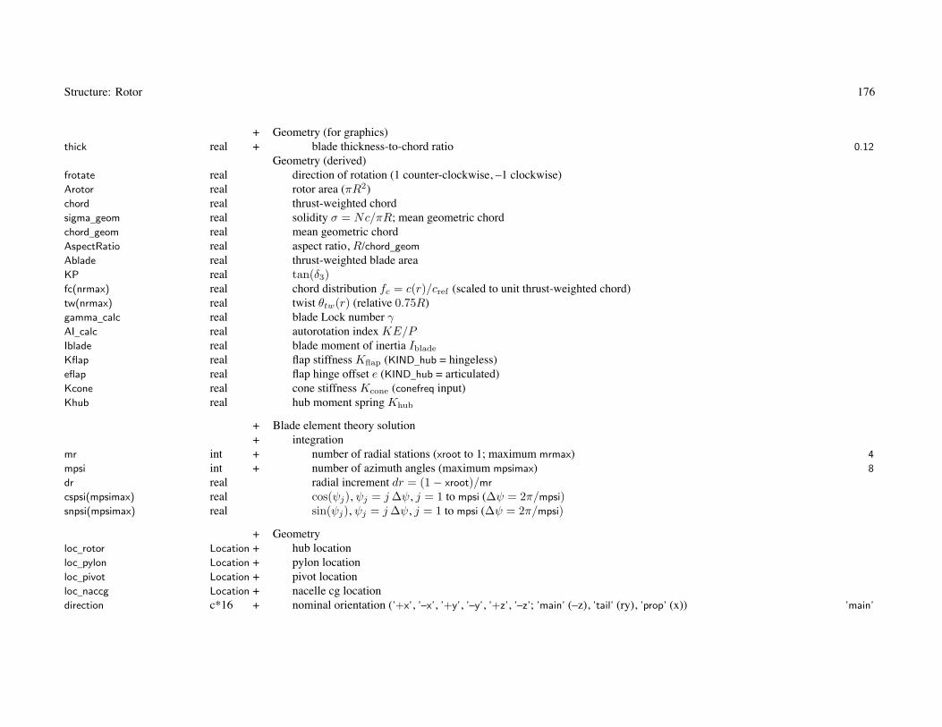
Structure: Rotor 176
+ Geometry (for graphics)thick real + blade thickness-to-chord ratio 0.12
Geometry (derived)frotate real direction of rotation (1 counter-clockwise, –1 clockwise)Arotor real rotor area (πR2)chord real thrust-weighted chordsigma_geom real solidity σ = Nc/πR; mean geometric chordchord_geom real mean geometric chordAspectRatio real aspect ratio, R/chord_geom
Ablade real thrust-weighted blade areaKP real tan(δ3)fc(nrmax) real chord distribution fc = c(r)/cref (scaled to unit thrust-weighted chord)tw(nrmax) real twist θtw(r) (relative 0.75R)gamma_calc real blade Lock number γAI_calc real autorotation index KE/PIblade real blade moment of inertia Iblade
Kflap real flap stiffness Kflap (KIND_hub = hingeless)eflap real flap hinge offset e (KIND_hub = articulated)Kcone real cone stiffness Kcone (conefreq input)Khub real hub moment spring Khub
+ Blade element theory solution+ integration
mr int + number of radial stations (xroot to 1; maximum mrmax) 4
mpsi int + number of azimuth angles (maximum mpsimax) 8
dr real radial increment dr = (1 − xroot)/mr
cspsi(mpsimax) real cos(ψj), ψj = j Δψ, j = 1 to mpsi (Δψ = 2π/mpsi)snpsi(mpsimax) real sin(ψj), ψj = j Δψ, j = 1 to mpsi (Δψ = 2π/mpsi)
+ Geometryloc_rotor Location + hub locationloc_pylon Location + pylon locationloc_pivot Location + pivot locationloc_naccg Location + nacelle cg locationdirection c*16 + nominal orientation (’+x’, ’–x’, ’+y’, ’–y’, ’+z’, ’–z’; ’main’ (–z), ’tail’ (ry), ’prop’ (x)) ’main’

Structure: Rotor 177
KIND_tilt int + shaft control (0 fixed shaft, 1 incidence, 2 cant, 3 both controls) 0
+ orientation of rotor shaftincid_hub real + incidence θh (deg) 0.
cant_hub real + cant angle φh (deg) 0.
+ orientation of pivot axesdihedral_pivot real + pivot dihedral angle φp (deg)pitch_pivot real + pivot pitch angle θp (deg)sweep_pivot real + pivot sweep angle ψp (deg)
+ reference shaft controlincid_ref real + incidence iref (deg) 0.
cant_ref real + cant angle cref (deg) 0.
+ moving weight for cg shiftSET_Wmove int + weight (1 wing tip weight, 2 Wgbrs, 3 Wgbrs and WES) 1
fWmove real + fraction moving weight 1.
Derived geometryiDirection int nominal orientation (1, –1, 2, –2, 3, –3, –3, r2, 1)axis_incid int axis incidence (±123)axis_cant int axis cant (±123)KIND_incid int incidence (0 fixed, 1 controlled)KIND_cant int cant angle (0 fixed, 1 controlled)CPF(3,3) real pivot axes relative airframe, CPF
CFP(3,3) real pivot axes relative airframe, CFP
WCHF(3,3) real WCHF (CSF for reference control)CSF(3,3) real rotor shaft relative airframe, CSF (zero shaft control)
loc_naccg, loc_pivot, orientation of pivot axes, and reference shaft control angles not used for KIND_tilt=fixed shaftfor tiltrotor, locations and orientation specified in helicopter mode, so incid_ref = 90
SET_Wmove: cg shift calculated using incidence and cant rotation of loc_naccg relative loc_pivot
moving weight fWmove*Wmove, Wmove = Wtip_total/nRotorOnWing or w/Nrotor
w = Wgbrs (drive system) or Wgbrs +∑
(WES) (drive system and engine system)

Structure: Rotor 178
+ ControlsKIND_control int + rotor control mode (1 thrust and TPP, 2 thrust and NFP, 3 pitch and TPP, 4 pitch and NFP) 1
KIND_cyclic int + cyclic input (1 tip-path-plane tilt, 2 hub moment, 3 lift offset) 1
KIND_coll int + collective input (1 thrust, 2 CT /σ) 2
SCALE_coll int + scale collective T matrix (0 for none) 1
+ collective (magnitude of thrust vector)INPUT_coll int + connection to aircraft controls (0 none, 1 input T matrix) 1
T_coll(ncontmax,nstatemax) real + control matrixnVcoll int + number of speeds (0 zero value; 1 constant; ≥ 2 piecewise linear, maximum nvelmax) 0
coll(nvelmax) real + valuesVcoll(nvelmax) real + speeds (CAS or TAS)
+ longitudinal cyclic (tip-path plane tilt or no-feathering plane tilt)INPUT_lngcyc int + connection to aircraft controls (0 none, 1 input T matrix) 1
T_lngcyc(ncontmax,nstatemax)
real + control matrixnVlngcyc int + number of speeds (0 zero value; 1 constant; ≥ 2 piecewise linear, maximum nvelmax) 0
lngcyc(nvelmax) real + valuesVlngcyc(nvelmax) real + speeds (CAS or TAS)
+ lateral cyclic (tip-path plane tilt or no-feathering plane tilt)INPUT_latcyc int + connection to aircraft controls (0 none, 1 input T matrix) 1
T_latcyc(ncontmax,nstatemax)
real + control matrixnVlatcyc int + number of speeds (0 zero value; 1 constant; ≥ 2 piecewise linear, maximum nvelmax) 0
latcyc(nvelmax) real + valuesVlatcyc(nvelmax) real + speeds (CAS or TAS)
+ incidence i (nacelle tilt)INPUT_incid int + connection to aircraft controls (0 none, 1 input T matrix) 1
T_incid(ncontmax,nstatemax)
real + control matrixnVincid int + number of speeds (0 zero value; 1 constant; ≥ 2 piecewise linear, maximum nvelmax) 0
incid(nvelmax) real + valuesVincid(nvelmax) real + speeds (CAS or TAS)
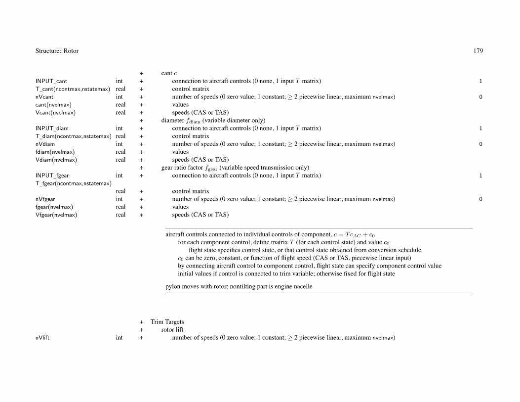
Structure: Rotor 179
+ cant cINPUT_cant int + connection to aircraft controls (0 none, 1 input T matrix) 1
T_cant(ncontmax,nstatemax) real + control matrixnVcant int + number of speeds (0 zero value; 1 constant; ≥ 2 piecewise linear, maximum nvelmax) 0
cant(nvelmax) real + valuesVcant(nvelmax) real + speeds (CAS or TAS)
+ diameter fdiam (variable diameter only)INPUT_diam int + connection to aircraft controls (0 none, 1 input T matrix) 1
T_diam(ncontmax,nstatemax) real + control matrixnVdiam int + number of speeds (0 zero value; 1 constant; ≥ 2 piecewise linear, maximum nvelmax) 0
fdiam(nvelmax) real + valuesVdiam(nvelmax) real + speeds (CAS or TAS)
+ gear ratio factor fgear (variable speed transmission only)INPUT_fgear int + connection to aircraft controls (0 none, 1 input T matrix) 1
T_fgear(ncontmax,nstatemax)
real + control matrixnVfgear int + number of speeds (0 zero value; 1 constant; ≥ 2 piecewise linear, maximum nvelmax) 0
fgear(nvelmax) real + valuesVfgear(nvelmax) real + speeds (CAS or TAS)
aircraft controls connected to individual controls of component, c = TcAC + c0
for each component control, define matrix T (for each control state) and value c0
flight state specifies control state, or that control state obtained from conversion schedulec0 can be zero, constant, or function of flight speed (CAS or TAS, piecewise linear input)by connecting aircraft control to component control, flight state can specify component control valueinitial values if control is connected to trim variable; otherwise fixed for flight state
pylon moves with rotor; nontilting part is engine nacelle
+ Trim Targets+ rotor lift
nVlift int + number of speeds (0 zero value; 1 constant; ≥ 2 piecewise linear, maximum nvelmax)

Structure: Rotor 180
Klift(nvelmax) real + targetVlift(nvelmax) real + speeds (CAS or TAS)
+ rotor propulsive forcenVprop int + number of speeds (0 zero value; 1 constant; ≥ 2 piecewise linear, maximum nvelmax)Kprop(nvelmax) real + targetVprop(nvelmax) real + speeds (CAS or TAS)
target definition determined by Aircraft%trim_quant
Klift can be fraction total aircraft lift, lift, CL/σ, or CT /σKprop can be fraction total aircraft drag, propulsive force −X , −CX/σ, or −X/q)
+ Rotor Thrust Capability (CT /σ vs μ)+ sustained
nsteady int + number of points (maximum 20) 16
mu_steady(20) real + advance ratioCTs_steady(20) real + CT /σ
+ transientntran int + number of points (maximum 20) 16
mu_tran(20) real + advance ratioCTs_tran(20) real + CT /σ
CTs_steady, CTS_tran used to calculate rotor thrust margin, which available for max effort or trimdefaults used if CTs(1)=0.
default CTs_steady = .170,.168,.161,.149,.131,.109,.084,.050,.049,.048,.047,.046,.045,.044,.043,.042default CTs_tran = .200,.197,.190,.177,.156,.135,.110,.080,.075,.070,.065,.060,.055,.050,.045,.040default mu_steady = 0.,.10,.20,.30,.40,.50,.60,.70,.71,.72,.73,.74,.75,.76,.77,.78default mu_tran = 0.,.10,.20,.30,.40,.50,.60,.70,.72,.74,.76,.78,.80,.82,.84,.86

Structure: Rotor 181
+ PerformanceMODEL_perf int + power model (1 standard, 2 table model) 1
PRotorInd PRotorInd standard model, induced powerPRotorPro PRotorPro standard model, profile powerPRotorTab PRotorTab table modelMODEL_Ftpp int + inplane forces, tip-path plane axes (1 neglect, 2 blade-element theory) 2
MODEL_Fpro int + inplane forces, profile (1 simplified, 2 blade element theory) 2
if thrust and TPP command, and neglect inplane forces relative TPP, then pitch control angles not required
+ InterferenceMODEL_int int + model (0 none, 1 standard, 2 with transition) 1
+ transitionVint_low real + low velocity (knots) 0.
Vint_high real + high velocity (knots) 0.
IRotor IRotor standard model
Kint=0 to suppress interference at component; MODEL_int=0 for no interference at allwith transition: interference factors linearly vary from Kint at V ≤ Vint_low to 0 at V ≥ Vint_high
+ GeometrySET_aeroaxes int + hub/pylon aerodynamic axes (0 input pitch, 1 helicopter, 2 propeller or tiltrotor) 1
pitch_aero real + pitch relative shaft axes θref , CBS = Y−θref 0.0
SET_Spylon int + pylon wetted area (1 fixed, input Swet; 2 scaled, Wgbrs; 3 scaled, Wgbrs and WES) 2
Swet_pylon real + area Spylon 0.0
kSwet_pylon real + factor, k = Spylon/(w/Nrotor)2/3 (Units_Dscale) 1.0
SET_Sduct int + duct area (1 fixed, input S_duct; 2 scaled, from fLength_duct) 2
S_duct real + area Sduct 0.0
fLength_duct real + duct length (fraction rotor radius) 1.2

Structure: Rotor 182
SET_Sspin int + spinner wetted area (1 fixed, input Swet; 2 scaled, from fSwet) 2
Swet_spin real + area Sspin 0.0
fSwet_spin real + factor, k = Sspin/Aspin 1.0
fRadius_spin real + spinner radius (fraction rotor radius) 0.
Derived geometryCBS(3,3) real pylon axes relative shaft, CBS
CBF(3,3) real pylon axes relative airframe, CBF (zero shaft control)Radius_spin real spinner radius Rspin
only SET_aeroaxes=input uses pitch_aero; pitch_aero=180 for helicopter, 90 for propeller
SET_Spylon, pylon wetted area: input (use Swet_pylon) or calculated (from kSwet_pylon)units of kSwet are ft2/lb2/3 or m2/kg2/3
w = Wgbrs (drive system) or Wgbrs +∑
WES (drive system and engine system)pylon wetted area used for pylon dragrotor pylon must be consistent with engine group nacelle
SET_Sduct, duct area: input (use S_duct) or calculated (from fLength_duct)Sduct = (2πR)�duct, �duct =fLength_duct*R; used for drag (wetted area 2Sduct) and weight
SET_Sspin, spinner wetted area: (use Swet_spin) or calculated (from fSwet_spin)Aspin = πR2
spin = spinner frontal area (from fRadius_spin*R); spinner radius used for drag and weight
+ DragMODEL_drag int + model (0 none, 1 standard) 1
Idrag real + incidence angle for helicopter nominal drag (deg; 0 for not tilt) 0.
DRotor DRotor standard modelDerived drag
DoQC_hub real hub cruise drag, area (D/q)hub
DoQH_hub real hub helicopter drag, area (D/q)hub
DoQV_hub real hub vertical drag, area (D/q)hub
DoQC_pylon real pylon cruise drag, area (D/q)pylon
DoQH_pylon real pylon helicopter drag, area (D/q)pylon

Structure: Rotor 183
DoQV_pylon real pylon vertical drag, area (D/q)pylon
DoQC_duct real duct cruise drag, area (D/q)duct
DoQH_duct real duct helicopter drag, area (D/q)duct
DoQV_duct real duct vertical drag, area (D/q)duct
DoQ_spin real spinner drag, area (D/q)spin
Swet_rotor real total wetted area Swet
+ WeightWeight Weight weight statement (component)
+ rotor group (or empennage or propulsion group)MODEL_weight int + model (0 input, 1 NDARC, 2 custom) 1
+ weight incrementdWblade real + blade 0.
dWhub real + hub and hinge 0.
dWshaft real + inter-rotor shaft 0.
dWspin real + fairing/spinner 0.
dWrfold real + blade fold 0.
dWtr real + tail rotor 0.
dWaux real + auxiliary thrust 0.
dWrsupt real + rotor support structure 0.
dWduct real + duct 0.
WRotor WRotor NDARC modelSET_Iblade int + blade moment of inertia (0 from Lock number, 1 from blade wt, 2 tip wt from Lock number, 3 tip wt from AI) 1
AI real + autorotation index KE/P = 12NbladeIbladeΩ2/P (sec) 3.0
Wblade_tip real + tip weight (per blade) 0.
rWblade_tip real + location tip weight (fraction blade radius) 0.9
fWblade_tip real + distributed weight for centrifugal force (fraction Wblade_tip) 1.0
rblade real + radius of gyration for distributed mass (fraction blade radius) 0.6
Wblade real blade weight (all blades; required for drive system weight)Wtip real weight on wing tip (required for tiltrotor wing weight)
+ Technology FactorsTECH_blade real + blade weight χblade 1.0
TECH_hub real + hub and hinge weight χhub 1.0
TECH_shaft real + inter-rotor shaft χshaft 1.0
TECH_spin real + fairing/spinner weight χspin 1.0

Structure: Rotor 184
TECH_rfold real + blade fold weight χfold 1.0
TECH_tr real + tail rotor weight χtr 1.0
TECH_aux real + auxiliary thrust weight χat 1.0
TECH_rsupt real + rotor support structure weight χsupt 1.0
TECH_duct real + duct weight χduct 1.0
weight model result multiplied by technology factor and increment added:Wxx = TECH_xx*Wxx_model + dWxx; for fixed (input) weight use MODEL_xx=0 or TECH_xx=0.
blade weight: Wblade = χbladewblade + dWblade + (1 + f)WtipNblade
SET_Iblade: calculate blade moment of inertia Iblade
0 from Lock number gamma, independent of blade weight1 from blade weight2 from Lock number gamma, tip weight Wblade_tip calculated from Iblade
3 from autorotation index AI, tip weight Wblade_tip calculated from Iblade
for tail rotor or auxiliary thrust weight model (MODEL_config = 2 or 3), Wblade_tip not used and SET_Iblade = 0
rotor weight = blade + hub + spinner + fold + shaft + support + ductrotor config determines where weight put in weight statement
main rotor: rotor grouptail rotor: empennage group (tail rotor)propeller: propulsion group (propeller/fan installation)

185
Chapter 47
Structure: PRotorInd
Variable Type Description Default
+ Rotor Induced Power, Standard Energy Performance MethodMODEL_ind int + model (1 constant, 2 standard) 2
+ induced velocity factors (ratio to momentum theory induced velocity)Ki_hover real + hover κhover 1.12
Ki_climb real + axial climb κclimb 1.08
Ki_prop real + axial cruise (propeller) κprop 2.0
Ki_edge real + edgewise flight (helicopter) κedge 2.0
+ variation with thrustCTs_Hind real + (CT /σ)ind for κh variation 0.08
kh1 real + coefficient kh1 for κh 0.
kh2 real + coefficient kh2 for κh 0.
Xh2 real + exponent Xh2 for κh 2.
CTs_Pind real + (CT /σ)ind for κp variation 0.08
kp1 real + coefficient kp1 for κp 0.
kp2 real + coefficient kp2 for κp 0.
Xp2 real + exponent kp2 for κp 2.
+ variation with shaft anglekpa real + coefficient khα for κp 0.
Xpa real + exponent Xhα for κp 2.
Maxial real + constant Maxial in transition from hover to climb 1.176
Xaxial real + exponent Xaxial in transition from hover to climb 0.65
+ variation with axial velocitymu_prop real + advance ratio μzprop for Ki_prop 1.0
ka1 real + coefficient ka1 for κ(μz) (linear) 0.
ka2 real + coefficient ka2 for κ(μz) (quadratic) 0.
ka3 real + coefficient ka3 for κ(μz) 0.
Xa real + exponent Xa for κ(μz) 4.5

Structure: PRotorInd 186
+ variation with edgewise velocitymu_edge real + advance ratio μedge for Ki_edge 0.35
ke1 real + coefficient ke1 for κ(μ) (linear) 0.8
ke2 real + coefficient ke2 for κ(μ) (quadratic) 0.
ke3 real + coefficient ke3 for κ(μ) 1.
Xe real + exponent Xe for κ(μ) 4.5
kea real + variation with rotor drag keα 0.
+ variation with lift offsetko1 real + coefficient ko1 for foff 0.
ko2 real + factor ko2 for foff 8.
Ki_min real + minimum κmin 1.
Ki_max real + maximum κmax 10.
fedge real edgewise scale factor Sfprop real axial scale factor S
MODEL_ind=constant uses only Ki_hover, Ki_prop, Ki_edge
nonzero values of Ki in FltState supersede calculated value
+ Momentum theoryMODEL_GE int + ground effect (0 none, 1 Cheeseman and Bennett, 2 BE Cheeseman and Bennett, 3 Law, 4 Hayden, 5 Zbrozek) 3
Cge real + effective height correction Cg 1.
MODEL_grad int + inflow gradient in forward flight (0 none, 1 White and Blake, 2 Coleman and Feingold) 1
fGradx real + longitudinal gradient factor fx 1.
fGrady real + lateral gradient factor fy 1.
fGradm real + hub moment inflow gradient factor fm 1.
Cge: for tiltrotors, typically Cg = 0.5; smaller effective height accounting for increased influence of ground comparedto isolated rotor

Structure: PRotorInd 187
+ Ducted fanMODEL_duct int + model (1 specify area ratio, 2 specify thrust ratio) 1
fDuctA real + area ratio fA (fan area/far wake area) 1.
fDuctT real + thrust ratio fT (rotor thrust/total thrust) 0.5
fDuctVx real + velocity ratio fV x (fan edgewise velocity/free stream velocity) 1.
fDuctVz real + velocity ratio fV z (fan axial velocity/free stream velocity) 1.
ducted fan model used only if config=’duct’
+ Twin rotorsMODEL_twin c*12 + model (based on config, none, side-by-side, coaxial, tandem, multirotor) ’config’
Kh_twin real + ideal induced velocity correction κtwin for hover 1.00
Kf_twin real + ideal induced velocity correction κtwin for forward flight 0.85
Cind_twin real + constant C in hover to forward flight transition 1.0
A_coaxial real + coaxial rotor nonuniform disk loading factor α 1.05
xh_multi(nrotormax) real + multirotor thrust factor xh for hover 1.0
xf_multi(nrotormax) real + multirotor thrust factor xf for forward flgiht 1.0
Derived twin rotorsiMODEL_twin int model (MODEL_twin_none, sidebyside, coaxial, tandem, multirotor)xh real thrust factor xh, hoverxf1 real thrust factor xf1, forward flight, this rotorxf2 real thrust factor xf2, forward flight, other rotor
MODEL_twin: ’config’, ’none’, ’side-by-side’ or ’tiltrotor’, ’coaxial’, ’tandem’, or ’multirotor’
’config’ must identify rotor as twin or multiple rotorscoaxial: MODEL_twin=’coaxial’ (use A_coaxial; Kh_twin not used)
or MODEL_twin=’tandem’ with zero horizontal separation (typically Kh_twin=0.90)coaxial and tandem: Kf_twin = 0.88 to 0.81 for rotor separation 0.06D to 0.12D

188
Chapter 48
Structure: PRotorPro
Variable Type Description Default
+ Rotor Profile Power, Standard Energy Performance Method+ Technology factor
TECH_drag real + profile power χ 1.0
Re_ref real + Reference Reynolds number Reref (0. for no correction) 0.0
X_Re real + exponent for Reynolds number correction XRe 0.2
MODEL_basic int + Basic model cdbasic (1 array, 2 equation) 2
+ array (cd vs thrust-weighted CT /σ)ncd int + number of points (maximum 24) 24
CTs_cd(24) real + blade loadingcd(24) real + drag coefficient
+ equationCTs_Dmin real + (CT /σ)Dmin for minimum profile drag (Δ = |CT /σ − (CT /σ)Dmin|) 0.07
d0_hel real + coefficient d0hel in drag, cdh = d0hel + d1helΔ + d2helΔ2 + Δcdsep (hover/edgewise) 0.009
d1_hel real + coefficient d1hel in drag (hover/edgewise) 0.0
d2_hel real + coefficient d2hel in drag (hover/edgewise) 0.5
d0_prop real + coefficient d0prop in drag, cdp = d0prop + d1propΔ + d2propΔ2 + Δcdsep (axial) 0.009
d1_prop real + coefficient d1prop in drag (axial) 0.0
d2_prop real + coefficient d2prop in drag (axial) 0.5
dprop real + variation with shaft angle, coefficient dpα for cdp 0.
Xprop real + variation with shaft angle, exponent Xpα for cdp 2.
CTs_sep real + (CT /σ)sep for separation (Δcdsep = dsep(|CT /σ| − (CT /σ)sep)Xsep ) 0.07
dsep real + factor dsep in drag increment 4.0
Xsep real + exponent Xsep in drag increment 3.0
df1 real + variation with edgewise velocity, coefficient df1 0.0
df2 real + variation with edgewise velocity, coefficient df2 0.0
Xf real + variation with edgewise velocity, exponent Xf 2.

Structure: PRotorPro 189
default array (cd(1)=0.): CT /σ = 0.0 to 0.23 (uniform increments)cd = .01100,.01075,.01025,.01000,.01010,.01070,.01050,.00975,.00925,.00926,.00938,.00977,
.01048,.01152,.01336,.01593,.01920,.02381,.03014,.04000,.08000,.16000,.32000,1.0000
nonzero values of cdo in FltState supersede calculated cdmean
MODEL_stall int + Stall model cdstall (0 none) 1
+ CT /σ at stall (Δs = |CT /σ| − (fs/fαfoff)(CT /σ)s, Δcd = ds1ΔXs1s + ds2ΔXs2
s )nstall int + number of points (maximum 20) 10
mu_stall(20) real + advance ratio V/Vtip
CTs_stall(20) real + (CT /σ)s
fstall real + constant fs in stall drag increment 1.0
dstall1 real + factor ds1 in stall drag increment 2.
dstall2 real + factor ds2 in stall drag increment 40.
Xstall1 real + exponent Xs1 in stall drag increment 2.0
Xstall2 real + exponent Xs2 in stall drag increment 3.0
+ variation with lift offsetdo1 real + coefficient do1 for foff 0.
do2 real + factor do2 for foff 8.
dsa real + variation with rotor drag dsα 0.
default used if CTs_stall(1)=0.
default CTs_stall = 0.17,0.16,0.15,0.14,0.13,0.12,0.11,0.10,0.10,0.10default mu_stall = 0.00,0.05,0.10,0.15,0.20,0.25,0.30,0.35,0.40,0.80
MODEL_comp int + Compressibility model cdcomp (0 none, 1 drag divergence, 2 similarity) 1
+ similarity modelfSim real + factor f 1.0
thick_tip real + blade tip thickness-to-chord ratio τ 0.08

Structure: PRotorPro 190
+ drag divergence model (Δm = Mat − Mdd, Δcd = dm1Δm + dm2ΔXmm )
dm1 real + coefficient dm1 in drag increment 0.056
dm2 real + coefficient dm2 in drag increment 0.416
Xm real + exponent Xm in drag increment 2.0
+ drag divergence Mach number (Mdd = Mdd0 − Mddcl c�)Mdd0 real + Mdd0 at zero lift 0.88
Mddcl real + derivative with lift κ = ∂Mdd/∂c� 0.16

191
Chapter 49
Structure: PRotorTab
Variable Type Description Default
+ Performance, Table MethodMODEL_indTab int + induced power model (0 standard, 1 table, 2 table with equations) 1
nVar_ind int + number independent variables (1 to 3) 0
var_ind(3) c*12 + variables ’ ’
MODEL_proTab int + profile power model (0 standard, 1 table, 2 table with equations) 1
KIND_proTab int + profile power model (0 standard, 1 table cdmean, 2 table cdmeanF = 8CPo/σ) 1
nVar_pro int + number independent variables (1 to 3) 0
var_pro(3) c*12 + variables ’ ’
+ independent variablesnmu int + number of μHP or μTPP values (maximum ntablemax) 0
nmuz int + number of μzHP or μzTPP values (maximum ntablemax) 0
nalpha int + number of αHP or αTPP values (maximum ntablemax) 0
nCTs int + number of CT /σ values (maximum ntablemax) 0
nMx int + number of lift offset Mx/TR values (maximum ntablemax) 0
nMat int + number of Mat values (maximum ntablemax) 0
mu(ntablemax) real + advance ratio μHP or μTPP
muz(ntablemax) real + axial advance ratio μzHP or μzTPP
alpha(ntablemax) real + shaft angle-of-attack αHP or αTPP
CTs(ntablemax) real + blade loading CT /σMx(ntablemax) real + lift offset Mx/TRMat(ntablemax) real + advancing tip Mach number Mat
+ tableKi(ntablemax,ntablemax,ntablemax)
real + induced power factor κcdo(ntablemax,ntablemax,ntablemax)
real + profile power mean cd

Structure: PRotorTab 192
Derived table variablesivar_ind(3) int induced power variables (tablevar_mu, muz, alpha, muTPP, muzTPP, alphaTPP, CTs, Mx, Mat)nvi(3) int number of variablesvi(ntablemax,3) real variable valuesivar_pro(3) int profile power variables (tablevar_mu, muz, alpha, muTPP, muzTPP, alphaTPP, CTs, Mx, Mat)nvo(3) int number of variablesvo(ntablemax,3) real variable values
independent variables: var_ind and var_pro
’mu’, ’muHP’: edgewise advance ratio μ (hub plane)’muz’, ’muzHP’: axial velocity ratio μz (hub plane)’alpha’, ’alphaHP’: shaft angle-of-attack α = tan−1(μz/μ) (hub plane)’muTPP’: edgewise advance ratio μ (tip-path plane)’muzTPP’: axial velocity ratio μz (tip-path plane)’alphaTPP’: shaft angle-of-attack α = tan−1(μz/μ) (tip-path plane)’CTs’, ’CT/s’: blade loading CT /σ’Mx’, ’offset’: lift offset Mx/TR’Mat’: advancing tip Mach number Mat
arrays of independent variables used for both induced power and profile power
nonzero values of Ki and/or cdo in FltState supersede table (or table with equations) values

193
Chapter 50
Structure: DRotor
Variable Type Description Default
+ Rotor Drag, Standard Model+ forward flight drag
SET_Dhub int + hub drag specification (1 fixed, D/q; 2 scaled, CD; 3 scaled, squared-cubed; 4 scaled, square-root) 2
DoQ_hub real + area (D/q)hub
CD_hub real + coefficient CDhub (based on rotor area, D/q = SCD) 0.0024
kDrag_hub real + k = (D/q)/(W/1000)2/3 or (D/q)/W 1/2 (Units_Dscale) 0.8
SET_Dpylon int + pylon drag specification (1 fixed, D/q; 2 scaled, CD) 2
DoQ_pylon real + area (D/q)pylon
CD_pylon real + coefficient CDpylon (based on pylon wetted area, D/q = SCD) 0.0
SET_Dduct int + duct drag specification (1 fixed, D/q; 2 scaled, CD) 2
DoQ_duct real + area (D/q)duct
CD_duct real + coefficient CDduct (based on duct wetted area, D/q = SCD) 0.0
SET_Dspin int + spinner drag specification (1 fixed, D/q; 2 scaled, CD) 1
DoQ_spin real + area (D/q)spin 0.0
CD_spin real + coefficient CDspin (based on spinner wetted area, D/q = SCD) 0.0
+ vertical dragSET_Vhub int + hub drag specification (1 fixed, D/q; 2 scaled, CD) 2
DoQV_hub real + area (D/q)V hub
CDV_hub real + coefficient CDV hub (based on rotor area, D/q = SCD) 0.0
SET_Vpylon int + pylon drag specification (1 fixed, D/q; 2 scaled, CD) 2
DoQV_pylon real + area (D/q)V pylon
CDV_pylon real + coefficient CDV pylon (based on pylon wetted area, D/q = SCD) 0.0
SET_Vduct int + duct drag specification (1 fixed, D/q; 2 scaled, CD) 2
DoQV_duct real + area (D/q)V duct
CDV_duct real + coefficient CDV duct (based on duct wetted area, D/q = SCD) 0.0
+ transition from forward flight drag to vertical dragMODEL_Dhub int + hub drag model (1 general, 2 quadratic) 2
MODEL_Dpylon int + pylon drag model (1 general, 2 quadratic) 2

Structure: DRotor 194
MODEL_Dduct int + duct drag model (1 general, 2 quadratic) 2
X_hub real + hub drag, transition exponent Xd 2.
X_pylon real + pylon drag, transition exponent Xd 2.
X_duct real + duct drag, transition exponent Xd 2.
Xh real hub drag, transition exponent Xd (derived)Xp real pylon drag, transition exponent Xd (derived)Xd real duct drag, transition exponent Xd (derived)
SET_xxx: fixed (use DoQ) or scaled (use CD); other parameter calculated
component drag contributions must be consistent; pylon is rotor support, and nacelle is engine supporttiltrotor with tilting engines use pylon drag (and no nacelle drag), since pylon connected to rotor shaft axestiltrotor with nontilting engines: use nacelle drag as wellrotor with a spinner (such as on a tiltrotor aircraft) likely not have hub drag
SET_Dhub, hub drag: use one of DoQ_hub, CD_hub, kDrag_hub
units of kDrag are ft2/klb2/3 or m2/Mg2/3; ft2/lb1/2 or m2/kg1/2
CD = 0.0040 for typical hubs, 0.0024 for current low drag hubs, 0.0015 for faired hubskDrag (2/3 power) = 1.4 for typical hubs, 0.8 for current low drag hubs, 0.5 for faired hubs (English units)kDrag (1/2 power) = 0.074 for single rotor helicopters, 0.049 for tandem helicopters,
0.038 for hingeless rotors, 0.027 for faired hubs (English units)W = fW WMTO (main rotor) or fThrust*Tdesign (antitorque or aux thrust rotor)

195
Chapter 51
Structure: IRotor
Variable Type Description Default
+ Rotor Interference, Standard Model+ model
MODEL_develop int + development along wake axis (1 step function, 2 nominal, 3 input Xdevelop) 3
Xdevelop real + rate parameter t 0.2
MODEL_boundary int + immersion in wake (1 step function, 2 always immersed, 3 input Xboundary) 3
MODEL_contract int + far wake contraction (0 no, 1 yes) 1
Xboundary real + boundary transition s (fraction contracted radius) 0.2
MODEL_int_twin int + twin rotor interference (1 no correction, 2 nominal, 3 input Ktwin) 1
Ktwin real + velocity factor in overlap region KT 1.4142
Nint_wing(nwingmax) int + number wing span stations 6
Nint_tail(ntailmax) int + number tail span stations 2
+ interference factors Kint (0. for no interference)Kint_fus real + at fuselage 1.0
Kint_wing(nwingmax) real + at wing 1.0
Kint_tail(ntailmax) real + at tail 1.0
Kint=0 to suppress interference at component; MODEL_int=0 for no interference at allinterference factor linearly transition from Kint at V ≤ Vint_low to 0 at V ≥ Vint_high
to account for wing or tail area in wake, interference averaged at Nint points along span
MODEL_develop: step function same as Xdevelop=0; nominal same as Xdevelop=1.
MODEL_boundary: step function same as Xboundary=0; always immersed same as Xboundary=∞MODEL_twin: only for coaxial or tandem or side-by-side; nominal same as Ktwin=
√2
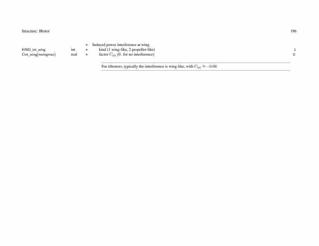
Structure: IRotor 196
+ Induced power interference at wingKIND_int_wing int + kind (1 wing-like, 2 propeller-like) 1
Cint_wing(nwingmax) real + factor Cint (0. for no interference) 0.
For tiltrotors, typically the interference is wing-like, with Cint∼= −0.06

197
Chapter 52
Structure: WRotor
Variable Type Description Default
+ Rotor Group, NDARC Weight ModelMODEL_config int + model (1 rotor, 2 tail rotor, 3 auxiliary thrust) 1
MODEL_Wblade int + blade weight model (1 AFDD82, 2 AFDD00, 3 lift offset, 4 Boeing, 5 GARTEUR, 6 Tishchenko) 1
MODEL_Whub int + hub and hinge weight model (1 AFDD82, 2 AFDD00, 3 lift offset, 4 Boeing, 5 GARTEUR, 6 Tishchenko) 1
MODEL_Wshaft int + inter-rotor shaft weight (from lift offset; 0 not included) 0
+ AFDD00 weight modelsMODEL_type int + hub weight equation depend on blade weight (for hub weight; 0 no, 1 yes) 1
KIND_rotor int + rotor kind (for blade weight; 1 tilting, 2 not) 2
+ AFDD00 and AFDD82: first flapwise natural frequency ν (per-rev at hover tip speed)flapfreq_blade real + blade (0. to use flapfreq) 0.
flapfreq_hub real + hub (0. to use flapfreq_blade) 0.
+ lift offset rotorMODEL_offset int + rotor tip clearance (for blade weight; 1 scaled, 2 fixed) 1
offset real + design lift offset L (roll moment/TR) 0.3
thick20 real + blade airfoil thickness-to-chord ratio τ.2R (at 20%R) 0.21
clearance_tip real + tip clearance, scaled s/R or fixed s (ft or m) 0.05
thick25 real + Boeing: blade airfoil thickness-to-chord ratio τ.25R (at 25%R) 0.15
MODEL_tr int + tail rotor weight model (1 AFDD, 2 Boeing, 3 GARTEUR) 1
thick70 real + GARTEUR: blade airfoil thickness-to-chord ratio τ.7R (at 70%R) 0.11
MODEL_aux int + auxiliary thrust weight model (1 AFDD10, 2 AFDD82, 3 Boeing, 4 GARTEUR, 5 Torenbeek) 1
thrust_aux real + AFDD82: design maximum thrust Tat 0.
power_aux real + AFDD10: design maximum power Pat 0.
material_aux real + AFDD10: material factor fm 1.

Structure: WRotor 198
rattach real + Boeing: blade attachment (fraction rotor radius) 0.09
fWfold real + blade fold weight ffold (fraction total blade weight) 0.
fWsupt real + rotor support structure weight (fraction maximum takeoff weight) 0.
Uduct real + duct weight per area Uduct (lb/ft2 or kg/m2) 1.5
MODEL_config: tail rotor and auxiliary thrust models use only rotor, support, and duct weights (not shaft, fold, orseparate blade and hub weights)duct weight only used for ducted fan configuration
for teetering and gimballed rotors, the flap frequency flapfreq_blade should be the coning frequency
The AFDD00 hub weight equation using the calculated blade weight (MODEL_type = 0) results in a lower averageerror, and best represents legacy rotor systems.Using the actual actual blade weight (MODEL_type = 1) is best for advanced technology rotors with blades lighter thantrend.
if thrust_aux=0, use design maximum thrust of rotor from sizing taskif power_aux=0, use design maximum power of rotor from sizing taskmaterial_aux=1 for composite construction, 1.20 for wood, 1.31 for aluminum spar, 1.44 for aluminum constructiondefault Ωprop is the reference rotor speed
typically fWfold = 0.04 for manual fold, 0.28 for automatic fold
rotor support structure weight must be consistent with engine support and pylon support weights of engine section
+ Custom Weight ModelWtParam_rotor(8) real + parameters 0.

199
Chapter 53
Structure: Wing
Variable Type Description Default
+ Wingtitle c*100 + titlenotes c*1000 + noteskWing int wing number
+ Geometrywingload real + wing loading W/S = fW WD/SfDGW real + fraction DGW fW (for wing loading) 1.0
area real + area Sspan real + span bchord real + chord cAspectRatio real + aspect ratio AR
wing parameters: for each wing; input two quantities, other two derived (SizeParam input)SET_wing = input two of (’area’ or wing loading ’WL’), (’span’ or ’ratio’ or ’radius’ or ’width’ or ’hub’ or ’panel’),
’chord’, aspect ratio ’aspect’
SET_wing = ’ratio+XX’ to calculate span from span of another wingSET_wing = ’radius+XX’ to calculate span from rotor radiusSET_wing = ’width+XX’ to calculate span from rotor radius, fuselage width, and clearance (tiltrotor)SET_wing = ’hub+XX’ to calculate span from rotor hub position (tiltrotor)SET_wing = ’panel+XX’ to calculate span from wing panel widths
if wing sized from wing loading (SET_wing=’WL+xx’), area = fDGW*DGW/wingload

Structure: Wing 200
+ Geometry+ rotors
nRotorOnWing int + number of rotors mounted on wing 0
RotorOnWing(nrotormax) int + rotor numbers+ span calculation
fSpan real + ratio wing span to span of other wing, or to rotor radius 1.0
otherWing int + other wing number 0
RotorForSpan int + rotor number for span (if nRotorOnWing=0) 0
RotorOnPanel(npanelmax) int + rotor at wing panel edgethick real + thickness ratio τw .23
fWidth_box real + wing torque box chord wtb (fraction wing chord) 0.45
RotorOnWing required for SET_wing = ’width’ or ’hub’; MODEL_wing = tiltrotor; SET_Vdrag = airfoil cd90
RotorOnPanel required for SET_panel = ’width’ or ’hub’
SET_wing = ’radius’ gets radius from RotorOnWing or RotorForSpan
taper, sweep, thickness used by weight equationstaper and sweep calculated for entire wing from wing panel geometry
fWidth_box used by tiltrotor weight equationsthick and fWidth_box used for fuel in wing
+ Geometry (for graphics)twist real + twist 0.
Geometry (derived)taper real taper ratiosweep real sweep (+ aft, deg)dihedral real dihedral (+ up, deg)MAC real mean aerodynamic chord cA
xAC real mean aerodynamic center chordwise offset from root aero center xA (+ aft)zAC real mean aerodynamic center vertical offset from root aero center zA (+ up)

Structure: Wing 201
+ Geometryloc_wing Location + aerodynamic center locationnPanel int + number of wing panels (maximum npanelmax) 1
KIND_ACoffset int + aero center offset (1 fixed, 2 fraction root chord, 3 fraction inboard chord) 1
+ Wing PanelsSET_panel(npanelmax) c*24 + panel parameters ’span+taper’
span_panel(npanelmax) real + span (one side), bp
area_panel(npanelmax) real + area (both sides), Sp
chord_panel(npanelmax) real + mean chord, cp
fspan_panel(npanelmax) real + ratio span to wing span (one side), bp/(b/2) 1.
farea_panel(npanelmax) real + ratio area to wing area (both sides), Sp/S 1.
fchord_panel(npanelmax) real + ratio mean chord to wing chord, cp/c 1.
+ panel edgesedge_panel(npanelmax) real + outboard edge, yE
fedge_panel(npanelmax) real + outboard edge, ηE = y/(b/2) 1.
lambdaI(npanelmax) real + inboard chord ratio, cI/cref 1.
lambdaO(npanelmax) real + outboard chord ratio, cO/cref 1.
+ aerodynamic center locussweep_panel(npanelmax) real + sweep Λp (deg, + aft) 0.
dihedral_panel(npanelmax) real + dihedral δp (deg, + up) 0.
dxAC_panel(npanelmax) real + chordwise offset at panel inboard edge xIp (+ aft) 0.
dzAC_panel(npanelmax) real + vertical offset at panel inboard edge zIp (+ up) 0.
+ control surfacesfchord_flap(npanelmax) real + flap chord �F = cF /cp (fraction panel chord) 0.25
fchord_flaperon(npanelmax) real + flaperon/aileron chord �f = cf/cp (fraction panel chord) 0.25
fspan_flap(npanelmax) real + flap span fb = bF /bp (fraction panel span) 0.5
fspan_flaperon(npanelmax) real + flaperon/aileron span fb = bf/bp (fraction panel span) 0.5
fAC_aileron(npanelmax) real + aileron aerodynamic center lateral position y 0.7
wing panels: SET_panel not required with only one panelSET_panel: specify consistent definition of panels (span, edge, area, chord)
panel span: ’span’ or ’bratio’, else free’span’ = input span_panel, bp
’bratio’ = input ratio to wing span, fspan_panel, bp/(b/2)

Structure: Wing 202
panel outboard edge: ’edge’, ’station’, ’width’, ’hub’, or ’adjust’ (not used for tip panel)’edge’ = input edge_panel, yE
’station’ = input fraction wing semispan fedge_panel, ηE = y/(b/2)’radius’ = from rotor radius’width’ = from rotor radius, fuselage width, and clearance (tiltrotor)’hub’ = from rotor hub position (tiltrotor)’adjust’ = from adjacent input panel span or span ratio
panel area or chord: ’area’, ’Sratio’, ’chord’, ’cratio’, ’taper’, else free’area’ = input area_panel, Sp
’Sratio’ = input ratio to wing area, farea_panel, Sp/S’chord’ = input chord_panel, cp
’cratio’ = input ratio to wing chord, fchord_panel, cp/c’taper’ = from chord ratios lambdaI and lambdaO
require consistent definition of panel spans and outboard edges, and consistent with SET_wing
all edges known (from input edge or station, or from adjacent panel span or span ratio)resulting edges unique and sequentialif wing span calculated from panel widths:
one and only one input panel span or span ratio that not used to define edgeif known span: no input panel span or span ratio that not used to define edge
panel area or chord:if one or more taper (and no free), calculate cref from wing areaif one (and only one) free, calculate Sp from wing area
fAC_aileron: from panel inboard edge, fraction panel spanfor nPanel=1, from centerline and fraction wing semispan
Derived geometryiSET_panel_span(npanelmax) int span (SET_panel_span, bratio, free)iSET_panel_edge(npanelmax) int edge (SET_panel_edge, station, radius, width, hub, adjust)iSET_panel_area(npanelmax) int area (SET_panel_area, Sratio, chord, cratio, taper, free)kind_area int kind area and chord solution (1 tapered panels, 2 free panel)chordI(npanelmax) real inboard chord cIp

Structure: Wing 203
chordO(npanelmax) real outboard chord cOp
eAC_aileron(npanelmax) real aileron aerodynamic center lateral position y (from centerline, fraction wing semispan)rArea_flap(npanelmax) real flap area/panel arearArea_flaperon(npanelmax) real flaperon-aileron area/panel areaKtef_flap(4,npanelmax) real trailing edge flap factors (Lf , Xf , Mf , Df )Ktef_flaperon(4,npanelmax) real trailing edge flap factors (Lf , Xf , Mf , Df )rArea_Wflap real total flap area/wing arearArea_Wflaperon real total flaperon-aileron area/wing areaisConsistent int consistent geometry (0 if calculated geometry not consistent)
+ Wing ExtensionsSET_ext int + extension (0 for none) 0
kPanel_ext int + wing panel number 2
KIT_ext int + wing extension as kit (0 not kit) 0
areaX real extension area SX (both sides)spanX real extension span bX (one side)areaI real inboard area (S − SX )spanI real inboard span (b − 2bX )area_flapI real inboard flap areaarea_flaperonI real inboard flaperon-aileron areaAspectRatioI real inboard wing aspect ratiosweepI real inboard wing sweeptaperI real inboard wing taper
+ Wing KitKIT_wing int + wing as kit (0 not, 1 kit, 2 kit as fixed useful load) 0
fWkit real + kit weight (fraction total wing weight) 0.
+ Controls (each panel)+ kind deflection
KIND_flap(npanelmax) int + flap (1 fraction root flap; 2 increment relative root flap; 3 independent) 3
KIND_aileron(npanelmax) int + aileron (1 fraction root aileron; 2 increment relative root aileron; 3 independent) 3
KIND_incid(npanelmax) int + incidence (1 fraction root incidence; 2 increment relative root incidence; 3 independent) 3
KIND_flaperon(npanelmax) int + kind flaperon deflection (1 fraction flap; 2 increment relative flap; 3 independent) 1

Structure: Wing 204
+ flap δFp
INPUT_flap(npanelmax) int + connection to aircraft controls (0 none, 1 input T matrix) 1
T_flap(ncontmax,nstatemax,npanelmax)
real + control matrixnVflap(npanelmax) int + number of speeds (0 zero value; 1 constant; ≥ 2 piecewise linear, maximum nvelmax) 0
flap(nvelmax,npanelmax) real + valuesVflap(nvelmax,npanelmax) real + speeds (CAS or TAS)
+ flaperon δfp
INPUT_flaperon(npanelmax) int + connection to aircraft controls (0 none, 1 input T matrix) 1
T_flaperon(ncontmax,nstatemax,npanelmax)
real + control matrixnVflaperon(npanelmax) int + number of speeds (0 zero value; 1 constant; ≥ 2 piecewise linear, maximum nvelmax) 0
flaperon(nvelmax,npanelmax)
real + valuesVflaperon(nvelmax,npanelmax)
real + speeds (CAS or TAS)+ aileron δap
INPUT_aileron(npanelmax) int + connection to aircraft controls (0 none, 1 input T matrix) 1
T_aileron(ncontmax,nstatemax,npanelmax)
real + control matrixnVaileron(npanelmax) int + number of speeds (0 zero value; 1 constant; ≥ 2 piecewise linear, maximum nvelmax) 0
aileron(nvelmax,npanelmax) real + valuesVaileron(nvelmax,npanelmax)
real + speeds (CAS or TAS)+ incidence ip
INPUT_incid(npanelmax) int + connection to aircraft controls (0 none, 1 input T matrix) 1
T_incid(ncontmax,nstatemax,npanelmax)
real + control matrixnVincid(npanelmax) int + number of speeds (0 zero value; 1 constant; ≥ 2 piecewise linear, maximum nvelmax) 0
incid(nvelmax,npanelmax) real + valuesVincid(nvelmax,npanelmax) real + speeds (CAS or TAS)

Structure: Wing 205
aircraft controls connected to individual controls of component, c = TcAC + c0
for each component control, define matrix T (for each control state) and value c0
flight state specifies control state, or that control state obtained from conversion schedulec0 can be zero, constant, or function of flight speed (CAS or TAS, piecewise linear input)by connecting aircraft control to comp control, flight state can specify comp control valueinitial values if control is connected to trim variable; otherwise fixed for flight state
+ Trim Target+ wing lift
nVlift int + number of speeds (0 zero value; 1 constant; ≥ 2 piecewise linear, maximum nvelmax)Klift(nvelmax) real + targetVlift(nvelmax) real + speeds (CAS or TAS)
target definition determined by Aircraft%trim_quant
Klift can be fraction total aircraft lift, lift, or CL
+ AerodynamicsMODEL_aero int + model (0 none, 1 standard) 1
Idrag real + incidence angle i for helicopter nominal drag (deg; 0 for not tilt) 0.
AWing AWing standard modelDerived drag
DoQC_wing real wing cruise drag, area (D/q)wing
DoQH_wing real wing helicopter drag, area (D/q)wing
DoQV_wing real wing vertical drag, area (D/q)wing
DoQ_wb real wing-body interference drag, area (D/q)wb
Swet real total wetted area Swet

Structure: Wing 206
+ WeightWeight Weight weight statement (component)
+ wing groupMODEL_weight int + model (0 input, 1 NDARC, 2 custom) 1
+ weight incrementdWprim real + wing primary structure 0.0
dWext real + wing extension 0.0
dWfair real + fairing 0.0
dWfit real + fittings 0.0
dWflap real + flaps and control surfaces 0.0
dWwfold real + wing fold 0.0
dWefold real + wing extension fold 0.0
WWing WWing NDARC model (except tiltrotor)WWingTR WWingTR NDARC tiltrotor model
+ tiltrotor modelxWtip real + increment for weight on wing tips 0.0
Wwing_total real wing weightWwing_ext real wing extension weightWwing_kit real wing kit weightWtip_total real weight on wing tips
+ Technology FactorsTECH_prim real + wing primary structure (torque box) weight χprim 1.0
TECH_ext real + wing extension weight χext 1.0
TECH_fair real + fairing weight χfair 1.0
TECH_fit real + fittings weight χfit 1.0
TECH_flap real + flaps and control surfaces weight χflap 1.0
TECH_wfold real + wing fold weight χfold 1.0
TECH_efold real + wing extension fold weight χefold 1.0
weight model result multiplied by technology factor and increment added:Wxx = TECH_xx*Wxx_model + dWxx; for fixed (input) weight use MODEL_xx=0 or TECH_xx=0.

Structure: Wing 207
tiltrotor model requires weight on wing tips: both sides; calculated as sum ofrotor group, engine section or nacelle group, air induction group,engine system, drive system (less drive shaft), rotary wing and conversion flight controls,hydraulic group, trapped fluids, wing tip extensions
xWtip adjusts Wtip_total, without changing weight statementsnegative increment required when engine and transmission not at tip location with rotor

208
Chapter 54
Structure: AWing
Variable Type Description Default
+ Wing Aerodynamics, Standard ModelAoA_zl real + zero lift angle of attack αzl (deg) 0.
CLmax real + maximum lift coefficient CLmax 1.5
SET_compress int + compressibility correction (0 none, 1 lift, 2 drag, 3 both) 0
+ liftSET_lift int + specification (2 2D dCL/dα; 3 3D dCL/dα) 2
dCLda real + lift curve slope CLα = dCL/dα (per rad) 5.73
Tind real + lift curve slope non-elliptical loading correction τ 0.25
Eind real + Oswald or span efficiency e (CDi = (CL − CL0)2/(πeAR)) 0.8
CL_Dmin real + lift coefficient for minimum induced drag CL0 0.0
dCLda3D real incompressible 3D lift curve slope CLα (derived)fDind real 1/(πeAR)AoA_max real αmax = CLmax/(dCL/dα3D) (deg)eta0 real + control effectiveness factor η0, η0 − η1|δ| 0.85
eta1 real + control effectiveness factor η1, η0 − η1|δ| 0.43
Mdiv real + lift-divergence Mach number Mdiv 0.75
+ pitch momentCMac real + pitch moment coefficient about aerdynamic center CMac 0.
+ Wing Drag, Standard Model+ forward flight drag
SET_drag int + specification (1 fixed, D/q; 2 scaled, CD) 2
DoQ real + area (D/q)0CD real + coefficient CD0 (based on wing area, D/q = SCD) 0.012
+ vertical dragSET_Vdrag int + specification (1 fixed, D/q; 2 scaled, CD; 3 airfoil cd90) 2
DoQV real + area (D/q)V
CDV real + coefficient, CDV (based on wing area, D/q = SCD) 2.

Structure: AWing 209
cd90 real + airfoil drag coefficient cd90 (–90 deg) 1.4
fd90 real + airfoil drag coefficient flap effectiveness factor fd90 2.5
CDcc real + compressibility drag increment CDcc at Mcc 0.0011
Mcc0 real + critical Mach number constant Mcc0 0.74
Mcc1 real + critical Mach number constant Mcc1 0.31
SET_xxx: fixed (use DoQ) or scaled (use CD); other parameter calculated
+ drag variation with angle of attackMODEL_drag int + model (0 none, 1 general, 2 quadratic) ΔCD = CD0Kd|αe|Xd 2
AoA_Dmin real + angle of attack for wing minimum drag αDmin (deg) 0.
Kdrag real + drag increment Kd 0.
Xdrag real + drag increment Xd 2.
MODEL_sep int + separated flow model (0 none, 1 general, 2 quadratic, 3 cubic) ΔCD = CD0Ks(|αe| − αs)Xs 3
AoA_sep real + angle of attack for separation αs (deg) 10.
Ksep real + drag increment Ks 0.
Xsep real + drag increment Xs 2.
Xd real drag exponent Xd (derived)Xs real drag exponent Xs (derived)
+ transition from forward flight drag to vertical dragAoA_tran real + angle of attack for transition αt (deg) 25.
Conventionally the Oswald efficiency e represents the wing parasite drag variation with lift, as well as the induced drag.If CDp varies with angle-of-attack, then e is just the span efficiency factor for the induced power (and CL0 should bezero).
+ wing-body interference dragSET_wb int + specification (1 fixed, D/q 2 scaled, CD) 1
DoQ_wb real + area (D/q)wb 0.
CD_wb real + coefficient CDwb (based on wing area, D/q = SCD) 0.

Structure: AWing 210
+ Interference velocityEtail(ntailmax) real + angle of attack change at tail, E = dε/dα (rad/rad) 0.
Kint_wing(nwingmax) real + interference factor Kint at other wings (0. for no interference) 0.
+ interference power factor Kint at rotors (0. for no interference)Kintn_rotor(nrotormax) real + normal (helicopter) 0.
Kintp_rotor(nrotormax) real + inplane (propeller) 0.
for tandem wings, typicallyKint_wing(aftwing)=2. for front-on-aft interferenceKint_wing(frontwing)=0. for aft-on-front interference
for biplane wings, typically Kint_wing(otherwing)=0.7
with mutual interference (as for biplane), require trim or other iteration for convergence
interference power: inplane (propeller) factor Kintp_rotor negative for favorable

211
Chapter 55
Structure: WWing
Variable Type Description Default
+ Wing Group, NDARC Weight ModelMODEL_wing int + model (1 area, 2 parametric, 3 tiltrotor, 4 other) 2
MODEL_other int + model (1 Boeing, 2 GARTEUR, Torenbeek (3 light, 4 transport), Raymer (5 transport, 6 general aviation))fLift real + lift factor 1.0
bFold real + parametric method: fraction wing span that folds bfold (0 to 1) 0.0
wfus real + Boeing: maximum fuselage width (fraction wing span)Vdive real + Boeing or Raymer: design dive speed Vdive (knots) 200.
rflaplift real + GARTEUR: ratio maximum lift with and without flaps+ area method
Uprim real + weight per area Uprim, wing primary structure (lb/ft2 or kg/m2) 5.
Uext real + weight per area Uext, wing extension (lb/ft2 or kg/m2) 3.
+ weight factors (fraction total wing weight)fWfair real + fairing ffair 0.10
fWfit real + fittings ffit 0.12
fWflap real + flaps and control surfaces fflap 0.10
fWfold real + wing fold ffold 0.0
fWefold real + wing extension fold fefold (fraction wing extension weight) 0.0
+ Custom Weight ModelWtParam_wing(8) real + parameters 0.

212
Chapter 56
Structure: WWingTR
Variable Type Description Default
+ Wing Group, NDARC Tiltrotor Weight Model+ jump takeoff condition
CTs_jump real + rotor maximum blade loading CT /σ 0.20
n_jump real + load factor njump at SDGW 2.0
Vtip_jump real + rotor tip speed (0. to use hover Vtip) 750.0
thickTR real + wing airfoil thickness-to-chord ratio τw 0.23
+ width of wing structural attachments to bodySET_Attach int + definition (0 input wAttach, 1 fraction fuselage width, 2 fraction wing span) 1
fAttach real + fraction width wattach/wfus 1.
wAttach real + width wattach (ft or m) 0.
fRG_pylon real + pylon radius of gyration rpylon/R (fraction rotor radius) 0.30
+ wing mode frequencies (per rev, fraction rotor speed)freq_beam real + beam bending frequency ωB 0.5
freq_chord real + chord bending frequency ωC 0.8
freq_tors real + torsion frequency ωT 0.9
SET_refrpm int + reference rotor speed (0 from input Vtip_freq, 1 hover Vtip, 2 cruise Vtip) 0
Vtip_freq real + rotor tip speed 600.
MODEL_form int + form factors (1 calculate, 2 input) 1
form_beam real + torque box beam bending FB 0.6048
form_chord real + torque box chord bending FC 0.4874
form_tors real + torque box torsion FT 1.6384
form_spar real + spar caps vertical/horizontal bending FV H 0.5018
eff_spar real + spar structural efficiency esp 0.8
eff_box real + torque box structural efficiency etb 0.8
+ tapered spar cap correction factorsC_t real + weight correction Ct (equivalent stiffness) 0.75
C_j real + weight correction Cj (equivalent strength) 0.50
C_m real + strength correction Cm (equivalent stiffness) 1.5

Structure: WWingTR 213
+ material (lb/in2, in/in, lb/in3; or N/m2, m/m, kg/m3)E_spar real + spar modulus Esp 10.E6
E_box real + torque box modulus Etb 10.E6
G_box real + torque box shear modulus Gtb 4.0E6
StrainU_spar real + spar ultimate strain allowable εU 0.01
StrainU_box real + torque box ultimate strain allowable εU 0.01
density_spar real + density spar cap ρsp 0.06
density_box real + density torque box ρtb 0.06
+ weight per area (lb/ft2 or kg/m2)Ufair real + fairing Ufair 2.
Uflap real + flaps and control surfaces Uflap 3.
UextTR real + wing extension Uext 3.
+ weight factorfWfitTR real + fittings ffit (fraction maximum thrust of one rotor) 0.01
fWfoldTR real + wing fold ffold (fraction total wing weight excluding fold) 0.0
fWefoldTR real + wing extension fold fefold (fraction wing extension weight) 0.0
jump takeoff: hover Vtip obtained from RotorOnWing(1) rotor
wing frequencies: reference rotor rotation speed from rotor Vtip and radiusfrom RotorOnWing(1) rotor; hover tip speed Vtip_ref(1), cruise Vtip_cruise
thickTR only used for tiltrotor wing weight
SET_Attach: attachment width used for both torsion stiffness and fairing area
+ Custom Weight ModelWtParam_wingtr(8) real + parameters 0.

214
Chapter 57
Structure: Tail
Variable Type Description Default
+ Empennagetitle c*100 + titlenotes c*1000 + notesKIND_tail int + kind (1 horizontal tail, 2 vertical tail, 3 V-tail horizontal, 4 V-tail vertical) 1
isHortail int horizontal tail (0 vertical)isVtail int V-tail (0 not)kTail int tail number
+ GeometrySET_tail c*16 + specification ’vol+aspect’
area real + area Sspan real + span bchord real + chord cAspectRatio real + aspect ratio ARTailVol real + tail volume VKIND_TailVol int + tail volume reference (1 wing, 2 rotor) 2
TailVolRef int + wing or rotor number for tail volume 1
otherVtail int + other V-tail number
KIND_tail used for geometry, baseline orientation, tail volume, tail weight modeltail parameters: input two quantities, others calculated
SET_tail = input two of (’area’ or tail volume ’vol’), (’span’ or aspect ratio ’aspect’ or ’chord’)tail volume reference: tail volume V = S�/RA (tailarea * taillength / (diskarea * radius))
or horizontal tail volume V = S�/Swcw (tailarea * taillength / (wingarea * wingchord))or vertical tail volume V = S�/Swbw (tailarea * taillength / (wingarea * wingspan))

Structure: Tail 215
V-tail: modeled as pair of horizontal and vertical tails (identified by otherVtail)separately sized, aerodynamic loads for each; dihedral calculated, cant set to zeroweight only for second tail, based on V-tail area and aspect ratio
+ Geometry (for graphics and weights)taper real + taper ratio 1.0
sweep real + sweep (+ aft, deg) 0.
dihedral real + dihedral (deg) 0.
thick real + thickness ratio .12
Derived geometryiSet_tail_area int area (SET_tail_area, vol)iSet_tail_len int length (SET_tail_span, AR, chord)Length_tail real tail length �rArea_control real control surface area/tail areaKtef_cont(4) real trailing edge flap factors (Lf , Xf , Mf , Df )CBF(3,3) real tail axes relative airframe, CBF
areaVtail real V-tail area SV
spanVtail real V-tail span bV
AspectRatioVtail real V-tail aspect ratio
+ Geometryloc_tail Location + aerodynamic center locationcant real + cant angle φ (deg) 0.0
fchord_cont real + control surface chord cf/c (fraction tail chord) 0.25
fspan_cont real + control surface span bf/b (fraction tail span) 1.0
+ Controls+ elevator δe or rudder δr
INPUT_cont int + connection to aircraft controls (0 none, 1 input T matrix) 1
T_cont(ncontmax,nstatemax) real + control matrixnVcont int + number of speeds (0 zero value; 1 constant; ≥ 2 piecewise linear, maximum nvelmax) 0
cont(nvelmax) real + valuesVcont(nvelmax) real + speeds (CAS or TAS)

Structure: Tail 216
+ incidence iINPUT_incid int + connection to aircraft controls (0 none, 1 input T matrix) 1
T_incid(ncontmax,nstatemax)
real + control matrixnVincid int + number of speeds (0 zero value; 1 constant; ≥ 2 piecewise linear, maximum nvelmax) 0
incid(nvelmax) real + valuesVincid(nvelmax) real + speeds (CAS or TAS)
horizontal tail cant angle: + to left (vertical tail for cant = 90)vertical tail cant angle: + to right (horizontal tail for cant = 90)
aircraft controls connected to individual controls of component, c = TcAC + c0
for each component control, define matrix T (for each control state) and value c0
flight state specifies control state, or that control state obtained from conversion schedulec0 can be zero, constant, or function of flight speed (CAS or TAS, piecewise linear input)by connecting aircraft control to comp control, flight state can specify comp control valueinitial values if control is connected to trim variable; otherwise fixed for flight state
+ AerodynamicsMODEL_aero int + model (0 none, 1 standard) 1
ATail ATail standard modelDerived drag
DoQ_tail real tail drag, area (D/q)tailDoQV_tail real tail vertical drag, area (D/q)V tail
Swet real total wetted area
+ WeightWeight Weight weight statement (component)
+ tail (empennage group)MODEL_weight int + model (0 input, 1 NDARC, 2 custom) 1
+ weight incrementdWtail real + basic 0.0

Structure: Tail 217
dWfold real + fold 0.0
WTail WTail NDARC modelWtail_total real tail weight
+ Technology FactorsTECH_tail real + tail weight χht or χvt 1.0
TECH_tfold real + fold weight χfold 1.0
weight model result multiplied by technology factor and increment added:Wxx = TECH_xx*Wxx_model + dWxx; for fixed (input) weight use MODEL_xx=0 or TECH_xx=0.

218
Chapter 58
Structure: ATail
Variable Type Description Default
+ Tail Aerodynamics, Standard ModelAoA_zl real + zero lift angle of attack αzl (deg) 0.
CLmax real + maximum lift coefficient CLmax 1.
SET_compress int + compressibility correction (0 none, 1 lift, 2 drag, 3 both) 0
+ liftSET_lift int + specification (2 2D dCL/dα; 3 3D dCL/dα) 2
dCLda real + lift curve slope CLα = dCL/dα (per rad) 5.73
Tind real + lift curve slope non-elliptical loading correction τ 0.25
Eind real + Oswald efficiency e (CDi = (CL − CL0)2/(πeAR)) 0.8
CL_Dmin real + lift coefficient for minimum induced drag CL0 0.0
dCLda3D real incompressible 3D lift curve slope CLα (derived)fDind real 1/(πeAR)AoA_max real αmax = CLmax/(dCL/dα3D) (deg)eta0 real + control effectiveness factor η0, η0 − η1|δ| 0.85
eta1 real + control effectiveness factor η1, η0 − η1|δ| 0.43
Mdiv real + lift-divergence Mach number Mdiv 0.75
+ Tail Drag, Standard Model+ forward flight drag
SET_drag int + specification (1 fixed, D/q; 2 scaled, CD) 2
DoQ real + area (D/q)0CD real + coefficient CD0 (based on tail area, D/q = SCD) 0.011
+ vertical dragSET_Vdrag int + specification (1 fixed, D/q; 2 scaled, CD) 2
DoQV real + area (D/q)V
CDV real + coefficient CDV (based on tail area, D/q = SCD) 1.

Structure: ATail 219
CDcc real + compressibility drag increment CDcc at Mcc 0.0011
Mcc0 real + critical Mach number constant Mcc0 0.74
Mcc1 real + critical Mach number constant Mcc1 0.31
SET_xxx: fixed (use DoQ) or scaled (use CD); other parameter calculated
+ drag variation with angle of attackMODEL_drag int + model (0 none, 1 general, 2 quadratic) ΔCD = CD0Kd|αe|Xd 2
AoA_Dmin real + angle of attack for tail minimum drag αDmin (deg) 0.
Kdrag real + drag increment Kd 0.
Xdrag real + drag increment Xd 2.
Xd real exponent Xd (derived)+ transition from forward flight drag to vertical drag
AoA_tran real + angle of attack for transition αt (deg) 25.

220
Chapter 59
Structure: WTail
Variable Type Description Default
+ Tail, NDARC Weight ModelMODEL_tail int + model (1 horizontal tail, 2 vertical tail, 3 based on KIND_tail) 3
+ horizontal tailMODEL_Htail int + model (1 helicopter or compound, 2 tiltrotor or tiltwing, 3 area, 4 other) 1
MODEL_Hother int + model (1 GARTEUR, Torenbeek (2 low speed, 3 transport), Raymer (4 transport, 5 general aviation))KIND_Htail int + Torenbeek or Raymer: kind (1 fixed, 2 variable incidence) 1
wfus real + Raymer: fuselage width at horizontal tail wf/bht (fraction span) 0.2
+ vertical tailMODEL_Vtail int + model (1 helicopter or compound, 2 tiltrotor or tiltwing, 3 area, 4 other) 1
MODEL_Vother int + model (1 GARTEUR, Torenbeek (2 low speed, 3 transport), Raymer (4 transport, 5 general aviation))place_AntiQ int + AFDD: antitorque placement (0 none, 1 on tail boom, 2 on vertical tail) 1
KIND_Vtail int + Torenbeek or Raymer: kind (1 conventional, 2 T-tail) 1
fTtail real + Torenbeek: T-tail factor (Shthht)/(Svtbvt) 0.8
Vdive real + design dive speed Vdive (knots) 200.
+ area methodUtail real + weight per area Utail (lb/ft2 or kg/m2) 3.
fTfold real + fold weight factor ffold (fraction total tail weight excluding fold) 0.0
weight models can use taper ratio, sweep, and thickness ratiodive speed: Vmax = SLS max speed, Vdive = 1.25Vmax
+ Custom Weight ModelWtParam_tail(8) real + parameters 0.

221
Chapter 60
Structure: FuelTank
Variable Type Description Default
+ Fuel Tank Systemtitle c*100 + titlenotes c*1000 + noteskTank int tank number
+ ConfigurationSET_burn int + fuel quantity stored and used (1 weight, 2 energy) 1
+ fuel weight propertiesfuel_density real + fuel weight per volume ρfuel (lb/gallon or kg/liter) 6.5
specific_energy real + fuel energy per weight efuel (MJ/kg) 42.8
fFuelWing(nwingmax) real + fraction wing torque box filled by fuel tanks 1.0
+ fuel tank sizingWfuel_cap real + fuel capacity Wfuel−cap (weight, lb or kg)Efuel_cap real + fuel capacity Efuel−cap (energy, MJ)fFuel_cap real + ratio capacity to mission fuel ffuel−cap 1.0
dFuel_cap real + capacity increment dfuel−cap 0.0
IDENT_battery c*16 + battery identification ’ ’
store and use weight: energy calculated from weightuse Wfuel_cap, Waux_cap, fuel_density, specific_energy, fFuelWing; fWtank, fWauxtank, other weight parameters
store and use energy: fuel weight zerouse Efuel_cap, Eaux_cap, IDENT_battery; eWtank, eWauxtank, energy_density, other weight parameters

Structure: FuelTank 222
fuel tank sizing: usable fuel capacity Wfuel_cap (weight) or Efuel_cap (energy)SET_tank=’input’: input Wfuel_cap or Efuel_cap
SET_tank=’miss’: calculate from mission fuel usedWfuel_cap or Efuel_cap = max(fFuel_cap*(maximum mission fuel), (maximum mission fuel)+(reserve fuel))
SET_tank=’miss+power’ = calculate from mission fuel used and mission battery discharge powerSET_tank=’f(miss)’ = function of mission fuel used
Wfuel_cap or Efuel_cap = dFuel_cap + fFuel_cap*((maximum mission fuel)+(reserve fuel))
battery identification: energy storage only, match ident of BatteryModel
+ Geometry (for graphics)place int + placement (1 internal, 2 sponson, 3 wing, 4 combination) 1
+ Auxiliary Fuel TankMauxtanksize int + number of auxiliary tank sizes (minimum 1, maximum nauxtankmax) 1
Waux_cap(nauxtankmax) real + fuel capacity Waux−cap (weight) 1000.
Eaux_cap(nauxtankmax) real + fuel capacity Eaux−cap (energy) 20000.
fWauxtank(nauxtankmax) real + tank weight fauxtank (fraction auxiliary fuel weight) 0.
eWauxtank(nauxtankmax) real + tank weight eauxtank (MJ/kg) 0.
DoQ_auxtank(nauxtankmax) real + drag (D/q)auxtank (each tank)loc_auxtank(nauxtankmax) Location + location
+ Equipment powerMODEL_Peq int + model (0 for none) 0
sfc real + specific fuel consumption 0.0
Peq_0 real + power loss Peq0, constant 0.0
Peq_d real + power loss Peqd, scale with density 0.0
Peq_t real + power loss Peqt, scale with temperature 0.0
Peq_deice real + deice power loss Peqi 0.0
specific fuel consumption: weight (lb/hp-hr or kg/kW-hr) or energy (MJ/hp-hr or MJ/kW-hr)

Structure: FuelTank 223
DerivedVfuel_cap real fuel capacity Vfuel−cap (volume)Wfuel_wing real wing fuel capacity Wfuel−wing
rWfuel_wing real wing fuel capacity (fraction Wfuel_cap)ncomp_in_tank int number of components in fuel tank systemkBatteryModel int battery identification (BatteryModel, from IDENT_battery)specific_power real specific power πtank = xmbdetank/3.6 (kW/kg)
+ WeightWeight Weight weight statement (component, not including auxiliary tanks)
+ fuel system (propulsion group)MODEL_weight int + model (0 input, 1 NDARC, 2 custom) 1
+ weight incrementdWtank real + tanks and support; battery management system 0.
dWplumb real + plumbing; power distribution (wiring) 0.
WTank WTank NDARC modelNeng int number of main enginesfuelflow real total fuel flow F at DGW takeoff conditions (lb/hr or kg/hr)
+ Technology FactorsTECH_tank real + fuel tank weight χtank 1.0
TECH_plumb real + plumbing weight χplumb 1.0
weight model result multiplied by technology factor and increment added:Wxx = TECH_xx*Wxx_model + dWxx; for fixed (input) weight use MODEL_xx=0 or TECH_xx=0.

224
Chapter 61
Structure: WTank
Variable Type Description Default
+ Fuel System, NDARC Weight Model+ weight storage+ fuel tank
MODEL_tank int + model (1 fraction, 2 parametric, Torenbeek (3 integral, 4 generic), Raymer (5 transport, 6 general aviation)) 2
ntank_int int + number of internal tanks Nint 4
fWtank real + tank weight ftank (fraction fuel capacity weight) 0.09
Ktoler real + parametric: ballistic tolerance factor fbt (1.0 to 2.5) 2.5
KIND_crash int + parametric: survivability (1 baseline, 2 UTTAS/AAH level of survivability) 2
Ktank real + Torenbeek (generic): factor Ktank 3.2
Xtank real + Torenbeek (generic): exponent Xtank 0.727
fint real + Raymer: integral tank capacity (fraction total) 1.0
fprot real + Raymer: protected tank capacity (fraction total) 1.0
+ plumbingMODEL_plumb int + model (1 fraction, 2 parametric) 2
nplumb int + total number of fuel tanks (internal and auxiliary) for plumbing Nplumb 4
K0_plumb real + weight increment K0plumb (lb) 150.
K1_plumb real + weight factor K1plumb (lb) 2.0
fWplumb real + plumbing weight fplumb (fraction total fuel system weight) 0.4
+ energy storageeWtank real + tank weight etank (MJ/kg)energy_density real + tank volume density ρtank (MJ/liter)fBMS real + battery management system (fraction basic tank weight) 0.2
fwire real + power distribution (wiring) weight (fraction basic tank weight) 0.2
MODEL_tank: fraction method uses fWtank; parametric method uses ntank_int, Ktoler, KIND_crash

Structure: WTank 225
K1_plumb is a crashworthiness and survivability factor; typically K1_plumb = 2.K0_plumb is the sum of weights for auxiliary fuel, in-flight refueling, pressure refueling, inerting system, etc.; typicallyK0_plumb = 50 to 250 lb
+ Custom Weight ModelWtParam_tank(8) real + parameters 0.

226
Chapter 62
Structure: Propulsion
Variable Type Description Default
+ Propulsion Grouptitle c*100 + titlenotes c*1000 + notes
propulsion group is set of components and engine groups, connected by drive systemcomponents (rotors) define power required, engine groups define power availabledrive system defines ratio of rotational speeds of components (relative primary rotor speed)
kPropulsion int propulsion group number
SpecificationkRotor_prim int primary rotorrotor_in_group(nrotormax) int rotors in group (0 no, 1 main rotor, 2 other)nRotor int number of rotors in groupnRotor_main int number of main rotorskEngine_prim int primary engine groupengine_in_group(nengmax) int engine groups in propulsion group (0 no, 1 only produce power, 2 can consume power)nEngineGroup int number of engine groupsfirstEngineGroup int first engine groupcanConsumePower int engine group generator or compressor, can consume shaft power (0 only produce power)
+ Drive systemnGear int + number of states (maximum ngearmax) 1
STATE_gear_var int + drive system state for variable speed transmisson (0 for none) 0

Structure: Propulsion 227
drive system branches: one primary rotor per propulsion group (specify Vtip), others dependent (specify gear ratio)specify primary engine group only if no rotors in propulsion group
drive system state: identifies gear ratio set for multiple speed transmissionsstate=0 to use conversion schedule, state=n (1 to nGear) to use gear ratio #n
variable speed transmission: for drive system state STATE_gear_var, gear ratio factor fgear (control) includedwhen evaluate rotational speed of dependent rotors and engines
+ Transmission lossesMODEL_Xloss int + model (1 fraction component power required; 2 with function drive shaft limit) 2
fPloss_xmsn real + gear box loss �xmsn (fraction total component power required) 0.04
Ploss_windage real + power loss due to windage Pwindage 0.0
+ Accessory lossesPacc_0 real + power loss Pacc0, constant 0.0
Pacc_d real + power loss Paccd, scale with density 0.0
Pacc_n real + power loss Paccn, scale with density and rpm 0.0
Pacc_deice real + deice power loss Pacci 0.0
fPacc_ECU real + ECU (etc.) power loss �acc (fraction component+transmission power) 0.0
fPacc_IRfan real + IRS fan loss �IRfan (fraction total engine power) 0.0
+ GeometrySET_length int + drive shaft length (1 input; 2 calculated) 2
Length_ds real + length �DS
fLength_ds real + factor 0.9
SET_length: input (use Length_ds) or calculated (from fLength_ds)
+ Drive system torque limitPlimit_ds real + drive system power limit PDSlimit
fPlimit_ds real + drive system power limit factor 1.0

Structure: Propulsion 228
+ Drive system ratingsnrate_ds int + number of ratings (1 for only continuous, maximum nratemax) 1
rating_ds(nratemax) c*12 + drive system rating designation ’ ’
frating_ds(nratemax) real + torque limit factor 1.0
Derived drive system limitQlimit_ds real drive system torque limit (PDSlimit at primary rotor reference speed)krateC_ds int MCQ or MCP rating numberarating_ds(nratemax) c*12 drive system rating designationxrating_ds(nratemax) real torque limit factor (f/fMCQ)
drive system torque limits: SET_limit_ds = input (use Plimit_xx) or calculate (from fPlimit_xx)SET_limit_ds=’input’: Plimit_ds inputSET_limit_ds=’ratio’: from takeoff power, fPlimit_ds
∑(NengPeng)
SET_limit_ds=’Pav’: from engine power available at transmission sizing conditions and missions (DESIGN_xmsn)fPlimit_ds(Ωref/Ωprim)
∑(NengPav)
SET_limit_ds=’Preq’: from engine power required at transmission sizing conditions and missions (DESIGN_xmsn)fPlimit_ds(Ωref/Ωprim)
∑(NengPreq)
engine shaft: options for SET_limit_ds�=’input’
SET_limit_es=0: Plimit_es
SET_limit_es=1: fPlimit_es × (engine group Peng or Pav or Preq , depending on SET_limit_ds)SET_limit_es=2: fPlimit_es ×PDSlimit(PengEG/PengPG)
drive system power limit: corresponds to power of all engines of propulsion group (all engine groups)can be used for trim (trim_quant=’Q margin’)used for drive system weight, tail rotor weight, transmission losseslimits propulsion group Pav (if FltState%SET_Plimit=on)
engine shaft power limit: corresponds to all engines of engine group (nEngine × Peng)limits engine group Pav (if FltState%SET_Plimit=on)
rotor shaft power limit: corresponds to one rotorall limits
can be used for max effort in flight state (max_quant=’Q margin’)can be used for max gross weight in flight condition or mission (SET_GW=’maxQ’ or ’maxPQ’)always check and print whether exceed torque limit

Structure: Propulsion 229
the engine model gives the power available, accounting for installation losses and mechanical limitsthen the power available is reduced by the factor FltState%fPower
next torque limits are applied (unless FltState%SET_Plimit=off), first engine shaft limit and then drive system limit
drive system ratings: must include maximum continuous (’MCQ’ or ’MCP’)blank to use engine ratings of first engine grouplimit at flight state is rxPlimit, where r is the rotor speed ratio and x is the rating factorif nrate_ds≤ 1, drive system rating not used
+ Control+ rotational speed increment ΔN , primary rotor or primary engine (rpm)
INPUT_DN int + connection to aircraft controls (0 none, 1 input T matrix) 0
T_DN(ncontmax,nstatemax) real + control matrixnVDN int + number of speeds (0 zero value; 1 constant; ≥ 2 piecewise linear, maximum nvelmax) 0
DN(nvelmax) real + valuesVDN(nvelmax) real + speeds (CAS or TAS)
aircraft controls connected to individual controls of component, c = TcAC + c0
for each component control, define matrix T (for each control state) and value c0
flight state specifies control state, or that control state obtained from conversion schedulec0 can be zero, constant, or function of flight speed (CAS or TAS, piecewise linear input)by connecting aircraft control to comp control, flight state can specify comp control valueinitial values if control is connected to trim variable; otherwise fixed for flight state
+ WeightWeight Weight weight statement (component, not including EngineGroup)
+ drive system (propulsion group)MODEL_DS int + model (0 input, 1 NDARC, 2 custom) 1
+ weight incrementdWgb real + gear box 0.

Structure: Propulsion 230
dWrs real + rotor shaft 0.
dWds real + drive shaft 0.
dWrb real + rotor brake 0.
dWcl real + clutch 0.
dWgd real + gas drive 0.
WDrive WDrive NDARC modelSTATE_gear_wt int + drive system state for weight 1
kEngineGroup_wt int + EngineGroup for weight 1
Wtip real weight on wing tipWgbrs real weight gear box and rotor shaft
+ Technology FactorsTECH_gb real + gear box weight χgb 1.0
TECH_rs real + rotor shaft weight χrs 1.0
TECH_ds real + drive shaft weight χds 1.0
TECH_rb real + rotor brake weight χrb 1.0
TECH_cl real + clutch weight χcl 1.0
TECH_gd real + gas drive weight χgd 1.0
weight model result multiplied by technology factor and increment added:Wxx = TECH_xx*Wxx_model + dWxx; for fixed (input) weight use MODEL_xx=0 or TECH_xx=0.
drive system weight = gear box (including rotor shaft) + drive shaft + rotor brake + clutch + gas drivetiltrotor wing weight model requires weight on wing tip (drive system, without rotor shaft)

231
Chapter 63
Structure: WDrive
Variable Type Description Default
+ Drive System, NDARC Weight Model+ gear box (including rotor shafts)
MODEL_gbrs int + model (1 AFDD83, 2 AFDD00, 3 other) 1
MODEL_other int + model (1 Boeing, 2 Boeing (alternate), GARTEUR (3 helicopter, 4 tiltrotor), 5 Tishchenko)fShaft real + rotor shaft weight frs (fraction gear box and rotor shaft weight) 0.13
ngearbox int + AFDD83: number of gear boxes Ngb 7
fTorque real + AFDD83: second (main or tail) rotor rated torque fQ (fraction total drive system rated torque) 0.03
nstage int + Boeing: number of stages in main-rotor drive 4
KIND_other int + other: separate tail rotor drive weight increment (0 none) 0
Ktrgb real + tail rotor drive weight increment factor Ktrgb 1.0
fPower_tr real + tail rotor power (fraction total drive system rated power) 0.15
gear_tr real + tail rotor gear ratio 5.0
+ drive shaft (AFDD82)ndriveshaft int + number of intermediate drive shafts Nds (excluding rotor shafts) 6
fPower real + second (main or tail) rotor rated power fP (fraction total drive system rated power) 0.15
fPower = fTorque*(otherrotor RPM)/(mainrotor RPM)typically fTorque=fPower=0.6 for twin main rotors (tandem, coaxial, tiltrotor)for single main rotor and tail rotor, fTorque = 0.03, fPower = 0.15 (0.18 for 2-bladed teeter)
typically fShaft = 0.13 (data range 0.06 to 0.20)
+ Custom Weight ModelWtParam_drive(8) real + parameters 0.

232
Chapter 64
Structure: EngineGroup
Variable Type Description Default
+ Engine Grouptitle c*100 + titlenotes c*1000 + noteskEngineGroup int engine group number
+ DescriptionMODEL_engine c*32 + engine model ’RPTEM’
IDENT_engine c*16 + engine identification ’Engine’
IDENT_system2 c*16 + second system identification ’ ’
nEngine int + number of engines Neng 1
nEngine_main int + number of main engines 1
Peng real + engine power Peng (SLS static at takeoff rating, 0. for P0_ref(rating_to)) 0.
rating_to c*12 + takeoff power rating ’MCP’
rating_idle c*12 + idle power rating ’MCP’
kFuelTank int + fuel tank system number 1
kRotor_react int + rotor number for reaction drive+ Propulsion Group
kPropulsion int + group number 1
KIND_xmsn int + drive system branch (1 primary, 0 dependent) 0
INPUT_gear int + gear ratio input (1 from Nspec, 2 gear) 1
gear(ngearmax) real + engine gear ratio r = Ωspec/Ωprim (ratio rpm to rpm of primary rotor in propulsion group) 1.0
DerivediMODEL_engine int engine model (MODEL_engine_xxx)KIND_engine int engine model (MODEL_engine_RPTEM, table, recip, comp, motor)canConsumePower int can consume shaft power (0 only produce power), generator or compressorcanProducePower int can produce shaft power (0 only consume power)isConvertReact int convertible engine, reaction drive (0 not)isConvertJet int convertible engine, turbojet/fan (0 not)

Structure: EngineGroup 233
kModel_eng int identification (EngineModel or EngineTable or RecipModel or CompressorModel or MotorModel, from IDENT_engine)kModel_sys2 int identification (EngineModel, from IDENT_system2)kBattery int battery model, from kFuelTank (0 for none)nrate int number of ratingsrating(nratemax) c*12 rating designations (lowercase)krateC int MCP rating numberkrate_to int takeoff power rating numberWOneEng real weight one engine Wone eng
Nref real reference engine speed (at drive state #1)
MODEL_engine: engine model’RPTEM’, ’shaft’ = turboshaft engine (RPTEM); IDENT_engine → EngineModel; fuel is weight’table’ = turboshaft engine (table); IDENT_engine → EngineTable; fuel is weight’recip’ = reciprocating engine; IDENT_engine → RecipModel; fuel is weight’comp’ = compressor; IDENT_engine → CompressorModel; not use fuel’comp+react’ = compressor for reaction drive; IDENT_engine → CompressorModel; not use fuel’motor’ = electric motor; IDENT_engine → MotorModel; fuel is energy’gen’ = electric generator; IDENT_engine → MotorModel; fuel is energy (generated, not burned)’motor+gen’ = motor + generator (mode B ≥ 0 for motor); IDENT_engine → MotorModel; fuel is energy’motor+cell’ = motor + fuel cell; IDENT_engine → MotorModel; fuel is weight
MODEL_engine: convertible engine; only with turboshaft’+react’ = reaction drive (mode B = 1); IDENT_system2 → EngineModel
’+jet’, ’+fan’ = turbojet/turbofan (mode B = 1); IDENT_system2 → EngineModel
engine identification: match ident of EngineModel or EngineTable or RecipModel or CompressorModel or MotorModel
second system identification: match ident of EngineModel; not use weightnumber of main engines: for fuel tank weight
for fixed engine: use Peng = 0. and no size task (or engine power not sized)takeoff power rating: for engine scaling, aircraft power loading, fuel tank weightFltState%rating can be set to ’idle’ (rating_idle) or ’takeoff’ (rating_to)
fuel tank system identified for burn must store and use weight (turboshaft, reciprocating, fuel cell)or energy (motor, may have BatteryModel)
fuel tank system identified for generation must store and use energy (may have BatteryModel)

Structure: EngineGroup 234
drive system branch: primary engine group only designated if no rotors for propulsion groupINPUT_gear: calculate gear from Nspec and Vtip_ref of primary rotor of propulsion group, or specify gear ratiovariable speed transmission: for drive system state STATE_gear_var, gear ratio factor fgear (control) included
when evaluate rotational speed of engine
+ SizingSET_power int + specification (0 sized, 1 fixed) 0
fPsize real + sized power ratio fn 1.0
SET_power: used if SIZE_perf=’engine’, to distribute power required among engine groupsmust size at least first engine group; SET_power and fPsize values not used for first groupcalculate fPsize for first engine group, must be > 0.
FltState%SET_Preq specifies distribution of power required for flight state
Engine model performance parameters (one engine)P0(nratemax) real power (P0)SP0(nratemax) real specific power (SP0)Pmech(nratemax) real mechanical limit of power (Pmech or Ppeak)sfc0C real specific fuel consumption at MCP (sfc0C)Fg0C real gross jet thrust at MCP (Fg0C = ST0Cm0C)Nspec real specification engine speed (Nspec)Nopt0C real optimum engine speed at MCP (Nopt0C)mdot0C real mass flow at MCP (m0C = P0C/SP0C)wdot0C real fuel flow at MCP (w0C = sfc0CP0C)sfc0(nratemax) real specific fuel consumption (sfc0)
Engine model performance parameters (one engine), ratio converted to basersfc0C_conv real specific fuel consumption at MCPrFg0C_conv real gross jet thrust at MCP, jet/fan onlyrwdot0C_conv real fuel flow at MCP

Structure: EngineGroup 235
reciprocating: only P0, Pmech, Nspec used, and sfc0
motor or generator: only P0, Pmech, Nspec usedmotor + fuel cell: and mdot0C, wdot0C, sfc0C, with Fg0C=0
+ Drive system torque limitSET_limit_es int + engine shaft (0 input, 1 fraction power, 2 fraction drive system limit) 1
Plimit_es real + engine shaft power limit PESlimit
fPlimit_es real + engine shaft power limit factor 1.0
Derived engine shaft limitQlimit_es real engine shaft torque limit (PESlimit at engine reference speed)
drive system torque limits: SET_limit_ds = input (use Plimit_es) or calculated (from fPlimit_es)SET_limit_ds=’input’: Plimit_ds inputSET_limit_ds=’ratio’: from takeoff power, fPlimit_ds
∑(NengPeng)
SET_limit_ds=’Pav’: from engine power available at transmission sizing conditions and missions (DESIGN_xmsn)fPlimit_ds(Ωref/Ωprim)
∑(NengPav)
SET_limit_ds=’Preq’: from engine power required at transmission sizing conditions and missions (DESIGN_xmsn)fPlimit_ds(Ωref/Ωprim)
∑(NengPreq)
engine shaft: options for SET_limit_ds�=’input’
SET_limit_es=0: Plimit_es
SET_limit_es=1: fPlimit_es × (engine group Peng or Pav or Preq , depending on SET_limit_ds)SET_limit_es=2: fPlimit_es ×PDSlimit(PengEG/PengPG)
engine shaft power limit: corresponds to all engines of engine group (nEngine × Peng)limits engine group Pav (if FltState%SET_Plimit=on)can be used for max effort in flight state (max_quant=’Q margin’)can be used for max gross weight in flight condition or mission (SET_GW=’maxQ’ or ’maxPQ’)always check and print whether exceed torque limit

Structure: EngineGroup 236
+ InstallationKffd real + deterioration factor on engine fuel flow or performance Kffd 1.05
eta_d real + engine inlet efficiency ηd (fraction, for δM ) 0.98
+ power losses (fraction power available, Ploss/Pa)fPloss_inlet real + engine inlet loss �in 0.0
fPloss_ps real + inlet particle separator loss �in 0.0
fPloss_exh real + engine exhaust loss �ex (IRS off) 0.015
+ auxiliary air momentum drag (IRS off)fMF_auxair real + mass flow faux (fraction engine mass flow) 0.007
eta_auxair real + ram recovery efficiency ηaux 0.75
+ IR suppressor+ power losses (IRS on)
fPloss_exh_IRon real + engine exhaust loss �ex 0.030
+ auxiliary air momentum drag (IRS on)fMF_auxair_IRon real + mass flow faux (fraction engine mass flow) 0.01
eta_auxair_IRon real + ram recovery efficiency ηaux 0.75
+ ConvertibleKffd_conv real + deterioration factor on engine fuel flow or performance Kffd 1.05
+ power losses (fraction power available, Ploss/Pa)fPloss_exh_conv real + engine exhaust loss �ex 0.015
installation power losses = inlet + particle separator + exhaust (including IRS)IR suppressor state specified by STATE_IRS in operating conditionmotor or generator: only use Kffd; motor + fuel cell: Kffd, fMF_auxair, eta_auxair
+ Geometryloc_engine Location + locationdirection c*16 + nominal orientation (’+x’, ’–x’, ’+y’, ’–y’, ’+z’, ’–z’) ’x’
SET_geom int + position (0 standard, 1 tiltrotor) 0
RotorForEngine int + rotor number 1
SET_Swet int + nacelle/cowling wetted area (1 fixed, input Swet; 2 scaled, WES ; 3 scaled, WES and Wgbrs) 2
Swet real + area Swet (per engine) 0.0
kSwet real + factor, k = Swet/(w/Neng)2/3 (Units_Dscale) 0.8

Structure: EngineGroup 237
Snac real nacelle/cowling area Snac
Swet_nac real total wetted area
SET_geom: calculation override part of location inputSET_geom=tiltrotor: calculate lateral position (BL) from RotorForEngine
SET_Swet, wetted area: input (use Swet) or calculated (from kSwet)units of kSwet are ft2/lb2/3 or m2/kg2/3
w = WES (engine system) or WES + Wgbrs/NEG (engine system and drive system)nacelle wetted area used for nacelle drag, and for cowling weightengine group nacelle must be consistent with rotor pylon
Derived geometryiDirection int nominal orientation (1, –1, 2, –2, 3, –3)axis_incid int axis incidence (±123)axis_yaw int axis yaw (±123)isFixed int orientation (1 fixed)CBF(3,3) real engine axes relative airframe, CBF (fixed)ef0(3) real engine direction, ef0
ef(3) real engine direction, ef (fixed)
+ Controls+ amplitude A (fixed engine group power)
INPUT_amp int + connection to aircraft controls (0 none, 1 input T matrix) 1
T_amp(ncontmax,nstatemax) real + control matrixnVamp int + number of speeds (0 zero value; 1 constant; ≥ 2 piecewise linear, maximum nvelmax) 0
amp(nvelmax) real + valuesVamp(nvelmax) real + speeds (CAS or TAS)
+ mode BINPUT_mode int + connection to aircraft controls (0 none, 1 input T matrix) 1
T_mode(ncontmax,nstatemax) real + control matrixnVmode int + number of speeds (0 zero value; 1 constant; ≥ 2 piecewise linear, maximum nvelmax) 0
mode(nvelmax) real + valuesVmode(nvelmax) real + speeds (CAS or TAS)

Structure: EngineGroup 238
+ incidence i (tilt)INPUT_incid int + connection to aircraft controls (0 none, 1 input T matrix) 1
T_incid(ncontmax,nstatemax)
real + control matrixnVincid int + number of speeds (0 zero value; 1 constant; ≥ 2 piecewise linear, maximum nvelmax) 0
incid(nvelmax) real + valuesVincid(nvelmax) real + speeds (CAS or TAS)
+ yaw ψINPUT_yaw int + connection to aircraft controls (0 none, 1 input T matrix) 1
T_yaw(ncontmax,nstatemax) real + control matrixnVyaw int + number of speeds (0 zero value; 1 constant; ≥ 2 piecewise linear, maximum nvelmax) 0
yaw(nvelmax) real + valuesVyaw(nvelmax) real + speeds (CAS or TAS)
+ gear ratio factor fgear (variable speed transmission only)INPUT_fgear int + connection to aircraft controls (0 none, 1 input T matrix) 1
T_fgear(ncontmax,nstatemax)
real + control matrixnVfgear int + number of speeds (0 zero value; 1 constant; ≥ 2 piecewise linear, maximum nvelmax) 0
fgear(nvelmax) real + valuesVfgear(nvelmax) real + speeds (CAS or TAS)
aircraft controls connected to individual controls of component, c = TcAC + c0
for each component control, define matrix T (for each control state) and value c0
flight state specifies control state, or that control state obtained from conversion schedulec0 can be zero, constant, or function of flight speed (CAS or TAS, piecewise linear input)by connecting aircraft control to comp control, flight state can specify comp control valueinitial values if control is connected to trim variable; otherwise fixed for flight state
+ Nacelle DragMODEL_drag int + model (0 none, 1 standard) 1
Idrag real + incidence angle i for helicopter nominal drag (deg; 0 for not tilt) 0.
DEngSys DEngSys standard model

Structure: EngineGroup 239
Derived dragDoQC_nac real nacelle cruise drag, area (D/q)nac
DoQH_nac real nacelle helicopter drag, area (D/q)nac
DoQV_nac real nacelle vertical drag, area (D/q)nac
component drag contributions must be consistentpylon is rotor support, and nacelle is engine support
tiltrotor with tilting engines use pylon drag (and no nacelle drag),since pylon connected to rotor shaft axes
tiltrotor with nontilting engines, use nacelle drag as well
+ WeightWeight Weight weight statement (component, including engine weight)
+ engine weightMODEL_weight int + model (0 input, 1 RPTEM or NASA, 2 custom) 1
dWEng real + weight increment (all engines) 0.0
+ engine system (except engine), engine section or nacelle group, air induction group+ model (0 input, 1 NDARC, 2 custom)
MODEL_sys int + engine system 1
MODEL_nac int + engine section or nacelle 1
MODEL_air int + air induction 1
+ weight incrementdWexh real + exhaust 0.0
dWacc real + accessories 0.0
dWsupt real + engine support 0.0
dWcowl real + engine cowling 0.0
dWpylon real + pylon support 0.0
dWair real + air induction 0.0
WEngSys WEngSys NDARC modelWeng_total real engine weightWES real engine system weight WES (engine, exhaust, accessories)Wtip real weight on wing tip

Structure: EngineGroup 240
+ Technology FactorsTECH_eng real + engine weight χeng 1.0
TECH_cowl real + engine cowling weight χcowl 1.0
TECH_pylon real + pylon structure weight χpylon 1.0
TECH_supt real + engine support structure weight χsupt 1.0
TECH_air real + air induction system weight χairind 1.0
TECH_exh real + exhaust system weight χexh 1.0
TECH_acc real + engine accessories weight χacc 1.0
weight model result multiplied by technology factor and increment added:Wxx = TECH_xx*Wxx_model + dWxx; for fixed (input) weight use MODEL_xx=0 or TECH_xx=0.
engine system weight = engine + exhaust + accessory (WES used for rotor pylon wetted area, engine nacelle wettedarea, rotor moving weight)nacelle weight = support + cowl + pylonengine weight parameters in EngineModel
tiltrotor wing weight model requires weight on wing tip:engine section or nacelle group, air induction group, engine system

241
Chapter 65
Structure: DEngSys
Variable Type Description Default
+ Nacelle Drag, Standard Model+ forward flight drag
SET_drag int + specification (1 fixed, D/q; 2 scaled, CD) 2
DoQ real + area (D/q)0CD real + coefficient CD0 (based on wetted area, D/q = SCD)
+ vertical dragSET_Vdrag int + specification (1 fixed, D/q; 2 scaled, CD) 2
DoQV real + area (D/q)V
CDV real + coefficient CDV (based on wetted area, D/q = SCD)+ transition from forward flight drag to vertical drag
Xdrag real + exponent Xd 2.0
SET_xxx: fixed (use DoQ) or scaled (use CD); other parameter calculated

242
Chapter 66
Structure: WEngSys
Variable Type Description Default
+ Engine Section or Nacelle Group, NDARC Weight ModelMODEL_nacelle int + model (1 parametric, 2 scale with power, 3 Boeing, 4 Raymer (transport)) 1
fWpylon real + pylon support structure weight fpylon (fraction maximum takeoff weight) 0.0
+ nacelle group weight, W vs P0C
Knac real + factor Knac
Xnac real + exponent Xnac
n_clf real + Boeing: crash load factor 20.
fWidth_nac real + Raymer: nacelle width (fraction nacelle length) 0.2
+ Air Induction Group, NDARC Weight ModelMODEL_airind int + model (1 parametric, 2 area) 1
fWair real + air induction weight fairind (fraction engine support plus air induction weight) 0.3
Uair real + weight per nacelle area Uairind (lb/ft2 or kg/m2)+ Engine System, NDARC Model+ exhaust system weight, per engine, including IR suppressor; Wexh vs P0C
Kwt0_exh real + K0exh 0.0
Kwt1_exh real + K1exh 0.002
+ engine accessoriesMODEL_lub int + lubrication system weight (1 in engine weight, 2 in accessory weight) 1
typically fWair = 0.3 (data range 0.1 to 0.6)
engine support and pylon support weights must be consistent with rotor support structure weight
+ Custom Weight ModelWtParam_engsys(8) real + parameters 0.

243
Chapter 67
Structure: JetGroup
Variable Type Description Default
+ Jet Grouptitle c*100 + titlenotes c*1000 + noteskJetGroup int jet group number
+ DescriptionMODEL_jet c*32 + jet model ’RPJEM’
IDENT_jet c*16 + jet identification ’Jet’
IDENT_system2 c*16 + second system identification ’ ’
nJet int + number of jets Njet 1
Tjet real + jet thrust Tjet (SLS static at takeoff rating, 0. for T0_ref(rating_to)) 0.
rating_to c*12 + takeoff thrust rating ’MCT’
rating_idle c*12 + idle thrust rating ’MCT’
kFuelTank int + fuel tank system number 1
kRotor_react int + rotor number for reaction driveDerived
iMODEL_jet int jet model (MODEL_jet_xxx)KIND_jet int jet model (MODEL_jet_RPJEM, simple)isConvertReact int convertible engine (0 not)kModel_jet int identification (JetModel, from IDENT_jet)kModel_sys2 int identification (JetModel, from IDENT_system2)nrate int number of ratingsrating(nratemax) c*12 rating designations (lowercase)krateC int MCT rating numberkrate_to int takeoff thrust rating numberWOneJet real weight one jet Wone jet

Structure: JetGroup 244
MODEL_jet: jet model’RPJEM’, ’jet’, ’fan’ = turbojet/turbofan engine (RPJEM); IDENT_jet → JetModel; fuel is weight’react’ = reaction drive (RPJEM)); IDENT_jet → JetModel; fuel is weight’simple’ = simple force generator; no model identified; fuel is weight or energy
MODEL_jet: convertible engine; only with turbojet/turbofan’+react’ = reaction drive (mode B = 1); IDENT_system2 → JetModel
jet identification: match ident of JetModel
second system identification: match ident of JetModel; not use weight
for fixed jet: use Tjet = 0. and no size task (or jet thrust not sized)
Jet model performance parameters (one jet)T0(nratemax) real thrust (T0)ST0(nratemax) real specific thrust (ST0)Tmech(nratemax) real mechanical limit of thrust (Tmech)sfc0C real specific fuel consumption at MCT (sfc0C)mdot0C real mass flow at MCT (m0C = T0C/ST0C)wdot0C real fuel flow at MCT (w0C = sfc0CT0C)Edot0C real energy flow at MCT (w0C = sfc0CT0C)
Jet model performance parameters (one jet), ratio converted to basersfc0C_conv real specific fuel consumption at MCTrwdot0C_conv real fuel flow at MCT
+ InstallationKffd real + deterioration factor on jet fuel flow Kffd 1.05
eta_d real + jet inlet efficiency ηd (fraction, for δM ) 0.98
+ power losses (fraction thrust available, Tloss/Ta)fTloss_inlet real + engine inlet loss �in 0.0
fTloss_exh real + engine exhaust loss �ex (IRS off) 0.01
+ auxiliary air momentum drag (IRS off)fMF_auxair real + mass flow faux (fraction engine mass flow) 0.007
eta_auxair real + ram recovery efficiency ηaux 0.75

Structure: JetGroup 245
+ IR suppressor+ power losses (IRS on)
fTloss_exh_IRon real + engine exhaust loss �ex 0.03
+ auxiliary air momentum drag (IRS on)fMF_auxair_IRon real + mass flow faux (fraction engine mass flow) 0.01
eta_auxair_IRon real + ram recovery efficiency ηaux 0.75
+ ConvertibleKffd_conv real + deterioration factor on jet fuel flow Kffd 1.05
+ power losses (fraction thrust available, Tloss/Ta)fTloss_exh_conv real + engine exhaust loss �ex 0.01
installation power losses = inlet + exhaust (including IRS)IR suppressor state specified by STATE_IRS_jet in operating condition
+ Simple force generatorTmax real + design maximum thrust Tmax 0.0
SET_burn int + fuel quantity used (1 weight, 2 energy) 1
sfc real + thrust specific fuel consumption (weight or energy) 1.0
SW real + specific weight S (per jet)KIND_simple int + weight group (1 engine system, 2 propeller/fan installation, 3 tail rotor) 1
fuel tank system identified must be consistent with SET_burn
+ Geometryloc_jet Location + locationdirection c*16 + nominal orientation (’+x’, ’–x’, ’+y’, ’–y’, ’+z’, ’–z’) ’x’
SET_Swet int + nacelle/cowling wetted area (1 fixed, input Swet; 2 scaled) 2
Swet real + area Swet (per jet) 0.0
kSwet real + factor, k = Swet/(WES/Njet)2/3 (Units_Dscale) 0.8

Structure: JetGroup 246
Snac real nacelle/cowling area Snac
Swet_nac real total wetted area
SET_Swet, wetted area: input (use Swet) or calculated (from kSwet)units of kSwet are ft2/lb2/3 or m2/kg2/3
nacelle wetted area used for nacelle drag, and for cowling weight
Derived geometryiDirection int nominal orientation (1, –1, 2, –2, 3, –3)axis_incid int axis incidence (±123)axis_yaw int axis yaw (±123)isFixed int orientation (1 fixed)CBF(3,3) real jet relative airframe, CBF (fixed)ef0(3) real jet direction, ef0
ef(3) real jet direction, ef (fixed)
+ Controls+ amplitude A
INPUT_amp int + connection to aircraft controls (0 none, 1 input T matrix) 1
T_amp(ncontmax,nstatemax) real + control matrixnVamp int + number of speeds (0 zero value; 1 constant; ≥ 2 piecewise linear, maximum nvelmax) 0
amp(nvelmax) real + valuesVamp(nvelmax) real + speeds (CAS or TAS)
+ mode BINPUT_mode int + connection to aircraft controls (0 none, 1 input T matrix) 1
T_mode(ncontmax,nstatemax) real + control matrixnVmode int + number of speeds (0 zero value; 1 constant; ≥ 2 piecewise linear, maximum nvelmax) 0
mode(nvelmax) real + valuesVmode(nvelmax) real + speeds (CAS or TAS)
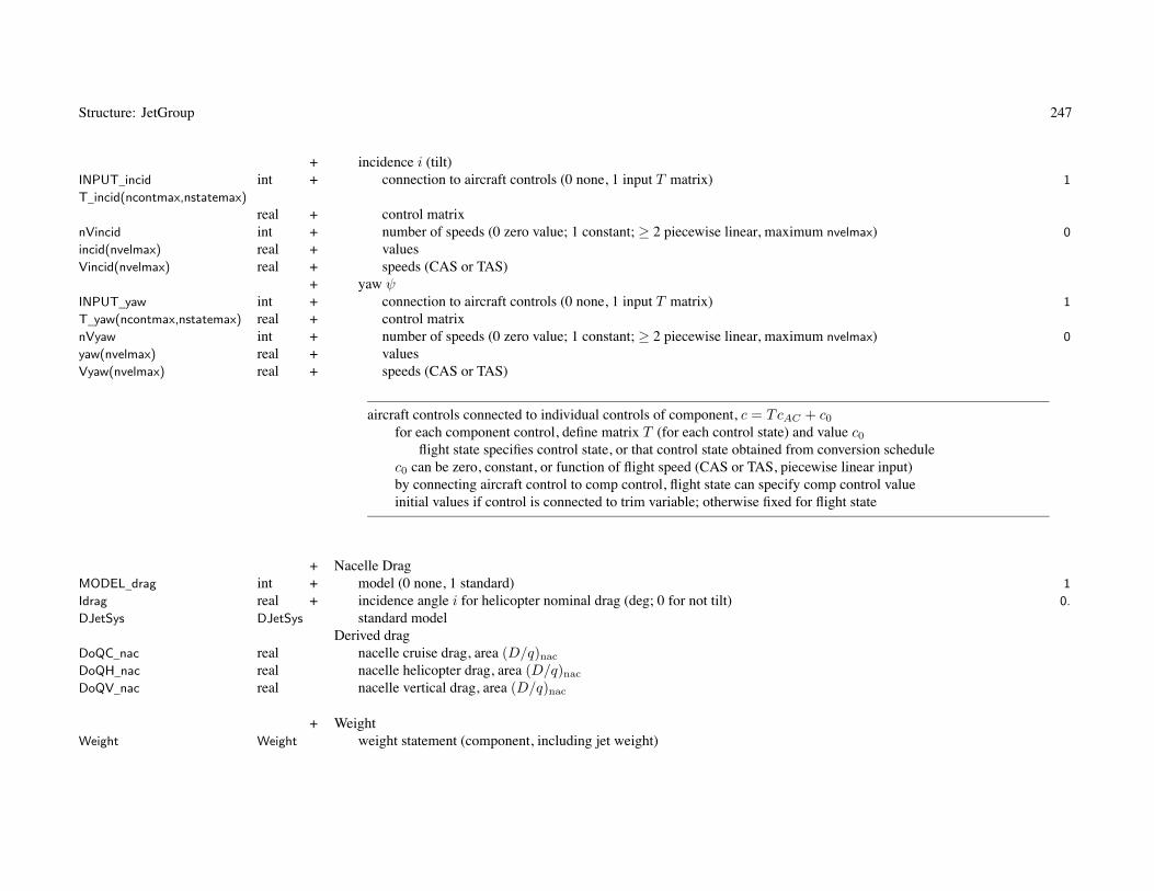
Structure: JetGroup 247
+ incidence i (tilt)INPUT_incid int + connection to aircraft controls (0 none, 1 input T matrix) 1
T_incid(ncontmax,nstatemax)
real + control matrixnVincid int + number of speeds (0 zero value; 1 constant; ≥ 2 piecewise linear, maximum nvelmax) 0
incid(nvelmax) real + valuesVincid(nvelmax) real + speeds (CAS or TAS)
+ yaw ψINPUT_yaw int + connection to aircraft controls (0 none, 1 input T matrix) 1
T_yaw(ncontmax,nstatemax) real + control matrixnVyaw int + number of speeds (0 zero value; 1 constant; ≥ 2 piecewise linear, maximum nvelmax) 0
yaw(nvelmax) real + valuesVyaw(nvelmax) real + speeds (CAS or TAS)
aircraft controls connected to individual controls of component, c = TcAC + c0
for each component control, define matrix T (for each control state) and value c0
flight state specifies control state, or that control state obtained from conversion schedulec0 can be zero, constant, or function of flight speed (CAS or TAS, piecewise linear input)by connecting aircraft control to comp control, flight state can specify comp control valueinitial values if control is connected to trim variable; otherwise fixed for flight state
+ Nacelle DragMODEL_drag int + model (0 none, 1 standard) 1
Idrag real + incidence angle i for helicopter nominal drag (deg; 0 for not tilt) 0.
DJetSys DJetSys standard modelDerived drag
DoQC_nac real nacelle cruise drag, area (D/q)nac
DoQH_nac real nacelle helicopter drag, area (D/q)nac
DoQV_nac real nacelle vertical drag, area (D/q)nac
+ WeightWeight Weight weight statement (component, including jet weight)

Structure: JetGroup 248
+ jet weightMODEL_weight int + model (0 input, 1 RPJEM, 2 custom) 1
dWJet real + weight increment (all jets) 0.0
+ engine system (except jet), engine section or nacelle group, air induction group+ model (0 input, 1 NDARC, 2 custom)
MODEL_sys int + engine system 1
MODEL_nac int + engine section or nacelle 1
MODEL_air int + air induction 1
+ weight incrementdWexh real + exhaust 0.0
dWacc real + accessories 0.0
dWsupt real + engine support 0.0
dWcowl real + engine cowling 0.0
dWpylon real + pylon support 0.0
dWair real + air induction 0.0
WJetSys WJetSys NDARC modelWjet_total real jet weightWES real engine system weight WES (engine, exhaust, accessories)
+ Technology FactorsTECH_jet real + jet weight χjet 1.0
TECH_jetcowl real + engine cowling weight χcowl 1.0
TECH_jetpylon real + pylon structure weight χpylon 1.0
TECH_jetsupt real + engine support structure weight χsupt 1.0
TECH_jetair real + air induction system weight χairind 1.0
TECH_jetexh real + exhaust system weight χexh 1.0
TECH_jetacc real + engine accessories weight χacc 1.0
weight model result multiplied by technology factor and increment added:Wxx = TECH_xx*Wxx_model + dWxx; for fixed (input) weight use MODEL_xx=0 or TECH_xx=0.
engine system weight = engine + exhaust + accessory (WES used for nacelle wetted area)nacelle weight = support + cowl + pylonjet weight parameters in JetModel

249
Chapter 68
Structure: DJetSys
Variable Type Description Default
+ Nacelle Drag, Standard Model+ forward flight drag
SET_drag int + specification (1 fixed, D/q; 2 scaled, CD) 2
DoQ real + area (D/q)0CD real + coefficient CD0 (based on wetted area, D/q = SCD)
+ vertical dragSET_Vdrag int + specification (1 fixed, D/q; 2 scaled, CD) 2
DoQV real + area (D/q)V
CDV real + coefficient CDV (based on wetted area, D/q = SCD)+ transition from forward flight drag to vertical drag
Xdrag real + exponent Xd 2.0
SET_xxx: fixed (use DoQ) or scaled (use CD); other parameter calculated

250
Chapter 69
Structure: WJetSys
Variable Type Description Default
+ Engine Section or Nacelle Group, NDARC Weight ModelMODEL_nacelle int + model (1 parametric, 2 scale with thrust, 3 Boeing, 4 Raymer (transport)) 1
fWpylon real + pylon support structure weight fpylon (fraction maximum takeoff weight) 0.0
+ nacelle group weight, W vs T0C
Knac real + factor Knac
Xnac real + exponent Xnac
n_clf real + Boeing: crash load factor 20.
fWidth_nac real + Raymer: nacelle width (fraction nacelle length) 0.2
+ Air Induction Group, NDARC Weight ModelMODEL_airind int + model (1 parametric, 2 area) 1
fWair real + air induction weight fairind (fraction engine support plus air induction weight) 0.3
Uair real + weight per nacelle area Uairind (lb/ft2 or kg/m2)+ Engine System, NDARC Model+ exhaust system weight, per jet; Wexh vs T0C
Kwt0_exh real + K0exh 0.0
Kwt1_exh real + K1exh 0.002
+ engine accessoriesMODEL_lub int + lubrication system weight (1 in jet weight, 2 in accessory weight) 1
+ Custom Weight ModelWtParam_jetsys(8) real + parameters 0.

251
Chapter 70
Structure: ChargeGroup
Variable Type Description Default
+ Charge Grouptitle c*100 + titlenotes c*1000 + noteskChargeGroup int charge group number
+ DescriptionMODEL_charge c*32 + charger model ’ ’
IDENT_charge c*16 + charger identification ’Charge’
nCharge int + number of chargers Nchrg 1
Pchrg real + charger power Pchrg (SLS static at takeoff rating, 0. for P0_ref(rating_to)) 0.
rating_to c*12 + takeoff thrust rating ’MCP’
rating_idle c*12 + idle thrust rating ’MCP’
kFuelTank int + fuel tank system number (generated) 1
kFuelTank_burn int + fuel tank system number (burned)Derived
iMODEL_charge int charger model (MODEL_charge_xxx)KIND_charge int charger model (MODEL_charge_fuelcell, solarcell)kModel_chrg int identification (FuelCellModel or SolarCellModel, from IDENT_charge)kBattery int battery model, from kFuelTank (0 for none)nrate int number of ratingsrating(nratemax) c*12 rating designations (lowercase)krateC int MCP rating numberkrate_to int takeoff thrust rating numberWOneChrg real weight one charger Wone chrg

Structure: ChargeGroup 252
MODEL_charge: charger model’fuel’ = fuel cell; IDENT_charge → FuelCellModel; fuel generated is energy
fuel burned is weight (kFuelTank_burn)’solar’ = solar cell; IDENT_charge → SolarCellModel; fuel generated is energy
charger identification: match ident of FuelCellModel or SolarCellModel
for fixed charger: use Pchrg = 0. and no size task (or charger power not sized)
fuel tank system identified for generation must store and use energy (may have BatteryModel)fuel tank system identified for burn must store and use weight
Charger model performance parameters (one charger)P0(nratemax) real power (P0)sfc0C real specific fuel consumption at MCP (sfc0C)mdot0C real mass flow at MCP (m0C)wdot0C real fuel flow at MCP (w0C = sfc0CP0C)solararea real solar cell total area
+ InstallationKffd real + deterioration factor on charger fuel flow or performance Kffd 1.05
+ auxiliary air momentum dragfMF_auxair real + mass flow faux (fraction charger mass flow) 0.007
eta_auxair real + ram recovery efficiency ηaux 0.75
+ Geometryloc_charger Location + locationdirection c*16 + nominal orientation (’+x’, ’–x’, ’+y’, ’–y’, ’+z’, ’–z’) ’x’
SET_Swet int + nacelle/cowling wetted area (1 fixed, input Swet; 2 scaled) 2
Swet real + area Swet (per charger) 0.0
kSwet real + factor, k = Swet/(W/Nchrg)2/3 (Units_Dscale) 0.8
Snac real nacelle/cowling area Snac
Swet_nac real total wetted area

Structure: ChargeGroup 253
SET_Swet, wetted area: input (use Swet) or calculated (from kSwet)units of kSwet are ft2/lb2/3 or m2/kg2/3
nacelle wetted area used for nacelle drag
Derived geometryiDirection int nominal orientation (1, –1, 2, –2, 3, –3)axis_incid int axis incidence (±123)axis_yaw int axis yaw (±123)isFixed int orientation (1 fixed)CBF(3,3) real charger relative airframe, CBF (fixed)ef0(3) real charger direction, ef0
ef(3) real charger direction, ef (fixed)
+ Controls+ amplitude A
INPUT_amp int + connection to aircraft controls (0 none, 1 input T matrix) 1
T_amp(ncontmax,nstatemax) real + control matrixnVamp int + number of speeds (0 zero value; 1 constant; ≥ 2 piecewise linear, maximum nvelmax) 0
amp(nvelmax) real + valuesVamp(nvelmax) real + speeds (CAS or TAS)
+ mode BINPUT_mode int + connection to aircraft controls (0 none, 1 input T matrix) 1
T_mode(ncontmax,nstatemax) real + control matrixnVmode int + number of speeds (0 zero value; 1 constant; ≥ 2 piecewise linear, maximum nvelmax) 0
mode(nvelmax) real + valuesVmode(nvelmax) real + speeds (CAS or TAS)
+ incidence i (tilt)INPUT_incid int + connection to aircraft controls (0 none, 1 input T matrix) 1
T_incid(ncontmax,nstatemax)
real + control matrixnVincid int + number of speeds (0 zero value; 1 constant; ≥ 2 piecewise linear, maximum nvelmax) 0
incid(nvelmax) real + valuesVincid(nvelmax) real + speeds (CAS or TAS)

Structure: ChargeGroup 254
+ yaw ψINPUT_yaw int + connection to aircraft controls (0 none, 1 input T matrix) 1
T_yaw(ncontmax,nstatemax) real + control matrixnVyaw int + number of speeds (0 zero value; 1 constant; ≥ 2 piecewise linear, maximum nvelmax) 0
yaw(nvelmax) real + valuesVyaw(nvelmax) real + speeds (CAS or TAS)
aircraft controls connected to individual controls of component, c = TcAC + c0
for each component control, define matrix T (for each control state) and value c0
flight state specifies control state, or that control state obtained from conversion schedulec0 can be zero, constant, or function of flight speed (CAS or TAS, piecewise linear input)by connecting aircraft control to comp control, flight state can specify comp control valueinitial values if control is connected to trim variable; otherwise fixed for flight state
+ Nacelle DragMODEL_drag int + model (0 none, 1 standard) 1
Idrag real + incidence angle i for helicopter nominal drag (deg; 0 for not tilt) 0.
DChrgSys DChrgSys standard modelDerived drag
DoQC_nac real nacelle cruise drag, area (D/q)nac
DoQH_nac real nacelle helicopter drag, area (D/q)nac
DoQV_nac real nacelle vertical drag, area (D/q)nac
+ WeightWeight Weight weight statement (component, including charger weight)
+ charger weightMODEL_weight int + model (0 input, 1 NDARC, 2 custom) 1
dWChrg real + weight increment (all chargers) 0.0
WChrgSys WChrgSys NDARC modelWchrg_total real charge group weightWES real engine system weight WES (engine, exhaust, accessories)

Structure: ChargeGroup 255
+ Technology FactorsTECH_chrg real + charger weight χchrg 1.0
weight model result multiplied by technology factor and increment added:Wxx = TECH_xx*Wxx_model + dWxx; for fixed (input) weight use MODEL_xx=0 or TECH_xx=0.
engine system weight = engine + exhaust + accessory = charge group weight (WES used for nacelle wetted area)charger weight parameters in FuelCellModel or SolarCellModel

256
Chapter 71
Structure: DChrgSys
Variable Type Description Default
+ Nacelle Drag, Standard Model+ forward flight drag
SET_drag int + specification (1 fixed, D/q; 2 scaled, CD) 2
DoQ real + area (D/q)0CD real + coefficient CD0 (based on wetted area, D/q = SCD)
+ vertical dragSET_Vdrag int + specification (1 fixed, D/q; 2 scaled, CD) 2
DoQV real + area (D/q)V
CDV real + coefficient CDV (based on wetted area, D/q = SCD)+ transition from forward flight drag to vertical drag
Xdrag real + exponent Xd 2.0
SET_xxx: fixed (use DoQ) or scaled (use CD); other parameter calculated

257
Chapter 72
Structure: WChrgSys
Variable Type Description Default
+ Custom Weight ModelWtParam_chrgsys(8) real + parameters 0.

258
Chapter 73
Structure: EngineModel
Variable Type Description Default
+ Engine Modeltitle c*100 + title ’Default’
notes c*1000 + notesident c*16 + identification ’Engine’
engine identification: used by IDENT_engine of EngineGroup input (eg ’T800’)
installed: power available Pav , power required Preq , gross jet thrust FG, net jet thrust FN
uninstalled: power available Pa, power required Pq, gross jet thrust Fg , net jet thrust Fn
“0” = SLS static; “C” = MCPmass flow = power / specific power (SP = P/m); fuel flow = specific fuel consumption * power (sfc = w/P )
engine model can be used by more than one engine group, so all parameters fixed
as model for turbojet or reaction drive of convertible engine:only use sfc0C_ref, sfc0C_ref, and parameters for optimum speed, thrust available, and performanceP0_ref and SP0_ref required, but not used; weight, ratings, technology, and scaling variables not used
kEngineModel int engine model number
+ WeightMODEL_weight int + RPTEM model (0 fixed, 1 W (P ), 2 SW (m)) 1
Weng real + engine weight (fixed) 0.
+ engine weight, Weng vs P0C model (W = K0eng + K1engP + K2engPXeng )
Kwt0_eng real + constant K0eng 0.
Kwt1_eng real + constant K1eng 0.25
Kwt2_eng real + constant K2eng 0.
Xwt_eng real + exponent Xeng 0.

Structure: EngineModel 259
+ engine weight, SW = P/Weng vs m0C modelSW_ref real + specific weight reference SWref (m = mtech) 4.
SW_limit real + specific weight limit SWlim (m = mlim) 5.
+ Custom Weight ModelWtParam_engine(8) real + parameters 0.
+ Parameters+ Engine Ratings
nrate int + number of ratings (maximum nratemax) 1
rating(nratemax) c*12 + rating designations ’MCP’
krateC int MCP rating number+ Reference
P0_ref(nratemax) real + power (P0) 2000.
SP0_ref(nratemax) real + specific power (SP0) 150.
Pmech_ref(nratemax) real + mechanical limit of power (Pmech) 2500.
sfc0C_ref real + specific fuel consumption at MCP (sfc0C) 0.45
SF0C_ref real + specific jet thrust (Fg0C = SF0Cm0C) 10.
Nspec_ref real + specification turbine speed (Nspec) 20000.
Nopt0C_ref real + optimum turbine speed at MCP (Nopt0C) 20000.
Derived ratiosrP0(nratemax) real power (P0R/P0C)rSP0(nratemax) real specific power (SP0R/SP0C)rPmech(nratemax) real mechanical limit of power (PmechR/P0C)
Reference Engine Rating: SLS, staticif MCP scaled, ratios to MCP values kept constant
engine rating: match rating designation in FltState; typically designated as’ERP’ = Emergency Rated Power (OEI power)’CRP’ = Contigency Rated Power (2.5 min)’MRP’ = Maximum Rated Power (5 or 10 min)’IRP’ = Intermediate Rated Power (30 min)’MCP’ = Maximum Continuous Power (normal operations)engine model being used may not contain data for all ratings

Structure: EngineModel 260
+ TechnologySP0C_tech real + specific power at MCP SPtech (0. for SP0_ref(MCP)) 0.
sfc0C_tech real + specific fuel consumption at MCP sfctech (0. for sfc0C_ref) 0.
Nspec_tech real + specification turbine speed Ntech (0. for Nspec_ref) 0.
+ ScalingFIX_size int + engine size (0 scaled, 1 fixed) 0
MF_limit real + mass flow at limit SP and sfc (mlim) 30.
SP0C_limit real + specific power limit SPlim 200.
sfc0C_limit real + specific fuel consumption limit sfclim 0.34
KNspec real + specification turbine speed variation (KNs2) 0.
Derived scalingspecific power available (SLS static, MCP, Nspec), SP0C vs m0C
P0C_limit real power limitKsp0 real Ksp0
Ksp1 real Ksp1
specific fuel consumption (SLS static, MCP, Nspec), sfc0C vs m0C
Ksfc0 real Ksfc0
Ksfc1 real Ksfc1
specification turbine speed, Nspec vs m0C
KNs1 real KNs1
KNs2 real KNs2
optimum turbine speed, Nopt0C
KNo real KNo
engine weight, SW = P/Weng vs m0C
Ksw0 real Ksw0
Ksw1 real Ksw1
SP and sfc functions are defined by values SP0C_tech, sfc0C_tech, mtech=P0C_ref/SP0C_tech
and limits SP0C_limit, sfc0C_limit, MF_limit
defaults SP0C_tech=SP0_ref(MCP), sfc0C_tech=sfc0C_ref, Nspec_tech=Nspec_ref
require mtech < mlim (otherwise get SP0C = SP0C_tech and sfc0C = sfc0C_tech)
for no variation of SP , sfc, and SW with scale, use FIX_size=1 or MF_limit=0.
engine weight scaling determined by MODEL_weight

Structure: EngineModel 261
+ Optimum Power Turbine SpeedMODEL_OptN int + model (0 none, 1 linear, 2 cubic) 1
+ linear, Nopt/Nspec vs Pq/P0
KNoptA real + constant KNoptA 1.
KNoptB real + constant KNoptB 0.
+ cubic, Nopt/Nopt0C vs Pq/P0C
KNopt0 real + constant KNopt0 1.
KNopt1 real + constant KNopt1 0.
KNopt2 real + constant KNopt2 0.
KNopt3 real + constant KNopt3 0.
XNopt real + exponent XNopt 0.
+ power turbine efficiency function, ηt(N)/ηt(Nspec)XNeta real + exponent XNη 2.0
engine power and performance variation with power turbine speed determined by Nopt and XNη
used only for INPUT_param = single set; no variation if MODEL_OptN=0
+ Power Available and Power Required ParametersINPUT_param int + parameter input form (1 single set; 2 interpolated) 1
Param EngineParam single set+ interpolated
nspeed int + number of engine speeds (maximum nspeedmax) 1
rNeng(nspeedmax) real + engine speed ratio, N/Nspec 1.
ParamN(nspeedmax) EngineParam parameter sets
interpolated: rNeng unique and sequential

262
Chapter 74
Structure: EngineParam
Variable Type Description Default
+ Parametersparent int parent (1 Param, 2 ParamN)kEngineModel int engine model numberkEngineParam int engine param number (ParamN)
+ Power AvailableINPUT_lin int + input form (1 coefficients K0, K1; 2 values θb, Kb) 1
+ referred specific power available, SPa/SP0 vs temperatureNspa(nratemax) int + number of regions (maximum nengkmax-1) 0
Kspa0(nengkmax,nratemax) real + Kspa0 (piecewise linear Kspa = K0 + K1θ) 3.5
Kspa1(nengkmax,nratemax) real + Kspa1 (piecewise linear Kspa = K0 + K1θ) -2.5
Tspak(nengkmax,nratemax) real + θb
Kspab(nengkmax,nratemax) real + Kspa−b
Xspa0(nengkmax,nratemax) real + Xspa0 (piecewise linear Xspa = X0 + X1θ) -.2
Xspa1(nengkmax,nratemax) real + Xspa1 (piecewise linear Xspa = X0 + X1θ) 0.
Tspax(nengkmax,nratemax) real + θb
Xspab(nengkmax,nratemax) real + Xspa−b
+ referred mass flow at power available, ma/m0 vs temperatureNmfa(nratemax) int + number of regions (maximum nengkmax-1) 0
Kmfa0(nengkmax,nratemax) real + Kmfa0 (piecewise linear Kmfa = K0 + K1θ) .3
Kmfa1(nengkmax,nratemax) real + Kmfa1 (piecewise linear Kmfa = K0 + K1θ) -.3
Tmfak(nengkmax,nratemax) real + θb
Kmfab(nengkmax,nratemax) real + Kmfa−b
Xmfa0(nengkmax,nratemax) real + Xmfa0 (piecewise linear Xmfa = X0 + X1θ) 1.
Xmfa1(nengkmax,nratemax) real + Xmfa1 (piecewise linear Xmfa = X0 + X1θ) 0.
Tmfax(nengkmax,nratemax) real + θb
Xmfab(nengkmax,nratemax) real + Xmfa−b

Structure: EngineParam 263
piecewise linear function:input form = coefficients K0, K1 (N sets) or values θb, Kb (N+1 values)form not input is calculated (N-1 θb, Kb or N K0, K1)input K0, K1: adjacent K1 different, resulting θb unique and sequentialinput θb, Kb: θb unique and sequential
Nspec = specification power turbine speedSPa, ma = referred specific power and mass flow available, at Nspec
SP0, m0 = referred specific power and mass flow available, at Nspec, SLS staticN = power turbine speed, Nopt = optimum power turbine speedηt = power turbine efficiency; assume gas power available PG = Pa/ηt insensitive to N , so ηt(N) give Pa(N)
+ Performance at Power Required+ referred fuel flow at power required, wreq/w0C vs Pq/P0C
Kffq0 real + constant Kffq0 .2
Kffq1 real + constant Kffq1 .8
Kffq2 real + constant Kffq2 0.
Kffq3 real + constant Kffq3 0.
Xffq real + exponent Xffq 1.3
+ referred mass flow at power required, mreq/m0C vs Pq/P0C
Kmfq0 real + constant Kmfq0 .6
Kmfq1 real + constant Kmfq1 .78
Kmfq2 real + constant Kmfq2 -.48
Kmfq3 real + constant Kmfq3 .1
Xmfq real + exponent Xmfq 3.5
+ gross jet thrust at power required, Fg/Fg0C vs Pq/P0C
Kfgq0 real + constant Kfgq0 .2
Kfgq1 real + constant Kfgq1 .8
Kfgq2 real + constant Kfgq2 0.
Kfgq3 real + constant Kfgq3 0.
Xfgq real + exponent Xfgq 2.0

Structure: EngineParam 264
+ installed net jet thrust at power required, FG/Fg (installed thrust loss) vs �ex
Kfgr0 real + constant Kfgr0 .8
Kfgr1 real + constant Kfgr1 .6
Kfgr2 real + constant Kfgr2 0.
Kfgr3 real + constant Kfgr3 0.

265
Chapter 75
Structure: EngineTable
Variable Type Description Default
+ Engine Tabletitle c*100 + title ’Default’
notes c*1000 + notesident c*16 + identification ’Engine’
engine identification: used by IDENT_engine of EngineGroup input
engine table can be used by more than one engine group, so all parameters fixed
kEngineTable int engine table number
+ Engine ratingsnrate int + number of ratings (maximum nratemax) 1
rating(nratemax) c*12 + rating designations ’MCP’
krateC int MCP rating numberNspec real + Specification turbine speed (Nspec)
+ Tablenalt int + number of altitudes (maximum nengtmax) 0
nspeed int + number of speeds (maximum nengtmax) 0
alt(nengtmax) real + altitude hspeed(nengtmax) real + speed V (TAS)Tp(nengtmax,nengtmax,nratemax)
real + power available Pa(h, V, R)Tw(nengtmax,nengtmax,nratemax)
real + fuel flow w(h, V, R)Tf(nengtmax,nengtmax,nratemax)
real + net thrust FN (h, V, R)

Structure: EngineTable 266
+ FactorsKp real + power available 1.0
Kw real + fuel flow 1.0
Kf real + net thrust 1.0
engine not scaled (SET_power, fPsize not used); eta_d not usedfixed engine weight dWEng (MODEL_weight=0)no mass flow value, so no momentum drag of auxillary air flow (fMF_auxair, eta_auxair not used)obtain Peng from table; mechanical limits included in power available datatables intended for installed engine, including losses, so expect fPloss_inlet=0, fPloss_ps=0, fPloss_exh=0
fuel flow multiplied by Kffd, accounting for deterioration of engine efficiency

267
Chapter 76
Structure: RecipModel
Variable Type Description Default
+ Reciprocating Engine Modeltitle c*100 + title ’Default’
notes c*1000 + notesident c*16 + identification ’Engine’
engine identification: used by IDENT_engine of EngineGroup input
installed: power available Pav , power required Preq , gross jet thrust FG, net jet thrust FN
uninstalled: power available Pa, power required Pq, gross jet thrust Fg , net jet thrust Fn
fuel flow = specific fuel consumption * power (sfc = w/P ); mass flow = fuel flow / fuel-air ratio
reciprocating engine model can be used by more than one engine group, so all parameters fixed
kRecipModel int reciprocating engine model number
+ WeightMODEL_weight int + model (0 fixed, 1 W (P )) 1
Weng real + engine weight (fixed) 0.
+ engine weight, Weng vs P0 model (W = K0eng + K1engP + K2engPXeng )
Kwt0_eng real + constant K0eng 0.
Kwt1_eng real + constant K1eng 0.25
Kwt2_eng real + constant K2eng 0.
Xwt_eng real + exponent Xeng 0.
+ Custom Weight ModelWtParam_recip(8) real + parameters 0.

Structure: RecipModel 268
+ Parameters+ Engine Ratings
nrate int + number of ratings (maximum nratemax) 1
rating(nratemax) c*12 + rating designations ’MCP’
krateC int MCP rating number+ Reference
P0_ref(nratemax) real + power (P0) 1000.
sfc0_ref(nratemax) real + specific fuel consumption (sfc0) 0.60
F0_ref(nratemax) real + fuel-air ratio (F0) 0.08
SF0_ref(nratemax) real + specific jet thrust (Fg = SF0m) 0.
Pmep_ref(nratemax) real + mean effective pressure limit (Pmep) 1000.
Pcrit_ref(nratemax) real + critical (throttle) limit (Pcrit) 1000.
N0_ref(nratemax) real + reference engine speed (N0) 2000.
Nspec_ref real + specification engine speed (Nspec) 2000.
Derived ratiosrP0(nratemax) real power (P0R/P0C)rN0(nratemax) real reference engine speed (N0R/Nspec)rcrit(nratemax) real critical power (PcritR/P0R)rmep(nratemax) real mechanical limit of power (PmechR/P0R * Nspec/N0R)
Reference Engine Rating: SLS, staticif MCP scaled, ratios to MCP values kept constant
engine rating: match rating designation in FltState; typically designated as’MRP’ = Maximum Rated Power (5 or 10 min)’MCP’ = Maximum Continuous Power (normal operations)
ratings encompass mixture settings and supercharger speeds
Pmep_ref: zero for no mechanical (mep) limitPcrit_ref: zero for no critical (throttle) limit; Xcrit = 0. for limit independent of engine speed

Structure: RecipModel 269
+ ScalingFIX_size int + engine size (0 scaled, 1 fixed) 0
Xo real + specific output exponent Xo 0.2
Xs real + mean piston speed exponent Xs 0.3
Xf real + specific fuel consumption exponent Xf 0.1
Derived scalingXsfc real exponent −Xf/(2 − Xo)XN real exponent −(1 + Xs)/(2 − Xo)
+ Power AvailableKp(nratemax) real + factor Kp 1.
Kram(nratemax) real + constant Kram 1.
XpN(nratemax) real + exponent XpN 1.
Xpt(nratemax) real + exponent Xpθ 0.5
Xcrit(nratemax) real + exponent Xcrit 3.0
+ Performance at Power Required+ fuel flow, wreq/w0 vs Pq/P0
MODEL_Kffq int + model (1 polynomial, 2 piecewise linear) 1
+ polynomialKffq0(nratemax) real + constant Kffq0 0.
Kffq1(nratemax) real + constant Kffq1 1.
Kffq2(nratemax) real + constant Kffq2 0.
Kffq3(nratemax) real + constant Kffq3 0.
+ piecewise linearNffq(nratemax) int + number of values (maximum nengrmax) 0
Pffq(nengrmax,nratemax) real + power ratio Pq/P0
Kffq(nengrmax,nratemax) real + factor Kffq
Xffq(nratemax) real + exponent Xffq 0.
+ fuel-air ratio, Freq/F0 vs Pq/P0
MODEL_KFq int + model (1 polynomial, 2 piecewise linear) 1
+ polynomialKFq0(nratemax) real + constant KFq0 1.
KFq1(nratemax) real + constant KFq1 0.
KFq2(nratemax) real + constant KFq2 0.
KFq3(nratemax) real + constant KFq3 0.

Structure: RecipModel 270
+ piecewise linearNFq(nratemax) int + number of values (maximum nengrmax) 0
PFq(nengrmax,nratemax) real + power ratio Pq/P0
KFq(nengrmax,nratemax) real + factor KFq
XFq(nratemax) real + exponent XFq 0.
+ installed net jet thrust, Kfgr = FG/Fg (installed thrust loss)Kfgr(nratemax) real + constant Kfgr 1.
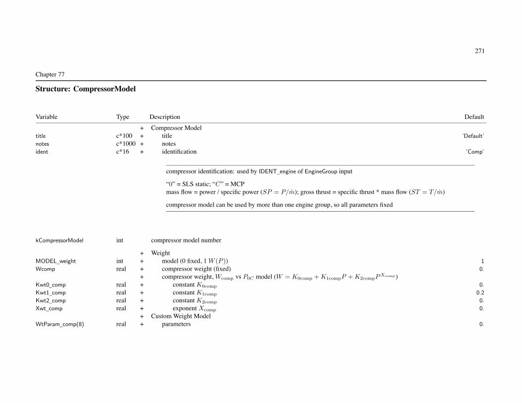
271
Chapter 77
Structure: CompressorModel
Variable Type Description Default
+ Compressor Modeltitle c*100 + title ’Default’
notes c*1000 + notesident c*16 + identification ’Comp’
compressor identification: used by IDENT_engine of EngineGroup input
“0” = SLS static; “C” = MCPmass flow = power / specific power (SP = P/m); gross thrust = specific thrust * mass flow (ST = T/m)
compressor model can be used by more than one engine group, so all parameters fixed
kCompressorModel int compressor model number
+ WeightMODEL_weight int + model (0 fixed, 1 W (P )) 1
Wcomp real + compressor weight (fixed) 0.
+ compressor weight, Wcomp vs P0C model (W = K0comp + K1compP + K2compPXcomp )Kwt0_comp real + constant K0comp 0.
Kwt1_comp real + constant K1comp 0.2
Kwt2_comp real + constant K2comp 0.
Xwt_comp real + exponent Xcomp 0.
+ Custom Weight ModelWtParam_comp(8) real + parameters 0.

Structure: CompressorModel 272
+ Parameters+ Compressor Ratings
nrate int + number of ratings (maximum nratemax) 1
rating(nratemax) c*12 + rating designations ’MCP’
krateC int MCP rating number+ Reference
P0_ref(nratemax) real + power (P0)SP0_ref(nratemax) real + specific power (SP0)Pmech_ref(nratemax) real + mechanical limit of power (Pmech)ST0C_ref real + specific jet thrust (Fg0C = ST0Cm0C)Nspec_ref real + specification compressor speed (Nspec)
Derived ratiosrP0(nratemax) real power (P0R/P0C)rSP0(nratemax) real specific power (SP0R/SP0C)rPmech(nratemax) real mechanical limit of power (PmechR/P0C)
Reference Compressor Rating: SLS, staticif MCP scaled, ratios to MCP values kept constant
compressor rating: match rating designation in FltState
+ Power Available+ referred specific power available, SPa/SP0
Xspa real + exponent Xspa 1.
+ referred mass flow at power available, ma/m0
Xmfa real + exponent Xmfa 1.
+ Performance at Power Required+ referred mass flow at power required, mreq/m0C vs Pq/P0C
Kmfq0 real + constant Kmfq0
Kmfq1 real + constant Kmfq1
Kmfq2 real + constant Kmfq2
Kmfq3 real + constant Kmfq3
Xmfq real + exponent Xmfq 1.
+ referred specific thrust at power required, STreq/ST0
Xstq real + exponent Xstq 1.

273
Chapter 78
Structure: MotorModel
Variable Type Description Default
+ Motor Modeltitle c*100 + title ’Default’
notes c*1000 + notesident c*16 + identification ’Motor’
motor identification: used by IDENT_engine of EngineGroup input
“0” = SLS static; “C” = MCP
motor model can be used by more than one engine group, so all parameters fixed
kMotorModel int motor model number
+ WeightMODEL_weight int + NASA model (0 fixed, 1 W (P ), 2 W (Q)) 2
Wmotor real + motor weight (fixed) 0.
+ motor weight, Wmotor vs P0C model (W = K0motor + K1motorP + K2motorPXmotor)
Kwt0_motor real + constant K0motor 0.
Kwt1_motor real + constant K1motor 0.
Kwt2_motor real + constant K2motor 0.
Xwt_motor real + exponent Xmotor 0.
+ motor weight, Wmotor vs Qpeak modelKIND_design int + torque-to-weight design (0 only high Q/W ; 1 high Q/W , 2 low Q/W factor) 0
+ Custom Weight ModelWtParam_motor(8) real + parameters 0.

Structure: MotorModel 274
+ Parameters+ Motor Ratings
nrate int + number of ratings (maximum nratemax) 1
rating(nratemax) c*12 + rating designations ’MCP’
krateC int MCP rating number+ Reference
P0_ref(nratemax) real + power (P0) 0.
Ppeak_ref(nratemax) real + mechanical limit of power (Ppeak)Nspec_ref real + specification motor speed (Nspec)
Derived ratiosrP0(nratemax) real power (P0R/P0C)rPpeak(nratemax) real mechanical limit of power (PpeakR/P0C)
Reference Motor Rating: SLS, staticif MCP scaled, ratios to MCP values kept constant
motor rating: match rating designation in FltState
+ Performance+ Motor/Generator Efficiency
KIND_eff int + kind (1 fixed, 2 function power, 3 map) 2
+ fixed or function powereta_motor real + reference efficiency (at Peng) 1.00
loss_motor real + power loss (fraction Peng) 0.00
+ efficiency map (Ploss = Pengfloss
∑3i=0
∑3j=0 Cijt
inj)Closs(4,4) real + loss coefficients Closs(i+1,j+1)= Cij 0.00
floss real + factor floss 1.00
eta_cont real + controller efficiency 1.00
+ Fuel Cellsfc0C real + specific fuel consumption at MCP (sfc0C) 0.
Kmf real + mass flow ratio (m/w) 86.
KIND_eff_cell int + efficiency kind (1 fixed, 2 function power) 2
eta_cell real + reference efficiency (at Peng) 1.00
loss_cell real + power loss (fraction Peng) 0.00

Structure: MotorModel 275
+ ScalingKNspec real + specification motor speed variation (KNs) 0.
KNbase real + base motor speed variation (KNb) 0.
Nspec used by efficiency map; Nbase affects Ppeak scalingfor no variation of motor speeds with scale, use KNspec = KNbase = 0.
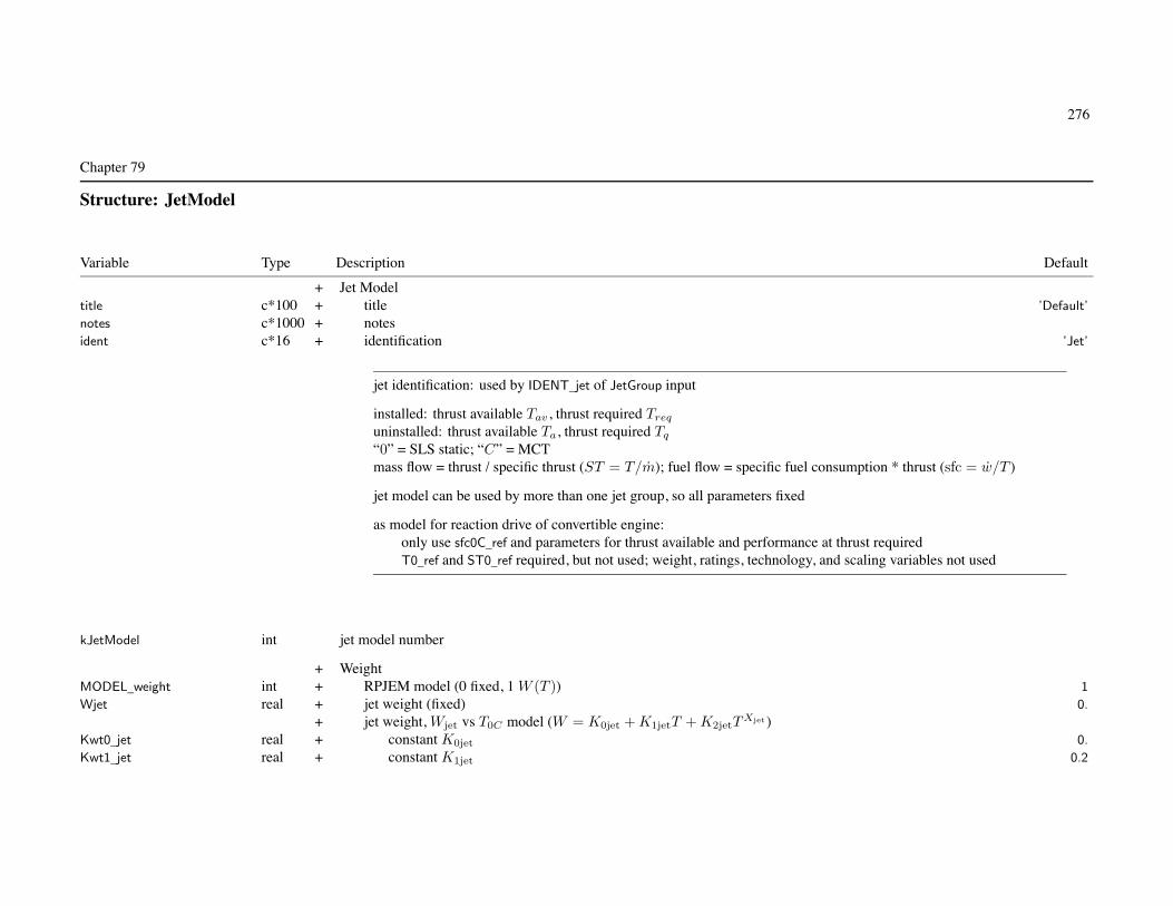
276
Chapter 79
Structure: JetModel
Variable Type Description Default
+ Jet Modeltitle c*100 + title ’Default’
notes c*1000 + notesident c*16 + identification ’Jet’
jet identification: used by IDENT_jet of JetGroup input
installed: thrust available Tav , thrust required Treq
uninstalled: thrust available Ta, thrust required Tq
“0” = SLS static; “C” = MCTmass flow = thrust / specific thrust (ST = T/m); fuel flow = specific fuel consumption * thrust (sfc = w/T )
jet model can be used by more than one jet group, so all parameters fixed
as model for reaction drive of convertible engine:only use sfc0C_ref and parameters for thrust available and performance at thrust requiredT0_ref and ST0_ref required, but not used; weight, ratings, technology, and scaling variables not used
kJetModel int jet model number
+ WeightMODEL_weight int + RPJEM model (0 fixed, 1 W (T )) 1
Wjet real + jet weight (fixed) 0.
+ jet weight, Wjet vs T0C model (W = K0jet + K1jetT + K2jetTXjet)
Kwt0_jet real + constant K0jet 0.
Kwt1_jet real + constant K1jet 0.2

Structure: JetModel 277
Kwt2_jet real + constant K2jet 0.
Xwt_jet real + exponent Xjet 0.
+ Custom Weight ModelWtParam_jet(8) real + parameters 0.
+ Parameters+ Jet Ratings
nrate int + number of ratings (maximum nratemax) 1
rating(nratemax) c*12 + rating designations ’MCT’
krateC int MCT rating number+ Reference
T0_ref(nratemax) real + thrust (T0) 0.
ST0_ref(nratemax) real + specific thrust (ST0)Tmech_ref(nratemax) real + mechanical limit of thrust (Tmech)sfc0C_ref real + specific fuel consumption at MCT (sfc0C)
Derived ratiosrT0(nratemax) real thrust (T0R/T0C)rST0(nratemax) real specific thrust (ST0R/ST0C)rTmech(nratemax) real mechanical limit of thrust (TmechR/T0C)
Reference Jet Rating: SLS, staticif MCT scaled, ratios to MCT values kept constant
jet rating: match rating designation in FltState
+ TechnologyST0C_tech real + specific thrust at MCT STtech (0. for ST0_ref(MCT)) 0.
sfc0C_tech real + specific fuel consumption at MCT sfctech (0. for sfc0C_ref) 0.
+ ScalingFIX_size int + engine size (0 scaled, 1 fixed) 0
MF_limit real + mass flow at limit ST and sfc (mlim) 0.
ST0C_limit real + specific thrust limit STlim 0.
sfc0C_limit real + specific fuel consumption limit sfclim

Structure: JetModel 278
Derived scalingspecific thrust available (SLS static, MCT), ST0C vs m0C
T0C_limit real thrust limitKst0 real Kst0
Kst1 real Kst1
specific fuel consumption (SLS static, MCT), sfc0C vs m0C
Ksfc0 real Ksfc0
Ksfc1 real Ksfc1
ST and sfc functions are defined by values ST0C_tech, sfc0C_tech, mtech=T0C_ref/ST0C_tech
and limits ST0C_limit, sfc0C_limit, MF_limit
defaults ST0C_tech=ST0_ref(MCT), sfc0C_tech=sfc0C_ref
require mtech < mlim (otherwise get ST0C = ST0C_tech and sfc0C = sfc0C_tech)
for no variation of ST and sfc with scale, use FIX_size=1 or MF_limit=0.
bypass real + Turbofan bypass ratio (0. for turbojet) 0.
+ Thrust Available+ referred specific thrust available, STa/ST0
Xsta real + exponent Xsta 1.
+ referred mass flow at thrust available, ma/m0
Xmfa real + exponent Xmfa 1.
+ Performance at Thrust Required+ referred fuel flow at thrust required, wreq/w0C vs Tq/T0C
Kffq0 real + constant Kffq0 0.
Kffq1 real + constant Kffq1 1.
Kffq2 real + constant Kffq2 0.
Xffq real + exponent Xffq 1.
+ referred mass flow at thrust required, mreq/m0C vs Tq/T0C
Kmfq real + constant Kmfq (0, 1, or 1/2) 1.
Xmfq real + exponent Xmfq 1.
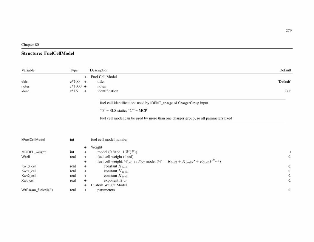
279
Chapter 80
Structure: FuelCellModel
Variable Type Description Default
+ Fuel Cell Modeltitle c*100 + title ’Default’
notes c*1000 + notesident c*16 + identification ’Cell’
fuel cell identification: used by IDENT_charge of ChargerGroup input
“0” = SLS static; “C” = MCP
fuel cell model can be used by more than one charger group, so all parameters fixed
kFuelCellModel int fuel cell model number
+ WeightMODEL_weight int + model (0 fixed, 1 W (P )) 1
Wcell real + fuel cell weight (fixed) 0.
+ fuel cell weight, Wcell vs P0C model (W = K0cell + K1cellP + K2cellPXcell )
Kwt0_cell real + constant K0cell 0.
Kwt1_cell real + constant K1cell 0.
Kwt2_cell real + constant K2cell 0.
Xwt_cell real + exponent Xcell 0.
+ Custom Weight ModelWtParam_fuelcell(8) real + parameters 0.

Structure: FuelCellModel 280
+ Parameters+ Fuel Cell Ratings
nrate int + number of ratings (maximum nratemax) 1
rating(nratemax) c*12 + rating designations ’MCP’
krateC int MCP rating number+ Reference
P0_ref(nratemax) real + power (P0) 0.
sfc0C_ref real + specific fuel consumption at MCP (sfc0C) 0.
Derived ratiosrP0(nratemax) real power (P0R/P0C)
Reference Fuel Cell Rating: SLS, staticif MCP scaled, ratios to MCP values kept constant
fuel cell rating: match rating designation in FltState
+ PerformanceKmf real + mass flow ratio (m/w) 86.
+ EfficiencyKIND_eff int + kind (1 fixed, 2 function power) 2
eta_cell real + reference efficiency (at Pchrg) 1.00
loss_cell real + power loss (fraction Pchrg) 0.00
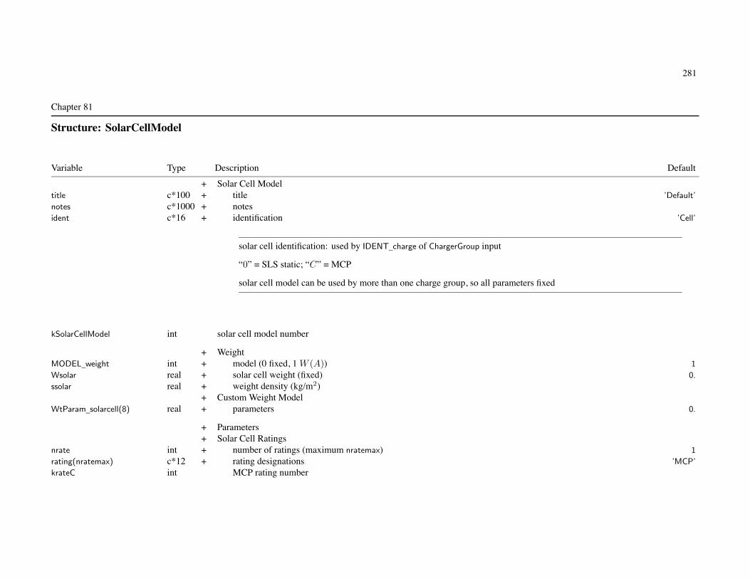
281
Chapter 81
Structure: SolarCellModel
Variable Type Description Default
+ Solar Cell Modeltitle c*100 + title ’Default’
notes c*1000 + notesident c*16 + identification ’Cell’
solar cell identification: used by IDENT_charge of ChargerGroup input
“0” = SLS static; “C” = MCP
solar cell model can be used by more than one charge group, so all parameters fixed
kSolarCellModel int solar cell model number
+ WeightMODEL_weight int + model (0 fixed, 1 W (A)) 1
Wsolar real + solar cell weight (fixed) 0.
ssolar real + weight density (kg/m2)+ Custom Weight Model
WtParam_solarcell(8) real + parameters 0.
+ Parameters+ Solar Cell Ratings
nrate int + number of ratings (maximum nratemax) 1
rating(nratemax) c*12 + rating designations ’MCP’
krateC int MCP rating number

Structure: SolarCellModel 282
+ ReferenceP0_ref(nratemax) real + power (P0) 0.
Derived ratiosrP0(nratemax) real power (P0R/P0C)
Reference Solar Cell Rating: SLS, staticif MCP scaled, ratios to MCP values kept constant
solar cell rating: match rating designation in FltState
+ Performanceesolar real + power density (W/m2)
+ EfficiencyKIND_eff int + kind (1 fixed, 2 function power) 2
eta_cell real + reference efficiency (at Pchrg) 1.00
loss_cell real + power loss (fraction Pchrg) 0.00

283
Chapter 82
Structure: BatteryModel
Variable Type Description Default
+ Battery Modeltitle c*100 + title ’Default’
notes c*1000 + notesident c*16 + identification ’Battery’
battery identification: used by IDENT_battery of FuelTank input
battery model can be used by more than one fuel tank system, so all parameters fixed
kBatteryModel int battery model number
+ PerformanceMODEL_battery int + model (1 equivalent circuit, 2 lithium-ion) 1
Vref real + reference voltage Vref 4.2
xmbd real + maximum burst discharge current xmbd (1/hr) 20.
xCCmax real + maximum charge current xCCmax (1/hr) 4.
Derived performanceCfromE real charge capacity C (A-hr) from energy capacity (MJ); (106/3600)/Vref
PfromE real power capacity P (hp or kW) from energy capacity (MJ); xmdb/Econv_dE
+ Equivalent Circuit ModelKIND_eff int + kind (1 fixed, 2 function power) 2
+ dischargeeta_dischrg real + reference efficiency (at Pref ) 1.00
loss_dischrg real + power loss (fraction Pref ) 0.00

Structure: BatteryModel 284
+ chargeeta_chrg real + reference efficiency (at Pref ) 1.00
loss_chrg real + power loss (fraction Pref ) 0.00
+ Lithium-Ion Model+ discharge
fcrit real + critical voltage factor (FV = fcrit is capacity) 0.6
fd real + nominal discharge voltage (Vd = fdVref ) 1.0
+ open circuit voltage ratio (Vo = VdFV (d))nFV int + number of points (maximum 40) 0
DoD(40) real + depth-of-discharge d (fraction) 0.
FV(40) real + FV 0.
Tref real + reference temperature Tref (deg C) 20.
fTC real + temperature control power loss fTC (fraction component power) 0.01
+ current influence on discharge voltageR real + internal resistance xmbdCR/Vref 0.1
kdI real + depth-of-discharge kdIxmbdC 0.05
+ temperature influence on discharge voltagekVT real + voltage increment kV T 0.005
kdT real + depth-of-discharge kdT 0.000005
+ chargefc real + nominal charge voltage (Vc = fcVref ) 1.0
kcV real + CC phase starting voltage decrement kcV 0.1
ks real + CV phase parameter kσ 0.2
Derived lithium-ion dischargeDoDrev(40) real reversed DoD
FVrev(40) real reversed FV
open circuit voltage ratio: monotonically decreasing; default used if nFV=0
default DoD = 0.,.1,.2,.3,.4,.5,.6,.7,.8,.9,.91,.92,.93,.94,.95,.96,.97,.98,.99,1.,1.01,1.02default FV = 1.,.97,.95,.93,.915,.90,.89,.88,.87,.85,.847,.842,.835,.826,.815,.8,.78,.75,.7,.6,.4,0.

285
Chapter 83
Structure: Location
Variable Type Description Default
+ Location+ input+ fixed (dimensional, arbitrary origin)
FIX_geom c*8 + input ’ ’
SL real + stationlineBL real + buttlineWL real + waterline
+ scaled (based on reference length, from reference point)XoL real + x/LYoL real + y/LZoL real + z/L
+ reference lengthKIND_scale int + kind (0 global, 1 rotor radius, 2 wing span, 3 fuselage length) 0
kScale int + identification (component number) 1
Fixed input: FIX_geom = ’x’, ’y’, ’z’ (or combination) to override INPUT_geom=2
Geometry: Location for each componentfixed geometry input (INPUT_geom = 1): dimensional SL/BL/WL
stationline + aft, buttline + right, waterline + up; arbitary origin; units = ft or mscaled geometry input (INPUT_geom = 2): divided by reference length (KIND_scale, kScale)
XoL + aft, YoL + right, ZoL + up; from reference pointoption to fix some geometry (FIX_geom in Location override INPUT_geom)option to specify reference length (KIND_scale in Location override global KIND_scale)
Reference point: KIND_Ref, kRef; input dimensional XX_Ref, or position of identified componentcomponent reference must be fixed
Locations can be calculated from other parameters (configuration specific)
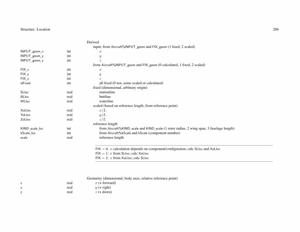
Structure: Location 286
Derivedinput, from Aircraft%INPUT_geom and FIX_geom (1 fixed; 2 scaled)
INPUT_geom_x int xINPUT_geom_y int yINPUT_geom_z int z
from Aircraft%INPUT_geom and FIX_geom (0 calculated, 1 fixed, 2 scaled)FIX_x int xFIX_y int yFIX_z int zisFixed int all fixed (0 not, some scaled or calculated)
fixed (dimensional, arbitrary origin)SLloc real stationlineBLloc real buttlineWLloc real waterline
scaled (based on reference length, from reference point)XoLloc real x/LYoLloc real y/LZoLloc real z/L
reference lengthKIND_scale_loc int from Aircraft%KIND_scale and KIND_scale (1 rotor radius, 2 wing span, 3 fuselage length)kScale_loc int from Aircraft%kScale and kScale (component number)scale real reference length
FIX = 0: x calculation depends on component/configuraton; calc SLloc and XoLloc
FIX = 1: x from SLloc; calc XoLloc
FIX = 2: x from XoLloc; calc SLloc
Geometry (dimensional, body axes, relative reference point)x real x (+ forward)y real y (+ right)z real z (+ down)

287
Chapter 84
Structure: Weight
Variable Type Description Default
WE real WEIGHT EMPTYW_structure real STRUCTUREW_wing real wing groupW_wing_basic real basic structureW_wing_secondary real secondary structureW_wing_fair real fairings (not RP8A)W_wing_fit real fittings (not RP8A)W_wing_fold real fold/tilt (not RP8A)W_wing_control real control surfacesW_rotor real rotor groupW_rotor_blade real blade assemblyW_rotor_hub real hub & hingeW_rotor_basic real basic (not RP8A)W_rotor_shaft real inter-rotor shaft (not RP8A)W_rotor_fair real fairing/spinner (not RP8A)W_rotor_fold real blade fold (not RP8A)W_rotor_supt real rotor support structure (not RP8A)W_rotor_duct real duct (not RP8A)W_tail real empennage groupW_Htail real horizontal tail (not RP8A)W_Htail_basic real basic (not RP8A)W_Htail_fold real fold (not RP8A)W_Vtail real vertical tail (not RP8A)W_Vtail_basic real basic (not RP8A)W_Vtail_fold real fold (not RP8A)W_tailrotor real tail rotor (not RP8A)W_tr_blade real bladesW_tr_hub real hub & hinge

Structure: Weight 288
W_tr_supt real rotor supportsW_tr_duct real rotor/fan ductW_fuselage real fuselage groupW_fus_basic real basic (not RP8A)W_fus_wingfold real wing & rotor fold/retraction (not RP8A)W_fus_tailfold real tail fold/tilt (not RP8A)W_fus_mar real marinization (not RP8A)W_fus_press real pressurization (not RP8A)W_fus_crash real crashworthiness (not RP8A)W_gear real alighting gear groupW_gear_basic real basic (not RP8A)W_gear_retract real retraction (not RP8A)W_gear_crash real crashworthiness (not RP8A)W_nacelle real engine section or nacelle groupW_nac_engsupt real engine support (not RP8A)W_nac_cowling real engine cowling (not RP8A)W_nac_pylon real pylon support (not RP8A)W_airind real air induction groupW_propulsion real PROPULSION GROUPW_engsys real engine systemW_engine real engineW_exhaust real exhaust systemW_acc real accessories (not RP8A)W_propeller real propeller/fan installationW_prop_blade real blades (not RP8A)W_prop_hub real hub & hinge (not RP8A)W_prop_supt real rotor supports (not RP8A)W_prop_duct real rotor/fan duct (not RP8A)W_fuelsys real fuel systemW_fuel_tank real tanks and supportW_fuel_plumb real plumbingW_drive real drive systemW_drive_box real gear boxesW_drive_xmsn real transmission drive

Structure: Weight 289
W_drive_rtrsft real rotor shaftW_drive_brake real rotor brake (not RP8A)W_drive_clutch real clutch (not RP8A)W_drive_gas real gas driveW_equip real SYSTEMS AND EQUIPMENTW_fltcont real flight controls groupW_fc_cockpit real cockpit controlsW_fc_afcs real automatic flight control systemW_fc_system real system controlsW_fc_fw real fixed wing systemsW_fc_fw_nonboost real non-boosted (not RP8A)W_fc_fw_mech real boost mechanisms (not RP8A)W_fc_rw real rotary wing systemsW_fc_rw_nonboost real non-boosted (not RP8A)W_fc_rw_mech real boost mechanisms (not RP8A)W_fc_rw_boost real boosted (not RP8A)W_fc_cv real conversion systemsW_fc_cv_nonboost real non-boosted (not RP8A)W_fc_cv_mech real boost mechanisms (not RP8A)W_auxpower real auxiliary power groupW_instrument real instruments groupW_hydraulic real hydraulic groupW_hyd_fw real fixed wing (not RP8A)W_hyd_rw real rotary wing (not RP8A)W_hyd_cv real conversion (not RP8A)W_hyd_eq real equipment (not RP8A)W_pneumatic real pneumatic groupW_electrical real electrical groupW_elect_aircraft real aircraft (not RP8A)W_elect_deice real anti-icing (not RP8A)W_avionics real avionics group (mission equipment)W_arm real armament groupW_armprov real armament provisions (not RP8A)W_armor real armor (not RP8A)

Structure: Weight 290
W_furnish real furnishings & equipment groupW_environ real environmental control groupW_deice real anti-icing groupW_load real load & handling groupW_vib real VIBRATION (not RP8A)W_cont real CONTINGENCYW_fixUL real FIXED USEFUL LOADW_fixUL_crew real crewW_fixUL_fluid real fluids (oil, unusable fuel) (not RP8A)W_fixUL_auxtank real auxilary fuel tanksW_fixUL_other real other fixed useful load (not RP8A)W_fixUL_equip real equpment increment (not RP8A)W_fixUL_foldkit real folding kit (not RP8A)W_fixUL_extkit real wing extension kit (not RP8A)W_fixUL_wingkit real wing kit (not RP8A)W_fixUL_otherkit real other kit (not RP8A)Wpayload real PAYLOADWfuel real USABLE FUELWfuel_std real standard tanks (not RP8A)Wfuel_aux real auxiliary tanks (not RP8A)
Wscaled real scaled weight (sum all K=3 in operating weight)Wfixed real fixed weight (sum all K=2 in operating weight)Wfeature real military features in empty weight
WO real OPERATING WEIGHT = weight empty + fixed useful loadWUL real USEFUL LOAD = fixed useful load + payload + usable fuel
GW real GROSS WEIGHT = weight empty + useful load = operating weight + payload + usable fuel
follows SAWE RP8A Group Weight Statement, except as notedtypical only lowest elements of hierarchy specified, others obtained by summation
set status flag when define weightcan define weights (k=2 or 3) at any level, ignore child weights if not lowest level
when print weight statement, designate all fixed (ie input) quantities

Structure: Weight 291
usage:set all W=K=0; put W, with K=2 or 3then fill structure: if K=0 and some child defined/sum, then W=
∑(child) and K=1
addition or increment sums all elements, with status Kt of total as follows
Ka = 0 1 2 3
Kb = 0 0 1 2 3Kb = 1 1 1 3 3Kb = 2 2 3 2 3Kb = 3 3 3 3 3
Status (0 none; 1 sum of child; 2 defined, fixed (input); 3 defined, not fixed (scaled, wt eq; or composite))KE int WEIGHT EMPTYK_structure int STRUCTUREK_wing int wing groupK_wing_basic int basic structureK_wing_secondary int secondary structureK_wing_fair int fairings (not RP8A)K_wing_fit int fittings (not RP8A)K_wing_fold int fold/tilt (not RP8A)K_wing_control int control surfacesK_rotor int rotor groupK_rotor_blade int blade assemblyK_rotor_hub int hub & hingeK_rotor_basic int basic (not RP8A)K_rotor_shaft int inter-rotor shaft (not RP8A)K_rotor_fair int fairing/spinner (not RP8A)K_rotor_fold int blade fold (not RP8A)K_rotor_supt int rotor support structure (not RP8A)K_rotor_duct int duct (not RP8A)K_tail int empennage groupK_Htail int horizontal tail (not RP8A)

Structure: Weight 292
K_Htail_basic int basic (not RP8A)K_Htail_fold int fold (not RP8A)K_Vtail int vertical tail (not RP8A)K_Vtail_basic int basic (not RP8A)K_Vtail_fold int fold (not RP8A)K_tailrotor int tail rotor (not RP8A)K_tr_blade int bladesK_tr_hub int hub & hingeK_tr_supt int rotor supportsK_tr_duct int rotor/fan ductK_fuselage int fuselage groupK_fus_basic int basic (not RP8A)K_fus_wingfold int wing & rotor fold/retraction (not RP8A)K_fus_tailfold int tail fold/tilt (not RP8A)K_fus_mar int marinization (not RP8A)K_fus_press int pressurization (not RP8A)K_fus_crash int crashworthiness (not RP8A)K_gear int alighting gear groupK_gear_basic int basic (not RP8A)K_gear_retract int retraction (not RP8A)K_gear_crash int crashworthiness (not RP8A)K_nacelle int engine section or nacelle groupK_nac_engsupt int engine support (not RP8A)K_nac_cowling int engine cowling (not RP8A)K_nac_pylon int pylon support (not RP8A)K_airind int air induction groupK_propulsion int PROPULSION GROUPK_engsys int engine systemK_engine int engineK_exhaust int exhaust systemK_acc int accessories (not RP8A)K_propeller int propeller/fan installationK_prop_blade int blades (not RP8A)K_prop_hub int hub & hinge (not RP8A)

Structure: Weight 293
K_prop_supt int rotor supports (not RP8A)K_prop_duct int rotor/fan duct (not RP8A)K_fuelsys int fuel systemK_fuel_tank int tanks and supportK_fuel_plumb int plumbingK_drive int drive systemK_drive_box int gear boxesK_drive_xmsn int transmission driveK_drive_rtrsft int rotor shaftK_drive_brake int rotor brake (not RP8A)K_drive_clutch int clutch (not RP8A)K_drive_gas int gas driveK_equip int SYSTEMS AND EQUIPMENTK_fltcont int flight controls groupK_fc_cockpit int cockpit controlsK_fc_afcs int automatic flight control systemK_fc_system int system controlsK_fc_fw int fixed wing systemsK_fc_fw_nonboost int non-boosted (not RP8A)K_fc_fw_mech int boost mechanisms (not RP8A)K_fc_rw int rotary wing systemsK_fc_rw_nonboost int non-boosted (not RP8A)K_fc_rw_mech int boost mechanisms (not RP8A)K_fc_rw_boost int boosted (not RP8A)K_fc_cv int conversion systemsK_fc_cv_nonboost int non-boosted (not RP8A)K_fc_cv_mech int boost mechanisms (not RP8A)K_auxpower int auxiliary power groupK_instrument int instruments groupK_hydraulic int hydraulic groupK_hyd_fw int fixed wing (not RP8A)K_hyd_rw int rotary wing (not RP8A)K_hyd_cv int conversion (not RP8A)K_hyd_eq int equipment (not RP8A)

Structure: Weight 294
K_pneumatic int pneumatic groupK_electrical int electrical groupK_elect_aircraft int aircraft (not RP8A)K_elect_deice int anti-icing (not RP8A)K_avionics int avionics group (mission equipment)K_arm int armament groupK_armprov int armament provisions (not RP8A)K_armor int armor (not RP8A)K_furnish int furnishings & equipment groupK_environ int environmental control groupK_deice int anti-icing groupK_load int load & handling groupK_vib int VIBRATION (not RP8A)K_cont int CONTINGENCYK_fixUL int FIXED USEFUL LOADK_fixUL_crew int crewK_fixUL_fluid int fluids (oil, unusable fuel) (not RP8A)K_fixUL_auxtank int auxilary fuel tanksK_fixUL_other int other fixed useful load (not RP8A)K_fixUL_equip int equipment increment (not RP8A)K_fixUL_foldkit int folding kit (not RP8A)K_fixUL_extkit int wing extension kit (not RP8A)K_fixUL_wingkit int wing kit (not RP8A)K_fixUL_otherkit int other kit (not RP8A)Kpayload int PAYLOADKfuel int USABLE FUELKfuel_std int standard tanks (not RP8A)Kfuel_aux int auxiliary tanks (not RP8A)KO int OPERATING WEIGHT = weight empty + fixed useful loadKUL int USEFUL LOAD = fixed useful load + payload + usable fuelKGW int GROSS WEIGHT = weight empty + useful load = operating weight + payload + usable fuel