ndbook 2012 a practical guide to exhaust gas cleaning systems … · 2019-02-10 · price: £105.00...
TRANSCRIPT
Price: £105.00
A practical guide to exhaust gas cleaning systems for the maritime industry
EGCSA Handbook 2012
EGC
SA H
An
dbo
ok
2012
Exhaust Gas Cleaning Systems are a highly effective solution to the challenges of IMO MARPOL Annex VI air pollution regulations and the added complexities of regional and national emissions legislation.It is crucial that ship owners and operators fully understand their options for compliance. To aid decision making this guide contains a wealth of information, including:
• The impact of emissions, current and future regulation and the IMO Guidelines for Exhaust Gas Cleaning Systems
• Types of Exhaust Gas Cleaning System for SOx, PM and NOx, including system configuration and installation, materials of construction and compliance instrumentation
• Scrubbing processes, dry chemical treatment and washwater handling
• Comprehensive details of commercially available systems from EGCSA members
As exhaust gas cleaning technologies and legislation evolve, it is intended to further update this publication to keep pace with developments and EGCSA encourages all with an interest in this business critical area to take full advantage of each new edition as it is released.
1
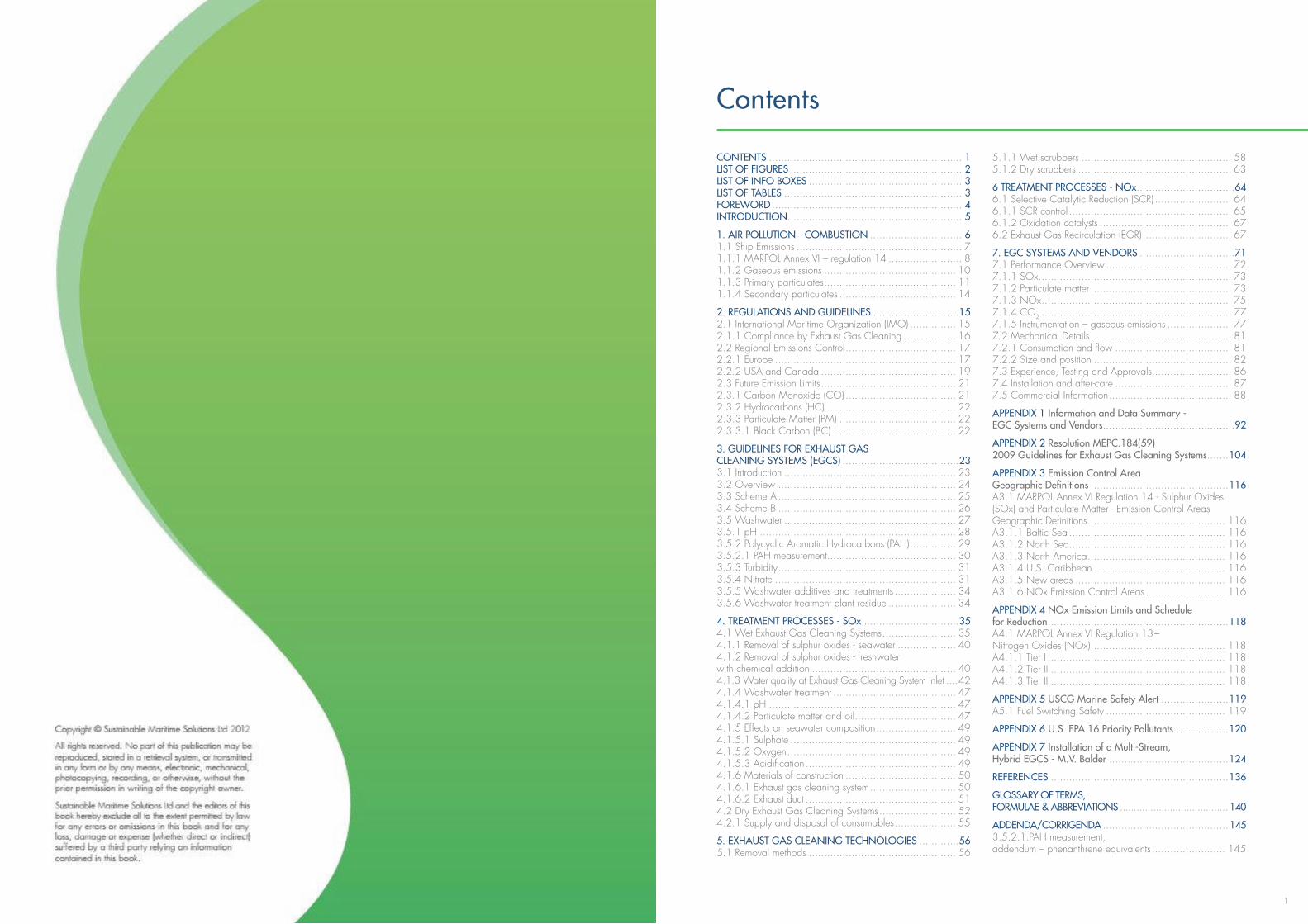
Contents
CONTENTS ............................................................... 1 LIST OF FIGURES ........................................................ 2 LIST OF INFO BOXES .................................................. 3 LIST OF TABLES .......................................................... 3 FOREWORD .............................................................. 4 INTRODUCTION......................................................... 5
1. AIR POLLUTION - COMBUSTION .............................. 6 1.1 Ship Emissions ...................................................... 7 1.1.1 MARPOL Annex VI – regulation 14 ........................ 8 1.1.2 Gaseous emissions ........................................... 10 1.1.3 Primary particulates ........................................... 11 1.1.4 Secondary particulates ...................................... 14
2. REGULATIONS AND GUIDELINES ............................15 2.1 International Maritime Organization (IMO) ............... 15 2.1.1 Compliance by Exhaust Gas Cleaning ................. 16 2.2 Regional Emissions Control .................................... 17 2.2.1 Europe ........................................................... 17 2.2.2 USA and Canada ............................................ 19 2.3 Future Emission Limits ............................................ 21 2.3.1 Carbon Monoxide (CO) .................................... 21 2.3.2 Hydrocarbons (HC) .......................................... 22 2.3.3 Particulate Matter (PM) ...................................... 22 2.3.3.1 Black Carbon (BC) ........................................ 22
3. GUIDELINES FOR EXHAUST GAS CLEANING SYSTEMS (EGCS) ......................................23 3.1 Introduction ........................................................ 23 3.2 Overview .......................................................... 24 3.3 Scheme A .......................................................... 25 3.4 Scheme B .......................................................... 26 3.5 Washwater ........................................................ 27 3.5.1 pH ................................................................ 28 3.5.2 Polycyclic Aromatic Hydrocarbons (PAH) ............... 29 3.5.2.1 PAH measurement .......................................... 30 3.5.3 Turbidity .......................................................... 31 3.5.4 Nitrate ........................................................... 31 3.5.5 Washwater additives and treatments .................... 34 3.5.6 Washwater treatment plant residue ...................... 34
4. TREATMENT PROCESSES - SOx ...............................35 4.1 Wet Exhaust Gas Cleaning Systems ........................ 35 4.1.1 Removal of sulphur oxides - seawater ................... 40 4.1.2 Removal of sulphur oxides - freshwater with chemical addition ............................................... 40 4.1.3 Water quality at Exhaust Gas Cleaning System inlet ....42 4.1.4 Washwater treatment ........................................ 47 4.1.4.1 pH ............................................................. 47 4.1.4.2 Particulate matter and oil ................................. 47 4.1.5 Effects on seawater composition .......................... 49 4.1.5.1 Sulphate ...................................................... 49 4.1.5.2 Oxygen ....................................................... 49 4.1.5.3 Acidification ................................................. 49 4.1.6 Materials of construction .................................... 50 4.1.6.1 Exhaust gas cleaning system ............................ 50 4.1.6.2 Exhaust duct ................................................. 51 4.2 Dry Exhaust Gas Cleaning Systems ......................... 52 4.2.1 Supply and disposal of consumables .................... 55
5. EXHAUST GAS CLEANING TECHNOLOGIES .............56 5.1 Removal methods ................................................ 56
5.1.1 Wet scrubbers ................................................. 58 5.1.2 Dry scrubbers .................................................. 63
6 TREATMENT PROCESSES - NOx ................................64 6.1 Selective Catalytic Reduction (SCR) ......................... 64 6.1.1 SCR control ..................................................... 65 6.1.2 Oxidation catalysts ........................................... 67 6.2 Exhaust Gas Recirculation (EGR) ............................. 67
7. EGC SYSTEMS AND VENDORS ...............................71 7.1 Performance Overview ......................................... 72 7.1.1 SOx ............................................................... 73 7.1.2 Particulate matter .............................................. 73 7.1.3 NOx .............................................................. 75 7.1.4 CO2 .............................................................. 77 7.1.5 Instrumentation – gaseous emissions ..................... 77 7.2 Mechanical Details .............................................. 81 7.2.1 Consumption and flow ...................................... 81 7.2.2 Size and position ............................................. 82 7.3 Experience, Testing and Approvals .......................... 86 7.4 Installation and after-care ...................................... 87 7.5 Commercial Information ........................................ 88
APPENDIX 1 Information and Data Summary - EGC Systems and Vendors ...........................................92
APPENDIX 2 Resolution MEPC.184(59) 2009 Guidelines for Exhaust Gas Cleaning Systems .......104
APPENDIX 3 Emission Control Area Geographic Definitions .............................................116 A3.1 MARPOL Annex VI Regulation 14 - Sulphur Oxides (SOx) and Particulate Matter - Emission Control Areas Geographic Definitions ............................................. 116 A3.1.1 Baltic Sea ................................................... 116 A3.1.2 North Sea ................................................... 116 A3.1.3 North America ............................................. 116 A3.1.4 U.S. Caribbean ........................................... 116 A3.1.5 New areas ................................................. 116 A3.1.6 NOx Emission Control Areas .......................... 116
APPENDIX 4 NOx Emission Limits and Schedule for Reduction ...........................................................118 A4.1 MARPOL Annex VI Regulation 13 – Nitrogen Oxides (NOx) ............................................ 118 A4.1.1 Tier I .......................................................... 118 A4.1.2 Tier II ......................................................... 118 A4.1.3 Tier III ......................................................... 118
APPENDIX 5 USCG Marine Safety Alert ......................119 A5.1 Fuel Switching Safety ....................................... 119
APPENDIX 6 U.S. EPA 16 Priority Pollutants ..................120
APPENDIX 7 Installation of a Multi-Stream, Hybrid EGCS - M.V. Balder .......................................124
REFERENCES ..........................................................136
GLOSSARY OF TERMS, FORMULAE & ABBREVIATIONS ....................................... 140
ADDENDA/CORRIGENDA .........................................145 3.5.2.1.PAH measurement, addendum – phenanthrene equivalents ........................ 145
32
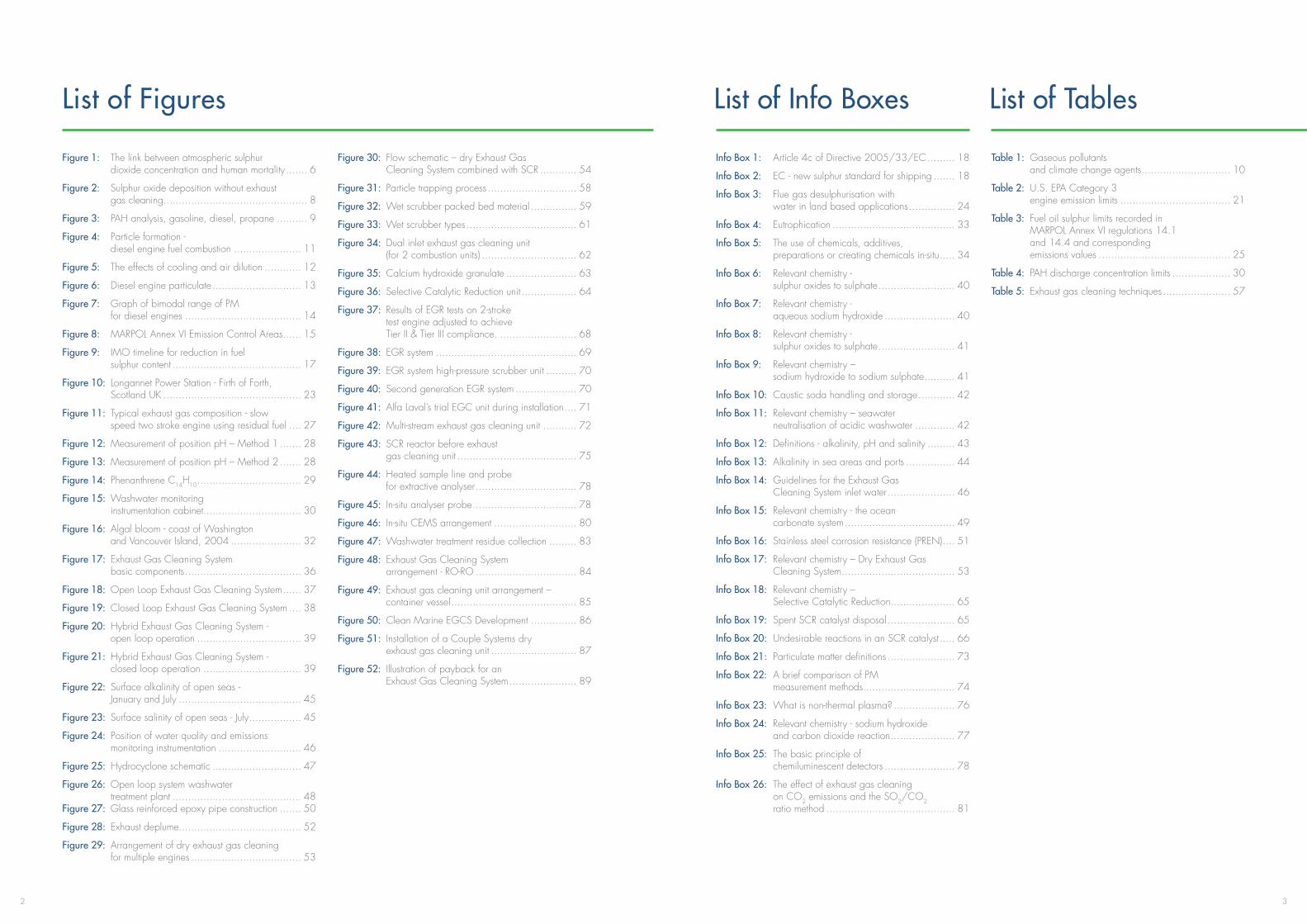
List of Figures
Figure 1: The link between atmospheric sulphur dioxide concentration and human mortality ....... 6
Figure 2: Sulphur oxide deposition without exhaust gas cleaning ............................................... 8
Figure 3: PAH analysis, gasoline, diesel, propane .......... 9
Figure 4: Particle formation - diesel engine fuel combustion ...................... 11
Figure 5: The effects of cooling and air dilution ............ 12
Figure 6: Diesel engine particulate ............................. 13
Figure 7: Graph of bimodal range of PM for diesel engines ...................................... 14
Figure 8: MARPOL Annex VI Emission Control Areas ...... 15
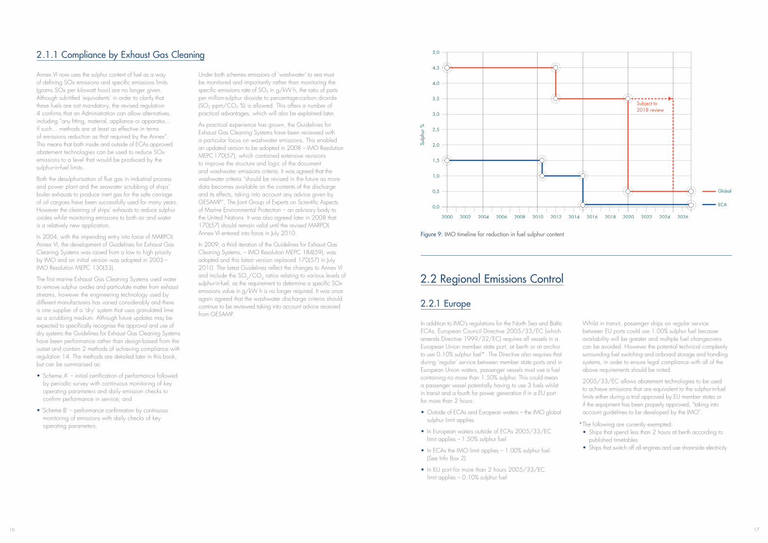
Figure 9: IMO timeline for reduction in fuel sulphur content .......................................... 17
Figure 10: Longannet Power Station - Firth of Forth, Scotland UK ............................................. 23
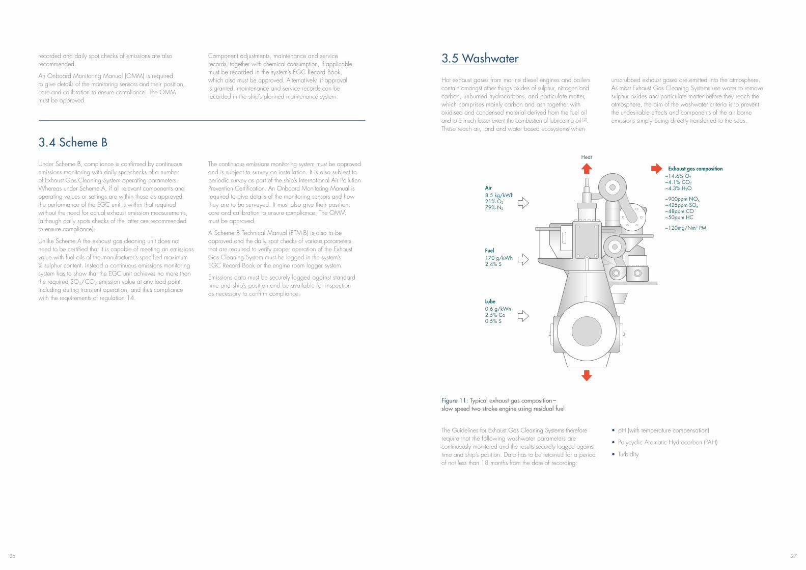
Figure 11: Typical exhaust gas composition - slow speed two stroke engine using residual fuel .... 27
Figure 12: Measurement of position pH – Method 1 ....... 28
Figure 13: Measurement of position pH – Method 2 ....... 28
Figure 14: Phenanthrene C14H10 .................................. 29
Figure 15: Washwater monitoring instrumentation cabinet................................ 30
Figure 16: Algal bloom - coast of Washington and Vancouver Island, 2004 ....................... 32
Figure 17: Exhaust Gas Cleaning System basic components ...................................... 36
Figure 18: Open Loop Exhaust Gas Cleaning System ...... 37
Figure 19: Closed Loop Exhaust Gas Cleaning System .... 38
Figure 20: Hybrid Exhaust Gas Cleaning System - open loop operation .................................. 39
Figure 21: Hybrid Exhaust Gas Cleaning System - closed loop operation ................................ 39
Figure 22: Surface alkalinity of open seas - January and July ........................................ 45
Figure 23: Surface salinity of open seas - July ................. 45
Figure 24: Position of water quality and emissions monitoring instrumentation ........................... 46
Figure 25: Hydrocyclone schematic ............................. 47
Figure 26: Open loop system washwater treatment plant .......................................... 48 Figure 27: Glass reinforced epoxy pipe construction ....... 50
Figure 28: Exhaust deplume........................................ 52
Figure 29: Arrangement of dry exhaust gas cleaning for multiple engines .................................... 53
Figure 30: Flow schematic – dry Exhaust Gas Cleaning System combined with SCR ............ 54
Figure 31: Particle trapping process ............................. 58
Figure 32: Wet scrubber packed bed material ............... 59
Figure 33: Wet scrubber types .................................... 61
Figure 34: Dual inlet exhaust gas cleaning unit (for 2 combustion units) ............................... 62
Figure 35: Calcium hydroxide granulate ....................... 63
Figure 36: Selective Catalytic Reduction unit .................. 64
Figure 37: Results of EGR tests on 2-stroke test engine adjusted to achieve Tier II & Tier III compliance. ......................... 68
Figure 38: EGR system .............................................. 69
Figure 39: EGR system high-pressure scrubber unit .......... 70
Figure 40: Second generation EGR system .................... 70
Figure 41: Alfa Laval’s trial EGC unit during installation .... 71
Figure 42: Multi-stream exhaust gas cleaning unit ........... 72
Figure 43: SCR reactor before exhaust gas cleaning unit ....................................... 75
Figure 44: Heated sample line and probe for extractive analyser ................................. 78
Figure 45: In-situ analyser probe .................................. 78
Figure 46: In-situ CEMS arrangement ........................... 80
Figure 47: Washwater treatment residue collection ......... 83
Figure 48: Exhaust Gas Cleaning System arrangement - RO-RO ................................. 84
Figure 49: Exhaust gas cleaning unit arrangement – container vessel ......................................... 85
Figure 50: Clean Marine EGCS Development ............... 86
Figure 51: Installation of a Couple Systems dry exhaust gas cleaning unit ............................ 87
Figure 52: Illustration of payback for an Exhaust Gas Cleaning System ...................... 89
List of Info Boxes
Info Box 1: Article 4c of Directive 2005/33/EC ......... 18
Info Box 2: EC - new sulphur standard for shipping ....... 18
Info Box 3: Flue gas desulphurisation with water in land based applications ............... 24
Info Box 4: Eutrophication ........................................ 33
Info Box 5: The use of chemicals, additives, preparations or creating chemicals in-situ ..... 34
Info Box 6: Relevant chemistry - sulphur oxides to sulphate ......................... 40
Info Box 7: Relevant chemistry - aqueous sodium hydroxide ....................... 40
Info Box 8: Relevant chemistry - sulphur oxides to sulphate ......................... 41
Info Box 9: Relevant chemistry – sodium hydroxide to sodium sulphate .......... 41
Info Box 10: Caustic soda handling and storage ............ 42
Info Box 11: Relevant chemistry – seawater neutralisation of acidic washwater ............. 42
Info Box 12: Definitions - alkalinity, pH and salinity ......... 43
Info Box 13: Alkalinity in sea areas and ports ................ 44
Info Box 14: Guidelines for the Exhaust Gas Cleaning System inlet water ...................... 46
Info Box 15: Relevant chemistry - the ocean carbonate system .................................... 49
Info Box 16: Stainless steel corrosion resistance (PREN) .... 51
Info Box 17: Relevant chemistry – Dry Exhaust Gas Cleaning System ..................................... 53
Info Box 18: Relevant chemistry – Selective Catalytic Reduction ..................... 65
Info Box 19: Spent SCR catalyst disposal ...................... 65
Info Box 20: Undesirable reactions in an SCR catalyst ..... 66
Info Box 21: Particulate matter definitions ...................... 73
Info Box 22: A brief comparison of PM measurement methods .............................. 74
Info Box 23: What is non-thermal plasma? .................... 76
Info Box 24: Relevant chemistry - sodium hydroxide and carbon dioxide reaction ..................... 77
Info Box 25: The basic principle of chemiluminescent detectors ....................... 78
Info Box 26: The effect of exhaust gas cleaning on CO2 emissions and the SO2/CO2 ratio method .......................................... 81
List of Tables
Table 1: Gaseous pollutants and climate change agents ............................. 10
Table 2: U.S. EPA Category 3 engine emission limits .................................... 21
Table 3: Fuel oil sulphur limits recorded in MARPOL Annex VI regulations 14.1 and 14.4 and corresponding emissions values ........................................... 25
Table 4: PAH discharge concentration limits ................... 30
Table 5: Exhaust gas cleaning techniques ...................... 57

54
Foreword
The Exhaust Gas Cleaning Systems Association will record its fifth anniversary in 2013. During this period the EGCSA members have installed a variety of commercial exhaust gas scrubbing systems. All these installations are able to meet and exceed the most stringent of current IMO MARPOL Annex VI emissions regulations.
EGCSA members have provided a real alternative to the expensive low sulphur fuels prescribed in MARPOL Annex VI. More importantly, Exhaust Gas Cleaning Systems (EGCS) are now providing real and significant cumulative savings to the global shipping industry. No other recent environmental regulation (IMO or any other) has ever enjoyed the payback, lower operating cost and lower GHG footprint than is achieved by installing Exhaus Gas Cleaning Systems.
It is a credit to the Association and its membership that this trade association has also invested in scientific research to ensure the long term viability of the technology and the continuing assessment of any possible long term environmental impact.
I commend this second edition of the EGCSA Handbook which is a rich resource for those interested in understanding the technology and its application.
Introduction
The original EGCSA handbook was published in September 2010. Since then many of the issues highlighted in the previous foreword remain. The promotion of LNG as a fuel which will displace HFO continues. Some of the questions around the handling and management of LNG fuel are still unanswered. Nevertheless LNG is certain to be in the future marine fuel mix. Dual fuelling with HFO and LNG will certainly address the range anxiety of pure LNG fuelled vessels.
The first EGCS training course at Brunel University in June 2012 set out to debunk the myths surrounding EGCS technology. It also set the context and need for cleaner air. With marketing sound bites blocking out sound technical and commercial decision making, the course provided the tools to evaluate and where appropriate assisted in developing the business case for an exhaust cleaning system investment.
Today further uncertainties prevail, including fleet over capacity in what appears to be a significant and sustained global downturn. The merchant marine business model that rode the peak freight rates and new-building tonnage has not served many ship-operators well. A shortage of free cash generation from operations and a withdrawal of finance by banks and other funders have placed a financial challenge on capital investment. The installation of ballast water systems, energy efficiency measures and emissions abatement technologies are all calling for significant investment in the existing fleet.
The certainties that will need to be faced are the reduction in sulphur to 0.10% in ECAs in 2015, possibly increasing demand for diesel by more than 40Mt. The impact on the cost of road transport diesel in Europe is uncertain but could lead to shortages and price spikes. The new ECA emissions limit will inevitably increase some seaborne transport costs, but it will also present an opportunity for those operators who have selected winning strategies to achieve massive competitive advantage. The journey to lower emissions will continue. A delay to 2025 of the global sulphur emissions cap looks increasingly unlikely, whilst the need to more closely align ship emission regulations with heavy-duty on-shore diesel emissions regulations is becoming an inevitability.
The Exhaust Gas Cleaning System industry has begun some consolidation. New entrants continue to appear whilst some of the “magic” solutions have lost their supporters. EGCSA will continue to pursue its key roles of transparency, accountability and integrity. The Association accepts that the forthcoming transition is a major and costly change. EGCSA continues to work closely with all stakeholders to ensure compliance is achieved by the most effective means.
Nevertheless the outlook appears expensive. But compared to other environmental regulations, emissions to air regulations provide a real opportunity to reduce operating costs and gain efficiency benefits.
The updated handbook contains more in-depth detail of exhaust gas cleaning processes, configurations of system deployment and the likely evolution of future emissions regulations.
A special thank-you to Mark West for his editing of the 2012 handbook.
Finally special thanks to our advertisers who chose to participate in the handbook with a page of information on their respective businesses and services. Without advertisers support producing this handbook at a reasonable cover price would be prohibitive. Please have a look at their contributions at the back of the handbook.MR. NICHOLAS CONFUORTO
Belco Technologies Corporation (a DuPont subsidiary) Chairman, EGCSA
MR. DONALD GREGORY
Director, EGCSA Partner Sustainable Maritime Solutions Ltd
76
1. Air Pollution – Combustion
Man-made air pollution was probably in evidence at a local level affecting human health from when man was first able to light fires and use them in caves and early dwellings.
In Europe two major tragedies are believed to have led to the development of air pollution policy and legislation. In December 1930 in the Meuse Valley in Belgium 63 persons died and many more fell ill [91]. The cause of the fatalities has never been fully established but it is known that the valley was heavily industrialised. In the winter
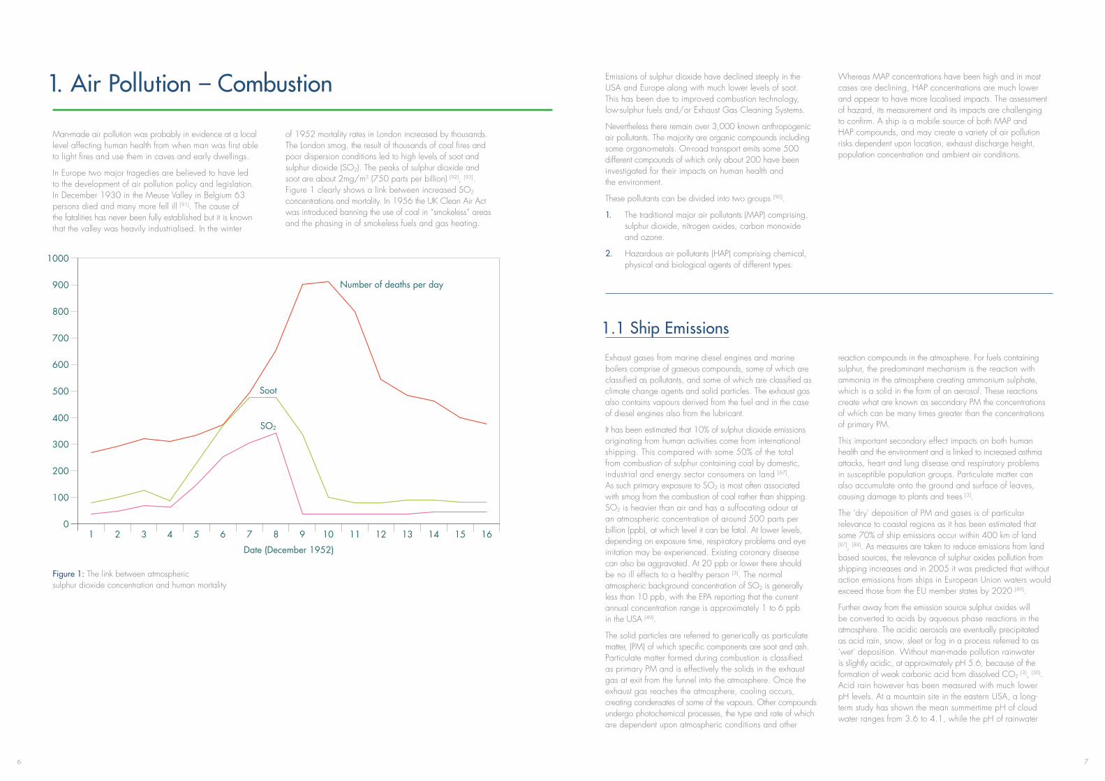
of 1952 mortality rates in London increased by thousands. The London smog, the result of thousands of coal fires and poor dispersion conditions led to high levels of soot and sulphur dioxide (SO2). The peaks of sulphur dioxide and soot are about 2mg/m3 (750 parts per billion) [92], [93]. Figure 1 clearly shows a link between increased SO2 concentrations and mortality. In 1956 the UK Clean Air Act was introduced banning the use of coal in “smokeless” areas and the phasing in of smokeless fuels and gas heating.
Figure 1: The link between atmospheric sulphur dioxide concentration and human mortality
Emissions of sulphur dioxide have declined steeply in the USA and Europe along with much lower levels of soot. This has been due to improved combustion technology, low-sulphur fuels and/or Exhaust Gas Cleaning Systems.
Nevertheless there remain over 3,000 known anthropogenic air pollutants. The majority are organic compounds including some organo-metals. On-road transport emits some 500 different compounds of which only about 200 have been investigated for their impacts on human health and the environment.
These pollutants can be divided into two groups [90].
1. The traditional major air pollutants (MAP) comprising, sulphur dioxide, nitrogen oxides, carbon monoxide and ozone.
2. Hazardous air pollutants (HAP) comprising chemical, physical and biological agents of different types.
Whereas MAP concentrations have been high and in most cases are declining, HAP concentrations are much lower and appear to have more localised impacts. The assessment of hazard, its measurement and its impacts are challenging to confirm. A ship is a mobile source of both MAP and HAP compounds, and may create a variety of air pollution risks dependent upon location, exhaust discharge height, population concentration and ambient air conditions.
1.1 Ship Emissions
Exhaust gases from marine diesel engines and marine boilers comprise of gaseous compounds, some of which are classified as pollutants, and some of which are classified as climate change agents and solid particles. The exhaust gas also contains vapours derived from the fuel and in the case of diesel engines also from the lubricant.
It has been estimated that 10% of sulphur dioxide emissions originating from human activities come from international shipping. This compared with some 50% of the total from combustion of sulphur containing coal by domestic, industrial and energy sector consumers on land [67]. As such primary exposure to SO2 is most often associated with smog from the combustion of coal rather than shipping. SO2 is heavier than air and has a suffocating odour at an atmospheric concentration of around 500 parts per billion (ppb), at which level it can be fatal. At lower levels, depending on exposure time, respiratory problems and eye irritation may be experienced. Existing coronary disease can also be aggravated. At 20 ppb or lower there should be no ill effects to a healthy person [3]. The normal atmospheric background concentration of SO2 is generally less than 10 ppb, with the EPA reporting that the current annual concentration range is approximately 1 to 6 ppb in the USA [49].
The solid particles are referred to generically as particulate matter, (PM) of which specific components are soot and ash. Particulate matter formed during combustion is classified as primary PM and is effectively the solids in the exhaust gas at exit from the funnel into the atmosphere. Once the exhaust gas reaches the atmosphere, cooling occurs, creating condensates of some of the vapours. Other compounds undergo photochemical processes, the type and rate of which are dependent upon atmospheric conditions and other
reaction compounds in the atmosphere. For fuels containing sulphur, the predominant mechanism is the reaction with ammonia in the atmosphere creating ammonium sulphate, which is a solid in the form of an aerosol. These reactions create what are known as secondary PM the concentrations of which can be many times greater than the concentrations of primary PM.
This important secondary effect impacts on both human health and the environment and is linked to increased asthma attacks, heart and lung disease and respiratory problems in susceptible population groups. Particulate matter can also accumulate onto the ground and surface of leaves, causing damage to plants and trees [3].
The ‘dry’ deposition of PM and gases is of particular relevance to coastal regions as it has been estimated that some 70% of ship emissions occur within 400 km of land [87], [88]. As measures are taken to reduce emissions from land based sources, the relevance of sulphur oxides pollution from shipping increases and in 2005 it was predicted that without action emissions from ships in European Union waters would exceed those from the EU member states by 2020 [89].
Further away from the emission source sulphur oxides will be converted to acids by aqueous phase reactions in the atmosphere. The acidic aerosols are eventually precipitated as acid rain, snow, sleet or fog in a process referred to as ‘wet’ deposition. Without man-made pollution rainwater is slightly acidic, at approximately pH 5.6, because of the formation of weak carbonic acid from dissolved CO2 [3], [50]. Acid rain however has been measured with much lower pH levels. At a mountain site in the eastern USA, a long-term study has shown the mean summertime pH of cloud water ranges from 3.6 to 4.1, while the pH of rainwater
Date (December 1952)
SO2
Soot
Number of deaths per day
1 2 3 4 5 6 7 8 9 10 11 12 13 14 15 16
98
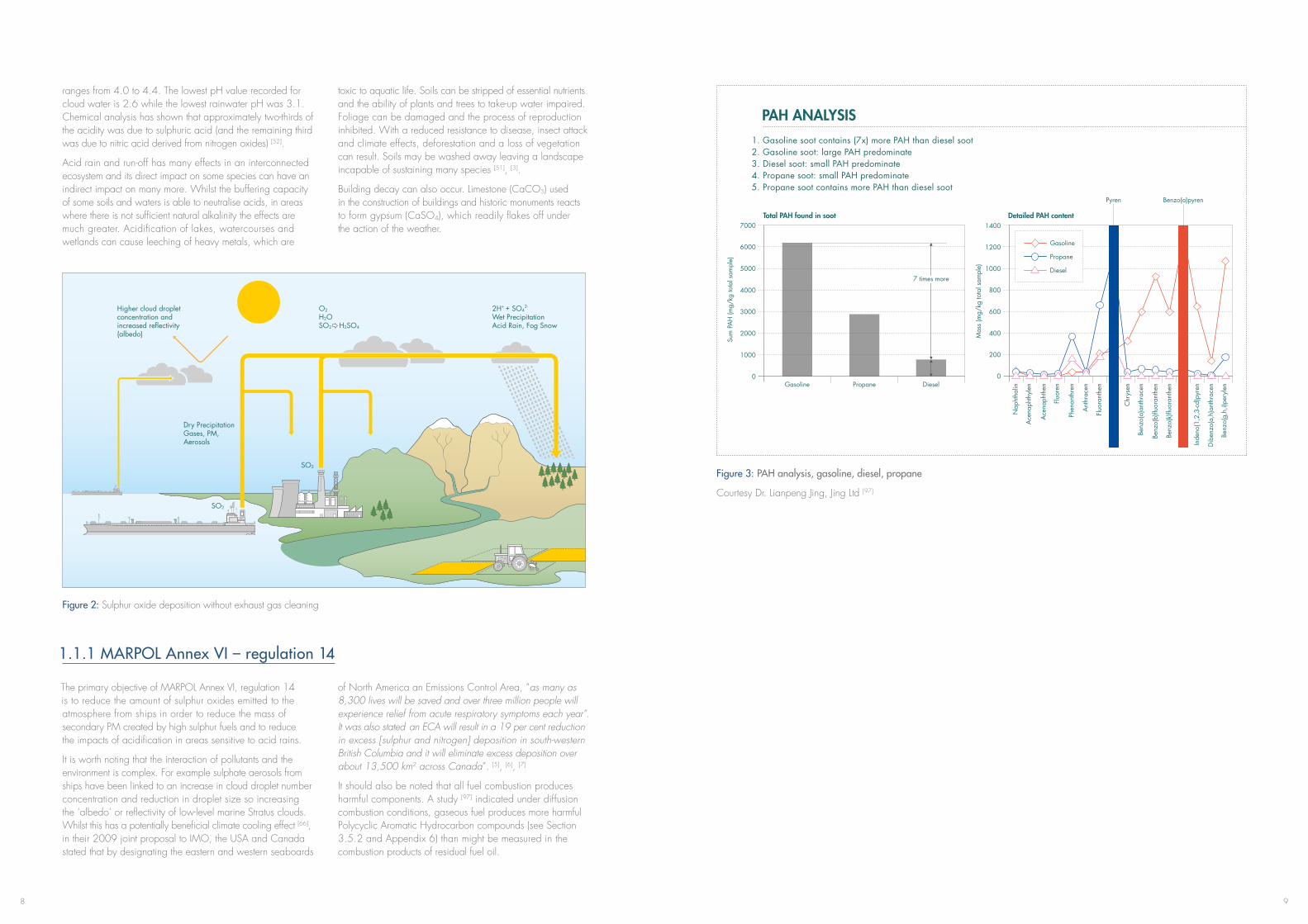
ranges from 4.0 to 4.4. The lowest pH value recorded for cloud water is 2.6 while the lowest rainwater pH was 3.1. Chemical analysis has shown that approximately two-thirds of the acidity was due to sulphuric acid (and the remaining third was due to nitric acid derived from nitrogen oxides) [52].
Acid rain and run-off has many effects in an interconnected ecosystem and its direct impact on some species can have an indirect impact on many more. Whilst the buffering capacity of some soils and waters is able to neutralise acids, in areas where there is not sufficient natural alkalinity the effects are much greater. Acidification of lakes, watercourses and wetlands can cause leeching of heavy metals, which are
toxic to aquatic life. Soils can be stripped of essential nutrients and the ability of plants and trees to take-up water impaired. Foliage can be damaged and the process of reproduction inhibited. With a reduced resistance to disease, insect attack and climate effects, deforestation and a loss of vegetation can result. Soils may be washed away leaving a landscape incapable of sustaining many species [51], [3].
Building decay can also occur. Limestone (CaCO3) used in the construction of buildings and historic monuments reacts to form gypsum (CaSO4), which readily flakes off under the action of the weather.
Figure 2: Sulphur oxide deposition without exhaust gas cleaning
1.1.1 MARPOL Annex VI – regulation 14
The primary objective of MARPOL Annex VI, regulation 14 is to reduce the amount of sulphur oxides emitted to the atmosphere from ships in order to reduce the mass of secondary PM created by high sulphur fuels and to reduce the impacts of acidification in areas sensitive to acid rains.
It is worth noting that the interaction of pollutants and the environment is complex. For example sulphate aerosols from ships have been linked to an increase in cloud droplet number concentration and reduction in droplet size so increasing the ‘albedo’ or reflectivity of low-level marine Stratus clouds. Whilst this has a potentially beneficial climate cooling effect [66], in their 2009 joint proposal to IMO, the USA and Canada stated that by designating the eastern and western seaboards
of North America an Emissions Control Area, “as many as 8,300 lives will be saved and over three million people will experience relief from acute respiratory symptoms each year”. It was also stated an ECA will result in a 19 per cent reduction in excess [sulphur and nitrogen] deposition in south-western British Columbia and it will eliminate excess deposition over about 13,500 km2 across Canada”. [5], [6], [7]
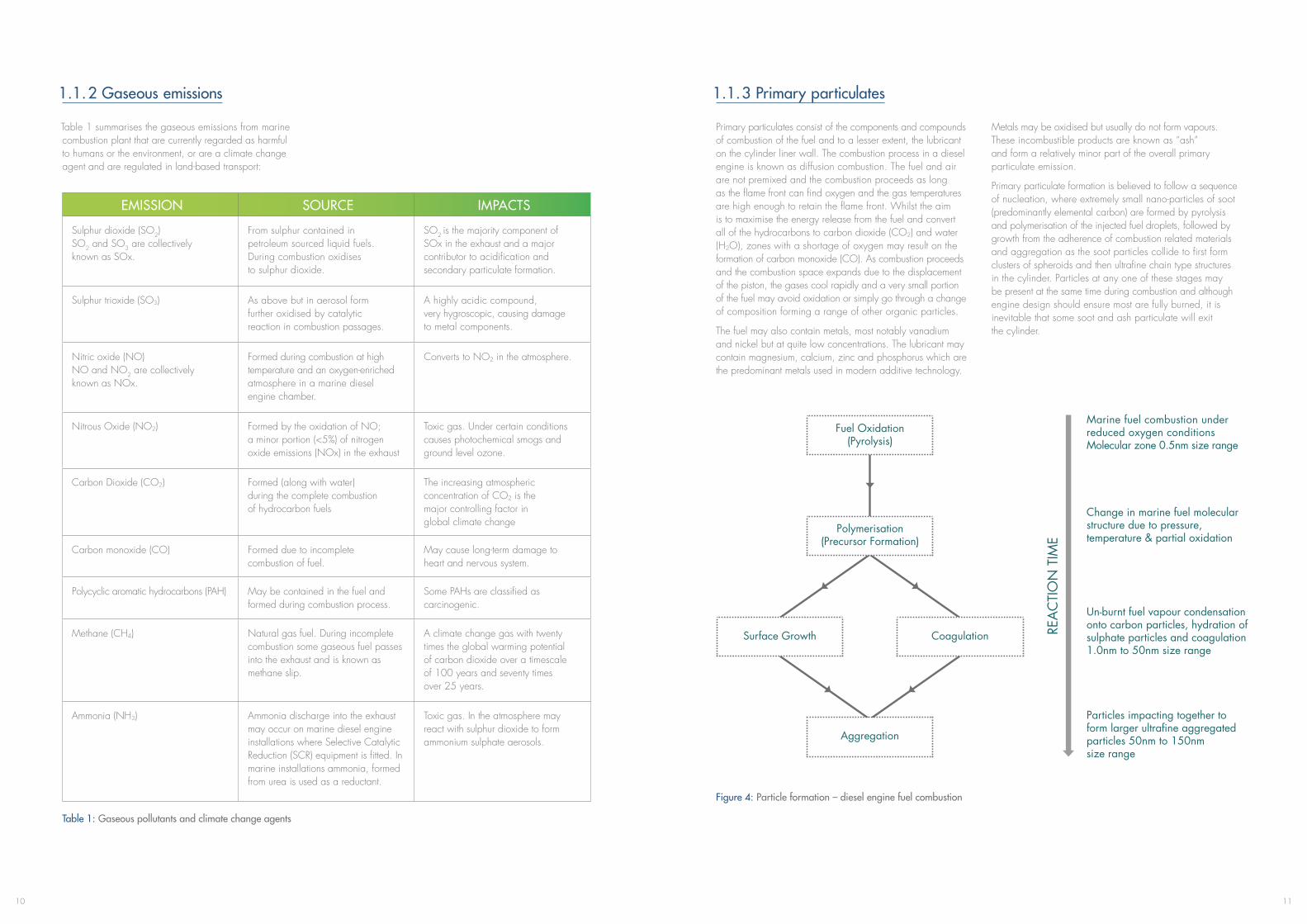
It should also be noted that all fuel combustion produces harmful components. A study [97] indicated under diffusion combustion conditions, gaseous fuel produces more harmful Polycyclic Aromatic Hydrocarbon compounds (see Section 3.5.2 and Appendix 6) than might be measured in the combustion products of residual fuel oil.
Figure 3: PAH analysis, gasoline, diesel, propane
Courtesy Dr. Lianpeng Jing, Jing Ltd [97]
Higher cloud droplet concentration and increased reflectivity (albedo)
Dry Precipitation Gases, PM, Aerosols
2H+ + SO42-
Wet Precipitation Acid Rain, Fog Snow
SO2
SO2
O2
H2OSO2 H2SO4
Total PAH found in soot
1. Gasoline soot contains (7x) more PAH than diesel soot2. Gasoline soot: large PAH predominate3. Diesel soot: small PAH predominate4. Propane soot: small PAH predominate5. Propane soot contains more PAH than diesel soot
PAH ANALYSIS
Gasoline Propane Diesel
Benzo(a)pyrenPyren
7 times more7 times more
Detailed PAH content
Diesel
Propane
Gasoline
1110
EMISSION SOURCE IMPACTS
Sulphur dioxide (SO2)SO2 and SO3 are collectively known as SOx.
From sulphur contained in petroleum sourced liquid fuels. During combustion oxidises to sulphur dioxide.
SO2 is the majority component of SOx in the exhaust and a major contributor to acidification and secondary particulate formation.
Sulphur trioxide (SO3) As above but in aerosol form further oxidised by catalytic reaction in combustion passages.
A highly acidic compound, very hygroscopic, causing damage to metal components.
Nitric oxide (NO) NO and NO2 are collectively known as NOx.
Formed during combustion at high temperature and an oxygen-enriched atmosphere in a marine diesel engine chamber.
Converts to NO2 in the atmosphere.
Nitrous Oxide (NO2) Formed by the oxidation of NO; a minor portion (<5%) of nitrogen oxide emissions (NOx) in the exhaust
Toxic gas. Under certain conditions causes photochemical smogs and ground level ozone.
Carbon Dioxide (CO2) Formed (along with water) during the complete combustion of hydrocarbon fuels
The increasing atmospheric concentration of CO2 is the major controlling factor in global climate change
Carbon monoxide (CO) Formed due to incomplete combustion of fuel.
May cause long-term damage to heart and nervous system.
Polycyclic aromatic hydrocarbons (PAH) May be contained in the fuel and formed during combustion process.
Some PAHs are classified as carcinogenic.
Methane (CH4) Natural gas fuel. During incomplete combustion some gaseous fuel passes into the exhaust and is known as methane slip.
A climate change gas with twenty times the global warming potential of carbon dioxide over a timescale of 100 years and seventy times over 25 years.
Ammonia (NH3) Ammonia discharge into the exhaust may occur on marine diesel engine installations where Selective Catalytic Reduction (SCR) equipment is fitted. In marine installations ammonia, formed from urea is used as a reductant.
Toxic gas. In the atmosphere may react with sulphur dioxide to form ammonium sulphate aerosols.
1.1.2 Gaseous emissions
Table 1 summarises the gaseous emissions from marine combustion plant that are currently regarded as harmful to humans or the environment, or are a climate change agent and are regulated in land-based transport:
Table 1: Gaseous pollutants and climate change agents
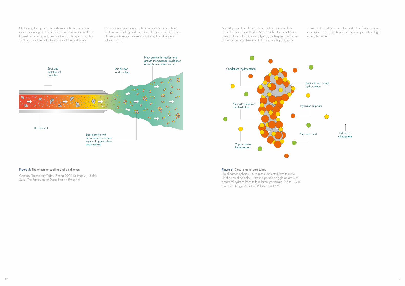
Figure 4: Particle formation – diesel engine fuel combustion
1.1.3 Primary particulates
Primary particulates consist of the components and compounds of combustion of the fuel and to a lesser extent, the lubricant on the cylinder liner wall. The combustion process in a diesel engine is known as diffusion combustion. The fuel and air are not premixed and the combustion proceeds as long as the flame front can find oxygen and the gas temperatures are high enough to retain the flame front. Whilst the aim is to maximise the energy release from the fuel and convert all of the hydrocarbons to carbon dioxide (CO2) and water (H2O), zones with a shortage of oxygen may result on the formation of carbon monoxide (CO). As combustion proceeds and the combustion space expands due to the displacement of the piston, the gases cool rapidly and a very small portion of the fuel may avoid oxidation or simply go through a change of composition forming a range of other organic particles.
The fuel may also contain metals, most notably vanadium and nickel but at quite low concentrations. The lubricant may contain magnesium, calcium, zinc and phosphorus which are the predominant metals used in modern additive technology.
Metals may be oxidised but usually do not form vapours. These incombustible products are known as “ash” and form a relatively minor part of the overall primary particulate emission.
Primary particulate formation is believed to follow a sequence of nucleation, where extremely small nano-particles of soot (predominantly elemental carbon) are formed by pyrolysis and polymerisation of the injected fuel droplets, followed by growth from the adherence of combustion related materials and aggregation as the soot particles collide to first form clusters of spheroids and then ultrafine chain type structures in the cylinder. Particles at any one of these stages may be present at the same time during combustion and although engine design should ensure most are fully burned, it is inevitable that some soot and ash particulate will exit the cylinder.
Marine fuel combustion under reduced oxygen conditions Molecular zone 0.5nm size range
Change in marine fuel molecular structure due to pressure, temperature & partial oxidation
Un-burnt fuel vapour condensation onto carbon particles, hydration of sulphate particles and coagulation 1.0nm to 50nm size range
Particles impacting together to form larger ultrafine aggregated particles 50nm to 150nm size range
Fuel Oxidation (Pyrolysis)
Polymerisation (Precursor Formation)
Surface Growth Coagulation
Aggregation
1312
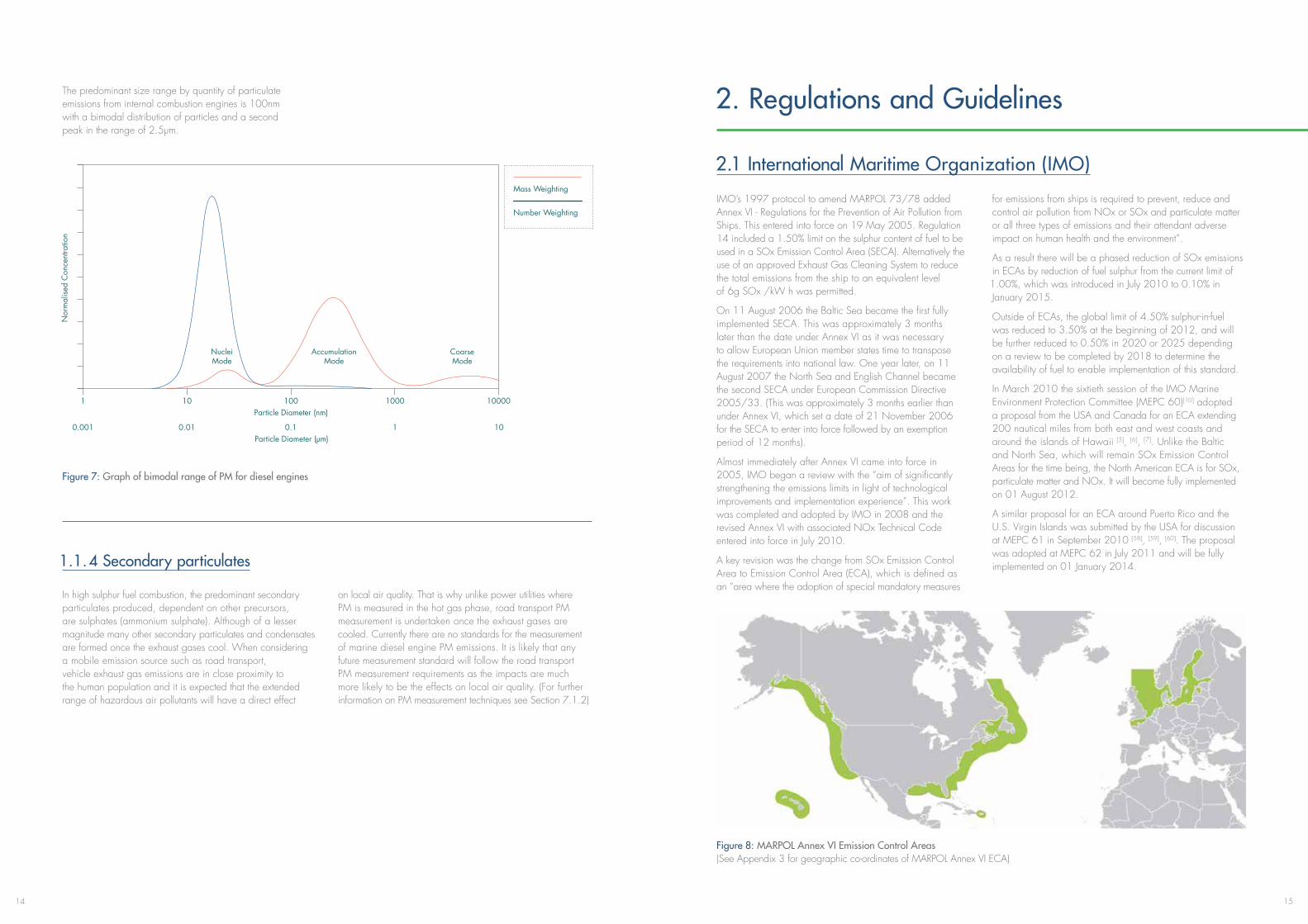
On leaving the cylinder, the exhaust cools and larger and more complex particles are formed as various incompletely burned hydrocarbons (known as the soluble organic fraction -SOF) accumulate onto the surface of the particulate
by adsorption and condensation. In addition atmospheric dilution and cooling of diesel exhaust triggers the nucleation of new particles such as semi-volatile hydrocarbons and sulphuric acid.
Figure 5: The effects of cooling and air dilution
Courtesy Technology Today, Spring 2006 Dr Imad A. Khalek, SwRI, The Particulars of Diesel Particle Emissions
Soot and metallic ash particles
Hot exhaust
Air dilution and cooling
New particle formation and growth (homogenous nucleation adsorption/condensation)
Soot particle with adsorbed/condensed layers of hydrocarbon and sulphate
A small proportion of the gaseous sulphur dioxide from the fuel sulphur is oxidised to SO3, which either reacts with water to form sulphuric acid (H2SO4), undergoes gas phase oxidation and condensation to form sulphate particles or
is oxidised as sulphate onto the particulate formed during combustion. These sulphates are hygroscopic with a high affinity for water.
Figure 6: Diesel engine particulate (Solid carbon spheres (10 to 80nm diameter) form to make ultrafine solid particles. Ultrafine particles agglomerate with adsorbed hydrocarbons to form larger particulate (0.5 to 1.0μm diameter). Fenger & Tjell Air Pollution 2009 [94])
Condensed hydrocarbon
Vapour phase hydrocarbon
Soot with adsorbed hydrocarbon
Hydrated sulphate
Sulphuric acid Exhaust to atmosphere
Sulphate oxidation and hydration
1514
The predominant size range by quantity of particulate emissions from internal combustion engines is 100nm with a bimodal distribution of particles and a second peak in the range of 2.5μm.
Figure 7: Graph of bimodal range of PM for diesel engines
1.1.4 Secondary particulates
In high sulphur fuel combustion, the predominant secondary particulates produced, dependent on other precursors, are sulphates (ammonium sulphate). Although of a lesser magnitude many other secondary particulates and condensates are formed once the exhaust gases cool. When considering a mobile emission source such as road transport, vehicle exhaust gas emissions are in close proximity to the human population and it is expected that the extended range of hazardous air pollutants will have a direct effect
on local air quality. That is why unlike power utilities where PM is measured in the hot gas phase, road transport PM measurement is undertaken once the exhaust gases are cooled. Currently there are no standards for the measurement of marine diesel engine PM emissions. It is likely that any future measurement standard will follow the road transport PM measurement requirements as the impacts are much more likely to be the effects on local air quality. (For further information on PM measurement techniques see Section 7.1.2)
0.001
Nuclei Mode
Accumulation Mode
Coarse Mode
0.01 0.1 1 10
Particle Diameter (nm)
Particle Diameter (μm)
1 10 100 1000 10000
Mass Weighting
Number Weighting
Figure 8: MARPOL Annex VI Emission Control Areas (See Appendix 3 for geographic co-ordinates of MARPOL Annex VI ECA)
2. Regulations and Guidelines
2.1 International Maritime Organization (IMO)
IMO’s 1997 protocol to amend MARPOL 73/78 added Annex VI - Regulations for the Prevention of Air Pollution from Ships. This entered into force on 19 May 2005. Regulation 14 included a 1.50% limit on the sulphur content of fuel to be used in a SOx Emission Control Area (SECA). Alternatively the use of an approved Exhaust Gas Cleaning System to reduce the total emissions from the ship to an equivalent level of 6g SOx /kW h was permitted.
On 11 August 2006 the Baltic Sea became the first fully implemented SECA. This was approximately 3 months later than the date under Annex VI as it was necessary to allow European Union member states time to transpose the requirements into national law. One year later, on 11 August 2007 the North Sea and English Channel became the second SECA under European Commission Directive 2005/33. (This was approximately 3 months earlier than under Annex VI, which set a date of 21 November 2006 for the SECA to enter into force followed by an exemption period of 12 months).
Almost immediately after Annex VI came into force in 2005, IMO began a review with the “aim of significantly strengthening the emissions limits in light of technological improvements and implementation experience”. This work was completed and adopted by IMO in 2008 and the revised Annex VI with associated NOx Technical Code entered into force in July 2010.
A key revision was the change from SOx Emission Control Area to Emission Control Area (ECA), which is defined as an “area where the adoption of special mandatory measures
for emissions from ships is required to prevent, reduce and control air pollution from NOx or SOx and particulate matter or all three types of emissions and their attendant adverse impact on human health and the environment”.
As a result there will be a phased reduction of SOx emissions in ECAs by reduction of fuel sulphur from the current limit of 1.00%, which was introduced in July 2010 to 0.10% in January 2015.
Outside of ECAs, the global limit of 4.50% sulphur-in-fuel was reduced to 3.50% at the beginning of 2012, and will be further reduced to 0.50% in 2020 or 2025 depending on a review to be completed by 2018 to determine the availability of fuel to enable implementation of this standard.
In March 2010 the sixtieth session of the IMO Marine Environment Protection Committee (MEPC 60)[10] adopted a proposal from the USA and Canada for an ECA extending 200 nautical miles from both east and west coasts and around the islands of Hawaii [5], [6], [7]. Unlike the Baltic and North Sea, which will remain SOx Emission Control Areas for the time being, the North American ECA is for SOx, particulate matter and NOx. It will become fully implemented on 01 August 2012.
A similar proposal for an ECA around Puerto Rico and the U.S. Virgin Islands was submitted by the USA for discussion at MEPC 61 in September 2010 [58], [59], [60]. The proposal was adopted at MEPC 62 in July 2011 and will be fully implemented on 01 January 2014.
1716
2 .1.1 Compliance by Exhaust Gas Cleaning
Annex VI now uses the sulphur content of fuel as a way of defining SOx emissions and specific emissions limits (grams SOx per kilowatt hour) are no longer given. Although sub-titled ‘equivalents’ in order to clarify that these fuels are not mandatory, the revised regulation 4 confirms that an Administration can allow alternatives, including “any fitting, material, appliance or apparatus... if such... methods are at least as effective in terms of emissions reduction as that required by the Annex”. This means that both inside and outside of ECAs approved abatement technologies can be used to reduce SOx emissions to a level that would be produced by the sulphur-in-fuel limits.
Both the desulphurisation of flue gas in industrial process and power plant and the seawater scrubbing of ships’ boiler exhausts to produce inert gas for the safe carriage of oil cargoes have been successfully used for many years. However the cleaning of ships’ exhausts to reduce sulphur oxides whilst monitoring emissions to both air and water is a relatively new application.
In 2004, with the impending entry into force of MARPOL Annex VI, the development of Guidelines for Exhaust Gas Cleaning Systems was raised from a low to high priority by IMO and an initial version was adopted in 2005 – IMO Resolution MEPC 130(53).
The first marine Exhaust Gas Cleaning Systems used water to remove sulphur oxides and particulate matter from exhaust streams, however the engineering technology used by different manufacturers has varied considerably and there is one supplier of a ‘dry’ system that uses granulated lime as a scrubbing medium. Although future updates may be expected to specifically recognise the approval and use of dry systems the Guidelines for Exhaust Gas Cleaning Systems have been performance rather than design-based from the outset and contain 2 methods of achieving compliance with regulation 14. The methods are detailed later in this book, but can be summarised as:
• ‘Scheme A’ – initial certification of performance followed by periodic survey with continuous monitoring of key operating parameters and daily emission checks to confirm performance in service; and
• ‘Scheme B’ – performance confirmation by continuous monitoring of emissions with daily checks of key operating parameters.
Under both schemes emissions of ‘washwater’ to sea must be monitored and importantly rather than monitoring the specific emissions rate of SO2 in g/kW h, the ratio of parts per million-sulphur dioxide to percentage-carbon dioxide (SO2 ppm/CO2 %) is allowed. This offers a number of practical advantages, which will also be explained later.
As practical experience has grown, the Guidelines for Exhaust Gas Cleaning Systems have been reviewed with a particular focus on washwater emissions. This enabled an updated version to be adopted in 2008 – IMO Resolution MEPC 170(57), which contained extensive revisions to improve the structure and logic of the document and washwater emissions criteria. It was agreed that the washwater criteria “should be revised in the future as more data becomes available on the contents of the discharge and its effects, taking into account any advice given by GESAMP”, The Joint Group of Experts on Scientific Aspects of Marine Environmental Protection – an advisory body to the United Nations. It was also agreed later in 2008 that 170(57) should remain valid until the revised MARPOL Annex VI entered into force in July 2010.
In 2009, a third iteration of the Guidelines for Exhaust Gas Cleaning Systems, – IMO Resolution MEPC 184(59), was adopted and this latest version replaced 170(57) in July 2010. The latest Guidelines reflect the changes to Annex VI and include the SO2/CO2 ratios relating to various levels of sulphur-in-fuel, as the requirement to determine a specific SOx emissions value in g/kW h is no longer required. It was once again agreed that the washwater discharge criteria should continue to be reviewed taking into account advice received from GESAMP.
2.2 Regional Emissions Control
2.2.1 Europe
In addition to IMO’s regulations for the North Sea and Baltic ECAs, European Council Directive 2005/33/EC (which amends Directive 1999/32/EC) requires all vessels in a European Union member state port, at berth or at anchor to use 0.10% sulphur fuel*. The Directive also requires that during ‘regular’ service between member state ports and in European Union waters, passenger vessels must use a fuel containing no more than 1.50% sulphur. This could mean a passenger vessel potentially having to use 3 fuels whilst in transit and a fourth for power generation if in a EU port for more than 2 hours:
• Outside of ECAs and European waters – the IMO global sulphur limit applies
• In European waters outside of ECAs 2005/33/EC limit applies – 1.50% sulphur fuel
• In ECAs the IMO limit applies – 1.00% sulphur fuel (See Info Box 2)
• In EU port for more than 2 hours 2005/33/EC limit applies – 0.10% sulphur fuel
Whilst in transit, passenger ships on regular service between EU ports could use 1.00% sulphur fuel because availability will be greater and multiple fuel changeovers can be avoided. However the potential technical complexity surrounding fuel switching and onboard storage and handling systems, in order to ensure legal compliance with all of the above requirements should be noted.
2005/33/EC allows abatement technologies to be used to achieve emissions that are equivalent to the sulphur-in-fuel limits either during a trial approved by EU member states or if the equipment has been properly approved, “taking into account guidelines to be developed by the IMO”.
Figure 9: IMO timeline for reduction in fuel sulphur content
Subject to 2018 review
*The following are currently exempted: • Ships that spend less than 2 hours at berth according to published timetables • Ships that switch off all engines and use shore-side electricity
18
As an alternative to using low sulphur marine fuels meeting the requirements of Articles 4a and 4b, Member States may allow ships to use an approved emission abatement technology, provided that these ships:
• Continuouslyachieveemissionreductions which are at least equivalent to those which would be achieved through the limits on sulphur in fuel specified in this Directive,
• Arefittedwithcontinuousemissionmonitoring equipment, and
• Documentthoroughlythatanywastestreams discharged into enclosed ports, harbours and estuaries have no impact on ecosystems, based on criteria communicated by the authorities of port States to the IMO
In other words the Directive requires a performance-based approach that can be considered the same as Scheme B of the Guidelines for Exhaust Gas Cleaning Systems
Info Box 2: EC – new sulphur standard for shipping
Info Box 1: Article 4c of Directive 2005/33/EC
As 2005/33 and 1999/32 are no longer fully aligned with MARPOL air pollution regulations the EC is in the process of harmonising its sulphur Directive for ships with the latest revisions to Annex VI. It is proposed that the additional requirement to use 0.10% sulphur fuel in port remains in place and that passenger vessels will continue to use no more than 1.50% sulphur fuel when operating on regular services to or from any EU port whilst in member state territorial seas, exclusive economic zones and pollution control zones falling outside of ECAs. It is proposed that this be reduced to 0.10% in 2020 so restoring the link with ECA requirements.
The proposal defines an emission abatement method in line with the revised MARPOL Annex VI, but adds that the alternative method of compliance must be “verifiable, quantifiable and enforceable”. Exhaust Gas Cleaning Systems must specifically comply with MEPC 184(59) although continuous monitoring of sulphur dioxide emissions remains a requirement [53].
Although the updated Directive has yet to be finalised the EC has issued official advice confirming the latest MARPOL Annex VI sulphur-in-fuel limits must be used during the interim period [54].
Q: What fuel do I need to use if I want to enter a SECA after 1 July 2010?
A: According to the revised MARPOL Annex VI, only fuel with a maximum sulphur content of 1.00% can be used.
Q: The EU Directive contains a limit value of 1.5%? Is this still applicable?
A: The 1.5% limit in EU law is still in force, but operators must comply with the stricter limit of 1.00% of the revised Annex VI. The Commission is in the process of amending EU law for the purpose aligning the limits contained in the EU Directive with those in MARPOL. Annex VI.
Q: What if a ship uses fuel exceeding 1.00% but below 1.5% sulphur whilst in ‘an EU SECA’?
A: The ship is in breach of MARPOL Annex VI. It will be up to the Flag State and the Port States to apply sanctions to the ship and to ensure that the ship continues its voyage using compliant fuel.
Q: What fuels must passenger ships use when operating on regular services to or from EU ports?
A: If a passenger ship operates in one of the seas designated as SECA, it has to use fuel not exceeding 1.00% sulphur as required by MARPOL Annex VI. If a passenger ship operates outside the SECAs but is operating a regular service to or from an EU port, than the ship has to use fuel not exceeding 1.5% sulphur as required by the Directive 1999/32/EC relating to the sulphur content in liquid fuels.
In the final step to amendment of the Directive the European Parliament debated marine fuel sulphur limits in September 2012 and posted a statement, which included the following [98]:
“Stricter limits on the sulphur content of shipping fuels are set to improve air quality along European coastlines and reduce the estimated 50,000 premature deaths caused each year by air pollution from ships. Parliament today approved legislation agreed with member states, which requires new general limits to be in place by 2020”.
“Highly polluting shipping fuels have a serious impact on the environment but this is also the most important health reform of this parliamentary mandate. With air pollution from shipping expected to outstrip land-based emissions by 2020, urgent remedial action is needed”.
“The new rules will bring European legislation in line with limits agreed by the International Maritime Organization. The general sulphur limit for fuels in European seas will fall from 3.5% to 0.5% by 2020, after MEPs [Members of the European Parliament] insisted on deleting provisions that would have allowed the deadline to be postponed by five years”.
“Fuel used in the Baltic Sea, North Sea and English Channel – Europe’s ‘sulphur emission control areas’ (SECAs) – will need to meet the new international standard of 0.1% by 2015 (from 1% currently)”.
“The limits can be met by using cleaner fuels or technology, such as scrubbers, that can deliver an equivalent result”.
“As part of its review of air quality legislation, the legislation asks the Commission to consider extending the stricter SECA limits to all EU territorial waters, i.e. within 12 nautical miles of the coastline.“
2.2.2 USA and Canada
United States federal marine air pollution legislation defines three categories of engine, subdivided by cylinder displacement and engine power or speed. Each sub division has Tiers of reducing emission limits for NOx, particulate matter, carbon monoxide and hydrocarbons and a model year from which the limits will apply [61], [62].
Title 40 of the U.S. Code of Federal Regulations, CFR Part 1043 [63] incorporates MARPOL Annex VI into U.S. Law. With the exception of a small number of old vessels operating on the Great Lakes the regulation is for all U.S. flagged Ocean Going Vessels (OGV) operating worldwide including the United States, and foreign flag vessels whilst in U.S. waters. (Part 1043 not only applies to open seas and the ECAs defined under Annex VI, but also all U.S. internal waters that are navigable including the Great Lakes). As such emissions of NOx, SOx and PM are controlled from the largest Category 3 marine
engines with a per cylinder displacement of over 30 litres. Smaller category 1 and 2 auxiliary engines on vessels with Category 3 propulsion engines are also permitted to comply with Annex VI under 40 CFR Part 1042.650 [62].
The U.S. Environmental Protection Agency (EPA) and the U.S. Coast Guard (USCG) jointly enforce U.S. and international air pollution requirements for vessels operating in U.S. waters [79]. In its Interim Guidance on the Non-Availability of Compliant Fuel Oil for the North American Emission Control Area [80], the EPA states that:
19
2120
• “First, and most importantly, fuel oil that complies with the 1.00% m/m (10,000 ppm) sulfur standard is expected to be available for ships that plan to operate in the North American ECA [from 01 August 2012] just as it has been available for ships operating in the North Sea and Baltic Sulfur Emission Control Areas since July 2010”.
• “The United States government also expects that vessel operators are vigorously preparing for the 0.10% m/m (1,000 ppm) MARPOL Annex VI ECA fuel oil sulfur standard that will become effective January 1, 2015, and that will likely necessitate the use of distillate fuel oil. We expect that vessel operators will be prepared to operate their vessels using fuel oil that meets the 0.10% m/m (1,000 ppm) sulfur standard as soon as that standard takes effect.”
Whilst it is not required to bunker distillate if 1.00% sulphur residual fuel is unavailable, ship operators must make best efforts to procure compliant fuel. If best efforts have been made and the fuel cannot be obtained the United States and the vessel’s flag Administration must be formally advised no later than 96 hours before entry into the ECA. However this will not mean the ship is deemed to be in compliance with MARPOL Annex VI. The U.S. government will take into account the information provided as well as all relevant circumstances, to determine what action, if any, to take in response to the MARPOL Annex VI violation.
Compliant fuel oil, if available, must be purchased from a U.S. port-of-call prior to further transit in the North American ECA. “Furthermore the United States government may require additional documentation and substantiation of fuel oil non-availability claims from owners or operators of ships that have submitted repeated or multiple Fuel Oil Non-Availability Reports. The United States government may also consider conducting more extensive inspections or exams of such ships while in port.”
Rather than using low sulphur fuel the guidance document reconfirms that approved Exhaust Gas Cleaning Systems can be used as an equivalent method of compliance.
It is an additional and separate requirement of The California Air Resources Board that distillate fuel is to be used in all main and auxiliary engines and boilers of Ocean Going Vessels within 24 nautical miles of the Californian coast unless on “continuous and expeditious navigation” [70]. If a vessel is calling at a California port facility or anchorage or entering internal waters such as an estuary, the following fuels have been required since December 2011 [64], [68]:
• Until August 2012 marine gas oil (MGO), with a maximum of 1.5 percent sulphur, or marine diesel oil (MDO), with a maximum of 0.5 percent sulphur
• From 01 August 2012 marine gas oil (MGO), with a maximum of 1.0 percent sulphur, or marine diesel oil (MDO), with a maximum of 0.5 percent sulphur
• After 01 January 2014 marine gas oil (MGO), or marine diesel oil (MDO), with a maximum of 0.1 percent sulphur
The second step coincides with the North American ECA becoming fully implemented. It partly harmonises the California fuel rule with Annex VI, although the latter does not stipulate that distillate fuel must be used in an ECA nor does it link sulphur content to the fuel grade.
In order to maximise the effectiveness of the new measures and discourage commercial shipping from using alternative routes outside of the controlled area the geographic boundaries of where the California fuel rule applies were also updated as of December 2011. The alternative routing was commercially attractive to ship operators as it reduced fuel costs but impinged on an active military sea range.
Abatement technologies including Exhaust Gas Cleaning Systems may be used in trials of up to 6 years (3 years + 3 year extension) as part of an emissions control research programme officially approved by the Californian authorities. However the fuel rule also states that if the USA adopts federal regulations that achieve emissions reductions within the regulated California waters that are equivalent to those achieved by the sulphur-in-fuel limits, then the limits will cease to apply. This appears to open the door for approved abatement technologies to be used after January 2015 under regulation 4 of the revised MARPOL Annex VI and CFR Part 1043.
The foregoing further illustrates the complex nature and fluidity of national, regional and international marine fuel rules that must be followed in order to comply with air pollution regulation. Again there are attendant technical considerations. Unless an approved emissions abatement system is fitted or the lowest sulphur content and therefore more expensive fuel oil permanently used, there is a need for properly managed fuel switching when moving between areas where different emissions limits apply. The practical and safety issues of fuel switching are subject of several advisory notices from industry bodies including the Classification Societies, ship operator associations and national coast guards. An example from the U.S. Coast Guard is given in Appendix 5.
2.3 Future Emission Limits
MARPOL Annex VI regulates the emissions of sulphur dioxide and nitrogen oxides. Indirectly secondary particulate matter is also regulated through the reductions in the formation of sulphate aerosols. The current regulation 14 limits are much less onerous when compared to limits for on-road vehicles and in some cases less restrictive than limits on industrial combustion plant.
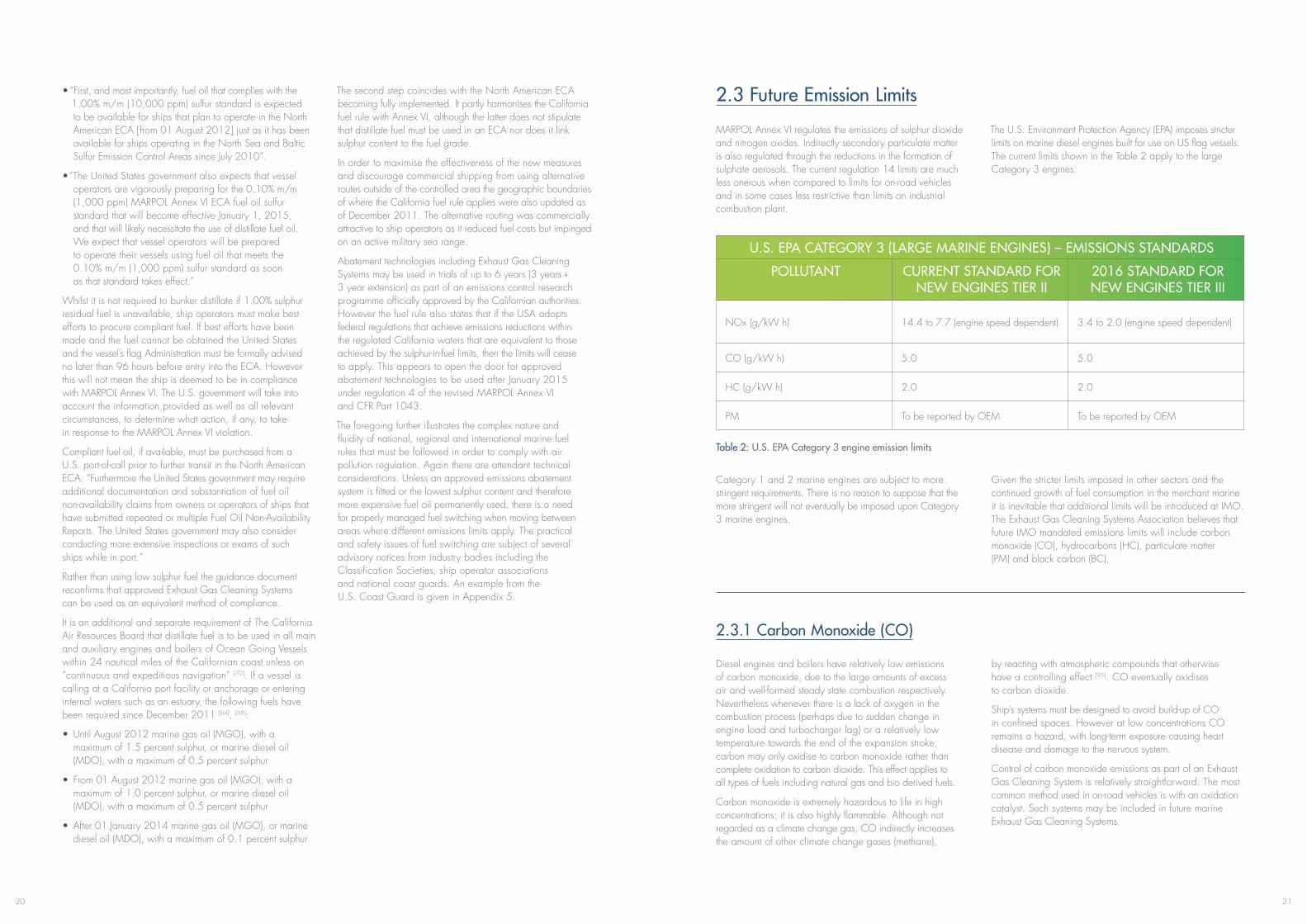
The U.S. Environment Protection Agency (EPA) imposes stricter limits on marine diesel engines built for use on US flag vessels. The current limits shown in the Table 2 apply to the large Category 3 engines.
U.S. EPA CATEGORY 3 (LARGE MARINE ENGINES) – EMISSIONS STANDARDS
POLLUTANT CURRENT STANDARD FOR NEW ENGINES TIER II
2016 STANDARD FOR NEW ENGINES TIER III
NOx (g/kW h) 14.4 to 7.7 (engine speed dependent) 3.4 to 2.0 (engine speed dependent)
CO (g/kW h) 5.0 5.0
HC (g/kW h) 2.0 2.0
PM To be reported by OEM To be reported by OEM
Table 2: U.S. EPA Category 3 engine emission limits
Category 1 and 2 marine engines are subject to more stringent requirements. There is no reason to suppose that the more stringent will not eventually be imposed upon Category 3 marine engines.
Given the stricter limits imposed in other sectors and the continued growth of fuel consumption in the merchant marine it is inevitable that additional limits will be introduced at IMO. The Exhaust Gas Cleaning Systems Association believes that future IMO mandated emissions limits will include carbon monoxide (CO), hydrocarbons (HC), particulate matter (PM) and black carbon (BC).
2.3.1 Carbon Monoxide (CO)
Diesel engines and boilers have relatively low emissions of carbon monoxide, due to the large amounts of excess air and well-formed steady state combustion respectively. Nevertheless whenever there is a lack of oxygen in the combustion process (perhaps due to sudden change in engine load and turbocharger lag) or a relatively low temperature towards the end of the expansion stroke, carbon may only oxidise to carbon monoxide rather than complete oxidation to carbon dioxide. This effect applies to all types of fuels including natural gas and bio derived fuels.
Carbon monoxide is extremely hazardous to life in high concentrations; it is also highly flammable. Although not regarded as a climate change gas, CO indirectly increases the amount of other climate change gases (methane),
by reacting with atmospheric compounds that otherwise have a controlling effect [95]. CO eventually oxidises to carbon dioxide.
Ship’s systems must be designed to avoid build-up of CO in confined spaces. However at low concentrations CO remains a hazard, with long-term exposure causing heart disease and damage to the nervous system.
Control of carbon monoxide emissions as part of an Exhaust Gas Cleaning System is relatively straightforward. The most common method used in on-road vehicles is with an oxidation catalyst. Such systems may be included in future marine Exhaust Gas Cleaning Systems.

2322
2.3.2 Hydrocarbons (HC)
Unburned fuel in exhaust gases is classified as hydrocarbons. In steady state combustion such as boilers this can occur during commencement of firing or during start-up under cold conditions. Under steady state and correctly adjusted firing conditions HC emissions from boilers should be negligible.
This is not the case for diesel engines where a number of factors conspire towards incomplete combustion. These include light load running or idling and sudden changes in engine load and turbocharger lag. Combustion is also inhibited by the cool expanding combustion gases as the piston moves down inside the cylinder and fuel can
lodge in crevices such as the annular space between the piston crown land and the liner wall.
Apart from minor loss of energy, unburned hydrocarbons are a photo-chemical pollutant which may under certain atmospheric conditions create photo-chemical smogs and increase ground level ozone. In the case of natural gas as a diesel engine fuel, methane slip causes both a pollutant and is a climate change gas with a global warming potential 20 times greater than that of carbon dioxide (see Table 1).
Hydrocarbon emissions can be eliminated in exhaust gas treatment systems, with on-road vehicles using an oxidation catalyst.
2.3.3 Particulate Matter (PM)
MARPOL Annex VI, regulation 14 mentions in the title emissions of particulate matter. However the regulation does not set any limits. This is in stark contrast to most other sectors of industry and transportation. In Europe and North America only aviation PM emissions remain unregulated.
Particulate matter emissions are present for all types of fuels and thus the only means of limiting emissions is by use of Exhaust Gas Cleaning Systems. Both wet and dry scrubbers can be effective in removal of micron range PM, and are capable of achieving virtually zero emissions.
However diesel engines produce a much higher number of ultrafine particles. Studies indicate that the ultrafine PM may have significant and harmful health effects. On-road vehicles have had imposed a continuous lowering of PM limits due to these concerns.
The removal of ultrafine particles appears to be more effectively achieved at lower temperatures created by wet scrubbers, however further development work is needed before zero emissions of ultrafine PM can be achieved. Dry scrubbers may take on the on-road approach using particulate traps and periodic regeneration.
2.3.3.1 Black Carbon (BC)Black Carbon is a form of ultrafine particulate matter, which has a very high surface area to mass ratio and acts as a very effective black body radiator. It is estimated [96] that transport diesel emits about 22% of anthropogenic Black Carbon and that some of these emissions may be contributing to the accelerated ice loss in the Arctic.
A definition of Black Carbon from international shipping has yet to be agreed by IMO. This is currently under discussion along with possible measurement techniques and control measures [99], [100], [101].
Black Carbon is defined by UNFCCC as having the second highest anthropogenic sourced climate change forcing impact after carbon dioxide.
Black carbon acts in two ways to accelerate climate change:
1. Fine particles in the atmosphere normally act as nucleation points for condensing water in the process of cloud formation. Black carbon particles act in a way
that prevents cloud formation and thus allows greater radiant energy to reach the lower atmosphere and ground level.
2. Black carbon cover on ice and snow reduces the albedo effect (reflectivity) increasing the absorbance of radiant energy. The radiant energy is then transferred through to the ice and snow causing increased melt rates.
Although Black Carbon is a significant climate change agent it is short lived, (approximately days to weeks). The elimination of BC emissions from shipping would have an immediate effect in slowing the rate of climate change, possibly by several years.
Means to deal with BC are similar to exhaust cleaning techniques used for trapping and removal of other ultrafine particles.
3. Guidelines for Exhaust Gas Cleaning Systems (EGCS)
3.1 Introduction
The 2009 Guidelines for Exhaust Gas Cleaning Systems– MEPC 184(59) have been effective since 1st July 2010. The timing aligned with the entry into force of the revised MARPOL Annex VI, under which regulation 4 now permits the use of approved abatement technologies that are at least as effective in reducing emissions as the Annex’s sulphur-in-fuel limits.
IMO cannot implement or enforce regulations, nor mandate that guidelines must be followed - the responsibility rests with the ship’s Flag State and each national government. The bodies responsible for maritime matters related to territorial waters and ports provide what is known generically as ‘port State Control’ (PSC). The power of PSC is derived from national legislation and the existence of regional PSC organizations. When ratified by nations, regulations such as those within Annex VI, become law enabling their practical enforcement so that foreign ships in national ports can be
inspected to verify the compliance of the ship and its equipment. Although the Guidelines for Exhaust Gas Cleaning Systems are just that – guidelines, which do not carry the same statutory weight as regulations, it would be normal for PSC to accept and apply them in the same way.
Although scrubbing technology has been successfully used on oil tankers and in shore-side industry for many years, exhaust gas cleaning to meet air pollution limits is a relatively new application for ships. IMO has recognised that as the technology continues to develop so the Guidelines for Exhaust Gas Cleaning Systems may have to evolve and has focussed in particular on the washwater discharge criteria. The current limits are intended to act as initial guidance for implementing Exhaust Gas Cleaning System designs and IMO has strongly requested that washwater samples be collected for analysis and data shared so that the criteria may be further reviewed in the future.
Figure 10: Longannet Power Station – Firth of Forth, Scotland UK
Courtesy _gee_flickr
2524
The coal fired Battersea Power Station on the River Thames in London was one of the first commercial applications of flue gas cleaning using water. This continued from the early 1930s to the 1960’s. Later the process using seawater was applied to boilers, smelters and refineries. The first in Norway was fitted to an aluminium smelting plant in 1968 followed by a number of industrial oil fuelled boilers. In 1981 a pilot plant was fitted to an oil fuelled utility boiler at the Cabras power station on the island of Guam. This was subject of a long-term bioassay test program using plankton, shellfish and other marine organisms in aquaria with water from the cleaning system’s treatment plant. Using similar organisms kept in fresh seawater as a cross reference, no harmful effects were found on the marine life over a one year test period. The test was carried out by marine biologists from R.W.Beck and Associates and was monitored by the U.S. EPA. [22]
The expansion of seawater flue gas desulphurisation, or SWFGD as it is known ashore, has gathered pace. In 1988 a unit capable of handling gas flow from a source equivalent to 125 MW was fitted to a coal-fired power station – Tata’s Trombay Unit 5 in Mumbai, India. In 1989 the equivalent of a 110 MW unit was fitted to the catalytic cracker at Statoil’s
Mongstad refinery in Norway. The equivalent of 160MW and 130MW units were also fitted to oil fuelled power stations on Tenerife in 1995 and Cyprus in 2005. [23]
Not only has the use of SWFGD increased but so too has the size of the installations. The equivalent of eight 700MW units were fitted to coal fired power stations in Malaysia from 2002 to 2008 and three units each capable of handling gas flow from a source equivalent to 600 MW were commissioned at the Longannet coal fired power station on Scotland’s Firth of Forth in 2009. The latter is of particular note as alkaline estuarial waters are used for the scrubbing process and this was regarded as the “Best Available Technique” for abatement of sulphur dioxide under the terms of UK Pollution Prevention and Control Regulations [24]. Compliance with the regulations is monitored by the Scottish Environmental Protection Agency. [25], [26]
The reference list of one major supplier to land based industry shows over 90 SWFGD units either installed or pending and that these manage sulphur dioxide emissions from sources with an equivalent total power of over 32GW (32 x 109W). [23]
Info Box 3: Flue gas desulphurisation with water in land based applications
3.2 Overview
Similar to the requirements of the NOx Technical Code for engines, an Exhaust Gas Cleaning (EGC) unit may be used subject to parameter checks following initial certification of its emissions performance or it may be equipped with an approved emission monitoring system. However unlike the NOx Technical Code the monitoring of a specific SOx emission rate (grams per kilowatt hour) is not required. Instead monitoring the ratio of SO2 (sulphur dioxide) to CO2 (carbon dioxide) emissions is permitted.
Sulphur oxide emissions from an engine (or other combustion unit such as a boiler) are almost entirely derived from the sulphur content of the fuel and unlike NOx formation are not related to engine design, operation and combustion conditions. The majority of CO2 is also derived from the combustion of hydrocarbon fuel and typically makes up about 6% of a diesel engine’s exhaust gas. The SO2/CO2
ratio therefore gives a robust measure of SOx emissions in proportion to the sulphur content of the fuel burned, which greatly simplifies monitoring requirements without compromising accuracy. Gas concentrations (parts per million/percent) can be used rather than determining the actual mass flow rate of SO2 and engine (or boiler) power is not required. It also removes the need to measure parameters such as engine speed and fuel flow as well as various other temperatures and pressures that are required under the NOx Technical Code. (Further technical details are given in the Guidelines for Exhaust Gas Cleaning Systems under Appendix 2 – “Proof of the SO2/CO2 Ratio Method”).
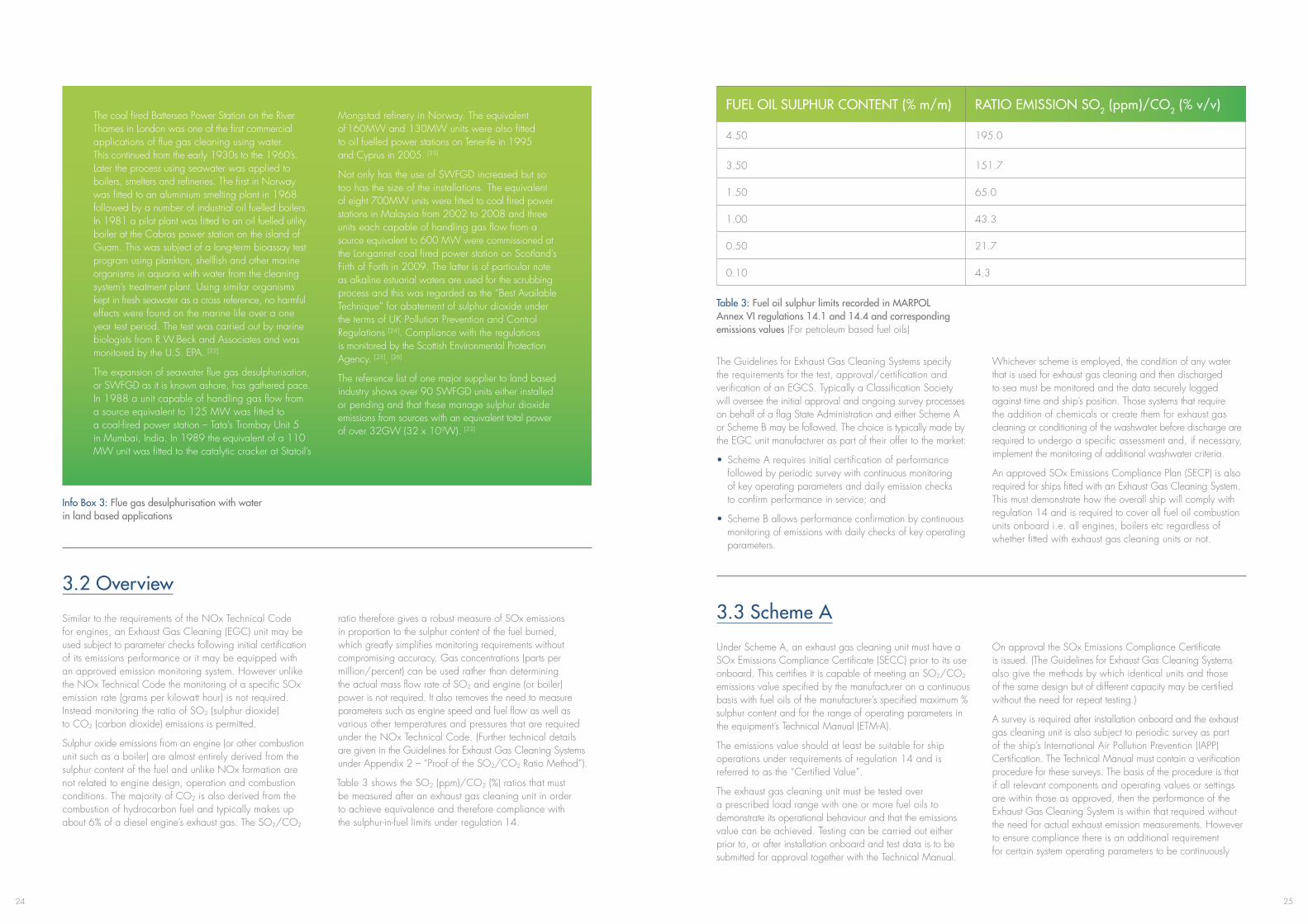
Table 3 shows the SO2 (ppm)/CO2 (%) ratios that must be measured after an exhaust gas cleaning unit in order to achieve equivalence and therefore compliance with the sulphur-in-fuel limits under regulation 14.
FUEL OIL SULPHUR CONTENT (% m/m) RATIO EMISSION SO2 (ppm)/CO2 (% v/v)
4.50 195.0
3.50 151.7
1.50 65.0
1.00 43.3
0.50 21.7
0.10 4.3
Table 3: Fuel oil sulphur limits recorded in MARPOL Annex VI regulations 14.1 and 14.4 and corresponding emissions values (For petroleum based fuel oils)
The Guidelines for Exhaust Gas Cleaning Systems specify the requirements for the test, approval/certification and verification of an EGCS. Typically a Classification Society will oversee the initial approval and ongoing survey processes on behalf of a flag State Administration and either Scheme A or Scheme B may be followed. The choice is typically made by the EGC unit manufacturer as part of their offer to the market:
• Scheme A requires initial certification of performance followed by periodic survey with continuous monitoring of key operating parameters and daily emission checks to confirm performance in service; and
• Scheme B allows performance confirmation by continuous monitoring of emissions with daily checks of key operating parameters.
Whichever scheme is employed, the condition of any water that is used for exhaust gas cleaning and then discharged to sea must be monitored and the data securely logged against time and ship’s position. Those systems that require the addition of chemicals or create them for exhaust gas cleaning or conditioning of the washwater before discharge are required to undergo a specific assessment and, if necessary, implement the monitoring of additional washwater criteria.
An approved SOx Emissions Compliance Plan (SECP) is also required for ships fitted with an Exhaust Gas Cleaning System. This must demonstrate how the overall ship will comply with regulation 14 and is required to cover all fuel oil combustion units onboard i.e. all engines, boilers etc regardless of whether fitted with exhaust gas cleaning units or not.
3.3 Scheme A
Under Scheme A, an exhaust gas cleaning unit must have a SOx Emissions Compliance Certificate (SECC) prior to its use onboard. This certifies it is capable of meeting an SO2/CO2 emissions value specified by the manufacturer on a continuous basis with fuel oils of the manufacturer’s specified maximum % sulphur content and for the range of operating parameters in the equipment’s Technical Manual (ETM-A).
The emissions value should at least be suitable for ship operations under requirements of regulation 14 and is referred to as the “Certified Value”.
The exhaust gas cleaning unit must be tested over a prescribed load range with one or more fuel oils to demonstrate its operational behaviour and that the emissions value can be achieved. Testing can be carried out either prior to, or after installation onboard and test data is to be submitted for approval together with the Technical Manual.
On approval the SOx Emissions Compliance Certificate is issued. (The Guidelines for Exhaust Gas Cleaning Systems also give the methods by which identical units and those of the same design but of different capacity may be certified without the need for repeat testing.)
A survey is required after installation onboard and the exhaust gas cleaning unit is also subject to periodic survey as part of the ship’s International Air Pollution Prevention (IAPP) Certification. The Technical Manual must contain a verification procedure for these surveys. The basis of the procedure is that if all relevant components and operating values or settings are within those as approved, then the performance of the Exhaust Gas Cleaning System is within that required without the need for actual exhaust emission measurements. However to ensure compliance there is an additional requirement for certain system operating parameters to be continuously
2726
recorded and daily spot checks of emissions are also recommended.
An Onboard Monitoring Manual (OMM) is required to give details of the monitoring sensors and their position, care and calibration to ensure compliance. The OMM must be approved.
Component adjustments, maintenance and service records, together with chemical consumption, if applicable, must be recorded in the system’s EGC Record Book, which also must be approved. Alternatively, if approval is granted, maintenance and service records can be recorded in the ship’s planned maintenance system.
3.4 Scheme B
Under Scheme B, compliance is confirmed by continuous emissions monitoring with daily spot-checks of a number of Exhaust Gas Cleaning System operating parameters. Whereas under Scheme A, if all relevant components and operating values or settings are within those as approved, the performance of the EGC unit is within that required without the need for actual exhaust emission measurements, (although daily spots checks of the latter are recommended to ensure compliance).
Unlike Scheme A the exhaust gas cleaning unit does not need to be certified that it is capable of meeting an emissions value with fuel oils of the manufacturer’s specified maximum % sulphur content. Instead a continuous emissions monitoring system has to show that the EGC unit achieves no more than the required SO2/CO2 emission value at any load point, including during transient operation, and thus compliance with the requirements of regulation 14.
The continuous emissions monitoring system must be approved and is subject to survey on installation. It is also subject to periodic survey as part of the ship’s International Air Pollution Prevention Certification. An Onboard Monitoring Manual is required to give details of the monitoring sensors and how they are to be surveyed. It must also give their position, care and calibration to ensure compliance. The OMM must be approved.
A Scheme B Technical Manual (ETM-B) is also to be approved and the daily spot checks of various parameters that are required to verify proper operation of the Exhaust Gas Cleaning System must be logged in the system’s EGC Record Book or the engine room logger system.
Emissions data must be securely logged against standard time and ship’s position and be available for inspection as necessary to confirm compliance.
3.5 Washwater
Hot exhaust gases from marine diesel engines and boilers contain amongst other things oxides of sulphur, nitrogen and carbon, unburned hydrocarbons, and particulate matter, which comprises mainly carbon and ash together with oxidised and condensed material derived from the fuel oil and to a much lesser extent the combustion of lubricating oil [3]. These reach air, land and water based ecosystems when
unscrubbed exhaust gases are emitted into the atmosphere. As most Exhaust Gas Cleaning Systems use water to remove sulphur oxides and particulate matter before they reach the atmosphere, the aim of the washwater criteria is to prevent the undesirable effects and components of the air borne emissions simply being directly transferred to the seas.
Figure 11: Typical exhaust gas composition – slow speed two stroke engine using residual fuel
The Guidelines for Exhaust Gas Cleaning Systems therefore require that the following washwater parameters are continuously monitored and the results securely logged against time and ship’s position. Data has to be retained for a period of not less than 18 months from the date of recording:
• pH (with temperature compensation)
• Polycyclic Aromatic Hydrocarbon (PAH)
• Turbidity
Heat
Work
Air8.5 kg/kWh21% O2
79% N2
Fuel170 g/kWh2.4% S
Lube0.6 g/kWh2.5% Ca0.5% S
Exhaust gas composition~14.6% O2
~4.1% CO2
~4.3% H2O
~900ppm NOx~425ppm SOx~48ppm CO~50ppm HC
~120mg/Nm3 PM
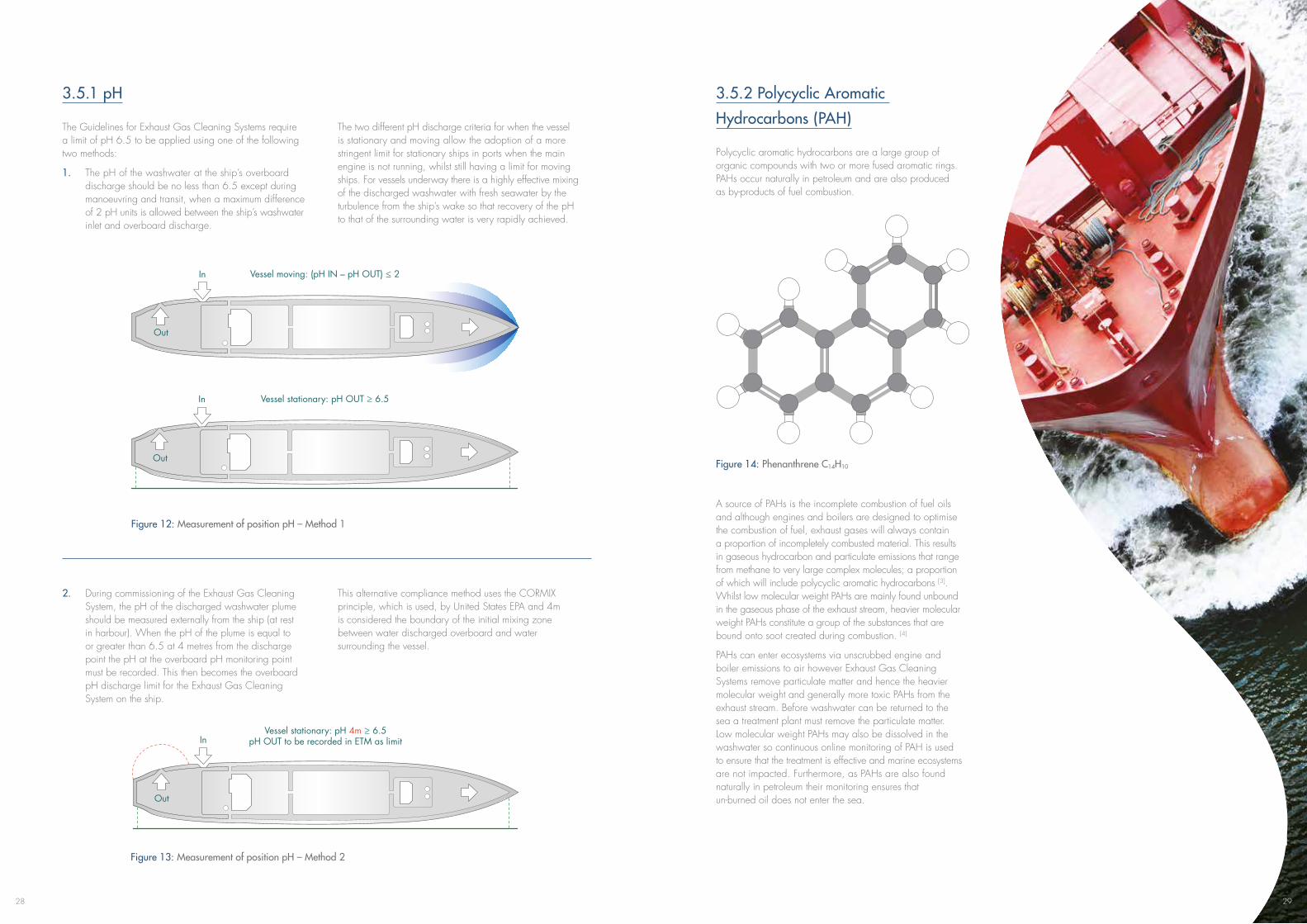
28
Figure 13: Measurement of position pH – Method 2
3.5.1 pH
The Guidelines for Exhaust Gas Cleaning Systems require a limit of pH 6.5 to be applied using one of the following two methods:
1. The pH of the washwater at the ship’s overboard discharge should be no less than 6.5 except during manoeuvring and transit, when a maximum difference of 2 pH units is allowed between the ship’s washwater inlet and overboard discharge.
The two different pH discharge criteria for when the vessel is stationary and moving allow the adoption of a more stringent limit for stationary ships in ports when the main engine is not running, whilst still having a limit for moving ships. For vessels underway there is a highly effective mixing of the discharged washwater with fresh seawater by the turbulence from the ship’s wake so that recovery of the pH to that of the surrounding water is very rapidly achieved.
Figure 12: Measurement of position pH – Method 1
2. During commissioning of the Exhaust Gas Cleaning System, the pH of the discharged washwater plume should be measured externally from the ship (at rest in harbour). When the pH of the plume is equal to or greater than 6.5 at 4 metres from the discharge point the pH at the overboard pH monitoring point must be recorded. This then becomes the overboard pH discharge limit for the Exhaust Gas Cleaning System on the ship.
This alternative compliance method uses the CORMIX principle, which is used, by United States EPA and 4m is considered the boundary of the initial mixing zone between water discharged overboard and water surrounding the vessel.
Vessel moving: (pH IN – pH OUT) ≤ 2
Discharge pH limits 1
In
Vessel stationary: pH OUT ≥ 6.5In
Out
Out
Discharge pH limits 2
Vessel stationary: pH 4m ≥ 6.5pH OUT to be recorded in ETM as limitIn
Out
3.5.2 Polycyclic Aromatic
Hydrocarbons (PAH)
Polycyclic aromatic hydrocarbons are a large group of organic compounds with two or more fused aromatic rings. PAHs occur naturally in petroleum and are also produced as by-products of fuel combustion.
A source of PAHs is the incomplete combustion of fuel oils and although engines and boilers are designed to optimise the combustion of fuel, exhaust gases will always contain a proportion of incompletely combusted material. This results in gaseous hydrocarbon and particulate emissions that range from methane to very large complex molecules; a proportion of which will include polycyclic aromatic hydrocarbons [3]. Whilst low molecular weight PAHs are mainly found unbound in the gaseous phase of the exhaust stream, heavier molecular weight PAHs constitute a group of the substances that are bound onto soot created during combustion. [4]
PAHs can enter ecosystems via unscrubbed engine and boiler emissions to air however Exhaust Gas Cleaning Systems remove particulate matter and hence the heavier molecular weight and generally more toxic PAHs from the exhaust stream. Before washwater can be returned to the sea a treatment plant must remove the particulate matter. Low molecular weight PAHs may also be dissolved in the washwater so continuous online monitoring of PAH is used to ensure that the treatment is effective and marine ecosystems are not impacted. Furthermore, as PAHs are also found naturally in petroleum their monitoring ensures that un-burned oil does not enter the sea.
Figure 14: Phenanthrene C14H10
29
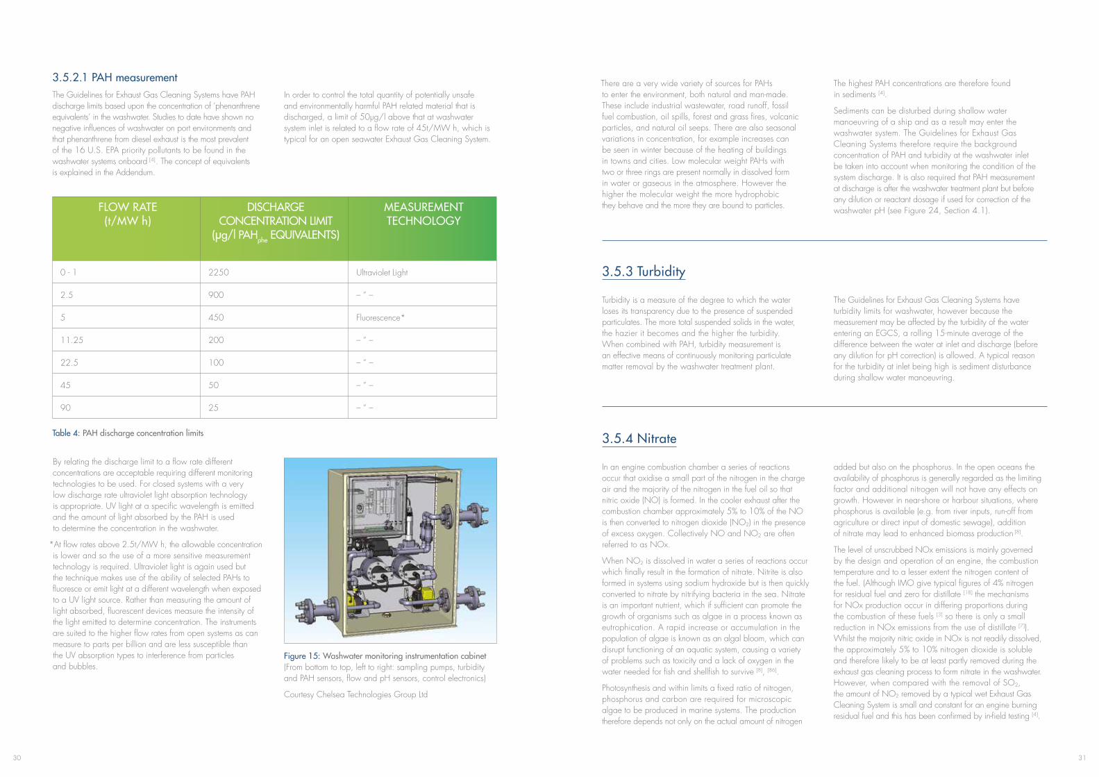
3130
3.5.2.1 PAH measurementThe Guidelines for Exhaust Gas Cleaning Systems have PAH discharge limits based upon the concentration of ‘phenanthrene equivalents’ in the washwater. Studies to date have shown no negative influences of washwater on port environments and that phenanthrene from diesel exhaust is the most prevalent of the 16 U.S. EPA priority pollutants to be found in the washwater systems onboard [4] . The concept of equivalents is explained in the Addendum.
In order to control the total quantity of potentially unsafe and environmentally harmful PAH related material that is discharged, a limit of 50μg/l above that at washwater system inlet is related to a flow rate of 45t/MW h, which is typical for an open seawater Exhaust Gas Cleaning System.
FLOW RATE (t/MW h)
DISCHARGE CONCENTRATION LIMIT
(μg/l PAHphe EQUIVALENTS)
MEASUREMENT TECHNOLOGY
0 - 1 2250 Ultraviolet Light
2.5 900 – ” –
5 450 Fluorescence*
11.25 200 – ” –
22.5 100 – ” –
45 50 – ” –
90 25 – ” –
Table 4: PAH discharge concentration limits
By relating the discharge limit to a flow rate different concentrations are acceptable requiring different monitoring technologies to be used. For closed systems with a very low discharge rate ultraviolet light absorption technology is appropriate. UV light at a specific wavelength is emitted and the amount of light absorbed by the PAH is used to determine the concentration in the washwater.
*At flow rates above 2.5t/MW h, the allowable concentration is lower and so the use of a more sensitive measurement technology is required. Ultraviolet light is again used but the technique makes use of the ability of selected PAHs to fluoresce or emit light at a different wavelength when exposed to a UV light source. Rather than measuring the amount of light absorbed, fluorescent devices measure the intensity of the light emitted to determine concentration. The instruments are suited to the higher flow rates from open systems as can measure to parts per billion and are less susceptible than the UV absorption types to interference from particles and bubbles.
Figure 15: Washwater monitoring instrumentation cabinet (From bottom to top, left to right: sampling pumps, turbidity and PAH sensors, flow and pH sensors, control electronics)
Courtesy Chelsea Technologies Group Ltd
There are a very wide variety of sources for PAHs to enter the environment, both natural and man-made. These include industrial wastewater, road runoff, fossil fuel combustion, oil spills, forest and grass fires, volcanic particles, and natural oil seeps. There are also seasonal variations in concentration, for example increases can be seen in winter because of the heating of buildings in towns and cities. Low molecular weight PAHs with two or three rings are present normally in dissolved form in water or gaseous in the atmosphere. However the higher the molecular weight the more hydrophobic they behave and the more they are bound to particles.
The highest PAH concentrations are therefore found in sediments [4].
Sediments can be disturbed during shallow water manoeuvring of a ship and as a result may enter the washwater system. The Guidelines for Exhaust Gas Cleaning Systems therefore require the background concentration of PAH and turbidity at the washwater inlet be taken into account when monitoring the condition of the system discharge. It is also required that PAH measurement at discharge is after the washwater treatment plant but before any dilution or reactant dosage if used for correction of the washwater pH (see Figure 24, Section 4.1).
3.5.3 Turbidity
Turbidity is a measure of the degree to which the water loses its transparency due to the presence of suspended particulates. The more total suspended solids in the water, the hazier it becomes and the higher the turbidity. When combined with PAH, turbidity measurement is an effective means of continuously monitoring particulate matter removal by the washwater treatment plant.
The Guidelines for Exhaust Gas Cleaning Systems have turbidity limits for washwater, however because the measurement may be affected by the turbidity of the water entering an EGCS, a rolling 15-minute average of the difference between the water at inlet and discharge (before any dilution for pH correction) is allowed. A typical reason for the turbidity at inlet being high is sediment disturbance during shallow water manoeuvring.
3.5.4 Nitrate
In an engine combustion chamber a series of reactions occur that oxidise a small part of the nitrogen in the charge air and the majority of the nitrogen in the fuel oil so that nitric oxide (NO) is formed. In the cooler exhaust after the combustion chamber approximately 5% to 10% of the NO is then converted to nitrogen dioxide (NO2) in the presence of excess oxygen. Collectively NO and NO2 are often referred to as NOx.
When NO2 is dissolved in water a series of reactions occur which finally result in the formation of nitrate. Nitrite is also formed in systems using sodium hydroxide but is then quickly converted to nitrate by nitrifying bacteria in the sea. Nitrate is an important nutrient, which if sufficient can promote the growth of organisms such as algae in a process known as eutrophication. A rapid increase or accumulation in the population of algae is known as an algal bloom, which can disrupt functioning of an aquatic system, causing a variety of problems such as toxicity and a lack of oxygen in the water needed for fish and shellfish to survive [8], [86].
Photosynthesis and within limits a fixed ratio of nitrogen, phosphorus and carbon are required for microscopic algae to be produced in marine systems. The production therefore depends not only on the actual amount of nitrogen
added but also on the phosphorus. In the open oceans the availability of phosphorus is generally regarded as the limiting factor and additional nitrogen will not have any effects on growth. However in near-shore or harbour situations, where phosphorus is available (e.g. from river inputs, run-off from agriculture or direct input of domestic sewage), addition of nitrate may lead to enhanced biomass production [8].
The level of unscrubbed NOx emissions is mainly governed by the design and operation of an engine, the combustion temperature and to a lesser extent the nitrogen content of the fuel. (Although IMO give typical figures of 4% nitrogen for residual fuel and zero for distillate [18] the mechanisms for NOx production occur in differing proportions during the combustion of these fuels [3] so there is only a small reduction in NOx emissions from the use of distillate [7]). Whilst the majority nitric oxide in NOx is not readily dissolved, the approximately 5% to 10% nitrogen dioxide is soluble and therefore likely to be at least partly removed during the exhaust gas cleaning process to form nitrate in the washwater. However, when compared with the removal of SO2, the amount of NO2 removed by a typical wet Exhaust Gas Cleaning System is small and constant for an engine burning residual fuel and this has been confirmed by in-field testing [4].

3332
The Guidelines for Exhaust Gas Cleaning Systems, therefore, do not currently require continuous monitoring of nitrate. There is however a limit on nitrate emissions based on removing 12% of the NOx from an exhaust stream. (This is based on an Exhaust Gas Cleaning System design with high alkalinity washwater that is capable of removing more NOx than the soluble NO2 fraction [85] and gives some future proofing whilst mitigating the risk of eutrophication).
Compliance has to be proven by laboratory analysis of a sample drawn during initial system certification and within 3 months of each 5 yearly renewal survey. Results must be retained in the EGC Record Book and be available for inspection, for example by Port State Control, as required. The EGC Technical Manual (ETM-A or -B) must also contain details of the sampling and analysis programme and typical nitrate levels if above 80% of the limit figure.
Figure 16: Algal bloom – coast of Washington and Vancouver Island, 2004
NASA images courtesy the SeaWiFS Project, NASA/Goddard Space Flight Center, and ORBIMAGE
Natural Colour Chlorophyll ConcentrationsOcean Chlorophyll Concentration (mg/m3)
0.04 1.0 10 60
Info Box 4: Eutrophication
O2 O2
Nitrogen and phosphorus are essential nutrients that promote the growth and development of plants and animals.
In healthy aquatic systems inputs of nitrogen and phosphorus are such that the growth of algae and phytoplankton is in balance with the rate of consumption by other life forms.
A balanced level of algae and phytoplankton results in high water clarity enabling light to reach plants and a dissolved oxygen content that sustains fish and shellfish stocks.
Eutrophication occurs when levels of phosphorus, nitrogen and sediment are such that the growth of algae and phytoplankton exceed the consumption by other life forms and blooms result.
The chlorophyll in the algae and phytoplankton together with sediment cause reduced water clarity preventing light reaching submerged plants resulting in death and decay. Surface plant growth can become excessive, further choking the system. The dissolved oxygen content of the water can become severely depleted impacting fish and shellfish stocks.
Phosphorus and nitrogen can enter aquatic ecosystems from human activities. Both are constituents of agricultural fertilisers in the form of phosphates and nitrates. Phosphates are found in human and animal waste. They are components of detergents and water treatments used to soften hard water, prevent boiler scale, suspend dirt particles and reduce corrosion. Phosphorus compounds are also widely used in industry, for example in the production of metals, glass, china and certain foodstuffs. [27]
The availability of phosphorus is a limiting factor in the growth of blooms in open seas but near shore can enter the marine environment via rivers from sewage, urban and industrial run-off and agriculture. If sufficient nitrogen and carbon are also available blooms can result.
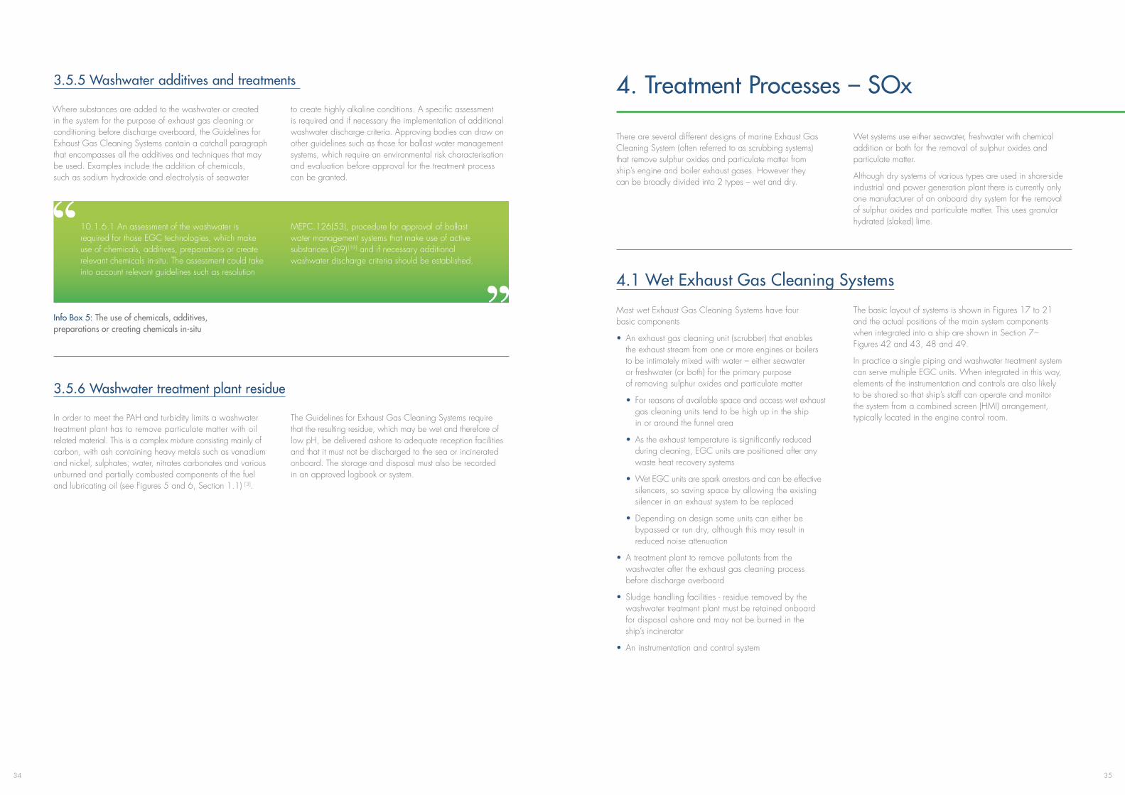
3534
3.5.5 Washwater additives and treatments
Where substances are added to the washwater or created in the system for the purpose of exhaust gas cleaning or conditioning before discharge overboard, the Guidelines for Exhaust Gas Cleaning Systems contain a catchall paragraph that encompasses all the additives and techniques that may be used. Examples include the addition of chemicals, such as sodium hydroxide and electrolysis of seawater
to create highly alkaline conditions. A specific assessment is required and if necessary the implementation of additional washwater discharge criteria. Approving bodies can draw on other guidelines such as those for ballast water management systems, which require an environmental risk characterisation and evaluation before approval for the treatment process can be granted.
10.1.6.1 An assessment of the washwater is required for those EGC technologies, which make use of chemicals, additives, preparations or create relevant chemicals in-situ. The assessment could take into account relevant guidelines such as resolution
MEPC.126(53), procedure for approval of ballast water management systems that make use of active substances (G9) [19] and if necessary additional washwater discharge criteria should be established.
Info Box 5: The use of chemicals, additives, preparations or creating chemicals in-situ
3.5.6 Washwater treatment plant residue
In order to meet the PAH and turbidity limits a washwater treatment plant has to remove particulate matter with oil related material. This is a complex mixture consisting mainly of carbon, with ash containing heavy metals such as vanadium and nickel, sulphates, water, nitrates carbonates and various unburned and partially combusted components of the fuel and lubricating oil (see Figures 5 and 6, Section 1.1) [3].
The Guidelines for Exhaust Gas Cleaning Systems require that the resulting residue, which may be wet and therefore of low pH, be delivered ashore to adequate reception facilities and that it must not be discharged to the sea or incinerated onboard. The storage and disposal must also be recorded in an approved logbook or system.
4. Treatment Processes – SOx
There are several different designs of marine Exhaust Gas Cleaning System (often referred to as scrubbing systems) that remove sulphur oxides and particulate matter from ship’s engine and boiler exhaust gases. However they can be broadly divided into 2 types – wet and dry.
Wet systems use either seawater, freshwater with chemical addition or both for the removal of sulphur oxides and particulate matter.
Although dry systems of various types are used in shore-side industrial and power generation plant there is currently only one manufacturer of an onboard dry system for the removal of sulphur oxides and particulate matter. This uses granular hydrated (slaked) lime.
4.1 Wet Exhaust Gas Cleaning Systems
Most wet Exhaust Gas Cleaning Systems have four basic components
• An exhaust gas cleaning unit (scrubber) that enables the exhaust stream from one or more engines or boilers to be intimately mixed with water – either seawater or freshwater (or both) for the primary purpose of removing sulphur oxides and particulate matter
• For reasons of available space and access wet exhaust gas cleaning units tend to be high up in the ship in or around the funnel area
• As the exhaust temperature is significantly reduced during cleaning, EGC units are positioned after any waste heat recovery systems
• Wet EGC units are spark arrestors and can be effective silencers, so saving space by allowing the existing silencer in an exhaust system to be replaced
• Depending on design some units can either be bypassed or run dry, although this may result in reduced noise attenuation
• A treatment plant to remove pollutants from the washwater after the exhaust gas cleaning process before discharge overboard
• Sludge handling facilities - residue removed by the washwater treatment plant must be retained onboard for disposal ashore and may not be burned in the ship’s incinerator
• An instrumentation and control system
The basic layout of systems is shown in Figures 17 to 21 and the actual positions of the main system components when integrated into a ship are shown in Section 7 – Figures 42 and 43, 48 and 49.
In practice a single piping and washwater treatment system can serve multiple EGC units. When integrated in this way, elements of the instrumentation and controls are also likely to be shared so that ship’s staff can operate and monitor the system from a combined screen (HMI) arrangement, typically located in the engine control room.
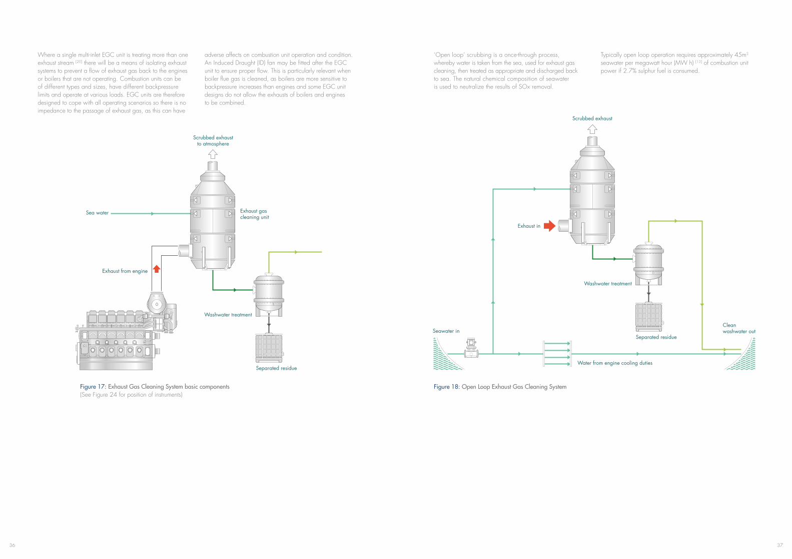
3736
Figure 17: Exhaust Gas Cleaning System basic components (See Figure 24 for position of instruments)
Where a single multi-inlet EGC unit is treating more than one exhaust stream [20] there will be a means of isolating exhaust systems to prevent a flow of exhaust gas back to the engines or boilers that are not operating. Combustion units can be of different types and sizes, have different backpressure limits and operate at various loads. EGC units are therefore designed to cope with all operating scenarios so there is no impedance to the passage of exhaust gas, as this can have
adverse affects on combustion unit operation and condition. An Induced Draught (ID) fan may be fitted after the EGC unit to ensure proper flow. This is particularly relevant when boiler flue gas is cleaned, as boilers are more sensitive to backpressure increases than engines and some EGC unit designs do not allow the exhausts of boilers and engines to be combined.
Separated residue
Washwater treatment
Exhaust from engine
Sea water
Scrubbed exhaustto atmosphere
Exhaust gas cleaning unit
Figure 18: Open Loop Exhaust Gas Cleaning System
‘Open loop’ scrubbing is a once-through process, whereby water is taken from the sea, used for exhaust gas cleaning, then treated as appropriate and discharged back to sea. The natural chemical composition of seawater is used to neutralize the results of SOx removal.
Typically open loop operation requires approximately 45m3 seawater per megawatt hour (MW h) [13] of combustion unit power if 2.7% sulphur fuel is consumed.
Separated residue
Washwater treatment
Scrubbed exhaust
Clean washwater outSeawater in
Exhaust in
Water from engine cooling duties
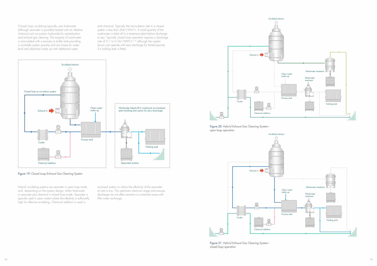
3938
'Closed loop' scrubbing typically uses freshwater (although seawater is possible) treated with an alkaline chemical such as sodium hydroxide for neutralization and exhaust gas cleaning. The majority of washwater is recirculated with a process or buffer tank providing a workable system quantity and any losses (in water level and alkalinity) made up with additional water
and chemical. Typically the recirculation rate in a closed system is less than 20m3/MW h. A small quantity of the washwater is bled off to a treatment plant before discharge to sea. Typically closed loop operation requires a discharge rate of 0.1 to 0.3m3/MW h [13] although the system shown can operate with zero discharge for limited periods if a holding tank is fitted.
Figure 19: Closed Loop Exhaust Gas Cleaning System
‘Hybrid’ scrubbing systems use seawater in open loop mode and, depending on the system design, either freshwater or seawater plus chemical in closed loop mode. Seawater is typically used in open waters where the alkalinity is sufficiently high for effective scrubbing. Chemical addition is used in
enclosed waters or where the alkalinity of the seawater at inlet is low. This optimises chemical usage and ensures discharges do not affect sensitive or contained areas with little water exchange.
Figure 20: Hybrid Exhaust Gas Cleaning System – open loop operation
Figure 21: Hybrid Exhaust Gas Cleaning System – closed loop operation
Chemical addition
Exhaust in
Scrubbed exhaust
Process tank
Holding tank
Clean water make-up
Cooler
Washwater treatment
Washwater treatment
Chemical addition
Cooler
Exhaust in
Washwater treatment
Washwater treatment
Scrubbed exhaust
Process tank
Holding tank
Clean water make-up

4140
4.1.1 Removal of sulphur oxides – seawater
Exhaust gas cleaning with water requires the exhaust gases to be intimately mixed with seawater in order to dissolve the sulphur oxides. Manufacturers use various techniques to achieve mixing without unduly obstructing the passage of exhaust gas as this could result in a ‘backpressure’ outside of the engine builder’s limits and adversely affect engine operation and condition. Sulphur oxides in the exhaust from
ships are virtually all sulphur dioxide – SO2, a very small percentage of which is further oxidised to sulphur trioxide – SO3. When dissolved in seawater a reaction occurs whereby the sulphur dioxide is ionised to bisulphite and sulphite, which is then readily oxidized to sulphate in seawater containing oxygen [1].
Info Box 6: Relevant chemistry – sulphur oxides to sulphate
Info Box 7: Relevant chemistry – aqueous sodium hydroxide
•NaOH(s)+H2O Na+ (aq) + OH– (aq) + H2O
SULPHUR DIOXIDE:
• SO2 + H2O ‘H2SO3’ (sulphurous acid) H+ + HSO3
– (bisulphite)
• HSO3– (bisulphite) H+ + SO3 2– (sulphite)
• SO3 2– (sulphite) + ½ O2 SO4 2– (sulphate)
SULPHUR TRIOXIDE:
• SO3 + H2O H2SO4 (sulphuric acid)
• H2SO4 + H2O HSO4– (hydrogen sulphate) +
H3O+ (hydronium*)
• HSO4– (hydrogen sulphate) + H2O SO4
2– (sulphate) + H3O+ (hydronium*)
*See glossary
The ionisation to bisulphite and sulphite produces excess hydrogen (H+) ions i.e. acidity, as does sulphuric acid formed from the small amounts of sulphuric trioxide. This will be initially neutralized by the seawater’s buffering capacity or alkalinity, which is mainly imparted by its natural bicarbonate content. However once the initial buffering capacity is consumed and the pH reduces to approximately 3 the ionisation of sulphur dioxide to sulphite is negligible [1] and removal becomes limited. (Note: sulphur trioxide reacts very rapidly with water to form sulphuric acid (comprising hydrogen and sulphate ions), which in turn has a great affinity for water. This enables Exhaust Gas Cleaning Systems to be highly effective at removing and neutralizing
this minor component).
The washwater flow of Exhaust Gas Cleaning Systems is optimised, so that sulphur dioxide can dissolve and an appropriate amount of buffering capacity is available to enable emissions to be reduced to the required level. Too little effective washwater flow, mixing or alkalinity and the required reduction in SO2 is not achieved, however too much washwater is inefficient in terms of pumping power and component size and weight. A system designer will also take into account the temperature of the water available for exhaust gas cleaning as the lower the temperature the greater the SO2 solubility.
4.1.2 Removal of sulphur oxides – freshwater with chemical addition
Exhaust gas cleaning can also be successfully achieved using freshwater with the addition of a suitably alkaline chemical. The majority of marine Exhaust Gas Cleaning Systems use
sodium hydroxide, also known as caustic soda, which is typically sold as a 50% solution, eliminating the need for solids handling equipment:
Info Box 8: Relevant chemistry – sulphur oxides to sulphate
Info Box 9: Relevant chemistry – sodium hydroxide to sodium sulphate
• SO2 + H2O “H2SO3” (sulphurous acid)
• “H2SO3” (sulphurous acid) H+ + HSO3– (bisulphite)
• HSO3– (bisulphite) H+ + SO3 2– (sulphite)
• SO3 2– (sulphite) + ½ O2 SO42– (sulphate)
FOR SO2
• Na+ + OH– +SO2 NaHSO3 (aq sodium bisulphite)
• 2Na+ + 2OH– + SO2 Na2SO3 (aq sodium sulphite) + H2O
• 2Na+ 2OH– + SO2 + ½ O2 Na2SO4 (aq sodium sulphate) + H2O
FOR SO3
• SO3 + H2O H2SO4 (sulphuric acid)
• 2NaOH+H2SO4 Na2SO4 (aq sodium sulphate) + 2H2O
As with the seawater Exhaust Gas Cleaning System the first step in an alkaline freshwater system is the absorption of SO2
into the aqueous solution. Depending on the pH bisulphite and sulphite form, followed by oxidation to sulphate.
The overall reactions with SO2 therefore produce a mixture of sodium bisulphite, sodium sulphite, and sodium sulphate.
The exact proportions of the sulphur species depend on the pH and degree of oxidation. [28]
The available alkalinity enables the washwater circulation rate in a typical Exhaust Gas Cleaning System with caustic soda addition to be approximately 20m3/MW h. This is less than half of the typical once-through rate of 45m3/MW h for a seawater system. This type of system therefore has advantages in terms of reduced power requirements for pumping, low or
zero discharge rates and potentially less issues with corrosion of system components. However this needs to be balanced by the need to store and handle caustic soda, the need for system coolers to maintain the recirculated washwater at a suitable temperature and the potential for additional freshwater generating capacity for top up purposes.

4342
Info Box 10: Caustic soda handling and storage
Info Box 11: Relevant chemistry – seawater neutralisation of acidic washwater
CAUSTIC SODA – NAOH [29]
Typical commercial form is a 50% w/v* solution:• pH14
• Density1.52t/m3
•Meltingpoint12°C
HANDLING• Colourlessandodourless.
• Reactsexothermicallywithwater,producingheat.
•Non-combustible
• Harmfultoeyeandskin,requiringappropriate personal protective equipment to be worn and safety showers are recommended.
• Corrosivetocertainmetals,forexamplealuminium, brass, bronze, tin and zinc (galvanised coatings)
• Typicallydeliveredbyroadtankerand1000litre IBC* container
• Producttemperaturegreaterthan20°Crequired
for pumping (viscosity approximately 110cSt at20°Crapidlyincreasesattemperatureslower than18°C)[30]
• Bulktransportationtemperatureoftenat40°C (delivery temperature should not be above 120 to125°F(50°C)tominimizecorrosionofunlined steel piping systems and equipment [31], [32]).
STORAGE• Tankcanbeofnormalshipbuildingsteel.
• Coatingnotnecessary,butrecommended.
• Stainlesssteelisnotrequired.
• Temperaturebetween20°Cand50°C
• Uncoatedmildsteeltanksshouldnotexceed 120to125°F(50°C)topreventcausticcorrosion cracking [31], [32]
• Productdensityneedstobeconsideredduring fabrication of tanks
* See glossary
4.1.3 Water quality at Exhaust Gas Cleaning System inlet
Wet Exhaust Gas Cleaning Systems are highly effective at reducing sulphur oxide emissions and removal rates of greater than 98% are possible. A key factor for sulphur acid neutralization, and therefore SOx removal, is the alkalinity of
water used to ‘wash’ the exhaust gases, rather than its salinity. Alkalinity is available naturally in seawater, which of course is also saline, but it can also be added artificially by use of an alkaline chemical such as sodium hydroxide.
The process of exhaust gas cleaning with water creates an excess of hydrogen (H+) ions i.e. acidity of the washwater.
Within an Exhaust Gas Cleaning System washwater acidity will be initially neutralized by the seawater’s natural alkalinity. Carbonate ions in the seawater combine with free hydrogen ions, to form free bicarbonate ions (HCO3
– ), and decrease the hydrogen ion activity.
Similarly calcium and magnesium bicarbonates, which contribute to the majority of total seawater
alkalinity combine with hydrogen ions so decreasing their activity, i.e. both bicarbonate and carbonate ions in seawater act to neutralise or buffer the washwater by consuming hydrogen ions and in so doing move the carbonate system equilibrium to the left.
Within an Exhaust Gas Cleaning System once the buffering capacity is consumed and the pH reduces to approximately 3 the ionisation process is negligible and sulphur oxide removal becomes limited. The pH is however quickly restored on mixing of the washwater with fresh seawater.
CO2(aq) + H2O H2CO3 (Carbonic Acid) H++ HCO3– (Bicarbonate) H++ CO3
2– (Carbonate)
Info Box 12: Definitions - alkalinity, pH and salinity
Alkalinity does not refer simply to pH, but to the ability of water to resist changes in pH. The buffering components of seawater are primarily bicarbonates and carbonates, but about 4.0% of the neutralisation is provided by borates and other ions in low concentrations [12]. Total alkalinity,
is the sum of all these and for the open ocean is usually constant and high at approximately 2200 to 2300μmol/l [1]. Salinity describes the total salt content of water and for the open ocean this is approximately 3.5% by weight (the majority salt in seawater being sodium chloride).
• Alkalinityisthecapacityofsolutesinanaqueous system to neutralize acid. [33]
• Bicarbonatesandcarbonatescontribute89.8% and 6.7% respectively to the total alkalinity of seawater [34]
• pHcanbeconsideredanabbreviationfor power of the concentration of hydrogen ions. The mathematical definition is pH is equal to the negative logarithmic value of the hydrogen ion (H+) concentration, or pH = -log [H+]
• pHvaluesarecalculatedinpowersof10. The hydrogen ion concentration of a solution with pH 1.0 is 10 times larger than the hydrogen ion concentration in a solution with pH 2.0. The larger the hydrogen ion concentration, the smaller the pH:
•WhenthepHisabove7thesolutionisbasic
•WhenthepHisbelow7thesolutionisacidic[35]
• Salinityisameasureoftheconcentrationofall the salts and ionic compounds in water.
• Sodiumandchlorine,whichcombinetoform sodium chloride make up greater than 85% of the salts in seawater, the majority of the remainder are sulphate (> 7.5%), and salts of magnesium (>3.5%) calcium (>1%) and potassium (>1%).
• Bicarbonatesmake-uplessthan0.5%ofthesalts in seawater [11]
• Salinityispracticallydeterminedfromthe conductivity ratio of the sampled seawater to a standard potassium chloride solution.
It is possible for waters to a have high alkalinity and a very low salinity (<0.05%) depending mainly on the calcium concentration [2]. Alkalinity in some coastal areas, ports, rivers and estuaries can be affected by the different drainage areas of the inflowing rivers, resulting in variations in the chemistry. Rivers flowing through a limestone area with soil rich in carbonates will be high in alkalinity whereas those flowing through acid soils and over igneous bedrock will not. For example, the areas crossed by the northern rivers of the Baltic Sea have a granite geology resulting in a lower alkalinity of approximately 500 to 1300μmol/l, whereas the southern rivers flow across a region of calcite geology resulting in high carbonate concentrations with consequently
higher alkalinity of approximately 1650 to 1950μmol/l. In general, the alkalinity in the Baltic Sea is also lower than open sea areas because of the minimal exchange of water through the Danish straits.
At low alkalinity levels the seawater Exhaust Gas Cleaning System can still operate, but removal will be reduced [2] where alkalinity is less than 1000μmol/l SO2 unless more washwater is supplied. The alkalinity of the majority of open sea areas and harbours is however high and therefore suitable for exhaust gas cleaning. In fact many rivers also have a suitably high alkalinity.
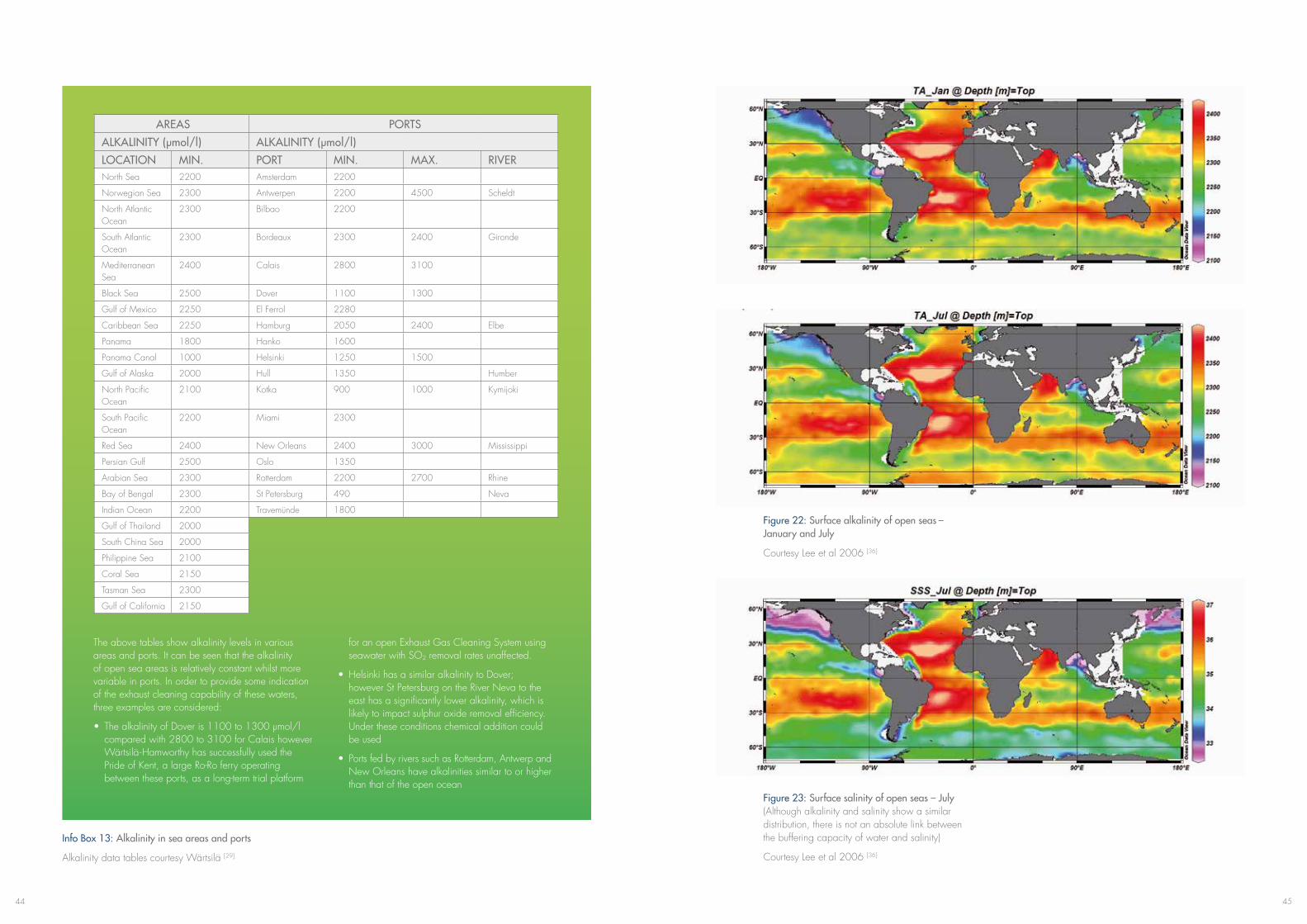
4544
Info Box 13: Alkalinity in sea areas and ports
Alkalinity data tables courtesy Wärtsilä [29]
AREAS PORTS
ALKALINITY (μmol/l) ALKALINITY (μmol/l)
LOCATION MIN. PORT MIN. MAX. RIVERNorth Sea 2200 Amsterdam 2200
Norwegian Sea 2300 Antwerpen 2200 4500 Scheldt
North Atlantic Ocean
2300 Bilbao 2200
South Atlantic Ocean
2300 Bordeaux 2300 2400 Gironde
Mediterranean Sea
2400 Calais 2800 3100
Black Sea 2500 Dover 1100 1300
Gulf of Mexico 2250 El Ferrol 2280
Caribbean Sea 2250 Hamburg 2050 2400 Elbe
Panama 1800 Hanko 1600
Panama Canal 1000 Helsinki 1250 1500
Gulf of Alaska 2000 Hull 1350 Humber
North Pacific Ocean
2100 Kotka 900 1000 Kymijoki
South Pacific Ocean
2200 Miami 2300
Red Sea 2400 New Orleans 2400 3000 Mississippi
Persian Gulf 2500 Oslo 1350
Arabian Sea 2300 Rotterdam 2200 2700 Rhine
Bay of Bengal 2300 St Petersburg 490 Neva
Indian Ocean 2200 Travemünde 1800
Gulf of Thailand 2000
South China Sea 2000
Philippine Sea 2100
Coral Sea 2150
Tasman Sea 2300
Gulf of California 2150
The above tables show alkalinity levels in various areas and ports. It can be seen that the alkalinity of open sea areas is relatively constant whilst more variable in ports. In order to provide some indication of the exhaust cleaning capability of these waters, three examples are considered:
• ThealkalinityofDoveris1100to1300µmol/l compared with 2800 to 3100 for Calais however Wärtsilä-Hamworthy has successfully used the Pride of Kent, a large Ro-Ro ferry operating between these ports, as a long-term trial platform
for an open Exhaust Gas Cleaning System using seawater with SO2 removal rates unaffected.
• HelsinkihasasimilaralkalinitytoDover; however St Petersburg on the River Neva to the east has a significantly lower alkalinity, which is likely to impact sulphur oxide removal efficiency. Under these conditions chemical addition could be used
• PortsfedbyriverssuchasRotterdam,Antwerpand New Orleans have alkalinities similar to or higher than that of the open ocean
Figure 22: Surface alkalinity of open seas – January and July
Courtesy Lee et al 2006 [36]
Figure 23: Surface salinity of open seas – July (Although alkalinity and salinity show a similar distribution, there is not an absolute link between the buffering capacity of water and salinity)
Courtesy Lee et al 2006 [36]
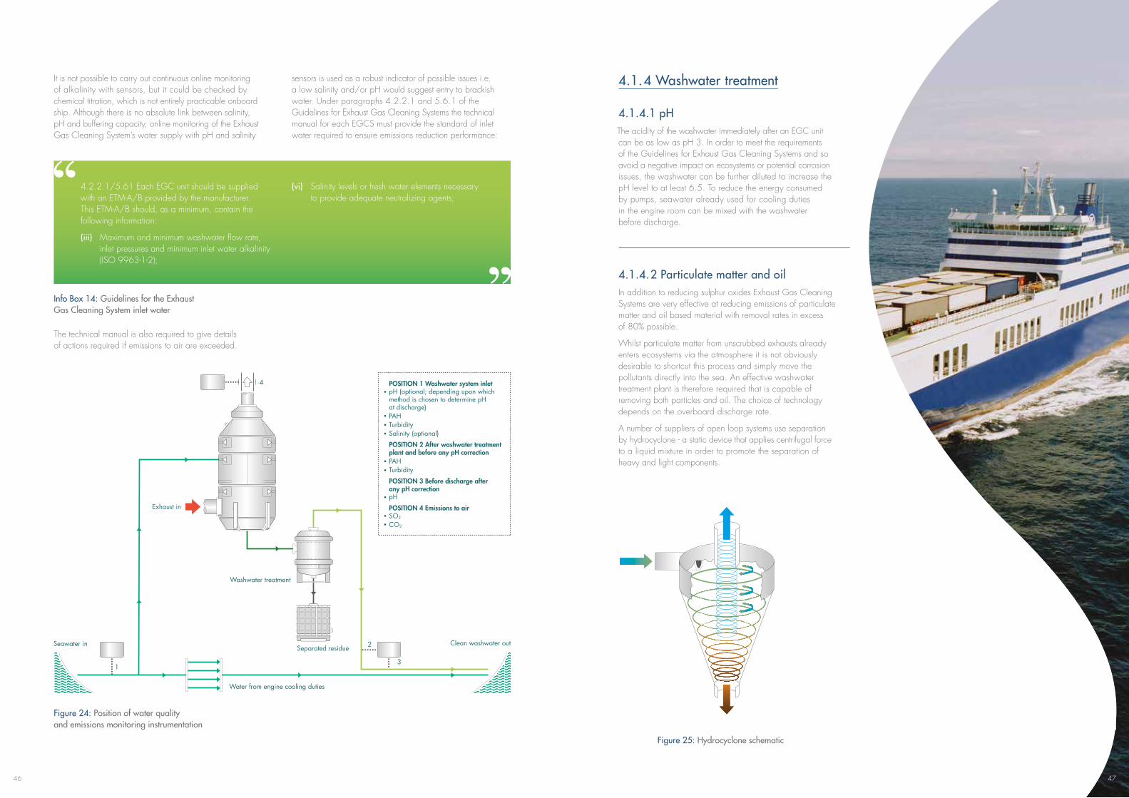
46
It is not possible to carry out continuous online monitoring of alkalinity with sensors, but it could be checked by chemical titration, which is not entirely practicable onboard ship. Although there is no absolute link between salinity, pH and buffering capacity, online monitoring of the Exhaust Gas Cleaning System’s water supply with pH and salinity
sensors is used as a robust indicator of possible issues i.e. a low salinity and/or pH would suggest entry to brackish water. Under paragraphs 4.2.2.1 and 5.6.1 of the Guidelines for Exhaust Gas Cleaning Systems the technical manual for each EGCS must provide the standard of inlet water required to ensure emissions reduction performance:
4.2.2.1/5.61 Each EGC unit should be supplied with an ETM-A/B provided by the manufacturer. This ETM-A/B should, as a minimum, contain the following information:
(iii) Maximum and minimum washwater flow rate, inlet pressures and minimum inlet water alkalinity (ISO 9963-1-2);
(vi) Salinity levels or fresh water elements necessary to provide adequate neutralizing agents;
Info Box 14: Guidelines for the Exhaust Gas Cleaning System inlet water
The technical manual is also required to give details of actions required if emissions to air are exceeded.
Figure 24: Position of water quality and emissions monitoring instrumentation
Separated residue
Washwater treatment
Exhaust in
Water from engine cooling duties
Clean washwater outSeawater in
POSITION 1 Washwater system inletpH (optional; depending upon which method is chosen to determine pH at discharge)PAHTurbiditySalinity (optional)
POSITION 2 After washwater treatment plant and before any pH correctionPAHTurbidity
POSITION 3 Before discharge after any pH correctionpH
POSITION 4 Emissions to airSO2
CO2
1
2
3
4
Figure 25: Hydrocyclone schematic
4.1.4 Washwater treatment
4.1.4.1 pH The acidity of the washwater immediately after an EGC unit can be as low as pH 3. In order to meet the requirements of the Guidelines for Exhaust Gas Cleaning Systems and so avoid a negative impact on ecosystems or potential corrosion issues, the washwater can be further diluted to increase the pH level to at least 6.5. To reduce the energy consumed by pumps, seawater already used for cooling duties in the engine room can be mixed with the washwater before discharge.
4.1.4.2 Particulate matter and oilIn addition to reducing sulphur oxides Exhaust Gas Cleaning Systems are very effective at reducing emissions of particulate matter and oil based material with removal rates in excess of 80% possible.
Whilst particulate matter from unscrubbed exhausts already enters ecosystems via the atmosphere it is not obviously desirable to shortcut this process and simply move the pollutants directly into the sea. An effective washwater treatment plant is therefore required that is capable of removing both particles and oil. The choice of technology depends on the overboard discharge rate.
A number of suppliers of open loop systems use separation by hydrocyclone - a static device that applies centrifugal force to a liquid mixture in order to promote the separation of heavy and light components.
47
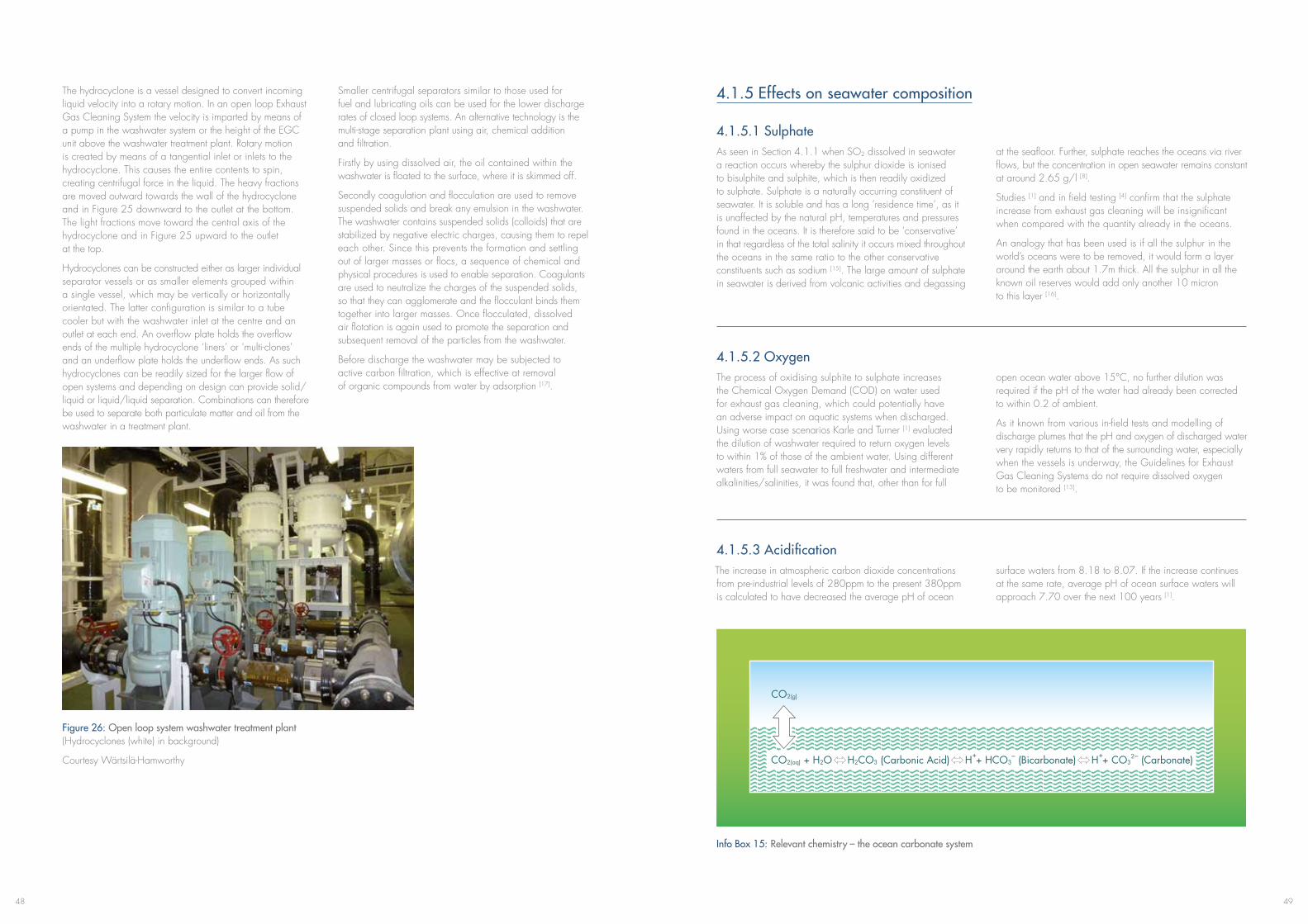
4948
The hydrocyclone is a vessel designed to convert incoming liquid velocity into a rotary motion. In an open loop Exhaust Gas Cleaning System the velocity is imparted by means of a pump in the washwater system or the height of the EGC unit above the washwater treatment plant. Rotary motion is created by means of a tangential inlet or inlets to the hydrocyclone. This causes the entire contents to spin, creating centrifugal force in the liquid. The heavy fractions are moved outward towards the wall of the hydrocyclone and in Figure 25 downward to the outlet at the bottom. The light fractions move toward the central axis of the hydrocyclone and in Figure 25 upward to the outlet at the top.
Hydrocyclones can be constructed either as larger individual separator vessels or as smaller elements grouped within a single vessel, which may be vertically or horizontally orientated. The latter configuration is similar to a tube cooler but with the washwater inlet at the centre and an outlet at each end. An overflow plate holds the overflow ends of the multiple hydrocyclone ‘liners’ or ‘multi-clones’ and an underflow plate holds the underflow ends. As such hydrocyclones can be readily sized for the larger flow of open systems and depending on design can provide solid/liquid or liquid/liquid separation. Combinations can therefore be used to separate both particulate matter and oil from the washwater in a treatment plant.
Figure 26: Open loop system washwater treatment plant (Hydrocyclones (white) in background)
Courtesy Wärtsilä-Hamworthy
Smaller centrifugal separators similar to those used for fuel and lubricating oils can be used for the lower discharge rates of closed loop systems. An alternative technology is the multi-stage separation plant using air, chemical addition and filtration.
Firstly by using dissolved air, the oil contained within the washwater is floated to the surface, where it is skimmed off.
Secondly coagulation and flocculation are used to remove suspended solids and break any emulsion in the washwater. The washwater contains suspended solids (colloids) that are stabilized by negative electric charges, causing them to repel each other. Since this prevents the formation and settling out of larger masses or flocs, a sequence of chemical and physical procedures is used to enable separation. Coagulants are used to neutralize the charges of the suspended solids, so that they can agglomerate and the flocculant binds them together into larger masses. Once flocculated, dissolved air flotation is again used to promote the separation and subsequent removal of the particles from the washwater.
Before discharge the washwater may be subjected to active carbon filtration, which is effective at removal of organic compounds from water by adsorption [17].
4.1.5 Effects on seawater composition
4.1.5.1 SulphateAs seen in Section 4.1.1 when SO2 dissolved in seawater a reaction occurs whereby the sulphur dioxide is ionised to bisulphite and sulphite, which is then readily oxidized to sulphate. Sulphate is a naturally occurring constituent of seawater. It is soluble and has a long ‘residence time’, as it is unaffected by the natural pH, temperatures and pressures found in the oceans. It is therefore said to be ‘conservative’ in that regardless of the total salinity it occurs mixed throughout the oceans in the same ratio to the other conservative constituents such as sodium [15]. The large amount of sulphate in seawater is derived from volcanic activities and degassing
at the seafloor. Further, sulphate reaches the oceans via river flows, but the concentration in open seawater remains constant at around 2.65 g/l [8].
Studies [1] and in field testing [4] confirm that the sulphate increase from exhaust gas cleaning will be insignificant when compared with the quantity already in the oceans.
An analogy that has been used is if all the sulphur in the world’s oceans were to be removed, it would form a layer around the earth about 1.7m thick. All the sulphur in all the known oil reserves would add only another 10 micron to this layer [16].
4.1.5.2 OxygenThe process of oxidising sulphite to sulphate increases the Chemical Oxygen Demand (COD) on water used for exhaust gas cleaning, which could potentially have an adverse impact on aquatic systems when discharged. Using worse case scenarios Karle and Turner [1] evaluated the dilution of washwater required to return oxygen levels to within 1% of those of the ambient water. Using different waters from full seawater to full freshwater and intermediate alkalinities/salinities, it was found that, other than for full
openoceanwaterabove15°C,nofurtherdilutionwasrequired if the pH of the water had already been corrected to within 0.2 of ambient.
As it known from various in-field tests and modelling of discharge plumes that the pH and oxygen of discharged water very rapidly returns to that of the surrounding water, especially when the vessels is underway, the Guidelines for Exhaust Gas Cleaning Systems do not require dissolved oxygen to be monitored [13].
4.1.5.3 Acidification The increase in atmospheric carbon dioxide concentrations from pre-industrial levels of 280ppm to the present 380ppm is calculated to have decreased the average pH of ocean
surface waters from 8.18 to 8.07. If the increase continues at the same rate, average pH of ocean surface waters will approach 7.70 over the next 100 years [1].
Info Box 15: Relevant chemistry – the ocean carbonate system
CO2(g)
CO2(aq) + H2O H2CO3 (Carbonic Acid) H++ HCO3– (Bicarbonate) H++ CO3
2– (Carbonate)
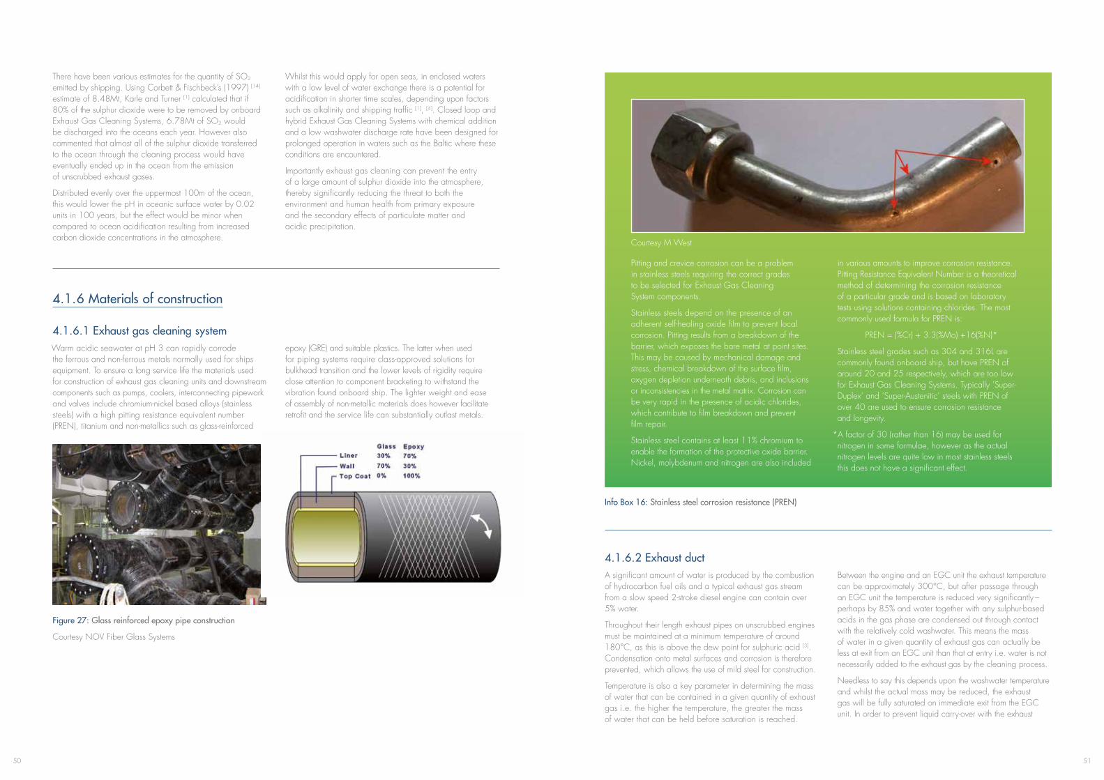
5150
There have been various estimates for the quantity of SO2 emitted by shipping. Using Corbett & Fischbeck’s (1997) [14] estimate of 8.48Mt, Karle and Turner [1] calculated that if 80% of the sulphur dioxide were to be removed by onboard Exhaust Gas Cleaning Systems, 6.78Mt of SO2 would be discharged into the oceans each year. However also commented that almost all of the sulphur dioxide transferred to the ocean through the cleaning process would have eventually ended up in the ocean from the emission of unscrubbed exhaust gases.
Distributed evenly over the uppermost 100m of the ocean, this would lower the pH in oceanic surface water by 0.02 units in 100 years, but the effect would be minor when compared to ocean acidification resulting from increased carbon dioxide concentrations in the atmosphere.
Whilst this would apply for open seas, in enclosed waters with a low level of water exchange there is a potential for acidification in shorter time scales, depending upon factors such as alkalinity and shipping traffic [1], [4]. Closed loop and hybrid Exhaust Gas Cleaning Systems with chemical addition and a low washwater discharge rate have been designed for prolonged operation in waters such as the Baltic where these conditions are encountered.
Importantly exhaust gas cleaning can prevent the entry of a large amount of sulphur dioxide into the atmosphere, thereby significantly reducing the threat to both the environment and human health from primary exposure and the secondary effects of particulate matter and acidic precipitation.
4.1.6 Materials of construction
4.1.6.1 Exhaust gas cleaning system Warm acidic seawater at pH 3 can rapidly corrode the ferrous and non-ferrous metals normally used for ships equipment. To ensure a long service life the materials used for construction of exhaust gas cleaning units and downstream components such as pumps, coolers, interconnecting pipework and valves include chromium-nickel based alloys (stainless steels) with a high pitting resistance equivalent number (PREN), titanium and non-metallics such as glass-reinforced
epoxy (GRE) and suitable plastics. The latter when used for piping systems require class-approved solutions for bulkhead transition and the lower levels of rigidity require close attention to component bracketing to withstand the vibration found onboard ship. The lighter weight and ease of assembly of non-metallic materials does however facilitate retrofit and the service life can substantially outlast metals.
Figure 27: Glass reinforced epoxy pipe construction
Courtesy NOV Fiber Glass Systems
Pitting and crevice corrosion can be a problem in stainless steels requiring the correct grades to be selected for Exhaust Gas Cleaning System components.
Stainless steels depend on the presence of an adherent self-healing oxide film to prevent local corrosion. Pitting results from a breakdown of the barrier, which exposes the bare metal at point sites. This may be caused by mechanical damage and stress, chemical breakdown of the surface film, oxygen depletion underneath debris, and inclusions or inconsistencies in the metal matrix. Corrosion can be very rapid in the presence of acidic chlorides, which contribute to film breakdown and prevent film repair.
Stainless steel contains at least 11% chromium to enable the formation of the protective oxide barrier. Nickel, molybdenum and nitrogen are also included
in various amounts to improve corrosion resistance. Pitting Resistance Equivalent Number is a theoretical method of determining the corrosion resistance of a particular grade and is based on laboratory tests using solutions containing chlorides. The most commonly used formula for PREN is:
PREN = (%Cr) + 3.3(%Mo) +16(%N)*
Stainless steel grades such as 304 and 316L are commonly found onboard ship, but have PREN of around 20 and 25 respectively, which are too low for Exhaust Gas Cleaning Systems. Typically ‘Super-Duplex’ and ‘Super-Austenitic’ steels with PREN of over 40 are used to ensure corrosion resistance and longevity.
*A factor of 30 (rather than 16) may be used for nitrogen in some formulae, however as the actual nitrogen levels are quite low in most stainless steels this does not have a significant effect.
Info Box 16: Stainless steel corrosion resistance (PREN)
4.1.6.2 Exhaust ductA significant amount of water is produced by the combustion of hydrocarbon fuel oils and a typical exhaust gas stream from a slow speed 2-stroke diesel engine can contain over 5% water.
Throughout their length exhaust pipes on unscrubbed engines must be maintained at a minimum temperature of around 180°C,asthisisabovethedewpointforsulphuricacid[3]. Condensation onto metal surfaces and corrosion is therefore prevented, which allows the use of mild steel for construction.
Temperature is also a key parameter in determining the mass of water that can be contained in a given quantity of exhaust gas i.e. the higher the temperature, the greater the mass of water that can be held before saturation is reached.
Between the engine and an EGC unit the exhaust temperature canbeapproximately300°C,butafterpassagethroughan EGC unit the temperature is reduced very significantly – perhaps by 85% and water together with any sulphur-based acids in the gas phase are condensed out through contact with the relatively cold washwater. This means the mass of water in a given quantity of exhaust gas can actually be less at exit from an EGC unit than that at entry i.e. water is not necessarily added to the exhaust gas by the cleaning process.
Needless to say this depends upon the washwater temperature and whilst the actual mass may be reduced, the exhaust gas will be fully saturated on immediate exit from the EGC unit. In order to prevent liquid carry-over with the exhaust
Courtesy M West
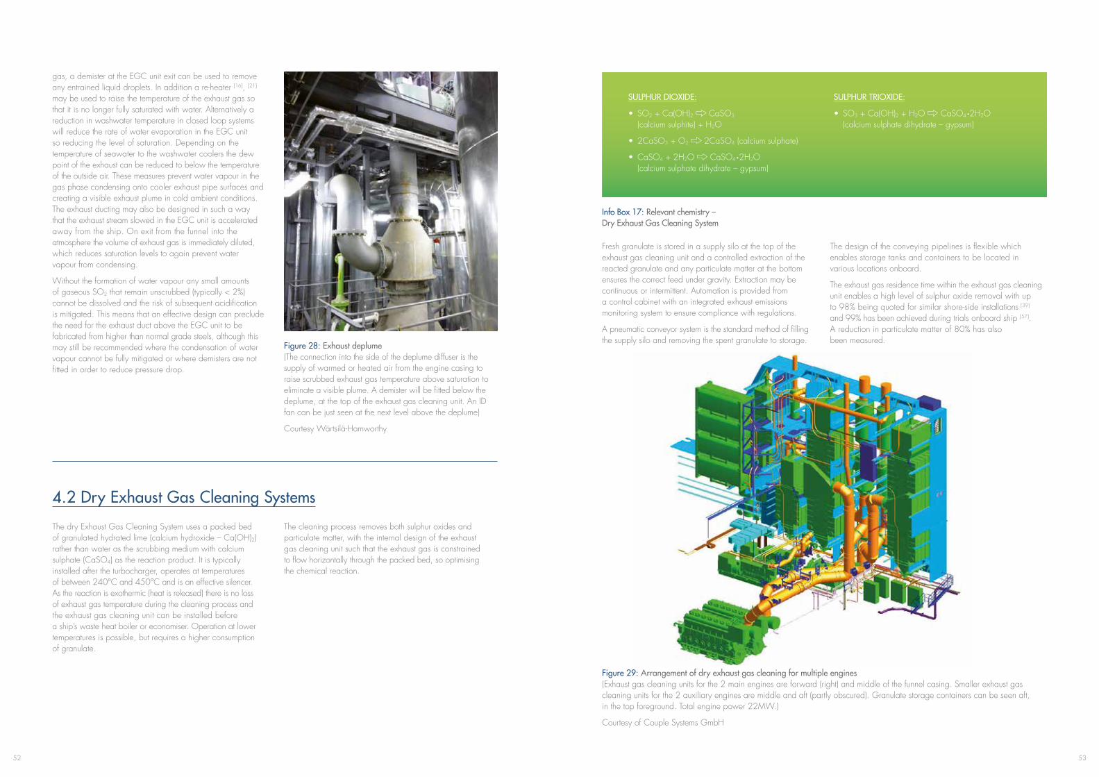
5352
gas, a demister at the EGC unit exit can be used to remove any entrained liquid droplets. In addition a re-heater [16], [21] may be used to raise the temperature of the exhaust gas so that it is no longer fully saturated with water. Alternatively a reduction in washwater temperature in closed loop systems will reduce the rate of water evaporation in the EGC unit so reducing the level of saturation. Depending on the temperature of seawater to the washwater coolers the dew point of the exhaust can be reduced to below the temperature of the outside air. These measures prevent water vapour in the gas phase condensing onto cooler exhaust pipe surfaces and creating a visible exhaust plume in cold ambient conditions. The exhaust ducting may also be designed in such a way that the exhaust stream slowed in the EGC unit is accelerated away from the ship. On exit from the funnel into the atmosphere the volume of exhaust gas is immediately diluted, which reduces saturation levels to again prevent water vapour from condensing.
Without the formation of water vapour any small amounts of gaseous SO2 that remain unscrubbed (typically < 2%) cannot be dissolved and the risk of subsequent acidification is mitigated. This means that an effective design can preclude the need for the exhaust duct above the EGC unit to be fabricated from higher than normal grade steels, although this may still be recommended where the condensation of water vapour cannot be fully mitigated or where demisters are not fitted in order to reduce pressure drop.
Figure 28: Exhaust deplume (The connection into the side of the deplume diffuser is the supply of warmed or heated air from the engine casing to raise scrubbed exhaust gas temperature above saturation to eliminate a visible plume. A demister will be fitted below the deplume, at the top of the exhaust gas cleaning unit. An ID fan can be just seen at the next level above the deplume)
Courtesy Wärtsilä-Hamworthy
4.2 Dry Exhaust Gas Cleaning Systems
The dry Exhaust Gas Cleaning System uses a packed bed of granulated hydrated lime (calcium hydroxide – Ca(OH)2) rather than water as the scrubbing medium with calcium sulphate (CaSO4) as the reaction product. It is typically installed after the turbocharger, operates at temperatures ofbetween240°Cand450°Candisaneffectivesilencer. As the reaction is exothermic (heat is released) there is no loss of exhaust gas temperature during the cleaning process and the exhaust gas cleaning unit can be installed before a ship’s waste heat boiler or economiser. Operation at lower temperatures is possible, but requires a higher consumption of granulate.
The cleaning process removes both sulphur oxides and particulate matter, with the internal design of the exhaust gas cleaning unit such that the exhaust gas is constrained to flow horizontally through the packed bed, so optimising the chemical reaction.
Info Box 17: Relevant chemistry – Dry Exhaust Gas Cleaning System
SULPHUR DIOXIDE:
• SO2 + Ca(OH)2 CaSO3 (calcium sulphite) + H2O
• 2CaSO3 + O2 2CaSO4 (calcium sulphate)
• CaSO4 + 2H2O CaSO4 ·2H2O (calcium sulphate dihydrate – gypsum)
SULPHUR TRIOXIDE:
• SO3 + Ca(OH)2 + H2O CaSO4 ·2H2O (calcium sulphate dihydrate – gypsum)
Fresh granulate is stored in a supply silo at the top of the exhaust gas cleaning unit and a controlled extraction of the reacted granulate and any particulate matter at the bottom ensures the correct feed under gravity. Extraction may be continuous or intermittent. Automation is provided from a control cabinet with an integrated exhaust emissions monitoring system to ensure compliance with regulations.
A pneumatic conveyor system is the standard method of filling the supply silo and removing the spent granulate to storage.
The design of the conveying pipelines is flexible which enables storage tanks and containers to be located in various locations onboard.
The exhaust gas residence time within the exhaust gas cleaning unit enables a high level of sulphur oxide removal with up to 98% being quoted for similar shore-side installations [39] and 99% has been achieved during trials onboard ship [57]. A reduction in particulate matter of 80% has also been measured.
Figure 29: Arrangement of dry exhaust gas cleaning for multiple engines (Exhaust gas cleaning units for the 2 main engines are forward (right) and middle of the funnel casing. Smaller exhaust gas cleaning units for the 2 auxiliary engines are middle and aft (partly obscured). Granulate storage containers can be seen aft, in the top foreground. Total engine power 22MW.)
Courtesy of Couple Systems GmbH
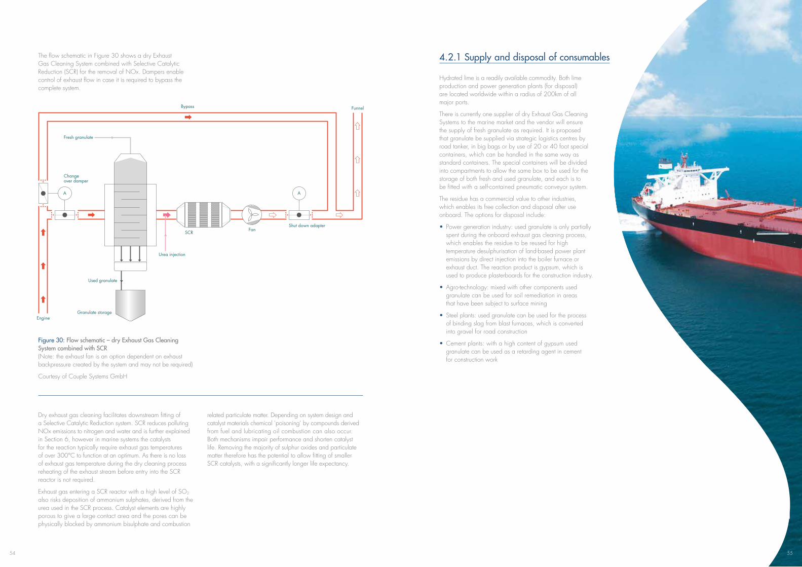
54
The flow schematic in Figure 30 shows a dry Exhaust Gas Cleaning System combined with Selective Catalytic Reduction (SCR) for the removal of NOx. Dampers enable control of exhaust flow in case it is required to bypass the complete system.
Figure 30: Flow schematic – dry Exhaust Gas Cleaning System combined with SCR (Note: the exhaust fan is an option dependent on exhaust backpressure created by the system and may not be required)
Courtesy of Couple Systems GmbH
Dry exhaust gas cleaning facilitates downstream fitting of a Selective Catalytic Reduction system. SCR reduces polluting NOx emissions to nitrogen and water and is further explained in Section 6, however in marine systems the catalysts for the reaction typically require exhaust gas temperatures ofover300°Ctofunctionatanoptimum.Asthereisnolossof exhaust gas temperature during the dry cleaning process reheating of the exhaust stream before entry into the SCR reactor is not required.
Exhaust gas entering a SCR reactor with a high level of SO2 also risks deposition of ammonium sulphates, derived from the urea used in the SCR process. Catalyst elements are highly porous to give a large contact area and the pores can be physically blocked by ammonium bisulphate and combustion
related particulate matter. Depending on system design and catalyst materials chemical ‘poisoning’ by compounds derived from fuel and lubricating oil combustion can also occur. Both mechanisms impair performance and shorten catalyst life. Removing the majority of sulphur oxides and particulate matter therefore has the potential to allow fitting of smaller SCR catalysts, with a significantly longer life expectancy.
Fresh granulate
Change over damper
Bypass
Engine
Used granulate
Granulate storage
SCR
Urea injection
FanShut down adapter
Funnel
AA
4.2.1 Supply and disposal of consumables
Hydrated lime is a readily available commodity. Both lime production and power generation plants (for disposal) are located worldwide within a radius of 200km of all major ports.
There is currently one supplier of dry Exhaust Gas Cleaning Systems to the marine market and the vendor will ensure the supply of fresh granulate as required. It is proposed that granulate be supplied via strategic logistics centres by road tanker, in big bags or by use of 20 or 40 foot special containers, which can be handled in the same way as standard containers. The special containers will be divided into compartments to allow the same box to be used for the storage of both fresh and used granulate, and each is to be fitted with a self-contained pneumatic conveyor system.
The residue has a commercial value to other industries, which enables its free collection and disposal after use onboard. The options for disposal include:
• Power generation industry: used granulate is only partially spent during the onboard exhaust gas cleaning process, which enables the residue to be reused for high temperature desulphurisation of land-based power plant emissions by direct injection into the boiler furnace or exhaust duct. The reaction product is gypsum, which is used to produce plasterboards for the construction industry.
• Agro-technology: mixed with other components used granulate can be used for soil remediation in areas that have been subject to surface mining
• Steel plants: used granulate can be used for the process of binding slag from blast furnaces, which is converted into gravel for road construction
• Cement plants: with a high content of gypsum used granulate can be used as a retarding agent in cement for construction work
55
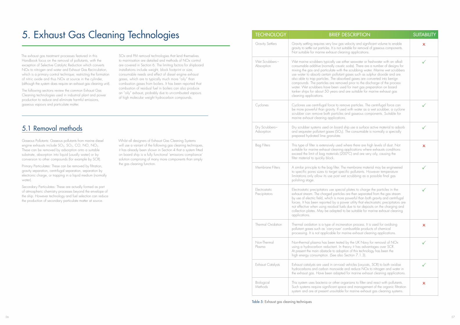
5756
5. Exhaust Gas Cleaning Technologies
The exhaust gas treatment processes featured in this Handbook focus on the removal of pollutants, with the exception of Selective Catalytic Reduction which converts NOx to nitrogen and water and Exhaust Gas Recirculation, which is a primary control technique; restricting the formation of nitric oxide and thus NOx at source in the cylinder, (although the system does require an exhaust gas cleaning unit).
The following sections review the common Exhaust Gas Cleaning technologies used in industrial plant and power production to reduce and eliminate harmful emissions, gaseous vapours and particulate matter.
SOx and PM removal technologies that lend themselves to marinisation are detailed and methods of NOx control are covered in Section 6. The limiting factors for shipboard installations include weight, block footprint or size, consumable needs and effect of diesel engine exhaust gases, which are to typically much more “oily” than combustion gases from boilers. It has been reported that combustion of residual fuel in boilers can also produce an “oily” exhaust, probably due to un-combusted vapours of high molecular weight hydrocarbon compounds.
5.1 Removal methods
Gaseous Pollutants: Gaseous pollutants from marine diesel engine exhausts include SO2, SO3, CO, NO, NO2. These can be removed by adsorption onto a suitable substrate, absorption into liquid (usually water) or by conversion to other compounds (for example by SCR).
Primary Particulates: These can be removed by filtration, gravity separation, centrifugal separation, separation by electronic charge, or trapping in a liquid medium (normally water).
Secondary Particulates: These are actually formed as part of atmospheric chemistry processes beyond the envelope of the ship. However technology and fuel selection can reduce the production of secondary particulate matter at source.
Whilst all designers of Exhaust Gas Cleaning Systems will use a variant of the following gas cleaning techniques, it has already been shown in Section 4 that a system fitted on board ship is a fully functional ‘emissions compliance’ solution comprising of many more components than simply the gas cleaning function.
TECHNOLOGY BRIEF DESCRIPTION SUITABILITY
Gravity Settlers Gravity settling requires very low gas velocity and significant volume to enable gravity to settle out particles. It is not suitable for removal of gaseous components. Not suitable for marine exhaust cleaning applications.
O
Wet Scrubbers – Absorption
Wet marine scrubbers typically use either seawater or freshwater with an alkali consumable additive (normally caustic soda). There are a number of designs for mixing the gas and particulate with the scrubbing water. Marine wet scrubbers use water to absorb certain pollutant gases such as sulphur dioxide and are also able to trap particles. The absorbed gases are converted into benign compounds. The particles are removed prior to the discharge of the process water. Wet scrubbers have been used for inert gas preparation on board tanker ships for about 50 years and are suitable for marine exhaust gas cleaning applications.
P
Cyclones Cyclones use centrifugal force to remove particles. The centrifugal force can be more powerful than gravity. If used with water as a wet scrubber, a cyclone scrubber can remove both particles and gaseous components. Suitable for marine exhaust cleaning applications.
P
Dry Scrubbers – Adsorption
Dry scrubber systems used on board ship use a surface active material to adsorb and sequester pollutant gases (SO2). The consumable is normally a specially prepared hydrated lime granulate.
P
Bag Filters This type of filter is extensively used where there are high levels of dust. Not suitable for marine exhaust cleaning applications where exhausts conditions exceedthelimitofbagmaterials(200°C)andareveryoily,causingthe filter material to quickly block.
O
Membrane Filters A similar principle to the bag filter. The membrane material may be engineered to specific pores sizes to target specific pollutants. However temperature limitations only allow its use post wet scrubbing as a possible final gas polishing stage.
P
Electrostatic Precipitators
Electrostatic precipitators use special plates to charge the particles in the exhaust stream. The charged particles are then separated from the gas stream by use of electric field, which is more powerful than both gravity and centrifugal forces. It has been reported by a power utility that electrostatic precipitators are not effective when using residual fuels due to tar deposits on the charging and collection plates. May be adapted to be suitable for marine exhaust cleaning applications.
P
Thermal Oxidation Thermal oxidation is a type of incineration process. It is used for oxidising pollutant gases such as ‘carry-over’ combustible products of chemical processing. It is not applicable for marine exhaust cleaning applications.
O
Non-Thermal Plasma
Non-thermal plasma has been tested by the UK Navy for removal of NOx using a hydrocarbon reductant. In theory it has advantages over SCR. At present the main obstacle to adoption of this technology has been the high energy consumption. (See also Section 7.1.3).
P
Exhaust Catalysts Exhaust catalysts are used in on-road vehicles (oxycats, SCR) to both oxidise hydrocarbons and carbon monoxide and reduce NOx to nitrogen and water in the exhaust gas. Have been adapted for marine exhaust cleaning applications.
P
Biological Methods
This system uses bacteria or other organisms to filter and react with pollutants. Such systems require significant space and management of the organic filtration system and are at present unsuitable for marine exhaust gas cleaning systems.
O
Table 5: Exhaust gas cleaning techniques
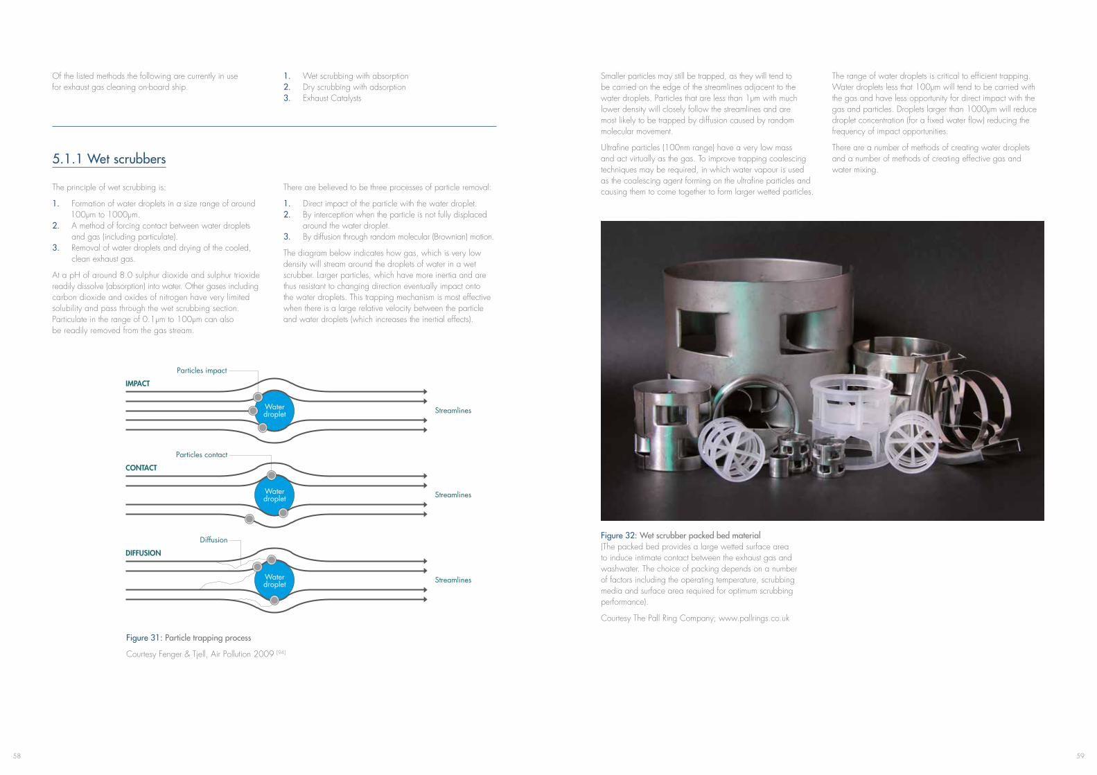
5958
Of the listed methods the following are currently in use for exhaust gas cleaning on-board ship.
1. Wet scrubbing with absorption 2. Dry scrubbing with adsorption 3. Exhaust Catalysts
5.1.1 Wet scrubbers
The principle of wet scrubbing is:
1. Formation of water droplets in a size range of around 100μm to 1000μm. 2. A method of forcing contact between water droplets and gas (including particulate). 3. Removal of water droplets and drying of the cooled, clean exhaust gas.
At a pH of around 8.0 sulphur dioxide and sulphur trioxide readily dissolve (absorption) into water. Other gases including carbon dioxide and oxides of nitrogen have very limited solubility and pass through the wet scrubbing section. Particulate in the range of 0.1μm to 100μm can also be readily removed from the gas stream.
There are believed to be three processes of particle removal:
1. Direct impact of the particle with the water droplet. 2. By interception when the particle is not fully displaced around the water droplet. 3. By diffusion through random molecular (Brownian) motion.
The diagram below indicates how gas, which is very low density will stream around the droplets of water in a wet scrubber. Larger particles, which have more inertia and are thus resistant to changing direction eventually impact onto the water droplets. This trapping mechanism is most effective when there is a large relative velocity between the particle and water droplets (which increases the inertial effects).
Figure 31: Particle trapping process
Courtesy Fenger & Tjell, Air Pollution 2009 [94]
Streamlines
Particles impact
Water droplet
IMPACT
Streamlines
Particles contact
CONTACT
Streamlines
Diffusion
DIFFUSION
Water droplet
Water droplet
Figure 32: Wet scrubber packed bed material (The packed bed provides a large wetted surface area to induce intimate contact between the exhaust gas and washwater. The choice of packing depends on a number of factors including the operating temperature, scrubbing media and surface area required for optimum scrubbing performance).
Courtesy The Pall Ring Company; www.pallrings.co.uk
Smaller particles may still be trapped, as they will tend to be carried on the edge of the streamlines adjacent to the water droplets. Particles that are less than 1μm with much lower density will closely follow the streamlines and are most likely to be trapped by diffusion caused by random molecular movement.
Ultrafine particles (100nm range) have a very low mass and act virtually as the gas. To improve trapping coalescing techniques may be required, in which water vapour is used as the coalescing agent forming on the ultrafine particles and causing them to come together to form larger wetted particles.
The range of water droplets is critical to efficient trapping. Water droplets less that 100μm will tend to be carried with the gas and have less opportunity for direct impact with the gas and particles. Droplets larger than 1000μm will reduce droplet concentration (for a fixed water flow) reducing the frequency of impact opportunities.
There are a number of methods of creating water droplets and a number of methods of creating effective gas and water mixing.
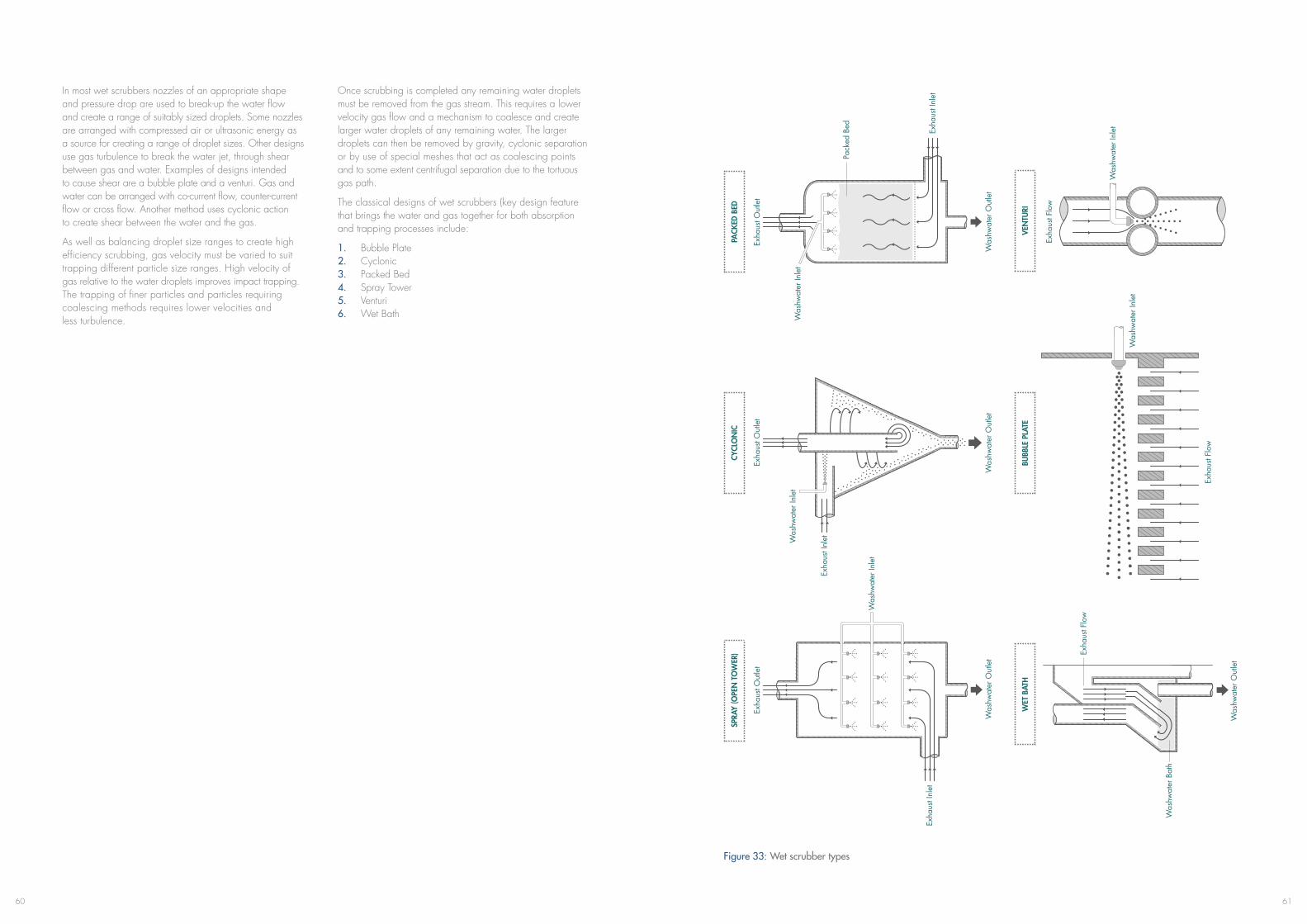
6160
In most wet scrubbers nozzles of an appropriate shape and pressure drop are used to break-up the water flow and create a range of suitably sized droplets. Some nozzles are arranged with compressed air or ultrasonic energy as a source for creating a range of droplet sizes. Other designs use gas turbulence to break the water jet, through shear between gas and water. Examples of designs intended to cause shear are a bubble plate and a venturi. Gas and water can be arranged with co-current flow, counter-current flow or cross flow. Another method uses cyclonic action to create shear between the water and the gas.
As well as balancing droplet size ranges to create high efficiency scrubbing, gas velocity must be varied to suit trapping different particle size ranges. High velocity of gas relative to the water droplets improves impact trapping. The trapping of finer particles and particles requiring coalescing methods requires lower velocities and less turbulence.
Once scrubbing is completed any remaining water droplets must be removed from the gas stream. This requires a lower velocity gas flow and a mechanism to coalesce and create larger water droplets of any remaining water. The larger droplets can then be removed by gravity, cyclonic separation or by use of special meshes that act as coalescing points and to some extent centrifugal separation due to the tortuous gas path.
The classical designs of wet scrubbers (key design feature that brings the water and gas together for both absorption and trapping processes include:
1. Bubble Plate 2. Cyclonic 3. Packed Bed 4. Spray Tower 5. Venturi 6. Wet Bath
Figure 33: Wet scrubber types
SPRA
Y (O
PEN
TO
WER
)PA
CKED
BED
Exha
ust O
utle
t
Was
hwat
er O
utle
t
Was
hwat
er In
let
Exha
ust I
nlet
Was
hwat
er In
let
Was
hwat
er O
utle
t
Pack
ed B
ed
Exha
ust F
low
Was
hwat
er In
let
VEN
TURI
Exha
ust F
low
Was
hwat
er In
let
BUBB
LE P
LATE
Was
hwat
er O
utle
t
Was
hwat
er B
ath
Exha
ust F
low
WET
BAT
H
CYCL
ON
IC
Was
hwat
er O
utle
t
Was
hwat
er In
let
Exha
ust I
nlet
Exha
ust O
utle
t
Exha
ust I
nlet
Exha
ust O
utle
t
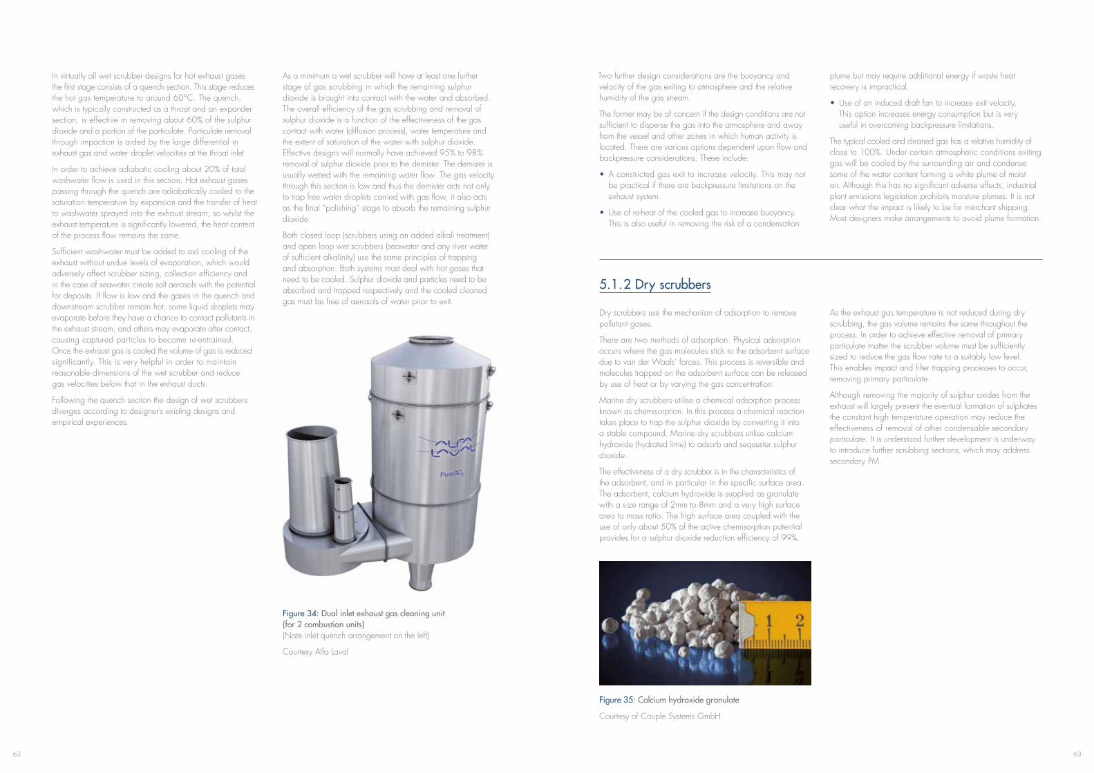
6362
In virtually all wet scrubber designs for hot exhaust gases the first stage consists of a quench section. This stage reduces thehotgastemperaturetoaround60°C.Thequench, which is typically constructed as a throat and an expander section, is effective in removing about 60% of the sulphur dioxide and a portion of the particulate. Particulate removal through impaction is aided by the large differential in exhaust gas and water droplet velocities at the throat inlet.
In order to achieve adiabatic cooling about 20% of total washwater flow is used in this section. Hot exhaust gases passing through the quench are adiabatically cooled to the saturation temperature by expansion and the transfer of heat to washwater sprayed into the exhaust stream, so whilst the exhaust temperature is significantly lowered, the heat content of the process flow remains the same.
Sufficient washwater must be added to aid cooling of the exhaust without undue levels of evaporation, which would adversely affect scrubber sizing, collection efficiency and in the case of seawater create salt aerosols with the potential for deposits. If flow is low and the gases in the quench and downstream scrubber remain hot, some liquid droplets may evaporate before they have a chance to contact pollutants in the exhaust stream, and others may evaporate after contact, causing captured particles to become re-entrained. Once the exhaust gas is cooled the volume of gas is reduced significantly. This is very helpful in order to maintain reasonable dimensions of the wet scrubber and reduce gas velocities below that in the exhaust ducts.
Following the quench section the design of wet scrubbers diverges according to designer’s existing designs and empirical experiences.
As a minimum a wet scrubber will have at least one further stage of gas scrubbing in which the remaining sulphur dioxide is brought into contact with the water and absorbed. The overall efficiency of the gas scrubbing and removal of sulphur dioxide is a function of the effectiveness of the gas contact with water (diffusion process), water temperature and the extent of saturation of the water with sulphur dioxide. Effective designs will normally have achieved 95% to 98% removal of sulphur dioxide prior to the demister. The demister is usually wetted with the remaining water flow. The gas velocity through this section is low and thus the demister acts not only to trap free water droplets carried with gas flow, it also acts as the final “polishing” stage to absorb the remaining sulphur dioxide.
Both closed loop (scrubbers using an added alkali treatment) and open loop wet scrubbers (seawater and any river water of sufficient alkalinity) use the same principles of trapping and absorption. Both systems must deal with hot gases that need to be cooled. Sulphur dioxide and particles need to be absorbed and trapped respectively and the cooled cleaned gas must be free of aerosols of water prior to exit.
Figure 34: Dual inlet exhaust gas cleaning unit (for 2 combustion units) (Note inlet quench arrangement on the left)
Courtesy Alfa Laval
Figure 35: Calcium hydroxide granulate
Courtesy of Couple Systems GmbH
Two further design considerations are the buoyancy and velocity of the gas exiting to atmosphere and the relative humidity of the gas stream.
The former may be of concern if the design conditions are not sufficient to disperse the gas into the atmosphere and away from the vessel and other zones in which human activity is located. There are various options dependent upon flow and backpressure considerations. These include:
• A constricted gas exit to increase velocity. This may not be practical if there are backpressure limitations on the exhaust system.
• Use of re-heat of the cooled gas to increase buoyancy. This is also useful in removing the risk of a condensation
plume but may require additional energy if waste heat recovery is impractical.
• Use of an induced draft fan to increase exit velocity. This option increases energy consumption but is very useful in overcoming backpressure limitations.
The typical cooled and cleaned gas has a relative humidity of close to 100%. Under certain atmospheric conditions exiting gas will be cooled by the surrounding air and condense some of the water content forming a white plume of moist air. Although this has no significant adverse effects, industrial plant emissions legislation prohibits moisture plumes. It is not clear what the impact is likely to be for merchant shipping. Most designers make arrangements to avoid plume formation.
5.1.2 Dry scrubbers
Dry scrubbers use the mechanism of adsorption to remove pollutant gases.
There are two methods of adsorption. Physical adsorption occurs where the gas molecules stick to the adsorbent surface due to van der Waals’ forces. This process is reversible and molecules trapped on the adsorbent surface can be released by use of heat or by varying the gas concentration.
Marine dry scrubbers utilise a chemical adsorption process known as chemisorption. In this process a chemical reaction takes place to trap the sulphur dioxide by converting it into a stable compound. Marine dry scrubbers utilise calcium hydroxide (hydrated lime) to adsorb and sequester sulphur dioxide.
The effectiveness of a dry scrubber is in the characteristics of the adsorbent, and in particular in the specific surface area. The adsorbent, calcium hydroxide is supplied as granulate with a size range of 2mm to 8mm and a very high surface area to mass ratio. The high surface area coupled with the use of only about 50% of the active chemisorption potential provides for a sulphur dioxide reduction efficiency of 99%.
As the exhaust gas temperature is not reduced during dry scrubbing, the gas volume remains the same throughout the process. In order to achieve effective removal of primary particulate matter the scrubber volume must be sufficiently sized to reduce the gas flow rate to a suitably low level. This enables impact and filter trapping processes to occur, removing primary particulate.
Although removing the majority of sulphur oxides from the exhaust will largely prevent the eventual formation of sulphates the constant high temperature operation may reduce the effectiveness of removal of other condensable secondary particulate. It is understood further development is underway to introduce further scrubbing sections, which may address secondary PM.
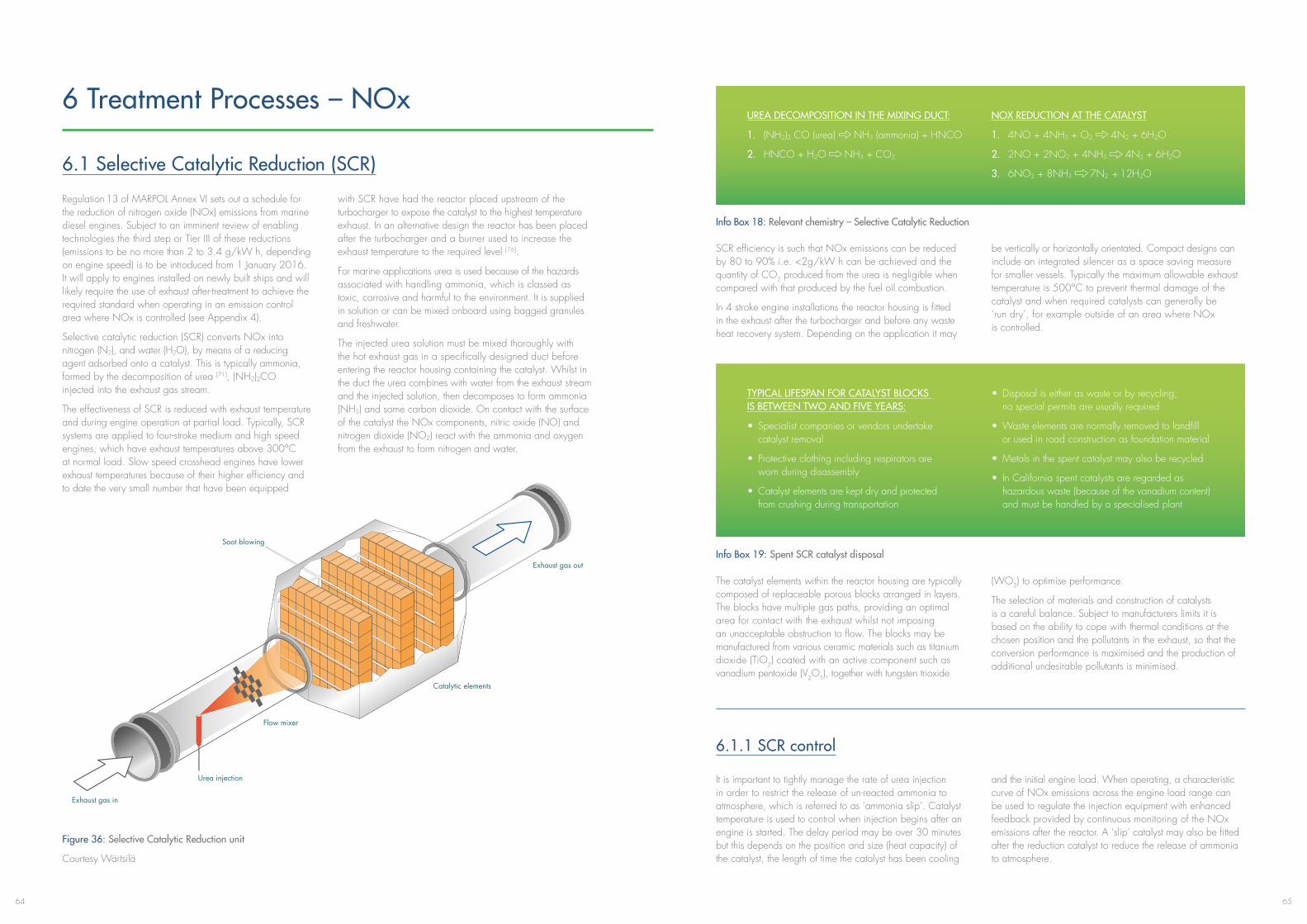
6564
6 Treatment Processes – NOx
6.1 Selective Catalytic Reduction (SCR)
Regulation 13 of MARPOL Annex VI sets out a schedule for the reduction of nitrogen oxide (NOx) emissions from marine diesel engines. Subject to an imminent review of enabling technologies the third step or Tier III of these reductions (emissions to be no more than 2 to 3.4 g/kW h, depending on engine speed) is to be introduced from 1 January 2016. It will apply to engines installed on newly built ships and will likely require the use of exhaust after-treatment to achieve the required standard when operating in an emission control area where NOx is controlled (see Appendix 4).
Selective catalytic reduction (SCR) converts NOx into nitrogen (N2), and water (H2O), by means of a reducing agent adsorbed onto a catalyst. This is typically ammonia, formed by the decomposition of urea [71], (NH2)2CO injected into the exhaust gas stream.
The effectiveness of SCR is reduced with exhaust temperature and during engine operation at partial load. Typically, SCR systems are applied to four-stroke medium and high speed engines,whichhaveexhausttemperaturesabove300°Cat normal load. Slow speed crosshead engines have lower exhaust temperatures because of their higher efficiency and to date the very small number that have been equipped
with SCR have had the reactor placed upstream of the turbocharger to expose the catalyst to the highest temperature exhaust. In an alternative design the reactor has been placed after the turbocharger and a burner used to increase the exhaust temperature to the required level [76].
For marine applications urea is used because of the hazards associated with handling ammonia, which is classed as toxic, corrosive and harmful to the environment. It is supplied in solution or can be mixed onboard using bagged granules and freshwater.
The injected urea solution must be mixed thoroughly with the hot exhaust gas in a specifically designed duct before entering the reactor housing containing the catalyst. Whilst in the duct the urea combines with water from the exhaust stream and the injected solution, then decomposes to form ammonia (NH3) and some carbon dioxide. On contact with the surface of the catalyst the NOx components, nitric oxide (NO) and nitrogen dioxide (NO2) react with the ammonia and oxygen from the exhaust to form nitrogen and water.
Figure 36: Selective Catalytic Reduction unit
Courtesy Wärtsilä
Soot blowing
Urea injection
Flow mixer
Catalytic elements
Exhaust gas out
Exhaust gas in
Info Box 18: Relevant chemistry – Selective Catalytic Reduction
Info Box 19: Spent SCR catalyst disposal
UREA DECOMPOSITION IN THE MIXING DUCT:
1. (NH2)2 CO (urea) NH3 (ammonia) + HNCO
2. HNCO + H2O NH3 + CO2
NOX REDUCTION AT THE CATALYST
1. 4NO + 4NH3 + O2 4N2 + 6H2O
2. 2NO + 2NO2 + 4NH3 4N2 + 6H2O
3. 6NO2 + 8NH3 7N2 + 12H2O
TYPICAL LIFESPAN FOR CATALYST BLOCKS IS BETWEEN TWO AND FIVE YEARS:
• Specialistcompaniesorvendorsundertake catalyst removal
• Protectiveclothingincludingrespiratorsare worn during disassembly
• Catalystelementsarekeptdryandprotected from crushing during transportation
• Disposaliseitheraswasteorbyrecycling; no special permits are usually required
•Wasteelementsarenormallyremovedtolandfill or used in road construction as foundation material
•Metalsinthespentcatalystmayalsoberecycled
• InCaliforniaspentcatalystsareregardedas hazardous waste (because of the vanadium content) and must be handled by a specialised plant
SCR efficiency is such that NOx emissions can be reduced by 80 to 90% i.e. <2g/kW h can be achieved and the quantity of CO2 produced from the urea is negligible when compared with that produced by the fuel oil combustion.
In 4 stroke engine installations the reactor housing is fitted in the exhaust after the turbocharger and before any waste heat recovery system. Depending on the application it may
be vertically or horizontally orientated. Compact designs can include an integrated silencer as a space saving measure for smaller vessels. Typically the maximum allowable exhaust temperatureis500°Ctopreventthermaldamageofthecatalyst and when required catalysts can generally be ‘run dry’, for example outside of an area where NOx is controlled.
The catalyst elements within the reactor housing are typically composed of replaceable porous blocks arranged in layers. The blocks have multiple gas paths, providing an optimal area for contact with the exhaust whilst not imposing an unacceptable obstruction to flow. The blocks may be manufactured from various ceramic materials such as titanium dioxide (TiO2) coated with an active component such as vanadium pentoxide (V2O5), together with tungsten trioxide
(WO3) to optimise performance.
The selection of materials and construction of catalysts is a careful balance. Subject to manufacturers limits it is based on the ability to cope with thermal conditions at the chosen position and the pollutants in the exhaust, so that the conversion performance is maximised and the production of additional undesirable pollutants is minimised.
6.1.1 SCR control
It is important to tightly manage the rate of urea injection in order to restrict the release of un-reacted ammonia to atmosphere, which is referred to as ‘ammonia slip’. Catalyst temperature is used to control when injection begins after an engine is started. The delay period may be over 30 minutes but this depends on the position and size (heat capacity) of the catalyst, the length of time the catalyst has been cooling
and the initial engine load. When operating, a characteristic curve of NOx emissions across the engine load range can be used to regulate the injection equipment with enhanced feedback provided by continuous monitoring of the NOx emissions after the reactor. A ‘slip’ catalyst may also be fitted after the reduction catalyst to reduce the release of ammonia to atmosphere.
6766
Catalyst temperature is a key parameter for optimum system performance, and operation at the design level is vital to prevent both ammonia slip and a reaction with sulphur trioxide (SO3) in the exhaust stream [69]. Typically,aminimumof300°Cto360°Cisrequired. At lower temperatures the formation of ammonium sulphate, (NH4)2SO4; a dry powdery compound, can result. Ammonium bisulphate, (NH4)HSO4 is also formed
at higher levels of SO3 (hence fuel sulphur). This is an adhesive and corrosive compound that reduces the effective area of the catalyst and is deposited in downstream components of the exhaust system impeding gas flow and the transfer of heat. Higher NOx emissions ensue and conditions overall can deteriorate with more ammonia slip and further fouling from the adherence of combustion derived particulate matter.
Info Box 20: Undesirable reactions in an SCR catalyst
In an SCR catalyst unwanted reactions can take place when sulphur dioxide in the exhaust is oxidized to sulphur trioxide.
• 2SO2 + O2 2SO3.
Two reactions can then follow
• 2NH3 (ammonia) + SO3 (sulphur trioxide) + H2O (NH4)2SO4 (ammonium sulphate)
•NH3 + SO3 + H2O NH4HSO4 (ammonium bisulphate)
The balance of the 2 species depends upon the exhaust temperature and concentration of ammonia from injected urea and sulphur trioxide from fuel sulphur.
Although a number of suppliers advise that a higher sulphur content is acceptable, particularly at higher exhaust temperatures, fuel oil with a low sulphur content (typically 1% maximum [77]) or an upstream SOx Exhaust Gas Cleaning System*, which does not impact exhaust temperature is generally specified to maximise the effective life of catalysts. By requiring a low sulphur content, deposits of ammonium sulphate and bisulphate that mask the surface and plug the pores of the catalyst are controlled, so ensuring contact with the exhaust gas is properly maintained. Depending on the materials of construction compounds can also be adsorbed onto and chemically react with active parts of catalysts further degrading performance. These ‘poisons’ include alkalis (sodium, potassium and calcium compounds) phosphorus
and certain heavy metals. This requires adherence to manufacturers recommendations in terms of the fuel oil type, composition and ash content (for example biofuels can have a high level of alkali metals). Recommended lubricating oil specifications for engines also have to be followed.
As deposits of soot, ash, and ammonium sulphates adversely affect the activity of the catalyst and cause an increase in pressure drop, a system using pressurised air or low frequency infrasound from an acoustic horn can be installed for regular cleaning of loose fouling from the catalyst surfaces.
*The Exhaust Gas Cleaning System could be either dry or wet with reheating of the exhaust gas after the cleaning process.
6.1.2 Oxidation catalysts
The majority nitrogen oxide in NOx is NO, which is reduced to nitrogen and water by reaction 1 in Info Box 18. However because this reaction is slower than reaction 2, an oxidation catalyst may be fitted before the reduction catalyst. This converts some NO to NO2 and allows manufacturers to use a smaller reactor and/or operate at lower temperatures [37].
Oxidation catalysts can also effectively convert other pollutants into simpler, less toxic compounds, such as carbon dioxide and water. These pollutants include carbon monoxide (CO), hydrocarbons, the soluble organic fraction of particulates (derived from unburned or partially combusted
fuel oil and engine lubricant), and several hydrocarbon derivatives, including polycyclic aromatic hydrocarbons (PAHs) [38].
The sulphur content of the fuel must however be considered for systems using oxidation catalysts. Whilst in a typical diesel engine exhaust a very small percentage of SO2 is oxidised to SO3, this can be significantly increased, particularly at higher engine loads and exhaust temperatures [37]. A proportion of the SO3 formed will react with some of the water vapour present to form damaging sulphuric acid. There will also be an increased potential for degrading deposits of particulate matter including sulphates of ammonia and metals [9] derived from the combusted fuel.
6.2 Exhaust Gas Recirculation (EGR)
During the process of combustion in an engine a series of complex reactions occur which cause some of the nitrogen in the charge air and most of any nitrogen in the fuel to oxidise and form nitric oxide (NO).
The majority of this NO is formed thermally by reactions between the nitrogen and oxygen in the charge air at a rate that is mainly dependent on the temperature within the combustion zone. Thermal NO formation is significant at1200°Candrisesexponentiallyabove1500°C.The amount of oxygen available i.e. excess air within the combustion zone and the time the combustion gas is exposed to a sufficiently high temperature are also important secondary factors [3].
On leaving the combustion chamber some of the nitric oxide is oxidised to nitrogen dioxide (NO2) and together these 2 gases form NOx in the ratio of approximately 90% to 95% NO, 5% to 10% NO2 [3].
Primary methods of NOx control focus on the process of NO formation and reductions down to Tier II levels can be achieved through the improved design and operational
adjustment of engines. Factors influencing NO formation include the pressure, timing and rate of fuel injection, fuel nozzle configuration, exhaust valve timing, the temperature and pressure of scavenge air, and compression ratio. Further reductions can be achieved by wet techniques such as fuel-water emulsions and by injection of water into the charge air or directly into the cylinders. Such measures lower combustion zone temperatures and oxygen levels. NO formation is suppressed but not to a sufficiently low level for Tier III compliance. Exhaust Gas Recirculation (EGR) is however another ‘at-engine’ method of NOx control, which can meet Tier III requirements. It is a well-known technology in on-road applications that has been now applied to large two-stroke marine diesel engines and is being explored for medium speed engines. It is a technique that lowers the oxygen content and increases the heat capacity of the ‘charge fluid’ – the mixture of fresh air and recirculated exhaust in the combustion chamber. This lowers the peak combustion temperature thereby suppressing the primary formation of NO.
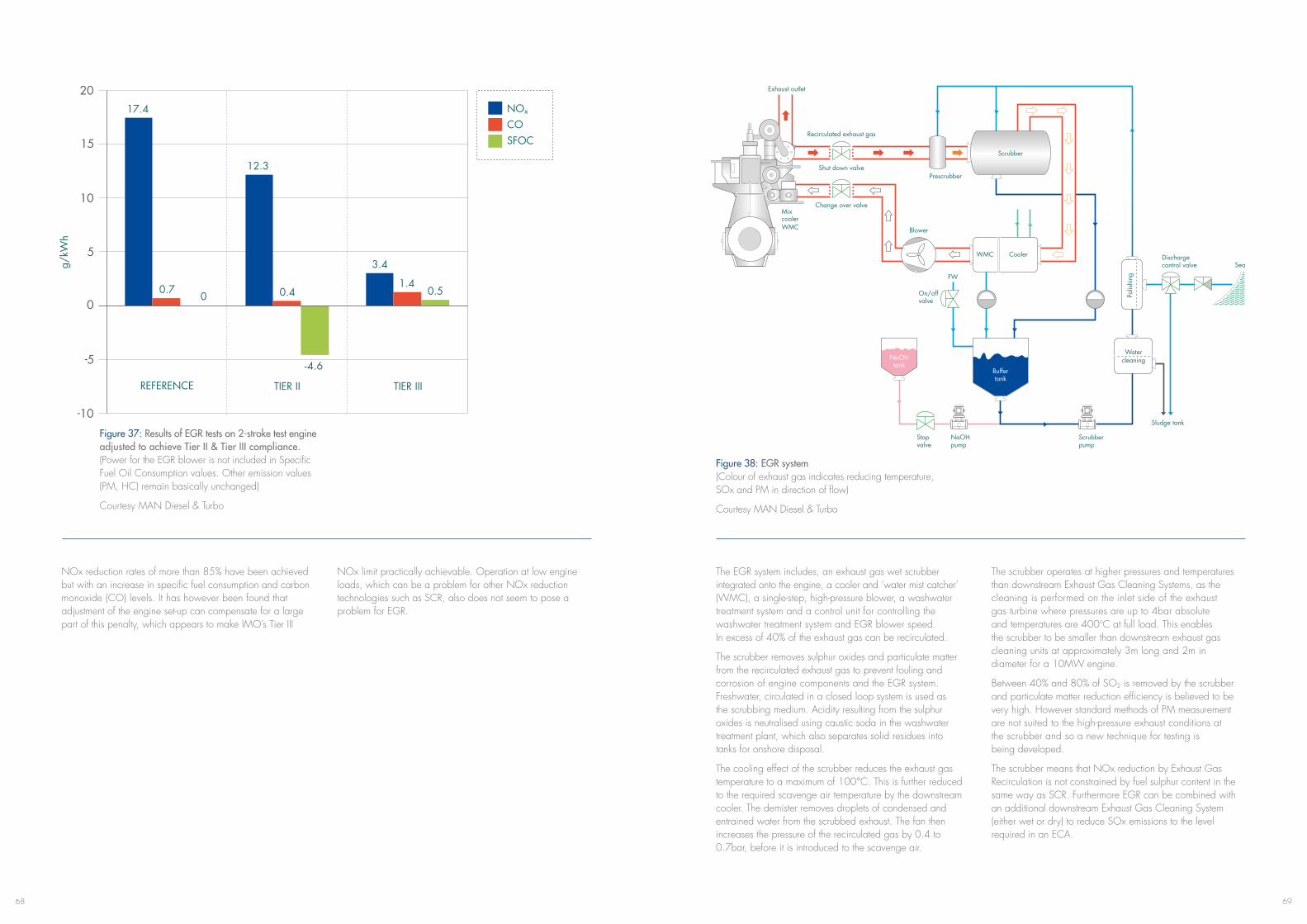
6968
Figure 37: Results of EGR tests on 2-stroke test engine adjusted to achieve Tier II & Tier III compliance. (Power for the EGR blower is not included in Specific Fuel Oil Consumption values. Other emission values (PM, HC) remain basically unchanged)
Courtesy MAN Diesel & Turbo
NOx reduction rates of more than 85% have been achieved but with an increase in specific fuel consumption and carbon monoxide (CO) levels. It has however been found that adjustment of the engine set-up can compensate for a large part of this penalty, which appears to make IMO’s Tier III
NOx limit practically achievable. Operation at low engine loads, which can be a problem for other NOx reduction technologies such as SCR, also does not seem to pose a problem for EGR.
NOx
COSFOC
REFERENCE TIER II TIER III
17.4
0.70
12.3
3.4
1.40.50.4
-4.6
Figure 38: EGR system (Colour of exhaust gas indicates reducing temperature, SOx and PM in direction of flow)
Courtesy MAN Diesel & Turbo
The EGR system includes, an exhaust gas wet scrubber integrated onto the engine, a cooler and ‘water mist catcher’ (WMC), a single-step, high-pressure blower, a washwater treatment system and a control unit for controlling the washwater treatment system and EGR blower speed. In excess of 40% of the exhaust gas can be recirculated.
The scrubber removes sulphur oxides and particulate matter from the recirculated exhaust gas to prevent fouling and corrosion of engine components and the EGR system. Freshwater, circulated in a closed loop system is used as the scrubbing medium. Acidity resulting from the sulphur oxides is neutralised using caustic soda in the washwater treatment plant, which also separates solid residues into tanks for onshore disposal.
The cooling effect of the scrubber reduces the exhaust gas temperaturetoamaximumof100°C.Thisisfurtherreducedto the required scavenge air temperature by the downstream cooler. The demister removes droplets of condensed and entrained water from the scrubbed exhaust. The fan then increases the pressure of the recirculated gas by 0.4 to 0.7bar, before it is introduced to the scavenge air.
The scrubber operates at higher pressures and temperatures than downstream Exhaust Gas Cleaning Systems, as the cleaning is performed on the inlet side of the exhaust gas turbine where pressures are up to 4bar absolute and temperatures are 400oC at full load. This enables the scrubber to be smaller than downstream exhaust gas cleaning units at approximately 3m long and 2m in diameter for a 10MW engine.
Between 40% and 80% of SO2 is removed by the scrubber and particulate matter reduction efficiency is believed to be very high. However standard methods of PM measurement are not suited to the high-pressure exhaust conditions at the scrubber and so a new technique for testing is being developed.
The scrubber means that NOx reduction by Exhaust Gas Recirculation is not constrained by fuel sulphur content in the same way as SCR. Furthermore EGR can be combined with an additional downstream Exhaust Gas Cleaning System (either wet or dry) to reduce SOx emissions to the level required in an ECA.
Exhaust outlet
Mix cooler WMC
Change over valve
Shut down valvePrescrubber
Scrubber
Blower
WMC Cooler
NaOH tank
Water cleaning
Buffer tank
FW
On/off valve
Stopvalve
NaOHpump
Scrubberpump
Discharge control valve Sea
Sludge tank
Recirculated exhaust gas
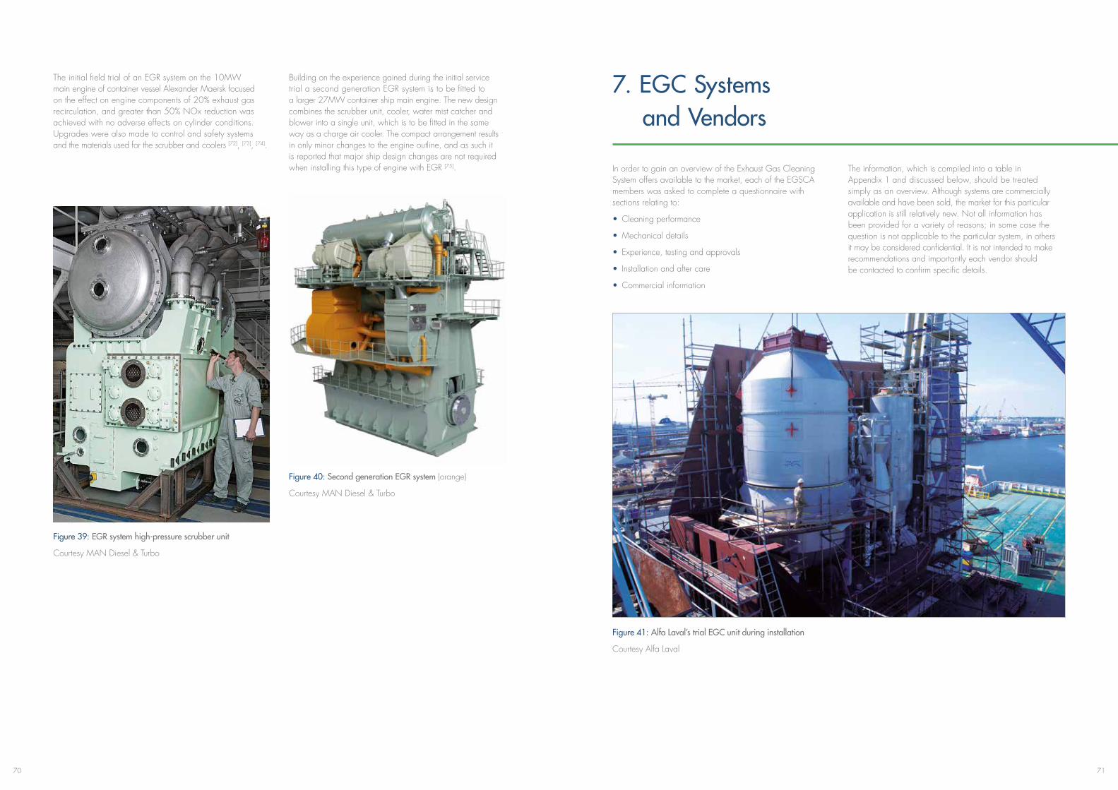
7170
The initial field trial of an EGR system on the 10MW main engine of container vessel Alexander Maersk focused on the effect on engine components of 20% exhaust gas recirculation, and greater than 50% NOx reduction was achieved with no adverse effects on cylinder conditions. Upgrades were also made to control and safety systems and the materials used for the scrubber and coolers [72], [73], [74].
Building on the experience gained during the initial service trial a second generation EGR system is to be fitted to a larger 27MW container ship main engine. The new design combines the scrubber unit, cooler, water mist catcher and blower into a single unit, which is to be fitted in the same way as a charge air cooler. The compact arrangement results in only minor changes to the engine outline, and as such it is reported that major ship design changes are not required when installing this type of engine with EGR [75].
Figure 40: Second generation EGR system (orange)
Courtesy MAN Diesel & Turbo
Figure 39: EGR system high-pressure scrubber unit
Courtesy MAN Diesel & Turbo
7. EGC Systems and Vendors
In order to gain an overview of the Exhaust Gas Cleaning System offers available to the market, each of the EGSCA members was asked to complete a questionnaire with sections relating to:
• Cleaning performance
• Mechanical details
• Experience, testing and approvals
• Installation and after care
• Commercial information
The information, which is compiled into a table in Appendix 1 and discussed below, should be treated simply as an overview. Although systems are commercially available and have been sold, the market for this particular application is still relatively new. Not all information has been provided for a variety of reasons; in some case the question is not applicable to the particular system, in others it may be considered confidential. It is not intended to make recommendations and importantly each vendor should be contacted to confirm specific details.
Figure 41: Alfa Laval’s trial EGC unit during installation
Courtesy Alfa Laval
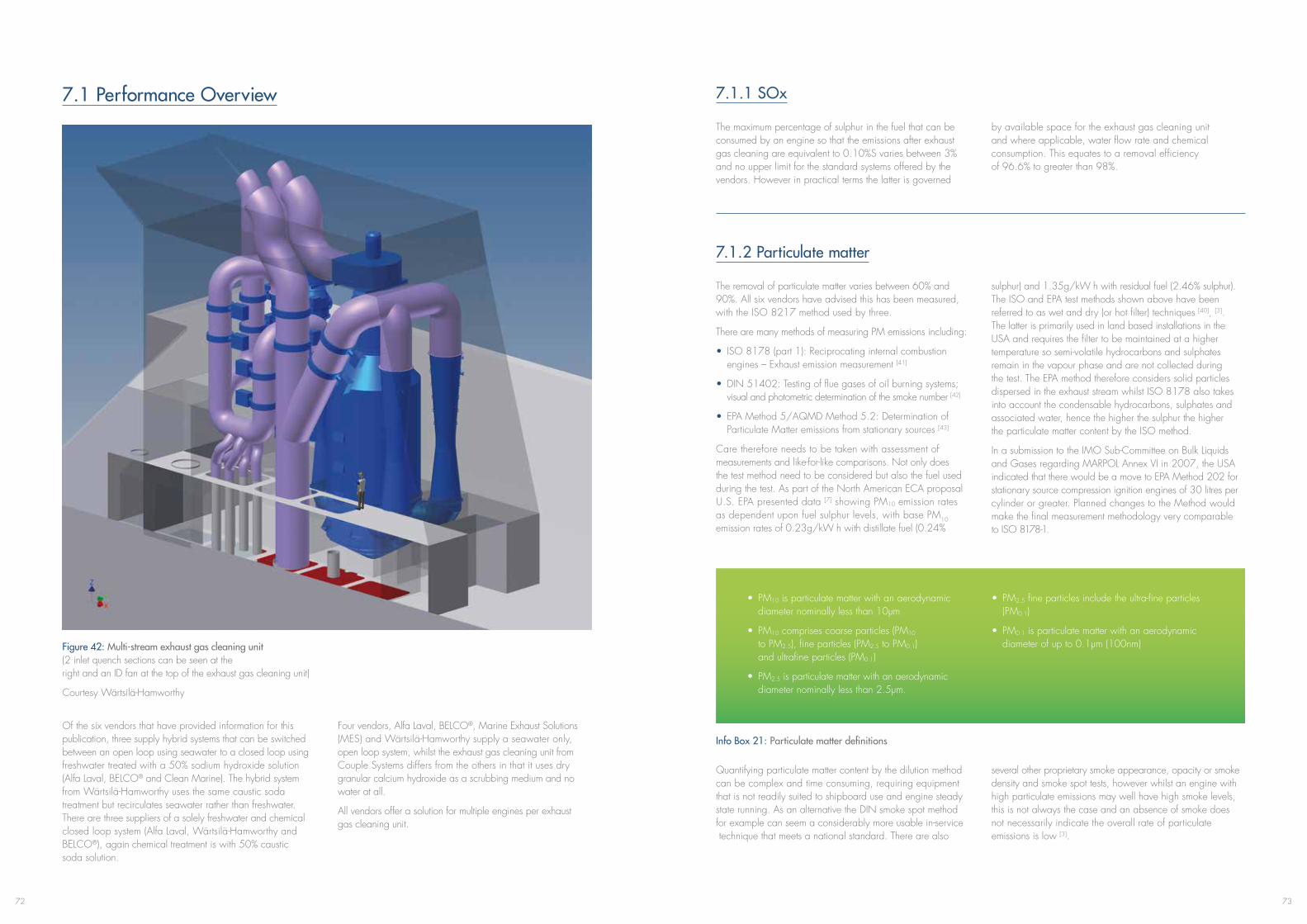
7372
7.1 Performance Overview
Of the six vendors that have provided information for this publication, three supply hybrid systems that can be switched between an open loop using seawater to a closed loop using freshwater treated with a 50% sodium hydroxide solution (Alfa Laval, BELCO® and Clean Marine). The hybrid system from Wärtsilä-Hamworthy uses the same caustic soda treatment but recirculates seawater rather than freshwater. There are three suppliers of a solely freshwater and chemical closed loop system (Alfa Laval, Wärtsilä-Hamworthy and BELCO®), again chemical treatment is with 50% caustic soda solution.
Four vendors, Alfa Laval, BELCO®, Marine Exhaust Solutions (MES) and Wärtsilä-Hamworthy supply a seawater only, open loop system, whilst the exhaust gas cleaning unit from Couple Systems differs from the others in that it uses dry granular calcium hydroxide as a scrubbing medium and no water at all.
All vendors offer a solution for multiple engines per exhaust gas cleaning unit.
Figure 42: Multi-stream exhaust gas cleaning unit (2 inlet quench sections can be seen at the right and an ID fan at the top of the exhaust gas cleaning unit)
Courtesy Wärtsilä-Hamworthy
7.1.1 SOx
The maximum percentage of sulphur in the fuel that can be consumed by an engine so that the emissions after exhaust gas cleaning are equivalent to 0.10%S varies between 3% and no upper limit for the standard systems offered by the vendors. However in practical terms the latter is governed
by available space for the exhaust gas cleaning unit and where applicable, water flow rate and chemical consumption. This equates to a removal efficiency of 96.6% to greater than 98%.
7.1.2 Particulate matter
The removal of particulate matter varies between 60% and 90%. All six vendors have advised this has been measured, with the ISO 8217 method used by three.
There are many methods of measuring PM emissions including:
• ISO 8178 (part 1): Reciprocating internal combustion engines – Exhaust emission measurement [41]
• DIN 51402: Testing of flue gases of oil burning systems; visual and photometric determination of the smoke number [42]
• EPA Method 5/AQMD Method 5.2: Determination of Particulate Matter emissions from stationary sources [43]
Care therefore needs to be taken with assessment of measurements and like-for-like comparisons. Not only does the test method need to be considered but also the fuel used during the test. As part of the North American ECA proposal U.S. EPA presented data [7] showing PM10 emission rates as dependent upon fuel sulphur levels, with base PM10 emission rates of 0.23g/kW h with distillate fuel (0.24%
sulphur) and 1.35g/kW h with residual fuel (2.46% sulphur). The ISO and EPA test methods shown above have been referred to as wet and dry (or hot filter) techniques [40], [3]. The latter is primarily used in land based installations in the USA and requires the filter to be maintained at a higher temperature so semi-volatile hydrocarbons and sulphates remain in the vapour phase and are not collected during the test. The EPA method therefore considers solid particles dispersed in the exhaust stream whilst ISO 8178 also takes into account the condensable hydrocarbons, sulphates and associated water, hence the higher the sulphur the higher the particulate matter content by the ISO method.
In a submission to the IMO Sub-Committee on Bulk Liquids and Gases regarding MARPOL Annex VI in 2007, the USA indicated that there would be a move to EPA Method 202 for stationary source compression ignition engines of 30 litres per cylinder or greater. Planned changes to the Method would make the final measurement methodology very comparable to ISO 8178-1.
• PM10 is particulate matter with an aerodynamic diameter nominally less than 10μm
• PM10 comprises coarse particles (PM10 to PM2.5), fine particles (PM2.5 to PM0.1) and ultrafine particles (PM0.1)
• PM2.5 is particulate matter with an aerodynamic diameter nominally less than 2.5μm.
• PM2.5 fine particles include the ultra-fine particles (PM0.1)
• PM0.1 is particulate matter with an aerodynamic diameterofupto0.1µm(100nm)
Info Box 21: Particulate matter definitions
Quantifying particulate matter content by the dilution method can be complex and time consuming, requiring equipment that is not readily suited to shipboard use and engine steady state running. As an alternative the DIN smoke spot method for example can seem a considerably more usable in-service technique that meets a national standard. There are also
several other proprietary smoke appearance, opacity or smoke density and smoke spot tests, however whilst an engine with high particulate emissions may well have high smoke levels, this is not always the case and an absence of smoke does not necessarily indicate the overall rate of particulate emissions is low [3].
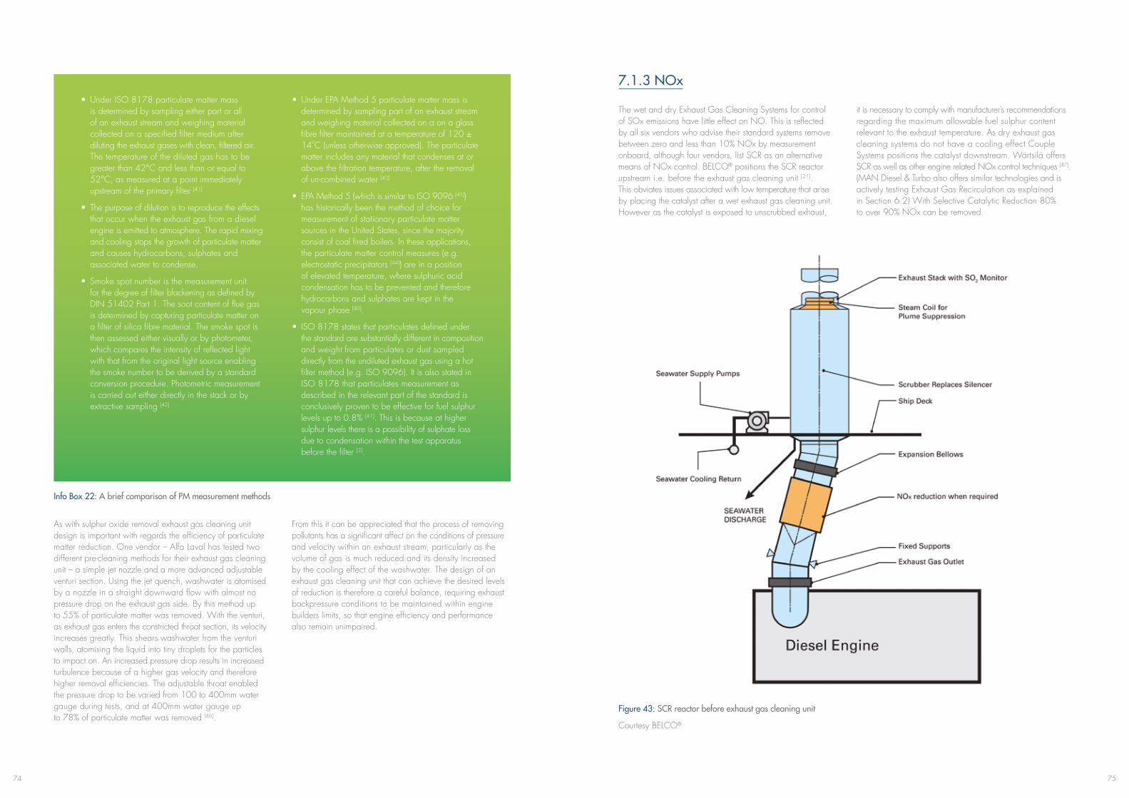
7574
• UnderISO8178particulatemattermass is determined by sampling either part or all of an exhaust stream and weighing material collected on a specified filter medium after diluting the exhaust gases with clean, filtered air. The temperature of the diluted gas has to be greaterthan42°Candlessthanorequalto 52°C,asmeasuredatapointimmediately upstream of the primary filter [41]
• Thepurposeofdilutionistoreproducetheeffects that occur when the exhaust gas from a diesel engine is emitted to atmosphere. The rapid mixing and cooling stops the growth of particulate matter and causes hydrocarbons, sulphates and associated water to condense.
• Smokespotnumberisthemeasurementunit for the degree of filter blackening as defined by DIN 51402 Part 1. The soot content of flue gas is determined by capturing particulate matter on a filter of silica fibre material. The smoke spot is then assessed either visually or by photometer, which compares the intensity of reflected light with that from the original light source enabling the smoke number to be derived by a standard conversion procedure. Photometric measurement is carried out either directly in the stack or by extractive sampling [42]
• UnderEPAMethod5particulatemattermassis determined by sampling part of an exhaust stream and weighing material collected on a on a glass fibre filter maintained at a temperature of 120 ± 14oC (unless otherwise approved). The particulate matter includes any material that condenses at or above the filtration temperature, after the removal of un-combined water [43]
• EPAMethod5(whichissimilartoISO9096[45]) has historically been the method of choice for measurement of stationary particulate matter sources in the United States, since the majority consist of coal fired boilers. In these applications, the particulate matter control measures (e.g. electrostatic precipitators [44]) are in a position of elevated temperature, where sulphuric acid condensation has to be prevented and therefore hydrocarbons and sulphates are kept in the vapour phase [40].
• ISO8178statesthatparticulatesdefinedunder the standard are substantially different in composition and weight from particulates or dust sampled directly from the undiluted exhaust gas using a hot filter method (e.g. ISO 9096). It is also stated in ISO 8178 that particulates measurement as described in the relevant part of the standard is conclusively proven to be effective for fuel sulphur levels up to 0.8% [41]. This is because at higher sulphur levels there is a possibility of sulphate loss due to condensation within the test apparatus before the filter [3].
Info Box 22: A brief comparison of PM measurement methods
As with sulphur oxide removal exhaust gas cleaning unit design is important with regards the efficiency of particulate matter reduction. One vendor – Alfa Laval has tested two different pre-cleaning methods for their exhaust gas cleaning unit – a simple jet nozzle and a more advanced adjustable venturi section. Using the jet quench, washwater is atomised by a nozzle in a straight downward flow with almost no pressure drop on the exhaust gas side. By this method up to 55% of particulate matter was removed. With the venturi, as exhaust gas enters the constricted throat section, its velocity increases greatly. This shears washwater from the venturi walls, atomising the liquid into tiny droplets for the particles to impact on. An increased pressure drop results in increased turbulence because of a higher gas velocity and therefore higher removal efficiencies. The adjustable throat enabled the pressure drop to be varied from 100 to 400mm water gauge during tests, and at 400mm water gauge up to 78% of particulate matter was removed [46].
From this it can be appreciated that the process of removing pollutants has a significant affect on the conditions of pressure and velocity within an exhaust stream, particularly as the volume of gas is much reduced and its density increased by the cooling effect of the washwater. The design of an exhaust gas cleaning unit that can achieve the desired levels of reduction is therefore a careful balance, requiring exhaust backpressure conditions to be maintained within engine builders limits, so that engine efficiency and performance also remain unimpaired.
7.1.3 NOx
The wet and dry Exhaust Gas Cleaning Systems for control of SOx emissions have little effect on NO. This is reflected by all six vendors who advise their standard systems remove between zero and less than 10% NOx by measurement onboard, although four vendors, list SCR as an alternative means of NOx control. BELCO® positions the SCR reactor upstream i.e. before the exhaust gas cleaning unit [21]. This obviates issues associated with low temperature that arise by placing the catalyst after a wet exhaust gas cleaning unit. However as the catalyst is exposed to unscrubbed exhaust,
it is necessary to comply with manufacturer’s recommendations regarding the maximum allowable fuel sulphur content relevant to the exhaust temperature. As dry exhaust gas cleaning systems do not have a cooling effect Couple Systems positions the catalyst downstream. Wärtsilä offers SCR as well as other engine related NOx control techniques [47]. (MAN Diesel & Turbo also offers similar technologies and is actively testing Exhaust Gas Recirculation as explained in Section 6.2) With Selective Catalytic Reduction 80% to over 90% NOx can be removed.
Figure 43: SCR reactor before exhaust gas cleaning unit
Courtesy BELCO®
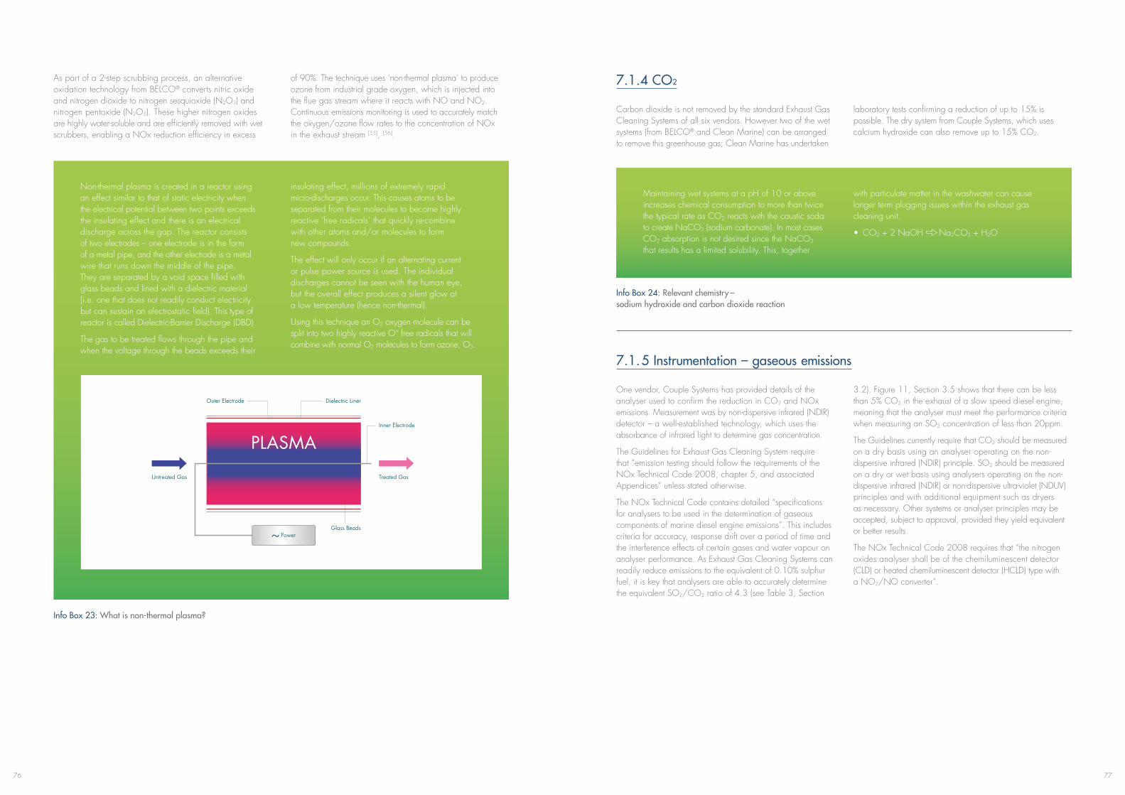
7776
As part of a 2-step scrubbing process, an alternative oxidation technology from BELCO® converts nitric oxide and nitrogen dioxide to nitrogen sesquioxide (N2O3) and nitrogen pentoxide (N2O5). These higher nitrogen oxides are highly water-soluble and are efficiently removed with wet scrubbers, enabling a NOx reduction efficiency in excess
of 90%. The technique uses ‘non-thermal plasma’ to produce ozone from industrial grade oxygen, which is injected into the flue gas stream where it reacts with NO and NO2. Continuous emissions monitoring is used to accurately match the oxygen/ozone flow rates to the concentration of NOx in the exhaust stream [55], [56].
Non-thermal plasma is created in a reactor using an effect similar to that of static electricity when the electrical potential between two points exceeds the insulating effect and there is an electrical discharge across the gap. The reactor consists of two electrodes – one electrode is in the form of a metal pipe, and the other electrode is a metal wire that runs down the middle of the pipe. They are separated by a void space filled with glass beads and lined with a dielectric material (i.e. one that does not readily conduct electricity but can sustain an electrostatic field). This type of reactor is called Dielectric-Barrier Discharge (DBD).
The gas to be treated flows through the pipe and when the voltage through the beads exceeds their
insulating effect, millions of extremely rapid micro-discharges occur. This causes atoms to be separated from their molecules to become highly reactive ‘free radicals’ that quickly re-combine with other atoms and/or molecules to form new compounds.
The effect will only occur if an alternating current or pulse power source is used. The individual discharges cannot be seen with the human eye, but the overall effect produces a silent glow at a low temperature (hence non-thermal).
Using this technique an O2 oxygen molecule can be split into two highly reactive O+ free radicals that will combine with normal O2 molecules to form ozone, O3.
Info Box 23: What is non-thermal plasma?
PLASMA
Outer Electrode Dielectric Liner
Untreated Gas Treated Gas
Inner Electrode
Glass Beads
7.1.4 CO2
Carbon dioxide is not removed by the standard Exhaust Gas Cleaning Systems of all six vendors. However two of the wet systems (from BELCO® and Clean Marine) can be arranged to remove this greenhouse gas; Clean Marine has undertaken
laboratory tests confirming a reduction of up to 15% is possible. The dry system from Couple Systems, which uses calcium hydroxide can also remove up to 15% CO2.
Maintaining wet systems at a pH of 10 or above increases chemical consumption to more than twice the typical rate as CO2 reacts with the caustic soda to create NaCO3 (sodium carbonate). In most cases CO2 absorption is not desired since the NaCO3 that results has a limited solubility. This, together
with particulate matter in the washwater can cause longer term plugging issues within the exhaust gas cleaning unit.
• CO2 + 2 NaOH Na2CO3 + H2O
Info Box 24: Relevant chemistry – sodium hydroxide and carbon dioxide reaction
7.1.5 Instrumentation – gaseous emissions
One vendor, Couple Systems has provided details of the analyser used to confirm the reduction in CO2 and NOx emissions. Measurement was by non-dispersive infrared (NDIR) detector – a well-established technology, which uses the absorbance of infrared light to determine gas concentration.
The Guidelines for Exhaust Gas Cleaning System require that “emission testing should follow the requirements of the NOx Technical Code 2008, chapter 5, and associated Appendices” unless stated otherwise.
The NOx Technical Code contains detailed “specifications for analysers to be used in the determination of gaseous components of marine diesel engine emissions”. This includes criteria for accuracy, response drift over a period of time and the interference effects of certain gases and water vapour on analyser performance. As Exhaust Gas Cleaning Systems can readily reduce emissions to the equivalent of 0.10% sulphur fuel, it is key that analysers are able to accurately determine the equivalent SO2/CO2 ratio of 4.3 (see Table 3, Section
3.2). Figure 11, Section 3.5 shows that there can be less than 5% CO2 in the exhaust of a slow speed diesel engine, meaning that the analyser must meet the performance criteria when measuring an SO2 concentration of less than 20ppm.
The Guidelines currently require that CO2 should be measured on a dry basis using an analyser operating on the non-dispersive infrared (NDIR) principle. SO2 should be measured on a dry or wet basis using analysers operating on the non-dispersive infrared (NDIR) or non-dispersive ultra-violet (NDUV) principles and with additional equipment such as dryers as necessary. Other systems or analyser principles may be accepted, subject to approval, provided they yield equivalent or better results.
The NOx Technical Code 2008 requires that “the nitrogen oxides analyser shall be of the chemiluminescent detector (CLD) or heated chemiluminescent detector (HCLD) type with a NO2/NO converter”.
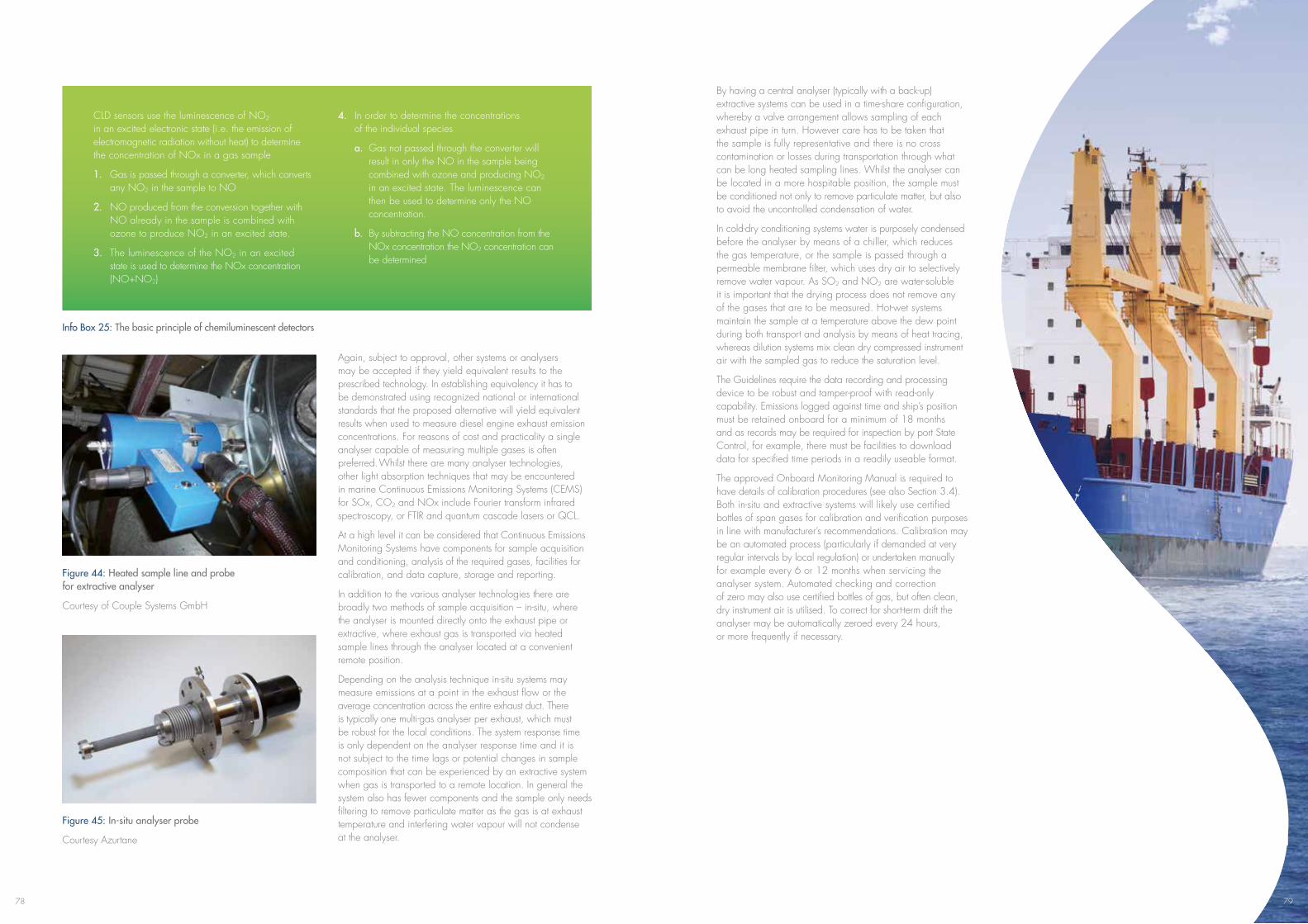
78
CLD sensors use the luminescence of NO2 in an excited electronic state (i.e. the emission of electromagnetic radiation without heat) to determine the concentration of NOx in a gas sample
1. Gas is passed through a converter, which converts any NO2 in the sample to NO
2. NO produced from the conversion together with NO already in the sample is combined with ozone to produce NO2 in an excited state.
3. The luminescence of the NO2 in an excited state is used to determine the NOx concentration (NO+NO2)
4. In order to determine the concentrations of the individual species
a. Gas not passed through the converter will result in only the NO in the sample being combined with ozone and producing NO2 in an excited state. The luminescence can then be used to determine only the NO concentration.
b. By subtracting the NO concentration from the NOx concentration the NO2 concentration can be determined
Info Box 25: The basic principle of chemiluminescent detectors
Again, subject to approval, other systems or analysers may be accepted if they yield equivalent results to the prescribed technology. In establishing equivalency it has to be demonstrated using recognized national or international standards that the proposed alternative will yield equivalent results when used to measure diesel engine exhaust emission concentrations. For reasons of cost and practicality a single analyser capable of measuring multiple gases is often preferred. Whilst there are many analyser technologies, other light absorption techniques that may be encountered in marine Continuous Emissions Monitoring Systems (CEMS) for SOx, CO2 and NOx include Fourier transform infrared spectroscopy, or FTIR and quantum cascade lasers or QCL.
At a high level it can be considered that Continuous Emissions Monitoring Systems have components for sample acquisition and conditioning, analysis of the required gases, facilities for calibration, and data capture, storage and reporting.
In addition to the various analyser technologies there are broadly two methods of sample acquisition – in-situ, where the analyser is mounted directly onto the exhaust pipe or extractive, where exhaust gas is transported via heated sample lines through the analyser located at a convenient remote position.
Depending on the analysis technique in-situ systems may measure emissions at a point in the exhaust flow or the average concentration across the entire exhaust duct. There is typically one multi-gas analyser per exhaust, which must be robust for the local conditions. The system response time is only dependent on the analyser response time and it is not subject to the time lags or potential changes in sample composition that can be experienced by an extractive system when gas is transported to a remote location. In general the system also has fewer components and the sample only needs filtering to remove particulate matter as the gas is at exhaust temperature and interfering water vapour will not condense at the analyser.
Figure 44: Heated sample line and probe for extractive analyser
Courtesy of Couple Systems GmbH
Figure 45: In-situ analyser probe
Courtesy Azurtane
By having a central analyser (typically with a back-up) extractive systems can be used in a time-share configuration, whereby a valve arrangement allows sampling of each exhaust pipe in turn. However care has to be taken that the sample is fully representative and there is no cross contamination or losses during transportation through what can be long heated sampling lines. Whilst the analyser can be located in a more hospitable position, the sample must be conditioned not only to remove particulate matter, but also to avoid the uncontrolled condensation of water.
In cold-dry conditioning systems water is purposely condensed before the analyser by means of a chiller, which reduces the gas temperature, or the sample is passed through a permeable membrane filter, which uses dry air to selectively remove water vapour. As SO2 and NO2 are water-soluble it is important that the drying process does not remove any of the gases that are to be measured. Hot-wet systems maintain the sample at a temperature above the dew point during both transport and analysis by means of heat tracing, whereas dilution systems mix clean dry compressed instrument air with the sampled gas to reduce the saturation level.
The Guidelines require the data recording and processing device to be robust and tamper-proof with read-only capability. Emissions logged against time and ship’s position must be retained onboard for a minimum of 18 months and as records may be required for inspection by port State Control, for example, there must be facilities to download data for specified time periods in a readily useable format.
The approved Onboard Monitoring Manual is required to have details of calibration procedures (see also Section 3.4). Both in-situ and extractive systems will likely use certified bottles of span gases for calibration and verification purposes in line with manufacturer’s recommendations. Calibration may be an automated process (particularly if demanded at very regular intervals by local regulation) or undertaken manually for example every 6 or 12 months when servicing the analyser system. Automated checking and correction of zero may also use certified bottles of gas, but often clean, dry instrument air is utilised. To correct for short-term drift the analyser may be automatically zeroed every 24 hours, or more frequently if necessary.
79
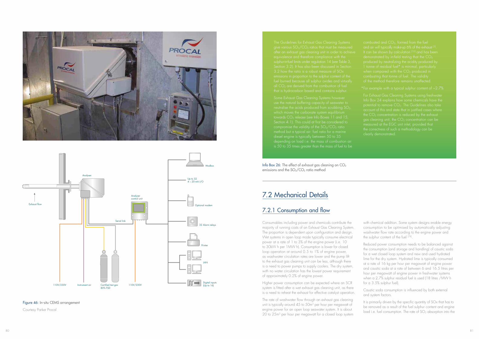
8180
Figure 46: In-situ CEMS arrangement
Courtesy Parker Procal
Exhaust flow
Modbus
Up to 324 – 20 mA I/O
Optional modem
32 Alarm relays
Printer
LAN
Digital inputs(Up to 16)
Serial link
Analyser control unit
Analyser
Certified test gas 80% FSD
110V/230V 110V/230VInstrument air
The Guidelines for Exhaust Gas Cleaning Systems give various SO2/CO2 ratios that must be measured after an exhaust gas cleaning unit in order to achieve equivalence and therefore compliance with the sulphur-in-fuel limits under regulation 14 (see Table 3, Section 3.2). It has also been discussed in Section 3.2 how the ratio is a robust measure of SOx emissions in proportion to the sulphur content of the fuel burned because all sulphur oxides and virtually all CO2 are derived from the combustion of fuel that is hydrocarbon based and contains sulphur.
Some Exhaust Gas Cleaning Systems however use the natural buffering capacity of seawater to neutralise the acids produced from scrubbing SO2, which moves the carbonate system equilibrium towards CO2 release (see Info Boxes 11 and 15, Section 4.1). This could at first be considered to compromise the validity of the SO2/CO2 ratio method but a typical air: fuel ratio for a marine diesel engine is typically between 50 to 35 depending on load i.e. the mass of combustion air is 50 to 35 times greater than the mass of fuel to be
combusted and CO2, formed from the fuel and air will typically make-up 6% of the exhaust [3]. It can be shown by calculation [12] and has been demonstrated by in-field testing that the CO2 produced by neutralizing the acidity produced by 1 tonne of residual fuel* is minimal, particularly when compared with the CO2 produced in combusting that tonne of fuel. The validity of the method therefore remains unaffected.
*For example with a typical sulphur content of ~2.7%
For Exhaust Gas Cleaning Systems using freshwater Info Box 24 explains how some chemicals have the potential to remove CO2. The Guidelines also take account of this and state that in justified cases where the CO2 concentration is reduced by the exhaust gas cleaning unit, the CO2 concentration can be measured at the EGC unit inlet, provided that the correctness of such a methodology can be clearly demonstrated.
Info Box 26: The effect of exhaust gas cleaning on CO2 emissions and the SO2/CO2 ratio method
7.2 Mechanical Details
7.2.1 Consumption and flow
Consumables including power and chemicals contribute the majority of running costs of an Exhaust Gas Cleaning System. The proportion is dependent upon configuration and design. Wet systems in open loop mode typically consume electrical power at a rate of 1 to 3% of the engine power (i.e. 10 to 30kW h per 1MW h). Consumption is lower for closed loop operation at around 0.5 to 1% of engine power, as washwater circulation rates are lower and the pump lift to the exhaust gas cleaning unit can be less, although there is a need to power pumps to supply coolers. The dry system, with no water circulation has the lowest power requirement of approximately 0.2% of engine power.
Higher power consumption can be expected where an SCR system is fitted after a wet exhaust gas cleaning unit, as there is a need to reheat the exhaust for effective catalyst operation.
The rate of washwater flow through an exhaust gas cleaning unit is typically around 45 to 50m3 per hour per megawatt of engine power for an open loop seawater system. It is about 20 to 25m3 per hour per megawatt for a closed loop system
with chemical addition. Some system designs enable energy consumption to be optimised by automatically adjusting washwater flow rate according to the engine power and the sulphur content of the fuel [78].
Reduced power consumption needs to be balanced against the consumption (and storage and handling) of caustic soda for a wet closed loop system and new and used hydrated lime for the dry system. Hydrated lime is typically consumed at a rate of 16 kg per hour per megawatt of engine power and caustic soda at a rate of between 6 and 16.5 litres per hour per megawatt of engine power in freshwater systems when a 2.7% sulphur residual fuel is used (18 litres /MW h for a 3.5% sulphur fuel).
Caustic soda consumption is influenced by both external and system factors.
It is primarily driven by the specific quantity of SOx that has to be removed as a result of the fuel sulphur content and engine load i.e. fuel consumption. The rate of SO2 absorption into the
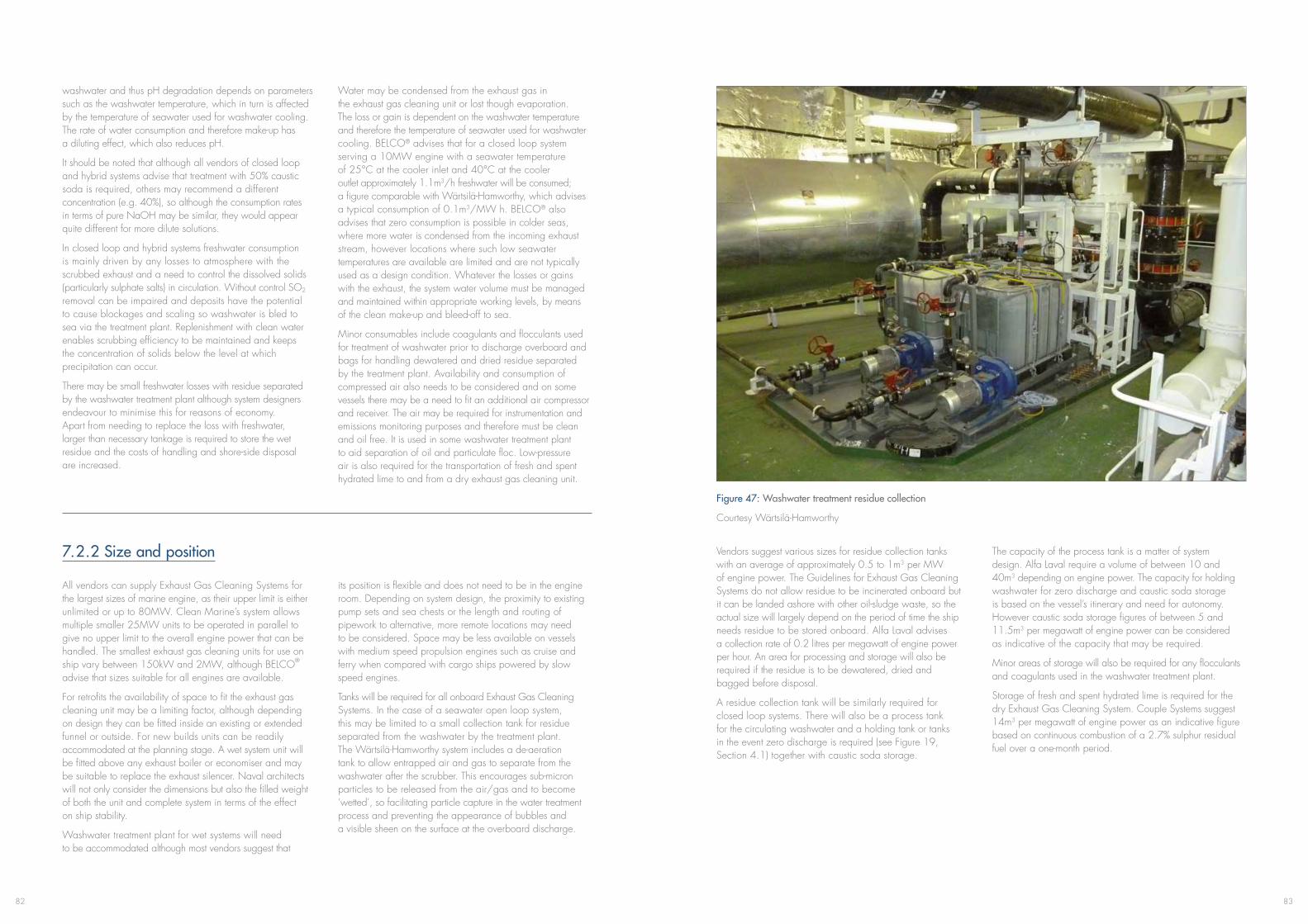
8382
washwater and thus pH degradation depends on parameters such as the washwater temperature, which in turn is affected by the temperature of seawater used for washwater cooling. The rate of water consumption and therefore make-up has a diluting effect, which also reduces pH.
It should be noted that although all vendors of closed loop and hybrid systems advise that treatment with 50% caustic soda is required, others may recommend a different concentration (e.g. 40%), so although the consumption rates in terms of pure NaOH may be similar, they would appear quite different for more dilute solutions.
In closed loop and hybrid systems freshwater consumption is mainly driven by any losses to atmosphere with the scrubbed exhaust and a need to control the dissolved solids (particularly sulphate salts) in circulation. Without control SO2
removal can be impaired and deposits have the potential to cause blockages and scaling so washwater is bled to sea via the treatment plant. Replenishment with clean water enables scrubbing efficiency to be maintained and keeps the concentration of solids below the level at which precipitation can occur.
There may be small freshwater losses with residue separated by the washwater treatment plant although system designers endeavour to minimise this for reasons of economy. Apart from needing to replace the loss with freshwater, larger than necessary tankage is required to store the wet residue and the costs of handling and shore-side disposal are increased.
Water may be condensed from the exhaust gas in the exhaust gas cleaning unit or lost though evaporation. The loss or gain is dependent on the washwater temperature and therefore the temperature of seawater used for washwater cooling. BELCO® advises that for a closed loop system serving a 10MW engine with a seawater temperature of25°Catthecoolerinletand40°Catthecooler outlet approximately 1.1m3/h freshwater will be consumed; a figure comparable with Wärtsilä-Hamworthy, which advises a typical consumption of 0.1m3/MW h. BELCO® also advises that zero consumption is possible in colder seas, where more water is condensed from the incoming exhaust stream, however locations where such low seawater temperatures are available are limited and are not typically used as a design condition. Whatever the losses or gains with the exhaust, the system water volume must be managed and maintained within appropriate working levels, by means of the clean make-up and bleed-off to sea.
Minor consumables include coagulants and flocculants used for treatment of washwater prior to discharge overboard and bags for handling dewatered and dried residue separated by the treatment plant. Availability and consumption of compressed air also needs to be considered and on some vessels there may be a need to fit an additional air compressor and receiver. The air may be required for instrumentation and emissions monitoring purposes and therefore must be clean and oil free. It is used in some washwater treatment plant to aid separation of oil and particulate floc. Low-pressure air is also required for the transportation of fresh and spent hydrated lime to and from a dry exhaust gas cleaning unit.
7.2.2 Size and position
All vendors can supply Exhaust Gas Cleaning Systems for the largest sizes of marine engine, as their upper limit is either unlimited or up to 80MW. Clean Marine’s system allows multiple smaller 25MW units to be operated in parallel to give no upper limit to the overall engine power that can be handled. The smallest exhaust gas cleaning units for use on ship vary between 150kW and 2MW, although BELCO® advise that sizes suitable for all engines are available.
For retrofits the availability of space to fit the exhaust gas cleaning unit may be a limiting factor, although depending on design they can be fitted inside an existing or extended funnel or outside. For new builds units can be readily accommodated at the planning stage. A wet system unit will be fitted above any exhaust boiler or economiser and may be suitable to replace the exhaust silencer. Naval architects will not only consider the dimensions but also the filled weight of both the unit and complete system in terms of the effect on ship stability.
Washwater treatment plant for wet systems will need to be accommodated although most vendors suggest that
its position is flexible and does not need to be in the engine room. Depending on system design, the proximity to existing pump sets and sea chests or the length and routing of pipework to alternative, more remote locations may need to be considered. Space may be less available on vessels with medium speed propulsion engines such as cruise and ferry when compared with cargo ships powered by slow speed engines.
Tanks will be required for all onboard Exhaust Gas Cleaning Systems. In the case of a seawater open loop system, this may be limited to a small collection tank for residue separated from the washwater by the treatment plant. The Wärtsilä-Hamworthy system includes a de-aeration tank to allow entrapped air and gas to separate from the washwater after the scrubber. This encourages sub-micron particles to be released from the air/gas and to become ‘wetted’, so facilitating particle capture in the water treatment process and preventing the appearance of bubbles and a visible sheen on the surface at the overboard discharge.
Figure 47: Washwater treatment residue collection
Courtesy Wärtsilä-Hamworthy
Vendors suggest various sizes for residue collection tanks with an average of approximately 0.5 to 1m3 per MW of engine power. The Guidelines for Exhaust Gas Cleaning Systems do not allow residue to be incinerated onboard but it can be landed ashore with other oil-sludge waste, so the actual size will largely depend on the period of time the ship needs residue to be stored onboard. Alfa Laval advises a collection rate of 0.2 litres per megawatt of engine power per hour. An area for processing and storage will also be required if the residue is to be dewatered, dried and bagged before disposal.
A residue collection tank will be similarly required for closed loop systems. There will also be a process tank for the circulating washwater and a holding tank or tanks in the event zero discharge is required (see Figure 19, Section 4.1) together with caustic soda storage.
The capacity of the process tank is a matter of system design. Alfa Laval require a volume of between 10 and 40m3 depending on engine power. The capacity for holding washwater for zero discharge and caustic soda storage is based on the vessel’s itinerary and need for autonomy. However caustic soda storage figures of between 5 and 11.5m3 per megawatt of engine power can be considered as indicative of the capacity that may be required.
Minor areas of storage will also be required for any flocculants and coagulants used in the washwater treatment plant.
Storage of fresh and spent hydrated lime is required for the dry Exhaust Gas Cleaning System. Couple Systems suggest 14m3 per megawatt of engine power as an indicative figure based on continuous combustion of a 2.7% sulphur residual fuel over a one-month period.
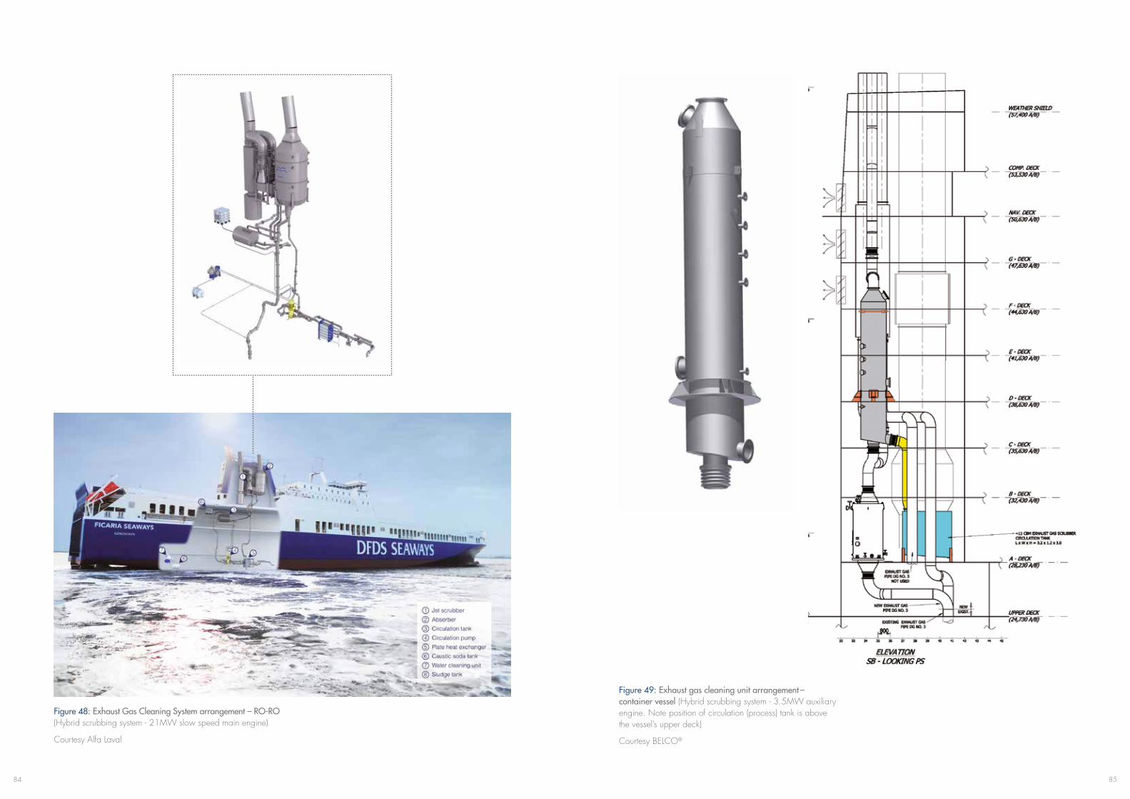
8584
Figure 48: Exhaust Gas Cleaning System arrangement – RO-RO (Hybrid scrubbing system - 21MW slow speed main engine)
Courtesy Alfa Laval
Figure 49: Exhaust gas cleaning unit arrangement – container vessel (Hybrid scrubbing system - 3.5MW auxiliary engine. Note position of circulation (process) tank is above the vessel’s upper deck)
Courtesy BELCO®
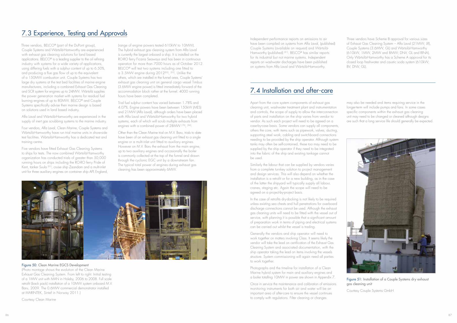
8786
7.3 Experience, Testing and Approvals
Three vendors, BELCO® (part of the DuPont group), Couple Systems and Wärtsilä-Hamworthy are experienced with exhaust gas cleaning solutions for land based applications. BELCO® is a leading supplier to the oil refining industry with systems for a wide variety of applications, using differing fuels with a sulphur content of up to 6.50%, and producing a flue gas flow of up to the equivalent of a 150MW combustion unit. Couple Systems has two large dry systems at the test bed facilities of marine engine manufacturers, including a combined Exhaust Gas Cleaning and SCR system for engines up to 24MW. Wärtsilä supplies the power generation market with systems for residual fuel burning engines of up to 80MW. BELCO® and Couple Systems specifically advise their marine design is based on solutions used in land based industry.
Alfa Laval and Wärtsilä-Hamworthy are experienced in the supply of inert gas scrubbing systems to the marine industry.
Four vendors, Alfa Laval, Clean Marine, Couple Systems and Wärtsilä-Hamworthy have run trial marine units in shore-side test facilities. Wärtsilä-Hamworthy has a dedicated test and training centre.
Five vendors have fitted Exhaust Gas Cleaning Systems to ships for tests. The now combined Wärtsilä-Hamworthy organization has conducted trials of greater than 50,000 running hours on ships including the RO-RO ferry Pride of Kent, tanker Suula [81], cruise ship Zaandam and a multi-inlet unit for three auxiliary engines on container ship APL England,
(range of engine powers tested 610kW to 10MW). The hybrid exhaust gas cleaning system from Alfa Laval is currently the largest onboard a ship. It is installed on the RO-RO ferry Ficaria Seaways and has been in continuous operation for more than 7000 hours as of October 2012. BELCO® will test two systems including one fitted to a 3.5MW engine during 2012[82], [83]. Unlike the others, which are installed in the funnel area, Couple Systems’ exhaust gas cleaning unit on general cargo vessel Timbus (3.6MW engine power) is fitted immediately forward of the accommodation block rather at the funnel. 4000 running hours have been completed.
Trial fuel sulphur content has varied between 1.78% and 4.07%. Engine powers have been between 150kW (MES) and 21MW (Alfa Laval), although orders have been placed with Alfa Laval and Wärtsilä-Hamworthy for two hybrid systems, each of which will scrub multiple exhausts from engines with a combined power of 28MW [78], [84].
Other than the Clean Marine trial on M.V. Baru, trials to date have been of an exhaust gas cleaning unit fitted to a single engine or a multi-inlet unit fitted to auxiliary engines. However on M.V. Baru the exhaust from the main engine, up to two auxiliary engines and occasionally the boiler is commonly collected at the top of the funnel and drawn through the cyclonic EGC unit by a downstream fan. The typical total power of engines during exhaust gas cleaning has been approximately 6MW.
Figure 50: Clean Marine EGCS Development (Photo montage shows the evolution of the Clean Marine Exhaust Gas Cleaning System. From left to right: Initial testing of a 1MW unit with MAN in Holeby, 2006 to 2008. Full scale retrofit (back pack) installation of a 10MW system onboard M.V. Baru, 2009. The 0.6MW commercial demonstrator installed at MARINTEK, Sintef in Norway 2011.)
Courtesy Clean Marine
Independent performance reports on emissions to air have been compiled on systems from Alfa Laval, (published) Couple Systems (available on request) and Wärtsilä-Hamworthy (published) [81]. BELCO® has similar reports for its industrial but not marine systems. Independent reports on washwater discharges have been published on systems from Alfa Laval and Wärtsilä-Hamworthy.
Three vendors have Scheme B approval for various sizes of Exhaust Gas Cleaning System – Alfa Laval (21MW; LR), Couple Systems (3.6MW, GL) and Wärtsilä-Hamworthy (610kW, 1MW, 2MW and 8MW; DNV, GL and RINA). Only Wärtsilä-Hamworthy has a Scheme A approval for its closed loop freshwater and caustic soda system (610kW; BV, DNV, GL).
7.4 Installation and after-care
Apart from the core system components of exhaust gas cleaning unit, washwater treatment plant and instrumentation and controls, the scope of supply to allow the interconnection of parts and installation on the ship varies from vendor to vendor. As such each project will need to be agreed on a case-by-case basis. Some vendors can supply all components, others the core, with items such as pipework, valves, ducting, supporting steel work, cabling and switchboard connections needing to be provided by the ship operator. Although system tanks may often be self-contained, these too may need to be supplied by the ship operator if they need to be integrated into the fabric of the ship and existing tankage cannot be used.
Similarly the labour that can be supplied by vendors varies from a complete turnkey solution to project management and design services. This will also depend on whether the installation is a retrofit or for a new building, as in the case of the latter the shipyard will typically supply all labour, cranes, staging etc. Again the scope will need to be agreed on a project-by-project basis.
In the case of retrofits dry-docking is not likely to be required unless existing sea chests and hull penetrations for overboard discharge connections cannot be used. Although the exhaust gas cleaning units will need to be fitted with the vessel out of service, with planning it is possible that a significant amount of preparation work in terms of piping and electrical systems can be carried out whilst the vessel is trading.
Generally the vendors and ship operator will need to work together on matters involving Class. It seems likely the vendor will take the lead on certification of the Exhaust Gas Cleaning System and associated documentation, with the ship operator taking the lead on items involving the vessels structure. System commissioning will again need all parties to work together.
Photographs and the timeline for installation of a Clean Marine hybrid system for main and auxiliary engines and a boiler totalling 10MW in power are shown in Appendix 7.
Once in service the maintenance and calibration of emissions monitoring instruments for both air and water will be an important area of after-care to ensure the vessel continues to comply with regulations. Filter cleaning or changes
may also be needed and items requiring service in the longer-term will include pumps and fans. In some cases specific components within the exhaust gas cleaning unit may need to be changed or cleaned although designs are such that a long service life should generally be expected.
Figure 51: Installation of a Couple Systems dry exhaust gas cleaning unit
Courtesy Couple Systems GmbH
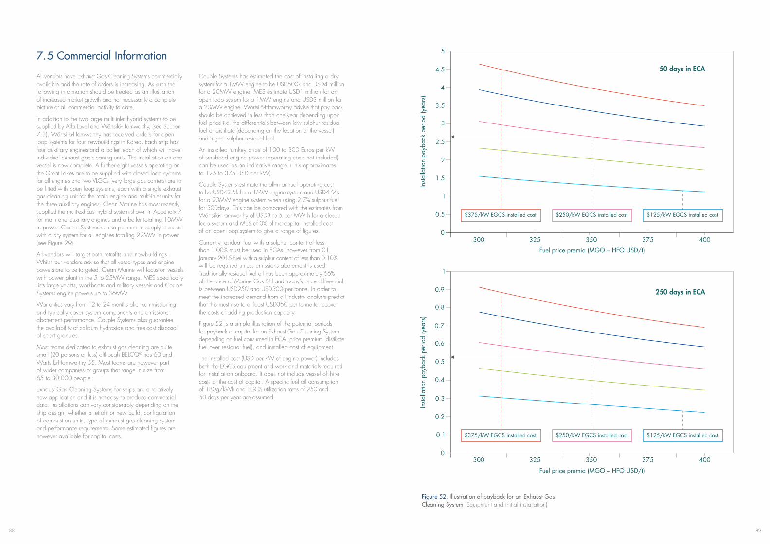
8988
7.5 Commercial Information
All vendors have Exhaust Gas Cleaning Systems commercially available and the rate of orders is increasing. As such the following information should be treated as an illustration of increased market growth and not necessarily a complete picture of all commercial activity to date.
In addition to the two large multi-inlet hybrid systems to be supplied by Alfa Laval and Wärtsilä-Hamworthy, (see Section 7.3), Wärtsilä-Hamworthy has received orders for open loop systems for four newbuildings in Korea. Each ship has four auxiliary engines and a boiler, each of which will have individual exhaust gas cleaning units. The installation on one vessel is now complete. A further eight vessels operating on the Great Lakes are to be supplied with closed loop systems for all engines and two VLGCs (very large gas carriers) are to be fitted with open loop systems, each with a single exhaust gas cleaning unit for the main engine and multi-inlet units for the three auxiliary engines. Clean Marine has most recently supplied the multi-exhaust hybrid system shown in Appendix 7 for main and auxiliary engines and a boiler totalling 10MW in power. Couple Systems is also planned to supply a vessel with a dry system for all engines totalling 22MW in power (see Figure 29).
All vendors will target both retrofits and newbuildings. Whilst four vendors advise that all vessel types and engine powers are to be targeted, Clean Marine will focus on vessels with power plant in the 5 to 25MW range. MES specifically lists large yachts, workboats and military vessels and Couple Systems engine powers up to 36MW.
Warranties vary from 12 to 24 months after commissioning and typically cover system components and emissions abatement performance. Couple Systems also guarantee the availability of calcium hydroxide and free-cost disposal of spent granules.
Most teams dedicated to exhaust gas cleaning are quite small (20 persons or less) although BELCO® has 60 and Wärtsilä-Hamworthy 55. Most teams are however part of wider companies or groups that range in size from 65 to 30,000 people.
Exhaust Gas Cleaning Systems for ships are a relatively new application and it is not easy to produce commercial data. Installations can vary considerably depending on the ship design, whether a retrofit or new build, configuration of combustion units, type of exhaust gas cleaning system and performance requirements. Some estimated figures are however available for capital costs.
Couple Systems has estimated the cost of installing a dry system for a 1MW engine to be USD500k and USD4 million for a 20MW engine. MES estimate USD1 million for an open loop system for a 1MW engine and USD3 million for a 20MW engine. Wärtsilä-Hamworthy advise that pay back should be achieved in less than one year depending upon fuel price i.e. the differentials between low sulphur residual fuel or distillate (depending on the location of the vessel) and higher sulphur residual fuel.
An installed turnkey price of 100 to 300 Euros per kW of scrubbed engine power (operating costs not included) can be used as an indicative range. (This approximates to 125 to 375 USD per kW).
Couple Systems estimate the all-in annual operating cost to be USD43.5k for a 1MW engine system and USD477k for a 20MW engine system when using 2.7% sulphur fuel for 300days. This can be compared with the estimates from Wärtsilä-Hamworthy of USD3 to 5 per MW h for a closed loop system and MES of 3% of the capital installed cost of an open loop system to give a range of figures.
Currently residual fuel with a sulphur content of less than 1.00% must be used in ECAs, however from 01 January 2015 fuel with a sulphur content of less than 0.10% will be required unless emissions abatement is used. Traditionally residual fuel oil has been approximately 66% of the price of Marine Gas Oil and today’s price differential is between USD250 and USD300 per tonne. In order to meet the increased demand from oil industry analysts predict that this must rise to at least USD350 per tonne to recover the costs of adding production capacity.
Figure 52 is a simple illustration of the potential periods for payback of capital for an Exhaust Gas Cleaning System depending on fuel consumed in ECA, price premium (distillate fuel over residual fuel), and installed cost of equipment.
The installed cost (USD per kW of engine power) includes both the EGCS equipment and work and materials required for installation onboard. It does not include vessel off-hire costs or the cost of capital. A specific fuel oil consumption of 180g/kWh and EGCS utilization rates of 250 and 50 days per year are assumed.
Figure 52: Illustration of payback for an Exhaust Gas Cleaning System (Equipment and initial installation)
50 days in ECA
250 days in ECA
Fuel price premia (MGO – HFO USD/t)
300 325 350 375 400
300 325 350 375 400
Fuel price premia (MGO – HFO USD/t)
$375/kW EGCS installed cost $250/kW EGCS installed cost $125/kW EGCS installed cost
$375/kW EGCS installed cost $250/kW EGCS installed cost $125/kW EGCS installed cost

90
Ships vary considerably and vessel operators are encouraged to work closely with EGCS vendors and undertake their own financial analysis to properly understand the return on investment.
Analysis will include a costed technical feasibility study, which will take into account the age, size and type of vessel and its engines. Exhaust Gas Cleaning Systems can be readily incorporated into newbuildings at the design stage. Whilst retrofitting can offer more challenges, it has been proven that the position of the exhaust gas cleaning unit can be flexible with multi-inlet units increasing the options. Often much of the work to install supporting systems can be readily undertaken with the vessel in service and drydocking may not be necessary. There must be sufficient space either existing or made available for the main components of the chosen system type, with an appropriate level of equipment redundancy. This needs to be balanced against additional tanks and handling systems for low sulphur fuel and relevant lubricants. The affect of the filled EGCS unit(s) and supporting systems on trim and stability will need to be checked as will availability of sufficient electrical power and
if required, compressed air and steam. The supply chain for consumables, facilities for sludge disposal and any support network for third party servicing, particularly of compliance monitoring equipment will also need to be confirmed. Again this needs to be balanced against the availability of low sulphur fuel alternatives if this method of compliance is considered.
Key drivers in the financial calculation are the installed cost of the system, the quantity of fuel consumed whilst in an ECA and the low sulphur fuel price premium. An independent guide by the U.S. Department of Transportation [65] makes an in-depth analysis of 3 scenarios for a containership and tanker. This not only takes into account the key drivers but also other factors including the costs of capital, inflation, power to operate the system, maintenance, consumables, the reduced energy available from residual fuel oil when compared with distillate, heating of residual fuel, which is not required for distillate, documentation, manpower and training.
The Guide concludes that: “cost savings are so significant that some ship operators may find installing an EGCS a competitive necessity”.
91
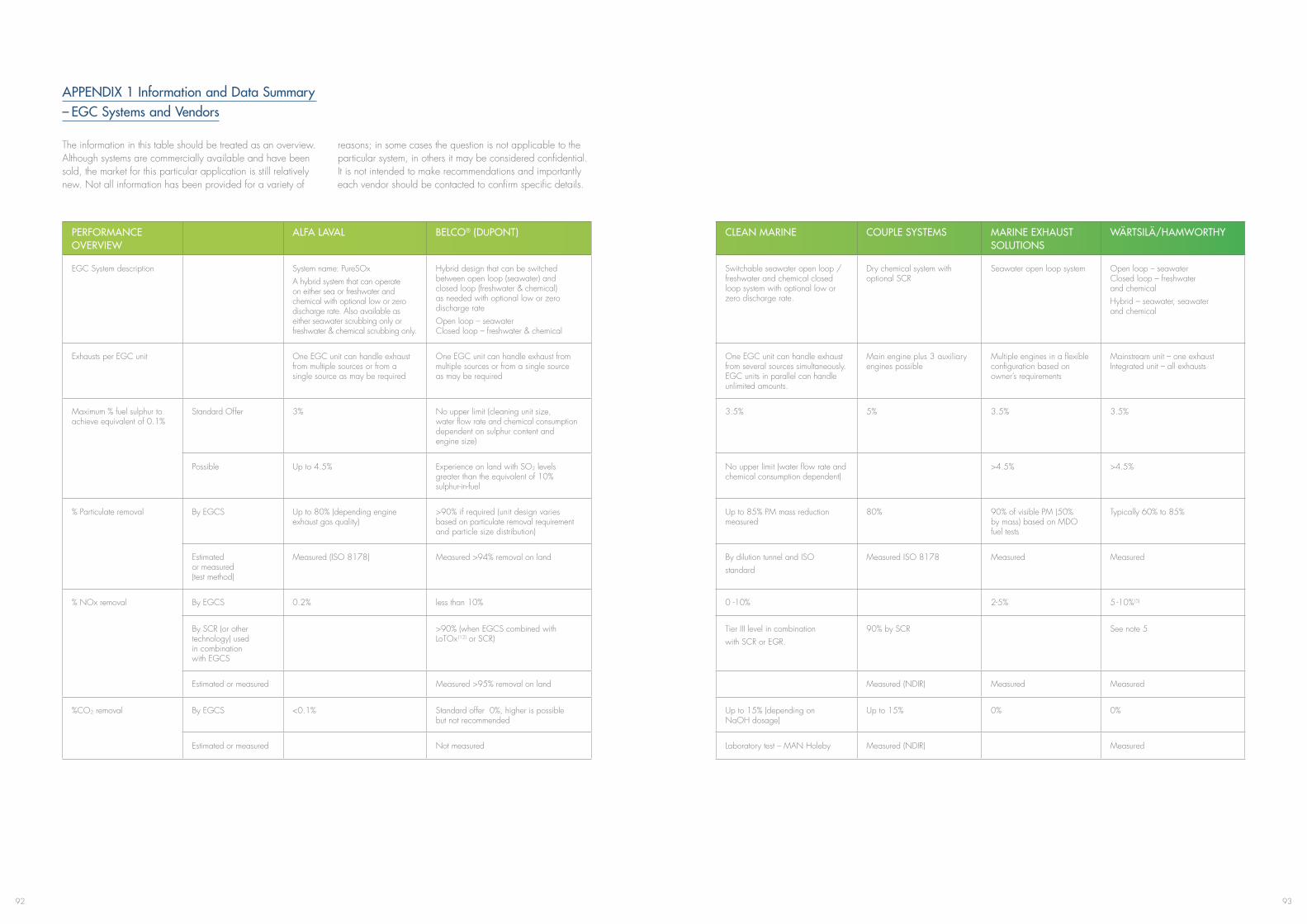
9392
APPENDIX 1 Information and Data Summary – EGC Systems and Vendors
The information in this table should be treated as an overview. Although systems are commercially available and have been sold, the market for this particular application is still relatively new. Not all information has been provided for a variety of
reasons; in some cases the question is not applicable to the particular system, in others it may be considered confidential. It is not intended to make recommendations and importantly each vendor should be contacted to confirm specific details.
PERFORMANCE OVERVIEW
ALFA LAVAL BELCO® (DUPONT) CLEAN MARINE COUPLE SYSTEMS MARINE EXHAUST SOLUTIONS
WäRTSILä/HAMWORTHY
EGC System description System name: PureSOxA hybrid system that can operate on either sea or freshwater and chemical with optional low or zero discharge rate. Also available as either seawater scrubbing only or freshwater & chemical scrubbing only.
Hybrid design that can be switched between open loop (seawater) and closed loop (freshwater & chemical) as needed with optional low or zero discharge rateOpen loop – seawater Closed loop – freshwater & chemical
Switchable seawater open loop / freshwater and chemical closed loop system with optional low or zero discharge rate.
Dry chemical system with optional SCR
Seawater open loop system Open loop – seawater Closed loop – freshwater and chemicalHybrid – seawater, seawater and chemical
Exhausts per EGC unit One EGC unit can handle exhaust from multiple sources or from a single source as may be required
One EGC unit can handle exhaust from multiple sources or from a single source as may be required
One EGC unit can handle exhaust from several sources simultaneously. EGC units in parallel can handle unlimited amounts.
Main engine plus 3 auxiliary engines possible
Multiple engines in a flexible configuration based on owner’s requirements
Mainstream unit – one exhaust Integrated unit – all exhausts
Maximum % fuel sulphur to achieve equivalent of 0.1%
Standard Offer 3% No upper limit (cleaning unit size, water flow rate and chemical consumption dependent on sulphur content and engine size)
3.5% 5% 3.5% 3.5%
Possible Up to 4.5% Experience on land with SO2 levels greater than the equivalent of 10% sulphur-in-fuel
No upper limit (water flow rate and chemical consumption dependent)
>4.5% >4.5%
% Particulate removal By EGCS Up to 80% (depending engine exhaust gas quality)
>90% if required (unit design varies based on particulate removal requirement and particle size distribution)
Up to 85% PM mass reduction measured
80% 90% of visible PM (50% by mass) based on MDO fuel tests
Typically 60% to 85%
Estimated or measured (test method)
Measured (ISO 8178) Measured >94% removal on land By dilution tunnel and ISOstandard
Measured ISO 8178 Measured Measured
% NOx removal By EGCS 0.2% less than 10% 0 -10% 2-5% 5 -10%(5)
By SCR (or other technology) used in combination with EGCS
>90% (when EGCS combined with LoTOx(12) or SCR)
Tier III level in combinationwith SCR or EGR.
90% by SCR See note 5
Estimated or measured Measured >95% removal on land Measured (NDIR) Measured Measured
%CO2 removal By EGCS <0.1% Standard offer 0%, higher is possible but not recommended
Up to 15% (depending on NaOH dosage)
Up to 15% 0% 0%
Estimated or measured Not measured Laboratory test – MAN Holeby Measured (NDIR) Measured
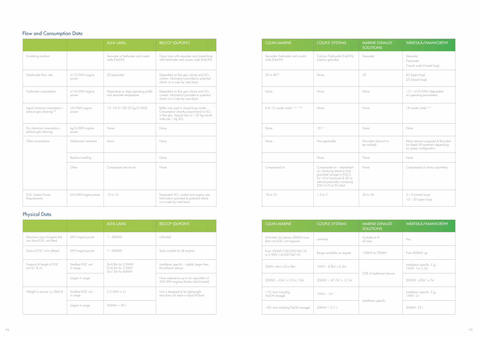
9594
ALFA LAVAL BELCO® (DUPONT) CLEAN MARINE COUPLE SYSTEMS MARINE EXHAUST SOLUTIONS
WäRTSILä/HAMWORTHY
Scrubbing medium Seawater or freshwater and caustic soda (NaOH)
Open loop with seawater and closed loop with freshwater and caustic soda (NaOH)
Seawater, freshwater and caustic soda (NaOH)
Calcium Hydroxide (Ca(OH)2 sorption granules)
Seawater SeawaterFreshwater Caustic soda (closed loop)
Washwater flow rate m3/h/MW engine power
50 (seawater) Dependent on flue gas volume and SO2 content. Information provided to potential clients on a case by case basis
20 to 40(3) None 50 45 (open loop)25 (closed loop)
Freshwater consumption m3/h/MW engine power
Depending on ships operating profile and seawater temperature
Dependent on flue gas volume and SO2 content. Information provided to potential clients on a case by case basis
None None None ~ 0.1 m3/h/MW (dependent on operating parameters)
Liquid chemical consumption – exhaust gas cleaning(14)
l/h/MW engine power
13 –16.5(1) (20 -25 kg/h/MW) Buffer only used in closed loop mode. Consumption directly proportional to SO2 in flue gas. Typical ratio is 1.25 kg caustic soda per 1 kg SO2
6 to 12 caustic soda (1, 3, 17,18) None None 18 caustic soda (1, 9)
Dry chemical consumption– exhaust gas cleaning
kg/h/MW engine power
None None None 16(11) None None
Other consumption Washwater treatment None None None Not applicable Flocculant (amount to be verified)
Minor amount coagulant & flocculent for bleed off treatment depending on system configuration
Residue handling None None None None
Other Compressed service air None Compressed air Compressed air – dependant on conveying distance from granulate storage to EGCS. For 10 m horizontal & 20 m vertical pneumatic conveying 250 m³/h at 50 mbar
None Compressed air (minor quantities)
EGC System Power Requirements
kW/MW engine power 10 to 12 Dependent SO2 content and engine size. Information provided to potential clients on a case by case basis
18 to 23 1.5 to 2 20 to 30 3 – 6 (closed loop)10 – 20 (open loop)
ALFA LAVAL BELCO® (DUPONT) CLEAN MARINE COUPLE SYSTEMS MARINE EXHAUST SOLUTIONS
WäRTSILä/HAMWORTHY
Maximum size of engine that can have EGC unit fitted
MW engine power 1 – 80MW Unlimited Unlimited, but above 25MW more than one EGC unit required unlimited Scalable to fit
all sizes Any
Sizes of EGC units offered MW engine power 1 – 80MW Sizes suitable for all engines From 25MW (180,000 Nm3/h) to 2 MW (14,000 Nm3/h) Range available on request 150kW to 70MW From 400kW up
Footprint & height of EGC unit (m2 & m)
Smallest EGC unit in range
D=0.8m for 0.5MW D=4.6m for 21MW D=7.5m for 60MW
Installation specific – slightly larger than the exhaust silencer 2MW:~4m2 x (5 to 8)m 1MW – 8.8m2 x 6.3m
25% of traditional silencer
Installation specific. E.g.: 1MW: 1m2 x 5m
Largest in range Have experience up to an equivalent of 200 MW engines/boilers (land based) 20MW: ~32m2 x (10 to 15)m 20MW -– 47.7m2 x 13.3m 20MW: <20m2 x 7m
Weight in service i.e. filled (t) Smallest EGC unit in range
0.5 MW = 3 t Unit is designed to be lightweight and does not retain a liquid fill level
~10 t (not including NaOH storage) 1MW – 14 t
Installation specific
Installation specific. E.g.: 1MW: 2 t
Largest in range 60MW = 70 t~30 t (not including NaOH storage) 20MW – 211 t 20MW: 55 t
Physical Data
Flow and Consumption Data

9796
ALFA LAVAL BELCO® (DUPONT) CLEAN MARINE COUPLE SYSTEMS MARINE EXHAUST SOLUTIONS
WäRTSILä/HAMWORTHY
Typical position of EGC unit Inside funnel or inside extended funnel area
Where space is available Inside and outside funnel Normally directly after the engine turbocharger or between turbocharger and exhaust gas boiler.
In place of traditional silencer/spark arrester
Retrofit: Inside existing or extended funnel Newbuildings: inside funnel
Footprint of washwater treatment plant (m2)
Smallest EGC unit in range
4m2 (for 21MW unit) Installation specific ~1.5m2 x 2m Not applicable Installation specific Installation and closed/open loop specific. E.g.: 12MW closed loop: 4.5m2
Largest in range ~4m2 x 3m Not applicable
Typical position of washwater treatment plant
Fresh water cleaning unit can be positioned at any free location
Where space is available. Typically on lower decks
Optional – on open deck or inside Not applicable Exhaust casing, engine room or outside
Anywhere that is suitable in terms of available space and practicability
Tankage required (m3/MW engine power)(6)
Washwater treatment plant residue
Dependent on installation and client’s storage requirements. Typical sludge production rate ~0.2 litre /MW h (Freshwater mode)
Flexible & installation specific – based on amount of ash in flue gas and client requirement for storage duration
~1m3 sludge/MW Not applicable ~ 0.5 m3 sludge/MW 70 – 300kg sludge/MW
Chemical addition – Exhaust Gas Cleaning System
Dependent on vessel, routing and opportunity to bunker – ~11.5m3 NaOH/MW (16 litres/MW/hour can be used for 2.7 % sulphur fuel to determine required autonomy)
Flexible & installation specific – based on amount of SO2 in flue gas and client requirement for closed loop operation duration
~5 – 6m3 NaOH/MW 14m3 Ca(OH)2 /MW (11.2 t Ca(OH)2 /MW)
None Open loop: nothingClosed loop: ~11.5m3 NaOH/MW (16 litres/MW/hour can be used for 2.7% sulphur fuel to determine required autonomy)
Other Circulation tank for fresh water operation. 0 – 10MW: 10m3, >10MW – 20MW: 20m3 >20MW: 40m3
None None Open loop: Optional de-aeration tank. Closed loop: bleed-off and effluent tanks for zero discharge. Size dependent on ship’s operational needs
ALFA LAVAL BELCO® (DUPONT) CLEAN MARINE COUPLE SYSTEMS MARINE EXHAUST SOLUTIONS
WäRTSILä/HAMWORTHY
Tested in commercial land based applications or test facilities ?
Yes Yes – marine design based on 200 land based units. Initial on board operation are on 3.5 MW and 2.2 MW engines
Yes a) Marine design based on industrial land based units b) 2 trial marine units at Technical University Hamburg c) 2 engine manufacturer test beds
No Yes – total installed power 465MW
Sizes 1MW from 1 MW to 150 MW equivalent 1MW 250,000 Am3/h (7)
or ~ 124,000 Nm3/hUp to 80MW
When fitted 2008 (200 hours testing) Since mid 1970s 2006 (testing between 2006 and 2008)
a) Operational over last 20 years
Since mid 1990’s
Where MAN Diesel test facility Mainly oil refineries also on oil fired engines, power boilers, oily waste incinerators & various industrial applications
MAN Holeby a) Ceramic industry, biomass incineration
Power generation – globalTest installations – Norway
Combustion material Residual Fuel Crude oil, oil waste, solid waste, coal, pet coke
Heavy fuel oil (ceramic industry)
MGO, MDO, HFO
Maximum % sulphur 2.4% 6.5% 5% Up to 5%
Tested on ship? Yes – Ficaria SeawaysSecond ship (Spliethoff) to start testing Q4 2012
Some applications in 1970’s for reduction of black smoke. Ship installation of current design will be tested in 4Q2012
Yes – one Yes – one Yes – two Yes
Testing
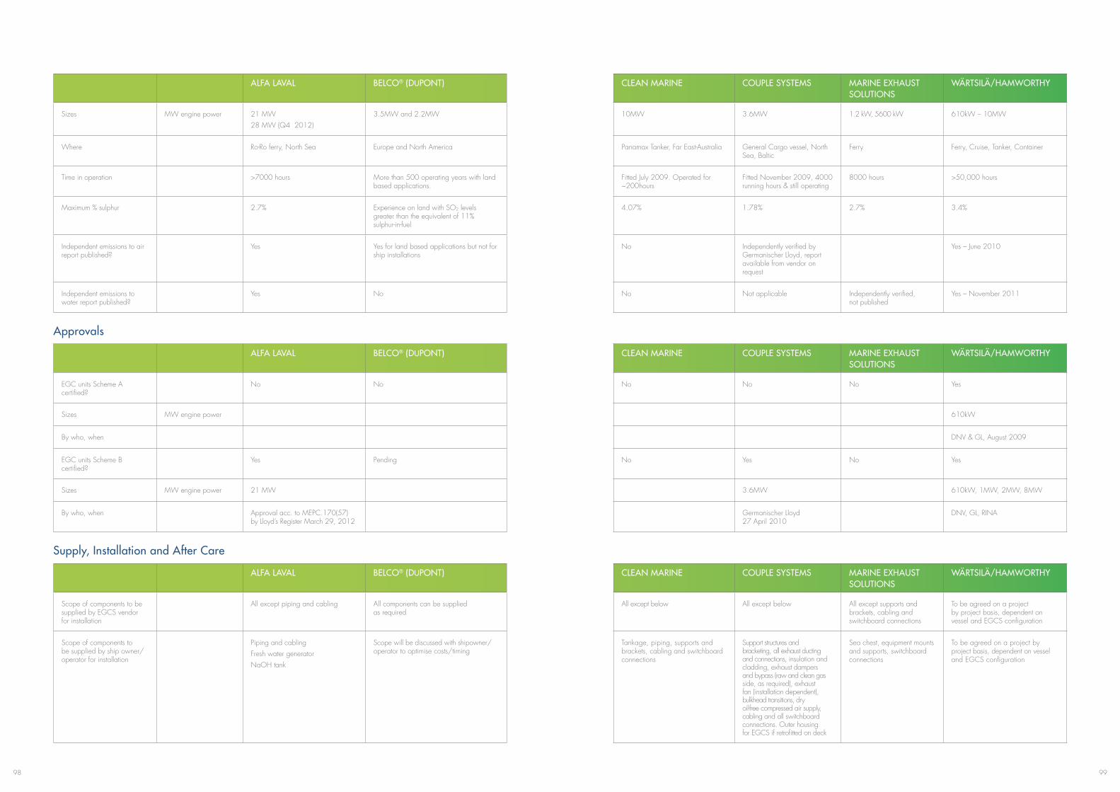
9998
ALFA LAVAL BELCO® (DUPONT) CLEAN MARINE COUPLE SYSTEMS MARINE EXHAUST SOLUTIONS
WäRTSILä/HAMWORTHY
Sizes MW engine power 21 MW28 MW (Q4 2012)
3.5MW and 2.2MW 10MW 3.6MW 1.2 kW, 5600 kW 610kW – 10MW
Where Ro-Ro ferry, North Sea Europe and North America Panamax Tanker, Far East-Australia General Cargo vessel, North Sea, Baltic
Ferry Ferry, Cruise, Tanker, Container
Time in operation >7000 hours More than 500 operating years with land based applications.
Fitted July 2009. Operated for ~200hours
Fitted November 2009, 4000 running hours & still operating
8000 hours >50,000 hours
Maximum % sulphur 2.7% Experience on land with SO2 levels greater than the equivalent of 11% sulphur-in-fuel
4.07% 1.78% 2.7% 3.4%
Independent emissions to air report published?
Yes Yes for land based applications but not for ship installations
No Independently verified by Germanischer Lloyd, report available from vendor on request
Yes – June 2010
Independent emissions to water report published?
Yes No No Not applicable Independently verified, not published
Yes – November 2011
ALFA LAVAL BELCO® (DUPONT) CLEAN MARINE COUPLE SYSTEMS MARINE EXHAUST SOLUTIONS
WäRTSILä/HAMWORTHY
EGC units Scheme A certified?
No No No No No Yes
Sizes MW engine power 610kW
By who, when DNV & GL, August 2009
EGC units Scheme B certified?
Yes Pending No Yes No Yes
Sizes MW engine power 21 MW 3.6MW 610kW, 1MW, 2MW, 8MW
By who, when Approval acc. to MEPC.170(57) by Lloyd’s Register March 29, 2012
Germanischer Lloyd 27 April 2010
DNV, GL, RINA
Approvals
Supply, Installation and After Care
ALFA LAVAL BELCO® (DUPONT) CLEAN MARINE COUPLE SYSTEMS MARINE EXHAUST SOLUTIONS
WäRTSILä/HAMWORTHY
Scope of components to be supplied by EGCS vendor for installation
All except piping and cabling All components can be supplied as required
All except below All except below All except supports and brackets, cabling and switchboard connections
To be agreed on a project by project basis, dependent on vessel and EGCS configuration
Scope of components to be supplied by ship owner/operator for installation
Piping and cablingFresh water generatorNaOH tank
Scope will be discussed with shipowner/operator to optimise costs/timing
Tankage, piping, supports and brackets, cabling and switchboard connections
Support structures and bracketing, all exhaust ducting and connections, insulation and cladding, exhaust dampers and bypass (raw and clean gas side, as required), exhaust fan (installation dependent), bulkhead transitions, dry oil-free compressed air supply, cabling and all switchboard connections. Outer housing for EGCS if retrofitted on deck
Sea chest, equipment mounts and supports, switchboard connections
To be agreed on a project by project basis, dependent on vessel and EGCS configuration
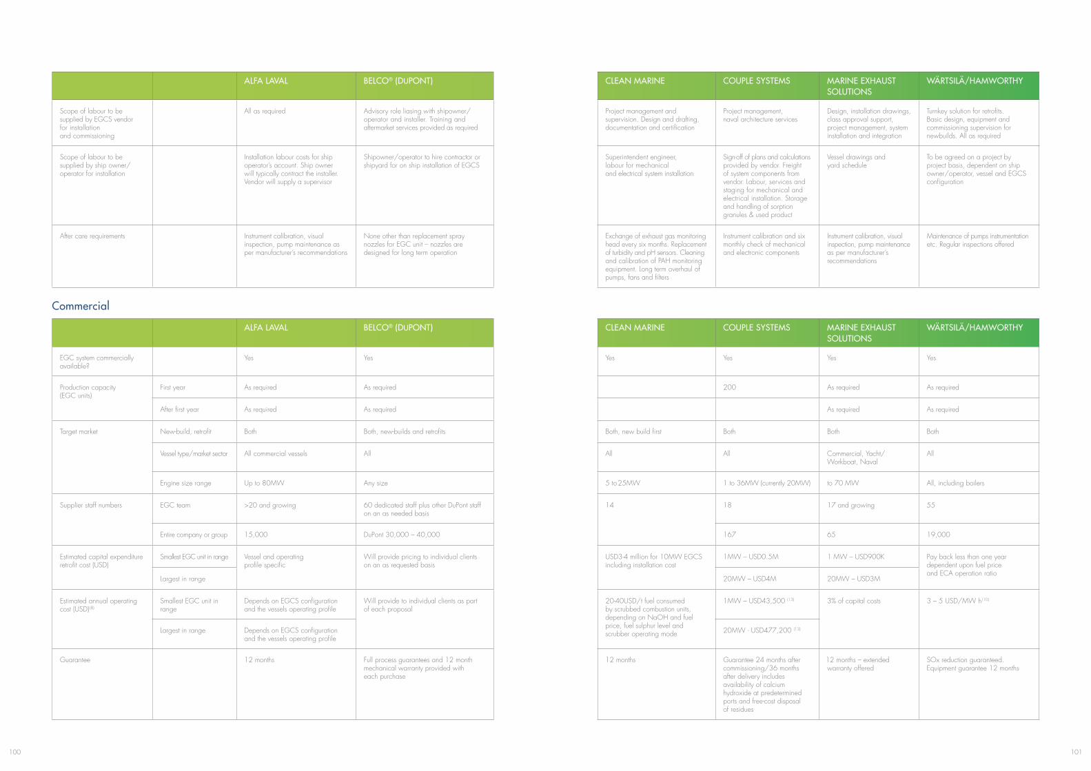
101100
ALFA LAVAL BELCO® (DUPONT) CLEAN MARINE COUPLE SYSTEMS MARINE EXHAUST SOLUTIONS
WäRTSILä/HAMWORTHY
Scope of labour to be supplied by EGCS vendor for installation and commissioning
All as required Advisory role liasing with shipowner/operator and installer. Training and aftermarket services provided as required
Project management and supervision. Design and drafting, documentation and certification
Project management, naval architecture services
Design, installation drawings, class approval support, project management, system installation and integration
Turnkey solution for retrofits. Basic design, equipment and commissioning supervision for newbuilds. All as required
Scope of labour to be supplied by ship owner/operator for installation
Installation labour costs for ship operator’s account. Ship owner will typically contract the installer. Vendor will supply a supervisor
Shipowner/operator to hire contractor or shipyard for on ship installation of EGCS
Superintendent engineer, labour for mechanical and electrical system installation
Sign-off of plans and calculations provided by vendor. Freight of system components from vendor. Labour, services and staging for mechanical and electrical installation. Storage and handling of sorption granules & used product
Vessel drawings and yard schedule
To be agreed on a project by project basis, dependent on ship owner/operator, vessel and EGCS configuration
After care requirements Instrument calibration, visual inspection, pump maintenance as per manufacturer’s recommendations
None other than replacement spray nozzles for EGC unit – nozzles are designed for long term operation
Exchange of exhaust gas monitoring head every six months. Replacement of turbidity and pH sensors. Cleaning and calibration of PAH monitoring equipment. Long term overhaul of pumps, fans and filters
Instrument calibration and six monthly check of mechanical and electronic components
Instrument calibration, visual inspection, pump maintenance as per manufacturer’s recommendations
Maintenance of pumps instrumentation etc. Regular inspections offered
ALFA LAVAL BELCO® (DUPONT) CLEAN MARINE COUPLE SYSTEMS MARINE EXHAUST SOLUTIONS
WäRTSILä/HAMWORTHY
EGC system commercially available?
Yes Yes Yes Yes Yes Yes
Production capacity (EGC units)
First year As required As required 200 As required As required
After first year As required As required As required As required
Target market New-build, retrofit Both Both, new-builds and retrofits Both, new build first Both Both Both
Vessel type/market sector All commercial vessels All All All Commercial, Yacht/Workboat, Naval
All
Engine size range Up to 80MW Any size 5 to 25MW 1 to 36MW (currently 20MW) to 70 MW All, including boilers
Supplier staff numbers EGC team >20 and growing 60 dedicated staff plus other DuPont staff on an as needed basis
14 18 17 and growing 55
Entire company or group 15,000 DuPont 30,000 – 40,000 167 65 19,000
Estimated capital expenditure retrofit cost (USD)
Smallest EGC unit in range Vessel and operating profile specific
Will provide pricing to individual clients on an as requested basis
USD3-4 million for 10MW EGCS including installation cost
1MW – USD0.5M 1 MW – USD900K Pay back less than one year dependent upon fuel price and ECA operation ratio
Largest in range 20MW – USD4M 20MW – USD3M
Estimated annual operating cost (USD) (8)
Smallest EGC unit in range
Depends on EGCS configuration and the vessels operating profile
Will provide to individual clients as part of each proposal
20-40USD/t fuel consumed by scrubbed combustion units, depending on NaOH and fuel price, fuel sulphur level and scrubber operating mode
1MW – USD43,500 (13) 3% of capital costs 3 – 5 USD/MW h(10)
Largest in range Depends on EGCS configuration and the vessels operating profile
20MW - USD477,200 (13)
Guarantee 12 months Full process guarantees and 12 month mechanical warranty provided with each purchase
12 months Guarantee 24 months after commissioning/36 months after delivery includes availability of calcium hydroxide at predetermined ports and free-cost disposal of residues
12 months – extended warranty offered
SOx reduction guaranteed. Equipment guarantee 12 months
Commercial
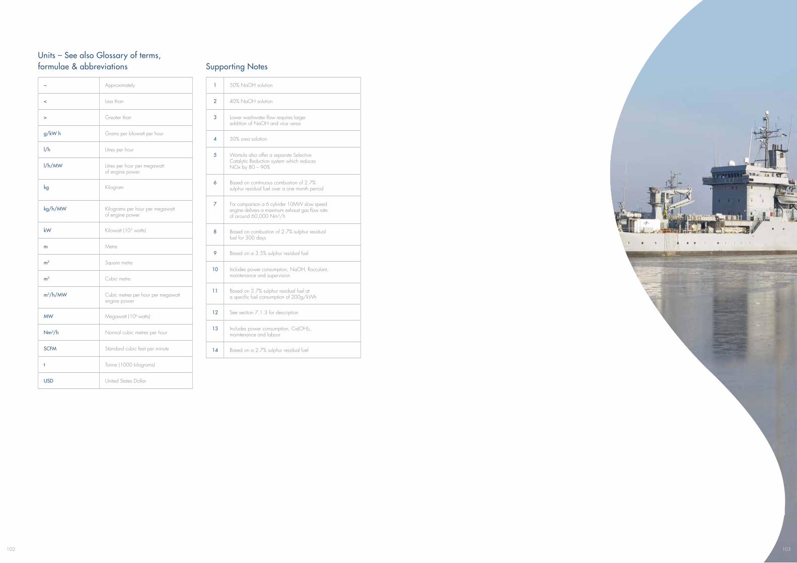
102
1 50% NaOH solution
2 40% NaOH solution
3 Lower washwater flow requires larger addition of NaOH and vice versa
4 30% urea solution
5 Wartsila also offer a separate Selective Catalytic Reduction system which reduces NOx by 80 – 90%
6 Based on continuous combustion of 2.7% sulphur residual fuel over a one month period
7 For comparison a 6 cylinder 10MW slow speed engine delivers a maximum exhaust gas flow rate of around 60,000 Nm3/h
8 Based on combustion of 2.7% sulphur residual fuel for 300 days
9 Based on a 3.5% sulphur residual fuel
10 Includes power consumption, NaOH, flocculant, maintenance and supervision
11 Based on 2.7% sulphur residual fuel at a specific fuel consumption of 200g/kWh
12 See section 7.1.3 for description
13 Includes power consumption, Ca(OH)2, maintenance and labour
14 Based on a 2.7% sulphur residual fuel
Units – See also Glossary of terms, formulae & abbreviations Supporting Notes
~ Approximately
< Less than
> Greater than
g/kW h Grams per kilowatt per hour
l/h Litres per hour
l/h/MW Litres per hour per megawatt of engine power
kg Kilogram
kg/h/MW Kilograms per hour per megawatt of engine power
kW Kilowatt (103 watts)
m Metre
m2 Square metre
m3 Cubic metre
m3/h/MW Cubic metres per hour per megawatt engine power
MW Megawatt (106 watts)
Nm3/h Normal cubic metres per hour
SCFM Standard cubic feet per minute
t Tonne (1000 kilograms)
USD United States Dollar
103
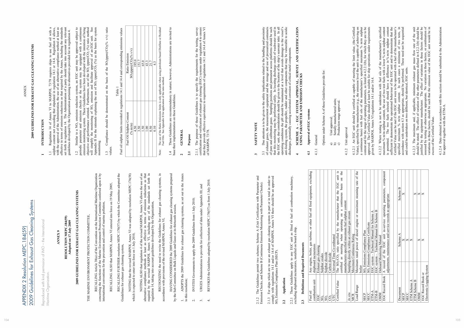
105104
APP
END
IX 2
Res
olut
ion
MEP
C.1
84(5
9)
2009
Gui
delin
es fo
r Ex
haus
t Gas
Cle
anin
g Sy
stem
s
Repr
oduc
ed w
ith k
ind
perm
issio
n of
IMO
– th
e In
tern
atio
nal
Mar
itim
e O
rgan
izat
ion.
MEP
C 5
9/24
/Add
.1
I:\M
EPC
\59\
24-A
dd-1
.doc
AN
NE
X 9
RE
SOL
UT
ION
ME
PC.1
84(5
9)
Ado
pted
on
17 J
uly
2009
2009
GU
IDE
LIN
ES
FOR
EX
HA
UST
GA
S C
LE
AN
ING
SY
STE
MS
THE
MA
RIN
E EN
VIR
ON
MEN
T PR
OTE
CTI
ON
CO
MM
ITTE
E,
R
ECA
LLIN
G A
rticl
e 38
(a) o
f the
Con
vent
ion
on th
e In
tern
atio
nal M
ariti
me
Org
aniz
atio
n co
ncer
ning
the
func
tions
of t
he M
arin
e En
viro
nmen
t Pro
tect
ion
Com
mitt
ee c
onfe
rred
upo
n it
by
inte
rnat
iona
l con
vent
ions
for t
he p
reve
ntio
n an
d co
ntro
l of m
arin
e po
llutio
n,
R
ECA
LLIN
G A
LSO
that
MA
RPO
L A
nnex
VI e
nter
ed in
to fo
rce
on 1
9 M
ay 2
005,
REC
ALL
ING
FU
RTH
ER re
solu
tion
MEP
C.1
70(5
7) b
y w
hich
the
Com
mitt
ee a
dopt
ed th
e G
uide
lines
for e
xhau
st g
as c
lean
ing
syst
em,
N
OTI
NG
that
the
revi
sed
MA
RPO
L A
nnex
VI w
as a
dopt
ed b
y re
solu
tion
MEP
C.1
76(5
8)
whi
ch is
exp
ecte
d to
ent
er in
to fo
rce
on 1
July
201
0,
N
OTI
NG
ALS
O th
at re
gula
tion
4 of
the
revi
sed
MA
RPO
L A
nnex
VI a
llow
s the
use
of a
n al
tern
ativ
e co
mpl
ianc
e m
etho
ds a
t le
ast
as e
ffec
tive
in t
erm
s of
em
issi
on r
educ
tions
as
that
re
quire
d by
the
rev
ised
MA
RPO
L A
nnex
VI,
incl
udin
g an
y of
the
sta
ndar
ds s
et f
orth
in
regu
latio
n 14
, tak
ing
into
acc
ount
gui
delin
es d
evel
oped
by
the
Org
aniz
atio
n,
R
ECO
GN
IZIN
G th
e ne
ed to
rev
ise
the
Gui
delin
es f
or e
xhau
st g
as c
lean
ing
syst
ems,
in
acco
rdan
ce w
ith p
rovi
sion
s of t
he re
vise
d M
AR
POL
Ann
ex V
I,
HA
VIN
G C
ON
SID
ERED
the
2009
Gui
delin
es fo
r exh
aust
gas
cle
anin
g sy
stem
s pr
epar
ed
by th
e Su
b-C
omm
ittee
on
Bul
k Li
quid
s and
Gas
es a
t its
thirt
eent
h se
ssio
n,
1.
AD
OPT
S th
e 20
09 G
uide
lines
for e
xhau
st g
as c
lean
ing
syst
ems,
as s
et o
ut in
the
Ann
ex
to th
is re
solu
tion;
2.
IN
VIT
ES G
over
nmen
ts to
app
ly th
e 20
09 G
uide
lines
from
1 Ju
ly 2
010;
3.
U
RG
ES A
dmin
istra
tions
to p
rovi
de fo
r col
lect
ion
of d
ata
unde
r App
endi
x II
I; an
d 4.
R
EVO
KES
the
Gui
delin
es a
dopt
ed b
y re
solu
tion
MEP
C.1
70(5
7) a
s fro
m 1
July
201
0.
MEP
C 5
9/24
/Add
.1
AN
NEX
9
Page
2
I:\M
EPC
\59\
24-A
dd-1
.doc
A
NN
EX
20
09 G
UID
EL
INE
S FO
R E
XH
AU
ST G
AS
CL
EA
NIN
G S
YST
EM
S
1 IN
TR
OD
UC
TIO
N
1.1
Reg
ulat
ion
14 o
f A
nnex
VI
to M
AR
POL
73/7
8 re
quire
s sh
ips
to u
se f
uel
oil
with
a
sulp
hur
cont
ent
not
exce
edin
g th
at s
tipul
ated
in r
egul
atio
n 14
.1 o
r 14
.4.
Reg
ulat
ion
4 al
low
s, w
ith th
e ap
prov
al o
f the
Adm
inis
tratio
n, th
e us
e of
an
alte
rnat
ive
com
plia
nce
met
hod
at le
ast a
s ef
fect
ive
in te
rms
of e
mis
sion
redu
ctio
ns a
s th
at re
quire
d by
the
Ann
ex, i
nclu
ding
the
stan
dard
s se
t for
th in
reg
ulat
ion
14.
The
Adm
inis
tratio
n of
a p
arty
sho
uld
take
into
acc
ount
any
rel
evan
t gu
idel
ines
dev
elop
ed b
y th
e O
rgan
izat
ion
perta
inin
g to
alte
rnat
ives
pro
vide
d fo
r in
regu
latio
n 4.
1.
2 Si
mila
r to
a N
Ox
emis
sion
red
uctio
n sy
stem
, an
EGC
uni
t m
ay b
e ap
prov
ed s
ubje
ct t
o pe
riodi
c pa
ram
eter
and
em
issi
on c
heck
s or
the
sys
tem
may
be
equi
pped
with
a c
ontin
uous
em
issi
on m
onito
ring
syst
em.
Thes
e G
uide
lines
hav
e be
en d
evel
oped
with
the
inte
ntio
n of
bei
ng
obje
ctiv
e an
d pe
rfor
man
ce o
rient
ed.
Furth
erm
ore,
use
of
the
SO2
(ppm
)/CO
2 (%
) ra
tio m
etho
d w
ill s
impl
ify t
he m
onito
ring
of S
Ox
emis
sion
and
fac
ilita
te a
ppro
val
of a
n EG
C u
nit.
See
A
ppen
dix
II f
or th
e ra
tiona
le e
xpla
inin
g th
e us
e of
SO
2 (p
pm)/C
O2
(%)
as th
e ba
sis
for
syst
em
mon
itorin
g.
1.3
Com
plia
nce
shou
ld b
e de
mon
stra
ted
on t
he b
asis
of
the
SO2(
ppm
)/CO
2(%
v/v
) ra
tio
valu
es.
Ta
ble
1 Fu
el o
il su
lphu
r lim
its re
cord
ed in
regu
latio
ns 1
4.1
and
14.4
and
cor
resp
ondi
ng e
mis
sion
s val
ues
Fuel
Oil
Sulp
hur C
onte
nt
(% m
/m)
Rat
io E
mis
sion
SO
2(pp
m)/C
O2(
% v
/v)
4.50
19
5.0
3.50
15
1.7
1.50
65
.0
1.00
43
.3
0.50
21
.7
0.10
4.
3 N
ote:
Th
e us
e of
the
Rat
io E
mis
sion
s lim
its is
onl
y ap
plic
able
whe
n us
ing
petro
leum
bas
ed D
istil
late
or R
esid
ual
Fuel
Oils
. Se
e A
ppen
dix
II fo
r app
licat
ion
of th
e ra
tio m
etho
d.
1.4
Thes
e G
uide
lines
are
reco
mm
enda
tory
in n
atur
e; h
owev
er, A
dmin
istra
tions
are
invi
ted
to
base
thei
r im
plem
enta
tion
on th
ese
Gui
delin
es.
2 G
EN
ER
AL
2.
1 Pu
rpos
e 2.
1.1
The
purp
ose
of t
hese
Gui
delin
es i
s to
spe
cify
the
req
uire
men
ts f
or t
he t
estin
g, s
urve
y ce
rtific
atio
n an
d ve
rific
atio
n of
exh
aust
gas
cle
anin
g (E
GC
) sys
tem
s un
der r
egul
atio
n 4
to e
nsur
e th
at th
ey p
rovi
de e
ffec
tive
equi
vale
nce
to re
quire
men
ts o
f reg
ulat
ions
14.
1 an
d 14
.4 o
f Ann
ex V
I of
MA
RPO
L 73
/78.
MEP
C 5
9/24
/Add
.1
AN
NEX
9
Page
3
I:\M
EPC
\59\
24-A
dd-1
.doc
2.1.
2 Th
e G
uide
lines
per
mit
two
sche
mes
; Sch
eme
A (
Uni
t Cer
tific
atio
n w
ith P
aram
eter
and
Em
issi
on C
heck
s, an
d Sc
hem
e B
(Con
tinuo
us E
mis
sion
Mon
itorin
g w
ith P
aram
eter
Che
cks)
. 2.
1.3
For
ship
s w
hich
are
to u
se a
n ex
haus
t gas
cle
anin
g sy
stem
in p
art o
r in
tota
l in
orde
r to
co
mpl
y w
ith r
egul
atio
ns 1
4.1
and/
or 1
4.4
of M
AR
POL
Ann
ex V
I th
ere
shou
ld b
e an
app
rove
d SO
x Em
issi
ons C
ompl
ianc
e Pl
an (S
ECP)
. 2.
2 A
pplic
atio
n 2.
2.1
Thes
e G
uide
lines
app
ly t
o an
y EG
C u
nit
as f
itted
to
fuel
oil
com
bust
ion
mac
hine
ry,
excl
udin
g sh
ipbo
ard
inci
nera
tors
, ins
talle
d on
boa
rd a
ship
. 2.
3 D
efin
ition
s and
Req
uire
d D
ocum
ents
Fuel
oil
com
bust
ion
unit
Any
eng
ine,
boi
ler,
gas
turb
ine,
or
othe
r fu
el o
il fir
ed e
quip
men
t, ex
clud
ing
ship
boar
d in
cine
rato
rs
EGC
Ex
haus
t gas
cle
anin
g SO
x Su
lphu
r oxi
des
SO2
Sulp
hur d
ioxi
de
CO
2 C
arbo
n di
oxid
e U
TC
Uni
vers
al T
ime
Co-
ordi
nate
d C
ertif
ied
Val
ue
The
SO2/C
O2
ratio
sp
ecifi
ed b
y th
e m
anuf
actu
rer
that
the
EG
C u
nit
is
certi
fied
as
mee
ting
whe
n op
erat
ing
on
a co
ntin
uous
ba
sis
on
the
man
ufac
ture
rs sp
ecifi
ed m
axim
um fu
el su
lphu
r con
tent
In
situ
Sa
mpl
ing
dire
ctly
with
in a
n ex
haus
t gas
stre
am
MC
R
Max
imum
Con
tinuo
us R
atin
g Lo
ad R
ange
M
axim
um r
ated
pow
er o
f di
esel
eng
ine
or m
axim
um s
team
ing
rate
of
the
boile
r SE
CP
SOx E
mis
sion
s Com
plia
nce
Plan
SE
CC
SO
x Em
issi
ons C
ompl
ianc
e C
ertif
icat
e ET
M-A
EG
C sy
stem
– T
echn
ical
Man
ual f
or S
chem
e A
ET
M-B
EG
C sy
stem
– T
echn
ical
Man
ual f
or S
chem
e B
O
MM
O
nboa
rd M
onito
ring
Man
ual
EGC
Rec
ord
Boo
k A
rec
ord
of t
he E
GC
uni
t in
-ser
vice
ope
ratin
g pa
ram
eter
s, co
mpo
nent
ad
just
men
ts, m
aint
enan
ce a
nd se
rvic
e re
cord
s as a
ppro
pria
te
D
ocum
ent
Sche
me
A
Sche
me
B
SEC
P X
X
SE
CC
X
ETM
Sch
eme
A
X
ET
M S
chem
e B
X
OM
M
X
X
EGC
Rec
ord
Boo
k or
El
ectro
nic
Logg
ing
Syst
em
X
X
MEP
C 5
9/24
/Add
.1
AN
NEX
9
Page
4
I:\M
EPC
\59\
24-A
dd-1
.doc
3 SA
FET
Y N
OT
E
3.1
Due
atte
ntio
n is
to b
e gi
ven
to th
e sa
fety
impl
icat
ions
rela
ted
to th
e ha
ndlin
g an
d pr
oxim
ity
of e
xhau
st g
ases
, the
mea
sure
men
t equ
ipm
ent a
nd th
e st
orag
e an
d us
e of
pre
ssur
ized
con
tain
ers
of p
ure
and
calib
ratio
n ga
ses.
Sam
plin
g po
sitio
ns a
nd p
erm
anen
t acc
ess
plat
form
s sh
ould
be
such
th
at th
is m
onito
ring
may
be
perf
orm
ed s
afel
y. I
n lo
catin
g di
scha
rge
outle
t of w
ashw
ater
use
d in
th
e EG
C u
nit,
due
cons
ider
atio
n sh
ould
be
give
n to
the
loca
tion
of th
e sh
ip’s
sea
wat
er in
let.
In a
ll op
erat
ing
cond
ition
s th
e pH
sho
uld
be m
aint
aine
d at
a le
vel t
hat a
void
s da
mag
e to
the
vess
el’s
an
ti-fo
ulin
g sy
stem
, the
pro
pelle
r, ru
dder
and
oth
er c
ompo
nent
s th
at m
ay b
e vu
lner
able
to a
cidi
c di
scha
rges
, pot
entia
lly c
ausi
ng a
ccel
erat
ed c
orro
sion
of c
ritic
al m
etal
com
pone
nts.
4 SC
HE
ME
A –
EG
C S
YST
EM
APP
RO
VA
L,
SUR
VE
Y A
ND
CE
RT
IFIC
AT
ION
U
SIN
G P
AR
AM
ET
ER
AN
D E
MIS
SIO
N C
HE
CK
S 4.
1 A
ppro
val o
f EG
C sy
stem
s 4.
1.1
Gen
eral
Opt
ions
und
er S
chem
e A
of t
hese
Gui
delin
es p
rovi
de fo
r: a)
U
nit a
ppro
val;
b)
Seria
lly m
anuf
actu
red
units
; c)
Pr
oduc
tion
rang
e ap
prov
al.
4.
1.2
Uni
t app
rova
l 4.
1.2.
1 A
n EG
C u
nit
shou
ld b
e ce
rtifie
d as
cap
able
of
mee
ting
the
limit
valu
e, (
the
Cer
tifie
d V
alue
), sp
ecifi
ed b
y th
e m
anuf
actu
rer (
e.g.
, the
em
issi
on le
vel t
he u
nit i
s ca
pabl
e of
ach
ievi
ng o
n a
cont
inuo
us b
asis
) w
ith f
uel
oils
of
the
man
ufac
ture
r’s
spec
ified
max
imum
% m
/m s
ulph
ur
cont
ent a
nd fo
r the
rang
e of
ope
ratin
g pa
ram
eter
s, as
list
ed in
4.2
.2.1
(b),
for w
hich
they
are
to b
e ap
prov
ed.
The
Cer
tifie
d V
alue
sho
uld
at le
ast b
e su
itabl
e fo
r shi
p op
erat
ions
und
er re
quire
men
ts
give
n by
MA
RPO
L A
nnex
VI r
egul
atio
ns 1
4.1
and/
or 1
4.4.
4.
1.2.
2 W
here
tes
ting
is n
ot t
o be
und
erta
ken
with
fue
l oi
ls o
f th
e m
anuf
actu
rer’
s sp
ecifi
ed
max
imum
% m
/m s
ulph
ur c
onte
nt, t
he u
se o
f tw
o te
st fu
els
with
a lo
wer
% m
/m s
ulph
ur c
onte
nt
is p
erm
itted
. T
he t
wo
fuel
s se
lect
ed s
houl
d ha
ve a
diff
eren
ce i
n %
m/m
sul
phur
con
tent
su
ffic
ient
to d
emon
stra
te th
e op
erat
iona
l beh
avio
ur o
f the
EG
C u
nit a
nd to
dem
onst
rate
that
the
Cer
tifie
d V
alue
can
be
met
if th
e EG
C u
nit w
ere
to b
e op
erat
ed w
ith a
fuel
of t
he m
anuf
actu
rer’
s sp
ecifi
ed m
axim
um %
m/m
sul
phur
con
tent
. I
n su
ch c
ases
a m
inim
um o
f tw
o te
sts,
in
acco
rdan
ce w
ith s
ectio
n 4.
3 as
app
ropr
iate
, sho
uld
be p
erfo
rmed
. Th
ese
need
not
be
sequ
entia
l an
d co
uld
be u
nder
take
n on
two
diff
eren
t, bu
t ide
ntic
al, E
GC
uni
ts.
4.1.
2.3
The
max
imum
and
, if
appl
icab
le,
min
imum
exh
aust
gas
mas
s flo
w r
ate
of t
he u
nit
shou
ld b
e st
ated
. Th
e ef
fect
of v
aria
tion
of th
e ot
her p
aram
eter
s de
fined
in 4
.2.2
.1(b
) sho
uld
be
just
ified
by
the
equi
pmen
t m
anuf
actu
rer.
The
eff
ect
of v
aria
tions
in
thes
e fa
ctor
s sh
ould
be
asse
ssed
by
test
ing
or o
ther
wis
e as
app
ropr
iate
. N
o va
riatio
n in
thes
e fa
ctor
s, or
com
bina
tion
of
varia
tions
in th
ese
fact
ors,
shou
ld b
e su
ch th
at th
e em
issi
on v
alue
of
the
EGC
uni
t wou
ld b
e in
ex
cess
of t
he C
ertif
ied
Val
ue.
4.1.
2.4
Dat
a ob
tain
ed in
acc
orda
nce
with
this
sec
tion
shou
ld b
e su
bmitt
ed to
the
Adm
inis
tratio
n fo
r app
rova
l tog
ethe
r with
the
ETM
-A.
107106
MEP
C 5
9/24
/Add
.1
AN
NEX
9
Page
5
I:\M
EPC
\59\
24-A
dd-1
.doc
4.1.
3 Se
rially
man
ufac
ture
d un
its
In
the
case
of n
omin
ally
sim
ilar E
GC
uni
ts o
f the
sam
e m
ass
flow
ratin
gs a
s th
at c
ertif
ied
unde
r 4.1
.2, a
nd to
avo
id th
e te
stin
g of
eac
h EG
C u
nit,
the
equi
pmen
t man
ufac
ture
r may
sub
mit,
fo
r acc
epta
nce
by th
e A
dmin
istra
tion,
a c
onfo
rmity
of p
rodu
ctio
n ar
rang
emen
t. T
he c
ertif
icat
ion
of e
ach
EGC
uni
t und
er th
is ar
rang
emen
t sho
uld
be su
bjec
t to
such
surv
eys t
hat t
he A
dmin
istra
tion
may
con
side
r nec
essa
ry a
s to
ass
ure
that
eac
h EG
C u
nit h
as a
n em
issi
on v
alue
of n
ot m
ore
than
th
e C
ertif
ied
Val
ue w
hen
oper
ated
in a
ccor
danc
e w
ith th
e pa
ram
eter
s def
ined
in 4
.2.2
.1(b
). 4.
1.4
Prod
uct r
ange
app
rova
l 4.
1.4.
1 In
the
case
of
an E
GC
uni
t of
the
sam
e de
sign
, but
of
diff
eren
t max
imum
exh
aust
gas
m
ass
flow
cap
aciti
es,
the
Adm
inis
tratio
n m
ay a
ccep
t, in
lie
u of
tes
ts o
n an
EG
C u
nit
of a
ll ca
paci
ties
in a
ccor
danc
e w
ith s
ectio
n 4.
1.2,
tes
ts o
f EG
C s
yste
ms
of t
hree
diff
eren
t ca
paci
ties
prov
ided
tha
t th
e th
ree
test
s ar
e pe
rfor
med
at
inte
rval
s in
clud
ing
the
high
est,
low
est
and
one
inte
rmed
iate
cap
acity
ratin
g w
ithin
the
rang
e.
4.1.
4.2
Whe
re t
here
are
sig
nific
ant
diff
eren
ces
in t
he d
esig
n of
EG
C u
nits
of
diff
eren
t ca
paci
ties,
this
pro
cedu
re s
houl
d no
t be
appl
ied
unle
ss it
can
be
show
n, to
the
satis
fact
ion
of th
e A
dmin
istra
tion,
that
in p
ract
ice
thos
e di
ffer
ence
s do
not m
ater
ially
alte
r the
per
form
ance
bet
wee
n th
e va
rious
EG
C u
nit t
ypes
. 4.
1.4.
3 Fo
r EG
C u
nits
of
diff
eren
t ca
paci
ties,
the
sens
itivi
ty t
o va
riatio
ns i
n th
e ty
pe o
f co
mbu
stio
n m
achi
nery
to w
hich
they
are
fitte
d sh
ould
be
deta
iled
toge
ther
with
sen
sitiv
ity to
the
varia
tions
in th
e pa
ram
eter
s lis
ted
in 4
.2.2
.1(b
). T
his
shou
ld b
e on
the
basi
s of
test
ing,
or o
ther
da
ta a
s app
ropr
iate
. 4.
1.4.
4 Th
e ef
fect
of
chan
ges
of E
GC
uni
t ca
paci
ty o
n w
ashw
ater
cha
ract
eris
tics
shou
ld b
e de
taile
d.
4.1.
4.5
All
supp
ortin
g da
ta o
btai
ned
in a
ccor
danc
e w
ith th
is s
ectio
n, to
geth
er w
ith th
e ET
M-A
fo
r eac
h ca
paci
ty u
nit,
shou
ld b
e su
bmitt
ed to
the
Adm
inis
tratio
n fo
r app
rova
l. 4.
2 Su
rvey
and
cer
tific
atio
n 4.
2.1
Proc
edur
es fo
r the
cer
tific
atio
n of
an
EGC
uni
t 4.
2.1.
1 In
ord
er to
mee
t the
req
uire
men
ts o
f 4.
1 ei
ther
prio
r to
, or
afte
r in
stal
latio
n on
boa
rd,
each
EG
C u
nit s
houl
d be
cer
tifie
d as
mee
ting
the
Cer
tifie
d V
alue
spe
cifie
d by
the
man
ufac
ture
r (e
.g.,
the
emis
sion
lev
el t
he u
nit
is c
apab
le o
f ac
hiev
ing
on a
con
tinuo
us b
asis
) un
der
the
oper
atin
g co
nditi
ons
and
rest
rictio
ns a
s gi
ven
by t
he E
GC
Tec
hnic
al M
anua
l (E
TM-A
) as
ap
prov
ed b
y th
e A
dmin
istra
tion.
4.
2.1.
2 D
eter
min
atio
n of
the
Cer
tifie
d V
alue
sho
uld
be i
n ac
cord
ance
with
the
pro
visi
ons
of
thes
e G
uide
lines
. 4.
2.1.
3 Ea
ch E
GC
uni
t mee
ting
the
requ
irem
ents
of 4
.2.1
.1 sh
ould
be
issu
ed w
ith a
SEC
C b
y th
e A
dmin
istra
tion.
The
form
of t
he S
ECC
is g
iven
in A
ppen
dix
I. 4.
2.1.
4 A
pplic
atio
n fo
r an
SEC
C s
houl
d be
mad
e by
the
EGC
sys
tem
man
ufac
ture
r, sh
ipow
ner
or o
ther
par
ty.
MEP
C 5
9/24
/Add
.1
AN
NEX
9
Page
6
I:\M
EPC
\59\
24-A
dd-1
.doc
4.2.
1.5
Any
sub
sequ
ent E
GC
uni
ts o
f the
sam
e de
sign
and
ratin
g as
that
cer
tifie
d un
der 4
.2.1
.1
may
be
issu
ed w
ith a
n SE
CC
by
the
Adm
inis
tratio
n w
ithou
t the
nee
d fo
r te
stin
g in
acc
orda
nce
with
4.2
.1.1
subj
ect t
o se
ctio
n 4.
1.3
of th
ese
Gui
delin
es.
4.2.
1.6
EGC
uni
ts o
f the
sam
e de
sign
, but
with
ratin
gs d
iffer
ent f
rom
that
cer
tifie
d un
der 4
.2.1
.1
may
be
acce
pted
by
the
Adm
inis
tratio
n su
bjec
t to
sect
ion
4.1.
4 of
thes
e G
uide
lines
. 4.
2.1.
7 EG
C u
nits
whi
ch tr
eat o
nly
part
of th
e ex
haus
t gas
flow
of t
he u
ptak
e in
whi
ch th
ey a
re
fitte
d sh
ould
be
subj
ect t
o sp
ecia
l con
side
ratio
n by
the
Adm
inis
tratio
n to
ens
ure
that
und
er a
ll de
fined
ope
ratin
g co
nditi
ons
that
the
over
all e
mis
sion
val
ue o
f th
e ex
haus
t gas
dow
n st
ream
of
the
syst
em is
no
mor
e th
an th
e C
ertif
ied
Val
ue.
4.2.
2 EG
C S
yste
m T
echn
ical
Man
ual “
Sche
me
A”
(ETM
-A).
4.2.
2.1
Each
EG
C u
nit s
houl
d be
sup
plie
d w
ith a
n ET
M-A
pro
vide
d by
the
man
ufac
ture
r. T
his
ETM
-A sh
ould
, as a
min
imum
, con
tain
the
follo
win
g in
form
atio
n:
(a)
the
iden
tific
atio
n of
the
unit
(man
ufac
ture
r, m
odel
/type
, ser
ial n
umbe
r an
d ot
her
deta
ils a
s ne
cess
ary)
incl
udin
g a
desc
riptio
n of
the
unit
and
any
requ
ired
anci
llary
sy
stem
s;
(b)
the
oper
atin
g lim
its, o
r ra
nge
of o
pera
ting
valu
es, f
or w
hich
the
unit
is c
ertif
ied.
Th
ese
shou
ld, a
s a m
inim
um, i
nclu
de:
(i)
m
axim
um a
nd, i
f app
licab
le, m
inim
um m
ass f
low
rate
of e
xhau
st g
as;
(ii)
the
pow
er, t
ype
and
othe
r re
leva
nt p
aram
eter
s of
the
fuel
oil
com
bust
ion
unit
for
whi
ch t
he E
GC
uni
t is
to
be f
itted
. In
the
cas
es o
f bo
ilers
, the
m
axim
um a
ir/fu
el ra
tio a
t 100
% lo
ad s
houl
d al
so b
e gi
ven.
In
the
case
s of
di
esel
eng
ines
whe
ther
the
engi
ne is
of 2
or 4
-stro
ke c
ycle
; (ii
i) m
axim
um
and
min
imum
w
ashw
ater
flo
w
rate
, in
let
pres
sure
s an
d m
inim
um in
let w
ater
alk
alin
ity (I
SO 9
963-
1-2)
; (iv
) ex
haus
t gas
inle
t tem
pera
ture
rang
es a
nd m
axim
um a
nd m
inim
um e
xhau
st
gas o
utle
t tem
pera
ture
with
the
EGC
uni
t in
oper
atio
n;
(v)
exha
ust g
as d
iffer
entia
l pre
ssur
e ra
nge
and
the
max
imum
exh
aust
gas
inle
t pr
essu
re w
ith t
he f
uel
oil
com
bust
ion
unit
oper
atin
g at
MC
R o
r 80
% o
f po
wer
ratin
g w
hich
ever
is a
ppro
pria
te;
(v
i) sa
linity
lev
els
or f
resh
wat
er e
lem
ents
nec
essa
ry t
o pr
ovid
e ad
equa
te
neut
raliz
ing
agen
ts; a
nd
(v
ii)
othe
r fac
tors
con
cern
ing
the
desi
gn a
nd o
pera
tion
of th
e EG
C u
nit r
elev
ant
to a
chie
ving
a m
axim
um e
miss
ion
valu
e no
hig
her t
han
the
Cer
tifie
d V
alue
;
(c
) an
y re
quire
men
ts o
r re
stric
tions
app
licab
le t
o th
e EG
C u
nit
or a
ssoc
iate
d eq
uipm
ent n
eces
sary
to e
nabl
e th
e un
it to
ach
ieve
a m
axim
um e
mis
sion
val
ue n
o hi
gher
than
the
Cer
tifie
d V
alue
;
MEP
C 5
9/24
/Add
.1
AN
NEX
9
Page
7
I:\M
EPC
\59\
24-A
dd-1
.doc
(d)
mai
nten
ance
, ser
vice
or
adju
stm
ent r
equi
rem
ents
in o
rder
that
the
EGC
uni
t can
co
ntin
ue t
o ac
hiev
e a
max
imum
em
issi
on v
alue
no
high
er t
han
the
Cer
tifie
d V
alue
. T
he m
aint
enan
ce,
serv
icin
g an
d ad
just
men
ts s
houl
d be
rec
orde
d in
the
EG
C R
ecor
d B
ook;
(e
) co
rrec
tive
actio
ns i
n ca
se o
f ex
ceed
ance
s of
the
app
licab
le m
axim
um a
llow
able
SO
2/CO
2 rat
io, o
r was
h w
ater
dis
char
ge c
riter
ia;
(f)
a ve
rific
atio
n pr
oced
ure
to b
e us
ed a
t su
rvey
s to
ens
ure
that
its
per
form
ance
is
mai
ntai
ned
and
that
the
unit
is u
sed
as re
quire
d (s
ee se
ctio
n 4.
4);
(g)
thro
ugh
rang
e pe
rfor
man
ce v
aria
tion
in w
ashw
ater
cha
ract
eris
tics;
(h
) de
sign
requ
irem
ents
of t
he w
ashw
ater
syst
em; a
nd
(i)
the
SEC
C.
4.
2.2.
2 Th
e ET
M-A
shou
ld b
e ap
prov
ed b
y th
e A
dmin
istra
tion.
4.
2.2.
3 Th
e ET
M-A
shou
ld b
e re
tain
ed o
n bo
ard
the
ship
ont
o w
hich
the
EGC
uni
t is f
itted
. Th
e ET
M-A
shou
ld b
e av
aila
ble
for s
urve
ys a
s req
uire
d.
4.2.
2.4
Am
endm
ents
to
the
ETM
-A w
hich
ref
lect
EG
C u
nit
chan
ges
that
aff
ect
perf
orm
ance
w
ith re
spec
t to
emis
sion
s to
air
and/
or w
ater
sho
uld
be a
ppro
ved
by th
e A
dmin
istra
tion.
Whe
re
addi
tions
, de
letio
ns o
r am
endm
ents
to
the
ETM
-A a
re s
epar
ate
to t
he E
TM-A
as
initi
ally
ap
prov
ed,
they
sho
uld
be r
etai
ned
with
the
ETM
-A a
nd s
houl
d be
con
side
red
as p
art
of t
he
ETM
-A.
4.2.
3 In
serv
ice
surv
eys
4.2.
3.1
The
EGC
un
it sh
ould
be
su
bjec
t to
su
rvey
on
in
stal
latio
n an
d at
In
itial
, A
nnua
l/Int
erm
edia
te a
nd R
enew
als S
urve
ys b
y th
e A
dmin
istra
tion.
4.
2.3.
2 In
acc
orda
nce
with
MA
RPO
L A
nnex
VI
regu
latio
n 10
, EG
C u
nits
may
als
o be
sub
ject
to
insp
ectio
n by
por
t Sta
te c
ontro
l. 4.
2.3.
3 Pr
ior t
o us
e ea
ch E
GC
uni
t sho
uld
be is
sued
with
an
SEC
C b
y th
e A
dmin
istra
tion.
4.
2.3.
4 Fo
llow
ing
the
inst
alla
tion
surv
ey a
s req
uire
d by
4.2
.3.1
, sec
tion
2.6
of th
e Su
pple
men
t to
the
ship
’s In
tern
atio
nal A
ir Po
llutio
n C
ertif
icat
e sh
ould
be
duly
com
plet
ed.
4.3
Em
issi
on li
mits
4.
3.1
Each
EG
C u
nit
shou
ld b
e ca
pabl
e of
red
ucin
g em
issi
ons
to e
qual
to
or l
ess
than
the
C
ertif
ied
Val
ue a
t an
y lo
ad p
oint
whe
n op
erat
ed i
n ac
cord
ance
with
the
crit
eria
as
give
n w
ithin
4.2
.2.1
(b),
as sp
ecifi
ed in
par
agra
phs 4
.3.2
to 4
.3.5
of t
hese
Gui
delin
es, a
nd a
s exc
epte
d in
pa
ragr
aph
4.3.
7.
4.3.
2 EG
C u
nits
fitte
d to
mai
n pr
opul
sion
die
sel e
ngin
es s
houl
d m
eet t
he re
quire
men
ts o
f 4.3
.1
at a
ll lo
ads b
etw
een
25-1
00%
of t
he lo
ad ra
nge
of th
e en
gine
s to
whi
ch th
ey a
re fi
tted.
MEP
C 5
9/24
/Add
.1
AN
NEX
9
Page
8
I:\M
EPC
\59\
24-A
dd-1
.doc
4.3.
3 EG
C u
nits
fitt
ed to
aux
iliar
y di
esel
eng
ines
sho
uld
mee
t the
req
uire
men
ts o
f 4.
3.1
at a
ll lo
ads b
etw
een
10-1
00%
of t
he lo
ad ra
nge
of th
e en
gine
s to
whi
ch th
ey a
re fi
tted.
4.
3.4
EGC
uni
ts f
itted
to
dies
el e
ngin
es w
hich
sup
ply
pow
er f
or b
oth
mai
n pr
opul
sion
and
au
xilia
ry p
urpo
ses s
houl
d m
eet t
he re
quire
men
ts o
f 4.3
.3.
4.3.
5 EG
C
units
fit
ted
to
boile
rs
shou
ld
mee
t th
e re
quire
men
ts
of
4.3.
1 at
al
l lo
ads
betw
een
10-1
00%
of t
he lo
ad ra
nge
(ste
amin
g ra
tes)
or,
if th
e tu
rn d
own
ratio
is sm
alle
r, ov
er th
e ac
tual
load
rang
e of
the
boile
rs to
whi
ch th
ey a
re fi
tted.
4.
3.6
In o
rder
to d
emon
stra
te p
erfo
rman
ce, e
miss
ion
mea
sure
men
ts s
houl
d be
und
erta
ken,
with
th
e ag
reem
ent o
f the
Adm
inis
tratio
n, a
t a m
inim
um o
f fou
r loa
d po
ints
. O
ne lo
ad p
oint
shou
ld b
e
at 9
5-10
0% o
f the
max
imum
exh
aust
gas
mas
s flo
w ra
te fo
r whi
ch th
e un
it is
to b
e ce
rtifie
d. O
ne
load
poi
nt s
houl
d be
with
in ±
5%
of t
he m
inim
um e
xhau
st g
as m
ass
flow
rate
for w
hich
the
unit
is to
be
certi
fied.
The
oth
er tw
o lo
ad p
oint
s sh
ould
be
equa
lly s
pace
d be
twee
n th
e m
axim
um a
nd
min
imum
exh
aust
gas
mas
s flo
w r
ates
. W
here
ther
e ar
e di
scon
tinui
ties
in th
e op
erat
ion
of th
e sy
stem
the
num
ber o
f loa
d po
ints
sho
uld
be in
crea
sed,
with
the
agre
emen
t of t
he A
dmin
istra
tion,
so
that
it is
dem
onst
rate
d th
at th
e re
quire
d pe
rfor
man
ce o
ver
the
stat
ed e
xhau
st g
as m
ass
flow
ra
te ra
nge
is re
tain
ed.
Add
ition
al in
term
edia
te lo
ad p
oint
s sho
uld
be te
sted
if th
ere
is e
vide
nce
of
an e
mis
sion
pea
k be
low
the
max
imum
exh
aust
gas
mas
s flo
w r
ate
and
abov
e, if
app
licab
le, t
he
min
imum
exh
aust
gas
flo
w r
ate.
Th
ese
addi
tiona
l te
sts
shou
ld b
e su
ffic
ient
num
ber
as t
o es
tabl
ish
the
emis
sion
pea
k va
lue.
4.
3.7
For
load
s be
low
tho
se s
peci
fied
in 4
.3.2
to
4.3.
5, t
he E
GC
uni
t sh
ould
con
tinue
in
oper
atio
n.
In th
ose
case
s w
here
the
fuel
oil
com
bust
ion
equi
pmen
t may
be
requ
ired
to o
pera
te
unde
r idl
ing
cond
ition
s, th
e SO
2 em
issi
on c
once
ntra
tion
(ppm
) at
sta
ndar
dize
d O
2 con
cent
ratio
n (1
5.0%
die
sel e
ngin
es, 3
.0%
boi
lers
) sho
uld
not e
xcee
d 50
ppm
. 4.
4 O
nboa
rd p
roce
dure
s for
dem
onst
ratin
g co
mpl
ianc
e 4.
4.1
For e
ach
EGC
unit,
the
ETM
-A sh
ould
con
tain
a v
erifi
catio
n pr
oced
ure
for u
se a
t sur
veys
as
requ
ired.
Thi
s pr
oced
ure
shou
ld n
ot re
quire
spe
cial
ized
equ
ipm
ent o
r an
in-d
epth
kno
wle
dge
of th
e sy
stem
. W
here
par
ticul
ar d
evic
es a
re re
quire
d th
ey sh
ould
be
prov
ided
and
mai
ntai
ned
as p
art o
f the
sy
stem
. Th
e EG
C un
it sh
ould
be
desig
ned
in su
ch a
way
as t
o fa
cilit
ate
insp
ectio
n as
requ
ired.
The
ba
sis o
f thi
s ver
ifica
tion
proc
edur
e is
that
if a
ll re
leva
nt c
ompo
nent
s and
ope
ratin
g va
lues
or s
ettin
gs
are
with
in th
ose
as a
ppro
ved,
then
the
perfo
rman
ce o
f the
EG
C sy
stem
is w
ithin
that
requ
ired
with
out
the
need
for a
ctua
l exh
aust
emiss
ion
mea
sure
men
ts. I
t is a
lso n
eces
sary
to e
nsur
e th
at th
e EG
C un
it is
fitte
d to
a fu
el o
il co
mbu
stion
uni
t for
whi
ch it
is ra
ted
– th
is fo
rms p
art o
f the
SEC
P. A
Tec
hnic
al
File
rela
ted
to a
n EI
APP
cer
tific
ate,
if a
vaila
ble,
or a
n Ex
haus
t Gas
Dec
lara
tion
issue
d by
the
engi
ne
mak
er o
r des
igne
r or a
noth
er c
ompe
tent
par
ty o
r a F
lue
Gas
Dec
lara
tion
issue
d by
the
boile
r mak
er o
r de
signe
r or a
noth
er c
ompe
tent
par
ty se
rves
this
purp
ose
to th
e sa
tisfa
ctio
n of
the
Adm
inist
ratio
n.
4.4.
2 In
clud
ed in
the
verif
icat
ion
proc
edur
e sh
ould
be
all c
ompo
nent
s an
d op
erat
ing
valu
es o
r se
tting
s whi
ch m
ay a
ffect
the
oper
atio
n of
the
EGC
uni
t and
its a
bilit
y to
mee
t the
Cer
tifie
d V
alue
. 4.
4.3
The
verif
icat
ion
proc
edur
e sh
ould
be
subm
itted
by
the
EGC
sys
tem
man
ufac
ture
r an
d ap
prov
ed b
y th
e A
dmin
istra
tion.
4.
4.4
The
verif
icat
ion
proc
edur
e sh
ould
cov
er b
oth
a do
cum
enta
tion
chec
k an
d a
phys
ical
che
ck
of th
e EG
C u
nit.
109108
MEP
C 5
9/24
/Add
.1
AN
NEX
9
Page
9
I:\M
EPC
\59\
24-A
dd-1
.doc
4.4.
5 Th
e Su
rvey
or s
houl
d ve
rify
that
eac
h EG
C u
nit
is i
nsta
lled
in a
ccor
danc
e w
ith t
he
ETM
-A a
nd h
as a
n SE
CC
as r
equi
red.
4.
4.6
At t
he d
iscr
etio
n of
the
Adm
inis
tratio
n, th
e Su
rvey
or s
houl
d ha
ve th
e op
tion
of c
heck
ing
one
or a
ll of
the
iden
tifie
d co
mpo
nent
s, op
erat
ing
valu
es o
r se
tting
s. W
here
ther
e is
mor
e th
an
one
EGC
uni
t, th
e A
dmin
istra
tion
may
, at i
ts d
iscr
etio
n, a
bbre
viat
e or
red
uce
the
exte
nt o
f th
e su
rvey
on
boar
d, h
owev
er, t
he e
ntire
sur
vey
shou
ld b
e co
mpl
eted
for a
t lea
st o
ne o
f eac
h ty
pe o
f EG
C u
nit
on b
oard
pro
vide
d th
at i
t is
exp
ecte
d th
at t
he o
ther
EG
C u
nits
per
form
in
the
sam
e m
anne
r. 4.
4.7
The
EGC
uni
t sho
uld
incl
ude
mea
ns to
aut
omat
ical
ly r
ecor
d w
hen
the
syst
em is
in u
se.
This
sho
uld
auto
mat
ical
ly r
ecor
d, a
t le
ast
at t
he f
requ
ency
spe
cifie
d in
par
agra
ph 5
.4.2
, as
a
min
imum
, w
ashw
ater
pre
ssur
e an
d flo
w r
ate
at t
he E
GC
uni
t’s i
nlet
con
nect
ion,
exh
aust
gas
pr
essu
re b
efor
e an
d pr
essu
re d
rop
acro
ss th
e EG
C u
nit,
fuel
oil
com
bust
ion
equi
pmen
t loa
d, a
nd
exha
ust
gas
tem
pera
ture
bef
ore
and
afte
r th
e EG
C u
nit.
The
dat
a re
cord
ing
syst
em s
houl
d co
mpl
y w
ith th
e re
quire
men
ts o
f se
ctio
ns 7
and
8.
In c
ase
of a
uni
t con
sum
ing
chem
ical
s at
a
know
n ra
te a
s do
cum
ente
d in
ETM
-A, r
ecor
ds o
f su
ch c
onsu
mpt
ion
in th
e EG
C R
ecor
d B
ook
also
serv
es th
is p
urpo
se.
4.4.
8 U
nder
Sch
eme
A,
if a
cont
inuo
us e
xhau
st g
as m
onito
ring
syst
em i
s no
t fit
ted,
it
is
reco
mm
ende
d th
at a
dai
ly s
pot c
heck
of t
he e
xhau
st g
as q
ualit
y in
term
s of
SO
2 (pp
m)/C
O2
(%)
ratio
, is
used
to v
erify
com
plia
nce
in c
onju
nctio
n w
ith p
aram
eter
che
cks
stip
ulat
ed in
4.4
.7.
If a
co
ntin
uous
exh
aust
gas
mon
itorin
g sy
stem
is
fitte
d, o
nly
daily
spo
t ch
ecks
of
the
para
met
ers
liste
d in
par
agra
ph 4
.4.7
wou
ld b
e ne
eded
to v
erify
pro
per o
pera
tion
of th
e EG
C u
nit.
4.4.
9 If
the
EGC
sys
tem
man
ufac
ture
r is
una
ble
to p
rovi
de a
ssur
ance
that
the
EGC
uni
t will
m
eet
the
Cer
tifie
d V
alue
or
belo
w b
etw
een
surv
eys,
by m
eans
of
the
verif
icat
ion
proc
edur
e st
ipul
ated
in
4.4.
1, o
r if
this
req
uire
s sp
ecia
list
equi
pmen
t or
in-
dept
h kn
owle
dge,
it
is
reco
mm
ende
d th
at c
ontin
uous
exh
aust
gas
mon
itorin
g of
eac
h EG
C u
nit b
e us
ed, S
chem
e B
, to
assu
re c
ompl
ianc
e w
ith re
gula
tions
14.
1 an
d/or
14.
4.
4.4.
10 A
n EG
C R
ecor
d B
ook
shou
ld b
e m
aint
aine
d by
the
ship
owne
r rec
ordi
ng m
aint
enan
ce a
nd
serv
ice
of t
he u
nit
incl
udin
g lik
e-fo
r-lik
e re
plac
emen
t. T
he f
orm
of
this
rec
ord
shou
ld b
e su
bmitt
ed b
y th
e EG
C s
yste
m m
anuf
actu
rer
and
appr
oved
by
the
Adm
inis
tratio
n.
This
EG
C
Rec
ord
Boo
k sh
ould
be
avai
labl
e at
sur
veys
as
requ
ired
and
may
be
read
in
conj
unct
ion
with
en
gine
-roo
m l
og-b
ooks
and
oth
er d
ata
as n
eces
sary
to
conf
irm t
he c
orre
ctio
n op
erat
ion
of t
he
EGC
un
it.
A
ltern
ativ
ely,
th
is
info
rmat
ion
shou
ld
be
reco
rded
in
th
e ve
ssel
’s
plan
ned
mai
nten
ance
reco
rd sy
stem
as a
ppro
ved
by th
e A
dmin
istra
tion.
5
SCH
EM
E B
– E
GC
SY
STE
M A
PPR
OV
AL
, SU
RV
EY
AN
D C
ER
TIF
ICA
TIO
N
USI
NG
CO
NT
INU
OU
S M
ON
ITO
RIN
G O
F SO
x EM
ISSI
ON
S 5.
1 G
ener
al
Th
is S
chem
e sh
ould
be
used
to d
emon
stra
te th
at th
e em
issi
ons f
rom
a fu
el o
il co
mbu
stio
n un
it fit
ted
with
an
EGC
will
, with
that
sys
tem
in o
pera
tion,
resu
lt in
the
requ
ired
emis
sion
val
ue
(e.g
., as
sta
ted
in th
e SE
CP)
or b
elow
at a
ny lo
ad p
oint
, inc
ludi
ng d
urin
g tra
nsie
nt o
pera
tion
and
thus
com
plia
nce
with
the
requ
irem
ents
of r
egul
atio
ns 1
4.1
and/
or 1
4.4
of M
AR
POL
Ann
ex V
I.
MEP
C 5
9/24
/Add
.1
AN
NEX
9
Page
10
I:\M
EPC
\59\
24-A
dd-1
.doc
5.2
App
rova
l
Com
plia
nce
dem
onst
rate
d in
ser
vice
by
cont
inuo
us e
xhau
st g
as m
onito
ring.
Mon
itorin
g sy
stem
sho
uld
be a
ppro
ved
by th
e A
dmin
istra
tion
and
the
resu
lts o
f tha
t mon
itorin
g av
aila
ble
to
the
Adm
inis
tratio
n as
nec
essa
ry to
dem
onst
rate
com
plia
nce
as re
quire
d.
5.3
Surv
ey a
nd c
ertif
icat
ion
5.3.
1 Th
e m
onito
ring
syst
em o
f the
EG
C s
yste
m sh
ould
be
subj
ect t
o su
rvey
on
inst
alla
tion
and
at In
itial
, Ann
ual/I
nter
med
iate
and
Ren
ewal
s Sur
veys
by
the
Adm
inis
tratio
n.
5.3.
2 In
acc
orda
nce
with
reg
ulat
ion
10 o
f M
AR
POL
Ann
ex V
I m
onito
ring
syst
ems
of
EGC
uni
ts m
ay a
lso
be su
bjec
t to
insp
ectio
n by
por
t Sta
te c
ontro
l. 5.
3.3
In th
ose
inst
ance
s w
here
an
EGC
sys
tem
is in
stal
led,
sec
tion
2.6
of th
e Su
pple
men
t to
the
ship
’s In
tern
atio
nal A
ir Po
llutio
n Pr
even
tion
Cer
tific
ate
shou
ld b
e du
ly c
ompl
eted
. 5.
4 C
alcu
latio
n of
em
issi
on r
ate
5.4.
1 Ex
haus
t ga
s co
mpo
sitio
n in
ter
ms
of S
O2
(ppm
)/CO
2 (%
) sh
ould
be
mea
sure
d at
an
appr
opria
te p
ositi
on a
fter
the
EGC
uni
t and
that
mea
sure
men
t sho
uld
be in
acc
orda
nce
with
the
requ
irem
ents
of s
ectio
n 6
as a
pplic
able
. 5.
4.2
SO2 (
ppm
) and
CO
2 (%
) to
be c
ontin
uous
ly m
onito
red
and
reco
rded
ont
o a
data
reco
rdin
g an
d pr
oces
sing
dev
ice
at a
rate
whi
ch sh
ould
not
be
less
than
0.0
035
Hz.
5.
4.3
If m
ore
than
one
ana
lyse
r is
to b
e us
ed to
det
erm
ine
the
SO2/C
O2
ratio
, the
se s
houl
d be
tu
ned
to h
ave
sim
ilar
sam
plin
g an
d m
easu
rem
ent
times
and
the
dat
a ou
tput
s al
igne
d so
tha
t th
e SO
2/CO
2 rat
io is
fully
repr
esen
tativ
e of
the
exha
ust g
as c
ompo
sitio
n.
5.5
Onb
oard
pro
cedu
res f
or d
emon
stra
ting
com
plia
nce
with
em
issi
on li
mit
5.5.
1 Th
e da
ta re
cord
ing
syst
em sh
ould
com
ply
with
the
requ
irem
ents
of s
ectio
ns 7
and
8.
5.5.
2 D
aily
spo
t che
cks
of th
e pa
ram
eter
s lis
ted
in p
arag
raph
4.4
.7 a
re n
eede
d to
ver
ify p
rope
r op
erat
ion
of th
e EG
C u
nit a
nd s
houl
d be
reco
rded
in th
e EG
C R
ecor
d B
ook
or in
the
engi
ne-ro
om
logg
er sy
stem
. 5.
6 E
GC
Sys
tem
Tec
hnic
al M
anua
l “Sc
hem
e B
” (E
TM
-B)
5.6.
1 Ea
ch E
GC
uni
t sho
uld
be s
uppl
ied
with
an
ETM
-B p
rovi
ded
by th
e M
anuf
actu
rer.
Thi
s ET
M-B
shou
ld, a
s a m
inim
um, c
onta
in th
e fo
llow
ing
info
rmat
ion:
(a
) th
e id
entif
icat
ion
of th
e un
it (m
anuf
actu
rer,
mod
el/ty
pe, s
eria
l num
ber
and
othe
r de
tails
as
nece
ssar
y) in
clud
ing
a de
scrip
tion
of th
e un
it an
d an
y re
quire
d an
cilla
ry
syst
ems;
(b
) th
e op
erat
ing
limits
, or
rang
e of
ope
ratin
g va
lues
, for
whi
ch th
e un
it is
cer
tifie
d.
Thes
e sh
ould
, as a
min
imum
, inc
lude
:
(i)
max
imum
and
, if a
pplic
able
, min
imum
mas
s flo
w ra
te o
f exh
aust
gas
;
MEP
C 5
9/24
/Add
.1
AN
NEX
9
Page
11
I:\M
EPC
\59\
24-A
dd-1
.doc
(ii)
the
pow
er, t
ype
and
othe
r re
leva
nt p
aram
eter
s of
the
fuel
oil
com
bust
ion
unit
for
whi
ch t
he E
GC
uni
t is
to
be f
itted
. In
the
cas
es o
f bo
ilers
, the
m
axim
um a
ir/fu
el ra
tio a
t 100
% lo
ad s
houl
d al
so b
e gi
ven.
In
the
case
s of
di
esel
eng
ines
whe
ther
the
engi
ne is
of 2
or 4
-stro
ke c
ycle
; (ii
i) m
axim
um
and
min
imum
w
ashw
ater
flo
w
rate
, in
let
pres
sure
s an
d m
inim
um in
let w
ater
alk
alin
ity (I
SO 9
963-
1-2)
; (iv
) ex
haus
t gas
inle
t tem
pera
ture
rang
es a
nd m
axim
um a
nd m
inim
um e
xhau
st
gas o
utle
t tem
pera
ture
with
the
EGC
uni
t in
oper
atio
n;
(v
) ex
haus
t gas
diff
eren
tial p
ress
ure
rang
e an
d th
e m
axim
um e
xhau
st g
as in
let
pres
sure
with
the
fue
l oi
l co
mbu
stio
n un
it op
erat
ing
at M
CR
or
80%
of
pow
er ra
ting
whi
chev
er is
app
ropr
iate
; (v
i) sa
linity
lev
els
or f
resh
wat
er e
lem
ents
nec
essa
ry t
o pr
ovid
e ad
equa
te
neut
raliz
ing
agen
ts; a
nd
(vii)
ot
her p
aram
eter
s as n
eces
sary
con
cern
ing
the
oper
atio
n of
the
EGC
uni
t; (c
) an
y re
quire
men
ts o
r re
stric
tions
app
licab
le t
o th
e EG
C u
nit
or a
ssoc
iate
d eq
uipm
ent;
(d)
corr
ectiv
e ac
tions
in
case
of
exce
edan
ces
of t
he a
pplic
able
max
imum
allo
wab
le
SO2/C
O2 r
atio
, or w
ashw
ater
dis
char
ge c
riter
ia;
(e)
thro
ugh
rang
e pe
rfor
man
ce v
aria
tion
in w
ashw
ater
cha
ract
eris
tics;
(f)
desi
gn re
quire
men
ts o
f the
was
hwat
er sy
stem
.
5.6.
2 Th
e ET
M-B
shou
ld b
e ap
prov
ed b
y th
e A
dmin
istra
tion.
5.
6.3
The
ETM
-B s
houl
d be
ret
aine
d on
boa
rd t
he s
hip
onto
whi
ch t
he E
GC
uni
t is
fitt
ed.
The
ETM
-B sh
ould
be
avai
labl
e fo
r sur
veys
as r
equi
red.
5.
6.4
Am
endm
ents
to th
e ET
M-B
whi
ch re
flect
EG
C u
nit c
hang
es th
at a
ffec
t per
form
ance
with
re
spec
t to
em
issi
ons
to a
ir an
d/or
wat
er s
houl
d be
app
rove
d by
the
Adm
inis
tratio
n.
Whe
re
addi
tions
, de
letio
ns o
r am
endm
ents
to
the
ETM
-B a
re s
epar
ate
to t
he E
TM-B
as
initi
ally
ap
prov
ed, t
hey
shou
ld b
e re
tain
ed w
ith th
e ET
M-B
and
shou
ld b
e co
nsid
ered
as p
art o
f the
ETM
-B.
6 E
MIS
SIO
N T
EST
ING
6.
1 Em
issi
on t
estin
g sh
ould
fol
low
the
req
uire
men
ts o
f th
e N
Ox
Tech
nica
l C
ode
2008
, ch
apte
r 5, a
nd a
ssoc
iate
d A
ppen
dice
s, ex
cept
as p
rovi
ded
for i
n th
ese
Gui
delin
es.
6.2
CO
2 sh
ould
be
mea
sure
d on
a d
ry b
asis
usi
ng a
n an
alys
er o
pera
ting
on n
on-d
ispe
rsiv
e in
fra-
red
(ND
IR)
prin
cipl
e.
SO2
shou
ld b
e m
easu
red
on a
dry
or
wet
bas
is u
sing
ana
lyse
rs
oper
atin
g on
non
-dis
pers
ive
infr
a-re
d (N
DIR
) or
non
-dis
pers
ive
ultra
-vio
let (
ND
UV
) pr
inci
ples
an
d w
ith a
dditi
onal
equ
ipm
ent s
uch
as d
ryer
s as
nec
essa
ry.
Oth
er s
yste
ms
or a
naly
ser p
rinci
ples
m
ay b
e ac
cept
ed, s
ubje
ct to
the
appr
oval
of t
he A
dmin
istra
tion,
pro
vide
d th
ey y
ield
equ
ival
ent o
r be
tter r
esul
ts to
thos
e of
the
equi
pmen
t ref
eren
ced
abov
e.
MEP
C 5
9/24
/Add
.1
AN
NEX
9
Page
12
I:\M
EPC
\59\
24-A
dd-1
.doc
6.3
Ana
lyse
r pe
rfor
man
ce s
houl
d be
in
acco
rdan
ce w
ith t
he r
equi
rem
ents
of
App
endi
x II
I se
ctio
ns 1
.6 to
1.1
0 of
the
NO
x Te
chni
cal C
ode
2008
. 6.
4 A
n ex
haus
t gas
sam
ple
for S
O2 s
houl
d be
obt
aine
d fr
om a
repr
esen
tativ
e sa
mpl
ing
poin
t do
wns
tream
of t
he E
GC
uni
t. 6.
5 SO
2 and
CO
2 sho
uld
be m
onito
red
usin
g ei
ther
in si
tu o
r ext
ract
ive
sam
ple
syst
ems.
6.6
Extra
ctiv
e ex
haus
t gas
sam
ples
for S
O2
dete
rmin
atio
n sh
ould
be
mai
ntai
ned
at a
suff
icie
nt
tem
pera
ture
to a
void
con
dens
ed w
ater
in th
e sa
mpl
ing
syst
em a
nd h
ence
loss
of S
O2.
6.7
If a
n ex
tract
ive
exha
ust g
as s
ampl
e fo
r det
erm
inat
ion
need
s to
be
drie
d pr
ior t
o an
alys
is it
sh
ould
be
done
in a
man
ner t
hat d
oes n
ot re
sult
in lo
ss o
f SO
2 in
the
sam
ple
as a
naly
sed.
6.
8 W
here
SO
2 is
mea
sure
d by
an
in s
itu s
yste
m, t
he w
ater
con
tent
in th
e ex
haus
t gas
stre
am
at th
at p
oint
is a
lso
to b
e de
term
ined
in o
rder
to c
orre
ct th
e re
adin
g to
a d
ry b
asis
val
ue.
6.9
In j
ustif
ied
case
s w
here
the
CO
2 co
ncen
tratio
n is
red
uced
by
the
EGC
uni
t, th
e C
O2 c
once
ntra
tion
can
be m
easu
red
at th
e EG
C u
nit i
nlet
, pro
vide
d th
at th
e co
rrec
tnes
s of
suc
h a
met
hodo
logy
can
be
clea
rly d
emon
stra
ted.
7
DA
TA
RE
CO
RD
ING
AN
D P
RO
CE
SSIN
G D
EV
ICE
7.
1 Th
e re
cord
ing
and
proc
essi
ng d
evic
e sh
ould
be
of r
obus
t, ta
mpe
r-pr
oof
desi
gn w
ith
read
-onl
y ca
pabi
lity.
7.
2 Th
e re
cord
ing
and
proc
essi
ng
devi
ce
shou
ld
reco
rd
the
data
re
quire
d by
se
ctio
ns 4
.4.7
, 5.4
.2, a
nd 1
0.3
agai
nst U
TC a
nd s
hips
pos
ition
by
a G
loba
l Nav
igat
iona
l Sat
ellit
e Sy
stem
(GN
SS).
7.3
The
reco
rdin
g an
d pr
oces
sing
dev
ice
shou
ld b
e ca
pabl
e of
pre
parin
g re
ports
ove
r sp
ecifi
ed ti
me
perio
ds.
7.4
Dat
a sh
ould
be
reta
ined
for
a p
erio
d of
not
les
s th
an 1
8 m
onth
s fr
om t
he d
ate
of
reco
rdin
g. I
f the
uni
t is
chan
ged
over
that
per
iod,
the
ship
owne
r sho
uld
ensu
re th
at th
e re
quire
d da
ta is
reta
ined
on
boar
d an
d av
aila
ble
as re
quire
d.
7.5
The
devi
ce sh
ould
be
capa
ble
of d
ownl
oadi
ng a
cop
y of
the
reco
rded
dat
a an
d re
ports
in a
re
adily
use
able
for
mat
. S
uch
copy
of
the
data
and
rep
orts
sho
uld
be a
vaila
ble
to t
he
Adm
inis
tratio
n or
por
t Sta
te a
utho
rity
as re
ques
ted.
8
ON
BO
AR
D M
ON
ITO
RIN
G M
AN
UA
L (O
MM
) 8.
1 A
n O
MM
sho
uld
be p
repa
red
to c
over
eac
h EG
C u
nit i
nsta
lled
in c
onju
nctio
n w
ith f
uel
oil c
ombu
stion
equ
ipm
ent,
whi
ch sh
ould
be
iden
tifie
d, fo
r whi
ch c
ompl
ianc
e is
to b
e de
mon
strat
ed.
8.2
The
OM
M sh
ould
, as a
min
imum
, inc
lude
:
(a)
the
sens
ors
to b
e us
ed i
n ev
alua
ting
EGC
sys
tem
per
form
ance
and
was
hwat
er
mon
itorin
g, th
eir s
ervi
ce, m
aint
enan
ce a
nd c
alib
ratio
n re
quire
men
ts;
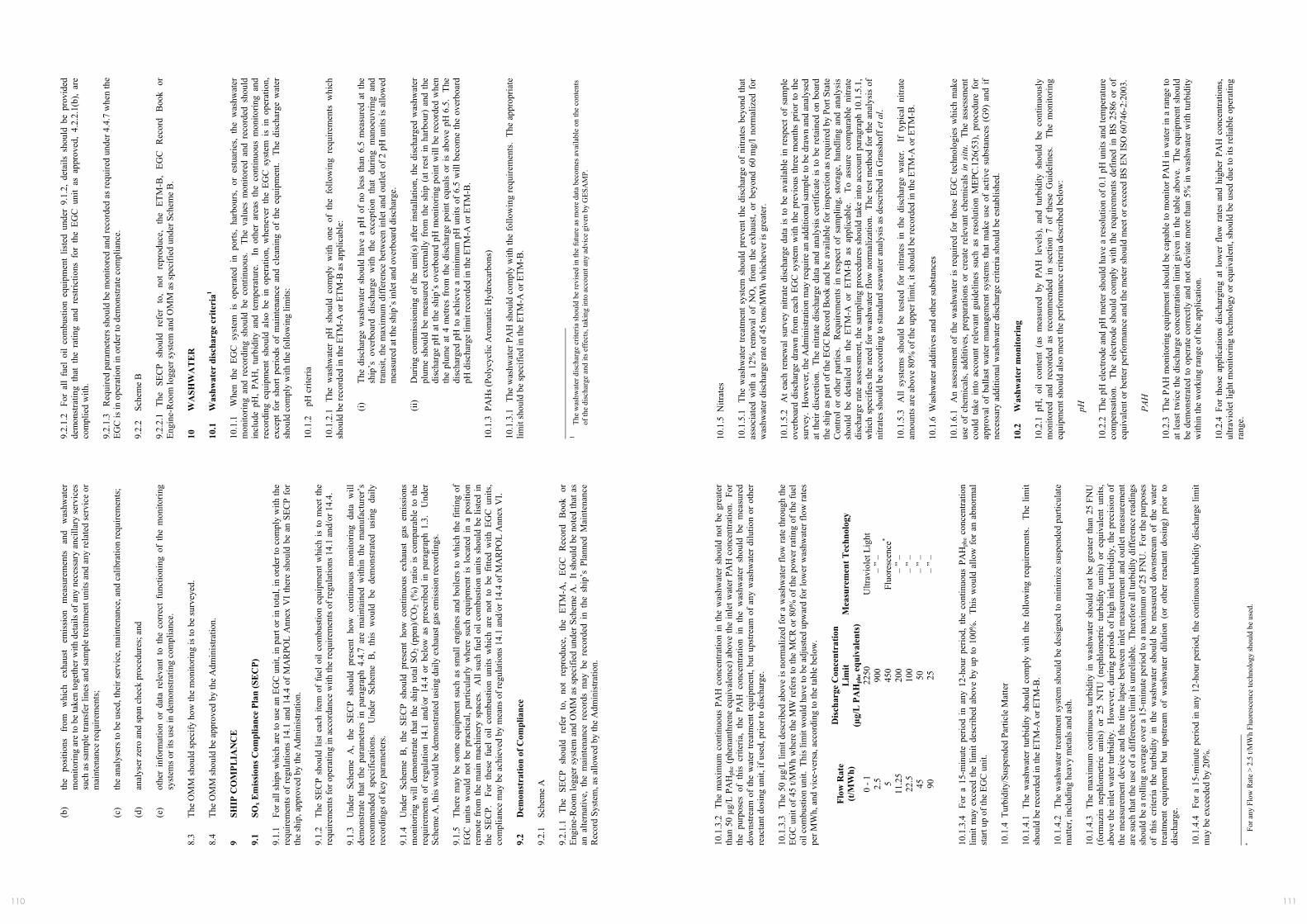
111110
MEP
C 5
9/24
/Add
.1
AN
NEX
9
Page
13
I:\M
EPC
\59\
24-A
dd-1
.doc
(b)
the
posi
tions
fr
om
whi
ch
exha
ust
emis
sion
m
easu
rem
ents
an
d w
ashw
ater
m
onito
ring
are
to b
e ta
ken
toge
ther
with
det
ails
of a
ny n
eces
sary
anc
illar
y se
rvic
es
such
as s
ampl
e tra
nsfe
r lin
es a
nd sa
mpl
e tre
atm
ent u
nits
and
any
rela
ted
serv
ice
or
mai
nten
ance
requ
irem
ents
; (c
) th
e an
alys
ers t
o be
use
d, th
eir s
ervi
ce, m
aint
enan
ce, a
nd c
alib
ratio
n re
quire
men
ts;
(d)
anal
yser
zer
o an
d sp
an c
heck
pro
cedu
res;
and
(e
) ot
her
info
rmat
ion
or d
ata
rele
vant
to
the
corr
ect
func
tioni
ng o
f th
e m
onito
ring
syst
ems o
r its
use
in d
emon
stra
ting
com
plia
nce.
8.
3 Th
e O
MM
shou
ld sp
ecify
how
the
mon
itorin
g is
to b
e su
rvey
ed.
8.4
The
OM
M sh
ould
be
appr
oved
by
the
Adm
inis
tratio
n.
9 SH
IP C
OM
PLIA
NC
E
9.1
SOx E
mis
sion
s Com
plia
nce
Plan
(SE
CP)
9.
1.1
For a
ll sh
ips
whi
ch a
re to
use
an
EGC
uni
t, in
par
t or i
n to
tal,
in o
rder
to c
ompl
y w
ith th
e re
quire
men
ts o
f re
gula
tions
14.
1 an
d 14
.4 o
f M
AR
POL
Ann
ex V
I th
ere
shou
ld b
e an
SEC
P fo
r th
e sh
ip, a
ppro
ved
by th
e A
dmin
istra
tion.
9.
1.2
The
SEC
P sh
ould
list
eac
h ite
m o
f fu
el o
il co
mbu
stio
n eq
uipm
ent w
hich
is to
mee
t the
re
quire
men
ts fo
r ope
ratin
g in
acc
orda
nce
with
the
requ
irem
ents
of r
egul
atio
ns 1
4.1
and/
or 1
4.4.
9.
1.3
Und
er S
chem
e A
, th
e SE
CP
shou
ld p
rese
nt h
ow c
ontin
uous
mon
itorin
g da
ta w
ill
dem
onst
rate
tha
t th
e pa
ram
eter
s in
par
agra
ph 4
.4.7
are
mai
ntai
ned
with
in t
he m
anuf
actu
rer’
s re
com
men
ded
spec
ifica
tions
. U
nder
Sch
eme
B,
this
wou
ld b
e de
mon
stra
ted
usin
g da
ily
reco
rdin
gs o
f key
par
amet
ers.
9.1.
4 U
nder
Sch
eme
B,
the
SEC
P sh
ould
pre
sent
how
con
tinuo
us e
xhau
st g
as e
mis
sion
s m
onito
ring
will
dem
onst
rate
tha
t th
e sh
ip t
otal
SO
2 (p
pm)/C
O2
(%)
ratio
is
com
para
ble
to t
he
requ
irem
ents
of
regu
latio
n 14
.1 a
nd/o
r 14
.4 o
r be
low
as
pres
crib
ed i
n pa
ragr
aph
1.3.
U
nder
Sc
hem
e A
, thi
s wou
ld b
e de
mon
stra
ted
usin
g da
ily e
xhau
st g
as e
mis
sion
reco
rdin
gs.
9.1.
5 Th
ere
may
be
som
e eq
uipm
ent s
uch
as s
mal
l eng
ines
and
boi
lers
to w
hich
the
fittin
g of
EG
C u
nits
wou
ld n
ot b
e pr
actic
al, p
artic
ular
ly w
here
suc
h eq
uipm
ent
is l
ocat
ed i
n a
posi
tion
rem
ote
from
the
mai
n m
achi
nery
spa
ces.
All
such
fuel
oil
com
bust
ion
units
sho
uld
be li
sted
in
the
SEC
P.
For
thes
e fu
el o
il co
mbu
stio
n un
its w
hich
are
not
to
be f
itted
with
EG
C u
nits
, co
mpl
ianc
e m
ay b
e ac
hiev
ed b
y m
eans
of r
egul
atio
ns 1
4.1
and/
or 1
4.4
of M
AR
POL
Ann
ex V
I. 9.
2 D
emon
stra
tion
of C
ompl
ianc
e 9.
2.1
Sche
me
A
9.2.
1.1
The
SEC
P sh
ould
re
fer
to,
not
repr
oduc
e,
the
ETM
-A,
EGC
R
ecor
d B
ook
or
Engi
ne-R
oom
logg
er s
yste
m a
nd O
MM
as
spec
ified
und
er S
chem
e A
. It
shou
ld b
e no
ted
that
as
an a
ltern
ativ
e, t
he m
aint
enan
ce r
ecor
ds m
ay b
e re
cord
ed i
n th
e sh
ip’s
Pla
nned
Mai
nten
ance
R
ecor
d Sy
stem
, as a
llow
ed b
y th
e A
dmin
istra
tion.
MEP
C 5
9/24
/Add
.1
AN
NEX
9
Page
14
I:\M
EPC
\59\
24-A
dd-1
.doc
9.2.
1.2
For
all
fuel
oil
com
bust
ion
equi
pmen
t lis
ted
unde
r 9.
1.2,
det
ails
sho
uld
be p
rovi
ded
dem
onst
ratin
g th
at t
he r
atin
g an
d re
stric
tions
for
the
EG
C u
nit
as a
ppro
ved,
4.2
.2.1
(b),
are
com
plie
d w
ith.
9.2.
1.3
Req
uire
d pa
ram
eter
s sho
uld
be m
onito
red
and
reco
rded
as r
equi
red
unde
r 4.4
.7 w
hen
the
EGC
is in
ope
ratio
n in
ord
er to
dem
onst
rate
com
plia
nce.
9.
2.2
Sche
me
B
9.2.
2.1
The
SEC
P sh
ould
re
fer
to,
not
repr
oduc
e,
the
ETM
-B,
EGC
R
ecor
d B
ook
or
Engi
ne-R
oom
logg
er sy
stem
and
OM
M a
s spe
cifie
d un
der S
chem
e B
. 10
W
ASH
WA
TE
R
10.1
W
ashw
ater
dis
char
ge c
rite
ria1
10.1
.1
Whe
n th
e EG
C s
yste
m i
s op
erat
ed i
n po
rts,
harb
ours
, or
est
uarie
s, th
e w
ashw
ater
m
onito
ring
and
reco
rdin
g sh
ould
be
cont
inuo
us.
The
val
ues
mon
itore
d an
d re
cord
ed s
houl
d in
clud
e pH
, PA
H,
turb
idity
and
tem
pera
ture
. I
n ot
her
area
s th
e co
ntin
uous
mon
itorin
g an
d re
cord
ing
equi
pmen
t sh
ould
als
o be
in
oper
atio
n, w
hene
ver
the
EGC
sys
tem
is
in o
pera
tion,
ex
cept
for
sho
rt pe
riods
of
mai
nten
ance
and
cle
anin
g of
the
equ
ipm
ent.
The
dis
char
ge w
ater
sh
ould
com
ply
with
the
follo
win
g lim
its:
10.1
.2
pH c
riter
ia
10.1
.2.1
Th
e w
ashw
ater
pH
sho
uld
com
ply
with
one
of
the
follo
win
g re
quire
men
ts w
hich
sh
ould
be
reco
rded
in th
e ET
M-A
or E
TM-B
as a
pplic
able
:
(i)
The
disc
harg
e w
ashw
ater
sho
uld
have
a p
H o
f no
less
than
6.5
mea
sure
d at
the
ship
’s o
verb
oard
dis
char
ge w
ith t
he e
xcep
tion
that
dur
ing
man
oeuv
ring
and
trans
it, th
e m
axim
um d
iffer
ence
bet
wee
n in
let a
nd o
utle
t of 2
pH
uni
ts is
allo
wed
m
easu
red
at th
e sh
ip’s
inle
t and
ove
rboa
rd d
isch
arge
.
(ii)
Dur
ing
com
mis
sion
ing
of th
e un
it(s)
afte
r in
stal
latio
n, th
e di
scha
rged
was
hwat
er
plum
e sh
ould
be
mea
sure
d ex
tern
ally
fro
m t
he s
hip
(at
rest
in
harb
our)
and
the
di
scha
rge
pH a
t the
shi
p’s
over
boar
d pH
mon
itorin
g po
int w
ill b
e re
cord
ed w
hen
the
plum
e at
4 m
etre
s fr
om th
e di
scha
rge
poin
t equ
als
or is
abo
ve p
H 6
.5.
The
disc
harg
ed p
H to
ach
ieve
a m
inim
um p
H u
nits
of
6.5
will
bec
ome
the
over
boar
d pH
dis
char
ge li
mit
reco
rded
in th
e ET
M-A
or E
TM-B
. 10
.1.3
PA
Hs (
Poly
cycl
ic A
rom
atic
Hyd
roca
rbon
s)
10.1
.3.1
Th
e w
ashw
ater
PA
H s
houl
d co
mpl
y w
ith th
e fo
llow
ing
requ
irem
ents
. Th
e ap
prop
riate
lim
it sh
ould
be
spec
ified
in th
e ET
M-A
or E
TM-B
.
1 Th
e w
ashw
ater
dis
char
ge c
riter
ia sh
ould
be
revi
sed
in th
e fu
ture
as m
ore
data
bec
omes
ava
ilabl
e on
the
cont
ents
of
the
disc
harg
e an
d its
eff
ects
, tak
ing
into
acc
ount
any
adv
ice
give
n by
GES
AM
P.
MEP
C 5
9/24
/Add
.1
AN
NEX
9
Page
15
I:\M
EPC
\59\
24-A
dd-1
.doc
10.1
.3.2
Th
e m
axim
um c
ontin
uous
PA
H c
once
ntra
tion
in th
e w
ashw
ater
sho
uld
not b
e gr
eate
r th
an 5
0 µg
/L P
AH
phe (
phen
anth
rene
equ
ival
ence
) abo
ve th
e in
let w
ater
PA
H c
once
ntra
tion.
For
th
e pu
rpos
es o
f th
is c
riter
ia,
the
PAH
con
cent
ratio
n in
the
was
hwat
er s
houl
d be
mea
sure
d do
wns
tream
of
the
wat
er tr
eatm
ent e
quip
men
t, bu
t ups
tream
of
any
was
hwat
er d
ilutio
n or
oth
er
reac
tant
dos
ing
unit,
if u
sed,
prio
r to
disc
harg
e.
10.1
.3.3
Th
e 50
µg/
L lim
it de
scrib
ed a
bove
is n
orm
aliz
ed fo
r a w
ashw
ater
flow
rate
thro
ugh
the
EGC
uni
t of 4
5 t/M
Wh
whe
re th
e M
W re
fers
to th
e M
CR
or 8
0% o
f the
pow
er ra
ting
of th
e fu
el
oil c
ombu
stio
n un
it. T
his l
imit
wou
ld h
ave
to b
e ad
just
ed u
pwar
d fo
r low
er w
ashw
ater
flow
rate
s pe
r MW
h, a
nd v
ice-
vers
a, a
ccor
ding
to th
e ta
ble
belo
w.
Flow
Rat
e (t
/MW
h)
Dis
char
ge C
once
ntra
tion
Lim
it (µ
g/L
PA
Hph
e equ
ival
ents
) M
easu
rem
ent T
echn
olog
y
0 - 1
22
50
Ultr
avio
let L
ight
2.
5 90
0 –
” –
5 45
0 Fl
uore
scen
ce*
11.2
5 20
0 –
” –
22.5
10
0 –
” –
45
50
– ”
– 90
25
–
” –
10.1
.3.4
Fo
r a
15-m
inut
e pe
riod
in a
ny 1
2-ho
ur p
erio
d, t
he c
ontin
uous
PA
Hph
e co
ncen
tratio
n lim
it m
ay e
xcee
d th
e lim
it de
scrib
ed a
bove
by
up to
100
%.
This
wou
ld a
llow
for
an
abno
rmal
st
art u
p of
the
EGC
uni
t. 10
.1.4
Tur
bidi
ty/S
uspe
nded
Par
ticle
Mat
ter
10.1
.4.1
Th
e w
ashw
ater
tur
bidi
ty s
houl
d co
mpl
y w
ith t
he f
ollo
win
g re
quire
men
ts.
The
limit
shou
ld b
e re
cord
ed in
the
ETM
-A o
r ETM
-B.
10.1
.4.2
Th
e w
ashw
ater
trea
tmen
t sys
tem
shou
ld b
e de
sign
ed to
min
imiz
e su
spen
ded
parti
cula
te
mat
ter,
incl
udin
g he
avy
met
als a
nd a
sh.
10.1
.4.3
Th
e m
axim
um c
ontin
uous
turb
idity
in w
ashw
ater
sho
uld
not b
e gr
eate
r th
an 2
5 FN
U
(for
maz
in n
ephl
omet
ric u
nits
) or
25
NTU
(ne
phlo
met
ric t
urbi
dity
uni
ts)
or e
quiv
alen
t un
its,
abov
e th
e in
let w
ater
turb
idity
. H
owev
er, d
urin
g pe
riods
of h
igh
inle
t tur
bidi
ty, t
he p
reci
sion
of
the
mea
sure
men
t dev
ice
and
the
time
laps
e be
twee
n in
let m
easu
rem
ent a
nd o
utle
t mea
sure
men
t ar
e su
ch th
at th
e us
e of
a d
iffer
ence
lim
it is
unr
elia
ble.
The
refo
re a
ll tu
rbid
ity d
iffer
ence
read
ings
sh
ould
be
a ro
lling
ave
rage
ove
r a 1
5-m
inut
e pe
riod
to a
max
imum
of 2
5 FN
U.
For t
he p
urpo
ses
of t
his
crite
ria t
he t
urbi
dity
in
the
was
hwat
er s
houl
d be
mea
sure
d do
wns
tream
of
the
wat
er
treat
men
t eq
uipm
ent
but
upst
ream
of
was
hwat
er d
ilutio
n (o
r ot
her
reac
tant
dos
ing)
prio
r to
di
scha
rge.
10
.1.4
.4
For a
15-
min
ute
perio
d in
any
12-
hour
per
iod,
the
cont
inuo
us tu
rbid
ity d
isch
arge
lim
it m
ay b
e ex
ceed
ed b
y 20
%.
*
For a
ny F
low
Rat
e >
2.5
t/MW
h Fl
uore
scen
ce te
chno
logy
shou
ld b
e us
ed.
MEP
C 5
9/24
/Add
.1
AN
NEX
9
Page
16
I:\M
EPC
\59\
24-A
dd-1
.doc
10.1
.5 N
itrat
es
10.1
.5.1
Th
e w
ashw
ater
trea
tmen
t sys
tem
sho
uld
prev
ent t
he d
isch
arge
of
nitra
tes
beyo
nd th
at
asso
ciat
ed w
ith a
12%
rem
oval
of
NO
x fr
om t
he e
xhau
st,
or b
eyon
d 60
mg/
l no
rmal
ized
for
w
ashw
ater
dis
char
ge ra
te o
f 45
tons
/MW
h w
hich
ever
is g
reat
er.
10.1
.5.2
A
t eac
h re
new
al s
urve
y ni
trate
dis
char
ge d
ata
is to
be
avai
labl
e in
res
pect
of
sam
ple
over
boar
d di
scha
rge
draw
n fr
om e
ach
EGC
sys
tem
with
the
prev
ious
thre
e m
onth
s pr
ior
to th
e su
rvey
. H
owev
er, t
he A
dmin
istra
tion
may
requ
ire a
n ad
ditio
nal s
ampl
e to
be
draw
n an
d an
alys
ed
at th
eir
disc
retio
n. T
he n
itrat
e di
scha
rge
data
and
ana
lysi
s ce
rtific
ate
is to
be
reta
ined
on
boar
d th
e sh
ip a
s par
t of t
he E
GC
Rec
ord
Boo
k an
d be
ava
ilabl
e fo
r ins
pect
ion
as re
quire
d by
Por
t Sta
te
Con
trol
or o
ther
par
ties.
Req
uire
men
ts i
n re
spec
t of
sam
plin
g, s
tora
ge, h
andl
ing
and
anal
ysis
sh
ould
be
deta
iled
in t
he E
TM-A
or
ETM
-B a
s ap
plic
able
. T
o as
sure
com
para
ble
nitra
te
disc
harg
e ra
te a
sses
smen
t, th
e sa
mpl
ing
proc
edur
es s
houl
d ta
ke in
to a
ccou
nt p
arag
raph
10.
1.5.
1,
whi
ch s
peci
fies
the
need
for w
ashw
ater
flow
nor
mal
izat
ion.
The
test
met
hod
for t
he a
naly
sis
of
nitra
tes s
houl
d be
acc
ordi
ng to
stan
dard
seaw
ater
ana
lysi
s as d
escr
ibed
in G
rass
hoff
et a
l. 10
.1.5
.3
All
syst
ems
shou
ld b
e te
sted
for
nitr
ates
in
the
disc
harg
e w
ater
. I
f ty
pica
l ni
trate
am
ount
s are
abo
ve 8
0% o
f the
upp
er li
mit,
it sh
ould
be
reco
rded
in th
e ET
M-A
or E
TM-B
. 10
.1.6
Was
hwat
er a
dditi
ves a
nd o
ther
subs
tanc
es
10.1
.6.1
A
n as
sess
men
t of
the
was
hwat
er is
req
uire
d fo
r th
ose
EGC
tech
nolo
gies
whi
ch m
ake
use
of c
hem
ical
s, ad
ditiv
es, p
repa
ratio
ns o
r cr
eate
rel
evan
t ch
emic
als
in s
itu.
The
asse
ssm
ent
coul
d ta
ke i
nto
acco
unt
rele
vant
gui
delin
es s
uch
as r
esol
utio
n M
EPC
.126
(53)
, pr
oced
ure
for
appr
oval
of
balla
st w
ater
man
agem
ent s
yste
ms
that
mak
e us
e of
act
ive
subs
tanc
es (
G9)
and
if
nece
ssar
y ad
ditio
nal w
ashw
ater
dis
char
ge c
riter
ia sh
ould
be
esta
blis
hed.
10
.2
Was
hwat
er m
onito
ring
10
.2.1
pH
, oi
l co
nten
t (a
s m
easu
red
by P
AH
lev
els)
, an
d tu
rbid
ity s
houl
d be
con
tinuo
usly
m
onito
red
and
reco
rded
as
reco
mm
ende
d in
sec
tion
7 of
the
se G
uide
lines
. T
he m
onito
ring
equi
pmen
t sho
uld
also
mee
t the
per
form
ance
crit
eria
des
crib
ed b
elow
:
pH
10.2
.2 T
he p
H e
lect
rode
and
pH
met
er s
houl
d ha
ve a
reso
lutio
n of
0.1
pH
uni
ts a
nd te
mpe
ratu
re
com
pens
atio
n.
The
elec
trode
sho
uld
com
ply
with
the
req
uire
men
ts d
efin
ed i
n B
S 25
86 o
r of
eq
uiva
lent
or b
ette
r per
form
ance
and
the
met
er sh
ould
mee
t or e
xcee
d B
S EN
ISO
607
46-2
:200
3.
PA
H
10.2
.3 T
he P
AH
mon
itorin
g eq
uipm
ent s
houl
d be
cap
able
to m
onito
r PA
H in
wat
er in
a ra
nge
to
at le
ast t
wic
e th
e di
scha
rge
conc
entra
tion
limit
give
n in
the
tabl
e ab
ove.
The
equ
ipm
ent s
houl
d be
dem
onst
rate
d to
ope
rate
cor
rect
ly a
nd n
ot d
evia
te m
ore
than
5%
in w
ashw
ater
with
turb
idity
w
ithin
the
wor
king
rang
e of
the
appl
icat
ion.
10
.2.4
For
tho
se a
pplic
atio
ns d
isch
argi
ng a
t lo
wer
flo
w r
ates
and
hig
her
PAH
con
cent
ratio
ns,
ultra
viol
et li
ght m
onito
ring
tech
nolo
gy o
r equ
ival
ent,
shou
ld b
e us
ed d
ue to
its
relia
ble
oper
atin
g ra
nge.
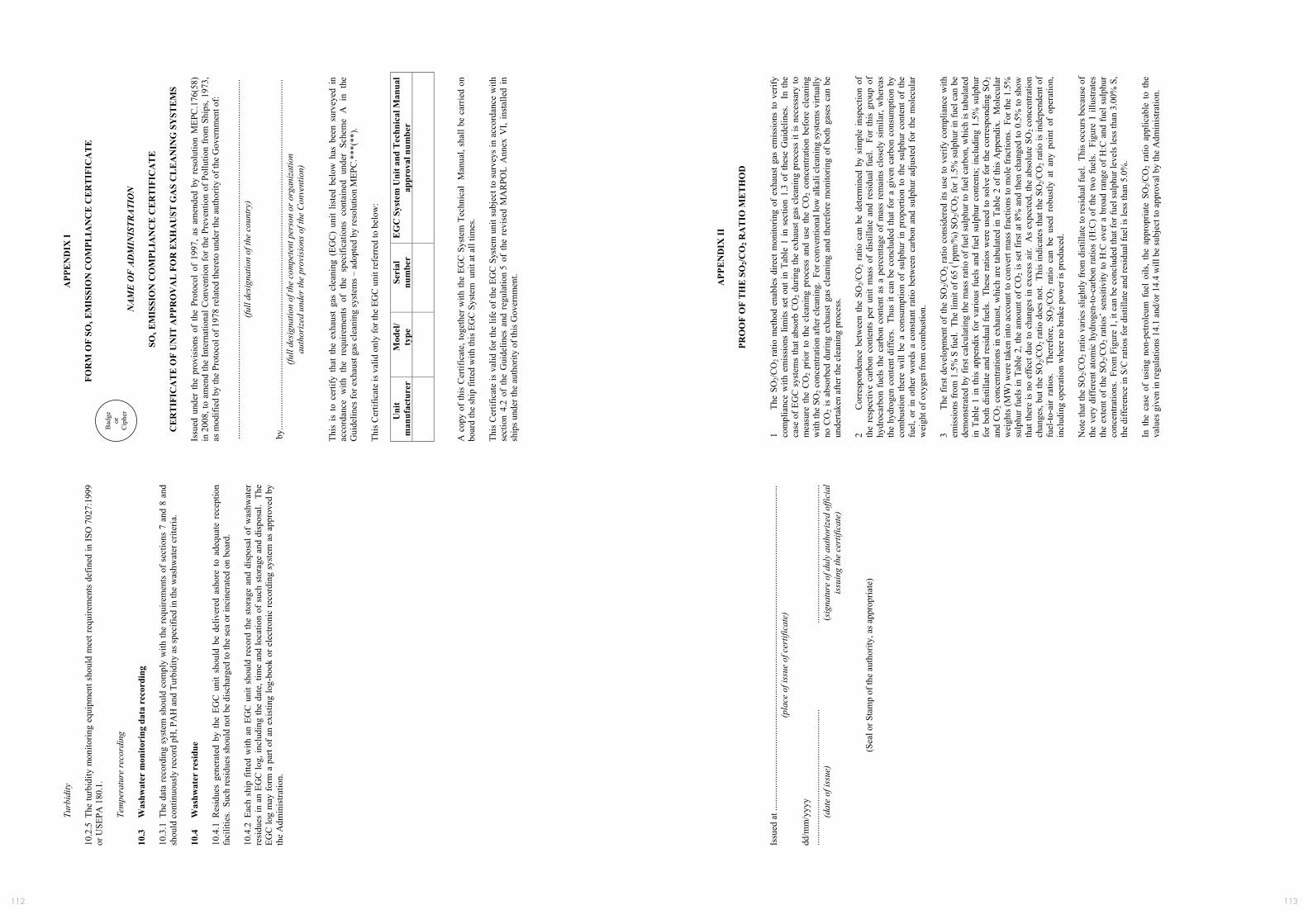
113112
MEP
C 5
9/24
/Add
.1
AN
NEX
9
Page
17
I:\M
EPC
\59\
24-A
dd-1
.doc
Turb
idity
10
.2.5
The
turb
idity
mon
itorin
g eq
uipm
ent s
houl
d m
eet r
equi
rem
ents
def
ined
in IS
O 7
027:
1999
or
USE
PA 1
80.1
.
Tem
pera
ture
reco
rdin
g 10
.3
Was
hwat
er m
onito
ring
dat
a re
cord
ing
10.3
.1 T
he d
ata
reco
rdin
g sy
stem
sho
uld
com
ply
with
the
requ
irem
ents
of s
ectio
ns 7
and
8 a
nd
shou
ld c
ontin
uous
ly re
cord
pH
, PA
H a
nd T
urbi
dity
as s
peci
fied
in th
e w
ashw
ater
crit
eria
. 10
.4
Was
hwat
er r
esid
ue
10.4
.1 R
esid
ues
gene
rate
d by
the
EG
C u
nit
shou
ld b
e de
liver
ed a
shor
e to
ade
quat
e re
cept
ion
faci
litie
s. S
uch
resi
dues
shou
ld n
ot b
e di
scha
rged
to th
e se
a or
inci
nera
ted
on b
oard
. 10
.4.2
Eac
h sh
ip f
itted
with
an
EGC
uni
t sho
uld
reco
rd th
e st
orag
e an
d di
spos
al o
f w
ashw
ater
re
sidu
es in
an
EGC
log,
incl
udin
g th
e da
te, t
ime
and
loca
tion
of s
uch
stor
age
and
disp
osal
. Th
e EG
C lo
g m
ay fo
rm a
par
t of a
n ex
istin
g lo
g-bo
ok o
r ele
ctro
nic
reco
rdin
g sy
stem
as
appr
oved
by
the
Adm
inis
tratio
n.
MEP
C 5
9/24
/Add
.1
AN
NEX
9
Page
18
I:\M
EPC
\59\
24-A
dd-1
.doc
APP
EN
DIX
I
FOR
M O
F SO
x EM
ISSI
ON
CO
MPL
IAN
CE
CE
RT
IFIC
AT
E
NA
ME
OF
AD
MIN
ISTR
ATI
ON
SOx E
MIS
SIO
N C
OM
PLIA
NC
E C
ER
TIF
ICA
TE
CE
RT
IFIC
AT
E O
F U
NIT
APP
RO
VA
L F
OR
EX
HA
UST
GA
S C
LE
AN
ING
SY
STE
MS
Issu
ed u
nder
the
pro
visi
ons
of t
he P
roto
col
of 1
997,
as
amen
ded
by r
esol
utio
n M
EPC
.176
(58)
in
200
8, to
am
end
the
Inte
rnat
iona
l Con
vent
ion
for t
he P
reve
ntio
n of
Pol
lutio
n fr
om S
hips
, 197
3,
as m
odifi
ed b
y th
e Pr
otoc
ol o
f 197
8 re
late
d th
eret
o un
der t
he a
utho
rity
of th
e G
over
nmen
t of:
...
......
......
......
......
......
......
......
......
......
......
......
......
......
......
......
......
......
......
......
......
......
......
......
......
......
...
(full
desi
gnat
ion
of th
e co
untr
y)
by
......
......
......
......
......
......
......
......
......
......
......
......
......
......
......
......
......
......
......
......
......
......
......
......
......
.. (fu
ll de
sign
atio
n of
the
com
pete
nt p
erso
n or
org
aniz
atio
n au
thor
ized
und
er th
e pr
ovis
ions
of t
he C
onve
ntio
n)
This
is
to c
ertif
y th
at t
he e
xhau
st g
as c
lean
ing
(EG
C)
unit
liste
d be
low
has
bee
n su
rvey
ed i
n ac
cord
ance
with
the
req
uire
men
ts o
f th
e sp
ecifi
catio
ns c
onta
ined
und
er S
chem
e A
in
the
Gui
delin
es fo
r exh
aust
gas
cle
anin
g sy
stem
s – a
dopt
ed b
y re
solu
tion
MEP
C.*
**(*
*).
This
Cer
tific
ate
is v
alid
onl
y fo
r the
EG
C u
nit r
efer
red
to b
elow
:
Uni
t m
anuf
actu
rer
Mod
el/
type
Se
rial
nu
mbe
r E
GC
Sys
tem
Uni
t and
Tec
hnic
al M
anua
l ap
prov
al n
umbe
r
A c
opy
of th
is C
ertif
icat
e, to
geth
er w
ith th
e EG
C S
yste
m T
echn
ical
Man
ual,
shal
l be
carr
ied
on
boar
d th
e sh
ip fi
tted
with
this
EG
C S
yste
m u
nit a
t all
times
. Th
is C
ertif
icat
e is
val
id fo
r the
life
of t
he E
GC
Sys
tem
uni
t sub
ject
to s
urve
ys in
acc
orda
nce
with
se
ctio
n 4.
2 of
the
Gui
delin
es a
nd r
egul
atio
n 5
of t
he r
evis
ed M
AR
POL
Ann
ex V
I, in
stal
led
in
ship
s und
er th
e au
thor
ity o
f thi
s Gov
ernm
ent.
Bad
ge
or
Cip
her
MEP
C 5
9/24
/Add
.1
AN
NEX
9
Page
19
I:\M
EPC
\59\
24-A
dd-1
.doc
Issu
ed a
t ....
......
......
......
......
......
......
......
......
......
......
......
......
......
......
......
......
......
......
......
......
......
......
.....
(pla
ce o
f iss
ue o
f cer
tific
ate)
dd
/mm
/yyy
y
......
......
......
......
......
......
......
......
......
.....
......
......
......
......
......
......
......
......
......
......
(d
ate
of is
sue)
(s
igna
ture
of d
uly
auth
oriz
ed o
ffici
al
is
suin
g th
e ce
rtifi
cate
)
(Sea
l or S
tam
p of
the
auth
ority
, as a
ppro
pria
te)
MEP
C 5
9/24
/Add
.1
AN
NEX
9
Page
20
I:\M
EPC
\59\
24-A
dd-1
.doc
APP
EN
DIX
II
PR
OO
F O
F T
HE
SO
2/CO
2 RA
TIO
ME
TH
OD
1
The
SO2/C
O2
ratio
met
hod
enab
les
dire
ct m
onito
ring
of e
xhau
st g
as e
mis
sion
s to
ver
ify
com
plia
nce
with
em
issi
ons
limits
set
out
in T
able
1 in
sec
tion
1.3
of th
ese
Gui
delin
es.
In th
e ca
se o
f EG
C s
yste
ms
that
abs
orb
CO
2 dur
ing
the
exha
ust g
as c
lean
ing
proc
ess
it is
nec
essa
ry to
m
easu
re t
he C
O2
prio
r to
the
cle
anin
g pr
oces
s an
d us
e th
e C
O2
conc
entra
tion
befo
re c
lean
ing
with
the
SO2 c
once
ntra
tion
afte
r cle
anin
g. F
or c
onve
ntio
nal l
ow a
lkal
i cle
anin
g sy
stem
s virt
ually
no
CO
2 is
abs
orbe
d du
ring
exha
ust g
as c
lean
ing
and
ther
efor
e m
onito
ring
of b
oth
gase
s ca
n be
un
derta
ken
afte
r the
cle
anin
g pr
oces
s. 2
Cor
resp
onde
nce
betw
een
the
SO2/C
O2
ratio
can
be
dete
rmin
ed b
y si
mpl
e in
spec
tion
of
the
resp
ectiv
e ca
rbon
con
tent
s pe
r un
it m
ass
of d
istill
ate
and
resi
dual
fue
l. F
or t
his
grou
p of
hy
droc
arbo
n fu
els
the
carb
on c
onte
nt a
s a
perc
enta
ge o
f m
ass
rem
ains
clo
sely
sim
ilar,
whe
reas
th
e hy
drog
en c
onte
nt d
iffer
s. T
hus
it ca
n be
con
clud
ed th
at fo
r a g
iven
car
bon
cons
umpt
ion
by
com
bust
ion
ther
e w
ill b
e a
cons
umpt
ion
of s
ulph
ur in
pro
porti
on to
the
sulp
hur
cont
ent o
f th
e fu
el, o
r in
oth
er w
ords
a c
onst
ant r
atio
bet
wee
n ca
rbon
and
sul
phur
adj
uste
d fo
r th
e m
olec
ular
w
eigh
t of o
xyge
n fr
om c
ombu
stio
n.
3 Th
e fir
st d
evel
opm
ent o
f the
SO
2/CO
2 rat
io c
onsi
dere
d its
use
to v
erify
com
plia
nce
with
em
issi
ons
from
1.5
% S
fuel
. Th
e lim
it of
65
(1 ppm
/%) S
O2/C
O2 f
or 1
.5%
sul
phur
in fu
el c
an b
e de
mon
stra
ted
by fi
rst c
alcu
latin
g th
e m
ass
ratio
of f
uel s
ulph
ur to
fuel
car
bon,
whi
ch is
tabu
late
d in
Tab
le 1
in th
is a
ppen
dix
for
vario
us f
uels
and
fue
l sul
phur
con
tent
s; in
clud
ing
1.5%
sul
phur
fo
r bot
h di
still
ate
and
resi
dual
fuel
s. T
hese
ratio
s w
ere
used
to s
olve
for t
he c
orre
spon
ding
SO
2 an
d C
O2 c
once
ntra
tions
in e
xhau
st, w
hich
are
tabu
late
d in
Tab
le 2
of t
his
App
endi
x. M
olec
ular
w
eigh
ts (M
W) w
ere
take
n in
to a
ccou
nt to
con
vert
mas
s fra
ctio
ns to
mol
e fr
actio
ns.
For t
he 1
.5%
su
lphu
r fue
ls in
Tab
le 2
, the
am
ount
of C
O2 i
s se
t firs
t at 8
% a
nd th
en c
hang
ed to
0.5
% to
sho
w
that
ther
e is
no
effe
ct d
ue to
cha
nges
in e
xces
s ai
r. A
s ex
pect
ed, t
he a
bsol
ute
SO2
conc
entra
tion
chan
ges,
but t
he S
O2/C
O2 r
atio
doe
s no
t. T
his
indi
cate
s th
at th
e SO
2/CO
2 rat
io is
inde
pend
ent o
f fu
el-to
-air
ratio
s. T
here
fore
, SO
2/CO
2 ra
tio c
an b
e us
ed r
obus
tly a
t an
y po
int
of o
pera
tion,
in
clud
ing
oper
atio
n w
here
no
brak
e po
wer
is p
rodu
ced.
N
ote
that
the
SO2/C
O2 r
atio
var
ies s
light
ly fr
om d
istil
late
to re
sidu
al fu
el.
This
occ
urs b
ecau
se o
f th
e ve
ry d
iffer
ent a
tom
ic h
ydro
gen-
to-c
arbo
n ra
tios
(H:C
) of
the
two
fuel
s. F
igur
e 1
illus
trate
s th
e ex
tent
of t
he S
O2/C
O2 r
atio
s’ s
ensi
tivity
to H
:C o
ver a
bro
ad ra
nge
of H
:C a
nd fu
el s
ulph
ur
conc
entra
tions
. Fr
om F
igur
e 1,
it c
an b
e co
nclu
ded
that
for f
uel s
ulph
ur le
vels
less
than
3.0
0% S
, th
e di
ffer
ence
in S
/C ra
tios f
or d
istil
late
and
resi
dual
fuel
is le
ss th
an 5
.0%
. In
the
cas
e of
usi
ng n
on-p
etro
leum
fue
l oi
ls,
the
appr
opria
te S
O2/C
O2
ratio
app
licab
le t
o th
e va
lues
giv
en in
regu
latio
ns 1
4.1
and/
or 1
4.4
will
be
subj
ect t
o ap
prov
al b
y th
e A
dmin
istra
tion.
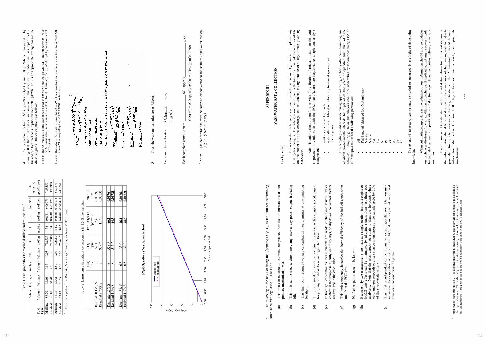
115114
MEP
C 5
9/24
/Add
.1
AN
NEX
9
Page
21
I:\M
EPC
\59\
24-A
dd-1
.doc
Tabl
e 1:
Fue
l pro
perti
es fo
r mar
ine
dist
illat
e an
d re
sidu
al fu
el*
C
arbo
n H
ydro
gen
Sulp
hur
Oth
er
C
H
S Fu
el S
/C
Exh
SO2/C
O2
Fuel
T
ype
%(m
/m)
%(m
/m)
%(m
/m)
%(m
/m)
mol
/kg
mol
/kg
mol
/kg
mol
/mol
pp
m/%
(v/v
)
Dis
tilla
te
86.2
0 13
.60
0.17
0.
03
71.8
333
136
0.05
31
0.00
074
7.39
559
Res
idua
l 86
.10
10.9
0 2.
70
0.30
71
.750
010
9 0.
8438
0.
0117
6 11
7.59
58
Dis
tilla
te
85.0
5 13
.42
1.50
0.
03
70.8
750
134.
2 0.
4688
0.
0066
14
66.1
376
Res
idua
l 87
.17
11.0
3 1.
50
0.30
72
.641
711
0.3
0.46
88
0.00
6453
64
.529
1 *
Bas
ed o
n pr
oper
ties i
n th
e IM
O N
Ox M
onito
ring
Gui
delin
es, r
esol
utio
n M
EPC
.103
(49)
.
Ta
ble
2: E
mis
sion
s cal
cula
tions
cor
resp
ondi
ng to
1.5
% fu
el su
lphu
r
C
O2
SO2
Exh
SO2/C
O2
Exh
S/C
%
1 ppm
1 pp
m/%
m
/m
Dis
tilla
te 0
.17%
S
8 59
.1
7.4
0.00
197
Res
idua
l 2.7
0% S
8
939.
7 11
7.5
0.03
136
D
istil
late
1.5
% S
8
528.
5 66
.1
0.01
764
Res
idua
l 1.5
% S
8
515.
7 64
.5
0.01
721
D
istil
late
1.5
% S
0.
5 33
.0
66.1
0.
0176
4 R
esid
ual 1
.5%
S
0.5
32.2
64
.5
0.01
721
SO
2/CO
2 ra
tio v
s %
sul
phur
in fu
el
050100
150
200
250 0,
000,
501,
001,
502,
002,
503,
003,
504,
004,
505,
00
% m
/m s
ulph
ur in
fuel
SO2(ppm)/CO2(%)
Dis
tilla
te fu
elR
esid
ual f
uel
MEP
C 5
9/24
/Add
.1
AN
NEX
9
Page
22
I:\M
EPC
\59\
24-A
dd-1
.doc
4 C
orre
spon
denc
e be
twee
n 65
(1 pp
m/%
) SO
2/CO
2 an
d 6.
0 g/
kWh
is d
emon
stra
ted
by
show
ing
that
the
ir S/
C r
atio
s ar
e si
mila
r. T
his
requ
ires
the
addi
tiona
l as
sum
ptio
n of
a
brak
e-sp
ecifi
ed fu
el c
onsu
mpt
ion
valu
e of
200
g/k
Wh.
Thi
s is
an
appr
opria
te a
vera
ge fo
r mar
ine
dies
el e
ngin
es.
The
calc
ulat
ion
is a
s fol
low
s:
Not
e 1:
The
S/C
mas
s ra
tios c
alcu
late
d ab
ove,
bas
ed o
n 6.
0 g/
kWh
and
200
g/kW
h B
SFC
, are
bot
h w
ithin
0.1
0% o
f th
e S/
C m
ass
ratio
s in
the
emis
sion
s ta
ble
(Tab
le 2
). T
here
fore
, 651 (
ppm
/%)
SO2/C
O2
corr
espo
nds
wel
l to
6.0
g/k
Wh.
N
ote
2: T
he v
alue
of
6.0
g/kW
h, h
ence
the
200g
/kW
h br
ake-
spec
ified
fue
l con
sum
ptio
n is
take
n fr
om M
AR
POL
Ann
ex V
I as a
dopt
ed b
y th
e 19
97 M
AR
POL
Con
fere
nce.
5
Thus
, the
wor
king
form
ulas
are
as f
ollo
ws:
For c
ompl
ete
com
bust
ion
= S
O2 (
ppm
* )
≤
65
CO
2 (%
* )
For i
ncom
plet
e co
mbu
stio
n =
___
____
____
____
SO
2 (p
pm* )_
____
____
____
____
___
≤ 6
5
CO
2(%
* ) + (C
O (p
pm* )/1
0000
) + (T
HC
(ppm
* )/100
00)
* Not
e:
gas
conc
entra
tions
mus
t be
sam
pled
or
conv
erte
d to
the
sam
e re
sidu
al w
ater
con
tent
(e
.g.,
fully
wet
, ful
ly d
ry).
MEP
C 5
9/24
/Add
.1
AN
NEX
9
Page
23
I:\M
EPC
\59\
24-A
dd-1
.doc
6 Th
e fo
llow
ing
is th
e ba
sis
of u
sing
the
(2 ppm
/%)
SO2/C
O2
as th
e lim
it fo
r de
term
inin
g co
mpl
ianc
e w
ith re
gula
tion
14.1
or 1
4.4:
(a)
This
lim
it ca
n be
use
d to
det
erm
ine
com
plia
nce
from
fuel
oil
burn
ers
that
do
not
prod
uce
mec
hani
cal p
ower
. (b
) Th
is l
imit
can
be u
sed
to d
eter
min
e co
mpl
ianc
e at
any
pow
er o
utpu
t, in
clud
ing
idle
. (c
) Th
is l
imit
only
req
uire
s tw
o ga
s co
ncen
tratio
n m
easu
rem
ents
at
one
sam
plin
g lo
catio
n.
(d)
Ther
e is
no
need
to m
easu
re a
ny e
ngin
e pa
ram
eter
s su
ch a
s en
gine
spe
ed, e
ngin
e to
rque
, eng
ine
exha
ust f
low
, or e
ngin
e fu
el fl
ow.
(e)
If b
oth
gas
conc
entra
tion
mea
sure
men
ts a
re m
ade
at t
he s
ame
resi
dual
wat
er
cont
ent i
n th
e sa
mpl
e (e
.g.,
fully
wet
, ful
ly d
ry),
no d
ry-to
-wet
con
vers
ion
fact
ors
are
requ
ired
in th
e ca
lcul
atio
n.
(f)
This
lim
it co
mpl
etel
y de
coup
les
the
ther
mal
eff
icie
ncy
of th
e fu
el o
il co
mbu
stio
n un
it fr
om th
e EG
C u
nit.
(g)
No
fuel
pro
perti
es n
eed
to b
e kn
own.
(h
) B
ecau
se o
nly
two
mea
sure
men
ts a
re m
ade
at a
sin
gle
loca
tion,
tran
sien
t eng
ine
or
EGC
S un
it ef
fect
s ca
n be
min
imiz
ed b
y al
igni
ng s
igna
ls f
rom
jus
t th
ese
two
anal
yser
s. (
Not
e th
at t
he m
ost
appr
opria
te p
oint
s to
alig
n ar
e th
e po
ints
whe
re
each
ana
lyse
r res
pond
s to
a s
tep
chan
ge in
em
issi
ons
at th
e sa
mpl
e pr
obe
by 5
0%
of th
e st
eady
-sta
te v
alue
.) (i)
Th
is l
imit
is i
ndep
ende
nt o
f th
e am
ount
of
exha
ust
gas
dilu
tion.
D
ilutio
n m
ay
occu
r du
e to
eva
pora
tion
of w
ater
in
an E
GC
unit,
and
as
part
of a
n ex
haus
t sa
mpl
er’s
pre
cond
ition
ing
syst
em.
2
ppm
mea
ns “
parts
per
mill
ion”
. It
is a
ssum
ed th
at p
pm is
mea
sure
d by
gas
ana
lyse
rs o
n a
mol
ar b
asis
, ass
umin
g id
eal
gas
beha
viou
r. T
he t
echn
ical
ly c
orre
ct u
nits
are
act
ually
mic
ro-m
oles
of
subs
tanc
e pe
r m
ole
of t
otal
am
ount
(µm
ol/m
ol),
but p
pm is
use
d in
ord
er to
be
cons
iste
nt w
ith u
nits
in th
e N
Ox T
echn
ical
Cod
e.
MEP
C 5
9/24
/Add
.1
AN
NEX
9
Page
24
I:\M
EPC
\59\
24-A
dd-1
.doc
APP
EN
DIX
III
W
ASH
WA
TE
R D
AT
A C
OL
LE
CT
ION
B
ackg
roun
d
The
was
hwat
er d
isch
arge
crit
eria
are
inte
nded
to a
ct a
s in
itial
gui
danc
e fo
r im
plem
entin
g EG
C sy
stem
des
igns
. Th
e cr
iteria
shou
ld b
e re
vise
d in
the
futu
re a
s mor
e da
ta b
ecom
es a
vaila
ble
on t
he c
onte
nts
of t
he d
isch
arge
and
its
eff
ects
, ta
king
int
o ac
coun
t an
y ad
vice
giv
en b
y G
ESA
MP.
Adm
inis
tratio
ns s
houl
d th
eref
ore
prov
ide
for
colle
ctio
n of
rel
evan
t da
ta.
To
this
end
, sh
ipow
ners
in
conj
unct
ion
with
the
EG
C m
anuf
actu
rer
are
requ
este
d to
sam
ple
and
anal
yse
sam
ples
of:
•
in
let w
ater
(for
bac
kgro
und)
; •
w
ater
afte
r the
scru
bber
(but
bef
ore
any
treat
men
t sys
tem
); an
d •
di
scha
rge
wat
er.
Th
is s
ampl
ing
coul
d be
mad
e du
ring
appr
oval
test
ing
or s
hortl
y af
ter c
omm
issi
onin
g an
d at
abo
ut t
wel
ve-m
onth
int
erva
ls f
or a
per
iod
of t
wo
year
s of
ope
ratio
n (m
inim
um o
f th
ree
sam
ples
). S
ampl
ing
guid
ance
and
ana
lysi
s sh
ould
be
unde
rtake
n by
labo
rato
ries
usin
g EP
A o
r IS
O te
st p
roce
dure
s for
the
follo
win
g pa
ram
eter
s:
pH
PA
H a
nd o
il (d
etai
led
GC
-MS
anal
ysis
)
Nitr
ate
N
itrite
Cd
C
u
Ni
Pb
Zn
A
s
Cr
V
The
exte
nt o
f la
bora
tory
tes
ting
may
be
varie
d or
enh
ance
d in
the
lig
ht o
f de
velo
ping
kn
owle
dge.
Whe
n su
bmitt
ing
sam
ple
data
to th
e A
dmin
istra
tion,
info
rmat
ion
shou
ld a
lso
be in
clud
ed
on w
ashw
ater
dis
char
ge fl
ow ra
tes,
dilu
tion
of d
isch
arge
, if a
pplic
able
, and
eng
ine
pow
er s
houl
d be
inc
lude
d as
wel
l as
spe
cific
atio
ns o
f th
e fu
el u
sed
from
the
bun
ker
deliv
ery
note
as
a m
inim
um.
It
is r
ecom
men
ded
that
the
ship
that
has
pro
vide
d th
is in
form
atio
n to
the
satis
fact
ion
of
the
Adm
inis
tratio
n sh
ould
be
gran
ted
a w
aive
r fo
r co
mpl
ianc
e of
the
exis
ting
inst
alla
tion(
s) to
po
ssib
le f
utur
e st
ricte
r w
ashw
ater
dis
char
ge s
tand
ards
. T
he A
dmin
istra
tion
shou
ld f
orw
ard
info
rmat
ion
subm
itted
on
this
iss
ue t
o th
e O
rgan
izat
ion
for
diss
emin
atio
n by
the
app
ropr
iate
m
echa
nism
s.
***

116
APPENDIX 3 Emission Control Area Geographic Definitions
A3.1 MARPOL Annex VI Regulation 14 – Sulphur Oxides (SOx) and Particulate Matter* – Emission Control Areas Geographic Definitions Full details of regulation 14 are contained in ‘Revised MAR-POL Annex VI [18] – Regulations for the prevention of air pollution from ships and NOx Technical Code 2008 – 2009 Edition’. This publication is available from IMO (www.imo.org) both in hard copy and electronically.
A3.1.1 Baltic Sea The Baltic Sea ECA is defined in regulation 1.11.2 of MARPOL Annex I:
• The Baltic Sea proper with the Gulf of Bothnia, Gulf of Finland and the entrance to the Baltic Sea bounded by theparalleloftheSkawintheSkagerrakat57°44.8’N
A3.1.2 North Sea The North Sea ECA is defined in regulation 5(a)(f) of MARPOL Annex V:
• The North Sea proper including seas therein with the boundary between:
i. TheNorthSeasouthwardsoflatitude62°Nand eastwardsoflongitude4°W;
ii. The Skagerrak, the southern limit of which is determined eastoftheSkawbylatitude57°44.8’N;and
iii. The English Channel and its approaches eastwards of longitude5°Wandnorthwardsoflatitude48°30’N
A3.1.3 North America The North American ECA is described by the coordinates provided in Appendix VII to MARPOL Annex VI and comprises:
• The sea area located off the Pacific coasts of the United States and Canada,
• Sea areas located off the Atlantic coasts of the United States, Canada, and France (Saint-Pierre-et-Miquelon) and the Gulf of Mexico coast of the United States
• The sea area located off the coasts of the Hawaiian Islands of Hawai’i, Maui, Oahu, Moloka’i, Ni’ihau, Kaua’i, Lana’i, and Kaho’olawe
These areas are defined by geodesic lines, which connect an extensive list of coordinates given in IMO Resolution MEPC 190(60). This is contained in Annex 11 of the final report of MEPC 60 [10]. The coordinates, that are also included as a new appendix VII of MARPOL Annex VI, have not been repeated here, as they total some 6 pages.
A3.1.4 U.S. Caribbean The United States Caribbean ECA is described by the coordinates provided in Appendix VII to MARPOL Annex VI and comprises:
• The sea area located off the Atlantic and Caribbean coasts of the Commonwealth of Puerto Rico and the United States Virgin Islands.
Again these areas are defined by geodesic lines, which connect an extensive list of coordinates. These are not repeated here but can be found in IMO document MEPC 62/6/2
A3.1.5 New areas Regulation 14 contains a catchall paragraph that SOx emission controls will apply to any other ECA, including any port area, designated by IMO in accordance with the criteria and procedures in Appendix III to MARPOL Annex VI.
A3.1.6 NOx Emission Control Areas *Note: Tier III NOx emission standards will also apply to engines installed on ships constructed on or after 1 January 2016, which are operating in ECAs designated as NOx emission control areas – see Appendix 4.
117
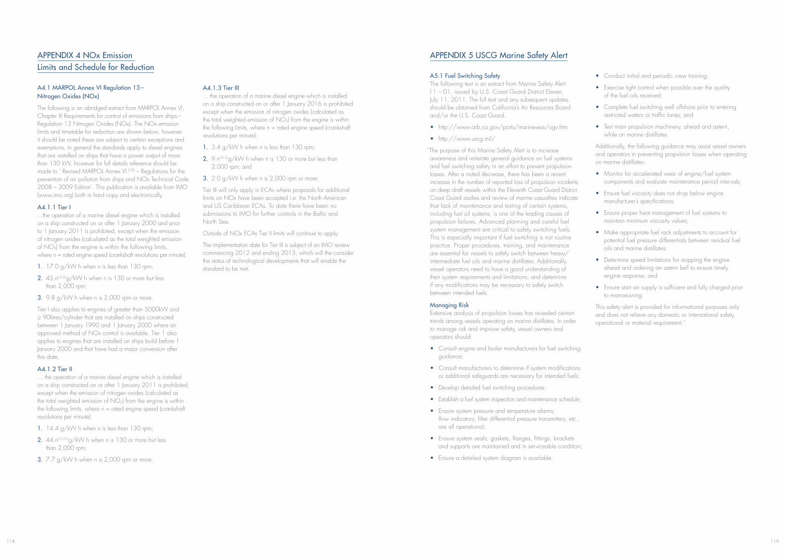
119118
APPENDIX 4 NOx Emission Limits and Schedule for Reduction
A4.1 MARPOL Annex VI Regulation 13 – Nitrogen Oxides (NOx)
The following is an abridged extract from MARPOL Annex VI, Chapter III Requirements for control of emissions from ships – Regulation 13 Nitrogen Oxides (NOx). The NOx emission limits and timetable for reduction are shown below, however it should be noted these are subject to certain exceptions and exemptions. In general the standards apply to diesel engines that are installed on ships that have a power output of more than 130 kW, however for full details reference should be made to ‘ Revised MARPOL Annex VI [18] – Regulations for the prevention of air pollution from ships and NOx Technical Code 2008 – 2009 Edition’. This publication is available from IMO (www.imo.org) both in hard copy and electronically.
A4.1.1 Tier I ...the operation of a marine diesel engine which is installed on a ship constructed on or after 1 January 2000 and prior to 1 January 2011 is prohibited, except when the emission of nitrogen oxides (calculated as the total weighted emission of NO2) from the engine is within the following limits, where n = rated engine speed (crankshaft revolutions per minute):
1. 17.0 g/kW h when n is less than 130 rpm;
2. 45.n(-0.2) g/kW h when n is 130 or more but less than 2,000 rpm;
3. 9.8 g/kW h when n is 2,000 rpm or more.
Tier I also applies to engines of greater than 5000kW and ≥ 90litres/cylinder that are installed on ships constructed between 1 January 1990 and 1 January 2000 where an approved method of NOx control is available. Tier 1 also applies to engines that are installed on ships build before 1 January 2000 and that have had a major conversion after this date.
A4.1.2 Tier II ... the operation of a marine diesel engine which is installed on a ship constructed on or after 1 January 2011 is prohibited, except when the emission of nitrogen oxides (calculated as the total weighted emission of NO2) from the engine is within the following limits, where n = rated engine speed (crankshaft revolutions per minute):
1. 14.4 g/kW h when n is less than 130 rpm;
2. 44.n(-0.23) g/kW h when n is 130 or more but less than 2,000 rpm;
3. 7.7 g/kW h when n is 2,000 rpm or more.
A4.1.3 Tier III ... the operation of a marine diesel engine which is installed on a ship constructed on or after 1 January 2016 is prohibited except when the emission of nitrogen oxides (calculated as the total weighted emission of NO2) from the engine is within the following limits, where n = rated engine speed (crankshaft revolutions per minute):
1. 3.4 g/kW h when n is less than 130 rpm;
2. 9.n(-0.2) g/kW h when n is 130 or more but less than 2,000 rpm; and
3. 2.0 g/kW h when n is 2,000 rpm or more;
Tier III will only apply in ECAs where proposals for additional limits on NOx have been accepted i.e. the North American and US Caribbean ECAs. To date there have been no submissions to IMO for further controls in the Baltic and North Sea.
Outside of NOx ECAs Tier II limits will continue to apply.
The implementation date for Tier III is subject of an IMO review commencing 2012 and ending 2013, which will the consider the status of technological developments that will enable the standard to be met.
APPENDIX 5 USCG Marine Safety Alert
A5.1 Fuel Switching Safety The following text is an extract from Marine Safety Alert 11 – 01, issued by U.S. Coast Guard District Eleven, July 11, 2011. The full text and any subsequent updates should be obtained from California’s Air Resources Board and/or the U.S. Coast Guard.
• http://www.arb.ca.gov/ports/marinevess/ogv.htm
• http://www.uscg.mil/
“The purpose of this Marine Safety Alert is to increase awareness and reiterate general guidance on fuel systems and fuel switching safety in an effort to prevent propulsion losses. After a noted decrease, there has been a recent increase in the number of reported loss of propulsion incidents on deep draft vessels within the Eleventh Coast Guard District. Coast Guard studies and review of marine casualties indicate that lack of maintenance and testing of certain systems, including fuel oil systems, is one of the leading causes of propulsion failures. Advanced planning and careful fuel system management are critical to safely switching fuels. This is especially important if fuel switching is not routine practice. Proper procedures, training, and maintenance are essential for vessels to safely switch between heavy/intermediate fuel oils and marine distillates. Additionally, vessel operators need to have a good understanding of their system requirements and limitations, and determine if any modifications may be necessary to safely switch between intended fuels.
Managing Risk Extensive analysis of propulsion losses has revealed certain trends among vessels operating on marine distillates. In order to manage risk and improve safety, vessel owners and operators should:
• Consult engine and boiler manufacturers for fuel switching guidance;
• Consult manufacturers to determine if system modifications or additional safeguards are necessary for intended fuels;
• Develop detailed fuel switching procedures;
• Establish a fuel system inspection and maintenance schedule;
• Ensure system pressure and temperature alarms, flow indicators, filter differential pressure transmitters, etc., are all operational;
• Ensure system seals, gaskets, flanges, fittings, brackets and supports are maintained and in serviceable condition;
• Ensure a detailed system diagram is available;
• Conduct initial and periodic crew training;
• Exercise tight control when possible over the quality of the fuel oils received;
• Complete fuel switching well offshore prior to entering restricted waters or traffic lanes; and
• Test main propulsion machinery, ahead and astern, while on marine distillates.
Additionally, the following guidance may assist vessel owners and operators in preventing propulsion losses when operating on marine distillates:
• Monitor for accelerated wear of engine/fuel system components and evaluate maintenance period intervals;
• Ensure fuel viscosity does not drop below engine manufacturer’s specifications;
• Ensure proper heat management of fuel systems to maintain minimum viscosity values;
• Make appropriate fuel rack adjustments to account for potential fuel pressure differentials between residual fuel oils and marine distillates;
• Determine speed limitations for stopping the engine ahead and ordering an astern bell to ensure timely engine response; and
• Ensure start air supply is sufficient and fully charged prior to manoeuvring.
This safety alert is provided for informational purposes only and does not relieve any domestic or international safety, operational or material requirement.”
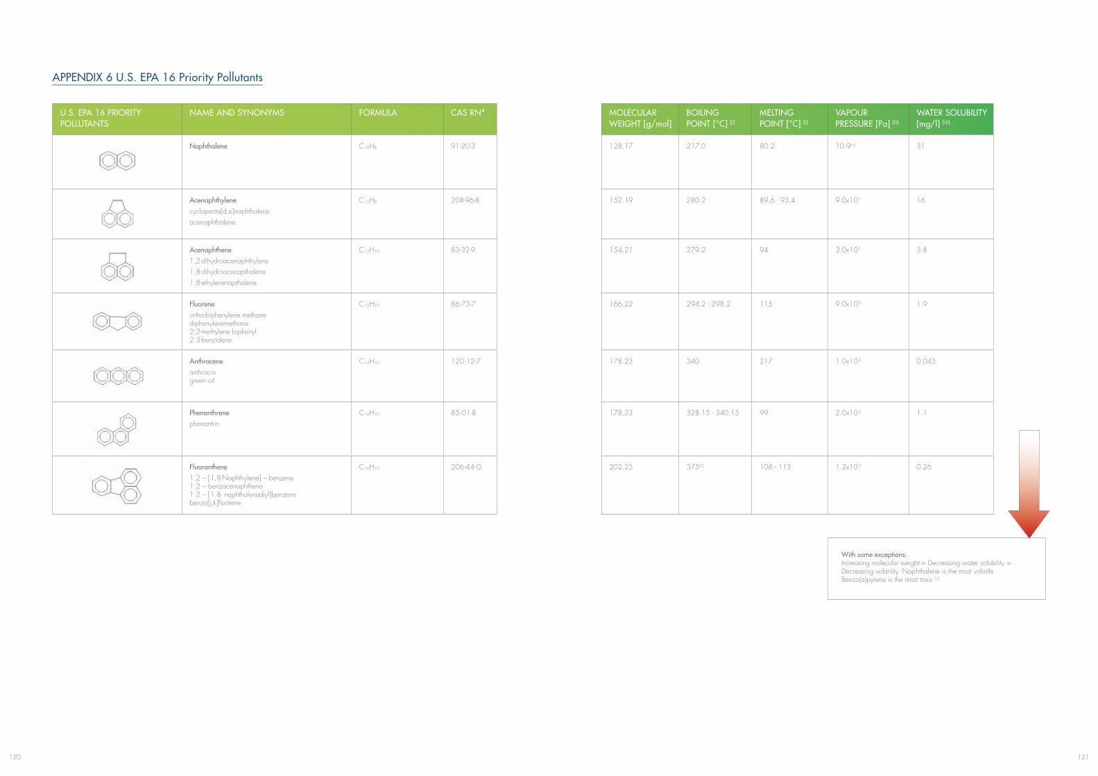
121120
APPENDIX 6 U.S. EPA 16 Priority Pollutants
U.S. EPA 16 PRIORITY POLLUTANTS
NAME AND SYNONYMS FORMULA CAS RN* MOLECULARWEIGHT [g/mol]
BOILING POINT [°C] [i]
MELTING POINT [°C] [i]
VAPOUR PRESSURE [Pa] [ii]
WATER SOLUBILITY [mg/l] [iii]
Naphthalene C10H8 91-20-3 128.17 217.0 80.2 10.9[iv] 31
Acenaphthylenecyclopenta[d,e]naphthaleneacenaphthalene
C12H8 208-96-8 152.19 280.2 89.6 - 93.4 9.0x10⁻¹ 16
Acenaphthene1,2-dihydroacenaphthylene1,8-dihydroacenapthalene1,8-ethylenenapthalene
C12H10 83-32-9 154.21 279.2 94 3.0x10⁻¹ 3.8
Fluoreneortho-biphenylene methane diphenylenemethane 2,2-methylene biphenyl 2.3-benzidene
C13H10 86-73-7 166.22 294.2 - 298.2 115 9.0x10⁻² 1.9
Anthraceneanthracin green oil
C14H10 120 -12-7 178.23 340 217 1.0x10⁻³ 0.045
Phenanthrenephenantrin
C14H10 85-01-8 178.23 328.15 - 340.15 99 2.0x10⁻² 1.1
Fluoranthene1.2 – [1,8-Naphthylene] – benzene 1.2 – benzacenaphthene 1.2 – [1.8- naphthalenediyl]benzene benzo[j,k]fluorene
C16H10 206-44-0 202.25 375[ii] 108 - 113 1.2x10⁻³ 0.26
With some exceptions:Increasing molecular weight = Decreasing water solubility =Decreasing volatility. Naphthalene is the most volatileBenzo(a)pyrene is the most toxic [v]
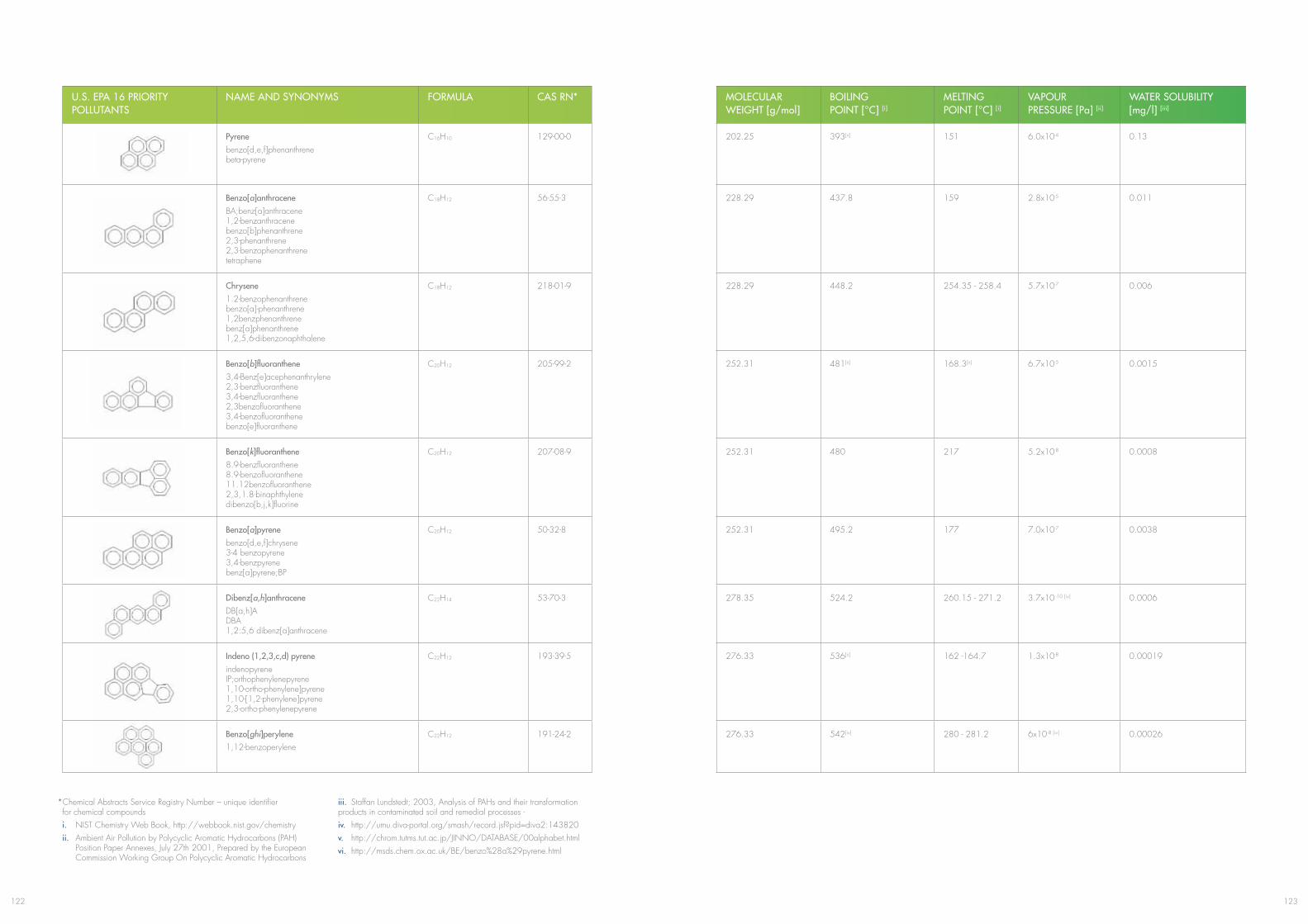
123122
U.S. EPA 16 PRIORITY POLLUTANTS
NAME AND SYNONYMS FORMULA CAS RN* MOLECULARWEIGHT [g/mol]
BOILING POINT [°C] [i]
MELTING POINT [°C] [i]
VAPOURPRESSURE [Pa] [ii]
WATER SOLUBILITY [mg/l] [iii]
Pyrenebenzo[d,e,f]phenanthrene beta-pyrene
C16H10 129-00-0 202.25 393[ii] 151 6.0x10⁻⁴ 0.13
Benzo[a]anthraceneBA;benz[a]anthracene 1,2-benzanthracene benzo[b]phenanthrene 2,3-phenanthrene 2,3-benzophenanthrene tetraphene
C18H12 56-55-3 228.29 437.8 159 2.8x10⁻⁵ 0.011
Chrysene1.2-benzophenanthrene benzo[a]-phenanthrene 1,2benzphenanthrene benz[a]phenanthrene 1,2,5,6-dibenzonaphthalene
C18H12 218-01-9 228.29 448.2 254.35 - 258.4 5.7x10⁻⁷ 0.006
Benzo[b]fluoranthene3,4-Benz[e]acephenanthrylene 2,3-benzfluoranthene 3,4-benzfluoranthene 2,3benzofluoranthene 3,4-benzofluoranthene benzo[e]fluoranthene
C20H12 205-99-2 252.31 481[ii] 168.3[ii] 6.7x10⁻⁵ 0.0015
Benzo[k]fluoranthene8.9-benzfluoranthene 8.9-benzofluoranthene 11.12benzofluoranthene 2,3,1.8-binaphthylene dibenzo[b,j,k]fluorine
C20H12 207-08-9 252.31 480 217 5.2x10⁻⁸ 0.0008
Benzo[a]pyrenebenzo[d,e,f]chrysene 3-4 benzopyrene 3,4-benzpyrene benz[a]pyrene;BP
C20H12 50-32-8 252.31 495.2 177 7.0x10⁻⁷ 0.0038
Dibenz[a,h]anthraceneDB[a,h]A DBA 1,2:5,6 dibenz[a]anthracene
C22H14 53-70-3 278.35 524.2 260.15 - 271.2 3.7x10 -10 [iv] 0.0006
Indeno (1,2,3,c,d) pyreneindenopyrene IP;orthophenylenepyrene 1,10-ortho-phenylene]pyrene 1,10-[1,2-phenylene]pyrene 2,3-ortho-phenylenepyrene
C22H12 193-39-5 276.33 536[ii] 162 -164.7 1.3x10⁻⁸ 0.00019
Benzo[ghi]perylene1,12-benzoperylene
C22H12 191-24-2 276.33 542[iv] 280 - 281.2 6x10⁻⁸ [iv] 0.00026
*Chemical Abstracts Service Registry Number – unique identifier for chemical compoundsi. NIST Chemistry Web Book, http://webbook.nist.gov/chemistryii. Ambient Air Pollution by Polycyclic Aromatic Hydrocarbons (PAH) Position Paper Annexes, July 27th 2001, Prepared by the European Commission Working Group On Polycyclic Aromatic Hydrocarbons
iii. Staffan Lundstedt; 2003, Analysis of PAHs and their transformation products in contaminated soil and remedial processes - iv. http://umu.diva-portal.org/smash/record.jsf?pid=diva2:143820v. http://chrom.tutms.tut.ac.jp/JINNO/DATABASE/00alphabet.htmlvi. http://msds.chem.ox.ac.uk/BE/benzo%28a%29pyrene.html
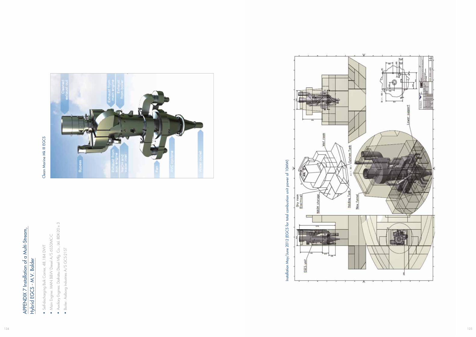
125124
APP
END
IX 7
Insta
llatio
n of
a M
ulti-
Stre
am,
Hyb
rid E
GC
S - M
.V. B
alde
r
• Se
lf-disc
harg
ing
Bulk
Car
rier,
48,1
84 D
WT
• M
ain
Engi
ne: M
AN
B&
W D
iese
l A/
S 6S
50M
C-C
• Au
xilia
ry E
ngin
es: D
aiha
tsu D
iese
l Mfg
. Co.
, Ltd
. 8DK
-20
x 3
• Bo
iler:
Aal
borg
Indu
strie
s A
/S
GC
S-21
ST
Cle
an M
arin
e M
k III
EG
CS
Insta
llatio
n M
ay/J
une
2012
(EG
CS
for
tota
l com
bust
ion
unit
pow
er o
f 10M
W)
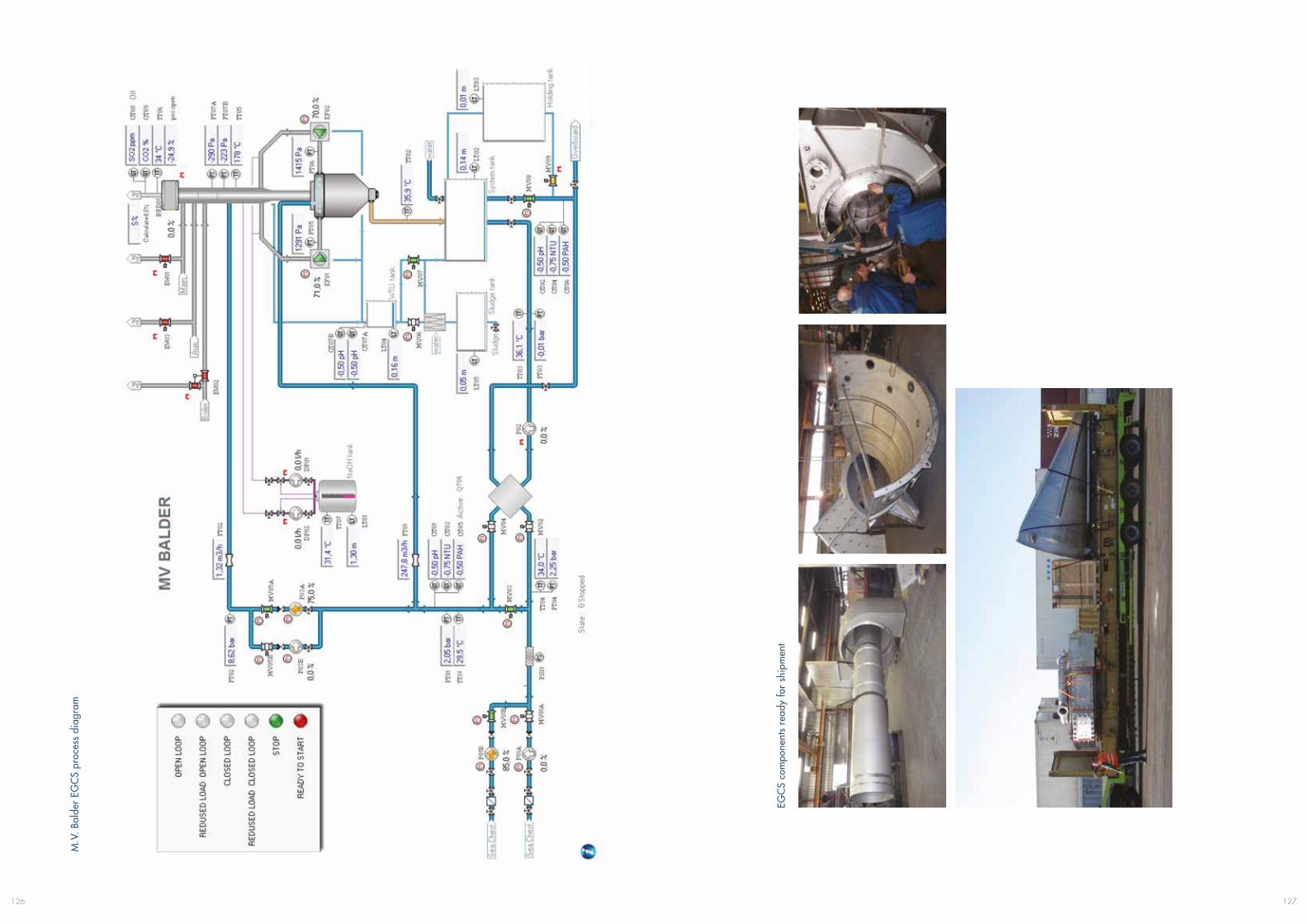
127126
M.V
. Bal
der
EGC
S pr
oces
s di
agra
m
EGC
S co
mpo
nent
s re
ady
for
ship
men
t

129128
Rem
oval
old
funn
el, c
lean
ing
out u
pper
eng
ine
room
cas
ing,
er
ectio
n an
d in
stal
latio
n of
Adv
ance
Vor
tex
Cha
mbe
r (A
VC
),
inst
alla
tion
of fa
ns
New
fan
hous
ing
and
low
er p
art o
f fun
nel,
inst
alla
tion
of
oute
r pi
pe, i
nsta
llatio
n of
inne
r pi
pe, i
nsta
llatio
n of
upp
er
part
and
byp
ass
lines
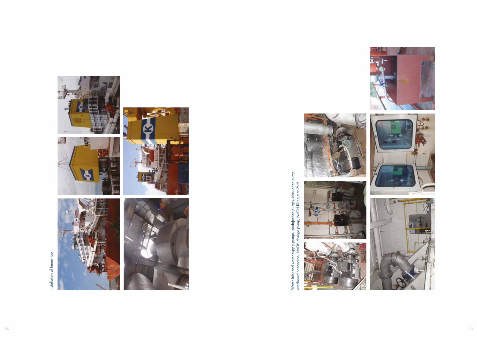
131130
Inst
alla
tion
of fu
nnel
top
Wat
er in
let a
nd w
ater
sup
ply
pum
ps, p
rein
ject
ion
pum
ps, c
ircu
latio
n pu
mp,
ov
erbo
ard
conn
ectio
n, N
aOH
dos
age
pum
p, N
aOH
filli
ng m
anifo
ld
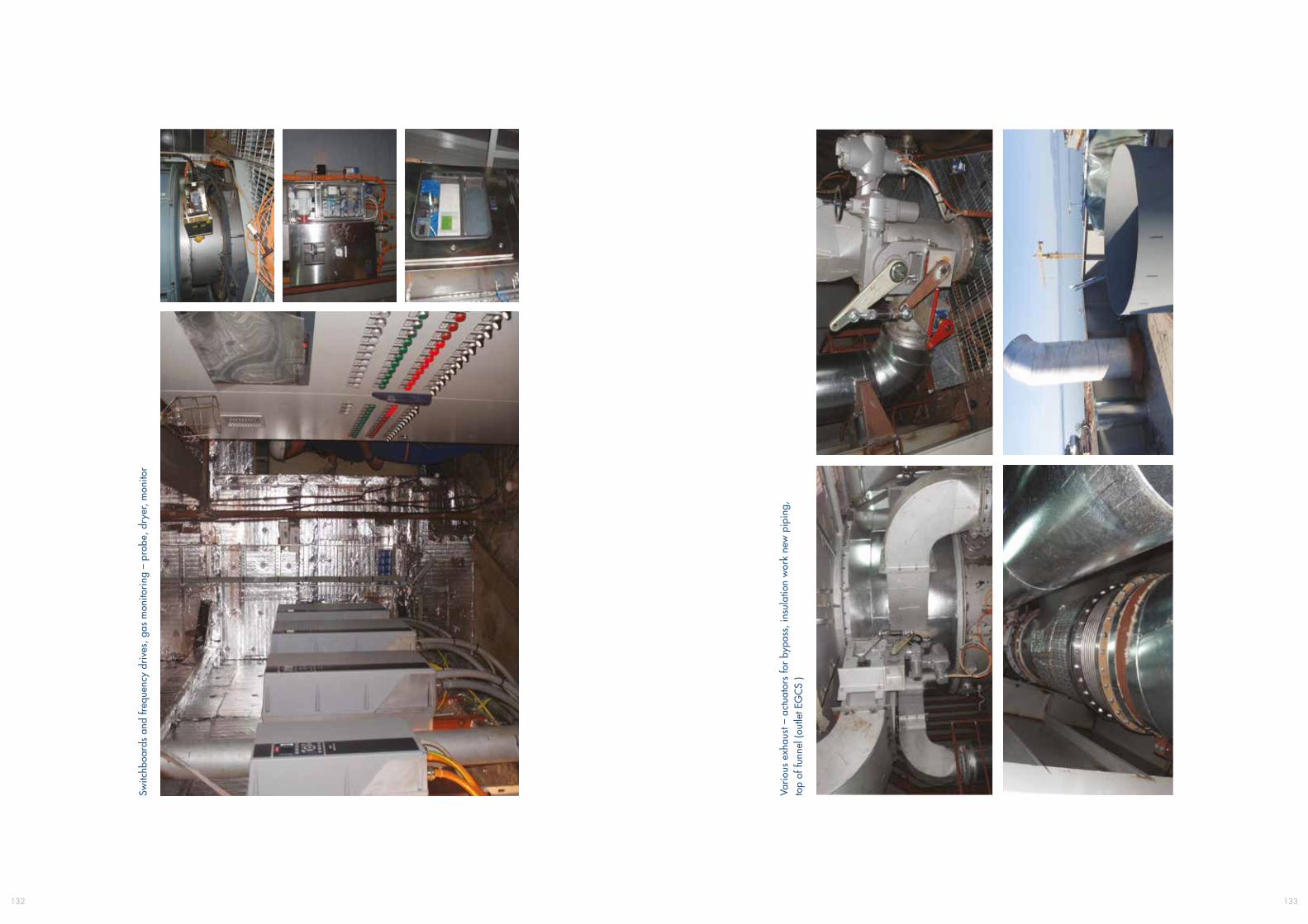
133132
Switc
hboa
rds
and
freq
uenc
y dr
ives
, gas
mon
itori
ng –
pro
be, d
ryer
, mon
itor
Vari
ous
exha
ust –
act
uato
rs fo
r by
pass
, ins
ulat
ion
wor
k ne
w p
ipin
g,
top
of fu
nnel
(out
let E
GC
S )
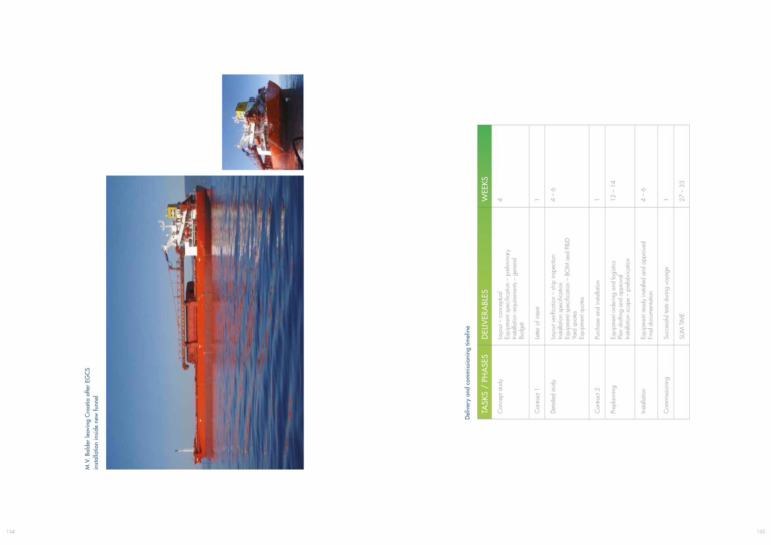
135134
M.V
. Bal
der
leav
ing
Cro
atia
afte
r EG
CS
in
stal
latio
n in
side
new
funn
el
TASK
S /
PHA
SES
DEL
IVER
ABL
ESW
EEKS
Con
cept
stu
dyLa
yout
– c
once
ptua
l Eq
uipm
ent s
peci
ficat
ion
– pr
elim
inar
y In
stalla
tion
requ
irem
ents
– ge
nera
l Bu
dget
4
Con
tract
1Le
tter o
f int
ent
1
Det
aile
d stu
dyLa
yout
ver
ifica
tion
– sh
ip in
spec
tion
Insta
llatio
n sp
ecifi
catio
n
Equi
pmen
t spe
cific
atio
n –
BOM
and
P&
ID
Yard
quo
tes
Equi
pmen
t quo
tes
4 –
6
Con
tract
2Pu
rcha
se a
nd in
stalla
tion
1
Prep
lann
ing
Equi
pmen
t ord
erin
g an
d lo
gisti
cs
Plan
dra
fting
and
app
rova
l In
stalla
tion
scop
e –
pref
abric
atio
n
12 –
14
Insta
llatio
nEq
uipm
ent r
eady
insta
lled
and
appr
oved
Fi
nal d
ocum
enta
tion
4 –
6
Com
miss
ioni
ngSu
cces
sful t
ests
durin
g vo
yage
1
SUM
TIM
E27
– 3
3
Del
iver
y an
d co
mm
issi
onin
g tim
elin
e
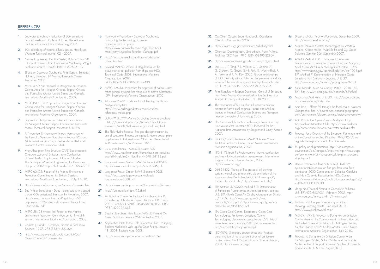
137136
REFERENCES
1. Seawater scrubbing - reduction of SOx emissions from ship exhausts. Karle and Turner. The Alliance For Global Sustainability Gothenburg 2007.
2. SOx scrubbing of marine exhaust gases. Henriksson. Wärtsilä Technical Journal, 02 – 2007.
3. Marine Engineering Practice Series, Volume 3 Part 20 – Exhaust Emissions from Combustion Machinery. Wright. Publisher: IMarEST, 2000. ISBN 1-902536-17-7.
4. Effects on Seawater Scrubbing. Final Report. Behrends, Hufnagl, Liebezeit. BP Marine/Research Centre Terramare, 2005.
5. MEPC 59/6/5: Proposal to Designate an Emission Control Area for Nitrogen Oxides, Sulphur Oxides and Particulate Matter. United States and Canada. International Maritime Organization, 2009.
6. MEPC INF/. 13: Proposal to Designate an Emission Control Area for Nitrogen Oxides, Sulphur Oxides and Particulate Matter. United States and Canada. International Maritime Organization, 2009.
7. Proposal to Designate an Emission Control Area for Nitrogen Oxides, Sulphur Oxides and Particulate Matter. Technical Support Document. U.S. EPA.
8. A Theoretical Environmental Impact Assessment of the Use of a Seawater Scrubber to Reduce SOx and NOx Emissions from Ships. Behrends and Liebezeit. Research Centre Terramare, 2003.
9. X-ray Absorption Fine Structure (XAFS) Spectroscopic Characterization of Emissions from Combustion of Fossil Fuels. Huggins and Huffman. Publisher: The Society of Materials Engineering for Resources of Japan, 2002. http://hdl.handle.net/10295/738
10. MEPC 60/22: Report of the Marine Environment Protection Committee on its Sixtieth Session. International Maritime Organization, 12 April 2010.
11. http://www.seafriends.org.nz/oceano/seawater.htm
12. Sea Water Scrubbing – Does it contribute to increased global CO2 emissions? Hamworthy Krystallon, 2007. http://www.hamworthy.com/PageFiles/1774 response-to-CO2-emissions-from-sea-water-scrubbing 14nov2007.pdf
13. MEPC 58/23 Annex 16: Report of the Marine Environment Protection Committee on its fifty-eighth session. International Maritime Organization, 2008.
14. Corbett, J.J. and P. Fischbeck, Emissions from ships. Science, 1997. 278 (5339): 823-824.
15. http://www.waterencyclopedia.com/Mi-Oc/ Ocean-Chemical-Processes.html
16. Hamworthy Krystallon – Seawater Scrubbing, Introducing the technology to owners, operators and shipyards. http://www.hamworthy.com/PageFiles/1774 Hamworthy Krystallon Scrubber Concept.pdf
17. http://www.lenntech.com/library/adsorption adsorption.htm
18. Revised MARPOL Annex VI, Regulations for the prevention of air pollution from ships and NOx Technical Code 2008. International Maritime Organization, 2009. Print edition ISBN 9789280142433.
19. MEPC 126(53): Procedure for approval of ballast water management systems that make use of active substances (G9). International Maritime Organization, 2005.
20. Alfa Laval PureSOx Exhaust Gas Cleaning Brochure – Multiple inlet systems – http://www.aalborg-industries.com/scrubber references_media.php
21. DuPont™ BELCO® Marine Scrubbing Systems Brochure – http://www2.dupont.com/sustainable-solutions/ en-us/dss/article/belco-marine-gas-scrubbing.html
22. The Flakt-Hydro Process - flue gas desulphurisation by use of seawater. Process principles & recent power plant applications in Indonesia and China. A. Ellestad et al ABB Environmental/ABB Power 1998.
23. List of installations – Alstom Seawater FGD http://www.no.alstom.com/home/business_activities ecs/trklklhygft/so2/_files/file_44598_54112.pdf
24. Longannet Power Station EMAS Statement 2005-06. http://www.scotash.com/pdfs/emas0506.pdf
25. Longannet Power Station EMAS Statement 2008. http://www.scottishpower.com/uploads longannetemas2008.pdf
26. http://www.scottishpower.com/Casestudies_828.asp
27. http://periodic.lanl.gov/15.shtml
28. Air Pollution Control Technology Handbook. Karl B. Schnelle and Charles A. Brown. Publisher CRC Press 2002. Print ISBN: 978-0-8493-9588-8.eBook ISBN: 978-1-4200-3643-5.
29. Sulphur Scrubbers. Henriksson, Wärtsilä Finland Oy, Green Solutions Seminar 26th September 2007.
30. Application Note to the Field, Common Fluid – Pumping Sodium Hydroxide with Liquiflo Gear Pumps. January 18, 2001; Revised Aug. 2008.
31. http://www.eng-tips.com/faqs.cfm?fid=1096
32. OxyChem Caustic Soda Handbook. Occidental Chemical Corporation 2009.
33. http://toxics.usgs.gov/definitions/alkalinity.html
34. Chemical Oceanography 2nd edition. Frank Millero. Publisher CRC Press 1996. ISBN 0-8493-2280-4.
35. http://www.engineeringtoolbox.com/ph-d_483.html
36. Lee, K., L. T. Tong, F. J. Millero, C. L. Sabine, A. G. Dickson, C. Goyet, G.-H. Park, R. Wanninkhof, R. A. Feely, and R. M. Key. 2006. Global relationships of total alkalinity with salinity and temperature in surface waters of the world’s oceans. Geophys Research Letters 33, L19605, doi:10.1029/2006GL027207.
37. Final Regulatory Support Document: Control of Emissions from New Marine Compression-Ignition Engines at or Above 30 Liters per Cylinder. U.S. EPA 2003.
38. The mechanics of fuel sulphur influence on exhaust emissions from diesel engines. Kozak and Merkisz. Institute of Internal Combustion Engines and Transport, Poznan University of Technology 2005.
39. Flue Gas Desulphurisation Technology Evaluation, Dry Lime versus Wet Limestone FGD. Prepared for the National Lime Association by Sargent and Lundy, March 2007.
40. BLG 12/6/23: Review of MARPOL Annex VI and the NOx Technical Code. United States. International Maritime Organization, 2007.
41. ISO 8178 (part 1): Reciprocating internal combustion engines – Exhaust emission measurement. International Organization for Standardization, 2006. http://www.iso.org/
42. DIN 51402: Testing of flue gases of oil burning systems; visual and photometric determination of the smoke number. Deutsches Institut für Normung e.V., 1986. http://din.de / http://www.beuth.de/
43. EPA Method 5/AQMD Method 5.2: Determination of Particulate Matter emissions from stationary sources. U.S. EPA/South Coast Air Quality Management District, _ / 1989. http://www.epa.gov/ttn/emc promgate/m-05.pdf / http://www.aqmd.gov/tao methods/stm/stm-005-2.pdf
44. IEA Clean Coal Centre, Databases, Clean Coal Technologies, Particulate Emissions Control Technologies, Electrostatic precipitators (ESP). http:/ www.iea-coal.org.uk/site/2010/database-section ccts/electrostatic-precipitators-esp?
45. ISO 9096: Stationary source emissions - Manual determination of mass concentration of particulate matter. International Organization for Standardization, 2003. http://www.iso.org/
46. Diesel and Gas Turbine Worldwide, December 2009. http://www.dieselpub.com/
47. Marine Emission Control Technologies by Wärtsilä Marine. Göran Hellén, Wärtsilä Finland Oy, Green Solutions Seminar 26th September 2007.
48. AQMD Method 100.1: Instrumental Analyser Procedures for Continuous Gaseous Emission Sampling. South Coast Air Quality Management District, 1989. http://www.aqmd.gov/tao/methods/stm/stm-100-1.pdf EPA Method 7: Determination of Nitrogen Oxide Emissions from Stationary Sources. U.S. EPA. http:/www.epa.gov/ttn/emc/promgate/m-07.pdf
49. Sulfur Dioxide, SO2 Air Quality 1980 – 2010. U.S. EPA. http://www.epa.gov/air/airtrends/sulfur.html
50. Measuring Acid Rain. U.S. EPA. http://www.epa.gov acidrain/measure/index.html
51. Acid Rain – Effects felt through the food chain. National Geographic. http://environment.nationalgeographic com/environment/global-warming/acid-rain-overview/
52. Acid Rain in the Alpine Zone – Acidity on High. Appalachian Mountain Club. http://www.outdoors org/conservation/airwater/airwater-acid-rain.cfm
53. Proposal for a Directive of the European Parliament and of the Council amending Directive 1999/32/EC as regards the sulphur content of marine fuels.
54. EU policy on ship emissions. http://ec.europa.eu environment/air/transport/ships.htm http://ec.europa eu/environment/air/transport/pdf/sulphur_standard shipping.pdf
55. Demonstration and feasibility of BOC LoTOx™ system for NOx control on flue gas from coal-fired combustor. 2000 Conference on Selective Catalytic and Non Catalytic Reduction for NOx Control. http://www.netl.doe.gov/publicationsproceedings/00/ scr00/ANDERSON.PDF
56. Using Non-Thermal Plasma to Control Air Pollutants. U.S. EPA-456/R-05-001, February 2005. http:/ www.epa.gov/ttn/catc/dir1/fnonthrm.pdf
57. Bunkerworld- Couple Systems’ dry scrubber showing ‘stunning results’. 2nd April 2010. http://www.bunkerworld.com/
58. MEPC 61/7/3: Proposal to Designate an Emission Control Area for the Commonwealth of Puerto Rico and the United States Virgin Islands for Nitrogen Oxides, Sulphur Oxides and Particulate Matter. United States. International Maritime Organization, June 2010.
59. Proposal to Designate an Emission Control Area for Nitrogen Oxides, Sulfur Oxides and Particulate Matter Technical Support Document & Table of Contents (2 documents). U.S. EPA, August 2010.
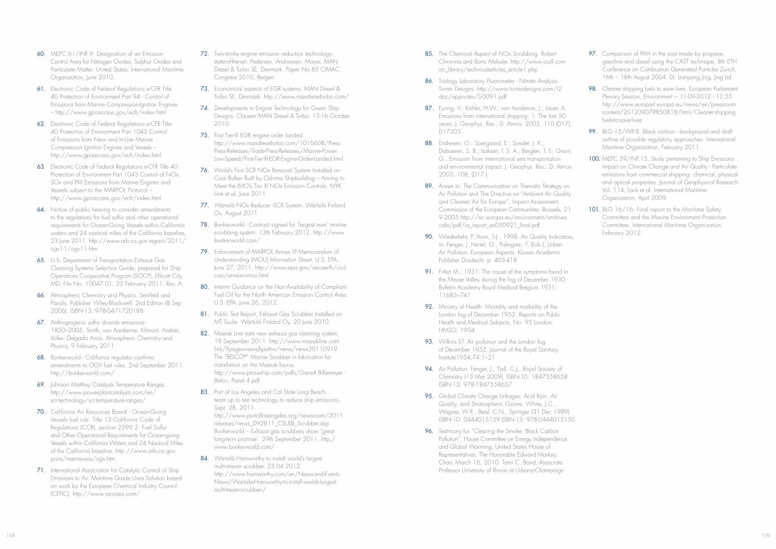
139138
60. MEPC 61/INF.9: Designation of an Emission Control Area for Nitrogen Oxides, Sulphur Oxides and Particulate Matter. United States. International Maritime Organization, June 2010.
61. Electronic Code of Federal Regulations e-CFR Title 40 Protection of Environment Part 94 - Control of Emissions from Marine Compression-Ignition Engines – http://www.gpoaccess.gov/ecfr/index.html
62. Electronic Code of Federal Regulations e-CFR Title 40 Protection of Environment Part 1042 Control of Emissions from New and In-Use Marine Compression Ignition Engines and Vessels – http://www.gpoaccess.gov/ecfr/index.html
63. Electronic Code of Federal Regulations e-CFR Title 40 Protection of Environment Part 1043 Control of NOx, SOx and PM Emissions from Marine Engines and Vessels subject to the MARPOL Protocol – http://www.gpoaccess.gov/ecfr/index.html
64. Notice of public hearing to consider amendments to the regulations for fuel sulfur and other operational requirements for Ocean-Going Vessels within California waters and 24 nautical miles of the California baseline, 23 June 2011. http://www.arb.ca.gov regact/2011/ ogv11/ogv11.htm
65. U.S. Department of Transportation Exhaust Gas Cleaning Systems Selection Guide, prepared for Ship Operations Cooperative Program (SOCP), Ellicott City, MD, File No. 10047.01, 22 February 2011, Rev. A.
66. Atmospheric Chemistry and Physics. Seinfeld and Pandis. Publisher Wiley-Blackwell; 2nd Edition (8 Sep 2006). ISBN-13: 978-0471720188.
67. Anthropogenic sulfur dioxide emissions: 1850–2005. Smith, van Aardenne, Klimont, Andres, Volke, Delgado Arias. Atmospheric Chemistry and Physics, 9 February 2011.
68. Bunkerworld - California regulator confirms amendments to OGV fuel rules. 2nd September 2011. http://bunkerworld.com/
69. Johnson Matthey Catalysts Temperature Ranges. http://www.powerplantcatalysts.com/en/ scr-technology/scr-temperature-ranges/
70. California Air Resources Board - Ocean-Going Vessels fuel rule. Title 13 California Code of Regulations (CCR), section 2299.2. Fuel Sulfur and Other Operational Requirements for Ocean-going Vessels within California Waters and 24 Nautical Miles of the California baseline. http://www.arb.ca.gov ports/marinevess/ogv.htm
71. International Association for Catalytic Control of Ship Emissions to Air. Maritime Grade Urea Solution based on work by the European Chemical Industry Council (CEFIC). http://www.iaccsea.com/
72. Two-stroke engine emission reduction technology: state-of-the-art. Pedersen, Andreasen, Mayer, MAN Diesel & Turbo SE, Denmark. Paper No.85 CIMAC Congress 2010, Bergen.
73. Economical aspects of EGR systems. MAN Diesel & Turbo SE, Denmark. http://www.mandieselturbo.com/
74. Developments in Engine Technology for Green Ship Designs. Clausen MAN Diesel & Turbo. 15-16 October 2010.
75. First Tier-III EGR engine order landed. http://www.mandieselturbo.com/1016608/Press Press-Releases/Trade-Press-Releases/Marine-Power Low-Speed/First-Tier-III-EGR-Engine-Order-Landed.html
76. World’s First SCR NOx Removal System Installed on Coal Bulker Built by Oshima Shipbuilding – Aiming to Meet the IMO’s Tier III NOx Emission Controls. NYK Line et al. June 2011.
77. Wärtsilä NOx Reducer -SCR System. Wärtsilä Finland Oy. August 2011
78. Bunkerworld - Contract signed for ‘largest ever’ marine scrubbing system. 13th February 2012. http://www bunkerworld.com/
79. Enforcement of MARPOL Annex VI Memorandum of Understanding (MOU) Information Sheet. U.S. EPA. June 27, 2011. http://www.epa.gov/oecaerth/civil caa/annexvi-mou.html
80. Interim Guidance on the Non-Availability of Compliant Fuel Oil for the North American Emission Control Area. U.S. EPA. June 26, 2012.
81. Public Test Report, Exhaust Gas Scrubber Installed on MT Suula. Wärtsilä Finland Oy. 20 June 2010.
82. Maersk Line tests new exhaust gas cleaning system. 19 September 2011. http://www.maerskline.com link/?page=news&path=/news/news20110919 The “BELCO®” Marine Scrubber in fabrication for installation on the Maersk-Taurus. http://www.pmsaship.com/pdfs/Garrett Billemeyer - Belco, Panel 4.pdf
83. Port of Los Angeles and Cal State Long Beach team up to test technology to reduce ship emissions. Sept. 28, 2011. http://www.portoflosangeles.org/newsroom/2011 releases/news_092811_CSULB_Scrubber.asp Bunkerworld – Exhaust gas scrubbers show ‘great long-term promise’. 29th September 2011. http:/ www.bunkerworld.com/
84. Wärtsilä Hamworthy to install world’s largest multi-stream scrubber. 23.04.2012. http://www.hamworthy.com/en/News-and-Events News/Wartsila-Hamworthy-to-install-worlds-largest- multi-tream-scrubber-/
85. The Chemical Aspect of NOx Scrubbing. Robert Chironna and Boris Altshuler. http://www.croll.com air_library/technicalarticles_article1.php
86. Triology Laboratory Fluorometer - Nitrate Analysis. Turner Designs. http://www.turnerdesigns.com/t2 doc/appnotes/S-0091.pdf
87. Eyring, V.; Köhler, H.W.; van Aardenne, J.; Lauer, A. Emissions from international shipping: 1. The last 50 years. J. Geophys. Res., D: Atmos. 2005, 110 (D17), D17305.
88. Endresen, O.; Soergaard, E.; Sundet, J. K.; Dalsoeren, S. B.; Isaksen, I. S. A.; Berglen, T. F.; Gravir, G., Emission from international sea transportation and environmental impact. J. Geophys. Res., D: Atmos. 2003, 108, (D17.)
89. Annex to: The Communication on Thematic Strategy on Air Pollution and The Directive on “Ambient Air Quality and Cleaner Air for Europe”, Impact Assessment. Commission of the European Communities. Brussels, 21 9.2005 http://ec.europa.eu/environment/archives cafe/pdf/ia_report_en050921_final.pdf
90. Wiederkehr, P.,Yoon, S-J., 1998. Air Quality Indicators, in: Fenger, J.,Hertel, O., Palmgren, F. (Eds.), Urban Air Pollution, European Aspects. Kluwer Academic Publisher Dordecht, p. 403-418
91. Firket M., 1931. The cause of the symptoms found in the Meuse Valley during the fog of December 1930. Bulletin Academy Royal Medical Belgium 1931; 11683–741
92. Ministry of Health. Mortality and morbidity of the London fog of December 1952. Reports on Public Health and Medical Subjects, No. 95 London: HMSO, 1954.
93. Wilkins ET. Air pollution and the London fog of December 1952. Journal of the Royal Sanitary Institute1954;74:1–21.
94. Air Pollution. Fenger, J., Tjell, C.J., Royal Society of Chemistry (13 Mar 2009). ISBN-10: 1847558658 ISBN-13: 978-1847558657
95. Global Climate Change Linkages: Acid Rain, Air Quality, and Stratospheric Ozone. White, J.C., Wagner, W.R., Beal, C.N., Springer (31 Dec 1989). ISBN-10: 0444015159 ISBN-13: 978-0444015150
96. Testimony for “Clearing the Smoke: Black Carbon Pollution”, House Committee on Energy Independence and Global Warming. United States House of Representatives, The Honorable Edward Markey, Chair, March 16, 2010. Tami C. Bond, Associate Professor University of Illinois at Urbana-Champaign
97. Comparison of PAH in the soot made by propane, gasoline and diesel using the CAST technique, 8th ETH Conference on Combustion Generated Particles Zurich, 16th – 18th August 2004. Dr. Lianpeng Jing, Jing Ltd
98. Cleaner shipping fuels to save lives. European Parliament Plenary Session, Environment − 11-09-2012 - 12:55 http://www.europarl.europa.eu/news/en/pressroom content/20120907IPR50818/html/Cleaner-shipping fuels-to-save-lives
99. BLG 15/WP.8. Black carbon - background and draft outline of possible regulatory approaches. International Maritime Organization, February 2011.
100. MEPC 59/INF.15. Study pertaining to Ship Emissions Impact on Climate Change and Air Quality - Particulate emissions from commercial shipping: chemical, physical and optical properties. Journal of Geophysical Research Vol. 114, Lack et al. International Maritime Organization, April 2009.
101. BLG 16/16. Final report to the Maritime Safety Committee and the Marine Environment Protection Committee. International Maritime Organization, February 2012
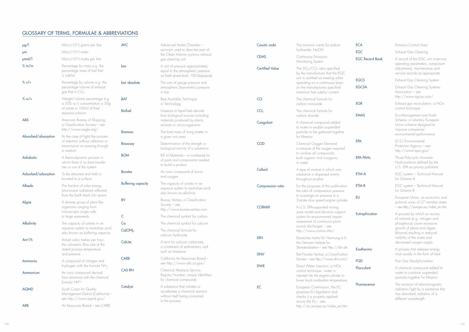
141140
GLOSSARY OF TERMS, FORMULAE & ABBREVIATIONS
μg/l Micro (10-6) grams per litre
μm Micro (10-6) meter
μmol/l Micro (10-6) moles per litre
% m/m Percentage by mass e.g. the percentage mass of fuel that is sulphur
% v/v Percentage by volume e.g. the percentage volume of exhaust gas that is CO2
% w/v Weight/volume percentage e.g. a 50% w/v concentration is 50g of solute in 100ml of final aqueous solution
ABS American Bureau of Shipping; a Classification Society – see http://www.eagle.org/
Absorbed/absorption (In the case of light) the process of retention without reflection or transmission on passing through a medium
Adiabatic A thermodynamic process in which there is no heat transfer into or out of the system.
Adsorbed/adsorption To be attracted and held or bonded to a surface
Albedo The fraction of solar energy (short-wave radiation) reflected from the Earth back into space
Algae A diverse group of plant like organisms ranging from microscopic single cells to large seaweeds
Alkalinity The capacity of solutes in an aqueous system to neutralize acid; also known as buffering capacity
Am3/h Actual cubic metres per hour; the volumetric flow rate at the stated process temperature and pressure
Ammonia A compound of nitrogen and hydrogen with the formula NH3
Ammonium An ionic compound derived from ammonia with the chemical formula NH4+
AQMD South Coast Air Quality Management District (California) – see http://www.aqmd.gov/
ARB Air Resources Board – see CARB
AVC Advanced Vortex Chamber – acronym used to describe part of the Clean Marine cyclonic exhaust gas cleaning unit
bar A unit of pressure approximately equal to the atmospheric pressure on Earth at sea level; 100 kilopascals
bar absolute The sum of gauge pressure and atmospheric (barometric) pressure in bar
BAT Best Available Technique or Technology
Biofuel Gaseous or liquid fuels derived from biological sources including materials produced by plants, animals or micro-organisms
Biomass The total mass of living matter in a given unit area
Bioassay Determination of the strength or biological activity of a substance
BOM Bill of Materials – a numbered list of parts and components needed to build a product
Borates An ionic compound of boron and oxygen
Buffering capacity The capacity of solutes in an aqueous system to neutralize acid; also known as alkalinity
BV Bureau Veritas; a Classification Society – see http://www.bureauveritas.com
C The chemical symbol for carbon
Ca The chemical symbol for calcium
Ca(OH)2 The chemical formula for calcium hydroxide
Calcite A term for calcium carbonate, a constituent of sedimentary rock such as limestone
CARB California Air Resources Board – see http://www.arb.ca.gov/
CAS RN Chemical Abstracts Service Registry Number; unique identifiers for chemical compounds
Catalyst A substance that initiates or accelerates a chemical reaction without itself being consumed in the process
Caustic soda The common name for sodium hydroxide; NaOH
CEMS Continuous Emissions Monitoring System
Certified Value The SO2/CO2 ratio specified by the manufacturer that the EGC unit is certified as meeting when operating on a continuous basis on the manufacturers specified maximum fuel sulphur content
CO The chemical formula for carbon monoxide
CO2 The chemical formula for carbon dioxide
Coagulant A chemical compound added to water to enable suspended particles to be gathered together for filtration
COD Chemical Oxygen Demand; a measure of the oxygen required to oxidize all compounds, both organic and inorganic, in water.
Colloid A type of mixture in which one substance is dispersed evenly throughout another
Compression ratio For the purposes of this publication the ratio of compression pressure to scavenge air pressure in a 2-stroke slow speed engine cylinder
CORMIX A U.S. EPA-supported mixing zone model and decision support system for environmental impact assessment of continuous point source discharges – see http://www.cormix.info/
DIN Deutsches Institut für Normung e.V; the German Institute for Standardization – see http://din.de
DNV Det Norske Veritas; a Classification Society – see http://www.dnv.com/
DWE Direct Water Injection; a NOx control technique - water is injected into the engine cylinder to lower local combustion temperatures
EC European Commission; the EC proposes EU legislation and checks it is properly applied across the EU – see http://ec.europa.eu/index_en.htm
ECA Emission Control Area
EGC Exhaust Gas Cleaning
EGC Record Book A record of the EGC unit in-service operating parameters, component adjustments, maintenance and service records as appropriate
EGCS Exhaust Gas Cleaning System
EGCSA Exhaust Gas Cleaning Systems Association – see http://www.egcsa.com/
EGR Exhaust gas recirculation; a NOx control technique
EMAS Eco-Management and Audit Scheme, a voluntary European Union initiative designed to improve companies’ environmental performance
EPA (U.S.) Environmental Protection Agency – see http://www.epa.gov/
EPA-PAHs Those Polycyclic Aromatic Hydrocarbons defined by the U.S. EPA as priority pollutants
ETM-A EGC system – Technical Manual for Scheme A
ETM-B EGC system – Technical Manual for Scheme B
EU European Union; an economic and political union of 27 member states – see http://europa.eu/index_en.htm
Eutrophication A process by which an excess of nutrients (e.g. nitrogen and phosphorus) cause excessive growth of plants and algae (blooms) resulting in reduced visibility of the water and decreased oxygen supply
Exothermic A process that releases energy most usually in the form of heat
FGD Flue Gas Desulphurisation
Flocculant A chemical compound added to water to combine suspended particles together for filtration
Fluorescence The emission of electromagnetic radiation/light by a substance that has absorbed radiation of a different wavelength
143142
Free radical An atom that has at least one unpaired electron in an orbital and is therefore highly reactive (unlike an ion there is no overall electrical charge as protons & electrons are equal in number)
Fuel oil combustion unit Any engine, boiler, gas turbine, or other fuel oil fired equipment, excluding shipboard incinerators
FTIR Fourier transform infrared spectroscopy; a technique used to measure the concentration of gaseous emissions
FWE Fuel Water Emulsion, a NOx control technique, which lowers local combustion temperatures
g/kW h Grams per kilowatt hour
g/l Grams per litre
g/mol Grams per mole; the molecular weight or molar mass of a substance
Geodesic The shortest line between two points on a mathematically defined surface
GESAMP Joint Group of Experts on the Scientific Aspects of Marine Environmental Protection – see http://www.gesamp.org
GL Germanischer Lloyd; a Classification Society – see http://www.gl-group.com/
GW Gigawatt; 1x10⁹ watts
H The chemical symbol for hydrogen
HAM Humid Air Motor; a NOx control technique for 4 stroke engines– water is sprayed into the engine’s charge air to reduce oxygen content and increase heat capacity.
HC Hydrocarbon emissions (inagaseousstateat190°C), primarily derived from the incomplete combustion of fuel
HCO3– The chemical formula for
bicarbonate
HFO Heavy fuel oil; a generic term for residual fuel. Typically HFO has a high sulphur content and is not suitable for use in an ECA (also see LSFO).
HMI Human Machine Interface; typically PC based interactive graphics representing a process system - enables monitoring and control.
H2SO4 The chemical formula for sulphuric acid
Hydrated lime A common name for calcium hydroxide; Ca(OH)2, also known as slaked lime
Hydronium (H3O+) Hydronium; – a water molecule with an extra hydrogen ion. Acids are compounds that yield hydrogen ions (H+) or hydronium ions (H3O+) when dissolved in water.
IAPP International Air Pollution Prevention certificate
IBC Intermediate Bulk Container; container for transport and storage of fluids and bulk materials – often seen as a1000 litre plastic cube in a metal cage.
IMarEST The Institute of Marine Engineering, Science & Technology – see http://www.imarest.org/
IMO International Maritime Organization – see http://www.imo.org/
Ion An atom or molecule or group that has lost or gained one or more electrons and so is electrically charged (positive or negative)
Ionisation The process of being dissociated into ions
ISO International Organization for Standardization – see http://www.iso.org/
LR Lloyd’s Register; a Classification Society - see http://www.lr.org/
LSFO Low Sulphur Fuel Oil; typically a residual fuel with a sulphur content suitable for use in an ECA until 2015
Luminescence The emission of electromagnetic radiation, including visible light after an atom, ion or molecule becomes elevated to an excited electronic state; sometimes referred to as cold light. Chemiluminesence is exhibited as a result of chemical reaction without heat
Lye The common name (U.S.) for sodium hydroxide; NaOH – see also caustic soda.
MARPOL The International Convention for the Prevention of Pollution from Ships, 1973, as modified by the Protocol of 1978 relating thereto (MARPOL 73/78)
MDO Marine Diesel Oil
MEPC Marine Environment Protection Committee; e.g. MEPC 60 was the sixtieth session of this IMO group and MEPC Resolution 184(59) was adopted at the fifty-ninth session
m3/MW h Cubic meters per megawatt hour
mg/l Milligrams per litre
MGO Marine Gas Oil
micron 1x10⁻⁶m; one thousandth of a millimetre/one millionth of a meter
MSDS Material Safety Datasheet
Mt 1 million tonnes; 1 x 10⁶ tonnes
N The chemical symbol for nitrogen
Na The chemical symbol for sodium
NaOH Sodium hydroxide, also commonly known as caustic soda
NDIR Non-dispersive infrared sensor; a spectroscopic device used to measure the concentration of gaseous emissions, for example NOx and CO2 from an engine
NDUV Non-dispersive ultraviolet sensor; a spectroscopic device used to measure the concentration of gaseous emissions, for example SO2 from an engine
nm Nano (10-9) meter
Nm3/h Normal cubic metres per hour; the volumetric flow rate of a gas normalised to a standard temperature and pressure
Nitrate An ionic compound of nitrogen and oxygen; NO3
–
NO The chemical formula for nitric oxide
NO2 The chemical formula for nitrogen dioxide
NOx The generic term for nitrogen oxides
Non-thermal plasma Plasma that occurs at room temperature when molecules are exposed to a strong electrical field (rather than extremely high temperature)
O The chemical symbol for oxygen
O3 Ozone
OMM Onboard Monitoring Manual
P The chemical symbol for phosphorus
Pa Pascal; the SI unit of pressure
PAH Polycyclic Aromatic Hydrocarbon
P&ID Piping and instrumentation drawing – shows components and flow of a process system
pH A measure of the acidity or basicity of a solution
Phenanthrene A polycyclic aromatic hydrocarbon and one of the U.S. EPA 16 priority pollutants; C14H10
Phosphate An ionic compound of phosphorus and oxygen
Photosynthesis A process that converts carbon dioxide into organic (carbon based) compounds, especially sugars, using the energy from sunlight
Phytoplankton Microscopic organisms in the upper layers of the ocean that form the basis of the marine food chain
Plasma A distinct phase of matter, separate from solids, liquids, and gases; a collection of charged particles (free radicals) resulting from exposure to extremely high temperatures
PM Particulate Matter
ppm Parts per million
PREN Pitting Resistance Equivalent number; indicates the ability of a stainless steel to resist pitting corrosion
PSC Port State Control
QCL Quantum Cascade Laser; a technology used to measure the concentration of gaseous emissions
RINA RINA; a Classification Society (created by Registro Italiano Navale) – see http://www.rina.org/
rpm Revolutions per minute
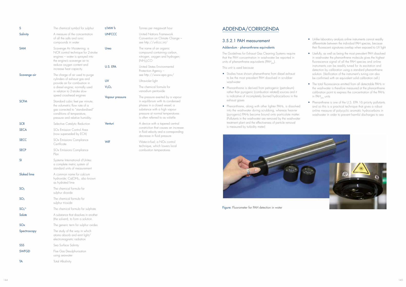
145144
S The chemical symbol for sulphur
Salinity A measure of the concentration of all the salts and ionic compounds in water
SAM Scavenge Air Moistening; a NOX control technique for 2-stroke engines – water is sprayed into the engine’s scavenge air to reduce oxygen content and increase heat capacity.
Scavenge air The charge of air used to purge cylinders of exhaust gas and provide air for combustion in a diesel engine; normally used in relation to 2-stroke slow speed crosshead engines
SCFM Standard cubic feet per minute; the volumetric flow rate of a gas corrected to “standardised” conditions of temperature, pressure and relative humidity.
SCR Selective Catalytic Reduction
SECA SOx Emission Control Area (now superseded by ECA)
SECC SOx Emissions Compliance Certificate
SECP SOx Emissions Compliance Plan
SI Systeme International d’Unites: a complete metric system of standard units of measurement
Slaked lime A common name for calcium hydroxide; Ca(OH)2, also known as hydrated lime
SO2 The chemical formula for sulphur dioxide
SO3 The chemical formula for sulphur trioxide
SO42– The chemical formula for sulphate
Solute A substance that dissolves in another (the solvent), to form a solution.
SOx The generic term for sulphur oxides
Spectroscopy The study of the way in which atoms absorb and emit light/ electromagnetic radiation
SSS Sea Surface Salinity
SWFGD Flue Gas Desulphurisation using seawater
TA Total Alkalinity
t/MW h Tonnes per megawatt hour
UNFCCC United Nations Framework Convention on Climate Change – see http://unfccc.int/
Urea The name of an organic compound containing carbon, nitrogen, oxygen and hydrogen; (NH2)2CO
U.S. EPA United States Environmental Protection Agency – see http://www.epa.gov/
UV Ultraviolet light
V2O5 The chemical formula for vanadium pentoxide
Vapour pressure The pressure exerted by a vapour in equilibrium with its condensed phases in a closed vessel; a substance with a high vapour pressure at normal temperatures is often referred to as volatile
Venturi A device with a tapered central constriction that causes an increase in fluid velocity and a corresponding decrease in fluid pressure
WIF Water-in-fuel; a NOx control technique, which lowers local combustion temperatures
ADDENDA/CORRIGENDA
3.5.2.1 PAH measurementAddendum - phenanthrene equivalents
The Guidelines for Exhaust Gas Cleaning Systems require that the PAH concentration in washwater be reported in units of phenanthrene equivalents (PAHphe).
This unit is used because
• Studies have shown phenanthrene from diesel exhaust to be the most prevalent PAH dissolved in scrubber washwater
• Phenanthrene is derived from petrogenic (petroleum) rather than pyrogenic (combustion related) sources and it is indicative of incompletely burned hydrocarbons in the exhaust gases
• Phenanthrene, along with other lighter PAHs, is dissolved into the washwater during scrubbing, whereas heavier (pyrogenic) PAHs become bound onto particulate matter. (Pollutants in the washwater are removed by the washwater treatment plant and the effectiveness of particle removal is measured by turbidity meter)
• Unlike laboratory analysis online instruments cannot readily differentiate between the individual PAH species, because their fluorescent signatures overlap when exposed to UV light
• Usefully, as well as being the most prevalent PAH dissolved in washwater the phenanthrene molecule gives the highest fluorescence signal of all the PAH species and online instruments can be readily tuned for its excitation and detection by calibration using a standard phenanthrene solution. (Verification of the instrument's tuning can also be confirmed with an equivalent solid calibration cell.)
• The total fluorescence emitted from all detectable PAHs in the washwater is therefore measured at the phenanthrene calibration point to express the concentration of the PAHs in PAHphe units
• Phenanthrene is one of the U.S. EPA 16 priority pollutants and so this is a practical technique that gives a robust online measure of polycyclic aromatic hydrocarbons in washwater in order to prevent harmful discharges to sea
Figure: Fluorometer for PAH detection in water
www.alfalaval.com
Is your ship or fleet prepared for January 1, 2015? Time to look at your options. PureSOx from Alfa Laval reduces harmful emissions by scrubbing sulphur from the exhaust gas from vessels operating on HFO. PureSOx is a hybrid system that runs in either seawater or freshwater mode.
It’s one minute to twelve…
Scan the code and watch the PureSOx animation
Cost-savingl Low-cost solution compared to running on low sulphur MGO
Flexiblel Exhaust from multiple engines cleaned with one scrubberl PureSOx functions in all known conditions
Easy to operatel Automatic switching between sea and freshwater model No need for chemical additives in seawater mode
Based on experiencel Largest system currently in operation (21 MW)
For more information, please contact Rene Diks on + 31 24 35 23 180 or [email protected]
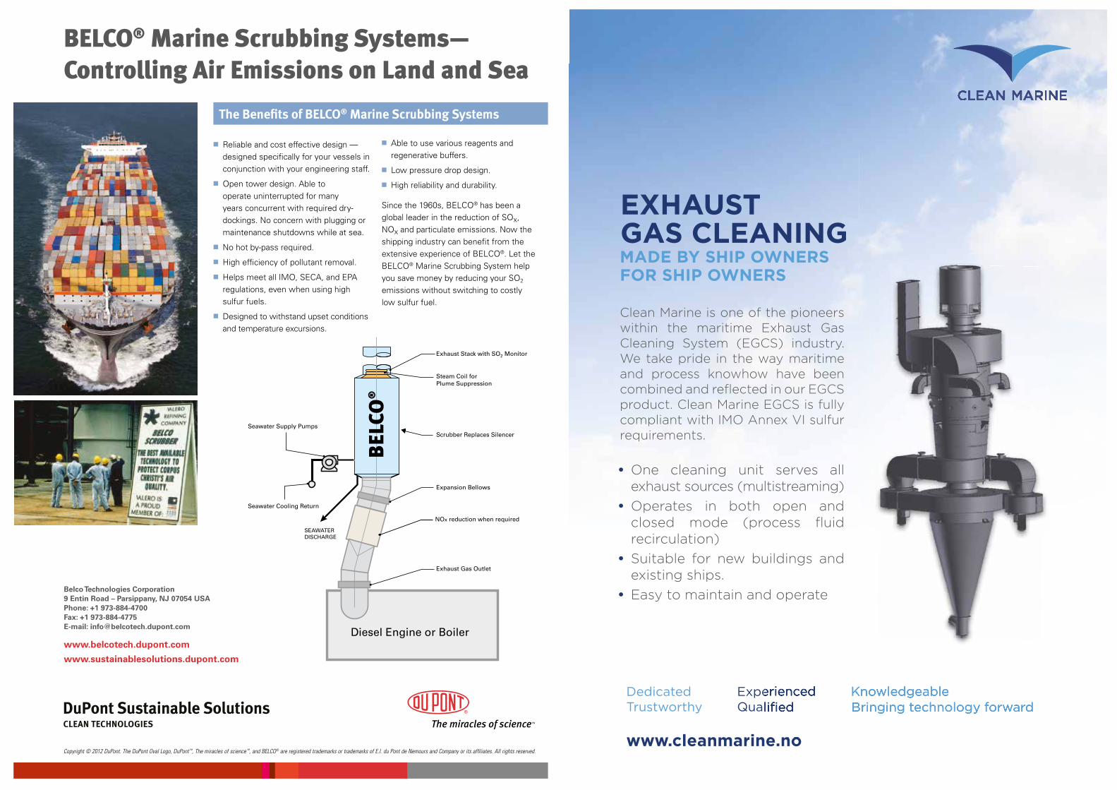
■ Reliable and cost effective design — designed specifically for your vessels in conjunction with your engineering staff.
■ Open tower design. Able to operate uninterrupted for many years concurrent with required dry-dockings. No concern with plugging or maintenance shutdowns while at sea.
■ No hot by-pass required.
■ High efficiency of pollutant removal.
■ Helps meet all IMO, SECA, and EPA regulations, even when using high sulfur fuels.
■ Designed to withstand upset conditions and temperature excursions.
■ Able to use various reagents and regenerative buffers.
■ Low pressure drop design.
■ High reliability and durability.
Since the 1960s, BELCO® has been a global leader in the reduction of SOx, NOx and particulate emissions. Now the shipping industry can benefit from the extensive experience of BELCO®. Let the BELCO® Marine Scrubbing System help you save money by reducing your SO2 emissions without switching to costly low sulfur fuel.
The Benefits of BELCO® Marine Scrubbing Systems
Belco Technologies Corporation 9 Entin Road – Parsippany, NJ 07054 USA Phone: +1 973-884-4700 Fax: +1 973-884-4775 E-mail: [email protected]
www.belcotech.dupont.com
www.sustainablesolutions.dupont.com
Copyright © 2012 DuPont. The DuPont Oval Logo, DuPont ™, The miracles of science ™, and BELCO® are registered trademarks or trademarks of E.I. du Pont de Nemours and Company or its affiliates. All rights reserved.
DuPont Sustainable SolutionsCLEAN TECHNOLOGIES
BELCO® Marine Scrubbing Systems— Controlling Air Emissions on Land and Sea
Exhaust Stack with SO2 Monitor
Steam Coil for Plume Suppression
Seawater Supply Pumps
Seawater Cooling Return
SEAWATERDISCHARGE
Expansion Bellows
NOx reduction when required
Exhaust Gas Outlet
Diesel Engine or Boiler
Scrubber Replaces Silencer
DedicatedTrustworthy
ExperiencedQualifi ed
KnowledgeableBringing technology forward
www.cleanmarine.no
ExperiencedQualifi ed
KnowledgeableBringing technology forward
www.cleanmarine.no
Clean Marine is one of the pioneers within the maritime Exhaust Gas Cleaning System (EGCS) industry. We take pride in the way maritime and process knowhow have been combined and refl ected in our EGCS product. Clean Marine EGCS is fully compliant with IMO Annex VI sulfur requirements.
• One cleaning unit serves all exhaust sources (multistreaming)
• Operates in both open and closed mode (process fl uid recirculation)
• Suitable for new buildings and existing ships.
• Easy to maintain and operate
EXHAUST GAS CLEANINGMADE BY SHIP OWNERSFOR SHIP OWNERS
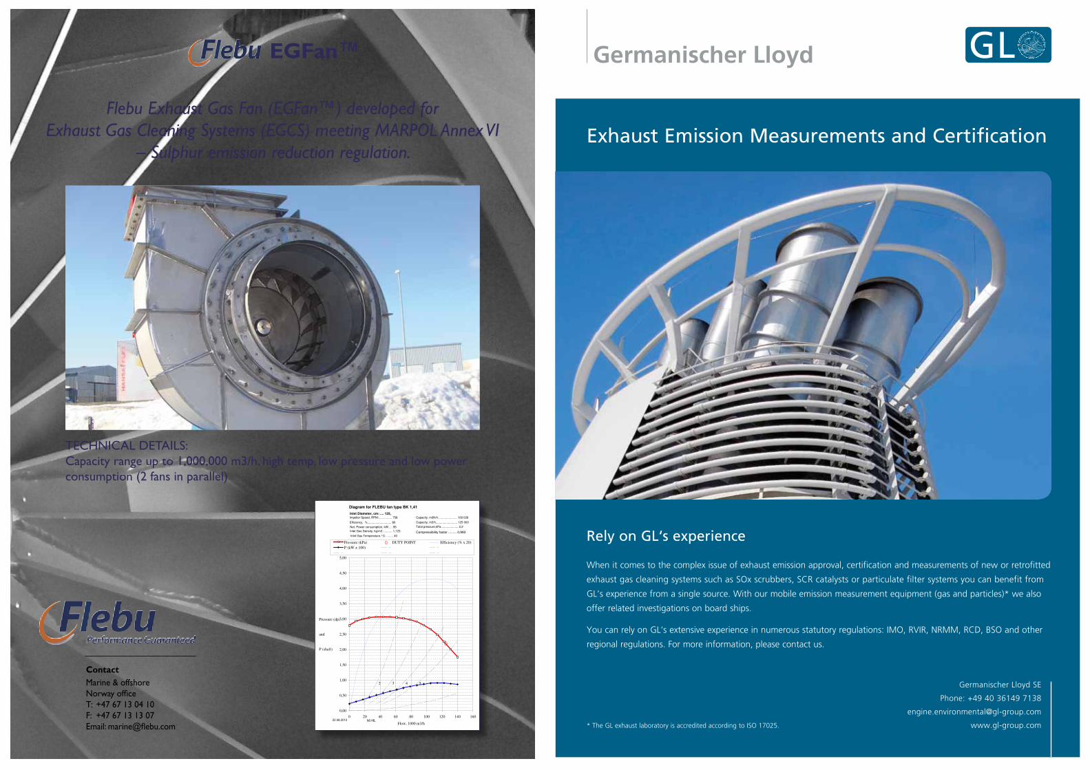
TECHNICAL DETAILS:Capacity range up to 1,000,000 m3/h, high temp, low pressure and low power consumption (2 fans in parallel)
EGFan™
Flebu Exhaust Gas Fan (EGFan™) developed for Exhaust Gas Cleaning Systems (EGCS) meeting MARPOL Annex VI
– Sulphur emission reduction regulation.
BS 848:Part 1:1980, class B
2 3 4 5
0,00
0,50
1,00
1,50
2,00
2,50
3,00
3,50
4,00
4,50
5,00
0 20 40 60 80 100 120 140 160
Flow, 1000 m3/h
Pressure (dp)
and
P (shaft)
Pressure (kPa) DUTY POINT Efficiency (% x 20)
P (kW x 100)
Inlet Diameter, cm: .... 125,
Inlet Gas Density, kg/m3 : ......... 1,123
Impeller Speed, RPM:................ 758
22.08.2012
Capacity, m3/h.......................... 125 000
Capacity, m3N/h....................... 109 026
Total pressure,kPa..................... 2,2
Efficiency, %............................. 80
Net. Power consumption, kW..... 95
Inlet Gas Temperature,°C: ........ 40
Diagram for FLEBU fan type BK 1,41
M.HIL
Compressibility factor ......... 0,993
Marine & offshoreNorway officeT: +47 67 13 04 10F: +47 67 13 13 07Email: [email protected]
Contact
Exhaust Emission Measurements and Certification
Germanischer Lloyd SE
Phone: +49 40 36149 7138
www.gl-group.com
Rely on GL‘s experience
When it comes to the complex issue of exhaust emission approval, certification and measurements of new or retrofitted
exhaust gas cleaning systems such as SOx scrubbers, SCR catalysts or particulate filter systems you can benefit from
GL’s experience from a single source. With our mobile emission measurement equipment (gas and particles)* we also
offer related investigations on board ships.
You can rely on GL‘s extensive experience in numerous statutory regulations: IMO, RVIR, NRMM, RCD, BSO and other
regional regulations. For more information, please contact us.
* The GL exhaust laboratory is accredited according to ISO 17025.
Exhaust GasCleaning
GTM-R ScrubberCompact and Lightweight
· Proven reduction of SOx and PM
· Hybrid functionality – Both open and closed loop operation
· An extremely small footprint
· Low weight resulting in minimal change to stability conditions
· Energy-efficiency – only 1.5% of main engine power is required
Comprehensive maritime industry data
IHS Fairplay Sea-web Directory connects businesses acrossthe maritime industry, helping subscribers quickly access,analyse, and export up-to-date company and contact data.
Now with enhanced database functionality that integratesacross the rest of the Sea-web family, IHS Fairplay Sea-webDirectory replaces the IHS Fairplay World Shipping Directory,a trusted source of maritime contact data throughout 22consecutive editions.
Sea-web Directory includes:
• Over 178,000 companies details
• Over 129,000 ship operators details
• Over 52,000 contact names
6724
_081
2AA
Find suppliers
Identify contractors
Locate repair yards
Research new markets
Identify key business contacts
Contact the IHS Fairplay experts to learn moreFor full information, visit www.ihs.com/seawebdirectoryTel: North/Central/South America: +1 (305) 718 9929Tel: Europe, Middle East and Africa: +44 (0) 1737 379000Tel: Asia: +65 6576 5300
Faster networking acrossthe maritime industry.
Connect with contacts across the maritime industry
Ship Operators Marine Equipment & Services
Ship Managers Marine Computing
Charterers Ship Finance
Shipbuilders & Repairers Marine Insurance
Surveyors Protection & Indemnity
Towing & Salvage Maritime Lawyers & Arbitrators
Offshore Supply Dredging
Ship Brokers Maritime Organisations
Consultants Maritime Schools
Classification Societies Port Authorities & Operators
Engine Builders, Designers & Repairers
Give your business a speed boost with the newSea-web Directory, from IHS Fairplay.
6724_0812AA_SeaWeb Directory_297x210.indd 1 07/08/2012 13:52
What is the future f shipping?
Lloyd’s Register is a trading name of the Lloyd’s Register Group of entities. Services are provided by members of the Lloyd’s Register Group. For further details please see our website: http://www.lr.org/entities
Lloyd’s Register is supporting the industry with the fuels, engine and design challenges of today and tomorrow.
Discover more at www.lr.org/marine
The design of eco-friendly marine power and propulsion solutions is crucial for MAN Diesel & Turbo.
Power competencies are offered with the world’s largest engine programme – having outputs spanning
from 450 to 87,220 kW per engine. Get up front!
Find out more at www.mandieselturbo.com
Low-speed Engines Medium-speed Engines Turbochargers Propellers Propulsion Packages PrimeServ
The Wakethe only emission we want to leave behind
Marine Emissions Monitoring
Applications
NOx Technical Code
MEPC 184 (59) Scheme B Scrubber Exhaust Gas Analysis System (SO2 / CO2)
Ship Efficiency
Approvals
ABS Type ApprovalAnnex VI Reg 13 NOx Tech Code
IMO Res. MEPC 103 (49)
IACS Unified Requirement E10 & IEC 60945 (parts)
Kittiwake Procal LtdA Kittiwake Group Company
Our PAH Total System Concept uses our own fluorescence measurement for PAH plus turbidity and pH all in one system. Designed to meet the requirements of Annex 9, MEPC.184(59), we are developing a complete black box solution to meet the rigorous schedule demands of the new regulations.
With a reputation for producing highly accurate and reliable instruments through quality design and manufacturing, we are developing the new generation Washwater Discharge Monitoring System.
Over the past 18 years, we invented the industry’s first on-line oil in water fluorometer with internal cell condition detector (TD-4100 XDC), the first IMO 107(49)-certified purpose designed fluorescence bilge water monitor (TD-107), the first hand held oil in water analyzer (TD-500D), and the first ever “No-Solvent Method” for oil in water analysis.
Our instruments are backed by expert knowledge and a world class service department.
Please visit our website: www.oilinwatermonitors.comfor more information.
2023 North Gateway Blvd., Suite 101, Fresno, California 93727 USA / TEL: 559 253 1414 / FAX: 559 253 1090 / www.oilinwatermonitors.com
EGC Washwater Discharge Monitors from the industryleader in oil inwater monitors!
TD-1000C
TD-3100
TD-4100/TD-4100C
The TD-4100XDC is a “Closed Cell” version of the rugged, world industry standard TD-4100XD Oil in Water Monitor. It was designed for normally clean water applications or dirty water applications where fouling can be controlled by chemical injection or optional on-board cleaning systems.
The TD-4100XD is designed specifically for offshore oil production, refining, petro-chemical, mining, and other industries that require robust on-line hardware for severe duty and hazardous area locations.
The field-proven TD-1000C is rugged and reliable with the lowest maintenance in the industry. Its fluorescence sensor technology provides high accuracy and repeatibility as well as the earliest leak detection available.
TD-107TD-107 uses our signature FLUORESCENCE measurement technology that can be universally applied to bilge water monitoring. Low maintenance, rugged, and all the features defined by marine customers and regulators.
#1 Worldwide for Environmental andProcess Oil in Water Monitors
TD-500D featuring the least expensive, lightest, smallest, easiest to use, most accurate and most repeatable device on the market for measuring crude oil and condensates in produced water, de-salter tail water, tank bottoms, cargo heaters, or anywhere that crude oil comes in contact with water. Compatible with all standard solvents. Analyze with solvent extraction or "No-Solvent" method.
TD-4100XD/TD-4100XDC
TD-4100 reliably detects BTEX, gasoline, diesel, jet fuel and oil in water. The TD-4100 is a nonfouling, continuous, on-line monitor that provides hydrocarbon and oil in water monitoring down to low ppb.
The TD-4100C is a “Closed Cell” version of the world industry standard TD-4100 Oil in Water Monitor. It was designed for normally clean water applications or dirty water applications where fouling can be controlled by chemical injection or external cleaning systems.
TD-500D
The TD-3100 is a low cost benchtop instrument that was developed to provide an alternative to industry standard oil and grease methods. Compatible with all standard solvents. Analyze with solvent extraction or "No-Solvent" method.
1170 E Champlain DrSuite 120Fresno, CA 93720 USA
t 559 434 6100c 559 289 2274f 559 434 5263
e [email protected] balldesign.com
6/17/12
Turner Designs Hydrocarbon Instruments 2012 EGCSA Ad(A4 Size - 297mm height x 210mm width)
FINAL
Wärtsilä is passionate about optimising lifecycle value by delivering whatever you
need from the only total offering in the business. And our merger with Hamworthy
has now made the best offering even better. Let’s work together to help you find
the shortest route to bigger profits. www.wartsila.com
YOUR SHORTERROUTE TOBIGGER PROFITSIS NOW EVENSHORTER

160
NOTES