near-infrared ao coronograph design for giant telescopes
TRANSCRIPT
Near -infrared AO coronograph design for giant telescopes
Gemini Preprint #87
Brent Ellerbroek Gemini Observatory, 670 N. A’ohoku Pl.,
Hilo, HI 96720
Richard Buchroeder Optical Design Service, 8 Bella Vista Drive,
Tucson, AZ 85745
Near-infrared AO coronagraph design for giant telescopes Brent Ellerbroeka and Richard Buchroederb
aGemini Observatory, 670 N. A�ohoku Pl., Hilo, HI 96720
bOptical Design Service, 8 Bella Vista Drive, Tucson, AZ 85745
ABSTRACT We describe the adaptive optical (AO) requirements, optical design, and expected performance of a near-infrared AO coronagraph for a 30 meter class giant telescope. The optical design of the instrument consists of back-to-back finite conjugate relays, each containing a collimated space between a pair of toric mirrors. The first collimated space contains the atmospheric dispersion compensator and the AO components, which are a tip/tilt mirror, a MEMS deformable mirror, and a beamsplitter for the wavefront sensing path. An occulting disk or similar focal plane mask is located at the intermediate image between the two relays, and a Lyot stop is placed at the pupil plane in the second relay. The required AO order of correction for a Strehl ratio of 0.9 at a wavelength of 2.2 microns is about 150 by 150, and the required control bandwidth is 42 Hz. The limiting magnitude at this level of performance is estimated to be 10.4. Keywords: Adaptive optics, giant telescopes, coronagraphs
1. INTRODUCTION The collecting aperture and angular resolution potentially provided by future giant telescopes will yield significant new opportunities for directly detecting extrasolar planets and studying circumstellar disks if the blurring induced by atmospheric turbulence can be compensated by an adaptive optical (AO) system. The requirements for this system are at once highly conventional and entirely revolutionary: Narrow field compensation using a bright, on-axis natural guide star (NGS) is the most straightforward mode of operation for adaptive optics, but high contrast imaging of very faint companions will require Strehl ratios and an order of correction well beyond what has been demonstrated in currently operating systems. This paper summarizes our initial thoughts on the requirements and design of an extreme AO (ExAO) coronagraph for a 30-meter class giant segmented mirror telescope (GSMT).1 Section 2 outlines the top-level science requirements, and derives a preliminary set of the implied requirements for the AO system and its component parts. Section 3 describes a conceptual opto-mechanical design, which in comparison with concepts for other AO operating modes on giant telescopes (e.g., MCAO) is relatively compact and almost straightforward. The same cannot be said for the AO components and control algorithms. Section 4 summarizes some of the key issues for near-term work in these areas.
2. PERFORMANCE AND IMPLEMENTATION REQUIREMENTS Table 1 summarizes the top-level science requirements we have assumed to develop a conceptual design for an AO coronagraph. Faint companions can only be detected if nearly all of the light from the central star is blocked by an occulting disk, and this in turn requires that an AO system deliver extremely high Strehl ratios. The lower the Strehl ratio, the longer the integration time that will be needed to average out the time-varying speckles in the uncompensated halo of the PSF. The science goals for high dynamic range imaging on giant telescopes are far beyond the capabilities of existing AO systems, and we hesitate to make a more definitive statement until future experiments and modeling establish the relationships between Strehl ratio, integration time, and PSF uniformity for ExAO.
Wavelength range, µm 1.0-5.0 Field of view diameter, arc sec 2
0.9 in K (initially) Mean on-axis Strehl (With a bright on-axis guide star and median seeing conditions)
0.9 in J (potential upgrade)
PSF stability and predictability TBD (excellent) Optical transmittance 0.80 Emissivity < 20% (2.0-5.0 µm) Atmospheric dispersion compensation
TBD
Coronagraphic elements Occulting disk Lyot stop
Table 1: Draft science requirements for ExAO point design
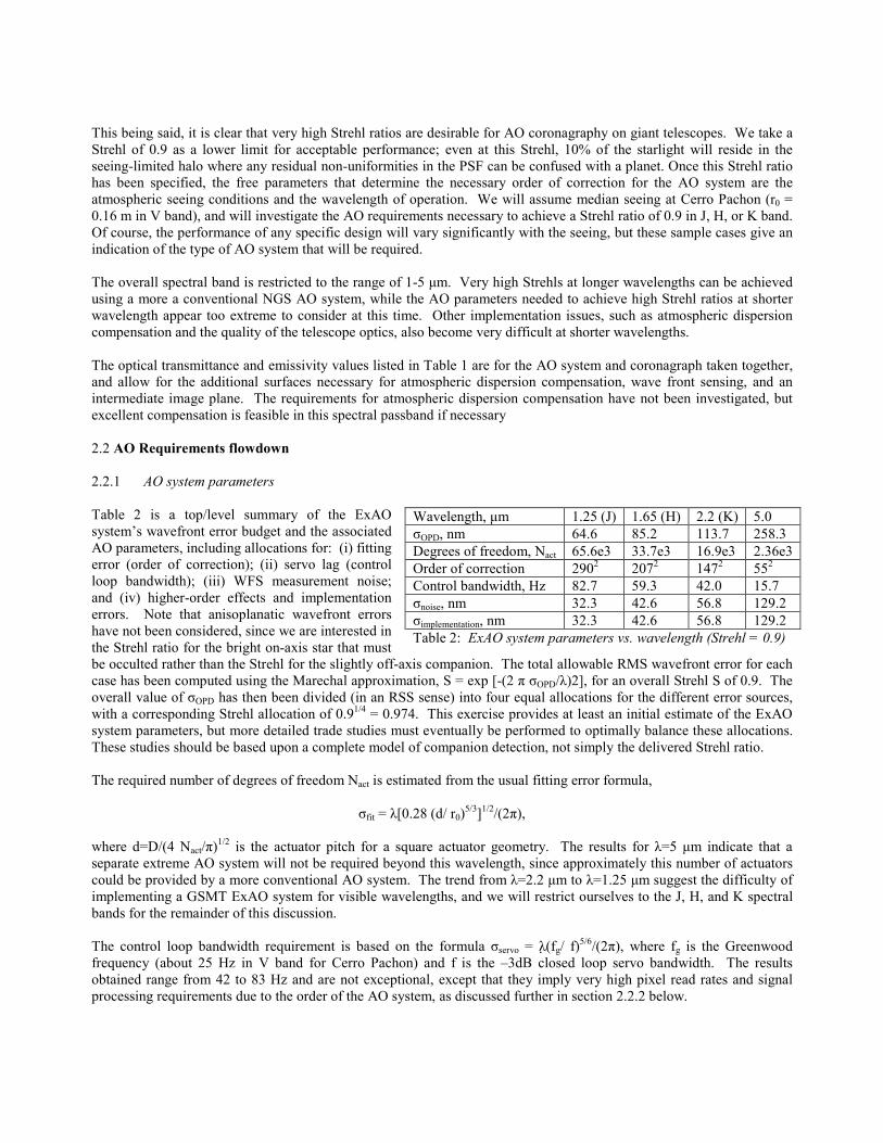
This being said, it is clear that very high Strehl ratios are desirable for AO coronagraphy on giant telescopes. We take a Strehl of 0.9 as a lower limit for acceptable performance; even at this Strehl, 10% of the starlight will reside in the seeing-limited halo where any residual non-uniformities in the PSF can be confused with a planet. Once this Strehl ratio has been specified, the free parameters that determine the necessary order of correction for the AO system are the atmospheric seeing conditions and the wavelength of operation. We will assume median seeing at Cerro Pachon (r0 = 0.16 m in V band), and will investigate the AO requirements necessary to achieve a Strehl ratio of 0.9 in J, H, or K band. Of course, the performance of any specific design will vary significantly with the seeing, but these sample cases give an indication of the type of AO system that will be required. The overall spectral band is restricted to the range of 1-5 µm. Very high Strehls at longer wavelengths can be achieved using a more a conventional NGS AO system, while the AO parameters needed to achieve high Strehl ratios at shorter wavelength appear too extreme to consider at this time. Other implementation issues, such as atmospheric dispersion compensation and the quality of the telescope optics, also become very difficult at shorter wavelengths. The optical transmittance and emissivity values listed in Table 1 are for the AO system and coronagraph taken together, and allow for the additional surfaces necessary for atmospheric dispersion compensation, wave front sensing, and an intermediate image plane. The requirements for atmospheric dispersion compensation have not been investigated, but excellent compensation is feasible in this spectral passband if necessary 2.2 AO Requirements flowdown 2.2.1 AO system parameters Table 2 is a top/level summary of the ExAO system�s wavefront error budget and the associated AO parameters, including allocations for: (i) fitting error (order of correction); (ii) servo lag (control loop bandwidth); (iii) WFS measurement noise; and (iv) higher-order effects and implementation errors. Note that anisoplanatic wavefront errors have not been considered, since we are interested in the Strehl ratio for the bright on-axis star that must be occulted rather than the Strehl for the slightly off-axis companion. The total allowable RMS wavefront error for each case has been computed using the Marechal approximation, S = exp [-(2 π σOPD/λ)2], for an overall Strehl S of 0.9. The overall value of σOPD has then been divided (in an RSS sense) into four equal allocations for the different error sources, with a corresponding Strehl allocation of 0.91/4 = 0.974. This exercise provides at least an initial estimate of the ExAO system parameters, but more detailed trade studies must eventually be performed to optimally balance these allocations. These studies should be based upon a complete model of companion detection, not simply the delivered Strehl ratio. The required number of degrees of freedom Nact is estimated from the usual fitting error formula,
σfit = λ[0.28 (d/ r0)5/3]1/2/(2π),
where d=D/(4 Nact/π)1/2 is the actuator pitch for a square actuator geometry. The results for λ=5 µm indicate that a separate extreme AO system will not be required beyond this wavelength, since approximately this number of actuators could be provided by a more conventional AO system. The trend from λ=2.2 µm to λ=1.25 µm suggest the difficulty of implementing a GSMT ExAO system for visible wavelengths, and we will restrict ourselves to the J, H, and K spectral bands for the remainder of this discussion. The control loop bandwidth requirement is based on the formula σservo = λ$(fg/ f)5/6/(2π), where fg is the Greenwood frequency (about 25 Hz in V band for Cerro Pachon) and f is the �3dB closed loop servo bandwidth. The results obtained range from 42 to 83 Hz and are not exceptional, except that they imply very high pixel read rates and signal processing requirements due to the order of the AO system, as discussed further in section 2.2.2 below.
Wavelength, µm 1.25 (J) 1.65 (H) 2.2 (K) 5.0 σOPD, nm 64.6 85.2 113.7 258.3 Degrees of freedom, Nact 65.6e3 33.7e3 16.9e3 2.36e3 Order of correction 2902 2072 1472 552 Control bandwidth, Hz 82.7 59.3 42.0 15.7 σnoise, nm 32.3 42.6 56.8 129.2 σimplementation, nm 32.3 42.6 56.8 129.2 Table 2: ExAO system parameters vs. wavelength (Strehl = 0.9)
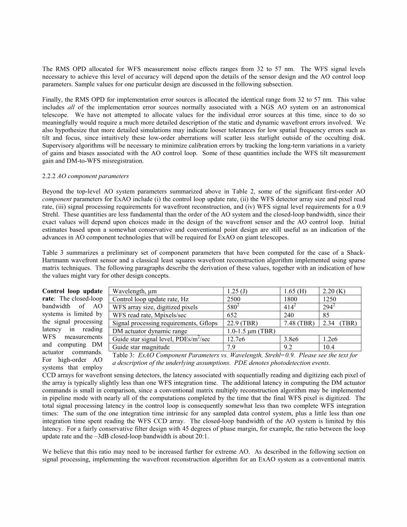
The RMS OPD allocated for WFS measurement noise effects ranges from 32 to 57 nm. The WFS signal levels necessary to achieve this level of accuracy will depend upon the details of the sensor design and the AO control loop parameters. Sample values for one particular design are discussed in the following subsection. Finally, the RMS OPD for implementation error sources is allocated the identical range from 32 to 57 nm. This value includes all of the implementation error sources normally associated with a NGS AO system on an astronomical telescope. We have not attempted to allocate values for the individual error sources at this time, since to do so meaningfully would require a much more detailed description of the static and dynamic wavefront errors involved. We also hypothesize that more detailed simulations may indicate looser tolerances for low spatial frequency errors such as tilt and focus, since intuitively these low-order aberrations will scatter less starlight outside of the occulting disk. Supervisory algorithms will be necessary to minimize calibration errors by tracking the long-term variations in a variety of gains and biases associated with the AO control loop. Some of these quantities include the WFS tilt measurement gain and DM-to-WFS misregistration. 2.2.2 AO component parameters Beyond the top-level AO system parameters summarized above in Table 2, some of the significant first-order AO component parameters for ExAO include (i) the control loop update rate, (ii) the WFS detector array size and pixel read rate, (iii) signal processing requirements for wavefront reconstruction, and (iv) WFS signal level requirements for a 0.9 Strehl. These quantities are less fundamental than the order of the AO system and the closed-loop bandwidth, since their exact values will depend upon choices made in the design of the wavefront sensor and the AO control loop. Initial estimates based upon a somewhat conservative and conventional point design are still useful as an indication of the advances in AO component technologies that will be required for ExAO on giant telescopes. Table 3 summarizes a preliminary set of component parameters that have been computed for the case of a Shack-Hartmann wavefront sensor and a classical least squares wavefront reconstruction algorithm implemented using sparse matrix techniques. The following paragraphs describe the derivation of these values, together with an indication of how the values might vary for other design concepts. Control loop update rate: The closed-loop bandwidth of AO systems is limited by the signal processing latency in reading WFS measurements and computing DM actuator commands. For high-order AO systems that employ CCD arrays for wavefront sensing detectors, the latency associated with sequentially reading and digitizing each pixel of the array is typically slightly less than one WFS integration time. The additional latency in computing the DM actuator commands is small in comparison, since a conventional matrix multiply reconstruction algorithm may be implemented in pipeline mode with nearly all of the computations completed by the time that the final WFS pixel is digitized. The total signal processing latency in the control loop is consequently somewhat less than two complete WFS integration times: The sum of the one integration time intrinsic for any sampled data control system, plus a little less than one integration time spent reading the WFS CCD array. The closed-loop bandwidth of the AO system is limited by this latency. For a fairly conservative filter design with 45 degrees of phase margin, for example, the ratio between the loop update rate and the �3dB closed-loop bandwidth is about 20:1. We believe that this ratio may need to be increased further for extreme AO. As described in the following section on signal processing, implementing the wavefront reconstruction algorithm for an ExAO system as a conventional matrix
Wavelength, µm 1.25 (J) 1.65 (H) 2.20 (K) Control loop update rate, Hz 2500 1800 1250 WFS array size, digitized pixels 5802 4142 2942 WFS read rate, Mpixels/sec 652 240 85 Signal processing requirements, Gflops 22.9 (TBR) 7.48 (TBR) 2.34 (TBR) DM actuator dynamic range 1.0-1.5 µm (TBR) Guide star signal level, PDEs/m2/sec 12.7e6 3.8e6 1.2e6 Guide star magnitude 7.9 9.2 10.4 Table 3: ExAO Component Parameters vs. Wavelength, Strehl=0.9. Please see the text for a description of the underlying assumptions. PDE denotes photodetection events.
multiply may be prohibitively expensive due to the number of degrees of freedom involved. More computationally efficient reconstruction methods are available, but all of the algorithms with which we are familiar require the full WFS measurement vector to be available before the majority of the computations can begin. The amount of latency in such a system is likely to be on the order of three WFS integration times: One for the sample-and-hold in any sampled data control system, approximately one for reading out the WFS CCD array, and approximately one for performing the wavefront reconstruction. The third contributor can only be reduced below one WFS integration time if the signal processor is idle for the remainder of each cycle, which suggests that more processing power has been purchased than is absolutely necessary. With increased latency, the ratio between the control loop update rate and closed loop bandwidth must also be increased to maintain the same level of loop stability. Three cycles of latency and a ratio of 30:1 correspond to about 42 degrees of phase margin, which is approximately the same as the 45 degrees achieved with two cycles of latency at a ratio of 20:1. We have consequently used a ratio of 30:1 to compute the control loop update rates listed in Table 3 above. This has obvious implications for the WFS CCD pixel read rate and wavefront reconstruction signal processing requirements as described further below. WFS array size and pixel rate: Shack-Hartmann wavefront sensors can be successfully implemented with a minimum of four pixels per subaperture, provided that the sensor is not required to work off null (i.e., the noncommon path wavefront errors in the WFS optical path are not too large) and that the individual Shack-Hartmann spots are approximately diffraction limited (i.e., the subaperture size is not greater than about 2r0 at the wavefront sensing wavelength). Both of these conditions should apply for ExAO on GSMT, so the WFS pixel values in Table 3 are simply twice the corresponding orders of correction appearing in Table 2. The WFS CCD array may contain additional, undigitized guard pixels used to increase the separation between the Shack-Hartmann spots and prevent optical crosstalk. The required array sizes range from about 3002 to 6002. These values are significantly larger than the current maximum of 1282 for high speed, low noise CCD arrays, but they do not appear to be infeasible. The WFS sensor pixel read rates are simply the product of these pixel values times the AO control loop update rate. These values are in the range from 85 to 652 megapixels per second. The current maximum read rate for low noise digitization is about 0.5 to 1 megapixel per second per digitizer, so it is clear that each array must include a very large number of output channels. Other wavefront sensing concepts that may be considered include the shearing interferometer and the point diffraction, or Smartt, interferometer. Either of these approaches would require the same total number of pixel measurements per second as the Shack-Hartmann sensor, but would provide additional options for how these measurements could be obtained. These include (i) four smaller CCD arrays with the same total number of pixels, each of which is read at the AO control loop update rate, or (ii) one such array read out at four times this rate. A lower order Shack-Hartmann system might still be necessary to initially close the loop and bring the phase error within the more limited dynamic range of these sensors. Signal processing requirements: It appears to be very unlikely that wavefront reconstruction algorithms for ExAO systems can be implemented as conventional matrix multiplies. The number of operations (adds and multiplies) needed to compute a single wavefront reconstruction using this approach is approximately equal to four times the square of the number of AO degrees of freedom. This corresponds to from 1.4 to 43 trillion operations per second for the ExAO system parameters outlined in Table 2 and Table 3 above, values which are up to about 13 thousand times larger than the computational load anticipated for the Gemini-South MCAO system. Alternative algorithms do exist that achieve dramatic reduction in computation requirements by exploiting the sparse structure of the DM-to-WFS influence matrix in a conventional NGS AO system. Once possible method reduces the number of computations required for one wavefront reconstruction from 4 Nact
2 to 12 Nact log (Nact).2 This corresponds to a range of 2.3 to 23 billion operations per second for the ExAO systems being considered here, equivalent to from 0.7 to 7 Gemini-South reconstructors. This particular algorithm is not particularly parallelizable, however, and would need to be implemented using a single CPU capable of this processing rate.
Developing new reconstruction approaches that are both computationally efficient and suitable for parallel implementation is now a very active area of research. An iterative algorithm developed at the University of Montana requires about 60 Nact log (Nact) operations per reconstruction, and is based upon sparse matrix multiply and Fourier transform operations that should be easier to implement in parallel.3 A third approach based upon fast Fourier transform (FFT) methods is also under development.4 More work is needed on these approaches and similar advanced algorithms, and also on the use of advanced signal processing hardware such as field programmable gate arrays (FPGAs). Of course, one of the key attractions of the Smartt interferometer is that would supply a direct phase measurement and eliminate the need for very high order wavefront reconstruction altogether. DM actuator dynamic range: The requirement on DM actuator dynamic range is relatively modest, provided that the low frequency, high amplitude wavefront errors in the atmosphere and telescope have already been compensated by a lower-order conventional DM, or perhaps by an adaptive secondary mirror. Assuming �low-order� correction by at least 700 actuators, the residual aberrations to be corrected by the ExAO DM will be similar to the tilt-removed wavefront errors on a 1-meter aperture. This error is no more than about 0.3 µm RMS, even with 1 arc second seeing and an airmass of 2. An actuator dynamic range of about 1.0 to 1.5 µm should therefore be adequate. Guide star signal level and magnitude: The ExAO system will be used primarily to detect planets around nearby bright stars. It is still useful to determine the guide star signal levels corresponding to values of σnoise listed in Table 2, since this will indicate (i) if the equal error budget allocations in this table should be rebalanced, and (ii) if the ExAO system might be capable of other types of observations involving somewhat fainter guide stars. Table 3 summarizes the results of first-order calculations for the required guide star signal levels and magnitudes, which range from about magnitude 8 to 10 for the WFS and photometric parameters and assumptions outlined below. The nearest stars that provide the largest angular separation to a prospective planet will have magnitudes no dimmer than about 5 or 6, which suggests that the answer is �yes� to questions (i) and (ii) above. To compute the required WFS signal level, we have worked backwards through the relationships
( ) ( )[ ]( ) .4/
/5.0)(/7.0
/log08.02.0
/
2/12
2/1220
222
ePDEPDE
sssB
B
actr
ss
rsnoise
NNSNR
dr
SNRNg
ffgdgg
σ
λλλθ
θσ
πσσ
θ
θ
+=
+=
=+=
==
Here gs is the noise gain of the AO temporal filter, gr is the noise gain of the wavefront reconstruction algorithm, d equal to the actuator pitch and subaperture width, and σθ is the 1-axis, 1-sigma error in a single WFS subaperture tilt measurement. The formulas for gs and gr are approximations that are valid for a type I control loop, a least squares wavefront reconstruction algorithm, and either a Shack-Hartmann or shearing interferometer wavefront sensor. The quantity θB is the effective blur radius of a Shack-Hartmann spot, SNR is the signal-to-noise ratio for a single WFS measurement, λs is the mean wavefront sensing wavelength, Npde is the number of photodetection events per WFS subaperture per measurement, and σe is the RMS detector read noise in units of electrons. The formula for θB is an approximation that is asymptotically correct for either very large or very small values of d and is modestly conservative in between. Sky background and dark current have been neglected in the formula for SNR, based upon the assumption that we are considering very bright guide stars and short integration times. The noise performance of the shearing interferometer WFS is roughly similar, assuming that the subaperture size and shear width have been optimized for the seeing conditions. Solving for Npde in terms of the other variables yields the result
( )[ ]./
2/16222
2/122
noiseBrs
epde
dggc
cccN
σθ
σ
=
++=
The WFS signal level L in units of photodetection events per second per square meter of collecting aperture is then given by
,/ 2dNfL pdes= and the corresponding guide star magnitude M is
),(log5.2 10
110
−−−= LLM τ where τ is the end-to-end throughput of the telescope, AO system, and WFS detector, and L0 is zeropoint (the signal level for a zero magnitude guide star). Table 3 summarizes the results of these calculations for the parameters σe
2 = 5, λs = 0.7 µm, τ = 0.4, and L0 = 4.4e10. All of these values must be iterated as the designs for the telescope and ExAO system progress.
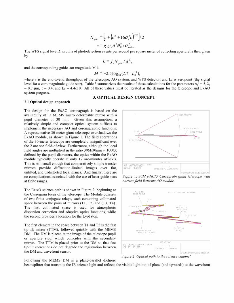
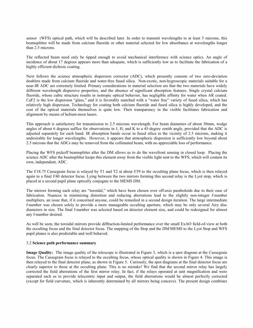
3. OPTICAL DESIGN CONCEPT 3.1 Optical design approach The design for the ExAO coronagraph is based on the availability of a MEMS micro deformable mirror with a pupil diameter of 30 mm. Given this assumption, a relatively simple and compact optical system suffices to implement the necessary AO and coronagraphic functions. A representative 30-meter giant telescope overshadows the ExAO module, as shown in Figure 1. The field aberrations of the 30-meter telescope are completely insignificant over the 2 arc sec field-of-view. Furthermore, although the local field angles are multiplied in the ratio 30M/30mm = 1000X defined by the pupil diameters, the optics within the ExAO module typically operate at only 17 arc-minutes off-axis. This is still small enough that comparatively simple transfer mirrors provide diffraction-limited images over flat, untilted, and undistorted focal planes. And finally, there are no complications associated with the use of laser guide stars at finite ranges. The ExAO science path is shown in Figure 2, beginning at the Cassegrain focus of the telescope. The Module consists of two finite conjugate relays, each containing collimated space between the pairs of mirrors (T1, T2) and (T3, T4). The first collimated space is used for atmospheric dispersion correction and adaptive optics functions, while the second provides a location for the Lyot stop. The first element in the space between T1 and T2 is the fast tip-tilt mirror (TTM), followed quickly with the MEMS DM. The DM is placed at the image of the telescope pupil or aperture stop, which coincides with the secondary mirror. The TTM is placed prior to the DM so that fast tip/tilt corrections do not degrade the registration between the DM and wavefront sensor. Following the MEMS DM is a plane-parallel dichroic beamsplitter that transmits the IR science light and reflects the visible light out-of-plane (and upwards) to the wavefront
Figure 1: 30M f/18.75 Cassegrain giant telescope with narrow-field Extreme AO module.
Figure 2: Optical path to the science channel
sensor (WFS) optical path, which will be described later. In order to transmit wavelengths to at least 5 microns, this beamsplitter will be made from calcium fluoride or other material selected for low absorbance at wavelengths longer than 2.5 microns. The reflected beam need only be tipped enough to avoid mechanical interference with science optics. An angle of incidence of about 17 degrees appears more than adequate, which is sufficiently low as to facilitate the fabrication of a highly efficient dichroic coating. Next follows the science atmospheric dispersion corrector (ADC), which presently consists of two zero-deviation doublets made from calcium fluoride and water-free fused silica. Non-exotic, non-hygroscopic materials suitable for a near-IR ADC are extremely limited. Primary considerations in material selection are that the two materials have widely different wavelength dispersive properties, and the absence of significant absorption features. Single crystal calcium fluoride, whose cubic structure results in isotropic optical behavior, has negligible affinity for water when AR coated. CaF2 is the low dispersion �glass,� and it is favorably matched with a �water free� variety of fused silica, which has relatively high dispersion. Technology for coating both calcium fluoride and fused silica is highly developed, and the cost of the optical materials themselves is quite low. Their transparency in the visible facilitates fabrication and alignment by means of helium-neon lasers. This approach is satisfactory for transmission to 2.5 microns wavelength. For beam diameters of about 30mm, wedge angles of about 6 degrees suffice for observations in J, H, and K to a 45-degree zenith angle, provided that the ADC is adjusted separately for each band. IR absorption bands occur in fused silica in the vicinity of 2.5 microns, making it undesirable for longer wavelengths. However, it appears that atmospheric dispersion is sufficiently low beyond about 2.5 microns that the ADCs may be removed from the collimated beam, with no appreciable loss of performance. Placing the WFS pickoff beamsplitter after the DM allows us to do the wavefront sensing in closed loop. Placing the science ADC after the beamsplitter keeps this element away from the visible light sent to the WFS, which will contain its own, independent, ADC. The f/18.75 Cassegrain focus is relayed by T1 and T2 at about f/39 to the occulting plane focus, which is then relayed again to a final f/40 detector focus. Lying between the two mirrors forming this second relay is the Lyot stop, which is placed at a second pupil plane optically conjugate to the MEMS DM. The mirrors forming each relay are �toroidal,� which have been chosen over off-axis paraboloids due to their ease of fabrication. Nuances in minimizing distortion and reducing aberrations lead to the slightly non-integer f-number multipliers, an issue that, if it concerned anyone, could be remedied in a second design iteration. The large intermediate f-number was chosen solely to provide a more manageable occulting aperture, which may be only several Airy disc diameters in size. The final f-number was selected based on detector element size, and could be redesigned for almost any f-number desired. As will be seen, the toroidal mirrors provide diffraction-limited performance over the small ExAO field-of-view at both the occulting focus and the final detector focus. The mapping of the Stop and the DM/MEMS to the Lyot Stop and WFS pupil planes is also predictable and well behaved. 3.2 Science path performance summary Image Quality: The image quality of the telescope is illustrated in Figure 3, which is a spot diagram at the Cassegrain focus. The Cassegrain focus is relayed to the occulting focus, whose optical quality is shown in Figure 4. This image is then relayed to the final detector plane, as shown in Figure 5. Curiously, the spot diagrams at the final detector focus are clearly superior to those at the occulting plane. This is no mistake! We find that the second mirror relay has largely corrected the field aberrations of the first mirror relay. In fact, if the relays operated at unit magnification and were separated such as to provide telecentric input and output, the field aberrations would be almost perfectly corrected (except for field curvature, which is inherently determined by all mirrors being concave). The present design combines
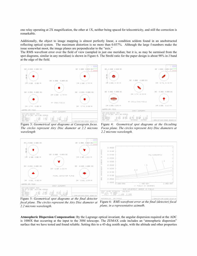
one relay operating at 2X magnification, the other at 1X, neither being spaced for telecentricity, and still the correction is remarkable. Additionally, the object to image mapping is almost perfectly linear, a condition seldom found in an unobstructed reflecting optical system. The maximum distortion is no more than 0.037%. Although the large f-numbers make the issue somewhat moot, the image planes are perpendicular to the �axis.� The RMS wavefront error over the field of view (sampled in just one meridian; but it is, as may be surmised from the spot diagrams, similar in any meridian) is shown in Figure 6. The Strehl ratio for the paper design is about 98% in J band at the edge of the field.
Atmospheric Dispersion Compensation: By the Lagrange optical invariant, the angular dispersion required at the ADC is 1000X that occurring at the input to the 30M telescope. The ZEMAX code includes an �atmospheric dispersion� surface that we have tested and found reliable. Setting this to a 45-deg zenith angle, with the altitude and other properties
Figure 3: Geometrical spot diagrams at Cassegrain focus. The circles represent Airy Disc diameter at 2.2 microns wavelength
Figure 4: Geometrical spot diagrams at the Occulting Focus plane. The circles represent Airy Disc diameters at 2.2 microns wavelength.
Figure 5: Geometrical spot diagrams at the final detector focal plane. The circles represent the Airy Disc diameter at 2.2 microns wavelength.
Figure 6: RMS wavefront error at the final (detector) focal plane, in a representative azimuth.
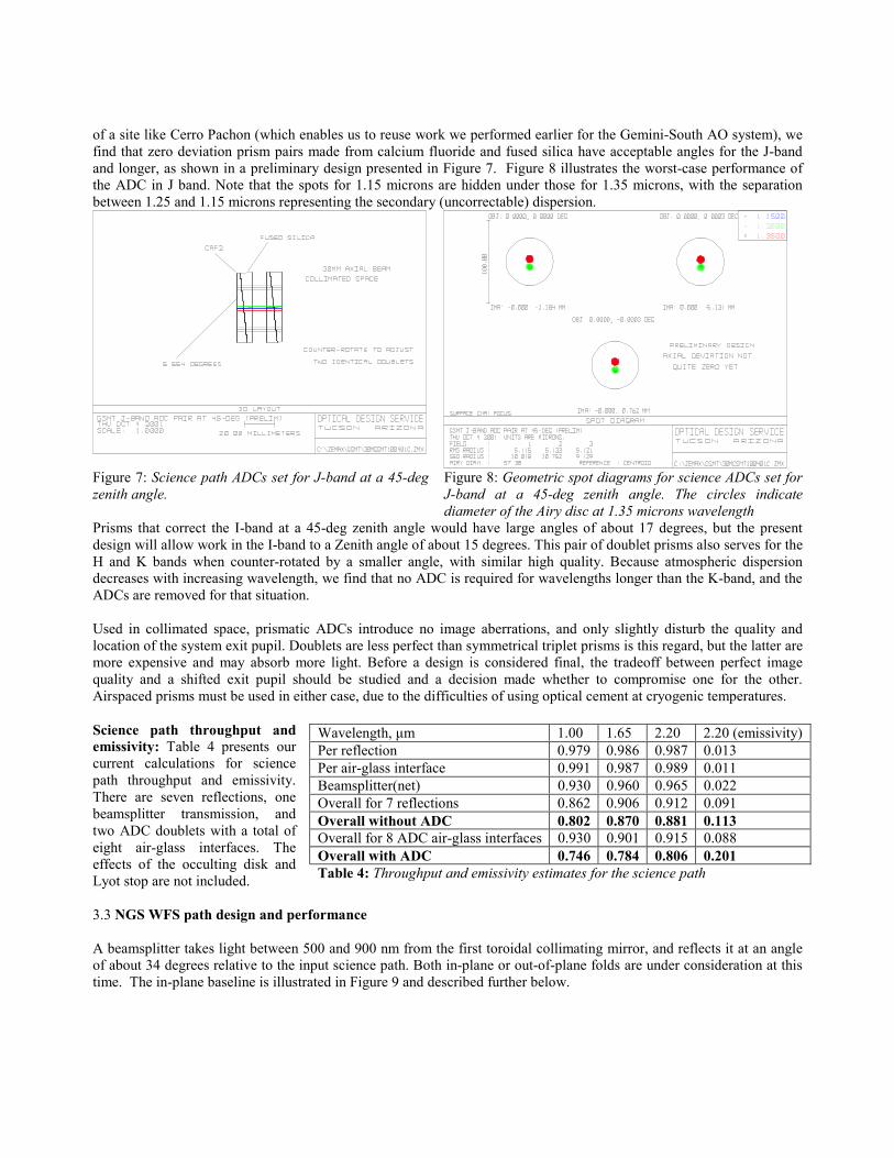
of a site like Cerro Pachon (which enables us to reuse work we performed earlier for the Gemini-South AO system), we find that zero deviation prism pairs made from calcium fluoride and fused silica have acceptable angles for the J-band and longer, as shown in a preliminary design presented in Figure 7. Figure 8 illustrates the worst-case performance of the ADC in J band. Note that the spots for 1.15 microns are hidden under those for 1.35 microns, with the separation between 1.25 and 1.15 microns representing the secondary (uncorrectable) dispersion.
Figure 7: Science path ADCs set for J-band at a 45-deg zenith angle.
Figure 8: Geometric spot diagrams for science ADCs set for J-band at a 45-deg zenith angle. The circles indicate diameter of the Airy disc at 1.35 microns wavelength
Prisms that correct the I-band at a 45-deg zenith angle would have large angles of about 17 degrees, but the present design will allow work in the I-band to a Zenith angle of about 15 degrees. This pair of doublet prisms also serves for the H and K bands when counter-rotated by a smaller angle, with similar high quality. Because atmospheric dispersion decreases with increasing wavelength, we find that no ADC is required for wavelengths longer than the K-band, and the ADCs are removed for that situation. Used in collimated space, prismatic ADCs introduce no image aberrations, and only slightly disturb the quality and location of the system exit pupil. Doublets are less perfect than symmetrical triplet prisms is this regard, but the latter are more expensive and may absorb more light. Before a design is considered final, the tradeoff between perfect image quality and a shifted exit pupil should be studied and a decision made whether to compromise one for the other. Airspaced prisms must be used in either case, due to the difficulties of using optical cement at cryogenic temperatures. Science path throughput and emissivity: Table 4 presents our current calculations for science path throughput and emissivity. There are seven reflections, one beamsplitter transmission, and two ADC doublets with a total of eight air-glass interfaces. The effects of the occulting disk and Lyot stop are not included. 3.3 NGS WFS path design and performance A beamsplitter takes light between 500 and 900 nm from the first toroidal collimating mirror, and reflects it at an angle of about 34 degrees relative to the input science path. Both in-plane or out-of-plane folds are under consideration at this time. The in-plane baseline is illustrated in Figure 9 and described further below.
Wavelength, µm 1.00 1.65 2.20 2.20 (emissivity) Per reflection 0.979 0.986 0.987 0.013 Per air-glass interface 0.991 0.987 0.989 0.011 Beamsplitter(net) 0.930 0.960 0.965 0.022 Overall for 7 reflections 0.862 0.906 0.912 0.091 Overall without ADC 0.802 0.870 0.881 0.113 Overall for 8 ADC air-glass interfaces 0.930 0.901 0.915 0.088 Overall with ADC 0.746 0.784 0.806 0.201 Table 4: Throughput and emissivity estimates for the science path
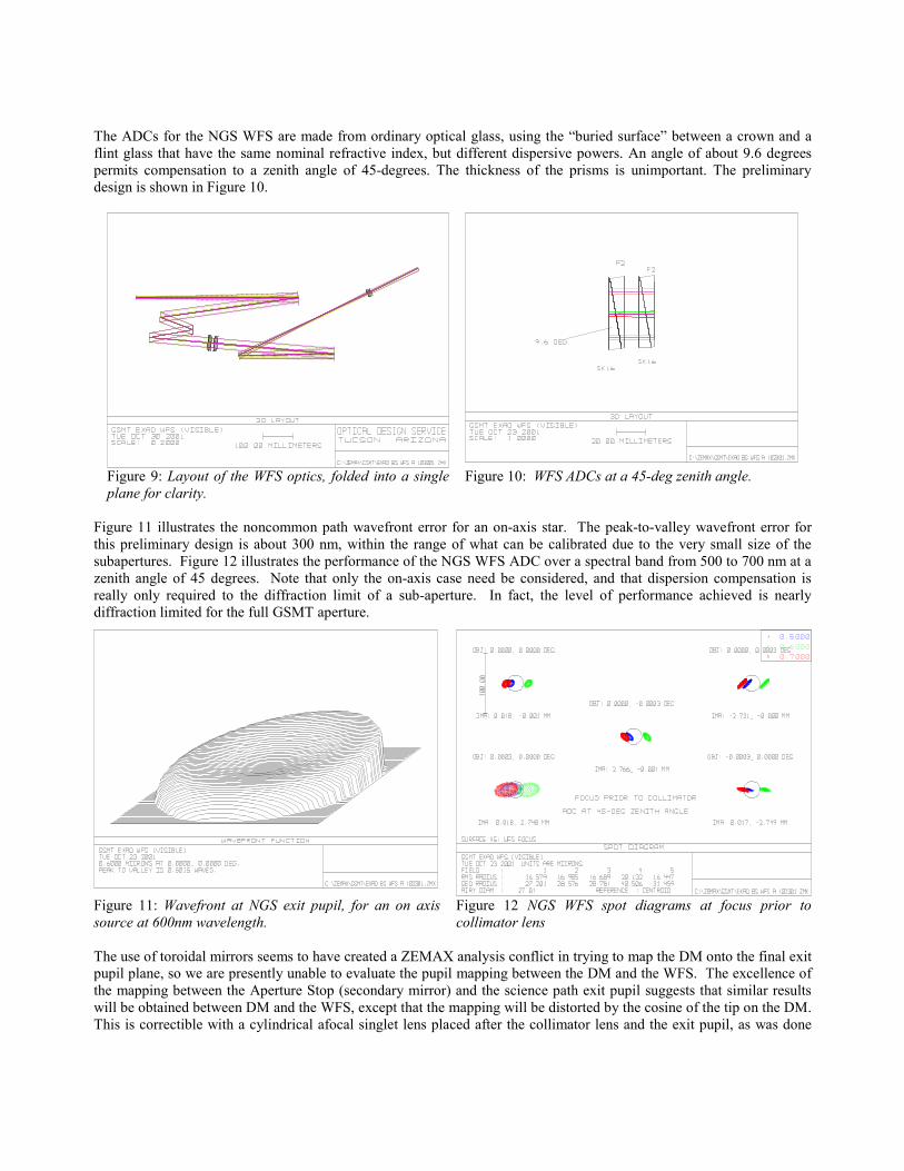
The ADCs for the NGS WFS are made from ordinary optical glass, using the �buried surface� between a crown and a flint glass that have the same nominal refractive index, but different dispersive powers. An angle of about 9.6 degrees permits compensation to a zenith angle of 45-degrees. The thickness of the prisms is unimportant. The preliminary design is shown in Figure 10.
Figure 9: Layout of the WFS optics, folded into a single plane for clarity.
Figure 10: WFS ADCs at a 45-deg zenith angle.
Figure 11 illustrates the noncommon path wavefront error for an on-axis star. The peak-to-valley wavefront error for this preliminary design is about 300 nm, within the range of what can be calibrated due to the very small size of the subapertures. Figure 12 illustrates the performance of the NGS WFS ADC over a spectral band from 500 to 700 nm at a zenith angle of 45 degrees. Note that only the on-axis case need be considered, and that dispersion compensation is really only required to the diffraction limit of a sub-aperture. In fact, the level of performance achieved is nearly diffraction limited for the full GSMT aperture.
The use of toroidal mirrors seems to have created a ZEMAX analysis conflict in trying to map the DM onto the final exit pupil plane, so we are presently unable to evaluate the pupil mapping between the DM and the WFS. The excellence of the mapping between the Aperture Stop (secondary mirror) and the science path exit pupil suggests that similar results will be obtained between DM and the WFS, except that the mapping will be distorted by the cosine of the tip on the DM. This is correctible with a cylindrical afocal singlet lens placed after the collimator lens and the exit pupil, as was done
Figure 11: Wavefront at NGS exit pupil, for an on axis source at 600nm wavelength.
Figure 12 NGS WFS spot diagrams at focus prior to collimator lens
for the Gemini-South MCAO WFS design.5 Lower quality pupil mapping is permitted as long as it is stable, and it has been suggested that the elaborate measures taken for the Gemini-South design are not required for the 30M GSMT. Finally, the NGS WFS path contains 6 reflections, two ADCs, and a doublet refractive collimating lens. This is very similar in complexity and element count to the science path optical system, so that the transmittance estimates presented in Table 1 for the science path are representative of what we expect here.
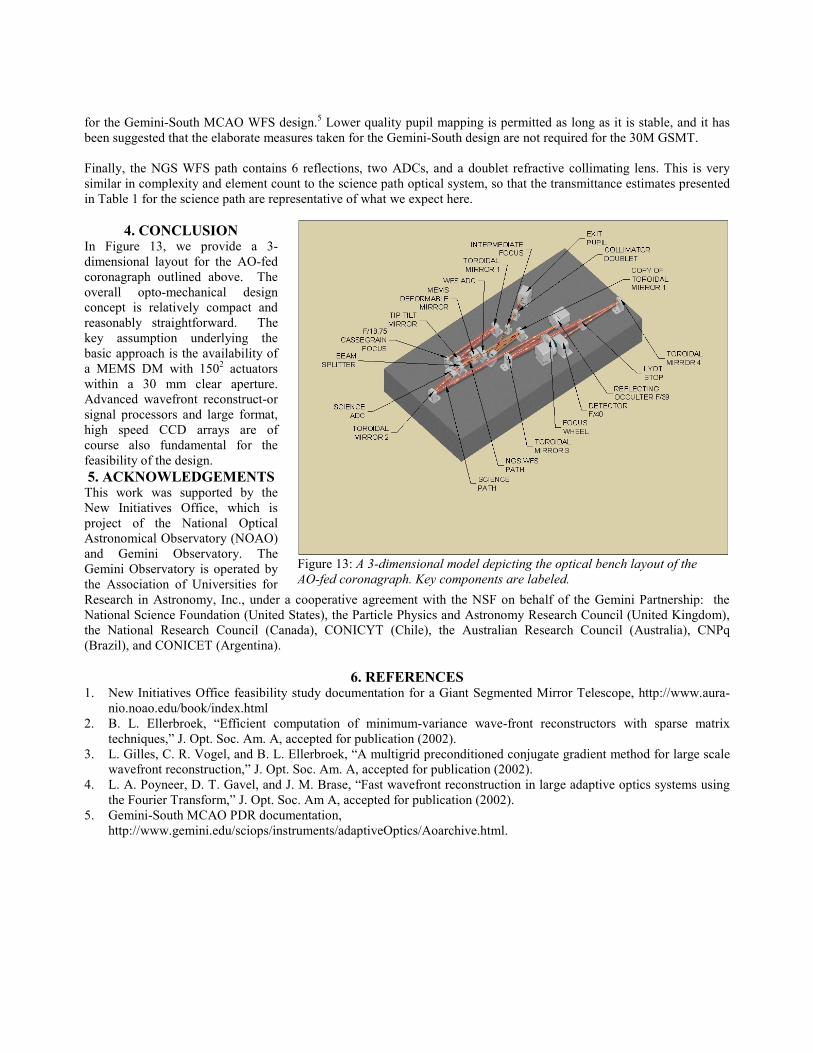
4. CONCLUSION In Figure 13, we provide a 3-dimensional layout for the AO-fed coronagraph outlined above. The overall opto-mechanical design concept is relatively compact and reasonably straightforward. The key assumption underlying the basic approach is the availability of a MEMS DM with 1502 actuators within a 30 mm clear aperture. Advanced wavefront reconstruct-or signal processors and large format, high speed CCD arrays are of course also fundamental for the feasibility of the design. 5. ACKNOWLEDGEMENTS
This work was supported by the New Initiatives Office, which is project of the National Optical Astronomical Observatory (NOAO) and Gemini Observatory. The Gemini Observatory is operated by the Association of Universities for Research in Astronomy, Inc., under a cooperative agreement with the NSF on behalf of the Gemini Partnership: the National Science Foundation (United States), the Particle Physics and Astronomy Research Council (United Kingdom), the National Research Council (Canada), CONICYT (Chile), the Australian Research Council (Australia), CNPq (Brazil), and CONICET (Argentina).
6. REFERENCES 1. New Initiatives Office feasibility study documentation for a Giant Segmented Mirror Telescope, http://www.aura-
nio.noao.edu/book/index.html 2. B. L. Ellerbroek, �Efficient computation of minimum-variance wave-front reconstructors with sparse matrix
techniques,� J. Opt. Soc. Am. A, accepted for publication (2002). 3. L. Gilles, C. R. Vogel, and B. L. Ellerbroek, �A multigrid preconditioned conjugate gradient method for large scale
wavefront reconstruction,� J. Opt. Soc. Am. A, accepted for publication (2002). 4. L. A. Poyneer, D. T. Gavel, and J. M. Brase, �Fast wavefront reconstruction in large adaptive optics systems using
the Fourier Transform,� J. Opt. Soc. Am A, accepted for publication (2002). 5. Gemini-South MCAO PDR documentation,
http://www.gemini.edu/sciops/instruments/adaptiveOptics/Aoarchive.html.
Figure 13: A 3-dimensional model depicting the optical bench layout of the AO-fed coronagraph. Key components are labeled.