near infrared-ii imaging, plasmonic platforms, graphene ...dailab.stanford.edu/2013 07 dai group...
TRANSCRIPT
Near Infrared-II Imaging,
Plasmonic Platforms,
Graphene Nanoribbons
&
Novel Materials for Energy
Hongjie Dai
Department of Chemistry, Stanford University

Our Current Research
NanoCarbon-
Inorganic Hybrid
materials
ENERGY
Carbon Nanotube
(CNT) & graphene
NANO-BIO
Graphene
Nanoribbon
NOVEL
1D SYSTEMS
500nm
Plasmonic Gold Films

Interface Nanomaterials with Bio-Systems
Carbon Nanotube
(CNT) & Nano-
graphene
500nm
Plasmonic Gold Films
• Utilization of the physical (electrical,
optical…) properties of nanomaterials
for imaging, detection, diagnosis and
treatment of diseases (cancer, heart
disease...)
Top Fatal Diseases:
1. Ischaemic heart disease
Annual deaths: ~ 7,200,000
2. Cancers
Annual deaths: ~7,100,000
3. Cerebrovascular disease (Stroke)
Annual deaths: ~ 5,500,000
Vessel diseases: #1 killer

500 nm
Making CNTs Biocompatible and Non-Toxic
in
PBS in PBS
80ºC
a NH2
NH2
NH2
Polyethylene Glycol
• Length 50- 200nm.
• Soluble in buffers and serum.
• Antibodies or peptides can be
attached.
SWNT/Phospholipid-PEG
(PEG)
XCNH
OPO
H
O
O -O
OO
OCH2CH2
O
O
45
(Kam, N.W.S. et al. PNAS 2005, 102, 11600.)

Photoluminescence Emission Wavelength (nm)
Exci
tati
on
Wav
elen
gth
(n
m)
(6,5) (10,2) (8,7)
Carbon Nanotubes Fluorescence in NIR-II
Resonance Raman
• Excited resonantly through Eii transitions in 500-900nm range.
• Fluoresce in 1-1.4 mm range (NIR II); large Stoke’s shift.
Weisman & Smalley @Rice

Smith, Andrew. M., Mancini, Michael. C.
Nie, Shuming. Nat Nano 2009, 4, 710.
Developing Optical Imaging in
The Second NIR Window (NIR-II, 1-1.4 mm)
Old NIR window
A new window
Si detector InGaAs detector
Kevin Welsher, Sarah P.
Sherlock, and Hongjie Dai.
PNAS. 108, 8943-8948, 2011.
Sc
att
eri
ng
Co
eff
icie
nt
[mm
-1]
Scattering l-a : Absorbance:
Reduced tissue scattering
in NIR-II
NIR I NIR II

Untreated
30 min
100 nM
NIR-II signal 1000 nm – 1400 nm
Little or no autofluorescence
NIR II Imaging of Mice
Welsher, K. et al. Nature Nanotechnology; 2009
With intravenously injected SWCNTs:

8
Deep-Tissue NIR II Video Rate Imaging
3.5 sec
3.5 sec
lungs
lungs
17.3 sec
(c)
17.3 sec
liver
liver
69 sec
69 sec
spleen
spleen
5.2 sec
5.2 sec
kidney
kidneys
Welsher, K.*, Sherlock, S.* Dai, H. Proc. Nat. Acad. Sci. 2011.
(Image into the body of a mouse optically)

9
Anatomical Mapping by Principle Component
Analysis (PCA) of NIR II Video Imaging
kidney
liver
lungs lungs
liver
kidney
spleen
heart
spleen
lungs
spleen
lungs
liver
kidney
spleen
kidney
kidney
liver
pancreas
pancreas pancreas
Welsher, K.*, Sherlock, S.* Dai, H. Proc. Nat. Acad. Sci. 2011.
• PCA groups pixels with similar time variance in signal

600 800 1000 1200 1400
Emission of IR800
(NIR-I)
Emission of nanotubes
(NIR-II)
Inte
ns
ity
[a
.u.]
Wavelength [nm]
Absorption
0 1 2 3 4 5 6
0.0
0.2
0.4
0.6
0.8
1.0 cross section profile
No
rma
lize
d P
L i
nte
ns
ity
Position [mm]
0.607 mm
0 2 4 6 80.0
0.2
0.4
0.6
0.8
1.0 cross section profile
No
rma
lize
d P
L i
nte
ns
ity
Position [mm]0 2 4 6 8 10 12
0.0
0.2
0.4
0.6
0.8
1.0
No
rma
lized
PL
in
ten
sit
y
Position [mm]
cross section profile
1.37 mm
0 1 2 3 4 5
0.0
0.2
0.4
0.6
0.8
1.0 cross section profile
No
rma
lized
PL
in
ten
sit
y
Position [mm]
0.283 mm
0 2 4 6 8 10
0.0
0.2
0.4
0.6
0.8
1.0 cross section profile
No
rma
lized
in
ten
sit
y
Position [mm]
0.583 mm
0 1 2 3 4 5 60.0
0.2
0.4
0.6
0.8
1.0 cross section profile
No
rma
lize
d P
L i
nte
ns
ity
Position [mm]
1 cm (f) (g) (h)
(l) (m) (n)
NIR-I IR dye 800
NIR-II SWNT
1x magnified
(i) (j) (k)
(o) (p)
5 mm 1 mm
(q)
1 cm
5 mm 1 mm
2.5x magnified 7x magnified
InGaAs camera
(NIR-II)
Si camera
(NIR-I)
mirror
zoomable lens
set
Simultaneous Imaging in NIR-I &NIR II
SWNT
+
IRDye-
800
complex

NIR-I Peripheral Vessel Imaging Imaging in NIR-I by detecting IRDye800 fluorescence:
0 2 4 6 8 100.0
0.2
0.4
0.6
0.8
1.0
No
rma
lize
d P
L i
nte
ns
ity
Position [mm]
cross section profile
0 2 4 6 80.0
0.2
0.4
0.6
0.8
1.0 cross section profile
No
rma
lize
d P
L i
nte
ns
ity
Position [mm]0 1 2 3 4 5 6
0.0
0.2
0.4
0.6
0.8
1.0 cross section profile
No
rma
lize
d P
L i
nte
ns
ity
Position [mm]
1 cm
Low mag Medium mag High mag
5 mm 1 mm
0 1 2 3 4 50.0
0.2
0.4
0.6
0.8
1.0 cross section profile
No
rma
lize
d P
L i
nte
ns
ity
Position [mm]0 2 4 6 8
0.0
0.2
0.4
0.6
0.8
1.0 cross section profile
No
rma
lized
in
ten
sit
y
Position [mm]0 1 2 3 4 5 6
0.0
0.2
0.4
0.6
0.8
1.0 cross section profile
No
rma
lized
PL
in
ten
sit
y
Position [mm]
(i)
(l)
NIR-
II
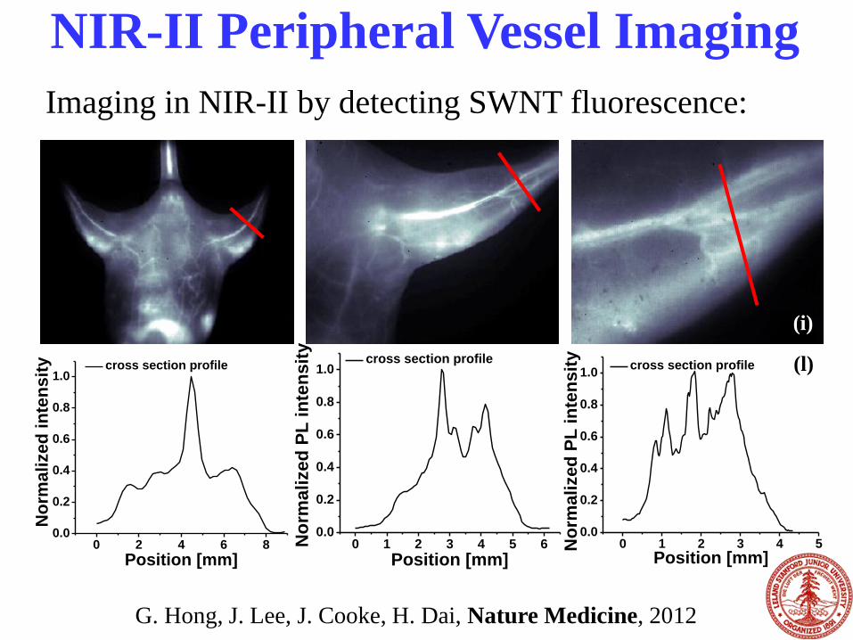
NIR-II Peripheral Vessel Imaging
Imaging in NIR-II by detecting SWNT fluorescence:
G. Hong, J. Lee, J. Cooke, H. Dai, Nature Medicine, 2012

5mm 5mm
NIR-I750-900nm
NIR-II1000-1400nm
NIR-I vs NIR-II imaging of ischemic mouse hindlimb
NIR-II Imaging: Reduced Scattering
G. Hong, J. Lee, J. Cooke, H. Dai, Nature Medicine, 2012
Previous imaging modality: micro-CT, MRI
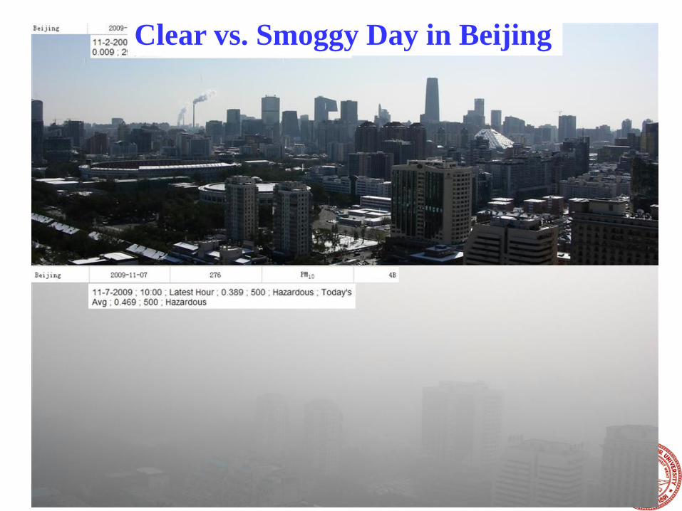
Clear vs. Smoggy Day in Beijing

t = 0 s t = 4.98 s t = 10.68 s
t = 30.62 s PCA
(a) (b) (c)
(d) (e)
aorta inferior
epigastric
femoral
external iliac
inferior
epigastric
heart
aorta epigastric
artery
femoral artery
femoral vein
epigastric veins
iliacfemoral
(f)
Sub-cm Deep Vessel Imaging &
Differentiation
G. Hong, J. Lee, J. Cooke, H. Dai, Nature Medicine, 2012

Video Rate Imaging of
Blood Flow in Healthy vs. Ischemic Hindlimb
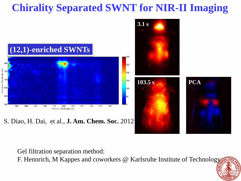
(12,1)-enriched SWNTs
103.5 s
3.1 s
PCA
Chirality Separated SWNT for NIR-II Imaging
S. Diao, H. Dai, et al., J. Am. Chem. Soc. 2012
Gel filtration separation method:
F. Hennrich, M Kappes and coworkers @ Karlsruhe Institute of Technology

Chirality Separated SWNT for
Tumor Photothermal Therapy
A. Antaris, et. al., ACS Nano, 2013
• Ultra-low dosage: ~ 4 μg of (6,5) SWCNTs per mouse
(0.254 mg/kg)
• Dual imaging & photothermal therapy
Density gradient centrifugation method:
M. Hersam, Northwestern.
A
B
C
Polyethylene glycol
(PEG)
SN-38
0
2000000
4000000
6000000
8000000
400 500 600 700
Wavelength (nm)
Flu
ore
sc
en
ce
In
ten
sit
y
SN38
GO-SN38
0
0.2
0.4
0.6
0.8
1
1.2
200 400 600 800Wavelength (nm)
Ab
so
rba
nc
e
GOGO-SN38SN38, in methanolGO Loaded SN38
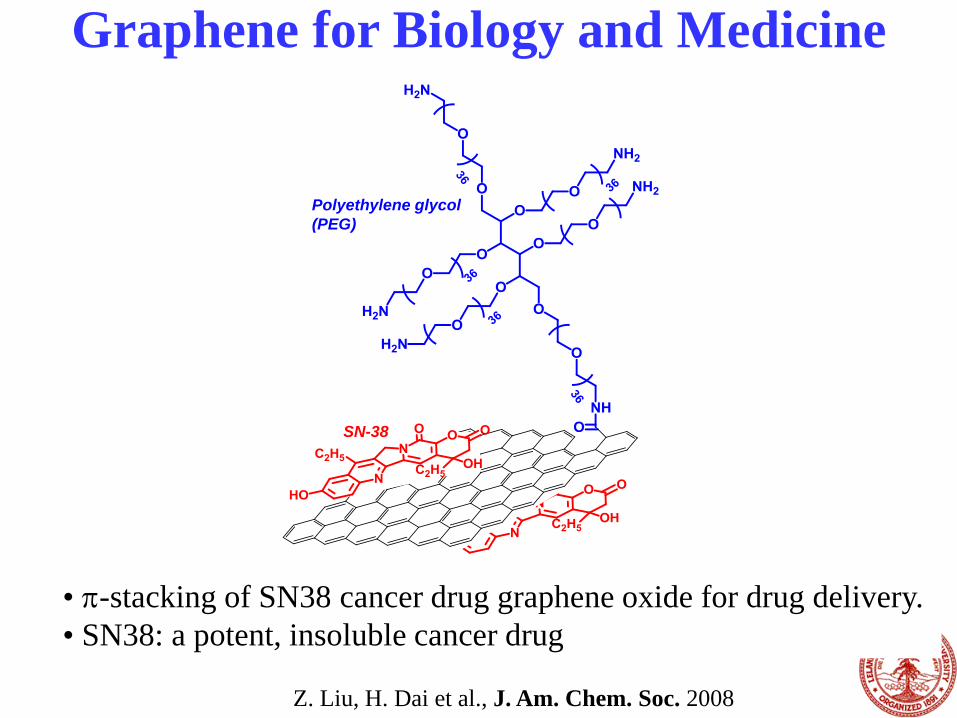
Graphene for Biology and Medicine
• p-stacking of SN38 cancer drug graphene oxide for drug delivery.
• SN38: a potent, insoluble cancer drug
J Am Chem Soc. 2008 August 20; 130(33):
10876–10877.
Z. Liu, H. Dai et al., J. Am. Chem. Soc. 2008

Graphene Oxide Are Fluorescent in
NIR-I & NIR-II Hailiang Wang, Joshua T.
Robinson, et. al. J. Am.
Chem. Soc., 131, 9910-
9911, 2009.
X. Sun, H. Dai, et. al. Nano Res, 1, 203-212 , 2008.

200 400 600 800 1000 12000
10
20
30
40
50
60
70
80
Ab
so
rban
ce
Wavelength (nm)
Nano-rGO
Nano-GO
Nano-Sized Reduced Graphene Oxide (rGO)
100 nm
100 nm
Nano-GO with
PEGylation
Nano-rGO
2 μm
GO as made
Non-covalent functionalized nano-rGO
Biocompatible
High optical absorbance in NIR
Useful for photothermal therapy
Joshua T. Robinson, H. Dai, et. al.
J. Am. Chem. Soc. 133, 6825-6831, 2011.
Nano-rGO
Nano-GO
pH 1 pH 13 2x PBS Serum

Photothermal Ablation of Cancer Cells With
RGD Peptide/Nano-rGO Complex
We are able to
photothermally
ablate cells with
targeted rGO.
In vivo trials are
currently underway
Joshua T. Robinson, H. Dai, et. al.
J. Am. Chem. Soc. 133, 6825-6831, 2011.

A Nanostructured Gold Platform for Biological Assays
(ELISA, Microarrays…)
A novel microarray platform on
nanostructured gold films for ultra-
sensitive multiplexed immunoassay of
proteins
- Sensitivity: down to ~ 1 fM (0.01
pg/ml) level (ELISA: pM level)
- Dynamic range: > 6 orders of
magnitude dynamic range.
- Multiplexed: detection of hundreds of
proteins each time.
- Uses small volume of serum or other
biological sample.
- Low cost; rapid; high throughput.
A powerful approach to disease
diagnosis:
- Cancer;
- Autoimmune disease diagnosis
(diabetes, rheumatoid arthritis,
Lupus,…)
…
• Can capture and
detect large numbers
of biological
molecules.
• High throughput.
• Little sample volume
needed.
• Powerful for
proteomic research
and diagnostics
• But sensitivity has
been limited.
S. Tabakman et al., Nature Comm. 2011
Plamonic substrate
antigen
Secondary antibody
Fluorophore reporter
PEG star
Autoantibody,
cytokine…
Plamonic Au substrate
• Many nano-gaps
• Gold film surface plasmon resonance in NIR range
1 mm

Fluorescence Enhancement of NIR Dyes
-1 000
0
1 000
Y (
µm
)
0 X (µm)
x10 3
20
40
Inte
nsi
ty (
cnt/
sec)
400 µm
-1 000
0 Y (
µm
)
0 X (µm)
x10 3
20
40
Inte
nsi
ty (
cnt/
sec)
400 µm
-1 000
0
1 000
Y (
µm
)
0 X (µm)
x10 3
20
40
Inte
nsi
ty (
cnt/
sec)
400 µm
-1 000
0 Y (
µm
)
0 X (µm)
x10 3
20
40
Inte
nsi
ty (
cnt/
sec)
400 µm
-1 000
0 Y (
µm
)
0 X (µm)
x10 3
50
100
Inte
nsi
ty (
cnt/
sec)
400 µm
-1 000
0
1 000
Y (
µm
)
0 X (µm)
x10 3
50
100
Inte
nsi
ty (
cnt/
sec)
400 µm
-1 000
0 Y (
µm
)
0 X (µm)
x10 3
50
100
Inte
nsi
ty (
cnt/
sec)
400 µm
-1 000
0
1 000
Y (
µm
)
0 X (µm)
x10 3
50
100
Inte
nsi
ty (
cnt/
sec)
400 µm
1 ? m
1 cm
1 m m
1 cm 1 cm
650 700 750 0.0
2.0x10 5
4.0x10 5
6.0x10 5
Flu
ore
scen
ce
inte
nsit
y
IgG-Cy5 on Au/Au IgG-cy5 on glass
Wavelength (nm) Wavelength (nm)
800 850 900 0.0
2.0x10 5
4.0x10 5
6.0x10 5
IgG-IRDye800 on Au/Au IgG-IRDye800 on glass
~ 100 fold enhancement

Multiplexed ImmunoAssays on Fluorescence
Enhancing, PEG-Star Coated Au Films
Glass Gold10
100
1000
10000
IRDye800 Fluorescence Intensity
Flu
orescen
ce I
nte
nsit
y
Plamonic substrate
antigen
Secondary antibody
Fluorophore reporter
6arm-PEG-COOH:
(10kDa)
AuGlass
AuGlass
AuGlass
AuGlass
22 22 22NH
C=O C=O C=OC=O
C=OC=O
C=O C=O
NHNH
NH NH
NHNH NH2
NH2
NH2
NH2 NHNH NHNH NHNH NHNH NHNH
C=O C=O C=OC=O
C=OC=O
C=O C=O
NHNH
NH NH
SS S SSS SS SAu
Glass
Au
Glass
Au
Glass
22 22 22NH
C=O C=O C=OC=O
C=OC=O
C=O C=O
NHNH
NH NH
NHNH NH2
NH2
NH2
NH2 NHNH NHNH NHNH NHNH NHNH
C=O C=O C=OC=O
C=OC=O
C=O C=O
NHNH
NH NH
SS S SSS SS S
Au
Glass
PEG star
CEA
Plamonic Au substrate
• Fluorescence enhancement (no quenching);
• Boosts binding signal for immunoassays by 100X
• Minimal nonspecific signal through surface chemistry
• PEG cushion retains protein structures and functions
S. Tabakman et al., Nature Comm. 2011
Cancer Biomarker Detection on Au Platform Towards
Early Cancer Diagnosis
• fM sensitivity
• 6 logs
• Branched PEG-
star blocking:
minimal non-
specific binding
• Plasmonics:
boosts specific
signal
26
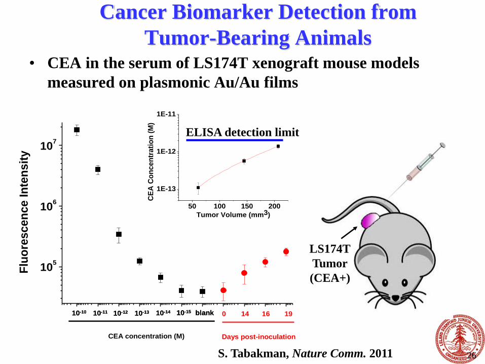
Cancer Biomarker Detection from
Tumor-Bearing Animals • CEA in the serum of LS174T xenograft mouse models
measured on plasmonic Au/Au films
Days post-inoculationCEA concentration (M)
10-10 10-11 10-12 10-13 10-14 blank10-1510-10 10-11 10-12 10-13 10-14 blank10-15 0 14 16 19
105
106
107
Flu
ore
scen
ce In
ten
sit
y
50 100 150 200
1E-13
1E-12
1E-11
CE
A C
on
ce
ntr
ati
on
(M
)
Tumor Volume (mm3)
LS174T
Tumor
(CEA+)
ELISA detection limit
S. Tabakman, Nature Comm. 2011

100
1000
Flu
ore
scen
ce In
ten
sit
y
100
1000
100
1000
µArray/Au
Nitrocellulose
Glass
*
* *
27
Multiplexed Autoantibody Detection on Gold
• Much broader dynamic range on gold.
• Lower detection limit down to fM
• Highly sensitive antigen microarrays
100
1000
Fluorescence Intensity
100
1000
100
1000
µA
rra
y/A
u
Nitro
cellu
lose
Gla
ss
S. Tabakman et al., Nature Comm. 2011;
With Dr. P.J. Utz,
Stanford Medical School
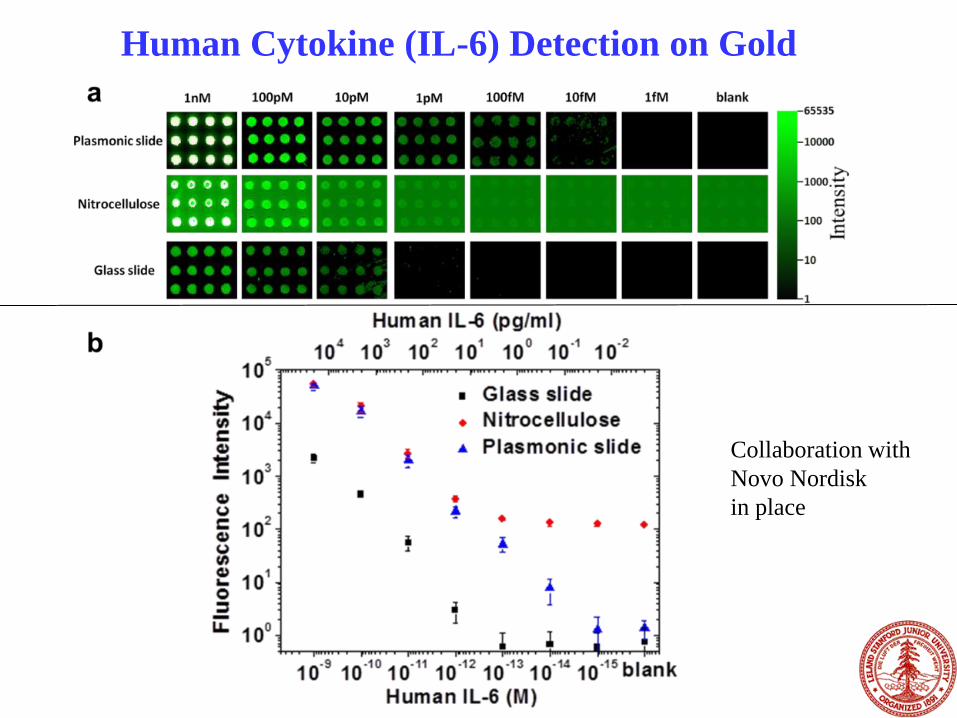
Human Cytokine (IL-6) Detection on Gold
Cytokine detection ar
Collaboration with
Novo Nordisk
in place
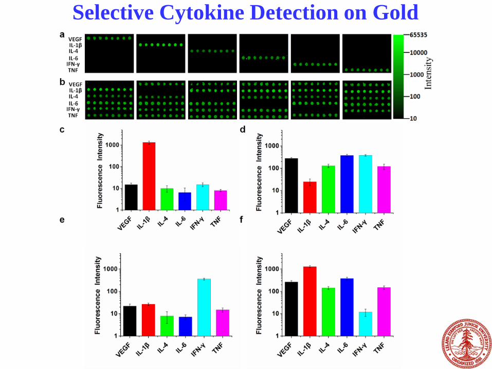
Selective Cytokine Detection on Gold

Multiplexed Detection of Cytokines Secreted
by Cancer Cells
Array on Gold: Array on Nitrocellulose:
(Bo Zhang, et al., Nano Research, 2013)
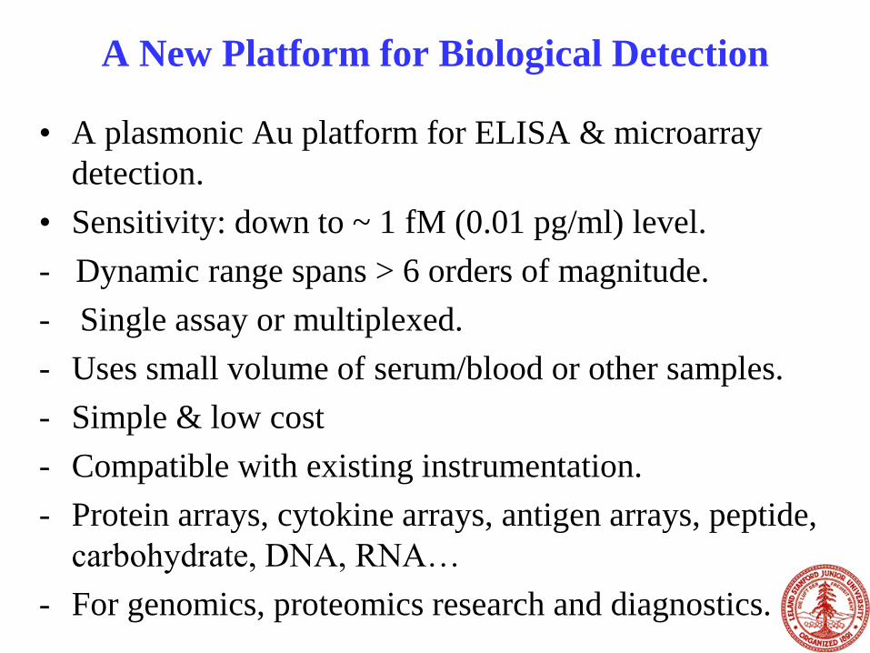
A New Platform for Biological Detection
• A plasmonic Au platform for ELISA & microarray
detection.
• Sensitivity: down to ~ 1 fM (0.01 pg/ml) level.
- Dynamic range spans > 6 orders of magnitude.
- Single assay or multiplexed.
- Uses small volume of serum/blood or other samples.
- Simple & low cost
- Compatible with existing instrumentation.
- Protein arrays, cytokine arrays, antigen arrays, peptide,
carbohydrate, DNA, RNA…
- For genomics, proteomics research and diagnostics.
A novel microarray platform on
nanostructured gold films for ultra-
sensitive multiplexed immunoassay of
proteins
- Sensitivity: down to ~ 1 fM (0.01
pg/ml) level (ELISA: pM level)
- Dynamic range: > 6 orders of
magnitude dynamic range.
- Multiplexed: detection of hundreds
of proteins each time.
- Uses small volume of serum or
other biological sample.
- Low cost; rapid; high throughput.
A powerful approach to disease
diagnosis:
- Cancer;
- Autoimmune disease diagnosis
(diabetes, rheumatoid arthritis,
Lupus,…)
…

Graphene Nanoribbons (GNR) Arm-chair GNR Zig-Zag GNR
Rich edge related chemistry and physics predicted

(Xiaolin Li, Xinran Wang, et al., Science, 2008)
Chemical Synthesis of Graphene Nanoribbons
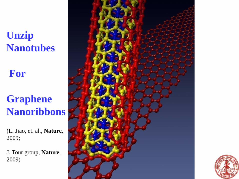
Unzip
Nanotubes
For
Graphene
Nanoribbons
(L. Jiao, et. al., Nature,
2009;
J. Tour group, Nature,
2009)
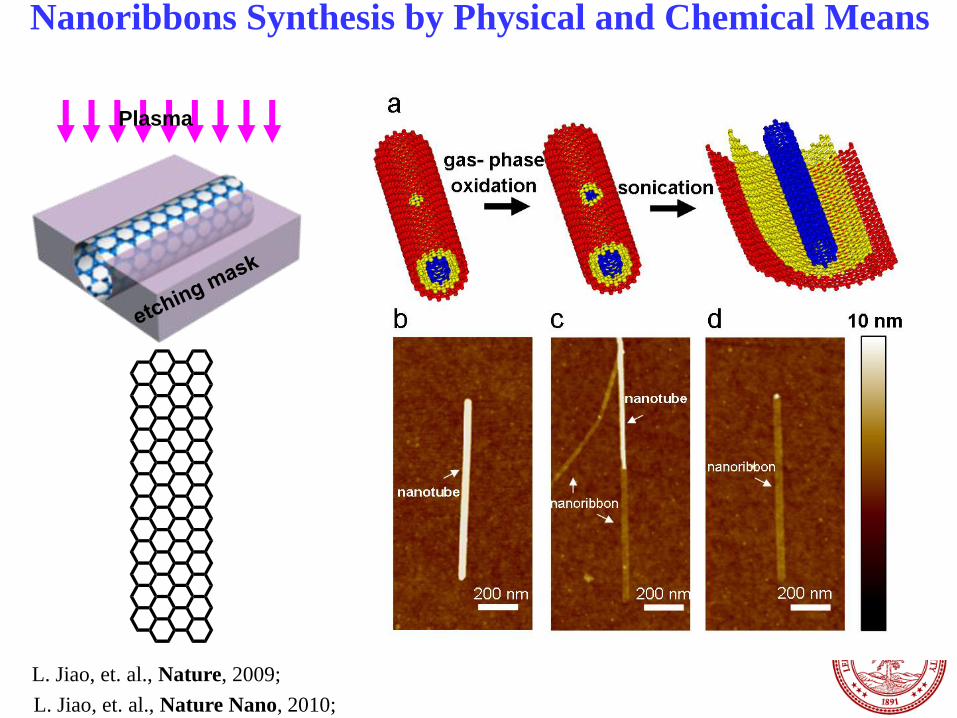
(b) (c)
Nanoribbons Synthesis by Physical and Chemical Means
Plasma
L. Jiao, et. al., Nature, 2009;
L. Jiao, et. al., Nature Nano, 2010;

High Quality Nanoribbons with Smooth Edges
• Moire pattern between layers
• Smooth edges, little roughness.
4 nm 4 nm
L. Xie (with K. Suenaga group) et al., JACS, 2011

Crommie, Dai, Louie groups, Nature Physics, 2011
• Highly Smooth edges
• Observation of
magnetic edge states at
nanoribbon edges
STM of Graphene Nanoribbons (GNR)

-3 -2 -1 0 1 2 3Vgs (V)
-40
-20
0
20
40
Vd
s (
mV
)
1.5
1.0
0.5
0.0
c T=2K
2.82.62.42.22.01.81.6Vgs (V)
-20
0
20
Vd
s (
mV
)
0.4
0.2
0.0
-40
-20
0
20
40
Vd
s (
mV
)
1.0
0.5
0.0
# holes
6 5 4 3 2 1
# electrons
1 2 3 Δε10 =3.6
Δε20 =16.2
d
e
1.0
0.5
0.0G
(e
2/h
)
-3 -2 -1 0 1Vgs (V)
4
3
2
1
0
G (
e2/h
)
-40 -20 0 20 40Vgs(V)
100nm
3.6
3.9
G (
e2/h
)
200100
T (K)
Vg=Vdirac-35V
L~86nm
W~14nm
a
0.01
2
4
0.1
2
4
1
2
4
G (
e2/h
)
20100-10-20Vgs(V)
290K 250K 200K 150K 100K 60K
4
0
G (
e2/h
)
-40 40Vgs (V)
b
0.01
2
4
0.1
2
4
1
2
4
G (
e2/h
)
20100-10-20Vgs(V)
290K 250K 200K 150K 100K 60K
2K
0.4
0.3
0.2
G (
e2/h
)
1050-5Vds (mV)
Quantum Transport of High Quality
Nanoribbons at 1.5 K
(Xinran Wang et al., Nature Nano, 2011)

Growth of Inorganic-NanoCarbon Hybrid for Energy
Storage and Electrocatalysis
H+H2 O2
OH-
e-e-
• High activity and rate capability.
• Durable.
• Low cost; non-precious metal based
(H. Wang et. al.,
Chem. Rev., 2013)
(Y. Liang et. al., JACS
(perspective),
2013)

ALD Growth of Metal Oxide on
Graphene
ALD nucleation requires surface functional groups.
Graphene edges and defect sites are more reactive.
(X. Wang, H. Dai, et al. JACS, 2008)

Nucleation and Growth of Inorganic Materials on
Oxidized Nano-Carbon
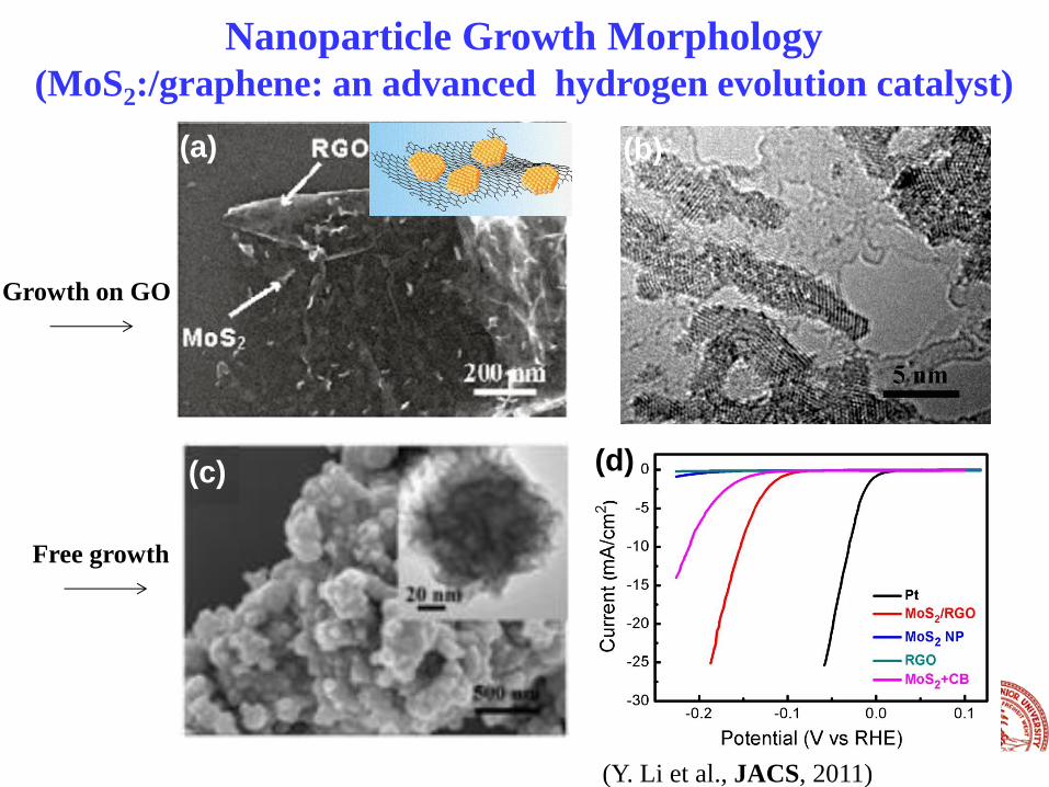
• Nucleation step: metal ions binding to COOH groups on GO or CNT. • Growth step: the degree of graphene oxidation affects morphology. • Nanoparticles grown are electrically wired up to carbon. • Covalent coupling between nanoparticle and carbon observed. • A series of covalently coupled hybrid materials for energy applications.
Precursor Free particles
B
nucleation/growth on oxygen functional groups
on nano-carbon
Traditional: free particles + carbon black (or CNTs)
‘Strongly coupled hybrid’ of
inorganic/nano-carbon
(SC-hybrid)
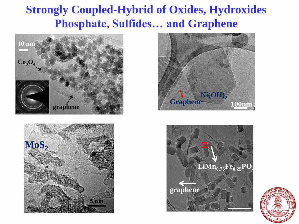
Strongly Coupled-Hybrid of Oxides, Hydroxides
Phosphate, Sulfides… and Graphene
MoS2
10 nm
graphene
Co3O4
LiMn0.75Fe0.25PO4
graphene
Graphene Ni(OH)2
100nm
(f)
(d)
(e)
(a) (b)
(c)
Nanoparticle Growth Morphology
(MoS2:/graphene: an advanced hydrogen evolution catalyst)
Free growth
Growth on GO
(Y. Li et al., JACS, 2011)
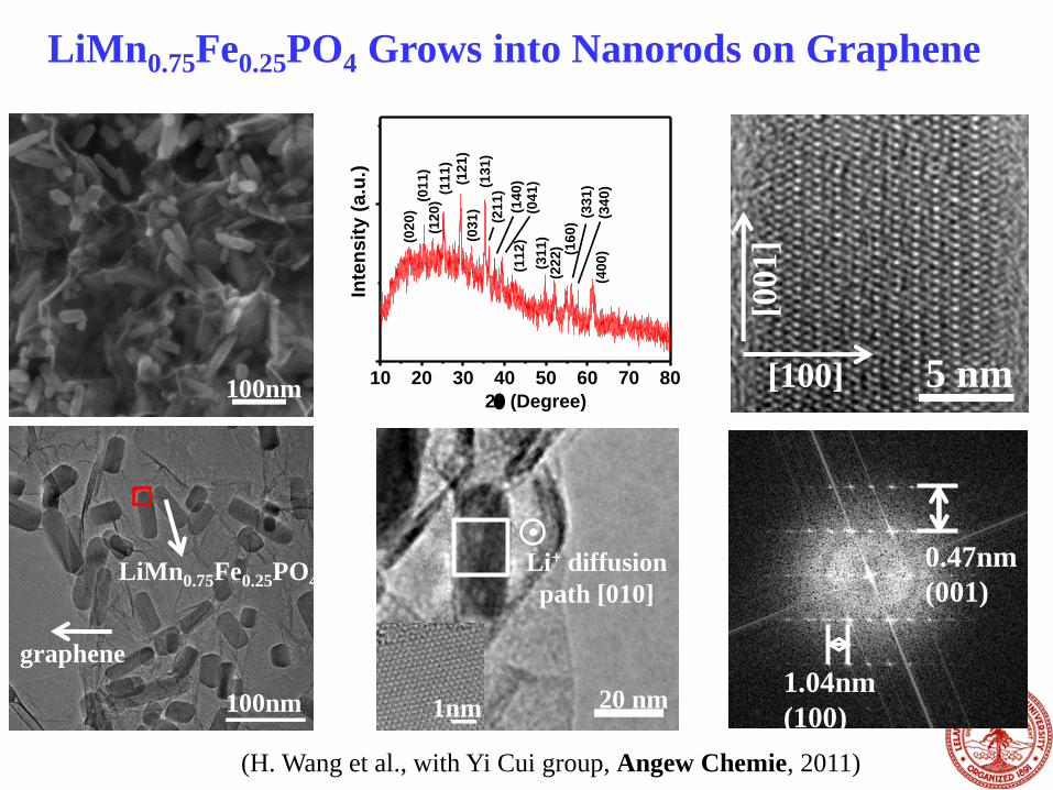
LiMn0.75Fe0.25PO4 Grows into Nanorods on Graphene
10 20 30 40 50 60 70 80
(34
0)
(33
1)
(31
1)
(11
2)
Inte
ns
ity
(a
.u.)
2 (Degree)
(40
0)
(13
1)
(16
0)
(03
1)
(12
1)
(11
1)
(12
0)(0
11
)(0
20
)
(22
2)
(04
1)
(14
0)
(21
1)
100nm
100nm
LiMn0.75Fe0.25PO4
graphene
20 nm
Li+ diffusion
path [010]
1nm
5 nm [100]
[001]
0.47nm
(001)
1.04nm
(100)
(H. Wang et al., with Yi Cui group, Angew Chemie, 2011)
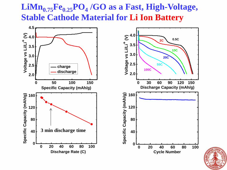
LiMn0.75Fe0.25PO4 /GO as a Fast, High-Voltage,
Stable Cathode Material for Li Ion Battery
0 50 100 150
2.0
2.5
3.0
3.5
4.0
4.5
V
olt
ag
e v
s L
i/L
i+ (
V)
Specific Capacity (mAh/g)
charge
discharge
0 20 40 60 80 1000
40
80
120
160
Sp
ecif
ic C
ap
acit
y (
mA
h/g
)
Cycle Number
0 20 40 60 80 1000
40
80
120
160
Sp
ec
ific
Ca
pac
ity (
mA
h/g
)
Discharge Rate (C)
0 30 60 90 120 150
2.0
2.5
3.0
3.5
4.0
100C
50C
20C
10C
2C
Vo
ltag
e v
s L
i/L
i+ (
V)
Discharge Capacity (mAh/g)
0.5C
3 min discharge time

GS
Ni(OH)2 300nm GS Ni(OH)2
100nm 10 20 30 40 50 60 70 80
(103)
(003)
(012)
(002)
(011)
Gra
ph
ite (
002)
(100)
Inte
nsit
y (
a.u
.)
2 (Degree)
(001)
Ni(OH)2 Nanoplates Grown on Graphene
1. Ni(Ac)2, 80OC
DMF/H2O (10:1)
2. H2O, 180OC
Hydrothermal
(Hailiang Wang et al., J. Am. Chem. Soc., 2010)
For ultra-fast Ni based alkaline batteries
47
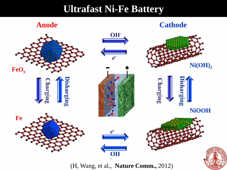
Ultrafast Ni-Fe Battery
Anode Cathode
FeOx
Fe
Ni(OH)2
NiOOH
(H, Wang, et al., Nature Comm., 2012)

0 50 100 150 200
0.4
0.8
1.2
1.6
2.0
Vo
lta
ge
(V
)
Time (s)
37A/g
(e)
0 40 80 120
0.4
0.6
0.8
1.0
1.2
1.4
1.6
Vo
lta
ge
(V
)
Discharge Capacity (mAh/g)
1.5A/g
3.7A/g
7.4A/g
15A/g
37A/g
0 200 400 600 800 0.0
0.2
0.4
0.6
0.8
1.0
Ca
pa
cit
y R
ete
nti
on
Cycle Number
(f) 0.5 1.0 1.5 2.0 -0.15
-0.10
-0.05
0.00
0.05
0.10
0.15 C
urr
en
t (A
)
Voltage (V)
100mV/s
40mV/s
20mV/s
10mV/s charging
discharging
Ultra-Fast Ni-Fe Battery
Higher energy density than
supercapacitors
Safe (KOH in water as electrolyte).
fast (2 min charge; 10 s discharge)
like supercap
(H, Wang, et al., Nature Comm., 2012)
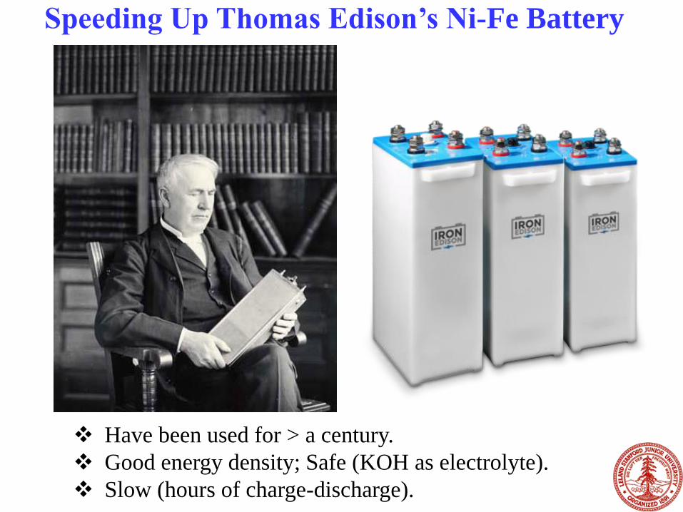
Speeding Up Thomas Edison’s Ni-Fe Battery
Have been used for > a century.
Good energy density; Safe (KOH as electrolyte).
Slow (hours of charge-discharge).

To demonstrate the reliability of the Edison nickel-iron battery, a battery-powered Bailey was entered in a 1,000-mile endurance run in 1910. (National Park Service / June 26, 2012)
SCIENCE
Stanford researchers update safer, cheaper Edison battery
Recharge a car
in minutes?
10 nm
graphene
Co3O4
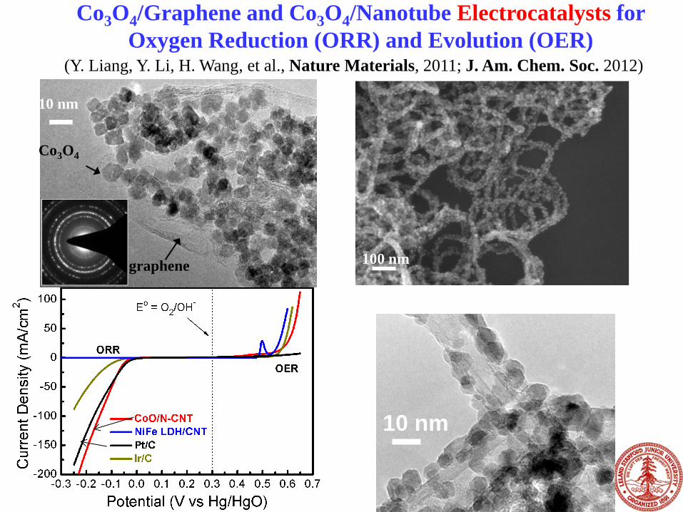
Co3O4/Graphene and Co3O4/Nanotube Electrocatalysts for
Oxygen Reduction (ORR) and Evolution (OER)
20 30 40 50 60 70
2 (degree)
Inte
nsi
ty (
a.u
.)
220
311
400
511 440
0.08 0.12 0.16
0.02
0.03
0.04
J -1(m
2/A
)
0.75V
0.70V
0.65V
0.60V
-1/2 (s1/2/rad1/2)
n = 3.9
0.2 0.3 0.4 0.5 0.6 0.7 0.8 0.9 1.0-7
-6
-5
-4
-3
-2
-1
0
1
2
Cu
rren
t D
ensi
ty (
mA
/cm
2)
Potential (V vs RHE)
400 rpm
625 rpm
900 rpm
1225 rpm
1600 rpm
2025 rpm
Co3O4/N-rmGO
0.2 0.4 0.6 0.8 1.0
50 mA
Potential (V vs RHE)
Co3O4/rmGO
Co3O4/N-rmGO
Pt/C
(Y. Liang, Y. Li, H. Wang, et al., Nature Materials, 2011; J. Am. Chem. Soc. 2012)
0.7 0.8 0.9 1.0-60
-40
-20
0
Co3O
4
Co3O
4 + N-rmGO mixture
Co3O
4/N-rmGOC
urr
ent
Den
sity
(m
A/c
m2)
Potential (V vs RHE)
Activity due to
Co3O4 covalent
coupling to GO
100 nm
10 nm

530 540 550
Abso
rpti
on
(a.
u.)
Photon Energy (eV)
Co3O4/N-rmGO
Co3O4
O K-edge
775 780 785 790 795 800
Ab
sorp
tio
n (
a.u
.)
Co3O4/N-rmGO
Co3O4
Photon Energy (eV)
Co L-edge
O 2p–Co 3d
unoccupied O 2p–Co 3d
hybridized state
Co 3d
e-
O2
X-Ray Absorption Spectroscopy
280 285 290 295 300
Abso
rpti
on
(a.u
.)
Photon energy (eV)
Co3O4/N-rmGO
N-rmGO
C K-edge
C=O p* C 1s →p*
C 1s →s*
• Perturbed C-O groups in GO upon particle growth: evidence of
Co-O-C-graphene bonding
• Strong coupling is responsible for high activity and stability of
catalysts
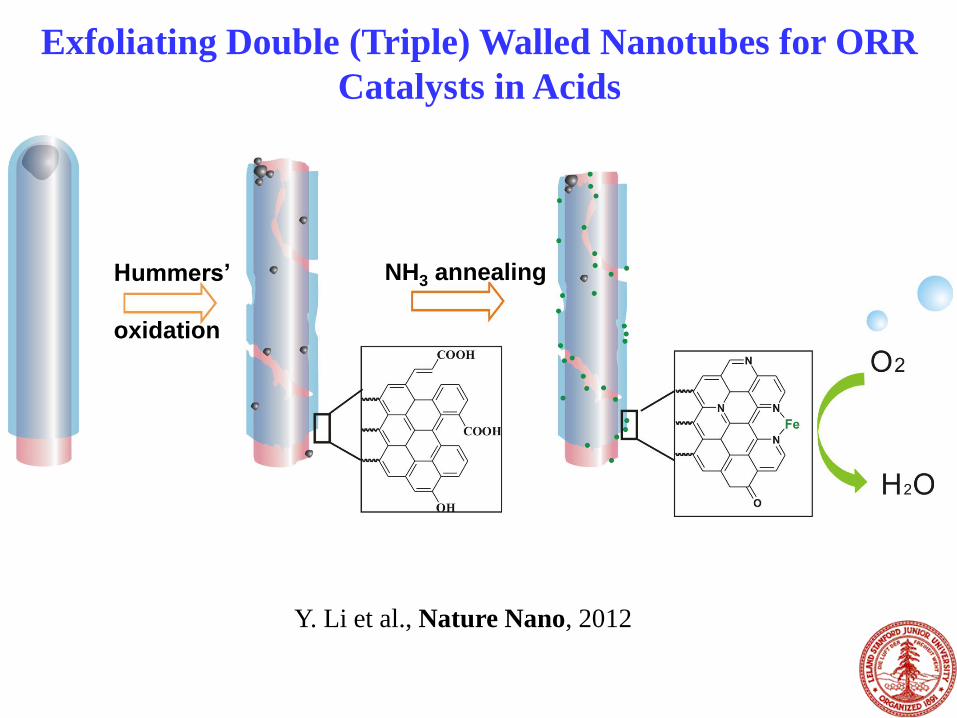
Harsh oxidation of double walled CNTs followed by NH3 annealing
Damaged outer-walls forming nanoscale graphene oxide pieces attached to the mostly intact
inner-walls (nanotube-nanographene complex, or NT-G)
Fe inherited from the catalyst seeds for the growth of CNTs
Exfoliating Double (Triple) Walled Nanotubes for ORR
Catalysts in Acids
Hummers’
oxidation
NH3 annealing
Y. Li et al., Nature Nano, 2012

(d) NT-NG
(e)
attached
nano-graphene
(f)
damaged
outer-walls
CNT
CNT
Nanotube-Nanographene Complexes Doped with
Fe and N
Y. Li et al., Nature Nano, 2012
• Intact inner wall for charge transport
• Highly defective/functional outerwall for catalytic sites
• Fe impurities are from nanotube raw material

(a)
(b)
(c)
(d)
An Active ORR Catalyst in Acid & Base
Y. Li et al.,
Nature
Nano,
accepted

BF (a) ADF (b)
CNT
nanographene
Atomic Scale Imaging and Chemical Mapping
Fe mapping combined mapping
(d) ADF (c)
(e) N mapping (f) (g)
W. Zhou & S. Pennycook. Oakridge
Single atom EELS

N Map Fe Map
N+Fe Map ADF
N
Fe
Single-Atom Imaging: Fe, N and C

High Energy Rechargeable
Zinc-Air Battery
• Primary Zn-air
battery has been
commercialized
• Not rechargeable
battery
2
44 ( ) 2Zn OH Zn OH e- - -
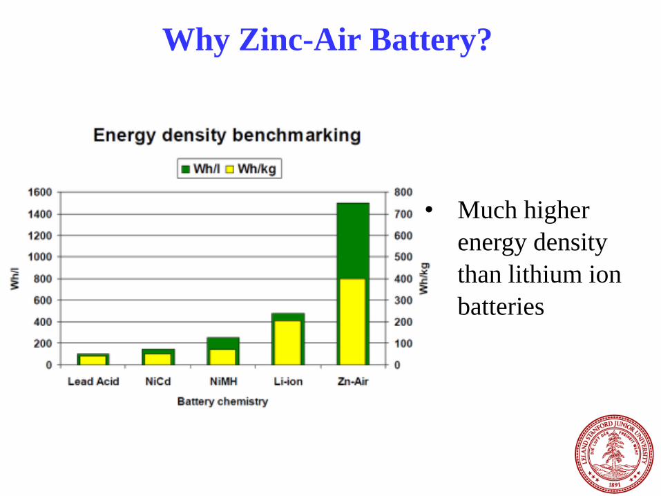
Why Zinc-Air Battery?
• Much higher
energy density
than lithium ion
batteries

Benefit of Rechargeable Zn Air Batteries
Why Zn air?
• Abundance of Zn on earth
• Safety and low-cost
• High energy density: 2 times of lithium ion battery.
One of the challenges for rechargeable Zn-air batteries:
• Cathode side need more active and stable electrocatalysts for
ORR & OER
Anode:
Cathode: 2 22 4 4O H O e OH- -
2
44 ( ) 2Zn OH Zn OH e- - -
(ORR/OER)
ORR: oxygen reduction reaction
OER: oxygen evolution reaction
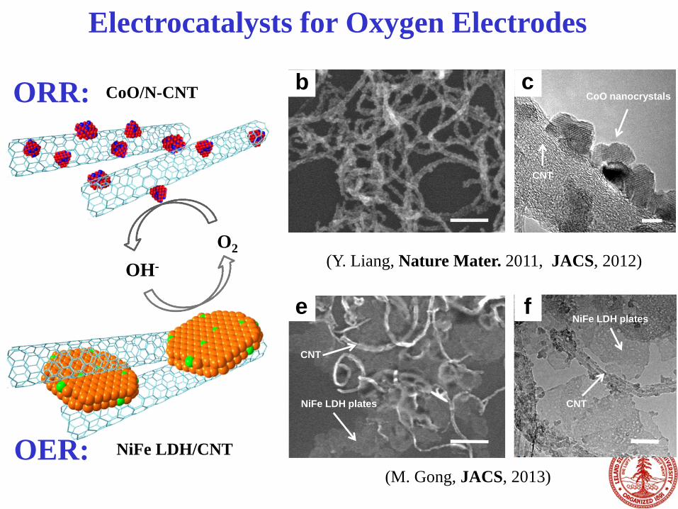
Figure 1 CoO/N-CNT
NiFe LDH/CNT
OH-
O2
b c
e f
CoO nanocrystals
CNT
CNT
NiFe LDH plates
NiFe LDH plates
CNT
Electrocatalysts for Oxygen Electrodes
ORR:
OER:
(Y. Liang, Nature Mater. 2011, JACS, 2012)
(M. Gong, JACS, 2013)

CoO/Oxidized-Nanotube Electrocatalyst for ORR
20 30 40 50 60 70
2 (degree)
Inte
nsi
ty (
a.u
.)
220
311
400
511 440
0.2 0.4 0.6 0.8 1.0
50 mA
Potential (V vs RHE)
Co3O4/rmGO
Co3O4/N-rmGO
Pt/C
(Y. Liang, Y. Li, H. Wang, et al., J. Am. Chem. Soc. 2012)
0.7 0.8 0.9 1.0-60
-40
-20
0
Co3O
4
Co3O
4 + N-rmGO mixture
Co3O
4/N-rmGOC
urr
ent
Den
sity
(m
A/c
m2)
Potential (V vs RHE)
Activity due to
Co3O4 covalent
coupling to GO
10 nm
100 nm
• Metal-oxide/Nanotube hybrid
outperform metal-oxide/graphene
• Higher electrical conductivity of
oxidized multi-walled nanotubes

A New OER Catalyst:
Ultrathin Nanoplates of NiFe Layered Double
Hydroxide/CNT Hybrid
63
(M. Gong et al., JACS, 2013)
• One of the most active catalyst to evolve oxygen in alkaline solutions
• Cheap and stable

Higher Activity and Durable than Ir/C in
Basic Solutions
64

0 2000 4000 6000 8000 10000-0.2
0.0
0.2
0.4
0.6
0.8
ORR
CoO/N-CNT
NiFe LDH/CNT
Pt/C
Ir/C
OER
Po
ten
tia
l (V
vs H
g/H
gO
)
Time (s)
j = 20 mA/cm2
theoretical potential
-0.3 -0.2 -0.1 0.0 0.1 0.2 0.3 0.4 0.5 0.6 0.7-200
-150
-100
-50
0
50
100
ORR
CoO/N-CNT
NiFe LDH/CNT
Pt/C
Ir/C
Cu
rren
t D
ensity (
mA
/cm
2)
Potential (V vs Hg/HgO)
OER
Eo = O2/OH
-
a
b
Electrocatalysts for Oxygen Electrodes
• Highly active in basic solutions,
matching Pt or Ir.
• Stable over days tested.
(Y. Li et al., Nature Comm., in press)

0 100 200 300 400 500 6000.8
0.9
1.0
1.1
1.2
1.3
1.4
1.5
Vo
lta
ge
(V
)
Specific Capacity (mAh/g)
10 mA/cm2
100 mA/cm2
0.0 0.1 0.2 0.3 0.4 0.5 0.60.4
0.6
0.8
1.0
1.2
1.4
CoO/N-CNT
Pt/C Pow
er
De
nsity (
W/c
m2)
Volta
ge
(V
)
Current Density (A/cm2)
0.00
0.05
0.10
0.15
0.20
0.25
Primary Zn-Air Battery
• High discharge peak power density
~265 mW/cm2
• Current density ~200 mA/cm2 at 1 V
• Energy density > 700 Wh/kg.
Y Li et al., Nature Comm., 2013

0.00 0.05 0.10 0.15 0.20 0.25 0.300.8
1.0
1.2
1.4
1.6
1.8
2.0
2.2
2.4
discharging
CoO/N-CNT + FeNi LDH
Pt/C + Ir/C
Current Density (A/cm2)
Voltage (
V)
charging
Figure 5
a
b
c
0 4 8 12 16 20 24 28 32 36 40
1.2
1.4
1.6
1.8
2.0
2.2
Voltage (
V)
Time (h)
j = 50 mA/cm2
d
Rechargeable Zn-Air Battery in a
Tri-Electrode Configuration
Summary 1. Systematic study of inorganic nanocrystal
growth on graphene
2. Using graphene hybrid materials to boost
the performance of supercapacitors, Ni-Fe
batteries, and Li ion batteries
68
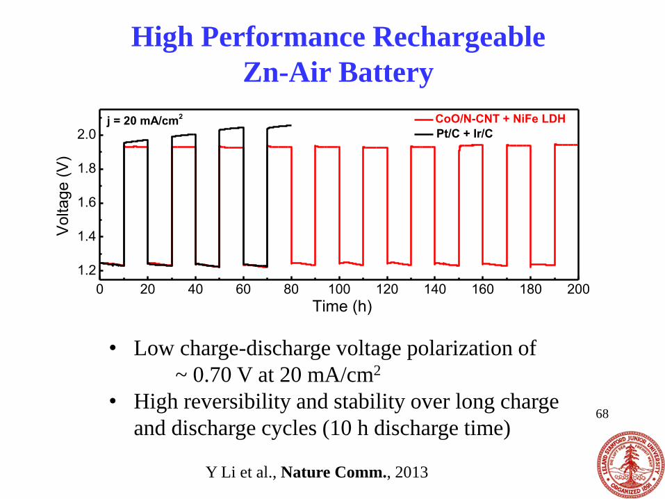
0 20 40 60 80 100 120 140 160 180 200
1.2
1.4
1.6
1.8
2.0j = 20 mA/cm
2 CoO/N-CNT + NiFe LDH
Pt/C + Ir/C
Vo
lta
ge
(V
)
Time (h)
• Low charge-discharge voltage polarization of
~ 0.70 V at 20 mA/cm2
• High reversibility and stability over long charge
and discharge cycles (10 h discharge time)
High Performance Rechargeable
Zn-Air Battery
Y Li et al., Nature Comm., 2013
• CNTs and nano-graphene for biology and medicine.
• A new near-infrared II imaging is developed.
• High quality graphene nanoribbons for physics and
devices.
• Novel Inorganic-carbon hybrid materials for fast energy
storage/release & advanced electrocatalysis.
• Graphene allows atomic/chemical imaging of catalyst sites
Summary
Acknowledgement
Professor Yi Cui
Professor Stephen Pennycook
Professor Wei Fei
Xiaolin Li, Liying Jiao
Xinran Wang, Liming Xie
Hailiang Wang
Yongye Liang
Yanguang Li
Tyler Medford, Wesley Chang
Yuan Yang
Guosong Hong, Kevin Welsher, Sarah Sherlock,
Joshua Robinson, Scott Tabakman, Bo Zhang
Shuo Diao, Alexander Antaris
Nadine Wong Shi Kam, Zhuang Liu,
Giuseppe Prencipe, Andrew Goodwin
Yuichiro Kato, Sasa Zaric, Zhuo Chen.
Professor P. J. Utz
Professor John Cooke
Nano-Bio: Energy & Electronics: