nec 2017 requirements for generator set overcurrent protection · per unit reactances alternator...
TRANSCRIPT

PowerHour webinar series for consulting engineersExperts you trust. Excellence you count on.
NEC 2017 Requirements for Generator Set Overcurrent Protection
January 24th, 2017 11:00 PDT / 13:00 CDT
(1PDH issued by Cummins)

Welcome!
PowerHour is designed to help our engineer partners to…
Keep up to date on products, technology, and codes and standards development
Interact with Cummins experts and gain access to ongoing technical support
Participate at your convenience, live or on-demand
Earn PDH
Technical tips: Audio is available through teleconference, or your computer (don’t forget to unmute)
You are in “listen only” mode throughout the event
Use the WebEx Q&A Panel to submit questions, comments, and feedback
throughout the event. We will provide sufficient Q&A time after presentation
If you lose audio, get disconnected, or experience a poor connection, please
disconnect and reconnect
Report technical issues using the WebEx Q&A Panel, or email
2

Meet your panelists
3
Munir Kaderbhai
Application Engineer
Cummins Power Systems
Cummins presenter:
Your local Cummins contacts:
AZ, ID, NM, NV: Carl Knapp ([email protected]), Rocky Mountain Region
CO, MT, ND, UT, WY: Joe Pekarek ([email protected]), Rocky Mountain Region
IL, IA, NB, SD: John Kilinskis ([email protected]), Central Region
WI, MN, ND: Michael Munson ([email protected]), Central Region
MO, KS: Earnest Glaser ([email protected]), Central Region
TX: Scott Thomas ([email protected]), Gulf Region
FL, GA, SC, NC and Eastern TN: Robert Kelly ([email protected]), South Region
IN, KY, OH, TN, WV: Thomas Stadulis ([email protected]), East Region
NY, NJ, CT, PA, MD: Charles Attisani ([email protected] ): East Region
For other states and territories, email [email protected] or visit http://power.cummins.com/sales-service-locator
Rich Scroggins
Technical Advisor
Cummins Power Systems
Cummins facilitator:
Tom Bakritzes,
Global Sales Training Manager
Cummins Panelist

Course Objectives
Participants will be able to:
Explain generator excitation systems and their effect on fault current
performance
Identify basic generator set overcurrent protection requirements in order
to specify the correct protection equipment.
Describe the NEC requirements for selective coordination, generator
disconnect, arc flash energy reduction and separation of circuits in
order to evaluate different means for achieving code compliance.
Identify recent important codes changes to NFPA70 NEC 2017
pertaining to the topics listed above.
4

Agenda
Generator performance under overcurrent conditions
– Review of generator excitation systems
– Alternator Decrement Curves
– PowerCommand AmpSentry functionality
Describe NEC requirements for
– Overload Protection
– Selective coordination
– Arc Energy Reduction
– Generator disconnect requirements
– Separation of circuits requirements
5

Generator Excitation Systems – Self (Shunt) Excited
Key Point: AVR may not
have the capability to
support the fault current
long enough to clear
downstream faults as the
main field in the
alternator may collapse.6
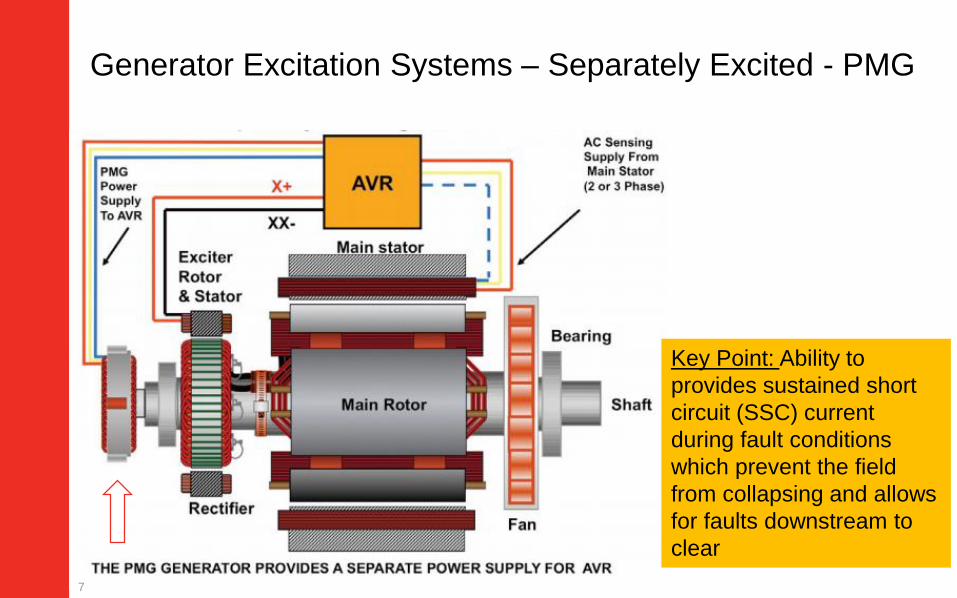
Key Point: Ability to
provides sustained short
circuit (SSC) current
during fault conditions
which prevent the field
from collapsing and allows
for faults downstream to
clear
Generator Excitation Systems – Separately Excited - PMG
7

Alternator Performance Under a Fault - Decrement Curve (Separately Excited)
I3ph, pu = (1/Xd” - 1/Xd’)*e(-t/Td”) + (1/Xd’ - 1/Xd)*e(-t/Td’) + 1/Xd
I3ph, pu = 1/Xd” Current is a function of the AVR, Excitation System and alternator electro-magnetic design.
Three phase fault characteristics
Key points:▪ Alternator fault current
decays, it doesn’t remain constant like fault current from a transformer
▪ System design software tools such as SKM account for this
8

Decrement Curve Multipliers
Instantaneous Fault Current
I3ph, p.u = 1/Xd”
ISLG, p.u = 3/( Xd” + X2 + X0 + 3 Rf)
ILL, p.u = 1.732/(Xd” + X2)
Single phase faults result in higher levels
of fault current
Unbalanced faults stress alternator rotor damper windings
Sustained short circuit current is determined by the AVR and excitation system
IEEE Std 142-2007 (Green Book)
1.7.1 “Unlike the transformer the three sequence reactances from a generator are not
equal. The zero sequence reactance has the lowest value and the positive sequence
reactance varies as a function of time. Thus, a generator will usually have a higher
initial ground fault current than three phase fault current if the generator has a solidly
grounded neutral.”9

Per Unit Reactances
▪ Alternator reactances are published using the alternator kVA rating as a base
▪ Fault current calculations need to use the same base or the reactances need to be converted to the genset kW rating base
▪ AmpSentry uses the genset standby kVA rating as a base
Example:
Generator Set: 2500kW DQKAN,
Alternator LVSI804X, 60Hz, 480V
Generator Set kVA = 3125
Alternator kVA = 4464
X”dgenset = 0.119/4464*3125 = 0.083
10

NEC Requirements
Overload protection of generator and conductors (Article
445.12 and 445.13)
Selective coordination (Articles 700.28 & 701.27 & 708.54)
Arc Energy Reduction (Article 240.87)
Disconnecting Means for Generators (Article 445.18)
Separation of Emergency Circuits (Article 700.10)
11

Generator Overload Protection
Code Requirement (NFPA 70 445.12(A))
– Generators, except AC generator exciters, shall be protected from
overloads by inherent design, circuit breakers, fuses, protective relays
or other identified overcurrent protective means suitable for the
conditions of use.
Exception: Where deemed … vital to the operation of the electrical
system…the overload sensing devices (shall) be permitted to be
connected to an annunciator or alarm…
Overload. Operation of equipment in excess of normal, full-load
rating, or of a conductor in excess of rated ampacity that, when it
persists for a sufficient length of time, would cause damage or
dangerous overheating. A fault, such as a short circuit or ground
fault, is not an overload. 12

Cable Overload Protection
N Article 445.13 (A): The ampacity of the conductors from the
generator terminals to the first distribution device(s) containing
overcurrent protection shall be not less than 115% of the nameplate
current rating of the generator.
Exception: Where the design and operation of the generator prevent
overloading, the ampacity of the conductors shall not be less than
100% of the nameplate current rating of the generator.
Article 240.21 (G): Conductors from generator terminals that meet
445.13 shall be permitted to be protected by the generator overload
protective device(s) required by 445.12.
13

N 445.13(B) Generators. Ampacity of Conductors. Overcurrent Protection Provided
Where the generator set is equipped with a listed overcurrent
protective device or a combination of a current transformer and
overcurrent relay, conductors shall be permitted to be tapped from the
load side of the protected terminals in accordance to 240.21(B)
14

Generator Set Overload
Protection - 445.12 (A)
Conductor Size
/Overload Protection -
445.13 (A), 240.21 (G)
Taps on main generator
set feeder conductor -
445.13(B)
15

10
1
0.1
0.05
1 103
AMPS (TIMES RATED)
TIM
E (
SE
CO
ND
S)
GENERATOR
THERMAL DAMAGE
CURVE
100
CABLE THERMAL
DAMAGE CURVE
Is the Protection There?
Generator and cable is required to be protected
– Thermal damage isn’t total failure
Conventional wisdom is not correct
– Most common protection is molded case breaker(s) with thermal/magnetic trip
– Fully rated breakers don’t protect generator
– Need fully adjustable electronic trip on the MCCB or other listed protective device
Any breaker used is susceptible to some level of nuisance trips due to instantaneous function
CABLE THERMAL
DAMAGE CURVE
16

Inherently Designed Overcurrent Protection - AmpSentry™ Protective Relay
▪ Overcurrent protection integral to the Cummins PowerCommandControl System
▪ UL listed device
▪ Provides overcurrent protection by shutting down the genset before alternator thermal damage occurs
▪ If current exceeds 300% of rated, AmpSentry™ decreases excitation to regulate current at 300% until:
– Fault is cleared by a downstream breaker
– Or generator set is shut down based on:
• Thermal damage curve for 3 phase fault
• 2 seconds for L-G fault
• 5 seconds for L- L fault
17

AmpSentry™ Trip Curve
Library Files available in:
– SKM POWER*TOOLS
– EasyPower® Suites
Link to access the trip curve -
http://power.cummins.com/power-systems-
analysis-equipment-library18

3 Phase L1-L2-L3 Short: AmpSentry Regulation and Shutdown
0
50
100
150
200
250
300
350
400
450
500
0 5 10 15 20
time, sec
%C
urr
en
t
Alt %Standby Max Line
Current
3-Phase Fault Response with AmpSentry™ Overcurrent Relay
Peak Current: IR/X”d
Regulates at 3X Rated
Shuts down before damage
19
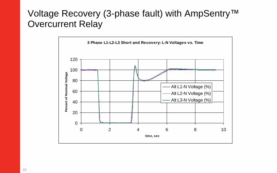
3 Phase L1-L2-L3 Short and Recovery: L-N Voltages vs. Time
0
20
40
60
80
100
120
0 2 4 6 8 10
time, sec
Perc
en
t o
f N
om
inal V
olt
ag
e
Alt L1-N Voltage (%)
Alt L2-N Voltage (%)
Alt L3-N Voltage (%)
Voltage Recovery (3-phase fault) with AmpSentry™ Overcurrent Relay
20

AmpSentry and Neutral Grounding Resistors
Neutral Grounding Resistors are not required to protect generator sets that
are equipped with the AmpSentry protective relay
NGR’s may still be necessary as part of the overall grounding and protection
scheme
AmpSentry will not limit instantaneous ground fault current
In the event of a L-G fault AmpSentry will regulate current in the faulted
phase at 300% of rated current for 2 seconds at which time the generator set
will shut down (or until some protective device clears the fault)
21

Online Certification
AmpSentry is UL Listed as a protective relay
http://database.ul.com/cgi-bin/XYV/template/LISEXT/1FRAME/index.htm
22

AmpSentryTM UL Label
23

What is Selective Coordination?
NEC Article 100 Definition
– Selective Coordination: Localization of an over-current condition to
restrict outages to the circuit or equipment affected, accomplished by
the choice of over-current protective devices and their ratings or
settings
Selective Coordination is required for emergency,
legally required standby and critical operations power
systems circuits
– NEC 700.32, 701.27, and 708.54 “…power system(s) shall be
selectively coordinated with all supply side OCPDs.” over-current
24

Selective Coordination
Without Selective Coordination
OPENS
NOT AFFECTED
UNNECESSARY
POWER LOSS Fault
OPENS
NOT
AFFECTED
With Selective Coordination
Fault
25

Demonstrating Selective Coordination
Engineers will use software packages
such as SKM to demonstrate
coordination on their projects
AmpSentry is included in the latest
version of SKM and EasyPower
Trip curves overlap – these
breakers are not
coordinated for high levels
of fault current
No overlap - breakers are
coordinated in this region
of the curve
26
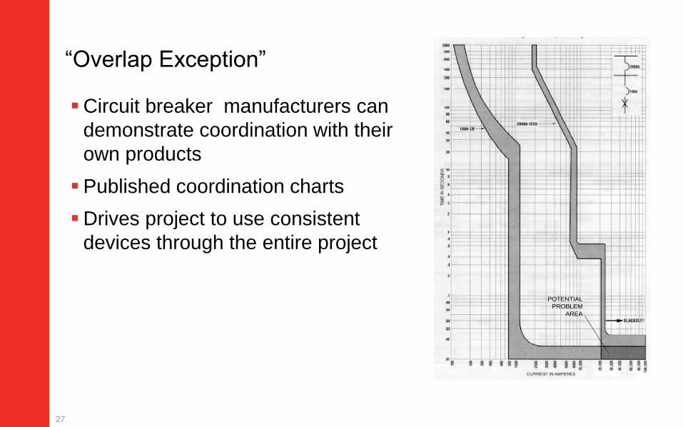
“Overlap Exception”
Circuit breaker manufacturers can
demonstrate coordination with their
own products
Published coordination charts
Drives project to use consistent
devices through the entire project
POTENTIAL
PROBLEM
AREA
27

AmpSentry and Selective Coordination
Amp Sentry simplifies
coordination by regulating fault
current until the downstream
breaker clears
Genset mounted molded case
circuit breaker present challenges
in coordinating with downstream
breakers
The inclusion of AmpSentry in
SKM and EasyPower software
simplifies design of coordinated
systems
28

(N) NFPA 70 240.87 (B) Arc Energy Reduction
“Where the highest continuous current trip
setting is 1200A or higher … one of the
following or approved equivalent means (to
reduce clearing time) shall be provided…
… Energy-reducing maintenance switching
with local status indicator
… an energy reducing maintenance switch
allows a worker to set a circuit breaker trip
time to “no intentional delay”
29

Generator Set Circuit Breaker Arc Flash Protection
Example – Square D P and H Micrologic™ solid
state trip units (P and H)
Energy Reduction Maintenance Setting (ERMS)
ERMS Switch “OFF” and “ON” ModeERMS Label on Trip UnitLocal ERMS Switch
30

Generator Set Integrated Arc Flash Protection –AmpSentry™ Maintenance Mode
AmpSentry Maintenance Mode similar
to circuit breaker arc energy reducing
function
Instantaneous generator set shutdown
in the event of a short circuit, bypassing
all time delays
−Can also be configured to shunt trip a
downstream breaker
Enabled by a customer input or by
connecting InPower service tool
Complies with NEC requirement for arc
energy reduction
31

AmpSentry and NEC Arc Flash Reduction
▪ Arc energy calculation depends on
several site specific factors
–Available fault current, arc interrupting time,
system voltage, grounding method, conductor
gap, working distance
▪ Maintenance Mode reduces arc
interrupting time
–Shuts down genset within 50 msec
–Configurable output can shunt trip a breaker
32

Generator Set Disconnect Means and Shutdown of Prime Mover
(N) NFPA 70-2014, 445.18
– (A) Disconnecting Means - Generators shall be equipped with
disconnect(s), lockable in the open position
– (B) Shutdown of Prime Mover
• (1) Provisions to disable all prime mover start control circuits
• (2) Initiate a shutdown mechanism that requires a mechanical reset
• Provisions for (B) permitted to satisfy requirements for (A) if capable of being
locked out.
– (C) Generator Installed in Parallel
• Provisions of 445.18(A) shall be capable of isolation the generator output
terminals from the paralleling equipment.
• Disconnect means shall not be required to located at the generator.
33

Generator Set Disconnect Means and Shutdown of Prime Mover (cont.)
E-stop switch with lockable
shroud
Disconnect starter battery and
lockout
34

Lock Out Tag Out
NFPA 70E Requires that equipment must be disconnected from all
sources of electrical supply
–Neither the E-stop switch or a genset mounted breaker is sufficient to
meet LOTO requirements
Genset has two sources of electrical supply
–Battery + charging system
–Utility or paralleled genset
LOTO procedure should include
–Removing and locking out battery cable
–Locking out breaker that feeds charging system
–Locking out paralleling breaker that connects utility or paralleled
genset
35

Separation of Emergency Circuits
NFPA70-2014 700.10 (B)(5)(c):
Emergency circuits shall not originate from the same vertical switchgear section, vertical switchboard section, panelboard enclosure or individual disconnect enclosure as other circuits
Could meet the requirement with individual enclosures for each breaker
– Selective Coordination requires breaker selection as a system
EMERGLEGAL
REQ’DOPTIONEMERG
LEGALREQ’D OPTION
36

Separation of Circuits
NFPA70-2014 700.10 (B)(5)(d):
It shall be permissible to utilize single or multiple feeders to supply distribution equipment between an emergency source and the point where the combination of emergency loads are separated from all other loads
EM
ER
GE
NC
Y
OP
TIO
NA
L
ST
AN
DB
Y
LE
GA
LL
Y
RE
QU
IRE
D
TO AUTOMATIC TRANSFER
SWITCHES & LOADS
PER NEC
51
37
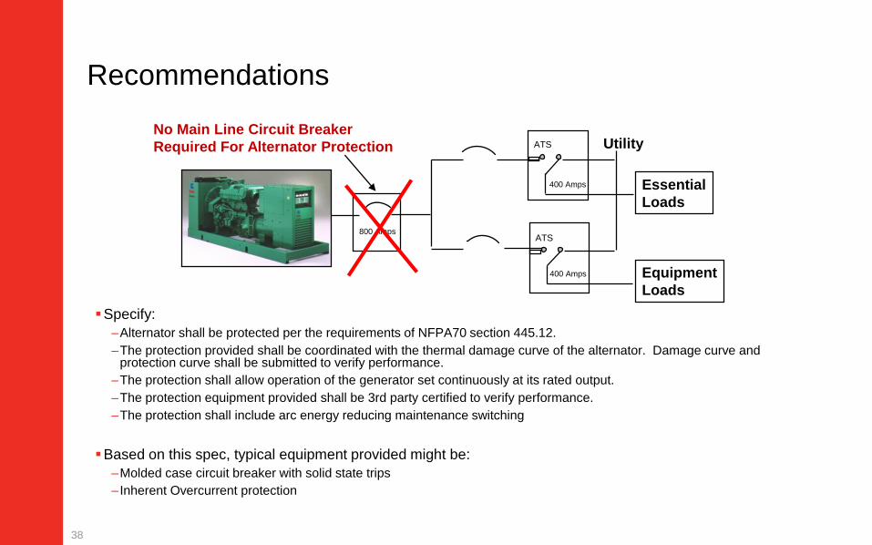
Recommendations
Specify:
–Alternator shall be protected per the requirements of NFPA70 section 445.12.
–The protection provided shall be coordinated with the thermal damage curve of the alternator. Damage curve and protection curve shall be submitted to verify performance.
–The protection shall allow operation of the generator set continuously at its rated output.
–The protection equipment provided shall be 3rd party certified to verify performance.
–The protection shall include arc energy reducing maintenance switching
Based on this spec, typical equipment provided might be:
–Molded case circuit breaker with solid state trips
– Inherent Overcurrent protection
800 Amps
Equipment
Loads
Essential
Loads
UtilityNo Main Line Circuit Breaker
Required For Alternator Protection
400 Amps
ATS
400 Amps
ATS
38

Generator Protection Summary
Generator set mounted thermal magnetic breakers may not
protect the generator and will be difficult to coordinate with
downstream devices
AmpSentry is a UL listed overcurrent protective relay integral to
Cummins generator controls
– Included in SKM and EasyPower software
– Meets NFPA 70 240.87 requirements for arc energy reducing maintenance
switching
The generator E-stop switch meets NEC disconnect requirements
Mounting breakers off of the generator simplifies separation of
circuits requirements
39

Q&A
Type your questions, comments, feedback in the WebEx
Q&A box. We will get to as many questions as we can
We will publish consolidated FAQ along with presentation
and webinar recording on powersuite.cummins.com
40
Your local Cummins contacts:
AZ, ID, NM, NV: Carl Knapp ([email protected]), Rocky Mountain Region
CO, MT, ND, UT, WY: Joe Pekarek ([email protected]), Rocky Mountain Region
IL, IA, NB, SD: John Kilinskis ([email protected]), Central Region
WI, MN, ND: Michael Munson ([email protected]), Central Region
MO, KS: Earnest Glaser ([email protected]), Central Region
TX: Scott Thomas ([email protected]), Gulf Region
FL, GA, SC, NC and Eastern TN: Robert Kelly ([email protected]), South Region
IN, KY, OH, TN, WV: Thomas Stadulis ([email protected]), East Region
NY, NJ, CT, PA, MD: Charles Attisani ([email protected] ): East Region
For other states and territories, email [email protected] or visit http://power.cummins.com/sales-service-locator

Closing
Watch out for a follow-up email including– A Link to webinar recording
– A PDH Certificate
– A 2-minute survey link. Tell us how we did and how we can improve
Visit powersuite.cummins.com for – PowerHour webinar recording, presentation and FAQ archive
– Other Cummins Continuing Education programs
– Sizing and spec development tool
41