necs -w r-410a hfc - prime · pdf filenecs-w electronic control can manage the ... 2 or 3 way...
TRANSCRIPT

R410A refrigerant
Total versatility
Integrated hydronic unit on evaporator/condenser side
Integrated condensation control
<
<
<
<
Water-cooled liquid chillers and water-to-water heat pumps
NECS_W__0152_0612_200907_GB
r HFC
R-410A
(The photo of the unit is indicative and may change depending on the model)
Climaveneta Technical Bulletin
0152 - 0612
43,4 - 186 kW
NECS-W

II NECS-W_0152_0612_200907_GB
NECS - W
HFC R410a
SUMMARYNECS-W
0152 - 0612
Liability disclaimer
This bulletin is not exhaustive about: installation, use, safety
precautions, handling and transport. Refer to “General Manual
for Installation” for further informations.
This bulletin refers to standard executions, in particular for
dimension, weight, electric, hydraulic, aeraulic and refrigerant
connections (whereas applicable). Contact Climaveneta Com-
mercial Offi ce for further drawings and schemes.
Climaveneta declines any liability derived from the bulletin’s
use.
This bulletin is of exclusive property of Climaveneta, and all
forms of copy are prohibited.
The information contained in this document may be modifi ed
without prior notice.
Company quality system
certifi ed to UNI EN ISO 9001
This company partici-
pates in the Eurovent
Certifi cation Programme.
The products are listed in the
Directory of certifi ed products.
Eurovent certifi cation ap-
plied to units with cooling
capacity up to l500 kW for
air cooled water chillers and
water cooled liquid chillers.
1. Product presentation
1.1 Energy indices ESEER and IPLV
1.2 Using the energy indices
1.3 Control unit with LED display
1.4 Integrated Hydronic Unit (Optional)
2. Unit description
2.1 Standard unit composition
2.2 Electric power and control panel
2.3 Accessories
3. Technical data
3.1 General technical data
3.2 Cooling capacity performance
3.3 Heat pump capacity performance
4. Operating range
5. Hydraulic data
5.1 Water fl ow and pressure drop
6. Hydronic groups
7. Electrical data
8. Full load sound level
9. Dimensional drawings
10. Free spaces - lifting mode - symbols
11. Legend of pipe connections
pg. n° III
pg. n° V
pg. n° V
pg. n° VI
pg. n° VII
pg. n° 1
pg. n° 1
pg. n° 1
pg. n° 1
pg. n° 2
pg. n° 2
pg. n° 4
pg. n° 8
pg. n° 12
pg. n° 13
pg. n° 13
pg. n° 14
pg. n° 19
pg. n° 20
pg. n° A1
pg. n° A3
pg. n° A4

III NECS-W_0152_0612_200907_GB
NECS - W
HFC R410a
1. PRODUCT PRESENTATION
NECS, the new CLIMAVENETA R410A proposal
Scroll compressors, featuring high efficiency, low vibrations and low noise emissions.Flexible range. Available from 113 – 341 kW with 9 sizes and 5 versions.Part load efficiency with EER > 4.3New controller with QuickMind.Idrorelax, for turning your ideas into reality.
Climaveneta introduces its new NECS-W range of chillers and heat pumps with scroll compressors, plate exchangers and R-410A, with both one-circuit two compressors and two-circuit four compressors, focused on maximum efficiency and mini-mum noise emission
Why R-410AAlthough R-410A is a blend, it behaves just like a pure gas and features a negligible temperature glide. Thanks to its outstand-ing heat conductivity, R-410A contributes towards achieving high system efficiency. R-410A is also an ecological gas be-cause its high efficiency reduces electricity consumption andconsequently CO2 emissions and because it does not damage the ozone layer (ODP = 0).
The scroll compressor has been expressly redesigned for use with the new gas and is now even more compact and silent than before.
Complete versatilityNECS-W units are designed to fully satisfy any application or installation needs throughout a complete range of models, hy-dronic configurations and accessories. NECS-W is available in chiller mode (chilled water production), heat pump for hot wa-ter production (plus possible water side reversal) NECS-WHand finally heat pump with “refrigerant side reversal” NECS-WN (chilled/hot water production).
High efficiency at partial loadClimaveneta has designed NECS-W units with the goal of guaranteeing high efficiency at part load. The result achieved in the new singlecircuit dual-compressor is an ESEER up to 6.01, equivalent to a 33% saving in seasonal energy consump-tion compared to traditional R-407C double-circuit unit.
AdvantagesThe technological choices aimed to provide the maximum overall quality and the use of the most innovative technologies make NECS-W a unit able to ensure maximum energy effi-ciency, easy installation thanks to its compact size, versatility and settings for integration in the Idrorelax centralized hydronic system (www.idrorelax.it).
Reversibile heat pumpsAll NECS-W are available as NECS-WN heat pump model; this model completes the Climaveneta water cooled units range.Making a comparison between NECS-WN and a traditional “water side reversal” heat pump, reductions in installation spaces and an easier water connection layout are achieved. It means saving in installation costs and time.
Condensing pessure control deviceNECS-W electronic control can manage the best suitable con-densing pressure control device for every applications: pres-sostatic valve, 2 or 3 way modulating valve and inverter on the condenser pumps. NECS-W units can therefore be combined with dry-coolers, evaporating towers and geothermal probes, or used to cool open-loop water (e.g.: aqueducts, wells, water tables).
Kit pumps available on hot/cold sideNECS-W units are designed in order to minimize installation time. Units are available with both evaporator /condenser hy-dronic kit.Hydronic kits are fully accessorized with every hydronic device in order to obtain: space reduction, installation costs saving and shortening installation time.The units are plug&play thanks to the feasibility to install 1 or 2 pumps on board, high and low pressure head on both evapora-tor and condenser sides.

IV NECS-W_0152_0612_200907_GB
NECS - W
HFC R410a
Consistent with corporate culture, the NECS-W series was designed to offer extremely high quality products with cutting-edge technology focusing on maximum energy efficiency at both full (EER) and part load (ESEER).
Energy efficiency at full loadNECS-W units stand out for their particularly high EER energy efficiency index. This result was achieved by focusing on the
design of plate exchangers both on the condenser side and on the evaporator side.These construction choices have both increased efficiency andprovided extremely high levels of reliability while significantly increasing compressor working life.
Energy efficiency at part loadAttention to energy consumption is continually gaining impor-tance, even at European level.The installed chiller unit works at full load only for extremely short periods of time while most of the energy is produced with part loads between 50 and 75%.
The ESEER parameter proposed by Eurovent, takes part load operating conditions into account when assessing unit effi-ciency.
Load Water temp. Weight

V NECS-W_0152_0612_200907_GB
NECS - W
HFC R410a
1.1 Energy indices ESEER and IPLVIncreasingly closer attention is being paid towards the power consumption of air-conditioning equipment, both in Europe and elsewhere. For many years in the United States, reference has not just been made to efficiency at rated conditions. A valuation index is used which considers marginal operation of the unit at rated conditions as well as the increased usage when the separation stages of the cooling compressors are used. The valuation index adopted in the United States is called IPLV (Integrated Part Load Value) and is defined in the regulations issued by ARI (American Refrigeration Institute).
ARI Standard IPLVARI =(1*EER100% + 42*EER75% + 45*EER50% + 12*EER25%) /100
Where EER100%, EER75%, EER50%, EER25% are the efficiencies of the chiller in the various load conditions (100% - 75% - 50% and 25% respectively), calculated in the external air temperature conditions shown below.
The temperature of the water leaving the evaporator is consid-ered constant at 6.7°C in all load conditions, with a delta of 5°C in the full load condition.The multipliers 1, 42, 45 e 12 are the cooling performance coef-ficients in various load conditions statistically calculated by ARI on the basis of surveys conducted, for various types of build-ings and operating conditions, in 29 American cities.
ESEER Comparison:NECS-W single-circuit vs. traditional dual-circuit unit. The com-parison proves that the new single-circuit NECS-W units with R-410A feature significantly greater energy efficiency (ESEER + 38%) over traditional dual-circuit units with R-407C.
NECS-W 202 Traditional unit Energy efficiency percent difference
Single circuit R-410A Two scroll - two circuit R-407C NECS-W 202 vs a traditional R407-C unit
EER 100% 4,53 4,48 + 1%
EER 75% 5,55 4,55 + 22%
EER 50% 6,55 4,48 + 46%
EER 25% 5,88 4,55 + 26 %
ESEER 6,01 4,52 + 33%
NECS-W ESEER0152 5,81
0182 5,98
0202 6,01
0252 5,69
0262 5,59
0302 5,66
0352 5,80
0412 5,71
0452 5,79
0512 5,78
0552 5,93
0612 5,80
In Europe there is a proposal for EECCAC (Energy Efficiency and Certification of Central Air Conditioner)
Proposal EECCACESEER = (3*EER100% +33*EER75% + 41*EER50% + 23*EER25%)/100
Evaporator temp. leaving 6,7°CDeltaT full load 5°CLoad 100% 75% 50% 25%Cond. water temp. 30°C 26°C 22°C 18°C
1.2 Using the energy indicesAfter establishing which index to use and estimating the total power required by the system in the summer mode (in kWh), we can calculate seasonal electricity consumption (in kWh) us-ing the following formula:
Power absorbed = Power requested / Index of efficiency
The real power calculation can be obtained more correctly in a “dynamic” form, that is, considering the load performance curve at different external temperatures, the location and the refer-ence number of operating hours.These figures will allow plant consultants and designers to make their evaluations depending on the type of building, the place of installation and the type of heat load. etc.. They can also determine the energy index using the method that best re-flects plant requirements and can make comparisons between similar or equivalent systems using the same reference unit.
NECS-WH ESEER0152 5,81
0182 5,98
0202 6,01
0252 5,69
0262 5,59
0302 5,66
0352 5,80
0412 5,71
0452 5,79
0512 5,78
0552 5,93
0612 5,80
NECS-WN ESEER0152 5,67
0182 5,86
0202 5,88
0252 5,59
0262 5,52
0302 5,54
0352 5,72
0412 5,61
0452 5,69
0512 5,66
0552 5,80
0612 5,70
IPLV (Integrated Part Load Value) ARI Standard indicesESEER (European Seasonal Energy Efficiency Ratio) Indices for EECCAC proposal

VI NECS-W_0152_0612_200907_GB
NECS - W
HFC R410a
All the two-compressor units are equipped, as a standard, withthe “W3000 Base” keyboard with LED display.On the four-compressor units the user friendly “W3000. Com-pact” keyboard with LCD is installed as a standard; also avail-able, on demand, for the two compressors units.The “W3000 Compact” onboard keyboard can be connected to a remote keyboard with LCD display.
Main functions: QuickMind, local and remote FWS supervi-sion, dual setpoint management, etc., confirm Climaveneta’s commitment to continually developing its electronics technol-
ogy. The heat pumps, moreover, are fitted with the original Climaveneta defrosting control system called “Smart Defrost” which considerably reduces defrosting times, thus improving the energy performance of the unit. Interfaces with BMS sys-tems: METASYS®, MODBUS®, LONWORKS®, SIEMENS®, TREND®.
Black Box logs data relative to 200 alarm events which can be printed with a personal computer.
1.3 Control unit with LED display
QuickMind is a special control unit which monitors the main operating parameters, predicts system behaviour and antici-pates unit settings in order to constantly optimise performance;it allows both return and delivery water temperatures to be cho-sen as adjustment parameters. It can reduce outlet temperature fluctuations even with a small amount of water in the system. When, for dual-compressor chillers featuring a maximum of 12 start-ups per hour and using a traditional adjustment system, the minimum recommended water content is 5.5 l/kW, Quick-
Mind ensures the same chiller operates correctly even with a water content of just 2.5 l/kW and considerably reduces outlet temperature fluctuations. The above graph shows that outlet temperature fluctuations with QuickMind are limited to 4.3°C asopposed to 7.54°C if the traditional adjustment system were used, without even ensuring an acceptable minimum compres-sor start time.
VII NECS-W_0152_0612_200907_GB
NECS - W
HFC R410a
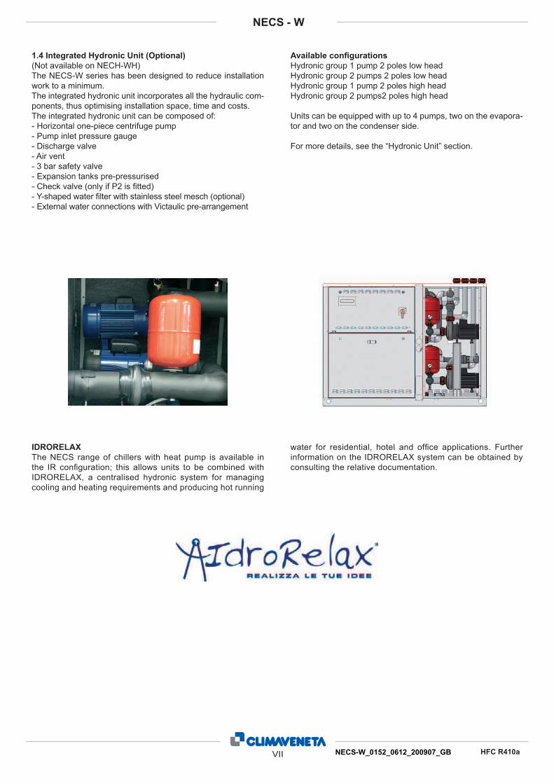
1.4 Integrated Hydronic Unit (Optional)
(Not available on NECH-WH)
The NECS-W series has been designed to reduce installation
work to a minimum.
The integrated hydronic unit incorporates all the hydraulic com-
ponents, thus optimising installation space, time and costs.
The integrated hydronic unit can be composed of:
- Horizontal one-piece centrifuge pump
- Pump inlet pressure gauge
- Discharge valve
- Air vent
- 3 bar safety valve
- Expansion tanks pre-pressurised
- Check valve (only if P2 is fi tted)
- Y-shaped water fi lter with stainless steel mesch (optional)
- External water connections with Victaulic pre-arrangement
Available confi gurations
Hydronic group 1 pump 2 poles low head
Hydronic group 2 pumps 2 poles low head
Hydronic group 1 pump 2 poles high head
Hydronic group 2 pumps2 poles high head
Units can be equipped with up to 4 pumps, two on the evapora-
tor and two on the condenser side.
For more details, see the “Hydronic Unit” section.
IDRORELAX
The NECS range of chillers with heat pump is available in
the IR confi guration; this allows units to be combined with
IDRORELAX, a centralised hydronic system for managing
cooling and heating requirements and producing hot running
water for residential, hotel and offi ce applications. Further
information on the IDRORELAX system can be obtained by
consulting the relative documentation.

1 NECS-W_0152_0612_200907_GB
NECS - W
HFC R410a
Water-to-water chillers
Water-to-water chillers. The unit is supplied with anti-freeze oil
and refrigerant and has been factory tested. On-site installation
therefore just involves making connections to the mains power
and water supplies.
Unit charged with R410A ecological refrigerant.
2.1 Standard unit composition
Supporting frame
Base and frame in thick hot-galvanised shaped sheet steel. All
parts polyesters-painted.
Panelling
The external panelling, made from simil peraluman, epoxy
painted sheet metal, offers maximum ease of access to the in-
ternal components.
Standard version without acoustic insulation on compressors
case.
Available, on request, acoustic insulation on compressors sec-
tion by 30mm thick Fiberform. See acoustic performances sec-
tion to be informed on the noise reduction level.
Compressors
Hermetic scroll compressors complete with an oil pump heater,
electronic overheating protection with centralised manual reset
and a two-pole electric motor.
Exchanger side customer
AISI 316 steel braze-welded plate exchanger. The heat ex-
changers are insulated with a closed-cell condensation proof
lining in neoprene.
When the unit is working, it is protected against lack of fl ow by
a differential pressure switch mounted on the water side. The
unit can work with antifreeze mixtures at exchanger outlet tem-
peratures as low as -8°C.
Exchanger side thermal source
AISI 316 steel braze welded plate exchanger. The exchangers
can be used with water from wells, from towers or with dry-
coolers.
Refrigerant circuit
Main components of the refrigerant circuit:
- dryer fi lter,
- refrigerant line sight glass with humidity indicator,
- externally equalised thermostatic valve,
- high pressure safety valve,
- high and low pressure switches,
2.2 Electric power and control panel
Electric power and control panel, built to EN 60204-1/EC 204-1
standards, complete with:
- control circuit transformer,
- general door lock isolator,
- automatic circuit breakers and contactors for compressors,
- terminals for cumulative alarm block (BCA),
- remote ON/OFF terminals,
- spring-type control circuit terminal board,
- electronic controller.
AVAILABLE VERSIONS
B (base)
Standard unit.
2.3 Accessories
- Noise insulation
- Rubber isolators
- Electronic soft start
- Compressor discharge valves
- Compressor suction valves
- Evaporator water fl ow switch (supplied separately)
- 3 way modulating valve for condensing control (supplied
loose)
- Pressostatic valve (supplied loose)
- 2 way modulating valve for condensing control (supplied
loose)
- Pump with onboard inverter for condensing control
- Upward water connections (only available with the hydronic
kit)
- Victaulic fl exible coupling kit for both condenser and evapora-
tor
- HP and LP gauges
- W3000 Compact Keyboard
- Remote keyboard (only with keyboard W3000 Compact)
- Water pumps kit (see attachment)
- Evaporator steel fi lter kit (supplied separately)
2. UNIT DESCRIPTION

3.1
2 GB
5 6,5 6,5 6,5 6,6 8,3 8,8

3 GB
9,4 11,5 13,6 13,1 12,6

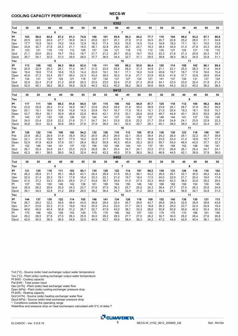
B3.2 COOLING CAPACITY PERFORMANCE
NECS-W
015235 40 45 50 5530 30 35 40 45 50 55 30 35 40 45 50 55
6 7 8Tev
PfPatQevDpev
44,1 42,0 39,6 37,1 34,3 31,3 45,5 43,4 41,0 38,4 35,5 32,4 46,9 44,7 42,3 39,7 36,7 33,68,87 9,96 11,2 12,6 14,2 15,9 8,91 10,00 11,2 12,6 14,2 15,9 8,95 10,0 11,3 12,7 14,2 15,97,58 7,22 6,82 6,38 5,90 5,38 7,83 7,46 7,06 6,61 6,12 5,58 8,07 7,71 7,29 6,83 6,33 5,7859,6 54,1 48,3 42,3 36,1 30,1 63,6 57,8 51,6 45,3 38,8 32,3 67,6 61,6 55,1 48,4 41,5 34,6
Tcd
52,9 51,9 50,8 49,7 48,5 47,29,06 8,89 8,70 8,50 8,29 8,06
PtQcdDpcd 35,3 34,0 32,6 31,1 29,5 27,9
54,4 53,4 52,2 51,0 49,7 48,39,31 9,14 8,94 8,73 8,51 8,2637,3 35,9 34,4 32,8 31,1 29,3
55,8 54,8 53,6 52,3 51,0 49,59,56 9,38 9,18 8,96 8,72 8,4639,3 37,9 36,3 34,5 32,7 30,8
Dpev 71,8 65,5 58,8 51,7 44,4 37,0 76,1 69,6 62,5 55,0 47,3 39,5 80,5 73,8 66,4 58,5 50,3 42,1Qev 8,32 7,95 7,53 7,06 6,54 5,97 8,56 8,19 7,76 7,28 6,75 6,17 8,81 8,43 8,00 7,51 6,97 6,37Pat 8,99 10,1 11,3 12,7 14,2 15,9 9,02 10,1 11,3 12,7 14,2 15,9 9,06 10,1 11,4 12,7 14,2 15,9Pf 48,3 46,1 43,7 41,0 38,0 34,7 49,7 47,5 45,1 42,3 39,2 35,8 51,1 48,9 46,4 43,6 40,4 37,0
9 10 11Tev
DpcdQcdPt 57,3 56,2 55,0 53,7 52,2 50,6
9,81 9,63 9,42 9,19 8,94 8,6641,4 39,9 38,2 36,3 34,4 32,2
58,7 57,6 56,4 55,0 53,4 51,710,1 9,88 9,67 9,42 9,15 8,8643,6 42,0 40,2 38,2 36,0 33,7
60,2 59,1 57,8 56,3 54,7 52,910,3 10,1 9,91 9,65 9,37 9,0545,8 44,1 42,2 40,1 37,7 35,2
018235 40 45 50 5530 30 35 40 45 50 55 30 35 40 45 50 55
6 7 8Tev
PfPatQevDpev
51,0 48,5 45,9 43,3 40,5 37,5 52,6 50,1 47,5 44,7 41,9 39,0 54,3 51,7 49,0 46,2 43,4 40,410,1 11,3 12,6 14,0 15,5 17,2 10,1 11,3 12,6 14,0 15,6 17,2 10,2 11,4 12,7 14,1 15,6 17,38,78 8,35 7,91 7,45 6,96 6,46 9,06 8,62 8,17 7,70 7,21 6,71 9,35 8,90 8,43 7,96 7,47 6,9651,1 46,3 41,5 36,8 32,2 27,7 54,5 49,4 44,3 39,4 34,6 29,9 58,0 52,6 47,2 42,0 37,0 32,2
Tcd
61,1 59,8 58,5 57,3 56,0 54,710,5 10,2 10,0 9,80 9,59 9,37
PtQcdDpcd 37,1 35,5 34,1 32,6 31,2 29,8
62,8 61,4 60,1 58,8 57,5 56,210,8 10,5 10,3 10,1 9,85 9,6339,2 37,5 35,9 34,4 32,9 31,4
64,5 63,0 61,7 60,3 59,0 57,711,0 10,8 10,6 10,3 10,1 9,8841,3 39,5 37,8 36,2 34,6 33,1
Dpev 61,6 55,8 50,2 44,8 39,6 34,6 65,4 59,2 53,3 47,6 42,2 37,0 69,2 62,7 56,5 50,6 44,9 39,6Qev 9,64 9,17 8,70 8,21 7,72 7,21 9,92 9,44 8,96 8,47 7,97 7,47 10,2 9,72 9,22 8,73 8,23 7,72Pat 10,2 11,4 12,7 14,1 15,7 17,3 10,3 11,5 12,8 14,2 15,7 17,4 10,3 11,5 12,8 14,2 15,7 17,4Pf 55,9 53,2 50,5 47,7 44,8 41,9 57,6 54,8 52,0 49,2 46,3 43,4 59,3 56,4 53,5 50,6 47,7 44,8
9 10 11Tev
DpcdQcdPt 66,2 64,7 63,2 61,8 60,5 59,2
11,3 11,1 10,8 10,6 10,4 10,143,6 41,6 39,8 38,1 36,4 34,9
67,9 66,3 64,8 63,3 62,0 60,711,6 11,4 11,1 10,9 10,6 10,445,9 43,8 41,8 40,0 38,3 36,7
69,6 67,9 66,3 64,9 63,5 62,211,9 11,6 11,4 11,1 10,9 10,748,2 45,9 43,8 41,9 40,2 38,6
020235 40 45 50 5530 30 35 40 45 50 55 30 35 40 45 50 55
6 7 8Tev
PfPatQevDpev
59,8 57,1 54,0 50,5 46,7 42,5 61,7 58,9 55,8 52,3 48,4 44,1 63,6 60,8 57,6 54,0 50,1 45,711,6 13,0 14,6 16,4 18,4 20,5 11,6 13,0 14,6 16,4 18,4 20,6 11,7 13,1 14,7 16,5 18,4 20,610,3 9,83 9,29 8,70 8,04 7,32 10,6 10,1 9,61 9,00 8,33 7,59 11,0 10,5 9,92 9,30 8,62 7,8751,0 46,4 41,5 36,4 31,1 25,8 54,3 49,5 44,4 38,9 33,4 27,7 57,7 52,7 47,3 41,6 35,7 29,8
Tcd
71,4 70,1 68,6 66,9 65,1 63,012,2 12,0 11,7 11,5 11,1 10,8
PtQcdDpcd 41,3 39,8 38,1 36,2 34,2 32,1
73,4 72,0 70,4 68,7 66,8 64,712,6 12,3 12,1 11,8 11,4 11,143,6 42,0 40,2 38,2 36,1 33,8
75,3 73,9 72,3 70,5 68,5 66,312,9 12,7 12,4 12,1 11,7 11,445,9 44,2 42,3 40,3 38,0 35,6
Dpev 61,2 56,0 50,4 44,4 38,2 32,0 64,9 59,4 53,5 47,3 40,8 34,2 68,6 62,9 56,8 50,3 43,5 36,6Qev 11,3 10,8 10,2 9,61 8,91 8,15 11,6 11,1 10,6 9,92 9,21 8,44 11,9 11,4 10,9 10,2 9,51 8,72Pat 11,7 13,1 14,7 16,5 18,5 20,6 11,8 13,2 14,7 16,5 18,5 20,6 11,8 13,2 14,8 16,5 18,5 20,6Pf 65,5 62,7 59,4 55,8 51,8 47,3 67,4 64,5 61,2 57,6 53,5 49,0 69,3 66,4 63,1 59,3 55,2 50,6
9 10 11Tev
DpcdQcdPt 77,2 75,8 74,1 72,3 70,2 68,0
13,2 13,0 12,7 12,4 12,0 11,648,4 46,6 44,6 42,4 39,9 37,4
79,2 77,7 76,0 74,1 71,9 69,613,6 13,3 13,0 12,7 12,3 11,950,8 49,0 46,8 44,5 42,0 39,3
81,1 79,6 77,8 75,9 73,7 71,313,9 13,6 13,3 13,0 12,6 12,253,4 51,4 49,2 46,7 44,1 41,2
Pt [kW] - Heating capacity
Dpcd [kPa] - Source (side) heat exchanger pressure dropQcd [m³/h] - Source (side) heating exchanger water flow
'-' Conditions outside the operating rangeWaterflow and pressure drop on heat exchangers calculated with 5°C of delta T
Tev [°C] - Plant (side) cooling exchanger output water temperaturePf [kW] - Cooling capacityPat [kW] - Total power inputQev [m³/h] - Plant (side) heat exchanger water flowDpev [kPa] - Plant (side) cooling exchanger pressure drop
Tcd [°C] - Source (side) heat exchanger output water temperature
4ELCADOC - Ver. 0.9.9.10 NECS-W_0152_0612_200909_GB Ref.: R410A

BCOOLING CAPACITY PERFORMANCE
NECS-W
025235 40 45 50 5530 30 35 40 45 50 55 30 35 40 45 50 55
6 7 8Tev
PfPatQevDpev
67,3 64,3 60,8 57,0 52,9 48,3 69,5 66,4 62,9 59,0 54,7 50,0 71,7 68,5 65,0 60,9 56,5 51,613,6 15,1 16,9 18,8 20,9 23,3 13,7 15,2 16,9 18,8 21,0 23,3 13,7 15,2 17,0 18,9 21,0 23,411,6 11,1 10,5 9,82 9,10 8,32 12,0 11,4 10,8 10,2 9,41 8,60 12,3 11,8 11,2 10,5 9,73 8,8948,4 44,1 39,5 34,7 29,8 24,9 51,5 47,0 42,2 37,1 31,9 26,6 54,8 50,1 45,0 39,6 34,1 28,4
Tcd
81,0 79,4 77,7 75,8 73,8 71,613,9 13,6 13,3 13,0 12,6 12,3
PtQcdDpcd 43,4 41,8 40,0 38,1 36,1 33,9
83,2 81,6 79,8 77,8 75,7 73,314,2 14,0 13,7 13,3 13,0 12,545,9 44,1 42,2 40,1 37,9 35,6
85,4 83,8 81,9 79,8 77,5 75,014,6 14,4 14,0 13,7 13,3 12,848,4 46,5 44,5 42,3 39,8 37,2
Dpev 58,2 53,3 48,0 42,2 36,3 30,3 61,8 56,7 51,0 44,9 38,6 32,2 65,4 60,1 54,1 47,7 41,0 34,1Qev 12,7 12,2 11,5 10,8 10,0 9,17 13,1 12,5 11,9 11,2 10,4 9,45 13,5 12,9 12,3 11,5 10,7 9,73Pat 13,8 15,3 17,0 18,9 21,0 23,4 13,8 15,3 17,0 18,9 21,0 23,4 13,9 15,4 17,1 19,0 21,1 23,4Pf 73,9 70,7 67,0 62,9 58,3 53,2 76,0 72,8 69,1 64,9 60,1 54,9 78,2 75,0 71,2 66,8 61,9 56,5
9 10 11Tev
DpcdQcdPt 87,6 86,0 84,0 81,8 79,3 76,6
15,0 14,7 14,4 14,0 13,6 13,150,9 49,0 46,8 44,4 41,8 38,9
89,9 88,1 86,1 83,8 81,2 78,215,4 15,1 14,8 14,4 13,9 13,453,6 51,6 49,2 46,6 43,7 40,6
92,1 90,3 88,2 85,8 83,0 79,915,8 15,5 15,1 14,7 14,2 13,756,3 54,2 51,7 48,9 45,7 42,3
026235 40 45 50 5530 30 35 40 45 50 55 30 35 40 45 50 55
6 7 8Tev
PfPatQevDpev
73,4 70,3 66,9 63,2 59,1 54,6 75,7 72,6 69,1 65,2 61,0 56,5 78,1 74,8 71,2 67,3 63,0 58,315,0 16,6 18,4 20,6 23,0 25,8 15,0 16,6 18,5 20,7 23,1 25,8 15,1 16,7 18,6 20,7 23,2 25,912,6 12,1 11,5 10,9 10,2 9,41 13,0 12,5 11,9 11,2 10,5 9,72 13,4 12,9 12,3 11,6 10,8 10,057,5 52,7 47,7 42,5 37,2 31,9 61,2 56,2 50,9 45,4 39,7 34,0 65,0 59,8 54,2 48,3 42,3 36,3
Tcd
88,4 86,9 85,3 83,7 82,1 80,415,1 14,9 14,6 14,3 14,1 13,8
PtQcdDpcd 51,7 50,0 48,3 46,5 44,6 42,8
90,8 89,2 87,6 85,9 84,1 82,315,5 15,3 15,0 14,7 14,4 14,154,6 52,8 50,9 48,9 46,9 44,9
93,2 91,5 89,8 88,0 86,2 84,216,0 15,7 15,4 15,1 14,8 14,457,6 55,6 53,5 51,4 49,2 47,0
Dpev 69,0 63,5 57,6 51,4 45,0 38,6 73,1 67,3 61,1 54,6 47,8 41,0 77,3 71,2 64,7 57,8 50,7 43,5Qev 13,8 13,3 12,6 11,9 11,2 10,4 14,2 13,7 13,0 12,3 11,5 10,7 14,7 14,1 13,4 12,7 11,9 11,0Pat 15,2 16,8 18,6 20,8 23,2 26,0 15,3 16,9 18,7 20,8 23,3 26,0 15,4 16,9 18,8 20,9 23,3 26,0Pf 80,4 77,1 73,4 69,4 64,9 60,1 82,7 79,4 75,6 71,5 66,9 62,0 85,1 81,6 77,8 73,5 68,9 63,8
9 10 11Tev
DpcdQcdPt 95,6 93,9 92,1 90,2 88,2 86,1
16,4 16,1 15,8 15,5 15,1 14,760,6 58,5 56,3 54,0 51,6 49,1
98,0 96,2 94,3 92,3 90,2 87,916,8 16,5 16,2 15,8 15,5 15,163,7 61,5 59,1 56,6 54,0 51,3
100 98,6 96,6 94,4 92,2 89,817,2 16,9 16,6 16,2 15,8 15,466,9 64,5 61,9 59,2 56,4 53,5
030235 40 45 50 5530 30 35 40 45 50 55 30 35 40 45 50 55
6 7 8Tev
PfPatQevDpev
87,7 84,0 79,8 75,2 70,1 64,6 90,4 86,7 82,4 77,7 72,6 66,9 93,2 89,3 85,0 80,2 75,0 69,317,6 19,4 21,6 24,1 26,9 30,1 17,7 19,5 21,7 24,2 27,0 30,2 17,8 19,6 21,8 24,3 27,1 30,315,1 14,5 13,7 12,9 12,1 11,1 15,6 14,9 14,2 13,4 12,5 11,5 16,1 15,4 14,6 13,8 12,9 11,935,1 32,2 29,1 25,8 22,4 19,0 37,3 34,3 31,0 27,6 24,0 20,4 39,7 36,4 33,0 29,4 25,7 22,0
Tcd
105 103 101 99,3 97,1 94,718,0 17,7 17,4 17,0 16,6 16,2
PtQcdDpcd 36,0 34,8 33,5 32,1 30,7 29,1
108 106 104 102 99,6 97,218,5 18,2 17,8 17,5 17,1 16,638,1 36,7 35,3 33,8 32,3 30,7
111 109 107 104 102 99,719,0 18,7 18,3 17,9 17,5 17,140,1 38,7 37,2 35,6 34,0 32,3
Dpev 42,1 38,7 35,0 31,3 27,4 23,5 44,6 41,0 37,2 33,2 29,2 25,2 47,1 43,3 39,4 35,3 31,1 27,0Qev 16,5 15,8 15,1 14,3 13,3 12,4 17,0 16,3 15,5 14,7 13,8 12,8 17,5 16,8 16,0 15,1 14,2 13,2Pat 17,9 19,7 21,8 24,3 27,2 30,4 18,0 19,8 21,9 24,4 27,2 30,4 18,1 19,8 22,0 24,4 27,3 30,4Pf 96,0 92,0 87,6 82,8 77,5 71,8 98,8 94,7 90,2 85,3 80,0 74,3 102 97,3 92,8 87,8 82,5 76,8
9 10 11Tev
DpcdQcdPt 114 112 109 107 105 102
19,5 19,1 18,8 18,4 17,9 17,542,2 40,7 39,0 37,4 35,7 34,0
117 114 112 110 107 10520,0 19,6 19,2 18,8 18,4 17,944,4 42,7 41,0 39,3 37,5 35,7
120 117 115 112 110 10720,5 20,1 19,7 19,3 18,8 18,446,6 44,8 43,0 41,2 39,3 37,5
Pt [kW] - Heating capacity
Dpcd [kPa] - Source (side) heat exchanger pressure dropQcd [m³/h] - Source (side) heating exchanger water flow
'-' Conditions outside the operating rangeWaterflow and pressure drop on heat exchangers calculated with 5°C of delta T
Tev [°C] - Plant (side) cooling exchanger output water temperaturePf [kW] - Cooling capacityPat [kW] - Total power inputQev [m³/h] - Plant (side) heat exchanger water flowDpev [kPa] - Plant (side) cooling exchanger pressure drop
Tcd [°C] - Source (side) heat exchanger output water temperature
5ELCADOC - Ver. 0.9.9.10 NECS-W_0152_0612_200909_GB Ref.: R410A
BCOOLING CAPACITY PERFORMANCE
NECS-W
035235 40 45 50 5530 30 35 40 45 50 55 30 35 40 45 50 55
6 7 8Tev
PfPatQevDpev
103 98,0 92,8 87,2 81,3 74,9 106 101 95,9 90,2 84,2 77,7 110 104 99,0 93,2 87,1 80,620,5 22,5 24,9 27,7 30,8 34,3 20,6 22,7 25,1 27,8 31,0 34,5 20,7 22,8 25,2 28,0 31,1 34,617,7 16,9 16,0 15,0 14,0 12,9 18,3 17,4 16,5 15,5 14,5 13,4 18,9 18,0 17,1 16,1 15,0 13,933,8 30,7 27,6 24,3 21,1 18,0 36,1 32,8 29,4 26,1 22,7 19,3 38,4 34,9 31,4 27,8 24,3 20,8
Tcd
123 121 118 115 112 10921,1 20,6 20,2 19,7 19,2 18,7
PtQcdDpcd 35,7 34,1 32,5 31,0 29,5 28,0
127 124 121 118 115 11221,7 21,2 20,7 20,2 19,7 19,237,7 36,0 34,4 32,7 31,1 29,5
130 127 124 121 118 11522,3 21,8 21,3 20,8 20,3 19,739,8 38,0 36,3 34,5 32,8 31,1
Dpev 40,8 37,2 33,4 29,7 26,0 22,3 43,4 39,5 35,5 31,6 27,7 23,9 45,9 41,8 37,7 33,6 29,6 25,6Qev 19,4 18,6 17,6 16,6 15,5 14,4 20,0 19,1 18,1 17,1 16,0 14,9 20,6 19,7 18,7 17,6 16,6 15,4Pat 20,9 22,9 25,3 28,1 31,2 34,7 21,0 23,0 25,4 28,2 31,3 34,8 21,1 23,1 25,5 28,3 31,4 34,9Pf 113 108 102 96,3 90,0 83,5 116 111 105 99,3 93,0 86,4 120 114 108 102 96,1 89,4
9 10 11Tev
DpcdQcdPt 134 131 127 124 121 118
22,9 22,4 21,8 21,3 20,8 20,342,0 40,1 38,2 36,3 34,6 32,8
137 134 131 127 124 12123,5 23,0 22,4 21,9 21,3 20,844,3 42,2 40,2 38,2 36,4 34,6
141 137 134 131 127 12424,1 23,5 23,0 22,4 21,9 21,346,6 44,3 42,2 40,2 38,2 36,4
041235 40 45 50 5530 30 35 40 45 50 55 30 35 40 45 50 55
6 7 8Tev
PfPatQevDpev
117 111 105 98,3 91,6 84,5 121 115 108 102 94,9 87,7 125 118 112 105 98,2 90,923,5 25,8 28,4 31,4 34,9 38,7 23,6 25,9 28,6 31,6 35,0 38,9 23,8 26,1 28,7 31,8 35,2 39,020,1 19,1 18,0 16,9 15,8 14,5 20,8 19,7 18,7 17,5 16,3 15,1 21,5 20,4 19,3 18,1 16,9 15,743,7 39,4 35,1 30,9 26,8 22,8 46,6 42,1 37,6 33,1 28,8 24,6 49,7 44,9 40,1 35,5 30,9 26,5
Tcd
140 137 133 130 126 12324,0 23,4 22,8 22,2 21,6 21,1
PtQcdDpcd 35,8 34,0 32,3 30,6 29,0 27,6
144 141 137 133 130 12724,7 24,1 23,5 22,8 22,2 21,737,9 36,0 34,1 32,4 30,7 29,1
148 144 141 137 133 13025,4 24,8 24,1 23,5 22,9 22,340,1 38,0 36,0 34,2 32,4 30,7
Dpev 52,9 47,8 42,8 37,9 33,1 28,4 56,2 50,8 45,5 40,4 35,3 30,5 59,7 54,0 48,4 43,0 37,7 32,7Qev 22,1 21,0 19,9 18,7 17,5 16,2 22,8 21,7 20,5 19,3 18,1 16,8 23,5 22,4 21,2 19,9 18,7 17,4Pat 23,9 26,2 28,9 31,9 35,4 39,2 24,0 26,3 29,0 32,1 35,5 39,4 24,2 26,5 29,1 32,2 35,7 39,6Pf 129 122 116 109 102 94,2 132 126 119 112 105 97,5 136 130 123 116 108 101
9 10 11Tev
DpcdQcdPt 152 148 144 141 137 133
26,1 25,4 24,8 24,1 23,5 22,942,3 40,1 38,0 36,0 34,2 32,4
156 152 148 144 141 13726,8 26,1 25,4 24,7 24,1 23,544,6 42,2 40,0 37,9 36,0 34,2
161 156 152 148 144 14127,5 26,8 26,1 25,4 24,7 24,146,9 44,5 42,1 39,9 37,9 36,0
045235 40 45 50 5530 30 35 40 45 50 55 30 35 40 45 50 55
6 7 8Tev
PfPatQevDpev
131 125 118 111 103 95,1 135 129 122 114 107 98,5 139 133 126 118 110 10226,2 28,8 31,7 35,1 38,9 43,1 26,4 28,9 31,9 35,3 39,1 43,2 26,5 29,1 32,1 35,5 39,2 43,422,5 21,4 20,3 19,1 17,8 16,4 23,3 22,1 21,0 19,7 18,4 17,0 24,0 22,9 21,7 20,4 19,0 17,641,0 37,2 33,3 29,4 25,5 21,7 43,8 39,7 35,6 31,5 27,3 23,3 46,6 42,3 38,0 33,6 29,2 25,0
Tcd
157 153 150 146 142 13826,9 26,2 25,6 25,0 24,3 23,7
PtQcdDpcd 36,1 34,5 32,8 31,2 29,6 28,0
161 158 154 150 146 14227,6 27,0 26,3 25,7 25,0 24,338,2 36,4 34,7 32,9 31,2 29,5
166 162 158 154 150 14528,4 27,7 27,0 26,3 25,6 24,940,4 38,5 36,6 34,7 32,8 31,0
Dpev 49,6 45,0 40,4 35,8 31,2 26,7 52,7 47,9 43,0 38,1 33,3 28,6 55,8 50,8 45,6 40,5 35,4 30,5Qev 24,7 23,6 22,3 21,0 19,6 18,2 25,5 24,3 23,0 21,7 20,3 18,8 26,3 25,0 23,7 22,4 20,9 19,4Pat 26,7 29,2 32,2 35,6 39,4 43,5 26,8 29,4 32,4 35,7 39,5 43,7 26,9 29,5 32,5 35,9 39,6 43,8Pf 144 137 130 122 114 105 148 141 134 126 118 109 152 145 138 130 121 113
9 10 11Tev
DpcdQcdPt 170 166 162 158 153 149
29,2 28,5 27,8 27,0 26,3 25,542,6 40,5 38,5 36,5 34,6 32,6
175 170 166 162 157 15330,0 29,2 28,5 27,7 27,0 26,244,9 42,7 40,6 38,4 36,3 34,2
179 175 170 166 161 15630,7 30,0 29,2 28,4 27,6 26,847,2 44,9 42,6 40,4 38,1 35,9
Pt [kW] - Heating capacity
Dpcd [kPa] - Source (side) heat exchanger pressure dropQcd [m³/h] - Source (side) heating exchanger water flow
'-' Conditions outside the operating rangeWaterflow and pressure drop on heat exchangers calculated with 5°C of delta T
Tev [°C] - Plant (side) cooling exchanger output water temperaturePf [kW] - Cooling capacityPat [kW] - Total power inputQev [m³/h] - Plant (side) heat exchanger water flowDpev [kPa] - Plant (side) cooling exchanger pressure drop
Tcd [°C] - Source (side) heat exchanger output water temperature
6ELCADOC - Ver. 0.9.9.10 NECS-W_0152_0612_200909_GB Ref.: R410A

BCOOLING CAPACITY PERFORMANCE
NECS-W
051235 40 45 50 5530 30 35 40 45 50 55 30 35 40 45 50 55
6 7 8Tev
PfPatQevDpev
146 139 132 124 115 106 150 144 136 128 119 110 155 148 140 132 123 11429,1 32,0 35,3 39,0 43,1 47,7 29,3 32,2 35,5 39,2 43,3 47,8 29,5 32,4 35,7 39,4 43,5 48,025,1 23,9 22,7 21,3 19,8 18,3 25,9 24,7 23,4 22,0 20,5 18,9 26,7 25,5 24,2 22,7 21,2 19,639,6 36,0 32,3 28,6 24,8 21,1 42,3 38,5 34,5 30,5 26,5 22,6 45,0 41,0 36,8 32,6 28,3 24,1
Tcd
175 171 167 163 158 15429,9 29,3 28,6 27,9 27,1 26,4
PtQcdDpcd 33,2 31,7 30,2 28,8 27,2 25,7
180 176 171 167 163 15830,8 30,1 29,4 28,6 27,8 27,035,1 33,5 31,9 30,3 28,7 27,0
185 180 176 171 167 16231,6 30,9 30,2 29,4 28,5 27,737,0 35,4 33,7 31,9 30,1 28,3
Dpev 47,8 43,6 39,2 34,7 30,2 25,7 50,7 46,2 41,6 36,9 32,1 27,4 53,7 49,0 44,1 39,1 34,1 29,1Qev 27,5 26,3 24,9 23,5 21,9 20,2 28,4 27,1 25,7 24,2 22,6 20,8 29,2 27,9 26,5 24,9 23,3 21,5Pat 29,6 32,6 35,9 39,5 43,6 48,1 29,8 32,7 36,0 39,7 43,8 48,2 30,0 32,9 36,2 39,8 43,9 48,3Pf 160 153 145 136 127 117 165 157 149 140 131 121 169 162 154 145 135 125
9 10 11Tev
DpcdQcdPt 190 185 181 176 171 165
32,5 31,7 31,0 30,1 29,3 28,339,0 37,3 35,5 33,6 31,7 29,7
195 190 185 180 175 16933,3 32,6 31,7 30,9 30,0 29,041,1 39,2 37,3 35,3 33,2 31,1
199 195 190 184 179 17334,2 33,4 32,5 31,6 30,7 29,743,2 41,3 39,2 37,0 34,8 32,5
055235 40 45 50 5530 30 35 40 45 50 55 30 35 40 45 50 55
6 7 8Tev
PfPatQevDpev
167 160 151 142 133 122 173 165 156 147 137 127 178 170 161 152 142 13133,4 36,7 40,5 44,8 49,5 54,7 33,6 36,9 40,7 45,0 49,7 54,9 33,8 37,1 40,9 45,2 49,9 55,128,8 27,5 26,0 24,5 22,8 21,1 29,8 28,4 26,9 25,3 23,6 21,8 30,7 29,3 27,8 26,1 24,4 22,535,7 32,5 29,1 25,7 22,4 19,1 38,1 34,6 31,1 27,5 23,9 20,4 40,6 36,9 33,2 29,4 25,6 21,8
Tcd
201 196 192 187 182 17734,4 33,6 32,8 32,0 31,2 30,3
PtQcdDpcd 35,5 33,9 32,3 30,7 29,2 27,6
207 202 197 192 187 18135,4 34,6 33,7 32,9 32,0 31,137,5 35,8 34,2 32,4 30,7 29,0
212 207 202 197 192 18636,4 35,5 34,7 33,8 32,8 31,939,6 37,8 36,0 34,2 32,3 30,4
Dpev 43,2 39,3 35,3 31,3 27,2 23,3 45,8 41,7 37,5 33,3 29,0 24,8 48,5 44,2 39,8 35,3 30,8 26,4Qev 31,7 30,2 28,7 27,0 25,2 23,3 32,6 31,1 29,5 27,8 26,0 24,0 33,6 32,1 30,4 28,7 26,8 24,8Pat 34,0 37,3 41,1 45,4 50,1 55,3 34,2 37,5 41,3 45,6 50,3 55,5 34,3 37,7 41,5 45,8 50,5 55,6Pf 184 175 166 157 146 135 189 181 171 161 151 139 195 186 177 166 155 144
9 10 11Tev
DpcdQcdPt 218 213 207 202 196 190
37,3 36,5 35,6 34,6 33,6 32,641,8 39,9 37,9 36,0 34,0 31,9
224 218 213 207 201 19538,3 37,4 36,5 35,5 34,5 33,444,1 42,0 39,9 37,8 35,6 33,5
229 224 218 212 206 19939,3 38,4 37,4 36,4 35,3 34,246,4 44,2 42,0 39,7 37,4 35,1
061235 40 45 50 5530 30 35 40 45 50 55 30 35 40 45 50 55
6 7 8Tev
PfPatQevDpev
189 180 171 161 150 138 195 186 176 166 155 143 202 192 182 171 160 14837,6 41,4 45,7 50,5 55,9 61,8 37,9 41,6 45,9 50,8 56,1 62,0 38,1 41,9 46,2 51,0 56,4 62,332,6 31,0 29,4 27,6 25,8 23,8 33,6 32,1 30,4 28,6 26,7 24,6 34,7 33,1 31,4 29,5 27,6 25,545,6 41,4 37,1 32,8 28,6 24,4 48,7 44,2 39,7 35,1 30,6 26,1 51,9 47,1 42,3 37,5 32,7 27,9
Tcd
227 222 216 211 206 20038,8 38,0 37,1 36,2 35,2 34,3
PtQcdDpcd 37,7 36,0 34,4 32,7 31,0 29,3
233 228 222 217 211 20540,0 39,0 38,1 37,1 36,2 35,139,9 38,1 36,3 34,5 32,7 30,9
240 234 228 222 216 21041,1 40,1 39,1 38,1 37,1 36,042,2 40,2 38,3 36,3 34,4 32,4
Dpev 55,2 50,2 45,1 39,9 34,8 29,8 58,6 53,3 47,9 42,5 37,1 31,8 62,1 56,5 50,9 45,1 39,4 33,8Qev 35,8 34,2 32,4 30,5 28,5 26,3 36,9 35,2 33,4 31,4 29,4 27,2 38,0 36,3 34,4 32,4 30,3 28,0Pat 38,3 42,1 46,4 51,2 56,6 62,5 38,5 42,3 46,6 51,4 56,8 62,8 38,7 42,5 46,8 51,7 57,0 63,0Pf 208 198 188 177 165 153 214 204 194 182 170 158 221 210 200 188 176 163
9 10 11Tev
DpcdQcdPt 246 240 234 228 222 215
42,2 41,2 40,2 39,1 38,0 36,944,5 42,4 40,3 38,3 36,2 34,1
253 247 240 234 227 22143,3 42,3 41,2 40,1 39,0 37,846,9 44,7 42,5 40,2 38,0 35,7
259 253 246 240 233 22644,4 43,4 42,3 41,1 39,9 38,749,4 47,0 44,6 42,3 39,9 37,4
Pt [kW] - Heating capacity
Dpcd [kPa] - Source (side) heat exchanger pressure dropQcd [m³/h] - Source (side) heating exchanger water flow
'-' Conditions outside the operating rangeWaterflow and pressure drop on heat exchangers calculated with 5°C of delta T
Tev [°C] - Plant (side) cooling exchanger output water temperaturePf [kW] - Cooling capacityPat [kW] - Total power inputQev [m³/h] - Plant (side) heat exchanger water flowDpev [kPa] - Plant (side) cooling exchanger pressure drop
Tcd [°C] - Source (side) heat exchanger output water temperature
7ELCADOC - Ver. 0.9.9.10 NECS-W_0152_0612_200909_GB Ref.: R410A

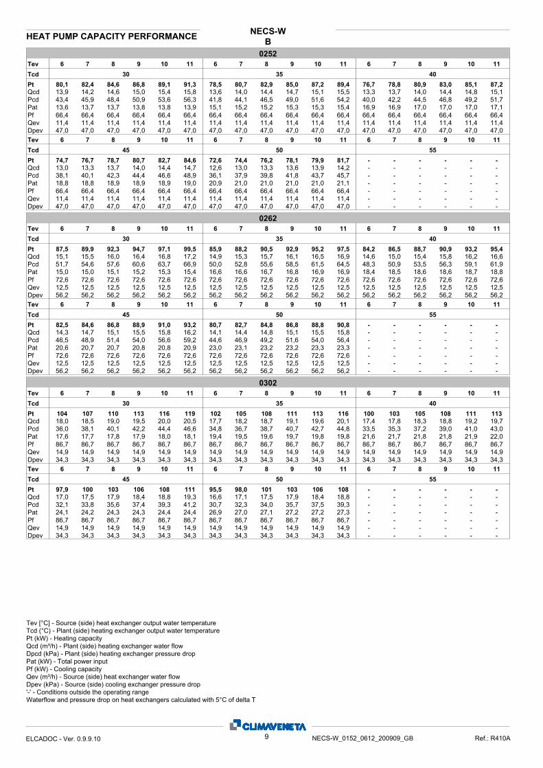
BNECS-W3.3 HEAT PUMP CAPACITY PERFORMANCE
01528 9 10 116 7 8 9 10 116 7 8 9 10 116 7
30 35 40
52,4
8,87
9,0635,3
Tcd
Pt
Pat
QcdPcd
53,9 55,3 56,8 58,2 59,6 51,3 52,8 54,2 55,6 57,0 58,5 50,2 51,6 52,9 54,3 55,7 57,1
8,91 8,95 8,99 9,02 9,06 9,96 10,00 10,0 10,1 10,1 10,1 11,2 11,2 11,3 11,3 11,3 11,4
9,31 9,56 9,81 10,1 10,3 8,89 9,14 9,38 9,63 9,88 10,1 8,70 8,94 9,18 9,42 9,67 9,9137,3 39,3 41,4 43,6 45,8 34,0 35,9 37,9 39,9 42,0 44,1 32,6 34,4 36,3 38,2 40,2 42,2
Tev
DpevQevPf 43,4 43,4 43,4 43,4 43,4 43,4
7,46 7,46 7,46 7,46 7,46 7,4657,8 57,8 57,8 57,8 57,8 57,8
43,4 43,4 43,4 43,4 43,4 43,47,46 7,46 7,46 7,46 7,46 7,4657,8 57,8 57,8 57,8 57,8 57,8
43,4 43,4 43,4 43,4 43,4 43,47,46 7,46 7,46 7,46 7,46 7,4657,8 57,8 57,8 57,8 57,8 57,8
31,1Pcd 32,8 34,5 36,3 38,2 40,1 29,5 31,1 32,7 34,4 36,0 37,7 - - - - - -8,50Qcd 8,73 8,96 9,19 9,42 9,65 8,29 8,51 8,72 8,94 9,15 9,37 - - - - - -
12,6Pat 12,6 12,7 12,7 12,7 12,7 14,2 14,2 14,2 14,2 14,2 14,2 - - - - - -
48,9Pt 50,3 51,6 52,9 54,2 55,6 47,6 48,9 50,1 51,3 52,6 53,8 - - - - - -
45 50 55Tcd
11109876 11109876 11109876Tev
DpevQevPf 43,4 43,4 43,4 43,4 43,4 43,4
7,46 7,46 7,46 7,46 7,46 7,4657,8 57,8 57,8 57,8 57,8 57,8
43,4 43,4 43,4 43,4 43,4 43,47,46 7,46 7,46 7,46 7,46 7,4657,8 57,8 57,8 57,8 57,8 57,8
- - - - - -- - - - - -- - - - - -
01828 9 10 116 7 8 9 10 116 7 8 9 10 116 7
30 35 40
60,5
10,1
10,537,1
Tcd
Pt
Pat
QcdPcd
62,2 63,9 65,6 67,3 69,0 59,1 60,7 62,4 64,0 65,6 67,2 57,8 59,3 60,9 62,5 64,0 65,6
10,1 10,2 10,2 10,3 10,3 11,3 11,3 11,4 11,4 11,5 11,5 12,6 12,6 12,7 12,7 12,8 12,8
10,8 11,0 11,3 11,6 11,9 10,2 10,5 10,8 11,1 11,4 11,6 10,0 10,3 10,6 10,8 11,1 11,439,2 41,3 43,6 45,9 48,2 35,5 37,5 39,5 41,6 43,8 45,9 34,1 35,9 37,8 39,8 41,8 43,8
Tev
DpevQevPf 50,1 50,1 50,1 50,1 50,1 50,1
8,62 8,62 8,62 8,62 8,62 8,6249,4 49,4 49,4 49,4 49,4 49,4
50,1 50,1 50,1 50,1 50,1 50,18,62 8,62 8,62 8,62 8,62 8,6249,4 49,4 49,4 49,4 49,4 49,4
50,1 50,1 50,1 50,1 50,1 50,18,62 8,62 8,62 8,62 8,62 8,6249,4 49,4 49,4 49,4 49,4 49,4
32,6Pcd 34,4 36,2 38,1 40,0 41,9 31,2 32,9 34,6 36,4 38,3 40,2 - - - - - -9,80Qcd 10,1 10,3 10,6 10,9 11,1 9,59 9,85 10,1 10,4 10,6 10,9 - - - - - -
14,0Pat 14,0 14,1 14,1 14,2 14,2 15,5 15,6 15,6 15,7 15,7 15,7 - - - - - -
56,4Pt 57,9 59,5 61,0 62,5 64,0 55,1 56,6 58,0 59,5 61,0 62,5 - - - - - -
45 50 55Tcd
11109876 11109876 11109876Tev
DpevQevPf 50,1 50,1 50,1 50,1 50,1 50,1
8,62 8,62 8,62 8,62 8,62 8,6249,4 49,4 49,4 49,4 49,4 49,4
50,1 50,1 50,1 50,1 50,1 50,18,62 8,62 8,62 8,62 8,62 8,6249,4 49,4 49,4 49,4 49,4 49,4
- - - - - -- - - - - -- - - - - -
02028 9 10 116 7 8 9 10 116 7 8 9 10 116 7
30 35 40
70,7
11,6
12,241,3
Tcd
Pt
Pat
QcdPcd
72,7 74,6 76,5 78,5 80,4 69,3 71,2 73,1 75,0 76,9 78,8 67,7 69,5 71,4 73,2 75,1 77,0
11,6 11,7 11,7 11,8 11,8 13,0 13,0 13,1 13,1 13,2 13,2 14,6 14,6 14,7 14,7 14,7 14,8
12,6 12,9 13,2 13,6 13,9 12,0 12,3 12,7 13,0 13,3 13,6 11,7 12,1 12,4 12,7 13,0 13,343,6 45,9 48,4 50,8 53,4 39,8 42,0 44,2 46,6 49,0 51,4 38,1 40,2 42,3 44,6 46,8 49,2
Tev
DpevQevPf 58,9 58,9 58,9 58,9 58,9 58,9
10,1 10,1 10,1 10,1 10,1 10,149,5 49,5 49,5 49,5 49,5 49,5
58,9 58,9 58,9 58,9 58,9 58,910,1 10,1 10,1 10,1 10,1 10,149,5 49,5 49,5 49,5 49,5 49,5
58,9 58,9 58,9 58,9 58,9 58,910,1 10,1 10,1 10,1 10,1 10,149,5 49,5 49,5 49,5 49,5 49,5
36,2Pcd 38,2 40,3 42,4 44,5 46,7 34,2 36,1 38,0 39,9 42,0 44,1 - - - - - -11,5Qcd 11,8 12,1 12,4 12,7 13,0 11,1 11,4 11,7 12,0 12,3 12,6 - - - - - -
16,4Pat 16,4 16,5 16,5 16,5 16,5 18,4 18,4 18,4 18,5 18,5 18,5 - - - - - -
65,9Pt 67,7 69,5 71,3 73,1 74,9 64,0 65,7 67,4 69,1 70,8 72,6 - - - - - -
45 50 55Tcd
11109876 11109876 11109876Tev
DpevQevPf 58,9 58,9 58,9 58,9 58,9 58,9
10,1 10,1 10,1 10,1 10,1 10,149,5 49,5 49,5 49,5 49,5 49,5
58,9 58,9 58,9 58,9 58,9 58,910,1 10,1 10,1 10,1 10,1 10,149,5 49,5 49,5 49,5 49,5 49,5
- - - - - -- - - - - -- - - - - -
Waterflow and pressure drop on heat exchangers calculated with 5°C of delta T'-' - Conditions outside the operating range
Dpcd (kPa) - Plant (side) heating exchanger pressure dropQcd (m³/h) - Plant (side) heating exchanger water flow
Pat (kW) - Total power input
Pt (kW) - Heating capacityTcd (°C) - Plant (side) heating exchanger output water temperature
Pf (kW) - Cooling capacityQev (m³/h) - Source (side) heat exchanger water flowDpev (kPa) - Source (side) cooling exchanger pressure drop
Tev [°C] - Source (side) heat exchanger output water temperature
8ELCADOC - Ver. 0.9.9.10 NECS-W_0152_0612_200909_GB Ref.: R410A
BNECS-W
HEAT PUMP CAPACITY PERFORMANCE
02528 9 10 116 7 8 9 10 116 7 8 9 10 116 7
30 35 40
80,1
13,6
13,943,4
Tcd
Pt
Pat
QcdPcd
82,4 84,6 86,8 89,1 91,3 78,5 80,7 82,9 85,0 87,2 89,4 76,7 78,8 80,9 83,0 85,1 87,2
13,7 13,7 13,8 13,8 13,9 15,1 15,2 15,2 15,3 15,3 15,4 16,9 16,9 17,0 17,0 17,0 17,1
14,2 14,6 15,0 15,4 15,8 13,6 14,0 14,4 14,7 15,1 15,5 13,3 13,7 14,0 14,4 14,8 15,145,9 48,4 50,9 53,6 56,3 41,8 44,1 46,5 49,0 51,6 54,2 40,0 42,2 44,5 46,8 49,2 51,7
Tev
DpevQevPf 66,4 66,4 66,4 66,4 66,4 66,4
11,4 11,4 11,4 11,4 11,4 11,447,0 47,0 47,0 47,0 47,0 47,0
66,4 66,4 66,4 66,4 66,4 66,411,4 11,4 11,4 11,4 11,4 11,447,0 47,0 47,0 47,0 47,0 47,0
66,4 66,4 66,4 66,4 66,4 66,411,4 11,4 11,4 11,4 11,4 11,447,0 47,0 47,0 47,0 47,0 47,0
38,1Pcd 40,1 42,3 44,4 46,6 48,9 36,1 37,9 39,8 41,8 43,7 45,7 - - - - - -13,0Qcd 13,3 13,7 14,0 14,4 14,7 12,6 13,0 13,3 13,6 13,9 14,2 - - - - - -
18,8Pat 18,8 18,9 18,9 18,9 19,0 20,9 21,0 21,0 21,0 21,0 21,1 - - - - - -
74,7Pt 76,7 78,7 80,7 82,7 84,6 72,6 74,4 76,2 78,1 79,9 81,7 - - - - - -
45 50 55Tcd
11109876 11109876 11109876Tev
DpevQevPf 66,4 66,4 66,4 66,4 66,4 66,4
11,4 11,4 11,4 11,4 11,4 11,447,0 47,0 47,0 47,0 47,0 47,0
66,4 66,4 66,4 66,4 66,4 66,411,4 11,4 11,4 11,4 11,4 11,447,0 47,0 47,0 47,0 47,0 47,0
- - - - - -- - - - - -- - - - - -
02628 9 10 116 7 8 9 10 116 7 8 9 10 116 7
30 35 40
87,5
15,0
15,151,7
Tcd
Pt
Pat
QcdPcd
89,9 92,3 94,7 97,1 99,5 85,9 88,2 90,5 92,9 95,2 97,5 84,2 86,5 88,7 90,9 93,2 95,4
15,0 15,1 15,2 15,3 15,4 16,6 16,6 16,7 16,8 16,9 16,9 18,4 18,5 18,6 18,6 18,7 18,8
15,5 16,0 16,4 16,8 17,2 14,9 15,3 15,7 16,1 16,5 16,9 14,6 15,0 15,4 15,8 16,2 16,654,6 57,6 60,6 63,7 66,9 50,0 52,8 55,6 58,5 61,5 64,5 48,3 50,9 53,5 56,3 59,1 61,9
Tev
DpevQevPf 72,6 72,6 72,6 72,6 72,6 72,6
12,5 12,5 12,5 12,5 12,5 12,556,2 56,2 56,2 56,2 56,2 56,2
72,6 72,6 72,6 72,6 72,6 72,612,5 12,5 12,5 12,5 12,5 12,556,2 56,2 56,2 56,2 56,2 56,2
72,6 72,6 72,6 72,6 72,6 72,612,5 12,5 12,5 12,5 12,5 12,556,2 56,2 56,2 56,2 56,2 56,2
46,5Pcd 48,9 51,4 54,0 56,6 59,2 44,6 46,9 49,2 51,6 54,0 56,4 - - - - - -14,3Qcd 14,7 15,1 15,5 15,8 16,2 14,1 14,4 14,8 15,1 15,5 15,8 - - - - - -
20,6Pat 20,7 20,7 20,8 20,8 20,9 23,0 23,1 23,2 23,2 23,3 23,3 - - - - - -
82,5Pt 84,6 86,8 88,9 91,0 93,2 80,7 82,7 84,8 86,8 88,8 90,8 - - - - - -
45 50 55Tcd
11109876 11109876 11109876Tev
DpevQevPf 72,6 72,6 72,6 72,6 72,6 72,6
12,5 12,5 12,5 12,5 12,5 12,556,2 56,2 56,2 56,2 56,2 56,2
72,6 72,6 72,6 72,6 72,6 72,612,5 12,5 12,5 12,5 12,5 12,556,2 56,2 56,2 56,2 56,2 56,2
- - - - - -- - - - - -- - - - - -
03028 9 10 116 7 8 9 10 116 7 8 9 10 116 7
30 35 40
104
17,6
18,036,0
Tcd
Pt
Pat
QcdPcd
107 110 113 116 119 102 105 108 111 113 116 100 103 105 108 111 113
17,7 17,8 17,9 18,0 18,1 19,4 19,5 19,6 19,7 19,8 19,8 21,6 21,7 21,8 21,8 21,9 22,0
18,5 19,0 19,5 20,0 20,5 17,7 18,2 18,7 19,1 19,6 20,1 17,4 17,8 18,3 18,8 19,2 19,738,1 40,1 42,2 44,4 46,6 34,8 36,7 38,7 40,7 42,7 44,8 33,5 35,3 37,2 39,0 41,0 43,0
Tev
DpevQevPf 86,7 86,7 86,7 86,7 86,7 86,7
14,9 14,9 14,9 14,9 14,9 14,934,3 34,3 34,3 34,3 34,3 34,3
86,7 86,7 86,7 86,7 86,7 86,714,9 14,9 14,9 14,9 14,9 14,934,3 34,3 34,3 34,3 34,3 34,3
86,7 86,7 86,7 86,7 86,7 86,714,9 14,9 14,9 14,9 14,9 14,934,3 34,3 34,3 34,3 34,3 34,3
32,1Pcd 33,8 35,6 37,4 39,3 41,2 30,7 32,3 34,0 35,7 37,5 39,3 - - - - - -17,0Qcd 17,5 17,9 18,4 18,8 19,3 16,6 17,1 17,5 17,9 18,4 18,8 - - - - - -
24,1Pat 24,2 24,3 24,3 24,4 24,4 26,9 27,0 27,1 27,2 27,2 27,3 - - - - - -
97,9Pt 100 103 106 108 111 95,5 98,0 101 103 106 108 - - - - - -
45 50 55Tcd
11109876 11109876 11109876Tev
DpevQevPf 86,7 86,7 86,7 86,7 86,7 86,7
14,9 14,9 14,9 14,9 14,9 14,934,3 34,3 34,3 34,3 34,3 34,3
86,7 86,7 86,7 86,7 86,7 86,714,9 14,9 14,9 14,9 14,9 14,934,3 34,3 34,3 34,3 34,3 34,3
- - - - - -- - - - - -- - - - - -
Waterflow and pressure drop on heat exchangers calculated with 5°C of delta T'-' - Conditions outside the operating range
Dpcd (kPa) - Plant (side) heating exchanger pressure dropQcd (m³/h) - Plant (side) heating exchanger water flow
Pat (kW) - Total power input
Pt (kW) - Heating capacityTcd (°C) - Plant (side) heating exchanger output water temperature
Pf (kW) - Cooling capacityQev (m³/h) - Source (side) heat exchanger water flowDpev (kPa) - Source (side) cooling exchanger pressure drop
Tev [°C] - Source (side) heat exchanger output water temperature
9ELCADOC - Ver. 0.9.9.10 NECS-W_0152_0612_200909_GB Ref.: R410A

BNECS-W
HEAT PUMP CAPACITY PERFORMANCE
03528 9 10 116 7 8 9 10 116 7 8 9 10 116 7
30 35 40
122
20,5
21,135,7
Tcd
Pt
Pat
QcdPcd
126 129 133 136 140 119 123 126 129 133 136 116 119 123 126 129 132
20,6 20,7 20,9 21,0 21,1 22,5 22,7 22,8 22,9 23,0 23,1 24,9 25,1 25,2 25,3 25,4 25,5
21,7 22,3 22,9 23,5 24,1 20,6 21,2 21,8 22,4 23,0 23,5 20,2 20,7 21,3 21,8 22,4 23,037,7 39,8 42,0 44,3 46,6 34,1 36,0 38,0 40,1 42,2 44,3 32,5 34,4 36,3 38,2 40,2 42,2
Tev
DpevQevPf 101 101 101 101 101 101
17,4 17,4 17,4 17,4 17,4 17,432,8 32,8 32,8 32,8 32,8 32,8
101 101 101 101 101 10117,4 17,4 17,4 17,4 17,4 17,432,8 32,8 32,8 32,8 32,8 32,8
101 101 101 101 101 10117,4 17,4 17,4 17,4 17,4 17,432,8 32,8 32,8 32,8 32,8 32,8
31,0Pcd 32,7 34,5 36,3 38,2 40,2 29,5 31,1 32,8 34,6 36,4 38,2 - - - - - -19,7Qcd 20,2 20,8 21,3 21,9 22,4 19,2 19,7 20,3 20,8 21,3 21,9 - - - - - -
27,7Pat 27,8 28,0 28,1 28,2 28,3 30,8 31,0 31,1 31,2 31,3 31,4 - - - - - -
113Pt 116 120 123 126 129 110 113 116 119 122 126 - - - - - -
45 50 55Tcd
11109876 11109876 11109876Tev
DpevQevPf 101 101 101 101 101 101
17,4 17,4 17,4 17,4 17,4 17,432,8 32,8 32,8 32,8 32,8 32,8
101 101 101 101 101 10117,4 17,4 17,4 17,4 17,4 17,432,8 32,8 32,8 32,8 32,8 32,8
- - - - - -- - - - - -- - - - - -
04128 9 10 116 7 8 9 10 116 7 8 9 10 116 7
30 35 40
139
23,5
24,035,8
Tcd
Pt
Pat
QcdPcd
143 147 151 155 159 135 139 143 147 151 155 131 135 139 143 146 150
23,6 23,8 23,9 24,0 24,2 25,8 25,9 26,1 26,2 26,3 26,5 28,4 28,6 28,7 28,9 29,0 29,1
24,7 25,4 26,1 26,8 27,5 23,4 24,1 24,8 25,4 26,1 26,8 22,8 23,5 24,1 24,8 25,4 26,137,9 40,1 42,3 44,6 46,9 34,0 36,0 38,0 40,1 42,2 44,5 32,3 34,1 36,0 38,0 40,0 42,1
Tev
DpevQevPf 115 115 115 115 115 115
19,7 19,7 19,7 19,7 19,7 19,742,1 42,1 42,1 42,1 42,1 42,1
115 115 115 115 115 11519,7 19,7 19,7 19,7 19,7 19,742,1 42,1 42,1 42,1 42,1 42,1
115 115 115 115 115 11519,7 19,7 19,7 19,7 19,7 19,742,1 42,1 42,1 42,1 42,1 42,1
30,6Pcd 32,4 34,2 36,0 37,9 39,9 29,0 30,7 32,4 34,2 36,0 37,9 - - - - - -22,2Qcd 22,8 23,5 24,1 24,7 25,4 21,6 22,2 22,9 23,5 24,1 24,7 - - - - - -
31,4Pat 31,6 31,8 31,9 32,1 32,2 34,9 35,0 35,2 35,4 35,5 35,7 - - - - - -
128Pt 131 135 139 142 146 124 128 131 135 138 142 - - - - - -
45 50 55Tcd
11109876 11109876 11109876Tev
DpevQevPf 115 115 115 115 115 115
19,7 19,7 19,7 19,7 19,7 19,742,1 42,1 42,1 42,1 42,1 42,1
115 115 115 115 115 11519,7 19,7 19,7 19,7 19,7 19,742,1 42,1 42,1 42,1 42,1 42,1
- - - - - -- - - - - -- - - - - -
04528 9 10 116 7 8 9 10 116 7 8 9 10 116 7
30 35 40
155
26,2
26,936,1
Tcd
Pt
Pat
QcdPcd
160 164 169 173 178 152 156 160 164 169 173 148 152 156 160 164 168
26,4 26,5 26,7 26,8 26,9 28,8 28,9 29,1 29,2 29,4 29,5 31,7 31,9 32,1 32,2 32,4 32,5
27,6 28,4 29,2 30,0 30,7 26,2 27,0 27,7 28,5 29,2 30,0 25,6 26,3 27,0 27,8 28,5 29,238,2 40,4 42,6 44,9 47,2 34,5 36,4 38,5 40,5 42,7 44,9 32,8 34,7 36,6 38,5 40,6 42,6
Tev
DpevQevPf 129 129 129 129 129 129
22,1 22,1 22,1 22,1 22,1 22,139,7 39,7 39,7 39,7 39,7 39,7
129 129 129 129 129 12922,1 22,1 22,1 22,1 22,1 22,139,7 39,7 39,7 39,7 39,7 39,7
129 129 129 129 129 12922,1 22,1 22,1 22,1 22,1 22,139,7 39,7 39,7 39,7 39,7 39,7
31,2Pcd 32,9 34,7 36,5 38,4 40,4 29,6 31,2 32,8 34,6 36,3 38,1 - - - - - -25,0Qcd 25,7 26,3 27,0 27,7 28,4 24,3 25,0 25,6 26,3 27,0 27,6 - - - - - -
35,1Pat 35,3 35,5 35,6 35,7 35,9 38,9 39,1 39,2 39,4 39,5 39,6 - - - - - -
144Pt 148 152 156 160 164 140 143 147 151 155 159 - - - - - -
45 50 55Tcd
11109876 11109876 11109876Tev
DpevQevPf 129 129 129 129 129 129
22,1 22,1 22,1 22,1 22,1 22,139,7 39,7 39,7 39,7 39,7 39,7
129 129 129 129 129 12922,1 22,1 22,1 22,1 22,1 22,139,7 39,7 39,7 39,7 39,7 39,7
- - - - - -- - - - - -- - - - - -
Waterflow and pressure drop on heat exchangers calculated with 5°C of delta T'-' - Conditions outside the operating range
Dpcd (kPa) - Plant (side) heating exchanger pressure dropQcd (m³/h) - Plant (side) heating exchanger water flow
Pat (kW) - Total power input
Pt (kW) - Heating capacityTcd (°C) - Plant (side) heating exchanger output water temperature
Pf (kW) - Cooling capacityQev (m³/h) - Source (side) heat exchanger water flowDpev (kPa) - Source (side) cooling exchanger pressure drop
Tev [°C] - Source (side) heat exchanger output water temperature
10ELCADOC - Ver. 0.9.9.10 NECS-W_0152_0612_200909_GB Ref.: R410A

BNECS-W
HEAT PUMP CAPACITY PERFORMANCE
05128 9 10 116 7 8 9 10 116 7 8 9 10 116 7
30 35 40
173
29,1
29,933,2
Tcd
Pt
Pat
QcdPcd
178 183 188 193 198 169 174 179 183 188 193 165 169 174 178 183 188
29,3 29,5 29,6 29,8 30,0 32,0 32,2 32,4 32,6 32,7 32,9 35,3 35,5 35,7 35,9 36,0 36,2
30,8 31,6 32,5 33,3 34,2 29,3 30,1 30,9 31,7 32,6 33,4 28,6 29,4 30,2 31,0 31,7 32,535,1 37,0 39,0 41,1 43,2 31,7 33,5 35,4 37,3 39,2 41,3 30,2 31,9 33,7 35,5 37,3 39,2
Tev
DpevQevPf 144 144 144 144 144 144
24,7 24,7 24,7 24,7 24,7 24,738,5 38,5 38,5 38,5 38,5 38,5
144 144 144 144 144 14424,7 24,7 24,7 24,7 24,7 24,738,5 38,5 38,5 38,5 38,5 38,5
144 144 144 144 144 14424,7 24,7 24,7 24,7 24,7 24,738,5 38,5 38,5 38,5 38,5 38,5
28,8Pcd 30,3 31,9 33,6 35,3 37,0 27,2 28,7 30,1 31,7 33,2 34,8 - - - - - -27,9Qcd 28,6 29,4 30,1 30,9 31,6 27,1 27,8 28,5 29,3 30,0 30,7 - - - - - -
39,0Pat 39,2 39,4 39,5 39,7 39,8 43,1 43,3 43,5 43,6 43,8 43,9 - - - - - -
160Pt 165 169 173 178 182 156 160 164 168 172 176 - - - - - -
45 50 55Tcd
11109876 11109876 11109876Tev
DpevQevPf 144 144 144 144 144 144
24,7 24,7 24,7 24,7 24,7 24,738,5 38,5 38,5 38,5 38,5 38,5
144 144 144 144 144 14424,7 24,7 24,7 24,7 24,7 24,738,5 38,5 38,5 38,5 38,5 38,5
- - - - - -- - - - - -- - - - - -
05528 9 10 116 7 8 9 10 116 7 8 9 10 116 7
30 35 40
199
33,4
34,435,5
Tcd
Pt
Pat
QcdPcd
205 210 216 222 227 194 200 205 211 216 222 189 194 200 205 210 216
33,6 33,8 34,0 34,2 34,3 36,7 36,9 37,1 37,3 37,5 37,7 40,5 40,7 40,9 41,1 41,3 41,5
35,4 36,4 37,3 38,3 39,3 33,6 34,6 35,5 36,5 37,4 38,4 32,8 33,7 34,7 35,6 36,5 37,437,5 39,6 41,8 44,1 46,4 33,9 35,8 37,8 39,9 42,0 44,2 32,3 34,2 36,0 37,9 39,9 42,0
Tev
DpevQevPf 165 165 165 165 165 165
28,4 28,4 28,4 28,4 28,4 28,434,6 34,6 34,6 34,6 34,6 34,6
165 165 165 165 165 16528,4 28,4 28,4 28,4 28,4 28,434,6 34,6 34,6 34,6 34,6 34,6
165 165 165 165 165 16528,4 28,4 28,4 28,4 28,4 28,434,6 34,6 34,6 34,6 34,6 34,6
30,7Pcd 32,4 34,2 36,0 37,8 39,7 29,2 30,7 32,3 34,0 35,6 37,4 - - - - - -32,0Qcd 32,9 33,8 34,6 35,5 36,4 31,2 32,0 32,8 33,6 34,5 35,3 - - - - - -
44,8Pat 45,0 45,2 45,4 45,6 45,8 49,5 49,7 49,9 50,1 50,3 50,5 - - - - - -
184Pt 189 194 199 204 209 179 184 189 193 198 203 - - - - - -
45 50 55Tcd
11109876 11109876 11109876Tev
DpevQevPf 165 165 165 165 165 165
28,4 28,4 28,4 28,4 28,4 28,434,6 34,6 34,6 34,6 34,6 34,6
165 165 165 165 165 16528,4 28,4 28,4 28,4 28,4 28,434,6 34,6 34,6 34,6 34,6 34,6
- - - - - -- - - - - -- - - - - -
06128 9 10 116 7 8 9 10 116 7 8 9 10 116 7
30 35 40
225
37,6
38,837,7
Tcd
Pt
Pat
QcdPcd
231 237 244 250 257 219 225 232 238 244 250 214 220 226 232 238 244
37,9 38,1 38,3 38,5 38,7 41,4 41,6 41,9 42,1 42,3 42,5 45,7 45,9 46,2 46,4 46,6 46,8
40,0 41,1 42,2 43,3 44,4 38,0 39,0 40,1 41,2 42,3 43,4 37,1 38,1 39,1 40,2 41,2 42,339,9 42,2 44,5 46,9 49,4 36,0 38,1 40,2 42,4 44,7 47,0 34,4 36,3 38,3 40,3 42,5 44,6
Tev
DpevQevPf 186 186 186 186 186 186
32,1 32,1 32,1 32,1 32,1 32,144,2 44,2 44,2 44,2 44,2 44,2
186 186 186 186 186 18632,1 32,1 32,1 32,1 32,1 32,144,2 44,2 44,2 44,2 44,2 44,2
186 186 186 186 186 18632,1 32,1 32,1 32,1 32,1 32,144,2 44,2 44,2 44,2 44,2 44,2
32,7Pcd 34,5 36,3 38,3 40,2 42,3 31,0 32,7 34,4 36,2 38,0 39,9 - - - - - -36,2Qcd 37,1 38,1 39,1 40,1 41,1 35,2 36,2 37,1 38,0 39,0 39,9 - - - - - -
50,5Pat 50,8 51,0 51,2 51,4 51,7 55,9 56,1 56,4 56,6 56,8 57,0 - - - - - -
208Pt 214 219 225 231 237 202 208 213 218 224 229 - - - - - -
45 50 55Tcd
11109876 11109876 11109876Tev
DpevQevPf 186 186 186 186 186 186
32,1 32,1 32,1 32,1 32,1 32,144,2 44,2 44,2 44,2 44,2 44,2
186 186 186 186 186 18632,1 32,1 32,1 32,1 32,1 32,144,2 44,2 44,2 44,2 44,2 44,2
- - - - - -- - - - - -- - - - - -
Waterflow and pressure drop on heat exchangers calculated with 5°C of delta T'-' - Conditions outside the operating range
Dpcd (kPa) - Plant (side) heating exchanger pressure dropQcd (m³/h) - Plant (side) heating exchanger water flow
Pat (kW) - Total power input
Pt (kW) - Heating capacityTcd (°C) - Plant (side) heating exchanger output water temperature
Pf (kW) - Cooling capacityQev (m³/h) - Source (side) heat exchanger water flowDpev (kPa) - Source (side) cooling exchanger pressure drop
Tev [°C] - Source (side) heat exchanger output water temperature
11ELCADOC - Ver. 0.9.9.10 NECS-W_0152_0612_200909_GB Ref.: R410A

4. OPERATING RANGE
NECS-W NECS-W
Evaporator Condenser
min max min max
Exch. water (in) (°C) 8 (1) 23 (1) 10 (2) 51 (2)
Exch. water (out) (°C) 5 (1) (3) 15 (1) 26 (2) 55 (2)
Thermal difference (°C) 3 8 4 16
(1) Condenser water temp. 30/35 °C(2) Evaporator water (in/out) 12/7 °C(3) With temperatures down to -8°C use anti-freeze mixtures. In case oflower temperatures, please contact our Sales Department.
ETHYLENE GLYCOL MIXTURE
Ethylene glycol and water mixtures, used as a heat-conveying fluid, cause a variation in unit performance. For correct data, use the factors indicated in the following table.
Freezing point (°C)
0 -5 -10 -15 -20 -25 -30 -35
Ethylene glycol percentage by weight
0 12% 20% 30% 35% 40% 45% 50%
cPf 1 0,985 0,98 0,974 0,97 0,965 0,964 0,96
cQ 1 1,02 1,04 1,075 1,11 1,14 1,17 1,2
cdp 1 1,07 1,11 1,18 1,22 1,24 1,27 1,3
cPf: cooling capacity correction factorcQ: flow correction factorcdp: pressure drop correction factor
For data concerning other kind of anti-freeze solutions (e.g. propyleneglycol) please contact our Sales Department.
Fouling factorsEvaporator Heat recovery Desuperheater
f1 fk1 fx1 f2 fk2 fx2 f3 fk3 fx3
(m2°C/W) 4,4 x 10⁻⁵ 1 1 1 - - - - - -
(m2 °C/W) 0,86 x 10⁻⁴ 0,96 0,99 0,99 - - - - - -
(m2 °C/W) 1,72 x 10⁻⁴ 0,93 0,98 0,98 - - - - - -
FOULING FACTORS
Performances are based on clean condition of tubes (fouling factor =1). For different fouling values, performance should be adjusted using the correction factors shown in the following table.
f1 - f2 - f3: capacity correction factorsfk1 - fk2 - fk3: compressor power input correction factorsfx1 - fx2 - fx3: total power input correction factors
Limits to exchanger water temperature are valid within the minimum -maximum water flow range indicated in the Hydraulic Data section.
12 NECS-W_0152_0612_200907_GB
NECS - W
HFC R410A
5. HYDRAULIC DATA
SIZEEvaporator Condenser Desuperheater
K Q min m3/h
Q max m3/h
W.c. min m3 K Q min
m3/hQ max m3/h K Q min
m3/hQ max m3/h
0152 1037 4.6 12.6 0.4 430 2.7 11.5 -- - -
0182 664 5.3 14.4 0.4 339 3.2 13.2 - - -
0202 481 6.2 16.9 0.5 276 3.7 15.5 - - -
0252 360 7.0 19.1 0.6 226 4.3 17.6 - - -
0262 360 7.7 20.9 0.6 226 4.7 19.2 - - -
0302 154 9.2 24.9 0.8 111 5.6 22.9 - - -
0352 108 10.8 29.1 0.9 80.0 6.5 26.6 - - -
0412 108 12.2 32.9 1.0 62.0 7.4 30.2 - - -
0452 81.0 13.7 36.9 1.1 50.0 8.3 33.9 - - -
0512 63.0 15.3 41.3 1.2 37.0 9.3 37.7 - - -
0552 43.0 17.7 47.4 1.4 30.0 10.7 43.4 - - -
0612 43.0 20.0 53.6 1.6 25.0 12.1 48.9 - - -
Water flow in the heat exchangers is given by:Q=Px0,86/Dt
Q: water flow (m3/h)Dt: difference between inlet and outlet water temp. (°C)P: heat exchanger capacity (kW)
Pressure drop is given by:Dp= K x Q2/1000
Q: water flow (m3/h)Dp: pressure drop (kPa)K: unit size ratio
Q min: minimum water flow admitted to the heat exchanger.Q max: maximum water flow admitted to the heat exchanger.C.a. min: minimum water content admitted in the plant using
traditional control logic.
5.1 Water flow and pressure drop
13 NECS-W_0152_0612_200907_GB
NECS - W
HFC R410A

The new NECS-W units can be equipped with evaporator and /
or condenser hydronic kits. The kit incorporates the main hydrau-
lic components thus optimizing hydraulic and electrical installa-
tion space, time and costs.
Moreover NECS-W can be provided with INVERTER pumps on
the condenser side. This device enables the condensing pres-
sure control, through the variable speed pump, reducing pump
energy consumption.
Available confi gurations
Evaporator and / or condenser hydronic kit can be provided
with following confi gurations:
Hydronic group 1 pump low head
Hydronic group 2 pumps low head
Hydronic group 1 pump high head
Hydronic group 2 pumps high head
Units can be equipped with up to 4 pumps, two on the evapora-
tor and two on the condenser side.
2-pole pump
Low head pump with 100 kPa external static pressure.
High head pump with 200 kPa external static pressure.
Horizontal one-piece centrifuge pump with one impeller, axial
suction and radial delivery, AISI 304L stainless steel pump body
impeller. The section of shaft in contact with the liquid is made
from stainless steel. Mechanical seal made from components
in ceramics/carbon/NBR/AISI304. Three-phase electric motor
protected to IP55, insulation class F, suitable for continuous
service.
Second pump
A second stand-by pump for high or low pressures is available
on request. The pumps are automatically exchanged on the
basis of a rotation programme and the stand-by pump cuts in
automatically if the primary pump fails. The two-pump hydron-
ic assembly is also fi tted with check valves to ensure the unit
works correctly.
Water-side mechanical fi lter (optional)
Y-fi lter designed and built to capture the impurities in the hy-
draulic circuit. It is fi tted with a 0.9 mm stainless steel mesh car-
tridge which can be replaced without removing the valve body
from the piping.
Sideward/Upward external water connections
2 compressors NECS-W units with hydronic kit installed on-
board are available with both side and up external water con-
nections. Standard units with external side water connections,
up-wards type is made to order.
Up-wards water connections type is suitable for technical
rooms with room-top water piping; reduced installation spaces
and saving costs will be obtained.
6. HYDRONIC GROUPS
14 NECS-W_0152_0612_200907_GB
NECS-W
HFC R410A

Confi guration of hydronic unit with 1 pump per circuit
The hydronic group comprises:
- P Horizontal one-piece centrifuge pump
- MA Hydraulic circuit pressure gauge
- SC Discharge valve
- S1 Exchanger input water temperature probe
- S2 Exchanger outlet water temperature probe
- SF Air vent
- VA 3 bar safety valve
- VE one 8 litre expansion tank pre-pressurised to 1.5 bar
Confi guration of hydronic unit with 2 pumps per circuit
The hydronic group comprises:
- P Horizontal one-piece centrifuge pump
- MA Hydraulic circuit pressure gauge
- SC Discharge valve
- S1 Exchanger input water temperature probe
- S2 Exchanger outlet water temperature probe
- SF Air vent
- VA 3 bar safety valve
- VE 8-litre expansion tanks, pre-pressurized to 1,5 bar
- VR Check valve (only if P2 is fi tted)
The electrical panel of the unit is protected with Automatic
circuit breakers.
The supply does not include the following accessories though
these are recommended to ensure correct system operation:
- Pressure gauges upline and downline from the unit
- Flexible joints on piping
- On-off valves
- Outlet control thermometer
- Flow switch
15 NECS-W_0152_0612_200907_GB
NECS-W
HFC R410A

Solutions Draw / Well Dry-Cooler Geothermal probe
Pressostatic valve X --- ---
2-way valve X --- ---
3-way valve --- X X
Inverter --- X X
Condensing pressure control
NECS-W2-way valve modulating 3-way valve modulating Pressostatic valve
Dp max kvs K Dp max kvas K K
0152 800 6.3 2520 300 19 277 5500
0182 800 6.3 2520 300 19 277 5500
0202 800 6.3 2520 300 19 277 5500
0252 800 6.3 2520 300 31 104 5500
0262 800 6.3 2520 300 31 104 5500
0302 800 10 1000 300 31 104 ---
0352 800 10 1000 300 31 104 ---
0412 800 10 1000 300 49 42 ---
0452 800 16 390 300 49 42 ---
0512 800 16 390 300 49 42 ---
0552 800 16 390 300 49 42 ---
0612 800 16 390 300 49 16 ---
K = Coeffi cients for calculating pressure drops
NECS-W electronic control can manage the best suitable con-
densing pressure control device for every application:
pressostatic valve, 2 or 3 way modulating valve and inverter on
the condenser pumps.
Table applicable only to valves and inverters supplied by
Climaveneta.
16 NECS-W_0152_0612_200907_GB
NECS-W
HFC R410A

Low head High head
SizePf (1)
[kW]
Q (1)
[m3/h]Pump ref.
F.L.I.
[kW]
F.L.A.
[A]
Hp
[kPa]Pump ref.
F.L.I.
[kW]
F.L.A.
[A]
Hp
[kPa]
0152 43.4 7.5 A 1.1 2.5 183 E 3.0 5.6 252
0182 50.1 8.6 A 1.1 2.5 179 E 3.0 5.6 251
0202 58.9 10.1 A 1.1 2.5 173 E 3.0 5.6 249
0252 66.4 11.4 A 1.1 2.5 167 E 3.0 5.6 247
0262 72.6 12.5 A 1.1 2.5 162 E 3.0 5.6 245
0302 86.7 14.9 A 1.1 2.5 148 D 2.5 5.0 237
0352 101.2 17.4 B 1.5 3.2 168 D 2.5 5.0 232
0412 114.7 19.7 B 1.5 3.2 154 F 3.0 6.0 287
0452 128.6 22.1 C 2.2 4.8 199 F 3.0 6.0 279
0512 143.5 24.7 C 2.2 4.8 191 F 3.0 6.0 269
0552 164.9 28.4 C 2.2 4.8 179 F 3.0 6.0 252
0612 186.3 32.0 D 2.2 5.0 174 G 4.0 8.1 304
Size
Low head High head
1 Pump 2 Pumps 1 Pump 2 Pumps
KP1Dpu
[kPa]
Hu
[kPa]KP2
Dpu
[kPa]
Hu
[kPa]KP1
Dpu
[kPa]
Hu
[kPa]KP2
Dpu
[kPa]
Hu
[kPa]KFI
0152 1105 62 121 1145 64 119 1105 62 190 1145 64 188 130
0182 730 54 125 768 57 122 730 54 197 768 57 194 130
0202 551 56 117 587 60 113 551 56 193 587 60 189 130
0252 429 56 111 465 60 107 429 56 191 465 60 187 130
0262 428 67 95 464 73 90 428 67 178 464 73 173 130
0302 174 39 109 198 44 104 170 38 199 180 40 197 47.9
0352 127 38 130 151 46 122 124 38 194 133 40 192 47.9
0412 127 49 105 150 58 96 123 48 239 133 52 235 47.9
0452 99 48 151 122 60 139 96 47 232 106 52 227 47.9
0512 81 49 142 104 63 128 77 47 222 87 53 216 47.9
0552 61 49 130 67 54 125 58 47 205 67 54 198 23.7
0612 57 58 116 67 69 105 57 58 246 67 69 235 23.7
(1) Values refer to rated operating conditions
Pf Cooling capacity of unit
Q Flow of water to evaporator
F.L.I. Power absorbed by pump
F.L.A. Current absorbed by pump
Hp Head of pump
Dpu Total pressure drop of hydronic group
Hu Working head
Coeffi cients for calculating pressure drops
KP1 Unit with Hydronic group and one pump
KP2 Unit with Hydronic group and two pumps
KFI Mains fi lter (optional)
Evaporator side
Pump characteristics
17 NECS-W_0152_0612_200907_GB
NECS-W
HFC R410A
100
150
200
250
300
350
400
4 6 8 10 12 14 16 18 20 22 24 26 28 30 32 34 36 38 40 42 44 46
Q [m3/h]
H [
kP
a]
A
BC
D
E
G
F

Low head High head
SizePf (1)
[kW]
Q (1)
[m3/h]Pump ref.
F.L.I.
[kW]
F.L.A.
[A]
Hp
[kPa]Pump ref.
F.L.I.
[kW]
F.L.A.
[A]
Hp
[kPa]
0152 52.8 9.1 A 1.1 2.5 177 E 3.0 5.6 250
0182 60.7 10.4 A 1.1 2.5 171 E 3.0 5.6 248
0202 71.1 12.2 A 1.1 2.5 162 E 3.0 5.6 245
0252 80.7 13.9 B 1.5 2.5 186 E 3.0 5.6 242
0262 88.2 15.2 B 1.5 2.5 180 E 3.0 5.6 239
0302 105.0 18.1 B 1.5 2.5 163 F 3.0 6.0 292
0352 122.5 21.1 C 1.5 3.2 145 F 3.0 6.0 282
0412 139.0 23.9 D 2.2 3.2 193 F 3.0 6.0 271
0452 155.8 26.8 D 2.2 4.8 183 F 3.0 6.0 258
0512 173.8 29.9 D 2.2 4.8 172 G 4.0 8.1 312
0552 199.6 34.3 E 3.0 4.8 181 G 4.0 8.1 289
0612 225.4 38.8 F 3.0 5.0 190 G 4.0 8.1 260
Size
Low head High head
1 Pump 2 Pumps 1 Pump 2 Pumps
KP1Dpu
[kPa]
Hu
[kPa]KP2
Dpu
[kPa]
Hu
[kPa]KP1
Dpu
[kPa]
Hu
[kPa]KP2
Dpu
[kPa]
Hu
[kPa]KFI
0152 507 43 134 544 46 131 507 43 207 544 46 204 130
0182 414 47 124 451 51 120 414 47 201 451 51 197 130
0202 354 54 108 390 60 102 354 54 191 390 60 185 130
0252 302 59 127 337 66 120 302 59 183 337 66 176 130
0262 300 70 110 335 78 102 300 70 169 335 78 161 130
0302 131 44 119 155 52 111 127 43 249 138 46 246 47.9
0352 100 45 100 123 56 89 96 44 238 106 48 234 47.9
0412 81 47 146 104 61 132 78 46 225 87 51 220 47.9
0452 69 51 132 92 68 115 65 48 210 75 55 203 47.9
0512 55 50 122 78 71 101 52 47 265 62 57 255 47.9
0552 48 58 123 71 85 96 45 54 235 54 65 224 23.7
0612 40 61 129 49 75 115 40 61 199 49 75 185 23.7
Condenser side
Pump characteristics
(1) Values refer to rated operating conditions
Pf Heating capacity of unit
Q Flow of water to condensator
F.L.I. Power absorbed by pump
F.L.A. Current absorbed by pump
Hp Head of pump
Dpu Total pressure drop of hydronic group
Hu Working head
Coeffi cients for calculating pressure drops
KP1 Unit with Hydronic group and one pump
KP2 Unit with Hydronic group and two pumps
KFI Mains fi lter (optional)
100
150
200
250
300
350
400
4 6 8 10 12 14 16 18 20 22 24 26 28 30 32 34 36 38 40 42 44 46
Q [m3/h]
H [
kP
a]
A
B
CD
E
G
F
18 NECS-W_0152_0612_200907_GB
NECS-W
HFC R410A

7. ELECTRICAL DATA
Maximum values
Size nCompressor Total unit (1)
F.L.I. [kW]
F.L.A. [A]
L.R.A. [A]
F.L.I. [kW]
F.L.A. [A]
S.A.[A]
0152 2 2x9 2x15.3 95 18 30.6 110
0182 2 2x10.1 2x16.4 111 20.2 32.8 127
0202 2 2x11.8 2x20.4 118 23.6 40.8 138
0252 2 2x13.2 2x22.6 118 26.4 45.2 141
0262 2 2x14.4 2x25.5 140 28.8 51 166
0302 2 2x16.9 2x27.9 198 33.8 55.8 226
0352 2 1x16.9+1x22.3 1x27.9+1x36.1 198/225 39.2 64 253
0412 2 2x22.3 2x36.1 225 44.6 72.2 261
0452 2 1x22.3+1x27.4 1x36.1+1x45.8 225/272 49.7 81.9 308
0512 2 2x27.4 2x45.8 272 54.8 91.6 318
0552 2 1x27.4+1x35.8 1x45.8+1x58.9 272/310 63.2 104.7 356
0612 2 2x35.8 2x58.9 310 71.6 117.8 369
F.L.I. Full load power input at max admissible conditionF.L.A. Full load current at max admissible conditionL.R.A. Locked rotor amperes for single compressorS.A. Starting current
(1) Safety values to be considered when cabling the unit for power supply and line-protections
Power supply: 400/3/50Voltage tolerance: 10%Maximum voltage unbalance: 3%
19 NECS-W_0152_0612_200907_GB
NECS - W
HFC R410A

BNECS-W8. FULL LOAD SOUND LEVEL
SIZE Octave band [Hz]
2000100050025012563 80004000
Total sound
level
Sound power level dB(A)
SOUND POWER
74 72 69 70 70 63 59 53 730152
75 73 70 71 71 64 60 54 740182
75 73 70 71 71 64 60 54 740202
75 73 70 71 71 64 60 54 740252
76 74 71 72 72 65 61 55 750262
76 74 75 74 70 68 64 53 760302
77 75 76 75 71 69 65 54 770352
77 75 76 75 71 69 65 54 770412
78 76 77 76 72 70 66 55 780452
78 76 77 76 72 70 66 55 780512
79 77 78 77 73 71 67 56 790552
79 77 78 77 73 71 67 56 790612
Plant (side) cooling exchanger water (in/out) 12/7 °C
Source (side) heat exchanger water (in/out) 30/35 °C
Sound power on the basis of measurements made in compliance with ISO 9614 and Eurovent 8/1 for Eurovent certified units;
in compliance with ISO 3744 for non-certified units
Such certification refers specifically to the sound Power Level in dB(A). This is therefore the only acoustic data to be considered as binding.
Working conditions
SIZE Octave band [Hz] at 10 m
2000100050025012563 80004000
Total sound
level
Sound pressure level dB(A)
SOUND PRESSURE LEVEL
43 41 38 39 39 32 28 22 420152
44 42 39 40 40 33 29 23 430182
44 42 39 40 40 33 29 23 430202
44 42 39 40 40 33 29 23 430252
45 43 40 41 41 34 30 24 440262
45 43 44 43 39 37 33 22 450302
46 44 45 44 40 38 34 23 460352
46 44 45 44 40 38 34 23 460412
47 45 46 45 41 39 35 24 470452
47 45 46 45 41 39 35 24 470512
48 46 47 46 42 40 36 25 480552
48 46 47 46 42 40 36 25 480612
Plant (side) cooling exchanger water (in/out) 12/7 °C
Source (side) heat exchanger water (in/out) 30/35 °C
Average sound pressure level, at 10 (m.) distance, unit in a free field on a reflective surface; non-binding value obtained
from the sound power level
Working conditions
20ELCADOC - Ver. 0.9.9.10 NECS-W_0152_0612_200909_GB Ref.: R410A

NECS-W
B - HL - HT - LN - SL
A 1 NECS-W_0152_0612_200907_GBELCAdoc 16/04/2008 HFC R410A
9. DIMENSIONAL DRAWINGS
REMARKS:
For installation purposes, please refer to the documentation sent after the purcha-
se-contract.
This technical data should be considered as indicative. CLIMAVENETA may modi-
fy them at any moment.
A
H
B
1 EVAPORATOR WATER INLET
2 EVAPORATOR WATER OUTLET
3 CONDENSER WATER INLET
4 CONDENSER WATER OUTLET
5 POWER INLET
6 MAIN ISOLATOR HANDLE

NECS-W
A2 NECS-W_0152_0612_200907_GB HFC R410A
DIMENSIONAL DRAWINGS
Size
DIMENSIONS AND WEIGHTS CLEARANCE (See following page)NECS
A [mm]
B [mm]
H [mm]
P [kg]
R1[mm]
R2 [mm]
R3 [mm]
0512 1055 649 1255 280 600 600 800
0182 1055 649 1255 295 600 600 800
0202 1055 649 1255 300 600 600 800
0252 1055 649 1255 310 600 600 800
0262 1055 649 1255 315 600 600 800
0302 1222 873 1496 565 600 600 800
0352 1222 873 1496 605 600 600 800
0412 1222 873 1496 635 600 600 800
0452 1222 873 1496 675 600 600 800
0512 1222 873 1496 715 600 600 800
0552 1222 873 1496 765 600 600 800
0612 1222 873 1496 795 600 600 800
Water connectionsEvaporator Condenser
VictaulicRif. 1- 2 Rif. 3 - 41 1/2” 1 1/2”
1 1/2” 1 1/2”
1 1/2” 1 1/2”
1 1/2” 1 1/2”
1 1/2” 1 1/2”
2 1/2” 2 1/2”
2 1/2” 2 1/2”
2 1/2” 2 1/2”
2 1/2” 2 1/2”
2 1/2” 2 1/2”
2 1/2” 2 1/2”
2 1/2” 2 1/2”

NECS-W
A3 NECS-W_0152_0612_200907_GB HFC R410A
10. CLEARANCE - LIFTING - SYMBOLS
LIFTING INSTRUCTIONS:
- Make sure that all the panels are firmly fixed in place before moving the unit- Before lifting it, check the weight on the CE label- Use all, and only, the lifting points provided- Use slings of equal length- Use a spread-bar (not included)- Move the unit carefully and avoid abrupt movements
ATTENZIONE: UTILIZZARE N° 4 FUNI DI SOLLEVAMENTO DI PARI LUNGHEZZA
A
B
R1 R2
R3
NOTE:For installation purposes, please refer to the documentation sent after the purchase contract. These technical data should be considered as indicative.CLIMAVENETA may modify them at any moment.
LIFTING
WARNING: USE 4 LIFTING SLINGS OF EQUAL LENGTH

11. LEGEND OF PIPE CONNECTIONS
UNI ISO 228/1
Pipe threads where pressure-tight joints are not made on the threads - Designation, dimensions and tolerances.
Used terminology: G: Pipe threads where pressure-tight joints are not made on
the threadsA: Close tolerance class for external pipe threads where pres-
sure-tight joints are not made on the threadsB: Wider tolerance class for external pipe threads where pres-
sure-tight joints are not made on the threads
Internal threads: G letter followed by thread mark (only toler-ance class)
External threads: G letter followed by thread mark and by A let-ter for A class external threads or by B letter for B class external threads.
UNI ISO 7/1
Pipe threads where pressure-tight joints are made on the threads - Designation, dimensions and tolerances
Used terminology:Rp: Internal cylindrical threads where pressure-tight joints are
made on the threadsRc: Internal conical threads where pressure-tight joints are
made on the threadsR: External conical threads where pressure-tight joints are
made on the threads
Internal cylindrical threads: R letter followed by P letterInternal conical threads: R letter followed by C letterExternal conical threads: R letter
Designation Description
UNI ISO 7/1 - Rp 1 1/2Internal cylindrical threads where pressure-tight joints are made on the threads, defined by stand-ard UNI ISO 7/1Conventional ø 1 1/2”
UNI ISO 7/1 - Rp 2 1/2Internal cylindrical threads where pressure-tight joints are made on the threads, defined by stand-ard UNI ISO 7/1Conventional ø 2 1/2”
UNI ISO 7/1 - Rp 3Internal cylindrical threads where pressure-tight joints are made on the threads, defined by stand-ard UNI ISO 7/1Conventional ø 3”
UNI ISO 7/1 - R 3External conical threads where pressure-tight joints are made on the threads, defined by standard UNI ISO 7/1Conventional ø 3”
UNI ISO 228/1 - G 4 B
Internal cylindrical threads where pressure-tight joints are not made on the threads, defined by standard UNI ISO 228/1Tolerance class B for external threadConventional ø 4”
DN 80 PN 16 Flange Nominal Diameter: 80 mmNominal Pressure: 16 bar
Notes:
Conventional diameter value [in inches] identifies short thread designation, based upon the relative standard. All relative values are defined by standards.As example, here below some values:
UNI ISO 7/1 UNI ISO 228/1Conventional ø 1” 1”
Pitch 2.309 mm 2.309 mmExternal ø 33.249 mm 33.249 mm
Core ø 30.291 mm 30.291 mm
Thread height 1.479 mm 1.479 mm
A4 NECS-W_0152_0612_200907_GB
NECS-W
HFC R134a

www.climaveneta.com
Climaveneta S.p.A.Via Sarson 57/c
36061 Bassano del Grappa (VI)
Italy
Tel +39 0424 509 500
Fax +39 0424 509 509
www.climaveneta.com
Climaveneta Home System Via Duca d’Aosta 121
31030 Mignagola (TV)
Italy
Tel +39 0422 4131
Fax +39 0422 413659
www.climaveneta.com
Climaveneta France3, Village d’Entreprises
ZA de la Couronne des Prés
Avenue de la Mauldre
78680 Epône
France
Tel +33 (0)1 30 95 19 19
Fax +33 (0)1 30 95 18 18
www.climaveneta.fr
Climaveneta DeutschlandRhenus Platz 2
59439 Holzwickede
Germany
Tel +49 2301 91222-0
Fax +49 2301 91222-99
www.climaveneta.de
Climaveneta
España - Top ClimaLondres 67, 1 4
08036 Barcelona
Spain
Tel +34 934 195 600
Fax +34 934 195 602
www.climaveneta.com
Climaveneta Chat Union
Refrig. Equipment Co Ltd88 Bai Yun Rd, Pudong Xinghuo
New dev. zone 201419 Shanghai
China
Tel 008 621 575 055 66
Fax 008 621 575 057 97
Climaveneta Polska Sp. z o.o.Ul. Sienkiewicza 13A,
05-120 Legionowo,
Poland
Tel +48 22 766 34 55-57
Fax +48 22 784 39 09
www.climaveneta.pl