neenah catalog r12
DESCRIPTION
noTRANSCRIPT
MAIN OFFICES AND PLANTS:2121 BROOKS AVENUE
NEENAH, WI 54956PHONE: (920) 725-7000
TOLL FREE; (800) 558-5075FAX: (920) 729-3661
http://www.NFCO.com
1
REGIONAL SALES OFFICES AND DISTRIBUTION CENTERS
Phoenix AZPhone: (602) 225-9801Fax: (602) 220-0354
Denver (Commerce City) COPhone: (303) 289-7192Fax: (303) 289-7193
Chicago (Carol Stream) ILPhone: (630) 653-5440Fax: (630) 653-0170
Rockford ILPhone: (815) 399-2228Fax: (815) 399-6765
Indianapolis INPhone: (317) 875-7245Fax: (317) 875-8637
Minneapolis-St. Paul (Shakopee) MNPhone: (952) 445-5335Fax: (952) 445-6417
St. Louis (St. Peters) MOPhone: (636) 928-1023Fax: (636) 928-4727
Albany NYPhone: (518) 458-CAST [2278]Fax: (518) 458-2280
Columbus OHPhone: (614) 876-9837Fax: (614) 876-0216
Oklahoma City OKPhone: (405) 942-8118Fax: (405) 942-7057
Pittsburgh (Cuddy) PAPhone: (412) 221-1789Fax: (412) 221-1863
Milwaukee (Waukesha) WIPhone: (262) 544-9900Fax: (262) 544-9964
Manufacturer’s Representatives are located in many principalcities throughout the U.S. Please call for the location nearestyou.
2
TABLE OF CONTENTS
FOR COMPLETE ALPHABETICAL GENERAL INDEX SEE PAGES 331 TO 333.PAGES
GENERAL INFORMATION . . . . . . . . . . . . . . . . . . . . . . . . . . . . . . . . . . . . . . . . . . . . . .3GENERAL SPECIFICATIONS . . . . . . . . . . . . . . . . . . . . . . . . . . . . . . . . . . . . . . . . . . . .4MODERNIZED CASTINGS . . . . . . . . . . . . . . . . . . . . . . . . . . . . . . . . . . . . . . . . . . . . . .5CAUTIONS FOR SPECIFIERS . . . . . . . . . . . . . . . . . . . . . . . . . . . . . . . . . . . . . . . . . . .6NO-PAINT POLICY . . . . . . . . . . . . . . . . . . . . . . . . . . . . . . . . . . . . . . . . . . . . . . . . . . .8NON-ROCKING MANHOLE COVERS . . . . . . . . . . . . . . . . . . . . . . . . . . . . . . . . . . . . .9MANHOLE COVERS . . . . . . . . . . . . . . . . . . . . . . . . . . . . . . . . . . . . . . . . . . . . . . . . . .10-84
Round, Square, Rectangular, Watertight, Double LidSELF-SEALING MANHOLE LID . . . . . . . . . . . . . . . . . . . . . . . . . . . . . . . . . . . . . . . . . .13WATER SERVICE CASTINGS . . . . . . . . . . . . . . . . . . . . . . . . . . . . . . . . . . . . . . . . . . .72-76
Hydrant, Valve, WellWATERTIGHT AND PRESSURE MANHOLE COVERS . . . . . . . . . . . . . . . . . . . . . . . . .77-84
Lamphole and Monument Boxes, ReservoirsADJUSTABLE MANHOLE FRAMES . . . . . . . . . . . . . . . . . . . . . . . . . . . . . . . . . . . . . . .81FLOATING MANHOLES . . . . . . . . . . . . . . . . . . . . . . . . . . . . . . . . . . . . . . . . . . . . . . . .82MANHOLE ADJUSTING RINGS . . . . . . . . . . . . . . . . . . . . . . . . . . . . . . . . . . . . . . . . . .85-86CAST IRON MANHOLE STEPS . . . . . . . . . . . . . . . . . . . . . . . . . . . . . . . . . . . . . . . . . .87-88CATCH BASIN COVERS . . . . . . . . . . . . . . . . . . . . . . . . . . . . . . . . . . . . . . . . . . . . . . .89-107
Round, Square, Beehive, Concave, ConvexCHOOSING THE PROPER INLET GRATE . . . . . . . . . . . . . . . . . . . . . . . . . . . . . . . . . .108STORM WATER MANAGEMENT . . . . . . . . . . . . . . . . . . . . . . . . . . . . . . . . . . . . . . . . .110VANE GRATES . . . . . . . . . . . . . . . . . . . . . . . . . . . . . . . . . . . . . . . . . . . . . . . . . . . . . . .112CATCH BASIN INLETS . . . . . . . . . . . . . . . . . . . . . . . . . . . . . . . . . . . . . . . . . . . . . . . .113-163
Curb Type, Square, RectangularBEHIND THE CURB INLETS . . . . . . . . . . . . . . . . . . . . . . . . . . . . . . . . . . . . . . . . . . . .164-170GUTTER INLETS . . . . . . . . . . . . . . . . . . . . . . . . . . . . . . . . . . . . . . . . . . . . . . . . . . . . .171-191, 214-227
Square, Rectangular, Flat, Concave, ConvexAIRPORT CASTINGS . . . . . . . . . . . . . . . . . . . . . . . . . . . . . . . . . . . . . . . . . . . . . . . . . .192-205INLETS FOR ROLL TYPE AND MOUNTABLE CURB . . . . . . . . . . . . . . . . . . . . . . . . . .206-213SLOTTED VANE DRAIN . . . . . . . . . . . . . . . . . . . . . . . . . . . . . . . . . . . . . . . . . . . . . . . .228CATCH BASIN TRAPS AND HOODS . . . . . . . . . . . . . . . . . . . . . . . . . . . . . . . . . . . . . .229-235MEDIAN HIGH CAPACITY DRAINS . . . . . . . . . . . . . . . . . . . . . . . . . . . . . . . . . . . . . . .236-237
Median Slope, Side Slope, Ditch Check DrainsBRIDGE, SUBWAY AND BUILDING DRAINS . . . . . . . . . . . . . . . . . . . . . . . . . . . . . . . .238-254
Scuppers, UnderdrainsDRAINAGE GRATES . . . . . . . . . . . . . . . . . . . . . . . . . . . . . . . . . . . . . . . . . . . . . . . . . .255-270
Round, Beehive, Square, Rectangular, DitchSIGN BASES . . . . . . . . . . . . . . . . . . . . . . . . . . . . . . . . . . . . . . . . . . . . . . . . . . . . . . . .271BUILDING CASTINGS . . . . . . . . . . . . . . . . . . . . . . . . . . . . . . . . . . . . . . . . . . . . . . . . .272-281
Downspout Shoes, Floor Drains, Floor Grids, Grease Traps, Areaway Grates, Cleanout Doors . . . .TRENCH COVERS . . . . . . . . . . . . . . . . . . . . . . . . . . . . . . . . . . . . . . . . . . . . . . . . . . . .282-287
Solid, Grated, Highway, TransverseVALVES AND GATES . . . . . . . . . . . . . . . . . . . . . . . . . . . . . . . . . . . . . . . . . . . . . . . . . .288-292
Pressure Relief, Flap and Flush, Shear, DrainageMANHOLE COVERS FOR SLAB . . . . . . . . . . . . . . . . . . . . . . . . . . . . . . . . . . . . . . . . .293-314
Coal Hole, Round, Rectangular, Square, Pressure, Grated, Cistern, WatertightELECTRICAL CASTINGS . . . . . . . . . . . . . . . . . . . . . . . . . . . . . . . . . . . . . . . . . . . . . . .315-319, 325
Manholes, Service BoxesSEWAGE DISPOSAL CASTINGS . . . . . . . . . . . . . . . . . . . . . . . . . . . . . . . . . . . . . . . . .320-322
Stop Plank Grooves, SpecialsSUBWAY CASTINGS . . . . . . . . . . . . . . . . . . . . . . . . . . . . . . . . . . . . . . . . . . . . . . . . . .323-324
Ballast Screens, Valve CoversFREE OPEN AREAS OF DRAINAGE GRATES . . . . . . . . . . . . . . . . . . . . . . . . . . . . . . .326-330TREE GRATES . . . . . . . . . . . . . . . . . . . . . . . . . . . . . . . . . . . . . . . . . . . . . . . .See insert in back of catalog
3
GENERAL: Castings shall be manufactured true to pattern; component parts shall fit together in a satisfactory manner.They shall be smooth and well cleaned by shotblasting.
QUALITY: Metal used in the manufacture of Neenah castings shall be ASTM-A-48, Class 35B Gray Iron or ASTM A536Grade 80-55-06 for Ductile Iron unless otherwise specified in your order and/or acknowledged at the time of order.
TOLERANCES: As cast dimensions may vary one-half the maximum shrinkage possessed by the metal or + /- 1/16 inch per foot.
BEARING SURFACES: All circular manhole frames and covers are furnished with machined horizontal bearing surfacesunless otherwise noted within or acknowledged at the time of order. All Square or rectangular units are furnished with ascast bearing surfaces unless otherwise noted within or acknowledged at the time of order.
UNPAINTED CASTINGS: Castings are furnished unpainted. See page 8 for additional information on Neenah’s no paintpolicy.
WEIGHTS: Weights are not shown in this catalog. Overall shape and function, rather than weight, are the majorconsiderations to be used in evaluating castings. Focus on basic dimensions and application when creating your casting specifications and specify Neenah Catalog Number. Current weights are always available from Neenah. (See"Casting Weights" on page 5 for more information.)
SUBMITTALS: Manufacturer’s shop drawings shall be submitted to the engineer for approval prior to manufacture or ship-ping of castings to job site. The engineer shall retain the right to reject castings not conforming to this specification and/orapproved submittal drawings.
Gray Iron - Best for Construction CastingsThe use of gray iron offers many advantages over other materials for construction castings.
Of all the common castable ferrous materials, gray irons exhibit the best corrosion and wear resistance as well as thedesirable quality of high compressive strength. These are valuable qualities for load bearing street hardware.
Strength:
Gray Iron produced by Neenah Foundry is laboratory tested from specimens to verify tensile strengths. Tensile strength is determined through the use of separately cast test bar specimens. Unless otherwise indicated within oracknowledged at the time of order, 35,000 p.s.i. minimum tensile strength iron is furnished. See "Test Bars Disclaimer" onpage 6 for further information.
When to Use Ductile IronDuctile Iron is an ideal material for construction castings when standard gray iron castings do not have the load bearingcapabilities for a particular application.
While having the advantages of Gray Iron, Ductile Iron has greater strength characteristics than structural carbon steelwithout steel’s inherent corrosion characteristics.
Ductile Iron is often used in areas subjected to loads greater than H20 loadings such as:• Industrial facilities with forklift traffic• Container Ports• Airports
Due to the excellent compressive strength of gray iron and the way these qualities relate to iron frames, mating ductile ironlids or grates with gray iron frames is often a cost-effective recommended approach.
There are many factors involved in choosing a grade of ductile iron. When there are unusual loading conditions or locations subjected to extreme heat or cold, please contact our Product Engineering Department for more information.
GENERAL INFORMATION

4
CASTINGS FOR DIFFERENT TRAFFIC CONDITIONS
To assist in selecting castings which meet a general load-bearing requirement, we have classified our castings into threeseparate categories. These are referenced as follows:
• EXTRA HEAVY DUTY: For airports and concentrated loads. These applications require special castings to accommodate wheel loads of 100 p.s.i. or greater. When selecting castings for heavy concentrated loads, advise loading conditions: total wheel load, tire or wheel contact area, and tire pressure. We will be happy to furnish you with information to assist you with your choice.
• HEAVY DUTY: Castings in this category exceed proof loads of 16,000 lbs. Many of the castings in this catalog are suitable for much heavier proof loads.
• LIGHT DUTY: These castings are recommended for sidewalks, terraces, and very light traffic. Specifiers are cautioned that it is possible for a site to be changed to a heavy duty requirement at some future date. If this happens, we strongly recommend that the installation be replaced with heavy duty castings. If in doubt, Neenah recommends specifying heavy duty castings.
LOAD BEARING CAPABILITIESResponsible consulting and public works engineers need to know how castings will perform in the field. For years empirical formulas have been erroneously used to determine loading capacities. Now Neenah offers full scale destructive testing as an accurate method of determining true load bearing capabilities.
FULL SCALE DESTRUCTIVE TESTINGProof load test is the recommended method of providing load performance of casting's service. You will find thistesting procedure explained in Federal Specification A-A 60005* and AASHTO M 306. The elements of the test are essentially these:1) A specified load is applied on a 9" x 9" area.2) The cover, grating or frame will be inspected for cracks or detrimental permanent deformation such as
buckling.3) Any crack or detrimental permanent deformation will cause the castings to be rejected.
Most tests are performed on our 200,000 lb. compression testing machine. Tests can take a casting beyond the A-A 60005* and AASHTO M 306 specification; even to destruction.
AVAILABLE PUBLISHED SPECIFICATIONSThere are several published specifications that are available to assist designers in specifying iron castings. It is the responsibility of the designer to determine if one or all of these specifications are appropriate for a given application. These specifications are referenced as follows:
For Gray iron • A-A 60005*-------------------------------Federal Specification – Frames, covers, gratings, steps, sump
and catch basin, manhole castings• ASTM-A-48------------------------------Standard Specification for Gray Iron Castings• AASHTO-M 105-------------------------Standard Specification for Gray iron Castings• AASHTO-M 306-------------------------Standard Specification for Drainage Structure Castings
For Ductile Iron• ASTM-A-536-----------------------------Standard Specification for Ductile Iron Castings• ASTM-A-897-----------------------------Standard Specification for Austempered Ductile Iron Castings
For Airport Castings• FAA AC: 150/5370-10, item D-751---Manholes, Catch Basins, Inlets and Inspection Holes• FAA AC: 150/5320-6, Appendix 3----Design of Structures for Heavy Aircraft
For Handicapped Compliance• Americans With Disabilities Act (ADA), Sections 4 Accessible Routes and Section 4.5.4 Gratings.
There may be applicable requirements and specifications other than those shown above that need to be consulted beforea designer specifies his requirements.*Replaced RR-F-621E as of May 26, 1998.

5
MODERN CASTINGS FOR TOMORROW’S WORLD
BREAKTHROUGHS IN CASTING CONCEPTS
Neenah makes continual effort to provide customers with the most modern and cost effective castings available.
PERFORMANCE CRITERIAIn times past, limited knowledge of the properties of gray iron caused specifiers to rely on weight as specifying criteriawhen calling for gray iron castings. In reality, the material properties of gray iron allow castings to be lighter in weight andthinner in section while still meeting or exceeding performance expectations. Proof load criteria, rather than casting weights, should be used in specifying construction castings. Various published specifications are available toassist specifiers with choices. See page 4 for a listing of published specifications.
CASTING WEIGHTSThe weights of Neenah Foundry castings are not shown in this catalog. Casting weights, section thicknesses and non-critical dimensions are periodically adjusted in a continued effort to bring our customers the best and most economical products available from our modern production facilities. Due to these occasional changes and adjustments, weights are not shown in this catalog in an effort to avoid confusion. Current weights are always available from Neenah.
Modern Platen LidsNeenah Engineers have known for some time that platen (plate shaped) lids are improved manhole covers which arepound per pound stronger than ribbed lids. Advantages of lighter weight, platen lids include:• Increased load capacity• Increased deflection resulting in increased energy absorption• Decreased weight• Easier to handle
Modern Lighter Weight Frames• Manhole frames have an inherently strong shape. In the past, metal sections had to be thicker
because foundry molding equipment was imprecise. To compensate, generous tolerances were required to ensure minimum section thickness.
• Today’s molding machines are capable of holding tight tolerances, allowing specifiers to reduce weights and section thicknesses. Technology now allows modern construction casting manufacturers to take advantage of the frame’s inherently strong shape.
• Modern frames are significantly reduced in weight and section thickness, without a reduction in relevant performance characteristics.
• Lighter frames are viable because gray iron is stronger in compression than in tension. The lighter frames are still so substantial that, under load testing, gray iron covers will fail well before failure of the frame.
FOR MORE INFORMATION, CALL US TO REQUEST A COPY OF OUR “MODERNIZED CASTINGS BROCHURE”.
6
PEDESTRIAN, BICYCLE AND HANDICAP CONSIDERATIONSNEENAH STRONGLY RECOMMENDS PROJECT DESIGNERS AND OTHER SPECIFIERS CAREFULLY CONSIDER PEDES-TRIAN, BICYCLE AND HANDICAP (ADA) ISSUES WHEN SPECIFYING THE USE OF CONSTRUCTION CASTINGS.DESIGNERS MUST RESPONSIBLY TAKE INTO CONSIDERATION VARIOUS CIRCUMSTANCES INVOLVING EACH SPE-CIFIC APPLICATION THAT MAY NOT OR COULD NOT HAVE BEEN ANTICIPATED BY THE MANUFACTURER.
NOTE: ALSO SEE “CHOOSING THE PROPER INLET GRATE” ON PAGE 108 AND “STORM WATER MANAGEMENTWITH NEENAH GRATES” ON PAGE 110.
AMERICANS WITH DISABILITIES ACT (ADA)PROJECT DESIGNERS AND OTHER SPECIFIERS MUST CAREFULLY CONSIDER AND IMPLEMENT THE REGULATIONSPUT FORTH IN THE AMERICANS WITH DISABILITIES ACT. PARTICULAR ATTENTION SHOULD BE PAID TO GRATINGTYPES AND THEIR LOCATION. NEENAH ADVISES A REVIEW OF THE REQUIREMENTS OF (ADA) WHEN DESIGNING APROJECT.
FASTENING FRAMES AND COVERS TOGETHER (FASTENING DEVICES)THIS NEENAH FOUNDRY CATALOG CONTAINS MANY ITEMS THAT HAVE COVERS FASTENED TO FRAMES USINGBOLTS OR OTHER FASTENING DEVICES. SPECIFIERS AND USERS MUST RECOGNIZE THAT BOLTS AND OTHER FAS-TENING DEVICES MAY HAVE A TENDENCY TO WORK LOOSE OVER A PERIOD OF TIME DUE TO TRAFFIC PATTERNS,VIBRATIONS, TEMPERATURE CYCLES, ETC. AND THAT ROUTINE INSPECTION AND MAINTENANCE SCHEDULESSHOULD BE IMPLEMENTED TO ASSURE THESE FASTENERS REMAIN TIGHT AND FUNCTIONAL. THEY MUST DETER-MINE THE NECESSITY AND FREQUENCY OF THESE INSPECTION AND MAINTENANCE INTERVALS FOR EACH INSTAL-LATION. PROCEDURES SHOULD BE ESTABLISHED TO ASSURE THAT MAINTENANCE CREWS CHECK FASTENINGDEVICES FOR PROPER FUNCTION AND TORQUE BOLTS TO YOUR ESTABLISHED REQUIREMENTS. CREWS MUSTREPAIR OR REPLACE FASTENING DEVICES, STRIPPED BOLTS AND THREADS PROMPTLY. CONSIDER EACH INSTAL-LATION INDIVIDUALLY TO BE SURE TRAFFIC OR USAGE PATTERNS WILL ALLOW THE USE OF FASTENING DEVICES.(SEE SECTION TITLED "GASKETED FRAMES AND COVERS" BELOW.
GASKETED FRAMES AND COVERSTHE NEENAH FOUNDRY CATALOG CONTAINS MANY ITEMS THAT HAVE NEOPRENE OR EPDM GASKETS PLACEDBETWEEN FRAME AND COVER. SPECIFIERS AND AGENCIES MUST RECOGNIZE THAT THESE GASKETS COMPRESSUNDER LOAD AND CAN RELEASE THIS COMPRESSED ENERGY IN THE FORM OF UPWARD MOTION WHENRELEASED RAPIDLY (SUCH AS NORMAL TRAFFIC LOADING). THIS ENERGY RELEASE MAY HAVE A TENDENCY TODISLODGE COVERS OR LOOSEN BOLTS IN BOLTED AND GASKETED UNITS. CONSIDER EACH INSTALLATION INDI-VIDUALLY AND CAREFULLY TO BE SURE TRAFFIC OR USAGE PATTERNS WILL ALLOW THE USE OF GASKETS. (SEESECTION "FASTENING FRAMES AND COVERS TOGETHER (FASTENING DEVICES)" ABOVE.
TEST BARS DISCLAIMERMOST GENERAL IRON CASTING SPECIFICATIONS REQUIRE PRODUCING FOUNDRIES TO MAINTAIN MINIMUM TEN-SILE STRENGTH PROPERTIES. THESE PROPERTIES ARE TO BE MEASURED ON TEST SPECIMENS MACHINED FROMSTANDARDIZED TEST COUPONS POURED FROM THE SAME IRON, BUT SEPARATELY FROM THE CASTINGS. TESTCOUPON DESIGN, DETAILS OF THE MACHINED TENSILE TEST BAR AND TEST CONDITIONS HAVE BEEN DEVELOPEDSUCH AS ASTM A 48 AND AASHTO M 306 TO PROVIDE MEANINGFUL EVALUATIONS OF SOUND, DEFECT-FREEMETAL UNDER STANDARDIZED CONDITIONS. THIS IS ONE OF THE FUNDAMENTAL PRINCIPLES UPON WHICHFOUNDRY OPERATION AND QUALITY PRACTICES ARE BASED.
SIGNIFICANTLY, THESE SPECIFICATIONS EXPLICITLY CAUTION THAT TENSILE PROPERTIES DETERMINED FROMSEPARATELY CAST COUPONS DEMONSTRATE THE POTENTIAL OF THE IRON USED TO MAKE THE CASTING. THEYARE NOT THE ACTUAL PROPERTIES POSSIBLE, LIKELY, OR TO BE EXPECTED IN THE CASTING. THE ACTUAL PROP-ERTIES DEVELOPED IN THE CASTING MAY DIFFER GREATLY FROM THOSE OF SEPARATELY CAST SPECIMENS ANDTHEY ARE, TO THE GREATEST DEGREE, DETERMINED BY FEATURES OF CASTING DESIGN. THIS IS MOSTLYBEYOND THE CONTROL OF THE PRODUCING FOUNDRY.
FOR THOSE PRIVATE CASTING SPECIFICATIONS WHICH REQUIRE TENSILE PROPERTIES TO BE DETERMINED FROMTEST BARS MACHINED FROM CASTINGS OR FROM ATTACHED COUPONS, THE DETAILS OF COMPLIANCE WITHTHESE SPECIFICATIONS AND THE COSTS THEREOF SHALL BE AS SPECIFICALLY AGREED BETWEEN THE PARTIES.ABSENT SUCH AN AGREEMENT, NEENAH FOUNDRY COMPANY DOES NOT WARRANT OR IMPLY THAT TENSILEPROPERTIES CALLED FOR IN A SEPARATELY CAST SPECIMEN WILL BE ACHIEVED AT ANY LOCATION IN THE CAST-ING(S).
CAUTIONS
7
WORKING WITH HEAVY CASTINGS CAN CAUSE INJURYCAST IRON PARTS, SUCH AS THOSE SOLD BY NEENAH FOUNDRY COMPANY, TEND TO BE HEAVY. IN AN EFFORTTO AVOID INJURY, NEENAH RECOMMENDS USERS ALWAYS USE LIFTING DEVICES WHEN HANDLING CASTINGS.PARTICULAR ATTENTION SHOULD BE PAID TO PROTECTING WORKER’S BACKS AND EXTREMITIES. IT IS THEUSER’S RESPONSIBILITY TO DETERMINE WHICH LIFTING DEVICE IS SUITABLE TO EACH SITUATION.
USERS SHOULD NEVER ALLOW ANY PART OF THEIR BODIES TO ENTER THE OPENING AREA OF AN OPEN HATCHCOVER UNLESS THE LID HAS BEEN SECURED IN A FASHION THAT WILL MAKE IT IMPOSSIBLE TO ACCIDENTALLYCLOSE. IT IS THE USER'S RESPONSIBILITY TO BE SURE THE CASTINGS ARE SECURE AND THE SITE IS SAFEBEFORE PROCEEDING.
8
NEENAH’s NO PAINT POLICY
Painting of Neenah construction castings has been discontinued for several reasons.
1. Asphaltic base paint contains volatile organic compounds or VOC’s. VOC’s are those air emissions coming from petroleum refineries, surface coating operations, and organic chemical manufacturing plants, to name a few. These compounds contribute to “air pollution” and are controlled under the authority of the United States Environmental Protection Agency and the Wisconsin Department of Natural Resources. In order to comply with the regulations of these agencies which limit the allowable amount of VOC’s emitted per gallon of paint, Neenah Foundry construction castings will not be painted.
2. Cast iron corrosion can best be described when compared to the corrosion of steel. The physical characteristics that differ between the two, include the greater concentrations of carbon and silicon in cast iron. These elements provide substantial corrosion resistance in gray iron.
Much of the carbon in gray iron occurs in the form of graphite flakes. This graphite is inert in most corrosive environments and provides a protective physical barrier against corrosion of the metal matrix. Technically speaking, it’s called graphitization. However, the graphite layer can mechanically be worn away exposing the iron to further oxidation.
Silicon in gray iron occurs in the metal matrix. When oxidation due to moisture initially occurs, a bright orange oxideresults. This loosely adhering oxide is water soluble and is easily washed or worn away. The presence of silicon in the iron eventually causes a much tighter adhering, insoluble, black oxide-iron silicate scale which inhibits further corrosion.
3. Painting of castings is cosmetic and, in fact, conceals defects which would be visible if the castings were unpainted.
4. The 1997 study, “A Guide To Standardized Highway Drainage Products,” states that painting, welding or plugging of cast iron castings is not allowed. This study was conducted by Task Force No. 13 under the sponsorship of the Joint Committee of the American Association of State Highway and Transportation officials, Associated General Contractors, and the American Road and Transportation Builders Association.
5. Attesting to its long life, cast iron water pipe is still in service today at Versailles, France supplying the famous foun-tains since its installation in 1664!
Neenah Foundry is continually upgrading its manufacturing facilities to provide the customer with a quality product. We also must protect the environment in which we live.
Neenah’s Unpainted Castings Brochure is available on request.
9
Non-Rocking Type Manhole Covers
NO NOISENO EXTRA COST
DOES AWAY WITH LOCKS
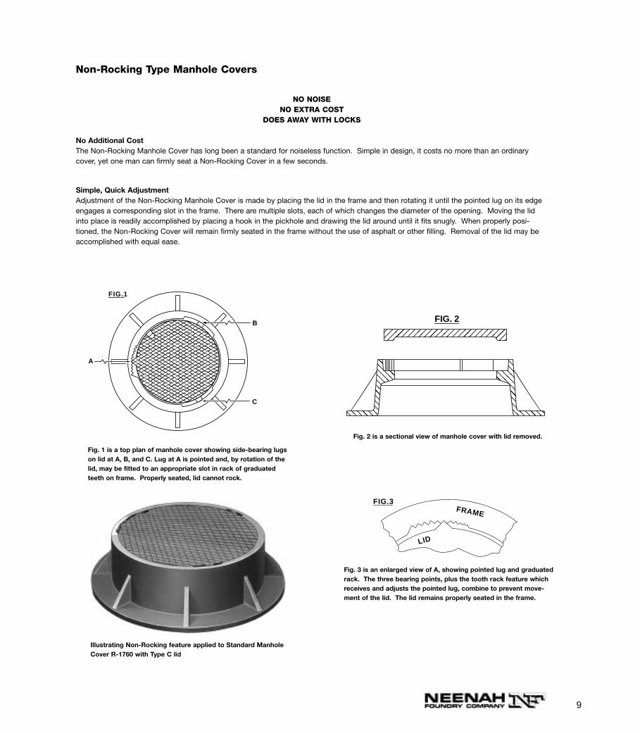
No Additional CostThe Non-Rocking Manhole Cover has long been a standard for noiseless function. Simple in design, it costs no more than an ordinarycover, yet one man can firmly seat a Non-Rocking Cover in a few seconds.
Simple, Quick AdjustmentAdjustment of the Non-Rocking Manhole Cover is made by placing the lid in the frame and then rotating it until the pointed lug on its edgeengages a corresponding slot in the frame. There are multiple slots, each of which changes the diameter of the opening. Moving the lidinto place is readily accomplished by placing a hook in the pickhole and drawing the lid around until it fits snugly. When properly posi-tioned, the Non-Rocking Cover will remain firmly seated in the frame without the use of asphalt or other filling. Removal of the lid may beaccomplished with equal ease.
FIG.1
A
B
C
FIG. 2
LID
FRAME
FIG.3
Illustrating Non-Rocking feature applied to Standard ManholeCover R-1760 with Type C lid
Fig. 2 is a sectional view of manhole cover with lid removed.
Fig. 1 is a top plan of manhole cover showing side-bearing lugson lid at A, B, and C. Lug at A is pointed and, by rotation of thelid, may be fitted to an appropriate slot in rack of graduatedteeth on frame. Properly seated, lid cannot rock.
Fig. 3 is an enlarged view of A, showing pointed lug and graduatedrack. The three bearing points, plus the tooth rack feature whichreceives and adjusts the pointed lug, combine to prevent move-ment of the lid. The lid remains properly seated in the frame.
10
INSTRUCTIONS FOR READING TABLES ON FOLLOWING PAGES
Tables on the following pages listing standard and special size manhole castings include most of the more popular types shown in order of theirclear openings arranged from larger to smaller.
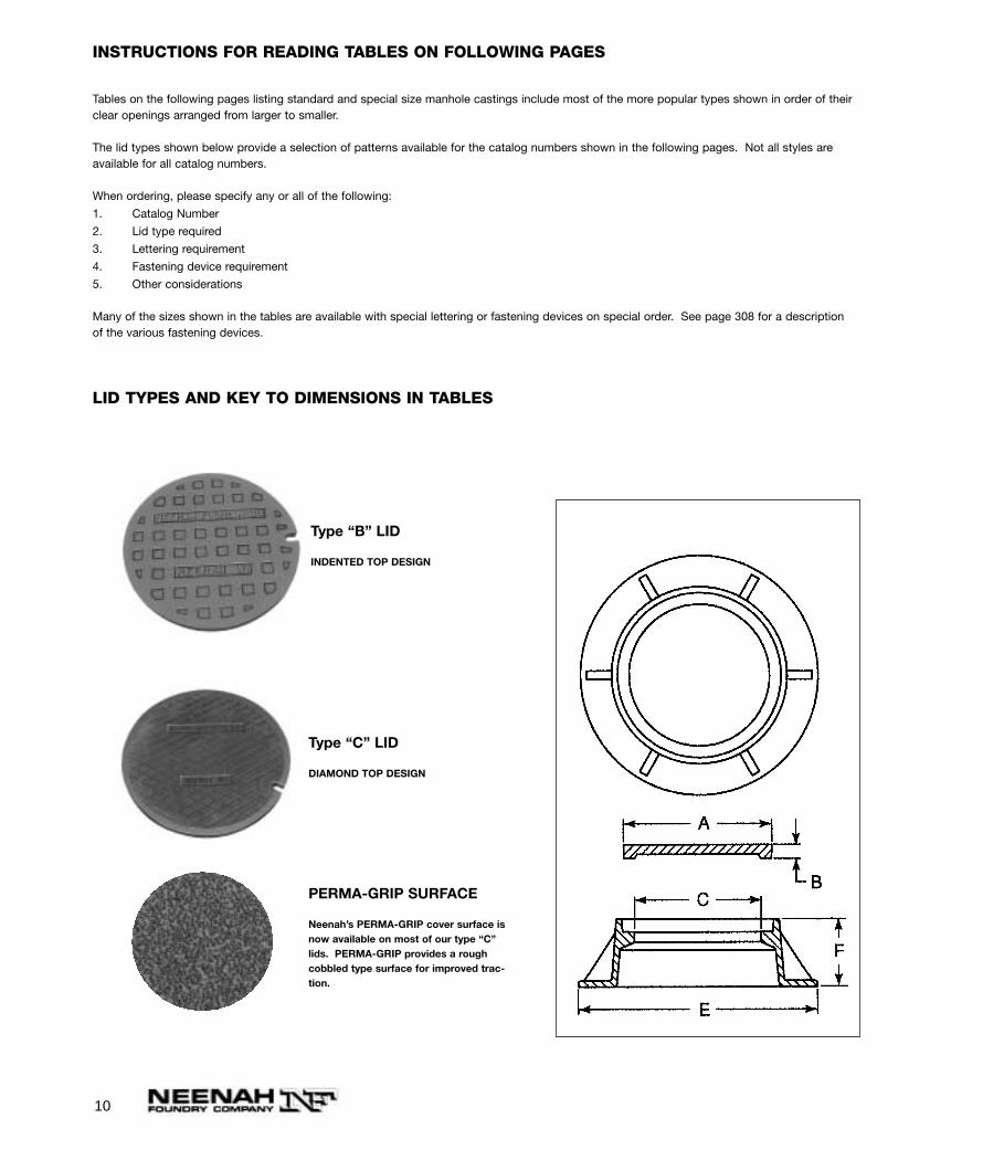
The lid types shown below provide a selection of patterns available for the catalog numbers shown in the following pages. Not all styles areavailable for all catalog numbers.
When ordering, please specify any or all of the following:
1. Catalog Number
2. Lid type required
3. Lettering requirement
4. Fastening device requirement
5. Other considerations
Many of the sizes shown in the tables are available with special lettering or fastening devices on special order. See page 308 for a descriptionof the various fastening devices.
LID TYPES AND KEY TO DIMENSIONS IN TABLES
Type “B” LID
INDENTED TOP DESIGN
Type “C” LID
DIAMOND TOP DESIGN
PERMA-GRIP SURFACE
Neenah’s PERMA-GRIP cover surface isnow available on most of our type “C”lids. PERMA-GRIP provides a roughcobbled type surface for improved trac-tion.
11
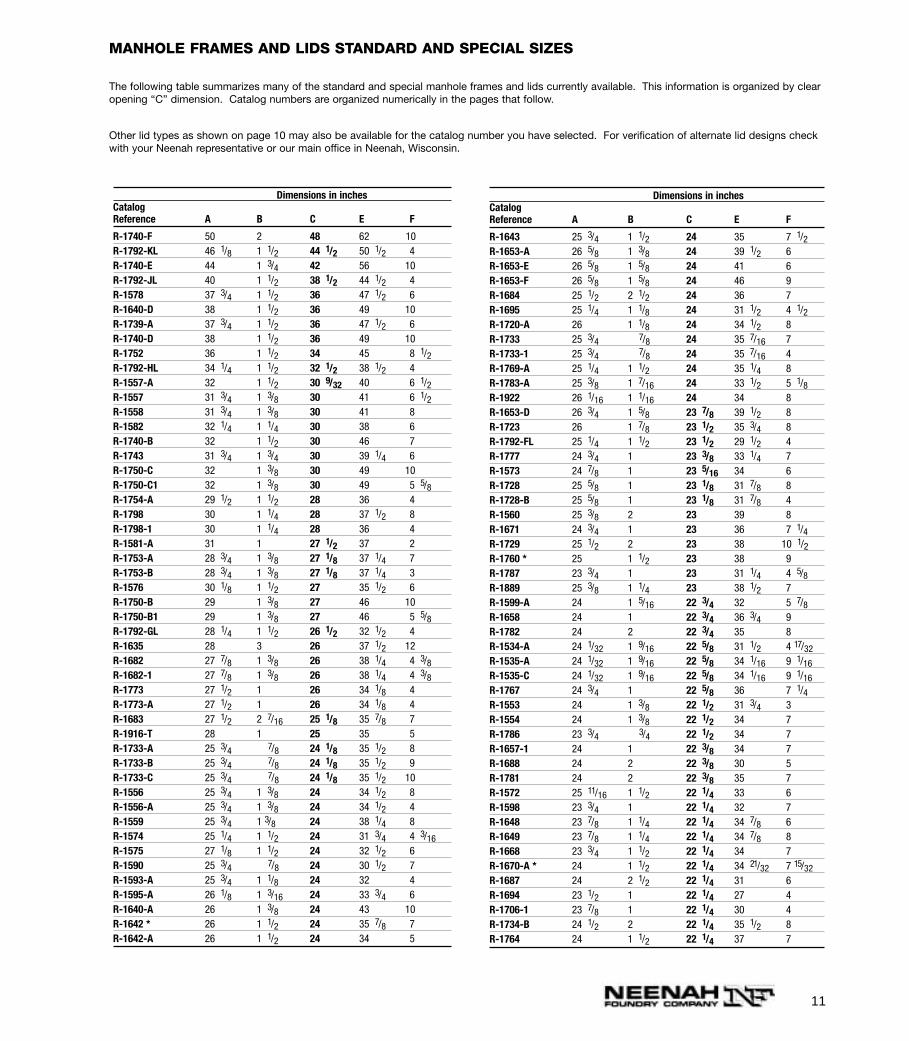
Dimensions in inchesCatalogReference A B C E F
R-1740-F 50 2 48 62 10 R-1792-KL 46 1/8 1 1/2 44 1/2 50 1/2 4 R-1740-E 44 1 3/4 42 56 10 R-1792-JL 40 1 1/2 38 1/2 44 1/2 4 R-1578 37 3/4 1 1/2 36 47 1/2 6 R-1640-D 38 1 1/2 36 49 10 R-1739-A 37 3/4 1 1/2 36 47 1/2 6 R-1740-D 38 1 1/2 36 49 10 R-1752 36 1 1/2 34 45 8 1/2R-1792-HL 34 1/4 1 1/2 32 1/2 38 1/2 4 R-1557-A 32 1 1/2 30 9/32 40 6 1/2R-1557 31 3/4 1 3/8 30 41 6 1/2R-1558 31 3/4 1 3/8 30 41 8 R-1582 32 1/4 1 1/4 30 38 6 R-1740-B 32 1 1/2 30 46 7 R-1743 31 3/4 1 3/4 30 39 1/4 6 R-1750-C 32 1 3/8 30 49 10 R-1750-C1 32 1 3/8 30 49 5 5/8R-1754-A 29 1/2 1 1/2 28 36 4 R-1798 30 1 1/4 28 37 1/2 8 R-1798-1 30 1 1/4 28 36 4 R-1581-A 31 1 27 1/2 37 2 R-1753-A 28 3/4 1 3/8 27 1/8 37 1/4 7 R-1753-B 28 3/4 1 3/8 27 1/8 37 1/4 3 R-1576 30 1/8 1 1/2 27 35 1/2 6 R-1750-B 29 1 3/8 27 46 10 R-1750-B1 29 1 3/8 27 46 5 5/8R-1792-GL 28 1/4 1 1/2 26 1/2 32 1/2 4 R-1635 28 3 26 37 1/2 12 R-1682 27 7/8 1 3/8 26 38 1/4 4 3/8R-1682-1 27 7/8 1 3/8 26 38 1/4 4 3/8R-1773 27 1/2 1 26 34 1/8 4 R-1773-A 27 1/2 1 26 34 1/8 4 R-1683 27 1/2 2 7/16 25 1/8 35 7/8 7 R-1916-T 28 1 25 35 5 R-1733-A 25 3/4 7/8 24 1/8 35 1/2 8 R-1733-B 25 3/4 7/8 24 1/8 35 1/2 9 R-1733-C 25 3/4 7/8 24 1/8 35 1/2 10 R-1556 25 3/4 1 3/8 24 34 1/2 8 R-1556-A 25 3/4 1 3/8 24 34 1/2 4 R-1559 25 3/4 1 3/8 24 38 1/4 8 R-1574 25 1/4 1 1/2 24 31 3/4 4 3/16R-1575 27 1/8 1 1/2 24 32 1/2 6 R-1590 25 3/4 7/8 24 30 1/2 7 R-1593-A 25 3/4 1 1/8 24 32 4 R-1595-A 26 1/8 1 3/16 24 33 3/4 6 R-1640-A 26 1 3/8 24 43 10 R-1642 * 26 1 1/2 24 35 7/8 7 R-1642-A 26 1 1/2 24 34 5
Dimensions in inchesCatalogReference A B C E F
R-1643 25 3/4 1 1/2 24 35 7 1/2R-1653-A 26 5/8 1 3/8 24 39 1/2 6 R-1653-E 26 5/8 1 5/8 24 41 6 R-1653-F 26 5/8 1 5/8 24 46 9 R-1684 25 1/2 2 1/2 24 36 7 R-1695 25 1/4 1 1/8 24 31 1/2 4 1/2R-1720-A 26 1 1/8 24 34 1/2 8 R-1733 25 3/4 7/8 24 35 7/16 7 R-1733-1 25 3/4 7/8 24 35 7/16 4 R-1769-A 25 1/4 1 1/2 24 35 1/4 8 R-1783-A 25 3/8 1 7/16 24 33 1/2 5 1/8R-1922 26 1/16 1 1/16 24 34 8 R-1653-D 26 3/4 1 5/8 23 7/8 39 1/2 8 R-1723 26 1 7/8 23 1/2 35 3/4 8 R-1792-FL 25 1/4 1 1/2 23 1/2 29 1/2 4 R-1777 24 3/4 1 23 3/8 33 1/4 7 R-1573 24 7/8 1 23 5/16 34 6 R-1728 25 5/8 1 23 1/8 31 7/8 8 R-1728-B 25 5/8 1 23 1/8 31 7/8 4 R-1560 25 3/8 2 23 39 8 R-1671 24 3/4 1 23 36 7 1/4R-1729 25 1/2 2 23 38 10 1/2R-1760 * 25 1 1/2 23 38 9 R-1787 23 3/4 1 23 31 1/4 4 5/8R-1889 25 3/8 1 1/4 23 38 1/2 7 R-1599-A 24 1 5/16 22 3/4 32 5 7/8R-1658 24 1 22 3/4 36 3/4 9 R-1782 24 2 22 3/4 35 8 R-1534-A 24 1/32 1 9/16 22 5/8 31 1/2 4 17/32R-1535-A 24 1/32 1 9/16 22 5/8 34 1/16 9 1/16R-1535-C 24 1/32 1 9/16 22 5/8 34 1/16 9 1/16R-1767 24 3/4 1 22 5/8 36 7 1/4R-1553 24 1 3/8 22 1/2 31 3/4 3 R-1554 24 1 3/8 22 1/2 34 7 R-1786 23 3/4 3/4 22 1/2 34 7 R-1657-1 24 1 22 3/8 34 7 R-1688 24 2 22 3/8 30 5 R-1781 24 2 22 3/8 35 7 R-1572 25 11/16 1 1/2 22 1/4 33 6 R-1598 23 3/4 1 22 1/4 32 7 R-1648 23 7/8 1 1/4 22 1/4 34 7/8 6 R-1649 23 7/8 1 1/4 22 1/4 34 7/8 8 R-1668 23 3/4 1 1/2 22 1/4 34 7 R-1670-A * 24 1 1/2 22 1/4 34 21/32 7 15/32R-1687 24 2 1/2 22 1/4 31 6 R-1694 23 1/2 1 22 1/4 27 4 R-1706-1 23 7/8 1 22 1/4 30 4 R-1734-B 24 1/2 2 22 1/4 35 1/2 8 R-1764 24 1 1/2 22 1/4 37 7
MANHOLE FRAMES AND LIDS STANDARD AND SPECIAL SIZES
The following table summarizes many of the standard and special manhole frames and lids currently available. This information is organized by clearopening “C” dimension. Catalog numbers are organized numerically in the pages that follow.
Other lid types as shown on page 10 may also be available for the catalog number you have selected. For verification of alternate lid designs checkwith your Neenah representative or our main office in Neenah, Wisconsin.
12
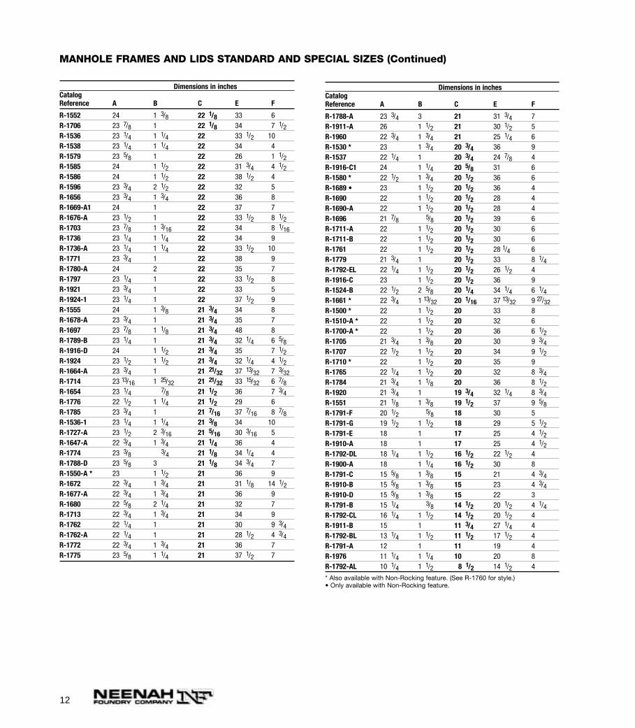
Dimensions in inchesCatalogReference A B C E F
R-1552 24 1 3/8 22 1/8 33 6 R-1706 23 7/8 1 22 1/8 34 7 1/2R-1536 23 1/4 1 1/4 22 33 1/2 10 R-1538 23 1/4 1 1/4 22 34 4 R-1579 23 5/8 1 22 26 1 1/2R-1585 24 1 1/2 22 31 3/4 4 1/2R-1586 24 1 1/2 22 38 1/2 4 R-1596 23 3/4 2 1/2 22 32 5 R-1656 23 3/4 1 3/4 22 36 8 R-1669-A1 24 1 22 37 7 R-1676-A 23 1/2 1 22 33 1/2 8 1/2R-1703 23 7/8 1 3/16 22 34 8 1/16R-1736 23 1/4 1 1/4 22 34 9 R-1736-A 23 1/4 1 1/4 22 33 1/2 10 R-1771 23 3/4 1 22 38 9 R-1780-A 24 2 22 35 7 R-1797 23 1/4 1 22 33 1/2 8 R-1921 23 3/4 1 22 33 5 R-1924-1 23 1/4 1 22 37 1/2 9 R-1555 24 1 3/8 21 3/4 34 8 R-1678-A 23 3/4 1 21 3/4 35 7 R-1697 23 7/8 1 1/8 21 3/4 48 8 R-1789-B 23 1/4 1 21 3/4 32 1/4 6 5/8R-1916-D 24 1 1/2 21 3/4 35 7 1/2R-1924 23 1/2 1 1/2 21 3/4 32 1/4 4 1/2R-1664-A 23 3/4 1 21 21/32 37 13/32 7 3/32R-1714 23 13/16 1 25/32 21 21/32 33 15/32 6 7/8R-1654 23 1/4 7/8 21 1/2 36 7 3/4R-1776 22 1/2 1 1/4 21 1/2 29 6 R-1785 23 3/4 1 21 7/16 37 7/16 8 7/8R-1536-1 23 1/4 1 1/4 21 3/8 34 10 R-1727-A 23 1/2 2 3/16 21 5/16 30 3/16 5 R-1647-A 22 3/4 1 3/4 21 1/4 36 4 R-1774 23 3/8 3/4 21 1/8 34 1/4 4 R-1788-D 23 5/8 3 21 1/8 34 3/4 7 R-1550-A * 23 1 1/2 21 36 9 R-1672 22 3/4 1 3/4 21 31 1/8 14 1/2R-1677-A 22 3/4 1 3/4 21 36 9 R-1680 22 5/8 2 1/4 21 32 7 R-1713 22 3/4 1 3/4 21 34 9 R-1762 22 1/4 1 21 30 9 3/4R-1762-A 22 1/4 1 21 28 1/2 4 3/4R-1772 22 3/4 1 3/4 21 36 7 R-1775 23 5/8 1 1/4 21 37 1/2 7
Dimensions in inchesCatalogReference A B C E F
R-1788-A 23 3/4 3 21 31 3/4 7 R-1911-A 26 1 1/2 21 30 1/2 5 R-1960 22 3/4 1 3/4 21 25 1/4 6 R-1530 * 23 1 3/4 20 3/4 36 9 R-1537 22 1/4 1 20 3/4 24 7/8 4 R-1916-C1 24 1 1/4 20 5/8 31 6 R-1580 * 22 1/2 1 3/4 20 1/2 36 6 R-1689 • 23 1 1/2 20 1/2 36 4 R-1690 22 1 1/2 20 1/2 28 4 R-1690-A 22 1 1/2 20 1/2 28 4 R-1696 21 7/8 5/8 20 1/2 39 6 R-1711-A 22 1 1/2 20 1/2 30 6 R-1711-B 22 1 1/2 20 1/2 30 6 R-1761 22 1 1/2 20 1/2 28 1/4 6 R-1779 21 3/4 1 20 1/2 33 8 1/4R-1792-EL 22 1/4 1 1/2 20 1/2 26 1/2 4 R-1916-C 23 1 1/2 20 1/2 36 9 R-1524-B 22 1/2 2 5/8 20 1/4 34 1/4 6 1/4R-1661 * 22 3/4 1 13/32 20 1/16 37 13/32 9 27/32R-1500 * 22 1 1/2 20 33 8 R-1510-A * 22 1 1/2 20 32 6 R-1700-A * 22 1 1/2 20 36 6 1/2R-1705 21 3/4 1 3/8 20 30 9 3/4R-1707 22 1/2 1 1/2 20 34 9 1/2R-1710 * 22 1 1/2 20 35 9 R-1765 22 1/4 1 1/2 20 32 8 3/4R-1784 21 3/4 1 1/8 20 36 8 1/2R-1920 21 3/4 1 19 3/4 32 1/4 8 3/4R-1551 21 1/8 1 3/8 19 1/2 37 9 5/8R-1791-F 20 1/2 5/8 18 30 5 R-1791-G 19 1/2 1 1/2 18 29 5 1/2R-1791-E 18 1 17 25 4 1/2R-1910-A 18 1 17 25 4 1/2R-1792-DL 18 1/4 1 1/2 16 1/2 22 1/2 4 R-1900-A 18 1 1/4 16 1/2 30 8 R-1791-C 15 5/8 1 3/8 15 21 4 3/4R-1910-B 15 5/8 1 3/8 15 23 4 3/4R-1910-D 15 5/8 1 3/8 15 22 3 R-1791-B 15 1/4 3/8 14 1/2 20 1/2 4 1/4R-1792-CL 16 1/4 1 1/2 14 1/2 20 1/2 4 R-1911-B 15 1 11 3/4 27 1/4 4 R-1792-BL 13 1/4 1 1/2 11 1/2 17 1/2 4 R-1791-A 12 1 11 19 4 R-1976 11 1/4 1 1/4 10 20 8 R-1792-AL 10 1/4 1 1/2 8 1/2 14 1/2 4
* Also available with Non-Rocking feature. (See R-1760 for style.) • Only available with Non-Rocking feature.
MANHOLE FRAMES AND LIDS STANDARD AND SPECIAL SIZES (Continued)
13
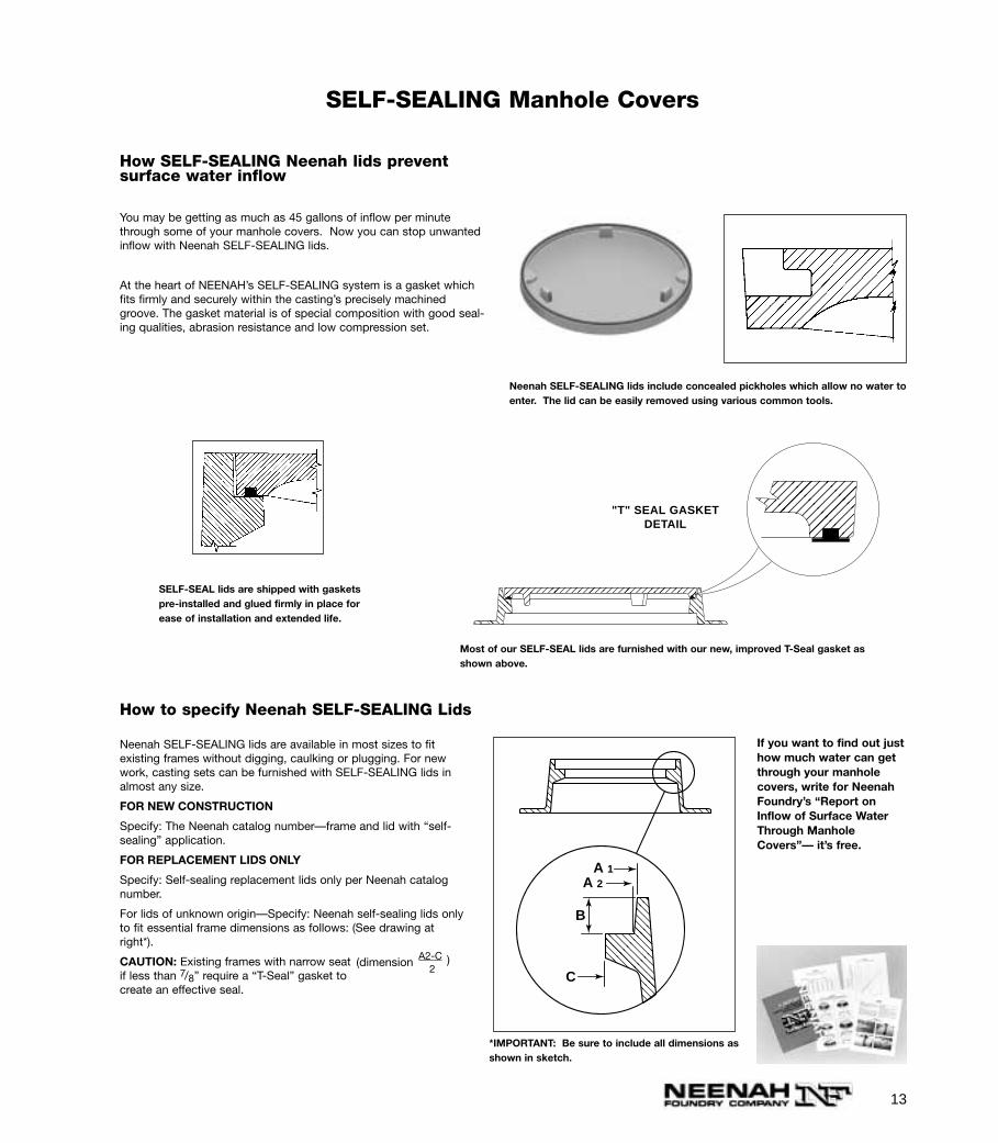
Neenah SELF-SEALING lids include concealed pickholes which allow no water toenter. The lid can be easily removed using various common tools.
SELF-SEALING Manhole Covers
How SELF-SEALING Neenah lids preventsurface water inflow
You may be getting as much as 45 gallons of inflow per minutethrough some of your manhole covers. Now you can stop unwantedinflow with Neenah SELF-SEALING lids.
At the heart of NEENAH’s SELF-SEALING system is a gasket whichfits firmly and securely within the casting’s precisely machinedgroove. The gasket material is of special composition with good seal-ing qualities, abrasion resistance and low compression set.
"T" SEAL GASKETDETAIL
Most of our SELF-SEAL lids are furnished with our new, improved T-Seal gasket asshown above.
SELF-SEAL lids are shipped with gasketspre-installed and glued firmly in place forease of installation and extended life.
Neenah SELF-SEALING lids are available in most sizes to fitexisting frames without digging, caulking or plugging. For newwork, casting sets can be furnished with SELF-SEALING lids inalmost any size.
FOR NEW CONSTRUCTION
Specify: The Neenah catalog number—frame and lid with “self-sealing” application.
FOR REPLACEMENT LIDS ONLY
Specify: Self-sealing replacement lids only per Neenah catalognumber.
For lids of unknown origin—Specify: Neenah self-sealing lids onlyto fit essential frame dimensions as follows: (See drawing atright*).
CAUTION: Existing frames with narrow seatif less than 7/8” require a “T-Seal” gasket tocreate an effective seal.
C
B
A 1A 2
*IMPORTANT: Be sure to include all dimensions asshown in sketch.
If you want to find out justhow much water can getthrough your manholecovers, write for NeenahFoundry’s “Report onInflow of Surface WaterThrough ManholeCovers”— it’s free.
How to specify Neenah SELF-SEALING Lids
(dimension A2-C2
)
14
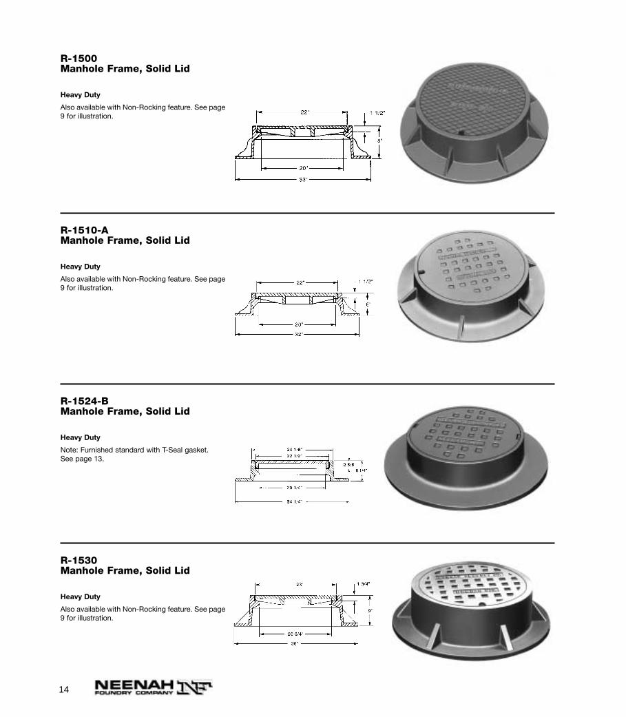
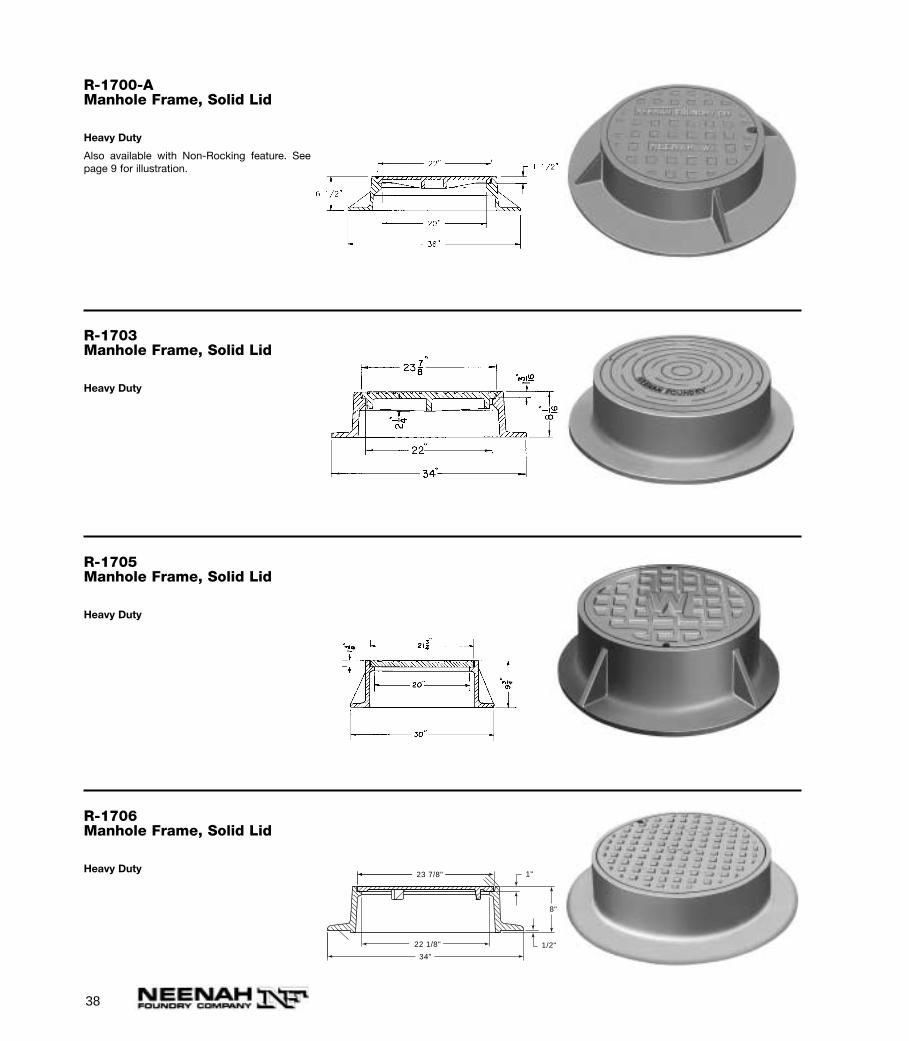
R-1500Manhole Frame, Solid Lid
Heavy Duty
Also available with Non-Rocking feature. See page9 for illustration.
R-1510-AManhole Frame, Solid Lid
Heavy Duty
Also available with Non-Rocking feature. See page9 for illustration.
R-1524-BManhole Frame, Solid Lid
Heavy Duty
Note: Furnished standard with T-Seal gasket.See page 13.
R-1530Manhole Frame, Solid Lid
Heavy Duty
Also available with Non-Rocking feature. See page9 for illustration.

15
R-1534-AManhole Frame, Solid Lid
Heavy Duty
With cam lugs. Also available without cam lugs.
1 9/16"31/32"
22 5/8"
31 1/2"
24 1/32"
4 17/32"
R-1535-AManhole Frame, Solid Lid
Heavy Duty24 1/32"
9 1/16"
1 9/16"
19/32"22 5/8"
29 29/32"
34 1/16"
R-1535-CManhole Frame, Solid Lid
Heavy Duty
With cam lugs. 24 1/32"
9 1/16"
1 9/16"
19/32"22 5/8"
29 29/32"
34 1/16"
R-1536Manhole Frame, Solid Lid
Heavy Duty
16
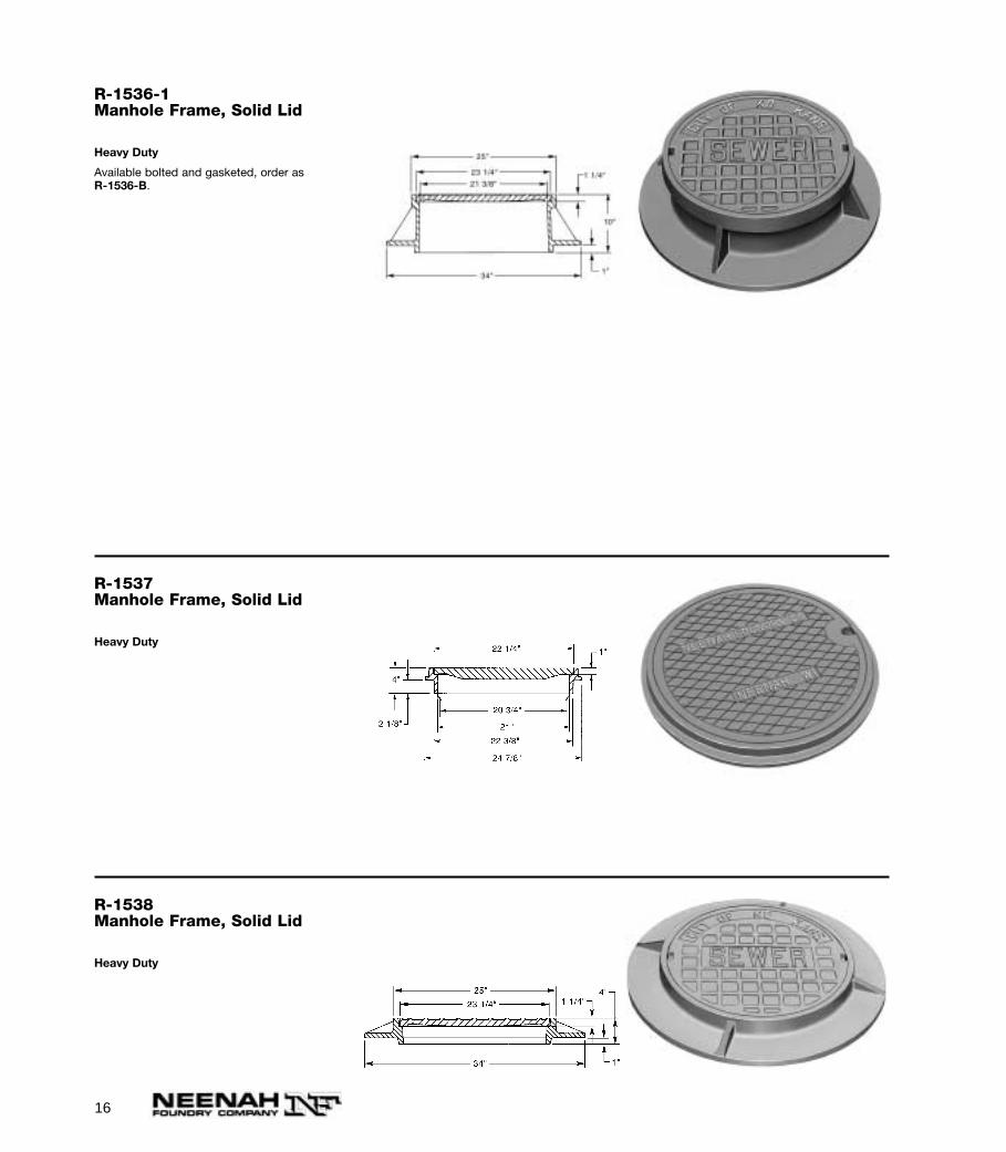
R-1536-1Manhole Frame, Solid Lid
Heavy Duty
Available bolted and gasketed, order as R-1536-B.
R-1537Manhole Frame, Solid Lid
Heavy Duty
R-1538Manhole Frame, Solid Lid
Heavy Duty

17
R-1550-AManhole Frame, Solid Lid
Heavy Duty
Also available with Non-Rocking feature. See page9 for illustration.
23"
24"
36"
21"
1 1/2"
9"
1"
R-1551Manhole Frame, Vented Lid
Heavy Duty
R-1552Manhole Frame, Vented Lid
Heavy Duty
R-1553Manhole Frame, Solid Lid
Heavy Duty
18
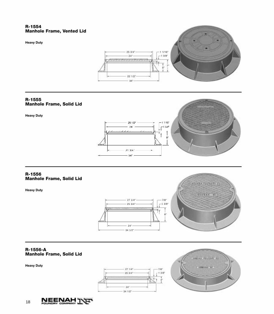
R-1554Manhole Frame, Vented Lid
Heavy Duty
R-1555Manhole Frame, Solid Lid
Heavy Duty
R-1556Manhole Frame, Solid Lid
Heavy Duty
1 3/8"
8"
25 3/4"
27 1/4"
24"
34 1/2"
7/8"
R-1556-AManhole Frame, Solid Lid
Heavy Duty
19
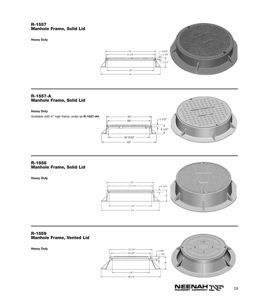
R-1557Manhole Frame, Solid Lid
Heavy Duty
1 3/8"
6 1/2"
31 3/4"
33"
30"
41"
13/16"
R-1557-AManhole Frame, Solid Lid
Heavy Duty
Available with 4” high frame, order as R-1557-A4.
32"
40"
33"1 1/2"
6 1/2"
30 9/32"
R-1558Manhole Frame, Solid Lid
Heavy Duty
1 3 / 8 "
8"
3 3 "
3 1 3 / 4 "
3 0 "
4 1 "
R-1559Manhole Frame, Vented Lid
Heavy Duty
1 3/8"
7/8"
8"
27 1/4"
25 3/4"
38 1/4"
24"
20
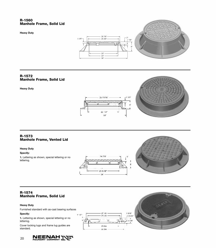
R-1560Manhole Frame, Solid Lid
Heavy Duty
26 7/8"25 3/8"
23"
8"
2"
24"
1 1/8"7/8"
39"
R-1572Manhole Frame, Solid Lid
Heavy Duty
R-1573Manhole Frame, Vented Lid
Heavy Duty
Specify:
1. Lettering as shown, special lettering or no lettering.
R-1574Manhole Frame, Solid Lid
Heavy Duty
Furnished standard with as-cast bearing surfaces
Specify:
1. Lettering as shown, special lettering or no lettering.
Cover locking lugs and frame lug guides are standard.
21
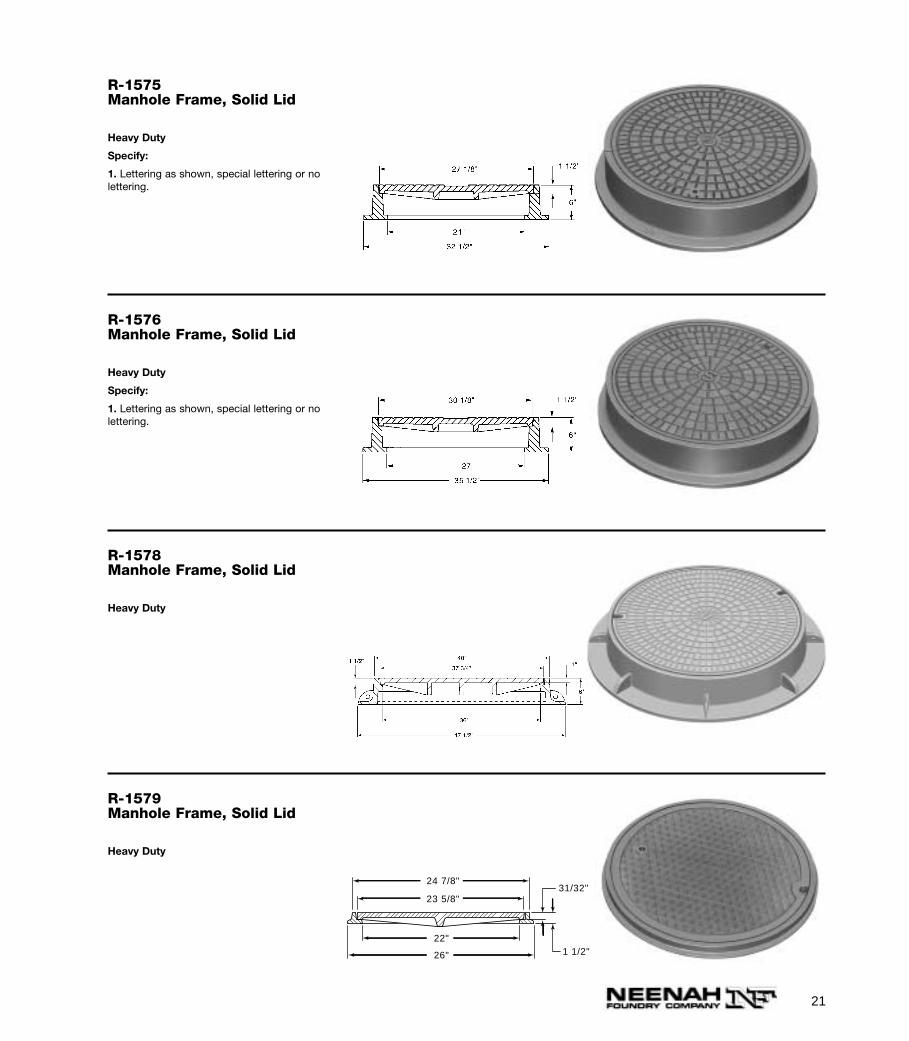
R-1575Manhole Frame, Solid Lid
Heavy Duty
Specify:
1. Lettering as shown, special lettering or no lettering.
R-1576Manhole Frame, Solid Lid
Heavy Duty
Specify:
1. Lettering as shown, special lettering or no lettering.
R-1578Manhole Frame, Solid Lid
Heavy Duty
R-1579Manhole Frame, Solid Lid
Heavy Duty
24 7/8"
23 5/8"
22"
26"
31/32"
1 1/2"
22
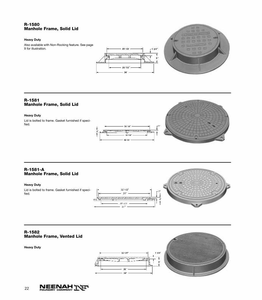
R-1580Manhole Frame, Solid Lid
Heavy Duty
Also available with Non-Rocking feature. See page9 for illustration.
R-1581Manhole Frame, Solid Lid
Heavy Duty
Lid is bolted to frame. Gasket furnished if speci-fied.
R-1581-AManhole Frame, Solid Lid
Heavy Duty
Lid is bolted to frame. Gasket furnished if speci-fied.
R-1582Manhole Frame, Vented Lid
Heavy Duty
23
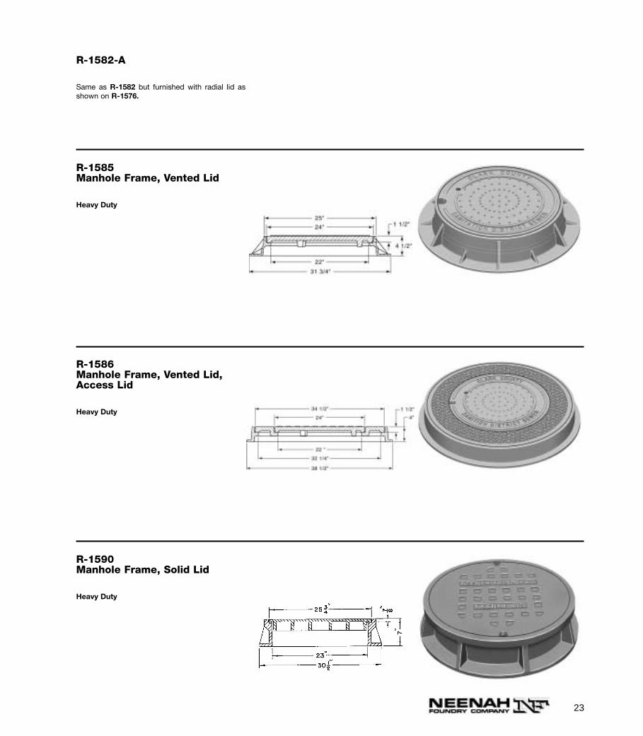
R-1582-A
Same as R-1582 but furnished with radial lid asshown on R-1576.
R-1585Manhole Frame, Vented Lid
Heavy Duty
R-1586Manhole Frame, Vented Lid,Access Lid
Heavy Duty
R-1590Manhole Frame, Solid Lid
Heavy Duty
24
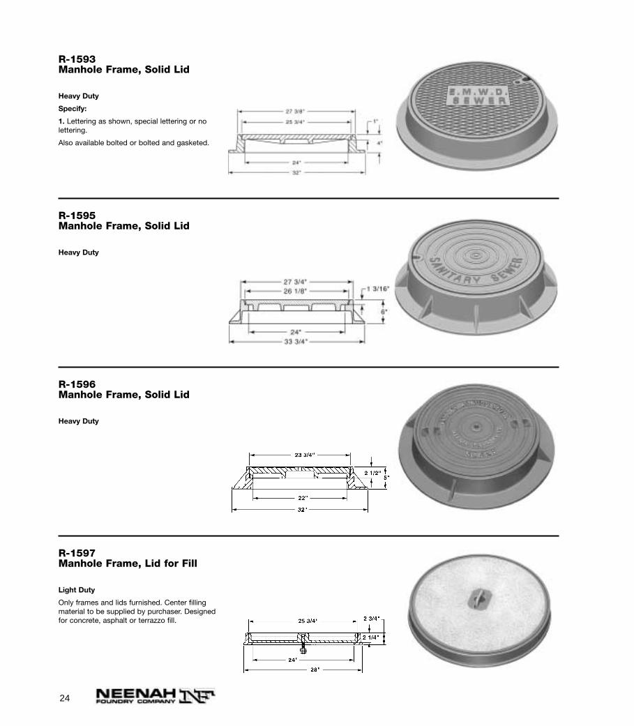
R-1593Manhole Frame, Solid Lid
Heavy Duty
Specify:
1. Lettering as shown, special lettering or no lettering.
Also available bolted or bolted and gasketed.
R-1595Manhole Frame, Solid Lid
Heavy Duty
R-1596Manhole Frame, Solid Lid
Heavy Duty
R-1597Manhole Frame, Lid for Fill
Light Duty
Only frames and lids furnished. Center fillingmaterial to be supplied by purchaser. Designedfor concrete, asphalt or terrazzo fill.

25
R-1598Manhole Frame, Solid Lid
Heavy Duty
R-1599-AManhole Frame, Vented Lid
Heavy Duty
R-1635Manhole Frame, Solid Lid
Heavy Duty
26
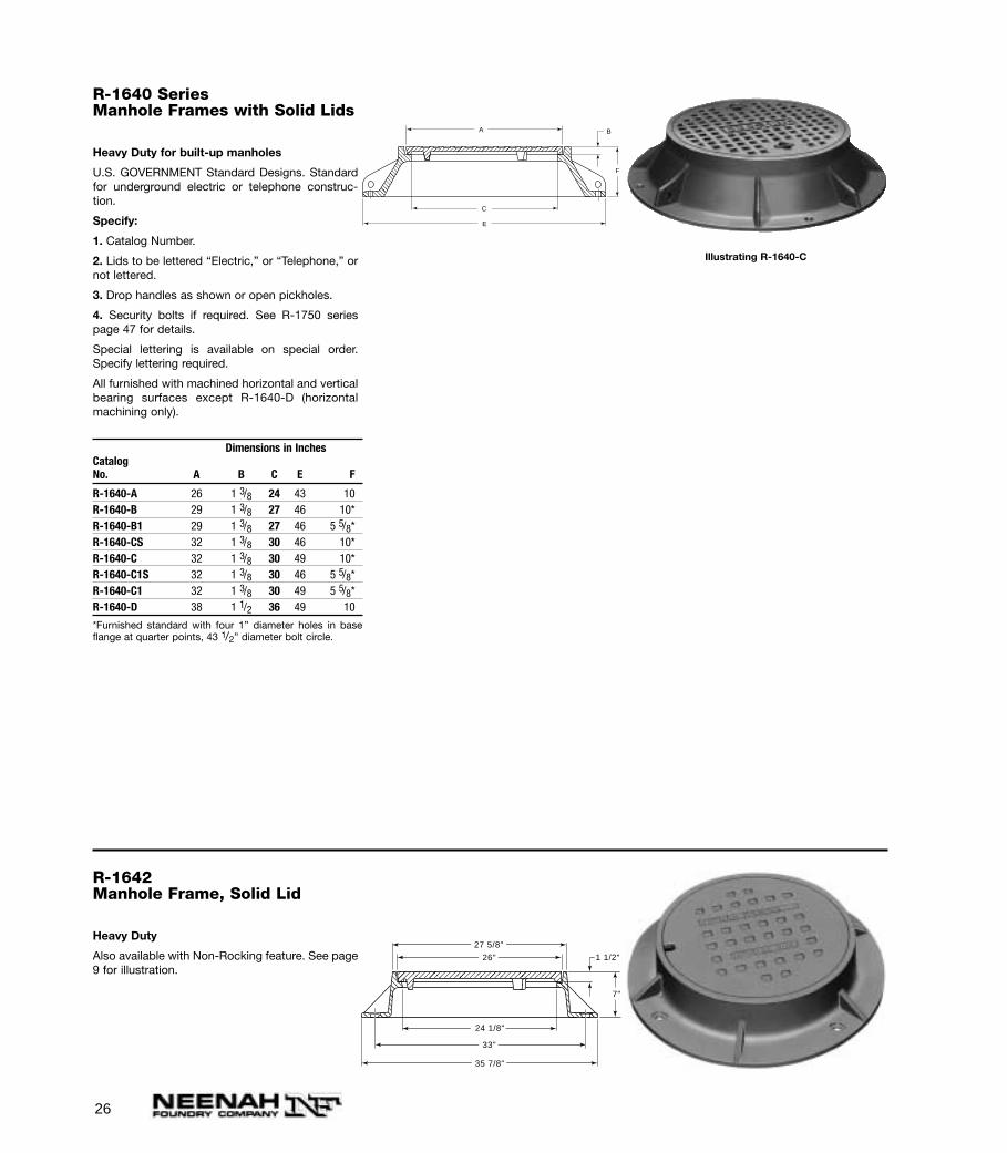
R-1640 SeriesManhole Frames with Solid Lids
Heavy Duty for built-up manholes
U.S. GOVERNMENT Standard Designs. Standardfor underground electric or telephone construc-tion.
Specify:
1. Catalog Number.
2. Lids to be lettered “Electric,” or “Telephone,” ornot lettered.
3. Drop handles as shown or open pickholes.
4. Security bolts if required. See R-1750 seriespage 47 for details.
Special lettering is available on special order.Specify lettering required.
All furnished with machined horizontal and verticalbearing surfaces except R-1640-D (horizontalmachining only).
Dimensions in InchesCatalogNo. A B C E F
R-1640-A 26 1 3/8 24 43 10R-1640-B 29 1 3/8 27 46 10*R-1640-B1 29 1 3/8 27 46 5 5/8*R-1640-CS 32 1 3/8 30 46 10*R-1640-C 32 1 3/8 30 49 10*R-1640-C1S 32 1 3/8 30 46 5 5/8*R-1640-C1 32 1 3/8 30 49 5 5/8*R-1640-D 38 1 1/2 36 49 10
*Furnished standard with four 1” diameter holes in baseflange at quarter points, 43 1/2” diameter bolt circle.
A B
C
E
F
Illustrating R-1640-C
R-1642Manhole Frame, Solid Lid
Heavy Duty
Also available with Non-Rocking feature. See page9 for illustration.
26"
33"
27 5/8"
35 7/8"
24 1/8"
1 1/2"
7"
27
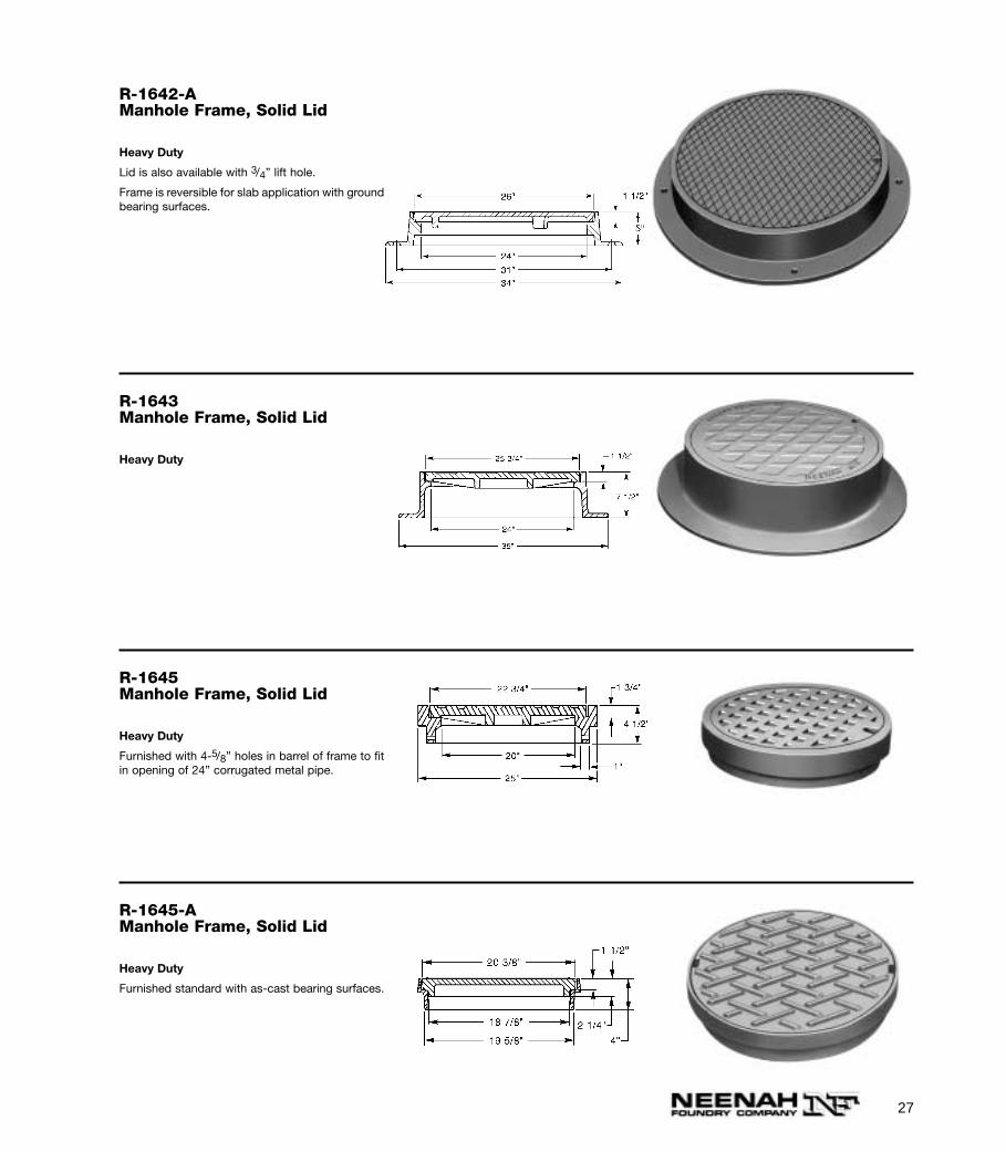
R-1642-AManhole Frame, Solid Lid
Heavy Duty
Lid is also available with 3/4” lift hole.
Frame is reversible for slab application with groundbearing surfaces.
R-1643Manhole Frame, Solid Lid
Heavy Duty
R-1645Manhole Frame, Solid Lid
Heavy Duty
Furnished with 4-5/8” holes in barrel of frame to fitin opening of 24” corrugated metal pipe.
R-1645-AManhole Frame, Solid Lid
Heavy Duty
Furnished standard with as-cast bearing surfaces.
28
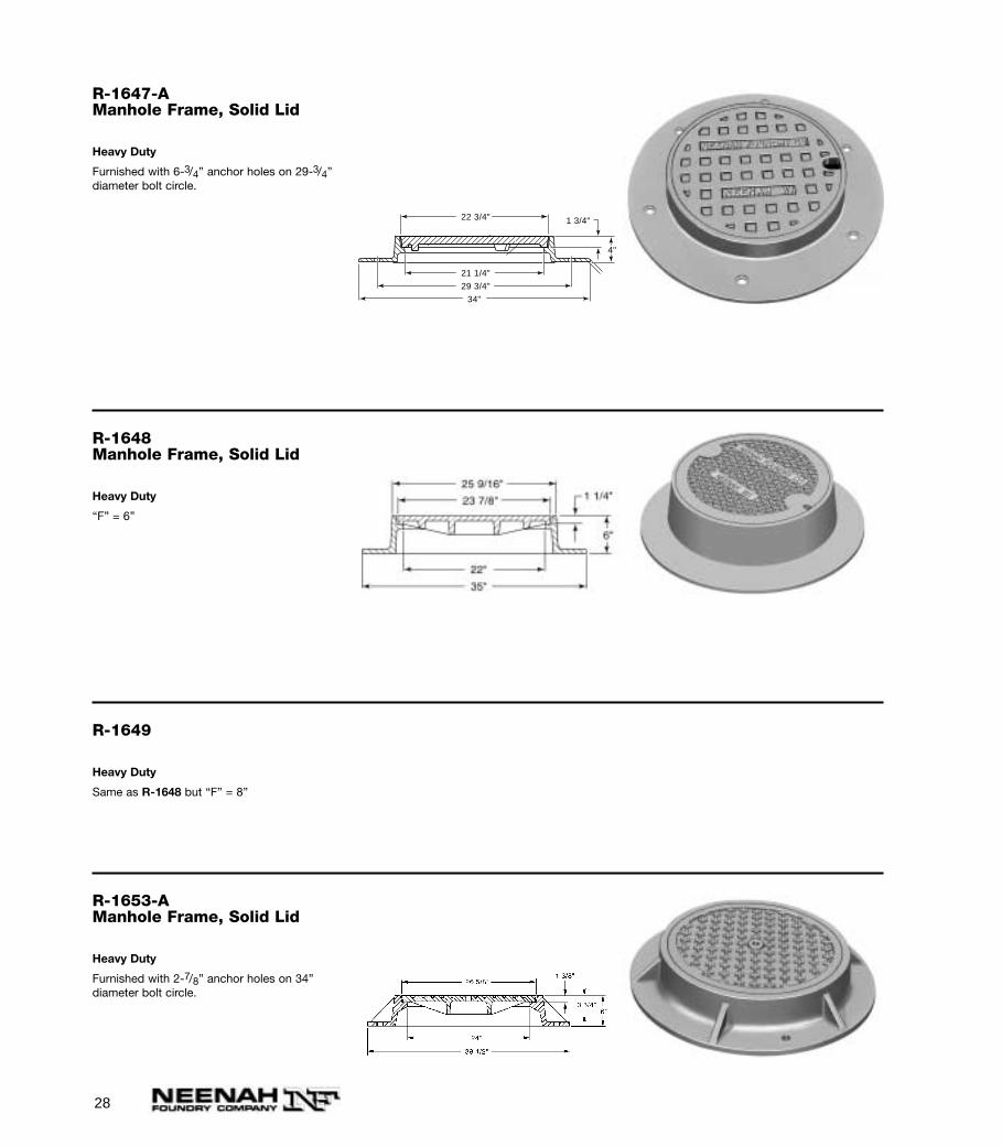
R-1647-AManhole Frame, Solid Lid
Heavy Duty
Furnished with 6-3/4” anchor holes on 29-3/4”diameter bolt circle.
22 3/4"
29 3/4"
34"
21 1/4"
1 3/4"
4"
R-1648Manhole Frame, Solid Lid
Heavy Duty
“F” = 6”
R-1649
Heavy Duty
Same as R-1648 but “F” = 8”
R-1653-AManhole Frame, Solid Lid
Heavy Duty
Furnished with 2-7/8” anchor holes on 34” diameter bolt circle.
29
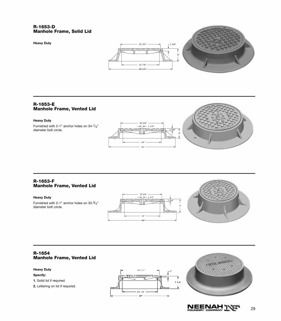
R-1654Manhole Frame, Vented Lid
Heavy Duty
Specify:
1. Solid lid if required.
2. Lettering on lid if required.
R-1653-DManhole Frame, Solid Lid
Heavy Duty
1 5/8"
8"
26 3/4"
23 7/8"
39 1/2"
R-1653-EManhole Frame, Vented Lid
Heavy Duty
Furnished with 2-1” anchor holes on 34-1/4” diameter bolt circle.
1 5/8"
26 5/8"
24"
41"
6"
1 1/4"
R-1653-FManhole Frame, Vented Lid
Heavy Duty
Furnished with 2-1” anchor holes on 33-3/4” diameter bolt circle.
1 5/8"
26 5/8"
24"
46"
9"
1 1/4"
30
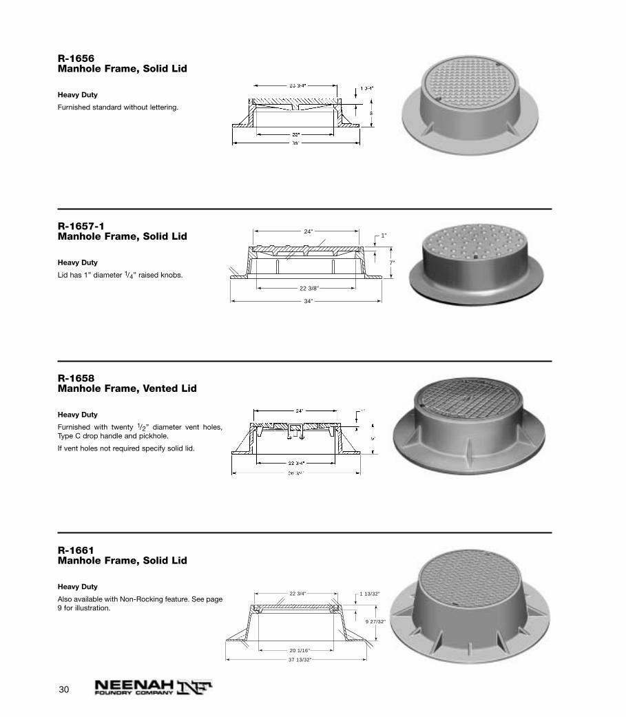
R-1656Manhole Frame, Solid Lid
Heavy Duty
Furnished standard without lettering.
R-1657-1Manhole Frame, Solid Lid
Heavy Duty
Lid has 1” diameter 1/4” raised knobs.
24"
7"
34"
22 3/8"
1"
R-1658Manhole Frame, Vented Lid
Heavy Duty
Furnished with twenty 1/2” diameter vent holes,Type C drop handle and pickhole.
If vent holes not required specify solid lid.
R-1661Manhole Frame, Solid Lid
Heavy Duty
Also available with Non-Rocking feature. See page9 for illustration.
22 3/4"
20 1/16"
37 13/32"
9 27/32"
1 13/32"
31
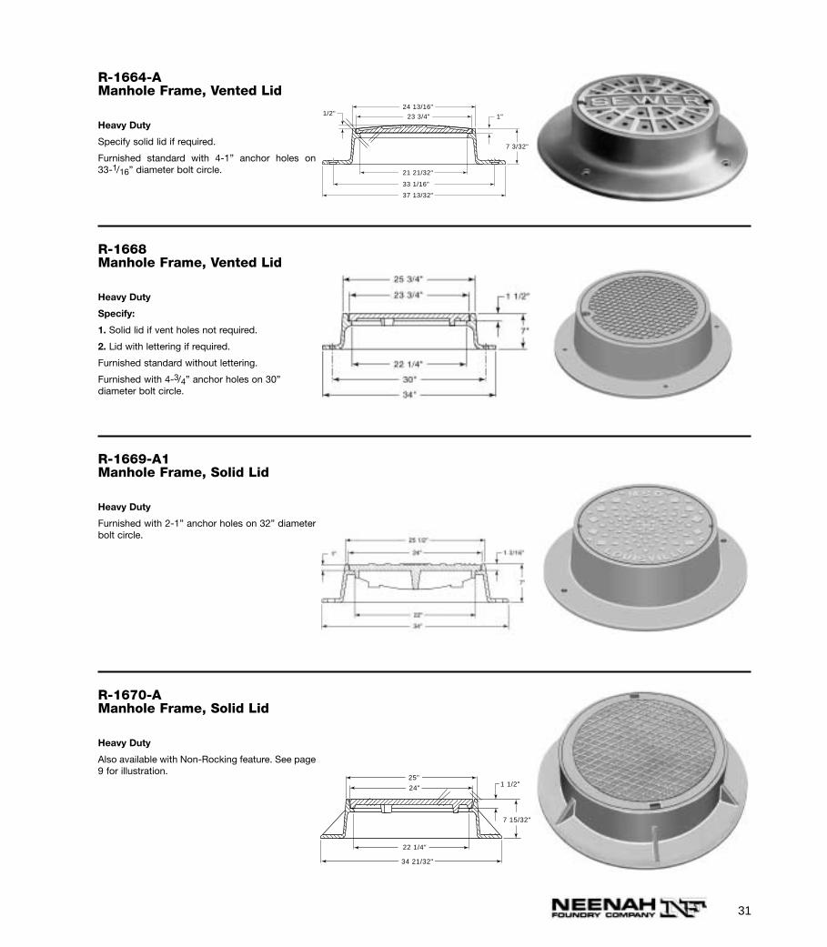
R-1664-AManhole Frame, Vented Lid
Heavy Duty
Specify solid lid if required.
Furnished standard with 4-1” anchor holes on 33-1/16” diameter bolt circle.
1/2" 1"
24 13/16"
23 3/4"
21 21/32"
33 1/16"
37 13/32"
7 3/32"
R-1668Manhole Frame, Vented Lid
Heavy Duty
Specify:
1. Solid lid if vent holes not required.
2. Lid with lettering if required.
Furnished standard without lettering.
Furnished with 4-3/4” anchor holes on 30” diameter bolt circle.
R-1669-A1Manhole Frame, Solid Lid
Heavy Duty
Furnished with 2-1” anchor holes on 32” diameterbolt circle.
R-1670-AManhole Frame, Solid Lid
Heavy Duty
Also available with Non-Rocking feature. See page9 for illustration.
24"
25"
34 21/32"
22 1/4"
1 1/2"
7 15/32"
32
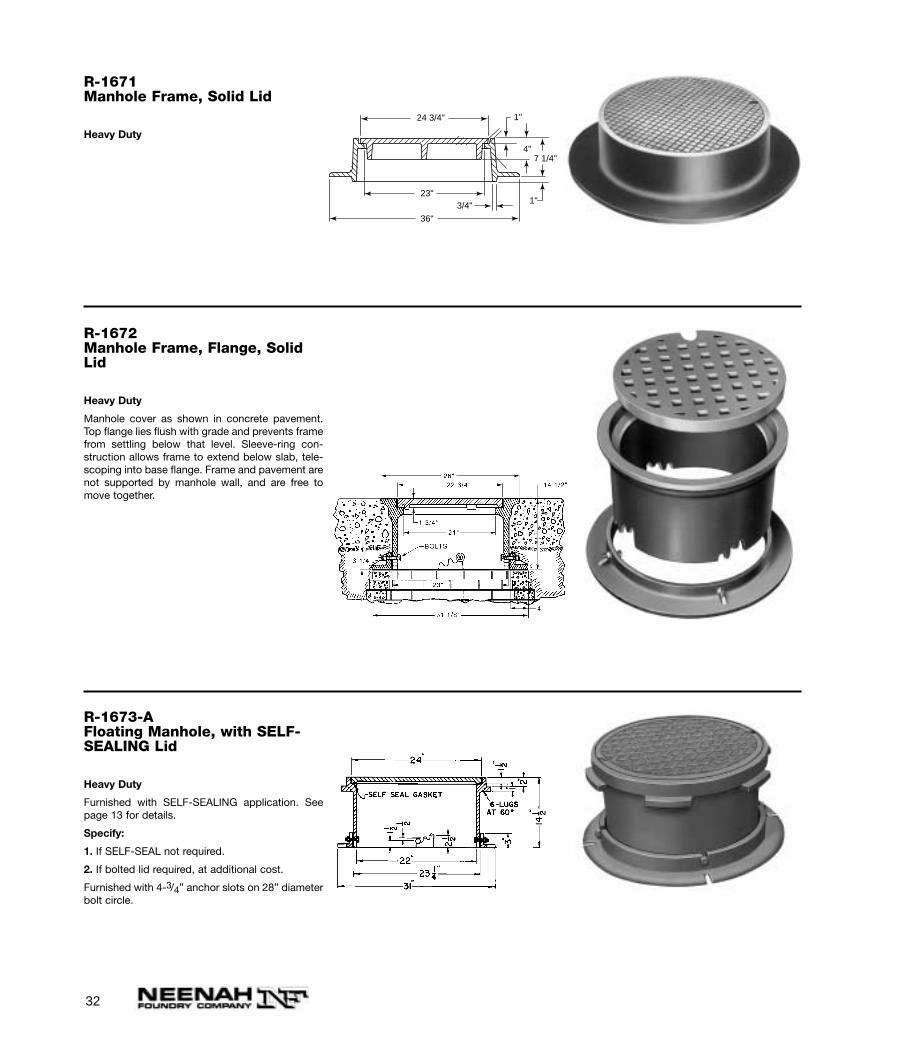
R-1671Manhole Frame, Solid Lid
Heavy Duty
R-1672Manhole Frame, Flange, SolidLid
Heavy Duty
Manhole cover as shown in concrete pavement.Top flange lies flush with grade and prevents framefrom settling below that level. Sleeve-ring con-struction allows frame to extend below slab, tele-scoping into base flange. Frame and pavement arenot supported by manhole wall, and are free tomove together.
R-1673-AFloating Manhole, with SELF-SEALING Lid
Heavy Duty
Furnished with SELF-SEALING application. Seepage 13 for details.
Specify:
1. If SELF-SEAL not required.
2. If bolted lid required, at additional cost.
Furnished with 4-3/4” anchor slots on 28” diameterbolt circle.
24 3/4"
7 1/4"4"
23"
36"
3/4"
1"
1"
33
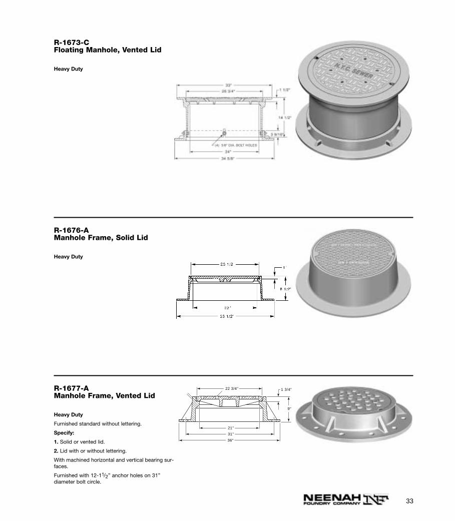
R-1673-CFloating Manhole, Vented Lid
Heavy Duty
R-1676-AManhole Frame, Solid Lid
Heavy Duty
R-1677-AManhole Frame, Vented Lid
Heavy Duty
Furnished standard without lettering.
Specify:
1. Solid or vented lid.
2. Lid with or without lettering.
With machined horizontal and vertical bearing sur-faces.
Furnished with 12-11/2” anchor holes on 31”diameter bolt circle.
22 3/4"
21"
31"
36"
9"
1 3/4"
34
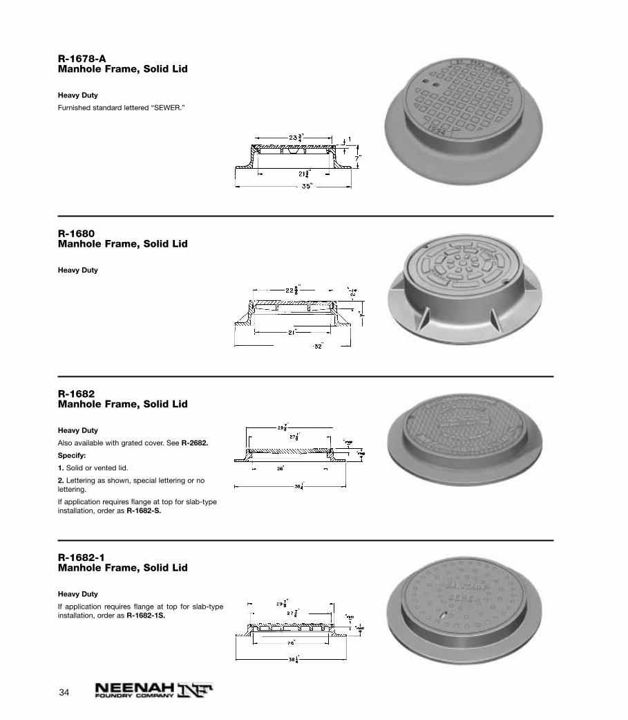
R-1678-AManhole Frame, Solid Lid
Heavy Duty
Furnished standard lettered “SEWER.”
R-1680Manhole Frame, Solid Lid
Heavy Duty
R-1682Manhole Frame, Solid Lid
Heavy Duty
Also available with grated cover. See R-2682.
Specify:
1. Solid or vented lid.
2. Lettering as shown, special lettering or no lettering.
If application requires flange at top for slab-typeinstallation, order as R-1682-S.
R-1682-1Manhole Frame, Solid Lid
Heavy Duty
If application requires flange at top for slab-typeinstallation, order as R-1682-1S.
35
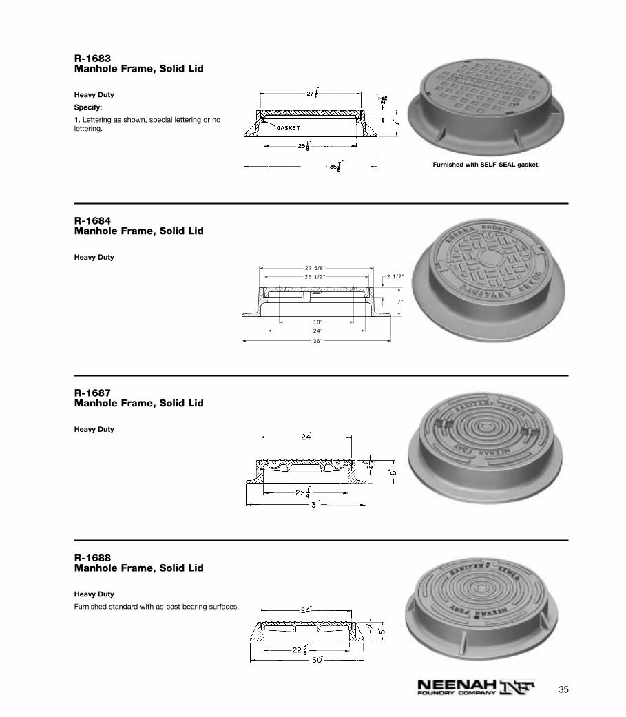
R-1683Manhole Frame, Solid Lid
Heavy Duty
Specify:
1. Lettering as shown, special lettering or no lettering.
Furnished with SELF-SEAL gasket.
R-1684Manhole Frame, Solid Lid
Heavy Duty
27 5/8"
25 1/2" 2 1/2"
7"
18"
24"
36"
R-1687Manhole Frame, Solid Lid
Heavy Duty
R-1688Manhole Frame, Solid Lid
Heavy Duty
Furnished standard with as-cast bearing surfaces.
36
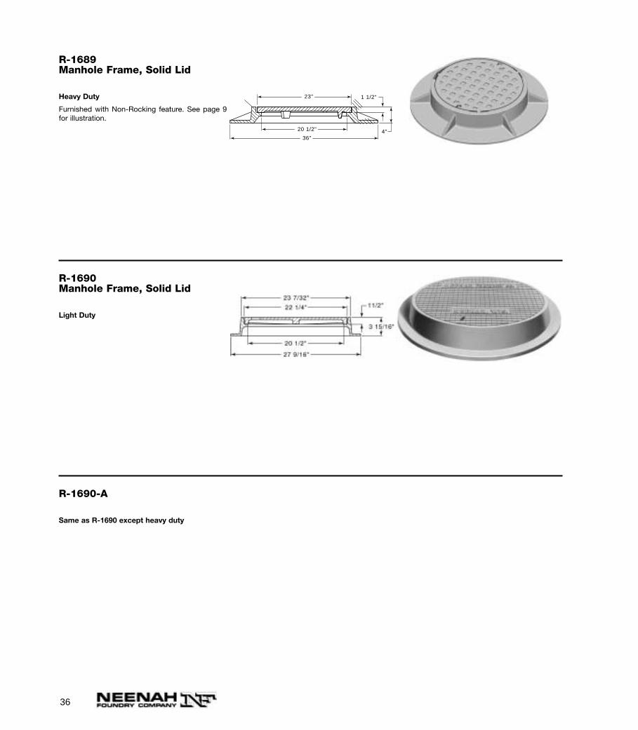
R-1689Manhole Frame, Solid Lid
Heavy Duty
Furnished with Non-Rocking feature. See page 9for illustration.
1 1/2"
4"
23"
36"
20 1/2"
R-1690Manhole Frame, Solid Lid
Light Duty
R-1690-A
Same as R-1690 except heavy duty
37
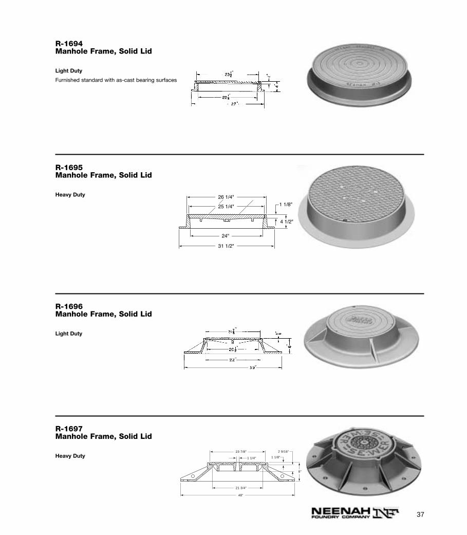
R-1694Manhole Frame, Solid Lid
Light Duty
Furnished standard with as-cast bearing surfaces
R-1695Manhole Frame, Solid Lid
Heavy Duty
1 1/8"
4 1/2"
26 1/4"
25 1/4"
31 1/2"
24"
R-1696Manhole Frame, Solid Lid
Light Duty
R-1697Manhole Frame, Solid Lid
Heavy Duty
1 1/8"1 1/4"
2 9/16"
8"
23 7/8"
21 3/4"
48"
38
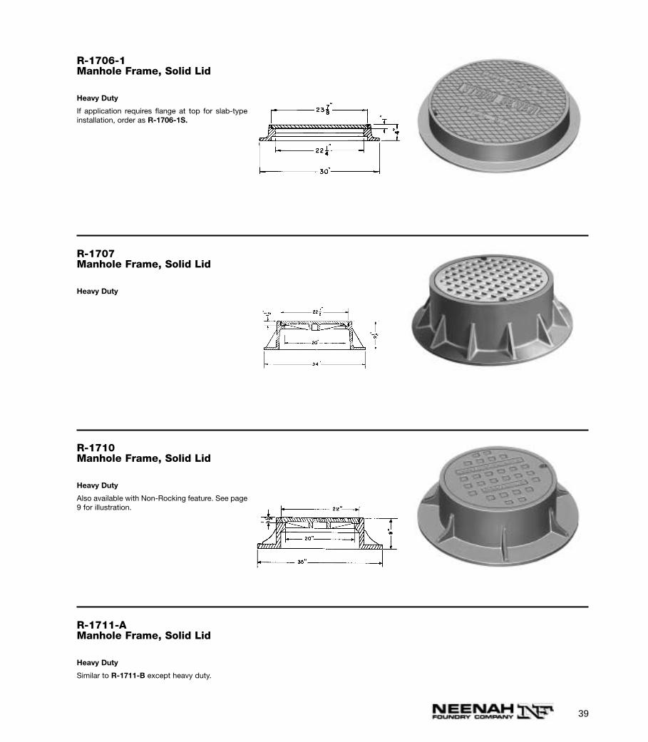
R-1700-AManhole Frame, Solid Lid
Heavy Duty
Also available with Non-Rocking feature. Seepage 9 for illustration.
R-1703Manhole Frame, Solid Lid
Heavy Duty
R-1705Manhole Frame, Solid Lid
Heavy Duty
R-1706Manhole Frame, Solid Lid
Heavy Duty24"23 7/8"
22 1/8"
34"
1"
1/2"
8"
39
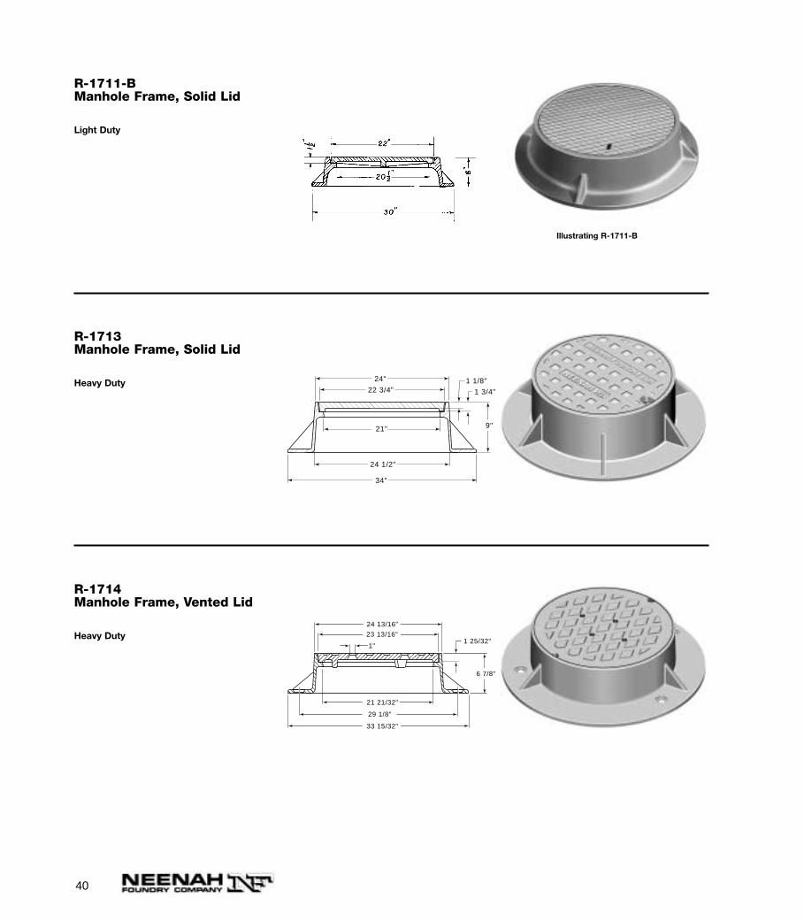
R-1706-1Manhole Frame, Solid Lid
Heavy Duty
If application requires flange at top for slab-typeinstallation, order as R-1706-1S.
R-1707Manhole Frame, Solid Lid
Heavy Duty
R-1710Manhole Frame, Solid Lid
Heavy Duty
Also available with Non-Rocking feature. See page9 for illustration.
R-1711-AManhole Frame, Solid Lid
Heavy Duty
Similar to R-1711-B except heavy duty.
40
R-1711-BManhole Frame, Solid Lid
Light Duty
Illustrating R-1711-B
R-1713Manhole Frame, Solid Lid
Heavy Duty
22 3/4"
24"
34"
21"
24 1/2"
1 1/8"
1 3/4"
9"
R-1714Manhole Frame, Vented Lid
Heavy Duty1 25/32"
24 13/16"
23 13/16"
21 21/32"
29 1/8"
33 15/32"
6 7/8"
1"
41
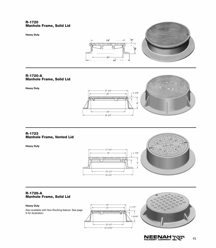
R-1720-AManhole Frame, Solid Lid
Heavy Duty
34 1/2"
27 1/4"1 1/8"26"
8"
24"
R-1723Manhole Frame, Vented Lid
Heavy Duty
1 7/8"
27 3/4"
26"
8"
23 1/2"
35 3/4"
R-1726-AManhole Frame, Solid Lid
Heavy Duty
Also available with Non-Rocking feature. See page9 for illustration.
34 21/32"
25"1 1/2"24"
22 1/4"
7 15/32"
R-1720Manhole Frame, Solid Lid
Heavy Duty
42
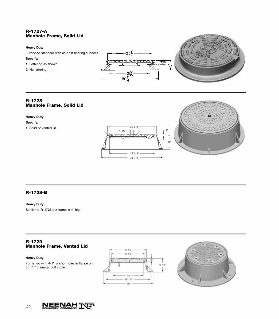
R-1727-AManhole Frame, Solid Lid
Heavy Duty
Furnished standard with as-cast bearing surfaces.
Specify:
1. Lettering as shown
2. No lettering
R-1728Manhole Frame, Solid Lid
Heavy Duty
Specify:
1. Solid or vented lid. 25 5/8"
23 5/8"
31 7/8"
8"
1"1 1/2"
R-1728-B
Heavy Duty
Similar to R-1728 but frame is 4” high.
R-1729Manhole Frame, Vented Lid
Heavy Duty
Furnished with 4-1” anchor holes in flange on 35 1/2” diameter bolt circle.
43
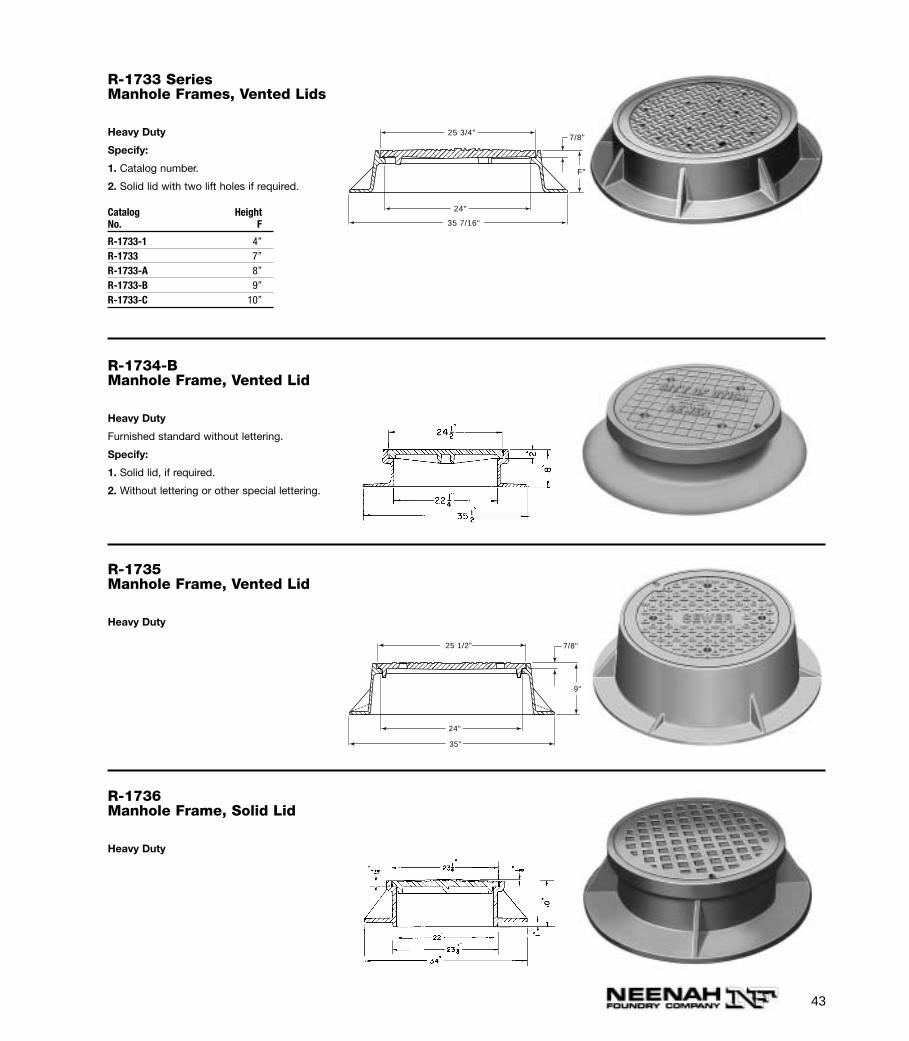
R-1734-BManhole Frame, Vented Lid
Heavy Duty
Furnished standard without lettering.
Specify:
1. Solid lid, if required.
2. Without lettering or other special lettering.
R-1735Manhole Frame, Vented Lid
Heavy Duty
25 1/2"
24"
35"
9"
7/8"
R-1736Manhole Frame, Solid Lid
Heavy Duty
R-1733 SeriesManhole Frames, Vented Lids
Heavy Duty
Specify:
1. Catalog number.
2. Solid lid with two lift holes if required.
Catalog HeightNo. F
R-1733-1 4”R-1733 7”R-1733-A 8”R-1733-B 9”R-1733-C 10”
35 7/16"
7/8"25 3/4"
F"
24"
44
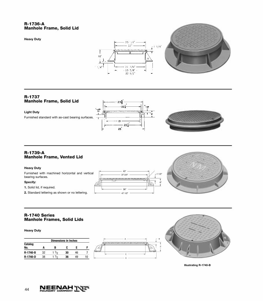
R-1736-AManhole Frame, Solid Lid
Heavy Duty
R-1737Manhole Frame, Solid Lid
Light Duty
Furnished standard with as-cast bearing surfaces.
R-1739-AManhole Frame, Vented Lid
Heavy Duty
Furnished with machined horizontal and verticalbearing surfaces.
Specify:
1. Solid lid, if required.
2. Standard lettering as shown or no lettering.
40"
47 1/2"
37 3/4"
36"
1 1/2"
6"
R-1740 SeriesManhole Frames, Solid Lids
Heavy Duty
Dimensions in InchesCatalogNo. A B C E F
R-1740-B 32 1 1/2 30 46 7R-1740-D 38 1 1/2 36 49 10
A B
C
E
F
Illustrating R-1740-B

45
R-1740-1 SeriesLarge Manhole Frames, Solid Lid with Removable Center Lid
Heavy Duty
Removable 22” diameter lid provides easy access to underground vault. R-1741-D off center accesslid aligns with permanent underground ladder fastened to vault wall.
Dimensions in InchesCatalog LidNo. A AA B C E F Type
R-1740-D2 38 19 1 1/2 36 49 10 BR-1740-E 44 22 1 3/4 42 56 10 BR-1740-E1 (See note below**)R-1740-F† 50 25 2 48 62 10 BR-1741-D* 38 — 1 1/2 36 49 10 CR-1741-E* 44 — 1 3/4 42 56 10 CR-1741-F*† 50 — 2 48 62 10 C
*22” diameter center lid located 6” off center.**Same as R-1740-E, except center lid has 31 15/16” diameter.†Base flange (Dimension E) is flattened to 59” at four quarter points.
Illustrating R-1740-E with type “B” lid.
Illustrating R-1741 Series type “C” Access lid
R-1741-F1Manhole Frame, Solid LidRemovable Center Lid
Heavy Duty
Illustrating R-1740Series with 22” dia.access lid.
Illustrating R-1741Series with accesslid off center
46
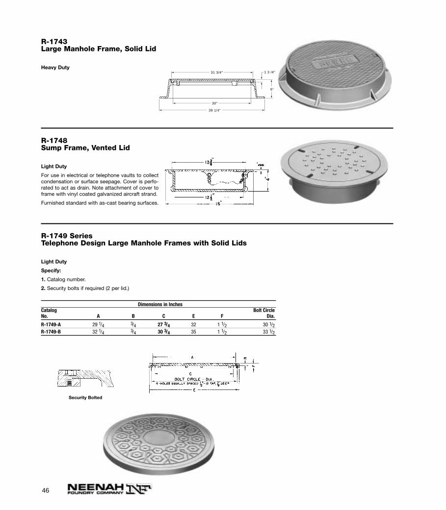
R-1743Large Manhole Frame, Solid Lid
Heavy Duty
39 1/4"
1 3 /4"31 3/4"
6"
30"
R-1748Sump Frame, Vented Lid
Light Duty
For use in electrical or telephone vaults to collectcondensation or surface seepage. Cover is perfo-rated to act as drain. Note attachment of cover toframe with vinyl coated galvanized aircraft strand.
Furnished standard with as-cast bearing surfaces.
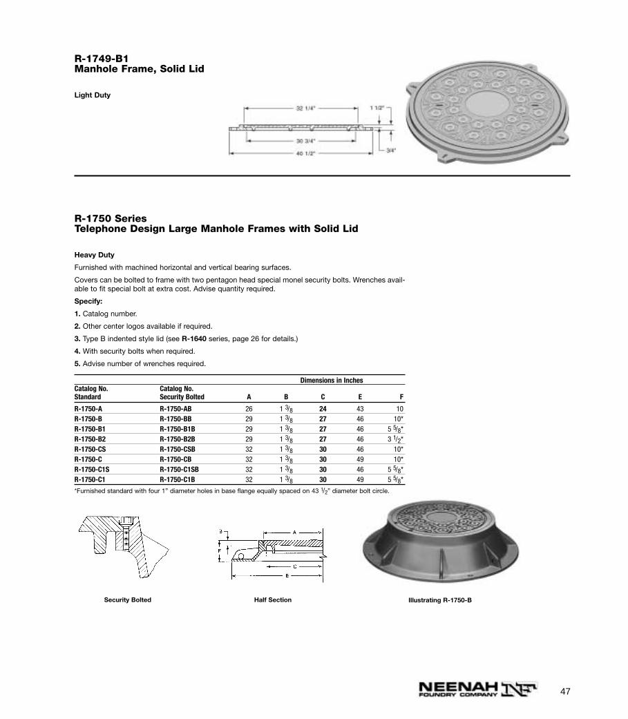
R-1749 SeriesTelephone Design Large Manhole Frames with Solid Lids
Light Duty
Specify:
1. Catalog number.
2. Security bolts if required (2 per lid.)
Dimensions in InchesCatalog Bolt CircleNo. A B C E F Dia.
R-1749-A 29 1/4 3/4 27 3/4 32 1 1/2 30 1/2R-1749-B 32 1/4 3/4 30 3/4 35 1 1/2 33 1/2
Security Bolted
47
R-1749-B1Manhole Frame, Solid Lid
Light Duty
Dimensions in InchesCatalog No. Catalog No.Standard Security Bolted A B C E F
R-1750-A R-1750-AB 26 1 3/8 24 43 10R-1750-B R-1750-BB 29 1 3/8 27 46 10*R-1750-B1 R-1750-B1B 29 1 3/8 27 46 5 5/8*R-1750-B2 R-1750-B2B 29 1 3/8 27 46 3 1/2*R-1750-CS R-1750-CSB 32 1 3/8 30 46 10*R-1750-C R-1750-CB 32 1 3/8 30 49 10*R-1750-C1S R-1750-C1SB 32 1 3/8 30 46 5 5/8*R-1750-C1 R-1750-C1B 32 1 3/8 30 49 5 5/8*
*Furnished standard with four 1” diameter holes in base flange equally spaced on 43 1/2” diameter bolt circle.
Security Bolted Half Section Illustrating R-1750-B
R-1750 SeriesTelephone Design Large Manhole Frames with Solid Lid
Heavy Duty
Furnished with machined horizontal and vertical bearing surfaces.
Covers can be bolted to frame with two pentagon head special monel security bolts. Wrenches avail-able to fit special bolt at extra cost. Advise quantity required.
Specify:
1. Catalog number.
2. Other center logos available if required.
3. Type B indented style lid (see R-1640 series, page 26 for details.)
4. With security bolts when required.
5. Advise number of wrenches required.
48
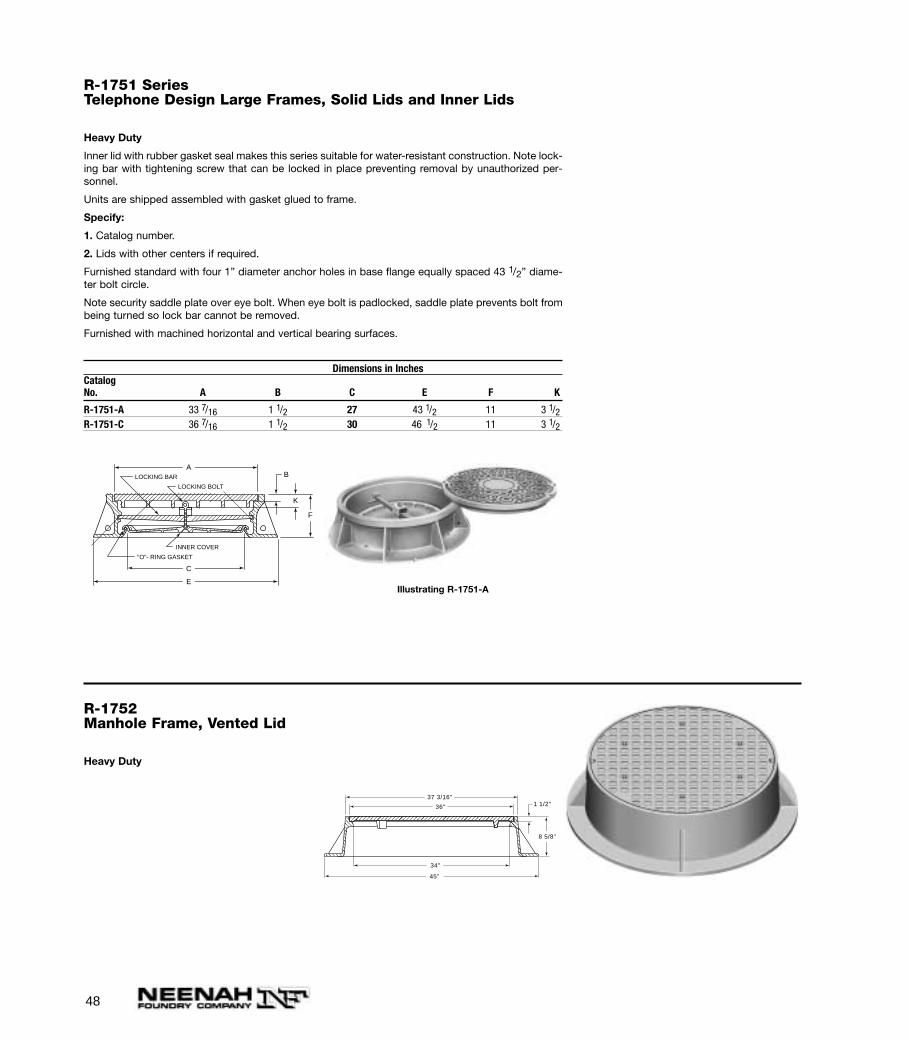
R-1751 SeriesTelephone Design Large Frames, Solid Lids and Inner Lids
Heavy Duty
Inner lid with rubber gasket seal makes this series suitable for water-resistant construction. Note lock-ing bar with tightening screw that can be locked in place preventing removal by unauthorized per-sonnel.
Units are shipped assembled with gasket glued to frame.
Specify:
1. Catalog number.
2. Lids with other centers if required.
Furnished standard with four 1” diameter anchor holes in base flange equally spaced 43 1/2” diame-ter bolt circle.
Note security saddle plate over eye bolt. When eye bolt is padlocked, saddle plate prevents bolt frombeing turned so lock bar cannot be removed.
Furnished with machined horizontal and vertical bearing surfaces.
Dimensions in InchesCatalogNo. A B C E F K
R-1751-A 33 7/16 1 1/2 27 43 1/2 11 3 1/2R-1751-C 36 7/16 1 1/2 30 46 1/2 11 3 1/2
A
C
E
K
F
B
"O"- RING GASKET
LOCKING BAR
INNER COVER
LOCKING BOLT
Illustrating R-1751-A
R-1752Manhole Frame, Vented Lid
Heavy Duty
45"
37 3/16"1 1/2"36"
34"
8 5/8"

49
R-1753-AManhole Frame, Solid Lid
Heavy Duty
With 4-7/8” anchor holes.
37 1/4"
34 1/4"
1 3/8"28 3/4"
7"
27 1/8"
Illustrating R-1753-A
R-1753-B
Heavy Duty
Same as R-1753-A except frame is 3” high.
R-1754-AManhole Frame, Solid Lid
Heavy Duty
29 5/8"
4"
28"
36"
1 1/2"
50
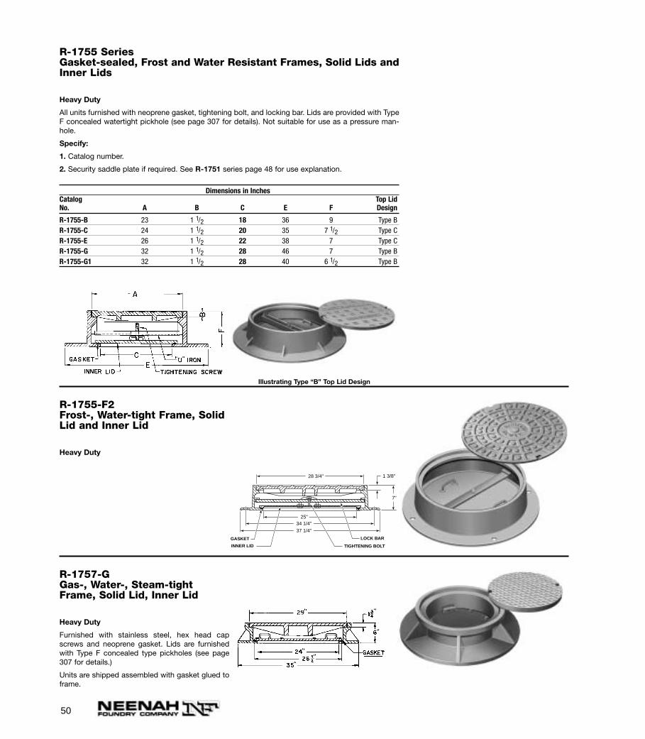
R-1755 SeriesGasket-sealed, Frost and Water Resistant Frames, Solid Lids andInner Lids
Heavy Duty
All units furnished with neoprene gasket, tightening bolt, and locking bar. Lids are provided with TypeF concealed watertight pickhole (see page 307 for details). Not suitable for use as a pressure man-hole.
Specify:
1. Catalog number.
2. Security saddle plate if required. See R-1751 series page 48 for use explanation.
Dimensions in InchesCatalog Top LidNo. A B C E F Design
R-1755-B 23 1 1/2 18 36 9 Type BR-1755-C 24 1 1/2 20 35 7 1/2 Type CR-1755-E 26 1 1/2 22 38 7 Type CR-1755-G 32 1 1/2 28 46 7 Type BR-1755-G1 32 1 1/2 28 40 6 1/2 Type B
Illustrating Type “B” Top Lid Design
R-1755-F2Frost-, Water-tight Frame, SolidLid and Inner Lid
Heavy Duty
1 3/8"
GASKET
7"
25"
28 3/4"
37 1/4"34 1/4"
INNER LID
LOCK BAR
TIGHTENING BOLT
R-1757-GGas-, Water-, Steam-tightFrame, Solid Lid, Inner Lid
Heavy Duty
Furnished with stainless steel, hex head capscrews and neoprene gasket. Lids are furnishedwith Type F concealed type pickholes (see page307 for details.)
Units are shipped assembled with gasket glued toframe.
51
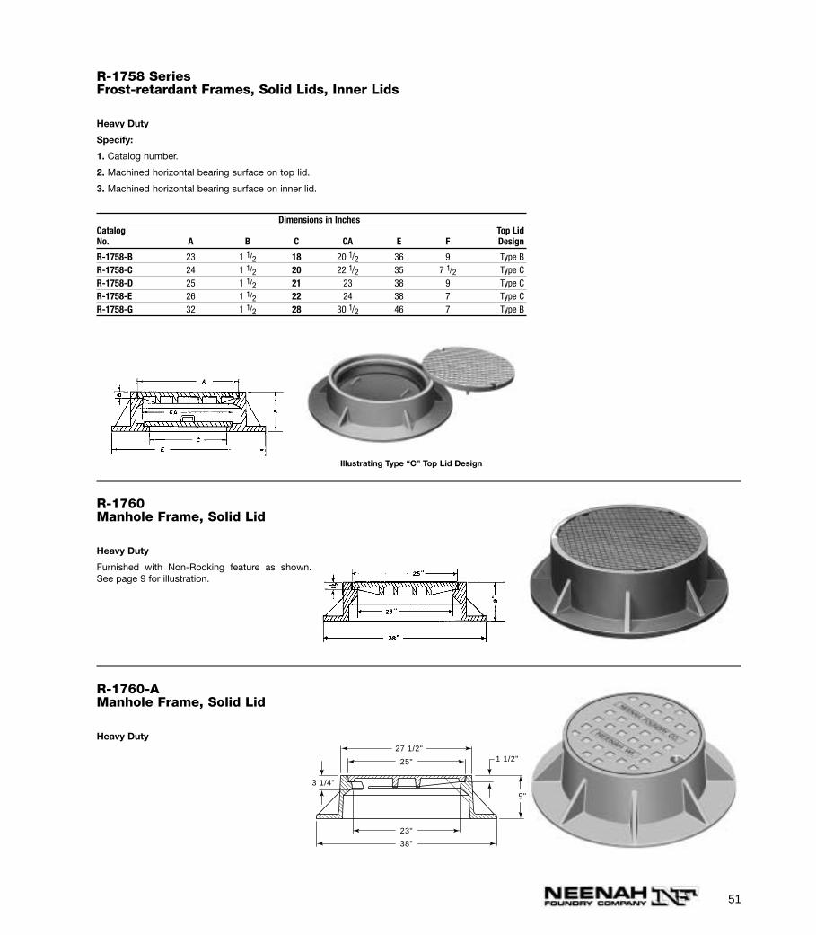
R-1758 SeriesFrost-retardant Frames, Solid Lids, Inner Lids
Heavy Duty
Specify:
1. Catalog number.
2. Machined horizontal bearing surface on top lid.
3. Machined horizontal bearing surface on inner lid.
Dimensions in InchesCatalog Top LidNo. A B C CA E F Design
R-1758-B 23 1 1/2 18 20 1/2 36 9 Type BR-1758-C 24 1 1/2 20 22 1/2 35 7 1/2 Type CR-1758-D 25 1 1/2 21 23 38 9 Type CR-1758-E 26 1 1/2 22 24 38 7 Type CR-1758-G 32 1 1/2 28 30 1/2 46 7 Type B
Illustrating Type “C” Top Lid Design
R-1760Manhole Frame, Solid Lid
Heavy Duty
Furnished with Non-Rocking feature as shown.See page 9 for illustration.
R-1760-AManhole Frame, Solid Lid
Heavy Duty
1 1/2"
3 1/4"
9"
27 1/2"
25"
23"
38"
52
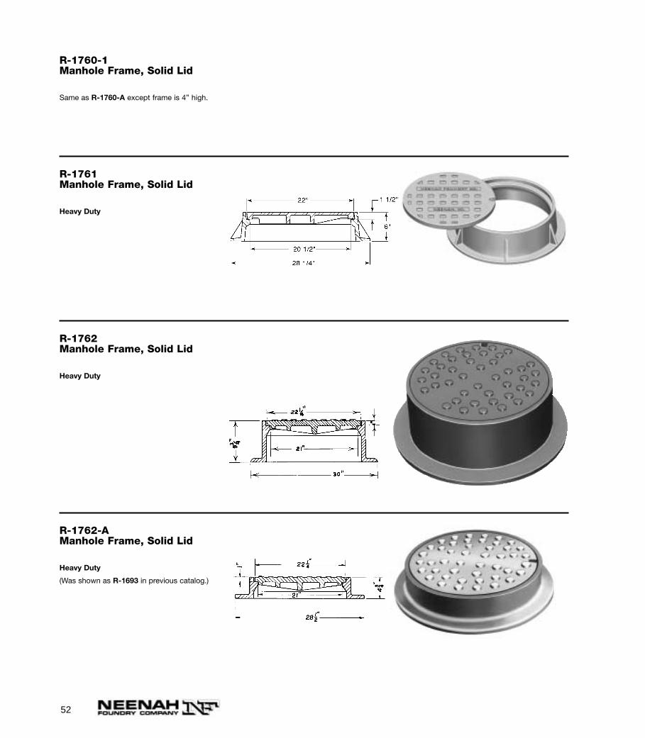
R-1760-1Manhole Frame, Solid Lid
Same as R-1760-A except frame is 4” high.
R-1761Manhole Frame, Solid Lid
Heavy Duty
R-1762Manhole Frame, Solid Lid
Heavy Duty
R-1762-AManhole Frame, Solid Lid
Heavy Duty
(Was shown as R-1693 in previous catalog.)
53
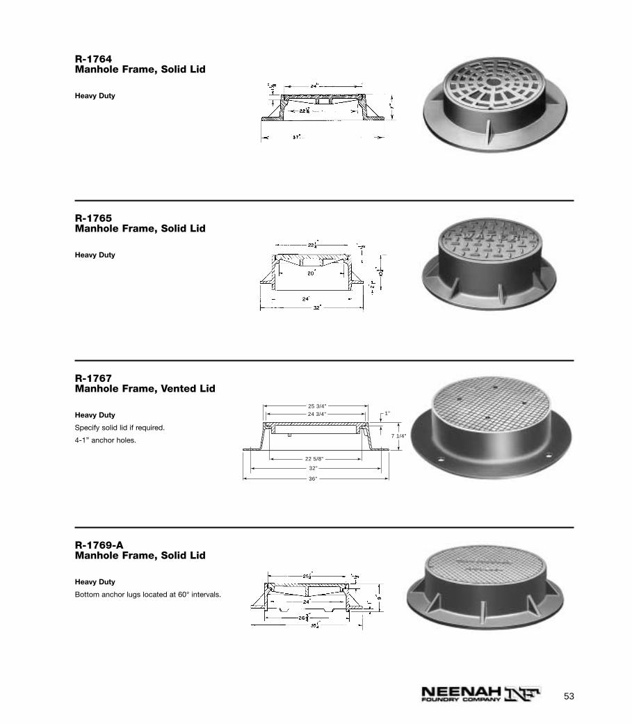
R-1764Manhole Frame, Solid Lid
Heavy Duty
R-1765Manhole Frame, Solid Lid
Heavy Duty
R-1767Manhole Frame, Vented Lid
Heavy Duty
Specify solid lid if required.
4-1” anchor holes.
24 3/4"
25 3/4"
36"
22 5/22 5/8"
32"
1"
7 1/4"
R-1769-AManhole Frame, Solid Lid
Heavy Duty
Bottom anchor lugs located at 60° intervals.
54
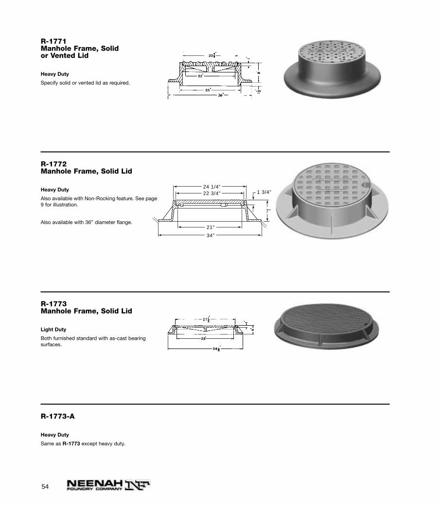
R-1771Manhole Frame, Solidor Vented Lid
Heavy Duty
Specify solid or vented lid as required.
R-1772Manhole Frame, Solid Lid
Heavy Duty
Also available with Non-Rocking feature. See page9 for illustration.
Also available with 36” diameter flange.
1 3/4"
7"
24 1/4"22 3/4"
21"
34"
R-1773Manhole Frame, Solid Lid
Light Duty
Both furnished standard with as-cast bearing surfaces.
R-1773-A
Heavy Duty
Same as R-1773 except heavy duty.
55
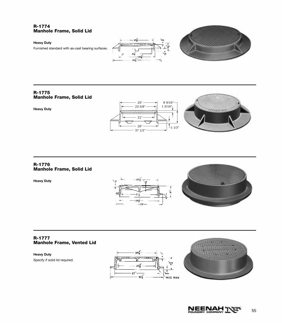
R-1774Manhole Frame, Solid Lid
Heavy Duty
Furnished standard with as-cast bearing surfaces.
R-1775Manhole Frame, Solid Lid
Heavy Duty
25"
26"
21"
23 5/8"
37 1/2"1 1/2"
1 5/16"8 9/16"
R-1776Manhole Frame, Solid Lid
Heavy Duty
R-1777Manhole Frame, Vented Lid
Heavy Duty
Specify if solid lid required.
56
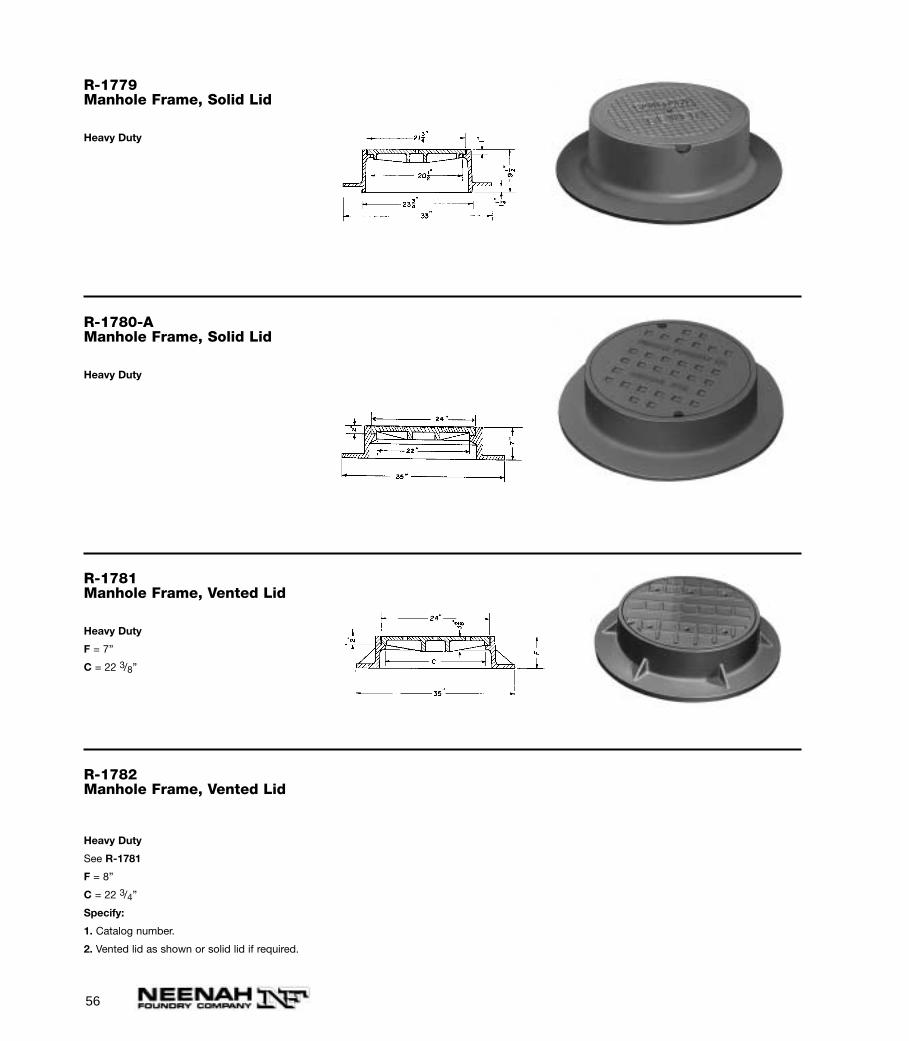
R-1779Manhole Frame, Solid Lid
Heavy Duty
R-1780-AManhole Frame, Solid Lid
Heavy Duty
R-1781Manhole Frame, Vented Lid
Heavy Duty
F = 7”
C = 22 3/8”
R-1782Manhole Frame, Vented Lid
Heavy Duty
See R-1781
F = 8”
C = 22 3/4”
Specify:
1. Catalog number.
2. Vented lid as shown or solid lid if required.
57
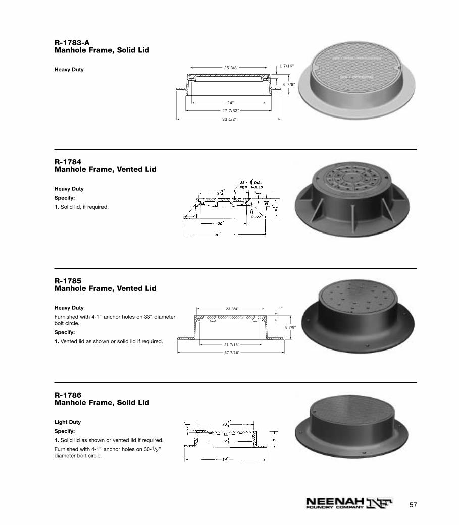
R-1783-AManhole Frame, Solid Lid
Heavy Duty
33 1/2"
27 7/32"
1 7/16"25 3/8"
24"
6 7/8"
R-1784Manhole Frame, Vented Lid
Heavy Duty
Specify:
1. Solid lid, if required.
R-1785Manhole Frame, Vented Lid
Heavy Duty
Furnished with 4-1” anchor holes on 33” diameterbolt circle.
Specify:
1. Vented lid as shown or solid lid if required.
37 7/16"
1"23 3/4"
8 7/8"
21 7/16"
R-1786Manhole Frame, Solid Lid
Light Duty
Specify:
1. Solid lid as shown or vented lid if required.
Furnished with 4-1” anchor holes on 30-1/2” diameter bolt circle.

58
R-1787Manhole Frame, Vented Lid
Heavy Duty
Specify:
1. Vented lid as shown or solid lid if required.
Furnished with 4-1” anchor holes on 28-3/4”diameter bolt circle.
31 1/4"
1"23 3/4"
4 5/8"
23 "
R-1788-AManhole Frame, Solid Lid
Heavy Duty
R-1788-B
Heavy Duty
Same as R-1788-A except lid has 12 slots 1 5/8” x 4 7/8”.
R-1788-DManhole Frame, Solid Lid
Heavy Duty
R-1788-A1Manhole Frame, Solid Lid
Heavy Duty
Available with integral cast stainless steelhandles.
3"
23 13/16"
21 1/16"
27 15/16"
31 1/2"
7 1/16"
59
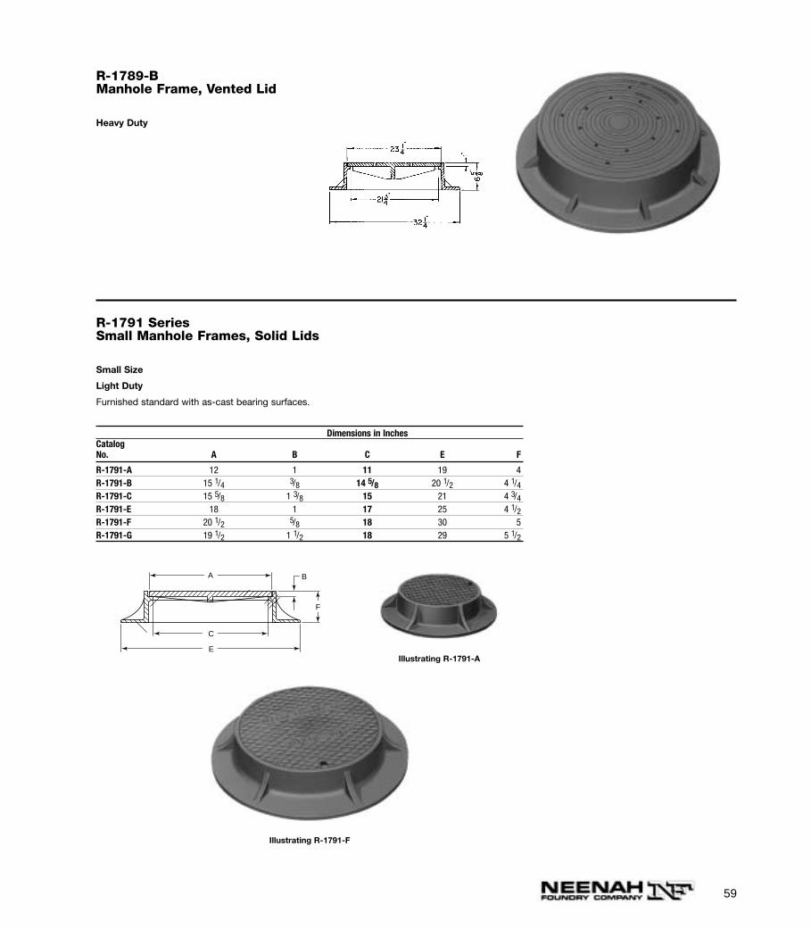
R-1789-BManhole Frame, Vented Lid
Heavy Duty
R-1791 SeriesSmall Manhole Frames, Solid Lids
Small Size
Light Duty
Furnished standard with as-cast bearing surfaces.
Dimensions in InchesCatalogNo. A B C E F
R-1791-A 12 1 11 19 4R-1791-B 15 1/4 3/8 14 5/8 20 1/2 4 1/4R-1791-C 15 5/8 1 3/8 15 21 4 3/4R-1791-E 18 1 17 25 4 1/2R-1791-F 20 1/2 5/8 18 30 5R-1791-G 19 1/2 1 1/2 18 29 5 1/2
A B
C
E
F
Illustrating R-1791-A
Illustrating R-1791-F
60
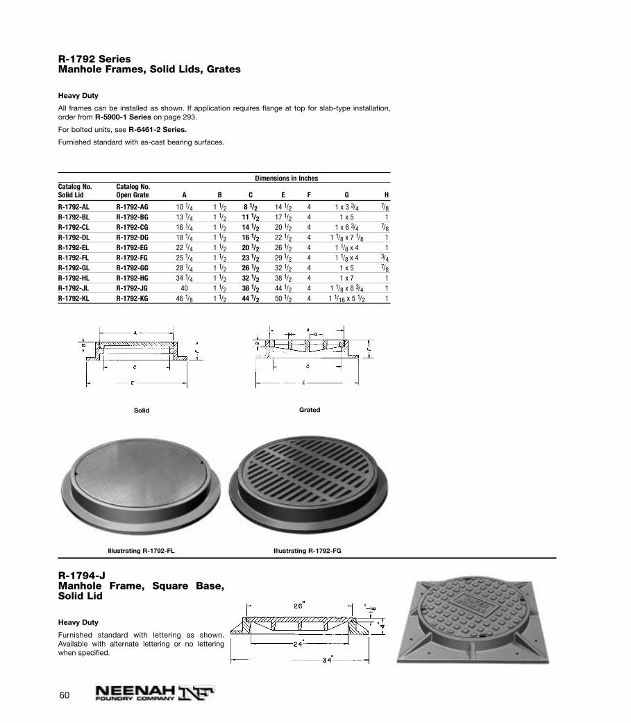
R-1792 SeriesManhole Frames, Solid Lids, Grates
Heavy Duty
All frames can be installed as shown. If application requires flange at top for slab-type installation,order from R-5900-1 Series on page 293.
For bolted units, see R-6461-2 Series.
Furnished standard with as-cast bearing surfaces.
Dimensions in InchesCatalog No. Catalog No.Solid Lid Open Grate A B C E F G H
R-1792-AL R-1792-AG 10 1/4 1 1/2 8 1/2 14 1/2 4 1 x 3 3/4 7/8R-1792-BL R-1792-BG 13 1/4 1 1/2 11 1/2 17 1/2 4 1 x 5 1R-1792-CL R-1792-CG 16 1/4 1 1/2 14 1/2 20 1/2 4 1 x 6 3/4 7/8R-1792-DL R-1792-DG 18 1/4 1 1/2 16 1/2 22 1/2 4 1 1/8 x 7 1/8 1R-1792-EL R-1792-EG 22 1/4 1 1/2 20 1/2 26 1/2 4 1 1/8 x 4 1R-1792-FL R-1792-FG 25 1/4 1 1/2 23 1/2 29 1/2 4 1 1/8 x 4 3/4R-1792-GL R-1792-GG 28 1/4 1 1/2 26 1/2 32 1/2 4 1 x 5 7/8R-1792-HL R-1792-HG 34 1/4 1 1/2 32 1/2 38 1/2 4 1 x 7 1R-1792-JL R-1792-JG 40 1 1/2 38 1/2 44 1/2 4 1 1/8 x 8 3/4 1R-1792-KL R-1792-KG 46 1/8 1 1/2 44 1/2 50 1/2 4 1 1/16 x 5 1/2 1
GratedSolid
Illustrating R-1792-FL Illustrating R-1792-FG
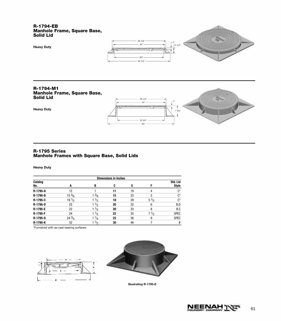
R-1794-JManhole Frame, Square Base,Solid Lid
Heavy Duty
Furnished standard with lettering as shown.Available with alternate lettering or no letteringwhen specified.
61
R-1794-EBManhole Frame, Square Base,Solid Lid
Heavy Duty
35 1/4"
32"
34"
40 1/2"
1"3 1/2"
R-1794-M1Manhole Frame, Square Base,Solid Lid
Heavy Duty
35 1/4"
32 3/4"
34"
46"
1"
7 3/4"
R-1795 SeriesManhole Frames with Square Base, Solid Lids
Heavy Duty
Dimensions in InchesCatalog Std. LidNo. A B C E F Style
R-1795-A 12 1 11 19 4 C*R-1795-B 15 5/8 1 3/8 15 23 5 C*R-1795-C 19 1/2 1 1/2 18 29 5 1/2 C*R-1795-D 22 1 1/2 20 32 6 B,DR-1795-E 22 1 1/2 20 33 8 B,CR-1795-F 24 1 1/2 22 35 7 1/2 SPECR-1795-G 24 3/4 1 1/4 22 36 9 SPECR-1795-K 32 1 1/2 30 46 7 B
*Furnished with as-cast bearing surfaces.
Illustrating R-1795-E
62
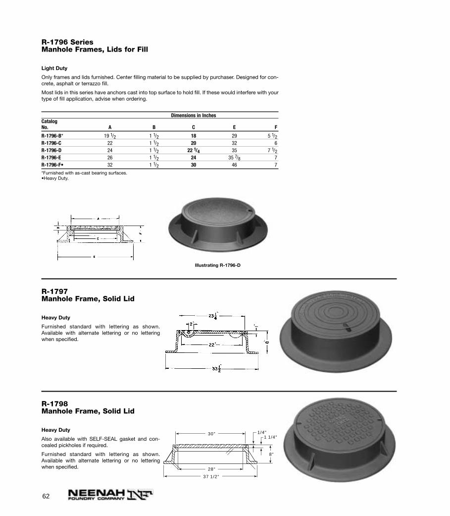
R-1796 SeriesManhole Frames, Lids for Fill
Light Duty
Only frames and lids furnished. Center filling material to be supplied by purchaser. Designed for con-crete, asphalt or terrazzo fill.
Most lids in this series have anchors cast into top surface to hold fill. If these would interfere with yourtype of fill application, advise when ordering.
Dimensions in InchesCatalogNo. A B C E F
R-1796-B* 19 1/2 1 1/2 18 29 5 1/2R-1796-C 22 1 1/2 20 32 6R-1796-D 24 1 1/2 22 1/4 35 7 1/2R-1796-E 26 1 1/2 24 35 7/8 7R-1796-F• 32 1 1/2 30 46 7
*Furnished with as-cast bearing surfaces.•Heavy Duty.
Illustrating R-1796-D
R-1797Manhole Frame, Solid Lid
Heavy Duty
Furnished standard with lettering as shown.Available with alternate lettering or no letteringwhen specified.
R-1798Manhole Frame, Solid Lid
Heavy Duty
Also available with SELF-SEAL gasket and con-cealed pickholes if required.
Furnished standard with lettering as shown.Available with alternate lettering or no letteringwhen specified.
30"
28"
37 1/2"
1/4"1 1/4"
8"
63
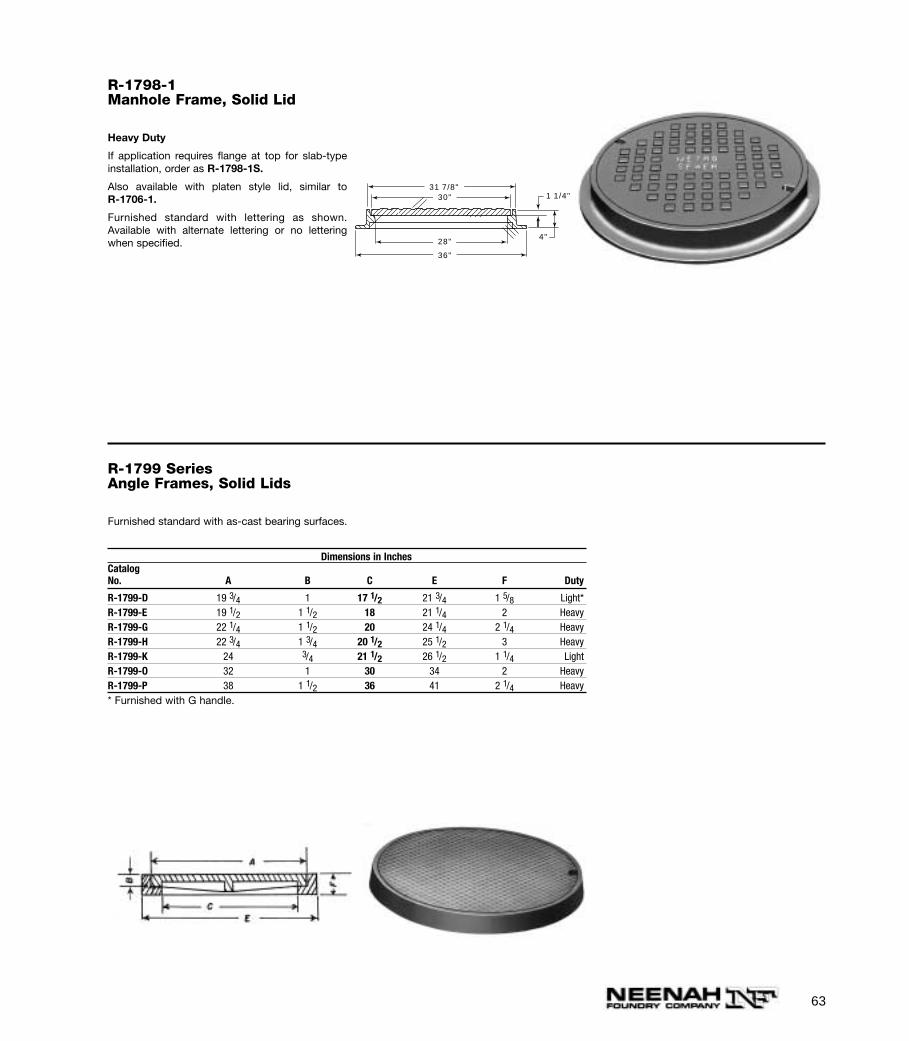
R-1798-1Manhole Frame, Solid Lid
Heavy Duty
If application requires flange at top for slab-typeinstallation, order as R-1798-1S.
Also available with platen style lid, similar to R-1706-1.
Furnished standard with lettering as shown.Available with alternate lettering or no letteringwhen specified.
30"
36"
28"
31 7/8"1 1/4"
4"
R-1799 SeriesAngle Frames, Solid Lids
Furnished standard with as-cast bearing surfaces.
Dimensions in InchesCatalogNo. A B C E F Duty
R-1799-D 19 3/4 1 17 1/2 21 3/4 1 5/8 Light*R-1799-E 19 1/2 1 1/2 18 21 1/4 2 HeavyR-1799-G 22 1/4 1 1/2 20 24 1/4 2 1/4 HeavyR-1799-H 22 3/4 1 3/4 20 1/2 25 1/2 3 HeavyR-1799-K 24 3/4 21 1/2 26 1/2 1 1/4 LightR-1799-O 32 1 30 34 2 HeavyR-1799-P 38 1 1/2 36 41 2 1/4 Heavy* Furnished with G handle.
64
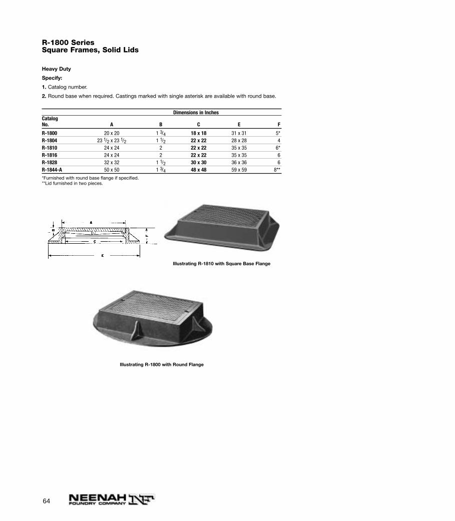
R-1800 SeriesSquare Frames, Solid Lids
Heavy Duty
Specify:
1. Catalog number.
2. Round base when required. Castings marked with single asterisk are available with round base.
Dimensions in InchesCatalogNo. A B C E F
R-1800 20 x 20 1 3/4 18 x 18 31 x 31 5*R-1804 23 1/2 x 23 1/2 1 1/2 22 x 22 28 x 28 4R-1810 24 x 24 2 22 x 22 35 x 35 6*R-1816 24 x 24 2 22 x 22 35 x 35 6R-1828 32 x 32 1 1/2 30 x 30 36 x 36 6R-1844-A 50 x 50 1 3/4 48 x 48 59 x 59 8**
*Furnished with round base flange if specified.**Lid furnished in two pieces.
Illustrating R-1810 with Square Base Flange
Illustrating R-1800 with Round Flange
65
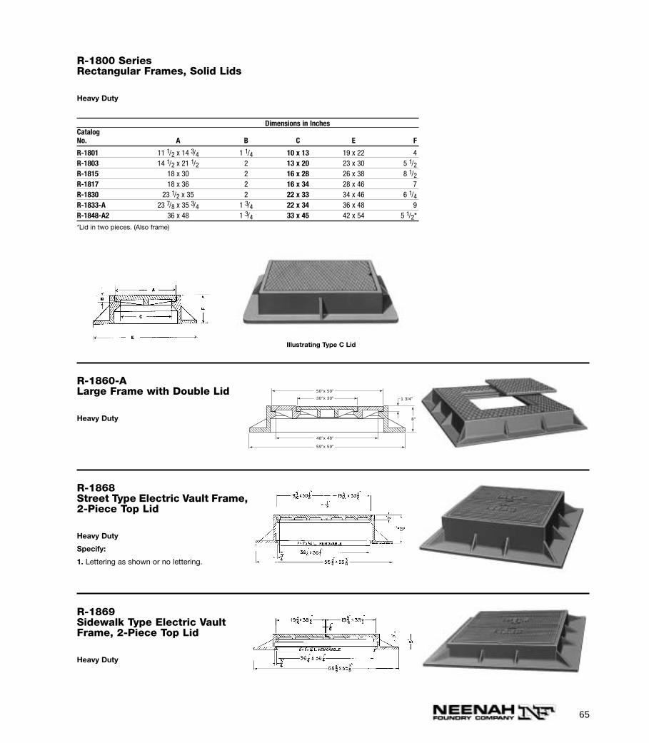
R-1800 SeriesRectangular Frames, Solid Lids
Heavy Duty
Dimensions in InchesCatalogNo. A B C E F
R-1801 11 1/2 x 14 3/4 1 1/4 10 x 13 19 x 22 4R-1803 14 1/2 x 21 1/2 2 13 x 20 23 x 30 5 1/2R-1815 18 x 30 2 16 x 28 26 x 38 8 1/2R-1817 18 x 36 2 16 x 34 28 x 46 7R-1830 23 1/2 x 35 2 22 x 33 34 x 46 6 1/4R-1833-A 23 7/8 x 35 3/4 1 3/4 22 x 34 36 x 48 9R-1848-A2 36 x 48 1 3/4 33 x 45 42 x 54 5 1/2*
*Lid in two pieces. (Also frame)
Illustrating Type C Lid
R-1860-ALarge Frame with Double Lid
Heavy Duty
50"x 50"
59"x 59"
30"x 30"
48"x 48"
1 3/4"
8"
R-1868Street Type Electric Vault Frame,2-Piece Top Lid
Heavy Duty
Specify:
1. Lettering as shown or no lettering.
R-1869Sidewalk Type Electric VaultFrame, 2-Piece Top Lid
Heavy Duty

66
R-1870Electric Vault Frame, Lid
Heavy Duty
4-Vent Holes
2-Lift Slots
Specify:
1. Lettering as shown, or no lettering. Special let-tering at extra cost.
R-1871 SeriesSquare Frames with Inner Lid and Locking Bar
Heavy Duty
Inner lid with machined seat and gasket for water-resistant function.
Units are shipped assembled with gasket glued to frame.
Specify:
1. Security saddle plate if required. See R-1751 Series page 48 for use explanation.
Dimensions in InchesCatalogNo. A B C CA E F
R-1871-D** 36 x 36 1 3/4 32 x 32 34 x 34 45 x 45 7
**2 Pc. top lid and 2 lock bars.
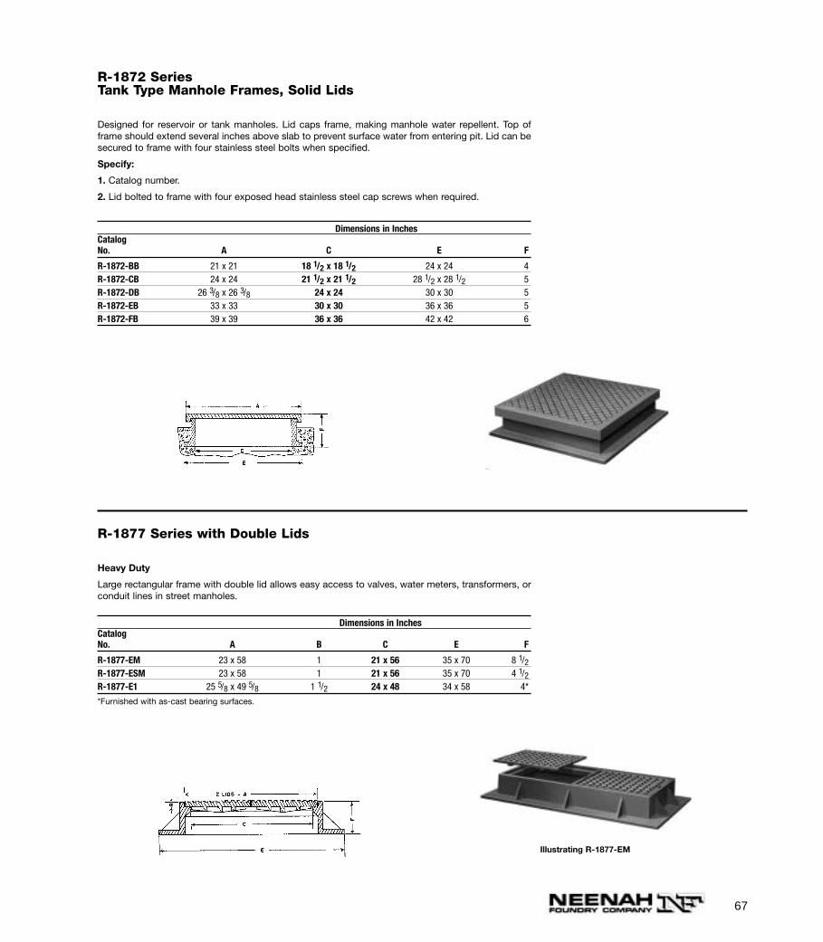
R-1872 SeriesTank Type Manhole Frames, Solid Lids
Designed for reservoir or tank manholes. Lid caps frame, making manhole water repellent. Top offrame should extend several inches above slab to prevent surface water from entering pit. Lid can besecured to frame with four stainless steel bolts when specified.
Specify:
1. Catalog number.
2. Lid bolted to frame with four exposed head stainless steel cap screws when required.
Dimensions in InchesCatalogNo. A C E F
R-1872-BB 21 x 21 18 1/2 x 18 1/2 24 x 24 4R-1872-CB 24 x 24 21 1/2 x 21 1/2 28 1/2 x 28 1/2 5R-1872-DB 26 3/8 x 26 3/8 24 x 24 30 x 30 5R-1872-EB 33 x 33 30 x 30 36 x 36 5R-1872-FB 39 x 39 36 x 36 42 x 42 6
R-1877 Series with Double Lids
Heavy Duty
Large rectangular frame with double lid allows easy access to valves, water meters, transformers, orconduit lines in street manholes.
Dimensions in InchesCatalogNo. A B C E F
R-1877-EM 23 x 58 1 21 x 56 35 x 70 8 1/2R-1877-ESM 23 x 58 1 21 x 56 35 x 70 4 1/2R-1877-E1 25 5/8 x 49 5/8 1 1/2 24 x 48 34 x 58 4*
*Furnished with as-cast bearing surfaces.
Illustrating R-1877-EM
67
68
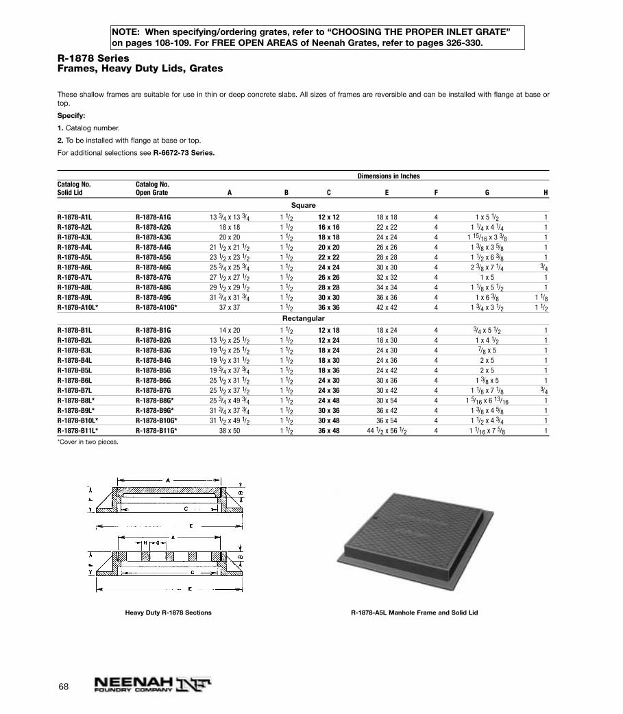
R-1878 SeriesFrames, Heavy Duty Lids, Grates
These shallow frames are suitable for use in thin or deep concrete slabs. All sizes of frames are reversible and can be installed with flange at base ortop.
Specify:
1. Catalog number.
2. To be installed with flange at base or top.
For additional selections see R-6672-73 Series.
Dimensions in InchesCatalog No. Catalog No.Solid Lid Open Grate A B C E F G H
Square
R-1878-A1L R-1878-A1G 13 3/4 x 13 3/4 1 1/2 12 x 12 18 x 18 4 1 x 5 1/2 1R-1878-A2L R-1878-A2G 18 x 18 1 1/2 16 x 16 22 x 22 4 1 1/4 x 4 1/4 1R-1878-A3L R-1878-A3G 20 x 20 1 1/2 18 x 18 24 x 24 4 1 15/16 x 3 3/8 1R-1878-A4L R-1878-A4G 21 1/2 x 21 1/2 1 1/2 20 x 20 26 x 26 4 1 3/8 x 3 5/8 1R-1878-A5L R-1878-A5G 23 1/2 x 23 1/2 1 1/2 22 x 22 28 x 28 4 1 1/2 x 6 3/8 1R-1878-A6L R-1878-A6G 25 3/4 x 25 3/4 1 1/2 24 x 24 30 x 30 4 2 3/8 x 7 1/4 3/4R-1878-A7L R-1878-A7G 27 1/2 x 27 1/2 1 1/2 26 x 26 32 x 32 4 1 x 5 1R-1878-A8L R-1878-A8G 29 1/2 x 29 1/2 1 1/2 28 x 28 34 x 34 4 1 1/8 x 5 1/2 1R-1878-A9L R-1878-A9G 31 3/4 x 31 3/4 1 1/2 30 x 30 36 x 36 4 1 x 6 3/8 1 1/8R-1878-A10L* R-1878-A10G* 37 x 37 1 1/2 36 x 36 42 x 42 4 1 3/4 x 3 1/2 1 1/2
Rectangular
R-1878-B1L R-1878-B1G 14 x 20 1 1/2 12 x 18 18 x 24 4 3/4 x 5 1/2 1R-1878-B2L R-1878-B2G 13 1/2 x 25 1/2 1 1/2 12 x 24 18 x 30 4 1 x 4 1/2 1R-1878-B3L R-1878-B3G 19 1/2 x 25 1/2 1 1/2 18 x 24 24 x 30 4 7/8 x 5 1R-1878-B4L R-1878-B4G 19 1/2 x 31 1/2 1 1/2 18 x 30 24 x 36 4 2 x 5 1R-1878-B5L R-1878-B5G 19 3/4 x 37 3/4 1 1/2 18 x 36 24 x 42 4 2 x 5 1R-1878-B6L R-1878-B6G 25 1/2 x 31 1/2 1 1/2 24 x 30 30 x 36 4 1 3/8 x 5 1R-1878-B7L R-1878-B7G 25 1/2 x 37 1/2 1 1/2 24 x 36 30 x 42 4 1 1/8 x 7 1/8 3/4R-1878-B8L* R-1878-B8G* 25 3/4 x 49 3/4 1 1/2 24 x 48 30 x 54 4 1 5/16 x 6 13/16 1R-1878-B9L* R-1878-B9G* 31 3/4 x 37 3/4 1 1/2 30 x 36 36 x 42 4 1 3/8 x 4 5/8 1R-1878-B10L* R-1878-B10G* 31 1/2 x 49 1/2 1 1/2 30 x 48 36 x 54 4 1 1/2 x 4 3/4 1R-1878-B11L* R-1878-B11G* 38 x 50 1 1/2 36 x 48 44 1/2 x 56 1/2 4 1 1/16 x 7 5/8 1
*Cover in two pieces.
Heavy Duty R-1878 Sections R-1878-A5L Manhole Frame and Solid Lid
NOTE: When specifying/ordering grates, refer to “CHOOSING THE PROPER INLET GRATE”on pages 108-109. For FREE OPEN AREAS of Neenah Grates, refer to pages 326-330.
69
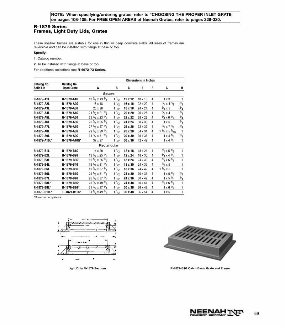
R-1879 SeriesFrames, Light Duty Lids, Grates
These shallow frames are suitable for use in thin or deep concrete slabs. All sizes of frames arereversible and can be installed with flange at base or top.
Specify:
1. Catalog number.
2. To be installed with flange at base or top.
For additional selections see R-6672-73 Series.
Dimensions in InchesCatalog No. Catalog No.Solid Lid Open Grate A B C E F G H
Square
R-1879-A1L R-1879-A1G 13 3/4 x 13 3/4 1 1/2 12 x 12 18 x 18 4 1 x 3 1R-1879-A2L R-1879-A2G 18 x 18 1 1/2 16 x 16 22 x 22 4 3/4 x 4 5/8 3/4R-1879-A3L R-1879-A3G 20 x 20 1 1/2 18 x 18 24 x 24 4 3/4 x 5 3/4R-1879-A4L R-1879-A4G 21 1/2 x 21 1/2 1 1/2 20 x 20 26 x 26 4 3/4 x 4 3/4R-1879-A5L R-1879-A5G 23 1/2 x 23 1/2 1 1/2 22 x 22 28 x 28 4 3/4 x 6 1/2 3/4R-1879-A6L R-1879-A6G 25 3/4 x 25 3/4 1 1/2 24 x 24 30 x 30 4 1 x 5 3/4R-1879-A7L R-1879-A7G 27 1/2 x 27 1/2 1 1/2 26 x 26 32 x 32 4 3/4 x 7 5/8 3/4R-1879-A8L R-1879-A8G 29 1/2 x 29 1/2 1 1/2 28 x 28 34 x 34 4 1 1/8 x 5 7/16 1R-1879-A9L R-1879-A9G 31 3/4 x 31 3/4 1 1/2 30 x 30 36 x 36 4 1 x 4 1/4 3/4R-1879-A10L* R-1879-A10G* 37 x 37 1 1/2 36 x 36 42 x 42 4 1 x 4 7/8 1
Rectangular
R-1879-B1L R-1879-B1G 14 x 20 1 1/2 12 x 18 18 x 24 4 3/4 x 5 1/2 1R-1879-B2L R-1879-B2G 13 1/2 x 25 1/2 1 1/2 12 x 24 18 x 30 4 3/4 x 4 1/2 1R-1879-B3L R-1879-B3G 19 1/2 x 25 1/2 1 1/2 18 x 24 24 x 30 4 7/8 x 5 1/4 1R-1879-B4L R-1879-B4G 19 1/2 x 31 1/2 1 1/2 18 x 30 24 x 36 4 3/4 x 5 1R-1879-B5L R-1879-B5G 19 3/4 x 37 3/4 1 1/2 18 x 36 24 x 42 4 1 1/8 x 5 1R-1879-B6L R-1879-B6G 25 1/2 x 31 1/2 1 1/2 24 x 30 30 x 36 4 1 x 5 1/8 3/4R-1879-B7L R-1879-B7G 25 1/2 x 37 1/2 1 1/2 24 x 36 30 x 42 4 1 x 5 1/8 3/4R-1879-B8L* R-1879-B8G* 25 3/4 x 49 3/4 1 1/2 24 x 48 30 x 54 4 3/4 x 5 1/8 1R-1879-B9L* R-1879-B9G* 31 3/4 x 37 3/4 1 1/2 30 x 36 36 x 42 4 1 x 6 1/2 1R-1879-B10L* R-1879-B10G* 31 1/2 x 49 1/2 1 1/2 30 x 48 36 x 54 4 1 x 5 1
*Cover in two pieces.
Light Duty R-1879 Sections R-1879-B1G Catch Basin Grate and Frame
NOTE: When specifying/ordering grates, refer to “CHOOSING THE PROPER INLET GRATE”on pages 108-109. For FREE OPEN AREAS of Neenah Grates, refer to pages 326-330.
70
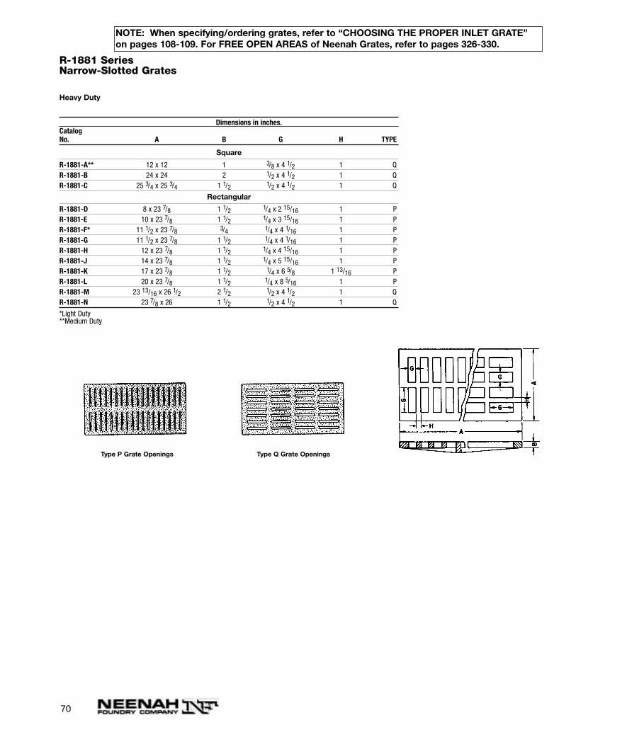
R-1881 SeriesNarrow-Slotted Grates
Heavy Duty
Dimensions in inches.CatalogNo. A B G H TYPE
Square
R-1881-A** 12 x 12 1 3/8 x 4 1/2 1 QR-1881-B 24 x 24 2 1/2 x 4 1/2 1 QR-1881-C 25 3/4 x 25 3/4 1 1/2 1/2 x 4 1/2 1 Q
Rectangular
R-1881-D 8 x 23 7/8 1 1/2 1/4 x 2 15/16 1 PR-1881-E 10 x 23 7/8 1 1/2 1/4 x 3 15/16 1 PR-1881-F* 11 1/2 x 23 7/8 3/4 1/4 x 4 1/16 1 PR-1881-G 11 1/2 x 23 7/8 1 1/2 1/4 x 4 1/16 1 PR-1881-H 12 x 23 7/8 1 1/2 1/4 x 4 15/16 1 PR-1881-J 14 x 23 7/8 1 1/2 1/4 x 5 15/16 1 PR-1881-K 17 x 23 7/8 1 1/2 1/4 x 6 5/8 1 13/16 PR-1881-L 20 x 23 7/8 1 1/2 1/4 x 8 5/16 1 PR-1881-M 23 13/16 x 26 1/2 2 1/2 1/2 x 4 1/2 1 QR-1881-N 23 7/8 x 26 1 1/2 1/2 x 4 1/2 1 Q
*Light Duty**Medium Duty
Type P Grate Openings Type Q Grate Openings
NOTE: When specifying/ordering grates, refer to “CHOOSING THE PROPER INLET GRATE”on pages 108-109. For FREE OPEN AREAS of Neenah Grates, refer to pages 326-330.
71
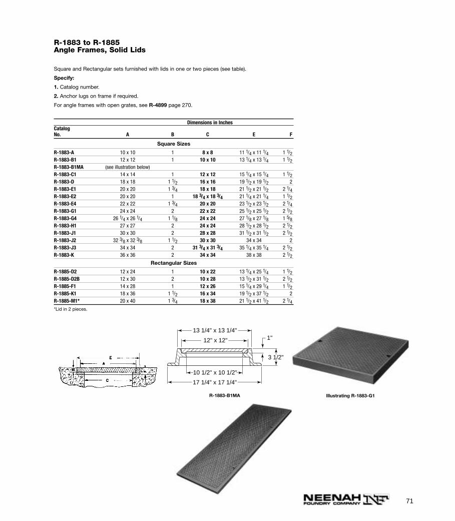
R-1883 to R-1885Angle Frames, Solid Lids
Square and Rectangular sets furnished with lids in one or two pieces (see table).
Specify:
1. Catalog number.
2. Anchor lugs on frame if required.
For angle frames with open grates, see R-4899 page 270.
Dimensions in InchesCatalogNo. A B C E F
Square Sizes
R-1883-A 10 x 10 1 8 x 8 11 1/4 x 11 1/4 1 1/2R-1883-B1 12 x 12 1 10 x 10 13 1/4 x 13 1/4 1 1/2R-1883-B1MA (see illustration below)R-1883-C1 14 x 14 1 12 x 12 15 1/4 x 15 1/4 1 1/2R-1883-D 18 x 18 1 1/2 16 x 16 19 1/2 x 19 1/2 2R-1883-E1 20 x 20 1 3/4 18 x 18 21 1/2 x 21 1/2 2 1/4R-1883-E2 20 x 20 1 18 3/4 x 18 3/4 21 1/4 x 21 1/4 1 1/2R-1883-E4 22 x 22 1 3/4 20 x 20 23 1/2 x 23 1/2 2 1/4R-1883-G1 24 x 24 2 22 x 22 25 1/2 x 25 1/2 2 1/2R-1883-G4 26 1/4 x 26 1/4 1 1/8 24 x 24 27 1/8 x 27 1/8 1 5/8R-1883-H1 27 x 27 2 24 x 24 28 1/2 x 28 1/2 2 1/2R-1883-J1 30 x 30 2 28 x 28 31 1/2 x 31 1/2 2 1/2R-1883-J2 32 3/8 x 32 3/8 1 1/2 30 x 30 34 x 34 2R-1883-J3 34 x 34 2 31 3/4 x 31 3/4 35 1/4 x 35 1/4 2 1/2R-1883-K 36 x 36 2 34 x 34 38 x 38 2 1/2
Rectangular Sizes
R-1885-D2 12 x 24 1 10 x 22 13 1/4 x 25 1/4 1 1/2R-1885-D2B 12 x 30 2 10 x 28 13 1/2 x 31 1/2 2 1/2R-1885-F1 14 x 28 1 12 x 26 15 1/4 x 29 1/4 1 1/2R-1885-K1 18 x 36 1 1/2 16 x 34 19 1/2 x 37 1/2 2R-1885-M1* 20 x 40 1 3/4 18 x 38 21 1/2 x 41 1/2 2 1/4*Lid in 2 pieces.
17 1/4" x 17 1/4"
13 1/4" x 13 1/4"
10 1/2" x 10 1/2"
12" x 12"
3 1/2"
1"
Illustrating R-1883-G1R-1883-B1MA
72
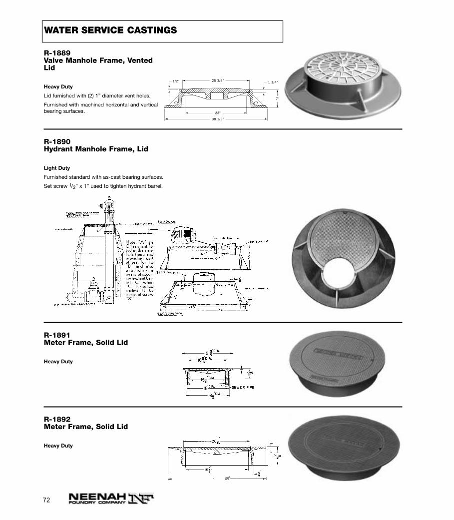
R-1889Valve Manhole Frame, VentedLid
Heavy Duty
Lid furnished with (2) 1” diameter vent holes.
Furnished with machined horizontal and verticalbearing surfaces.
25 3/8"
38 1/2"
23"
7"
1 1/4"1/2"
R-1890Hydrant Manhole Frame, Lid
Light Duty
Furnished standard with as-cast bearing surfaces.
Set screw 1/2” x 1” used to tighten hydrant barrel.
R-1891Meter Frame, Solid Lid
Heavy Duty
R-1892Meter Frame, Solid Lid
Heavy Duty
WATER SERVICE CASTINGS
73
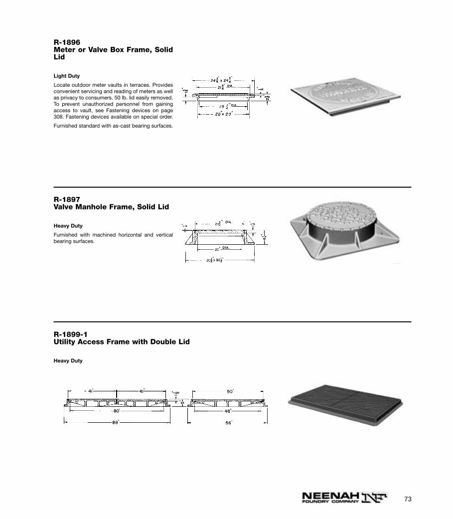
R-1896Meter or Valve Box Frame, SolidLid
Light Duty
Locate outdoor meter vaults in terraces. Providesconvenient servicing and reading of meters as wellas privacy to consumers. 50 lb. lid easily removed.To prevent unauthorized personnel from gainingaccess to vault, see Fastening devices on page308. Fastening devices available on special order.
Furnished standard with as-cast bearing surfaces.
R-1897Valve Manhole Frame, Solid Lid
Heavy Duty
Furnished with machined horizontal and verticalbearing surfaces.
R-1899-1Utility Access Frame with Double Lid
Heavy Duty

74
R-1900 SeriesValve Manhole Frame, Lid with Center Lid
Heavy Duty
Small inner lid permits easy access to valve without need of removing larger lid.
Dimensions in InchesCatalogNo. A AA B C CC E F
R-1900-A 18 7 1/4 1 1/4 16 1/2 6 30 8*R-1900-B 23 6 1 1/2 21 5 36 9*R-1900-B1 24 7 3/8 1 1/2 22 1/4 6 1/8 35 7 1/2R-1900-C 26 10 1 1/2 24 8 1/2 35 7/8 7*R-1900-D 32 12 1 1/2 30 10 46 7R-1900-D1 (See illustration below)R-1900-E 38 12 1 1/2 36 10 49 10
*Furnished with as-cast bearing surfaces.
2 3/4"
1"
1"
1"1 1/2"
3"
12"
10"
30"
34"
31 7/8"
Illustrating R-1900-D1
Illustrating R-1900-A
Note center lid
75
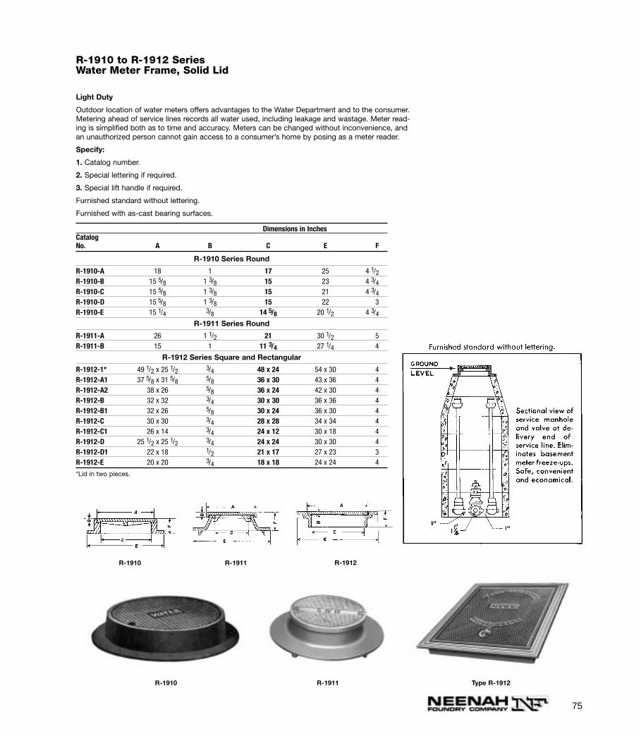
R-1910 to R-1912 SeriesWater Meter Frame, Solid Lid
Light Duty
Outdoor location of water meters offers advantages to the Water Department and to the consumer.Metering ahead of service lines records all water used, including leakage and wastage. Meter read-ing is simplified both as to time and accuracy. Meters can be changed without inconvenience, andan unauthorized person cannot gain access to a consumer’s home by posing as a meter reader.
Specify:
1. Catalog number.
2. Special lettering if required.
3. Special lift handle if required.
Furnished standard without lettering.
Furnished with as-cast bearing surfaces.
Dimensions in InchesCatalogNo. A B C E F
R-1910 Series Round
R-1910-A 18 1 17 25 4 1/2R-1910-B 15 5/8 1 3/8 15 23 4 3/4R-1910-C 15 5/8 1 3/8 15 21 4 3/4R-1910-D 15 5/8 1 3/8 15 22 3R-1910-E 15 1/4 3/8 14 5/8 20 1/2 4 3/4
R-1911 Series Round
R-1911-A 26 1 1/2 21 30 1/2 5R-1911-B 15 1 11 3/4 27 1/4 4
R-1912 Series Square and Rectangular
R-1912-1* 49 1/2 x 25 1/2 3/4 48 x 24 54 x 30 4R-1912-A1 37 5/8 x 31 5/8 5/8 36 x 30 43 x 36 4R-1912-A2 38 x 26 5/8 36 x 24 42 x 30 4R-1912-B 32 x 32 3/4 30 x 30 36 x 36 4R-1912-B1 32 x 26 5/8 30 x 24 36 x 30 4R-1912-C 30 x 30 3/4 28 x 28 34 x 34 4R-1912-C1 26 x 14 3/4 24 x 12 30 x 18 4R-1912-D 25 1/2 x 25 1/2 3/4 24 x 24 30 x 30 4R-1912-D1 22 x 18 1/2 21 x 17 27 x 23 3R-1912-E 20 x 20 3/4 18 x 18 24 x 24 4
*Lid in two pieces.
R-1910 R-1911
R-1910 R-1911 Type R-1912
R-1912
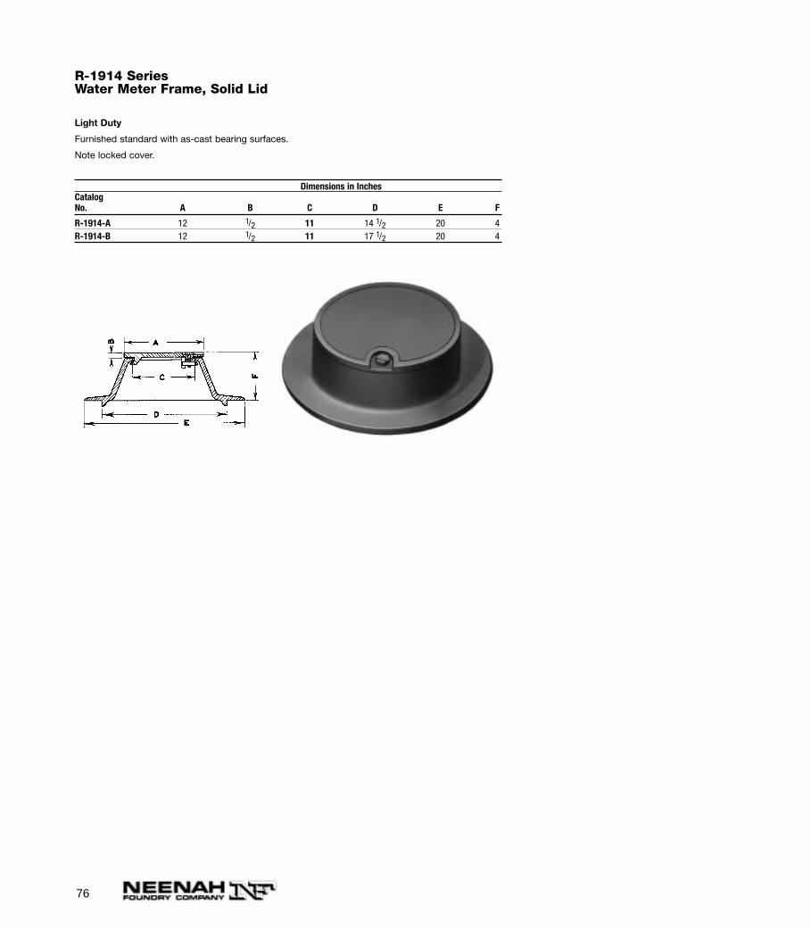
76
R-1914 SeriesWater Meter Frame, Solid Lid
Light Duty
Furnished standard with as-cast bearing surfaces.
Note locked cover.
Dimensions in InchesCatalogNo. A B C D E F
R-1914-A 12 1/2 11 14 1/2 20 4R-1914-B 12 1/2 11 17 1/2 20 4
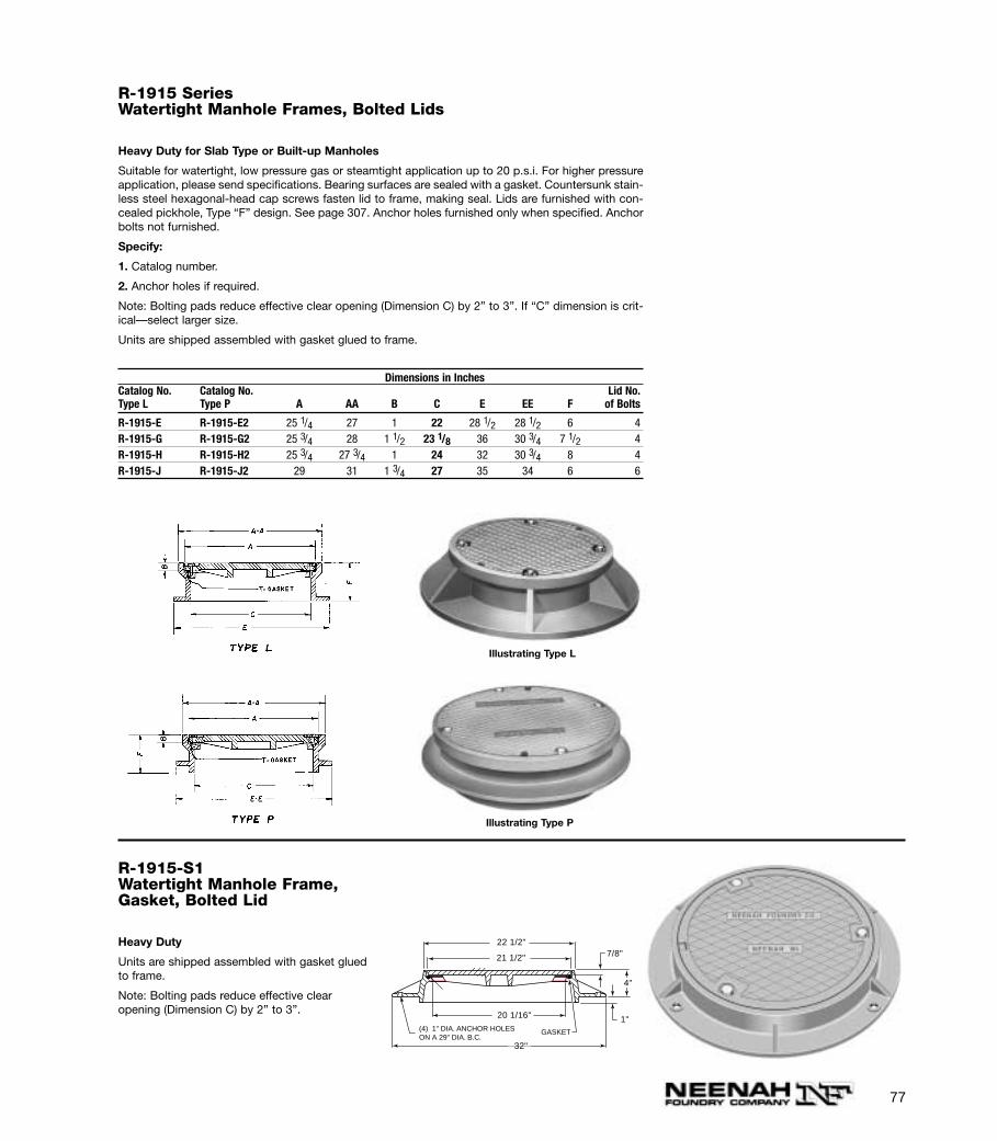
77
R-1915 SeriesWatertight Manhole Frames, Bolted Lids
Heavy Duty for Slab Type or Built-up Manholes
Suitable for watertight, low pressure gas or steamtight application up to 20 p.s.i. For higher pressureapplication, please send specifications. Bearing surfaces are sealed with a gasket. Countersunk stain-less steel hexagonal-head cap screws fasten lid to frame, making seal. Lids are furnished with con-cealed pickhole, Type “F” design. See page 307. Anchor holes furnished only when specified. Anchorbolts not furnished.
Specify:
1. Catalog number.
2. Anchor holes if required.
Note: Bolting pads reduce effective clear opening (Dimension C) by 2” to 3”. If “C” dimension is crit-ical—select larger size.
Units are shipped assembled with gasket glued to frame.
Dimensions in InchesCatalog No. Catalog No. Lid No.Type L Type P A AA B C E EE F of Bolts
R-1915-E R-1915-E2 25 1/4 27 1 22 28 1/2 28 1/2 6 4R-1915-G R-1915-G2 25 3/4 28 1 1/2 23 1/8 36 30 3/4 7 1/2 4R-1915-H R-1915-H2 25 3/4 27 3/4 1 24 32 30 3/4 8 4R-1915-J R-1915-J2 29 31 1 3/4 27 35 34 6 6
Illustrating Type L
Illustrating Type P
R-1915-S1Watertight Manhole Frame,Gasket, Bolted Lid
Heavy Duty
Units are shipped assembled with gasket gluedto frame.
Note: Bolting pads reduce effective clear opening (Dimension C) by 2” to 3”.
(4) 1" DIA. ANCHOR HOLESON A 29" DIA. B.C.
GASKET
20 1/16"
32"
21 1/2"
22 1/2"7/8"
4"
1"
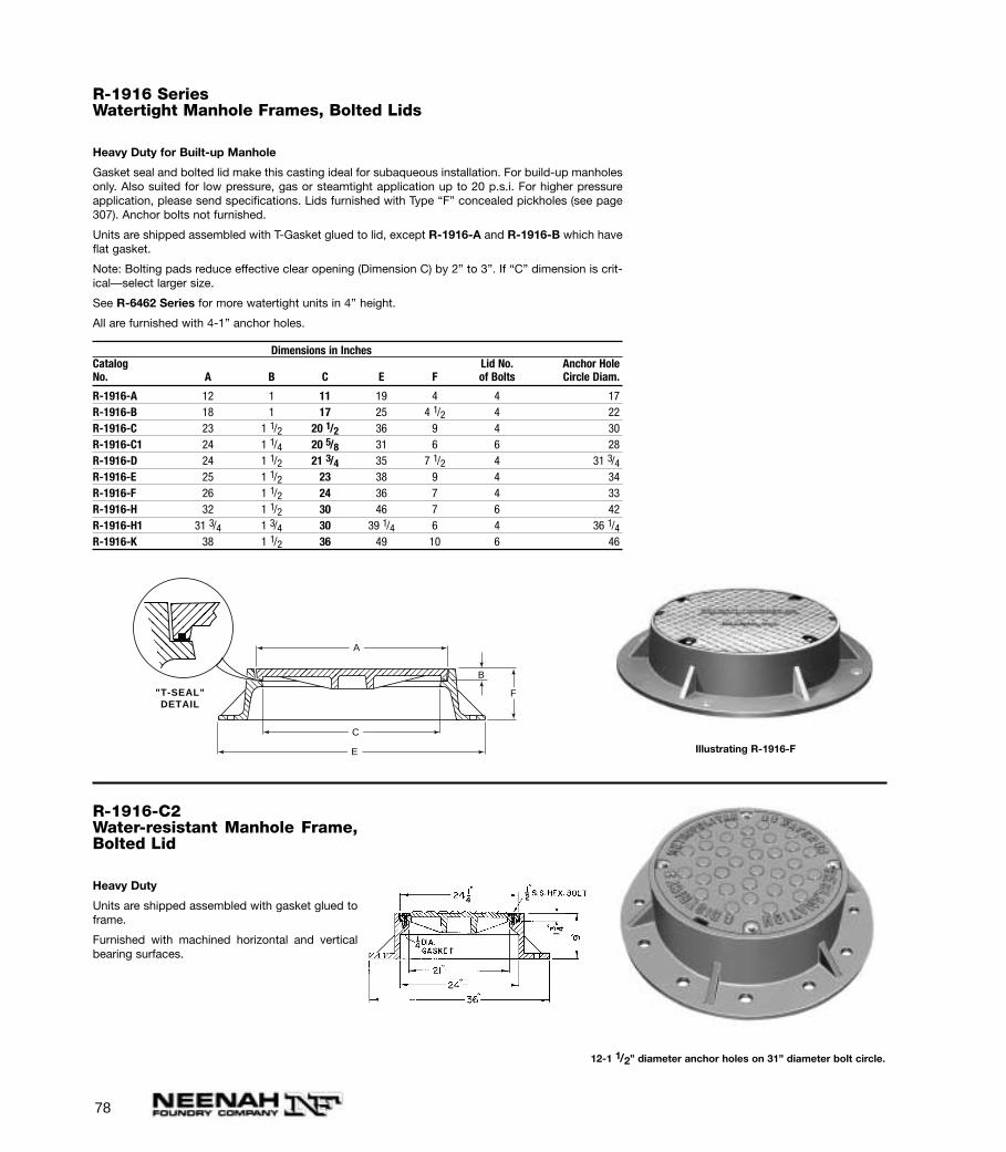
78
R-1916 SeriesWatertight Manhole Frames, Bolted Lids
Heavy Duty for Built-up Manhole
Gasket seal and bolted lid make this casting ideal for subaqueous installation. For build-up manholesonly. Also suited for low pressure, gas or steamtight application up to 20 p.s.i. For higher pressureapplication, please send specifications. Lids furnished with Type “F” concealed pickholes (see page307). Anchor bolts not furnished.
Units are shipped assembled with T-Gasket glued to lid, except R-1916-A and R-1916-B which haveflat gasket.
Note: Bolting pads reduce effective clear opening (Dimension C) by 2” to 3”. If “C” dimension is crit-ical—select larger size.
See R-6462 Series for more watertight units in 4’’ height.
All are furnished with 4-1” anchor holes.
Dimensions in InchesCatalog Lid No. Anchor HoleNo. A B C E F of Bolts Circle Diam.
R-1916-A 12 1 11 19 4 4 17R-1916-B 18 1 17 25 4 1/2 4 22R-1916-C 23 1 1/2 20 1/2 36 9 4 30R-1916-C1 24 1 1/4 20 5/8 31 6 6 28R-1916-D 24 1 1/2 21 3/4 35 7 1/2 4 31 3/4R-1916-E 25 1 1/2 23 38 9 4 34R-1916-F 26 1 1/2 24 36 7 4 33R-1916-H 32 1 1/2 30 46 7 6 42R-1916-H1 31 3/4 1 3/4 30 39 1/4 6 4 36 1/4R-1916-K 38 1 1/2 36 49 10 6 46
A
B
F
C
E
"T-SEAL"DETAIL
Illustrating R-1916-F
R-1916-C2Water-resistant Manhole Frame,Bolted Lid
Heavy Duty
Units are shipped assembled with gasket glued toframe.
Furnished with machined horizontal and verticalbearing surfaces.
12-1 1/2” diameter anchor holes on 31” diameter bolt circle.
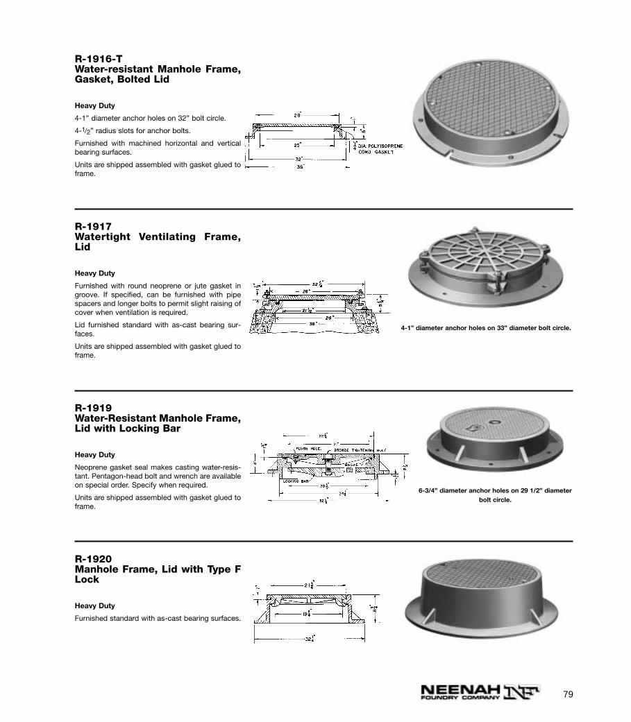
79
R-1916-TWater-resistant Manhole Frame,Gasket, Bolted Lid
Heavy Duty
4-1” diameter anchor holes on 32” bolt circle.
4-1/2” radius slots for anchor bolts.
Furnished with machined horizontal and verticalbearing surfaces.
Units are shipped assembled with gasket glued toframe.
R-1917Watertight Ventilating Frame,Lid
Heavy Duty
Furnished with round neoprene or jute gasket ingroove. If specified, can be furnished with pipespacers and longer bolts to permit slight raising ofcover when ventilation is required.
Lid furnished standard with as-cast bearing sur-faces.
Units are shipped assembled with gasket glued toframe.
4-1” diameter anchor holes on 33” diameter bolt circle.
R-1919Water-Resistant Manhole Frame,Lid with Locking Bar
Heavy Duty
Neoprene gasket seal makes casting water-resis-tant. Pentagon-head bolt and wrench are availableon special order. Specify when required.
Units are shipped assembled with gasket glued toframe.
6-3/4” diameter anchor holes on 29 1/2” diameterbolt circle.
R-1920Manhole Frame, Lid with Type FLock
Heavy Duty
Furnished standard with as-cast bearing surfaces.
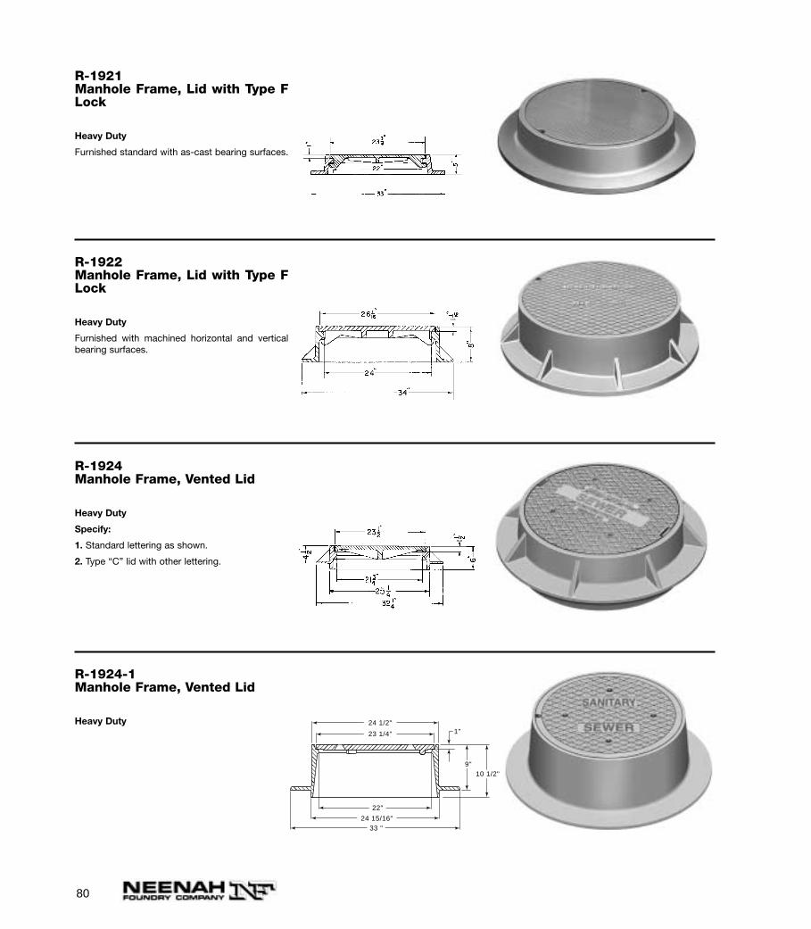
80
R-1921Manhole Frame, Lid with Type FLock
Heavy Duty
Furnished standard with as-cast bearing surfaces.
R-1922Manhole Frame, Lid with Type FLock
Heavy Duty
Furnished with machined horizontal and verticalbearing surfaces.
R-1924Manhole Frame, Vented Lid
Heavy Duty
Specify:
1. Standard lettering as shown.
2. Type “C” lid with other lettering.
R-1924-1Manhole Frame, Vented Lid
Heavy Duty
24 1/2"
23 1/4"
22"
24 15/16"33 "
9"10 1/2"
1"
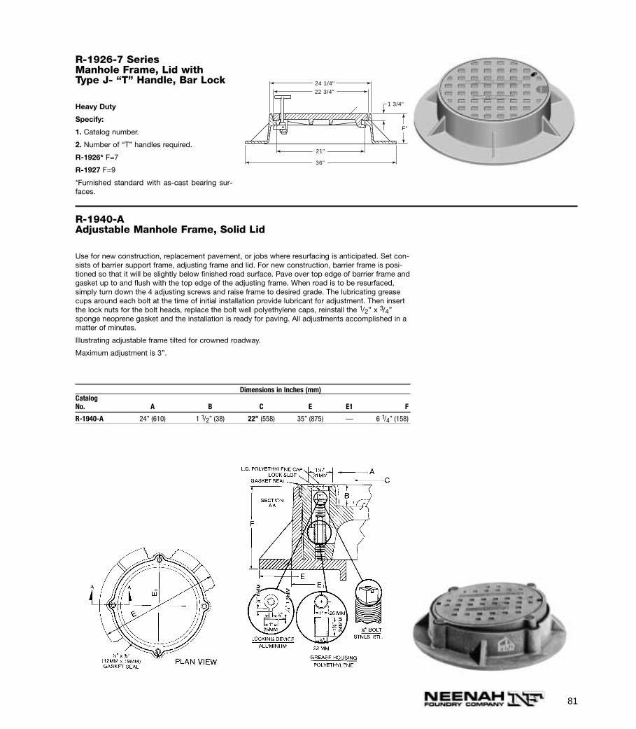
81
R-1926-7 SeriesManhole Frame, Lid with Type J- “T” Handle, Bar Lock
Heavy Duty
Specify:
1. Catalog number.
2. Number of “T” handles required.
R-1926* F=7
R-1927 F=9
*Furnished standard with as-cast bearing sur-faces.
22 3/4"
1 3/4"
F"
24 1/4"
21"
36"
R-1940-AAdjustable Manhole Frame, Solid Lid
Use for new construction, replacement pavement, or jobs where resurfacing is anticipated. Set con-sists of barrier support frame, adjusting frame and lid. For new construction, barrier frame is posi-tioned so that it will be slightly below finished road surface. Pave over top edge of barrier frame andgasket up to and flush with the top edge of the adjusting frame. When road is to be resurfaced,simply turn down the 4 adjusting screws and raise frame to desired grade. The lubricating greasecups around each bolt at the time of initial installation provide lubricant for adjustment. Then insertthe lock nuts for the bolt heads, replace the bolt well polyethylene caps, reinstall the 1/2” x 3/4”sponge neoprene gasket and the installation is ready for paving. All adjustments accomplished in amatter of minutes.
Illustrating adjustable frame tilted for crowned roadway.
Maximum adjustment is 3”.
Dimensions in Inches (mm)CatalogNo. A B C E E1 F
R-1940-A 24” (610) 1 1/2” (38) 22” (558) 35” (875) — 6 1/4” (158)
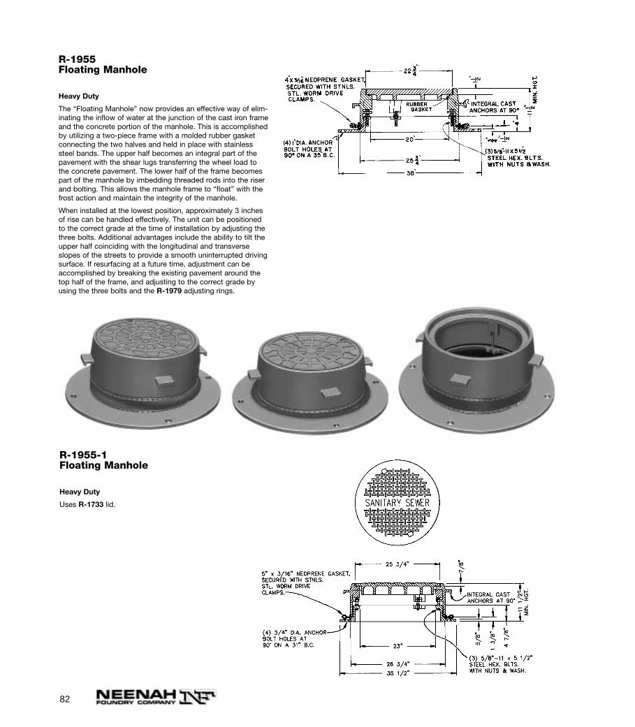
82
R-1955Floating Manhole
Heavy Duty
The “Floating Manhole” now provides an effective way of elim-inating the inflow of water at the junction of the cast iron frameand the concrete portion of the manhole. This is accomplishedby utilizing a two-piece frame with a molded rubber gasketconnecting the two halves and held in place with stainlesssteel bands. The upper half becomes an integral part of thepavement with the shear lugs transferring the wheel load tothe concrete pavement. The lower half of the frame becomespart of the manhole by imbedding threaded rods into the riserand bolting. This allows the manhole frame to “float” with thefrost action and maintain the integrity of the manhole.
When installed at the lowest position, approximately 3 inchesof rise can be handled effectively. The unit can be positionedto the correct grade at the time of installation by adjusting thethree bolts. Additional advantages include the ability to tilt theupper half coinciding with the longitudinal and transverseslopes of the streets to provide a smooth uninterrupted drivingsurface. If resurfacing at a future time, adjustment can beaccomplished by breaking the existing pavement around thetop half of the frame, and adjusting to the correct grade byusing the three bolts and the R-1979 adjusting rings.
R-1955-1Floating Manhole
Heavy Duty
Uses R-1733 lid.
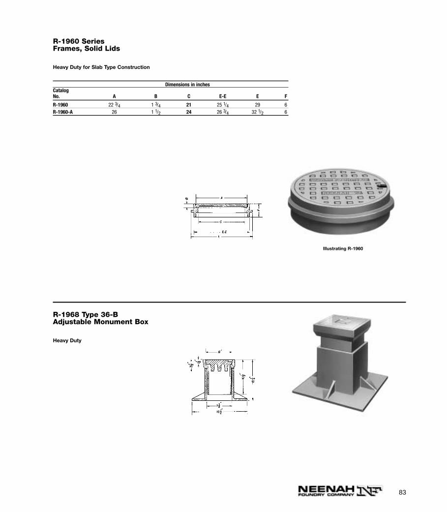
83
R-1960 SeriesFrames, Solid Lids
Heavy Duty for Slab Type Construction
Dimensions in inchesCatalogNo. A B C E-E E F
R-1960 22 3/4 1 3/4 21 25 1/4 29 6R-1960-A 26 1 1/2 24 26 3/4 32 1/2 6
R-1968 Type 36-BAdjustable Monument Box
Heavy Duty
Illustrating R-1960
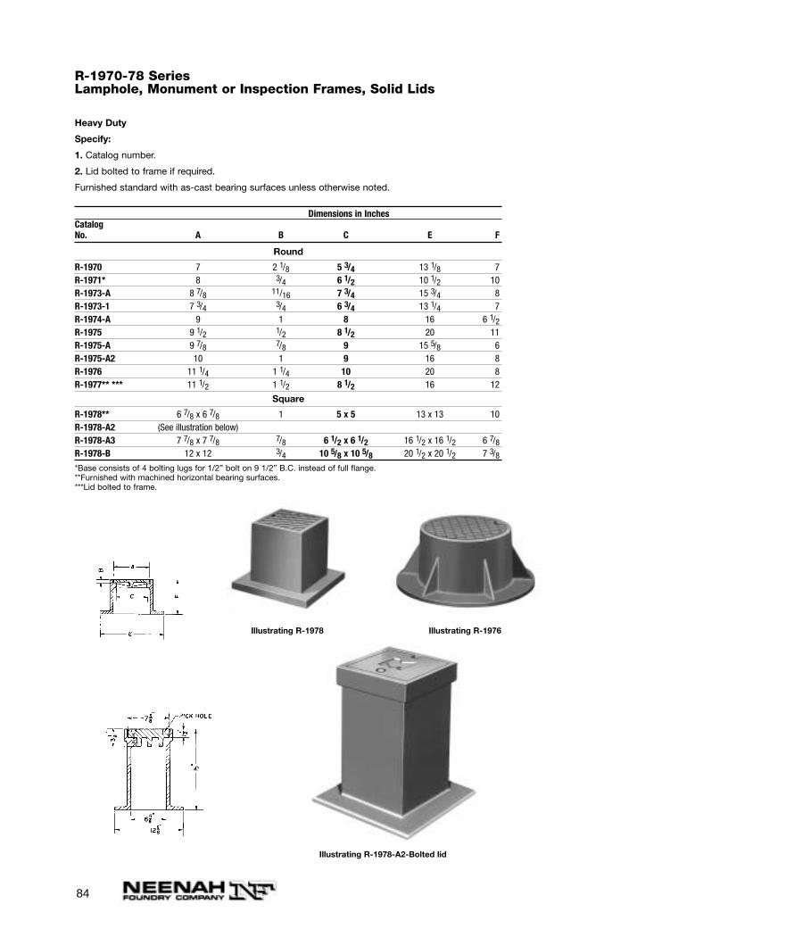
84
R-1970-78 SeriesLamphole, Monument or Inspection Frames, Solid Lids
Heavy Duty
Specify:
1. Catalog number.
2. Lid bolted to frame if required.
Furnished standard with as-cast bearing surfaces unless otherwise noted.
Dimensions in InchesCatalogNo. A B C E F
Round
R-1970 7 2 1/8 5 3/4 13 1/8 7R-1971* 8 3/4 6 1/2 10 1/2 10R-1973-A 8 7/8 11/16 7 3/4 15 3/4 8R-1973-1 7 3/4 3/4 6 3/4 13 1/4 7R-1974-A 9 1 8 16 6 1/2R-1975 9 1/2 1/2 8 1/2 20 11R-1975-A 9 7/8 7/8 9 15 5/8 6R-1975-A2 10 1 9 16 8R-1976 11 1/4 1 1/4 10 20 8R-1977** *** 11 1/2 1 1/2 8 1/2 16 12
Square
R-1978** 6 7/8 x 6 7/8 1 5 x 5 13 x 13 10R-1978-A2 (See illustration below)R-1978-A3 7 7/8 x 7 7/8 7/8 6 1/2 x 6 1/2 16 1/2 x 16 1/2 6 7/8R-1978-B 12 x 12 3/4 10 5/8 x 10 5/8 20 1/2 x 20 1/2 7 3/8*Base consists of 4 bolting lugs for 1/2” bolt on 9 1/2” B.C. instead of full flange.**Furnished with machined horizontal bearing surfaces.***Lid bolted to frame.
Illustrating R-1978 Illustrating R-1976
Illustrating R-1978-A2-Bolted lid
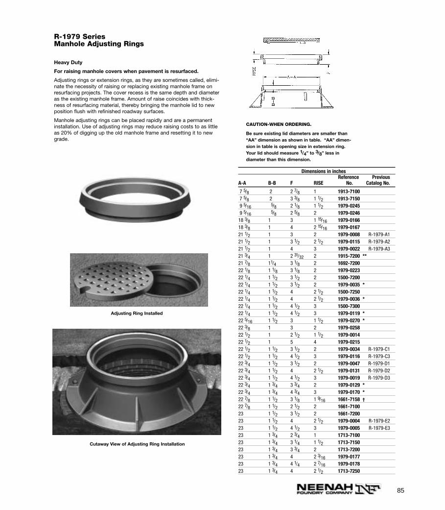
85
R-1979 SeriesManhole Adjusting Rings
Heavy Duty
For raising manhole covers when pavement is resurfaced.
Adjusting rings or extension rings, as they are sometimes called, elimi-nate the necessity of raising or replacing existing manhole frame onresurfacing projects. The cover recess is the same depth and diameteras the existing manhole frame. Amount of raise coincides with thick-ness of resurfacing material, thereby bringing the manhole lid to newposition flush with refinished roadway surfaces.
Manhole adjusting rings can be placed rapidly and are a permanentinstallation. Use of adjusting rings may reduce raising costs to as littleas 20% of digging up the old manhole frame and resetting it to newgrade.
Adjusting Ring Installed
Cutaway View of Adjusting Ring Installation
CAUTION-WHEN ORDERING.
Be sure existing lid diameters are smaller than“AA” dimension as shown in table. “AA” dimen-sion in table is opening size in extension ring.Your lid should measure 1/4” to 3/8” less indiameter than this dimension.
Dimensions in inchesReference Previous
A-A B-B F RISE No. Catalog No.
7 5/8 2 2 7/8 1 1913-71007 5/8 2 3 3/8 1 1/2 1913-71509 5/16 5/8 2 1/8 1 1/2 1979-02459 5/16 5/8 2 5/8 2 1979-0246
18 3/8 1 3 1 15/16 1979-016618 3/8 1 4 2 15/16 1979-016721 1/2 1 3 2 1979-0008 R-1979-A121 1/2 1 3 1/2 2 1/2 1979-0115 R-1979-A221 1/2 1 4 3 1979-0022 R-1979-A321 3/4 1 2 31/32 2 1915-7200 **21 7/8 11/4 3 1/8 2 1692-720022 1/8 1 1/8 3 1/8 2 1979-022322 1/4 1 1/2 3 1/2 2 1500-7200 22 1/4 1 1/2 3 1/2 2 1979-0035 *22 1/4 1 1/2 4 2 1/2 1500-7250 22 1/4 1 1/2 4 2 1/2 1979-0036 *22 1/4 1 1/2 4 1/2 3 1500-7300 22 1/4 1 1/2 4 1/2 3 1979-0119 *22 5/16 1 1/2 3 1 1/2 1979-0270 *22 3/8 1 3 2 1979-025822 1/2 1 2 1/2 1 1/2 1979-001422 1/2 1 5 4 1979-021522 1/2 1 1/2 3 1/2 2 1979-0034 R-1979-C122 1/2 1 1/2 4 1/2 3 1979-0116 R-1979-C322 3/4 1 1/2 3 1/2 2 1979-0047 R-1979-D122 3/4 1 1/2 4 2 1/2 1979-0131 R-1979-D222 3/4 1 1/2 4 1/2 3 1979-0019 R-1979-D322 3/4 1 3/4 3 3/4 2 1979-0129 *22 3/4 1 3/4 4 3/4 3 1979-0170 *22 7/8 1 1/2 3 1/8 1 9/16 1661-7158 †22 7/8 1 1/2 2 1/2 2 1661-710023 1 1/2 3 1/2 2 1661-720023 1 1/2 4 2 1/2 1979-0004 R-1979-E223 1 1/2 4 1/2 3 1979-0005 R-1979-E323 1 3/4 2 3/4 1 1713-710023 1 3/4 3 1/4 1 1/2 1713-715023 1 3/4 3 3/4 2 1713-720023 1 3/4 4 2 3/16 1979-017723 1 3/4 4 1/4 2 7/16 1979-017823 1 3/4 4 2 1/2 1713-7250
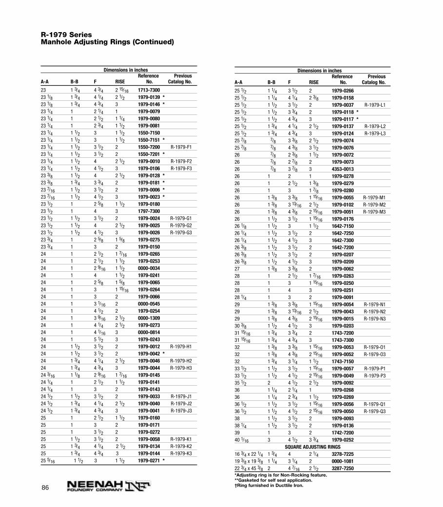
86
R-1979 SeriesManhole Adjusting Rings (Continued)
Dimensions in inchesReference Previous
A-A B-B F RISE No. Catalog No.
23 1 3/4 4 3/4 2 15/16 1713-730023 1/8 1 3/4 4 1/4 2 1/2 1979-0139 *23 1/8 1 3/4 4 3/4 3 1979-0146 *23 1/4 1 2 1/4 1 1979-007923 1/4 1 2 1/2 1 1/4 1979-008023 1/4 1 2 3/4 1 1/2 1979-008123 1/4 1 1/2 3 1 1/2 1550-715023 1/4 1 1/2 3 1 1/2 1550-7151 *23 1/4 1 1/2 3 1/2 2 1550-7200 R-1979-F123 1/4 1 1/2 3 1/2 2 1550-7201 *23 1/4 1 1/2 4 2 1/2 1979-0010 R-1979-F223 1/4 1 1/2 4 1/2 3 1979-0106 R-1979-F323 3/8 1 1/2 4 2 1/2 1979-0128 *23 3/8 1 3/4 3 3/4 2 1979-0181 *23 7/16 1 1/2 3 1/2 2 1979-0006 *23 7/16 1 1/2 4 1/2 3 1979-0023 *23 1/2 1 2 5/8 1 1/2 1979-018023 1/2 1 4 3 1797-730023 1/2 1 1/2 3 1/2 2 1979-0024 R-1979-G123 1/2 1 1/2 4 2 1/2 1979-0025 R-1979-G223 1/2 1 1/2 4 1/2 3 1979-0026 R-1979-G323 3/4 1 2 5/8 1 5/8 1979-027523 3/4 1 3 2 1979-015024 1 2 1/2 1 7/16 1979-026524 1 2 1/2 1 1/2 1979-025324 1 2 9/16 1 1/2 0000-003424 1 4 1 1/2 1979-024124 1 2 5/8 1 5/8 1979-006524 1 3 1 15/16 1979-026424 1 3 2 1979-006624 1 3 1/16 2 0000-054524 1 4 1/2 2 1979-025424 1 3 9/16 2 1/2 0000-130924 1 4 1/4 2 1/2 1979-027324 1 4 1/16 3 0000-081424 1 5 1/2 3 1979-024324 1 1/2 3 1/2 2 1979-0012 R-1979-H124 1 1/2 3 1/2 2 1979-0042 *24 1 3/4 4 1/4 2 1/2 1979-0046 R-1979-H224 1 3/4 4 3/4 3 1979-0044 R-1979-H324 3/16 1 1/8 2 9/16 1 7/16 1979-014524 1/4 1 2 1/2 1 1/2 1979-014124 1/4 1 3 2 1979-014324 1/2 1 1/2 3 1/2 2 1979-0033 R-1979-J124 1/2 1 3/4 4 1/4 2 1/2 1979-0040 R-1979-J224 1/2 1 3/4 4 3/4 3 1979-0041 R-1979-J325 1 2 1/2 1 1/2 1979-016025 1 3 2 1979-017125 1 3 1/2 2 1979-027225 1 1/2 3 1/2 2 1979-0058 R-1979-K125 1 3/4 4 1/4 2 1/2 1979-0134 R-1979-K225 1 3/4 4 3/4 3 1979-0144 R-1979-K325 5/16 1 1/2 3 1 1/2 1979-0271 *
Dimensions in inchesReference Previous
A-A B-B F RISE No. Catalog No.
25 1/2 1 1/4 3 1/2 2 1979-026625 1/2 1 1/4 4 1/4 2 3/8 1979-015825 1/2 1 1/2 3 1/2 2 1979-0037 R-1979-L125 1/2 1 1/2 3 3/4 2 1979-0118 *25 1/2 1 1/2 4 3/4 3 1979-0117 *25 1/2 1 3/4 4 1/4 2 1/2 1979-0137 R-1979-L225 1/2 1 3/4 4 3/4 3 1979-0124 R-1979-L325 7/8 7/8 3 3/8 2 1/2 1979-007425 7/8 7/8 4 3/8 3 1/2 1979-007626 7/8 2 3/8 1 1/2 1979-007226 7/8 2 7/8 2 1979-007326 7/8 3 7/8 3 4353-001326 1 2 1 1979-027826 1 2 1/2 1 3/8 1979-027926 1 3 1 7/8 1979-028026 1 3/8 3 3/8 1 15/16 1979-0055 R-1979-M126 1 3/8 3 13/16 2 1/2 1979-0102 R-1979-M226 1 3/8 4 3/8 2 15/16 1979-0051 R-1979-M326 1 1/2 3 1/2 1 15/16 1979-017626 1/8 1 1/2 3 1 1/2 1642-715026 1/4 1 1/2 3 1/2 2 1642-725026 1/4 1 1/2 4 1/2 3 1642-730026 3/8 1 1/2 3 1/2 2 1642-720026 3/8 1 1/2 3 1/2 2 1979-020726 3/8 1 1/2 4 1/2 3 1979-020927 1 3/8 3 3/8 2 1979-006228 1 2 1/2 1 7/16 1979-026328 1 3 1 15/16 1979-025028 1 4 3 1979-025128 1/4 1 3 2 1979-009129 1 3/8 3 3/8 1 15/16 1979-0054 R-1979-N129 1 3/8 3 13/16 2 1/2 1979-0043 R-1979-N229 1 3/8 4 3/8 2 15/16 1979-0015 R-1979-N330 3/8 1 1/2 4 1/2 3 1979-020331 15/16 1 3/4 3 3/4 2 1743-720031 15/16 1 3/4 4 3/4 3 1743-730032 1 3/8 3 3/8 1 15/16 1979-0053 R-1979-O132 1 3/8 4 3/8 2 15/16 1979-0052 R-1979-O332 1 3/4 3 1/4 1 1/2 1743-715033 1/2 1 1/2 3 1/2 1 15/16 1979-0057 R-1979-P133 1/2 1 1/2 4 1/2 2 15/16 1979-0049 R-1979-P335 1/2 2 4 1/2 2 1/2 1979-009236 1 1/4 2 1/4 1 1979-026836 1 1/4 2 3/4 1 1/2 1979-026936 1/2 1 1/2 3 1/2 1 15/16 1979-0056 R-1979-Q136 1/2 1 1/2 4 1/2 2 15/16 1979-0050 R-1979-Q338 1 1/2 3 1/2 2 1979-009338 1/4 1 1/2 3 1/2 2 1979-013639 1 3 2 1742-720040 1/16 3 4 1/2 3 3/4 1979-0252
SQUARE ADJUSTING RINGS16 3/4 x 22 1/4 1 3/4 4 2 1/4 3278-722519 3/8 x 19 3/8 1 1/4 3 1/4 2 0000-108122 3/4 x 45 3/8 2 4 7/16 2 1/2 3287-7250*Adjusting ring is for Non-Rocking feature.**Gasketed for self seal application.†Ring furnished in Ducttile Iron.
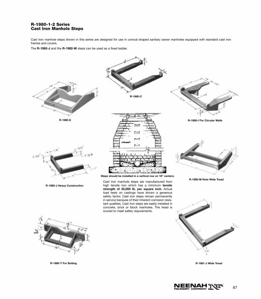
87
R-1980-1-2 SeriesCast Iron Manhole Steps
Cast iron manhole steps shown in this series are designed for use in conical shaped sanitary sewer manholes equipped with standard cast ironframes and covers.
The R-1982-J and the R-1982-W steps can be used as a fixed ladder.
R-1980-E R-1980-I For Circular Walls
R-1980-J Heavy ConstructionCast iron manhole steps are manufactured fromhigh tensile iron which has a minimum tensilestrength of 35,000 lb. per square inch. Actualload tests on castings have shown a generoussafety factor. Cast iron steps remain permanentlyin service because of their inherent corrosion resis-tant qualities. Cast iron steps are easily installed inconcrete, brick or block manholes. The tread isscored to meet safety requirements.
Steps should be installed in a vertical row on 16” centers.
R-1980-T For Bolting
R-1980-M Note Wide Tread
R-1981-J Wide Tread
R-1980-C
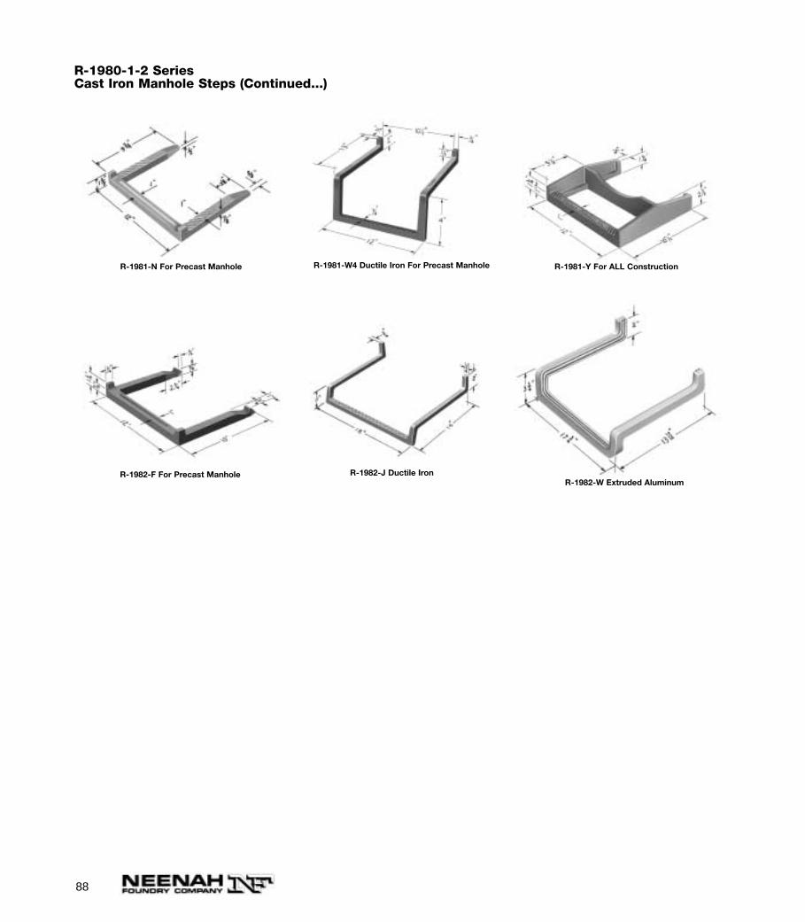
88
R-1981-Y For ALL Construction
R-1982-F For Precast Manhole
R-1981-W4 Ductile Iron For Precast Manhole
R-1982-J Ductile Iron
R-1980-1-2 SeriesCast Iron Manhole Steps (Continued...)
R-1981-N For Precast Manhole
R-1982-W Extruded Aluminum
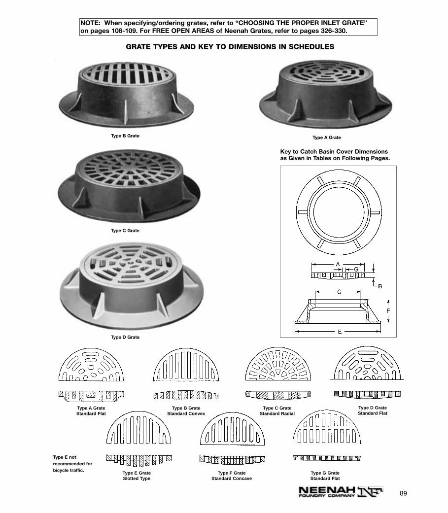
89
Key to Catch Basin Cover Dimensionsas Given in Tables on Following Pages.
GRATE TYPES AND KEY TO DIMENSIONS IN SCHEDULES
Type A GrateType B Grate
Type C Grate
Type D Grate
Type B GrateStandard Convex
Type A GrateStandard Flat
Type C GrateStandard Radial
Type D GrateStandard Flat
Type E GrateSlotted Type
Type F GrateStandard Concave
Type G GrateStandard Flat
Type E not recommended forbicycle traffic.
NOTE: When specifying/ordering grates, refer to “CHOOSING THE PROPER INLET GRATE”on pages 108-109. For FREE OPEN AREAS of Neenah Grates, refer to pages 326-330.
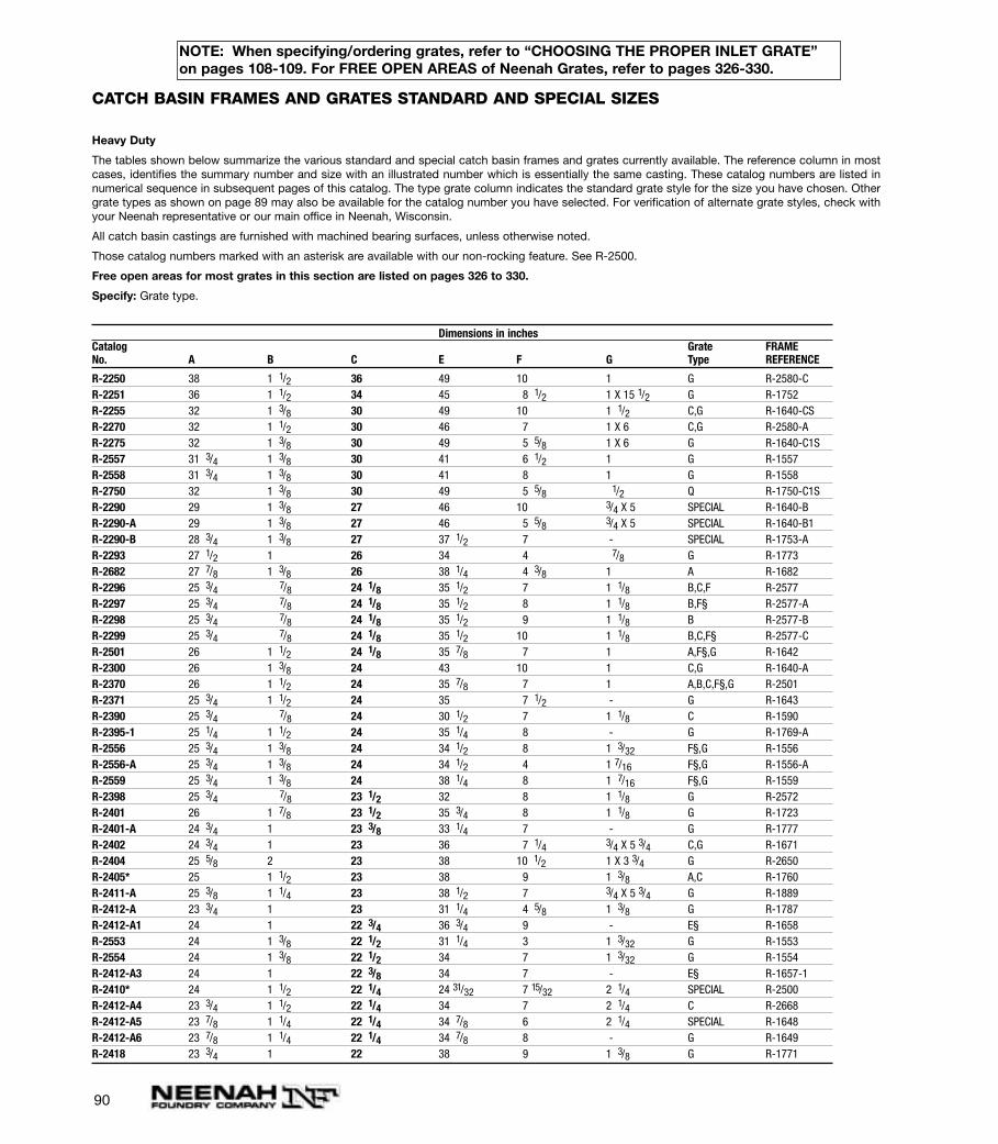
CATCH BASIN FRAMES AND GRATES STANDARD AND SPECIAL SIZES
Heavy Duty
The tables shown below summarize the various standard and special catch basin frames and grates currently available. The reference column in mostcases, identifies the summary number and size with an illustrated number which is essentially the same casting. These catalog numbers are listed innumerical sequence in subsequent pages of this catalog. The type grate column indicates the standard grate style for the size you have chosen. Othergrate types as shown on page 89 may also be available for the catalog number you have selected. For verification of alternate grate styles, check withyour Neenah representative or our main office in Neenah, Wisconsin.
All catch basin castings are furnished with machined bearing surfaces, unless otherwise noted.
Those catalog numbers marked with an asterisk are available with our non-rocking feature. See R-2500.
Free open areas for most grates in this section are listed on pages 326 to 330.
Specify: Grate type.
Dimensions in inchesCatalog Grate FRAMENo. A B C E F G Type REFERENCE
R-2250 38 1 1/2 36 49 10 1 G R-2580-CR-2251 36 1 1/2 34 45 8 1/2 1 X 15 1/2 G R-1752R-2255 32 1 3/8 30 49 10 1 1/2 C,G R-1640-CSR-2270 32 1 1/2 30 46 7 1 X 6 C,G R-2580-AR-2275 32 1 3/8 30 49 5 5/8 1 X 6 G R-1640-C1SR-2557 31 3/4 1 3/8 30 41 6 1/2 1 G R-1557R-2558 31 3/4 1 3/8 30 41 8 1 G R-1558R-2750 32 1 3/8 30 49 5 5/8 1/2 Q R-1750-C1SR-2290 29 1 3/8 27 46 10 3/4 X 5 SPECIAL R-1640-BR-2290-A 29 1 3/8 27 46 5 5/8 3/4 X 5 SPECIAL R-1640-B1R-2290-B 28 3/4 1 3/8 27 37 1/2 7 - SPECIAL R-1753-AR-2293 27 1/2 1 26 34 4 7/8 G R-1773R-2682 27 7/8 1 3/8 26 38 1/4 4 3/8 1 A R-1682R-2296 25 3/4 7/8 24 1/8 35 1/2 7 1 1/8 B,C,F R-2577R-2297 25 3/4 7/8 24 1/8 35 1/2 8 1 1/8 B,F§ R-2577-AR-2298 25 3/4 7/8 24 1/8 35 1/2 9 1 1/8 B R-2577-BR-2299 25 3/4 7/8 24 1/8 35 1/2 10 1 1/8 B,C,F§ R-2577-CR-2501 26 1 1/2 24 1/8 35 7/8 7 1 A,F§,G R-1642R-2300 26 1 3/8 24 43 10 1 C,G R-1640-AR-2370 26 1 1/2 24 35 7/8 7 1 A,B,C,F§,G R-2501R-2371 25 3/4 1 1/2 24 35 7 1/2 - G R-1643R-2390 25 3/4 7/8 24 30 1/2 7 1 1/8 C R-1590R-2395-1 25 1/4 1 1/2 24 35 1/4 8 - G R-1769-AR-2556 25 3/4 1 3/8 24 34 1/2 8 1 3/32 F§,G R-1556R-2556-A 25 3/4 1 3/8 24 34 1/2 4 1 7/16 F§,G R-1556-AR-2559 25 3/4 1 3/8 24 38 1/4 8 1 7/16 F§,G R-1559R-2398 25 3/4 7/8 23 1/2 32 8 1 1/8 G R-2572R-2401 26 1 7/8 23 1/2 35 3/4 8 1 1/8 G R-1723R-2401-A 24 3/4 1 23 3/8 33 1/4 7 - G R-1777R-2402 24 3/4 1 23 36 7 1/4 3/4 X 5 3/4 C,G R-1671R-2404 25 5/8 2 23 38 10 1/2 1 X 3 3/4 G R-2650R-2405* 25 1 1/2 23 38 9 1 3/8 A,C R-1760R-2411-A 25 3/8 1 1/4 23 38 1/2 7 3/4 X 5 3/4 G R-1889R-2412-A 23 3/4 1 23 31 1/4 4 5/8 1 3/8 G R-1787R-2412-A1 24 1 22 3/4 36 3/4 9 - E§ R-1658R-2553 24 1 3/8 22 1/2 31 1/4 3 1 3/32 G R-1553R-2554 24 1 3/8 22 1/2 34 7 1 3/32 G R-1554R-2412-A3 24 1 22 3/8 34 7 - E§ R-1657-1R-2410* 24 1 1/2 22 1/4 24 31/32 7 15/32 2 1/4 SPECIAL R-2500R-2412-A4 23 3/4 1 1/2 22 1/4 34 7 2 1/4 C R-2668R-2412-A5 23 7/8 1 1/4 22 1/4 34 7/8 6 2 1/4 SPECIAL R-1648R-2412-A6 23 7/8 1 1/4 22 1/4 34 7/8 8 - G R-1649R-2418 23 3/4 1 22 38 9 1 3/8 G R-1771
90
NOTE: When specifying/ordering grates, refer to “CHOOSING THE PROPER INLET GRATE”on pages 108-109. For FREE OPEN AREAS of Neenah Grates, refer to pages 326-330.
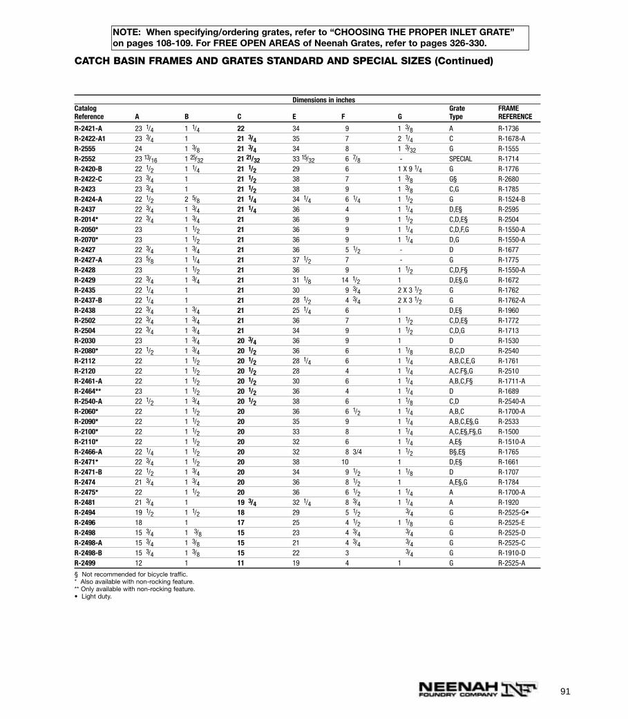
91
Dimensions in inchesCatalog Grate FRAMEReference A B C E F G Type REFERENCE
R-2421-A 23 1/4 1 1/4 22 34 9 1 3/8 A R-1736R-2422-A1 23 3/4 1 21 3/4 35 7 2 1/4 C R-1678-AR-2555 24 1 3/8 21 3/4 34 8 1 3/32 G R-1555R-2552 23 13/16 1 25/32 21 21/32 33 15/32 6 7/8 - SPECIAL R-1714R-2420-B 22 1/2 1 1/4 21 1/2 29 6 1 X 9 1/4 G R-1776R-2422-C 23 3/4 1 21 1/2 38 7 1 3/8 G§ R-2680R-2423 23 3/4 1 21 1/2 38 9 1 3/8 C,G R-1785R-2424-A 22 1/2 2 5/8 21 1/4 34 1/4 6 1/4 1 1/2 G R-1524-BR-2437 22 3/4 1 3/4 21 1/4 36 4 1 1/4 D,E§ R-2595R-2014* 22 3/4 1 3/4 21 36 9 1 1/2 C,D,E§ R-2504R-2050* 23 1 1/2 21 36 9 1 1/4 C,D,F,G R-1550-AR-2070* 23 1 1/2 21 36 9 1 1/4 D,G R-1550-AR-2427 22 3/4 1 3/4 21 36 5 1/2 - D R-1677R-2427-A 23 5/8 1 1/4 21 37 1/2 7 - G R-1775R-2428 23 1 1/2 21 36 9 1 1/2 C,D,F§ R-1550-AR-2429 22 3/4 1 3/4 21 31 1/8 14 1/2 1 D,E§,G R-1672R-2435 22 1/4 1 21 30 9 3/4 2 X 3 1/2 G R-1762R-2437-B 22 1/4 1 21 28 1/2 4 3/4 2 X 3 1/2 G R-1762-AR-2438 22 3/4 1 3/4 21 25 1/4 6 1 D,E§ R-1960R-2502 22 3/4 1 3/4 21 36 7 1 1/2 C,D,E§ R-1772R-2504 22 3/4 1 3/4 21 34 9 1 1/2 C,D,G R-1713R-2030 23 1 3/4 20 3/4 36 9 1 D R-1530R-2080* 22 1/2 1 3/4 20 1/2 36 6 1 1/8 B,C,D R-2540R-2112 22 1 1/2 20 1/2 28 1/4 6 1 1/4 A,B,C,E,G R-1761R-2120 22 1 1/2 20 1/2 28 4 1 1/4 A,C.F§,G R-2510R-2461-A 22 1 1/2 20 1/2 30 6 1 1/4 A,B,C,F§ R-1711-AR-2464** 23 1 1/2 20 1/2 36 4 1 1/4 D R-1689R-2540-A 22 1/2 1 3/4 20 1/2 38 6 1 1/8 C,D R-2540-AR-2060* 22 1 1/2 20 36 6 1/2 1 1/4 A,B,C R-1700-AR-2090* 22 1 1/2 20 35 9 1 1/4 A,B,C,E§,G R-2533R-2100* 22 1 1/2 20 33 8 1 1/4 A,C,E§,F§,G R-1500R-2110* 22 1 1/2 20 32 6 1 1/4 A,E§ R-1510-AR-2466-A 22 1/4 1 1/2 20 32 8 3/4 1 1/2 B§,E§ R-1765R-2471* 22 3/4 1 1/2 20 38 10 1 D,E§ R-1661R-2471-B 22 1/2 1 3/4 20 34 9 1/2 1 1/8 D R-1707R-2474 21 3/4 1 3/4 20 36 8 1/2 1 A,E§,G R-1784R-2475* 22 1 1/2 20 36 6 1/2 1 1/4 A R-1700-AR-2481 21 3/4 1 19 3/4 32 1/4 8 3/4 1 1/4 A R-1920R-2494 19 1/2 1 1/2 18 29 5 1/2 3/4 G R-2525-G•R-2496 18 1 17 25 4 1/2 1 1/8 G R-2525-ER-2498 15 3/4 1 3/8 15 23 4 3/4 3/4 G R-2525-DR-2498-A 15 3/4 1 3/8 15 21 4 3/4 3/4 G R-2525-CR-2498-B 15 3/4 1 3/8 15 22 3 3/4 G R-1910-DR-2499 12 1 11 19 4 1 G R-2525-A
§ Not recommended for bicycle traffic. * Also available with non-rocking feature.** Only available with non-rocking feature.• Light duty.
CATCH BASIN FRAMES AND GRATES STANDARD AND SPECIAL SIZES (Continued)
NOTE: When specifying/ordering grates, refer to “CHOOSING THE PROPER INLET GRATE”on pages 108-109. For FREE OPEN AREAS of Neenah Grates, refer to pages 326-330.

92
R-2500Catch Basin Frame and Grate
Heavy Duty
Grate illustrated has non-rocking feature. Can alsobe furnished with machined bearing surfaces.
Specify:
1. Non-rocking, or machined bearing surfaces.
24"
25"
34 21/32"
22 1/4"
1 1/2"2 1/4"
1 1/2"
7 15/32"
Uses R-1670-A frame.
R-2501Catch Basin Frame and Grate
Heavy Duty
26"
33"
27 5/8"
35 7/8"
24 1/8"
1 1/2"
7"
1" 1 3/8"
Uses R-1642 frame.
R-2502Catch Basin Frame and Grate
Heavy Duty
Also available with 36" diameter frame flange.
1 3/4"
7"
1"1 1/4"
1 3/8"
3/4"
1 1/2"
21"
34"
24 1/4"22 3/4"
Uses R-1772 frame.
R-2504Catch Basin Frame and Grate
Heavy Duty
22 3/4"
24"
34"
21"
1 3/4"
9"
1 1/4"
1 3/8"
3/4"
1 1/2"
1"
Uses R-1713 frame.
NOTE: When specifying/ordering grates, refer to “CHOOSING THE PROPER INLET GRATE”on pages 108-109. For FREE OPEN AREAS of Neenah Grates, refer to pages 326-330.

R-2510 SeriesFor Pipe Bell
Light Duty
Bell and spigot vitrified clay and concrete pipe are made under many specifications and dimensionsvary. Check the sizes in the table to be sure they will fit the pipe you are using.
Dimensions in InchesCatalog Pipe GrateNo. A B C E F G H Size Type Frame
R-2510-1 15 3/4 1 3/8 15 22 3 3/4 1 18 G* R-1910-DR-2510 22 1 1/2 20 1/2 27 9/16 4 2 1/4 3/4 24 C R-1690R-2510-2 27 1/2 1 26 34 4 7/8 3/4 30 G* R-1773
*Furnished with as-cast bearing surfaces.
Illustrating R-2510 with type “C” grate.
R-2510-ACatch Basin Frame, BeehiveGrate
Heavy Duty
Designed to fit in bell of 24” sewer pipe.
For other beehive catch basin castings, see pages99 and 100.
Furnished standard with as-cast bearing surfaces. Uses R-1761 frame.
93
NOTE: When specifying/ordering grates, refer to “CHOOSING THE PROPER INLET GRATE”on pages 108-109. For FREE OPEN AREAS of Neenah Grates, refer to pages 326-330.
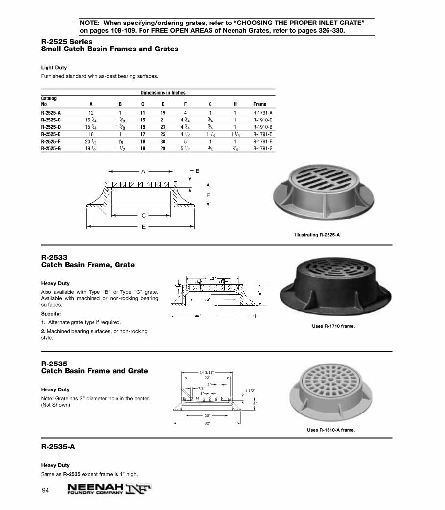
94
R-2525 SeriesSmall Catch Basin Frames and Grates
Light Duty
Furnished standard with as-cast bearing surfaces.
Dimensions in InchesCatalogNo. A B C E F G H Frame
R-2525-A 12 1 11 19 4 1 1 R-1791-AR-2525-C 15 3/4 1 3/8 15 21 4 3/4 3/4 1 R-1910-CR-2525-D 15 3/4 1 3/8 15 23 4 3/4 3/4 1 R-1910-BR-2525-E 18 1 17 25 4 1/2 1 1/8 1 1/4 R-1791-ER-2525-F 20 1/2 5/8 18 30 5 1 1 R-1791-FR-2525-G 19 1/2 1 1/2 18 29 5 1/2 3/4 3/4 R-1791-G
A B
C
E
F
Illustrating R-2525-A
R-2533Catch Basin Frame, Grate
Heavy Duty
Also available with Type “B” or Type “C” grate.Available with machined or non-rocking bearingsurfaces.
Specify:
1. Alternate grate type if required.
2. Machined bearing surfaces, or non-rockingstyle.
Uses R-1710 frame.
R-2535Catch Basin Frame and Grate
Heavy Duty
Note: Grate has 2” diameter hole in the center.(Not Shown)
1 1/2"
6"
2"
1"7/8"
24 3/16"
22"
20"
32"
Uses R-1510-A frame.
R-2535-A
Heavy Duty
Same as R-2535 except frame is 4” high.
NOTE: When specifying/ordering grates, refer to “CHOOSING THE PROPER INLET GRATE”on pages 108-109. For FREE OPEN AREAS of Neenah Grates, refer to pages 326-330.

95
R-2540Catch Basin Frame, Grate
Heavy Duty
24 3/4"
22 1/2"
20 1/2"
36"
6"
1 3/4"
Uses R-1580 frame.
R-2540-A
Same as R-2540 except furnished with 38” diameter base flange.
R-2545Special Drain
Light Duty
Storm drain for 18” tile pipe. Fits bell or spigot end.Grate is removable. Opening in outer diameter per-mits leaves and debris to wash through, eliminat-ing clogging.
Furnished standard with as-cast bearing surfaces.
R-2546
Same as R-2545 except for 15” tongue andgroove reinforced concrete pipe.
NOTE: When specifying/ordering grates, refer to “CHOOSING THE PROPER INLET GRATE”on pages 108-109. For FREE OPEN AREAS of Neenah Grates, refer to pages 326-330.
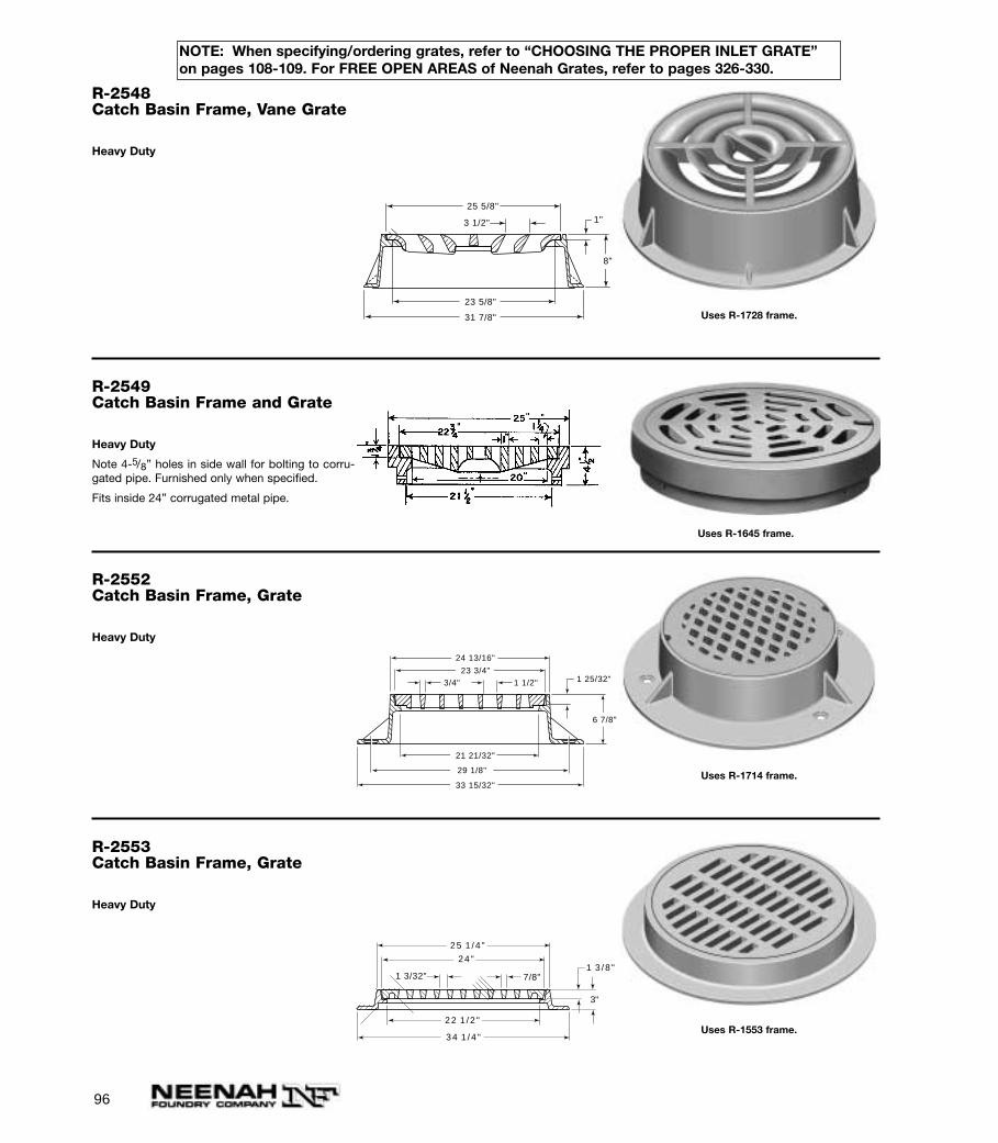
96
R-2548Catch Basin Frame, Vane Grate
Heavy Duty
25 5/8"
23 5/8"
31 7/8"
8"
1"3 1/2"
Uses R-1728 frame.
R-2549Catch Basin Frame and Grate
Heavy Duty
Note 4-5/8” holes in side wall for bolting to corru-gated pipe. Furnished only when specified.
Fits inside 24” corrugated metal pipe.
Uses R-1645 frame.
R-2552Catch Basin Frame, Grate
Heavy Duty
1 25/32"
24 13/16"
23 3/4"
21 21/32"
29 1/8"
33 15/32"
6 7/8"
3/4" 1 1/2"
Uses R-1714 frame.
R-2553Catch Basin Frame, Grate
Heavy Duty
1 3 /8 "
3"
3 4 1 /4 "
2 4 "
2 2 1 /2 "
2 5 1 /4 "
1 3/32" 7/8"
Uses R-1553 frame.
NOTE: When specifying/ordering grates, refer to “CHOOSING THE PROPER INLET GRATE”on pages 108-109. For FREE OPEN AREAS of Neenah Grates, refer to pages 326-330.
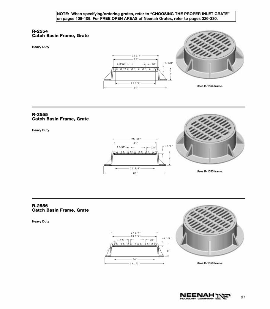
97
R-2554Catch Basin Frame, Grate
Heavy Duty
1 3 /8 "
7"
34 "
24 "
22 1 /2 "
25 3 /4 "
1 3/32" 7/8"
Uses R-1554 frame.
R-2555Catch Basin Frame, Grate
Heavy Duty
1 3 / 8 "
8"
34 "
2 4 "
2 1 3 / 4 "
25 1 /2 "
1 3/32" 7/8"
Uses R-1555 frame.
R-2556Catch Basin Frame, Grate
Heavy Duty
1 3 / 8 "
8"
3 4 1 / 2 "
2 5 3 / 4 "
2 4 "
2 7 1 / 4 "
1 3/32" 7/8"
Uses R-1556 frame.
NOTE: When specifying/ordering grates, refer to “CHOOSING THE PROPER INLET GRATE”on pages 108-109. For FREE OPEN AREAS of Neenah Grates, refer to pages 326-330.
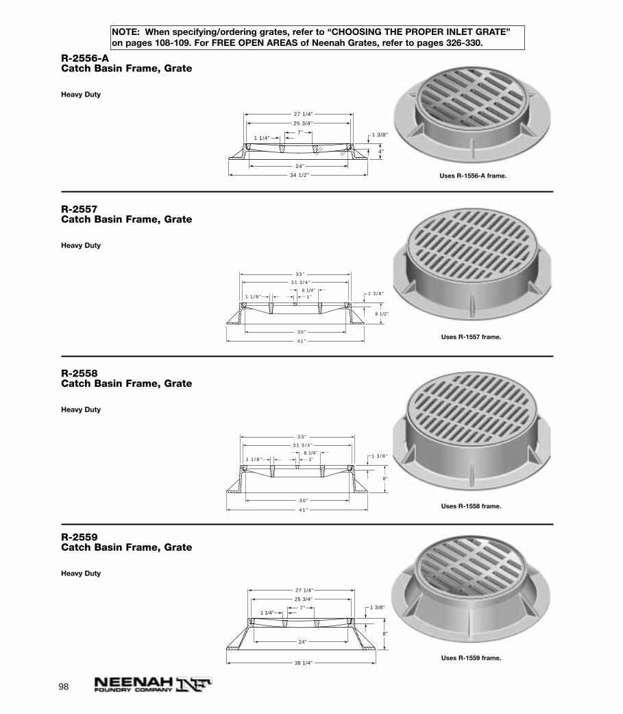
98
R-2556-ACatch Basin Frame, Grate
Heavy Duty
1 3/8"
4"
7"
25 3/4"
27 1/4"
24"
34 1/2"
1 1/4"
Uses R-1556-A frame.
R-2557Catch Basin Frame, Grate
Heavy Duty
1 3 / 8 "1 1 / 8 "
3 3 "
3 1 3 / 4 "
3 0 "
4 1 "
6 1/2"
6 1/4"1 "
Uses R-1557 frame.
R-2558Catch Basin Frame, Grate
Heavy Duty
1 3 / 8 "
8"
3 3 "
3 1 3 / 4 "
3 0 "
4 1 "
1 1 / 8 "6 1/4"
1"
Uses R-1558 frame.
R-2559Catch Basin Frame, Grate
Heavy Duty
1 3/8"
8"
27 1/4"
25 3/4"
38 1/4"
24"
7"
1 1/4"
Uses R-1559 frame.
NOTE: When specifying/ordering grates, refer to “CHOOSING THE PROPER INLET GRATE”on pages 108-109. For FREE OPEN AREAS of Neenah Grates, refer to pages 326-330.
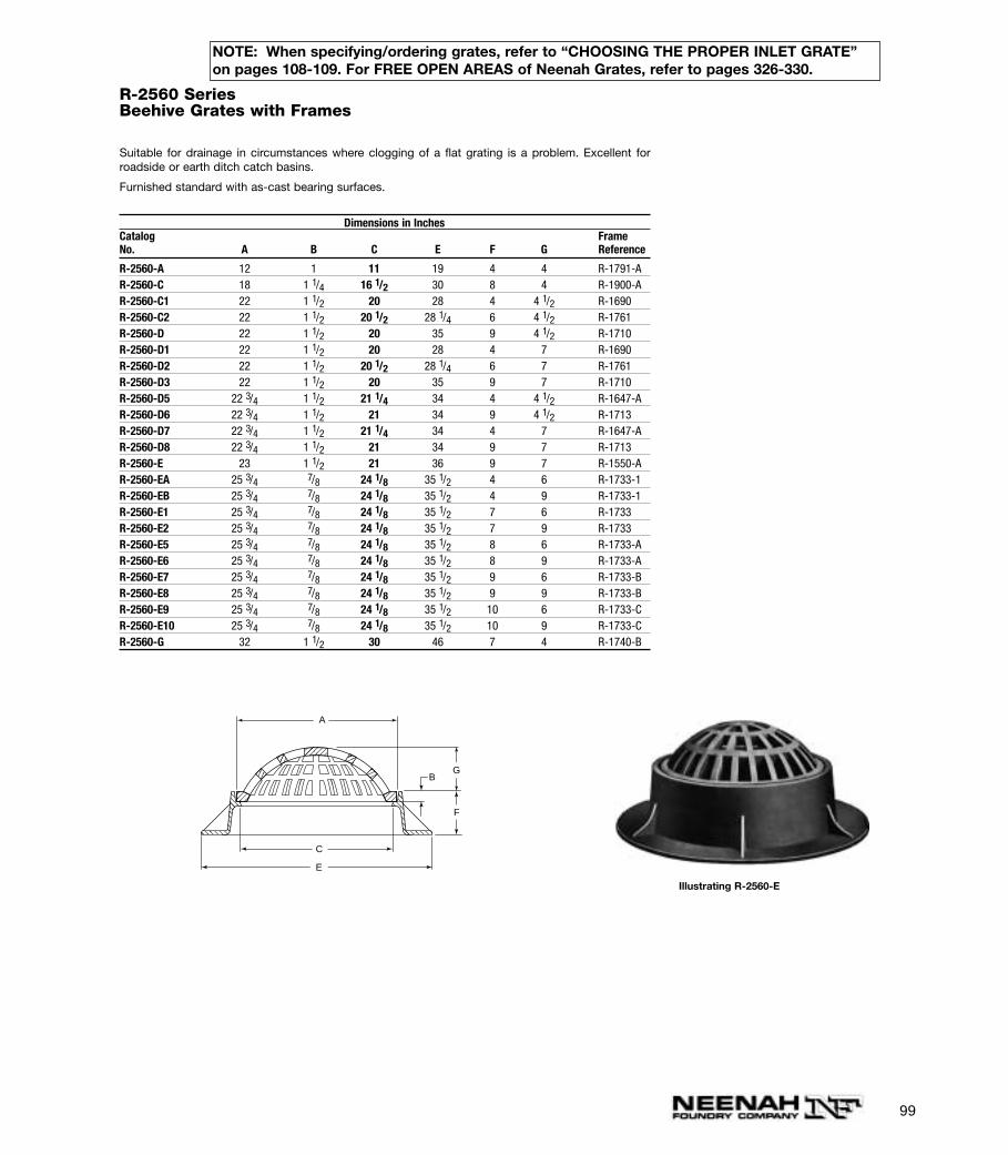
R-2560 SeriesBeehive Grates with Frames
Suitable for drainage in circumstances where clogging of a flat grating is a problem. Excellent forroadside or earth ditch catch basins.
Furnished standard with as-cast bearing surfaces.
Dimensions in InchesCatalog FrameNo. A B C E F G Reference
R-2560-A 12 1 11 19 4 4 R-1791-AR-2560-C 18 1 1/4 16 1/2 30 8 4 R-1900-AR-2560-C1 22 1 1/2 20 28 4 4 1/2 R-1690R-2560-C2 22 1 1/2 20 1/2 28 1/4 6 4 1/2 R-1761R-2560-D 22 1 1/2 20 35 9 4 1/2 R-1710R-2560-D1 22 1 1/2 20 28 4 7 R-1690R-2560-D2 22 1 1/2 20 1/2 28 1/4 6 7 R-1761R-2560-D3 22 1 1/2 20 35 9 7 R-1710R-2560-D5 22 3/4 1 1/2 21 1/4 34 4 4 1/2 R-1647-AR-2560-D6 22 3/4 1 1/2 21 34 9 4 1/2 R-1713R-2560-D7 22 3/4 1 1/2 21 1/4 34 4 7 R-1647-AR-2560-D8 22 3/4 1 1/2 21 34 9 7 R-1713R-2560-E 23 1 1/2 21 36 9 7 R-1550-AR-2560-EA 25 3/4 7/8 24 1/8 35 1/2 4 6 R-1733-1R-2560-EB 25 3/4 7/8 24 1/8 35 1/2 4 9 R-1733-1R-2560-E1 25 3/4 7/8 24 1/8 35 1/2 7 6 R-1733R-2560-E2 25 3/4 7/8 24 1/8 35 1/2 7 9 R-1733R-2560-E5 25 3/4 7/8 24 1/8 35 1/2 8 6 R-1733-AR-2560-E6 25 3/4 7/8 24 1/8 35 1/2 8 9 R-1733-AR-2560-E7 25 3/4 7/8 24 1/8 35 1/2 9 6 R-1733-BR-2560-E8 25 3/4 7/8 24 1/8 35 1/2 9 9 R-1733-BR-2560-E9 25 3/4 7/8 24 1/8 35 1/2 10 6 R-1733-CR-2560-E10 25 3/4 7/8 24 1/8 35 1/2 10 9 R-1733-CR-2560-G 32 1 1/2 30 46 7 4 R-1740-B
A
B
C
E
F
G
Illustrating R-2560-E
99
NOTE: When specifying/ordering grates, refer to “CHOOSING THE PROPER INLET GRATE”on pages 108-109. For FREE OPEN AREAS of Neenah Grates, refer to pages 326-330.
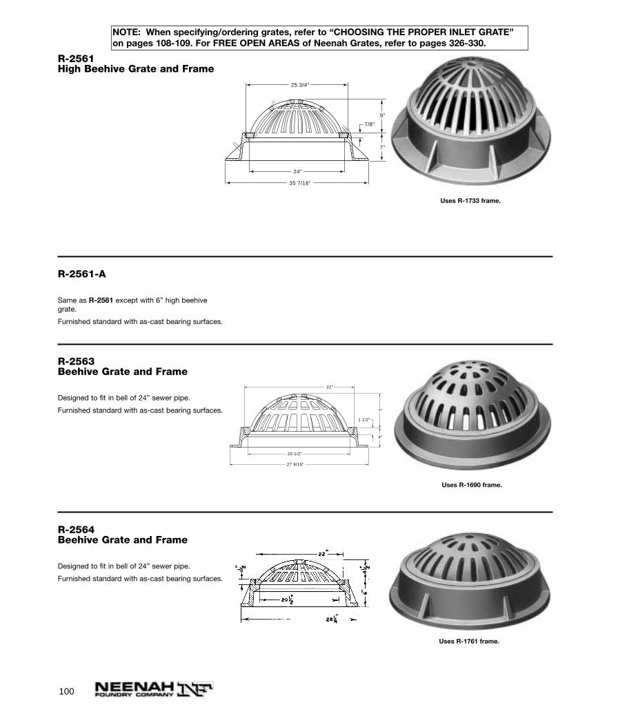
100
R-2561High Beehive Grate and Frame
35 7/16"
7/8"
25 3/4"
7"
9"
24"
Uses R-1733 frame.
R-2561-A
Same as R-2561 except with 6” high beehivegrate.
Furnished standard with as-cast bearing surfaces.
R-2563Beehive Grate and Frame
Designed to fit in bell of 24” sewer pipe.
Furnished standard with as-cast bearing surfaces.
27 9/16"
20 1/2"
1 1/2"
4"
7"
22"
Uses R-1690 frame.
R-2564Beehive Grate and Frame
Designed to fit in bell of 24” sewer pipe.
Furnished standard with as-cast bearing surfaces.
Uses R-1761 frame.
NOTE: When specifying/ordering grates, refer to “CHOOSING THE PROPER INLET GRATE”on pages 108-109. For FREE OPEN AREAS of Neenah Grates, refer to pages 326-330.
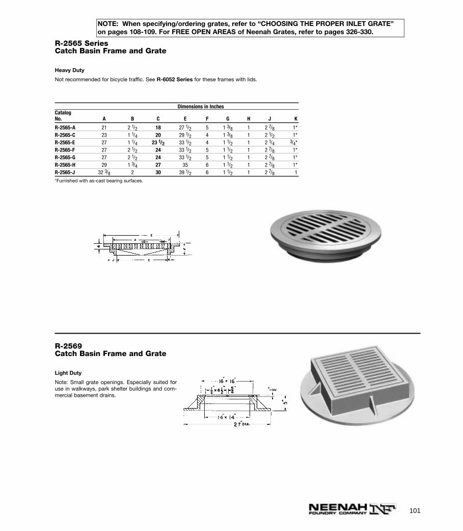
101
R-2565 SeriesCatch Basin Frame and Grate
Heavy Duty
Not recommended for bicycle traffic. See R-6052 Series for these frames with lids.
Dimensions in InchesCatalogNo. A B C E F G H J K
R-2565-A 21 2 1/2 18 27 1/2 5 1 3/8 1 2 7/8 1*R-2565-C 23 1 1/4 20 29 1/2 4 1 3/8 1 2 1/2 1*R-2565-E 27 1 1/4 23 1/2 33 1/2 4 1 1/2 1 2 1/4 3/4*R-2565-F 27 2 1/2 24 33 1/2 5 1 1/2 1 2 7/8 1*R-2565-G 27 2 1/2 24 33 1/2 5 1 1/2 1 2 7/8 1*R-2565-H 29 1 3/4 27 35 6 1 1/2 1 2 7/8 1*R-2565-J 32 3/8 2 30 39 1/2 6 1 1/2 1 2 7/8 1
*Furnished with as-cast bearing surfaces.
R-2569Catch Basin Frame and Grate
Light Duty
Note: Small grate openings. Especially suited foruse in walkways, park shelter buildings and com-mercial basement drains.
NOTE: When specifying/ordering grates, refer to “CHOOSING THE PROPER INLET GRATE”on pages 108-109. For FREE OPEN AREAS of Neenah Grates, refer to pages 326-330.
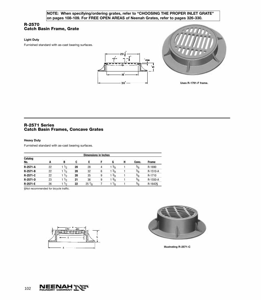
102
R-2570Catch Basin Frame, Grate
Light Duty
Furnished standard with as-cast bearing surfaces.
Uses R-1791-F frame.
R-2571 SeriesCatch Basin Frames, Concave Grates
Heavy Duty
Furnished standard with as-cast bearing surfaces.
Dimensions in InchesCatalogNo. A B C E F G H Conc. Frame
R-2571-A 22 1 1/2 20 28 4 1 3/8 1 5/8 R-1690R-2571-B 22 1 1/2 20 32 6 1 3/8 1 5/8 R-1510-AR-2571-C 22 1 1/2 20 35 9 1 3/8 1 5/8 R-1710R-2571-D 23 1 1/2 21 36 9 1 3/8 1 5/8 R-1550-AR-2571-E 26 1 1/2 22 25 7/8 7 1 1/8 1 5/8 R-1642§
§Not recommended for bicycle traffic.
Illustrating R-2571-C
NOTE: When specifying/ordering grates, refer to “CHOOSING THE PROPER INLET GRATE”on pages 108-109. For FREE OPEN AREAS of Neenah Grates, refer to pages 326-330.
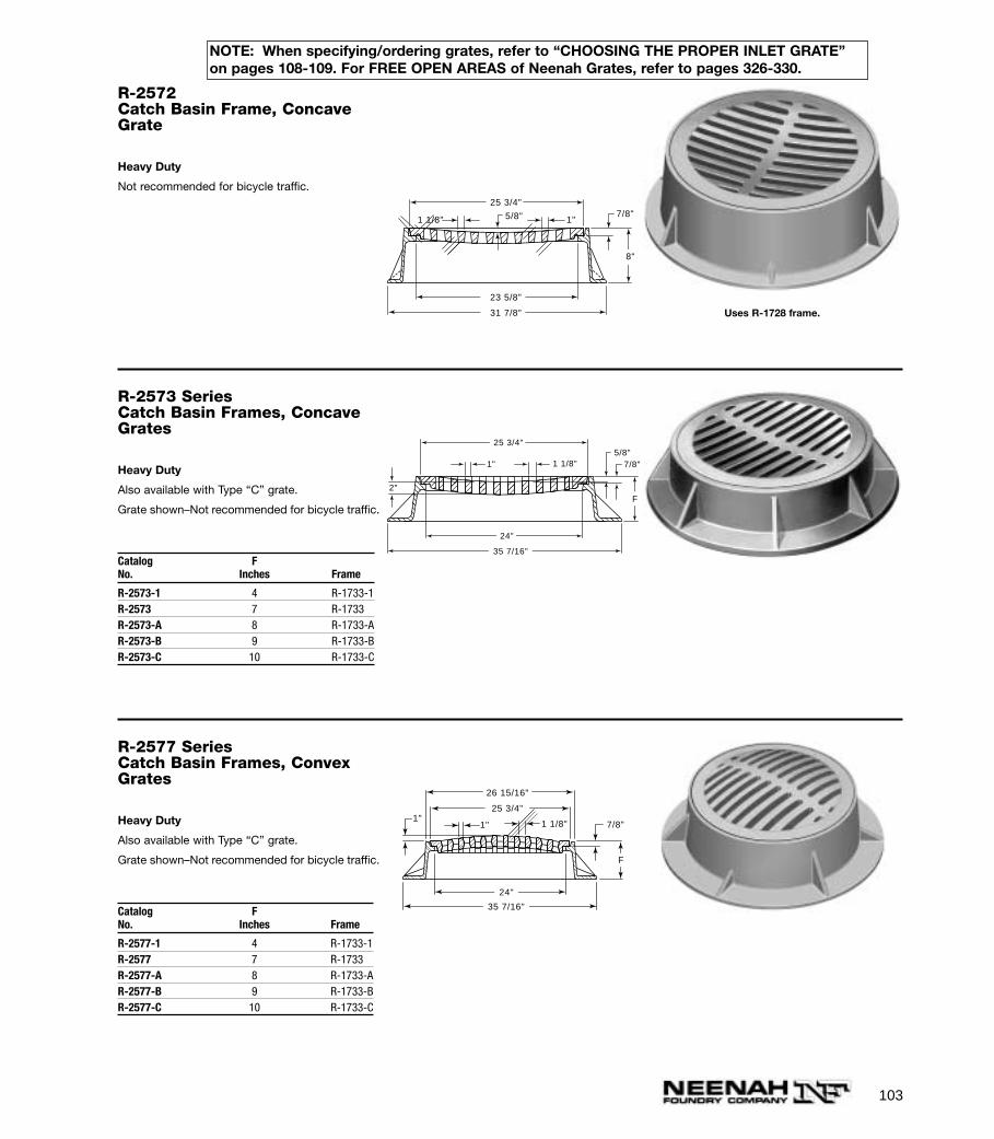
103
R-2572Catch Basin Frame, ConcaveGrate
Heavy Duty
Not recommended for bicycle traffic. 25 3/4"
23 5/8"
31 7/8"
8"
7/8"1"1 1/8" 5/8"
Uses R-1728 frame.
R-2573 SeriesCatch Basin Frames, ConcaveGrates
Heavy Duty
Also available with Type “C” grate.
Grate shown–Not recommended for bicycle traffic.
Catalog FNo. Inches Frame
R-2573-1 4 R-1733-1R-2573 7 R-1733R-2573-A 8 R-1733-AR-2573-B 9 R-1733-BR-2573-C 10 R-1733-C
35 7/16"
7/8" 5/8"
2"
25 3/4"
F
24"
1" 1 1/8"
R-2577 SeriesCatch Basin Frames, ConvexGrates
Heavy Duty
Also available with Type “C” grate.
Grate shown–Not recommended for bicycle traffic.
Catalog FNo. Inches Frame
R-2577-1 4 R-1733-1R-2577 7 R-1733R-2577-A 8 R-1733-AR-2577-B 9 R-1733-BR-2577-C 10 R-1733-C
1 1/8"1"
F
1"7/8"
25 3/4"
26 15/16"
24"
35 7/16"
NOTE: When specifying/ordering grates, refer to “CHOOSING THE PROPER INLET GRATE”on pages 108-109. For FREE OPEN AREAS of Neenah Grates, refer to pages 326-330.
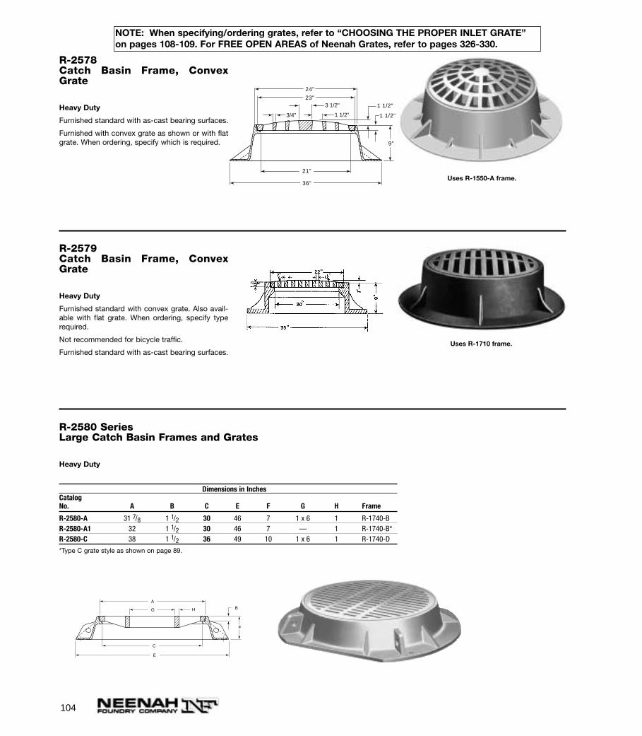
104
R-2578Catch Basin Frame, ConvexGrate
Heavy Duty
Furnished standard with as-cast bearing surfaces.
Furnished with convex grate as shown or with flatgrate. When ordering, specify which is required.
23"
24"
36"
21"
1 1/2"
1 1/2"
9"
3 1/2"
3/4" 1 1/2"
Uses R-1550-A frame.
R-2579Catch Basin Frame, ConvexGrate
Heavy Duty
Furnished standard with convex grate. Also avail-able with flat grate. When ordering, specify typerequired.
Not recommended for bicycle traffic.
Furnished standard with as-cast bearing surfaces. Uses R-1710 frame.
R-2580 SeriesLarge Catch Basin Frames and Grates
Heavy Duty
Dimensions in InchesCatalogNo. A B C E F G H Frame
R-2580-A 31 7/8 1 1/2 30 46 7 1 x 6 1 R-1740-BR-2580-A1 32 1 1/2 30 46 7 — 1 R-1740-B*R-2580-C 38 1 1/2 36 49 10 1 x 6 1 R-1740-D
*Type C grate style as shown on page 89.
A
G B
C
E
F
H
NOTE: When specifying/ordering grates, refer to “CHOOSING THE PROPER INLET GRATE”on pages 108-109. For FREE OPEN AREAS of Neenah Grates, refer to pages 326-330.
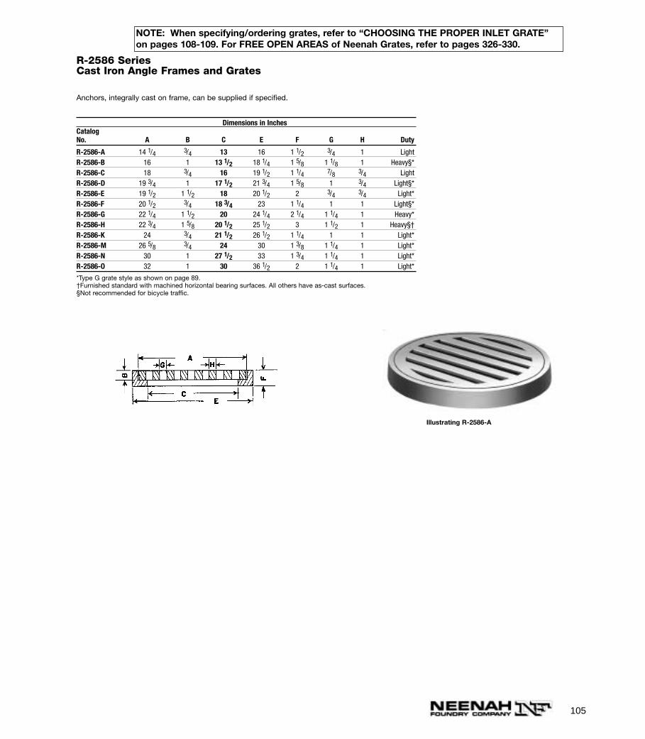
105
R-2586 SeriesCast Iron Angle Frames and Grates
Anchors, integrally cast on frame, can be supplied if specified.
Dimensions in InchesCatalogNo. A B C E F G H Duty
R-2586-A 14 1/4 3/4 13 16 1 1/2 3/4 1 LightR-2586-B 16 1 13 1/2 18 1/4 1 5/8 1 1/8 1 Heavy§*R-2586-C 18 3/4 16 19 1/2 1 1/4 7/8 3/4 LightR-2586-D 19 3/4 1 17 1/2 21 3/4 1 5/8 1 3/4 Light§*R-2586-E 19 1/2 1 1/2 18 20 1/2 2 3/4 3/4 Light*R-2586-F 20 1/2 3/4 18 3/4 23 1 1/4 1 1 Light§*R-2586-G 22 1/4 1 1/2 20 24 1/4 2 1/4 1 1/4 1 Heavy*R-2586-H 22 3/4 1 5/8 20 1/2 25 1/2 3 1 1/2 1 Heavy§†R-2586-K 24 3/4 21 1/2 26 1/2 1 1/4 1 1 Light*R-2586-M 26 5/8 3/4 24 30 1 3/8 1 1/4 1 Light*R-2586-N 30 1 27 1/2 33 1 3/4 1 1/4 1 Light*R-2586-O 32 1 30 36 1/2 2 1 1/4 1 Light*
*Type G grate style as shown on page 89.†Furnished standard with machined horizontal bearing surfaces. All others have as-cast surfaces.§Not recommended for bicycle traffic.
Illustrating R-2586-A
NOTE: When specifying/ordering grates, refer to “CHOOSING THE PROPER INLET GRATE”on pages 108-109. For FREE OPEN AREAS of Neenah Grates, refer to pages 326-330.
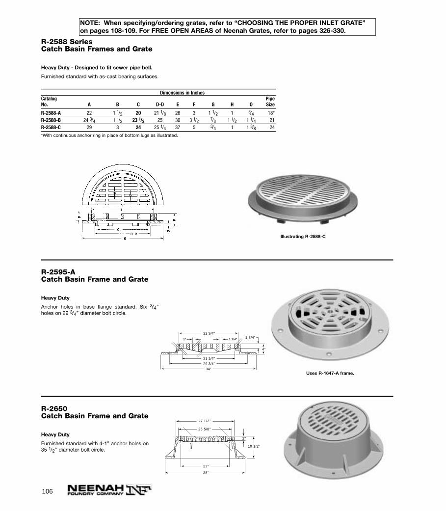
106
R-2588 SeriesCatch Basin Frames and Grate
Heavy Duty - Designed to fit sewer pipe bell.
Furnished standard with as-cast bearing surfaces.
Dimensions in InchesCatalog PipeNo. A B C D-D E F G H O Size
R-2588-A 22 1 1/2 20 21 1/8 26 3 1 1/2 1 3/4 18*R-2588-B 24 3/4 1 1/2 23 1/2 25 30 3 1/2 7/8 1 1/2 1 1/4 21R-2588-C 29 3 24 25 1/4 37 5 3/4 1 1 3/8 24
*With continuous anchor ring in place of bottom lugs as illustrated.
Illustrating R-2588-C
R-2595-ACatch Basin Frame and Grate
Heavy Duty
Anchor holes in base flange standard. Six 3/4”holes on 29 3/4” diameter bolt circle.
22 3/4"
29 3/4"
34"
21 1/4"
1 3/4"
4"
1" 1 1/4"
Uses R-1647-A frame.
R-2650Catch Basin Frame and Grate
Heavy Duty
Furnished standard with 4-1” anchor holes on 35 1/2” diameter bolt circle.
27 1/2"
25 5/8"
23"
38"
2"
10 1/2"
NOTE: When specifying/ordering grates, refer to “CHOOSING THE PROPER INLET GRATE”on pages 108-109. For FREE OPEN AREAS of Neenah Grates, refer to pages 326-330.
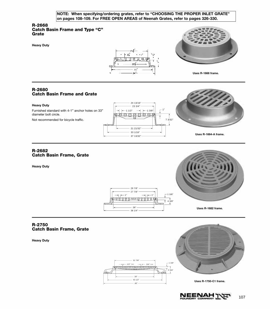
107
R-2668Catch Basin Frame and Type “C”Grate
Heavy Duty
Uses R-1668 frame.
R-2680Catch Basin Frame and Grate
Heavy Duty
Furnished standard with 4-1” anchor holes on 33”diameter bolt circle.
Not recommended for bicycle traffic.
1"1 1/2" 1 3/8"
24 13/16"
23 3/4"
21 21/32"
33 1/16"
37 13/32"
7 3/32"
Uses R-1664-A frame.
R-2682Catch Basin Frame, Grate
Heavy Duty
4 3/8"
1 3/8"
29 7/8"
27 7/8"
38 1/4"
26"
1" 1"
Uses R-1682 frame.
R-2750Catch Basin Frame, Grate
Heavy Duty
1/2" 3/4"TYP. TYP.
31 7/8"
43 1/2"
30"
49"
1 3/8"
5 5/8"
Uses R-1750-C1 frame.
NOTE: When specifying/ordering grates, refer to “CHOOSING THE PROPER INLET GRATE”on pages 108-109. For FREE OPEN AREAS of Neenah Grates, refer to pages 326-330.
108
CHOOSING THE PROPER INLET GRATE
Adopting an inlet grate design requires an analysis of the functions the grate should perform. A designer must review thedrainage requirements and then specify which functions will be necessary for satisfactory grate and all other performancerequirements of each application. For example, if the only consideration is for the grate to efficiently intercept large quantities of storm water from the gutter - then a grate with the proper geometry and flow through area is the one tochoose. Although capacity is an important function, there are other considerations that must be evaluated to satisfy therequirements of a functional, correctly located, safe grate. Some considerations are listed below. Designers must note that there may be other considerations in addition to those listed below that should be evaluated prior to making a choice.
NOTE: ALSO SEE “CAUTIONS” ON PAGE 6 AND “STORM WATER MANAGEMENT WITH NEENAH GRATES” ONPAGE 110.
CONSIDERATIONS FOR HANDICAPPED PERSONS, BICYCLES AND PEDESTRIANSDesign and placement of the grate must be suitable for use in areas where it is possible for handicapped persons, bicycles,and pedestrians to be present.
THE ADOPTION OF THE AMERICANS WITH DISABILITIES ACT (ADA), THE PROMINENCE OF NARROW TIRED BICYCLES AND CONCERN FOR PEDESTRIAN SAFETY DICTATES THAT DESIGNERS CAREFULLY CONSIDER THE SAFETY OF THE TYPE OF GRATINGS SELECTED FOR VARIOUS APPLICATIONS. IF THE INSTALLATION IS CHANGEDIN CONCEPT, SCOPE OR USAGE PATTERN AT SOME FUTURE DATE, DESIGNERS MUST AT THAT TIME RECONSIDERTHE TYPES OF GRATINGS USED AND DETERMINE IF THEY STILL MEET THEIR SAFETY REQUIREMENTS. IF NOT,DESIGNERS MUST REPLACE THESE EXISTING GRATES WITH MORE APPROPRIATE STYLES.
GRATES FOR BICYCLES The designer must determine the appropriate grate design and inlet location for safe use bybicycle traffic, having in mind the specific details of location and foreseeable use. The following are some important considerations:1. The style of grate employed should allow bicycle travel from all accessible directions. Grates located in open
areas, or adjacent to driveways, or in other locations where they are not adjacent to barrier curbs, require special attention in this regard.
2. In general, we suggest consideration of our Type L vane style grates. We think certain grates shown in our catalog are generally not suitable for use where bicycle traffic is a consideration, and those grates are so designated in this catalog. The absence of such a designation, however, does not mean that a grate would necessarily be safe in any specific location, and the designer is responsible for making the appropriate grate selection.
3. If slotted grates or vane-type grates other than our Type L are considered, they should have sufficiently narrow openings, and/or should have appropriately spaced transverse (cross) bars, to ensure that any foreseeable width and diameter of bicycle tire cannot drop down into openings to an unsafe extent.
4. Gutter slopes should not be substantially swaled into the curb so as to create a disturbance in the roadway which might affect the ability of bicycles or other traffic to traverse them.
GRATES FOR PEDESTRIANS AND HANDICAPPED Various regulations or customs may dictate the use of specific typesof grates: such as gratings with longitudinal slot openings no greater than 1/4” or 1/2”. Designers must carefully evaluatethe location and placement of grates against applicable specifications to be sure they are using grates that will satisfy thespecification's requirement and provide a pathway (accessible route) for pedestrians and handicapped persons. TheAmericans With Disabilities Act (ADA) provides grating specification guidelines that can be used in creating accessibleroutes for handicapped individuals.
HYDRAULIC EFFICIENCYThe ability of a grate to intercept storm water or its hydraulic efficiency is an important function. The main considerations indesign are the geometry and the flow through area of the openings for each individual grate. NEENAH has recognized thedesigner's need for hydraulic information on individual grates. We studied individual grate performance by establishing ourown hydraulic testing program and are now capable of supplying grate capacity information on most of the grates shown inthis catalog. Please call us for specific charts and information or to request your copy of Neenah's Inlet Grate CapacitiesManual.
109
SCREENING OUT HARMFUL DEBRISAn inlet grate must act as a strainer and prevent harmful debris from entering sewer lines. Objects such as branches, largesheets of semi rigid material, sticks, chunks of wood, etc. which are easily passed by large curb openings (open throat) areconveniently prevented from entering the catch basin by a well chosen grate.
If large debris gets into the catch basin, it can often float or wash into the lines, clogging them at inaccessible locationsand making the drainage system ineffective.
Should clogging of the grate occur at the upstream end, grates of longer lengths usually provide the extra flow throughcapacity necessary to accommodate the gutter flow as well as some of the side flow.
ABILITY TO PASS UNOBJECTIONABLE DEBRIS Organic material, such as grass clippings, leaves, small stones, scraps of paper and even small twigs should be passedinto the catch basin. Because of their size and configuration they are not a hazard for the sewer lines.
Grates designed with closely spaced bars for strength and safety become easily clogged from very small but always present debris. The problem is magnified even more as this debris is packed into the openings by passing traffic creating a hard, semi solid surface. The velocity of the gutter flow is insufficient to dislodge the packed debris and so the gratebecomes ineffective.
The answer then is to provide grate openings wide enough, of suitable length or of special design to pass this debris andstill meet the other requirements. Neenah has many sizes and styles that can be implemented into your designs.
STRENGTH Inlet grates placed in roadways must be designed to withstand heavy traffic loads. A common designation for standardhighway loads is described as H20-44 loading for single axle trucks and HS20-44 for tandem axle trucks (tractor semi-trailer units). The maximum axle loading in both cases is 32,000 lbs. Or 16,000 lb. for each set of dual wheels. There may be cases where more extreme design loads are necessary such as airports, commercial applications, industrialsites or installations where extra heavy loads and/or extremely hard tires are present. (See page 4 for a list of publishedspecifications available to assist you in your design.)
PERMANENCY A gutter inlet grate should be designed to match or exceed the expected life of the installation. The inherent rust resisting properties of unpainted cast iron and its time-tested performance insures long life. The strength ofcast iron grates resists earth and pavement pressures-qualities one should question in other non-cast iron materials.
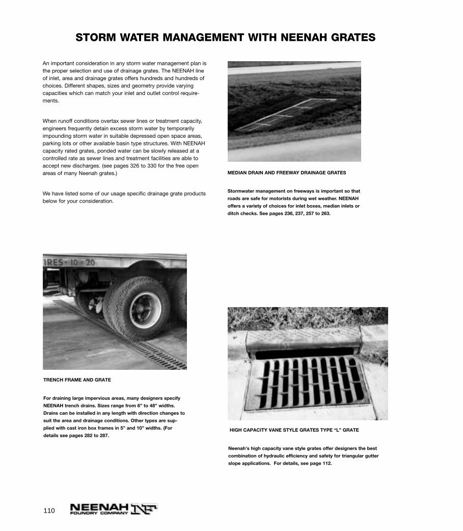
110
An important consideration in any storm water management plan isthe proper selection and use of drainage grates. The NEENAH lineof inlet, area and drainage grates offers hundreds and hundreds ofchoices. Different shapes, sizes and geometry provide varyingcapacities which can match your inlet and outlet control require-ments.
When runoff conditions overtax sewer lines or treatment capacity,engineers frequently detain excess storm water by temporarilyimpounding storm water in suitable depressed open space areas,parking lots or other available basin type structures. With NEENAHcapacity rated grates, ponded water can be slowly released at acontrolled rate as sewer lines and treatment facilities are able toaccept new discharges. (see pages 326 to 330 for the free openareas of many Neenah grates.)
We have listed some of our usage specific drainage grate productsbelow for your consideration.
STORM WATER MANAGEMENT WITH NEENAH GRATES
TRENCH FRAME AND GRATE
For draining large impervious areas, many designers specify
NEENAH trench drains. Sizes range from 6” to 48” widths.
Drains can be installed in any length with direction changes to
suit the area and drainage conditions. Other types are sup-
plied with cast iron box frames in 5” and 10” widths. (For
details see pages 282 to 287.
MEDIAN DRAIN AND FREEWAY DRAINAGE GRATES
Stormwater management on freeways is important so that
roads are safe for motorists during wet weather. NEENAH
offers a variety of choices for inlet boxes, median inlets or
ditch checks. See pages 236, 237, 257 to 263.
HIGH CAPACITY VANE STYLE GRATES TYPE “L” GRATE
Neenah's high capacity vane style grates offer designers the best
combination of hydraulic efficiency and safety for triangular gutter
slope applications. For details, see page 112.
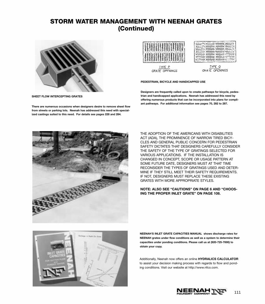
111
SHEET FLOW INTERCEPTING GRATES
There are numerous occasions when designers desire to remove sheet flowfrom streets or parking lots. Neenah has addressed this need with special-ized castings suited to this need. For details see pages 228 and 284.
THE ADOPTION OF THE AMERICANS WITH DISABILITIESACT (ADA), THE PROMINENCE OF NARROW TIRED BICY-CLES AND GENERAL PUBLIC CONCERN FOR PEDESTRIANSAFETY DICTATES THAT DESIGNERS CAREFULLY CONSIDERTHE SAFETY OF THE TYPE OF GRATINGS SELECTED FORVARIOUS APPLICATIONS. IF THE INSTALLATION ISCHANGED IN CONCEPT, SCOPE OR USAGE PATTERN ATSOME FUTURE DATE, DESIGNERS MUST AT THAT TIMERECONSIDER THE TYPES OF GRATINGS USED AND DETER-MINE IF THEY STILL MEET THEIR SAFETY REQUIREMENTS.IF NOT, DESIGNERS MUST REPLACE THESE EXISTINGGRATES WITH MORE APPROPRIATE STYLES.
NOTE: ALSO SEE “CAUTIONS” ON PAGE 6 AND “CHOOS-ING THE PROPER INLET GRATE” ON PAGE 108.
PEDESTRIAN, BICYCLE AND HANDICAPPED USE
Designers are frequently called upon to create pathways for bicycle, pedes-trian and handicapped applications. Neenah has addressed this need byoffering numerous products that can be incorporated into plans for compli-ant pathways. For additional information see pages 70, 282 to 287.
NEENAH'S INLET GRATE CAPACITIES MANUAL shows discharge rates for
NEENAH grates under flow conditions as well as a system to determine their
capacities under ponding conditions. Please call us at (920-725-7000) to
obtain your copy.
STORM WATER MANAGEMENT WITH NEENAH GRATES(Continued)
Additionally, Neenah now offers an online HYDRALICS CALCULATORto assist your decision making process with regards to flow and pond-ing conditions. Visit our website at http://www.nfco.com.
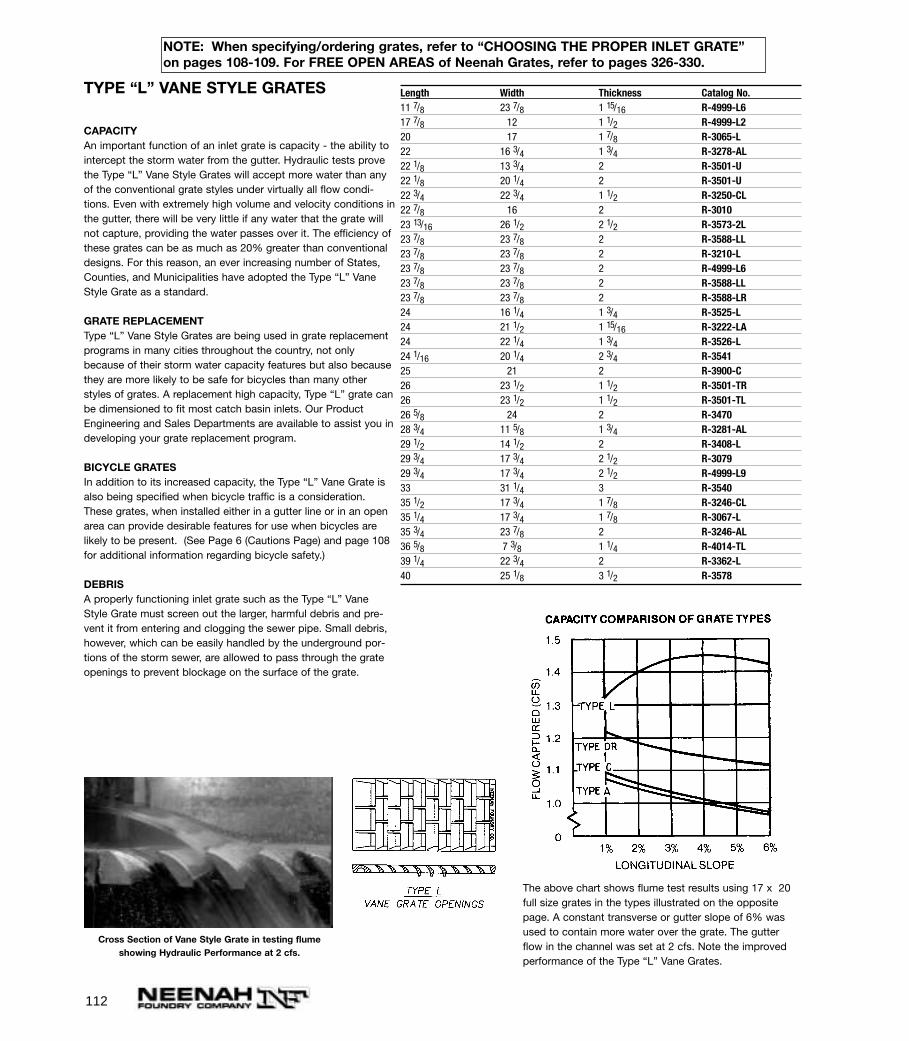
112
TYPE “L” VANE STYLE GRATES
CAPACITYAn important function of an inlet grate is capacity - the ability tointercept the storm water from the gutter. Hydraulic tests provethe Type “L” Vane Style Grates will accept more water than anyof the conventional grate styles under virtually all flow condi-tions. Even with extremely high volume and velocity conditions inthe gutter, there will be very little if any water that the grate willnot capture, providing the water passes over it. The efficiency ofthese grates can be as much as 20% greater than conventionaldesigns. For this reason, an ever increasing number of States,Counties, and Municipalities have adopted the Type “L” VaneStyle Grate as a standard.
GRATE REPLACEMENTType “L” Vane Style Grates are being used in grate replacementprograms in many cities throughout the country, not onlybecause of their storm water capacity features but also becausethey are more likely to be safe for bicycles than many otherstyles of grates. A replacement high capacity, Type “L” grate canbe dimensioned to fit most catch basin inlets. Our ProductEngineering and Sales Departments are available to assist you indeveloping your grate replacement program.
BICYCLE GRATESIn addition to its increased capacity, the Type “L” Vane Grate isalso being specified when bicycle traffic is a consideration.These grates, when installed either in a gutter line or in an openarea can provide desirable features for use when bicycles arelikely to be present. (See Page 6 (Cautions Page) and page 108for additional information regarding bicycle safety.)
DEBRIS A properly functioning inlet grate such as the Type “L” VaneStyle Grate must screen out the larger, harmful debris and pre-vent it from entering and clogging the sewer pipe. Small debris,however, which can be easily handled by the underground por-tions of the storm sewer, are allowed to pass through the grateopenings to prevent blockage on the surface of the grate.
Cross Section of Vane Style Grate in testing flumeshowing Hydraulic Performance at 2 cfs.
The above chart shows flume test results using 17 x 20full size grates in the types illustrated on the oppositepage. A constant transverse or gutter slope of 6% wasused to contain more water over the grate. The gutterflow in the channel was set at 2 cfs. Note the improvedperformance of the Type “L” Vane Grates.
Length Width Thickness Catalog No.11 7/8 23 7/8 1 15/16 R-4999-L617 7/8 12 1 1/2 R-4999-L220 17 1 7/8 R-3065-L22 16 3/4 1 3/4 R-3278-AL22 1/8 13 3/4 2 R-3501-U22 1/8 20 1/4 2 R-3501-U22 3/4 22 3/4 1 1/2 R-3250-CL22 7/8 16 2 R-301023 13/16 26 1/2 2 1/2 R-3573-2L23 7/8 23 7/8 2 R-3588-LL23 7/8 23 7/8 2 R-3210-L23 7/8 23 7/8 2 R-4999-L623 7/8 23 7/8 2 R-3588-LL23 7/8 23 7/8 2 R-3588-LR24 16 1/4 1 3/4 R-3525-L24 21 1/2 1 15/16 R-3222-LA24 22 1/4 1 3/4 R-3526-L24 1/16 20 1/4 2 3/4 R-354125 21 2 R-3900-C26 23 1/2 1 1/2 R-3501-TR26 23 1/2 1 1/2 R-3501-TL26 5/8 24 2 R-347028 3/4 11 5/8 1 3/4 R-3281-AL29 1/2 14 1/2 2 R-3408-L29 3/4 17 3/4 2 1/2 R-307929 3/4 17 3/4 2 1/2 R-4999-L933 31 1/4 3 R-354035 1/2 17 3/4 1 7/8 R-3246-CL35 1/4 17 3/4 1 7/8 R-3067-L35 3/4 23 7/8 2 R-3246-AL36 5/8 7 3/8 1 1/4 R-4014-TL39 1/4 22 3/4 2 R-3362-L40 25 1/8 3 1/2 R-3578
NOTE: When specifying/ordering grates, refer to “CHOOSING THE PROPER INLET GRATE”on pages 108-109. For FREE OPEN AREAS of Neenah Grates, refer to pages 326-330.
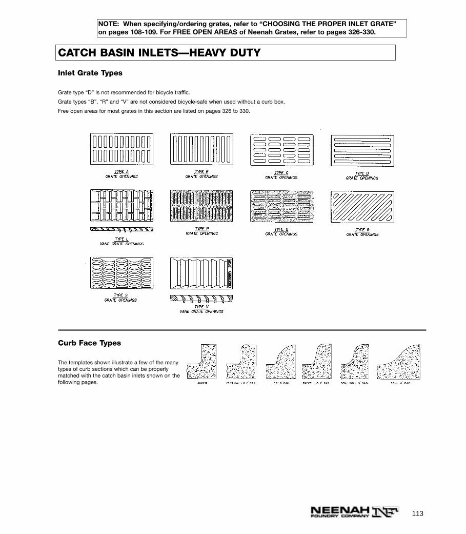
113
Curb Face Types
The templates shown illustrate a few of the manytypes of curb sections which can be properlymatched with the catch basin inlets shown on thefollowing pages.
CATCH BASIN INLETS—HEAVY DUTY
Inlet Grate Types
Grate type “D” is not recommended for bicycle traffic.
Grate types “B”, “R” and “V” are not considered bicycle-safe when used without a curb box.
Free open areas for most grates in this section are listed on pages 326 to 330.
NOTE: When specifying/ordering grates, refer to “CHOOSING THE PROPER INLET GRATE”on pages 108-109. For FREE OPEN AREAS of Neenah Grates, refer to pages 326-330.
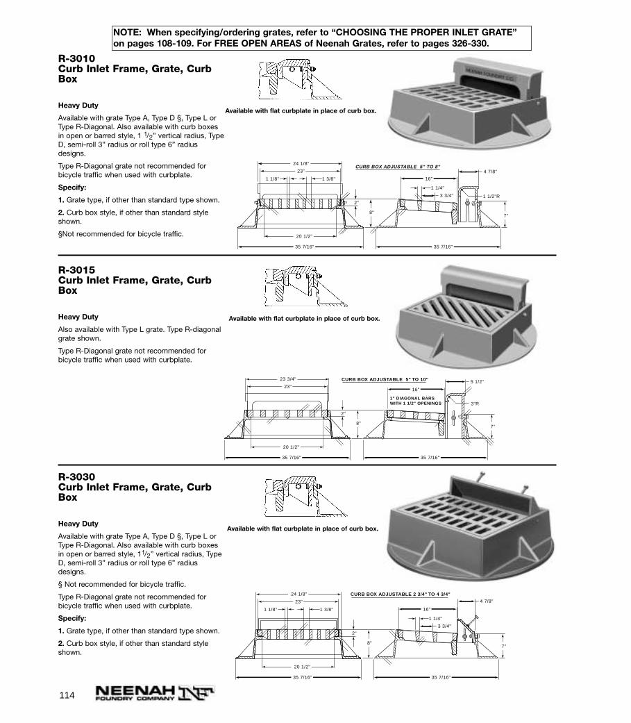
114
R-3015Curb Inlet Frame, Grate, CurbBox
Heavy Duty
Also available with Type L grate. Type R-diagonalgrate shown.
Type R-Diagonal grate not recommended forbicycle traffic when used with curbplate.
R-3030Curb Inlet Frame, Grate, CurbBox
Heavy Duty
Available with grate Type A, Type D §, Type L orType R-Diagonal. Also available with curb boxesin open or barred style, 11/2” vertical radius, TypeD, semi-roll 3” radius or roll type 6” radiusdesigns.
§ Not recommended for bicycle traffic.
Type R-Diagonal grate not recommended forbicycle traffic when used with curbplate.
Specify:
1. Grate type, if other than standard type shown.
2. Curb box style, if other than standard styleshown.
R-3010Curb Inlet Frame, Grate, CurbBox
Heavy Duty
Available with grate Type A, Type D §, Type L orType R-Diagonal. Also available with curb boxesin open or barred style, 1 1/2” vertical radius, TypeD, semi-roll 3” radius or roll type 6” radiusdesigns.
Type R-Diagonal grate not recommended forbicycle traffic when used with curbplate.
Specify:
1. Grate type, if other than standard type shown.
2. Curb box style, if other than standard styleshown.
§Not recommended for bicycle traffic.
Available with flat curbplate in place of curb box.
1 1/8"
1 1/4"
3 3/4"
1 3/8"
4 7/8"
2"
7"8"
20 1/2"
24 1/8"
23"
16"
35 7/16" 35 7/16"
1 1/2"R
CURB BOX ADJUSTABLE 5" TO 8"
Available with flat curbplate in place of curb box.
Available with flat curbplate in place of curb box.
5 1/2"
2"
7"8"
20 1/2"
23 3/4"
23"16"
35 7/16" 35 7/16"
3"R1" DIAGONAL BARSWITH 1 1/2" OPENINGS
CURB BOX ADJUSTABLE 5" TO 10"
1 1/8"
1 1/4"
3 3/4"
1 3/8"
4 7/8"
2"
7"8"
20 1/2"
24 1/8"
23"
16"
35 7/16" 35 7/16"
CURB BOX ADJUSTABLE 2 3/4" TO 4 3/4"
NOTE: When specifying/ordering grates, refer to “CHOOSING THE PROPER INLET GRATE”on pages 108-109. For FREE OPEN AREAS of Neenah Grates, refer to pages 326-330.

115
R-3032-BSplit Curb Inlet Frame, Grate, Curb Box
Heavy Duty
R-3033-BSplit Curb Inlet Frame, Grate, Curb Box
Heavy Duty
R-3031-BCurb Inlet Frame, Grate, Curb Box
Heavy Duty
NOTE: When specifying/ordering grates, refer to “CHOOSING THE PROPER INLET GRATE”on pages 108-109. For FREE OPEN AREAS of Neenah Grates, refer to pages 326-330.
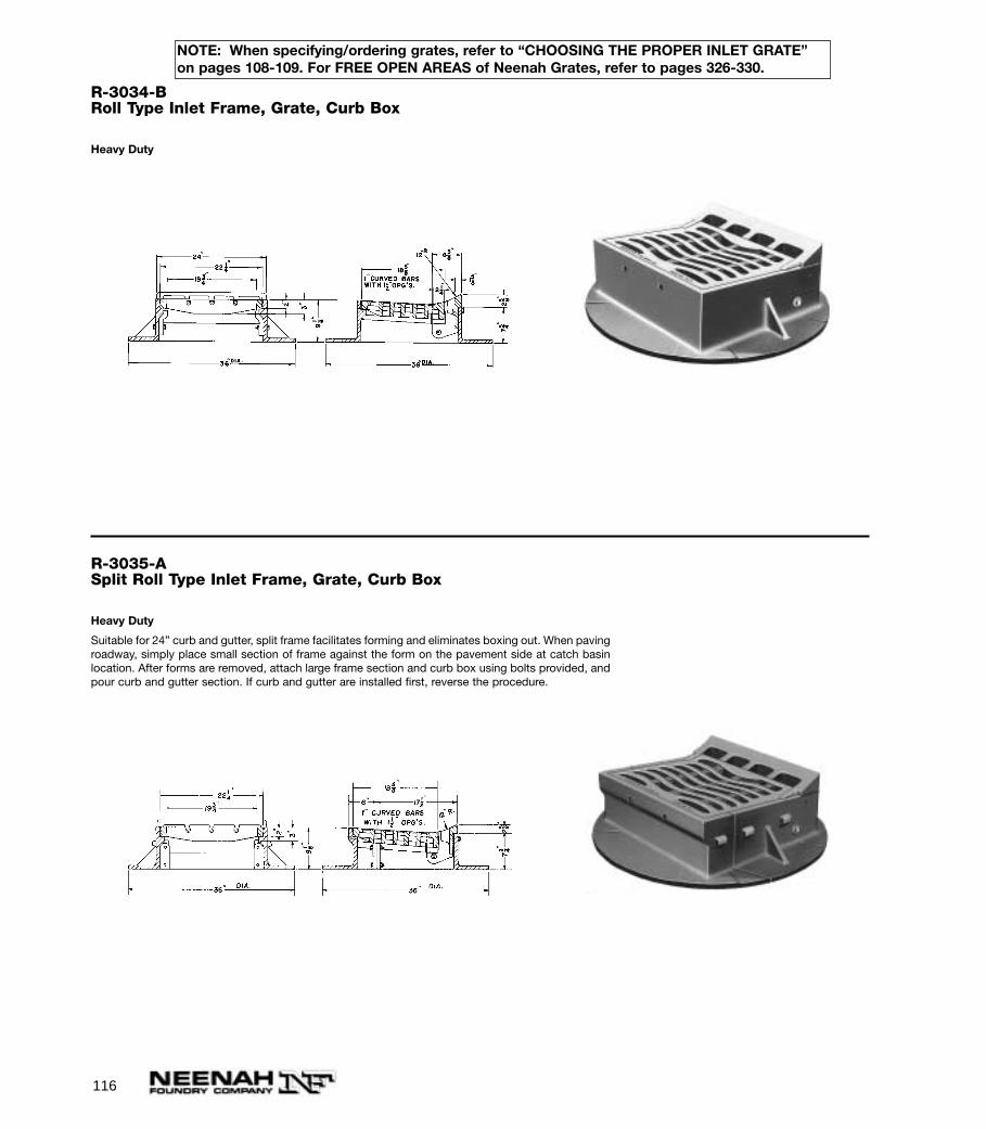
116
R-3034-BRoll Type Inlet Frame, Grate, Curb Box
Heavy Duty
R-3035-ASplit Roll Type Inlet Frame, Grate, Curb Box
Heavy Duty
Suitable for 24” curb and gutter, split frame facilitates forming and eliminates boxing out. When pavingroadway, simply place small section of frame against the form on the pavement side at catch basinlocation. After forms are removed, attach large frame section and curb box using bolts provided, andpour curb and gutter section. If curb and gutter are installed first, reverse the procedure.
NOTE: When specifying/ordering grates, refer to “CHOOSING THE PROPER INLET GRATE”on pages 108-109. For FREE OPEN AREAS of Neenah Grates, refer to pages 326-330.
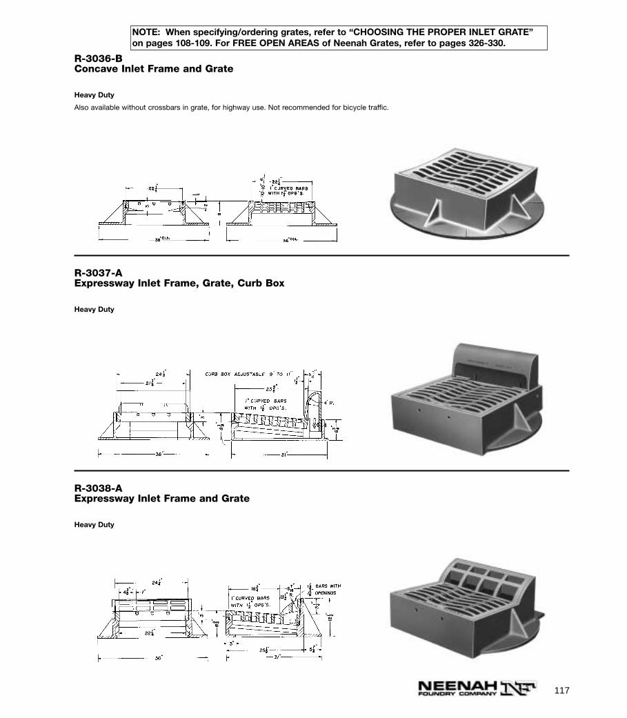
117
R-3036-BConcave Inlet Frame and Grate
Heavy Duty
Also available without crossbars in grate, for highway use. Not recommended for bicycle traffic.
R-3037-AExpressway Inlet Frame, Grate, Curb Box
Heavy Duty
R-3038-AExpressway Inlet Frame and Grate
Heavy Duty
NOTE: When specifying/ordering grates, refer to “CHOOSING THE PROPER INLET GRATE”on pages 108-109. For FREE OPEN AREAS of Neenah Grates, refer to pages 326-330.
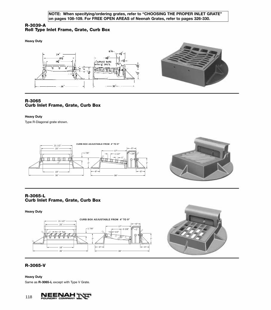
118
R-3039-ARoll Type Inlet Frame, Grate, Curb Box
Heavy Duty
R-3065Curb Inlet Frame, Grate, Curb Box
Heavy Duty
Type R-Diagonal grate shown.
R-3065-LCurb Inlet Frame, Grate, Curb Box
Heavy Duty
R-3065-V
Heavy Duty
Same as R-3065-L except with Type V Grate.
1 1/2"
17"
36"
1"
2R"
6"
6" 6"
7" 7"
1 7/8"
20"
18"
36"
21 1/2"CURB BOX ADJUSTABLE FROM 4" TO 9"
6 3/8"17"
36"
1/2"2"
6"
6" 6"
7" 7"
1 7/8"
20"
18"
36"
21 1/2"
3" Typ.
CURB BOX ADJUSTABLE FROM 4" TO 9"
NOTE: When specifying/ordering grates, refer to “CHOOSING THE PROPER INLET GRATE”on pages 108-109. For FREE OPEN AREAS of Neenah Grates, refer to pages 326-330.
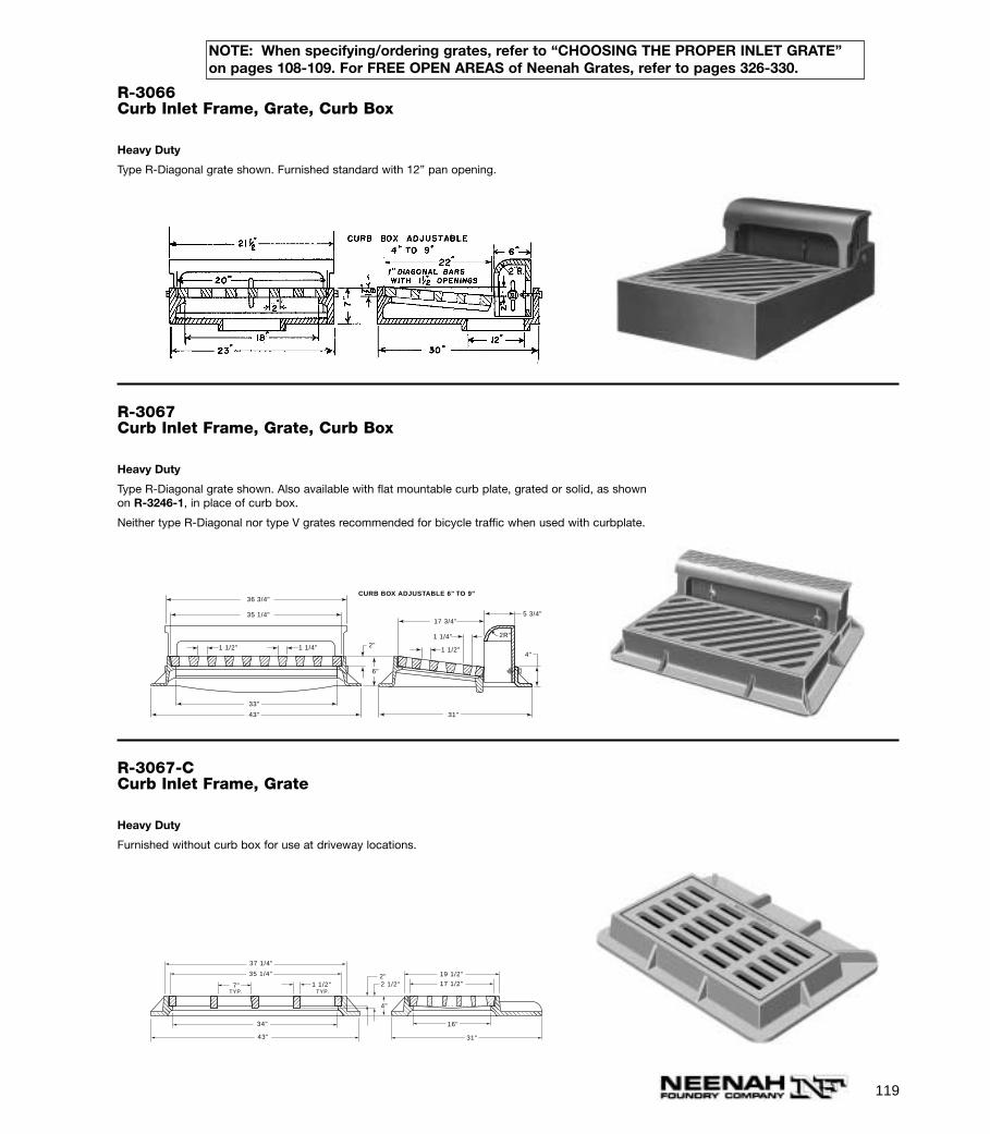
119
R-3066Curb Inlet Frame, Grate, Curb Box
Heavy Duty
Type R-Diagonal grate shown. Furnished standard with 12” pan opening.
R-3067Curb Inlet Frame, Grate, Curb Box
Heavy Duty
Type R-Diagonal grate shown. Also available with flat mountable curb plate, grated or solid, as shownon R-3246-1, in place of curb box.
Neither type R-Diagonal nor type V grates recommended for bicycle traffic when used with curbplate.
1 1/4"
1 1/2"1 1/2" 1 1/4"
17 3/4"5 3/4"
31"
6"
4"2"
33"
43"
36 3/4"
35 1/4"
CURB BOX ADJUSTABLE 6" TO 9"
2R"
R-3067-CCurb Inlet Frame, Grate
Heavy Duty
Furnished without curb box for use at driveway locations.
4"
2"2 1/2"
TYP.1 1/2"
TYP.
34"
35 1/4"
7"
37 1/4"
43"
19 1/2"
17 1/2"
16"
31"
NOTE: When specifying/ordering grates, refer to “CHOOSING THE PROPER INLET GRATE”on pages 108-109. For FREE OPEN AREAS of Neenah Grates, refer to pages 326-330.
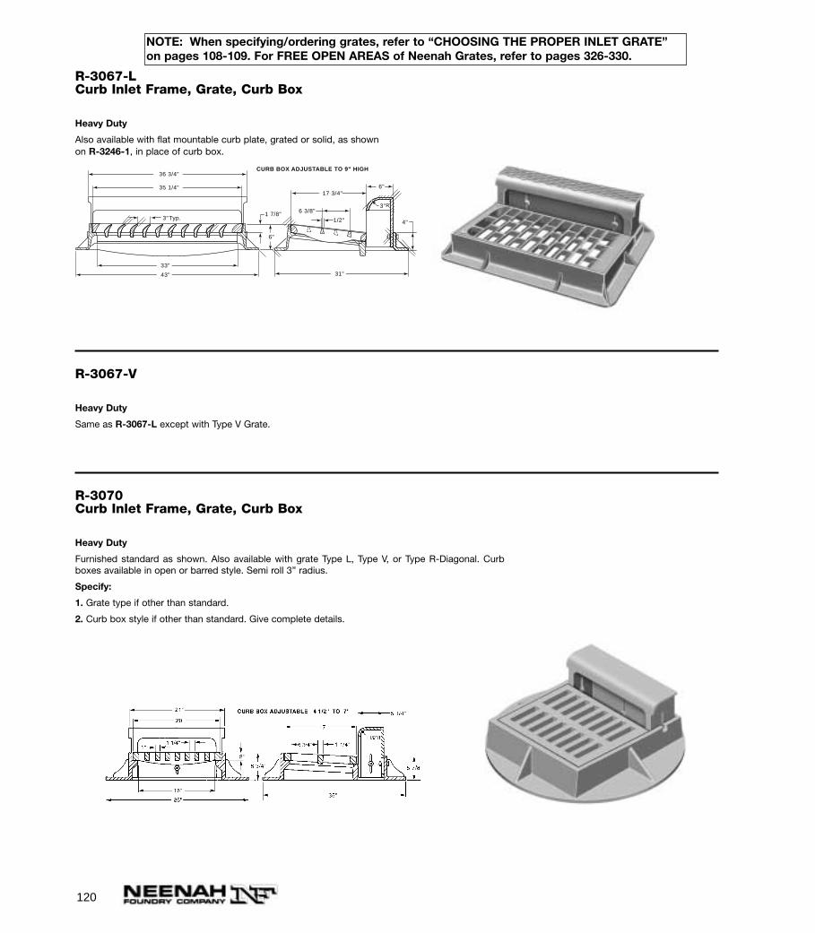
120
R-3067-LCurb Inlet Frame, Grate, Curb Box
Heavy Duty
Also available with flat mountable curb plate, grated or solid, as shown on R-3246-1, in place of curb box.
1/2"
6 3/8"
17 3/4"6"
31"
6"
4"1 7/8"
33"
43"
36 3/4"
35 1/4"
CURB BOX ADJUSTABLE TO 9" HIGH
3"R
3"Typ.
R-3067-V
Heavy Duty
Same as R-3067-L except with Type V Grate.
R-3070Curb Inlet Frame, Grate, Curb Box
Heavy Duty
Furnished standard as shown. Also available with grate Type L, Type V, or Type R-Diagonal. Curbboxes available in open or barred style. Semi roll 3” radius.
Specify:
1. Grate type if other than standard.
2. Curb box style if other than standard. Give complete details.
NOTE: When specifying/ordering grates, refer to “CHOOSING THE PROPER INLET GRATE”on pages 108-109. For FREE OPEN AREAS of Neenah Grates, refer to pages 326-330.

121
R-3075Curb Inlet Frame, Grate, Curb Box
Heavy Duty
Type R-Diagonal grate shown.
R-3075-L
Heavy Duty
Same as R-3075 except with L style grate (seepage 113).
R-3075-V
Heavy Duty
Same as R-3075 except with V style grate (seepage 113).
R-30763 Flange Gutter Inlet Frame and Grate
Heavy Duty
For frame only—specify R-3076 frame only.
For grate only—specify R-3076 grate only.
Also available with Type L grate see R-3079.
Type V grate shown not recommended for bicycle traffic when used without barrier curb hoods.
2 1/2"5"
3"
31 1/4"
23 1/8"
29 3/4" 17 3/4"
15 3/4"
19 5/8"
28" 16"
38"
NOTE: When specifying/ordering grates, refer to “CHOOSING THE PROPER INLET GRATE”on pages 108-109. For FREE OPEN AREAS of Neenah Grates, refer to pages 326-330.
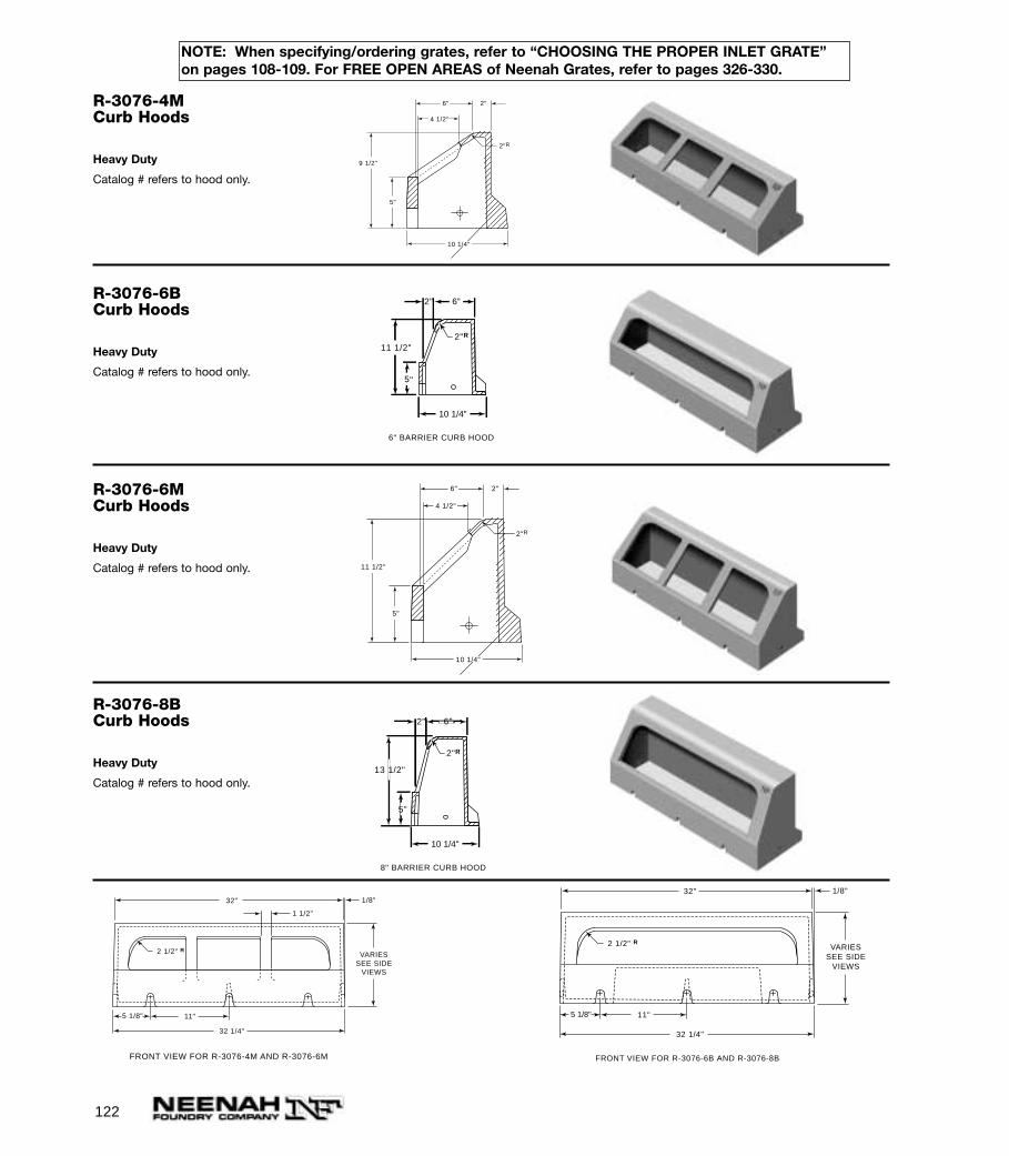
122
R-3076-4MCurb Hoods
Heavy Duty
Catalog # refers to hood only.
4 1/2"
6"
10 1/4"
2"
5"
9 1/2"
2"R
R-3076-6BCurb Hoods
Heavy Duty
Catalog # refers to hood only.
6" BARRIER CURB HOOD
2"R
2"
11 1/2"
5"
6"
10 1/4"
R-3076-6MCurb Hoods
Heavy Duty
Catalog # refers to hood only.
4 1/2"
6"
10 1/4"
2"
5"
11 1/2"
2"R
R-3076-8BCurb Hoods
Heavy Duty
Catalog # refers to hood only.
5"
2"
13 1/2"
6"
8" BARRIER CURB HOOD
2"R
10 1/4"
VARIESSEE SIDE
VIEWS
1/8"
5 1/8"
1 1/2"
11"
32 1/4"
32"
FRONT VIEW FOR R-3076-4M AND R-3076-6M
2 1/2" R VARIESSEE SIDE
VIEWS
1/8"
5 1/8" 11"
32 1/4"
32"
FRONT VIEW FOR R-3076-6B AND R-3076-8B
2 1/2" R
NOTE: When specifying/ordering grates, refer to “CHOOSING THE PROPER INLET GRATE”on pages 108-109. For FREE OPEN AREAS of Neenah Grates, refer to pages 326-330.
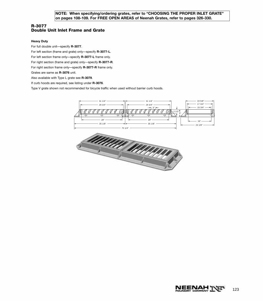
123
R-3077Double Unit Inlet Frame and Grate
Heavy Duty
For full double unit—specify R-3077.
For left section (frame and grate) only—specify R-3077-L.
For left section frame only—specify R-3077-L frame only.
For right section (frame and grate) only—specify R-3077-R.
For right section frame only—specify R-3077-R frame only.
Grates are same as R-3076 unit.
Also available with Type L grate see R-3079.
If curb hoods are required, see listing under R-3076.
Type V grate shown not recommended for bicycle traffic when used without barrier curb hoods.
2 1/2"5"
3"
31 1/4"
23 1/8"
29 3/4" 17 3/4"
15 3/4"
19 5/8"
28"16"
35 1/8"
31 1/4"
29 3/4"
28"
35 1/8"
70 1/4"
NOTE: When specifying/ordering grates, refer to “CHOOSING THE PROPER INLET GRATE”on pages 108-109. For FREE OPEN AREAS of Neenah Grates, refer to pages 326-330.

124
R-3078Inlet Frame and Grate (Center Section)
Heavy Duty
For frame only—specify R-3078 frame only.
Grate is same as R-3076 unit.
Also available with Type L grate see R-3079.
If curb hoods are required, see listing under R-3076.
Type V grate shown not recommended for bicycle traffic when used without barrier curb hoods.
Illustrating unit composed of R-3077-L, R-3078, R-3077-R and R-3076-6B curb hoods.
NOTE: When specifying/ordering grates, refer to “CHOOSING THE PROPER INLET GRATE”on pages 108-109. For FREE OPEN AREAS of Neenah Grates, refer to pages 326-330.

125
R-3079Inlet Frame and Grate (Center Section)
Heavy Duty
R-3157-1Curb Inlet Frame, Grate, Curb Box
Heavy Duty
R-3157-2Curb Inlet Frame, Grate, Curb Box
Heavy Duty
22 7/8"
25 1/8"
32 5/8" 26 3/4"
9 3/4"17 5/8"
17 5/8"
20"
20 1/2"
10 1/4"
5 3/4"
3 1/2"1 1/2"
7"
NOTE: When specifying/ordering grates, refer to “CHOOSING THE PROPER INLET GRATE”on pages 108-109. For FREE OPEN AREAS of Neenah Grates, refer to pages 326-330.
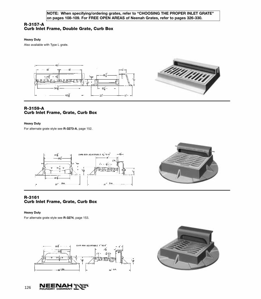
126
R-3157-ACurb Inlet Frame, Double Grate, Curb Box
Heavy Duty
Also available with Type L grate.
R-3159-ACurb Inlet Frame, Grate, Curb Box
Heavy Duty
For alternate grate style see R-3273-A, page 152.
R-3161Curb Inlet Frame, Grate, Curb Box
Heavy Duty
For alternate grate style see R-3274, page 153.
NOTE: When specifying/ordering grates, refer to “CHOOSING THE PROPER INLET GRATE”on pages 108-109. For FREE OPEN AREAS of Neenah Grates, refer to pages 326-330.
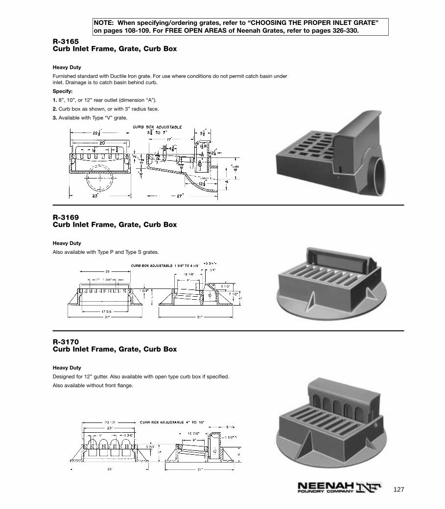
127
R-3165Curb Inlet Frame, Grate, Curb Box
Heavy Duty
Furnished standard with Ductile Iron grate. For use where conditions do not permit catch basin underinlet. Drainage is to catch basin behind curb.
Specify:
1. 8”, 10”, or 12” rear outlet (dimension “A”).
2. Curb box as shown, or with 3” radius face.
3. Available with Type “V” grate.
R-3169Curb Inlet Frame, Grate, Curb Box
Heavy Duty
Also available with Type P and Type S grates.
R-3170Curb Inlet Frame, Grate, Curb Box
Heavy Duty
Designed for 12” gutter. Also available with open type curb box if specified.
Also available without front flange.
NOTE: When specifying/ordering grates, refer to “CHOOSING THE PROPER INLET GRATE”on pages 108-109. For FREE OPEN AREAS of Neenah Grates, refer to pages 326-330.
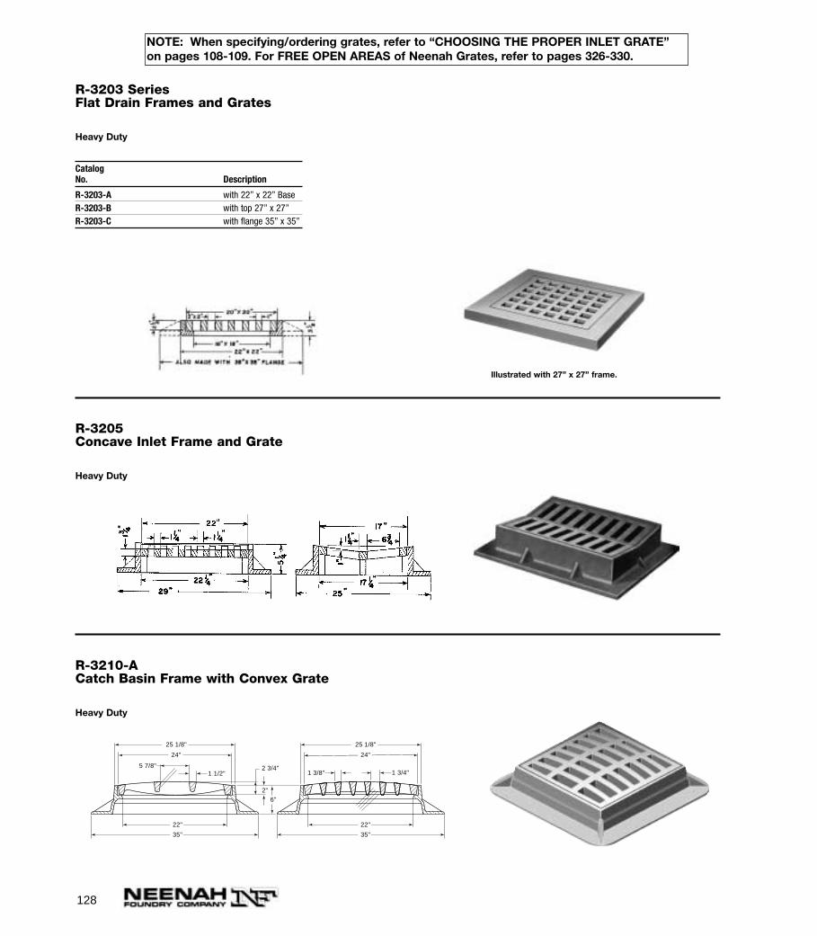
128
R-3203 SeriesFlat Drain Frames and Grates
Heavy Duty
CatalogNo. Description
R-3203-A with 22” x 22” BaseR-3203-B with top 27” x 27”R-3203-C with flange 35” x 35”
Illustrated with 27” x 27” frame.
R-3205Concave Inlet Frame and Grate
Heavy Duty
R-3210-ACatch Basin Frame with Convex Grate
Heavy Duty
1 3/4"1 3/8"
2"
6"
24"
22"
35"
22"
35"
25 1/8"
24"
25 1/8"
5 7/8"1 1/2"
2 3/4"
NOTE: When specifying/ordering grates, refer to “CHOOSING THE PROPER INLET GRATE”on pages 108-109. For FREE OPEN AREAS of Neenah Grates, refer to pages 326-330.
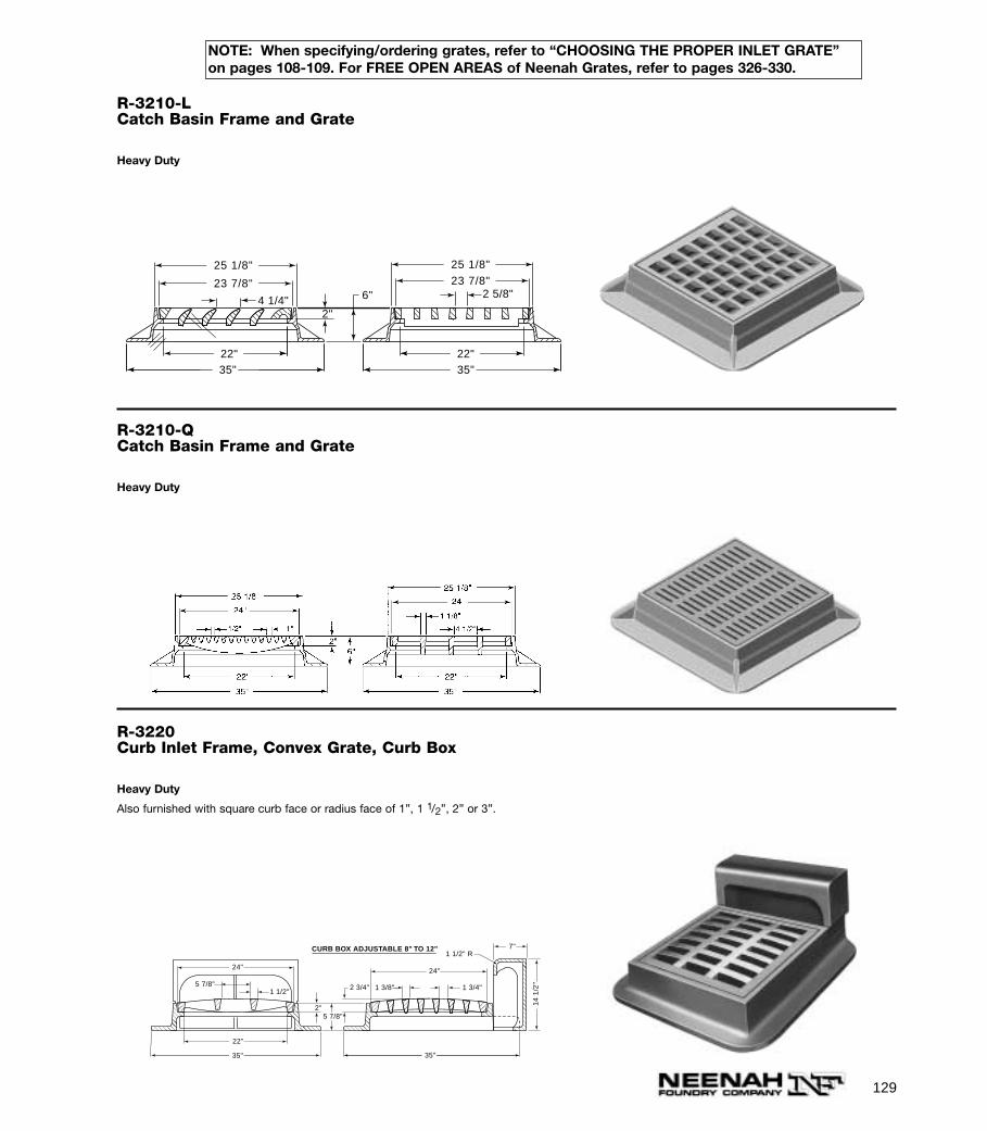
129
R-3210-LCatch Basin Frame and Grate
Heavy Duty
4 1/4"2 5/8"
2"
25 1/8"
23 7/8"
25 1/8"
23 7/8"6"
22" 35"
22" 35"
R-3210-QCatch Basin Frame and Grate
Heavy Duty
R-3220Curb Inlet Frame, Convex Grate, Curb Box
Heavy Duty
Also furnished with square curb face or radius face of 1”, 1 1/2”, 2” or 3”.
24"24"
24"35"
22"
5 7/8"
5 7/8"
1 1/2"2 3/4"
24"35"
1 3/8" 1 3/4"
2"
7"1 1/2" R
14
1/2
"
CURB BOX ADJUSTABLE 8" TO 12"
NOTE: When specifying/ordering grates, refer to “CHOOSING THE PROPER INLET GRATE”on pages 108-109. For FREE OPEN AREAS of Neenah Grates, refer to pages 326-330.
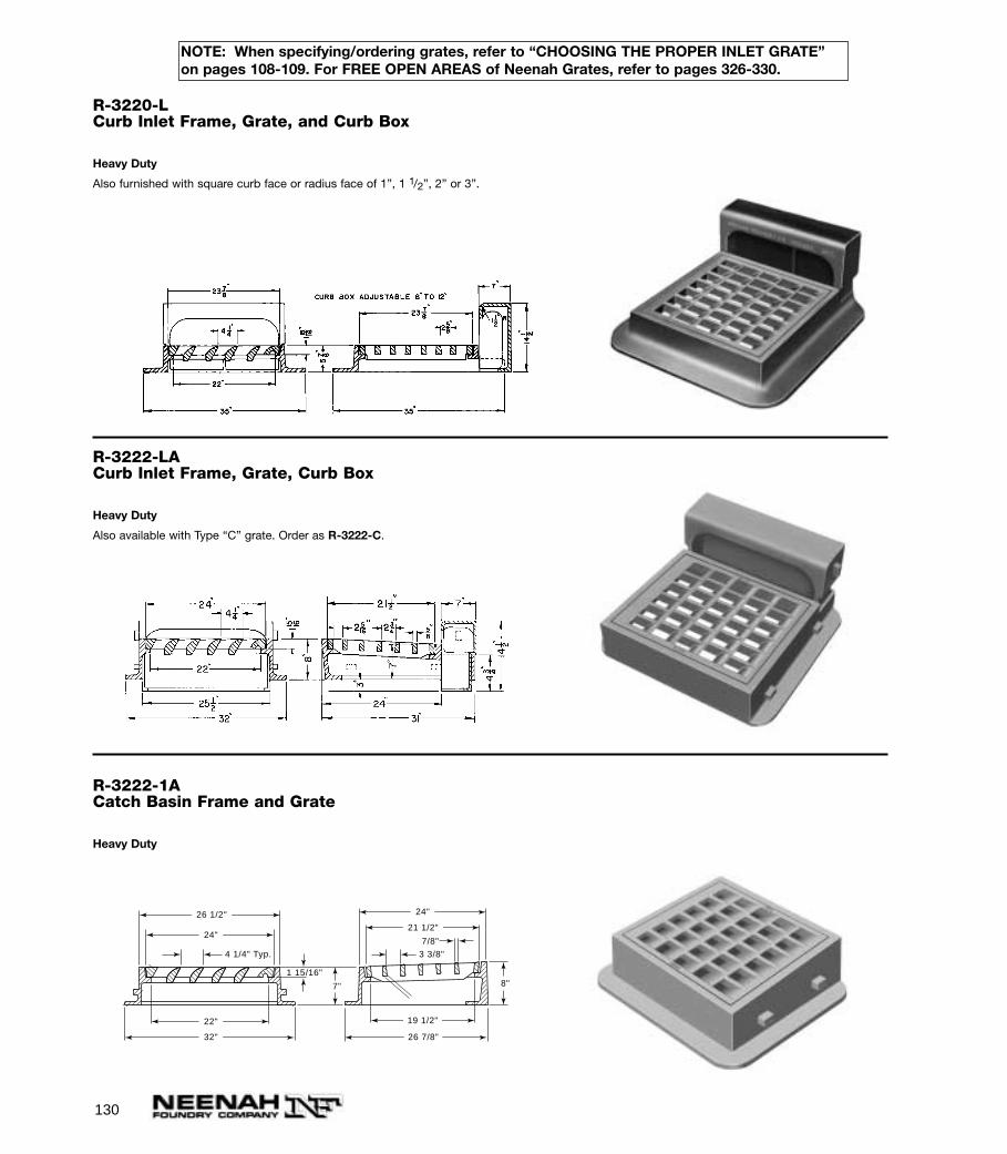
130
R-3222-1ACatch Basin Frame and Grate
Heavy Duty
4 1/4" Typ. 3 3/8"
7/8"
7" 8"
26 7/8"
24"
21 1/2"
26 1/2"
24"
22"
32"
19 1/2"
1 15/16"
R-3220-LCurb Inlet Frame, Grate, and Curb Box
Heavy Duty
Also furnished with square curb face or radius face of 1”, 1 1/2”, 2” or 3”.
R-3222-LACurb Inlet Frame, Grate, Curb Box
Heavy Duty
Also available with Type “C” grate. Order as R-3222-C.
NOTE: When specifying/ordering grates, refer to “CHOOSING THE PROPER INLET GRATE”on pages 108-109. For FREE OPEN AREAS of Neenah Grates, refer to pages 326-330.
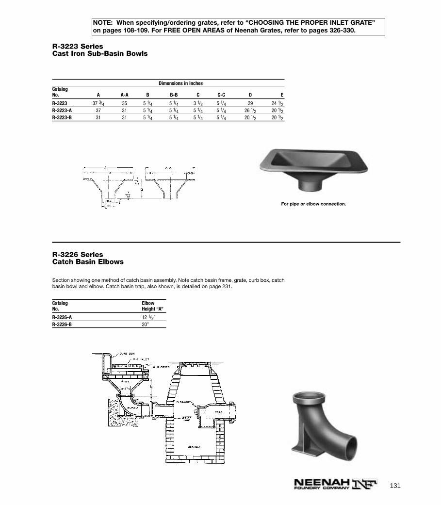
131
R-3223 SeriesCast Iron Sub-Basin Bowls
Dimensions in InchesCatalogNo. A A-A B B-B C C-C D E
R-3223 37 3/4 35 5 1/4 5 1/4 3 1/2 5 1/4 29 24 1/2R-3223-A 37 31 5 1/4 5 1/4 5 1/4 5 1/4 26 1/2 20 1/2R-3223-B 31 31 5 1/4 5 1/4 5 1/4 5 1/4 20 1/2 20 1/2
For pipe or elbow connection.
R-3226 SeriesCatch Basin Elbows
Section showing one method of catch basin assembly. Note catch basin frame, grate, curb box, catchbasin bowl and elbow. Catch basin trap, also shown, is detailed on page 231.
Catalog ElbowNo. Height “A”
R-3226-A 12 1/2”R-3226-B 20”
NOTE: When specifying/ordering grates, refer to “CHOOSING THE PROPER INLET GRATE”on pages 108-109. For FREE OPEN AREAS of Neenah Grates, refer to pages 326-330.
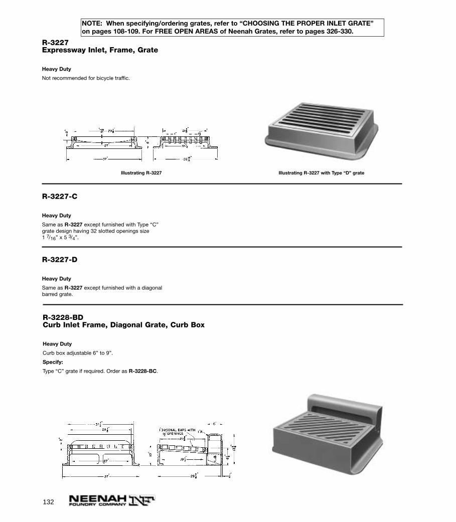
132
R-3227Expressway Inlet, Frame, Grate
Heavy Duty
Not recommended for bicycle traffic.
Illustrating R-3227 Illustrating R-3227 with Type “D” grate
R-3227-C
Heavy Duty
Same as R-3227 except furnished with Type “C”grate design having 32 slotted openings size 1 7/16” x 5 3/4”.
R-3227-D
Heavy Duty
Same as R-3227 except furnished with a diagonalbarred grate.
R-3228-BDCurb Inlet Frame, Diagonal Grate, Curb Box
Heavy Duty
Curb box adjustable 6” to 9”.
Specify:
Type “C” grate if required. Order as R-3228-BC.
NOTE: When specifying/ordering grates, refer to “CHOOSING THE PROPER INLET GRATE”on pages 108-109. For FREE OPEN AREAS of Neenah Grates, refer to pages 326-330.
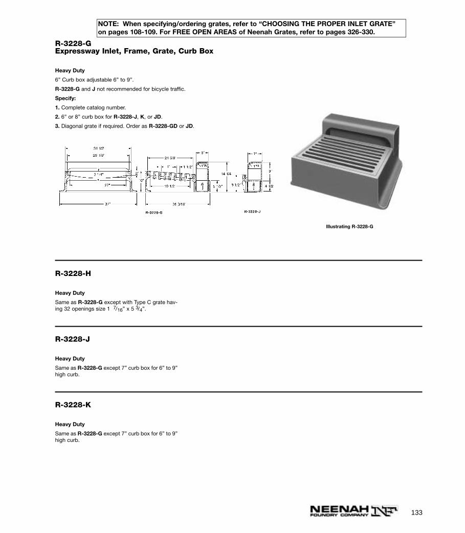
133
R-3228-GExpressway Inlet, Frame, Grate, Curb Box
Heavy Duty
6” Curb box adjustable 6” to 9”.
R-3228-G and J not recommended for bicycle traffic.
Specify:
1. Complete catalog number.
2. 6” or 8” curb box for R-3228-J, K, or JD.
3. Diagonal grate if required. Order as R-3228-GD or JD.
Illustrating R-3228-G
R-3228-H
Heavy Duty
Same as R-3228-G except with Type C grate hav-ing 32 openings size 1 7/16” x 5 3/4”.
R-3228-J
Heavy Duty
Same as R-3228-G except 7” curb box for 6” to 9”high curb.
R-3228-K
Heavy Duty
Same as R-3228-G except 7” curb box for 6” to 9”high curb.
NOTE: When specifying/ordering grates, refer to “CHOOSING THE PROPER INLET GRATE”on pages 108-109. For FREE OPEN AREAS of Neenah Grates, refer to pages 326-330.
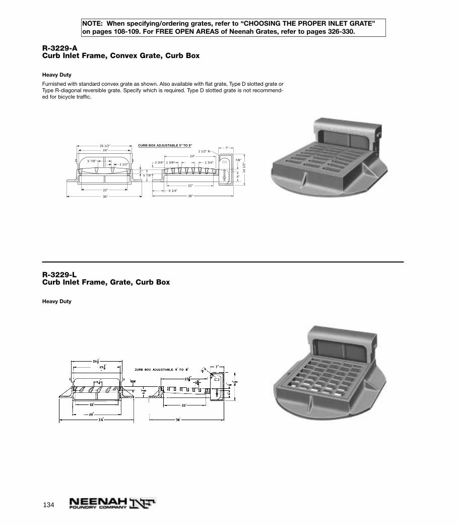
134
R-3229-ACurb Inlet Frame, Convex Grate, Curb Box
Heavy Duty
Furnished with standard convex grate as shown. Also available with flat grate, Type D slotted grate orType R-diagonal reversible grate. Specify which is required. Type D slotted grate is not recommend-ed for bicycle traffic.
24"
36"
22"
5 7/8"
5 7/8"
6 1/4"
1 1/2"2 3/4"
24"38"
22"
1 3/8" 1 3/4"
2"
7"1 1/2" R
14
1/2
"
CURB BOX ADJUSTABLE 5" TO 8"
24"26 1/2"
4"
7/8"
R-3229-LCurb Inlet Frame, Grate, Curb Box
Heavy Duty
NOTE: When specifying/ordering grates, refer to “CHOOSING THE PROPER INLET GRATE”on pages 108-109. For FREE OPEN AREAS of Neenah Grates, refer to pages 326-330.
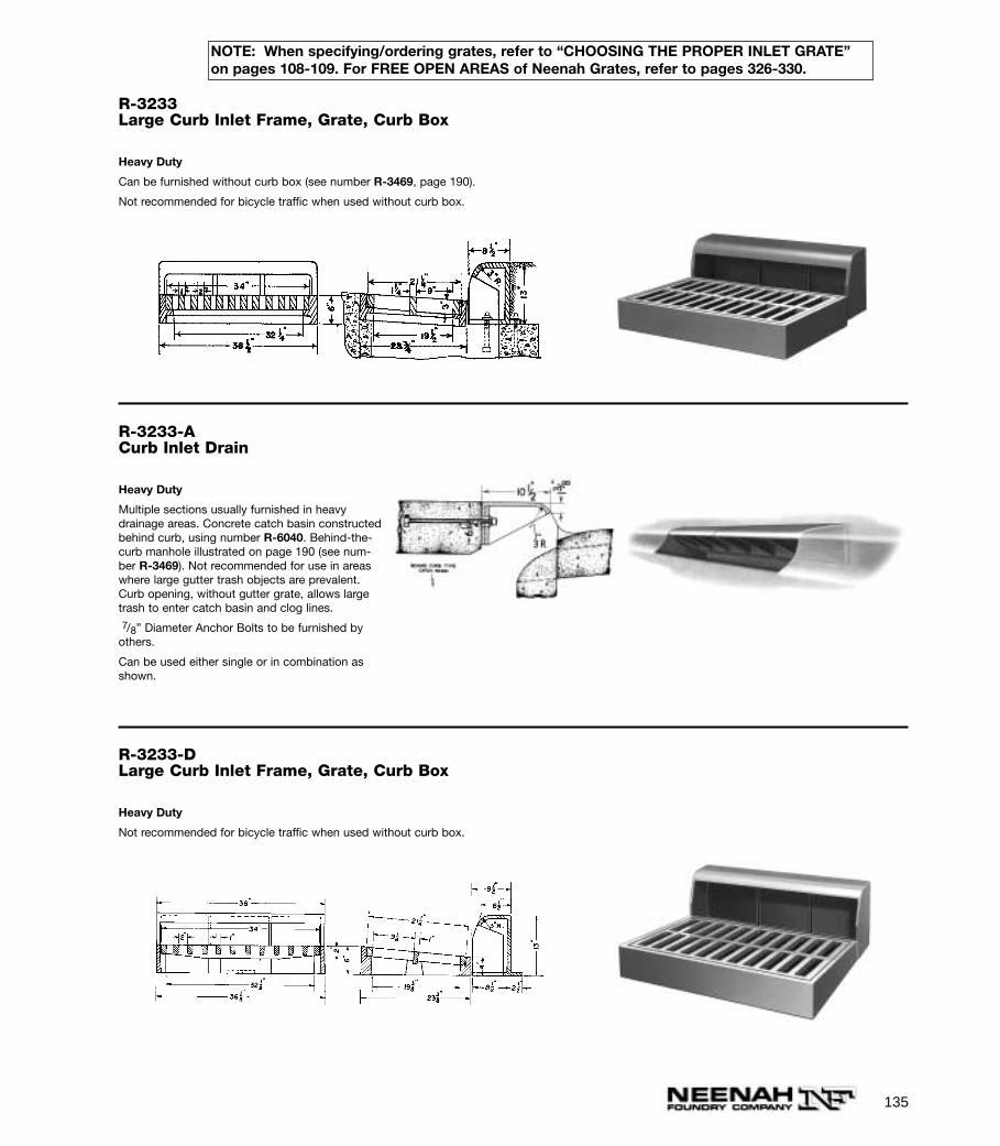
135
R-3233Large Curb Inlet Frame, Grate, Curb Box
Heavy Duty
Can be furnished without curb box (see number R-3469, page 190).
Not recommended for bicycle traffic when used without curb box.
R-3233-ACurb Inlet Drain
Heavy Duty
Multiple sections usually furnished in heavydrainage areas. Concrete catch basin constructedbehind curb, using number R-6040. Behind-the-curb manhole illustrated on page 190 (see num-ber R-3469). Not recommended for use in areaswhere large gutter trash objects are prevalent.Curb opening, without gutter grate, allows largetrash to enter catch basin and clog lines.7/8” Diameter Anchor Bolts to be furnished by
others.
Can be used either single or in combination asshown.
R-3233-DLarge Curb Inlet Frame, Grate, Curb Box
Heavy Duty
Not recommended for bicycle traffic when used without curb box.
NOTE: When specifying/ordering grates, refer to “CHOOSING THE PROPER INLET GRATE”on pages 108-109. For FREE OPEN AREAS of Neenah Grates, refer to pages 326-330.
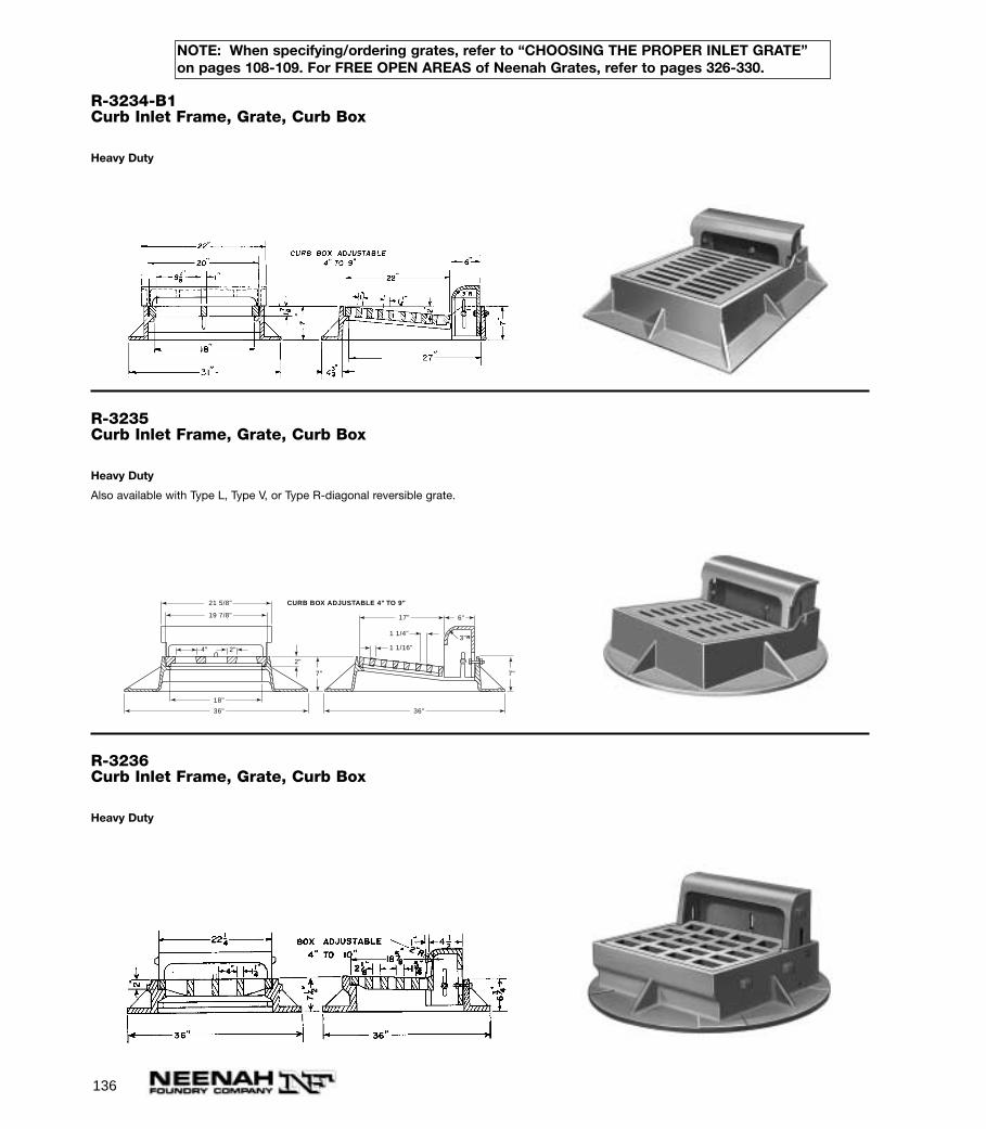
136
R-3234-B1Curb Inlet Frame, Grate, Curb Box
Heavy Duty
R-3235Curb Inlet Frame, Grate, Curb Box
Heavy Duty
Also available with Type L, Type V, or Type R-diagonal reversible grate.
3"R
7"
6"
7"
17"
1 1/4"
1 1/16"
36"36"
18"
2"
2"4"
21 5/8"
19 7/8"
CURB BOX ADJUSTABLE 4" TO 9"
R-3236Curb Inlet Frame, Grate, Curb Box
Heavy Duty
NOTE: When specifying/ordering grates, refer to “CHOOSING THE PROPER INLET GRATE”on pages 108-109. For FREE OPEN AREAS of Neenah Grates, refer to pages 326-330.
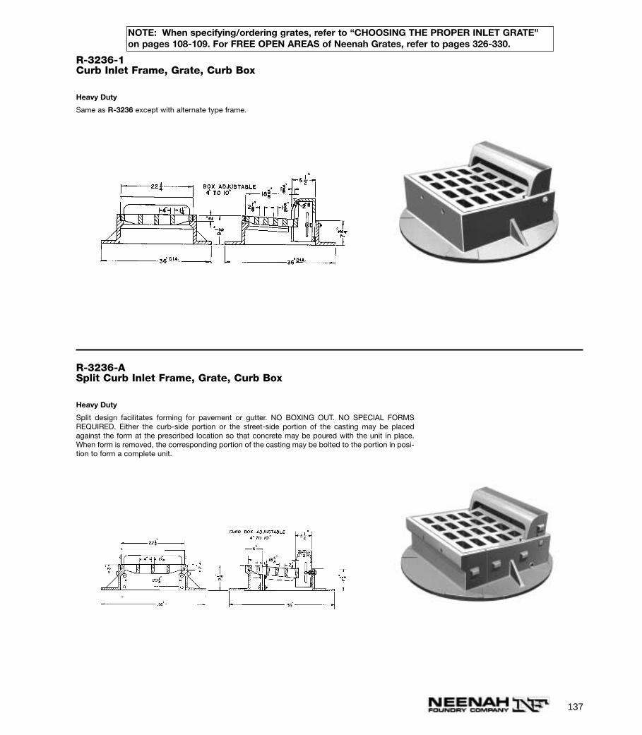
137
NOTE: When specifying/ordering grates, refer to “CHOOSING THE PROPER INLET GRATE”on pages 108-109. For FREE OPEN AREAS of Neenah Grates, refer to pages 326-330.
R-3236-1Curb Inlet Frame, Grate, Curb Box
Heavy Duty
Same as R-3236 except with alternate type frame.
R-3236-ASplit Curb Inlet Frame, Grate, Curb Box
Heavy Duty
Split design facilitates forming for pavement or gutter. NO BOXING OUT. NO SPECIAL FORMSREQUIRED. Either the curb-side portion or the street-side portion of the casting may be placedagainst the form at the prescribed location so that concrete may be poured with the unit in place.When form is removed, the corresponding portion of the casting may be bolted to the portion in posi-tion to form a complete unit.
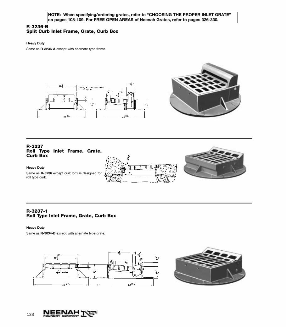
138
NOTE: When specifying/ordering grates, refer to “CHOOSING THE PROPER INLET GRATE”on pages 108-109. For FREE OPEN AREAS of Neenah Grates, refer to pages 326-330.
R-3236-BSplit Curb Inlet Frame, Grate, Curb Box
Heavy Duty
Same as R-3236-A except with alternate type frame.
R-3237Roll Type Inlet Frame, Grate,Curb Box
Heavy Duty
Same as R-3236 except curb box is designed forroll type curb.
R-3237-1Roll Type Inlet Frame, Grate, Curb Box
Heavy Duty
Same as R-3034-B except with alternate type grate.
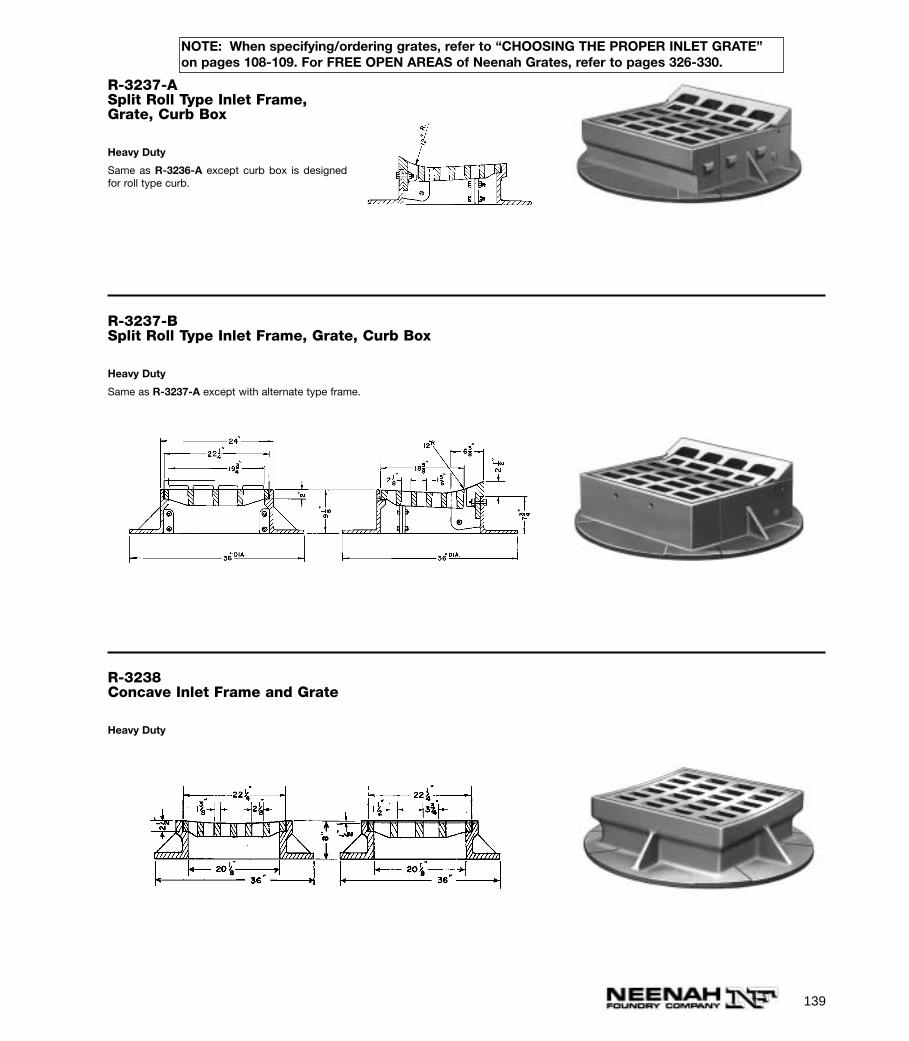
139
NOTE: When specifying/ordering grates, refer to “CHOOSING THE PROPER INLET GRATE”on pages 108-109. For FREE OPEN AREAS of Neenah Grates, refer to pages 326-330.
R-3237-ASplit Roll Type Inlet Frame,Grate, Curb Box
Heavy Duty
Same as R-3236-A except curb box is designedfor roll type curb.
R-3237-BSplit Roll Type Inlet Frame, Grate, Curb Box
Heavy Duty
Same as R-3237-A except with alternate type frame.
R-3238Concave Inlet Frame and Grate
Heavy Duty

140
NOTE: When specifying/ordering grates, refer to “CHOOSING THE PROPER INLET GRATE”on pages 108-109. For FREE OPEN AREAS of Neenah Grates, refer to pages 326-330.
R-3246Curb Inlet Frame, Grate, Curb Box
Heavy Duty
Also available with Type L or Type V grate. Also available with square, 1” radius, 2” radius or D-shapedcurb face.
Also available with flat mountable curb plate, grated or solid, as shown on R-3246-1, in place of curb box.
R-3246-1
Same as R-3246 except with plate over curb boxopening. See illustration.
Neither type R-Diagonal nor type V grates recom-mended for bicycle traffic when used with curbplate.
R-3246-I with Curb Plate
R-3246-ACurb Inlet Frame, Grate, Curb Box
Heavy Duty
Also available with Type R-Diagonal Reversible grate.
3"R
1 1/4" 1 3/4"
5 3/4"
23 7/8"
34 7/8"43"
33 1/2"
35 3/4"
36 1/2"
4"
2"
6 1/2"
CURB BOX HEIGHT ADJ. 5" TO 10"
6 1/2" Typ.2"
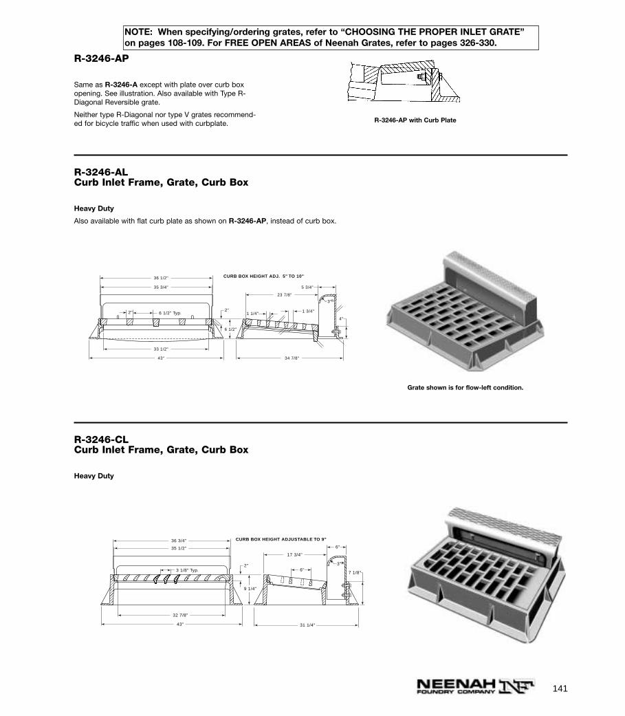
141
R-3246-AP
Same as R-3246-A except with plate over curb boxopening. See illustration. Also available with Type R-Diagonal Reversible grate.
Neither type R-Diagonal nor type V grates recommend-ed for bicycle traffic when used with curbplate. R-3246-AP with Curb Plate
R-3246-ALCurb Inlet Frame, Grate, Curb Box
Heavy Duty
Also available with flat curb plate as shown on R-3246-AP, instead of curb box.
3"R
1 1/4" 1 3/4"
5 3/4"
23 7/8"
34 7/8"43"
33 1/2"
35 3/4"
36 1/2"
4"
2"
6 1/2"
CURB BOX HEIGHT ADJ. 5" TO 10"
6 1/2" Typ.2"
Grate shown is for flow-left condition.
R-3246-CLCurb Inlet Frame, Grate, Curb Box
Heavy Duty
3"R
6"
6"
17 3/4"
31 1/4"43"
32 7/8"
36 3/4"
35 1/2"
7 1/8"
2"
9 1/4"
CURB BOX HEIGHT ADJUSTABLE TO 9"
3 1/8" Typ.
NOTE: When specifying/ordering grates, refer to “CHOOSING THE PROPER INLET GRATE”on pages 108-109. For FREE OPEN AREAS of Neenah Grates, refer to pages 326-330.
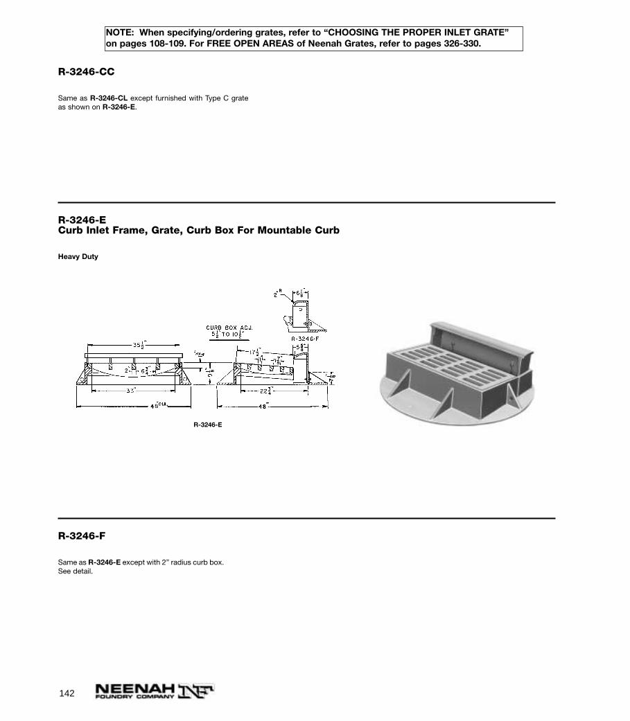
142
NOTE: When specifying/ordering grates, refer to “CHOOSING THE PROPER INLET GRATE”on pages 108-109. For FREE OPEN AREAS of Neenah Grates, refer to pages 326-330.
R-3246-CC
Same as R-3246-CL except furnished with Type C grateas shown on R-3246-E.
R-3246-ECurb Inlet Frame, Grate, Curb Box For Mountable Curb
Heavy Duty
R-3246-E
R-3246-F
Same as R-3246-E except with 2” radius curb box.See detail.
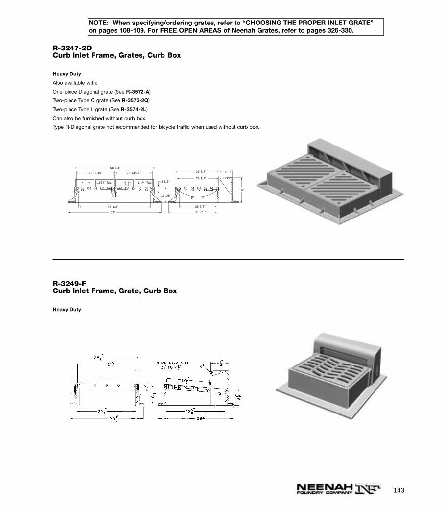
143
NOTE: When specifying/ordering grates, refer to “CHOOSING THE PROPER INLET GRATE”on pages 108-109. For FREE OPEN AREAS of Neenah Grates, refer to pages 326-330.
R-3247-2DCurb Inlet Frame, Grates, Curb Box
Heavy Duty
Also available with:
One-piece Diagonal grate (See R-3572-A)
Two-piece Type Q grate (See R-3573-2Q)
Two-piece Type L grate (See R-3574-2L)
Can also be furnished without curb box.
Type R-Diagonal grate not recommended for bicycle traffic when used without curb box.
2 1/2"
26 3/4"
26 1/2"
25 7/8"45 1/2"
59"
23 13/16" 23 13/16"
58 1/4"
31 7/8"
1.662" 1 1/4"Typ. Typ.
8"
16"
10 1/8"
R-3249-FCurb Inlet Frame, Grate, Curb Box
Heavy Duty

144
NOTE: When specifying/ordering grates, refer to “CHOOSING THE PROPER INLET GRATE”on pages 108-109. For FREE OPEN AREAS of Neenah Grates, refer to pages 326-330.
R-3250-ACurb Inlet Frame, Grate, Curb Box
Heavy Duty
Also available with Type C grate. Note lug preventing grate rotation.
Alternate box for straight face curb is available.
IMPORTANT—remove cap screws from curb box when concrete curb has set.
Furnished standard with as-cast bearing surfaces.
Not recommended for bicycle traffic.
13 11/16"1 3/8"
10"10 7/8"
3 1/2"
4 1/2"
3/4"1/2" Lug
1 1/2"
27"
24"
25"
25 5/8"
33 1/2"
19 3/8"
33 1/2"
1 1/4"
R-3250-1Curb Inlet Frame, Grate, Curb Box
Heavy Duty
Also available with Type C grate.
Extended curb box provides additional drainage capacity through curb. Note sweeping radius for effi-ciency in self-cleaning and reduction of turbulence.
IMPORTANT—remove cap screws from curb box when concrete curb has set.
Furnished standard with as-cast bearing surfaces.
Not recommended for bicycle traffic.
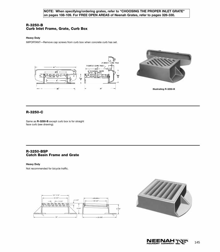
145
NOTE: When specifying/ordering grates, refer to “CHOOSING THE PROPER INLET GRATE”on pages 108-109. For FREE OPEN AREAS of Neenah Grates, refer to pages 326-330.
R-3250-BCurb Inlet Frame, Grate, Curb Box
Heavy Duty
IMPORTANT—Remove cap screws from curb box when concrete curb has set.
Illustrating R-3250-B
R-3250-C
Same as R-3250-B except curb box is for straightface curb (see drawing).
R-3250-BSPCatch Basin Frame and Grate
Heavy Duty
Not recommended for bicycle traffic.
1 1/2"3 1/4"
22 3/4"
20 1/2"
31 5/8"
8 7/8"
24" X 24"
22 3/4"
38"
9 3/4"
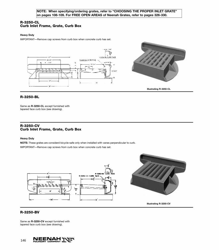
146
NOTE: When specifying/ordering grates, refer to “CHOOSING THE PROPER INLET GRATE”on pages 108-109. For FREE OPEN AREAS of Neenah Grates, refer to pages 326-330.
R-3250-CLCurb Inlet Frame, Grate, Curb Box
Heavy Duty
IMPORTANT—Remove cap screws from curb box when concrete curb has set.
Illustrating R-3250-CL
R-3250-BL
Same as R-3250-CL except furnished withtapered face curb box (see drawing).
R-3250-CVCurb Inlet Frame, Grate, Curb Box
Heavy Duty
NOTE: These grates are considerd bicycle-safe only when installed with vanes perpendicular to curb.
IMPORTANT—Remove cap screws from curb box when concrete curb has set.
Illustrating R-3250-CV
R-3250-BV
Same as R-3250-CV except furnished withtapered face curb box (see drawing).
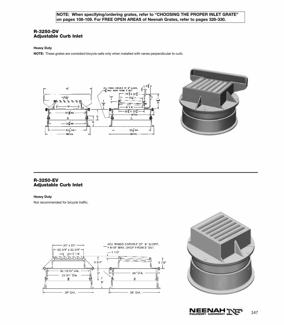
147
NOTE: When specifying/ordering grates, refer to “CHOOSING THE PROPER INLET GRATE”on pages 108-109. For FREE OPEN AREAS of Neenah Grates, refer to pages 326-330.
R-3250-DVAdjustable Curb Inlet
Heavy Duty
NOTE: These grates are considerd bicycle-safe only when installed with vanes perpendicular to curb.
R-3250-EVAdjustable Curb Inlet
Heavy Duty
Not recommended for bicycle traffic.
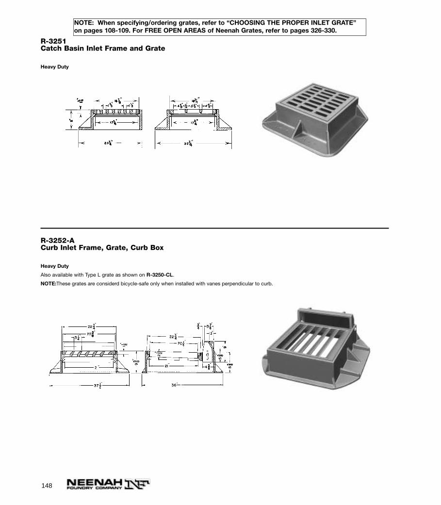
148
NOTE: When specifying/ordering grates, refer to “CHOOSING THE PROPER INLET GRATE”on pages 108-109. For FREE OPEN AREAS of Neenah Grates, refer to pages 326-330.
R-3251Catch Basin Inlet Frame and Grate
Heavy Duty
R-3252-ACurb Inlet Frame, Grate, Curb Box
Heavy Duty
Also available with Type L grate as shown on R-3250-CL.
NOTE:These grates are considerd bicycle-safe only when installed with vanes perpendicular to curb.
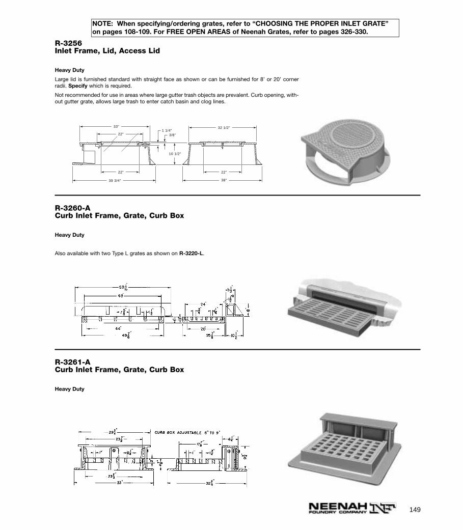
149
NOTE: When specifying/ordering grates, refer to “CHOOSING THE PROPER INLET GRATE”on pages 108-109. For FREE OPEN AREAS of Neenah Grates, refer to pages 326-330.
R-3256Inlet Frame, Lid, Access Lid
Heavy Duty
Large lid is furnished standard with straight face as shown or can be furnished for 8’ or 20’ cornerradii. Specify which is required.
Not recommended for use in areas where large gutter trash objects are prevalent. Curb opening, with-out gutter grate, allows large trash to enter catch basin and clog lines.
33"
22"
22" 22"
38"39 3/4"
32 1/2"1 1/4"
3/8"
10 1/2"
R-3260-ACurb Inlet Frame, Grate, Curb Box
Heavy Duty
Also available with two Type L grates as shown on R-3220-L.
R-3261-ACurb Inlet Frame, Grate, Curb Box
Heavy Duty
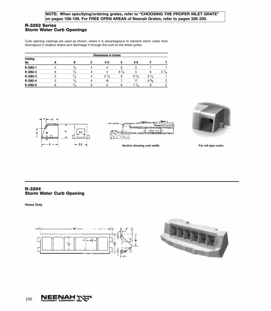
150
NOTE: When specifying/ordering grates, refer to “CHOOSING THE PROPER INLET GRATE”on pages 108-109. For FREE OPEN AREAS of Neenah Grates, refer to pages 326-330.
R-3262 SeriesStorm Water Curb Openings
Curb opening castings are used as shown, where it is advantageous to transmit storm water fromdownspout in shallow drains and discharge it through the curb to the street gutter.
Dimensions in InchesCatalogNo. A B C C-C E E-E F T
R-3262-1 5 1/2 4 4 6 5 7 1R-3262-2 6 1/2 4 4 8 1/4 5 6 2 1/4R-3262-3 5 1/2 4 5 1/2 6 6 1/2 6 1/2 1R-3262-4 5 1/2 4 16 7 17 6 3/8 2R-3262-6 6 1/2 6 6 8 7 1/4 9 2
Section showing curb width. For roll type curbs.
R-3264Storm Water Curb Opening
Heavy Duty
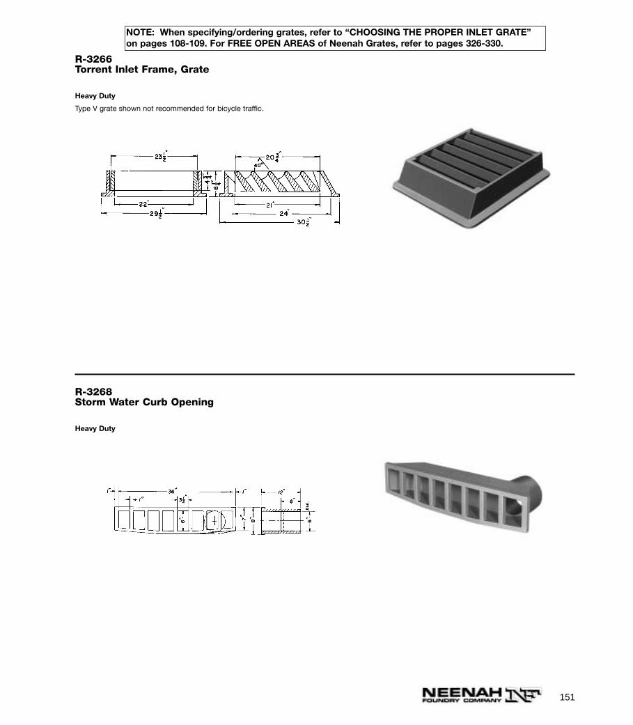
151
NOTE: When specifying/ordering grates, refer to “CHOOSING THE PROPER INLET GRATE”on pages 108-109. For FREE OPEN AREAS of Neenah Grates, refer to pages 326-330.
R-3266Torrent Inlet Frame, Grate
Heavy Duty
Type V grate shown not recommended for bicycle traffic.
R-3268Storm Water Curb Opening
Heavy Duty
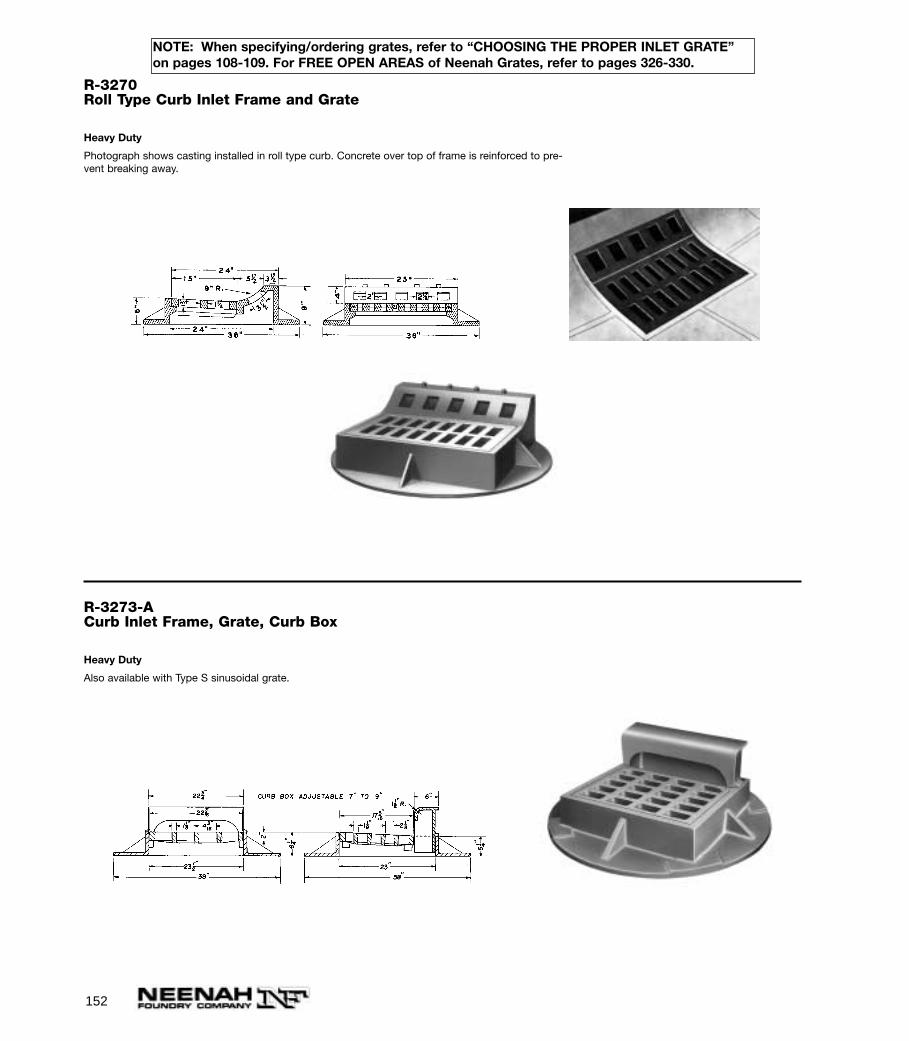
152
NOTE: When specifying/ordering grates, refer to “CHOOSING THE PROPER INLET GRATE”on pages 108-109. For FREE OPEN AREAS of Neenah Grates, refer to pages 326-330.
R-3270Roll Type Curb Inlet Frame and Grate
Heavy Duty
Photograph shows casting installed in roll type curb. Concrete over top of frame is reinforced to pre-vent breaking away.
R-3273-ACurb Inlet Frame, Grate, Curb Box
Heavy Duty
Also available with Type S sinusoidal grate.
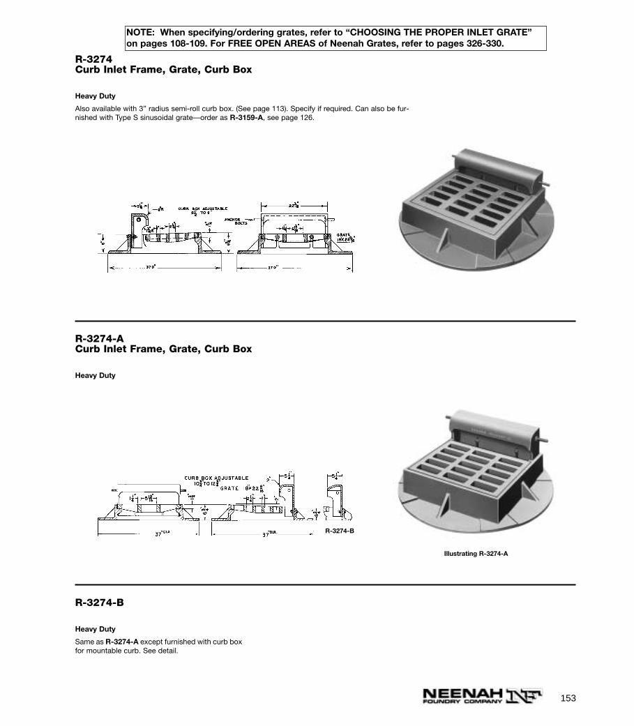
153
NOTE: When specifying/ordering grates, refer to “CHOOSING THE PROPER INLET GRATE”on pages 108-109. For FREE OPEN AREAS of Neenah Grates, refer to pages 326-330.
R-3274Curb Inlet Frame, Grate, Curb Box
Heavy Duty
Also available with 3” radius semi-roll curb box. (See page 113). Specify if required. Can also be fur-nished with Type S sinusoidal grate—order as R-3159-A, see page 126.
R-3274-ACurb Inlet Frame, Grate, Curb Box
Heavy Duty
R-3274-B
Heavy Duty
Same as R-3274-A except furnished with curb boxfor mountable curb. See detail.
R-3274-B
Illustrating R-3274-A
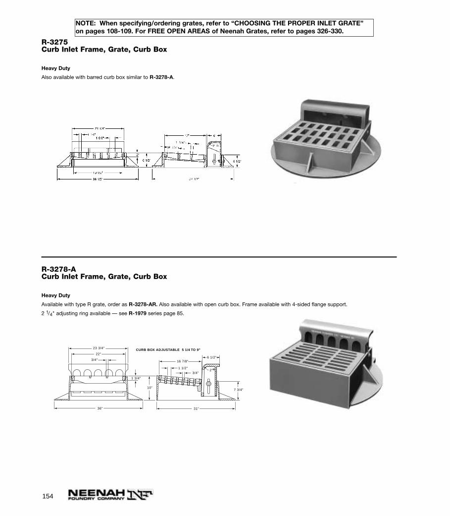
154
NOTE: When specifying/ordering grates, refer to “CHOOSING THE PROPER INLET GRATE”on pages 108-109. For FREE OPEN AREAS of Neenah Grates, refer to pages 326-330.
R-3275Curb Inlet Frame, Grate, Curb Box
Heavy Duty
Also available with barred curb box similar to R-3278-A.
R-3278-ACurb Inlet Frame, Grate, Curb Box
Heavy Duty
Available with type R grate, order as R-3278-AR. Also available with open curb box. Frame available with 4-sided flange support.
2 1/4" adjusting ring available — see R-1979 series page 85.
2"R
7 3/4"10"
31"
6 1/2"16 7/8"
23 3/4"
22"
36"
1 1/2"3/4"
3/4"
1 3/4"
CURB BOX ADJUSTABLE 5 1/4 TO 9"
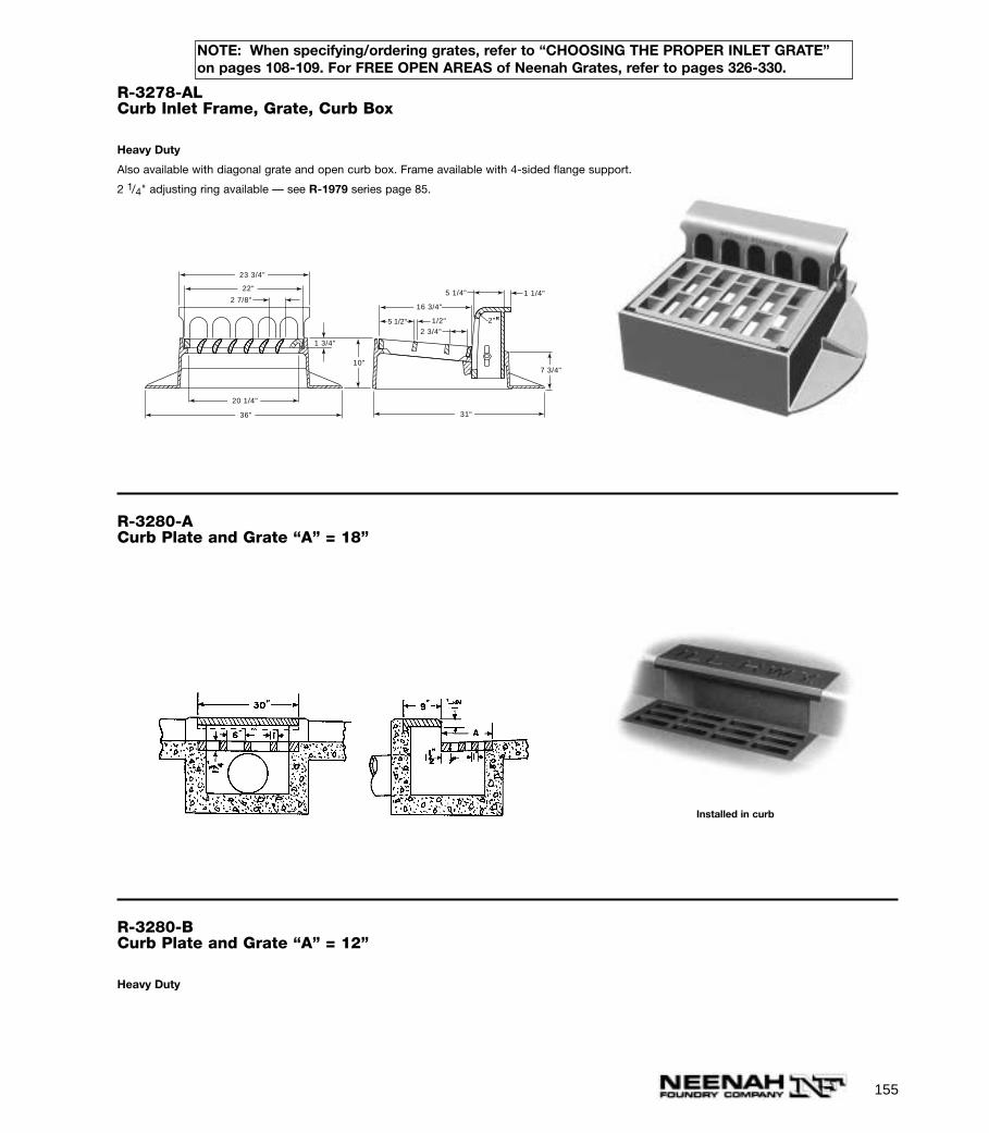
155
NOTE: When specifying/ordering grates, refer to “CHOOSING THE PROPER INLET GRATE”on pages 108-109. For FREE OPEN AREAS of Neenah Grates, refer to pages 326-330.
R-3278-ALCurb Inlet Frame, Grate, Curb Box
Heavy Duty
Also available with diagonal grate and open curb box. Frame available with 4-sided flange support.
2 1/4" adjusting ring available — see R-1979 series page 85.
5 1/2"
5 1/4" 1 1/4"
1/2"
2 3/4"
7 3/4"10"
1 3/4"
16 3/4"
31"
2 7/8"
23 3/4"
20 1/4"
22"
36"
2"R
R-3280-ACurb Plate and Grate “A” = 18”
Installed in curb
R-3280-BCurb Plate and Grate “A” = 12”
Heavy Duty
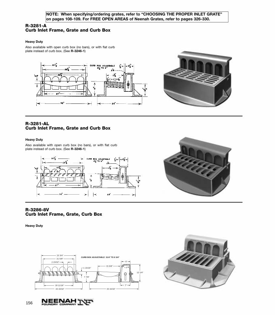
156
NOTE: When specifying/ordering grates, refer to “CHOOSING THE PROPER INLET GRATE”on pages 108-109. For FREE OPEN AREAS of Neenah Grates, refer to pages 326-330.
R-3281-ACurb Inlet Frame, Grate and Curb Box
Heavy Duty
Also available with open curb box (no bars), or with flat curbplate instead of curb box. (See R-3246-1)
R-3281-ALCurb Inlet Frame, Grate and Curb Box
Heavy Duty
Also available with open curb box (no bars), or with flat curbplate instead of curb box. (See R-3246-1)
R-3286-8VCurb Inlet Frame, Grate, Curb Box
Heavy Duty
2"R15 5/8"
33 15/32"33 15/32"
21 5/8"
19 11/16"
23 3/4"
7"
7 7/8"
12 1/4"
1 15/16"
2 23/32" 6"
CURB BOX ADJUSTABLE 51/4" TO 8 3/4"
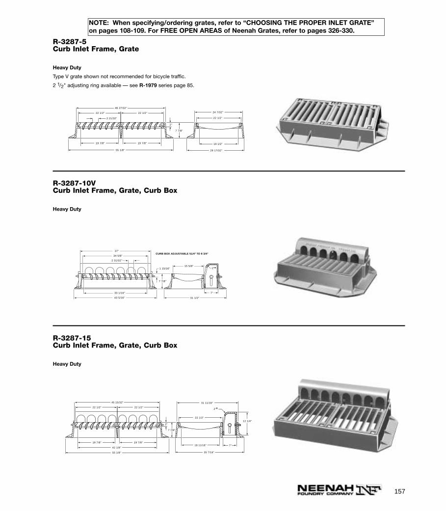
157
NOTE: When specifying/ordering grates, refer to “CHOOSING THE PROPER INLET GRATE”on pages 108-109. For FREE OPEN AREAS of Neenah Grates, refer to pages 326-330.
R-3287-5Curb Inlet Frame, Grate
Heavy Duty
Type V grate shown not recommended for bicycle traffic.
2 1/2" adjusting ring available — see R-1979 series page 85.
7 7/8"
22 1/2"
24 7/32"
19 1/2"
29 17/32"
2"
46 27/32"
22 1/2"
19 7/8" 19 7/8"
55 1/8"
22 1/2"
2 21/32"
R-3287-10VCurb Inlet Frame, Grate, Curb Box
Heavy Duty
2"R15 5/8"
31 1/2"43 5/16"
34 5/8"
33 1/16"
37"
7"
7 7/8"
1 15/16"
2 31/32"
CURB BOX ADJUSTABLE 51/4" TO 8 3/4"
R-3287-15Curb Inlet Frame, Grate, Curb Box
Heavy Duty
7 7/8"
12 1/4"22 1/2"
31 11/16"
19 11/16"
35 7/16"
2"
7"
2"R
45 15/32"
22 1/2"
19 7/8" 19 7/8"
42 1/8"
55 1/8"
22 1/2"
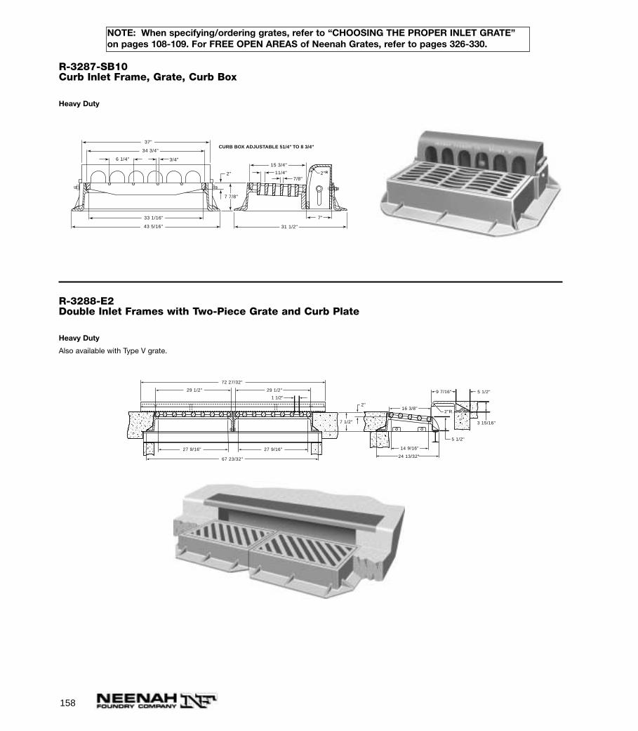
158
NOTE: When specifying/ordering grates, refer to “CHOOSING THE PROPER INLET GRATE”on pages 108-109. For FREE OPEN AREAS of Neenah Grates, refer to pages 326-330.
R-3287-SB10Curb Inlet Frame, Grate, Curb Box
Heavy Duty
15 3/4"
31 1/2"43 5/16"
34 3/4"
33 1/16"
37"
7"
7 7/8"
2"
6 1/4"
CURB BOX ADJUSTABLE 51/4" TO 8 3/4"
11/4"7/8"
3/4"
2"R
R-3288-E2Double Inlet Frames with Two-Piece Grate and Curb Plate
Heavy Duty
Also available with Type V grate.
14 9/16"
5 1/2"
7 1/2"
5 1/2"9 7/16"
3 15/16"
24 13/32"
2"R.
2"
72 27/32"
29 1/2" 29 1/2"
27 9/16"27 9/16" 27 9/16"
67 23/32"
16 3/8"
1 1/2"
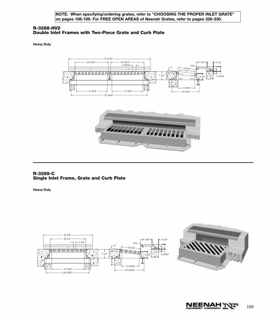
159
NOTE: When specifying/ordering grates, refer to “CHOOSING THE PROPER INLET GRATE”on pages 108-109. For FREE OPEN AREAS of Neenah Grates, refer to pages 326-330.
R-3288-HV2Double Inlet Frames with Two-Piece Grate and Curb Plate
Heavy Duty
2" 16 3/4"14"
14 9/16"
5 1/2"7 1/2"
5 1/2"9 7/16"
3 15/16"
24 13/32"
2"R.
72 27/32 "
29 15/16" 29 15/16"2 15/16"
27 9/16" 27 9/16"
67 23/32"
R-3289-CSingle Inlet Frame, Grate and Curb Plate
Heavy Duty
2" 16 3/8"
14 9/16"
5 1/2"7 1/2"
5 1/2"9 7/16"
3 15/16"
24 13/32"
2"R.
42 1/8"
29 1/2"
27 9/16"
36 13/32"
1 1/2"

160
NOTE: When specifying/ordering grates, refer to “CHOOSING THE PROPER INLET GRATE”on pages 108-109. For FREE OPEN AREAS of Neenah Grates, refer to pages 326-330.
R-3289-HVSingle Inlet Frame, Grate and Curb Plate
Heavy Duty
2" 16 3/4"
14 9/16"
5 1/2"7 1/2"
5 1/2"9 7/16"
3 15/16"
24 13/32"
2"R.
42 1/8"
29 15/16"
27 9/16"
36 13/32"
2 15/16"
14"
R-3290Curb Inlet Frame, Grate and Curb Box
Heavy Duty
Can be furnished with Type L, Type V or Type D § slotted grate. Curb box with 3” radius as shown, 2”radius, square face or Type D curb face (see page 113 for design).
§ Not recommended for bicycle traffic.
Specify:
1. Grate type preferred.
2. Curb box style if other than shown.
Also available with flat mountable curb plate, grated or solid, as shown onR-3246-1, in place of curb box.
Type V grates not recommended for bicycle traffic when used with curbplate.
1 3/4"
1 1/4"6 1/2" 1 3/4"
17 1/2"
31"
6"
4"2"
33"
43"
36 3/4"
35 1/4"
CURB BOX ADJUSTABLE 6" TO 9"
2"
5 3/4"
R

161
NOTE: When specifying/ordering grates, refer to “CHOOSING THE PROPER INLET GRATE”on pages 108-109. For FREE OPEN AREAS of Neenah Grates, refer to pages 326-330.
R-3290-AGutter Inlet Frame and Grate
Heavy Duty
Furnished without curb box for use at driveway locations and in gutters.
23 3/4"
31"
4"
2"1 1/8"
6"
2"
35 3/4"
6 3/4"
33"
43"
R-3290-BGutter Inlet Frame and Grate
Heavy Duty
Not recommended for bicycle traffic.
R-3290-CGutter Inlet Frame and Grate
Heavy Duty
Not recommended for bicycle traffic.
1 1/8" 1 1/2"
30 3/16"
31 1/8"
34 7/8"
2"
6 1/2"
4"
36 7/8"
35 7/8"
10 3/4"3/4"
43"
R-3291Gutter Inlet Frame and Grate
Heavy Duty
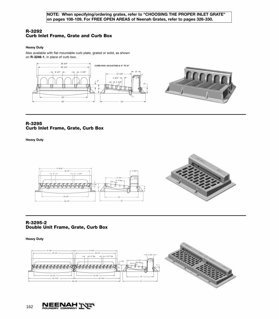
162
NOTE: When specifying/ordering grates, refer to “CHOOSING THE PROPER INLET GRATE”on pages 108-109. For FREE OPEN AREAS of Neenah Grates, refer to pages 326-330.
R-3292Curb Inlet Frame, Grate and Curb Box
Heavy Duty
Also available with flat mountable curb plate, grated or solid, as shownon R-3246-1, in place of curb box.
1 3/4"
1 1/4"
6 1/2" 1 3/4"17 1/2"
31"
6"
4"2"
33"
43"
36 3/4"
35 1/4"CURB BOX ADJUSTABLE 6" TO 8"
1"R
6"
R-3295Curb Inlet Frame, Grate, Curb Box
Heavy Duty
6 3/8"1/2"
4"
2"R
5 3/4"
17 3/4"
24"
31"
1 1/4"3"
35 1/4"
33 1/8"
43 1/4"
37 9/16"
1 7/8"
6"
R-3295-2Double Unit Frame, Grate, Curb Box
Heavy Duty
6 3/8"1/2"4"
2"R
5 3/4"
17 3/4"
24"
31"
1 7/8"
35 1/4"
33 1/8"
40 7/16" 40 7/16"
80 7/8"
37 3/8"
1 1/4"3"
35 1/4"
33 1/8"
37 3/8"
6"
Typ. Typ.
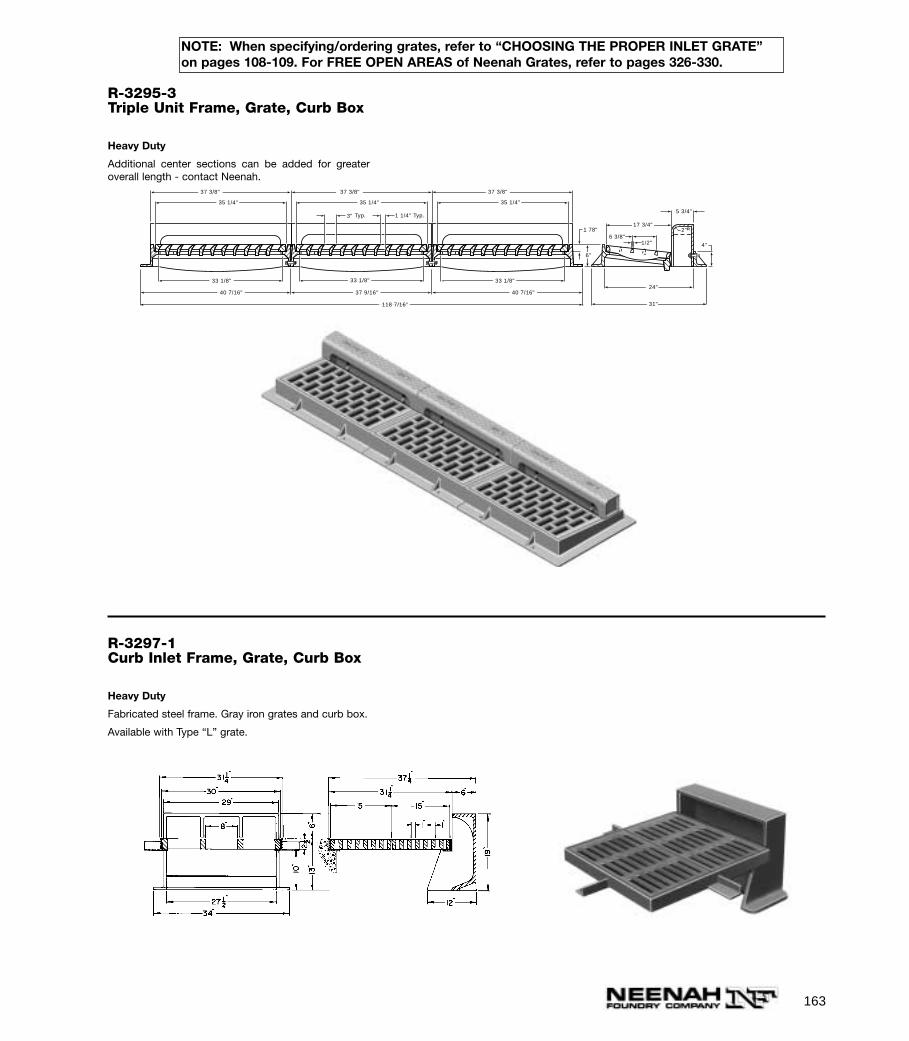
163
R-3295-3Triple Unit Frame, Grate, Curb Box
Heavy Duty
Additional center sections can be added for greateroverall length - contact Neenah.
4"
2"R
5 3/4"
6 3/8"
17 3/4"
24"
31"
1 78"
35 1/4"
33 1/8"
40 7/16" 40 7/16"37 9/16"
118 7/16"
37 3/8"
35 1/4"
33 1/8"
37 3/8"
6"
1 1/4"3"
35 1/4"
33 1/8"
37 3/8"
Typ. Typ.
1/2"
R-3297-1Curb Inlet Frame, Grate, Curb Box
Heavy Duty
Fabricated steel frame. Gray iron grates and curb box.
Available with Type “L” grate.
NOTE: When specifying/ordering grates, refer to “CHOOSING THE PROPER INLET GRATE”on pages 108-109. For FREE OPEN AREAS of Neenah Grates, refer to pages 326-330.

R-3308Catch Basin Frame and Lid
Heavy Duty
For behind-the-curb construction.
Not recommended for use in areas where large gutter trash objects are prevalent. Curb opening, with-out gutter grate, allows large trash to enter catch basin and clog lines.
Furnished standard with as-cast bearing surfaces.
164
R-3303Catch Basin Frame and Lid
Heavy Duty
For behind-the-curb construction.
Furnished standard with as-cast bearing surfaces.
R-3305Catch Basin Frame and Lid
Heavy Duty
For behind-the-curb construction.
Furnished standard with as-cast bearing surfaces.
BEHIND THE CURB INLETS
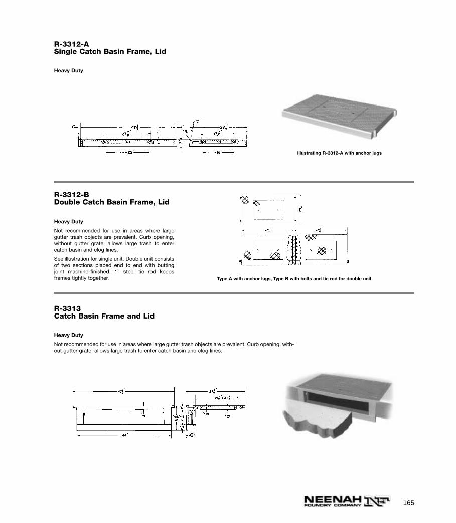
R-3312-ASingle Catch Basin Frame, Lid
Heavy Duty
Illustrating R-3312-A with anchor lugs
R-3312-BDouble Catch Basin Frame, Lid
Heavy Duty
Not recommended for use in areas where largegutter trash objects are prevalent. Curb opening,without gutter grate, allows large trash to entercatch basin and clog lines.
See illustration for single unit. Double unit consistsof two sections placed end to end with buttingjoint machine-finished. 1” steel tie rod keepsframes tightly together. Type A with anchor lugs, Type B with bolts and tie rod for double unit
165
R-3313Catch Basin Frame and Lid
Heavy Duty
Not recommended for use in areas where large gutter trash objects are prevalent. Curb opening, with-out gutter grate, allows large trash to enter catch basin and clog lines.
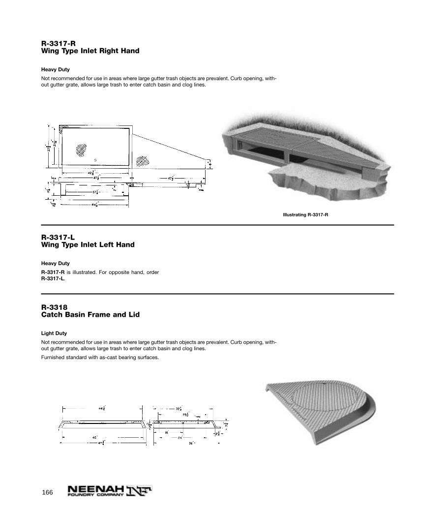
166
R-3318Catch Basin Frame and Lid
Light Duty
Not recommended for use in areas where large gutter trash objects are prevalent. Curb opening, with-out gutter grate, allows large trash to enter catch basin and clog lines.
Furnished standard with as-cast bearing surfaces.
R-3317-RWing Type Inlet Right Hand
Heavy Duty
Not recommended for use in areas where large gutter trash objects are prevalent. Curb opening, with-out gutter grate, allows large trash to enter catch basin and clog lines.
Illustrating R-3317-R
R-3317-LWing Type Inlet Left Hand
Heavy Duty
R-3317-R is illustrated. For opposite hand, orderR-3317-L.

167
Illustrating deep pan outlet furnished with R-3323-Pand R-3324-P only
R-3323Inlet with Flat Pan Outlet
Furnished standard with as-cast bearing sur-faces.
“F” = 6 1/4”
Not recommended for use in areas where largegutter trash objects are prevalent. Curb opening,without gutter grate, allows large trash to entercatch basin and clog lines.
Illustrating R-3324 with flat pan outlet
R-3323-P
Heavy Duty
Same as R-3323 except furnished with deep panoutlet.
R-3324Inlet with Flat Pan Outlet
Furnished standard with as-cast bearing surfaces.
Same as R-3323 except “F” = 8 1/2”
R-3324-P
Heavy Duty
Same as R-3324 except furnished with deep panoutlet.
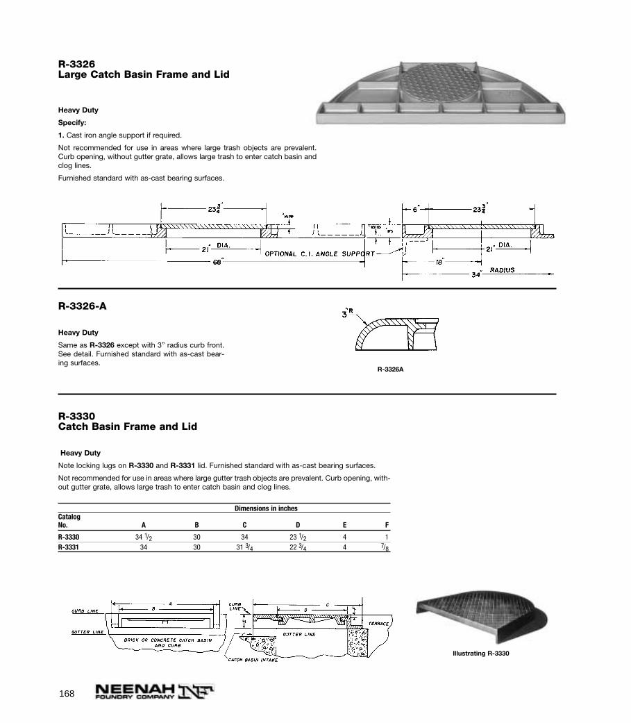
168
R-3330Catch Basin Frame and Lid
Heavy Duty
Note locking lugs on R-3330 and R-3331 lid. Furnished standard with as-cast bearing surfaces.
Not recommended for use in areas where large gutter trash objects are prevalent. Curb opening, with-out gutter grate, allows large trash to enter catch basin and clog lines.
Illustrating R-3330
Dimensions in inchesCatalogNo. A B C D E F
R-3330 34 1/2 30 34 23 1/2 4 1R-3331 34 30 31 3/4 22 3/4 4 7/8
R-3326Large Catch Basin Frame and Lid
Heavy Duty
Specify:
1. Cast iron angle support if required.
Not recommended for use in areas where large trash objects are prevalent.Curb opening, without gutter grate, allows large trash to enter catch basin andclog lines.
Furnished standard with as-cast bearing surfaces.
R-3326-A
Heavy Duty
Same as R-3326 except with 3” radius curb front.See detail. Furnished standard with as-cast bear-ing surfaces.
R-3326A

169
R-3331Catch Basin Frame and Lid
Heavy Duty
Illustrating R-3331
R-3333-ACatch Basin Frame and Lid
For behind-the-curb construction.
Furnished standard with as-cast bearing surfaces.
Lids furnished standard with type “F” locks (shownon page 308).
Openings are 3” x 4 1/2”.
25"26"
18"
20"
6"
R-3334-FCatch Basin Frame and Lid
Heavy Duty
For behind-the-curb construction.
Not recommended for use in areas where large gutter trash objects are prevalent. Curb opening, with-out gutter grate, allows large trash to enter catch basin and clog lines.
Furnished standard with as-cast bearing surfaces.
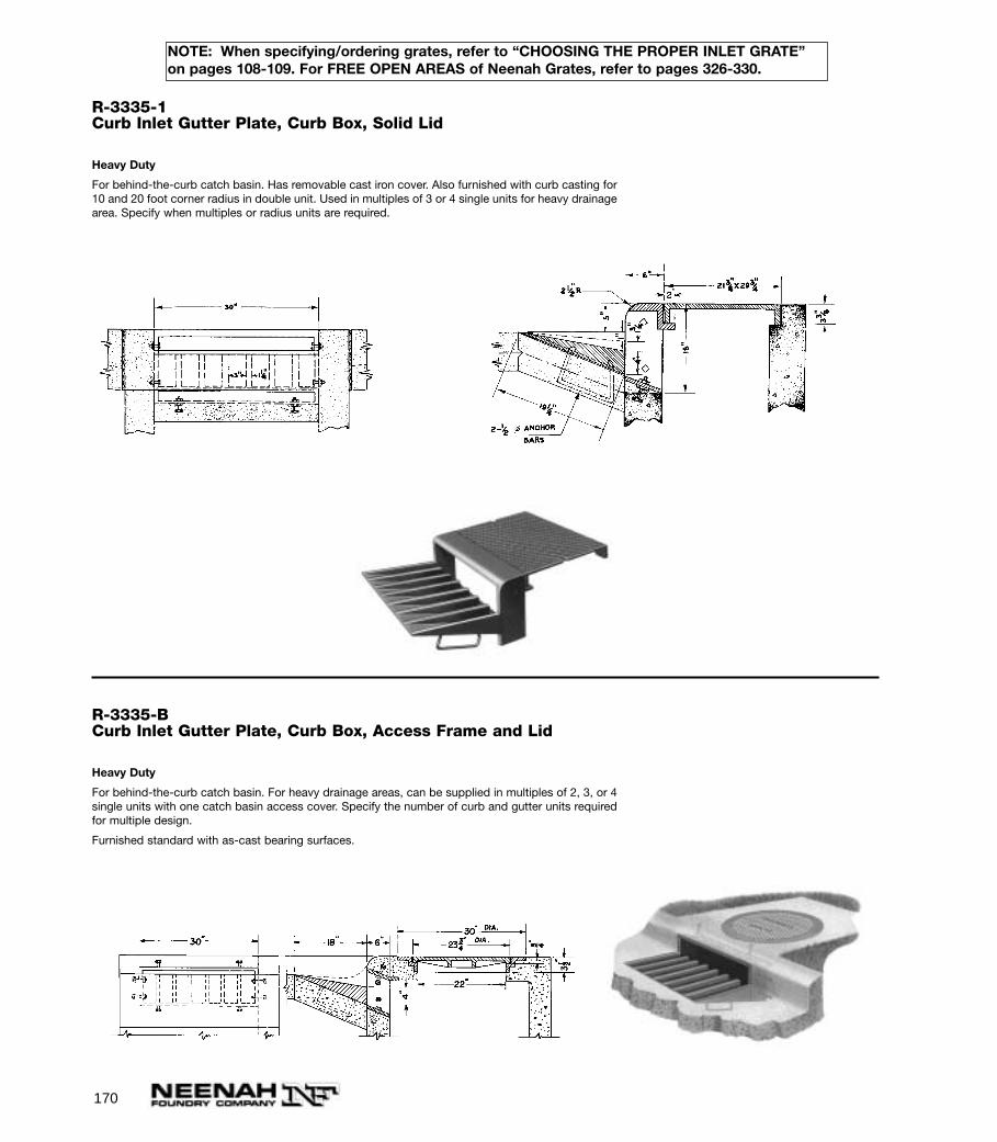
170
R-3335-BCurb Inlet Gutter Plate, Curb Box, Access Frame and Lid
Heavy Duty
For behind-the-curb catch basin. For heavy drainage areas, can be supplied in multiples of 2, 3, or 4single units with one catch basin access cover. Specify the number of curb and gutter units requiredfor multiple design.
Furnished standard with as-cast bearing surfaces.
R-3335-1Curb Inlet Gutter Plate, Curb Box, Solid Lid
Heavy Duty
For behind-the-curb catch basin. Has removable cast iron cover. Also furnished with curb casting for10 and 20 foot corner radius in double unit. Used in multiples of 3 or 4 single units for heavy drainagearea. Specify when multiples or radius units are required.
NOTE: When specifying/ordering grates, refer to “CHOOSING THE PROPER INLET GRATE”on pages 108-109. For FREE OPEN AREAS of Neenah Grates, refer to pages 326-330.

171
R-3337-AGutter Inlet Frame and Grate
Heavy Duty
R-3338-FSingle Convex Inlet Frame and Grate
Heavy Duty
Grate reversible if flat top inlet is required.
28 5/8"
19 5/8"
16 7/8"
14 3/8"26 3/8"
31 3/8"
24" 12 1/8"
1"
1"
2" 3"
3/4"5/8"2 1/8"
Illustrating R-3338-F Single Unit
GUTTER INLET FRAMES AND GRATES
R-3338-G
Heavy Duty
Same as R-3338-F except two grates used withlarger frame having overall flange 31 1/2” x 34 1/2”.
NOTE: When specifying/ordering grates, refer to “CHOOSING THE PROPER INLET GRATE”on pages 108-109. For FREE OPEN AREAS of Neenah Grates, refer to pages 326-330.
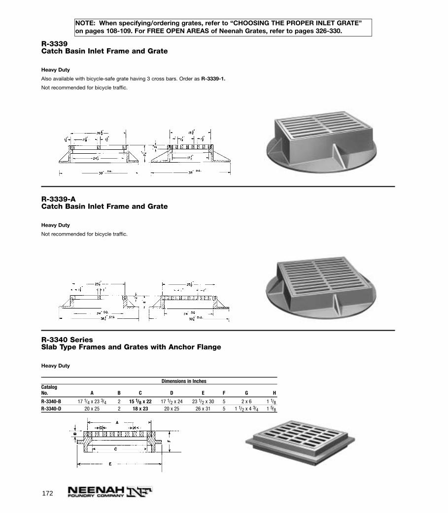
172
R-3339Catch Basin Inlet Frame and Grate
Heavy Duty
Also available with bicycle-safe grate having 3 cross bars. Order as R-3339-1.
Not recommended for bicycle traffic.
R-3339-ACatch Basin Inlet Frame and Grate
Heavy Duty
Not recommended for bicycle traffic.
R-3340 SeriesSlab Type Frames and Grates with Anchor Flange
Heavy Duty
Dimensions in InchesCatalogNo. A B C D E F G H
R-3340-B 17 1/4 x 23 3/4 2 15 1/8 x 22 17 1/2 x 24 23 1/2 x 30 5 2 x 6 1 1/8R-3340-D 20 x 25 2 18 x 23 20 x 25 26 x 31 5 1 1/2 x 4 3/4 1 5/8
NOTE: When specifying/ordering grates, refer to “CHOOSING THE PROPER INLET GRATE”on pages 108-109. For FREE OPEN AREAS of Neenah Grates, refer to pages 326-330.
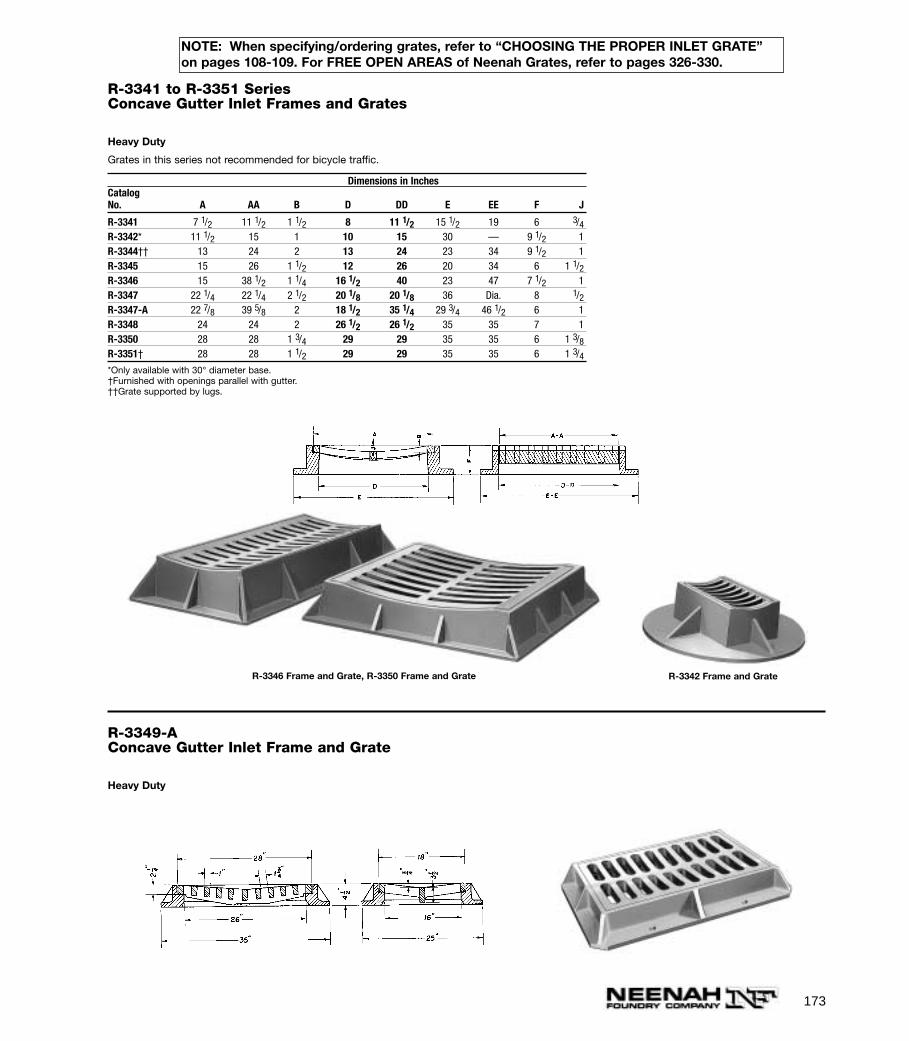
173
NOTE: When specifying/ordering grates, refer to “CHOOSING THE PROPER INLET GRATE”on pages 108-109. For FREE OPEN AREAS of Neenah Grates, refer to pages 326-330.
R-3341 to R-3351 SeriesConcave Gutter Inlet Frames and Grates
Heavy Duty
Grates in this series not recommended for bicycle traffic.
Dimensions in InchesCatalogNo. A AA B D DD E EE F J
R-3341 7 1/2 11 1/2 1 1/2 8 11 1/2 15 1/2 19 6 3/4R-3342* 11 1/2 15 1 10 15 30 — 9 1/2 1R-3344†† 13 24 2 13 24 23 34 9 1/2 1R-3345 15 26 1 1/2 12 26 20 34 6 1 1/2R-3346 15 38 1/2 1 1/4 16 1/2 40 23 47 7 1/2 1R-3347 22 1/4 22 1/4 2 1/2 20 1/8 20 1/8 36 Dia. 8 1/2R-3347-A 22 7/8 39 5/8 2 18 1/2 35 1/4 29 3/4 46 1/2 6 1R-3348 24 24 2 26 1/2 26 1/2 35 35 7 1R-3350 28 28 1 3/4 29 29 35 35 6 1 3/8R-3351† 28 28 1 1/2 29 29 35 35 6 1 3/4*Only available with 30° diameter base.†Furnished with openings parallel with gutter.††Grate supported by lugs.
R-3346 Frame and Grate, R-3350 Frame and Grate R-3342 Frame and Grate
R-3349-AConcave Gutter Inlet Frame and Grate
Heavy Duty
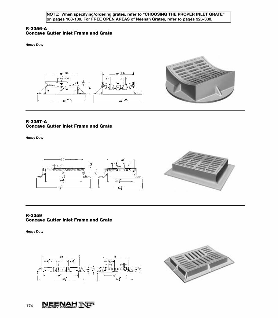
R-3359Concave Gutter Inlet Frame and Grate
Heavy Duty
R-3356-AConcave Gutter Inlet Frame and Grate
Heavy Duty
R-3357-AConcave Gutter Inlet Frame and Grate
Heavy Duty
174
NOTE: When specifying/ordering grates, refer to “CHOOSING THE PROPER INLET GRATE”on pages 108-109. For FREE OPEN AREAS of Neenah Grates, refer to pages 326-330.
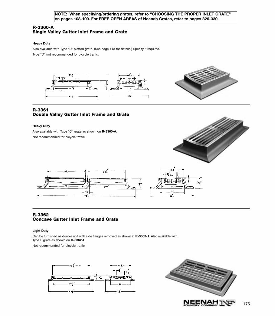
R-3360-ASingle Valley Gutter Inlet Frame and Grate
Heavy Duty
Also available with Type “D” slotted grate. (See page 113 for details.) Specify if required.
Type “D” not recommended for bicycle traffic.
R-3361Double Valley Gutter Inlet Frame and Grate
Heavy Duty
Also available with Type “C” grate as shown on R-3360-A.
Not recommended for bicycle traffic.
175
NOTE: When specifying/ordering grates, refer to “CHOOSING THE PROPER INLET GRATE”on pages 108-109. For FREE OPEN AREAS of Neenah Grates, refer to pages 326-330.
R-3362Concave Gutter Inlet Frame and Grate
Light Duty
Can be furnished as double unit with side flanges removed as shown in R-3363-1. Also available withType L grate as shown on R-3362-L
Not recommended for bicycle traffic.

176
NOTE: When specifying/ordering grates, refer to “CHOOSING THE PROPER INLET GRATE”on pages 108-109. For FREE OPEN AREAS of Neenah Grates, refer to pages 326-330.
R-3362-LConcave Gutter Inlet Frame and Grate
Heavy Duty
Can be furnished as double unit with side flanges removed as shown in R-3363-1.
R-3363-1Double Unit Inlet Frame, Grate, Curb Box
Light Duty
Not recommended for bicycle traffic.
Also available with Type L grates as shown on R-3362-L.
R-3362-1Concave Curb Inlet Frame, Grate, Curb Box
Light Duty
Also available with Type L grate as shown on R-3362-L
Not recommended for bicycle traffic.
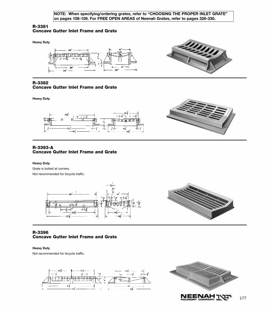
R-3382Concave Gutter Inlet Frame and Grate
Heavy Duty
R-3393-AConcave Gutter Inlet Frame and Grate
Heavy Duty
Grate is bolted at corners.
Not recommended for bicycle traffic.
R-3396Concave Gutter Inlet Frame and Grate
Heavy Duty
Not recommended for bicycle traffic.
R-3381Concave Gutter Inlet Frame and Grate
Heavy Duty
177
NOTE: When specifying/ordering grates, refer to “CHOOSING THE PROPER INLET GRATE”on pages 108-109. For FREE OPEN AREAS of Neenah Grates, refer to pages 326-330.
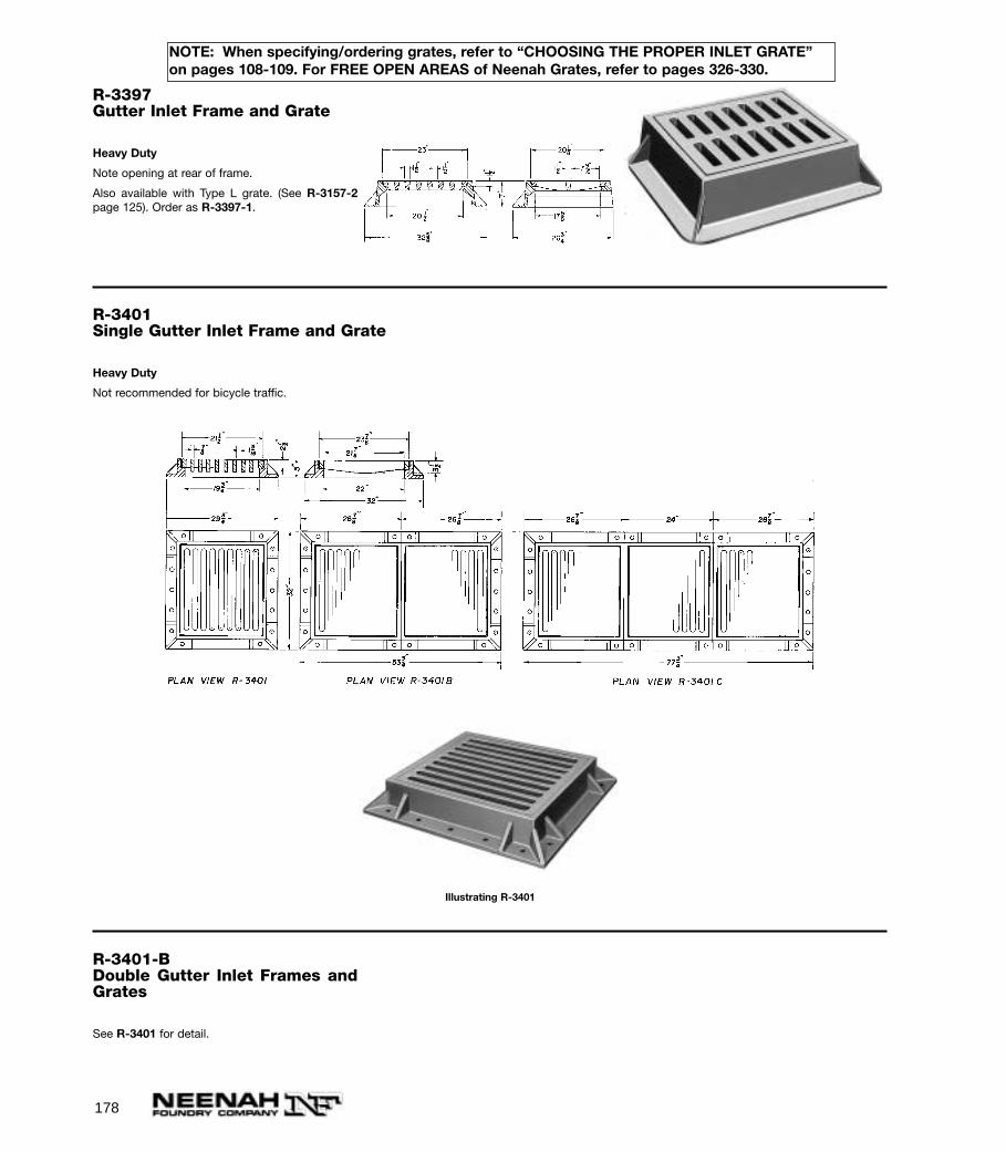
178
NOTE: When specifying/ordering grates, refer to “CHOOSING THE PROPER INLET GRATE”on pages 108-109. For FREE OPEN AREAS of Neenah Grates, refer to pages 326-330.
R-3397Gutter Inlet Frame and Grate
Heavy Duty
Note opening at rear of frame.
Also available with Type L grate. (See R-3157-2page 125). Order as R-3397-1.
R-3401Single Gutter Inlet Frame and Grate
Heavy Duty
Not recommended for bicycle traffic.
Illustrating R-3401
R-3401-BDouble Gutter Inlet Frames andGrates
See R-3401 for detail.
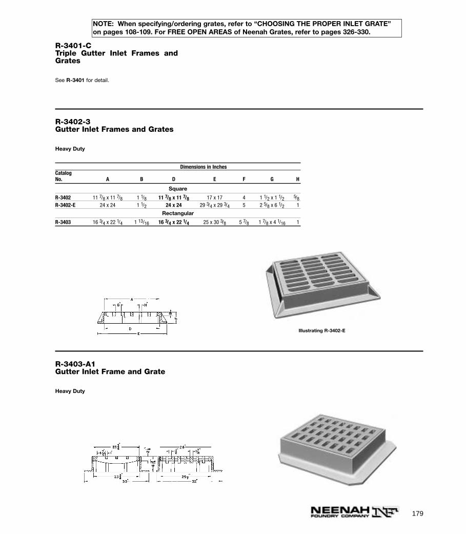
179
NOTE: When specifying/ordering grates, refer to “CHOOSING THE PROPER INLET GRATE”on pages 108-109. For FREE OPEN AREAS of Neenah Grates, refer to pages 326-330.
R-3401-CTriple Gutter Inlet Frames andGrates
See R-3401 for detail.
R-3402-3Gutter Inlet Frames and Grates
Heavy Duty
Dimensions in InchesCatalogNo. A B D E F G H
Square
R-3402 11 7/8 x 11 7/8 1 1/8 11 7/8 x 11 7/8 17 x 17 4 1 1/2 x 1 1/2 5/8R-3402-E 24 x 24 1 1/2 24 x 24 29 3/4 x 29 3/4 5 2 5/8 x 6 1/2 1
Rectangular
R-3403 16 3/4 x 22 1/4 1 13/16 16 3/4 x 22 1/4 25 x 30 3/8 5 7/8 1 7/8 x 4 1/16 1
Illustrating R-3402-E
R-3403-A1Gutter Inlet Frame and Grate
Heavy Duty

180
NOTE: When specifying/ordering grates, refer to “CHOOSING THE PROPER INLET GRATE”on pages 108-109. For FREE OPEN AREAS of Neenah Grates, refer to pages 326-330.
R-3403-FGutter Inlet Frame and Grate
Heavy Duty
Not recommended for bicycle traffic.
R-3404-5Gutter Inlet Frames and Grates
Heavy Duty
Dimensions in InchesCatalogNo. A B C E F G H
R-3404 21 1/2 x 21 1/2 1 1/2 20 1/8 x 20 1/8 30 5/8 x 30 5/8 5 1/8 2 x 2 15/16R-3405 23 5/8 x 23 5/8 1 1/2 22 x 22 32 3/4 x 32 3/4 6 2 1/8 x 2 1/8 1R-3405-A• 23 7/8 x 23 7/8 2 22 x 22 32 1/8 x 32 1/8 6 1/8 2 1/4 x 2 1/4 1 7/16R-3405-B*• 23 7/8 x 23 7/8 2 22 x 22 32 1/8 x 29 6 1/8 2 1/4 x 2 1/4 1 7/16
*Same as R-3405-A except base flange on 3 sides only.•Also available with Type L grate. See R-3588-LL.
6"
1 1/2"
26 7/8" x 26 7/8"
23 5/8" x 23 5/8"
32 3/4" x 32 3/4"
22" x 22"
1"
2 1/8"
Illustrating R-3405
7/8" 1 5/8" 2 1/2"2 1/8"Typ.
37 5/8"
35 5/8"
29 3/8"
27 7/8"
33 1/4"
42 1/4"
25 3/16"
10 9/16"
33 13/16"
3 1/2"2"
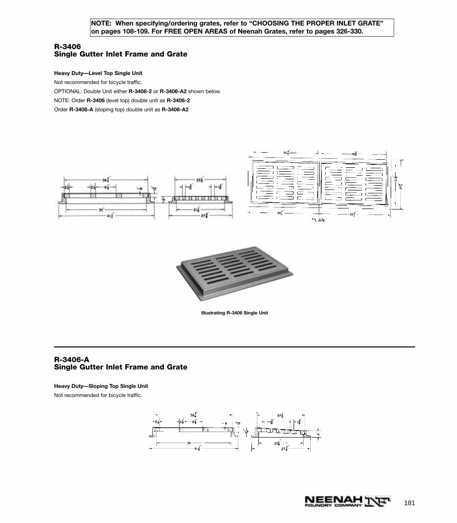
181
NOTE: When specifying/ordering grates, refer to “CHOOSING THE PROPER INLET GRATE”on pages 108-109. For FREE OPEN AREAS of Neenah Grates, refer to pages 326-330.
R-3406Single Gutter Inlet Frame and Grate
Heavy Duty—Level Top Single Unit
Not recommended for bicycle traffic.
OPTIONAL: Double Unit either R-3406-2 or R-3406-A2 shown below.
NOTE: Order R-3406 (level top) double unit as R-3406-2
Order R-3406-A (sloping top) double unit as R-3406-A2
Illustrating R-3406 Single Unit
R-3406-ASingle Gutter Inlet Frame and Grate
Heavy Duty—Sloping Top Single Unit
Not recommended for bicycle traffic.
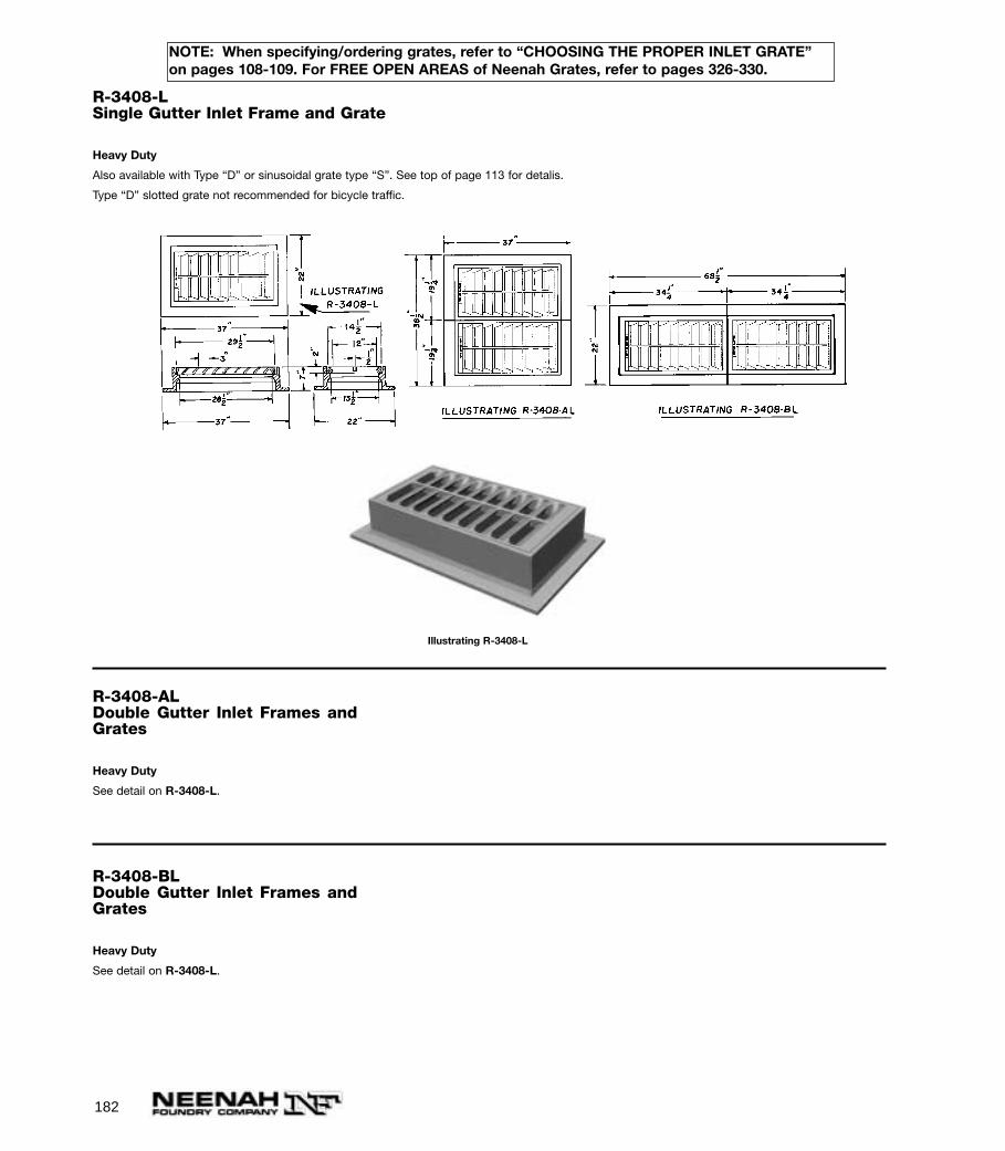
182
NOTE: When specifying/ordering grates, refer to “CHOOSING THE PROPER INLET GRATE”on pages 108-109. For FREE OPEN AREAS of Neenah Grates, refer to pages 326-330.
R-3408-LSingle Gutter Inlet Frame and Grate
Heavy Duty
Also available with Type “D” or sinusoidal grate type “S”. See top of page 113 for detalis.
Type “D” slotted grate not recommended for bicycle traffic.
Illustrating R-3408-L
R-3408-ALDouble Gutter Inlet Frames andGrates
Heavy Duty
See detail on R-3408-L.
R-3408-BLDouble Gutter Inlet Frames andGrates
Heavy Duty
See detail on R-3408-L.
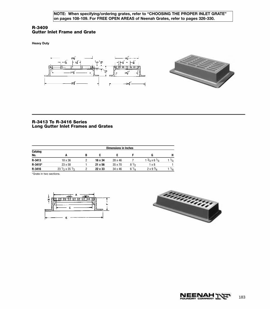
183
NOTE: When specifying/ordering grates, refer to “CHOOSING THE PROPER INLET GRATE”on pages 108-109. For FREE OPEN AREAS of Neenah Grates, refer to pages 326-330.
R-3409Gutter Inlet Frame and Grate
Heavy Duty
R-3413 To R-3416 SeriesLong Gutter Inlet Frames and Grates
Dimensions in InchesCatalogNo. A B C E F G H
R-3413 18 x 36 2 16 x 34 28 x 46 7 1 3/4 x 6 1/4 1 1/4R-3415* 23 x 58 1 21 x 56 35 x 70 8 1/2 1 x 8 1R-3416 23 1/2 x 35 1/2 2 22 x 33 34 x 46 6 1/4 2 x 9 3/4 1 1/4*Grate in two sections.
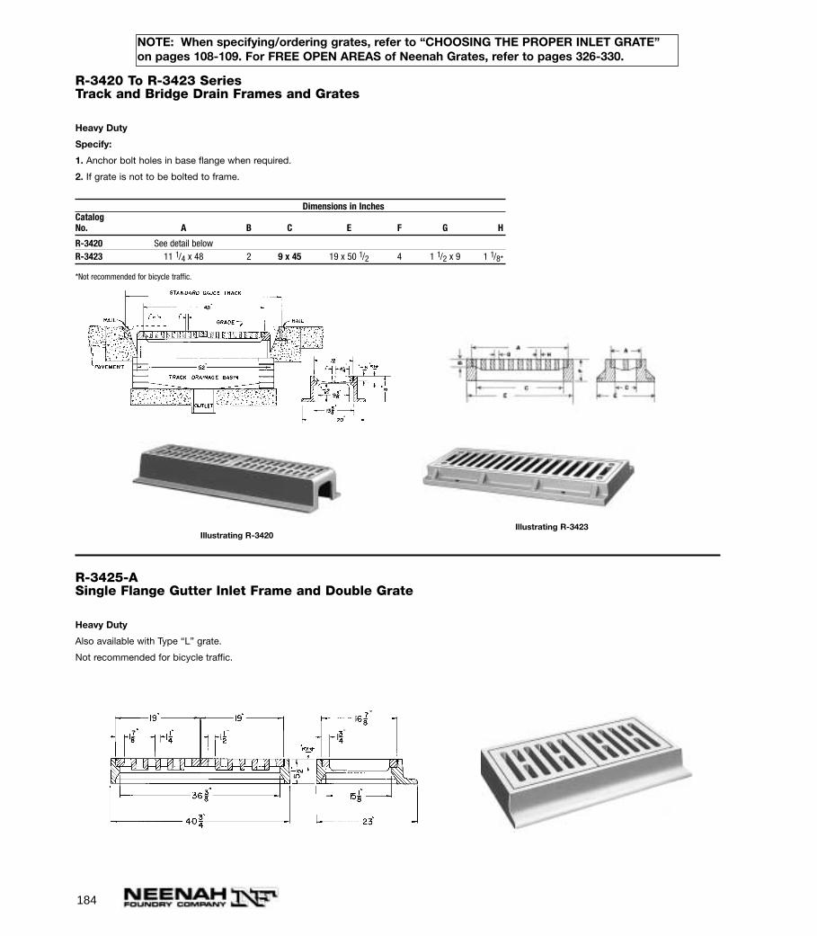
184
NOTE: When specifying/ordering grates, refer to “CHOOSING THE PROPER INLET GRATE”on pages 108-109. For FREE OPEN AREAS of Neenah Grates, refer to pages 326-330.
R-3420 To R-3423 SeriesTrack and Bridge Drain Frames and Grates
Heavy Duty
Specify:
1. Anchor bolt holes in base flange when required.
2. If grate is not to be bolted to frame.
Dimensions in InchesCatalogNo. A B C E F G H
R-3420 See detail belowR-3423 11 1/4 x 48 2 9 x 45 19 x 50 1/2 4 1 1/2 x 9 1 1/8*
*Not recommended for bicycle traffic.
Illustrating R-3420Illustrating R-3423
R-3425-ASingle Flange Gutter Inlet Frame and Double Grate
Heavy Duty
Also available with Type “L” grate.
Not recommended for bicycle traffic.
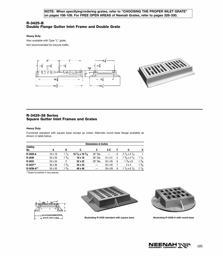
185
NOTE: When specifying/ordering grates, refer to “CHOOSING THE PROPER INLET GRATE”on pages 108-109. For FREE OPEN AREAS of Neenah Grates, refer to pages 326-330.
R-3425-BDouble Flange Gutter Inlet Frame and Double Grate
Heavy Duty
Also available with Type “L” grate.
Not recommended for bicycle traffic.
R-3429-38 SeriesSquare Gutter Inlet Frames and Grates
Heavy Duty
Furnished standard with square base except as noted. Alternate round base flange available asshown in table below.
Dimensions in InchesCatalogNo. A B C E E-E F G H
R-3429-A 18 x 18 1 1/2 16 1/4 x 16 1/4 30” Dia. — 6 2 1/4 x 4 1/4 1R-3430 20 x 20 1 3/4 18 x 18 36” Dia. 31 x 31 5 1 3/8 x 3 1/2 1 1/4R-3433 24 x 24 2 22 x 22 38” Dia. 35 x 35 6 1 3/4 x 6 1 3/8R-3437** 36 x 36 1 3/4 34 x 34 — 45 x 45 7 2 x 4 1 3/8R-3438-A** 50 x 50 1 3/4 48 x 48 — 59 x 59 8 1 1/2 x 6 1/4 1 1/8**Grate furnished in two pieces.
Illustrating R-3430 standard with square base Illustrating R-3429-A with round base
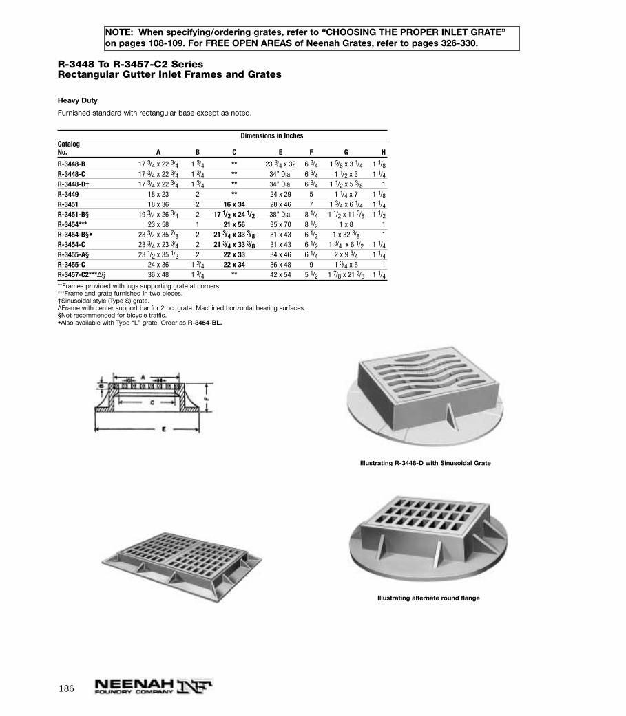
186
NOTE: When specifying/ordering grates, refer to “CHOOSING THE PROPER INLET GRATE”on pages 108-109. For FREE OPEN AREAS of Neenah Grates, refer to pages 326-330.
R-3448 To R-3457-C2 SeriesRectangular Gutter Inlet Frames and Grates
Heavy Duty
Furnished standard with rectangular base except as noted.
Dimensions in InchesCatalogNo. A B C E F G H
R-3448-B 17 3/4 x 22 3/4 1 3/4 ** 23 3/4 x 32 6 3/4 1 5/8 x 3 1/4 1 1/8R-3448-C 17 3/4 x 22 3/4 1 3/4 ** 34” Dia. 6 3/4 1 1/2 x 3 1 1/4R-3448-D† 17 3/4 x 22 3/4 1 3/4 ** 34” Dia. 6 3/4 1 1/2 x 5 3/8 1R-3449 18 x 23 2 ** 24 x 29 5 1 1/4 x 7 1 1/8R-3451 18 x 36 2 16 x 34 28 x 46 7 1 3/4 x 6 1/4 1 1/4R-3451-B§ 19 3/4 x 26 3/4 2 17 1/2 x 24 1/2 38” Dia. 8 1/4 1 1/2 x 11 3/8 1 1/2R-3454*** 23 x 58 1 21 x 56 35 x 70 8 1/2 1 x 8 1R-3454-B§• 23 3/4 x 35 7/8 2 21 3/4 x 33 3/8 31 x 43 6 1/2 1 x 32 3/8 1R-3454-C 23 3/4 x 23 3/4 2 21 3/4 x 33 3/8 31 x 43 6 1/2 1 3/4 x 6 1/2 1 1/4R-3455-A§ 23 1/2 x 35 1/2 2 22 x 33 34 x 46 6 1/4 2 x 9 3/4 1 1/4R-3455-C 24 x 36 1 3/4 22 x 34 36 x 48 9 1 3/4 x 6 1R-3457-C2***∆§ 36 x 48 1 3/4 ** 42 x 54 5 1/2 1 7/8 x 21 3/8 1 1/4**Frames provided with lugs supporting grate at corners.***Frame and grate furnished in two pieces.†Sinusoidal style (Type S) grate.∆Frame with center support bar for 2 pc. grate. Machined horizontal bearing surfaces.§Not recommended for bicycle traffic. •Also available with Type “L” grate. Order as R-3454-BL.
Illustrating R-3448-D with Sinusoidal Grate
Illustrating alternate round flange
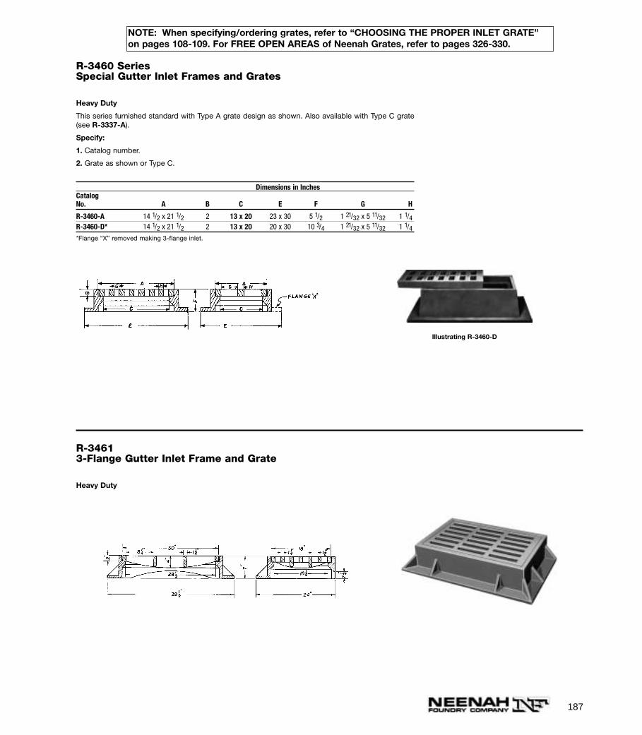
187
NOTE: When specifying/ordering grates, refer to “CHOOSING THE PROPER INLET GRATE”on pages 108-109. For FREE OPEN AREAS of Neenah Grates, refer to pages 326-330.
R-3460 SeriesSpecial Gutter Inlet Frames and Grates
Heavy Duty
This series furnished standard with Type A grate design as shown. Also available with Type C grate(see R-3337-A).
Specify:
1. Catalog number.
2. Grate as shown or Type C.
Dimensions in InchesCatalogNo. A B C E F G H
R-3460-A 14 1/2 x 21 1/2 2 13 x 20 23 x 30 5 1/2 1 21/32 x 5 11/32 1 1/4R-3460-D* 14 1/2 x 21 1/2 2 13 x 20 20 x 30 10 3/4 1 21/32 x 5 11/32 1 1/4*Flange “X” removed making 3-flange inlet.
Illustrating R-3460-D
R-34613-Flange Gutter Inlet Frame and Grate
Heavy Duty
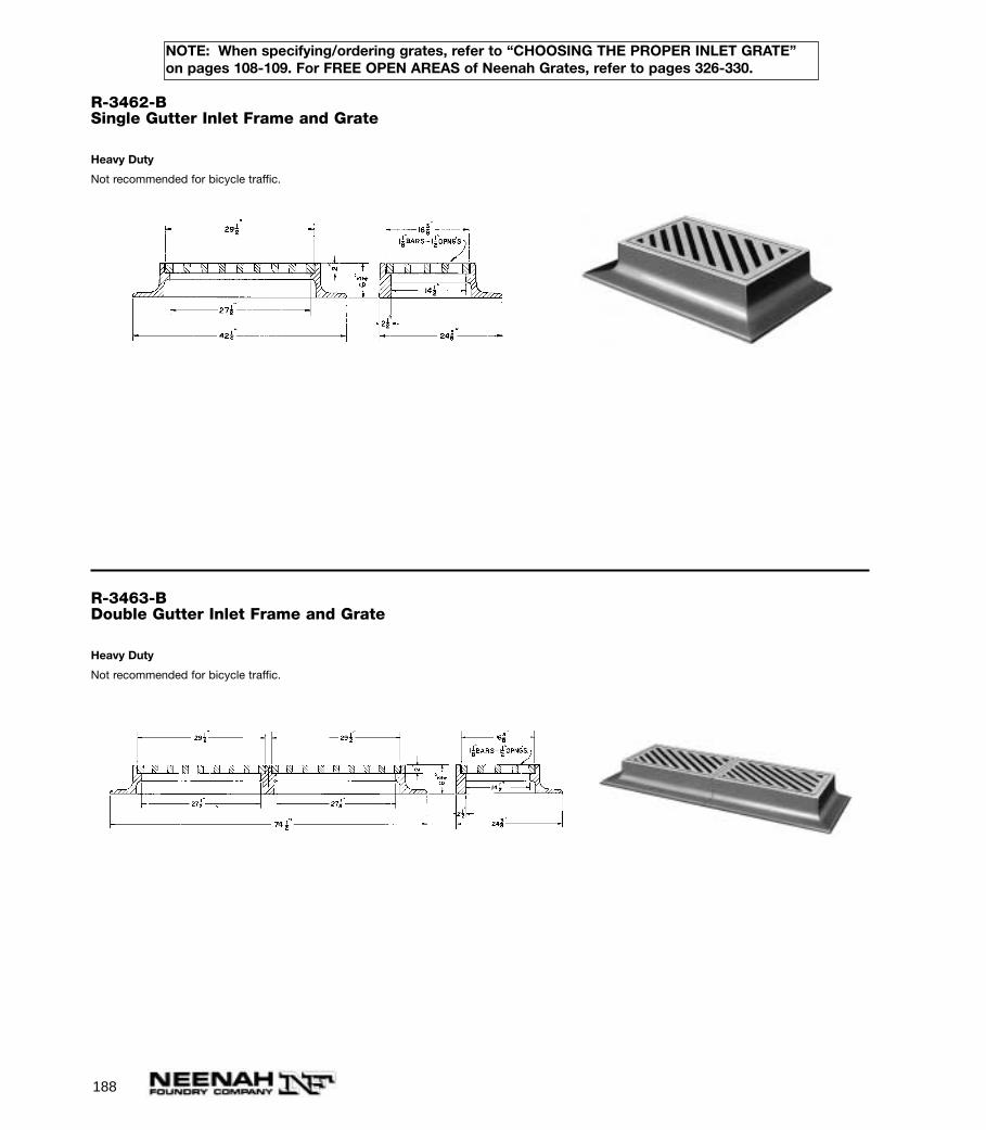
188
NOTE: When specifying/ordering grates, refer to “CHOOSING THE PROPER INLET GRATE”on pages 108-109. For FREE OPEN AREAS of Neenah Grates, refer to pages 326-330.
R-3462-BSingle Gutter Inlet Frame and Grate
Heavy Duty
Not recommended for bicycle traffic.
R-3463-BDouble Gutter Inlet Frame and Grate
Heavy Duty
Not recommended for bicycle traffic.
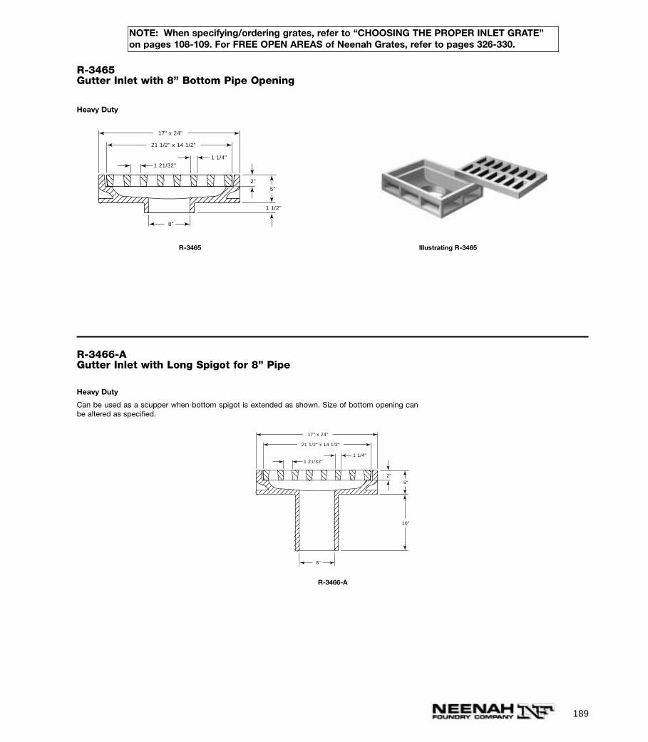
189
NOTE: When specifying/ordering grates, refer to “CHOOSING THE PROPER INLET GRATE”on pages 108-109. For FREE OPEN AREAS of Neenah Grates, refer to pages 326-330.
R-3465Gutter Inlet with 8” Bottom Pipe Opening
Heavy Duty
1 21/32"
1 1/4"
1 1/2"
21 1/2" x 14 1/2"
17" x 24"
8"
5"2"
R-3465 Illustrating R-3465
R-3466-AGutter Inlet with Long Spigot for 8” Pipe
Heavy Duty
Can be used as a scupper when bottom spigot is extended as shown. Size of bottom opening canbe altered as specified.
1 21/32"1 1/4"
21 1/2" x 14 1/2"
17" x 24"
8"
10"
5"2"
R-3466-A
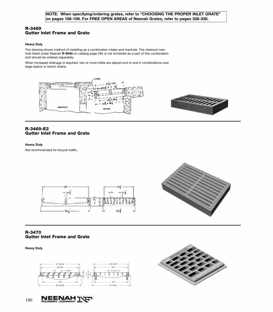
190
NOTE: When specifying/ordering grates, refer to “CHOOSING THE PROPER INLET GRATE”on pages 108-109. For FREE OPEN AREAS of Neenah Grates, refer to pages 326-330.
R-3469Gutter Inlet Frame and Grate
Heavy Duty
The drawing shows method of installing as a combination intake and manhole. The cleanout man-hole listed under Neenah R-6040 on catalog page 294 is not furnished as a part of this combinationand should be ordered separately.
When increased drainage is required, two or more inlets are placed end to end in combinations overlarge basins or trench drains.
R-3469-E2Gutter Inlet Frame and Grate
Heavy Duty
Not recommended for bicycle traffic.
R-3470Gutter Inlet Frame and Grate
Heavy Duty
27 13/16"
29 13/16"
26 5/8"
24"
27 5/16"
24"
3 3/4"
25 1/16"
24"
6 1/4"
2" 2 1/2"
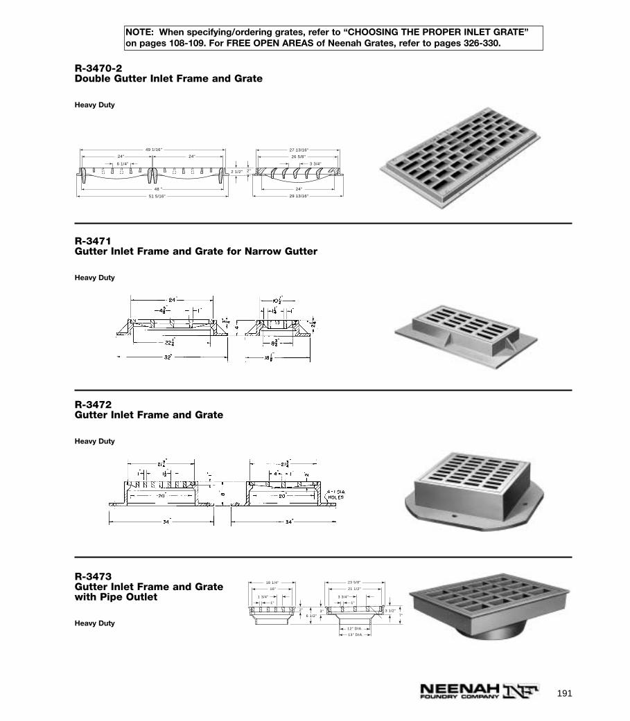
191
NOTE: When specifying/ordering grates, refer to “CHOOSING THE PROPER INLET GRATE”on pages 108-109. For FREE OPEN AREAS of Neenah Grates, refer to pages 326-330.
R-3470-2Double Gutter Inlet Frame and Grate
Heavy Duty
27 13/16"
29 13/16"
26 5/8"
24"
3 3/4"
51 5/16"
48 "
49 1/16"
24" 24"
6 1/4"
2"2 1/2"
R-3471Gutter Inlet Frame and Grate for Narrow Gutter
Heavy Duty
R-3472Gutter Inlet Frame and Grate
Heavy Duty
R-3473Gutter Inlet Frame and Gratewith Pipe Outlet
Heavy Duty
1 3/4" 3 3/4"
1" 1"
23 5/8"
21 1/2"
18 1/4"
16"
12" DIA.
13" DIA.
2" 3" 3 1/2"
6 1/2" 7"
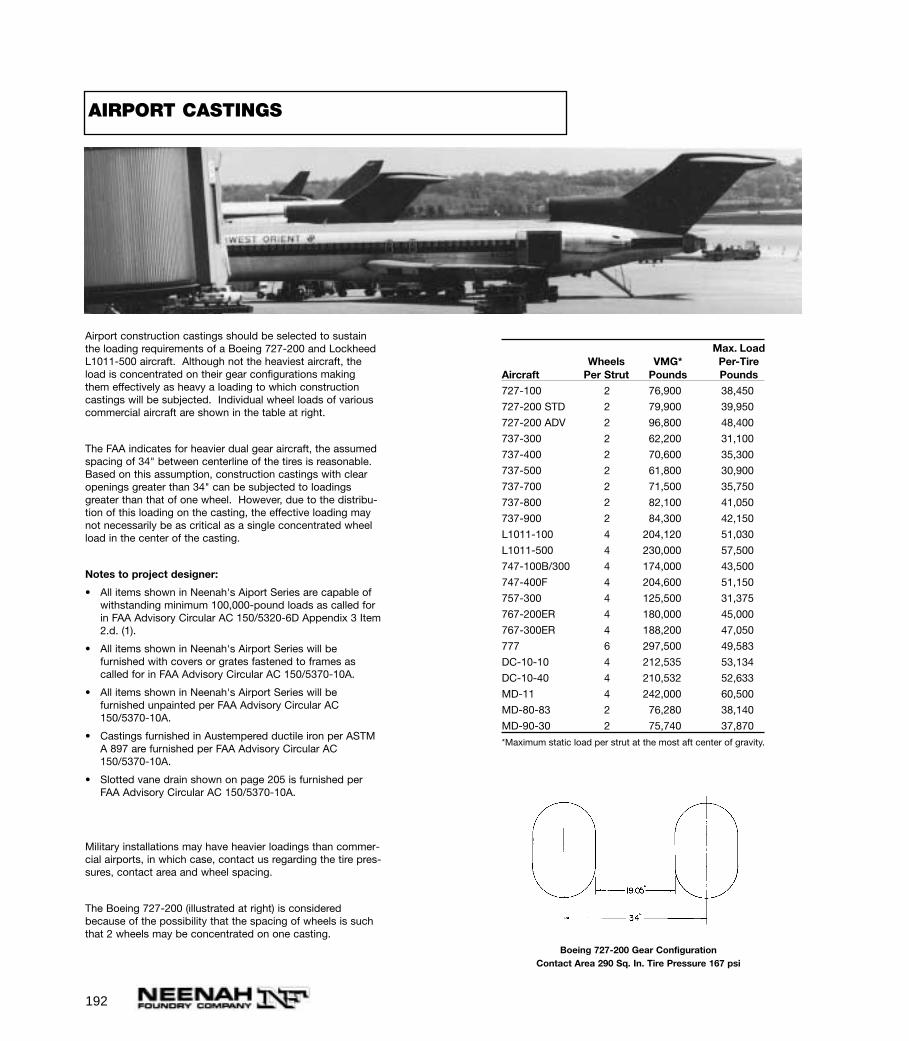
192
Airport construction castings should be selected to sustainthe loading requirements of a Boeing 727-200 and LockheedL1011-500 aircraft. Although not the heaviest aircraft, theload is concentrated on their gear configurations makingthem effectively as heavy a loading to which constructioncastings will be subjected. Individual wheel loads of variouscommercial aircraft are shown in the table at right.
The FAA indicates for heavier dual gear aircraft, the assumedspacing of 34" between centerline of the tires is reasonable.Based on this assumption, construction castings with clearopenings greater than 34" can be subjected to loadingsgreater than that of one wheel. However, due to the distribu-tion of this loading on the casting, the effective loading maynot necessarily be as critical as a single concentrated wheelload in the center of the casting.
Notes to project designer:
• All items shown in Neenah's Aiport Series are capable ofwithstanding minimum 100,000-pound loads as called forin FAA Advisory Circular AC 150/5320-6D Appendix 3 Item 2.d. (1).
• All items shown in Neenah's Airport Series will be furnished with covers or grates fastened to frames as called for in FAA Advisory Circular AC 150/5370-10A.
• All items shown in Neenah's Airport Series will be furnished unpainted per FAA Advisory Circular AC 150/5370-10A.
• Castings furnished in Austempered ductile iron per ASTM A 897 are furnished per FAA Advisory Circular AC 150/5370-10A.
• Slotted vane drain shown on page 205 is furnished per FAA Advisory Circular AC 150/5370-10A.
Military installations may have heavier loadings than commer-cial airports, in which case, contact us regarding the tire pres-sures, contact area and wheel spacing.
The Boeing 727-200 (illustrated at right) is consideredbecause of the possibility that the spacing of wheels is suchthat 2 wheels may be concentrated on one casting.
Boeing 727-200 Gear ConfigurationContact Area 290 Sq. In. Tire Pressure 167 psi
Max. LoadWheels VMG* Per-Tire
Aircraft Per Strut Pounds Pounds
727-100 2 76,900 38,450
727-200 STD 2 79,900 39,950
727-200 ADV 2 96,800 48,400
737-300 2 62,200 31,100
737-400 2 70,600 35,300
737-500 2 61,800 30,900
737-700 2 71,500 35,750
737-800 2 82,100 41,050
737-900 2 84,300 42,150
L1011-100 4 204,120 51,030
L1011-500 4 230,000 57,500
747-100B/300 4 174,000 43,500
747-400F 4 204,600 51,150
757-300 4 125,500 31,375
767-200ER 4 180,000 45,000
767-300ER 4 188,200 47,050
777 6 297,500 49,583
DC-10-10 4 212,535 53,134
DC-10-40 4 210,532 52,633
MD-11 4 242,000 60,500
MD-80-83 2 76,280 38,140
MD-90-30 2 75,740 37,870
*Maximum static load per strut at the most aft center of gravity.
AIRPORT CASTINGS
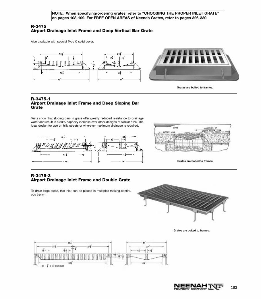
R-3475-1Airport Drainage Inlet Frame and Deep Sloping BarGrate
Tests show that sloping bars in grate offer greatly reduced resistance to drainagewater and result in a 30% capacity increase over other designs of similar area. Theideal design for use on hilly streets or wherever maximum drainage is required.
R-3475Airport Drainage Inlet Frame and Deep Vertical Bar Grate
Also available with special Type C solid cover.
R-3475-3Airport Drainage Inlet Frame and Double Grate
To drain large areas, this inlet can be placed in multiples making continu-ous trench.
Grates are bolted to frames.
Grates are bolted to frames.
193
Grates are bolted to frames.
NOTE: When specifying/ordering grates, refer to “CHOOSING THE PROPER INLET GRATE”on pages 108-109. For FREE OPEN AREAS of Neenah Grates, refer to pages 326-330.
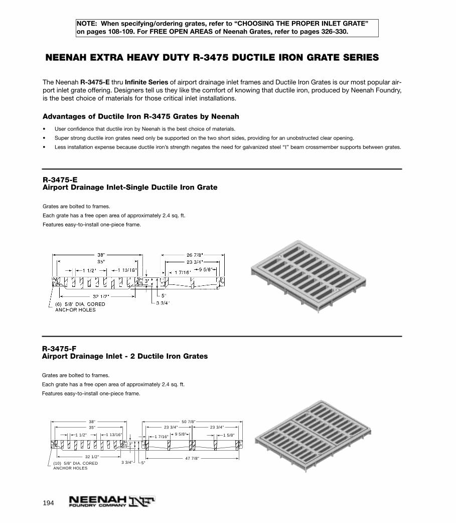
194
R-3475-FAirport Drainage Inlet - 2 Ductile Iron Grates
Grates are bolted to frames.
Each grate has a free open area of approximately 2.4 sq. ft.
Features easy-to-install one-piece frame.
R-3475-EAirport Drainage Inlet-Single Ductile Iron Grate
Grates are bolted to frames.
Each grate has a free open area of approximately 2.4 sq. ft.
Features easy-to-install one-piece frame.
38"35"
32 1/2"
50 7/8"
47 7/8"
23 3/4" 23 3/4"
1 1/2" 1 13/16"
3"
3 3/4"
9 5/8"1 7/16" 1 5/8"
(10) 5/8" DIA. COREDANCHOR HOLES
5"
The Neenah R-3475-E thru Infinite Series of airport drainage inlet frames and Ductile Iron Grates is our most popular air-port inlet grate offering. Designers tell us they like the comfort of knowing that ductile iron, produced by Neenah Foundry,is the best choice of materials for those critical inlet installations.
Advantages of Ductile Iron R-3475 Grates by Neenah
• User confidence that ductile iron by Neenah is the best choice of materials.
• Super strong ductile iron grates need only be supported on the two short sides, providing for an unobstructed clear opening.
• Less installation expense because ductile iron’s strength negates the need for galvanized steel “I” beam crossmember supports between grates.
NEENAH EXTRA HEAVY DUTY R-3475 DUCTILE IRON GRATE SERIES
NOTE: When specifying/ordering grates, refer to “CHOOSING THE PROPER INLET GRATE”on pages 108-109. For FREE OPEN AREAS of Neenah Grates, refer to pages 326-330.
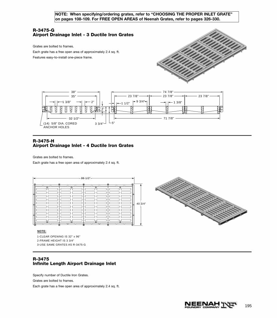
195
R-3475-HAirport Drainage Inlet - 4 Ductile Iron Grates
Grates are bolted to frames.
Each grate has a free open area of approximately 2.4 sq. ft.
38"35"
32 1/2"
74 7/8"23 7/8" 23 7/8" 23 7/8"
1 3/8" 2"
5"
3"
3 3/4"
9 3/4"
71 7/8"
1 1/2" 1 3/8"
(14) 5/8" DIA. COREDANCHOR HOLES
R-3475-GAirport Drainage Inlet - 3 Ductile Iron Grates
Grates are bolted to frames.
Each grate has a free open area of approximately 2.4 sq. ft.
Features easy-to-install one-piece frame.
R-3475Infinite Length Airport Drainage Inlet
Specify number of Ductile Iron Grates.
Grates are bolted to frames.
Each grate has a free open area of approximately 2.4 sq. ft.
99 1/2"
40 3/4"
NOTE:
1-CLEAR OPENING IS 32" x 96"
2-FRAME HEIGHT IS 3 3/4"
3-USE SAME GRATES AS R-3475-G
NOTE: When specifying/ordering grates, refer to “CHOOSING THE PROPER INLET GRATE”on pages 108-109. For FREE OPEN AREAS of Neenah Grates, refer to pages 326-330.
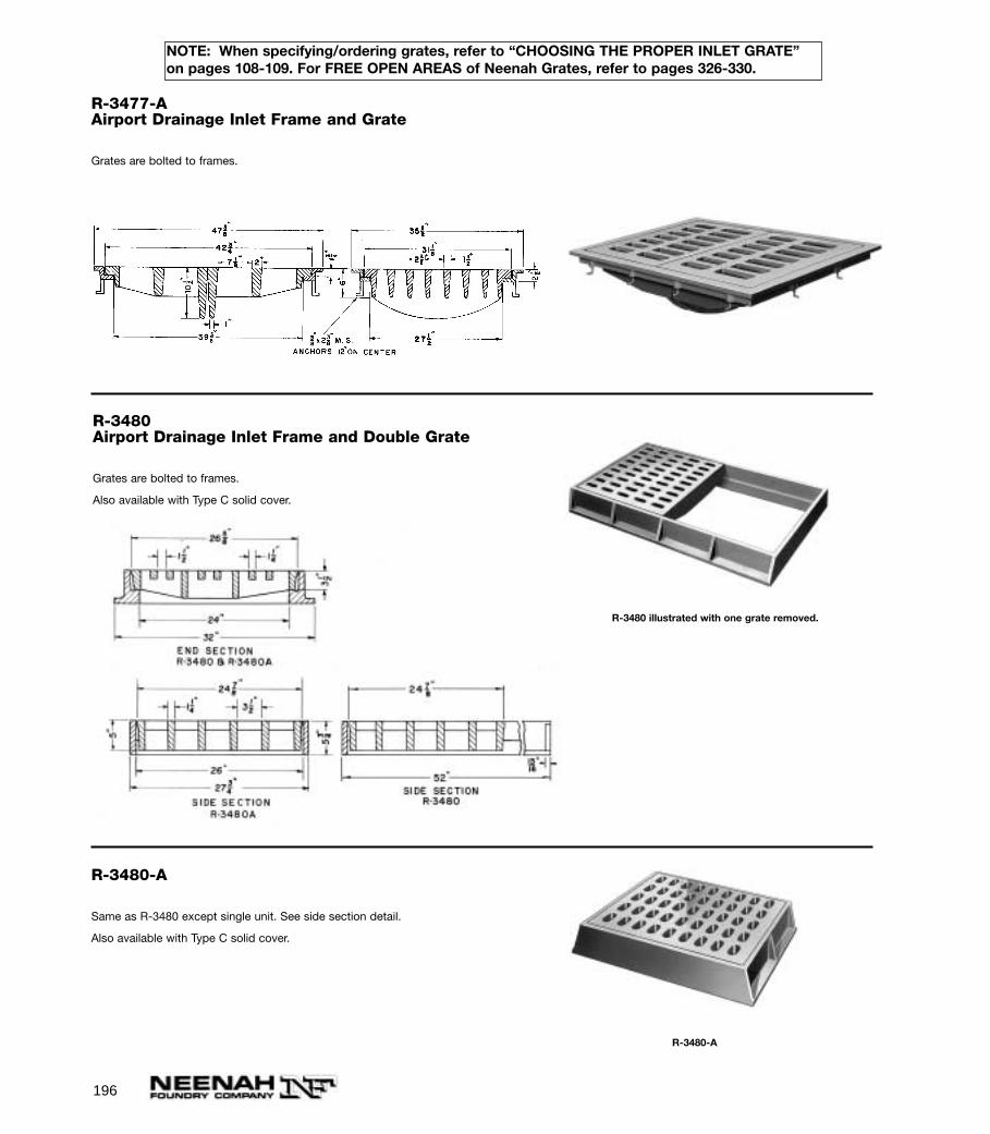
196
R-3477-AAirport Drainage Inlet Frame and Grate
Grates are bolted to frames.
R-3480Airport Drainage Inlet Frame and Double Grate
Grates are bolted to frames.
Also available with Type C solid cover.
R-3480 illustrated with one grate removed.
R-3480-A
R-3480-A
Same as R-3480 except single unit. See side section detail.
Also available with Type C solid cover.
NOTE: When specifying/ordering grates, refer to “CHOOSING THE PROPER INLET GRATE”on pages 108-109. For FREE OPEN AREAS of Neenah Grates, refer to pages 326-330.
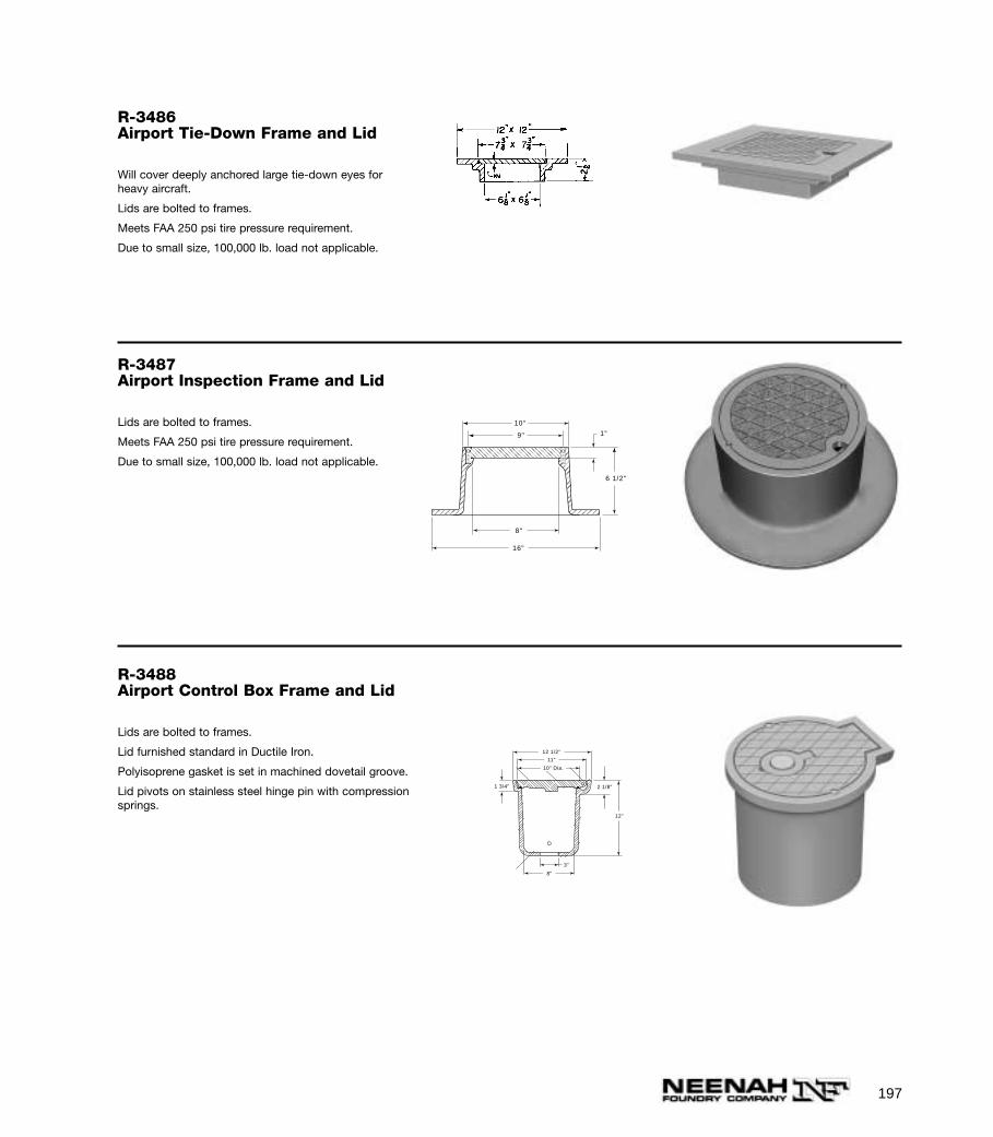
197
R-3487Airport Inspection Frame and Lid
Lids are bolted to frames.
Meets FAA 250 psi tire pressure requirement.
Due to small size, 100,000 lb. load not applicable.
R-3486Airport Tie-Down Frame and Lid
Will cover deeply anchored large tie-down eyes forheavy aircraft.
Lids are bolted to frames.
Meets FAA 250 psi tire pressure requirement.
Due to small size, 100,000 lb. load not applicable.
R-3488Airport Control Box Frame and Lid
Lids are bolted to frames.
Lid furnished standard in Ductile Iron.
Polyisoprene gasket is set in machined dovetail groove.
Lid pivots on stainless steel hinge pin with compressionsprings.
9"
10"
1"
6 1/2"
8"
16"
3"
8"
12 1/2"
11"
10" Dia.
2 1/8"1 3/4"
12"
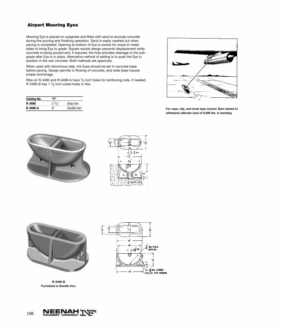
198
Mooring Eye is placed on subgrade and filled with sand to exclude concreteduring the pouring and finishing operation. Sand is easily washed out whenpaving is completed. Opening at bottom of Eye is socket for wood or metalstake to bring Eye to grade. Square socket design prevents displacement whileconcrete is being poured and, if required, the hole provides drainage to the sub-grade after Eye is in place. Alternative method of setting is to push the Eye inposition in the wet concrete. Both methods are approved.
When used with bituminous slab, the Eyes should be set in concrete basebefore paving. Design permits in-flowing of concrete, and wide base insuresproper anchorage.
Ribs on R-3490 and R-3490-A have 1/2 inch holes for reinforcing rods, if needed.R-3490-B has 1 1/8 inch cored holes in ribs.
For rope, clip, and hook type anchor. Bars tested towithstand ultimate load of 9,000 lbs. in bending.
R-3490-BFurnished in Ductile Iron.
Catalog No. “F”R-3490 3 1/2” Gray IronR-3490-A 6” Ductile Iron
Airport Mooring Eyes
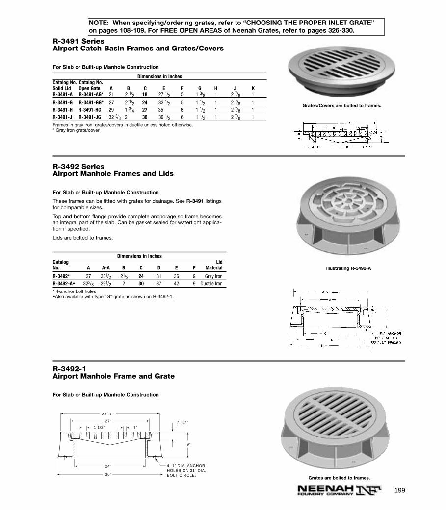
199
9"
33 1/2"
27"
24"
36"
2 1/2"1 1/2" 1"
4- 1" DIA. ANCHORHOLES ON 31" DIA.BOLT CIRCLE.
Grates are bolted to frames.
R-3491 SeriesAirport Catch Basin Frames and Grates/Covers
For Slab or Built-up Manhole Construction
Dimensions in InchesCatalog No. Catalog No.Solid Lid Open Gate A B C E F G H J KR-3491-A R-3491-AG* 21 2 1/2 18 27 1/2 5 1 3/8 1 2 7/8 1
R-3491-G R-3491-GG* 27 2 1/2 24 33 1/2 5 1 1/2 1 2 7/8 1R-3491-H R-3491-HG 29 1 3/4 27 35 6 1 1/2 1 2 7/8 1R-3491-J R-3491-JG 32 3/8 2 30 39 1/2 6 1 1/2 1 2 7/8 1
Frames in gray iron, grates/covers in ductile unless noted otherwise.* Gray iron grate/cover
R-3492 SeriesAirport Manhole Frames and Lids
For Slab or Built-up Manhole Construction
These frames can be fitted with grates for drainage. See R-3491 listingsfor comparable sizes.
Top and bottom flange provide complete anchorage so frame becomesan integral part of the slab. Can be gasket sealed for watertight applica-tion if specified.
Lids are bolted to frames.
R-3492-1Airport Manhole Frame and Grate
For Slab or Built-up Manhole Construction
Dimensions in InchesCatalog LidNo. A A-A B C D E F Material
R-3492* 27 331/2 21/2 24 31 36 9 Gray IronR-3492-A• 323/8 391/2 2 30 37 42 9 Ductile Iron
* 4-anchor bolt holes•Also available with type “G” grate as shown on R-3492-1.
Illustrating R-3492-A
Grates/Covers are bolted to frames.
NOTE: When specifying/ordering grates, refer to “CHOOSING THE PROPER INLET GRATE”on pages 108-109. For FREE OPEN AREAS of Neenah Grates, refer to pages 326-330.
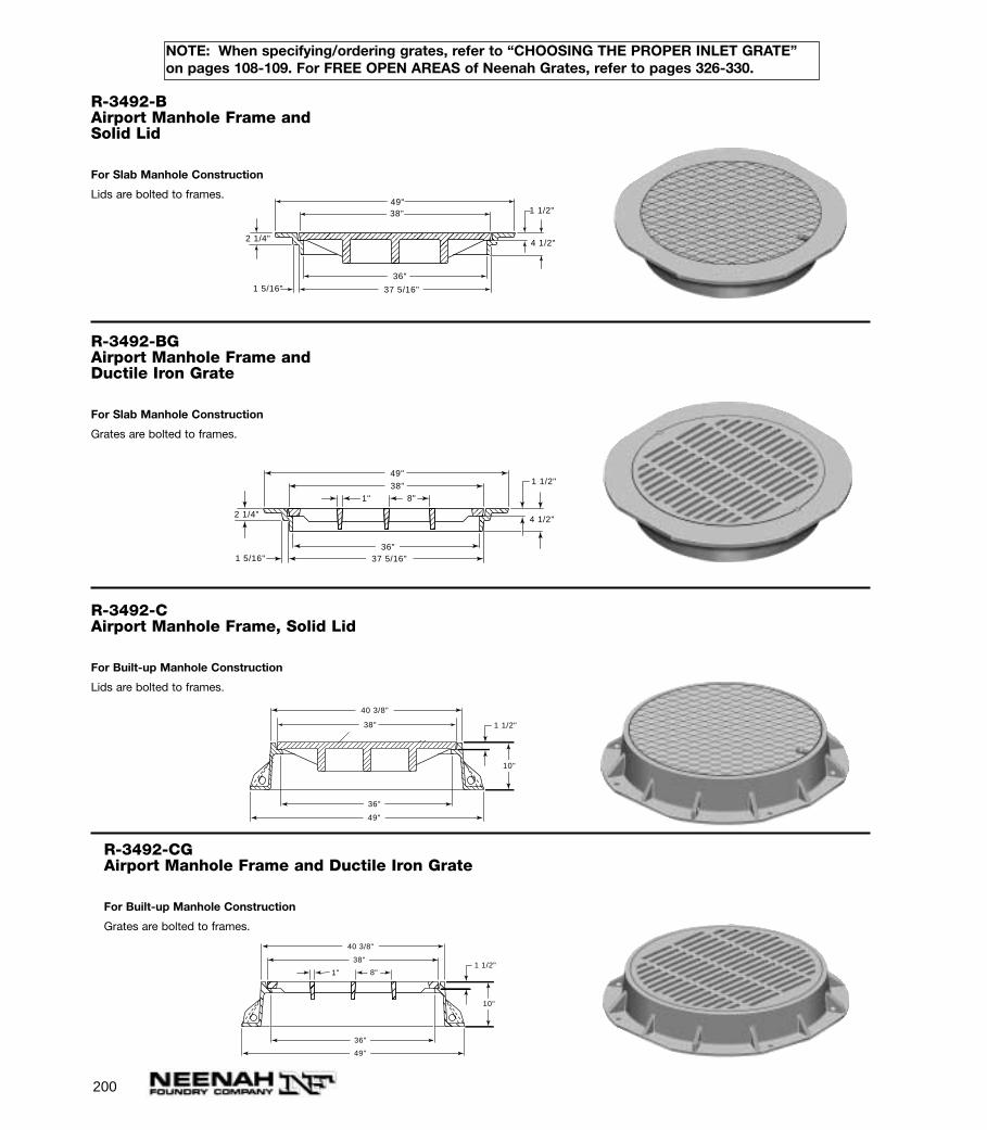
200
R-3492-BAirport Manhole Frame andSolid Lid
For Slab Manhole Construction
Lids are bolted to frames.
49" 38" 1 1/2"
4 1/2"
1 5/16"
2 1/4"
37 5/16"
36"
R-3492-BGAirport Manhole Frame andDuctile Iron Grate
For Slab Manhole Construction
Grates are bolted to frames.
49"
38" 8"1"
1 1/2"
4 1/2"
1 5/16"
2 1/4"
37 5/16" 36"
R-3492-CAirport Manhole Frame, Solid Lid
For Built-up Manhole Construction
Lids are bolted to frames.
36"
49"
40 3/8"
10"
1 1/2" 38"
R-3492-CGAirport Manhole Frame and Ductile Iron Grate
For Built-up Manhole Construction
Grates are bolted to frames.
38"
36"
49"
40 3/8"
8"1"
10"
1 1/2"
NOTE: When specifying/ordering grates, refer to “CHOOSING THE PROPER INLET GRATE”on pages 108-109. For FREE OPEN AREAS of Neenah Grates, refer to pages 326-330.
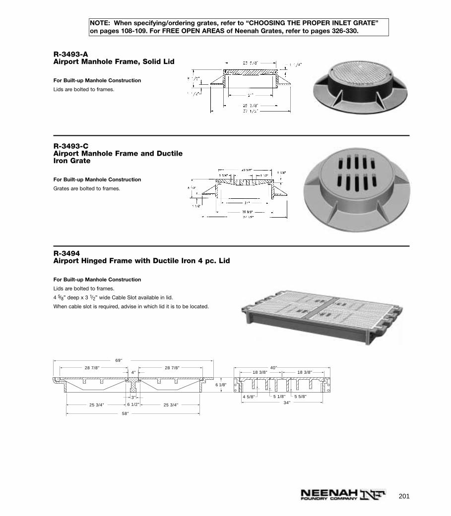
201
R-3493-AAirport Manhole Frame, Solid Lid
For Built-up Manhole Construction
Lids are bolted to frames.
R-3493-CAirport Manhole Frame and DuctileIron Grate
For Built-up Manhole Construction
Grates are bolted to frames.
R-3494Airport Hinged Frame with Ductile Iron 4 pc. Lid
For Built-up Manhole Construction
Lids are bolted to frames.
4 5/8” deep x 3 1/2” wide Cable Slot available in lid.
When cable slot is required, advise in which lid it is to be located.
6 1/8"
40"18 3/8" 18 3/8"
4 5/8" 5 1/8" 5 5/8"
34"
69"
28 7/8" 28 7/8"4"
25 3/4" 25 3/4"
3"
6 1/2"
58"
NOTE: When specifying/ordering grates, refer to “CHOOSING THE PROPER INLET GRATE”on pages 108-109. For FREE OPEN AREAS of Neenah Grates, refer to pages 326-330.
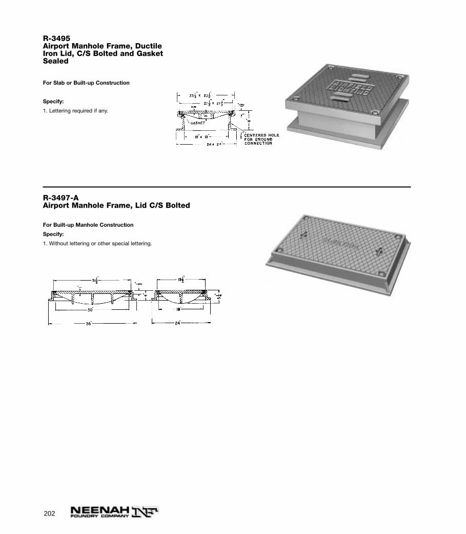
202
R-3495Airport Manhole Frame, DuctileIron Lid, C/S Bolted and GasketSealed
For Slab or Built-up Construction
Specify:
1. Lettering required if any.
R-3497-AAirport Manhole Frame, Lid C/S Bolted
For Built-up Manhole Construction
Specify:
1. Without lettering or other special lettering.
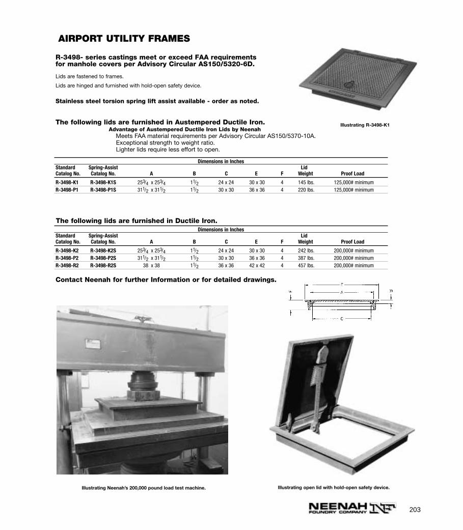
203
R-3498- series castings meet or exceed FAA requirementsfor manhole covers per Advisory Circular AS150/5320-6D.
Lids are fastened to frames.
Lids are hinged and furnished with hold-open safety device.
Stainless steel torsion spring lift assist available - order as noted.
Dimensions in InchesStandard Spring-Assist LidCatalog No. Catalog No. A B C E F Weight Proof Load
R-3498-K1 R-3498-K1S 253/4 x 253/4 11/2 24 x 24 30 x 30 4 145 lbs. 125,000# minimumR-3498-P1 R-3498-P1S 311/2 x 311/2 11/2 30 x 30 36 x 36 4 220 lbs. 125,000# minimum
AIRPORT UTILITY FRAMES
Illustrating Neenah’s 200,000 pound load test machine. Illustrating open lid with hold-open safety device.
The following lids are furnished in Austempered Ductile Iron.Advantage of Austempered Ductile Iron Lids by Neenah
Meets FAA material requirements per Advisory Circular AS150/5370-10A.Exceptional strength to weight ratio.Lighter lids require less effort to open.
The following lids are furnished in Ductile Iron.Dimensions in Inches
Standard Spring-Assist LidCatalog No. Catalog No. A B C E F Weight Proof Load
R-3498-K2 R-3498-K2S 253/4 x 253/4 11/2 24 x 24 30 x 30 4 242 lbs. 200,000# minimumR-3498-P2 R-3498-P2S 311/2 x 311/2 11/2 30 x 30 36 x 36 4 387 lbs. 200,000# minimumR-3498-R2 R-3498-R2S 38 x 38 11/2 36 x 36 42 x 42 4 457 lbs. 200,000# minimum
Illustrating R-3498-K1
Contact Neenah for further Information or for detailed drawings.
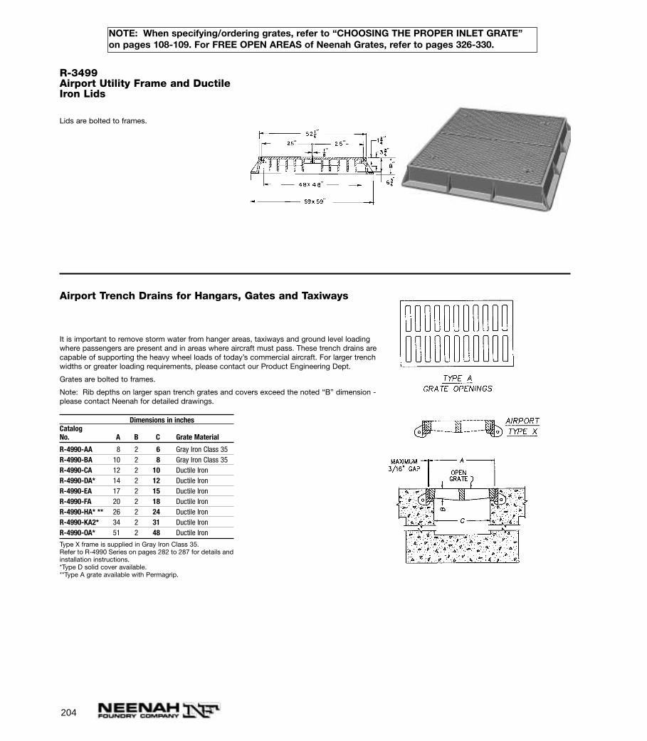
204
R-3499Airport Utility Frame and DuctileIron Lids
Lids are bolted to frames.
Airport Trench Drains for Hangars, Gates and Taxiways
It is important to remove storm water from hanger areas, taxiways and ground level loadingwhere passengers are present and in areas where aircraft must pass. These trench drains arecapable of supporting the heavy wheel loads of today’s commercial aircraft. For larger trenchwidths or greater loading requirements, please contact our Product Engineering Dept.
Grates are bolted to frames.
Note: Rib depths on larger span trench grates and covers exceed the noted “B” dimension -please contact Neenah for detailed drawings.
Dimensions in inchesCatalogNo. A B C Grate Material
R-4990-AA 8 2 6 Gray Iron Class 35R-4990-BA 10 2 8 Gray Iron Class 35R-4990-CA 12 2 10 Ductile IronR-4990-DA* 14 2 12 Ductile IronR-4990-EA 17 2 15 Ductile IronR-4990-FA 20 2 18 Ductile IronR-4990-HA* ** 26 2 24 Ductile IronR-4990-KA2* 34 2 31 Ductile IronR-4990-OA* 51 2 48 Ductile Iron
Type X frame is supplied in Gray Iron Class 35.Refer to R-4990 Series on pages 282 to 287 for details andinstallation instructions.*Type D solid cover available.**Type A grate available with Permagrip.
NOTE: When specifying/ordering grates, refer to “CHOOSING THE PROPER INLET GRATE”on pages 108-109. For FREE OPEN AREAS of Neenah Grates, refer to pages 326-330.
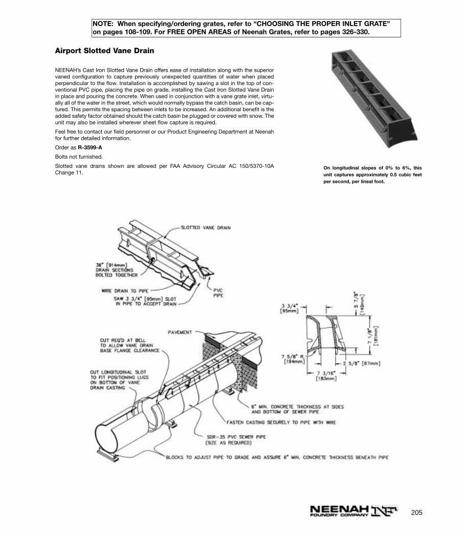
205
Airport Slotted Vane Drain
NEENAH’s Cast Iron Slotted Vane Drain offers ease of installation along with the superiorvaned configuration to capture previously unexpected quantities of water when placedperpendicular to the flow. Installation is accomplished by sawing a slot in the top of con-ventional PVC pipe, placing the pipe on grade, installing the Cast Iron Slotted Vane Drainin place and pouring the concrete. When used in conjunction with a vane grate inlet, virtu-ally all of the water in the street, which would normally bypass the catch basin, can be cap-tured. This permits the spacing between inlets to be increased. An additional benefit is theadded safety factor obtained should the catch basin be plugged or covered with snow. Theunit may also be installed wherever sheet flow capture is required.
Feel free to contact our field personnel or our Product Engineering Department at Neenahfor further detailed information.
Order as R-3599-A
Bolts not furnished.
Slotted vane drains shown are allowed per FAA Advisory Circular AC 150/5370-10AChange 11.
On longitudinal slopes of 0% to 6%, thisunit captures approximately 0.5 cubic feetper second, per lineal foot.
NOTE: When specifying/ordering grates, refer to “CHOOSING THE PROPER INLET GRATE”on pages 108-109. For FREE OPEN AREAS of Neenah Grates, refer to pages 326-330.
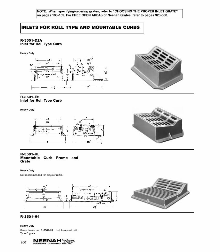
206
NOTE: When specifying/ordering grates, refer to “CHOOSING THE PROPER INLET GRATE”on pages 108-109. For FREE OPEN AREAS of Neenah Grates, refer to pages 326-330.
R-3501-D2AInlet for Roll Type Curb
Heavy Duty
R-3501-E2Inlet for Roll Type Curb
Heavy Duty
R-3501-HLMountable Curb Frame andGrate
Heavy Duty
Not recommended for bicycle traffic.
R-3501-H4
Heavy Duty
Same frame as R-3501-HL, but furnished withType C grate.
INLETS FOR ROLL TYPE AND MOUNTABLE CURBS
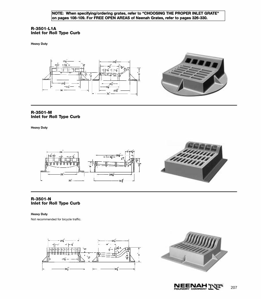
207
NOTE: When specifying/ordering grates, refer to “CHOOSING THE PROPER INLET GRATE”on pages 108-109. For FREE OPEN AREAS of Neenah Grates, refer to pages 326-330.
R-3501-L1AInlet for Roll Type Curb
Heavy Duty
R-3501-MInlet for Roll Type Curb
Heavy Duty
R-3501-NInlet for Roll Type Curb
Heavy Duty
Not recommended for bicycle traffic.
NOTE: When specifying/ordering grates, refer to “CHOOSING THE PROPER INLET GRATE”on pages 108-109. For FREE OPEN AREAS of Neenah Grates, refer to pages 326-330.
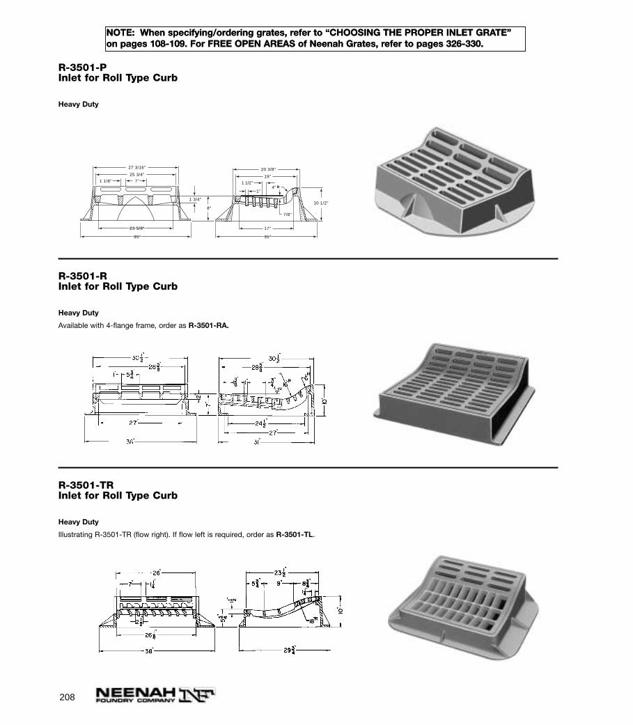
208
NOTE: When specifying/ordering grates, refer to “CHOOSING THE PROPER INLET GRATE”on pages 108-109. For FREE OPEN AREAS of Neenah Grates, refer to pages 326-330.
R-3501-PInlet for Roll Type Curb
Heavy Duty
1"
1 1/2"4" R
19"
17"
31"35"
20 3/8"27 3/16"
25 3/4"
23 5/8"
10 1/2"8"
7"
1 3/4"
1 1/8"
7/8"
R-3501-RInlet for Roll Type Curb
Heavy Duty
Available with 4-flange frame, order as R-3501-RA.
R-3501-TRInlet for Roll Type Curb
Heavy Duty
Illustrating R-3501-TR (flow right). If flow left is required, order as R-3501-TL.
NOTE: When specifying/ordering grates, refer to “CHOOSING THE PROPER INLET GRATE”on pages 108-109. For FREE OPEN AREAS of Neenah Grates, refer to pages 326-330.
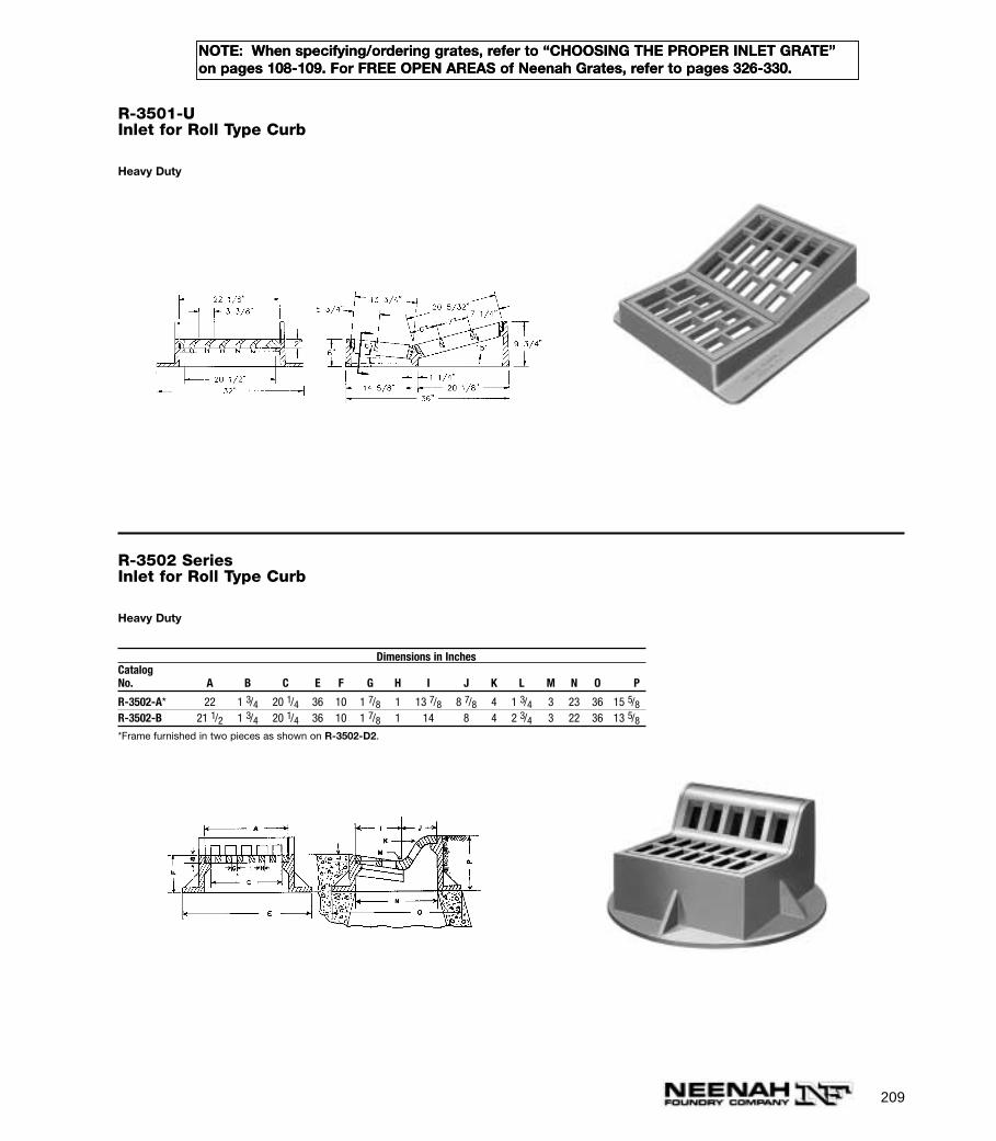
209
NOTE: When specifying/ordering grates, refer to “CHOOSING THE PROPER INLET GRATE”on pages 108-109. For FREE OPEN AREAS of Neenah Grates, refer to pages 326-330.
R-3501-UInlet for Roll Type Curb
Heavy Duty
R-3502 SeriesInlet for Roll Type Curb
Heavy Duty
Dimensions in InchesCatalogNo. A B C E F G H I J K L M N O P
R-3502-A* 22 1 3/4 20 1/4 36 10 1 7/8 1 13 7/8 8 7/8 4 1 3/4 3 23 36 15 5/8R-3502-B 21 1/2 1 3/4 20 1/4 36 10 1 7/8 1 14 8 4 2 3/4 3 22 36 13 5/8*Frame furnished in two pieces as shown on R-3502-D2.
NOTE: When specifying/ordering grates, refer to “CHOOSING THE PROPER INLET GRATE”on pages 108-109. For FREE OPEN AREAS of Neenah Grates, refer to pages 326-330.
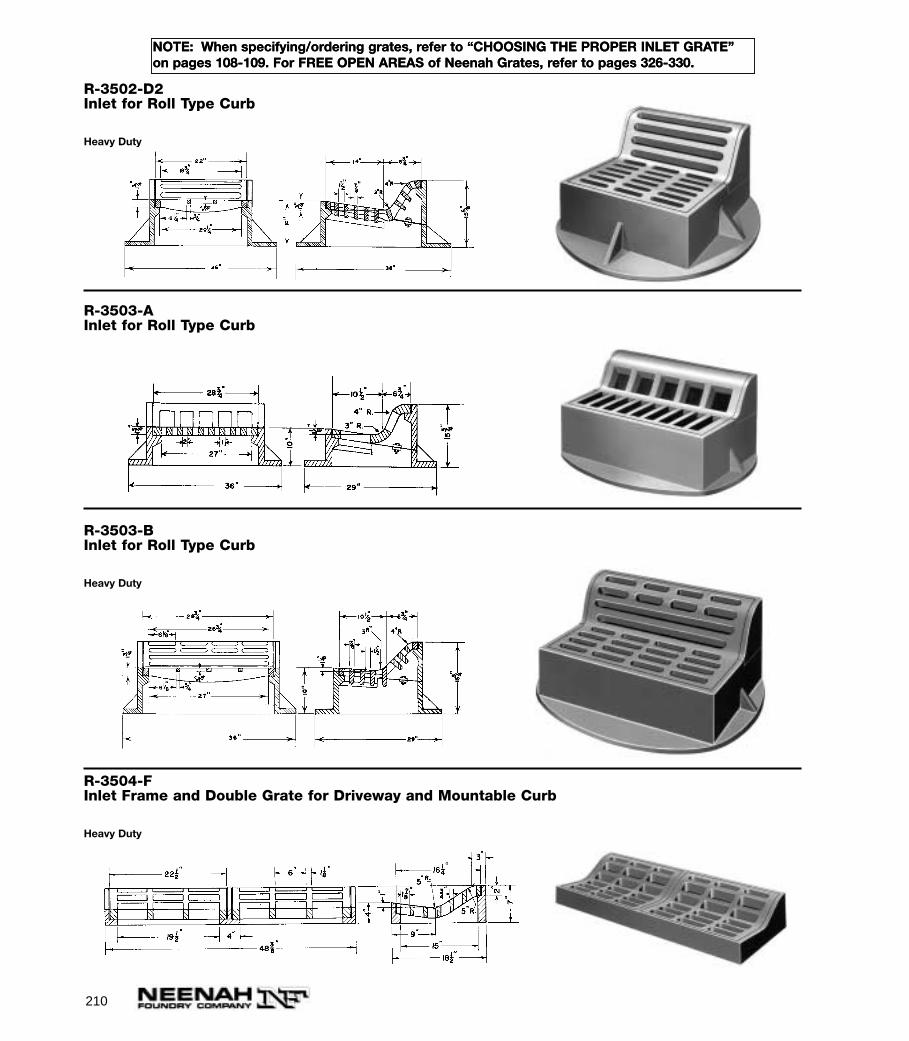
210
NOTE: When specifying/ordering grates, refer to “CHOOSING THE PROPER INLET GRATE”on pages 108-109. For FREE OPEN AREAS of Neenah Grates, refer to pages 326-330.
R-3503-BInlet for Roll Type Curb
Heavy Duty
R-3504-FInlet Frame and Double Grate for Driveway and Mountable Curb
Heavy Duty
R-3502-D2Inlet for Roll Type Curb
Heavy Duty
R-3503-AInlet for Roll Type Curb
NOTE: When specifying/ordering grates, refer to “CHOOSING THE PROPER INLET GRATE”on pages 108-109. For FREE OPEN AREAS of Neenah Grates, refer to pages 326-330.

211
NOTE: When specifying/ordering grates, refer to “CHOOSING THE PROPER INLET GRATE”on pages 108-109. For FREE OPEN AREAS of Neenah Grates, refer to pages 326-330.
R-3506-A2 to R-3517 SeriesInlet Frames and Grates for Driveway and Mountable Curb
Heavy Duty
Dimensions in InchesCatalogNo. A AB AA B E EA F G H I J K L M
R-3506-A2* 19 1/4 19 1/4 8 1/8 11 1/8 28 1/4 30 12 1/2 6 1/4 3/4 10 1 1/2 1 1/4 1 1/2 7/8R-3506-B* 19 1/4 19 1/4 8 1/8 11 1/8 28 1/4 30 11 4 3/4 1 10 1 1/2 1 1/2 1 7/8 1R-3507-C§ 22 22 11 11 35 35 10 19 3/4 — 10 1 3/4 2 1 1/2 7/8R-3507-D§†† 22 22 11 11 30 35 10 19 3/4 — 10 1 3/4 2 1 1/2 7/8R-3508-A2 22 3/4 22 3/4 11 3/8 11 3/8 35 Dia. 12 6 1/4 3/4 10 1 3/4 2 1 1/2 7/8R-3508-B 22 3/4 22 3/4 11 3/8 11 3/8 35 Dia. 10 6 1 10 1 3/4 1 3/4 2 1R-3508-B1§ 22 3/4 22 3/4 11 3/8 11 3/8 35 Dia. 10 20 3/4 — 10 1 3/4 1 3/4 1 1/2 7/8R-3508-B2* 22 1/2 22 1/2 11 1/4 11 1/4 35 Dia. 10 6 1 10 1 3/4 1 3/4 1 7/8R-3508-C* 22 3/4 22 3/4 11 3/8 11 3/8 38 Dia. 13 1/2 4 1/4 1 3/16 10 2 3/8 1/2 1 3/8 1R-3509 17 22 8 1/2 8 1/2 25 29 5 1/4 1 1/4 1 1/4 5 1/4 1 3/4 1 6 3/4 1 1/4R-3510§ 21 3/4 35 3/4 13 7/8 7 7/8 30 44 9 1/2 10 3/8 1 1/8 6 2 1 1 7/8 1 1/8R-3511 19 30 8 1/8 10 7/8 27 38 8 8 1/2 1 1/8 7 2 1 3/8 1 7/8 1 1/8R-3513 24 24 16 1/4 7 3/4 36 35 5/8 7 1 1/4 1 7 1 7/8 2 1/2 4 2 1/4R-3514-F† 29 3/8 28 1/8 19 1/8 10 1/4 38 1/4 36 1/4 11 1/2 7 1/2 1 8 2 1 1/2 1 1/2 1R-3514-F2 29 3/8 28 1/8 19 1/8 10 1/4 38 1/4 69 1/2 11 1/2 7 1/2 1 8 2 1 1/2 1 1/2 1R-3517 22 1/4 22 1/4 11 1/8 11 1/8 36 Dia. 6 6 1 6 2 1/2 2 1
*No base flange at rear.††No base flange on front.§Not recommended for bicycle traffic. †Also available with 44” diameter base flange.
Illustrating R-3508-A2 Illustrating R-3508-C with depressed bar grate
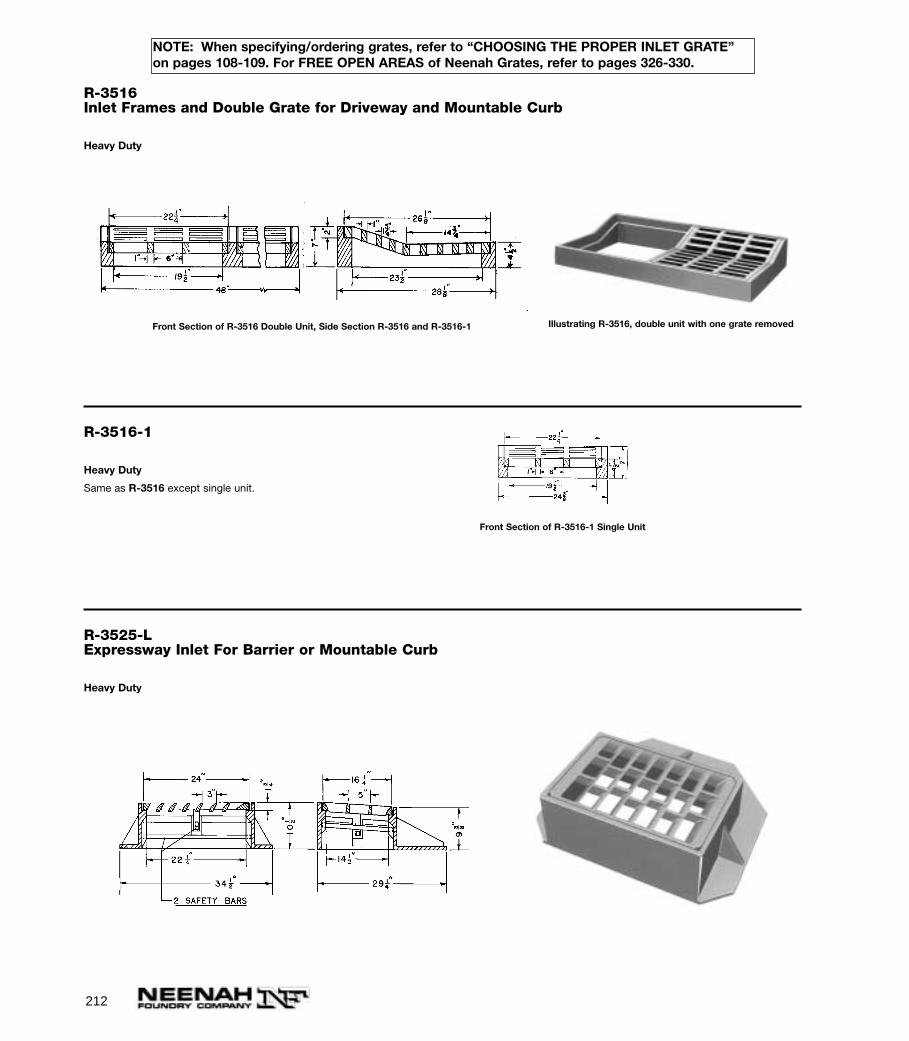
212
NOTE: When specifying/ordering grates, refer to “CHOOSING THE PROPER INLET GRATE”on pages 108-109. For FREE OPEN AREAS of Neenah Grates, refer to pages 326-330.
R-3516Inlet Frames and Double Grate for Driveway and Mountable Curb
Heavy Duty
Front Section of R-3516 Double Unit, Side Section R-3516 and R-3516-1 Illustrating R-3516, double unit with one grate removed
R-3516-1
Heavy Duty
Same as R-3516 except single unit.
Front Section of R-3516-1 Single Unit
R-3525-LExpressway Inlet For Barrier or Mountable Curb
Heavy Duty
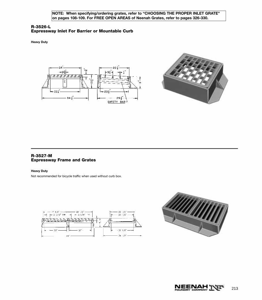
213
NOTE: When specifying/ordering grates, refer to “CHOOSING THE PROPER INLET GRATE”on pages 108-109. For FREE OPEN AREAS of Neenah Grates, refer to pages 326-330.
R-3526-LExpressway Inlet For Barrier or Mountable Curb
Heavy Duty
R-3527-MExpressway Frame and Grates
Heavy Duty
Not recommended for bicycle traffic when used without curb box.
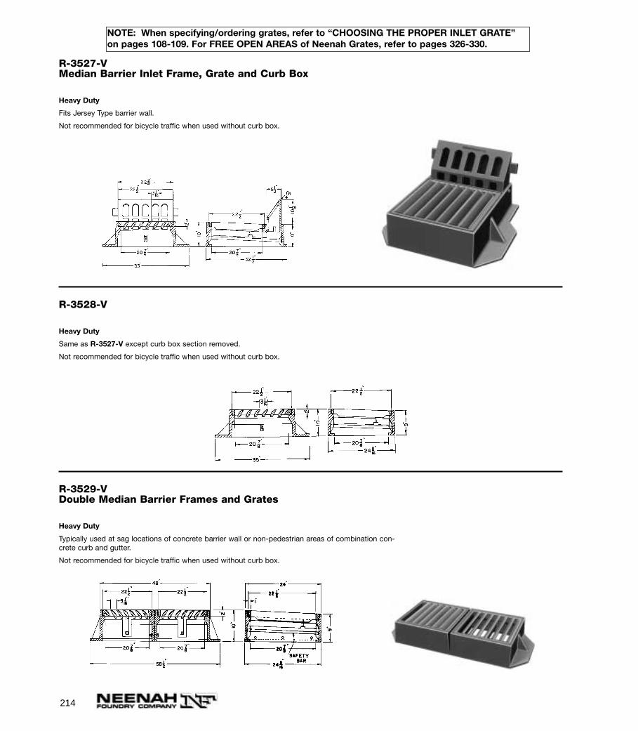
214
NOTE: When specifying/ordering grates, refer to “CHOOSING THE PROPER INLET GRATE”on pages 108-109. For FREE OPEN AREAS of Neenah Grates, refer to pages 326-330.
R-3527-VMedian Barrier Inlet Frame, Grate and Curb Box
Heavy Duty
Fits Jersey Type barrier wall.
Not recommended for bicycle traffic when used without curb box.
R-3528-V
Heavy Duty
Same as R-3527-V except curb box section removed.
Not recommended for bicycle traffic when used without curb box.
R-3529-VDouble Median Barrier Frames and Grates
Heavy Duty
Typically used at sag locations of concrete barrier wall or non-pedestrian areas of combination con-crete curb and gutter.
Not recommended for bicycle traffic when used without curb box.
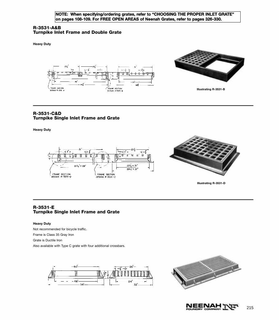
215
NOTE: When specifying/ordering grates, refer to “CHOOSING THE PROPER INLET GRATE”on pages 108-109. For FREE OPEN AREAS of Neenah Grates, refer to pages 326-330.
R-3531-A&BTurnpike Inlet Frame and Double Grate
Heavy Duty
Illustrating R-3531-B
R-3531-C&DTurnpike Single Inlet Frame and Grate
Heavy Duty
Illustrating R-3531-D
R-3531-ETurnpike Single Inlet Frame and Grate
Heavy Duty
Not recommended for bicycle traffic.
Frame is Class 35 Gray Iron
Grate is Ductile Iron
Also available with Type C grate with four additional crossbars.
NOTE: When specifying/ordering grates, refer to “CHOOSING THE PROPER INLET GRATE”on pages 108-109. For FREE OPEN AREAS of Neenah Grates, refer to pages 326-330.
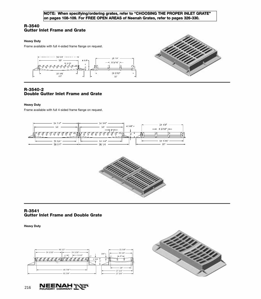
216
NOTE: When specifying/ordering grates, refer to “CHOOSING THE PROPER INLET GRATE”on pages 108-109. For FREE OPEN AREAS of Neenah Grates, refer to pages 326-330.
R-3540Gutter Inlet Frame and Grate
Heavy Duty
Frame available with full 4-sided frame flange on request.
R-3540-2Double Gutter Inlet Frame and Grate
Heavy Duty
Frame available with full 4-sided frame flange on request.
R-3541Gutter Inlet Frame and Double Grate
Heavy Duty
3 1/2"
49 1/2"
45 7/8""
61 3/4"
24 1/16" 24 1/16"
2 3/4"7"
27 3/4"
27 1/2"
18"
6"
21 5/8"
20 1/4"3/4"
NOTE: When specifying/ordering grates, refer to “CHOOSING THE PROPER INLET GRATE”on pages 108-109. For FREE OPEN AREAS of Neenah Grates, refer to pages 326-330.
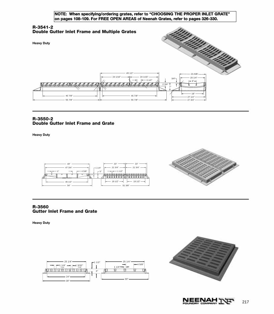
217
NOTE: When specifying/ordering grates, refer to “CHOOSING THE PROPER INLET GRATE”on pages 108-109. For FREE OPEN AREAS of Neenah Grates, refer to pages 326-330.
R-3541-2Double Gutter Inlet Frame and Multiple Grates
Heavy Duty
2 3/4"7"
27 3/4"
27 1/2"
18"
6"
21 5/8"
20 1/4"3/4"3 1/2"
49 1/2"
45 7/8"
55 7/8"
45 7/8"
55 7/8"
24 1/16" 24 1/16"
R-3550-2Double Gutter Inlet Frame and Grate
Heavy Duty
5"1"
1 1/4"
23" 23"
21 3/4"47 3/4"
45 1/2"
49"
54"
19 1/2" 19 1/2"
51 3/8"
21 3/4"
1 1/2"4 5/8"
R-3560Gutter Inlet Frame and Grate
Heavy Duty
1 1/4" 1 3/32"TYP.TYP.
24"
30"
25 1/4"
30"
3"
4 5/8"1 1/4"
1 1/2"25 1/4"
NOTE: When specifying/ordering grates, refer to “CHOOSING THE PROPER INLET GRATE”on pages 108-109. For FREE OPEN AREAS of Neenah Grates, refer to pages 326-330.
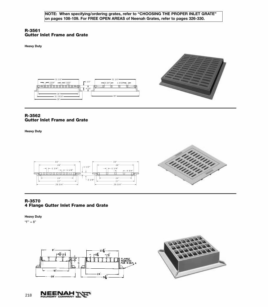
218
NOTE: When specifying/ordering grates, refer to “CHOOSING THE PROPER INLET GRATE”on pages 108-109. For FREE OPEN AREAS of Neenah Grates, refer to pages 326-330.
R-3561Gutter Inlet Frame and Grate
Heavy Duty
1 3/16" 1 3/32"TYP.TYP.
31 15/16"30"
36"
4 1/2"
4 3/4" 1 3/16"1 1/2"
31 1/4"
31 1/4"
36"
R-3562Gutter Inlet Frame and Grate
Heavy Duty
3 3 "
2 6 "
1 1 / 4 "4 3 / 4 "
3 3 "
2 6 "
2 7 "
2 4 "
2 9 3 / 4 "
1 1 / 4 "1 1 / 8 "
2 7 "
2 4 "
2 9 3 / 4 "
1 1 / 2 "
2 1 / 8 "
R-35704 Flange Gutter Inlet Frame and Grate
Heavy Duty
“F” = 8”
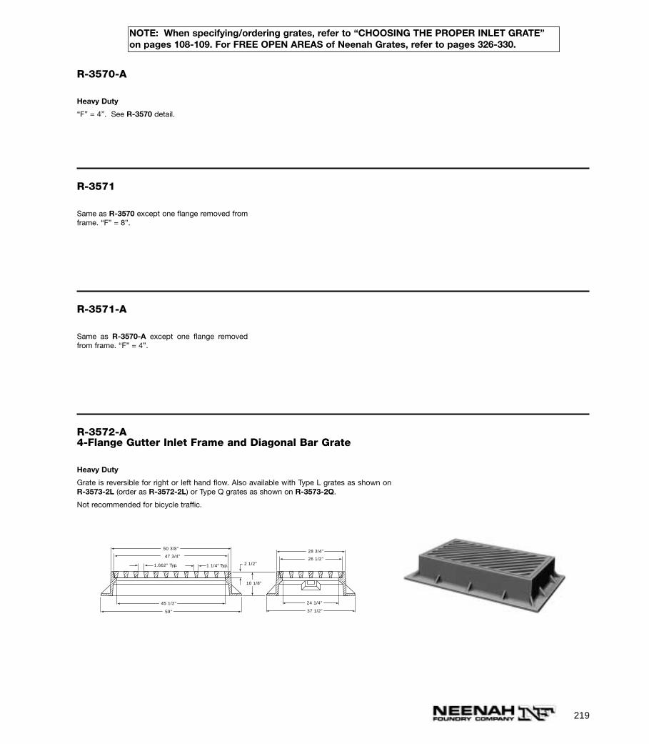
219
NOTE: When specifying/ordering grates, refer to “CHOOSING THE PROPER INLET GRATE”on pages 108-109. For FREE OPEN AREAS of Neenah Grates, refer to pages 326-330.
R-3570-A
Heavy Duty
“F” = 4”. See R-3570 detail.
R-3571
Same as R-3570 except one flange removed fromframe. “F” = 8”.
R-3571-A
Same as R-3570-A except one flange removedfrom frame. “F” = 4”.
R-3572-A4-Flange Gutter Inlet Frame and Diagonal Bar Grate
Heavy Duty
Grate is reversible for right or left hand flow. Also available with Type L grates as shown onR-3573-2L (order as R-3572-2L) or Type Q grates as shown on R-3573-2Q.
Not recommended for bicycle traffic.
2 1/2"
10 1/8"
28 3/4"
26 1/2"
24 1/4"45 1/2"
59"
50 3/8"
37 1/2"
1.662" 1 1/4"Typ. Typ.
47 3/4"
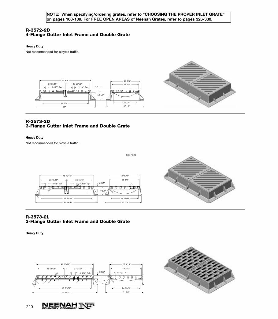
220
NOTE: When specifying/ordering grates, refer to “CHOOSING THE PROPER INLET GRATE”on pages 108-109. For FREE OPEN AREAS of Neenah Grates, refer to pages 326-330.
R-3572-2D4-Flange Gutter Inlet Frame and Double Grate
Heavy Duty
Not recommended for bicycle traffic.
2 1/2"
10 1/8"
28 3/4"
26 1/2"
24 1/4"45 1/2"
59"
23 13/16" 23 13/16"
50 3/8"
37 1/2"
1.662" 1 1/4"Typ. Typ.
R-3573-2D3-Flange Gutter Inlet Frame and Double Grate
Heavy Duty
Not recommended for bicycle traffic.
2 1/2"
7 7/8"
2 1/2"
7 7/8"
27 9/16"
26 1/2"
24 13/32"
23 13/16"23 13/16"
31 7/8"
45 21/32"
55 29/32"
48 13/16"
R-3573-2D
1.662" 1 1/4"Typ. Typ.
R-3573-2L3-Flange Gutter Inlet Frame and Double Grate
Heavy Duty
2 1/2"
7 7/8"
2 1/2"
23 13/16"23 13/16"
45 21/32"
55 29/32"
48 13/16"
3 1/2" Typ. 7" Typ.
27 9/16"
26 1/2"
24 13/32"
31 7/8"
7 7/8"

221
NOTE: When specifying/ordering grates, refer to “CHOOSING THE PROPER INLET GRATE”on pages 108-109. For FREE OPEN AREAS of Neenah Grates, refer to pages 326-330.
R-3573-2Q3-Flange Gutter Inlet Frame and Double Grate
Heavy Duty
2 1/2"
7 7/8"
2 1/2"
7 7/8"
4 1/2" 1 1/8" 1" 1/2"
27 9/16"
26 1/2"
24 13/32"
31 7/8"
23 13/16"
45 21/32"
55 29/32"
23 13/16"
48 13/16"
R-3574-2D4-Flange Gutter Inlet Frame and Double Grate
Heavy Duty
Not recommended for bicycle traffic.
2 31/32"
2 1/2"
23 13/16" 23 13/16" 26 1/2"
24 1/32"
31 7/8"
45 9/32"
53 5/32"
1 11/16" 1 1/4"
R-3574-2L4-Flange Gutter Inlet Frame and Double Grate
Heavy Duty
2 31/32"
2 1/2"
24 1/32"
31 7/8"
45 9/32"
53 5/32"
26 1/2"23 13/16"23 13/16"
3 1/2"
7" Typ.
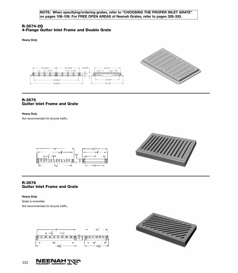
222
NOTE: When specifying/ordering grates, refer to “CHOOSING THE PROPER INLET GRATE”on pages 108-109. For FREE OPEN AREAS of Neenah Grates, refer to pages 326-330.
R-3574-2Q4-Flange Gutter Inlet Frame and Double Grate
Heavy Duty
45 9/32"
53 5/32"
2 31/32"
2 1/2"
23 13/16" 23 13/16" 26 1/2"
24 1/32"
31 7/8"
4 1/2" 1" 1 1/8" 1/2"
R-3575Gutter Inlet Frame and Grate
Heavy Duty
Not recommended for bicycle traffic.
R-3576Gutter Inlet Frame and Grate
Heavy Duty
Grate is reversible.
Not recommended for bicycle traffic.
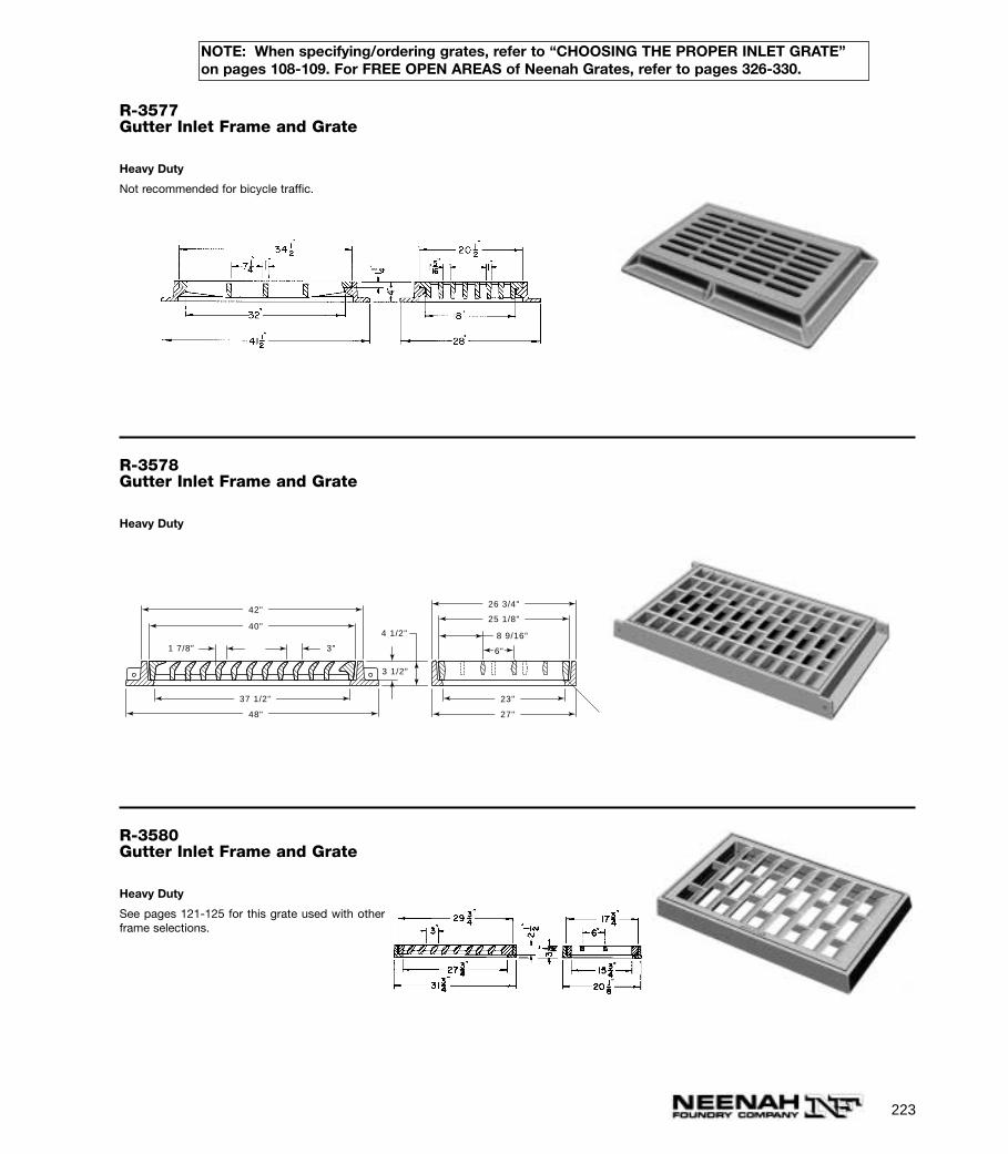
223
NOTE: When specifying/ordering grates, refer to “CHOOSING THE PROPER INLET GRATE”on pages 108-109. For FREE OPEN AREAS of Neenah Grates, refer to pages 326-330.
R-3577Gutter Inlet Frame and Grate
Heavy Duty
Not recommended for bicycle traffic.
R-3578Gutter Inlet Frame and Grate
Heavy Duty
1 7/8" 3"
3 1/2"
4 1/2"
6"
8 9/16"
37 1/2"
26 3/4"
25 1/8"
48" 27"
23"
42"
40"
R-3580Gutter Inlet Frame and Grate
Heavy Duty
See pages 121-125 for this grate used with otherframe selections.

224
NOTE: When specifying/ordering grates, refer to “CHOOSING THE PROPER INLET GRATE”on pages 108-109. For FREE OPEN AREAS of Neenah Grates, refer to pages 326-330.
R-3580-1Double Inlet Frame and Grate
Heavy Duty
Typically used at sag locations. See pages 121-125 for this grate used with other frame selections.
R-3581Gutter Inlet Frame and Grate
Heavy Duty
Not recommended for bicycle traffic.
R-35884-Flange Gutter Inlet Frame andGrate
Heavy Duty
Same as R-3589 with slotted grate except framehas 4 flanges.
NOTE: When specifying/ordering grates, refer to “CHOOSING THE PROPER INLET GRATE”on pages 108-109. For FREE OPEN AREAS of Neenah Grates, refer to pages 326-330.
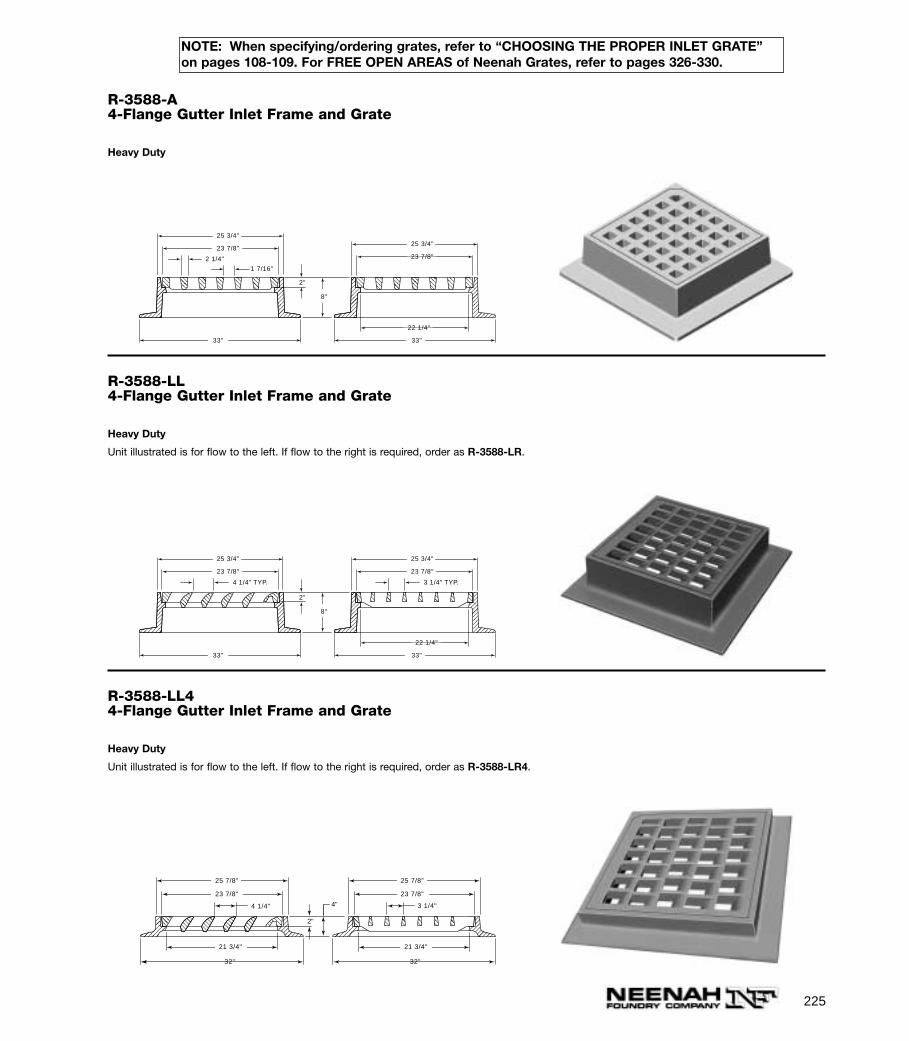
225
NOTE: When specifying/ordering grates, refer to “CHOOSING THE PROPER INLET GRATE”on pages 108-109. For FREE OPEN AREAS of Neenah Grates, refer to pages 326-330.
R-3588-A4-Flange Gutter Inlet Frame and Grate
Heavy Duty
25 3/4"
23 7/8"
22 1/4"
25 3/4"
23 7/8"
33"33"
2 1/4"
1 7/16"
2"
8"
R-3588-LL4-Flange Gutter Inlet Frame and Grate
Heavy Duty
Unit illustrated is for flow to the left. If flow to the right is required, order as R-3588-LR.
25 3/4"
23 7/8"
22 1/4"
25 3/4"
23 7/8"
33"33"
4 1/4" TYP.
3 1/4" TYP.
2"
8"
R-3588-LL44-Flange Gutter Inlet Frame and Grate
Heavy Duty
Unit illustrated is for flow to the left. If flow to the right is required, order as R-3588-LR4.
4"
2"
25 7/8"
23 7/8"
21 3/4"
32"
25 7/8"
23 7/8"
21 3/4"
32"
3 1/4"4 1/4"
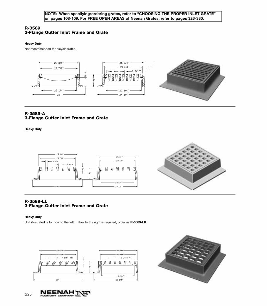
226
NOTE: When specifying/ordering grates, refer to “CHOOSING THE PROPER INLET GRATE”on pages 108-109. For FREE OPEN AREAS of Neenah Grates, refer to pages 326-330.
R-35893-Flange Gutter Inlet Frame and Grate
Heavy Duty
Not recommended for bicycle traffic.
1 3/16"1"
2"
25 3/4" 25 3/4"
23 7/8" 23 7/8"
22 1/4"
33"
8"
22 1/4"
24 1/4"
R-3589-A3-Flange Gutter Inlet Frame and Grate
Heavy Duty
25 3/4"
23 7/8"
22 1/4"
29 1/4"
25 3/4"
23 7/8"
33"
2 1/4"
1 7/16"
2"
8"
R-3589-LL3-Flange Gutter Inlet Frame and Grate
Heavy Duty
Unit illustrated is for flow to the left. If flow to the right is required, order as R-3589-LR.
22 1/4"
25 3/4"
23 7/8"
25 3/4"
23 7/8"
29 1/4"33"
4 1/4" TYP. 3 1/4" TYP.
2"8"
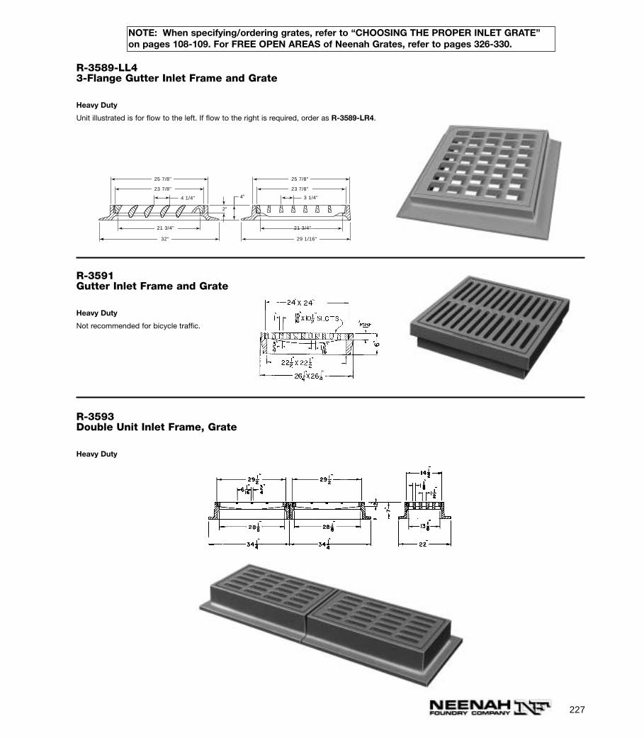
227
NOTE: When specifying/ordering grates, refer to “CHOOSING THE PROPER INLET GRATE”on pages 108-109. For FREE OPEN AREAS of Neenah Grates, refer to pages 326-330.
R-3589-LL43-Flange Gutter Inlet Frame and Grate
Heavy Duty
Unit illustrated is for flow to the left. If flow to the right is required, order as R-3589-LR4.
4"
2"
25 7/8"
23 7/8"
21 3/4"
29 1/16"
25 7/8"
23 7/8"
21 3/4"
32"
3 1/4"4 1/4"
R-3591Gutter Inlet Frame and Grate
Heavy Duty
Not recommended for bicycle traffic.
R-3593Double Unit Inlet Frame, Grate
Heavy Duty

228
NOTE: When specifying/ordering grates, refer to “CHOOSING THE PROPER INLET GRATE”on pages 108-109. For FREE OPEN AREAS of Neenah Grates, refer to pages 326-330.
R-3599-ASlotted Vane Drain, Sheetflow
NEENAH’s Cast Iron Slotted Vane Drain offers ease of installation along with the superior vaned configuration to capture previously unexpected quan-tities of water when placed perpendicular to the flow. Installation is accomplished by sawing a slot in the top of conventional PVC pipe, placing the pipeon grade, installing the Cast Iron Slotted Vane Drain in place and pouring the concrete. When used in conjunction with a vane grate inlet, virtually all ofthe water in the street, which would normally bypass the catch basin, can be captured. This permits the spacing between inlets to be increased. Anadditional benefit is the added safety factor obtained should the catch basin be plugged or covered with snow. The unit may also be installed atentrances and exits of parking areas to capture sheet flow before it enters a commercial street.
Bolts not furnished.
Feel free to contact our field personnel or our Product Engineering Department at Neenah for further detailed information.
On longitudinal slopes of 0% to 6%, this unit captures approximately 0.5 cubic feet per second, per lineal foot.
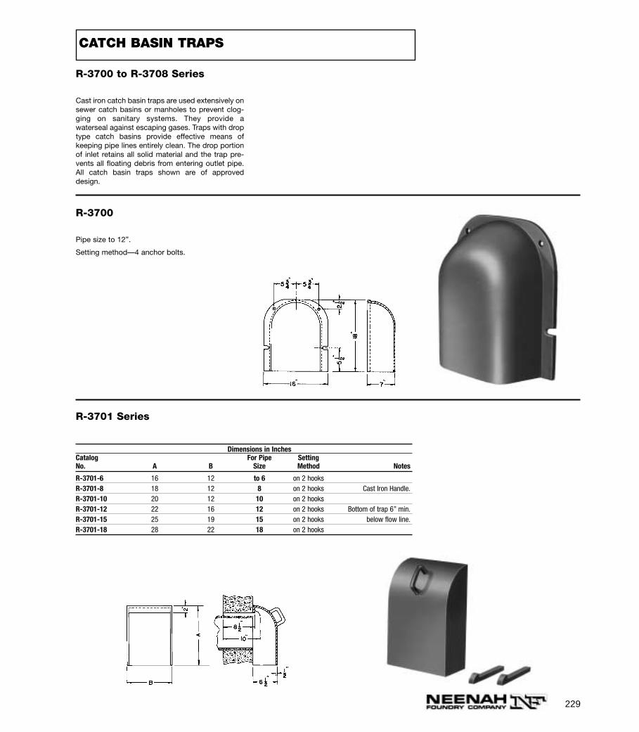
229
R-3700 to R-3708 Series
Cast iron catch basin traps are used extensively onsewer catch basins or manholes to prevent clog-ging on sanitary systems. They provide awaterseal against escaping gases. Traps with droptype catch basins provide effective means ofkeeping pipe lines entirely clean. The drop portionof inlet retains all solid material and the trap pre-vents all floating debris from entering outlet pipe.All catch basin traps shown are of approveddesign.
R-3700
Pipe size to 12”.
Setting method—4 anchor bolts.
R-3701 Series
Dimensions in InchesCatalog For Pipe SettingNo. A B Size Method Notes
R-3701-6 16 12 to 6 on 2 hooksR-3701-8 18 12 8 on 2 hooks Cast Iron Handle.R-3701-10 20 12 10 on 2 hooksR-3701-12 22 16 12 on 2 hooks Bottom of trap 6” min.R-3701-15 25 19 15 on 2 hooks below flow line.R-3701-18 28 22 18 on 2 hooks
CATCH BASIN TRAPS
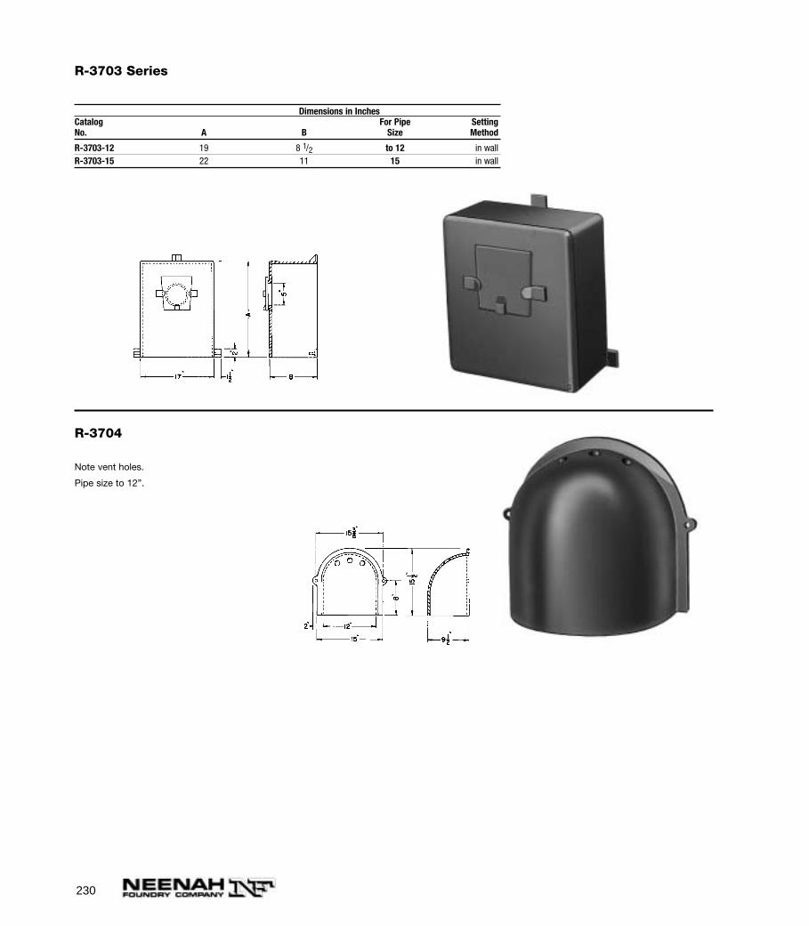
230
R-3703 Series
Dimensions in InchesCatalog For Pipe SettingNo. A B Size Method
R-3703-12 19 8 1/2 to 12 in wallR-3703-15 22 11 15 in wall
R-3704
Note vent holes.
Pipe size to 12”.
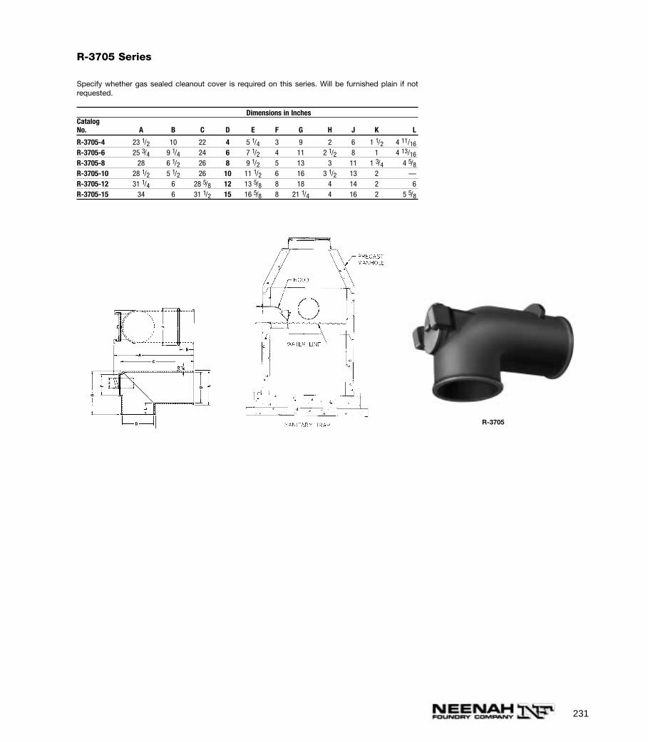
231
R-3705 Series
Specify whether gas sealed cleanout cover is required on this series. Will be furnished plain if notrequested.
Dimensions in InchesCatalogNo. A B C D E F G H J K L
R-3705-4 23 1/2 10 22 4 5 1/4 3 9 2 6 1 1/2 4 11/16R-3705-6 25 3/4 9 1/4 24 6 7 1/2 4 11 2 1/2 8 1 4 13/16R-3705-8 28 6 1/2 26 8 9 1/2 5 13 3 11 1 3/4 4 5/8R-3705-10 28 1/2 5 1/2 26 10 11 1/2 6 16 3 1/2 13 2 —R-3705-12 31 1/4 6 28 5/8 12 13 5/8 8 18 4 14 2 6R-3705-15 34 6 31 1/2 15 16 5/8 8 21 1/4 4 16 2 5 5/8
R-3705
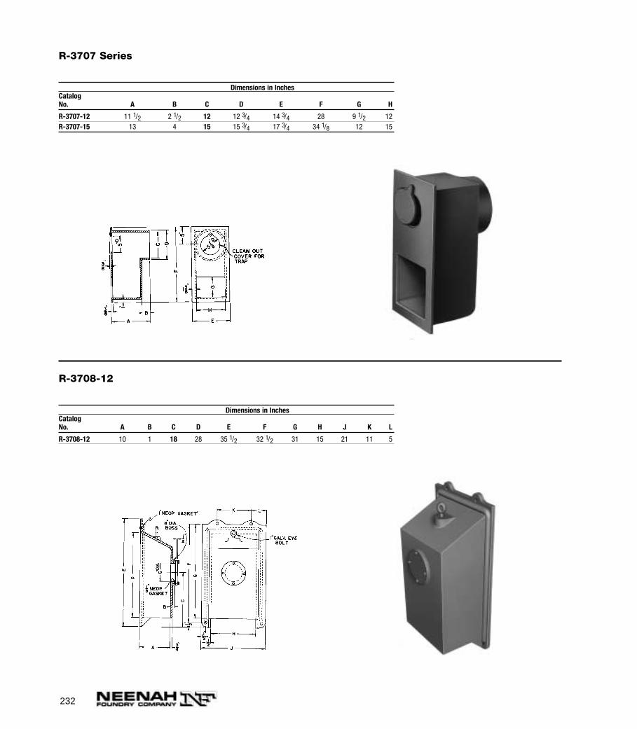
232
R-3707 Series
Dimensions in InchesCatalogNo. A B C D E F G H
R-3707-12 11 1/2 2 1/2 12 12 3/4 14 3/4 28 9 1/2 12R-3707-15 13 4 15 15 3/4 17 3/4 34 1/8 12 15
R-3708-12
Dimensions in InchesCatalogNo. A B C D E F G H J K L
R-3708-12 10 1 18 28 35 1/2 32 1/2 31 15 21 11 5
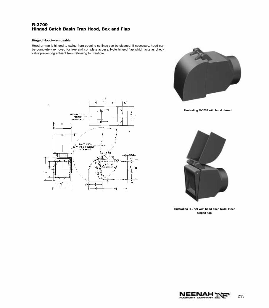
233
R-3709Hinged Catch Basin Trap Hood, Box and Flap
Hinged Hood—removable
Hood or trap is hinged to swing from opening so lines can be cleaned. If necessary, hood canbe completely removed for free and complete access. Note hinged flap which acts as checkvalve preventing effluent from returning to manhole.
Illustrating R-3709 with hood open Note: Innerhinged flap
Illustrating R-3709 with hood closed

234
R-3712Catch Basin Trap
39 1/4"
33 1/4"
15"
9"
15"
9"
3"
30"
9"
5/8" Typ.22 3/4"
#35 BRASS SASH CHAIN
BRASS WEDGE1/8" THICK NEOPRENEGASKET
NEENAH FOUNDRY CO.
R-3711Catch Basin Hood with Hook for12” Wall
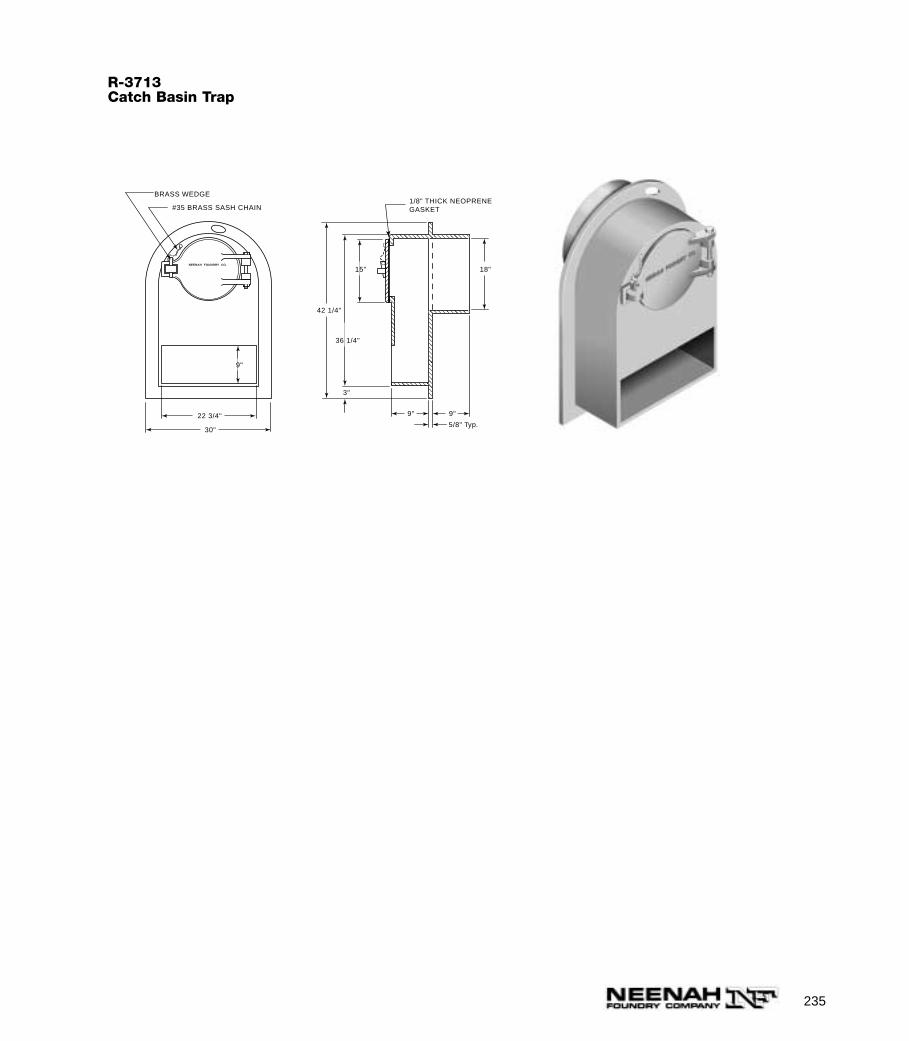
235
R-3713Catch Basin Trap
42 1/4"
36 1/4"
15"
9"
18"
9"
3"
30"
9"
5/8" Typ.22 3/4"
#35 BRASS SASH CHAIN
BRASS WEDGE1/8" THICK NEOPRENEGASKET
NEENAH FOUNDRY CO.
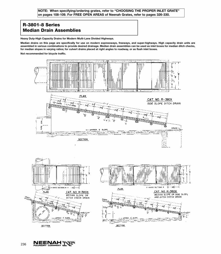
236
Heavy Duty-High Capacity Drains for Modern Multi-Lane Divided Highways.
Median drains on this page are specifically for use on modern expressways, freeways, and super-highways. High capacity drain units areassembled in various combinations to provide desired drainage. Median drain assemblies can be used as inlet boxes for median ditch checks,for median slopes in varying ratios; for culvert drains placed at right angles to roadway, or as flush inlet boxes.
Not recommended for bicycle traffic.
R-3801-8 SeriesMedian Drain Assemblies
NOTE: When specifying/ordering grates, refer to “CHOOSING THE PROPER INLET GRATE”on pages 108-109. For FREE OPEN AREAS of Neenah Grates, refer to pages 326-330.
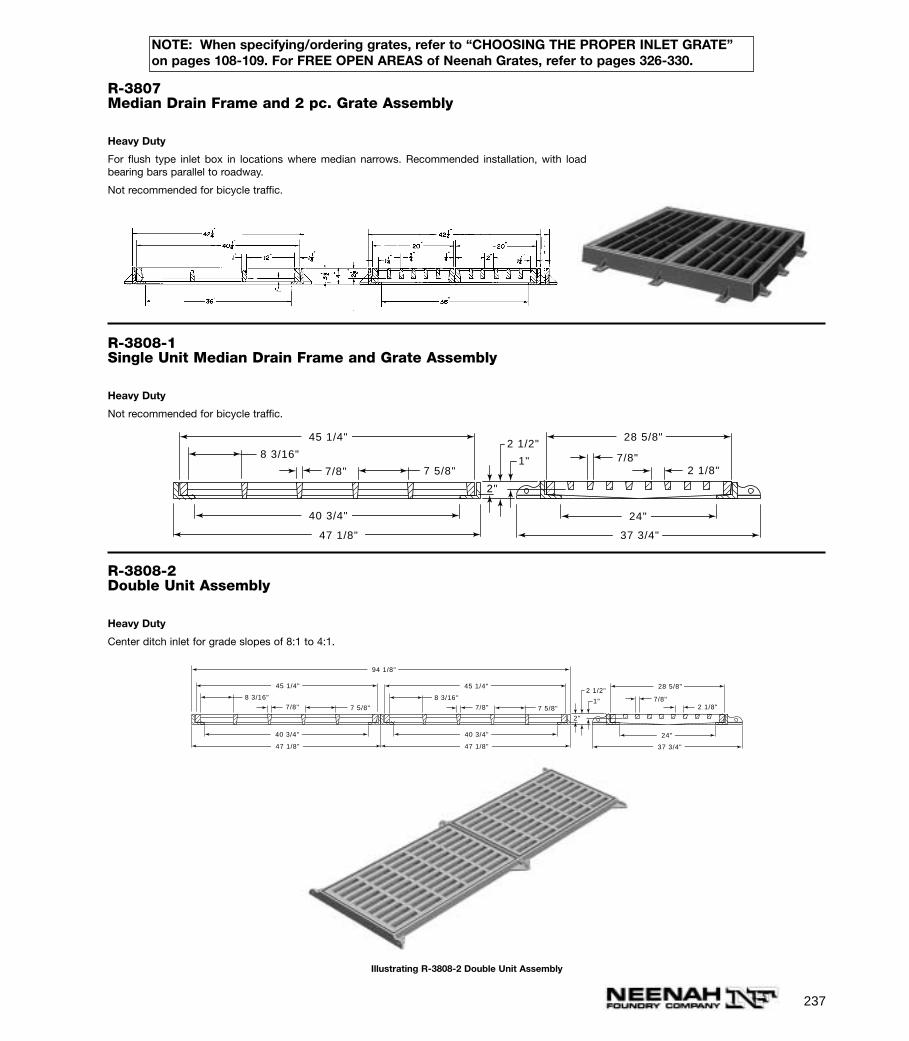
237
R-3807Median Drain Frame and 2 pc. Grate Assembly
Heavy Duty
For flush type inlet box in locations where median narrows. Recommended installation, with loadbearing bars parallel to roadway.
Not recommended for bicycle traffic.
R-3808-1Single Unit Median Drain Frame and Grate Assembly
Heavy Duty
Not recommended for bicycle traffic.
47 1/8"
40 3/4"
47 1/8"
40 3/4"
45 1/4"
94 1/8"
8 3/16"
7 5/8"7/8"
45 1/4"
8 3/16"
7/8" 7 5/8"
24"
28 5/8"
7/8" 2 1/8"
2"
2 1/2"
1"
37 3/4"
R-3808-2Double Unit Assembly
Heavy Duty
Center ditch inlet for grade slopes of 8:1 to 4:1.
47 1/8"
24"
45 1/4" 28 5/8"
37 3/4"
40 3/4"
8 3/16"
7 5/8"7/8"7/8"
2 1/8"
2"
2 1/2"
1"
Illustrating R-3808-2 Double Unit Assembly
NOTE: When specifying/ordering grates, refer to “CHOOSING THE PROPER INLET GRATE”on pages 108-109. For FREE OPEN AREAS of Neenah Grates, refer to pages 326-330.
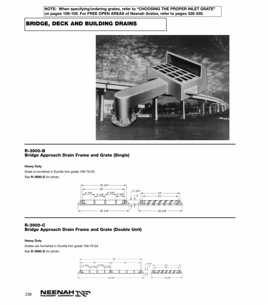
238
BRIDGE, DECK AND BUILDING DRAINS
R-3900-BBridge Approach Drain Frame and Grate (Single)
Heavy Duty
Grate is furnished in Ductile Iron grade 100-70-03.
See R-3900-D for photo.
23"21"
26 3/8"
6 7/8" 6 3/8"5 3/8"6 3/8"
25"
26 3/4"
30 1/8"
2"
2 3/4"
R-3900-CBridge Approach Drain Frame and Grate (Double Unit)
Heavy Duty
Grates are furnished in Ductile Iron grade 100-70-03.
See R-3900-D for photo.
23"21"
26 3/8"
6 7/8" 6 3/8"5 3/8"6 3/8"
25" 25"
52"
55 3/8"
2"2 3/4"
NOTE: When specifying/ordering grates, refer to “CHOOSING THE PROPER INLET GRATE”on pages 108-109. For FREE OPEN AREAS of Neenah Grates, refer to pages 326-330.

239
NOTE: When specifying/ordering grates, refer to “CHOOSING THE PROPER INLET GRATE”on pages 108-109. For FREE OPEN AREAS of Neenah Grates, refer to pages 326-330.
R-3900-DBridge Approach Drain Frame and Grate (Triple Unit)
Heavy Duty
Grates are furnished in Ductile Iron grade 100-70-03.
6 7/8" 6 3/8"5 3/8"6 3/8"
25" 25" 25"
77 1/4"
80 5/8"
23"21"
26 3/8"
2"2 3/4"
R-3919Bridge Drain Frame and Grate
Heavy Duty
Not recommended for bicycle traffic.
R-3920-VBridge Drain Frame and Grate
Heavy Duty
Type V grate (shown) is considered bicycle safe only when installed with vanes perpendicular to thecurb.
3"
2"
3 1/2"
3 1/2"
18"
6"
23 1/2"
27 1/2"
16 1/2"
21 1/2" 14 1/2"
11 7/8"
5 7/16"
6 7/8"

240
NOTE: When specifying/ordering grates, refer to “CHOOSING THE PROPER INLET GRATE”on pages 108-109. For FREE OPEN AREAS of Neenah Grates, refer to pages 326-330.
R-3921-V1Bridge Drain Frame and Bolted Grate
Heavy Duty
Available with Type “L” grates (order as R-3921-L1) or Type “B” grate shown on R-4014-T2.
Type V grate (shown) is considered bicycle safe only when installed with vanes perpendicular to the curb.
Standard 125# flanged template downspout furnished by others.
2 3/16"1 1/4" 17 5/8"
9 1/4"
22 17/32" 7 17/32"
24"
13 3/4"
6"
11"DRILL AND TAP (8) HOLES FOR3/4"-10 UNC BOLTS ON A 9-1/2"DIA. B.C. (TWO BLIND HOLESARE 1-1/4" DEEP. REMAININGSIX ARE THRU HOLES)
26 1/16"
R-3922Bridge Drain Frame and Bolted Grate
Heavy Duty
Type “V” ductile iron grate (shown) is considered bicycle safe only when installed with vanesperpendicular to the curb.
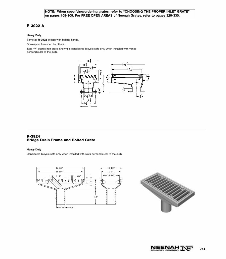
241
NOTE: When specifying/ordering grates, refer to “CHOOSING THE PROPER INLET GRATE”on pages 108-109. For FREE OPEN AREAS of Neenah Grates, refer to pages 326-330.
R-3922-A
Heavy Duty
Same as R-3922 except with bolting flange.
Downspout furnished by others.
Type “V” ductile iron grate (shown) is considered bicycle safe only when installed with vanesperpendicular to the curb.
R-3924Bridge Drain Frame and Bolted Grate
Heavy Duty
Considered bicycle safe only when installed with slots perpendicular to the curb.
12"
8"4"2"
2" 5/8"
5/8"
35 1/4"
37 5/8" 17 1/2"
12 7/8"
15"
6"
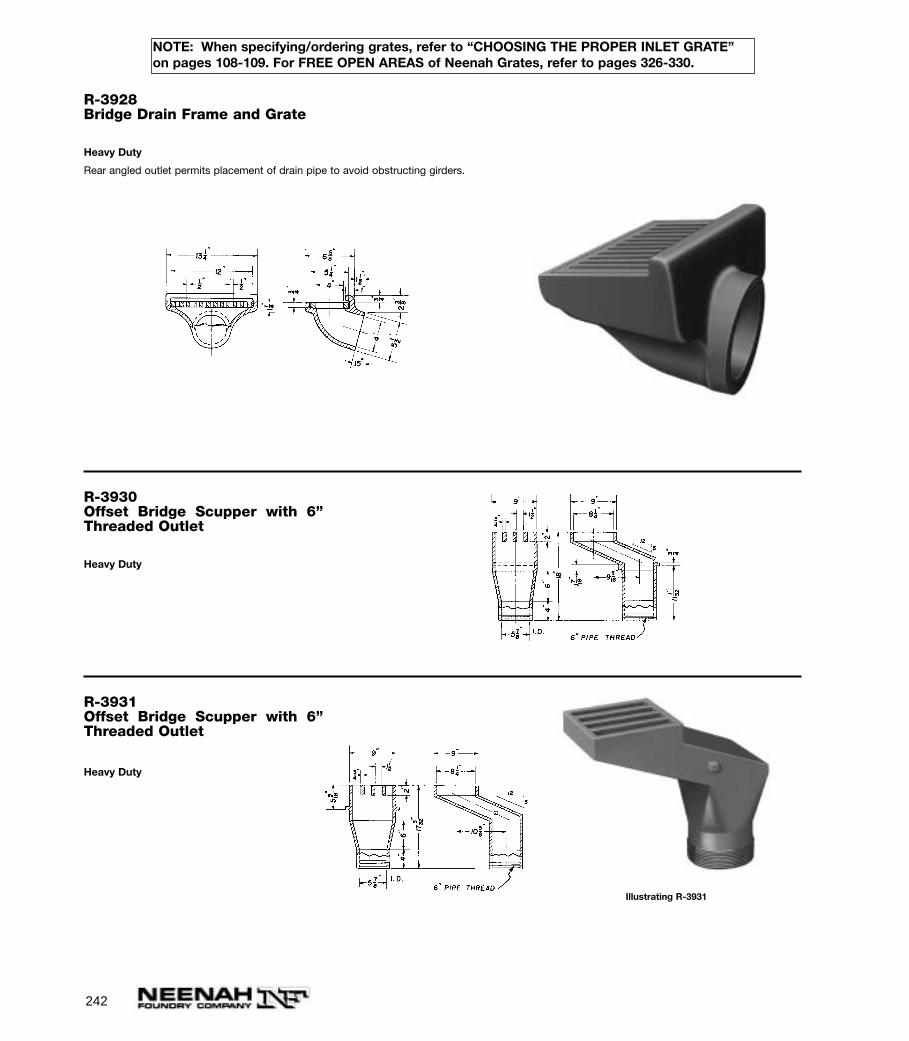
242
NOTE: When specifying/ordering grates, refer to “CHOOSING THE PROPER INLET GRATE”on pages 108-109. For FREE OPEN AREAS of Neenah Grates, refer to pages 326-330.
R-3928Bridge Drain Frame and Grate
Heavy Duty
Rear angled outlet permits placement of drain pipe to avoid obstructing girders.
R-3930Offset Bridge Scupper with 6”Threaded Outlet
Heavy Duty
R-3931Offset Bridge Scupper with 6”Threaded Outlet
Heavy Duty
Illustrating R-3931
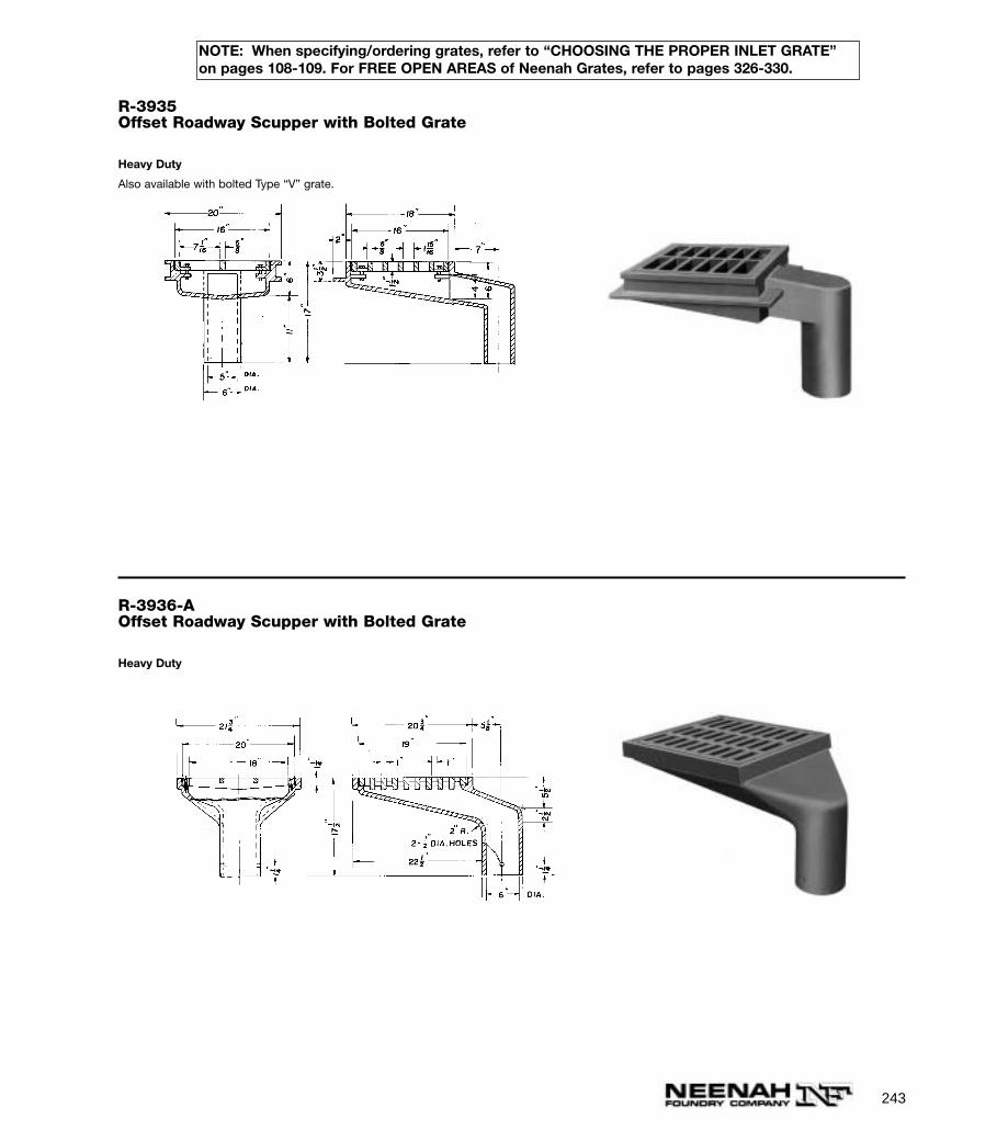
R-3935Offset Roadway Scupper with Bolted Grate
Heavy Duty
Also available with bolted Type “V” grate.
R-3936-AOffset Roadway Scupper with Bolted Grate
Heavy Duty
243
NOTE: When specifying/ordering grates, refer to “CHOOSING THE PROPER INLET GRATE”on pages 108-109. For FREE OPEN AREAS of Neenah Grates, refer to pages 326-330.
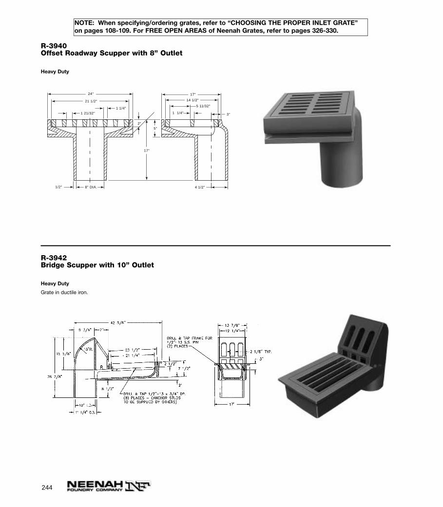
244
NOTE: When specifying/ordering grates, refer to “CHOOSING THE PROPER INLET GRATE”on pages 108-109. For FREE OPEN AREAS of Neenah Grates, refer to pages 326-330.
R-3940Offset Roadway Scupper with 8” Outlet
Heavy Duty
1 21/32"1 1/4"
21 1/2"
17"
14 1/2"
24"
8" DIA.
5 11/32"
1/2"
1 1/4" 3"
2"5"
4 1/2"
17"
R-3942Bridge Scupper with 10” Outlet
Heavy Duty
Grate in ductile iron.
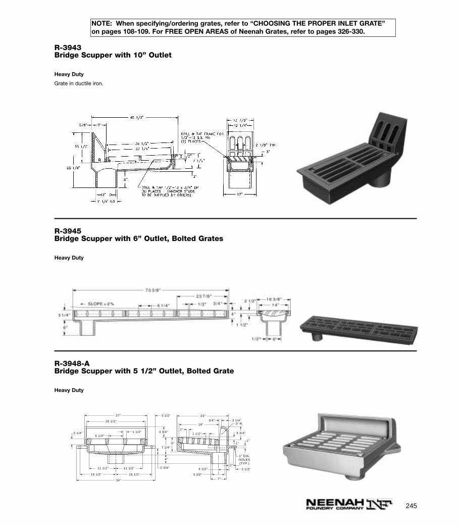
245
NOTE: When specifying/ordering grates, refer to “CHOOSING THE PROPER INLET GRATE”on pages 108-109. For FREE OPEN AREAS of Neenah Grates, refer to pages 326-330.
R-3943Bridge Scupper with 10” Outlet
Heavy Duty
Grate in ductile iron.
R-3945Bridge Scupper with 6” Outlet, Bolted Grates
Heavy Duty
R-3948-ABridge Scupper with 5 1/2” Outlet, Bolted Grate
Heavy Duty
3 1/4"3/4"
1"
5 3/4"
3" R.
1"1 1/2"
23"
18"
4 1/2"2"
3 1/2"
5 1/2"
6"
7"
7 1/4"
4 3/4"
1" DIA.HOLES(TYP.)
1"
4"
11 1/2" 11 1/2"
15 1/2" 15 1/2"
27"
1 1/2"
25 1/2"
2 3/4"
34"
3 1/2"
2 1/4"6 1/4"
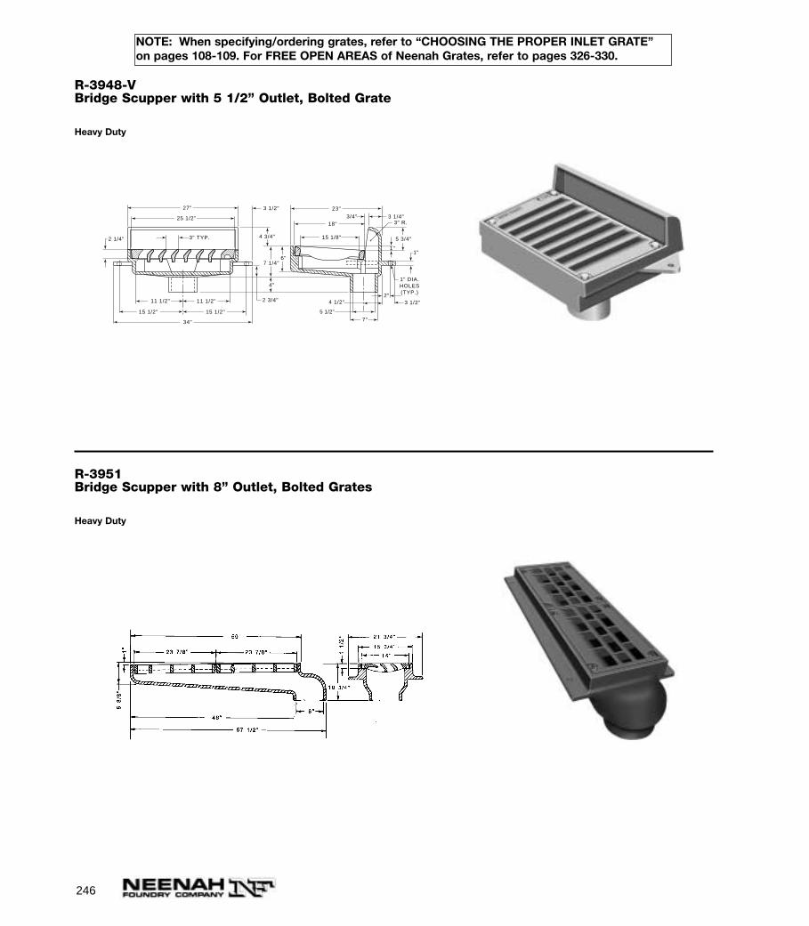
246
NOTE: When specifying/ordering grates, refer to “CHOOSING THE PROPER INLET GRATE”on pages 108-109. For FREE OPEN AREAS of Neenah Grates, refer to pages 326-330.
R-3948-VBridge Scupper with 5 1/2” Outlet, Bolted Grate
Heavy Duty
3" TYP.
2 3/4"
3 1/2"
2 1/4"
27"
25 1/2"
11 1/2"
15 1/2"
11 1/2"
15 1/2"
34"
3 1/4"3/4"
1"
5 3/4"
3" R.
23"
18"
15 1/8"
4 1/2"2"
3 1/2"
5 1/2"
6"
7"
7 1/4"
4 3/4"
1" DIA.HOLES(TYP.)
1"
4"
R-3951Bridge Scupper with 8” Outlet, Bolted Grates
Heavy Duty
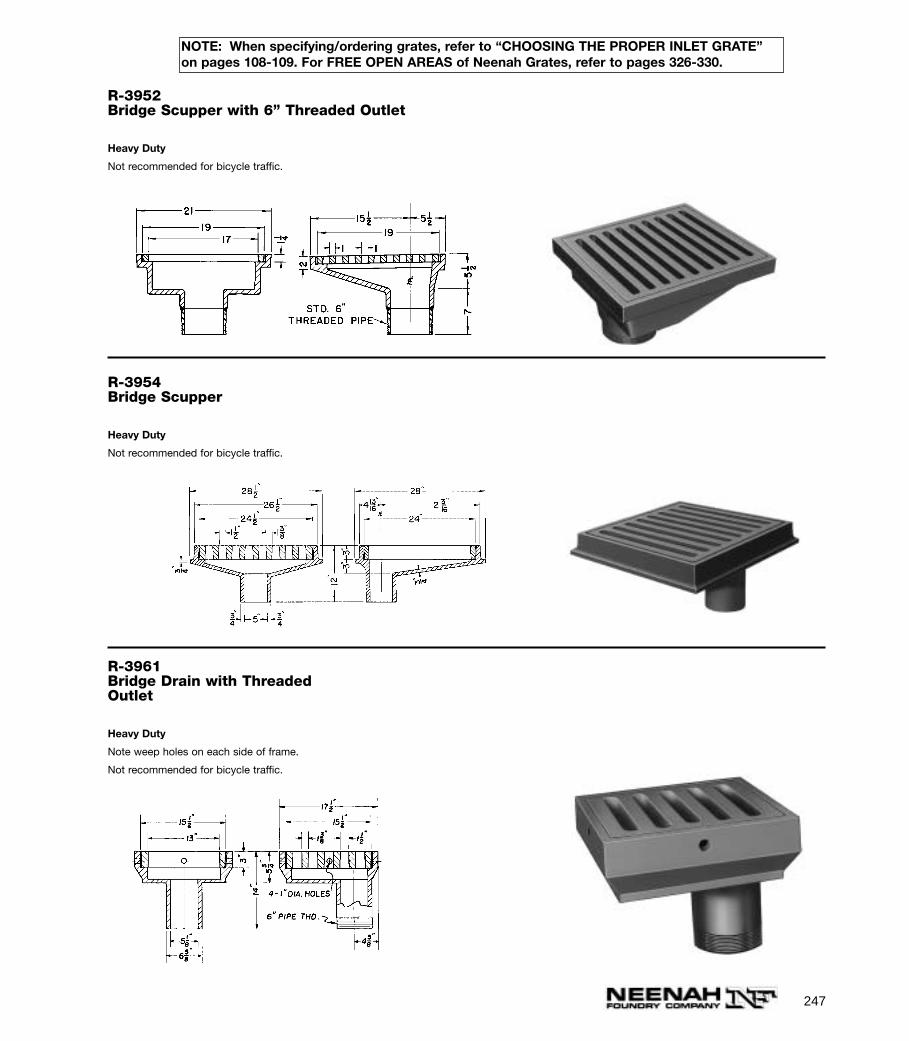
247
NOTE: When specifying/ordering grates, refer to “CHOOSING THE PROPER INLET GRATE”on pages 108-109. For FREE OPEN AREAS of Neenah Grates, refer to pages 326-330.
R-3952Bridge Scupper with 6” Threaded Outlet
Heavy Duty
Not recommended for bicycle traffic.
R-3954Bridge Scupper
Heavy Duty
Not recommended for bicycle traffic.
R-3961Bridge Drain with ThreadedOutlet
Heavy Duty
Note weep holes on each side of frame.
Not recommended for bicycle traffic.
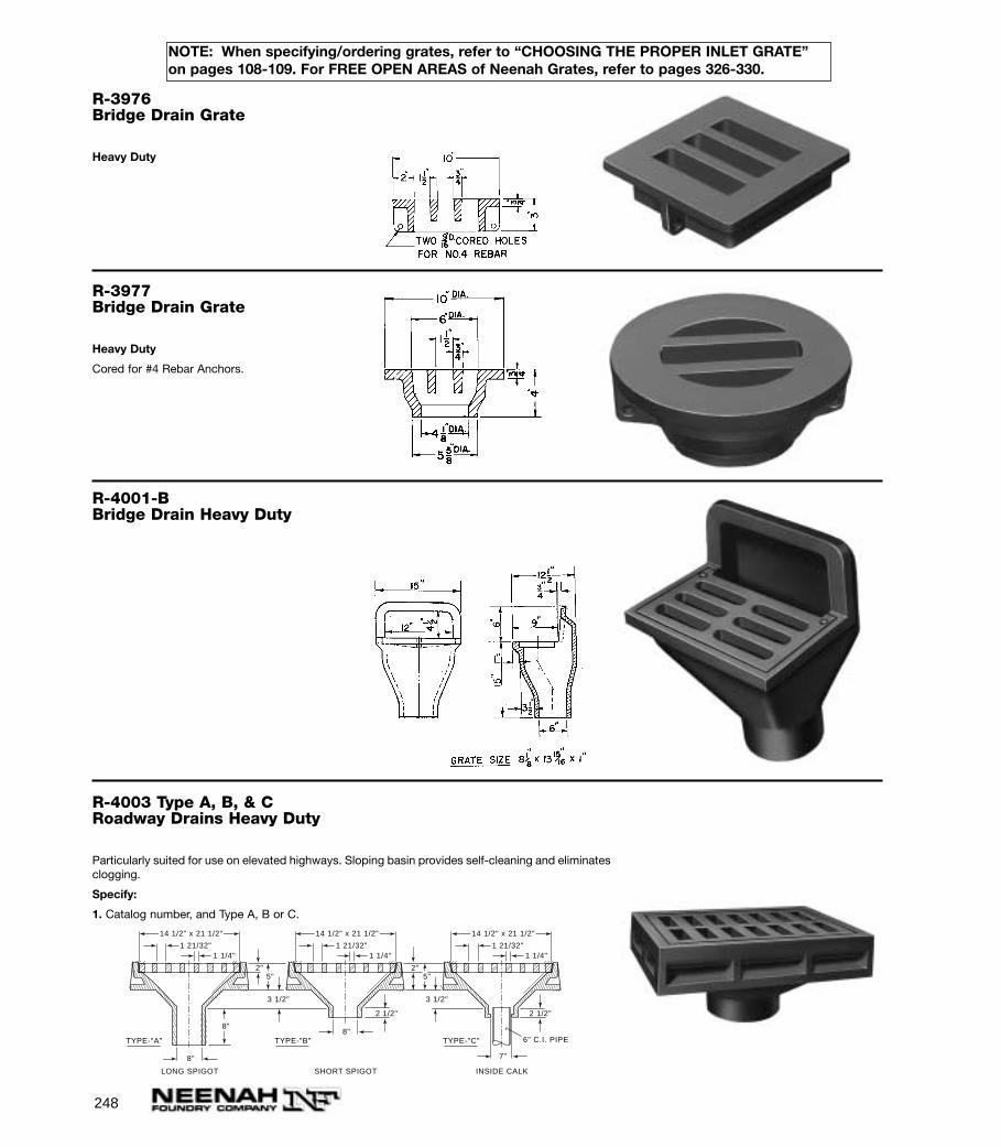
248
NOTE: When specifying/ordering grates, refer to “CHOOSING THE PROPER INLET GRATE”on pages 108-109. For FREE OPEN AREAS of Neenah Grates, refer to pages 326-330.
R-3976Bridge Drain Grate
Heavy Duty
R-3977Bridge Drain Grate
Heavy Duty
Cored for #4 Rebar Anchors.
R-4001-BBridge Drain Heavy Duty
R-4003 Type A, B, & CRoadway Drains Heavy Duty
Particularly suited for use on elevated highways. Sloping basin provides self-cleaning and eliminatesclogging.
Specify:
1. Catalog number, and Type A, B or C.
1 1/4"1 21/32"
14 1/2" x 21 1/2"
8"
5"
8"
2"
3 1/2"
1 1/4"1 21/32"
14 1/2" x 21 1/2"
8"
5"2"
3 1/2"
1 1/4"1 21/32"
14 1/2" x 21 1/2"
7"
2 1/2" 2 1/2"
6" C.I. PIPETYPE-"A" TYPE-"B" TYPE-"C"
LONG SPIGOT INSIDE CALKSHORT SPIGOT
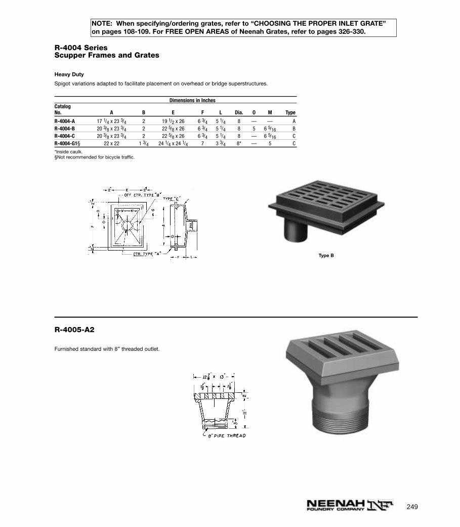
249
NOTE: When specifying/ordering grates, refer to “CHOOSING THE PROPER INLET GRATE”on pages 108-109. For FREE OPEN AREAS of Neenah Grates, refer to pages 326-330.
R-4004 SeriesScupper Frames and Grates
Heavy Duty
Spigot variations adapted to facilitate placement on overhead or bridge superstructures.
Dimensions in InchesCatalogNo. A B E F L Dia. O M Type
R-4004-A 17 1/4 x 23 3/4 2 19 1/2 x 26 6 3/4 5 1/4 8 — — AR-4004-B 20 3/8 x 23 3/4 2 22 5/8 x 26 6 3/4 5 1/4 8 5 6 5/16 BR-4004-C 20 3/8 x 23 3/4 2 22 5/8 x 26 6 3/4 5 1/4 8 — 6 5/16 CR-4004-G1§ 22 x 22 1 3/4 24 1/4 x 24 1/4 7 3 3/4 8* — 5 C
*Inside caulk.§Not recommended for bicycle traffic.
Type B
R-4005-A2
Furnished standard with 8” threaded outlet.

250
NOTE: When specifying/ordering grates, refer to “CHOOSING THE PROPER INLET GRATE”on pages 108-109. For FREE OPEN AREAS of Neenah Grates, refer to pages 326-330.
R-4006
Integral-cast bars. Outlet threaded for 6” pipe.
R-4007
Note bolt for fastening to square trough extension.
R-4007-A6
A = 30°
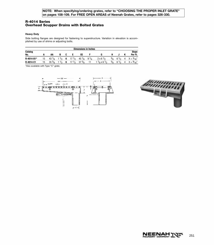
251
NOTE: When specifying/ordering grates, refer to “CHOOSING THE PROPER INLET GRATE”on pages 108-109. For FREE OPEN AREAS of Neenah Grates, refer to pages 326-330.
R-4014 SeriesOverhead Scupper Drains with Bolted Grates
Heavy Duty
Side bolting flanges are designed for fastening to superstructure. Variation in elevation is accom-plished by use of shims or adjusting bolts.
Dimensions in InchesCatalog SlopeNo. A AA B C E EE F G H J K Per Ft.
R-4014-B1* 15 43 1/8 1 1/2 6 17 1/2 45 1/8 9 1/4 2 x 6 1/2 5/8 6 1/2 4 X = 3/16”R-4014-C1 15 35 5/8 1 1/2 6 17 1/2 37 5/8 11 1 7/8 x 6 1/2 5/8 6 1/2 4 X = 9/16”
*Also available with Type “C” grate.

252
NOTE: When specifying/ordering grates, refer to “CHOOSING THE PROPER INLET GRATE”on pages 108-109. For FREE OPEN AREAS of Neenah Grates, refer to pages 326-330.
R-4014-T2Overhead Scupper with Bolted Grate
Heavy Duty
Standard 125 # flanged template downspout furnished by others.
7/16"1 9/16"
7 1/2"
1 1/4"3 1/2"
11"
7 1/4"
24"
22 7/16"
9 1/4"
1/2" DIA. HEX HD. BOLTS AND WASHERS.
3/4" DIA. HEX HD. BOLTSAND WASHERS - 8 REQUIREDON 9 1/2" DIA. BOLT CIRCLE
DOWNSPOUT FURNISHEDBY OTHERS.
R-4014-TOverhead Scupper with Bolted Grate
Heavy Duty
Standard 125 # flanged template downspout furnished by others.
R-4014-TLOverhead Scupper with Bolted Grate
Heavy Duty
Downspout furnished by others.
9 1 / 4 "
7 1/2"
1 1/4"
3 6 3 / 4 "
2 9 "
1 / 2 " ( T Y P . ) 4 " ( T Y P . )
3 8 "
7 1 / 4 "3 1 / 2 "
2 3 / 8 "
4 0 "
6 "1 1 " DRILL AND TAP 8 HOLES
FOR 3/4"-10 UNC BOLTSON 9 1/2" ø BOLT CIRCLE.
Available with type L grate, order as R-4014-TL2. Also available with Type V grate shown on R-3921-V1.Type V grate is considered bicycle safe only when installed with vanes perpendicular to the curb.
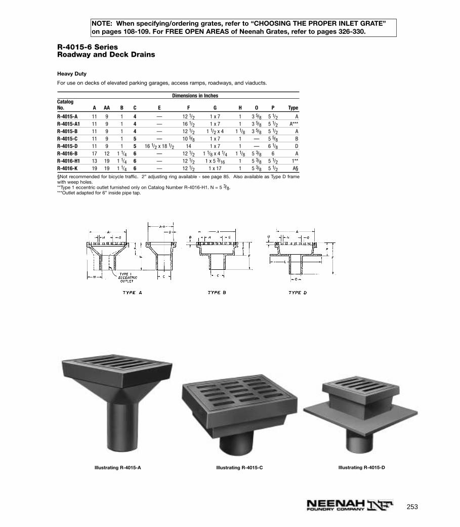
R-4015-6 SeriesRoadway and Deck Drains
Heavy Duty
For use on decks of elevated parking garages, access ramps, roadways, and viaducts.
Dimensions in InchesCatalogNo. A AA B C E F G H O P Type
R-4015-A 11 9 1 4 — 12 1/2 1 x 7 1 3 5/8 5 1/2 AR-4015-A1 11 9 1 4 — 16 1/2 1 x 7 1 3 5/8 5 1/2 A***R-4015-B 11 9 1 4 — 12 1/2 1 1/2 x 4 1 1/8 3 5/8 5 1/2 AR-4015-C 11 9 1 5 — 10 5/8 1 x 7 1 — 5 5/8 BR-4015-D 11 9 1 5 16 1/2 x 18 1/2 14 1 x 7 1 — 6 1/8 DR-4016-B 17 12 1 1/4 6 — 12 1/2 1 1/8 x 4 1/4 1 1/8 5 3/8 6 AR-4016-H1 13 19 1 1/4 6 — 12 1/2 1 x 5 3/16 1 5 3/8 5 1/2 1**R-4016-K 19 19 1 1/4 6 — 12 1/2 1 x 17 1 5 3/8 5 1/2 A§
§Not recommended for bicycle traffic. 2” adjusting ring available - see page 85. Also available as Type D framewith weep holes.**Type 1 eccentric outlet furnished only on Catalog Number R-4016-H1. N = 5 3/8.***Outlet adapted for 6” inside pipe tap.
Illustrating R-4015-A Illustrating R-4015-C Illustrating R-4015-D
253
NOTE: When specifying/ordering grates, refer to “CHOOSING THE PROPER INLET GRATE”on pages 108-109. For FREE OPEN AREAS of Neenah Grates, refer to pages 326-330.

254
NOTE: When specifying/ordering grates, refer to “CHOOSING THE PROPER INLET GRATE”on pages 108-109. For FREE OPEN AREAS of Neenah Grates, refer to pages 326-330.
R-4018
Parking Garage Drain
Grate is furnished in Ductile Iron.
R-4028Cast Iron Underdrains
Drawing below shows how cast iron underdrain sections are used along railroad right-of-way. Ballast or gravel-filled road bed permits ready drainageof surface water into underdrain whence it is conducted to the storm sewer.
Note drainage intake holes in each section of cast iron underdrain.
Laying length is 18 inches
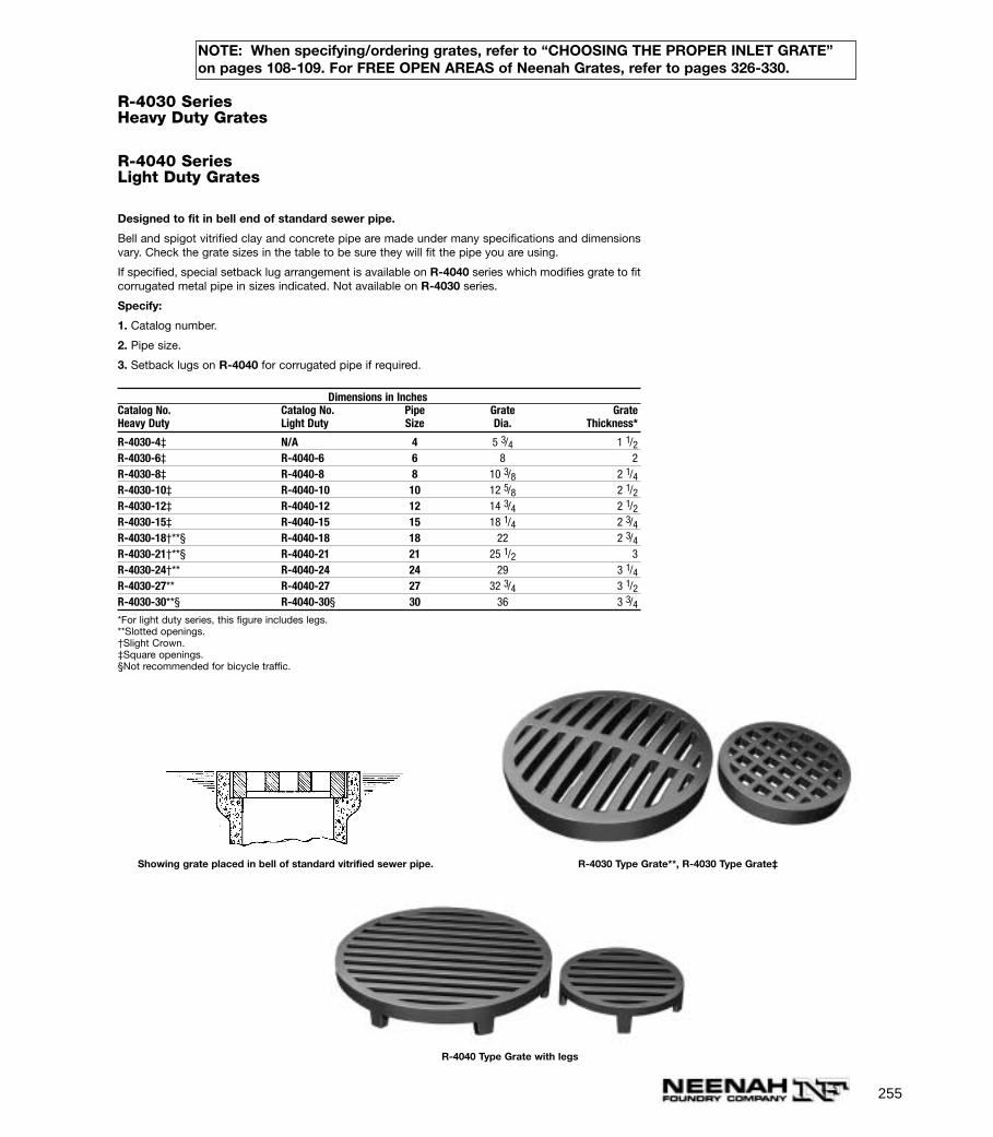
255
NOTE: When specifying/ordering grates, refer to “CHOOSING THE PROPER INLET GRATE”on pages 108-109. For FREE OPEN AREAS of Neenah Grates, refer to pages 326-330.
R-4030 SeriesHeavy Duty Grates
R-4040 SeriesLight Duty Grates
Designed to fit in bell end of standard sewer pipe.
Bell and spigot vitrified clay and concrete pipe are made under many specifications and dimensionsvary. Check the grate sizes in the table to be sure they will fit the pipe you are using.
If specified, special setback lug arrangement is available on R-4040 series which modifies grate to fitcorrugated metal pipe in sizes indicated. Not available on R-4030 series.
Specify:
1. Catalog number.
2. Pipe size.
3. Setback lugs on R-4040 for corrugated pipe if required.
Dimensions in InchesCatalog No. Catalog No. Pipe Grate GrateHeavy Duty Light Duty Size Dia. Thickness*
R-4030-4‡ N/A 4 5 3/4 1 1/2R-4030-6‡ R-4040-6 6 8 2R-4030-8‡ R-4040-8 8 10 3/8 2 1/4R-4030-10‡ R-4040-10 10 12 5/8 2 1/2R-4030-12‡ R-4040-12 12 14 3/4 2 1/2R-4030-15‡ R-4040-15 15 18 1/4 2 3/4R-4030-18†**§ R-4040-18 18 22 2 3/4R-4030-21†**§ R-4040-21 21 25 1/2 3R-4030-24†** R-4040-24 24 29 3 1/4R-4030-27** R-4040-27 27 32 3/4 3 1/2R-4030-30**§ R-4040-30§ 30 36 3 3/4*For light duty series, this figure includes legs.**Slotted openings.†Slight Crown.‡Square openings.§Not recommended for bicycle traffic.
Showing grate placed in bell of standard vitrified sewer pipe. R-4030 Type Grate**, R-4030 Type Grate‡
R-4040 Type Grate with legs
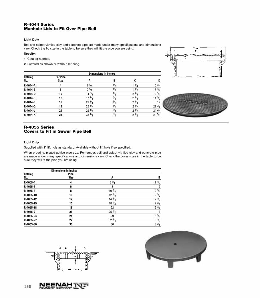
256
R-4055 SeriesCovers to Fit in Sewer Pipe Bell
Light Duty
Supplied with 1” lift hole as standard. Available without lift hole if so specified.
When ordering, please advise pipe size. Remember, bell and spigot vitrified clay and concrete pipeare made under many specifications and dimensions vary. Check the cover sizes in the table to besure they will fit the pipe you are using.
Dimensions in InchesCatalog PipeNo. Size A B
R-4055-4 4 5 3/4 1 1/2R-4055-6 6 8 2R-4055-8 8 10 3/8 2 1/4R-4055-10 10 12 5/8 2 1/2R-4055-12 12 14 3/4 2 1/2R-4055-15 15 18 1/4 2 3/4R-4055-18 18 22 2 3/4R-4055-21 21 25 1/2 3R-4055-24 24 29 3 1/4R-4055-27 27 32 3/4 3 1/2R-4055-30 30 36 3 3/4
R-4044 SeriesManhole Lids to Fit Over Pipe Bell
Light Duty
Bell and spigot vitrified clay and concrete pipe are made under many specifications and dimensionsvary. Check the lid size in the table to be sure they will fit the pipe you are using.
Specify:
1. Catalog number.
2. Lettered as shown or without lettering.
Dimensions in InchesCatalog For PipeNo. Size A B C D
R-4044-A 4 7 1/8 1/2 1 1/4 5 3/8R-4044-B 6 9 1/2 1/2 1 1/2 7 3/4R-4044-D 10 14 3/4 1/2 2 1/4 12 3/4R-4044-E 12 17 1/4 5/8 2 1/4 14 1/2R-4044-F 15 21 1/4 5/8 2 1/4 17R-4044-G 18 25 1/2 5/8 2 1/2 21 3/4R-4044-J 21 29 1/2 3/4 2 1/2 24 7/8R-4044-K 24 33 1/4 3/4 2 1/2 29 1/4
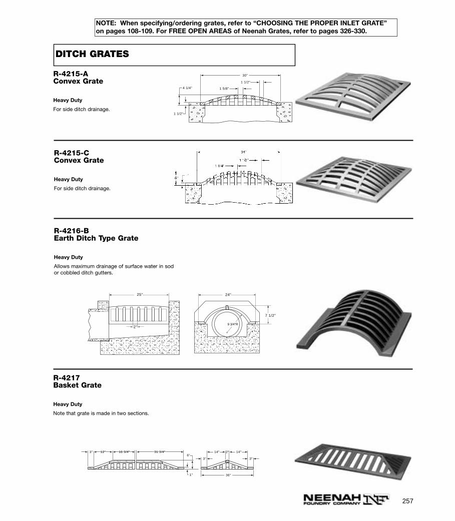
257
NOTE: When specifying/ordering grates, refer to “CHOOSING THE PROPER INLET GRATE”on pages 108-109. For FREE OPEN AREAS of Neenah Grates, refer to pages 326-330.
R-4215-AConvex Grate
Heavy Duty
For side ditch drainage.
4 1/4"
1 1/2"
30"
1 5/8"
1 1/2"
R-4215-CConvex Grate
Heavy Duty
For side ditch drainage.
R-4216-BEarth Ditch Type Grate
Heavy Duty
Allows maximum drainage of surface water in sodor cobbled ditch gutters.
25"
9 3/4"R
7 1/2"
24"
2"
R-4217Basket Grate
Heavy Duty
Note that grate is made in two sections.
6"3"
3"
3"
2"
1"
14"12" 14"16 3/4" 31 3/4"
36"
DITCH GRATES
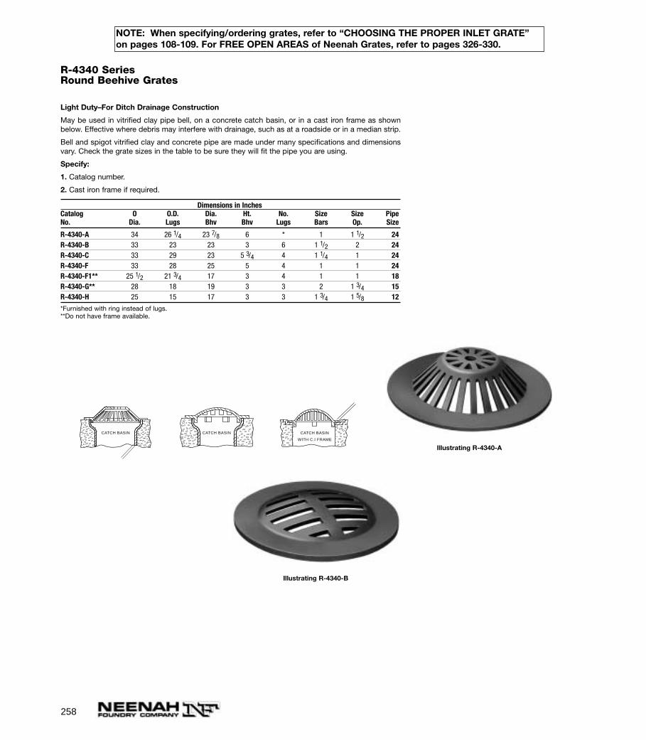
258
NOTE: When specifying/ordering grates, refer to “CHOOSING THE PROPER INLET GRATE”on pages 108-109. For FREE OPEN AREAS of Neenah Grates, refer to pages 326-330.
R-4340 SeriesRound Beehive Grates
Light Duty–For Ditch Drainage Construction
May be used in vitrified clay pipe bell, on a concrete catch basin, or in a cast iron frame as shownbelow. Effective where debris may interfere with drainage, such as at a roadside or in a median strip.
Bell and spigot vitrified clay and concrete pipe are made under many specifications and dimensionsvary. Check the grate sizes in the table to be sure they will fit the pipe you are using.
Specify:
1. Catalog number.
2. Cast iron frame if required.
Dimensions in InchesCatalog O O.D. Dia. Ht. No. Size Size PipeNo. Dia. Lugs Bhv Bhv Lugs Bars Op. Size
R-4340-A 34 26 1/4 23 7/8 6 * 1 1 1/2 24R-4340-B 33 23 23 3 6 1 1/2 2 24R-4340-C 33 29 23 5 3/4 4 1 1/4 1 24R-4340-F 33 28 25 5 4 1 1 24R-4340-F1** 25 1/2 21 3/4 17 3 4 1 1 18R-4340-G** 28 18 19 3 3 2 1 3/4 15R-4340-H 25 15 17 3 3 1 3/4 1 5/8 12
*Furnished with ring instead of lugs.**Do not have frame available.
CATCH BASIN CATCH BASIN
WITH C.I FRAME
CATCH BASIN
Illustrating R-4340-A
Illustrating R-4340-B
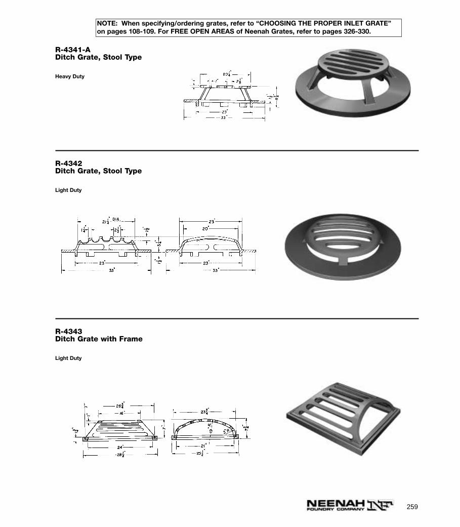
259
NOTE: When specifying/ordering grates, refer to “CHOOSING THE PROPER INLET GRATE”on pages 108-109. For FREE OPEN AREAS of Neenah Grates, refer to pages 326-330.
R-4341-ADitch Grate, Stool Type
Heavy Duty
R-4342Ditch Grate, Stool Type
Light Duty
R-4343Ditch Grate with Frame
Light Duty

260
NOTE: When specifying/ordering grates, refer to “CHOOSING THE PROPER INLET GRATE”on pages 108-109. For FREE OPEN AREAS of Neenah Grates, refer to pages 326-330.
R-4344Railroad Bridge Drain Grate with Frame
Light Duty
R-4345 To R-4346 SeriesSquare Beehive Drainage Grates, Frame
Light Duty — For Off-Roadway Construction
These castings are suitable for use at low points of large graded areas and will drain a substantial vol-ume of surface water from all sides.
Dimensions in InchesCatalog Grate Grate Frame Height HeightNo. Overall Top Size Overall Grate Frame
R-4345 26 x 26 12 x 12 6 1/4R-4346 26 x 26 12 x 12 30 x 30 6 1/4 4
R4345 furnished as grate only.
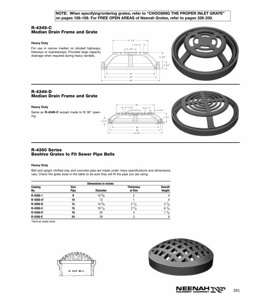
261
NOTE: When specifying/ordering grates, refer to “CHOOSING THE PROPER INLET GRATE”on pages 108-109. For FREE OPEN AREAS of Neenah Grates, refer to pages 326-330.
R-4349-CMedian Drain Frame and Grate
Heavy Duty
For use in narrow median on divided highways,freeways or expressways. Provides large capacitydrainage when required during heavy rainfalls.
24 "
26 "
29 "
3 3 / 4 "
6 3 / 4 "
17 1 / 2 "
1 1 / 2 "
5 3 / 4 "
R-4349-DMedian Drain Frame and Grate
Heavy Duty
Same as R-4349-C except made to fit 36” open-ing.
7 1 / 2 "
1 1 / 2 " 1"5 3 / 4 " 2 5 / 8 "
3 3 / 4 "
29"
39"
36"
42 1/8"
R-4350 SeriesBeehive Grates to Fit Sewer Pipe Bells
Heavy Duty
Bell and spigot vitrified clay and concrete pipe are made under many specifications and dimensionsvary. Check the grate sizes in the table to be sure they will fit the pipe you are using.
Dimensions in inchesCatalog Size Thickness OverallNo. Pipe Diameter at Rim Height
R-4350-1 8 10 3/8 2 4R-4350-A* 10 12 1 4R-4350-B 12 14 3/4 2 1/2 5 1/2R-4350-C 15 18 1/4 2 1/2 6 1/4R-4350-D 18 22 3 7 1/2R-4350-E 24 29 3 9
*Vertical radial slots.
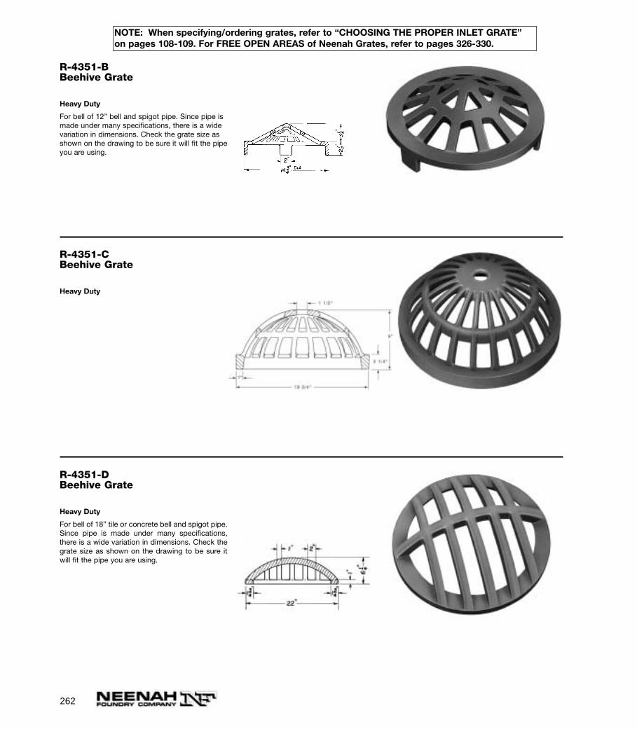
262
NOTE: When specifying/ordering grates, refer to “CHOOSING THE PROPER INLET GRATE”on pages 108-109. For FREE OPEN AREAS of Neenah Grates, refer to pages 326-330.
R-4351-BBeehive Grate
Heavy Duty
For bell of 12” bell and spigot pipe. Since pipe ismade under many specifications, there is a widevariation in dimensions. Check the grate size asshown on the drawing to be sure it will fit the pipeyou are using.
R-4351-CBeehive Grate
Heavy Duty
R-4351-DBeehive Grate
Heavy Duty
For bell of 18” tile or concrete bell and spigot pipe.Since pipe is made under many specifications,there is a wide variation in dimensions. Check thegrate size as shown on the drawing to be sure itwill fit the pipe you are using.

263
NOTE: When specifying/ordering grates, refer to “CHOOSING THE PROPER INLET GRATE”on pages 108-109. For FREE OPEN AREAS of Neenah Grates, refer to pages 326-330.
R-4352Beehive Grate
Heavy Duty
R-4353Beehive Grate with Frame
Light Duty
R-4360 SeriesTurtle-Back Grates and Frames
Light Duty
Various kinds and types of pipe are made undermany specifications and dimensions vary. Checkthe grate sizes in the table to be sure the gratesand frames will fit the pipe you are using.
Dimensions in InchesCatalogNo. A C F G H R
R-4360-A 18 1/4 16 1/4 2 3/4 1 1/2 1 5/8R-4360-B 22 18 2 3/4 1 1/2 1 3/4R-4360-C 23 1/4 17 3 1/2 2 1 1/2 1 3/4R-4360-D 28 1/2 24 3 5/8 1 1 3
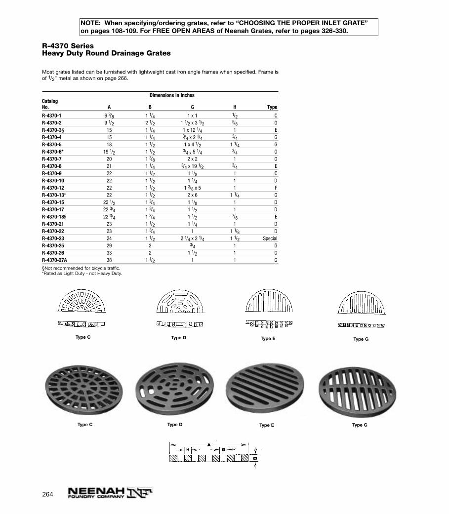
264
NOTE: When specifying/ordering grates, refer to “CHOOSING THE PROPER INLET GRATE”on pages 108-109. For FREE OPEN AREAS of Neenah Grates, refer to pages 326-330.
R-4370 SeriesHeavy Duty Round Drainage Grates
Most grates listed can be furnished with lightweight cast iron angle frames when specified. Frame isof 1/2” metal as shown on page 266.
Dimensions in InchesCatalogNo. A B G H Type
R-4370-1 6 3/8 1 1/4 1 x 1 1/2 CR-4370-2 9 1/2 2 1/2 1 1/2 x 3 1/2 5/8 GR-4370-3§ 15 1 1/4 1 x 12 1/4 1 ER-4370-4 15 1 1/4 3/4 x 2 1/4 3/4 GR-4370-5 18 1 1/2 1 x 4 1/2 1 1/4 GR-4370-6* 19 1/2 1 1/2 3/4 x 5 1/4 3/4 GR-4370-7 20 1 3/8 2 x 2 1 GR-4370-8 21 1 1/4 3/4 x 19 1/2 3/4 ER-4370-9 22 1 1/2 1 1/8 1 CR-4370-10 22 1 1/2 1 1/4 1 DR-4370-12 22 1 1/2 1 3/8 x 5 1 FR-4370-13* 22 1 1/2 2 x 6 1 1/4 GR-4370-15 22 1/2 1 3/4 1 1/8 1 DR-4370-17 22 3/4 1 3/4 1 1/2 1 DR-4370-18§ 22 3/4 1 3/4 1 1/2 7/8 ER-4370-21 23 1 1/2 1 1/4 1 DR-4370-22 23 1 3/4 1 1 1/8 DR-4370-23 24 1 1/2 2 1/4 x 2 1/4 1 1/2 SpecialR-4370-25 29 3 3/4 1 GR-4370-26 33 2 1 1/2 1 GR-4370-27A 38 1 1/2 1 1 G
§Not recommended for bicycle traffic. *Rated as Light Duty - not Heavy Duty.
Type C Type EType D Type G
Type GType C Type D Type E
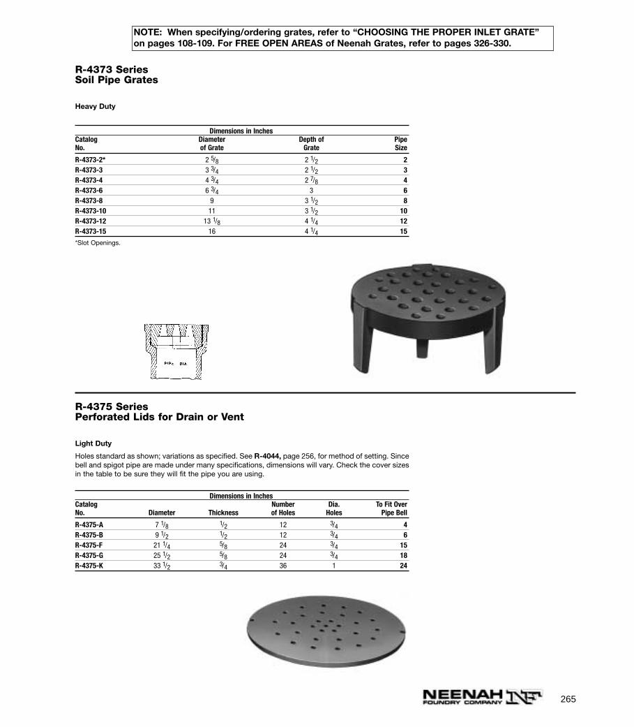
265
NOTE: When specifying/ordering grates, refer to “CHOOSING THE PROPER INLET GRATE”on pages 108-109. For FREE OPEN AREAS of Neenah Grates, refer to pages 326-330.
R-4373 SeriesSoil Pipe Grates
Heavy Duty
Dimensions in InchesCatalog Diameter Depth of PipeNo. of Grate Grate Size
R-4373-2* 2 5/8 2 1/2 2R-4373-3 3 3/4 2 1/2 3R-4373-4 4 3/4 2 7/8 4R-4373-6 6 3/4 3 6R-4373-8 9 3 1/2 8R-4373-10 11 3 1/2 10R-4373-12 13 1/8 4 1/4 12R-4373-15 16 4 1/4 15
*Slot Openings.
R-4375 SeriesPerforated Lids for Drain or Vent
Light Duty
Holes standard as shown; variations as specified. See R-4044, page 256, for method of setting. Sincebell and spigot pipe are made under many specifications, dimensions will vary. Check the cover sizesin the table to be sure they will fit the pipe you are using.
Dimensions in InchesCatalog Number Dia. To Fit OverNo. Diameter Thickness of Holes Holes Pipe Bell
R-4375-A 7 1/8 1/2 12 3/4 4R-4375-B 9 1/2 1/2 12 3/4 6R-4375-F 21 1/4 5/8 24 3/4 15R-4375-G 25 1/2 5/8 24 3/4 18R-4375-K 33 1/2 3/4 36 1 24

266
NOTE: When specifying/ordering grates, refer to “CHOOSING THE PROPER INLET GRATE”on pages 108-109. For FREE OPEN AREAS of Neenah Grates, refer to pages 326-330.
R-4380 SeriesLight Duty Round Drainage Grates, Flat Bar Type
Angle frame as shown can be furnished with many grates on pages 264 to 267. Special frame anchorsfurnished on request.
Specify:
1. Catalog Number.
2. Angle frame when required.
Dimensions in inchesCatalogNo. A B G H
R-4380-AA1 3 3/4 3/8 3/8 3/8R-4380-A 4 1/2 3/8 3/8R-4380-A1 4 3/4 3/8 1/2 3/8R-4380-B1 5 1/2 1/2 1/2R-4380-1 5 1/2 1/2 1/2 1/2R-4380-3 6 1 1/2 3/4R-4380-4 8 1/2 5/8 5/8R-4380-4A1 8 1/2 3/4 1 1R-4380-4A 10 3/4 1/2 1/2R-4380-6 10 1/2 3/4 3 1/2 x 1 1/2 3/4R-4380-7 11 3/4 1 3/4 x 4 1/4 1R-4380-8§ 12 1/2 1 1 1R-4380-9 14 1/4 3/4 1 1R-4380-10 15 5/8 3/4 3/8R-4380-11 15 1 5/8 3/4R-4380-12 15 1/4 1/2 5/8 3/8R-4380-13 16 1 1 1/8 1R-4380-13A 17 3/4 1/2 1 x 3 1/2 1/2R-4380-14 18 3/4 7/8 3/4R-4380-15§ 18 1 1 1/8 1 1/4R-4380-16 19 1/2 3/4 1R-4380-17 19 1 3/4 1/2R-4380-18 20 1 2 x 2 1 1/4R-4380-21§ 24 3/4 1 1/4 5/8R-4380-22 26 5/8 3/4 7/8 3/4R-4380-23 28 1 2 1/8 x 4 2R-4380-24 30 3/4 7/8 3/4R-4380-25§ 32 3/4 1 3/8 1R-4380-26§ 33 1/2 3/4 1 3/8 1R-4380-32 39 3/4 3 1/2 1 1
§Not recommended for bicycle traffic.
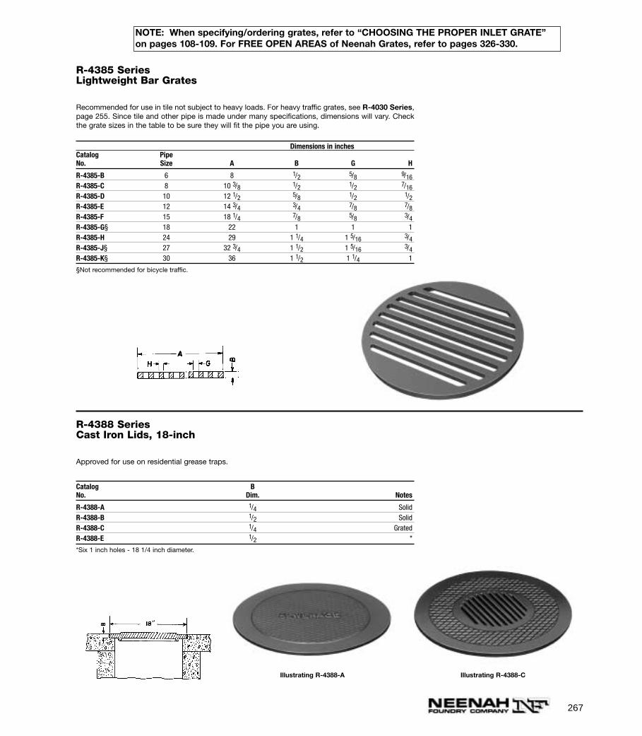
267
NOTE: When specifying/ordering grates, refer to “CHOOSING THE PROPER INLET GRATE”on pages 108-109. For FREE OPEN AREAS of Neenah Grates, refer to pages 326-330.
R-4385 SeriesLightweight Bar Grates
Recommended for use in tile not subject to heavy loads. For heavy traffic grates, see R-4030 Series,page 255. Since tile and other pipe is made under many specifications, dimensions will vary. Checkthe grate sizes in the table to be sure they will fit the pipe you are using.
Dimensions in inchesCatalog PipeNo. Size A B G H
R-4385-B 6 8 1/2 5/8 9/16R-4385-C 8 10 3/8 1/2 1/2 7/16R-4385-D 10 12 1/2 5/8 1/2 1/2R-4385-E 12 14 3/4 3/4 7/8 7/8R-4385-F 15 18 1/4 7/8 5/8 3/4R-4385-G§ 18 22 1 1 1R-4385-H 24 29 1 1/4 1 5/16 3/4R-4385-J§ 27 32 3/4 1 1/2 1 5/16 3/4R-4385-K§ 30 36 1 1/2 1 1/4 1
§Not recommended for bicycle traffic.
R-4388 SeriesCast Iron Lids, 18-inch
Approved for use on residential grease traps.
Catalog BNo. Dim. Notes
R-4388-A 1/4 SolidR-4388-B 1/2 SolidR-4388-C 1/4 GratedR-4388-E 1/2 *
*Six 1 inch holes - 18 1/4 inch diameter.
Illustrating R-4388-A Illustrating R-4388-C
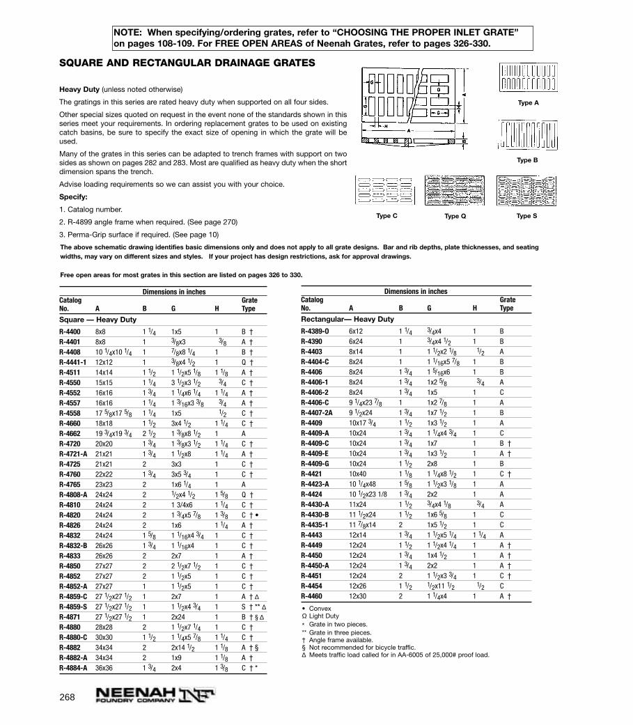
Dimensions in inchesCatalog GrateNo. A B G H Type
Square — Heavy Duty
R-4400 8x8 1 1/4 1x5 1 B †R-4401 8x8 1 3/8x3 3/8 A †R-4408 10 1/4x10 1/4 1 7/8x8 1/4 1 B †R-4441-1 12x12 1 3/8x4 1/2 1 Q †R-4511 14x14 1 1/2 1 1/2x5 1/8 1 1/8 A †R-4550 15x15 1 1/4 3 1/2x3 1/2 3/4 C †R-4552 16x16 1 3/4 1 1/4x6 1/4 1 1/4 A †R-4557 16x16 1 1/4 1 3/16x3 3/8 3/4 A †R-4558 17 5/8x17 5/8 1 1/4 1x5 1/2 C †R-4660 18x18 1 1/2 3x4 1/2 1 1/4 C †R-4662 19 3/4x19 3/4 2 1/2 1 3/8x8 1/2 1 AR-4720 20x20 1 3/4 1 3/8x3 1/2 1 1/4 C †R-4721-A 21x21 1 3/4 1 1/2x8 1 1/4 A †R-4725 21x21 2 3x3 1 C †R-4760 22x22 1 3/4 3x5 3/4 1 C †R-4765 23x23 2 1x6 1/4 1 AR-4808-A 24x24 2 1/2x4 1/2 1 5/8 Q †R-4810 24x24 2 1 3/4x6 1 1/4 C †R-4820 24x24 2 1 3/4x5 7/8 1 3/8 C † •R-4826 24x24 2 1x6 1 1/4 A †R-4832 24x24 1 5/8 1 1/16x4 3/4 1 C †R-4832-B 26x26 1 3/4 1 1/16x4 1 C †R-4833 26x26 2 2x7 1 A †R-4850 27x27 2 2 1/2x7 1/2 1 C †R-4852 27x27 2 1 1/2x5 1 C †R-4852-A 27x27 1 1 1/2x5 1 C †R-4859-C 27 1/2x27 1/2 1 2x7 1 A † ∆R-4859-S 27 1/2x27 1/2 1 1 1/2x4 3/4 1 S † ** ∆R-4871 27 1/2x27 1/2 1 2x24 1 B † § ∆R-4880 28x28 2 1 1/2x7 1/4 1 C †R-4880-C 30x30 1 1/2 1 1/4x5 7/8 1 1/4 C †R-4882 34x34 2 2x14 1/2 1 1/8 A † §R-4882-A 34x34 2 1x9 1 1/8 A †R-4884-A 36x36 1 3/4 2x4 1 3/8 C † *
268
NOTE: When specifying/ordering grates, refer to “CHOOSING THE PROPER INLET GRATE”on pages 108-109. For FREE OPEN AREAS of Neenah Grates, refer to pages 326-330.
Dimensions in inchesCatalog GrateNo. A B G H Type
Rectangular— Heavy Duty
R-4389-O 6x12 1 1/4 3/4x4 1 B R-4390 6x24 1 3/4x4 1/2 1 B R-4403 8x14 1 1 1/2x2 1/8 1/2 AR-4404-C 8x24 1 1 1/16x5 7/8 1 B R-4406 8x24 1 3/4 1 5/16x6 1 B R-4406-1 8x24 1 3/4 1x2 5/8 3/4 AR-4406-2 8x24 1 3/4 1x5 1 CR-4406-C 9 1/4x23 7/8 1 1x2 7/8 1 AR-4407-2A 9 1/2x24 1 3/4 1x7 1/2 1 B R-4409 10x17 3/4 1 1/2 1x3 1/2 1 AR-4409-A 10x24 1 3/4 1 1/4x4 3/4 1 CR-4409-C 10x24 1 3/4 1x7 1 B †R-4409-E 10x24 1 3/4 1x3 1/2 1 A †R-4409-G 10x24 1 1/2 2x8 1 B R-4421 10x40 1 1/8 1 1/4x8 1/2 1 C †R-4423-A 10 1/4x48 1 5/8 1 1/2x3 1/8 1 AR-4424 10 1/2x23 1/8 1 3/4 2x2 1 AR-4430-A 11x24 1 1/2 3/4x4 1/8 3/4 AR-4430-B 11 1/2x24 1 1/2 1x6 5/8 1 CR-4435-1 11 7/8x14 2 1x5 1/2 1 CR-4443 12x14 1 3/4 1 1/2x5 1/4 1 1/4 AR-4449 12x24 1 1/2 1 1/2x4 1/4 1 A †R-4450 12x24 1 3/4 1x4 1/2 1 A †R-4450-A 12x24 1 3/4 2x2 1 A †R-4451 12x24 2 1 1/2x3 3/4 1 C †R-4454 12x26 1 1/2 1/2x11 1/2 1/2 CR-4460 12x30 2 1 1/4x4 1 A †
SQUARE AND RECTANGULAR DRAINAGE GRATES
Heavy Duty (unless noted otherwise)
The gratings in this series are rated heavy duty when supported on all four sides.
Other special sizes quoted on request in the event none of the standards shown in thisseries meet your requirements. In ordering replacement grates to be used on existingcatch basins, be sure to specify the exact size of opening in which the grate will beused.
Many of the grates in this series can be adapted to trench frames with support on twosides as shown on pages 282 and 283. Most are qualified as heavy duty when the shortdimension spans the trench.
Advise loading requirements so we can assist you with your choice.
Specify:
1. Catalog number.
2. R-4899 angle frame when required. (See page 270)
3. Perma-Grip surface if required. (See page 10)
The above schematic drawing identifies basic dimensions only and does not apply to all grate designs. Bar and rib depths, plate thicknesses, and seatingwidths, may vary on different sizes and styles. If your project has design restrictions, ask for approval drawings.
Free open areas for most grates in this section are listed on pages 326 to 330.
Type C Type Q Type S
Type B
Type A
• ConvexΩ Light Duty
* Grate in two pieces.** Grate in three pieces.† Angle frame available.§ Not recommended for bicycle traffic.∆ Meets traffic load called for in AA-6005 of 25,000# proof load.
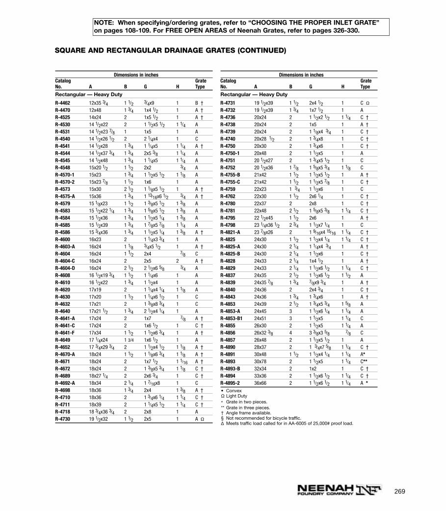
269
NOTE: When specifying/ordering grates, refer to “CHOOSING THE PROPER INLET GRATE”on pages 108-109. For FREE OPEN AREAS of Neenah Grates, refer to pages 326-330.
SQUARE AND RECTANGULAR DRAINAGE GRATES (CONTINUED)
Dimensions in inchesCatalog GrateNo. A B G H Type
Rectangular — Heavy Duty
R-4462 12x35 3/4 1 1/2 3/4x9 1 B †R-4470 12x48 1 3/4 1x4 1/2 1 A †R-4525 14x24 2 1x5 1/2 1 A †R-4530 14 1/2x22 2 1 1/2x5 1/2 1 1/4 A R-4531 14 1/2x23 7/8 1 1x5 1 A R-4540 14 1/2x26 1/2 2 2 1/4x4 1 CR-4541 14 1/2x28 1 3/4 1 1/4x5 1 1/4 A †R-4544 14 1/2x37 3/4 1 3/4 2x5 3/8 1 1/4 A R-4545 14 1/2x48 1 3/4 1 1/4x5 1 1/4 A R-4548 15x20 1/2 1 1/2 2x2 3/4 A R-4570-1 15x23 1 3/4 1 1/2x5 1/2 1 1/8 A R-4570-2 15x23 7/8 1 1/2 1x6 1 A R-4573 15x30 2 1/2 1 1/8x5 1/2 1 A †R-4575-A 15x36 1 3/4 1 13/16x6 1/2 3/4 A †R-4579 15 1/8x23 1 1/2 1 3/8x5 1/2 1 3/8 A R-4583 15 1/2x22 1/4 1 3/4 1 5/8x5 1/2 1 3/8 A R-4584 15 1/2x36 1 3/4 1 1/2x5 1/4 1 3/8 A R-4585 15 1/2x39 1 3/4 1 7/8x5 7/8 1 1/4 A R-4586 15 3/4x36 1 3/4 1 1/2x5 1/4 1 3/8 A †R-4600 16x23 2 1 1/4x3 3/4 1 A R-4603-A 16x24 1 1/8 3/4x5 1/2 1 A †R-4604 16x24 1 1/2 2x4 7/8 CR-4604-C 16x24 2 2x5 2 A †R-4604-D 16x24 2 1/2 2 1/2x6 5/8 3/4 A R-4608 16 1/2x19 3/4 1 1/2 1 1/4x6 1 A R-4610 16 1/2x22 1 3/4 1 1/2x4 1 A R-4620 17x19 2 1 1/4x4 1/4 1 1/8 A R-4630 17x20 1 1/2 1 1/4x6 1/2 1 CR-4632 17x21 2 1 3/8x8 3/4 1 CR-4640 17x21 1/2 1 3/4 2 1/2x4 1/4 1 A R-4641-A 17x24 2 1x7 7/8 A †R-4641-C 17x24 2 1x6 1/2 1 C †R-4641-F 17x34 1 1/2 1 1/2x6 3/4 1 A †R-4649 17 1/4x24 1 3/4 1x6 1/2 1 A R-4652 17 3/4x29 3/4 2 1 1/2x4 1/2 1 1/8 A †R-4670-A 18x24 1 1/2 1 1/8x6 3/4 1 1/8 A †R-4671 18x24 2 1x7 1/2 1 1/16 A †R-4672 18x24 2 1 3/8x5 3/4 1 1/8 C †R-4689 18x27 1/4 2 2x6 3/4 1 C †R-4692-A 18x34 2 1/4 1 7/16x8 1 CR-4698 18x36 1 3/4 2x4 1 3/8 A †R-4710 18x36 2 1 3/4x6 1/4 1 1/4 C †R-4711 18x39 2 1 1/4x5 1/2 1 1/4 C †R-4718 18 3/4x36 3/4 2 2x8 1 A R-4730 19 1/2x32 1 1/2 2x5 1 A Ω
Dimensions in inchesCatalog GrateNo. A B G H Type
Rectangular — Heavy Duty
R-4731 19 1/2x39 1 1/2 2x4 1/2 1 C ΩR-4732 19 1/2x39 1 3/4 1x7 1/2 1 A R-4736 20x24 2 1 1/2x2 1/2 1 1/4 C †R-4738 20x24 2 1x5 1 A †R-4739 20x24 2 1 1/8x4 3/4 1 C †R-4740 20x28 1/2 2 1 3/4x8 1 C †R-4750 20x30 2 1 3/4x6 1 C †R-4750-1 20x48 2 1 1/2x5 1 A R-4751 20 1/2x27 2 1 3/4x5 1/2 1 CR-4752 20 1/2x36 1 7/8 1 5/8x5 3/4 1 1/8 CR-4755-B 21x42 1 1/2 1 1/2x5 1/2 1 A †R-4755-C 21x42 1 1/2 1 1/2x5 7/8 1 C †R-4759 22x23 1 3/4 1 1/2x6 1 CR-4762 22x30 1 1/2 2x6 1/4 1 C †R-4780 22x37 2 2x8 1 C †R-4781 22x48 2 1/2 1 5/8x5 3/8 1 1/4 C †R-4795 22 1/2x45 1 1/2 2x6 1 A †R-4798 23 1/4x36 1/2 2 3/4 1 1/2x7 1/4 1 CR-4821-A 23 7/8x26 2 1 9/16x4 15/16 1 1/4 C †R-4825 24x30 1 1/2 1 1/2x4 1/4 1 1/4 C †R-4825-A 24x30 2 1/4 1 1/4x4 3/4 1 A †R-4825-B 24x30 2 1/4 1 1/2x6 1 C †R-4828 24x33 2 1/4 1x4 1/2 1 A †R-4829 24x33 2 1/4 1 1/2x6 1/2 1 1/4 C †R-4837 24x35 2 1/2 1 1/2x6 1/2 1 1/2 A R-4839 24x35 7/8 1 3/4 7/8x9 3/4 1 A †R-4840 24x36 2 2x4 3/4 1 C †R-4843 24x36 1 3/4 1 3/4x6 1 A †R-4853 24x39 2 1/2 1 3/4x5 3/4 1 5/8 AR-4853-A 24x45 3 1 1/2x6 1/4 1 1/4 A R-4853-B1 24x51 3 1 1/2x5 1 1/4 CR-4855 26x30 2 1 1/2x5 1 1/4 AR-4856 26x32 3/8 4 3 3/8x3 5/8 7/8 C R-4857 26x48 2 1 1/2x5 1/2 1 A R-4890 28x37 2 1 3/4x7 5/8 1 1/4 C †R-4891 30x48 1 1/2 1 1/2x4 1/4 1 1/4 A*R-4893 30x78 2 1 1/2x5 1 1/4 C**R-4893-B 32x34 2 1x2 1 C †R-4894 33x36 2 1 1/2x6 1/2 1 1/4 C †R-4895-2 36x66 2 1 1/2x6 1/2 1 1/4 A *• ConvexΩ Light Duty
* Grate in two pieces.** Grate in three pieces.† Angle frame available.§ Not recommended for bicycle traffic.∆ Meets traffic load called for in AA-6005 of 25,000# proof load.
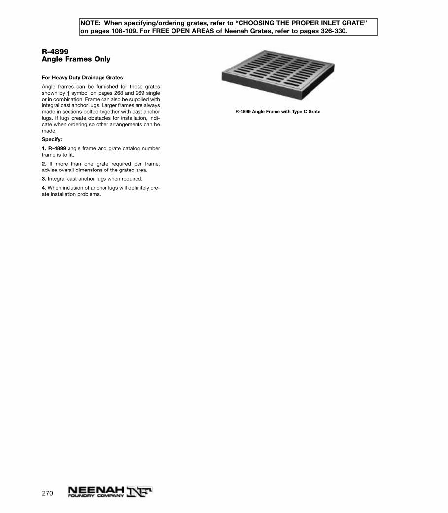
270
NOTE: When specifying/ordering grates, refer to “CHOOSING THE PROPER INLET GRATE”on pages 108-109. For FREE OPEN AREAS of Neenah Grates, refer to pages 326-330.
R-4899Angle Frames Only
For Heavy Duty Drainage Grates
Angle frames can be furnished for those gratesshown by † symbol on pages 268 and 269 singleor in combination. Frame can also be supplied withintegral cast anchor lugs. Larger frames are alwaysmade in sections bolted together with cast anchorlugs. If lugs create obstacles for installation, indi-cate when ordering so other arrangements can bemade.
Specify:
1. R-4899 angle frame and grate catalog numberframe is to fit.
2. If more than one grate required per frame,advise overall dimensions of the grated area.
3. Integral cast anchor lugs when required.
4. When inclusion of anchor lugs will definitely cre-ate installation problems.
R-4899 Angle Frame with Type C Grate

271
R-4905 SeriesSign and Marker Bases
Heavy Duty
Bases only furnished in cast iron. Special lettering available at additional cost.
Cored hole for sign post is standard. Pipe tap is available if specified.
Specify:
1. Catalog Number.
2. Size of pipe tap if required.
Dimensions in inchesCatalogNo. A B D*
Round
R-4905-B 15 3 1 1/2R-4905-C 20 5 1 3/4
*Dimensions revised if specified.
Illustrating Round Type
R-4907Base Casting for TelescopingPost
Heavy Duty
Base furnished with three holes for rigid anchor-age. Round base has opening for square telescop-ing post. Lettering on base as shown or special let-tering if specified.
Also available for use with 2” diameter galvanizedpipe.
Specify:
1. Without lettering or lettering other than shown.
SIGN AND FLAG BASES
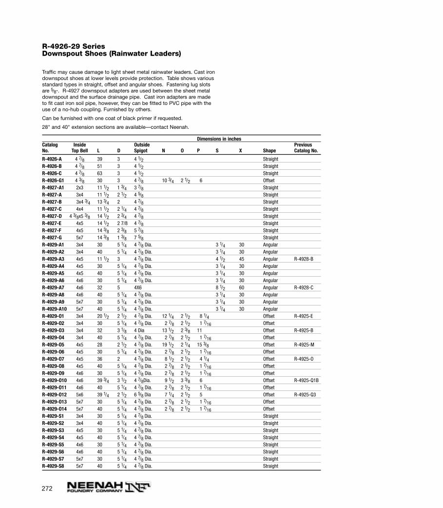
272
R-4926-29 SeriesDownspout Shoes (Rainwater Leaders)
Traffic may cause damage to light sheet metal rainwater leaders. Cast irondownspout shoes at lower levels provide protection. Table shows variousstandard types in straight, offset and angular shoes. Fastening lug slotsare 5/8”. R-4927 downspout adapters are used between the sheet metaldownspout and the surface drainage pipe. Cast iron adapters are madeto fit cast iron soil pipe, however, they can be fitted to PVC pipe with theuse of a no-hub coupling. Furnished by others.
Can be furnished with one coat of black primer if requested.
28" and 40" extension sections are available—contact Neenah.
Dimensions in inchesCatalog Inside Outside PreviousNo. Top Bell L D Spigot N O P S X Shape Catalog No.
R-4926-A 4 7/8 39 3 4 1/2 StraightR-4926-B 4 7/8 51 3 4 1/2 StraightR-4926-C 4 7/8 63 3 4 1/2 StraightR-4926-G1 4 3/8 30 3 4 7/8 10 3/4 2 1/2 6 OffsetR-4927-A1 2x3 11 1/2 1 3/4 3 7/8 StraightR-4927-A 3x4 11 1/2 2 1/2 4 5/8 StraightR-4927-B 3x4 3/4 13 3/4 2 4 7/8 StraightR-4927-C 4x4 11 1/2 2 1/4 4 7/8 StraightR-4927-D 4 3/8x5 3/8 14 1/2 2 3/4 4 7/8 StraightR-4927-E 4x5 14 1/2 2 7/8 4 7/8 StraightR-4927-F 4x5 14 3/8 2 3/8 5 7/8 StraightR-4927-G 5x7 14 3/8 1 3/8 7 5/8 StraightR-4929-A1 3x4 30 5 1/4 4 7/8 Dia. 3 1/4 30 AngularR-4929-A2 3x4 40 5 1/4 4 7/8 Dia. 3 1/4 30 AngularR-4929-A3 4x5 11 1/2 3 4 7/8 Dia. 4 1/2 45 Angular R-4928-BR-4929-A4 4x5 30 5 1/4 4 7/8 Dia. 3 1/4 30 AngularR-4929-A5 4x5 40 5 1/4 4 7/8 Dia. 3 1/4 30 AngularR-4929-A6 4x6 30 5 1/4 4 7/8 Dia. 3 1/4 30 AngularR-4929-A7 4x6 32 5 4X6 8 1/2 60 Angular R-4928-CR-4929-A8 4x6 40 5 1/4 4 7/8 Dia. 3 1/4 30 AngularR-4929-A9 5x7 30 5 1/4 4 7/8 Dia. 3 1/4 30 AngularR-4929-A10 5x7 40 5 1/4 4 7/8 Dia. 3 1/4 30 AngularR-4929-O1 3x4 20 1/2 2 1/2 4 7/8 Dia. 12 1/4 2 1/2 8 1/4 Offset R-4925-ER-4929-O2 3x4 30 5 1/4 4 7/8 Dia. 2 7/8 2 1/2 1 7/16 OffsetR-4929-O3 3x4 32 3 1/8 4 Dia 13 1/2 2 3/8 11 Offset R-4925-BR-4929-O4 3x4 40 5 1/4 4 7/8 Dia. 2 7/8 2 1/2 1 7/16 OffsetR-4929-O5 4x5 28 2 1/2 4 7/8 Dia. 19 1/2 2 1/4 15 3/8 Offset R-4925-MR-4929-O6 4x5 30 5 1/4 4 7/8 Dia. 2 7/8 2 1/2 1 7/16 OffsetR-4929-O7 4x5 36 2 4 7/8 Dia. 8 1/2 2 1/2 4 1/4 Offset R-4925-OR-4929-O8 4x5 40 5 1/4 4 7/8 Dia. 2 7/8 2 1/2 1 7/16 OffsetR-4929-O9 4x6 30 5 1/4 4 7/8 Dia. 2 7/8 2 1/2 1 7/16 OffsetR-4929-O10 4x6 39 3/4 3 1/2 4 7/8Dia. 9 1/2 3 3/8 6 Offset R-4925-Q1BR-4929-O11 4x6 40 5 1/4 4 7/8 Dia. 2 7/8 2 1/2 1 7/16 OffsetR-4929-O12 5x6 39 1/4 2 1/2 6 5/8 Dia 7 1/4 2 1/2 5 Offset R-4925-Q3R-4929-O13 5x7 30 5 1/4 4 7/8 Dia. 2 7/8 2 1/2 1 7/16 OffsetR-4929-O14 5x7 40 5 1/4 4 7/8 Dia. 2 7/8 2 1/2 1 7/16 OffsetR-4929-S1 3x4 30 5 1/4 4 7/8 Dia. StraightR-4929-S2 3x4 40 5 1/4 4 7/8 Dia. StraightR-4929-S3 4x5 30 5 1/4 4 7/8 Dia. StraightR-4929-S4 4x5 40 5 1/4 4 7/8 Dia. StraightR-4929-S5 4x6 30 5 1/4 4 7/8 Dia. StraightR-4929-S6 4x6 40 5 1/4 4 7/8 Dia. StraightR-4929-S7 5x7 30 5 1/4 4 7/8 Dia. StraightR-4929-S8 5x7 40 5 1/4 4 7/8 Dia. Straight
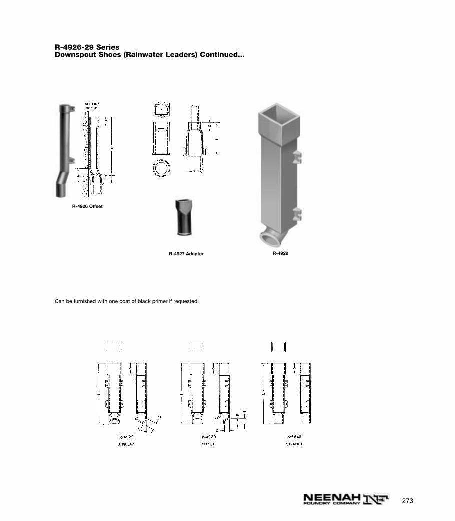
273
R-4927 Adapter R-4929
R-4926 Offset
R-4926-29 SeriesDownspout Shoes (Rainwater Leaders) Continued...
Can be furnished with one coat of black primer if requested.
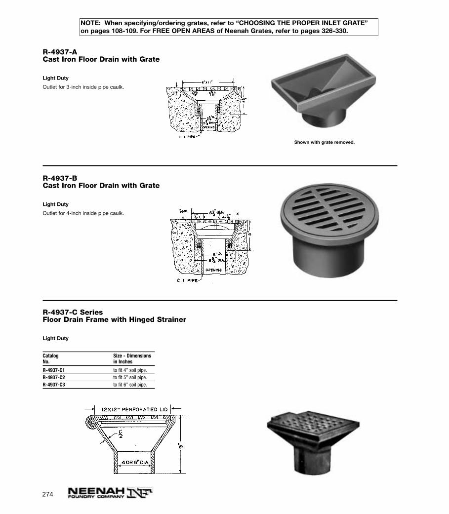
274
R-4937-ACast Iron Floor Drain with Grate
Light Duty
Outlet for 3-inch inside pipe caulk.
Shown with grate removed.
R-4937-BCast Iron Floor Drain with Grate
Light Duty
Outlet for 4-inch inside pipe caulk.
R-4937-C SeriesFloor Drain Frame with Hinged Strainer
Light Duty
Catalog Size - DimensionsNo. in Inches
R-4937-C1 to fit 4” soil pipe.R-4937-C2 to fit 5” soil pipe.R-4937-C3 to fit 6” soil pipe.
NOTE: When specifying/ordering grates, refer to “CHOOSING THE PROPER INLET GRATE”on pages 108-109. For FREE OPEN AREAS of Neenah Grates, refer to pages 326-330.
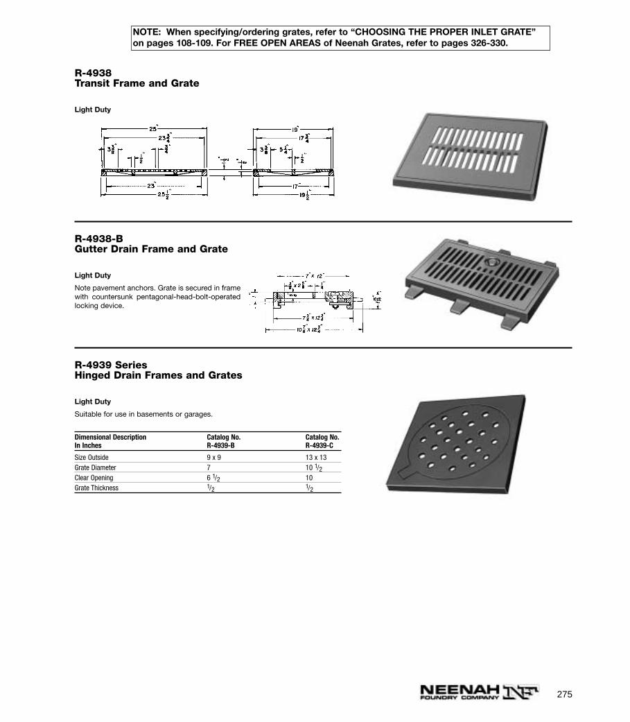
275
R-4938-BGutter Drain Frame and Grate
Light Duty
Note pavement anchors. Grate is secured in framewith countersunk pentagonal-head-bolt-operatedlocking device.
R-4939 SeriesHinged Drain Frames and Grates
Light Duty
Suitable for use in basements or garages.
Dimensional Description Catalog No. Catalog No.In Inches R-4939-B R-4939-C
Size Outside 9 x 9 13 x 13Grate Diameter 7 10 1/2Clear Opening 6 1/2 10Grate Thickness 1/2 1/2
R-4938Transit Frame and Grate
Light Duty
NOTE: When specifying/ordering grates, refer to “CHOOSING THE PROPER INLET GRATE”on pages 108-109. For FREE OPEN AREAS of Neenah Grates, refer to pages 326-330.
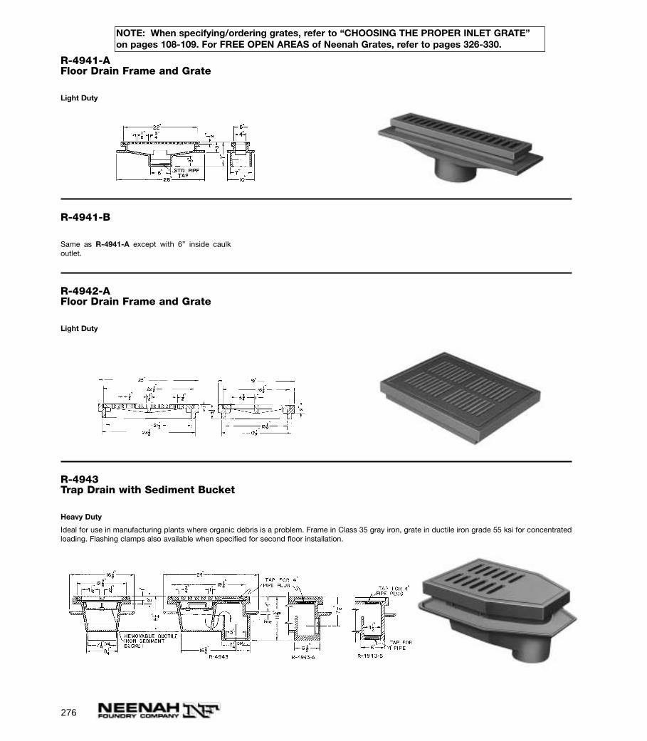
276
R-4941-AFloor Drain Frame and Grate
Light Duty
R-4941-B
Same as R-4941-A except with 6” inside caulkoutlet.
R-4942-AFloor Drain Frame and Grate
Light Duty
R-4943Trap Drain with Sediment Bucket
Heavy Duty
Ideal for use in manufacturing plants where organic debris is a problem. Frame in Class 35 gray iron, grate in ductile iron grade 55 ksi for concentratedloading. Flashing clamps also available when specified for second floor installation.
NOTE: When specifying/ordering grates, refer to “CHOOSING THE PROPER INLET GRATE”on pages 108-109. For FREE OPEN AREAS of Neenah Grates, refer to pages 326-330.

277
R-4943-A
Same as R-4943 except with side outlet tapped toreceive standard 4” pipe. See detail.
R-4943-B
Same as R-4943 except with bottom outlet tappedto receive standard 4” pipe. See detail.
R-4950 To R-4951Cast Iron Cleanout Frames andDoors
R-4950 Type A Series medium duty cleanouts arefor use in chimneys or for ash pit doors on inciner-ators. Not recommended for installations subject-ed to intense heat.
Dimensions in inchesCatalog No.Size A B F M N
R-4950 Type A - Medium
8 x 8 8 8 2 2 210 x 10 10 10 2 2 212 x 12 12 12 2 2 212 x 16 12 16 3 3 316 x 12 16 12 4 2 1/2 2 1/216 x 16 16 16 3 3 316 x 18 16 18 4 3 316 x 20 16 20 4 3 320 x 16 20 16 4 3 320 x 20 20 20 4 3 320 x 24 20 24 4 3 324 x 24 24 24 4 3 324 x 30 24 30 4 3 3
R-4951 Type B - Heavy
16 x 18 16 18 4 3 1/2 3 1/2
R-4972 SeriesConcrete Floor Protectors
Cast iron grids provide a surface resistant toimpact, abrasion and corrosion—afford bettertraction. Laid in areas subjected to heavy trucktraffic, floor grids are invaluable in protecting thefloor from excessive wear. Concrete is pouredflush with the top of the casting so that theexposed iron protects the concrete. Grate ispushed into concrete as it is poured.
Dimensions in inchesCatalogNo. Size Thickness
R-4972-C 24 x 24 7/8R-4972-D 18 x 36 7/8
23 7/8"
1 11/16" 7/16"7/8"
Type A Type B
NOTE: When specifying/ordering grates, refer to “CHOOSING THE PROPER INLET GRATE”on pages 108-109. For FREE OPEN AREAS of Neenah Grates, refer to pages 326-330.
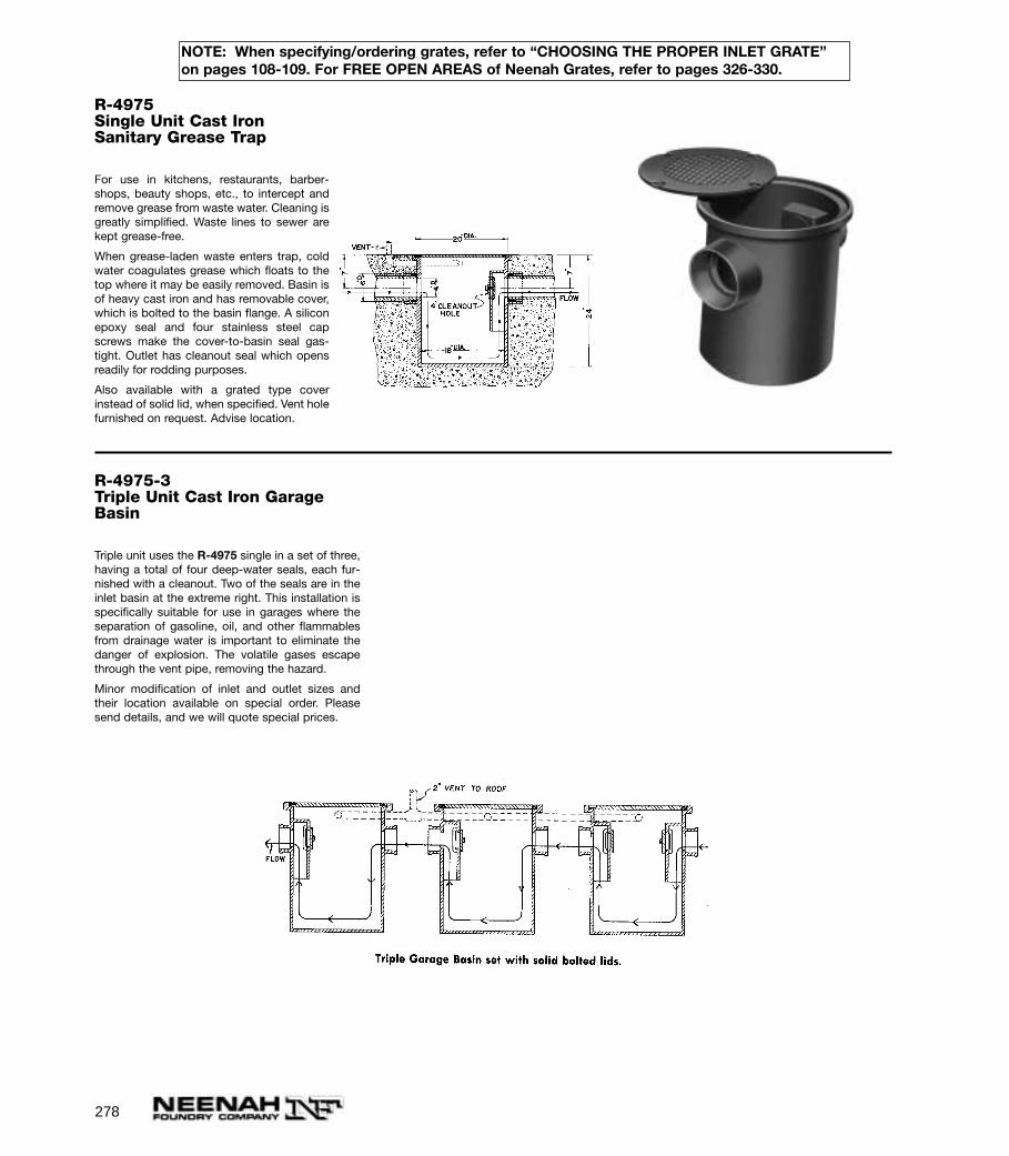
278
R-4975Single Unit Cast IronSanitary Grease Trap
For use in kitchens, restaurants, barber-shops, beauty shops, etc., to intercept andremove grease from waste water. Cleaning isgreatly simplified. Waste lines to sewer arekept grease-free.
When grease-laden waste enters trap, coldwater coagulates grease which floats to thetop where it may be easily removed. Basin isof heavy cast iron and has removable cover,which is bolted to the basin flange. A siliconepoxy seal and four stainless steel capscrews make the cover-to-basin seal gas-tight. Outlet has cleanout seal which opensreadily for rodding purposes.
Also available with a grated type coverinstead of solid lid, when specified. Vent holefurnished on request. Advise location.
R-4975-3Triple Unit Cast Iron GarageBasin
Triple unit uses the R-4975 single in a set of three,having a total of four deep-water seals, each fur-nished with a cleanout. Two of the seals are in theinlet basin at the extreme right. This installation isspecifically suitable for use in garages where theseparation of gasoline, oil, and other flammablesfrom drainage water is important to eliminate thedanger of explosion. The volatile gases escapethrough the vent pipe, removing the hazard.
Minor modification of inlet and outlet sizes andtheir location available on special order. Pleasesend details, and we will quote special prices.
NOTE: When specifying/ordering grates, refer to “CHOOSING THE PROPER INLET GRATE”on pages 108-109. For FREE OPEN AREAS of Neenah Grates, refer to pages 326-330.

279
R-4976-7 SeriesType A and B Cast Iron Areaway Gratings
Light Duty
For use over window wells providing maximum light transmission. Also suitable for use as ventilatingand shaft gratings.
Not recommended for bicycle traffic.
Specify:
1. Catalog Number.
2. Type A or Type B design.
Dimensions in inchesCatalogNo. A B Openings Bars
Half Round
R-4976-1 12 x 24 1 1 1/4 1/4R-4976-2 15 x 30 1 1 1/4 1/2R-4976-3 20 x 40 1 1/4 1 1/4 5/16R-4976-4 24 x 48 1 1/4 1 1/4 5/16
Rectangular
R-4977-1 12 x 24 1 1 1/4 1/4R-4977-2 15 x 30 1 1 1/4 1/4R-4977-3 20 x 40 1 1/4 1 1/4 5/16R-4977-4 24 x 48 1 1/4 1 1/4 5/16R-4977-5 30 x 60 1 1/4 1 1/4 5/16
Note: On Type A, grate size exceeds dimension “A” by 1 1/2” on all except wall side. On Type B, grate is 1” widerand 2” longer than dimension “A”.
Type A with lip to set on top of areaway wall. Type B to set in recess of areaway wall.Illustrating R-4976
Illustrating R-4977
NOTE: When specifying/ordering grates, refer to “CHOOSING THE PROPER INLET GRATE”on pages 108-109. For FREE OPEN AREAS of Neenah Grates, refer to pages 326-330.
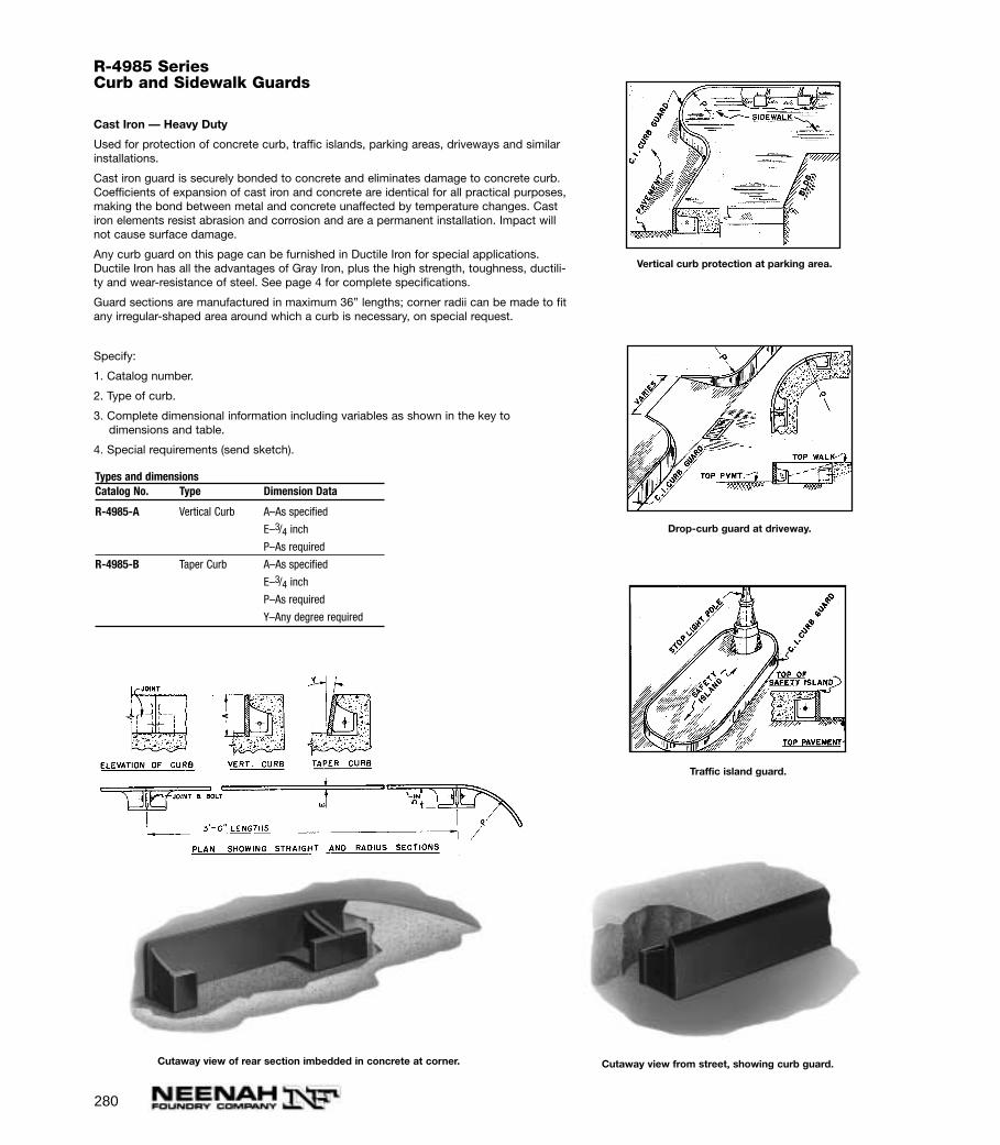
280
R-4985 SeriesCurb and Sidewalk Guards
Cast Iron — Heavy Duty
Used for protection of concrete curb, traffic islands, parking areas, driveways and similarinstallations.
Cast iron guard is securely bonded to concrete and eliminates damage to concrete curb.Coefficients of expansion of cast iron and concrete are identical for all practical purposes,making the bond between metal and concrete unaffected by temperature changes. Castiron elements resist abrasion and corrosion and are a permanent installation. Impact willnot cause surface damage.
Any curb guard on this page can be furnished in Ductile Iron for special applications.Ductile Iron has all the advantages of Gray Iron, plus the high strength, toughness, ductili-ty and wear-resistance of steel. See page 4 for complete specifications.
Guard sections are manufactured in maximum 36” lengths; corner radii can be made to fitany irregular-shaped area around which a curb is necessary, on special request.
Specify:
1. Catalog number.
2. Type of curb.
3. Complete dimensional information including variables as shown in the key to dimensions and table.
4. Special requirements (send sketch).
Types and dimensionsCatalog No. Type Dimension Data
R-4985-A Vertical Curb A–As specified
E–3/4 inch
P–As required
R-4985-B Taper Curb A–As specified
E–3/4 inch
P–As required
Y–Any degree required
Cutaway view of rear section imbedded in concrete at corner.
Vertical curb protection at parking area.
Drop-curb guard at driveway.
Traffic island guard.
Cutaway view from street, showing curb guard.
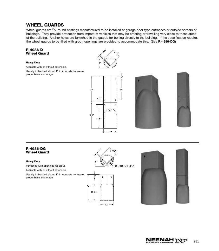
281
R-4986-DWheel Guard
Heavy Duty
Available with or without extension.
Usually imbedded about 1” in concrete to insureproper base anchorage.
R-4986-DGWheel Guard
Heavy Duty
Furnished with openings for grout.
Available with or without extension.
Usually imbedded about 1” in concrete to insureproper base anchorage.
WHEEL GUARDSWheel guards are 3/4 round castings manufactured to be installed at garage door type entrances or outside corners ofbuildings. They provide protection from impact of vehicles that may be entering or travelling very close to these areasof the building. Anchor holes are furnished in the guards for bolting directly to the building. If the specification requiresthe wheel guards to be filled with grout, openings are provided to accommodate this. (See R-4986-DG)
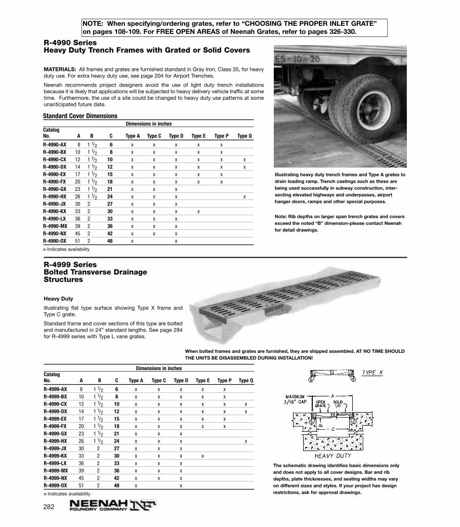
282
R-4999 SeriesBolted Transverse DrainageStructures
Heavy Duty
Illustrating flat type surface showing Type X frame andType C grate.
Standard frame and cover sections of this type are boltedand manufactured in 24” standard lengths. See page 284for R-4999 series with Type L vane grates.
Dimensions in inchesCatalogNo. A B C Type A Type C Type D Type E Type P Type Q
R-4999-AX 8 1 1/2 6 x x x x xR-4999-BX 10 1 1/2 8 x x x x xR-4999-CX 12 1 1/2 10 x x x x x xR-4999-DX 14 1 1/2 12 x x x x x xR-4999-EX 17 1 1/2 15 x x x x xR-4999-FX 20 1 1/2 18 x x x x xR-4999-GX 23 1 1/2 21 x x xR-4999-HX 26 1 1/2 24 x x x xR-4999-JX 30 2 27 x x xR-4999-KX 33 2 30 x x x xR-4999-LX 36 2 33 x x xR-4999-MX 39 2 36 x x xR-4999-NX 45 2 42 x x xR-4999-OX 51 2 48 x x
x-Indicates availability
R-4990 SeriesHeavy Duty Trench Frames with Grated or Solid Covers
MATERIALS: All frames and grates are furnished standard in Gray Iron, Class 35, for heavyduty use. For extra heavy duty use, see page 204 for Airport Trenches.
Neenah recommends project designers avoid the use of light duty trench installationsbecause it is likely that applications will be subjected to heavy delivery vehicle traffic at sometime. Furthermore, the use of a site could be changed to heavy duty use patterns at someunanticipated future date.
Standard Cover DimensionsDimensions in inches
CatalogNo. A B C Type A Type C Type D Type E Type P Type Q
R-4990-AX 8 1 1/2 6 x x x x xR-4990-BX 10 1 1/2 8 x x x x xR-4990-CX 12 1 1/2 10 x x x x x xR-4990-DX 14 1 1/2 12 x x x x x xR-4990-EX 17 1 1/2 15 x x x x xR-4990-FX 20 1 1/2 18 x x x x xR-4990-GX 23 1 1/2 21 x x xR-4990-HX 26 1 1/2 24 x x x xR-4990-JX 30 2 27 x x xR-4990-KX 33 2 30 x x x xR-4990-LX 36 2 33 x x xR-4990-MX 39 2 36 x x xR-4990-NX 45 2 42 x x xR-4990-OX 51 2 48 x x
x-Indicates availability
Illustrating heavy duty trench frames and Type A grates todrain loading ramp. Trench castings such as these arebeing used successfully in subway construction, inter-secting elevated highways and underpasses, airporthanger doors, ramps and other special purposes.
When bolted frames and grates are furnished, they are shipped assembled. AT NO TIME SHOULDTHE UNITS BE DISASSEMBLED DURING INSTALLATION!
The schematic drawing identifies basic dimensions onlyand does not apply to all cover designs. Bar and ribdepths, plate thicknesses, and seating widths may varyon different sizes and styles. If your project has designrestrictions, ask for approval drawings.
NOTE: When specifying/ordering grates, refer to “CHOOSING THE PROPER INLET GRATE”on pages 108-109. For FREE OPEN AREAS of Neenah Grates, refer to pages 326-330.
Note: Rib depths on larger span trench grates and coversexceed the noted “B” dimension-please contact Neenahfor detail drawings.
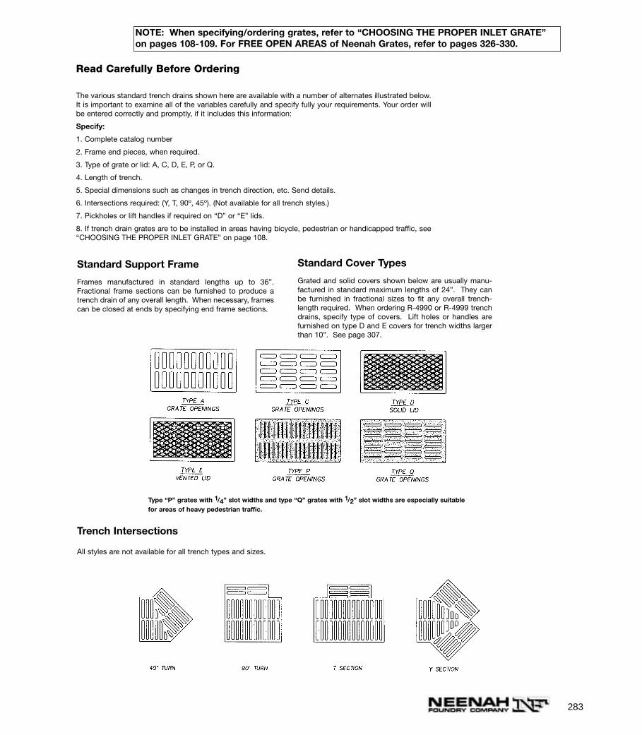
283
Read Carefully Before Ordering
The various standard trench drains shown here are available with a number of alternates illustrated below.It is important to examine all of the variables carefully and specify fully your requirements. Your order willbe entered correctly and promptly, if it includes this information:
Specify:
1. Complete catalog number
2. Frame end pieces, when required.
3. Type of grate or lid: A, C, D, E, P, or Q.
4. Length of trench.
5. Special dimensions such as changes in trench direction, etc. Send details.
6. Intersections required: (Y, T, 90º, 45º). (Not available for all trench styles.)
7. Pickholes or lift handles if required on “D” or “E” lids.
8. If trench drain grates are to be installed in areas having bicycle, pedestrian or handicapped traffic, see“CHOOSING THE PROPER INLET GRATE” on page 108.
Trench Intersections
All styles are not available for all trench types and sizes.
Standard Support Frame
Frames manufactured in standard lengths up to 36”.Fractional frame sections can be furnished to produce atrench drain of any overall length. When necessary, framescan be closed at ends by specifying end frame sections.
Standard Cover Types
Grated and solid covers shown below are usually manu-factured in standard maximum lengths of 24”. They canbe furnished in fractional sizes to fit any overall trench-length required. When ordering R-4990 or R-4999 trenchdrains, specify type of covers. Lift holes or handles arefurnished on type D and E covers for trench widths largerthan 10”. See page 307.
Type “P” grates with 1/4” slot widths and type “Q” grates with 1/2” slot widths are especially suitablefor areas of heavy pedestrian traffic.
NOTE: When specifying/ordering grates, refer to “CHOOSING THE PROPER INLET GRATE”on pages 108-109. For FREE OPEN AREAS of Neenah Grates, refer to pages 326-330.
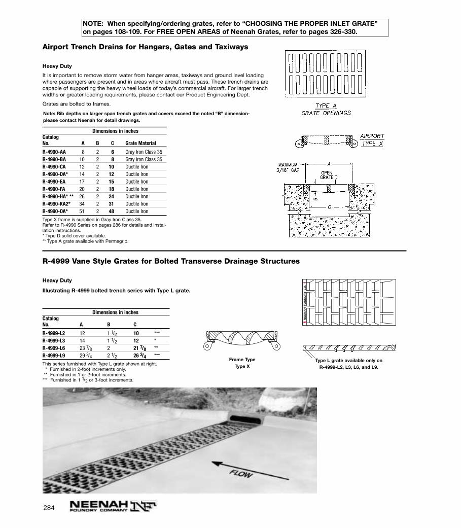
284
Airport Trench Drains for Hangars, Gates and Taxiways
Heavy Duty
It is important to remove storm water from hanger areas, taxiways and ground level loadingwhere passengers are present and in areas where aircraft must pass. These trench drains arecapable of supporting the heavy wheel loads of today’s commercial aircraft. For larger trenchwidths or greater loading requirements, please contact our Product Engineering Dept.
Grates are bolted to frames.
Dimensions in inchesCatalogNo. A B C Grate Material
R-4990-AA 8 2 6 Gray Iron Class 35R-4990-BA 10 2 8 Gray Iron Class 35R-4990-CA 12 2 10 Ductile IronR-4990-DA* 14 2 12 Ductile IronR-4990-EA 17 2 15 Ductile IronR-4990-FA 20 2 18 Ductile IronR-4990-HA* ** 26 2 24 Ductile IronR-4990-KA2* 34 2 31 Ductile IronR-4990-OA* 51 2 48 Ductile Iron
Type X frame is supplied in Gray Iron Class 35.Refer to R-4990 Series on pages 286 for details and instal-lation instructions.* Type D solid cover available.** Type A grate available with Permagrip.
R-4999 Vane Style Grates for Bolted Transverse Drainage Structures
Heavy Duty
Illustrating R-4999 bolted trench series with Type L grate.
Dimensions in inchesCatalogNo. A B C
R-4999-L2 12 1 1/2 10 ***R-4999-L3 14 1 1/2 12 *R-4999-L6 23 7/8 2 21 7/8 **R-4999-L9 29 3/4 2 1/2 26 3/4 ***
This series furnished with Type L grate shown at right.* Furnished in 2-foot increments only.
** Furnished in 1 or 2-foot increments.*** Furnished in 1 1/2 or 3-foot increments.
NE
EN
AH
FO
UN
DR
Y C
O.
Type L grate available only on R-4999-L2, L3, L6, and L9.
Frame Type Type X
NOTE: When specifying/ordering grates, refer to “CHOOSING THE PROPER INLET GRATE”on pages 108-109. For FREE OPEN AREAS of Neenah Grates, refer to pages 326-330.
Note: Rib depths on larger span trench grates and covers exceed the noted “B” dimension-please contact Neenah for detail drawings.

285
R-4995 - R-4996 Type M Trench Frame with Solid or Grated Cover
Heavy Duty
Cast Iron Trench Assemblies—Light or Heavy Duty—For Use in Sidewalks, Driveways, Garages,Loading Docks, etc.
Read Carefully Before Ordering
Specify:1. Complete catalog number.
2. Light or heavy duty.
3. Overall length of cover required.
4. Lid solid, flat grated, or diagonally barred convex grate.
5. Location of outlet, side, bottom or end (give dimensional location and pipe size).
6. Whether one end or both ends are to be open or closed.
Trench covers are used over areas requiring long drainageassemblies. Can be supplied in a variety of sizes and lengths tomeet special needs. For trenches of irregular pattern, arrange-ments can be made to furnish cover to fit.
Standard 4-inch outlet at end of drain. Special size outlets are available on specialorder. Side and bottom outlets optional and furnished only when specified.
Dimensions in inchesCatalogNo. Description A B C D Length
Standard Sizes—Light Duty
R-4995-A1** with grated cover 11 1/2 3/4 10 6 3/4 as orderedR-4995-A2* with grated cover 7 3/4 5 4 3/4 as orderedR-4995-B1 with solid cover 11 1/2 3/4 10 6 3/4 as orderedR-4995-B2 with solid cover 7 3/4 5 4 3/4 as ordered
Standard Sizes—Heavy Duty
R-4996-A1** with grated cover 11 1/2 1 1/2 10 6 as orderedR-4996-A2* with grated cover 7 1 1/4 5 4 1/4 as orderedR-4996-B1 with solid cover 11 1/2 1 1/2 10 6 as orderedR-4996-B2 with solid cover 7 1 1/4 5 4 1/4 as ordered
Above Standard Frames made in 4 ft. sections, covers in 2 ft. lengths.*Available with Type B grate only (see page 268).**Also available with Type P grate (see page 283).
Illustrating Type M frame with grated cover. Standard with 4-inch outside caulk outlet. Can be equipped forinside caulk if specified.
Sections: Thru Drains, Type M
R-4994 Curb and Sidewalk Guards–Renumbered to R-4985 Series
NOTE: When specifying/ordering grates, refer to “CHOOSING THE PROPER INLET GRATE”on pages 108-109. For FREE OPEN AREAS of Neenah Grates, refer to pages 326-330.
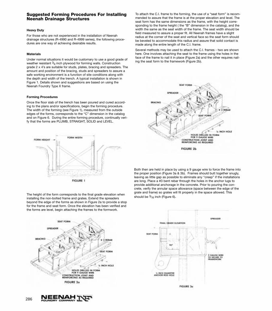
286
Both then are held in place by using a 9 gauge wire to force the frame intothe proper position (Figure 3a & 3b). Frames should butt together snugly,leaving as little gap as possible to eliminate any “creep” if the installationsare long. Place a #3 bent rebar through the holes in the anchor lugs toprovide additional anchorage in the concrete. Prior to pouring the con-crete, verify the annular space allowance (space between the edge of thegrate and frame) so grates will fit properly in the space allowed. Thisshould be 3/16 inch (Figure 6).
Suggested Forming Procedures For InstallingNeenah Drainage Structures
Heavy Duty
For those who are not experienced in the installation of Neenahdrainage structures (R-4990 and R-4999 series), the following proce-dures are one way of achieving desirable results.
Materials
Under normal situations it would be customary to use a good grade ofweather resistant 3/4 inch plywood for forming walls. Constructiongrade 2 x 4’s are suitable for studs, plates, bracing and spreaders. Theamount and position of the bracing, studs and spreaders to assure asafe working environment is a function of site conditions along withthe depth and width of the trench. A typical installation is shown inFigure 1. Details shown and suggestions are based on using theNeenah Foundry Type X frame.
Forming Procedures
Once the floor slab of the trench has been poured and cured accord-ing to the plans and/or specifications, begin the forming procedure.The width of the forming (see Figure 1), measured from the outsideedges of the forms, corresponds to the “C” dimension in the catalogand on Figure 6. During the entire forming procedure, continually veri-fy that the forms are PLUMB, STRAIGHT, SOLID and LEVEL.
The height of the form corresponds to the final grade elevation wheninstalling the non-bolted frame and grates. Extend the spreadersbeyond the edge of the forms as shown in Figure 2a to provide a stopfor the frame and seat form. Once the elevation has been verified andthe forms are level, begin attaching the frames to the formwork.
To attach the C.I. frame to the forming, the use of a “seat form” is recom-mended to assure that the frame is at the proper elevation and level. Theseat form has the same dimensions as the frame, with the height corre-sponding to the frame height ( the “B” dimension in the catalog), and thewidth the same as the seat width of the frame. The seat width should befield measured to assure a proper fit. All Neenah frames have a slightradius at the corner of the seat and vertical face so the seat form shouldbe beveled to accommodate this radius and assure that solid contact ismade along the entire length of the C.I. frame.
Several methods may be used to attach the C.I. frames - two are shownhere. One involves attaching the seat to the frame using the holes in theface of the frame to nail it in place (Figure 2a) and the other requires nail-ing the seat form to the framework (Figure 2b).
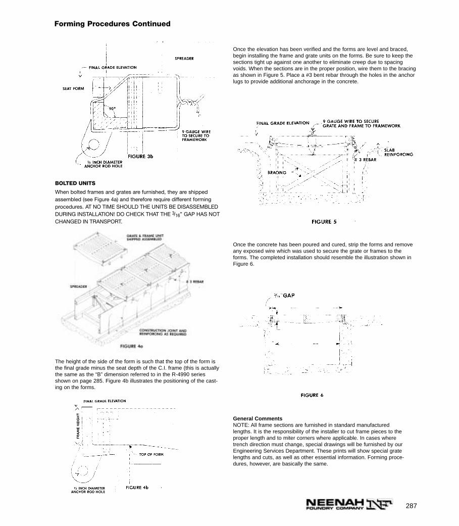
287
Forming Procedures Continued
BOLTED UNITS
When bolted frames and grates are furnished, they are shippedassembled (see Figure 4a) and therefore require different formingprocedures. AT NO TIME SHOULD THE UNITS BE DISASSEMBLEDDURING INSTALLATION! DO CHECK THAT THE 3/16” GAP HAS NOTCHANGED IN TRANSPORT.
The height of the side of the form is such that the top of the form isthe final grade minus the seat depth of the C.I. frame (this is actuallythe same as the “B” dimension referred to in the R-4990 seriesshown on page 285. Figure 4b illustrates the positioning of the cast-ing on the forms.
Once the elevation has been verified and the forms are level and braced,begin installing the frame and grate units on the forms. Be sure to keep thesections tight up against one another to eliminate creep due to spacingvoids. When the sections are in the proper position, wire them to the bracingas shown in Figure 5. Place a #3 bent rebar through the holes in the anchorlugs to provide additional anchorage in the concrete.
Once the concrete has been poured and cured, strip the forms and removeany exposed wire which was used to secure the grate or frames to theforms. The completed installation should resemble the illustration shown inFigure 6.
General CommentsNOTE: All frame sections are furnished in standard manufacturedlengths. It is the responsibility of the installer to cut frame pieces to theproper length and to miter corners where applicable. In cases wheretrench direction must change, special drawings will be furnished by ourEngineering Services Department. These prints will show special gratelengths and cuts, as well as other essential information. Forming proce-dures, however, are basically the same.
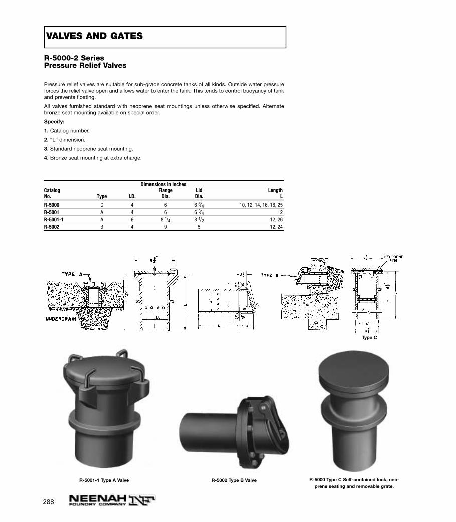
288
R-5000-2 SeriesPressure Relief Valves
Pressure relief valves are suitable for sub-grade concrete tanks of all kinds. Outside water pressureforces the relief valve open and allows water to enter the tank. This tends to control buoyancy of tankand prevents floating.
All valves furnished standard with neoprene seat mountings unless otherwise specified. Alternatebronze seat mounting available on special order.
Specify:
1. Catalog number.
2. “L” dimension.
3. Standard neoprene seat mounting.
4. Bronze seat mounting at extra charge.
Dimensions in inchesCatalog Flange Lid LengthNo. Type I.D. Dia. Dia. L
R-5000 C 4 6 6 3/4 10, 12, 14, 16, 18, 25R-5001 A 4 6 6 3/4 12R-5001-1 A 6 8 1/4 8 1/2 12, 26R-5002 B 4 9 5 12, 24
R-5000 Type C Self-contained lock, neo-prene seating and removable grate.
R-5001-1 Type A Valve R-5002 Type B Valve
VALVES AND GATES
Type C
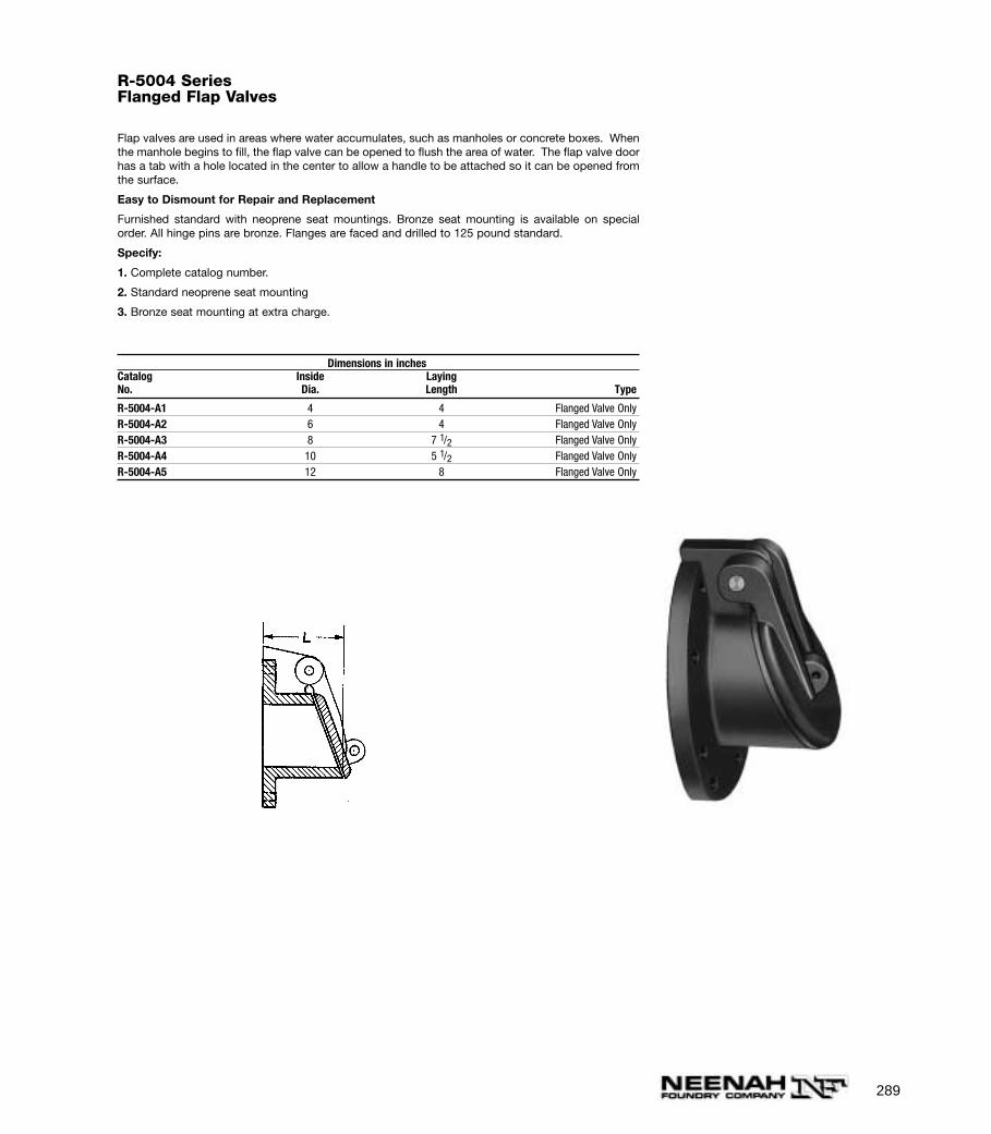
289
R-5004 SeriesFlanged Flap Valves
Flap valves are used in areas where water accumulates, such as manholes or concrete boxes. Whenthe manhole begins to fill, the flap valve can be opened to flush the area of water. The flap valve doorhas a tab with a hole located in the center to allow a handle to be attached so it can be opened fromthe surface.
Easy to Dismount for Repair and Replacement
Furnished standard with neoprene seat mountings. Bronze seat mounting is available on specialorder. All hinge pins are bronze. Flanges are faced and drilled to 125 pound standard.
Specify:
1. Complete catalog number.
2. Standard neoprene seat mounting
3. Bronze seat mounting at extra charge.
Dimensions in inchesCatalog Inside LayingNo. Dia. Length Type
R-5004-A1 4 4 Flanged Valve OnlyR-5004-A2 6 4 Flanged Valve OnlyR-5004-A3 8 7 1/2 Flanged Valve OnlyR-5004-A4 10 5 1/2 Flanged Valve OnlyR-5004-A5 12 8 Flanged Valve Only
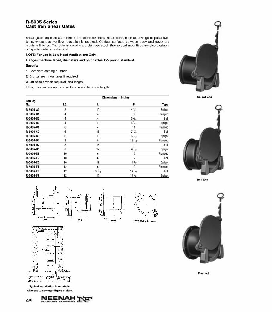
290
R-5005 SeriesCast Iron Shear Gates
Shear gates are used as control applications for many installations, such as sewage disposal sys-tems, where positive flow regulation is required. Contact surfaces between body and cover aremachine finished. The gate hinge pins are stainless steel. Bronze seat mountings are also availableon special order at extra cost.
NOTE: For use in Low Head Applications Only.
Flanges machine faced, diameters and bolt circles 125 pound standard.
Specify:
1. Complete catalog number.
2. Bronze seat mountings if required.
3. Lift handle when required, and length.
Lifting handles are optional and are available in any length.
Dimensions in inchesCatalogNo. I.D. L F Type
R-5005-A3 3 10 4 1/4 SpigotR-5005-B1 4 4 9 FlangedR-5005-B2 4 4 5 3/4 BellR-5005-B3 4 10 5 1/4 SpigotR-5005-C1 6 4 11 FlangedR-5005-C2 6 16 7 7/8 BellR-5005-C3 6 10 6 1/2 SpigotR-5005-D1 8 5 13 1/2 FlangedR-5005-D2 8 16 10 BellR-5005-D3 8 12 9 1/2 SpigotR-5005-E1 10 6 16 FlangedR-5005-E2 10 6 12 BellR-5005-E3 10 12 11 5/8 SpigotR-5005-F1 12 6 19 FlangedR-5005-F2 12 8 3/4 14 1/8 BellR-5005-F3 12 15 13 3/4 Spigot
Typical installation in manholeadjacent to sewage disposal plant.
Bell End
Flanged
Spigot End
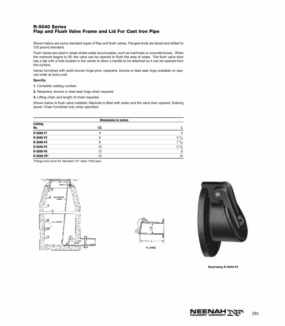
291
R-5040 SeriesFlap and Flush Valve Frame and Lid For Cast Iron Pipe
Shown below are some standard types of flap and flush valves. Flanged ends are faced and drilled to125 pound standard.
Flush valves are used in areas where water accumulates, such as manholes or concrete boxes. Whenthe manhole begins to fill, the valve can be opened to flush the area of water. The flush valve doorhas a tab with a hole located in the center to allow a handle to be attached so it can be opened fromthe surface.
Valves furnished with solid bronze hinge pins; neoprene, bronze or lead seat rings available on spe-cial order at extra cost.
Specify:
1. Complete catalog number.
2. Neoprene, bronze or lead seat rings when required.
3. Lifting chain and length of chain required.
Shown below is flush valve installed. Manhole is filled with water and the valve then opened, flushingsewer. Chain furnished only when specified.
Dimensions in inchesCatalogNo. I.D. L
R-5040-F1 4 4R-5040-F3 6 4 1/2R-5040-F4 8 7 1/2R-5040-F5 10 5 1/2R-5040-F6 12 8R-5040-F8* 15 14
*Flange bolt circle for Standard 16” class 125# pipe.
Illustrating R-5040-F3
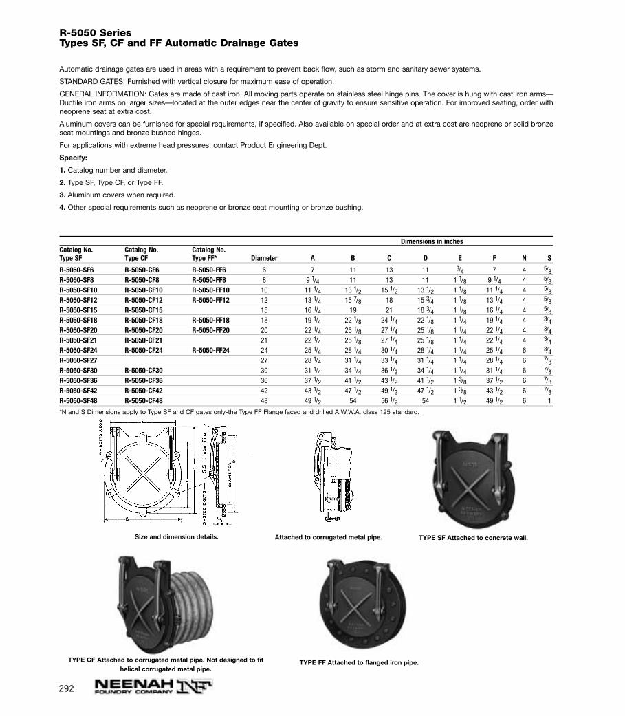
292
R-5050 SeriesTypes SF, CF and FF Automatic Drainage Gates
Automatic drainage gates are used in areas with a requirement to prevent back flow, such as storm and sanitary sewer systems.
STANDARD GATES: Furnished with vertical closure for maximum ease of operation.
GENERAL INFORMATION: Gates are made of cast iron. All moving parts operate on stainless steel hinge pins. The cover is hung with cast iron arms—Ductile iron arms on larger sizes—located at the outer edges near the center of gravity to ensure sensitive operation. For improved seating, order withneoprene seat at extra cost.
Aluminum covers can be furnished for special requirements, if specified. Also available on special order and at extra cost are neoprene or solid bronzeseat mountings and bronze bushed hinges.
For applications with extreme head pressures, contact Product Engineering Dept.
Specify:
1. Catalog number and diameter.
2. Type SF, Type CF, or Type FF.
3. Aluminum covers when required.
4. Other special requirements such as neoprene or bronze seat mounting or bronze bushing.
Dimensions in inchesCatalog No. Catalog No. Catalog No.Type SF Type CF Type FF* Diameter A B C D E F N S
R-5050-SF6 R-5050-CF6 R-5050-FF6 6 7 11 13 11 3/4 7 4 5/8R-5050-SF8 R-5050-CF8 R-5050-FF8 8 9 1/4 11 13 11 1 1/8 9 1/4 4 5/8R-5050-SF10 R-5050-CF10 R-5050-FF10 10 11 1/4 13 1/2 15 1/2 13 1/2 1 1/8 11 1/4 4 5/8R-5050-SF12 R-5050-CF12 R-5050-FF12 12 13 1/4 15 7/8 18 15 3/4 1 1/8 13 1/4 4 5/8R-5050-SF15 R-5050-CF15 15 16 1/4 19 21 18 3/4 1 1/8 16 1/4 4 5/8R-5050-SF18 R-5050-CF18 R-5050-FF18 18 19 1/4 22 1/8 24 1/4 22 1/8 1 1/4 19 1/4 4 3/4R-5050-SF20 R-5050-CF20 R-5050-FF20 20 22 1/4 25 1/8 27 1/4 25 1/8 1 1/4 22 1/4 4 3/4R-5050-SF21 R-5050-CF21 21 22 1/4 25 1/8 27 1/4 25 1/8 1 1/4 22 1/4 4 3/4R-5050-SF24 R-5050-CF24 R-5050-FF24 24 25 1/4 28 1/4 30 1/4 28 1/4 1 1/4 25 1/4 6 3/4R-5050-SF27 27 28 1/4 31 1/4 33 1/4 31 1/4 1 1/4 28 1/4 6 7/8R-5050-SF30 R-5050-CF30 30 31 1/4 34 1/4 36 1/2 34 1/4 1 1/4 31 1/4 6 7/8R-5050-SF36 R-5050-CF36 36 37 1/2 41 1/2 43 1/2 41 1/2 1 3/8 37 1/2 6 7/8R-5050-SF42 R-5050-CF42 42 43 1/2 47 1/2 49 1/2 47 1/2 1 3/8 43 1/2 6 7/8R-5050-SF48 R-5050-CF48 48 49 1/2 54 56 1/2 54 1 1/2 49 1/2 6 1
*N and S Dimensions apply to Type SF and CF gates only-the Type FF Flange faced and drilled A.W.W.A. class 125 standard.
Size and dimension details. TYPE SF Attached to concrete wall.
TYPE CF Attached to corrugated metal pipe. Not designed to fithelical corrugated metal pipe.
TYPE FF Attached to flanged iron pipe.
Attached to corrugated metal pipe.
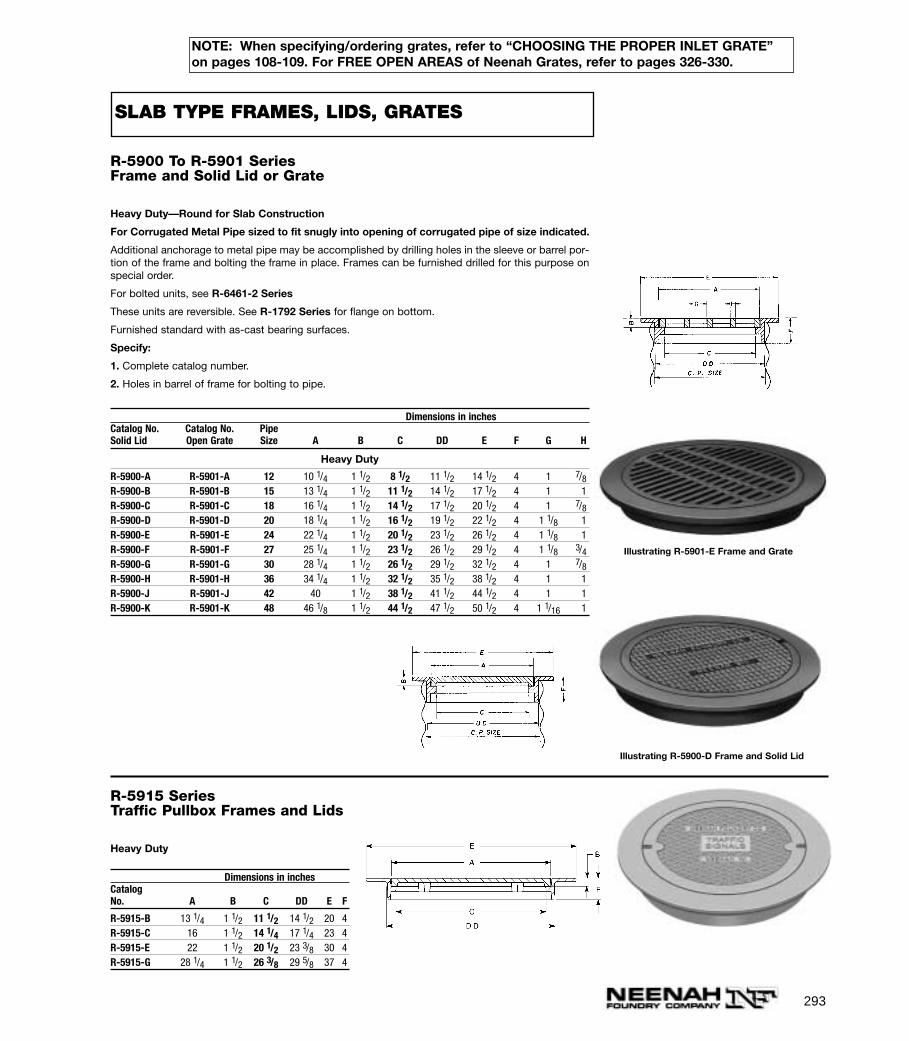
293
R-5900 To R-5901 SeriesFrame and Solid Lid or Grate
Heavy Duty—Round for Slab Construction
For Corrugated Metal Pipe sized to fit snugly into opening of corrugated pipe of size indicated.
Additional anchorage to metal pipe may be accomplished by drilling holes in the sleeve or barrel por-tion of the frame and bolting the frame in place. Frames can be furnished drilled for this purpose onspecial order.
For bolted units, see R-6461-2 Series
These units are reversible. See R-1792 Series for flange on bottom.
Furnished standard with as-cast bearing surfaces.
Specify:
1. Complete catalog number.
2. Holes in barrel of frame for bolting to pipe.
Dimensions in inchesCatalog No. Catalog No. PipeSolid Lid Open Grate Size A B C DD E F G H
Heavy Duty
R-5900-A R-5901-A 12 10 1/4 1 1/2 8 1/2 11 1/2 14 1/2 4 1 7/8R-5900-B R-5901-B 15 13 1/4 1 1/2 11 1/2 14 1/2 17 1/2 4 1 1R-5900-C R-5901-C 18 16 1/4 1 1/2 14 1/2 17 1/2 20 1/2 4 1 7/8R-5900-D R-5901-D 20 18 1/4 1 1/2 16 1/2 19 1/2 22 1/2 4 1 1/8 1R-5900-E R-5901-E 24 22 1/4 1 1/2 20 1/2 23 1/2 26 1/2 4 1 1/8 1R-5900-F R-5901-F 27 25 1/4 1 1/2 23 1/2 26 1/2 29 1/2 4 1 1/8 3/4R-5900-G R-5901-G 30 28 1/4 1 1/2 26 1/2 29 1/2 32 1/2 4 1 7/8R-5900-H R-5901-H 36 34 1/4 1 1/2 32 1/2 35 1/2 38 1/2 4 1 1R-5900-J R-5901-J 42 40 1 1/2 38 1/2 41 1/2 44 1/2 4 1 1R-5900-K R-5901-K 48 46 1/8 1 1/2 44 1/2 47 1/2 50 1/2 4 1 1/16 1
Illustrating R-5900-D Frame and Solid Lid
Illustrating R-5901-E Frame and Grate
R-5915 SeriesTraffic Pullbox Frames and Lids
Heavy Duty
Dimensions in inchesCatalogNo. A B C DD E F
R-5915-B 13 1/4 1 1/2 11 1/2 14 1/2 20 4R-5915-C 16 1 1/2 14 1/4 17 1/4 23 4R-5915-E 22 1 1/2 20 1/2 23 3/8 30 4R-5915-G 28 1/4 1 1/2 26 3/8 29 5/8 37 4
SLAB TYPE FRAMES, LIDS, GRATES
NOTE: When specifying/ordering grates, refer to “CHOOSING THE PROPER INLET GRATE”on pages 108-109. For FREE OPEN AREAS of Neenah Grates, refer to pages 326-330.
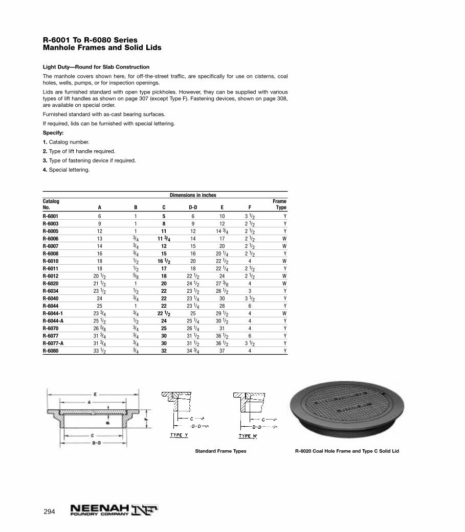
294
R-6001 To R-6080 SeriesManhole Frames and Solid Lids
Light Duty—Round for Slab Construction
The manhole covers shown here, for off-the-street traffic, are specifically for use on cisterns, coalholes, wells, pumps, or for inspection openings.
Lids are furnished standard with open type pickholes. However, they can be supplied with varioustypes of lift handles as shown on page 307 (except Type F). Fastening devices, shown on page 308,are available on special order.
Furnished standard with as-cast bearing surfaces.
If required, lids can be furnished with special lettering.
Specify:
1. Catalog number.
2. Type of lift handle required.
3. Type of fastening device if required.
4. Special lettering.
Dimensions in inchesCatalog FrameNo. A B C D-D E F Type
R-6001 6 1 5 6 10 3 1/2 YR-6003 9 1 8 9 12 2 1/2 YR-6005 12 1 11 12 14 3/4 2 1/2 YR-6006 13 3/4 11 3/4 14 17 2 1/2 WR-6007 14 3/4 12 15 20 2 1/2 WR-6008 16 3/4 15 16 20 1/4 2 1/2 YR-6010 18 1/2 16 1/2 20 22 1/2 4 WR-6011 18 1/2 17 18 22 1/4 2 1/2 YR-6012 20 1/2 5/8 18 22 1/2 24 2 1/2 WR-6020 21 1/2 1 20 24 1/2 27 3/8 4 WR-6034 23 1/2 1/2 22 23 1/2 26 1/2 3 YR-6040 24 3/4 22 23 1/4 30 3 1/2 YR-6044 25 1 22 23 1/4 28 6 YR-6044-1 23 3/4 3/4 22 1/2 25 29 1/2 4 WR-6044-A 25 1/2 1/2 24 25 1/4 30 1/2 4 YR-6070 26 5/8 3/4 25 26 1/4 31 4 YR-6077 31 3/4 3/4 30 31 1/2 36 1/2 6 YR-6077-A 31 3/4 3/4 30 31 1/2 36 1/2 3 1/2 YR-6080 33 1/2 3/4 32 34 3/4 37 4 Y
Standard Frame Types R-6020 Coal Hole Frame and Type C Solid Lid
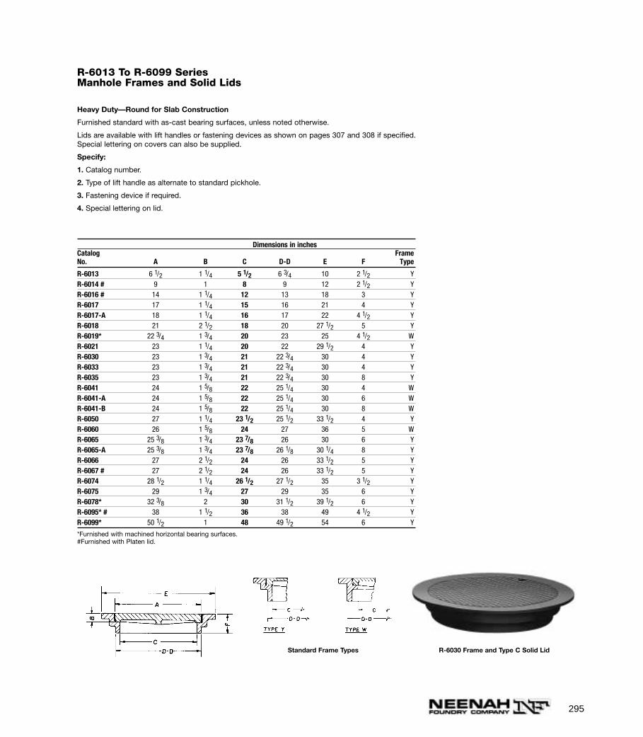
295
R-6013 To R-6099 SeriesManhole Frames and Solid Lids
Heavy Duty—Round for Slab Construction
Furnished standard with as-cast bearing surfaces, unless noted otherwise.
Lids are available with lift handles or fastening devices as shown on pages 307 and 308 if specified.Special lettering on covers can also be supplied.
Specify:
1. Catalog number.
2. Type of lift handle as alternate to standard pickhole.
3. Fastening device if required.
4. Special lettering on lid.
Dimensions in inchesCatalog FrameNo. A B C D-D E F Type
R-6013 6 1/2 1 1/4 5 1/2 6 3/4 10 2 1/2 YR-6014 # 9 1 8 9 12 2 1/2 YR-6016 # 14 1 1/4 12 13 18 3 YR-6017 17 1 1/4 15 16 21 4 YR-6017-A 18 1 1/4 16 17 22 4 1/2 YR-6018 21 2 1/2 18 20 27 1/2 5 YR-6019* 22 3/4 1 3/4 20 23 25 4 1/2 WR-6021 23 1 1/4 20 22 29 1/2 4 YR-6030 23 1 3/4 21 22 3/4 30 4 YR-6033 23 1 3/4 21 22 3/4 30 4 YR-6035 23 1 3/4 21 22 3/4 30 8 YR-6041 24 1 5/8 22 25 1/4 30 4 WR-6041-A 24 1 5/8 22 25 1/4 30 6 WR-6041-B 24 1 5/8 22 25 1/4 30 8 WR-6050 27 1 1/4 23 1/2 25 1/2 33 1/2 4 YR-6060 26 1 5/8 24 27 36 5 WR-6065 25 3/8 1 3/4 23 7/8 26 30 6 YR-6065-A 25 3/8 1 3/4 23 7/8 26 1/8 30 1/4 8 YR-6066 27 2 1/2 24 26 33 1/2 5 YR-6067 # 27 2 1/2 24 26 33 1/2 5 YR-6074 28 1/2 1 1/4 26 1/2 27 1/2 35 3 1/2 YR-6075 29 1 3/4 27 29 35 6 YR-6078* 32 3/8 2 30 31 1/2 39 1/2 6 YR-6095* # 38 1 1/2 36 38 49 4 1/2 YR-6099* 50 1/2 1 48 49 1/2 54 6 Y
*Furnished with machined horizontal bearing surfaces.#Furnished with Platen lid.
Standard Frame Types R-6030 Frame and Type C Solid Lid

296
R-6110 To R-6137 SeriesCatch Basin Frames and Grates
Heavy and Light Duty—Round for Slab Construction
Furnished standard with as-cast bearing surfaces unless noted otherwise.
Dimensions in inchesCatalog FrameNo. A B C D-D E F G H Type
Heavy Duty
R-6110§ 21 2 1/2 18 20 27 1/2 5 1 3/8 1 YR-6111§ 23 1 1/4 20 22 29 1/2 4 1 3/8 1 YR-6112 23 1 3/4 21 22 3/4 30 4 1 1/2 1 YR-6113 24 1 5/8 22 25 1/4 30 4 3/4 1 WR-6114§ 27 1 1/4 23 1/2 25 1/2 33 1/2 4 1 1/2 1 YR-6115§ 27 2 1/2 24 26 33 1/2 5 1 1/2 1 YR-6116§ 29 1 3/4 27 29 35 6 1 1/2 1 YR-6117§* 32 3/8 2 30 32 39 1/2 6 1 1/2 1 YR-6118* 38 1 1/2 36 38 49 4 1/2 1 1 Y
Light Duty
R-6130 20 1/2 5/8 18 22 1/2 24 2 1/2 1 1 WR-6131 21 1/2 1 20 23 1/2 27 4 1/2 3/4 WR-6132 24 3/4 22 23 1/4 30 3 1/2 1/2 1/2 YR-6133 25 1 22 23 1/4 28 6 1/2 1/2 YR-6134 26 5/8 3/4 25 26 1/4 31 4 7/8 3/4 YR-6136§ 31 3/4 3/4 30 31 1/2 36 1/2 6 1 1/4 1 YR-6137§ 33 1/2 3/4 32 34 3/4 37 4 1 1/4 1 Y
§Not recommended for bicycle traffic. *Machined horizontal bearing surfaces.
Heavy Duty R-6115 Frame and Grate
Light Duty R-6134 Frame and Grate
R-6052 SeriesManhole Frames and Solid Lids Heavy Duty U.S. GovernmentStandard
Furnished standard with as-cast bearing surfaces.
For same units with grates, see R-2565 Series.
Specify:
1. Catalog number.
2. Lift holes as shown in photo, or lift handle, see page 307.
3. Lettering on lid, as required.
Dimensions in inchesCatalogNo. A B C E F J K
R-6052-A 21 2 1/2 18 27 1/2 5 2 7/8 1R-6052-C 23 1 1/4 20 29 1/2 4 2 1/2 1R-6052-D 27 1 1/4 23 1/2 33 1/2 4 2 1/4 3/4R-6052-F 27 2 1/2 24 33 1/2 5 2 7/8 1R-6052-G 27 2 1/2 24 33 1/2 5 2 7/8 1R-6052-H 29 1 3/4 27 35 6 2 7/8 1R-6052-J 32 3/8 2 30 39 1/2 6 2 7/8 1
Illustrating R-6052-G
NOTE: When specifying/ordering grates, refer to “CHOOSING THE PROPER INLET GRATE”on pages 108-109. For FREE OPEN AREAS of Neenah Grates, refer to pages 326-330.

297
R-6140Manhole Frame and Lid withLocking Lugs
Heavy Duty
Furnished standard with as-cast bearing surfaces.
R-6140 Illustrating R-6140
R-6141With Lock
Heavy Duty
Lid interchangeable with R-1922. See page 80.
Furnished with machined horizontal and verticalbearing surfaces.
R-6141
R-6142Slab Type Manhole Frame andLid
Heavy Duty
R-6143Slab Type Manhole Frame andLid
Heavy Duty
Furnished standard with as-cast bearing surfaces.
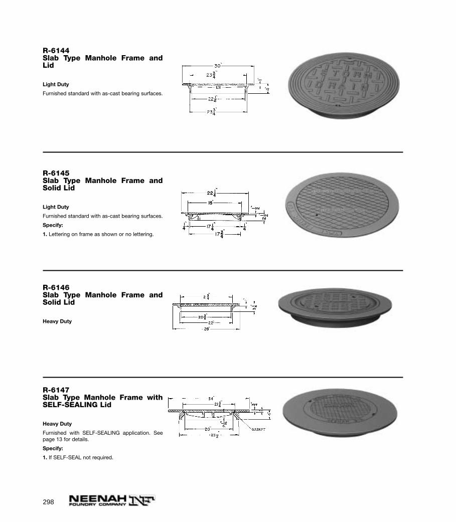
298
R-6146Slab Type Manhole Frame andSolid Lid
Heavy Duty
R-6147Slab Type Manhole Frame withSELF-SEALING Lid
Heavy Duty
Furnished with SELF-SEALING application. Seepage 13 for details.
Specify:
1. If SELF-SEAL not required.
R-6145Slab Type Manhole Frame andSolid Lid
Light Duty
Furnished standard with as-cast bearing surfaces.
Specify:
1. Lettering on frame as shown or no lettering.
R-6144Slab Type Manhole Frame andLid
Light Duty
Furnished standard with as-cast bearing surfaces.
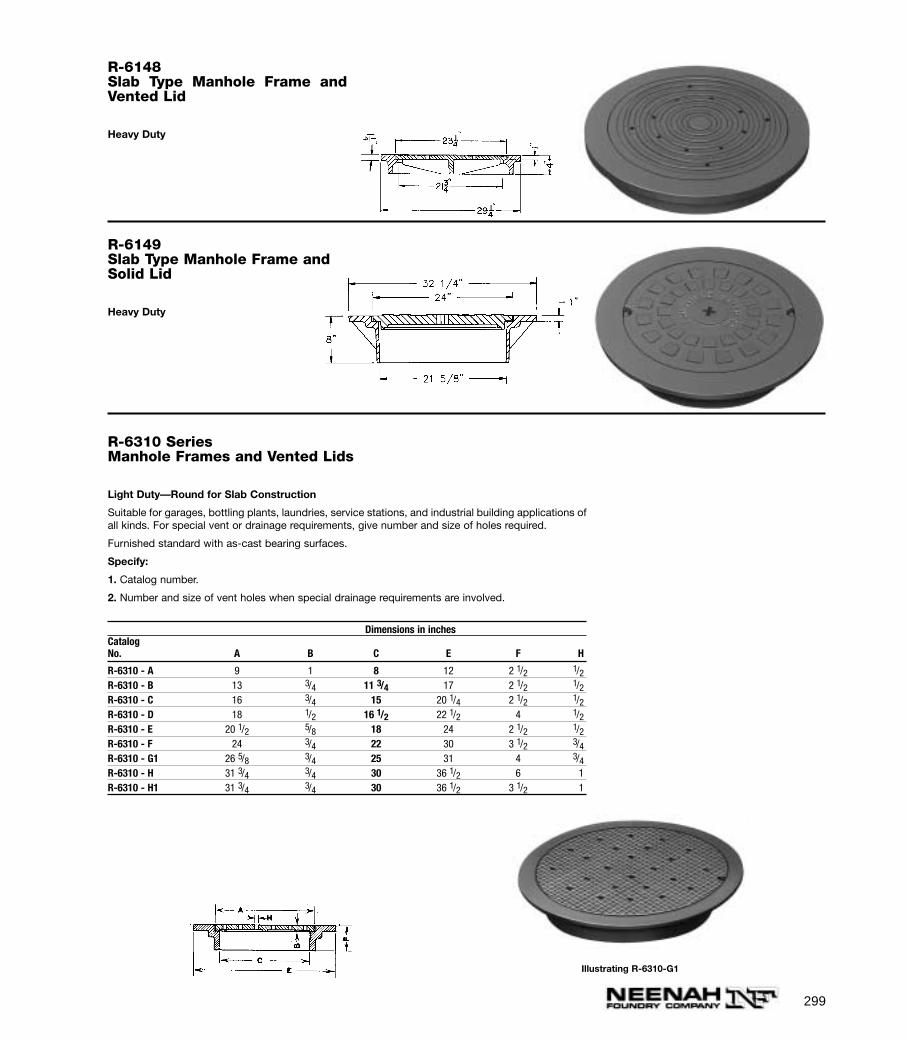
299
R-6148Slab Type Manhole Frame andVented Lid
Heavy Duty
R-6149Slab Type Manhole Frame andSolid Lid
Heavy Duty
R-6310 SeriesManhole Frames and Vented Lids
Light Duty—Round for Slab Construction
Suitable for garages, bottling plants, laundries, service stations, and industrial building applications ofall kinds. For special vent or drainage requirements, give number and size of holes required.
Furnished standard with as-cast bearing surfaces.
Specify:
1. Catalog number.
2. Number and size of vent holes when special drainage requirements are involved.
Dimensions in inchesCatalogNo. A B C E F H
R-6310 - A 9 1 8 12 2 1/2 1/2R-6310 - B 13 3/4 11 3/4 17 2 1/2 1/2R-6310 - C 16 3/4 15 20 1/4 2 1/2 1/2R-6310 - D 18 1/2 16 1/2 22 1/2 4 1/2R-6310 - E 20 1/2 5/8 18 24 2 1/2 1/2R-6310 - F 24 3/4 22 30 3 1/2 3/4R-6310 - G1 26 5/8 3/4 25 31 4 3/4R-6310 - H 31 3/4 3/4 30 36 1/2 6 1R-6310 - H1 31 3/4 3/4 30 36 1/2 3 1/2 1
Illustrating R-6310-G1
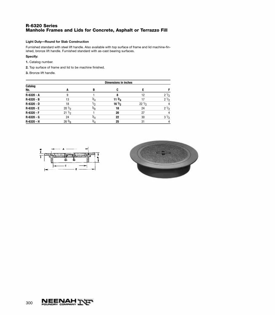
300
R-6320 SeriesManhole Frames and Lids for Concrete, Asphalt or Terrazzo Fill
Light Duty—Round for Slab Construction
Furnished standard with steel lift handle. Also available with top surface of frame and lid machine-fin-ished, bronze lift handle. Furnished standard with as-cast bearing surfaces.
Specify:
1. Catalog number.
2. Top surface of frame and lid to be machine finished.
3. Bronze lift handle.
Dimensions in inchesCatalogNo. A B C E F
R-6320 - A 9 1 8 12 2 1/2R-6320 - B 13 3/4 11 3/4 17 2 1/2R-6320 - D 18 1/2 16 1/2 22 1/2 4R-6320 - E 20 1/2 5/8 18 24 2 1/2R-6320 - F 21 1/2 1 20 27 4R-6320 - G 24 3/4 22 30 3 1/2R-6320 - H 26 5/8 3/4 25 31 4

301
R-6350-1-2 SeriesManhole Frames with Solid, Vented, or Grated Covers
Light Duty—Round for Slab Construction
These covers are used extensively by plumbers and contractors for inside use. Note that covers are adaptable for use with clay tile catch basin or sub-construction, frames to fit inside of and flush with top of bell.
Furnished standard with as-cast bearing surfaces.
Dimensions in inches
Catalog No. Catalog No. Catalog No. For PipeSolid Perforated Grated A B C E F Size
R-6350-A - R-6352-A 13 1/2 12 15 2 1/2 12R-6350-B R-6351-B R-6352-B 16 3/4 15 20 1/4 2 1/2 15R-6350-C - - 18 1/4 17 21 3 18R-6350-D R-6351-D R-6352-D 19 1/2 18 21 3 18R-6350-E R-6351-E R-6352-E 21 1/2 20 23 3 20R-6350-G R-6351-G R-6352-G 25 1/2 24 27 3 24
Illustrating R-6350-G Illustrating R-6352-E
NOTE: When specifying/ordering grates, refer to “CHOOSING THE PROPER INLET GRATE”on pages 108-109. For FREE OPEN AREAS of Neenah Grates, refer to pages 326-330.
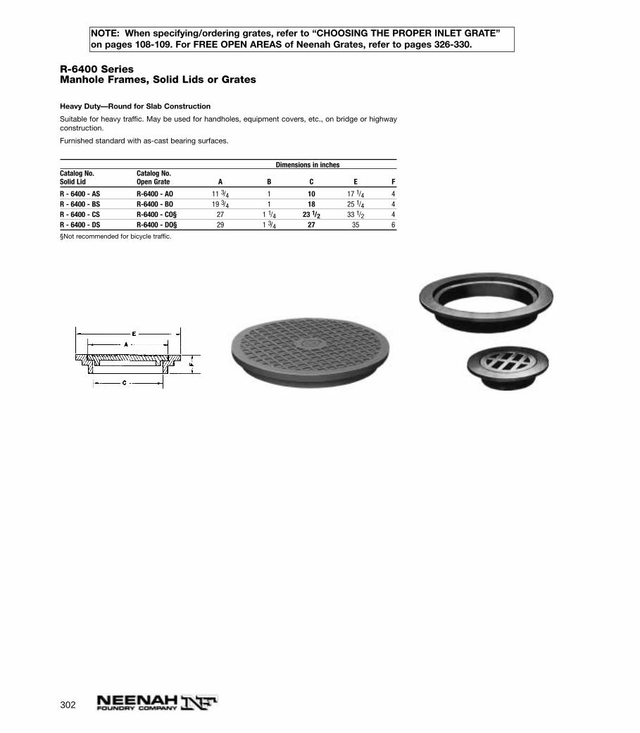
302
R-6400 SeriesManhole Frames, Solid Lids or Grates
Heavy Duty—Round for Slab Construction
Suitable for heavy traffic. May be used for handholes, equipment covers, etc., on bridge or highwayconstruction.
Furnished standard with as-cast bearing surfaces.
Dimensions in inchesCatalog No. Catalog No.Solid Lid Open Grate A B C E F
R - 6400 - AS R-6400 - AO 11 3/4 1 10 17 1/4 4R - 6400 - BS R-6400 - BO 19 3/4 1 18 25 1/4 4R - 6400 - CS R-6400 - CO§ 27 1 1/4 23 1/2 33 1/2 4R - 6400 - DS R-6400 - DO§ 29 1 3/4 27 35 6
§Not recommended for bicycle traffic.
NOTE: When specifying/ordering grates, refer to “CHOOSING THE PROPER INLET GRATE”on pages 108-109. For FREE OPEN AREAS of Neenah Grates, refer to pages 326-330.

303
R-6450 SeriesRound Frames, Solid or Grated Covers
Light Duty to Fit Bell End of Vitrified Clay Pipe
Furnished standard with as-cast bearing surfaces.
CAUTION: Pipe bell sizes from different manufacturers frequently vary. Check the casting dimensionswith the table below to be sure the casting will fit the pipe you are using.
Dimensions in inchesCatalog No. Catalog No. Pipe FrameSolid Lid Open Grate Size A B C D2 E F Type
R - 6450 - AL R-6450 - AG 8 9 1 8 10 1/8 12 2 1/2 YR - 6450 - BL R-6450 - BG 10 12 1 11 13 14 3/4 2 1/2 YR - 6450 - CL R-6450 - CG 12 13 3/4 11 3/4 14 1/2 17 2 1/2 WR - 6450 - DL R-6450 - DG 15 16 3/4 15 18 20 1/4 2 1/2 YR - 6450 - EL R-6450 - EG 18 20 1/2 5/8 18 22 1/2 24 2 1/2 WR - 6450 - FL R-6450 - FG 20 21 1/2 1 20 24 1/2 27 4 WR - 6450 - GL R-6450 - GG 21 24 3/4 22 25 1/2 30 3 1/2 YR - 6450 - HL R-6450 - HG 24 26 5/8 3/4 25 28 1/2 31 4 YR - 6450 - JL R-6450 - JG§ 27 31 3/4 3/4 30 35 1/4 36 1/2 6 YR - 6450 - KL R-6450 - KG§ 30 33 1/2 3/4 32 35 1/2 37 4 Y
§Not recommended for bicycle traffic.
Frame with Solid LidFrame with Open Grate
NOTE: When specifying/ordering grates, refer to “CHOOSING THE PROPER INLET GRATE”on pages 108-109. For FREE OPEN AREAS of Neenah Grates, refer to pages 326-330.
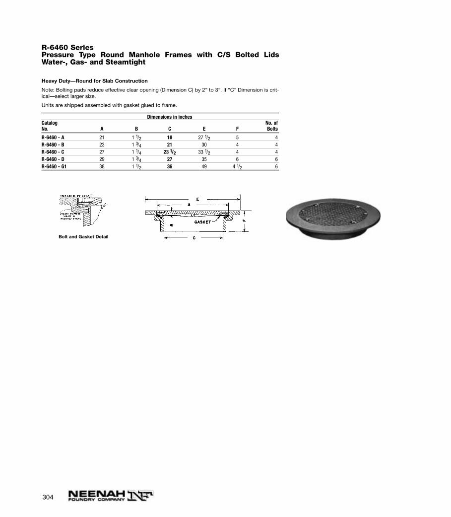
304
R-6460 SeriesPressure Type Round Manhole Frames with C/S Bolted LidsWater-, Gas- and Steamtight
Heavy Duty—Round for Slab Construction
Note: Bolting pads reduce effective clear opening (Dimension C) by 2” to 3”. If “C” Dimension is crit-ical—select larger size.
Units are shipped assembled with gasket glued to frame.
Dimensions in inchesCatalog No. ofNo. A B C E F Bolts
R-6460 - A 21 1 1/2 18 27 1/2 5 4R-6460 - B 23 1 3/4 21 30 4 4R-6460 - C 27 1 1/4 23 1/2 33 1/2 4 4R-6460 - D 29 1 3/4 27 35 6 6R-6460 - G1 38 1 1/2 36 49 4 1/2 6
Bolt and Gasket Detail

305
R-6461 To R-6462 SeriesPressure Type Round Manhole Frames with C/S Bolted LidsWater-, Gas-, and Steamtight
Heavy Duty for Slab or Built-Up Manholes
Frames in this series are reversible and can be installed with flange at top for slab construction, orwith flange at base for use with built-up manhole.
Slab construction type manhole covers are sized to fit in the opening of corrugated metal pipe from12” to 48” in diameter.
Furnished standard with concealed, watertight pickhole (described in R-6464 Series.) Lids sealedwith gasket and fastened with stainless steel bolts.
Units are shipped assembled with gasket glued to lid.
Dimensions in inchesCatalog No. Catalog No. No. ofSlab Type Built-Up Type A B C E F Bolts
Heavy Duty
R-6461 - AH R-6462 - AH 10 1/4 1 1/2 6 1/2 14 1/2 4 4R-6461 - BH R-6462 - BH 13 1/4 1 1/2 9 1/2 17 1/2 4 4R-6461 - CH R-6462 - CH 16 1/4 1 1/2 12 1/2 20 1/2 4 4R-6461 - DH R-6462 - DH 18 1/4 1 1/2 14 1/2 22 1/2 4 4R-6461 - EH* R-6462 - EH* 22 1/4 1 1/2 18 1/2 26 1/2 4 4R-6461 - FH* R-6462 - FH* 25 1/4 1 1/2 21 1/2 29 1/2 4 4R-6461 - GH R-6462 - GH 28 1/4 1 1/2 24 1/2 32 1/2 4 6R-6461 - HH R-6462 - HH 34 1/4 1 1/2 30 1/2 38 1/2 4 6R-6461 - JH* R-6462 - JH* 40 1 1/2 36 1/2 44 1/2 4 6R-6461 - KH R-6462 - KH 46 1/8 1 1/2 42 1/2 50 1/2 4 6
*Furnished standard with as-cast bearing surfaces.
Illustrating R-6461-EH Slab Type Illustrating R-6462-EH Built-up Type
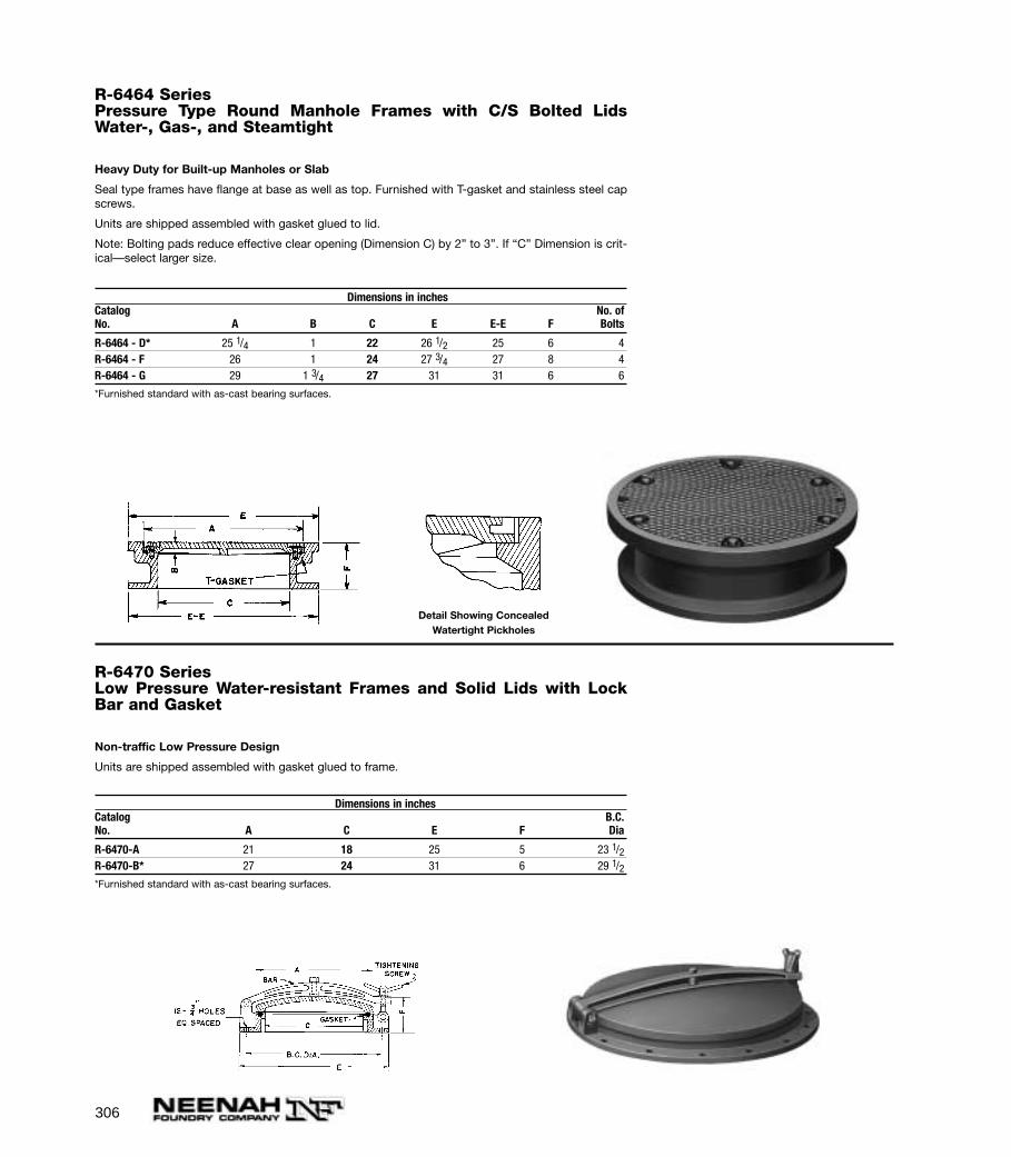
306
R-6464 SeriesPressure Type Round Manhole Frames with C/S Bolted LidsWater-, Gas-, and Steamtight
Heavy Duty for Built-up Manholes or Slab
Seal type frames have flange at base as well as top. Furnished with T-gasket and stainless steel capscrews.
Units are shipped assembled with gasket glued to lid.
Note: Bolting pads reduce effective clear opening (Dimension C) by 2” to 3”. If “C” Dimension is crit-ical—select larger size.
Dimensions in inchesCatalog No. ofNo. A B C E E-E F Bolts
R-6464 - D* 25 1/4 1 22 26 1/2 25 6 4R-6464 - F 26 1 24 27 3/4 27 8 4R-6464 - G 29 1 3/4 27 31 31 6 6
*Furnished standard with as-cast bearing surfaces.
Detail Showing ConcealedWatertight Pickholes
R-6470 SeriesLow Pressure Water-resistant Frames and Solid Lids with LockBar and Gasket
Non-traffic Low Pressure Design
Units are shipped assembled with gasket glued to frame.
Dimensions in inchesCatalog B.C.No. A C E F Dia
R-6470-A 21 18 25 5 23 1/2R-6470-B* 27 24 31 6 29 1/2*Furnished standard with as-cast bearing surfaces.
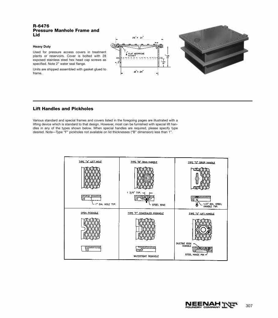
307
R-6476Pressure Manhole Frame andLid
Heavy Duty
Used for pressure access covers in treatmentplants or reservoirs. Cover is bolted with 28exposed stainless steel hex head cap screws asspecified. Note 2” water seal flange.
Units are shipped assembled with gasket glued toframe.
Lift Handles and Pickholes
Various standard and special frames and covers listed in the foregoing pages are illustrated with alifting device which is standard to that design. However, most can be furnished with special lift han-dles in any of the types shown below. When special handles are required, please specify typedesired. Note—Type “F” pickholes not available on lid thicknesses (“B” dimension) less than 1”.
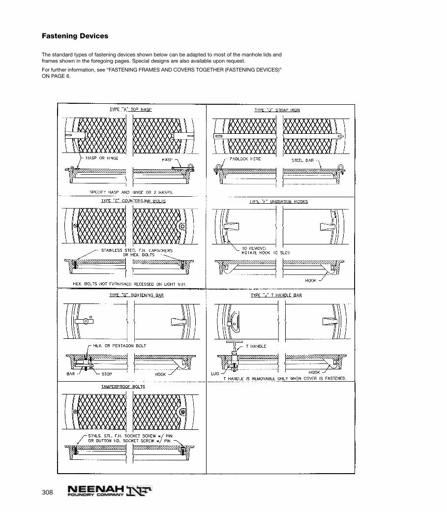
308
Fastening Devices
The standard types of fastening devices shown below can be adapted to most of the manhole lids andframes shown in the foregoing pages. Special designs are also available upon request.
For further information, see “FASTENING FRAMES AND COVERS TOGETHER (FASTENING DEVICES)”ON PAGE 6.
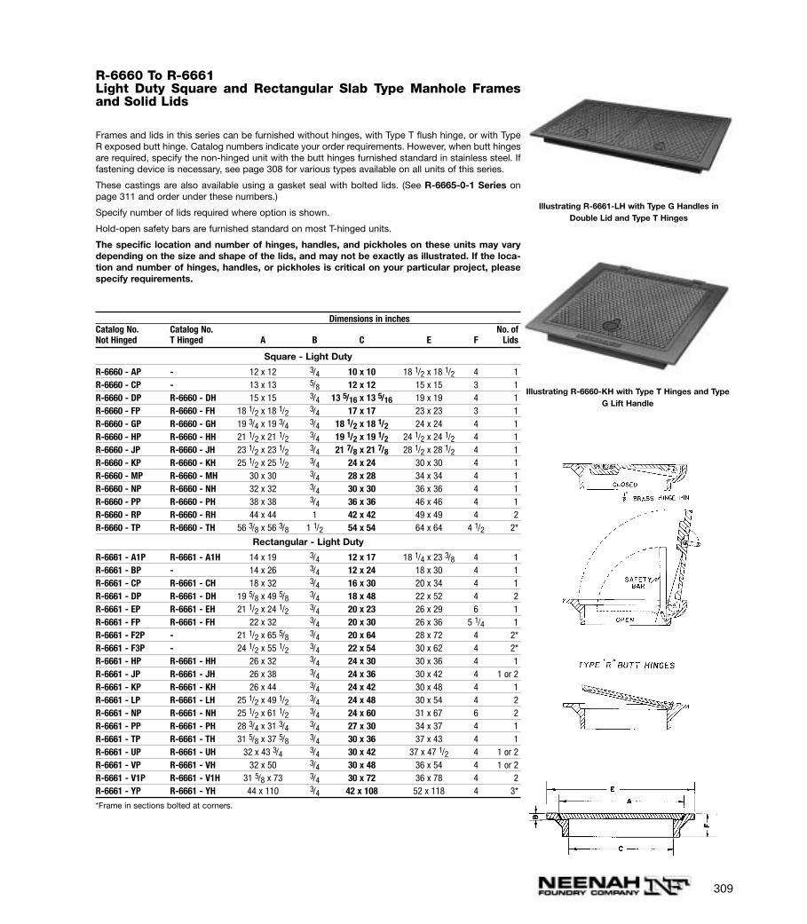
309
R-6660 To R-6661Light Duty Square and Rectangular Slab Type Manhole Framesand Solid Lids
Frames and lids in this series can be furnished without hinges, with Type T flush hinge, or with TypeR exposed butt hinge. Catalog numbers indicate your order requirements. However, when butt hingesare required, specify the non-hinged unit with the butt hinges furnished standard in stainless steel. Iffastening device is necessary, see page 308 for various types available on all units of this series.
These castings are also available using a gasket seal with bolted lids. (See R-6665-0-1 Series onpage 311 and order under these numbers.)
Specify number of lids required where option is shown.
Hold-open safety bars are furnished standard on most T-hinged units.
The specific location and number of hinges, handles, and pickholes on these units may varydepending on the size and shape of the lids, and may not be exactly as illustrated. If the loca-tion and number of hinges, handles, or pickholes is critical on your particular project, pleasespecify requirements.
Dimensions in inchesCatalog No. Catalog No. No. ofNot Hinged T Hinged A B C E F Lids
Square - Light Duty
R-6660 - AP - 12 x 12 3/4 10 x 10 18 1/2 x 18 1/2 4 1R-6660 - CP - 13 x 13 5/8 12 x 12 15 x 15 3 1R-6660 - DP R-6660 - DH 15 x 15 3/4 13 5/16 x 13 5/16 19 x 19 4 1R-6660 - FP R-6660 - FH 18 1/2 x 18 1/2 3/4 17 x 17 23 x 23 3 1R-6660 - GP R-6660 - GH 19 3/4 x 19 3/4 3/4 18 1/2 x 18 1/2 24 x 24 4 1R-6660 - HP R-6660 - HH 21 1/2 x 21 1/2 3/4 19 1/2 x 19 1/2 24 1/2 x 24 1/2 4 1R-6660 - JP R-6660 - JH 23 1/2 x 23 1/2 3/4 21 7/8 x 21 7/8 28 1/2 x 28 1/2 4 1R-6660 - KP R-6660 - KH 25 1/2 x 25 1/2 3/4 24 x 24 30 x 30 4 1R-6660 - MP R-6660 - MH 30 x 30 3/4 28 x 28 34 x 34 4 1R-6660 - NP R-6660 - NH 32 x 32 3/4 30 x 30 36 x 36 4 1R-6660 - PP R-6660 - PH 38 x 38 3/4 36 x 36 46 x 46 4 1R-6660 - RP R-6660 - RH 44 x 44 1 42 x 42 49 x 49 4 2R-6660 - TP R-6660 - TH 56 3/8 x 56 3/8 1 1/2 54 x 54 64 x 64 4 1/2 2*
Rectangular - Light Duty
R-6661 - A1P R-6661 - A1H 14 x 19 3/4 12 x 17 18 1/4 x 23 3/8 4 1R-6661 - BP - 14 x 26 3/4 12 x 24 18 x 30 4 1R-6661 - CP R-6661 - CH 18 x 32 3/4 16 x 30 20 x 34 4 1R-6661 - DP R-6661 - DH 19 5/8 x 49 5/8 3/4 18 x 48 22 x 52 4 2R-6661 - EP R-6661 - EH 21 1/2 x 24 1/2 3/4 20 x 23 26 x 29 6 1R-6661 - FP R-6661 - FH 22 x 32 3/4 20 x 30 26 x 36 5 1/4 1R-6661 - F2P - 21 1/2 x 65 5/8 3/4 20 x 64 28 x 72 4 2*R-6661 - F3P - 24 1/2 x 55 1/2 3/4 22 x 54 30 x 62 4 2*R-6661 - HP R-6661 - HH 26 x 32 3/4 24 x 30 30 x 36 4 1R-6661 - JP R-6661 - JH 26 x 38 3/4 24 x 36 30 x 42 4 1 or 2R-6661 - KP R-6661 - KH 26 x 44 3/4 24 x 42 30 x 48 4 1R-6661 - LP R-6661 - LH 25 1/2 x 49 1/2 3/4 24 x 48 30 x 54 4 2R-6661 - NP R-6661 - NH 25 1/2 x 61 1/2 3/4 24 x 60 31 x 67 6 2R-6661 - PP R-6661 - PH 28 3/4 x 31 3/4 3/4 27 x 30 34 x 37 4 1R-6661 - TP R-6661 - TH 31 5/8 x 37 5/8 3/4 30 x 36 37 x 43 4 1R-6661 - UP R-6661 - UH 32 x 43 3/4 3/4 30 x 42 37 x 47 1/2 4 1 or 2R-6661 - VP R-6661 - VH 32 x 50 3/4 30 x 48 36 x 54 4 1 or 2R-6661 - V1P R-6661 - V1H 31 5/8 x 73 3/4 30 x 72 36 x 78 4 2R-6661 - YP R-6661 - YH 44 x 110 3/4 42 x 108 52 x 118 4 3*
*Frame in sections bolted at corners.
Illustrating R-6661-LH with Type G Handles inDouble Lid and Type T Hinges
Illustrating R-6660-KH with Type T Hinges and TypeG Lift Handle
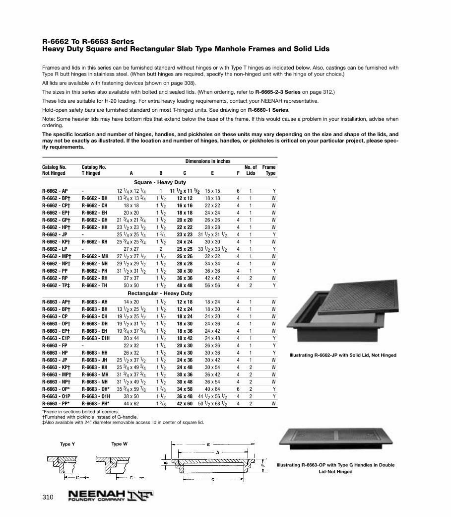
310
R-6662 To R-6663 SeriesHeavy Duty Square and Rectangular Slab Type Manhole Frames and Solid Lids
Frames and lids in this series can be furnished standard without hinges or with Type T hinges as indicated below. Also, castings can be furnished withType R butt hinges in stainless steel. (When butt hinges are required, specify the non-hinged unit with the hinge of your choice.)
All lids are available with fastening devices (shown on page 308).
The sizes in this series also available with bolted and sealed lids. (When ordering, refer to R-6665-2-3 Series on page 312.)
These lids are suitable for H-20 loading. For extra heavy loading requirements, contact your NEENAH representative.
Hold-open safety bars are furnished standard on most T-hinged units. See drawing on R-6660-1 Series.
Note: Some heavier lids may have bottom ribs that extend below the base of the frame. If this would cause a problem in your installation, advise whenordering.
The specific location and number of hinges, handles, and pickholes on these units may vary depending on the size and shape of the lids, andmay not be exactly as illustrated. If the location and number of hinges, handles, or pickholes is critical on your particular project, please spec-ify requirements.
Dimensions in inchesCatalog No. Catalog No. No. of FrameNot Hinged T Hinged A B C E F Lids Type
Square - Heavy Duty
R-6662 - AP - 12 1/4 x 12 1/4 1 11 1/2 x 11 1/2 15 x 15 6 1 YR-6662 - BP† R-6662 - BH 13 3/4 x 13 3/4 1 1/2 12 x 12 18 x 18 4 1 WR-6662 - CP† R-6662 - CH 18 x 18 1 1/2 16 x 16 22 x 22 4 1 WR-6662 - EP† R-6662 - EH 20 x 20 1 1/2 18 x 18 24 x 24 4 1 WR-6662 - GP† R-6662 - GH 21 3/4 x 21 3/4 1 1/2 20 x 20 26 x 26 4 1 WR-6662 - HP† R-6662 - HH 23 1/2 x 23 1/2 1 1/2 22 x 22 28 x 28 4 1 WR-6662 - JP - 25 1/4 x 25 1/4 1 3/4 23 x 23 31 1/2 x 31 1/2 4 1 YR-6662 - KP† R-6662 - KH 25 3/4 x 25 3/4 1 1/2 24 x 24 30 x 30 4 1 WR-6662 - LP - 27 x 27 2 25 x 25 33 1/2 x 33 1/2 4 1 YR-6662 - MP† R-6662 - MH 27 1/2 x 27 1/2 1 1/2 26 x 26 32 x 32 4 1 WR-6662 - NP† R-6662 - NH 29 1/2 x 29 1/2 1 1/2 28 x 28 34 x 34 4 1 WR-6662 - PP R-6662 - PH 31 1/2 x 31 1/2 1 1/2 30 x 30 36 x 36 4 1 YR-6662 - RP R-6662 - RH 37 x 37 1 1/2 36 x 36 42 x 42 4 2 WR-6662 - TP‡ R-6662 - TH 50 x 50 1 1/2 48 x 48 56 x 56 4 2 Y
Rectangular - Heavy Duty
R-6663 - AP† R-6663 - AH 14 x 20 1 1/2 12 x 18 18 x 24 4 1 WR-6663 - BP† R-6663 - BH 13 1/2 x 25 1/2 1 1/2 12 x 24 18 x 30 4 1 WR-6663 - CP R-6663 - CH 19 1/2 x 25 1/2 1 1/2 18 x 24 24 x 30 4 1 WR-6663 - DP† R-6663 - DH 19 1/2 x 31 1/2 1 1/2 18 x 30 24 x 36 4 1 WR-6663 - EP† R-6663 - EH 19 3/4 x 37 3/4 1 1/2 18 x 36 24 x 42 4 1 WR-6663 - E1P R-6663 - E1H 20 x 44 1 1/2 18 x 42 24 x 48 4 1 YR-6663 - FP - 22 x 32 1 1/4 20 x 30 26 x 36 4 1 YR-6663 - HP R-6663 - HH 26 x 32 1 1/2 24 x 30 30 x 36 4 1 YR-6663 - JP R-6663 - JH 25 1/2 x 37 1/2 1 1/2 24 x 36 30 x 42 4 1 WR-6663 - KP† R-6663 - KH 25 3/4 x 49 3/4 1 1/2 24 x 48 30 x 54 4 2 WR-6663 - MP† R-6663 - MH 31 3/4 x 37 3/4 1 1/2 30 x 36 36 x 42 4 2 WR-6663 - NP† R-6663 - NH 31 1/2 x 49 1/2 1 1/2 30 x 48 36 x 54 4 2 WR-6663 - OP* R-6663 - OH* 35 3/4 x 59 7/8 1 3/8 34 x 58 40 x 64 6 2 YR-6663 - O1P R-6663 - O1H 38 x 50 1 1/2 36 x 48 44 1/2 x 56 1/2 4 2 YR-6663 - PP* R-6663 - PH* 44 x 62 1 3/8 42 x 60 50 1/2 x 68 1/2 4 2 W
*Frame in sections bolted at corners.†Furnished with pickhole instead of G-handle.‡Also available with 24” diameter removable access lid in center of square lid.
Illustrating R-6662-JP with Solid Lid, Not Hinged
Illustrating R-6663-OP with Type G Handles in DoubleLid-Not Hinged
Type Y Type W
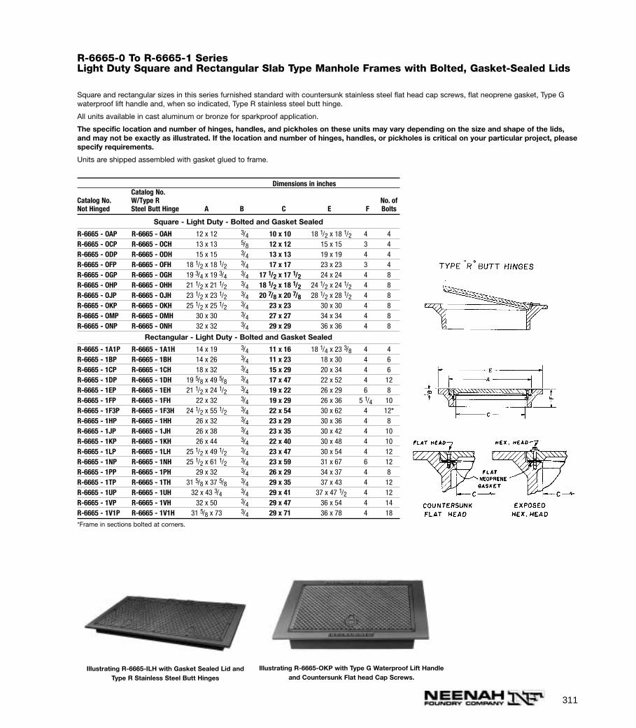
311
R-6665-0 To R-6665-1 SeriesLight Duty Square and Rectangular Slab Type Manhole Frames with Bolted, Gasket-Sealed Lids
Square and rectangular sizes in this series furnished standard with countersunk stainless steel flat head cap screws, flat neoprene gasket, Type Gwaterproof lift handle and, when so indicated, Type R stainless steel butt hinge.
All units available in cast aluminum or bronze for sparkproof application.
The specific location and number of hinges, handles, and pickholes on these units may vary depending on the size and shape of the lids,and may not be exactly as illustrated. If the location and number of hinges, handles, or pickholes is critical on your particular project, pleasespecify requirements.
Units are shipped assembled with gasket glued to frame.
Dimensions in inchesCatalog No.
Catalog No. W/Type R No. ofNot Hinged Steel Butt Hinge A B C E F Bolts
Square - Light Duty - Bolted and Gasket Sealed
R-6665 - OAP R-6665 - OAH 12 x 12 3/4 10 x 10 18 1/2 x 18 1/2 4 4R-6665 - OCP R-6665 - OCH 13 x 13 5/8 12 x 12 15 x 15 3 4R-6665 - ODP R-6665 - ODH 15 x 15 3/4 13 x 13 19 x 19 4 4R-6665 - OFP R-6665 - OFH 18 1/2 x 18 1/2 3/4 17 x 17 23 x 23 3 4R-6665 - OGP R-6665 - OGH 19 3/4 x 19 3/4 3/4 17 1/2 x 17 1/2 24 x 24 4 8R-6665 - OHP R-6665 - OHH 21 1/2 x 21 1/2 3/4 18 1/2 x 18 1/2 24 1/2 x 24 1/2 4 8R-6665 - OJP R-6665 - OJH 23 1/2 x 23 1/2 3/4 20 7/8 x 20 7/8 28 1/2 x 28 1/2 4 8R-6665 - OKP R-6665 - OKH 25 1/2 x 25 1/2 3/4 23 x 23 30 x 30 4 8R-6665 - OMP R-6665 - OMH 30 x 30 3/4 27 x 27 34 x 34 4 8R-6665 - ONP R-6665 - ONH 32 x 32 3/4 29 x 29 36 x 36 4 8
Rectangular - Light Duty - Bolted and Gasket Sealed
R-6665 - 1A1P R-6665 - 1A1H 14 x 19 3/4 11 x 16 18 1/4 x 23 3/8 4 4R-6665 - 1BP R-6665 - 1BH 14 x 26 3/4 11 x 23 18 x 30 4 6R-6665 - 1CP R-6665 - 1CH 18 x 32 3/4 15 x 29 20 x 34 4 6R-6665 - 1DP R-6665 - 1DH 19 5/8 x 49 5/8 3/4 17 x 47 22 x 52 4 12R-6665 - 1EP R-6665 - 1EH 21 1/2 x 24 1/2 3/4 19 x 22 26 x 29 6 8R-6665 - 1FP R-6665 - 1FH 22 x 32 3/4 19 x 29 26 x 36 5 1/4 10R-6665 - 1F3P R-6665 - 1F3H 24 1/2 x 55 1/2 3/4 22 x 54 30 x 62 4 12*R-6665 - 1HP R-6665 - 1HH 26 x 32 3/4 23 x 29 30 x 36 4 8R-6665 - 1JP R-6665 - 1JH 26 x 38 3/4 23 x 35 30 x 42 4 10R-6665 - 1KP R-6665 - 1KH 26 x 44 3/4 22 x 40 30 x 48 4 10R-6665 - 1LP R-6665 - 1LH 25 1/2 x 49 1/2 3/4 23 x 47 30 x 54 4 12R-6665 - 1NP R-6665 - 1NH 25 1/2 x 61 1/2 3/4 23 x 59 31 x 67 6 12R-6665 - 1PP R-6665 - 1PH 29 x 32 3/4 26 x 29 34 x 37 4 8R-6665 - 1TP R-6665 - 1TH 31 5/8 x 37 5/8 3/4 29 x 35 37 x 43 4 12R-6665 - 1UP R-6665 - 1UH 32 x 43 3/4 3/4 29 x 41 37 x 47 1/2 4 12R-6665 - 1VP R-6665 - 1VH 32 x 50 3/4 29 x 47 36 x 54 4 14R-6665 - 1V1P R-6665 - 1V1H 31 5/8 x 73 3/4 29 x 71 36 x 78 4 18
*Frame in sections bolted at corners.
Illustrating R-6665-OKP with Type G Waterproof Lift Handleand Countersunk Flat head Cap Screws.
Illustrating R-6665-ILH with Gasket Sealed Lid andType R Stainless Steel Butt Hinges
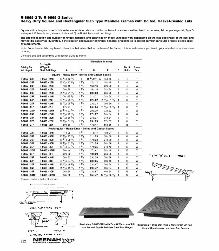
312
R-6665-2 To R-6665-3 SeriesHeavy Duty Square and Rectangular Slab Type Manhole Frames with Bolted, Gasket-Sealed Lids
Square and rectangular sizes in this series are furnished standard with countersunk stainless steel hex head cap screws, flat neoprene gasket, Type Gwaterproof lift handle and, when so indicated, Type R stainless steel butt hinge.
The specific location and number of hinges, handles, and pickholes on these units may vary depending on the size and shape of the lids, andmay not be exactly as illustrated. If the location and number of hinges, handles, or pickholes is critical on your particular project, please spec-ify requirements.
Note: Some heavier lids may have bottom ribs that extend below the base of the frame. If this would cause a problem in your intstallation, advise whenordering.
Units are shipped assembled with gasket glued to frame.
Dimensions in inchesCatalog No.
Catalog No. W/Type R No. of FrameNot Hinged Steel Butt Hinge A B C E F Bolts Type
Square - Heavy Duty - Bolted and Gasket Sealed
R-6665 - 2AP R-6665 - 2AH 12 1/4 x 12 1/4 1 11 1/2 x 11 1/2 15 x 15 6 4 YR-6665 - 2BP R-6665 - 2BH 13 3/4 x 13 3/4 1 1/2 12 x 12 18 x 18 4 4 WR-6665 - 2CP R-6665 - 2CH 18 x 18 1 1/2 16 x 16 22 x 22 4 4 WR-6665 - 2EP R-6665 - 2EH 20 x 20 1 1/2 18 x 18 24 x 24 4 4 WR-6665 - 2GP R-6665 - 2GH 21 1/2 x 21 1/2 1 1/2 20 x 20 26 x 26 4 4 WR-6665 - 2HP R-6665 - 2HH 23 1/2 x23 1/2 1 1/2 21 x 21 28 x 28 4 8 WR-6665 - 2JP R-6665 - 2JH 25 1/4 x 25 1/4 1 3/4 22 x 22 31 1/2 x 31 1/2 4 8 YR-6665 - 2KP R-6665 - 2KH 25 3/4 x 25 3/4 1 1/2 23 x 23 30 x 30 4 8 WR-6665 - 2LP R-6665 - 2LH 27 x 27 2 24 x 24 33 1/2 x 33 1/2 4 8 YR-6665 - 2MP R-6665 - 2MH 27 1/2 x 27 1/2 1 1/2 25 x 25 32 x 32 4 8 WR-6665 - 2NP R-6665 - 2NH 29 1/2 x 29 1/2 1 1/2 27 x 27 34 x 34 4 8 WR-6665 - 2OP R-6665 - 2OH 30 3/8 x 30 3/8 1 3/4 27 x 27 34 x 34 4 8 YR-6665 - 2PP R-6665 - 2PH 31 1/2 x 31 1/2 1 1/2 29 x 29 37 x 37 4 8 YR-6665 - 2TP R-6665 - 2TH 50 x 50 1 1/2 47 x 47 56 x 56 4 16 Y
Rectangular - Heavy Duty - Bolted and Gasket Sealed
R-6665 - 3AP R-6665 - 3AH 14 x 20 1 1/2 11 x 17 18 x 24 4 6 WR-6665 - 3BP R-6665 - 3BH 13 1/2 x 25 1/2 1 1/2 11 x 23 18 x 30 4 6 WR-6665 - 3CP R-6665 - 3CH 19 1/2 x 25 1/2 1 1/2 17 x 23 24 x 30 4 8 WR-6665 - 3DP R-6665 - 3DH 19 1/2 x 31 1/2 1 1/2 17 x 29 24 x 36 4 8 WR-6665 - 3EP R-6665 - 3EH 19 3/4 x 37 3/4 1 1/2 17 x 35 24 x 42 4 10 WR-6665 - 3E1P R-6665 - 3E1H 20 x 44 1 1/2 17 x 41 24 x 48 4 10 YR-6665 - 3FP R-6665 - 3FH 22 x 32 1 1/4 19 x 29 26 x 36 4 8 YR-6665 - 3HP R-6665 - 3HH 26 x 32 1 1/2 23 x 29 30 x 36 4 8 YR-6665 - 3JP R-6665 - 3JH 25 1/2 x 37 1/2 1 1/2 23 x 35 30 x 42 4 10 WR-6665 - 3KP R-6665 - 3KH 25 3/4 x 49 3/4 1 1/2 23 x 47 30 x 54 4 12 WR-6665 - 3NP R-6665 - 3NH 31 1/2 x 49 1/2 1 1/2 29 x 47 36 x 54 4 16 WR-6665 - 3OP R-6665 - 3OH 36 x 60 1 3/8 33 x 57 40 x 64 6 16 Y*R-6665 - 3O1P R-6665 - 3O1H 38 x 50 1 1/2 35 x 47 44 1/2 x 56 1/2 4 14 W
*Frame in sections bolted at corners.
Illustrating R-6665-2GP Type G Waterproof Lift han-dle and Countersunk Hex Head Cap Screws
Illustrating R-6665-3KH with Type G Waterproof LiftHandles and Type R Stainless Steel Butt Hinges
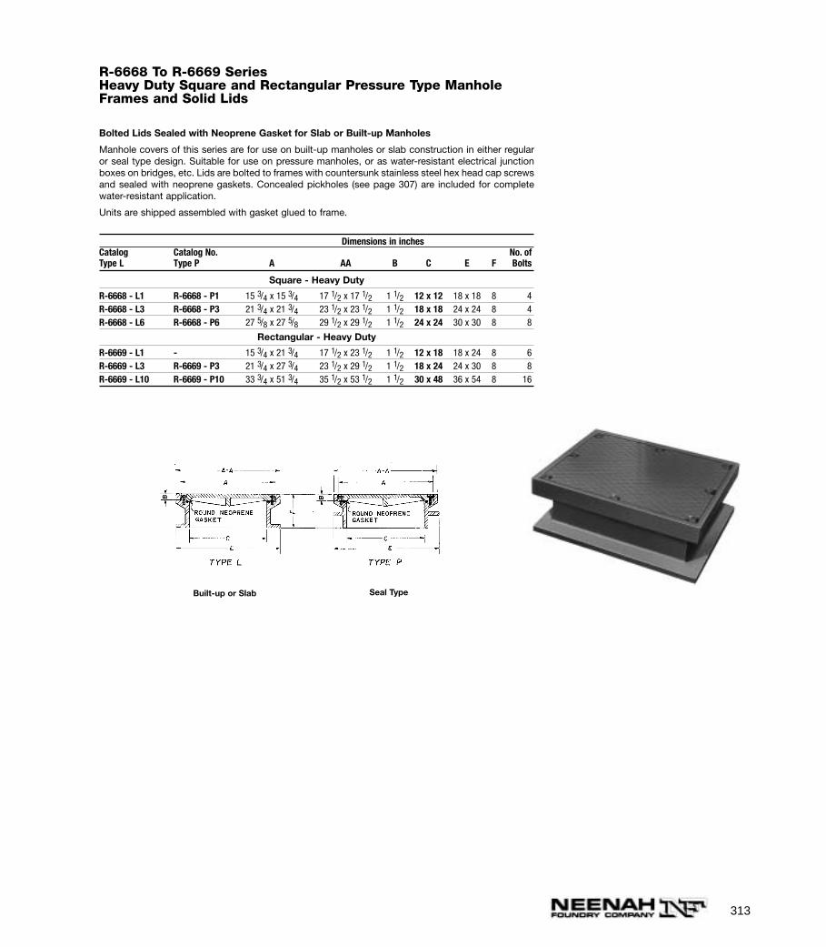
313
R-6668 To R-6669 SeriesHeavy Duty Square and Rectangular Pressure Type ManholeFrames and Solid Lids
Bolted Lids Sealed with Neoprene Gasket for Slab or Built-up Manholes
Manhole covers of this series are for use on built-up manholes or slab construction in either regularor seal type design. Suitable for use on pressure manholes, or as water-resistant electrical junctionboxes on bridges, etc. Lids are bolted to frames with countersunk stainless steel hex head cap screwsand sealed with neoprene gaskets. Concealed pickholes (see page 307) are included for completewater-resistant application.
Units are shipped assembled with gasket glued to frame.
Dimensions in inchesCatalog Catalog No. No. ofType L Type P A AA B C E F Bolts
Square - Heavy Duty
R-6668 - L1 R-6668 - P1 15 3/4 x 15 3/4 17 1/2 x 17 1/2 1 1/2 12 x 12 18 x 18 8 4R-6668 - L3 R-6668 - P3 21 3/4 x 21 3/4 23 1/2 x 23 1/2 1 1/2 18 x 18 24 x 24 8 4R-6668 - L6 R-6668 - P6 27 5/8 x 27 5/8 29 1/2 x 29 1/2 1 1/2 24 x 24 30 x 30 8 8
Rectangular - Heavy Duty
R-6669 - L1 - 15 3/4 x 21 3/4 17 1/2 x 23 1/2 1 1/2 12 x 18 18 x 24 8 6R-6669 - L3 R-6669 - P3 21 3/4 x 27 3/4 23 1/2 x 29 1/2 1 1/2 18 x 24 24 x 30 8 8R-6669 - L10 R-6669 - P10 33 3/4 x 51 3/4 35 1/2 x 53 1/2 1 1/2 30 x 48 36 x 54 8 16
Built-up or Slab Seal Type
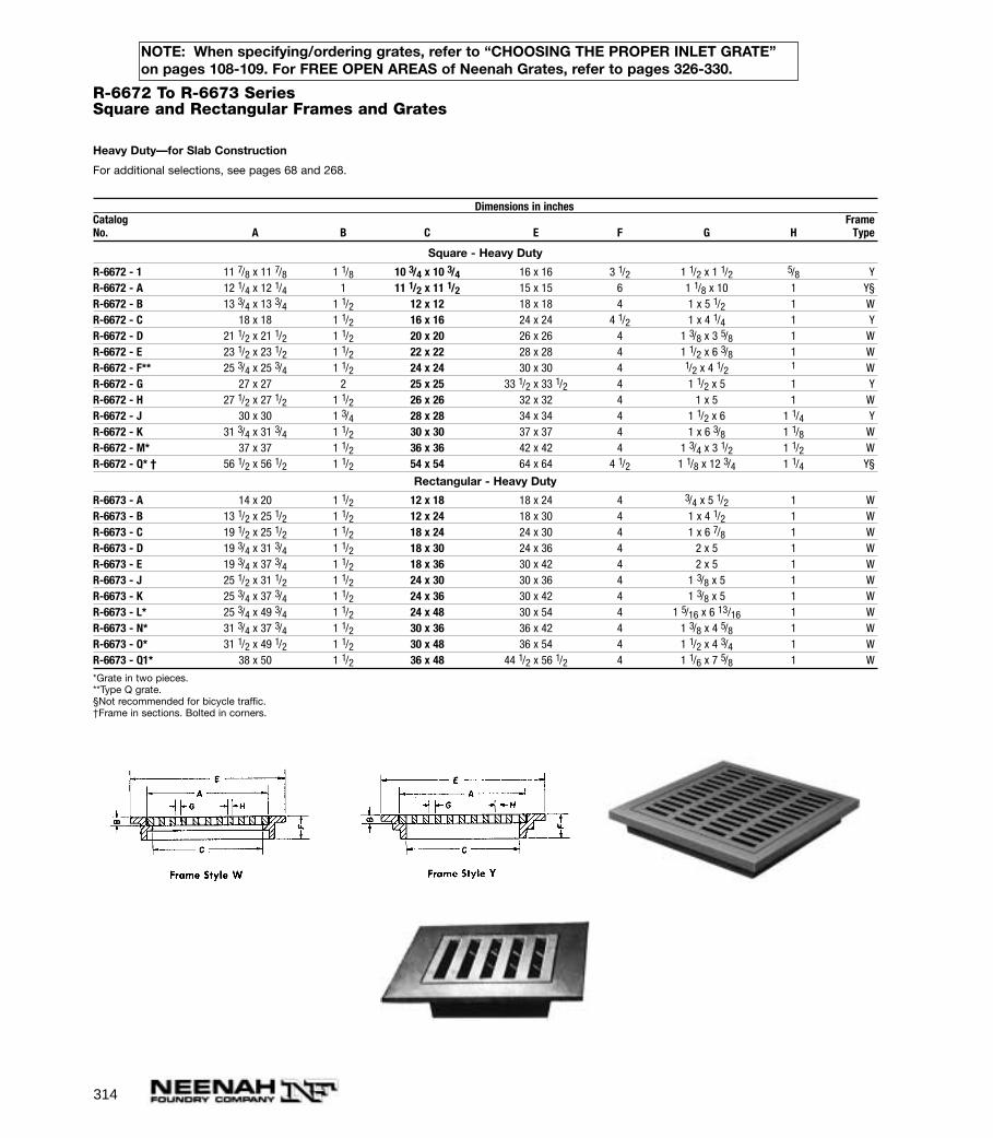
314
R-6672 To R-6673 SeriesSquare and Rectangular Frames and Grates
Heavy Duty—for Slab Construction
For additional selections, see pages 68 and 268.
Dimensions in inchesCatalog FrameNo. A B C E F G H Type
Square - Heavy Duty
R-6672 - 1 11 7/8 x 11 7/8 1 1/8 10 3/4 x 10 3/4 16 x 16 3 1/2 1 1/2 x 1 1/2 5/8 YR-6672 - A 12 1/4 x 12 1/4 1 11 1/2 x 11 1/2 15 x 15 6 1 1/8 x 10 1 Y§R-6672 - B 13 3/4 x 13 3/4 1 1/2 12 x 12 18 x 18 4 1 x 5 1/2 1 WR-6672 - C 18 x 18 1 1/2 16 x 16 24 x 24 4 1/2 1 x 4 1/4 1 YR-6672 - D 21 1/2 x 21 1/2 1 1/2 20 x 20 26 x 26 4 1 3/8 x 3 5/8 1 WR-6672 - E 23 1/2 x 23 1/2 1 1/2 22 x 22 28 x 28 4 1 1/2 x 6 3/8 1 WR-6672 - F** 25 3/4 x 25 3/4 1 1/2 24 x 24 30 x 30 4 1/2 x 4 1/2 1 WR-6672 - G 27 x 27 2 25 x 25 33 1/2 x 33 1/2 4 1 1/2 x 5 1 YR-6672 - H 27 1/2 x 27 1/2 1 1/2 26 x 26 32 x 32 4 1 x 5 1 WR-6672 - J 30 x 30 1 3/4 28 x 28 34 x 34 4 1 1/2 x 6 1 1/4 YR-6672 - K 31 3/4 x 31 3/4 1 1/2 30 x 30 37 x 37 4 1 x 6 3/8 1 1/8 WR-6672 - M* 37 x 37 1 1/2 36 x 36 42 x 42 4 1 3/4 x 3 1/2 1 1/2 WR-6672 - Q* † 56 1/2 x 56 1/2 1 1/2 54 x 54 64 x 64 4 1/2 1 1/8 x 12 3/4 1 1/4 Y§
Rectangular - Heavy Duty
R-6673 - A 14 x 20 1 1/2 12 x 18 18 x 24 4 3/4 x 5 1/2 1 WR-6673 - B 13 1/2 x 25 1/2 1 1/2 12 x 24 18 x 30 4 1 x 4 1/2 1 WR-6673 - C 19 1/2 x 25 1/2 1 1/2 18 x 24 24 x 30 4 1 x 6 7/8 1 WR-6673 - D 19 3/4 x 31 3/4 1 1/2 18 x 30 24 x 36 4 2 x 5 1 WR-6673 - E 19 3/4 x 37 3/4 1 1/2 18 x 36 30 x 42 4 2 x 5 1 WR-6673 - J 25 1/2 x 31 1/2 1 1/2 24 x 30 30 x 36 4 1 3/8 x 5 1 WR-6673 - K 25 3/4 x 37 3/4 1 1/2 24 x 36 30 x 42 4 1 3/8 x 5 1 WR-6673 - L* 25 3/4 x 49 3/4 1 1/2 24 x 48 30 x 54 4 1 5/16 x 6 13/16 1 WR-6673 - N* 31 3/4 x 37 3/4 1 1/2 30 x 36 36 x 42 4 1 3/8 x 4 5/8 1 WR-6673 - O* 31 1/2 x 49 1/2 1 1/2 30 x 48 36 x 54 4 1 1/2 x 4 3/4 1 WR-6673 - Q1* 38 x 50 1 1/2 36 x 48 44 1/2 x 56 1/2 4 1 1/6 x 7 5/8 1 W
*Grate in two pieces. **Type Q grate.§Not recommended for bicycle traffic. †Frame in sections. Bolted in corners.
NOTE: When specifying/ordering grates, refer to “CHOOSING THE PROPER INLET GRATE”on pages 108-109. For FREE OPEN AREAS of Neenah Grates, refer to pages 326-330.

315
R-6679-A1 & B1Electrical Hand Hole Frame and Lid
Specify:
1. Complete catalog number.
2. Lettering as shown, special lettering or no lettering.
Dimensions in inchesCatalogNo. A B C D E F Duty
R-6679 - A1 23 1/2 1 1/4 22 23 1/2 31 1/2 4 LightR-6679 - B1 23 1/2 1 1/4 22 23 1/2 31 1/2 4 Heavy
R-6680-AManhole Frame and Solid Lid
Heavy Duty
Furnished standard with as-cast bearing surfaces.
ELECTRICAL FRAMES AND LIDS

316
R-6681-5 SeriesPull Box Frames and Lids
Light Duty—Electrical Pull Box
Light weight design for pull boxes, junction or splice boxes, in areas not subject to traffic. Ideal forstreet lighting or traffic marker installations.
Specify:
1. Complete catalog number.
2. Special lettering on lids if required.
Dimensions in inchesCatalog FrameNo. A B C E F Style
Square
R-6681 - 2 17 5/8 x 17 5/8 1/2 16 7/8 x 16 7/8 22 1/8 X 22 1/8 3 1R-6683 - 1 18 x 18 1 17 3/8 x 17 3/8 22 X 22 3 1R-6683 - 2 23 3/4 x 23 3/4 15/16 21 7/8 x 21 7/8 30 X 30 3 1
Rectangular
R-6684 - 2 10 3/4 x 18 3/4 1/2 10 x 18 16 x 24 3 1R-6685 - 1 17 7/8 x 24 1/2 17 x 22 1/2 24 1/2 x 30 3 2R-6685 - 5 24 x 36 1 23 x 34 3/4 29 x 41 3 1/8 2
Illustrating R-6683-1 Illustrating R-6684-2
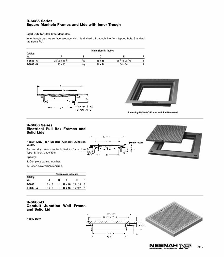
317
R-6685 SeriesSquare Manhole Frames and Lids with Inner Trough
Light Duty for Slab Type Manholes
Inner trough catches surface seepage which is drained off through line from tapped hole. Standardtap size is 3/4”.
Dimensions in inchesCatalogNo. A B C E F
R-6685 - C 23 1/2 x 23 1/2 3/4 18 x 18 28 1/2 x 28 1/2 4R-6685 - D 30 x 30 3/4 24 x 24 34 x 34 4
Illustrating R-6685-D Frame with Lid Removed
R-6686 SeriesElectrical Pull Box Frames andSolid Lids
Heavy Duty—for Electric Conduit JunctionVaults.
For security, cover can be bolted to frame (seeType “E” lock, page 308).
Specify:
1. Complete catalog number.
2. Bolted cover when required.
Dimensions in inchesCatalogNo. A B C E F
R-6686 18 x 18 1 16 x 16 24 x 24 2R-6686 - A 12 x 18 1 10 x 16 16 x 22 2
R-6686-DConduit Junction Well Frameand Solid Lid
Heavy Duty

318
R-6687 SeriesConduit Box Frames with Solid Lids
Light Duty for Street Lighting Installations
Lids can be furnished bolted at the corners or provided with special lettering if specified.
Specify:
1. Catalog number.
2. Lid bolted to frame.
3. Special lettering when required.
Dimensions in inches
CatalogNo. A B C E F
R-6687 - A 10 x 10 1 8 x 8 11 1/4 x 11 1/4 1 1/2R-6687 - A1 12 x 18 1/2 10 x 16 13 1/2 x 19 1/2 1 1/4R-6687 - B 13 7/8 x 15 7/8 1/2 12 x 14 15 x 17 1R-6687 - C 14 x 28 1 12 x 26 15 1/4 x 29 1/4 1 1/2R-6687 - D 15 7/8 x 15 7/8 1 1/8 14 1/2 x 14 1/2 17 1/8 x 17 1/8 1 3/4R-6687 - E 20 3/8 x 20 3/8 1 18 3/4 x 18 3/4 21 1/4 x 21 1/4 1 1/2R-6687 - F 23 x 29 1 1/2 20 x 26 24 x 30 2 1/8
R-6688-2Handhole Frame and Lid
Light Duty
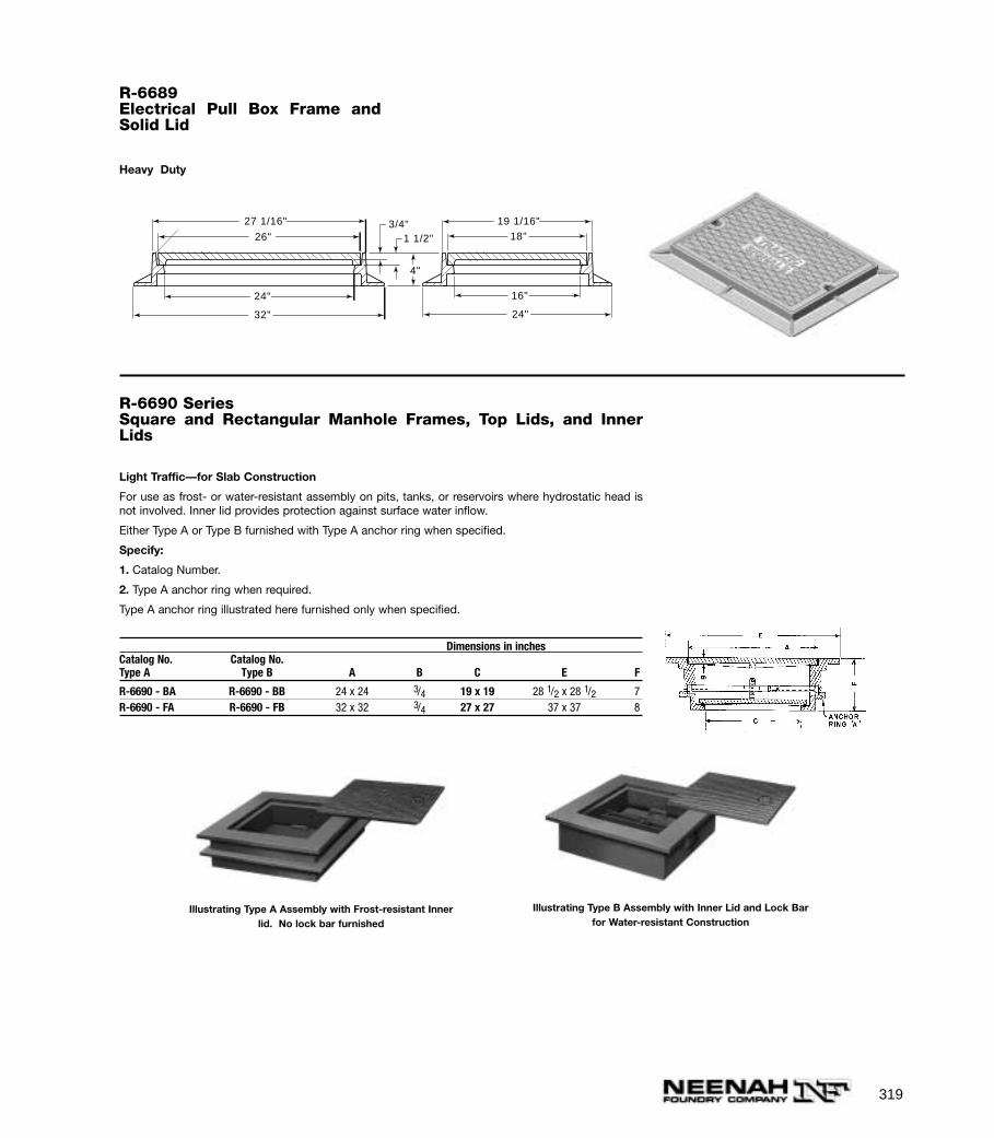
319
R-6689Electrical Pull Box Frame andSolid Lid
Heavy Duty
19 1/16"27 1/16"
26" 18"
16"
24"
24"
32"
1 1/2"
4"
3/4"
R-6690 SeriesSquare and Rectangular Manhole Frames, Top Lids, and InnerLids
Light Traffic—for Slab Construction
For use as frost- or water-resistant assembly on pits, tanks, or reservoirs where hydrostatic head isnot involved. Inner lid provides protection against surface water inflow.
Either Type A or Type B furnished with Type A anchor ring when specified.
Specify:
1. Catalog Number.
2. Type A anchor ring when required.
Type A anchor ring illustrated here furnished only when specified.
Dimensions in inchesCatalog No. Catalog No.Type A Type B A B C E F
R-6690 - BA R-6690 - BB 24 x 24 3/4 19 x 19 28 1/2 x 28 1/2 7R-6690 - FA R-6690 - FB 32 x 32 3/4 27 x 27 37 x 37 8
Illustrating Type A Assembly with Frost-resistant Innerlid. No lock bar furnished
Illustrating Type B Assembly with Inner Lid and Lock Barfor Water-resistant Construction
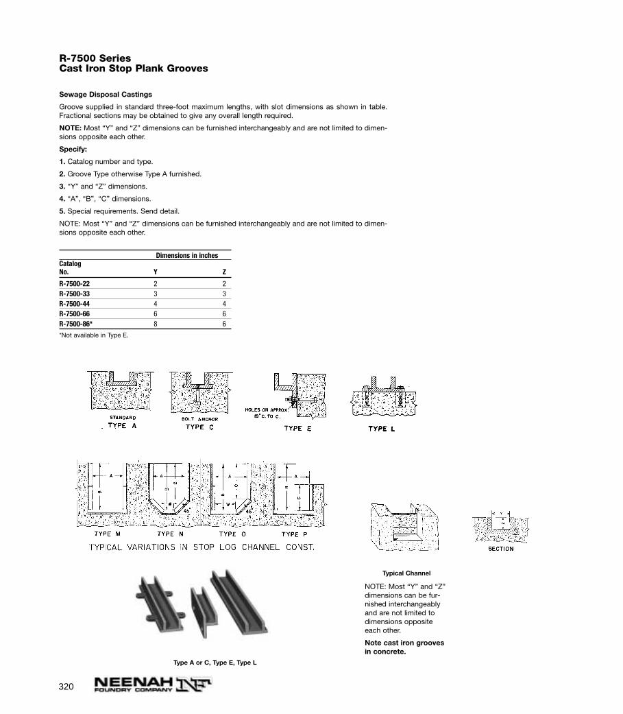
320
R-7500 SeriesCast Iron Stop Plank Grooves
Sewage Disposal Castings
Groove supplied in standard three-foot maximum lengths, with slot dimensions as shown in table.Fractional sections may be obtained to give any overall length required.
NOTE: Most “Y” and “Z” dimensions can be furnished interchangeably and are not limited to dimen-sions opposite each other.
Specify:
1. Catalog number and type.
2. Groove Type otherwise Type A furnished.
3. “Y” and “Z” dimensions.
4. “A”, “B”, “C” dimensions.
5. Special requirements. Send detail.
NOTE: Most “Y” and “Z” dimensions can be furnished interchangeably and are not limited to dimen-sions opposite each other.
Dimensions in inchesCatalogNo. Y Z
R-7500-22 2 2R-7500-33 3 3R-7500-44 4 4R-7500-66 6 6R-7500-86* 8 6
*Not available in Type E.
Type A or C, Type E, Type L
Typical Channel
NOTE: Most “Y” and “Z”dimensions can be fur-nished interchangeablyand are not limited todimensions oppositeeach other.
Note cast iron groovesin concrete.
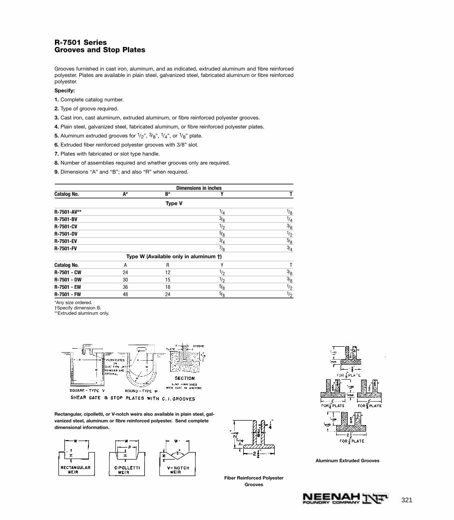
321
R-7501 SeriesGrooves and Stop Plates
Grooves furnished in cast iron, aluminum, and as indicated, extruded aluminum and fibre reinforcedpolyester. Plates are available in plain steel, galvanized steel, fabricated aluminum or fibre reinforcedpolyester.
Specify:
1. Complete catalog number.
2. Type of groove required.
3. Cast iron, cast aluminum, extruded aluminum, or fibre reinforced polyester grooves.
4. Plain steel, galvanized steel, fabricated aluminum, or fibre reinforced polyester plates.
5. Aluminum extruded grooves for 1/2”, 3/8”, 1/4”, or 1/8” plate.
6. Extruded fiber reinforced polyester grooves with 3/8” slot.
7. Plates with fabricated or slot type handle.
8. Number of assemblies required and whether grooves only are required.
9. Dimensions “A” and “B”; and also “R” when required.
Dimensions in inchesCatalog No. A* B* Y T
Type V
R-7501-AV** 1/4 1/8R-7501-BV 3/8 1/4R-7501-CV 1/2 3/8R-7501-DV 5/8 1/2R-7501-EV 3/4 5/8R-7501-FV 7/8 3/4
Type W (Available only in aluminum †)
Catalog No. A R Y TR-7501 - CW 24 12 1/2 3/8R-7501 - DW 30 15 1/2 3/8R-7501 - EW 36 18 5/8 1/2R-7501 - FW 48 24 5/8 1/2*Any size ordered.†Specify dimension B.**Extruded aluminum only.
Aluminum Extruded Grooves
Fiber Reinforced PolyesterGrooves
Rectangular, cipolletti, or V-notch weirs also available in plain steel, gal-vanized steel, aluminum or fibre reinforced polyester. Send completedimensional information.
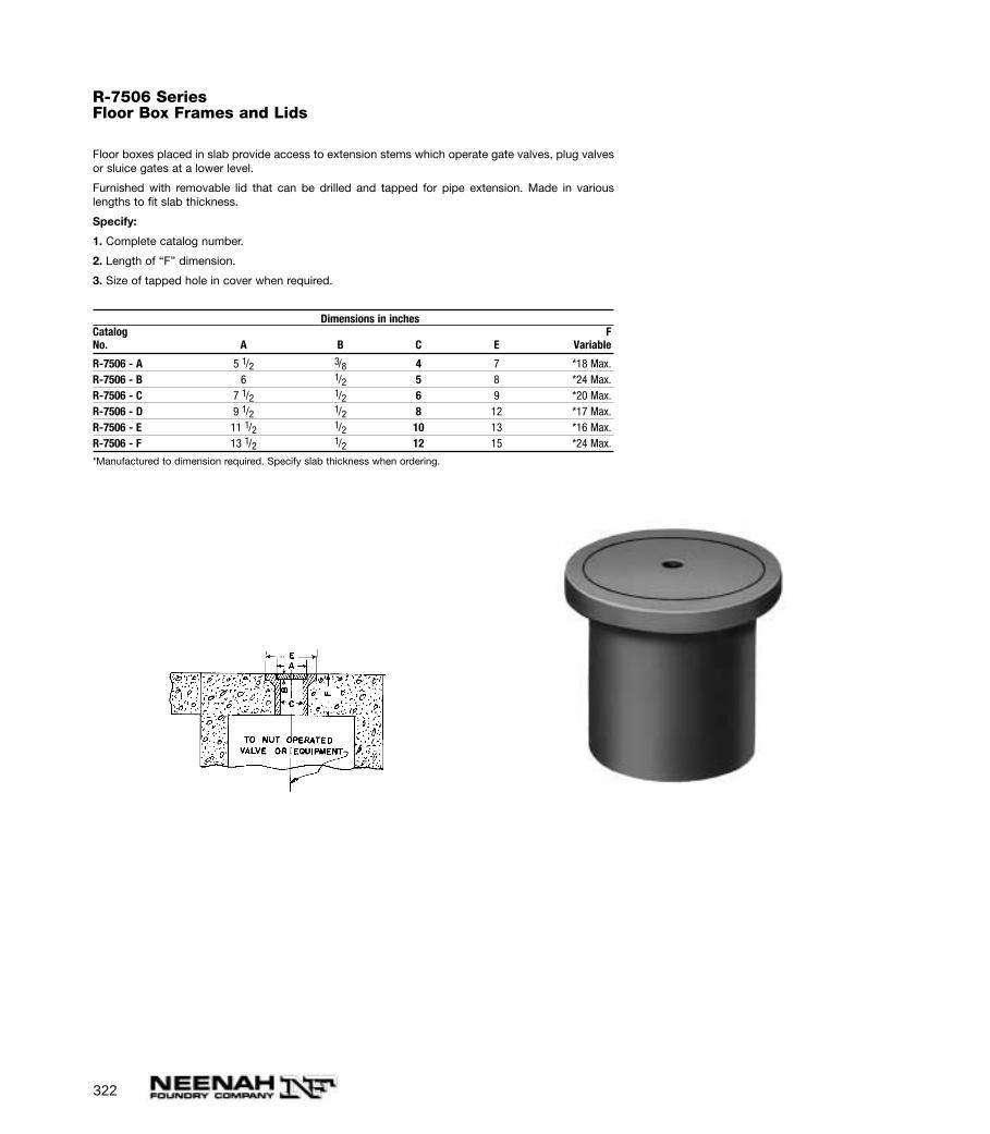
322
R-7506 SeriesFloor Box Frames and Lids
Floor boxes placed in slab provide access to extension stems which operate gate valves, plug valvesor sluice gates at a lower level.
Furnished with removable lid that can be drilled and tapped for pipe extension. Made in variouslengths to fit slab thickness.
Specify:
1. Complete catalog number.
2. Length of “F” dimension.
3. Size of tapped hole in cover when required.
Dimensions in inchesCatalog FNo. A B C E Variable
R-7506 - A 5 1/2 3/8 4 7 *18 Max.R-7506 - B 6 1/2 5 8 *24 Max.R-7506 - C 7 1/2 1/2 6 9 *20 Max.R-7506 - D 9 1/2 1/2 8 12 *17 Max.R-7506 - E 11 1/2 1/2 10 13 *16 Max.R-7506 - F 13 1/2 1/2 12 15 *24 Max.
*Manufactured to dimension required. Specify slab thickness when ordering.
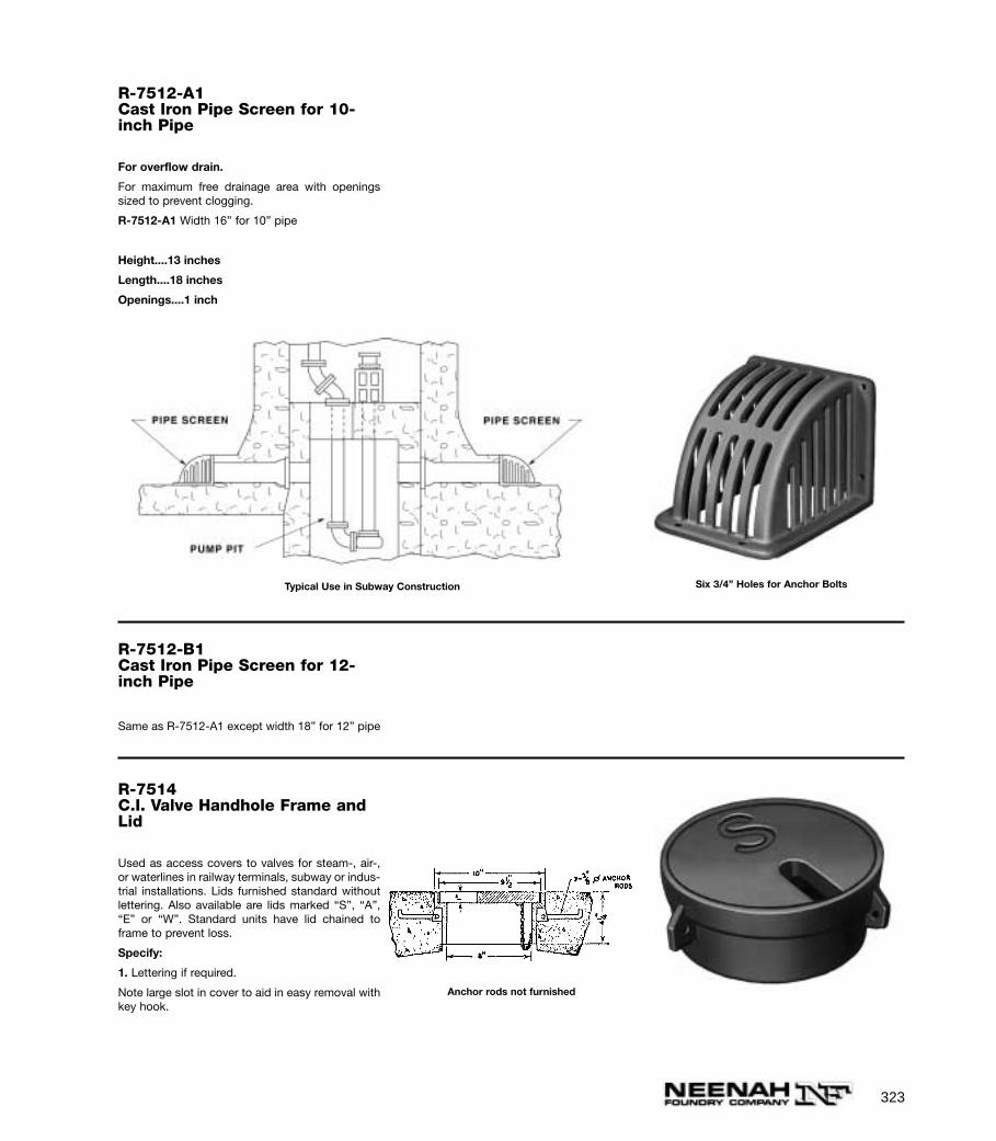
323
R-7512-A1Cast Iron Pipe Screen for 10-inch Pipe
For overflow drain.
For maximum free drainage area with openingssized to prevent clogging.
R-7512-A1 Width 16” for 10” pipe
Height....13 inches
Length....18 inches
Openings....1 inch
Six 3/4” Holes for Anchor Bolts
R-7512-B1Cast Iron Pipe Screen for 12-inch Pipe
Same as R-7512-A1 except width 18” for 12” pipe
R-7514C.I. Valve Handhole Frame andLid
Used as access covers to valves for steam-, air-,or waterlines in railway terminals, subway or indus-trial installations. Lids furnished standard withoutlettering. Also available are lids marked “S”, “A”,“E” or “W”. Standard units have lid chained toframe to prevent loss.
Specify:
1. Lettering if required.
Note large slot in cover to aid in easy removal withkey hook.
Anchor rods not furnished
Typical Use in Subway Construction

324
R-7516Round Ballast Screen
Designed to fit R-2504 standard catch basin framewith grate fitting top recess of ballast screen.
Also compatible with R-1713 frames and lids.
Can be double or triple stacked as needed.
Specify:
1. Top grate when required..
Used where positive drainage must be assuredIllustrating R-7516 Round Ballast Screen with Top
Grate Removed
R-7516-CRound Ballast Screen
Designed to fit in lid opening of R-5901-E slabtype frame. Frame is designed to fit 24” corrugat-ed metal pipe. When required, top cover grate canalso be furnished.
Furnished standard with as-cast bearing surfaces.
Can be double or triple stacked as needed.
Specify:
1. Top grate when required.
2. Frame when required.
(If neither of the above are specified, ballast screenonly will be furnished.)
R-7516-DRectangular Ballast Screen
Can be double or triple stacked as needed.
NOTE: When specifying/ordering grates, refer to “CHOOSING THE PROPER INLET GRATE”on pages 108-109. For FREE OPEN AREAS of Neenah Grates, refer to pages 326-330.
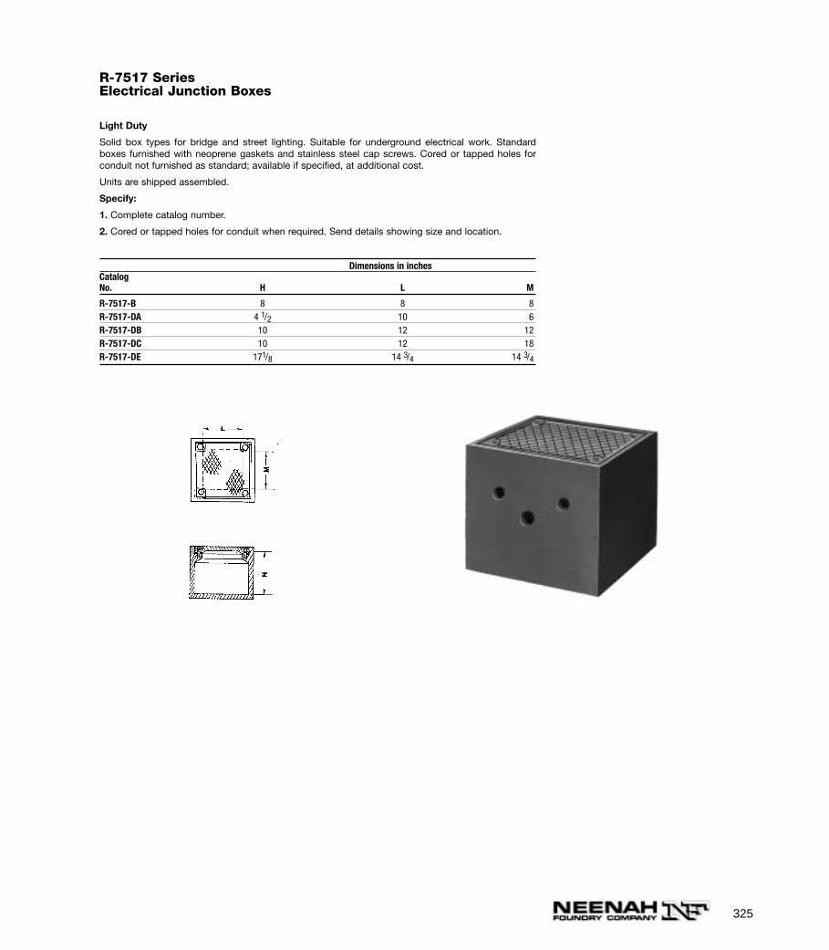
325
R-7517 SeriesElectrical Junction Boxes
Light Duty
Solid box types for bridge and street lighting. Suitable for underground electrical work. Standardboxes furnished with neoprene gaskets and stainless steel cap screws. Cored or tapped holes forconduit not furnished as standard; available if specified, at additional cost.
Units are shipped assembled.
Specify:
1. Complete catalog number.
2. Cored or tapped holes for conduit when required. Send details showing size and location.
Dimensions in inchesCatalogNo. H L M
R-7517-B 8 8 8R-7517-DA 4 1/2 10 6R-7517-DB 10 12 12R-7517-DC 10 12 18R-7517-DE 171/8 14 3/4 14 3/4
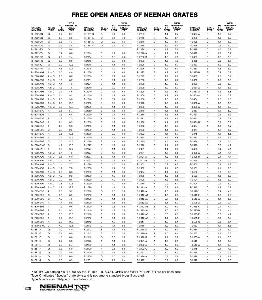
326
R-1792-AG G 0.2 2.7
R-1792-BG G 0.3 3.5
R-1792-CG G 0.5 4.3
R-1792-DG G 0.7 4.8
R-1792-EG G 1.0 5.8
R-1792-FG G 1.7 6.6
R-1792-GG G 2.0 7.4
R-1792-HG G 2.7 9.0
R-1792-JG G 3.7 10.5
R-1792-KG G 4.8 12.1
R-1878-A1G A or C 0.5 4.6
R-1878-A2G A or C 0.8 6.0
R-1878-A3G A or C 1.0 6.7
R-1878-A4G A or C 1.1 7.3
R-1878-A5G A or C 1.8 7.8
R-1878-A6G A or C 2.7 8.6
R-1878-A7G A or C 2.1 9.2
R-1878-A8G A or C 2.3 9.8
R-1878-A9G A or C 2.5 10.6
R-1878-A10G A or C 3.0 12.3
R-1878-B1G A 0.6 5.7
R-1878-B2G A 0.9 6.5
R-1878-B3G A 1.2 7.5
R-1878-B4G A 2.1 8.5
R-1878-B5G A 2.5 9.6
R-1878-B6G C 2.6 9.5
R-1878-B7G A 2.6 10.5
R-1878-B8G A 3.7 12.6
R-1878-B9G C 3.3 11.6
R-1878-B10G C 4.9 13.5
R-1878-B11G A 5.0 14.7
R-1879-A1G A or C 0.4 4.6
R-1879-A2G A or C 0.8 6.0
R-1879-A3G A or C 1.2 6.7
R-1879-A4G A or C 1.4 7.3
R-1879-A5G A or C 1.9 7.8
R-1879-A6G A or C 2.0 8.6
R-1879-A7G A or C 1.7 9.2
R-1879-A8G A or C 2.2 9.8
R-1879-A9G A or C 2.8 10.6
R-1879-A10G A or C 3.7 12.3
R-1879-B1G A 0.6 5.7
R-1879-B2G C 0.9 6.5
R-1879-B3G C 1.0 7.5
R-1879-B4G A 1.4 8.5
R-1879-B5G A 1.9 9.6
R-1879-B6G A 2.4 9.5
R-1879-B7G A 3.0 10.6
R-1879-B8G A 3.2 12.6
R-1879-B9G A 3.2 11.6
R-1879-B10G C 4.2 13.5
R-1881-A Q 0.2 4.0
R-1881-B Q 0.8 8.0
R-1881-C Q 1.0 8.6
R-1881-D Q 0.2 5.3
R-1881-E Q 0.2 5.7
R-1881-F Q 0.3 5.9
R-1881-G Q 0.3 5.9
R-1881-H Q 0.3 6.0
R-1881-J Q 0.3 6.3
R-1881-K Q 0.4 6.8
R-1881-L Q 0.5 7.8
R-1881-M Q 0.9 8.3
R-1881-N Q 0.9 8.3
R-2014 C 1.1 6.0
R-2014 E 1.3 6.0
R-2015 D 0.9 6.0
R-2015 C 1.1 6.0
R-2015 G 1.2 6.0
R-2030 D 1.1 6.0
R-2030 C 1.1 6.0
R-2031 D 1.1 6.0
R-2031 E 1.1 6.0
R-2040 D 0.9 6.0
R-2040 C 1.1 6.0
R-2040 E 1.1 6.0
R-2040 F 0.7 6.0
R-2050 D 0.9 6.0
R-2050 C 1.1 6.0
R-2050 E 1.1 6.0
R-2050 F 0.7 6.0
R-2060 A 1.1 6.0
R-2060 B 1.2 6.0
R-2060 C 1.1 6.0
R-2060 E 1.1 6.0
R-2070 D 0.9 6.0
R-2070 B 1.2 6.0
R-2070 E 1.1 6.0
R-2077 B 1.2 6.0
R-2077 C 1.1 6.0
R-2077 D 1.0 6.0
R-2077 E 1.1 6.0
R-2077 F 0.6 6.0
R-2080 D 1.0 5.9
R-2080 C 1.2 5.9
R-2090 A 1.1 5.0
R-2090 B 1.2 5.8
R-2090 C 1.2 5.8
R-2090 D 1.0 5.8
R-2090 E 1.1 5.8
R-2090 G 1.0 5.8
R-2100 A 1.1 5.8
R-2100 C 1.1 5.8
R-2100 E 1.1 5.8
R-2100 F 0.6 5.8
R-2110 A 1.1 5.8
R-2110 E 1.1 5.8
R-2112 A 1.1 5.8
R-2112 B 1.2 5.8
R-2112 C 1.1 5.8
R-2112 E 1.1 5.8
R-2112 F 0.6 5.8
R-2112 G 0.6 5.8
R-2120 A 1.1 5.8
R-2120 C 1.1 5.8
R-2120 F 0.6 5.8
R-2120 G 1.1 5.8
R-2250 G 3.0 9.9
R-2251 G 2.9 9.4
R-2255 C 1.4 8.4
R-2255 G 1.9 8.4
R-2270 G 1.9 8.4
R-2275 G 1.9 8.4
R-2290 K 1.2 7.6
R-2290-A K 1.2 7.6
R-2290-B K 1.0 7.5
R-2293 G 1.6 7.2
R-2296 B 1.2 6.7
R-2296 F 1.2 6.7
R-2297 B 1.2 6.7
R-2297 F 1.2 6.7
R-2298 B 1.2 6.7
R-2298 F 1.2 6.7
R-2299 B 1.2 6.7
R-2299 F 1.2 6.7
R-2300 G 1.2 6.8
R-2300 C 1.6 6.8
R-2370 B 1.2 6.8
R-2370 F 1.3 6.8
R-2370 A 1.1 6.8
R-2370 G 1.2 6.8
R-2371 G 1.2 6.7
R-2390 G 1.4 6.7
R-2390 C 1.5 6.7
R-2392 C 1.4 6.7
R-2392 G 1.4 6.7
R-2394 G 1.2 6.8
R-2395-1 G 1.6 6.6
R-2398 G 1.4 6.7
R-2401 G 1.4 6.8
R-2401 C 1.6 6.8
R-2401-A G 1.2 6.5
R-2401-B E 0.9 6.2
R-2402 G 0.7 6.5
R-2402 C 1.1 6.5
R-2404 G 1.1 6.7
R-2405 A 1.0 6.5
R-2405 C 1.6 6.5
R-2410 K 0.9 6.1
R-2411-A G 0.7 6.6
R-2412-A G 1.0 6.2
R-2412-A1 E 1.0 6.3
R-2412-A2 G 0.7 6.5
R-2412-A3 C 1.1 6.3
R-2412-A3 E 1.0 6.3
R-2412-A4 C 1.0 6.5
R-2412-A5 K 0.8 6.3
R-2412-A6 G 1.1 6.3
R-2414 D 1.0 6.1
R-2418 G 1.0 6.2
R-2418-A K 1.0 6.3
R-2420-A A 1.0 6.4
R-2420-B G 1.1 5.9
R-2421-A A 1.0 6.1
R-2422-A K 1.0 6.2
R-2422-C G 1.0 6.2
R-2423 G 1.0 6.2
R-2424-A G 0.9 5.9
R-2427 D 0.9 6.0
R-2427-A G 1.0 6.2
R-2428 D 1.0 6.0
R-2428 C 1.1 6.0
R-2428 F 0.6 6.0
R-2429 D 1.0 5.9
R-2429 E 1.3 5.9
R-2429 G 1.2 5.9
R-2435 G 0.9 5.8
R-2437 D 1.0 5.9
R-2437 E 1.3 5.9
R-2437-B G 0.9 5.8
R-2438 D 1.0 5.9
R-2438 E 1.3 5.9
R-2453 K 0.8 6.2
R-2461-A A 1.1 5.8
R-2461-A B 1.2 5.8
R-2461-A C 1.1 5.8
R-2464 D 1.0 6.0
R-2466-A B 1.2 5.8
R-2466-A E 1.1 5.8
R-2467 C 1.1 5.9
R-2467 D 0.9 5.9
R-2471 D 0.9 5.9
R-2471-B D 0.9 5.9
R-2474 A 1.1 5.7
R-2474 G 1.2 5.7
R-2475 A 1.1 5.8
R-2481 A 1.1 5.7
R-2494 G 0.8 5.1
R-2496 G 0.6 4.7
R-2498 G 0.4 4.1
R-2498-A G 0.4 4.1
R-2498-B G 0.4 4.1
R-2499 G 0.2 3.1
R-2500 G 0.9 6.2
R-2501 G 1.1 6.8
R-2502 D 0.9 6.0
R-2502 G 1.3 6.0
R-2504 G 1.3 6.0
R-2504 D 0.9 6.0
R-2510 C 1.3 5.8
R-2510-1 G 0.4 4.1
R-2510-2 G 1.6 7.2
R-2510-A C 1.1 5.8
R-2525-A E 0.2 3.1
R-2525-C G 0.4 4.1
R-2525-D G 0.4 4.1
R-2525-E E 0.6 4.7
R-2525-F G 0.8 5.4
R-2525-G G 0.8 5.1
R-2533 A 1.1 5.8
R-2534 C 0.9 6.0
R-2535 C 1.1 5.8
R-2535-A C 1.1 5.8
R-2540 D 1.1 5.9
R-2540-A D 1.1 5.9
R-2545 K 0.4 4.7
R-2546 K 0.4 3.5
R-2548 V 0.8 6.7
R-2549 D 0.9 6.0
WEIRSQ. PERIMETER
CATALOG GRATE FT. LINEALNUMBER TYPE OPEN FEET
WEIRSQ. PERIMETER
CATALOG GRATE FT. LINEALNUMBER TYPE OPEN FEET
WEIRSQ. PERIMETER
CATALOG GRATE FT. LINEALNUMBER TYPE OPEN FEET
WEIRSQ. PERIMETER
CATALOG GRATE FT. LINEALNUMBER TYPE OPEN FEET
FREE OPEN AREAS OF NEENAH GRATES
• NOTE: On catalog #’s R-4990-AA thru R-4999-L9, SQ.FT. OPEN and WEIR PERIMETER are per lineal foot.Type K indicates “Special” grate style and is not among standard types illustrated.Type M indicates roll-type or mountable curb.
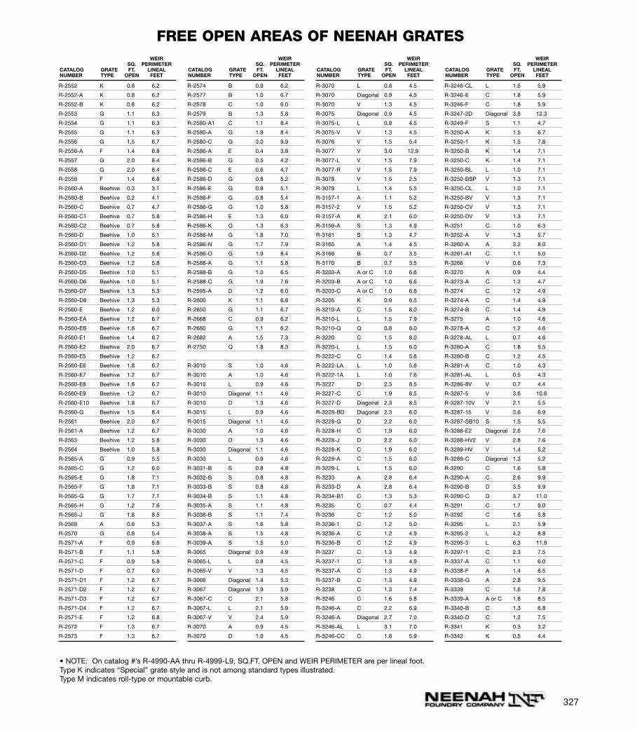
327
R-2552 K 0.8 6.2
R-2552-A K 0.8 6.2
R-2552-B K 0.8 6.2
R-2553 G 1.1 6.3
R-2554 G 1.1 6.3
R-2555 G 1.1 6.3
R-2556 G 1.5 6.7
R-2556-A F 1.4 6.8
R-2557 G 2.0 8.4
R-2558 G 2.0 8.4
R-2559 F 1.4 6.8
R-2560-A Beehive 0.3 3.1
R-2560-B Beehive 0.2 4.1
R-2560-C Beehive 0.7 4.7
R-2560-C1 Beehive 0.7 5.8
R-2560-C2 Beehive 0.7 5.8
R-2560-D Beehive 1.0 5.1
R-2560-D1 Beehive 1.2 5.8
R-2560-D2 Beehive 1.2 5.8
R-2560-D3 Beehive 1.2 5.8
R-2560-D5 Beehive 1.0 5.1
R-2560-D6 Beehive 1.0 5.1
R-2560-D7 Beehive 1.3 5.3
R-2560-D8 Beehive 1.3 5.3
R-2560-E Beehive 1.2 6.0
R-2560-EA Beehive 1.2 6.7
R-2560-EB Beehive 1.8 6.7
R-2560-E1 Beehive 1.4 6.7
R-2560-E2 Beehive 2.0 6.7
R-2560-E5 Beehive 1.2 6.7
R-2560-E6 Beehive 1.8 6.7
R-2560-E7 Beehive 1.2 6.7
R-2560-E8 Beehive 1.8 6.7
R-2560-E9 Beehive 1.2 6.7
R-2560-E10 Beehive 1.8 6.7
R-2560-G Beehive 1.5 8.4
R-2561 Beehive 2.0 6.7
R-2561-A Beehive 1.2 6.7
R-2563 Beehive 1.2 5.8
R-2564 Beehive 1.0 5.8
R-2565-A G 0.9 5.5
R-2565-C G 1.2 6.0
R-2565-E G 1.8 7.1
R-2565-F G 1.8 7.1
R-2565-G G 1.7 7.1
R-2565-H G 1.2 7.6
R-2565-J G 1.8 8.5
R-2569 A 0.6 5.3
R-2570 G 0.8 5.4
R-2571-A F 0.9 5.8
R-2571-B F 1.1 5.8
R-2571-C F 0.9 5.8
R-2571-D F 0.7 6.0
R-2571-D1 F 1.2 6.7
R-2571-D2 F 1.2 6.7
R-2571-D3 F 1.2 6.7
R-2571-D4 F 1.2 6.7
R-2571-E F 1.2 6.8
R-2572 F 1.3 6.7
R-2573 F 1.3 6.7
R-2574 B 0.9 6.2
R-2577 B 1.0 6.7
R-2578 C 1.0 6.0
R-2579 B 1.3 5.8
R-2580-A1 C 1.1 8.4
R-2580-A G 1.9 8.4
R-2580-C G 3.0 9.9
R-2586-A E 0.4 3.8
R-2586-B G 0.5 4.2
R-2586-C E 0.6 4.7
R-2586-D G 0.8 5.2
R-2586-E G 0.8 5.1
R-2586-F G 0.8 5.4
R-2586-G G 1.0 5.8
R-2586-H E 1.3 6.0
R-2586-K G 1.3 6.3
R-2586-M G 1.8 7.0
R-2586-N G 1.7 7.9
R-2586-O G 1.9 8.4
R-2588-A G 1.1 5.8
R-2588-B G 1.0 6.5
R-2588-C G 1.9 7.6
R-2595-A D 1.2 6.0
R-2600 K 1.1 6.8
R-2650 G 1.1 6.7
R-2668 C 0.9 6.2
R-2680 G 1.1 6.2
R-2682 A 1.5 7.3
R-2750 Q 1.8 8.3
R-3010 S 1.0 4.6
R-3010 A 1.0 4.6
R-3010 L 0.9 4.6
R-3010 Diagonal 1.1 4.6
R-3010 D 1.3 4.6
R-3015 L 0.9 4.6
R-3015 Diagonal 1.1 4.6
R-3030 A 1.0 4.6
R-3030 D 1.3 4.6
R-3030 Diagonal 1.1 4.6
R-3030 L 0.9 4.6
R-3031-B S 0.8 4.8
R-3032-B S 0.8 4.8
R-3033-B S 0.8 4.8
R-3034-B S 1.1 4.8
R-3035-A S 1.1 4.8
R-3036-B S 1.1 7.4
R-3037-A S 1.6 5.8
R-3038-A S 1.5 4.8
R-3039-A S 1.5 5.0
R-3065 Diagonal 0.9 4.9
R-3065-L L 0.8 4.5
R-3065-V V 1.3 4.5
R-3066 Diagonal 1.4 5.3
R-3067 Diagonal 1.9 5.9
R-3067-C C 2.1 5.8
R-3067-L L 2.1 5.9
R-3067-V V 2.4 5.9
R-3070 A 0.9 4.5
R-3070 D 1.0 4.5
R-3070 L 0.8 4.5
R-3070 Diagonal 0.9 4.5
R-3070 V 1.3 4.5
R-3075 Diagonal 0.9 4.5
R-3075-L L 0.8 4.5
R-3075-V V 1.3 4.5
R-3076 V 1.5 5.4
R-3077 V 3.0 12.9
R-3077-L V 1.5 7.9
R-3077-R V 1.5 7.9
R-3078 V 1.5 2.5
R-3079 L 1.4 5.5
R-3157-1 A 1.1 5.2
R-3157-2 V 1.5 5.2
R-3157-A K 2.1 6.0
R-3159-A S 1.3 4.9
R-3161 S 1.3 4.7
R-3165 A 1.4 4.5
R-3169 B 0.7 3.5
R-3170 B 0.7 3.5
R-3203-A A or C 1.0 6.6
R-3203-B A or C 1.0 6.6
R-3203-C A or C 1.0 6.6
R-3205 K 0.9 6.5
R-3210-A C 1.5 8.0
R-3210-L L 1.5 7.9
R-3210-Q Q 0.8 8.0
R-3220 C 1.5 8.0
R-3220-L L 1.5 6.0
R-3222-C C 1.4 5.6
R-3222-LA L 1.0 5.6
R-3222-1A L 1.0 7.6
R-3227 D 2.3 8.5
R-3227-C C 1.9 8.5
R-3227-D Diagonal 2.3 8.5
R-3228-BD Diagonal 2.3 6.0
R-3228-G D 2.2 6.0
R-3228-H C 1.9 6.0
R-3228-J D 2.2 6.0
R-3228-K C 1.9 6.0
R-3229-A C 1.5 8.0
R-3229-L L 1.5 6.0
R-3233 A 2.8 6.4
R-3233-D A 2.8 6.4
R-3234-B1 C 1.3 5.3
R-3235 C 0.7 4.4
R-3236 C 1.2 5.0
R-3236-1 C 1.2 5.0
R-3236-A C 1.2 4.9
R-3236-B C 1.2 4.9
R-3237 C 1.3 4.9
R-3237-1 C 1.3 4.9
R-3237-A C 1.3 4.9
R-3237-B C 1.3 4.9
R-3238 C 1.3 7.4
R-3246 C 1.6 5.8
R-3246-A C 2.2 6.9
R-3246-A Diagonal 2.7 7.0
R-3246-AL L 3.1 7.0
R-3246-CC C 1.8 5.9
R-3246-CL L 1.6 5.9
R-3246-E C 1.8 5.9
R-3246-F C 1.8 5.9
R-3247-2D Diagonal 3.8 12.3
R-3249-F S 1.1 4.7
R-3250-A K 1.5 6.7
R-3250-1 K 1.5 7.8
R-3250-B K 1.4 7.1
R-3250-C K 1.4 7.1
R-3250-BL L 1.0 7.1
R-3250-BSP V 1.3 7.1
R-3250-CL L 1.0 7.1
R-3250-BV V 1.3 7.1
R-3250-CV V 1.3 7.1
R-3250-DV V 1.3 7.1
R-3251 C 1.0 6.3
R-3252-A V 1.3 5.7
R-3260-A A 3.2 8.0
R-3261-A1 C 1.1 5.0
R-3266 V 0.6 7.3
R-3270 A 0.9 4.4
R-3273-A C 1.2 4.7
R-3274 C 1.2 4.9
R-3274-A C 1.4 4.9
R-3274-B C 1.4 4.9
R-3275 A 1.0 4.6
R-3278-A C 1.2 4.6
R-3278-AL L 0.7 4.6
R-3280-A C 1.8 5.5
R-3280-B C 1.2 4.5
R-3281-A C 1.0 4.3
R-3281-AL L 0.5 4.3
R-3286-8V V 0.7 4.4
R-3287-5 V 3.6 10.6
R-3287-10V V 2.1 5.5
R-3287-15 V 3.6 6.9
R-3287-SB10 S 1.5 5.5
R-3288-E2 Diagonal 2.6 7.6
R-3288-HV2 V 2.8 7.6
R-3289-HV V 1.4 5.2
R-3289-C Diagonal 1.3 5.2
R-3290 C 1.6 5.8
R-3290-A C 2.6 9.9
R-3290-B D 3.5 9.9
R-3290-C D 3.7 11.0
R-3291 C 1.7 9.0
R-3292 C 1.6 5.8
R-3295 L 2.1 5.9
R-3295-2 L 4.2 8.8
R-3295-3 L 6.3 11.8
R-3297-1 C 2.3 7.5
R-3337-A C 1.1 6.0
R-3338-F A 1.4 6.5
R-3338-G A 2.8 9.5
R-3339 C 1.6 7.8
R-3339-A A or C 1.8 8.5
R-3340-B C 1.3 6.8
R-3340-D C 1.2 7.5
R-3341 K 0.3 3.2
R-3342 K 0.5 4.4
WEIRSQ. PERIMETER
CATALOG GRATE FT. LINEALNUMBER TYPE OPEN FEET
WEIRSQ. PERIMETER
CATALOG GRATE FT. LINEALNUMBER TYPE OPEN FEET
WEIRSQ. PERIMETER
CATALOG GRATE FT. LINEALNUMBER TYPE OPEN FEET
WEIRSQ. PERIMETER
CATALOG GRATE FT. LINEALNUMBER TYPE OPEN FEET
FREE OPEN AREAS OF NEENAH GRATES
• NOTE: On catalog #’s R-4990-AA thru R-4999-L9, SQ.FT. OPEN and WEIR PERIMETER are per lineal foot.Type K indicates “Special” grate style and is not among standard types illustrated.Type M indicates roll-type or mountable curb.
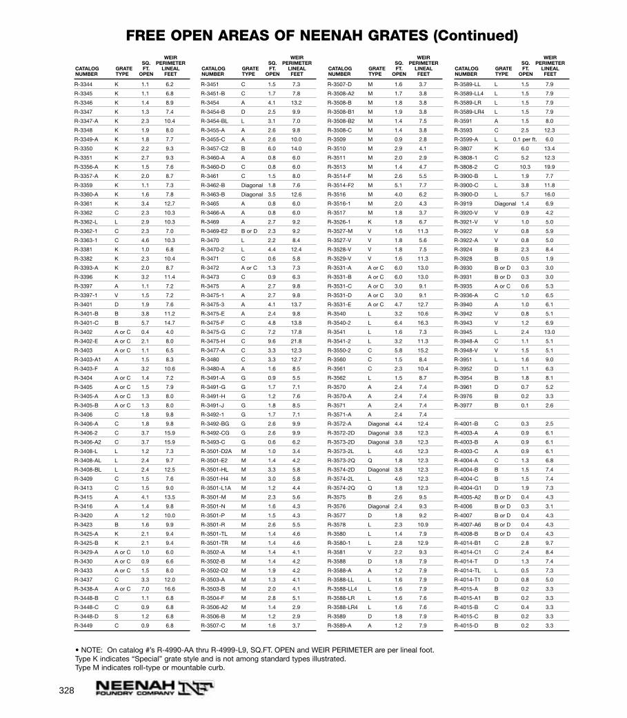
328
R-3344 K 1.1 6.2
R-3345 K 1.1 6.8
R-3346 K 1.4 8.9
R-3347 K 1.3 7.4
R-3347-A K 2.3 10.4
R-3348 K 1.9 8.0
R-3349-A K 1.8 7.7
R-3350 K 2.2 9.3
R-3351 K 2.7 9.3
R-3356-A K 1.5 7.6
R-3357-A K 2.0 8.7
R-3359 K 1.1 7.3
R-3360-A K 1.6 7.8
R-3361 K 3.4 12.7
R-3362 C 2.3 10.3
R-3362-L L 2.9 10.3
R-3362-1 C 2.3 7.0
R-3363-1 C 4.6 10.3
R-3381 K 1.0 6.8
R-3382 K 2.3 10.4
R-3393-A K 2.0 8.7
R-3396 K 3.2 11.4
R-3397 A 1.1 7.2
R-3397-1 V 1.5 7.2
R-3401 D 1.9 7.6
R-3401-B B 3.8 11.2
R-3401-C B 5.7 14.7
R-3402 A or C 0.4 4.0
R-3402-E A or C 2.1 8.0
R-3403 A or C 1.1 6.5
R-3403-A1 A 1.5 8.3
R-3403-F A 3.2 10.6
R-3404 A or C 1.4 7.2
R-3405 A or C 1.5 7.9
R-3405-A A or C 1.3 8.0
R-3405-B A or C 1.3 8.0
R-3406 C 1.8 9.8
R-3406-A C 1.8 9.8
R-3406-2 C 3.7 15.9
R-3406-A2 C 3.7 15.9
R-3408-L L 1.2 7.3
R-3408-AL L 2.4 9.7
R-3408-BL L 2.4 12.5
R-3409 C 1.5 7.6
R-3413 C 1.5 9.0
R-3415 A 4.1 13.5
R-3416 A 1.4 9.8
R-3420 A 1.2 10.0
R-3423 B 1.6 9.9
R-3425-A K 2.1 9.4
R-3425-B K 2.1 9.4
R-3429-A A or C 1.0 6.0
R-3430 A or C 0.9 6.6
R-3433 A or C 1.5 8.0
R-3437 C 3.3 12.0
R-3438-A A or C 7.0 16.6
R-3448-B C 1.1 6.8
R-3448-C C 0.9 6.8
R-3448-D S 1.2 6.8
R-3449 C 0.9 6.8
R-3451 C 1.5 7.3
R-3451-B C 1.7 7.8
R-3454 A 4.1 13.2
R-3454-B D 2.5 9.9
R-3454-BL L 3.1 7.0
R-3455-A A 2.6 9.8
R-3455-C A 2.6 10.0
R-3457-C2 B 6.0 14.0
R-3460-A A 0.8 6.0
R-3460-D C 0.8 6.0
R-3461 C 1.5 8.0
R-3462-B Diagonal 1.8 7.6
R-3463-B Diagonal 3.5 12.6
R-3465 A 0.8 6.0
R-3466-A A 0.8 6.0
R-3469 A 2.7 9.2
R-3469-E2 B or D 2.3 9.2
R-3470 L 2.2 8.4
R-3470-2 L 4.4 12.4
R-3471 C 0.6 5.8
R-3472 A or C 1.3 7.3
R-3473 C 0.9 6.3
R-3475 A 2.7 9.8
R-3475-1 A 2.7 9.8
R-3475-3 A 4.1 13.7
R-3475-E A 2.4 9.8
R-3475-F C 4.8 13.8
R-3475-G C 7.2 17.8
R-3475-H C 9.6 21.8
R-3477-A C 3.3 12.3
R-3480 C 3.3 12.7
R-3480-A A 1.6 8.5
R-3491-A G 0.9 5.5
R-3491-G G 1.7 7.1
R-3491-H G 1.2 7.6
R-3491-J G 1.8 8.5
R-3492-1 G 1.7 7.1
R-3492-BG G 2.6 9.9
R-3492-CG G 2.6 9.9
R-3493-C G 0.6 6.2
R-3501-D2A M 1.0 3.4
R-3501-E2 M 1.4 4.2
R-3501-HL M 3.3 5.8
R-3501-H4 M 3.0 5.8
R-3501-L1A M 1.2 4.4
R-3501-M M 2.3 5.6
R-3501-N M 1.6 4.3
R-3501-P M 1.5 4.3
R-3501-R M 2.6 5.5
R-3501-TL M 1.4 4.6
R-3501-TR M 1.4 4.6
R-3502-A M 1.4 4.1
R-3502-B M 1.4 4.2
R-3502-D2 M 1.9 4.2
R-3503-A M 1.3 4.1
R-3503-B M 2.0 4.1
R-3504-F M 2.8 5.1
R-3506-A2 M 1.4 2.9
R-3506-B M 1.2 2.9
R-3507-C M 1.6 3.7
R-3507-D M 1.6 3.7
R-3508-A2 M 1.7 3.8
R-3508-B M 1.8 3.8
R-3508-B1 M 1.9 3.8
R-3508-B2 M 1.4 7.5
R-3508-C M 1.4 3.8
R-3509 M 0.9 2.8
R-3510 M 2.9 4.1
R-3511 M 2.0 2.9
R-3513 M 1.4 4.7
R-3514-F M 2.6 5.5
R-3514-F2 M 5.1 7.7
R-3516 M 4.0 6.2
R-3516-1 M 2.0 4.3
R-3517 M 1.8 3.7
R-3526-1 K 1.8 6.7
R-3527-M V 1.6 11.3
R-3527-V V 1.8 5.6
R-3528-V V 1.8 7.5
R-3529-V V 1.6 11.3
R-3531-A A or C 6.0 13.0
R-3531-B A or C 6.0 13.0
R-3531-C A or C 3.0 9.1
R-3531-D A or C 3.0 9.1
R-3531-E A or C 4.7 12.7
R-3540 L 3.2 10.6
R-3540-2 L 6.4 16.3
R-3541 L 1.6 7.3
R-3541-2 L 3.2 11.3
R-3550-2 C 5.8 15.2
R-3560 C 1.5 8.4
R-3561 C 2.3 10.4
R-3562 L 1.5 8.7
R-3570 A 2.4 7.4
R-3570-A A 2.4 7.4
R-3571 A 2.4 7.4
R-3571-A A 2.4 7.4
R-3572-A Diagonal 4.4 12.4
R-3572-2D Diagonal 3.8 12.3
R-3573-2D Diagonal 3.8 12.3
R-3573-2L L 4.6 12.3
R-3573-2Q Q 1.8 12.3
R-3574-2D Diagonal 3.8 12.3
R-3574-2L L 4.6 12.3
R-3574-2Q Q 1.8 12.3
R-3575 B 2.6 9.5
R-3576 Diagonal 2.4 9.3
R-3577 D 1.8 9.2
R-3578 L 2.3 10.9
R-3580 L 1.4 7.9
R-3580-1 L 2.8 12.9
R-3581 V 2.2 9.3
R-3588 D 1.8 7.9
R-3588-A A 1.2 7.9
R-3588-LL L 1.6 7.9
R-3588-LL4 L 1.6 7.9
R-3588-LR L 1.6 7.6
R-3588-LR4 L 1.6 7.6
R-3589 D 1.8 7.9
R-3589-A A 1.2 7.9
R-3589-LL L 1.5 7.9
R-3589-LL4 L 1.5 7.9
R-3589-LR L 1.5 7.9
R-3589-LR4 L 1.5 7.9
R-3591 A 1.5 8.0
R-3593 C 2.5 12.3
R-3599-A L 0.1 per ft. 6.0
R-3807 K 6.0 13.4
R-3808-1 C 5.2 12.3
R-3808-2 C 10.3 19.9
R-3900-B L 1.9 7.7
R-3900-C L 3.8 11.8
R-3900-D L 5.7 16.0
R-3919 Diagonal 1.4 6.9
R-3920-V V 0.9 4.2
R-3921-V V 1.0 5.0
R-3922 V 0.8 5.9
R-3922-A V 0.8 5.0
R-3924 B 2.3 8.4
R-3928 B 0.5 1.9
R-3930 B or D 0.3 3.0
R-3931 B or D 0.3 3.0
R-3935 A or C 0.6 5.3
R-3936-A C 1.0 6.5
R-3940 A 1.0 6.1
R-3942 V 0.8 5.1
R-3943 V 1.2 6.9
R-3945 L 2.4 13.0
R-3948-A C 1.1 5.1
R-3948-V V 1.5 5.1
R-3951 L 1.6 9.0
R-3952 D 1.1 6.3
R-3954 B 1.8 8.1
R-3961 D 0.7 5.2
R-3976 B 0.2 3.3
R-3977 B 0.1 2.6
R-4001-B C 0.3 2.5
R-4003-A A 0.9 6.1
R-4003-B A 0.9 6.1
R-4003-C A 0.9 6.1
R-4004-A C 1.3 6.8
R-4004-B B 1.5 7.4
R-4004-C B 1.5 7.4
R-4004-G1 D 1.9 7.3
R-4005-A2 B or D 0.4 4.3
R-4006 B or D 0.3 3.1
R-4007 B or D 0.4 4.3
R-4007-A6 B or D 0.4 4.3
R-4008-B B or D 0.4 4.3
R-4014-B1 C 2.8 9.7
R-4014-C1 C 2.4 8.4
R-4014-T D 1.3 7.4
R-4014-TL L 0.5 7.3
R-4014-T1 D 0.8 5.0
R-4015-A B 0.2 3.3
R-4015-A1 B 0.2 3.3
R-4015-B C 0.4 3.3
R-4015-C B 0.2 3.3
R-4015-D B 0.2 3.3
WEIRSQ. PERIMETER
CATALOG GRATE FT. LINEALNUMBER TYPE OPEN FEET
WEIRSQ. PERIMETER
CATALOG GRATE FT. LINEALNUMBER TYPE OPEN FEET
WEIRSQ. PERIMETER
CATALOG GRATE FT. LINEALNUMBER TYPE OPEN FEET
WEIRSQ. PERIMETER
CATALOG GRATE FT. LINEALNUMBER TYPE OPEN FEET
FREE OPEN AREAS OF NEENAH GRATES (Continued)
• NOTE: On catalog #’s R-4990-AA thru R-4999-L9, SQ.FT. OPEN and WEIR PERIMETER are per lineal foot.Type K indicates “Special” grate style and is not among standard types illustrated.Type M indicates roll-type or mountable curb.
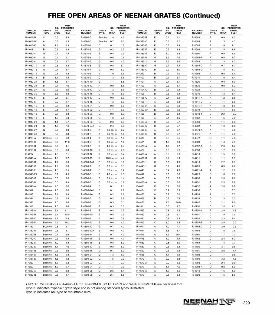
329
R-4016-B C 0.5 4.8
R-4016-H1 A 0.6 5.3
R-4016-K D 1.1 6.3
R-4018 B 0.2 3.8
R-4030-4 G 0.1 1.4
R-4030-6 G 0.1 2.1
R-4030-8 G 0.2 2.7
R-4030-10 G 0.3 3.3
R-4030-12 G 0.4 3.7
R-4030-15 G 0.8 4.8
R-4030-18 B 1.1 5.8
R-4030-21 B 1.3 6.7
R-4030-24 B 2.1 7.6
R-4030-27 G 2.8 3.0
R-4030-30 G 3.5 3.3
R-4040-6 E 0.1 2.1
R-4040-8 E 0.2 2.7
R-4040-10 E 0.3 3.3
R-4040-12 E 0.4 3.7
R-4040-15 E 0.7 4.8
R-4040-18 E 1.2 5.8
R-4040-21 G 1.4 6.7
R-4040-24 G 1.6 7.6
R-4040-27 G 2.3 3.0
R-4040-30 G 2.9 3.3
R-4215-A Beehive 2.0 9.0
R-4215-C Beehive 3.3 11.3
R-4216-B Beehive 2.2 4.1
R-4216-D Beehive 3.0 3.8
R-4217 Beehive 4.9 7.1
R-4340-A Beehive 1.5 6.2
R-4340-B Beehive 1.1 6.0
R-4340-C Beehive 1.2 6.0
R-4340-F Beehive 1.6 6.5
R-4340-F1 Beehive 0.7 4.5
R-4340-G Beehive 0.6 5.0
R-4340-H Beehive 0.5 4.5
R-4341-A Beehive 2.5 6.0
R-4342 Beehive 2.0 6.0
R-4343 Beehive 2.4 8.4
R-4344 Beehive 0.2 2.9
R-4345 Beehive 2.0 8.6
R-4346 Beehive 2.0 8.6
R-4349-A Beehive 2.4 11.1
R-4349-B Beehive 5.4 15.5
R-4349-C Beehive 2.4 6.9
R-4349-D Beehive 5.4 10.2
R-4350-1 Beehive 0.3 2.7
R-4350-A Beehive 0.3 3.1
R-4350-B Beehive 0.4 3.9
R-4350-C Beehive 0.6 4.8
R-4350-D Beehive 1.0 5.8
R-4350-E Beehive 1.7 7.6
R-4351-B Beehive 0.5 3.9
R-4351-D Beehive 1.6 5.8
R-4351-E Beehive 1.5 5.8
R-4352 Beehive 1.3 5.8
R-4353 Beehive 1.8 6.7
R-4360-A Beehive 0.6 4.3
R-4360-B Beehive 0.8 4.7
R-4360-C Beehive 1.4 4.5
R-4360-D Beehive 0.7 6.3
R-4370-1 C 0.1 1.7
R-4370-2 G 0.2 2.5
R-4370-3 E 0.4 3.9
R-4370-4 G 0.6 3.9
R-4370-5 G 0.8 4.7
R-4370-6 G 0.8 5.1
R-4370-7 G 0.8 5.2
R-4370-8 E 1.0 5.5
R-4370-9 C 1.3 5.8
R-4370-10 G 1.1 5.8
R-4370-12 F 0.9 5.8
R-4370-13 G 1.3 5.8
R-4370-15 D 1.0 5.9
R-4370-17 D 0.9 6.0
R-4370-18 E 1.3 6.0
R-4370-21 D 0.9 6.0
R-4370-22 D 1.1 6.0
R-4370-23 G 0.9 6.3
R-4370-25 G 1.9 7.6
R-4370-26 G 2.8 8.6
R-4370-27A G 2.4 9.9
R-4373-2 K 1.0 sq. in. 0.7
R-4373-3 K 1.0 sq. in. 1.0
R-4373-4 K 3.0 sq. in. 1.2
R-4373-6 K 3.0 sq. in. 1.8
R-4373-8 K 4.0 sq. in. 2.4
R-4373-10 K 5.0 sq. in. 2.9
R-4373-12 K 8.0 sq. in. 3.4
R-4373-15 K 20.0 sq. in. 4.2
R-4380-AA1 E 2.8 sq. in. 1.0
R-4380-A E 3.7 sq. in. 1.1
R-4380-A1 E 6.0 sq. in. 1.2
R-4380-B1 E 4.8 sq. in. 1.3
R-4380-1 E 5.4 sq. in. 1.4
R-4380-3 E 6.0 sq. in. 1.6
R-4380-4 E 0.1 2.1
R-4380-4A1 E 0.1 2.2
R-4380-4A E 0.2 2.6
R-4380-6 G 0.2 2.8
R-4380-7 G 0.3 3.1
R-4380-8 E 0.3 3.3
R-4380-9 E 0.4 3.7
R-4380-10 E 0.5 3.9
R-4380-11 E 0.5 3.9
R-4380-12 E 0.6 4.0
R-4380-13 G 0.7 4.2
R-4380-13A E 0.9 4.7
R-4380-14 E 0.7 4.7
R-4380-15 E 0.6 4.7
R-4380-16 E 0.8 5.0
R-4380-17 E 0.8 5.0
R-4380-18 G 0.7 5.2
R-4380-21 G 1.3 6.3
R-4380-22 G 1.5 7.0
R-4380-23 G 1.1 7.3
R-4380-24 G 1.7 7.9
R-4380-25 G 2.5 8.4
R-4380-26 G 2.7 8.8
R-4385-B E 0.1 2.1
R-4385-C E 0.3 2.7
R-4385-E E 0.5 3.9
R-4385-F E 0.5 4.8
R-4385-G E 1.0 5.8
R-4385-H G 1.6 7.6
R-4385-J G 2.5 8.6
R-4385-K G 2.7 9.4
R-4389-O B 0.2 3.0
R-4390 B 0.3 5.0
R-4400 B 0.1 2.7
R-4401 A 0.1 2.7
R-4403 A 0.3 3.7
R-4404-C B 0.5 5.3
R-4406 B 0.5 5.3
R-4406-C A 0.4 5.5
R-4406-1 A 0.5 5.3
R-4406-2 C 0.6 5.3
R-4407-2A B 0.6 5.6
R-4408 B 0.3 3.4
R-4409 A 0.4 4.6
R-4409-A C 0.7 5.7
R-4409-C B 0.5 5.7
R-4409-E A 0.5 5.7
R-4409-G B 0.8 5.7
R-4410 B 0.8 6.5
R-4421 C 1.0 8.3
R-4423-A A 1.2 9.7
R-4424 A 0.6 5.6
R-4430-A A 0.6 6.0
R-4430-B C 0.7 5.9
R-4435-1 C 0.8 4.3
R-4441-1 Q 0.2 4.0
R-4443 A 0.4 4.3
R-4449 A 0.8 6.0
R-4450 A 0.8 6.0
R-4450-A A 0.6 6.0
R-4451 C 0.7 6.0
R-4454 C 0.9 6.3
R-4460 A 0.8 7.0
R-4462 B 0.9 7.8
R-4470 A 1.5 10.0
R-4511 A 0.5 4.7
R-4525 A 0.8 6.3
R-4530 A 0.8 6.1
R-4531 A 0.8 6.4
R-4540 C 1.0 6.8
R-4541 A 1.0 7.1
R-4544 A 1.8 8.7
R-4545 A 1.6 10.4
R-4548 A 1.0 5.9
R-4550 C 0.8 5.0
R-4552 A 0.6 5.3
R-4557 A 0.8 5.3
R-4558 C 1.1 5.9
R-4570-1 A 0.9 6.3
R-4570-2 A 0.9 6.5
R-4573 A 1.1 7.5
R-4575-A A 1.7 8.5
R-4579 A 0.8 6.4
R-4583 A 0.9 6.3
R-4584 A 1.3 4.3
R-4585 A 1.9 9.1
R-4586 A 1.5 8.6
R-4600 A 0.9 6.5
R-4603-A A 0.8 6.7
R-4604 C 1.3 6.7
R-4604-C A 0.7 6.7
R-4604-D A 1.5 6.7
R-4608 A 0.8 6.0
R-4610 A 1.0 6.4
R-4620 A 0.8 6.0
R-4630 C 0.9 6.2
R-4632 C 1.1 6.3
R-4640 A 1.3 6.4
R-4641-A A 1.2 6.8
R-4641-C C 1.1 6.8
R-4641-F A 1.8 8.5
R-4649 A 1.1 6.9
R-4649-1 C 2.2 10.0
R-4652 A 1.5 7.9
R-4660 C 1.1 6.0
R-4662 A 1.3 6.6
R-4670-A A 1.1 7.0
R-4671 A 1.1 7.0
R-4672 C 1.1 7.0
R-4689 C 1.4 7.5
R-4692-A D 2.0 8.7
R-4698 A 1.7 9.0
R-4710 C 1.5 9.0
R-4711 C 1.1 9.5
R-4718 A 2.7 9.3
R-4720 C 0.9 6.7
R-4721-A A 1.2 7.0
R-4725 C 1.6 7.0
R-4730 A 2.0 8.6
R-4731 A 2.5 9.8
R-4732 A 2.0 9.8
R-4736 C 1.1 7.3
R-4738 A 1.1 7.3
R-4739 C 1.3 7.3
R-4740 C 2.1 8.0
R-4750 C 2.4 8.3
R-4750-1 A 2.8 11.3
R-4751 C 1.9 7.9
R-4752 C 2.3 9.4
R-4755-B A 2.8 10.5
R-4755-C C 2.9 10.5
R-4759 C 1.5 7.5
R-4760 C 1.7 7.3
R-4762 C 2.4 8.7
R-4765 A 1.4 7.7
R-4780 C 3.1 9.8
R-4781 C 3.0 11.7
R-4792 C 1.7 9.8
R-4795 A 3.2 11.3
R-4798 C 2.4 9.9
R-4808-A Q 0.8 8.0
R-4810 C 1.5 8.0
R-4820 C 1.5 8.0
WEIRSQ. PERIMETER
CATALOG GRATE FT. LINEALNUMBER TYPE OPEN FEET
WEIRSQ. PERIMETER
CATALOG GRATE FT. LINEALNUMBER TYPE OPEN FEET
WEIRSQ. PERIMETER
CATALOG GRATE FT. LINEALNUMBER TYPE OPEN FEET
WEIRSQ. PERIMETER
CATALOG GRATE FT. LINEALNUMBER TYPE OPEN FEET
FREE OPEN AREAS OF NEENAH GRATES (Continued)
• NOTE: On catalog #’s R-4990-AA thru R-4999-L9, SQ.FT. OPEN and WEIR PERIMETER are per lineal foot.Type K indicates “Special” grate style and is not among standard types illustrated.Type M indicates roll-type or mountable curb.

330
R-4821-A C 1.7 8.3
R-4825 C 1.8 9.0
R-4825-A A 2.1 9.0
R-4825-B C 2.0 9.0
R-4826 A 1.3 8.0
R-4828 A 1.9 9.5
R-4829 C 2.2 9.5
R-4832 C 1.5 8.0
R-4832-B C 1.8 8.7
R-4833 A 2.3 8.7
R-4837 A 2.2 9.8
R-4839 A 2.1 9.9
R-4840 C 2.8 10.0
R-4843 A 2.6 10.0
R-4850 C 2.7 9.0
R-4852 C 2.0 9.0
R-4852-A Q 1.8 9.0
R-4853 A 2.5 10.5
R-4853-A A 3.1 11.5
R-4853-B1 C 3.3 12.5
R-4855 A 2.0 9.3
R-4856 C 3.1 9.7
R-4857 A 3.1 12.3
R-4859-C A 2.4 9.1
R-4871 B 2.7 9.2
R-4880 C 2.5 9.3
R-4880-C C 2.2 10.0
R-4882 A 4.0 11.3
R-4882-A A 2.8 11.3
R-4884-A C 3.3 6.0
R-4890 C 3.4 10.8
R-4891 A 3.5 13.0
R-4893 C 6.0 18.0
R-4893-B C 1.9 11.0
R-4894 C 3.3 11.5
R-4895-2 A 6.6 17.0
R-4938 A 0.8 6.9
R-4938-1 A 1.5 8.2
R-4938-B A 0.2 3.2
R-4939-B K 4.7 sq. in. 3.0
R-4941-A B 0.4 4.7
R-4942-A A 0.7 6.5
R-4943 K 0.3 5.4
R-4943-A K 0.3 5.4
R-4943-B K 0.3 5.4
R-4976-1 A 0.9 3.1
R-4976-1 B 0.9 3.1
R-4976-2 A 1.5 4.2
R-4976-2 B 1.5 4.2
R-4976-3 A 2.5 5.2
R-4976-3 B 2.5 5.2
R-4976-4 A 3.7 6.3
R-4976-4 B 3.7 6.3
R-4976-5 B 5.2 8.1
R-4977-1 A 1.5 4.0
R-4977-1 B 1.5 4.0
R-4977-2 A 2.0 5.0
R-4977-2 B 2.0 5.0
R-4977-3 A 3.7 10.0
R-4977-3 B 3.7 10.0
R-4977-4 A 5.3 12.0
R-4977-4 B 5.3 12.0
R-4977-5 A 8.0 15.0
R-4977-5 B 8.0 15.0
R-4990-AA A 0.2 • 2.0
R-4990-AX A 0.2 • 2.0
C 0.3 • 2.0
P 0.1 • 2.0
R-4990-BA A 0.3 • 2.0
R-4990-BX A 0.3 • 2.0
C 0.3 • 2.0
P 0.1 • 2.0
R-4990-CA A 0.4 • 2.0
R-4990-CX A 0.4 • 2.0
C 0.4 • 2.0
P 0.1 • 2.0
R-4990-DA A 0.4 • 2.0
R-4990-DX A 0.4 • 2.0
C 0.5 • 2.0
P 0.2 • 2.0
R-4990-EA A 0.5 • 2.0
R-4990-EX A 0.6 • 2.0
C 0.5 • 2.0
P 0.2 • 2.0
R-4990-FA A 0.6 • 2.0
R-4990-FX A 0.7 • 2.0
C 0.8 • 2.0
P 0.5 • 2.0
R-4990-GX A 0.8 • 2.0
C 0.7 • 2.0
R-4990-HA A 0.9 • 2.0
R-4990-HX A 0.9 • 2.0
C 0.9 • 2.0
R-4990-JX A 1.0 • 2.0
C 1.1 • 2.0
R-4990-KA2 A 0.6 • 2.0
R-4990-KX A 1.1 • 2.0
C 0.9 • 2.0
R-4990-LX A 1.2 • 2.0
C 1.2 • 2.0
R-4990-MX A 1.3 • 2.0
C 1.3 • 2.0
R-4990-NX A 1.5 • 2.0
C 1.6 • 2.0
R-4990-OA A 2.7 • 2.0
R-4990-OX A 1.7 • 2.0
C NA • 2.0
R-4995-A1 B 0.2 • 2.0
C 0.3 • 2.0
R-4995-A2 B 0.2 • 2.0
R-4996-A1 Diagonal 0.3 • 2.0
Convex
C 0.3 • 2.0
R-4996-A2 B 0.2 • 2.0
R-4996-A3 C 0.3 • 2.0
R-4999-Series Same as R-4990 Series
R-4999-L3 L 0.3 • 2.0
R-4999-L6 L 0.8 • 2.0
R-4999-L9 L 0.9 • 2.0
R-5901-A G 0.2 2.7
R-5901-B G 0.3 3.5
R-5901-C G 0.5 4.3
R-5901-D G 0.7 4.8
R-5901-E G 1.1 5.8
R-5901-F G 1.6 6.6
R-5901-G G 2.0 7.4
R-5901-H G 2.5 8.9
R-5901-J G 3.7 10.5
R-5901-K G 4.8 12.1
R-6020 G 1.0 5.6
R-6040 G 1.3 6.2
R-6070 G 1.5 6.9
R-6077 G 2.5 8.3
R-6080 G 2.7 8.7
R-6110 G 0.9 5.5
R-6111 G 1.2 6.0
R-6112 G 1.3 6.0
R-6113 G 0.9 6.3
R-6114 G 1.8 7.0
R-6115 G 1.7 7.0
R-6116 G 1.2 7.6
R-6117 G 1.8 8.5
R-6118 G 2.6 9.9
R-6130 G 0.8 5.4
R-6131 G 1.0 5.6
R-6132 G 1.3 6.3
R-6133 G 1.3 6.5
R-6134 G 1.5 6.9
R-6136 G 2.5 8.3
R-6137 G 2.7 8.8
R-6352-A G 0.4 3.4
R-6352-B G 0.8 4.2
R-6352-D G 0.7 4.9
R-6352-E G 0.8 5.5
R-6352-G G 1.3 6.5
R-6400-AO G 0.3 3.1
R-6400-BO G 0.8 5.0
R-6400-CO G 1.8 7.0
R-6400-DO G 1.2 7.6
R-6450-AG G 0.2 2.4
R-6450-BG G 0.2 3.1
R-6450-CG G 0.4 3.4
R-6450-DG G 0.5 4.2
R-6450-EG G 0.7 5.4
R-6450-FG G 0.1 5.6
R-6450-GG G 1.3 6.3
R-6450-HG G 1.3 6.9
R-6450-JG G 1.9 8.3
R-6450-KG G 2.7 8.8
R-6672-1 A or C 0.4 3.9
R-6672-A A or C 0.8 4.1
R-6672-B A or C 0.5 4.6
R-6672-C A or C 0.8 6.0
R-6672-D A or C 1.1 7.3
R-6672-E A or C 1.8 7.9
R-6672-F A or C 2.7 8.6
R-6672-G A or C 2.2 9.0
R-6672-H A or C 2.1 9.2
R-6672-J A or C 2.4 10.0
R-6672-K A or C 2.5 10.6
R-6672-M A or C 3.0 12.3
R-6672-Q A or C 9.3 18.8
R-6673-A A 0.6 5.7
R-6673-B A 0.9 6.5
R-6673-C A 1.2 7.5
R-6673-D A 2.1 8.6
R-6673-E A 2.5 9.6
R-6673-J A 2.6 9.5
R-6673-K A 2.9 10.6
R-6673-L A 3.7 12.6
R-6673-N A 3.3 11.6
R-6673-O A 4.9 13.5
R-6673-Q1 A 5.0 14.7
R-7511 Beehive 1.1 5.5
WEIRSQ. PERIMETER
CATALOG GRATE FT. LINEALNUMBER TYPE OPEN FEET
WEIRSQ. PERIMETER
CATALOG GRATE FT. LINEALNUMBER TYPE OPEN FEET
WEIRSQ. PERIMETER
CATALOG GRATE FT. LINEALNUMBER TYPE OPEN FEET
WEIRSQ. PERIMETER
CATALOG GRATE FT. LINEALNUMBER TYPE OPEN FEET
FREE OPEN AREAS OF NEENAH GRATES (Continued)
• NOTE: On catalog #’s R-4990-AA thru R-4999-L9, SQ.FT. OPEN and WEIR PERIMETER are per lineal foot.Type K indicates “Special” grate style and is not among standard types illustrated.Type M indicates roll-type or mountable curb.
331
APage
Adjustable Manhole Frames . . . . . . . . . . . . . . . . . . . . . . .81Adjusting Rings for Manhole Frames . . . . . . . . . . . . . .85-86Airport Castings
Catch Basins . . . . . . . . . . . . . . . . . . . . . . . . . . . . .199Control Box . . . . . . . . . . . . . . . . . . . . . . . . . . . . . .197Drainage Inlets . . . . . . . . . . . . . . . . . . . . . . . .193-196Inspection Frame and Lid . . . . . . . . . . . . . . . . . . . .197Manhole Frame and Grate . . . . . . . . . . . . . . . .199-201Manhole Frame and Lid . . . . . . . . . . . . . . . . .199-201Mooring Eyes . . . . . . . . . . . . . . . . . . . . . . . . . . . . .198Tie-Down Frame and Lid . . . . . . . . . . . . . . . . . . . .197Trench Frames and Grates . . . . . . . . . . . . . . .204, 284Utility Frames and Lids . . . . . . . . . . . . . . . . . .201-204
Angle Frames and Covers . . . . . . . . . . . . . . . . . . . . . .63, 71Light Duty . . . . . . . . . . . . . . . . . . . . . . . . . . . . . . . .63
Angle Frames and Grates . . . . . . . . . . . . . . . . . . . . . . . .270Areaway Gratings
Light Duty . . . . . . . . . . . . . . . . . . . . . . . . . . . . . . .279Ash Pit Doors . . . . . . . . . . . . . . . . . . . . . . . . . . . . . . . . .277
B
Ballast Screens . . . . . . . . . . . . . . . . . . . . . . . . . . . . . . . .324Bases, Sign and Flag . . . . . . . . . . . . . . . . . . . . . . . . . . .271Basket Type Grates . . . . . . . . . . . . . . . . . .257, 259, 261-263
Light Duty . . . . . . . . . . . . . . . . . . . . . . . .258-260, 263Beehive Grates . . . . . . . . . . . . . . . . . . .93, 99,100, 261-263
Light Duty . . . . . . . . . . . . . . . . . . . . . . . .258, 260, 263Bridge Drains and Scuppers . . . . . . . . . . . . . . . . . . .238-254
C
Castings for Different Traffic Conditions . . . . . . . . . . . . . . . .4Catch Basin Covers . . . . . . . . . . . . . . . . . .89-107, 293, 296
Beehive . . . . . . . . . . . . . . . . . . . . . . . . . . .93, 99, 100Concave . . . . . . . . . . . . . . . . . . . . . . . . . . 98, 102-103Convex . . . . . . . . . . . . . . . . . . . . . . . . . . . . . .103-104For Corrugated Pipe . . . . . . . . . . . . . . . . . . . . . . . . .96For Pipe Bell . . . . . . . . . . . . . . . . . . . . . . . .93, 95, 106Light Duty . . . . . . . . . . . . . . .93-95, 101-102, 105, 296Non-Rocking . . . . . . . . . . . . . . . . . . . . . . . . . . .90, 92Slab Type . . . . . . . . . . . . . . . . . . . . . . . .101, 293, 296Vane Grate . . . . . . . . . . . . . . . . . . . . . . . . . . . . . . . .96With Angle Frames . . . . . . . . . . . . . . . . . . . . . . . . .105With Narrow Opening Grates . . . . . . . . . . . . .101, 107
Catch Basin GratesConcave . . . . . . . . . . . . . . 98, 102-103, 174-177, 217
Catch Basin Hood . . . . . . . . . . . . . . . . . . . . . . . . . .229-235Catch Basin Inlets . . . . . . . . . . . . . . . . . . . . . .113-163, 172
Behind Curb Type . . . . . . . . . . . . . . . . . . . . . .164-169Concave . . . . . . . . . . . . . . . . . . . . . . . . . . . . . . . .139Expressway . . . . . . . . . . . . . . . . . . . . . . . . . . . . . .132With Pan Outlets . . . . . . . . . . . . . . . . . . . . . .119, 167
Catch Basin Traps . . . . . . . . . . . . . . . . . . . . . . . . . .229-235Cautions . . . . . . . . . . . . . . . . . . . . . . . . . . . . . . . . . . . . . . .6Choosing the Proper Inlet Grate . . . . . . . . . . . . . . . . . . .108Cleanout Frames and Doors . . . . . . . . . . . . . . . . . . . . . .277Curb Face Types . . . . . . . . . . . . . . . . . . . . . . . . . . . . . . .113Curb Guards . . . . . . . . . . . . . . . . . . . . . . . . . . . . . . . . . .280
PageCurb Hoods . . . . . . . . . . . . . . . . . . . . . . . . . . . . . . . . . .122Curb Inlet Drain 135Curb Openings . . . . . . . . . . . . . . . . . . . . . . . . . . . . .150-151Curb Plate and Grate . . . . . . . . . . . . . . . . . . . . . . . . . . .155Curb Type Inlets . . . . . . . . . . . . . . . . . . . . . . . . . . . .113-163
Adjustable . . . . . . . . .112, 114-115, 117-121, 126-127132-134, 136-137, 140-143, 148-149
153-156, 160, 162Adjustable Frame . . . . . . . . . . . . . . . . . . . . . . . . . .147Behind Curb Type . . . . . . . . . . . . . . . . . . . . . . . . .170Concave . . . . . . . . . . . . . . . . . . . . . . . . . . . . . . . .176Double Grate . . . . . . . . . . . . . .126, 143, 158-159, 162Light Duty . . . . . . . . . . . . . . . . . . . . . . . . . . . . . . .176Split Type . . . . . . . . . . . . . . . . . . . . .115, 116, 137-139Triple Grate . . . . . . . . . . . . . . . . . . . . . . . . . . . . . .163With Access Lid . . . . . . . . . . . . . . . . . . . . . . . . . . .149With Rear Outlet . . . . . . . . . . . . . . . . . . . . . . . . . . .127
D
Ditch Grates . . . . . . . . . . . . . . . . . . . . . . .257, 259, 261-263Light Duty . . . . . . . . . . . . . . . . . . . . . . . .258-260, 263
Doors, Ash Pit . . . . . . . . . . . . . . . . . . . . . . . . . . . . . . . . .277Doorway Guards . . . . . . . . . . . . . . . . . . . . . . . . . . . . . . .281Downspouts . . . . . . . . . . . . . . . . . . . . . . . . . . . . . . . . . .272
F
Fastening Devices . . . . . . . . . . . . . . . . . . . . . . . . . . . . . .308Flanged Flap Valves . . . . . . . . . . . . . . . . . . . . . . . . . . . .289Floating Manhole Covers . . . . . . . . . . . . . . . . . . . . . . . . . .82Floor Box Frames and Lids . . . . . . . . . . . . . . . . . . . . . . .322Floor Drains
Light Duty . . . . . . . . . . . . . . . . . . . . . . . . . . . .274, 276Floor Protectors . . . . . . . . . . . . . . . . . . . . . . . . . . . . . . .277Flush Valves . . . . . . . . . . . . . . . . . . . . . . . . . . . . . . . . . .291Forming Procedures . . . . . . . . . . . . . . . . . . . . . . . . . . . .286Free Open Areas of Grates . . . . . . . . . . . . . . . . . . . . . . .326
G
Gates, Automatic Drainage . . . . . . . . . . . . . . . . . . . . . . .292Gates, Shear . . . . . . . . . . . . . . . . . . . . . . . . . . . . . . . . . .290Grate Types . . . . . . . . . . . . .70, 89, 113, 264, 268, 283, 284Grates
Basket Type . . . . . . . . . . . . . . . . . . . . . . . . . .258-263For Pipe Bell . . . . . . . . . . . . . . . . . . . . . .255, 266-267Light Duty . . . . . . . . . . . . . . . . . . . .255, 264, 266-268Round . . . . . . . . . . . . . . . . . . . . . . . . . . . . . . . . . .264Square and Rectangular . . . . . . . . . . . . . . . . .268-269
Grates, AreawayLight Duty . . . . . . . . . . . . . . . . . . . . . . . . . . . . . . .279
Grates, Narrow Slotted . . . . . . . . . . . . . . . . . . . . . . . . . . .70Light Duty . . . . . . . . . . . . . . . . . . . . . . . . . . . . . . . .70
Grates, Soil pipe . . . . . . . . . . . . . . . . . . . . . . . . . . . . . . .265Grease Traps . . . . . . . . . . . . . . . . . . . . . . . . . . . . . . . . . .278Grooves, Stop Plank . . . . . . . . . . . . . . . . . . . . . . . .320-321Guards
Curb . . . . . . . . . . . . . . . . . . . . . . . . . . . . . . . . . . . .280Doorway . . . . . . . . . . . . . . . . . . . . . . . . . . . . . . . .281
INDEX

332
PageGutter Drain Frame and Grate
Light Duty . . . . . . . . . . . . . . . . . . . . . . . . . . . . . . .275Gutter Inlets . . . . . . . .121, 123-125, 129-130, 151, 161, 171
178-188, 190-191, 217-219, 222-227Concave . . . . . . . . . . . . . . . . . . . . .117, 128, 173-177Convex . . . . . . . . . . . . . . . . . . . . . . . . . . . . . . . . .128Double Grate . . . . . . . . . .123, 125, 175, 178, 181, 182
184-186,188, 191Expressway . . . . . . . . . . . . . . . . . . . . . . . . . . .212-215Light Duty . . . . . . . . . . . . . . . . . . . . . . . . . . . .175-176Median Barrier . . . . . . . . . . . . . . . . . . . . . . . . . . . .214Median Barrier, Double . . . . . . . . . . . . . . . . . . . . . .214Narrow Slotted Grate . . . . . . . . . . . . . . . . . . . . . . .129Slab Type . . . . . . . . . . . . . . . . . . . . . . . . . . . . . . . .172Triple Grate . . . . . . . . . . . . . . . . . . . . . . . . . . .124, 179With Angle Frame . . . . . . . . . . . . . . . . . . . . . . . . . .128With Pan Outlets . . . . . . . . . . . . . . . . . . . . . .189, 191
H
Handhole Frame and Lid . . . . . . . . . . . . . . . . . . . . . . . . .323Handles, Lift . . . . . . . . . . . . . . . . . . . . . . . . . . . . . . . . . .307Hinges . . . . . . . . . . . . . . . . . . . . . . . . . . . . . . .308, 309, 311Hold-Open Safety Bar . . . . . . . . . . . . . . . . . . . . . . . . . . .309
I
Inlet Bowls . . . . . . . . . . . . . . . . . . . . . . . . . . . . . . . . . . .131Inlet Elbows . . . . . . . . . . . . . . . . . . . . . . . . . . . . . . . . . . .131Inspection Frames and Covers . . . . . . . . . . . . . . . . . . . . .84
J
Junction BoxesLight Duty . . . . . . . . . . . . . . . . . . . . . . . . . . . . . . .325
L
Lamphole Covers . . . . . . . . . . . . . . . . . . . . . . . . . . . . . . .84Lid Types . . . . . . . . . . . . . . . . . . . . . . . . . . . . . . . . . .10, 283Lids
Grease Trap . . . . . . . . . . . . . . . . . . . . . . . . . . . . . .267Lids, Round, Perforated
Light Duty . . . . . . . . . . . . . . . . . . . . . . . . . . . . . . .265Lift Handles . . . . . . . . . . . . . . . . . . . . . . . . . . . . . . . . . . .307Load Capacities . . . . . . . . . . . . . . . . . . . . . . . . . . . . . . . . .4
M
Manhole Adjusting Rings . . . . . . . . . . . . . . . . . . . . . . .85-86Manhole Covers . . . . .11-12, 14-44, 46, 48-49, 51-54, 56-59
62, 67, 75, 81, 83, 90-91, 99, 102-104Adjustable . . . . . . . . . . . . . . . . . . . . . . . . . . . . . . . .82Electrical . . . . . . . . . . . . . . . . . . . . . . .26, 90, 316-319Floating . . . . . . . . . . . . . . . . . . . . . . . . . .32-33, 82, 91For Corrugated Pipe . . . . . . . . . . . . . . . . . . . . . . . . .27For Fill . . . . . . . . . . . . . . . . . . . . . . . . . . . .24, 62, 300For Sump . . . . . . . . . . . . . . . . . . . . . . . . . . . . . . . .46Frost-Retardant . . . . . . . . . . . . . . . . . . . . . .50-51, 319Gas-tight . . . . . . . . . . . . . . . . . . . . . . . . . . . .50, 77-78Lid for Fill . . . . . . . . . . . . . . . . . . . . . . . . . .24, 62, 300
PageLight Duty . . . . . . . . . .24, 36-37, 40, 44, 46-47, 54, 57
59, 62, 69, 76-77, 90, 93-94,102300, 309, 311, 315-319
Non-Rocking . . . . . . . . . . . . . . . . . . . . . .9, 11, 51, 90Pressure Type . . . . . . . . . . . . . . . . . . . . .305-307, 313Rectangular . . . . . . . . . . . . . . . . . . . . . . . . . . . .68-69Rectangular Base . . . . . . . . . . . . . . . . . . . . . . . .65-66Reversible . . . . . . . . . . . . . . . . . .27, 39, 60, 63, 68-69Slab Type . . . . . . . . . . . . . . . . . . . . . . . .68-69, 75, 83Square Base . . . . . . . . . . . . . . . . . . . . . .60-61, 64-69Steam-tight . . . . . . . . . . . . . . . . . . . . . . . . . .50, 77-79Telephone . . . . . . . . . . . . . . . . . . . . . . . . . . .46-48, 90Water Service . . . . . . . . . . . . . . . .72-77, 90, 93-94, 99Water-resistant . . . . . . . . . . . . . . . . . . .66, 78-80, 319Water-tight . . . . . . . . . . . . . . . . . . . . . . .50, 77-79, 91With Access Lid . . . . . . . . . . . . . . . . . . . . . .23, 74, 99With Anchor Lugs . . . . . . . . . . . . . . . . . . . . . . . .53, 90With Anchor Ring . . . . . . . . . . . . . . . . . . .55-56, 90-91With Angle Frames . . . . . . . . . . . . . . . . . . . . . . .63, 71With F-Lock . . . . . . . . . . . . . . . . . . . . . . . . . . . . . . .80With Inner Lid . . . . . . . . . . . . . . . . . . . . . . . . . .51, 319With Inner Lid and Lock Bar . . . . . . . . .48, 50, 66, 319With Inner Trough . . . . . . . . . . . . . . . . . . . . . . . . . .317With Locking Lugs . . . . . . . . . . . . . . . . . . . . . . . . . .20With Removable Center Lid . . . . . . . . . . . . . . . . . . .45
Manhole Covers for SlabSquare and Rectangular . . . . . . . . . . . . . . . . .309-312
Manhole Frames and Lids, RoundElectrical . . . . . . . . . . . . . . . . . . . . . . . . . . . . . . . .315
Manhole LidsFor Pipe Bell . . . . . . . . . . . . . . . . . . . . . . . . . . . . .256Light Duty . . . . . . . . . . . . . . . . . . . . . . . . . . . . . . .256
Manhole Steps . . . . . . . . . . . . . . . . . . . . . . . . . . . . . . .87-88Manholes, Slab Type . . . . . . . . . . . . . . . . . . . . . . . .295-299Median Drains . . . . . . . . . . . . . . . . . . . . . . . . . . . . .236-237Modern Castings . . . . . . . . . . . . . . . . . . . . . . . . . . . . . . . . .5Monument Box, Adjustable
Slab Type . . . . . . . . . . . . . . . . . . . . . . . . . . . . . . . . .83Monument Boxes . . . . . . . . . . . . . . . . . . . . . . . . . . . . . . .84
N
No Paint Policy . . . . . . . . . . . . . . . . . . . . . . . . . . . . . . . . . .8Non-Rocking Lids . . . . . . . . . . . . . . . . . . . . . . . . . . . . . . . .9
P
Perma-Grip Surface . . . . . . . . . . . . . . . . . . . . . . . . . . . . .10Pipe Screens . . . . . . . . . . . . . . . . . . . . . . . . . . . . . . . . . .323Ponding Information . . . . . . . . . . . . . . . . . . . . . . . . . . . .110Pressure Relief Valves . . . . . . . . . . . . . . . . . . . . . . . . . . .288
R
Reservoir Cover . . . . . . . . . . . . . . . . . . . . . . . . . . . . . . . .307Reservoir Manhole Covers . . . . . . . . . . . . . . . . . . . . . . . .67Roll Type Inlets . . . . . .116, 118, 138, 141, 152-153, 206-212
Split Type . . . . . . . . . . . . . . . . . . . . . . . . . . . .116, 139With Pan Outlet . . . . . . . . . . . . . . . . . . . . . . . . . . .208
INDEX (Continued)

333
PageS
Safety Bar . . . . . . . . . . . . . . . . . . . . . . . . . . . . . . . . . . . .309Sales and Distribution Centers . . . . . . . . . . . . . . . . . . . . . .1Screens . . . . . . . . . . . . . . . . . . . . . . . . . . . . . . . . . . . . . .323Scuppers . . . . . . . . . . . . . . . . . . . . . . . . . . . . . . . . .238-254Self-Sealing Lids . . . . . . . . . . . . . . . . . . . . . . . . . . . . . . . .13Sewer Pipe Grates . . . . . . . . . . . . . . . . . .255, 258, 261-262
Light Duty . . . . . . . . . . . . . . . . . . . . . . . . . . . .255, 258Sidewalk Guards . . . . . . . . . . . . . . . . . . . . . . . . . . . . . . .280Sign and Flag Bases . . . . . . . . . . . . . . . . . . . . . . . . . . . .271Slab Type Frames and Covers . . . . . . . . . .83, 295-299, 302
Electrical . . . . . . . . . . . . . . . . . . . . . . . . . . . . . . . .315For Corrugated Pipe . . . . . . . . . . . . . . . . . . . . . . . .305For Pipe Bell . . . . . . . . . . . . . . . . . . . . . . . . . . . . .301Light Duty . . . . . . . . . . . . . . . .294, 298-299, 301, 303Manhole, Locking . . . . . . . . . . . . . . . . . . . . . . . . . .297Pressure Type . . . . . . . . . . . . . . . . . . . . . . . . .304-305
Slab Type Frames and Grates . . . . . . . . . . . . .293, 296, 302For Pipe Bell . . . . . . . . . . . . . . . . . . . . . . . . . . . . .301Light Duty . . . . . . . . . . . . . . . . . . . . . . . .296, 301, 303Square and Rectangular . . . . . . . . . . . . . . . . . . . . .314
Slotted Vane Drain . . . . . . . . . . . . . . . . . . . . . . . . . .205, 228Specifications . . . . . . . . . . . . . . . . . . . . . . . . . . . . . . . . . . .4Steps, Manhole . . . . . . . . . . . . . . . . . . . . . . . . . . . . . .87-88Stop Plank Grooves . . . . . . . . . . . . . . . . . . . . . . . . .320-321Stormwater Management . . . . . . . . . . . . . . . . . . . . . . . .110Storm Water Curb Openings . . . . . . . . . . . . . . . . . .150-151
T
T-Hinges . . . . . . . . . . . . . . . . . . . . . . . . . . . . . . . . .309, 310Tank Manhole Covers . . . . . . . . . . . . . . . . . . . . . . . . . . . .67Track Drain . . . . . . . . . . . . . . . . . . . . . . . . . . . . . . . . . . .184Transit Frame and Grate
Light Duty . . . . . . . . . . . . . . . . . . . . . . . . . . . . . . .275Trap Drain with Sediment Bucket . . . . . . . . . . . . . . .276-277Trap, Catch Basin . . . . . . . . . . . . . . . . . . . . . . . . . . .229-235Tree Grates . . . . . . . . . . . . . . . .see insert in back of catalogTrench Box Frames and Covers . . . . . . . . . . . . . . . . . . . .285Trench Frames and Covers . . . . . . . . . . . . . . . . . . . . . . .282Trench Frames with Type L Grates . . . . . . . . . . . . . . . . . .284
U
U.S. Government Manhole Covers . . . . . .11, 26-27, 90, 101199, 296
Underdrains . . . . . . . . . . . . . . . . . . . . . . . . . . . . . . . . . .254Utility Manholes . . . . . . . . . . . . . . . . . . . . . . . .26, 47-48, 90
Light Duty . . . . . . . . . . . . . . . . . . . . . . . . . . . . . .46-47
V
Vane Grates, Type L . . . . . . . . . . . . . . . . . . . . . . . . . . . .112Valves
Flanged Flap . . . . . . . . . . . . . . . . . . . . . . . . . . . . .289Pressure Relief . . . . . . . . . . . . . . . . . . . . . . . . . . .288
Valves, Flush . . . . . . . . . . . . . . . . . . . . . . . . . . . . . . . . . .291
PageW
Water Meter Covers . . . . . . . . . . . . . . . . . . . . .72-75, 90, 99Light Duty . . . . . . . . . . . . . . . . . . .72-73, 75-76, 93-94
Wheel Load Capacities . . . . . . . . . . . . . . . . . . . . . . . . . . . .4Wheel Guards . . . . . . . . . . . . . . . . . . . . . . . . . . . . . . . . .281
INDEX (Continued)

334
NOTES

335
NOTES

336
NOTES