nemi pb-free solder projects: progress and...
TRANSCRIPT

NEMI Pb-Free Solder Projects:NEMI Pb-Free Solder Projects:Progress and ResultsProgress and Results
Carol HandwerkerNIST
Gaithersburg MDOctober 20, 2003
IPC-Frankfurt

Connect with and Strengthen Your Supply ChainConnect with and Strengthen Your Supply Chain
OutlineOutline
• History of Pb-Free Projects Worldwide and NEMIProject Structure
• Analysis of Sn-Ag-Cu Alloy Results– Issues in processing, particularly in the transition period
– Reliability testing results
– Melting behavior of Sn-Ag-Cu alloys as function ofcomposition

Connect with and Strengthen Your Supply ChainConnect with and Strengthen Your Supply Chain
Connect with and Strengthen Your Supply ChainConnect with and Strengthen Your Supply Chain
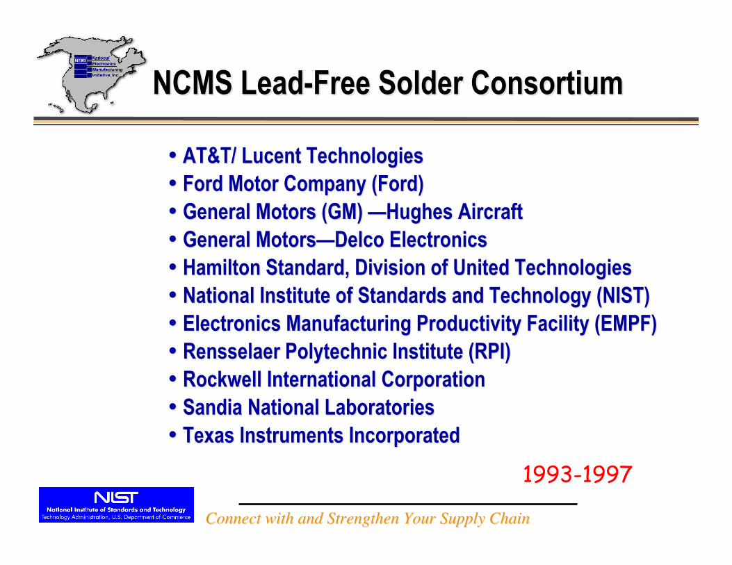
•• AT&T/ Lucent Technologies AT&T/ Lucent Technologies•• Ford Motor Company (Ford) Ford Motor Company (Ford)•• General Motors (GM) General Motors (GM) ——Hughes AircraftHughes Aircraft•• General Motors General Motors——Delco ElectronicsDelco Electronics•• Hamilton Standard, Division of United Technologies Hamilton Standard, Division of United Technologies•• National Institute of Standards and Technology (NIST) National Institute of Standards and Technology (NIST)•• Electronics Manufacturing Productivity Facility (EMPF) Electronics Manufacturing Productivity Facility (EMPF)•• Rensselaer Polytechnic Institute (RPI) Rensselaer Polytechnic Institute (RPI)•• Rockwell International Corporation Rockwell International Corporation•• SandiaSandia National Laboratories National Laboratories•• Texas Instruments Incorporated Texas Instruments Incorporated
NCMS Lead-Free Solder ConsortiumNCMS Lead-Free Solder Consortium
1993-1997
Connect with and Strengthen Your Supply ChainConnect with and Strengthen Your Supply Chain
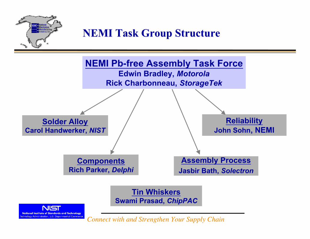
NEMI Task Group StructureNEMI Task Group Structure
NEMI Pb-free Assembly Task ForceEdwin Bradley, Motorola
Rick Charbonneau, StorageTek
Solder AlloyCarol Handwerker, NIST
ComponentsRich Parker, Delphi
ReliabilityJohn Sohn, NEMI
Assembly ProcessJasbir Bath, Solectron
Tin WhiskersSwami Prasad, ChipPAC
Connect with and Strengthen Your Supply ChainConnect with and Strengthen Your Supply Chain
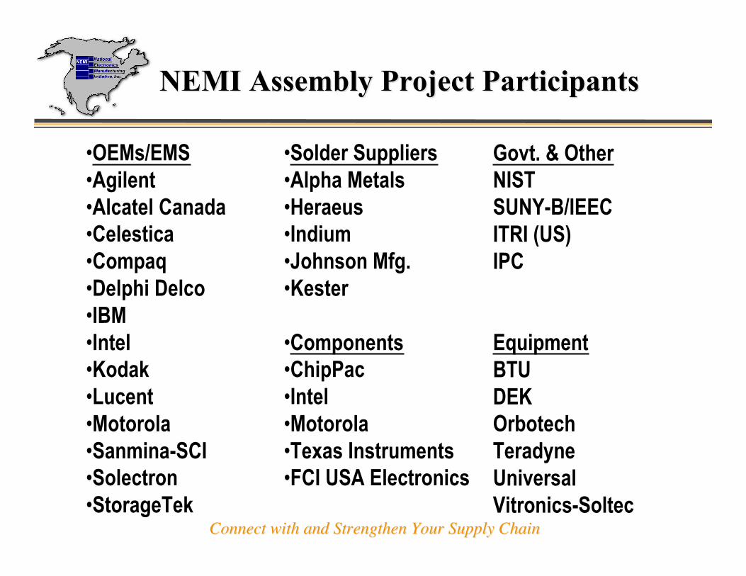
NEMI Assembly Project ParticipantsNEMI Assembly Project Participants
•OEMs/EMS•Agilent•Alcatel Canada•Celestica •Compaq•Delphi Delco•IBM•Intel•Kodak•Lucent•Motorola•Sanmina-SCI•Solectron•StorageTek
•Solder Suppliers•Alpha Metals•Heraeus•Indium•Johnson Mfg.•Kester
•Components•ChipPac•Intel•Motorola•Texas Instruments•FCI USA Electronics
Govt. & OtherNISTSUNY-B/IEECITRI (US)IPC
EquipmentBTUDEKOrbotechTeradyneUniversalVitronics-Soltec
Connect with and Strengthen Your Supply ChainConnect with and Strengthen Your Supply Chain
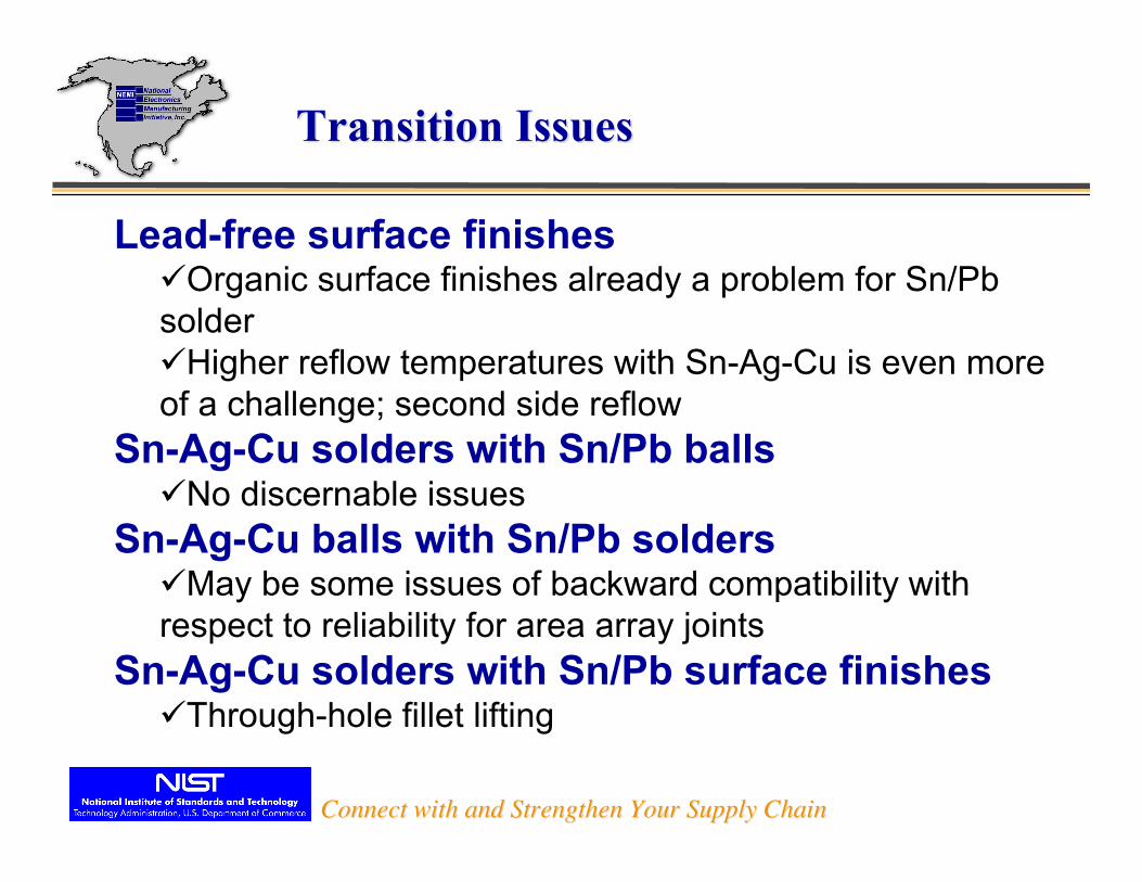
Lead-free surface finishes¸Organic surface finishes already a problem for Sn/Pbsolder¸Higher reflow temperatures with Sn-Ag-Cu is even moreof a challenge; second side reflow
Sn-Ag-Cu solders with Sn/Pb balls¸No discernable issues
Sn-Ag-Cu balls with Sn/Pb solders¸May be some issues of backward compatibility withrespect to reliability for area array joints
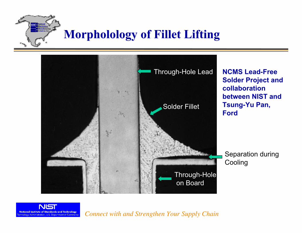
Sn-Ag-Cu solders with Sn/Pb surface finishes¸Through-hole fillet lifting
Transition IssuesTransition Issues
Connect with and Strengthen Your Supply ChainConnect with and Strengthen Your Supply Chain
Through-Hole Lead
Solder Fillet
Separation duringCooling
Through-Hole on Board
MorpholologyMorpholology of Fillet Lifting of Fillet Lifting
NCMS Lead-FreeSolder Project andcollaborationbetween NIST andTsung-Yu Pan,Ford
Connect with and Strengthen Your Supply ChainConnect with and Strengthen Your Supply Chain
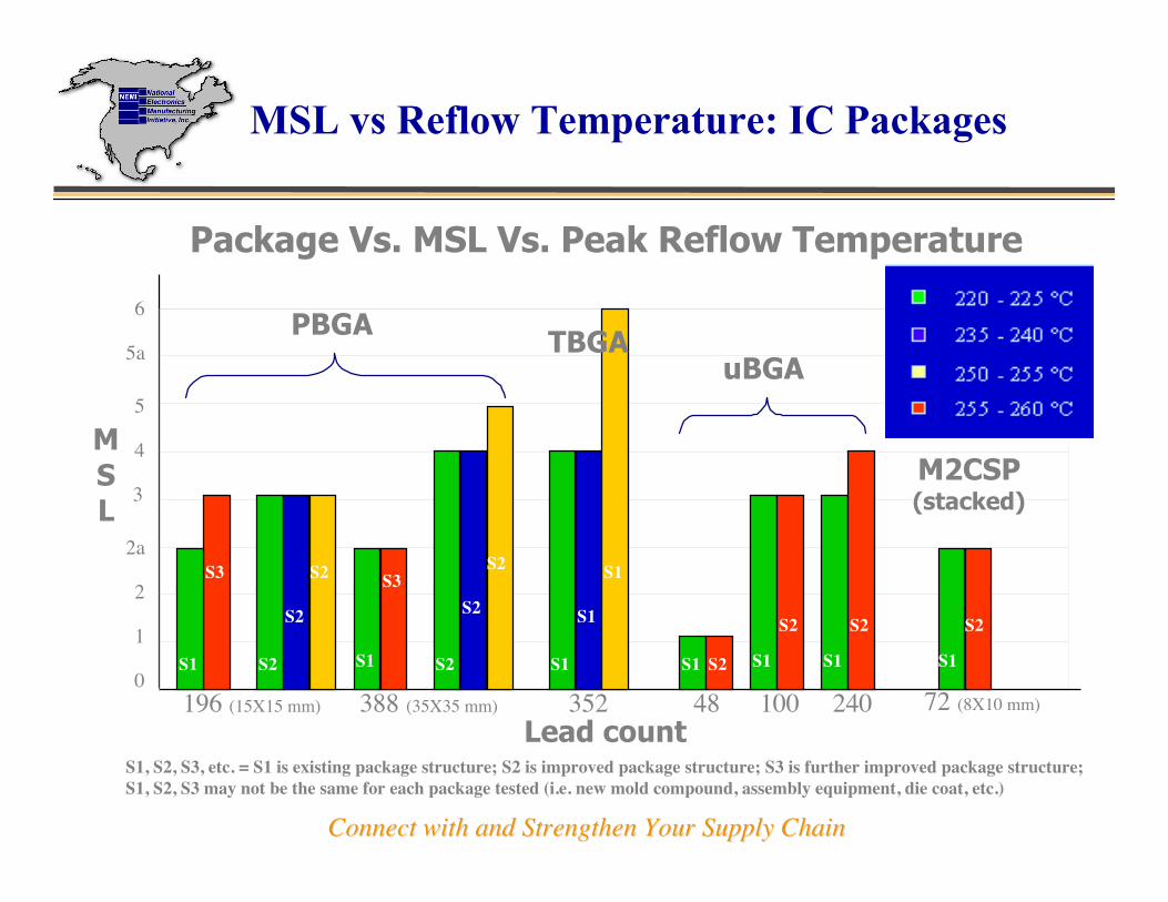
0
3
2
4
2a
1
5a
5
6
48 100 240352
PBGA
M2CSP(stacked)
196 (15X15 mm) 72 (8X10 mm)
Lead count
MSL
Package Vs. MSL Vs. Peak Reflow Temperature
uBGATBGA
388 (35X35 mm)
S1
S2
S1
S2
S1
S2
S1 S2S1
S1
S1
S1
S3
S2
S2
S2
S1
S3
S2
S2
S2
MSL vs Reflow Temperature: IC Packages
S1, S2, S3, etc. = S1 is existing package structure; S2 is improved package structure; S3 is further improved package structure;S1, S2, S3 may not be the same for each package tested (i.e. new mold compound, assembly equipment, die coat, etc.)
Connect with and Strengthen Your Supply ChainConnect with and Strengthen Your Supply Chain
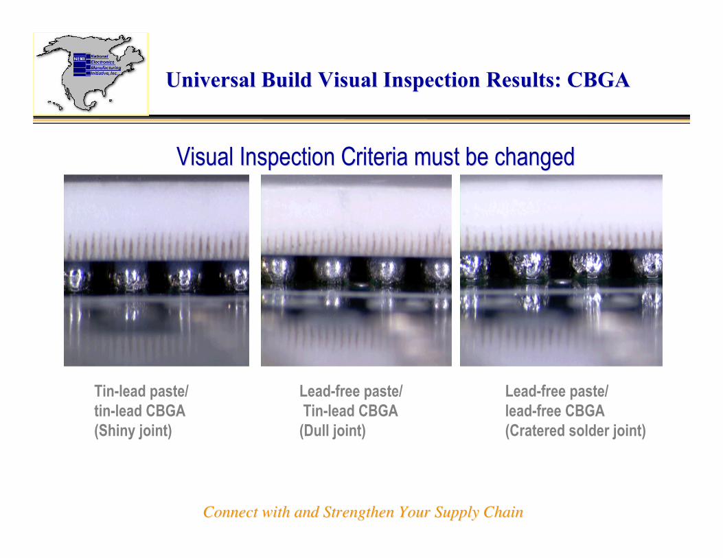
Universal Build Visual Inspection Results: CBGAUniversal Build Visual Inspection Results: CBGA
Visual Inspection Criteria must be changedVisual Inspection Criteria must be changed
Tin-lead paste/tin-lead CBGA(Shiny joint)
Lead-free paste/ Tin-lead CBGA(Dull joint)
Lead-free paste/lead-free CBGA(Cratered solder joint)

Connect with and Strengthen Your Supply ChainConnect with and Strengthen Your Supply Chain
Reliability Test MatrixReliability Test Matrix
ComponentSourceDescriptionReliability Testing-40 to 125°
C0 to 100°
CType 1 TSOPAMD48 Pin TSOP with leads on shortsides, SnPb and NiPd finishesSolectron2512 ResistorKoaspeerzero ohm chip resistor, SnPb andpure Sn finishesSanmina-SCI169 CSPLucent0.8mm pitch, 11x11mm, 7.7 x 7.7mm die, SnAgCu and SnPb ballsKodakLucent208 CSP(HDPUG)ChipPac0.8mm pitch, 15x15mm, 8.1 x 8.1mm die, SnAgCu and SnPb ballsKodak (bothSnAgCualloys)Sanmina-SCI256 BGA(NCMS)Amkor1.27mm pitch, 27x27 mm, 10.0 x10.0 mm die, SnAgCu and SnPbballsCelesticaSanmina-SCI256 CBGAVendorpart; IBMball attach1.27mm pitch, no die, SnAgCu andSnPb ballsMotorola
SnAgCu balls: Sn4.0Ag0.5Cu - provided by Heraeus

Connect with and Strengthen Your Supply ChainConnect with and Strengthen Your Supply Chain
Reliability flow chartReliability flow chart
Test PlanDesign, Procure
BoardsAssembly
Identify, ProcureComponents
CTEMeasurements
T0 Information• AOI• C-SAM• x-ray
Bend Testing
ElectrochemicalMigration Testing
ThermalCycling
Data Analysis
Failure Analysis• Post-cycling C-SAM• Cross-section• Joint characterization• Dye Penetrant Analysis
Pre-AssemblyC-SAM
Final Report

Connect with and Strengthen Your Supply ChainConnect with and Strengthen Your Supply Chain
ATC Relative PerformanceATC Relative Performance
-40 to +125 0 to 100
Component Relative Performance Relative Performance
SnPb - SnPb SnPb - LF LF-LF SnPb - SnPb SnPb - LF LF-LF
AMD 48 TSOP - im Ag bds 0 - 0
AMD 48 TSOP - NiAu bds 0 + +
2512 Resistors - im Ag bds 0 0 0
2512 Resistors - NiAu bds 0
169 CSP 0 + + 0 0 +
208 CSP 0 0 + 0 + +
208 CSP - JEITA alloy 0
256 PBGA 0 0 0 0 0 0
256 Ceramic BGA 0 - +0 equivalent to SnPb-SnPb benchmark (95% confidence bounds)
- statistically worse than SnPb-SnPb benchmark
+ statistically better than SnPb-SnPb benchmark

Connect with and Strengthen Your Supply ChainConnect with and Strengthen Your Supply Chain
Example of Solder Joint Microstructure:Example of Solder Joint Microstructure:169CSP, LF-LF, -40 169CSP, LF-LF, -40 °°C to +125 C to +125 °°CC
Solder consists oftin dendritesseparated byCu-Sn and Ag-Snintermetallics
Sn-3.9Ag-0.6Cu
Connect with and Strengthen Your Supply ChainConnect with and Strengthen Your Supply Chain
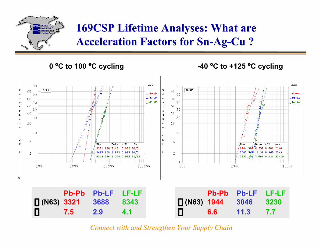
169CSP Lifetime Analyses: What are169CSP Lifetime Analyses: What areAcceleration Factors for Sn-Ag-Cu ?Acceleration Factors for Sn-Ag-Cu ?
0 °C to 100 °C cycling -40 °C to +125 °C cycling
Pb-Pb Pb-LF LF-LFh (N63) 3321 3688 8343b 7.5 2.9 4.1
Pb-Pb Pb-LF LF-LFh (N63) 1944 3046 3230b 6.6 11.3 7.7

Connect with and Strengthen Your Supply ChainConnect with and Strengthen Your Supply Chain
Debate on Alloy CompositionDebate on Alloy Composition
Which alloy composition should we use?
Three main effects of solder alloy composition:
During assembly:
melting, wetting, reaction, solidification
After assembly:
thermal fatigue resistance, fracture, tin pest (?)

Connect with and Strengthen Your Supply ChainConnect with and Strengthen Your Supply Chain
Liquidus TemperaturesLiquidus Temperaturesof Sn-Ag-Cu solderof Sn-Ag-Cu soldersystem as a function ofsystem as a function ofcompositioncomposition
- Liquidus temperature is- Liquidus temperature ishighest temperature wherehighest temperature wheresolid is presentsolid is present
- Lines correspond to- Lines correspond tocompositions with the samecompositions with the sameliquidus temperatureliquidus temperature
Phase Diagram ofPhase Diagram ofSn-Ag-Cu SoldersSn-Ag-Cu Solders
NEMI
JEIDA

Connect with and Strengthen Your Supply ChainConnect with and Strengthen Your Supply Chain
Melting Behavior of Sn-Ag-Cu soldersMelting Behavior of Sn-Ag-Cu solders
NEMI
eutecticJEIDA

Connect with and Strengthen Your Supply ChainConnect with and Strengthen Your Supply Chain
Melting Behavior of Sn-Ag-Cu soldersMelting Behavior of Sn-Ag-Cu solders
NEMI
eutectic
JEIDA

Connect with and Strengthen Your Supply ChainConnect with and Strengthen Your Supply Chain
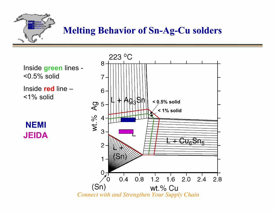
Melting Behavior of Sn-Ag-Cu soldersMelting Behavior of Sn-Ag-Cu solders
Inside green lines -<0.5% solid
Inside red line –<1% solid
< 0.5% solid
< 1% solid
NEMIJEIDA
Connect with and Strengthen Your Supply ChainConnect with and Strengthen Your Supply Chain
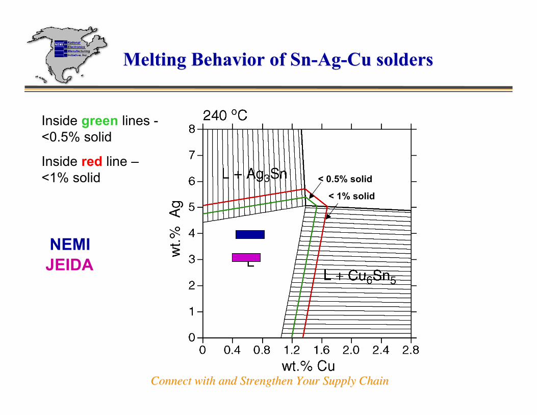
Melting Behavior of Sn-Ag-Cu soldersMelting Behavior of Sn-Ag-Cu solders
Inside green lines -<0.5% solid
Inside red line –<1% solid
< 0.5% solid
< 1% solid
NEMIJEIDA
Connect with and Strengthen Your Supply ChainConnect with and Strengthen Your Supply Chain
Melting Behavior of Sn-Ag-Cu soldersMelting Behavior of Sn-Ag-Cu solders
Inside green lines -<0.5% solid
Inside red line –<1% solid < 0.5% solid
< 1% solid
NEMIJEIDA
Connect with and Strengthen Your Supply ChainConnect with and Strengthen Your Supply Chain
Tin Whisker Formation¸Why? When? How?¸Is there a magic bullet?
Open IssuesOpen Issues
Connect with and Strengthen Your Supply ChainConnect with and Strengthen Your Supply Chain
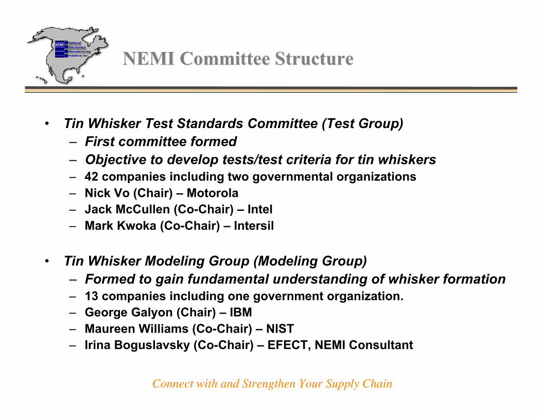
NEMI Committee StructureNEMI Committee Structure
• Tin Whisker Test Standards Committee (Test Group)– First committee formed– Objective to develop tests/test criteria for tin whiskers– 42 companies including two governmental organizations– Nick Vo (Chair) – Motorola– Jack McCullen (Co-Chair) – Intel– Mark Kwoka (Co-Chair) – Intersil
• Tin Whisker Modeling Group (Modeling Group)– Formed to gain fundamental understanding of whisker formation– 13 companies including one government organization.– George Galyon (Chair) – IBM– Maureen Williams (Co-Chair) – NIST– Irina Boguslavsky (Co-Chair) – EFECT, NEMI Consultant
Connect with and Strengthen Your Supply ChainConnect with and Strengthen Your Supply Chain
Tin Whisker CommitteesTin Whisker Committees
• Tin Whisker Users Group (Users Group)
– Formed by large companies with high reliabilityproducts to look at mitigation techniques
– Started in late 2002
– 10 companies
– George Galyon (Chair) – IBM
– Richard Coyle (Co-Chair) – Lucent

Connect with and Strengthen Your Supply ChainConnect with and Strengthen Your Supply Chain
Test Team MembersTest Team Members
• Agilent
• Alcatel
• Allegro Microsystems
• AMD
• Analog Devices
• Boeing
• ChipPAC
• Cooper Bussmann
• Delphi Delco
• Engelhard Clal
• Enthone
• FCI Framatome
• Flextronics
• HP
• IBM• Indium• Infineon AG• Intel (Co-Chair)• Intersil (Co-Chair)• IPC• ITRI Soldertec• Kemet• Lockheed Martin• Microchip• Micro Semi• Molex• Motorola (Chair)• NASA Goddard
• NIST• NEMI• On Semi• Philips• Raytheon• Soldering Tech.• Shipley• Solectron• ST Micro• SUNY Binghamton• SUNY Buffalo• Technic• Texas Instruments• US Army

Connect with and Strengthen Your Supply ChainConnect with and Strengthen Your Supply Chain
Overview of Whisker Committee EffortOverview of Whisker Committee Effort
• Direct:– Completed two comprehensive matrices, Phase 1 and 2, both for
ICs and Passives.
– Proposed a definition for whiskers.
– Developed an inspection protocol.
– Identified three test methods recommended for plating finishdevelopment and characterization.
– Initiated test method document for potential release by JEDEC.
– Preparing matrix for Phase 3 DOE (validation and verification).
• Indirect:– Generated considerable momentum to understand whiskers and
tin plating globally.
Connect with and Strengthen Your Supply ChainConnect with and Strengthen Your Supply Chain
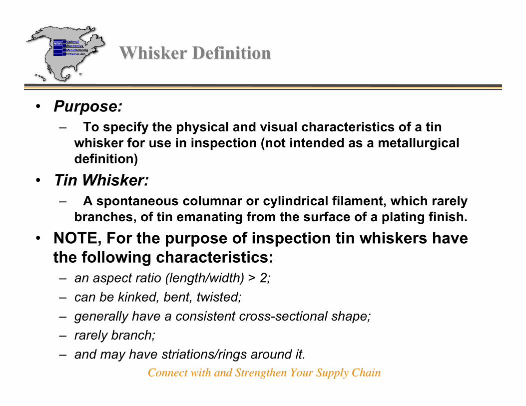
Whisker DefinitionWhisker Definition
• Purpose:– To specify the physical and visual characteristics of a tin
whisker for use in inspection (not intended as a metallurgicaldefinition)
• Tin Whisker:– A spontaneous columnar or cylindrical filament, which rarely
branches, of tin emanating from the surface of a plating finish.
• NOTE, For the purpose of inspection tin whiskers havethe following characteristics:– an aspect ratio (length/width) > 2;
– can be kinked, bent, twisted;
– generally have a consistent cross-sectional shape;
– rarely branch;
– and may have striations/rings around it.
Connect with and Strengthen Your Supply ChainConnect with and Strengthen Your Supply Chain
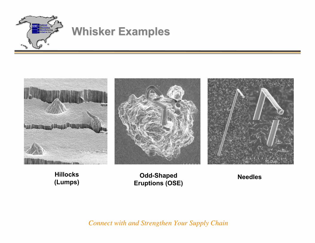
Whisker ExamplesWhisker Examples
Odd-ShapedEruptions (OSE)
Hillocks(Lumps)
Needles
Connect with and Strengthen Your Supply ChainConnect with and Strengthen Your Supply Chain
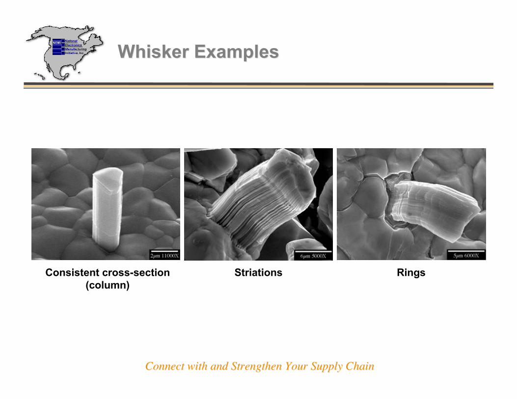
Whisker ExamplesWhisker Examples
Consistent cross-section(column)
Striations Rings
Connect with and Strengthen Your Supply ChainConnect with and Strengthen Your Supply Chain
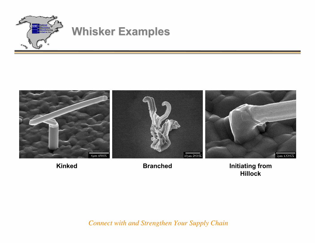
Whisker ExamplesWhisker Examples
Kinked Branched Initiating fromHillock

Connect with and Strengthen Your Supply ChainConnect with and Strengthen Your Supply Chain
Inspection ProtocolInspection Protocol
• Scope:– Establish an inspection method to quantify the propensity of an
electroplated lead finish to develop tin whiskers.
– Examples of electroplated lead finish uses: terminals of ICs andpassives, connectors, printed circuit boards, etceteras.
• Purpose:To recommend the equipment, locations and area of inspection, samplesize and procedure for inspection.
• Equipment:Scanning Electron Microscope (SEM) is recommended for whiskerinspection and verification.

Connect with and Strengthen Your Supply ChainConnect with and Strengthen Your Supply Chain
Inspection ProtocolInspection Protocol
• Procedure:
– Use carbon tape, paint, or other conductive material to attach the sampleto the work holder to prevent charging.
• When handling the samples, care must be taken to avoid contact with theelectroplated finish. Contact with the finish may detach whiskers.
– Inspect each sample for whiskers at a magnification of 300X.
– The samples should be mounted in the best position (maximizeinspection areas and view of critical locations such as bends) for SEMinspection.
– At each inspection:
• Record the presence of hillocks, odd-shaped eruptions and whiskers(whiskers ≥ 10 microns in length or > 2 in aspect ratio).
• Estimate and record the length of the longest whisker. Whisker length ismeasured from the termination/electroplate surface. Use higher power asnecessary to determine length.
• Record the whisker density representative of the level of whisker growth(number of whiskers within a 250µm X 250µm area).

Connect with and Strengthen Your Supply ChainConnect with and Strengthen Your Supply Chain
Inspection ProtocolInspection Protocol
• Recommended Sample Sizes:
– Example: Leaded PackagesInspect all plated surfaces, as practical, of 3 leads on a minimum of 3packages randomly chosen from the test samples.

Connect with and Strengthen Your Supply ChainConnect with and Strengthen Your Supply Chain
SEM Inspection Set-upSEM Inspection Set-up
CarbonTape
SEM WorkHolder
PackageLive Bug

Connect with and Strengthen Your Supply ChainConnect with and Strengthen Your Supply Chain
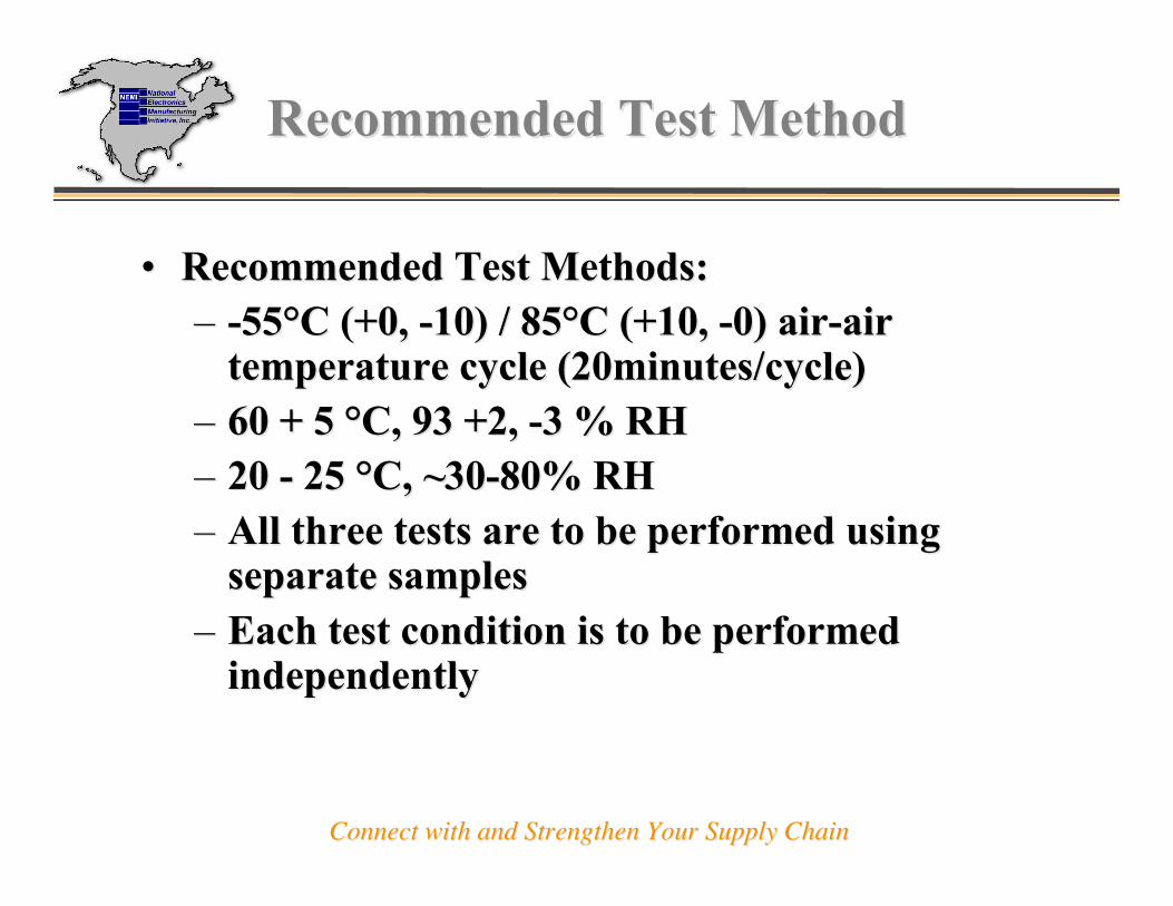
Recommended Test MethodRecommended Test Method
•• Prepared whisker test method for release by JEDEC.Prepared whisker test method for release by JEDEC.•• Purpose:Purpose:
–– Provide test method to aid in the evaluation andProvide test method to aid in the evaluation anddevelopment of plating finishes.development of plating finishes.
–– Provide an industry-standardized test forProvide an industry-standardized test forcomparison of whisker-propensity for differentcomparison of whisker-propensity for differentplating systems and processes.plating systems and processes.
–– Not intended for use in reliability assessment orNot intended for use in reliability assessment orqualification.qualification.
Connect with and Strengthen Your Supply ChainConnect with and Strengthen Your Supply Chain
Recommended Test MethodRecommended Test Method
•• Recommended Test Methods:Recommended Test Methods:–– -55-55°°C (+0, -10) / 85C (+0, -10) / 85°°C (+10, -0) air-airC (+10, -0) air-air
temperature cycle (20minutes/cycle)temperature cycle (20minutes/cycle)–– 60 + 5 60 + 5 °°C, 93 +2, -3 % RHC, 93 +2, -3 % RH–– 20 - 25 20 - 25 °°C, ~30-80% RHC, ~30-80% RH–– All three tests are to be performed usingAll three tests are to be performed using
separate samplesseparate samples–– Each test condition is to be performedEach test condition is to be performed
independentlyindependently
Connect with and Strengthen Your Supply ChainConnect with and Strengthen Your Supply Chain
Database for Solder Properties withEmphasis on Lead-free SoldersRelease 3.0
developed byNational Institute of Standards & Technology andColorado School of Mines (under contract to NIST)
http://www.boulder.nist.gov/div853/• Viewable using web browsers• Downloadable in Microsoft Word formats• Release number changes as database is updated

Connect with and Strengthen Your Supply ChainConnect with and Strengthen Your Supply Chain
Further InformationFurther Information
http://www.metallurgy.nist.gov/solder/
http://www.nemi.org