nerc requirements for setting load-dependent power · pdf filenerc requirements for setting...
TRANSCRIPT

NERC Requirements for Setting Load-Dependent Power Plant Protection: PRC-025-1
Charles J. Mozina, Consultant
Beckwith Electric Co., Inc. www.BeckwithElectric.com
I. Introduction
During the 2003 blackout, 290 bulk power generators tripped off-line. These trippings resulted in the loss of 52,000 MWs of generation. Investigation of these trippings indicated that many were due to improperly set generator relays or mis-coordination with transmission line protection. A major area that contributed to the loss of generation was the inability of power plant protection to “ride through” survivable system low-voltage events. Transmission line protection loadability and low voltage “ride through” has been addressed in the NERC (North America Electric Reliability Corporation) Standard PRC-023-2. NERC PRC-025-1 addresses loadability of power plant protection and is much more complicated to apply than the transmission loadability requirements outlined in PRC-023-2. PRC-025-1 successfully passed NERC balloting and was adopted by NERC Board of Trustees in August 2013. The standard was approved by FERC in July 2014 with an effective date of Oct. 1, 2014. The standard requires implementation within 60 months of the effective date. PRC-025-1 will require every generator owner (GO), transmission owner (TO) and distribution provider to set load responsive power plant protective relays to meet required stress points as outlined in the standard. It requires documentation of setting calculations and evidence that the settings were installed by the required compliant date. In addition, PRC-025-1 also covers transmission line protection for specific one-line configurations for lines that exit power plants.
Since many recent major power system disturbances are the result of voltage collapse, generator protection must be secure during low voltage system conditions while still providing generator protection. The generator AVR (Automatic Voltage Regulator) needs to provide VAr support within its capability to rapidly stabilize system voltage during major disturbances as well as during power system restoration. This paper will outline PRC-025-1 requirements to ride through survivable system low voltage. The standard has a number of calculation options and addresses load dependent generator unit protection (21 and 51V), generator step-up transformer (GSU) relays (51), auxiliary transformer relays (51) that supply plant load when the generator is on-line, and backup transmission line protection (21) for specific one-line configurations for lines exiting the power plant. Transmission line requirement can involve Distribution Providers (DP) depending on ownership. The stress points in the case of generators, GSU and transmission lines are based on the effects of generator excitation system field-forcing. These effects are discussed in detail in this paper in addition to the calculation options.

II. Generator Excitation Systems and Watt/VAr Capability A. Excitation Control Basics
The excitation system of a generator provides the energy for the magnetic field that keeps the generator in synchronism with the power system. Present-day exciters fall into two broad categories: those using ac generators (alternators) as a power source and those using transformers. Fig. 1 illustrates a typical transformer-supplied excitation system. In addition to maintaining synchronism of the generator, the excitation system also affects the amount of reactive power that the generator may absorb or produce. Increasing the excitation current (dc current to the field windings) will increase the reactive power output. Decreasing the excitation will have the opposite effect, and in extreme cases of low excitation, may result in loss of synchronism of the generator with the power system. If the generator is operating isolated from the power system and no other reactive power sources are controlling terminal voltage, increasing the level of excitation current will increase the generator terminal voltage and vice versa. The most commonly used voltage control mode for generators of significant size that are connected to a power system is the AVR (automatic voltage regulator) mode. In this mode, the excitation system helps to maintain power system voltage within acceptable limits by supplying or absorbing reactive power as required.
Fig. 1 Typical Transformer-Supplied Excitation System
B. Steady-State Excitation Control Response
Under steady-state conditions, the excitation controls are used to prevent the AVR from imposing unacceptable conditions upon the generator. These controls are the maximum and minimum excitation limiters. The overexcitation limiter (OEL) prevents the AVR from trying to supply more excitation current than the excitation system can supply or the generator field can withstand. The OEL must limit excitation current before the generator field overload protection operates. The underexcitation limiter (UEL) prevents

the AVR from reducing excitation to such a low level that the generator is in danger of losing synchronism, exceeding machine underexcited capability, or tripping due to exceeding the loss of excitation protection setting. The UEL must prevent reduction of field current to a level where the generator loss-of-field protection may operate.
The generator capability curve establishes the steady-state (continuous) generator operating limits. The generator capability curve is normally published at generator-rated voltage. The curve also shows how the AVR control limits steady-state operation to within generator capabilities. Generator capability is a composite of three different curves: the stator winding limit, the rotor heating limit, and the stator end iron limit (see Fig. 2). The stator winding limit is a long-term condition relative to the carrying capability of the generator winding current.
Fig. 2 Typical Generator Capability Curve and Operating Limits
The generator excitation control limiters are intended to limit operation of the generator to within its continuous capabilities. Fig. 2 illustrates how these limiter setpoints can be plotted on a typical generator capability curve. Generally, the setting of the UEL control will also coordinated with the steady-state stability limit of the generator which is a function of the generator impedance, system impedance and generator terminal voltage.
C. Transient Excitation Control Response
During system disturbances―either short circuits or a system condition that depresses the system voltage―electrical power cannot be fully delivered to the transmission system. Fast response of the excitation system helps to increase the

synchronizing torque to allow the generator to remain in synchronism with the system during these conditions. This is done through excitation system field forcing. The design of the excitation protection/control system accommodates field forcing during faults to aid in maintaining transient stability. This dictates that very high rotor field current (typically in the range of 140-200% of rating) must be permitted to flow for a short time without causing the exciter control to reduce field voltage because of the high field current. After the short circuit has been cleared, the resulting oscillations of the generator rotor speed with respect to the system frequency will cause the terminal voltage to fluctuate above and below the AVR setpoint. Field forcing times are typically at least 1 second but may be as long as 10 seconds before the field current is reduced. During the time that field forcing occurs, the generator can supply a high level of reactive power to the system and operate outside its steady-state capability curve.
During system disturbances when the system voltage is reduced due to impending system voltage collapse, field forcing can take place as the excitation system attempts to maintain the AVR setpoint voltage. NERC’s analysis of the 2003 blackout indicated that the power system should be able to survive an 85% transmission system voltage without causing relay systems operations―either on the transmission system or at generator installations. Based on simulation studies that NERC conducted with 2003 blackout models, they determined that when the power plant transmission voltage is reduced to 85%, generators can increase their Mvar output to approximately 150% of their Mw rating as shown in Fig. 3. During this period, the generator is also providing its rated Mw output. These studies are the basis of the stress points that NERC has established.
Fig. 3 NERC Simulation

III. MW-MVAR (P-Q) to Resistance-Reactance (R-X) Conversion
A key load-dependent relay on a major generator as well as transmission lines that exit a power plant is the phase distance (21) relaying which measures impedance. Its operating characteristics are typically displayed on a Resistance-Reactance (R-X) diagram. Generator capability, excitation control limiters and NERC stress points are provided in terms of Mw-Mvars limits. To coordinate the generator capability, excitation limiters and NERC PRC-25-1 stress points with 21 impedance relays, it is necessary to either convert these limits to an R-X plot or to convert impedance relay settings to a MW-Mvar plot. Fig. 4 illustrates this conversion [1]. The CT and VT ratios (Rc/Rv) convert primary ohms to secondary quantities that are set within the relay. The KV in Fig. 4 is the voltage at the measuring point of the 21 relay. Note that the impedance is proportional to the square of the voltage which makes the 21 relay extremely sensitive to voltage.
MVA = kV2
Z( Rc )
Rv
Fig. 4 Transformation from MW- Mvar to R-X and R-X to MW-Mvar Plot [1]
IV. NERC Reliability Standard―PRC-025 -1 [2]
NERC PRC-025-1 was developed over 2 years and successfully passed NERC balloting. It was approved by NERC Board of Trustees in August 2013. PRC-025-1 will require every generator owner (GO), transmission owner (TO) and distribution provider to set load responsive power plant protective relays to meet required stress points as outlined in the standard. It requires documentation of setting calculations and evidence that the settings were installed by the required compliant date. In addition, PRC-025-1 also covers transmission line protection for specific one-line configurations for lines that exit power plants.
A. NERC Requirements (R1) and Measures (M1) For PRC-025-1 Standard
R1. Each Generator Owner, Transmission Owner, and Distribution Provider shall apply settings that are in accordance with PRC-025-1 – Attachment 1: Relay Settings,

on each load-responsive protective relay while maintaining reliable fault protection. [Violation Risk Factor: High]
M1. For each load-responsive protective relay, each Generator Owner, Transmission Owner, and Distribution Provider shall have evidence (e.g., summaries of calculations, spreadsheets, simulation reports, or setting sheets) that settings were applied in accordance with PRC-025-1. B. NERC PRC-025-1 Implementation Plan
Each Generator Owner, Transmission Owner, and Distribution Provider that owns load-responsive protective relays that become applicable to this standard by the timetable indicated in Table 1:
Table 1 - From NERC Implementation Plan [3]
V. NERC PRC-025-1 Requirements
PRC-025-1 addresses load-dependent relays on three power plant components --- generators, transformers and lines that exit power plants. PRC-025-1 also addresses setting requirements for load-dependent relays at the interconnection point of asynchronous generation facilities such as wind farms and solar installation if these installations meet the requirements outlined in the NERC’s definition of the Bulk Power System (BES). This paper does not address those parts of the standard. The paper concentrates on the application at conventional power plants. The following are a few key definitions from the standard.

A. Generator Ratings Defined
Synchronous generator relay pickup setting criteria values are derived from the unit’s maximum gross Real Power capability, in megawatts (MW), as reported to the Transmission Planner, and the unit’s Reactive Power capability, in megavoltampere-reactive (Mvar), is determined by calculating the MW value based on the unit’s nameplate megavoltampere (MVA) rating at rated power factor. If different seasonal capabilities are reported, the maximum capability shall be used for the purposes of this standard. B. Transformer Taps Defined
Calculations using the GSU transformer turns ratio shall use the actual tap that is applied (i.e., in service) for GSU transformers with deenergized tap changers (DETC). If load tap changers (LTC) are used, the calculations shall reflect the tap that results in the lowest generator bus voltage. When the criterion specifies the use of the GSU transformer’s impedance, the nameplate impedance at the nominal GSU transformer turns ratio shall be used.
C. Transmission Lines Defined
PRC-025-1 primarily addresses one-line applications where the power plant is connected to the system through a single line that connects the GSU to the main transmission substation. At many installations, the power plant is at a far enough distance from the transmission yard that short-line protection is used to provide protection. These short-line protection packages generally contain load-dependent distance relays as backup that are addressed in the standard. D. Typical Power Plant Protection
Fig. 5 illustrates typical protection for the generator, GSU transformer and unit auxiliary transformer (UAT) for a unit-connected configuration. Load-dependent relay functions discussed in PRC-025-1 are highlighted in red and are a small portion of total protection.
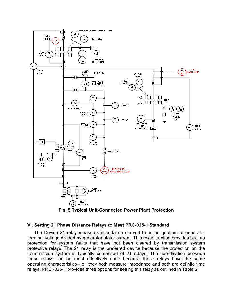
Fig. 5 Typical Unit-Connected Power Plant Protection
VI. Setting 21 Phase Distance Relays to Meet PRC-025-1 Standard
The Device 21 relay measures impedance derived from the quotient of generator terminal voltage divided by generator stator current. This relay function provides backup protection for system faults that have not been cleared by transmission system protective relays. The 21 relay is the preferred device because the protection on the transmission system is typically comprised of 21 relays. The coordination between these relays can be most effectively done because these relays have the same operating characteristics–i.e., they both measure impedance and both are definite time relays. PRC -025-1 provides three options for setting this relay as outlined in Table 2.
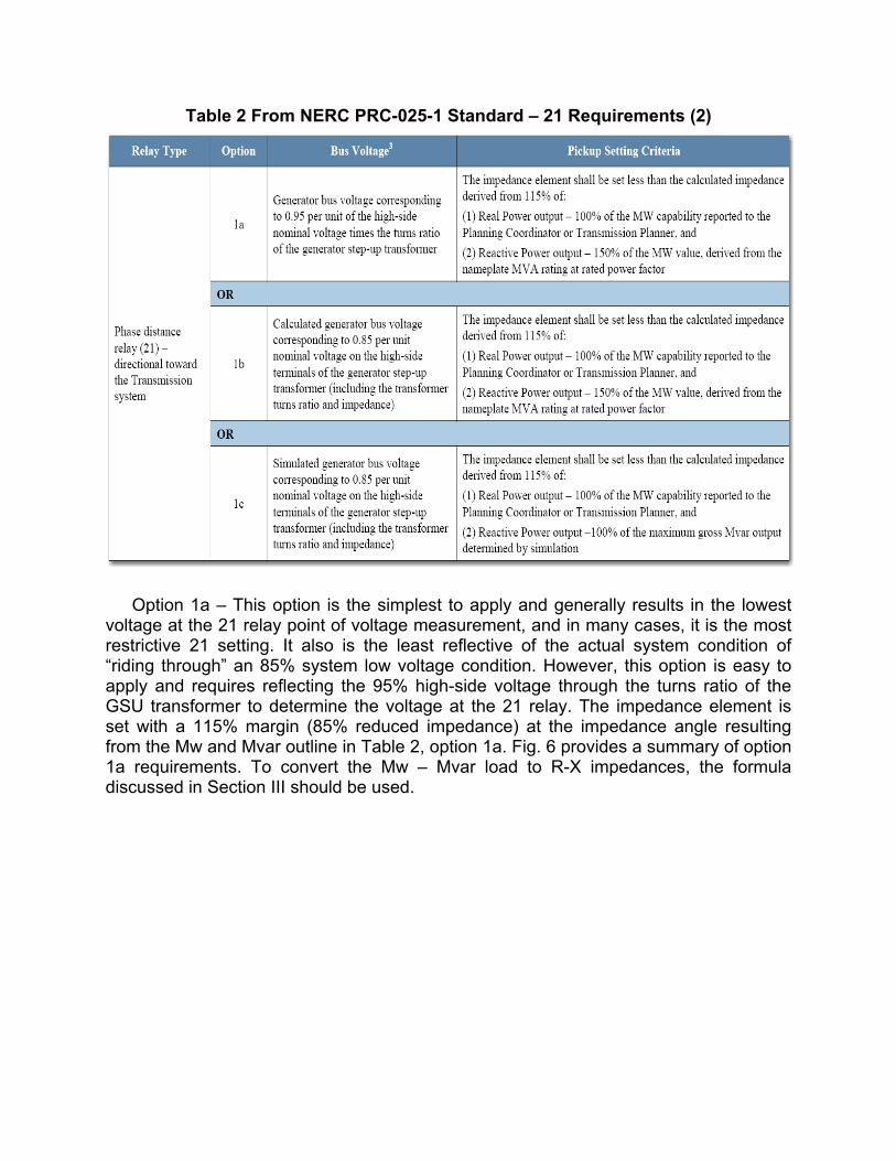
Table 2 From NERC PRC-025-1 Standard – 21 Requirements (2)
Option 1a – This option is the simplest to apply and generally results in the lowest voltage at the 21 relay point of voltage measurement, and in many cases, it is the most restrictive 21 setting. It also is the least reflective of the actual system condition of “riding through” an 85% system low voltage condition. However, this option is easy to apply and requires reflecting the 95% high-side voltage through the turns ratio of the GSU transformer to determine the voltage at the 21 relay. The impedance element is set with a 115% margin (85% reduced impedance) at the impedance angle resulting from the Mw and Mvar outline in Table 2, option 1a. Fig. 6 provides a summary of option 1a requirements. To convert the Mw – Mvar load to R-X impedances, the formula discussed in Section III should be used.

Fig. 6 Phase Distance 21 Setting Stress Point – Option 1a Calculation
Option 1b - This option requires the calculation of the voltage at the 21 relay point of voltage measurement which is at the generator terminals. The impedance element is set with a 115% margin (85% reduced impedance) at the impedance angle resulting from the Mw and Mvar outline in Table 2, option 1b. Fig. 7 provides a summary of option 1b requirements. To convert the Mw – Mvar load to R-X impedances, the formula discussed in Section III should be used. Note that the impedance angle and the Mw-Mvar angle are the same (see Section III).
Fig. 7 Phase Distance 21 Setting Stress Point – Option 1b Calculation
Option 1c – This option is the most accurate because it simulates the actual field forcing of the specific AVR on the generator for a case where the transmission voltage is reduced to 85%. It replicates the test that NERC has performed in establishing the requirements for options 1a and 1b. However, it requires a computer simulation typically

done with a transient stability study where a load is added to the generator transmission bus and it is increased until the bus voltage is reduced to 85%. The Mvar and Mva are determined by the simulation. Fig. 8 provides a summary of option 1c requirements.
Fig. 8 Phase Distance 21 Setting Stress Point – Option 1c Simulation
A. Load Encroachment Methods
Load encroachment methods available in digital relays provide a means of extending the relay reach to improve backup protection for system faults. Fig. 9 illustrates a load encroachment application. There is a major difference in applying load encroachment for distance relays on transmission lines than for generator distance relays---and that difference is the impedance angle. The impedance angle for transmission application to meet PRC-023-2 is 30 degrees while the angle for impedance relays in 53 degrees which would require a setting angle of around 57-60 degrees to provide a margin. AVR field-forcing causes a high Vars flow to account for this high angle. As a result, there is a very limited margin for arc resistance at the point of fault as illustrated in Fig. 9.

Fig. 9. Load Encroachment
B. Impedance Swings and Out-of-Step Blocking
PRC-025-1 provides industry guidance to avoid improper relay trippings during system low voltage events. However, during major system disturbances that are fault-induced, there can be impedance oscillations that can cause relay mis-operation for stable and unstable power swings. Out-of-step blocking methods have long been used on the transmission system to block operation of impedance relays during power swings. The method can be used on generator 21 relays as illustrated in Fig. 10. The trip impedance characteristic must be set with a margin over the NERC stress. On a swing condition, the blocking element will be picked up before the trip element. This logic is used to block operation of the trip element during a swing conditions. For a fault within the mho trip element, both tripping and blocking elements will pick up at the same time. Thus, the scheme can detect the difference between a fault and swing condition and block tripping for a swing condition. The 21 trip elements must be set with a delay (typically 0.8 to 1.0 sec.) to coordinate with transmission system backup protection and local breaker failure. This time delay is very long when compared to the swing rates. Many users rely on this delay to prevent false operation during stable or unstable power swings. They rely on the impedance locus passing through the impedance characteristic for a stable or unstable swing and exiting the impedance characteristic before the relay can time out and trip.
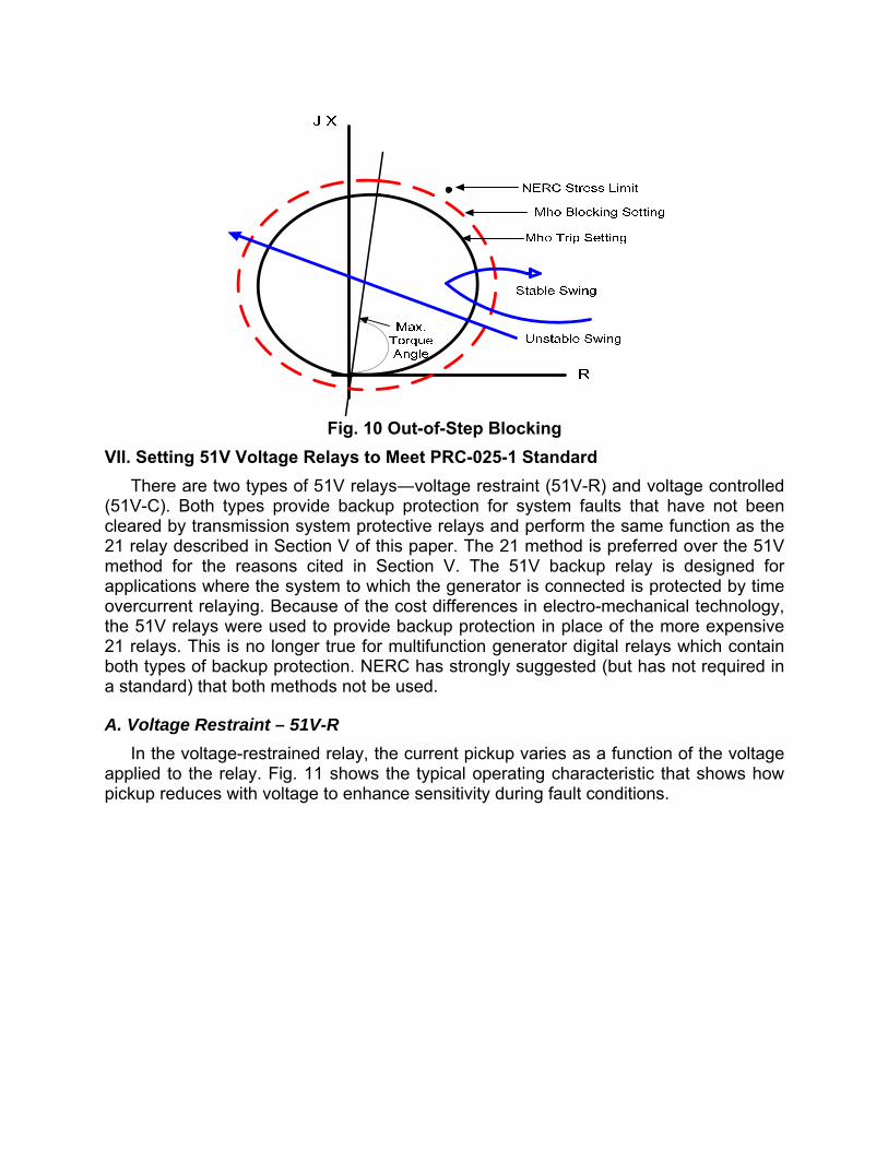
Fig. 10 Out-of-Step Blocking
VII. Setting 51V Voltage Relays to Meet PRC-025-1 Standard
There are two types of 51V relays―voltage restraint (51V-R) and voltage controlled (51V-C). Both types provide backup protection for system faults that have not been cleared by transmission system protective relays and perform the same function as the 21 relay described in Section V of this paper. The 21 method is preferred over the 51V method for the reasons cited in Section V. The 51V backup relay is designed for applications where the system to which the generator is connected is protected by time overcurrent relaying. Because of the cost differences in electro-mechanical technology, the 51V relays were used to provide backup protection in place of the more expensive 21 relays. This is no longer true for multifunction generator digital relays which contain both types of backup protection. NERC has strongly suggested (but has not required in a standard) that both methods not be used.
A. Voltage Restraint – 51V-R
In the voltage-restrained relay, the current pickup varies as a function of the voltage applied to the relay. Fig. 11 shows the typical operating characteristic that shows how pickup reduces with voltage to enhance sensitivity during fault conditions.

Fig. 11 51V-R Voltage Restraint Characteristic
The requirements for the NERC stress point for PRC-025-1 for the 51V-R relay are the same as those for the 21 relay. PRC -025-1 provides three options for setting this relay as outlined in Table 3.
Option 2a – This is the same as Option 1a for the 21 relay discussed in Section V. Fig. 6 illustrates the Mw and Mvar requirements. The voltage at the generator is calculated by assuming a 95% transmission bus voltage and reflecting it through the turns ratio of the GSU to determine the voltage at the 51V-R relay. The relay is connected at the same point as the 21 relay in Fig. 6. The Mva level is then converted to a current at the voltage calculated and the 51V-R set with a 115% margin above that current level.
Option 2b – This is the same as Option 1b for the 21 relay discussed in Section V. Fig. 7 illustrates the Mw and Mvar requirements. The current element is set with a 115% margin from the Mw and Mvar outlined in Table 3 option 2b and at the voltage calculated at the relay for an 85% voltage on the transmission bus.
Option 2c – This is the same as option 1c for the 21 relay described in Section V. This option is the most accurate because it simulates the actual field forcing of the specific AVR on the generator for a case where the transmission voltage is reduced to 85%. It replicates the test that NERC has performed in establishing the requirements for options 2a and 2b. It requires a computer simulation typically done with a transient stability study where a load is added to the generator transmission bus and is increased until the bus voltage is reduced to 85%. The Mvar and Mva are determined by the simulation. Fig. 8 provides a summary of option 2c requirements.
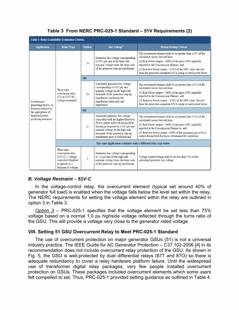
Table 3 From NERC PRC-025-1 Standard – 51V Requirements (2)
B. Voltage Restraint – 51V-C
In the voltage-control relay, the overcurrent element (typical set around 40% of generator full load) is enabled when the voltage falls below the level set within the relay. The NERC requirements for setting the voltage element within the relay are outlined in option 3 in Table 3.
Option 3 – PRC-025-1 specifies that the voltage element be set less than 75% voltage based on a normal 1.0 pu highside voltage reflected through the turns ratio of the GSU. This will provide a voltage very close to the generator rated voltage. VIII. Setting 51 GSU Overcurrent Relay to Meet PRC-025-1 Standard
The use of overcurrent protection on major generator GSUs (51) is not a universal industry practice. The IEEE Guide for AC Generator Protection – C37.102-2006 [4] in its recommendation does not include overcurrent relay protection of the GSU. As shown in Fig. 5, the GSU is well-protected by duel differential relays (87T and 87O) so there is adequate redundancy to cover a relay hardware platform failure. Until the widespread use of transformer digital relay packages, very few people installed overcurrent protection on GSUs. These packages included overcurrent elements which some users felt compelled to set. Thus, PRC-025-1 provided setting guidance as outlined in Table 4.

The load current through a GSU is limited by the Mva rating of the generator and the GSU is sized to handle that load on a continuous basis. PRC-025-1 provides two options outlined in Table 4.
Table 4 From NERC PRC-025-1 Standard – GSU 51 Requirements (2)
Option 15a – Fig.12 shows the required calculation to determine the 51 stress point current. The Mva is converted to current at the 0.85 pu voltage level and a margin of 115% is then applied.
Fig. 12 Phase Overcurrent 51 Setting Stress Point – Option 15a Calculation
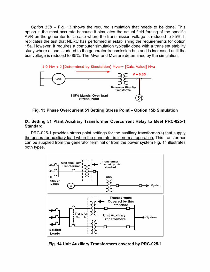
Option 15b – Fig. 13 shows the required simulation that needs to be done. This option is the most accurate because it simulates the actual field forcing of the specific AVR on the generator for a case where the transmission voltage is reduced to 85%. It replicates the test that NERC has performed in establishing the requirements for option 15a. However, it requires a computer simulation typically done with a transient stability study where a load is added to the generator transmission bus and is increased until the bus voltage is reduced to 85%. The Mvar and Mva are determined by the simulation.
Fig. 13 Phase Overcurrent 51 Setting Stress Point – Option 15b Simulation
IX. Setting 51 Plant Auxiliary Transformer Overcurrent Relay to Meet PRC-025-1 Standard
PRC-025-1 provides stress point settings for the auxiliary transformer(s) that supply the generator auxiliary load when the generator is in normal operation. This transformer can be supplied from the generator terminal or from the power system Fig. 14 illustrates both types.
Fig. 14 Unit Auxiliary Transformers covered by PRC-025-1

Table 5 shows the stress point setting requirements for UATs.
Table 5 From NERC PRC-025-1 Standard – UAT 51 Requirements (2)
Option 13a – The 51 relay pickup should be set at 150% of the UAT maximum nameplate Mva.
Option 13b – The 51 relay pickup should be set at 150% of the UAT measured current when the generator is at maximum gross MW output report to the Transmission Planner. X. Setting 21 Transmission Line Relay for Lines Exiting Power Plant to Meet PRC-025-1
PRC-025-1 covers transmission line protection for specific one-line configurations for lines exiting power plants. There are many installations where the power plant is not close enough to the transmission substation so that convention differential protection cannot be used to provide protection for line that connect the GSU to the transmission substation. Fig.15 illustrates such a one-line configuration. Most of these lines are protected with short-line schemes such as line differential protection. However, these schemes generally have 21 relays as backup protection.
Fig. 15 Transmission One-Line Subject to PRC-025-1

Table 6 shows the stress point setting requirement for 21 relay transmission line protection.
Table 6 From NERC PRC-025-1 Standard – 21 Requirements (2)
Option 14a - Fig.16 shows the required calculation to determine the 21 stress point impedance. The Mva is converted to impedance at the 0.85 pu voltage level and a margin of 115% is then applied.
Fig. 16 Impedance Relay 21 Setting Stress Point – Option 14a Simulation
Option 14b - – Fig. 17 shows the required simulation that needs to be done. This option is the most accurate because it simulates the actual field forcing of the specific AVR on the generator for a case where the transmission voltage is reduced to 85%.

Fig. 17 Impedance Relay 21 Setting Stress Point – Option 14b Simulation
XI. Conclusions
As a result of the NERC analysis of the 2003 blackout, NERC has established “voltage ride through” criteria that have resulted in two standards. Transmission line protection loadability and low voltage “ride through” has been addressed in Standard PRC-023-2. NERC PRC-025-1 addresses loadability of power plant protection and is much more complicated to apply than the transmission loadability requirements outlined in PRC-023-2. PRC-025-1 addresses the effects of generator field forcing. As discussed in this paper, PRC-025-1 has many options and calculation methods to establish stress point limits. The adoption of PRC-025-1 will result in limiting generator remote backup protection for transmission system faults on lines exiting power plants. It will require that transmission line protection for lines exiting power plants to have delineated primary and backup protection and local breaker failure because in most cases remote backup will not be possible. XII. References [1] “Protective Relaying Theory and Applications” edited by Walter A. Elmore, ABB
Power T&D Company Inc., Coral Springs, FL, 1994. [2] “NERC PRC-025-1 – Generator Relay Loadability” NERC Website
http://www.nerc.com. [3] “Implementation Plan – PRC-025-1 –Generator Relay Loadability” NERC Website
http://www.nerc.com. [4] “IEEE Guide for AC Generator Protection” C37-102-2006
XIII. About the Author
Charles (Chuck) Mozina is an IEEE Life Fellow and a Distinguished IAS Lecturer. He is a Consultant for Beckwith Electric Co. Inc., specializing in power plant and generator protection. He is an active 30-year member of the IEEE Power System Relaying Committee (PSRC) and is the past chairman of the Rotating Machinery Subcommittee. He is active in the IEEE IAS committees that address industrial protection. He is a former U.S. representative to the CIGRE Study Committee 34 (now B-5) on System Protection.
Chuck has a Bachelor of Science in Electrical Engineering from Purdue University and is a graduate of the eight-month GE Power System Engineering Course. He has more than 25 years of experience as a protection engineer at Centerior Energy (now part of FirstEnergy), a major investor-owned utility in Cleveland, Ohio where he was the Manager of the System Protection Section. For 10 years, Chuck was employed by Beckwith Electric as the Manager of Application Engineering for Protection and Protection Systems. He is a registered Professional Engineer in Ohio and the recipient of the 2015 Harold Kaufmann Award. He has authored a number of papers and magazine articles on protective relaying.