net-vision...net-vision 7 - socomec gb 5 1. electronic emission notice 1.1. federal communications...
TRANSCRIPT

NET-VISIONVersion 7
GB
www.socomec.com
OPERATING
AND
INSTALLATION
MANUAL

2 GB NET-VISION 7 - SOCOMEC
1. ELECTRONIC EMISSION NOTICE . . . . . . . . . . . . . . . . . . . . . . . . . . . . . . . . . . . . . . . . . . . . . . . . . . . .5
1.1. FEDERAL COMMUNICATIONS COMMISSION (FCC) . . . . . . . . . . . . . . . . . . . . . . . . . . . . . .5
2. SAFETY INFORMATION . . . . . . . . . . . . . . . . . . . . . . . . . . . . . . . . . . . . . . . . . . . . . . . . . . . . . . . . . . . .5
2.1. FOR NET VISION CARD . . . . . . . . . . . . . . . . . . . . . . . . . . . . . . . . . . . . . . . . . . . . . . . . . . . . .5
2.2. FOR NET VISION BOX . . . . . . . . . . . . . . . . . . . . . . . . . . . . . . . . . . . . . . . . . . . . . . . . . . . . . .5
3. GENERAL DESCRIPTION . . . . . . . . . . . . . . . . . . . . . . . . . . . . . . . . . . . . . . . . . . . . . . . . . . . . . . . . . . .6
3.1. NET VISION PRESENTATION . . . . . . . . . . . . . . . . . . . . . . . . . . . . . . . . . . . . . . . . . . . . . . . . .6
3.2. SOCOMEC UPS COMPATIBILITY . . . . . . . . . . . . . . . . . . . . . . . . . . . . . . . . . . . . . . . . . . . . . .6
3.3. NET VISION 7 FEATURES . . . . . . . . . . . . . . . . . . . . . . . . . . . . . . . . . . . . . . . . . . . . . . . . . . . .7
4. REQUIREMENTS . . . . . . . . . . . . . . . . . . . . . . . . . . . . . . . . . . . . . . . . . . . . . . . . . . . . . . . . . . . . . . . . . .8
4.1. WEB BROWSER . . . . . . . . . . . . . . . . . . . . . . . . . . . . . . . . . . . . . . . . . . . . . . . . . . . . . . . . . . .8
4.2. NET VISION Explorer . . . . . . . . . . . . . . . . . . . . . . . . . . . . . . . . . . . . . . . . . . . . . . . . . . . . . . . .8
5. NET VISION INSTALLATION . . . . . . . . . . . . . . . . . . . . . . . . . . . . . . . . . . . . . . . . . . . . . . . . . . . . . . . . .8
6. UPS SERIAL LINK SETTINGS . . . . . . . . . . . . . . . . . . . . . . . . . . . . . . . . . . . . . . . . . . . . . . . . . . . . . . .8
7. NET VISION 7 BOOT SEQUENCE . . . . . . . . . . . . . . . . . . . . . . . . . . . . . . . . . . . . . . . . . . . . . . . . . . . .9
7.1. EMD LIGHTS SEQUENCE . . . . . . . . . . . . . . . . . . . . . . . . . . . . . . . . . . . . . . . . . . . . . . . . . . . .9
7.2. MODBUS POLLING . . . . . . . . . . . . . . . . . . . . . . . . . . . . . . . . . . . . . . . . . . . . . . . . . . . . . . . . .9
7.3. UPS DATA BASE . . . . . . . . . . . . . . . . . . . . . . . . . . . . . . . . . . . . . . . . . . . . . . . . . . . . . . . . . .10
7.4. UPS ARCHITECTURE: . . . . . . . . . . . . . . . . . . . . . . . . . . . . . . . . . . . . . . . . . . . . . . . . . . . . . .10
8. NET VISION ExPLORER PRESENTATION . . . . . . . . . . . . . . . . . . . . . . . . . . . . . . . . . . . . . . . . . . . . .11
8.1. IP SETTINGS (only for NV 7) . . . . . . . . . . . . . . . . . . . . . . . . . . . . . . . . . . . . . . . . . . . . . . . .11
8.2. BROWSE . . . . . . . . . . . . . . . . . . . . . . . . . . . . . . . . . . . . . . . . . . . . . . . . . . . . . . . . . . . . . . . .11
8.3. FW UPGRADE . . . . . . . . . . . . . . . . . . . . . . . . . . . . . . . . . . . . . . . . . . . . . . . . . . . . . . . . . . . .12
8.4. NET VISION SETTINGS FILE DOWNLOAD (only for NV 7) . . . . . . . . . . . . . . . . . . . . . . . . . .12
8.5. BATCH OPERATION . . . . . . . . . . . . . . . . . . . . . . . . . . . . . . . . . . . . . . . . . . . . . . . . . . . . . . .12
8.6. SUPGRADE.EXE TOOL . . . . . . . . . . . . . . . . . . . . . . . . . . . . . . . . . . . . . . . . . . . . . . . . . . . .12
9. IP ADDRESS CONFIGURATION . . . . . . . . . . . . . . . . . . . . . . . . . . . . . . . . . . . . . . . . . . . . . . . . . . . . .13
9.1. PREPARING NET VISION . . . . . . . . . . . . . . . . . . . . . . . . . . . . . . . . . . . . . . . . . . . . . . . . . . .13
9.2. DEFAULT IP ADDRESS . . . . . . . . . . . . . . . . . . . . . . . . . . . . . . . . . . . . . . . . . . . . . . . . . . . . .13
9.3. NET VISION ACCESS . . . . . . . . . . . . . . . . . . . . . . . . . . . . . . . . . . . . . . . . . . . . . . . . . . . . . .13
9.4. IP SETTINGS USING NETWORK IF DHCP NOT PRESENT . . . . . . . . . . . . . . . . . . . . . . . .13
9.5. IP SETTINGS USING A TERMINAL AND RS232 CONNECTION for NET VISION 5 and 6 .13
9.6. IP SETTINGS USING A TERMINAL AND USB for NET VISION 7 . . . . . . . . . . . . . . . . . . . .13
10. NET VISION 6 FUNCTIONS . . . . . . . . . . . . . . . . . . . . . . . . . . . . . . . . . . . . . . . . . . . . . . . . . . . . . . .14
11. RESET NET VISION WITH FACTORY SETTINGS . . . . . . . . . . . . . . . . . . . . . . . . . . . . . . . . . . . . . .14
12. NET VISION 7 USER INTERFACE. . . . . . . . . . . . . . . . . . . . . . . . . . . . . . . . . . . . . . . . . . . . . . . . . . .15
12.1. NET VISION HOME PAGE . . . . . . . . . . . . . . . . . . . . . . . . . . . . . . . . . . . . . . . . . . . . . . . . . .15
12.2. NET VISION MENU . . . . . . . . . . . . . . . . . . . . . . . . . . . . . . . . . . . . . . . . . . . . . . . . . . . . . . .16
12.3. UPS ARCHITECTURE TREE-VIEW . . . . . . . . . . . . . . . . . . . . . . . . . . . . . . . . . . . . . . . . . . .19
12.4. UPS SYNOPTIC . . . . . . . . . . . . . . . . . . . . . . . . . . . . . . . . . . . . . . . . . . . . . . . . . . . . . . . . . .19
12.5. USER LOGIN . . . . . . . . . . . . . . . . . . . . . . . . . . . . . . . . . . . . . . . . . . . . . . . . . . . . . . . . . . . .20
GB CONTENTS

3GBNET-VISION 7 - SOCOMEC
13. UPS MONITORING . . . . . . . . . . . . . . . . . . . . . . . . . . . . . . . . . . . . . . . . . . . . . . . . . . . . . . . . . . . . . .21
13.1. UNIT SYNOPTIC . . . . . . . . . . . . . . . . . . . . . . . . . . . . . . . . . . . . . . . . . . . . . . . . . . . . . . . . .21
13.2. SYSTEM SYNOPTIC . . . . . . . . . . . . . . . . . . . . . . . . . . . . . . . . . . . . . . . . . . . . . . . . . . . . . .26
13.3. ALARM TABLE . . . . . . . . . . . . . . . . . . . . . . . . . . . . . . . . . . . . . . . . . . . . . . . . . . . . . . . . . . .27
14. UPS DASHBOARD . . . . . . . . . . . . . . . . . . . . . . . . . . . . . . . . . . . . . . . . . . . . . . . . . . . . . . . . . . . . . .28
15. REAL TIME GRAPH. . . . . . . . . . . . . . . . . . . . . . . . . . . . . . . . . . . . . . . . . . . . . . . . . . . . . . . . . . . . . .29
16. CLIENT TABLE . . . . . . . . . . . . . . . . . . . . . . . . . . . . . . . . . . . . . . . . . . . . . . . . . . . . . . . . . . . . . . . . .29
17. UPS MANAGEMENT . . . . . . . . . . . . . . . . . . . . . . . . . . . . . . . . . . . . . . . . . . . . . . . . . . . . . . . . . . . . .30
17.1. UPS CONTROL . . . . . . . . . . . . . . . . . . . . . . . . . . . . . . . . . . . . . . . . . . . . . . . . . . . . . . . . . .30
17.2. BATTERY TEST . . . . . . . . . . . . . . . . . . . . . . . . . . . . . . . . . . . . . . . . . . . . . . . . . . . . . . . . . .31
17.3. BATTERY TEST SCHEDULE . . . . . . . . . . . . . . . . . . . . . . . . . . . . . . . . . . . . . . . . . . . . . . . .31
17.4. eco mode SCHEDULE . . . . . . . . . . . . . . . . . . . . . . . . . . . . . . . . . . . . . . . . . . . . . . . . . . . . .32
17.5. WEEKLY SHUTDOWN SCHEDULE . . . . . . . . . . . . . . . . . . . . . . . . . . . . . . . . . . . . . . . . . . .32
17.6. SPECIAL DAY SHUTDOWN SCHEDULE . . . . . . . . . . . . . . . . . . . . . . . . . . . . . . . . . . . . . .32
17.7. POWER SHARE . . . . . . . . . . . . . . . . . . . . . . . . . . . . . . . . . . . . . . . . . . . . . . . . . . . . . . . . . .33
17.8. SHUTDOWN MANAGEMENT . . . . . . . . . . . . . . . . . . . . . . . . . . . . . . . . . . . . . . . . . . . . . . .34
18. EMD DEVICE MANAGEMENT . . . . . . . . . . . . . . . . . . . . . . . . . . . . . . . . . . . . . . . . . . . . . . . . . . . . .37
19. NET VISION MANAGEMENT . . . . . . . . . . . . . . . . . . . . . . . . . . . . . . . . . . . . . . . . . . . . . . . . . . . . . .38
19.1. DATE and TIME . . . . . . . . . . . . . . . . . . . . . . . . . . . . . . . . . . . . . . . . . . . . . . . . . . . . . . . . . .38
19.2. NET VISION CONFIGURATION . . . . . . . . . . . . . . . . . . . . . . . . . . . . . . . . . . . . . . . . . . . . . .39
19.3. NET VISION CONTROL . . . . . . . . . . . . . . . . . . . . . . . . . . . . . . . . . . . . . . . . . . . . . . . . . . . .40
19.4. MULTI-USER TABLE . . . . . . . . . . . . . . . . . . . . . . . . . . . . . . . . . . . . . . . . . . . . . . . . . . . . . .41
19.5. REMOTE VIEW PRO CONFIGURATION . . . . . . . . . . . . . . . . . . . . . . . . . . . . . . . . . . . . . . .41
19.6. REMOTE VIEW PRO Server Configuration . . . . . . . . . . . . . . . . . . . . . . . . . . . . . . . . . . . . .42
19.7. SNMP v3 USM TABLE CONFIGURATION . . . . . . . . . . . . . . . . . . . . . . . . . . . . . . . . . . . . . .43
19.8. SNMP TRAP RECEIVERS CONFIGURATION . . . . . . . . . . . . . . . . . . . . . . . . . . . . . . . . . . .43
19.9. EMAIL NOTIFICATION . . . . . . . . . . . . . . . . . . . . . . . . . . . . . . . . . . . . . . . . . . . . . . . . . . . . .45
19.10. AUTHENTICATION CONFIGURATION . . . . . . . . . . . . . . . . . . . . . . . . . . . . . . . . . . . . . . . .46
19.11. WOL TARGETS . . . . . . . . . . . . . . . . . . . . . . . . . . . . . . . . . . . . . . . . . . . . . . . . . . . . . . . . .47
19.12. MODBUS TCP CONFIGURATION . . . . . . . . . . . . . . . . . . . . . . . . . . . . . . . . . . . . . . . . . . .47
19.13. SYSLOG SETUP . . . . . . . . . . . . . . . . . . . . . . . . . . . . . . . . . . . . . . . . . . . . . . . . . . . . . . . .48
19.14. DDNS SETUP . . . . . . . . . . . . . . . . . . . . . . . . . . . . . . . . . . . . . . . . . . . . . . . . . . . . . . . . . .48
19.15. FIREWALL SETUP . . . . . . . . . . . . . . . . . . . . . . . . . . . . . . . . . . . . . . . . . . . . . . . . . . . . . . .49
19.16. UPnP PROTOCOL . . . . . . . . . . . . . . . . . . . . . . . . . . . . . . . . . . . . . . . . . . . . . . . . . . . . . . .49
20. ExTERNAL LINK SETUP . . . . . . . . . . . . . . . . . . . . . . . . . . . . . . . . . . . . . . . . . . . . . . . . . . . . . . . . . .50
21. HISTORY LOG . . . . . . . . . . . . . . . . . . . . . . . . . . . . . . . . . . . . . . . . . . . . . . . . . . . . . . . . . . . . . . . . . .51
21.1. HISTORY LOG . . . . . . . . . . . . . . . . . . . . . . . . . . . . . . . . . . . . . . . . . . . . . . . . . . . . . . . . . . .51
21.2. UPS EXTENDED HISTORY LOG . . . . . . . . . . . . . . . . . . . . . . . . . . . . . . . . . . . . . . . . . . . . .53
21.3. UPS EVENTS LOG . . . . . . . . . . . . . . . . . . . . . . . . . . . . . . . . . . . . . . . . . . . . . . . . . . . . . . .55
21.4. NET VISION EVENTS LOG . . . . . . . . . . . . . . . . . . . . . . . . . . . . . . . . . . . . . . . . . . . . . . . . .56
21.5. CLEAR & SAVE LOG DATA . . . . . . . . . . . . . . . . . . . . . . . . . . . . . . . . . . . . . . . . . . . . . . . . .58

4 GB NET-VISION 7 - SOCOMEC
CERTIFICATE AND CONDITIONS OF WARRANTYInstalling the software means full acceptance of all contractual terms. For this reason, please read all the points listed below carefully. If you do not agree with one or more of the contractual terms, do not install this software and/or return it immediately to SOCOMEC.1. Copyright and intelleCtual property ownership rightsThe user of the software acknowledges that all rights referred thereto and the copyright belong to SOCOMEC, in relation to both the source code and the object code.Anyone entering into possession of the software without prior authorization from SOCOMEC must immediately uninstall it, if it has been installed and return it to SOCOMEC. If such persons fail to take this action SOCOMEC will exercise its rights to the full extent permitted by civil and criminal law.The software and documentation are protected by copyright. The unlawful use and/or copying par-tially or totally of the software shall lead to claims for damages. It is permitted to create a backup copy of the media supplied by SOCOMEC (CD Rom). This documentation and software are not specifications. SOCOMEC reserves the right to make any changes to data without prior notice.SOCOMEC retains the full and exclusive ownership of all intellectual rights, such as, but not lim-ited to the ones related to documentation, software, source code, object code, etc. Only a per-sonal right to utilize the documentation and software for the application indicated by SOCOMEC is granted to their recipients. All reproduction, modification, dissemination of this documentation and software whether in part or whole and by any manner are expressly prohibited except upon SO-COMEC’s express prior written consent.2. liCense to useThe NET VISION. NET VISION Explorer and supporting documentation are freely installable for pri-vate use solely.The software contains confidential information. This license does not authorize the user to modify, adapt, decompile or disassemble the software in question or to reconstruct the source code using any other method. SOCOMEC will protect its rights against any such unauthorized use to the full extent permitted by civil and criminal law.The software may not be hired out to third parties. The license of use of this software is issued ex-clusively for the purposes laid down in the software documentation.3. entry into forCe and duration of the liCenseThis license enters into force on the day of installation of the software, whereby the user accepts these conditions of use and liability. The license is open term and has no date of expiry. The licence and the limited rights of use by the user of the software will be invalidated in case of a breach of any of the points laid down in paragraphs “1. Copyright and Intellectual Property ownership rights” and “2. License”.4. warranty ConditionsSOCOMEC neither implicitly nor explicitly provides any warranty concerning the usability of the soft-ware. Despite the extensive use of resources to develop the software, no guarantees are provided concerning the absence of errors. SOCOMEC may provide the support needed to solve any errors present in the software. Such support is limited to the correction of programming errors and is not extended to the implementation of new functions that are not present in the version of the software used by the user. Should the user find any manifest or hidden errors, they must be notified to SOCOMEC in writing. 5. software updatesThis licence does not grant the right to receive software updates, or new versions. 6. limitations of liabilitySOCOMEC shall not be held liable, under any circumstances, for damage of any kind, including economic losses, directly or indirectly consequential to the use of, or inability to use the software. 7. severabilityIf any clause of this contract is found to be ineffective or become ineffective for any reason what-soever, the remaining terms of the licence shall still apply. The unenforceable clause or ineffective provisions will be replaced by a clause, also with retroactive effect, that addresses subsequently identified requirements, within the scope of legal enforceability.8. amendments to the liCenCeAny amendment to this licence must be made in writing.9. appliCable lawThis contract is subject to French law.
The information contained herein, the software and documentation, are the exclusive property of SOCOMEC.

5GBNET-VISION 7 - SOCOMEC
1. ELECTRONIC EMISSION NOTICE
1.1. FEDERAL COMMUNICATIONS COMMISSION (FCC)This equipment has been tested and found to comply with the limits for a Class B digital device, pursuant to Part 15 of the FCC Rules. These limits are designed to provide reasonable protec-tion against harmful interference when the equipment is operated in a commercial environment.
1.1.1. CE Notice
This device complies with the EMC directive of the European Community and meets or exceeds the following technical standard:• EN 55022:1998 – “Limits and Methods of Measurement of Radio Interference Characteristics
of Information Technology Equipment.” This device complies with the CISPR Class B standard• EN 55024:1998 – “Electromagnetic compatibility - Generic immunity standard Part1: Residen-
tial and light industry.”
2. SAFETY INFORMATION
2.1. FOR NET VISION CARD• All servicing of this equipment must be performed by qualified service personnel. Remove
rings, watches, and other jewellery before servicing the unit.• Before plugging in/pulling out the Net Vision card to/from the UPS, please make sure that the
power supplying the UPS has been switched off. Hot swap of the Net Vision in UPS is inhibited.
2.2. FOR NET VISION BOx• To reduce the risk of fire or electric shock, install the unit in a temperature-controlled indoor
area free of conductive objects. Do not place the unit near liquids or in an excessively humid environment.
• Do not allow liquids or foreign objects to enter the unit• The unit does not contain any user-serviceable parts. Do not open the unit.• All servicing of this equipment must be performed by qualified service personnel. Remove
rings, watches, and other jewellery before servicing the unit.• Before maintenance, repair or shipment, the unit must be switched off completely and un-
plugged and all connections removed.• Before plugging in the Net Vision power adaptor, please make sure the power source rating
matches the Net Vision power adaptor rating.
6 GB NET-VISION 7 - SOCOMEC
3. GENERAL DESCRIPTION
3.1. NET VISION PRESENTATIONNET VISION is a network adapter for the professional monitoring and remote control of a single and modular UPS or parallel UPS system.The NET VISION network adaptor allows a UPS to connect directly the Ethernet network allow-ing secure management of the UPS over the network using a web browser or NMS application via SNMP. The protocols used for connection are independent of the platform and operating system, therefore Net Vision is extremely flexible and suitable for all systems.In addition to monitoring and control, the NET VISION interface provides a high level of protec-tion for standalone servers or hosts managing virtual machines powered by the UPS.In critical conditions, up to 250 devices powered by the UPS can be switched off in an orderly sequence whilst ensuring data integrity.The remote shutdown is provided by a client shutdown to be installed on all standalone servers (JNC) or on a virtual machine (VIRTUAL-JNC) that require this automatic function.JNC and VIRTUAL-JNC are shutdown agent software available for free on SOCOMEC’s web site or on the NET VISION CD.
3.2. SOCOMEC UPS COMPATIBILITYNet Vision is compatible with the following SOCOMEC UPS products:
• NETYS PR
• NETYS RT
• ITYS
• ITYS-PRO
• MODULYS
• MODULYS GP 2.0
• MASTERYS BC. IP+. EM and GP
• MASTERYS BC+ / GP4
• DELPHYS MP / MX
• DELPHYS BC. GP and Xtend
• And all new SOCOMEC UPS with standard COM-Slot.

7GBNET-VISION 7 - SOCOMEC
3.3. NET VISION 7 FEATURES
3.3.1. UPS FUNCTIONS
• Real-time UPS health monitoring• Comprehensive UPS management and flexible configuration via Web Browser• Automatic detection of UPS architecture: single, modular, or parallel system.• Battery test management (if supported by UPS)• UPS controls (If enabled by UPS)• UPS date and time synchronisation (if enabled by UPS)• Automatic UPS events notification via E-mail and SNMP Trap• Complete shutdown procedure to protect up to 250 servers/workstations or HOSTS/VM from
data loss due to power outage• Scheduling shutdown/start-up/reboot of UPS via remote control (only for single phase UPS)• Regularly records UPS parameters for statistical analysis and event diagnostics
3.3.2. NETWORK SERVICES
• Assigned IP automatically via DHCP or BOOTP• Standard RFC1628 UPS MIB and NET VISION proprietary MIB supported• 10/100Mbps fast Ethernet auto-sense network environment• Configuration utility simplifies the firmware upgrade process• Radius users account support• IPv4 and IPv6 dual-stake• Supports MODBUS TCP protocol to connect monitoring equipment• Digital output to support relay control device (EMD)• Firewall network access control avoiding non-authorized IP access
3.3.3. NETWORK PROTOCOLS
• IPv4 / v6• HTTP / HTTPs with certificate• DHCP / BOOTP• SNMP v1 / v2c / v3 (MD5-SHA / DES-AES)• SMTP over TLS• SSH • UPnP• NTP / ICMP• WOL• RADIUS• TFTP• SYSLOG
8 GB NET-VISION 7 - SOCOMEC
4. REQUIREMENTS
4.1. WEB BROWSERNET VISION interacts with the end user through a web browser. All web browsers compliant with HTML. js and XML technologies can access to NET VISION pages.
4.2. NET VISION ExplorerThis tool must be installed in a Windows™ computer to configure IP settings, to upload the NET VISION configuration, or to upgrade the FW. Please refer to the Appendix.NET VISION Explorer detects all UPS connected on the same local network through NET VI-SION. This tool helps to check the IP addresses of each NET VISION.NET VISION Explorer is compliant with all NET VISION FW versions from V5 to V7.
5. NET VISION INSTALLATION
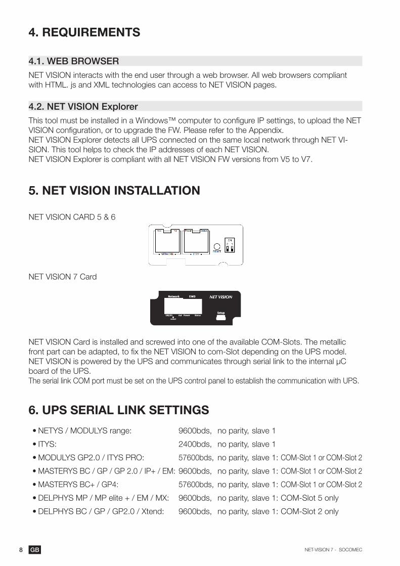
NET VISION CARD 5 & 6
NET VISION 7 Card
NET VISION Card is installed and screwed into one of the available COM-Slots. The metallic front part can be adapted, to fix the NET VISION to com-Slot depending on the UPS model.NET VISION is powered by the UPS and communicates through serial link to the internal µC board of the UPS.The serial link COM port must be set on the UPS control panel to establish the communication with UPS.
6. UPS SERIAL LINK SETTINGS
• NETYS / MODULYS range: 9600bds, no parity, slave 1
• ITYS: 2400bds, no parity, slave 1
• MODULYS GP2.0 / ITYS PRO: 57600bds, no parity, slave 1: COM-Slot 1 or COM-Slot 2
• MASTERYS BC / GP / GP 2.0 / IP+ / EM: 9600bds, no parity, slave 1: COM-Slot 1 or COM-Slot 2
• MASTERYS BC+ / GP4: 57600bds, no parity, slave 1: COM-Slot 1 or COM-Slot 2
• DELPHYS MP / MP elite + / EM / MX: 9600bds, no parity, slave 1: COM-Slot 5 only
• DELPHYS BC / GP / GP2.0 / Xtend: 9600bds, no parity, slave 1: COM-Slot 2 only
9GBNET-VISION 7 - SOCOMEC
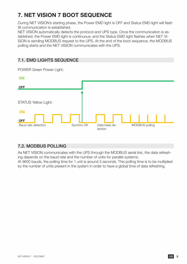
7. NET VISION 7 BOOT SEQUENCEDuring NET VISION’s starting phase, the Power EMD light is OFF and Status EMD light will flash till communication is established.NET VISION automatically detects the protocol and UPS type. Once the communication is es-tablished, the Power EMD light is continuous; and the Status EMD light flashes when NET VI-SION is sending MODBUS request to the UPS. At the end of the boot sequence, the MODBUS polling starts and the NET VISION communicates with the UPS.
7.1. EMD LIGHTS SEQUENCE
POWER Green Power Light:
ON
OFF
STATUS Yellow Light:
ON
OFFBaud rate detection Synchro OK Data base de-
tectionMODBUS polling
7.2. MODBUS POLLINGAs NET VISION communicates with the UPS through the MODBUS serial link, the data refresh-ing depends on the baud rate and the number of units for parallel systems.At 9600 bauds, the polling time for 1 unit is around 3 seconds. This polling time is to be multiplied by the number of units present in the system in order to have a global time of data refreshing.

10 GB NET-VISION 7 - SOCOMEC
7.3. UPS DATA BASE
NET VISION manages 2 types of UPS mapping:
• ‘JBUSP’ mapping for NETYS PR - RT / ITYS / MODULYS / MASTERYS MC-BC-GP-IP-EM / DELPHYS BC-GP-Xtend
• ‘VU-MAP’ mapping for ITYS-PRO / MODULYS GP 2.0 / MASTERYS BC+ and GP4 ranges and future SOCOMEC UPS range.
JBUSP TABLESSTATUS S00 – S63 0x1020 4 w
ALARMS A00 – A63 0x1040 4 w
MEASUREMENTS M00 – M47 0x1060 48 w
VU-MAP TABLESSTATUS S000 – S127 0x0030 8 w
ALARMS A000 – A127 0x0038 8 w
MEASUREMENTS M000 – M079 0x0040 80 w
MODBUS TCP access must follow the addresses according to the UPS mappingPlease refer to the Appendix: MODBUS TCP JBUSP and VU-MAP TABLE.
7.4. UPS ARCHITECTURE:• Single Unit 1 phase and 3 phases• Converter - without battery• Module – without bypass• Modular Unit up to 8 modules• Parallel system, distributed bypass or centralized bypass, up to 6 Units (JBUSP) and 10 Units
(VU-MAP) • Modular system up to 3 Units – 24 modules.
11GBNET-VISION 7 - SOCOMEC
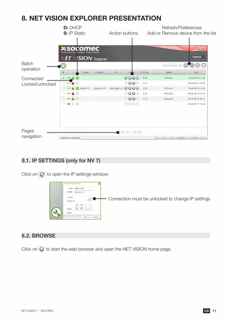
8. NET VISION ExPLORER PRESENTATION
8.1. IP SETTINGS (only for NV 7)
Click on to open the IP settings window:
8.2. BROWSE
Click on to start the web browser and open the NET VISION home page.
Action buttonsD: DHCPS: IP Static
Refresh/PreferencesAdd or Remove device from the list
Batch operation
Connected Locked/unlocked
Pages navigation
Connection must be unlocked to change IP settings
12 GB NET-VISION 7 - SOCOMEC
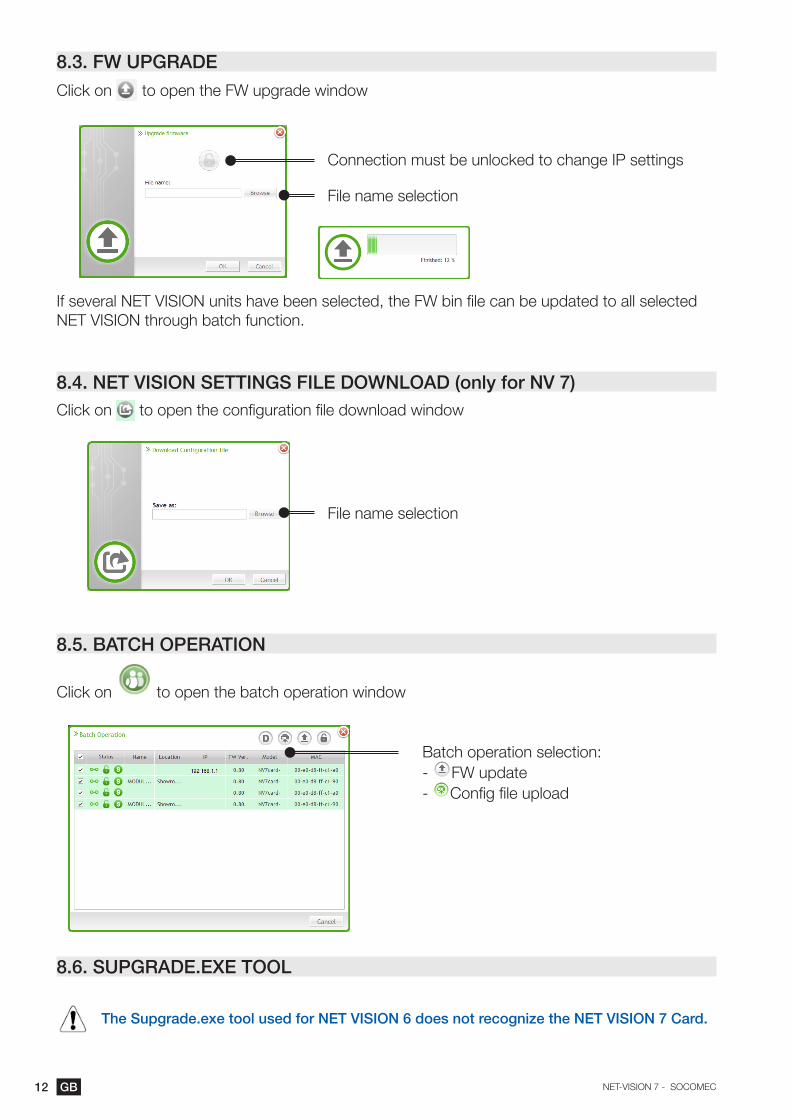
8.3. FW UPGRADE
Click on to open the FW upgrade window
If several NET VISION units have been selected, the FW bin file can be updated to all selected NET VISION through batch function.
8.4. NET VISION SETTINGS FILE DOWNLOAD (only for NV 7)Click on to open the configuration file download window
8.5. BATCH OPERATION
Click on to open the batch operation window
8.6. SUPGRADE.ExE TOOL
The Supgrade.exe tool used for NET VISION 6 does not recognize the NET VISION 7 Card.
Connection must be unlocked to change IP settings
File name selection
File name selection
Batch operation selection:- FW update - Config file upload

13GBNET-VISION 7 - SOCOMEC
9. IP ADDRESS CONFIGURATION
9.1. PREPARING NET VISIONOnce the UPS power is on and NET VISION has been installed in the COM-Slot and connected to the Network, the Net Vision’s IP address must be programmed.
9.2. DEFAULT IP ADDRESSIf a DHCP server is available on the same Network as NET VISION, the NET VISION will request a valid IP address from the server. If the DHCP server is not available, NET VISION switches to the following default IP address: 192.168.7.18IPv6 is not activated by default. The default IP address is set to IPv4 format
9.3. NET VISION ACCESSWhen the Net Vision has a valid IP address, open the web browser and enter the IP address set manually or given by the DHCP server. The IP address can be checked with the NET VISION Explorer software utility (see NET VISION explorer §).
By default, NET VISION requests the admin account login and password to open web pages.Login: adminPassword: public
9.4. IP SETTINGS USING NETWORK IF DHCP NOT PRESENT For the case of NET VISION 5 and 6:1. You need a computer with Terminal application connected to the same Network as Net Vision.2. Check the IP address of your terminal3. Run a terminal session (a DOS session for example)4. Execute the following command: ROUTE ADD 192.168.7.18 computer.IP.address 5. Test the connection to Net Vision: Ping 192.168.7.186. If the NET VISION responds to the ping, open a web session to modify IP parameters.
For the case of NET VISION 7Even if DHCP is not available, the IP address can be set through the Net Vision Explorer tool.
9.5. IP SETTINGS USING A TERMINAL AND RS232 CONNECTION for NET VISION 5 and 61. Connect the RS232/RJ45 PC cable from Net Vision to your computer2. Open a Terminal session with the parameters assigned to the right COM port:• 9600 bauds• Parity none• 8 bits data• No control
3. Press ‘space’ to open the communication.4. Enter the password: public (default password)
9.6. IP SETTINGS USING A TERMINAL AND USB for NET VISION 7The USB Gadget Serial driver must be installed. Please refer to the APPENDIX.Once the device is recognized, open an SSH terminal connection to modify IP settings.

14 GB NET-VISION 7 - SOCOMEC
10. NET VISION 6 FUNCTIONS
Please refer to the dedicated NET VISION 6 User manual, for all related functions.
The following chapters concern NET VISION 7
11. RESET NET VISION WITH FACTORY SETTINGS
When removing NET VISION from the network, make sure it does not affect your remote monitoring system.
1. Remove Network cable and EMD if present2. Unscrew and remove the board3. Set SW1 and SW2 according to requirements4. Replace the board in the Com-Slot5. Wait for NET VISION to restart: Green/Yellow EMD LED fixed ON6. Remove the board again7. Set SW1 and SW2 to OFF position – Normal mode8. Replace the board in Com-Slot and tighten screw9. Wait for NET VISION to restart for a new operation
DIP SWITCH functions SW1 SW2 SW3 SW4
NORMAL MODE OFF OFF X X
ADMIN PASSWORD RESET On OFF X X
RESET TO FACTORY DEFAULT OFF On X X
If functions have been set before this procedure (email, SNMP, Shutdown …) those functions will need to be reconfigured.
The RESET button does not affect the Net Vision settings, it only restarts Net Vision.
Make sure that the IP given by the DHCP server remains the same as before the Net Vision RESET.

15GBNET-VISION 7 - SOCOMEC
12. NET VISION 7 USER INTERFACE
12.1. NET VISION HOME PAGE
NET VISION reference UPS Reference Shortcut access Login
NET VISION MENU UPS tree-view UPS SYNOPTIC Parameters table

16 GB NET-VISION 7 - SOCOMEC
12.2. NET VISION MENU
12.2.1. UPS Monitoring
UPS monitoring items Access to Shortcut access
“Comprehensive view” UPS synoptic
“UPS Dashboard” Synthesis page of UPS parameters displayed by widgets
“UPS real-time Graph” Scan function of UPS parameters
“Client table” List of Servers connected to NET VISION asso-ciated with shutdown client
12.2.2. UPS Management
UPS management items Access condition
“Shutdown management” Always
“Battery Test”If Battery is presentThe battery test can be applied only if remote controls are enabled by UPS
Controls are available for Read/Write user rights and admin accounts
“Battery Schedule” If Battery is present and remote controls are en-abled by UPS. Available only for ‘VU_MAP’ UPS
“UPS control” If remote controls enabled by UPS
“eco mode schedule” If eco mode and remote controls are enabled by UPS
“Weekly schedule” If “weekly schedule” is selected in shutdown event
“Special day schedule” If “special day” is selected in shutdown event
“Power share” If “Power share” function is present and remote controls are enabled by UPS
“EMD device” If the EMD device is connected to NET VISION
17GBNET-VISION 7 - SOCOMEC
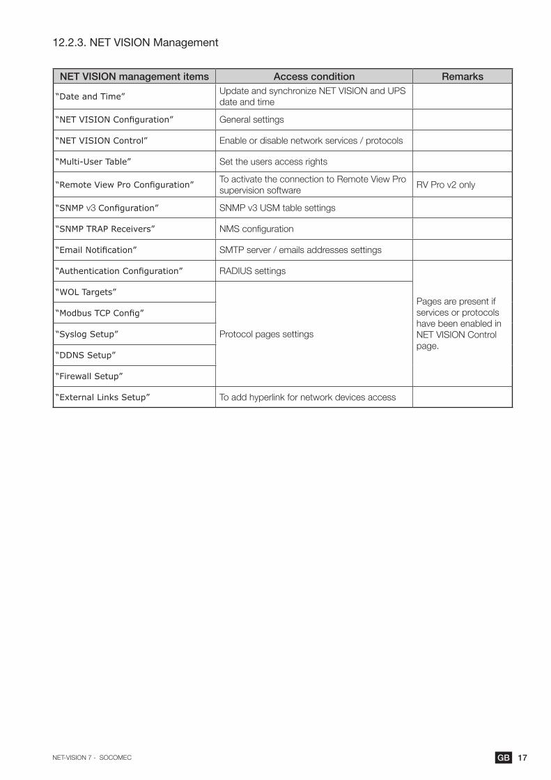
12.2.3. NET VISION Management
NET VISION management items Access condition Remarks
“Date and Time” Update and synchronize NET VISION and UPS date and time
“NET VISION Configuration” General settings
“NET VISION Control” Enable or disable network services / protocols
“Multi-User Table” Set the users access rights
“Remote View Pro Configuration” To activate the connection to Remote View Pro supervision software
RV Pro v2 only
“SNMP v3 Configuration” SNMP v3 USM table settings
“SNMP TRAP Receivers” NMS configuration
“Email Notification” SMTP server / emails addresses settings
“Authentication Configuration” RADIUS settings
Pages are present if services or protocols have been enabled in NET VISION Control page.
“WOL Targets”
Protocol pages settings
“Modbus TCP Config”
“Syslog Setup”
“DDNS Setup”
“Firewall Setup”
“External Links Setup” To add hyperlink for network devices access

18 GB NET-VISION 7 - SOCOMEC
12.2.4. History Log menu
History Log items Remarks
“UPS History Log”
NET VISION stores the measurements ev-ery 60s by default. 2048 is the maximum of records stored by NET VISION.
Shortcut access in graphic mode
“UPS Extend History log”NET VISION stores in this log the minimum, average and maximum of UPS measurements every 1 hour by default; up to 2048 records
Shortcut access in graphic mode
“UPS event Log” Store UPS alarms (add and remove)
“NET VISION Event Log” Store all actions done on NET VISION
“Clear and save Logs” Remove logs from NET VISION memoryDownload logs to local computer (csv)
List of measurements stored by NET VISION in “History Log” and “Extend History Log”
Input voltage (V) Per phase
A measurement stored with a value of -1 means that this measurement is not managed by the UPS
Input frequency (Hz * 10)
Output load rate (%) per phase
Output voltage (V) per phase
Battery capacity (%)
UPS temperature (°C) or (°F)
EMD temperature (°C) if EMD connected
EMD humidity (%) if EMD connected
12.2.5. External Link
An extra menu is present if devices have been activated. These links give direct access to other devices. It automatically opens a new page in the web browser with the selected link.

19GBNET-VISION 7 - SOCOMEC
12.3. UPS ARCHITECTURE TREE-VIEW
NET VISION automatically recognizes the UPS topology and adapts the UPS tree-view and synoptic view.
UPS TOPOLOGIES
SINGLE UNIT UPS MODULAR UNIT UPSMODULAR SYSTEM
Up to 3 units in parallelPARALLEL SYSTEM UPSUp to 10 units in parallel
UPS reference UPS reference Module number Module number
SYSTEM reference
Unit number• Module number
Unit number• Module number
SYSTEM reference
Unit number
Unit number
Unit number
Unit number
Modules numbered from 1 to 8, according the physical position in the unit’s cabinet
Modules numbered from 1 to 24, according the physical position in the unit’s cabinet
In case of centralized bypass, the Bypass Unit is not repre-sented
Device status management:
STATUS SINGLE / MODULAR SYSTEM UNIT MODULE
On standby
Operating
Operating with alarm
Operating with critical alarm
Imminent stop flashing
Click for access to:UNIT SYNOPTIC
UNIT TABLE
SYSTEMSYNOPTICUPS TABLE
UNIT SYNOPTIC
UNIT TABLE
MODULE TABLE
12.4. UPS SYNOPTIC
NET VISION manages 2 types of synoptic: SYSTEM VIEW and UNIT VIEW
SYSTEM VIEW FOR PARALLEL SYSTEMS
Overviews of units’ input and bypass input sup-ply and the global output of the UPS.The UPS output parameters table gives the glob-al measurements of all units that are operating.
UNIT VIEW FOR SINGLE, MODULAR OR UNITS AS PART OF A PARALLEL SYSTEM
This view gives details of rectifier and bypass inputs supply, battery status and unit output pa-rameters.

20 GB NET-VISION 7 - SOCOMEC
12.5. USER LOGIN
The login status is given by following icons:
Not logged Logged
Click on the button to open a session or to close the current session.Login popup:
The admin session default credentials are: Login: adminPassword: public
The web pages are opened in “Read Only” mode if the “HTTP Security Control” is disabled.To access to all the configurations and UPS controls, it is necessary to open a session as admin or with a “Read/Write” user access account.
It is possible to set a “Login Timeout (in Seconds)” in the NET VISION Configuration page. At the end of the timeout, the current session is closed automatically and switches to “Read Only” ac-cess mode.
NET VISION does not allow more than one admin session.
If an admin session is still open, a new session that is opened forces the logout of the previous admin session.

21GBNET-VISION 7 - SOCOMEC
13. UPS MONITORING
13.1. UNIT SYNOPTIC
13.1.1. SYNOPTIC ANIMATION
ELEMENT GREY GREEN YELLOW RED
1 Rectifier input supply Not present Present
2 Rectifier On + prev. alarm On + critical alarm
3 Rectifier output Rectifier off Rectifier on
4 DC Bus Rectifier off Rectifier on
5 Inverter input Rectifier off Rectifier on On battery
6 Inverter On + prev. alarm On + critical alarm
7 Inverter output Inverter off Inverter on On battery
8 Output offOn inverter orOn eco mode
On bypass orOn battery
9 Load 0% Up to 90% Above 90% Above 100%
10 Battery defaultBattery room or temp, alarm or test failed
Battery alarm
11 Bypass input supply Not present Present
12 Bypass input Not present Present Bypass on
13 Bypass On + prev. alarm On + critical alarm
14 Bypass output Bypass offBypass on and eco mode
Bypass on
15 Maintenance Bypass present On maintenance bypass
16 Bypass impossible Impossible Locked
17 Maintenance alarm Active
18 Alarm present If one alarm present
19 Genset Genset on
20 Battery sharingPresent if the battery is shared with all other Units in parallel system
The output load rate value is reported to synoptic. The load value is not displayed if the mainte-nance bypass is closed.During battery charging and battery charged status, the battery capacity value in % is displayed.The capacity value is replaced by the remaining backup time when the battery is discharging.
11
15
16
12 13 149
17
18
19 20 108
1 2 3 4 5 6 7

22 GB NET-VISION 7 - SOCOMEC
13.1.2. BATTERY ANIMATION
Battery status Battery symbol
Battery circuit open
Battery charged
Battery discharging
Battery discharged
Battery charging
13.1.3. LOAD ANIMATION
LOAD RATE 0% 10% 50% 90% 100% 120%
Example of values
13.1.4. UNIT SYNOPTIC NAVIGATION
Clicking on the rectifier , battery , inverter , bypass and output load symbols shows the related parameters table below the synoptic.
To switch back to Unit/UPS Parameters Table click on or button, or select “com-prehensive view” in the UPS Monitoring menu
Navigation overview
Status
Measurements
….….
If one or more alarm is present, clicking on opens the alarm table. The icon flashes when a new alarm is incoming. In this situation, it opens the alarm page, resets all alarms and stops the audible alarm on UPS.
Subset Table

23GBNET-VISION 7 - SOCOMEC
13.1.5. UNIT / UPS PARAMETERS TABLE
The table is updated with data read from the UPS or from the Unit selected
“UPS or Unit Parameters”
“UPS Status”The status displayed depends on the type of UPS range. Status lists are not available for all UPS, de-pending on the range and UPS functionalities
“Unknown” – no communication with UPS“In Service mode”“On maintenance bypass”“Imminent STOP”“Auto-test procedure”“Operating on Battery”“Battery test in progress”“Load protected by Inverter”“Normal mode” – for OFF LINE UPS“UPS in eco mode”“Load on Bypass”“Unit Available”“On standby”“Load OFF”
“Output load rate (%)” Per phase
“Output Power (kVA)” Per phase if measurements available from UPS
“Output Voltage (V)” Per phase
“Rectifier voltage (V)” Per phase
“Battery capacity (%)”
Only if battery present“Remaining backup time (mn)”
“Battery voltage (V)”
“Temperature (°C)” UPS ambiance temperature
“date / time”
“EMD Parameters”
“EMD temperature (°C)”
“EMD humidity (%)”
“EMD Alarm 1”
“EMD Alarm 2”
Only if “EMD” device is connected to NET VISION

24 GB NET-VISION 7 - SOCOMEC
13.1.6. BATTERY PARAMETERS TABLE
“Battery Parameters”
“Battery StatusThe status list displayed depends on the type of UPS range. Depending on the range and UPS functionalities, parts of the status list are not man-aged.
“Unknown”“Battery disconnected”“Battery discharged”“Battery low”“Battery discharging”“Battery to input” – specific function (optional)“Battery alarm”“Battery room alarm” – if sensor present“Battery temperature alarm” – if sensor present“Battery test running”“Battery charging”“Battery OK”
“Battery voltage (V)”In case of 2 battery strings, the global voltage is dis-played.
“Battery capacity (%)”
“Battery capacity (Ah)”
“Remaining Backup time (mn)”Value present in the table during the battery discharg-ing when computed or indicates the nominal backup time in normal operation
“Battery temperature (°C)” If the temperature sensor is present (option)
“Time since on battery power (mn)” Present only during battery discharging
13.1.7. OUTPUT PARAMETERS TABLE
“Output Parameters”“Output Status”
The status list displayed depends on the
type of UPS range. The status list is not
available for all UPS, depending on the
range and UPS functionalities
“Unknown” – if no com with UPS“On maintenance bypass”“Load protected by inverter”“Normal mode” – for OFF LINE UPS“eco mode”“Load on Bypass”“On standby”“Load OFF”
“Output load rate (%)” Per phase
“Output Power (kVA)” Present if computed by UPS
“Output Power (kW)” Present if computed by UPS
“Output Current (A)” Per phase
“Output Voltage (V)” Per phase
“Output Frequency (Hz)”
25GBNET-VISION 7 - SOCOMEC
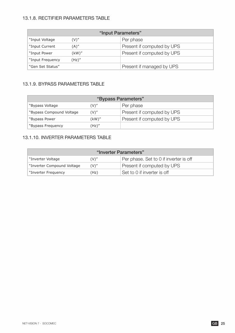
13.1.8. RECTIFIER PARAMETERS TABLE
“Input Parameters”“Input Voltage (V)” Per phase“Input Current (A)” Present if computed by UPS“Input Power (kW)” Present if computed by UPS“Input Frequency (Hz)”
“Gen Set Status” Present if managed by UPS
13.1.9. BYPASS PARAMETERS TABLE
“Bypass Parameters”“Bypass Voltage (V)” Per phase“Bypass Compound Voltage (V)” Present if computed by UPS“Bypass Power (kW)” Present if computed by UPS“Bypass Frequency (Hz)”
13.1.10. INVERTER PARAMETERS TABLE
“Inverter Parameters”“Inverter Voltage (V)” Per phase. Set to 0 if inverter is off“Inverter Compound Voltage (V)” Present if computed by UPS“Inverter Frequency (Hz) Set to 0 if inverter is off

26 GB NET-VISION 7 - SOCOMEC
13.2. SYSTEM SYNOPTIC
13.2.1. ANIMATION
ELEMENT GREY GREEN YELLOW RED
1 Rectifier input supply Not present Present
7 Inverter output Inverter off Inverter on On battery
8 Output offOn inverterOn eco mode
On bypassOn battery
9 Load 0% Up to 90% Above 90% Above 100%
11 Bypass input supply Not present Present
12 Bypass input Not present Present Bypass on
14 Bypass output Bypass offBypass on and eco mode
Bypass on
15 Maintenance Bypass PresentOn maintenance bypass
13.2.2. NAVIGATION
Clicking on the System and output load symbols shows the related parameters table below the synoptic.
Clicking on the button or “Comprehensive View” in the Monitor menu switches back to the
“UPS Parameters Table”.
13.2.3. UPS PARAMETERS TABLE
The table is updated with data read from the UPS at System level, which is a combination from all Unit data.See “Unit/UPS Parameters Table”
13.2.4. UPS OUTPUT PARAMETERS TABLE
The table is updated with data read from the UPS at System level, which is a combination from all Unit data.See UPS “Output Parameters Table”
11
15
1214
9
8
1
7

27GBNET-VISION 7 - SOCOMEC
13.3. ALARM TABLE
The alarm table is accessible by clicking on the icon. The number associated to the icon indicates the number of active alarms.The alarm icon is shown while the general alarm is present.The alarms table reports the current active alarms and indicates the last incoming alarm. Each alarm is time-stamped when it occurs.All alarms from the ‘JBUSP’ (A00 to A63) or ‘VU-MAP’ (A000 – A127) table are reported in this page.
Alarm Table
Number of Active Alarms 1
Last Alarm General Alarm
Index Alarm Time UPS Alarm Description Level
AxxxorAxx
dd/mm/yyyy hh:mm:ssInformationWarningCritical
For a parallel UPS system, the table shows only active alarms at system level.

28 GB NET-VISION 7 - SOCOMEC
14. UPS DASHBOARD
This page gives an overview of UPS parameters through graphical widgets.Measurements not available or not computed are not represented in this pageOutput currents are represented in bar-graph. The vertical line defines the nominal amps limit.
During battery discharging, remaining backup time is displayed
Go back to synoptic;
For a parallel UPS system, the measurements shown are values read from system level.

29GBNET-VISION 7 - SOCOMEC
15. REAL TIME GRAPHThis widget allows you to scan UPS parameters in real time.Measurements can be selected / unselected for more visibility.Click on to launch the scanning
Click on to interrupt the scanning
Data scanned is not stored by NET VISION
Go back to synoptic;
16. CLIENT TABLEThis page lists all servers / Hosts connected to NET VISION. JNC and VIRTUAL-JNC software shut-down agents have to be installed on all servers to manage the events shutdown sent by NET VISION
Client Table
Connected Client Number 1
Index IP Address Client Name Connected Time
1 192.168.1.2 IT Server (JNC) 2017/04/08 11:17:18
30 GB NET-VISION 7 - SOCOMEC
17. UPS MANAGEMENT
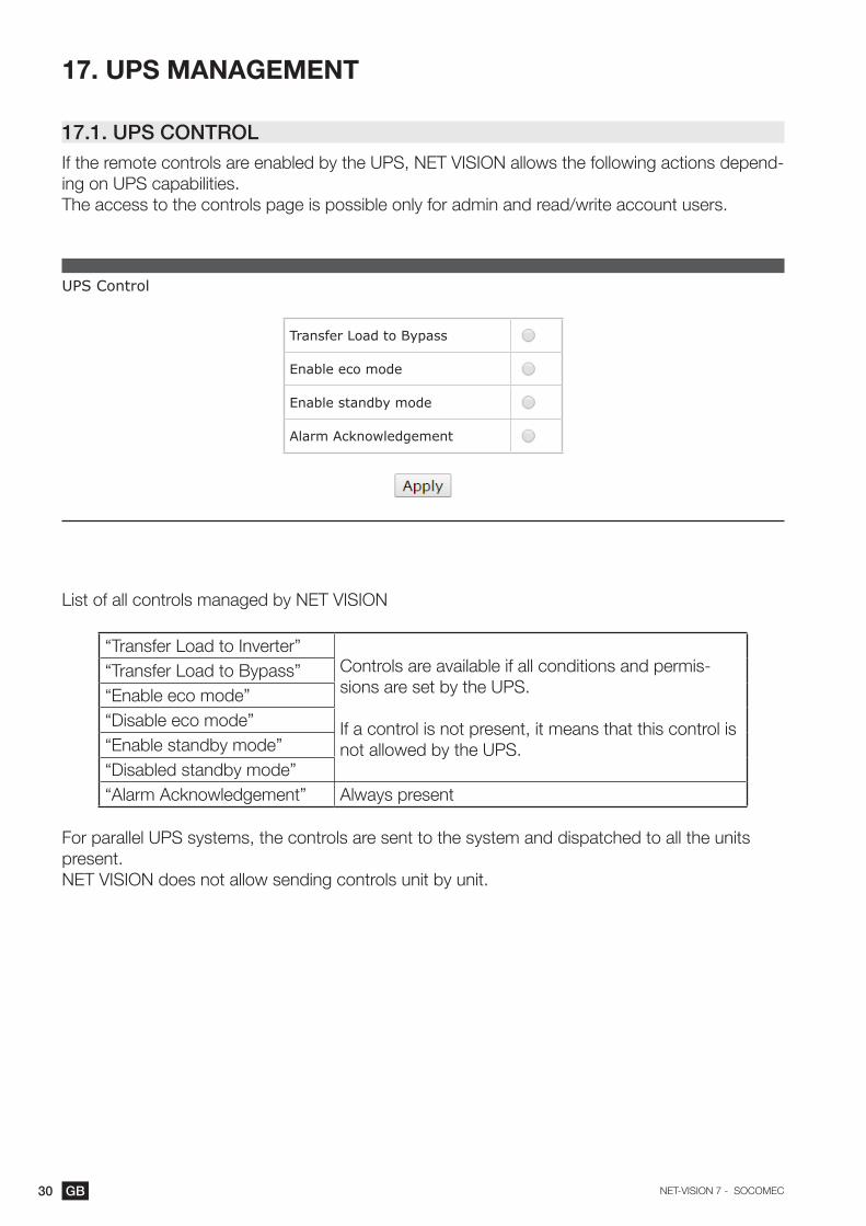
17.1. UPS CONTROLIf the remote controls are enabled by the UPS, NET VISION allows the following actions depend-ing on UPS capabilities.The access to the controls page is possible only for admin and read/write account users.
UPS Control
Transfer Load to Bypass
Enable eco mode
Enable standby mode
Alarm Acknowledgement
List of all controls managed by NET VISION
“Transfer Load to Inverter”Controls are available if all conditions and permis-sions are set by the UPS.
If a control is not present, it means that this control is not allowed by the UPS.
“Transfer Load to Bypass”“Enable eco mode”“Disable eco mode”“Enable standby mode”“Disabled standby mode”“Alarm Acknowledgement” Always present
For parallel UPS systems, the controls are sent to the system and dispatched to all the units present.NET VISION does not allow sending controls unit by unit.
31GBNET-VISION 7 - SOCOMEC
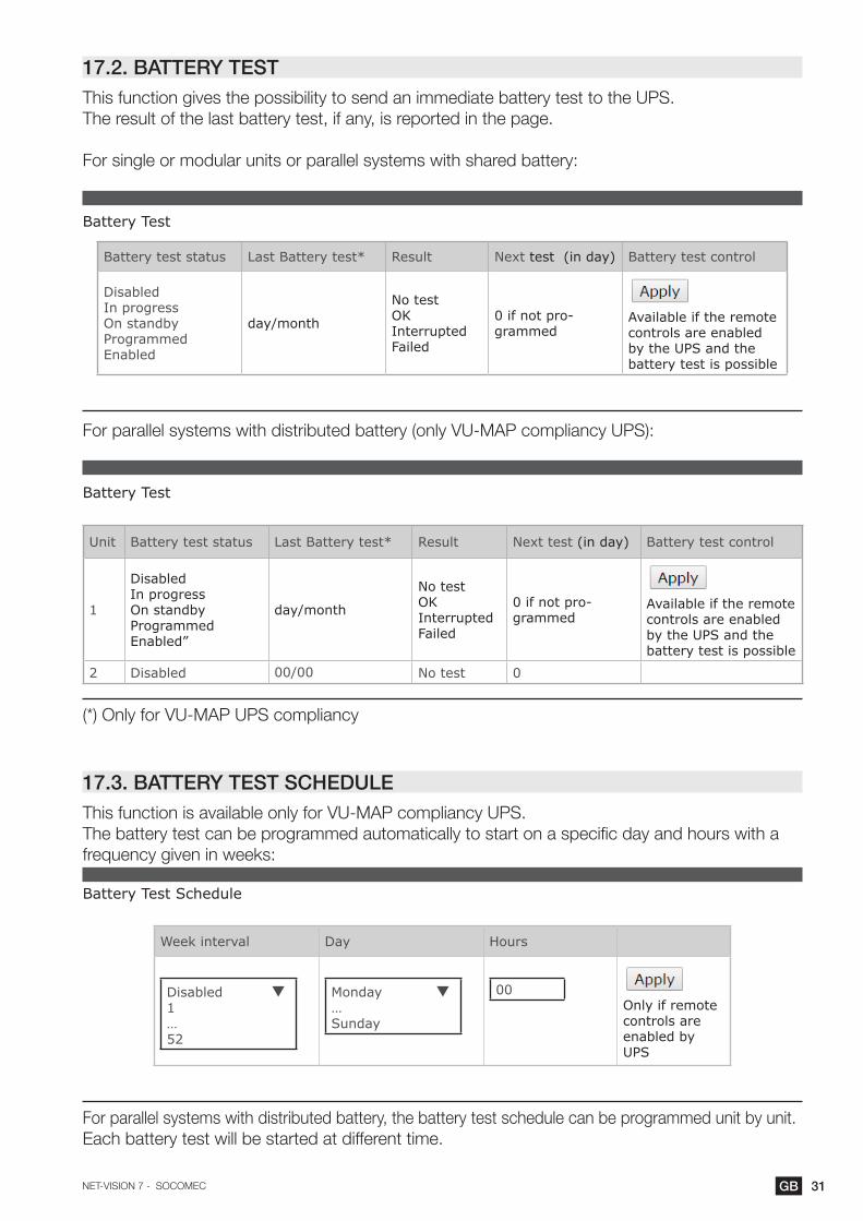
17.2. BATTERY TESTThis function gives the possibility to send an immediate battery test to the UPS.The result of the last battery test, if any, is reported in the page.
For single or modular units or parallel systems with shared battery:
Battery Test
Battery test status Last Battery test* Result Next test (in day) Battery test control
DisabledIn progressOn standbyProgrammedEnabled
day/month
No testOKInterruptedFailed
0 if not pro-grammed
Available if the remote controls are enabled by the UPS and the battery test is possible
For parallel systems with distributed battery (only VU-MAP compliancy UPS):
Battery Test
Unit Battery test status Last Battery test* Result Next test (in day) Battery test control
1
DisabledIn progressOn standbyProgrammedEnabled”
day/month
No testOKInterruptedFailed
0 if not pro-grammed
Available if the remote controls are enabled by the UPS and the battery test is possible
2 Disabled 00/00 No test 0
(*) Only for VU-MAP UPS compliancy
17.3. BATTERY TEST SCHEDULEThis function is available only for VU-MAP compliancy UPS.The battery test can be programmed automatically to start on a specific day and hours with a frequency given in weeks:
Battery Test Schedule
Week interval Day Hours
Disabled 1…52
Monday …Sunday
00Only if remote controls are enabled by UPS
For parallel systems with distributed battery, the battery test schedule can be programmed unit by unit.Each battery test will be started at different time.

32 GB NET-VISION 7 - SOCOMEC
17.4. eco mode SCHEDULEThis function is available if the eco mode function is enabled by the UPS.NET VISION can manage a running period in eco mode, than switches again in nomal mode.
Eco mode Schedule
Index Enabled eco mode Disabled eco mode
1Disabled Monday…Sunday
00:00 Disabled 00:00
17.5. WEEKLY SHUTDOWN SCHEDULEThis function is activated if the “Weekly Schedule” event is enabled in the “event shutdown man-agement” page.
Weekly Schedule
Index SHUTDOWN period RESTART period
1Disabled Monday…Sunday
00:00 Disabled 00:00
17.6. SPECIAL DAY SHUTDOWN SCHEDULEThis function is activated if the “Special Schedule” event is enabled in the “event shutdown man-agement” page.
Special Schedule
Index SHUTDOWN period RESTART period
1 01/01/2017 00:00 01/01/2017 00:00

33GBNET-VISION 7 - SOCOMEC
17.7. POWER SHAREThis function is available if the UPS manages power plugs and remote controls have been activated.The configurations and Plugs controls page is accessible for admin account login only.
Power Share Management
Available Plugs Mode Value
Plug 1
None Battery CapacityRemaining backup timeEmergency light ONTime since on battery
Power share Plugs 1 2
MODE SETTINGSBattery Capacity: switches the output plug to OFF when the value is reached.Remaining Backup time: switches the output plug to OFF when the value is reached.Time on Battery: switches the output plug to OFF when the value is reached.Emergency lighting: switches the output plug to ON when the UPS is on battery.
PLUGS CONTROLSelect to close or unselect to open the plugs then apply.Plugs are immediately opened or closed according the control sent.
34 GB NET-VISION 7 - SOCOMEC
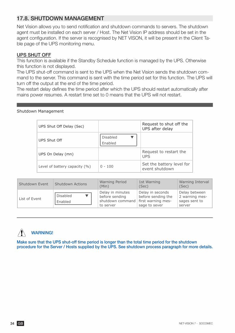
17.8. SHUTDOWN MANAGEMENTNet Vision allows you to send notification and shutdown commands to servers. The shutdown agent must be installed on each server / Host. The Net Vision IP address should be set in the agent configuration. If the server is recognised by NET VISON, it will be present in the Client Ta-ble page of the UPS monitoring menu.
ups shut offThis function is available if the Standby Schedule function is managed by the UPS. Otherwise this function is not displayed.The UPS shut-off command is sent to the UPS when the Net Vision sends the shutdown com-mand to the server. This command is sent with the time period set for this function. The UPS will turn off the output at the end of the time period.The restart delay defines the time period after which the UPS should restart automatically after mains power resumes. A restart time set to 0 means that the UPS will not restart.
Shutdown Management
UPS Shut Off Delay (Sec) Request to shut off the UPS after delay
UPS Shut OffDisabled
Enabled
UPS On Delay (mn) Request to restart the UPS
Level of battery capacity (%) 0 - 100 Set the battery level for event shutdown
Shutdown Event Shutdown Actions Warning Period(Min)
1st Warning(Sec)
Warning Interval(Sec)
List of EventDisabled
Enabled
Delay in minutes before sending shutdown command to server
Delay in seconds before sending the first warning mes-sage to sever
Delay between 2 warning mes-sages sent to server
WARNING!
Make sure that the UPS shut-off time period is longer than the total time period for the shutdown procedure for the Server / Hosts supplied by the UPS. See shutdown process paragraph for more details.

35GBNET-VISION 7 - SOCOMEC
shutdown seQuenCe
ON Reversible period
UPS UPS event (AC failed)UPS shutdown delay
OFF
ON
Net Vision
Warning delay
1st warn-ing delay
Warning interval
OFF
ONJNC orVIRUTAL-JNVSW Agent
shutdown delay
OSshutdown
AC failed warning messagesScript
executionOFF
Shutdown countdown
Reversible period:If the event is removed during this period, the shutdown process is cancelled.At the end of this period, the NET VISION sends the shutdown command to servers and the UPS standby control if enabled.
Shutdown delay:The Shutdown agent can start running scripts or batch files before the OS shutdown.
UPS shutdown delay must be greater than the server’s shutdown time, evaluated as the shutdown delay set on the agent + OS shutdown itself.

36 GB NET-VISION 7 - SOCOMEC
shutdown event seleCtion
• UPS on battery (AC Failed)• Battery Low• Battery Level• Imminent Stop• UPS Overload• Temperature Alarm• On Bypass• Weekly Schedule – activate the Weekly schedule page• Special Day – activate the Special Schedule page
Additional events if EMD device present:• EMD Temperature• EMD Humidity• EMD Alarm-1• EMD Alarm-2
shutdown test proCedure
Net Vision allows you to simulate an AC fail event. After test validation the Shutdown procedure starts, with the settings of ‘AC failed’ event. The AC Failed simulation is disabled if the AC Failed Shutdown action is disabled.Net Vision sends the notification and the shutdown command to the server.At the end of the procedure, after sending the shutdown command. Net Vision waits around 2 minutes before sending a shutdown cancel command. This command permits the agent to re-cover normal UPS status. The agent is then ready for the shutdown procedure again.During the test, the button is disabled and switches to ‘enabled’ when the ‘shutdown cancel’ command is sent to servers.
WARNING!
If the Warning period = 0, the server shutdown command is sent immediately.
37GBNET-VISION 7 - SOCOMEC
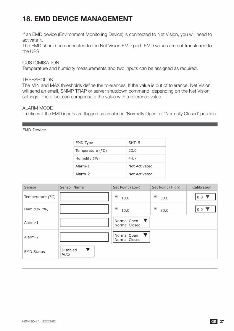
18. EMD DEVICE MANAGEMENT
If an EMD device (Environment Monitoring Device) is connected to Net Vision, you will need to activate it.The EMD should be connected to the Net Vision EMD port. EMD values are not transferred to the UPS.
CUSTOMISATIONTemperature and humidity measurements and two inputs can be assigned as required.
THRESHOLDSThe MIN and MAX thresholds define the tolerances. If the value is out of tolerance, Net Vision will send an email, SNMP TRAP or server shutdown command, depending on the Net Vision settings. The offset can compensate the value with a reference value.
ALARM MODEIt defines if the EMD inputs are flagged as an alert in ‘Normally Open’ or ‘Normally Closed’ position.
EMD Device
EMD Type SHT15
Temperature (°C) 23.0
Humidity (%) 44.7
Alarm-1 Not Activated
Alarm-2 Not Activated
Sensor Sensor Name Set Point (Low) Set Point (High) Calibration
Temperature (°C) 18.0 30.0 0.0
Humidity (%) 10.0 80.0 0.0
Alarm-1 Normal Open Normal Closed
Alarm-2 Normal Open Normal Closed
EMD Status Disabled Auto

38 GB NET-VISION 7 - SOCOMEC
19. NET VISION MANAGEMENT
19.1. DATE and TIME
UPS Date and TimeNet Vision allows the synchronisation of the UPS date and time. When Net Vision detects a new date and time (set manually or via NTP server), it sends the new values to the UPS if this func-tion is enabled.This function is enabled if the date and time are managed by the UPS. Otherwise this part is not displayed.
sends the current date and time to the UPS manually.
Date and TimeSynchronise with computer where the web browser is openSynchronise with NTP serverSet values manually.Net Vision also manages the time zone; GMT + [x] hours.
Date and Time
Date on UPS (dd/mm/yyyy)
Time on UPS (hh:mm:ss)
Synchronize UPS Disabled Enabled
Date and Time
System Date(dd/mm/yyyy)
System Time(hh:mm:ss)
Time Zone GMT+
Daylight Saving Time: Disabled Enabled
Synchronize with computer time
Computer Date:
Computer Time:
Synchronize with NTP server
NTP Server: IP address
Set manually
Date (dd/mm/yyyy): 01/01/2017
Time (hh:mm:ss): 00:00:00
In case of using NTP synchronisation GMT and daylight management are to set according NTP server configuration. GMT time zone and daylight are often managed by NTP server itself.
39GBNET-VISION 7 - SOCOMEC
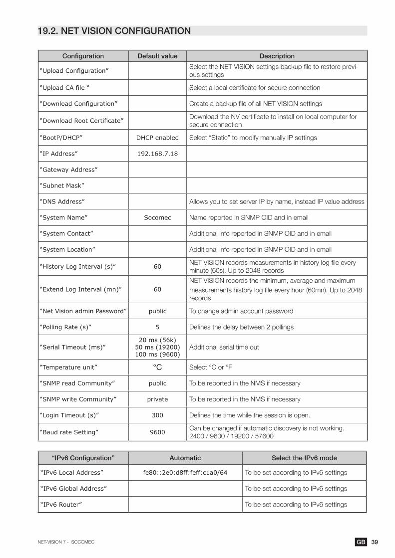
19.2. NET VISION CONFIGURATION
Configuration Default value Description
“Upload Configuration” Select the NET VISION settings backup file to restore previ-ous settings
“Upload CA file “ Select a local certificate for secure connection
“Download Configuration” Create a backup file of all NET VISION settings
“Download Root Certificate” Download the NV certificate to install on local computer for secure connection
“BootP/DHCP” DHCP enabled Select “Static” to modify manually IP settings
“IP Address” 192.168.7.18
“Gateway Address”
“Subnet Mask”
“DNS Address” Allows you to set server IP by name, instead IP value address
“System Name” Socomec Name reported in SNMP OID and in email
“System Contact” Additional info reported in SNMP OID and in email
“System Location” Additional info reported in SNMP OID and in email
“History Log Interval (s)” 60 NET VISION records measurements in history log file every minute (60s). Up to 2048 records
“Extend Log Interval (mn)” 60NET VISION records the minimum, average and maximum measurements history log file every hour (60mn). Up to 2048 records
“Net Vision admin Password” public To change admin account password
“Polling Rate (s)” 5 Defines the delay between 2 pollings
“Serial Timeout (ms)”20 ms (56k)
50 ms (19200)100 ms (9600)
Additional serial time out
“Temperature unit” °C Select °C or °F
“SNMP read Community” public To be reported in the NMS if necessary
“SNMP write Community” private To be reported in the NMS if necessary
“Login Timeout (s)” 300 Defines the time while the session is open.
“Baud rate Setting” 9600 Can be changed if automatic discovery is not working.2400 / 9600 / 19200 / 57600
“IPv6 Configuration” Automatic Select the IPv6 mode
“IPv6 Local Address” fe80::2e0:d8ff:feff:c1a0/64 To be set according to IPv6 settings
“IPv6 Global Address” To be set according to IPv6 settings
“IPv6 Router” To be set according to IPv6 settings

40 GB NET-VISION 7 - SOCOMEC
19.3. NET VISION CONTROL
Configuration Default value Description
“BootP/DHCP”
“PING Echo” The ping answer can be disabled
“Network Upgrade” The FW upgrade, through TFTP, from NET VISION Explorer can be disabled.
“Force Security HTTP” Port 443 To enable HTTPs secure connection
“HTTP Port” Port 80 To enable web page and changing port
“HTTP Security Control” To force login request when web page is open
“SSH Connection” Port 22 To enable remote console (such as putty tool ) for NET VI-SION configuration
“SNMP Support” Port 161 To enable connection to NMS
“SMTP Support” Port 25 To enable email functions
“UPnP Control” To enable NET VISION as a Network device
“RADIUS/Authentication” To enable authentication protocol page settings
“WOL Target”To enable Wake On LAN settings page.Protocol to restart servers when NET VISION restarts after a shutdown due to AC failure.
“Modbus Configuration” To enable MODBUS TCP protocol
“Syslog Setup” To enable Syslog settings page
“DDNS Setup” To enable DDNS settings page
“Firewall Setup” To enable Firewall settings page
“SNMP Unit Select” 0 for SystemUnit 1 to 12
0 to populate all SNMP OID with UPS data at system level.Set to unit number to populate all SNMP OID with the local UNIT data where the NET VISION is connected.NET VISION must be installed on each Unit.
“SNMP TRAP / E-mail Filter” DisabledThis function enable or disable TRAP3 and TRAP4 notifica-tion when “severity” level is set as filter to send TRAP or e-mail.

41GBNET-VISION 7 - SOCOMEC
19.4. MULTI-USER TABLEThis table sets user’s credential to access the NET VISION interface, NET VISION allows up to 8 user accounts.Admin account is not managed in this table, this account is always active.To be more effective the “HTTP Security Control” must be set to force the login before accessing to web pages.
Multi-User Table
Index User Name Password Access type
1Disabled Read OnlyRead/Write
Remark:This table combines with the RADIUS function. NET VISION checks before on RADIUS server (if enabled) the user account. If the user is existing on RADIUS server, NETVISION will take the RA-DIUS account credentials. Otherwise he will check the local user account set in the Multi-User table.
19.5. REMOTE VIEW PRO CONFIGURATIONIf Remote View Pro supervision SW is running to monitor the UPS, the server IP must be report-ed in NET VISION.Remote View Pro SW sees NET VISION as a communication node server.NET VISION must be added on Remote View Pro accordingly.
Remote View Pro Configuration
Server Control Disabled Enabled
Server IP
Server Port 80
GUID NV MAC address
Password To set

42 GB NET-VISION 7 - SOCOMEC
19.6. REMOTE VIEW PRO Server ConfigurationThis function is available from Remote View Pro v2.x version. Previous release has to be up-dated with last package available on SOCOMEC’s WEB page. A new licence is not needed if already installed. The configurations are reported in the new release during installation setup.
A new group has to be created in “Device Group” as NV7 type.• Select a Name for this group• Copy the GUID given by Net Vision• Set the same password as in Net Vision• Apply to save settings.
Once the new Device Group is connect, Add the Net Vision 7 in Node ListIf an EMD device is connected to this Net Vision 7, EMD device has to be added as a second node.

43GBNET-VISION 7 - SOCOMEC
19.7. SNMP v3 USM TABLE CONFIGURATIONThis page contains the related setting for configuring the SNMPv3 protocol.The security level defines the access for authentication and privacy password.“noAuthNoPriv” with no authentication and no privacy passwords“authNoPriv” with authentication password but no privacy password“authPriv” with no authentication password but with privacy passwordUser name and Password set to NET VISION must be reported in the SNMP v3 configuration of the NMS.If Authentication is requested, the protocol must be chosen between HMAC-MD5 or HMAC-SHAIf Privacy protocol is requested, the protocol must be chosen between DES or AESThe protocols chosen in NET VISION must be reported in the SNMP v3 configuration of the NMS
SNMP USM table Configuration
Index User Name Auth-Password Auth-Protocol Priv-Password Priv-Protocol Security level
1 MD5 SHA
DES AES
noAuthNoPriv authNoPrivauthPriv
19.8. SNMP TRAP RECEIVERS CONFIGURATIONThis page lists the parameters for SNMP trap receivers. NET VISION allows up to 8 NMS IP Address.As NET VISION manages its own MIB file and the standard RFC1628 MIB, you have to select the correct MIB file used to monitor the UPS.In case of using the NET VISION MIB file, a specific filter for TRAP sending can be applied as following:• Filtering by Severity: in this case a second filter can be applied such as:
“Information”: all TRAPs will be send“Warning”: ‘warning’ and ‘critical’ TRAPs will be send“Critical”: only ‘critical’ TRAPs will be sent.
TRAP 3 and TRAP 4 will be not sent with this filter if “SNMP TRAP Filter” has been enabled in the “NET VISION Control” page.
• Filtering by Event: it is necessary to select events that will send TRAP to the NMS.Once events have been selected or unselected, the selection must be saved: click on
to save the SNMP settings
SNMP Trap Receivers Table
In-dex
NMS IP address
Community String Trap Type Trap Version Event Filter Severity
1None RFC1628NET VISION TRAP
v1 v2cv3
By Severity InformationWarningCritical
2 By Event
For SNMP v3 Trap Version, the USM table must be set according to the NMS configuration.

44 GB NET-VISION 7 - SOCOMEC
Filter by specific event: TRAP list selection ordered by severity
| information
This trap is sent upon completion of a UPS diagnostic test. Not available for all UPS
The UPS status is normal. Load protected by UPS. TRAP 22
Alarm cancelled. All alarms are disabled. TRAP 24: General alarm no longer present
The UPS has cancelled the shutdown procedure to agent. TRAP 26: Sent if the server shutdown has been enabled
This trap is sent each time an alarm is removed from the alarm table. TRAP 4: entry removed
The Input supply has been restored. TRAP 23
The communication between UPS and the agent has been restored. TRAP 25
NET VISION is restarting. TRAP 27
EMD Sensor Not over high temperature. TRAP 31
EMD Sensor Not over high humidity. TRAP 35
EMD input2 is restored. TRAP 39
EMD Sensor Not under low temperature. TRAP 29
EMD Sensor Not under low humidity. TRAP 33
EMD input1 is restored. TRAP 37
| warning
The UPS is operating on battery power. TRAP 1: Sent every minute with remaining backup time
The UPS output is in overload TRAP 6: Output load rate more than 100%.
The battery is in alarm. TRAP 11
The battery test has detected a weak battery. TRAP16: Test failed
Load supplied by automatic Bypass. TRAP 18: On bypass and not eco mode activated
A warning message has been sent to shutdown agent. TRAP 20: Sent if the server shutdown has been enabled
This TRAP is sent each time an alarm is inserted into to the alarm table.
TRAP 3: New entry added
Redundancy is lost. TRAP 7
The UPS has switched to battery backup power. TRAP 15: Battery discharging – sent once
The UPS internal temperature has reached the threshold. TRAP 17
A preventive alarm has been detected by the UPS. TRAP 19 (including general alarm)
A shutdown command has been sent to agent. TRAP 21: Sent if the server shutdown has been enabled
| CritiCal
The UPS is about to switch off the output power. TRAP 5: Imminent stop
The battery has been detected as discharged. TRAP 9
A critical alarm has been detected on the UPS. TRAP 12
UPS is no longer communicating with the agent. TRAP 14
The battery has been disconnected from the UPS. TRAP 8
The battery is near of the end of backup time. TRAP 10: Battery low / end of backup time
The load has been disconnected from the UPS. TRAP 13: Load off or on standby mode
EMD Sensor detected low temperature. TRAP 28
EMD Sensor detected low humidity. TRAP 32
EMD input1 is active. TRAP 36
EMD Sensor detected high temperature. TRAP 30
EMD Sensor detected high humidity. TRAP 34
EMD input2 is active. TRAP 38

45GBNET-VISION 7 - SOCOMEC
19.9. EMAIL NOTIFICATIONThis page gives the description of UPS email notification settings. Email sending follows the same rule as for TRAP management.
The first part is dedicated to Mail Server and user account if necessary.
“Mail Server” IP address or server full name
"User Account" Needed if authentication is enabled
“User Password” Needed if authentication is enabled
“Sender email Address” name@domain
“Mail Subject Prefix” Free text as mail subject
“DNS Address”
“Mail Daily Status Report at (hh:mm)” 00:00
“Mail support TLS” To enabled if required by e-mail server
“Mail support authentication” To by enabled if user account is required
Send Test functionOnce the Mail Server and account have been set and saved on NET VISION, click on to test the configuration with function.
Mail Type“Events” The email is sent when the event occurs“Daily Status” NET VISION sends a daily e-mail at defined time. This e-mail includes his-
tory log files in attachment.“Events / Status” An e-mail is sent when the event occurs with the history log file in attachment.
Event filter by severity:Information: all alarms are sent via emailWarning: alarms tagged as “warning” and “critical” are sentCritical: only critical alarms are sent
Event filter by specific event:Refer to SNMP TRAP event selection.Selecting this filter means the emails are sent at the same time as SNMP TRAP. Refer to event list for TRAP
Email Notification
Index Mail account Description Mail Type Event Filter Event Level
1None EventsDaily statusEvents/status
By SeverityInformationWarningCritical
2 None By Event
Note: the e-mail address length is limited to 64 characters.
46 GB NET-VISION 7 - SOCOMEC
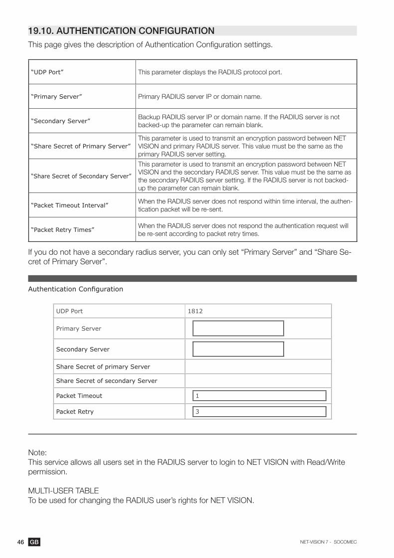
19.10. AUTHENTICATION CONFIGURATIONThis page gives the description of Authentication Configuration settings.
“UDP Port” This parameter displays the RADIUS protocol port.
“Primary Server” Primary RADIUS server IP or domain name.
“Secondary Server” Backup RADIUS server IP or domain name. If the RADIUS server is not backed-up the parameter can remain blank.
“Share Secret of Primary Server”This parameter is used to transmit an encryption password between NET VISION and primary RADIUS server. This value must be the same as the primary RADIUS server setting.
“Share Secret of Secondary Server”
This parameter is used to transmit an encryption password between NET VISION and the secondary RADIUS server. This value must be the same as the secondary RADIUS server setting. If the RADIUS server is not backed-up the parameter can remain blank.
“Packet Timeout Interval” When the RADIUS server does not respond within time interval, the authen-tication packet will be re-sent.
“Packet Retry Times” When the RADIUS server does not respond the authentication request will be re-sent according to packet retry times.
If you do not have a secondary radius server, you can only set “Primary Server” and “Share Se-cret of Primary Server”.
Authentication Configuration
UDP Port 1812
Primary Server
Secondary Server
Share Secret of primary Server
Share Secret of secondary Server
Packet Timeout 1
Packet Retry 3
Note:This service allows all users set in the RADIUS server to login to NET VISION with Read/Write permission.
MULTI-USER TABLETo be used for changing the RADIUS user’s rights for NET VISION.

47GBNET-VISION 7 - SOCOMEC
19.11. WOL TARGETSThe “Wake On LAN” function restarts through network interface all registered client servers. Up to 32 MAC client addresses can be managed by NET VISION. WOL frame is sent to servers in case of servers have been shut down after an AC failed procedure.
Wake On LAN Targets
Repeating Times 1
Interval Timer (s) 1
Test Index Mac Address Control Description
1 00:00:00:00:00:00 Enabled
19.12. MODBUS TCP CONFIGURATIONThis page enables or disables the MODBUS TCP protocol; the MODBUS Port can be changed.
Modbus Configuration
Modbus TCP Configuration Enabled Disabled
Modbus Port 502
Refer to Annex for UPS data access through MODBUS TCP protocol.
48 GB NET-VISION 7 - SOCOMEC
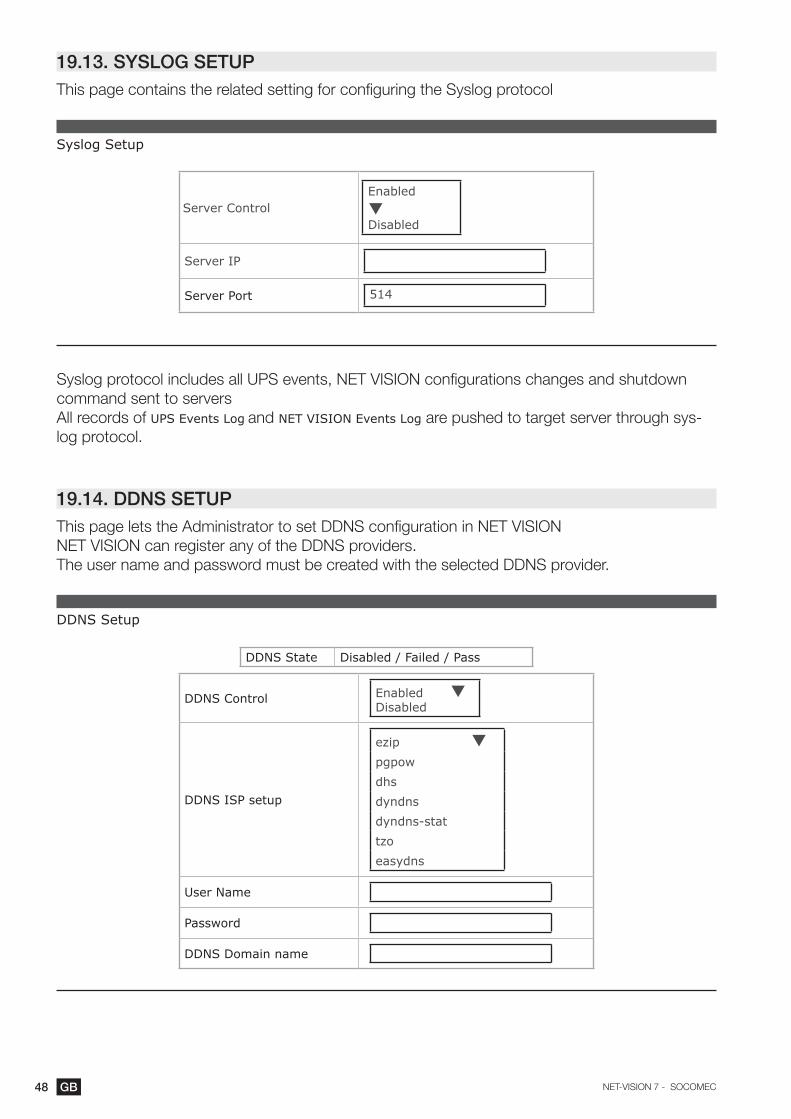
19.13. SYSLOG SETUPThis page contains the related setting for configuring the Syslog protocol
Syslog Setup
Server ControlEnabled Disabled
Server IP
Server Port 514
Syslog protocol includes all UPS events, NET VISION configurations changes and shutdown command sent to serversAll records of UPS Events Log and NET VISION Events Log are pushed to target server through sys-log protocol.
19.14. DDNS SETUPThis page lets the Administrator to set DDNS configuration in NET VISIONNET VISION can register any of the DDNS providers.The user name and password must be created with the selected DDNS provider.
DDNS Setup
DDNS State Disabled / Failed / Pass
DDNS Control Enabled Disabled
DDNS ISP setup
ezip pgpowdhsdyndnsdyndns-stattzoeasydns
User Name
Password
DDNS Domain name
49GBNET-VISION 7 - SOCOMEC
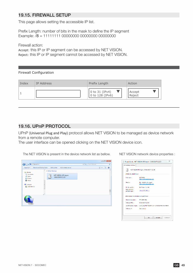
19.15. FIREWALL SETUPThis page allows setting the accessible IP list.
Prefix Length: number of bits in the mask to define the IP segment Example: /8 = 11111111 00000000 00000000 00000000
Firewall action:Accept: this IP or IP segment can be accessed by NET VISION.Reject: this IP or IP segment cannot be accessed by NET VISION.
Firewall Configuration
Index IP Address Prefix Length Action
1 0 to 31 (IPv4) 0 to 128 (IPv6)
Accept Reject
19.16. UPnP PROTOCOLUPnP (Universal Plug and Play) protocol allows NET VISION to be managed as device network from a remote computer.The user interface can be opened clicking on the NET VISION device icon.
The NET VISION is present in the device network list as bellow. NET VISION network device properties :
50 GB NET-VISION 7 - SOCOMEC
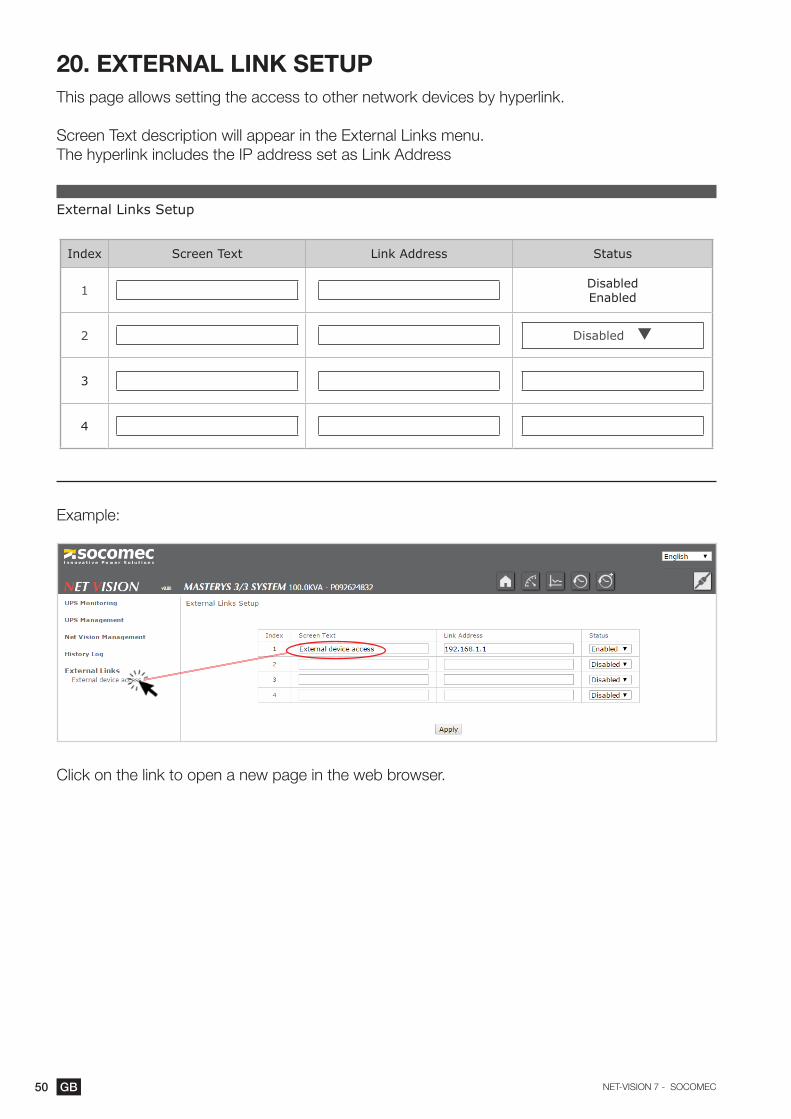
20. ExTERNAL LINK SETUPThis page allows setting the access to other network devices by hyperlink.
Screen Text description will appear in the External Links menu.The hyperlink includes the IP address set as Link Address
External Links Setup
Index Screen Text Link Address Status
1 DisabledEnabled
2 Disabled
3
4
Example:
Click on the link to open a new page in the web browser.
51GBNET-VISION 7 - SOCOMEC
21. HISTORY LOG
21.1. HISTORY LOG
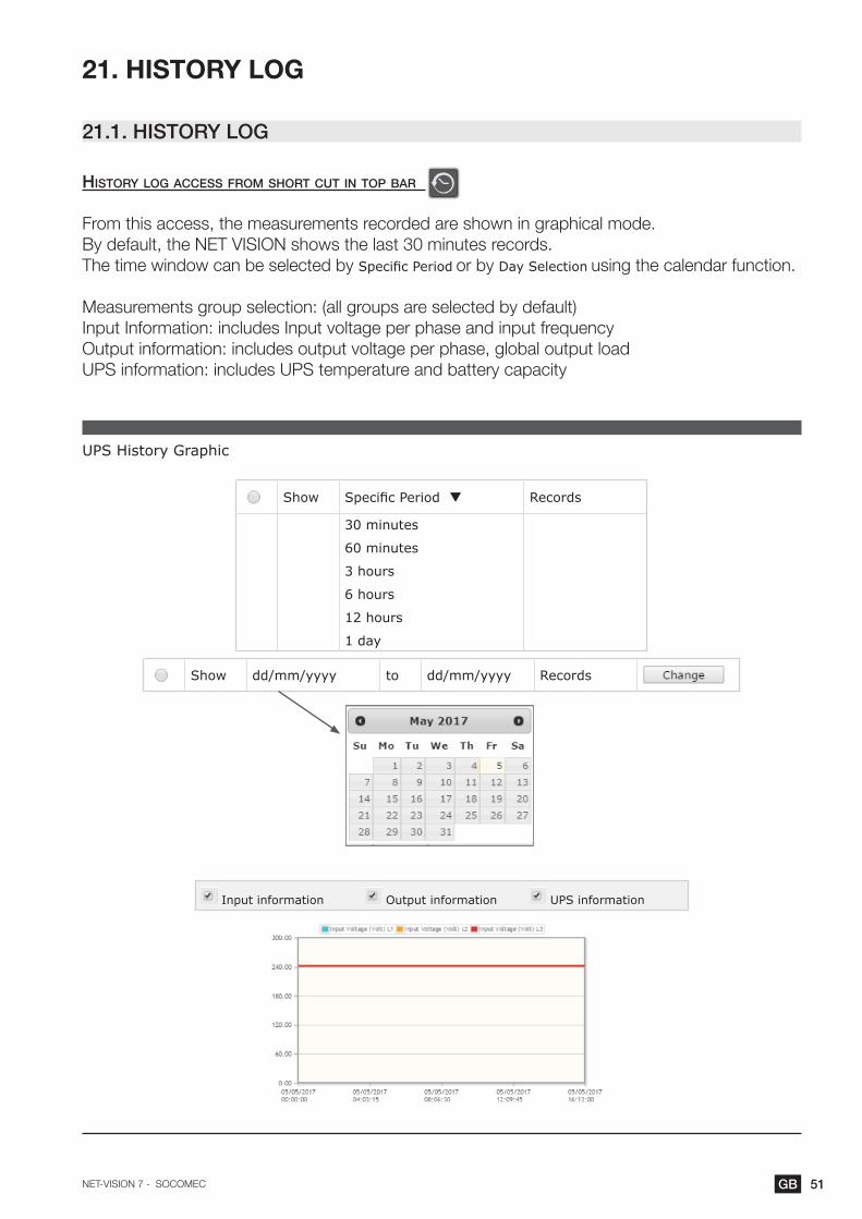
history log aCCess from short Cut in top bar
From this access, the measurements recorded are shown in graphical mode.By default, the NET VISION shows the last 30 minutes records.The time window can be selected by Specific Period or by Day Selection using the calendar function.
Measurements group selection: (all groups are selected by default)Input Information: includes Input voltage per phase and input frequencyOutput information: includes output voltage per phase, global output loadUPS information: includes UPS temperature and battery capacity
UPS History Graphic
Show Specific Period Records
30 minutes
60 minutes
3 hours
6 hours
12 hours
1 day
Show dd/mm/yyyy to dd/mm/yyyy Records
Input information Output information UPS information

52 GB NET-VISION 7 - SOCOMEC
history log from net vision menu item
This menu shows the history log page by page in a table presentation.The last 5 records are shown in the table by default.
The time window can also be changed via the calendar.The number of pages available is displayed above and below the table. Page numbers are used as buttons to change the log page.
UPS History Log
from dd/mm/yyyy to dd/mm/yyyy
Log count per page 5
<< < 1 2 3 > >>
Log Input Voltage (V) Output Voltage (V) Input frequency (Hz) Output Load (%)
Battery Capacity
(%)
UPS temperature
(°C)
Datetime R S T R S T R S T
<< < 1 2 3 > >>
If an EMD device is connected, the temperature and humidity measurements are added in the table.
Maximum number of records: 2048If the sample is set to 1 minute, the complete time window offers a view of 2048 minute (~1 day and 18 minutes)

53GBNET-VISION 7 - SOCOMEC
21.2. UPS ExTENDED HISTORY LOG
aCCess from short Cut in top bar
From this access, the measurements recorded are shown in graphical mode.For each measurement, NET VISION stores the minimum, average and maximum values during the sample rate (60 minutes by default)By default, the NET VISION shows the last 30 minutes records. It could be that the NET VISION shows “No Record!” due to the sample rate; in such a case, another period must be chosen to have data in the table.The time window can be selected by Specific Period or by Day Selection using the calendar function.
Measurements group selection: (all groups are selected by default)Input Information: includes input voltage per phase and input frequencyOutput information: includes output voltage per phase, global output loadUPS information: includes UPS temperature and battery capacity
UPS Extended History Graphic
Show Specific Period Records
30 minutes
60 minutes
3 hours
6 hours
12 hours
1 day
Show dd/mm/yyyy to dd/mm/yyyy Records
Input information Output information UPS information
The graphs represent the minimum, average and maximum values of each measurement.

54 GB NET-VISION 7 - SOCOMEC
ups extended log from net vision menu item
From this access, the measurements recorded are shown in table mode.By default, the last 5 records are shown in the table
The time window can also be changed via the calendarThe number of pages available is displayed above and below the table.
UPS Extended Log
from dd/mm/yyyy to dd/mm/yyyy
Log count per page 5
<< < 1 2 3 > >>
Start time End time Input Voltage (V) R Input Voltage (V) S Input Voltage (V) Tdd/mm/yyyy hh:mm:ss
dd/mm/yyyy
hh:mm:ssMin Min Min Avg Max Avg Max Avg Max
<< < 1 2 3 > >>
If an EMD device is connected, the temperature and humidity measurements are added in the table.
Maximum number of records: 2048If the sample is set to 1 hour, the complete time window is a view of 2048 hours (~85 days and 8 hours)

55GBNET-VISION 7 - SOCOMEC
21.3. UPS EVENTS LOGAll incoming and out coming alarms detected by NET VISION are stored in the UPS events log.
UPS Events Logfrom dd/mm/yyyy to dd/mm/yyyy
Log count per page 5
<< < 1 2 3 > >>
Event Time (dd/mm/yyyy hh:mm:ss) Event Level Event Description
01/01/1970 00:00:00InformationWarningCritical
‘has been removed’ when the alarm disappears
Clicking on changes the display order: by date and time or by severity level.
List of UPS event stored by NET VISION
UPS Imminent Stop UPS Power Off If function present
Overload Alarm Wrong Configuration
Ambient Temperature Alarm Internal / Communication failure
Transfer locked Option Board Alarm
Transfer impossible External Input 1 to 4 Alarm If ADC programmed
Insufficient resource Parallel system only Unit 1 to 12 General Alarm Parallel system only
Redundancy lost Parallel system only UPS connected
Output Short circuit detection UPS not connected
Maintenance Alarm Power Plugs 1 to 4 ON If power share plugs present
Remote Service Alarm If function present Power Plugs 1 to 4 OFF If power share plugs present
General Alarm Transfer Load to Bypass
UPS STATUS EVENTS
Battery disconnected If function present Transfer Load to Inverter
Battery discharged Enable eco mode
End of Backup Time / Battery Low Disable eco mode
Operating on Battery Enable standby mode
Battery Temperature Alarm If function present Disable standby mode
Battery Room Alarm If function present Alarm Acknowledgement
Battery Test failed On maintenance bypass
Battery Alarm Auto-test in progress
Rectifier Critical Alarm Rectifier General Al. Battery test in progress
Rectifier Preventive Alarm Load protected by Inverter
Rectifier Input Supply not OK Normal mode
Gen Set Alarm If function present UPS in eco mode
Charger Critical Alarm Load on bypass
Charger Preventive Alarm Charger General Al. Unit Available
Inverter Critical Alarm On standby
Inverter Preventive Alarm Inverter General Al. Load off
Bypass Critical Alarm UPS shut off sent
Bypass Preventive Alarm Bypass General Al. Standby schedule sent
Bypass Input Supply not OK Eco mode schedule sent
Phase Rotation fault
Maintenance Bypass Alarm
FAN Failure

56 GB NET-VISION 7 - SOCOMEC
21.4. NET VISION EVENTS LOGAny modifications of NET VISION configurations and settings are stored in the NET VISION Events log.
NET VISION Events Log
from dd/mm/yyyy to dd/mm/yyyy
Log count per page 5
<< < 1 2 3 > >>Event Time (dd/mm/yyyy hh:mm:ss) Event Level Event Description
01/01/1970 00:00:00InformationWarningCritical
Clicking on changes the display order: by date and time or by severity level.
List of NET VISION events stored in the log: “???” defines the local IP address
Cold boot
Warm boot
Network link up
Network link down
NET VISION UPS Agent Restart
NET VISION UPS Agent Parameters reset to default
Parameters checksum error
NET VISION UPS Agent Firmware upgrade
History log cleared
Extended history log cleared
UPS event log cleared
NET VISION UPS Agent event log cleared
History log interval changed
Extended history log interval changed
Send shutdown warning to clients
Send shutdown request to clients
Send UPS shutdown command to UPS
Send shutdown cancel to clients
Send UPS output on command to UPS
UPS communication lost
UPS communication restored
??? Time changed by user
??? Time changed by server
??? Time changed by RTC
Cannot connect to mail server
Incorrect Mail receiver
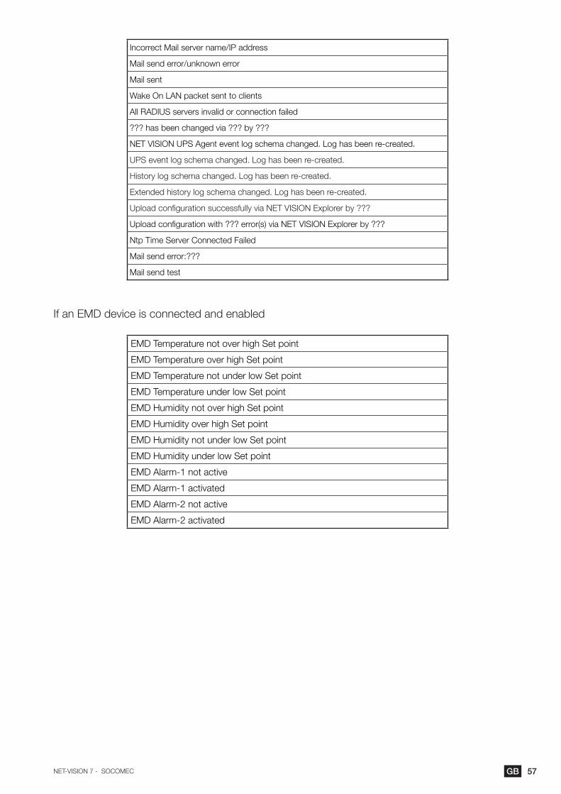
57GBNET-VISION 7 - SOCOMEC
Incorrect Mail server name/IP address
Mail send error/unknown error
Mail sent
Wake On LAN packet sent to clients
All RADIUS servers invalid or connection failed
??? has been changed via ??? by ???
NET VISION UPS Agent event log schema changed. Log has been re-created.
UPS event log schema changed. Log has been re-created.
History log schema changed. Log has been re-created.
Extended history log schema changed. Log has been re-created.
Upload configuration successfully via NET VISION Explorer by ???
Upload configuration with ??? error(s) via NET VISION Explorer by ???
Ntp Time Server Connected Failed
Mail send error:???
Mail send test
If an EMD device is connected and enabled
EMD Temperature not over high Set point
EMD Temperature over high Set point
EMD Temperature not under low Set point
EMD Temperature under low Set point
EMD Humidity not over high Set point
EMD Humidity over high Set point
EMD Humidity not under low Set point
EMD Humidity under low Set point
EMD Alarm-1 not active
EMD Alarm-1 activated
EMD Alarm-2 not active
EMD Alarm-2 activated

58 GB NET-VISION 7 - SOCOMEC
21.5. CLEAR & SAVE LOG DATAThis page allows storing all log files to a local computer, to backup files on a local computer or to clear logs on NET VISION.The log files are stored in CSV format and can be opened with a standard Office programme, such as MS Excel.Save and Clear log functions are accessible for admin or Read/write account users.
Clear & Save Log Data
UPS History Log
UPS Extended Log
UPS Events Log
NET VISION Events Log
Clear Log Data
NET VISION Events Log UPS Events Log
UPS Extended Log UPS History Log
stored filesClick on to store the file on a local computer
Clear logsSelect which Log to clear and click on

59GBNET-VISION 7 - SOCOMEC
appendix: net vision 7 mib file oid desCription
upsIdent(1) No. Variables
.1.3.6.1.4.1.4555.1.1.7.1.1
1 upsIdentModel2 upsIdentSerialNumber3 upsIdentUserRef4 upsIdentUserLocation5 upsIdentAgentSoftwareVersion
upsBattery (2) No. Variables Values
.1.3.6.1.4.1.4555.1.1.7.1.2
1 upsBatteryStatus
unknown(1). batteryNormal(2). batteryCharging(3). batteryTest(4). batteryDischarging(5). batteryLow(6). batteryDepleted(7). batteryFailure(8). batteryDisconnected(9)
2 upsSecondsOnBattery Seconds3 upsEstimatedMinutesRemaining Minutes4 upsEstimatedChargeRemaining %5 upsBatteryVoltage Format ###.# V6 upsBatteryTemperature Format ##.# °C (*)
upsInput(3) No. Variables Values
.1.3.6.1.4.1.4555.1.1.7.1.3
1 upsInputNumLines 3 for 3 phase UPS2 upsInputFrequency Format ##.# Hz3 upsInputTable/upsInputEntry/3.1.1 upsInputLineIndex3.1.2 upsInputVoltage ###.# V3.1.3 upsInputCurrent ###.# A (*)3.1.4 upsInputVoltageMax ###.# V3.1.5 upsInputVoltageMin ###.# V
General rule: In case measurements not managed by UPS the related IOD value is set at -1 or 65535.
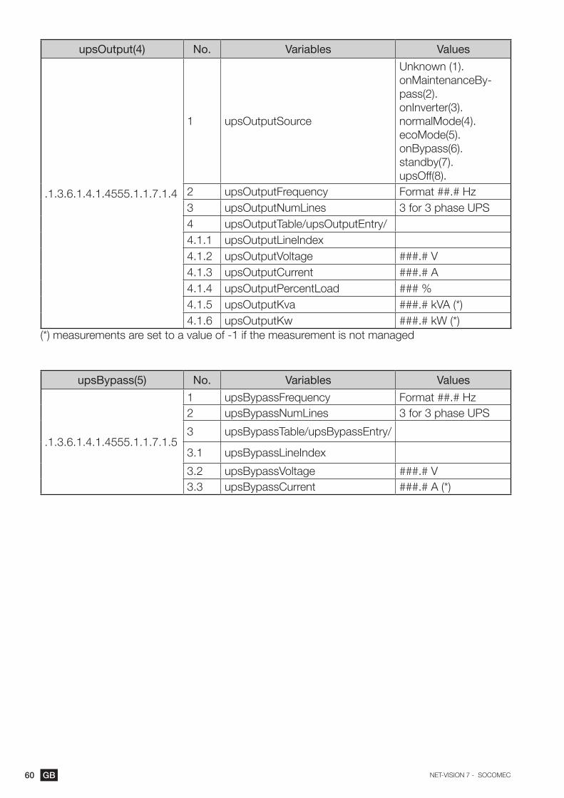
60 GB NET-VISION 7 - SOCOMEC
upsOutput(4) No. Variables Values
.1.3.6.1.4.1.4555.1.1.7.1.4
1 upsOutputSource
Unknown (1). onMaintenanceBy-pass(2). onInverter(3). normalMode(4). ecoMode(5). onBypass(6). standby(7). upsOff(8).
2 upsOutputFrequency Format ##.# Hz3 upsOutputNumLines 3 for 3 phase UPS4 upsOutputTable/upsOutputEntry/4.1.1 upsOutputLineIndex4.1.2 upsOutputVoltage ###.# V4.1.3 upsOutputCurrent ###.# A4.1.4 upsOutputPercentLoad ### %4.1.5 upsOutputKva ###.# kVA (*)4.1.6 upsOutputKw ###.# kW (*)
(*) measurements are set to a value of -1 if the measurement is not managed
upsBypass(5) No. Variables Values
.1.3.6.1.4.1.4555.1.1.7.1.5
1 upsBypassFrequency Format ##.# Hz2 upsBypassNumLines 3 for 3 phase UPS
3 upsBypassTable/upsBypassEntry/
3.1 upsBypassLineIndex
3.2 upsBypassVoltage ###.# V3.3 upsBypassCurrent ###.# A (*)
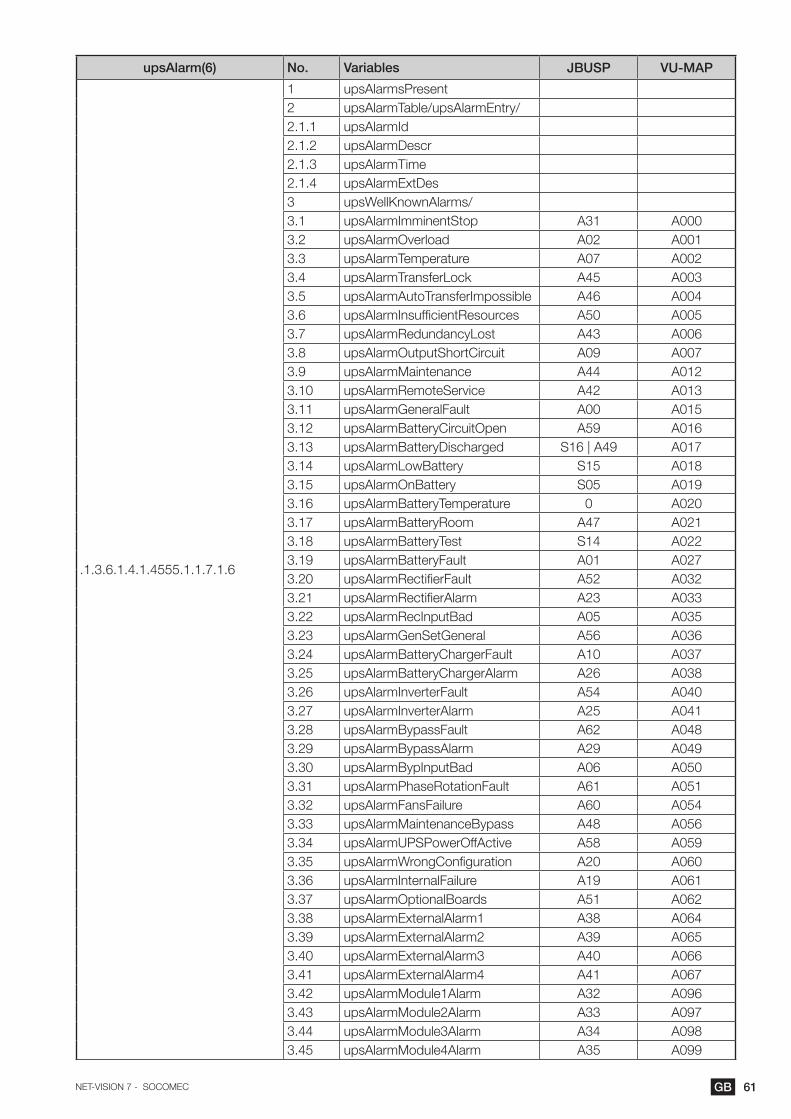
61GBNET-VISION 7 - SOCOMEC
upsAlarm(6) No. Variables JBUSP VU-MAP
.1.3.6.1.4.1.4555.1.1.7.1.6
1 upsAlarmsPresent2 upsAlarmTable/upsAlarmEntry/2.1.1 upsAlarmId2.1.2 upsAlarmDescr 2.1.3 upsAlarmTime2.1.4 upsAlarmExtDes3 upsWellKnownAlarms/3.1 upsAlarmImminentStop A31 A0003.2 upsAlarmOverload A02 A0013.3 upsAlarmTemperature A07 A0023.4 upsAlarmTransferLock A45 A0033.5 upsAlarmAutoTransferImpossible A46 A0043.6 upsAlarmInsufficientResources A50 A0053.7 upsAlarmRedundancyLost A43 A0063.8 upsAlarmOutputShortCircuit A09 A0073.9 upsAlarmMaintenance A44 A0123.10 upsAlarmRemoteService A42 A0133.11 upsAlarmGeneralFault A00 A0153.12 upsAlarmBatteryCircuitOpen A59 A0163.13 upsAlarmBatteryDischarged S16 | A49 A0173.14 upsAlarmLowBattery S15 A0183.15 upsAlarmOnBattery S05 A0193.16 upsAlarmBatteryTemperature 0 A0203.17 upsAlarmBatteryRoom A47 A0213.18 upsAlarmBatteryTest S14 A0223.19 upsAlarmBatteryFault A01 A0273.20 upsAlarmRectifierFault A52 A0323.21 upsAlarmRectifierAlarm A23 A0333.22 upsAlarmRecInputBad A05 A0353.23 upsAlarmGenSetGeneral A56 A0363.24 upsAlarmBatteryChargerFault A10 A0373.25 upsAlarmBatteryChargerAlarm A26 A0383.26 upsAlarmInverterFault A54 A0403.27 upsAlarmInverterAlarm A25 A0413.28 upsAlarmBypassFault A62 A0483.29 upsAlarmBypassAlarm A29 A0493.30 upsAlarmBypInputBad A06 A0503.31 upsAlarmPhaseRotationFault A61 A0513.32 upsAlarmFansFailure A60 A0543.33 upsAlarmMaintenanceBypass A48 A0563.34 upsAlarmUPSPowerOffActive A58 A0593.35 upsAlarmWrongConfiguration A20 A0603.36 upsAlarmInternalFailure A19 A0613.37 upsAlarmOptionalBoards A51 A0623.38 upsAlarmExternalAlarm1 A38 A0643.39 upsAlarmExternalAlarm2 A39 A0653.40 upsAlarmExternalAlarm3 A40 A0663.41 upsAlarmExternalAlarm4 A41 A0673.42 upsAlarmModule1Alarm A32 A0963.43 upsAlarmModule2Alarm A33 A0973.44 upsAlarmModule3Alarm A34 A0983.45 upsAlarmModule4Alarm A35 A099
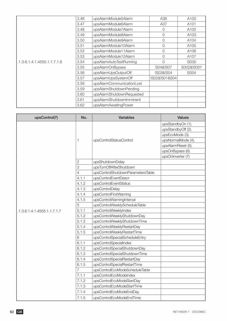
62 GB NET-VISION 7 - SOCOMEC
.1.3.6.1.4.1.4555.1.1.7.1.6
3.46 upsAlarmModule5Alarm A36 A1003.47 upsAlarmModule6Alarm A37 A1013.48 upsAlarmModule7Alarm 0 A1023.49 upsAlarmModule8Alarm 0 A1033.50 upsAlarmModule9Alarm 0 A1043.51 upsAlarmModule10Alarm 0 A1053.52 upsAlarmModule11Alarm 0 A1063.53 upsAlarmModule12Alarm 0 A1073.54 upsAlarmAutoTestRunning 0 S0303.55 upsAlarmOnBypass S04&!S07 S002&!S0073.56 upsAlarmUpsOutputOff !S03&!S04 S0043.57 upsAlarmUpsSystemOff !S02&!S01&S043.58 upsAlarmCommunicationLost3.59 upsAlarmShutdownPending3.60 upsAlarmShutdownRequested3.61 upsAlarmShutdownImminent3.62 upsAlarmAwaitingPower
upsControl(7) No. Variables Values
.1.3.6.1.4.1.4555.1.1.7.1.7
1 upsControlStatusControl
upsStandbyOn (1).upsStandbyOff (2).upsEcoMode (3).upsNormalMode (4).upsAlarmReset (5).upsOnBypass (6).upsOnInverter (7)
2 upsShutdownDelay3 upsTurnOffAfterShutdown4 upsControlShutdownParametersTable4.1.1 upsControlEventDescr4.1.2 upsControlEventStatus4.1.3 upsControlDelay4.1.4 upsControlFirstWarning4.1.5 upsControlWarningInterval5 upsControlWeeklyScheduleTable5.1.1 upsControlWeeklyIndex5.1.2 upsControlWeeklyShutdownDay5.1.3 upsControlWeeklyShutdownTime5.1.4 upsControlWeeklyRestartDay5.1.5 upsControlWeeklyRestartTime6 upsControlSpecialScheduleEntry6.1.1 upsControlSpecialIndex6.1.2 upsControlSpecialShutdownDay6.1.3 upsControlSpecialShutdownTime6.1.4 upsControlSpecialRestartDay6.1.5 upsControlSpecialRestartTime7 upsControlEcoModeScheduleTable7.1.1 upsControlEcoModeIndex7.1.2 upsControlEcoModeStartDay7.1.3 upsControlEcoModeStartTime
7.1.4 upsControlEcoModeEndDay
7.1.5 upsControlEcoModeEndTime

63GBNET-VISION 7 - SOCOMEC
upsConfig(8) No. Variables
.1.3.6.1.4.1.4555.1.1.7.1.8
1 upsConfigNomKva2 upsConfigNbrUnit3 upsConfigUnitKva4 upsConfigRemoteCtrl5 upsDevicesTable/upsDevicesEntry5.1.1 indexOfDevice5.1.2 addrOfDevice5.1.3 nameOfDevice5.1.4 timeOfConnection5.1.5 statusOfConnection5.1.6 severityOfConnection
upsAgent(9) No. Variables
.1.3.6.1.4.1.4555.1.1.7.1.9
1 upsAgentIpaddress2 upsAgentGateway3 upsAgentSubnetMask4 upsAgentDate5 upsAgentTime6 upsAgentNtpTimeServer7 upsAgentNtpTimeZone8 upsAgentHistoryLogFrequency9 upsAgentExtHistoryLogFrequency10 upsAgentPollRate11 upsAgentBaudRate12 upsAgentDhcpStatus13 upsAgentTelnetStatus14 upsAgentTftpStatus15 upsAgentResetToDefault16 upsAgentRestart17 upsAgentClearAgentLog18 upsAgentClearEventLog19 upsAgentClearExtHistoryLog20 upsAgentClearHistoryLog21 upsAgentTrapsReceiversTable/upsAgentTrapsReceiversEntry21.1.1 trapsIndex21.1.2 trapsReceiverAddr21.1.3 receiverCommunityString21.1.4 receiverNmstype22 upsAgentAccessControlTable/upsAgentAccessControlEntry23 upsAgentMibVersion50 upsAgentTrapString
emdStatus(10) No. Variables
.1.3.6.1.4.1.4555.1.1.7.1.10
1 emdStatusTemperature2 emdStatusHumidity3 emdStatusIn1Active4 emdStatusIn2Active

64 GB NET-VISION 7 - SOCOMEC
appendix: net vision 7 trap desCription
upsTraps(2) No. Variables Level JBUSP VU-MAP
Sent if TRAP Filter enabled
1 upsTrapOnBattery Critical S05 A0192 upsTrapTestCompleted Not managed3 upsTrapAlarmEntryAdded Warning upsWellKnownAlarms OID4 upsTrapAlarmEntryRemoved Information upsWellKnownAlarms OID
TRAP send to Remote View
Pro monitoring SW
5 upsTrapImminentStop Critical A31 A0006 upsTrapOverload Warning A02 A0017 upsTrapRedundancyLost Warning A43 A0068 upsTrapBatteryCircuitOpen Critical A59 A0169 upsTrapBatteryDischarged Critical S16 A01710 upsTrapBatteryLow Critical S15 A01811 upsTrapBatteryAlarm Warning A01 A02712 upsTrapUpsCriticalAlarm Critical A52|A54|A62 A032|A040|A04813 upsTrapLoadOFF Critical !S03&!S04 S00414 upsTrapCommunicationLost Critical NET VISION event15 upsTrapOnBatteryPower Warning S05 A01916 upsTrapBatteryTestfailed Warning S14 A02217 upsTrapTemperatureAlarm Warning A07 A02018 upsTrapOnBypass Warning S04&!S06 S00219 upsTrapUpsPreventiveAlarm Warning A00 A01520 upsTrapShutdownWarning Warning
Shutdown agent21 upsTrapShutdownrequest Warning22 upsTrapUpsNormal Information S03 S000|S00123 upsTrapPowerRestored Information S00 S04824 upsTrapAlarmCancelled Information !A15 !A01525 upsTrapComEstablished Information
Shutdown agent26 upsTrapShutdwonCancelled Information27 upsTrapAgentRestarting Information NET VISION event28 upsTrapEmdTempLow Critical
EMD events
29 upsTrapEmdTempNotLow Information30 upsTrapEmdTempHigh Critical31 upsTrapEmdTempNotHigh Information32 upsTrapEmdHumidityLow Critical33 upsTrapEmdHumidityNotLow Information34 upsTrapEmdHumidityHigh Critical35 upsTrapEmdHumidityNotHigh Information36 upsTrapEmdFirstInputActive Critical37 upsTrapEmdFirstInputRestored Information38 upsTrapEmdSecondInputActive Critical39 upsTrapEmdSecondInputRestored Information40 TRAP TEST Information Manual test
TRAP1 to TRAP4 are managed as defined by RFC1628.TRAP1: sent every minute with remaining backup time and running time on battery as parameters.TRAP3: sent every time a new alarm is added to the list. The alarm index sent as parameters follows the well-known alarm index OID.TRAP4: sent every time when an alarm is removed from alarm list. The alarm index is the same
as sent with TRAP3.

65GBNET-VISION 7 - SOCOMEC
appendix: rfC1628 wellKnowalarms oid desCription
Those alarms OID and description are reported in TRAP 3 (added) and TRAP 4 (removed)
OID .1.3.6.1.2.1.33.1.6.3 JBUSP VU-MAP
.1 upsAlarmBatteryBad A01 or A47 A027 or A20 or A21
.2 upsAlarmOnBattery S05 A019
.3 upsAlarmLowBattery S15 A018
.4 upsAlarmDepletedBattery S16|A49 A017
.5 upsAlarmTempBad A07 A002
.6 upsAlarmInputBad A05 A035
.7 upsAlarmOutputBad Not available
.8 upsAlarmOutputOverload A02 A001
.9 upsAlarmOnBypass S04&!S07 S002&!S006
.10 upsAlarmBypassBad A29 A049 Critical alarm
.11 upsAlarmOutputOffAsRequested Not available
.12 upsAlarmUpsOffAsRequested Not available
.13 upsAlarmChargerFailed A26 A038
.14 upsAlarmUpsOutputOff !S03&!S04 S004
.15 upsAlarmUpsSystemOff !S02 & !S03 & !S04 !S049 & !S52 & !S57
.16 upsAlarmFanFailure A60 A054
.17 upsAlarmFuseFailure Not available
.18 upsAlarmGeneralFault A00 A015
.19 upsAlarmDiagnosticTestFailed S14 A022 Battery test failed
.20 upsAlarmCommunicationsLost NV alarm
.21 upsAlarmAwaitingPower Shutdown agent
.22 upsAlarmShutdownPending Shutdown agent
.23 upsAlarmShutdownImminent Shutdown agent
.24 upsAlarmTestInProgress S10 A034 Battery test
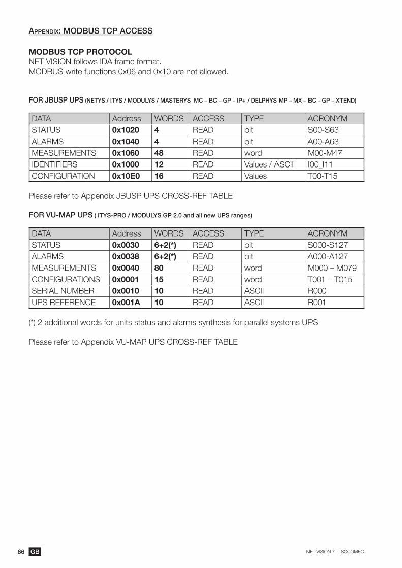
66 GB NET-VISION 7 - SOCOMEC
appendix: modbus tCp aCCess
MODBUS TCP PROTOCOLNET VISION follows IDA frame format. MODBUS write functions 0x06 and 0x10 are not allowed.
FOR JBUSP UPS (NETYS / ITYS / MODULYS / MASTERYS MC – BC – GP – IP+ / DELPHYS MP – Mx – BC – GP – xTEND)
DATA Address WORDS ACCESS TYPE ACRONYMSTATUS 0x1020 4 READ bit S00-S63ALARMS 0x1040 4 READ bit A00-A63MEASUREMENTS 0x1060 48 READ word M00-M47IDENTIFIERS 0x1000 12 READ Values / ASCII I00_I11CONFIGURATION 0x10E0 16 READ Values T00-T15
Please refer to Appendix JBUSP UPS CROSS-REF TABLE
FOR VU-MAP UPS ( ITYS-PRO / MODULYS GP 2.0 and all new UPS ranges)
DATA Address WORDS ACCESS TYPE ACRONYMSTATUS 0x0030 6+2(*) READ bit S000-S127ALARMS 0x0038 6+2(*) READ bit A000-A127MEASUREMENTS 0x0040 80 READ word M000 – M079CONFIGURATIONS 0x0001 15 READ word T001 – T015SERIAL NUMBER 0x0010 10 READ ASCII R000UPS REFERENCE 0x001A 10 READ ASCII R001
(*) 2 additional words for units status and alarms synthesis for parallel systems UPS
Please refer to Appendix VU-MAP UPS CROSS-REF TABLE

67GBNET-VISION 7 - SOCOMEC
appendix: vu-map ups Cross-ref table: itys-pro / modulys gp2.0 / new range
List of status managed by the UPS. This table is accessible on MODBUS TCP by requesting 8 words to address 0x0030.Reading the 4 first words of status table are enough to monitor single UPS, as the next words are linked to parallel system data.
Address level Acronym Description Address level Acronym Description
0x0030
I S000 Load protected by Inverter
0x0034
S064 Card in Slot 1 present
S001 Load supplied in Normal mode S065 Card in Slot 2 present
W S002 Load supplied by automatic Bypass S066Card in Slot 3 pres-ent
W S003 Load supplied by Maintenance Bypass S067Card in Slot 4 pres-ent
C S004 Load OFF S068Card in Slot 5 pres-ent
S005 S069Card in Slot 6 pres-ent
I S006 UPS in eco mode S070
I S007 UPS in energy saver S071
S008 Burn-in mode S072 Programmable S072
W S009 In Service mode S073 Programmable S073
S010 Line-interactive mode S074 Programmable S074
I S011 Operating S075 Programmable S075
I S012 Available S076 Programmable S076
W S013 on Standby S077 Programmable S077
I S014 Unit isolated S078 Programmable S078
W S015 Maintenance Alert S079 Programmable S079
0x0031
S016 Output Breaker closed
0x0035
S080 Programmable S080
S017 Maintenance Bypass closed S081 Programmable S081
S018 External Maintenance Bypass closed S082 Programmable S082
S019 External Output Breaker closed S083 Programmable S083
S020 Single phase Input supply S084 Programmable S084
S021 Rectifier Input Breaker S085 Programmable S085
S022 Bypass Input Breaker S086 Programmable S086
I S023 Gen set ON S087 Programmable S087
S024 Busbar 1 closed S088 Programmable S088
S025 Busbar 2 closed S089 Programmable S089
I S026 Automatic Start in progress S090 Programmable S090
W S027 Maintenance Bypass proc. in progress S091 Programmable S091
W S028 UPS OFF procedure in progress S092 Programmable S092
S029 S093 Programmable S093
I S030 Auto-test Procedure in progress S094 Programmable S094
I S031 Alarm Acknowledgement requested S095 Programmable S095

68 GB NET-VISION 7 - SOCOMEC
0x0032
I S032 Battery OK
0x0036
S096 [1] is operating
I S033 Battery charged S097 [2] is operating
I S034 Battery Test in progress S098 [3] is operating
I S035 Battery Test programmed S099 [4] is operating
I S036 Battery charging S100 [5] is operating
W S037 Battery Test interrupted S101 [6] is operating
I S038 Floating Voltage reduced S102 [7] is operating
I S039 Battery discharge to Input S103 [8] is operating
I S040 UPS backup system connected S104 [9] is operating
I S041 UPS backup system charged / ready S105 [10] is operating
I S042 UPS backup system charging S106 [11] is operating
S043 S107 [12] is operating
S044 All inverters are ON S108 [13] is operating
S045 All rectifiers are ON S109 [14] is operating
S046 All bypasses are available S110 [15] is operating
S047 All Units or Modules are available S111
0x0033
I S048 Rectifier Input Supply present
0x0037
S112 [1] is available
I S049 Rectifier ON S113 [2] is available
I S050 Charger ON S114 [3] is available
S051 Rectifier is starting S115 [4] is available
I S052 Inverter ON S116 [5] is available
I S053 Inverter Switch ON S117 [6] is available
S054 S118 [7] is available
S055 S119 [8] is available
I S056 Bypass Input Supply present S120 [9] is available
I S057 Bypass Static Switch closed S121 [10] is available
I S058 Bypass Input & Inverter synchronised S122 [11] is available
I S059 ACS external synchronisation S123 [12] is available
S060 PowerShare Plug 1 closed S124 [13] is available
S061 PowerShare Plug 2 closed S125 [14] is available
S062 PowerShare Plug 3 closed S126 [15] is available
S063 PowerShare Plug 4 closed S127Data no longer up-dated
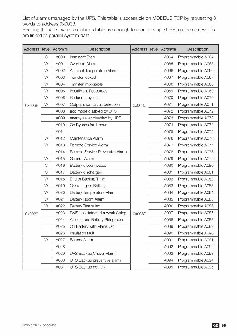
69GBNET-VISION 7 - SOCOMEC
List of alarms managed by the UPS. This table is accessible on MODBUS TCP by requesting 8 words to address 0x0038.Reading the 4 first words of alarms table are enough to monitor single UPS, as the next words are linked to parallel system data.
Address level Acronym Description Address level Acronym Description
0x0038
C A000 Imminent Stop
0x003C
A064 Programmable A064
W A001 Overload Alarm A065 Programmable A065
W A002 Ambient Temperature Alarm A066 Programmable A066
W A003 Transfer locked A067 Programmable A067
W A004 Transfer impossible A068 Programmable A068
W A005 Insufficient Resources A069 Programmable A069
W A006 Redundancy lost A070 Programmable A070
W A007 Output short circuit detection A071 Programmable A071
A008 eco mode disabled by UPS A072 Programmable A072
A009 energy saver disabled by UPS A073 Programmable A073
A010 On Bypass for 1 hour A074 Programmable A074
A011 A075 Programmable A075
W A012 Maintenance Alarm A076 Programmable A076
W A013 Remote Service Alarm A077 Programmable A077
A014 Remote Service Preventive Alarm A078 Programmable A078
W A015 General Alarm A079 Programmable A079
0x0039
C A016 Battery disconnected
0x003D
A080 Programmable A080
C A017 Battery discharged A081 Programmable A081
W A018 End of Backup Time A082 Programmable A082
W A019 Operating on Battery A083 Programmable A083
W A020 Battery Temperature Alarm A084 Programmable A084
W A021 Battery Room Alarm A085 Programmable A085
W A022 Battery Test failed A086 Programmable A086
A023 BMS has detected a weak String A087 Programmable A087
A024 At least one Battery String open A088 Programmable A088
A025 On Battery with Mains OK A089 Programmable A089
A026 Insulation fault A090 Programmable A090
W A027 Battery Alarm A091 Programmable A091
A028 A092 Programmable A092
A029 UPS Backup Critical Alarm A093 Programmable A093
A030 UPS Backup preventive alarm A094 Programmable A094
A031 UPS Backup not OK A095 Programmable A095
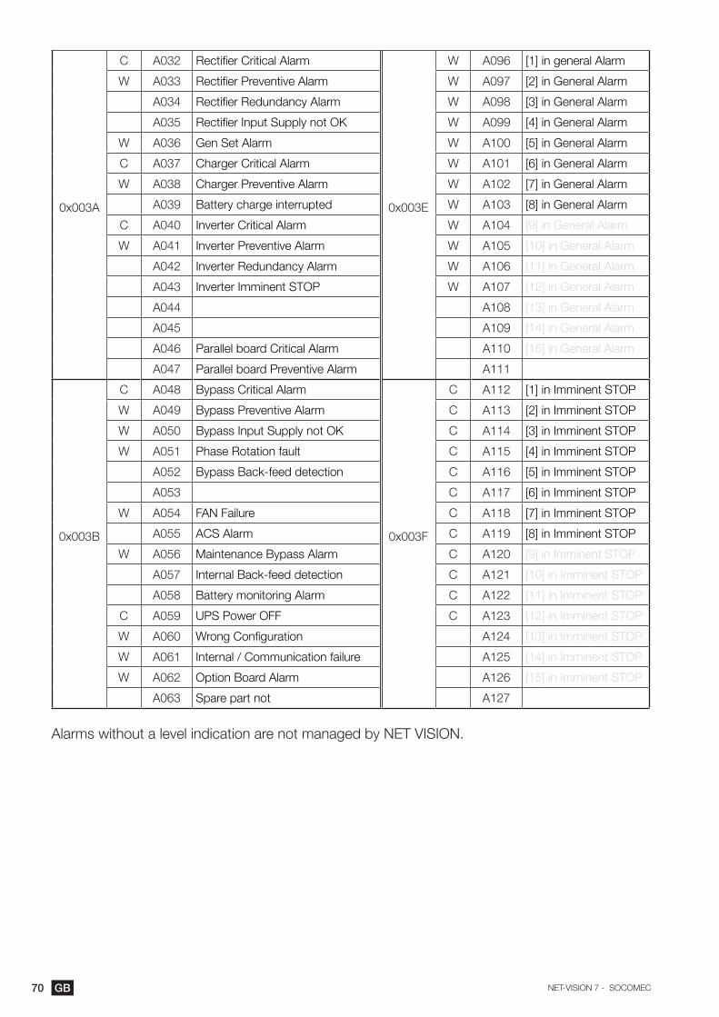
70 GB NET-VISION 7 - SOCOMEC
0x003A
C A032 Rectifier Critical Alarm
0x003E
W A096 [1] in general Alarm
W A033 Rectifier Preventive Alarm W A097 [2] in General Alarm
A034 Rectifier Redundancy Alarm W A098 [3] in General Alarm
A035 Rectifier Input Supply not OK W A099 [4] in General Alarm
W A036 Gen Set Alarm W A100 [5] in General Alarm
C A037 Charger Critical Alarm W A101 [6] in General Alarm
W A038 Charger Preventive Alarm W A102 [7] in General Alarm
A039 Battery charge interrupted W A103 [8] in General Alarm
C A040 Inverter Critical Alarm W A104 [9] in General Alarm
W A041 Inverter Preventive Alarm W A105 [10] in General Alarm
A042 Inverter Redundancy Alarm W A106 [11] in General Alarm
A043 Inverter Imminent STOP W A107 [12] in General Alarm
A044 A108 [13] in General Alarm
A045 A109 [14] in General Alarm
A046 Parallel board Critical Alarm A110 [15] in General Alarm
A047 Parallel board Preventive Alarm A111
0x003B
C A048 Bypass Critical Alarm
0x003F
C A112 [1] in Imminent STOP
W A049 Bypass Preventive Alarm C A113 [2] in Imminent STOP
W A050 Bypass Input Supply not OK C A114 [3] in Imminent STOP
W A051 Phase Rotation fault C A115 [4] in Imminent STOP
A052 Bypass Back-feed detection C A116 [5] in Imminent STOP
A053 C A117 [6] in Imminent STOP
W A054 FAN Failure C A118 [7] in Imminent STOP
A055 ACS Alarm C A119 [8] in Imminent STOP
W A056 Maintenance Bypass Alarm C A120 [9] in Imminent STOP
A057 Internal Back-feed detection C A121 [10] in Imminent STOP
A058 Battery monitoring Alarm C A122 [11] in Imminent STOP
C A059 UPS Power OFF C A123 [12] in Imminent STOP
W A060 Wrong Configuration A124 [13] in Imminent STOP
W A061 Internal / Communication failure A125 [14] in Imminent STOP
W A062 Option Board Alarm A126 [15] in Imminent STOP
A063 Spare part not A127
Alarms without a level indication are not managed by NET VISION.

71GBNET-VISION 7 - SOCOMEC
List of measurements managed by the UPS. This table is accessible on MODBUS TCP by requesting up to 80 words to address 0x0040.
Address Acronym Description Unit 0x000E=0 0x000E=1
0x0040 M000 Output load rate % ### ###
0x0041 M001 Output load rate L1 % ### ###
0x0042 M002 Output load rate L2 % ### ###
0x0043 M003 Output load rate L3 % ### ###
0x0044 M004 Output Apparent Power kVA ## ### # ###.#
0x0045 M005 Output Active Power kW ## ### # ###.#
0x0046 M006 Output current L1 A ## ### # ###.#
0x0047 M007 Output current L2 A ## ### # ###.#
0x0048 M008 Output current L3 A ## ### # ###.#
0x0049 M009 Output neutral current A ## ### # ###.#
0x004A M010 Output voltage L1 V ### ###
0x004B M011 Output voltage L2 V ### ###
0x004C M012 Output voltage L3 V ### ###
0x004D M013 Output frequency Hz ##.# ##.#
0x004E M014 Output Crest Factor #.# #.#
0x004F M015 Ambient Temperature °C ##.# ##.#
0x0050 M016 Battery voltage string + V # ### ###.#
0x0051 M017 Battery voltage string - V # ### ###.#
0x0052 M018 Battery current string + A ## ### # ###.#
0x0053 M019 Battery current string - A ## ### # ###.#
0x0054 M020
0x0055 M021
0x0056 M022 Battery capacity % ### ###
0x0057 M023 Battery capacity Ah ## ### # ###.#
0x0058 M024 Remaining Battery backup time Mn ### ###
0x0059 M025 Time on battery s ### ###
0x005A M026 Battery temperature °C ##.# ##.#
0x005B M027 Battery temperature average °C ##.# ##.#
0x005C M028 DC Storage voltage V # ### ###.#
0x005D M029 DC Storage temperature °C ##.# ##.#
0x005E M030
0x005F M031
0x0060 M032 Rect. input supply volt. L1 V ### ###
0x0061 M033 Rect. input supply volt. L2 V ### ###
0x0062 M034 Rect. input supply volt. L3 V ### ###
0x0063 M035 Rect. input supply freq. Hz ##.# ##.#
0x0064 M036 Rect. input supply volt. U12 V ### ###
0x0065 M037 Rect. input supply volt. U23 V ### ###
0x0066 M038 Rect. input supply volt. U31 V ### ###
0x0067 M039 Bypass input supply voltage L1 V ### ###

72 GB NET-VISION 7 - SOCOMEC
0x0068 M040 Bypass input supply voltage L2 V ### ###
0x0069 M041 Bypass input supply voltage L3 V ### ###
0x006A M042 Bypass input supply freq. Hz ##.# ##.#
0x006B M043 Bypass input supply volt U12 V ### ###
0x006C M044 Bypass input supply volt. U23 V ### ###
0x006D M045 Bypass input supply volt. U31 V ### ###
0x006E M046
0x006F M047
0x0070 M048 Output Apparent P. L1 kVA ## ### # ###.#
0x0071 M049 Output Apparent P. L2 kVA ## ### # ###.#
0x0072 M050 Output Apparent P. L3 kVA ## ### # ###.#
0x0073 M051 Output Active Power L1 kW ## ### # ###.#
0x0074 M052 Output Active Power L2 kW ## ### # ###.#
0x0075 M053 Output Active Power L3 kW ## ### # ###.#
0x0076 M054 Output voltage U12 V ### ###
0x0077 M055 Output voltage U23 V ### ###
0x0078 M056 Output voltage U31 V ### ###
0x0079 M057 Output Power factor L1 #.## #.##
0x007A M058 Output Power factor L2 #.## #.##
0x007B M059 Output Power factor L3 #.## #.##
0x007C M060 Output Crest Factor L1 #.# #.#
0x007D M061 Output Crest Factor L2 #.# #.#
0x007E M062 Output Crest Factor L3 #.# #.#
0x007F M063 Output Crest Factor neutral #.# #.#
0x0080 M064 Rect. Input Current L1 A ## ### # ###.#
0x0081 M065 Rect. Input Current L1 A ## ### # ###.#
0x0082 M066 Rect. Input Current L1 A ## ### # ###.#
0x0083 M067 Rect. Active Power L1 kW ## ### # ###.#
0x0084 M068 Rect. Active Power L2 kW ## ### # ###.#
0x0085 M069 Rect. Active Power L3 kW ## ### # ###.#
0x0086 M070 Bypass Input Current L1 A ## ### # ###.#
0x0087 M071 Bypass Input Current L2 A ## ### # ###.#
0x0088 M072 Bypass Input Current L3 A ## ### # ###.#
0x0089 M073 Bypass Active Power L1 kW ## ### # ###.#
0x008A M074 Bypass Active Power L2 kW ## ### # ###.#
0x008B M075 Bypass Active Power L3 kW ## ### # ###.#
0x008C M076
0x008D M077
0x008E M078
0x008F M079

73GBNET-VISION 7 - SOCOMEC
appendix: Jbusp ups Cross-ref table: netys / itys / masterys / delphysList of status managed by UPS. This table is accessible on MODBUS TCP by requesting 4 words to address 0x1020.
LEVELNETYS PR/RT
ITYSMASTERYS BC/
GPDELPHYS MP/
MXDELPHYS BC/
GPS00 I Rectifier Input supply present X X X XS01 I Inverter ON X X X XS02 I Rectifier ON X X X XS03 I Load protected by inverter X X X XS04 W Load on automatic bypass X X X XS05 W on battery / Battery discharging X X X XS06 Remote controls disabled X X XS07 Eco-mode ON X X X XS08 W Stand-by mode X XS09 Buzzer on X X X XS10 I Battery test in progress X X X XS11 I Battery test programmed X X XS12 I Battery test in stand-by X X XS13 I Battery test supported X X X XS14 W Battery test failed X X X XS15 C Battery near end of backup time X X X XS16 C Battery discharged X X X XS17 I Battery OK X X X XS18S19S20S21S22S23 Inverter synchro with mains X X X XS24 Boost on X XS25S26 I Bypass input supply present X X X XS27 I Battery charging X X X XS28 Bypass input fr. out of tolerance X X X XS29 Stand-by scheduleS30 UPS on parallel system For parallel For parallel For parallelS31 Battery extension XS32 Unit 1 present
If parallel system according to
number of units
If parallel system according to
number of units
If parallel system according to
number of units
S33 Unit 2 presentS34 Unit 3 presentS35 Unit 4 presentS36 Unit 5 presentS37 Unit 6 presentS38 External Input 1 X X XS39 External Input 2 X X XS40 External Input 3 X X XS41 External Input 4 X X XS42 Controls permission table managed X X X XS43 power share If presentS44S45S46 I Operating on Gen Set If present If present If presentS47 S48 W Maintenance mode active X X XS49 W End of the first maintenance period X X X…
S63
For more information please refer to MODBUS User manual according to the UPS range.

74 GB NET-VISION 7 - SOCOMEC
List of alarms managed by the UPS. This table is accessible on MODBUS TCP by requesting 4 words to address 0x1040.
LEVEL NETYS/ITYSMASTERYS
BC/GPDELPHYS MP/
MXDELPHYS GP
A00 W General Alarm X X X X
A01 W Battery failure X X X X
A02 W UPS overload X X X X
A03 Output voltage out of tolerance X
A04 Control failure X X
A05 W Rec. input supply out of tolerance X X X
A06 W Bypass input supply out of tolerance X X X X
A07 W Over temperature alarm X X X X
A08 W Maintenance bypass closed X X X
A09
A10 W Battery charger fault X X
A11
A12
A13 Pre-charge out of tolerance X
A14 BOOST too low X
A15 BOOST too high X
A16 VDC too high X X
A17 Improper condition of use X X
A18 Inverter stopped for overload X X X
A19 W Microprocessor control system X
A20 W data map corrupted X
A21 PLL fault (sources synchronization) X X
A22 Rectifier input supply fault X X X X
A23 W Rectifier preventive alarm X X X
A24
A25 W Inverter preventive alarm X X X
A26 W Charger general alarm X X X
A27 Output Voltage over limit X
A28
A29 W Bypass preventive alarm X X
A30 UPS stopped for overload X X
A31 C Imminent STOP X X X X
A32 W Unit 1 general alarm
If parallel sys-tem according to number of
units
If parallel sys-tem according to number of
units
If parallel sys-tem according to number of
units
A33 W Unit 2 general alarm
A34 W Unit 3 general alarm
A35 W Unit 4 general alarm
A36 W Unit 5 general alarm
A37 W Unit 6 general alarm
A38 W External alarm 1 X X X
A39 External alarm 2 X

75GBNET-VISION 7 - SOCOMEC
A40 External alarm 3 X
A41 External alarm 4 X
A42 W Remote service alarm X X X
A43 W redundancy loss X X
A44 W Servicing alarm X X X
A45 W Auto. and manual transfer disable X X
A46 W Automatic transfer disable X X
A47 W Battery room alarm X X
A48 W Maintenance bypass alarm X X
A49 C Battery discharged X X X
A50 W insufficient resources X X X
A51 W Synoptic alarm X X X
A52 C Rectifier fault X X X
A53
A54 C Inverter fault X X X
A55 Parallel fault X
A56 W Gen set alarm If option set
A57 Gen set fault If option set
A58 C ESD activated X X X
A59 C Battery circuit open X X X
A60 W Fan failure X
A61 W Phase rotation fault X
A62 C Bypass critical alarm X X
A63
Alarms without a level indication are not managed by NET VISION.
For more information please refer to the MODBUS User manual according to the UPS range.
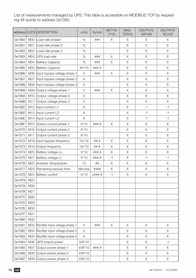
76 GB NET-VISION 7 - SOCOMEC
List of measurements managed by UPS. This table is accessible on MODBUS TCP by request-ing 48 words to address 0x1060.
address CODE DESCRIPTION units formatNETYS/
ITYSMAS-
TERYSDELPHYS MP/MX
DELPHYS BC/GP
0x1060 M00 Load rate phase1 % ### X X X X
0x1061 M01 Load rate phase 2 % X X X
0x1062 M02 Load rate phase 3 % X X X
0x1063 M03 UPS load rate % ### X X X X
0x1064 M04 Battery Capacity % ### X X X X
0x1065 M05 Battery Capacity Ah*10 ###.# X X X
0x1066 M06 Input bypass voltage phase 1 V ### X X X X
0x1067 M07 Input bypass voltage phase 2 V X X X
0x1068 M08 Input bypass voltage phase 3 V X X X
0x1069 M09 Output voltage phase 1 V ### X X X X
0x106A M10 Output voltage phase 2 V X X X
0x106B M11 Output voltage phase 3 V X X X
0x106C M12 Input current L1 A X -1 -1
0x106D M13 Input current L2 A X -1 -1
0x106E M14 Input current L3 A X -1 -1
0x106F M15 Output current phase 1 A*10 ###.# X X X X
0x1070 M16 Output current phase 2 A*10 X X X
0x1071 M17 Output current phase 3 A*10 X X X
0x1072 M18 Input bypass frequency Hz*10 ##.# X X X X
0x1073 M19 Output frequency Hz*10 ##.# X X X X
0x1074 M20 Battery voltage (+) V*10 ###.# X X X X
0x1075 M21 Battery voltage (-) V*10 ###.# -1 X -1 -1
0x1076 M22 Ambient Temperature °C ## X X X X
0x1077 M23 Remaining backup time Minutes #### X X X X
0x1078 M24 Battery current A*10 ±###.# -1 X X X
0x1079 M25
0x107A M26
0x107B M27
0x107C M28
0x107D M29
0x107E M30
0x107F M31
0x1080 M32
0x1081 M33 Rectifier input voltage phase 1 V ### X X X X
0x1082 M34 Rectifier input voltage phase 2 V X X X
0x1083 M35 Rectifier input voltage phase 3 V X X X
0x1084 M36 UPS output power kW*10 X X -1
0x1085 M37 Output power phase 1 kVA*10 ###.# X X X
0x1086 M38 Output power phase 2 kVA*10 X X X
0x1087 M39 Output power phase 3 kVA*10 X X X
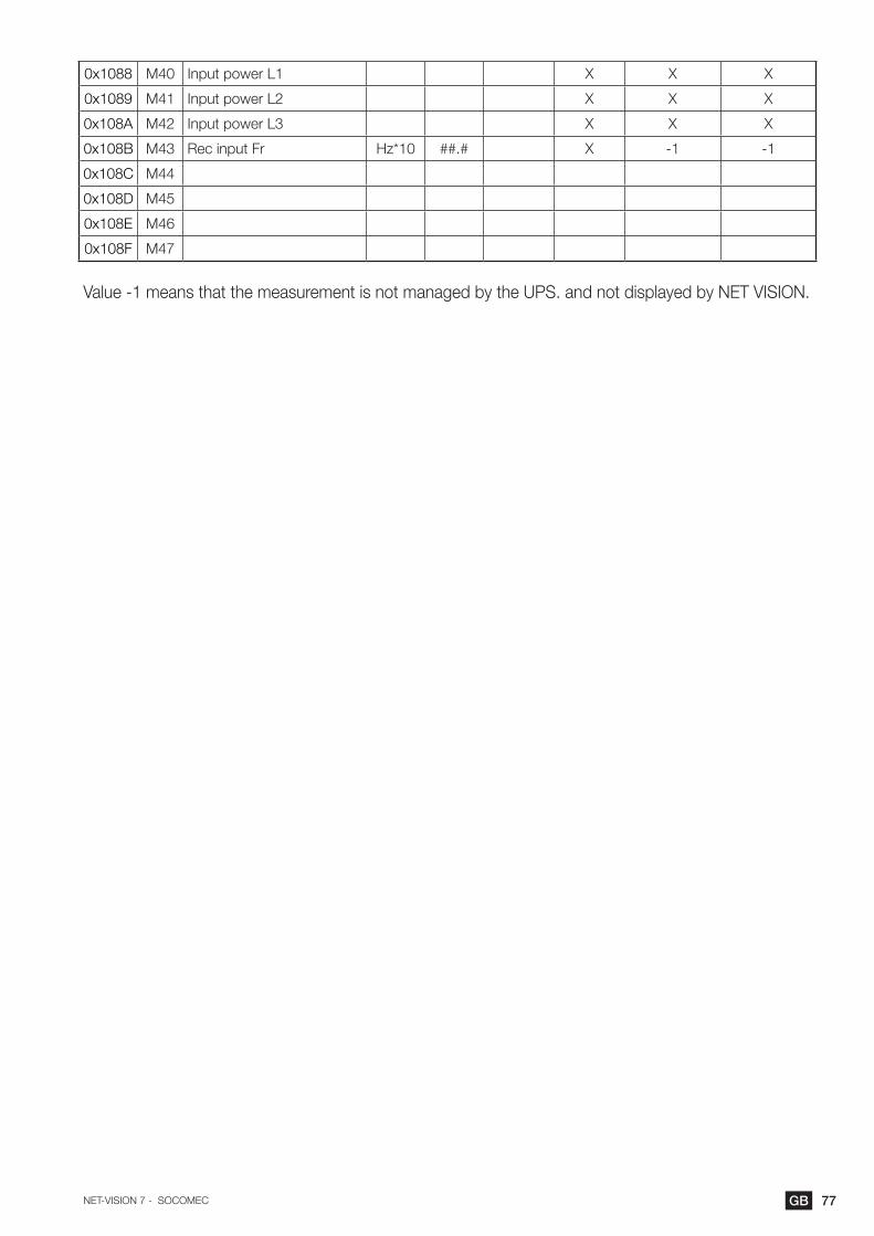
77GBNET-VISION 7 - SOCOMEC
0x1088 M40 Input power L1 X X X
0x1089 M41 Input power L2 X X X
0x108A M42 Input power L3 X X X
0x108B M43 Rec input Fr Hz*10 ##.# X -1 -1
0x108C M44
0x108D M45
0x108E M46
0x108F M47
Value -1 means that the measurement is not managed by the UPS. and not displayed by NET VISION.

78 GB NET-VISION 7 - SOCOMEC
appendix: Configuring net vision via ssh
SSH must be enabled in the NET VISION Control page.Using SSH tool to open a terminal session:
login as: [email protected]’s password:
Date 03/05/2017 Time 16:41:53
+================================================================+| Configuration Utility || [Socomec Net Vision 7 V1.00] |+================================================================+ 1. SNMP/WEB Card Settings 2. Reset Accounts/Passwords to Default 3. Reset Configuration to Default 4. Restart SNMP/WEB Card 0. Exit
Please Enter Your Choice =>

79GBNET-VISION 7 - SOCOMEC
+===========================================================+| ConfigurationUtility || UPSModel:MODULYSGP2.0 |+===========================================================+ 1. IP. Time and System Group 2. Network Control Group 3. Account Control Group 4. Email Group 5. SNMP Group 0. Back to Main Menu
Please Enter Your Choice => 1
+===========================================================+| ConfigurationUtility || [IP. Time and System Group] |+===========================================================+
SNMP/WEB Card Version : Net Vision 7 v1.00 Ethernet Address : 00:E0:D8:FF:C1:90
1. IPv4 Group 2. IPv6 Group 3. Date and Time Group 4. System Contact : Technical Support Team 5. System Name : Socomec 6. System Location : 0. Return to previous menu
Please Enter Your Choice => 1
+===========================================================+| IP. Time and System Group || [IPv4 Group] |+===========================================================+
1. IP Address : 192.168.1.1 2. Gateway Address : 192.168.2.1 3. Network Subnet : 255.255.0.0 0. Return to previous menu
Please Enter Your Choice =>
Select the new IP address and go back to the main menu
All Network services can be configured via this interface.
At the end of all settings, select 0 to go back to the main menu to exit the session.
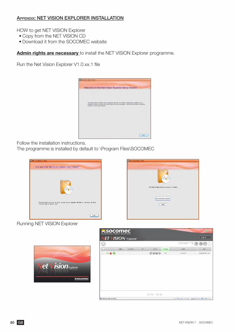
80 GB NET-VISION 7 - SOCOMEC
appendix: net vision explorer installation
HOW to get NET VISION Explorer• Copy from the NET VISION CD• Download it from the SOCOMEC website
Admin rights are necessary to install the NET VISION Explorer programme.
Run the Net Vision Explorer V1.0.xx.1 file
Follow the installation instructions.The programme is installed by default to \Program Files\SOCOMEC
Running NET VISION Explorer
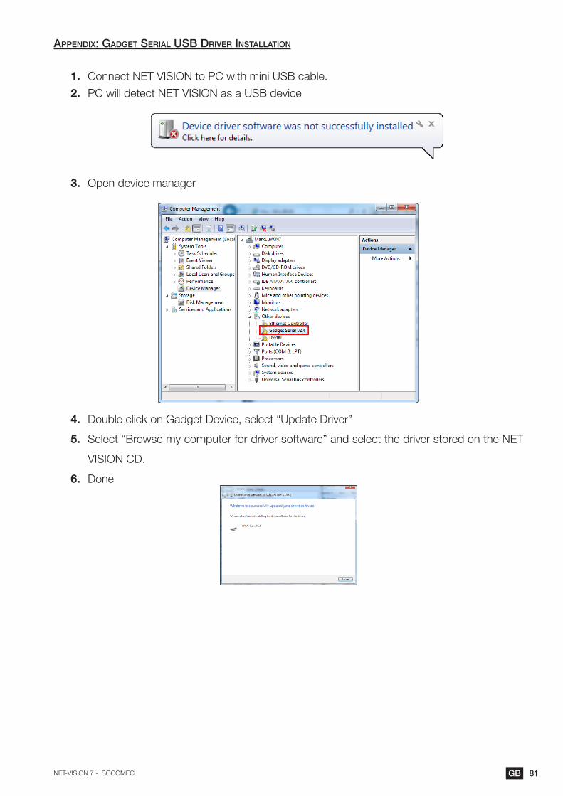
81GBNET-VISION 7 - SOCOMEC
appendix: gadget serial usb driver installation
1. Connect NET VISION to PC with mini USB cable.
2. PC will detect NET VISION as a USB device
3. Open device manager
4. Double click on Gadget Device, select “Update Driver”
5. Select “Browse my computer for driver software” and select the driver stored on the NET
VISION CD.
6. Done

82 GB NET-VISION 7 - SOCOMEC
appendix: teChniCal information
LED DefinitionThe function of the NET VISION is indicated by the Status/EMD and Network LEDs, as listed in the following table.
Port Green LED Yellow LED Function
Network
ON Flashing(1sec) Ethernet 100 Traffic
OFF Flashing(1sec) Ethernet 10 Traffic
ON ON 100 Base-TX Ready
OFF ON 10 Base-T Ready
OFF OFF Ethernet Disconnection
Status/EMD
OFF Flashing ~1 second UPS detection
ON OFF UPS detected, no com with UPS
ON Flashing Communication with UPS
Two LEDs cross Flashing Two LEDs cross Flashing Auto Diagnostic Mode
ON ON Auto Diagnostic Failed
OFF OFF Hardware Error
Technical specification
Function Description
Power Input NV with USB (Host) function voltage: +7.5V ~ 40V
Power Consumption 3.0 Watts Maximum
SMT Switch SMT switch on the board for configuration
Dimensions (L x W x H mm) 129.9(L) x 60.0(W) mm
Operating Temperature -20 ~ 70° C
Operating Humidity 10 ~ 80 % (Non-condensing)
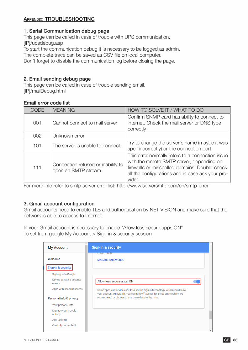
83GBNET-VISION 7 - SOCOMEC
appendix: troubleshooting
1. Serial Communication debug pageThis page can be called in case of trouble with UPS communication.[IP]/upsdebug.aspTo start the communication debug it is necessary to be logged as admin.The complete trace can be saved as CSV file on local computer.Don’t forget to disable the communication log before closing the page.
2. Email sending debug pageThis page can be called in case of trouble sending email.[IP]/mailDebug.html
Email error code listCODE MEANING HOW TO SOLVE IT / WHAT TO DO
001 Cannot connect to mail server Confirm SNMP card has ability to connect to internet. Check the mail server or DNS type correctly
002 Unknown error
101 The server is unable to connect.Try to change the server's name (maybe it was spell incorrectly) or the connection port.
111Connection refused or inability to open an SMTP stream.
This error normally refers to a connection issue with the remote SMTP server, depending on firewalls or misspelled domains. Double-check all the configurations and in case ask your pro-vider.
For more info refer to smtp server error list: http://www.serversmtp.com/en/smtp-error
3. Gmail account configurationGmail accounts need to enable TLS and authentication by NET VISION and make sure that the network is able to access to Internet.
In your Gmail account is necessary to enable “Allow less secure apps ON”To set from google My Account > Sign-in & security session

Non contractual document. Subject to change without notice.
www.socomec.com
hEAd offICE
SOCOMEC GROUPSAS SOCOMEC capital 10 686 000 € R.C.S. Strasbourg B 548 500 149 B.P. 60010 - 1, rue de Westhouse F-67235 Benfeld Cedex - FRANCE Tel. +33 3 88 57 41 41 Fax +33 3 88 74 08 00 [email protected]
Socomec worldwide
BELGIUMCritical Power / Power Control & Safety / Energy EfficiencyTel. +32 2 340 02 30 Fax +32 2 346 28 99 [email protected]
FRANCECritical Power / Power Control & Safety / Energy EfficiencyTel. +33 1 45 14 63 00 Fax +33 1 48 67 31 12 [email protected]
GERMANyCritical PowerTel. +49 621 71 68 40 Fax +49 621 71 68 444 [email protected] Control & Safety / Energy EfficiencyTel. +49 7243 65292 0 Fax +49 7243 65292 13 [email protected]
ITALyCritical Power Tel.+39 02 98 242 942 Fax +39 02 98 240 723 [email protected] Control & Safety / Energy EfficiencyTel.+39 02 98 49 821 Fax +39 02 98 24 33 10 [email protected]
NETHERLANDSCritical Power / Power Control & Safety / Energy EfficiencyTel. +31 30 760 0900 Fax +31 30 637 2166 [email protected]
POLANDCritical PowerTel. +48 22 825 73 60 Fax. +48 22 825 73 70 [email protected] Control & Safety / Energy EfficiencyTel. +48 91 442 64 11 Fax +48 91 442 64 19 [email protected]
PORTUGALCritical Power / Power Control & Safety / Energy EfficiencyTel.+351 261 812 599 Fax +351 261 812 570 [email protected]
ROMANIACritical Power / Power Control & Safety / Energy EfficiencyTel. +40 21 319 36 88 Fax +40 21 319 36 89 [email protected]
SERBIACritical Power / Power Control & Safety / Energy EfficiencyTel. +381 11 40 43 246 Fax +381 11 40 43 245 [email protected]
SLOvENIACritical Power / Power Control & Safety / Energy EfficiencyTel. +386 1 5807 860 Fax +386 1 561 11 73 [email protected]
SPAINCritical Power / Power Control & Safety / Energy EfficiencyTel. +34 93 540 75 75 Fax +34 93 540 75 76 [email protected]
SwITZERLANDCritical PowerTel. +41 44 745 40 80 Fax +41 44 745 40 85 [email protected]
TURKEyCritical Power / Power Control & Safety / Energy EfficiencyTel. +90 216 540 71 20-21-22 Fax +90 216 540 71 27 [email protected]
UNITED KINGDOMCritical PowerTel. +44 1285 863 300 Fax +44 1285 862 304 [email protected] Control & Safety / Energy EfficiencyTel. +44 1462 440 033 Fax +44 1462 431 143 [email protected]
Non
con
trac
tual
doc
umen
t. ©
201
7, S
ocom
ec S
AS
. All
right
s re
serv
ed. -
doc
umen
t prin
ted
on p
aper
from
sus
tain
ably
man
aged
fore
sts.
YoUR dISTRIBUToR / PARTNER
IN ASIA PACIfIC
AUSTRALIACritical Power / Power Control & SafetyTel. +61 2 9325 3900 Fax +61 2 9888 9544 [email protected]
CHINACritical Power / Power Control & Safety / Energy EfficiencyTel. +86 21 52 98 95 55 Fax +86 21 62 28 34 68 [email protected]
INDIACritical Power / Power Control & Safety / Energy EfficiencyTel. +91 44 39215400 [email protected]
INDONESIAPower Control & Safety / Energy EfficiencyTel. +62 (21) 29619645-6Fax +62 (21) 29619644 [email protected] PowerTel. +62 (21) 29619645-6Fax +62 (21) 29619644 [email protected]
SINGAPORE Critical Power / Power Control & Safety / Energy EfficiencyTel.+65 6506 7600 Fax +65 64 58 7377 [email protected]
THAILANDCritical PowerTel. +66 2 941 1644 7 Fax +66 2 941 1650 [email protected]
IN MIddlE EAST
UNITED ARAB EMIRATESCritical Power / Power Control & Safety / Energy EfficiencyTel. +971 4 29 98 441 Fax +971 4 29 98 449 [email protected]
IN AMERICA
USA, CANADA & MEXICOPower Control & Safety / Energy EfficiencyTel. +1 617 245 0447 Fax +1 617 245 0437 [email protected]
oThER CoUNTRIES
NORTH AFRICAAlgeria / Morocco / [email protected]
AFRICAOther [email protected]
SOUTH EUROPECyprus / Greece / Israel / [email protected]
SOUTH AMERICATel. +34 93 540 75 75 [email protected]
MORE DETAILSwww.socomec.com/worldwide
IN EURoPE