netide runtime architecture consolidation - … cnet-ict-619543-netide/d 2.5 date: security: public...
TRANSCRIPT

Document: CNET-ICT-619543-NetIDE/D 2.5Date: Security: PublicStatus: Final Version: 1.0
Document Properties
Document Number: D 2.5
Document Title:
NetIDE Runtime Architecture Consolidation
Document Responsible: Telefonica, I+D
Document Editor(s): Pedro A. Aranda, Diego R. Lopez (TID)
Authors:
Pedro A. Aranda(TID) Elisa Rojas (TELCA)Roberto Doriguzzi Corin (CN) Kevin Phemius (THALES)Arne Schwabe (UPB) Christian Stritzke (IPT)Sergio Tamurejo (IMDEA)
Target Dissemination Level: PU
Status of the Document: Final
Version: 1.0
Production Properties:
Reviewers: Carmen Guerrero(IMDEA) & C. Stritzke (IPT)
Document History:
Version Date Issued by
1.0 22-Apr-2016 Pedro A. Aranda
Disclaimer:This document has been produced in the context of the NetIDE Project. The research leading to these results hasreceived funding from the European Community’s Seventh Framework Programme (FP7/2010–2013) under grantagreement n◦ 619543.All information in this document is provided “as is” and no guarantee or warranty is given that the informationis fit for any particular purpose. The user thereof uses the information at its sole risk and liability.For the avoidance of all doubts, the European Commission has no liability in respect of this document, which ismerely representing the authors view.
NetIDEPublic
i
Ref. Ares(2016)2304435 - 18/05/2016
Document: CNET-ICT-619543-NetIDE/D 2.5Date: Security: PublicStatus: Final Version: 1.0
Abstract:This deliverable presents the status of the architecture discussions in NetIDE after the secondyear review. The previous iteration of the architecture was proposed in Deliverable D2.4 [1] andwas implemented and verified in Work Package 4. As a result, we found out that the initialconcept of the core and the backends did not interact as expected and the core could not delimitits interactions with the backends.In this iteration of the architecture, we have dealt with most limitations that result from theinitial implementation of the core. We have a viable approach to the interaction between coreand backends, and have a new approach to application composition and conflict resolution whichwe have called transaction based.In addition, we have continued with the study of the state of the art and provide a short analysisof other approaches.
Keywords:
Network Engine, Conflict resolution, Run-to-completion, Shim, Backend, NetIDE protocol
iiPublic
NetIDE
Document: CNET-ICT-619543-NetIDE/D 2.5Date: Security: PublicStatus: Final Version: 1.0
Contents
List of Figures iv
List of Acronyms vi
Executive Summary 1
1 Introduction 2
2 NetIDE Engine 32.1 Shim Layer and Backend . . . . . . . . . . . . . . . . . . . . . . . . . . . . . . . . . . 4
2.1.1 General architecture of a Shim Layer . . . . . . . . . . . . . . . . . . . . . . . 4
2.1.2 General architecture of a Backend . . . . . . . . . . . . . . . . . . . . . . . . 5
2.2 Core Layer . . . . . . . . . . . . . . . . . . . . . . . . . . . . . . . . . . . . . . . . . 7
2.2.1 The LogPub module . . . . . . . . . . . . . . . . . . . . . . . . . . . . . . . . 7
2.2.2 Message format . . . . . . . . . . . . . . . . . . . . . . . . . . . . . . . . . . . 8
2.3 Application Format and IDE . . . . . . . . . . . . . . . . . . . . . . . . . . . . . . . 9
3 NetIDE Concepts, evolution and clarifications 103.1 Modelling the modules . . . . . . . . . . . . . . . . . . . . . . . . . . . . . . . . . . . 10
3.1.1 Shortcomings of the current OpenFlow (OF) model . . . . . . . . . . . . . . 10
3.1.2 Modelling modules . . . . . . . . . . . . . . . . . . . . . . . . . . . . . . . . . 11
3.1.3 Pairing input and output events: grouping vs. the FENCE mechanism . . . . . 12
3.2 Assumptions . . . . . . . . . . . . . . . . . . . . . . . . . . . . . . . . . . . . . . . . 15
3.3 Further work . . . . . . . . . . . . . . . . . . . . . . . . . . . . . . . . . . . . . . . . 15
4 Approaches to composition 164.1 Related work in composition . . . . . . . . . . . . . . . . . . . . . . . . . . . . . . . 16
4.1.1 Pyretic . . . . . . . . . . . . . . . . . . . . . . . . . . . . . . . . . . . . . . . 16
4.1.2 CoVisor . . . . . . . . . . . . . . . . . . . . . . . . . . . . . . . . . . . . . . . 16
4.1.3 Flowbricks . . . . . . . . . . . . . . . . . . . . . . . . . . . . . . . . . . . . . 17
4.2 Our approach . . . . . . . . . . . . . . . . . . . . . . . . . . . . . . . . . . . . . . . . 17
4.3 Mapping the Data Centre Use Case to composition specifications . . . . . . . . . . . 18
4.3.1 A short recap . . . . . . . . . . . . . . . . . . . . . . . . . . . . . . . . . . . . 18
4.3.2 Parallel composition in the DMZ . . . . . . . . . . . . . . . . . . . . . . . . . 19
4.3.3 Serial composition in the private zone . . . . . . . . . . . . . . . . . . . . . . 19
4.4 Mangling and merging of messages . . . . . . . . . . . . . . . . . . . . . . . . . . . . 20
4.5 Basic concepts for composition . . . . . . . . . . . . . . . . . . . . . . . . . . . . . . 21
4.6 Modular bricks . . . . . . . . . . . . . . . . . . . . . . . . . . . . . . . . . . . . . . . 22
4.6.1 Composing modular bricks in parallel . . . . . . . . . . . . . . . . . . . . . . 22
4.6.2 Composing modular bricks in sequence . . . . . . . . . . . . . . . . . . . . . . 27
4.6.3 Combination of different composition types . . . . . . . . . . . . . . . . . . . 30
4.7 Sending the composed output back to the network . . . . . . . . . . . . . . . . . . . 31
4.8 Further work . . . . . . . . . . . . . . . . . . . . . . . . . . . . . . . . . . . . . . . . 31
NetIDEPublic
iii
Document: CNET-ICT-619543-NetIDE/D 2.5Date: Security: PublicStatus: Final Version: 1.0
5 State of the art 335.1 PGA: Policy Graph Abstraction . . . . . . . . . . . . . . . . . . . . . . . . . . . . . 335.2 NetASM . . . . . . . . . . . . . . . . . . . . . . . . . . . . . . . . . . . . . . . . . . . 33
6 Conclusion 36
A NetIDE Protocol Specification v1.3 37A.1 The NetIDE protocol header . . . . . . . . . . . . . . . . . . . . . . . . . . . . . . . 37A.2 Module announcement . . . . . . . . . . . . . . . . . . . . . . . . . . . . . . . . . . . 38A.3 Heartbeat . . . . . . . . . . . . . . . . . . . . . . . . . . . . . . . . . . . . . . . . . . 39A.4 Handshake . . . . . . . . . . . . . . . . . . . . . . . . . . . . . . . . . . . . . . . . . 39A.5 The FENCE mechanism . . . . . . . . . . . . . . . . . . . . . . . . . . . . . . . . . . 40A.6 The OpenFlow protocol . . . . . . . . . . . . . . . . . . . . . . . . . . . . . . . . . . 41
A.6.1 Properly handling reply messages . . . . . . . . . . . . . . . . . . . . . . . . . 42A.7 Other SBI protocols . . . . . . . . . . . . . . . . . . . . . . . . . . . . . . . . . . . . 43
Bibliography 45
ivPublic
NetIDE

Document: CNET-ICT-619543-NetIDE/D 2.5Date: Security: PublicStatus: Final Version: 1.0
List of Figures
2.1 Architecture of the Network Engine . . . . . . . . . . . . . . . . . . . . . . . . . . . 32.2 Architecture of a shim . . . . . . . . . . . . . . . . . . . . . . . . . . . . . . . . . . . 42.3 Architecture of a Backend . . . . . . . . . . . . . . . . . . . . . . . . . . . . . . . . . 52.4 Architecture of the Network Engine with the Backend+. . . . . . . . . . . . . . . . . 62.5 High level view of the NetIDE Core . . . . . . . . . . . . . . . . . . . . . . . . . . . . 72.6 The location if the LogPub in the NetIDE Core . . . . . . . . . . . . . . . . . . . . . 82.7 The inner working of the LogPub in PUB mode . . . . . . . . . . . . . . . . . . . . . 92.8 The inner working of the LogPub in SUB mode . . . . . . . . . . . . . . . . . . . . . 9
3.1 Our view of a module . . . . . . . . . . . . . . . . . . . . . . . . . . . . . . . . . . . 113.2 Different execution flows . . . . . . . . . . . . . . . . . . . . . . . . . . . . . . . . . . 113.3 Encapsulating multiple responses in a single PDU . . . . . . . . . . . . . . . . . . . . 13
4.1 Logical and physical view of Use Case 1 . . . . . . . . . . . . . . . . . . . . . . . . . 184.2 Parallel composition . . . . . . . . . . . . . . . . . . . . . . . . . . . . . . . . . . . . 274.3 Sequential composition . . . . . . . . . . . . . . . . . . . . . . . . . . . . . . . . . . . 294.4 Sequential and parallel composition . . . . . . . . . . . . . . . . . . . . . . . . . . . . 304.5 Parallel and sequential composition . . . . . . . . . . . . . . . . . . . . . . . . . . . . 30
5.1 PGA system architecture [2] . . . . . . . . . . . . . . . . . . . . . . . . . . . . . . . . 345.2 NetASM is located between P4 [2] and the network [3] . . . . . . . . . . . . . . . . . 345.3 NetASM instruction set [3] . . . . . . . . . . . . . . . . . . . . . . . . . . . . . . . . 35
A.1 Fence mechanism workflow. Both nxid and module id refer to the NetIDE headerfields. . . . . . . . . . . . . . . . . . . . . . . . . . . . . . . . . . . . . . . . . . . . . 41
A.2 Request/reply message handling. xid refers to the OpenFlow header field. . . . . . . 42
NetIDEPublic
v
Document: CNET-ICT-619543-NetIDE/D 2.5Date: Security: PublicStatus: Final Version: 1.0
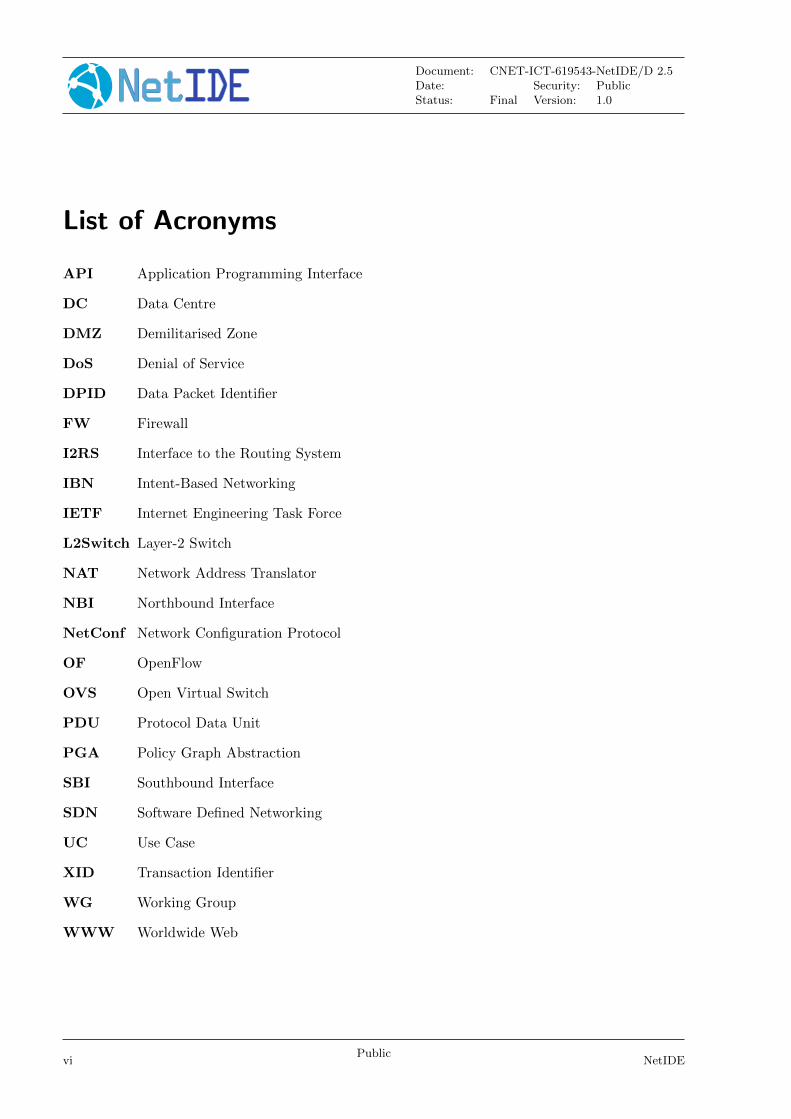
List of Acronyms
API Application Programming Interface
DC Data Centre
DMZ Demilitarised Zone
DoS Denial of Service
DPID Data Packet Identifier
FW Firewall
I2RS Interface to the Routing System
IBN Intent-Based Networking
IETF Internet Engineering Task Force
L2Switch Layer-2 Switch
NAT Network Address Translator
NBI Northbound Interface
NetConf Network Configuration Protocol
OF OpenFlow
OVS Open Virtual Switch
PDU Protocol Data Unit
PGA Policy Graph Abstraction
SBI Southbound Interface
SDN Software Defined Networking
UC Use Case
XID Transaction Identifier
WG Working Group
WWW Worldwide Web
viPublic
NetIDE
Document: CNET-ICT-619543-NetIDE/D 2.5Date: Security: PublicStatus: Final Version: 1.0
Executive Summary
This document describes the advances in the architectural concepts since Deliverable D2.4 [1]until the end of the second year. In this period of time, we have performed a second iterationin the implementation of the NetIDE architecture, motivated by the introduction of the Corein the Network Engine. The Core simplifies the architecture and implementation of the shims,since it decouples the interaction between core and shims from the implementation of applicationcomposition mechanisms.
As a result of the first implementation of the core, we unveiled some underlying issues in ourarchitecture, linked with our way to model modules. We have solved these issues and as a result,we have been able to overcome the deadlock we were in and continue our development. Currently,weare tackling new composition modes which go beyond the current state of the art.
This milestone document is highly interdependent with Milestone M4.1 [4], which documents thestatus of the implementation. We include a consolidated version of the NetIDE protocol definitionin Annex A to document the advances since the milestone document.
NetIDEPublic
1
Document: CNET-ICT-619543-NetIDE/D 2.5Date: Security: PublicStatus: Final Version: 1.0
1 Introduction
This milestone document presents the state of the evolution of the NetIDE architecture at the endof the second year of the project. We document the additional architectural work since the releaseof Deliverable D2.4 [1]. The contents of this document takes the initial contributions to the internalMilestone M2.3 document and refines it for a more consistent presentation.
The project has spent a good amount of work dealing with the concept of the NetIDE Applicationand its implications as a result of the first prototype of the Core. We have encountered someconceptual shortcomings which had to be addressed in order to get a working Core where we canexplore our application composition approach and specifically the conflict resolution concepts wehave come up with.
This deliverable is structured as follows:
• In Chapter 2 we present the current status of the NetIDE Network Engine and discuss theimpact of the evolution of our theoretical foundations on its different components.
• In Chapter 3 we discuss the underlying model for network applications we have assumed forour development and propose a set of reasonable assumptions on the network applicationsthat we will use to build NetIDE applications.
• In Chapter 4 we discuss our theoretical approach to application composition in the contextof what other state-of-the-art projects have proposed in the field.
• In Chapter 5 we position our approach additional against the current state of the art, and
• in Chapter 6 we draw conclusions and outline the resulting work.
In addition we document the current status of the NetIDE Protocol in Annex A. During the lastediting phase, the project underwent the 2nd year review and the review report has arrived beforedelivering this document. We feel that the purpose of the outcome letter will be better served, ifthe comments are addressed in depth in the upcoming Deliverable D2.6.
2Public
NetIDE
Document: CNET-ICT-619543-NetIDE/D 2.5Date: Security: PublicStatus: Final Version: 1.0
2 NetIDE Engine
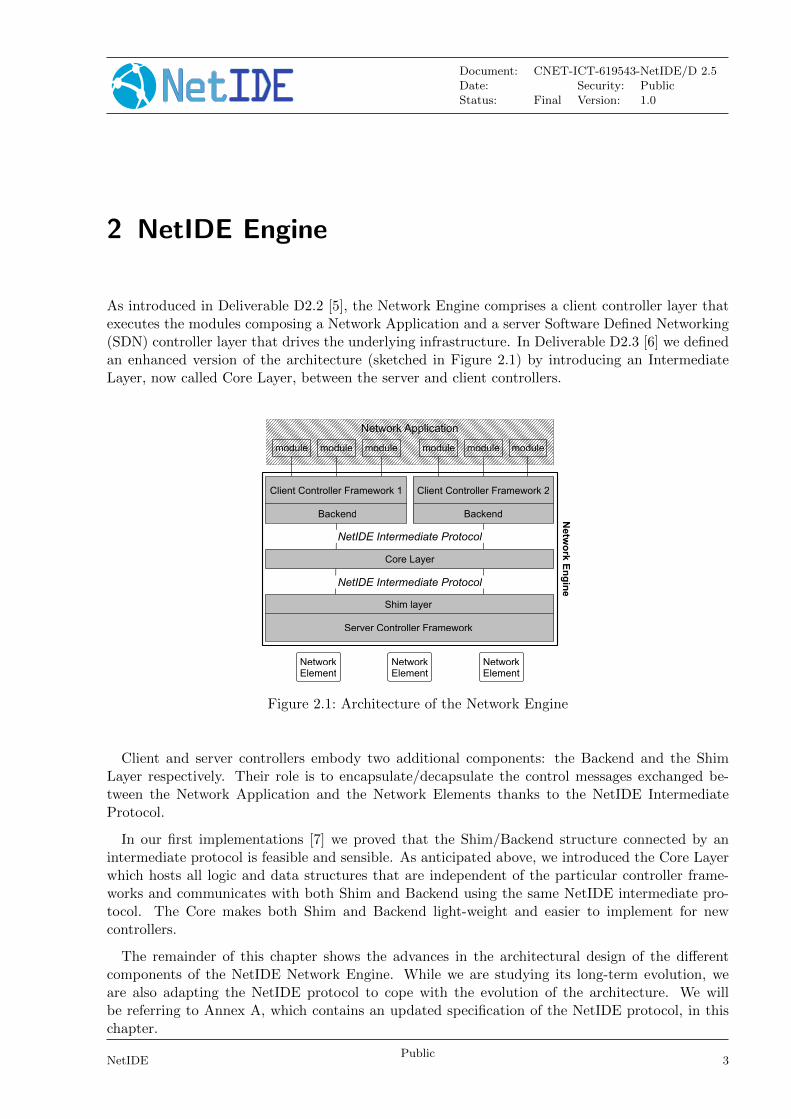
As introduced in Deliverable D2.2 [5], the Network Engine comprises a client controller layer thatexecutes the modules composing a Network Application and a server Software Defined Networking(SDN) controller layer that drives the underlying infrastructure. In Deliverable D2.3 [6] we definedan enhanced version of the architecture (sketched in Figure 2.1) by introducing an IntermediateLayer, now called Core Layer, between the server and client controllers.
Netw
ork E
ng
ine
NetworkElement
NetworkElement
NetworkElement
Server Controller Framework
Shim layer
Backend Backend
Client Controller Framework 1 Client Controller Framework 2
NetIDE Intermediate Protocol
module
Core Layer
NetIDE Intermediate Protocol
modulemodule module module module
Network Application
Figure 2.1: Architecture of the Network Engine
Client and server controllers embody two additional components: the Backend and the ShimLayer respectively. Their role is to encapsulate/decapsulate the control messages exchanged be-tween the Network Application and the Network Elements thanks to the NetIDE IntermediateProtocol.
In our first implementations [7] we proved that the Shim/Backend structure connected by anintermediate protocol is feasible and sensible. As anticipated above, we introduced the Core Layerwhich hosts all logic and data structures that are independent of the particular controller frame-works and communicates with both Shim and Backend using the same NetIDE intermediate pro-tocol. The Core makes both Shim and Backend light-weight and easier to implement for newcontrollers.
The remainder of this chapter shows the advances in the architectural design of the differentcomponents of the NetIDE Network Engine. While we are studying its long-term evolution, weare also adapting the NetIDE protocol to cope with the evolution of the architecture. We willbe referring to Annex A, which contains an updated specification of the NetIDE protocol, in thischapter.
NetIDEPublic
3
Document: CNET-ICT-619543-NetIDE/D 2.5Date: Security: PublicStatus: Final Version: 1.0
2.1 Shim Layer and Backend
As a brief reminder, the Backend module essentially attaches to a client controllers SouthboundInterface (SBI), intercepts any activities there, and translates them into the NetIDE API format.Similarly, the Shim attaches at the Northbound Interface (NBI) of a server controller and interactswith the Core Layer and with the Backends of the active client controllers. In this Section weprovide a short description of the internal architecture for both Shim Layer and Backend.
2.1.1 General architecture of a Shim Layer
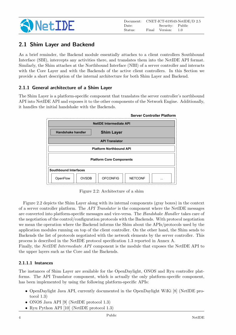
The Shim Layer is a platform-specific component that translates the server controller’s northboundAPI into NetIDE API and exposes it to the other components of the Network Engine. Additionally,it handles the initial handshake with the Backends.
Figure 2.2: Architecture of a shim
Figure 2.2 depicts the Shim Layer along with its internal components (gray boxes) in the contextof a server controller platform. The API Translator is the component where the NetIDE messagesare converted into platform-specific messages and vice-versa. The Handshake Handler takes care ofthe negotiation of the control/configuration protocols with the Backends. With protocol negotiationwe mean the operation where the Backend informs the Shim about the APIs/protocols used by theapplication modules running on top of the client controller. On the other hand, the Shim sends toBackends the list of protocols negotiated with the network elements by the server controller. Thisprocess is described in the NetIDE protocol specification 1.3 reported in Annex A.Finally, the NetIDE Intermediate API component is the module that exposes the NetIDE API tothe upper layers such as the Core and the Backends.
2.1.1.1 Instances
The instances of Shim Layer are available for the OpenDaylight, ONOS and Ryu controller plat-forms. The API Translator component, which is actually the only platform-specific component,has been implemented by using the following platform-specific APIs:
• OpenDaylight Java API, currently documented in the OpenDaylight WiKi [8] (NetIDE pro-tocol 1.3)
• ONOS Java API [9] (NetIDE protocol 1.3)
• Ryu Python API [10] (NetIDE protocol 1.3)
4Public
NetIDE
Document: CNET-ICT-619543-NetIDE/D 2.5Date: Security: PublicStatus: Final Version: 1.0
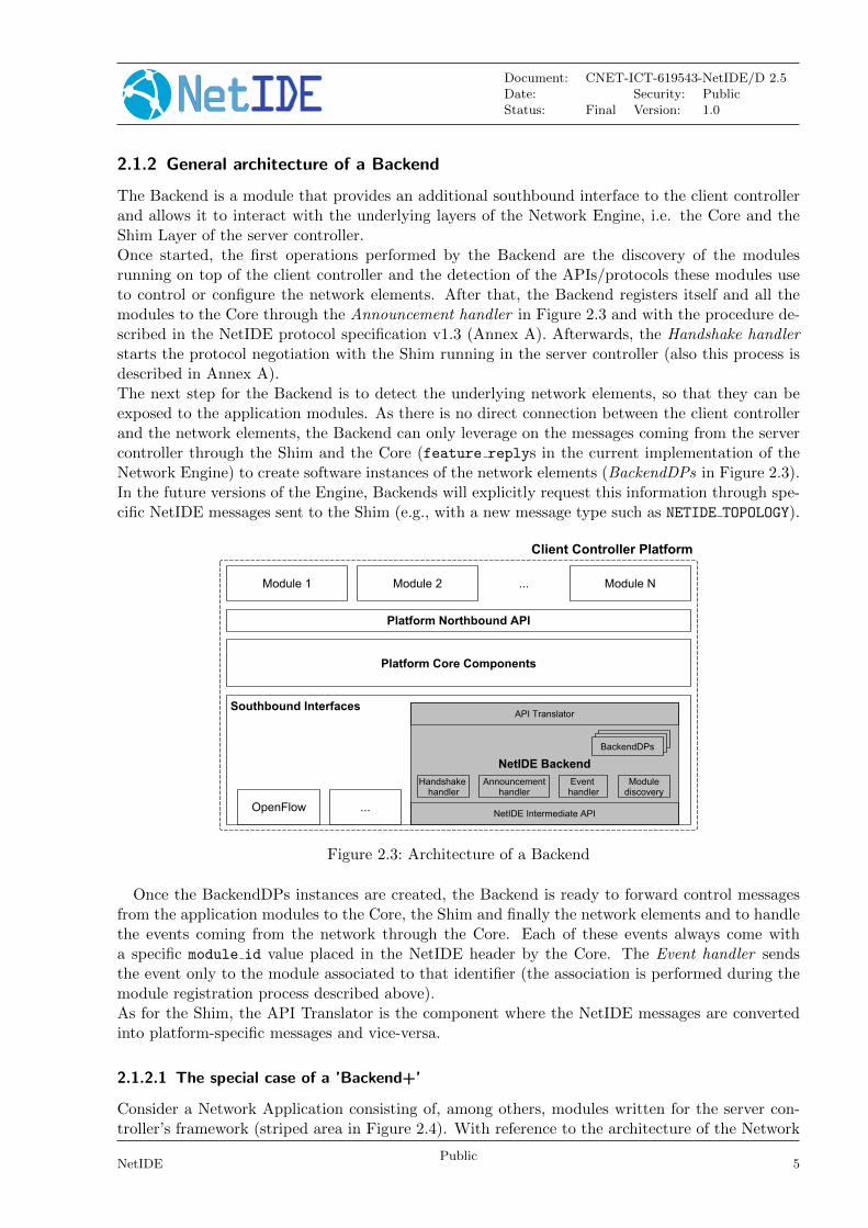
2.1.2 General architecture of a Backend
The Backend is a module that provides an additional southbound interface to the client controllerand allows it to interact with the underlying layers of the Network Engine, i.e. the Core and theShim Layer of the server controller.Once started, the first operations performed by the Backend are the discovery of the modulesrunning on top of the client controller and the detection of the APIs/protocols these modules useto control or configure the network elements. After that, the Backend registers itself and all themodules to the Core through the Announcement handler in Figure 2.3 and with the procedure de-scribed in the NetIDE protocol specification v1.3 (Annex A). Afterwards, the Handshake handlerstarts the protocol negotiation with the Shim running in the server controller (also this process isdescribed in Annex A).The next step for the Backend is to detect the underlying network elements, so that they can beexposed to the application modules. As there is no direct connection between the client controllerand the network elements, the Backend can only leverage on the messages coming from the servercontroller through the Shim and the Core (feature replys in the current implementation of theNetwork Engine) to create software instances of the network elements (BackendDPs in Figure 2.3).In the future versions of the Engine, Backends will explicitly request this information through spe-cific NetIDE messages sent to the Shim (e.g., with a new message type such as NETIDE TOPOLOGY).
Figure 2.3: Architecture of a Backend
Once the BackendDPs instances are created, the Backend is ready to forward control messagesfrom the application modules to the Core, the Shim and finally the network elements and to handlethe events coming from the network through the Core. Each of these events always come witha specific module id value placed in the NetIDE header by the Core. The Event handler sendsthe event only to the module associated to that identifier (the association is performed during themodule registration process described above).As for the Shim, the API Translator is the component where the NetIDE messages are convertedinto platform-specific messages and vice-versa.
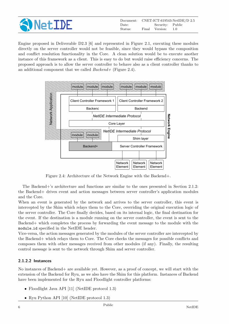
2.1.2.1 The special case of a ’Backend+’
Consider a Network Application consisting of, among others, modules written for the server con-troller’s framework (striped area in Figure 2.4). With reference to the architecture of the Network
NetIDEPublic
5
Document: CNET-ICT-619543-NetIDE/D 2.5Date: Security: PublicStatus: Final Version: 1.0
Engine proposed in Deliverable D2.3 [6] and represented in Figure 2.1, executing these modulesdirectly on the server controller would not be feasible, since they would bypass the compositionand conflict resolution functionality in the Core. A clean solution would be to execute anotherinstance of this framework as a client. This is easy to do but would raise efficiency concerns. Theproposed approach is to allow the server controller to behave also as a client controller thanks toan additional component that we called Backend+ (Figure 2.4).
Netw
ork E
ng
ine
NetworkElement
NetworkElement
Server Controller Framework
Shim layer
Backend Backend
Client Controller Framework 1 Client Controller Framework 2
NetIDE Intermediate Protocol
module
Core Layer
NetIDE Intermediate Protocol
modulemodule module module module
Backend+
module module
Net
wor
k A
pplic
atio
n
NetworkElement
Figure 2.4: Architecture of the Network Engine with the Backend+.
The Backend+’s architecture and functions are similar to the ones presented in Section 2.1.2:the Backend+ drives event and action messages between server controller’s application modulesand the Core.When an event is generated by the network and arrives to the server controller, this event isintercepted by the Shim which relays them to the Core, overriding the original execution logic ofthe server controller. The Core finally decides, based on its internal logic, the final destination forthe event. If the destination is a module running on the server controller, the event is sent to theBackend+ which completes the process by forwarding the event message to the module with themodule id specified in the NetIDE header.Vice-versa, the action messages generated by the modules of the server controller are intercepted bythe Backend+ which relays them to Core. The Core checks the messages for possible conflicts andcomposes them with other messages received from other modules (if any). Finally, the resultingcontrol message is sent to the network through Shim and server controller.
2.1.2.2 Instances
No instances of Backend+ are available yet. However, as a proof of concept, we will start with theextension of the Backend for Ryu, as we also have the Shim for this platform. Instances of Backendhave been implemented for the Ryu and Floodlight controller platforms:
• Floodlight Java API [11] (NetIDE protocol 1.3)
• Ryu Python API [10] (NetIDE protocol 1.3)
6Public
NetIDE
Document: CNET-ICT-619543-NetIDE/D 2.5Date: Security: PublicStatus: Final Version: 1.0
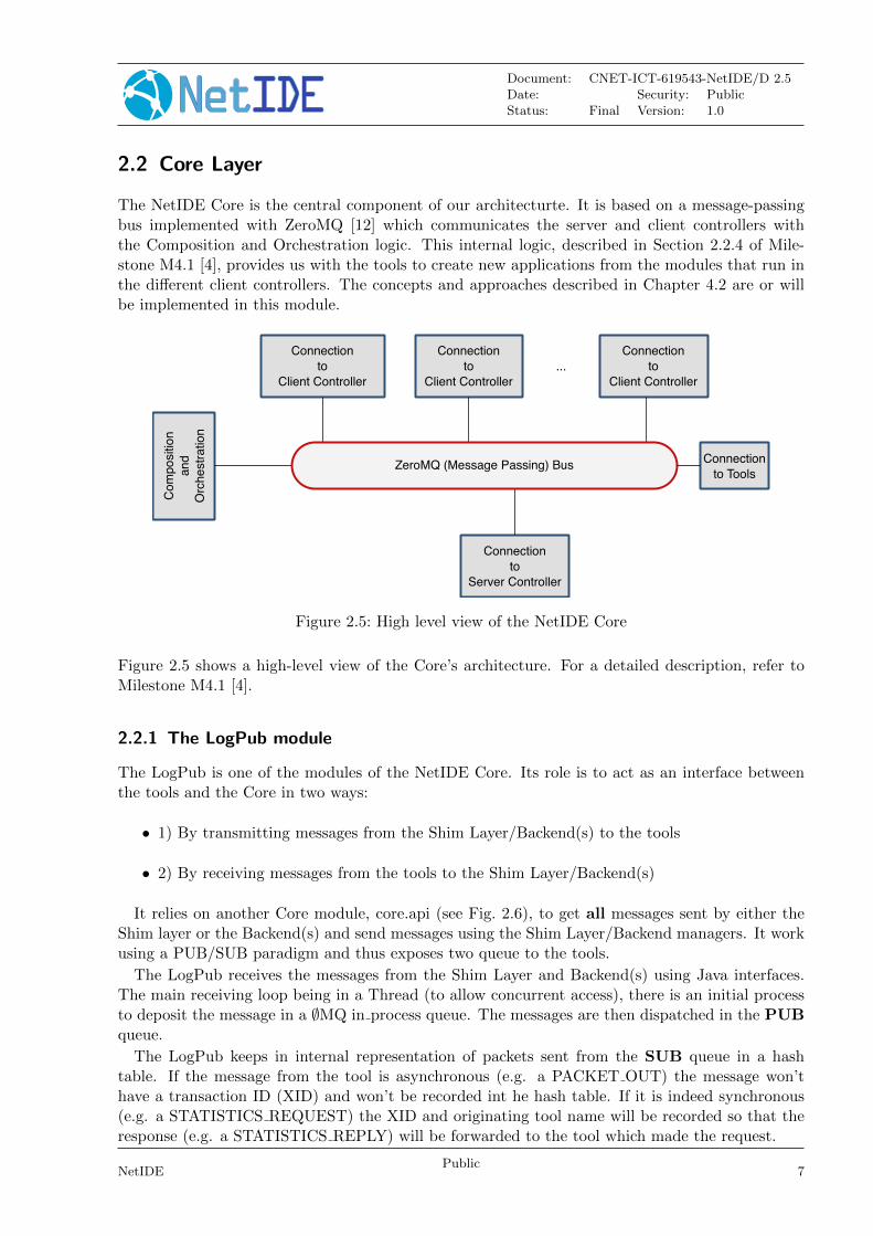
2.2 Core Layer
The NetIDE Core is the central component of our architecturte. It is based on a message-passingbus implemented with ZeroMQ [12] which communicates the server and client controllers withthe Composition and Orchestration logic. This internal logic, described in Section 2.2.4 of Mile-stone M4.1 [4], provides us with the tools to create new applications from the modules that run inthe different client controllers. The concepts and approaches described in Chapter 4.2 are or willbe implemented in this module.
ZeroMQ (Message Passing) Bus
Connection
to
Client Controller
Connection
to
Client Controller
Connection
to
Client Controller
Connection
to
Server Controller
Co
mp
ositi
on
an
d
Orc
he
str
atio
n
Connection
to Tools
...
Figure 2.5: High level view of the NetIDE Core
Figure 2.5 shows a high-level view of the Core’s architecture. For a detailed description, refer toMilestone M4.1 [4].
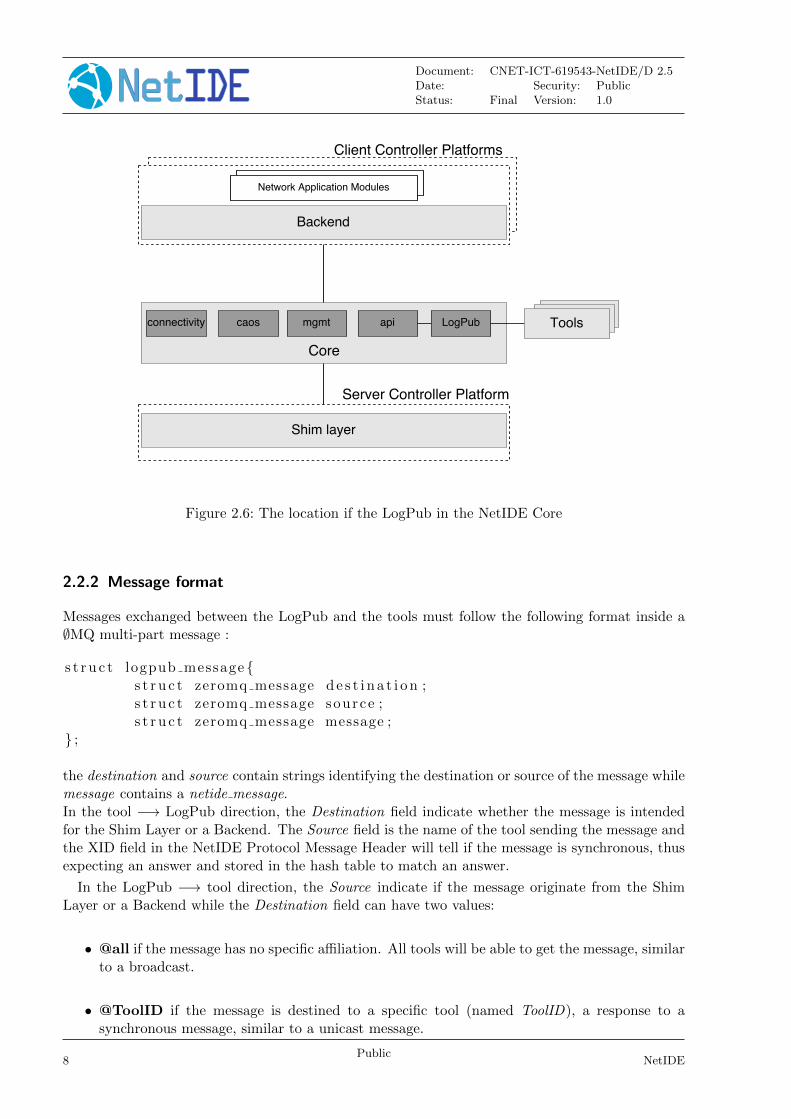
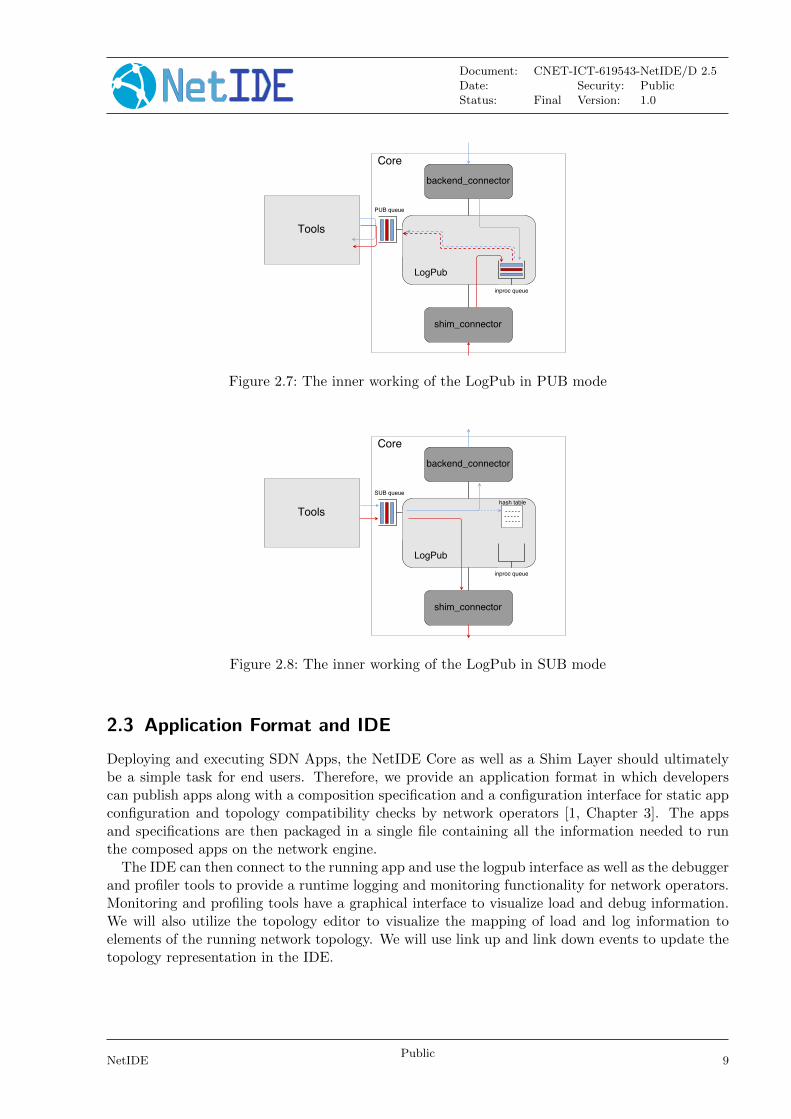
2.2.1 The LogPub module
The LogPub is one of the modules of the NetIDE Core. Its role is to act as an interface betweenthe tools and the Core in two ways:
• 1) By transmitting messages from the Shim Layer/Backend(s) to the tools
• 2) By receiving messages from the tools to the Shim Layer/Backend(s)
It relies on another Core module, core.api (see Fig. 2.6), to get all messages sent by either theShim layer or the Backend(s) and send messages using the Shim Layer/Backend managers. It workusing a PUB/SUB paradigm and thus exposes two queue to the tools.
The LogPub receives the messages from the Shim Layer and Backend(s) using Java interfaces.The main receiving loop being in a Thread (to allow concurrent access), there is an initial processto deposit the message in a ∅MQ in process queue. The messages are then dispatched in the PUBqueue.
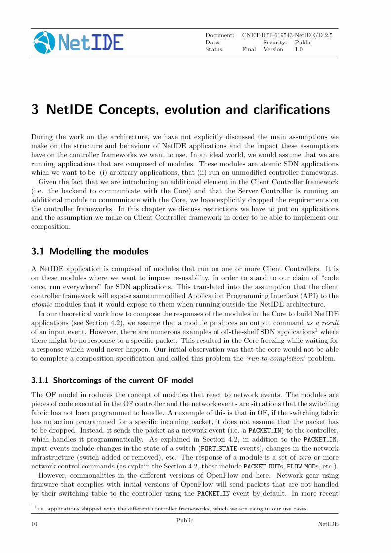
The LogPub keeps in internal representation of packets sent from the SUB queue in a hashtable. If the message from the tool is asynchronous (e.g. a PACKET OUT) the message won’thave a transaction ID (XID) and won’t be recorded int he hash table. If it is indeed synchronous(e.g. a STATISTICS REQUEST) the XID and originating tool name will be recorded so that theresponse (e.g. a STATISTICS REPLY) will be forwarded to the tool which made the request.
NetIDEPublic
7
Document: CNET-ICT-619543-NetIDE/D 2.5Date: Security: PublicStatus: Final Version: 1.0
Figure 2.6: The location if the LogPub in the NetIDE Core
2.2.2 Message format
Messages exchanged between the LogPub and the tools must follow the following format inside a∅MQ multi-part message :
s t r u c t logpub message {s t r u c t zeromq message d e s t i n a t i o n ;s t r u c t zeromq message source ;s t r u c t zeromq message message ;
} ;
the destination and source contain strings identifying the destination or source of the message whilemessage contains a netide message.In the tool −→ LogPub direction, the Destination field indicate whether the message is intendedfor the Shim Layer or a Backend. The Source field is the name of the tool sending the message andthe XID field in the NetIDE Protocol Message Header will tell if the message is synchronous, thusexpecting an answer and stored in the hash table to match an answer.
In the LogPub −→ tool direction, the Source indicate if the message originate from the ShimLayer or a Backend while the Destination field can have two values:
• @all if the message has no specific affiliation. All tools will be able to get the message, similarto a broadcast.
• @ToolID if the message is destined to a specific tool (named ToolID), a response to asynchronous message, similar to a unicast message.
8Public
NetIDE
Document: CNET-ICT-619543-NetIDE/D 2.5Date: Security: PublicStatus: Final Version: 1.0
Figure 2.7: The inner working of the LogPub in PUB mode
Figure 2.8: The inner working of the LogPub in SUB mode
2.3 Application Format and IDE
Deploying and executing SDN Apps, the NetIDE Core as well as a Shim Layer should ultimatelybe a simple task for end users. Therefore, we provide an application format in which developerscan publish apps along with a composition specification and a configuration interface for static appconfiguration and topology compatibility checks by network operators [1, Chapter 3]. The appsand specifications are then packaged in a single file containing all the information needed to runthe composed apps on the network engine.
The IDE can then connect to the running app and use the logpub interface as well as the debuggerand profiler tools to provide a runtime logging and monitoring functionality for network operators.Monitoring and profiling tools have a graphical interface to visualize load and debug information.We will also utilize the topology editor to visualize the mapping of load and log information toelements of the running network topology. We will use link up and link down events to update thetopology representation in the IDE.
NetIDEPublic
9
Document: CNET-ICT-619543-NetIDE/D 2.5Date: Security: PublicStatus: Final Version: 1.0
3 NetIDE Concepts, evolution and clarifications
During the work on the architecture, we have not explicitly discussed the main assumptions wemake on the structure and behaviour of NetIDE applications and the impact these assumptionshave on the controller frameworks we want to use. In an ideal world, we would assume that we arerunning applications that are composed of modules. These modules are atomic SDN applicationswhich we want to be (i) arbitrary applications, that (ii) run on unmodified controller frameworks.
Given the fact that we are introducing an additional element in the Client Controller framework(i.e. the backend to communicate with the Core) and that the Server Controller is running anadditional module to communicate with the Core, we have explicitly dropped the requirements onthe controller frameworks. In this chapter we discuss restrictions we have to put on applicationsand the assumption we make on Client Controller framework in order to be able to implement ourcomposition.
3.1 Modelling the modules
A NetIDE application is composed of modules that run on one or more Client Controllers. It ison these modules where we want to impose re-usability, in order to stand to our claim of “codeonce, run everywhere” for SDN applications. This translated into the assumption that the clientcontroller framework will expose same unmodified Application Programming Interface (API) to theatomic modules that it would expose to them when running outside the NetIDE architecture.
In our theoretical work how to compose the responses of the modules in the Core to build NetIDEapplications (see Section 4.2), we assume that a module produces an output command as a resultof an input event. However, there are numerous examples of off-the-shelf SDN applications1 wherethere might be no response to a specific packet. This resulted in the Core freezing while waiting fora response which would never happen. Our initial observation was that the core would not be ableto complete a composition specification and called this problem the ’run-to-completion’ problem.
3.1.1 Shortcomings of the current OF model
The OF model introduces the concept of modules that react to network events. The modules arepieces of code executed in the OF controller and the network events are situations that the switchingfabric has not been programmed to handle. An example of this is that in OF, if the switching fabrichas no action programmed for a specific incoming packet, it does not assume that the packet hasto be dropped. Instead, it sends the packet as a network event (i.e. a PACKET IN) to the controller,which handles it programmatically. As explained in Section 4.2, in addition to the PACKET IN,input events include changes in the state of a switch (PORT STATE events), changes in the networkinfrastructure (switch added or removed), etc. The response of a module is a set of zero or morenetwork control commands (as explain the Section 4.2, these include PACKET OUTs, FLOW MODs, etc.).
However, commonalities in the different versions of OpenFlow end here. Network gear usingfirmware that complies with initial versions of OpenFlow will send packets that are not handledby their switching table to the controller using the PACKET IN event by default. In more recent
1i.e. applications shipped with the different controller frameworks, which we are using in our use cases
10Public
NetIDE

Document: CNET-ICT-619543-NetIDE/D 2.5Date: Security: PublicStatus: Final Version: 1.0
versions, packets will be silently dropped if there is no explicit rule to send unmatched packets tothe controller.
In addition, OpenFlow not only has this reactive model, but also includes a proactive behaviourthat will send output commands that are not related to any network event to the network. This isneeded, e.g. to make sure that the default action of the switching matrix is to send the packet tothe controller as a PACKET IN in the case of OFv1.3 and above.
Input:PACKET IN
Generalised: evModule
Output:(PACKET OUT | FLOW MOD)*
Generalised: out*
Figure 3.1: Our view of a module
Figure 3.1 shows a simplified, high-level view of a module we have used for our initial implemen-tations. In it, we only consider PACKET IN events as input for modules and either PACKET OUT orFLOW MOD as outputs of the module.
3.1.2 Modelling modules
From a very high level perspective, and leaving the previously mentioned case of modules thatsend commands to the network proactively for further study, we can have different several differentexecution flows, depending on whether nor output events occur and when they happen in time ifthey in fact occur. The different possibilities are shown in Figure 3.2.
Module
ev
out
out1
n
Execution
(a) Module with one or more re-sponses
Module
ev
Execution
(b) Module with no re-sponse
Module
ev
out
out1
n
Execution
(c) Module with silence at theend of the execution
Figure 3.2: Different execution flows
The most simple case, which would be that of a module with a single output as a response to aninput event upon which the execution of the module terminates, can be derived from Figure 3.2a,if the only output event is outn. State-of-the-art solutions like FlowVisor or CoVisor do notconsider to understand the relation between the input and the output event and thus only partiallyaccommodate for such a model. They only deal with single output events that they compare withtheir network model for slicing or deducing the output command that should be sent to the switch.
NetIDEPublic
11
Document: CNET-ICT-619543-NetIDE/D 2.5Date: Security: PublicStatus: Final Version: 1.0
These solutions will completely miss the situation shown in Figure 3.2b. Actually the semanticsof this module behaviour is not tackled by current OF models. On one hand, it is a silent request todrop the input event and if that input event corresponds to a PACKET IN, the packet associated to itwill be dropped. However, there are other architectural dependencies here to decide the semanticsbehind this behaviour. This depends on the version of the OF protocol. In the OF specificationv1.0, switches automatically send packets they could not treat with their current switching stateto the controller. However this is no longer the case in OF v1.3 and later. As a matter of fact,controller frameworks like Floodlight will send a first FLOW MOD command to the switches duringinitialisation, to restore this behaviour. However, this is platform-dependent and cannot beexpected to happen at all times.
This solution gets even worse if we consider the possibility of a module that sends one or moreresponses to an input event but includes a significant processing period after the last responsebefore finishing the execution of the event response routine (Figure 3.2c).
The impact on conflict resolution of this semantic ambiguity is significant. Concentrating onthe case of response versus no response (and putting the case of silence after activity shown inFigure 3.2c aside for the moment being), we find some of the most serious shortcomings of theOpenFlow protocol. Let’s take the case of two modules, both well-behaving on their own, thatblock packets linked, e.g. to a Denial of Service (DoS) attack:
• One includes a monitoring function that uses the input events to provide statistics, forensics,etc. Packets should therefore not be dropped and therefore, no output command is generated.
• The other sends explicit DROP actions for packets belonging to DoS attacks
In this case, if we make the explicit DROP prevail over the silence, we loose the extra capabilitiesprovided by the module that generates no explicit output.
3.1.3 Pairing input and output events: grouping vs. the FENCE mechanism
The initial implementation of the Core always assumed that there would be a response to a networkevent. As explained in the previous section, this is not always the case. Therefore we needed toprovide (i) a means for the core to know when the module has finished processing the input event,and (ii) a means in the core to correlate input events with their output.
In order to be able to pair network events to their resulting output events, we have two possibil-ities:
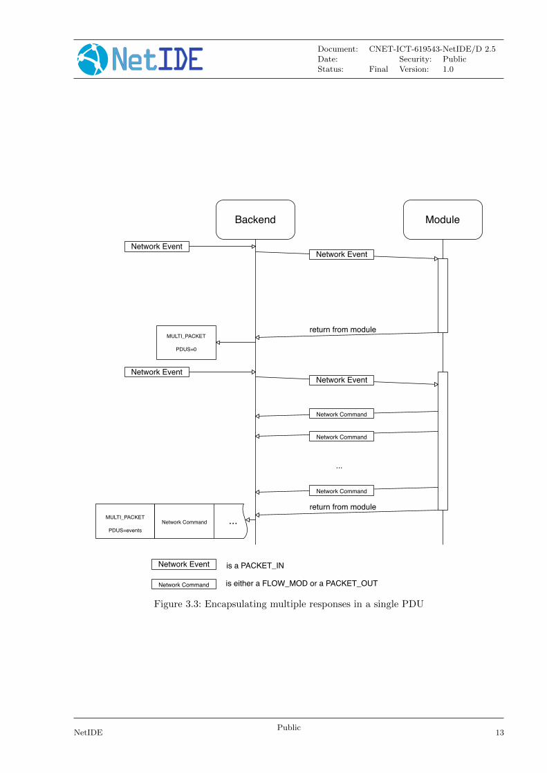
Grouping messages One possible solution is to group all responses to a PACKET IN in a singleProtocol Data Unit (PDU): the backend collects all responses produced by a module and when itdetects that the event has been handled by the message, it emits a response PDU. A new messagetype for this response PDU needs to be defined in the NetIDE protocol.An additional refinement would be to include the PACKET IN in the multi-packet PDU in order todeliver the input and output events correlated to the Core. This could be beneficial, depending onits implementation.
12Public
NetIDE
Document: CNET-ICT-619543-NetIDE/D 2.5Date: Security: PublicStatus: Final Version: 1.0
MULTI_PACKET
PDUS=0
MULTI_PACKET
PDUS=events
Network Command ...
ModuleBackend
Network Event
return from module
Network Event
Network EventNetwork Event
Network Command
return from module
Network Command
Network Command
Network Command is either a FLOW_MOD or a PACKET_OUT
...
Network Event is a PACKET_IN
Figure 3.3: Encapsulating multiple responses in a single PDU
NetIDEPublic
13
Document: CNET-ICT-619543-NetIDE/D 2.5Date: Security: PublicStatus: Final Version: 1.0
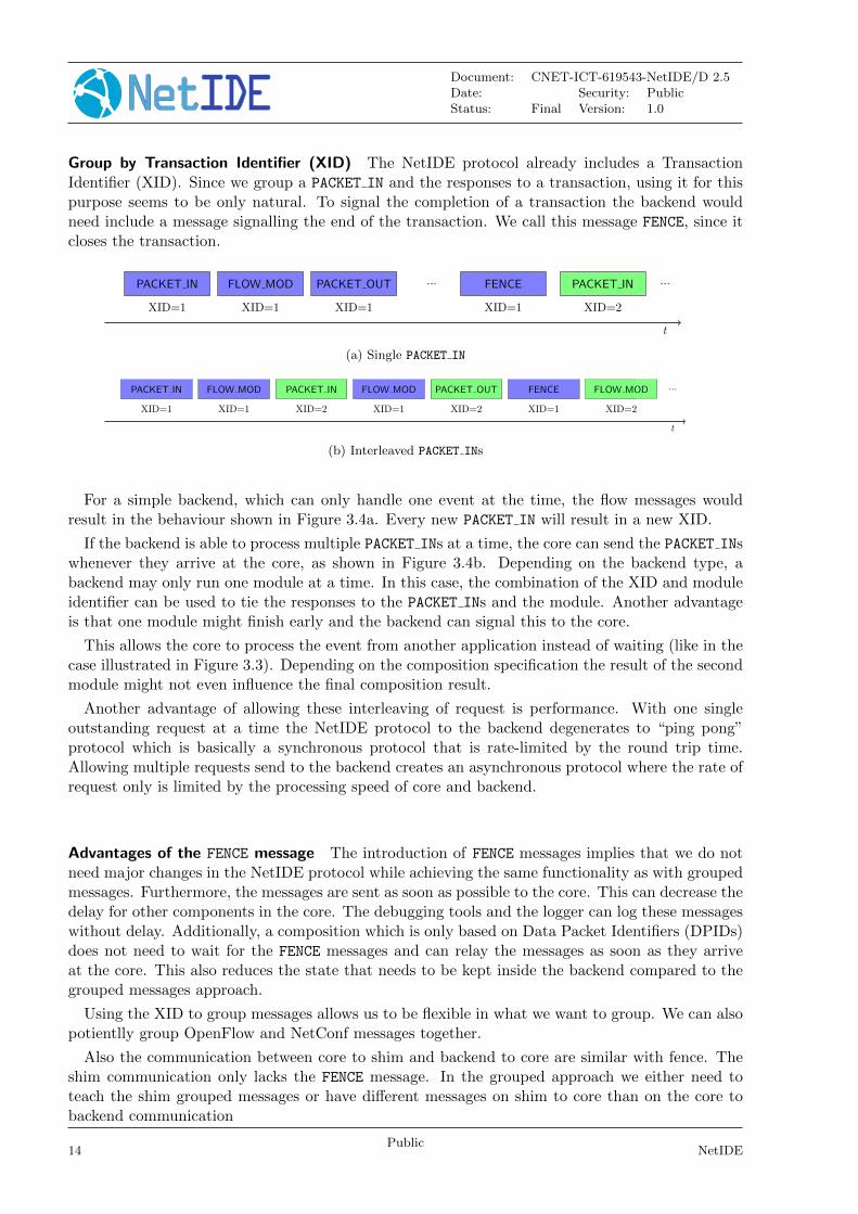
Group by Transaction Identifier (XID) The NetIDE protocol already includes a TransactionIdentifier (XID). Since we group a PACKET IN and the responses to a transaction, using it for thispurpose seems to be only natural. To signal the completion of a transaction the backend wouldneed include a message signalling the end of the transaction. We call this message FENCE, since itcloses the transaction.
XID=2XID=1
PACKET IN
XID=1
FLOW MOD
XID=1
PACKET OUT
XID=1
FENCE PACKET IN... ...
t
(a) Single PACKET IN
XID=1
PACKET IN
XID=1
FLOW MOD
XID=2
PACKET IN
XID=1
FLOW MOD
XID=2
PACKET OUT
XID=1
FENCE
XID=2
FLOW MOD ...
t
(b) Interleaved PACKET INs
For a simple backend, which can only handle one event at the time, the flow messages wouldresult in the behaviour shown in Figure 3.4a. Every new PACKET IN will result in a new XID.
If the backend is able to process multiple PACKET INs at a time, the core can send the PACKET INswhenever they arrive at the core, as shown in Figure 3.4b. Depending on the backend type, abackend may only run one module at a time. In this case, the combination of the XID and moduleidentifier can be used to tie the responses to the PACKET INs and the module. Another advantageis that one module might finish early and the backend can signal this to the core.
This allows the core to process the event from another application instead of waiting (like in thecase illustrated in Figure 3.3). Depending on the composition specification the result of the secondmodule might not even influence the final composition result.
Another advantage of allowing these interleaving of request is performance. With one singleoutstanding request at a time the NetIDE protocol to the backend degenerates to “ping pong”protocol which is basically a synchronous protocol that is rate-limited by the round trip time.Allowing multiple requests send to the backend creates an asynchronous protocol where the rate ofrequest only is limited by the processing speed of core and backend.
Advantages of the FENCE message The introduction of FENCE messages implies that we do notneed major changes in the NetIDE protocol while achieving the same functionality as with groupedmessages. Furthermore, the messages are sent as soon as possible to the core. This can decrease thedelay for other components in the core. The debugging tools and the logger can log these messageswithout delay. Additionally, a composition which is only based on Data Packet Identifiers (DPIDs)does not need to wait for the FENCE messages and can relay the messages as soon as they arriveat the core. This also reduces the state that needs to be kept inside the backend compared to thegrouped messages approach.
Using the XID to group messages allows us to be flexible in what we want to group. We can alsopotientlly group OpenFlow and NetConf messages together.
Also the communication between core to shim and backend to core are similar with fence. Theshim communication only lacks the FENCE message. In the grouped approach we either need toteach the shim grouped messages or have different messages on shim to core than on the core tobackend communication
14Public
NetIDE
Document: CNET-ICT-619543-NetIDE/D 2.5Date: Security: PublicStatus: Final Version: 1.0
3.2 Assumptions
The stalemate the project came to as a result of the ’run-to-completion’ problem has made usrevisit the implicit assumptions which had been building up inside the project team and makethem explicit.
• Modules must to abide by the {OUTPUT EV ENT, ...} = f(INPUT EV ENT ) rule andwe accept the empty set (∅) as output
• Modules have to respond (including ∅ as a response) to an input event in a finite time
• Backends need to be able to detect when a module has finished processing and provide amechanism that will allow the Core to bind the output to the input.
• Modules may not leave code executing (i.e. spawn a thread, . . . ) after the backend detectsthe end of execution
This results in the following assumptions for the client controllers:
• client controller frameworks may need modifications to run in the NetIDE Network Engine,namely
1. a mechanism to signal back to the backend that a network event has been processed
2. a mechanism to handle XIDs
3. a mechanism to handle modules
• client controllers will provide modules the same API they expect when running as an inde-pendent controller framework
3.3 Further work
Further work will be:
• to extend our model to cope with pro-active applications, i.e. applications that generateFLOW MODs that are not responses to input network events,
• to investigate other network events in addition to PACKET IN,
• to investigate further network commands in addition FLOW MOD and PACKET OUT; and finally
• to investigate how to extend our work to cover other SDN approaches in addition to Open-Flow.
NetIDEPublic
15

Document: CNET-ICT-619543-NetIDE/D 2.5Date: Security: PublicStatus: Final Version: 1.0
4 Approaches to composition
After a first clarification about the evolution of the NetIDE architecture status, this chapter isdevoted to the composition of SDN applications. More specifically, we give a short overview of thecomposition approaches we have encountered in the literature and projects in the same problemspace as the composition logic of our network Engine, to propose an alternative approach whichshould give us a more flexible and holistic approach to SDN network composition. We will deep intoour network composition concepts, introducing our approach, relating it with the UC! (UC!)1,trying to generalize the concept with the composition of modular bricks of functionality and finallyanalysing how the composed output goes back to the network.
4.1 Related work in composition
So far, we have been considering the approaches proposed by Pyretic, CoVisor and Flowbricks forour composition mechanism in NetIDE. All use the sequential (�) and parallel (+) operators. Ad-ditionally, CoVisor introduces the (B) operator, which introduces the concept of “default actions”.With this new operator, the criterion followed to apply � and + is based on the priorities of theapplications rather than on the input and outputs of the applications.
For example, on one hand, a L2 monitor and a L2 switch are independent from each other (they“work in parallel”) and thus + is applied (L2-monitor+L2-switch). On the other hand, a L3-L4firewall and a L3 router are not independent (a firewall can block traffic of the router) and thus� is applied (L3-L4-firewall�L3-router). Both examples take PACKET IN as input and generatePACKET OUT/FLOW MOD messages as outputs. More specifically, in the latter example, the only actionthat the firewall is doing is filtering the PACKET IN events that arrive to the router later on; thequestion remains whether it makes sense to execute them in parallel (for example) and filter theproduced outputs afterwards (so that we save execution time as threads work in parallel).
We include some more insights on the behaviour of these approaches in the following sections.
4.1.1 Pyretic
We initially omitted Pyretic [13] because it requires the modification of application (they need to berewritten in a common high-level language), but it is the first approach to introduce the sequential(�) and parallel (+) operators, continued later on by CoVisor.
4.1.2 CoVisor
CoVisor [14] implements the composition of applications from different SDN controller frameworks,which is done incrementally to improve performance. It also includes the (B) operator for “de-fault actions”. However, after taking a look at their prototype (which only supports up to threeapplications), it still has some flaws in comparison to what we want to achieve in NetIDE:
1. It does not apply conflict resolution. Composition is applied incrementally, but withoutchecking possible conflicts between applications.
2. It requires some minor modifications on the applications (or at least in the prototype).
3. It only supports FLOW MOD messages as outputs so far.
16Public
NetIDE
Document: CNET-ICT-619543-NetIDE/D 2.5Date: Security: PublicStatus: Final Version: 1.0
4.1.3 Flowbricks
Flowbricks [15] also includes the sequential (�) and parallel (+) operators and it supports bothFLOW MOD and PACKET OUT messages. However, they do not have a formal composition languagespecification and their prototype considers PACKET IN messages are only sent to one single appli-cation at a time, i.e. the application whose table generates the PACKET IN message.
4.2 Our approach
In our approach, we leverage the same operators: sequential (�) and parallel (+), but applythem based on input and outputs instead of basing them on logical behaviours of the applications.Therefore, by default, parallel composition is applied to all application modules and sequentialcomposition is only considered when the input of a module needs to be the explicit output ofanother. This reduces the time of composition, since parallel composition only requires one call tothe application modules and one call back, while sequential needs one call per application module,which will be queuing for its turn.
This changes the typical sequential example of a L3-L4 firewall and a L3 router. Both modulescan now be executed in parallel and later on filter the outputs of the router based on the firewalloutputs, and they will only be executed in sequence when the firewall does specific modificationsto the output packets that will be later processed by the router. For example, if the firewall blockstraffic from IP address 10.0.0.1 and the router forwards it to port 3, we will get two outputs: dropand a PACKET OUT for port 3, after composing the actions, we get a drop because the firewall has ahigher priority and vetoes the forwarding (parallel execution works here). However, if the firewallblocks the traffic but produces another packet with IP 192.168.0.1, the router will need to get thatpacket as an input and thus we will need sequential composition (parallel execution does not workhere), although these types of actions are more typically from NAT modules than firewalls.
An initial list of inputs and their generated outputs that will require composition for the OFprotocol (all versions from 1.0 to 1.4) is provided below:
• Inputs: Events from the network that will generate a number of outputs.
– PacketIn
– FlowRemoved
– PortStatus
• Outputs: Actions to be applied to the network that can be generated (or not) by a previousinput.
– PacketOut
– FlowMod
– GroupMod
– PortMod
– TableMod
In the specific case of TableMod, this message is usually envisioned for the beginning of the commu-nication, but we include it in the list as well, as different application modules could send several ofthem and some decision should be made; default decision: send unmatched packet to the controller(i.e. the NetIDE Network Engine).
NetIDEPublic
17
Document: CNET-ICT-619543-NetIDE/D 2.5Date: Security: PublicStatus: Final Version: 1.0
4.3 Mapping the Data Centre Use Case to composition specifications
The Data Centre use case has been driving the architecture work in the project. We have doneconcrete steps to define the different composition types to the elements in the Use Case (UC).
4.3.1 A short recap
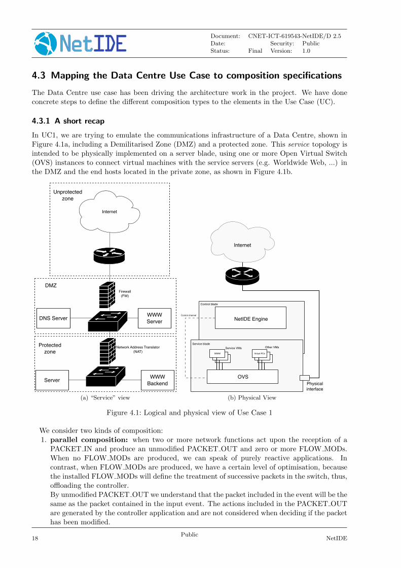
In UC1, we are trying to emulate the communications infrastructure of a Data Centre, shown inFigure 4.1a, including a Demilitarised Zone (DMZ) and a protected zone. This service topology isintended to be physically implemented on a server blade, using one or more Open Virtual Switch(OVS) instances to connect virtual machines with the service servers (e.g. Worldwide Web, ...) inthe DMZ and the end hosts located in the private zone, as shown in Figure 4.1b.
Internet
DNS ServerWWW
Server
WWW
BackendServer
Unprotected
zone
DMZ
Protected
zone
Firewall
(FW)
Network Address Translator
(NAT)
(a) “Service” view
Physical
interface
OVS
WWW
Service VMs Other VMs
NetIDE Engine
Internet
Control blade
Service blade
Control channel
Virtual PCs
(b) Physical View
Figure 4.1: Logical and physical view of Use Case 1
We consider two kinds of composition:1. parallel composition: when two or more network functions act upon the reception of a
PACKET IN and produce an unmodified PACKET OUT and zero or more FLOW MODs.When no FLOW MODs are produced, we can speak of purely reactive applications. Incontrast, when FLOW MODs are produced, we have a certain level of optimisation, becausethe installed FLOW MODs will define the treatment of successive packets in the switch, thus,offloading the controller.By unmodified PACKET OUT we understand that the packet included in the event will be thesame as the packet contained in the input event. The actions included in the PACKET OUTare generated by the controller application and are not considered when deciding if the packethas been modified.
18Public
NetIDE

Document: CNET-ICT-619543-NetIDE/D 2.5Date: Security: PublicStatus: Final Version: 1.0
2. serial composition: when a network function acts upon the reception of a PACKET INand produces a modified PACKET OUT and zero or more FLOW MODs which are used asinput for another network function. In this case, we postulate that the PACKET OUT isfed as a PACKET IN to the second network function and the resulting FLOW MODs arecomposed.By modified PACKET OUT we consider the case when the fields in the packet contained inthe input event are modified (e.g. when the IP source or destination address, TCP/UDPsource or destination port, etc. are modified)
Under these premises, we cover both cases in UC1: the Firewall and the Layer-2 Switch in theDemilitarised Zone provide an example of parallel composition, and the Network Address Translatorand the Layer-2 Switch in the protected zone are an example of serial composition.
4.3.2 Parallel composition in the DMZ
Assume the Layer-2 Switch (L2Switch) works as follows:
on arp_request: learn from packet; flood
on arp_reply: send to learnt port
else: FLOW_MOD and send to learnt port
Assume the Firewall (FW) works as follows:
on arp_request: flood packet
on arp_reply: send packet
else: apply FW rules (i.e. DROP filtered packets or send to output port)
The main composition takes place in the else: case, where a DROP action issued by the FWshould take preference over the action proposed by the Layer-2 Switch module. Note that in thiscase, the Firewall is not properly applying any transformation on the packet and hence, the packetdata in the PACKET IN and PACKET OUT event will remain unchanged. It is hence an example for aparallel composition.
4.3.3 Serial composition in the private zone
Assume that the L2Switch we use in the private zone behaves like the L2Switch in the DMZ inthe previous section and assume the FW between the private zone and the DMZ also implementsNetwork Address Translator (NAT) functionalities:
terminate ARP traffic on a fake MAC
for traffic from inside to outside
create NAT association
apply to inside packets
for traffic from outside to inside
if association exists
reverse apply to outside packets
Comparing this case with the FW case, the resulting actions of the module include modifying thepacket. Handling different packets at the inputs of the two modules implies a serial composition.
NetIDEPublic
19

Document: CNET-ICT-619543-NetIDE/D 2.5Date: Security: PublicStatus: Final Version: 1.0
4.4 Mangling and merging of messages
The previous section introduced operations for PACKET OUTs and FLOW MODs: Namely, merging twoFLOW MODs (FM1 ∩ FM2), intersection of FLOW MODs and applying to a FLOW MOD to PACKET OUT
(FM(PO2). Additionally applying a FLOW MOD to a packet may also be useful in the context ofcomposition. In this section we will discuss the challenges and properties of these operations. Thefollowing section is written specifically discussing OpenFlow concept, terminology and flaws. Butthe general problem and concepts apply to other protocol as well.
We begin by describing the simplest operation: Merging and intersection of FLOW MODs is concep-tually simpler than FLOW MOD and another entity since inputs and outputs are identical. The basicidea is to look at what both FLOW MODs are doing to a packet and generate a FLOW MOD (or multipleflows) that are the result of desired operation. That means intersection/merging of the parts of aFLOW MOD.
The main defining elements of a FLOW MOD are its match and its action. When speaking aboutmerging and intersection of FLOW MODs we have to carefully specify what we want to merge andintersect. When operating on two FLOW MODs we can decide individually on both parts if merging orintersecting is the right decision. Intersection of the match is probably the most natural operation,since it is straightforward take create a match that only matches packets that both original matchesmatch. Merging matches of two matches is as simple as intersection but not very useful in mostcases. More useful is to create the matches that are only matched by one of the FLOW MODs.Whenever we need to merge/intersect FLOW MODs we have a set of three matches for which we haveto decide on an approach for the actions. These matches are the intersection (FM1 ∩ FM2) andthe packets only matched by one of the FLOW MODs (FM1 \ FM2 and FM2 \ FM1.
Handling the match of a FLOW MOD is only half of the FLOW MOD mangling. The other half is togenerate a new action from the original actions. More than the matches the actions of a FLOW MOD
carry semantic. By combining/merging this actions the semantics of the two actions is merged too.Each action is set of individual instructions. These instructions modify the header of a packet orspecify the forwarding behaviour. Example of instructions are “set output port=5”, “remove vlantag”, “set source mac addresse to 0011.2233.abcd”.
We recognise that action set can be incompatible. We differentiate between semantic and syntac-tic conflicts. We will first explain syntactic conflicts. A simple example for type are two instructionsthat set the same fields but to different values. Assume as a result of a misconfiguration of thecomposition two load-balancing apps are active that rewrite the destination IP address of a packetand pick two different server. In this case we have two instruction that try to set the destinationIP address but to different IP addresses. Different Instruction can also be mutually exclusive likeremoving the VLAN tag and the same time changing the VLAN id. Or dropping the packet andany other action that modifies the packets. These syntactic conflicts can be detected and handledby the composition mechanism.
But even when no syntactic conflict between two fields exists they might still generate a semanticconflict. These kind of conflicts are not automatically detectable but still cause problems. Assumeagain the two load-balancing applications again and one decides to redirect to a different port onthe same server and the other decides to redirect to a different IP address. The resulting mergedaction set will redirect the packets to a IP/port combination that will not work. As a said, theseconflicts cannot be reliable detected but we can specify set of instructions (like setting the ports/ipaddresses) that are considered to be a conflict as well.
The case of applying FLOW MOD with a PACKET IN or PACKET OUT are different because we have dif-ferent inputs and outputs. Of the possible combinations that might occur only one case is straight-forward, the applying of a FLOW MOD to a packet that produces a PACKET OUT (FM1(PI1) = PO1).This can be done by simply emulating the behaviour a normal switch would use. Unfortunately,
20Public
NetIDE

Document: CNET-ICT-619543-NetIDE/D 2.5Date: Security: PublicStatus: Final Version: 1.0
for the sequential composition we need a PACKET IN and not a PACKET OUT. A PACKET OUT containsagain two parts, an actual (usually Ethernet) packet and instruction. The instructions are a subsetof the FLOW MOD instructions, namely those that specify handling of the packet and not modificationof the packet. ( e.g. setting the output port). The PACKET IN on the other hand also has a packetand a match. The match is in the same format as the FLOW MOD matches but is an exact match(e.g. specific ingress port instead of a range of ingress ports).
To generate a new PACKET IN for a serial composition we need to have an exact match and apacket. The logical thing for a serial composition is to use the output of an application (i.e. thePACKET OUT) for that. In that case we can assume that all action that the application wants toapply to the packet are either already applied or in the action set of the packet set. Of the actionset some action can be applied to the packet directly since they mutate the packet itself (likeadding a vlan id). But everything that is not directly related to the content of the packet cannotbe represented in the new packet. Instructions like setting the output queue, rate limits, meters,goto table x cannot be expressed as an match or directly in the packet. The only way to deal withthese instruction is to remember them and then merge/intersect all action from all modules of asequential composition in the last step. There is a subset of instruction that have an equivalentor almost equivalent in matches, most notably the Set-Output-Port instruction. But setting theingress port for the next module to the ingress port of the PACKET OUT seems to be very strangedecision. The fill out the match for the PACKET IN the only viable way seems to be to use the matchof the original PACKET IN.
In summary all these problem with generating a new PACKET IN make sequential to be onlyusable in a very limited environment and even then the user has to carefully specify how the actualmerging should be done in his/her use case.
4.5 Basic concepts for composition
The basic concepts of this new approach are listed below:
• Parallel composition is applied to all application modules and sequential composition is onlyconsidered when the input of a module needs to be the explicit output of another.
• Parallel composition merges the output based on priorities assigned to the application modules(previous to deployment or with default values). Sequential composition too, but part of theoutput is redirected as an input for the next module in line.
• “Veto” actions are also generated based on outputs, depending on how much the applica-tion modules care about their outputs and how others affect theirs. These “veto” actionsreduce/limit other outputs.
• The priority levels are the following:
– 0: represents literally “no priority” (default).Thus, it is the lowest level of priority, as well as the default priority level for all modules.
– 1-n: represents a concrete level of priority (non default), where 1 is the lowest and n thehighest.The difference with 0 is that, from level 1 on, modules can produce “veto” actionsaccordingly. Therefore, two modules with value 0 will not compete against each otherand will not generate “veto” actions, while any module with priority 1-n will compete,which might eventually provoke the cancellation of their outputs.
• In the specific case of OF, parallel composition is applied when modules generate actions asoutputs and sequential composition is applied when modules generate changes in other fields,such as data in the case of a PacketOut message.
NetIDEPublic
21

Document: CNET-ICT-619543-NetIDE/D 2.5Date: Security: PublicStatus: Final Version: 1.0
4.6 Modular bricks
In order to develop this idea of composition (based on input and outputs), first we define a listof bricks that provide basic functionality. For these bricks, we are just focusing on three types ofOF messages: PACKET IN, PACKET OUT and FLOW MOD. All of them can either work in reactive mode(after receiving a PACKET IN ) or proactive (with no previously message received), but the differenceis the type of output they generate:
• flood : produces a PACKET OUT containing an action with a broadcast output port (0xfffb inOF1.0).
• fwd : produces a PACKET OUT and a FLOW MOD both containing an action with a specific outputport ID.
• drop: produces a FLOW MOD with an empty list of actions.
• no-response: produces no response at all.
One network application is composed by different application modules (e.g. switch, router,firewall, etc.) and, at the same time, these modules are composed by a number of the previouslydefined bricks.
4.6.1 Composing modular bricks in parallel
In this section, we analyse the composed output of different combinations of bricks in parallel.More specifically, we consider how to compose PACKET OUT and FLOW MOD messages.In order to do so, we apply the following principle: PACKET OUT messages are usually temporaland independent from the switches tables, which are modified by FLOW MOD messages. Therefore,FLOW MOD messages need to be merged and might affect PACKET OUTs, depending on their priority,but PACKET OUT should not affect FLOW MOD.Notice we will represent PACKET OUT as POi and FLOW MOD as FMi.
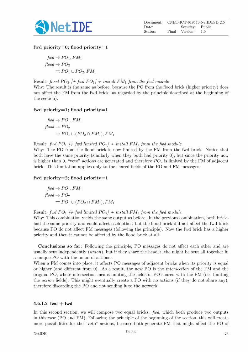
4.6.1.1 fwd + flood
In this first section, we will compose the two first bricks: flood and fwd, which could be associatedwith a switching and a load balancer module, respectively, for instance. Another example modulesfor the fwd brick could be a router or a switch modules after a previous phase of learning.In the following paragraphs we combine these two bricks with different priorities assigned1.
fwd priority=0; flood priority=0
fwd→ PO1, FM1
flood→ PO2
⇒ PO1 ∪ PO2, FM1
Result: flood PO2 [+ fwd PO1] + install FM1 from the fwd moduleWhy: If PO1 and PO2 share the header fields, the union of a PO for specific ports and a POfor all ports (flooding) is translated into a flooded PO (which is PO2), otherwise, both are sentindependently. The FM is also installed and not affected, because the priority of both bricks is 0.
1Notation used:op → events means that the operation op produces events⇒ events shows the events resulting from the composition of the two operations
22Public
NetIDE
Document: CNET-ICT-619543-NetIDE/D 2.5Date: Security: PublicStatus: Final Version: 1.0
fwd priority=0; flood priority=1
fwd→ PO1, FM1
flood→ PO2
⇒ PO1 ∪ PO2, FM1
Result: flood PO2 [+ fwd PO1] + install FM1 from the fwd moduleWhy: The result is the same as before, because the PO from the flood brick (higher priority) doesnot affect the FM from the fwd brick (as regarded by the principle described at the beginning ofthe section).
fwd priority=1; flood priority=1
fwd→ PO1, FM1
flood→ PO2
⇒ PO1 ∪ (PO2 ∩ FM1), FM1
Result: fwd PO1 [+ fwd limited PO2] + install FM1 from the fwd moduleWhy: The PO from the flood brick is now limited by the FM from the fwd brick. Notice thatboth have the same priority (similarly when they both had priority 0), but since the priority nowis higher than 0, “veto” actions are generated and therefore PO2 is limited by the FM of adjacentbrick. This limitation applies only to the shared fields of the PO and FM messages.
fwd priority=2; flood priority=1
fwd→ PO1, FM1
flood→ PO2
⇒ PO1 ∪ (PO2 ∩ FM1), FM1
Result: fwd PO1 [+ fwd limited PO2] + install FM1 from the fwd moduleWhy: This combination yields the same output as before. In the previous combination, both brickshad the same priority and could affect each other, but the flood brick did not affect the fwd brickbecause PO do not affect FM messages (following the principle). Now the fwd brick has a higherpriority and then it cannot be affected by the flood brick at all.
Conclusions so far: Following the principle, PO messages do not affect each other and areusually sent independently (union), but if they share the header, the might be sent all together ina unique PO with the union of actions.When a FM comes into place, it affects PO messages of adjacent bricks when its priority is equalor higher (and different from 0). As a result, the new PO is the intersection of the FM and theoriginal PO, where intersection means limiting the fields of PO shared with the FM (i.e. limitingthe action fields). This might eventually create a PO with no actions (if they do not share any),therefore discarding the PO and not sending it to the network.
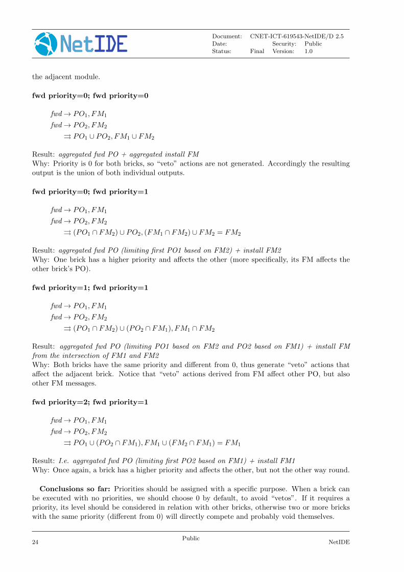
4.6.1.2 fwd + fwd
In this second section, we will compose two equal bricks: fwd, which both produce two outputsin this case (PO and FM). Following the principle of the beginning of the section, this will createmore possibilities for the “veto” actions, because both generate FM that might affect the PO of
NetIDEPublic
23
Document: CNET-ICT-619543-NetIDE/D 2.5Date: Security: PublicStatus: Final Version: 1.0
the adjacent module.
fwd priority=0; fwd priority=0
fwd→ PO1, FM1
fwd→ PO2, FM2
⇒ PO1 ∪ PO2, FM1 ∪ FM2
Result: aggregated fwd PO + aggregated install FMWhy: Priority is 0 for both bricks, so “veto” actions are not generated. Accordingly the resultingoutput is the union of both individual outputs.
fwd priority=0; fwd priority=1
fwd→ PO1, FM1
fwd→ PO2, FM2
⇒ (PO1 ∩ FM2) ∪ PO2, (FM1 ∩ FM2) ∪ FM2 = FM2
Result: aggregated fwd PO (limiting first PO1 based on FM2) + install FM2Why: One brick has a higher priority and affects the other (more specifically, its FM affects theother brick’s PO).
fwd priority=1; fwd priority=1
fwd→ PO1, FM1
fwd→ PO2, FM2
⇒ (PO1 ∩ FM2) ∪ (PO2 ∩ FM1), FM1 ∩ FM2
Result: aggregated fwd PO (limiting PO1 based on FM2 and PO2 based on FM1) + install FMfrom the intersection of FM1 and FM2Why: Both bricks have the same priority and different from 0, thus generate “veto” actions thataffect the adjacent brick. Notice that “veto” actions derived from FM affect other PO, but alsoother FM messages.
fwd priority=2; fwd priority=1
fwd→ PO1, FM1
fwd→ PO2, FM2
⇒ PO1 ∪ (PO2 ∩ FM1), FM1 ∪ (FM2 ∩ FM1) = FM1
Result: I.e. aggregated fwd PO (limiting first PO2 based on FM1) + install FM1Why: Once again, a brick has a higher priority and affects the other, but not the other way round.
Conclusions so far: Priorities should be assigned with a specific purpose. When a brick canbe executed with no priorities, we should choose 0 by default, to avoid “vetos”. If it requires apriority, its level should be considered in relation with other bricks, otherwise two or more brickswith the same priority (different from 0) will directly compete and probably void themselves.
24Public
NetIDE

Document: CNET-ICT-619543-NetIDE/D 2.5Date: Security: PublicStatus: Final Version: 1.0
4.6.1.3 fwd + drop
In this third section, we will compose two different bricks, both containing a FM: fwd and drop.Following the principle of the beginning of the section, this will create more possibilities for the“veto” actions, because both generate FM that might affect the PO of the adjacent module.
fwd priority=0; drop priority=0
fwd→ PO1, FM1
fwd→ FM2
⇒ PO1, FM1 ∪ FM2 = FM1
Result: fwd PO1 + install FM1 (FM2 is empty)Why: The union of FM1 and FM2 will usually be just FM1, while their matching fields are thesame. Otherwise we would install both FM independently.
fwd priority=0; drop priority=1
fwd→ PO1, FM1
fwd→ FM2
⇒ (PO1 ∩ FM2) = ∅, (FM1 ∩ FM2) ∪ FM2 = FM2
Result: no PO + install FM2Why: The intersection of PO1 and FM2 will usually be an empty set, while their matching fieldsare the same.
fwd priority=1; drop priority=1
fwd→ PO1, FM1
fwd→ FM2
⇒ (PO1 ∩ FM2) = ∅, FM1 ∩ FM2 = FM2
Result: no PO + install FM2Why: The result is the same as before because flood has no PO that could be affected by FM1.
fwd priority=2; drop priority=1
fwd→ PO1, FM1
fwd→ FM2
⇒ PO1, FM1 ∪ (FM2 ∩ FM1) = FM1
Result: fwd PO1 + install FM1Why: The drop brick does not affect the fwd brick.
Conclusions so far: It is particularly dangerous when a FM has an empty set of actions (drop),which might eventually void other FM or PO messages.
NetIDEPublic
25
Document: CNET-ICT-619543-NetIDE/D 2.5Date: Security: PublicStatus: Final Version: 1.0
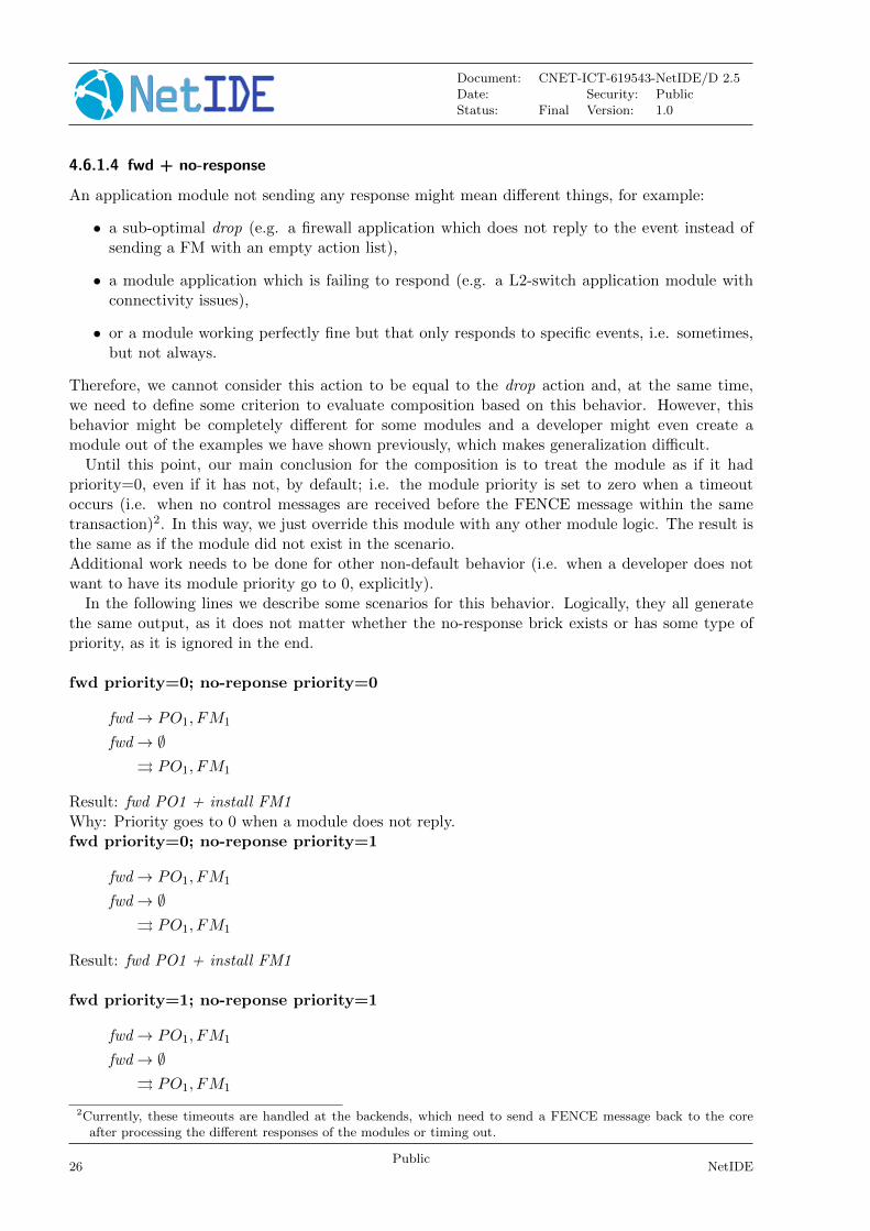
4.6.1.4 fwd + no-response
An application module not sending any response might mean different things, for example:
• a sub-optimal drop (e.g. a firewall application which does not reply to the event instead ofsending a FM with an empty action list),
• a module application which is failing to respond (e.g. a L2-switch application module withconnectivity issues),
• or a module working perfectly fine but that only responds to specific events, i.e. sometimes,but not always.
Therefore, we cannot consider this action to be equal to the drop action and, at the same time,we need to define some criterion to evaluate composition based on this behavior. However, thisbehavior might be completely different for some modules and a developer might even create amodule out of the examples we have shown previously, which makes generalization difficult.
Until this point, our main conclusion for the composition is to treat the module as if it hadpriority=0, even if it has not, by default; i.e. the module priority is set to zero when a timeoutoccurs (i.e. when no control messages are received before the FENCE message within the sametransaction)2. In this way, we just override this module with any other module logic. The result isthe same as if the module did not exist in the scenario.Additional work needs to be done for other non-default behavior (i.e. when a developer does notwant to have its module priority go to 0, explicitly).
In the following lines we describe some scenarios for this behavior. Logically, they all generatethe same output, as it does not matter whether the no-response brick exists or has some type ofpriority, as it is ignored in the end.
fwd priority=0; no-reponse priority=0
fwd→ PO1, FM1
fwd→ ∅⇒ PO1, FM1
Result: fwd PO1 + install FM1Why: Priority goes to 0 when a module does not reply.fwd priority=0; no-reponse priority=1
fwd→ PO1, FM1
fwd→ ∅⇒ PO1, FM1
Result: fwd PO1 + install FM1
fwd priority=1; no-reponse priority=1
fwd→ PO1, FM1
fwd→ ∅⇒ PO1, FM1
2Currently, these timeouts are handled at the backends, which need to send a FENCE message back to the coreafter processing the different responses of the modules or timing out.
26Public
NetIDE

Document: CNET-ICT-619543-NetIDE/D 2.5Date: Security: PublicStatus: Final Version: 1.0
Result: fwd PO1 + install FM1
fwd priority=2; no-reponse priority=1
fwd→ PO1, FM1
fwd→ ∅⇒ PO1, FM1
Result: fwd PO1 + install FM1
4.6.1.5 Conclusion
As a general rule, we could apply the rules from the “fwd + fwd” section for parallel compositionwith priorities. Since both modules produce PO and FM messages.
+ +
PacketIn PacketIn PacketIn
PacketOut PacketOut PacketOutFlowMod FlowMod FlowMod
PacketOut FlowMod
Figure 4.2: Parallel composition
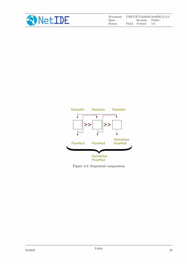
4.6.2 Composing modular bricks in sequence
In this section, we analyse the composed output of combinations of bricks in sequence. In this case,the output of a module will be converted in the input for the following one (e.g. for a NAT). Inorder to do so, we apply the following principle:
When a module generates an output, this will affect the input of the next module in the chain.PACKET OUT messages are directly forwarded as an input PACKET IN for the next module. FLOW MOD
messages just transform the original PACKET IN by applying the actions/instructions field, and thisnew PACKET IN is forwarded to the next module. Moreover, PACKET OUT messages go from onemodule to the next and the only PACKET OUT messages going to the network are the ones producedby the last module in the queue, while all FLOW MOD messages are saved for a final merging, followingthe parallel composition specification.
NetIDEPublic
27
Document: CNET-ICT-619543-NetIDE/D 2.5Date: Security: PublicStatus: Final Version: 1.0
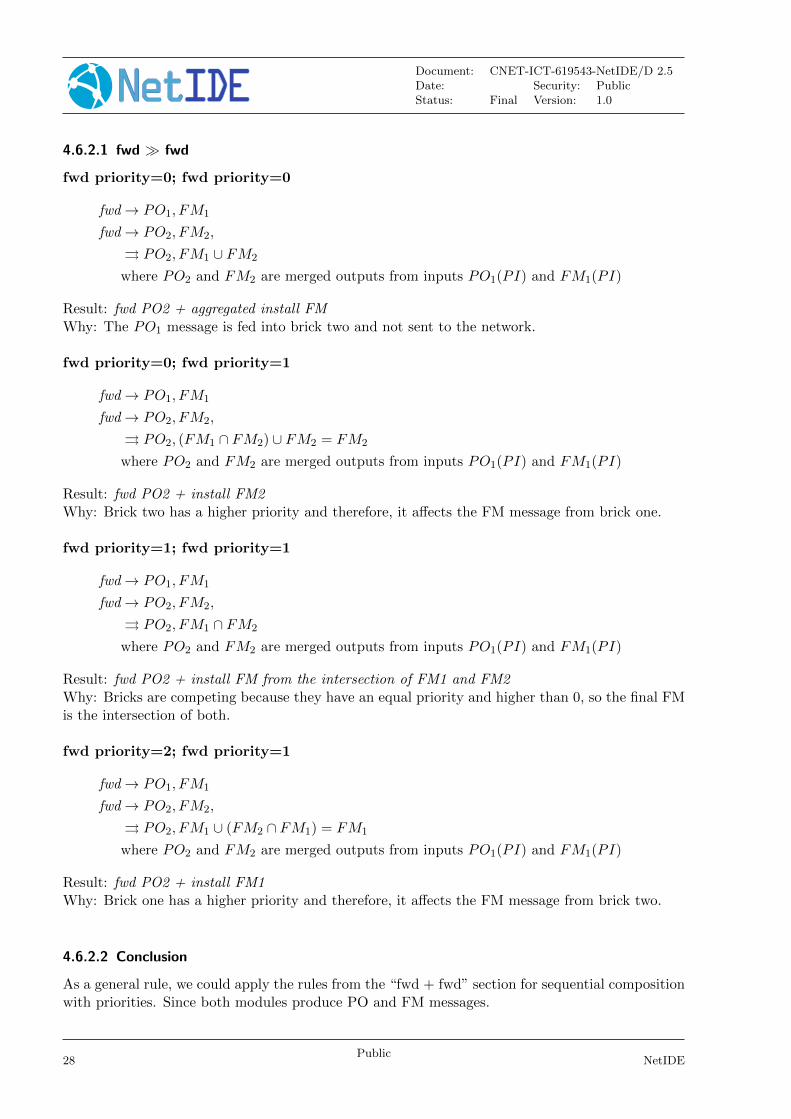
4.6.2.1 fwd � fwd
fwd priority=0; fwd priority=0
fwd→ PO1, FM1
fwd→ PO2, FM2,
⇒ PO2, FM1 ∪ FM2
where PO2 and FM2 are merged outputs from inputs PO1(PI) and FM1(PI)
Result: fwd PO2 + aggregated install FMWhy: The PO1 message is fed into brick two and not sent to the network.
fwd priority=0; fwd priority=1
fwd→ PO1, FM1
fwd→ PO2, FM2,
⇒ PO2, (FM1 ∩ FM2) ∪ FM2 = FM2
where PO2 and FM2 are merged outputs from inputs PO1(PI) and FM1(PI)
Result: fwd PO2 + install FM2Why: Brick two has a higher priority and therefore, it affects the FM message from brick one.
fwd priority=1; fwd priority=1
fwd→ PO1, FM1
fwd→ PO2, FM2,
⇒ PO2, FM1 ∩ FM2
where PO2 and FM2 are merged outputs from inputs PO1(PI) and FM1(PI)
Result: fwd PO2 + install FM from the intersection of FM1 and FM2Why: Bricks are competing because they have an equal priority and higher than 0, so the final FMis the intersection of both.
fwd priority=2; fwd priority=1
fwd→ PO1, FM1
fwd→ PO2, FM2,
⇒ PO2, FM1 ∪ (FM2 ∩ FM1) = FM1
where PO2 and FM2 are merged outputs from inputs PO1(PI) and FM1(PI)
Result: fwd PO2 + install FM1Why: Brick one has a higher priority and therefore, it affects the FM message from brick two.
4.6.2.2 Conclusion
As a general rule, we could apply the rules from the “fwd + fwd” section for sequential compositionwith priorities. Since both modules produce PO and FM messages.
28Public
NetIDE
Document: CNET-ICT-619543-NetIDE/D 2.5Date: Security: PublicStatus: Final Version: 1.0
>>
PacketIn PacketIn PacketIn
PacketOutFlowMod FlowMod FlowMod
PacketOut FlowMod
>>
Figure 4.3: Sequential composition
NetIDEPublic
29
Document: CNET-ICT-619543-NetIDE/D 2.5Date: Security: PublicStatus: Final Version: 1.0
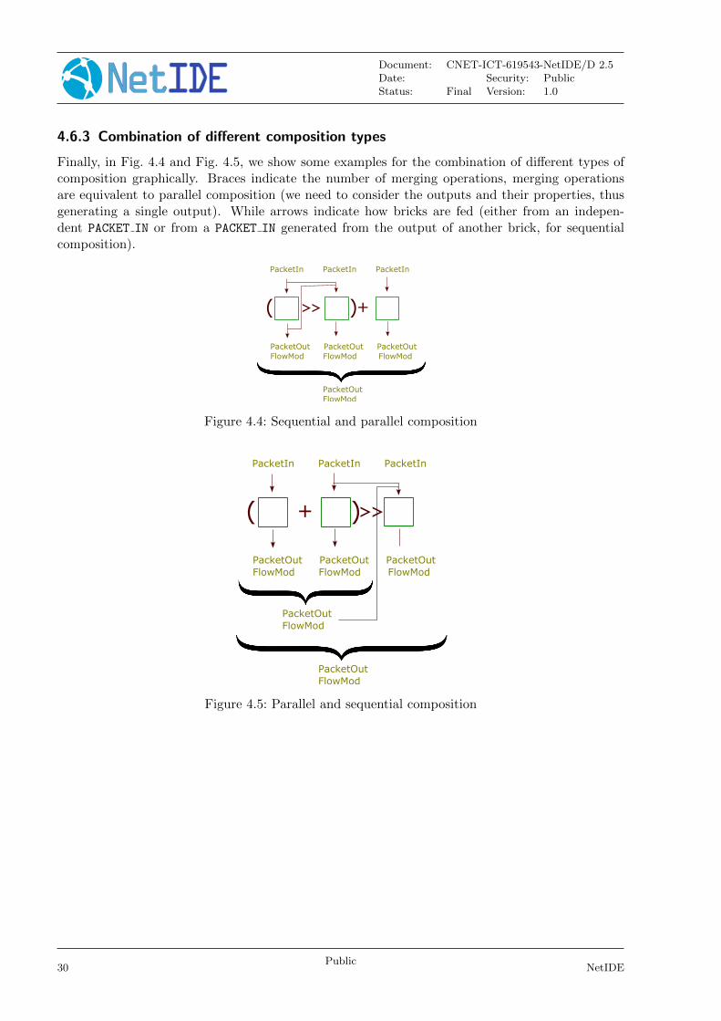
4.6.3 Combination of different composition types
Finally, in Fig. 4.4 and Fig. 4.5, we show some examples for the combination of different types ofcomposition graphically. Braces indicate the number of merging operations, merging operationsare equivalent to parallel composition (we need to consider the outputs and their properties, thusgenerating a single output). While arrows indicate how bricks are fed (either from an indepen-dent PACKET IN or from a PACKET IN generated from the output of another brick, for sequentialcomposition).
+
PacketIn PacketIn PacketIn
PacketOut PacketOut PacketOutFlowMod FlowMod FlowMod
PacketOut FlowMod
>>( )
Figure 4.4: Sequential and parallel composition
+
PacketIn PacketIn PacketIn
PacketOut PacketOut PacketOutFlowMod FlowMod FlowMod
PacketOut FlowMod
( )>>
PacketOut FlowMod
Figure 4.5: Parallel and sequential composition
30Public
NetIDE
Document: CNET-ICT-619543-NetIDE/D 2.5Date: Security: PublicStatus: Final Version: 1.0
4.7 Sending the composed output back to the network
In the previous sections, we have explained how to compose the different PACKET OUT and FLOW MOD
messages as outputs of different modular bricks. So the “how” is clear, but we still need to definethe “when”, because outputs might arrive at the core at different moments in time and there is noway of knowing when all outputs are ready to be composed. This “when” is represented by the {(merging symbol) in Figures 4.2, 4.3, 4.4 and 4.5 (this last one contains two {).
The ideal approach would be that the back-ends are able to tell the core when all the outputsare ready. However, due to the nature of protocols like OF, this is not feasible, because there is noattachment between input and outputs. Therefore, the application would need to be modified sothat it tells the backend when it is done, but this goes against one of the principles of the NetIDEproject: reusing application modules. Nevertheless, this should be further studied because someSDN controllers provide a way of notifying this finalization of events, as Floodlight with the internalsignal STOP.
A first (bad performance) approach would be keeping the input events, i.e. PacketIn messages,and just send them one by one with a timer. Therefore, the execution would be: send the PacketInto the application modules, receive all outputs during that timer, compose it and send the mergedoutput back to the network.
A second (not so clean, as it implies extra messages in the communication) approach wouldbe forcing the SDN controllers to notify the finalisation of an event indirectly. If we know thatthe controller executes events in order, maybe one option is to insert a second input after eachPacketIn, like a Hello message, because the input should be stateless and its response should beclearly defined. In this way, if all events are executed in order, we know that if we receive theresponse for the second input, the output for the first one should have been already received.
A third approach is to mix composition with the BigFlow table [1] concept. The merging wouldbe done incrementally and accepting more than one PacketIn message at a time. The cumulativeoutputs are sent to the network after some timer which is independent for each input (PacketIn).
4.8 Further work
With the current work, we are confident that we have a valid approach to composition. Our furtherwork will focus on:
• investigating the semantics of the no-response behaviour and providing other approaches tohandle it in addition to the current default behavior (i.e. setting priority to 0),
• continuing to investigate the behaviour of sequential compositions (i.e. finding alternativesto the current way of handling PACKET OUT messages, which go to the network and to thenext module, when the developer may only want to forward them to the next module in thechain),
• researching advanced composition specifications (involvong 3 or more modules) and improvingthe expressivity of our composition language, to cover as much behaviors as possible; andfinally
• to generalise the composition to ther types of OF messages (in addition to the currentlysupported PACKET IN, PACKET OUT and FLOW MOD) and to other SBI protocols.
In relation to this last point, we are interacting with the Interface to the Routing System (I2RS)Working Group (WG) at the Internet Engineering Task Force (IETF). They are starting to discussthe feasibility of conflict resolution in their architecture. As discussed in Deliverable D2.4 [1], theirclient/agent architecture is similar to the first iterations of ours, they use the Network ConfigurationProtocol (NetConf) as their signalling transport protocol and their applications generate network
NetIDEPublic
31

Document: CNET-ICT-619543-NetIDE/D 2.5Date: Security: PublicStatus: Final Version: 1.0
configuration commands as a response to incoming network events. I2RS therefore provides a goodplayground for generalising our concepts and seek greater impact of our work.
32Public
NetIDE
Document: CNET-ICT-619543-NetIDE/D 2.5Date: Security: PublicStatus: Final Version: 1.0
5 State of the art
In this section, we analyse recently published approaches related to the current work in WP2. Morespecifically, we first present Policy Graph Abstraction (PGA), which is an evolved compositionmechanism that merges applications based on “graphs” instead of on “language” components.After this, we introduce the NetASM which defines a network assembler language and introduces ainstruction set so that the network device is totally programmable, i.e. the data plane is no longera fixed-function device, but rather a fully programmable device whose behavior is dictated by theprogrammer, with the ability to reconfigure it on-demand. We believe that the instruction setdefined by NetASM can guide the definition of the NetIDE API 2.0, agnostic to the SBI protocolused.
5.1 PGA: Policy Graph Abstraction
PGA [2] tries to tackle the composition of network policies with a new vision. The three mainaspects of these approach are:
• PGA treats the underlying network as “one big switch” to resolve conflicts. It considersthis step crucial for conflict resolution and network “harmony” because, otherwise, you needto compute this table on runtime every time a new actions appears, which means slowerperformance.
• It includes one “complex”, realistic and very valuable use case that cannot be solved “easily”with parallel and sequential operators (followed by other “classical” composition approaches).
• Therefore, it proposes representing policies with graphs, which lets the network do automaticcomposition, i.e. no need for the network manager to be thinking in input and outputs (neededotherwise for the parallel/sequential idea). This is related to Intent-Based Networking (IBN).
5.2 NetASM
NetASM [3] is a network assembler that takes high-level SDN languages (NetKAT, P4, etc.) andmaps the primitives to device-specific directives in FPGAs and various chipsets. NetASM aims tobe an intermediate representation that compilers can use to optimize packet processing pipelinesfrom high-level languages to different targets. It is a device-independent language that aims to beexpressive enough to act as the target language for compilers for high-level languages, yet low-levelenough to be efficiently assembled on various device architectures.
NetASM provides assembly instructions that directly reflect the capabilities of the underlyingdevice, thus providing either a human programmer or compiler precise, fine-grained control overthe devices resources. It exposes the details in the language such as creating tables and defininglayouts of the processing pipeline. The instruction set contains 23 instructions (shown in Fig. 5.3. ANetASM program is a list of finite set of instructions. Using the NetASM primitives, a programmercan specify any kind of data plane. NetASM provides instructions for the following operations: (1)load, (2) store, (3) computation, (4) branch, (5) header (i.e., adding or removing headers in theheader set), and (6) special operations (e.g., checksum, hash).
NetIDEPublic
33
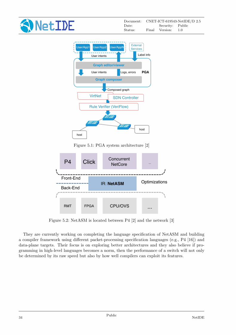
Document: CNET-ICT-619543-NetIDE/D 2.5Date: Security: PublicStatus: Final Version: 1.0
User/App1 User/App2 User/AppNExternal
Services
Graph editor/viewer
Graph composer
VirtNet SDN Controller
Rule Verifier (VeriFlow)
User intents
User intents Logs, errors
Label info
Composed graph
PGA
host
host
Figure 5.1: PGA system architecture [2]
P4 ClickConcurrent
NetCore ...
IR: NetASM OptimizationsFront-End
Back-End
RMT FPGA CPU/OVS ...
Figure 5.2: NetASM is located between P4 [2] and the network [3]
They are currently working on completing the language specification of NetASM and buildinga compiler framework using different packet-processing specification languages (e.g., P4 [16]) anddata-plane targets. Their focus is on exploring better architectures and they also believe if pro-gramming in high-level languages becomes a norm, then the performance of a switch will not onlybe determined by its raw speed but also by how well compilers can exploit its features.
34Public
NetIDE
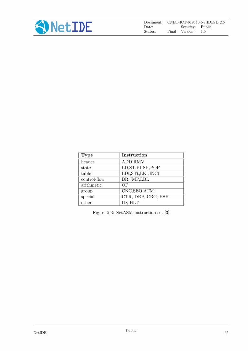
Document: CNET-ICT-619543-NetIDE/D 2.5Date: Security: PublicStatus: Final Version: 1.0
Type Instruction
header ADD,RMV
state LD,ST,PUSH,POP
table LDt,STt,LKt,INCt
control-flow BR,JMP,LBL
arithmetic OP
group CNC,SEQ,ATM
special CTR, DRP, CRC, HSH
other ID, HLT
Figure 5.3: NetASM instruction set [3]
NetIDEPublic
35

Document: CNET-ICT-619543-NetIDE/D 2.5Date: Security: PublicStatus: Final Version: 1.0
6 Conclusion
After the definition of the architecture in Deliverable D2.4 [1], we have interacted with Work Pack-age 4 to resolve the implementation issues arising from the Core development. These have helpedus clarifying underlying concepts. With the current status, we are confident that we have arrived toa flexible architecture that allows composition strategies that exceed what competing developmentsare achieving.
The work on the core will continue and will be reported in upcoming deliverables. In additionto the further work we cite in the different chapters, and from a more theoretical perspective, weare starting to work on a theoretical framework for conflict resolution and composition that can begeneralised to more Southbound Interfaces. The approach of using transactions instead of networkevents should allow us to apply the framework in scenarios beyond the NetIDE Network Engine,like the I2RS architecture.
36Public
NetIDE
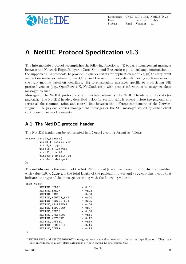
Document: CNET-ICT-619543-NetIDE/D 2.5Date: Security: PublicStatus: Final Version: 1.0
A NetIDE Protocol Specification v1.3
The Intermediate protocol accomplishes the following functions: (i) to carry management messagesbetween the Network Engine’s layers (Core, Shim and Backend); e.g., to exchange information onthe supported SBI protocols, to provide unique identifiers for application modules, (ii) to carry eventand action messages between Shim, Core, and Backend, properly demultiplexing such messages tothe right module based on identifiers, (iii) to encapsulate messages specific to a particular SBIprotocol version (e.g., OpenFlow 1.X, NetConf, etc.) with proper information to recognize thesemessages as such.Messages of the NetIDE protocol contain two basic elements: the NetIDE header and the data (orpayload). The NetIDE header, described below in Section A.1, is placed before the payload andserves as the communication and control link between the different components of the NetworkEngine. The payload carries management messages or the SBI messages issued by either clientcontrollers or network elements.
A.1 The NetIDE protocol header
The NetIDE header can be represented in a C-style coding format as follows:
struct netide_header{
uint8_t netide_ver;
uint8_t type;
uint16_t length;
uint32_t nxid
uint32_t module_id
uint64_t datapath_id
};
The netide ver is the version of the NetIDE protocol (the current version v1.3 which is identifiedwith value 0x04), length is the total length of the payload in bytes and type contains a code thatindicates the type of the message according with the following values1:
enum type{
NETIDE_HELLO = 0x01 ,
NETIDE_ERROR = 0x02 ,
NETIDE_MGMT = 0x03 ,
NETIDE_MODULE_ANN = 0x04 ,
NETIDE_MODULE_ACK = 0x05 ,
NETIDE_HEARTBEAT = 0x06 ,
NETIDE_TOPOLOGY = 0x07 ,
NETIDE_FENCE = 0x08 ,
NETIDE_OPENFLOW = 0x11 ,
NETIDE_NETCONF = 0x12 ,
NETIDE_OPFLEX = 0x13 ,
NETIDE_OFCONFIG = 0x14 ,
NETIDE_OTHER = 0xFF
};
1 NETIDE MGMT and NETIDE TOPOLOGY message types are not documented in the current specification. They havebeen introduced to allow future extensions of the Network Engine capabilities.
NetIDEPublic
37
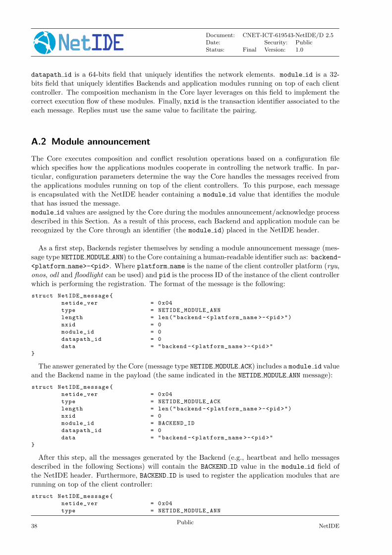
Document: CNET-ICT-619543-NetIDE/D 2.5Date: Security: PublicStatus: Final Version: 1.0
datapath id is a 64-bits field that uniquely identifies the network elements. module id is a 32-bits field that uniquely identifies Backends and application modules running on top of each clientcontroller. The composition mechanism in the Core layer leverages on this field to implement thecorrect execution flow of these modules. Finally, nxid is the transaction identifier associated to theeach message. Replies must use the same value to facilitate the pairing.
A.2 Module announcement
The Core executes composition and conflict resolution operations based on a configuration filewhich specifies how the applications modules cooperate in controlling the network traffic. In par-ticular, configuration parameters determine the way the Core handles the messages received fromthe applications modules running on top of the client controllers. To this purpose, each messageis encapsulated with the NetIDE header containing a module id value that identifies the modulethat has issued the message.module id values are assigned by the Core during the modules announcement/acknowledge processdescribed in this Section. As a result of this process, each Backend and application module can berecognized by the Core through an identifier (the module id) placed in the NetIDE header.
As a first step, Backends register themselves by sending a module announcement message (mes-sage type NETIDE MODULE ANN) to the Core containing a human-readable identifier such as: backend-<platform name>-<pid>. Where platform name is the name of the client controller platform (ryu,onos, odl and floodlight can be used) and pid is the process ID of the instance of the client controllerwhich is performing the registration. The format of the message is the following:
struct NetIDE_message{
netide_ver = 0x04
type = NETIDE_MODULE_ANN
length = len("backend -<platform_name >-<pid >")
nxid = 0
module_id = 0
datapath_id = 0
data = "backend -<platform_name >-<pid >"
}
The answer generated by the Core (message type NETIDE MODULE ACK) includes a module id valueand the Backend name in the payload (the same indicated in the NETIDE MODULE ANN message):
struct NetIDE_message{
netide_ver = 0x04
type = NETIDE_MODULE_ACK
length = len("backend -<platform_name >-<pid >")
nxid = 0
module_id = BACKEND_ID
datapath_id = 0
data = "backend -<platform_name >-<pid >"
}
After this step, all the messages generated by the Backend (e.g., heartbeat and hello messagesdescribed in the following Sections) will contain the BACKEND ID value in the module id field ofthe NetIDE header. Furthermore, BACKEND ID is used to register the application modules that arerunning on top of the client controller:
struct NetIDE_message{
netide_ver = 0x04
type = NETIDE_MODULE_ANN
38Public
NetIDE
Document: CNET-ICT-619543-NetIDE/D 2.5Date: Security: PublicStatus: Final Version: 1.0
length = len("module_name")
nxid = 0
module_id = BACKEND_ID
datapath_id = 0
data = "module_name"
}
where module name is the name of the module under registration. The module’s name can beassigned by the Backend or retrieved from the module itself via API calls. The Core replies with:
struct NetIDE_message{
netide_ver = 0x04
type = NETIDE_MODULE_ACK
length = len("module_name")
nxid = 0
module_id = MODULE_ID
datapath_id = 0
data = "module_name"
}
After this last step, the Backend allows the application modules to control the network. Inparticular, network commands sent towards the network (e.g. OpenFlow FLOW MODs, PACKET OUTs,FEATURES REQUESTs) are intercepted by the Backend, which encapsulates them with the NetIDEheader containing the MODULE ID value. Such a value is then used by the Core to recognize thesender of the message and to properly feed the composition and conflict resolution operators.
A.3 Heartbeat
The heartbeat mechanism has been introduced after the adoption of the ZeroMQ messaging queuinglibrary [12] to transmit the NetIDE messages. Unfortunately, the ZeroMQ library does not offerany mechanism to find out about disrupted connections (and also completely unresponsive peers).This limitation can be an issue for the Core’s composition mechanism and for the tools connectedto the Network Engine, as they are not able to understand when an client controller disconnectsor crashes. As a countermeasure, Backends must periodically send (let’s say every 5 seconds) a“heartbeat” message to the Core. If the Core does not receive at least one “heartbeat“ messagefrom the Backend within a certain timeframe, the Core considers it disconnected, removes all therelated data from its memory structures and informs the relevant tools. In order to minimize theservice disruption, the Core applies default policies as specified in the composition specification(e.g. a ”drop all” action in case of disconnected firewall module).The format of the message is the following:
struct NetIDE_message{
netide_ver = 0x04
type = NETIDE_HEARTBEAT
length = 0
nxid = 0
module_id = BACKEND_ID
datapath_id = 0
data = 0
}
A.4 Handshake
Upon completion of the module announcement/acknowledge process, the Backend must immedi-ately send a hello message with the list of the supported control and/or management protocols.
NetIDEPublic
39

Document: CNET-ICT-619543-NetIDE/D 2.5Date: Security: PublicStatus: Final Version: 1.0
The format of the message is the following:
struct NetIDE_message{
netide_ver = 0x04
type = NETIDE_HELLO
length = 2* NR_PROTOCOLS
nxid = 0
module_id = BACKEND_ID
datapath_id = 0
data = [list of supported protocols]
}
Where data contains one 2-byte word (in big endian order) for each protocol, with the first bytecontaining the code of the protocol according to the above enum, while the second byte indicatesthe version of the protocol (e.g. according to the ONF specification, 0x01 for OpenFlow v1.0, 0x02for OpenFlow v1.1, etc.). NETCONF version is marked with 0x01 that refers to the specificationin the RFC6241 [17], while OpFlex version is marked with 0x00 since this protocol is still in work-in-progress stage [18].The Core relays hello messages to the server controller which responds with another hello messagecontaining the following:
struct NetIDE_message{
netide_ver = 0x04
type = NETIDE_HELLO
length = 2* NR_PROTOCOLS
nxid = 0
module_id = BACKEND_ID
datapath_id = 0
data = [list of supported protocols]
}
if at least one of the protocols requested by the client is supported. In particular, data containsthe codes of the protocols that match the client’s request (2-bytes words, big endian order). Thebackend id value is used in the NetIDE header to allow the Core to forward the reply to theBackend that started the handshake. If none of the requested protocols is supported by the servercontroller, the header of the reply is as follows:
struct NetIDE_message{
netide_ver = 0x04
type = NETIDE_ERROR
length = 2* NR_PROTOCOLS
nxid = 0
module_id = BACKEND_ID
datapath_id = 0
data = [list of supported protocols]
}
where the payload of the message data contains the codes of all the protocols supported by theserver controller (2-bytes words, big endian order).
A.5 The FENCE mechanism
An application module may respond to a given network event (e.g., an OpenFlow PACKET IN) witha set of zero, one or multiple network commands (e.g., OpenFlow FLOW MODs and PACKET OUTs).The so-called FENCE mechanism is a means for the Core to correlate events and commands andto know when the module has finished processing the input event.This mechanism is implemented through the message type NETIDE FENCE which is sent by the
40Public
NetIDE
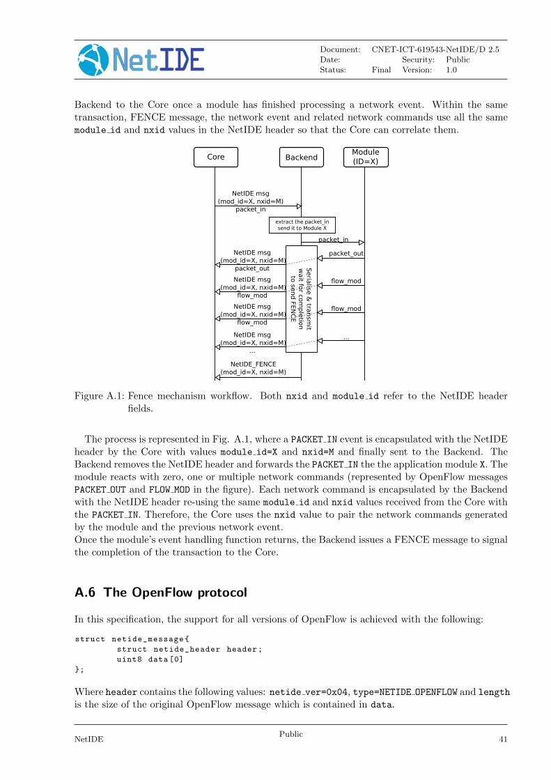
Document: CNET-ICT-619543-NetIDE/D 2.5Date: Security: PublicStatus: Final Version: 1.0
Backend to the Core once a module has finished processing a network event. Within the sametransaction, FENCE message, the network event and related network commands use all the samemodule id and nxid values in the NetIDE header so that the Core can correlate them.
Module(ID=X)BackendCore
NetIDE msg(mod_id=X, nxid=M)
packet_in
packet_in
packet_out
NetIDE_FENCE (mod_id=X, nxid=M)
flow_mod
flow_mod
...
extract the packet_insend it to Module X
NetIDE msg (mod_id=X, nxid=M)
packet_out Seria
lise &
transm
itw
ait fo
r com
ple
tion
to se
nd
FEN
CE
NetIDE msg (mod_id=X, nxid=M)
flow_mod
NetIDE msg (mod_id=X, nxid=M)
flow_mod
NetIDE msg (mod_id=X, nxid=M)
...
Figure A.1: Fence mechanism workflow. Both nxid and module id refer to the NetIDE headerfields.
The process is represented in Fig. A.1, where a PACKET IN event is encapsulated with the NetIDEheader by the Core with values module id=X and nxid=M and finally sent to the Backend. TheBackend removes the NetIDE header and forwards the PACKET IN the the application module X. Themodule reacts with zero, one or multiple network commands (represented by OpenFlow messagesPACKET OUT and FLOW MOD in the figure). Each network command is encapsulated by the Backendwith the NetIDE header re-using the same module id and nxid values received from the Core withthe PACKET IN. Therefore, the Core uses the nxid value to pair the network commands generatedby the module and the previous network event.Once the module’s event handling function returns, the Backend issues a FENCE message to signalthe completion of the transaction to the Core.
A.6 The OpenFlow protocol
In this specification, the support for all versions of OpenFlow is achieved with the following:
struct netide_message{
struct netide_header header;
uint8 data [0]
};
Where header contains the following values: netide ver=0x04, type=NETIDE OPENFLOW and length
is the size of the original OpenFlow message which is contained in data.
NetIDEPublic
41
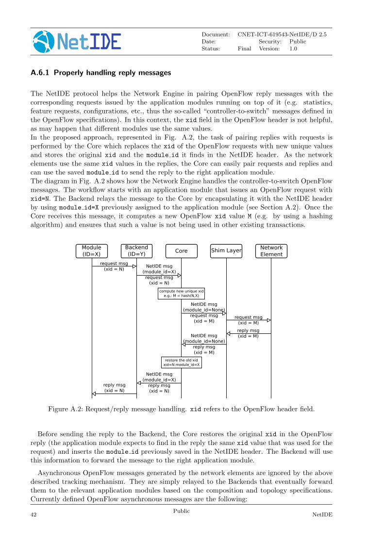
Document: CNET-ICT-619543-NetIDE/D 2.5Date: Security: PublicStatus: Final Version: 1.0
A.6.1 Properly handling reply messages
The NetIDE protocol helps the Network Engine in pairing OpenFlow reply messages with thecorresponding requests issued by the application modules running on top of it (e.g. statistics,feature requests, configurations, etc., thus the so-called “controller-to-switch” messages defined inthe OpenFlow specifications). In this context, the xid field in the OpenFlow header is not helpful,as may happen that different modules use the same values.In the proposed approach, represented in Fig. A.2, the task of pairing replies with requests isperformed by the Core which replaces the xid of the OpenFlow requests with new unique valuesand stores the original xid and the module id it finds in the NetIDE header. As the networkelements use the same xid values in the replies, the Core can easily pair requests and replies andcan use the saved module id to send the reply to the right application module.The diagram in Fig. A.2 shows how the Network Engine handles the controller-to-switch OpenFlowmessages. The workflow starts with an application module that issues an OpenFlow request withxid=N. The Backend relays the message to the Core by encapsulating it with the NetIDE headerby using module id=X previously assigned to the application module (see Section A.2). Once theCore receives this message, it computes a new OpenFlow xid value M (e.g. by using a hashingalgorithm) and ensures that such a value is not being used in other existing transactions.
Module(ID=X)
Backend(ID=Y)
Core Shim Layer NetworkElement
request msg(xid = N)
compute new unique xide.g.: M = hash(N,X)
NetIDE msg(module_id=X)request msg
(xid = N)
NetIDE msg(module_id=None)
request msg(xid = M)
request msg(xid = M)
reply msg(xid = M)
restore the old xidxid=N module_id=X
NetIDE msg(module_id=None)
reply msg(xid = M)
NetIDE msg(module_id=X)
reply msg(xid = N)
reply msg(xid = N)
Figure A.2: Request/reply message handling. xid refers to the OpenFlow header field.
Before sending the reply to the Backend, the Core restores the original xid in the OpenFlowreply (the application module expects to find in the reply the same xid value that was used for therequest) and inserts the module id previously saved in the NetIDE header. The Backend will usethis information to forward the message to the right application module.
Asynchronous OpenFlow messages generated by the network elements are ignored by the abovedescribed tracking mechanism. They are simply relayed to the Backends that eventually forwardthem to the relevant application modules based on the composition and topology specifications.Currently defined OpenFlow asynchronous messages are the following:
42Public
NetIDE
Document: CNET-ICT-619543-NetIDE/D 2.5Date: Security: PublicStatus: Final Version: 1.0
Message Type ID Description OF Version
OFPT PACKET IN 10 New packet received by a switch 1.0-1.5
OFPT FLOW REMOVED 11 Flow rule removed from the table 1.0-1.5
OFPT PORT STATUS 12 Port added, removed or modified 1.0-1.5
OFPT ROLE STATUS 30 Controller role change event 1.4-1.5
OFPT TABLE STATUS 31 Changes of the table state 1.4-1.5
OFPT REQUESTFORWARD 32 Request forwarding by the switch 1.4-1.5
OFPT CONTROLLER STATUS 35 Controller status change event 1.5
A.7 Other SBI protocols
The NetIDE intermediate protocol can easily support other SBI protocols, such as NetConf [17],OF-Config [19] or OpFlex [18].While OF-Config configurations are only encoded in eXtensible Markup Language (XML), NetConfand OpFlex specifications are more flexible and support both XML and JavaScript Object Notation(JSON) encoding formats. For this reason, we need an additional field in the NetIDE header toindicate the format of the message contained in data and to allow the recipients to correctlyhandle it. To this purpose, when transmitting NetConf or OpFlex messages, the sender must settype=NETIDE OTHER in the NetIDE header to indicate the presence of an additional 16-bits field atthe end of the header. This field, named ext type, specifies the SBI protocol and the format ofthe message carried by data:
struct netide_message{
struct netide_header header;
uint16_t ext_type;
uint8_t data [0];
};
Where header contains the following values: netide ver=0x04, type=NETIDE OTHER and length
is the size of the original SBI message carried by data. The value of ext type indicates the SBIprotocol in the most significant byte (as specified in Section A.1) and the format of the message(either 0x00 for XML or 0x01 for JSON) in the least significant byte.
NetIDEPublic
43

Document: CNET-ICT-619543-NetIDE/D 2.5Date: Security: PublicStatus: Final Version: 1.0
Bibliography
[1] The NetIDE Consortium. NetIDE deliverable 2.4 - NetIDE Core concepts and Architecturev2, Sep 2015.
[2] Chaithan Prakash, Jeongkeun Lee, Yoshio Turner, Joon-Myung Kang, Aditya Akella, SujataBanerjee, Charles Clark, Yadi Ma, Puneet Sharma, and Ying Zhang. Pga: Using graphsto express and automatically reconcile network policies. In Proceedings of the 2015 ACMConference on Special Interest Group on Data Communication, SIGCOMM ’15, pages 29–42,New York, NY, USA, 2015. ACM.
[3] Muhammad Shahbaz and Nick Feamster. The case for an intermediate representation forprogrammable data planes. In Proceedings of the 1st ACM SIGCOMM Symposium on SoftwareDefined Networking Research, SOSR ’15, pages 3:1–3:6, New York, NY, USA, 2015. ACM.
[4] The NetIDE Consortium. M4.1. Technical report, The European Commission, Dec 2015.
[5] The NetIDE Consortium. NetIDE deliverable 2.2 - NetIDE Architecture Redefinition: theNetIDE Runtime Approach, May 2014.
[6] The NetIDE Consortium. NetIDE deliverable 2.3 - NetIDE IRF APIs Integrated Platform v1,Apr 2015.
[7] The NetIDE Consortium. D4.1 - NetIDE Network Engine v1. Technical report, The EuropeanCommission, 2014.
[8] OpenDaylight Developer WIKI, main page. https://wiki.opendaylight.org/view/Main_
Page, Nov 2015.
[9] ONOS Java API. http://api.onosproject.org/, Nov 2015.
[10] Ryu API reference. http://ryu-zhdoc.readthedocs.org/en/latest/developing.html,Nov 2015.
[11] OpenFlowJ Loxi Java API. https://github.com/floodlight/loxigen/wiki/
OpenFlowJ-Loxi, Nov 2015.
[12] 0MQ Distributed Messaging. http://zeromq.org/, 2014.
[13] Joshua Reich, Christopher Monsanto, Nate Foster, Jennifer Rexford, and David Walker. Mod-ular SDN Programming with Pyretic. USENIX ;login, 38(5):128–134, Oct. 2013.
[14] Xin Jin, Jennifer Gossels, Jennifer Rexford, and David Walker. Covisor: A compositionalhypervisor for software-defined networks. In 12th USENIX Symposium on Networked SystemsDesign and Implementation (NSDI 15), pages 87–101, Oakland, CA, May 2015. USENIXAssociation.
[15] A. Dixit, K. Kogan, and P. Eugster. Composing heterogeneous sdn controllers with flowbricks.In Network Protocols (ICNP), 2014 IEEE 22nd International Conference on, pages 287–292,Oct 2014.
NetIDEPublic
45

Document: CNET-ICT-619543-NetIDE/D 2.5Date: Security: PublicStatus: Final Version: 1.0
[16] P4: high-level programming protocol-independent packet processors. http://onrc.stanford.edu/p4.html, 20152015.
[17] R. Enns, M. Bjorklund, J. Schoenwaelder, and A. Bierman. Network Configuration Protocol(NETCONF). Technical Report 6241, IETF Secretariat, June 2011.
[18] M. Smith et al. OpFlex Control Protocol. Technical report, IETF, November 2014.
[19] OpenFlow Management and Configuration Protocol (OF-Config 1.1). https://www.
opennetworking.org/images/stories/downloads/sdn-resources/onf-specifications/
openflow-config/of-config-1.1.pdf, Jun 2012.
46Public
NetIDE