nettap nt 50 · 2020-01-02 · user manual nettap nt 50 gateway devices hilscher gesellschaft für...
TRANSCRIPT

User Manual
netTAP NT 50
Gateway Devices
Hilscher Gesellschaft für Systemautomation mbH www.hilscher.com
DOC091202UM13EN | Revision 13 | English | 2015-01 | Released | Public

Introduction 2/86
netTAP NT 50 | Gateway Devices DOC091202UM13EN | Revision 13 | English | 2015-01 | Released | Public © Hilscher, 2010-2015
Table of Contents 1 INTRODUCTION.........................................................................................................5
1.1 About the User Manual ...............................................................................................5 1.1.1 Obligation to read and understand the Manual ....................................................5 1.1.2 List of Revisions ...................................................................................................6 1.1.3 Conventions in this Manual ..................................................................................7
1.2 Reference to Hardware, Software and Firmware .......................................................8 1.3 Contents of the Product DVD .....................................................................................9
1.3.1 Directory Structure of the DVD.............................................................................9 1.3.2 Device Description Files.....................................................................................10 1.3.3 Documentation for netTAP NT 50 ......................................................................11
1.4 Legal Notes...............................................................................................................13 1.4.1 Copyright ............................................................................................................13 1.4.2 Important Notes ..................................................................................................13 1.4.3 Exclusion of Liability ...........................................................................................14 1.4.4 Warranty .............................................................................................................14 1.4.5 Export Regulations .............................................................................................15 1.4.6 Registered Trademarks......................................................................................15
2 SAFETY ....................................................................................................................16 2.1 General Note ............................................................................................................16 2.2 Intended Use ............................................................................................................16 2.3 Personnel Qualification.............................................................................................16 2.4 References Safety ....................................................................................................16 2.5 Safety Instructions to avoid Personal Injury..............................................................17
2.5.1 Danger of unsafe System Operation..................................................................17 2.6 Safety Instructions to avoid Property Damage .........................................................17
2.6.1 Device Destruction by exceeding allowed Supply Voltage ................................17 2.6.2 Danger of unsafe System Operation..................................................................17
2.7 Labeling of Safety Messages....................................................................................18
3 DESCRIPTION AND REQUIREMENTS ...................................................................19 3.1 Device Description....................................................................................................19 3.2 Device Types and Protocol Conversions..................................................................20
3.2.1 Device Names ....................................................................................................20 3.2.2 Protocol Conversions .........................................................................................21
3.3 System Requirements ..............................................................................................22 3.4 Configuration Requirements .....................................................................................22
4 DEVICE DRAWINGS AND CONNECTIONS ............................................................23 4.1 Device and Dimensioned Drawings..........................................................................23 4.2 Positions of LEDs and Control Elements..................................................................24
4.2.1 Range of Values for the Address Switches........................................................24 4.3 Connections..............................................................................................................25
4.3.1 X1 Top Connection.............................................................................................25 4.3.2 X2 Front Connection...........................................................................................25

Introduction 3/86
netTAP NT 50 | Gateway Devices DOC091202UM13EN | Revision 13 | English | 2015-01 | Released | Public © Hilscher, 2010-2015
4.3.3 X3 Bottom Connection .......................................................................................28 4.4 Schematic Diagram - Galvanic Isolation...................................................................32
4.4.1 Galvanic Isolation of NT 50-xx-EN Devices .......................................................32 4.4.2 Galvanic Isolation of NT 50-xx-RS .....................................................................33 4.4.3 Galvanic Isolation of NT 50-RS-EN....................................................................34
5 NT 50 MOUNTING AND DISMOUNTING .................................................................35 5.1 DIN Top Hat Rail Mounting of the NT 50 ..................................................................35 5.2 Removing the NT 50 from the DIN Top Hat Rail ......................................................35
6 COMMISSIONING ....................................................................................................36 6.1 Load Firmware and Configuration ............................................................................36
6.1.1 Download Configuration Files from the PC ........................................................36 6.1.2 Potential Differences for Device Types NT 50-xx-RS ........................................37
6.2 Start-up Behavior......................................................................................................37
7 TROUBLESHOOTING ..............................................................................................38 7.1 Failure in 10 MBit/s Half Duplex Mode and Workaround..........................................39
8 LEDS.........................................................................................................................40 8.1 System LEDs ............................................................................................................40 8.2 LEDs Real Time Ethernet Protocols .........................................................................41
8.2.1 LEDs EtherNet/IP Scanner (Master) ..................................................................41 8.2.2 LEDs EtherNet/IP Adapter (Slave) .....................................................................42 8.2.3 LEDs Open Modbus/TCP...................................................................................43 8.2.4 LEDs PROFINET IO Controller ..........................................................................44 8.2.5 LEDs PROFINET IO-RT-Device ........................................................................45
8.3 LEDs Fieldbus Protocols ..........................................................................................46 8.3.1 LED PROFIBUS DP Master ...............................................................................46 8.3.2 LED PROFIBUS DP Slave .................................................................................46 8.3.3 LED CANopen Master ........................................................................................47 8.3.4 LED CANopen Slave..........................................................................................48 8.3.5 LED DeviceNet Master.......................................................................................49 8.3.6 LED DeviceNet Slave.........................................................................................49 8.3.7 LED CC-Link Slave.............................................................................................50
8.4 LEDs Serial Protocols...............................................................................................51 8.4.1 LED Modbus RTU ..............................................................................................51 8.4.2 LED ASCII ..........................................................................................................51
9 TECHNICAL DATA ...................................................................................................52 9.1 Technical Data netTAP 50 Gateway.........................................................................52 9.2 Technical Data of Real-Time Ethernet Communication Protocols............................54
9.2.1 EtherNet/IP Scanner (Master) Link ....................................................................54 9.2.2 EtherNet/IP Adapter (Slave)...............................................................................55 9.2.3 Open Modbus/TCP.............................................................................................56 9.2.4 PROFINET IO-RT-Controller Link ......................................................................57 9.2.5 PROFINET IO-RT-Device ..................................................................................58
9.3 Technical Data Fieldbus Protocols ...........................................................................59 9.3.1 CANopen Master Link ........................................................................................59 9.3.2 CANopen Slave ..................................................................................................60

Introduction 4/86
netTAP NT 50 | Gateway Devices DOC091202UM13EN | Revision 13 | English | 2015-01 | Released | Public © Hilscher, 2010-2015
9.3.3 CC-Link Slave.....................................................................................................61 9.3.4 DeviceNet Master Link .......................................................................................62 9.3.5 DeviceNet Slave .................................................................................................63 9.3.6 PROFIBUS DP Master Link ...............................................................................64 9.3.7 PROFIBUS DP Slave .........................................................................................65
9.4 Technical Data serial Protocols ................................................................................66 9.4.1 ASCII ..................................................................................................................66 9.4.2 Modbus RTU Master/Slave ................................................................................67
10 WIRING INSTRUCTIONS .........................................................................................68 10.1 Assembly of D-Sub Connectors................................................................................69 10.2 Ethernet ....................................................................................................................70 10.3 PROFIBUS ...............................................................................................................71 10.4 CANopen ..................................................................................................................73 10.5 DeviceNet .................................................................................................................74 10.6 CC-Link.....................................................................................................................76 10.7 RS-232......................................................................................................................78 10.8 RS-422......................................................................................................................79 10.9 RS-485......................................................................................................................81
11 DECOMMISSIONING/DISPOSAL.............................................................................83 11.1 Put the Device out of Operation................................................................................83 11.2 Disposal of Waste Electronic Equipment..................................................................83
12 APPENDIX ................................................................................................................84 12.1 List of Figures ...........................................................................................................84 12.2 List of Tables ............................................................................................................84 12.3 Contacts....................................................................................................................86

Introduction 5/86
netTAP NT 50 | Gateway Devices DOC091202UM13EN | Revision 13 | English | 2015-01 | Released | Public © Hilscher, 2010-2015
1 Introduction 1.1 About the User Manual
This user manual describes the hardware, installation, commissioning, and operation of the netTAP NT 50 series of gateways.
1.1.1 Obligation to read and understand the Manual
Important!
To avoid personal injury and to avoid property damage to your system or to your device, you must read and understand all instructions in the manual and all accompanying texts to your device, before installing and operating your device.
First read the Safety Instructions in the safety chapter.
Obey to all Safety Messages in the manual.
Keep the product DVD providing the product manuals.

Introduction 6/86
netTAP NT 50 | Gateway Devices DOC091202UM13EN | Revision 13 | English | 2015-01 | Released | Public © Hilscher, 2010-2015
1.1.2 List of Revisions
Index Date Chapter Revisions
8 2012-11-09 Firmware Version 1.1.x.x
3.4 Section Configuration Requirements updated.
7.1 Section Failure in 10 MBit/s Half Duplex Mode and Workaround: Serial numbers added.
8.3.4 Section LED CANopen Slave: State for baurate detection added.
8.3.7 Section LED CC-Link Slave added.
9.2.1 Section EtherNet/IP Scanner (Master) Link: Address Conflict Detection is sup-ported.
9.3.2 Section CANopen Slave: - Event timer added, - Address switch added, - Auto baudrate detection is supported.
9.3.3 Section CC-Link Slave: Address switch added.
9.3.5 Section DeviceNet Slave: Address switch added.
9.3.7 Section PROFIBUS DP Slave: - Maximum number of modules: Max. 4 input modules and max. 4 output mod-ules, max. 24 modules when using manual setting, - Address switch added.
9 2013-02-04 1.3.3 Section Documentation for netTAP NT 50 updated.
10 2013-06-24 4.3.2.5 Corrections
11 2014-03-10 1.3.1 Section Directory Structure of the DVD updated.
4.3.2.1 Section X2 for Device Type NT 50-CO-xx: Note added that pins 1, 4, 5, 6, 8 and 9 have to stay unconnected.
12 2014-03-24 9.2.3 Section Open Modbus/TCP: Information added: ‚Maximum number of connec-tions is 16’.
10.4 Maximum cable length for 1 MBit/s is 30 m.
13 2015-01-27 1.3.2 Device description files updated.
9.2.5 PROFINET IO-Device: max. 512 byte input and max. 512 byte output data.
9.4.1 ASCII: max telegram length is 512 bytes.
Table 1: List of Revisions

Introduction 7/86
netTAP NT 50 | Gateway Devices DOC091202UM13EN | Revision 13 | English | 2015-01 | Released | Public © Hilscher, 2010-2015
1.1.3 Conventions in this Manual Operation instructions, a result of an operation step or notes are marked as follows:
Operation Instructions:
<instruction>
or
1. <instruction>
2. <instruction>
Results:
<result>
Notes:
Important: <important note>
Note: <note>
<note, where to find further information>
Numbering:
... reference to the figure used in that section. If the numbers refer-ence to a section outside the current section then a cross reference to that section and figure is indicated.
Introduction 8/86
netTAP NT 50 | Gateway Devices DOC091202UM13EN | Revision 13 | English | 2015-01 | Released | Public © Hilscher, 2010-2015
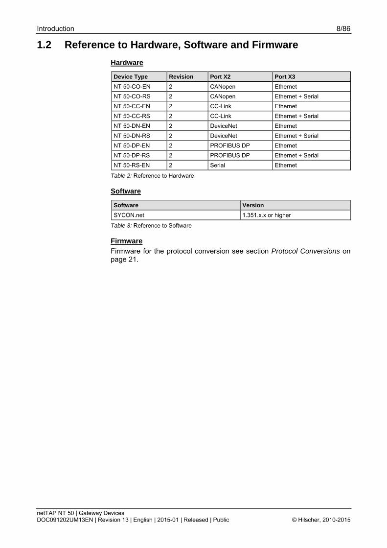
1.2 Reference to Hardware, Software and Firmware
Hardware
Device Type Revision Port X2 Port X3
NT 50-CO-EN 2 CANopen Ethernet
NT 50-CO-RS 2 CANopen Ethernet + Serial
NT 50-CC-EN 2 CC-Link Ethernet
NT 50-CC-RS 2 CC-Link Ethernet + Serial
NT 50-DN-EN 2 DeviceNet Ethernet
NT 50-DN-RS 2 DeviceNet Ethernet + Serial
NT 50-DP-EN 2 PROFIBUS DP Ethernet
NT 50-DP-RS 2 PROFIBUS DP Ethernet + Serial
NT 50-RS-EN 2 Serial Ethernet
Table 2: Reference to Hardware
Software
Software Version
SYCON.net 1.351.x.x or higher
Table 3: Reference to Software
Firmware
Firmware for the protocol conversion see section Protocol Conversions on page 21.

Introduction 9/86
netTAP NT 50 | Gateway Devices DOC091202UM13EN | Revision 13 | English | 2015-01 | Released | Public © Hilscher, 2010-2015
1.3 Contents of the Product DVD The product DVD gateway solutions for the netTAP NT 50 contains:
Setup program for the configuration and diagnostic software SYCON.net and for the Ethernet Device Configuration software.
Documentation
Firmware
Device Description Files (GSD, GSDML, EDS, ...)
Video-Audio Tutorials
Example projects for SYCON.net
1.3.1 Directory Structure of the DVD All manuals on this DVD are delivered in the Adobe Acrobat® Reader for-mat (PDF).
Directory Name Description
Documentation Documentation in the Acrobat® Reader Format (PDF)
Electronic Data Sheets (e.g. EDS, GSD, GSDML)
Device Description File
Firmware Loadable Firmware
fscommand Files used during installation
Setups & Drivers Configuration and diagnostic software SYCON.net USB Driver (not relevant for NT 50) Debugger software for netSCRIPT (not relevant for NT 50) Lua for Windows (not relevant for NT 50)
Supplements & Examples
Example projects for SYCON.net Example files for netSCRIPT (not relevant for NT 50) Links to websites about Modbus Device recovery (not relevant for NT 50)
Training & Podcasts Videos about commissioning
Table 4: Directory Structure of the gateway solution DVD

Introduction 10/86
netTAP NT 50 | Gateway Devices DOC091202UM13EN | Revision 13 | English | 2015-01 | Released | Public © Hilscher, 2010-2015
1.3.2 Device Description Files The directory EDS on the DVD provides device description files for the net-TAP NT 50 device.
netTAP NT 50 as File name
CC-Link Slave nt50-cc-ccs_1.csp (for one Remote Device Station), nt50-cc-ccs_2.csp (for two Remote Device Stations), nt50-cc-ccs_3.csp (for three Remote Device Stations), nt50-cc-ccs_4.csp (for four Remote Device Stations), nt50-cc-ccs_io_1.csp (for one Remote IO Station)
CANopen Slave NT50_CO_COS.EDS
DeviceNet Slave NT50_DN_DNS.EDS
EtherNet/IP Adapter HILSCHER NT 50-EN EIS V1.1.EDS
PROFIBUS DP Slave HIL_0C99.GSD
PROFINET IO-Device GSDML-V2.2-HILSCHER-NT 50-EN PNS-20150106-074400.xml
Table 5: Device Description Files for netTAP NT 50 on the DVD
The device description files are for the configuration of the used master.
Introduction 11/86
netTAP NT 50 | Gateway Devices DOC091202UM13EN | Revision 13 | English | 2015-01 | Released | Public © Hilscher, 2010-2015
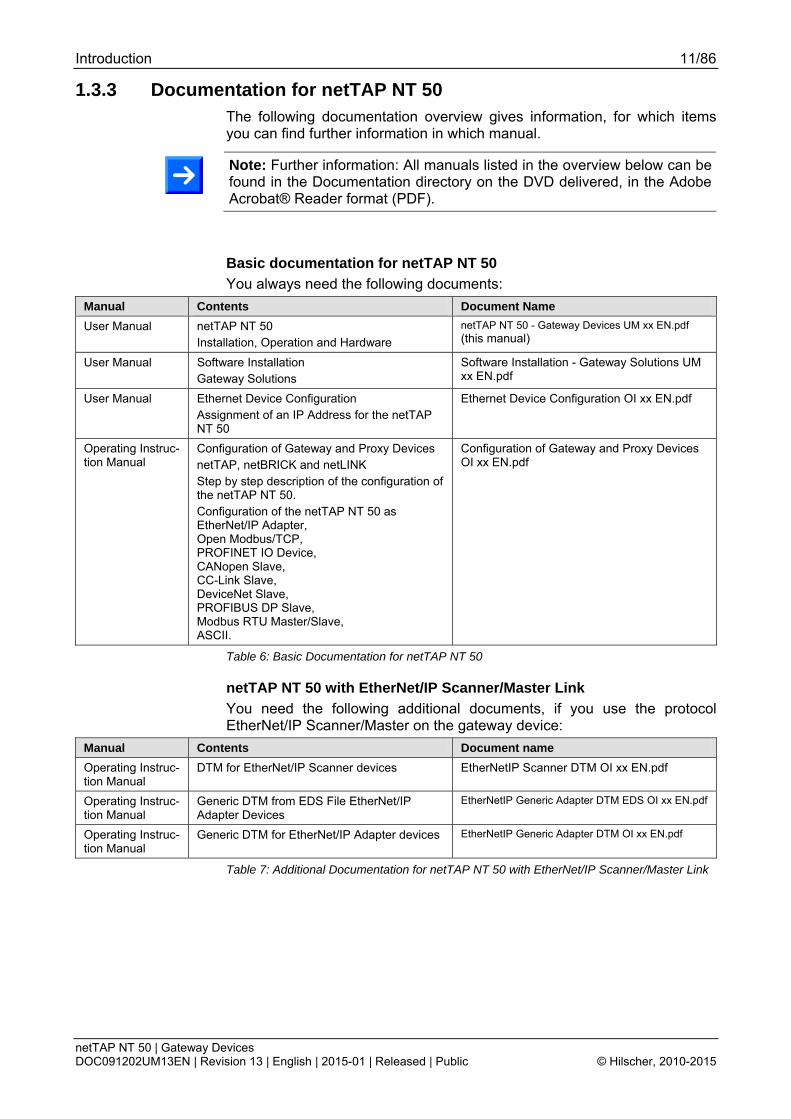
1.3.3 Documentation for netTAP NT 50 The following documentation overview gives information, for which items you can find further information in which manual.
Note: Further information: All manuals listed in the overview below can be found in the Documentation directory on the DVD delivered, in the Adobe Acrobat® Reader format (PDF).
Basic documentation for netTAP NT 50
You always need the following documents:
Manual Contents Document Name
User Manual netTAP NT 50 Installation, Operation and Hardware
netTAP NT 50 - Gateway Devices UM xx EN.pdf (this manual)
User Manual Software Installation Gateway Solutions
Software Installation - Gateway Solutions UM xx EN.pdf
User Manual Ethernet Device Configuration Assignment of an IP Address for the netTAP NT 50
Ethernet Device Configuration OI xx EN.pdf
Operating Instruc-tion Manual
Configuration of Gateway and Proxy Devices netTAP, netBRICK and netLINK Step by step description of the configuration of the netTAP NT 50. Configuration of the netTAP NT 50 as EtherNet/IP Adapter, Open Modbus/TCP, PROFINET IO Device, CANopen Slave, CC-Link Slave, DeviceNet Slave, PROFIBUS DP Slave, Modbus RTU Master/Slave, ASCII.
Configuration of Gateway and Proxy Devices OI xx EN.pdf
Table 6: Basic Documentation for netTAP NT 50
netTAP NT 50 with EtherNet/IP Scanner/Master Link
You need the following additional documents, if you use the protocol EtherNet/IP Scanner/Master on the gateway device:
Manual Contents Document name
Operating Instruc-tion Manual
DTM for EtherNet/IP Scanner devices EtherNetIP Scanner DTM OI xx EN.pdf
Operating Instruc-tion Manual
Generic DTM from EDS File EtherNet/IP Adapter Devices
EtherNetIP Generic Adapter DTM EDS OI xx EN.pdf
Operating Instruc-tion Manual
Generic DTM for EtherNet/IP Adapter devices EtherNetIP Generic Adapter DTM OI xx EN.pdf
Table 7: Additional Documentation for netTAP NT 50 with EtherNet/IP Scanner/Master Link

Introduction 12/86
netTAP NT 50 | Gateway Devices DOC091202UM13EN | Revision 13 | English | 2015-01 | Released | Public © Hilscher, 2010-2015
netTAP NT 50 with PROFINET IO Controller Link
You need the following additional documents, if you use the protocol PROFINET IO Controller on the gateway device:
Manual Contents Document name
Operating Instruc-tion Manual
DTM for PROFINET IO Controller devices PROFINET IO Controller DTM OI xx EN.pdf
Operating Instruc-tion Manual
Generic DTM for PROFINET IO Device de-vices
PROFINET IO Generic Device DTM IO xx EN.pdf
Table 8: Additional Documentation for netTAP NT 50 with PROFINET IO Controller Link
netTAP NT 50 with CANopen Master Link
You need the following additional documents, if you use the protocol CANopen Master on the gateway device:
Manual Contents Document name
Operating Instruc-tion Manual
DTM for CANopen Master devices CANopen Master DTM OI xx EN.pdf
Operating Instruc-tion Manual
Generic DTM for CANopen Slave devices CANopen Generic Slave DTM OI xx EN.pdf
Table 9: Additional Documentation for netTAP NT 50 with CANopen Master Link
netTAP NT 50 with DeviceNet Master Link
You need the following additional documents, if you use the protocol DeviceNet Master on the gateway device:
Manual Contents Document name
Operating Instruc-tion Manual
DTM for DeviceNet Master devices DeviceNet Master DTM OI xx EN.pdf
Operating Instruc-tion Manual
Generic DTM for DeviceNet Slave devices DeviceNet Generic Slave DTM OI xx EN.pdf
Table 10: Additional Documentation for netTAP NT 50 with DeviceNet Master Link
netTAP NT 50 with PROFIBUS DP Master Link
You need the following additional documents, if you use the protocol PROFIBUS DP Master on the gateway device:
Manual Contents Document name
Operating Instruc-tion Manual
DTM for PROFIBUS DP Master devices PROFIBUS DP Master DTM OI xx EN.pdf
Operating Instruc-tion Manual
Generic DTM for PROFIBUS DP Slave de-vices
PROFIBUS DP Generic Slave DTM OI xx EN.pdf
Table 11: Additional Documentation for netTAP NT 50 with PROFIBUS DP Master Link
netTAP NT 50 with ASCII
You need the following additional documents, if you use the protocol ASCII on the gateway device:
Manual Contents Document name
User Manual ASCII Handshake Mechanism ASCII – Handshake Mechanism UM xx EN.pdf
Table 12: Additional Documentation for netTAP NT 50 with ASCII

Introduction 13/86
netTAP NT 50 | Gateway Devices DOC091202UM13EN | Revision 13 | English | 2015-01 | Released | Public © Hilscher, 2010-2015
1.4 Legal Notes
1.4.1 Copyright © Hilscher, 2010-2015, Hilscher Gesellschaft für Systemautomation mbH
All rights reserved.
The images, photographs and texts in the accompanying material (user manual, accompanying texts, documentation, etc.) are protected by Ger-man and international copyright law as well as international trade and pro-tection provisions. You are not authorized to duplicate these in whole or in part using technical or mechanical methods (printing, photocopying or other methods), to manipulate or transfer using electronic systems without prior written consent. You are not permitted to make changes to copyright no-tices, markings, trademarks or ownership declarations. The included dia-grams do not take the patent situation into account. The company names and product descriptions included in this document may be trademarks or brands of the respective owners and may be trademarked or patented. Any form of further use requires the explicit consent of the respective rights owner.
1.4.2 Important Notes The user manual, accompanying texts and the documentation were created for the use of the products by qualified experts, however, errors cannot be ruled out. For this reason, no guarantee can be made and neither juristic responsibility for erroneous information nor any liability can be assumed. Descriptions, accompanying texts and documentation included in the user manual do not present a guarantee nor any information about proper use as stipulated in the contract or a warranted feature. It cannot be ruled out that the user manual, the accompanying texts and the documentation do not correspond exactly to the described features, standards or other data of the delivered product. No warranty or guarantee regarding the correctness or accuracy of the information is assumed.
We reserve the right to change our products and their specification as well as related user manuals, accompanying texts and documentation at all times and without advance notice, without obligation to report the change. Changes will be included in future manuals and do not constitute any obli-gations. There is no entitlement to revisions of delivered documents. The manual delivered with the product applies.
Hilscher Gesellschaft für Systemautomation mbH is not liable under any circumstances for direct, indirect, incidental or follow-on damage or loss of earnings resulting from the use of the information contained in this publica-tion.

Introduction 14/86
netTAP NT 50 | Gateway Devices DOC091202UM13EN | Revision 13 | English | 2015-01 | Released | Public © Hilscher, 2010-2015
1.4.3 Exclusion of Liability The software was produced and tested with utmost care by Hilscher Ge-sellschaft für Systemautomation mbH and is made available as is. No war-ranty can be assumed for the performance and flawlessness of the soft-ware for all usage conditions and cases and for the results produced when utilized by the user. Liability for any damages that may result from the use of the hardware or software or related documents, is limited to cases of in-tent or grossly negligent violation of significant contractual obligations. In-demnity claims for the violation of significant contractual obligations are lim-ited to damages that are foreseeable and typical for this type of contract.
It is strictly prohibited to use the software in the following areas:
for military purposes or in weapon systems;
for the design, construction, maintenance or operation of nuclear facili-ties;
in air traffic control systems, air traffic or air traffic communication sys-tems;
in life support systems;
in systems in which failures in the software could lead to personal injury or injuries leading to death.
We inform you that the software was not developed for use in dangerous environments requiring fail-proof control mechanisms. Use of the software in such an environment occurs at your own risk. No liability is assumed for damages or losses due to unauthorized use.
1.4.4 Warranty Although the hardware and software was developed with utmost care and tested intensively, Hilscher Gesellschaft für Systemautomation mbH does not guarantee its suitability for any purpose not confirmed in writing. It can-not be guaranteed that the hardware and software will meet your require-ments, that the use of the software operates without interruption and that the software is free of errors. No guarantee is made regarding infringe-ments, violations of patents, rights of ownership or the freedom from inter-ference by third parties. No additional guarantees or assurances are made regarding marketability, freedom of defect of title, integration or usability for certain purposes unless they are required in accordance with the law and cannot be limited. Warranty claims are limited to the right to claim rectifica-tion.

Introduction 15/86
netTAP NT 50 | Gateway Devices DOC091202UM13EN | Revision 13 | English | 2015-01 | Released | Public © Hilscher, 2010-2015
1.4.5 Export Regulations The delivered product (including the technical data) is subject to export or import laws as well as the associated regulations of different counters, in particular those of Germany and the USA. The software may not be ex-ported to countries where this is prohibited by the United States Export Administration Act and its additional provisions. You are obligated to com-ply with the regulations at your personal responsibility. We wish to inform you that you may require permission from state authorities to export, re-export or import the product.
1.4.6 Registered Trademarks Windows® XP, Windows® Vista and Windows® 7 are registered trademarks of Microsoft Corporation.
Adobe-Acrobat® is a registered trademark of the Adobe Systems Incorpo-rated.
CANopen® is a registered trademark of CAN in AUTOMATION - Interna-tional Users and Manufacturers Group e.V (CiA), Nürnberg.
CC-Link® is a registered trademark of Mitsubishi Electric Corporation, To-kyo, Japan.
DeviceNet® and EtherNet/IP® are trademarks of ODVA (Open DeviceNet Vendor Association, Inc).
Modbus® is a registered trademark of Schneider Electric.
PROFIBUS and PROFINET are registered trademarks of PROFIBUS Inter-national, Karlsruhe.
All other mentioned trademarks are property of their respective legal own-ers.

Safety 16/86
netTAP NT 50 | Gateway Devices DOC091202UM13EN | Revision 13 | English | 2015-01 | Released | Public © Hilscher, 2010-2015
2 Safety 2.1 General Note
The user manual, the accompanying texts and the documentation are writ-ten for the use of the products by educated personnel. When using the products, all safety instructions and all valid legal regulations have to be obeyed. Technical knowledge is presumed. The user has to assure that all legal regulations are obeyed.
2.2 Intended Use Devices described in this manual:
NT 50-CC-EN,
NT 50-CC-RS,
NT 50-CO-EN,
NT 50-CO-RS,
NT 50-DN-EN,
NT 50-DN-RS,
NT 50-DP-EN,
NT 50-DP-RS,
NT 50-RS-EN,
are devices for communication and connect two communication networks. The NT 50 devices work as a gateway between these two networks.
The NT 50 devices are in a compact housing and suitable for DIN rail mounting according to DIN EN 60715.
The devices should be operated only in an environment appropriate to the technical data.
2.3 Personnel Qualification The netTAP NT 50 Gateway must only be installed, configured and re-moved by qualified personnel. Job-specific technical skills for people pro-fessionally working with electricity must be present concerning the following topics:
Safety and health at work
Mounting and attaching of electrical equipment
Measurement and Analysis of electrical functions and systems
Evaluation of the safety of electrical systems and equipment
Installing and Configuring IT
2.4 References Safety [1] ANSI Z535.6-2006 American National Standard for Product Safety Information in
Product Manuals, Instructions, and Other Collateral Materials
[2] IEC 60950-1, Information technology equipment - Safety - Part 1: General requirements, (IEC 60950-1:2005, modified); German Edition EN 60950-1:2006
[3] EN 61340-5-1 and EN 61340-5-2 as well as IEC 61340-5-1 and IEC 61340-5-2
Safety 17/86
netTAP NT 50 | Gateway Devices DOC091202UM13EN | Revision 13 | English | 2015-01 | Released | Public © Hilscher, 2010-2015
2.5 Safety Instructions to avoid Personal Injury To ensure your own personal safety and to avoid personal injury, you nec-essarily must read, understand and follow the following safety instructions and all safety messages in this manual about danger causing personal in-jury, before you install and operate your netTAP NT 50 device.
2.5.1 Danger of unsafe System Operation To prevent harm of persons, do not remove this device under runtime con-ditions before you can not guarantee further a safe and secure operation of the plant.
2.6 Safety Instructions to avoid Property Damage To avoid property damage respectively device destruction of the netTAP NT 50 device, you necessarily must read, understand and follow the follow-ing safety instructions and all safety messages in this manual about danger causing property damage, before you install and operate your netTAP NT 50 device.
2.6.1 Device Destruction by exceeding allowed Supply Voltage Adhere for all netTAP NT 50 device described in this manual the instruction hereafter:
The netTAP NT 50 may only be operated with the specified supply voltage. Make sure that the limits of the allowed range for the supply voltage are not exceeded. A supply voltage above the upper limit can cause severe dam-age to the netTAP NT 50! A supply voltage below the lower limit can cause malfunction in the netTAP NT 50. The allowed range for the supply voltage is defined by the tolerances specified in this manual.
The data on the mandatory supply voltage for the netTAP NT 50 device you find in the section System Requirements on page 22. There the re-quired and permitted supply voltage for the netTAP NT 50 device is pro-vided inclusively the permitted tolerance range.
2.6.2 Danger of unsafe System Operation To prevent property damage, do not remove this device under runtime con-ditions before you can not guarantee further a safe and secure operation of the plant.

Safety 18/86
netTAP NT 50 | Gateway Devices DOC091202UM13EN | Revision 13 | English | 2015-01 | Released | Public © Hilscher, 2010-2015
2.7 Labeling of Safety Messages The Section Safety Messages at the beginning of a chapter are pin-
pointed particularly. They are highlighted with a specific safety symbol and a signal word according to the degree of endangerment. Inside the safety message the danger is exactly named.
The Integrated Safety Messages within a instruction description are highlighted with a signal word according to the degree of endangerment and possibly by an principle symbol. Inside the safety message the dan-ger is exactly named.
Safety Sym-bol
Safety Symbol (USA)
Sort of Warning or Principle
Warning of Personal Injury and Property Damage Message USA: Warning of Personal Injury As in the scope of the ANSI Z535 Standard (for USA) instructions to a property dam-age message may not contain a warning triangle, this property damage messages are listed separatly for the USA.
Warning of Damages by Electrostatic Discharge
Table 13: Safety Symbols and Sort of Warning or Principle
Signal Word Meaning Meaning (USA)
Indicates a Property Damage Message. Indicates a Property Damage Message.
Note Indicates an important note in the manual. Indicates an Important Note in the Manual.
Table 14: Signal Words
In this document all Safety Instructions and Safety Messages are designed according both to the international used safety conventions as well as to the ANSI Z535 standard, refer to reference safety [S1].
Description and Requirements 19/86
netTAP NT 50 | Gateway Devices DOC091202UM13EN | Revision 13 | English | 2015-01 | Released | Public © Hilscher, 2010-2015
3 Description and Requirements 3.1 Device Description
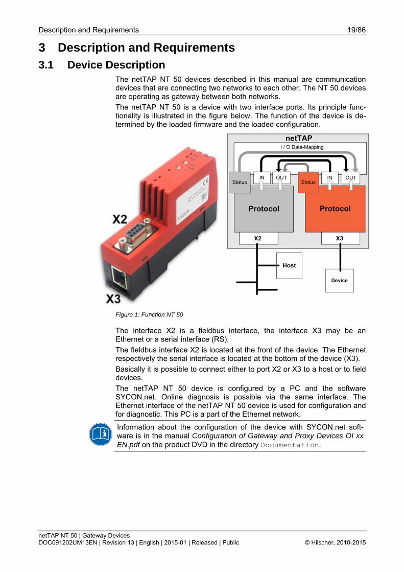
The netTAP NT 50 devices described in this manual are communication devices that are connecting two networks to each other. The NT 50 devices are operating as gateway between both networks.
The netTAP NT 50 is a device with two interface ports. Its principle func-tionality is illustrated in the figure below. The function of the device is de-termined by the loaded firmware and the loaded configuration.
Figure 1: Function NT 50
The interface X2 is a fieldbus interface, the interface X3 may be an Ethernet or a serial interface (RS).
The fieldbus interface X2 is located at the front of the device. The Ethernet respectively the serial interface is located at the bottom of the device (X3).
Basically it is possible to connect either to port X2 or X3 to a host or to field devices.
The netTAP NT 50 device is configured by a PC and the software SYCON.net. Online diagnosis is possible via the same interface. The Ethernet interface of the netTAP NT 50 device is used for configuration and for diagnostic. This PC is a part of the Ethernet network.
Information about the configuration of the device with SYCON.net soft-ware is in the manual Configuration of Gateway and Proxy Devices OI xx EN.pdf on the product DVD in the directory Documentation.

Description and Requirements 20/86
netTAP NT 50 | Gateway Devices DOC091202UM13EN | Revision 13 | English | 2015-01 | Released | Public © Hilscher, 2010-2015
The gateway functionality is determined by the loadable firmware.
The firmware buffers the cyclic send and receive data of the protocol at port X2 and the protocol of port X3 internally. The configuration tool enables the flexible mapping of the receive data of protocol X2 to send data of the pro-tocol X3 and vice versa.
Status information of the protocol at port X2 can be mapped into the send data of the protocol at port X3 and vice versa.
The firmware of netTAP NT 50 as gateway does not support acyclic com-munications or services of the supported protocols.
If the device is operated in a bus system as a master, then exactly one slave can be connected. Thus, for example for protocols with master func-tionality the designation „PROFIBUS DP Master Link“ means, that one PROFIBUS DP Slave can be connected.
3.2 Device Types and Protocol Conversions
3.2.1 Device Names The descriptive device name of netTAP devices consists of the following parts
1. Device Type netTAP 50
2. Network on port X2 (upper port on the device), in the example DP for PROFIBUS DP.
3. Network on port X3 (port at the bottom of the device) , in the example RE for Real-time Ethernet
The following communication systems are currently supported at the pri-mary network X2:
Code 2 Supported Communication System
CC CC-Link
CO CANopen
DN DeviceNet
DP PROFIBUS DP
RS Serial (Modbus RTU or ASCII)
Table 15: Network on port X2 (Primary Network)
The following communication systems are currently supported at the sec-ondary network X3:
Code 3 Supported Communication System
EN Ethernet (1* RJ45)
RS Serial (Modbus RTU or ASCII) (RJ45)
Table 16: Network on port X3 (Secondary Network)

Description and Requirements 21/86
netTAP NT 50 | Gateway Devices DOC091202UM13EN | Revision 13 | English | 2015-01 | Released | Public © Hilscher, 2010-2015
3.2.2 Protocol Conversions The following table lists the protocol conversion and the necessary netTAP NT 50 device type.
Device Name Protocol at X2 Protocol at X3 Firmware File Firmware Version
NT 50-CC-EN CC-Link Slave EtherNet/IP Adapter/Slave EtherNet/IP Scanner/Master (1) PROFINET IO Device PROFINET IO Controller (1) Open Modbus/TCP
N5CCSEIS.NXF N5CCSEIM.NXF N5CCSPNS.NXF N5CCSPNM.NXF N5CCSOMB.NXF
NT 50-CC-RS CC-Link Slave ASCII Modbus RTU Master / Slave
N5CCSASC.NXF N5CCSMBR.NXF
CANopen Master (for one sla-ve)
EtherNet/IP Adapter/Slave PROFINET IO Device Open Modbus/TCP
N5COMEIS.NXF N5COMPNS.NXF N5COMOMB.NXF
NT 50-CO-EN
CANopen Slave EtherNet/IP Adapter/Slave EtherNet/IP Scanner/Master (1) PROFINET IO Device PROFINET IO Controller (1) Open Modbus/TCP
N5COSEIS.NXF N5COSEIM.NXF N5COSPNS.NXF N5COSPNM.NXF N5COSOMB.NXF
CANopen Master (for one sla-ve)
ASCII Modbus RTU Master / Slave
N5COMASC.NXF N5COMMBR.NXF
NT 50-CO-RS
CANopen Slave ASCII Modbus RTU Master / Slave
N5COSASC.NXF N5COSMBR.NXF
DeviceNet Master (for one sla-ve)
EtherNet/IP Adapter/Slave PROFINET IO Device Open Modbus/TCP
N5DNMEIS.NXF N5DNMPNS.NXF N5DNMOMB.NXF
NT 50-DN-EN
DeviceNet Slave EtherNet/IP Adapter/Slave EtherNet/IP Scanner/Master (1) PROFINET IO Device PROFINET IO Controller (1) Open Modbus/TCP
N5DNSEIS.NXF N5DNSEIM.NXF N5DNSPNS.NXF N5DNSPNM.NXF N5DNSOMB.NXF
DeviceNet Master (for one sla-ve)
ASCII Modbus RTU Master / Slave
N5DNMASC.NXF N5DNMMBR.NXF
NT 50-DN-RS
DeviceNet Slave ASCII Modbus RTU Master / Slave
N5DNSASC.NXF N5DNSMBR.NXF
PROFIBUS DP Master (for one slave)
EtherNet/IP Adapter/Slave PROFINET IO Device Open Modbus/TCP
N5DPMEIS.NXF N5DPMPNS.NXF N5DPMOMB.NXF
NT 50-DP-EN
PROFIBUS DP Slave EtherNet/IP Adapter/Slave EtherNet/IP Scanner/Master (1) PROFINET IO Device PROFINET IO Controller (1) Open Modbus/TCP
N5DPSEIS.NXF N5DPSEIM.NXF N5DPSPNS.NXF N5DPSPNM.NXF N5DPSOMB.NXF
PROFIBUS DP Master (for one slave)
ASCII Modbus RTU Master / Slave
N5DPMASC.NXF N5DPMMBR.NXF
NT 50-DP-RS
PROFIBUS DP Slave ASCII Modbus RTU Master / Slave
N5DPSASC.NXF N5DPSMBR.NXF
ASCII EtherNet/IP Adapter/Slave Ethernet/IP Scanner/Master (1) PROFINET IO Device PROFINET IO Controller (1) Open Modbus/TCP
N5ASCEIS.NXF N5ASCEIM.NXF N5ASCPNS.NXF N5ASCPNM.NXF N5ASCOMB.NXF
NT 50-RS-EN
Modbus RTU Master/Slave EtherNet/IP Adapter/Slave EtherNet/IP Scanner/Master (1) PROFINET IO Device PROFINET IO Controller (1) Open Modbus/TCP
N5MBREIS.NXF N5MBREIM.NXF N5MBRPNS.NXF N5MBRPNM.NXF N5MBROMB.NXF
1.1.x.x
Table 17: List of Protocol Conversion and NT 50 Device Type

Description and Requirements 22/86
netTAP NT 50 | Gateway Devices DOC091202UM13EN | Revision 13 | English | 2015-01 | Released | Public © Hilscher, 2010-2015
3.3 System Requirements The netTAP NT 50 device must be mounted on a DIN-rail according to DIN EN 60715.
A suitable power supply is required. The voltage to be applied must be in the allowed range 24 V ± 6 V DC. The power supply must be able to deliver at least a current of 100 mA at 24 V.
Power supply is possible via pins 1 (GND) and 2 (24V) of the netTAP NT 50 power supply connector located on the upper side of the device.
Device Destruction!
The voltage must not exceed 30 V significantly, otherwise the device may be destroyed or damaged.
In order to avoid damage caused by overheating or freezing, it is necessary that the temperature of the device does not exceed the limits of the allowed temperature range.
The following preconditions must additionally be met in order to operate the Gateway device successfully:
1. The Gateway device must have been provided with the correctly suiting firmware.
2. The Gateway device must have been configured correctly using the SYCON.net configuration software.
3.4 Configuration Requirements The configuration software SYCON.net must be installed on a PC. The re-quirements for the PC are:
PC with 1 GHz processor or higher
Windows® XP SP3, Windows® Vista (32 bit) SP2, Windows® 7 (32 bit) or Windows® 7 (64 bit)
Administrator rights
Internet Explorer 5.5 or higher
Free disk space: min. 400 MByte
DVD ROM drive
RAM: min. 512 MByte, recommended 1024 MByte
Graphic resolution: min. 1024 x 768 pixel
Keyboard and Mouse
USB
Note: If the project file is saved and opened again or it is used on another PC, the system requirements need to match. Particularly the DTMs need to be installed on the used PC.

Device Drawings and Connections 23/86
netTAP NT 50 | Gateway Devices DOC091202UM13EN | Revision 13 | English | 2015-01 | Released | Public © Hilscher, 2010-2015
4 Device Drawings and Connections 4.1 Device and Dimensioned Drawings
Side view Front view
with Combicon con-nector
with D-Sub male connector
with D-Sub female connector
Bottom View
with RJ45 Socket
with RJ45 Socket
with RJ45 Socket
Device type NT 50-CC-EN NT 50-CC-RS NT 50-DN-EN NT 50-DN-RS
NT 50-CO-EN NT 50-CO-RS NT 50-RS-EN
NT 50-DP-EN NT 50-DP-RS
Figure 2: Device Drawings
In the drawing above:
X1 Connector for Power Supply
X2 and X3 Communication interfaces
Dimensions of the power supply plug X1 in mm

Device Drawings and Connections 24/86
netTAP NT 50 | Gateway Devices DOC091202UM13EN | Revision 13 | English | 2015-01 | Released | Public © Hilscher, 2010-2015
4.2 Positions of LEDs and Control Elements
Meaning of the elements
Connector X1 for power supply
SYS-LED
APL-LED
COM-LED
LED, depends on protocol at X2
LED, depends on protocol at X2
Rotary address switch, factor 10
Rotary address switch, factor 1
The address switches can be activated with SYCON.net version 1.351 (or higher) and can be used with firmware version 1.1 (or higher) for PROFIBUS DP Slave, DeviceNet Slave, CANopen Slave and CC-Link Slave.
Section Range of Values for the Address Switches on this page lists the range of values for each protocol.
LED, green, LINK at X3
LED, yellow, ACT respectively Rx/Tx (activity) at X3
Figure 3: LEDs and Control Elements
4.2.1 Range of Values for the Address Switches
Protocol Valid range of values
PROFIBUS DP Slave 0 … 99 (station address)
DeviceNet Slave 0 … 63 (MAC ID)
CANopen Slave 0 … 99 (Node ID)
Protocol Valid range of values Number of Stations
1 … 64 1
1 … 63 2
1 … 62 3
CC-Link Slave
1 … 61 4
The number of sta-tions depends on the configuration
Figure 4: Range of Values for the Address Switches

Device Drawings and Connections 25/86
netTAP NT 50 | Gateway Devices DOC091202UM13EN | Revision 13 | English | 2015-01 | Released | Public © Hilscher, 2010-2015
4.3 Connections
4.3.1 X1 Top Connection The power supply of the netTAP 50 device has to be connected to the
power connector X1 . The power supply voltage must be in the range be-tween 18 V and 30 V DC. The plug is included in delivery.
Supply Voltage Pin Assignment
Supply Volta-ge
Pin Signal Description
1 0 V / GND
Ground of supply voltage
Mini Combicon 2 24 V +24 V supply voltage
Table 18: Supply Voltage Pin Assignment
4.3.2 X2 Front Connection
4.3.2.1 X2 for Device Type NT 50-CO-xx
CANopen Pin Assignment
CANopen Pin Signal Description
2 CAN L CAN Low bus line
3 ISO GND
CAN ground
7 CAN H CAN High bus line
1, 4, 5, 6, 8, 9
Important note and strongly recommended: Leave these pins unconnected! Otherwise there is a high risk of a device damage.
9-pole sub-D male.
Shield PE Metal shell on PE
Table 19: CANopen Pin Assignment
Please note the wiring instructions in section CANopen on page 73.
4.3.2.2 X2 for Device Type NT 50-CC-xx
CC-Link Pin Assignment
CC-Link Pin Signal Description
1 DA Data positive
2 DB Data negative
3 DG Data ground
4 SLD Shield, internally connected to common ground
Socket, female
5 FG Field ground, internally connected to common ground
Table 20: CC-Link Pin Assignment
Please note the wiring instructions in section CC-Link on page 76.

Device Drawings and Connections 26/86
netTAP NT 50 | Gateway Devices DOC091202UM13EN | Revision 13 | English | 2015-01 | Released | Public © Hilscher, 2010-2015
4.3.2.3 X2 for Device Type NT 50-DN-xx
DeviceNet Pin Assignment
DeviceNet Pin Signal Description
1 ISO GND Common ground DeviceNet-power supply.
2 CAN L CAN Low signal
3 Drain Shield
4 CAN H CAN High signal COMBICON Socket, female
5 V+ +24 V DeviceNet-power supply
Table 21: DeviceNet Pin Assignment
Please note the wiring instructions in section DeviceNet on page 74.
4.3.2.4 X2 for Device Type NT 50-DP-xx
RS-485 PROFIBUS Pin Assignment
PROFIBUS Pin Signal Description
3 Rx/Tx + Receive- / Transmit data positive
4 CNTR-P Control signal for repeater (direction control)
5 ISO GND Data ground
6 VP Power supply positive 9-pole sub-D socket, female
8 Rx/Tx - Receive- / Transmit data negative
Table 22: PROFIBUS RS-485 Pin Assignment
A pull up resistor of 100 kΩ is connected device internally at “Rx / Tx +“.
A pull down resistor of 100 kΩ is connected device internally at “Rx / Tx -“.
Please note the wiring instructions in section PROFIBUS on page 71.

Device Drawings and Connections 27/86
netTAP NT 50 | Gateway Devices DOC091202UM13EN | Revision 13 | English | 2015-01 | Released | Public © Hilscher, 2010-2015
4.3.2.5 X2 for Device Type NT 50-RS-EN
RS-232 Pin Assignment
RS-232 Pin Signal Description
1 GND Reference potential, ground of power supply
6 RxD Receive data
9-pole sub-D socket, male
8 TxD Transmit data
Table 23: RS-232 Pin Assignment
Please note the wiring instructions in section RS-232 on page 78.
RS-422 Pin Assignment
RS-422 Pin Signal Description
1 GND Reference potential, ground of power supply
4 RxD + Receive data positive
5 RxD - Receive data negative
6 TxD + Transmit data positive
9-pole sub-D socket, male
8 TxD - Transmit data negative
Table 24: RS-422 Pin Assignment
A pull up resistor of 10 kΩ is connected device internally at “RxD +“.
A pull down resistor of 10 kΩ is connected device internally at “RxD -“.
Please note the wiring instructions in section RS-422 on page 79.
RS-485 Pin Assignment
RS-485 Pin Signal Description
1 GND Reference potential, ground of power supply
4 RxD/TxD+ Receive data / Transmit data positive
9-pole sub-D socket, male
5 RxD/TxD- Receive data / Transmit data negative
Table 25: RS-485 Pin Assignment
A pull up resistor of 10 kΩ is connected device internally at “RxD/TxD +“.
A pull down resistor of 10 kΩ is connected device internally at “RxD/TxD -“.
Please note the wiring instructions in section RS-485 on page 81.

Device Drawings and Connections 28/86
netTAP NT 50 | Gateway Devices DOC091202UM13EN | Revision 13 | English | 2015-01 | Released | Public © Hilscher, 2010-2015
4.3.3 X3 Bottom Connection
4.3.3.1 X3 for Device Type NT 50-xx-EN
Ethernet on RJ45 Pin Assignment
Ethernet Pin Signal Description
1 TX+ Transmit data positive
2 TX– Transmit data negative
3 RX+ Receive data positive
4 Term 1
5 Term 1
Connected and terminated to PE via RC combination*
6 RX– Receive data negative
7 Term 2
8 Term 2
Connected and terminated to PE via RC combination*
RJ45 socket, fe-male
* Bob Smith Termination
Table 26: Ethernet RJ45 Pin Assignment
Important: Please note for the use of hubs and switches the wiring in-structions in section Ethernet on page 70.
4.3.3.2 X3 for Device Type NT 50-xx-RS
For this device type, the Ethernet interface is required for the configuration of the device. It may be necessary for diagnostic purpose to use a Y cable, which separates the serial interface (RS) and the Ethernet interface.
Device Damage!
Make sure that the NT 50 device and the remote device (via RS-232, RS-422 respectively RS-485) have the same potential. Otherwise a compensating current may cause device damage, because the serial in-terface of the NT 50 device has no galvanic isolation to its power sup-ply.
Device Damage!
Make sure that only a 4-wire Ethernet cable is used (with pin 1, 2, 3 and 6), if no Y cable for separation of the Ethernet and serial interface is used. On pin 4, 5, 7 and 8 on the NT 50 device are the signals for the serial interface. If you transfer these signal via an Ethernet cable to the connected device (e. g. to a switch) this may cause a device damage of the used devices.

Device Drawings and Connections 29/86
netTAP NT 50 | Gateway Devices DOC091202UM13EN | Revision 13 | English | 2015-01 | Released | Public © Hilscher, 2010-2015
RS-232 and Ethernet on RJ45 Pin Assignment
Ethernet Pin Signal Description
1 Ethernet TX+ Transmit data positive *
2 Ethernet TX– Transmit data negative *
3 Ethernet RX+ Receive data positive *
4 RS232 3,3 V Data potential 'High', not usable as power supply. Ri appr. 300 Ω.
5 RS232 GND Data reference potential, ground of power supply
6 Ethernet RX– Receive data negative *
7 RS232 TxD Transmit data
8 RS232 RxD Receive data
PE Metal case on PE
RJ45 socket, fe-male
* Bob Smith Termination
Table 27: RJ45 Ethernet / RS-232 Pin Assignment
The figure on the right shows a Y cable adapter for the separation of the RS-232 and the Ethernet signal lines.
Make sure that there is no interrup-tion of the shield connection when preparing the cable.
Make sure that the TxD signal of one device is connected to the RxD signal of the other device for a RS-232 connection.
An Ethernet connection is neces-sary for configuration and diagnos-tic.
You can use a direct cable con-nection to the RS-232 remote device as shown on the right.
An Ethernet cable is required for configuration of the device as shown on the left, which has to be plugged into the X3 RJ45 socket instead of the RS-232 cable dur-ing configuration of the NT 50 device.
Diagnostic is not possible while the RS-232 interface is used with the cable shown at the right.

Device Drawings and Connections 30/86
netTAP NT 50 | Gateway Devices DOC091202UM13EN | Revision 13 | English | 2015-01 | Released | Public © Hilscher, 2010-2015
RS-422 and Ethernet on RJ45 Pin Assignment
Ethernet Pin Signal Description
1 Ethernet TX+ Transmit data positive *
2 Ethernet TX– Transmit data negative *
3 Ethernet RX+ Receive data positive *
4 RS422 RxD - Receive data negative
5 RS422 RxD + Receive data positive
6 Ethernet RX– Receive data negative *
7 RS422 TxD - Transmit data negative
8 RS422 TxD + Transmit data positive
PE Metal housing on PE
RJ45 socket, fe-male
* Bob Smith Termination
Table 28: RJ45 Ethernet / RS-422 Pin Assignment
The figure on the right shows a Y cable adapter for the separation of the RS-422 and the Ethernet signal lines.
Make sure that there is no interrup-tion of the shield connection when preparing the cable.
Make sure that the TxD+ signal of one device is connected to the RxD+ signal of the other device for a RS-422 connection. Make sure that the TxD- signal of one device is connected to the RxD- signal of the other device for a RS-422 connec-tion.
You can use a direct cable con-nection to the RS-422 remote device as shown on the right.
An Ethernet cable is required for configuration of the device as shown on the left, which has to be plugged into the X3 RJ45 socket instead of the RS-422 cable dur-ing configuration of the NT 50 device.
Diagnostic is not possible while the RS-422 interface is used with the cable shown at the right.

Device Drawings and Connections 31/86
netTAP NT 50 | Gateway Devices DOC091202UM13EN | Revision 13 | English | 2015-01 | Released | Public © Hilscher, 2010-2015
RS-485 and Ethernet on RJ45 Pin Assignment
Ethernet Pin Signal Description
1 Ethernet TX+ Transmit data positive *
2 Ethernet TX– Transmit data negative
3 Ethernet RX+ Receive data positive *
4 RS485 RxD/TxD - Receive data / Transmit data negative
5 RS485 RxD/TxD + Receive data / Transmit data positive
6 Ethernet RX– Receive data negative *
7 not used
8 not used
PE metal housing on PE
RJ45 socket, fe-male
* Bob Smith Abschluss
Table 29: RJ45 Ethernet / RS-485 Pin Assignment
The figure on the right shows a Y cable adapter for the separation of the RS-485 and the Ethernet signal lines.
Make sure that there is no interrup-tion of the shield connection when preparing the cable.
Make sure that the RxD/TxD+ sig-nal of one device is connected to the RxD/TxD+ signal of the other device for a RS-485 connection. Make sure that the RxD/TxD- signal of one device is connected to the RxD/TxD- signal of the other device for a RS-485 connection.
You can use a direct cable con-nection to the RS-485 remote device as shown on the right.
An Ethernet cable is required for configuration of the device as shown on the left, which has to be plugged into the X3 RJ45 socket instead of the RS-485 cable dur-ing configuration of the NT 50 device.
Diagnostic is not possible while the RS-485 interface is used with the cable shown at the right.

Device Drawings and Connections 32/86
netTAP NT 50 | Gateway Devices DOC091202UM13EN | Revision 13 | English | 2015-01 | Released | Public © Hilscher, 2010-2015
4.4 Schematic Diagram - Galvanic Isolation The following schematic diagrams illustrate the internal connection between the different connectors. This gives you the chance to properly install the device in accordance with the potential equalization concept of your plant.
Note: The PE connection (potential equalization) of the device is done via the DIN rail.
4.4.1 Galvanic Isolation of NT 50-xx-EN Devices The device types NT 50-CC-EN, NT 50-CO-EN, NT 50-DN-EN and NT 50-DN-EN has three galvanically isolated areas. The coupling to PE is shown in the following figure and in the following table.
Figure 5: Galvanic Isolation of NT 50-xx-EN Devices
Area Con-nection
Protocol galv. Iso-lation Coupling
Coupling against PE potential
Functional earthing to PE
HF Cf = 10 nF / 500 V, Lf = 47 μH
X1
- no
Cx1 4 * 10 nF / 500 V
-
CC-Link inductive Cx2 3,3 nF / 1000 V
directly to Combicon Pin 4
CANopen optically Cx2 1 MΩ // 15 nF / 1000 V directly via the metal con-nection of the D-Sub-male connector
DeviceNet optically Cx2 1 MΩ // 15 nF / 1000 V
1 MΩ // 15 nF 1000 V Combicon Pin 3
X2
Profibus DP inductive Cx2 1 MΩ // 2,2 nF/ 1000 V directly via the metal con-nection of the D-Sub female connector
X3
Ethernet inductive Cx3 6 * 75 Ω, 1 nF / 2000 V Directly via the metal con-nection of RJ 45 sockets
Table 30: Coupling NT 50-xx-EN Devices

Device Drawings and Connections 33/86
netTAP NT 50 | Gateway Devices DOC091202UM13EN | Revision 13 | English | 2015-01 | Released | Public © Hilscher, 2010-2015
4.4.2 Galvanic Isolation of NT 50-xx-RS The device types NT 50-CC-RS, NT 50-CO-RS, NT 50-DN-RS and NT 50-DN-RS has three galvanically isolated areas. The coupling to PE is shown in the following figure and in the following table.
Figure 6: Galvanic Isolation of NT 50-xx-RS Devices
Area Connec-tion
Protocol galv. Iso-lation Coupling
Coupling against PE potential
Functional earthing to PE
HF Cf = 10 nF / 500 V, Lf = 47 μH
X1
-
no
Cx1 4 * 10 nF / 500 V
no
CC-Link inductive Cx2 3,3 nF / 1000 V directly
CANopen optisch Cx2 1 MΩ // 15 nF / 1000 V directly via the metal connection of the D-Sub male connector
DeviceNet optically Cx2 1 MΩ // 15 nF / 1000 V Combicon Pin 3 1 MΩ // 15 nF 1000V
X2
Profibus DP inductive Cx2 1 MΩ // 2,2 nF / 1000 V
directly via the metal connection of the D-Sub female connector
X3 Teil
Ethernet, only for diag-nostic
inductive Cx3 2 * 75 Ω, 1 nF / 2000 V Directly via the metal connection of RJ 45 sockets
X3 Teil
RS232 RS422 RS485
no
Directly via the metal connection of RJ 45 sockets
Table 31: Coupling NT 50-xx-RS Devices

Device Drawings and Connections 34/86
netTAP NT 50 | Gateway Devices DOC091202UM13EN | Revision 13 | English | 2015-01 | Released | Public © Hilscher, 2010-2015
4.4.3 Galvanic Isolation of NT 50-RS-EN The device type NT 50-RS-EN has three galvanically isolated areas. The coupling to PE is shown in the following figure and in the following table.
Figure 7: Galvanic Isolation of NT 50 -RS-EN Devices
Area Connec-tion
Protocol galv. Isola-tion Coupling
Coupling against PE potential
Functional earthing to PE
HF
Cf = 10 nF / 500 V, Lf = 47 μH
X1
- no
Cx1
4 * 10 nF / 500 V
no
HF
Cf = 10 nF, Lf = 47 μH
X2
RS232 RS422 RS485
no
Cx1
4 * 10 nF / 500 V
directly via the metal connection of the D-Sub female connector
X3
Ethernet inductive Cx3
6 * 75Ω + 10 nF / 2000 V Directly via the metal connection of RJ 45 sockets
Table 32: Coupling NT 50-RS-EN Devices

NT 50 Mounting and Dismounting 35/86
netTAP NT 50 | Gateway Devices DOC091202UM13EN | Revision 13 | English | 2015-01 | Released | Public © Hilscher, 2010-2015
5 NT 50 Mounting and Dismounting The devices can be mounted side-by-side without any gap. On the top side, the devices should have a minimum distance of 20 mm to the next device.
The air ventilation slots of the device must not be covered by any objects.
5.1 DIN Top Hat Rail Mounting of the NT 50 Mount the top hat rail according to DIN EN 60715 for the netTAP device horizontally at the intended location. The DIN top hat rail has to be con-nected with the potential equalization conductor (PE).
Push the device onto the top hat rail from above .
Then press the device against the mounting surface, according to ar-row .
Figure 8: Mounting the netTAP NT 50 device onto the top-hat rail
Afterwards connect the 24 V supply voltage to the device. Grounding is done via a grounding contact located at the backside of the device connect-ing it electrically to the top-hat rail.
5.2 Removing the NT 50 from the DIN Top Hat Rail In order to remove the netTAP from the top-hat rail, first remove the power supply cable and all data cables from the device.
To release the device from the top-hat rail, use a screw driver, which you put at the clip in the center of the device. By pressing slightly the screw driver in direction of arrow the lock at the top-hat rail is re-leased. You can then easily pull the device off the top-hat rail in direction of arrow .
Figure 9: Removing the NT 50 device from the Top-Hat Rail

Commissioning 36/86
netTAP NT 50 | Gateway Devices DOC091202UM13EN | Revision 13 | English | 2015-01 | Released | Public © Hilscher, 2010-2015
6 Commissioning 6.1 Load Firmware and Configuration
The device delivered without loaded firmware and configuration.
It is necessary that a firmware and configuration is loaded into the device for commissioning.
The device can be configured before or after mounting via the RJ45 Ethernet interface at the bottom of the device. A PC with SYCON.net soft-ware is necessary for configuration.
For communication from SYCON.net software to the netTAP NT 50 device via Ethernet, it is necessary to assign an IP address to the netTAP NT 50 device. This is done with the Ethernet Device Setup Software, which is in-stalled together with SYCON.net software.
Information about this is in the manual Configuration of Gateway and Proxy Devices OI xx EN.pdf on the product DVD in the directory Docu-mentation.
Note: The IP address, which was set with the Ethernet Device Setup Software, is set permanently. A PROFINET IO Controller may change this IP address.
6.1.1 Download Configuration Files from the PC
1. The configuration can be created and saved offline with or without realdevice on a standard PC with the software SYCON.net. The configura-tion can be downloaded into the device in two steps afterwards
2. The selected firmware and configuration has to be transferred in two steps via an Ethernet connection into the device.
The configuration is stored in the device in a non-volatile flash memory. Once set the data will be available after each power cycle.
These steps are described in the operating instruction manual Configu-ration of Gateway and Proxy Devices OI xx EN.pdf.
So it is possible to transfer the configuration into the device before or after mounting the device at its place of use.
Information about this is in the manual Configuration of Gateway and Proxy Devices OI xx EN.pdf on the product DVD in the directory „Docu-mentation“.
Important: Do not interrupt the communication during the download of the firmware into the netTAP NT 50 device.
If the communication to the netTAP NT 50 device is interrupted during download of the firmware, the power supply for the device must not switch off till the next complete download of the firmware into the device, because otherwise the functionality of the device is destroyed. Then the device has to be send back for repair to the manufacturer.

Commissioning 37/86
netTAP NT 50 | Gateway Devices DOC091202UM13EN | Revision 13 | English | 2015-01 | Released | Public © Hilscher, 2010-2015
6.1.2 Potential Differences for Device Types NT 50-xx-RS
Device Destruction!
Make sure that for the NT 50-xx-RS device and the remote device (via RS-232, RS-422 respectively RS-485) have the same potential. Other-wise a compensating current may cause device damage, because the serial interface of the NT 50 device has no galvanic isolation to its power supply.
6.2 Start-up Behavior The firmware and the configuration data are loaded from the FLASH mem-ory into the RAM of the NT 50 device after return of the power supply and subsequently the firmware is started. This process can take several sec-onds (appr. 4 seconds) depending on the size of the configuration data.

Troubleshooting 38/86
netTAP NT 50 | Gateway Devices DOC091202UM13EN | Revision 13 | English | 2015-01 | Released | Public © Hilscher, 2010-2015
7 Troubleshooting Two methods for troubleshooting exist:
The visual analysis of the LED conditions of the device
The analysis via the Ethernet port along with the configuration tool SYCON.net.
The following overview describes the error conditions that may be detected by a visual check of the LEDs.
In order to find the correct position of the LEDs please follow the chapter Positions of LEDs and Control Elements from page 24. The numbers in the column LED state is referencing the position number in the device drawing.
LED state Remedy
No LED is on The device is not powered or the device has a malfunction and needs re-placement.
SYS LED flashes yellow/green at 1 Hz
After a power cycle the device has not found a valid firmware and remains in bootloader mode. The device has to be send back to the manufacturer for repair.
SYS LED is permanet yellow
The device has a malfunction and needs replacement.
SYS LED flashes yellow after Power On
The device has not found a firmware. The device has to be send back to the manufacturer for repair.
SYS LED is permanet green,
APL LED on red flashing or red on
The device is well initialized. Further analysis is possible with the LED APL. Follow the chapter System LEDs on page 40.
APL LED flashing green The communication via port X2 or/and port X3 is not in data exchange mode. See chapter System LEDs on page 40.
Table 33: NT 50 Troubleshooting
The device is operational just in case the illustrated error conditions do not met. Further protocol specific error diagnostics via the LEDs is possible by reading on the chapter “LEDs”
In deep diagnostics is possible at any time via the Ethernet diagnostic port of the device and a PC with the software SYCON.net.
In case of trouble you should make sure that you have downloaded a cor-rect signal mapping to the device via SYCON.net
For some protocols it is necessary to synchronize data via a handshake be-tween the gateway and the superordinated PLC. Please make sure that the handshake mechanism is kept.

Troubleshooting 39/86
netTAP NT 50 | Gateway Devices DOC091202UM13EN | Revision 13 | English | 2015-01 | Released | Public © Hilscher, 2010-2015
7.1 Failure in 10 MBit/s Half Duplex Mode and Workaround Only devices NT 50-xx-EN respectively NT 50 xx-RS are affected that were produced before 2011 and have a serial number below the serial number listed in the following table:
Device Type NT 50 Serial Number below
NT 50-CC-EN 20023
NT 50-CC-RS 20022
NT 50-CO-EN 20023
NT 50-CO-RS 20019
NT 50-DN-EN 20019
NT 50-DN-RS 20019
NT 50-DP-EN 20025
NT 50-DP-RS 20026
NT 50-RS-EN 20023
Affected Hardware
Hardware with the communication controller netX 50, netX 100 or netX 500; netX/Internal PHYs.
When can this Failure occur?
When using standard Ethernet communication with 10 MBit/s half duplex mode, the PHY gets stuck in case of network collisions. Then no further network communication is possible. Only device power cycling allows Ethernet communication again.
This problem can only occur with Ethernet TCP/UDP IP, EtherNet/IP or Modbus TCP protocols when using hubs at 10 MBit/s. The issue described above is not applicable for protocols which use 100 MBit/s or full duplex mode.
Solution / Workaround:
Do not use 10 MBit/s-only hubs. Use either switches or 10/100 MBit/s Dual Speed hubs, to make sure the netX Ethernet ports are connected with 100 MBit/s or in full duplex mode.
This erratum is fixed with all components of the ‘Y’ charge (9 digit charge number shows ‘Y’ at position 5 (nnnnYnnnn).
Reference
“Summary of 10BT problem on EthernetPHY”, RenesasElectronics Europe, April 27, 2010

LEDs 40/86
netTAP NT 50 | Gateway Devices DOC091202UM13EN | Revision 13 | English | 2015-01 | Released | Public © Hilscher, 2010-2015
8 LEDs 8.1 System LEDs
LED Color State Meaning
Duo LED yellow/green
(green) On Operating System running. further diagnostic see APL LED.
(yel-low)
On This state may occur only briefly. If this LED stays permanently yellow, then a hardware failure is possible.
(yellow /green)
Flashing yellow/green
Error state! Boot loader active.
SYS
(off) Off Power supply for the device is missing or
hardware failure.
LED Color State Meaning
Duo LED red/green
(green)
On The communication on X2 and X3 is in cyclic data exchange and the gateway function is executed
(green)
Blinking with2 s off, 0,5 s on
netTAP is initialized, but the communication on X2 is not in cyclic data exchange.
(green)
Blinking with2 s off, 0,5 s on, 0,5 s off, 0,5 s on,
netTAP is initialized, but the communication on X3 is not in cyclic data exchange.
(red)
Blinking with2 s off, 0,5 s on
netTAP is initialized, but the configuration for the communication protocol on X2 is missing or has an error
(red)
Blinking with2 s off, 0,5 s on, 0,5 s off, 0,5 s on,
netTAP is initialized, but the configuration for the communication protocol on X3 is missing or has an error
APL
(red)
On netTAP has detected an error during the ini-tialization: Missing configuration, error in con-figuration or internal error
Figure 10: LEDs

LEDs 41/86
netTAP NT 50 | Gateway Devices DOC091202UM13EN | Revision 13 | English | 2015-01 | Released | Public © Hilscher, 2010-2015
8.2 LEDs Real Time Ethernet Protocols
8.2.1 LEDs EtherNet/IP Scanner (Master) The subsequent table describes the meaning of the LEDs for the Real-Time Ethernet device when the firmware of the EtherNet/IP Scanner (Master) protocol is loaded to the device.
LED Color State Meaning
Duo LED red/green
(green) On Device operational: If the device is operating correctly, the module status indicator shall be steady green.
(green) Flashing Standby: If the device has not been configured, the module status indicator shall be flashing green.
(red) On Major fault: If the device has detected a non-recoverable major fault, the module status indicator shall be steady red.
(red) Flashing Minor fault: If the device has detected a recoverable minor fault, the mod-ule status indicator shall be flashing red. NOTE: An incorrect or inconsistent configuration would be considered a minor fault.
(red/green)
Flashing Self-test: While the device is performing its power up testing, the module status indicator shall be flashing green/red.
MS Number in the device drawing:
(off) Off No power: If no power is supplied to the device, the module status indicator
shall be steady off.
Duo LED red/green
(green) On Connected: If the device has at least one established connection (even to the Message Router), the network status indicator shall be steady green.
(green) Flashing No connections: If the device has no established connections, but has obtained an IP address, the network status indicator shall be flashing green.
(red) On Duplicate IP: If the device has detected that its IP address is already in use, the network status indicator shall be steady red.
(red) Flashing Connection timeout: If one or more of the connections in which this device is the target has timed out, the network status indicator shall be flashing red. This shall be left only if all timed out connections are reestablished or if the device is reset.
(red/green)
Flashing Self-test: While the device is performing its power up testing, the network status indicator shall be flashing green/red.
NS Number in the device drawing:
(off) Off Not powered, no IP address: If the device does not have an IP address (or
is powered off), the network status indicator shall be steady off.
LED green
(green) On A connection to the Ethernet exists
LINK/RJ45 Number in the device drawing:
(off)
Off The device has no connection to the Ethernet
LED yellow ACT/RJ45 Number in the device drawing
(yellow) Flashing The device sends/receives Ethernet frames
Table 34: LEDs EtherNet/IP Scanner (Master)

LEDs 42/86
netTAP NT 50 | Gateway Devices DOC091202UM13EN | Revision 13 | English | 2015-01 | Released | Public © Hilscher, 2010-2015
8.2.2 LEDs EtherNet/IP Adapter (Slave) The subsequent table describes the meaning of the LEDs for the Real-Time Ethernet device when the firmware of the EtherNet/IP Adapter (Slave) pro-tocol is loaded to the device.
LED Color State Meaning
Duo LED red/green
(green) On Device operational: If the device is operating correctly, the module status indicator shall be steady green.
(green) Flashing Standby: If the device has not been configured, the module status indicator shall be flashing green.
(red) On Major fault: If the device has detected a non-recoverable major fault, the module status indicator shall be steady red.
(red) Flashing Minor fault: If the device has detected a recoverable minor fault, the mod-ule status indicator shall be flashing red. NOTE: An incorrect or inconsistent configuration would be considered a minor fault.
(red/green)
Flashing Self-test: While the device is performing its power up testing, the module status indicator shall be flashing green/red.
MS Number in the device drawing:
(off) Off No power: If no power is supplied to the device, the module status indicator
shall be steady off.
Duo LED red/green
(green) On Connected: If the device has at least one established connection (even to the Message Router), the network status indicator shall be steady green.
(green) Flashing No connections: If the device has no established connections, but has obtained an IP address, the network status indicator shall be flashing green.
(red) On Duplicate IP: If the device has detected that its IP address is already in use, the network status indicator shall be steady red.
(red) Flashing Connection timeout: If one or more of the connections in which this device is the target has timed out, the network status indicator shall be flashing red. This shall be left only if all timed out connections are reestablished or if the device is reset.
(red/green)
Flashing Self-test: While the device is performing its power up testing, the network status indicator shall be flashing green/red.
NS Number in the device drawing:
(off) Off Not powered, no IP address: If the device does not have an IP address (or
is powered off), the network status indicator shall be steady off.
LED green
(green) On A connection to the Ethernet exists
LINK/RJ45Number in the device drawing:
(off)
Off The device has no connection to the Ethernet
LED yellow ACT/RJ45 Number in the device drawing:
(yellow) Flashing The device sends/receives Ethernet frames
Table 35: LEDs EtherNet/IP Adapter (Slave)

LEDs 43/86
netTAP NT 50 | Gateway Devices DOC091202UM13EN | Revision 13 | English | 2015-01 | Released | Public © Hilscher, 2010-2015
8.2.3 LEDs Open Modbus/TCP The subsequent table describes the meaning of the LEDs for the Real-Time Ethernet device when the firmware of the Open Modbus/TCP protocol is loaded to the device.
LED Color State Meaning
Duo LED red/green
(off) Off Not Ready
OMB task is not ready
(green) Flashing cyclic with 1Hz
Ready, not configured yet OMB task is ready and not configured yet
(green) Flashing cyclic with 5Hz
Waiting for Communication: OMB task is configured
RUN Number in the device drawing
(green) On Connected: OMB task has communication – at least one TCP connection is es-tablished
Duo LED red/green
(off) Off No communication error
(red) Flashing cyclic with 2Hz (On/Off Ratio = 25 %)
System error
ERR Number in the device drawing:
(red) On Communication error active
LED green
(green) On A connection to the Ethernet exists
LINK/RJ Number in the device drawing:
(off) Off The device has no connection to the Ethernet
LED yellow ACT/RJ Number in the device drawing:
(yellow) Flashing The device sends/receives Ethernet frames
Table 36: LEDs Open Modbus/TCP

LEDs 44/86
netTAP NT 50 | Gateway Devices DOC091202UM13EN | Revision 13 | English | 2015-01 | Released | Public © Hilscher, 2010-2015
8.2.4 LEDs PROFINET IO Controller The subsequent table describes the meaning of the LEDs for the Real-Time Ethernet device when the firmware of the PROFINET IO-RT Controller pro-tocol is loaded to the device.
LED Color State Meaning
Duo LED red/green
(red) On (together with BF „red ON“) No valid Master license
(red) Flashing cy-clic at 2 Hz
System error: Invalid configuration, Watchdog error or internal error
SF
Name in the device draw-
ing:
(off) Off No error
Duo LED red/green
(red) On No Connection: No Link. or (together with SF „red ON“) No valid Master license
(red) Flashing cy-clic at 2 Hz
Configuration fault: not all configured IO-Devices are connected.
BF
Name in the device draw-
ing:
(off) Off No error
LED green
(green)
On A connection to the Ethernet exists
LINK RJ45
(off) Off The device has no connection to the Ethernet
LED yellow RX/TX RJ45
(yel-low)
Flashing The device sends/receives Ethernet frames
Table 37: LEDs PROFINET IO-RT Controller

LEDs 45/86
netTAP NT 50 | Gateway Devices DOC091202UM13EN | Revision 13 | English | 2015-01 | Released | Public © Hilscher, 2010-2015
8.2.5 LEDs PROFINET IO-RT-Device The subsequent table describes the meaning of the LEDs for the Real-Time Ethernet device when the firmware of the PROFINET IO-RT-Device proto-col is loaded to the device.
LED Color State Meaning
Duo LED red/green
(red) On Watchdog timeout; channel, generic or extended diagnosis present; sys-tem error
(red) Flashing cyclic at 2 Hz (for 3 sec.)
DCP signal service is initiated via the bus
SF Number in the device drawing:
(off) Off No error
Duo LED red/green
(red) On No configuration; or low speed physical link; or no physical link
(red) Flashing cyclic at 2 Hz
No data exchange
BF Number in the device drawing:
(off) Off No error
LED green
(green)
On A connection to the Ethernet exists
LINK/RJ45
(off) Off The device has no connection to the Ethernet
LED yellow RX/TX/RJ45
(yel-
low)
Flashing The device sends/receives Ethernet frames
Table 38: LEDs PROFINET IO-RT-Device

LEDs 46/86
netTAP NT 50 | Gateway Devices DOC091202UM13EN | Revision 13 | English | 2015-01 | Released | Public © Hilscher, 2010-2015
8.3 LEDs Fieldbus Protocols
8.3.1 LED PROFIBUS DP Master The subsequent table describes the meaning of the LEDs for the cifX card fieldbus when the firmware of the PROFIBUS DP Master protocol is loaded to the device.
LED Color State Meaning
cifX Card with 1 Communication LED (current Hardware Revision)
Duo LED red/green
(green) Flashing acyclic
No configuration or stack error
(green) Flashing cy-clic
Profibus is configured, but bus communication is not yet released from the application
(green) On Communication to all Slaves is established
(red) Flashing cy-clic
Communication to at least one Slave is disconnected
COM
(red) On Communication to one/all Slaves is disconnected
Table 39: LEDs PROFIBUS DP Master – 1 Communication LED
8.3.2 LED PROFIBUS DP Slave The subsequent table describes the meaning of the LED for the device when the firmware of the PROFIBUS DP Slave protocol is loaded to the device.
LED Color State Meaning
Duo LED red/green
(green) On RUN, cyclic communication.
(red) On Wrong configuration at PROFIBUS-DPside.
(red) Flashing cy-clic
STOP, no communication, connection error.
COM
(red) Flashing acyclic
Not configured.
Table 40: LEDs PROFIBUS DP Slave

LEDs 47/86
netTAP NT 50 | Gateway Devices DOC091202UM13EN | Revision 13 | English | 2015-01 | Released | Public © Hilscher, 2010-2015
8.3.3 LED CANopen Master The subsequent table describes the meaning of the LEDs for the fieldbus device when the firmware of the CANopen Master protocol is loaded to the device.
LED Color State Meaning
Duo LED red/green
(off) Off RESET: The device is executing a reset
(green) Single flash STOPPED: The device is in STOPPED state
(green) Blinking PREOPERATIONAL: The device is in the PREOPERATIONAL state
(green) On OPERATIONAL: The device is in the OPERATIONAL state
(red) Single flash Warning Limit reached: At least one of the error counters of the CAN controller has reached or exceeded the warning level (too many error frames).
(red) Double flash
Error Control Event: A guard event (NMT Slave or NMT-master) or a heartbeat event (Heartbeat consumer) has occurred.
CAN
(red) On Bus Off: The CAN controller is bus off
Table 41: LEDs CANopen Master
LED State Definition for CANopen Master for the CAN LED
Indicator state Definition
On The indicator is constantly on.
Off The indicator is constantly off.
Flickering The indicator turns on and off with a frequency of 10 Hz: on for 50 ms, followed by off for 50 ms.
Blinking The indicator turns on and off with a frequency of 2,5 Hz: on for 200 ms, followed by off for 200 ms.
Single Flash The indicator shows one short flash (200 ms) followed by a long off phase (1,000 ms).
Double Flash The indicator shows a sequence of two short flashes (each 200 ms), separated by a short off phase (200 ms). The sequence is finished by a long off phase (1,000 ms).
Table 42: LED State Definition for CANopen Master for the CAN LED

LEDs 48/86
netTAP NT 50 | Gateway Devices DOC091202UM13EN | Revision 13 | English | 2015-01 | Released | Public © Hilscher, 2010-2015
8.3.4 LED CANopen Slave The subsequent table describes the meaning of the LEDs for the device when the firmware of the CANopen Slave protocol is loaded to the device.
LED Color State Meaning
Duo LED red/green
(off) Off RESET: The device is executing a reset
(green) Single flash STOPPED: The device is in STOPPED state
(green) Blinking PREOPERATIONAL: The device is in the PREOPERATIONAL state
(green) On OPERATIONAL: The device is in the OPERATIONAL state
(red/green)
Flickering (alternatively red / green)
Auto Baud Rate Detection active: The Device is in the Auto Baud Rate Detection mode
(red) Single flash Warning Limit reached: At least one of the error counters of the CAN controller has reached or exceeded the warning level (too many error frames).
(red) Double flash Error Control Event: A guard event (NMT Slave or NMT-master) or a heartbeat event (Heartbeat consumer) has occurred.
CAN
(red) On Bus Off: The CAN controller is bus off
Table 43: LEDs CANopen Slave
LED State Definition for CANopen Slave for the CAN LED
Indicator state Definition
On The indicator is constantly on.
Off The indicator is constantly off.
Flickering The indicator turns on and off with a frequency of 10 Hz: on for 50 ms, followed by off for 50 ms.
Blinking The indicator turns on and off with a frequency of 2,5 Hz: on for 200 ms, followed by off for 200 ms.
Single Flash The indicator shows one short flash (200 ms) followed by a long off phase (1,000 ms).
Double Flash The indicator shows a sequence of two short flashes (each 200 ms), separated by a short off pha-se (200 ms). The sequence is finished by a long off phase (1,000 ms).
Table 44: LED State Definition for CANopen Slave for the CAN LED

LEDs 49/86
netTAP NT 50 | Gateway Devices DOC091202UM13EN | Revision 13 | English | 2015-01 | Released | Public © Hilscher, 2010-2015
8.3.5 LED DeviceNet Master The subsequent table describes the meaning of the LEDs for the fieldbus when the firmware of the DeviceNet Master protocol is loaded to the de-vice.
LED Color State Meaning
Duo LED red/green
(green) On Device is online and has one or more connections in the established state
(green) Flashing Device is online and has no connection in the established state
(green/red/ off)
Green/Red/ Off
Selftest after power on: Green on for 0,25 s, then red on for 0,25 s, then off
(red) Flashing Connection timeout
(red) On Critical connection failure; device has detected a network error: duplicate MAC-ID or sever error in CAN network (CAN-bus off)
MNS
(off) Off After start of the device and during duplicate MAC-ID check
Table 45: LEDs DeviceNet Master
8.3.6 LED DeviceNet Slave The subsequent table describes the meaning of the LEDs for the fieldbus when the firmware of the DeviceNet Slave protocol is loaded to the device.
LED Color State Meaning
Duo LED red/green
(green) On Device is online and has one or more connections in the established state
(green) Flashing Device is online and has no connection in the established state
(green/red/ off)
Green/Red/ Off
Selftest after power on: Green on for 0,25 s, then red on for 0,25 s, then off
(red) On Critical connection failure; device has detected a network error: duplicate MAC-ID or sever error in CAN network (CAN-bus off)
(red) Flashing Connection timeout
MNS
(off) Off After start of the device and during duplicate MAC-ID check
Table 46: LEDs DeviceNet Slave

LEDs 50/86
netTAP NT 50 | Gateway Devices DOC091202UM13EN | Revision 13 | English | 2015-01 | Released | Public © Hilscher, 2010-2015
8.3.7 LED CC-Link Slave The subsequent table describes the meaning of the LEDs for the NT 50-CC-xx device when the firmware of the CC-Link Slave protocol is loaded on X2 to the device.
LED Color State Meaning
Duo LED red/green
(off) Off 1. Before participating in the network
2. Unable to detect carrier 3. Timeout 4. Resetting hardware
(green)
On Receive both refresh and polling signals or just the refresh signal normally, after participating in the network.
(red) Blinking The switch setting has been changed from the setting at the reset cancella-tion (blinks for 0.4 sec.).
L RUN L ERR Name in the device drawing:
COM
(red) On 1. CRC error 2. Address parameter error (0, 65 or greater is set including the number of occupied stations) 3. Baud rate switch setting error during cancellation of reset (5 or greater)
Table 47: LEDs CC-Link Slave X2

LEDs 51/86
netTAP NT 50 | Gateway Devices DOC091202UM13EN | Revision 13 | English | 2015-01 | Released | Public © Hilscher, 2010-2015
8.4 LEDs Serial Protocols
8.4.1 LED Modbus RTU The subsequent table describes the meaning of the LEDs for the Modbus RTU protocol.
LED Color State Meaning
Duo LED red/green
(green)
On The device has a valid configuration for Modbus RTU and is ready for Modbus communication respectively sends/receives Modbus RTU telegrams
(red) On Communication error: The device works as Modbus RTU Master: - the slave device answered with a error (Modbus Exception), e. g. functioncode not supported, access to invalid register addresses or coil addresses - receive error detected, e. g. parity error or checksum error - timeout (slave device does not answer) The device works as Modbus RTU Slave: - the Modbus RTU Master device uses an invalid functioncode - the Modbus RTU Master device has accessed an invalid register ad-dresses or coil addresses - receive error detected, e. g. parity error or checksum error - timeout (application does not answer or answers with error) The error display is set back with the next error free Modbus telegram sequence
COM
with protocol at X2
with protocol at X3
(off) Off During initialisation or invalid Modbus RTU configuration or missing
power supply
Table 48: LEDs Modbus RTU Protocol
8.4.2 LED ASCII The subsequent table describes the meaning of the LEDs for the ASCII protocol.
LED Color State Meaning
Duo LED red/green
(green) Flashing cyclic with 5 Hz
The device sends/receive data
(green) On The device is ready for serial communication
(red) Flashing cyclic with 5 Hz
The device is configured and is in the state stop
(red) Flashing cyclic with 1 Hz
The device is not configured
COM
with protokocol at X2
with protocol at X3
(off) Off During initialisation or missing power supply
Table 49: LEDs ASCII Protocol

Technical Data 52/86
netTAP NT 50 | Gateway Devices DOC091202UM13EN | Revision 13 | English | 2015-01 | Released | Public © Hilscher, 2010-2015
9 Technical Data 9.1 Technical Data netTAP 50 Gateway
NT 50 Parameter Value
Communication controller Type netX 50
RAM 8 MB SDRAM Memory
FLASH 4 MB serial Flash
Diagnostic Interface Socket RJ45 Socket 4-pin Ethernet
Display LED Display SYS System Status APL Application Status COM Communication Status LINK Link ACT Activity
Voltage 24 V ± 6 V DC
Current at 24 V (typically) 72 mA 150 mA with short circuit at the output of PROFIBUS
Continuous short circuit may cause device damage
Power Consumption 1,8 W
Power supply
Connector Mini-COMBICON, 2-pin
Temperature rang 0 … + 60 °C Environmental conditions
Humidity no condensation allowed
Dimensions (L x W x H) 100 x 26 x 66 mm (without con-nector)
Weight appr. 80 g
Mounting on DIN rail EN 60715
Protection Class IP 20
Device
RoHS Yes
CE Sign Yes
Emission CISPR 11 Class A
CE Sign
Immunity EN 61131-2:2003
Configuration Software SYCON.net
Table 50: Technical Data NT 50 (Part 1)

Technical Data 53/86
netTAP NT 50 | Gateway Devices DOC091202UM13EN | Revision 13 | English | 2015-01 | Released | Public © Hilscher, 2010-2015
NT 50 Parameter Value
Transmission rate 100 MBit/s 10 MBit/s (depending on loaded firmware)
Interface Type 100 BASE-TX, isolated 10 BASE-TX (depending on loaded firmware), isolated
Half duplex/Full duplex supported (at 100 MBit/s)
Auto-Negotiation supported (depending on loaded firmware)
Auto-Crossover supported
Ethernet Interface for the device types: NT 50-DP-EN, NT 50-CO-EN, NT 50-DN-EN, NT 50-RS-EN
Connector 1 * RJ45
Transmission rate 9,6 kBit/s, 19,2 kBit/s, 31,25 kBit/s, 45,45 kBit/s, 93,75 kBit/s, 187,5 kBit/s, 500 kBit/s, 1,5 MBit/s, 3 MBit/s, 6 MBit/s, 12 MBit/s
Interface Type RS 485, optically isolated
PROFIBUS Interface for the device types NT 50-DP-EN
Connector SubD female, 9-pin
Transmission rate 10 kBit/s, 20 kBit/s, 50 kBit/s, 100 kBit/s, 125 kBit/s, 250 kBit/s, 500 kBit/s, 800 kBit/s, 1 MBit/s
Interface Type ISO 11898, optically isolated
CANopen Interface for the device type: NT 50-CO-XX
Connector SubD male, 9-pin
Transmission rate 125 kBit/s, 250 kBit/s, 500 kBit/s
Interface Type ISO 11898, optically isolated
DeviceNet Interface for the device type: NT 50-DN-EN
Connector COMBICON, 5-pin
Interface Type RS-232, RS-422, RS-485 Serial Interface for the device type: NT 50-xx-RS
Connector RJ45 Ethernet and serial interface to-gether in one connector
Table 51: Technical Data NT 50 (Part 2)

Technical Data 54/86
netTAP NT 50 | Gateway Devices DOC091202UM13EN | Revision 13 | English | 2015-01 | Released | Public © Hilscher, 2010-2015
9.2 Technical Data of Real-Time Ethernet Communication Protocols
9.2.1 EtherNet/IP Scanner (Master) Link
Parameter Description
Maximum number of EtherNet/IP connections 1 connections for implicit (to one Adapter/Slave only)
Maximum number of cyclic input data 504 bytes
Maximum number of cyclic output data 504 bytes
IO Connection type Cyclic, minimum 1 ms (depending on the used number of input and output data)
UCMM, Class 3 Supported
Predefined standard objects Identity Object Message Route Object Assembly Object Connection Manager Ethernet Link Object TCP/IP Object
ACD (Address Conflict Detection) Supported
DHCP Supported
BOOTP Supported
Baud rates 10 and 100 MBit/s
Data transport layer Ethernet II, IEEE 802.3
Integrated switch Supported
Limitations No acyclic user data communication CIP Sync Services are not implemented TAGs are not supported
Reference to firmware/stack version V2.4.x.x
Table 52: Technical Data EtherNet/IP Scanner (Master) Link Protocol

Technical Data 55/86
netTAP NT 50 | Gateway Devices DOC091202UM13EN | Revision 13 | English | 2015-01 | Released | Public © Hilscher, 2010-2015
9.2.2 EtherNet/IP Adapter (Slave)
Parameter Description
Maximum number of input data 504 bytes
Maximum number of output data 504 bytes
IO Connection 1 explicit owner, up to 2 listen only
IO Connection type Cyclic, minimum 1 ms
UCMM Supported
Predefined standard objects Identity Object Message Route Object Assembly Object Connection Manager Ethernet Link Object TCP/IP Object
DHCP Supported
BOOTP Supported
Baud rates 10 and 100 MBit/s
Data transport layer Ethernet II, IEEE 802.3
Integrated switch Supported
Limitations No acyclic user data communication CIP Sync Services are not implemented TAGs are not supported ACD (Address Conflict Detection) not supported DLR not supported (ring topology)
Reference to firmware/stack version V2.1.x.x
Table 53: Technical Data EtherNet/IP Adapter (Slave) Protocol

Technical Data 56/86
netTAP NT 50 | Gateway Devices DOC091202UM13EN | Revision 13 | English | 2015-01 | Released | Public © Hilscher, 2010-2015
9.2.3 Open Modbus/TCP
Parameter Description
Maximum number of input data 256 Registers
Maximum number of output data 256 Registers
Maximum number of client connections 16
Acyclic communication Read/Write Register: - Max. 125 Registers per Read Telegram (FC 3, 4, 23), - Max. 121 Registers per Write Telegram (FC 23), - Max. 123 Registers per Write Telegram (FC 16) Read/Write Coil: - Max. 2000 Coils per Read Telegram (FC 1, 2), - Max. 1968 Coils per Write Telegram (FC 15)
Modbus Function Codes 1, 2, 3, 4, 5, 6, 7, 15, 16, 23 (Function code 23 in server mode only)
Protocol Mode Client or Server
Baud rates 10 and 100 MBit/s
Data transport layer Ethernet II, IEEE 802.3
Reference to stack version V2.5.x.x
Table 54: Technical Data Open Modbus/TCP Protocol

Technical Data 57/86
netTAP NT 50 | Gateway Devices DOC091202UM13EN | Revision 13 | English | 2015-01 | Released | Public © Hilscher, 2010-2015
9.2.4 PROFINET IO-RT-Controller Link H:\Manual netX Products\Modules\TechnicalDataProtocols.EN\
PROFINET IO RT Controller\V2_5\man.004\
PROFI-NET_IO_RT_Controller_Technical_Data_Protocol_netX50_netTAP50_en.doc
Parameter Description
Maximum number of PROFINET IO Devices 1 (to one IO Device only)
Maximum number of cyclic input data 1024 bytes per device (= IOCR data length)
Maximum number of cyclic output data 1024 bytes per device (= IOCR data length)
Supported Protocols RTC – Real Time Cyclic Protocol, Class 1 RTA – Real Time Acyclic Protocol DCP – Discovery and configuration Protocol CL-RPC – Connectionless Remote Procedure Call
Context management by CL-RPC Supported
Minimum cycle time 1 ms Different IO-Devices can be configured with different cycle times
Baud rate 100 MBit/s Full-Duplex mode
Data transport layer Ethernet II, IEEE 802.3
Configuration File Maximum 1 MByte
Limitations Read/Write Record not supported No Alarm processing RT over UDP not supported Multicast communication not supported DHCP is not supported Only one IOCR per IO Device NameOfStation of IO Controller CANNOT be set using the DCP SET NameOfStation service but only at start-up while configuring the IO Controller The buffer for IO-Device diagnosis data will be overwritten in case of multiple diagnostic events. Only one (the last) event is stored at the same time. If a single event produces more than 200 bytes of diagnosis data, only the first 200 bytes will be taken care of. The usable (minimum) cycle time depends on the number of used IO Devices, the number of used input and output data. The cycle-time, the number of configured IO Devices and the amount of IO data depend on each other. For example it is not possible due to performance reasons to have 128 IO Devices communication with cycle-time 1ms. The size of the bus configuration file is limited by the size of the RAM Disk (1 MByte) Only one API (API = 0) is supported. Any Profile requesting a different API is currently not supported. WriteMultiple-Record service is not supported
Reference to firmware/stack version V2.5.x.x
Table 55: Technical Data PROFINET IO RT Controller Link Protocol

Technical Data 58/86
netTAP NT 50 | Gateway Devices DOC091202UM13EN | Revision 13 | English | 2015-01 | Released | Public © Hilscher, 2010-2015
9.2.5 PROFINET IO-RT-Device
Parameter Description
Maximum number of cyclic input data 512 bytes
Maximum number of cyclic output data 512 bytes
Supported protocols RTC – Real Time Cyclic Protocol, Class 1 and 2 (unsynchronized) RTA – Real Time Acyclic Protocol DCP – Discovery and configuration Protocol CL-RPC – Connectionless Remote Procedure Call LLDP – Link Layer Discovery Protocol SNMP – Simple Network Management Protocol
Used Protocols (subset) UDP, IP, ARP, ICMP (Ping)
Topology recognition LLDP, SNMP V1, MIB2, physical device
VLAN- and priority tagging yes
Context Management by CL-RPC Supported
Minimum cycle time 1 ms
Baud rate 100 MBit/s
Data transport layer Ethernet II, IEEE 802.3
Limitations No acyclic user data transfer RT over UDP not supported Multicast communication not supported Only one device instance is supported DHCP is not supported RT Class 2 synchronized (IRT 'flex') is not supported RT Class 3 is not supported FastStartUp is not supported Media Redundancy is not supported Access to the submodule granular status bytes (IOPS & IOCS) is not supported The amount of configured IO-data influences the minimum cycle time that can be reached. Supervisor-AR is not supported, Supervisor-DA-AR is supported Only 1 Input-CR and 1 Output-CR are supported Multiple WriteRequests are not supported
Reference to stack version V3.4.x.x
Table 56: Technical Data PROFINET IO RT Device Protocol

Technical Data 59/86
netTAP NT 50 | Gateway Devices DOC091202UM13EN | Revision 13 | English | 2015-01 | Released | Public © Hilscher, 2010-2015
9.3 Technical Data Fieldbus Protocols
9.3.1 CANopen Master Link
Parameter Description
Maximum number of CANopen nodes 1 (to one node only)
Maximum number of cyclic input data 512 bytes
Maximum number of cyclic output data 512 bytes
Maximum number of receive PDOs 64
Maximum number of transmit PDOs 64
Exchange of process data Via PDO transfer: - synchronized, - remotely requested and - event driven (change of date)
Functions Emergency message (consumer) Node guarding / life guarding, heartbeat PDO mapping NMT Master SYNC protocol (producer) Simple boot-up process, reading object 1000H for identification
Baud rates 10 kBits/s, 20 kBits/s, 50 kBits/s, 100 kBits/s, 125 kBits/s, 250 kBits/s, 500 kBits/s, 800 kBits/s, 1 MBits/s
Data transport layer CAN Frames
CAN Frame type 11 Bit
Limitations SDO-Upload/Download for user data transfer not supported
Reference to firmware/stack version V2.2.x.x
Table 57: Technical Data CANopen Master Link Protocol

Technical Data 60/86
netTAP NT 50 | Gateway Devices DOC091202UM13EN | Revision 13 | English | 2015-01 | Released | Public © Hilscher, 2010-2015
9.3.2 CANopen Slave
Parameter Description
Maximum number of cyclic input data 512 bytes Objects 2200, 2201, 2202, 2203 each with up to 128 bytes
Maximum number of cyclic output data 512 bytes Objects 2000, 2001, 2002, 2003 each with up to 128 bytes
Maximum number of receive PDOs 64
Maximum number of transmit PDOs 64
Exchange of process data Via PDO transfer - synchronized, - remotely requested and - event driven (change of date, event timer)
Functions Node guarding / life guarding, heartbeat PDO mapping NMT Slave SYNC protocol (consumer) SDO upload/download (server, for configuration) Emergency message (producer)
Baud rates 10 kBits/s, 20 kBits/s, 50 kBits/s, 100 kBits/s, 125 kBits/s, 250 kBits/s, 500 kBits/s, 800 kBits/s, 1 MBits/s Auto baudrate detection is supported
Data transport layer CAN Frames
CAN Frame type for CANopen 11 Bit
Limitations Timestamp (producer/consumer) not supported on application level.
Reference to stack version V3.0.x.x
Table 58: Technical Data CANopen Slave Protocol
Configuration of the node address
The CANopen node address can be configured by SYCON.net or by ad-dress switches. The address switches can be activated with SYCON.net version 1.351 (or higher) and can be used with firmware version 1.1 (or higher).

Technical Data 61/86
netTAP NT 50 | Gateway Devices DOC091202UM13EN | Revision 13 | English | 2015-01 | Released | Public © Hilscher, 2010-2015
9.3.3 CC-Link Slave
Parameter Description
Firmware works according to CC-Link Version 2.0:
Station Types Remote Device Station (up to 4 occupied stations)
Maximum input data 368 bytes
Maximum output data 368 bytes
Input data remote device station 112 bytes (RY) and 256 bytes (RWw)
Output data remote device station 112 bytes (RX) and 256 bytes (RWr)
Extension cycles 1, 2, 4, 8
Baud rates 156 kBit/s, 625 kBit/s, 2500 kBit/s, 5 MBit/s, 10 MBit/s
Limitation Intelligent Device Station not supported
Firmware works according to CC-Link Version 1.11:
Station Types Remote I/O station, Remote device station’ (up to 4 occupied stations)
Maximum input data 48 bytes
Maximum output data 48 bytes
Input data remote I/O station 4 bytes (RY)
Output data remote I/O station 4 bytes (RX)
Input data remote device station 4 bytes (RY) and 8 bytes (RWw) per occupied station
Output data remote device station 4 bytes (RX) and 8 bytes (RWr) per occupied station
Baud rates 156 kBit/s, 625 kBit/s, 2500 kBit/s, 5 MBit/s, 10 MBit/s
Firmware
Reference to stack version V2.6.x.x
Table 59: Technical Data CC-Link-Slave Protocol
Configuration of the station number
The CC-Link station number can be configured by SYCON.net or by ad-dress switches. The address switches can be activated with SYCON.net version 1.351 (or higher) and can be used with firmware version 1.1 (or higher).

Technical Data 62/86
netTAP NT 50 | Gateway Devices DOC091202UM13EN | Revision 13 | English | 2015-01 | Released | Public © Hilscher, 2010-2015
9.3.4 DeviceNet Master Link
Parameter Description
Maximum number of DeviceNet slaves 1 (one slave only)
Maximum number of total cyclic input data 255 bytes
Maximum number of total cyclic output data 255 bytes
Maximum Configuration data 1000 bytes
Connections Bit Strobe Change of State Cyclic Poll Explicit Peer-to-Peer Messaging (Only for parameterization)
Function Quick Connect
Fragmentation Explicit and I/O
UCMM Supported
Objects Identity Object (Class Code 0x01) Message Router Object (Class Code 0x02) DeviceNet Object (Class Code 0x03) Connection Object (Class Code 0x05) Acknowledge Handler Object (Class Code 0x06)
Baud rates 125 kBits/s, 250 kBit/s, 500 kBit/s Auto baudrate detection is not supported
Data transport layer CAN frames
Limitations User data transfer through the gateway only via IO connections
Reference to firmware/stack version V2.2.x.x
Table 60: Technical Data DeviceNet Master Link Protocol

Technical Data 63/86
netTAP NT 50 | Gateway Devices DOC091202UM13EN | Revision 13 | English | 2015-01 | Released | Public © Hilscher, 2010-2015
9.3.5 DeviceNet Slave
Parameter Description
Maximum number of cyclic input data 255 bytes
Maximum number of cyclic output data 255 bytes
Connections Poll Change-of-state Cyclic Bit-strobe
Fragmentation Explicit and I/O
UCMM Not supported
Baud rates 125 kBits/s, 250 kBit/s, 500 kBit/s Auto baudrate detection is not supported
Data transport layer CAN frames
Limitations Access to Application Object only via IO connection
Reference to stack version V2.3.x.x
Table 61: Technical Data DeviceNet Slave Protocol
Configuration of the MAC ID
The DeviceNet MAC ID can be configured by SYCON.net or by address switches. The address switches can be activated with SYCON.net version 1.351 (or higher) and can be used with firmware version 1.1 (or higher).

Technical Data 64/86
netTAP NT 50 | Gateway Devices DOC091202UM13EN | Revision 13 | English | 2015-01 | Released | Public © Hilscher, 2010-2015
9.3.6 PROFIBUS DP Master Link
Parameter Description
Maximum number of PROFIBUS DP slaves 1 (to one slave only)
Maximum number of cyclic input data 244 bytes
Maximum number of cyclic output data 244 bytes
Configuration data Max. 244 bytes
Parameterization data 7 bytes standard parameters Max. 237 bytes application specific parameters
Baud rate 9,6 kBits/s, 19,2 kBits/s, 31,25 kBits/s, 45,45 kBits/s 93,75 kBits/s, 187,5 kBits/s, 500 kBits/s, 1, 5 MBits/s, 3 MBits/s, 6 MBits/s, 12 MBit/s Auto baudrate detection is not supported
Data transport layer PROFIBUS FDL
Limitations DP V1 services class 1 and 2 are not supported DP V2 services are not implemented
Reference to firmware/stack version V2.3.x.x
Table 62: Technical Data PROFIBUS DP Master Link Protocol

Technical Data 65/86
netTAP NT 50 | Gateway Devices DOC091202UM13EN | Revision 13 | English | 2015-01 | Released | Public © Hilscher, 2010-2015
9.3.7 PROFIBUS DP Slave
Parameter Description
Maximum number of cyclic input data 244 bytes
Maximum number of cyclic output data 244 bytes
Maximum number of modules Max. 4 input modules and max. 4 output modules, max. 24 modules when using manual setting
Baud rate 9,6 kBits/s, 19,2 kBits/s, 31,25 kBits/s, 45,45 kBits/s 93,75 kBits/s, 187,5 kBits/s, 500 kBits/s, 1, 5 MBits/s, 3 MBits/s, 6 MBits/s, 12 MBit/s Auto baudrate detection is supported
Data transport layer PROFIBUS FDL
Limitations DP V1 services class 1 and 2 to transfer user data are not suppor-ted SSCY1S – Slave to slave communication state machine not implemented Data exchange broadcast not implemented I&M0 with fixed settings only
Reference to firmware/stack version V2.4.x.x
Table 63: Technical Data PROFIBUS DP Slave Protocol
Configuration of the station address
The PROFIBUS station address can be configured by SYCON.net or by address switches. The address switches can be activated with SYCON.net version 1.351 (or higher) and can be used with firmware version 1.1 (or higher).

Technical Data 66/86
netTAP NT 50 | Gateway Devices DOC091202UM13EN | Revision 13 | English | 2015-01 | Released | Public © Hilscher, 2010-2015
9.4 Technical Data serial Protocols
9.4.1 ASCII
Parameter Description and Value Range
Maximum telegram length 512 bytes
Data bits 7, 8 bits
Stop bits 1, 2 bit(s)
Parity None, even, odd
Baud rate 300 bit/s, 600 bit/s, 1200 bit/s, 2400 bit/s, 4800 bit/s, 9600 bit/s, 19200 bit/s, 38400 bit/s, 57600 bit/s, 115200 bit/s
Duplex Half-duplex
Flow control None
Indicator for end of received telegram On receipt of a fixed number of characters On receipt of termination character(s) Elapse of character delay time
Timing parameter Response timeout Receive watchdog time Send cycle time Character delay time
Number of send buffers 1
Number of receive buffers 1
Number of transmission retries 1
Maximum number of structure elements of a send telegram
10
Maximum number of structure elements of a receive telegram
10
Structure elements Start character(s), Device address, Object index or start address, Command identifier, Data area with length information, Data area with termination character(s), End character(s), Checksum, Character(s) without meaning (fix length)
Checksum methods CRC8, CRC16, CRC32, Exor
Reference to stack version V1.0.x.x
Table 64: Technical Data ASCII Protocol

Technical Data 67/86
netTAP NT 50 | Gateway Devices DOC091202UM13EN | Revision 13 | English | 2015-01 | Released | Public © Hilscher, 2010-2015
9.4.2 Modbus RTU Master/Slave
Parameter Description and Value Range
Maximum number of input data 256 Registers
Maximum number of output data 256 Registers
Acyclic communication Read/Write Register, Maximum 125 Registers per Read Telegram (FC 3, 4), Maximum 123 Registers per Write Telegram (FC 16), Maximum 118 Registers per Write Telegram (FC 23), Maximum 118 Registers per Read Telegram (FC 23) Read/Write Coil, Maximum 2000 Coils per Read Telegram (FC 1, 2), Maximum 1968 Coils per Write Telegram (FC 15)
Function Codes Modbus Master 1, 2, 3, 4, 5, 6, 15, 16
Function Codes Modbus Slave 1, 2, 3, 4, 5, 6, 7, 8, 15, 16, 23
Mode Modbus Master or Modbus Slave
Baud rates 1200 bit/s, 2400 bit/s, 4800 bit/s, 9600 bit/s, 19200 bit/s, 38400 bit/s, 57600 bit/s, 115200 bit/s
Data bits 8 bits
Stop bits 1, 2 bit(s)
Parity None, even, odd
Limitations Broadcast not supported
Reference to stack version V1.3.x.x
Table 65: Technical Data Modbus RTU Protocol

Wiring Instructions 68/86
netTAP NT 50 | Gateway Devices DOC091202UM13EN | Revision 13 | English | 2015-01 | Released | Public © Hilscher, 2010-2015
10 Wiring Instructions Please note the wiring instructions for the corresponding protocol specifica-tions, otherwise a perfect function of the device is not guaranteed.
Use shielded cables, where the shield at both end should be connect ex-tensively with the potential equalization. Cables for communication should be layed/placed as far away as possible from cables transferring energy, to avoid EMC influence caused by switching operation from cables transfer-ring energy.

Wiring Instructions 69/86
netTAP NT 50 | Gateway Devices DOC091202UM13EN | Revision 13 | English | 2015-01 | Released | Public © Hilscher, 2010-2015
10.1 Assembly of D-Sub Connectors The design of the bus cabling is an essential factor for the proper function of communication. Therefore, special attention should be paid to the cable connections with its connectors. Particularly, ensure good shield connec-tion.
The shield must be connected as follows
1. Dismantle the cable.
2. Pull back the shielding from the cable sheathing.
3. Reduce the shielding that later it is covered by the nozzle.
4. Push a nozzle or shrinking tube over the cable sheathing that at the cable end a zone of 5 to 8 mm remains free.
5. Connect the wire ends with the connector
6. Then push the cable in the plug to the bare braided shield under the strain relief.
7. Fix the strain relief with screws.
The cable connection should look like shown below:
Figure 11: D-Sub Cable Assemblies
Fixing screw UNC.
Metallic plug collar
Strain relief for connecting the shielding with the connector housing
Shrinking tube or nozzle to cover the shielding and for bend protec-tion
Cable shielding pulled back over the cable sheathing
Metallic or metallized connector housing
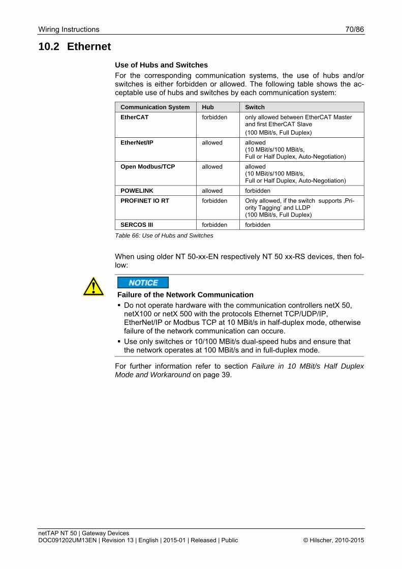
Wiring Instructions 70/86
netTAP NT 50 | Gateway Devices DOC091202UM13EN | Revision 13 | English | 2015-01 | Released | Public © Hilscher, 2010-2015
10.2 Ethernet
Use of Hubs and Switches
For the corresponding communication systems, the use of hubs and/or switches is either forbidden or allowed. The following table shows the ac-ceptable use of hubs and switches by each communication system:
Communication System Hub Switch
EtherCAT forbidden only allowed between EtherCAT Master and first EtherCAT Slave (100 MBit/s, Full Duplex)
EtherNet/IP allowed allowed (10 MBit/s/100 MBit/s, Full or Half Duplex, Auto-Negotiation)
Open Modbus/TCP allowed allowed (10 MBit/s/100 MBit/s, Full or Half Duplex, Auto-Negotiation)
POWELINK allowed forbidden
PROFINET IO RT forbidden Only allowed, if the switch supports ‚Pri-ority Tagging’ and LLDP (100 MBit/s, Full Duplex)
SERCOS III forbidden forbidden
Table 66: Use of Hubs and Switches
When using older NT 50-xx-EN respectively NT 50 xx-RS devices, then fol-low:
Failure of the Network Communication
Do not operate hardware with the communication controllers netX 50, netX100 or netX 500 with the protocols Ethernet TCP/UDP/IP, EtherNet/IP or Modbus TCP at 10 MBit/s in half-duplex mode, otherwise failure of the network communication can occure.
Use only switches or 10/100 MBit/s dual-speed hubs and ensure that the network operates at 100 MBit/s and in full-duplex mode.
For further information refer to section Failure in 10 MBit/s Half Duplex Mode and Workaround on page 39.

Wiring Instructions 71/86
netTAP NT 50 | Gateway Devices DOC091202UM13EN | Revision 13 | English | 2015-01 | Released | Public © Hilscher, 2010-2015
10.3 PROFIBUS Please ensure that termination resistors are available at both ends of the cable. If special PROFIBUS connectors are being used, these resistors are often found inside the connector and must be switched on. For baud rates above 1.5 MBaud use only special connectors, which also include addi-tional inductance.
It is not permitted to have T-stubs on PROFIBUS high baud rates. Use only a special cable which is approved for PROFIBUS-DP. Make a solid connec-tion from the cable shield to ground at every device and make sure that there is no potential difference between the grounds at the devices.
If the Hilscher device is linked with only one other device on the bus, they must be at the ends of the bus line. The reason is that these devices must deliver the power supply for the termination resistors. Otherwise the Master can be connected at any desired position.
Figure 12: PROFIBUS-DP-Network
Up to 32 PROFIBUS devices can be connected to one bus segment. If several bus segments are linked to each other with repeaters, there can be up to 127 devices on the network.
Only PROFIBUS certified cable, preferably the cable type A, should be used.

Wiring Instructions 72/86
netTAP NT 50 | Gateway Devices DOC091202UM13EN | Revision 13 | English | 2015-01 | Released | Public © Hilscher, 2010-2015
The maximum length of a bus segment depends on the baudrate used, see the following table.
Baud rate in kBit/s Max. distance in m
9,6 1.200
19,2 1.200
93,75 1.200
187,5 1.000
500 400
1.500 200
3.000 100
6.000 100
12.000 100
Table 67: PROFIBUS Segment Length in Dependence of the Baud Rate
The following table contains the most important electrical dsata concerning PROFIBUS certified cable:
Parameter Value
Impedance 135…165 Ω
Capacity < 30 pF/m
Loop resistance 110 Ω/km
Wire gauge 0,64 mm
Table 68: Characteristics of PROFIBUS certified Cable

Wiring Instructions 73/86
netTAP NT 50 | Gateway Devices DOC091202UM13EN | Revision 13 | English | 2015-01 | Released | Public © Hilscher, 2010-2015
10.4 CANopen Please use only CAN certified cable with the following characteristics:
Parameter Value
Impedance 120 Ω ± 12 Ω
Capacity per units length
< 50 pF/m
Table 69: Characteristics of CAN certified Cable
Figure 13: Termination CANopen Network
At the ends of the network there must be two resistors of 120 Ω to termi-nate the cable. It is allowed to use repeaters to increase the number of nodes, which may be connected, or to increase the maximum cable length.
The CAN segment length in dependence of the Baud rate or corresponding Loop Resistance and Wire Gauge is given in the following table:
Baud rate in kBit/s s
Max. distance Loop Resistance Wire Gauge
10 1000 m <26 Ω/km 0,75...0,80 mm2
20 1000 m <26 Ω/km 0,75...0,80 mm2
50 1000 m <26 Ω/km 0,75...0,80 mm2
125 500 m <40 Ω/km 0,50...0,60 mm2
250 250 m <40 Ω/km 0,50...0,60 mm2
500 100 m <60 Ω/km 0,34...0,60 mm2
800 50 m <60 Ω/km 0,34...0,60 mm2
1.000 30 m 70 Ω/km 0,25...0,34 mm2
Table 70: CAN Segment Length in dependence of the Baud rate or corresponding Loop Re-sistance and Wire Gauge

Wiring Instructions 74/86
netTAP NT 50 | Gateway Devices DOC091202UM13EN | Revision 13 | English | 2015-01 | Released | Public © Hilscher, 2010-2015
10.5 DeviceNet
Up to 64 DeviceNet devices can be linked together over the bus. The maximum length of the bus cable depends on the used baud rate and the used cable type. Only special proved DeviceNet cable should be used.
The maximum length of the DeviceNet cable depends from the baud rate and from the chosen cable type. In the following table, these are listed in the following table:
Baudrate in kbit/s Maximum length of cable (thick cable)
Maximum length of cable (thick cable)
125 500 m 100 m
250 250 m 100 m
500 100 m 100 m
Table 71: Maximum length in dependence from the Baud Rate for DeviceNet Cables
The data line cables must match the following conditions:
Data line cable
Impedance Capacity Loop Resis-tance
Wire Gauge (Diameter)
Thick 120 Ohm <39,4 pf/m <22,6 Ohm/km 2 * 1.1 mm
Thin 120 Ohm <39,4 pf/m <91,8 Ohm/km 2 * 0,6 mm
Table 72 Characteristics of DeviceNet Data Line Cable
The power supply cables must match the following conditions:
Power supply cable
Loop Resis-tance
Wire Gauge (Diameter)
Thick <11,8 Ohm/km 2 * 1.4 mm
Thin <57,4 Ohm/km 2 * 0,7 mm
Table 73: Characteristics of DeviceNet Power Supply Cable
Figure 14: DeviceNet Network
Please ensure that termination resistors with 120 Ohm are available at both ends of the cable.
Further devices can be connected via T-stubs to the bus cable. The maxi-mum length of all T-stubs is 6 m. The whole length of the bus cable and all

Wiring Instructions 75/86
netTAP NT 50 | Gateway Devices DOC091202UM13EN | Revision 13 | English | 2015-01 | Released | Public © Hilscher, 2010-2015
T-stubs does not exceed the maximum length listed in the following table. There are two different types of cables. If both cables types are used within the same network, the maximum length is:
Max. distance Baud rate in kBits/s
Lthick + 5 x Lthin <= 500 m at 125 kBaud
Lthick + 2,5 x Lthin <= 250 m at 250 kBaud
Lthick + Lthin <= 100 m at 500 kBaud
Table 74: DeviceNet Segment Length in dependence of the Baud rate
The DeviceNet cable contains the data line cables and the power supply cables.

Wiring Instructions 76/86
netTAP NT 50 | Gateway Devices DOC091202UM13EN | Revision 13 | English | 2015-01 | Released | Public © Hilscher, 2010-2015
10.6 CC-Link Use only a special cable which is approved for CC-Link. CC-Link specifies several shielded three-core Twisted Pair cables. It is recommended to use only one type of cable for an installation. Please ensure that termination re-sistors are available at both ends of the cable. The value of the termination resistor depends on the used type of cable and can be 100, 110 and 130 Ω, respectively.
The following illustration displays the basic network structure.
Figure 15: CC-Link Network
(*) The termination resistor depends on the used cable type (see CC-Link Cable Wiring Manual).
The maximum length of one bus segment depends on the used baud rate. The structure of the network can be built up without or with branches. The details listed here are taken from the "CC link Cable Wiring manual" from July 2004. Also further details are contained there. The document is ready for download on http://www.cc-link.org.
Note: For CC-Link V2.00 the cable specification V1.10 has not been changed.

Wiring Instructions 77/86
netTAP NT 50 | Gateway Devices DOC091202UM13EN | Revision 13 | English | 2015-01 | Released | Public © Hilscher, 2010-2015
Only trunk line, without branches:
Baud rate max. Length cable V1.00
max. Length ca-ble V1.10 and cable V1.00 with high capacity
max. length high flexible V1.10 (Type 50%)
156 kbps 1200 m 1200 m 600 m
625 kbps 600 m 900 m 450 m
2,5 Mbps 200 m 400 m 200 m
5 Mbps 150 m 160 m 80 m
10 Mbps 100 m 100 m 50 m
Table 75: Maximum length
Note: Further cable types are available with which however only lower maximum lengths can be reached.
Trunk line with branch lines:
baud rate 156 kbps 625 kbps
max. length trunk line 500 m 100 m
max. number of devices in branch line
6 6
max. cable length of branch line
8 m 8 m
max. length of all branch lines
200 m 50 m
Table 76: Maximum length
Further devices can be connected via T-branches to the bus cable only at the baud rates 156 kbps and 625 kbps. The maximum length of all T-stubs is limited to 8 m. The whole length of the bus cable and all T-branches does not exceed the maximum length listed in the following table.
Minimum Distance:
Between two devices a minimum distance is to be kept.
Distance between CC-Link devices
CC-Link cable V1.00 CC-Link cable V1.10
Remote device to next re-mote device
0.3 m or more 0.2 m or more
Remote device to next Mas-ter and/or intelligent device
1 m or more 0.2 m or more
Table 77: Minimum distance between two devices

Wiring Instructions 78/86
netTAP NT 50 | Gateway Devices DOC091202UM13EN | Revision 13 | English | 2015-01 | Released | Public © Hilscher, 2010-2015
10.7 RS-232
Device Damage!
Make sure that the NT 50 device and the remote device via RS-232 have the same potential or insert a galvanic isolation, to avoid compen-sation current between the used devices.
The RS232 interface (EIA-232) is a point-to-point connection of two com-munication devices. Only shielded cables have to be used. No termination resistors are required.
Take care of the pin assignment at the communication partner. This de-cides, whether you need a so called null modem cable with crossed pin as-signments.
Figure 16: RS-232 Null-Modem Cable Connection
* Pinning of the remote device: see device description of the used devi-ce.
Conductor length and transmission rates
max. baud rate
max. length
19.200 15 m
57.600 5 m
In the EIA-232 norm a maximum cable ca-pacitance of 2500 pF is allowed for a RS232 connection.
Cables of such capacitance may have the following lengths depending on the baud rate 115.200 <2 m
Higher length can be achieved with cables of extraordinarily low capaci-tance.
Pin assignmet for connector X2 see section X2 for Device Type NT 50-RS-EN on page 27.
Pin assignmet for connector X3 see section X3 for Device Type NT 50-xx-RS on page 28.

Wiring Instructions 79/86
netTAP NT 50 | Gateway Devices DOC091202UM13EN | Revision 13 | English | 2015-01 | Released | Public © Hilscher, 2010-2015
10.8 RS-422
Device Damage!
Make sure that the NT 50 device and the remote device via RS-422 have the same potential or insert a galvanic isolation, to avoid compen-sation current between the used devices.
The lines of this industry bus interface are operated in push-pull action, four lines are required which can be controlled in half duplex or full duplex mode. This interface has been designed for one master and at maximum 10 slaves. Using repeaters, using even more slaves is possible.
Cable lengths of up to 1.2 km (at low baud rates) and data transmission ra-tes of up to 10 MBit/s (at maximally 12 m length of line) are possible. The maximum useable transmission rate depends on the technical data of the used devices.
The following illustration shows wiring for RS-422:
Figure 17: RS-422 Wiring
Bus Requirements:
The bus cable must be a shielded 4.wire twisted pair cable. Each pair of wi-res has to be used for exactly one data transmission direction. The shield should be connected at both ends to the potential equalization system.
On each end, the bus requires a termination resistor (LT) of 90 Ω to 150 Ω between the lines. This value depends on the characteristic wave imped-ance of the cable.
The pull-up and pull-down resistors should have a resistance of 390 Ω up to 650 Ω.

Wiring Instructions 80/86
netTAP NT 50 | Gateway Devices DOC091202UM13EN | Revision 13 | English | 2015-01 | Released | Public © Hilscher, 2010-2015
Cable Requirements:
The workmanship of bus cabling is an important factor of the reliable opera-tion and also for the electromagnetic compatibility and emission. It is man-datory to use shielded twisted-pair cables. The shield of the cable must consist of a copper wire mesh.
Parameter Value
Characteristic wave impedance
150 Ω ± 15 Ω
Capacitance < 30 pF/m
Loop resistance 110 Ω/km
Wire gauge 0,64 mm
Table 78: Electric Requirements to RS-422 Cables
The following lengths of lines can be achieved:
Max. overall length of line
Max. Baud rate Max. length of a single branch line
120 m 1 MBit/s 0,3 m
600 m 500 kBit/s 0,6 m
1200 m 100 kBit/s 1,5 m
Table 79: RS-422 Conductor Length and Transmission Rates
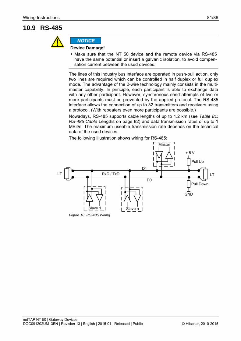
Wiring Instructions 81/86
netTAP NT 50 | Gateway Devices DOC091202UM13EN | Revision 13 | English | 2015-01 | Released | Public © Hilscher, 2010-2015
10.9 RS-485
Device Damage!
Make sure that the NT 50 device and the remote device via RS-485 have the same potential or insert a galvanic isolation, to avoid compen-sation current between the used devices.
The lines of this industry bus interface are operated in push-pull action, only two lines are required which can be controlled in half duplex or full duplex mode. The advantage of the 2-wire technology mainly consists in the multi-master capability. In principle, each participant is able to exchange data with any other participant. However, synchronous send attempts of two or more participants must be prevented by the applied protocol. The RS-485 interface allows the connection of up to 32 transmitters and receivers using a protocol. (With repeaters even more participants are possible.)
Nowadays, RS-485 supports cable lengths of up to 1.2 km (see Table 81: RS-485 Cable Lengths on page 82) and data transmission rates of up to 1 MBit/s. The maximum useable transmission rate depends on the technical data of the used devices.
The following illustration shows wiring for RS-485:
Figure 18: RS-485 Wiring

Wiring Instructions 82/86
netTAP NT 50 | Gateway Devices DOC091202UM13EN | Revision 13 | English | 2015-01 | Released | Public © Hilscher, 2010-2015
Bus requirements:
The bus cable must be a shielded twisted pair cable where the shield should be connected at both ends with large contact areas to the potential equalization system.
On each end, the bus requires a termination resistor (LT) between the lines D1 und D0 of approximately the amount of the characteristic wave imped-ance of the cable, which usually amounts to a value between 120 Ω and 220 Ω.
The pull-up and pull-down resistors should have a value of 390 Ω up to 650 Ω.
Cable requirements:
The workmanship of bus cabling is an important factor of the reliable opera-tion and also for the electromagnetic compatibility and emission. It is man-datory to use shielded twisted-pair cables. The shield of the cable must consist of a copper wire mesh.
Parameter Value
Characteristic wave impedance
150 Ω ± 15 Ω
Capacitance < 30 pF/m
Loop resistance 110 Ω/km
Wire gauge 0,64 mm
Table 80: Electric Requirements to RS-485 Cables
The following lengths of lines can be achieved:
Max. overall length of line
Max. Baud rate Max. length of a single branch line
120 m 1 MBit/s 0,3 m
600 m 500 kBit/s 0,6 m
1200 m 100 kBit/s 1,5 m
Table 81: RS-485 Cable Lengths

Decommissioning/Disposal 83/86
netTAP NT 50 | Gateway Devices DOC091202UM13EN | Revision 13 | English | 2015-01 | Released | Public © Hilscher, 2010-2015
11 Decommissioning/Disposal 11.1 Put the Device out of Operation
Danger of unsafe System Operation!
To prevent property damage, do not remove this device under runtimeconditions before you can not guarantee further a safe and secure opera-tion of the plant.
Disconnect the communication cables from the device.
Disconnect the plug for power supply.
Remove the device as described in section Removing the NT 50 from the DIN Top Hat Rail on page 35.
11.2 Disposal of Waste Electronic Equipment According to the European Directive 2002/96/EG “Waste Electrical and Electronic Equipment (WEEE)”, waste electronic equipment may not be disposed of as household waste. As a consumer, you are legally obliged to dispose of all waste electronic equipment according to national and local regulations.
Waste Electronic Equipment
This product must not be treated as household waste.
This product must be disposed of at a designated waste electronic equipment collecting point.

Appendix 84/86
netTAP NT 50 | Gateway Devices DOC091202UM13EN | Revision 13 | English | 2015-01 | Released | Public © Hilscher, 2010-2015
12 Appendix 12.1 List of Figures Figure 1: Function NT 50 19 Figure 2: Device Drawings 23 Figure 3: LEDs and Control Elements 24 Figure 4: Range of Values for the Address Switches 24 Figure 5: Galvanic Isolation of NT 50-xx-EN Devices 32 Figure 6: Galvanic Isolation of NT 50-xx-RS Devices 33 Figure 7: Galvanic Isolation of NT 50 -RS-EN Devices 34 Figure 8: Mounting the netTAP NT 50 device onto the top-hat rail 35 Figure 9: Removing the NT 50 device from the Top-Hat Rail 35 Figure 10: LEDs 40 Figure 11: D-Sub Cable Assemblies 69 Figure 12: PROFIBUS-DP-Network 71 Figure 13: Termination CANopen Network 73 Figure 14: DeviceNet Network 74 Figure 15: CC-Link Network 76 Figure 16: RS-232 Null-Modem Cable Connection 78 Figure 17: RS-422 Wiring 79 Figure 18: RS-485 Wiring 81
12.2 List of Tables Table 1: List of Revisions 6 Table 2: Reference to Hardware 8 Table 3: Reference to Software 8 Table 4: Directory Structure of the gateway solution DVD 9 Table 5: Device Description Files for netTAP NT 50 on the DVD 10 Table 6: Basic Documentation for netTAP NT 50 11 Table 7: Additional Documentation for netTAP NT 50 with EtherNet/IP Scanner/Master Link 11 Table 8: Additional Documentation for netTAP NT 50 with PROFINET IO Controller Link 12 Table 9: Additional Documentation for netTAP NT 50 with CANopen Master Link 12 Table 10: Additional Documentation for netTAP NT 50 with DeviceNet Master Link 12 Table 11: Additional Documentation for netTAP NT 50 with PROFIBUS DP Master Link 12 Table 12: Additional Documentation for netTAP NT 50 with ASCII 12 Table 13: Safety Symbols and Sort of Warning or Principle 18 Table 14: Signal Words 18 Table 15: Network on port X2 (Primary Network) 20 Table 16: Network on port X3 (Secondary Network) 20 Table 17: List of Protocol Conversion and NT 50 Device Type 21 Table 18: Supply Voltage Pin Assignment 25 Table 19: CANopen Pin Assignment 25 Table 20: CC-Link Pin Assignment 25 Table 21: DeviceNet Pin Assignment 26 Table 22: PROFIBUS RS-485 Pin Assignment 26 Table 23: RS-232 Pin Assignment 27 Table 24: RS-422 Pin Assignment 27 Table 25: RS-485 Pin Assignment 27 Table 26: Ethernet RJ45 Pin Assignment 28 Table 27: RJ45 Ethernet / RS-232 Pin Assignment 29 Table 28: RJ45 Ethernet / RS-422 Pin Assignment 30 Table 29: RJ45 Ethernet / RS-485 Pin Assignment 31 Table 30: Coupling NT 50-xx-EN Devices 32 Table 31: Coupling NT 50-xx-RS Devices 33 Table 32: Coupling NT 50-RS-EN Devices 34

Appendix 85/86
netTAP NT 50 | Gateway Devices DOC091202UM13EN | Revision 13 | English | 2015-01 | Released | Public © Hilscher, 2010-2015
Table 33: NT 50 Troubleshooting 38 Table 34: LEDs EtherNet/IP Scanner (Master) 41 Table 35: LEDs EtherNet/IP Adapter (Slave) 42 Table 36: LEDs Open Modbus/TCP 43 Table 37: LEDs PROFINET IO-RT Controller 44 Table 38: LEDs PROFINET IO-RT-Device 45 Table 39: LEDs PROFIBUS DP Master – 1 Communication LED 46 Table 40: LEDs PROFIBUS DP Slave 46 Table 41: LEDs CANopen Master 47 Table 42: LED State Definition for CANopen Master for the CAN LED 47 Table 43: LEDs CANopen Slave 48 Table 44: LED State Definition for CANopen Slave for the CAN LED 48 Table 45: LEDs DeviceNet Master 49 Table 46: LEDs DeviceNet Slave 49 Table 47: LEDs CC-Link Slave X2 50 Table 48: LEDs Modbus RTU Protocol 51 Table 49: LEDs ASCII Protocol 51 Table 50: Technical Data NT 50 (Part 1) 52 Table 51: Technical Data NT 50 (Part 2) 53 Table 52: Technical Data EtherNet/IP Scanner (Master) Link Protocol 54 Table 53: Technical Data EtherNet/IP Adapter (Slave) Protocol 55 Table 54: Technical Data Open Modbus/TCP Protocol 56 Table 55: Technical Data PROFINET IO RT Controller Link Protocol 57 Table 56: Technical Data PROFINET IO RT Device Protocol 58 Table 57: Technical Data CANopen Master Link Protocol 59 Table 58: Technical Data CANopen Slave Protocol 60 Table 59: Technical Data CC-Link-Slave Protocol 61 Table 60: Technical Data DeviceNet Master Link Protocol 62 Table 61: Technical Data DeviceNet Slave Protocol 63 Table 62: Technical Data PROFIBUS DP Master Link Protocol 64 Table 63: Technical Data PROFIBUS DP Slave Protocol 65 Table 64: Technical Data ASCII Protocol 66 Table 65: Technical Data Modbus RTU Protocol 67 Table 66: Use of Hubs and Switches 70 Table 67: PROFIBUS Segment Length in Dependence of the Baud Rate 72 Table 68: Characteristics of PROFIBUS certified Cable 72 Table 69: Characteristics of CAN certified Cable 73 Table 70: CAN Segment Length in dependence of the Baud rate or corresponding Loop Resistance and
Wire Gauge 73 Table 71: Maximum length in dependence from the Baud Rate for DeviceNet Cables 74 Table 72 Characteristics of DeviceNet Data Line Cable 74 Table 73: Characteristics of DeviceNet Power Supply Cable 74 Table 74: DeviceNet Segment Length in dependence of the Baud rate 75 Table 75: Maximum length 77 Table 76: Maximum length 77 Table 77: Minimum distance between two devices 77 Table 78: Electric Requirements to RS-422 Cables 80 Table 79: RS-422 Conductor Length and Transmission Rates 80 Table 80: Electric Requirements to RS-485 Cables 82 Table 81: RS-485 Cable Lengths 82

Appendix 86/86
netTAP NT 50 | Gateway Devices DOC091202UM13EN | Revision 13 | English | 2015-01 | Released | Public © Hilscher, 2010-2015
12.3 Contacts
Headquarters
Germany Hilscher Gesellschaft für Systemautomation mbH Rheinstrasse 15 65795 Hattersheim Phone: +49 (0) 6190 9907-0 Fax: +49 (0) 6190 9907-50 E-Mail: [email protected]
Support Phone: +49 (0) 6190 9907-99 E-Mail: [email protected]
Subsidiaries
China Hilscher Systemautomation (Shanghai) Co. Ltd. 200010 Shanghai Phone: +86 (0) 21-6355-5161 E-Mail: [email protected]
Support Phone: +86 (0) 21-6355-5161 E-Mail: [email protected]
France Hilscher France S.a.r.l. 69500 Bron Phone: +33 (0) 4 72 37 98 40 E-Mail: [email protected]
Support Phone: +33 (0) 4 72 37 98 40 E-Mail: [email protected]
India Hilscher India Pvt. Ltd. Pune, Delhi, Mumbai Phone: +91 8888 750 777 E-Mail: [email protected]
Italy Hilscher Italia S.r.l. 20090 Vimodrone (MI) Phone: +39 02 25007068 E-Mail: [email protected]
Support Phone: +39 02 25007068 E-Mail: [email protected]
Japan Hilscher Japan KK Tokyo, 160-0022 Phone: +81 (0) 3-5362-0521 E-Mail: [email protected]
Support Phone: +81 (0) 3-5362-0521 E-Mail: [email protected]
Korea Hilscher Korea Inc. Seongnam, Gyeonggi, 463-400 Phone: +82 (0) 31-789-3715 E-Mail: [email protected]
Switzerland Hilscher Swiss GmbH 4500 Solothurn Phone: +41 (0) 32 623 6633 E-Mail: [email protected]
Support Phone: +49 (0) 6190 9907-99 E-Mail: [email protected]
USA Hilscher North America, Inc. Lisle, IL 60532 Phone: +1 630-505-5301 E-Mail: [email protected]
Support Phone: +1 630-505-5301 E-Mail: [email protected]