network address translation -...
TRANSCRIPT
7450 ESS and 7750 SR Multiservice Integrated Service Adapter Guide Page 743
Network Address Translation
In This Chapter
This chapter provides information about Network Address Translation (NAT) and implementation
notes.
Topics in this chapter include:
• Terminology on page 744
• Network Address Translation (NAT) Overview on page 746
• NAT Point-to-Point Tunneling Protocol (PPTP) Application Layer Gateway (ALG) on
page 748
• Large Scale NAT on page 755
• One-to-One (1:1) NAT on page 763
• L2-Aware NAT on page 770
• Port Control Protocol (PCP) on page 772
• DS-Lite and NAT64 Fragmentation on page 774
• NAT Logging on page 777
• NAT Stateless Dual-Homing on page 794
• Deterministic NAT on page 801
• Enhanced Statistics in NAT — Histogram on page 822
• NAT – Multiple NAT Policies per Inside Routing Context on page 826
• ISA Feature Interactions on page 836
• Universal Plug and Play Internet Gateway Device Service on page 846
Terminology
Page 744 7450 ESS and 7750 SR Multiservice Integrated Service Adapter Guide
Terminology
BNG Subscriber — A broader term than the ESM Subscriber, independent of the platform on
which the subscriber is instantiated. It includes ESM subscribers on 7750 SR as well as
subscribers instantiated on third party BNGs. Some of the NAT functions, such as Subscriber
Aware Large Scale NAT44 utilizing standard RADIUS attribute work with subscribers
independently of the platform on which they are instantiated.
Deterministic NAT — A mode of operation where mappings between the NAT subscriber and the
outside IP address and port range are allocated at the time of configuration. Each subscriber is
permanently mapped to an outside IP and a dedicated port block. This dedicated port block is
referred to as deterministic port block. Logging is not needed as the reverse mapping can be
obtained using a known formula. The subscriber’s ports can be expanded by allocating a dynamic
port block in case that all ports in deterministic port block are exhausted. In such case logging for
the dynamic port block allocation/de-allocation is required.
Enhanced Subscriber Management (ESM) subscriber — A host or a collection of hosts
instantiated in 7750 SR Broadband Network Gateway (BNG). The ESM subscriber represents
a household or a business entity for which various services with committed Service Level
Agreements (SLA) can be delivered. NAT function is not part of basic ESM functionality.
L2-Aware NAT — In the context of 7750 SR platform combines Enhanced Subscriber
Management (ESM) subscriber-id and inside IP address to perform translation into a unique
outside IP address and outside port. This is in contrast with classical NAT technique where
only inside IP is considered for address translations. Since the subscriber-id alone is sufficient
to make the address translation unique, L2-Aware NAT allows many ESM subscribers to share
the same inside IP address. The scalability, performance and reliability requirements are the
same as in LSN.
Large Scale NAT (LSN) — Refers to a collection of network address translation techniques used
in service provider network implemented on a highly scalable, high performance hardware that
facilitates various intra and inter-node redundancy mechanisms. The purpose of LSN semantics is
to make delineation between high scale and high performance NAT functions found in service
provider networks and enterprise NAT that is usually serving much smaller customer base at
smaller speeds. The following NAT techniques can be grouped under the LSN name:
• Large Scale NAT44 or Carrier Grade NAT (CGN)
• DS-Lite
• NAT64
Each distinct NAT technique is referred to by its corresponding name (Large Scale NAT44 [or
CGN], DS-Lite and NAT64) with the understanding that in the context of 7750 SR platform,
they are all part of LSN (and not enterprise based NAT).
Network Address Translation
7450 ESS and 7750 SR Multiservice Integrated Service Adapter Guide Page 745
Large Scale NAT44 term can be interchangeably used with the term Carrier Grade NAT
(CGN) which in its name implies high reliability, high scale and high performance. These are
again typical requirements found in service provider (carrier) network.
L2-Aware NAT term refers to a separate category of NAT defined outside of LSN.
NAT RADIUS accounting — Reporting (or logging) of address translation related events (port-
block allocation/de-allocation) via RADIUS accounting facility. NAT RADIUS accounting is
facilitated via regular RADIUS accounting messages (star/interim-update/stop) as defined in
RFC 2866, RADIUS Accounting, with NAT specific VSAs.
NAT RADIUS accounting — Can be interchangeably used with the term NAT RADIUS logging.
NAT Subscriber — in NAT terminology a NAT subscriber is an inside entity whose true identity is
hidden from the outside. There are a few types of NAT implementation in 7750 and
subscribers for each implementation are defined as follows:
• Large Scale NAT44 (or CGN) — The subscriber is an inside IPv4 address.
• L2-Aware NAT — The subscriber is an ESM subscriber which can spawn multiple IPv4
inside addresses.
• DS-Lite — The subscriber in DS-lite can be identified by the CPE’s IPv6 address (B4
element) or an IPv6 prefix. The selection of address or prefix as the representation of a
DS-Lite subscriber is configuration dependent.
• NAT64 — The subscriber is an IPv6 prefix.
Non-deterministic NAT — A mode of operation where all outside IP address and port block
allocations are made dynamically at the time of subscriber instantiation. Logging in such case
is required.
Port block — A collection of ports that is assigned to a subscriber. A deterministic LSN subscriber
can have only one deterministic port block that can be extended by multiple dynamic port
blocks. Non-deterministic LSN subscriber can be assigned only dynamic port blocks. All port
blocks for a LSN subscriber must be allocated from a single outside IP address.
Port range — A collection of ports that can spawn multiple port blocks of the same type. For
example, deterministic port range includes all ports that are reserved for deterministic
consumption. Similarly dynamic port range is a total collection of ports that can be allocated
in the form of dynamic port blocks. Other types of port ranges are well-known ports and static
port forwards.
Network Address Translation (NAT) Overview
Page 746 7450 ESS and 7750 SR Multiservice Integrated Service Adapter Guide
Network Address Translation (NAT) Overview
The Alcatel-Lucent 7750 SR supports Network Address (and port) Translation (NAPT) to provide
continuity of legacy IPv4 services during the migration to native IPv6. By equipping the
Multiservice ISA (MS ISA) in an IOM3-XP, the 7750 SR can operate in two different modes,
known as:
• Large Scale NAT, and;
• Layer 2-Aware NAT
These two modes both perform source address and port translation as commonly deployed for
shared Internet access. The 7750 SR with NAT is used to provide consumer broadband or business
Internet customers access to IPv4 internet resources with a shared pool of IPv4 addresses, such as
may occur around the forecast IPv4 exhaustion. During this time it, is expected that native IPv6
services will still be growing and a significant amount of Internet content will remain IPv4.
Principles of NAT
Network Address Translation devices modify the IP headers of packets between a host and server,
changing some or all of the source address, destination address, source port (TCP/UDP),
destination port (TCP/UDP), or ICMP query ID (for ping). The 7750 SR in both NAT modes
performs Source Network Address and Port Translation (S-NAPT). S-NAPT devices are
commonly deployed in residential gateways and enterprise firewalls to allow multiple hosts to
share one or more public IPv4 addresses to access the Internet. The common terms of inside and
outside in the context of NAT refer to devices inside the NAT (that is behind or masqueraded by
the NAT) and outside the NAT, on the public Internet.
TCP/UDP connections use ports for multiplexing, with 65536 ports available for every IP address.
Whenever many hosts are trying to share a single public IP address there is a chance of port
collision where two different hosts may use the same source port for a connection. The resultant
collision is avoided in S-NAPT devices by translating the source port and tracking this in a stateful
manner. All S-NAPT devices are stateful in nature and must monitor connection establishment and
traffic to maintain translation mappings. The 7750 SR NAT implementation does not use the well-
known port range (1..1023).
In most circumstances, S-NAPT requires the inside host to establish a connection to the public
Internet host or server before a mapping and translation will occur. With the initial outbound IP
packet, the S-NAPT knows the inside IP, inside port, remote IP, remote port and protocol. With
this information the S-NAPT device can select an IP and port combination (referred to as outside
IP and outside port) from its pool of addresses and create a unique mapping for this flow of data.
Network Address Translation
7450 ESS and 7750 SR Multiservice Integrated Service Adapter Guide Page 747
Any traffic returned from the server will use the outside IP and outside port in the destination IP/
port fields – matching the unique NAT mapping. The mapping then provides the inside IP and
inside port for translation.
The requirement to create a mapping with inside port and IP, outside port and IP and protocol will
generally prevent new connections to be established from the outside to the inside as may occur
when an inside host wishes to be a server.
Application Compatibility
Applications which operate as servers (such as HTTP, SMTP, etc) or peer-to-peer applications can
have difficulty when operating behind an S-NAPT because traffic from the Internet can reach the
NAT without a mapping in place.
Different methods can be employed to overcome this, including:
• Port Forwarding;
• STUN support; and,
• Application Layer Gateways (ALG)
The 7750 SR supports all three methods following the best-practice RFC for TCP (RFC 5382,
NAT Behavioral Requirements for TCP) and UDP (RFC 4787, Network Address Translation
(NAT) Behavioral Requirements for Unicast UDP). Port Forwarding is supported on the 7750 SR
to allow servers which operate on well-known ports <1024 (such as HTTP and SMTP) to request
the appropriate outside port for permanent allocation.
STUN is facilitated by the support of Endpoint-Independent Filtering and Endpoint-Independent
Mapping (RFC 4787) in the NAT device, allowing STUN-capable applications to detect the NAT
and allow inbound P2P connections for that specific application. Many new SIP clients and IM
chat applications are STUN capable.
Application Layer Gateways (ALG) allows the NAT to monitor the application running over TCP
or UDP and make appropriate changes in the NAT translations to suit. The 7750 SR has an FTP
ALG enabled following the recommendation of the IETF BEHAVE RFC for NAT (RFC 5382).
Even with these three mechanisms some applications will still experience difficulty operating
behind a NAT. As an industry-wide issue, forums like UPnP the IETF, operator and vendor
communities are seeking technical alternatives for application developers to traverse NAT
(including STUN support). In many cases the alternative of an IPv6-capable application will give
better long-term support without the cost or complexity associated with NAT.
NAT Point-to-Point Tunneling Protocol (PPTP) Application Layer Gateway (ALG)
Page 748 7450 ESS and 7750 SR Multiservice Integrated Service Adapter Guide
NAT Point-to-Point Tunneling Protocol (PPTP) Application Layer Gateway (ALG)
PPTP is defined in RFC 2637, Point-to-Point Tunneling Protocol (PPTP), and is used to provide
VPN connection for home/mobile users to gain secure access to the enterprise network. Encrypted
payload is transported over GRE tunnel that is negotiated over TCP control channel. In order for
PPTP traffic to pass through NAT, the NAT device must correlate the TCP control channel with the
corresponding GRE tunnel. This mechanism is referred to as PPTP ALG.
PPTP Protocol
There are two components of PPTP:
1. TCP control connection between the two endpoints.
2. An IP tunnel operating between the same endpoints. These are used to transport GRE
encapsulated PPP packets for user sessions between the endpoints. PPTP uses an
extended version of GRE to carry user PPP packets.
The control connection is established from the PPTP clients (for example, home users behind the
NAT) to the PPTP server which is located on the outside of the NAT. Each session that carries data
between the two endpoints can be referred as call. Multiple sessions (or calls) can carry data in a
multiplexed fashion over a tunnel. The tunnel protocol is defined by a modified version of GRE.
Call ID in the GRE header is used to multiplex sessions over the tunnel. The Call-ID is negotiated
during the session/call establishment phase.
Supported Control Messages
This section discusses PPTP ALG supported control messages.
Control Connection Management — The following messages are used to maintain the control
connection.
• Start-Control-Connection-Request
• Start-Control-Connection-Reply
• Stop-Control-Connection-Request
• Stop-Control-Connection-Reply
• Echo-Request
• Echo-Reply
Network Address Translation
7450 ESS and 7750 SR Multiservice Integrated Service Adapter Guide Page 749
The remaining control message types are sent over the established TCP session to open/
maintain sessions and to convey information about the link state:
Call Management — Call management messages are used to establish/terminate a session/call and
to exchange information about the multiplexing field (Call-id). Call-IDs must be captured and
translated by the NAT. The call management messages are:
• Outgoing-Call-Request (contains Call ID)
• Outgoing-Call-Reply (contains Call ID and peer’s Call-ID)
• Call-Clear-Request (contains Call ID)
• Call-Disconnect-Notify (contains Call ID)
Error Reporting — This message is sent by the client to indicate WAN error conditions that occur
on the interface supporting PPP.
• Wan-Error-Notify (contains Call ID and Peer’s Call ID)
PPP Session Control — This message is sent in both directions to setup PPP-negotiated options.
• Set-Link-Info (contains Call ID and Peer’s Call ID)
Once Call-ID is negotiated by both endpoints, it is inserted in GRE header and used as
multiplexing filed in the tunnel that carries data traffic.
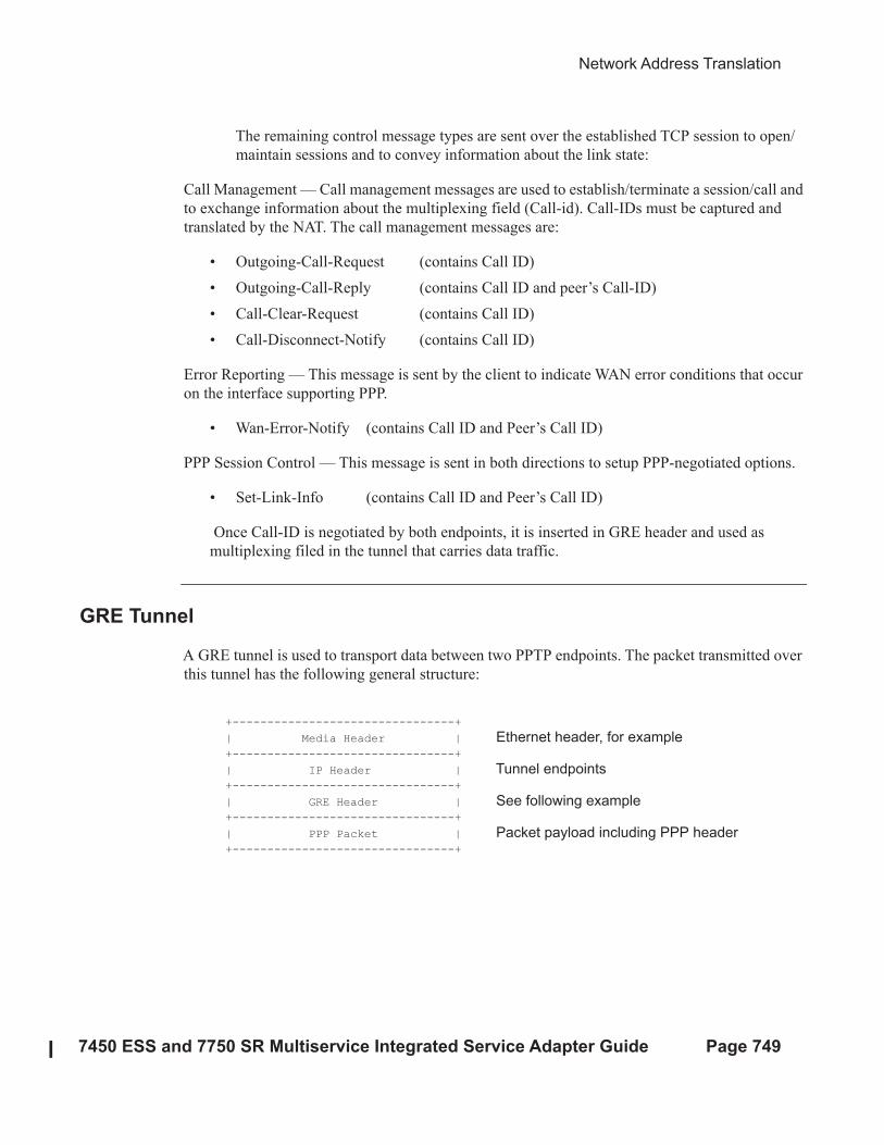
GRE Tunnel
A GRE tunnel is used to transport data between two PPTP endpoints. The packet transmitted over
this tunnel has the following general structure:
+--------------------------------+
| Media Header | Ethernet header, for example +--------------------------------+
| IP Header | Tunnel endpoints +--------------------------------+
| GRE Header | See following example +--------------------------------+
| PPP Packet | Packet payload including PPP header +--------------------------------+
PPTP ALG Operation
Page 750 7450 ESS and 7750 SR Multiservice Integrated Service Adapter Guide
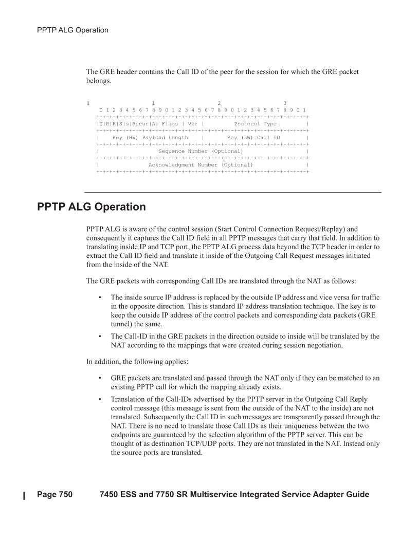
The GRE header contains the Call ID of the peer for the session for which the GRE packet
belongs.
0 1 2 3
0 1 2 3 4 5 6 7 8 9 0 1 2 3 4 5 6 7 8 9 0 1 2 3 4 5 6 7 8 9 0 1
+-+-+-+-+-+-+-+-+-+-+-+-+-+-+-+-+-+-+-+-+-+-+-+-+-+-+-+-+-+-+-+-+
|C|R|K|S|s|Recur|A| Flags | Ver | Protocol Type |
+-+-+-+-+-+-+-+-+-+-+-+-+-+-+-+-+-+-+-+-+-+-+-+-+-+-+-+-+-+-+-+-+
| Key (HW) Payload Length | Key (LW) Call ID |
+-+-+-+-+-+-+-+-+-+-+-+-+-+-+-+-+-+-+-+-+-+-+-+-+-+-+-+-+-+-+-+-+
| Sequence Number (Optional) |
+-+-+-+-+-+-+-+-+-+-+-+-+-+-+-+-+-+-+-+-+-+-+-+-+-+-+-+-+-+-+-+-+
| Acknowledgment Number (Optional) |
+-+-+-+-+-+-+-+-+-+-+-+-+-+-+-+-+-+-+-+-+-+-+-+-+-+-+-+-+-+-+-+-+
PPTP ALG Operation
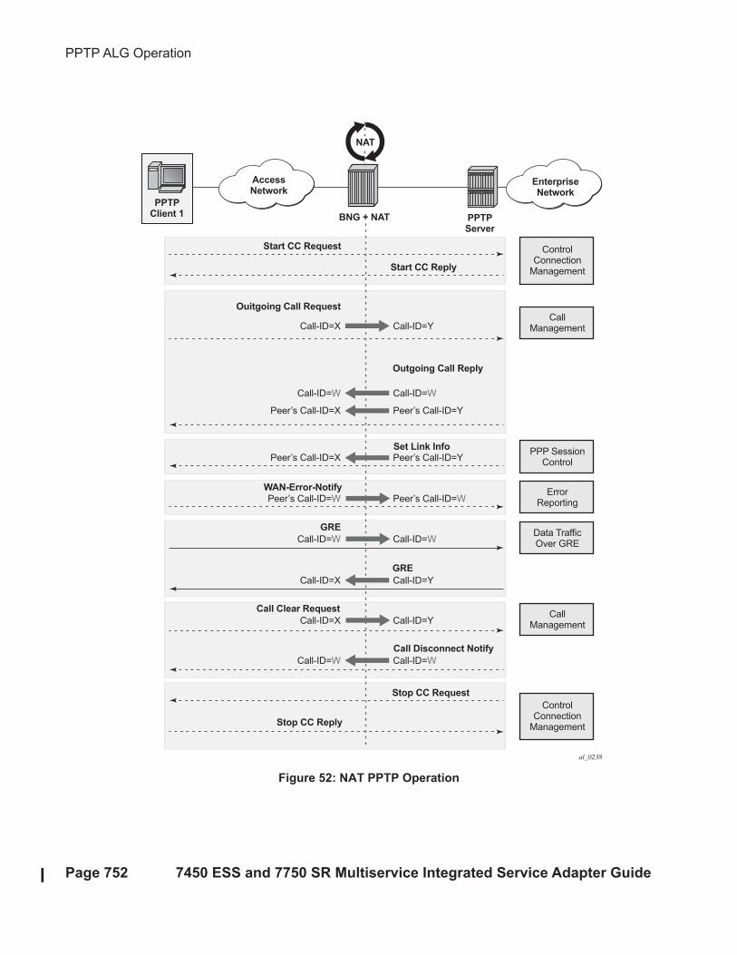
PPTP ALG is aware of the control session (Start Control Connection Request/Replay) and
consequently it captures the Call ID field in all PPTP messages that carry that field. In addition to
translating inside IP and TCP port, the PPTP ALG process data beyond the TCP header in order to
extract the Call ID field and translate it inside of the Outgoing Call Request messages initiated
from the inside of the NAT.
The GRE packets with corresponding Call IDs are translated through the NAT as follows:
• The inside source IP address is replaced by the outside IP address and vice versa for traffic
in the opposite direction. This is standard IP address translation technique. The key is to
keep the outside IP address of the control packets and corresponding data packets (GRE
tunnel) the same.
• The Call-ID in the GRE packets in the direction outside to inside will be translated by the
NAT according to the mappings that were created during session negotiation.
In addition, the following applies:
• GRE packets are translated and passed through the NAT only if they can be matched to an
existing PPTP call for which the mapping already exists.
• Translation of the Call-IDs advertised by the PPTP server in the Outgoing Call Reply
control message (this message is sent from the outside of the NAT to the inside) are not
translated. Subsequently the Call ID in such messages are transparently passed through the
NAT. There is no need to translate those Call IDs as their uniqueness between the two
endpoints are guaranteed by the selection algorithm of the PPTP server. This can be
thought of as destination TCP/UDP ports. They are not translated in the NAT. Instead only
the source ports are translated.

Network Address Translation
7450 ESS and 7750 SR Multiservice Integrated Service Adapter Guide Page 751
• PPTP session initiation in the outside to inside direction through the NAT is not
supported.
• Call-ID’s are allocated and used in the same fashion as the outside TCP/UDP ports
(random with parity). They are taken from the same port range as ICMP ports.
The basic principle of PPTP NAT ALG is shown in Figure 52.
PPTP ALG Operation
Page 752 7450 ESS and 7750 SR Multiservice Integrated Service Adapter Guide
Figure 52: NAT PPTP Operation
ControlConnection
Management
ControlConnection
Management
PPP SessionControl
ErrorReporting
CallManagement
Data TrafficOver GRE
CallManagement
PPTPClient 1
AccessNetwork
BNG + NAT
EnterpriseNetwork
PPTPServer
NAT
Call Clear Request
Stop CC Reply
Ouitgoing Call Request
Call-ID=X Call-ID=Y
Call-ID=W Call-ID=W
Peer’s Call-ID=X Peer’s Call-ID=Y
Peer’s Call-ID=X Peer’s Call-ID=Y
Peer’s Call-ID=W Peer’s Call-ID=W
GRE
GRE
WAN-Error-Notify
Call-ID=W Call-ID=W
Call-ID=X Call-ID=Y
Call-ID=X Call-ID=Y
Call-ID=W Call-ID=W
Start CC Request
Call Disconnect Notify
Stop CC Request
Outgoing Call Reply
Start CC Reply
Set Link Info
al_0238
Network Address Translation
7450 ESS and 7750 SR Multiservice Integrated Service Adapter Guide Page 753
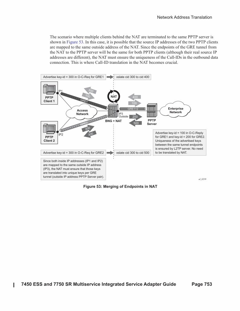
The scenario where multiple clients behind the NAT are terminated to the same PPTP server is
shown in Figure 53. In this case, it is possible that the source IP addresses of the two PPTP clients
are mapped to the same outside address of the NAT. Since the endpoints of the GRE tunnel from
the NAT to the PPTP server will be the same for both PPTP clients (although their real source IP
addresses are different), the NAT must ensure the uniqueness of the Call-IDs in the outbound data
connection. This is where Call-ID translation in the NAT becomes crucial.
Figure 53: Merging of Endpoints in NAT
PPTPClient 1
PPTPClient 2
AccessNetwork
BNG + NAT PPTPServer
NAT 400
100
300
100
500
200
300
200
IP1
Advertise key-id = 300 in O-C-Req for GRE1
Since both inside IP addresses (IP1 and IP2)
are mapped to the same outside IP address
(IP3), the NAT must ensure that those keys
are translated into unique keys per GRE
tunnel (outside IP address PPTP Server pair).
Advertise key-id = 100 in O-C-Reply
for GRE1 and key-id = 200 for GRE2.
Uniqueness of the advertised keys
between the same tunnel endpoints
is ensured by L2TP server. No need
to be translated by NAT.
xslate cid 300 to cid 400
Advertise key-id = 300 in O-C-Req for GRE2 xslate cid 300 to cid 500
IP3Outside
IP2
al_0239
EnterpriseNetwork
GRE1+2
GRE2
GRE1
Multiple Sessions Initiated From the Same PPTP Client Node
Page 754 7450 ESS and 7750 SR Multiservice Integrated Service Adapter Guide
Multiple Sessions Initiated From the Same PPTP Client Node
The 7x50 supports a deployment scenario where multiple calls (or tunnels) are established from a
single PPTP node within a single control connection. In this case, there is only one set of Start-
Control-Connection-Req/Reply messages (one control channel) and multiple sets of Outgoing-
Call-Req/Reply messages.
Selection of Call IDs in NAT
Call-Id are taken from the same pool as the ICMP port ranges. Port-ranges and Call-IDs are both
16-bit values. Call-id selection mechanism is the same as the outside TCP/UDP port selection
mechanism (random with parity).
Network Address Translation
7450 ESS and 7750 SR Multiservice Integrated Service Adapter Guide Page 755
Large Scale NAT
Large Scale NAT represents the most common deployment of S-NAPT in carrier networks today,
it is already employed by mobile operators around the world for handset access to the Internet.
A Large Scale NAT is typically deployed in a central network location with two interfaces, the
inside towards the customers, and the outside towards the Internet. A Large Scale NAT functions
as an IP router and is located between two routed network segments (the ISP network and the
Internet).
Traffic can be sent to the Large Scale NAT function on the 7750 SR using IP filters (ACL) applied
to SAPs or by installing static routes with a next-hop of the NAT application. These two methods
allow for increased flexibility in deploying the Large Scale NAT, especially those environments
where IP MPLS VPN are being used in which case the NAT function can be deployed on a single
PE and perform NAT for any number of other PE by simply exporting the default route.
The 7750 SR NAT implementation supports NAT in the base routing instance and VPRN, and
through NAT traffic may originate in one VPRN (the inside) and leave through another VPRN or
the base routing instance (the outside). This technique can be employed to provide customer’s of
IP MPLS VPN with Internet access by introducing a default static route in the customer VPRN,
and NATing it into the Internet routing instance.
As Large Scale NAT is deployed between two routed segments, the IP addresses allocated to hosts
on the inside must be unique to each host within the VPRN. While RFC1918 private addresses
have typically been used for this in enterprise or mobile environments, challenges can occur in
fixed residential environments where a subscriber has existing S-NAPT in their residential
gateway. In these cases the RFC 1918 private address in the home network may conflict with the
address space assigned to the residential gateway WAN interface. Some of these issues are
documented in draft-shirasaki-nat444-isp-shared-addr-02. Should a conflict occur, many
residential gateways will fail to forward IP traffic.
Port Range Blocks
Page 756 7450 ESS and 7750 SR Multiservice Integrated Service Adapter Guide
Port Range Blocks
The S-NAPT service on the 7750 BNG incorporates a port range block feature to address
scalability of a NAT mapping solution. With a single BNG capable of hundreds of thousands of
NAT mappings every second, logging each mapping as it is created and destroyed logs for later
retrieval (as may be required by law enforcement) could quickly overwhelm the fastest of
databases and messaging protocols. Port range blocks address the issue of logging and customer
location functions by allocating a block of contiguous outside ports to a single subscriber. Rather
than log each NAT mapping, a single log entry is created when the first mapping is created for a
subscriber and a final log entry when the last mapping is destroyed. This can reduce the number of
log entries by 5000x or more. An added benefit is that as the range is allocated on the first
mapping, external applications or customer location functions may be populated with this data to
make real-time subscriber identification, rather than having to query the NAT as to the subscriber
identity in real-time and possibly delay applications.
Port range blocks are configurable as part of outside pool configuration, allowing the operator to
specify the number of ports allocated to each subscriber when a mapping is created. Once a range
is allocated to the subscriber, these ports are used for all outbound dynamic mappings and are
assigned in a random manner to minimise the predictability of port allocations (draft-ietf-tsvwg-
port-randomization-05).
Port range blocks also serve another useful function in a Large Scale NAT environment, and that is
to manage the fair allocation of the shared IP resources among different subscribers.
When a subscriber exhausts all ports in their block, further mappings will be prohibited. As with
any enforcement system, some exceptions are allowed and the NAT application can be configured
for reserved ports to allow high-priority applications access to outside port resources while
exhausted by low priority applications.
Reserved Ports and Priority Sessions
Reserved ports allows an operator to configure a small number of ports to be reserved for
designated applications should a port range block be exhausted. Such a scenario may occur when a
subscriber is unwittingly subjected to a virus or engaged in extreme cases of P2P file transfers. In
these situations, rather than block all new mappings indiscriminately the 7750 NAT application
allows operators to nominate a number of reserved ports and then assign a 7750 forwarding class
as containing high priority traffic for the NAT application. Whenever traffic reaches the NAT
application which matches a priority session forwarding class, reserved ports will be consumed to
improve the chances of success. Priority sessions could be used by the operator for services such
as DNS, web portal, e-mail, VoIP, etc to permit these applications even when a subscriber
exhausted their ports.
Network Address Translation
7450 ESS and 7750 SR Multiservice Integrated Service Adapter Guide Page 757
Preventing Port Block Starvation
Dynamic Port Block Starvation in LSN
The outside IP address is always shared for the subscriber with a port forward (static or via PCP)
and the dynamically allocated port block, insofar as the port from the port forward is in the range
>1023. This behavior can lead to starvation of dynamic port blocks for the subscriber. An example
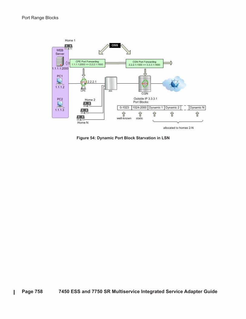
for this scenario is shown in Figure 54.
• A static port forward for the WEB server in Home 1 is allocated in the CPE and the CGN.
At the time of static port forward creation, no other dynamic port blocks for Home 1 exist
(PCs are powered off).
• Assume that the outside IP address for the newly created static port forward in the CGN is
3.3.3.1.
• Over time dynamic port blocks are allocated for a number of other homes that share the
same outside IP address, 3.3.3.1. Eventually those dynamic port block allocations will
exhaust all dynamic port block range for the address 3.3.3.1.
• Once the dynamic port blocks are exhausted for outside IP address 3.3.3.1, a new outside
IP address (for example, 3.3.3.2) will be allocated for additional homes.
Eventually the PCs in Home 1 come to life and they try to connect to the Internet. Due to the
dynamic port block exhaustion for the IP address 3.3.3.1 (that is mandated by static port forward –
Web Server), the dynamic port block allocation will fail and consequently the PCs will not be able
to access the Internet. There will be no additional attempt within CGN to allocate another outside
IP address. Note that in the CGN there is no distinction between the PCs in Home 1 and the Web
Server when it comes to source IP address. They both share the same source IP address 2.2.2.1 on
the CPE.
• The solution for this is to reserve a port block (or blocks) during the static port forward
creation for the given subscriber.
Port Range Blocks
Page 758 7450 ESS and 7750 SR Multiservice Integrated Service Adapter Guide
Figure 54: Dynamic Port Block Starvation in LSN
Network Address Translation
7450 ESS and 7750 SR Multiservice Integrated Service Adapter Guide Page 759
Dynamic Port Block Reservation
To prevent starvation of dynamic port blocks for the subscribers that utilize port forwards, a
dynamic port block (or blocks) will be reserved during the lifetime of the port forward. Those
reserved dynamic port blocks will be associated with the same subscriber that created the port
forward. However, a log would not be generated until the dynamic port block is actually used and
mapping within that block are created.
At the time of the port forward creation, the dynamic port block will be reserved in the following
fashion:
• If the dynamic port block for the subscriber does not exist, then a dynamic port block for
the subscriber will be reserved. No log for the reserved dynamic port block is generated
until the dynamic port block starts being utilized (mapping created due to the traffic flow).
• If the corresponding dynamic port block already exists, then it will be reserved even after
the last mapping within the last port block had expired.
The reserved dynamic port block (even without any mapping) will continue to be associated with
the subscriber as long as the port forward for the subscriber is present. The log (syslog or
RADIUS) will be generated only when there is not active mapping within the dynamic port block
AND all port forwards for the subscriber are deleted.
Additional considerations with dynamic port block reservation:
• The port block reservation should be triggered only by the first port forward for the
subscriber. The subsequent port forwards will not trigger additional dynamic port block
reservation.
• Only a single dynamic port block for the subscriber is reserved (i.e no multiple port-block
reservations for the subscriber are possible).
• This feature is enabled with the configuration command port-forwarding-dyn-block-
reservation under the configure>service>vprn>nat>outside>pool and the
configure>router>nat>outside>pool CLI hierarchy. This command can be enabled only
if the maximum number of configured port blocks per outside IP is greater or equal then
the maximum configured number of subscribers per outside IP address. This will
guarantee that all subscribers (up the maximum number per outside IP address)
configured with port forwards will be able to reserve a dynamic port block.
• In case that the port-reservation is enabled while the outside pool is operational and
subscribers traffic is already present, the following two cases will have to be considered:
→ The configured number of subscribers per outside IP is less or equal than the
configured number of port blocks per outside IP address (this is permitted) but all
dynamic port blocks per outside IP address are occupied at the moment when port
reservation is enabled. This will leave existing subscribers with port forwards that do

Port Range Blocks
Page 760 7450 ESS and 7750 SR Multiservice Integrated Service Adapter Guide
not have any dynamic port blocks allocated (orphaned subscribers), unable to reserve
dynamic port blocks. In this case the orphaned subscribers will have to wait until
dynamic port blocks allocated to the subscribers without port forwards are freed.
→ The configured number of subscribers per outside IP is greater than the configured
number of port blocks per outside IP address. In addition, all dynamic port blocks per
outside IP address are allocated. Before the port reservation is even enabled, the
subscriber-limit per outside IP address will have to be lowered (by configuration) so
that it is equal or less than the configured number of port blocks per outside IP
address. This action will cause random deletion of subscribers that do not have any
port forwards. Such subscribers will be deleted until the number of subscriber falls
below the newly configured subscriber limit. Note that subscribers with static port
forwards will not be deleted, regardless of the configured subscriber-limit number.
Once the number of subscriber is within the newly configured subscriber-limit, the
port-reservation can take place under the condition that the dynamic port blocks are
available. If certain subscribers with pot forwards have more than one dynamic port
block allocated, the orphaned subscribers will have to wait for those additional
dynamic port blocks to expire and consequently be released.
• This feature is supported on the following applications: CGN, DS-Lite and NAT64.
Network Address Translation
7450 ESS and 7750 SR Multiservice Integrated Service Adapter Guide Page 761
Timeouts
Creating a NAT mapping is only one half of the problem – removing a NAT mapping at the
appropriate time maximizes the shared port resource. Having ports mapped when an application is
no longer active reduces solution scale and may impact the customer experience should they
exhaust their port range block. The NAT application provides timeout configuration for TCP, UDP
and ICMP.
TCP state is tracked for all TCP connections, supporting both three-way handshake and
simultaneous TCP SYN connections. Separate and configurable timeouts exist for TCP SYN, TCP
transition (between SYN and Open), established and time-wait state. Time-wait assassination is
supported and enabled by default to quickly remove TCP mappings in the TIME WAIT state.
UDP does not have the concept of connection state and is subject to a simple inactivity timer.
Alcatel-Lucent-sponsored research into applications and NAT behavior suggested some
applications, like the Bittorrent Distributed Hash Protocol (DHT) can make a large number of
outbound UDP connections that are unsuccessful. Rather than wait the default five (5) minutes to
time these out, the 7750 NAT application supports an udp-initial timeout which defaults to 15
seconds. When the first outbound UDP packet is sent, the 15 second time starts – it is only after
subsequent packets (inbound or outbound) that the default UDP timer will become active, greatly
reducing the number of UDP mappings.

Watermarks
Page 762 7450 ESS and 7750 SR Multiservice Integrated Service Adapter Guide
Watermarks
It is possible to define watermarks to monitor the actual usage of sessions and/or ports.
For each watermark, a high and a low value has to be set. Once the high value is reached, a
notification will be send. As soon as the usage drops below the low watermark, another
notification will be send.
Watermarks can be defined on nat-group, pool and policy level.
• Nat-group: Watermarks can be placed to monitor the total number of sessions on an
MDA.
• Pool: Watermarks can be placed to monitor the total number of blocks in use in a pool.
• Policy: In the policy it is possible to define watermarks on session and port usage. In both
cases, it is the usage per subscriber (for l2-aware nat) or per host (for large-scale nat) that
will be monitored.
Network Address Translation
7450 ESS and 7750 SR Multiservice Integrated Service Adapter Guide Page 763
One-to-One (1:1) NAT
In 1:1 NAT, each source IP address is translated in 1:1 fashion to a corresponding outside IP
address. However, the source ports are passed transparently without translation.
The mapping between the inside IP addresses and outside IP addresses in 1:1 NAT supports two
modes:
• Dynamic - the operator can specify the outside IP addresses in the pool, but the exact
mapping between the inside IP address and the configured outside IP addresses is
performed dynamically by the system in a semi-random fashion.
• Static – the mappings between IP addresses are configurable and they can be explicitly
set.
Dynamic version of 1:1 NAT is protocol dependent. Only TCP/UDP/ICMP protocols are allowed
to traverse such NAT. All other protocols are discarded, with the exception of PPTP with ALG. In
this case, only GRE traffic associated with PPTP is allowed through dynamic 1:1 NAT.
Static version of 1:1 NAT is protocol agnostic. This means that all IP based protocols are allowed
to traverse static 1:1 NAT.
The following is applicable to 1:1 NAT:
• Even though source ports are not being translated, the state maintenance for TCP and
UDP traffic is still performed.
• Traffic can be initiated from outside towards any statically mapped IPv4 address.
• 1:1 NAT can be supported simultaneously with NAPT (classic non 1:1 NAT) within the
same inside routing context. This is accomplished by configuring two separate NAT
pools, one for 1:1 NAT and the other for non 1:1 NAPT.
Static 1:1 NAT
In static 1:1 NAT, inside IP addresses are statically mapped to the outside IP addresses. In this
fashion, devices on the outside can predictably initiate traffic to the devices on the inside.
Static configuration is based on the CLI concepts used in deterministic NAT. For example:
config
router
nat
inside
deterministic
prefix 10.0.0.0/24 subscriber-type classic-lsn-sub nat-policy
‘one-to-one’
map start 10.0.0.10 end 10.0.0.10 to 1.2.3.4

Static 1:1 NAT
Page 764 7450 ESS and 7750 SR Multiservice Integrated Service Adapter Guide
map start 10.0.0.15 end 10.0.0.15 to 1.2.3.20
map start 10.0.0.100 end 10.0.0.100 to 1.2.3.30
Static mappings are configured according to the map statements. The map statement can be
configured manually by the operator or automatically by the system. IP addresses from the
automatically generated map statements are sequentially mapped into available outside IP address
in the pool:
• The first inside IP address will be mapped to the 1st available outside IP address from the
pool
• The second inside IP address will be mapped to the 2nd available outside IP address from
the pool
• Etc.
The following mappings apply to the example from above:
Static mappings
10.0.0.0 — 1.2.3.0
10.0.0.1 — 1.2.3.1
10.0.0.2 — 1.2.3.2
10.0.0.3 — 1.2.3.3
10.0.0.4 — 1.2.3.5
10.0.0.5 — 1.2.3.6
:
10.0.0.9 — 1.2.3.10
10.0.0.10 — 1.2.3.4
10.0.0.11 — 1.2.3.11
10.0.0.12 — 1.2.3.12
:
10.0.0.14 — 1.2.3.14
10.0.0.15 — 1.2.3.20
10.0.0.16 — 1.2.3.15
:
10.0.0.19 — 1.2.3.18
10.0.0.20 — 1.2.3.19
10.0.0.21 — 1.2.3.21
:
10.0.0.28 — 1.2.3.28
10.0.0.29 — 1.2.3.29
10.0.0.30 — 1.2.3.31
:
10.0.0.99 — 1.2.3.100
10.0.0.100 — 1.2.3.30
10.0.0.101 — 1.2.3.101
:
10.0.0.255 — 1.2.3.255
Network Address Translation
7450 ESS and 7750 SR Multiservice Integrated Service Adapter Guide Page 765
Protocol Agnostic Behavior
Although static 1:1 NAT is protocol agnostic, the state maintenance for TCP and UDP traffic is
still required in order to support ALGs. Because of that, the existing scaling limits related to the
number of supported flows still apply.
Protocol agnostic behavior in 1:1 NAT is a property of a NAT pool:
config
router / service vprn
nat
outside
pool “one-to-one” nat-group 1 large-scale application agnostic
mode one-to-one
no port-forward-range
no port-reservation
subscriber-limit 1
deterministic port-reservation 65536
address-range 192.168.0.0 192.168.255.255
The application agnostic command is a pool create-time parameter. This command will
automatically pre-set the following pool parameters:
mode one-to-one
no port-forward-range
no port-reservation
subscriber-limit 1
deterministic port-reservation 65536.
Once pre-set, these parameters cannot be changed while pool is operating in protocol agnostic
mode.
The deterministic port-reservation 65536 command configures the pool to operate in static (or
deterministic) mode.
Modification of Parameters in Static 1:1 NAT
Parameters in static 1:1 NAT can be changed according to the following rules:
• Deterministic pool must be in a no shutdown state any time when a prefix or a map
command in deterministic NAT is added or removed.
• All configured prefixes referencing the pool via the nat-policy must be deleted (un-
configured) before the pool can be shut down.
• Map statements can be modified only when prefix is shutdown state. All existing map
statements must be removed before the new ones are created.
Static 1:1 NAT
Page 766 7450 ESS and 7750 SR Multiservice Integrated Service Adapter Guide
Load Distribution over ISAs in Static 1:1 NAT
For best traffic distribution over ISAs, the value of the classic-lsn-max-subscriber-limit parameter
should be set to 1.
config
router / service vprn X
nat
inside
deterministic
classic-lsn-max-subscriber-limit <num>
This mean that traffic is load balanced over ISAs based on inside IP addresses. In static 1:1 NAT
this is certainly possible since the subscriber-limit parameter at the pool level is preset to a fixed
value of 1.
However, if 1:1 static NAT is simultaneously used with regular (many-to-one) deterministic NAT
where the subscriber-limit parameter can be set to a value greater than 1, then the classic-lsn-max-
subscriber-limit parameter will also have to be set to a value that is greater than 1. The
consequence of this is that the traffic will be load balanced based on the consecutive blocks of IP
addresses (subnets) rather than individual IP addresses. Further information on this topic is
provided in sections describing Deterministic NAT behavior.
NAT-Policy Selection
Traffic match criteria used in selection of specific nat-policy in static 1:1 NAT (deterministic part
of the configuration) must not overlap with traffic match criteria that is used in selection of
specific nat-policy used in filters or in destination-prefix statement (these are used for traffic
diversion to NAT). Otherwise, traffic will be dropped in ISA.
A specific nat-policy in this context refers to a non-default nat-policy, or a nat-policy that is
directly referenced in a filter, in a destination-prefix command or in a deterministic prefix
command.
The following example is used to clarify this point further:
• Traffic is diverted to nat using specific nat-policy pol-2:
service vprn 10
nat
inside
destination-prefix 192.168.0.0/16 nat-policy pol-2
determinisitic
prefix 10.10.10.0/24 subscriber-type classic-lsn-sub nat-policy pol-1
Network Address Translation
7450 ESS and 7750 SR Multiservice Integrated Service Adapter Guide Page 767
• Deterministic (source) prefix 10.10.10.0/30 is configured to be mapped to specific nat-
policy pol-1 that point to protocol agnostic 1:1 nat pool.
service vprn 10
nat
inside
destination-prefix 192.168.0.0/16 nat-policy pol-2
determinisitic
prefix 10.10.10.0/30 subscriber-type classic-lsn-sub nat-policy pol-1
• Packet received in the ISA has srcIP 10.10.10.1 and destIP 192.168.10.10.
• In case that no NAT mapping for this traffic exists in the ISA, a nat-policy (and with this
the NAT pool) needs to be determined in order to create the mapping. Traffic is diverted to
NAT using nat-policy pol-2, while the deterministic mapping says that nat-policy pol-1
should be used (and thus a different pool from the one referenced in nat-policy pol-2). Due
to the specific nat-policy conflict, traffic will be dropped in the ISA.
In order to successfully pass traffic between two subnets through NAT while simultaneously using
static 1:1 NAT and regular LSN44, a default (non-specific) nat-policy can be used for regular
LSN44.
For example:
service vprn 10
nat
inside
destination-prefix 192.168.0.0/16
nat-policy pol-2
determinisitic
prefix 10.10.10.0/30 subscriber-type classic-lsn-sub nat-policy pol-1
In this case, the four hosts from the prefix 10.10.10.0/30 will be mapped in 1:1 fashion to 4 IP
addresses from the pool referenced in the specific nat-policy pol-1, while all other hosts from the
10.10.10.0/24 network will be mapped to the NAPT pool referenced by the default nat-policy pol-
2. In this fashion, nat-policy conflict is avoided.
In summary, specific nat-policy (in filter, destination-prefix command or in deterministic prefix
command) will always take precedence over default nat-policy. However, traffic that matches
classification criteria (in filter, destination-prefix command or a deterministic prefix command)
that leads to multiple specific nat-policies, will be dropped.
Static 1:1 NAT
Page 768 7450 ESS and 7750 SR Multiservice Integrated Service Adapter Guide
Mapping Timeout
Static 1:1 NAT mappings are explicitly configured, and therefore their lifetime is tied to the
configuration.
Logging
The logging mechanism for static mapping is the same as in Deterministic NAT - configuration
changes are logged via syslog enhanced with reverse querying on the system.
Restrictions
Static 1:1 NAT is supported only for LSN44 (no support for DS-Lite/NAT64 or L2-aware NAT).
Network Address Translation
7450 ESS and 7750 SR Multiservice Integrated Service Adapter Guide Page 769
ICMP
In 1:1 NAT, certain ICMP messages contain an additional IP header that is embedded in the ICMP
header. For example, when the ICMP message is sent to the source due to the inability to deliver
datagram to its destination, the ICMP generating node will include the original IP header of the
packet + 64bits of the original datagram. This information will help the source node to match the
ICMP message to the process associated with this message in the first place.
When such message are received in the downstream direction (on the outside), 1:1 NAT will
recognize them and change the destination IP address not only in the outside header but also in the
ICMP header. In other words, a lookup in the downstream direction will be performed in the ISA
to determine if the packet is ICMP with specific type. Depending on the outcome, the destination
IP address in the ICMP header will be changed (reverted to the original source IP address).
Messages which carry original IP header within ICMP header are:
• Destination Unreachable Messages (Type 3)
• Time Exceeded Message (Type 11)
• Parameter Problem Message (Type 12)
• Source Quench Message (Type 4)
L2-Aware NAT
Page 770 7450 ESS and 7750 SR Multiservice Integrated Service Adapter Guide
L2-Aware NAT
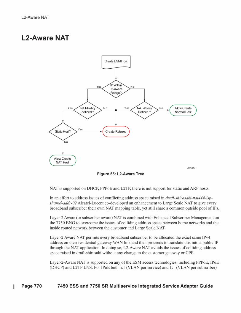
Figure 55: L2-Aware Tree
NAT is supported on DHCP, PPPoE and L2TP, there is not support for static and ARP hosts.
In an effort to address issues of conflicting address space raised in draft-shirasaki-nat444-isp-
shared-addr-02 Alcatel-Lucent co-developed an enhancement to Large Scale NAT to give every
broadband subscriber their own NAT mapping table, yet still share a common outside pool of IPs.
Layer-2 Aware (or subscriber aware) NAT is combined with Enhanced Subscriber Management on
the 7750 BNG to overcome the issues of colliding address space between home networks and the
inside routed network between the customer and Large Scale NAT.
Layer-2 Aware NAT permits every broadband subscriber to be allocated the exact same IPv4
address on their residential gateway WAN link and then proceeds to translate this into a public IP
through the NAT application. In doing so, L2-Aware NAT avoids the issues of colliding address
space raised in draft-shirasaki without any change to the customer gateway or CPE.
Layer-2-Aware NAT is supported on any of the ESM access technologies, including PPPoE, IPoE
(DHCP) and L2TP LNS. For IPoE both n:1 (VLAN per service) and 1:1 (VLAN per subscriber)
IP Within
L2-aware
Range?
Create ESM Host
Create Refused
NAT-Policy
defined ?
N o Allow Create
Normal Host
N oYes
NAT-Policy
Defined ?
Yes
Allow Create
NAT Host
Yes No
Static Host?Yes
No
OSSG711

Network Address Translation
7450 ESS and 7750 SR Multiservice Integrated Service Adapter Guide Page 771
models are supported. A subscriber device operating with L2-Aware NAT needs no modification
or enhancement – existing address mechanisms (DHCP or PPP/IPCP) are identical to a public IP
service, the 7750 BNG simply translates all IPv4 traffic into a pool of IPv4 addresses, allowing
many L2-Aware NAT subscribers to share the same IPv4 address.
More information on L2-Aware NAT can be found in draft-miles-behave-l2nat-00.
Port Control Protocol (PCP)
Page 772 7450 ESS and 7750 SR Multiservice Integrated Service Adapter Guide
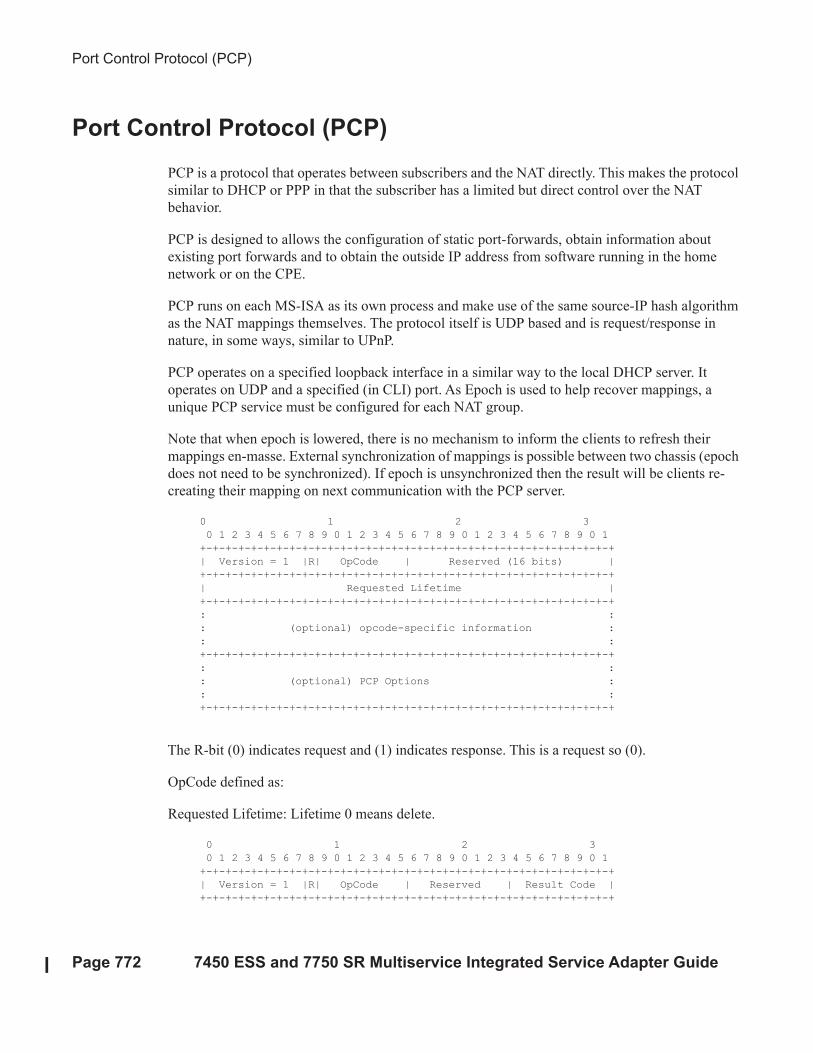
Port Control Protocol (PCP)
PCP is a protocol that operates between subscribers and the NAT directly. This makes the protocol
similar to DHCP or PPP in that the subscriber has a limited but direct control over the NAT
behavior.
PCP is designed to allows the configuration of static port-forwards, obtain information about
existing port forwards and to obtain the outside IP address from software running in the home
network or on the CPE.
PCP runs on each MS-ISA as its own process and make use of the same source-IP hash algorithm
as the NAT mappings themselves. The protocol itself is UDP based and is request/response in
nature, in some ways, similar to UPnP.
PCP operates on a specified loopback interface in a similar way to the local DHCP server. It
operates on UDP and a specified (in CLI) port. As Epoch is used to help recover mappings, a
unique PCP service must be configured for each NAT group.
Note that when epoch is lowered, there is no mechanism to inform the clients to refresh their
mappings en-masse. External synchronization of mappings is possible between two chassis (epoch
does not need to be synchronized). If epoch is unsynchronized then the result will be clients re-
creating their mapping on next communication with the PCP server.
0 1 2 3
0 1 2 3 4 5 6 7 8 9 0 1 2 3 4 5 6 7 8 9 0 1 2 3 4 5 6 7 8 9 0 1
+-+-+-+-+-+-+-+-+-+-+-+-+-+-+-+-+-+-+-+-+-+-+-+-+-+-+-+-+-+-+-+-+
| Version = 1 |R| OpCode | Reserved (16 bits) |
+-+-+-+-+-+-+-+-+-+-+-+-+-+-+-+-+-+-+-+-+-+-+-+-+-+-+-+-+-+-+-+-+
| Requested Lifetime |
+-+-+-+-+-+-+-+-+-+-+-+-+-+-+-+-+-+-+-+-+-+-+-+-+-+-+-+-+-+-+-+-+
: :
: (optional) opcode-specific information :
: :
+-+-+-+-+-+-+-+-+-+-+-+-+-+-+-+-+-+-+-+-+-+-+-+-+-+-+-+-+-+-+-+-+
: :
: (optional) PCP Options :
: :
+-+-+-+-+-+-+-+-+-+-+-+-+-+-+-+-+-+-+-+-+-+-+-+-+-+-+-+-+-+-+-+-+
The R-bit (0) indicates request and (1) indicates response. This is a request so (0).
OpCode defined as:
Requested Lifetime: Lifetime 0 means delete.
0 1 2 3
0 1 2 3 4 5 6 7 8 9 0 1 2 3 4 5 6 7 8 9 0 1 2 3 4 5 6 7 8 9 0 1
+-+-+-+-+-+-+-+-+-+-+-+-+-+-+-+-+-+-+-+-+-+-+-+-+-+-+-+-+-+-+-+-+
| Version = 1 |R| OpCode | Reserved | Result Code |
+-+-+-+-+-+-+-+-+-+-+-+-+-+-+-+-+-+-+-+-+-+-+-+-+-+-+-+-+-+-+-+-+
Network Address Translation
7450 ESS and 7750 SR Multiservice Integrated Service Adapter Guide Page 773
| Lifetime |
+-+-+-+-+-+-+-+-+-+-+-+-+-+-+-+-+-+-+-+-+-+-+-+-+-+-+-+-+-+-+-+-+
| Epoch |
+-+-+-+-+-+-+-+-+-+-+-+-+-+-+-+-+-+-+-+-+-+-+-+-+-+-+-+-+-+-+-+-+
: :
: (optional) OpCode-specific response data :
: :
+-+-+-+-+-+-+-+-+-+-+-+-+-+-+-+-+-+-+-+-+-+-+-+-+-+-+-+-+-+-+-+-+
: (optional) Options :
+-+-+-+-+-+-+-+-+-+-+-+-+-+-+-+-+-+-+-+-+-+-+-+-+-+-+-+-+-+-+-+-+
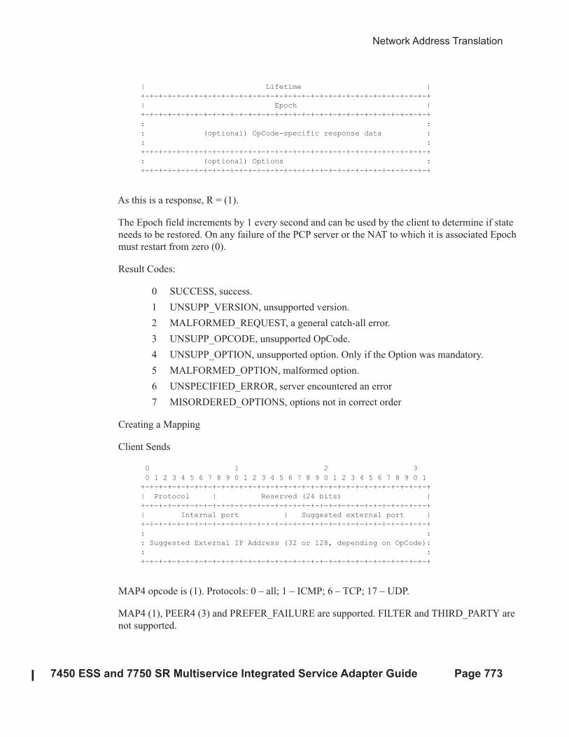
As this is a response, R = (1).
The Epoch field increments by 1 every second and can be used by the client to determine if state
needs to be restored. On any failure of the PCP server or the NAT to which it is associated Epoch
must restart from zero (0).
Result Codes:
0 SUCCESS, success.
1 UNSUPP_VERSION, unsupported version.
2 MALFORMED_REQUEST, a general catch-all error.
3 UNSUPP_OPCODE, unsupported OpCode.
4 UNSUPP_OPTION, unsupported option. Only if the Option was mandatory.
5 MALFORMED_OPTION, malformed option.
6 UNSPECIFIED_ERROR, server encountered an error
7 MISORDERED_OPTIONS, options not in correct order
Creating a Mapping
Client Sends
0 1 2 3
0 1 2 3 4 5 6 7 8 9 0 1 2 3 4 5 6 7 8 9 0 1 2 3 4 5 6 7 8 9 0 1
+-+-+-+-+-+-+-+-+-+-+-+-+-+-+-+-+-+-+-+-+-+-+-+-+-+-+-+-+-+-+-+-+
| Protocol | Reserved (24 bits) |
+-+-+-+-+-+-+-+-+-+-+-+-+-+-+-+-+-+-+-+-+-+-+-+-+-+-+-+-+-+-+-+-+
| Internal port | Suggested external port |
+-+-+-+-+-+-+-+-+-+-+-+-+-+-+-+-+-+-+-+-+-+-+-+-+-+-+-+-+-+-+-+-+
: :
: Suggested External IP Address (32 or 128, depending on OpCode):
: :
+-+-+-+-+-+-+-+-+-+-+-+-+-+-+-+-+-+-+-+-+-+-+-+-+-+-+-+-+-+-+-+-+
MAP4 opcode is (1). Protocols: 0 – all; 1 – ICMP; 6 – TCP; 17 – UDP.
MAP4 (1), PEER4 (3) and PREFER_FAILURE are supported. FILTER and THIRD_PARTY are
not supported.
DS-Lite and NAT64 Fragmentation
Page 774 7450 ESS and 7750 SR Multiservice Integrated Service Adapter Guide
DS-Lite and NAT64 Fragmentation
Overview
In general, fragmentation functionality is invoked when the size of a fragmentation eligible packet
exceeds the size of the MTU of the egress interface/tunnel. Packets eligible for fragmentation are:
• IPv4 packets/fragments with the DF bit in the IPv4 header cleared. Fragmentation can be
performed on any routing node between the source and the destination of the packet.
• IPv6 packets on the source node. Fragmentation of IPv6 packet on the transient routing
nodes is not allowed.
The best practice is to avoid fragmentation in the network by ensuring adequate MTU size on the
transient/source nodes. Drawbacks of the fragmentation are:
• Increased processing and memory demands to the network nodes (especially during
reassembly process)
• Increased byte overhead
• Increased latency.
Fragmentation can be particularly deceiving in a tunneled environment whereby the tunnel
encapsulation adds extra overhead to the original packet. This extra overhead could tip the size of
the resulting packet over the egress MTU limit.
Fragmentation could be one solution in cases where the restriction in the mtu size on the packet’s
path from source to the destination cannot be avoided. 7x50 supports IPv6 fragmentation in DS-
Lite and NAT64 with some enriched capabilities, such as optional packet IPv6 fragmentation even
in cases where DF-bit in corresponding IPv4 packet is set.
In general, the lengths of the fragments must be chosen such that resulting fragment packets fit
within the MTU of the path to the packets destination(s).
In downstream direction fragmentation can be implemented in two ways:
• IPV4 packet can be fragmented in the carrier IOM before it reaches ISA for any NAT
function.
• IPv6 packet can be fragmented in the ISA, once the IPv4 packet is IPv6 encapsulated in
DS-lite or IPv6 translated in NAT64.
In upstream direction, IPv4 packets can be fragmented once they are de-capsulated in DS-lite or
translated in NAT64. The fragmentation will occur in the IOM.
Network Address Translation
7450 ESS and 7750 SR Multiservice Integrated Service Adapter Guide Page 775
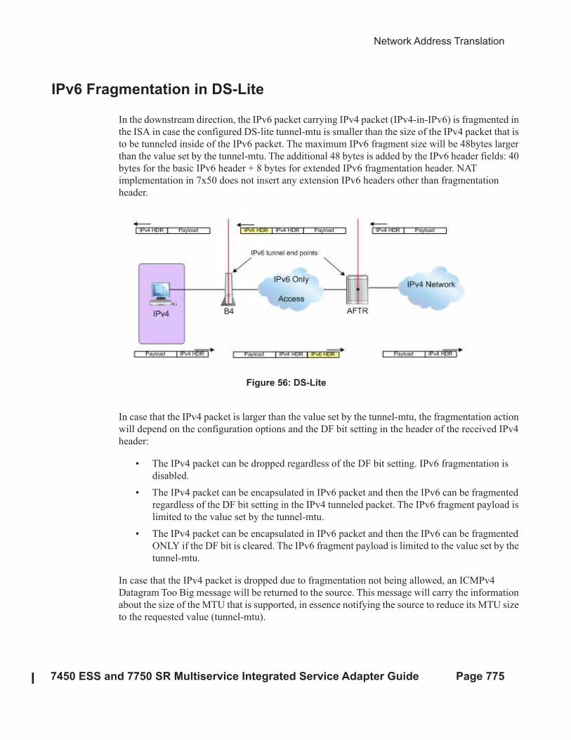
IPv6 Fragmentation in DS-Lite
In the downstream direction, the IPv6 packet carrying IPv4 packet (IPv4-in-IPv6) is fragmented in
the ISA in case the configured DS-lite tunnel-mtu is smaller than the size of the IPv4 packet that is
to be tunneled inside of the IPv6 packet. The maximum IPv6 fragment size will be 48bytes larger
than the value set by the tunnel-mtu. The additional 48 bytes is added by the IPv6 header fields: 40
bytes for the basic IPv6 header + 8 bytes for extended IPv6 fragmentation header. NAT
implementation in 7x50 does not insert any extension IPv6 headers other than fragmentation
header.
Figure 56: DS-Lite
In case that the IPv4 packet is larger than the value set by the tunnel-mtu, the fragmentation action
will depend on the configuration options and the DF bit setting in the header of the received IPv4
header:
• The IPv4 packet can be dropped regardless of the DF bit setting. IPv6 fragmentation is
disabled.
• The IPv4 packet can be encapsulated in IPv6 packet and then the IPv6 can be fragmented
regardless of the DF bit setting in the IPv4 tunneled packet. The IPv6 fragment payload is
limited to the value set by the tunnel-mtu.
• The IPv4 packet can be encapsulated in IPv6 packet and then the IPv6 can be fragmented
ONLY if the DF bit is cleared. The IPv6 fragment payload is limited to the value set by the
tunnel-mtu.
In case that the IPv4 packet is dropped due to fragmentation not being allowed, an ICMPv4
Datagram Too Big message will be returned to the source. This message will carry the information
about the size of the MTU that is supported, in essence notifying the source to reduce its MTU size
to the requested value (tunnel-mtu).
NAT64
Page 776 7450 ESS and 7750 SR Multiservice Integrated Service Adapter Guide
The maximum number of supported fragments per IPv6 packet is 8. Considering that the minimum
standard based size for IPv6 packet is 1280bytes, 8 fragments is enough to cover jumbo Ethernet
frames.
configure
[router] | [service vprn]
nat
inside
dual-stack-lite
address <IPv6 Addr>
tunnel-mtu bytes
ip-fragmentation {disabled|fragment-ipv6|fragment-ipv6-
unless-ipv4-df-set}
NAT64
Downstream fragmentation in NAT64 works in similar fashion. The difference between DS-lite is
that in NAT64 the configured ipv6-mtu represents the mtu size of the ipv6 packet (as opposed to
payload of the IPv6 tunnel in DS-lite). In addition, IPv4 packet in NAT64 is not tunneled but
instead IPv4/v6 headers are translated. Consequently, the fragmented IPv6 packet size will be
28bytes larger than the translated IPv4 packet p 20bytes difference in basic IP header sizes
(40bytes IPv6 header vs 20byte IPv4 header) plus 8 bytes for extended fragmentation IPv6 header.
Note than the only extended IPv6 header that NAT64 generates is the fragmentation header.
In case that the IPv4 packet is dropped due to the fragmentation not being allowed, the returned
ICMP message will contain MTU size of ipv6-mtu minus 28 bytes.
Otherwise the fragmentation options are the same as in DS-lite.
configure
[router] | [service vprn]
nat
inside
nat64
ipv6-mtu bytes
ip-fragmentation {disabled|fragment-ipv6|fragment-ipv6-unless-ipv4-df-set}
Network Address Translation
7450 ESS and 7750 SR Multiservice Integrated Service Adapter Guide Page 777
NAT Logging
LSN logging is extremely important to the Service Providers (SP) who are required by the
government agencies to track source of suspicious Internet activities back to the users that are
hidden behind the LSN device.
The 7750-SR supports several modes of logging for LSN applications. Choosing the right logging
model will depend on the required scale, simplicity of deployment and granularity of the logged
data.
For most purposes logging of allocation/de-allocation of outside port-blocks and outside IP
address along with the corresponding LSN subscriber and inside service-id will suffice.
In certain cases port-block based logging is not satisfactory and per flow logging is required.
Syslog/SNMP/Local-File Logging
The simplest form of LSN and L2-Aware NAT logging is via logging facility in the 7750-SR,
commonly called logger. Each port-block allocation/de-allocation event will be recorded and send
to the system logging facility (logger). Such an event can be:
• Recorded in the system memory as part of regular logs.
• Written to a local file.
• Sent to an external server via syslog facility.
• Sent to a SNMT trap destination.
In this mode of logging, all applications in the system share the same logger.
Syslog/SNMP/Local-File logging on LSN is mutually exclusive with NAT RADIUS-based
logging.
Syslog/SNMP/local-file logging must be separately enabled for LSN and L2-Aware NAT in log
even-control. The following displays relevant MIB events:
2012 tmnxNatPlBlockAllocationLsn
2013 tmnxNatPlBlockAllocationL2Aw
Syslog/SNMP/Local-File Logging
Page 778 7450 ESS and 7750 SR Multiservice Integrated Service Adapter Guide
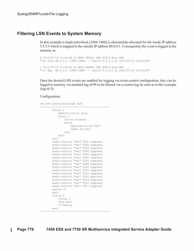
Filtering LSN Events to System Memory
In this example a single port-block [1884-1888] is allocated/de-allocated for the inside IP address
5.5.5.5 which is mapped to the outside IP address 80.0.0.1. Consequently the event is logged in the
memory as.
2 2012/07/12 16:40:58.23 WEST MINOR: NAT #2012 Base NAT
"{2} Free 80.0.0.1 [1884-1888] -- vprn10 5.5.5.5 at 2012/07/12 16:40:58"
1 2012/07/12 16:39:55.15 WEST MINOR: NAT #2012 Base NAT
"{1} Map 80.0.0.1 [1884-1888] -- vprn10 5.5.5.5 at 2012/07/12 16:39:55"
Once the desired LSN events are enabled for logging via event-control configuration, they can be
logged to memory via standard log-id 99 or be filtered via a custom log-id, such as in this example
(log-id 5):
Configuration:
*A:left-a20>config>log# info
----------------------------------------------
filter 1
default-action drop
entry 1
action forward
match
application eq "nat"
numbr eq 2012
exit
exit
exit
event-control "nat" 2001 suppress
event-control "nat" 2002 suppress
event-control "nat" 2003 suppress
event-control "nat" 2004 suppress
event-control "nat" 2005 suppress
event-control "nat" 2006 suppress
event-control "nat" 2007 suppress
event-control "nat" 2008 suppress
event-control "nat" 2009 suppress
event-control "nat" 2010 suppress
event-control "nat" 2011 suppress
event-control "nat" 2012 generate
event-control "nat" 2014 suppress
event-control "nat" 2015 suppress
event-control "nat" 2017 suppress
syslog 10
exit
log-id 5
filter 1
from main
to memory
exit
----------------------------------------------
Network Address Translation
7450 ESS and 7750 SR Multiservice Integrated Service Adapter Guide Page 779
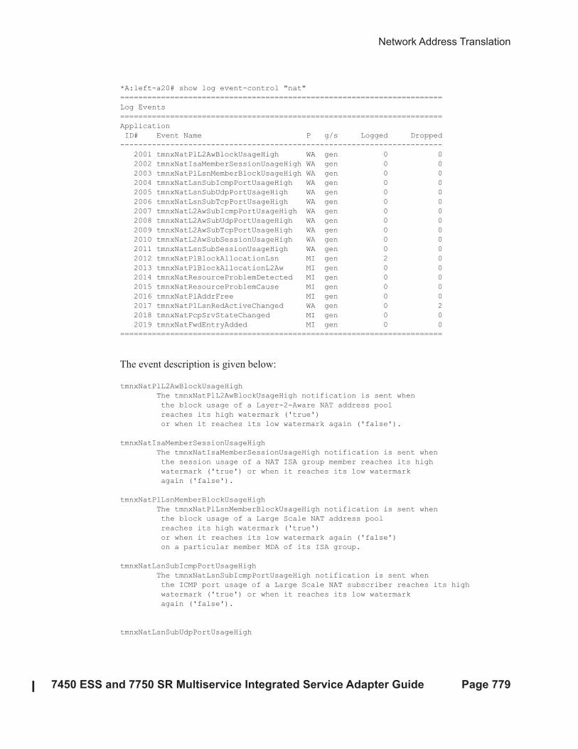
*A:left-a20# show log event-control "nat"
=======================================================================
Log Events
=======================================================================
Application
ID# Event Name P g/s Logged Dropped
-----------------------------------------------------------------------
2001 tmnxNatPlL2AwBlockUsageHigh WA gen 0 0
2002 tmnxNatIsaMemberSessionUsageHigh WA gen 0 0
2003 tmnxNatPlLsnMemberBlockUsageHigh WA gen 0 0
2004 tmnxNatLsnSubIcmpPortUsageHigh WA gen 0 0
2005 tmnxNatLsnSubUdpPortUsageHigh WA gen 0 0
2006 tmnxNatLsnSubTcpPortUsageHigh WA gen 0 0
2007 tmnxNatL2AwSubIcmpPortUsageHigh WA gen 0 0
2008 tmnxNatL2AwSubUdpPortUsageHigh WA gen 0 0
2009 tmnxNatL2AwSubTcpPortUsageHigh WA gen 0 0
2010 tmnxNatL2AwSubSessionUsageHigh WA gen 0 0
2011 tmnxNatLsnSubSessionUsageHigh WA gen 0 0
2012 tmnxNatPlBlockAllocationLsn MI gen 2 0
2013 tmnxNatPlBlockAllocationL2Aw MI gen 0 0
2014 tmnxNatResourceProblemDetected MI gen 0 0
2015 tmnxNatResourceProblemCause MI gen 0 0
2016 tmnxNatPlAddrFree MI gen 0 0
2017 tmnxNatPlLsnRedActiveChanged WA gen 0 2
2018 tmnxNatPcpSrvStateChanged MI gen 0 0
2019 tmnxNatFwdEntryAdded MI gen 0 0
=======================================================================
The event description is given below:
tmnxNatPlL2AwBlockUsageHigh
The tmnxNatPlL2AwBlockUsageHigh notification is sent when
the block usage of a Layer-2-Aware NAT address pool
reaches its high watermark ('true')
or when it reaches its low watermark again ('false').
tmnxNatIsaMemberSessionUsageHigh
The tmnxNatIsaMemberSessionUsageHigh notification is sent when
the session usage of a NAT ISA group member reaches its high
watermark ('true') or when it reaches its low watermark
again ('false').
tmnxNatPlLsnMemberBlockUsageHigh
The tmnxNatPlLsnMemberBlockUsageHigh notification is sent when
the block usage of a Large Scale NAT address pool
reaches its high watermark ('true')
or when it reaches its low watermark again ('false')
on a particular member MDA of its ISA group.
tmnxNatLsnSubIcmpPortUsageHigh
The tmnxNatLsnSubIcmpPortUsageHigh notification is sent when
the ICMP port usage of a Large Scale NAT subscriber reaches its high
watermark ('true') or when it reaches its low watermark
again ('false').
tmnxNatLsnSubUdpPortUsageHigh
Syslog/SNMP/Local-File Logging
Page 780 7450 ESS and 7750 SR Multiservice Integrated Service Adapter Guide
The tmnxNatLsnSubUdpPortUsageHigh notification is sent when
the UDP port usage of a Large Scale NAT subscriber reaches its high
watermark ('true') or when it reaches its low watermark
again ('false').
tmnxNatLsnSubTcpPortUsageHigh
The tmnxNatLsnSubTcpPortUsageHigh notification is sent when
the TCP port usage of a Large Scale NAT subscriber reaches its high
watermark ('true') or when it reaches its low watermark
again ('false').
tmnxNatL2AwSubIcmpPortUsageHigh
The tmnxNatL2AwSubIcmpPortUsageHigh notification is sent when
the ICMP port usage of a Layer-2-Aware NAT subscriber reaches its high
watermark ('true') or when it reaches its low watermark
again ('false').
tmnxNatL2AwSubUdpPortUsageHigh
The tmnxNatL2AwSubUdpPortUsageHigh notification is sent when
the UDP port usage of a Layer-2-Aware NAT subscriber reaches its high
watermark ('true') or when it reaches its low watermark
again ('false').
tmnxNatL2AwSubTcpPortUsageHigh
The tmnxNatL2AwSubTcpPortUsageHigh notification is sent when
the TCP port usage of a Layer-2-Aware NAT subscriber reaches its high
watermark ('true') or when it reaches its low watermark
again ('false').
tmnxNatL2AwSubSessionUsageHigh
The tmnxNatL2AwSubSessionUsageHigh notification is sent when
the session usage of a Layer-2-Aware NAT subscriber reaches its high
watermark ('true') or when it reaches its low watermark
again ('false').
tmnxNatLsnSubSessionUsageHigh
The tmnxNatLsnSubSessionUsageHigh notification is sent when
the session usage of a Large Scale NAT subscriber reaches its high
watermark ('true') or when it reaches its low watermark
again ('false').
tmnxNatPlBlockAllocationLsn
The tmnxNatPlBlockAllocationLsn notification is sent when
an outside IP address and a range of ports is allocated to
a NAT subscriber associated with a Large Scale NAT (LSN) pool,
and when this allocation expires.
tmnxNatPlBlockAllocationL2Aw
The tmnxNatPlBlockAllocationL2Aw notification is sent when
an outside IP address and a range of ports is allocated to
a NAT subscriber associated with a Layer-2-Aware NAT pool,
and when this allocation expires.
tmnxNatResourceProblemDetected
The tmnxNatResourceProblemDetected notification is sent when
the value of the object tmnxNatResourceProblem changes.
tmnxNatResourceProblemCause
The tmnxNatResourceProblemCause notification is to describe the cause
Network Address Translation
7450 ESS and 7750 SR Multiservice Integrated Service Adapter Guide Page 781
of a NAT resource problem.
tmnxNatPlAddrFree
The tmnxNatPlAddrFree notification is sent when
a range of outside IP addresses becomes free at once.
tmnxNatPlLsnRedActiveChanged
The tmnxNatPlLsnRedActiveChanged notification is related to NAT Redundancy sent when the
value of the object tmnxNatPlLsnRedActive changes. The cause is
explained in the tmnxNatNotifyDescription which is a printable character string.
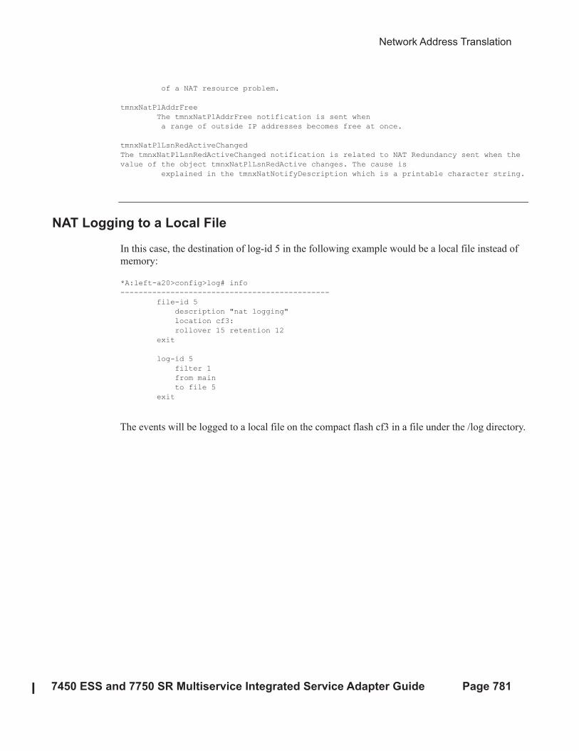
NAT Logging to a Local File
In this case, the destination of log-id 5 in the following example would be a local file instead of
memory:
*A:left-a20>config>log# info
----------------------------------------------
file-id 5
description "nat logging"
location cf3:
rollover 15 retention 12
exit
log-id 5
filter 1
from main
to file 5
exit
The events will be logged to a local file on the compact flash cf3 in a file under the /log directory.
SNMP Trap Logging
Page 782 7450 ESS and 7750 SR Multiservice Integrated Service Adapter Guide
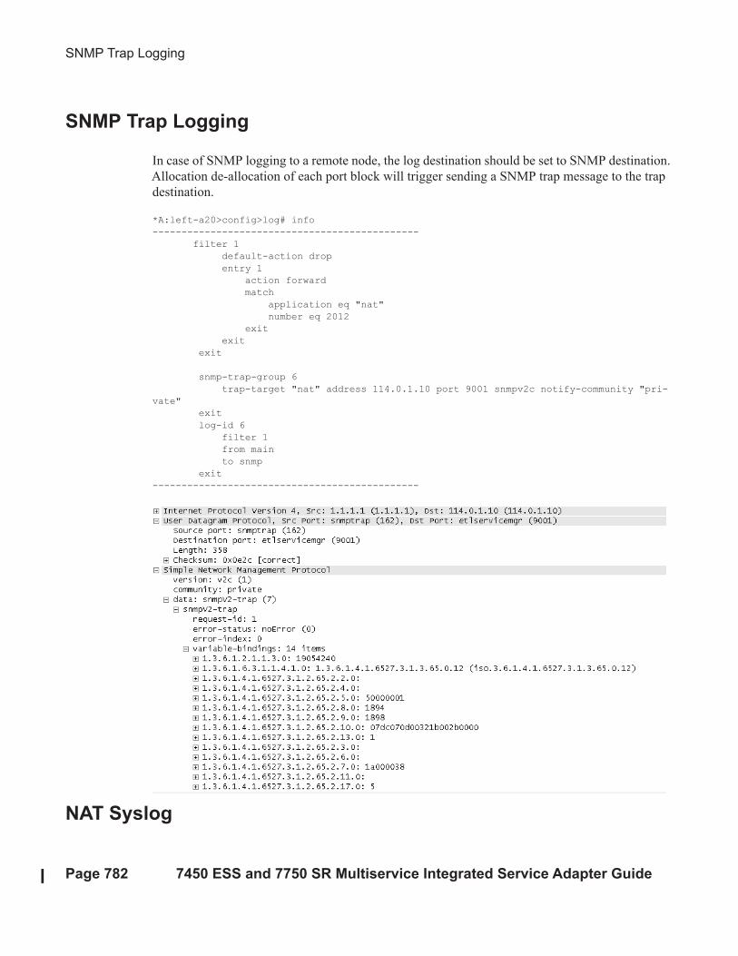
SNMP Trap Logging
In case of SNMP logging to a remote node, the log destination should be set to SNMP destination.
Allocation de-allocation of each port block will trigger sending a SNMP trap message to the trap
destination.
*A:left-a20>config>log# info
----------------------------------------------
filter 1
default-action drop
entry 1
action forward
match
application eq "nat"
number eq 2012
exit
exit
exit
snmp-trap-group 6
trap-target "nat" address 114.0.1.10 port 9001 snmpv2c notify-community "pri-
vate"
exit
log-id 6
filter 1
from main
to snmp
exit
----------------------------------------------
NAT Syslog

Network Address Translation
7450 ESS and 7750 SR Multiservice Integrated Service Adapter Guide Page 783
NAT logs can be sent to a syslog remote facility. A separate syslog message is generated for every
port-block allocation/de-allocation.
*A:left-a20>config>log#info
----------------------------------------------
...
filter 1
default-action drop
entry 1
action forward
match
application eq "nat"
number eq 2012
exit
exit
exit
syslog 7
address 114.0.1.10
exit
log-id 7
filter 1
from main
to syslog 7
exit
----------------------------------------------
Severity level for this event can be changed via CLI:
*A:left-a20# configure log event-control "nat" 2012 generate
<severity-level>
cleared indeterminate critical major minor warning

LSN RADIUS Logging
Page 784 7450 ESS and 7750 SR Multiservice Integrated Service Adapter Guide
LSN RADIUS Logging
LSN RADIUS logging (or accounting) is based on RADIUS accounting messages as defined in
RFC 2866. It requires an operator to have RADIUS accounting infrastructure in place. For that
reason, LSN RADIUS logging and LSN RADIUS accounting terms can be used interchangeably.
This mode of logging operation is introduced so that the shared logging infrastructure in 7750 SR
can be offloaded by disabling syslog/SNMP/Local-file LSN logging. The result is increased
performance and higher scale, particularly in cases when multiple BB-ISA cards within the same
system are deployed to perform aggregated LSN functions.
An additional benefit of LSN RADIUS logging over syslog/SNMP/local-file logging is reliable
transport. Although RADIUS accounting relies on unreliable UDP transport, each accounting
message from the RADIUS client must be acknowledged on the application level by the receiving
end (accounting server).
Each port-block allocation or de-allocation is reported to an external accounting (logging) server
in the form of start, interim-update or stop messages. The type of accounting messages generated
depends on the mode of operation:
• START and STOP per port-block. An accounting START is generated when a new port-
block for the LSN subscriber is allocated. Similarly, the accounting STOP is generated
when the port-block is released. Each accounting START/STOP pair of messages that are
triggered by port block allocation/de-allocation within the same subscriber will have the
same multi-acct-session-id (subscriber significant) but a different acct-session-id (port-
block significant). This mode of operation is enabled by inclusion of multi-acct-session-id
within the nat-accounting-policy.
• START and STOP per subscriber. An accounting START will be generated when the first
port block for the NAT subscriber is allocated. Each consecutive port-block allocation/de-
allocation will trigger an INTERIM-UPDATE messages with the same acct-session-id
(subscriber significant). The termination cause attribute in acct STOP messages will
indicate the reason for port-block de-allocation. De-allocation of the last port-block for the
LSN subscriber will trigger an acct STOP message. There is no multi-acct-session-id
present in this mode of operation.
The accounting messages are generated and reported directly from the BB-ISA card, therefore
bypassing accounting infrastructure residing on the Control Plane Module (CPM).
LSN RADIUS logging is enabled per nat-group. To achieve the required scale, each BB-ISA card
in the nat-group group with LSN RADIUS logging enabled runs a RADIUS client with its own IP
address. Accounting messages can be distributed to up to 5 accounting servers that can be accessed
in round-robin fashion. Alternatively, in direct access mode, only one accounting server in the list
is used. When this server fails, the next one in the list is used.
Network Address Translation
7450 ESS and 7750 SR Multiservice Integrated Service Adapter Guide Page 785
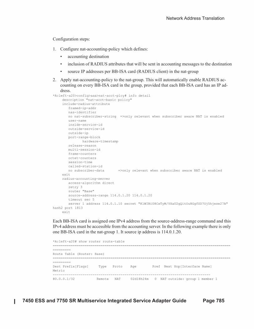
Configuration steps:
1. Configure nat-accounting-policy which defines:
• accounting destination
• inclusion of RADIUS attributes that will be sent in accounting messages to the destination
• source IP addresses per BB-ISA card (RADIUS client) in the nat-group
2. Apply nat-accounting-policy to the nat-group. This will automatically enable RADIUS ac-
counting on every BB-ISA card in the group, provided that each BB-ISA card has an IP ad-
dress.*A:left-a20>config>aaa>nat-acct-plcy# info detail
description "nat-acct-basic policy"
include-radius-attribute
framed-ip-addr
nas-identifier
no nat-subscriber-string =>only relevant when subscriber aware NAT is enabled
user-name
inside-service-id
outside-service-id
outside-ip
port-range-block
hardware-timestamp
release-reason
multi-session-id
frame-counters
octet-counters
session-time
called-station-id
no subscriber-data =>only relevant when subscriber aware NAT is enabled
exit
radius-accounting-server
access-algorithm direct
retry 3
router "Base"
source-address-range 114.0.1.20 114.0.1.20
timeout sec 5
server 1 address 114.0.1.10 secret "KlWIBi08CxTyM/YXaU2gQitOu8GgfSD7Oj5hjese27A"
hash2 port 1813
exit
Each BB-ISA card is assigned one IPv4 address from the source-address-range command and this
IPv4 address must be accessible from the accounting server. In the following example there is only
one BB-ISA card in the nat-group 1. It source ip address is 114.0.1.20.
*A:left-a20# show router route-table
=========================================================================================
=========
Route Table (Router: Base)
=========================================================================================
=========
Dest Prefix[Flags] Type Proto Age Pref Next Hop[Interface Name]
Metric
-------------------------------------------------------------------------------
80.0.0.1/32 Remote NAT 02d18h24m 0 NAT outside: group 1 member 1
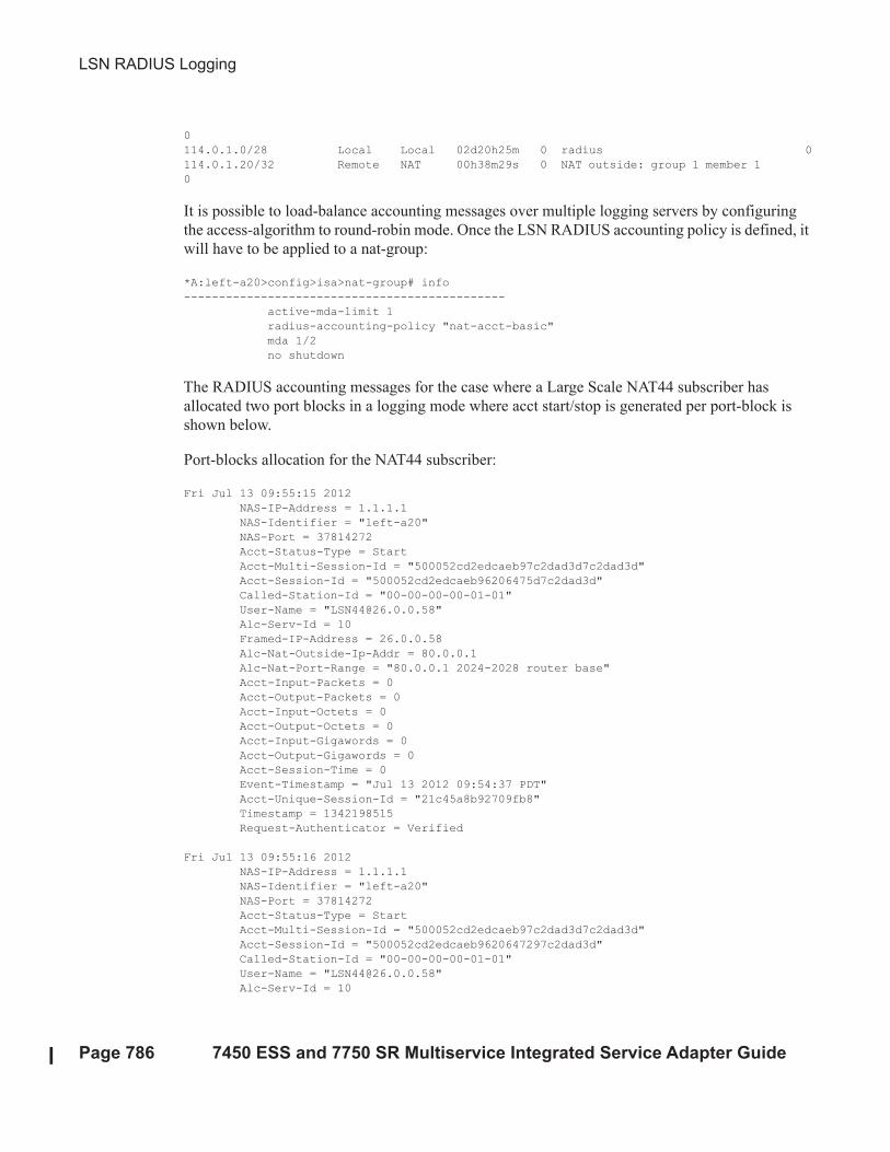
LSN RADIUS Logging
Page 786 7450 ESS and 7750 SR Multiservice Integrated Service Adapter Guide
0
114.0.1.0/28 Local Local 02d20h25m 0 radius 0
114.0.1.20/32 Remote NAT 00h38m29s 0 NAT outside: group 1 member 1
0
It is possible to load-balance accounting messages over multiple logging servers by configuring
the access-algorithm to round-robin mode. Once the LSN RADIUS accounting policy is defined, it
will have to be applied to a nat-group:
*A:left-a20>config>isa>nat-group# info
----------------------------------------------
active-mda-limit 1
radius-accounting-policy "nat-acct-basic"
mda 1/2
no shutdown
The RADIUS accounting messages for the case where a Large Scale NAT44 subscriber has
allocated two port blocks in a logging mode where acct start/stop is generated per port-block is
shown below.
Port-blocks allocation for the NAT44 subscriber:
Fri Jul 13 09:55:15 2012
NAS-IP-Address = 1.1.1.1
NAS-Identifier = "left-a20"
NAS-Port = 37814272
Acct-Status-Type = Start
Acct-Multi-Session-Id = "500052cd2edcaeb97c2dad3d7c2dad3d"
Acct-Session-Id = "500052cd2edcaeb96206475d7c2dad3d"
Called-Station-Id = "00-00-00-00-01-01"
User-Name = "[email protected]"
Alc-Serv-Id = 10
Framed-IP-Address = 26.0.0.58
Alc-Nat-Outside-Ip-Addr = 80.0.0.1
Alc-Nat-Port-Range = "80.0.0.1 2024-2028 router base"
Acct-Input-Packets = 0
Acct-Output-Packets = 0
Acct-Input-Octets = 0
Acct-Output-Octets = 0
Acct-Input-Gigawords = 0
Acct-Output-Gigawords = 0
Acct-Session-Time = 0
Event-Timestamp = "Jul 13 2012 09:54:37 PDT"
Acct-Unique-Session-Id = "21c45a8b92709fb8"
Timestamp = 1342198515
Request-Authenticator = Verified
Fri Jul 13 09:55:16 2012
NAS-IP-Address = 1.1.1.1
NAS-Identifier = "left-a20"
NAS-Port = 37814272
Acct-Status-Type = Start
Acct-Multi-Session-Id = "500052cd2edcaeb97c2dad3d7c2dad3d"
Acct-Session-Id = "500052cd2edcaeb9620647297c2dad3d"
Called-Station-Id = "00-00-00-00-01-01"
User-Name = "[email protected]"
Alc-Serv-Id = 10
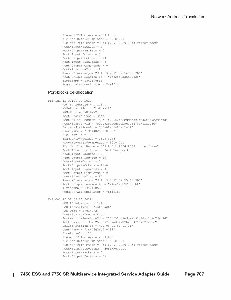
Network Address Translation
7450 ESS and 7750 SR Multiservice Integrated Service Adapter Guide Page 787
Framed-IP-Address = 26.0.0.58
Alc-Nat-Outside-Ip-Addr = 80.0.0.1
Alc-Nat-Port-Range = "80.0.0.1 2029-2033 router base"
Acct-Input-Packets = 0
Acct-Output-Packets = 5
Acct-Input-Octets = 0
Acct-Output-Octets = 370
Acct-Input-Gigawords = 0
Acct-Output-Gigawords = 0
Acct-Session-Time = 1
Event-Timestamp = "Jul 13 2012 09:54:38 PDT"
Acct-Unique-Session-Id = "baf26e8a35e31020"
Timestamp = 1342198516
Request-Authenticator = Verified
Port-blocks de-allocation
Fri Jul 13 09:56:18 2012
NAS-IP-Address = 1.1.1.1
NAS-Identifier = "left-a20"
NAS-Port = 37814272
Acct-Status-Type = Stop
Acct-Multi-Session-Id = "500052cd2edcaeb97c2dad3d7c2dad3d"
Acct-Session-Id = "500052cd2edcaeb96206475d7c2dad3d"
Called-Station-Id = "00-00-00-00-01-01"
User-Name = "[email protected]"
Alc-Serv-Id = 10
Framed-IP-Address = 26.0.0.58
Alc-Nat-Outside-Ip-Addr = 80.0.0.1
Alc-Nat-Port-Range = "80.0.0.1 2024-2028 router base"
Acct-Terminate-Cause = Port-Unneeded
Acct-Input-Packets = 0
Acct-Output-Packets = 25
Acct-Input-Octets = 0
Acct-Output-Octets = 1850
Acct-Input-Gigawords = 0
Acct-Output-Gigawords = 0
Acct-Session-Time = 64
Event-Timestamp = "Jul 13 2012 09:55:41 PDT"
Acct-Unique-Session-Id = "21c45a8b92709fb8"
Timestamp = 1342198578
Request-Authenticator = Verified
Fri Jul 13 09:56:20 2012
NAS-IP-Address = 1.1.1.1
NAS-Identifier = "left-a20"
NAS-Port = 37814272
Acct-Status-Type = Stop
Acct-Multi-Session-Id = "500052cd2edcaeb97c2dad3d7c2dad3d"
Acct-Session-Id = "500052cd2edcaeb9620647297c2dad3d"
Called-Station-Id = "00-00-00-00-01-01"
User-Name = "[email protected]"
Alc-Serv-Id = 10
Framed-IP-Address = 26.0.0.58
Alc-Nat-Outside-Ip-Addr = 80.0.0.1
Alc-Nat-Port-Range = "80.0.0.1 2029-2033 router base"
Acct-Terminate-Cause = Host-Request
Acct-Input-Packets = 0
Acct-Output-Packets = 25
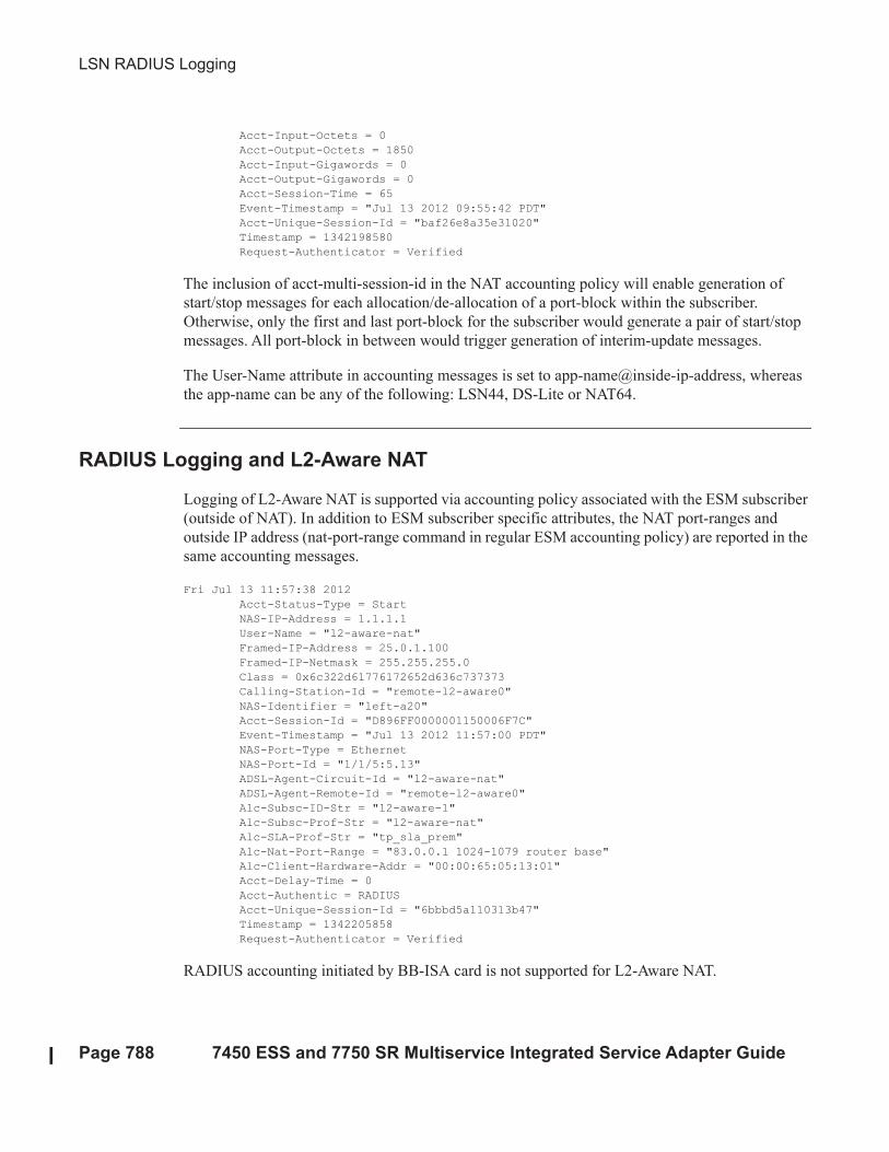
LSN RADIUS Logging
Page 788 7450 ESS and 7750 SR Multiservice Integrated Service Adapter Guide
Acct-Input-Octets = 0
Acct-Output-Octets = 1850
Acct-Input-Gigawords = 0
Acct-Output-Gigawords = 0
Acct-Session-Time = 65
Event-Timestamp = "Jul 13 2012 09:55:42 PDT"
Acct-Unique-Session-Id = "baf26e8a35e31020"
Timestamp = 1342198580
Request-Authenticator = Verified
The inclusion of acct-multi-session-id in the NAT accounting policy will enable generation of
start/stop messages for each allocation/de-allocation of a port-block within the subscriber.
Otherwise, only the first and last port-block for the subscriber would generate a pair of start/stop
messages. All port-block in between would trigger generation of interim-update messages.
The User-Name attribute in accounting messages is set to app-name@inside-ip-address, whereas
the app-name can be any of the following: LSN44, DS-Lite or NAT64.
RADIUS Logging and L2-Aware NAT
Logging of L2-Aware NAT is supported via accounting policy associated with the ESM subscriber
(outside of NAT). In addition to ESM subscriber specific attributes, the NAT port-ranges and
outside IP address (nat-port-range command in regular ESM accounting policy) are reported in the
same accounting messages.
Fri Jul 13 11:57:38 2012
Acct-Status-Type = Start
NAS-IP-Address = 1.1.1.1
User-Name = "l2-aware-nat"
Framed-IP-Address = 25.0.1.100
Framed-IP-Netmask = 255.255.255.0
Class = 0x6c322d61776172652d636c737373
Calling-Station-Id = "remote-l2-aware0"
NAS-Identifier = "left-a20"
Acct-Session-Id = "D896FF0000001150006F7C"
Event-Timestamp = "Jul 13 2012 11:57:00 PDT"
NAS-Port-Type = Ethernet
NAS-Port-Id = "1/1/5:5.13"
ADSL-Agent-Circuit-Id = "l2-aware-nat"
ADSL-Agent-Remote-Id = "remote-l2-aware0"
Alc-Subsc-ID-Str = "l2-aware-1"
Alc-Subsc-Prof-Str = "l2-aware-nat"
Alc-SLA-Prof-Str = "tp_sla_prem"
Alc-Nat-Port-Range = "83.0.0.1 1024-1079 router base"
Alc-Client-Hardware-Addr = "00:00:65:05:13:01"
Acct-Delay-Time = 0
Acct-Authentic = RADIUS
Acct-Unique-Session-Id = "6bbbd5a110313b47"
Timestamp = 1342205858
Request-Authenticator = Verified
RADIUS accounting initiated by BB-ISA card is not supported for L2-Aware NAT.
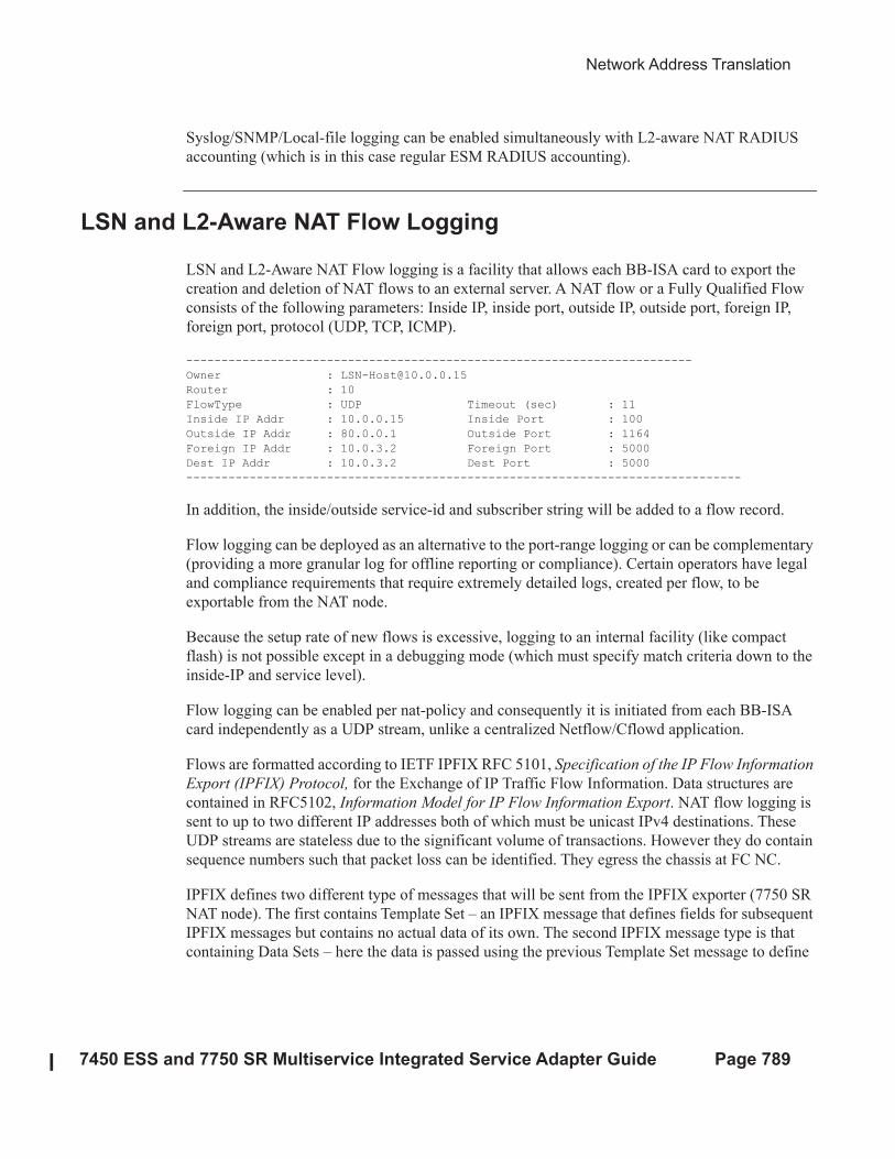
Network Address Translation
7450 ESS and 7750 SR Multiservice Integrated Service Adapter Guide Page 789
Syslog/SNMP/Local-file logging can be enabled simultaneously with L2-aware NAT RADIUS
accounting (which is in this case regular ESM RADIUS accounting).
LSN and L2-Aware NAT Flow Logging
LSN and L2-Aware NAT Flow logging is a facility that allows each BB-ISA card to export the
creation and deletion of NAT flows to an external server. A NAT flow or a Fully Qualified Flow
consists of the following parameters: Inside IP, inside port, outside IP, outside port, foreign IP,
foreign port, protocol (UDP, TCP, ICMP).
------------------------------------------------------------------------
Owner : [email protected]
Router : 10
FlowType : UDP Timeout (sec) : 11
Inside IP Addr : 10.0.0.15 Inside Port : 100
Outside IP Addr : 80.0.0.1 Outside Port : 1164
Foreign IP Addr : 10.0.3.2 Foreign Port : 5000
Dest IP Addr : 10.0.3.2 Dest Port : 5000
-------------------------------------------------------------------------------
In addition, the inside/outside service-id and subscriber string will be added to a flow record.
Flow logging can be deployed as an alternative to the port-range logging or can be complementary
(providing a more granular log for offline reporting or compliance). Certain operators have legal
and compliance requirements that require extremely detailed logs, created per flow, to be
exportable from the NAT node.
Because the setup rate of new flows is excessive, logging to an internal facility (like compact
flash) is not possible except in a debugging mode (which must specify match criteria down to the
inside-IP and service level).
Flow logging can be enabled per nat-policy and consequently it is initiated from each BB-ISA
card independently as a UDP stream, unlike a centralized Netflow/Cflowd application.
Flows are formatted according to IETF IPFIX RFC 5101, Specification of the IP Flow Information
Export (IPFIX) Protocol, for the Exchange of IP Traffic Flow Information. Data structures are
contained in RFC5102, Information Model for IP Flow Information Export. NAT flow logging is
sent to up to two different IP addresses both of which must be unicast IPv4 destinations. These
UDP streams are stateless due to the significant volume of transactions. However they do contain
sequence numbers such that packet loss can be identified. They egress the chassis at FC NC.
IPFIX defines two different type of messages that will be sent from the IPFIX exporter (7750 SR
NAT node). The first contains Template Set – an IPFIX message that defines fields for subsequent
IPFIX messages but contains no actual data of its own. The second IPFIX message type is that
containing Data Sets – here the data is passed using the previous Template Set message to define
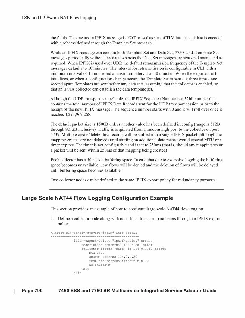
LSN and L2-Aware NAT Flow Logging
Page 790 7450 ESS and 7750 SR Multiservice Integrated Service Adapter Guide
the fields. This means an IPFIX message is NOT passed as sets of TLV, but instead data is encoded
with a scheme defined through the Template Set message.
While an IPFIX message can contain both Template Set and Data Set, 7750 sends Template Set
messages periodically without any data, whereas the Data Set messages are sent on demand and as
required. When IPFIX is used over UDP, the default retransmission frequency of the Template Set
messages defaults to 10 minutes. The interval for retransmission is configurable in CLI with a
minimum interval of 1 minute and a maximum interval of 10 minutes. When the exporter first
initializes, or when a configuration change occurs the Template Set is sent out three times, one
second apart. Templates are sent before any data sets, assuming that the collector is enabled, so
that an IPFIX collector can establish the data template set.
Although the UDP transport is unreliable, the IPFIX Sequence Number is a 32bit number that
contains the total number of IPFIX Data Records sent for the UDP transport session prior to the
receipt of the new IPFIX message. The sequence number starts with 0 and it will roll over once it
reaches 4,294,967,268.
The default packet size is 1500B unless another value has been defined in config (range is 512B
through 9212B inclusive). Traffic is originated from a random high-port to the collector on port
4739. Multiple create/delete flow records will be stuffed into a single IPFIX packet (although the
mapping creates are not delayed) until stuffing an additional data record would exceed MTU or a
timer expires. The timer is not configurable and is set to 250ms (that is, should any mapping occur
a packet will be sent within 250ms of that mapping being created)
Each collector has a 50 packet buffering space. In case that due to excessive logging the buffering
space becomes unavailable, new flows will be denied and the deletion of flows will be delayed
until buffering space becomes available.
Two collector nodes can be defined in the same IPFIX export policy for redundancy purposes.
Large Scale NAT44 Flow Logging Configuration Example
This section provides an example of how to configure large scale NAT44 flow logging.
1. Define a collector node along with other local transport parameters through an IPFIX export-
policy.
*A:left-a20>config>service>ipfix# info detail
----------------------------------------------
ipfix-export-policy "ipxif-policy" create
description "external IPFIX collector"
collector router "Base" ip 114.0.1.10 create
mtu 1500
source-address 114.0.1.20
template-refresh-timeout min 10
no shutdown
exit
exit
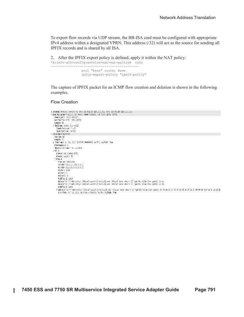
Network Address Translation
7450 ESS and 7750 SR Multiservice Integrated Service Adapter Guide Page 791
To export flow records via UDP stream, the BB-ISA card must be configured with appropriate
IPv4 address within a designated VPRN. This address (/32) will act as the source for sending all
IPFIX records and is shared by all ISA.
2. After the IPFIX export policy is defined, apply it within the NAT policy:*A:left-a20>config>service>nat>nat-policy# info
----------------------------------------------
pool "base" router Base
ipfix-export-policy "ipxif-policy"
The capture of IPFIX packet for an ICMP flow creation and deletion is shown in the following
examples.
Flow Creation
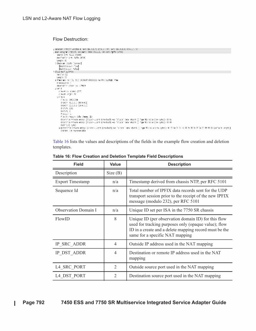
LSN and L2-Aware NAT Flow Logging
Page 792 7450 ESS and 7750 SR Multiservice Integrated Service Adapter Guide
Flow Destruction:
Table 16 lists the values and descriptions of the fields in the example flow creation and deletion
templates.
Table 16: Flow Creation and Deletion Template Field Descriptions
Field Value Description
Description Size (B)
Export Timestamp n/a Timestamp derived from chassis NTP, per RFC 5101
Sequence Id n/a Total number of IPFIX data records sent for the UDP
transport session prior to the receipt of the new IPFIX
message (modulo 232), per RFC 5101
Observation Domain I n/a Unique ID set per ISA in the 7750 SR chassis
FlowID 8 Unique ID (per observation domain ID) for this flow
used for tracking purposes only (opaque value); flow
ID in a create and a delete mapping record must be the
same for a specific NAT mapping
IP_SRC_ADDR 4 Outside IP address used in the NAT mapping
IP_DST_ADDR 4 Destination or remote IP address used in the NAT
mapping
L4_SRC_PORT 2 Outside source port used in the NAT mapping
L4_DST_PORT 2 Destination source port used in the NAT mapping
Network Address Translation
7450 ESS and 7750 SR Multiservice Integrated Service Adapter Guide Page 793
flowStartMilliseconds a 8 Timestamp when the flow was created (chassis NTP
derived) in milliseconds from epoch, per RFC 5102
flowEndMilliseconds b 8 Timestamp when the flow was destroyed (chassis NTP
derived) in milliseconds from epoch, per RFC 510
PROTOCOL 1 Protocol ID, TCP, UDP or ICMP. Per RFC 5102
PADDING 1 n/a
flowEndReason
<$elemparanumonly<$e
lemparanumonlyb
1 Supported flow end reasons:
• 0x01: Idle Timeout—A mapping expired
(because of UDP or TCP timeout)
• 0x03: End of Flow Detected—A mapping
closed (only used for TCP after a FIN or
RST).
• 0x04: Forced End—Collects all other reasons
included administrative or failure case
aluInsideServiceID 2 16-bit service ID representing the inside service ID
aluOutsideServiceI 2 16-bit service ID representing the outside service ID
aluNatSubString var A variable 8B aligned string that represents the NAT
subscriber construct (as currently used in the tools
dump service nat session commands)
a. Flow Creation Template Set only
b. Flow Deletion Template Set only
Table 16: Flow Creation and Deletion Template Field Descriptions (Continued)
Field Value Description
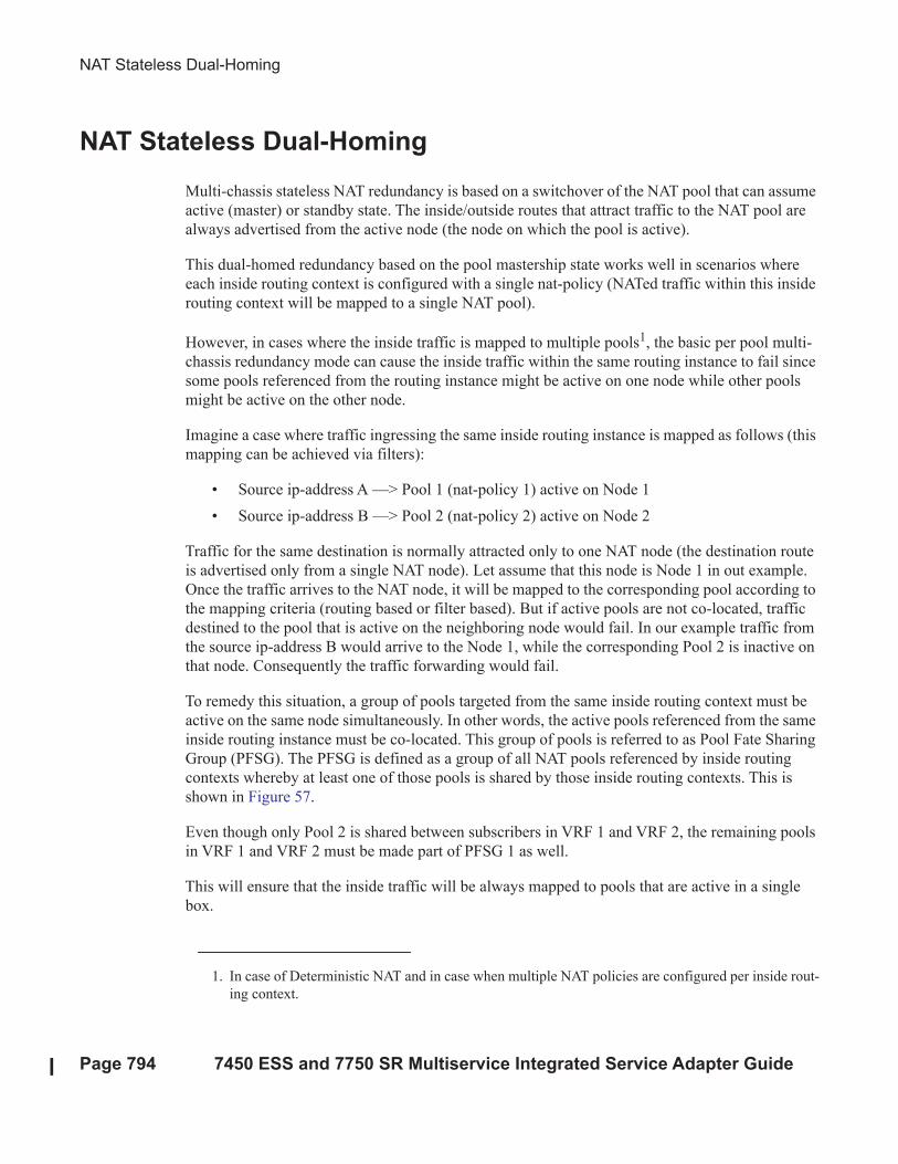
NAT Stateless Dual-Homing
Page 794 7450 ESS and 7750 SR Multiservice Integrated Service Adapter Guide
NAT Stateless Dual-Homing
Multi-chassis stateless NAT redundancy is based on a switchover of the NAT pool that can assume
active (master) or standby state. The inside/outside routes that attract traffic to the NAT pool are
always advertised from the active node (the node on which the pool is active).
This dual-homed redundancy based on the pool mastership state works well in scenarios where
each inside routing context is configured with a single nat-policy (NATed traffic within this inside
routing context will be mapped to a single NAT pool).
However, in cases where the inside traffic is mapped to multiple pools1, the basic per pool multi-
chassis redundancy mode can cause the inside traffic within the same routing instance to fail since
some pools referenced from the routing instance might be active on one node while other pools
might be active on the other node.
Imagine a case where traffic ingressing the same inside routing instance is mapped as follows (this
mapping can be achieved via filters):
• Source ip-address A —> Pool 1 (nat-policy 1) active on Node 1
• Source ip-address B —> Pool 2 (nat-policy 2) active on Node 2
Traffic for the same destination is normally attracted only to one NAT node (the destination route
is advertised only from a single NAT node). Let assume that this node is Node 1 in out example.
Once the traffic arrives to the NAT node, it will be mapped to the corresponding pool according to
the mapping criteria (routing based or filter based). But if active pools are not co-located, traffic
destined to the pool that is active on the neighboring node would fail. In our example traffic from
the source ip-address B would arrive to the Node 1, while the corresponding Pool 2 is inactive on
that node. Consequently the traffic forwarding would fail.
To remedy this situation, a group of pools targeted from the same inside routing context must be
active on the same node simultaneously. In other words, the active pools referenced from the same
inside routing instance must be co-located. This group of pools is referred to as Pool Fate Sharing
Group (PFSG). The PFSG is defined as a group of all NAT pools referenced by inside routing
contexts whereby at least one of those pools is shared by those inside routing contexts. This is
shown in Figure 57.
Even though only Pool 2 is shared between subscribers in VRF 1 and VRF 2, the remaining pools
in VRF 1 and VRF 2 must be made part of PFSG 1 as well.
This will ensure that the inside traffic will be always mapped to pools that are active in a single
box.
1. In case of Deterministic NAT and in case when multiple NAT policies are configured per inside rout-
ing context.
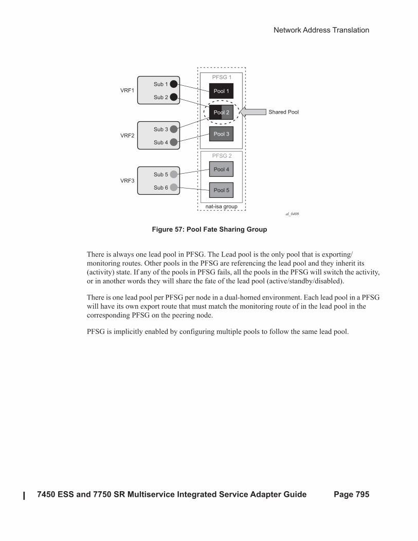
Network Address Translation
7450 ESS and 7750 SR Multiservice Integrated Service Adapter Guide Page 795
Figure 57: Pool Fate Sharing Group
There is always one lead pool in PFSG. The Lead pool is the only pool that is exporting/
monitoring routes. Other pools in the PFSG are referencing the lead pool and they inherit its
(activity) state. If any of the pools in PFSG fails, all the pools in the PFSG will switch the activity,
or in another words they will share the fate of the lead pool (active/standby/disabled).
There is one lead pool per PFSG per node in a dual-homed environment. Each lead pool in a PFSG
will have its own export route that must match the monitoring route of in the lead pool in the
corresponding PFSG on the peering node.
PFSG is implicitly enabled by configuring multiple pools to follow the same lead pool.
al_0409
Sub 1
Sub 2
VRF1 Pool 1
PFSG 1
PFSG 2
Pool 2
Pool 3
Pool 4
Shared Pool
Pool 5
nat-isa group
Sub 3
Sub 4
VRF2
Sub 5
Sub 6
VRF3
Configuration Considerations
Page 796 7450 ESS and 7750 SR Multiservice Integrated Service Adapter Guide
Configuration Considerations
Attracting traffic to the active NAT node (from inside and outside) is based on the routing.
On the outside, the active pool address range will be advertised. On the inside, the destination
prefix or steering route (in case of filter based diversion to the NAT function) will be advertised by
the node with the active pool.
The advertisement of the routes will be driven by the activity of the pools in the pool fate sharing
group:
configure
router/service vprn
nat
outside
pool <name>
redundancy
export <ip-prefix/length>
monitor <ip-prefix/length>[no] shutdown
follow router <rtr-id> pool <master-pool>
For example:
router/service vprn
nat
outside
pool "nat0-pool" nat-group 1 type large-scale create
port-reservation ports 252
redundancy
follow router 500 pool "nat500-pool"
exit
address-range 128.251.12.0 128.251.12.10 create
exit
no shutdown
exit
exit
exit
A pool can be one of the following:
• A leading pool: configure export- and monitor-route and put in no shutdown
• A following pool: configure follow
Both sets of options are thus mutually exclusive.
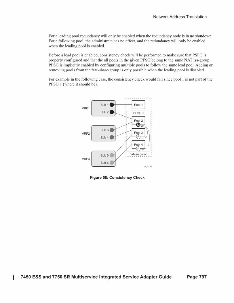
Network Address Translation
7450 ESS and 7750 SR Multiservice Integrated Service Adapter Guide Page 797
For a leading pool redundancy will only be enabled when the redundancy node is in no shutdown.
For a following pool, the administrate has no effect, and the redundancy will only be enabled
when the leading pool is enabled.
Before a lead pool is enabled, consistency check will be performed to make sure that PSFG is
properly configured and that the all pools in the given PFSG belong to the same NAT isa-group.
PFSG is implicitly enabled by configuring multiple pools to follow the same lead pool. Adding or
removing pools from the fate-share-group is only possible when the leading pool is disabled.
For example in the following case, the consistency check would fail since pool 1 is not part of the
PFSG 1 (where it should be).
Figure 58: Consistency Check
al_0410
Sub 1
Sub 2
VRF1Pool 1
Pool 2
F
F
M
PFSG 1
Pool 3
Pool 4
nat-isa group
Sub 3
Sub 4
VRF2
Sub 5
Sub 6
VRF3
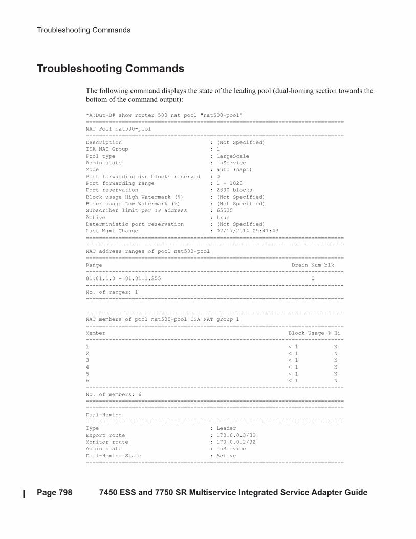
Troubleshooting Commands
Page 798 7450 ESS and 7750 SR Multiservice Integrated Service Adapter Guide
Troubleshooting Commands
The following command displays the state of the leading pool (dual-homing section towards the
bottom of the command output):
*A:Dut-B# show router 500 nat pool "nat500-pool"
===============================================================================
NAT Pool nat500-pool
===============================================================================
Description : (Not Specified)
ISA NAT Group : 1
Pool type : largeScale
Admin state : inService
Mode : auto (napt)
Port forwarding dyn blocks reserved : 0
Port forwarding range : 1 - 1023
Port reservation : 2300 blocks
Block usage High Watermark (%) : (Not Specified)
Block usage Low Watermark (%) : (Not Specified)
Subscriber limit per IP address : 65535
Active : true
Deterministic port reservation : (Not Specified)
Last Mgmt Change : 02/17/2014 09:41:43
===============================================================================
===============================================================================
NAT address ranges of pool nat500-pool
===============================================================================
Range Drain Num-blk
-------------------------------------------------------------------------------
81.81.1.0 - 81.81.1.255 0
-------------------------------------------------------------------------------
No. of ranges: 1
===============================================================================
===============================================================================
NAT members of pool nat500-pool ISA NAT group 1
===============================================================================
Member Block-Usage-% Hi
-------------------------------------------------------------------------------
1 < 1 N
2 < 1 N
3 < 1 N
4 < 1 N
5 < 1 N
6 < 1 N
-------------------------------------------------------------------------------
No. of members: 6
===============================================================================
===============================================================================
Dual-Homing
===============================================================================
Type : Leader
Export route : 170.0.0.3/32
Monitor route : 170.0.0.2/32
Admin state : inService
Dual-Homing State : Active
===============================================================================
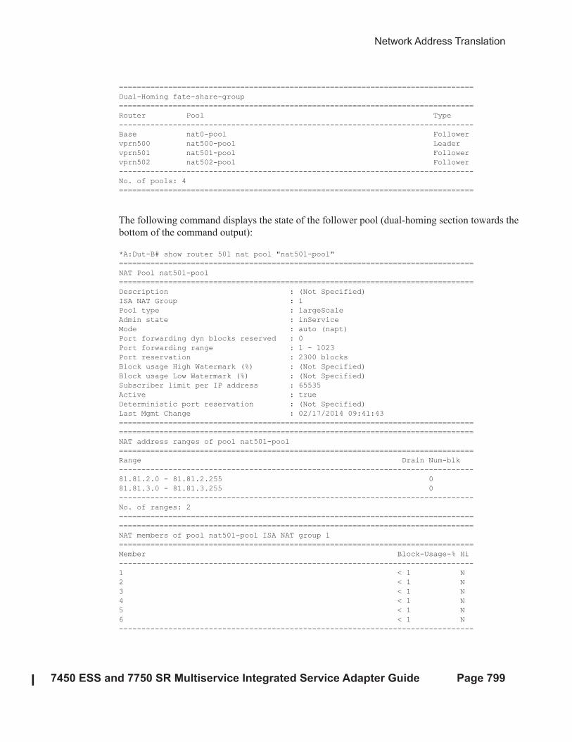
Network Address Translation
7450 ESS and 7750 SR Multiservice Integrated Service Adapter Guide Page 799
===============================================================================
Dual-Homing fate-share-group
===============================================================================
Router Pool Type
-------------------------------------------------------------------------------
Base nat0-pool Follower
vprn500 nat500-pool Leader
vprn501 nat501-pool Follower
vprn502 nat502-pool Follower
-------------------------------------------------------------------------------
No. of pools: 4
===============================================================================
The following command displays the state of the follower pool (dual-homing section towards the
bottom of the command output):
*A:Dut-B# show router 501 nat pool "nat501-pool"
===============================================================================
NAT Pool nat501-pool
===============================================================================
Description : (Not Specified)
ISA NAT Group : 1
Pool type : largeScale
Admin state : inService
Mode : auto (napt)
Port forwarding dyn blocks reserved : 0
Port forwarding range : 1 - 1023
Port reservation : 2300 blocks
Block usage High Watermark (%) : (Not Specified)
Block usage Low Watermark (%) : (Not Specified)
Subscriber limit per IP address : 65535
Active : true
Deterministic port reservation : (Not Specified)
Last Mgmt Change : 02/17/2014 09:41:43
===============================================================================
===============================================================================
NAT address ranges of pool nat501-pool
===============================================================================
Range Drain Num-blk
-------------------------------------------------------------------------------
81.81.2.0 - 81.81.2.255 0
81.81.3.0 - 81.81.3.255 0
-------------------------------------------------------------------------------
No. of ranges: 2
===============================================================================
===============================================================================
NAT members of pool nat501-pool ISA NAT group 1
===============================================================================
Member Block-Usage-% Hi
-------------------------------------------------------------------------------
1 < 1 N
2 < 1 N
3 < 1 N
4 < 1 N
5 < 1 N
6 < 1 N
-------------------------------------------------------------------------------
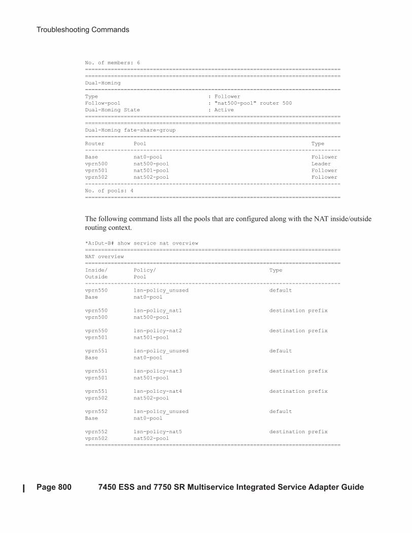
Troubleshooting Commands
Page 800 7450 ESS and 7750 SR Multiservice Integrated Service Adapter Guide
No. of members: 6
===============================================================================
===============================================================================
Dual-Homing
===============================================================================
Type : Follower
Follow-pool : "nat500-pool" router 500
Dual-Homing State : Active
===============================================================================
===============================================================================
Dual-Homing fate-share-group
===============================================================================
Router Pool Type
-------------------------------------------------------------------------------
Base nat0-pool Follower
vprn500 nat500-pool Leader
vprn501 nat501-pool Follower
vprn502 nat502-pool Follower
-------------------------------------------------------------------------------
No. of pools: 4
===============================================================================
The following command lists all the pools that are configured along with the NAT inside/outside
routing context.
*A:Dut-B# show service nat overview
===============================================================================
NAT overview
===============================================================================
Inside/ Policy/ Type
Outside Pool
-------------------------------------------------------------------------------
vprn550 lsn-policy_unused default
Base nat0-pool
vprn550 lsn-policy_nat1 destination prefix
vprn500 nat500-pool
vprn550 lsn-policy-nat2 destination prefix
vprn501 nat501-pool
vprn551 lsn-policy_unused default
Base nat0-pool
vprn551 lsn-policy-nat3 destination prefix
vprn501 nat501-pool
vprn551 lsn-policy-nat4 destination prefix
vprn502 nat502-pool
vprn552 lsn-policy_unused default
Base nat0-pool
vprn552 lsn-policy-nat5 destination prefix
vprn502 nat502-pool
===============================================================================
Network Address Translation
7450 ESS and 7750 SR Multiservice Integrated Service Adapter Guide Page 801
Deterministic NAT
Overview
In deterministic NAT the subscriber is deterministically mapped into an outside IP address and a
port block. The algorithm that performs this deterministic mapping is revertive, which means that
a NAT subscriber can be uniformly derived from the outside IP address and the outside port (and
the routing instance). Thus, logging in deterministic NAT is not needed.
The deterministic [subscriber <-> outside-ip, deterministic-port-block] mapping can be
automatically extended by a dynamic port-block in case that deterministic port block becomes
exhausted of ports. By extending the original deterministic port block of the NAT subscriber by a
dynamic port block yields a satisfactory compromise between a deterministic NAT and a non-
deterministic NAT. There will be no logging as long as the translations are in the domain of the
deterministic NAT. Once the dynamic port block is allocated for port extension, logging will be
automatically activated.
NAT subscribers in deterministic NAT are not assigned outside IP address and deterministic port-
block on a first come first serve basis. Instead, deterministic mappings will be pre-created at the
time of configuration regardless of whether the NAT subscriber is active or not. In other words we
can say that overbooking of the outside address pool is not supported in deterministic NAT.
Consequently, all configured deterministic subscribers (for example, inside IP addresses in LSN44
or IPv6 address/prefix in DS-Lite) will be guaranteed access to NAT resources.
Supported Deterministic NAT Flavors
7x50 supports Deterministic LSN44 and Deterministic DS-Lite. The basic deterministic NAT
principle is applied equally to both NAT flavors. The difference between the two stem from the
difference in interpretation of the subscriber – in LSN44 a subscriber is an IPv4 address, whereas
in DS-Lite the subscriber is an IPv6 address or prefix (configuration dependent).
With the exception of classic-lsn-max-subscriber-limit and dslite-max-subscriber-limit commands
in the inside routing context, the deterministic NAT configuration blocks are for the most part
common to LSN44 and DS-Lite.
Deterministic DS-Lite section at the end of this section will focus on the features specific to DS-
Lite.
Number of Subscribers per Outside IP and per Pool
Page 802 7450 ESS and 7750 SR Multiservice Integrated Service Adapter Guide
Number of Subscribers per Outside IP and per Pool
The outside pools in deterministic NAT can contain an arbitrary number of address ranges, where
each address range can contain an arbitrary number of IP addresses (up to the ISA maximum).
The maximum number of NAT subscribers that can be mapped to a single outside IP address is
configurable using a subscriber-limit command under the pool hierarchy. For Deterministic NAT,
this number is restricted to the power of 2 (2^n). The consequence of this is that the number of
NAT subscribers must be configuration-wise organized in ranges with the boundary that must be
power of 2.
For example, in LSN44 where the NAT subscriber is an IP address, the deterministic subscribers
would be configured with prefixes (for example, 10.10.10.0/24 – 256 subscribers) rather than an
IP address range that would contain an arbitrary number of addresses (e.g. 10.10.10.10 –
10.10.10.50).
On the other hand, in DS-Lite the deterministic subscribers are for the most part already
determined by the prefix with the subscriber-prefix-length command under the DS-Lite
configuration node.
The number of subscribers per outside IP (the subscriber-limit command [2^n]) multiplied by the
number of IP addresses over all address-range in an outside pool will determine the maximum
number of subscribers that a deterministic pool can support.
Referencing a Pool
In deterministic NAT, the outside pool can be shared amongst subscribers from multiple routing
instances. Also, NAT subscribers from a single routing instance can be selectively mapped to
different outside pools.
Outside Pool Configuration
The number of deterministic mappings that a single outside IP address can sustain is determined
through the configuration of the outside pool.
The port allocation per an outside IP is shown in Figure 59.
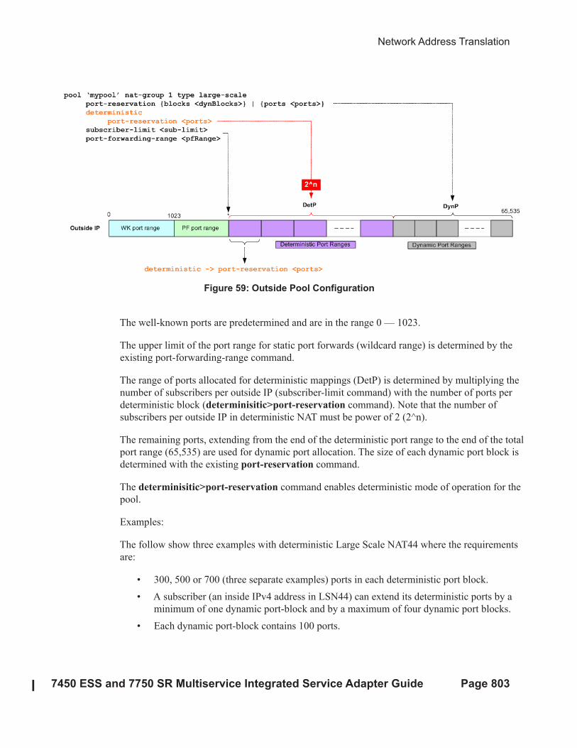
Network Address Translation
7450 ESS and 7750 SR Multiservice Integrated Service Adapter Guide Page 803
Figure 59: Outside Pool Configuration
The well-known ports are predetermined and are in the range 0 — 1023.
The upper limit of the port range for static port forwards (wildcard range) is determined by the
existing port-forwarding-range command.
The range of ports allocated for deterministic mappings (DetP) is determined by multiplying the
number of subscribers per outside IP (subscriber-limit command) with the number of ports per
deterministic block (determinisitic>port-reservation command). Note that the number of
subscribers per outside IP in deterministic NAT must be power of 2 (2^n).
The remaining ports, extending from the end of the deterministic port range to the end of the total
port range (65,535) are used for dynamic port allocation. The size of each dynamic port block is
determined with the existing port-reservation command.
The determinisitic>port-reservation command enables deterministic mode of operation for the
pool.
Examples:
The follow show three examples with deterministic Large Scale NAT44 where the requirements
are:
• 300, 500 or 700 (three separate examples) ports in each deterministic port block.
• A subscriber (an inside IPv4 address in LSN44) can extend its deterministic ports by a
minimum of one dynamic port-block and by a maximum of four dynamic port blocks.
• Each dynamic port-block contains 100 ports.
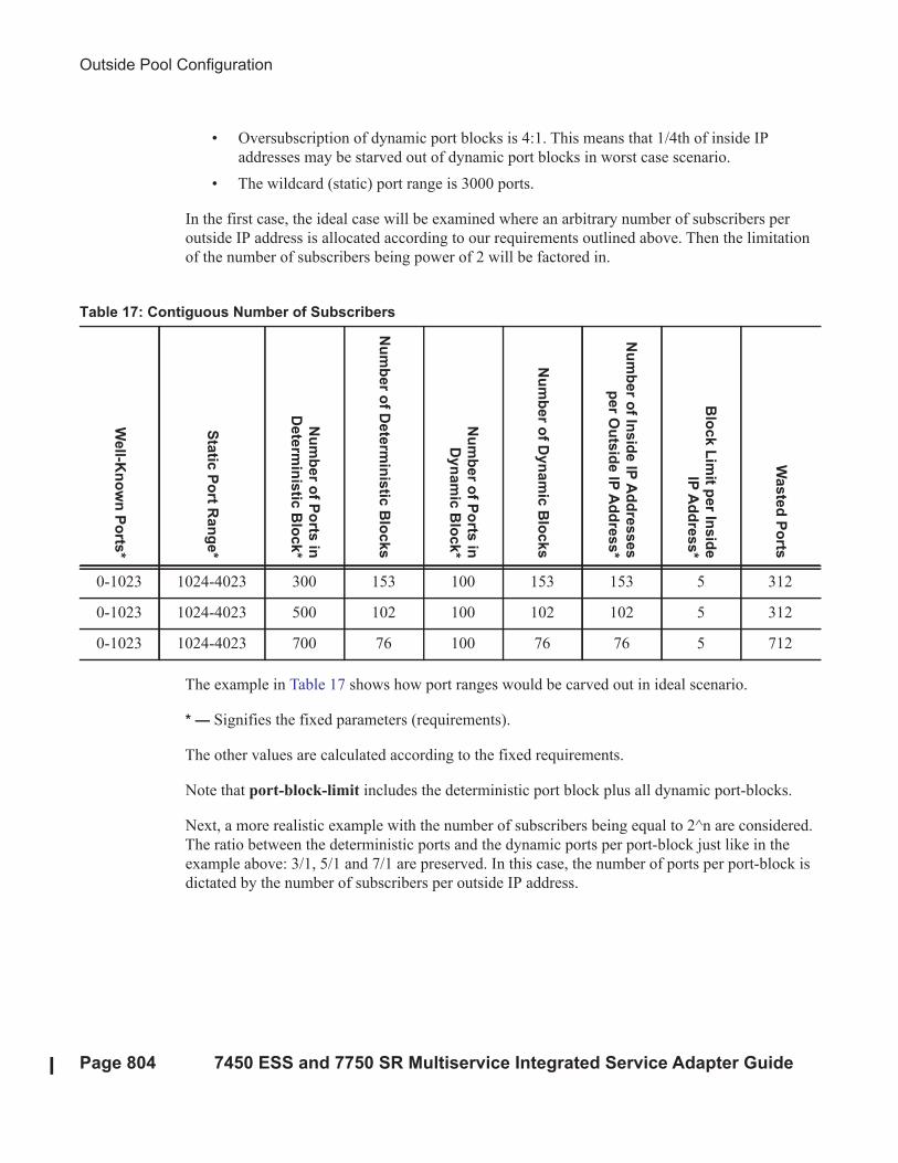
Outside Pool Configuration
Page 804 7450 ESS and 7750 SR Multiservice Integrated Service Adapter Guide
• Oversubscription of dynamic port blocks is 4:1. This means that 1/4th of inside IP
addresses may be starved out of dynamic port blocks in worst case scenario.
• The wildcard (static) port range is 3000 ports.
In the first case, the ideal case will be examined where an arbitrary number of subscribers per
outside IP address is allocated according to our requirements outlined above. Then the limitation
of the number of subscribers being power of 2 will be factored in.
The example in Table 17 shows how port ranges would be carved out in ideal scenario.
* — Signifies the fixed parameters (requirements).
The other values are calculated according to the fixed requirements.
Note that port-block-limit includes the deterministic port block plus all dynamic port-blocks.
Next, a more realistic example with the number of subscribers being equal to 2^n are considered.
The ratio between the deterministic ports and the dynamic ports per port-block just like in the
example above: 3/1, 5/1 and 7/1 are preserved. In this case, the number of ports per port-block is
dictated by the number of subscribers per outside IP address.
Table 17: Contiguous Number of Subscribers
Well-K
nown Ports*
Static Port R
ange*
Number of Ports in
Deterministic Block*
Number of Deterministic Blocks
Number of Ports in
Dynamic Block*
Number of Dynamic Blocks
Number of Inside IP Addresses
per Outside IP Address*
Block Limit per In
side
IP Address*
Wasted Ports
0-1023 1024-4023 300 153 100 153 153 5 312
0-1023 1024-4023 500 102 100 102 102 5 312
0-1023 1024-4023 700 76 100 76 76 5 712
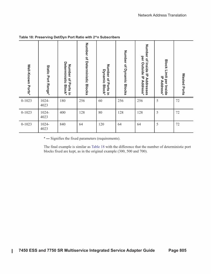
Network Address Translation
7450 ESS and 7750 SR Multiservice Integrated Service Adapter Guide Page 805
* — Signifies the fixed parameters (requirements).
The final example is similar as Table 18 with the difference that the number of deterministic port
blocks fixed are kept, as in the original example (300, 500 and 700).
Table 18: Preserving Det/Dyn Port Ratio with 2^n Subscribers
Well-K
nown Ports*
Static Port R
ange*
Number of Ports in
Deterministic Block*
Number of Deterministic Blocks
Number of Ports in
Dynamic Block*
Number of Dynamic Blocks
Number of In
side IP Addresses
per Outside IP Address*
Block Limit p
er In
side
IP Address*
Wasted Ports
0-1023 1024-
4023
180 256 60 256 256 5 72
0-1023 1024-
4023
400 128 80 128 128 5 72
0-1023 1024-
4023
840 64 120 64 64 5 72
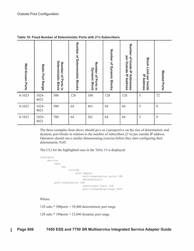
Outside Pool Configuration
Page 806 7450 ESS and 7750 SR Multiservice Integrated Service Adapter Guide
The three examples from above should give us a perspective on the size of deterministic and
dynamic port blocks in relation to the number of subscribers (2^n) per outside IP address.
Operators should run a similar dimensioning exercise before they start configuring their
deterministic NAT.
The CLI for the highlighted case in the Table 19 is displayed:
configure
service
vprn
nat
outside
pool mypool
port-reservation ports 180
deterministic
port-reservation 300
subscriber-limit 128
port-forwarding-range 4023
Where:
128 subs * 300ports = 38,400 deterministic port range
128 subs * 180ports = 23,040 dynamic port range
Table 19: Fixed Number of Deterministic Ports with 2^n Subscribers
Well-K
nown Ports
Static Port R
ange
Number of Ports in
Deterministic Block
Number of Deterministic Blocks
Number of Ports in
Dynamic Block
Number of Dynamic Blocks
Number of In
side IP Addresses
per Outside IP Address
Block Limit p
er In
side
IP Address
Wasted Ports
0-1023 1024-
4023
300 128 180 128 128 5 72
0-1023 1024-
4023
500 64 461 64 64 5 8
0-1023 1024-
4023
700 64 261 64 64 5 8
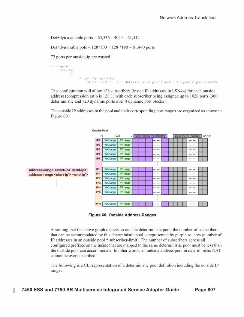
Network Address Translation
7450 ESS and 7750 SR Multiservice Integrated Service Adapter Guide Page 807
Det+dyn available ports = 65,536 – 4024 = 61,512
Det+dyn usable pots = 128*300 + 128 *180 = 61,440 ports
72 ports per outside-ip are wasted.
configure
service
nat
nat-policy mypolicy
block-limit 5 z 1 deterministic port block + 4 dynamic port blocks
This configuration will allow 128 subscribers (inside IP addresses in LSN44) for each outside
address (compression ratio is 128:1) with each subscriber being assigned up to 1020 ports (300
deterministic and 720 dynamic ports over 4 dynamic port blocks).
The outside IP addresses in the pool and their corresponding port ranges are organized as shown in
Figure 60.
Figure 60: Outside Address Ranges
Assuming that the above graph depicts an outside deterministic pool, the number of subscribers
that can be accommodated by this deterministic pool is represented by purple squares (number of
IP addresses in an outside pool * subscriber-limit). The number of subscribers across all
configured prefixes on the inside that are mapped to the same deterministic pool must be less than
the outside pool can accommodate. In other words, an outside address pool in deterministic NAT
cannot be oversubscribed.
The following is a CLI representation of a deterministic pool definition including the outside IP
ranges:

Mapping Rules and the map Command in Deterministic LSN44
Page 808 7450 ESS and 7750 SR Multiservice Integrated Service Adapter Guide
pool ‘mypool’ nat-group 1 type large-scale
port-reservation {blocks <dynBlocks>} | {ports <ports>}
deterministic
port-reservation <ports>
subscriber-limit <sub-limit>
port-forwarding-range <pfRange>
address-range <start-ip-address> <end-ip-address>
address-range <start-ip-address> <end-ip-address>
Mapping Rules and the map Command in Deterministic LSN44
The common building block on the inside in the deterministic LSN44 configuration is a IPv4
prefix. The NAT subscribers (inside IPv4 addresses) from the configured prefix will be
deterministically mapped to the outside IP addresses and corresponding deterministic port-blocks.
Any inside prefix in any routing instance can be mapped to any pool in any routing instance
(including the one in which the inside prefix is defined).
The mapping between the inside prefix and the deterministic pool is achieved through a nat-policy
that can be referenced per each individual inside IPv4 prefix. IPv4 addresses from the prefixes on
the inside will be distributed over the IP addresses defined in the outside pool referenced by the
nat-policy.
The mapping itself is represented by the map command under the prefix hierarchy:
router/service vprn
nat
inside
deterministic
prefix <ip-prefix/length> subscriber-type <nat-sub-type> nat-policy
<nat-policy-name>
map start <inside-ip-address> end <inside-ip-address> to <outside-
ip-address>
The purpose of the map statement is to split the number of subscribers within the configured prefix
over available sequences of outside IP addresses. The key parameter that governs mappings
between the inside IPv4 addresses and outside IPv4 addresses in deterministic LSN44 is defined
by the outside>pool>subscriber-limit command. This parameter must be power of 2 and it limits
the maximum number of NAT subscribers that can be mapped to the same outside IP address.
The follow are rules governing the configuration of the map statement:
1. If the number of subscribers per configured prefix is greater than the subscriber-limit
per outside IP parameter (2^n), then the lowest n bits of the map start inside-ip-
address must be set to 0.
2. If the number of subscribers per configured prefix is equal or less than the subscriber-
limit per outside IP parameter (2^n), then only one map command for this prefix is

Network Address Translation
7450 ESS and 7750 SR Multiservice Integrated Service Adapter Guide Page 809
allowed. In this case there is no restriction on the lower n bits of the map start inside-
ip-address. The range of the inside IP addresses in such map statement represents the
prefix itself.
3. The outside-ip-address in the map statements must be unique amongst all map state-
ments referencing the same pool. In other words, two map statements cannot reference
the same outside-ip-address in the pool.
In case that the number of subscribers (IP addresses in LSN44) in the map statement is larger than
the subscriber-limit per outside IP, then the subscribers must be split over a block of consecutive
outside IP addresses where the outside-ip-address in the map statement represent only the first
outside IP address in that block.
The number of subscribers (range of inside IP addresses in LSN44) in the map statement does not
have to be a power of 2. Rather it has to be a multiple of a power of two p m * 2^n, where m is the
number of consecutive outside IP addresses to which the subscribers are mapped and the 2^n is the
subscriber-limit per outside IP.
An example of the map statement is given below:
router
nat
outside
pool ‘my-det-pool’ nat-group 1 type large-scale
subscriber-limit 128
deterministic
port-reservation 400
address-range 128.251.0.0 128.251.0.10
service vprn 10
nat
inside
deterministic
prefix 10.0.0.0/24 subscriber-type classic-lsn-sub nat-policy det
map start 10.0.0.0 end 10.0.0.255 to 128.251.0.1
In this case, the configured 10.0.0.0/24 prefix is represented by the range of IP addresses in the
map statement (10.0.0.0-10.0.0.255). Since the range of 256 IP addresses in the map statement
cannot be mapped into a single outside IP address (subscriber-limit=128), this range must be
further implicitly split within the system and mapped into multiple outside IP addresses. The
implicit split will create two IP address ranges, each with 128 IP addresses (10.0.0.0/25 and
10.0.0.128/25) so that addresses from each IP range are mapped to one outside IP address. The
hosts from the range 10.0.0.0-10.0.0.127 will be mapped to the first IP address in the pool
(128.251.0.1) as explicitly stated in the map statement (to statement). The hosts from the second
range, 10.0.0.128-10.0.0.255 will be implicitly mapped to the next consecutive IP address
(128.251.0.2).
Alternatively, the map statement can be configured as:
service vprn 10

Mapping Rules and the map Command in Deterministic LSN44
Page 810 7450 ESS and 7750 SR Multiservice Integrated Service Adapter Guide
nat
inside
deterministic
prefix 10.0.0.0/24 subscriber-type classic-lsn-sub nat-policy det
map start 10.0.0.0 end 10.0.0.127 to 128.251.0.1
map start 10.0.0.128 end 10.0.0.255 to 128.251.0.5
In this case the IP address range in the map statement is split into two non-consecutive outside IP
addresses. This gives the operator more freedom in configuring the mappings.
However, the following configuration is not supported:
service vprn 10
nat
inside
deterministic
prefix 10.0.0.0/24 subscriber-type classic-lsn-sub nat-policy det
map start 10.0.0.0 end 10.0.0.63 to 128.251.0.1
map start 10.0.0.64 end 10.0.0.127 to 128.251.0.3
map start 10.0.0.128 end 10.0.0.255 to 128.251.0.5
Considering that the subscriber-limit = 128 (2^n; where n=7), the lower n bits of the start address
in the second map statement (map start 10.0.0.64 end 10.0.0.127 to 128.251.0.3) are not 0. This is
in violation of the rule #1 that governs the provisioning of the map statement.
Assuming that we use the same pool with 128 subscribers per outside IP address, the following
scenario is also not supported (note that configured prefix in this example is different than in
previous example):
service vprn 10
nat
inside
deterministic
prefix 10.0.0.0/26 subscriber-type classic-lsn-sub nat-policy det
map start 10.0.0.0 end 10.0.0.63 to 128.251.0.1
prefix 10.0.1.0/26 subscriber-type classic-lsn-sub nat-policy det
map start 10.0.1.0 end 10.0.1.63 to 128.251.0.1
Although the lower n bits in both map statements are 0, both statements are referencing the same
outside IP (128.251.0.1). This is violating rule #2 that governs the provisioning of the map
statement. Each of the prefixes in this case will have to be mapped to a different outside IP
address, which will lead to underutilization of outside IP addresses (half of the deterministic port-
blocks in each of the two outside IP addresses will be not be utilized).
In conclusion, considering that the number of subscribers per outside IP (subscriber-limit) must be
2^n, the inside IP addresses from the configured prefix will be split on the 2^n boundary so that
every deterministic port-block of an outside IP is utilized. In case that the originally configured
prefix contains less subscribers (IP addresses in LSN44) than an outside IP address can

Network Address Translation
7450 ESS and 7750 SR Multiservice Integrated Service Adapter Guide Page 811
accommodate (2^n), all subscribers from such configured prefix will be mapped to a single
outside IP. Since the outside IP cannot be shared with NAT subscribers from other prefixes, some
of the deterministic port-blocks for this particular outside IP address will not be utilized.
Note that each configured prefix can evaluate into multiple map commands. The number of map
commands will depend on the length of the configured prefix, the subscriber-limit command and
fragmentation of outside address-range within the pool with which the prefix is associated.
Hashing Considerations in Deterministic LSN44
Support for multiple MS-ISAs in the nat-group calls for traffic hashing on the inside in the ingress
direction. This will ensure fair load balancing of the traffic amongst multiple MS-ISAs. While
hashing in non-deterministic LSN44 can be performed per source IP address, hashing in
deterministic LSN44 is based on subnets instead of individual IP addresses. The length of the
hashing subnet is common for all configured prefixes within an inside routing instance. In case
that a prefixes from an inside routing instances is referencing multiple pools, the common hashing
prefix length will be chosen according to the pool with the highest number of subscribers per
outside IP address. This will ensure that subscribers mapped to the same outside IP address will be
always hashed to the same MS-ISA.
In general, load distribution based on hashing is dependent on the sample. Large and more diverse
sample will ensure better load balancing. Therefore the efficiency of load distribution between the
MS-ISAs is dependent on the number and diversity of subnets that hashing algorithm is taking into
consideration within the inside routing context.
A simple rule for good load balancing is to configure a large number of subscribers relative to the
largest t subscriber-limit parameter in any given pool that is referenced from this inside routing
instance.
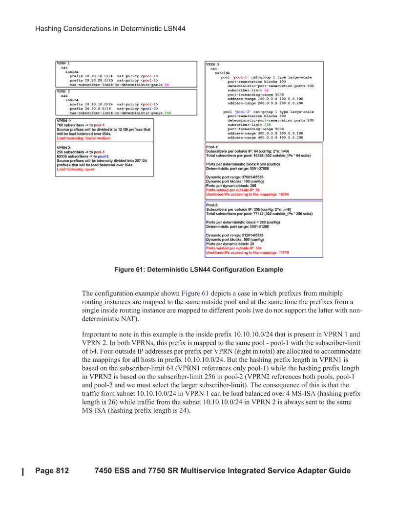
Hashing Considerations in Deterministic LSN44
Page 812 7450 ESS and 7750 SR Multiservice Integrated Service Adapter Guide
Figure 61: Deterministic LSN44 Configuration Example
The configuration example shown Figure 61 depicts a case in which prefixes from multiple
routing instances are mapped to the same outside pool and at the same time the prefixes from a
single inside routing instance are mapped to different pools (we do not support the latter with non-
deterministic NAT).
Important to note in this example is the inside prefix 10.10.10.0/24 that is present in VPRN 1 and
VPRN 2. In both VPRNs, this prefix is mapped to the same pool - pool-1 with the subscriber-limit
of 64. Four outside IP addresses per prefix per VPRN (eight in total) are allocated to accommodate
the mappings for all hosts in prefix 10.10.10.0/24. But the hashing prefix length in VPRN1 is
based on the subscriber-limit 64 (VPRN1 references only pool-1) while the hashing prefix length
in VPRN2 is based on the subscriber-limit 256 in pool-2 (VPRN2 references both pools, pool-1
and pool-2 and we must select the larger subscriber-limit). The consequence of this is that the
traffic from subnet 10.10.10.0/24 in VPRN 1 can be load balanced over 4 MS-ISA (hashing prefix
length is 26) while traffic from the subnet 10.10.10.0/24 in VPRN 2 is always sent to the same
MS-ISA (hashing prefix length is 24).
Network Address Translation
7450 ESS and 7750 SR Multiservice Integrated Service Adapter Guide Page 813
Distribution of Outside IP Addresses Across MS-ISAs in an MS-ISA NA
Group
Distribution of outside IP addresses across the MS-ISAs is dependent on the ingress hashing
algorithm. Since traffic from the same subscriber is always pre-hashed to the same MS-ISA, the
corresponding outside IP address also must reside on the same ISA. CPM runs the hashing
algorithm in advance to determine on which MS-ISA the traffic from particular inside subnet will
land and then the corresponding outside IP address (according to deterministic NAT mapping
algorithm) will be configured in that particular MS-ISA.
Sharing of Deterministic NAT Pools
Sharing of the deterministic pools between LSN44 and DS-Lite is supported.
Simultaneous support of dynamic and deterministic NAT
Simultaneous support for deterministic and non-deterministic NAT inside of the same routing
instance is supported. However, an outside pool can be only deterministic (although expandable
by dynamic ports blocks) or non-deterministic at any given time.
Ingress hashing for all NATed traffic within the VRF will in this case be performed based on the
subnets driven by the classic-lsn-max-subscriber-limit parameter.
Selecting Traffic for NAT
Deterministic NAT does not change the way how traffic is selected for the NAT function but
instead only defines a predictable way for translating subscribers into outside IP addresses and
port-blocks.
Traffic is still diverted to NAT using the existing methods:
• routing based – traffic is forwarded to the NAT function if it matches a configured
destination prefix that is part of the routing table. In this case inside and outside routing
context must be separated.
• filter based – traffic is forwarded to the NAT function based on any criteria that can be
defined inside an IP filter. In this case the inside and outside routing context can be the
same.
Inverse Mappings
Page 814 7450 ESS and 7750 SR Multiservice Integrated Service Adapter Guide
Inverse Mappings
The inverse mapping can be performed with a MIB locally on the 7x50 node or externally via a
script sourced in 7x50. In both cases, the input parameters are <outside routing instance, outside
IP, outside port. The output from the mapping is the subscriber and the inside routing context in
which the subscriber resides.
MIB approach
Reverse mapping information can be obtained using the following command:
tools dump nat deterministic-mapping outside-ip <ipv4-address> router <router-instance>
outside-port <[1..65535]>
<ipv4-address> : a.b.c.d
<router-instance> : <router-name>|<service-id>
router-name - "Base"
service-id - [1..2147483647]
Example:
tools dump nat deterministic-mapping outside-ip 85.0.0.2 router "Base" outside-port 2333
Output:
Inside router 10 ip 20.0.5.171 -- outside router Base ip 85.0.0.2 port 2333 at Mon Jan 7 10:02:02
PST 2013
Off-line Approach to Obtain Deterministic Mappings
Instead of querying the system directly, there is an option where a Python script can be generated
on 7x50 and exported to an external node. This Python script contains mapping logic for the
configured deterministic NAT in 7x50. The script can be then queried off-line to obtain mappings
in either direction. The external node must have installed Python scripting language with the
following modules: getopt, math, os, socket and sys.
The purpose of such offline approach is to provide fast queries without accessing 7x50. Exporting
the Python script for reverse querying is a manual operation that needs to be repeated every time
there is configuration change in deterministic NAT.
The script is exported outside of the box to a remote location (assuming that writing permissions
on the external node are correctly set). The remote location is specified with the following
command:
Network Address Translation
7450 ESS and 7750 SR Multiservice Integrated Service Adapter Guide Page 815
config service nat deterministic-script location <remote-url>
<remote-url> - [{ftp://|tftp://}<login>:<pswd>@<remote-locn>/][<file-path>]
180 chars max
The status of the script is shown using the following command:
show service nat deterministic-script
========================================================================
Deterministic NAT script data
========================================================================
Location : ftp://10.10.10.10/pub/det-nat-script/det-nat.py
Save needed : yes
Last save result : none
Last save time : N/A
========================================================================
Once the script location is specified, the script can be exported to that location with the following
command:
admin nat save-deterministic-script
This needs to be repeated manually every time the configuration affecting deterministic NAT
changes.
Once the script is exported (saved), the status of the script is changed as well:
show service nat deterministic-script
========================================================================
Deterministic NAT script data
========================================================================
Location : ftp://10.10.10.10/pub/det-nat-script/det-nat.py
Save needed : no
Last save result : sucess
Last save time : 2013/01/07 10:33:43
========================================================================
The script itself can be run to obtain mapping in forward or backward direction:
user@external-server:/home/ftp/pub/det-nat-script$ ./det-nat.py
Usage: det-nat-.py {{DIRECTION PARAMS} | -h[elp] }
where DIRECTION := { -f[orward] | -b[ackward] }
where PARAMS := { -s[ervice] -a[ddress] -p[ort] }
The following displays an example in which source addresses are mapped in the following
manner:
Router 10, Source-ip: 20.0.5.0-20.0.5.127 to router base, outside-ip 85.0.0.1
Router 10 Source-ip: 20.0.5.128-20.0.5.255 to router base outside-ip 85.0.0.2
The forward query for this example will be performed as:
user@external-server:/home/ftp/pub/det-nat-script$ ./det-nat.py -f -s 10 -a 20.0.5.10
Logging
Page 816 7450 ESS and 7750 SR Multiservice Integrated Service Adapter Guide
Output:
subscriber has public ip address 85.0.0.1 from service 0 and is using ports [1324 - 1353]
The reverse query for this example will be performed as:
user@external-server:/home/ftp/pub/det-nat-script$ ./det-nat.py -b -s 0 -a 85.0.0.1 -p
3020
Output:
subscriber has private ip address 20.0.5.66 from service 10
Logging
Every configuration change concerning the deterministic pool will be logged and the script (if
configured for export) will be automatically updated (although not exported). This is needed to
keep current track of deterministic mappings. In addition, every time a deterministic port-block is
extended by a dynamic block, the dynamic block will be logged just as it is today in non-
deterministic NAT. The same logic is followed when the dynamic block is de-allocated.
All static port forwards (including PCP) are also logged.
PCP allocates static port forwards from the wildcard-port range.
L
Deterministic DS-Lite
A subscriber in non-deterministic DS-Lite is defined as v6 prefix, with the prefix length being
configured under the DS-Lite NAT node:
config>service>vprn>nat>inside>dslite#
subscriber-prefix-length [32..64 | 128](default is 128)
All incoming IPv6 traffic with source IPv6 addresses falling under a unique v6 prefix that is
configured with subscriber-prefix-length command will be considered as a single subscriber. As a
result, all source IPv4 addresses carried within that IPv6 prefix will be mapped to the same outside
IPv4 address.
The concept of deterministic DS-Lite is very similar to deterministic LSN44. The DS-lite
subscribers (IPv6 addresses/prefixes) are deterministically mapped to outside IPv4 addresses and
corresponding deterministic port-blocks.
Although the subscriber in DS-Lite is considered to be either a B4 element (IPv6 address) or the
aggregation of B4 elements (IPv6 prefix determined by the subscriber-prefix-length command),
only the IPv4 source addresses and ports carried inside of the IPv6 tunnel are actually translated.
Network Address Translation
7450 ESS and 7750 SR Multiservice Integrated Service Adapter Guide Page 817
The prefix statement for deterministic DS-lite remains under the same deterministic CLI node as
for the deterministic LSN44. However, the prefix statement parameters for deterministic DS-Lite
differ from the one for deterministic LSN44 in the following fashion:
• DS-Lite prefix will be a v6 prefix (instead of v4). The DS-lite subscriber whose traffic is
mapped to a particular outside IPv4 address and the deterministic port block is deduced
from the prefix statement and the subscriber-prefix-length statement.
• Subscriber-type is set to dslite-lsn-sub.
config>service>vprn>nat>inside>deterministic#
prefix <v6-prefix/length> subscriber-type dslite-lsn-sub nat-policy <policy-name>
Example:
config>service>vprn>nat>inside>deterministic#
prefix ABCD:FF::/56 subscriber-type dslite-lsn-sub nat-policy det-policy
config>service>vprn>nat>inside>dslite#
subscriber-prefix-length 60
In this case, 16 v6 prefixes (from ABCD:FF::/60 to ABCD:FF:00:F0::/60) are considered DS-Lite
subscribers. The source IPv4 addresses/ports inside of the IPv6 tunnels is mapped into respective
deterministic port blocks within an outside IPv4 address according to the map statement.
The map statement contains minor modifications as well. It maps DS-Lite subscribers (IPv6
address or prefix) to corresponding outside IPv4 addresses. Continuing on the previous example:
map start ABCD:FF::/60 end ABCD:FF:00:F0::/60 to 128.251.1.1
The prefix length (/60) in this case MUST be the same as configured subscriber-prefix-length. If
we assume that the subscriber-limit in the corresponding pool is set to 8 and outside IP address
range is 128.251.1.1 - 128.251.1.10, then the actual mapping is the following:
ABCD:FF::/60 to ABCD:FF:00:70::/60 to 128.151.1.1
ABCD:FF:00:80::/60 to ABCD:FF:00:F0::/60 to 128.151.1.2
Hashing Considerations in DS-Lite
The ingress hashing and load distribution between the ISAs in Deterministic DS-Lite is governed
by the highest number of configured subscribers per outside IP address in any pool referenced
within the given inside routing context.
This limit is configured under:
configure
router/service vprn
nat
inside

Deterministic DS-Lite
Page 818 7450 ESS and 7750 SR Multiservice Integrated Service Adapter Guide
deterministic
dslite-max-subscriber-limit <1,2,4,8…32768>
While ingress hashing in non-deterministic DS-Lite is governed by the subscriber-prefix-length
command, in deterministic DS-Lite the ingress hashing is governed by the combination of dslite-
max-subscriber-limit and subscriber-prefix-length commands. This is to ensure that all DS-Lite
subscribers that are mapped to a single outside IP address are always sent to the same MS-ISA (on
which that outside IPv4 address resides). In essence, as soon as deterministic DS-Lite is enabled,
the ingress hashing is performed on an aggregated set of n = log2(dslite-max-subscriber-limit)
contiguous subscribers. n is the number of bits used to represent the largest number of subscribers
within an inside routing context, that is mapped to the same outside IP address in any pool
referenced from this inside routing context (referenced through the nat-policy).
Once the deterministic DS-lite is enabled (a prefix command under the deterministic CLI node is
configured), the ingress hashing influenced by the dslite-max-subscriber-limit will be in effect for
both flavors of DS-Lite (deterministic AND non-deterministic) within the inside routing context
assuming that both flavors are configured simultaneously.
With introduction of deterministic DS-lite, the configuration of the subscriber-prefix-length must
adhere to the following rule:
• The configured value for the subscriber-prefix-length minus the number of bits
representing the dslite-max-subscriber-limit value, must be in the range [32..64,128]. Or:
subscriber-prefix-length – n = [32..64,128]
where n = log2(dslite-max-subscriber-limit)
[or dslite-max-subscriber-limit = 2^n]
This can be clarified by the two following examples:
• dslite-max-subscriber-limit = 64 — n=6 [log2(64) = 6] .
This means that 64 DS-Lite subscribers will be mapped to the same outside IP address.
Consequently the prefix length of those subscribers must be reduced by 6 bits for hashing purposes
(so that chunks of 64 subscribers are always hashed to the same ISA).
According to our rule, the prefix of those subscribers (subscriber-prefix-length) can be only in the
range of [38..64], and no longer in the range [32..64, 128].
• dslite-max-subscriber-limit = 1 > n=0 [log2(1) = 0]
This means that each DS-lite subscriber will be mapped to its own outside IPv4 address.
Consequently there is no need for the aggregation of the subscribers for hashing purposes, since
each DS-lite subscriber is mapped to an entire outside IPv4 address (with all ports). Since the
subscriber prefix length will not be contracted in this case, the prefix length can be configured in
the range [32..64, 128].
Network Address Translation
7450 ESS and 7750 SR Multiservice Integrated Service Adapter Guide Page 819
In other words the largest configured prefix length for the deterministic DS-lite subscriber will be
32+n, where n = log2(dslite-max-subscriber-limit). The subscriber prefix length can extend up to
64 bits. Beyond 64 bits for the subscriber prefix length, there is only one value allowed: 128. In
the case n must be 0, which means that the mapping between B4 elements (or IPv6 address) and
the IPv4 outside addresses is in 1:1 ratio (no sharing of outside IPv4 addresses).
The dependency between the subscriber definition in DS-Lite (based on the subscriber-prefix-
length) and the subscriber hashing mechanism on ingress (based on the dslite-max-subscriber-
limit value), will influence the order in which deterministic DS-lite is configured.
Order of Configuration Steps in Deterministic DS-Lite
Configure deterministic DS-Lite in the following order.
1. Configure DS-lite subscriber-prefix-length
2. Configure dslite-max-subscriber-limit
3. Configure deterministic prefix (using a nat-policy)
4. Optionally configure map statements under the prefix
5. Configure DS-lite AFTR endpoints
6. Enable (no shutdown) DS-lite node
Modifying the dslite-max-subscriber-limit requires that all nat-policies be removed from the
inside routing context.
To migrate a non-deterministic DS-Lite configuration to a deterministic DS-Lite configuration, the
non-deterministic DS-Lite configuration must be first removed from the system. The following
steps should be followed:
1. Shutdown DS-lite node
2. Remove DS-lite AFTR endpoints
3. Remove global nat-policy
4. Configure/modify DS-lite subscriber-prefix-length
5. Configure dslite-max-subscriber-limit
6. Reconfigure global nat-policy
7. Configure deterministic prefix
8. Optionally configure a manual map statement(s) under the prefix
9. Reconfigure DS-lite AFTR endpoints
10. Enable (no shutdown) DS-lite node
11. Configuration Restrictions in Deterministic NAT
NAT Pool
• To modify nat pool parameters, the nat pool must be in a shutdown state.
Deterministic DS-Lite
Page 820 7450 ESS and 7750 SR Multiservice Integrated Service Adapter Guide
• Shutting down the nat pool by configuration (shutdown command) is not allowed in case
that any nat-policy referencing this pool is active. In other words, all configured prefixes
referencing the pool via the nat-policy must be deleted system-wide before the pool can be
shut down. Once the pool is enabled again, all prefixes referencing this pool (with the nat-
policy) will have to be recreated. For a large number of prefixes, this can be performed
with an offline configuration file executed using the exec command.
NAT Policy
• All NAT policies (deterministic and non-deterministic) in the same inside routing-instance
must point to the same nat-group.
• A nat-policy (be it a global or in a deterministic prefix) must be configured before one can
configure an AFTR endpoint.
NA Group
• The active-mda-limit in a nat-group cannot be modified as long as a deterministic prefix
using that NAT group exists in the configuration (even if that prefix is shutdown). In other
words, all deterministic prefixes referencing (with the nat-policy) any pool in that nat-
group, must be removed.
Deterministic Mappings (prefix ans map statements)
• Non-deterministic policy must be removed before adding deterministic mappings.
• Modifying, adding or deleting prefix and map statements in deterministic DS-Lite require
that the corresponding nat pool is enabled (in no-shutdown state).
• Removing an existing prefix statement requires that the prefix node is in a shutdown state.
config>service>vprn>nat>inside>deterministic# info
----------------------------------------------
classic-lsn-max-subscriber-limit 128
prefix 10.0.5.0/24 subscriber-type classic-lsn-sub nat-policy "det"
map start 10.0.5.0 end 10.0.5.127 to 128.251.0.7
map start 10.0.5.128 end 10.0.5.255 to 128.251.0.2
shutdown
config>service>vprn>nat>inside>deterministic# info
----------------------------------------------
dslite-max-subscriber-limit 128
prefix 2001:db8:0:1/64 subscriber-type dslite-lsn-sub nat-policy "det"
map start 2001:BD8::/64 end 2001:BD8::FF:0:0:0:0/64 to 85.0.0.5
shutdown
config>service>vprn>nat>inside>ds-lite#
subscriber-prefix-length 64
no shutdown
Similarly, the map statements can be added or removed only if the prefix node is in a shutdown
state.
Network Address Translation
7450 ESS and 7750 SR Multiservice Integrated Service Adapter Guide Page 821
• There are a few rules governing the configuration of the map statement:
→ If the number of subscribers per configured prefix is greater than the subscriber-limit
per outside IP parameter (2^n), then the lowest n bits of the map start <inside-ip-
address> must be set to 0.
→ If the number of subscribers per configured prefix is equal or less than the subscriber-
limit per outside IP parameter (2^n), then only one map command for this prefix is
allowed. In this case there is no restriction on the lower n bits of the map start <inside-
ip-address>. The range of the inside IP addresses in such map statement represents the
prefix itself.
The outside-ip-address in the map statements must be unique amongst all map statements
referencing the same pool. In other words, two map statements cannot reference the same
<outside-ip-address> in a pool.
Configuration Parameters
• The subscriber-limit in deterministic nat pool must be a power of 2.
• The nat inside classic-lsn-max-subscriber-limit must be power of 2 and at least as large as
the largest subscriber-limit in any deterministic nat pool referenced by this routing
instance. In order to change this parameter, all nat-policies in that inside routing instance
must be removed.
• The nat inside ds-lite-max-subscriber-limit must be power of 2 and at least as large as the
largest subscriber-limit in any deterministic nat pool referenced by this routing instance.
In order to change this parameter, all nat-policies in that inside routing instance must be
removed.
• In DS-lite, the [subscriber-prefix-length - log2(dslite-max-subscriber-limit)] value must
fall within [32 ..64, 128].
• In Ds-Lite, the subscriber-prefix-length can be only modified if the DS-lite CLI node is in
shutdown state and there are no deterministic DS-lite prefixes configured.
Miscellaneous
• Deterministic NAT is not supported in combination with 1:1 NAT. Therefore the nat pool
cannot be in mode 1:1 when used as deterministic pool. Even if each subscriber is mapped
to its own unique outside IP (sub-limit=1, det-port-reservation ports (65535-1023), NAPT
(port translation) function is still performed.
• Wildcard port forwards (including PCP) will map to the wildcard port ranges and not the
deterministic port range. Consequently logs will be generated for static port forwards
using PCP.
Enhanced Statistics in NAT — Histogram
Page 822 7450 ESS and 7750 SR Multiservice Integrated Service Adapter Guide
Enhanced Statistics in NAT — Histogram
The NAT command histogram displays compartmentalized port distribution per protocol for an
aggregated number of subscribers. This allows operators to trend port usage over time and
consequently adjust the configuration as the port demand per subscriber increase/decrease. For
example, an operator may find that the port usage in a pools has increased over a period of time.
Accordingly, the operator may plan to increase the number of ports per port block.
The feature is not applicable to pools which operate in one-to-one mode.
The output is organized in port buckets with the number of subscribers in each bucket.
# tools dump nat histogram
- histogram router <router-instance> pool <pool-name> bucket-size <[1..65536]> num-buck-
ets <[2..50]>
<router-instance> : <router-name>|<service-id>
router-name - "Base"
service-id - [1..2147483647]
<pool-name> : [32 chars max]
For example:
tools dump nat histogram router "Base" pool "det" bucket-size 20 num-buckets 20
========================================================================Usage histogram
NAT pool "det" router "Base"
========================================================================
Num-ports Sub-TCP Sub-UDP Sub-ICMP
------------------------------------------------------------------------
0-19 0 0 0
20-39 0 0 0
40-59 0 0 0
60-79 0 0 0
80-99 0 0 0
100-119 0 0 0
120-139 0 0 0
140-159 0 0 0
160-179 0 0 0
180-199 0 0 0
200-219 0 0 0
220-239 0 0 0
240-259 0 0 0
260-279 0 0 0
280-299 0 0 0
300-319 0 0 0
320-339 0 0 0
340-359 0 0 0
360-379 0 0 0
380- 0 0 0
---------------------------------------------------
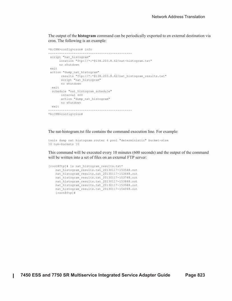
Network Address Translation
7450 ESS and 7750 SR Multiservice Integrated Service Adapter Guide Page 823
The output of the histogram command can be periodically exported to en external destination via
cron. The following is an example:
*A:CPM>config>cron# info
----------------------------------------------
script "nat_histogram"
location "ftp://*:*@138.203.8.62/nat-histogram.txt"
no shutdown
exit
action "dump_nat_histogram"
results "ftp://*:*@138.203.8.62/nat_histogram_results.txt"
script "nat_histogram"
no shutdown
exit
schedule "nat_histogram_schedule"
interval 600
action "dump_nat_histogram"
no shutdown
exit
----------------------------------------------
*A:CPM>config>cron#
The nat-histogram.txt file contains the command execution line. For example:
tools dump nat histogram router 4 pool "deterministic" bucket-size
10 num-buckets 10
This command will be executed every 10 minutes (600 seconds) and the output of the command
will be written into a set of files on an external FTP server:
[root@ftp]# ls nat_histogram_results.txt*
nat_histogram_results.txt_20130117-153548.out
nat_histogram_results.txt_20130117-153648.out
nat_histogram_results.txt_20130117-153748.out
nat_histogram_results.txt_20130117-153848.out
nat_histogram_results.txt_20130117-153948.out
nat_histogram_results.txt_20130117-154048.out
[root@ftp]#
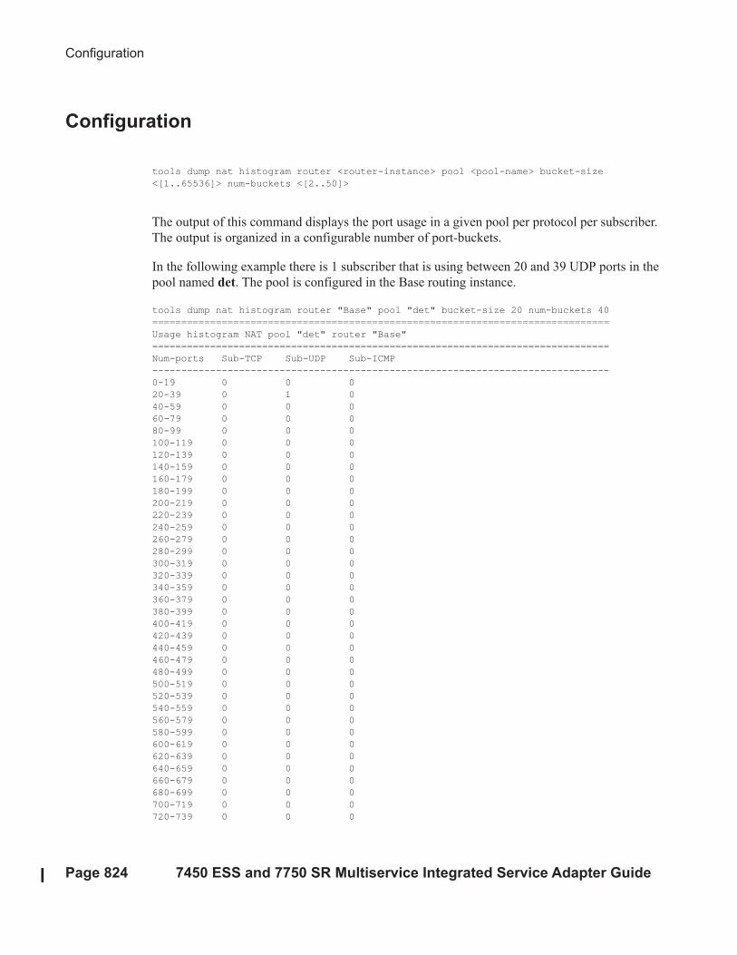
Configuration
Page 824 7450 ESS and 7750 SR Multiservice Integrated Service Adapter Guide
Configuration
tools dump nat histogram router <router-instance> pool <pool-name> bucket-size
<[1..65536]> num-buckets <[2..50]>
The output of this command displays the port usage in a given pool per protocol per subscriber.
The output is organized in a configurable number of port-buckets.
In the following example there is 1 subscriber that is using between 20 and 39 UDP ports in the
pool named det. The pool is configured in the Base routing instance.
tools dump nat histogram router "Base" pool "det" bucket-size 20 num-buckets 40
===============================================================================
Usage histogram NAT pool "det" router "Base"
===============================================================================
Num-ports Sub-TCP Sub-UDP Sub-ICMP
-------------------------------------------------------------------------------
0-19 0 0 0
20-39 0 1 0
40-59 0 0 0
60-79 0 0 0
80-99 0 0 0
100-119 0 0 0
120-139 0 0 0
140-159 0 0 0
160-179 0 0 0
180-199 0 0 0
200-219 0 0 0
220-239 0 0 0
240-259 0 0 0
260-279 0 0 0
280-299 0 0 0
300-319 0 0 0
320-339 0 0 0
340-359 0 0 0
360-379 0 0 0
380-399 0 0 0
400-419 0 0 0
420-439 0 0 0
440-459 0 0 0
460-479 0 0 0
480-499 0 0 0
500-519 0 0 0
520-539 0 0 0
540-559 0 0 0
560-579 0 0 0
580-599 0 0 0
600-619 0 0 0
620-639 0 0 0
640-659 0 0 0
660-679 0 0 0
680-699 0 0 0
700-719 0 0 0
720-739 0 0 0

Network Address Translation
7450 ESS and 7750 SR Multiservice Integrated Service Adapter Guide Page 825
740-759 0 0 0
760-779 0 0 0
780- 0 0 0
-------------------------------------------------------------------------------
No. of entries: 40
===============================================================================
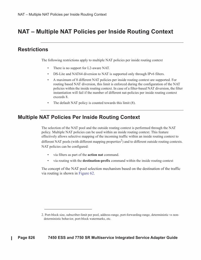
NAT – Multiple NAT Policies per Inside Routing Context
Page 826 7450 ESS and 7750 SR Multiservice Integrated Service Adapter Guide
NAT – Multiple NAT Policies per Inside Routing Context
Restrictions
The following restrictions apply to multiple NAT policies per inside routing context
• There is no support for L2-aware NAT.
• DS-Lite and NAT64 diversion to NAT is supported only through IPv6 filters.
• A maximum of 8 different NAT policies per inside routing context are supported. For
routing based NAT diversion, this limit is enforced during the configuration of the NAT
policies within the inside routing context. In case of a filter-based NAT diversion, the filter
instantiation will fail if the number of different nat-policies per inside routing context
exceeds 8.
• The default NAT policy is counted towards this limit (8).
Multiple NAT Policies Per Inside Routing Context
The selection of the NAT pool and the outside routing context is performed through the NAT
policy. Multiple NAT policies can be used within an inside routing context. This feature
effectively allows selective mapping of the incoming traffic within an inside routing context to
different NAT pools (with different mapping properties2) and to different outside routing contexts.
NAT policies can be configured:
• via filters as part of the action nat command.
• via routing with the destination-prefix command within the inside routing context
The concept of the NAT pool selection mechanism based on the destination of the traffic
via routing is shown in Figure 62.
2. Port-block size, subscriber-limit per pool, address-range, port-forwarding-range, deterministic vs non-
deterministic behavior, port-block watermarks, etc.

Network Address Translation
7450 ESS and 7750 SR Multiservice Integrated Service Adapter Guide Page 827
Figure 62: Pool Selection Based on Traffic Destination
Diversion of the traffic to NAT based on the source of the traffic is shown in Figure 63.
Only filter-based diversion solution is supported for this case. The filter-based solution can be
extended to a 5 tuple matching criteria.
Figure 63: NAT Pool Selection Based on the Inside Source IP Address
al_0401
7x50 NAT
NAT InsideVRF1 (or GRT)
NAT InsideVRF1 (or GRT)
Pool A’ Subscriber 1
Source IP = A’
Dest A -> pool A`, VRF 1
Dest B -> pool B`, VRF 1Subscriber 1
Source IP = B’
1
Pool B’
Subscriber 1Source IP = X
Dest B
Dest A
7x50 NAT
NAT InsideVRF1 (or GRT)
NAT OutsideVRF1 (or GRT)
NAT OutsideVRF2 (or GRT)
Pool A’ Subscriber 1
Source IP = A’
Dest A -> pool A`, VRF 1
Dest B -> pool B`, VRF 2Subscriber 1Source IP = B’
2
Pool B’
Subscriber 1Source IP = X
Dest B
Dest A
Network A
Network B
Network A
Network B
al_0402
7x50 NAT
NAT InsideVRF1 (or GRT)
NAT OutsideVRF1 (or GRT)
Pool A’ Subscriber 1
Source IP = A’
Dest X -> pool A`, VRF 1
Dest Y -> pool B`, VRF 1Subscriber 1Source IP = B’
3
Pool B’Subscriber 2Source IP = Y
Subscriber 1Source IP = X
7x50 NAT
NAT InsideVRF1 (or GRT)
NAT OutsideVRF1 (or GRT)
Pool A’
Dest X -> pool A`, VRF 1
Dest Y -> pool B`, VRF 1
Subscriber 1Source IP = B’
Subscriber 1Source IP = A’
Pool B’Subscriber 2Source IP = Y
Subscriber 1Source IP = X
4
Network A
Network B
Network A
Network B
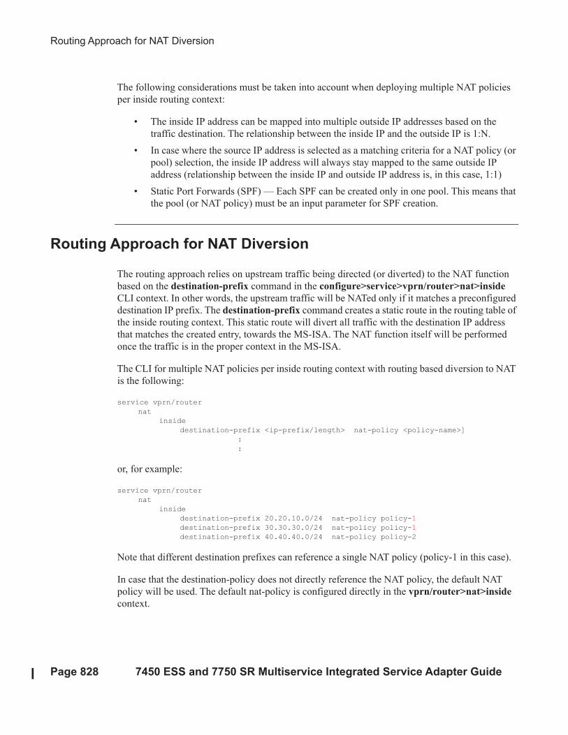
Routing Approach for NAT Diversion
Page 828 7450 ESS and 7750 SR Multiservice Integrated Service Adapter Guide
The following considerations must be taken into account when deploying multiple NAT policies
per inside routing context:
• The inside IP address can be mapped into multiple outside IP addresses based on the
traffic destination. The relationship between the inside IP and the outside IP is 1:N.
• In case where the source IP address is selected as a matching criteria for a NAT policy (or
pool) selection, the inside IP address will always stay mapped to the same outside IP
address (relationship between the inside IP and outside IP address is, in this case, 1:1)
• Static Port Forwards (SPF) — Each SPF can be created only in one pool. This means that
the pool (or NAT policy) must be an input parameter for SPF creation.
Routing Approach for NAT Diversion
The routing approach relies on upstream traffic being directed (or diverted) to the NAT function
based on the destination-prefix command in the configure>service>vprn/router>nat>inside
CLI context. In other words, the upstream traffic will be NATed only if it matches a preconfigured
destination IP prefix. The destination-prefix command creates a static route in the routing table of
the inside routing context. This static route will divert all traffic with the destination IP address
that matches the created entry, towards the MS-ISA. The NAT function itself will be performed
once the traffic is in the proper context in the MS-ISA.
The CLI for multiple NAT policies per inside routing context with routing based diversion to NAT
is the following:
service vprn/router
nat
inside
destination-prefix <ip-prefix/length> nat-policy <policy-name>]
:
:
or, for example:
service vprn/router
nat
inside
destination-prefix 20.20.10.0/24 nat-policy policy-1
destination-prefix 30.30.30.0/24 nat-policy policy-1
destination-prefix 40.40.40.0/24 nat-policy policy-2
Note that different destination prefixes can reference a single NAT policy (policy-1 in this case).
In case that the destination-policy does not directly reference the NAT policy, the default NAT
policy will be used. The default nat-policy is configured directly in the vprn/router>nat>inside
context.
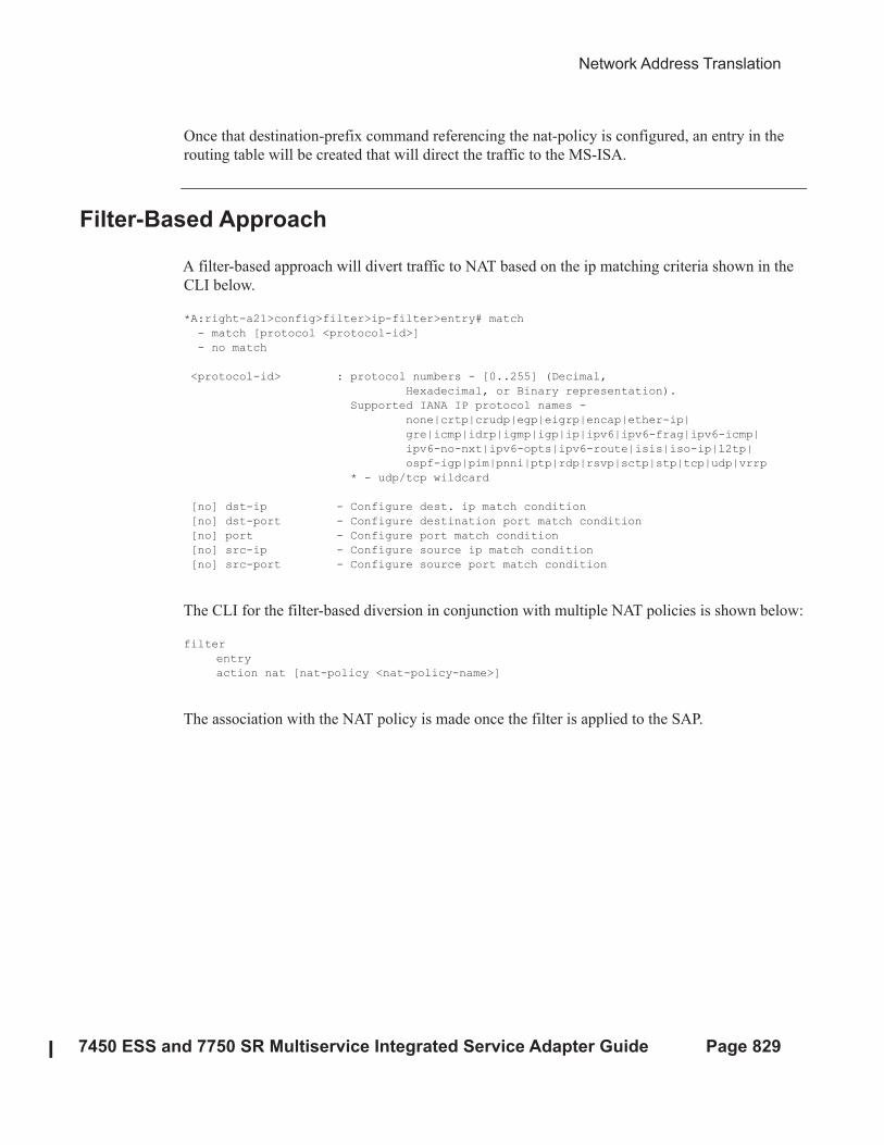
Network Address Translation
7450 ESS and 7750 SR Multiservice Integrated Service Adapter Guide Page 829
Once that destination-prefix command referencing the nat-policy is configured, an entry in the
routing table will be created that will direct the traffic to the MS-ISA.
Filter-Based Approach
A filter-based approach will divert traffic to NAT based on the ip matching criteria shown in the
CLI below.
*A:right-a21>config>filter>ip-filter>entry# match
- match [protocol <protocol-id>]
- no match
<protocol-id> : protocol numbers - [0..255] (Decimal,
Hexadecimal, or Binary representation).
Supported IANA IP protocol names -
none|crtp|crudp|egp|eigrp|encap|ether-ip|
gre|icmp|idrp|igmp|igp|ip|ipv6|ipv6-frag|ipv6-icmp|
ipv6-no-nxt|ipv6-opts|ipv6-route|isis|iso-ip|l2tp|
ospf-igp|pim|pnni|ptp|rdp|rsvp|sctp|stp|tcp|udp|vrrp
* - udp/tcp wildcard
[no] dst-ip - Configure dest. ip match condition
[no] dst-port - Configure destination port match condition
[no] port - Configure port match condition
[no] src-ip - Configure source ip match condition
[no] src-port - Configure source port match condition
The CLI for the filter-based diversion in conjunction with multiple NAT policies is shown below:
filter
entry
action nat [nat-policy <nat-policy-name>]
The association with the NAT policy is made once the filter is applied to the SAP.
Multiple NAT Policies with DS-Lite and NAT64
Page 830 7450 ESS and 7750 SR Multiservice Integrated Service Adapter Guide
Multiple NAT Policies with DS-Lite and NAT64
DS-Lite and NAT64 diversion to NAT with multiple nat-policies is supported only through IPv6
filters:
configure
filter
ipv6-filter
entry <entry-id> [time-range <time-range-name>] [create]
action nat nat-type <nat-type> [nat-policy <nat-policy-name>]
exit
exit
exit
exit
Where the nat-type parameter can be either dslite or nat64.
The DS-Lite AFTR address and NAT64 destination prefix configuration under the corresponding
(DS-Lite or NAT64) router/vprn>nat>inside context is mandatory. Note that this is even in the
case when only filters are desired for traffic diversion to NAT.
For example, every AFTR address and NAT64 prefix that is configured as a match criteria in the
filter, must also be duplicated in the router/vprn>nat>inside context. However, the opposite is
not required.
IPv6 traffic with the destination address outside of the AFTR/NAT64 address/prefix will follow
normal IPv6 routing path within the 7750 SR.
Default NAT Policy
The default nat-policy is always mandatory and must be configured under the router/
vprn>nat>inside context. This default NAT policy can reference any configured pool in the
desired ISA group. The pool referenced in the default nat-policy can be then overridden by the
nat-policy associated with the destination-prefix in LSN44 or by the nat-policy referenced in the
ipv4/ipv6-filter used for NAT diversion in LSN44/DS-Lite/NAT64.
The NAT CLI nodes will fail to activate (be brought out of the no shutdown state), unless a valid
nat-policy is referenced in the router/vprn>nat>inside context.
Network Address Translation
7450 ESS and 7750 SR Multiservice Integrated Service Adapter Guide Page 831
Scaling Considerations
Each subscriber using multiple policies is counted as 1 subscriber for the inside resources scaling
limits (such as the number of subscribers per MS-ISA), and counted as 1 subscriber per
(subscriber + policy combination) for the outside limits (subscriber-limit!subscribers per IP;
port-reservation ! port/block reservations per subscriber).
Multiple NAT Policies and SPF Configuration Considerations
Any given Static Port Forward (SPF) can be created only in one pool. This pool, which is
referenced through the nat-policy, has to be specified at the SPF creation time, either explicitly
through the configuration request or implicitly via defaults.
Explicit request will be submitted either via SAM or via CLI:
tools perform nat port-forwarding-action lsn
- lsn create router <router-instance> [b4 <ipv6-address>] [aftr <ipv6-address>] ip <ip-
address> protocol {tcp|udp} [port <port>] lifetime <lifetime> [outside-ip <ipv4-
address>] [outside-port <port>] [nat-policy <policy-name>]
In the absence of the nat-policy referenced in the SPF creation request, the default nat-policy under the vprn/router>nat>inside context will be used.
The consequence of this is that the operator must know the nat-policy in which the SPF is to be
created. The SPF cannot be created via PCP outside of the pool referenced by the default nat-
policy, since PCP does not provide means to communicate nat-policy name in the SPF creation
request.
The static port forward creation and their use by the subscriber types must follow these rules:
• Default nat-policy — Any subscriber type can use an SPF created in the pool referenced
by the default nat-policy
• Deterministic LSN44 nat-policy — Only deterministic LSN44 subscribers matching the
configured prefix can use the SPF created in the pool referenced by the deterministic
LSN44 prefix nat-policy
• Deterministic DS-Lite nat-policy — Only deterministic DS-Lite subscribers matching the
configured prefix can use the SPF created in the pool referenced by the deterministic DS-
Lite prefix nat-policy
• LSN44 filter based nat-policy — Only LSN44 subscribers matching the configured filter
entry can use the SPF created in the pool referenced by the non-deterministic LSN44 nat-
policy within the filter
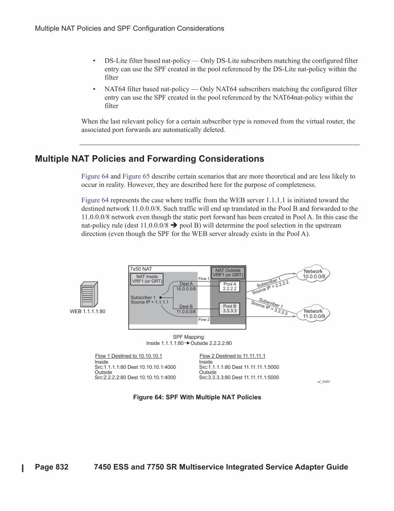
Multiple NAT Policies and SPF Configuration Considerations
Page 832 7450 ESS and 7750 SR Multiservice Integrated Service Adapter Guide
• DS-Lite filter based nat-policy — Only DS-Lite subscribers matching the configured filter
entry can use the SPF created in the pool referenced by the DS-Lite nat-policy within the
filter
• NAT64 filter based nat-policy — Only NAT64 subscribers matching the configured filter
entry can use the SPF created in the pool referenced by the NAT64nat-policy within the
filter
When the last relevant policy for a certain subscriber type is removed from the virtual router, the
associated port forwards are automatically deleted.
Multiple NAT Policies and Forwarding Considerations
Figure 64 and Figure 65 describe certain scenarios that are more theoretical and are less likely to
occur in reality. However, they are described here for the purpose of completeness.
Figure 64 represents the case where traffic from the WEB server 1.1.1.1 is initiated toward the
destined network 11.0.0.0/8. Such traffic will end up translated in the Pool B and forwarded to the
11.0.0.0/8 network even though the static port forward has been created in Pool A. In this case the
nat-policy rule (dest 11.0.0.0/8 ! pool B) will determine the pool selection in the upstream
direction (even though the SPF for the WEB server already exists in the Pool A).
Figure 64: SPF With Multiple NAT Policies
al_0403
7x50 NAT
NAT InsideVRF1 (or GRT)
NAT OutsideVRF1 (or GRT)
Pool A2.2.2.2
Flow 1
Flow 2
Dest A10.0.0.0/8
Dest B11.0.0.0/8
Pool B3.3.3.3
Subscriber 1
Source IP = 2.2.2.2
Subscriber 1Source IP = 3.3.3.3
Subscriber 1Source IP = 1.1.1.1
WEB 1.1.1.1:80
SPF Mapping:
Inside 1.1.1.1:80 Outside 2.2.2.2:80
Flow 1 Destined to 10.10.10.1InsideSrc:1.1.1.1:80 Dest 10.10.10.1:4000OutsideSrc:2.2.2.2:80 Dest 10.10.10.1:4000
Flow 2 Destined to 11.11.11.1InsideSrc:1.1.1.1:80 Dest 11.11.11.1:5000OutsideSrc:3.3.3.3:80 Dest 11.11.11.1:5000
Network10.0.0.0/8
Network11.0.0.0/8
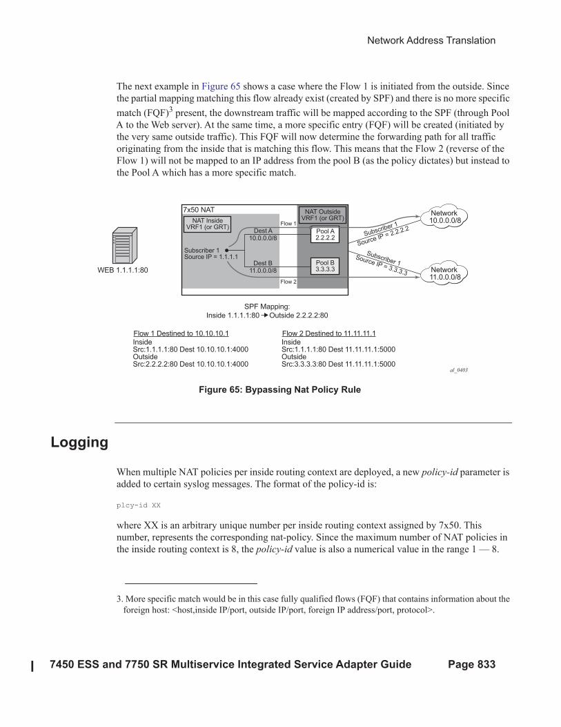
Network Address Translation
7450 ESS and 7750 SR Multiservice Integrated Service Adapter Guide Page 833
The next example in Figure 65 shows a case where the Flow 1 is initiated from the outside. Since
the partial mapping matching this flow already exist (created by SPF) and there is no more specific
match (FQF)3 present, the downstream traffic will be mapped according to the SPF (through Pool
A to the Web server). At the same time, a more specific entry (FQF) will be created (initiated by
the very same outside traffic). This FQF will now determine the forwarding path for all traffic
originating from the inside that is matching this flow. This means that the Flow 2 (reverse of the
Flow 1) will not be mapped to an IP address from the pool B (as the policy dictates) but instead to
the Pool A which has a more specific match.
Figure 65: Bypassing Nat Policy Rule
Logging
When multiple NAT policies per inside routing context are deployed, a new policy-id parameter is
added to certain syslog messages. The format of the policy-id is:
plcy-id XX
where XX is an arbitrary unique number per inside routing context assigned by 7x50. This
number, represents the corresponding nat-policy. Since the maximum number of NAT policies in
the inside routing context is 8, the policy-id value is also a numerical value in the range 1 — 8.
3. More specific match would be in this case fully qualified flows (FQF) that contains information about the
foreign host: <host,inside IP/port, outside IP/port, foreign IP address/port, protocol>.
al_0403
7x50 NAT
NAT InsideVRF1 (or GRT)
NAT OutsideVRF1 (or GRT)
Pool A2.2.2.2
Flow 1
Flow 2
Dest A10.0.0.0/8
Dest B11.0.0.0/8
Pool B3.3.3.3
Subscriber 1
Source IP = 2.2.2.2
Subscriber 1Source IP = 3.3.3.3
Subscriber 1Source IP = 1.1.1.1
WEB 1.1.1.1:80
SPF Mapping:
Inside 1.1.1.1:80 Outside 2.2.2.2:80
Flow 1 Destined to 10.10.10.1InsideSrc:1.1.1.1:80 Dest 10.10.10.1:4000OutsideSrc:2.2.2.2:80 Dest 10.10.10.1:4000
Flow 2 Destined to 11.11.11.1InsideSrc:1.1.1.1:80 Dest 11.11.11.1:5000OutsideSrc:3.3.3.3:80 Dest 11.11.11.1:5000
Network10.0.0.0/8
Network11.0.0.0/8
Logging
Page 834 7450 ESS and 7750 SR Multiservice Integrated Service Adapter Guide
Introduction of the policy-id in logs is necessary due to the bulk-operations associated with
multiple NAT policies per inside routing context. A bulk operation, for example, represents the
removal of the nat-policy from the configuration, shutting down the NAT pool, or removing an IP
address range from the pool. Note that removing a NAT accounting policy in case of RADIUS
NAT logging will not trigger a summarization log since an acct-off message is sent. Such
operations have a tendency to be heavy on NAT logging since they affect a large number of NAT
subscribers at once. Summarization logs are introduced to prevent excessive logging during bulk
operations. For example, the nat-policy deletion can be logged with a single (summarized) entry
containing the policy-id of the nat-policy that was removed and the inside srvc-id. Since all logs
contain the policy-id, a single summarization free4 log can be compared to all map2 logs
containing the same policy-id to determine for which subscribers the NAT mappings have ceased.
Summarization log is always generated on the CPM, regardless of whether the RADIUS logging is
enabled or not. A summarization log simply cannot be generated via RADIUS logging since the
RADIUS accounting message streams (start/interim-updates/stop) are always generated per
subscriber. In other words, for RADIUS logging, the summarization log would need to be sent to
each subscriber, which defeats the purpose of the summarization logs.
A summarization log on the CPM is generated:
• When the nat-policy is removed — With a single nat-policy per inside routing context, a
summarization log is generated with only one field: inside srvc-id (vprn or base). This is
sufficient since there is only one nat-policy per inside routing context. To determine
subscribers for which NAT mappings are terminated, the operator should search all most
recent map logs matching the service-id from the summarization log.
With multiple NAT policies per inside routing context, the inside srvc-id and the policy-id
are included in the summarization log (no outside IPs, outside srvc-id, port-block or
source IP).
A log search based on the policy-id and inside srvc-id should reveal all subscribers whose
mappings were affected by the nat-policy removal.
• When the pool is shutdown — The 7x50 will send a summarization log that includes the
outside srvc-id and all IP address ranges configured in the pool. No other parameters are
included in the summarization log.
A log search based on the outside IP address and outside srvc-id should reveal all
subscribers for which the NAT mappings have ceased.
• When an IP address-range is removed from the pool. The 7x50 will send a summarization
log that includes the outside srvc-id and the IP address range that has been removed. No
other parameters are included in the summarization log.
A log search based on the outside IP addresses in the range and the outside srvc id should
reveal all subscribers for which the NAT mappings have ceased.
4. Map and Free logs are generated when the port-block for the subscribers are allocated and de-allocated.
Network Address Translation
7450 ESS and 7750 SR Multiservice Integrated Service Adapter Guide Page 835
• When the last AFTR address is removed.
• When DS-Lite/NAT64 node is shutdown.
• When deterministic NAT prefixes are created or removed.
Summarization logs in RADIUS logging
The summarization log for bulk operation while RADIUS logging is in effect will be generated
only in the CPM (syslog). This means that for bulk operations with RADIUS logging, the operator
will have to rely on RADIUS logging as well as on the CPM logging.
An open log sequence in RADIUS, for example a map for the <inside IP 1, outside IP 1,port-block
1> followed at some later time with a map for <inside IP 2, outside IP 1, port-block 1>, is an
indication that the free log for <inside IP 1, outside IP 1,port-block 1> is missing. This means that
either the free log for <inside IP 1, outside IP 1,port-block 1> was lost or that a policy/pool/
address-range was removed from the configuration. In the latter case, the operator should look in
the CPM log for the summarization message.
The summarization logs are enabled via the event control 2021 tmnxNatLsnSubBlksFree which is
by default suppressed. The even control 2021 is also used to report when all blocks for the
subscriber are freed.
ISA Feature Interactions
Page 836 7450 ESS and 7750 SR Multiservice Integrated Service Adapter Guide
ISA Feature Interactions
This section describes the interaction between MS-ISA applications and other system features.
MS-ISA Use with Service Mirrors
All MS-ISA uses include support for service mirroring running with no feature interactions or
impacts. For example, any service diverted to AA, IPsec, NAT, LNS, or supported combinations
of MS-ISA application also supports service mirroring simultaneously.
LNS, Application Assurance and NAT
Multiple uses of MS-ISAs can be combined at one time by daisy-chaining use of the MS-ISAs.
Services and subscribers terminated on the LNS ISA are full supported by Application Assurance
per AA subscriber and service capabilities, and by the full NAT capabilities.
When Application Assurance and NAT are used in combination (for both ESM and SAP service
contexts):
• AA is always on subscriber of NAT to be able to see the original (inside) subscriber IP
tuple (IP + port numbers).
• AA subscriber ID includes the VRF context from the service, so shared or private
subscriber IP as seen in Layer-2 Aware NAT is compatible with AA subscriber contexts.
Network Address Translation
7450 ESS and 7750 SR Multiservice Integrated Service Adapter Guide Page 837
Subscriber Aware Large Scale NAT44
Subscriber aware Large Scale NAT44 attempts to combine the positive attributes of Large Scale
NAT44 and L2-Aware NAT, namely:
• The ability for some traffic to bypass the NAT function, such as IPTV traffic and VoIP
traffic whenever a unique IP address per subscriber is used (ie, not L2-aware NAT where
all subs share the same IP). This can be achieved using existing Large Scale NAT44
mechanisms (ingress IP-filters)
• The use of RADIUS Acct for logging of port-ranges, including multiple port-range
blocks.
• The use of subscriber-identification/RADIUS user-name to identify the customer to
simplify management of Large Scale NAT44 subscribers.
Subscriber awareness in Large Scale NAT44 will facilitate release of NAT resources immediately
after the BNG subscriber is terminated, without having to wait for the last flow of the subscriber to
expire on its own (TCP timeout is 4hours by default).
The subscriber aware Large Scale NAT44 function leverages RADIUS accounting proxy built-in
to the 7750SR. The RADIUS accounting proxy allows the 7750SR to inform Large Scale NAT44
application about individual BNG subscribers from the RADIUS accounting messages generated
by a remote BNG and use this information in the management of Large Scale NAT44 subscribers.
The combination of the two allows, for example, the 7750SR running as a Large Scale NAT44 to
make the correlation between the BNG subscriber (represented in the Large Scale NAT44 by the
Inside IP Address) and RADIUS attributes such as User-Name, Alc-Sub-Ident-String, Calling-
Station-Id or Class. These attributes can subsequently be used for either management of the Large
Scale NAT44 subscriber, or in the NAT RADIUS Accounting messages generated by the 7750SR
Large Scale NAT44 application. Doing so will simplify both the administration of the Large Scale
NAT44 and the logging function for port-range blocks.
As BNG subscribers authenticate and come online, the RADIUS accounting messages are
‘snooped’ via RADIUS accounting proxy which creates a cache of attributes from the BNG
subscriber. BNG subscribers are correlated with the NAT subscriber via framed-ip address, and
one of the following attributes that must be present in the accounting messages generated by BNG:
• User-name
• Subscriber id
• RADIUS Class attribute
• Calling-Station-id
• IMSI
• IMEI
Subscriber Aware Large Scale NAT44
Page 838 7450 ESS and 7750 SR Multiservice Integrated Service Adapter Guide
Framed-ip address must also be present in the accounting messages generated by BNG.
Large Scale NAT44 Subscriber Aware application will receive a number of cached attributes
which will then be used for appropriate management of Large Scale NAT44 subscribers, for
example:
• Delete the Large Scale NAT44 subscriber when the BNG subscriber is terminated
• Report attributes in Large Scale NAT44 accounting messages according to configuration
options
Creation and removal of RADIUS accounting proxy cache entries related to BNG subscriber is
triggered by the receipt of accounting start/stop messages sourced by the BNG subscriber.
Modification of entries can be triggered by interim-update messages carrying updated attributes.
Cached entries can also be purged via CLI.
In addition to passing one of the above attributes in Large Scale NAT44 RADIUS accounting
messages, a set of opaque BNG subscriber RADIUS attributes can optionally be passed in Large
Scale NAT44 RADIUS accounting messages. Up to 128B of such opaque attributes will be
accepted. The remaining attributes will be truncated.
Large Scale NAT44 subscriber instantiation can optionally be denied in case that corresponding
BNG subscriber cannot be identified in Large Scale NAT44 via RADIUS accounting proxy.
Configuration guidelines:
1. Configure RADIUS accounting proxy functionality in a routing instance that will receive ac-
counting messages from the remote or local BNG. Optionally forward received accounting
message received by RADIUS accounting proxy to the final accounting destination (accounting
server).
2. Point the BNG RADIUS accounting destination to the RADIUS accounting proxy – this way
RADIUS accounting proxy will receive and ‘snoop’ BNG RADIUS accounting data.
BNG subscriber can be associated with two accounting policies, therefore pointing to two
different accounting destinations. For example, one to the RADIUS accounting proxy, the
other one to the real accounting server.
3. Configure subscriber aware Large Scale NAT44. From Large Scale NAT44 Subscriber Aware
application reference the RADIUS Proxy accounting server and define the string that will be
used to correlate BNG subscriber with the Large Scale NAT44 subscriber.
4. Optionally enable NAT RADIUS accounting that will include BNG subscriber relevant data.
Network Address Translation
7450 ESS and 7750 SR Multiservice Integrated Service Adapter Guide Page 839
(1) *A:left-a20>config>service>vprn#
radius-proxy
server "proxy-acct" purpose accounting create
default-accounting-server-policy "lsn-policy"
description "two side server -interface:client ; default-plcy:real
server"
interface "rad-proxy-loopback"
secret "TEg1UEZzemRMyZXD1HvvQGkeGfoQ58MF" hash2
no shutdown
exit
exit
RADIUS accounting proxy will listen to accounting messages on interface ‘rad-proxy-loopback’.
The name ‘proxy-acct’ as defined by the server command will be used to reference this proxy
accounting server from Large Scale NAT44.
Received accounting messages can be relayed further from RADIUS accounting proxy to the
accounting server which can be indirectly referenced in the default-accounting-policy ‘lsn-policy’.
The lsn-policy is defined as:
*A:left-a20>config>aaa#
radius-server-policy "lsn-policy" create
servers
router "Base"
source-address 114.0.1.12
server 1 name "114"
exit
exit
This lsn-policy can then reference an external RADIUS accounting server with its own security
credentials. This external accounting server can be configured in any routing instance.
*A:left-a20>config>router>radius-server# info
----------------------------------------------
server "114" address 114.0.1.10 secret "KRr7H.K3i0z9O/hj2BUSmdJUdl.zWrkE" hash2
port 1813 create
description "real radius or acct server"
exit
(2) Two RADIUS accounting policies can be configured in BNG – one to the real radius server, the
other one to the RADIUS accounting proxy.
*A:left-a20>config>subscr-mgmt>sub-prof# info
----------------------------------------------
radius-accounting-policy "real-acct-srvr" duplicate “lsn”
egress
agg-rate-limit 10000
exit
----------------------------------------------
*A:left-a20>config>subscr-mgmt>acct-plcy# info
----------------------------------------------
description “lsn radius-acct-policy”
Subscriber Aware Large Scale NAT44
Page 840 7450 ESS and 7750 SR Multiservice Integrated Service Adapter Guide
update-interval 5
include-radius-attribute
acct-authentic
acct-delay-time
called-station-id
calling-station-id remote-id
circuit-id
framed-interface-id
framed-ip-addr
framed-ip-netmask
mac-address
nas-identifier
nas-port-id
nas-port-type
nat-port-range
remote-id
sla-profile
sub-profile
subscriber-id
user-name
alc-acct-triggered-reason
exit
session-id-format number
radius-accounting-server
router 10 (service id where proxy radius is configured)
server 1 address 5.5.5.5 secret "cVi1sidvgH28Pd9QoN1flE" hash2
(radius proxy IP address is 5.5.5.5 on interface “rad-proxy-loopback”; the ‘secret’ is
the same as configured on RADIUS accounting proxy)
exit
(3) Sub-aware Large Scale NAT44 references the RADIUS accounting proxy server ‘proxy-acct’ and
defines the calling-station-id attribute from the BNG subscriber as the matching attribute:
*A:left-a20>config>service>vprn>nat>inside# info
----------------------------------------------
nat-policy "nat-base"
destination-prefix 10.0.0.0/16
subscriber-identification
attribute vendor "standard" attribute-type "station-id"
description "sub-aware CGN"
radius-proxy-server router 10 name "proxy-acct"
no shutdown
exit
----------------------------------------------
(4) Optionally RADIUS NAT accounting can be enabled:
*A:left-a20>config>isa>nat-group# info
----------------------------------------------
active-mda-limit 1
radius-accounting-policy "nat-acct-basic"
mda 1/2
no shutdown
*A:left-a20>config>aaa>nat-acct-plcy# info detail
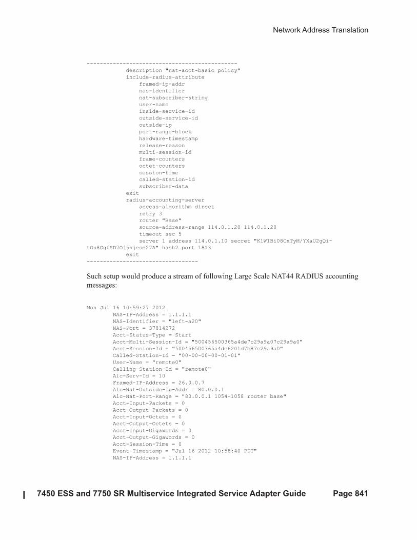
Network Address Translation
7450 ESS and 7750 SR Multiservice Integrated Service Adapter Guide Page 841
----------------------------------------------
description "nat-acct-basic policy"
include-radius-attribute
framed-ip-addr
nas-identifier
nat-subscriber-string
user-name
inside-service-id
outside-service-id
outside-ip
port-range-block
hardware-timestamp
release-reason
multi-session-id
frame-counters
octet-counters
session-time
called-station-id
subscriber-data
exit
radius-accounting-server
access-algorithm direct
retry 3
router "Base"
source-address-range 114.0.1.20 114.0.1.20
timeout sec 5
server 1 address 114.0.1.10 secret "KlWIBi08CxTyM/YXaU2gQi-
tOu8GgfSD7Oj5hjese27A" hash2 port 1813
exit
----------------------------------
Such setup would produce a stream of following Large Scale NAT44 RADIUS accounting
messages:
Mon Jul 16 10:59:27 2012
NAS-IP-Address = 1.1.1.1
NAS-Identifier = "left-a20"
NAS-Port = 37814272
Acct-Status-Type = Start
Acct-Multi-Session-Id = "500456500365a4de7c29a9a07c29a9a0"
Acct-Session-Id = "500456500365a4de6201d7b87c29a9a0"
Called-Station-Id = "00-00-00-00-01-01"
User-Name = "remote0"
Calling-Station-Id = "remote0"
Alc-Serv-Id = 10
Framed-IP-Address = 26.0.0.7
Alc-Nat-Outside-Ip-Addr = 80.0.0.1
Alc-Nat-Port-Range = "80.0.0.1 1054-1058 router base"
Acct-Input-Packets = 0
Acct-Output-Packets = 0
Acct-Input-Octets = 0
Acct-Output-Octets = 0
Acct-Input-Gigawords = 0
Acct-Output-Gigawords = 0
Acct-Session-Time = 0
Event-Timestamp = "Jul 16 2012 10:58:40 PDT"
NAS-IP-Address = 1.1.1.1
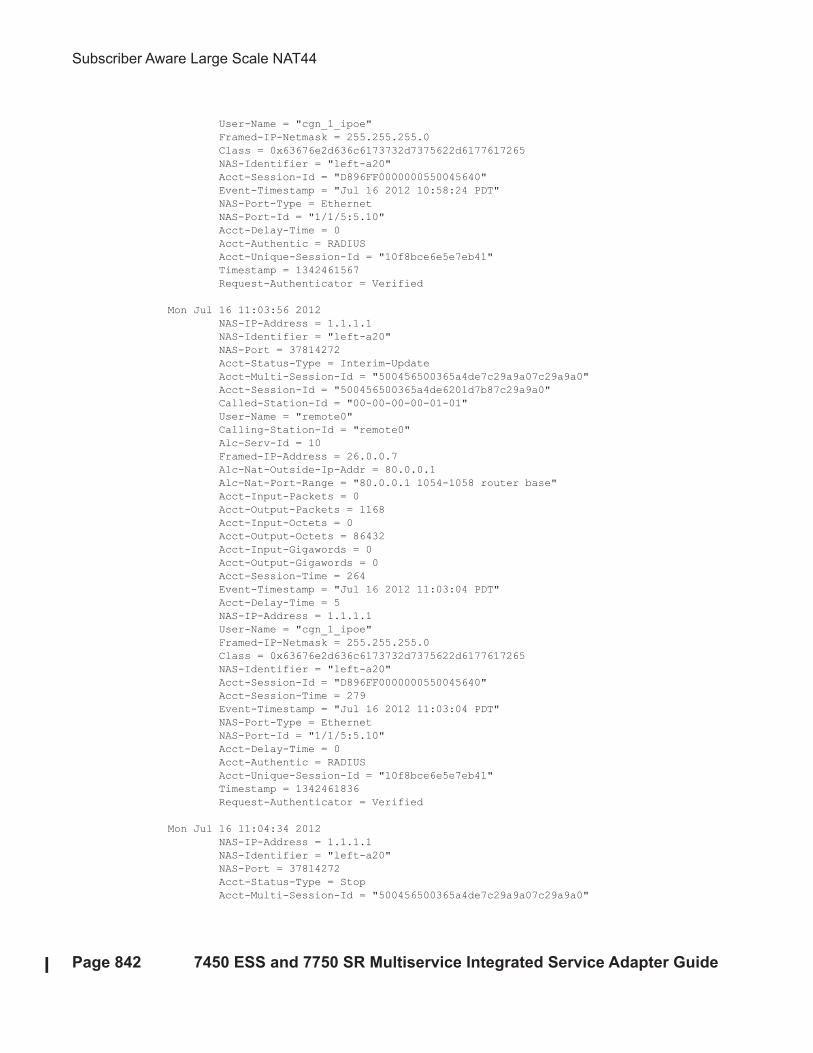
Subscriber Aware Large Scale NAT44
Page 842 7450 ESS and 7750 SR Multiservice Integrated Service Adapter Guide
User-Name = "cgn_1_ipoe"
Framed-IP-Netmask = 255.255.255.0
Class = 0x63676e2d636c6173732d7375622d6177617265
NAS-Identifier = "left-a20"
Acct-Session-Id = "D896FF0000000550045640"
Event-Timestamp = "Jul 16 2012 10:58:24 PDT"
NAS-Port-Type = Ethernet
NAS-Port-Id = "1/1/5:5.10"
Acct-Delay-Time = 0
Acct-Authentic = RADIUS
Acct-Unique-Session-Id = "10f8bce6e5e7eb41"
Timestamp = 1342461567
Request-Authenticator = Verified
Mon Jul 16 11:03:56 2012
NAS-IP-Address = 1.1.1.1
NAS-Identifier = "left-a20"
NAS-Port = 37814272
Acct-Status-Type = Interim-Update
Acct-Multi-Session-Id = "500456500365a4de7c29a9a07c29a9a0"
Acct-Session-Id = "500456500365a4de6201d7b87c29a9a0"
Called-Station-Id = "00-00-00-00-01-01"
User-Name = "remote0"
Calling-Station-Id = "remote0"
Alc-Serv-Id = 10
Framed-IP-Address = 26.0.0.7
Alc-Nat-Outside-Ip-Addr = 80.0.0.1
Alc-Nat-Port-Range = "80.0.0.1 1054-1058 router base"
Acct-Input-Packets = 0
Acct-Output-Packets = 1168
Acct-Input-Octets = 0
Acct-Output-Octets = 86432
Acct-Input-Gigawords = 0
Acct-Output-Gigawords = 0
Acct-Session-Time = 264
Event-Timestamp = "Jul 16 2012 11:03:04 PDT"
Acct-Delay-Time = 5
NAS-IP-Address = 1.1.1.1
User-Name = "cgn_1_ipoe"
Framed-IP-Netmask = 255.255.255.0
Class = 0x63676e2d636c6173732d7375622d6177617265
NAS-Identifier = "left-a20"
Acct-Session-Id = "D896FF0000000550045640"
Acct-Session-Time = 279
Event-Timestamp = "Jul 16 2012 11:03:04 PDT"
NAS-Port-Type = Ethernet
NAS-Port-Id = "1/1/5:5.10"
Acct-Delay-Time = 0
Acct-Authentic = RADIUS
Acct-Unique-Session-Id = "10f8bce6e5e7eb41"
Timestamp = 1342461836
Request-Authenticator = Verified
Mon Jul 16 11:04:34 2012
NAS-IP-Address = 1.1.1.1
NAS-Identifier = "left-a20"
NAS-Port = 37814272
Acct-Status-Type = Stop
Acct-Multi-Session-Id = "500456500365a4de7c29a9a07c29a9a0"
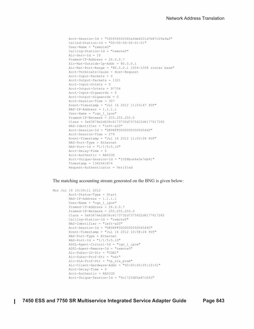
Network Address Translation
7450 ESS and 7750 SR Multiservice Integrated Service Adapter Guide Page 843
Acct-Session-Id = "500456500365a4de6201d7b87c29a9a0"
Called-Station-Id = "00-00-00-00-01-01"
User-Name = "remote0"
Calling-Station-Id = "remote0"
Alc-Serv-Id = 10
Framed-IP-Address = 26.0.0.7
Alc-Nat-Outside-Ip-Addr = 80.0.0.1
Alc-Nat-Port-Range = "80.0.0.1 1054-1058 router base"
Acct-Terminate-Cause = Host-Request
Acct-Input-Packets = 0
Acct-Output-Packets = 1321
Acct-Input-Octets = 0
Acct-Output-Octets = 97754
Acct-Input-Gigawords = 0
Acct-Output-Gigawords = 0
Acct-Session-Time = 307
Event-Timestamp = "Jul 16 2012 11:03:47 PDT"
NAS-IP-Address = 1.1.1.1
User-Name = "cgn_1_ipoe"
Framed-IP-Netmask = 255.255.255.0
Class = 0x63676e2d636c6173732d7375622d6177617265
NAS-Identifier = "left-a20"
Acct-Session-Id = "D896FF0000000550045640"
Acct-Session-Time = 279
Event-Timestamp = "Jul 16 2012 11:03:04 PDT"
NAS-Port-Type = Ethernet
NAS-Port-Id = "1/1/5:5.10"
Acct-Delay-Time = 0
Acct-Authentic = RADIUS
Acct-Unique-Session-Id = "10f8bce6e5e7eb41"
Timestamp = 1342461874
Request-Authenticator = Verified
The matching accounting stream generated on the BNG is given below:
Mon Jul 16 10:59:11 2012
Acct-Status-Type = Start
NAS-IP-Address = 1.1.1.1
User-Name = "cgn_1_ipoe"
Framed-IP-Address = 26.0.0.7
Framed-IP-Netmask = 255.255.255.0
Class = 0x63676e2d636c6173732d7375622d6177617265
Calling-Station-Id = "remote0"
NAS-Identifier = "left-a20"
Acct-Session-Id = "D896FF0000000550045640"
Event-Timestamp = "Jul 16 2012 10:58:24 PDT"
NAS-Port-Type = Ethernet
NAS-Port-Id = "1/1/5:5.10"
ADSL-Agent-Circuit-Id = "cgn_1_ipoe"
ADSL-Agent-Remote-Id = "remote0"
Alc-Subsc-ID-Str = "CGN1"
Alc-Subsc-Prof-Str = "nat"
Alc-SLA-Prof-Str = "tp_sla_prem"
Alc-Client-Hardware-Addr = "00:00:65:05:10:01"
Acct-Delay-Time = 0
Acct-Authentic = RADIUS
Acct-Unique-Session-Id = "9c1723d05e87c043"
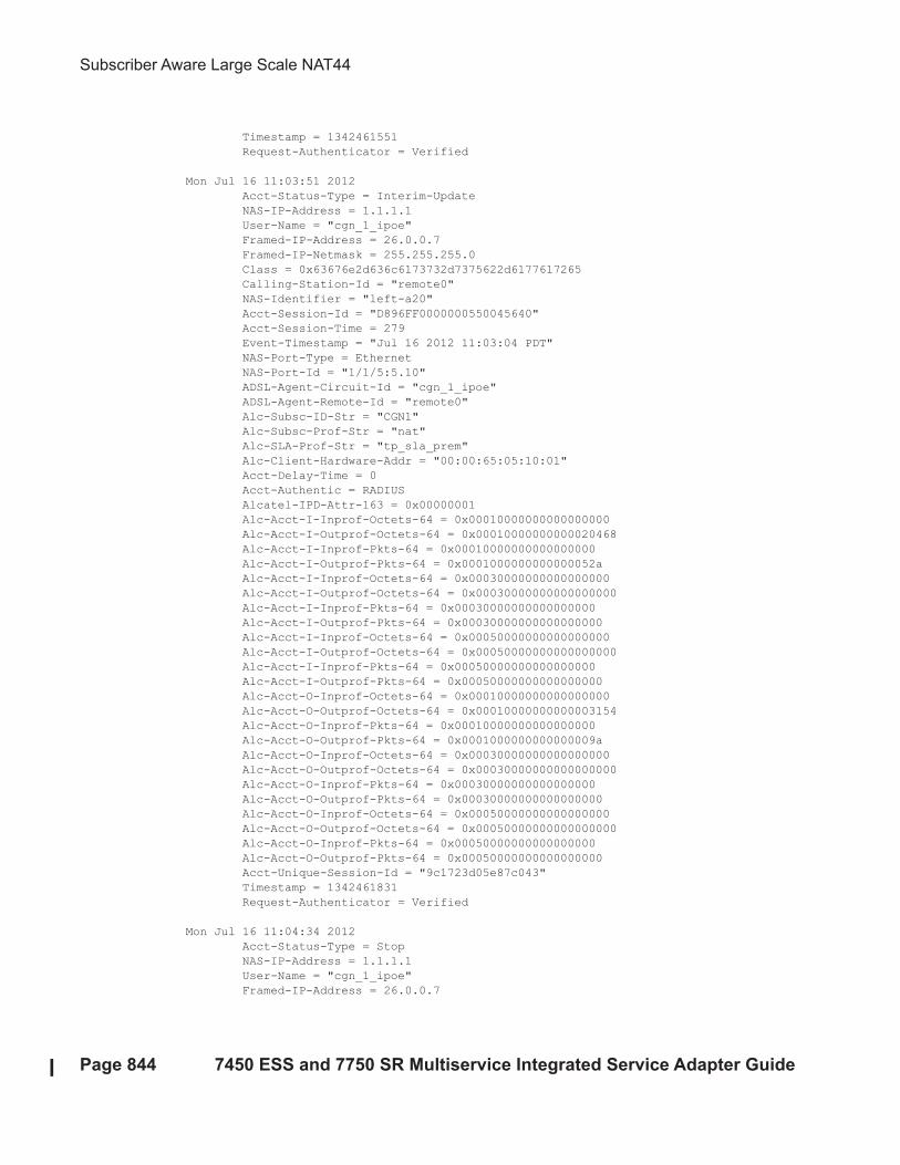
Subscriber Aware Large Scale NAT44
Page 844 7450 ESS and 7750 SR Multiservice Integrated Service Adapter Guide
Timestamp = 1342461551
Request-Authenticator = Verified
Mon Jul 16 11:03:51 2012
Acct-Status-Type = Interim-Update
NAS-IP-Address = 1.1.1.1
User-Name = "cgn_1_ipoe"
Framed-IP-Address = 26.0.0.7
Framed-IP-Netmask = 255.255.255.0
Class = 0x63676e2d636c6173732d7375622d6177617265
Calling-Station-Id = "remote0"
NAS-Identifier = "left-a20"
Acct-Session-Id = "D896FF0000000550045640"
Acct-Session-Time = 279
Event-Timestamp = "Jul 16 2012 11:03:04 PDT"
NAS-Port-Type = Ethernet
NAS-Port-Id = "1/1/5:5.10"
ADSL-Agent-Circuit-Id = "cgn_1_ipoe"
ADSL-Agent-Remote-Id = "remote0"
Alc-Subsc-ID-Str = "CGN1"
Alc-Subsc-Prof-Str = "nat"
Alc-SLA-Prof-Str = "tp_sla_prem"
Alc-Client-Hardware-Addr = "00:00:65:05:10:01"
Acct-Delay-Time = 0
Acct-Authentic = RADIUS
Alcatel-IPD-Attr-163 = 0x00000001
Alc-Acct-I-Inprof-Octets-64 = 0x00010000000000000000
Alc-Acct-I-Outprof-Octets-64 = 0x00010000000000020468
Alc-Acct-I-Inprof-Pkts-64 = 0x00010000000000000000
Alc-Acct-I-Outprof-Pkts-64 = 0x0001000000000000052a
Alc-Acct-I-Inprof-Octets-64 = 0x00030000000000000000
Alc-Acct-I-Outprof-Octets-64 = 0x00030000000000000000
Alc-Acct-I-Inprof-Pkts-64 = 0x00030000000000000000
Alc-Acct-I-Outprof-Pkts-64 = 0x00030000000000000000
Alc-Acct-I-Inprof-Octets-64 = 0x00050000000000000000
Alc-Acct-I-Outprof-Octets-64 = 0x00050000000000000000
Alc-Acct-I-Inprof-Pkts-64 = 0x00050000000000000000
Alc-Acct-I-Outprof-Pkts-64 = 0x00050000000000000000
Alc-Acct-O-Inprof-Octets-64 = 0x00010000000000000000
Alc-Acct-O-Outprof-Octets-64 = 0x00010000000000003154
Alc-Acct-O-Inprof-Pkts-64 = 0x00010000000000000000
Alc-Acct-O-Outprof-Pkts-64 = 0x0001000000000000009a
Alc-Acct-O-Inprof-Octets-64 = 0x00030000000000000000
Alc-Acct-O-Outprof-Octets-64 = 0x00030000000000000000
Alc-Acct-O-Inprof-Pkts-64 = 0x00030000000000000000
Alc-Acct-O-Outprof-Pkts-64 = 0x00030000000000000000
Alc-Acct-O-Inprof-Octets-64 = 0x00050000000000000000
Alc-Acct-O-Outprof-Octets-64 = 0x00050000000000000000
Alc-Acct-O-Inprof-Pkts-64 = 0x00050000000000000000
Alc-Acct-O-Outprof-Pkts-64 = 0x00050000000000000000
Acct-Unique-Session-Id = "9c1723d05e87c043"
Timestamp = 1342461831
Request-Authenticator = Verified
Mon Jul 16 11:04:34 2012
Acct-Status-Type = Stop
NAS-IP-Address = 1.1.1.1
User-Name = "cgn_1_ipoe"
Framed-IP-Address = 26.0.0.7
Network Address Translation
7450 ESS and 7750 SR Multiservice Integrated Service Adapter Guide Page 845
Framed-IP-Netmask = 255.255.255.0
Class = 0x63676e2d636c6173732d7375622d6177617265
Calling-Station-Id = "remote0"
NAS-Identifier = "left-a20"
Acct-Session-Id = "D896FF0000000550045640"
Acct-Session-Time = 322
Acct-Terminate-Cause = User-Request
Event-Timestamp = "Jul 16 2012 11:03:47 PDT"
NAS-Port-Type = Ethernet
NAS-Port-Id = "1/1/5:5.10"
ADSL-Agent-Circuit-Id = "cgn_1_ipoe"
ADSL-Agent-Remote-Id = "remote0"
Alc-Subsc-ID-Str = "CGN1"
Alc-Subsc-Prof-Str = "nat"
Alc-SLA-Prof-Str = "tp_sla_prem"
Alc-Client-Hardware-Addr = "00:00:65:05:10:01"
Acct-Delay-Time = 0
Acct-Authentic = RADIUS
Alc-Acct-I-Inprof-Octets-64 = 0x00010000000000000000
Alc-Acct-I-Outprof-Octets-64 = 0x000100000000000248c4
Alc-Acct-I-Inprof-Pkts-64 = 0x00010000000000000000
Alc-Acct-I-Outprof-Pkts-64 = 0x000100000000000005d9
Alc-Acct-I-Inprof-Octets-64 = 0x00030000000000000000
Alc-Acct-I-Outprof-Octets-64 = 0x00030000000000000000
Alc-Acct-I-Inprof-Pkts-64 = 0x00030000000000000000
Alc-Acct-I-Outprof-Pkts-64 = 0x00030000000000000000
Alc-Acct-I-Inprof-Octets-64 = 0x00050000000000000000
Alc-Acct-I-Outprof-Octets-64 = 0x00050000000000000000
Alc-Acct-I-Inprof-Pkts-64 = 0x00050000000000000000
Alc-Acct-I-Outprof-Pkts-64 = 0x00050000000000000000
Alc-Acct-O-Inprof-Octets-64 = 0x00010000000000000000
Alc-Acct-O-Outprof-Octets-64 = 0x00010000000000003860
Alc-Acct-O-Inprof-Pkts-64 = 0x00010000000000000000
Alc-Acct-O-Outprof-Pkts-64 = 0x000100000000000000b0
Alc-Acct-O-Inprof-Octets-64 = 0x00030000000000000000
Alc-Acct-O-Outprof-Octets-64 = 0x00030000000000000000
Alc-Acct-O-Inprof-Pkts-64 = 0x00030000000000000000
Alc-Acct-O-Outprof-Pkts-64 = 0x00030000000000000000
Alc-Acct-O-Inprof-Octets-64 = 0x00050000000000000000
Alc-Acct-O-Outprof-Octets-64 = 0x00050000000000000000
Alc-Acct-O-Inprof-Pkts-64 = 0x00050000000000000000
Alc-Acct-O-Outprof-Pkts-64 = 0x00050000000000000000
Acct-Unique-Session-Id = "9c1723d05e87c043"
Timestamp = 1342461874
Request-Authenticator = Verified
Universal Plug and Play Internet Gateway Device Service
Page 846 7450 ESS and 7750 SR Multiservice Integrated Service Adapter Guide
Universal Plug and Play Internet Gateway Device Service
Universal Plug and Play (UPnP), which is a set of specifications defined by the UPnP forum. One
specification is called Internet Gateway Device (IGD) which defines a protocol for clients to
automatically configure port mappings on a NAT device. Today, many gaming, P2P, VoIP
applications support the UPnP IGD protocol. The SR OS supports the following UPnP version 1
InternetGatewayDevice version 1 features:
• Supports only L2-Aware NAT hosts.
• Distributed subscriber management is not supported.
• The UPnP server runs on NAT ISA and only serves the local L2-aware NAT hosts on the
same ISA.
• The UPnP server can be enabled per subscriber by configuring a upnp-policy in the sub-
profile.
• UPnP discovery is supported.
• UPnP eventing is not supported.
• The following IGD devices and services are supported:
→ InternetGatewayDevice
− WANDevice
− WANConnectionDevice
− WANIPConnection service
• For WANIPConnection services:
→ Optional state variables in a WANIPConnection service are not supported.
→ Optional actions in a WANIPConnection services are not supported.
→ Wildcard ExternalPort is not supported.
→ Only supports wildcard RemoteHost.
→ Up to 64 bytes of port mapping description are supported.
→ The SR OS supports a vendor specific action X_ClearPortMapping. This clears all
port mappings of the subscriber belonging to the requesting host. This action has no in
or out arguments.
Network Address Translation
7450 ESS and 7750 SR Multiservice Integrated Service Adapter Guide Page 847
• If the NewExternalPort in an addPortMapping request is same as the external port of one
existing UPnP port mapping:
→ If NewInternalClient is different from InternalClient of existing mapping, then system
the will reject the request.
→ If NewInternalClient is same as InternalClient of existing mapping:
− With strict-mode on — If the source IP address of the request is same as
InternalClient of existing mapping, then the request is accepted;
otherwise the request is rejected.
− With strict-mode off, the request is accepted.
• The system also supports the Alc-UPnP-Sub-Override-Policy RADIUS VSA which can
be included in access-accept or CoA request. It can be used to override the upnp-policy
configured in sub-profile or disable UPnP for the subscriber. See RADIUS reference
guide for detail usage.
Configuring UPnP IGD Service
1. Configure L2-aware NAT.
2. Create a upnp-policy:
config>service
upnp
upnp-policy "test" create
no description
http-listening-port 5000
mapping-limit 100
no strict-mode
exit
3. Configure the upnp-policy as created in Step 2 in the subscriber profile:
config>subscr-mgmt
sub-profile "l2nat-upnp" create
nat-policy "l2"
upnp-policy "test"
exit

Configuring UPnP IGD Service
Page 848 7450 ESS and 7750 SR Multiservice Integrated Service Adapter Guide
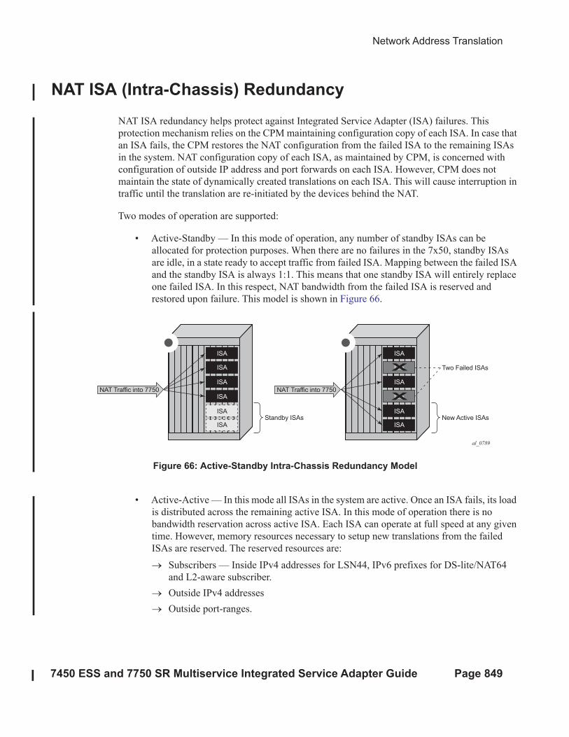
Network Address Translation
7450 ESS and 7750 SR Multiservice Integrated Service Adapter Guide Page 849
NAT ISA (Intra-Chassis) Redundancy
NAT ISA redundancy helps protect against Integrated Service Adapter (ISA) failures. This
protection mechanism relies on the CPM maintaining configuration copy of each ISA. In case that
an ISA fails, the CPM restores the NAT configuration from the failed ISA to the remaining ISAs
in the system. NAT configuration copy of each ISA, as maintained by CPM, is concerned with
configuration of outside IP address and port forwards on each ISA. However, CPM does not
maintain the state of dynamically created translations on each ISA. This will cause interruption in
traffic until the translation are re-initiated by the devices behind the NAT.
Two modes of operation are supported:
• Active-Standby — In this mode of operation, any number of standby ISAs can be
allocated for protection purposes. When there are no failures in the 7x50, standby ISAs
are idle, in a state ready to accept traffic from failed ISA. Mapping between the failed ISA
and the standby ISA is always 1:1. This means that one standby ISA will entirely replace
one failed ISA. In this respect, NAT bandwidth from the failed ISA is reserved and
restored upon failure. This model is shown in Figure 66.
Figure 66: Active-Standby Intra-Chassis Redundancy Model
• Active-Active — In this mode all ISAs in the system are active. Once an ISA fails, its load
is distributed across the remaining active ISA. In this mode of operation there is no
bandwidth reservation across active ISA. Each ISA can operate at full speed at any given
time. However, memory resources necessary to setup new translations from the failed
ISAs are reserved. The reserved resources are:
→ Subscribers — Inside IPv4 addresses for LSN44, IPv6 prefixes for DS-lite/NAT64
and L2-aware subscriber.
→ Outside IPv4 addresses
→ Outside port-ranges.
al_0789
NAT Traffic into 7750
Standby ISAs
ISA
ISA
ISA
ISA
ISA
ISA
NAT Traffic into 7750
New Active ISAs
Two Failed ISAs
ISA
ISA
ISA
ISA
ISA
ISA
X
X
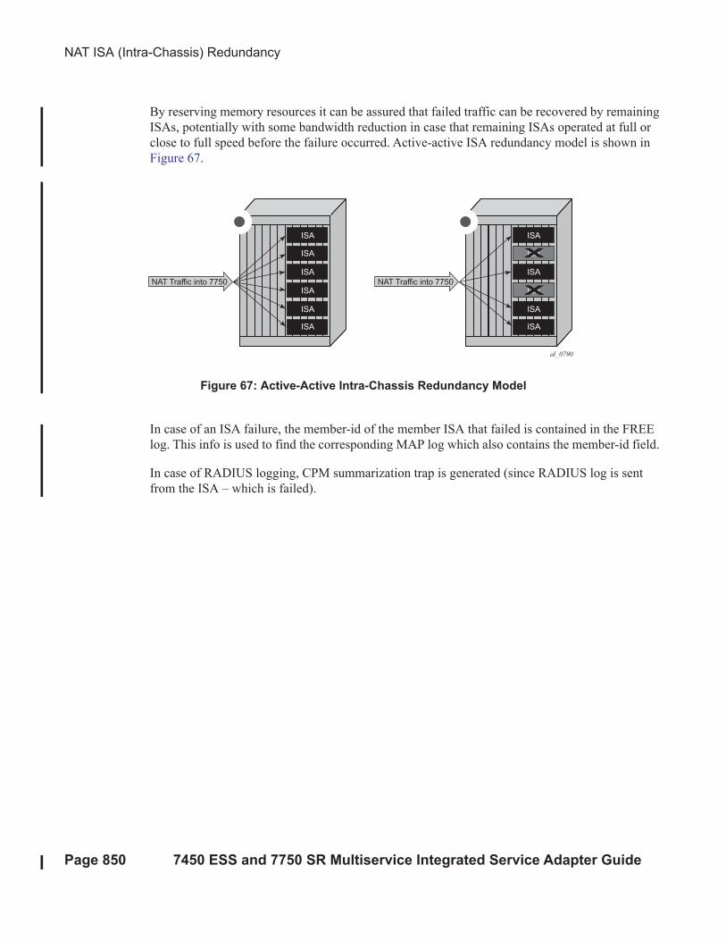
NAT ISA (Intra-Chassis) Redundancy
Page 850 7450 ESS and 7750 SR Multiservice Integrated Service Adapter Guide
By reserving memory resources it can be assured that failed traffic can be recovered by remaining
ISAs, potentially with some bandwidth reduction in case that remaining ISAs operated at full or
close to full speed before the failure occurred. Active-active ISA redundancy model is shown in
Figure 67.
Figure 67: Active-Active Intra-Chassis Redundancy Model
In case of an ISA failure, the member-id of the member ISA that failed is contained in the FREE
log. This info is used to find the corresponding MAP log which also contains the member-id field.
In case of RADIUS logging, CPM summarization trap is generated (since RADIUS log is sent
from the ISA – which is failed).
al_0790
NAT Traffic into 7750
ISA
ISA
ISA
ISA
ISA
ISA
NAT Traffic into 7750
ISA
ISA
ISA
ISA
ISA
ISA
X
X
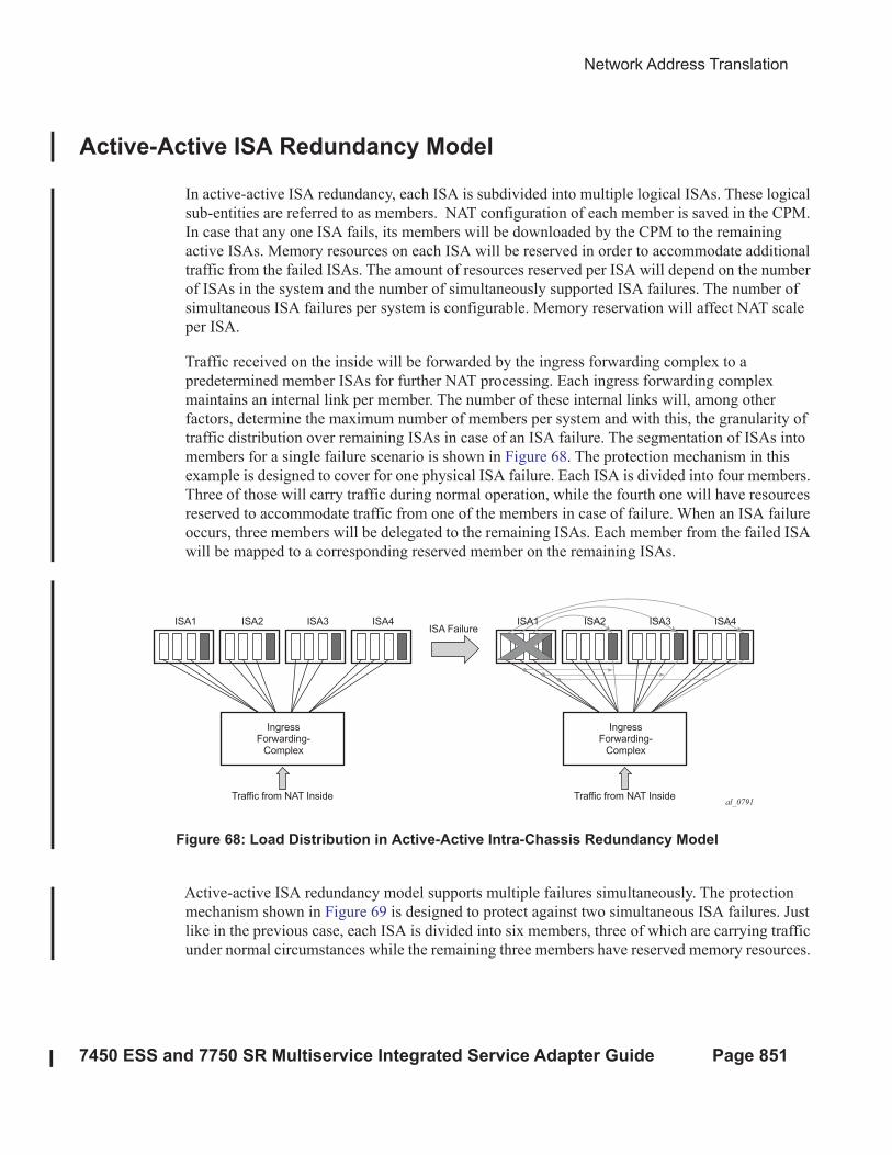
Network Address Translation
7450 ESS and 7750 SR Multiservice Integrated Service Adapter Guide Page 851
Active-Active ISA Redundancy Model
In active-active ISA redundancy, each ISA is subdivided into multiple logical ISAs. These logical
sub-entities are referred to as members. NAT configuration of each member is saved in the CPM.
In case that any one ISA fails, its members will be downloaded by the CPM to the remaining
active ISAs. Memory resources on each ISA will be reserved in order to accommodate additional
traffic from the failed ISAs. The amount of resources reserved per ISA will depend on the number
of ISAs in the system and the number of simultaneously supported ISA failures. The number of
simultaneous ISA failures per system is configurable. Memory reservation will affect NAT scale
per ISA.
Traffic received on the inside will be forwarded by the ingress forwarding complex to a
predetermined member ISAs for further NAT processing. Each ingress forwarding complex
maintains an internal link per member. The number of these internal links will, among other
factors, determine the maximum number of members per system and with this, the granularity of
traffic distribution over remaining ISAs in case of an ISA failure. The segmentation of ISAs into
members for a single failure scenario is shown in Figure 68. The protection mechanism in this
example is designed to cover for one physical ISA failure. Each ISA is divided into four members.
Three of those will carry traffic during normal operation, while the fourth one will have resources
reserved to accommodate traffic from one of the members in case of failure. When an ISA failure
occurs, three members will be delegated to the remaining ISAs. Each member from the failed ISA
will be mapped to a corresponding reserved member on the remaining ISAs.
Figure 68: Load Distribution in Active-Active Intra-Chassis Redundancy Model
Active-active ISA redundancy model supports multiple failures simultaneously. The protection
mechanism shown in Figure 69 is designed to protect against two simultaneous ISA failures. Just
like in the previous case, each ISA is divided into six members, three of which are carrying traffic
under normal circumstances while the remaining three members have reserved memory resources.
al_0791Traffic from NAT Inside
ISA FailureISA1 ISA2 ISA3 ISA4
IngressForwarding-
Complex
Traffic from NAT Inside
IngressForwarding-
Complex
ISA1 ISA2 ISA3 ISA4
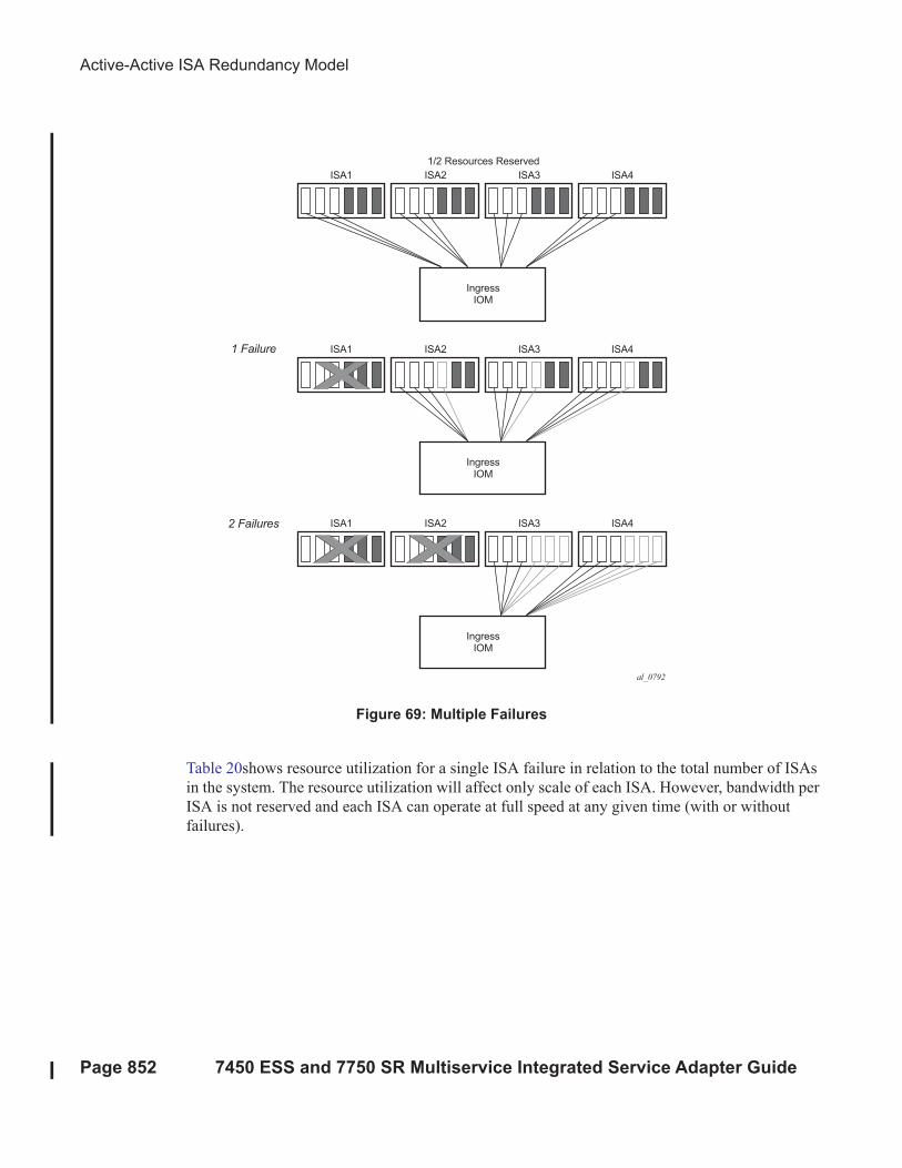
Active-Active ISA Redundancy Model
Page 852 7450 ESS and 7750 SR Multiservice Integrated Service Adapter Guide
Figure 69: Multiple Failures
Table 20shows resource utilization for a single ISA failure in relation to the total number of ISAs
in the system. The resource utilization will affect only scale of each ISA. However, bandwidth per
ISA is not reserved and each ISA can operate at full speed at any given time (with or without
failures).
al_0792
ISA1 ISA2
1/2 Resources Reserved
ISA3 ISA4
IngressIOM
ISA11 Failure
2 Failures
ISA2 ISA3 ISA4
IngressIOM
ISA1 ISA2 ISA3 ISA4
IngressIOM
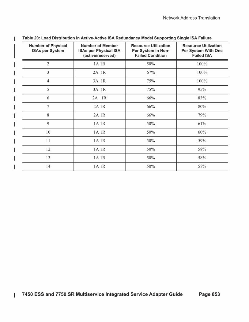
Network Address Translation
7450 ESS and 7750 SR Multiservice Integrated Service Adapter Guide Page 853
Table 20: Load Distribution in Active-Active ISA Redundancy Model Supporting Single ISA Failure
Number of Physical
ISAs per System
Number of Member
ISAs per Physical ISA
(active/reserved)
Resource Utilization
Per System in Non-
Failed Condition
Resource Utilization
Per System With One
Failed ISA
2 1A 1R 50% 100%
3 2A 1R 67% 100%
4 3A 1R 75% 100%
5 3A 1R 75% 95%
6 2A 1R 66% 83%
7 2A 1R 66% 80%
8 2A 1R 66% 79%
9 1A 1R 50% 61%
10 1A 1R 50% 60%
11 1A 1R 50% 59%
12 1A 1R 50% 58%
13 1A 1R 50% 58%
14 1A 1R 50% 57%
Start-up Conditions
Page 854 7450 ESS and 7750 SR Multiservice Integrated Service Adapter Guide
Start-up Conditions
During the first five minutes of system boot-up or nat-group activation, the system behaves as if
all ISAs are operational. Consequently, ISAs are segmented in its members according to the
configured maximum number of supported failures.
Upon expiration of this initial five minute interval, the system is re-evaluated. In case that one of
more ISAs are found in faulty state during re-evaluation, the members of the failed ISAs will be
distributed to the remaining ISAs that are operational.
Recovery
Once a failed ISA is recovered, the system will automatically accept it and traffic will be assigned
to it. Traffic that is moved to the recovered ISA will be interrupted.
Adding Additional ISAs in the ISA Group
Adding additional ISAs in an operational nat-group requires reconfiguration of the active mda-
limit for the nat-group (or the failed mda-limit for that matter). This is only possible when nat-
group is in an administratively shutdown state.