network admission control - cisco.com · restrictions for network admission control † this...
TRANSCRIPT

Americas Headquarters:Cisco Systems, Inc., 170 West Tasman Drive, San Jose, CA 95134-1706 USA
Network Admission Control
First Published: May 27, 2004Last Updated: March 30, 2011
The Network Admission Control feature addresses the increased threat and impact of worms and viruses have on business networks. This feature is part of the Cisco Self-Defending Network Initiative that helps customers identify, prevent, and adapt to security threats.
In its initial phase, the Cisco Network Admission Control (NAC) functionality enables Cisco routers to enforce access privileges when an endpoint attempts to connect to a network. This access decision can be on the basis of information about the endpoint device, such as its current antivirus state. The antivirus state includes information such as version of antivirus software, virus definitions, and version of scan engine.
Network admission control systems allow noncompliant devices to be denied access, placed in a quarantined area, or given restricted access to computing resources, thus keeping insecure nodes from infecting the network.
The key component of the Cisco Network Admission Control program is the Cisco Trust Agent, which resides on an endpoint system and communicates with Cisco routers on the network. The Cisco Trust Agent collects security state information, such as what antivirus software is being used, and communicates this information to Cisco routers. The information is then relayed to a Cisco Secure Access Control Server (ACS) where access control decisions are made. The ACS directs the Cisco router to perform enforcement against the endpoint.
Finding Feature InformationYour software release may not support all the features documented in this module. For the latest feature information and caveats, see the release notes for your platform and software release. To find information about the features documented in this module, and to see a list of the releases in which each feature is supported, see the “Feature Information for Network Admission Control” section on page 27.
Use Cisco Feature Navigator to find information about platform support and Cisco IOS and Catalyst OS software image support. To access Cisco Feature Navigator, go to http://tools.cisco.com/ITDIT/CFN/jsp/index.jsp. An account on Cisco.com is not required.

Network Admission Control Contents
2
Contents• Prerequisites for Network Admission Control, page 2
• Restrictions for Network Admission Control, page 2
• Information About Network Admission Control, page 2
• How to Configure Network Admission Control, page 7
• Configuration Examples for Network Admission Control, page 23
• Additional References, page 26
• Feature Information for Network Admission Control, page 27
• Glossary, page 28
Prerequisites for Network Admission Control• The Cisco IOS router must be running Cisco IOS software Release 12.3(8)T or later.
• The Cisco Trust Agent must be installed on the endpoint devices (for example, on PCs and laptops).
• A Cisco Secure ACS is required for authentication, authorization, and accounting (AAA).
• A proficiency with configuring access control lists (ACLs) and AAA is necessary.
Restrictions for Network Admission Control• This feature is available only on Cisco IOS firewall feature sets.
Information About Network Admission ControlBefore configuring the Network Admission Control feature, the following concepts need to be understood:
• Virus Infections and Their Effect on Networks, page 3
• How Network Admission Control Works, page 3
• Network Access Device, page 4
• Cisco Trust Agent, page 4
• Cisco Secure ACS, page 4
• Remediation, page 5
• Network Admission Control and Authentication Proxy, page 5
• NAC MIB, page 5

Network Admission Control Information About Network Admission Control
3Netword Admission Control
Virus Infections and Their Effect on NetworksVirus infections are the single largest cause of serious security breaches for networks and often result in huge financial losses. Sources of virus infections are insecure endpoints (for example, PCs, laptops, and servers). Although the endpoints may have antivirus software installed, the software is often disabled. Even if the software is enabled, the endpoints may not have the latest virus definitions and scan engines. A larger security risk is from devices that do not have any antivirus software installed. Although antivirus vendors today are making it more difficult to disable the antivirus software, they are not addressing the risk of outdated virus definitions and scan engines.
How Network Admission Control WorksEndpoint systems, or clients, are normally hosts on the network, such as PCs, laptops, workstations, and servers. The endpoint systems are a potential source of virus infections, and their antivirus states have to be validated before they are granted network access. When an endpoint attempts an IP connection to a network through an upstream Cisco network access device (typically a Cisco IOS router), the router challenges the endpoint for its antivirus state. The endpoint systems run a client called Cisco Trust Agent, which collects antivirus state information from the end device and transports the information to the Cisco network access device. This information is then communicated to a Cisco Secure ACS where the antivirus state of the endpoint is validated and access control decisions are made and returned to Cisco network access devices. The network devices either permit, deny, or quarantine the end device. The Cisco Secure ACS may in turn use back-end antivirus vendor-specific servers for evaluating the antivirus state of the endpoint.
Figure 1 illustrates how Cisco Network Admission Control works.
Figure 1 Cisco IOS Network Admission Control System
Figure 1 shows that IP admission control is applied at the LAN interface. All network devices must be validated for their antivirus states upon their initial IP connections through the router. Until then, all traffic from endpoint systems (except for EAPoUDP and Cisco Secure ACS traffic) is blocked at the interface.
User
User
E2/1
Cisco ACS
Cisco IOS router
1177
23
Admission controlwith input interface
ACL to block all usertraffic except
EAPoUDP and ACS
ISP andInternet

Network Admission Control Information About Network Admission Control
4
The endpoint system is then challenged for its antivirus state over an EAPoUDP association. The endpoint system gains access to the network if it complies with the network admission control policy as evaluated by the Cisco Secure ACS. If the endpoint system does not comply, the device is either denied access or quarantined.
Network Access DeviceA network access device (NAD) is typically a Cisco IOS router (a Layer 3 Extensible Authentication Protocol over User Datagram Protocol [EAPoUDP] access point) that provides connectivity to external networks, such as the Internet or remote enterprise networks. Cisco Network Admission Control functionality may have an Intercept ACL, which determines connections that are intercepted for network admission. Connections from endpoints that match the access list are intercepted by Network Admission Control and are challenged for their antivirus states over a Layer 3 association before they are granted network access.
Cisco Trust AgentCisco Trust Agent is a specialized software that runs on endpoint systems. Cisco Trust Agent responds to challenges from the router about the antivirus state of an endpoint system. If an endpoint system is not running the Cisco Trust Agent, the network access device (router) classifies the endpoint system as “clientless.” The network access device uses the EOU clientless username and EOU clientless password that are configured on the network access device as the credentials of the endpoint system for validation with Cisco Secure ACS. The policy attributes that are associated with this username are enforced against the endpoint system.
Cisco Secure ACSCisco Secure ACS provides authentication, authorization, and accounting services for network admission control using industry-standard RADIUS authentication protocol. Cisco Secure ACS returns access control decisions to the network access device on the basis of the antivirus credentials of the endpoint system.
Using RADIUS cisco_av_pair vendor-specific attributes (VSAs), the following attribute-value pairs (AV pairs) can be set on the Cisco Secure ACS. These AV pairs are sent to the network access device along with other access-control attributes.
• url-redirect—Enables the AAA client to intercept an HTTP request and redirect it to a new URL. This redirection is especially useful if the result of posture validation indicates that the network access control endpoint requires an update or patch to be made available on a remediation web server. For example, a user can be redirected to a remediation web server to download and apply a new virus Directory Administration Tool (DAT) file or an operating system patch. (See the following example.)
url-redirect=http://10.1.1.1
• posture-token—Enables Cisco Secure ACS to send a text version of a system posture token (SPT) that is derived by posture validation. The SPT is always sent in numeric format, and using the posture-token AV pair makes it easier to view the result of a posture validation request on the AAA client. (See the following example.)
posture-token=Healthy

Network Admission Control Information About Network Admission Control
5Netword Admission Control
Valid SPTs, in order of best to worst, are as follows:
– Healthy
– Checkup
– Quarantine
– Infected
– Unknown
• status-query-timeout—Overrides the status-query default value of the AAA client with the user specified value, in seconds. (See the following example.)
status-query-timeout=150
For more information about AV pairs that are supported by Cisco IOS software, see the documentation for the releases of Cisco IOS software that are implemented on your AAA clients.
RemediationNetwork Admission Control supports HTTP redirection that redirects any HTTP request from the endpoint device to a specified redirect address. This support mechanism redirects all HTTP requests from a source to a specified web page (URL) to which the latest antivirus files can be downloaded. For the HTTP redirection to work, the value must be set for the “url-redirect” VSA on the ACS and, correspondingly, associate an access control entry in the downloadable ACL that permits the access of the endpoint system to the redirect URL address. After the value of the url-redirect VSA has been set and the access control entry has been associated, any HTTP request that matches the IP admission Intercept ACL are redirected to the specified redirect URL address.
Network Admission Control and Authentication ProxyIt is possible that network admission control and authentication proxy can be configured for the same set of hosts on a given interface. In each case, the Intercept ACL should be the same for IP admission EAPoUDP and authentication proxy. IP admission proxy with proxy authentication should be configured first, followed by IP admission control.
NAC MIBThe NAC MIB feature adds Simple Network Management Protocol (SNMP) support for the NAC subsystem. Using SNMP commands (get and set operations), an administrator can monitor and control NAC sessions on the network access device (NAD).
For more information about SNMP get and set operations, see the subsection “Related Documents” in the section “Additional References.”
Correlation Between SNMP Get and Set Operations and the Cisco CLI
Most of the objects in the object tables in the NAC MIB (CISCO-NAC-NAD-MIB.my) describe various EAPoUDP and session parameters that are applicable to the setup of a NAD. These properties can be viewed and modified by performing various SNMP get and set operations. Many of the values of the table objects can also be viewed or modified by configuring corresponding command-line interface (CLI) commands on a router. For example, an SNMP get operation can be performed on the

Network Admission Control Information About Network Admission Control
6
cnnEOUGlobalObjectsGroup table or the show eou command can be configured on a router. The parameter information obtained from the SNMP get operation is the same as the output from the show eou command. Similarly, performing an SNMP get operation on the table cnnEouIfConfigTable provides interface-specific parameters that can also be viewed in output from the show eou command.
SNMP set operations are allowed for table objects that have corresponding CLI commands, which can be used to modify table object values. For example, to change the value range for the cnnEouHostValidateAction object in the cnnEouHostValidateAction MIB table to 2, you can either perform the SNMP set operation or configure the eou initialize all command on a router.
For examples of NAC MIB output, see the subsection “NAC MIB Output: Examples” in the section “Configuration Examples for Network Admission Control.”
Initializing and Revalidating Sessions
NAC allows administrators to initialize and revalidate sessions using the following CLI commands:
• eou initialize all
• eou initialize authentication clientless
• eou initialize authentication eap
• eou initialize authentication static
• eou initialize ip {ip-address}
• eou initialize mac {mac-address}
• eou initialize posturetoken {string}
• eou revalidate all
• eou revalidate authentication clientless
• eou revalidate authentication eap
• eou revalidate authentication static
• eou revalidate ip {ip-address}
• eou revalidate mac {mac-address}
• eou revalidate posturetoken {string}
The initialization and revalidation actions can also be accomplished by performing SNMP set operations on the objects of the cnnEouHostValidateAction table. For more information about initializing and revalidating sessions, see the section “CLI Commands That Correlate to cnnEouHostValidateAction Table Objects.”
For examples of CLI commands that correlate to changes that can be made to cnnEouHostValidateAction table objects, see the subsection “NAC MIB Output: Examples” in the section “Configuration Examples for Network Admission Control.”
Session-Specific Information
The NAC MIB provides a way to view session-specific details using the cnnEouHostQueryTable and cnnEouHostResultTable. The cnnEouHostQueryTable is used to build the query. The query is the same format as the show eou ip {ip-address} command (that is, the IP address would be shown as in the show eou ip command—for example, 10.1.1.1). Administrators must use the SNMP set operation on the objects of the cnnEouHostQueryTable to create the query. The results of the query are stored as a row in the cnnEouHostResultTable. For more information about viewing session-specific details, see the section “Viewing MIB Query Results.”

Network Admission Control How to Configure Network Admission Control
7Netword Admission Control
Using show Commands to View MIB Object Information
The CLI commands show eou, show eou all, show eou authentication, show eou initialize, show eou ip, show eou mac, show eou posturetoken, show eou revalidate, and show ip device tracking all provide the same output information as that in the CISCO-NAC-NAD-MIB tables using SNMP get operations.
For examples of show command output information that can also be viewed in MIB object tables, see the subsection “NAC MIB Output: Examples” in the section “Configuration Examples for Network Admission Control.”
How to Configure Network Admission ControlThis section contains the following procedures:
• Configuring the ACL and Admission Control, page 7 (required)
• Configuring Global EAPoUDP Values, page 9 (optional)
• Configuring an Interface-Specific EAPoUDP Association, page 10 (optional)
• Configuring AAA for EAPoUDP, page 11 (optional)
• Configuring the Identity Profile and Policy, page 12 (required)
• Clearing EAPoUDP Sessions That Are Associated with an Interface, page 14 (optional)
• Verifying Network Admission Control, page 15 (optional)
• Troubleshooting Network Admission Control, page 15 (optional)
• Monitoring and Controlling NAC with the CISCO-NAC-NAD-MIB, page 16 (optional)
Configuring the ACL and Admission ControlNetwork admission control is applied in the inbound direction at any interface. Applying network admission control inbound at an interface causes network admission control to intercept the initial IP connections of the intercept end system through the router.
Use the steps in this section to configure an intercept ACL.
Note In this configuration, an intercept ACL is defined as “101,” and the Intercept ACL is associated with the IP admission control rule “greentree.” Any IP traffic that is destined to the 192.50.0.0 network are subjected to validation. In addition, beginning with Step 5, an intercept ACL is applied inbound to the interface that is associated with network admission control. This ACL typically blocks access to endpoint systems until they are validated. This ACL is referred to as the default access list.
SUMMARY STEPS
1. enable
2. configure terminal
3. access-list access-list-number {permit | deny} protocol source destination
4. ip admission name admission-name [eapoudp | proxy {ftp | http | telnet}] [list {acl | acl-name}]
5. interface type slot/port

Network Admission Control How to Configure Network Admission Control
8
6. ip address ip-address mask
7. ip admission admission-name
8. exit
9. access-list access-list-number {permit | deny} protocol source destination
10. ip access-group {access-list-number | access-list-name} in
DETAILED STEPS
Command or Action Purpose
Step 1 enable
Example:Router> enable
Enables privileged EXEC mode.
• Enter your password if prompted.
Step 2 configure terminal
Example:Router# configure terminal
Enters global configuration mode.
Step 3 access-list access-list-number {permit | deny} protocol source destination
Example:Router (config)# access-list 101 permit ip any 192.50.0.0 0.0.0.255
Defines a numbered access list.
Step 4 ip admission name admission-name [eapoudp | proxy {ftp | http | telnet}] [list {acl | acl-name}]
Example:Router (config)# ip admission name greentree eapoudp list 101
Creates IP network admission control rules. The rules define how you apply admission control. The rules are as follows:
• eapoudp—Specifies IP network admission control using EAPoUDP.
• proxy ftp—Specifies FTP to trigger authentication proxy.
• proxy http—Specifies HTTP to trigger authentication proxy.
• proxy telnet—Specifies Telnet to trigger authentication proxy.
You can associate the named rule with an ACL, providing control over which hosts use the admission control feature. If no standard access list is defined, the named admission rule intercepts IP traffic from all hosts whose connection-initiating packets are received at the configured interface.
The list option allows you to apply a standard, extended (1 through 199) or named access list to a named admission control rule. IP connections that are initiated by hosts in the access list are intercepted by the admission control feature.

Network Admission Control How to Configure Network Admission Control
9Netword Admission Control
Configuring Global EAPoUDP ValuesTo configure global EAPoUDP values, perform the following steps.
SUMMARY STEPS
1. enable
Step 5 interface type slot/port
Example:Router (config)# interface ethernet 2/1
Defines an interface and enters interface configuration mode.
Step 6 ip address ip-address mask
Example:Router (config-if)# ip address 192.0.0.1 255.255.255.0
Sets a primary or secondary IP address for an interface.
Step 7 ip admission admission-name
Example:Router (config-if)# ip admission greentree
Applies the named admission control rule at the interface.
Step 8 exit
Example:Router (config-if)# exit
Exits interface configuration mode.
Step 9 access-list access-list-number {permit | deny} protocol source destination
Example:Router (config)# access-list 105 permit udp any any
or
Router (config)# access-list 105 permit ip host 192.168.0.2 any
or
Router (config)# access-list 105 deny ip any any
Defines a numbered access list.
Note In the first two examples (under “Command or Action”), ACL “105” denies all IP traffic except UDP and access to 192.168.0.2 (Cisco Secure ACS).
Note In the third example (under “Command or Action,” ACL “105” is applied on the interface that is configured for network admission control, and access to endpoint systems (except for EAPoUDP traffic and access to Cisco Secure ACS [192.168.0.2 in the example] is blocked until their antivirus states are validated. This ACL (“105”) is referred to as “Interface ACL.”
Step 10 ip access-group {access-list-number | access-list-name} in
Example:Router (config)# ip access-group 105 in
Controls access to an interface.
Command or Action Purpose

Network Admission Control How to Configure Network Admission Control
10
2. configure terminal
3. eou {allow | clientless | default | initialize | logging | max-retry | port | rate-limit | revalidate | timeout}
DETAILED STEPS
Configuring an Interface-Specific EAPoUDP AssociationTo configure an EAPoUDP association that can be changed or customized for a specific interface that is associated with network admission control, perform the following steps.
SUMMARY STEPS
1. enable
2. configure terminal
3. interface type slot/port
4. eou [default | max-retry | revalidate | timeout]
Command or Action Purpose
Step 1 enable
Example:Router> enable
Enables privileged EXEC mode.
• Enter your password if prompted.
Step 2 configure terminal
Example:Router# configure terminal
Enters global configuration mode.
Step 3 eou {allow | clientless | default | initialize | logging | max-retry | port | rate-limit | revalidate | timeout}
Example:Router (config)# eou initialize
Specifies EAPoUDP values.
• For a breakout of available keywords and arguments for the eou command, see the following commands:
– eou allow
– eou clientless
– eou default
– eou initialize
– eou logging
– eou max-retry
– eou port
– eou rate-limit
– eou revalidate
– eou timeout
Network Admission Control How to Configure Network Admission Control
11Netword Admission Control
DETAILED STEPS
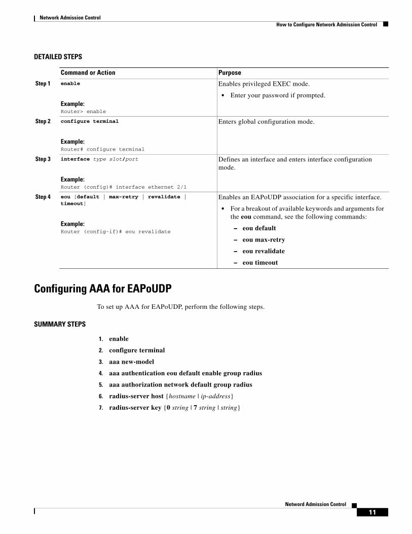
Configuring AAA for EAPoUDPTo set up AAA for EAPoUDP, perform the following steps.
SUMMARY STEPS
1. enable
2. configure terminal
3. aaa new-model
4. aaa authentication eou default enable group radius
5. aaa authorization network default group radius
6. radius-server host {hostname | ip-address}
7. radius-server key {0 string | 7 string | string}
Command or Action Purpose
Step 1 enable
Example:Router> enable
Enables privileged EXEC mode.
• Enter your password if prompted.
Step 2 configure terminal
Example:Router# configure terminal
Enters global configuration mode.
Step 3 interface type slot/port
Example:Router (config)# interface ethernet 2/1
Defines an interface and enters interface configuration mode.
Step 4 eou [default | max-retry | revalidate | timeout]
Example:Router (config-if)# eou revalidate
Enables an EAPoUDP association for a specific interface.
• For a breakout of available keywords and arguments for the eou command, see the following commands:
– eou default
– eou max-retry
– eou revalidate
– eou timeout

Network Admission Control How to Configure Network Admission Control
12
DETAILED STEPS
Configuring the Identity Profile and PolicyIdentity is a common infrastructure that is used to specify local profile and policy configurations. The identity profile allows you to statically authorize or validate individual devices on the basis of IP address, MAC address, or device type. Each statically authenticated device can be associated with a local policy that specifies the network access control attributes. Hosts are added to this “exception list” using the identity profile command, and corresponding policies are associated with these hosts using the identity policy command.
If the client is part of the identity (that is, the client is on the exception list), the status of the client is set on the basis of the identity configuration. The client does not have to go through the posture validation process, and the associated identity policy is applied for the client.
Command or Action Purpose
Step 1 enable
Example:Router> enable
Enables privileged EXEC mode.
• Enter your password if prompted.
Step 2 configure terminal
Example:Router# configure terminal
Enters global configuration mode.
Step 3 aaa new-model
Example:Router (config)# aaa new-model
Enables the AAA access control model.
Step 4 aaa authentication eou default enable group radius
Example:Router (config)# aaa authentication eou default enable group radius
Sets authentication lists for an EAPoUDP association.
Step 5 aaa authorization network default group radius
Example:Router (config)# aaa authorization network default group radius
Uses the list of all RADIUS servers for authentication.
Step 6 radius-server host {hostname | ip-address}
Example:Router (config)# radius-server host 192.0.0.40
Specifies a RADIUS server host.
Step 7 radius-server key {0 string | 7 string | string}
Example:Router (config)# radius-server key cisco
Sets the authentication and encryption key for all RADIUS communications between the router and the RADIUS daemon.

Network Admission Control How to Configure Network Admission Control
13Netword Admission Control
SUMMARY STEPS
1. enable
2. configure terminal
3. identity profile eapoudp
4. device {authorize {ip address ip-address {policy policy-name} | mac-address mac-address | type {cisco | ip | phone}} | not-authorize}
5. exit
6. identity policy policy-name [access-group group-name | description line-of-description | redirect url | template [virtual-template interface-name]]
7. access-group group-name
8. exit
9. exit
10. ip access-list extended access-list-name
11. {permit | deny} source source-wildcard destination destination-wildcard
DETAILED STEPS
Command or Action Purpose
Step 1 enable
Example:Router> enable
Enables privileged EXEC mode.
• Enter your password if prompted.
Step 2 configure terminal
Example:Router# configure terminal
Enters global configuration mode.
Step 3 identity profile eapoudp
Example:Router (config)# identity profile eapoudp
Creates an identity profile and enters identity profile configuration mode.
Step 4 device {authorize {ip address ip-address {policy policy-name} | mac-address mac-address | type {cisco | ip | phone}} | not-authorize}
Example:Router (config-identity-prof)# device authorize ip address 10.10.142.25 policy policyname1
Statically authorizes an IP device and applies an associated policy to the device.
Step 5 exit
Example:Router (config-identity-prof)# exit
Exits identity profile configuration mode.

Network Admission Control How to Configure Network Admission Control
14
Clearing EAPoUDP Sessions That Are Associated with an InterfaceTo clear EAPoUDP sessions that are associated with a particular interface or that are on the NAD, perform the following steps.
SUMMARY STEPS
1. enable
2. clear eou all
Step 6 identity policy policy-name [access-group group-name | description line-of-description | redirect url | template [virtual-template interface-name]]
Example:Router (config-identity-prof)# identity policy policyname1
Creates an identity policy and enters identity policy configuration mode.
Step 7 access-group group-name
Example:Router (config-identity-policy)# access-group exempt-acl
Defines network access attributes for the identity policy.
Step 8 exit
Example:Router (config-identity-policy)# exit
Exits identity policy configuration mode.
Step 9 exit
Example:Router (config-identity-prof)# exit
Exits identity profile configuration mode.
Step 10 ip access-list extended access-list-name
Example:Router (config)# ip access-list extended exempt-acl
Defines access control for statically authenticated devices (and enters network access control configuration mode).
Step 11 {permit | deny} source source-wildcard destination destination-wildcard
Example:Router (config-ext-nacl)# permit ip any 192.50.0.0. 0.0.0.255
Set conditions to allow a packet to pass a named IP access list.
Command or Action Purpose

Network Admission Control How to Configure Network Admission Control
15Netword Admission Control
DETAILED STEPS
Verifying Network Admission ControlTo verify EAP and EAPoUDP messages or sessions, perform the following steps. The show commands may be used in any order or independent of the other show command.
SUMMARY STEPS
1. enable
2. show eou all
3. show ip admission eapoudp
DETAILED STEPS
Troubleshooting Network Admission ControlThe following commands may be used to display information about EAP and EAPoUDP messages or sessions. The debug commands may be used in any order or independent of the other debug commands.
Command or Action Purpose
Step 1 enable
Example:Router> enable
Enables privileged EXEC mode.
• Enter your password if prompted.
Step 2 clear eou all
Example:Router# clear eou all
Clears all EAPoUDP sessions on the NAD.
Command or Action Purpose
Step 1 enable
Example:Router> enable
Enables privileged EXEC mode.
• Enter your password if prompted.
Step 2 show eou all
Example:Router# show eou all
Displays information about EAPoUDP sessions on the network access device.
Step 3 show ip admission eapoudp
Example:Router# show ip admission eapoudp
Displays the network admission control configuration or network admission cache entries.

Network Admission Control How to Configure Network Admission Control
16
SUMMARY STEPS
1. enable
2. debug eap {all | errors | packets | sm}
3. debug eou {all | eap | errors | packets | sm}
4. debug ip admission eapoudp
DETAILED STEPS
Monitoring and Controlling NAC with the CISCO-NAC-NAD-MIBThis section includes the following tasks:
• CLI Commands That Correlate to cnnEouHostValidateAction Table Objects, page 17
• CLI Commands That Correlate to cnnEouIfConfigTable Objects, page 17
• CLI Commands That Correlate to cnnEouHostValidateAction Table Objects, page 17
• Creating MIB Query Tables, page 18
• Viewing MIB Query Results, page 21
CLI Commands That Correlate to cnnEouGlobalObjectsGroup Table Objects
An SNMP get or set operation can be performed to obtain or change information about value ranges for objects in the cnnEouGlobalObjectsGroup table. The same information can be viewed in output from the show eou command. Table 1 displays examples of some global configuration objects and the SNMP get and set operations required to obtain or change their values.
For an example of show eou command output, see the section “show eou” section on page 24.
Command or Action Purpose
Step 1 enable
Example:Router> enable
Enables privileged EXEC mode.
• Enter your password if prompted.
Step 2 debug eap {all | errors | packets | sm}
Example:Router# debug eap all
Displays information about EAP messages.
Step 3 debug eou {all | eap | errors | packets | sm}
Example:Router# debug eou all
Displays information about EAPoUDP messages.
Step 4 debug ip admission eapoudp
Example:Router# debug ip admission eapoudp
Displays information about IP admission events.

Network Admission Control How to Configure Network Admission Control
17Netword Admission Control
CLI Commands That Correlate to cnnEouIfConfigTable Objects
An SNMP get operation is performed to obtain information about value ranges for objects in the cnnEouIfConfigTable. The same information can be viewed in output from the show eou command. Table 2 displays examples of some interface-specific configuration objects and the SNMP get operations required to obtain their values.
CLI Commands That Correlate to cnnEouHostValidateAction Table Objects
EOU sessions can be initialized or revalidated by the CLI or by using the SNMP set operation on the table cnnEouHostValidateAction.
Following are some examples (listed by CLI command) that correlate to MIB objects.
eou initialize all
EOU initialization can be accomplished for all sessions by using the eou initialize all command or by using an SNMP set operation on the object cnnEouHostValidateAction. This object must be set to the numeric value 2.
eou initialize authentication clientless
EOU initialization can be accomplished for sessions having an authentication type “clientless” using the eou initialize authentication clientless command or an SNMP set operation on the object cnnEouHostValidateAction. This object must be set to the numeric value 3.
eou initialize ip
EOU initialization can be accomplished for a particular session using the eou initialize ip {ip-address} command.
Table 1 Obtaining and Changing Global Configuration Values Using SNMP Get and Set
Operations
Global Configuration Objects SNMP Operation
EAPoUDP version Performs a get operation on the cnnEouVersion object. (The object value is “1.”)
EAPoUDP port Performs a get operation on the cnnEouPort object.
Enabling logging (enable EOU logging)
Sets the cnnEouLoggingEnable object. (The object value is “true.”)
Table 2 Obtaining Interface-Specific Configuration Values Using SNMP Get Operations
Interface-Specific Object SNMP Operation
AAA timeout Performs a get operation on the cnnEouIfTimeoutAAA object.
• Format: GET cnnEouIfTimeoutAAA.IfIndex
• You must specify the corresponding index number of the specific interface.
Maximum retries Performs a get operation on the cnnEouIfMaxRetry object.
• Format: GET cnnEouIfMaxRetry.IfIndex

Network Admission Control How to Configure Network Admission Control
18
To achieve the same result using an SNMP operation, three objects have to be set in the cnnEouHostValidateAction MIB table:
• cnnEouHostValidateAction—The value range must be set.
• cnnEouHostValidateIpAddrType—The IP address type must be set. This value must be set to IPv4 because IPv4 is currently the only address type supported by NAC. (This value is the type of address being set for the cnnEouHostValidateIPAddr object.)
• cnnEouHostValidateIPAddr—The IP address must be set.
Note The three MIB objects should be set in a single SNMP set operation.
eou initialize posturetoken
All sessions having a particular posturetoken can be initialized using the eou initialize posturetoken {string} command. The default value range for this command is 8.
To achieve the same result using an SNMP set operation, you must set the following objects:
• cnnEouHostValidateAction—Set this value to 8.
• cnnEouHostValidatePostureTokenStr—Set the string value.
Note The two MIB objects should be set in a single SNMP set operation.
Creating MIB Query Tables
The MIB table cnnEouHostQueryTable is used to create, or build, MIB queries.
MIB Query Correlating to the CLI show eou all Command
To build a query that provides the same results as using the show eou all command, perform the following SNMP get operation.
The object cnnEouHostQueryMask in the table cnnEouHostQueryTable indicates the kind of query. The corresponding value of the cnnEouHostQueryMask object in output from the show eou all command is 8 (the integer value).
SUMMARY STEPS
1. Set the cnnEouHostQueryStatus object to createandgo.
2. Set the cnnEouHostQueryMask object to 8.
3. Set the cnnEouHostQueryStatus object to active to indicate that query creation is complete.
DETAILED STEPS
Command or Action Purpose
Step 1 Set the cnnEouHostQueryStatus object to createandgo. Creates a query row.
Step 2 Set the cnnEouHostQueryMask object to 8. Corresponds in value to the show eou all command.
Step 3 Set the cnnEouHostQueryStatus object to active. Indicates that you have finished building the query.

Network Admission Control How to Configure Network Admission Control
19Netword Admission Control
Note Examples are not shown in the previous table because the format differs depending on the software you are using.
What to Do Next
View the results. See the section “Viewing MIB Query Results Correlating to the show eou all Command.”
Viewing MIB Query Results Correlating to the show eou all Command
After the MIB query has been built and you have indicated that you are finished (with the “active” status), the results can be viewed. A query in the cnnEouHostQueryTable is represented by a row. The row number is the Query Index. Similarly, the cnnEouHostResultTable is composed of result rows. Each row in the cnnEouHostResultTable is uniquely identified by a combination of Query Index and Result Index. The results of the cnnEouHostQueryTable index and the cnnEouHostResultTable have to be matched. Match one row in the Query table to one of the rows in the Result table. For example, if a query that corresponds to a show command results in ten sessions, the Result table has ten rows, each row corresponding to a particular session. The first row in the Result table is R1.1. The second row is R1.2, and so on to R1.10. If another query is created in the Query table, and it results in five sessions, five rows are created in the Result table (R2.1, R2.2, R2.3, R2.4, and R2.5).
Table 3 illustrates how the Query table sessions are mapped to Result table rows.
Creating the SNMP Query
To create an SNMP query that provides the same information as output from the show eou ip {ip-address} command, perform the following steps.
SUMMARY STEPS
1. Set cnnEouHostQueryStatus to createandgo.
2. Set cnnEouHostQueryIpAddrType to IPv4 and the IP address (for example, 10.2.3.4).
3. Set cnnEouHostQueryStatus to active.
Table 3 Query Table-to-Result Table Mapping
Query Table Result Table Rows
Q1 (10 sessions) R1.1, R1.2, R1.3, R1.4, R1.5, R1.6, R1.7, R1.8, R1.9, R1.10
Q2 (5 sessions) R2.1, R2.2, R2.3, R2.4, R2.5

Network Admission Control How to Configure Network Admission Control
20
DETAILED STEPS
Note Examples are not shown in the previous table because the format differs depending on the software you are using.
Viewing the Results
To view the results in the cnnEouHostResultTable, perform the following steps.
SUMMARY STEPS
1. Perform a get operation on cnnEouHostQueryRows.
2. Perform a get operation on the cnnEouHostResultTable objects in the format resultTableObjectName.QueryIndex.ResultIndex.
DETAILED STEPS
Note Examples are not shown in the above table because the format differs depending on the software you are using.
MIB Query Correlating to the show eou ip Command
To build a MIB query that provides the same results as the show eou ip {ip-address}command, perform the following SNMP get operation.
Command or Action Purpose
Step 1 Set cnnEouHostQueryStatus to createandgo. Creates a query row.
Step 2 Set cnnEouHostQueryIpAddrType to IPv4 and the IP address (for example, 10.2.3.4).
Sets the address type.
• The only address type currently supported by NAC is IPv4.
Step 3 Set cnnEouHostQueryStatus to active. Indicates you have finished building the query.
Command or Action Purpose
Step 1 Perform a get operation on cnnEouHostQueryRows. Finds how many rows are created in a Result table for a particular query.
• If a query row is a negative number, the query is still being processed.
Step 2 Perform a get operation on the cnnEouHostResultTable objects in the format resultTableObjectName.QueryIndex.ResultIndex.
Finds the value of a particular object in a Result table that matches a particular query.
• For multiple rows in the Result table for a single query, the ResultIndex ranges from 1 to the value of cnnEouHostQueryRows.

Network Admission Control How to Configure Network Admission Control
21Netword Admission Control
SUMMARY STEPS
1. Set the cnnEouHostQueryStatus object to createandgo.
2. Set the cnnEouHostQueryIpAddrType object to “IPv4”.
3. Set the cnnEouHostQueryIpAddr object to IP address (for example, 10.2.3.4).
4. Set the cnnEouHostQueryStatus object to active.
DETAILED STEPS
Note Examples are not shown in the previous table because the format differs depending on the software you are using.
Viewing MIB Query Results
After the MIB query has been built, the results can be viewed in cnnEouHostResultTable. For information about how to review the results, see the subsection “Viewing MIB Query Results Correlating to the show eou all Command” section on page 19” for more information.
Splitting a Query into Subqueries
If you are doing a MIB query that correlates to the show eou all command, there could possibly be as many as 2,000 rows of output. To ensure that you can view all the information in a MIB query, you can split the query into subqueries. For example, for a query having 2,000 rows of output, you could split the query into four subqueries to view the results in a page-by-page format. The first subquery would include rows 1 through 500 (the first 500 sessions); the second subquery would include rows 501 through 1,000; the third subquery would include rows 1,001 through 1,500; and the fourth subquery would include rows 1,501 through 2,000.
Note The cnnEouHostQueryTotalHosts object provides the total number of hosts (number of rows) that match a query criterion. By looking at this number, you can determine how many subqueries are necessary. However, you cannot get the cnnEouHostQueryTotalHosts object number until you have built your first query.
Build your query by performing the following steps.
Command or Action Purpose
Step 1 Set the cnnEouHostQueryStatus object to createandgo. Sets the query status.
Step 2 Set the cnnEouHostQueryIpAddrType object to “IPv4”.
Sets the address type.
Note The only address type currently supported by NAC is IPv4.
Step 3 Set the cnnEouHostQueryIpAddr object to IP address (for example, 10.2.3.4).
Sets the IP address.
Step 4 Set the cnnEouHostQueryStatus object to active. Indicates that you have finished building the query.

Network Admission Control How to Configure Network Admission Control
22
SUMMARY STEPS
1. Set the cnnEouHostQueryStatus object to createandgo.
2. Set the cnnEouHostQueryMask object to 8.
3. Set cnnEouHostQueryRows to 500.
4. Set cnnEouHostQuerySkipNHosts to 0.
5. Set the cnnEouHostQueryStatus object to active.
DETAILED STEPS
Note Examples are not shown in the previous table because the format differs depending on the software you are using. The table is on the basis of a query having 2,000 sessions (rows).
What to Do Next
After the above task is performed, information for the first 500 hosts (rows) is queried. To view query information for the next 500 hosts (rows), perform the same five steps, with the exception of changing the cnnEouHostQuerySkipNHosts object value to 500 in Step 4. This task results in query information for rows 501 through 1000. In the same way, to obtain query information for the remaining hosts (through 2000), perform the same five steps again, with the exception of changing the cnnEouHostQuerySkipNHosts object values in Step 4 to 1000 and 1500, respectively.
Command or Action Purpose
Step 1 Set the cnnEouHostQueryStatus object to createandgo. Sets the query status.
Step 2 Set the cnnEouHostQueryMask object to 8. Correlates to the default of the show eou all command.
Step 3 Set cnnEouHostQueryRows to 500. Identifies the maximum number of rows to be built in the result table for this query.
Step 4 Set cnnEouHostQuerySkipNHosts to 0. Corresponds to the result rows to be created.
Step 5 Set the cnnEouHostQueryStatus object to active. Indicates that you have finished building the query.

Network Admission Control Configuration Examples for Network Admission Control
23Netword Admission Control
Configuration Examples for Network Admission ControlThis section includes the following example.
• Network Admission Control: Example, page 23
• NAC MIB Output: Examples, page 24
Network Admission Control: ExampleThe following output example shows that IP admission control has been configured on a Cisco IOS router:
Router# show running-config
Building configuration... Current configuration: 1240 bytes!version 12.3service timestamps debug datetime msecservice timestamps log datetime msecno service password-encryption!hostname Router!boot-start-markerboot-end-marker!aaa new-model!!aaa authentication eou default group radiusaaa session-id commonip subnet-zeroip cef!! The following line creates a network admission rule. A list is not specified; therefore,! the rule intercepts all traffic on the applied interface.ip admission name avrule eapoudp!eou logging!!interface FastEthernet0/0 ip address 10.13.11.106 255.255.255.0 duplex auto speed auto!interface FastEthernet0/1 ip address 10.0.0.1 255.255.255.0 ip access-group 102 in! The following line configures an IP admission control interface. ip admission avrule duplex auto speed auto!ip http serverno ip http secure-serverip classless!
Network Admission Control Configuration Examples for Network Admission Control
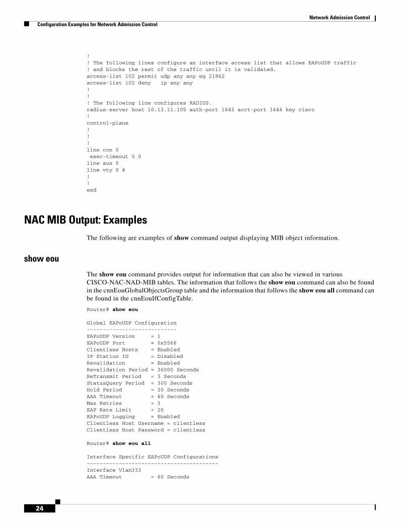
24
!! The following lines configure an interface access list that allows EAPoUDP traffic! and blocks the rest of the traffic until it is validated.access-list 102 permit udp any any eq 21862access-list 102 deny ip any any!!! The following line configures RADIUS. radius-server host 10.13.11.105 auth-port 1645 acct-port 1646 key cisco!control-plane!!!line con 0 exec-timeout 0 0line aux 0line vty 0 4! !end
NAC MIB Output: ExamplesThe following are examples of show command output displaying MIB object information.
show eou
The show eou command provides output for information that can also be viewed in various CISCO-NAC-NAD-MIB tables. The information that follows the show eou command can also be found in the cnnEouGlobalObjectsGroup table and the information that follows the show eou all command can be found in the cnnEouIfConfigTable.
Router# show eou
Global EAPoUDP Configuration----------------------------EAPoUDP Version = 1EAPoUDP Port = 0x5566Clientless Hosts = EnabledIP Station ID = DisabledRevalidation = EnabledRevalidation Period = 36000 SecondsReTransmit Period = 3 SecondsStatusQuery Period = 300 SecondsHold Period = 30 SecondsAAA Timeout = 60 SecondsMax Retries = 3EAP Rate Limit = 20EAPoUDP Logging = EnabledClientless Host Username = clientlessClientless Host Password = clientless
Router# show eou all
Interface Specific EAPoUDP Configurations-----------------------------------------Interface Vlan333AAA Timeout = 60 Seconds

Network Admission Control Configuration Examples for Network Admission Control
25Netword Admission Control
Max Retries = 3eou initialize interface {interface-name}eou revalidate interface {interface-name}
show ip device tracking all
The show ip device tracking all command provides output for information that can also be found in the cnnIpDeviceTrackingObjectsGroup MIB table. The following is an example of such show command output:
Router# show ip device tracking all
IP Device Tracking = EnabledProbe Count: 2Probe Interval: 10

Network Admission Control Additional References
26
Additional References
Related Documents
MIBs
Technical Assistance
Related Topic Document Title
Configuring ACLs “IP Access List Overview” feature module.
Authentication, authorization, and accounting “Authentication, Authorization, and Accounting” section of Cisco IOS Security Configuration Guide: Securing User Services, Release 12.4T.
Interfaces, configuring Cisco IOS Configuration Fundamentals Configuration Guide, Release 12.4T.SNMP and SNMP get and set operations
MIBs MIBs Link
None. To locate and download MIBs for selected platforms, Cisco IOS releases, and feature sets, use Cisco MIB Locator found at the following URL:
http://www.cisco.com/go/mibs
Description Link
The Cisco Support and Documentation website provides online resources to download documentation, software, and tools. Use these resources to install and configure the software and to troubleshoot and resolve technical issues with Cisco products and technologies. Access to most tools on the Cisco Support and Documentation website requires a Cisco.com user ID and password.
http://www.cisco.com/cisco/web/support/index.html

Network Admission Control Feature Information for Network Admission Control
27Netword Admission Control
Feature Information for Network Admission ControlTable 4 lists the release history for this feature.
Use Cisco Feature Navigator to find information about platform support and software image support. Cisco Feature Navigator enables you to determine which software images support a specific software release, feature set, or platform. To access Cisco Feature Navigator, go to http://www.cisco.com/go/cfn. An account on Cisco.com is not required.
Note Table 4 lists only the software release that introduced support for a given feature in a given software release train. Unless noted otherwise, subsequent releases of that software release train also support that feature.
Table 4 Feature Information for Network Admission Control
Feature Name Releases Feature Information
Network Admission Control 12.3(8)T The Network Admission Control feature addresses the increased threat and impact of worms and viruses to networked businesses. This feature is part of the Cisco Self-Defending Network Initiative that helps customers identify, prevent, and adapt to security threats.
In its initial phase, the Cisco Network Admission Control functionality enables Cisco routers to enforce access privileges when an endpoint attempts to connect to a network.
The following sections provide information about this feature:
• Prerequisites for Network Admission Control, page 2
• Restrictions for Network Admission Control, page 2
• Information About Network Admission Control, page 2
• How to Configure Network Admission Control, page 7
• Configuration Examples for Network Admission Control, page 23
The following commands were introduced or modified by this feature: aaa authentication eou default enable group radius, access-group (identity policy), auth-type, clear eou, clear ip admission cache, debug eap, debug eou, debug ip admission eapoudp, description (identity policy), description (identity profile), device (identity profile), eou allow, eou clientless, eou default, eou initialize, eou logging, eou max-retry, eou port, eou rate-limit, eou revalidate, eou timeout, identity policy, identity profile eapoudp, ip admission, ip admission name, redirect (identity policy), show eou, show ip admission, template (identity policy).

Network Admission Control Glossary
28
Glossarydefault access policy—Set of ACLs that are applied to a client device until its credentials are validated by the AAA server.
EAPoUDP—Extensible Authentication Protocol over User Datagram Protocol. EAP is a framework that supports multiple, optional authentication mechanisms for PPP, including clear-text passwords, challenge-response, and arbitrary dialogue sequences. UDP is a connectionless transport layer protocol in the TCP/IP protocol stack. UDP is a simple protocol that exchanges datagrams without acknowledgments or guaranteed delivery, and it requires that error processing and retransmission be handled by other protocols. UDP is defined in RFC 768.
ip admission rule—Named rule that defines how IP admission control is applied. The IP admission rule is associated with an Intercept ACL and provides control over which hosts can use the IP admission feature. To create an IP admission control rule, use the ip admission name command.
posture token—Status that is used to convey the result of the evaluation of posture credentials. The AAA server maps the posture token (its status can be Healthy, Checkup, Quarantine, Infected, or Unknown) to a network access policy (ACL, URL, redirect, or status query timer) for the peer that the client wants to reach.
Cisco and the Cisco Logo are trademarks of Cisco Systems, Inc. and/or its affiliates in the U.S. and other countries. A listing of Cisco's trademarks can be found at www.cisco.com/go/trademarks. Third party trademarks mentioned are the property of their respective owners. The use of the word partner does not imply a partnership relationship between Cisco and any other company. (1005R)
Any Internet Protocol (IP) addresses used in this document are not intended to be actual addresses. Any examples, command display output, and figures included in the document are shown for illustrative purposes only. Any use of actual IP addresses in illustrative content is unintentional and coincidental.
© 2004, 2007–20011 Cisco Systems, Inc. All rights reserved.
NAC MIB 12.4(15)T Support was added for the CISCO-NAC-NAD-MIB. This MIB module is used to monitor and configure the NAD on the Cisco NAC system.
The following sections provide information about this feature:
• “NAC MIB” section on page 5
• “Monitoring and Controlling NAC with the CISCO-NAC-NAD-MIB” section on page 16
The following commands were introduced or modified by this feature: show ip device tracking.
12.2(33)SXI This feature was integrated into Cisco IOS Release 12.2(33)SXI.
Table 4 Feature Information for Network Admission Control (continued)
Feature Name Releases Feature Information