network deployment guide
TRANSCRIPT
Silver Peak
Network Deployment Guide
VXOA 7.3
November 2015
PN 200059-001 Rev M
Silver Peak NX Series Appliances Network Deployment Guide
ii PN 200059-001 Rev M
Silver Peak NX Series Appliances Network Deployment Guide
Document PN 200059-001 Rev M
Date: November 2015
Copyright © 2015 Silver Peak Systems, Inc. All rights reserved. Information in this document is subject to change at any time. Use of this documentation is restricted as specified in the End User License Agreement. No part of this documentation can be reproduced, except as noted in the End User License Agreement, in whole or in part, without the written consent of Silver Peak Systems, Inc.
Trademark Notification
The following are trademarks of Silver Peak Systems, Inc.: Silver Peak SystemsTM, the Silver Peak logo, Network MemoryTM, Silver Peak NX-SeriesTM, Silver Peak VX-SeriesTM, Silver Peak VRX-SeriesTM, Silver Peak Unity EdgeConnectTM, and Silver Peak OrchestratorTM. All trademark rights reserved. All other brand or product names are trademarks or registered trademarks of their respective companies or organizations.
Warranties and Disclaimers
THIS DOCUMENTATION IS PROVIDED “AS IS” WITHOUT WARRANTY OF ANY KIND, EITHER EXPRESSED OR IMPLIED, INCLUDING, BUT NOT LIMITED TO, THE IMPLIED WARRANTIES OF MERCHANTABILITY, FITNESS FOR A PARTICULAR PURPOSE, OR NON-INFRINGEMENT. SILVER PEAK SYSTEMS, INC. ASSUMES NO RESPONSIBILITY FOR ERRORS OR OMISSIONS IN THIS DOCUMENTATION OR OTHER DOCUMENTS WHICH ARE REFERENCED BY OR LINKED TO THIS DOCUMENTATION. REFERENCES TO CORPORATIONS, THEIR SERVICES AND PRODUCTS, ARE PROVIDED “AS IS” WITHOUT WARRANTY OF ANY KIND, EITHER EXPRESSED OR IMPLIED. IN NO EVENT SHALL SILVER PEAK SYSTEMS, INC. BE LIABLE FOR ANY SPECIAL, INCIDENTAL, INDIRECT OR CONSEQUENTIAL DAMAGES OF ANY KIND, OR ANY DAMAGES WHATSOEVER, INCLUDING, WITHOUT LIMITATION, THOSE RESULTING FROM LOSS OF USE, DATA OR PROFITS, WHETHER OR NOT ADVISED OF THE POSSIBILITY OF DAMAGE, AND ON ANY THEORY OF LIABILITY, ARISING OUT OF OR IN CONNECTION WITH THE USE OF THIS DOCUMENTATION. THIS DOCUMENTATION MAY INCLUDE TECHNICAL OR OTHER INACCURACIES OR TYPOGRAPHICAL ERRORS. CHANGES ARE PERIODICALLY ADDED TO THE INFORMATION HEREIN; THESE CHANGES WILL BE INCORPORATED IN NEW EDITIONS OF THE DOCUMENTATION. SILVER PEAK SYSTEMS, INC. MAY MAKE IMPROVEMENTS AND/OR CHANGES IN THE PRODUCT(S) AND/OR THE PROGRAM(S) DESCRIBED IN THIS DOCUMENTATION AT ANY TIME.
Silver Peak Systems, Inc.2860 De La Cruz Boulevard, Suite 100Santa Clara, CA 95050
1.877.210.7325 (toll-free in USA)+1.408.935.1850
http://www.silver-peak.com/support
Contents
PN 200059-001 Rev M iii
Contents
Preface . . . . . . . . . . . . . . . . . . . . . . . . . . . . . . . . . . . . . . . . . . . . . . . . . . . . . . . . . . . . . . . . . . . . . . . . . . vii
Who Should Read This Manual?. . . . . . . . . . . . . . . . . . . . . . . . . . . . . . . . . . . . . . . . . . . . . . . . . . . . . . . . . . . . . . vii
Manual Organization . . . . . . . . . . . . . . . . . . . . . . . . . . . . . . . . . . . . . . . . . . . . . . . . . . . . . . . . . . . . . . . . . . . . . . . vii
Related Publications . . . . . . . . . . . . . . . . . . . . . . . . . . . . . . . . . . . . . . . . . . . . . . . . . . . . . . . . . . . . . . . . . . . . . . . viii
Technical Support . . . . . . . . . . . . . . . . . . . . . . . . . . . . . . . . . . . . . . . . . . . . . . . . . . . . . . . . . . . . . . . . . . . . . . . . . viii
Chapter 1 Fundamentals of Deploying WAN Optimization . . . . . . . . . . . . . . . . . . . . . . . . . . . . . 1
Introduction . . . . . . . . . . . . . . . . . . . . . . . . . . . . . . . . . . . . . . . . . . . . . . . . . . . . . . . . . . . . . . . . . . . . . . . . . . . . . . . 2
Definition of Terms . . . . . . . . . . . . . . . . . . . . . . . . . . . . . . . . . . . . . . . . . . . . . . . . . . . . . . . . . . . . . . . . . . . . . . . 2
Using Physical and Virtual Appliances . . . . . . . . . . . . . . . . . . . . . . . . . . . . . . . . . . . . . . . . . . . . . . . . . . . . . . . . . . 4
Ethernet Interfaces and IP Addresses . . . . . . . . . . . . . . . . . . . . . . . . . . . . . . . . . . . . . . . . . . . . . . . . . . . . . . . . 4
Configuring the mgmt0 Interface. . . . . . . . . . . . . . . . . . . . . . . . . . . . . . . . . . . . . . . . . . . . . . . . . . . . . . . . . . . . . 5
Choosing an Optimization Strategy for the Traffic Path . . . . . . . . . . . . . . . . . . . . . . . . . . . . . . . . . . . . . . . . . . . . . 8
Configuring Dynamic Path Control . . . . . . . . . . . . . . . . . . . . . . . . . . . . . . . . . . . . . . . . . . . . . . . . . . . . . . . . . . . . . 9
How to configure DPC in the Route Policy . . . . . . . . . . . . . . . . . . . . . . . . . . . . . . . . . . . . . . . . . . . . . . . . . . . . . 9
How to configure a Preferred Interface . . . . . . . . . . . . . . . . . . . . . . . . . . . . . . . . . . . . . . . . . . . . . . . . . . . . . . . 11
WAN Hardening . . . . . . . . . . . . . . . . . . . . . . . . . . . . . . . . . . . . . . . . . . . . . . . . . . . . . . . . . . . . . . . . . . . . . . . . . . 12
Determining the Need for Traffic Redirection . . . . . . . . . . . . . . . . . . . . . . . . . . . . . . . . . . . . . . . . . . . . . . . . . . . . 13
When using subnet sharing. . . . . . . . . . . . . . . . . . . . . . . . . . . . . . . . . . . . . . . . . . . . . . . . . . . . . . . . . . . . . . . . 14
When defaulting to TCP-based or IP-based auto-optimization . . . . . . . . . . . . . . . . . . . . . . . . . . . . . . . . . . . . . 15
When specifying a tunnel . . . . . . . . . . . . . . . . . . . . . . . . . . . . . . . . . . . . . . . . . . . . . . . . . . . . . . . . . . . . . . . . . 16
High Availability . . . . . . . . . . . . . . . . . . . . . . . . . . . . . . . . . . . . . . . . . . . . . . . . . . . . . . . . . . . . . . . . . . . . . . . . . . . 17
Auto-optimization or Explicit Route Maps? . . . . . . . . . . . . . . . . . . . . . . . . . . . . . . . . . . . . . . . . . . . . . . . . . . . . 17
Asymmetry Mitigation . . . . . . . . . . . . . . . . . . . . . . . . . . . . . . . . . . . . . . . . . . . . . . . . . . . . . . . . . . . . . . . . . . . . 17
High Availability with Explicit Route-Maps . . . . . . . . . . . . . . . . . . . . . . . . . . . . . . . . . . . . . . . . . . . . . . . . . . . . 17
Considerations for Deployments . . . . . . . . . . . . . . . . . . . . . . . . . . . . . . . . . . . . . . . . . . . . . . . . . . . . . . . . . . . . . . 18
Verifying Connectivity After Configuring Deployment . . . . . . . . . . . . . . . . . . . . . . . . . . . . . . . . . . . . . . . . . . . . . . 19
ping . . . . . . . . . . . . . . . . . . . . . . . . . . . . . . . . . . . . . . . . . . . . . . . . . . . . . . . . . . . . . . . . . . . . . . . . . . . . . . . . . . 19
ping -r [or ping -R]: ping with Record Route option . . . . . . . . . . . . . . . . . . . . . . . . . . . . . . . . . . . . . . . . . . . . . . 19
traceroute . . . . . . . . . . . . . . . . . . . . . . . . . . . . . . . . . . . . . . . . . . . . . . . . . . . . . . . . . . . . . . . . . . . . . . . . . . . . . 19
Basic procedure . . . . . . . . . . . . . . . . . . . . . . . . . . . . . . . . . . . . . . . . . . . . . . . . . . . . . . . . . . . . . . . . . . . . . . . . 20
Chapter 2 In-Line Deployment. . . . . . . . . . . . . . . . . . . . . . . . . . . . . . . . . . . . . . . . . . . . . . . . . . . . . . 21
Overview . . . . . . . . . . . . . . . . . . . . . . . . . . . . . . . . . . . . . . . . . . . . . . . . . . . . . . . . . . . . . . . . . . . . . . . . . . . . . . . . 22
Network Diagram . . . . . . . . . . . . . . . . . . . . . . . . . . . . . . . . . . . . . . . . . . . . . . . . . . . . . . . . . . . . . . . . . . . . . . . 22
Summary of Initial Configuration Tasks . . . . . . . . . . . . . . . . . . . . . . . . . . . . . . . . . . . . . . . . . . . . . . . . . . . . . . 23
Collecting the Necessary Information . . . . . . . . . . . . . . . . . . . . . . . . . . . . . . . . . . . . . . . . . . . . . . . . . . . . . . . . 23
Using the Initial Config Wizard . . . . . . . . . . . . . . . . . . . . . . . . . . . . . . . . . . . . . . . . . . . . . . . . . . . . . . . . . . . . . . . 25
Verifying Appliance Connectivity . . . . . . . . . . . . . . . . . . . . . . . . . . . . . . . . . . . . . . . . . . . . . . . . . . . . . . . . . . . . . . 32
Creating Tunnels . . . . . . . . . . . . . . . . . . . . . . . . . . . . . . . . . . . . . . . . . . . . . . . . . . . . . . . . . . . . . . . . . . . . . . . . . . 33
Verifying Traffic . . . . . . . . . . . . . . . . . . . . . . . . . . . . . . . . . . . . . . . . . . . . . . . . . . . . . . . . . . . . . . . . . . . . . . . . . . . 35
Chapter 3 Out-of-Path with Policy-Based-Routing Redirection . . . . . . . . . . . . . . . . . . . . . . . . 39
SECTION 1: Using Subnet Sharing . . . . . . . . . . . . . . . . . . . . . . . . . . . . . . . . . . . . . . . . . . . . . . . . . . . . . . . .40
Overview . . . . . . . . . . . . . . . . . . . . . . . . . . . . . . . . . . . . . . . . . . . . . . . . . . . . . . . . . . . . . . . . . . . . . . . . . . . . . . . . 41
Silver Peak NX Series Appliances Network Deployment Guide
iv PN 200059-001 Rev M
Network Diagram . . . . . . . . . . . . . . . . . . . . . . . . . . . . . . . . . . . . . . . . . . . . . . . . . . . . . . . . . . . . . . . . . . . . . . . 41
Summary of Initial Configuration Tasks . . . . . . . . . . . . . . . . . . . . . . . . . . . . . . . . . . . . . . . . . . . . . . . . . . . . . . 42
Collecting the Necessary Information . . . . . . . . . . . . . . . . . . . . . . . . . . . . . . . . . . . . . . . . . . . . . . . . . . . . . . . . 43
Using the Initial Config Wizard . . . . . . . . . . . . . . . . . . . . . . . . . . . . . . . . . . . . . . . . . . . . . . . . . . . . . . . . . . . . . . . 44
Verifying Appliance Connectivity . . . . . . . . . . . . . . . . . . . . . . . . . . . . . . . . . . . . . . . . . . . . . . . . . . . . . . . . . . . . . . 56
Enabling Subnet Sharing. . . . . . . . . . . . . . . . . . . . . . . . . . . . . . . . . . . . . . . . . . . . . . . . . . . . . . . . . . . . . . . . . . . . 58
Creating Tunnels and Updating the Subnet Table . . . . . . . . . . . . . . . . . . . . . . . . . . . . . . . . . . . . . . . . . . . . . . . . 60
Configuring the Router to Redirect Traffic . . . . . . . . . . . . . . . . . . . . . . . . . . . . . . . . . . . . . . . . . . . . . . . . . . . . . . . 64
Using a Cisco Router for Policy-Based Routing (PBR). . . . . . . . . . . . . . . . . . . . . . . . . . . . . . . . . . . . . . . . . . . 64
Using a Juniper Router for Filter-Based Forwarding (FBF). . . . . . . . . . . . . . . . . . . . . . . . . . . . . . . . . . . . . . . . 65
Verifying Traffic . . . . . . . . . . . . . . . . . . . . . . . . . . . . . . . . . . . . . . . . . . . . . . . . . . . . . . . . . . . . . . . . . . . . . . . . . . . 67
SECTION 2: Using TCP/IP–based Auto-Optimization . . . . . . . . . . . . . . . . . . . . . . . . . . . . . . . . . . . . . . . . .70
Overview . . . . . . . . . . . . . . . . . . . . . . . . . . . . . . . . . . . . . . . . . . . . . . . . . . . . . . . . . . . . . . . . . . . . . . . . . . . . . . . . 71
Network Diagram . . . . . . . . . . . . . . . . . . . . . . . . . . . . . . . . . . . . . . . . . . . . . . . . . . . . . . . . . . . . . . . . . . . . . . . 71
Summary of Initial Configuration Tasks . . . . . . . . . . . . . . . . . . . . . . . . . . . . . . . . . . . . . . . . . . . . . . . . . . . . . . 73
Collecting the Necessary Information . . . . . . . . . . . . . . . . . . . . . . . . . . . . . . . . . . . . . . . . . . . . . . . . . . . . . . . . 74
Using the Initial Config Wizard with Site A’s Appliance. . . . . . . . . . . . . . . . . . . . . . . . . . . . . . . . . . . . . . . . . . . . . 75
Configuring the Router for Policy-Based Routing (PBR) . . . . . . . . . . . . . . . . . . . . . . . . . . . . . . . . . . . . . . . . . . . . 81
Configuring a Tunnel to the Remote Site . . . . . . . . . . . . . . . . . . . . . . . . . . . . . . . . . . . . . . . . . . . . . . . . . . . . . . . 83
Configuring Site B’s Appliance . . . . . . . . . . . . . . . . . . . . . . . . . . . . . . . . . . . . . . . . . . . . . . . . . . . . . . . . . . . . . . . 85
Chapter 4 Out-of-Path with WCCP . . . . . . . . . . . . . . . . . . . . . . . . . . . . . . . . . . . . . . . . . . . . . . . . . . 87
Overview . . . . . . . . . . . . . . . . . . . . . . . . . . . . . . . . . . . . . . . . . . . . . . . . . . . . . . . . . . . . . . . . . . . . . . . . . . . . . . . . 88
Network Diagram . . . . . . . . . . . . . . . . . . . . . . . . . . . . . . . . . . . . . . . . . . . . . . . . . . . . . . . . . . . . . . . . . . . . . . . 88
Summary of Configuration Tasks . . . . . . . . . . . . . . . . . . . . . . . . . . . . . . . . . . . . . . . . . . . . . . . . . . . . . . . . . . . 90
Collecting the Necessary Information . . . . . . . . . . . . . . . . . . . . . . . . . . . . . . . . . . . . . . . . . . . . . . . . . . . . . . . . 91
Configuring the Site A Router for WCCP. . . . . . . . . . . . . . . . . . . . . . . . . . . . . . . . . . . . . . . . . . . . . . . . . . . . . . . . 92
Outbound Redirection and Enabling WCCP . . . . . . . . . . . . . . . . . . . . . . . . . . . . . . . . . . . . . . . . . . . . . . . . . . . 92
Inbound Redirection . . . . . . . . . . . . . . . . . . . . . . . . . . . . . . . . . . . . . . . . . . . . . . . . . . . . . . . . . . . . . . . . . . . . . 93
Using the Initial Config Wizard with Site A’s Appliance. . . . . . . . . . . . . . . . . . . . . . . . . . . . . . . . . . . . . . . . . . . . . 94
Configuring WCCP on Appliance A. . . . . . . . . . . . . . . . . . . . . . . . . . . . . . . . . . . . . . . . . . . . . . . . . . . . . . . . . . . 100
Configuring WCCP Service Groups for Outbound Traffic Redirection . . . . . . . . . . . . . . . . . . . . . . . . . . . . . . 100
Configuring WCCP Service Groups for Inbound Traffic Redirection. . . . . . . . . . . . . . . . . . . . . . . . . . . . . . . . 105
Using the Initial Config Wizard with Site B’s Appliance. . . . . . . . . . . . . . . . . . . . . . . . . . . . . . . . . . . . . . . . . . . . 110
Verifying Appliance Connectivity . . . . . . . . . . . . . . . . . . . . . . . . . . . . . . . . . . . . . . . . . . . . . . . . . . . . . . . . . . . . . 116
Enabling Subnet Sharing. . . . . . . . . . . . . . . . . . . . . . . . . . . . . . . . . . . . . . . . . . . . . . . . . . . . . . . . . . . . . . . . . . . 118
Creating Tunnels and Updating the Subnet Table . . . . . . . . . . . . . . . . . . . . . . . . . . . . . . . . . . . . . . . . . . . . . . . 120
Verifying Traffic . . . . . . . . . . . . . . . . . . . . . . . . . . . . . . . . . . . . . . . . . . . . . . . . . . . . . . . . . . . . . . . . . . . . . . . . . . 124
Best Practices . . . . . . . . . . . . . . . . . . . . . . . . . . . . . . . . . . . . . . . . . . . . . . . . . . . . . . . . . . . . . . . . . . . . . . . . . . . 126
Tips for Deployment . . . . . . . . . . . . . . . . . . . . . . . . . . . . . . . . . . . . . . . . . . . . . . . . . . . . . . . . . . . . . . . . . . . . 126
GRE and L2 Redirection . . . . . . . . . . . . . . . . . . . . . . . . . . . . . . . . . . . . . . . . . . . . . . . . . . . . . . . . . . . . . . . . . 127
Chapter 5 Out-of-Path with VRRP Peering to a WAN Router . . . . . . . . . . . . . . . . . . . . . . . . . 129
Overview . . . . . . . . . . . . . . . . . . . . . . . . . . . . . . . . . . . . . . . . . . . . . . . . . . . . . . . . . . . . . . . . . . . . . . . . . . . . . . . 130
Network Diagram . . . . . . . . . . . . . . . . . . . . . . . . . . . . . . . . . . . . . . . . . . . . . . . . . . . . . . . . . . . . . . . . . . . . . . 130
Summary of Initial Configuration Tasks . . . . . . . . . . . . . . . . . . . . . . . . . . . . . . . . . . . . . . . . . . . . . . . . . . . . . 132
Collecting the Necessary Information . . . . . . . . . . . . . . . . . . . . . . . . . . . . . . . . . . . . . . . . . . . . . . . . . . . . . . . 133
Using the Initial Config Wizard . . . . . . . . . . . . . . . . . . . . . . . . . . . . . . . . . . . . . . . . . . . . . . . . . . . . . . . . . . . . . . 134
Verifying Appliance Connectivity . . . . . . . . . . . . . . . . . . . . . . . . . . . . . . . . . . . . . . . . . . . . . . . . . . . . . . . . . . . . . 146
Enabling Subnet Sharing. . . . . . . . . . . . . . . . . . . . . . . . . . . . . . . . . . . . . . . . . . . . . . . . . . . . . . . . . . . . . . . . . . . 147
Contents
PN 200059-001 Rev M v
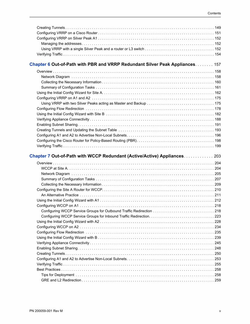
Creating Tunnels . . . . . . . . . . . . . . . . . . . . . . . . . . . . . . . . . . . . . . . . . . . . . . . . . . . . . . . . . . . . . . . . . . . . . . . . . 149
Configuring VRRP on a Cisco Router . . . . . . . . . . . . . . . . . . . . . . . . . . . . . . . . . . . . . . . . . . . . . . . . . . . . . . . . . 151
Configuring VRRP on Silver Peak A1 . . . . . . . . . . . . . . . . . . . . . . . . . . . . . . . . . . . . . . . . . . . . . . . . . . . . . . . . . 152
Managing the addresses. . . . . . . . . . . . . . . . . . . . . . . . . . . . . . . . . . . . . . . . . . . . . . . . . . . . . . . . . . . . . . . . . 152
Using VRRP with a single Silver Peak and a router or L3 switch . . . . . . . . . . . . . . . . . . . . . . . . . . . . . . . . . . 152
Verifying Traffic . . . . . . . . . . . . . . . . . . . . . . . . . . . . . . . . . . . . . . . . . . . . . . . . . . . . . . . . . . . . . . . . . . . . . . . . . . 154
Chapter 6 Out-of-Path with PBR and VRRP Redundant Silver Peak Appliances. . . . . . . . 157
Overview . . . . . . . . . . . . . . . . . . . . . . . . . . . . . . . . . . . . . . . . . . . . . . . . . . . . . . . . . . . . . . . . . . . . . . . . . . . . . . . 158
Network Diagram . . . . . . . . . . . . . . . . . . . . . . . . . . . . . . . . . . . . . . . . . . . . . . . . . . . . . . . . . . . . . . . . . . . . . . 158
Collecting the Necessary Information . . . . . . . . . . . . . . . . . . . . . . . . . . . . . . . . . . . . . . . . . . . . . . . . . . . . . . . 160
Summary of Configuration Tasks . . . . . . . . . . . . . . . . . . . . . . . . . . . . . . . . . . . . . . . . . . . . . . . . . . . . . . . . . . 161
Using the Initial Config Wizard for Site A. . . . . . . . . . . . . . . . . . . . . . . . . . . . . . . . . . . . . . . . . . . . . . . . . . . . . . . 162
Configuring VRRP on A1 and A2 . . . . . . . . . . . . . . . . . . . . . . . . . . . . . . . . . . . . . . . . . . . . . . . . . . . . . . . . . . . . 175
Using VRRP with two Silver Peaks acting as Master and Backup . . . . . . . . . . . . . . . . . . . . . . . . . . . . . . . . . 175
Configuring Flow Redirection . . . . . . . . . . . . . . . . . . . . . . . . . . . . . . . . . . . . . . . . . . . . . . . . . . . . . . . . . . . . . . . 178
Using the Initial Config Wizard with Site B . . . . . . . . . . . . . . . . . . . . . . . . . . . . . . . . . . . . . . . . . . . . . . . . . . . . . 182
Verifying Appliance Connectivity . . . . . . . . . . . . . . . . . . . . . . . . . . . . . . . . . . . . . . . . . . . . . . . . . . . . . . . . . . . . . 188
Enabling Subnet Sharing. . . . . . . . . . . . . . . . . . . . . . . . . . . . . . . . . . . . . . . . . . . . . . . . . . . . . . . . . . . . . . . . . . . 191
Creating Tunnels and Updating the Subnet Table . . . . . . . . . . . . . . . . . . . . . . . . . . . . . . . . . . . . . . . . . . . . . . . 193
Configuring A1 and A2 to Advertise Non-Local Subnets. . . . . . . . . . . . . . . . . . . . . . . . . . . . . . . . . . . . . . . . . . . 196
Configuring the Cisco Router for Policy-Based Routing (PBR) . . . . . . . . . . . . . . . . . . . . . . . . . . . . . . . . . . . . . . 198
Verifying Traffic . . . . . . . . . . . . . . . . . . . . . . . . . . . . . . . . . . . . . . . . . . . . . . . . . . . . . . . . . . . . . . . . . . . . . . . . . . 199
Chapter 7 Out-of-Path with WCCP Redundant (Active/Active) Appliances. . . . . . . . . . . . . 203
Overview . . . . . . . . . . . . . . . . . . . . . . . . . . . . . . . . . . . . . . . . . . . . . . . . . . . . . . . . . . . . . . . . . . . . . . . . . . . . . . . 204
WCCP at Site A. . . . . . . . . . . . . . . . . . . . . . . . . . . . . . . . . . . . . . . . . . . . . . . . . . . . . . . . . . . . . . . . . . . . . . . . 204
Network Diagram . . . . . . . . . . . . . . . . . . . . . . . . . . . . . . . . . . . . . . . . . . . . . . . . . . . . . . . . . . . . . . . . . . . . . . 205
Summary of Configuration Tasks . . . . . . . . . . . . . . . . . . . . . . . . . . . . . . . . . . . . . . . . . . . . . . . . . . . . . . . . . . 207
Collecting the Necessary Information . . . . . . . . . . . . . . . . . . . . . . . . . . . . . . . . . . . . . . . . . . . . . . . . . . . . . . . 209
Configuring the Site A Router for WCCP. . . . . . . . . . . . . . . . . . . . . . . . . . . . . . . . . . . . . . . . . . . . . . . . . . . . . . . 210
An Alternative Practice . . . . . . . . . . . . . . . . . . . . . . . . . . . . . . . . . . . . . . . . . . . . . . . . . . . . . . . . . . . . . . . . . . 211
Using the Initial Config Wizard with A1 . . . . . . . . . . . . . . . . . . . . . . . . . . . . . . . . . . . . . . . . . . . . . . . . . . . . . . . . 212
Configuring WCCP on A1 . . . . . . . . . . . . . . . . . . . . . . . . . . . . . . . . . . . . . . . . . . . . . . . . . . . . . . . . . . . . . . . . . . 218
Configuring WCCP Service Groups for Outbound Traffic Redirection . . . . . . . . . . . . . . . . . . . . . . . . . . . . . . 218
Configuring WCCP Service Groups for Inbound Traffic Redirection. . . . . . . . . . . . . . . . . . . . . . . . . . . . . . . . 223
Using the Initial Config Wizard with A2 . . . . . . . . . . . . . . . . . . . . . . . . . . . . . . . . . . . . . . . . . . . . . . . . . . . . . . . . 228
Configuring WCCP on A2 . . . . . . . . . . . . . . . . . . . . . . . . . . . . . . . . . . . . . . . . . . . . . . . . . . . . . . . . . . . . . . . . . . 234
Configuring Flow Redirection . . . . . . . . . . . . . . . . . . . . . . . . . . . . . . . . . . . . . . . . . . . . . . . . . . . . . . . . . . . . . . . 235
Using the Initial Config Wizard with B . . . . . . . . . . . . . . . . . . . . . . . . . . . . . . . . . . . . . . . . . . . . . . . . . . . . . . . . . 239
Verifying Appliance Connectivity . . . . . . . . . . . . . . . . . . . . . . . . . . . . . . . . . . . . . . . . . . . . . . . . . . . . . . . . . . . . . 245
Enabling Subnet Sharing. . . . . . . . . . . . . . . . . . . . . . . . . . . . . . . . . . . . . . . . . . . . . . . . . . . . . . . . . . . . . . . . . . . 248
Creating Tunnels . . . . . . . . . . . . . . . . . . . . . . . . . . . . . . . . . . . . . . . . . . . . . . . . . . . . . . . . . . . . . . . . . . . . . . . . . 250
Configuring A1 and A2 to Advertise Non-Local Subnets. . . . . . . . . . . . . . . . . . . . . . . . . . . . . . . . . . . . . . . . . . . 253
Verifying Traffic . . . . . . . . . . . . . . . . . . . . . . . . . . . . . . . . . . . . . . . . . . . . . . . . . . . . . . . . . . . . . . . . . . . . . . . . . . 255
Best Practices . . . . . . . . . . . . . . . . . . . . . . . . . . . . . . . . . . . . . . . . . . . . . . . . . . . . . . . . . . . . . . . . . . . . . . . . . . . 258
Tips for Deployment . . . . . . . . . . . . . . . . . . . . . . . . . . . . . . . . . . . . . . . . . . . . . . . . . . . . . . . . . . . . . . . . . . . . 258
GRE and L2 Redirection . . . . . . . . . . . . . . . . . . . . . . . . . . . . . . . . . . . . . . . . . . . . . . . . . . . . . . . . . . . . . . . . . 259

Silver Peak NX Series Appliances Network Deployment Guide
vi PN 200059-001 Rev M
PN 200059-001 Rev M vii
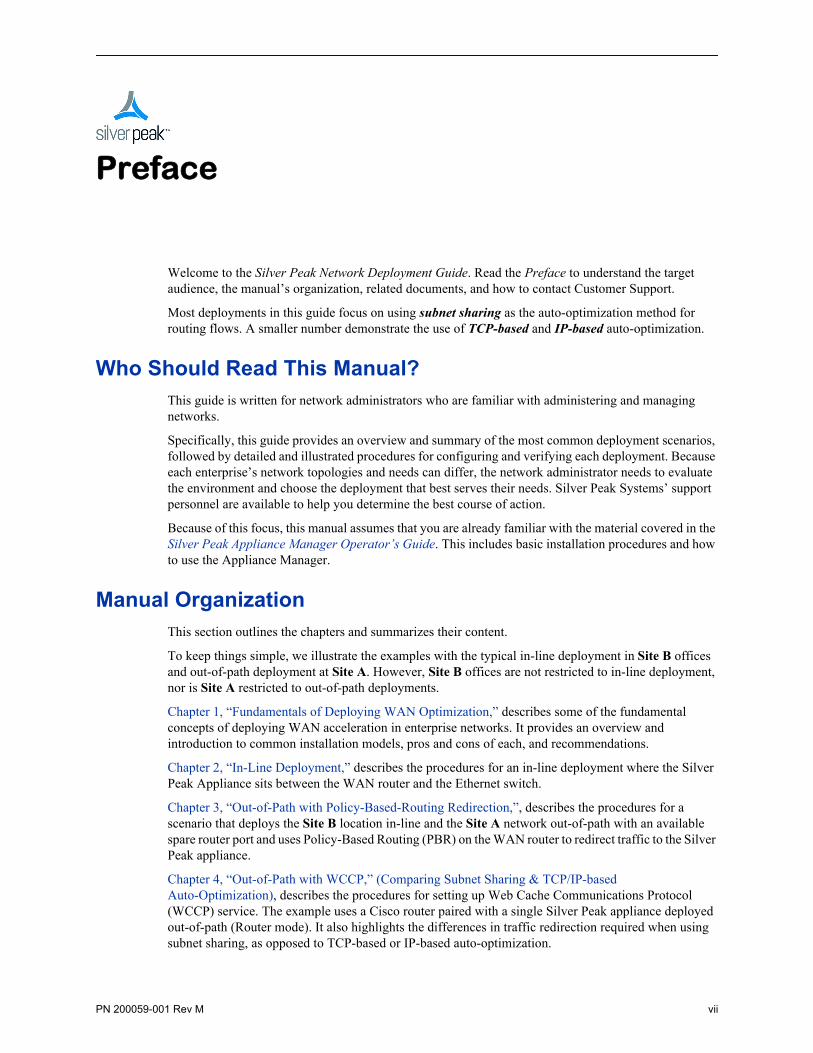
Preface
Welcome to the Silver Peak Network Deployment Guide. Read the Preface to understand the target audience, the manual’s organization, related documents, and how to contact Customer Support.
Most deployments in this guide focus on using subnet sharing as the auto-optimization method for routing flows. A smaller number demonstrate the use of TCP-based and IP-based auto-optimization.
Who Should Read This Manual?This guide is written for network administrators who are familiar with administering and managing networks.
Specifically, this guide provides an overview and summary of the most common deployment scenarios, followed by detailed and illustrated procedures for configuring and verifying each deployment. Because each enterprise’s network topologies and needs can differ, the network administrator needs to evaluate the environment and choose the deployment that best serves their needs. Silver Peak Systems’ support personnel are available to help you determine the best course of action.
Because of this focus, this manual assumes that you are already familiar with the material covered in the Silver Peak Appliance Manager Operator’s Guide. This includes basic installation procedures and how to use the Appliance Manager.
Manual OrganizationThis section outlines the chapters and summarizes their content.
To keep things simple, we illustrate the examples with the typical in-line deployment in Site B offices and out-of-path deployment at Site A. However, Site B offices are not restricted to in-line deployment, nor is Site A restricted to out-of-path deployments.
Chapter 1, “Fundamentals of Deploying WAN Optimization,” describes some of the fundamental concepts of deploying WAN acceleration in enterprise networks. It provides an overview and introduction to common installation models, pros and cons of each, and recommendations.
Chapter 2, “In-Line Deployment,” describes the procedures for an in-line deployment where the Silver Peak Appliance sits between the WAN router and the Ethernet switch.
Chapter 3, “Out-of-Path with Policy-Based-Routing Redirection,”, describes the procedures for a scenario that deploys the Site B location in-line and the Site A network out-of-path with an available spare router port and uses Policy-Based Routing (PBR) on the WAN router to redirect traffic to the Silver Peak appliance.
Chapter 4, “Out-of-Path with WCCP,” (Comparing Subnet Sharing & TCP/IP-based Auto-Optimization), describes the procedures for setting up Web Cache Communications Protocol (WCCP) service. The example uses a Cisco router paired with a single Silver Peak appliance deployed out-of-path (Router mode). It also highlights the differences in traffic redirection required when using subnet sharing, as opposed to TCP-based or IP-based auto-optimization.
Silver Peak NX Series Appliances Network Deployment Guide Related Publications
viii PN 200059-001 Rev M
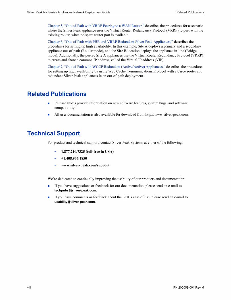
Chapter 5, “Out-of-Path with VRRP Peering to a WAN Router,” describes the procedures for a scenario where the Silver Peak appliance uses the Virtual Router Redundancy Protocol (VRRP) to peer with the existing router, when no spare router port is available.
Chapter 6, “Out-of-Path with PBR and VRRP Redundant Silver Peak Appliances,” describes the procedures for setting up high availability. In this example, Site A deploys a primary and a secondary appliance out-of-path (Router mode), and the Site B location deploys the appliance in-line (Bridge mode). Additionally, the peered Site A appliances use the Virtual Router Redundancy Protocol (VRRP) to create and share a common IP address, called the Virtual IP address (VIP).
Chapter 7, “Out-of-Path with WCCP Redundant (Active/Active) Appliances,” describes the procedures for setting up high availability by using Web Cache Communications Protocol with a Cisco router and redundant Silver Peak appliances in an out-of-path deployment.
Related Publications Release Notes provide information on new software features, system bugs, and software
compatibility.
All user documentation is also available for download from http://www.silver-peak.com.
Technical SupportFor product and technical support, contact Silver Peak Systems at either of the following:
• 1.877.210.7325 (toll-free in USA)
• +1.408.935.1850
• www.silver-peak.com/support
We’re dedicated to continually improving the usability of our products and documentation.
If you have suggestions or feedback for our documentation, please send an e-mail to [email protected].
If you have comments or feedback about the GUI’s ease of use, please send an e-mail to [email protected].
PN 200059-001 Rev M 1
C H A P T E R 1
Fundamentals of Deploying WAN Optimization
This chapter describes some of the fundamental concepts of deploying WAN acceleration in enterprise networks.
In This Chapter Introduction See page 2.
Using Physical and Virtual Appliances See page 4.
Configuring the mgmt0 Interface See page 5.
Choosing an Optimization Strategy for the Traffic Path See page 8.
Configuring Dynamic Path Control See page 9.
WAN Hardening See page 12.
Determining the Need for Traffic Redirection See page 13.
High Availability See page 17.
Considerations for Deployments See page 18.
Verifying Connectivity After Configuring Deployment See page 19.
Silver Peak NX Series Appliances Network Deployment Guide Introduction
2 PN 200059-001 Rev M
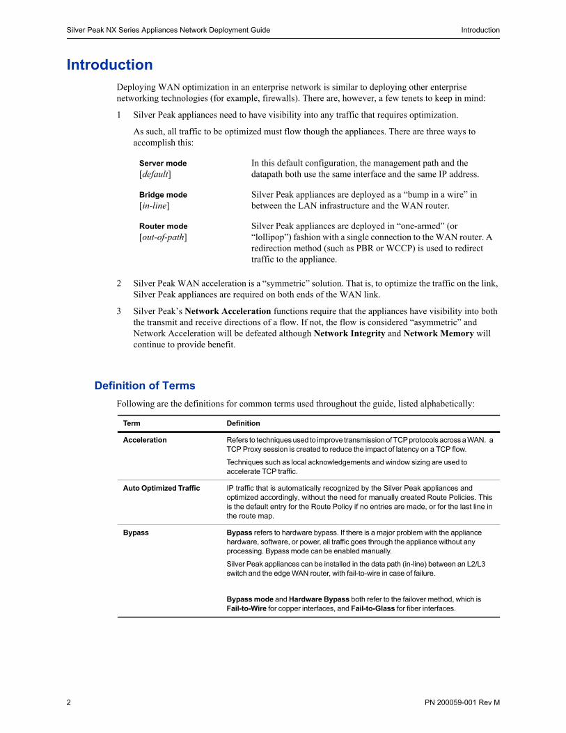
IntroductionDeploying WAN optimization in an enterprise network is similar to deploying other enterprise networking technologies (for example, firewalls). There are, however, a few tenets to keep in mind:
1 Silver Peak appliances need to have visibility into any traffic that requires optimization.
As such, all traffic to be optimized must flow though the appliances. There are three ways to accomplish this:
2 Silver Peak WAN acceleration is a “symmetric” solution. That is, to optimize the traffic on the link, Silver Peak appliances are required on both ends of the WAN link.
3 Silver Peak’s Network Acceleration functions require that the appliances have visibility into both the transmit and receive directions of a flow. If not, the flow is considered “asymmetric” and Network Acceleration will be defeated although Network Integrity and Network Memory will continue to provide benefit.
Definition of Terms
Following are the definitions for common terms used throughout the guide, listed alphabetically:
Server mode [default]
In this default configuration, the management path and the datapath both use the same interface and the same IP address.
Bridge mode [in-line]
Silver Peak appliances are deployed as a “bump in a wire” in between the LAN infrastructure and the WAN router.
Router mode [out-of-path]
Silver Peak appliances are deployed in “one-armed” (or “lollipop”) fashion with a single connection to the WAN router. A redirection method (such as PBR or WCCP) is used to redirect traffic to the appliance.
Term Definition
Acceleration Refers to techniques used to improve transmission of TCP protocols across a WAN. a TCP Proxy session is created to reduce the impact of latency on a TCP flow.
Techniques such as local acknowledgements and window sizing are used to accelerate TCP traffic.
Auto Optimized Traffic IP traffic that is automatically recognized by the Silver Peak appliances and optimized accordingly, without the need for manually created Route Policies. This is the default entry for the Route Policy if no entries are made, or for the last line in the route map.
Bypass Bypass refers to hardware bypass. If there is a major problem with the appliance hardware, software, or power, all traffic goes through the appliance without any processing. Bypass mode can be enabled manually.
Silver Peak appliances can be installed in the data path (in-line) between an L2/L3 switch and the edge WAN router, with fail-to-wire in case of failure.
Bypass mode and Hardware Bypass both refer to the failover method, which is Fail-to-Wire for copper interfaces, and Fail-to-Glass for fiber interfaces.
Introduction Chapter 1 Fundamentals of Deploying WAN Optimization
PN 200059-001 Rev M 3
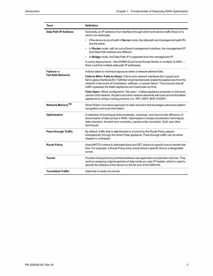
Data Path IP Address Generally, an IP address of an interface through which end-device traffic flows or to which it is redirected.
• If the device is out-of-path in Server mode, the data path and management path IPs are the same.
• In Router mode, with an out-of-band management interface, the management IP and Data Path address are different.
• In Bridge mode, the Data Path IP is separate from the management IP.
In some deployments—like DHRM (Dual Home Router Mode) or multiple VLANS — there could be multiple data path IP addresses.
Failover orFail-Safe Behavior
Actions taken to minimize exposure when a network element fails.
Fails-to-Wire / Fails-to-Glass: Fail-to-wire network interfaces [for copper] and fail-to-glass interfaces [for 1GB fiber only] mechanically isolate the appliances from the network in the event of a hardware, software, or power failure. This ensures that all traffic bypasses the failed appliance and maximizes up-time.
Fails-Open: When configured to “fail open”, a failed appliance presents no link-level carrier to the network. Routers and other network elements will route around the failed appliance by using a routing protocol (i.e., RIP, OSPF, BGP, EIGRP).
Network MemoryTM Silver Peak's innovative approach to data reduction that leverages advanced pattern recognition and local information
Optimization A collection of techniques that accelerate, compress, and improve the efficiency of transmission of data across a WAN. Optimization includes acceleration techniques, data reduction, forward error correction, packet order correction, QoS, and other techniques.
Pass-through Traffic By default, traffic that is not directed to a tunnel by the Route Policy passes transparently through the Silver Peak appliance. Pass-through traffic can be either shaped or unshaped.
Route Policy Uses MATCH criteria to delineate flows and SET actions to specify how to handle that flow. For example, a Route Policy entry would direct a specific flow to a designated tunnel.
Tunnel Provide virtual point-to-point links between two application acceleration devices. They work by wrapping original packets of data inside an outer IP header, which is used to specify the address of the device on the far end of the WAN link.
Tunnelized Traffic Data that is inside of a tunnel
Term Definition
Silver Peak NX Series Appliances Network Deployment Guide Using Physical and Virtual Appliances
4 PN 200059-001 Rev M
Using Physical and Virtual Appliances1 Configure the management interface, mgmt0, via the console.
(required for virtual machine, optional for physical appliance)
2 Configure mgmt0 with a static IP address.
DHCP will work, but as a best practice, you should configure a static IP address. Otherwise, you might lose communication with the machine after an outage, upgrade, or reboot.
3 (virtual machine only) For in-line or router mode, add interface(s).
By default, the Silver Peak virtual appliances come up in server mode with only one interface (mgmt0). If we’re deploying the appliance in bridge (in-line) mode, we need to add virtual interfaces to the hypervisor environment for the lan0 and wan0 interfaces required for an in-line deployment. If we’re deploying in router (out-of-path) mode, we need only add the wan0 interface.
Add interfaces per the documentation for your hypervisor.
Ethernet Interfaces and IP Addresses
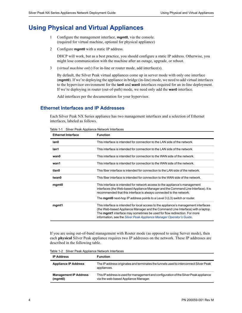
Each Silver Peak NX Series appliance has two management interfaces and a selection of Ethernet interfaces, labeled as follows.
Table 1-1 Silver Peak Appliance Network Interfaces
If you are using out-of-band management with Router mode (as opposed to using Server mode), then each physical Silver Peak appliance requires two IP addresses on the network. These IP addresses are described in the following table.
Table 1-2 Silver Peak Appliance Network Interfaces
Ethernet Interface Function
lan0 This interface is intended for connection to the LAN side of the network.
lan1 This interface is intended for connection to the LAN side of the network.
wan0 This interface is intended for connection to the WAN side of the network.
wan1 This interface is intended for connection to the WAN side of the network.
tlan0 This fiber interface is intended for connection to the LAN side of the network.
twan0 This fiber interface is intended for connection to the WAN side of the network.
mgmt0 This interface is intended for network access to the appliance’s management interfaces (the Web-based Appliance Manager and the Command Line Interface). It is recommended that this interface is always connected to the network.
The mgmt0 next-hop IP address points to a Level 3 (L3) switch or router.
mgmt1 This interface is intended for local access to the appliance’s management interfaces (the Web-based Appliance Manager and the Command Line Interface) with a laptop. The mgmt1 interface may sometimes be used for flow redirection. For more information, see the Silver Peak Appliance Manager Operator’s Guide.
IP Address Function
Appliance IP Address The IP address originates and terminates the tunnels used to interconnect Silver Peak appliances.
Management IP Address (mgmt0)
This IP address is used for management and configuration of the Silver Peak appliance via the web-based Appliance Manager.
Using Physical and Virtual Appliances Chapter 1 Fundamentals of Deploying WAN Optimization
PN 200059-001 Rev M 5
Although it isn’t a requirement, it’s considered a best practice to use different subnets for mgmt0 and the Appliance data path IP.
Configuring the mgmt0 Interface
The physical (NX) and virtual appliance Quick Start Guides each explain how to access and configure the mgmt0 interface. Here, we offer a quick, generic review.
Note The mgmt0 next-hop is to an L3 (not L2) switch.
To configure the mgmt0 interface on a physical (NX) appliance
Refer to the NX Series Appliances Quick Start Guide.
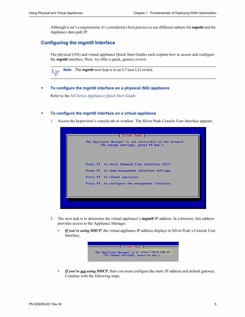
To configure the mgmt0 interface on a virtual appliance
1 Access the hypervisor’s console tab or window. The Silver Peak Console User Interface appears.
2 The next task is to determine the virtual appliance’s mgmt0 IP address. In a browser, this address provides access to the Appliance Manager.
• If you’re using DHCP, the virtual appliance IP address displays in Silver Peak’s Console User Interface.
• If you’re not using DHCP, then you must configure the static IP address and default gateway. Continue with the following steps.
Silver Peak NX Series Appliances Network Deployment Guide Using Physical and Virtual Appliances
6 PN 200059-001 Rev M
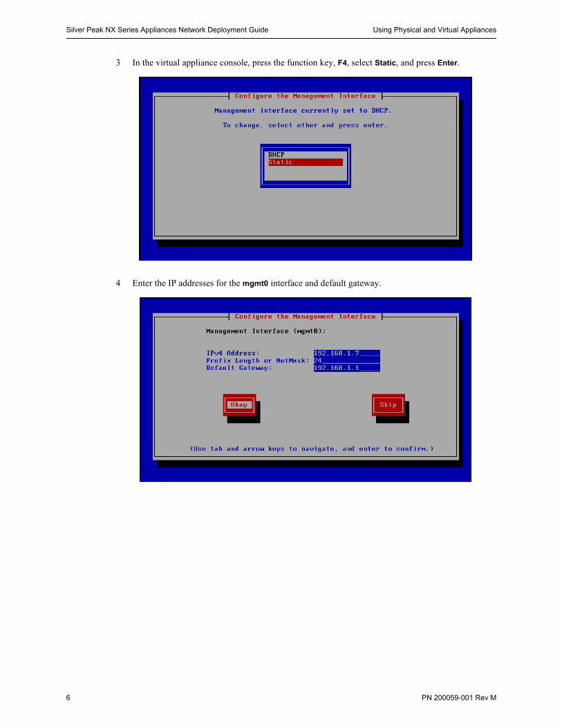
3 In the virtual appliance console, press the function key, F4, select Static, and press Enter.
4 Enter the IP addresses for the mgmt0 interface and default gateway.
Using Physical and Virtual Appliances Chapter 1 Fundamentals of Deploying WAN Optimization
PN 200059-001 Rev M 7
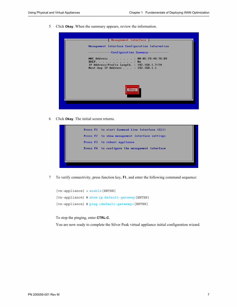
5 Click Okay. When the summary appears, review the information.
6 Click Okay. The initial screen returns.
7 To verify connectivity, press function key, F1, and enter the following command sequence:
[vx-appliance] > enable[ENTER]
[vx-appliance] # show ip default-gateway[ENTER]
[vx-appliance] # ping <default-gateway>[ENTER]
To stop the pinging, enter CTRL-C.
You are now ready to complete the Silver Peak virtual appliance initial configuration wizard.
Silver Peak NX Series Appliances Network Deployment Guide Choosing an Optimization Strategy for the Traffic Path
8 PN 200059-001 Rev M
Choosing an Optimization Strategy for the Traffic PathThe Route Policy specifies where to direct flows.
By default, the Route Policy auto-optimizes all unicast IP traffic, automatically directing flows to the appropriate tunnel. Auto-optimization strategies reduce the need to create explicit route map entries for optimization.
The three strategies that auto-optimization uses are subnet sharing, TCP-based auto-opt, and IP-based auto-opt.
Subnet sharing is the appliance’s first choice for auto-optimization. When subnet sharing is disabled, the appliance defaults to using TCP-based auto-opt and IP-based auto-opt (as a shortcut, this document may refer to it as TCP/IP-based auto-optimization).
When might you choose to disable subnet sharing? If your network has numerous non-local LAN-side routers, you would need to manually enter each one into the appliance’s subnet table. With TCP-based or IP-based auto-opt, this is unnecessary; however, if your appliance is not deployed in-line, you would need to configure inbound redirection using either Policy-Based Routing (PBR), Filter-Based Forwarding (FBF), or Web Cache Communication Protocol (WCCP).
For a discussion of when you need inbound and outbound redirection, see “Determining the Need for Traffic Redirection” on page 13.
Auto-optimization uses different mechanisms for TCP versus non-TCP traffic. Because both mechanisms ultimately require an exchange of packets between two appliances, unidirectional IP traffic will not trigger auto-optimization.
Auto-opt may not work with a firewall in the path. Some firewalls may be configured to strip out or block the TCP options in the initial SYN packet, which will break auto-optimization. Subnet sharing does not use the TCP options field, and thus avoids this issue. Therefore, use of subnet sharing is a recommended best practice.
You can, if you choose, modify the default entry’s SET action of auto-optimized.
The Route Policy, then, only requires manual entries for flows that are to be:
• sent pass-through (shaped or unshaped)
• dropped
• configured for a specific high-availability deployment.
• routed based on application, VLAN, DSCP, or ACL (Access Control List)
You can, however, choose to forego auto-optimization and create any and all route policies manually.
Note IMPORTANT — A tunnel must exist before subnet sharing can proceed.
Using Appliance Manager, you can create tunnels in one of three ways:
If you enable auto-tunnel on the Configuration - System page, then the initial TCP-based or IP-based handshaking creates the tunnel. That requires outbound and inbound redirection to be in place.
You can let the Initial Configuration Wizard create the tunnel to the remote appliance.
You can create a tunnel manually on the Configuration - Tunnels page.
Configuring Dynamic Path Control Chapter 1 Fundamentals of Deploying WAN Optimization
PN 200059-001 Rev M 9
Configuring Dynamic Path ControlDynamic Path Control (DPC) is the mechanism for intelligently routing applications over multiple WAN paths, including the Internet. DPC uses real-time information about the state of each path to assess and direct traffic.
With DPC, you can easily direct real-time traffic, such as voice or video, to the connection with the lowest packet loss or lowest latency.
Because network conditions change constantly, the path with the least loss or latency might not always be the same. DPC uses latency, packet loss, and throughput utilization data to make intelligent routing decisions for any application on the WAN.
Points to consider before configuring DPC:
DPC can be configured between any pair of appliances with more than one tunnel connecting them.
When configuring a route policy for DPC, the Destination must either be auto-optimized or a Peer that’s connected by more than one tunnel.
How to configure DPC in the Route Policy
The examples below show how to configure the three available types of dynamic path control: load
balancing, low-loss, and low-latency.
Although we’ve used CIFs, SSH, and FTP traffic to illustrate, the steps work with any application. Note that these examples are not intended to be recommendations about how to handle that specific traffic in your network.
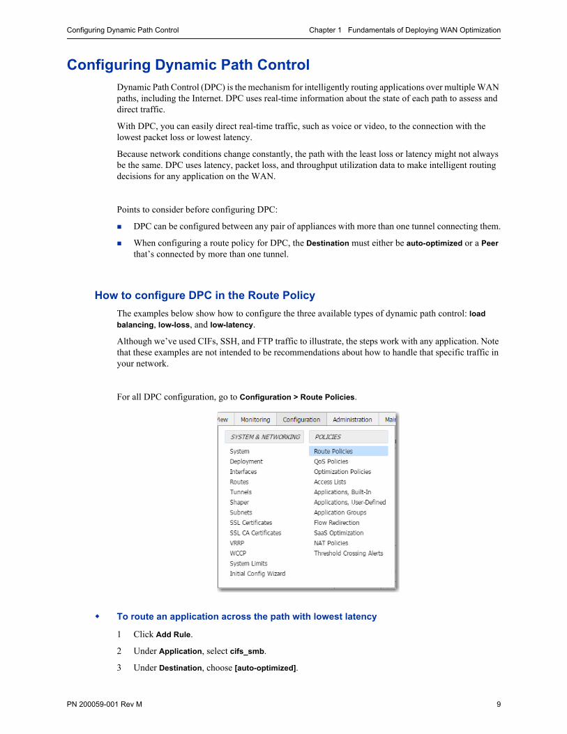
For all DPC configuration, go to Configuration > Route Policies.
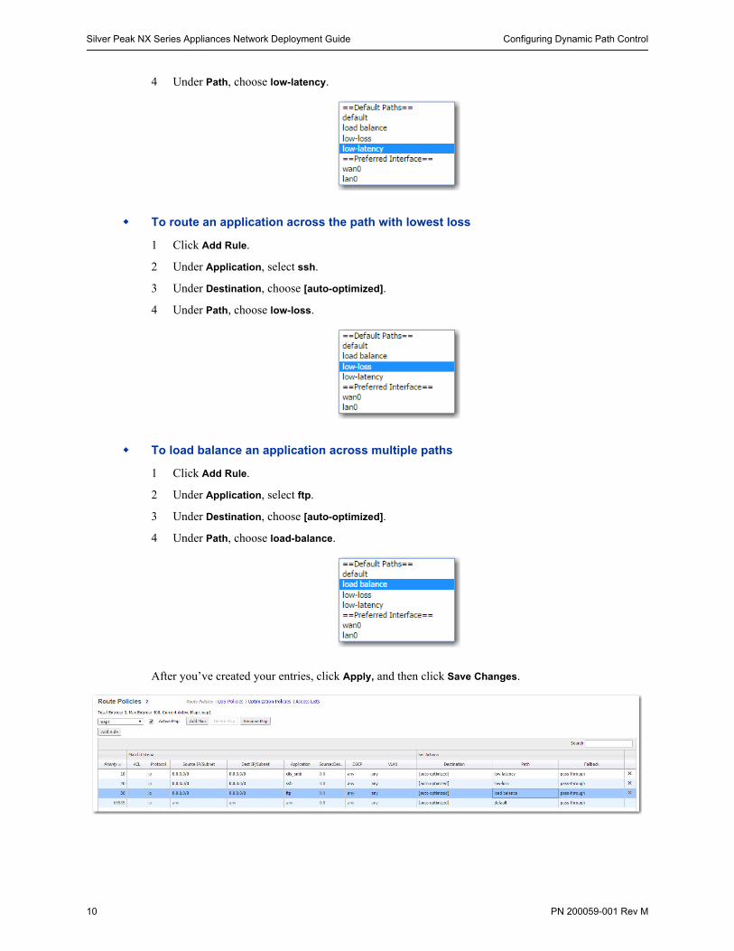
To route an application across the path with lowest latency
1 Click Add Rule.
2 Under Application, select cifs_smb.
3 Under Destination, choose [auto-optimized].
Silver Peak NX Series Appliances Network Deployment Guide Configuring Dynamic Path Control
10 PN 200059-001 Rev M
4 Under Path, choose low-latency.
To route an application across the path with lowest loss
1 Click Add Rule.
2 Under Application, select ssh.
3 Under Destination, choose [auto-optimized].
4 Under Path, choose low-loss.
To load balance an application across multiple paths
1 Click Add Rule.
2 Under Application, select ftp.
3 Under Destination, choose [auto-optimized].
4 Under Path, choose load-balance.
After you’ve created your entries, click Apply, and then click Save Changes.
Configuring Dynamic Path Control Chapter 1 Fundamentals of Deploying WAN Optimization
PN 200059-001 Rev M 11
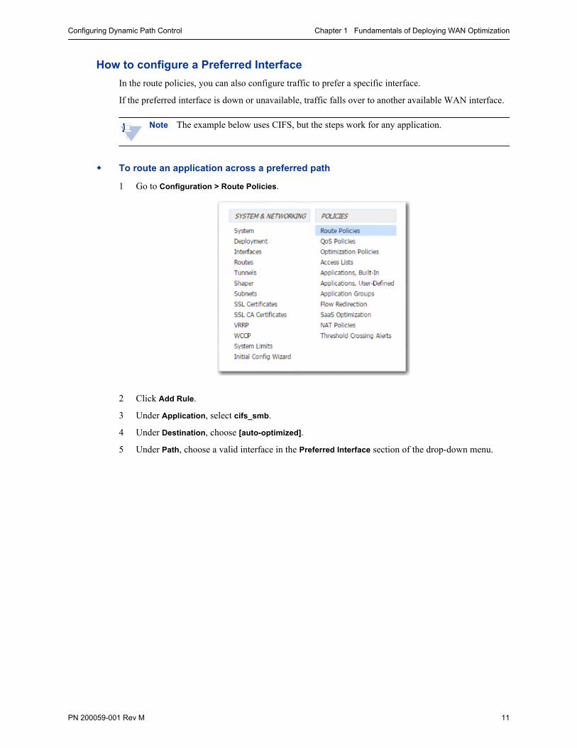
How to configure a Preferred Interface
In the route policies, you can also configure traffic to prefer a specific interface.
If the preferred interface is down or unavailable, traffic falls over to another available WAN interface.
Note The example below uses CIFS, but the steps work for any application.
To route an application across a preferred path
1 Go to Configuration > Route Policies.
2 Click Add Rule.
3 Under Application, select cifs_smb.
4 Under Destination, choose [auto-optimized].
5 Under Path, choose a valid interface in the Preferred Interface section of the drop-down menu.
Silver Peak NX Series Appliances Network Deployment Guide WAN Hardening
12 PN 200059-001 Rev M
WAN HardeningWAN hardening is an option that provides additional protection against unsafe connections from remote sites. When WAN hardening is enabled, only traffic arriving from a Silver Peak IPsec tunnels is allowed to enter.
When Silver Peak appliances are deployed in Router Mode, you have the option of hardening any WAN–side interface. This means:
For traffic inbound from the WAN, the appliance only accepts encapsulated traffic arriving from another Silver Peak appliance, via an IPsec tunnel. All other connections are rejected.
For traffic outbound to the WAN, the appliance only allows IPsec tunnel packets and management traffic.
Any data from the internet that gets backhauled via a Silver Peak IPSec tunnel will reach its destination at the hardened sites. This allows for integration with other security tools, such as firewalls, at the data center.
Data sourced directly from the internet, or any other connection that doesn’t flow through a Silver Peak IPsec tunnel, is discarded when it hits the hardened interface. Only data from authenticated Silver Peak IPsec tunnels is allowed to pass across a hardened interface.
To enable or disable interface hardening, do one of the following:
On the Configuration > Deployment page, click the lock icon, or
On the Configuration > Interfaces page, select or deselect the checkboxin the Hardened Interfaces column.
Determining the Need for Traffic Redirection Chapter 1 Fundamentals of Deploying WAN Optimization
PN 200059-001 Rev M 13
Determining the Need for Traffic RedirectionTo optimize traffic, the appliance must intercept both the inbound and outbound packets for each flow.
Therefore, whenever you place an appliance out-of-path, you must redirect traffic from the client to the appliance.
There are three methods for redirecting outbound packets from the client to the appliance (known as LAN-side redirection, or outbound redirection):
• PBR (Policy-Based Routing) — configured on the router. No other special configuration required on the appliance. This is also known as Filter-Based Forwarding (FBF).
If you want to deploy two Silver Peaks at the site, for redundancy, then you also need to use VRRP (Virtual Router Redundancy Protocol).
• WCCP (Web Cache Communication Protocol) — configured on both the router and the Silver Peak appliance. You can also use WCCP for redundancy and load balancing.
• Host routing — the server/end station has a default or subnet-based static route that points to the Silver Peak appliance as its next hop. Host routing is the preferred method when a virtual appliance is using a single interface, mgmt0, for datapath traffic (also known as Server Mode).
To ensure end-to-end connectivity in case of appliance failure, consider using VRRP between the appliance and a router, or the appliance and another redundant Silver Peak.
How you plan to optimize traffic affects whether or not you also need inbound redirection from the WAN router (also known as WAN-side redirection):
• If you enable subnet sharing (which relies on advertising local subnets between Silver Peak appliances) or route policies (which specify destination IP addresses), then you only need outbound redirection.
If you have subnets that are not directly attached to the Silver Peak, you may need to manually add those subnets so the local appliance can advertise them to its peers. If those subnets are not reachable via the default LAN–side next-hop router, then you may also need to add a static route to the local Silver Peak, specifying which next-hop router to use to reach a given subnet. For an example, see “Configuring A1 and A2 to Advertise Non-Local Subnets” on page 196.
• If, instead, you default to TCP-based or IP-based auto-optimization (which relies on initial handshaking outside a tunnel), then you must set up inbound and outbound redirection on the WAN router.
• Additionally, for TCP flows to be optimized, both directions must travel through the same client and server appliances. If the TCP flows are asymmetric —as could occur in a high-availability deployment — you need to configure clusters for flow redirection among local appliances.
For more about flow redirection, refer to the Appliance Manager Operator’s Guide.
The following diagrams show where redirection is required and which methods you can use:
• when subnet sharing is enabled
• when using TCP-based or IP-based auto-optimization (that is, subnet sharing is not enabled)
• when directed to a specific tunnel by the Route Policy
Silver Peak NX Series Appliances Network Deployment Guide Determining the Need for Traffic Redirection
14 PN 200059-001 Rev M
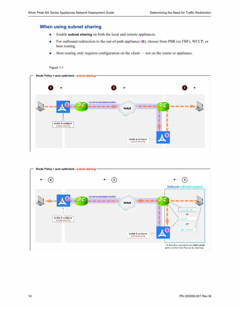
When using subnet sharing
Enable subnet sharing on both the local and remote appliances.
For outbound redirection to the out-of-path appliance (B), choose from PBR (or FBF), WCCP, or host routing.
Host routing only requires configuration on the client — not on the router or appliance.
Figure 1-1
Determining the Need for Traffic Redirection Chapter 1 Fundamentals of Deploying WAN Optimization
PN 200059-001 Rev M 15
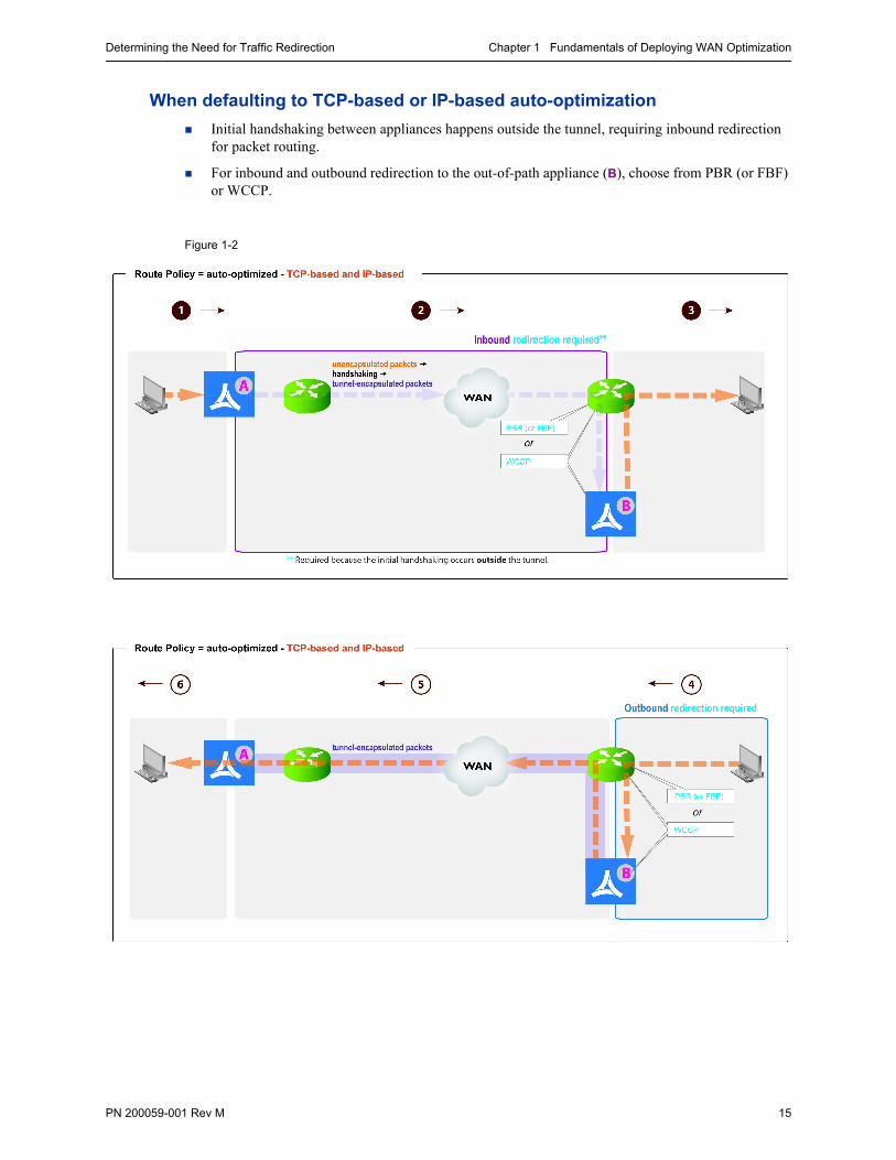
When defaulting to TCP-based or IP-based auto-optimization
Initial handshaking between appliances happens outside the tunnel, requiring inbound redirection for packet routing.
For inbound and outbound redirection to the out-of-path appliance (B), choose from PBR (or FBF) or WCCP.
Figure 1-2
Silver Peak NX Series Appliances Network Deployment Guide Determining the Need for Traffic Redirection
16 PN 200059-001 Rev M
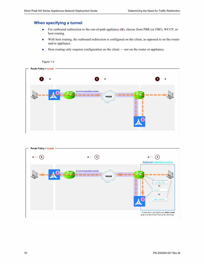
When specifying a tunnel
For outbound redirection to the out-of-path appliance (B), choose from PBR (or FBF), WCCP, or host routing.
With host routing, the outbound redirection is configured on the client, as opposed to on the router and/or appliance.
Host routing only requires configuration on the client — not on the router or appliance.
Figure 1-3
High Availability Chapter 1 Fundamentals of Deploying WAN Optimization
PN 200059-001 Rev M 17
High AvailabilityIn High Availability (HA) configurations, the redundant Silver Peak appliances are deployed in router mode and either WCCP or PBR redirects flows from the routers to the appliances.
The redundant appliances may be configured Active/Active or Active/Backup. This is determined by how the WCCP or PBR redirection is configured on the routers and the appliances.
For the purposes of discussion, we’ll assume that HA is configured in the same location as the servers and we’ll refer to the HA (redundant) appliances as “server-side”. We’ll refer to the non-redundant appliances as “client-side”. Of course, it doesn’t need to be this way—it’s possible to have redundant Silver Peak appliances in offices without servers.
Auto-optimization or Explicit Route Maps?
In HA configurations, the decision about whether to use auto-optimization or explicit route maps has further implications. Considerations include the following:
• The network may already have inherent asymmetry, relative to the deployment you want to configure.
• Provisioning redundant appliances may introduce network asymmetry where none existed before.
• Depending on exactly how a router’s inbound and outbound redirection statements are configured, it’s possible to arrive at an asymmetric condition.
• With load sharing (Active/Active) configurations, asymmetry is a fact of life.
Asymmetry Mitigation
Flow redirection can prevent TCP asymmetry in high availability environments.
For the appliances, this requires configuring HA (or redundant) appliances as peers, and enabling flow redirection. Both tasks are on the Configuration - Flow Redirection screen.
Where it’s an element of any deployment chapter in this guide, the instructions include the configuration steps.
High Availability with Explicit Route-Maps
When auto-optimization is not enabled, explicit route maps in the appliance determine how to route traffic into the tunnels for optimization.
We’ll examine two high availability situations from the point of view of the client-side appliance:
Asymmetry in Active/Backup Configurations
One tunnel carries all the traffic. If that link goes down, then the Backup appliance receives the client’s traffic via another tunnel. Enabling flow redirection on the peered server-side appliances ensures that the same tunnel carries those flows back to the client.
Asymmetry in Active/Active Configurations
The server-side router is load balancing and determines which peer appliance receives the returning flow. Enabling flow redirection among peers prevents TCP asymmetry.
Silver Peak NX Series Appliances Network Deployment Guide Considerations for Deployments
18 PN 200059-001 Rev M
Considerations for Deployments Which sites require optimization?
What deployment mode (router, bridge) is appropriate for each site?
Are you going to use ACLs (Access Control Lists) instead of, or in addition to, auto-optimization?
Are you going to enable all optimization for all flows? Or be more specific?
Are you going to use the default QoS configuration or something more advanced?
Do you need to consider high availability (HA)?
Do you need to consider asymmetry?
Verifying Connectivity After Configuring Deployment Chapter 1 Fundamentals of Deploying WAN Optimization
PN 200059-001 Rev M 19
Verifying Connectivity After Configuring DeploymentAfter you configure a deployment, you need to verify connectivity between the networks to ensure that traffic is optimized on either side.
This section describes ping -r and traceroute, as well as the pros and cons of using each. Finally, it summarizes a procedure for verifying connectivity.
ping
ping is a good general tool to verify reachability. However, it is not the best tool to use to verify correct deployment of WAN optimization appliances because:
1 It doesn’t verify the path that traffic takes.
It’s important to verify the path, not just reachability, because the appliance must intercept traffic on both sides of the WAN for optimization and acceleration to be effective.
2 It relies on ICMP, and some redirection methods (for example, WCCP) don’t support ICMP.
You need a tool that can verify paths by revealing all hops taken along a path. Some tools you can use to verify the paths taken are ping -r and traceroute.
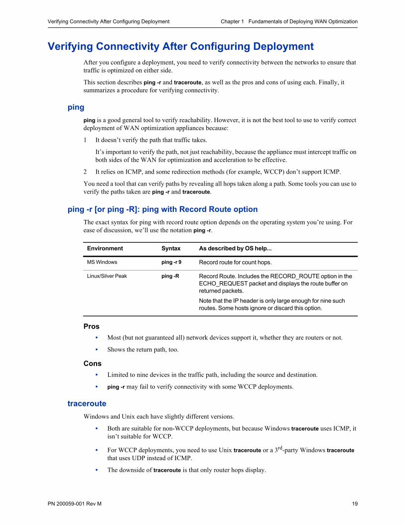
ping -r [or ping -R]: ping with Record Route option
The exact syntax for ping with record route option depends on the operating system you’re using. For ease of discussion, we’ll use the notation ping -r.
Pros
• Most (but not guaranteed all) network devices support it, whether they are routers or not.
• Shows the return path, too.
Cons
• Limited to nine devices in the traffic path, including the source and destination.
• ping -r may fail to verify connectivity with some WCCP deployments.
traceroute
Windows and Unix each have slightly different versions.
• Both are suitable for non-WCCP deployments, but because Windows traceroute uses ICMP, it isn’t suitable for WCCP.
• For WCCP deployments, you need to use Unix traceroute or a 3rd-party Windows traceroute that uses UDP instead of ICMP.
• The downside of traceroute is that only router hops display.
Environment Syntax As described by OS help...
MS Windows ping -r 9 Record route for count hops.
Linux/Silver Peak ping -R Record Route. Includes the RECORD_ROUTE option in the ECHO_REQUEST packet and displays the route buffer on returned packets.
Note that the IP header is only large enough for nine such routes. Some hosts ignore or discard this option.
Silver Peak NX Series Appliances Network Deployment Guide Verifying Connectivity After Configuring Deployment
20 PN 200059-001 Rev M
Basic procedure
1 Verify connectivity for optimized traffic.
• In Router mode (out-of-path deployment), Silver Peak appliances look like router hops. They’ll display in both ping -r and traceroute.
• In Bridge mode (in-line deployment), Silver Peak appliances look like bridges. They’ll display in ping -r, but not in traceroute.
2 Verify connectivity for pass-through traffic.
As a best practice, always verify connectivity for all devices in the network. For example, if you’ve configured a route policy to cause certain traffic from certain devices to be handled as pass-through or pass-through unshaped, you should also verify connectivity for these devices.
3 Test network connectivity by using your applications. For example, do a CIFS mount or an FTP transfer.
PN 200059-001 Rev M 21
C H A P T E R 2
In-Line DeploymentUsing Subnet Sharing
In this deployment scenario, the Silver Peak Appliance sits between the WAN router and the Ethernet switch.
In This Chapter Overview See page 22.
Using the Initial Config Wizard See page 25.
Verifying Appliance Connectivity See page 32.
Creating Tunnels See page 33.
Verifying Traffic See page 35.
Silver Peak NX Series Appliances Network Deployment Guide Overview
22 PN 200059-001 Rev M
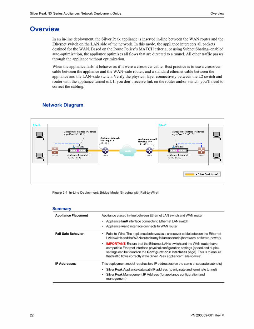
OverviewIn an in-line deployment, the Silver Peak appliance is inserted in-line between the WAN router and the Ethernet switch on the LAN side of the network. In this mode, the appliance intercepts all packets destined for the WAN. Based on the Route Policy’s MATCH criteria, or using Subnet Sharing–enabled auto-optimization, the appliance optimizes all flows that are directed to a tunnel. All other traffic passes through the appliance without optimization.
When the appliance fails, it behaves as if it were a crossover cable. Best practice is to use a crossover cable between the appliance and the WAN–side router, and a standard ethernet cable between the appliance and the LAN–side switch. Verify the physical layer connectivity between the L2 switch and router with the appliance turned off. If you don’t receive link on the router and/or switch, you’ll need to correct the cabling.
Network Diagram
Figure 2-1 In-Line Deployment: Bridge Mode [Bridging with Fail-to-Wire]
Summary
Appliance Placement Appliance placed in-line between Ethernet LAN switch and WAN router
• Appliance lan0 interface connects to Ethernet LAN switch
• Appliance wan0 interface connects to WAN router
Fail-Safe Behavior • Fails-to-Wire: The appliance behaves as a crossover cable between the Ethernet LAN switch and the WAN router in any failure scenario (hardware, software, power).
• IMPORTANT: Ensure that the Ethernet LAN’s switch and the WAN router have compatible Ethernet interface physical configuration settings (speed and duplex settings can be found on the Configuration > Interfaces page). This is to ensure that traffic flows correctly if the Silver Peak appliance “Fails-to-wire”.
IP Addresses This deployment model requires two IP addresses (on the same or separate subnets)
• Silver Peak Appliance data path IP address (to originate and terminate tunnel)
• Silver Peak Management IP Address (for appliance configuration and management)
Overview Chapter 2 In-Line Deployment
PN 200059-001 Rev M 23
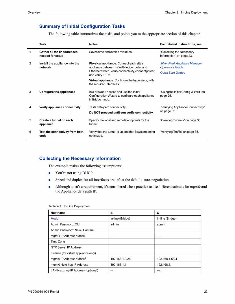
Summary of Initial Configuration Tasks
The following table summarizes the tasks, and points you to the appropriate section of this chapter.
Collecting the Necessary Information
The example makes the following assumptions:
You’re not using DHCP.
Speed and duplex for all interfaces are left at the default, auto-negotiation.
Although it isn’t a requirement, it’s considered a best practice to use different subnets for mgmt0 and the Appliance data path IP.
Table 2-1 In-Line Deployment
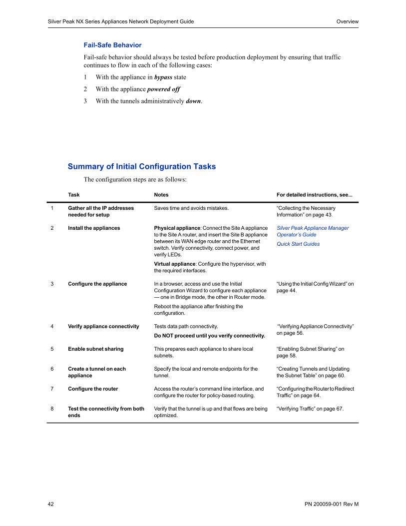
Task Notes For detailed instructions, see...
1 Gather all the IP addresses needed for setup
Saves time and avoids mistakes. “Collecting the Necessary Information” on page 23.
2 Install the appliance into the network
Physical appliance: Connect each site’s appliance between its WAN edge router and Ethernet switch. Verify connectivity, connect power, and verify LEDs.
Virtual appliance: Configure the hypervisor, with the required interfaces.
Silver Peak Appliance Manager Operator’s Guide
Quick Start Guides
3 Configure the appliances In a browser, access and use the Initial Configuration Wizard to configure each appliance in Bridge mode.
“Using the Initial Config Wizard” on page 25.
4 Verify appliance connectivity Tests data path connectivity.
Do NOT proceed until you verify connectivity.
“Verifying Appliance Connectivity” on page 32.
5 Create a tunnel on each appliance
Specify the local and remote endpoints for the tunnel.
“Creating Tunnels” on page 33.
6 Test the connectivity from both ends
Verify that the tunnel is up and that flows are being optimized.
“Verifying Traffic” on page 35.
Hostname B C
Mode In-line (Bridge) In-line (Bridge)
Admin Password: Old admin admin
Admin Password: New / Confirm
mgmt1 IP Address / Mask --- ---
Time Zone
NTP Server IP Address
License (for virtual appliance only)
mgmt0 IP Address / Maska 192.168.1.9/24 192.168.1.5/24
mgmt0 Next-hop IP Address 192.168.1.1 192.168.1.1
LAN Next-hop IP Address (optional) b --- ---

Silver Peak NX Series Appliances Network Deployment Guide Overview
24 PN 200059-001 Rev M
Appliance data path IP Address / Mask 10.110.11.100/24 10.110.21.100/24
Appliance data path Next-hop IP 10.110.11.1/24 10.110.21.1/24
a. In this example, all mgmt0 IP addresses are in the same subnet. In your actual network, it’s likely that mgmt0 IP addresses are in different subnets.
b. LAN next-hop IP is only required when there are subnets for which the Silver Peak appliance does not have a configured IP address.
Hostname B C
Using the Initial Config Wizard Chapter 2 In-Line Deployment
PN 200059-001 Rev M 25
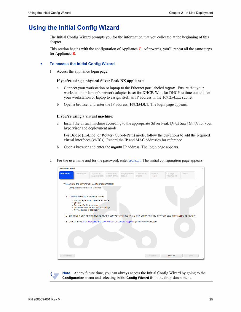
Using the Initial Config WizardThe Initial Config Wizard prompts you for the information that you collected at the beginning of this chapter.
This section begins with the configuration of Appliance C. Afterwards, you’ll repeat all the same steps for Appliance B.
To access the Initial Config Wizard
1 Access the appliance login page.
If you’re using a physical Silver Peak NX appliance:
a Connect your workstation or laptop to the Ethernet port labeled mgmt1. Ensure that your workstation or laptop’s network adapter is set for DHCP. Wait for DHCP to time out and for your workstation or laptop to assign itself an IP address in the 169.254.x.x subnet.
b Open a browser and enter the IP address, 169.254.0.1. The login page appears.
If you’re using a virtual machine:
a Install the virtual machine according to the appropriate Silver Peak Quick Start Guide for your hypervisor and deployment mode.
For Bridge (In-Line) or Router (Out-of-Path) mode, follow the directions to add the required virtual interfaces (vNICs). Record the IP and MAC addresses for reference.
b Open a browser and enter the mgmt0 IP address. The login page appears.
2 For the username and for the password, enter admin. The initial configuration page appears.
Note At any future time, you can always access the Initial Config Wizard by going to the Configuration menu and selecting Initial Config Wizard from the drop-down menu.
Silver Peak NX Series Appliances Network Deployment Guide Using the Initial Config Wizard
26 PN 200059-001 Rev M
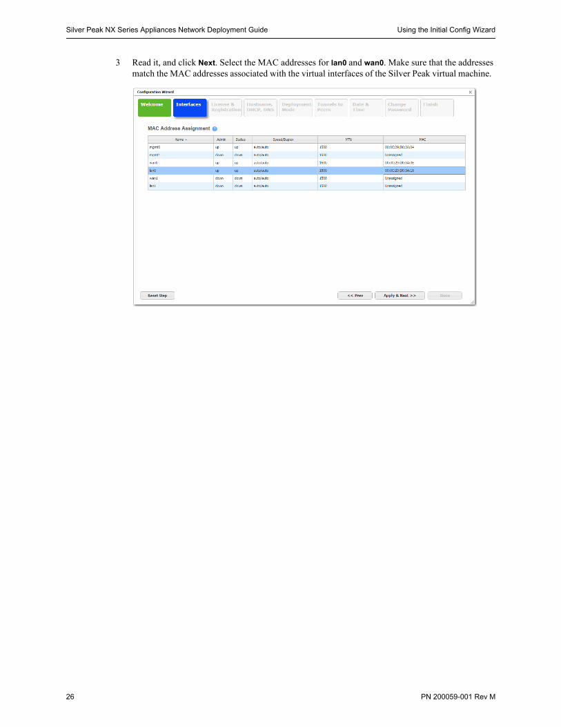
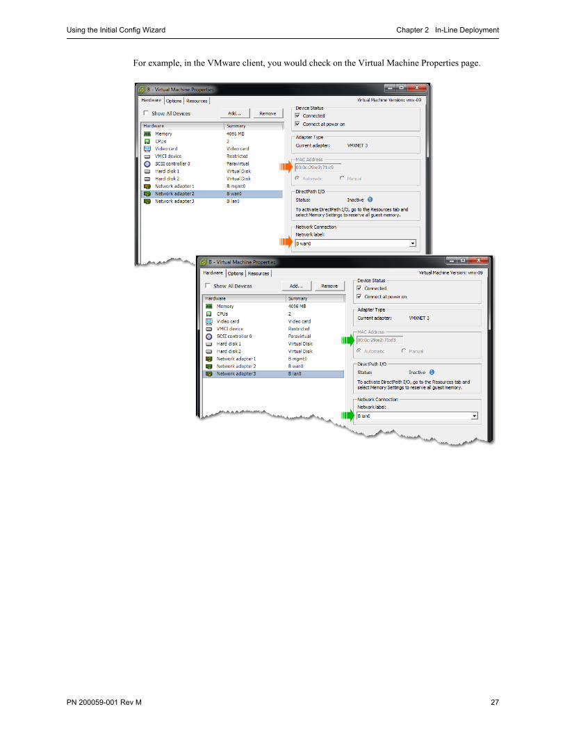
3 Read it, and click Next. Select the MAC addresses for lan0 and wan0. Make sure that the addresses match the MAC addresses associated with the virtual interfaces of the Silver Peak virtual machine.
Using the Initial Config Wizard Chapter 2 In-Line Deployment
PN 200059-001 Rev M 27
For example, in the VMware client, you would check on the Virtual Machine Properties page.

Silver Peak NX Series Appliances Network Deployment Guide Using the Initial Config Wizard
28 PN 200059-001 Rev M
4 Click Apply & Next. The License & Registration page appears. Enter the license details.
5 Click Apply & Next. The Management Interface (mgmt0) page appears. Enter the appliance name and management IP details.

Using the Initial Config Wizard Chapter 2 In-Line Deployment
PN 200059-001 Rev M 29
6 Click Apply & Next. The Deployment Mode page appears. Under Deployment, select Bridge and configure the appliance data path IP next-hop router address and max WAN bandwidth.
7 Click Apply & Next. The Tunnels to Peers page appears.
a Leave Auto Tunnel and Auto Subnet Sharing deselected. We’ll take care of these features later. Although it’s not technically necessary to deselect either one, we have chosen to do so for tutorial purposes later in this chapter.
b Do not add tunnels. We’ll manually add remote appliances and create tunnels later.
Silver Peak NX Series Appliances Network Deployment Guide Using the Initial Config Wizard
30 PN 200059-001 Rev M
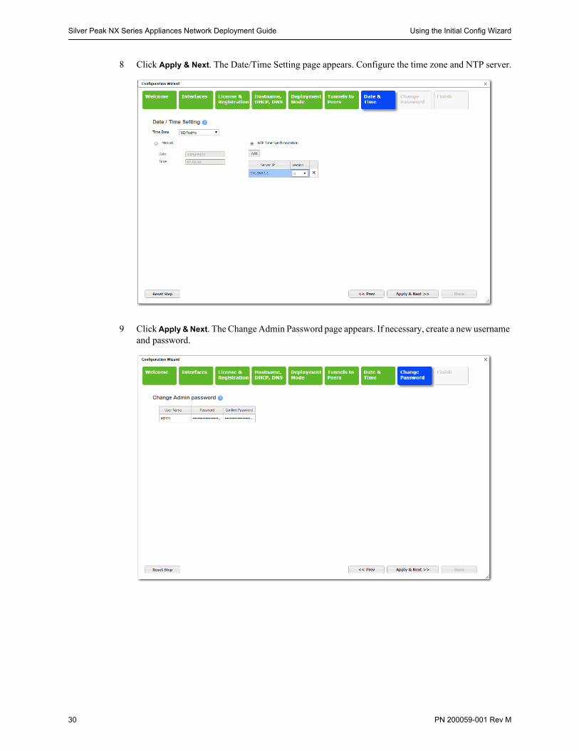
8 Click Apply & Next. The Date/Time Setting page appears. Configure the time zone and NTP server.
9 Click Apply & Next. The Change Admin Password page appears. If necessary, create a new username and password.
Using the Initial Config Wizard Chapter 2 In-Line Deployment
PN 200059-001 Rev M 31
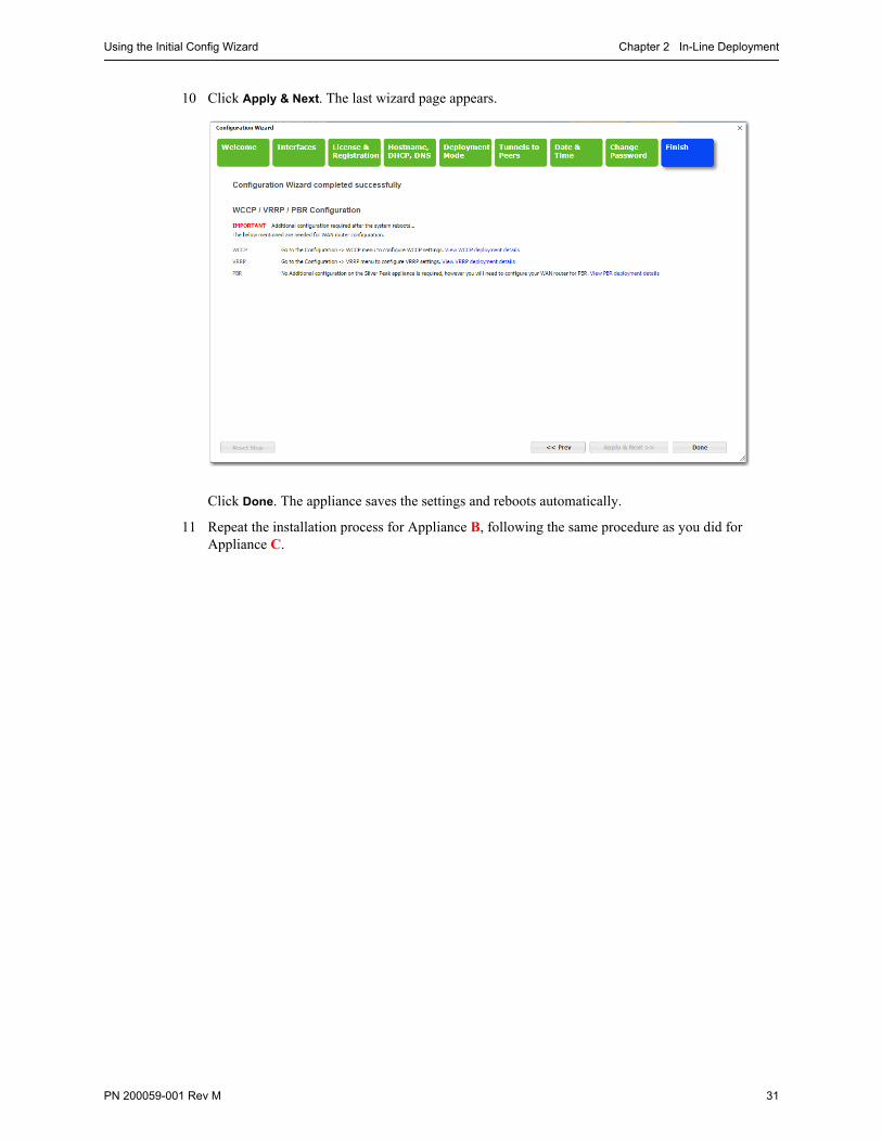
10 Click Apply & Next. The last wizard page appears.
Click Done. The appliance saves the settings and reboots automatically.
11 Repeat the installation process for Appliance B, following the same procedure as you did for Appliance C.
Silver Peak NX Series Appliances Network Deployment Guide Verifying Appliance Connectivity
32 PN 200059-001 Rev M
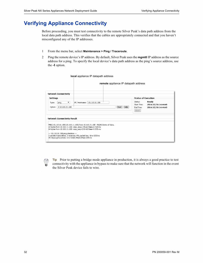
Verifying Appliance ConnectivityBefore proceeding, you must test connectivity to the remote Silver Peak’s data path address from the local data path address. This verifies that the cables are appropriately connected and that you haven’t misconfigured any of the IP addresses.
1 From the menu bar, select Maintenance > Ping / Traceroute.
2 Ping the remote device’s IP address. By default, Silver Peak uses the mgmt0 IP address as the source address for a ping. To specify the local device’s data path address as the ping’s source address, use the -I option.
Tip Prior to putting a bridge mode appliance in production, it is always a good practice to test connectivity with the appliance in bypass to make sure that the network will function in the event the Silver Peak device fails to wire.
local appliance IP datapath address
remote appliance IP datapath address
Creating Tunnels Chapter 2 In-Line Deployment
PN 200059-001 Rev M 33
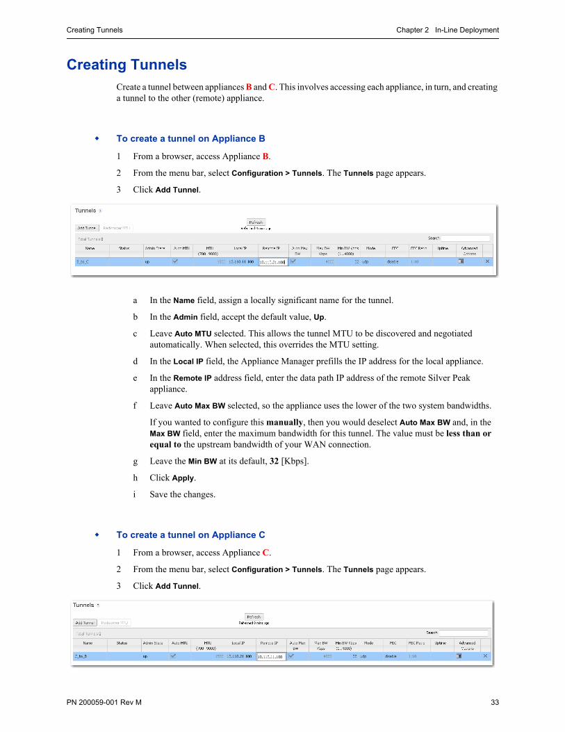
Creating TunnelsCreate a tunnel between appliances B and C. This involves accessing each appliance, in turn, and creating a tunnel to the other (remote) appliance.
To create a tunnel on Appliance B
1 From a browser, access Appliance B.
2 From the menu bar, select Configuration > Tunnels. The Tunnels page appears.
3 Click Add Tunnel.
a In the Name field, assign a locally significant name for the tunnel.
b In the Admin field, accept the default value, Up.
c Leave Auto MTU selected. This allows the tunnel MTU to be discovered and negotiated automatically. When selected, this overrides the MTU setting.
d In the Local IP field, the Appliance Manager prefills the IP address for the local appliance.
e In the Remote IP address field, enter the data path IP address of the remote Silver Peak appliance.
f Leave Auto Max BW selected, so the appliance uses the lower of the two system bandwidths.
If you wanted to configure this manually, then you would deselect Auto Max BW and, in the Max BW field, enter the maximum bandwidth for this tunnel. The value must be less than or equal to the upstream bandwidth of your WAN connection.
g Leave the Min BW at its default, 32 [Kbps].
h Click Apply.
i Save the changes.
To create a tunnel on Appliance C
1 From a browser, access Appliance C.
2 From the menu bar, select Configuration > Tunnels. The Tunnels page appears.
3 Click Add Tunnel.

Silver Peak NX Series Appliances Network Deployment Guide Creating Tunnels
34 PN 200059-001 Rev M
a In the Name field, assign a locally significant name for the tunnel.
b In the Admin field, accept the default value, Up.
c Leave Auto MTU selected. This allows the tunnel MTU to be discovered and negotiated automatically. When selected, this overrides the MTU setting.
d In the Local IP field, the Appliance Manager prefills the IP address for the local appliance.
e In the Remote IP address field, enter the data path IP address of the remote Silver Peak appliance.
f Leave Auto Max BW selected, so the appliance uses the lower of the two system bandwidths.
g Leave the Min BW at its default, 32 [Kbps].
h Click Apply.
i Save the changes.
Within a few seconds, the tunnel Status changes to Up - active. Click Refresh, if required.
Be aware that a tunnel doesn’t come up unless it’s configured on both ends. Configuring a tunnel on a single device will not cause a connection to come up.
Verifying Traffic Chapter 2 In-Line Deployment
PN 200059-001 Rev M 35
Verifying TrafficSubnet sharing enables Silver Peak devices that are connected by tunnels to automatically share subnet information and direct all IP traffic to the appropriate destinations.
1 Verify that each appliance is learning subnets from the other appliance.
a At each appliance, access Configuration > Subnets.
b Verify that local subnets are being advertised to peers.
c Verify that the subnet table lists subnets learned from the remote appliance.
The local appliance uses this learned subnet information. When auto optimization is enabled (this is the default Route Policy, and it hasn’t been changed in this example), LAN-to-WAN flows are examined for the destination address. If the destination address matches a subnet learned by the local appliance, the flow is routed into the tunnel that terminates at the Silver Peak advertising the subnet.
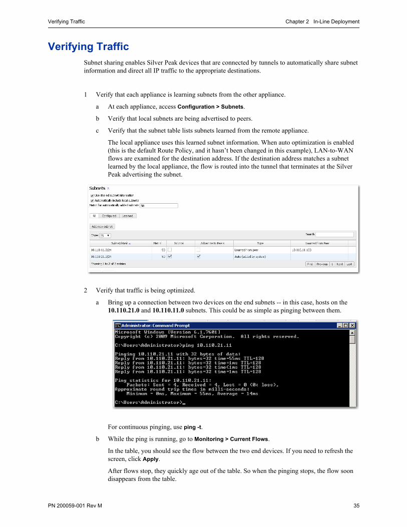
2 Verify that traffic is being optimized.
a Bring up a connection between two devices on the end subnets -- in this case, hosts on the 10.110.21.0 and 10.110.11.0 subnets. This could be as simple as pinging between them.
For continuous pinging, use ping -t.
b While the ping is running, go to Monitoring > Current Flows.
In the table, you should see the flow between the two end devices. If you need to refresh the screen, click Apply.
After flows stop, they quickly age out of the table. So when the pinging stops, the flow soon disappears from the table.

Silver Peak NX Series Appliances Network Deployment Guide Verifying Traffic
36 PN 200059-001 Rev M
In this example, the Outbound Tunnel is the one connecting the two Silver Peak appliances.
Clicking the icon in the Detail column provides additional information for as long as the flow is active.
The Inbound and Outbound sections provide basic statistical information associated with the flow.
Verifying Traffic Chapter 2 In-Line Deployment
PN 200059-001 Rev M 37
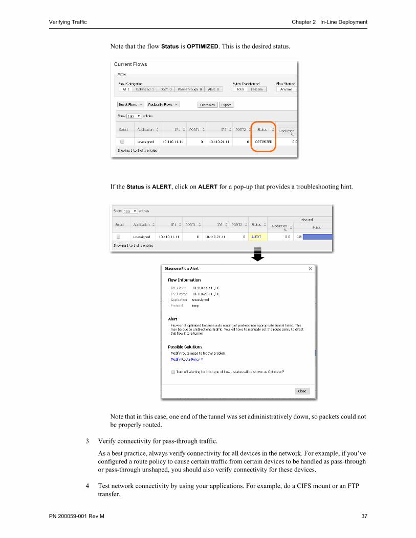
Note that the flow Status is OPTIMIZED. This is the desired status.
If the Status is ALERT, click on ALERT for a pop-up that provides a troubleshooting hint.
Note that in this case, one end of the tunnel was set administratively down, so packets could not be properly routed.
3 Verify connectivity for pass-through traffic.
As a best practice, always verify connectivity for all devices in the network. For example, if you’ve configured a route policy to cause certain traffic from certain devices to be handled as pass-through or pass-through unshaped, you should also verify connectivity for these devices.
4 Test network connectivity by using your applications. For example, do a CIFS mount or an FTP transfer.

Silver Peak NX Series Appliances Network Deployment Guide Verifying Traffic
38 PN 200059-001 Rev M
PN 200059-001 Rev M 39
C H A P T E R 3
Out-of-Path with Policy-Based-Routing Redirection
Section 1: Using Subnet SharingSection 2: Using TCP/IP–based Auto-Optimization
This chapter contains two sections, each of which describes a method of using Policy-Based Routing (PBR) on the WAN router to redirect traffic to the Silver Peak appliance.
The first section uses Subnet Sharing as the preferred auto-optimization method, and allows appliances connected by an operational tunnel to optimize all packets in a flow. It simplifies network configuration and, when you’re using an out-of-path Silver Peak appliance, it eliminates the need for WAN-to-LAN packet redirection on the inbound WAN interfaces of your router.
It may not always be possible to use subnet sharing, however, if the configuration of your network precludes it. The second section uses TCP-based or IP-based auto-optimization without subnet sharing. In this case, the first TCP SYN packet in the flow is transmitted outside the tunnel. Therefore, to ensure that the SYN packets arrive at an out-of-path Silver Peak appliance, you must configure WAN-to-LAN PBR packet redirection on your router’s WAN–facing interfaces, as described in this section.
For more explanation, see “Determining the Need for Traffic Redirection” on page 13.
Note If you’re using a Juniper router, their equivalent term for this redirection method is Filter-Based Forwarding [FBF]. Check your router manufacturer’s documentation to verify terminology.
In This Chapter SECTION 1: Using Subnet Sharing See page 40.
SECTION 2: Using TCP/IP–based Auto-Optimization See page 70.

Silver Peak NX Series Appliances Network Deployment Guide
40 PN 200059-001 Rev M
SECTION 1: USING SUBNET SHARING
In This Section Using the Initial Config Wizard See page 44.
Verifying Appliance Connectivity See page 56.
Enabling Subnet Sharing See page 58.
Creating Tunnels and Updating the Subnet Table See page 60.
Configuring the Router to Redirect Traffic See page 64.
Verifying Traffic See page 67.
Overview Chapter 3 Out-of-Path with Policy-Based-Routing Redirection
PN 200059-001 Rev M 41
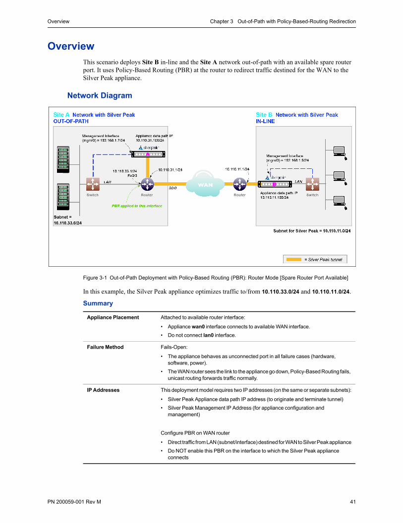
OverviewThis scenario deploys Site B in-line and the Site A network out-of-path with an available spare router port. It uses Policy-Based Routing (PBR) at the router to redirect traffic destined for the WAN to the Silver Peak appliance.
Network Diagram
Figure 3-1 Out-of-Path Deployment with Policy-Based Routing (PBR): Router Mode [Spare Router Port Available]
In this example, the Silver Peak appliance optimizes traffic to/from 10.110.33.0/24 and 10.110.11.0/24.
Summary
Appliance Placement Attached to available router interface:
• Appliance wan0 interface connects to available WAN interface.
• Do not connect lan0 interface.
Failure Method Fails-Open:
• The appliance behaves as unconnected port in all failure cases (hardware, software, power).
• The WAN router sees the link to the appliance go down, Policy-Based Routing fails, unicast routing forwards traffic normally.
IP Addresses This deployment model requires two IP addresses (on the same or separate subnets):
• Silver Peak Appliance data path IP address (to originate and terminate tunnel)
• Silver Peak Management IP Address (for appliance configuration and management)
Configure PBR on WAN router
• Direct traffic from LAN (subnet/interface) destined for WAN to Silver Peak appliance
• Do NOT enable this PBR on the interface to which the Silver Peak appliance connects
Silver Peak NX Series Appliances Network Deployment Guide Overview
42 PN 200059-001 Rev M
Fail-Safe Behavior
Fail-safe behavior should always be tested before production deployment by ensuring that traffic continues to flow in each of the following cases:
1 With the appliance in bypass state
2 With the appliance powered off
3 With the tunnels administratively down.
Summary of Initial Configuration Tasks
The configuration steps are as follows:
Task Notes For detailed instructions, see...
1 Gather all the IP addresses needed for setup
Saves time and avoids mistakes. “Collecting the Necessary Information” on page 43.
2 Install the appliances Physical appliance: Connect the Site A appliance to the Site A router, and insert the Site B appliance between its WAN edge router and the Ethernet switch. Verify connectivity, connect power, and verify LEDs.
Virtual appliance: Configure the hypervisor, with the required interfaces.
Silver Peak Appliance Manager Operator’s Guide
Quick Start Guides
3 Configure the appliance In a browser, access and use the Initial Configuration Wizard to configure each appliance — one in Bridge mode, the other in Router mode.
Reboot the appliance after finishing the configuration.
“Using the Initial Config Wizard” on page 44.
4 Verify appliance connectivity Tests data path connectivity.
Do NOT proceed until you verify connectivity.
“Verifying Appliance Connectivity” on page 56.
5 Enable subnet sharing This prepares each appliance to share local subnets.
“Enabling Subnet Sharing” on page 58.
6 Create a tunnel on each appliance
Specify the local and remote endpoints for the tunnel.
“Creating Tunnels and Updating the Subnet Table” on page 60.
7 Configure the router Access the router’s command line interface, and configure the router for policy-based routing.
“Configuring the Router to Redirect Traffic” on page 64.
8 Test the connectivity from both ends
Verify that the tunnel is up and that flows are being optimized.
“Verifying Traffic” on page 67.
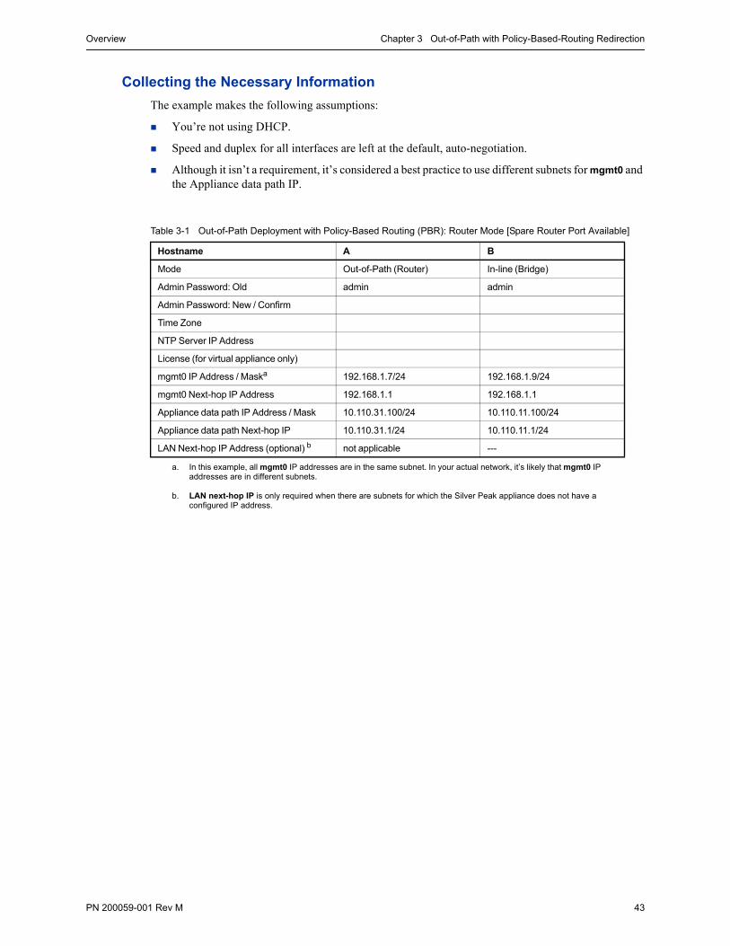
Overview Chapter 3 Out-of-Path with Policy-Based-Routing Redirection
PN 200059-001 Rev M 43
Collecting the Necessary Information
The example makes the following assumptions:
You’re not using DHCP.
Speed and duplex for all interfaces are left at the default, auto-negotiation.
Although it isn’t a requirement, it’s considered a best practice to use different subnets for mgmt0 and the Appliance data path IP.
Table 3-1 Out-of-Path Deployment with Policy-Based Routing (PBR): Router Mode [Spare Router Port Available]
Hostname A B
Mode Out-of-Path (Router) In-line (Bridge)
Admin Password: Old admin admin
Admin Password: New / Confirm
Time Zone
NTP Server IP Address
License (for virtual appliance only)
mgmt0 IP Address / Maska
a. In this example, all mgmt0 IP addresses are in the same subnet. In your actual network, it’s likely that mgmt0 IP addresses are in different subnets.
192.168.1.7/24 192.168.1.9/24
mgmt0 Next-hop IP Address 192.168.1.1 192.168.1.1
Appliance data path IP Address / Mask 10.110.31.100/24 10.110.11.100/24
Appliance data path Next-hop IP 10.110.31.1/24 10.110.11.1/24
LAN Next-hop IP Address (optional) b
b. LAN next-hop IP is only required when there are subnets for which the Silver Peak appliance does not have a configured IP address.
not applicable ---
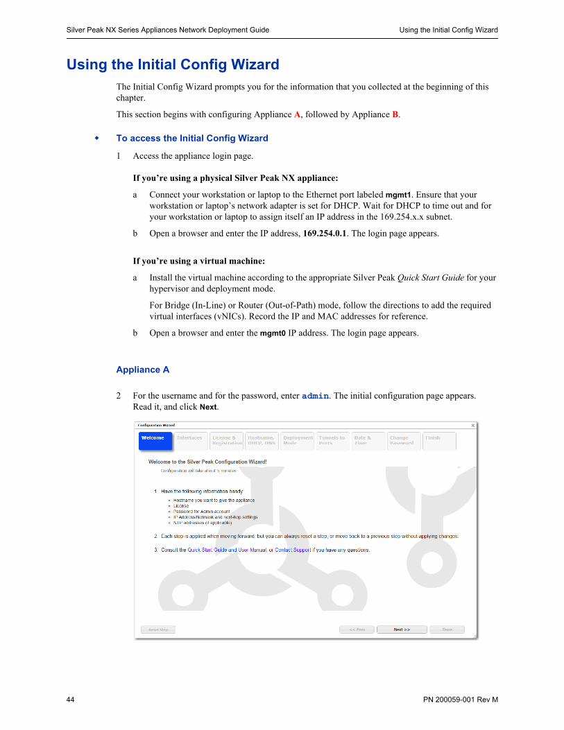
Silver Peak NX Series Appliances Network Deployment Guide Using the Initial Config Wizard
44 PN 200059-001 Rev M
Using the Initial Config WizardThe Initial Config Wizard prompts you for the information that you collected at the beginning of this chapter.
This section begins with configuring Appliance A, followed by Appliance B.
To access the Initial Config Wizard
1 Access the appliance login page.
If you’re using a physical Silver Peak NX appliance:
a Connect your workstation or laptop to the Ethernet port labeled mgmt1. Ensure that your workstation or laptop’s network adapter is set for DHCP. Wait for DHCP to time out and for your workstation or laptop to assign itself an IP address in the 169.254.x.x subnet.
b Open a browser and enter the IP address, 169.254.0.1. The login page appears.
If you’re using a virtual machine:
a Install the virtual machine according to the appropriate Silver Peak Quick Start Guide for your hypervisor and deployment mode.
For Bridge (In-Line) or Router (Out-of-Path) mode, follow the directions to add the required virtual interfaces (vNICs). Record the IP and MAC addresses for reference.
b Open a browser and enter the mgmt0 IP address. The login page appears.
Appliance A
2 For the username and for the password, enter admin. The initial configuration page appears. Read it, and click Next.
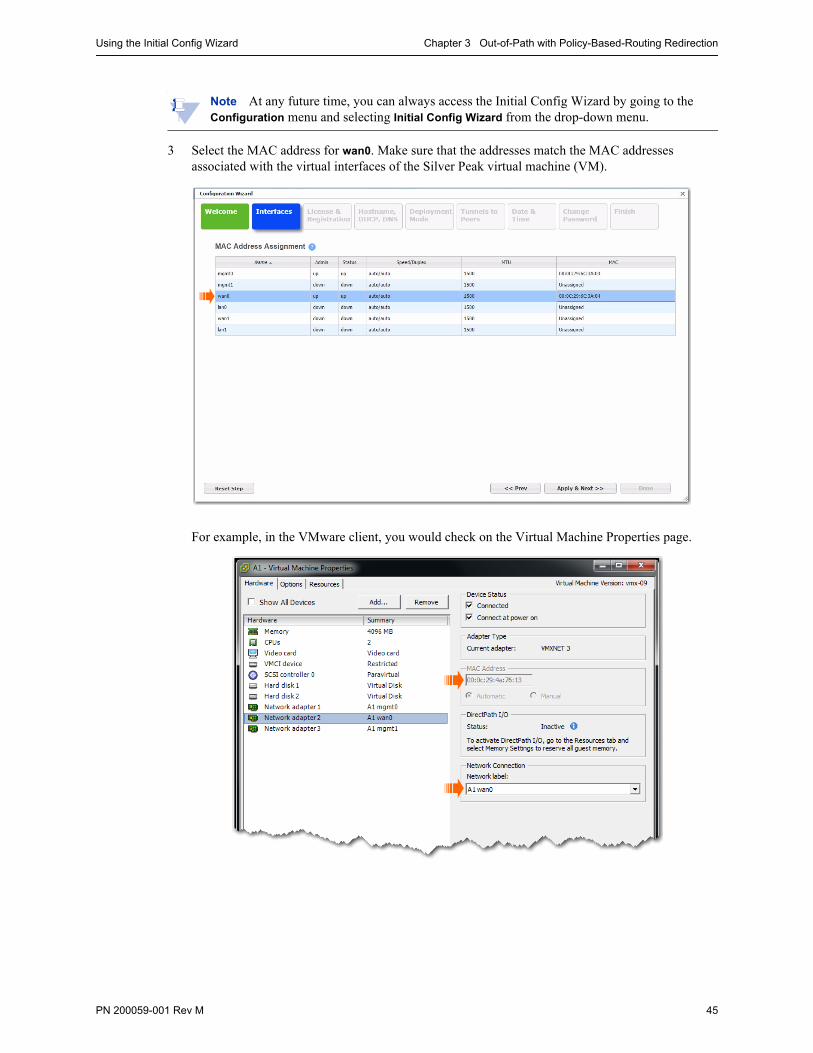
Using the Initial Config Wizard Chapter 3 Out-of-Path with Policy-Based-Routing Redirection
PN 200059-001 Rev M 45
Note At any future time, you can always access the Initial Config Wizard by going to the Configuration menu and selecting Initial Config Wizard from the drop-down menu.
3 Select the MAC address for wan0. Make sure that the addresses match the MAC addresses associated with the virtual interfaces of the Silver Peak virtual machine (VM).
For example, in the VMware client, you would check on the Virtual Machine Properties page.

Silver Peak NX Series Appliances Network Deployment Guide Using the Initial Config Wizard
46 PN 200059-001 Rev M
4 Click Apply & Next. The License & Registration page appears. Enter the license details.
5 Click Apply & Next. The Management Interface (mgmt0) page appears. Enter the appliance name and management IP details.

Using the Initial Config Wizard Chapter 3 Out-of-Path with Policy-Based-Routing Redirection
PN 200059-001 Rev M 47
6 Click Apply & Next. The Deployment Mode page appears. Under Deployment, select Router and then click +Add to add a WAN interface.
Configure the appliance data path IP next-hop router address and max WAN bandwidth.
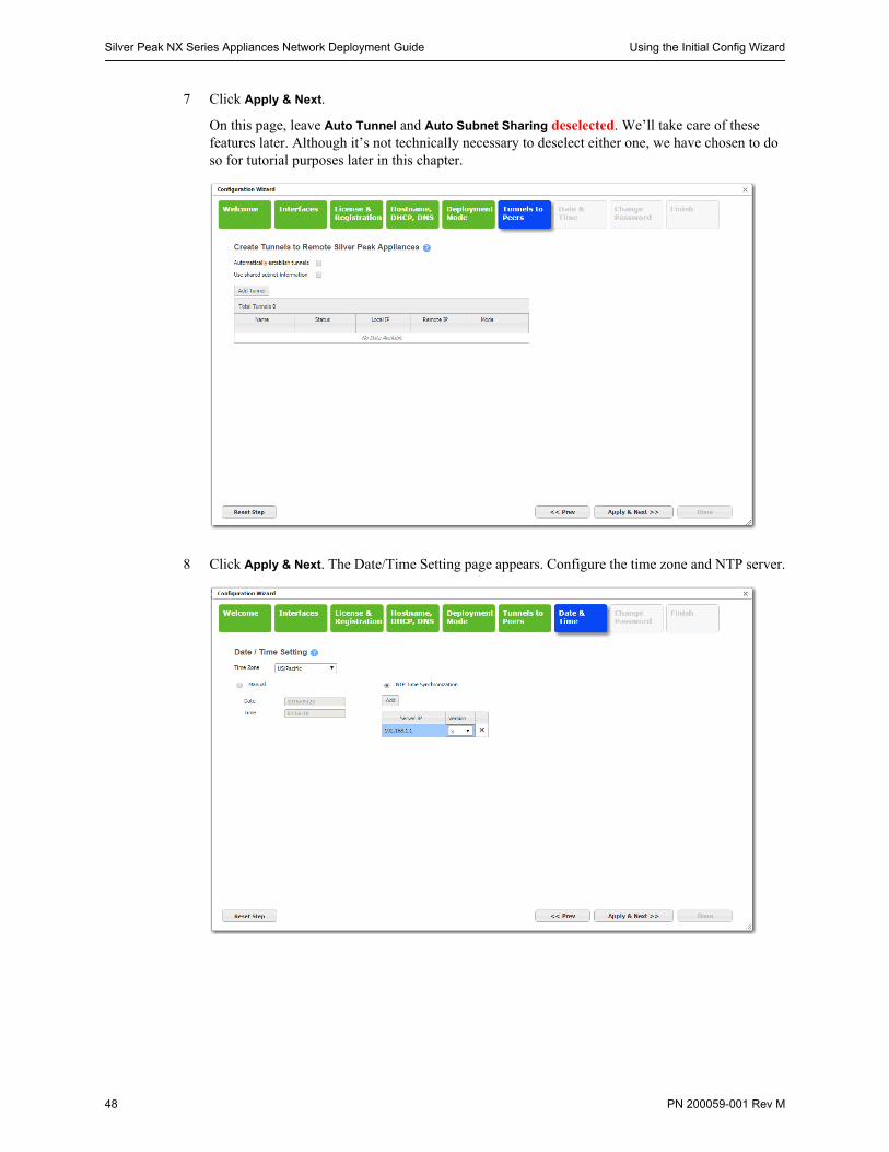
Silver Peak NX Series Appliances Network Deployment Guide Using the Initial Config Wizard
48 PN 200059-001 Rev M
7 Click Apply & Next.
On this page, leave Auto Tunnel and Auto Subnet Sharing deselected. We’ll take care of these features later. Although it’s not technically necessary to deselect either one, we have chosen to do so for tutorial purposes later in this chapter.
8 Click Apply & Next. The Date/Time Setting page appears. Configure the time zone and NTP server.

Using the Initial Config Wizard Chapter 3 Out-of-Path with Policy-Based-Routing Redirection
PN 200059-001 Rev M 49
9 Click Apply & Next. The Change Admin Password page appears. If necessary, create a new username and password.
10 Click Apply & Next. The last wizard page appears.
11 Click Done. The appliance saves the settings and reboots automatically.
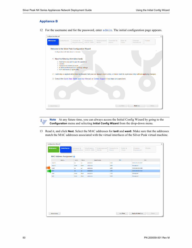
Silver Peak NX Series Appliances Network Deployment Guide Using the Initial Config Wizard
50 PN 200059-001 Rev M
Appliance B
12 For the username and for the password, enter admin. The initial configuration page appears.
Note At any future time, you can always access the Initial Config Wizard by going to the Configuration menu and selecting Initial Config Wizard from the drop-down menu.
13 Read it, and click Next. Select the MAC addresses for lan0 and wan0. Make sure that the addresses match the MAC addresses associated with the virtual interfaces of the Silver Peak virtual machine.
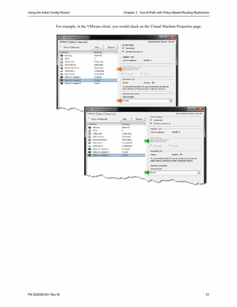
Using the Initial Config Wizard Chapter 3 Out-of-Path with Policy-Based-Routing Redirection
PN 200059-001 Rev M 51
For example, in the VMware client, you would check on the Virtual Machine Properties page.

Silver Peak NX Series Appliances Network Deployment Guide Using the Initial Config Wizard
52 PN 200059-001 Rev M
14 Click Apply & Next. The License & Registration page appears. Enter the license details.
15 Click Apply & Next. The Management Interface (mgmt0) page appears. Enter the appliance name and management IP details.

Using the Initial Config Wizard Chapter 3 Out-of-Path with Policy-Based-Routing Redirection
PN 200059-001 Rev M 53
16 Click Apply & Next. The Deployment Mode page appears. Under Deployment, select Bridge and configure the appliance data path IP next-hop router address and max WAN bandwidth.
17 Click Apply & Next. The Tunnels to Peers page appears.
a Leave Auto Tunnel and Auto Subnet Sharing deselected. We’ll take care of these features later. Although it’s not technically necessary to deselect either one, we have chosen to do so for tutorial purposes later in this chapter.
b Do not add tunnels. We’ll manually add remote appliances and create tunnels later.

Silver Peak NX Series Appliances Network Deployment Guide Using the Initial Config Wizard
54 PN 200059-001 Rev M
18 Click Apply & Next. The Date/Time Setting page appears. Configure the time zone and NTP server.
19 Click Apply & Next. The Change Admin Password page appears. If necessary, create a new username and password.
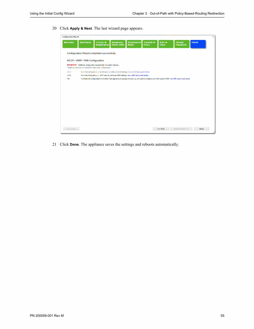
Using the Initial Config Wizard Chapter 3 Out-of-Path with Policy-Based-Routing Redirection
PN 200059-001 Rev M 55
20 Click Apply & Next. The last wizard page appears.
21 Click Done. The appliance saves the settings and reboots automatically.
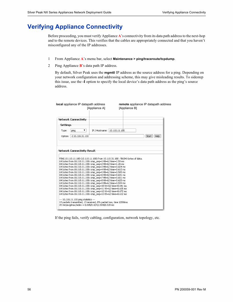
Silver Peak NX Series Appliances Network Deployment Guide Verifying Appliance Connectivity
56 PN 200059-001 Rev M
Verifying Appliance ConnectivityBefore proceeding, you must verify Appliance A’s connectivity from its data path address to the next-hop and to the remote devices. This verifies that the cables are appropriately connected and that you haven’t misconfigured any of the IP addresses.
1 From Appliance A’s menu bar, select Maintenance > ping/traceroute/tcpdump.
2 Ping Appliance B’s data path IP address.
By default, Silver Peak uses the mgmt0 IP address as the source address for a ping. Depending on your network configuration and addressing scheme, this may give misleading results. To sidestep this issue, use the -I option to specify the local device’s data path address as the ping’s source address.
If the ping fails, verify cabling, configuration, network topology, etc.
local appliance IP datapath address[Appliance A]
remote appliance IP datapath address[Appliance B]
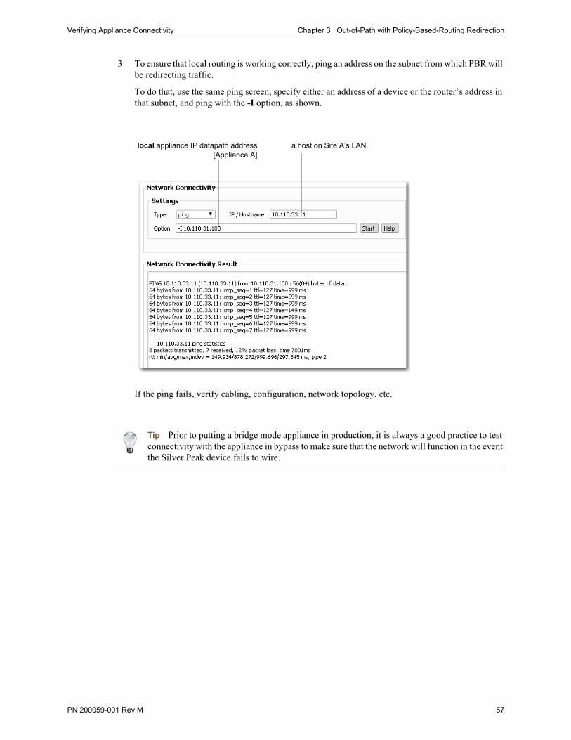
Verifying Appliance Connectivity Chapter 3 Out-of-Path with Policy-Based-Routing Redirection
PN 200059-001 Rev M 57
3 To ensure that local routing is working correctly, ping an address on the subnet from which PBR will be redirecting traffic.
To do that, use the same ping screen, specify either an address of a device or the router’s address in that subnet, and ping with the -I option, as shown.
If the ping fails, verify cabling, configuration, network topology, etc.
Tip Prior to putting a bridge mode appliance in production, it is always a good practice to test connectivity with the appliance in bypass to make sure that the network will function in the event the Silver Peak device fails to wire.
local appliance IP datapath address[Appliance A]
a host on Site A’s LAN
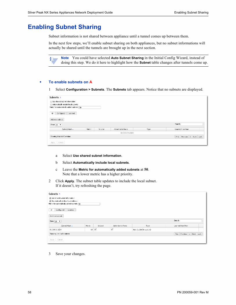
Silver Peak NX Series Appliances Network Deployment Guide Enabling Subnet Sharing
58 PN 200059-001 Rev M
Enabling Subnet SharingSubnet information is not shared between appliance until a tunnel comes up between them.
In the next few steps, we’ll enable subnet sharing on both appliances, but no subnet informations will actually be shared until the tunnels are brought up in the next section.
Note You could have selected Auto Subnet Sharing in the Initial Config Wizard, instead of doing this step. We do it here to highlight how the Subnet table changes after tunnels come up.
To enable subnets on A
1 Select Configuration > Subnets. The Subnets tab appears. Notice that no subnets are displayed.
a Select Use shared subnet information.
b Select Automatically include local subnets.
c Leave the Metric for automatically added subnets at 50. Note that a lower metric has a higher priority.
2 Click Apply. The subnet table updates to include the local subnet. If it doesn’t, try refreshing the page.
3 Save your changes.
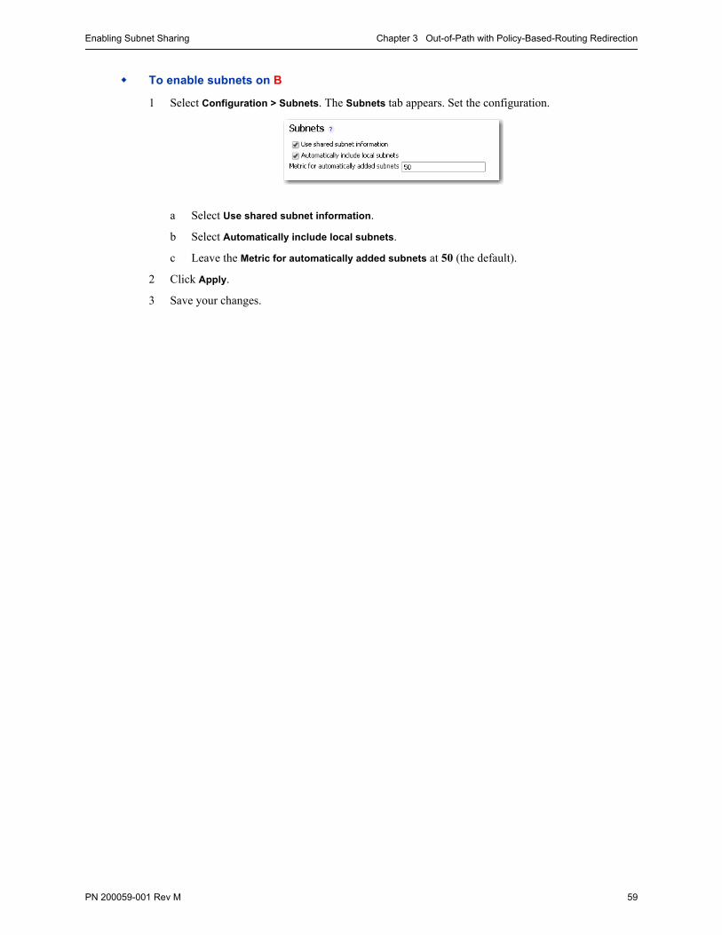
Enabling Subnet Sharing Chapter 3 Out-of-Path with Policy-Based-Routing Redirection
PN 200059-001 Rev M 59
To enable subnets on B
1 Select Configuration > Subnets. The Subnets tab appears. Set the configuration.
a Select Use shared subnet information.
b Select Automatically include local subnets.
c Leave the Metric for automatically added subnets at 50 (the default).
2 Click Apply.
3 Save your changes.
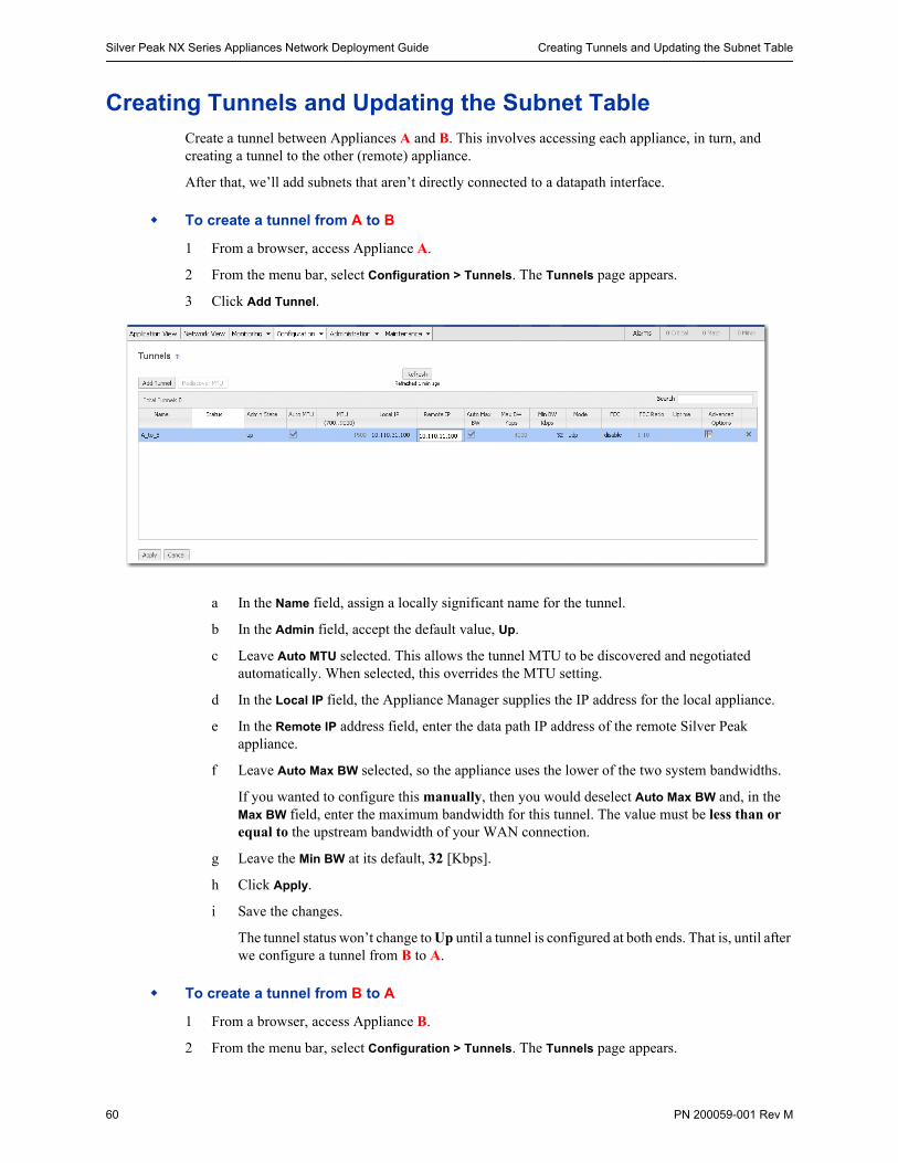
Silver Peak NX Series Appliances Network Deployment Guide Creating Tunnels and Updating the Subnet Table
60 PN 200059-001 Rev M
Creating Tunnels and Updating the Subnet TableCreate a tunnel between Appliances A and B. This involves accessing each appliance, in turn, and creating a tunnel to the other (remote) appliance.
After that, we’ll add subnets that aren’t directly connected to a datapath interface.
To create a tunnel from A to B
1 From a browser, access Appliance A.
2 From the menu bar, select Configuration > Tunnels. The Tunnels page appears.
3 Click Add Tunnel.
a In the Name field, assign a locally significant name for the tunnel.
b In the Admin field, accept the default value, Up.
c Leave Auto MTU selected. This allows the tunnel MTU to be discovered and negotiated automatically. When selected, this overrides the MTU setting.
d In the Local IP field, the Appliance Manager supplies the IP address for the local appliance.
e In the Remote IP address field, enter the data path IP address of the remote Silver Peak appliance.
f Leave Auto Max BW selected, so the appliance uses the lower of the two system bandwidths.
If you wanted to configure this manually, then you would deselect Auto Max BW and, in the Max BW field, enter the maximum bandwidth for this tunnel. The value must be less than or equal to the upstream bandwidth of your WAN connection.
g Leave the Min BW at its default, 32 [Kbps].
h Click Apply.
i Save the changes.
The tunnel status won’t change to Up until a tunnel is configured at both ends. That is, until after we configure a tunnel from B to A.
To create a tunnel from B to A
1 From a browser, access Appliance B.
2 From the menu bar, select Configuration > Tunnels. The Tunnels page appears.
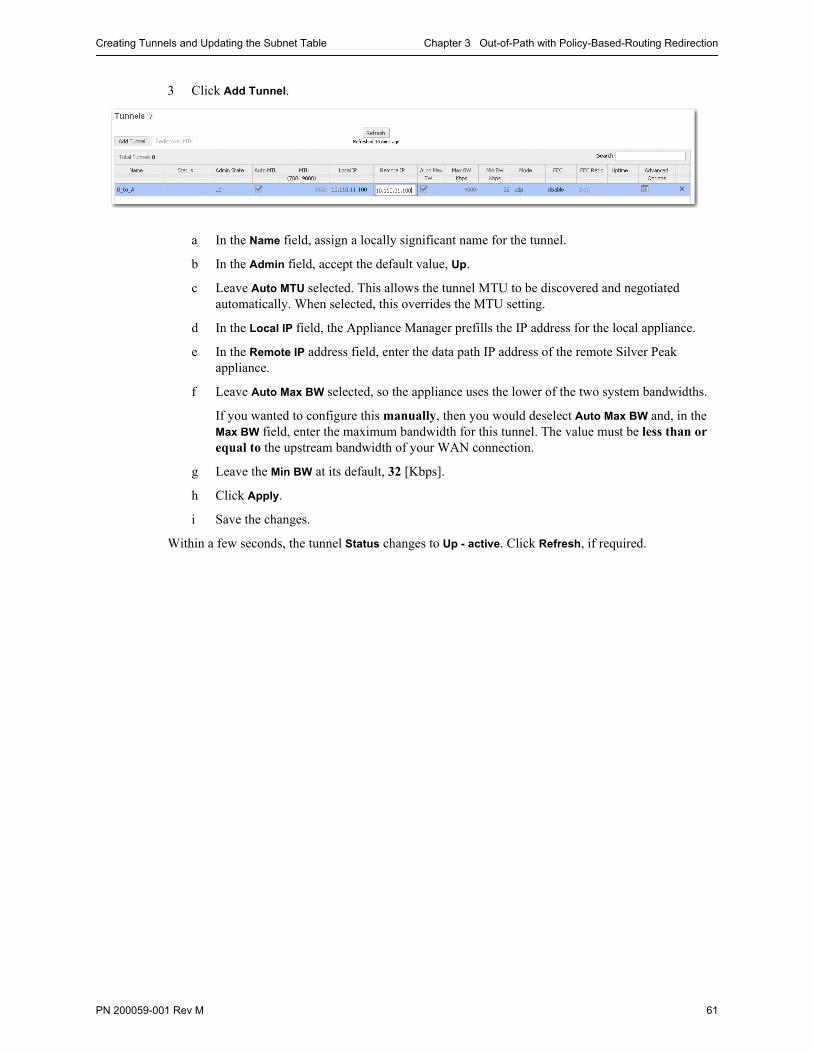
Creating Tunnels and Updating the Subnet Table Chapter 3 Out-of-Path with Policy-Based-Routing Redirection
PN 200059-001 Rev M 61
3 Click Add Tunnel.
a In the Name field, assign a locally significant name for the tunnel.
b In the Admin field, accept the default value, Up.
c Leave Auto MTU selected. This allows the tunnel MTU to be discovered and negotiated automatically. When selected, this overrides the MTU setting.
d In the Local IP field, the Appliance Manager prefills the IP address for the local appliance.
e In the Remote IP address field, enter the data path IP address of the remote Silver Peak appliance.
f Leave Auto Max BW selected, so the appliance uses the lower of the two system bandwidths.
If you wanted to configure this manually, then you would deselect Auto Max BW and, in the Max BW field, enter the maximum bandwidth for this tunnel. The value must be less than or equal to the upstream bandwidth of your WAN connection.
g Leave the Min BW at its default, 32 [Kbps].
h Click Apply.
i Save the changes.
Within a few seconds, the tunnel Status changes to Up - active. Click Refresh, if required.
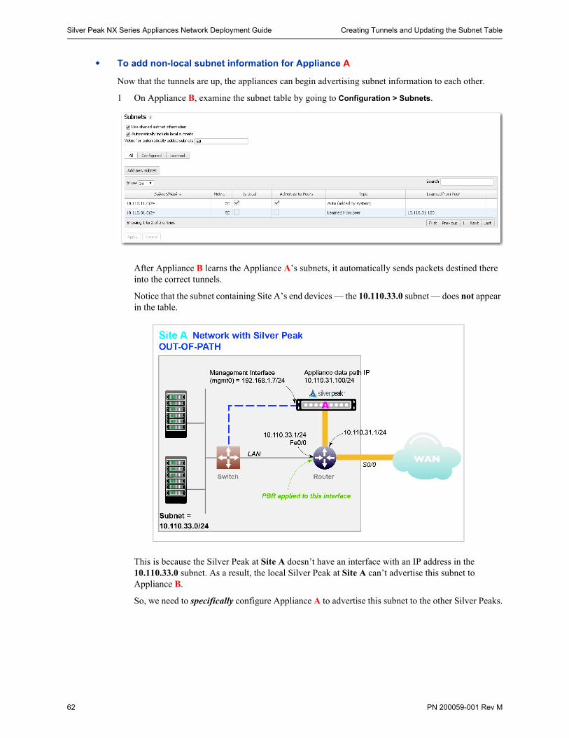
Silver Peak NX Series Appliances Network Deployment Guide Creating Tunnels and Updating the Subnet Table
62 PN 200059-001 Rev M
To add non-local subnet information for Appliance A
Now that the tunnels are up, the appliances can begin advertising subnet information to each other.
1 On Appliance B, examine the subnet table by going to Configuration > Subnets.
After Appliance B learns the Appliance A’s subnets, it automatically sends packets destined there into the correct tunnels.
Notice that the subnet containing Site A’s end devices — the 10.110.33.0 subnet — does not appear in the table.
This is because the Silver Peak at Site A doesn’t have an interface with an IP address in the 10.110.33.0 subnet. As a result, the local Silver Peak at Site A can’t advertise this subnet to Appliance B.
So, we need to specifically configure Appliance A to advertise this subnet to the other Silver Peaks.
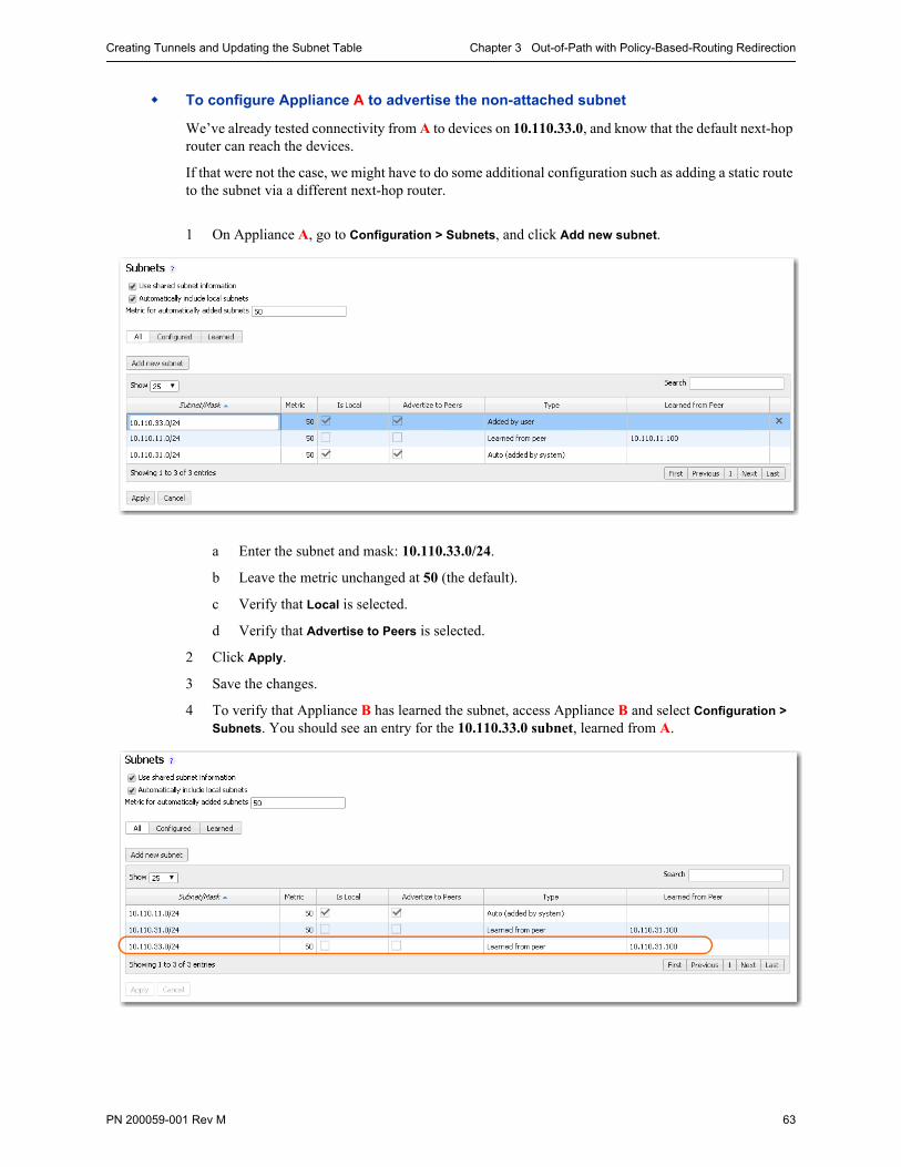
Creating Tunnels and Updating the Subnet Table Chapter 3 Out-of-Path with Policy-Based-Routing Redirection
PN 200059-001 Rev M 63
To configure Appliance A to advertise the non-attached subnet
We’ve already tested connectivity from A to devices on 10.110.33.0, and know that the default next-hop router can reach the devices.
If that were not the case, we might have to do some additional configuration such as adding a static route to the subnet via a different next-hop router.
1 On Appliance A, go to Configuration > Subnets, and click Add new subnet.
a Enter the subnet and mask: 10.110.33.0/24.
b Leave the metric unchanged at 50 (the default).
c Verify that Local is selected.
d Verify that Advertise to Peers is selected.
2 Click Apply.
3 Save the changes.
4 To verify that Appliance B has learned the subnet, access Appliance B and select Configuration >
Subnets. You should see an entry for the 10.110.33.0 subnet, learned from A.
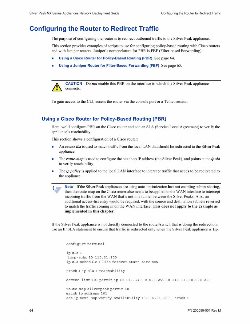
Silver Peak NX Series Appliances Network Deployment Guide Configuring the Router to Redirect Traffic
64 PN 200059-001 Rev M
Configuring the Router to Redirect TrafficThe purpose of configuring the router is to redirect outbound traffic to the Silver Peak appliance.
This section provides examples of scripts to use for configuring policy-based routing with Cisco routers and with Juniper routers. Juniper’s nomenclature for PBR is FBF (Filter-based Forwarding):
Using a Cisco Router for Policy-Based Routing (PBR) See page 64.
Using a Juniper Router for Filter-Based Forwarding (FBF) See page 65.
CAUTION Do not enable this PBR on the interface to which the Silver Peak appliance connects.
To gain access to the CLI, access the router via the console port or a Telnet session.
Using a Cisco Router for Policy-Based Routing (PBR)
Here, we’ll configure PBR on the Cisco router and add an SLA (Service Level Agreement) to verify the appliance’s reachability.
This section shows a configuration of a Cisco router:
An access list is used to match traffic from the local LAN that should be redirected to the Silver Peak appliance.
The route-map is used to configure the next hop IP address (the Silver Peak), and points at the ip sla to verify reachability.
The ip policy is applied to the local LAN interface to intercept traffic that needs to be redirected to the appliance.
Note If the Silver Peak appliances are using auto-optimization but not enabling subnet sharing, then the route-map on the Cisco router also needs to be applied to the WAN interface to intercept incoming traffic from the WAN that’s not in a tunnel between the Silver Peaks. Also, an additional access-list entry would be required, with the source and destination subnets reversed to match the traffic coming in on the WAN interface. This does not apply to the example as implemented in this chapter.
If the Silver Peak appliance is not directly connected to the router/switch that is doing the redirection, use an IP SLA statement to ensure that traffic is redirected only when the Silver Peak appliance is Up.
configure terminal
ip sla 1 icmp-echo 10.110.31.100ip sla schedule 1 life forever start-time now
track 1 ip sla 1 reachability
access-list 101 permit ip 10.110.33.0 0.0.0.255 10.110.11.0 0.0.0.255
route-map silverpeak permit 10match ip address 101set ip next-hop verify-availability 10.110.31.100 1 track 1
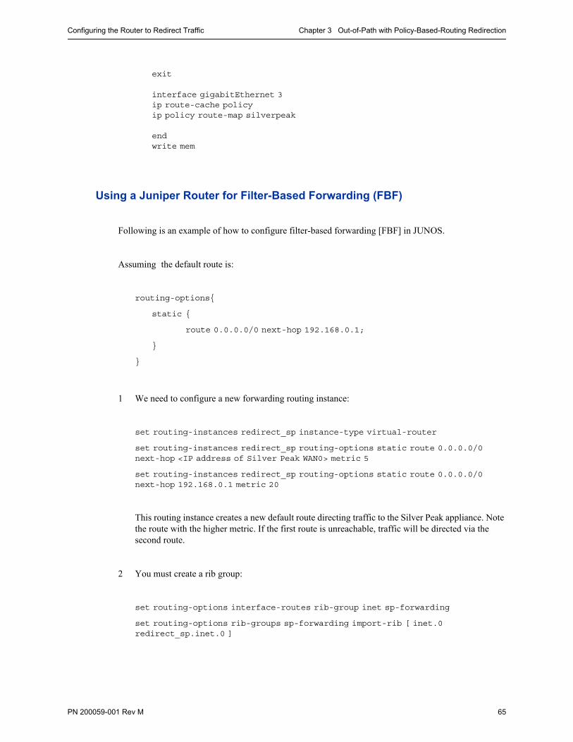
Configuring the Router to Redirect Traffic Chapter 3 Out-of-Path with Policy-Based-Routing Redirection
PN 200059-001 Rev M 65
exit
interface gigabitEthernet 3 ip route-cache policyip policy route-map silverpeak
endwrite mem
Using a Juniper Router for Filter-Based Forwarding (FBF)
Following is an example of how to configure filter-based forwarding [FBF] in JUNOS.
Assuming the default route is:
routing-options{
static {
route 0.0.0.0/0 next-hop 192.168.0.1;
}
}
1 We need to configure a new forwarding routing instance:
set routing-instances redirect_sp instance-type virtual-router
set routing-instances redirect_sp routing-options static route 0.0.0.0/0 next-hop <IP address of Silver Peak WAN0> metric 5
set routing-instances redirect_sp routing-options static route 0.0.0.0/0 next-hop 192.168.0.1 metric 20
This routing instance creates a new default route directing traffic to the Silver Peak appliance. Note the route with the higher metric. If the first route is unreachable, traffic will be directed via the second route.
2 You must create a rib group:
set routing-options interface-routes rib-group inet sp-forwarding
set routing-options rib-groups sp-forwarding import-rib [ inet.0 redirect_sp.inet.0 ]

Silver Peak NX Series Appliances Network Deployment Guide Configuring the Router to Redirect Traffic
66 PN 200059-001 Rev M
3 Create firewall filters that dictate which traffic uses the created routing instance:
set firewall family inet filter silverpeak_fbf term 1 from source-address 172.60.10.0/24
set firewall family inet filter silverpeak_fbf term 1 then routing-instance redirect_sp
set firewall family inet filter silverpeak_fbf term default then accept
This simply creates a filter that says traffic from Site A should use the created routing instance. That is, traffic from 172.60.10.0/24 should use 172.70.10.101 as its default route.
4 Apply the filter to an interface. Note that similar to PBR, the filter should not be applied to the interface directly connected to the Silver Peak appliance.
set interfaces ge-1/0/0 unit 0 family inet filter input silverpeak_fbf
Once a commit is executed, traffic that matches the filter is redirected.
Note This configuration is valid for a Silver Peak appliance that is directly connected to the Juniper device.
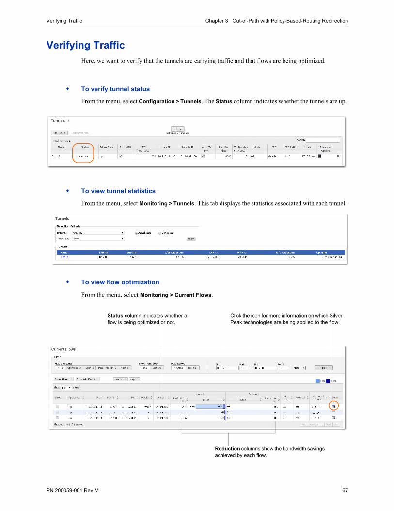
Verifying Traffic Chapter 3 Out-of-Path with Policy-Based-Routing Redirection
PN 200059-001 Rev M 67
Verifying TrafficHere, we want to verify that the tunnels are carrying traffic and that flows are being optimized.
To verify tunnel status
From the menu, select Configuration > Tunnels. The Status column indicates whether the tunnels are up.
To view tunnel statistics
From the menu, select Monitoring > Tunnels. This tab displays the statistics associated with each tunnel.
To view flow optimization
From the menu, select Monitoring > Current Flows.
Reduction columns show the bandwidth savings achieved by each flow.
Click the icon for more information on which Silver Peak technologies are being applied to the flow.
Status column indicates whether a flow is being optimized or not.
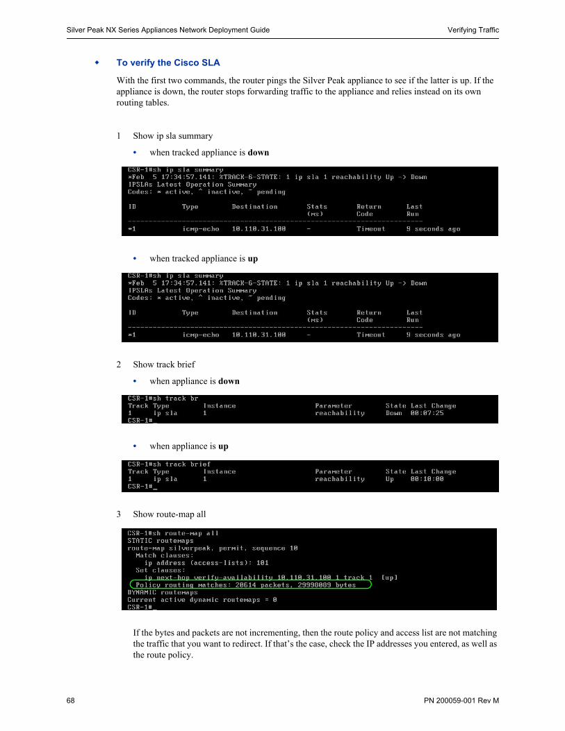
Silver Peak NX Series Appliances Network Deployment Guide Verifying Traffic
68 PN 200059-001 Rev M
To verify the Cisco SLA
With the first two commands, the router pings the Silver Peak appliance to see if the latter is up. If the appliance is down, the router stops forwarding traffic to the appliance and relies instead on its own routing tables.
1 Show ip sla summary
• when tracked appliance is down
• when tracked appliance is up
2 Show track brief
• when appliance is down
• when appliance is up
3 Show route-map all
If the bytes and packets are not incrementing, then the route policy and access list are not matching the traffic that you want to redirect. If that’s the case, check the IP addresses you entered, as well as the route policy.

Verifying Traffic Chapter 3 Out-of-Path with Policy-Based-Routing Redirection
PN 200059-001 Rev M 69
To verify connectivity for pass-through traffic
As a best practice, always verify connectivity for all devices in the network. For example, if you’ve configured a route policy to cause certain traffic from certain devices to be handled as pass-through or pass-through unshaped, you should also verify connectivity for these devices.
To verify network connectivity
Test network connectivity by using your applications. For example, do a CIFS mount or an FTP transfer.
Silver Peak NX Series Appliances Network Deployment Guide Verifying Traffic
70 PN 200059-001 Rev M
SECTION 2: USING TCP/IP–BASED AUTO-OPTIMIZATION
In This Section Overview See page 41.
Using the Initial Config Wizard See page 44.
Configuring the Router to Redirect Traffic See page 64.
Verifying Traffic See page 67.
Configuring Site B’s Appliance See page 85.
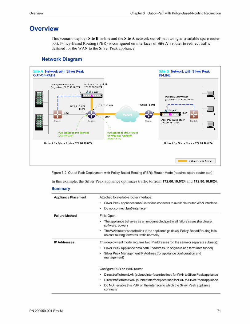
Overview Chapter 3 Out-of-Path with Policy-Based-Routing Redirection
PN 200059-001 Rev M 71
OverviewThis scenario deploys Site B in-line and the Site A network out-of-path using an available spare router port. Policy-Based Routing (PBR) is configured on interfaces of Site A’s router to redirect traffic destined for the WAN to the Silver Peak appliance.
Network Diagram
Figure 3-2 Out-of-Path Deployment with Policy-Based Routing (PBR): Router Mode [requires spare router port]
In this example, the Silver Peak appliance optimizes traffic to/from 172.60.10.0/24 and 172.80.10.0/24.
Summary
Appliance Placement Attached to available router interface:
• Silver Peak appliance wan0 interface connects to available router WAN interface
• Do not connect lan0 interface
Failure Method Fails-Open:
• The appliance behaves as an unconnected port in all failure cases (hardware, software, power)
• The WAN router sees the link to the appliance go down, Policy-Based Routing fails, unicast routing forwards traffic normally.
IP Addresses This deployment model requires two IP addresses (on the same or separate subnets):
• Silver Peak Appliance data path IP address (to originate and terminate tunnel)
• Silver Peak Management IP Address (for appliance configuration and management)
Configure PBR on WAN router
• Direct traffic from LAN (subnet/interface) destined for WAN to Silver Peak appliance
• Direct traffic from WAN (subnet/interface) destined for LAN to Silver Peak appliance
• Do NOT enable this PBR on the interface to which the Silver Peak appliance connects

Silver Peak NX Series Appliances Network Deployment Guide Overview
72 PN 200059-001 Rev M
Fail-Safe Behavior
Fail-safe behavior should always be tested before production deployment by ensuring that traffic continues to flow in each of the following cases:
1 With the appliance in bypass state
2 With the appliance powered off
3 With the tunnels administratively down.
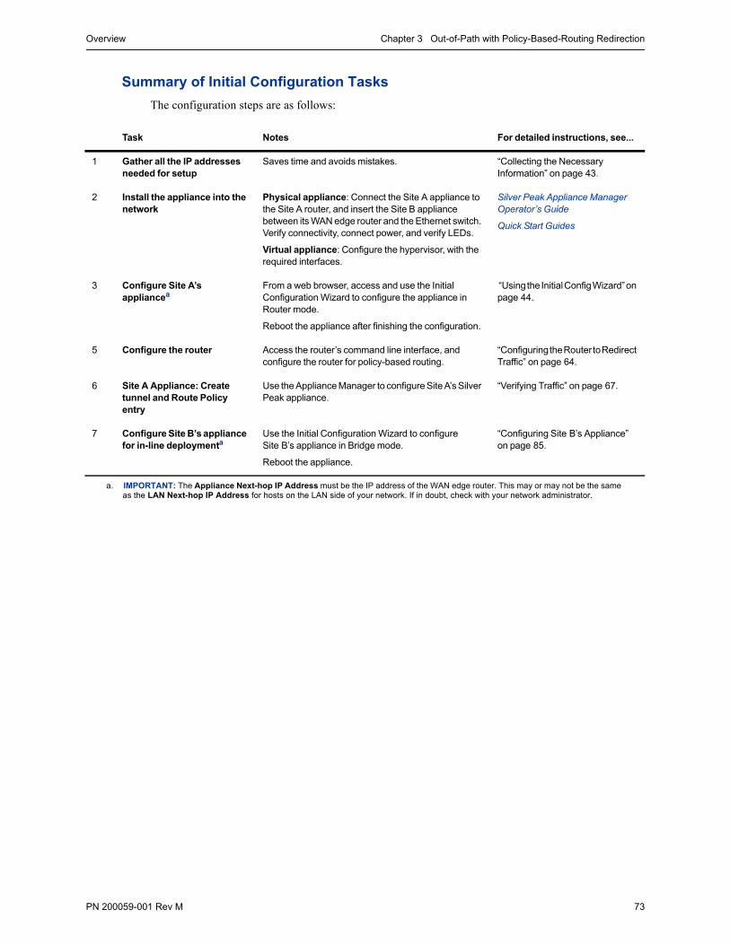
Overview Chapter 3 Out-of-Path with Policy-Based-Routing Redirection
PN 200059-001 Rev M 73
Summary of Initial Configuration Tasks
The configuration steps are as follows:
Task Notes For detailed instructions, see...
1 Gather all the IP addresses needed for setup
Saves time and avoids mistakes. “Collecting the Necessary Information” on page 43.
2 Install the appliance into the network
Physical appliance: Connect the Site A appliance to the Site A router, and insert the Site B appliance between its WAN edge router and the Ethernet switch. Verify connectivity, connect power, and verify LEDs.
Virtual appliance: Configure the hypervisor, with the required interfaces.
Silver Peak Appliance Manager Operator’s Guide
Quick Start Guides
3 Configure Site A’s appliancea
From a web browser, access and use the Initial Configuration Wizard to configure the appliance in Router mode.
Reboot the appliance after finishing the configuration.
“Using the Initial Config Wizard” on page 44.
5 Configure the router Access the router’s command line interface, and configure the router for policy-based routing.
“Configuring the Router to Redirect Traffic” on page 64.
6 Site A Appliance: Create tunnel and Route Policy entry
Use the Appliance Manager to configure Site A’s Silver Peak appliance.
“Verifying Traffic” on page 67.
7 Configure Site B’s appliance for in-line deploymenta
Use the Initial Configuration Wizard to configure Site B’s appliance in Bridge mode.
Reboot the appliance.
“Configuring Site B’s Appliance” on page 85.
a. IMPORTANT: The Appliance Next-hop IP Address must be the IP address of the WAN edge router. This may or may not be the same as the LAN Next-hop IP Address for hosts on the LAN side of your network. If in doubt, check with your network administrator.
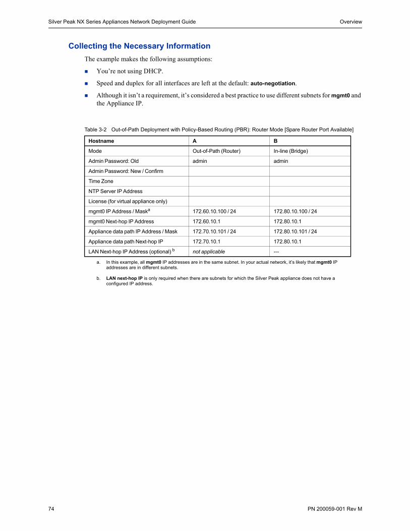
Silver Peak NX Series Appliances Network Deployment Guide Overview
74 PN 200059-001 Rev M
Collecting the Necessary Information
The example makes the following assumptions:
You’re not using DHCP.
Speed and duplex for all interfaces are left at the default: auto-negotiation.
Although it isn’t a requirement, it’s considered a best practice to use different subnets for mgmt0 and the Appliance IP.
Table 3-2 Out-of-Path Deployment with Policy-Based Routing (PBR): Router Mode [Spare Router Port Available]
Hostname A B
Mode Out-of-Path (Router) In-line (Bridge)
Admin Password: Old admin admin
Admin Password: New / Confirm
Time Zone
NTP Server IP Address
License (for virtual appliance only)
mgmt0 IP Address / Maska
a. In this example, all mgmt0 IP addresses are in the same subnet. In your actual network, it’s likely that mgmt0 IP addresses are in different subnets.
172.60.10.100 / 24 172.80.10.100 / 24
mgmt0 Next-hop IP Address 172.60.10.1 172.80.10.1
Appliance data path IP Address / Mask 172.70.10.101 / 24 172.80.10.101 / 24
Appliance data path Next-hop IP 172.70.10.1 172.80.10.1
LAN Next-hop IP Address (optional) b
b. LAN next-hop IP is only required when there are subnets for which the Silver Peak appliance does not have a configured IP address.
not applicable ---
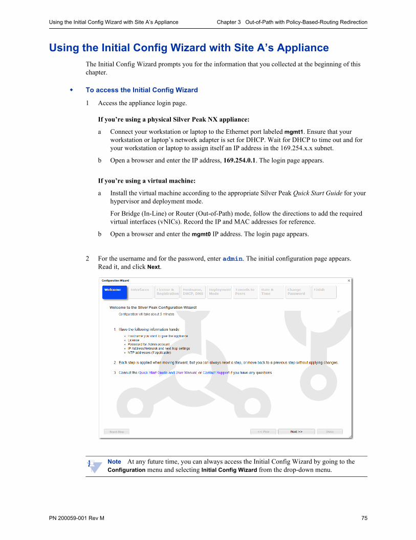
Using the Initial Config Wizard with Site A’s Appliance Chapter 3 Out-of-Path with Policy-Based-Routing Redirection
PN 200059-001 Rev M 75
Using the Initial Config Wizard with Site A’s ApplianceThe Initial Config Wizard prompts you for the information that you collected at the beginning of this chapter.
To access the Initial Config Wizard
1 Access the appliance login page.
If you’re using a physical Silver Peak NX appliance:
a Connect your workstation or laptop to the Ethernet port labeled mgmt1. Ensure that your workstation or laptop’s network adapter is set for DHCP. Wait for DHCP to time out and for your workstation or laptop to assign itself an IP address in the 169.254.x.x subnet.
b Open a browser and enter the IP address, 169.254.0.1. The login page appears.
If you’re using a virtual machine:
a Install the virtual machine according to the appropriate Silver Peak Quick Start Guide for your hypervisor and deployment mode.
For Bridge (In-Line) or Router (Out-of-Path) mode, follow the directions to add the required virtual interfaces (vNICs). Record the IP and MAC addresses for reference.
b Open a browser and enter the mgmt0 IP address. The login page appears.
2 For the username and for the password, enter admin. The initial configuration page appears. Read it, and click Next.
Note At any future time, you can always access the Initial Config Wizard by going to the Configuration menu and selecting Initial Config Wizard from the drop-down menu.
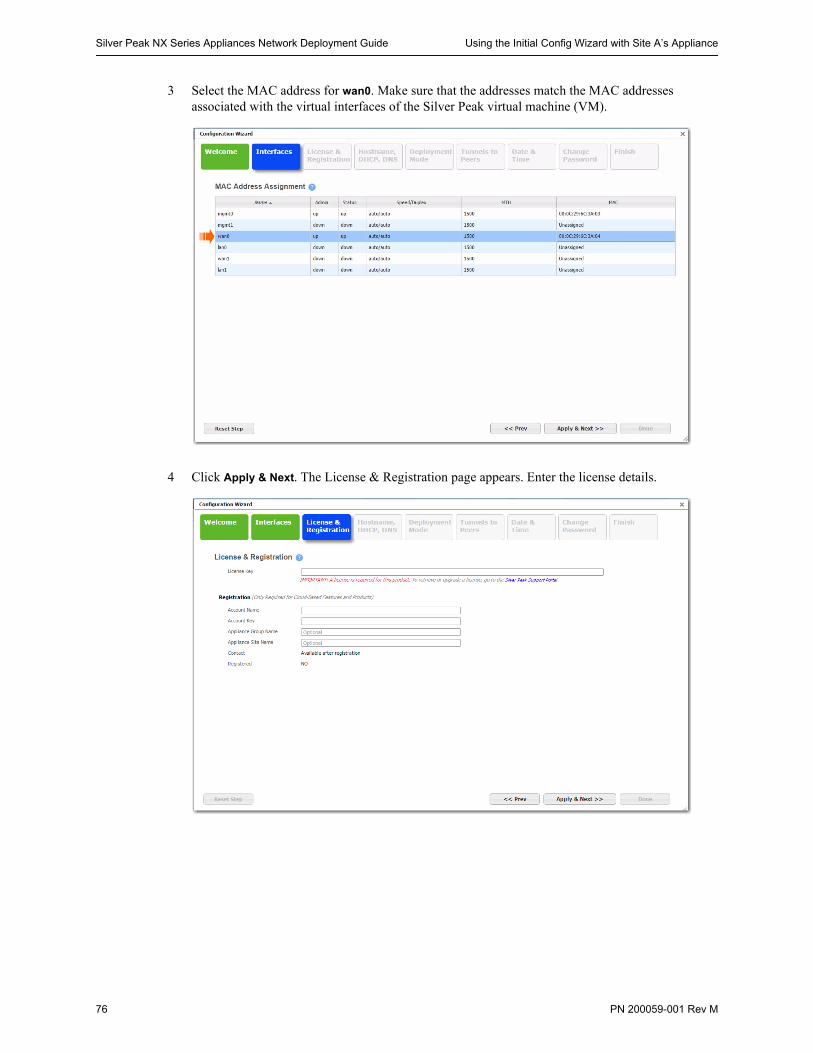
Silver Peak NX Series Appliances Network Deployment Guide Using the Initial Config Wizard with Site A’s Appliance
76 PN 200059-001 Rev M
3 Select the MAC address for wan0. Make sure that the addresses match the MAC addresses associated with the virtual interfaces of the Silver Peak virtual machine (VM).
4 Click Apply & Next. The License & Registration page appears. Enter the license details.
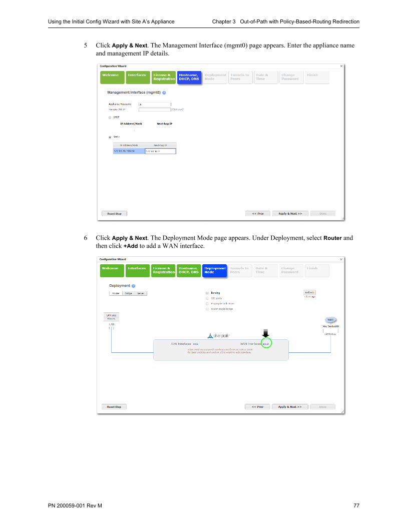
Using the Initial Config Wizard with Site A’s Appliance Chapter 3 Out-of-Path with Policy-Based-Routing Redirection
PN 200059-001 Rev M 77
5 Click Apply & Next. The Management Interface (mgmt0) page appears. Enter the appliance name and management IP details.
6 Click Apply & Next. The Deployment Mode page appears. Under Deployment, select Router and then click +Add to add a WAN interface.
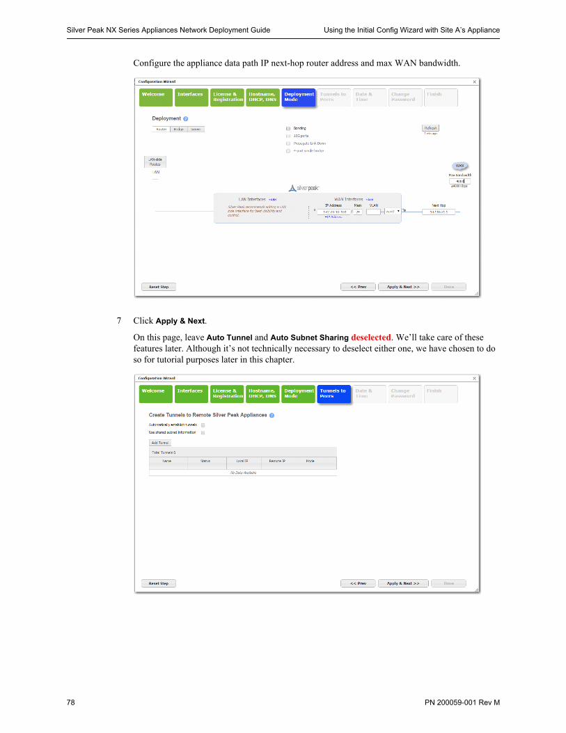
Silver Peak NX Series Appliances Network Deployment Guide Using the Initial Config Wizard with Site A’s Appliance
78 PN 200059-001 Rev M
Configure the appliance data path IP next-hop router address and max WAN bandwidth.
7 Click Apply & Next.
On this page, leave Auto Tunnel and Auto Subnet Sharing deselected. We’ll take care of these features later. Although it’s not technically necessary to deselect either one, we have chosen to do so for tutorial purposes later in this chapter.
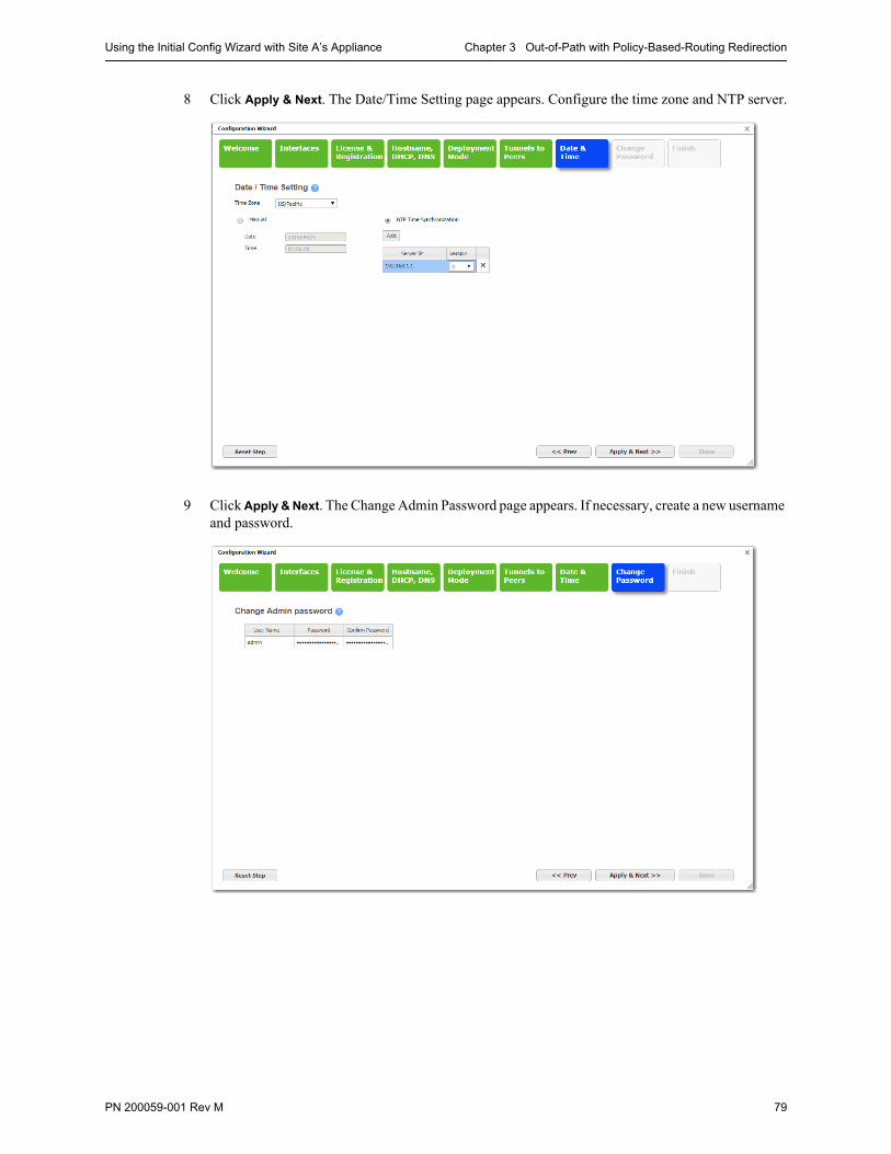
Using the Initial Config Wizard with Site A’s Appliance Chapter 3 Out-of-Path with Policy-Based-Routing Redirection
PN 200059-001 Rev M 79
8 Click Apply & Next. The Date/Time Setting page appears. Configure the time zone and NTP server.
9 Click Apply & Next. The Change Admin Password page appears. If necessary, create a new username and password.
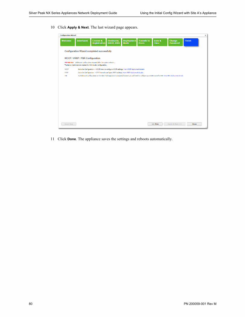
Silver Peak NX Series Appliances Network Deployment Guide Using the Initial Config Wizard with Site A’s Appliance
80 PN 200059-001 Rev M
10 Click Apply & Next. The last wizard page appears.
11 Click Done. The appliance saves the settings and reboots automatically.
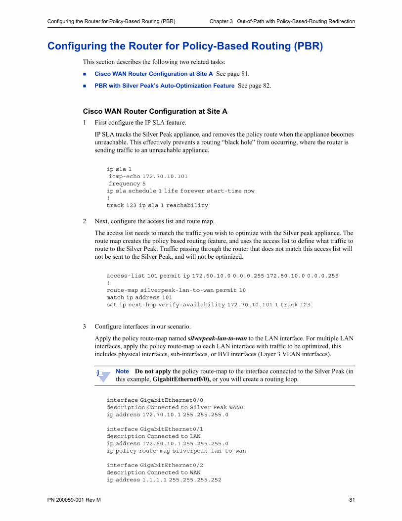
Configuring the Router for Policy-Based Routing (PBR) Chapter 3 Out-of-Path with Policy-Based-Routing Redirection
PN 200059-001 Rev M 81
Configuring the Router for Policy-Based Routing (PBR)This section describes the following two related tasks:
Cisco WAN Router Configuration at Site A See page 81.
PBR with Silver Peak’s Auto-Optimization Feature See page 82.
Cisco WAN Router Configuration at Site A
1 First configure the IP SLA feature.
IP SLA tracks the Silver Peak appliance, and removes the policy route when the appliance becomes unreachable. This effectively prevents a routing “black hole” from occurring, where the router is sending traffic to an unreachable appliance.
ip sla 1 icmp-echo 172.70.10.101 frequency 5ip sla schedule 1 life forever start-time now!track 123 ip sla 1 reachability
2 Next, configure the access list and route map.
The access list needs to match the traffic you wish to optimize with the Silver peak appliance. The route map creates the policy based routing feature, and uses the access list to define what traffic to route to the Silver Peak. Traffic passing through the router that does not match this access list will not be sent to the Silver Peak, and will not be optimized.
access-list 101 permit ip 172.60.10.0 0.0.0.255 172.80.10.0 0.0.0.255!route-map silverpeak-lan-to-wan permit 10match ip address 101set ip next-hop verify-availability 172.70.10.101 1 track 123
3 Configure interfaces in our scenario.
Apply the policy route-map named silverpeak-lan-to-wan to the LAN interface. For multiple LAN interfaces, apply the policy route-map to each LAN interface with traffic to be optimized, this includes physical interfaces, sub-interfaces, or BVI interfaces (Layer 3 VLAN interfaces).
Note Do not apply the policy route-map to the interface connected to the Silver Peak (in this example, GigabitEthernet0/0), or you will create a routing loop.
interface GigabitEthernet0/0description Connected to Silver Peak WAN0ip address 172.70.10.1 255.255.255.0
interface GigabitEthernet0/1description Connected to LANip address 172.60.10.1 255.255.255.0ip policy route-map silverpeak-lan-to-wan
interface GigabitEthernet0/2description Connected to WANip address 1.1.1.1 255.255.255.252
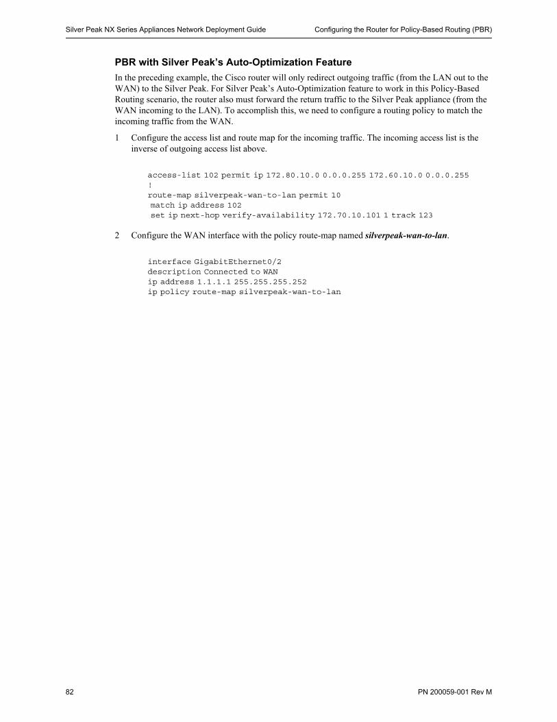
Silver Peak NX Series Appliances Network Deployment Guide Configuring the Router for Policy-Based Routing (PBR)
82 PN 200059-001 Rev M
PBR with Silver Peak’s Auto-Optimization Feature
In the preceding example, the Cisco router will only redirect outgoing traffic (from the LAN out to the WAN) to the Silver Peak. For Silver Peak’s Auto-Optimization feature to work in this Policy-Based Routing scenario, the router also must forward the return traffic to the Silver Peak appliance (from the WAN incoming to the LAN). To accomplish this, we need to configure a routing policy to match the incoming traffic from the WAN.
1 Configure the access list and route map for the incoming traffic. The incoming access list is the inverse of outgoing access list above.
access-list 102 permit ip 172.80.10.0 0.0.0.255 172.60.10.0 0.0.0.255 !route-map silverpeak-wan-to-lan permit 10 match ip address 102 set ip next-hop verify-availability 172.70.10.101 1 track 123
2 Configure the WAN interface with the policy route-map named silverpeak-wan-to-lan.
interface GigabitEthernet0/2description Connected to WANip address 1.1.1.1 255.255.255.252ip policy route-map silverpeak-wan-to-lan
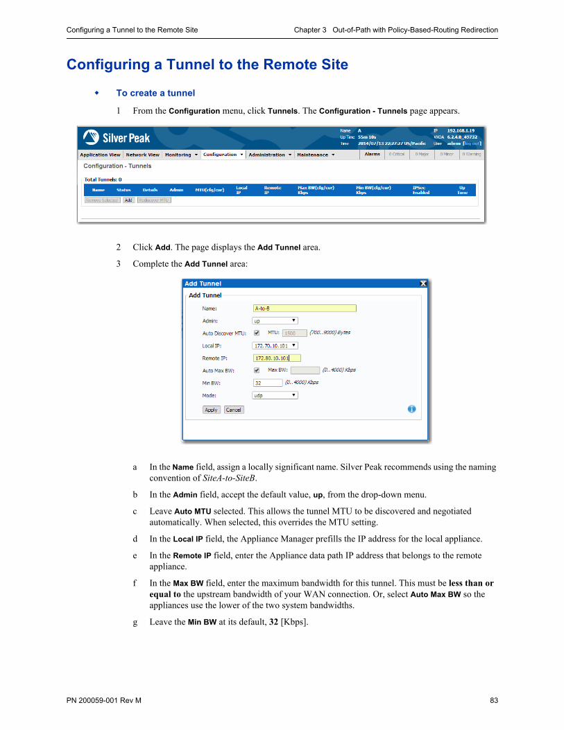
Configuring a Tunnel to the Remote Site Chapter 3 Out-of-Path with Policy-Based-Routing Redirection
PN 200059-001 Rev M 83
Configuring a Tunnel to the Remote Site
To create a tunnel
1 From the Configuration menu, click Tunnels. The Configuration - Tunnels page appears.
2 Click Add. The page displays the Add Tunnel area.
3 Complete the Add Tunnel area:
a In the Name field, assign a locally significant name. Silver Peak recommends using the naming convention of SiteA-to-SiteB.
b In the Admin field, accept the default value, up, from the drop-down menu.
c Leave Auto MTU selected. This allows the tunnel MTU to be discovered and negotiated automatically. When selected, this overrides the MTU setting.
d In the Local IP field, the Appliance Manager prefills the IP address for the local appliance.
e In the Remote IP field, enter the Appliance data path IP address that belongs to the remote appliance.
f In the Max BW field, enter the maximum bandwidth for this tunnel. This must be less than or equal to the upstream bandwidth of your WAN connection. Or, select Auto Max BW so the appliances use the lower of the two system bandwidths.
g Leave the Min BW at its default, 32 [Kbps].
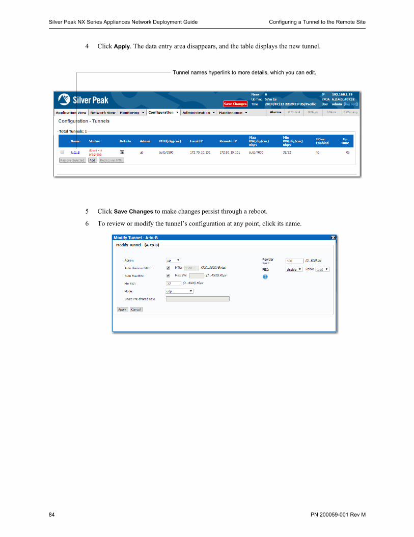
Silver Peak NX Series Appliances Network Deployment Guide Configuring a Tunnel to the Remote Site
84 PN 200059-001 Rev M
4 Click Apply. The data entry area disappears, and the table displays the new tunnel.
5 Click Save Changes to make changes persist through a reboot.
6 To review or modify the tunnel’s configuration at any point, click its name.
Tunnel names hyperlink to more details, which you can edit.
Configuring Site B’s Appliance Chapter 3 Out-of-Path with Policy-Based-Routing Redirection
PN 200059-001 Rev M 85
Configuring Site B’s Appliance1 Use the Initial Configuration Wizard to configure Site B’s appliance in-line (Bridge mode).
2 Verify connectivity for Site B’s appliance.
3 Create the tunnel, B-to-A.
4 Verifying connectivity for tunnel and pass-through traffic
Once you’ve defined the tunnel on both devices you’ve configured, you must verify that the tunnel is Up and Active, and that you’re able to access hosts through the tunnel.
For more information, see “Verifying Connectivity After Configuring Deployment” on page 19.

Silver Peak NX Series Appliances Network Deployment Guide Configuring Site B’s Appliance
86 PN 200059-001 Rev M
PN 200059-001 Rev M 87
C H A P T E R 4
Out-of-Path with WCCPComparing Subnet Sharing & TCP/IP-based Auto-Optimization
This chapter provides a step-by-step example for setting up Web Cache Communications Protocol (WCCP) service.
The example uses a Cisco router paired with a single Silver Peak appliance. The Silver Peak appliances participating in the WCCP service group must be deployed out-of-path (Router mode).
The example also compares two of the auto-optimization methods—subnet sharing (which, when enabled, is the method that takes precedence), and TCP-based and IP-based auto-optimization. Both methods require outbound (LAN–side) redirection; TCP/IP-based auto-optimization also requires inbound (WAN–side) redirection. For more explanation, see “Determining the Need for Traffic Redirection” on page 13.
In This Chapter Overview See page 88.
Configuring the Site A Router for WCCP See page 92.
Using the Initial Config Wizard with Site A’s Appliance See page 94.
Configuring WCCP on Appliance A See page 100.
Using the Initial Config Wizard with Site B’s Appliance See page 110.
Verifying Appliance Connectivity See page 116.
Enabling Subnet Sharing See page 118.
Creating Tunnels and Updating the Subnet Table See page 120.
Verifying Traffic See page 124.
Best Practices See page 126.
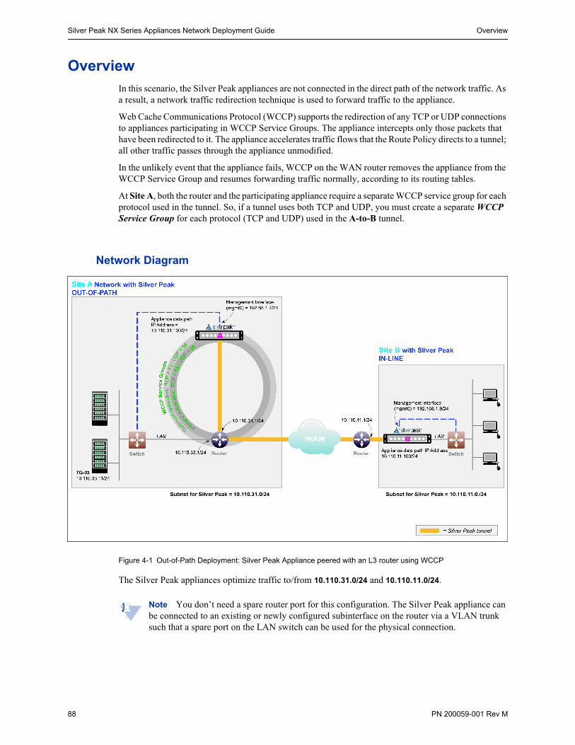
Silver Peak NX Series Appliances Network Deployment Guide Overview
88 PN 200059-001 Rev M
OverviewIn this scenario, the Silver Peak appliances are not connected in the direct path of the network traffic. As a result, a network traffic redirection technique is used to forward traffic to the appliance.
Web Cache Communications Protocol (WCCP) supports the redirection of any TCP or UDP connections to appliances participating in WCCP Service Groups. The appliance intercepts only those packets that have been redirected to it. The appliance accelerates traffic flows that the Route Policy directs to a tunnel; all other traffic passes through the appliance unmodified.
In the unlikely event that the appliance fails, WCCP on the WAN router removes the appliance from the WCCP Service Group and resumes forwarding traffic normally, according to its routing tables.
At Site A, both the router and the participating appliance require a separate WCCP service group for each protocol used in the tunnel. So, if a tunnel uses both TCP and UDP, you must create a separate WCCP Service Group for each protocol (TCP and UDP) used in the A-to-B tunnel.
Network Diagram
Figure 4-1 Out-of-Path Deployment: Silver Peak Appliance peered with an L3 router using WCCP
The Silver Peak appliances optimize traffic to/from 10.110.31.0/24 and 10.110.11.0/24.
Note You don’t need a spare router port for this configuration. The Silver Peak appliance can be connected to an existing or newly configured subinterface on the router via a VLAN trunk such that a spare port on the LAN switch can be used for the physical connection.
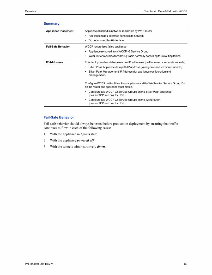
Overview Chapter 4 Out-of-Path with WCCP
PN 200059-001 Rev M 89
Summary
Fail-Safe Behavior
Fail-safe behavior should always be tested before production deployment by ensuring that traffic continues to flow in each of the following cases:
1 With the appliance in bypass state
2 With the appliance powered off
3 With the tunnels administratively down.
Appliance Placement Appliance attached in network, reachable by WAN router
• Appliance wan0 interface connects to network
• Do not connect lan0 interface
Fail-Safe Behavior WCCP recognizes failed appliance
• Appliance removed from WCCP v2 Service Group
• WAN router resumes forwarding traffic normally according to its routing tables
IP Addresses This deployment model requires two IP addresses (on the same or separate subnets)
• Silver Peak Appliance data path IP address (to originate and terminate tunnels)
• Silver Peak Management IP Address (for appliance configuration and management)
Configure WCCP on the Silver Peak appliance and the WAN router. Service Group IDs on the router and appliance must match.
• Configure two WCCP v2 Service Groups on the Silver Peak appliance (one for TCP and one for UDP)
• Configure two WCCP v2 Service Groups on the WAN router (one for TCP and one for UDP)
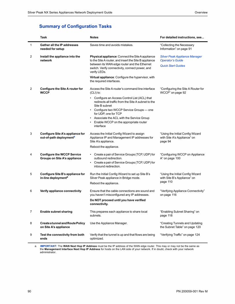
Silver Peak NX Series Appliances Network Deployment Guide Overview
90 PN 200059-001 Rev M
Summary of Configuration Tasks
Task Notes For detailed instructions, see...
1 Gather all the IP addresses needed for setup
Saves time and avoids mistakes. “Collecting the Necessary Information” on page 91
2 Install the appliance into the network
Physical appliance: Connect the Site A appliance to the Site A router, and insert the Site B appliance between its WAN edge router and the Ethernet switch. Verify connectivity, connect power, and verify LEDs.
Virtual appliance: Configure the hypervisor, with the required interfaces.
Silver Peak Appliance Manager Operator’s Guide
Quick Start Guides
2 Configure the Site A router for WCCP
Access the Site A router’s command line interface (CLI) to:
• Configure an Access Control List (ACL) that redirects all traffic from the Site A subnet to the Site B subnet
• Configure two WCCP Service Groups — one for UDP, one for TCP
• Associate the ACL with the Service Group• Enable WCCP on the appropriate router
interface
“Configuring the Site A Router for WCCP” on page 92
3 Configure Site A’s appliance for out-of-path deploymenta
a. IMPORTANT: The WAN Next Hop IP Address must be the IP address of the WAN edge router. This may or may not be the same as the Management Interface Next Hop IP Address for hosts on the LAN side of your network. If in doubt, check with your network administrator.
Access the Initial Config Wizard to assign Appliance IP and Management IP addresses for Site A’s appliance.
Reboot the appliance.
“Using the Initial Config Wizard with Site A’s Appliance” on page 94
4 Configure the WCCP Service Groups on Site A’s appliance
• Create a pair of Service Groups (TCP, UDP) for outbound redirection.
• Create a pair of Service Groups (TCP, UDP) for inbound redirection.
“Configuring WCCP on Appliance A” on page 100
5 Configure Site B’s appliance for in-line deploymenta
Run the Initial Config Wizard to set up Site B’s Silver Peak appliance in Bridge mode.
Reboot the appliance.
“Using the Initial Config Wizard with Site B’s Appliance” on page 110
6 Verify appliance connectivity Ensure that the cable connections are sound and you haven’t misconfigured any IP addresses.
Do NOT proceed until you have verified connectivity.
“Verifying Appliance Connectivity” on page 116
7 Enable subnet sharing This prepares each appliance to share local subnets.
“Enabling Subnet Sharing” on page 118
8 Create a tunnel and Route Policy on Site A’s appliance
Use the Appliance Manager. “Creating Tunnels and Updating the Subnet Table” on page 120
9 Test the connectivity from both ends
Verify that the tunnel is up and that flows are being optimized.
“Verifying Traffic” on page 124
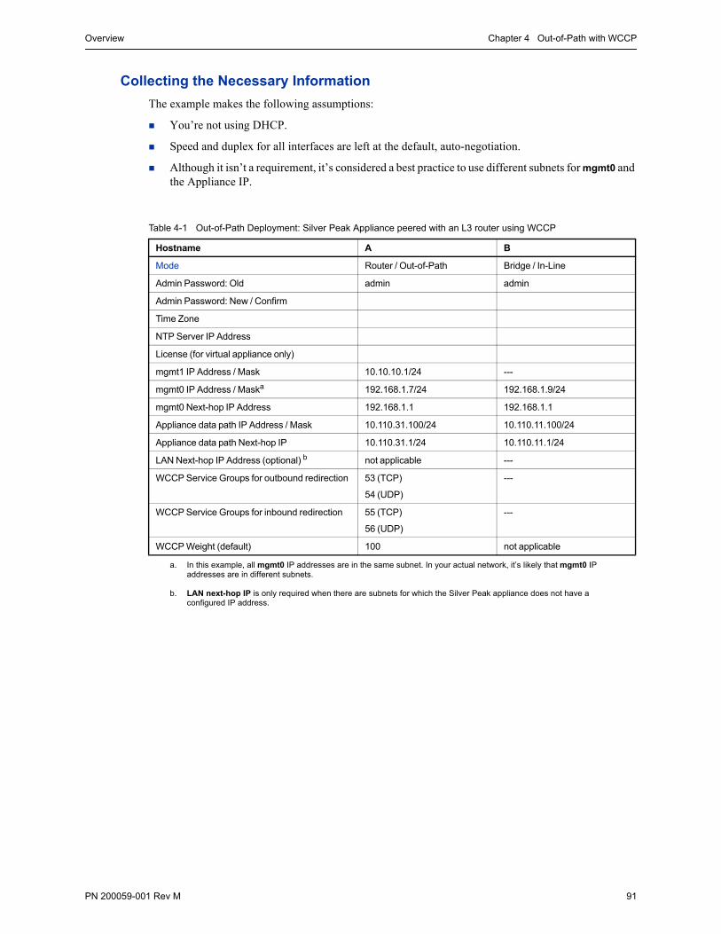
Overview Chapter 4 Out-of-Path with WCCP
PN 200059-001 Rev M 91
Collecting the Necessary Information
The example makes the following assumptions:
You’re not using DHCP.
Speed and duplex for all interfaces are left at the default, auto-negotiation.
Although it isn’t a requirement, it’s considered a best practice to use different subnets for mgmt0 and the Appliance IP.
Table 4-1 Out-of-Path Deployment: Silver Peak Appliance peered with an L3 router using WCCP
Hostname A B
Mode Router / Out-of-Path Bridge / In-Line
Admin Password: Old admin admin
Admin Password: New / Confirm
Time Zone
NTP Server IP Address
License (for virtual appliance only)
mgmt1 IP Address / Mask 10.10.10.1/24 ---
mgmt0 IP Address / Maska
a. In this example, all mgmt0 IP addresses are in the same subnet. In your actual network, it’s likely that mgmt0 IP addresses are in different subnets.
192.168.1.7/24 192.168.1.9/24
mgmt0 Next-hop IP Address 192.168.1.1 192.168.1.1
Appliance data path IP Address / Mask 10.110.31.100/24 10.110.11.100/24
Appliance data path Next-hop IP 10.110.31.1/24 10.110.11.1/24
LAN Next-hop IP Address (optional) b
b. LAN next-hop IP is only required when there are subnets for which the Silver Peak appliance does not have a configured IP address.
not applicable ---
WCCP Service Groups for outbound redirection 53 (TCP)
54 (UDP)
---
WCCP Service Groups for inbound redirection 55 (TCP)
56 (UDP)
---
WCCP Weight (default) 100 not applicable
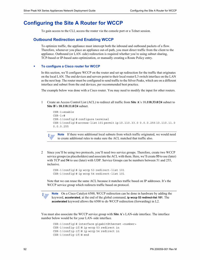
Silver Peak NX Series Appliances Network Deployment Guide Configuring the Site A Router for WCCP
92 PN 200059-001 Rev M
Configuring the Site A Router for WCCPTo gain access to the CLI, access the router via the console port or a Telnet session.
Outbound Redirection and Enabling WCCP
To optimize traffic, the appliance must intercept both the inbound and outbound packets of a flow. Therefore, whenever you place an appliance out-of-path, you must direct traffic from the client to the appliance. Outbound (or LAN–side) redirection is required whether you’re using subnet sharing, TCP-based or IP-based auto-optimization, or manually creating a Route Policy entry.
To configure a Cisco router for WCCP
In this section, we’ll configure WCCP on the router and set up redirection for the traffic that originates on the local LAN. The end devices and servers point to their local router/L3 switch interface on the LAN as the next hop. The router must be configured to send traffic to the Silver Peaks, which are on a different interface and subnet from the end devices, per recommended best practice.
The example below was done with a Cisco router. You may need to modify the input for other routers.
1 Create an Access Control List (ACL) to redirect all traffic from Site A’s 10.110.33.0/24 subnet to Site B’s 10.110.11.0/24 subnet.
CSR-1>enableCSR-1>#CSR-1(config)# configure terminalCSR-1(config)# access-list 101 permit ip 10.110.33.0 0.0.0.255 10.110.11.0 0.0.0.255
Note If there were additional local subnets from which traffic originated, we would need to create additional rules to make sure the ACL matched that traffic also.
2 Since you’ll be using two protocols, you’ll need two service groups. Therefore, create two WCCP service groups (as placeholders) and associate the ACL with them. Here, we’ll create 53 to use (later) with TCP and 54 to use (later) with UDP. Service Groups can be numbers between 51 and 255, inclusive.
CSR-1(config)# ip wccp 53 redirect-list 101CSR-1(config)# ip wccp 54 redirect-list 101
Note that we can reuse the same ACL because it matches traffic based on IP addresses. It’s the WCCP service group which redirects traffic based on protocol.
Note On a Cisco Catalyst 6500, WCCP redirection can be done in hardware by adding the keyword, accelerated, at the end of the global command, ip wccp 53 redirect-list 101. The accelerated keyword allows the 6500 to do WCCP redirection (forwarding) in L2.
You must also associate the WCCP service group with Site A’s LAN-side interface. The interface number below would be for your LAN–side interface.
CSR-1(config)# interface gigabitEthernet <number>CSR-1(config-if)# ip wccp 53 redirect inCSR-1(config-if)# ip wccp 54 redirect inCSR-1(config-if)# end
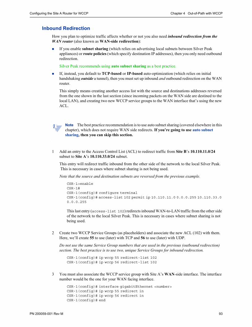
Configuring the Site A Router for WCCP Chapter 4 Out-of-Path with WCCP
PN 200059-001 Rev M 93
Inbound Redirection
How you plan to optimize traffic affects whether or not you also need inbound redirection from the WAN router (also known as WAN-side redirection):
If you enable subnet sharing (which relies on advertising local subnets between Silver Peak appliances) or route policies (which specify destination IP addresses), then you only need outbound redirection.
Silver Peak recommends using auto subnet sharing as a best practice.
If, instead, you default to TCP-based or IP-based auto-optimization (which relies on initial handshaking outside a tunnel), then you must set up inbound and outbound redirection on the WAN router.
This simply means creating another access list with the source and destinations addresses reversed from the one shown in the last section (since incoming packets on the WAN side are destined to the local LAN), and creating two new WCCP service groups to the WAN interface that’s using the new ACL.
Note The best practice recommendation is to use auto subnet sharing (covered elsewhere in this chapter), which does not require WAN side redirects. If you’re going to use auto subnet sharing, then you can skip this section.
1 Add an entry to the Access Control List (ACL) to redirect traffic from Site B’s 10.110.11.0/24 subnet to Site A’s 10.110.33.0/24 subnet.
This entry will redirect traffic inbound from the other side of the network to the local Silver Peak. This is necessary in cases where subnet sharing is not being used.
Note that the source and destination subnets are reversed from the previous example.
CSR-1>enableCSR-1#CSR-1(config)# configure terminalCSR-1(config)# access-list 102 permit ip 10.110.11.0 0.0.0.255 10.110.33.0 0.0.0.255
This last entry (access-list 102) redirects inbound WAN-to-LAN traffic from the other side of the network to the local Silver Peak. This is necessary in cases where subnet sharing is not being used.
2 Create two WCCP Service Groups (as placeholders) and associate the new ACL (102) with them. Here, we’ll create 55 to use (later) with TCP and 56 to use (later) with UDP.
Do not use the same Service Group numbers that are used in the previous (outbound redirection) section. The best practice is to use two, unique Service Groups for inbound redirection.
CSR-1(config)# ip wccp 55 redirect-list 102CSR-1(config)# ip wccp 56 redirect-list 102
3 You must also associate the WCCP service group with Site A’s WAN-side interface. The interface number would be the one for your WAN facing interface.
CSR-1(config)# interface gigabitEthernet <number>CSR-1(config)# ip wccp 55 redirect inCSR-1(config)# ip wccp 56 redirect inCSR-1(config)# end
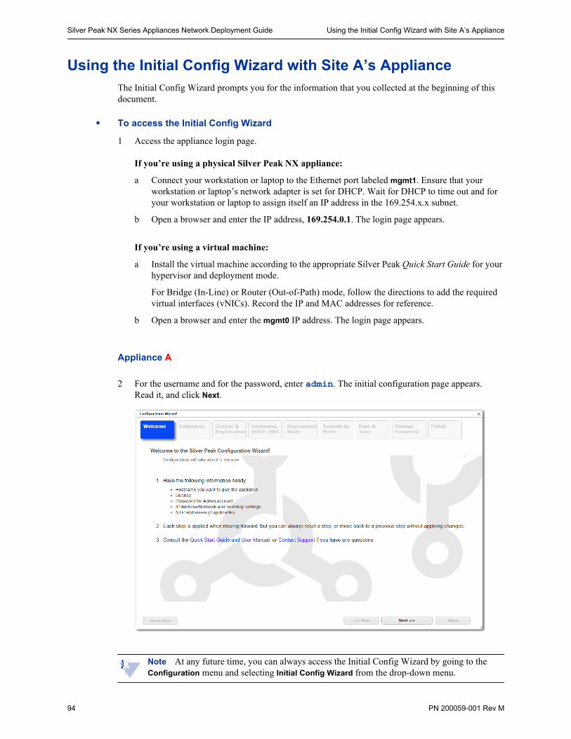
Silver Peak NX Series Appliances Network Deployment Guide Using the Initial Config Wizard with Site A’s Appliance
94 PN 200059-001 Rev M
Using the Initial Config Wizard with Site A’s ApplianceThe Initial Config Wizard prompts you for the information that you collected at the beginning of this document.
To access the Initial Config Wizard
1 Access the appliance login page.
If you’re using a physical Silver Peak NX appliance:
a Connect your workstation or laptop to the Ethernet port labeled mgmt1. Ensure that your workstation or laptop’s network adapter is set for DHCP. Wait for DHCP to time out and for your workstation or laptop to assign itself an IP address in the 169.254.x.x subnet.
b Open a browser and enter the IP address, 169.254.0.1. The login page appears.
If you’re using a virtual machine:
a Install the virtual machine according to the appropriate Silver Peak Quick Start Guide for your hypervisor and deployment mode.
For Bridge (In-Line) or Router (Out-of-Path) mode, follow the directions to add the required virtual interfaces (vNICs). Record the IP and MAC addresses for reference.
b Open a browser and enter the mgmt0 IP address. The login page appears.
Appliance A
2 For the username and for the password, enter admin. The initial configuration page appears. Read it, and click Next.
Note At any future time, you can always access the Initial Config Wizard by going to the Configuration menu and selecting Initial Config Wizard from the drop-down menu.
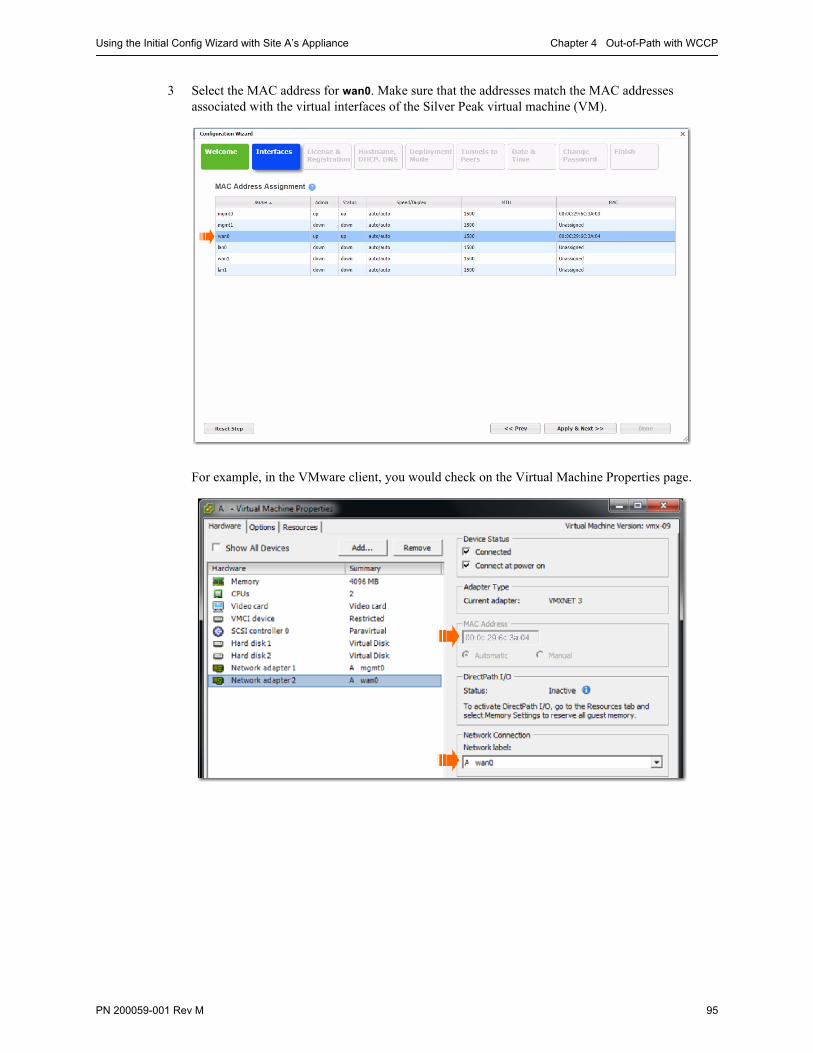
Using the Initial Config Wizard with Site A’s Appliance Chapter 4 Out-of-Path with WCCP
PN 200059-001 Rev M 95
3 Select the MAC address for wan0. Make sure that the addresses match the MAC addresses associated with the virtual interfaces of the Silver Peak virtual machine (VM).
For example, in the VMware client, you would check on the Virtual Machine Properties page.

Silver Peak NX Series Appliances Network Deployment Guide Using the Initial Config Wizard with Site A’s Appliance
96 PN 200059-001 Rev M
4 Click Apply & Next. The License & Registration page appears. Enter the license details.
5 Click Apply & Next. The Management Interface (mgmt0) page appears. Enter the appliance name and management IP details.
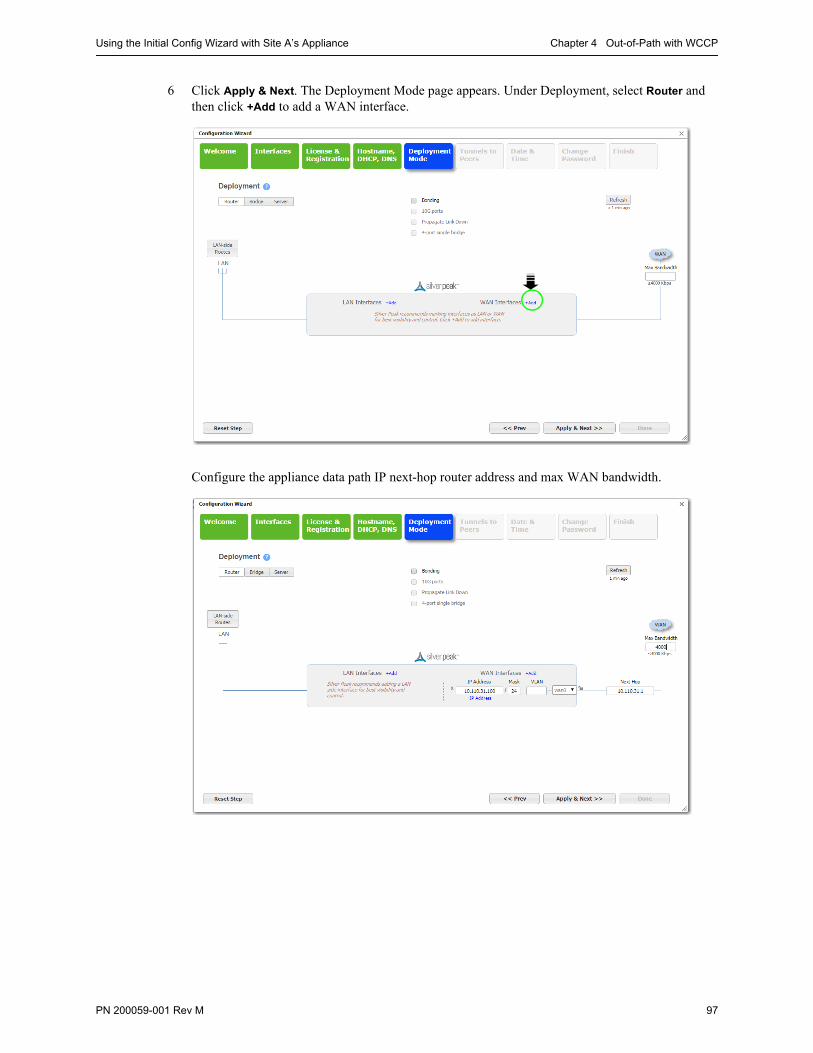
Using the Initial Config Wizard with Site A’s Appliance Chapter 4 Out-of-Path with WCCP
PN 200059-001 Rev M 97
6 Click Apply & Next. The Deployment Mode page appears. Under Deployment, select Router and then click +Add to add a WAN interface.
Configure the appliance data path IP next-hop router address and max WAN bandwidth.
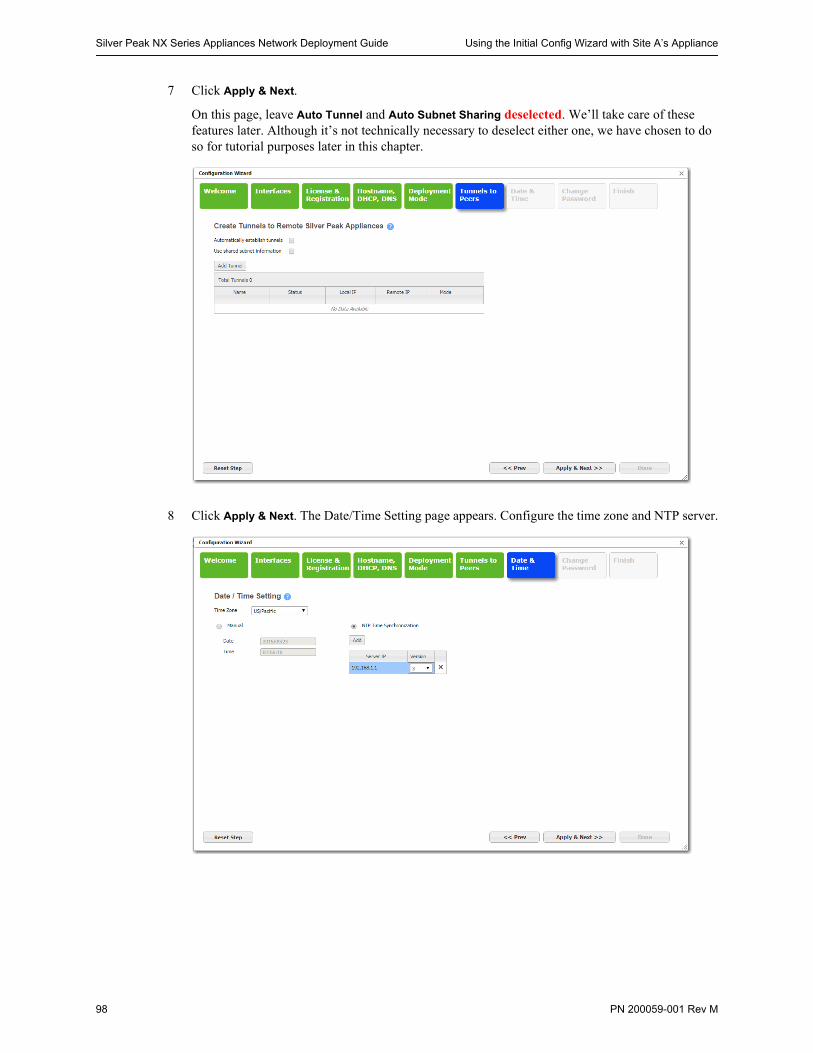
Silver Peak NX Series Appliances Network Deployment Guide Using the Initial Config Wizard with Site A’s Appliance
98 PN 200059-001 Rev M
7 Click Apply & Next.
On this page, leave Auto Tunnel and Auto Subnet Sharing deselected. We’ll take care of these features later. Although it’s not technically necessary to deselect either one, we have chosen to do so for tutorial purposes later in this chapter.
8 Click Apply & Next. The Date/Time Setting page appears. Configure the time zone and NTP server.
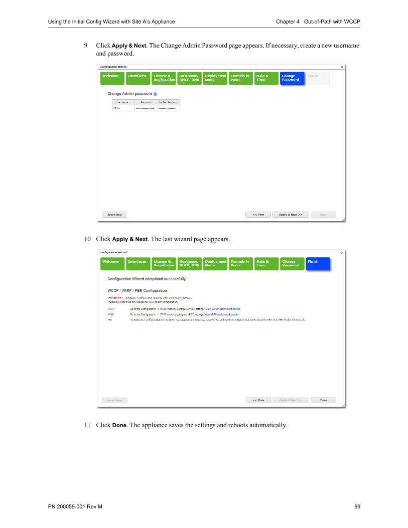
Using the Initial Config Wizard with Site A’s Appliance Chapter 4 Out-of-Path with WCCP
PN 200059-001 Rev M 99
9 Click Apply & Next. The Change Admin Password page appears. If necessary, create a new username and password.
10 Click Apply & Next. The last wizard page appears.
11 Click Done. The appliance saves the settings and reboots automatically.
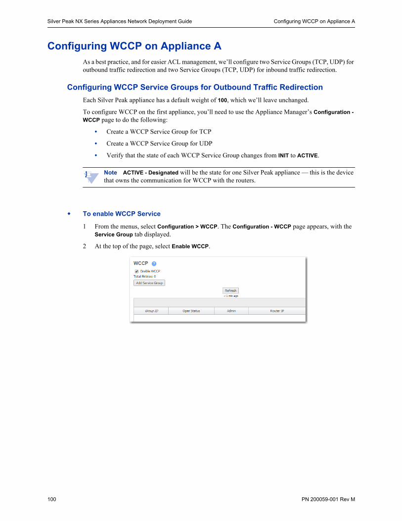
Silver Peak NX Series Appliances Network Deployment Guide Configuring WCCP on Appliance A
100 PN 200059-001 Rev M
Configuring WCCP on Appliance AAs a best practice, and for easier ACL management, we’ll configure two Service Groups (TCP, UDP) for outbound traffic redirection and two Service Groups (TCP, UDP) for inbound traffic redirection.
Configuring WCCP Service Groups for Outbound Traffic Redirection
Each Silver Peak appliance has a default weight of 100, which we’ll leave unchanged.
To configure WCCP on the first appliance, you’ll need to use the Appliance Manager’s Configuration -
WCCP page to do the following:
• Create a WCCP Service Group for TCP
• Create a WCCP Service Group for UDP
• Verify that the state of each WCCP Service Group changes from INIT to ACTIVE.
Note ACTIVE - Designated will be the state for one Silver Peak appliance — this is the device that owns the communication for WCCP with the routers.
To enable WCCP Service
1 From the menus, select Configuration > WCCP. The Configuration - WCCP page appears, with the Service Group tab displayed.
2 At the top of the page, select Enable WCCP.
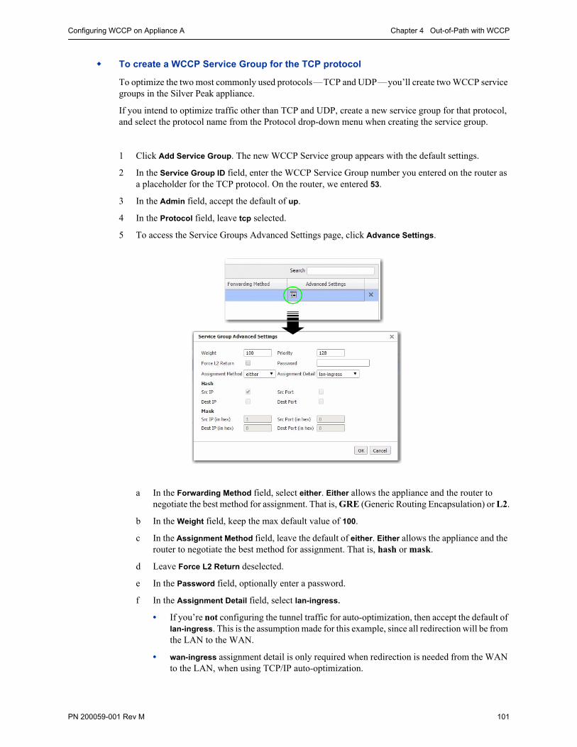
Configuring WCCP on Appliance A Chapter 4 Out-of-Path with WCCP
PN 200059-001 Rev M 101
To create a WCCP Service Group for the TCP protocol
To optimize the two most commonly used protocols—TCP and UDP—you’ll create two WCCP service groups in the Silver Peak appliance.
If you intend to optimize traffic other than TCP and UDP, create a new service group for that protocol, and select the protocol name from the Protocol drop-down menu when creating the service group.
1 Click Add Service Group. The new WCCP Service group appears with the default settings.
2 In the Service Group ID field, enter the WCCP Service Group number you entered on the router as a placeholder for the TCP protocol. On the router, we entered 53.
3 In the Admin field, accept the default of up.
4 In the Protocol field, leave tcp selected.
5 To access the Service Groups Advanced Settings page, click Advance Settings.
a In the Forwarding Method field, select either. Either allows the appliance and the router to negotiate the best method for assignment. That is, GRE (Generic Routing Encapsulation) or L2.
b In the Weight field, keep the max default value of 100.
c In the Assignment Method field, leave the default of either. Either allows the appliance and the router to negotiate the best method for assignment. That is, hash or mask.
d Leave Force L2 Return deselected.
e In the Password field, optionally enter a password.
f In the Assignment Detail field, select lan-ingress.
• If you’re not configuring the tunnel traffic for auto-optimization, then accept the default of lan-ingress. This is the assumption made for this example, since all redirection will be from the LAN to the WAN.
• wan-ingress assignment detail is only required when redirection is needed from the WAN to the LAN, when using TCP/IP auto-optimization.

Silver Peak NX Series Appliances Network Deployment Guide Configuring WCCP on Appliance A
102 PN 200059-001 Rev M
• custom is used to provide granular control of flow distribution. Contact Silver Peak Technical Support for assistance.
g To save the settings and close the dialog box, click OK.
6 From the Interface field, select wan0.
7 For Compatibility Mode, select the option appropriate for your router. If a WCCP group is peering with a router running Nexus OS, then the appliance must adjust its WCCP protocol packets to be compatible. By default, the appliance is IOS-compatible.
8 In the Router IP Address field, enter the IP address of the WCCP router, 10.110.31.1.
9 Click Apply. A new WCCP Service Group for TCP appears.

Configuring WCCP on Appliance A Chapter 4 Out-of-Path with WCCP
PN 200059-001 Rev M 103
To create a WCCP Service Group for the UDP protocol
1 On the Configuration - WCCP page, click Add Service Group. A new WCCP Service Group appears with the default settings.
2 In the Service Group ID field, enter the WCCP Service Group number you entered on the router as a placeholder for the UDP protocol. On the router, we entered 54.
3 In the Admin field, accept the default of up.
4 In the Protocol field, leave udp selected.
5 To access the Service Groups Advanced Settings page, click Advance Settings.
a In the Forwarding Method field, select either. Either allows the appliance and the router to negotiate the best method for assignment. That is, GRE (Generic Routing Encapsulation) or L2.
b In the Weight field, keep the max default value of 100.
c In the Assignment Method field, leave the default of either. Either allows the appliance and the router to negotiate the best method for assignment. That is, hash or mask.
d Leave Force L2 Return deselected.
e In the Password field, optionally enter a password.
f In the Assignment Detail field, select lan-ingress.
• If you’re not configuring the tunnel traffic for auto-optimization, then accept the default of lan-ingress. This is the assumption made for this example, since all redirection will be from the LAN to the WAN.
• wan-ingress assignment detail is only required when redirection is needed from the WAN to the LAN, when using TCP/IP auto-optimization.
• custom is used to provide granular control of flow distribution. Contact Silver Peak Technical Support for assistance.
g To save the settings and close the dialog box, click OK.
6 From the Interface field, select wan0.
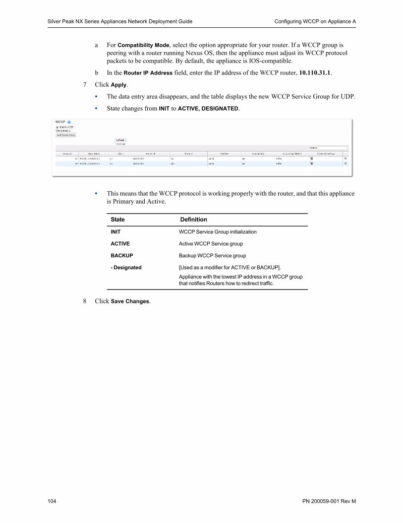
Silver Peak NX Series Appliances Network Deployment Guide Configuring WCCP on Appliance A
104 PN 200059-001 Rev M
a For Compatibility Mode, select the option appropriate for your router. If a WCCP group is peering with a router running Nexus OS, then the appliance must adjust its WCCP protocol packets to be compatible. By default, the appliance is IOS-compatible.
b In the Router IP Address field, enter the IP address of the WCCP router, 10.110.31.1.
7 Click Apply.
• The data entry area disappears, and the table displays the new WCCP Service Group for UDP.
• State changes from INIT to ACTIVE, DESIGNATED.
• This means that the WCCP protocol is working properly with the router, and that this appliance is Primary and Active.
8 Click Save Changes.
State Definition
INIT WCCP Service Group initialization
ACTIVE Active WCCP Service group
BACKUP Backup WCCP Service group
- Designated [Used as a modifier for ACTIVE or BACKUP].
Appliance with the lowest IP address in a WCCP group that notifies Routers how to redirect traffic.
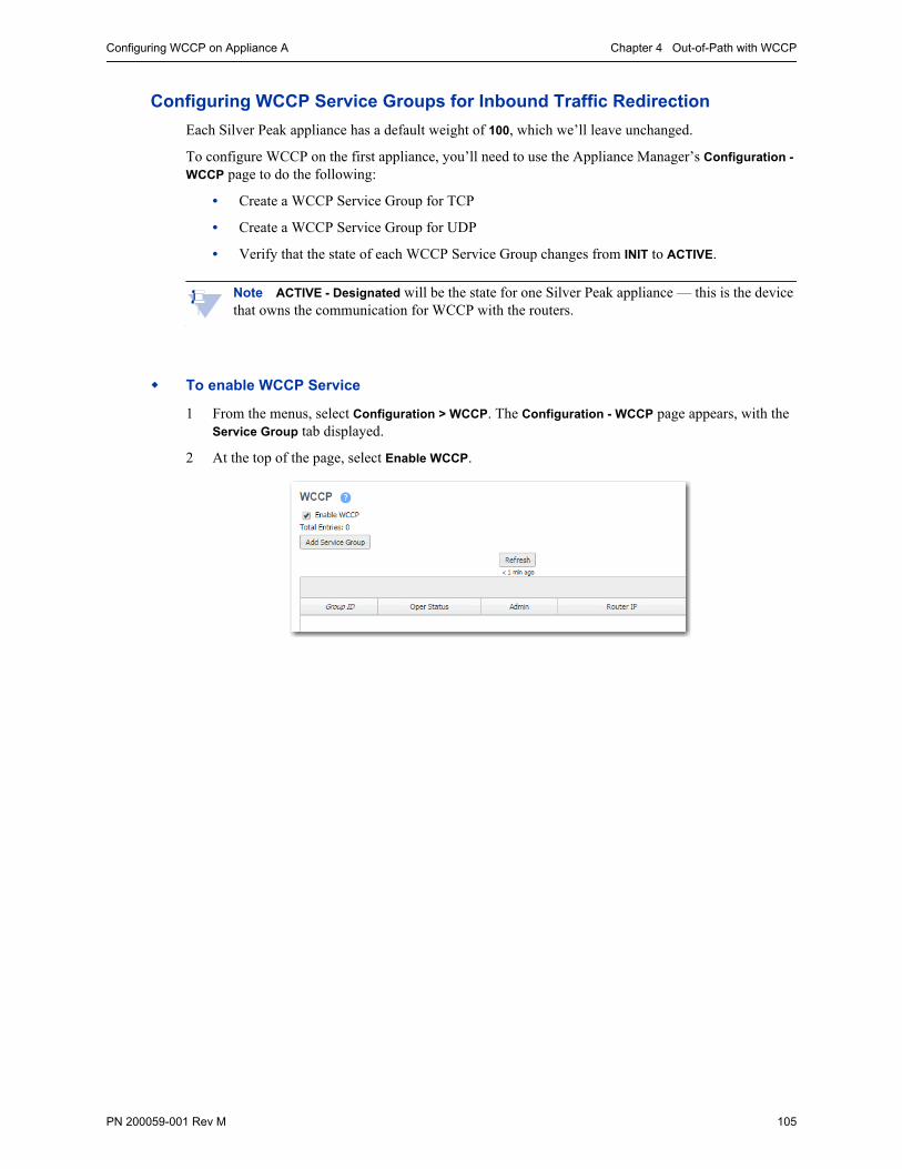
Configuring WCCP on Appliance A Chapter 4 Out-of-Path with WCCP
PN 200059-001 Rev M 105
Configuring WCCP Service Groups for Inbound Traffic Redirection
Each Silver Peak appliance has a default weight of 100, which we’ll leave unchanged.
To configure WCCP on the first appliance, you’ll need to use the Appliance Manager’s Configuration -
WCCP page to do the following:
• Create a WCCP Service Group for TCP
• Create a WCCP Service Group for UDP
• Verify that the state of each WCCP Service Group changes from INIT to ACTIVE.
Note ACTIVE - Designated will be the state for one Silver Peak appliance — this is the device that owns the communication for WCCP with the routers.
To enable WCCP Service
1 From the menus, select Configuration > WCCP. The Configuration - WCCP page appears, with the Service Group tab displayed.
2 At the top of the page, select Enable WCCP.
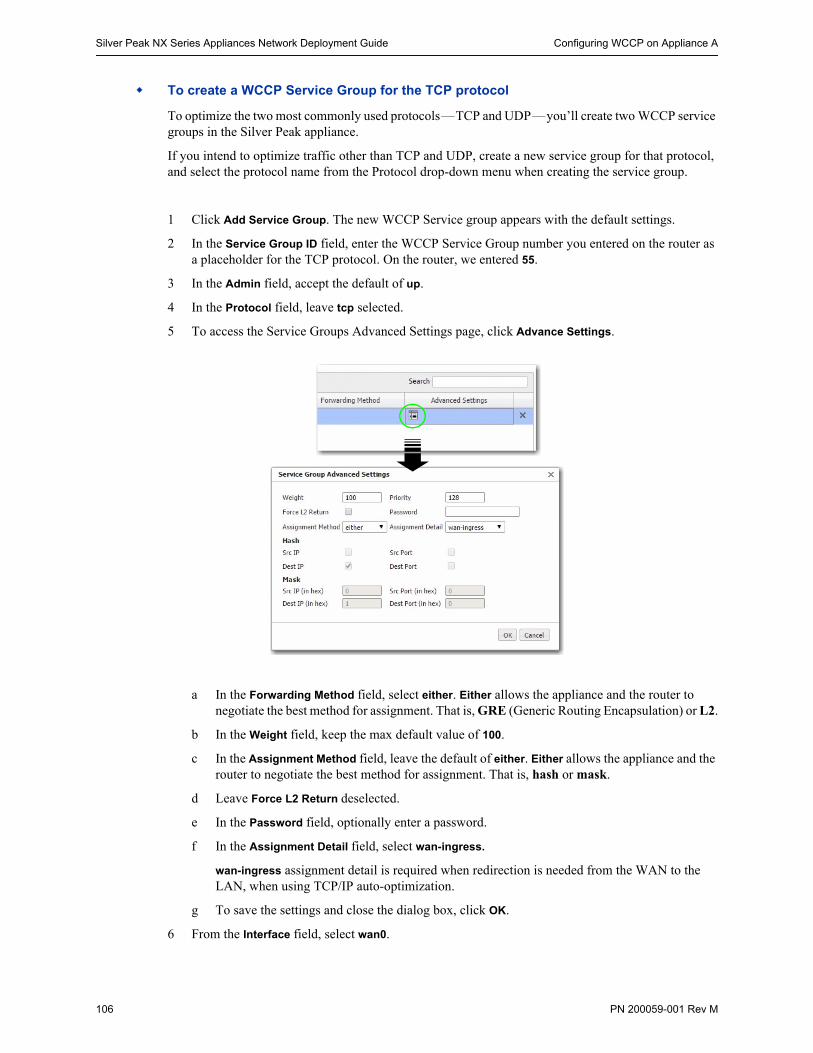
Silver Peak NX Series Appliances Network Deployment Guide Configuring WCCP on Appliance A
106 PN 200059-001 Rev M
To create a WCCP Service Group for the TCP protocol
To optimize the two most commonly used protocols—TCP and UDP—you’ll create two WCCP service groups in the Silver Peak appliance.
If you intend to optimize traffic other than TCP and UDP, create a new service group for that protocol, and select the protocol name from the Protocol drop-down menu when creating the service group.
1 Click Add Service Group. The new WCCP Service group appears with the default settings.
2 In the Service Group ID field, enter the WCCP Service Group number you entered on the router as a placeholder for the TCP protocol. On the router, we entered 55.
3 In the Admin field, accept the default of up.
4 In the Protocol field, leave tcp selected.
5 To access the Service Groups Advanced Settings page, click Advance Settings.
a In the Forwarding Method field, select either. Either allows the appliance and the router to negotiate the best method for assignment. That is, GRE (Generic Routing Encapsulation) or L2.
b In the Weight field, keep the max default value of 100.
c In the Assignment Method field, leave the default of either. Either allows the appliance and the router to negotiate the best method for assignment. That is, hash or mask.
d Leave Force L2 Return deselected.
e In the Password field, optionally enter a password.
f In the Assignment Detail field, select wan-ingress.
wan-ingress assignment detail is required when redirection is needed from the WAN to the LAN, when using TCP/IP auto-optimization.
g To save the settings and close the dialog box, click OK.
6 From the Interface field, select wan0.

Configuring WCCP on Appliance A Chapter 4 Out-of-Path with WCCP
PN 200059-001 Rev M 107
7 For Compatibility Mode, select the option appropriate for your router. If a WCCP group is peering with a router running Nexus OS, then the appliance must adjust its WCCP protocol packets to be compatible. By default, the appliance is IOS-compatible.
8 In the Router IP Address field, enter the IP address of the WCCP router, 10.110.31.1.
9 Click Apply. A new WCCP Service Group for TCP appears.
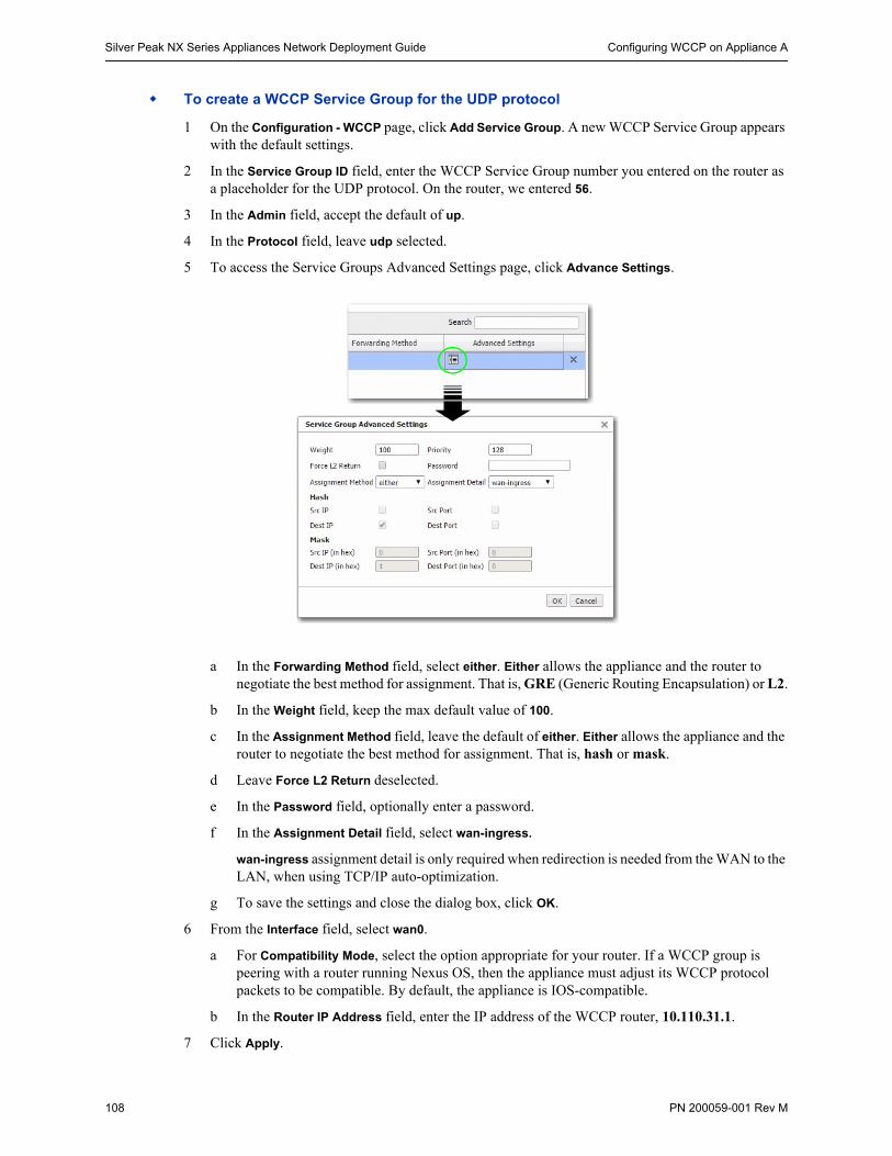
Silver Peak NX Series Appliances Network Deployment Guide Configuring WCCP on Appliance A
108 PN 200059-001 Rev M
To create a WCCP Service Group for the UDP protocol
1 On the Configuration - WCCP page, click Add Service Group. A new WCCP Service Group appears with the default settings.
2 In the Service Group ID field, enter the WCCP Service Group number you entered on the router as a placeholder for the UDP protocol. On the router, we entered 56.
3 In the Admin field, accept the default of up.
4 In the Protocol field, leave udp selected.
5 To access the Service Groups Advanced Settings page, click Advance Settings.
a In the Forwarding Method field, select either. Either allows the appliance and the router to negotiate the best method for assignment. That is, GRE (Generic Routing Encapsulation) or L2.
b In the Weight field, keep the max default value of 100.
c In the Assignment Method field, leave the default of either. Either allows the appliance and the router to negotiate the best method for assignment. That is, hash or mask.
d Leave Force L2 Return deselected.
e In the Password field, optionally enter a password.
f In the Assignment Detail field, select wan-ingress.
wan-ingress assignment detail is only required when redirection is needed from the WAN to the LAN, when using TCP/IP auto-optimization.
g To save the settings and close the dialog box, click OK.
6 From the Interface field, select wan0.
a For Compatibility Mode, select the option appropriate for your router. If a WCCP group is peering with a router running Nexus OS, then the appliance must adjust its WCCP protocol packets to be compatible. By default, the appliance is IOS-compatible.
b In the Router IP Address field, enter the IP address of the WCCP router, 10.110.31.1.
7 Click Apply.
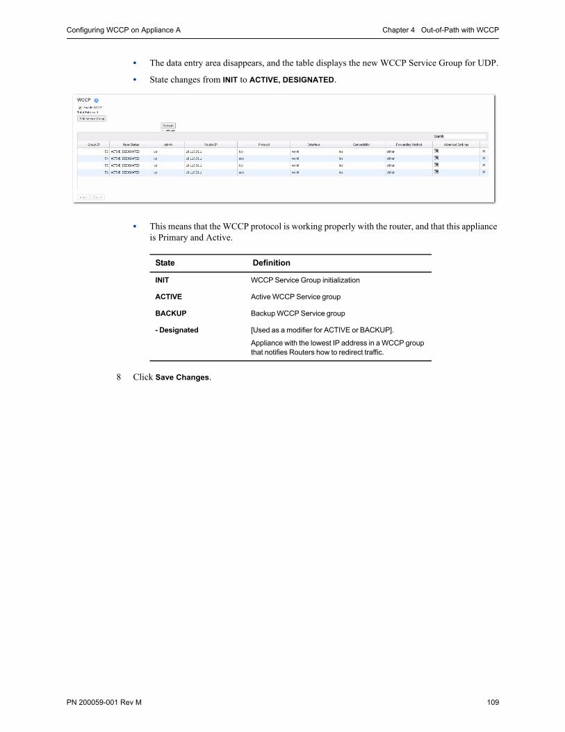
Configuring WCCP on Appliance A Chapter 4 Out-of-Path with WCCP
PN 200059-001 Rev M 109
• The data entry area disappears, and the table displays the new WCCP Service Group for UDP.
• State changes from INIT to ACTIVE, DESIGNATED.
• This means that the WCCP protocol is working properly with the router, and that this appliance is Primary and Active.
8 Click Save Changes.
State Definition
INIT WCCP Service Group initialization
ACTIVE Active WCCP Service group
BACKUP Backup WCCP Service group
- Designated [Used as a modifier for ACTIVE or BACKUP].
Appliance with the lowest IP address in a WCCP group that notifies Routers how to redirect traffic.

Silver Peak NX Series Appliances Network Deployment Guide Using the Initial Config Wizard with Site B’s Appliance
110 PN 200059-001 Rev M
Using the Initial Config Wizard with Site B’s ApplianceThe Initial Config Wizard prompts you for the information that you collected at the beginning of this document.
To access the Initial Config Wizard
1 Access the appliance login page.
If you’re using a physical Silver Peak NX appliance:
a Connect your workstation or laptop to the Ethernet port labeled mgmt1. Ensure that your workstation or laptop’s network adapter is set for DHCP. Wait for DHCP to time out and for your workstation or laptop to assign itself an IP address in the 169.254.x.x subnet.
b Open a browser and enter the IP address, 169.254.0.1. The login page appears.
If you’re using a virtual machine:
a Install the virtual machine according to the appropriate Silver Peak Quick Start Guide for your hypervisor and deployment mode.
For Bridge (In-Line) or Router (Out-of-Path) mode, follow the directions to add the required virtual interfaces (vNICs). Record the IP and MAC addresses for reference.
b Open a browser and enter the mgmt0 IP address. The login page appears.
Appliance B
2 For the username and for the password, enter admin. The initial configuration page appears.
Note At any future time, you can always access the Initial Config Wizard by going to the Configuration menu and selecting Initial Config Wizard from the drop-down menu.
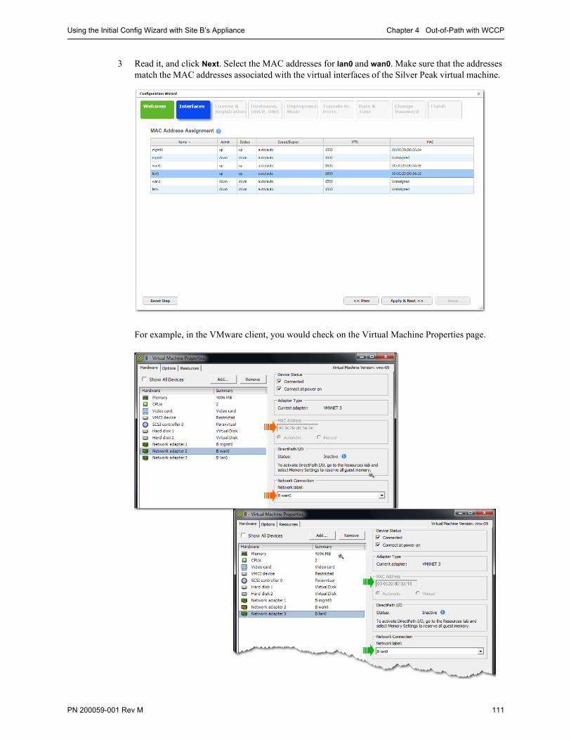
Using the Initial Config Wizard with Site B’s Appliance Chapter 4 Out-of-Path with WCCP
PN 200059-001 Rev M 111
3 Read it, and click Next. Select the MAC addresses for lan0 and wan0. Make sure that the addresses match the MAC addresses associated with the virtual interfaces of the Silver Peak virtual machine.
For example, in the VMware client, you would check on the Virtual Machine Properties page.
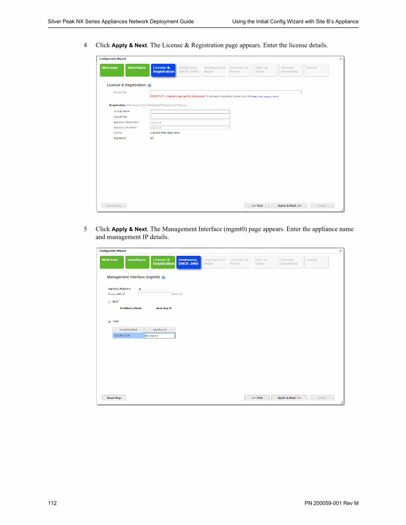
Silver Peak NX Series Appliances Network Deployment Guide Using the Initial Config Wizard with Site B’s Appliance
112 PN 200059-001 Rev M
4 Click Apply & Next. The License & Registration page appears. Enter the license details.
5 Click Apply & Next. The Management Interface (mgmt0) page appears. Enter the appliance name and management IP details.
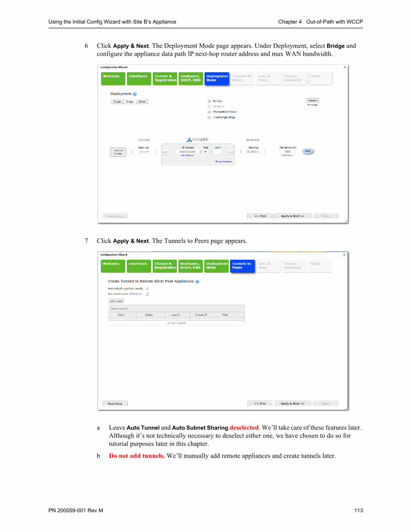
Using the Initial Config Wizard with Site B’s Appliance Chapter 4 Out-of-Path with WCCP
PN 200059-001 Rev M 113
6 Click Apply & Next. The Deployment Mode page appears. Under Deployment, select Bridge and configure the appliance data path IP next-hop router address and max WAN bandwidth.
7 Click Apply & Next. The Tunnels to Peers page appears.
a Leave Auto Tunnel and Auto Subnet Sharing deselected. We’ll take care of these features later. Although it’s not technically necessary to deselect either one, we have chosen to do so for tutorial purposes later in this chapter.
b Do not add tunnels. We’ll manually add remote appliances and create tunnels later.
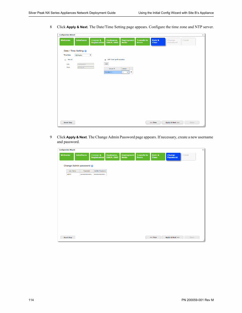
Silver Peak NX Series Appliances Network Deployment Guide Using the Initial Config Wizard with Site B’s Appliance
114 PN 200059-001 Rev M
8 Click Apply & Next. The Date/Time Setting page appears. Configure the time zone and NTP server.
9 Click Apply & Next. The Change Admin Password page appears. If necessary, create a new username and password.
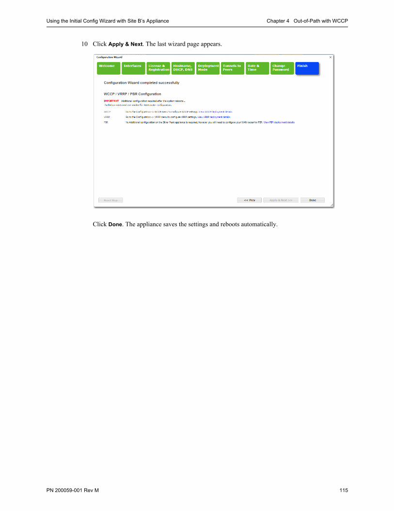
Using the Initial Config Wizard with Site B’s Appliance Chapter 4 Out-of-Path with WCCP
PN 200059-001 Rev M 115
10 Click Apply & Next. The last wizard page appears.
Click Done. The appliance saves the settings and reboots automatically.
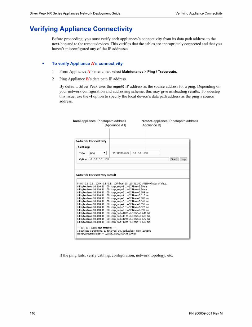
Silver Peak NX Series Appliances Network Deployment Guide Verifying Appliance Connectivity
116 PN 200059-001 Rev M
Verifying Appliance ConnectivityBefore proceeding, you must verify each appliances’s connectivity from its data path address to the next-hop and to the remote devices. This verifies that the cables are appropriately connected and that you haven’t misconfigured any of the IP addresses.
To verify Appliance A’s connectivity
1 From Appliance A’s menu bar, select Maintenance > Ping / Traceroute.
2 Ping Appliance B’s data path IP address.
By default, Silver Peak uses the mgmt0 IP address as the source address for a ping. Depending on your network configuration and addressing scheme, this may give misleading results. To sidestep this issue, use the -I option to specify the local device’s data path address as the ping’s source address.
If the ping fails, verify cabling, configuration, network topology, etc.
local appliance IP datapath address[Appliance A1]
remote appliance IP datapath address[Appliance B]
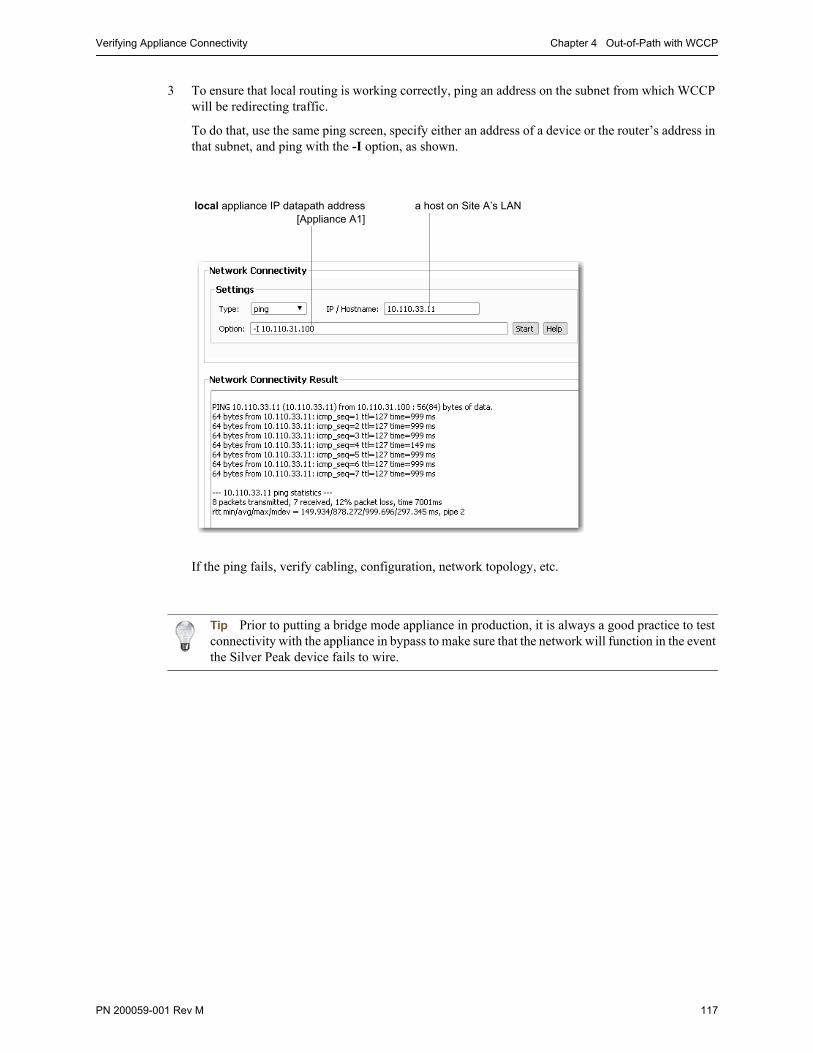
Verifying Appliance Connectivity Chapter 4 Out-of-Path with WCCP
PN 200059-001 Rev M 117
3 To ensure that local routing is working correctly, ping an address on the subnet from which WCCP will be redirecting traffic.
To do that, use the same ping screen, specify either an address of a device or the router’s address in that subnet, and ping with the -I option, as shown.
If the ping fails, verify cabling, configuration, network topology, etc.
Tip Prior to putting a bridge mode appliance in production, it is always a good practice to test connectivity with the appliance in bypass to make sure that the network will function in the event the Silver Peak device fails to wire.
local appliance IP datapath address[Appliance A1]
a host on Site A’s LAN
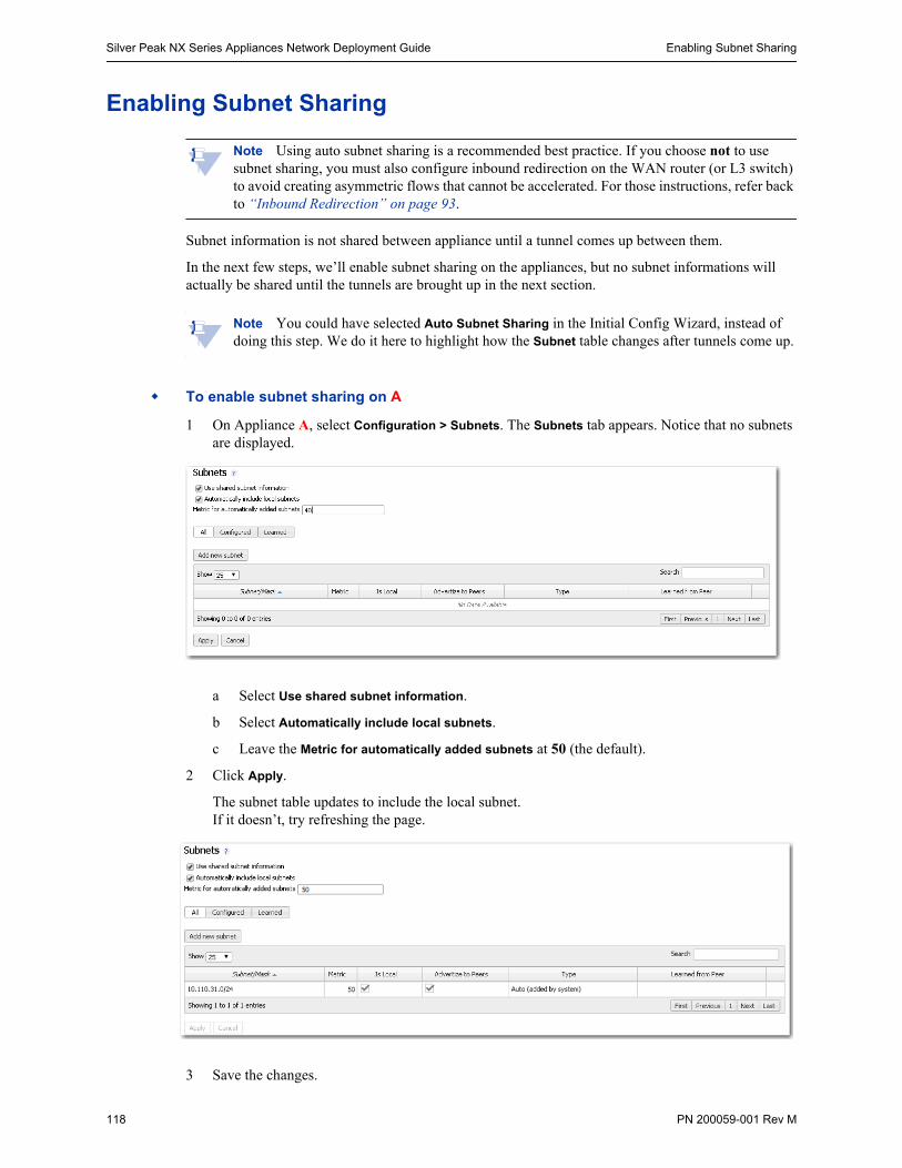
Silver Peak NX Series Appliances Network Deployment Guide Enabling Subnet Sharing
118 PN 200059-001 Rev M
Enabling Subnet Sharing
Note Using auto subnet sharing is a recommended best practice. If you choose not to use subnet sharing, you must also configure inbound redirection on the WAN router (or L3 switch) to avoid creating asymmetric flows that cannot be accelerated. For those instructions, refer back to “Inbound Redirection” on page 93.
Subnet information is not shared between appliance until a tunnel comes up between them.
In the next few steps, we’ll enable subnet sharing on the appliances, but no subnet informations will actually be shared until the tunnels are brought up in the next section.
Note You could have selected Auto Subnet Sharing in the Initial Config Wizard, instead of doing this step. We do it here to highlight how the Subnet table changes after tunnels come up.
To enable subnet sharing on A
1 On Appliance A, select Configuration > Subnets. The Subnets tab appears. Notice that no subnets are displayed.
a Select Use shared subnet information.
b Select Automatically include local subnets.
c Leave the Metric for automatically added subnets at 50 (the default).
2 Click Apply.
The subnet table updates to include the local subnet. If it doesn’t, try refreshing the page.
3 Save the changes.
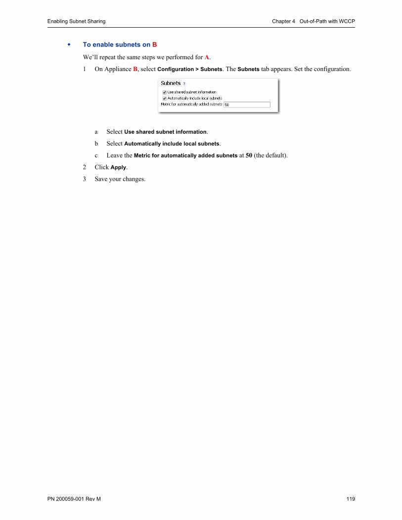
Enabling Subnet Sharing Chapter 4 Out-of-Path with WCCP
PN 200059-001 Rev M 119
To enable subnets on B
We’ll repeat the same steps we performed for A.
1 On Appliance B, select Configuration > Subnets. The Subnets tab appears. Set the configuration.
a Select Use shared subnet information.
b Select Automatically include local subnets.
c Leave the Metric for automatically added subnets at 50 (the default).
2 Click Apply.
3 Save your changes.

Silver Peak NX Series Appliances Network Deployment Guide Creating Tunnels and Updating the Subnet Table
120 PN 200059-001 Rev M
Creating Tunnels and Updating the Subnet TableFrom each appliance, you must create a tunnel to each remote appliance to which it will be sending traffic.
We’ll create tunnels from Silver Peak A to B. Then we’ll create tunnels from B to A.
After that, we’ll add subnets that aren’t directly connected to a datapath interface.
To create a tunnel from A to B
1 From a browser, access Appliance A.
2 From the menu bar, select Configuration > Tunnels. The Tunnels page appears.
3 Click Add Tunnel.
a In the Name field, assign a locally significant name for the tunnel.
b In the Admin field, accept the default value, Up.
c Leave Auto MTU selected. This allows the tunnel MTU to be discovered and negotiated automatically. When selected, this overrides the MTU setting.
d In the Local IP field, the Appliance Manager prefills the IP address for the local appliance.
e In the Remote IP address field, enter the data path IP address of Appliance B.
f Leave Auto Max BW selected, so the appliance uses the lower of the two system bandwidths.
If you wanted to configure this manually, then you would deselect Auto Max BW and, in the Max BW field, enter the maximum bandwidth for this tunnel. The value must be less than or equal to the upstream bandwidth of your WAN connection.
g Leave the Min BW at its default, 32 [Kbps].
h Click Apply.
i Save the changes.
The tunnel status won’t change to Up until a tunnel is configured at both ends. That is, until after we configure a tunnel from B to A.
To create tunnels from B to A
1 From a browser, access Appliance B.
2 From the menu bar, select Configuration > Tunnels. The Tunnels page appears.
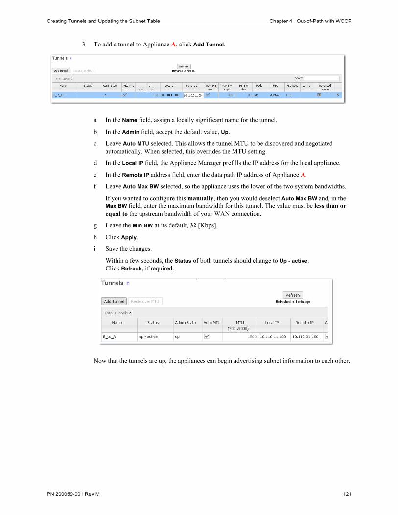
Creating Tunnels and Updating the Subnet Table Chapter 4 Out-of-Path with WCCP
PN 200059-001 Rev M 121
3 To add a tunnel to Appliance A, click Add Tunnel.
a In the Name field, assign a locally significant name for the tunnel.
b In the Admin field, accept the default value, Up.
c Leave Auto MTU selected. This allows the tunnel MTU to be discovered and negotiated automatically. When selected, this overrides the MTU setting.
d In the Local IP field, the Appliance Manager prefills the IP address for the local appliance.
e In the Remote IP address field, enter the data path IP address of Appliance A.
f Leave Auto Max BW selected, so the appliance uses the lower of the two system bandwidths.
If you wanted to configure this manually, then you would deselect Auto Max BW and, in the Max BW field, enter the maximum bandwidth for this tunnel. The value must be less than or equal to the upstream bandwidth of your WAN connection.
g Leave the Min BW at its default, 32 [Kbps].
h Click Apply.
i Save the changes.
Within a few seconds, the Status of both tunnels should change to Up - active. Click Refresh, if required.
Now that the tunnels are up, the appliances can begin advertising subnet information to each other.
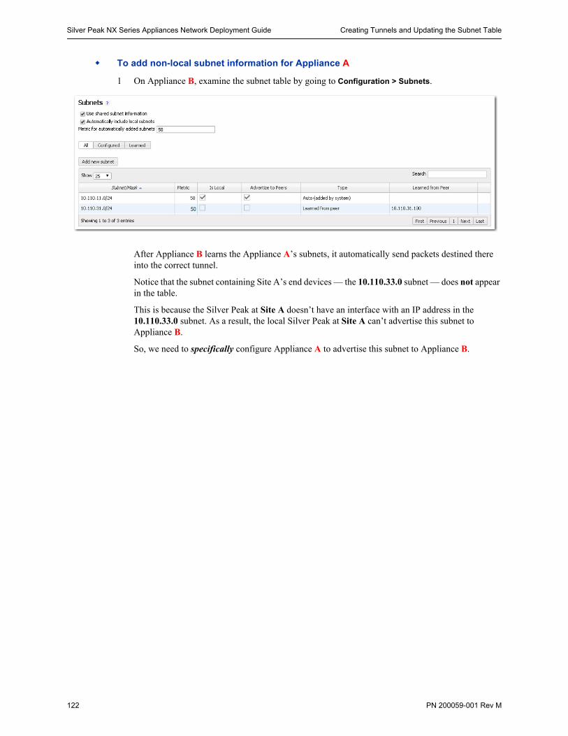
Silver Peak NX Series Appliances Network Deployment Guide Creating Tunnels and Updating the Subnet Table
122 PN 200059-001 Rev M
To add non-local subnet information for Appliance A
1 On Appliance B, examine the subnet table by going to Configuration > Subnets.
After Appliance B learns the Appliance A’s subnets, it automatically send packets destined there into the correct tunnel.
Notice that the subnet containing Site A’s end devices — the 10.110.33.0 subnet — does not appear in the table.
This is because the Silver Peak at Site A doesn’t have an interface with an IP address in the 10.110.33.0 subnet. As a result, the local Silver Peak at Site A can’t advertise this subnet to Appliance B.
So, we need to specifically configure Appliance A to advertise this subnet to Appliance B.
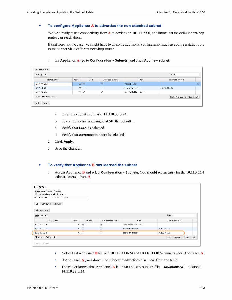
Creating Tunnels and Updating the Subnet Table Chapter 4 Out-of-Path with WCCP
PN 200059-001 Rev M 123
To configure Appliance A to advertise the non-attached subnet
We’ve already tested connectivity from A to devices on 10.110.33.0, and know that the default next-hop router can reach them.
If that were not the case, we might have to do some additional configuration such as adding a static route to the subnet via a different next-hop router.
1 On Appliance A, go to Configuration > Subnets, and click Add new subnet.
a Enter the subnet and mask: 10.110.33.0/24.
b Leave the metric unchanged at 50 (the default).
c Verify that Local is selected.
d Verify that Advertise to Peers is selected.
2 Click Apply.
3 Save the changes.
To verify that Appliance B has learned the subnet
1 Access Appliance B and select Configuration > Subnets. You should see an entry for the 10.110.33.0 subnet, learned from A.
• Notice that Appliance B learned 10.110.31.0/24 and 10.110.33.0/24 from its peer, Appliance A.
• If Appliance A goes down, the subnets it advertises disappear from the table.
• The router knows that Appliance A is down and sends the traffic—unoptimized—to subnet 10.110.33.0/24.
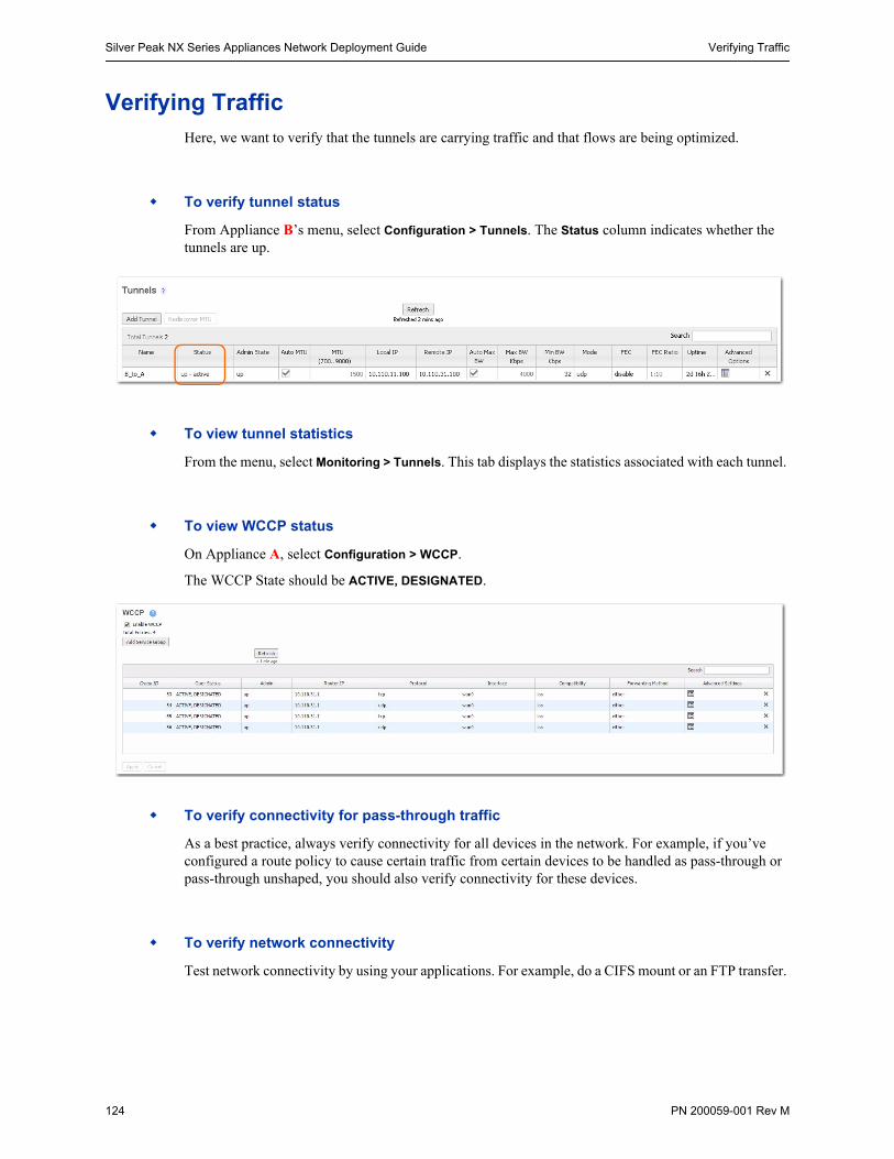
Silver Peak NX Series Appliances Network Deployment Guide Verifying Traffic
124 PN 200059-001 Rev M
Verifying TrafficHere, we want to verify that the tunnels are carrying traffic and that flows are being optimized.
To verify tunnel status
From Appliance B’s menu, select Configuration > Tunnels. The Status column indicates whether the tunnels are up.
To view tunnel statistics
From the menu, select Monitoring > Tunnels. This tab displays the statistics associated with each tunnel.
To view WCCP status
On Appliance A, select Configuration > WCCP.
The WCCP State should be ACTIVE, DESIGNATED.
To verify connectivity for pass-through traffic
As a best practice, always verify connectivity for all devices in the network. For example, if you’ve configured a route policy to cause certain traffic from certain devices to be handled as pass-through or pass-through unshaped, you should also verify connectivity for these devices.
To verify network connectivity
Test network connectivity by using your applications. For example, do a CIFS mount or an FTP transfer.
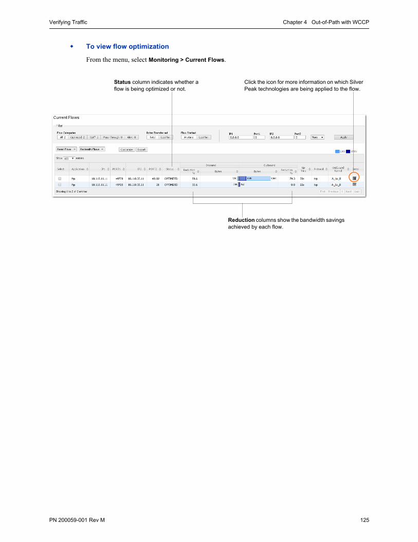
Verifying Traffic Chapter 4 Out-of-Path with WCCP
PN 200059-001 Rev M 125
To view flow optimization
From the menu, select Monitoring > Current Flows.
Reduction columns show the bandwidth savings achieved by each flow.
Click the icon for more information on which Silver Peak technologies are being applied to the flow.
Status column indicates whether a flow is being optimized or not.
Silver Peak NX Series Appliances Network Deployment Guide Best Practices
126 PN 200059-001 Rev M
Best Practices
Tips for Deployment
Inbound WCCP redirection is preferred over outbound [also known as ingress/egress] redirection because inbound redirection is less CPU-intensive on the router. Inbound redirection is done in hardware where as outbound is done in software.
• For Catalyst 6000/76xx deployments, use only inbound redirection to avoid using “redirection exclude in”, which is not understood by the switch hardware and must be processed in software.
• For Catalyst 6000/76xx deployments, use L2 redirection for near line-rate redirection. Silver Peak appliances automatically negotiate assignment and forwarding methods with all routers and L3 switches from Cisco to the best possible combination that the router or L3 switch supports.
WCCPv2 interception forwards all packets from the router or L3 switch to the appliance. Special care should be taken when traffic redirected to the appliance has to be returned back to the router or L3 switch. For many routers the return traffic is delivered via L2 so there is no CPU impact. However, Catalyst 6000/76xx switches returns via GRE so the CPU can be negatively impacted unless Force L2 return is enabled on the appliance.
• Force L2 Return should only be enabled when the interface/VLAN that the appliance is connected to is not also an interface with the redirection applied to.
The appliance should always be connected to an interface/VLAN that does not have redirection enabled – preferably a separate interface/VLAN would be provided for the appliance.
The appliance and Catalyst switch negotiate which redirect and return method to use when the service group is formed. There can be many access VLANs on the aggregation switches. Redirection is configured on all VLANs that need optimization. Layer 2 switching ports, including trunk ports, are not eligible for redirection.
If Auto Optimization is used for matching traffic to be optimized via the appliance, WCCP redirection must also be applied on the uplinks of the router or L3 switch to the core/WAN.
If WCCP redirection is needed on both the WAN and the LAN, the preferred configuration on the appliance is to set the WCCP group configured on the WAN to wan-ingress and the group configured on the LAN to lan-ingress.
• The configuration of wan-ingress and lan-ingress ensures that load balancing is symmetrical in both directions of a flow.
• wan-ingress uses the destination address for distribution in the router/L3 switch table
• lan-ingress uses the source address for distribution.
If Route Policies are used for matching traffic to be optimized via the appliance, WCCP redirection is not required on the core uplinks, only the access/LAN links. If Active/Active redistribution is enabled with route policies, then flow redirection is required to handle asymmetrical flows caused by load balancing. Flow redirection can handle millions of flows and ensures that the owner of a given flow always receives the TCP flow for processing.

Best Practices Chapter 4 Out-of-Path with WCCP
PN 200059-001 Rev M 127
GRE and L2 Redirection
Packet redirection is the process of forwarding packets from the router or L3 switch to the appliance. The router or L3 switch intercepts the packet and forwards it to the appliance for optimization. The two methods of redirecting packets are Generic Route Encapsulation (GRE) and L2 redirection. GRE is processed at Layer 3 while L2 is processed at Layer 2.
Silver Peak appliances support both GRE and L2 Redirection.
Silver Peak appliances support both Mask and Hash assignments.
• Additional mask and hash assignment adjustment can help fine-tune the distribution of traffic to the appliances. The advanced configuration for fine-tuning can be found in the “custom” feature of the WCCP configuration on the appliance.
• Mask assignments are set up on the appliance. The first appliance that joins the WCCP service group determines the redirection method and masking value – this appliance is referred to as the “designated” appliance. Subsequent appliances that join the group must have the same redirection and mask value setup; otherwise, they are not active participants in the WCCP group.
• Appliances support both Hash and Mask capabilities for optimal throughput. The preferred WCCP configuration on the appliance is to leave both assignment and forwarding method to “either” which will allow the preferred negotiation to happen between the appliance and the router or L3 switch when WCCP is first enabled.
GRE
GRE is a protocol that carries other protocols as its payload:
In this case, the payload is a packet from the router to the appliance. GRE works on routing and switching platforms. It allows the WCCP clients to be separate from the router via multiple hops. Because GRE is processed in software, router CPU utilization increases with GRE redirection. Hardware-assisted GRE redirection is available on the Catalyst 6500 with Sup720.
L2 Redirection
L2 redirection requires the appliance to be in the same subnet as the router or switch (L2 adjacency).
The switch rewrites the destination L2 MAC header with the appliance MAC address. The packet is forwarded without additional lookup.
L2 redirection is done in hardware and is available on the Catalyst 6500/7600 platforms. CPU utilization is not impacted because L2 redirection is hardware-assisted; only the first packet is switched by the Multilayer Switch Feature Card (MSFC) with hashing.
After the MSFC populates the NetFlow table, subsequent packets are switched in hardware. L2 redirection is preferred over GRE because of lower CPU utilization.
There are two methods to load balance appliances with L2 redirection: hashing and masking.

Silver Peak NX Series Appliances Network Deployment Guide Best Practices
128 PN 200059-001 Rev M
PN 200059-001 Rev M 129
C H A P T E R 5
Out-of-Path with VRRP Peering to a WAN Router
With Subnet Sharing in Use
This chapter provides a step-by-step example of a deployment where the Silver Peak appliance uses the Virtual Router Redundancy Protocol (VRRP) to peer with the existing router, when no spare router port is available.
In This Chapter Overview See page 130.
Using the Initial Config Wizard See page 134.
Verifying Appliance Connectivity See page 146.
Enabling Subnet Sharing See page 147.
Creating Tunnels See page 149.
Configuring VRRP on a Cisco Router See page 151.
Configuring VRRP on Silver Peak A1 See page 152.
Verifying Traffic See page 154.
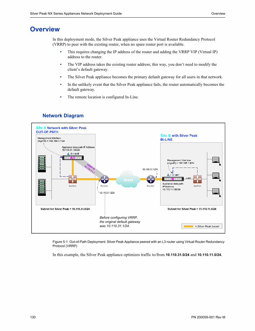
Silver Peak NX Series Appliances Network Deployment Guide Overview
130 PN 200059-001 Rev M
OverviewIn this deployment mode, the Silver Peak appliance uses the Virtual Router Redundancy Protocol (VRRP) to peer with the existing router, when no spare router port is available.
• This requires changing the IP address of the router and adding the VRRP VIP (Virtual IP) address to the router.
• The VIP address takes the existing router address; this way, you don’t need to modify the client’s default gateway.
• The Silver Peak appliance becomes the primary default gateway for all users in that network.
• In the unlikely event that the Silver Peak appliance fails, the router automatically becomes the default gateway.
• The remote location is configured In-Line.
Network Diagram
Figure 5-1 Out-of-Path Deployment: Silver Peak Appliance peered with an L3 router using Virtual Router Redundancy Protocol (VRRP)
In this example, the Silver Peak appliance optimizes traffic to/from 10.110.31.0/24 and 10.110.11.0/24.
Before configuring VRRP, the original default gateway was 10.110.31.1/24.
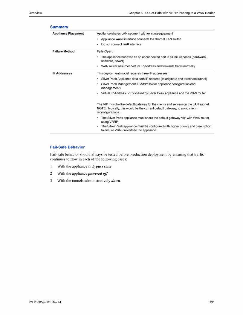
Overview Chapter 5 Out-of-Path with VRRP Peering to a WAN Router
PN 200059-001 Rev M 131
Summary
Fail-Safe Behavior
Fail-safe behavior should always be tested before production deployment by ensuring that traffic continues to flow in each of the following cases:
1 With the appliance in bypass state
2 With the appliance powered off
3 With the tunnels administratively down.
Appliance Placement Appliance shares LAN segment with existing equipment
• Appliance wan0 interface connects to Ethernet LAN switch
• Do not connect lan0 interface
Failure Method Fails-Open:
• The appliance behaves as an unconnected port in all failure cases (hardware, software, power)
• WAN router assumes Virtual IP Address and forwards traffic normally
IP Addresses This deployment model requires three IP addresses:
• Silver Peak Appliance data path IP address (to originate and terminate tunnel)
• Silver Peak Management IP Address (for appliance configuration and management)
• Virtual IP Address (VIP) shared by Silver Peak appliance and the WAN router
The VIP must be the default gateway for the clients and servers on the LAN subnet. NOTE: Typically, this would be the current default gateway, to avoid client reconfigurations.
• The Silver Peak appliance must share the default gateway VIP with WAN router using VRRP.
• The Silver Peak appliance must be configured with higher priority and preemption to ensure VRRP reverts to the appliance.
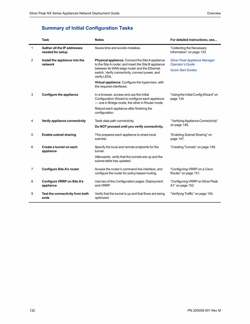
Silver Peak NX Series Appliances Network Deployment Guide Overview
132 PN 200059-001 Rev M
Summary of Initial Configuration Tasks
Task Notes For detailed instructions, see...
1 Gather all the IP addresses needed for setup
Saves time and avoids mistakes. “Collecting the Necessary Information” on page 133.
2 Install the appliance into the network
Physical appliance: Connect the Site A appliance to the Site A router, and insert the Site B appliance between its WAN edge router and the Ethernet switch. Verify connectivity, connect power, and verify LEDs.
Virtual appliance: Configure the hypervisor, with the required interfaces.
Silver Peak Appliance Manager Operator’s Guide
Quick Start Guides
3 Configure the appliance In a browser, access and use the Initial Configuration Wizard to configure each appliance — one in Bridge mode, the other in Router mode.
Reboot each appliance after finishing the configuration.
“Using the Initial Config Wizard” on page 134.
4 Verify appliance connectivity Tests data path connectivity.
Do NOT proceed until you verify connectivity.
“Verifying Appliance Connectivity” on page 146.
5 Enable subnet sharing This prepares each appliance to share local subnets.
“Enabling Subnet Sharing” on page 147.
6 Create a tunnel on each appliance
Specify the local and remote endpoints for the tunnel.
Afterwards, verify that the tunnels are up and the subnet table has updated.
“Creating Tunnels” on page 149.
7 Configure Site A’s router Access the router’s command line interface, and configure the router for policy-based routing.
“Configuring VRRP on a Cisco Router” on page 151.
8 Configure VRRP on Site A’s appliance
Use two of the Configuration pages: Deployment and VRRP
“Configuring VRRP on Silver Peak A1” on page 152
9 Test the connectivity from both ends
Verify that the tunnel is up and that flows are being optimized.
“Verifying Traffic” on page 154.
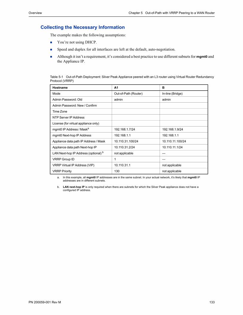
Overview Chapter 5 Out-of-Path with VRRP Peering to a WAN Router
PN 200059-001 Rev M 133
Collecting the Necessary Information
The example makes the following assumptions:
You’re not using DHCP.
Speed and duplex for all interfaces are left at the default, auto-negotiation.
Although it isn’t a requirement, it’s considered a best practice to use different subnets for mgmt0 and the Appliance IP.
Table 5-1 Out-of-Path Deployment: Silver Peak Appliance peered with an L3 router using Virtual Router Redundancy Protocol (VRRP)
Hostname A1 B
Mode Out-of-Path (Router) In-line (Bridge)
Admin Password: Old admin admin
Admin Password: New / Confirm
Time Zone
NTP Server IP Address
License (for virtual appliance only)
mgmt0 IP Address / Maska
a. In this example, all mgmt0 IP addresses are in the same subnet. In your actual network, it’s likely that mgmt0 IP addresses are in different subnets.
192.168.1.7/24 192.168.1.9/24
mgmt0 Next-hop IP Address 192.168.1.1 192.168.1.1
Appliance data path IP Address / Mask 10.110.31.100/24 10.110.11.100/24
Appliance data path Next-hop IP 10.110.31.2/24 10.110.11.1/24
LAN Next-hop IP Address (optional) b
b. LAN next-hop IP is only required when there are subnets for which the Silver Peak appliance does not have a configured IP address.
not applicable ---
VRRP Group ID 1 ---
VRRP Virtual IP Address (VIP) 10.110.31.1 not applicable
VRRP Priority 130 not applicable
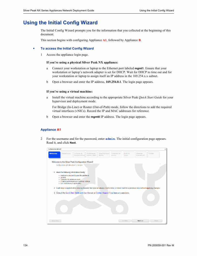
Silver Peak NX Series Appliances Network Deployment Guide Using the Initial Config Wizard
134 PN 200059-001 Rev M
Using the Initial Config WizardThe Initial Config Wizard prompts you for the information that you collected at the beginning of this document.
This section begins with configuring Appliance A1, followed by Appliance B.
To access the Initial Config Wizard
1 Access the appliance login page.
If you’re using a physical Silver Peak NX appliance:
a Connect your workstation or laptop to the Ethernet port labeled mgmt1. Ensure that your workstation or laptop’s network adapter is set for DHCP. Wait for DHCP to time out and for your workstation or laptop to assign itself an IP address in the 169.254.x.x subnet.
b Open a browser and enter the IP address, 169.254.0.1. The login page appears.
If you’re using a virtual machine:
a Install the virtual machine according to the appropriate Silver Peak Quick Start Guide for your hypervisor and deployment mode.
For Bridge (In-Line) or Router (Out-of-Path) mode, follow the directions to add the required virtual interfaces (vNICs). Record the IP and MAC addresses for reference.
b Open a browser and enter the mgmt0 IP address. The login page appears.
Appliance A1
2 For the username and for the password, enter admin. The initial configuration page appears. Read it, and click Next.
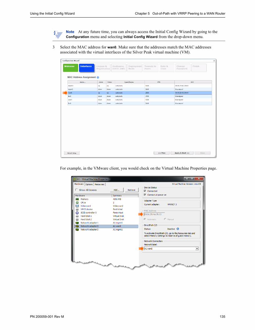
Using the Initial Config Wizard Chapter 5 Out-of-Path with VRRP Peering to a WAN Router
PN 200059-001 Rev M 135
Note At any future time, you can always access the Initial Config Wizard by going to the Configuration menu and selecting Initial Config Wizard from the drop-down menu.
3 Select the MAC address for wan0. Make sure that the addresses match the MAC addresses associated with the virtual interfaces of the Silver Peak virtual machine (VM).
For example, in the VMware client, you would check on the Virtual Machine Properties page.

Silver Peak NX Series Appliances Network Deployment Guide Using the Initial Config Wizard
136 PN 200059-001 Rev M
4 Click Apply & Next. The License & Registration page appears. Enter the license details.
5 Click Apply & Next. The Management Interface (mgmt0) page appears. Enter the appliance name and management IP details.

Using the Initial Config Wizard Chapter 5 Out-of-Path with VRRP Peering to a WAN Router
PN 200059-001 Rev M 137
6 Click Apply & Next. The Deployment Mode page appears. Under Deployment, select Router and then click +Add to add a WAN interface.
Configure the appliance data path IP next-hop router address and max WAN bandwidth.

Silver Peak NX Series Appliances Network Deployment Guide Using the Initial Config Wizard
138 PN 200059-001 Rev M
7 Click Apply & Next.
On this page, leave Auto Tunnel and Auto Subnet Sharing deselected. We’ll take care of these features later. Although it’s not technically necessary to deselect either one, we have chosen to do so for tutorial purposes later in this chapter.
8 Click Apply & Next. The Date/Time Setting page appears. Configure the time zone and NTP server.
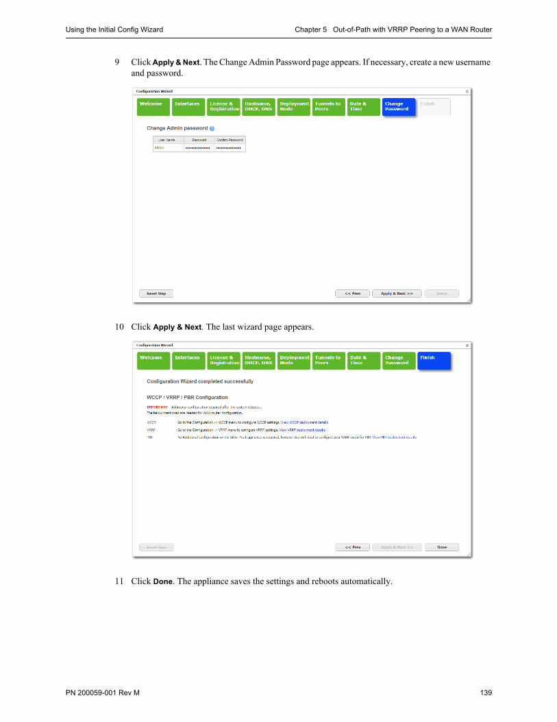
Using the Initial Config Wizard Chapter 5 Out-of-Path with VRRP Peering to a WAN Router
PN 200059-001 Rev M 139
9 Click Apply & Next. The Change Admin Password page appears. If necessary, create a new username and password.
10 Click Apply & Next. The last wizard page appears.
11 Click Done. The appliance saves the settings and reboots automatically.
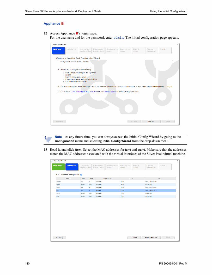
Silver Peak NX Series Appliances Network Deployment Guide Using the Initial Config Wizard
140 PN 200059-001 Rev M
Appliance B
12 Access Appliance B’s login page.For the username and for the password, enter admin. The initial configuration page appears.
Note At any future time, you can always access the Initial Config Wizard by going to the Configuration menu and selecting Initial Config Wizard from the drop-down menu.
13 Read it, and click Next. Select the MAC addresses for lan0 and wan0. Make sure that the addresses match the MAC addresses associated with the virtual interfaces of the Silver Peak virtual machine.
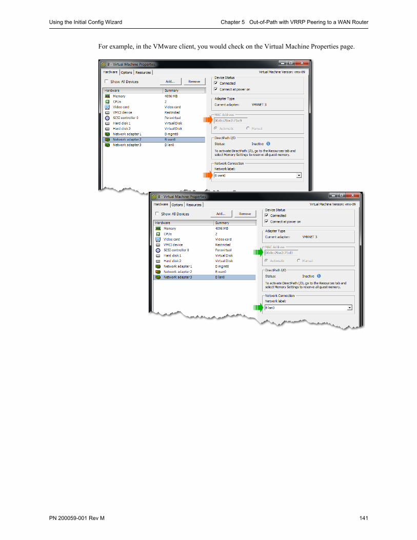
Using the Initial Config Wizard Chapter 5 Out-of-Path with VRRP Peering to a WAN Router
PN 200059-001 Rev M 141
For example, in the VMware client, you would check on the Virtual Machine Properties page.

Silver Peak NX Series Appliances Network Deployment Guide Using the Initial Config Wizard
142 PN 200059-001 Rev M
14 Click Apply & Next. The License & Registration page appears. Enter the license details.
15 Click Apply & Next. The Management Interface (mgmt0) page appears. Enter the appliance name and management IP details.
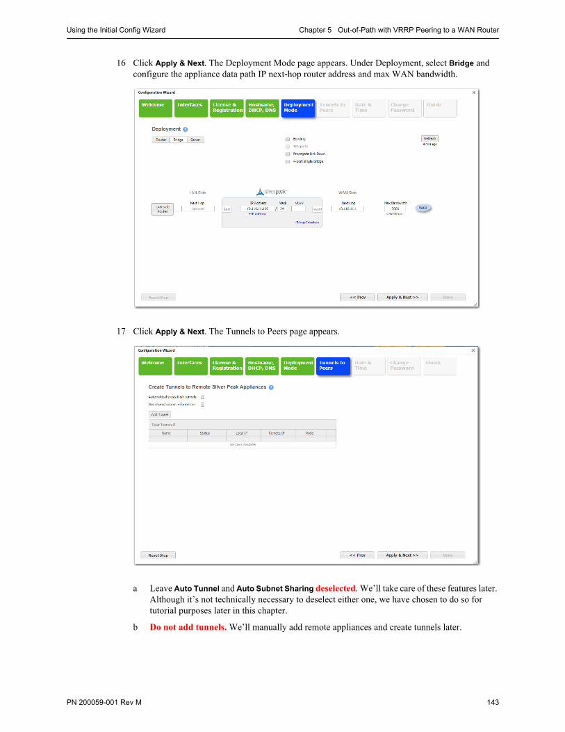
Using the Initial Config Wizard Chapter 5 Out-of-Path with VRRP Peering to a WAN Router
PN 200059-001 Rev M 143
16 Click Apply & Next. The Deployment Mode page appears. Under Deployment, select Bridge and configure the appliance data path IP next-hop router address and max WAN bandwidth.
17 Click Apply & Next. The Tunnels to Peers page appears.
a Leave Auto Tunnel and Auto Subnet Sharing deselected. We’ll take care of these features later. Although it’s not technically necessary to deselect either one, we have chosen to do so for tutorial purposes later in this chapter.
b Do not add tunnels. We’ll manually add remote appliances and create tunnels later.

Silver Peak NX Series Appliances Network Deployment Guide Using the Initial Config Wizard
144 PN 200059-001 Rev M
18 Click Apply & Next. The Date/Time Setting page appears. Configure the time zone and NTP server.
19 Click Apply & Next. The Change Admin Password page appears. If necessary, create a new username and password.

Using the Initial Config Wizard Chapter 5 Out-of-Path with VRRP Peering to a WAN Router
PN 200059-001 Rev M 145
20 Click Apply & Next. The last wizard page appears.
21 Click Done. The appliance saves the settings and reboots automatically.
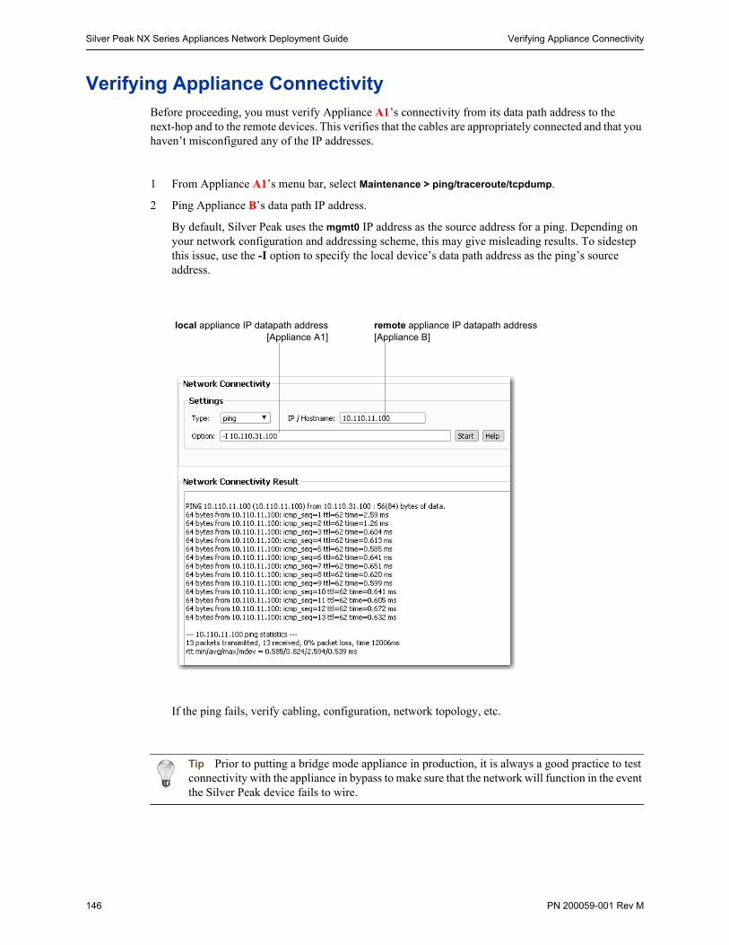
Silver Peak NX Series Appliances Network Deployment Guide Verifying Appliance Connectivity
146 PN 200059-001 Rev M
Verifying Appliance ConnectivityBefore proceeding, you must verify Appliance A1’s connectivity from its data path address to the next-hop and to the remote devices. This verifies that the cables are appropriately connected and that you haven’t misconfigured any of the IP addresses.
1 From Appliance A1’s menu bar, select Maintenance > ping/traceroute/tcpdump.
2 Ping Appliance B’s data path IP address.
By default, Silver Peak uses the mgmt0 IP address as the source address for a ping. Depending on your network configuration and addressing scheme, this may give misleading results. To sidestep this issue, use the -I option to specify the local device’s data path address as the ping’s source address.
If the ping fails, verify cabling, configuration, network topology, etc.
Tip Prior to putting a bridge mode appliance in production, it is always a good practice to test connectivity with the appliance in bypass to make sure that the network will function in the event the Silver Peak device fails to wire.
local appliance IP datapath address[Appliance A1]
remote appliance IP datapath address[Appliance B]
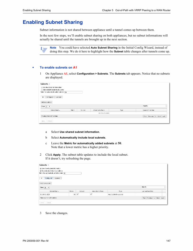
Enabling Subnet Sharing Chapter 5 Out-of-Path with VRRP Peering to a WAN Router
PN 200059-001 Rev M 147
Enabling Subnet SharingSubnet information is not shared between appliance until a tunnel comes up between them.
In the next few steps, we’ll enable subnet sharing on both appliances, but no subnet informations will actually be shared until the tunnels are brought up in the next section.
Note You could have selected Auto Subnet Sharing in the Initial Config Wizard, instead of doing this step. We do it here to highlight how the Subnet table changes after tunnels come up.
To enable subnets on A1
1 On Appliance A1, select Configuration > Subnets. The Subnets tab appears. Notice that no subnets are displayed.
a Select Use shared subnet information.
b Select Automatically include local subnets.
c Leave the Metric for automatically added subnets at 50. Note that a lower metric has a higher priority.
2 Click Apply. The subnet table updates to include the local subnet. If it doesn’t, try refreshing the page.
3 Save the changes.
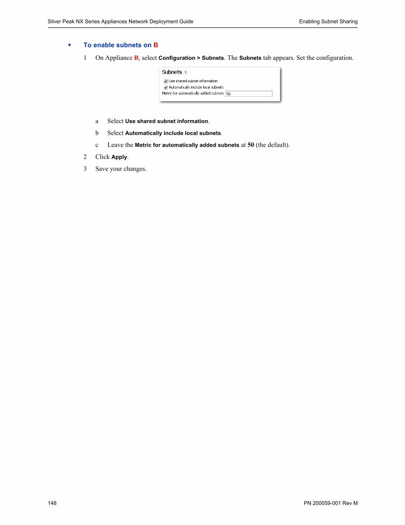
Silver Peak NX Series Appliances Network Deployment Guide Enabling Subnet Sharing
148 PN 200059-001 Rev M
To enable subnets on B
1 On Appliance B, select Configuration > Subnets. The Subnets tab appears. Set the configuration.
a Select Use shared subnet information.
b Select Automatically include local subnets.
c Leave the Metric for automatically added subnets at 50 (the default).
2 Click Apply.
3 Save your changes.
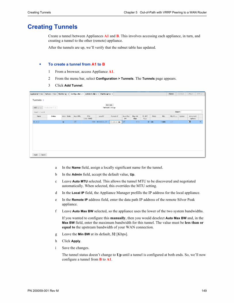
Creating Tunnels Chapter 5 Out-of-Path with VRRP Peering to a WAN Router
PN 200059-001 Rev M 149
Creating TunnelsCreate a tunnel between Appliances A1 and B. This involves accessing each appliance, in turn, and creating a tunnel to the other (remote) appliance.
After the tunnels are up, we’ll verify that the subnet table has updated.
To create a tunnel from A1 to B
1 From a browser, access Appliance A1.
2 From the menu bar, select Configuration > Tunnels. The Tunnels page appears.
3 Click Add Tunnel.
a In the Name field, assign a locally significant name for the tunnel.
b In the Admin field, accept the default value, Up.
c Leave Auto MTU selected. This allows the tunnel MTU to be discovered and negotiated automatically. When selected, this overrides the MTU setting.
d In the Local IP field, the Appliance Manager prefills the IP address for the local appliance.
e In the Remote IP address field, enter the data path IP address of the remote Silver Peak appliance.
f Leave Auto Max BW selected, so the appliance uses the lower of the two system bandwidths.
If you wanted to configure this manually, then you would deselect Auto Max BW and, in the Max BW field, enter the maximum bandwidth for this tunnel. The value must be less than or equal to the upstream bandwidth of your WAN connection.
g Leave the Min BW at its default, 32 [Kbps].
h Click Apply.
i Save the changes.
The tunnel status doesn’t change to Up until a tunnel is configured at both ends. So, we’ll now configure a tunnel from B to A1.
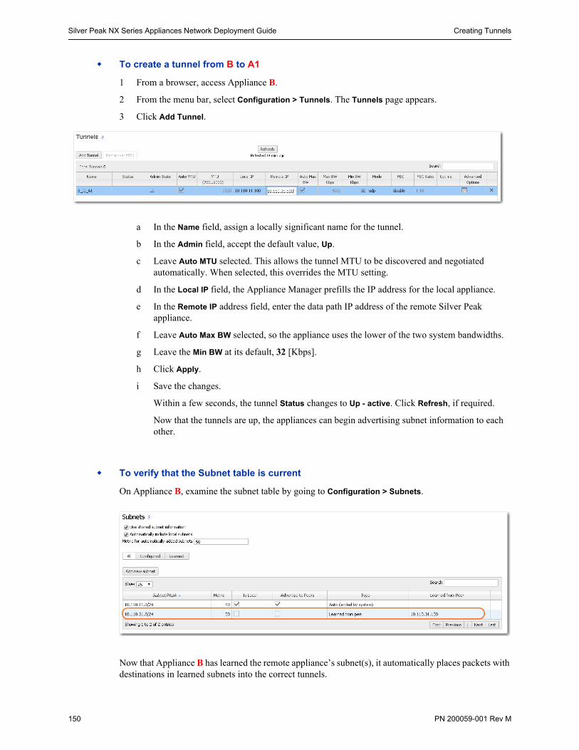
Silver Peak NX Series Appliances Network Deployment Guide Creating Tunnels
150 PN 200059-001 Rev M
To create a tunnel from B to A1
1 From a browser, access Appliance B.
2 From the menu bar, select Configuration > Tunnels. The Tunnels page appears.
3 Click Add Tunnel.
a In the Name field, assign a locally significant name for the tunnel.
b In the Admin field, accept the default value, Up.
c Leave Auto MTU selected. This allows the tunnel MTU to be discovered and negotiated automatically. When selected, this overrides the MTU setting.
d In the Local IP field, the Appliance Manager prefills the IP address for the local appliance.
e In the Remote IP address field, enter the data path IP address of the remote Silver Peak appliance.
f Leave Auto Max BW selected, so the appliance uses the lower of the two system bandwidths.
g Leave the Min BW at its default, 32 [Kbps].
h Click Apply.
i Save the changes.
Within a few seconds, the tunnel Status changes to Up - active. Click Refresh, if required.
Now that the tunnels are up, the appliances can begin advertising subnet information to each other.
To verify that the Subnet table is current
On Appliance B, examine the subnet table by going to Configuration > Subnets.
Now that Appliance B has learned the remote appliance’s subnet(s), it automatically places packets with destinations in learned subnets into the correct tunnels.
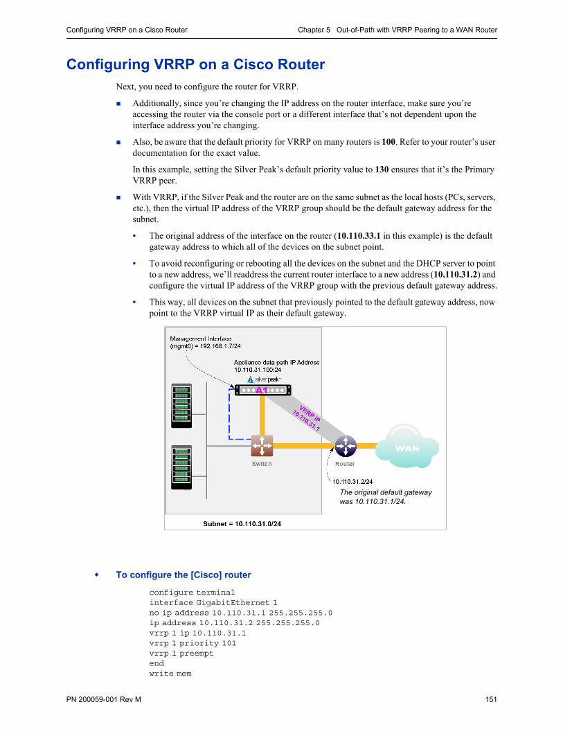
Configuring VRRP on a Cisco Router Chapter 5 Out-of-Path with VRRP Peering to a WAN Router
PN 200059-001 Rev M 151
Configuring VRRP on a Cisco RouterNext, you need to configure the router for VRRP.
Additionally, since you’re changing the IP address on the router interface, make sure you’re accessing the router via the console port or a different interface that’s not dependent upon the interface address you’re changing.
Also, be aware that the default priority for VRRP on many routers is 100. Refer to your router’s user documentation for the exact value.
In this example, setting the Silver Peak’s default priority value to 130 ensures that it’s the Primary VRRP peer.
With VRRP, if the Silver Peak and the router are on the same subnet as the local hosts (PCs, servers, etc.), then the virtual IP address of the VRRP group should be the default gateway address for the subnet.
• The original address of the interface on the router (10.110.33.1 in this example) is the default gateway address to which all of the devices on the subnet point.
• To avoid reconfiguring or rebooting all the devices on the subnet and the DHCP server to point to a new address, we’ll readdress the current router interface to a new address (10.110.31.2) and configure the virtual IP address of the VRRP group with the previous default gateway address.
• This way, all devices on the subnet that previously pointed to the default gateway address, now point to the VRRP virtual IP as their default gateway.
To configure the [Cisco] router
configure terminalinterface GigabitEthernet 1no ip address 10.110.31.1 255.255.255.0ip address 10.110.31.2 255.255.255.0vrrp 1 ip 10.110.31.1vrrp 1 priority 101vrrp 1 preemptendwrite mem
The original default gateway was 10.110.31.1/24.
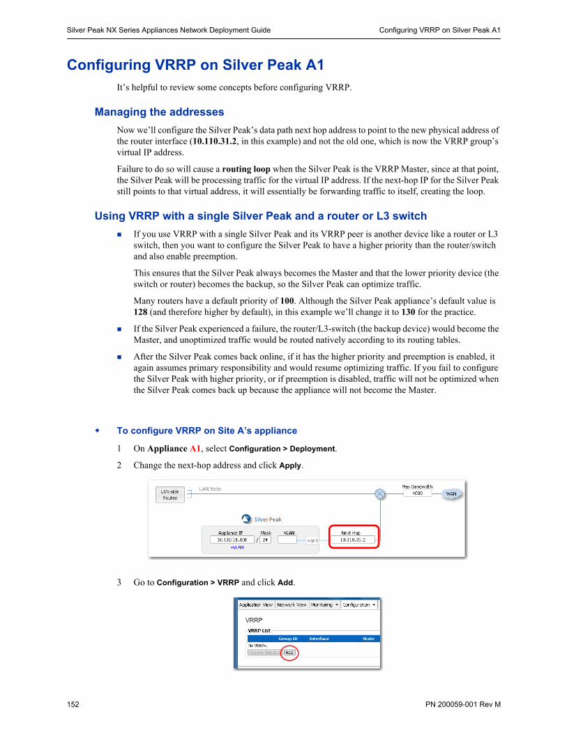
Silver Peak NX Series Appliances Network Deployment Guide Configuring VRRP on Silver Peak A1
152 PN 200059-001 Rev M
Configuring VRRP on Silver Peak A1It’s helpful to review some concepts before configuring VRRP.
Managing the addresses
Now we’ll configure the Silver Peak’s data path next hop address to point to the new physical address of the router interface (10.110.31.2, in this example) and not the old one, which is now the VRRP group’s virtual IP address.
Failure to do so will cause a routing loop when the Silver Peak is the VRRP Master, since at that point, the Silver Peak will be processing traffic for the virtual IP address. If the next-hop IP for the Silver Peak still points to that virtual address, it will essentially be forwarding traffic to itself, creating the loop.
Using VRRP with a single Silver Peak and a router or L3 switch
If you use VRRP with a single Silver Peak and its VRRP peer is another device like a router or L3 switch, then you want to configure the Silver Peak to have a higher priority than the router/switch and also enable preemption.
This ensures that the Silver Peak always becomes the Master and that the lower priority device (the switch or router) becomes the backup, so the Silver Peak can optimize traffic.
Many routers have a default priority of 100. Although the Silver Peak appliance’s default value is 128 (and therefore higher by default), in this example we’ll change it to 130 for the practice.
If the Silver Peak experienced a failure, the router/L3-switch (the backup device) would become the Master, and unoptimized traffic would be routed natively according to its routing tables.
After the Silver Peak comes back online, if it has the higher priority and preemption is enabled, it again assumes primary responsibility and would resume optimizing traffic. If you fail to configure the Silver Peak with higher priority, or if preemption is disabled, traffic will not be optimized when the Silver Peak comes back up because the appliance will not become the Master.
To configure VRRP on Site A’s appliance
1 On Appliance A1, select Configuration > Deployment.
2 Change the next-hop address and click Apply.
3 Go to Configuration > VRRP and click Add.
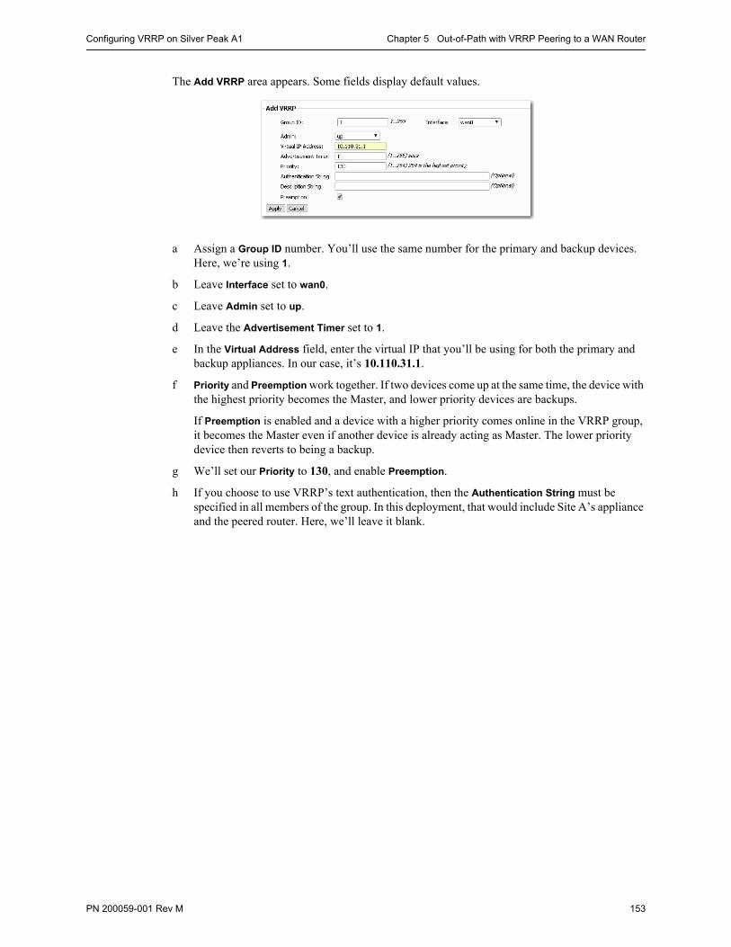
Configuring VRRP on Silver Peak A1 Chapter 5 Out-of-Path with VRRP Peering to a WAN Router
PN 200059-001 Rev M 153
The Add VRRP area appears. Some fields display default values.
a Assign a Group ID number. You’ll use the same number for the primary and backup devices. Here, we’re using 1.
b Leave Interface set to wan0.
c Leave Admin set to up.
d Leave the Advertisement Timer set to 1.
e In the Virtual Address field, enter the virtual IP that you’ll be using for both the primary and backup appliances. In our case, it’s 10.110.31.1.
f Priority and Preemption work together. If two devices come up at the same time, the device with the highest priority becomes the Master, and lower priority devices are backups.
If Preemption is enabled and a device with a higher priority comes online in the VRRP group, it becomes the Master even if another device is already acting as Master. The lower priority device then reverts to being a backup.
g We’ll set our Priority to 130, and enable Preemption.
h If you choose to use VRRP’s text authentication, then the Authentication String must be specified in all members of the group. In this deployment, that would include Site A’s appliance and the peered router. Here, we’ll leave it blank.
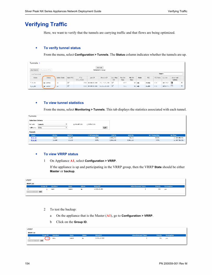
Silver Peak NX Series Appliances Network Deployment Guide Verifying Traffic
154 PN 200059-001 Rev M
Verifying TrafficHere, we want to verify that the tunnels are carrying traffic and that flows are being optimized.
To verify tunnel status
From the menu, select Configuration > Tunnels. The Status column indicates whether the tunnels are up.
To view tunnel statistics
From the menu, select Monitoring > Tunnels. This tab displays the statistics associated with each tunnel.
To view VRRP status
1 On Appliance A1, select Configuration > VRRP.
If the appliance is up and participating in the VRRP group, then the VRRP State should be either Master or backup.
2 To test the backup:
a On the appliance that is the Master (A1), go to Configuration > VRRP.
b Click on the Group ID.
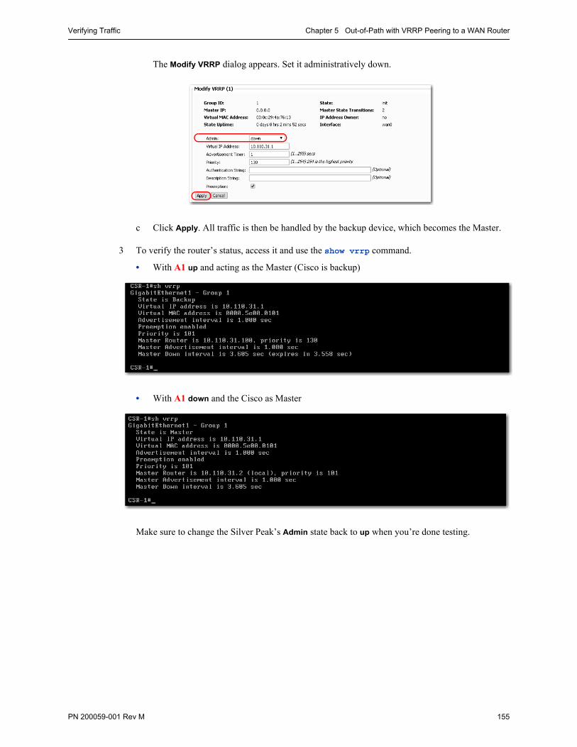
Verifying Traffic Chapter 5 Out-of-Path with VRRP Peering to a WAN Router
PN 200059-001 Rev M 155
The Modify VRRP dialog appears. Set it administratively down.
c Click Apply. All traffic is then be handled by the backup device, which becomes the Master.
3 To verify the router’s status, access it and use the show vrrp command.
• With A1 up and acting as the Master (Cisco is backup)
• With A1 down and the Cisco as Master
Make sure to change the Silver Peak’s Admin state back to up when you’re done testing.
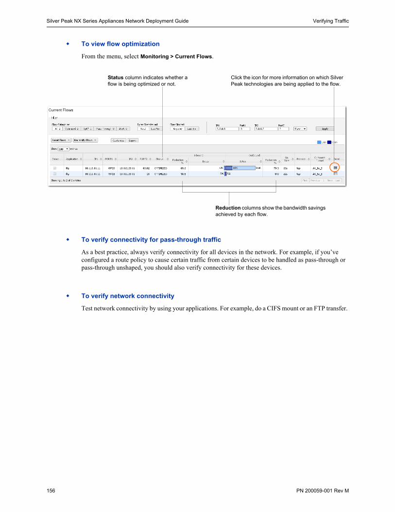
Silver Peak NX Series Appliances Network Deployment Guide Verifying Traffic
156 PN 200059-001 Rev M
To view flow optimization
From the menu, select Monitoring > Current Flows.
To verify connectivity for pass-through traffic
As a best practice, always verify connectivity for all devices in the network. For example, if you’ve configured a route policy to cause certain traffic from certain devices to be handled as pass-through or pass-through unshaped, you should also verify connectivity for these devices.
To verify network connectivity
Test network connectivity by using your applications. For example, do a CIFS mount or an FTP transfer.
Reduction columns show the bandwidth savings achieved by each flow.
Click the icon for more information on which Silver Peak technologies are being applied to the flow.
Status column indicates whether a flow is being optimized or not.
PN 200059-001 Rev M 157
C H A P T E R 6
Out-of-Path with PBR and VRRP Redundant Silver Peak Appliances
With Subnet Sharing in Use
This chapter provides a step-by-step example for configuring high availability.
In this example, Site A deploys two redundant appliances out-of-path (Router mode), used as Active and Standby. Site B deploys a single appliance in-line (Bridge mode).
The peered appliances at Site A use the Virtual Router Redundancy Protocol (VRRP) to create and share a common IP address, called the Virtual IP address (VIP).
In This Chapter Overview See page 158.
Using the Initial Config Wizard for Site A See page 162.
Configuring VRRP on A1 and A2 See page 175.
Configuring Flow Redirection See page 178.
Using the Initial Config Wizard with Site B See page 182.
Verifying Appliance Connectivity See page 188.
Enabling Subnet Sharing See page 191.
Creating Tunnels and Updating the Subnet Table See page 193.
Configuring A1 and A2 to Advertise Non-Local Subnets See page 196.
Configuring the Cisco Router for Policy-Based Routing (PBR) See page 198.
Verifying Traffic See page 199.
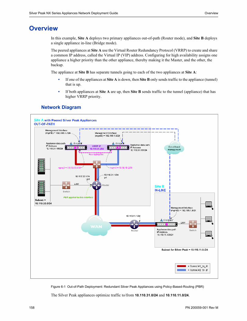
Silver Peak NX Series Appliances Network Deployment Guide Overview
158 PN 200059-001 Rev M
OverviewIn this example, Site A deploys two primary appliances out-of-path (Router mode), and Site B deploys a single appliance in-line (Bridge mode).
The peered appliances at Site A use the Virtual Router Redundancy Protocol (VRRP) to create and share a common IP address, called the Virtual IP (VIP) address. Configuring for high availability assigns one appliance a higher priority than the other appliance, thereby making it the Master, and the other, the backup.
The appliance at Site B has separate tunnels going to each of the two appliances at Site A:
• If one of the appliances at Site A is down, then Site B only sends traffic to the appliance (tunnel) that is up.
• If both appliances at Site A are up, then Site B sends traffic to the tunnel (appliance) that has higher VRRP priority.
Network Diagram
Figure 6-1 Out-of-Path Deployment: Redundant Silver Peak Appliances using Policy-Based-Routing (PBR)
The Silver Peak appliances optimize traffic to/from 10.110.31.0/24 and 10.110.11.0/24.
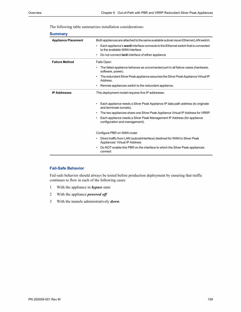
Overview Chapter 6 Out-of-Path with PBR and VRRP Redundant Silver Peak Appliances
PN 200059-001 Rev M 159
The following table summarizes installation considerations:
Summary
Fail-Safe Behavior
Fail-safe behavior should always be tested before production deployment by ensuring that traffic continues to flow in each of the following cases:
1 With the appliance in bypass state
2 With the appliance powered off
3 With the tunnels administratively down.
Appliance Placement Both appliances are attached to the same available subnet via an Ethernet LAN switch:
• Each appliance’s wan0 interface connects to the Ethernet switch that is connected to the available WAN interface
• Do not connect lan0 interface of either appliance
Failure Method Fails Open:
• The failed appliance behaves as unconnected port in all failure cases (hardware, software, power).
• The redundant Silver Peak appliance assumes the Silver Peak Appliance Virtual IP Address.
• Remote appliances switch to the redundant appliance.
IP Addresses This deployment model requires five IP addresses:
• Each appliance needs a Silver Peak Appliance IP data path address (to originate and terminate tunnels).
• The two appliances share one Silver Peak Appliance Virtual IP Address for VRRP.
• Each appliance needs a Silver Peak Management IP Address (for appliance configuration and management).
Configure PBR on WAN router
• Direct traffic from LAN (subnet/interface) destined for WAN to Silver Peak Appliances’ Virtual IP Address
• Do NOT enable this PBR on the interface to which the Silver Peak appliances connect
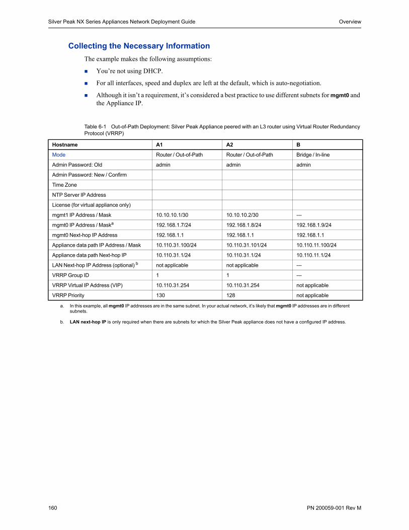
Silver Peak NX Series Appliances Network Deployment Guide Overview
160 PN 200059-001 Rev M
Collecting the Necessary Information
The example makes the following assumptions:
You’re not using DHCP.
For all interfaces, speed and duplex are left at the default, which is auto-negotiation.
Although it isn’t a requirement, it’s considered a best practice to use different subnets for mgmt0 and the Appliance IP.
Table 6-1 Out-of-Path Deployment: Silver Peak Appliance peered with an L3 router using Virtual Router Redundancy Protocol (VRRP)
Hostname A1 A2 B
Mode Router / Out-of-Path Router / Out-of-Path Bridge / In-line
Admin Password: Old admin admin admin
Admin Password: New / Confirm
Time Zone
NTP Server IP Address
License (for virtual appliance only)
mgmt1 IP Address / Mask 10.10.10.1/30 10.10.10.2/30 ---
mgmt0 IP Address / Maska 192.168.1.7/24 192.168.1.8/24 192.168.1.9/24
mgmt0 Next-hop IP Address 192.168.1.1 192.168.1.1 192.168.1.1
Appliance data path IP Address / Mask 10.110.31.100/24 10.110.31.101/24 10.110.11.100/24
Appliance data path Next-hop IP 10.110.31.1/24 10.110.31.1/24 10.110.11.1/24
LAN Next-hop IP Address (optional) b not applicable not applicable ---
VRRP Group ID 1 1 ---
VRRP Virtual IP Address (VIP) 10.110.31.254 10.110.31.254 not applicable
VRRP Priority 130 128 not applicable
a. In this example, all mgmt0 IP addresses are in the same subnet. In your actual network, it’s likely that mgmt0 IP addresses are in different subnets.
b. LAN next-hop IP is only required when there are subnets for which the Silver Peak appliance does not have a configured IP address.
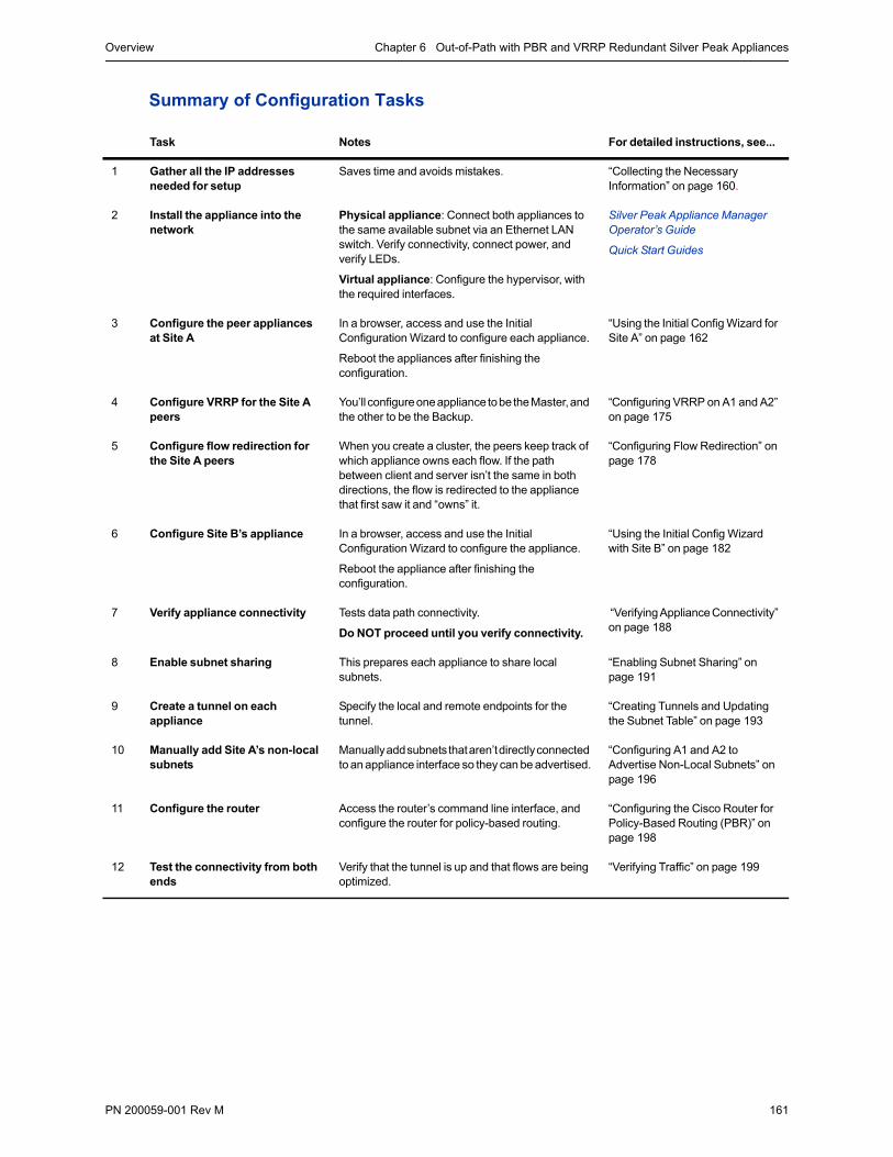
Overview Chapter 6 Out-of-Path with PBR and VRRP Redundant Silver Peak Appliances
PN 200059-001 Rev M 161
Summary of Configuration Tasks
Task Notes For detailed instructions, see...
1 Gather all the IP addresses needed for setup
Saves time and avoids mistakes. “Collecting the Necessary Information” on page 160.
2 Install the appliance into the network
Physical appliance: Connect both appliances to the same available subnet via an Ethernet LAN switch. Verify connectivity, connect power, and verify LEDs.
Virtual appliance: Configure the hypervisor, with the required interfaces.
Silver Peak Appliance Manager Operator’s Guide
Quick Start Guides
3 Configure the peer appliances at Site A
In a browser, access and use the Initial Configuration Wizard to configure each appliance.
Reboot the appliances after finishing the configuration.
“Using the Initial Config Wizard for Site A” on page 162
4 Configure VRRP for the Site A peers
You’ll configure one appliance to be the Master, and the other to be the Backup.
“Configuring VRRP on A1 and A2” on page 175
5 Configure flow redirection for the Site A peers
When you create a cluster, the peers keep track of which appliance owns each flow. If the path between client and server isn’t the same in both directions, the flow is redirected to the appliance that first saw it and “owns” it.
“Configuring Flow Redirection” on page 178
6 Configure Site B’s appliance In a browser, access and use the Initial Configuration Wizard to configure the appliance.
Reboot the appliance after finishing the configuration.
“Using the Initial Config Wizard with Site B” on page 182
7 Verify appliance connectivity Tests data path connectivity.
Do NOT proceed until you verify connectivity.
“Verifying Appliance Connectivity” on page 188
8 Enable subnet sharing This prepares each appliance to share local subnets.
“Enabling Subnet Sharing” on page 191
9 Create a tunnel on each appliance
Specify the local and remote endpoints for the tunnel.
“Creating Tunnels and Updating the Subnet Table” on page 193
10 Manually add Site A’s non-local subnets
Manually add subnets that aren’t directly connected to an appliance interface so they can be advertised.
“Configuring A1 and A2 to Advertise Non-Local Subnets” on page 196
11 Configure the router Access the router’s command line interface, and configure the router for policy-based routing.
“Configuring the Cisco Router for Policy-Based Routing (PBR)” on page 198
12 Test the connectivity from both ends
Verify that the tunnel is up and that flows are being optimized.
“Verifying Traffic” on page 199
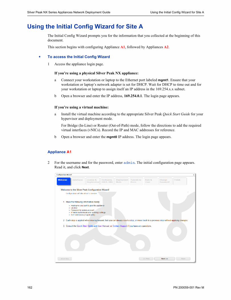
Silver Peak NX Series Appliances Network Deployment Guide Using the Initial Config Wizard for Site A
162 PN 200059-001 Rev M
Using the Initial Config Wizard for Site AThe Initial Config Wizard prompts you for the information that you collected at the beginning of this document.
This section begins with configuring Appliance A1, followed by Appliances A2.
To access the Initial Config Wizard
1 Access the appliance login page.
If you’re using a physical Silver Peak NX appliance:
a Connect your workstation or laptop to the Ethernet port labeled mgmt1. Ensure that your workstation or laptop’s network adapter is set for DHCP. Wait for DHCP to time out and for your workstation or laptop to assign itself an IP address in the 169.254.x.x subnet.
b Open a browser and enter the IP address, 169.254.0.1. The login page appears.
If you’re using a virtual machine:
a Install the virtual machine according to the appropriate Silver Peak Quick Start Guide for your hypervisor and deployment mode.
For Bridge (In-Line) or Router (Out-of-Path) mode, follow the directions to add the required virtual interfaces (vNICs). Record the IP and MAC addresses for reference.
b Open a browser and enter the mgmt0 IP address. The login page appears.
Appliance A1
2 For the username and for the password, enter admin. The initial configuration page appears.Read it, and click Next.
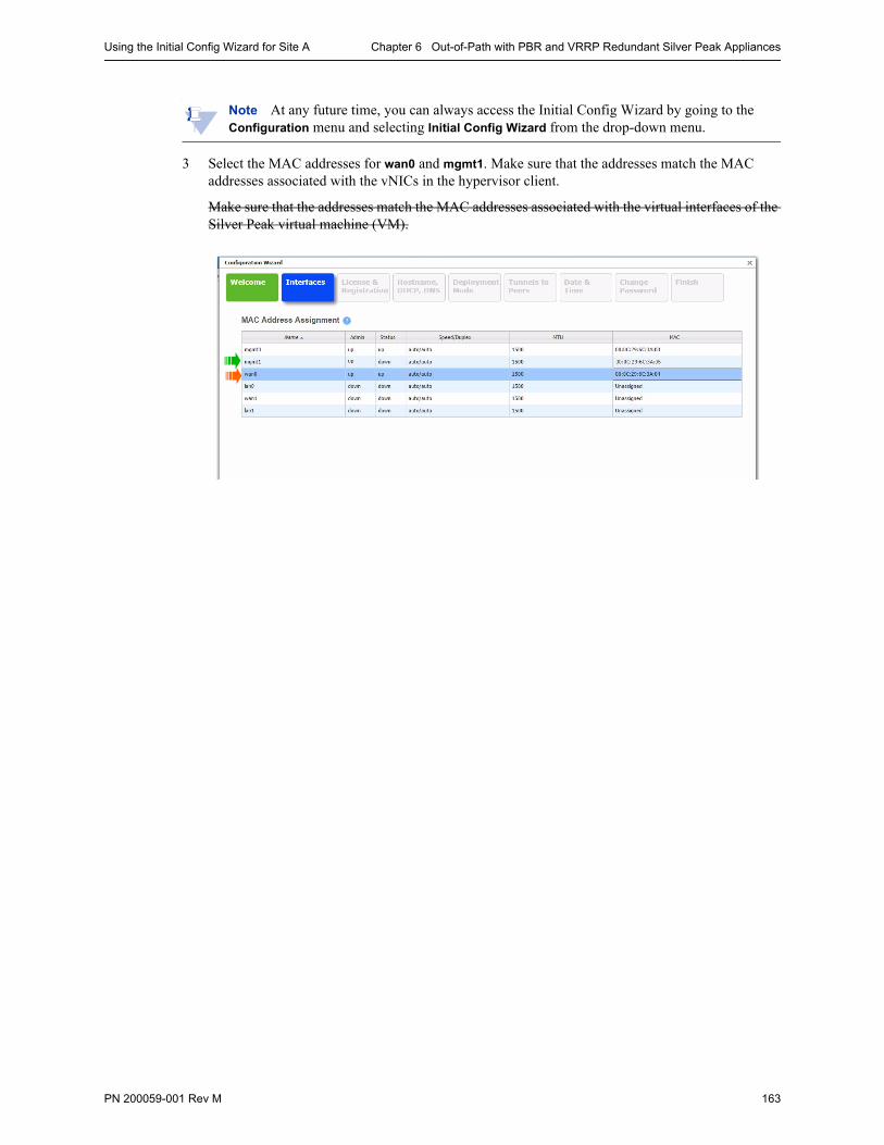
Using the Initial Config Wizard for Site A Chapter 6 Out-of-Path with PBR and VRRP Redundant Silver Peak Appliances
PN 200059-001 Rev M 163
Note At any future time, you can always access the Initial Config Wizard by going to the Configuration menu and selecting Initial Config Wizard from the drop-down menu.
3 Select the MAC addresses for wan0 and mgmt1. Make sure that the addresses match the MAC addresses associated with the vNICs in the hypervisor client.
Make sure that the addresses match the MAC addresses associated with the virtual interfaces of the Silver Peak virtual machine (VM).
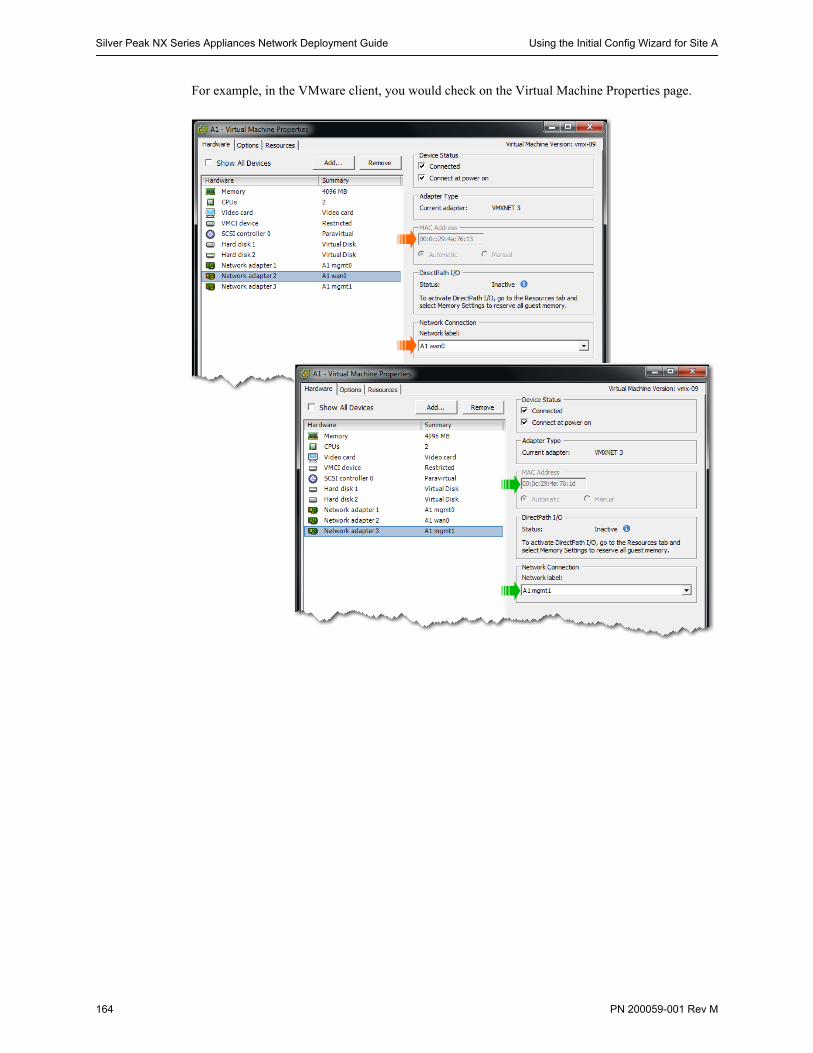
Silver Peak NX Series Appliances Network Deployment Guide Using the Initial Config Wizard for Site A
164 PN 200059-001 Rev M
For example, in the VMware client, you would check on the Virtual Machine Properties page.
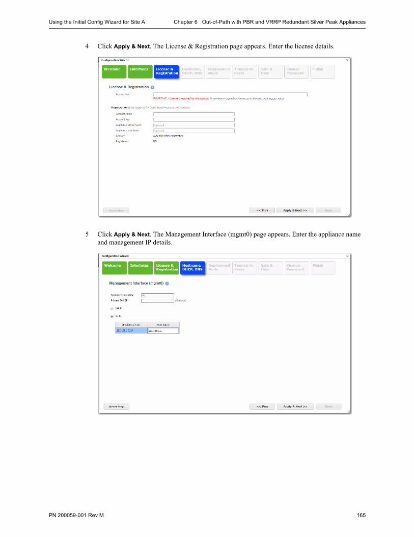
Using the Initial Config Wizard for Site A Chapter 6 Out-of-Path with PBR and VRRP Redundant Silver Peak Appliances
PN 200059-001 Rev M 165
4 Click Apply & Next. The License & Registration page appears. Enter the license details.
5 Click Apply & Next. The Management Interface (mgmt0) page appears. Enter the appliance name and management IP details.
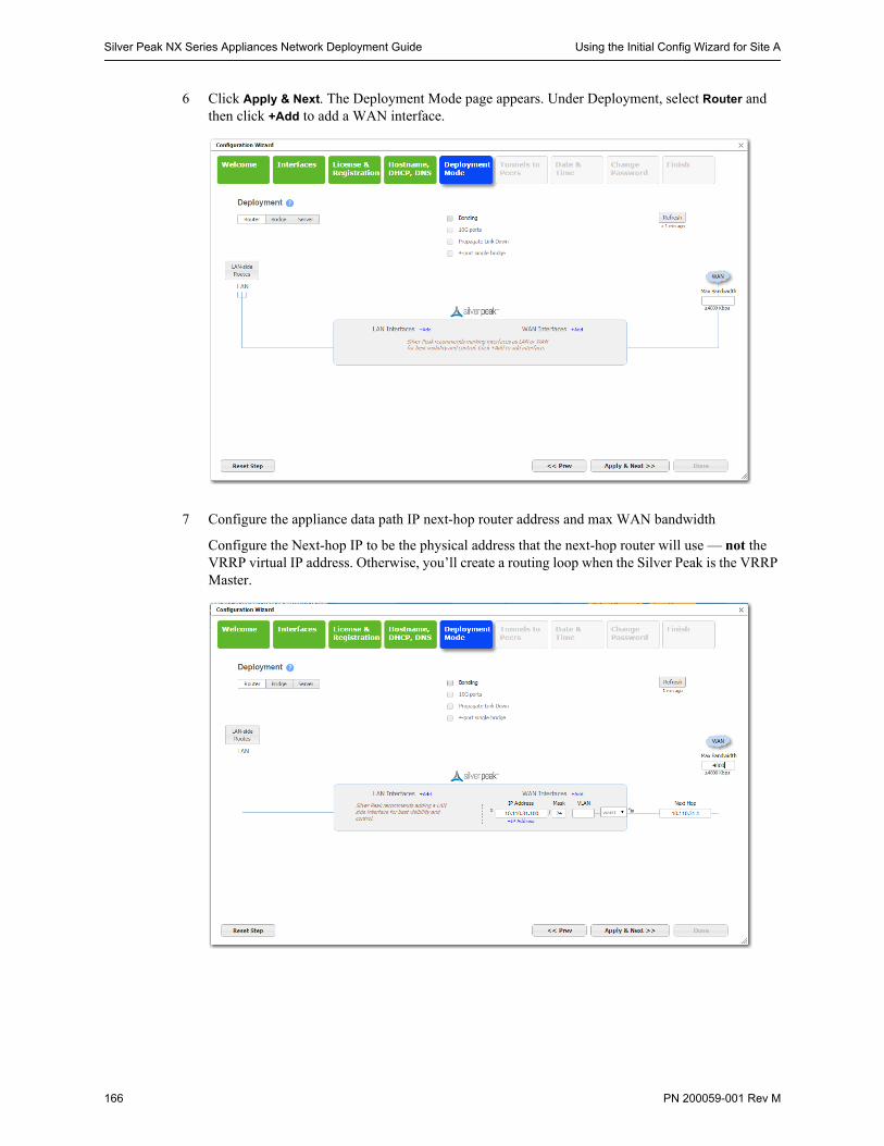
Silver Peak NX Series Appliances Network Deployment Guide Using the Initial Config Wizard for Site A
166 PN 200059-001 Rev M
6 Click Apply & Next. The Deployment Mode page appears. Under Deployment, select Router and then click +Add to add a WAN interface.
7 Configure the appliance data path IP next-hop router address and max WAN bandwidth
Configure the Next-hop IP to be the physical address that the next-hop router will use — not the VRRP virtual IP address. Otherwise, you’ll create a routing loop when the Silver Peak is the VRRP Master.
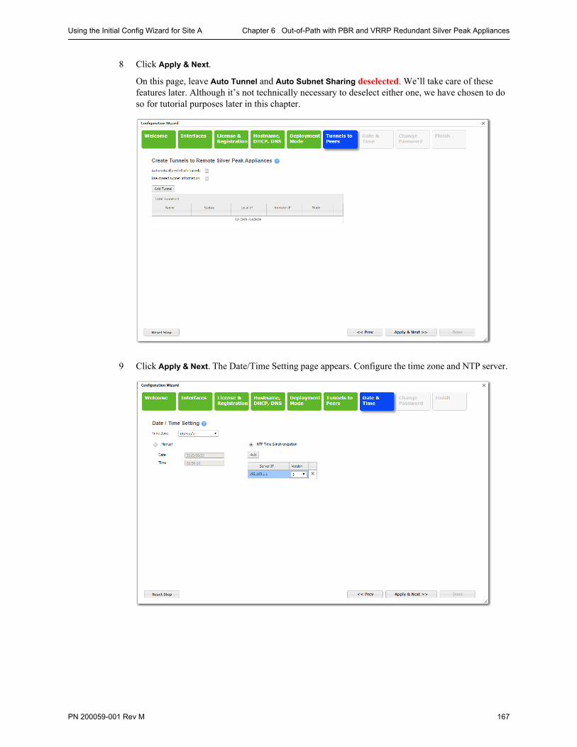
Using the Initial Config Wizard for Site A Chapter 6 Out-of-Path with PBR and VRRP Redundant Silver Peak Appliances
PN 200059-001 Rev M 167
8 Click Apply & Next.
On this page, leave Auto Tunnel and Auto Subnet Sharing deselected. We’ll take care of these features later. Although it’s not technically necessary to deselect either one, we have chosen to do so for tutorial purposes later in this chapter.
9 Click Apply & Next. The Date/Time Setting page appears. Configure the time zone and NTP server.
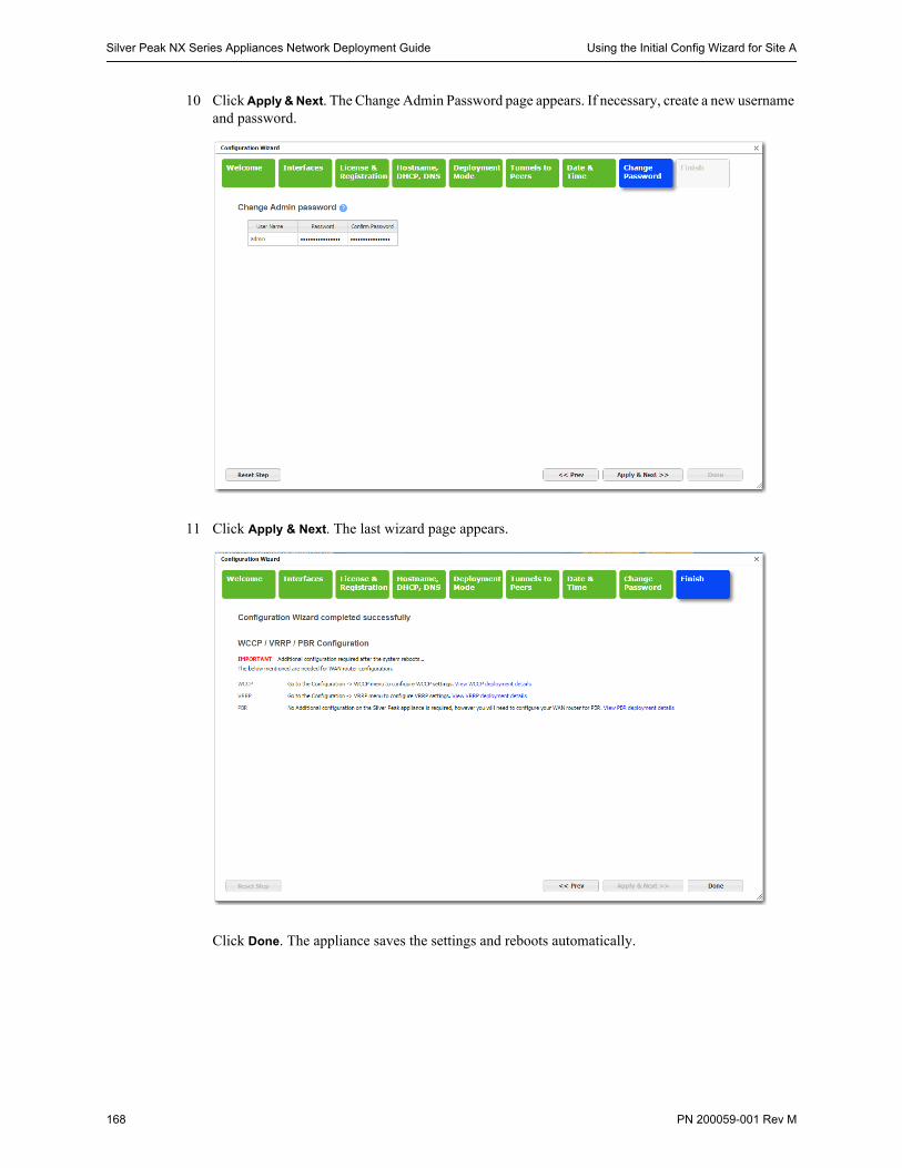
Silver Peak NX Series Appliances Network Deployment Guide Using the Initial Config Wizard for Site A
168 PN 200059-001 Rev M
10 Click Apply & Next. The Change Admin Password page appears. If necessary, create a new username and password.
11 Click Apply & Next. The last wizard page appears.
Click Done. The appliance saves the settings and reboots automatically.
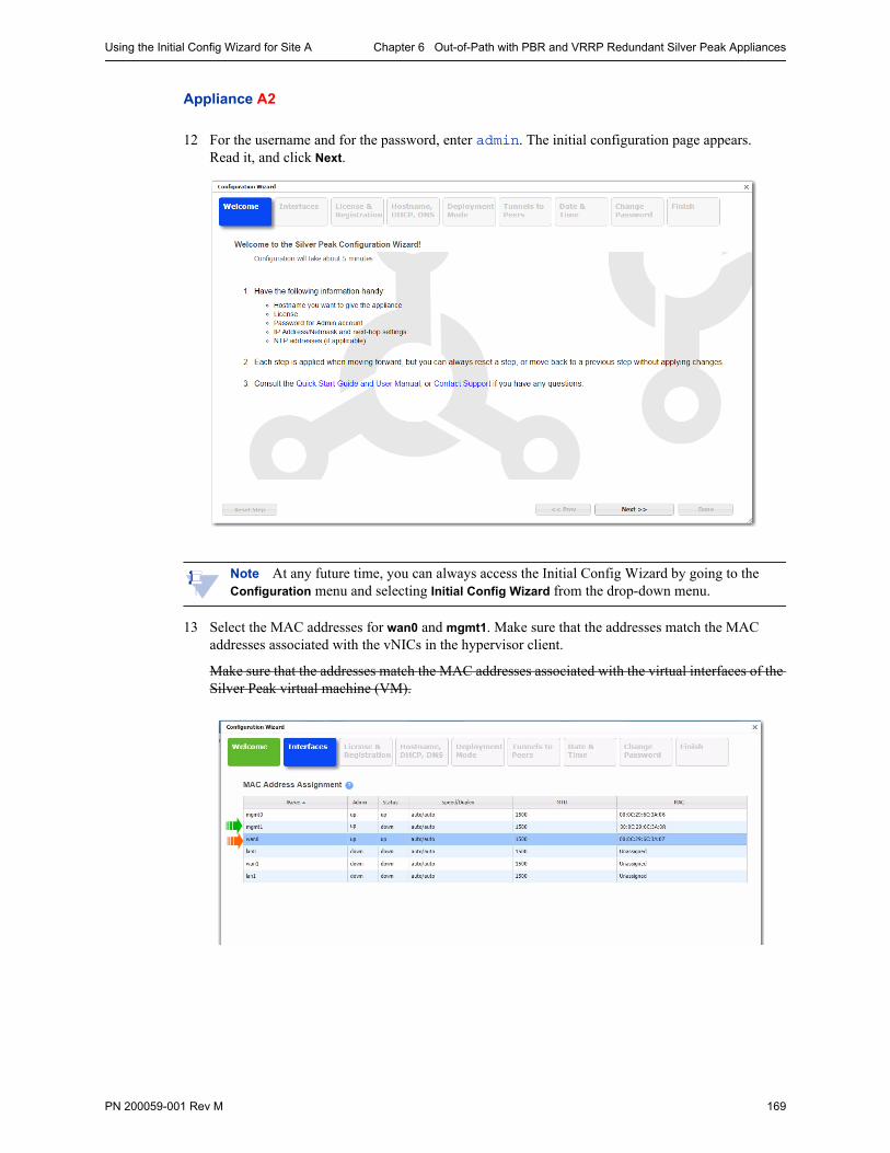
Using the Initial Config Wizard for Site A Chapter 6 Out-of-Path with PBR and VRRP Redundant Silver Peak Appliances
PN 200059-001 Rev M 169
Appliance A2
12 For the username and for the password, enter admin. The initial configuration page appears.Read it, and click Next.
Note At any future time, you can always access the Initial Config Wizard by going to the Configuration menu and selecting Initial Config Wizard from the drop-down menu.
13 Select the MAC addresses for wan0 and mgmt1. Make sure that the addresses match the MAC addresses associated with the vNICs in the hypervisor client.
Make sure that the addresses match the MAC addresses associated with the virtual interfaces of the Silver Peak virtual machine (VM).
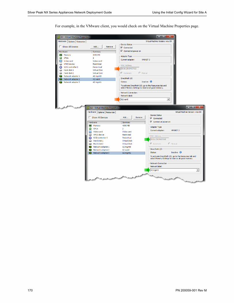
Silver Peak NX Series Appliances Network Deployment Guide Using the Initial Config Wizard for Site A
170 PN 200059-001 Rev M
For example, in the VMware client, you would check on the Virtual Machine Properties page.
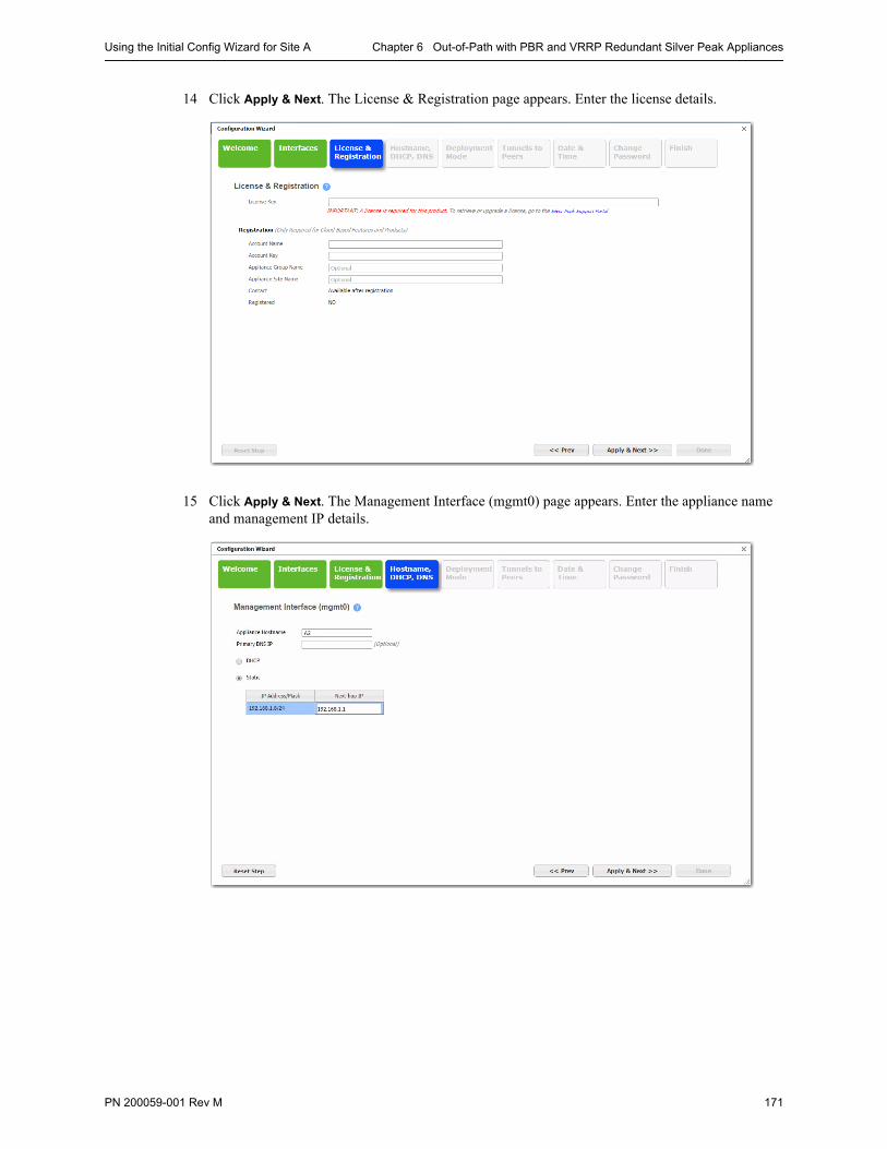
Using the Initial Config Wizard for Site A Chapter 6 Out-of-Path with PBR and VRRP Redundant Silver Peak Appliances
PN 200059-001 Rev M 171
14 Click Apply & Next. The License & Registration page appears. Enter the license details.
15 Click Apply & Next. The Management Interface (mgmt0) page appears. Enter the appliance name and management IP details.
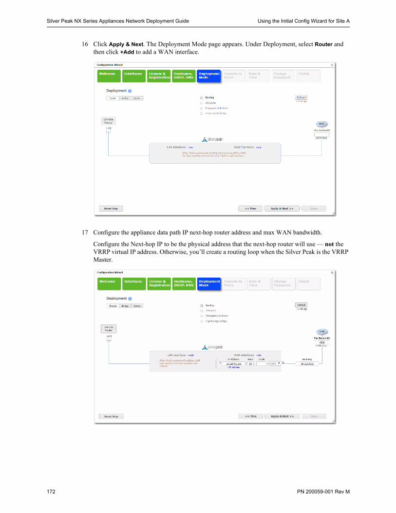
Silver Peak NX Series Appliances Network Deployment Guide Using the Initial Config Wizard for Site A
172 PN 200059-001 Rev M
16 Click Apply & Next. The Deployment Mode page appears. Under Deployment, select Router and then click +Add to add a WAN interface.
17 Configure the appliance data path IP next-hop router address and max WAN bandwidth.
Configure the Next-hop IP to be the physical address that the next-hop router will use — not the VRRP virtual IP address. Otherwise, you’ll create a routing loop when the Silver Peak is the VRRP Master.

Using the Initial Config Wizard for Site A Chapter 6 Out-of-Path with PBR and VRRP Redundant Silver Peak Appliances
PN 200059-001 Rev M 173
18 Click Apply & Next.
On this page, leave Auto Tunnel and Auto Subnet Sharing deselected. We’ll take care of these features later. Although it’s not technically necessary to deselect either one, we have chosen to do so for tutorial purposes later in this chapter.
19 Click Apply & Next. The Date/Time Setting page appears. Configure the time zone and NTP server.
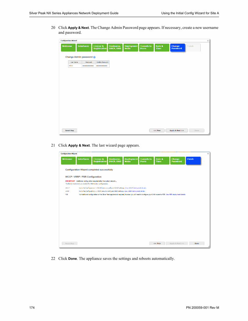
Silver Peak NX Series Appliances Network Deployment Guide Using the Initial Config Wizard for Site A
174 PN 200059-001 Rev M
20 Click Apply & Next. The Change Admin Password page appears. If necessary, create a new username and password.
21 Click Apply & Next. The last wizard page appears.
22 Click Done. The appliance saves the settings and reboots automatically.
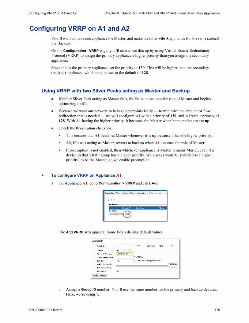
Configuring VRRP on A1 and A2 Chapter 6 Out-of-Path with PBR and VRRP Redundant Silver Peak Appliances
PN 200059-001 Rev M 175
Configuring VRRP on A1 and A2You’ll want to make one appliance the Master, and make the other Site A appliance (on the same subnet) the Backup.
On the Configuration - VRRP page, you’ll start to set this up by using Virtual Router Redundancy Protocol (VRRP) to assign the primary appliance a higher priority than you assign the secondary appliance.
Since this is the primary appliance, set the priority to 130. This will be higher than the secondary (backup) appliance, which remains set to the default of 128.
Using VRRP with two Silver Peaks acting as Master and Backup
If either Silver Peak acting as Master fails, the Backup assumes the role of Master and begins optimizing traffic.
Because we want our network to behave deterministically — to minimize the amount of flow redirection that is needed — we will configure A1 with a priority of 130, and A2 with a priority of 128. With A1 having the higher priority, it becomes the Master when both appliances are up.
Check the Preemption checkbox.
• This ensures that A1 becomes Master whenever it is up because it has the higher priority.
• A2, if it was acting as Master, reverts to backup when A1 assumes the role of Master.
• If preemption is not enabled, then whichever appliance is Master remains Master, even if a device in that VRRP group has a higher priority. We always want A1 (which has a higher priority) to be the Master, so we enable preemption. .
To configure VRRP on Appliance A1
1 On Appliance A1, go to Configuration > VRRP and click Add.
The Add VRRP area appears. Some fields display default values.
a Assign a Group ID number. You’ll use the same number for the primary and backup devices. Here, we’re using 1.
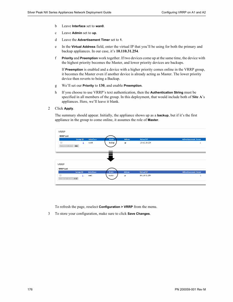
Silver Peak NX Series Appliances Network Deployment Guide Configuring VRRP on A1 and A2
176 PN 200059-001 Rev M
b Leave Interface set to wan0.
c Leave Admin set to up.
d Leave the Advertisement Timer set to 1.
e In the Virtual Address field, enter the virtual IP that you’ll be using for both the primary and backup appliances. In our case, it’s 10.110.31.254.
f Priority and Preemption work together. If two devices come up at the same time, the device with the highest priority becomes the Master, and lower priority devices are backups.
If Preemption is enabled and a device with a higher priority comes online in the VRRP group, it becomes the Master even if another device is already acting as Master. The lower priority device then reverts to being a Backup.
g We’ll set our Priority to 130, and enable Preemption.
h If you choose to use VRRP’s text authentication, then the Authentication String must be specified in all members of the group. In this deployment, that would include both of Site A’s appliances. Here, we’ll leave it blank.
2 Click Apply.
The summary should appear. Initially, the appliance shows up as a backup, but if it’s the first appliance in the group to come online, it assumes the role of Master.
To refresh the page, reselect Configuration > VRRP from the menu.
3 To store your configuration, make sure to click Save Changes.
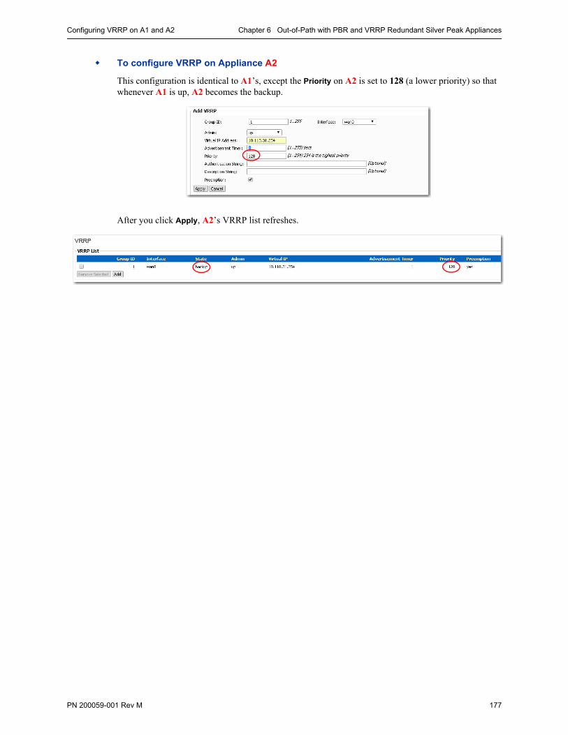
Configuring VRRP on A1 and A2 Chapter 6 Out-of-Path with PBR and VRRP Redundant Silver Peak Appliances
PN 200059-001 Rev M 177
To configure VRRP on Appliance A2
This configuration is identical to A1’s, except the Priority on A2 is set to 128 (a lower priority) so that whenever A1 is up, A2 becomes the backup.
After you click Apply, A2’s VRRP list refreshes.
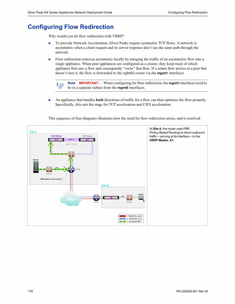
Silver Peak NX Series Appliances Network Deployment Guide Configuring Flow Redirection
178 PN 200059-001 Rev M
Configuring Flow RedirectionWhy would you do flow redirection with VRRP?
To provide Network Acceleration, Silver Peaks require symmetric TCP flows. A network is asymmetric when a client request and its server response don’t use the same path through the network.
Flow redirection removes asymmetry locally by merging the traffic of an asymmetric flow into a single appliance. When peer appliances are configured as a cluster, they keep track of which appliance first saw a flow and consequently “owns” that flow. If a return flow arrives at a peer that doesn’t own it, the flow is forwarded to the rightful owner via the mgmt1 interfaces.
Note IMPORTANT — When configuring for flow redirection, the mgmt1 interfaces need to be in a separate subnet from the mgmt0 interfaces.
An appliance that handles both directions of traffic for a flow can then optimize the flow properly. Specifically, this sets the stage for TCP acceleration and CIFS acceleration.
This sequence of four diagrams illustrates how the need for flow redirection arises, and is resolved.
At Site A, the router uses PBR (Policy-Based Routing) to direct outbound traffic—arriving at its interface—to the VRRP Master, A1.
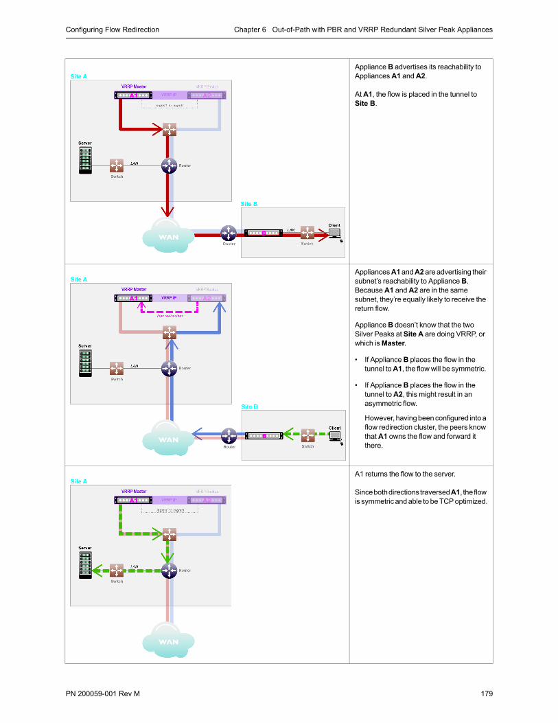
Configuring Flow Redirection Chapter 6 Out-of-Path with PBR and VRRP Redundant Silver Peak Appliances
PN 200059-001 Rev M 179
Appliance B advertises its reachability to Appliances A1 and A2.
At A1, the flow is placed in the tunnel to Site B.
Appliances A1 and A2 are advertising their subnet’s reachability to Appliance B. Because A1 and A2 are in the same subnet, they’re equally likely to receive the return flow.
Appliance B doesn’t know that the two Silver Peaks at Site A are doing VRRP, or which is Master.
• If Appliance B places the flow in the tunnel to A1, the flow will be symmetric.
• If Appliance B places the flow in the tunnel to A2, this might result in an asymmetric flow.
However, having been configured into a flow redirection cluster, the peers know that A1 owns the flow and forward it there.
A1 returns the flow to the server.
Since both directions traversed A1, the flow is symmetric and able to be TCP optimized.
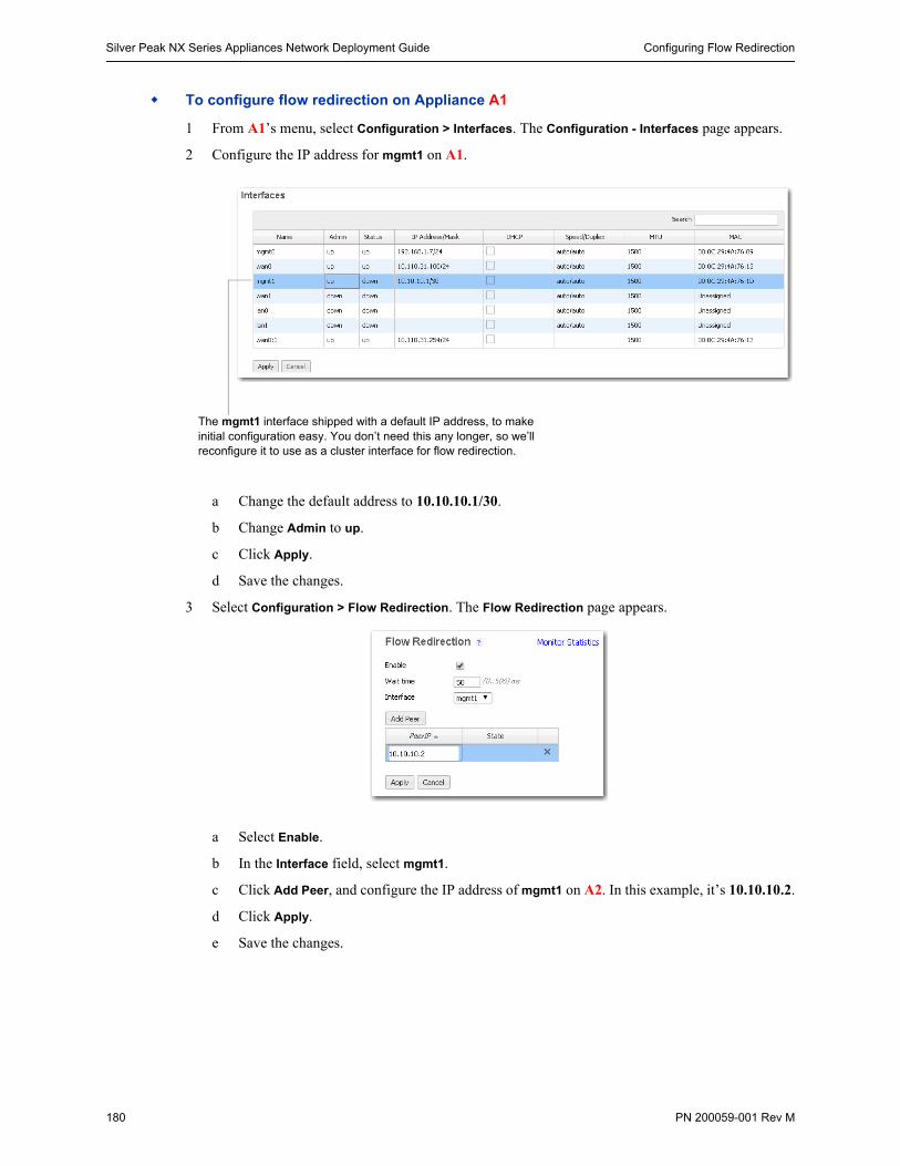
Silver Peak NX Series Appliances Network Deployment Guide Configuring Flow Redirection
180 PN 200059-001 Rev M
To configure flow redirection on Appliance A1
1 From A1’s menu, select Configuration > Interfaces. The Configuration - Interfaces page appears.
2 Configure the IP address for mgmt1 on A1.
a Change the default address to 10.10.10.1/30.
b Change Admin to up.
c Click Apply.
d Save the changes.
3 Select Configuration > Flow Redirection. The Flow Redirection page appears.
a Select Enable.
b In the Interface field, select mgmt1.
c Click Add Peer, and configure the IP address of mgmt1 on A2. In this example, it’s 10.10.10.2.
d Click Apply.
e Save the changes.
The mgmt1 interface shipped with a default IP address, to make initial configuration easy. You don’t need this any longer, so we’ll reconfigure it to use as a cluster interface for flow redirection.
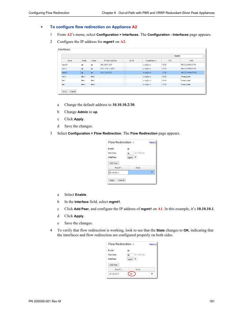
Configuring Flow Redirection Chapter 6 Out-of-Path with PBR and VRRP Redundant Silver Peak Appliances
PN 200059-001 Rev M 181
To configure flow redirection on Appliance A2
1 From A2’s menu, select Configuration > Interfaces. The Configuration - Interfaces page appears.
2 Configure the IP address for mgmt1 on A2.
a Change the default address to 10.10.10.2/30.
b Change Admin to up.
c Click Apply.
d Save the changes.
3 Select Configuration > Flow Redirection. The Flow Redirection page appears.
a Select Enable.
b In the Interface field, select mgmt1.
c Click Add Peer, and configure the IP address of mgmt1 on A1. In this example, it’s 10.10.10.1.
d Click Apply.
e Save the changes.
4 To verify that flow redirection is working, look to see that the State changes to OK, indicating that the interfaces and flow redirection are configured properly on both sides.
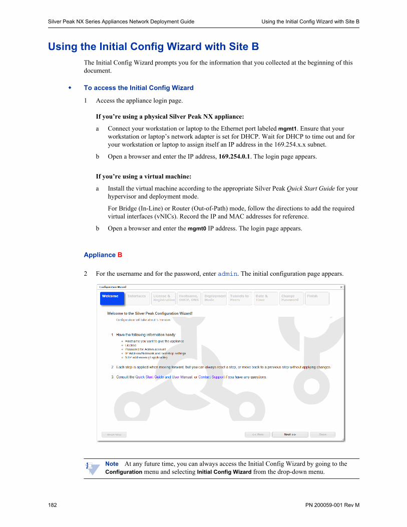
Silver Peak NX Series Appliances Network Deployment Guide Using the Initial Config Wizard with Site B
182 PN 200059-001 Rev M
Using the Initial Config Wizard with Site BThe Initial Config Wizard prompts you for the information that you collected at the beginning of this document.
To access the Initial Config Wizard
1 Access the appliance login page.
If you’re using a physical Silver Peak NX appliance:
a Connect your workstation or laptop to the Ethernet port labeled mgmt1. Ensure that your workstation or laptop’s network adapter is set for DHCP. Wait for DHCP to time out and for your workstation or laptop to assign itself an IP address in the 169.254.x.x subnet.
b Open a browser and enter the IP address, 169.254.0.1. The login page appears.
If you’re using a virtual machine:
a Install the virtual machine according to the appropriate Silver Peak Quick Start Guide for your hypervisor and deployment mode.
For Bridge (In-Line) or Router (Out-of-Path) mode, follow the directions to add the required virtual interfaces (vNICs). Record the IP and MAC addresses for reference.
b Open a browser and enter the mgmt0 IP address. The login page appears.
Appliance B
2 For the username and for the password, enter admin. The initial configuration page appears.
Note At any future time, you can always access the Initial Config Wizard by going to the Configuration menu and selecting Initial Config Wizard from the drop-down menu.
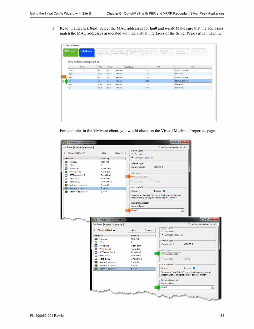
Using the Initial Config Wizard with Site B Chapter 6 Out-of-Path with PBR and VRRP Redundant Silver Peak Appliances
PN 200059-001 Rev M 183
3 Read it, and click Next. Select the MAC addresses for lan0 and wan0. Make sure that the addresses match the MAC addresses associated with the virtual interfaces of the Silver Peak virtual machine.
For example, in the VMware client, you would check on the Virtual Machine Properties page.

Silver Peak NX Series Appliances Network Deployment Guide Using the Initial Config Wizard with Site B
184 PN 200059-001 Rev M
4 Click Apply & Next. The License & Registration page appears. Enter the license details.
5 Click Apply & Next. The Management Interface (mgmt0) page appears. Enter the appliance name and management IP details.
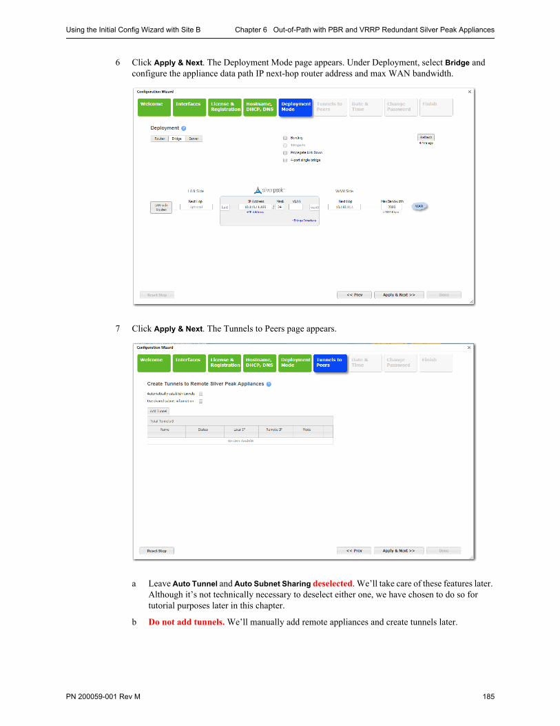
Using the Initial Config Wizard with Site B Chapter 6 Out-of-Path with PBR and VRRP Redundant Silver Peak Appliances
PN 200059-001 Rev M 185
6 Click Apply & Next. The Deployment Mode page appears. Under Deployment, select Bridge and configure the appliance data path IP next-hop router address and max WAN bandwidth.
7 Click Apply & Next. The Tunnels to Peers page appears.
a Leave Auto Tunnel and Auto Subnet Sharing deselected. We’ll take care of these features later. Although it’s not technically necessary to deselect either one, we have chosen to do so for tutorial purposes later in this chapter.
b Do not add tunnels. We’ll manually add remote appliances and create tunnels later.
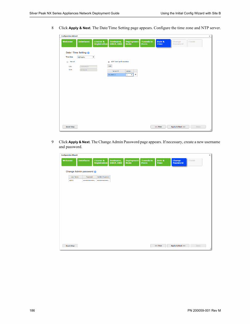
Silver Peak NX Series Appliances Network Deployment Guide Using the Initial Config Wizard with Site B
186 PN 200059-001 Rev M
8 Click Apply & Next. The Date/Time Setting page appears. Configure the time zone and NTP server.
9 Click Apply & Next. The Change Admin Password page appears. If necessary, create a new username and password.

Using the Initial Config Wizard with Site B Chapter 6 Out-of-Path with PBR and VRRP Redundant Silver Peak Appliances
PN 200059-001 Rev M 187
10 Click Apply & Next. The last wizard page appears.
11 Click Done. The appliance saves the settings and reboots automatically.
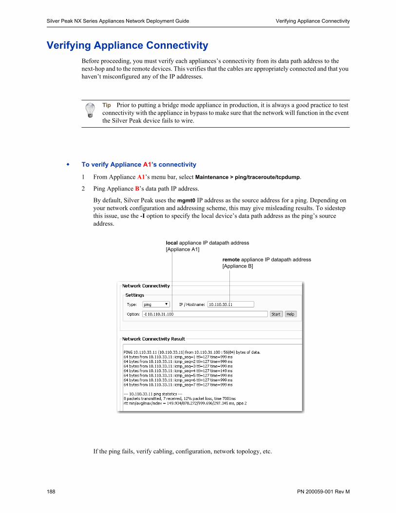
Silver Peak NX Series Appliances Network Deployment Guide Verifying Appliance Connectivity
188 PN 200059-001 Rev M
Verifying Appliance ConnectivityBefore proceeding, you must verify each appliances’s connectivity from its data path address to the next-hop and to the remote devices. This verifies that the cables are appropriately connected and that you haven’t misconfigured any of the IP addresses.
Tip Prior to putting a bridge mode appliance in production, it is always a good practice to test connectivity with the appliance in bypass to make sure that the network will function in the event the Silver Peak device fails to wire.
To verify Appliance A1’s connectivity
1 From Appliance A1’s menu bar, select Maintenance > ping/traceroute/tcpdump.
2 Ping Appliance B’s data path IP address.
By default, Silver Peak uses the mgmt0 IP address as the source address for a ping. Depending on your network configuration and addressing scheme, this may give misleading results. To sidestep this issue, use the -I option to specify the local device’s data path address as the ping’s source address.
If the ping fails, verify cabling, configuration, network topology, etc.
local appliance IP datapath address[Appliance A1]
remote appliance IP datapath address[Appliance B]
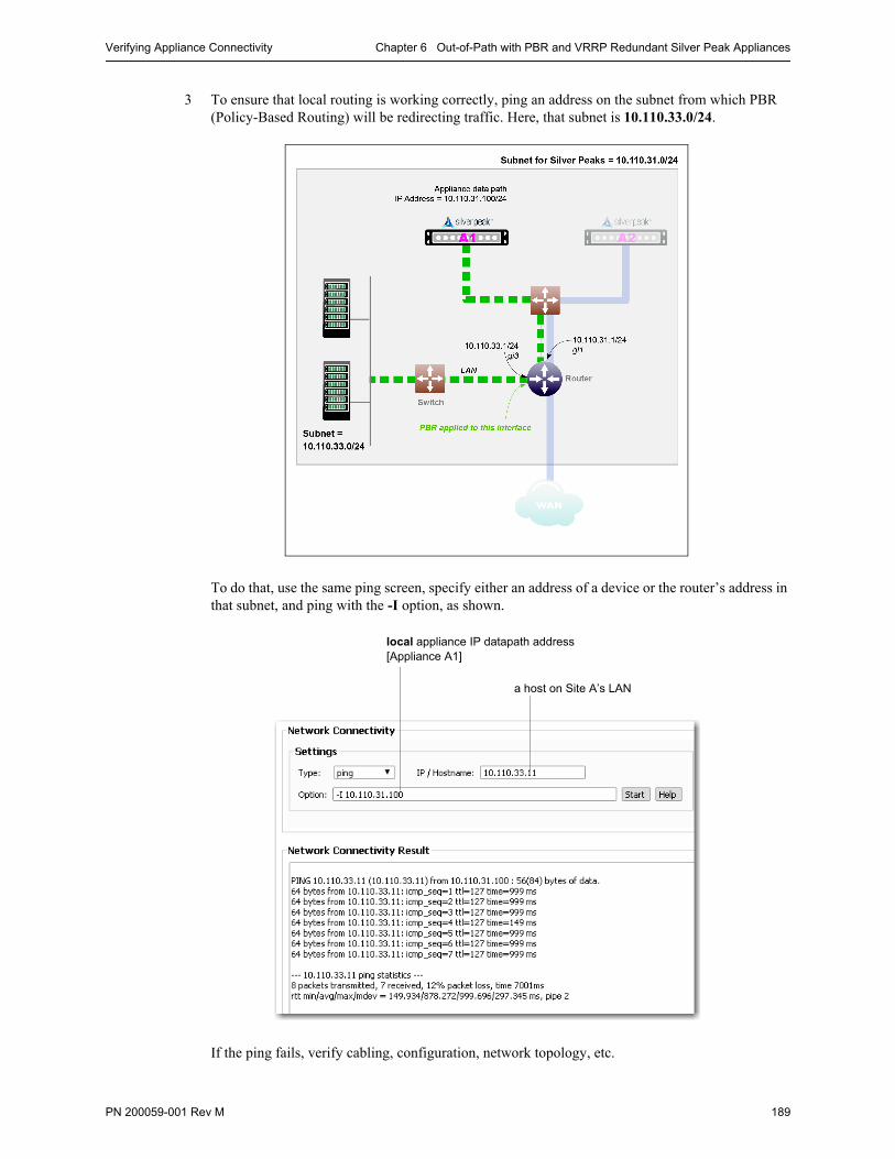
Verifying Appliance Connectivity Chapter 6 Out-of-Path with PBR and VRRP Redundant Silver Peak Appliances
PN 200059-001 Rev M 189
3 To ensure that local routing is working correctly, ping an address on the subnet from which PBR (Policy-Based Routing) will be redirecting traffic. Here, that subnet is 10.110.33.0/24.
To do that, use the same ping screen, specify either an address of a device or the router’s address in that subnet, and ping with the -I option, as shown.
If the ping fails, verify cabling, configuration, network topology, etc.
local appliance IP datapath address[Appliance A1]
a host on Site A’s LAN
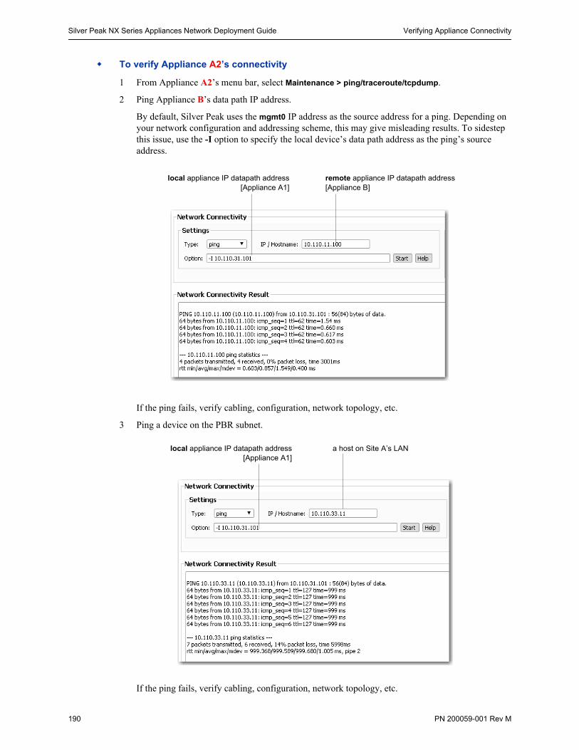
Silver Peak NX Series Appliances Network Deployment Guide Verifying Appliance Connectivity
190 PN 200059-001 Rev M
To verify Appliance A2’s connectivity
1 From Appliance A2’s menu bar, select Maintenance > ping/traceroute/tcpdump.
2 Ping Appliance B’s data path IP address.
By default, Silver Peak uses the mgmt0 IP address as the source address for a ping. Depending on your network configuration and addressing scheme, this may give misleading results. To sidestep this issue, use the -I option to specify the local device’s data path address as the ping’s source address.
If the ping fails, verify cabling, configuration, network topology, etc.
3 Ping a device on the PBR subnet.
If the ping fails, verify cabling, configuration, network topology, etc.
local appliance IP datapath address[Appliance A1]
remote appliance IP datapath address[Appliance B]
local appliance IP datapath address[Appliance A1]
a host on Site A’s LAN
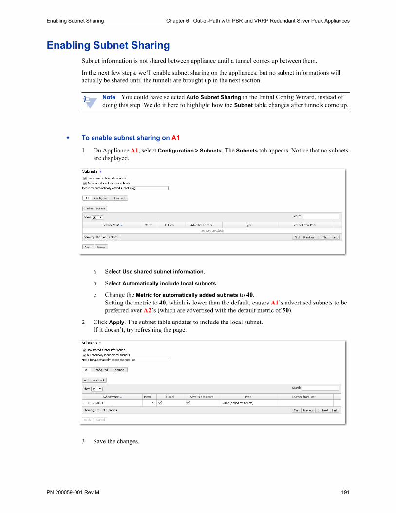
Enabling Subnet Sharing Chapter 6 Out-of-Path with PBR and VRRP Redundant Silver Peak Appliances
PN 200059-001 Rev M 191
Enabling Subnet SharingSubnet information is not shared between appliance until a tunnel comes up between them.
In the next few steps, we’ll enable subnet sharing on the appliances, but no subnet informations will actually be shared until the tunnels are brought up in the next section.
Note You could have selected Auto Subnet Sharing in the Initial Config Wizard, instead of doing this step. We do it here to highlight how the Subnet table changes after tunnels come up.
To enable subnet sharing on A1
1 On Appliance A1, select Configuration > Subnets. The Subnets tab appears. Notice that no subnets are displayed.
a Select Use shared subnet information.
b Select Automatically include local subnets.
c Change the Metric for automatically added subnets to 40. Setting the metric to 40, which is lower than the default, causes A1’s advertised subnets to be preferred over A2’s (which are advertised with the default metric of 50).
2 Click Apply. The subnet table updates to include the local subnet. If it doesn’t, try refreshing the page.
3 Save the changes.
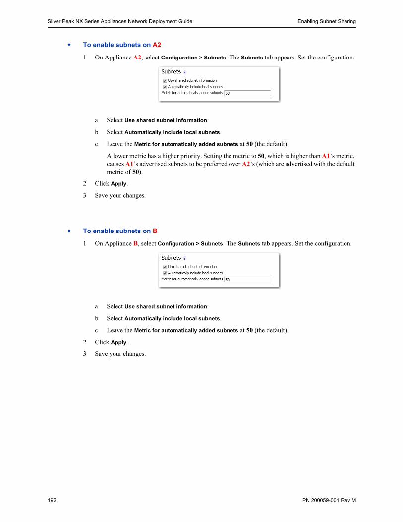
Silver Peak NX Series Appliances Network Deployment Guide Enabling Subnet Sharing
192 PN 200059-001 Rev M
To enable subnets on A2
1 On Appliance A2, select Configuration > Subnets. The Subnets tab appears. Set the configuration.
a Select Use shared subnet information.
b Select Automatically include local subnets.
c Leave the Metric for automatically added subnets at 50 (the default).
A lower metric has a higher priority. Setting the metric to 50, which is higher than A1’s metric, causes A1’s advertised subnets to be preferred over A2’s (which are advertised with the default metric of 50).
2 Click Apply.
3 Save your changes.
To enable subnets on B
1 On Appliance B, select Configuration > Subnets. The Subnets tab appears. Set the configuration.
a Select Use shared subnet information.
b Select Automatically include local subnets.
c Leave the Metric for automatically added subnets at 50 (the default).
2 Click Apply.
3 Save your changes.
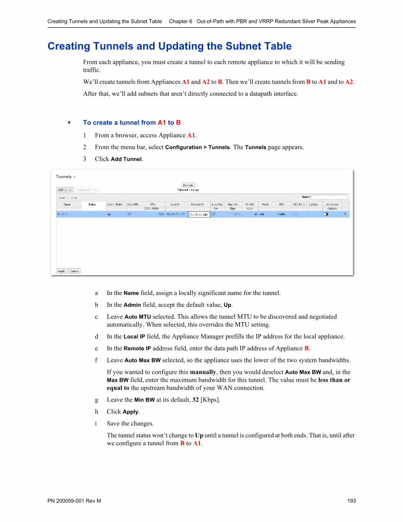
Creating Tunnels and Updating the Subnet Table Chapter 6 Out-of-Path with PBR and VRRP Redundant Silver Peak Appliances
PN 200059-001 Rev M 193
Creating Tunnels and Updating the Subnet TableFrom each appliance, you must create a tunnel to each remote appliance to which it will be sending traffic.
We’ll create tunnels from Appliances A1 and A2 to B. Then we’ll create tunnels from B to A1 and to A2.
After that, we’ll add subnets that aren’t directly connected to a datapath interface.
To create a tunnel from A1 to B
1 From a browser, access Appliance A1.
2 From the menu bar, select Configuration > Tunnels. The Tunnels page appears.
3 Click Add Tunnel.
a In the Name field, assign a locally significant name for the tunnel.
b In the Admin field, accept the default value, Up.
c Leave Auto MTU selected. This allows the tunnel MTU to be discovered and negotiated automatically. When selected, this overrides the MTU setting.
d In the Local IP field, the Appliance Manager prefills the IP address for the local appliance.
e In the Remote IP address field, enter the data path IP address of Appliance B.
f Leave Auto Max BW selected, so the appliance uses the lower of the two system bandwidths.
If you wanted to configure this manually, then you would deselect Auto Max BW and, in the Max BW field, enter the maximum bandwidth for this tunnel. The value must be less than or equal to the upstream bandwidth of your WAN connection.
g Leave the Min BW at its default, 32 [Kbps].
h Click Apply.
i Save the changes.
The tunnel status won’t change to Up until a tunnel is configured at both ends. That is, until after we configure a tunnel from B to A1.

Silver Peak NX Series Appliances Network Deployment Guide Creating Tunnels and Updating the Subnet Table
194 PN 200059-001 Rev M
To create a tunnel from A2 to B
1 From a browser, access Appliance A2.
2 From the menu bar, select Configuration > Tunnels. The Tunnels page appears.
3 Click Add Tunnel.
a In the Name field, assign a locally significant name for the tunnel.
b In the Admin field, accept the default value, Up.
c Leave Auto MTU selected. This allows the tunnel MTU to be discovered and negotiated automatically. When selected, this overrides the MTU setting.
d In the Local IP field, the Appliance Manager prefills the IP address for the local appliance.
e In the Remote IP address field, enter the data path IP address of Appliance B.
f Leave Auto Max BW selected, so the appliance uses the lower of the two system bandwidths.
g Leave the Min BW at its default, 32 [Kbps].
h Click Apply.
i Save the changes.
The tunnel status won’t change to Up until a tunnel is configured at both ends. So, we’ll now configure a tunnel from B to A1.
To create tunnels from B to A1 and to A2
1 From a browser, access Appliance B.
2 From the menu bar, select Configuration > Tunnels. The Tunnels page appears.
3 To add a tunnel to Appliance A1, click Add Tunnel.
a In the Name field, assign a locally significant name for the tunnel.
b Enter the Remote IP address (that is, the data path IP address of Appliance A1).
c Click Apply.
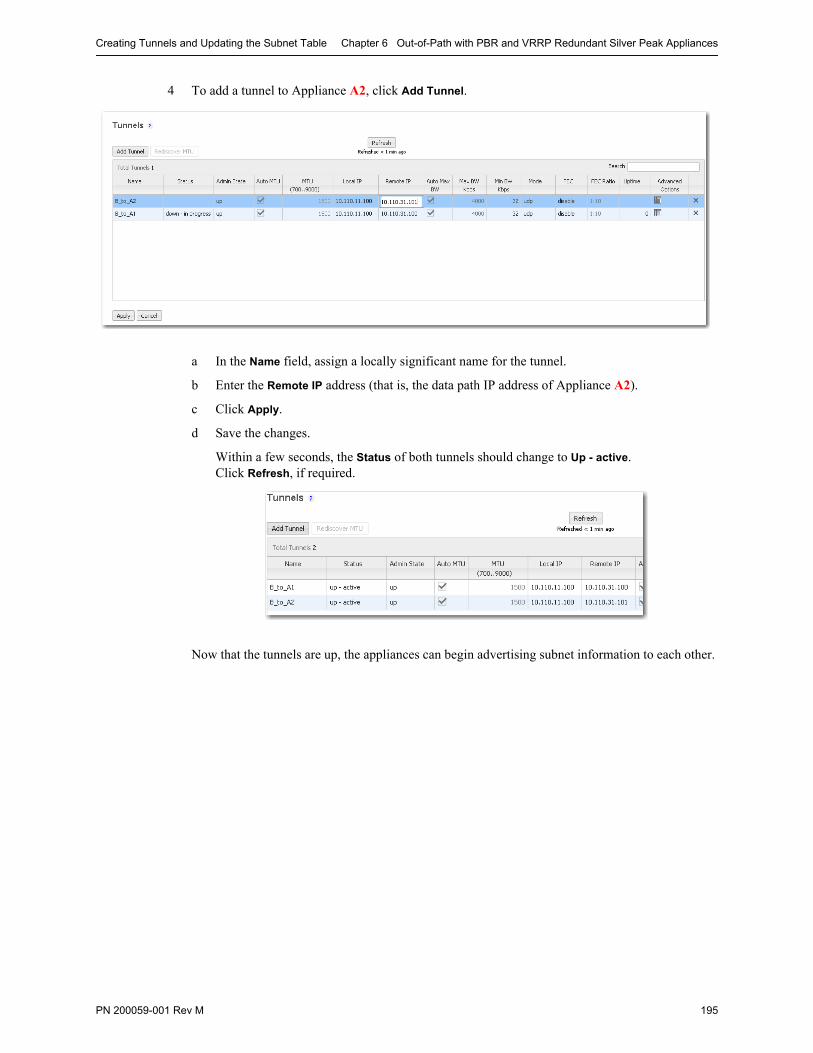
Creating Tunnels and Updating the Subnet Table Chapter 6 Out-of-Path with PBR and VRRP Redundant Silver Peak Appliances
PN 200059-001 Rev M 195
4 To add a tunnel to Appliance A2, click Add Tunnel.
a In the Name field, assign a locally significant name for the tunnel.
b Enter the Remote IP address (that is, the data path IP address of Appliance A2).
c Click Apply.
d Save the changes.
Within a few seconds, the Status of both tunnels should change to Up - active. Click Refresh, if required.
Now that the tunnels are up, the appliances can begin advertising subnet information to each other.
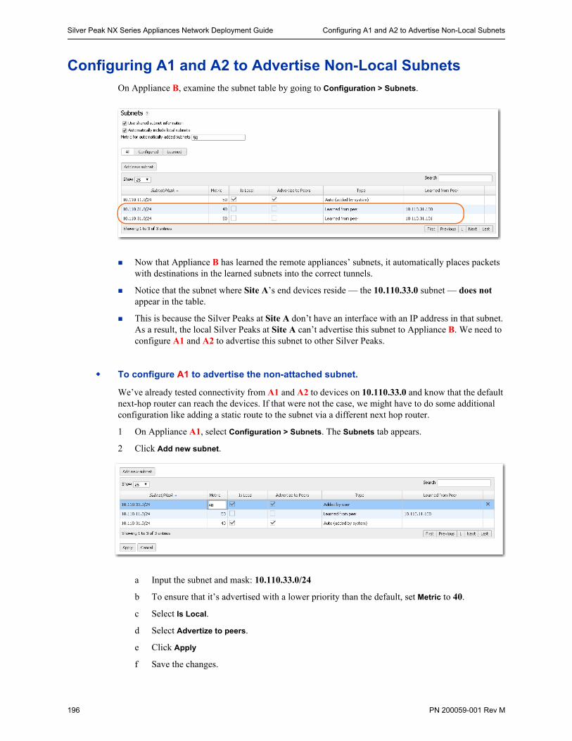
Silver Peak NX Series Appliances Network Deployment Guide Configuring A1 and A2 to Advertise Non-Local Subnets
196 PN 200059-001 Rev M
Configuring A1 and A2 to Advertise Non-Local SubnetsOn Appliance B, examine the subnet table by going to Configuration > Subnets.
Now that Appliance B has learned the remote appliances’ subnets, it automatically places packets with destinations in the learned subnets into the correct tunnels.
Notice that the subnet where Site A’s end devices reside — the 10.110.33.0 subnet — does not appear in the table.
This is because the Silver Peaks at Site A don’t have an interface with an IP address in that subnet. As a result, the local Silver Peaks at Site A can’t advertise this subnet to Appliance B. We need to configure A1 and A2 to advertise this subnet to other Silver Peaks.
To configure A1 to advertise the non-attached subnet.
We’ve already tested connectivity from A1 and A2 to devices on 10.110.33.0 and know that the default next-hop router can reach the devices. If that were not the case, we might have to do some additional configuration like adding a static route to the subnet via a different next hop router.
1 On Appliance A1, select Configuration > Subnets. The Subnets tab appears.
2 Click Add new subnet.
a Input the subnet and mask: 10.110.33.0/24
b To ensure that it’s advertised with a lower priority than the default, set Metric to 40.
c Select Is Local.
d Select Advertize to peers.
e Click Apply
f Save the changes.
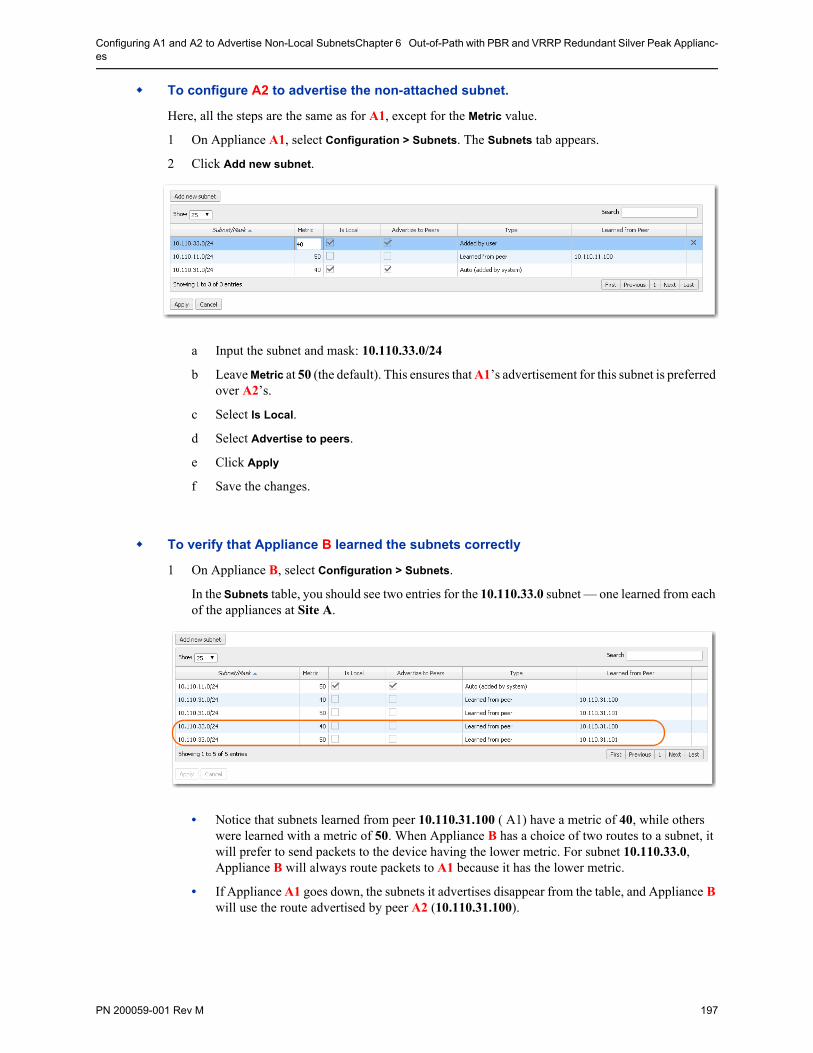
Configuring A1 and A2 to Advertise Non-Local SubnetsChapter 6 Out-of-Path with PBR and VRRP Redundant Silver Peak Applianc-es
PN 200059-001 Rev M 197
To configure A2 to advertise the non-attached subnet.
Here, all the steps are the same as for A1, except for the Metric value.
1 On Appliance A1, select Configuration > Subnets. The Subnets tab appears.
2 Click Add new subnet.
a Input the subnet and mask: 10.110.33.0/24
b Leave Metric at 50 (the default). This ensures that A1’s advertisement for this subnet is preferred over A2’s.
c Select Is Local.
d Select Advertise to peers.
e Click Apply
f Save the changes.
To verify that Appliance B learned the subnets correctly
1 On Appliance B, select Configuration > Subnets.
In the Subnets table, you should see two entries for the 10.110.33.0 subnet — one learned from each of the appliances at Site A.
• Notice that subnets learned from peer 10.110.31.100 ( A1) have a metric of 40, while others were learned with a metric of 50. When Appliance B has a choice of two routes to a subnet, it will prefer to send packets to the device having the lower metric. For subnet 10.110.33.0, Appliance B will always route packets to A1 because it has the lower metric.
• If Appliance A1 goes down, the subnets it advertises disappear from the table, and Appliance B will use the route advertised by peer A2 (10.110.31.100).
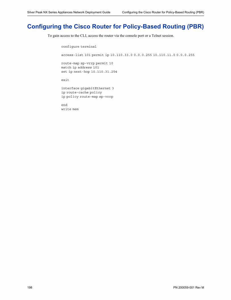
Silver Peak NX Series Appliances Network Deployment Guide Configuring the Cisco Router for Policy-Based Routing (PBR)
198 PN 200059-001 Rev M
Configuring the Cisco Router for Policy-Based Routing (PBR)To gain access to the CLI, access the router via the console port or a Telnet session.
configure terminal
access-list 101 permit ip 10.110.33.0 0.0.0.255 10.110.11.0 0.0.0.255
route-map sp-vrrp permit 10match ip address 101set ip next-hop 10.110.31.254
exit
interface gigabitEthernet 3 ip route-cache policyip policy route-map sp-vrrp
endwrite mem
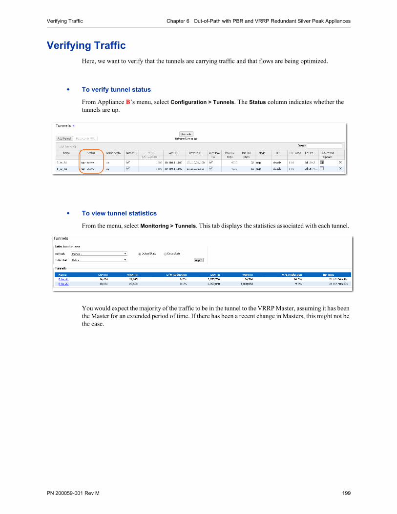
Verifying Traffic Chapter 6 Out-of-Path with PBR and VRRP Redundant Silver Peak Appliances
PN 200059-001 Rev M 199
Verifying TrafficHere, we want to verify that the tunnels are carrying traffic and that flows are being optimized.
To verify tunnel status
From Appliance B’s menu, select Configuration > Tunnels. The Status column indicates whether the tunnels are up.
To view tunnel statistics
From the menu, select Monitoring > Tunnels. This tab displays the statistics associated with each tunnel.
You would expect the majority of the traffic to be in the tunnel to the VRRP Master, assuming it has been the Master for an extended period of time. If there has been a recent change in Masters, this might not be the case.
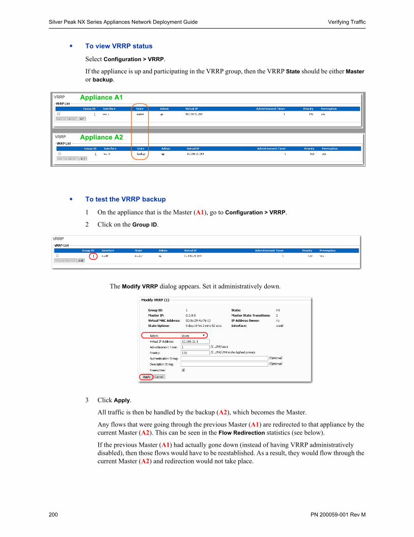
Silver Peak NX Series Appliances Network Deployment Guide Verifying Traffic
200 PN 200059-001 Rev M
To view VRRP status
Select Configuration > VRRP.
If the appliance is up and participating in the VRRP group, then the VRRP State should be either Master or backup.
To test the VRRP backup
1 On the appliance that is the Master (A1), go to Configuration > VRRP.
2 Click on the Group ID.
The Modify VRRP dialog appears. Set it administratively down.
3 Click Apply.
All traffic is then be handled by the backup (A2), which becomes the Master.
Any flows that were going through the previous Master (A1) are redirected to that appliance by the current Master (A2). This can be seen in the Flow Redirection statistics (see below).
If the previous Master (A1) had actually gone down (instead of having VRRP administratively disabled), then those flows would have to be reestablished. As a result, they would flow through the current Master (A2) and redirection would not take place.
Appliance A1
Appliance A2
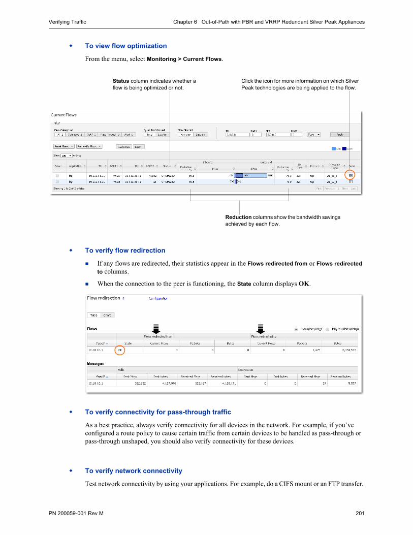
Verifying Traffic Chapter 6 Out-of-Path with PBR and VRRP Redundant Silver Peak Appliances
PN 200059-001 Rev M 201
To view flow optimization
From the menu, select Monitoring > Current Flows.
To verify flow redirection
If any flows are redirected, their statistics appear in the Flows redirected from or Flows redirected
to columns.
When the connection to the peer is functioning, the State column displays OK.
To verify connectivity for pass-through traffic
As a best practice, always verify connectivity for all devices in the network. For example, if you’ve configured a route policy to cause certain traffic from certain devices to be handled as pass-through or pass-through unshaped, you should also verify connectivity for these devices.
To verify network connectivity
Test network connectivity by using your applications. For example, do a CIFS mount or an FTP transfer.
Reduction columns show the bandwidth savings achieved by each flow.
Click the icon for more information on which Silver Peak technologies are being applied to the flow.
Status column indicates whether a flow is being optimized or not.

Silver Peak NX Series Appliances Network Deployment Guide Verifying Traffic
202 PN 200059-001 Rev M
PN 200059-001 Rev M 203
C H A P T E R 7
Out-of-Path with WCCP Redundant (Active/Active) Appliances
With Subnet Sharing in Use
This chapter provides a step-by-step example for setting up HA (high availability) Silver Peak appliances by using Web Cache Communications Protocol (WCCP) service with a Cisco router. If one appliance goes down, the other then handles all the traffic. In an Active/Active deployment, the peered appliances are also load balancing.
In this example, Site A deploys two active, redundant appliances (named A1 and A2) out-of-path (Router mode) and, remotely, Site B deploys a single appliance (named B), in-line (Bridge mode). The focus of this chapter is on the HA appliances; in practice, the remote appliance can be in either bridge or router mode.
In This Chapter Overview See page 204.
Configuring the Site A Router for WCCP See page 210.
Using the Initial Config Wizard with A1 See page 212.
Configuring WCCP on A1 See page 218.
Using the Initial Config Wizard with A2 See page 228.
Configuring WCCP on A2 See page 234.
Configuring Flow Redirection See page 235.
Using the Initial Config Wizard with B See page 239.
Verifying Appliance Connectivity See page 245.
Enabling Subnet Sharing See page 248.
Creating Tunnels See page 250.
Configuring A1 and A2 to Advertise Non-Local Subnets See page 253.
Verifying Traffic See page 255.
Best Practices See page 258.
Silver Peak NX Series Appliances Network Deployment Guide Overview
204 PN 200059-001 Rev M
OverviewWeb Cache Communications Protocol (WCCP) supports the redirection of any TCP or UDP connections to appliances participating in WCCP Service Groups. The appliance intercepts only those packets that have been redirected to it. The appliance accelerates traffic flows that match its Route Policy; all other traffic passes through the appliance unmodified.
The two active Silver Peak appliances participating in the WCCP service group must be deployed out-of-path (Router mode). In this example, those appliances are at Site A. For the purposes of this specific example, Site B at the remote end deploys the appliance in-line (Bridge mode); there is no inherent restriction on what mode it needs to be.
WCCP at Site A
Each of the peered appliances at headquarters uses WCCP to redirect traffic from the router to the appliances.
WCCP redirects all traffic that is in a WCCP Service Group shared by the appliance and router.
A service group consists of a set of WCCP-enabled routers and appliances that exchange WCCP messages. The routers send traffic to the appliances in the service group. The configuration of the service group determines how traffic is distributed to appliances in the service group.
To use WCCP, you must create a separate WCCP Service Group for each protocol (TCP and UDP) used in the SiteA-to-SiteB tunnel.
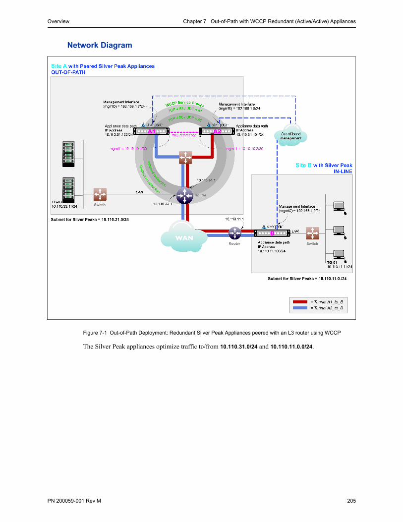
Overview Chapter 7 Out-of-Path with WCCP Redundant (Active/Active) Appliances
PN 200059-001 Rev M 205
Network Diagram
Figure 7-1 Out-of-Path Deployment: Redundant Silver Peak Appliances peered with an L3 router using WCCP
The Silver Peak appliances optimize traffic to/from 10.110.31.0/24 and 10.110.11.0.0/24.
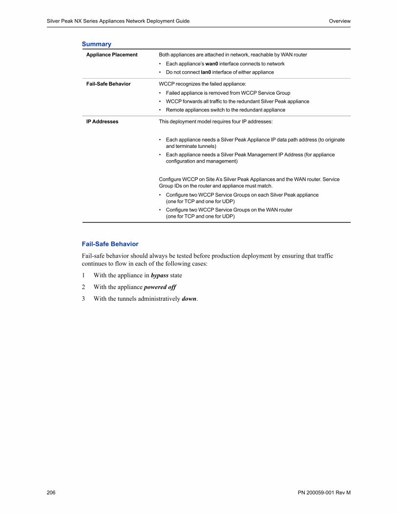
Silver Peak NX Series Appliances Network Deployment Guide Overview
206 PN 200059-001 Rev M
Summary
Fail-Safe Behavior
Fail-safe behavior should always be tested before production deployment by ensuring that traffic continues to flow in each of the following cases:
1 With the appliance in bypass state
2 With the appliance powered off
3 With the tunnels administratively down.
Appliance Placement Both appliances are attached in network, reachable by WAN router
• Each appliance’s wan0 interface connects to network
• Do not connect lan0 interface of either appliance
Fail-Safe Behavior WCCP recognizes the failed appliance:
• Failed appliance is removed from WCCP Service Group
• WCCP forwards all traffic to the redundant Silver Peak appliance
• Remote appliances switch to the redundant appliance
IP Addresses This deployment model requires four IP addresses:
• Each appliance needs a Silver Peak Appliance IP data path address (to originate and terminate tunnels)
• Each appliance needs a Silver Peak Management IP Address (for appliance configuration and management)
Configure WCCP on Site A’s Silver Peak Appliances and the WAN router. Service Group IDs on the router and appliance must match.
• Configure two WCCP Service Groups on each Silver Peak appliance (one for TCP and one for UDP)
• Configure two WCCP Service Groups on the WAN router (one for TCP and one for UDP)
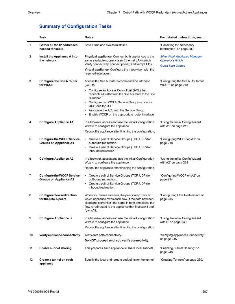
Overview Chapter 7 Out-of-Path with WCCP Redundant (Active/Active) Appliances
PN 200059-001 Rev M 207
Summary of Configuration Tasks
Task Notes For detailed instructions, see...
1 Gather all the IP addresses needed for setup
Saves time and avoids mistakes. “Collecting the Necessary Information” on page 209.
2 Install the Appliance A into the network
Physical appliance: Connect both appliances to the same available subnet via an Ethernet LAN switch. Verify connectivity, connect power, and verify LEDs.
Virtual appliance: Configure the hypervisor, with the required interfaces.
Silver Peak Appliance Manager Operator’s Guide
Quick Start Guides
3 Configure the Site A router for WCCP
Access the Site A router’s command line interface (CLI) to:
• Configure an Access Control List (ACL) that redirects all traffic from the Site A subnet to the Site B subnet
• Configure two WCCP Service Groups — one for UDP, one for TCP
• Associate the ACL with the Service Group• Enable WCCP on the appropriate router interface
“Configuring the Site A Router for WCCP” on page 210
4 Configure Appliance A1 In a browser, access and use the Initial Configuration Wizard to configure the appliance.
Reboot the appliance after finishing the configuration.
“Using the Initial Config Wizard with A1” on page 212.
5 Configure the WCCP Service Groups on Appliance A1
• Create a pair of Service Groups (TCP, UDP) for outbound redirection.
• Create a pair of Service Groups (TCP, UDP) for inbound redirection.
“Configuring WCCP on A1” on page 218
6 Configure Appliance A2 In a browser, access and use the Initial Configuration Wizard to configure the appliance.
Reboot the appliance after finishing the configuration.
“Using the Initial Config Wizard with A2” on page 228
7 Configure the WCCP Service Groups on Appliance A2
• Create a pair of Service Groups (TCP, UDP) for outbound redirection.
• Create a pair of Service Groups (TCP, UDP) for inbound redirection.
“Configuring WCCP on A2” on page 234
8 Configure flow redirection for the Site A peers
When you create a cluster, the peers keep track of which appliance owns each flow. If the path between client and server isn’t the same in both directions, the flow is redirected to the appliance that first saw it and “owns” it.
“Configuring Flow Redirection” on page 235
9 Configure Appliance B In a browser, access and use the Initial Configuration Wizard to configure the appliance.
Reboot the appliance after finishing the configuration.
“Using the Initial Config Wizard with B” on page 239
10 Verify appliance connectivity Tests data path connectivity.
Do NOT proceed until you verify connectivity.
“Verifying Appliance Connectivity” on page 245
11 Enable subnet sharing This prepares each appliance to share local subnets. “Enabling Subnet Sharing” on page 248.
12 Create a tunnel on each appliance
Specify the local and remote endpoints for the tunnel. “Creating Tunnels” on page 250.

Silver Peak NX Series Appliances Network Deployment Guide Overview
208 PN 200059-001 Rev M
13 Manually add Site A’s non-local subnets
Manually add subnets that aren’t directly connected to an appliance interface so they can be advertised.
“Configuring A1 and A2 to Advertise Non-Local Subnets” on page 253
14 Test the connectivity from both ends
Verify that the tunnel is up and that flows are being optimized.
“Verifying Traffic” on page 255
Task Notes For detailed instructions, see...
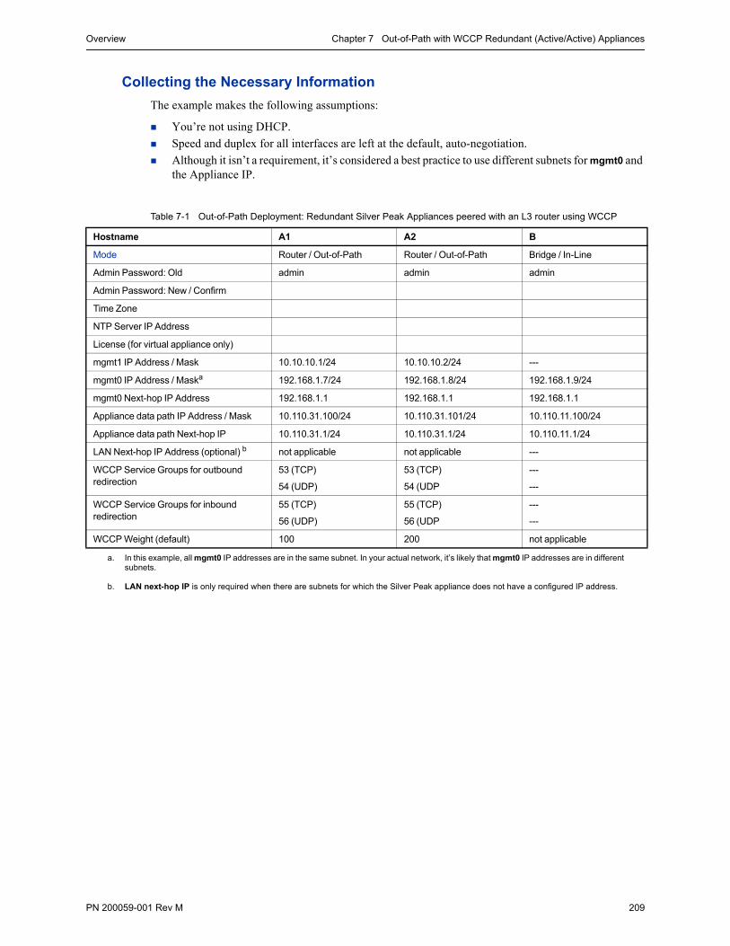
Overview Chapter 7 Out-of-Path with WCCP Redundant (Active/Active) Appliances
PN 200059-001 Rev M 209
Collecting the Necessary Information
The example makes the following assumptions:
You’re not using DHCP.
Speed and duplex for all interfaces are left at the default, auto-negotiation.
Although it isn’t a requirement, it’s considered a best practice to use different subnets for mgmt0 and the Appliance IP.
Table 7-1 Out-of-Path Deployment: Redundant Silver Peak Appliances peered with an L3 router using WCCP
Hostname A1 A2 B
Mode Router / Out-of-Path Router / Out-of-Path Bridge / In-Line
Admin Password: Old admin admin admin
Admin Password: New / Confirm
Time Zone
NTP Server IP Address
License (for virtual appliance only)
mgmt1 IP Address / Mask 10.10.10.1/24 10.10.10.2/24 ---
mgmt0 IP Address / Maska 192.168.1.7/24 192.168.1.8/24 192.168.1.9/24
mgmt0 Next-hop IP Address 192.168.1.1 192.168.1.1 192.168.1.1
Appliance data path IP Address / Mask 10.110.31.100/24 10.110.31.101/24 10.110.11.100/24
Appliance data path Next-hop IP 10.110.31.1/24 10.110.31.1/24 10.110.11.1/24
LAN Next-hop IP Address (optional) b not applicable not applicable ---
WCCP Service Groups for outbound redirection
53 (TCP)
54 (UDP)
53 (TCP)
54 (UDP
---
---
WCCP Service Groups for inbound redirection
55 (TCP)
56 (UDP)
55 (TCP)
56 (UDP
---
---
WCCP Weight (default) 100 200 not applicable
a. In this example, all mgmt0 IP addresses are in the same subnet. In your actual network, it’s likely that mgmt0 IP addresses are in different subnets.
b. LAN next-hop IP is only required when there are subnets for which the Silver Peak appliance does not have a configured IP address.
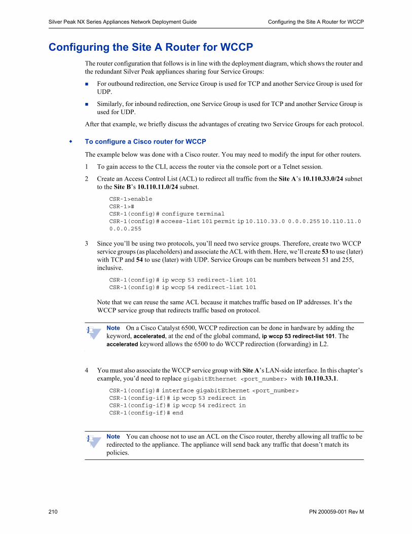
Silver Peak NX Series Appliances Network Deployment Guide Configuring the Site A Router for WCCP
210 PN 200059-001 Rev M
Configuring the Site A Router for WCCPThe router configuration that follows is in line with the deployment diagram, which shows the router and the redundant Silver Peak appliances sharing four Service Groups:
For outbound redirection, one Service Group is used for TCP and another Service Group is used for UDP.
Similarly, for inbound redirection, one Service Group is used for TCP and another Service Group is used for UDP.
After that example, we briefly discuss the advantages of creating two Service Groups for each protocol.
To configure a Cisco router for WCCP
The example below was done with a Cisco router. You may need to modify the input for other routers.
1 To gain access to the CLI, access the router via the console port or a Telnet session.
2 Create an Access Control List (ACL) to redirect all traffic from the Site A’s 10.110.33.0/24 subnet to the Site B’s 10.110.11.0/24 subnet.
CSR-1>enableCSR-1>#CSR-1(config)# configure terminalCSR-1(config)# access-list 101 permit ip 10.110.33.0 0.0.0.255 10.110.11.0 0.0.0.255
3 Since you’ll be using two protocols, you’ll need two service groups. Therefore, create two WCCP service groups (as placeholders) and associate the ACL with them. Here, we’ll create 53 to use (later) with TCP and 54 to use (later) with UDP. Service Groups can be numbers between 51 and 255, inclusive.
CSR-1(config)# ip wccp 53 redirect-list 101CSR-1(config)# ip wccp 54 redirect-list 101
Note that we can reuse the same ACL because it matches traffic based on IP addresses. It’s the WCCP service group that redirects traffic based on protocol.
Note On a Cisco Catalyst 6500, WCCP redirection can be done in hardware by adding the keyword, accelerated, at the end of the global command, ip wccp 53 redirect-list 101. The accelerated keyword allows the 6500 to do WCCP redirection (forwarding) in L2.
4 You must also associate the WCCP service group with Site A’s LAN-side interface. In this chapter’s example, you’d need to replace gigabitEthernet <port_number> with 10.110.33.1.
CSR-1(config)# interface gigabitEthernet <port_number>CSR-1(config-if)# ip wccp 53 redirect inCSR-1(config-if)# ip wccp 54 redirect inCSR-1(config-if)# end
Note You can choose not to use an ACL on the Cisco router, thereby allowing all traffic to be redirected to the appliance. The appliance will send back any traffic that doesn’t match its policies.
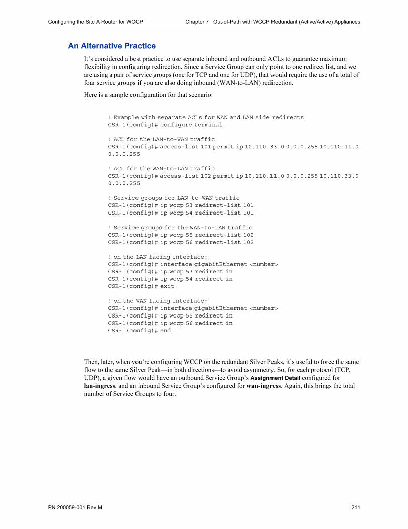
Configuring the Site A Router for WCCP Chapter 7 Out-of-Path with WCCP Redundant (Active/Active) Appliances
PN 200059-001 Rev M 211
An Alternative Practice
It’s considered a best practice to use separate inbound and outbound ACLs to guarantee maximum flexibility in configuring redirection. Since a Service Group can only point to one redirect list, and we are using a pair of service groups (one for TCP and one for UDP), that would require the use of a total of four service groups if you are also doing inbound (WAN-to-LAN) redirection.
Here is a sample configuration for that scenario:
! Example with separate ACLs for WAN and LAN side redirectsCSR-1(config)# configure terminal
! ACL for the LAN-to-WAN trafficCSR-1(config)# access-list 101 permit ip 10.110.33.0 0.0.0.255 10.110.11.0 0.0.0.255
! ACL for the WAN-to-LAN trafficCSR-1(config)# access-list 102 permit ip 10.110.11.0 0.0.0.255 10.110.33.0 0.0.0.255
! Service groups for LAN-to-WAN trafficCSR-1(config)# ip wccp 53 redirect-list 101CSR-1(config)# ip wccp 54 redirect-list 101
! Service groups for the WAN-to-LAN trafficCSR-1(config)# ip wccp 55 redirect-list 102CSR-1(config)# ip wccp 56 redirect-list 102
! on the LAN facing interface:CSR-1(config)# interface gigabitEthernet <number>CSR-1(config)# ip wccp 53 redirect inCSR-1(config)# ip wccp 54 redirect inCSR-1(config)# exit
! on the WAN facing interface:CSR-1(config)# interface gigabitEthernet <number>CSR-1(config)# ip wccp 55 redirect inCSR-1(config)# ip wccp 56 redirect inCSR-1(config)# end
Then, later, when you’re configuring WCCP on the redundant Silver Peaks, it’s useful to force the same flow to the same Silver Peak—in both directions—to avoid asymmetry. So, for each protocol (TCP, UDP), a given flow would have an outbound Service Group’s Assignment Detail configured for lan-ingress, and an inbound Service Group’s configured for wan-ingress. Again, this brings the total number of Service Groups to four.
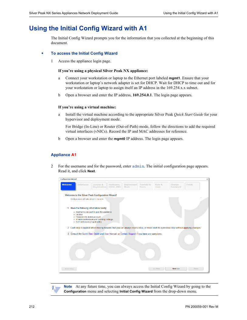
Silver Peak NX Series Appliances Network Deployment Guide Using the Initial Config Wizard with A1
212 PN 200059-001 Rev M
Using the Initial Config Wizard with A1The Initial Config Wizard prompts you for the information that you collected at the beginning of this document.
To access the Initial Config Wizard
1 Access the appliance login page.
If you’re using a physical Silver Peak NX appliance:
a Connect your workstation or laptop to the Ethernet port labeled mgmt1. Ensure that your workstation or laptop’s network adapter is set for DHCP. Wait for DHCP to time out and for your workstation or laptop to assign itself an IP address in the 169.254.x.x subnet.
b Open a browser and enter the IP address, 169.254.0.1. The login page appears.
If you’re using a virtual machine:
a Install the virtual machine according to the appropriate Silver Peak Quick Start Guide for your hypervisor and deployment mode.
For Bridge (In-Line) or Router (Out-of-Path) mode, follow the directions to add the required virtual interfaces (vNICs). Record the IP and MAC addresses for reference.
b Open a browser and enter the mgmt0 IP address. The login page appears.
Appliance A1
2 For the username and for the password, enter admin. The initial configuration page appears.Read it, and click Next.
Note At any future time, you can always access the Initial Config Wizard by going to the Configuration menu and selecting Initial Config Wizard from the drop-down menu.
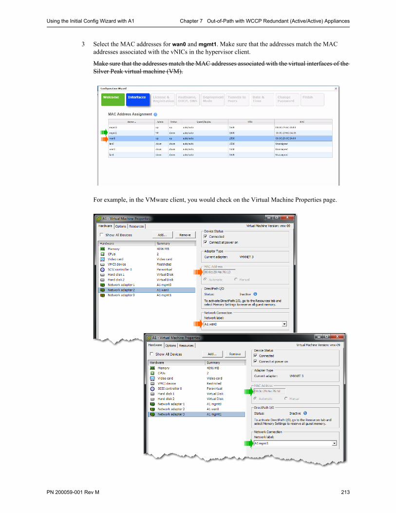
Using the Initial Config Wizard with A1 Chapter 7 Out-of-Path with WCCP Redundant (Active/Active) Appliances
PN 200059-001 Rev M 213
3 Select the MAC addresses for wan0 and mgmt1. Make sure that the addresses match the MAC addresses associated with the vNICs in the hypervisor client.
Make sure that the addresses match the MAC addresses associated with the virtual interfaces of the Silver Peak virtual machine (VM).
For example, in the VMware client, you would check on the Virtual Machine Properties page.

Silver Peak NX Series Appliances Network Deployment Guide Using the Initial Config Wizard with A1
214 PN 200059-001 Rev M
4 Click Apply & Next. The License & Registration page appears. Enter the license details.
5 Click Apply & Next. The Management Interface (mgmt0) page appears. Enter the appliance name and management IP details.
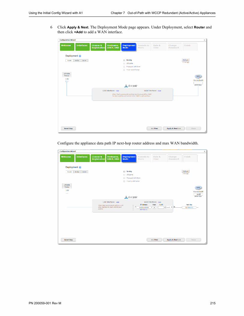
Using the Initial Config Wizard with A1 Chapter 7 Out-of-Path with WCCP Redundant (Active/Active) Appliances
PN 200059-001 Rev M 215
6 Click Apply & Next. The Deployment Mode page appears. Under Deployment, select Router and then click +Add to add a WAN interface.
Configure the appliance data path IP next-hop router address and max WAN bandwidth.

Silver Peak NX Series Appliances Network Deployment Guide Using the Initial Config Wizard with A1
216 PN 200059-001 Rev M
7 Click Apply & Next.
On this page, leave Auto Tunnel and Auto Subnet Sharing deselected. We’ll take care of these features later. Although it’s not technically necessary to deselect either one, we have chosen to do so for tutorial purposes later in this chapter.
8 Click Apply & Next. The Date/Time Setting page appears. Configure the time zone and NTP server.
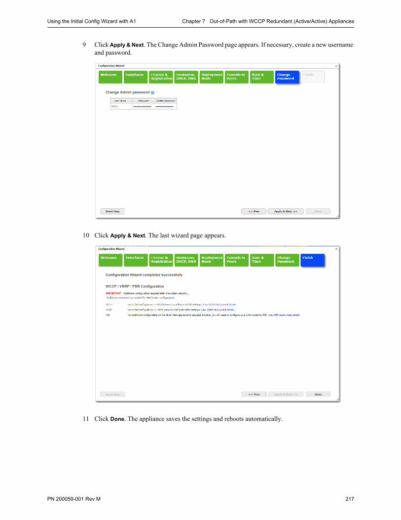
Using the Initial Config Wizard with A1 Chapter 7 Out-of-Path with WCCP Redundant (Active/Active) Appliances
PN 200059-001 Rev M 217
9 Click Apply & Next. The Change Admin Password page appears. If necessary, create a new username and password.
10 Click Apply & Next. The last wizard page appears.
11 Click Done. The appliance saves the settings and reboots automatically.
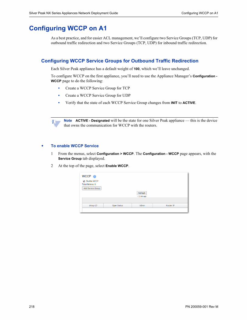
Silver Peak NX Series Appliances Network Deployment Guide Configuring WCCP on A1
218 PN 200059-001 Rev M
Configuring WCCP on A1As a best practice, and for easier ACL management, we’ll configure two Service Groups (TCP, UDP) for outbound traffic redirection and two Service Groups (TCP, UDP) for inbound traffic redirection.
Configuring WCCP Service Groups for Outbound Traffic Redirection
Each Silver Peak appliance has a default weight of 100, which we’ll leave unchanged.
To configure WCCP on the first appliance, you’ll need to use the Appliance Manager’s Configuration -
WCCP page to do the following:
• Create a WCCP Service Group for TCP
• Create a WCCP Service Group for UDP
• Verify that the state of each WCCP Service Group changes from INIT to ACTIVE.
Note ACTIVE - Designated will be the state for one Silver Peak appliance — this is the device that owns the communication for WCCP with the routers.
To enable WCCP Service
1 From the menus, select Configuration > WCCP. The Configuration - WCCP page appears, with the Service Group tab displayed.
2 At the top of the page, select Enable WCCP.
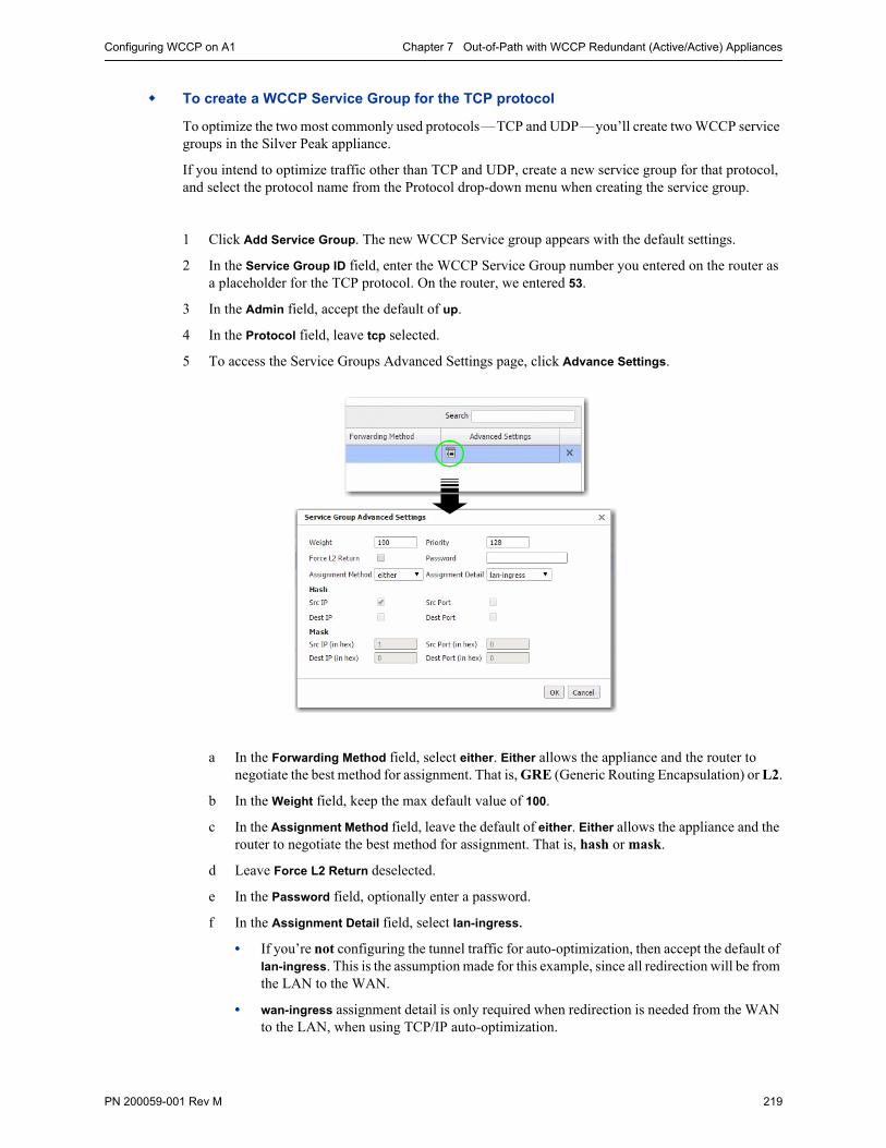
Configuring WCCP on A1 Chapter 7 Out-of-Path with WCCP Redundant (Active/Active) Appliances
PN 200059-001 Rev M 219
To create a WCCP Service Group for the TCP protocol
To optimize the two most commonly used protocols—TCP and UDP—you’ll create two WCCP service groups in the Silver Peak appliance.
If you intend to optimize traffic other than TCP and UDP, create a new service group for that protocol, and select the protocol name from the Protocol drop-down menu when creating the service group.
1 Click Add Service Group. The new WCCP Service group appears with the default settings.
2 In the Service Group ID field, enter the WCCP Service Group number you entered on the router as a placeholder for the TCP protocol. On the router, we entered 53.
3 In the Admin field, accept the default of up.
4 In the Protocol field, leave tcp selected.
5 To access the Service Groups Advanced Settings page, click Advance Settings.
a In the Forwarding Method field, select either. Either allows the appliance and the router to negotiate the best method for assignment. That is, GRE (Generic Routing Encapsulation) or L2.
b In the Weight field, keep the max default value of 100.
c In the Assignment Method field, leave the default of either. Either allows the appliance and the router to negotiate the best method for assignment. That is, hash or mask.
d Leave Force L2 Return deselected.
e In the Password field, optionally enter a password.
f In the Assignment Detail field, select lan-ingress.
• If you’re not configuring the tunnel traffic for auto-optimization, then accept the default of lan-ingress. This is the assumption made for this example, since all redirection will be from the LAN to the WAN.
• wan-ingress assignment detail is only required when redirection is needed from the WAN to the LAN, when using TCP/IP auto-optimization.
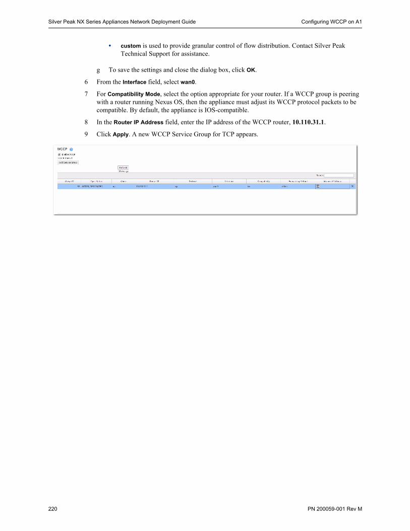
Silver Peak NX Series Appliances Network Deployment Guide Configuring WCCP on A1
220 PN 200059-001 Rev M
• custom is used to provide granular control of flow distribution. Contact Silver Peak Technical Support for assistance.
g To save the settings and close the dialog box, click OK.
6 From the Interface field, select wan0.
7 For Compatibility Mode, select the option appropriate for your router. If a WCCP group is peering with a router running Nexus OS, then the appliance must adjust its WCCP protocol packets to be compatible. By default, the appliance is IOS-compatible.
8 In the Router IP Address field, enter the IP address of the WCCP router, 10.110.31.1.
9 Click Apply. A new WCCP Service Group for TCP appears.
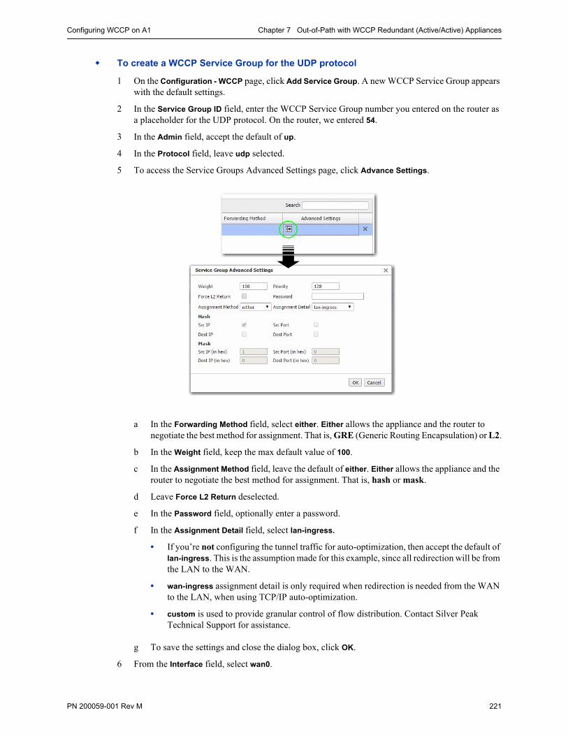
Configuring WCCP on A1 Chapter 7 Out-of-Path with WCCP Redundant (Active/Active) Appliances
PN 200059-001 Rev M 221
To create a WCCP Service Group for the UDP protocol
1 On the Configuration - WCCP page, click Add Service Group. A new WCCP Service Group appears with the default settings.
2 In the Service Group ID field, enter the WCCP Service Group number you entered on the router as a placeholder for the UDP protocol. On the router, we entered 54.
3 In the Admin field, accept the default of up.
4 In the Protocol field, leave udp selected.
5 To access the Service Groups Advanced Settings page, click Advance Settings.
a In the Forwarding Method field, select either. Either allows the appliance and the router to negotiate the best method for assignment. That is, GRE (Generic Routing Encapsulation) or L2.
b In the Weight field, keep the max default value of 100.
c In the Assignment Method field, leave the default of either. Either allows the appliance and the router to negotiate the best method for assignment. That is, hash or mask.
d Leave Force L2 Return deselected.
e In the Password field, optionally enter a password.
f In the Assignment Detail field, select lan-ingress.
• If you’re not configuring the tunnel traffic for auto-optimization, then accept the default of lan-ingress. This is the assumption made for this example, since all redirection will be from the LAN to the WAN.
• wan-ingress assignment detail is only required when redirection is needed from the WAN to the LAN, when using TCP/IP auto-optimization.
• custom is used to provide granular control of flow distribution. Contact Silver Peak Technical Support for assistance.
g To save the settings and close the dialog box, click OK.
6 From the Interface field, select wan0.

Silver Peak NX Series Appliances Network Deployment Guide Configuring WCCP on A1
222 PN 200059-001 Rev M
a For Compatibility Mode, select the option appropriate for your router. If a WCCP group is peering with a router running Nexus OS, then the appliance must adjust its WCCP protocol packets to be compatible. By default, the appliance is IOS-compatible.
b In the Router IP Address field, enter the IP address of the WCCP router, 10.110.31.1.
7 Click Apply.
• The data entry area disappears, and the table displays the new WCCP Service Group for UDP.
• State changes from INIT to ACTIVE, DESIGNATED.
• This means that the WCCP protocol is working properly with the router, and that this appliance is Primary and Active.
8 Click Save Changes.
State Definition
INIT WCCP Service Group initialization
ACTIVE Active WCCP Service group
BACKUP Backup WCCP Service group
- Designated [Used as a modifier for ACTIVE or BACKUP].
Appliance with the lowest IP address in a WCCP group that notifies Routers how to redirect traffic.
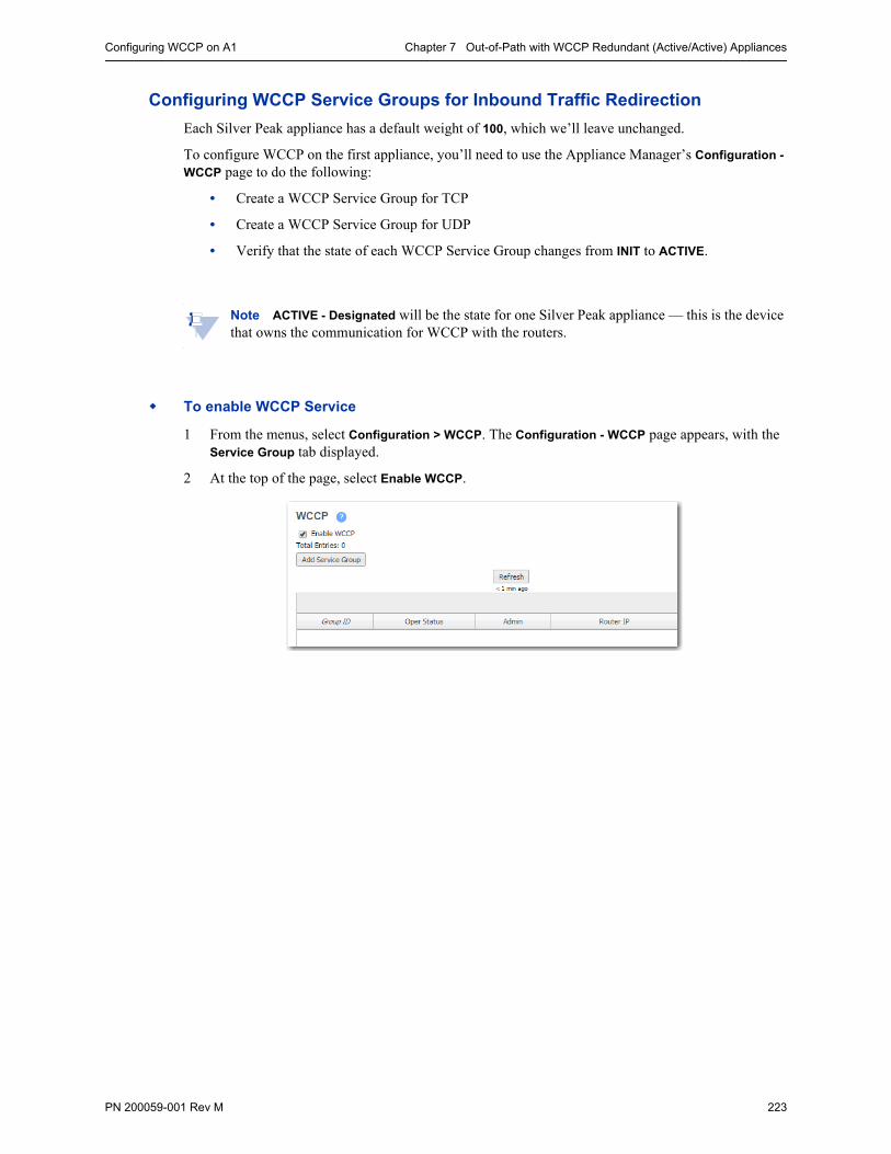
Configuring WCCP on A1 Chapter 7 Out-of-Path with WCCP Redundant (Active/Active) Appliances
PN 200059-001 Rev M 223
Configuring WCCP Service Groups for Inbound Traffic Redirection
Each Silver Peak appliance has a default weight of 100, which we’ll leave unchanged.
To configure WCCP on the first appliance, you’ll need to use the Appliance Manager’s Configuration -
WCCP page to do the following:
• Create a WCCP Service Group for TCP
• Create a WCCP Service Group for UDP
• Verify that the state of each WCCP Service Group changes from INIT to ACTIVE.
Note ACTIVE - Designated will be the state for one Silver Peak appliance — this is the device that owns the communication for WCCP with the routers.
To enable WCCP Service
1 From the menus, select Configuration > WCCP. The Configuration - WCCP page appears, with the Service Group tab displayed.
2 At the top of the page, select Enable WCCP.
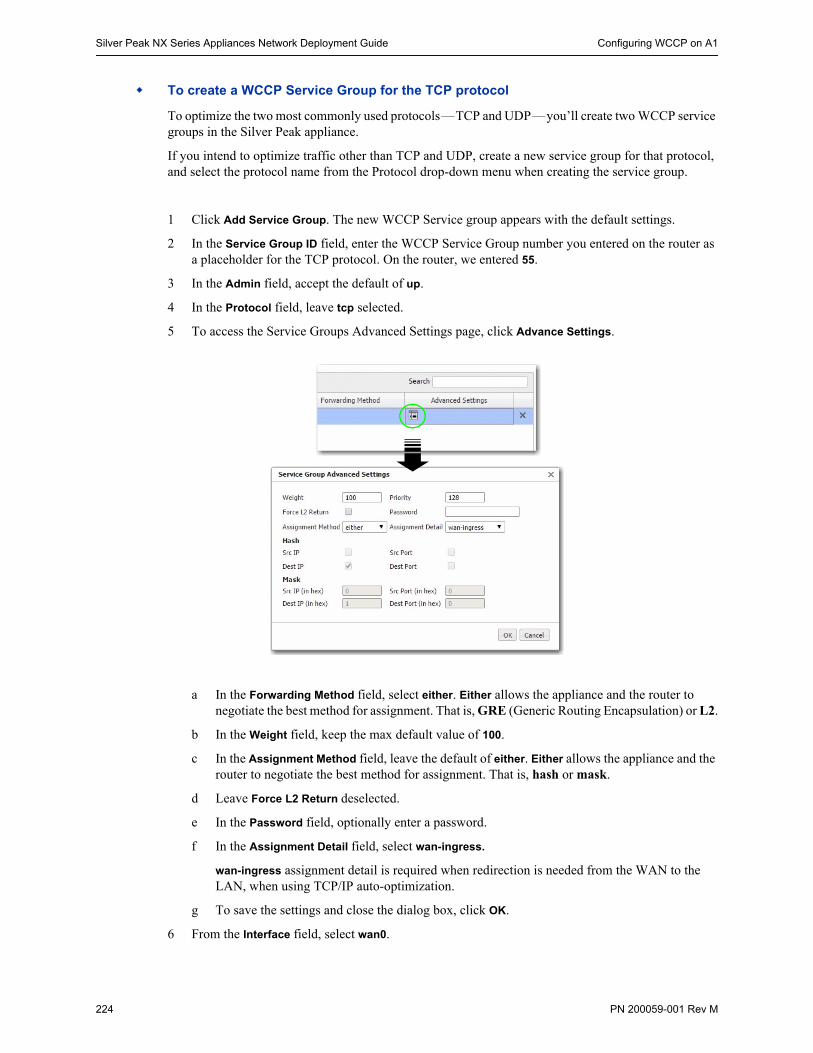
Silver Peak NX Series Appliances Network Deployment Guide Configuring WCCP on A1
224 PN 200059-001 Rev M
To create a WCCP Service Group for the TCP protocol
To optimize the two most commonly used protocols—TCP and UDP—you’ll create two WCCP service groups in the Silver Peak appliance.
If you intend to optimize traffic other than TCP and UDP, create a new service group for that protocol, and select the protocol name from the Protocol drop-down menu when creating the service group.
1 Click Add Service Group. The new WCCP Service group appears with the default settings.
2 In the Service Group ID field, enter the WCCP Service Group number you entered on the router as a placeholder for the TCP protocol. On the router, we entered 55.
3 In the Admin field, accept the default of up.
4 In the Protocol field, leave tcp selected.
5 To access the Service Groups Advanced Settings page, click Advance Settings.
a In the Forwarding Method field, select either. Either allows the appliance and the router to negotiate the best method for assignment. That is, GRE (Generic Routing Encapsulation) or L2.
b In the Weight field, keep the max default value of 100.
c In the Assignment Method field, leave the default of either. Either allows the appliance and the router to negotiate the best method for assignment. That is, hash or mask.
d Leave Force L2 Return deselected.
e In the Password field, optionally enter a password.
f In the Assignment Detail field, select wan-ingress.
wan-ingress assignment detail is required when redirection is needed from the WAN to the LAN, when using TCP/IP auto-optimization.
g To save the settings and close the dialog box, click OK.
6 From the Interface field, select wan0.

Configuring WCCP on A1 Chapter 7 Out-of-Path with WCCP Redundant (Active/Active) Appliances
PN 200059-001 Rev M 225
7 For Compatibility Mode, select the option appropriate for your router. If a WCCP group is peering with a router running Nexus OS, then the appliance must adjust its WCCP protocol packets to be compatible. By default, the appliance is IOS-compatible.
8 In the Router IP Address field, enter the IP address of the WCCP router, 10.110.31.1.
9 Click Apply. A new WCCP Service Group for TCP appears.
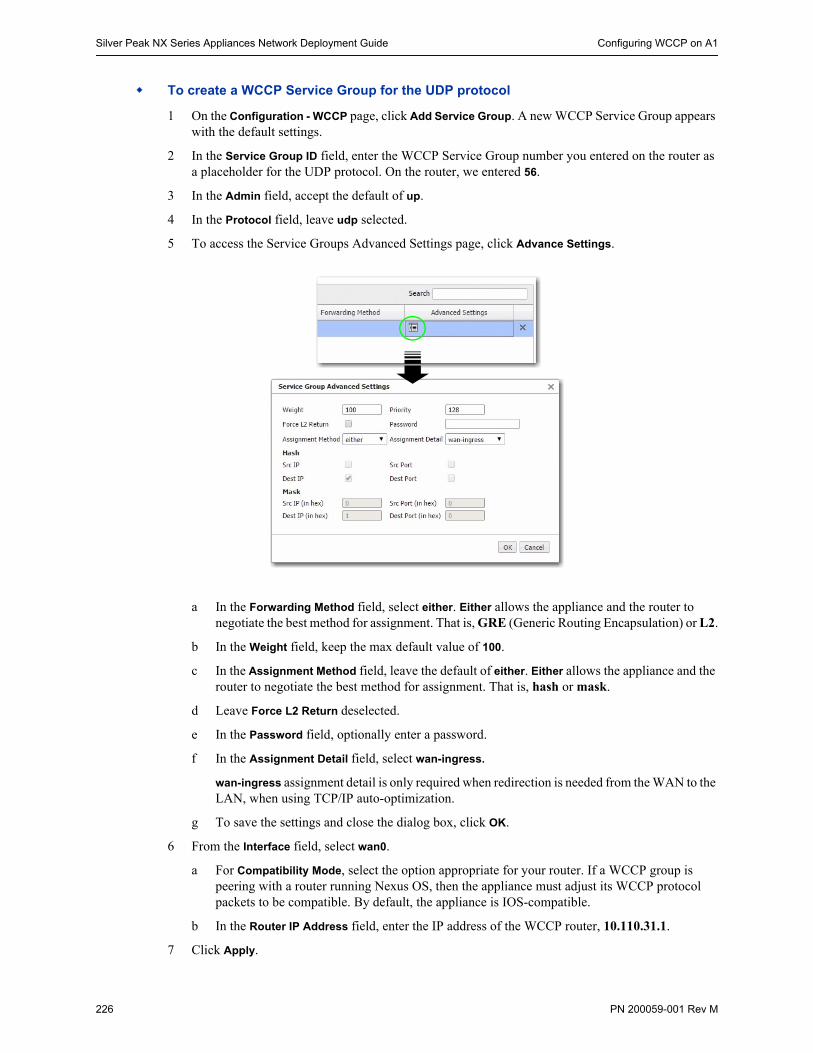
Silver Peak NX Series Appliances Network Deployment Guide Configuring WCCP on A1
226 PN 200059-001 Rev M
To create a WCCP Service Group for the UDP protocol
1 On the Configuration - WCCP page, click Add Service Group. A new WCCP Service Group appears with the default settings.
2 In the Service Group ID field, enter the WCCP Service Group number you entered on the router as a placeholder for the UDP protocol. On the router, we entered 56.
3 In the Admin field, accept the default of up.
4 In the Protocol field, leave udp selected.
5 To access the Service Groups Advanced Settings page, click Advance Settings.
a In the Forwarding Method field, select either. Either allows the appliance and the router to negotiate the best method for assignment. That is, GRE (Generic Routing Encapsulation) or L2.
b In the Weight field, keep the max default value of 100.
c In the Assignment Method field, leave the default of either. Either allows the appliance and the router to negotiate the best method for assignment. That is, hash or mask.
d Leave Force L2 Return deselected.
e In the Password field, optionally enter a password.
f In the Assignment Detail field, select wan-ingress.
wan-ingress assignment detail is only required when redirection is needed from the WAN to the LAN, when using TCP/IP auto-optimization.
g To save the settings and close the dialog box, click OK.
6 From the Interface field, select wan0.
a For Compatibility Mode, select the option appropriate for your router. If a WCCP group is peering with a router running Nexus OS, then the appliance must adjust its WCCP protocol packets to be compatible. By default, the appliance is IOS-compatible.
b In the Router IP Address field, enter the IP address of the WCCP router, 10.110.31.1.
7 Click Apply.
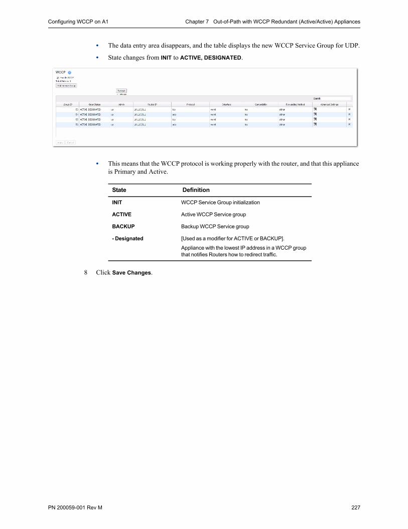
Configuring WCCP on A1 Chapter 7 Out-of-Path with WCCP Redundant (Active/Active) Appliances
PN 200059-001 Rev M 227
• The data entry area disappears, and the table displays the new WCCP Service Group for UDP.
• State changes from INIT to ACTIVE, DESIGNATED.
• This means that the WCCP protocol is working properly with the router, and that this appliance is Primary and Active.
8 Click Save Changes.
State Definition
INIT WCCP Service Group initialization
ACTIVE Active WCCP Service group
BACKUP Backup WCCP Service group
- Designated [Used as a modifier for ACTIVE or BACKUP].
Appliance with the lowest IP address in a WCCP group that notifies Routers how to redirect traffic.

Silver Peak NX Series Appliances Network Deployment Guide Using the Initial Config Wizard with A2
228 PN 200059-001 Rev M
Using the Initial Config Wizard with A2The Initial Config Wizardprompts you fort he information that you collected at the beginning of this document.
To access the Initial Config Wizard
1 Access the appliance login page.
If you’re using a physical Silver Peak NX appliance:
a Connect your workstation or laptop to the Ethernet port labeled mgmt1. Ensure that your workstation or laptop’s network adapter is set for DHCP. Wait for DHCP to time out and for your workstation or laptop to assign itself an IP address in the 169.254.x.x subnet.
b Open a browser and enter the IP address, 169.254.0.1. The login page appears.
If you’re using a virtual machine:
a Install the virtual machine according to the appropriate Silver Peak Quick Start Guide for your hypervisor and deployment mode.
For Bridge (In-Line) or Router (Out-of-Path) mode, follow the directions to add the required virtual interfaces (vNICs). Record the IP and MAC addresses for reference.
b Open a browser and enter the mgmt0 IP address. The login page appears.
Appliance A2
2 For the username and for the password, enter admin. The initial configuration page appears.Read it, and click Next.
Note At any future time, you can always access the Initial Config Wizard by going to the Configuration menu and selecting Initial Config Wizard from the drop-down menu.
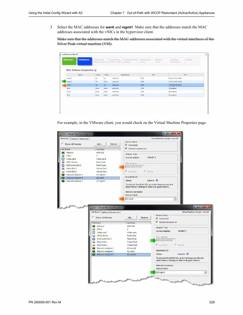
Using the Initial Config Wizard with A2 Chapter 7 Out-of-Path with WCCP Redundant (Active/Active) Appliances
PN 200059-001 Rev M 229
3 Select the MAC addresses for wan0 and mgmt1. Make sure that the addresses match the MAC addresses associated with the vNICs in the hypervisor client.
Make sure that the addresses match the MAC addresses associated with the virtual interfaces of the Silver Peak virtual machine (VM).
For example, in the VMware client, you would check on the Virtual Machine Properties page.
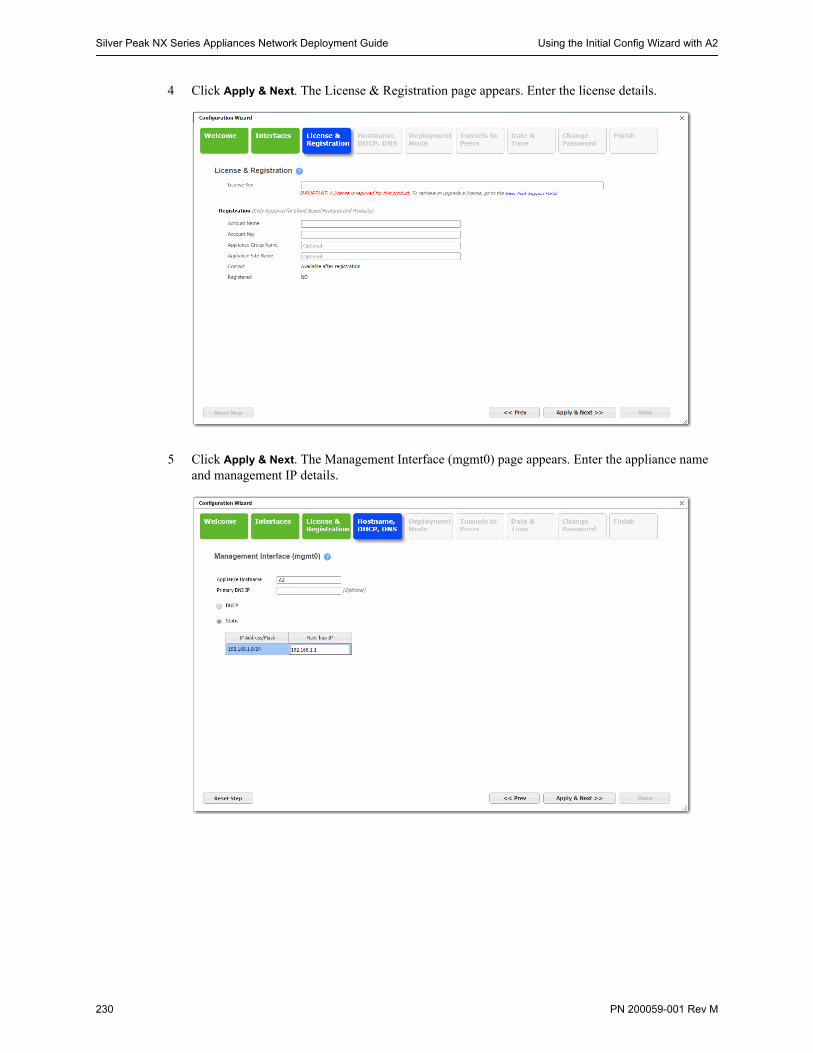
Silver Peak NX Series Appliances Network Deployment Guide Using the Initial Config Wizard with A2
230 PN 200059-001 Rev M
4 Click Apply & Next. The License & Registration page appears. Enter the license details.
5 Click Apply & Next. The Management Interface (mgmt0) page appears. Enter the appliance name and management IP details.
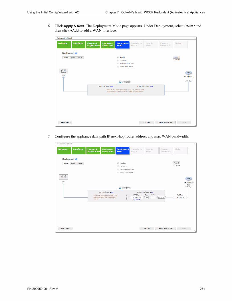
Using the Initial Config Wizard with A2 Chapter 7 Out-of-Path with WCCP Redundant (Active/Active) Appliances
PN 200059-001 Rev M 231
6 Click Apply & Next. The Deployment Mode page appears. Under Deployment, select Router and then click +Add to add a WAN interface.
7 Configure the appliance data path IP next-hop router address and max WAN bandwidth.
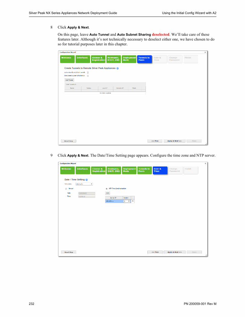
Silver Peak NX Series Appliances Network Deployment Guide Using the Initial Config Wizard with A2
232 PN 200059-001 Rev M
8 Click Apply & Next.
On this page, leave Auto Tunnel and Auto Subnet Sharing deselected. We’ll take care of these features later. Although it’s not technically necessary to deselect either one, we have chosen to do so for tutorial purposes later in this chapter.
9 Click Apply & Next. The Date/Time Setting page appears. Configure the time zone and NTP server.

Using the Initial Config Wizard with A2 Chapter 7 Out-of-Path with WCCP Redundant (Active/Active) Appliances
PN 200059-001 Rev M 233
10 Click Apply & Next. The Change Admin Password page appears. If necessary, create a new username and password.
11 Click Apply & Next. The last wizard page appears.
12 Click Done. The appliance saves the settings and reboots automatically.
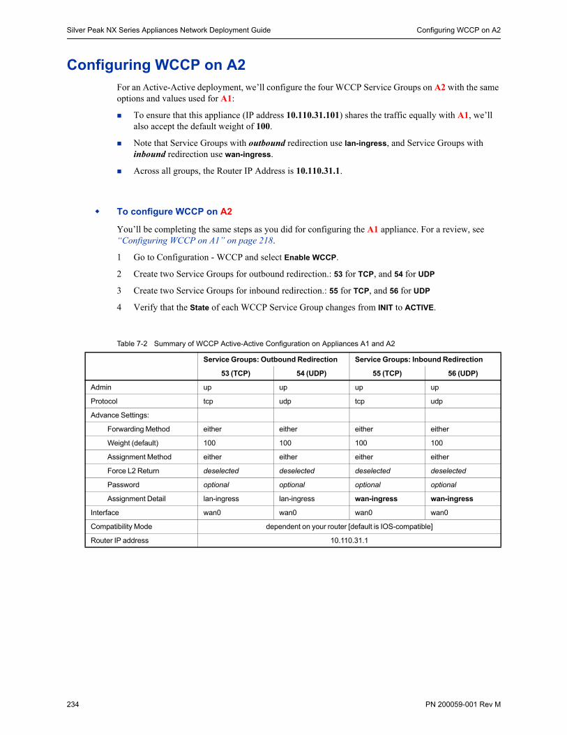
Silver Peak NX Series Appliances Network Deployment Guide Configuring WCCP on A2
234 PN 200059-001 Rev M
Configuring WCCP on A2For an Active-Active deployment, we’ll configure the four WCCP Service Groups on A2 with the same options and values used for A1:
To ensure that this appliance (IP address 10.110.31.101) shares the traffic equally with A1, we’ll also accept the default weight of 100.
Note that Service Groups with outbound redirection use lan-ingress, and Service Groups with inbound redirection use wan-ingress.
Across all groups, the Router IP Address is 10.110.31.1.
To configure WCCP on A2
You’ll be completing the same steps as you did for configuring the A1 appliance. For a review, see “Configuring WCCP on A1” on page 218.
1 Go to Configuration - WCCP and select Enable WCCP.
2 Create two Service Groups for outbound redirection.: 53 for TCP, and 54 for UDP
3 Create two Service Groups for inbound redirection.: 55 for TCP, and 56 for UDP
4 Verify that the State of each WCCP Service Group changes from INIT to ACTIVE.
Table 7-2 Summary of WCCP Active-Active Configuration on Appliances A1 and A2
Service Groups: Outbound Redirection Service Groups: Inbound Redirection
53 (TCP) 54 (UDP) 55 (TCP) 56 (UDP)
Admin up up up up
Protocol tcp udp tcp udp
Advance Settings:
Forwarding Method either either either either
Weight (default) 100 100 100 100
Assignment Method either either either either
Force L2 Return deselected deselected deselected deselected
Password optional optional optional optional
Assignment Detail lan-ingress lan-ingress wan-ingress wan-ingress
Interface wan0 wan0 wan0 wan0
Compatibility Mode dependent on your router [default is IOS-compatible]
Router IP address 10.110.31.1
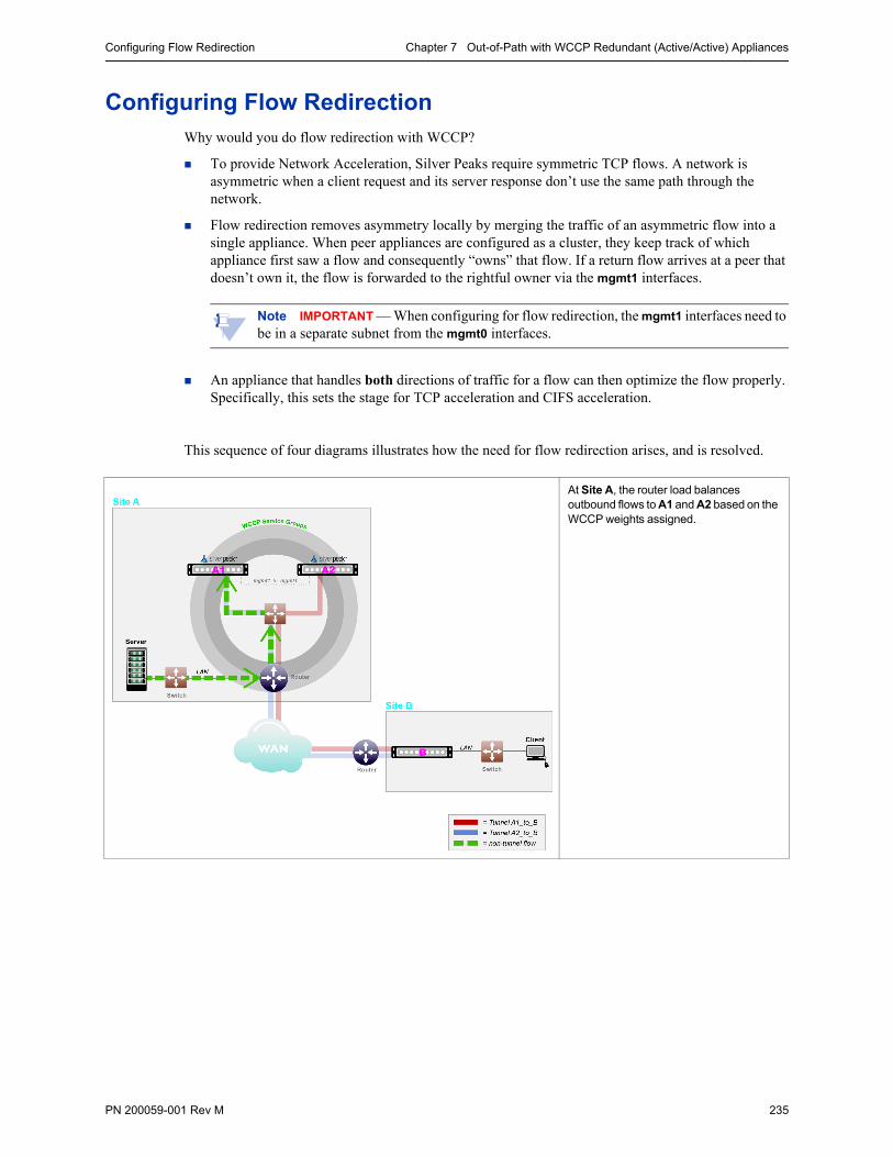
Configuring Flow Redirection Chapter 7 Out-of-Path with WCCP Redundant (Active/Active) Appliances
PN 200059-001 Rev M 235
Configuring Flow RedirectionWhy would you do flow redirection with WCCP?
To provide Network Acceleration, Silver Peaks require symmetric TCP flows. A network is asymmetric when a client request and its server response don’t use the same path through the network.
Flow redirection removes asymmetry locally by merging the traffic of an asymmetric flow into a single appliance. When peer appliances are configured as a cluster, they keep track of which appliance first saw a flow and consequently “owns” that flow. If a return flow arrives at a peer that doesn’t own it, the flow is forwarded to the rightful owner via the mgmt1 interfaces.
Note IMPORTANT — When configuring for flow redirection, the mgmt1 interfaces need to be in a separate subnet from the mgmt0 interfaces.
An appliance that handles both directions of traffic for a flow can then optimize the flow properly. Specifically, this sets the stage for TCP acceleration and CIFS acceleration.
This sequence of four diagrams illustrates how the need for flow redirection arises, and is resolved.
At Site A, the router load balances outbound flows to A1 and A2 based on the WCCP weights assigned.
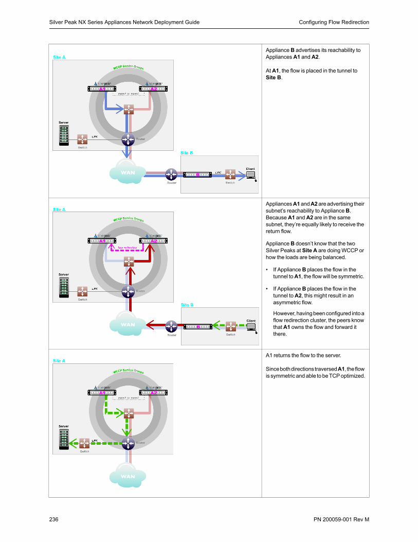
Silver Peak NX Series Appliances Network Deployment Guide Configuring Flow Redirection
236 PN 200059-001 Rev M
Appliance B advertises its reachability to Appliances A1 and A2.
At A1, the flow is placed in the tunnel to Site B.
Appliances A1 and A2 are advertising their subnet’s reachability to Appliance B. Because A1 and A2 are in the same subnet, they’re equally likely to receive the return flow.
Appliance B doesn’t know that the two Silver Peaks at Site A are doing WCCP or how the loads are being balanced.
• If Appliance B places the flow in the tunnel to A1, the flow will be symmetric.
• If Appliance B places the flow in the tunnel to A2, this might result in an asymmetric flow.
However, having been configured into a flow redirection cluster, the peers know that A1 owns the flow and forward it there.
A1 returns the flow to the server.
Since both directions traversed A1, the flow is symmetric and able to be TCP optimized.
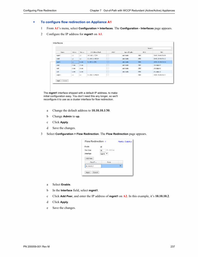
Configuring Flow Redirection Chapter 7 Out-of-Path with WCCP Redundant (Active/Active) Appliances
PN 200059-001 Rev M 237
To configure flow redirection on Appliance A1
1 From A1’s menu, select Configuration > Interfaces. The Configuration - Interfaces page appears.
2 Configure the IP address for mgmt1 on A1.
a Change the default address to 10.10.10.1/30.
b Change Admin to up.
c Click Apply.
d Save the changes.
3 Select Configuration > Flow Redirection. The Flow Redirection page appears.
a Select Enable.
b In the Interface field, select mgmt1.
c Click Add Peer, and enter the IP address of mgmt1 on A2. In this example, it’s 10.10.10.2.
d Click Apply.
e Save the changes.
The mgmt1 interface shipped with a default IP address, to make initial configuration easy. You don’t need this any longer, so we’ll reconfigure it to use as a cluster interface for flow redirection.
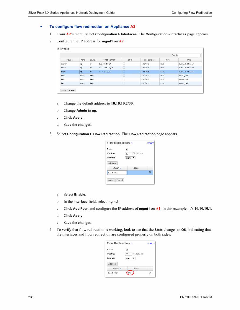
Silver Peak NX Series Appliances Network Deployment Guide Configuring Flow Redirection
238 PN 200059-001 Rev M
To configure flow redirection on Appliance A2
1 From A2’s menu, select Configuration > Interfaces. The Configuration - Interfaces page appears.
2 Configure the IP address for mgmt1 on A2.
a Change the default address to 10.10.10.2/30.
b Change Admin to up.
c Click Apply.
d Save the changes.
3 Select Configuration > Flow Redirection. The Flow Redirection page appears.
a Select Enable.
b In the Interface field, select mgmt1.
c Click Add Peer, and configure the IP address of mgmt1 on A1. In this example, it’s 10.10.10.1.
d Click Apply.
e Save the changes.
4 To verify that flow redirection is working, look to see that the State changes to OK, indicating that the interfaces and flow redirection are configured properly on both sides.
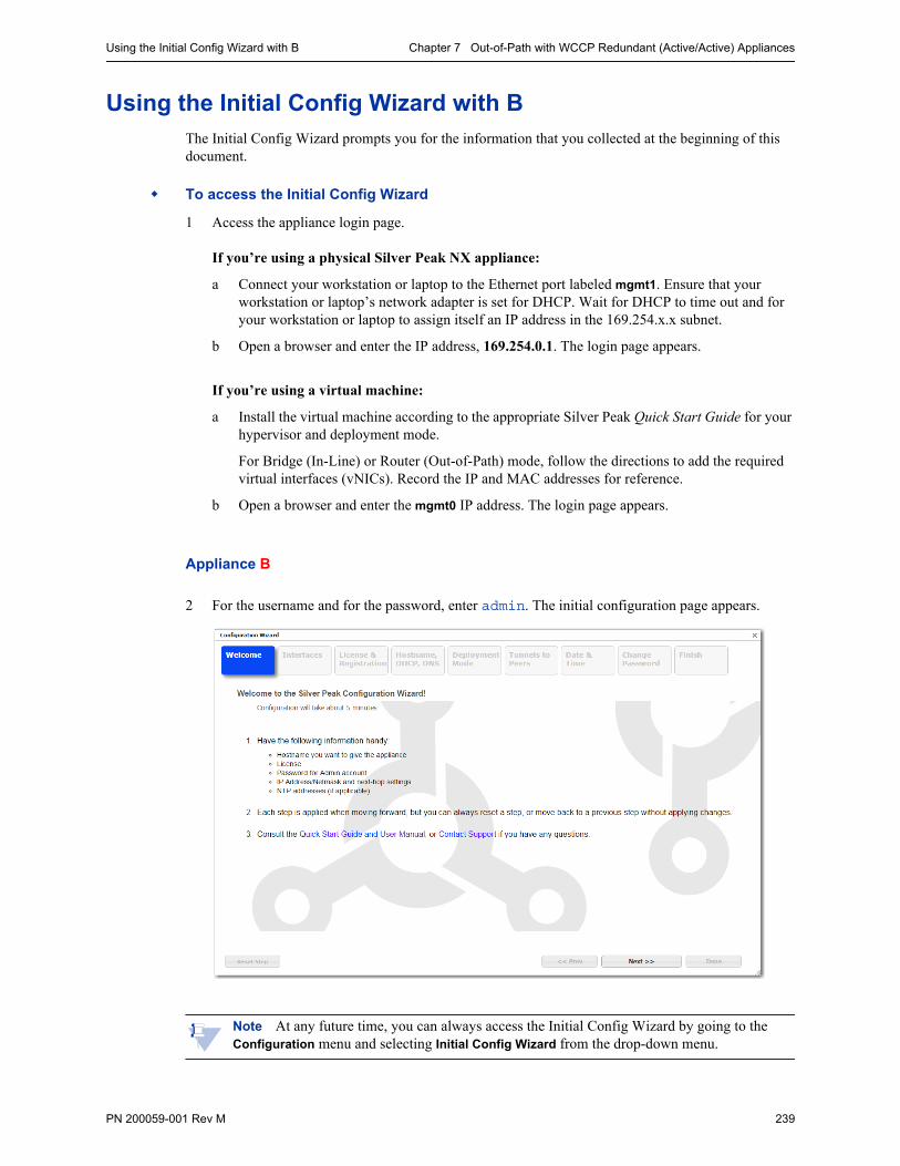
Using the Initial Config Wizard with B Chapter 7 Out-of-Path with WCCP Redundant (Active/Active) Appliances
PN 200059-001 Rev M 239
Using the Initial Config Wizard with BThe Initial Config Wizard prompts you for the information that you collected at the beginning of this document.
To access the Initial Config Wizard
1 Access the appliance login page.
If you’re using a physical Silver Peak NX appliance:
a Connect your workstation or laptop to the Ethernet port labeled mgmt1. Ensure that your workstation or laptop’s network adapter is set for DHCP. Wait for DHCP to time out and for your workstation or laptop to assign itself an IP address in the 169.254.x.x subnet.
b Open a browser and enter the IP address, 169.254.0.1. The login page appears.
If you’re using a virtual machine:
a Install the virtual machine according to the appropriate Silver Peak Quick Start Guide for your hypervisor and deployment mode.
For Bridge (In-Line) or Router (Out-of-Path) mode, follow the directions to add the required virtual interfaces (vNICs). Record the IP and MAC addresses for reference.
b Open a browser and enter the mgmt0 IP address. The login page appears.
Appliance B
2 For the username and for the password, enter admin. The initial configuration page appears.
Note At any future time, you can always access the Initial Config Wizard by going to the Configuration menu and selecting Initial Config Wizard from the drop-down menu.
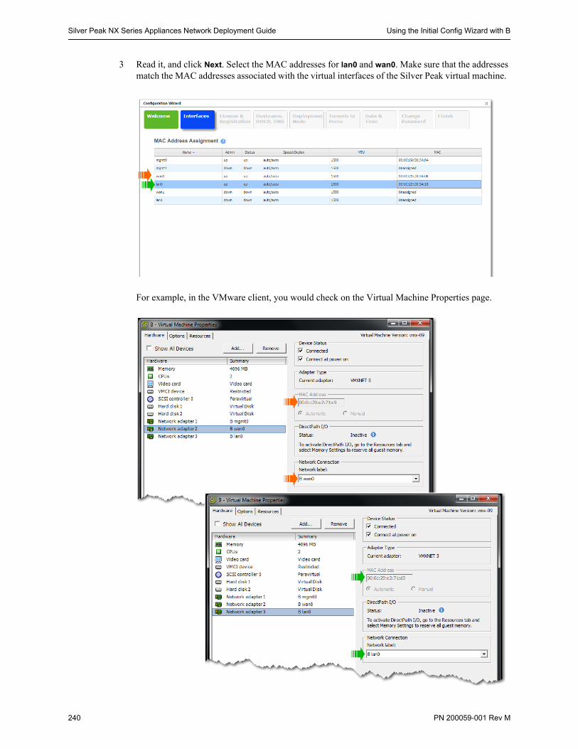
Silver Peak NX Series Appliances Network Deployment Guide Using the Initial Config Wizard with B
240 PN 200059-001 Rev M
3 Read it, and click Next. Select the MAC addresses for lan0 and wan0. Make sure that the addresses match the MAC addresses associated with the virtual interfaces of the Silver Peak virtual machine.
For example, in the VMware client, you would check on the Virtual Machine Properties page.

Using the Initial Config Wizard with B Chapter 7 Out-of-Path with WCCP Redundant (Active/Active) Appliances
PN 200059-001 Rev M 241
4 Click Apply & Next. The License & Registration page appears. Enter the license details.
5 Click Apply & Next. The Management Interface (mgmt0) page appears. Enter the appliance name and management IP details.
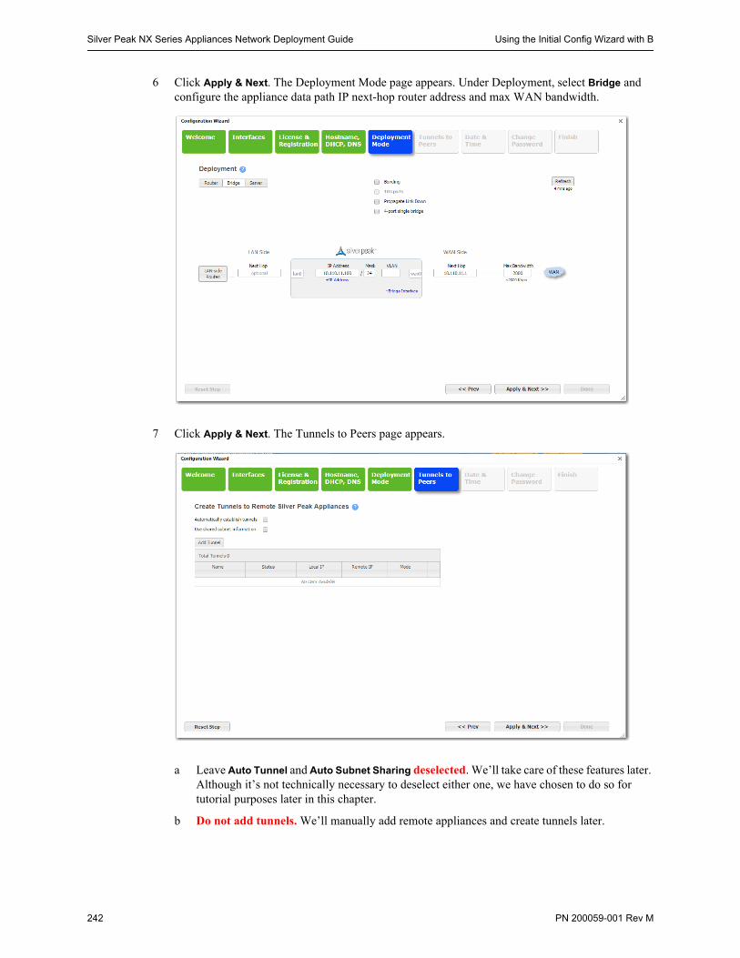
Silver Peak NX Series Appliances Network Deployment Guide Using the Initial Config Wizard with B
242 PN 200059-001 Rev M
6 Click Apply & Next. The Deployment Mode page appears. Under Deployment, select Bridge and configure the appliance data path IP next-hop router address and max WAN bandwidth.
7 Click Apply & Next. The Tunnels to Peers page appears.
a Leave Auto Tunnel and Auto Subnet Sharing deselected. We’ll take care of these features later. Although it’s not technically necessary to deselect either one, we have chosen to do so for tutorial purposes later in this chapter.
b Do not add tunnels. We’ll manually add remote appliances and create tunnels later.
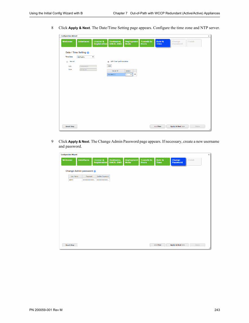
Using the Initial Config Wizard with B Chapter 7 Out-of-Path with WCCP Redundant (Active/Active) Appliances
PN 200059-001 Rev M 243
8 Click Apply & Next. The Date/Time Setting page appears. Configure the time zone and NTP server.
9 Click Apply & Next. The Change Admin Password page appears. If necessary, create a new username and password.
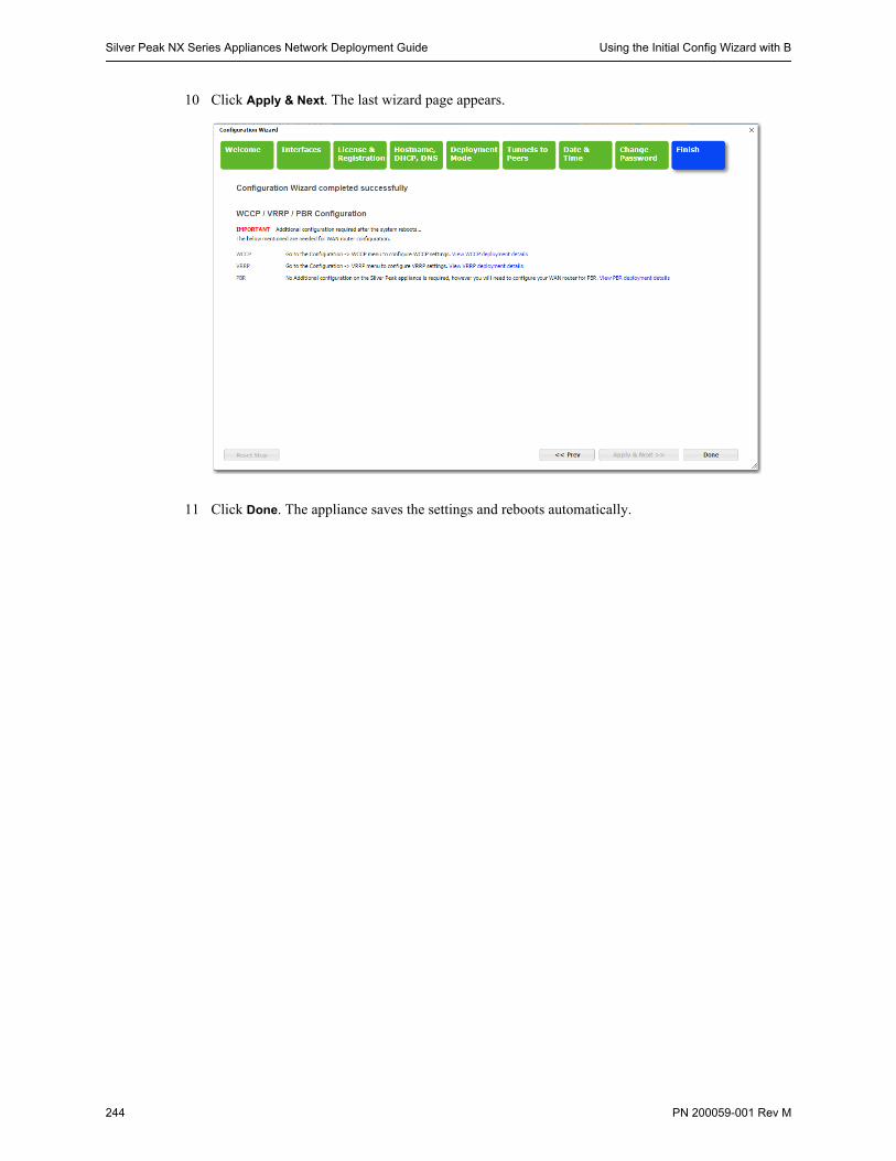
Silver Peak NX Series Appliances Network Deployment Guide Using the Initial Config Wizard with B
244 PN 200059-001 Rev M
10 Click Apply & Next. The last wizard page appears.
11 Click Done. The appliance saves the settings and reboots automatically.
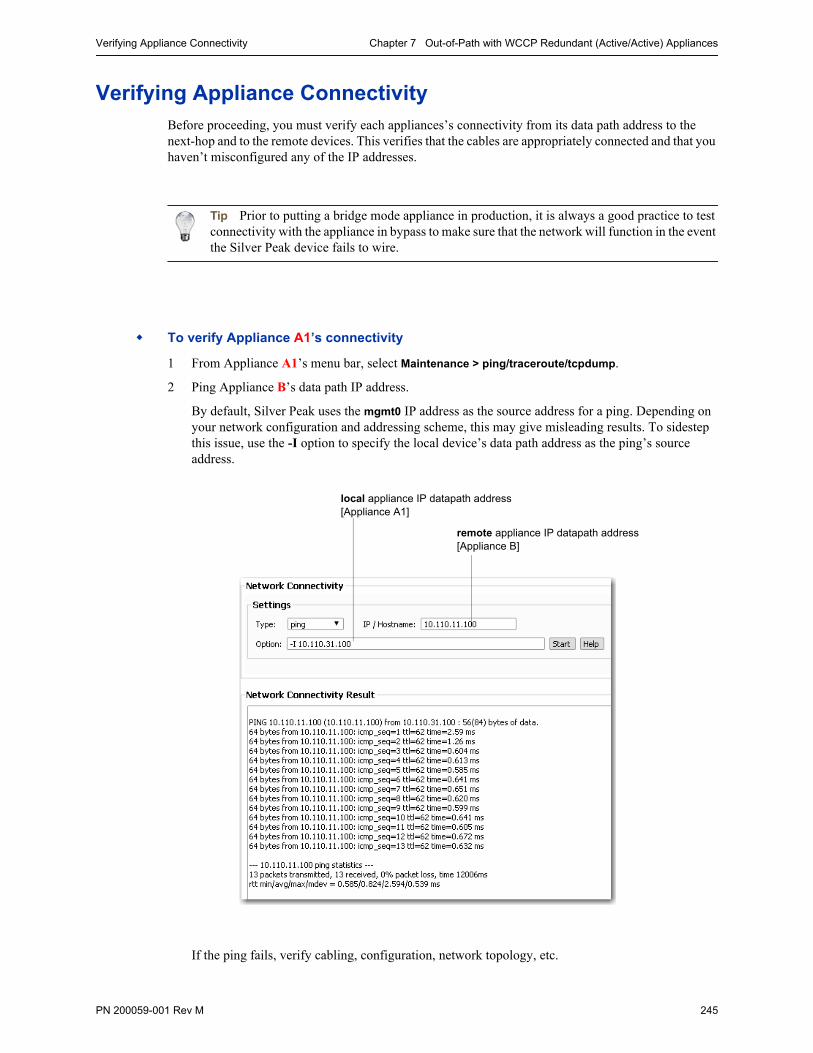
Verifying Appliance Connectivity Chapter 7 Out-of-Path with WCCP Redundant (Active/Active) Appliances
PN 200059-001 Rev M 245
Verifying Appliance ConnectivityBefore proceeding, you must verify each appliances’s connectivity from its data path address to the next-hop and to the remote devices. This verifies that the cables are appropriately connected and that you haven’t misconfigured any of the IP addresses.
Tip Prior to putting a bridge mode appliance in production, it is always a good practice to test connectivity with the appliance in bypass to make sure that the network will function in the event the Silver Peak device fails to wire.
To verify Appliance A1’s connectivity
1 From Appliance A1’s menu bar, select Maintenance > ping/traceroute/tcpdump.
2 Ping Appliance B’s data path IP address.
By default, Silver Peak uses the mgmt0 IP address as the source address for a ping. Depending on your network configuration and addressing scheme, this may give misleading results. To sidestep this issue, use the -I option to specify the local device’s data path address as the ping’s source address.
If the ping fails, verify cabling, configuration, network topology, etc.
local appliance IP datapath address[Appliance A1]
remote appliance IP datapath address[Appliance B]
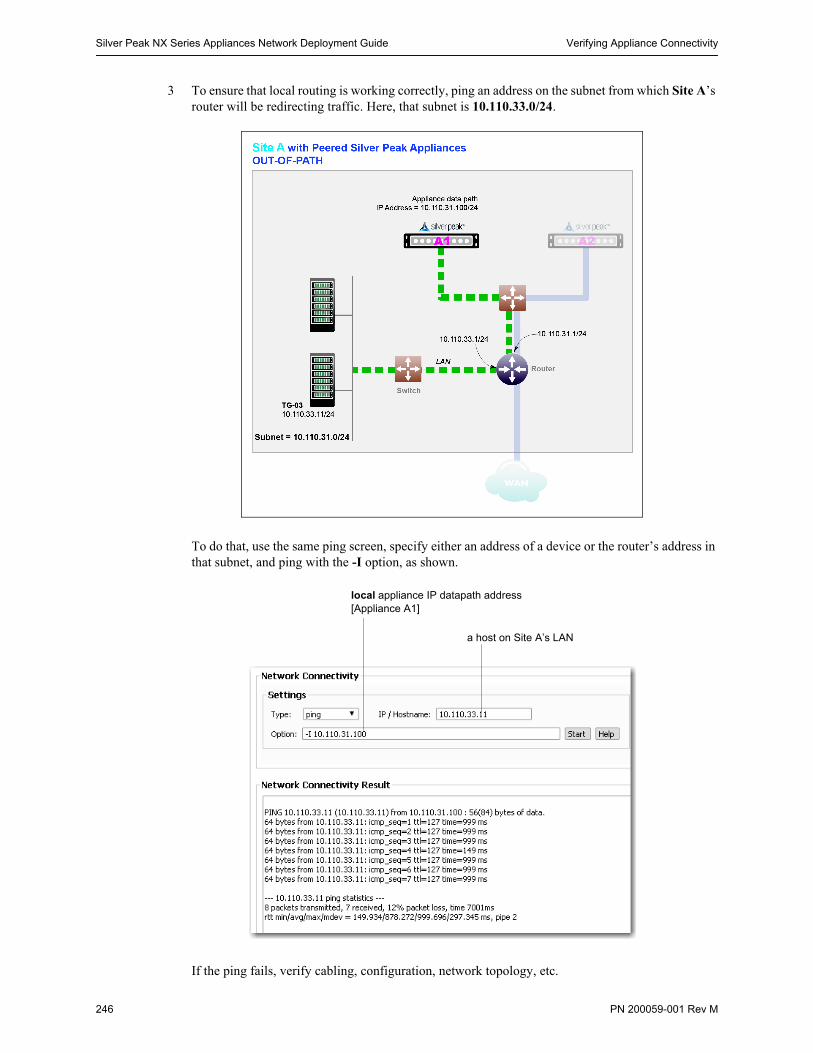
Silver Peak NX Series Appliances Network Deployment Guide Verifying Appliance Connectivity
246 PN 200059-001 Rev M
3 To ensure that local routing is working correctly, ping an address on the subnet from which Site A’s router will be redirecting traffic. Here, that subnet is 10.110.33.0/24.
To do that, use the same ping screen, specify either an address of a device or the router’s address in that subnet, and ping with the -I option, as shown.
If the ping fails, verify cabling, configuration, network topology, etc.
local appliance IP datapath address[Appliance A1]
a host on Site A’s LAN
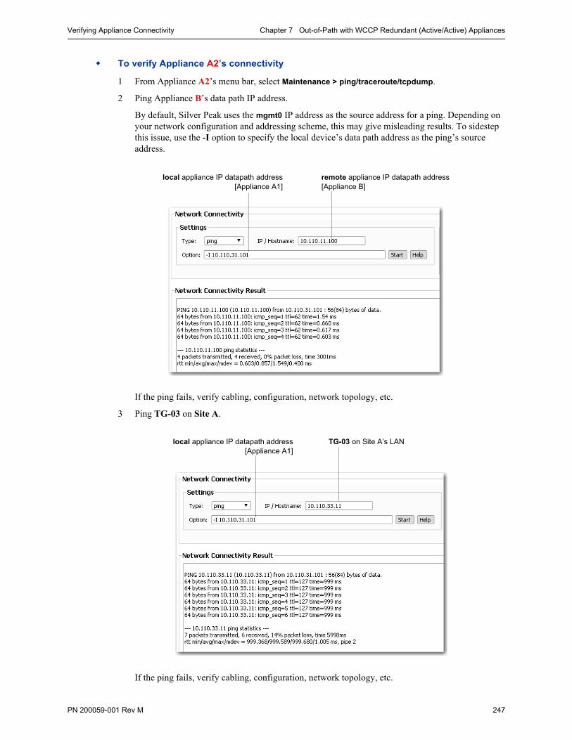
Verifying Appliance Connectivity Chapter 7 Out-of-Path with WCCP Redundant (Active/Active) Appliances
PN 200059-001 Rev M 247
To verify Appliance A2’s connectivity
1 From Appliance A2’s menu bar, select Maintenance > ping/traceroute/tcpdump.
2 Ping Appliance B’s data path IP address.
By default, Silver Peak uses the mgmt0 IP address as the source address for a ping. Depending on your network configuration and addressing scheme, this may give misleading results. To sidestep this issue, use the -I option to specify the local device’s data path address as the ping’s source address.
If the ping fails, verify cabling, configuration, network topology, etc.
3 Ping TG-03 on Site A.
If the ping fails, verify cabling, configuration, network topology, etc.
local appliance IP datapath address[Appliance A1]
remote appliance IP datapath address[Appliance B]
local appliance IP datapath address[Appliance A1]
TG-03 on Site A’s LAN
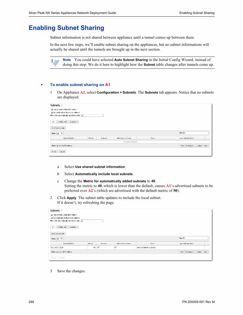
Silver Peak NX Series Appliances Network Deployment Guide Enabling Subnet Sharing
248 PN 200059-001 Rev M
Enabling Subnet SharingSubnet information is not shared between appliance until a tunnel comes up between them.
In the next few steps, we’ll enable subnet sharing on the appliances, but no subnet informations will actually be shared until the tunnels are brought up in the next section.
Note You could have selected Auto Subnet Sharing in the Initial Config Wizard, instead of doing this step. We do it here to highlight how the Subnet table changes after tunnels come up.
To enable subnet sharing on A1
1 On Appliance A1, select Configuration > Subnets. The Subnets tab appears. Notice that no subnets are displayed.
a Select Use shared subnet information.
b Select Automatically include local subnets.
c Change the Metric for automatically added subnets to 40. Setting the metric to 40, which is lower than the default, causes A1’s advertised subnets to be preferred over A2’s (which are advertised with the default metric of 50).
2 Click Apply. The subnet table updates to include the local subnet. If it doesn’t, try refreshing the page.
3 Save the changes.
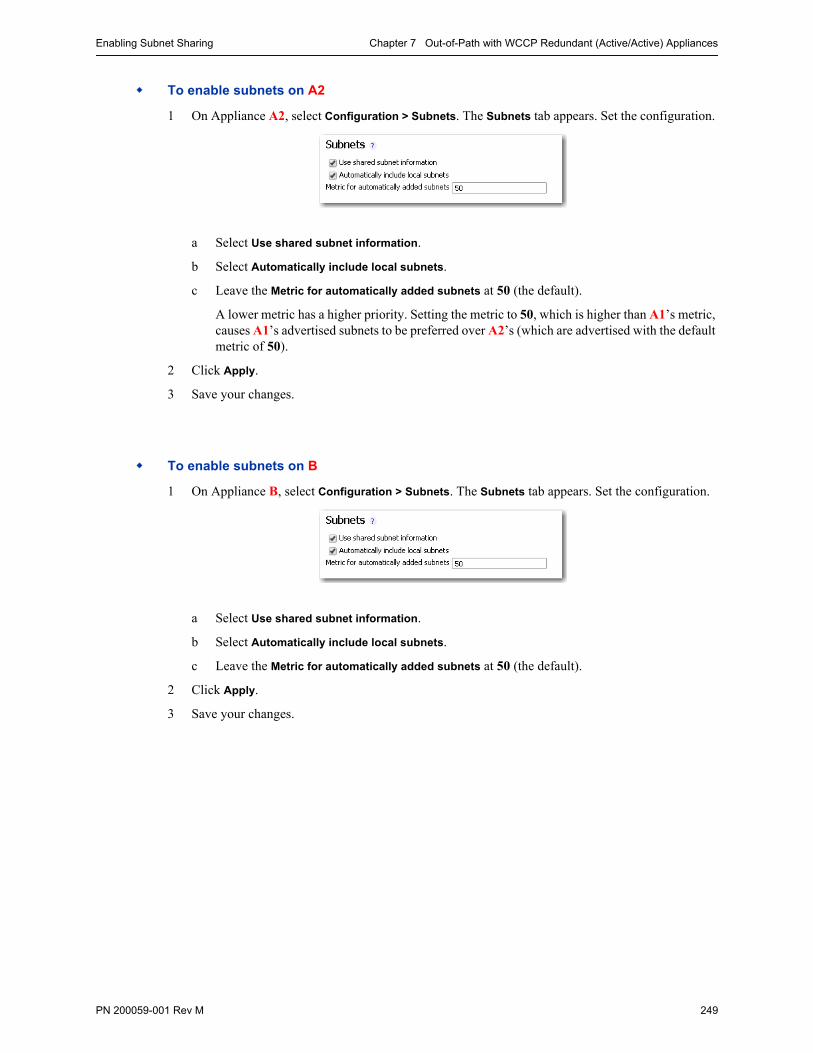
Enabling Subnet Sharing Chapter 7 Out-of-Path with WCCP Redundant (Active/Active) Appliances
PN 200059-001 Rev M 249
To enable subnets on A2
1 On Appliance A2, select Configuration > Subnets. The Subnets tab appears. Set the configuration.
a Select Use shared subnet information.
b Select Automatically include local subnets.
c Leave the Metric for automatically added subnets at 50 (the default).
A lower metric has a higher priority. Setting the metric to 50, which is higher than A1’s metric, causes A1’s advertised subnets to be preferred over A2’s (which are advertised with the default metric of 50).
2 Click Apply.
3 Save your changes.
To enable subnets on B
1 On Appliance B, select Configuration > Subnets. The Subnets tab appears. Set the configuration.
a Select Use shared subnet information.
b Select Automatically include local subnets.
c Leave the Metric for automatically added subnets at 50 (the default).
2 Click Apply.
3 Save your changes.
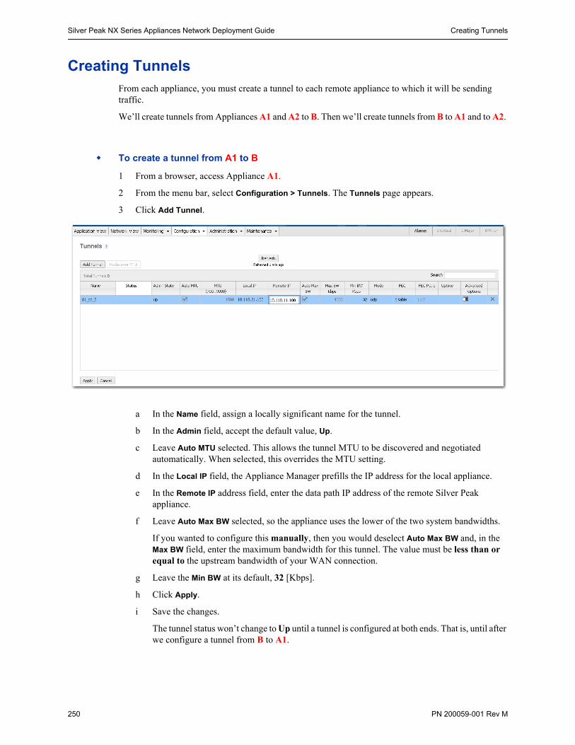
Silver Peak NX Series Appliances Network Deployment Guide Creating Tunnels
250 PN 200059-001 Rev M
Creating TunnelsFrom each appliance, you must create a tunnel to each remote appliance to which it will be sending traffic.
We’ll create tunnels from Appliances A1 and A2 to B. Then we’ll create tunnels from B to A1 and to A2.
To create a tunnel from A1 to B
1 From a browser, access Appliance A1.
2 From the menu bar, select Configuration > Tunnels. The Tunnels page appears.
3 Click Add Tunnel.
a In the Name field, assign a locally significant name for the tunnel.
b In the Admin field, accept the default value, Up.
c Leave Auto MTU selected. This allows the tunnel MTU to be discovered and negotiated automatically. When selected, this overrides the MTU setting.
d In the Local IP field, the Appliance Manager prefills the IP address for the local appliance.
e In the Remote IP address field, enter the data path IP address of the remote Silver Peak appliance.
f Leave Auto Max BW selected, so the appliance uses the lower of the two system bandwidths.
If you wanted to configure this manually, then you would deselect Auto Max BW and, in the Max BW field, enter the maximum bandwidth for this tunnel. The value must be less than or equal to the upstream bandwidth of your WAN connection.
g Leave the Min BW at its default, 32 [Kbps].
h Click Apply.
i Save the changes.
The tunnel status won’t change to Up until a tunnel is configured at both ends. That is, until after we configure a tunnel from B to A1.
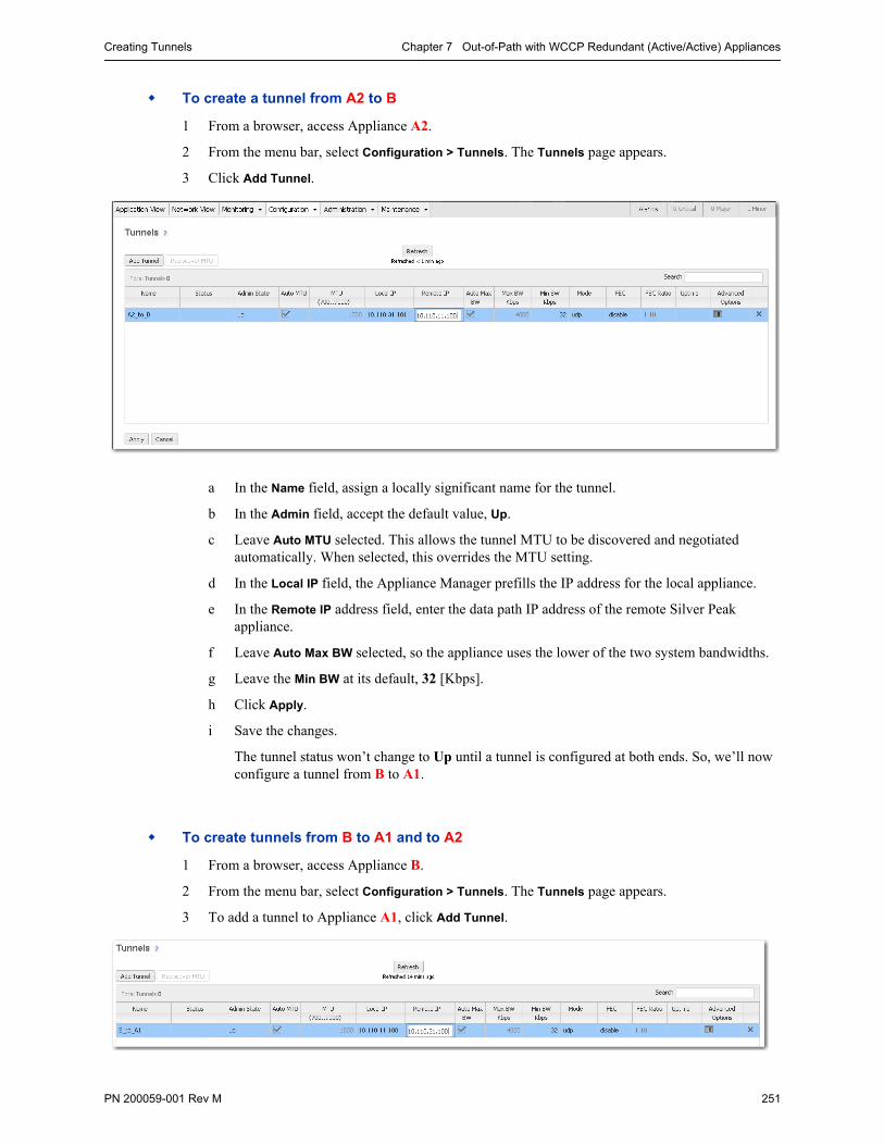
Creating Tunnels Chapter 7 Out-of-Path with WCCP Redundant (Active/Active) Appliances
PN 200059-001 Rev M 251
To create a tunnel from A2 to B
1 From a browser, access Appliance A2.
2 From the menu bar, select Configuration > Tunnels. The Tunnels page appears.
3 Click Add Tunnel.
a In the Name field, assign a locally significant name for the tunnel.
b In the Admin field, accept the default value, Up.
c Leave Auto MTU selected. This allows the tunnel MTU to be discovered and negotiated automatically. When selected, this overrides the MTU setting.
d In the Local IP field, the Appliance Manager prefills the IP address for the local appliance.
e In the Remote IP address field, enter the data path IP address of the remote Silver Peak appliance.
f Leave Auto Max BW selected, so the appliance uses the lower of the two system bandwidths.
g Leave the Min BW at its default, 32 [Kbps].
h Click Apply.
i Save the changes.
The tunnel status won’t change to Up until a tunnel is configured at both ends. So, we’ll now configure a tunnel from B to A1.
To create tunnels from B to A1 and to A2
1 From a browser, access Appliance B.
2 From the menu bar, select Configuration > Tunnels. The Tunnels page appears.
3 To add a tunnel to Appliance A1, click Add Tunnel.
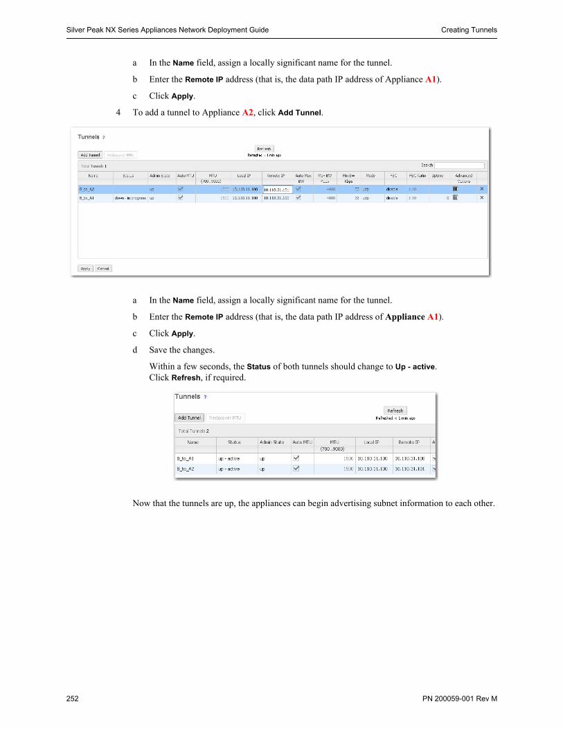
Silver Peak NX Series Appliances Network Deployment Guide Creating Tunnels
252 PN 200059-001 Rev M
a In the Name field, assign a locally significant name for the tunnel.
b Enter the Remote IP address (that is, the data path IP address of Appliance A1).
c Click Apply.
4 To add a tunnel to Appliance A2, click Add Tunnel.
a In the Name field, assign a locally significant name for the tunnel.
b Enter the Remote IP address (that is, the data path IP address of Appliance A1).
c Click Apply.
d Save the changes.
Within a few seconds, the Status of both tunnels should change to Up - active. Click Refresh, if required.
Now that the tunnels are up, the appliances can begin advertising subnet information to each other.
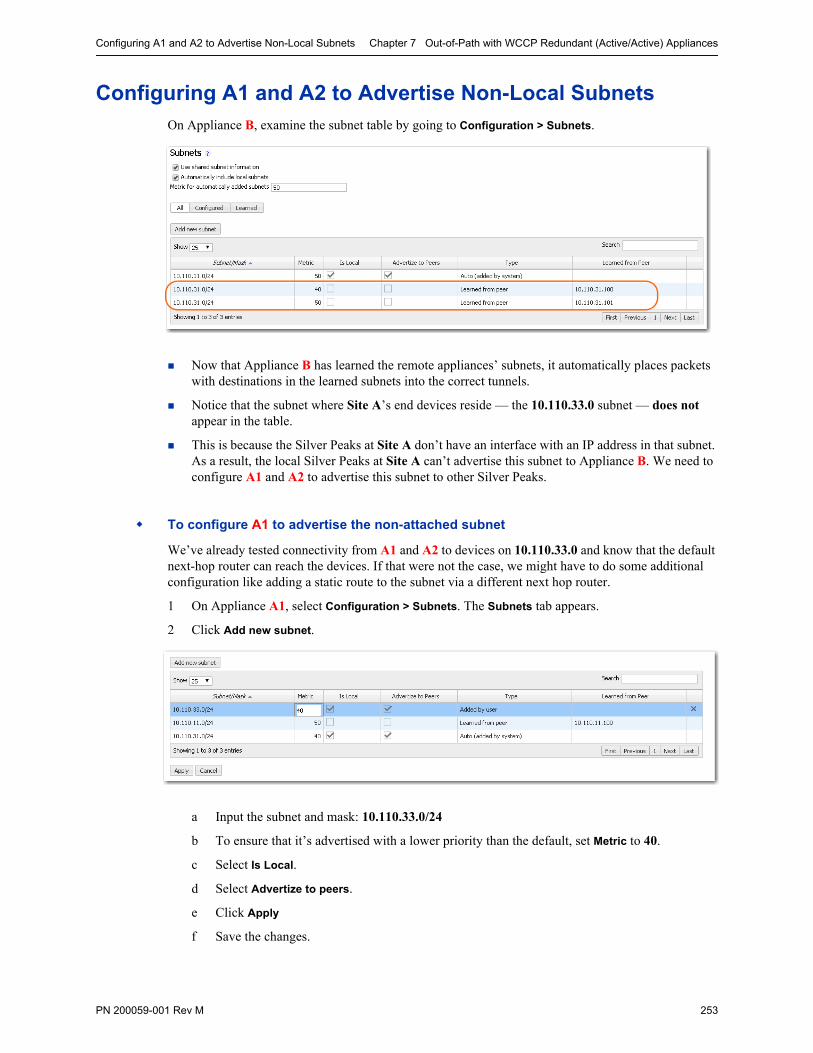
Configuring A1 and A2 to Advertise Non-Local Subnets Chapter 7 Out-of-Path with WCCP Redundant (Active/Active) Appliances
PN 200059-001 Rev M 253
Configuring A1 and A2 to Advertise Non-Local SubnetsOn Appliance B, examine the subnet table by going to Configuration > Subnets.
Now that Appliance B has learned the remote appliances’ subnets, it automatically places packets with destinations in the learned subnets into the correct tunnels.
Notice that the subnet where Site A’s end devices reside — the 10.110.33.0 subnet — does not appear in the table.
This is because the Silver Peaks at Site A don’t have an interface with an IP address in that subnet. As a result, the local Silver Peaks at Site A can’t advertise this subnet to Appliance B. We need to configure A1 and A2 to advertise this subnet to other Silver Peaks.
To configure A1 to advertise the non-attached subnet
We’ve already tested connectivity from A1 and A2 to devices on 10.110.33.0 and know that the default next-hop router can reach the devices. If that were not the case, we might have to do some additional configuration like adding a static route to the subnet via a different next hop router.
1 On Appliance A1, select Configuration > Subnets. The Subnets tab appears.
2 Click Add new subnet.
a Input the subnet and mask: 10.110.33.0/24
b To ensure that it’s advertised with a lower priority than the default, set Metric to 40.
c Select Is Local.
d Select Advertize to peers.
e Click Apply
f Save the changes.
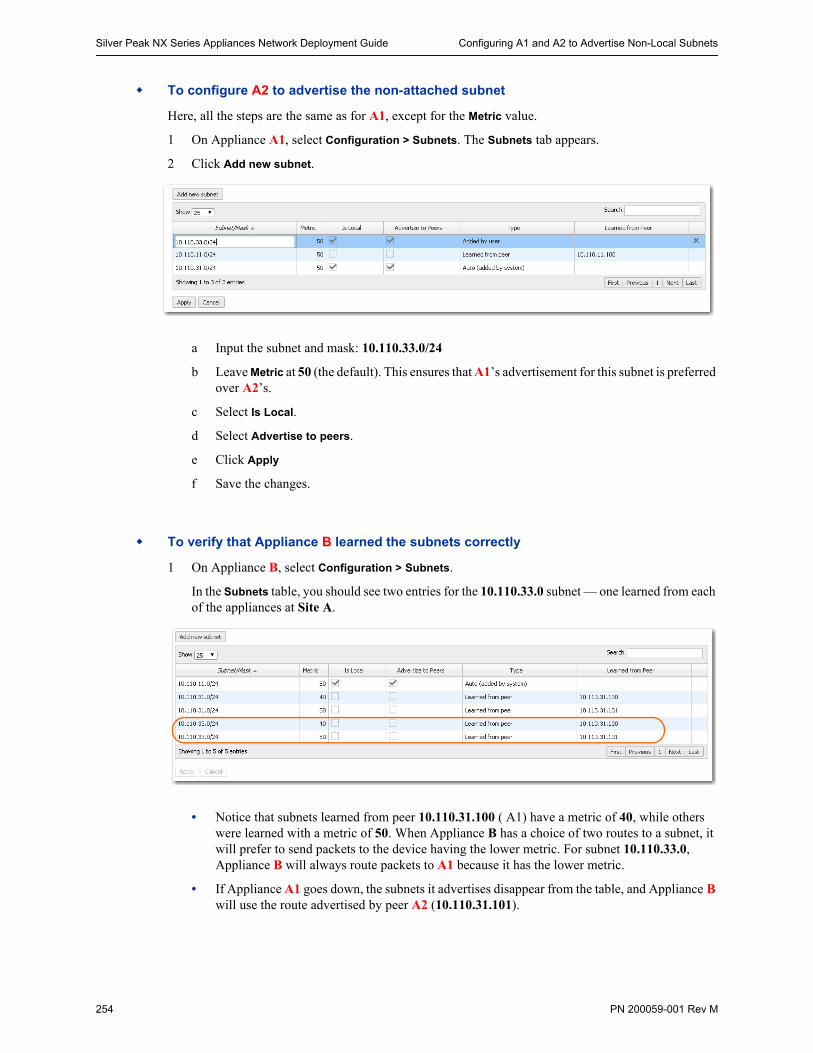
Silver Peak NX Series Appliances Network Deployment Guide Configuring A1 and A2 to Advertise Non-Local Subnets
254 PN 200059-001 Rev M
To configure A2 to advertise the non-attached subnet
Here, all the steps are the same as for A1, except for the Metric value.
1 On Appliance A1, select Configuration > Subnets. The Subnets tab appears.
2 Click Add new subnet.
a Input the subnet and mask: 10.110.33.0/24
b Leave Metric at 50 (the default). This ensures that A1’s advertisement for this subnet is preferred over A2’s.
c Select Is Local.
d Select Advertise to peers.
e Click Apply
f Save the changes.
To verify that Appliance B learned the subnets correctly
1 On Appliance B, select Configuration > Subnets.
In the Subnets table, you should see two entries for the 10.110.33.0 subnet — one learned from each of the appliances at Site A.
• Notice that subnets learned from peer 10.110.31.100 ( A1) have a metric of 40, while others were learned with a metric of 50. When Appliance B has a choice of two routes to a subnet, it will prefer to send packets to the device having the lower metric. For subnet 10.110.33.0, Appliance B will always route packets to A1 because it has the lower metric.
• If Appliance A1 goes down, the subnets it advertises disappear from the table, and Appliance B will use the route advertised by peer A2 (10.110.31.101).
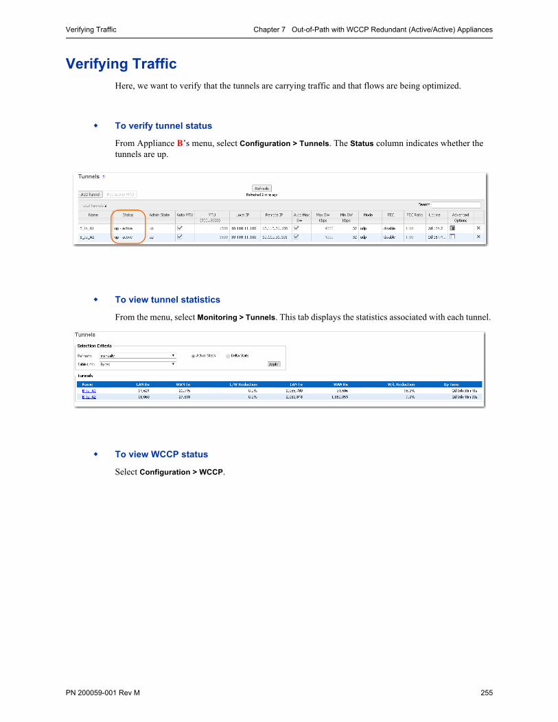
Verifying Traffic Chapter 7 Out-of-Path with WCCP Redundant (Active/Active) Appliances
PN 200059-001 Rev M 255
Verifying TrafficHere, we want to verify that the tunnels are carrying traffic and that flows are being optimized.
To verify tunnel status
From Appliance B’s menu, select Configuration > Tunnels. The Status column indicates whether the tunnels are up.
To view tunnel statistics
From the menu, select Monitoring > Tunnels. This tab displays the statistics associated with each tunnel.
To view WCCP status
Select Configuration > WCCP.
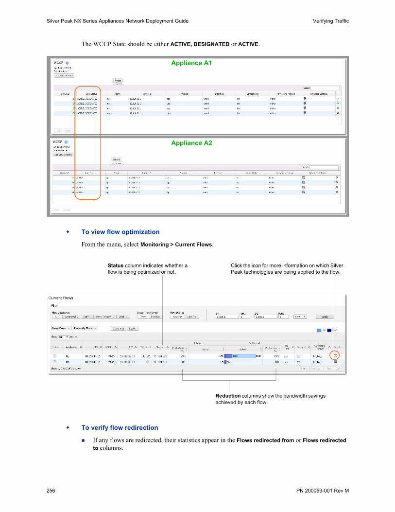
Silver Peak NX Series Appliances Network Deployment Guide Verifying Traffic
256 PN 200059-001 Rev M
The WCCP State should be either ACTIVE, DESIGNATED or ACTIVE.
To view flow optimization
From the menu, select Monitoring > Current Flows.
To verify flow redirection
If any flows are redirected, their statistics appear in the Flows redirected from or Flows redirected
to columns.
Appliance A1
Appliance A2
Reduction columns show the bandwidth savings achieved by each flow.
Click the icon for more information on which Silver Peak technologies are being applied to the flow.
Status column indicates whether a flow is being optimized or not.
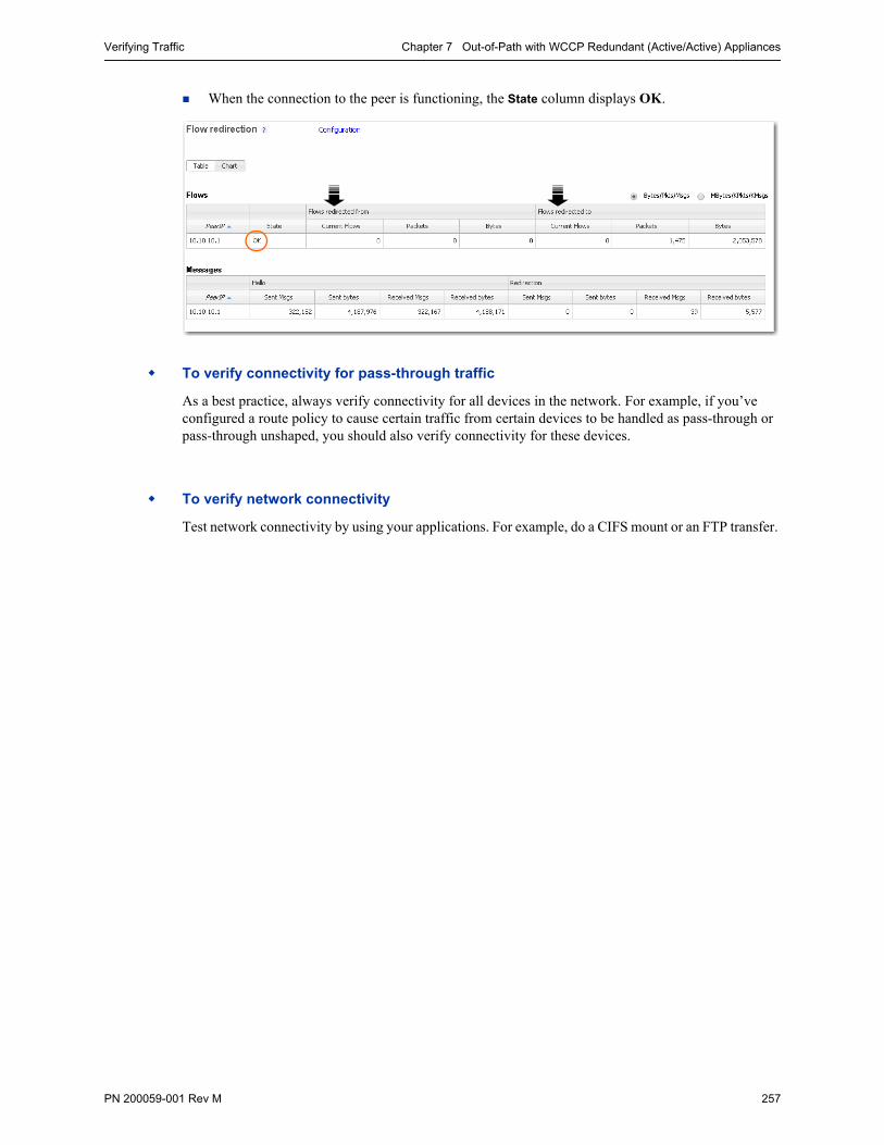
Verifying Traffic Chapter 7 Out-of-Path with WCCP Redundant (Active/Active) Appliances
PN 200059-001 Rev M 257
When the connection to the peer is functioning, the State column displays OK.
To verify connectivity for pass-through traffic
As a best practice, always verify connectivity for all devices in the network. For example, if you’ve configured a route policy to cause certain traffic from certain devices to be handled as pass-through or pass-through unshaped, you should also verify connectivity for these devices.
To verify network connectivity
Test network connectivity by using your applications. For example, do a CIFS mount or an FTP transfer.

Silver Peak NX Series Appliances Network Deployment Guide Best Practices
258 PN 200059-001 Rev M
Best Practices
Tips for Deployment
Inbound WCCP redirection is preferred over outbound [also known as ingress/egress] redirection because inbound redirection is less CPU-intensive on the router. Inbound redirection is done in hardware where as outbound is done in software.
• For Catalyst 6000/76xx deployments, use only inbound redirection to avoid using “redirection exclude in”, which is not understood by the switch hardware and must be processed in software.
• For Catalyst 6000/76xx deployments, use L2 redirection for near line-rate redirection. Silver Peak appliances automatically negotiate assignment and forwarding methods with all routers and L3 switches from Cisco to the best possible combination that the router or L3 switch supports.
WCCPv2 interception forwards all packets from the router or L3 switch to the appliance. Special care should be taken when traffic redirected to the appliance has to be returned back to the router or L3 switch. For many routers the return traffic is delivered via L2 so there is no CPU impact. However, Catalyst 6000/76xx switches returns via GRE so the CPU can be negatively impacted unless Force L2 return is enabled on the appliance.
• Force L2 Return should only be enabled when the interface/VLAN that the appliance is connected to is not also an interface with the redirection applied to.
The appliance should always be connected to an interface/VLAN that does not have redirection enabled – preferably a separate interface/VLAN would be provided for the appliance.
The appliance and Catalyst switch negotiate which redirect and return method to use when the service group is formed. There can be many access VLANs on the aggregation switches. Redirection is configured on all VLANs that need optimization. Layer 2 switching ports, including trunk ports, are not eligible for redirection.
If Auto Optimization is used for matching traffic to be optimized via the appliance, WCCP redirection must also be applied on the uplinks of the router or L3 switch to the core/WAN.
If WCCP redirection is needed on both the WAN and the LAN, the preferred configuration on the appliance is to set the WCCP group configured on the WAN to wan-ingress and the group configured on the LAN to lan-ingress.
• The configuration of wan-ingress and lan-ingress ensures that load balancing is symmetrical in both directions of a flow.
• wan-ingress uses the destination address for distribution in the router/L3 switch table
• lan-ingress uses the source address for distribution.
If Route Policies are used for matching traffic to be optimized via the appliance, WCCP redirection is not required on the core uplinks, only the access/LAN links. If Active/Active redistribution is enabled with route policies, then flow redirection is required to handle asymmetrical flows caused by load balancing. Flow redirection can handle millions of flows and ensures that the owner of a given flow always receives the TCP flow for proxy.
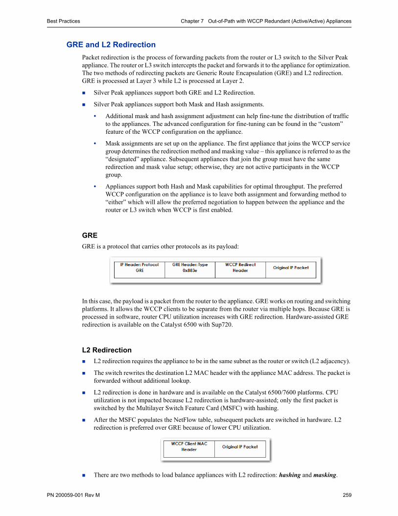
Best Practices Chapter 7 Out-of-Path with WCCP Redundant (Active/Active) Appliances
PN 200059-001 Rev M 259
GRE and L2 Redirection
Packet redirection is the process of forwarding packets from the router or L3 switch to the Silver Peak appliance. The router or L3 switch intercepts the packet and forwards it to the appliance for optimization. The two methods of redirecting packets are Generic Route Encapsulation (GRE) and L2 redirection. GRE is processed at Layer 3 while L2 is processed at Layer 2.
Silver Peak appliances support both GRE and L2 Redirection.
Silver Peak appliances support both Mask and Hash assignments.
• Additional mask and hash assignment adjustment can help fine-tune the distribution of traffic to the appliances. The advanced configuration for fine-tuning can be found in the “custom” feature of the WCCP configuration on the appliance.
• Mask assignments are set up on the appliance. The first appliance that joins the WCCP service group determines the redirection method and masking value – this appliance is referred to as the “designated” appliance. Subsequent appliances that join the group must have the same redirection and mask value setup; otherwise, they are not active participants in the WCCP group.
• Appliances support both Hash and Mask capabilities for optimal throughput. The preferred WCCP configuration on the appliance is to leave both assignment and forwarding method to “either” which will allow the preferred negotiation to happen between the appliance and the router or L3 switch when WCCP is first enabled.
GRE
GRE is a protocol that carries other protocols as its payload:
In this case, the payload is a packet from the router to the appliance. GRE works on routing and switching platforms. It allows the WCCP clients to be separate from the router via multiple hops. Because GRE is processed in software, router CPU utilization increases with GRE redirection. Hardware-assisted GRE redirection is available on the Catalyst 6500 with Sup720.
L2 Redirection
L2 redirection requires the appliance to be in the same subnet as the router or switch (L2 adjacency).
The switch rewrites the destination L2 MAC header with the appliance MAC address. The packet is forwarded without additional lookup.
L2 redirection is done in hardware and is available on the Catalyst 6500/7600 platforms. CPU utilization is not impacted because L2 redirection is hardware-assisted; only the first packet is switched by the Multilayer Switch Feature Card (MSFC) with hashing.
After the MSFC populates the NetFlow table, subsequent packets are switched in hardware. L2 redirection is preferred over GRE because of lower CPU utilization.
There are two methods to load balance appliances with L2 redirection: hashing and masking.

Silver Peak NX Series Appliances Network Deployment Guide Best Practices
260 PN 200059-001 Rev M

PN 200059-001 Rev M 261

Silver Peak Systems, Inc.2860 De La Cruz Blvd., Suite 100Santa Clara, CA 95050
1.877.210.7325+1.408.935.1850
www.silver-peak.com