network infrastructure - cisco€¦ · network infrastructure, ... properly designing a lan...
TRANSCRIPT
Cisco Unified Communications SRND (BasOL-10030-08
C H A P T E R 3
Network InfrastructureLast revised on: October 30, 2008
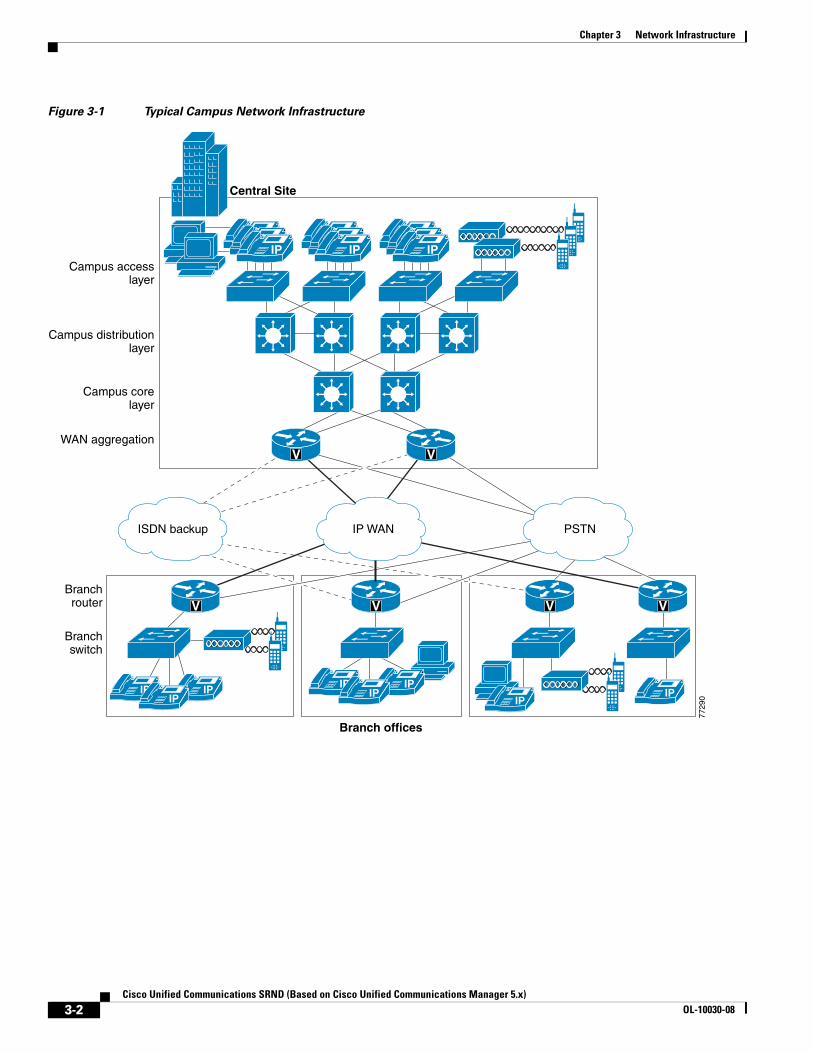
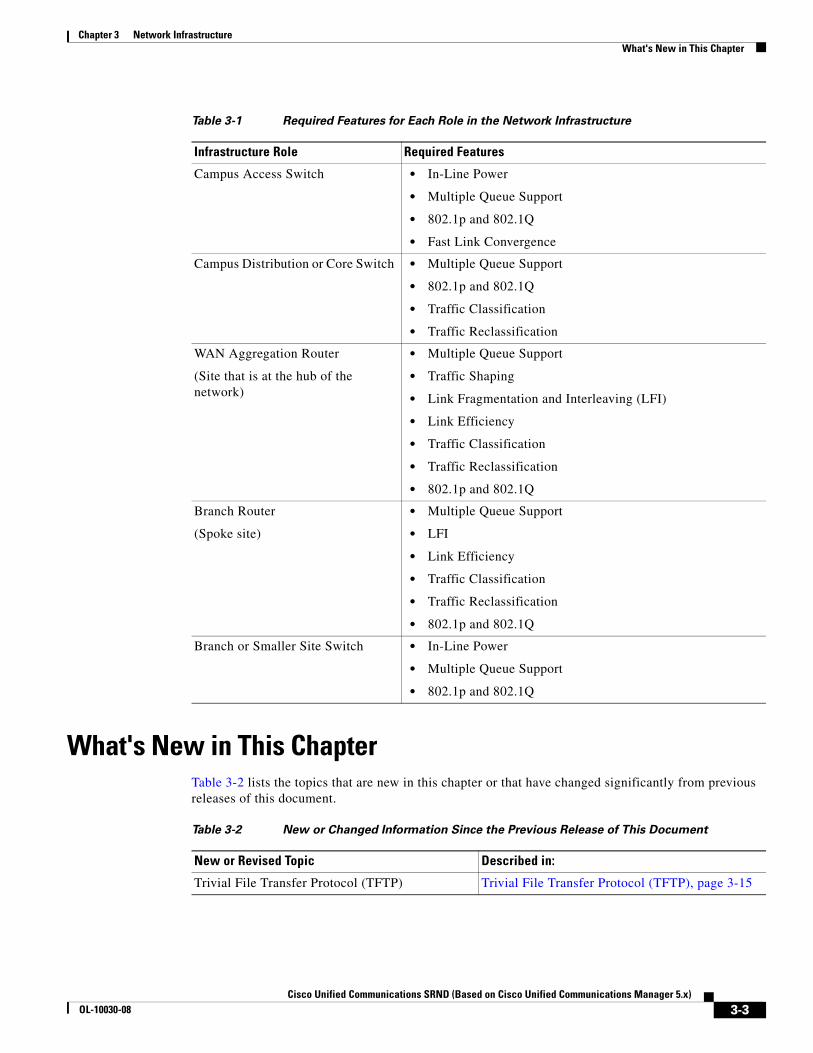
This chapter describes the requirements of the network infrastructure needed to build an IP telephony system in an enterprise environment. Figure 3-1 illustrates the roles of the various devices that form the network infrastructure, and Table 3-1 summarizes the features required to support each of these roles.
IP telephony places strict requirements on IP packet loss, packet delay, and delay variation (or jitter). Therefore, you need to enable most of the Quality of Service (QoS) mechanisms available on Cisco switches and routers throughout the network. For the same reasons, redundant devices and network links that provide quick convergence after network failures or topology changes are also important to ensure a highly available infrastructure
The following sections describe the network infrastructure features as they relate to:
• LAN Infrastructure, page 3-4
• WAN Infrastructure, page 3-30
• Wireless LAN Infrastructure, page 3-63
3-1ed on Cisco Unified Communications Manager 5.x)
Chapter 3 Network Infrastructure
Figure 3-1 Typical Campus Network Infrastructure
V
V
IPIPIP
IP
V
IPIP
IPIPIPIPIPIP
IP
Central Site
Campus accesslayer
Campus distributionlayer
Campus corelayer
Branchrouter
Branchswitch
WAN aggregation
ISDN backup PSTN
Branch offices
7729
0
V
IPIPIP
V
V
IP WAN
IP
3-2Cisco Unified Communications SRND (Based on Cisco Unified Communications Manager 5.x)
OL-10030-08
Chapter 3 Network InfrastructureWhat's New in This Chapter
What's New in This ChapterTable 3-2 lists the topics that are new in this chapter or that have changed significantly from previous releases of this document.
Table 3-1 Required Features for Each Role in the Network Infrastructure
Infrastructure Role Required Features
Campus Access Switch • In-Line Power
• Multiple Queue Support
• 802.1p and 802.1Q
• Fast Link Convergence
Campus Distribution or Core Switch • Multiple Queue Support
• 802.1p and 802.1Q
• Traffic Classification
• Traffic Reclassification
WAN Aggregation Router
(Site that is at the hub of the network)
• Multiple Queue Support
• Traffic Shaping
• Link Fragmentation and Interleaving (LFI)
• Link Efficiency
• Traffic Classification
• Traffic Reclassification
• 802.1p and 802.1Q
Branch Router
(Spoke site)
• Multiple Queue Support
• LFI
• Link Efficiency
• Traffic Classification
• Traffic Reclassification
• 802.1p and 802.1Q
Branch or Smaller Site Switch • In-Line Power
• Multiple Queue Support
• 802.1p and 802.1Q
Table 3-2 New or Changed Information Since the Previous Release of This Document
New or Revised Topic Described in:
Trivial File Transfer Protocol (TFTP) Trivial File Transfer Protocol (TFTP), page 3-15
3-3Cisco Unified Communications SRND (Based on Cisco Unified Communications Manager 5.x)
OL-10030-08
Chapter 3 Network InfrastructureLAN Infrastructure
LAN InfrastructureCampus LAN infrastructure design is extremely important for proper IP telephony operation on a converged network. Proper LAN infrastructure design requires following basic configuration and design best practices for deploying a highly available network. Further, proper LAN infrastructure design requires deploying end-to-end QoS on the network. The following sections discuss these requirements:
• LAN Design for High Availability, page 3-4
• LAN Quality of Service (QoS), page 3-25
LAN Design for High AvailabilityProperly designing a LAN requires building a robust and redundant network from the top down. By structuring the LAN as a layered model (see Figure 3-1) and developing the LAN infrastructure one step of the model at a time, you can build a highly available, fault tolerant, and redundant network. Once these layers have been designed properly, you can add network services such as DHCP and TFTP to provide additional network functionality. The following sections examine the infrastructure layers and network services:
• Campus Access Layer, page 3-4
• Campus Distribution Layer, page 3-7
• Campus Core Layer, page 3-9
• Network Services, page 3-10
For more information on campus design, refer to the Gigabit Campus Network Design white paper at
http://www.cisco.com/warp/public/cc/so/neso/lnso/cpso/gcnd_wp.pdf
Campus Access Layer
The access layer of the Campus LAN includes the portion of the network from the desktop port(s) to the wiring closet switch.
Proper access layer design starts with assigning a single IP subnet per virtual LAN (VLAN). Typically, a VLAN should not span multiple wiring closet switches; that is, a VLAN should have presence in one and only one access layer switch (see Figure 3-2). This practice eliminates topological loops at Layer 2, thus avoiding temporary flow interruptions due to Spanning Tree convergence. However, with the introduction of standards-based IEEE 802.1w Rapid Spanning Tree Protocol (RSTP) and 802.1s Multiple Instance Spanning Tree Protocol (MISTP), Spanning Tree can converge at much higher rates. More importantly, confining a VLAN to a single access layer switch also serves to limit the size of the broadcast domain. There is the potential for large numbers of devices within a single VLAN or broadcast domain to generate large amounts of broadcast traffic periodically, which can be problematic. A good rule of thumb is to limit the number of devices per VLAN to about 512, which is equivalent to two Class C subnets (that is, a 23-bit subnet masked Class C address). Typical access layer switches include the stackable Cisco Catalyst 2950, 3500XL, 3550, and 3750, as well as the Cisco 3560 and the larger, higher-density Catalyst 4000 and 6000 switches.
3-4Cisco Unified Communications SRND (Based on Cisco Unified Communications Manager 5.x)
OL-10030-08
Chapter 3 Network InfrastructureLAN Infrastructure
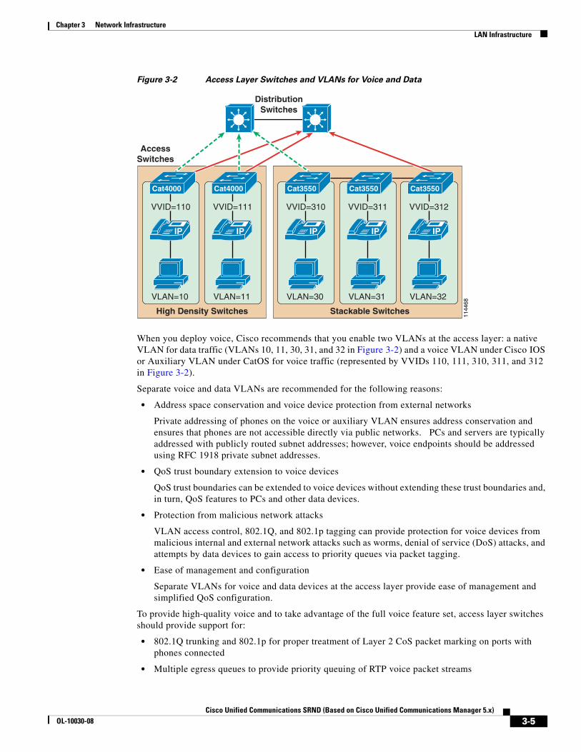
Figure 3-2 Access Layer Switches and VLANs for Voice and Data
When you deploy voice, Cisco recommends that you enable two VLANs at the access layer: a native VLAN for data traffic (VLANs 10, 11, 30, 31, and 32 in Figure 3-2) and a voice VLAN under Cisco IOS or Auxiliary VLAN under CatOS for voice traffic (represented by VVIDs 110, 111, 310, 311, and 312 in Figure 3-2).
Separate voice and data VLANs are recommended for the following reasons:
• Address space conservation and voice device protection from external networks
Private addressing of phones on the voice or auxiliary VLAN ensures address conservation and ensures that phones are not accessible directly via public networks. PCs and servers are typically addressed with publicly routed subnet addresses; however, voice endpoints should be addressed using RFC 1918 private subnet addresses.
• QoS trust boundary extension to voice devices
QoS trust boundaries can be extended to voice devices without extending these trust boundaries and, in turn, QoS features to PCs and other data devices.
• Protection from malicious network attacks
VLAN access control, 802.1Q, and 802.1p tagging can provide protection for voice devices from malicious internal and external network attacks such as worms, denial of service (DoS) attacks, and attempts by data devices to gain access to priority queues via packet tagging.
• Ease of management and configuration
Separate VLANs for voice and data devices at the access layer provide ease of management and simplified QoS configuration.
To provide high-quality voice and to take advantage of the full voice feature set, access layer switches should provide support for:
• 802.1Q trunking and 802.1p for proper treatment of Layer 2 CoS packet marking on ports with phones connected
• Multiple egress queues to provide priority queuing of RTP voice packet streams
1144
68
IP
Cat4000
VVID=110
VLAN=10
High Density Switches
IP
Cat4000
VVID=111
VLAN=11
IP
Cat3550
VVID=310
VLAN=30
Stackable Switches
IP
Cat3550
VVID=311
VLAN=31
IP
Cat3550
VVID=312
VLAN=32
DistributionSwitches
AccessSwitches
3-5Cisco Unified Communications SRND (Based on Cisco Unified Communications Manager 5.x)
OL-10030-08
Chapter 3 Network InfrastructureLAN Infrastructure
• The ability to classify or reclassify traffic and establish a network trust boundary
• Inline power capability (Although inline power capability is not mandatory, it is highly recommended for the access layer switches.)
• Layer 3 awareness and the ability to implement QoS access control lists (These features are required if you are using certain IP telephony endpoints, such as a PC running a softphone application, that cannot benefit from an extended trust boundary.)
Spanning Tree Protocol (STP)
To minimize convergence times and maximize fault tolerance at Layer 2, enable the following STP features:
• PortFast
Enable PortFast on all access ports. The phones, PCs, or servers connected to these ports do not forward bridge protocol data units (BPDUs) that could affect STP operation. PortFast ensures that the phone or PC, when connected to the port, is able to begin receiving and transmitting traffic immediately without having to wait for STP to converge.
• Root guard or BPDU guard
Enable root guard or BPDU guard on all access ports to prevent the introduction of a rogue switch that might attempt to become the Spanning Tree root, thereby causing STP re-convergence events and potentially interrupting network traffic flows. Ports that are set to errdisable state by BPDU guard must either be re-enabled manually or the switch must be configured to re-enable ports automatically from the errdisable state after a configured period of time.
• UplinkFast and BackboneFast
Enable these features where appropriate to ensure that, when changes occur on the Layer 2 network, STP converges as rapidly as possible to provide high availability. When using stackable switches such as the Catalyst 2950, 3550, or 3750, enable Cross-Stack UplinkFast (CSUF) to provide fast failover and convergence if a switch in the stack fails.
• UniDirectional Link Detection (UDLD)
Enable this feature to reduce convergence and downtime on the network when link failures or misbehaviors occur, thus ensuring minimal interruption of network service. UDLD detects, and takes out of service, links where traffic is flowing in only one direction. This feature prevents defective links from being mistakenly considered as part of the network topology by the Spanning Tree and routing protocols.
Note With the introduction of RSTP 802.1w, features such as PortFast and UplinkFast are not required because these mechanisms are built in to this standard. If RSTP has been enabled on the Catalyst switch, these commands are not necessary.
3-6Cisco Unified Communications SRND (Based on Cisco Unified Communications Manager 5.x)
OL-10030-08
Chapter 3 Network InfrastructureLAN Infrastructure
Campus Distribution Layer
The distribution layer of the Campus LAN includes the portion of the network from the wiring closet switches to the next-hop switch, and it is the first Layer-2-to-Layer-3 traversal in the LAN. Distribution layer switches typically include Layer 3-enabled Catalyst 4000 and 6000 switches and the Catalyst 3750 for smaller deployments.
At the distribution layer, it is important to provide redundancy to ensure high availability, including redundant links between the distribution layer switches (or routers) and the access layer switches. To avoid creating topological loops at Layer 2, use Layer 3 links for the connections between redundant Distribution switches when possible.
Hot Standby Router Protocol (HSRP)
HSRP should also be enabled at the distribution layer to ensure that all routers are made redundant and that, in the event of a failure, another router can take over. HSRP configuration should incorporate the following:
• Standby track
The standby track command indicates that the HSRP should monitor a particular interface(s). If the interface goes down, then the HSRP priority of the box is reduced, typically forcing a failover to another device. This command is used in conjunction with the standby preempt command.
• Standby preempt
This command ensures that, when a device's priority becomes higher than all the other HSRP-configured devices in the standby group, that device will take over as the active Layer 3 router for the HSRP standby address.
HSRP should also be configured in such a way as to load-balance traffic between both HSRP routers. To provide load balancing, configure each HSRP device as the active HSRP router for one VLAN or interface, and configure the standby router for another VLAN or interface. Evenly distributing active and standby VLANs between both HSRP devices ensures load-balancing. Devices on one VLAN use the active HSRP device as their default gateway, and devices on another VLAN use the same HSRP device as a standby default gateway only if the other HSRP device fails. This type of configuration prevents all network traffic from being sent to a single active router and enables other HSRP devices to help carry the load.
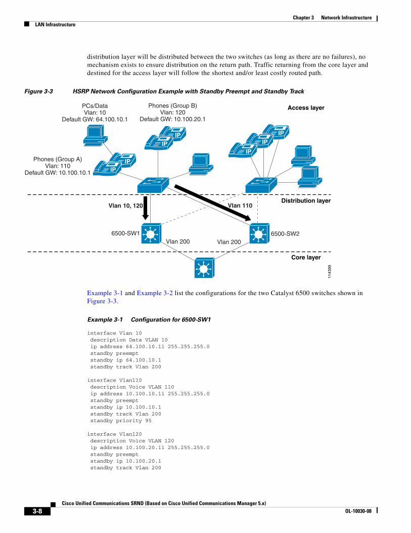
Figure 3-3 shows an example of an HSRP-enabled network. In this figure, the two Catalyst 6500 switches (6500-SW1 and 6500-SW2) have been configured with multiple VLAN interfaces. Assuming that there are no link failures in the network, 6500-SW1 is the standby HSRP router for VLAN 110 (the voice VLAN for Group A phones) and is the active HSRP router for VLAN 10 (the data VLAN) and for VLAN 120 (the voice VLAN for Group B phones). 6500-SW2 is configured in reverse; it is the active HSRP router for VLAN 110 and the standby HSRP router for VLAN 10 and VLAN 120. As configured, both switches are actively in use, and the load can be distributed between the two by evenly distributing all Layer 2 VLANs between them. Each switch is also configured to track its local VLAN 200 interface and, in the event of a VLAN 200 link failure, the other switch will preempt and become the active router for all VLANs. Likewise, if either switch fails, the other switch will handle the traffic for all three VLANs.
The PCs and phones at the access layer in Figure 3-3 have been configured with default gateways that correspond to the HSRP addresses for each of the HSRP groups. Devices in voice VLANs 110 and 120 are pointing to 10.100.10.1 and 10.100.20.1, respectively, as the default gateways, which correspond to the HSRP addresses for the VLAN 110 and 120 interfaces on both switches. Devices in data VLAN 10 are pointing to 64.100.10.1 as the default gateway, which corresponds to the HSRP address of the VLAN 10 interface on both switches. Note that, while traffic flowing from the access layer to the
3-7Cisco Unified Communications SRND (Based on Cisco Unified Communications Manager 5.x)
OL-10030-08
Chapter 3 Network InfrastructureLAN Infrastructure
distribution layer will be distributed between the two switches (as long as there are no failures), no mechanism exists to ensure distribution on the return path. Traffic returning from the core layer and destined for the access layer will follow the shortest and/or least costly routed path.
Figure 3-3 HSRP Network Configuration Example with Standby Preempt and Standby Track
Example 3-1 and Example 3-2 list the configurations for the two Catalyst 6500 switches shown in Figure 3-3.
Example 3-1 Configuration for 6500-SW1
interface Vlan 10 description Data VLAN 10 ip address 64.100.10.11 255.255.255.0 standby preempt standby ip 64.100.10.1 standby track Vlan 200
interface Vlan110 description Voice VLAN 110 ip address 10.100.10.11 255.255.255.0 standby preempt standby ip 10.100.10.1 standby track Vlan 200 standby priority 95
interface Vlan120 description Voice VLAN 120 ip address 10.100.20.11 255.255.255.0 standby preempt standby ip 10.100.20.1 standby track Vlan 200
Access layer
Distribution layer
Core layer
1143
99
Vlan 200 Vlan 200
Vlan 10, 120 Vlan 110
PCs/DataVlan: 10
Default GW: 64.100.10.1
Phones (Group A)Vlan: 110
Default GW: 10.100.10.1
Phones (Group B)Vlan: 120
Default GW: 10.100.20.1
6500-SW1 6500-SW2
IP
IP
IP
IP
IPIP
IP
3-8Cisco Unified Communications SRND (Based on Cisco Unified Communications Manager 5.x)
OL-10030-08
Chapter 3 Network InfrastructureLAN Infrastructure
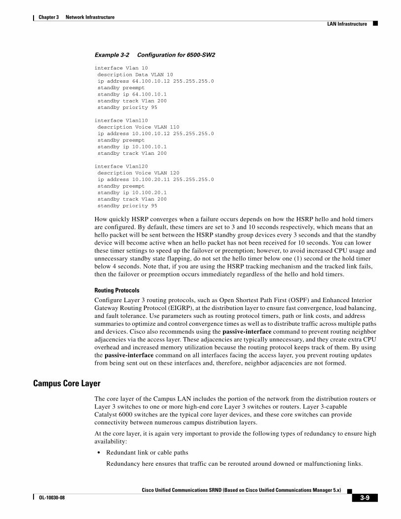
Example 3-2 Configuration for 6500-SW2
interface Vlan 10 description Data VLAN 10 ip address 64.100.10.12 255.255.255.0 standby preempt standby ip 64.100.10.1 standby track Vlan 200 standby priority 95
interface Vlan110 description Voice VLAN 110 ip address 10.100.10.12 255.255.255.0 standby preempt standby ip 10.100.10.1 standby track Vlan 200
interface Vlan120 description Voice VLAN 120 ip address 10.100.20.11 255.255.255.0 standby preempt standby ip 10.100.20.1 standby track Vlan 200 standby priority 95
How quickly HSRP converges when a failure occurs depends on how the HSRP hello and hold timers are configured. By default, these timers are set to 3 and 10 seconds respectively, which means that an hello packet will be sent between the HSRP standby group devices every 3 seconds and that the standby device will become active when an hello packet has not been received for 10 seconds. You can lower these timer settings to speed up the failover or preemption; however, to avoid increased CPU usage and unnecessary standby state flapping, do not set the hello timer below one (1) second or the hold timer below 4 seconds. Note that, if you are using the HSRP tracking mechanism and the tracked link fails, then the failover or preemption occurs immediately regardless of the hello and hold timers.
Routing Protocols
Configure Layer 3 routing protocols, such as Open Shortest Path First (OSPF) and Enhanced Interior Gateway Routing Protocol (EIGRP), at the distribution layer to ensure fast convergence, load balancing, and fault tolerance. Use parameters such as routing protocol timers, path or link costs, and address summaries to optimize and control convergence times as well as to distribute traffic across multiple paths and devices. Cisco also recommends using the passive-interface command to prevent routing neighbor adjacencies via the access layer. These adjacencies are typically unnecessary, and they create extra CPU overhead and increased memory utilization because the routing protocol keeps track of them. By using the passive-interface command on all interfaces facing the access layer, you prevent routing updates from being sent out on these interfaces and, therefore, neighbor adjacencies are not formed.
Campus Core Layer
The core layer of the Campus LAN includes the portion of the network from the distribution routers or Layer 3 switches to one or more high-end core Layer 3 switches or routers. Layer 3-capable Catalyst 6000 switches are the typical core layer devices, and these core switches can provide connectivity between numerous campus distribution layers.
At the core layer, it is again very important to provide the following types of redundancy to ensure high availability:
• Redundant link or cable paths
Redundancy here ensures that traffic can be rerouted around downed or malfunctioning links.
3-9Cisco Unified Communications SRND (Based on Cisco Unified Communications Manager 5.x)
OL-10030-08
Chapter 3 Network InfrastructureLAN Infrastructure
• Redundant devices
Redundancy here ensures that, in the event of a device failure, another device in the network can continue performing tasks that the failed device was doing.
• Redundant device sub-systems
This type of redundancy ensures that multiple power supplies and Supervisor engines are available within a device so that the device can continue to function in the event that one of these components fails.
Routing protocols at the core layer should again be configured and optimized for path redundancy and fast convergence. There should be no STP in the core because network connectivity should be routed at Layer 3. Finally, each link between the core and distribution devices should belong to its own VLAN or subnet and be configured using a 30-bit subnet mask.
Data Center and Server Farm
Typically, Cisco Unified Communications Manager (Unified CM) cluster servers, including media resource servers, reside in a data center or server farm environment. In addition, centralized gateways and centralized hardware media resources such as conference bridges, DSP or transcoder farms, and media termination points are located in the data center or server farm. Because these servers and resources are critical to voice networks, Cisco recommends distributing all Unified CM cluster servers, centralized voice gateways, and centralized hardware resources between multiple physical switches and, if possible, multiple physical locations within the campus. This distribution of resources ensures that, given a hardware failure (such as a switch or switch line card failure), at least some servers in the cluster will still be available to provide telephony services. In addition, some gateways and hardware resources will still be available to provide access to the PSTN and to provide auxiliary services. Besides being physically distributed, these servers, gateways, and hardware resources should be distributed among separate VLANs or subnets so that, if a broadcast storm or denial of service attack occurs on a particular VLAN, not all voice connectivity and services will be disrupted.
Network Services
The deployment of an IP Communications system requires the coordinated design of a well structured, highly available, and resilient network infrastructure as well as an integrated set of network services including Domain Name System (DNS), Dynamic Host Configuration Protocol (DHCP), Trivial File Transfer Protocol (TFTP), and Network Time Protocol (NTP).
Domain Name System (DNS)
DNS enables the mapping of host names and network services to IP addresses within a network or networks. DNS server(s) deployed within a network provide a database that maps network services to hostnames and, in turn, hostnames to IP addresses. Devices on the network can query the DNS server and receive IP addresses for other devices in the network, thereby facilitating communication between network devices.
Complete reliance on a single network service such as DNS can introduce an element of risk when a critical IP Communications system is deployed. If the DNS server becomes unavailable and a network device is relying on that server to provide a hostname-to-IP-address mapping, communication can and will fail. For this reason, Cisco highly recommends that you do not rely on DNS name resolution for any communications between Unified CM and the IP Communications endpoints. The use of DNS to provide simplified system management and Server (SRV) records is supported, and Cisco recommends defining each Unified CM cluster as a member of a valid sub-domain within the larger organizational DNS domain whenever possible.
3-10Cisco Unified Communications SRND (Based on Cisco Unified Communications Manager 5.x)
OL-10030-08
Chapter 3 Network InfrastructureLAN Infrastructure
Configure Unified CM(s), gateways, and endpoint devices to use IP addresses rather than hostnames. Cisco does not recommend configuration of DNS parameters such as DNS server addresses, hostnames, and domain names in endpoint device configurations. During the initial installation of the publisher in a Unified CM cluster, the publisher will be referenced in the server table by the hostname you provided for the system. Before installation and configuration of any subsequent subscribers or the definition of any endpoints, you should change this server entry to the IP address of the publisher rather than the hostname. Each subscriber added to the cluster should be defined in this same server table via IP address initially and not by hostname. Each subscriber should be added to this server table one device at a time, and there should be no definitions for non-existent subscribers at any time other than the new subscriber being installed.
During installation of the publisher and subscriber, Cisco recommend that you do not select the option to enable DNS unless DNS is specifically required for system management purposes. If DNS is enabled, Cisco still highly recommend that you do not use DNS names in the configuration of the IP Communications endpoints, gateways, and Unified CM servers. Even if DNS is enabled on the servers in the cluster, it is never used for any intra-cluster server-to-server communications and is used only for communications to devices external to the cluster itself.
Note Enabling the DNS service is not required for the use of SRV records by Unified CM.
Cisco Unified CM 5.0 does not permit the manual configuration of HOSTS or LHOSTS files. A local version of the HOSTS table is automatically built by the publisher in each cluster and distributed to all subscriber nodes via a secure communications channel. This local table is used for managing secure intra-cluster communications and does not contain addresses or names of any endpoints other than the Unified CM servers themselves. LMHOSTS files do not exist and are not used by Cisco Unified CM 5.0.
There are some situations in which configuring and using DNS might be unavoidable. For example, if Network Address Translation (NAT) is required for communications between the IP phones and Unified CM in the IP Communications network, DNS is required to ensure proper mapping of NAT translated addresses to network host devices. Likewise, some IP telephony disaster recovery network configurations rely on DNS to ensure proper failover of the network during failure scenarios by mapping hostnames to secondary backup site IP addresses.
If either of these two situations exists and DNS must be configured, you must deploy DNS servers in a geographically redundant fashion so that a single DNS server failure will not prevent network communications between IP telephony devices. By providing DNS server redundancy in the event of a single DNS server failure, you ensure that devices relying on DNS to communicate on the network can still receive hostname-to-IP-address mappings from a backup or secondary DNS server.
Note Hostname resolution within the cluster via either the local HOSTS file or DNS queries is performed only at subsystem initialization (that is, when a server is booted up). As a result, in order for a server within the cluster to resolve a DNS name that has been changed in either the HOSTS file or the DNS server, the Cisco CallManager Service must be restarted on all servers within the cluster.
Dynamic Host Configuration Protocol (DHCP)
DHCP is used by hosts on the network to obtain initial configuration information, including IP address, subnet mask, default gateway, and TFTP server address. DHCP eases the administrative burden of manually configuring each host with an IP address and other configuration information. DHCP also provides automatic reconfiguration of network configuration when devices are moved between subnets. The configuration information is provided by a DHCP server located in the network, which responds to DHCP requests from DHCP-capable clients.
3-11Cisco Unified Communications SRND (Based on Cisco Unified Communications Manager 5.x)
OL-10030-08
Chapter 3 Network InfrastructureLAN Infrastructure
You should configure IP Communications endpoints to use DHCP to simplify deployment of these devices. Any RFC 2131 compliant DHCP server can be used to provide configuration information to IP Communications network devices. When deploying IP telephony devices in an existing data-only network, all you have to do is add DHCP voice scopes to an existing DHCP server for these new voice devices. Because IP telephony devices are configured to use and rely on a DHCP server for IP configuration information, you must deploy DHCP servers in a redundant fashion. At least two DHCP servers should be deployed within the telephony network such that, if one of the servers fails, the other can continue to answer DHCP client requests. You should also ensure that DHCP server(s) are configured with enough IP subnet addresses to handle all DHCP-reliant clients within the network.
DHCP Option 150
IP telephony endpoints can be configured to rely on DHCP Option 150 to identify the source of telephony configuration information, available from a server running the Trivial File Transfer Protocol (TFTP).
In the simplest configuration, where a single TFTP server is offering service to all deployed endpoints, Option 150 is delivered as a single IP address pointing to the system's designated TFTP server. The DHCP scope can also deliver two IP addresses under Option 150, for deployments where there are two TFTP servers within the same cluster. The phone would use the second address if it fails to contact the primary TFTP server, thus providing redundancy. To achieve both redundancy and load sharing between the TFTP servers, you can configure Option 150 to provide the two TFTP server addresses in reverse order for half of the DHCP scopes.
Note If the primary TFTP server is available but is not able to grant the requested file to the phone (for example, because the requesting phone is not configured on that cluster), the phone will not attempt to contact the secondary TFTP server.
Cisco highly recommends using a direct IP address (that is, not relying on a DNS service) for Option 150 because doing so eliminates dependencies on DNS service availability during the phone boot-up and registration process.
Note Even though IP phones support a maximum of two TFTP servers under Option 150, you could configure a cluster with more than two TFTP servers. For instance, if a Unified CM system is clustered over a WAN at three separate sites, three TFTP servers could be deployed (one at each site). Phones within each site could then be granted a DHCP scope containing that site's TFTP server within Option 150. This configuration would bring the TFTP service closer to the endpoints, thus reducing latency and ensuring failure isolation between the sites (one site's failure would not affect TFTP service at another site). However, when the configuration file is modified, the publisher must send a new copy of the database to each TFTP server in the cluster. This propagation of the database consumes publisher CPU resources and can slow performance if more than two TFTP servers are deployed in the cluster.
DHCP Lease Times
Configure DHCP lease times as appropriate for the network environment. Given a fairly static network in which PCs and telephony devices remain in the same place for long periods of time, Cisco recommends longer DHCP lease times (for example, one week). Shorter lease times require more frequent renewal of the DHCP configuration and increase the amount of DHCP traffic on the network. Conversely, networks that incorporate large numbers of mobile devices, such as laptops and wireless telephony devices, should be configured with shorter DHCP lease times (for example, one day) to prevent depletion of DHCP-managed subnet addresses. Mobile devices typically use IP addresses for
3-12Cisco Unified Communications SRND (Based on Cisco Unified Communications Manager 5.x)
OL-10030-08
Chapter 3 Network InfrastructureLAN Infrastructure
short increments of time and then might not request a DHCP renewal or new address for a long period of time. Longer lease times will tie up these IP addresses and prevent them from being reassigned even when they are no longer being used.
Cisco Unified IP Phones adhere to the conditions of the DHCP lease duration as specified in the DHCP server's scope configuration. Once half the lease time has expired since the last successful DHCP server acknowledgment, the IP phone will request a lease renewal. This DHCP client Request, once acknowledged by the DHCP server, will allow the IP phone to retain use of the IP scope (that is, the IP address, default gateway, subnet mask, DNS server (optional), and TFTP server (optional)) for another lease period. If the DHCP server becomes unavailable, an IP phone will not be able to renew its DHCP lease, and as soon as the lease expires, it will relinquish its IP configuration and will thus become unregistered from Unified CM until a DHCP server can grant it another valid scope.
In centralized call processing deployments, if a remote site is configured to use a centralized DHCP server (through the use of a DHCP relay agent such as the IP Helper Address in Cisco IOS) and if connectivity to the central site is severed, IP phones within the branch will not be able to renew their DHCP scope leases. In this situation, branch IP phones are at risk of seeing their DHCP lease expire, thus losing the use of their IP address, which would lead to service interruption. Given the fact that phones attempt to renew their leases at half the lease time, DHCP lease expiration can occur as soon as half the lease time since the DHCP server became unreachable. For example, if the lease time of a DHCP scope is set to 4 days and a WAN failure causes the DHCP server to be unavailable to the phones in a branch, those phones will be unable to renew their leases at half the lease time (in this case, 2 days). The IP phones could stop functioning as early as 2 days after the WAN failure, unless the WAN comes back up and the DHCP server is available before that time. If the WAN connectivity failure persists, all phones see their DHCP scope expire after a maximum of 4 days from the WAN failure.
This situation can be mitigated by one of the following methods:
• Set the DHCP scope lease to a long duration (for example, 8 days or more).
This method would give the system administrator a minimum of half the lease time to remedy any DHCP reachability problem. Long lease durations also have the effect of reducing the frequency of network traffic associated with lease renewals.
• Configure co-located DHCP server functionality (for example, run a DHCP server function on the branch's Cisco IOS router).
This approach is immune to WAN connectivity interruption. One effect of such an approach is to decentralize the management of IP addresses, requiring incremental configuration efforts in each branch. (See DHCP Network Deployments, page 3-13, for more information.)
Note The term co-located refers to two or more devices in the same physical location, with no WAN or MAN connection between them.
DHCP Network Deployments
There are two options for deploying DHCP functionality within an IP telephony network:
• Centralized DHCP Server
Typically, for a single-site campus IP telephony deployment, the DHCP server should be installed at a central location within the campus. As mentioned previously, redundant DHCP servers should be deployed. If the IP telephony deployment also incorporates remote branch telephony sites, as in a centralized multisite Unified CM deployment, a centralized server can be used to provide DHCP service to devices in the remote sites. This type of deployment requires that you configure the ip helper-address on the branch router interface. Keep in mind that, if redundant DHCP servers are deployed at the central site, both servers' IP addresses must be configured as ip helper-address.
3-13Cisco Unified Communications SRND (Based on Cisco Unified Communications Manager 5.x)
OL-10030-08
Chapter 3 Network InfrastructureLAN Infrastructure
Also note that, if branch-side telephony devices rely on a centralized DHCP server and the WAN link between the two sites fails, devices at the branch site will be unable to send DHCP requests or receive DHCP responses.
Note By default, service dhcp is enabled on the Cisco IOS device and does not appear in the configuration. Do not disable this service on the branch router because doing so will disable the DHCP relay agent on the device, and the ip helper-address configuration command will not work.
• Centralized DHCP Server and Remote Site Cisco IOS DHCP Server
When configuring DHCP for use in a centralized multisite Unified CM deployment, you can use a centralized DHCP server to provide DHCP service to centrally located devices. Remote devices could receive DHCP service from a locally installed server or from the Cisco IOS router at the remote site. This type of deployment ensures that DHCP services are available to remote telephony devices even during WAN failures. Example 3-3 lists the basic Cisco IOS DHCP server configuration commands.
Example 3-3 Cisco IOS DHCP Server Configuration Commands
! Activate DHCP Service on the IOS Device
service dhcp
! Specify any IP Address or IP Address Range to be excluded from the DHCP pool
ip dhcp excluded-address <ip-address>|<ip-address-low> <ip-address-high>
! Specify the name of this specific DHCP pool, the subnet and mask for this! pool, the default gateway and up to four TFTP
ip dhcp pool <dhcp-pool name> network <ip-subnet> <mask> default-router <default-gateway-ip> option 150 ip <tftp-server-ip-1> ...
! Note: IP phones use only the first two addresses supplied in the option 150! field even if more than two are configured.
Unified CM DHCP Sever (Standalone versus Co-Resident DHCP)
Typically DHCP servers are dedicated machine(s) in most network infrastructures, and they run in conjunction with the DNS and Windows Internet Naming Service (WINS) services used by that network. In some instances, given a small Unified CM deployment with no more than 1000 devices registering to the cluster, you may run DHCP on a Unified CM server to support those devices. However, if the server experiences high CPU load, you should move DHCP to a standalone server. If more than 1000 devices are registered to the cluster, DHCP must not be run on a Unified CM server but instead must be run on a dedicated or standalone server(s).
Note The term co-resident refers to two or more services or applications running on the same server.
3-14Cisco Unified Communications SRND (Based on Cisco Unified Communications Manager 5.x)
OL-10030-08
Chapter 3 Network InfrastructureLAN Infrastructure
Trivial File Transfer Protocol (TFTP)
Within a Cisco Unified CM system, endpoints such as IP phones rely on a TFTP-based process to acquire configuration files, software images, and other endpoint-specific information. The Cisco TFTP service is a file serving system that can run on one or more Unified CM servers. It builds configuration files and serves firmware files, ringer files, device configuration files, and so forth, to endpoints.
The TFTP file systems can hold several file types, such as the following:
• Phone configuration files
• Phone firmware files
• Certificate Trust List (CTL) files
• Tone localization files
• User interface (UI) localization and dictionary files
• Ringer files
• Softkey files
• Dial plan files for SIP phones
The TFTP server manages and serves two types of files, those that are not modifiable (for example, firmware files for phones) and those that can be modified (for example, configuration files).
A typical configuration file contains a prioritized list of Unified CMs for a device (for example, an SCCP or SIP phone), the TCP ports on which the device connects to those Unified CMs, and an executable load identifier. Configuration files for selected devices contain locale information and URLs for the messages, directories, services, and information buttons on the phone.
When a device's configuration changes, the TFTP server rebuilds the configuration files by pulling the relevant information from the Unified CM database. The new file(s) is then downloaded to the phone once the phone has been reset. As an example, if a single phone's configuration file is modified (such as during Extension Mobility login or logout), only that file is rebuilt and downloaded to the phone. However, if the configuration details of a device pool are changed (for example, if the primary Unified CM server is changed), then all devices in that device pool need to have their configuration files rebuilt and downloaded. For device pools that contain large numbers of devices, this file rebuilding process can impact server performance.
When a device requests a configuration file from the TFTP server, the TFTP server searches for the configuration file in its internal caches, the disk, and then alternate Cisco file servers (if specified). If the TFTP server finds the configuration file, it sends it to the device. If the configuration file provides Unified CM names, the device resolves the name by using DNS and opens a connection to the Unified CM. If the device does not receive an IP address or name, it uses the TFTP server name or IP address to attempt a registration connection. If the TFTP server cannot find the configuration file, it sends a "file not found" message to the device.
A device that requests a configuration file while the TFTP server is rebuilding configuration files or while it is processing the maximum number of requests, will receive a message from the TFTP server that causes the device to request the configuration file later. The Maximum Serving Count service parameter, which can be configured, specifies the maximum number of requests that can be handled concurrently by the TFTP server. (Default value = 500 requests.) Use the default value if the TFTP service is run along with other Cisco CallManager services on the same server. For a dedicated TFTP server, use the following suggested values for the Maximum Serving Count:
• 1500 requests for a single-processor system
• 3000 requests for a dual-processor system
3-15Cisco Unified Communications SRND (Based on Cisco Unified Communications Manager 5.x)
OL-10030-08
Chapter 3 Network InfrastructureLAN Infrastructure
An Example of TFTP in Operation
Every time an endpoint reboots, the endpoint will request a configuration file (via TFTP) whose name is based on the requesting endpoint's MAC address. (For a Cisco Unified IP Phone 7961 with MAC address ABCDEF123456, the file name would be SEPABCDEF123456.cnf.xml.) The received configuration file includes the software version that the phone must run and a list of Cisco Unified CM servers with which the phone should register. The endpoint might also download, via TFTP, ringer files, softkey templates, and other miscellaneous files to acquire the necessary configuration information before becoming operational.
If the configuration file includes software file(s) version numbers that are different than those the phone is currently using, the phone will also download the new software file(s) from the TFTP server to upgrade itself. The number of files an endpoint must download to upgrade its software varies based on the type of endpoint and the differences between the phone's current software and the new software.
TFTP File Transfer Times
Each time an endpoint requests a file, there is a new TFTP transfer session. For centralized call processing deployments, the time to complete each of these transfers will affect the time it takes for an endpoint to start and become operational as well as the time it takes for an endpoint to upgrade during a scheduled maintenance. While TFTP transfer times are not the only factor that can affect these end states, they are a significant component.
The time to complete each file transfer via TFTP is predictable as a function of the file size, the percentage of TFTP packets that must be retransmitted, and the network latency or round-trip time.
At first glance, network bandwidth might seem to be missing from the previous statement, but it is actually included via the percentage of TFTP packets that must be retransmitted. This is because, if there is not enough network bandwidth to support the file transfer(s), then packets will be dropped by the network interface queuing algorithms and will have to be retransmitted.
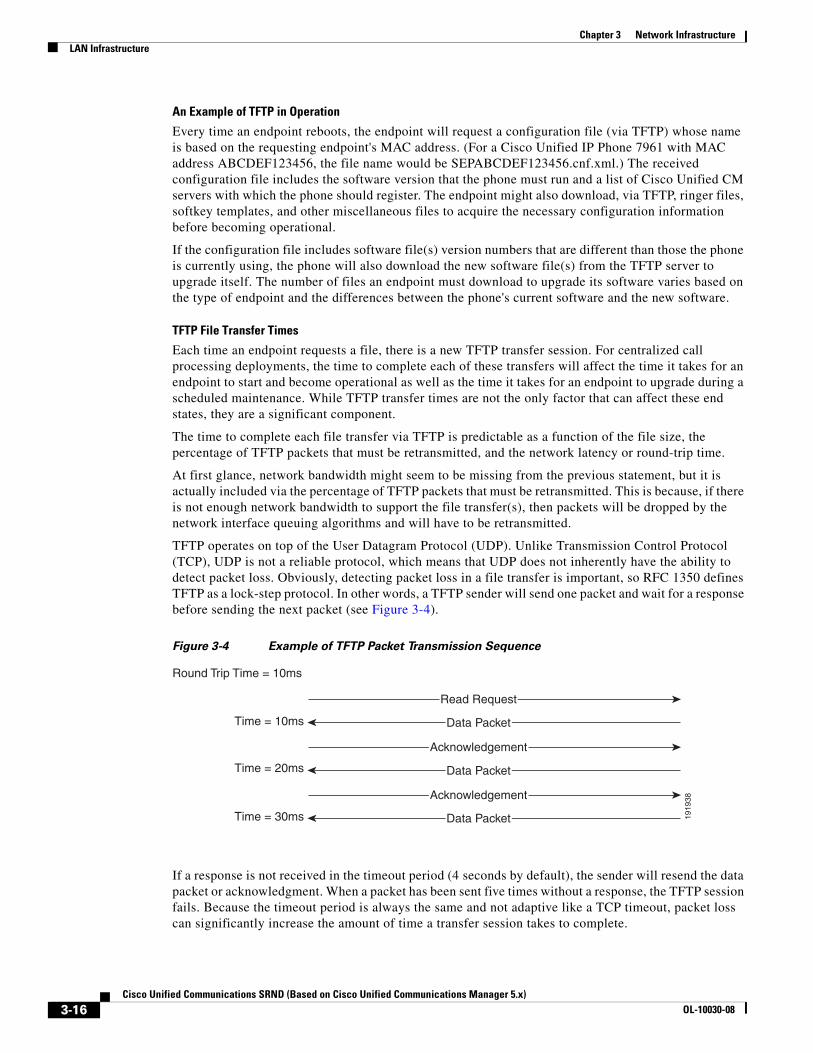
TFTP operates on top of the User Datagram Protocol (UDP). Unlike Transmission Control Protocol (TCP), UDP is not a reliable protocol, which means that UDP does not inherently have the ability to detect packet loss. Obviously, detecting packet loss in a file transfer is important, so RFC 1350 defines TFTP as a lock-step protocol. In other words, a TFTP sender will send one packet and wait for a response before sending the next packet (see Figure 3-4).
Figure 3-4 Example of TFTP Packet Transmission Sequence
If a response is not received in the timeout period (4 seconds by default), the sender will resend the data packet or acknowledgment. When a packet has been sent five times without a response, the TFTP session fails. Because the timeout period is always the same and not adaptive like a TCP timeout, packet loss can significantly increase the amount of time a transfer session takes to complete.
1919
38
Round Trip Time = 10ms
Time = 10ms
Time = 20ms
Time = 30ms
Read Request
Data Packet
Acknowledgement
Data Packet
Acknowledgement
Data Packet
3-16Cisco Unified Communications SRND (Based on Cisco Unified Communications Manager 5.x)
OL-10030-08
Chapter 3 Network InfrastructureLAN Infrastructure
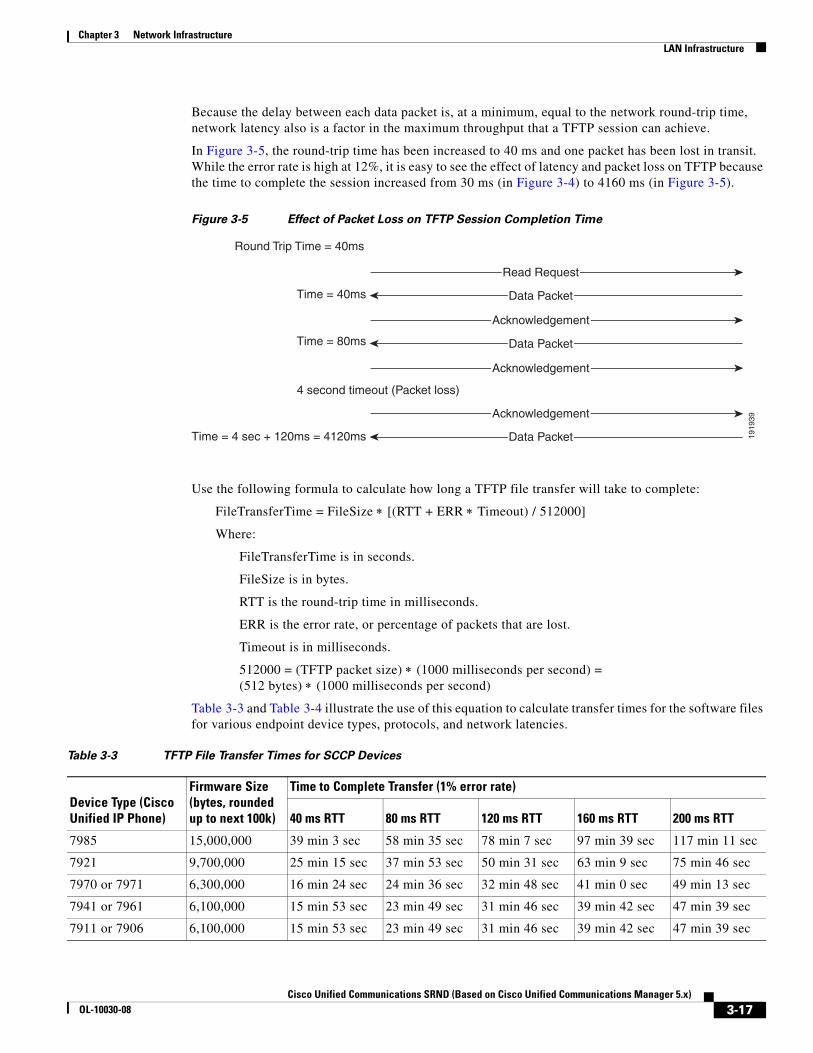
Because the delay between each data packet is, at a minimum, equal to the network round-trip time, network latency also is a factor in the maximum throughput that a TFTP session can achieve.
In Figure 3-5, the round-trip time has been increased to 40 ms and one packet has been lost in transit. While the error rate is high at 12%, it is easy to see the effect of latency and packet loss on TFTP because the time to complete the session increased from 30 ms (in Figure 3-4) to 4160 ms (in Figure 3-5).
Figure 3-5 Effect of Packet Loss on TFTP Session Completion Time
Use the following formula to calculate how long a TFTP file transfer will take to complete:
FileTransferTime = FileSize ∗ [(RTT + ERR ∗ Timeout) / 512000]
Where:
FileTransferTime is in seconds.
FileSize is in bytes.
RTT is the round-trip time in milliseconds.
ERR is the error rate, or percentage of packets that are lost.
Timeout is in milliseconds.
512000 = (TFTP packet size) ∗ (1000 milliseconds per second) = (512 bytes) ∗ (1000 milliseconds per second)
Table 3-3 and Table 3-4 illustrate the use of this equation to calculate transfer times for the software files for various endpoint device types, protocols, and network latencies.
1919
39
Round Trip Time = 40ms
Time = 40ms
Time = 80ms
Time = 4 sec + 120ms = 4120ms
Read Request
Data Packet
Acknowledgement
Data Packet
Acknowledgement
Data Packet
Acknowledgement
4 second timeout (Packet loss)
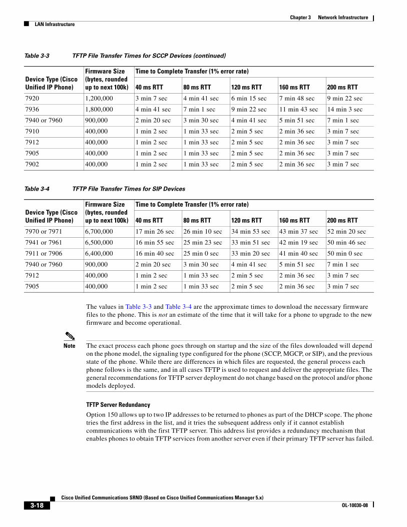
Table 3-3 TFTP File Transfer Times for SCCP Devices
Device Type (Cisco Unified IP Phone)
Firmware Size (bytes, rounded up to next 100k)
Time to Complete Transfer (1% error rate)
40 ms RTT 80 ms RTT 120 ms RTT 160 ms RTT 200 ms RTT
7985 15,000,000 39 min 3 sec 58 min 35 sec 78 min 7 sec 97 min 39 sec 117 min 11 sec
7921 9,700,000 25 min 15 sec 37 min 53 sec 50 min 31 sec 63 min 9 sec 75 min 46 sec
7970 or 7971 6,300,000 16 min 24 sec 24 min 36 sec 32 min 48 sec 41 min 0 sec 49 min 13 sec
7941 or 7961 6,100,000 15 min 53 sec 23 min 49 sec 31 min 46 sec 39 min 42 sec 47 min 39 sec
7911 or 7906 6,100,000 15 min 53 sec 23 min 49 sec 31 min 46 sec 39 min 42 sec 47 min 39 sec
3-17Cisco Unified Communications SRND (Based on Cisco Unified Communications Manager 5.x)
OL-10030-08
Chapter 3 Network InfrastructureLAN Infrastructure
The values in Table 3-3 and Table 3-4 are the approximate times to download the necessary firmware files to the phone. This is not an estimate of the time that it will take for a phone to upgrade to the new firmware and become operational.
Note The exact process each phone goes through on startup and the size of the files downloaded will depend on the phone model, the signaling type configured for the phone (SCCP, MGCP, or SIP), and the previous state of the phone. While there are differences in which files are requested, the general process each phone follows is the same, and in all cases TFTP is used to request and deliver the appropriate files. The general recommendations for TFTP server deployment do not change based on the protocol and/or phone models deployed.
TFTP Server Redundancy
Option 150 allows up to two IP addresses to be returned to phones as part of the DHCP scope. The phone tries the first address in the list, and it tries the subsequent address only if it cannot establish communications with the first TFTP server. This address list provides a redundancy mechanism that enables phones to obtain TFTP services from another server even if their primary TFTP server has failed.
7920 1,200,000 3 min 7 sec 4 min 41 sec 6 min 15 sec 7 min 48 sec 9 min 22 sec
7936 1,800,000 4 min 41 sec 7 min 1 sec 9 min 22 sec 11 min 43 sec 14 min 3 sec
7940 or 7960 900,000 2 min 20 sec 3 min 30 sec 4 min 41 sec 5 min 51 sec 7 min 1 sec
7910 400,000 1 min 2 sec 1 min 33 sec 2 min 5 sec 2 min 36 sec 3 min 7 sec
7912 400,000 1 min 2 sec 1 min 33 sec 2 min 5 sec 2 min 36 sec 3 min 7 sec
7905 400,000 1 min 2 sec 1 min 33 sec 2 min 5 sec 2 min 36 sec 3 min 7 sec
7902 400,000 1 min 2 sec 1 min 33 sec 2 min 5 sec 2 min 36 sec 3 min 7 sec
Table 3-4 TFTP File Transfer Times for SIP Devices
Device Type (Cisco Unified IP Phone)
Firmware Size (bytes, rounded up to next 100k)
Time to Complete Transfer (1% error rate)
40 ms RTT 80 ms RTT 120 ms RTT 160 ms RTT 200 ms RTT
7970 or 7971 6,700,000 17 min 26 sec 26 min 10 sec 34 min 53 sec 43 min 37 sec 52 min 20 sec
7941 or 7961 6,500,000 16 min 55 sec 25 min 23 sec 33 min 51 sec 42 min 19 sec 50 min 46 sec
7911 or 7906 6,400,000 16 min 40 sec 25 min 0 sec 33 min 20 sec 41 min 40 sec 50 min 0 sec
7940 or 7960 900,000 2 min 20 sec 3 min 30 sec 4 min 41 sec 5 min 51 sec 7 min 1 sec
7912 400,000 1 min 2 sec 1 min 33 sec 2 min 5 sec 2 min 36 sec 3 min 7 sec
7905 400,000 1 min 2 sec 1 min 33 sec 2 min 5 sec 2 min 36 sec 3 min 7 sec
Table 3-3 TFTP File Transfer Times for SCCP Devices (continued)
Device Type (Cisco Unified IP Phone)
Firmware Size (bytes, rounded up to next 100k)
Time to Complete Transfer (1% error rate)
40 ms RTT 80 ms RTT 120 ms RTT 160 ms RTT 200 ms RTT
3-18Cisco Unified Communications SRND (Based on Cisco Unified Communications Manager 5.x)
OL-10030-08
Chapter 3 Network InfrastructureLAN Infrastructure
TFTP Load Sharing
Cisco recommends that you grant different ordered lists of TFTP servers to different subnets to allow for load balancing. For example:
• In subnet 10.1.1.0/24: Option 150: TFTP1_Primary, TFTP1_Secondary
• In subnet 10.1.2.0/24: Option 150: TFTP1_Secondary, TFTP1_Primary
Under normal operations, a phone in subnet 10.1.1.0/24 will request TFTP services from TFTP1_Primary, while a phone in subnet 10.1.2.0/24 will request TFTP services from TFTP1_Secondary. If TFTP1_Primary fails, then phones from both subnets will request TFTP services from TFTP1_Secondary.
Load balancing avoids having a single TFTP server hot-spot, where all phones from multiple clusters rely on the same server for service. TFTP load balancing is especially important when phone software loads are transferred, such as during a Unified CM upgrade, because more files of larger size are being transferred, thus imposing a bigger load on the TFTP server.
Centralized TFTP Services
In multi-cluster systems, it is possible to have a single subnet or VLAN containing phones from multiple clusters. In this situation, the TFTP servers whose addresses are provided to all phones in the subnet or VLAN must answer the file transfer requests made by each phone, regardless of which cluster contains the phone. In a centralized TFTP deployment, a set of TFTP servers associated with one of the clusters must provide TFTP services to all the phones in the multi-cluster system.
In order to provide this single point of file access, each cluster's TFTP server must be able to serve files via the central proxy TFTP server. With Cisco Unified CM 5.0 and later releases, this proxy arrangement is accomplished by configuring a set of possible redirect locations in the central TFTP server, pointing to each of the other clusters’ TFTP servers. This configuration uses a HOST redirect statement in the Alternate File Locations on the centralized TFTP server, one for each of the other clusters. Each of the redundant TFTP servers in the centralized cluster should point to one of the redundant servers in each of the child clusters. It is not necessary to point the centralized server to both redundant servers in the child clusters because the redistribution of files within each individual cluster and the failover mechanisms of the phones between the redundant servers in the central cluster provide for a very high degree of fault tolerance.
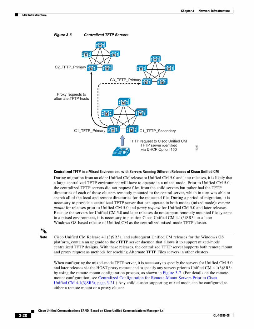
Figure 3-6 shows an example of the operation of this process. A request from a phone registered to Cluster 3 is directed to the centralized TFTP server configured in Cluster 1 (C1_TFTP_Primary). This server will in turn query each of the configured alternate TFTP servers until one responds with a copy of the file initially requested by the phone. Requests to the centralized secondary TFTP server (C1_TFTP_Secondary) will be sent by proxy to the other clusters’ secondary TFTP servers until either the requested file is found or all servers report that the requested file does not exist.
3-19Cisco Unified Communications SRND (Based on Cisco Unified Communications Manager 5.x)
OL-10030-08
Chapter 3 Network InfrastructureLAN Infrastructure
Figure 3-6 Centralized TFTP Servers
Centralized TFTP in a Mixed Environment, with Servers Running Different Releases of Cisco Unified CM
During migration from an older Unified CM release to Unified CM 5.0 and later releases, it is likely that a large centralized TFTP environment will have to operate in a mixed mode. Prior to Unified CM 5.0, the centralized TFTP servers did not request files from the child servers but rather had the TFTP directories of each of those clusters remotely mounted to the central server, which in turn was able to search all of the local and remote directories for the requested file. During a period of migration, it is necessary to provide a centralized TFTP server that can operate in both modes (mixed mode): remote mount for releases prior to Unified CM 5.0 and proxy request for Unified CM 5.0 and later releases. Because the servers for Unified CM 5.0 and later releases do not support remotely mounted file systems in a mixed environment, it is necessary to position Cisco Unified CM 4.1(3)SR3a or a later Windows OS-based release of Unified CM as the centralized mixed-mode TFTP cluster.
Note Cisco Unified CM Release 4.1(3)SR3a, and subsequent Unified CM releases for the Windows OS platform, contain an upgrade to the cTFTP server daemon that allows it to support mixed-mode centralized TFTP designs. With these releases, the centralized TFTP server supports both remote mount and proxy request as methods for reaching Alternate TFTP Files servers in other clusters.
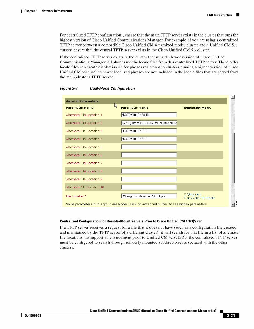
When configuring the mixed-mode TFTP server, it is necessary to specify the servers for Unified CM 5.0 and later releases via the HOST proxy request and to specify any servers prior to Unified CM 4.1(3)SR3a by using the remote mount configuration process, as shown in Figure 3-7. (For details on the remote mount configuration, see Centralized Configuration for Remote-Mount Servers Prior to Cisco Unified CM 4.1(3)SR3r, page 3-21.) Any child cluster supporting mixed mode can be configured as either a remote mount or a proxy cluster.
1533
71
M
M
M M
M
IP
C2_TFTP_Primary
Proxy requests toalternate TFTP hosts
C3_TFTP_Primary
C1_TFTP_Primary C1_TFTP_Secondary
TFTP request to Cisco Unified CM TFTP server identifiedvia DHCP Option 150
M
M
M M
M
M
M
M M
M
3-20Cisco Unified Communications SRND (Based on Cisco Unified Communications Manager 5.x)
OL-10030-08
Chapter 3 Network InfrastructureLAN Infrastructure
For centralized TFTP configurations, ensure that the main TFTP server exists in the cluster that runs the highest version of Cisco Unified Communications Manager. For example, if you are using a centralized TFTP server between a compatible Cisco Unified CM 4.x (mixed mode) cluster and a Unified CM 5.x cluster, ensure that the central TFTP server exists in the Cisco Unified CM 5.x cluster.
If the centralized TFTP server exists in the cluster that runs the lower version of Cisco Unified Communications Manager, all phones use the locale files from this centralized TFTP server. These older locale files can create display issues for phones registered to clusters running a higher version of Cisco Unified CM because the newer localized phrases are not included in the locale files that are served from the main cluster's TFTP server.
Figure 3-7 Dual-Mode Configuration
Centralized Configuration for Remote-Mount Servers Prior to Cisco Unified CM 4.1(3)SR3r
If a TFTP server receives a request for a file that it does not have (such as a configuration file created and maintained by the TFTP server of a different cluster), it will search for that file in a list of alternate file locations. To support an environment prior to Unified CM 4.1(3)SR3, the centralized TFTP server must be configured to search through remotely mounted subdirectories associated with the other clusters.
3-21Cisco Unified Communications SRND (Based on Cisco Unified Communications Manager 5.x)
OL-10030-08
Chapter 3 Network InfrastructureLAN Infrastructure
Example 3-4 Alternate TFTP FIle Locations
A large campus system is deployed using three clusters, and each cluster contains a TFTP server. TFTP1, the TFTP server for Cluster1, is configured as the centralized TFTP server for the campus. The other clusters and TFTP servers are named in sequence as TFTP2 for Cluster2 and TFTP3 for Cluster3. In all subnets, the DHCP scope provides TFTP1's IP address as Option 150.
First, TFTP2 and TFTP3 are configured to write their configuration files to TFTP1's drive, each in a different subdirectory, as follows:
• TFTP2's alternate file location is set to: \\TFTP1_IP\Program Files\Cisco\TFTPpath\TFTP2
• TFTP3's alternate file location is set to: \\TFTP1_IP\Program Files\Cisco\TFTPpath\TFTP3
Second, TFTP1 is configured to search in the alternate file locations as follows:
• Alternate File Location 1: c:\Program Files\Cisco\TFTPpath\TFTP2
• Alternate File Location 2: c:\Program Files\Cisco\TFTPpath\TFTP3
Note In this example, TFTP1_IP represents the IP address of TFTP1. Also, TFTP1 requires that Windows NT subdirectories be created manually for TFTP2 and TFTP3.
Cisco recommends that you use Universal Naming Convention (UNC) paths (in the form at \\<IP_address>\<Full_path_to_folder>) to point a TFTP server to alternate file locations. Cisco does not recommend creating non-default NT "shares" or using DNS names. Also, ensure that all clusters meet the proper login ID, password, and security privileges (workgroup, domain, or directory-based) for the Cisco TFTP service.
With Cisco Unified CM Release 3.2 and later, Cisco TFTP servers cache the IP phone configuration files in RAM by default. For those files to be written to a centralized TFTP server, you must disable (turn off) file caching by setting the following service parameters as indicated on each TFTP server configured to write to the centralized TFTP server:
• Enable Caching of Configuration Files: False (required)
• Enable Caching of Constant and Bin Files at Startup: False (recommended)
Note Beginning with Cisco Unified CM Release 5.1, the Enable Caching of Configuration Files service parameter is no longer available and configuration files are always cached in memory (rather than written to disk).
Network Time Protocol (NTP)
NTP allows network devices to synchronize their clocks to a network time server or network-capable clock. NTP is critical for ensuring that all devices in a network have the same time. When troubleshooting or managing a telephony network, it is crucial to synchronize the time stamps within all error and security logs, traces, and system reports on devices throughout the network. This synchronization enables administrators to recreate network activities and behaviors based on a common timeline. Billing records and call detail records (CDRs) also require accurate synchronized time.
Unified CM NTP Time Synchronization
Time synchronization is especially critical on Unified CM servers. In addition to ensuring that CDR records are accurate and that log files are synchronized, having an accurate time source is necessary for any future IPSec features to be enabled within the cluster and for communications with any external entity.
3-22Cisco Unified Communications SRND (Based on Cisco Unified Communications Manager 5.x)
OL-10030-08
Chapter 3 Network InfrastructureLAN Infrastructure
Unified CM 5.0 automatically synchronizes the NTP time of all subscribers in the cluster to the publisher. During installation, each subscriber is automatically configured to point to an NTP server running on the publisher. The publisher considers itself to be a master server and provides time for the cluster based on its internal hardware clock unless it is configured to synchronize from an external server. Cisco highly recommends configuring the publisher to point to a Stratum-1, Stratum-2, or Stratum-3 NTP server to ensure that the cluster time is synchronized with an external time source.
Note Manual configuration of the NTP.conf file is no longer possible, and any changes made to the file will be automatically replaced by the system configuration.
For additional information about NTP time synchronization in a Cisco Unified Communications environment, refer to the Cisco IP Telephony Clock Synchronization: Best Practices white paper, available at
http://www.cisco.com/en/US/products/sw/voicesw/ps556/products_white_paper0900aecd8037fdb5.shtml
Cisco IOS and CatOS NTP Time Synchronization
Time synchronization is also important for other devices within the network. Cisco IOS routers and Catalyst switches should be configured to synchronize their time with the rest of the network devices via NTP. This is critical for ensuring that debug, syslog, and console log messages are time-stamped appropriately. Troubleshooting telephony network issues is simplified when a clear timeline can be drawn for events that occur on devices throughout the network.
Example 3-5 illustrates the configuration of NTP time synchronization on Cisco IOS and CatOS devices.
Example 3-5 Cisco IOS and CatOS NTP Configuration
Cisco IOS configuration:
ntp server 64.100.21.254
CatOS configuration:
set ntp server 64.100.21.254set ntp client enable
To ensure proper NTP time synchronization on routers and switches, it might be necessary to configure time zones using the clock timezone command (in Cisco IOS) and/or the set timezone command (in CatOS).
Power over Ethernet (PoE)
PoE (or inline power) is 48 Volt DC power provided over standard Ethernet unshielded twisted-pair (UTP) cable. Instead of using wall power, IP phones and other inline powered devices (PDs) such as the Aironet Wireless Access Points can receive power provided by inline power-capable Catalyst Ethernet switches or other inline power source equipment (PSE). Inline power is enabled by default on all inline power-capable Catalyst switches.
Deploying inline power-capable switches with uninterrupted power supplies (UPS) ensures that IP phones continue to receive power during power failure situations. Provided the rest of the telephony network is available during these periods of power failure, then IP phones should be able to continue
3-23Cisco Unified Communications SRND (Based on Cisco Unified Communications Manager 5.x)
OL-10030-08
Chapter 3 Network InfrastructureLAN Infrastructure
making and receiving calls. You should deploy inline power-capable switches at the campus access layer within wiring closets to provide inline-powered Ethernet ports for IP phones, thus eliminating the need for wall power.
Cisco PoE is delivered on the same wire pairs used for data connectivity (pins 1, 2, 3, and 6). If existing access switch ports are not capable of inline power, you can use a power patch panel to inject power into the cabling. (In this case pins 4, 5, 7, and 8 are used.) Additionally, power injectors may be used for specific deployment needs.
Caution The use of power injectors or power patch panels can damage some devices because power is always applied to the Ethernet pairs. PoE switch ports automatically detect the presence of a device that requires PoE before enabling it on a port-by-port basis.
In addition to Cisco PoE inline power, Cisco now supports the IEEE 802.3af PoE standard. Currently, only some access switches and phones comply with 802.3af. Over time, all phones and switches will support 802.3af PoE. The Catalyst 6500, 4500, and 3750 are currently capable of supporting 802.3af. For information about which Cisco Unified IP Phones support the 802.3af PoE standard, see the Endpoint Features Summary, page 20-37.
Category 3 Cabling
The use of Category 3 cabling is supported for IP Communications under the following conditions:
• Phones with a PC port and a PC attached to it (Cisco Unified IP Phones 7971, 7970, 7961, 7960, 7941, 7940, 7911, and 7910+SW) should be set to 10 Mb, full-duplex.
This setting requires hard-coding the upstream switch port, the phone switch and PC ports, and the PC NIC port to 10 Mb, full-duplex. No ports should be set to AUTO negotiate. If desired, you can hard-code the phone's PC port to 10 Mb half-duplex, thereby forcing the PC's NIC to negotiate to 10 Mb half-duplex (assuming the PC's NIC is configured to AUTO negotiate). This configuration is acceptable as long as the uplink between the phone and the upstream switch port is set to 10 Mb full-duplex.
• Phones with no PC ports and with 10 Mb switch ports (Cisco Unified IP Phones 7902, 7905, and 7910) should be allowed to auto-negotiate to 10 Mb, half-duplex.
Because these phones support only 10 Mb Ethernet and their ports cannot be manually configured, the upstream switch port should be set to either AUTO negotiate or 10 Mb, half-duplex. In both cases, these phones will negotiate to 10 Mb, half-duplex.
• Phones with a PC port but no PC attached to it (Cisco Unified IP Phones 7971, 7970, 7961, 7960, 7941, 7940, 7912, 7911, and 7910+SW) can be allowed to negotiate to 10 Mb, half-duplex.
If you leave these phones with the default switch port configuration of AUTO negotiate and configure the upstream switch port to 10 Mb, half-duplex, these phones will revert to 10Mb, half-duplex.
Note The Cisco Unified IP Phone 7912 should not be used with Category 3 cable when a PC is attached because the switch and PC ports on this phone cannot be forced to 10 Mb, full duplex.
3-24Cisco Unified Communications SRND (Based on Cisco Unified Communications Manager 5.x)
OL-10030-08
Chapter 3 Network InfrastructureLAN Infrastructure
IBM Type 1A and 2A Cabling
The use of IBM Cabling System (ICS) or Token Ring shielded twisted-pair type 1A or 2A cabling is supported for IP Communications under the following conditions:
• Cable lengths should be 100 meters or less.
• Adapters without impedance matching should be used for converting from universal data connector (UDC) to RJ-45 Ethernet standard.
Note There are only two twisted pairs in the Token Ring cables. Therefore, inline power for IP phones can be supported, but mid-span power insertion cannot (with Cisco Inline Power and 802.3af) because it requires more than two pairs.
Running data over the network is not always a sufficient test of the quality of the cable plant because some non-compliance issues might not be apparent. Therefore, customers might want to perform a cable plant survey to verify that their type 1A and 2A cabling installation is compliant with Ethernet standards.
For more information about the use of IBM cabling, refer to the Product Bulletin Shielded Twisted-Pair Cabling Support for Cisco Fast Ethernet Products, available at
http://www.cisco.com
LAN Quality of Service (QoS)Until recently, quality of service was not an issue in the enterprise campus due to the asynchronous nature of data traffic and the ability of network devices to tolerate buffer overflow and packet loss. However, with new applications such as voice and video, which are sensitive to packet loss and delay, buffers and not bandwidth are the key QoS issue in the enterprise campus.
Figure 3-8 illustrates the typical oversubscription that occurs in LAN infrastructures.
3-25Cisco Unified Communications SRND (Based on Cisco Unified Communications Manager 5.x)
OL-10030-08
Chapter 3 Network InfrastructureLAN Infrastructure
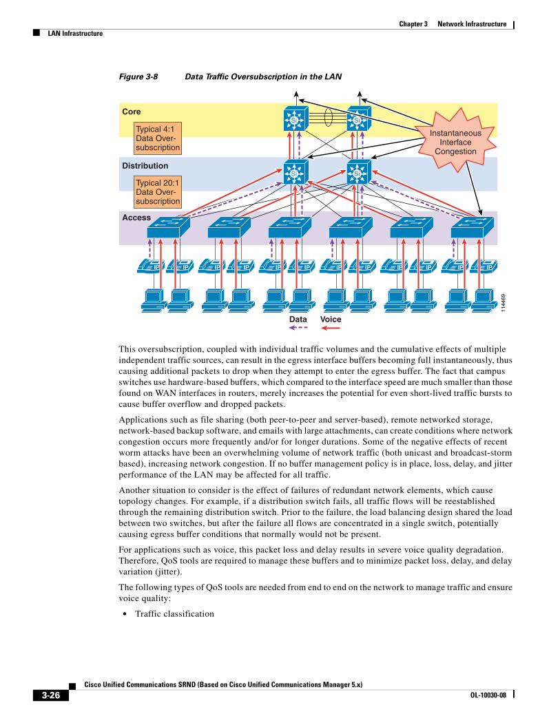
Figure 3-8 Data Traffic Oversubscription in the LAN
This oversubscription, coupled with individual traffic volumes and the cumulative effects of multiple independent traffic sources, can result in the egress interface buffers becoming full instantaneously, thus causing additional packets to drop when they attempt to enter the egress buffer. The fact that campus switches use hardware-based buffers, which compared to the interface speed are much smaller than those found on WAN interfaces in routers, merely increases the potential for even short-lived traffic bursts to cause buffer overflow and dropped packets.
Applications such as file sharing (both peer-to-peer and server-based), remote networked storage, network-based backup software, and emails with large attachments, can create conditions where network congestion occurs more frequently and/or for longer durations. Some of the negative effects of recent worm attacks have been an overwhelming volume of network traffic (both unicast and broadcast-storm based), increasing network congestion. If no buffer management policy is in place, loss, delay, and jitter performance of the LAN may be affected for all traffic.
Another situation to consider is the effect of failures of redundant network elements, which cause topology changes. For example, if a distribution switch fails, all traffic flows will be reestablished through the remaining distribution switch. Prior to the failure, the load balancing design shared the load between two switches, but after the failure all flows are concentrated in a single switch, potentially causing egress buffer conditions that normally would not be present.
For applications such as voice, this packet loss and delay results in severe voice quality degradation. Therefore, QoS tools are required to manage these buffers and to minimize packet loss, delay, and delay variation (jitter).
The following types of QoS tools are needed from end to end on the network to manage traffic and ensure voice quality:
• Traffic classification
1144
69
Typical 4:1Data Over-subscription
Typical 20:1Data Over-subscription
Si
Distribution
Access
SiCore
IPIP IPIP IPIP IPIP IPIP IPIP
Si Si
Data Voice
InstantaneousInterface
Congestion
3-26Cisco Unified Communications SRND (Based on Cisco Unified Communications Manager 5.x)
OL-10030-08
Chapter 3 Network InfrastructureLAN Infrastructure
Classification involves the marking of packets with a specific priority denoting a requirement for class of service (CoS) from the network. The point at which these packet markings are trusted or not trusted is considered the trust boundary. Trust is typically extended to voice devices (phones) and not to data devices (PCs).
• Queuing or scheduling
Interface queuing or scheduling involves assigning packets to one of several queues based on classification for expedited treatment throughout the network.
• Bandwidth provisioning
Provisioning involves accurately calculating the required bandwidth for all applications plus element overhead.
The following sections discuss the use of these QoS mechanisms in a campus environment:
• Traffic Classification, page 3-27
• Interface Queuing, page 3-28
• Bandwidth Provisioning, page 3-29
• Impairments to IP Communications if QoS is Not Employed, page 3-29
Traffic Classification
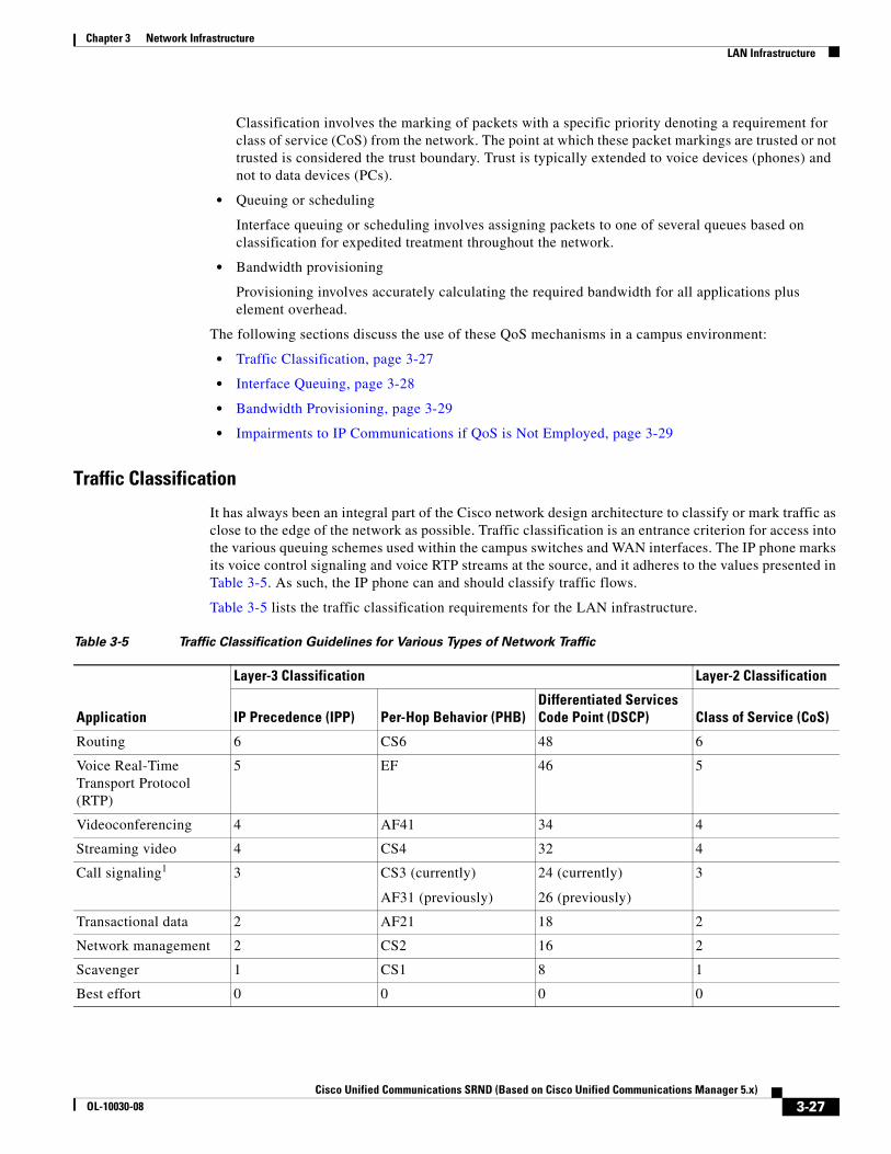
It has always been an integral part of the Cisco network design architecture to classify or mark traffic as close to the edge of the network as possible. Traffic classification is an entrance criterion for access into the various queuing schemes used within the campus switches and WAN interfaces. The IP phone marks its voice control signaling and voice RTP streams at the source, and it adheres to the values presented in Table 3-5. As such, the IP phone can and should classify traffic flows.
Table 3-5 lists the traffic classification requirements for the LAN infrastructure.
Table 3-5 Traffic Classification Guidelines for Various Types of Network Traffic
Application
Layer-3 Classification Layer-2 Classification
IP Precedence (IPP) Per-Hop Behavior (PHB)Differentiated Services Code Point (DSCP) Class of Service (CoS)
Routing 6 CS6 48 6
Voice Real-Time Transport Protocol (RTP)
5 EF 46 5
Videoconferencing 4 AF41 34 4
Streaming video 4 CS4 32 4
Call signaling1 3 CS3 (currently)
AF31 (previously)
24 (currently)
26 (previously)
3
Transactional data 2 AF21 18 2
Network management 2 CS2 16 2
Scavenger 1 CS1 8 1
Best effort 0 0 0 0
3-27Cisco Unified Communications SRND (Based on Cisco Unified Communications Manager 5.x)
OL-10030-08
Chapter 3 Network InfrastructureLAN Infrastructure
For more information about traffic classification, refer to the Enterprise QoS Solution Reference Network Design (SRND), available at
http://www.cisco.com/go/designzone
Traffic Classification for Video Telephony
The main classes of interest for IP Video Telephony are:
• Voice
Voice is classified as CoS 5 (IP Precedence 5, PHB EF, or DSCP 46).
• Videoconferencing
Videoconferencing is classified as CoS 4 (IP Precedence 4, PHB AF41, or DSCP 34).
• Call signaling
Call signaling for voice and videoconferencing is now classified as CoS 3 (IP Precedence 3, PHB CS3, or DSCP 24) but was previously classified as PHB AF31 or DSCP 26.
Cisco highly recommends these classifications as best practices in a Cisco Unified Communications network.
The voice component of a call can be classified in one of two ways, depending on the type of call in progress. A voice-only (or normal) telephone call would have the media classified as CoS 5 (IP Precedence 5 or PHB EF), while the audio channel of a video conference would have the media classified as CoS 4 (IP Precedence 4 or PHB AF41). All the Cisco IP Video Telephony products adhere to the Cisco Corporate QoS Baseline standard, which requires that the audio and video channels of a video call both be marked as CoS 4 (IP Precedence 4 or PHB AF41). The reasons for this recommendation include, but are not limited to, the following:
• To preserve lip-sync between the audio and video channels
• To provide separate classes for audio-only calls and video calls
The signaling class is applicable to all voice signaling protocols (such as SCCP, MGCP, and so on) as well as video signaling protocols (such as SCCP, H.225, RAS, CAST, and so on). These protocols are discussed in more detail in the section on Software-Based Endpoints, page 20-31.
Given the recommended classes, the first step is decide where the packets will be classified (that is, which device will be the first to mark the traffic with its QoS classification). There are essentially two places to mark or classify traffic:
• On the originating endpoint — the classification is then trusted by the upstream switches and routers
• On the switches and/or routers — because the endpoint is either not capable of classifying its own packets or is not trustworthy to classify them correctly
Interface Queuing
After packets have been marked with the appropriate tag at Layer 2 (CoS) and Layer 3 (DSCP or PHB), it is important to configure the network to schedule or queue traffic based on this classification, so as to provide each class of traffic with the service it needs from the network. By enabling QoS on campus switches, you can configure all voice traffic to use separate queues, thus virtually eliminating the possibility of dropped voice packets when an interface buffer fills instantaneously.
1. The recommended DSCP/PHB marking for call control signaling traffic has been changed from 26/AF31 to 24/CS3. A marking migration is planned within Cisco to reflect this change, however many products still mark signaling traffic as 26/AF31. Therefore, in the interim, Cisco recommends that both AF31 and CS3 be reserved for call signaling.
3-28Cisco Unified Communications SRND (Based on Cisco Unified Communications Manager 5.x)
OL-10030-08
Chapter 3 Network InfrastructureLAN Infrastructure
Although network management tools may show that the campus network is not congested, QoS tools are still required to guarantee voice quality. Network management tools show only the average congestion over a sample time span. While useful, this average does not show the congestion peaks on a campus interface.
Transmit interface buffers within a campus tend to congest in small, finite intervals as a result of the bursty nature of network traffic. When this congestion occurs, any packets destined for that transmit interface are dropped. The only way to prevent dropped voice traffic is to configure multiple queues on campus switches. For this reason, Cisco recommends always using a switch that has at least two output queues on each port and the ability to send packets to these queues based on QoS Layer 2 and/or Layer 3 classification. Cisco Catalyst 6000, 4000, 3750, 35XX, and 2950 switches all support two or more output queues per port.
Bandwidth Provisioning
In the campus LAN, bandwidth provisioning recommendations can be summarized by the motto, Over provision and under subscribe. This motto implies careful planning of the LAN infrastructure so that the available bandwidth is always considerably higher than the load and there is no steady-state congestion over the LAN links.
The addition of voice traffic onto a converged network does not represent a significant increase in overall network traffic load; the bandwidth provisioning is still driven by the demands of the data traffic requirements. The design goal is to avoid extensive data traffic congestion on any link that will be traversed by telephony signaling or media flows. Contrasting the bandwidth requirements of a single G.711 voice call (approximately 86 kbps) to the raw bandwidth of a FastEthernet link (100 Mbps) indicates that voice is not a source of traffic that causes network congestion in the LAN, but rather it is a traffic flow to be protected from LAN network congestion.
Impairments to IP Communications if QoS is Not Employed
If QoS is not deployed, packet drops and excessive delay and jitter can occur, leading to impairments of the telephony services. When media packets are subjected to drops, delay, and jitter, the user-perceivable effects include clicking sound, harsh-sounding voice, extended periods of silence, and echo.
When signaling packets are subjected to the same conditions, user-perceivable impairments include unresponsiveness to user input (such as delay to dial tone), continued ringing upon answer, and double dialing of digits due to the user's belief that the first attempt was not effective (thus requiring hang-up and redial). More extreme cases can include endpoint re-initialization, call termination, and the spurious activation of SRST functionality at branch offices (leading to interruption of gateway calls).
These effects apply to all deployment models. However, single-site (campus) deployments tend to be less likely to experience the conditions caused by sustained link interruptions because the larger quantity of bandwidth typically deployed in LAN environments (minimum links of 100 Mbps) allows for some residual bandwidth to be available for the IP Communications system.
In any WAN-based deployment model, traffic congestion is more likely to produce sustained and/or more frequent link interruptions because the available bandwidth is much less than in a LAN (typically less than 2 Mbps), so the link is more easily saturated. The effects of link interruptions impact the users, whether or not the voice media traverses the packet network.
3-29Cisco Unified Communications SRND (Based on Cisco Unified Communications Manager 5.x)
OL-10030-08
Chapter 3 Network InfrastructureWAN Infrastructure
WAN InfrastructureProper WAN infrastructure design is also extremely important for proper IP telephony operation on a converged network. Proper infrastructure design requires following basic configuration and design best practices for deploying a WAN that is as highly available as possible and that provides guaranteed throughput. Furthermore, proper WAN infrastructure design requires deploying end-to-end QoS on all WAN links. The following sections discuss these requirements:
• WAN Design and Configuration, page 3-30
• WAN Quality of Service (QoS), page 3-33
• Resource Reservation Protocol (RSVP), page 3-40
• Bandwidth Provisioning, page 3-49
WAN Design and ConfigurationProperly designing a WAN requires building fault-tolerant network links and planning for the possibility that these links might become unavailable. By carefully choosing WAN topologies, provisioning the required bandwidth, and approaching the WAN infrastructure as another layer in the network topology, you can built a fault-tolerant and redundant network. The following sections examine the required infrastructure layers and network services:
• Deployment Considerations, page 3-30
• Guaranteed Bandwidth, page 3-31
• Best-Effort Bandwidth, page 3-32
Deployment Considerations
WAN deployments for voice networks may be hub-and-spoke or an arbitrary topology. A hub-and-spoke topology consists of a central hub site and multiple remote spoke sites connected into the central hub site. In this scenario, each remote or spoke site is one WAN-link hop away from the central or hub site and two WAN-link hops away from all other spoke sites. An arbitrary topology may contain multiple WAN links and any number of hops between the sites. In this scenario there may be many different paths to the same site or there may be different links used for communication with some sites compared to other sites. The simplest example is three sites, each with a WAN link to the other two sites, forming a triangle. In that case there are two potential paths between each site to each other site.
Topology-unaware call admission control requires the WAN to be hub-and-spoke, or a spoke-less hub in the case of MPLS VPN. This topology ensures that call admission control, provided by Unified CM's locations or a gatekeeper, works properly in keeping track of the bandwidth available between any two sites in the WAN. In addition, multiple hub-and-spoke deployments can be interconnected via WAN links.
Topology-aware call admission control may be used with either hub-and-spoke or an arbitrary WAN topology. This form of call admission control requires parts of the WAN infrastructure to support Resource Reservation Protocol (RSVP). For details, see Resource Reservation Protocol (RSVP), page 3-40, and Call Admission Control, page 9-1.
For more information about centralized and distributed multisite deployment models as well as Multiprotocol Label Switching (MPLS) implications for these deployment models, see the chapter on Deployment Models, page 2-1.
3-30Cisco Unified Communications SRND (Based on Cisco Unified Communications Manager 5.x)
OL-10030-08
Chapter 3 Network InfrastructureWAN Infrastructure
WAN links should, when possible, be made redundant to provide higher levels of fault tolerance. Redundant WAN links provided by different service providers or located in different physical ingress/egress points within the network can ensure backup bandwidth and connectivity in the event that a single link fails. In non-failure scenarios, these redundant links may be used to provide additional bandwidth and offer load balancing of traffic on a per-flow basis over multiple paths and equipment within the WAN. Topology-unaware call admission control normally requires redundant paths to be over-provisioned and under-subscribed to allow for failures that reduce the available bandwidth between sites without the call admission control mechanism being aware of those failures or the reduction in bandwidth. Topology-aware call admission control is able to adjust dynamically to many of the topology changes and allows for efficient use of the total available bandwidth.
Voice and data should remain converged at the WAN, just as they are converged at the LAN. QoS provisioning and queuing mechanisms are typically available in a WAN environment to ensure that voice and data can interoperate on the same WAN links. Attempts to separate and forward voice and data over different links can be problematic in many instances because the failure of one link typically forces all traffic over a single link, thus diminishing throughput for each type of traffic and in most cases reducing the quality of voice. Furthermore, maintaining separate network links or devices makes troubleshooting and management difficult at best.
Because of the potential for WAN links to fail or to become oversubscribed, Cisco recommends deploying non-centralized resources as appropriate at sites on the other side of the WAN. Specifically, media resources, DHCP servers, voice gateways, and call processing applications such as Survivable Remote Site Telephony (SRST) and Cisco Unified Communications Manager Express (Unified CME) should be deployed at non-central sites when and if appropriate, depending on the site size and how critical these functions are to that site. Keep in mind that de-centralizing voice applications and devices can increase the complexity of network deployments, the complexity of managing these resources throughout the enterprise, and the overall cost of a the network solution; however, these factors can be mitigated by the fact that the resources will be available during a WAN link failure.
When deploying voice in a WAN environment, Cisco recommends that you use the lower-bandwidth G.729 codec for any voice calls that will traverse WAN links because this practice will provide bandwidth savings on these lower-speed links. Furthermore, media resources such as MoH should be configured to use multicast transport mechanism when possible because this practice will provide additional bandwidth savings.
Finally, recommendation G.114 of the International Telecommunication Union (ITU) states that the one-way delay in a voice network should be less than or equal to 150 milliseconds. It is important to keep this in mind when implementing low-speed WAN links within a network. Topologies, technologies, and physical distance should be considered for WAN links so that one-way delay is kept at or below this 150-millisecond recommendation. For deployments that use clustering over the WAN, the one-way delay for signaling traffic between clusters should not exceed 20 milliseconds (see Clustering Over the IP WAN, page 2-17).
Guaranteed Bandwidth
Because voice is typically deemed a critical network application, it is imperative that bearer and signaling voice traffic always reaches its destination. For this reason, it is important to choice a WAN topology and link type that can provide guaranteed dedicated bandwidth. The following WAN link technologies can provide guaranteed dedicated bandwidth:
• Leased Lines
• Frame Relay
• Asynchronous Transfer Mode (ATM)
• ATM/Frame-Relay Service Interworking
3-31Cisco Unified Communications SRND (Based on Cisco Unified Communications Manager 5.x)
OL-10030-08
Chapter 3 Network InfrastructureWAN Infrastructure
• Multiprotocol Label Switching (MPLS)
• Cisco Voice and Video Enabled IP Security VPN (IPSec V3PN)
These link technologies, when deployed in a dedicated fashion or when deployed in a private network, can provide guaranteed traffic throughput. All of these WAN link technologies can be provisioned at specific speeds or bandwidth sizes. In addition, these link technologies have built-in mechanisms that help guarantee throughput of network traffic even at low link speeds. Features such as traffic shaping, fragmentation and packet interleaving, and committed information rates (CIR) can help ensure that packets are not dropped in the WAN, that all packets are given access at regular intervals to the WAN link, and that enough bandwidth is available for all network traffic attempting to traverse these links.
Best-Effort Bandwidth
There are some WAN topologies that are unable to provide guaranteed dedicated bandwidth to ensure that network traffic will reach its destination, even when that traffic is critical. These topologies are extremely problematic for voice traffic, not only because they provide no mechanisms to provision guaranteed network throughput, but also because they provide no traffic shaping, packet fragmentation and interleaving, queuing mechanisms, or end-to-end QoS to ensure that critical traffic such as voice will be given preferential treatment.
The following WAN network topologies and link types are examples of this kind of best-effort bandwidth technology:
• The Internet
• DSL
• Cable
• Satellite
• Wireless
In most cases, none of these link types can provide the guaranteed network connectivity and bandwidth required for critical voice and voice applications. However, these technologies might be suitable for personal or telecommuter-type network deployments. At times, these topologies can provide highly available network connectivity and adequate network throughput; but at other times, these topologies can become unavailable for extended periods of time, can be throttled to speeds that render network throughput unacceptable for real-time applications such as voice, or can cause extensive packet losses and require repeated retransmissions. In other words, these links and topologies are unable to provide guaranteed bandwidth, and when traffic is sent on these links, it is sent best-effort with no guarantee that it will reach its destination. For this reason, Cisco recommends that you do not use best-effort WAN topologies for voice-enabled networks that require enterprise-class voice services and quality.
Note There are some new QoS mechanisms for DSL and cable technologies that can provide guaranteed bandwidth; however, these mechanisms are not typically deployed by service providers, and these services are still significantly oversubscribed.
3-32Cisco Unified Communications SRND (Based on Cisco Unified Communications Manager 5.x)
OL-10030-08
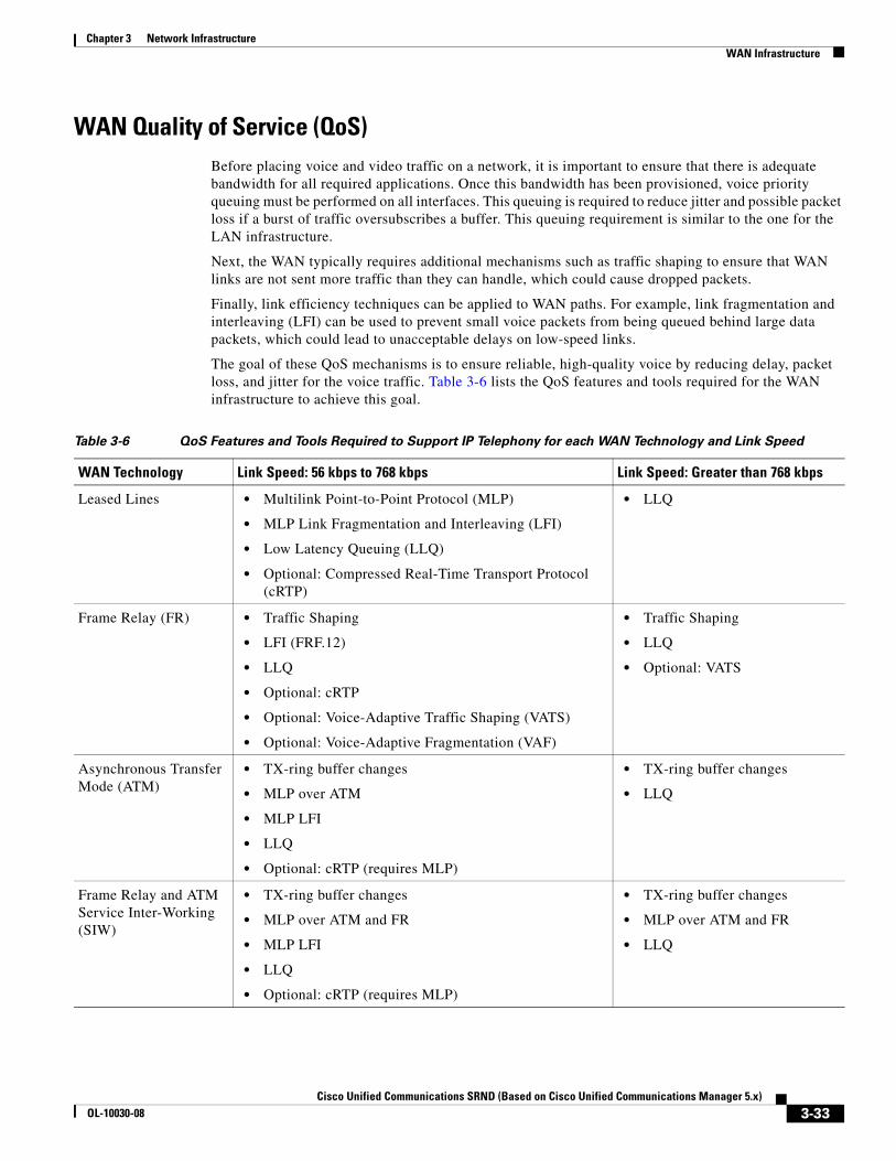
Chapter 3 Network InfrastructureWAN Infrastructure
WAN Quality of Service (QoS)Before placing voice and video traffic on a network, it is important to ensure that there is adequate bandwidth for all required applications. Once this bandwidth has been provisioned, voice priority queuing must be performed on all interfaces. This queuing is required to reduce jitter and possible packet loss if a burst of traffic oversubscribes a buffer. This queuing requirement is similar to the one for the LAN infrastructure.
Next, the WAN typically requires additional mechanisms such as traffic shaping to ensure that WAN links are not sent more traffic than they can handle, which could cause dropped packets.
Finally, link efficiency techniques can be applied to WAN paths. For example, link fragmentation and interleaving (LFI) can be used to prevent small voice packets from being queued behind large data packets, which could lead to unacceptable delays on low-speed links.
The goal of these QoS mechanisms is to ensure reliable, high-quality voice by reducing delay, packet loss, and jitter for the voice traffic. Table 3-6 lists the QoS features and tools required for the WAN infrastructure to achieve this goal.
Table 3-6 QoS Features and Tools Required to Support IP Telephony for each WAN Technology and Link Speed
WAN Technology Link Speed: 56 kbps to 768 kbps Link Speed: Greater than 768 kbps
Leased Lines • Multilink Point-to-Point Protocol (MLP)
• MLP Link Fragmentation and Interleaving (LFI)
• Low Latency Queuing (LLQ)
• Optional: Compressed Real-Time Transport Protocol (cRTP)
• LLQ
Frame Relay (FR) • Traffic Shaping
• LFI (FRF.12)
• LLQ
• Optional: cRTP
• Optional: Voice-Adaptive Traffic Shaping (VATS)
• Optional: Voice-Adaptive Fragmentation (VAF)
• Traffic Shaping
• LLQ
• Optional: VATS
Asynchronous Transfer Mode (ATM)
• TX-ring buffer changes
• MLP over ATM
• MLP LFI
• LLQ
• Optional: cRTP (requires MLP)
• TX-ring buffer changes
• LLQ
Frame Relay and ATM Service Inter-Working (SIW)
• TX-ring buffer changes
• MLP over ATM and FR
• MLP LFI
• LLQ
• Optional: cRTP (requires MLP)
• TX-ring buffer changes
• MLP over ATM and FR
• LLQ
3-33Cisco Unified Communications SRND (Based on Cisco Unified Communications Manager 5.x)
OL-10030-08
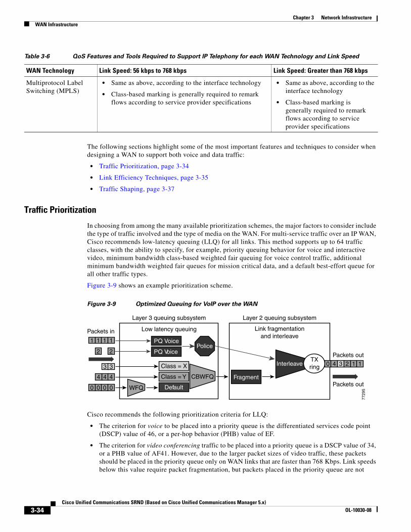
Chapter 3 Network InfrastructureWAN Infrastructure
The following sections highlight some of the most important features and techniques to consider when designing a WAN to support both voice and data traffic:
• Traffic Prioritization, page 3-34
• Link Efficiency Techniques, page 3-35
• Traffic Shaping, page 3-37
Traffic Prioritization
In choosing from among the many available prioritization schemes, the major factors to consider include the type of traffic involved and the type of media on the WAN. For multi-service traffic over an IP WAN, Cisco recommends low-latency queuing (LLQ) for all links. This method supports up to 64 traffic classes, with the ability to specify, for example, priority queuing behavior for voice and interactive video, minimum bandwidth class-based weighted fair queuing for voice control traffic, additional minimum bandwidth weighted fair queues for mission critical data, and a default best-effort queue for all other traffic types.
Figure 3-9 shows an example prioritization scheme.
Figure 3-9 Optimized Queuing for VoIP over the WAN
Cisco recommends the following prioritization criteria for LLQ:
• The criterion for voice to be placed into a priority queue is the differentiated services code point (DSCP) value of 46, or a per-hop behavior (PHB) value of EF.
• The criterion for video conferencing traffic to be placed into a priority queue is a DSCP value of 34, or a PHB value of AF41. However, due to the larger packet sizes of video traffic, these packets should be placed in the priority queue only on WAN links that are faster than 768 Kbps. Link speeds below this value require packet fragmentation, but packets placed in the priority queue are not
Multiprotocol Label Switching (MPLS)
• Same as above, according to the interface technology
• Class-based marking is generally required to remark flows according to service provider specifications
• Same as above, according to the interface technology
• Class-based marking is generally required to remark flows according to service provider specifications
Table 3-6 QoS Features and Tools Required to Support IP Telephony for each WAN Technology and Link Speed
WAN Technology Link Speed: 56 kbps to 768 kbps Link Speed: Greater than 768 kbps
Low latency queuing
PQ Voice
PQ Voice
Class = X
Class = Y
Default
CBWFQ Fragment
Interleave
WFQ
2 2
1 1 1 1
0 0 0 0
3 3
44 4
0 4 3 2 1 177
295
Packets out
Packets outTXring
Link fragmentationand interleave
Layer 2 queuing subsystemLayer 3 queuing subsystem
Packets in
Police
3-34Cisco Unified Communications SRND (Based on Cisco Unified Communications Manager 5.x)
OL-10030-08
Chapter 3 Network InfrastructureWAN Infrastructure
fragmented, thus smaller voice packets could be queued behind larger video packets. For links speeds of 768 Kbps or lower, video conferencing traffic should be placed in a separate class-based weighted fair queue (CBWFQ).
Note One-way video traffic, such as the traffic generated by streaming video applications for services such as video-on-demand or live video feeds, should always use a CBWFQ scheme because that type of traffic has a much higher delay tolerance than two-way video conferencing traffic
• As the WAN links become congested, it is possible to starve the voice control signaling protocols, thereby eliminating the ability of the IP phones to complete calls across the IP WAN. Therefore, voice control protocols, such as H.323, MGCP, and Skinny Client Control Protocol (SCCP), require their own class-based weighted fair queue. The entrance criterion for this queue is a DSCP value of 24 or a PHB value of CS3.
Note Cisco has begun to change the marking of voice control protocols from DSCP 26 (PHB AF31) to DSCP 24 (PHB CS3). However many products still mark signaling traffic as DSCP 26 (PHB AF31); therefore, in the interim, Cisco recommends that you reserve both AF31 and CS3 for call signaling.
• In some cases, certain data traffic might require better than best-effort treatment. This traffic is referred to as mission-critical data, and it is placed into one or more queues that have the required amount of bandwidth. The queuing scheme within this class is first-in-first-out (FIFO) with a minimum allocated bandwidth. Traffic in this class that exceeds the configured bandwidth limit is placed in the default queue. The entrance criterion for this queue could be a Transmission Control Protocol (TCP) port number, a Layer 3 address, or a DSCP/PHB value.
• All remaining traffic can be placed in a default queue for best-effort treatment. If you specify the keyword fair, the queuing algorithm will be weighted fair queuing (WFQ).
Link Efficiency Techniques
The following link efficiency techniques improve the quality and efficiency of low-speed WAN links.
Compressed Real-Time Transport Protocol (cRTP)
You can increase link efficiency by using Compressed Real-Time Transport Protocol (cRTP). This protocol compresses a 40-byte IP, User Datagram Protocol (UDP), and RTP header into approximately two to four bytes. cRTP operates on a per-hop basis. Use cRTP on a particular link only if that link meets all of the following conditions:
• Voice traffic represents more than 33% of the load on the specific link.
• The link uses a low bit-rate codec (such as G.729).
• No other real-time application (such as video conferencing) is using the same link.
If the link fails to meet any one of the preceding conditions, then cRTP is not effective and you should not use it on that link. Another important parameter to consider before using cRTP is router CPU utilization, which is adversely affected by compression and decompression operations.
cRTP on ATM and Frame Relay Service Inter-Working (SIW) links requires the use of Multilink Point-to-Point Protocol (MLP).
3-35Cisco Unified Communications SRND (Based on Cisco Unified Communications Manager 5.x)
OL-10030-08
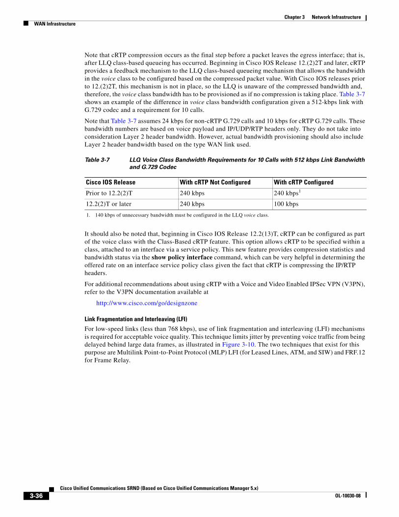
Chapter 3 Network InfrastructureWAN Infrastructure
Note that cRTP compression occurs as the final step before a packet leaves the egress interface; that is, after LLQ class-based queueing has occurred. Beginning in Cisco IOS Release 12.(2)2T and later, cRTP provides a feedback mechanism to the LLQ class-based queueing mechanism that allows the bandwidth in the voice class to be configured based on the compressed packet value. With Cisco IOS releases prior to 12.(2)2T, this mechanism is not in place, so the LLQ is unaware of the compressed bandwidth and, therefore, the voice class bandwidth has to be provisioned as if no compression is taking place. Table 3-7 shows an example of the difference in voice class bandwidth configuration given a 512-kbps link with G.729 codec and a requirement for 10 calls.
Note that Table 3-7 assumes 24 kbps for non-cRTP G.729 calls and 10 kbps for cRTP G.729 calls. These bandwidth numbers are based on voice payload and IP/UDP/RTP headers only. They do not take into consideration Layer 2 header bandwidth. However, actual bandwidth provisioning should also include Layer 2 header bandwidth based on the type WAN link used.
It should also be noted that, beginning in Cisco IOS Release 12.2(13)T, cRTP can be configured as part of the voice class with the Class-Based cRTP feature. This option allows cRTP to be specified within a class, attached to an interface via a service policy. This new feature provides compression statistics and bandwidth status via the show policy interface command, which can be very helpful in determining the offered rate on an interface service policy class given the fact that cRTP is compressing the IP/RTP headers.
For additional recommendations about using cRTP with a Voice and Video Enabled IPSec VPN (V3PN), refer to the V3PN documentation available at
http://www.cisco.com/go/designzone
Link Fragmentation and Interleaving (LFI)
For low-speed links (less than 768 kbps), use of link fragmentation and interleaving (LFI) mechanisms is required for acceptable voice quality. This technique limits jitter by preventing voice traffic from being delayed behind large data frames, as illustrated in Figure 3-10. The two techniques that exist for this purpose are Multilink Point-to-Point Protocol (MLP) LFI (for Leased Lines, ATM, and SIW) and FRF.12 for Frame Relay.
Table 3-7 LLQ Voice Class Bandwidth Requirements for 10 Calls with 512 kbps Link Bandwidth
and G.729 Codec
Cisco IOS Release With cRTP Not Configured With cRTP Configured
Prior to 12.2(2)T 240 kbps 240 kbps1
1. 140 kbps of unnecessary bandwidth must be configured in the LLQ voice class.
12.2(2)T or later 240 kbps 100 kbps
3-36Cisco Unified Communications SRND (Based on Cisco Unified Communications Manager 5.x)
OL-10030-08
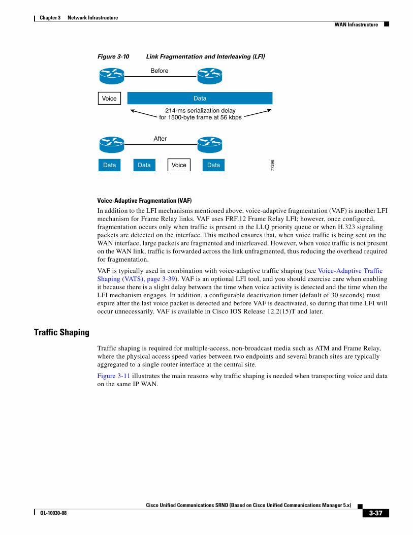
Chapter 3 Network InfrastructureWAN Infrastructure
Figure 3-10 Link Fragmentation and Interleaving (LFI)
Voice-Adaptive Fragmentation (VAF)
In addition to the LFI mechanisms mentioned above, voice-adaptive fragmentation (VAF) is another LFI mechanism for Frame Relay links. VAF uses FRF.12 Frame Relay LFI; however, once configured, fragmentation occurs only when traffic is present in the LLQ priority queue or when H.323 signaling packets are detected on the interface. This method ensures that, when voice traffic is being sent on the WAN interface, large packets are fragmented and interleaved. However, when voice traffic is not present on the WAN link, traffic is forwarded across the link unfragmented, thus reducing the overhead required for fragmentation.
VAF is typically used in combination with voice-adaptive traffic shaping (see Voice-Adaptive Traffic Shaping (VATS), page 3-39). VAF is an optional LFI tool, and you should exercise care when enabling it because there is a slight delay between the time when voice activity is detected and the time when the LFI mechanism engages. In addition, a configurable deactivation timer (default of 30 seconds) must expire after the last voice packet is detected and before VAF is deactivated, so during that time LFI will occur unnecessarily. VAF is available in Cisco IOS Release 12.2(15)T and later.
Traffic Shaping
Traffic shaping is required for multiple-access, non-broadcast media such as ATM and Frame Relay, where the physical access speed varies between two endpoints and several branch sites are typically aggregated to a single router interface at the central site.
Figure 3-11 illustrates the main reasons why traffic shaping is needed when transporting voice and data on the same IP WAN.
Voice
VoiceData Data Data
Data
Before
After
214-ms serialization delayfor 1500-byte frame at 56 kbps
7729
6
3-37Cisco Unified Communications SRND (Based on Cisco Unified Communications Manager 5.x)
OL-10030-08
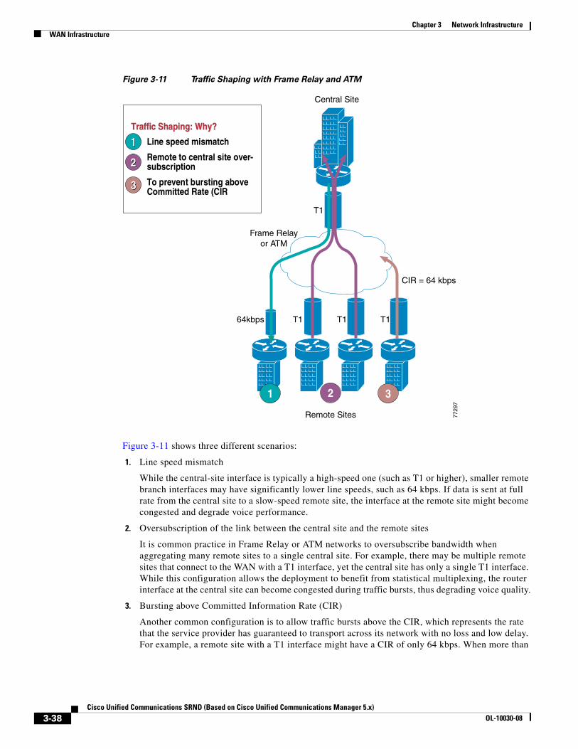
Chapter 3 Network InfrastructureWAN Infrastructure
Figure 3-11 Traffic Shaping with Frame Relay and ATM
Figure 3-11 shows three different scenarios:
1. Line speed mismatch
While the central-site interface is typically a high-speed one (such as T1 or higher), smaller remote branch interfaces may have significantly lower line speeds, such as 64 kbps. If data is sent at full rate from the central site to a slow-speed remote site, the interface at the remote site might become congested and degrade voice performance.
2. Oversubscription of the link between the central site and the remote sites
It is common practice in Frame Relay or ATM networks to oversubscribe bandwidth when aggregating many remote sites to a single central site. For example, there may be multiple remote sites that connect to the WAN with a T1 interface, yet the central site has only a single T1 interface. While this configuration allows the deployment to benefit from statistical multiplexing, the router interface at the central site can become congested during traffic bursts, thus degrading voice quality.
3. Bursting above Committed Information Rate (CIR)
Another common configuration is to allow traffic bursts above the CIR, which represents the rate that the service provider has guaranteed to transport across its network with no loss and low delay. For example, a remote site with a T1 interface might have a CIR of only 64 kbps. When more than
2
Traffic Shaping: Why?Traffic Shaping: Why?
1. Line speed mismatch
2. Remote to central site over-subscription
3. To prevent bursting above Committed Rate (CIR
11
22
33
Central Site
Frame Relayor ATM
64kbps T1 T1 T1
T1
Remote Sites
1 3
7729
7
CIR = 64 kbps
3-38Cisco Unified Communications SRND (Based on Cisco Unified Communications Manager 5.x)
OL-10030-08
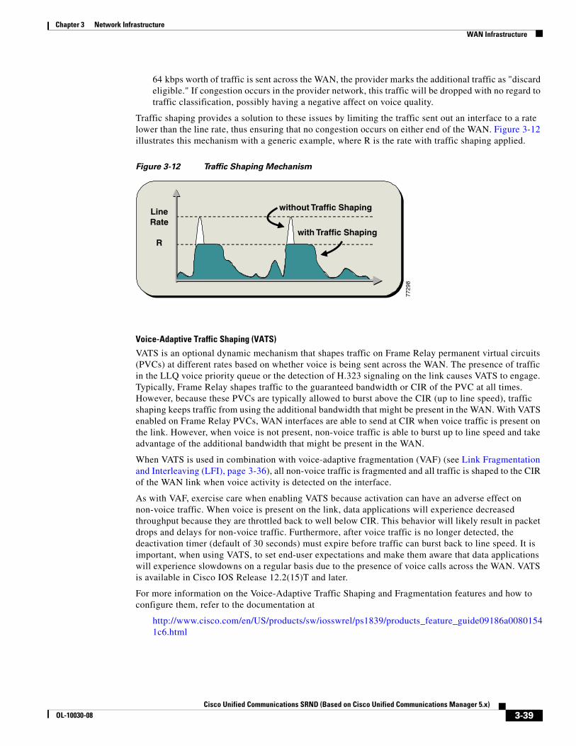
Chapter 3 Network InfrastructureWAN Infrastructure
64 kbps worth of traffic is sent across the WAN, the provider marks the additional traffic as "discard eligible." If congestion occurs in the provider network, this traffic will be dropped with no regard to traffic classification, possibly having a negative affect on voice quality.
Traffic shaping provides a solution to these issues by limiting the traffic sent out an interface to a rate lower than the line rate, thus ensuring that no congestion occurs on either end of the WAN. Figure 3-12 illustrates this mechanism with a generic example, where R is the rate with traffic shaping applied.
Figure 3-12 Traffic Shaping Mechanism
Voice-Adaptive Traffic Shaping (VATS)
VATS is an optional dynamic mechanism that shapes traffic on Frame Relay permanent virtual circuits (PVCs) at different rates based on whether voice is being sent across the WAN. The presence of traffic in the LLQ voice priority queue or the detection of H.323 signaling on the link causes VATS to engage. Typically, Frame Relay shapes traffic to the guaranteed bandwidth or CIR of the PVC at all times. However, because these PVCs are typically allowed to burst above the CIR (up to line speed), traffic shaping keeps traffic from using the additional bandwidth that might be present in the WAN. With VATS enabled on Frame Relay PVCs, WAN interfaces are able to send at CIR when voice traffic is present on the link. However, when voice is not present, non-voice traffic is able to burst up to line speed and take advantage of the additional bandwidth that might be present in the WAN.
When VATS is used in combination with voice-adaptive fragmentation (VAF) (see Link Fragmentation and Interleaving (LFI), page 3-36), all non-voice traffic is fragmented and all traffic is shaped to the CIR of the WAN link when voice activity is detected on the interface.
As with VAF, exercise care when enabling VATS because activation can have an adverse effect on non-voice traffic. When voice is present on the link, data applications will experience decreased throughput because they are throttled back to well below CIR. This behavior will likely result in packet drops and delays for non-voice traffic. Furthermore, after voice traffic is no longer detected, the deactivation timer (default of 30 seconds) must expire before traffic can burst back to line speed. It is important, when using VATS, to set end-user expectations and make them aware that data applications will experience slowdowns on a regular basis due to the presence of voice calls across the WAN. VATS is available in Cisco IOS Release 12.2(15)T and later.
For more information on the Voice-Adaptive Traffic Shaping and Fragmentation features and how to configure them, refer to the documentation at
http://www.cisco.com/en/US/products/sw/iosswrel/ps1839/products_feature_guide09186a00801541c6.html
LineRate
R
without Traffic Shaping
with Traffic Shaping
7729
8
3-39Cisco Unified Communications SRND (Based on Cisco Unified Communications Manager 5.x)
OL-10030-08
Chapter 3 Network InfrastructureWAN Infrastructure
Resource Reservation Protocol (RSVP)The Resource Reservation Protocol (RSVP) is the first significant industry-standard protocol for dynamically setting up end-to-end QoS across a heterogeneous network. RSVP, which runs over IP, was first introduced by the IETF in RFC 2205, and it enables an application to reserve network bandwidth dynamically. Using RSVP, applications can request a certain level of QoS for a data flow across a network. Because of its distributed and dynamic nature, RSVP is capable of reserving bandwidth across any network topology, therefore it can be used to provide topology-aware call admission control for voice and video calls.
This section focuses on the RSVP protocol principles and its interactions with the WAN infrastructure, specifically the QoS aspects, while the motivation and the mechanisms for call admission control based on RSVP are described in the chapter on Call Admission Control, page 9-1.
This section covers the following specific topics:
• RSVP Principles, page 3-40
• RSVP and QoS in WAN Routers, page 3-43
• RSVP Application ID, page 3-47
• RSVP Design Best Practices, page 3-49
RSVP Principles
RSVP performs resource reservation for a given data flow across a network by defining signaling messages that are exchanged between the source and destination devices for the data flow and that are processed by intermediate routers along the path. The RSVP signaling messages are IP packets with the protocol number in the IP header set to 46, and they are routed through the network according to the existing routing protocols.
Not all routers on the path are required to support RSVP because the protocol is designed to operate transparently across RSVP-unaware nodes. On each RSVP-enabled router, the RSVP process intercepts the signaling messages and interacts with the QoS manager for the router interfaces involved in the data flow in order to "reserve" bandwidth resources. When the available resources are not sufficient for the data flow anywhere along the path, the routers signals the failure back to the application that originated the reservation request.
The principles of RSVP signaling can be explained by using the example shown in Figure 3-13. In this diagram, an application wishes to reserve network resources for a data stream flowing from Device 1, whose IP address is 10.10.10.10, to Device 2, whose IP address is 10.60.60.60.
3-40Cisco Unified Communications SRND (Based on Cisco Unified Communications Manager 5.x)
OL-10030-08
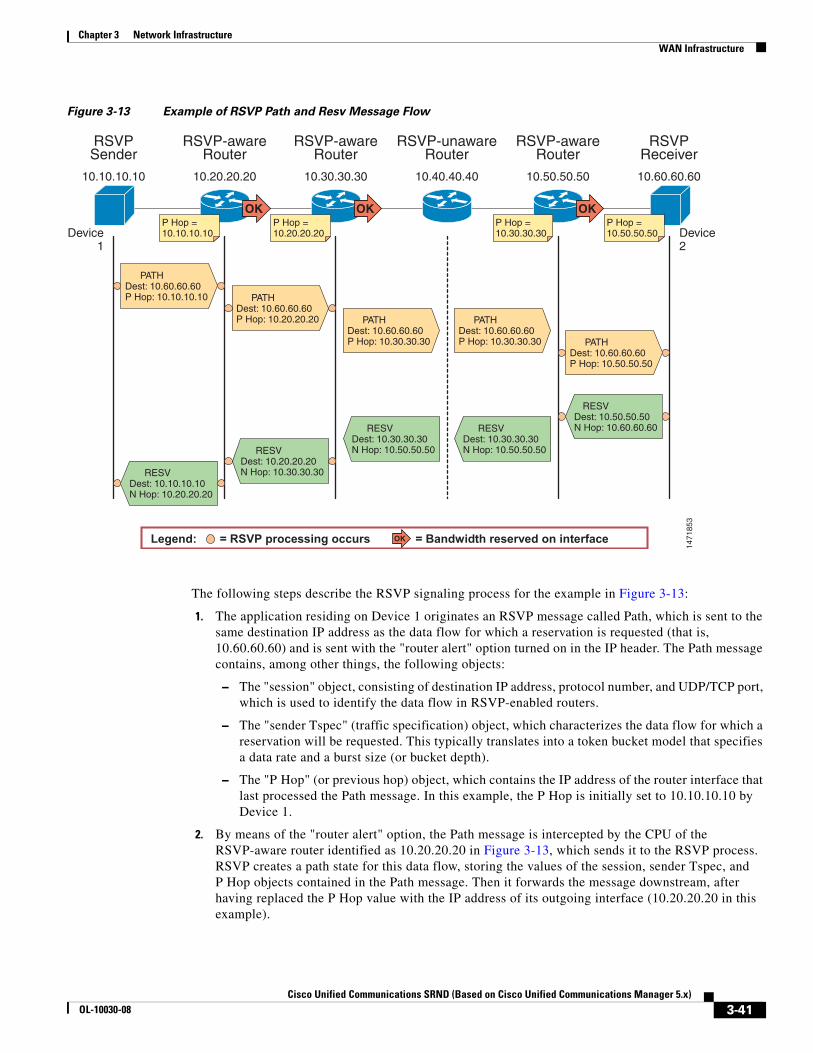
Chapter 3 Network InfrastructureWAN Infrastructure
Figure 3-13 Example of RSVP Path and Resv Message Flow
The following steps describe the RSVP signaling process for the example in Figure 3-13:
1. The application residing on Device 1 originates an RSVP message called Path, which is sent to the same destination IP address as the data flow for which a reservation is requested (that is, 10.60.60.60) and is sent with the "router alert" option turned on in the IP header. The Path message contains, among other things, the following objects:
– The "session" object, consisting of destination IP address, protocol number, and UDP/TCP port, which is used to identify the data flow in RSVP-enabled routers.
– The "sender Tspec" (traffic specification) object, which characterizes the data flow for which a reservation will be requested. This typically translates into a token bucket model that specifies a data rate and a burst size (or bucket depth).
– The "P Hop" (or previous hop) object, which contains the IP address of the router interface that last processed the Path message. In this example, the P Hop is initially set to 10.10.10.10 by Device 1.
2. By means of the "router alert" option, the Path message is intercepted by the CPU of the RSVP-aware router identified as 10.20.20.20 in Figure 3-13, which sends it to the RSVP process. RSVP creates a path state for this data flow, storing the values of the session, sender Tspec, and P Hop objects contained in the Path message. Then it forwards the message downstream, after having replaced the P Hop value with the IP address of its outgoing interface (10.20.20.20 in this example).
Legend: = RSVP processing occurs = Bandwidth reserved on interface
RSVPSender
Device1
Device2
PATHDest: 10.60.60.60P Hop: 10.10.10.10
P Hop =10.10.10.10
P Hop =10.20.20.20
P Hop =10.30.30.30
P Hop =10.50.50.50
RSVP-awareRouter
RSVP-awareRouter
OK OK
OK
OK
RSVP-unawareRouter
RSVP-awareRouter
RSVPReceiver
10.10.10.10 10.20.20.20 10.30.30.30 10.40.40.40 10.50.50.50 10.60.60.60
PATHDest: 10.60.60.60P Hop: 10.20.20.20 PATH
Dest: 10.60.60.60P Hop: 10.30.30.30
PATHDest: 10.60.60.60P Hop: 10.30.30.30 PATH
Dest: 10.60.60.60P Hop: 10.50.50.50
RESVDest: 10.50.50.50N Hop: 10.60.60.60RESV
Dest: 10.30.30.30N Hop: 10.50.50.50
RESVDest: 10.30.30.30N Hop: 10.50.50.50RESV
Dest: 10.20.20.20N Hop: 10.30.30.30RESV
Dest: 10.10.10.10N Hop: 10.20.20.20
1471
853
3-41Cisco Unified Communications SRND (Based on Cisco Unified Communications Manager 5.x)
OL-10030-08
Chapter 3 Network InfrastructureWAN Infrastructure
3. Similarly, the Path message is intercepted by the CPU of the following RSVP-aware router, identified as 10.30.30.30 in Figure 3-13. After creating the path state and changing the P Hop value to 10.30.30.30, this router also forwards the message downstream.
4. The Path message now arrives at the RSVP-unaware router identified as 10.40.40.40 in Figure 3-13. Because RSVP is not enabled on this router, it just routes this message according to the existing routing protocols like any other IP packet, without any additional processing and without changing the content of any of the message objects.
5. Therefore, the Path message gets to the RSVP-aware router identified as 10.50.50.50, which processes the message, creates the corresponding path state, and forwards the message downstream. Notice that the P Hop recorded by this router still contains the IP address of the last RSVP-aware router along the network path, or 10.30.30.30 in this example.
6. The RSVP Receiver at Device 2 receives the Path message with a P Hop value of 10.50.50.50, and it can now initiate the actual reservation by originating a message called Resv. For this reason, RSVP is known as a receiver-initiated protocol. The Resv message carries the reservation request hop-by-hop from the receiver to the sender, along the reverse paths of the data flow for the session. At each hop, the IP destination address of the Resv message is the IP address of the previous-hop node, obtained from the path state. Hence, in this case Device 2 sends the Resv message with a destination IP address of 10.50.50.50. The Resv message contains, among other things, the following objects:
– The "session" object, which is used to identify the data flow.
– The "N Hop" (or next hop) object, which contains the IP address of the node that generated the message. In this example, the N Hop is initially set to 10.60.60.60 by Device 2.
7. When RSVP-aware router 10.50.50.50 receives the Resv message for this data flow, it matches it against the path state information using the received session object, and it verifies if the reservation request can be accepted based on the following criteria:
– Policy control — Is this user and/or application allowed to make this reservation request?
– Admission control — Are there enough bandwidth resources available on the relevant outgoing interface to accommodate this reservation request?
8. In this case, we assume that both policy and admission control are successful on 10.50.50.50, which means that the bandwidth provided by the Tspec in the path state for this session is reserved on the outgoing interface (in the same direction as the data flow, that is from Device 1 to Device 2), and a corresponding "reservation state" is created. Now router 10.50.50.50 can send a Resv message upstream by sending it as a unicast IP packet to the destination IP address stored in the P Hop for this session, which was 10.30.30.30. The N Hop object is also updated with the value of 10.50.50.50.
9. The Resv message now transits through the RSVP-unaware router identified as 10.40.40.40, which will route it toward its destination of 10.30.30.30 like any other IP packet. This mechanism allows RSVP signaling to work across a heterogeneous network where some nodes are not RSVP-enabled.
10. The RSVP-aware router identified as 10.30.30.30 receives the Resv message and processes it according to the mechanisms described in steps 7 and 8. Assuming policy and admission control are successful also at this hop, the bandwidth is reserved on the outgoing interface and a Resv message is sent to the previous hop, or 10.20.20.20 in this example.
11. After a similar process within the router identified as 10.20.20.20, the Resv finally reaches the RSVP sender, Device 1. This indicates to the requesting application that an end-to-end reservation has been established and that bandwidth has been set aside for this data flow in all RSVP-enabled routers across the network.
This example shows how the two main RSVP signaling messages, Path and Resv, travel across the network to establish reservations. Several other messages are defined in the RSVP standard to address error situations, reservation failures, and release of resources. In particular, the ResvErr message is used
3-42Cisco Unified Communications SRND (Based on Cisco Unified Communications Manager 5.x)
OL-10030-08
Chapter 3 Network InfrastructureWAN Infrastructure
to signal failure to reserve the requested resources due to either policy control or admission control somewhere along the network. If, for example, admission control had failed at node 10.50.50.50 in Figure 3-13, this node would have sent a ResvErr message back to Device 2, specifying the cause of the failure, and the application would have been notified.
Another important aspect of the RSVP protocol is that it adopts a soft-state approach, which means that for each session both the path state and the reservation state along the network need to be refreshed periodically by the application by sending identical Path and Resv messages. If a router does not receive refresh messages for a given session for a certain period of time, it deletes the corresponding state and releases the resources reserved. This allows RSVP to react dynamically to network topology changes or routing changes due to link failures. The reservations simply start flowing along the new routes based on the routing protocol decisions, and the reservations along the old routes time-out and are eventually deleted.
Note This section focuses on providing an overview of RSVP principles and mechanisms. For more information on protocol behavior and extensions, complete message formats, and interactions with other protocols, refer to the numerous RFC documents related to RSVP, available at http://www.ietf.org.
RSVP and QoS in WAN Routers
RSVP has been supported in Cisco routers for many years, however most configurations recommended in this document are based on the RSVP Scalability Enhancements feature, which was first introduced in Cisco IOS Release 12.2(2)T.
By issuing the following Cisco IOS command in interface configuration mode on each Cisco IOS router interface, you can enable RSVP and define the maximum amount of bandwidth that it can control:
ip rsvp bandwidth [interface-kbps] [single-flow-kbps]
The interface-kbps parameter specifies the upper limit of bandwidth that RSVP can reserve on the given interface, while the single-flow-kbps parameter provides an upper bandwidth limit for each individual reservation (so that flows with higher bandwidth requests will be rejected even if there is bandwidth available on the interface).
Note When RSVP is enabled on a router interface, all other interfaces in the router will drop RSVP messages unless they are also enabled for RSVP. To avoid dropping RSVP messages, enable RSVP on all interfaces through which you expect RSVP signaling to transit. If call admission control is not desired on an interface, set the bandwidth value to 75% of the interface bandwidth.
Within Cisco IOS, RSVP can be configured to operate according to two different models: the Integrated Services (IntServ) model, described in RFC 2210, or the Integrated Services/Differentiated Services (IntServ/DiffServ) model, described in RFC 2998. Both RFC documents are available on the IETF website at
http://www.ietf.org
Figure 3-14 shows the difference between these two approaches from the perspective of a Cisco IOS router.
3-43Cisco Unified Communications SRND (Based on Cisco Unified Communications Manager 5.x)
OL-10030-08
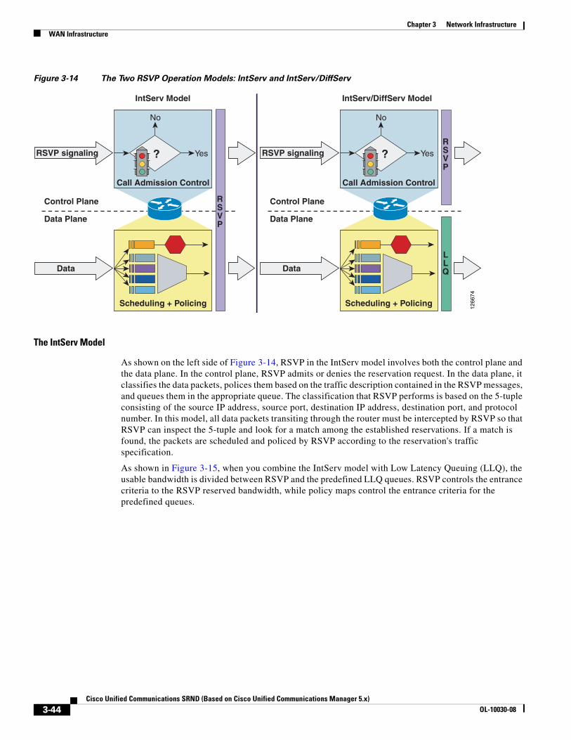
Chapter 3 Network InfrastructureWAN Infrastructure
Figure 3-14 The Two RSVP Operation Models: IntServ and IntServ/DiffServ
The IntServ Model
As shown on the left side of Figure 3-14, RSVP in the IntServ model involves both the control plane and the data plane. In the control plane, RSVP admits or denies the reservation request. In the data plane, it classifies the data packets, polices them based on the traffic description contained in the RSVP messages, and queues them in the appropriate queue. The classification that RSVP performs is based on the 5-tuple consisting of the source IP address, source port, destination IP address, destination port, and protocol number. In this model, all data packets transiting through the router must be intercepted by RSVP so that RSVP can inspect the 5-tuple and look for a match among the established reservations. If a match is found, the packets are scheduled and policed by RSVP according to the reservation's traffic specification.
As shown in Figure 3-15, when you combine the IntServ model with Low Latency Queuing (LLQ), the usable bandwidth is divided between RSVP and the predefined LLQ queues. RSVP controls the entrance criteria to the RSVP reserved bandwidth, while policy maps control the entrance criteria for the predefined queues.
Call Admission Control
1266
74
?
No
YesRSVP signaling
RSVP
Control Plane
Data Plane
IntServ Model
Scheduling + Policing
Data
Call Admission Control
?
No
YesRSVP signalingRSVP
Control Plane
Data Plane
IntServ/DiffServ Model
Scheduling + Policing
Data
LLQ
3-44Cisco Unified Communications SRND (Based on Cisco Unified Communications Manager 5.x)
OL-10030-08
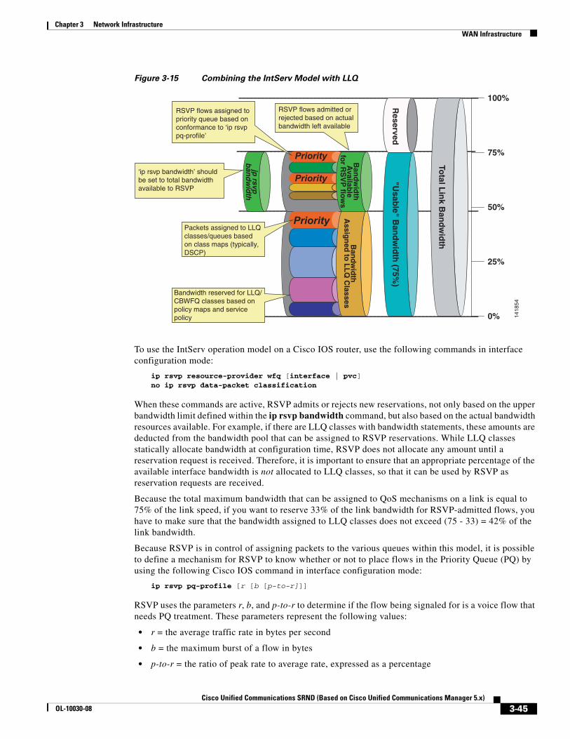
Chapter 3 Network InfrastructureWAN Infrastructure
Figure 3-15 Combining the IntServ Model with LLQ
To use the IntServ operation model on a Cisco IOS router, use the following commands in interface configuration mode:
ip rsvp resource-provider wfq [interface | pvc]no ip rsvp data-packet classification
When these commands are active, RSVP admits or rejects new reservations, not only based on the upper bandwidth limit defined within the ip rsvp bandwidth command, but also based on the actual bandwidth resources available. For example, if there are LLQ classes with bandwidth statements, these amounts are deducted from the bandwidth pool that can be assigned to RSVP reservations. While LLQ classes statically allocate bandwidth at configuration time, RSVP does not allocate any amount until a reservation request is received. Therefore, it is important to ensure that an appropriate percentage of the available interface bandwidth is not allocated to LLQ classes, so that it can be used by RSVP as reservation requests are received.
Because the total maximum bandwidth that can be assigned to QoS mechanisms on a link is equal to 75% of the link speed, if you want to reserve 33% of the link bandwidth for RSVP-admitted flows, you have to make sure that the bandwidth assigned to LLQ classes does not exceed (75 - 33) = 42% of the link bandwidth.
Because RSVP is in control of assigning packets to the various queues within this model, it is possible to define a mechanism for RSVP to know whether or not to place flows in the Priority Queue (PQ) by using the following Cisco IOS command in interface configuration mode:
ip rsvp pq-profile [r [b [p-to-r]]]
RSVP uses the parameters r, b, and p-to-r to determine if the flow being signaled for is a voice flow that needs PQ treatment. These parameters represent the following values:
• r = the average traffic rate in bytes per second
• b = the maximum burst of a flow in bytes
• p-to-r = the ratio of peak rate to average rate, expressed as a percentage
100%
75%
50%
25%
0% 1418
54
Priority
Priority
Priority
"Usab
le" Ban
dwid
th (75%
)
Ban
dwid
thA
ssign
ed to
LL
Q C
lassesB
andw
idth
Availab
lefo
r RS
VP
flows
jp rsvp
ban
dwid
th
Total L
ink B
andw
idth
RSVP flows assigned to priority queue based on conformance to ‘ip rsvp pq-profile’
RSVP flows admitted or rejected based on actual bandwidth left available
‘ip rsvp bandwidth’ should be set to total bandwidth available to RSVP
Packets assigned to LLQ classes/queues based on class maps (typically, DSCP)
Bandwidth reserved for LLQ/ CBWFQ classes based on policy maps and service policy
Reserved
3-45Cisco Unified Communications SRND (Based on Cisco Unified Communications Manager 5.x)
OL-10030-08
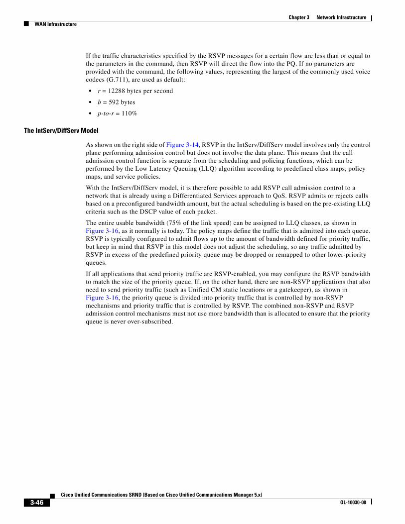
Chapter 3 Network InfrastructureWAN Infrastructure
If the traffic characteristics specified by the RSVP messages for a certain flow are less than or equal to the parameters in the command, then RSVP will direct the flow into the PQ. If no parameters are provided with the command, the following values, representing the largest of the commonly used voice codecs (G.711), are used as default:
• r = 12288 bytes per second
• b = 592 bytes
• p-to-r = 110%
The IntServ/DiffServ Model
As shown on the right side of Figure 3-14, RSVP in the IntServ/DiffServ model involves only the control plane performing admission control but does not involve the data plane. This means that the call admission control function is separate from the scheduling and policing functions, which can be performed by the Low Latency Queuing (LLQ) algorithm according to predefined class maps, policy maps, and service policies.
With the IntServ/DiffServ model, it is therefore possible to add RSVP call admission control to a network that is already using a Differentiated Services approach to QoS. RSVP admits or rejects calls based on a preconfigured bandwidth amount, but the actual scheduling is based on the pre-existing LLQ criteria such as the DSCP value of each packet.
The entire usable bandwidth (75% of the link speed) can be assigned to LLQ classes, as shown in Figure 3-16, as it normally is today. The policy maps define the traffic that is admitted into each queue. RSVP is typically configured to admit flows up to the amount of bandwidth defined for priority traffic, but keep in mind that RSVP in this model does not adjust the scheduling, so any traffic admitted by RSVP in excess of the predefined priority queue may be dropped or remapped to other lower-priority queues.
If all applications that send priority traffic are RSVP-enabled, you may configure the RSVP bandwidth to match the size of the priority queue. If, on the other hand, there are non-RSVP applications that also need to send priority traffic (such as Unified CM static locations or a gatekeeper), as shown in Figure 3-16, the priority queue is divided into priority traffic that is controlled by non-RSVP mechanisms and priority traffic that is controlled by RSVP. The combined non-RSVP and RSVP admission control mechanisms must not use more bandwidth than is allocated to ensure that the priority queue is never over-subscribed.
3-46Cisco Unified Communications SRND (Based on Cisco Unified Communications Manager 5.x)
OL-10030-08
Chapter 3 Network InfrastructureWAN Infrastructure
Figure 3-16 LLQ Bandwidth Allocation with RSVP
To use the IntServ/DiffServ operation model on a Cisco IOS router, use the following commands in interface configuration mode:
ip rsvp resource-provider noneip rsvp data-packet classification none
When these commands are active, RSVP admits or rejects new reservations uniquely based on the upper bandwidth limits defined within the ip rsvp bandwidth command, independently from the actual bandwidth resources available on the interface. Once admitted, the RSVP flows are subject to the same scheduling rules as all other non-RSVP traffic (for example, LLQ class and policy maps). Therefore, it is important to ensure that the RSVP-enabled traffic is marked with the appropriate DSCP value and that the bandwidth of the corresponding PQ or CBWFQ queues is provisioned to accommodate both RSVP-enabled traffic and all other traffic.
In this operating model, the ip rsvp pq-profile command is inactive because RSVP does not control the scheduling function.
RSVP Application ID
An application identity (app-id) is an RSVP object that can be inserted into the policy element of an RSVP message. This object is described in RFC 2872. This policy object helps to identify the application and associate it with the RSVP reservation request, thus allowing routers along the path to make appropriate decisions based on the application information.
The need for an app-id arises because RSVP is used to support multiple applications such as voice and video.
Without using an app-id, there is only one bandwidth value that is configurable per interface in RSVP. RSVP will admit requests until this bandwidth limit is reached. It does not differentiate between the requests and is not aware of the type of application for which the bandwidth is requested. As a result of this, it is quite possible for RSVP to exhaust the allowed bandwidth by admitting requests representing
100%
75%
50%
25%
0% 1418
55
Priority "Usab
le" Ban
dwid
th (75%
)
Ban
dwid
thA
ssign
ed to
LL
Q C
lasses
jp rsvp
ban
dwid
thn
on
RS
VP
Total L
ink B
andw
idth
Reserved
RSVP flows assigned to priority queue based on LLQ classes(typically, DSCP)
RSVP flows admitted or rejected based on 'ip rsvp bandwidth' only
If there are non-RSVPreal-time applications, provision priority queue accordingly
Packets assigned to LLQ classes/queues based on class maps (typically, DSCP)
Bandwidth reserved for LLQ/ CBWFQ classes based on policy maps and service policy
3-47Cisco Unified Communications SRND (Based on Cisco Unified Communications Manager 5.x)
OL-10030-08
Chapter 3 Network InfrastructureWAN Infrastructure
just one type of application, thus causing all subsequent requests to be rejected due to unavailable bandwidth. In this way, a few video calls could prevent all or most of the voice calls from being admitted. For example, if an organization allocates 1000 units to RSVP, RSVP might exhaust a majority of this amount by admitting two 384-kbps video calls, thus leaving very little bandwidth for voice calls.
The solution to this problem is to configure separate bandwidth limits for individual applications or classes of traffic. Limiting bandwidth per application requires that an RSVP local policy matching the application bandwidth limit be applied to the router interface and that each reservation request flag the application to which it belongs so that it may be admitted against the appropriate bandwidth limit.
The app-id is not a single piece of information but multiple variable-length strings. As is described in RFC 2872, the object may include the following attributes:
• An identifier of the application (APP). This attribute is required.
• Global unique identifier (GUID). Optional.
• Version number of the application (VER). This attribute is required.
• Sub-application identifier (SAPP). An arbitrary number of sub-application elements can be included. Optional.
For example:
• APP = AudioStream
• GUID = CiscoSystems
• VER = 5.0.1.0
• SAPP = (not specified)
How Unified CM Uses the Application ID
To support RSVP Application ID functionality, Unified CM has two cluster-wide service parameters that define the Application ID used to tag audio and video call reservations using RSVP:
• RSVP Audio Application ID (Default is "AudioStream")
• RSVP Video Application ID (Default is "VideoStream")
It is possible to change these service parameters, but Cisco recommend that you leave them at their default values unless you require the ability to differentiate one cluster’s reservations from another using the same link.
How Voice Calls are Tagged
When a voice call is made between locations with an RSVP policy, the resulting reservations for the audio stream will be tagged with the RSVP Audio Application ID.
How Video Calls are Tagged
When a video call is made between locations with an RSVP policy, the resulting reservations for the audio stream will be tagged with the RSVP Audio Application ID and the reservations for the video stream will be tagged with the RSVP Video Application ID.
Application ID Call Admission Control Model
As mentioned in the chapter on Call Admission Control, page 9-1, the call admission control model supported by Application ID differs from the one supported by "static" locations. Because the audio stream of a video call is marked with the RSVP Audio Application ID, it is possible to guarantee a
3-48Cisco Unified Communications SRND (Based on Cisco Unified Communications Manager 5.x)
OL-10030-08
Chapter 3 Network InfrastructureWAN Infrastructure
minimum number of voice calls and allow them to take over the entire available bandwidth. Video calls are allowed up to a certain maximum bandwidth but may be denied when the entire bandwidth is consumed by voice calls that were established first.
RSVP Design Best Practices
When deploying RSVP in the IP WAN in conjunction with Unified CM, observe the following design best practices:
• Cisco recommends that you use the IntServ/DiffServ model if either of the following statements is true:
– The only traffic destined for the Priority Queue (PQ) in the IP WAN interfaces is RSVP-enabled traffic.
– All the non-RSVP traffic destined for the PQ can be deterministically limited to a certain amount by an out-of-band call admission control mechanism (such as Unified CM locations or a Cisco IOS gatekeeper).
• If all the PQ traffic is RSVP-enabled, the value specified in the ip rsvp bandwidth command and the priority command should match once Layer 2 overhead is taken into account.
• If RSVP is enabled on one or more interfaces of a router, all interfaces through which you expect RSVP signaling to transit should also be enabled for RSVP to ensure that RSVP messages do not get dropped. If call admission control is not desired on an interface, set the bandwidth value to 75% of the interface bandwidth.
• If some PQ traffic is not RSVP-enabled, you must ensure that the sum of the values specified in the ip rsvp bandwidth command and in the out-of-band call admission control mechanism do not exceed the bandwidth value specified in the priority command.
• Enable RSVP Application ID support if you need to limit the maximum amount of bandwidth used by video calls. Application ID Support is introduced in Cisco IOS Release 12.4(6)T. For more information, see RSVP Application ID, page 3-47.
• Enable RSVP at the edge of the network, including the router WAN interfaces on both sides of the WAN link.
• Enable RSVP at all possible WAN congestion points, including redundant links of different speeds.
• Ensure symmetric routing on load-balanced MPLS WAN links.
• Bundle Interfaces, including MLPPP, ATM-IMA, and FRF.16, should have the RSVP bandwidth configured to the size of one physical link.
• RSVP is currently not available on Tunnel Interfaces.
• RSVP is currently not available on the Catalyst Switching Platforms.
Bandwidth ProvisioningProperly provisioning the network bandwidth is a major component of designing a successful IP network. You can calculate the required bandwidth by adding the bandwidth requirements for each major application (for example, voice, video, and data). This sum then represents the minimum bandwidth requirement for any given link, and it should not exceed approximately 75% of the total available bandwidth for the link. This 75% rule assumes that some bandwidth is required for overhead traffic, such as routing and Layer 2 keep-alives. Figure 3-17 illustrates this bandwidth provisioning process.
3-49Cisco Unified Communications SRND (Based on Cisco Unified Communications Manager 5.x)
OL-10030-08
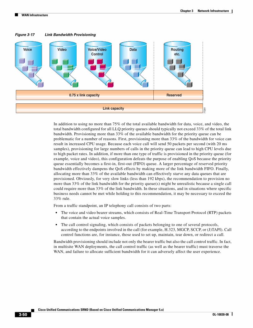
Chapter 3 Network InfrastructureWAN Infrastructure
Figure 3-17 Link Bandwidth Provisioning
In addition to using no more than 75% of the total available bandwidth for data, voice, and video, the total bandwidth configured for all LLQ priority queues should typically not exceed 33% of the total link bandwidth. Provisioning more than 33% of the available bandwidth for the priority queue can be problematic for a number of reasons. First, provisioning more than 33% of the bandwidth for voice can result in increased CPU usage. Because each voice call will send 50 packets per second (with 20 ms samples), provisioning for large numbers of calls in the priority queue can lead to high CPU levels due to high packet rates. In addition, if more than one type of traffic is provisioned in the priority queue (for example, voice and video), this configuration defeats the purpose of enabling QoS because the priority queue essentially becomes a first-in, first-out (FIFO) queue. A larger percentage of reserved priority bandwidth effectively dampens the QoS effects by making more of the link bandwidth FIFO. Finally, allocating more than 33% of the available bandwidth can effectively starve any data queues that are provisioned. Obviously, for very slow links (less than 192 kbps), the recommendation to provision no more than 33% of the link bandwidth for the priority queue(s) might be unrealistic because a single call could require more than 33% of the link bandwidth. In these situations, and in situations where specific business needs cannot be met while holding to this recommendation, it may be necessary to exceed the 33% rule.
From a traffic standpoint, an IP telephony call consists of two parts:
• The voice and video bearer streams, which consists of Real-Time Transport Protocol (RTP) packets that contain the actual voice samples.
• The call control signaling, which consists of packets belonging to one of several protocols, according to the endpoints involved in the call (for example, H.323, MGCP, SCCP, or (J)TAPI). Call control functions are, for instance, those used to set up, maintain, tear down, or redirect a call.
Bandwidth provisioning should include not only the bearer traffic but also the call control traffic. In fact, in multisite WAN deployments, the call control traffic (as well as the bearer traffic) must traverse the WAN, and failure to allocate sufficient bandwidth for it can adversely affect the user experience.
Video
0.75 x link capacity Reserved
Link capacity
Voice/VideoControl
Data Routingetc.
Voice
7729
1
3-50Cisco Unified Communications SRND (Based on Cisco Unified Communications Manager 5.x)
OL-10030-08
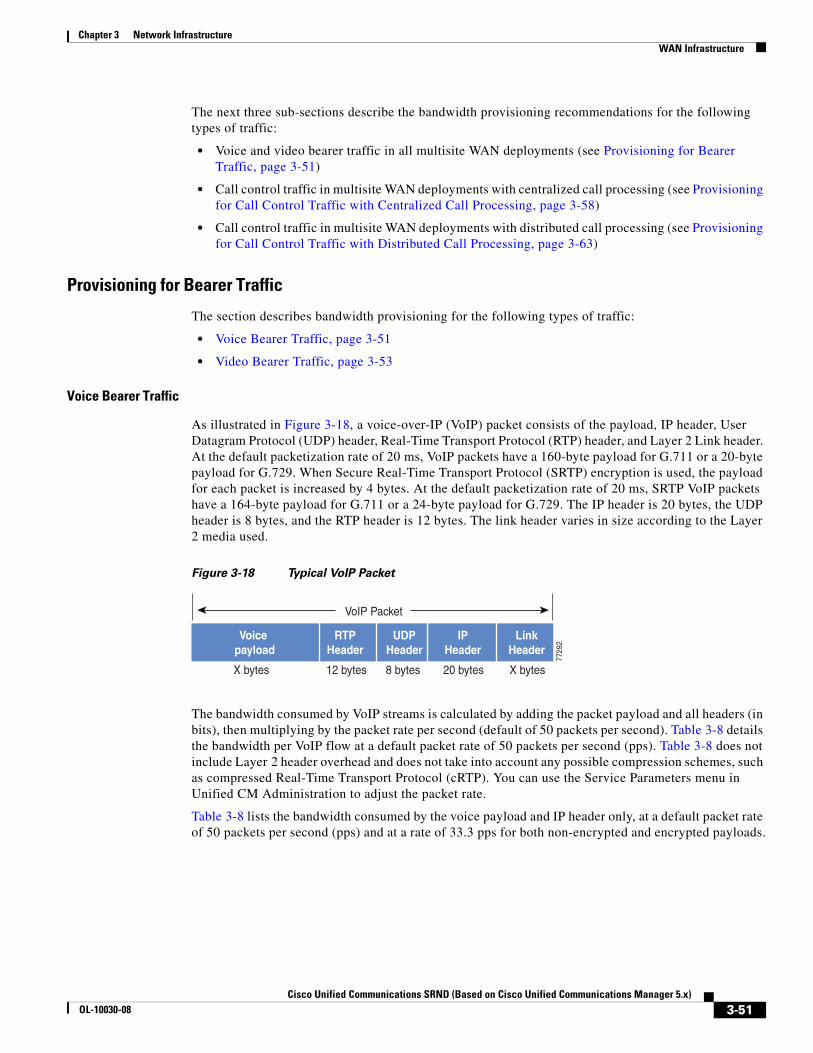
Chapter 3 Network InfrastructureWAN Infrastructure
The next three sub-sections describe the bandwidth provisioning recommendations for the following types of traffic:
• Voice and video bearer traffic in all multisite WAN deployments (see Provisioning for Bearer Traffic, page 3-51)
• Call control traffic in multisite WAN deployments with centralized call processing (see Provisioning for Call Control Traffic with Centralized Call Processing, page 3-58)
• Call control traffic in multisite WAN deployments with distributed call processing (see Provisioning for Call Control Traffic with Distributed Call Processing, page 3-63)
Provisioning for Bearer Traffic
The section describes bandwidth provisioning for the following types of traffic:
• Voice Bearer Traffic, page 3-51
• Video Bearer Traffic, page 3-53
Voice Bearer Traffic
As illustrated in Figure 3-18, a voice-over-IP (VoIP) packet consists of the payload, IP header, User Datagram Protocol (UDP) header, Real-Time Transport Protocol (RTP) header, and Layer 2 Link header. At the default packetization rate of 20 ms, VoIP packets have a 160-byte payload for G.711 or a 20-byte payload for G.729. When Secure Real-Time Transport Protocol (SRTP) encryption is used, the payload for each packet is increased by 4 bytes. At the default packetization rate of 20 ms, SRTP VoIP packets have a 164-byte payload for G.711 or a 24-byte payload for G.729. The IP header is 20 bytes, the UDP header is 8 bytes, and the RTP header is 12 bytes. The link header varies in size according to the Layer 2 media used.
Figure 3-18 Typical VoIP Packet
The bandwidth consumed by VoIP streams is calculated by adding the packet payload and all headers (in bits), then multiplying by the packet rate per second (default of 50 packets per second). Table 3-8 details the bandwidth per VoIP flow at a default packet rate of 50 packets per second (pps). Table 3-8 does not include Layer 2 header overhead and does not take into account any possible compression schemes, such as compressed Real-Time Transport Protocol (cRTP). You can use the Service Parameters menu in Unified CM Administration to adjust the packet rate.
Table 3-8 lists the bandwidth consumed by the voice payload and IP header only, at a default packet rate of 50 packets per second (pps) and at a rate of 33.3 pps for both non-encrypted and encrypted payloads.
Voice payload
RTPHeader
UDPHeader
IPHeader
LinkHeader
VoIP Packet
X bytes 12 bytes 8 bytes 20 bytes X bytes
7729
2
3-51Cisco Unified Communications SRND (Based on Cisco Unified Communications Manager 5.x)
OL-10030-08
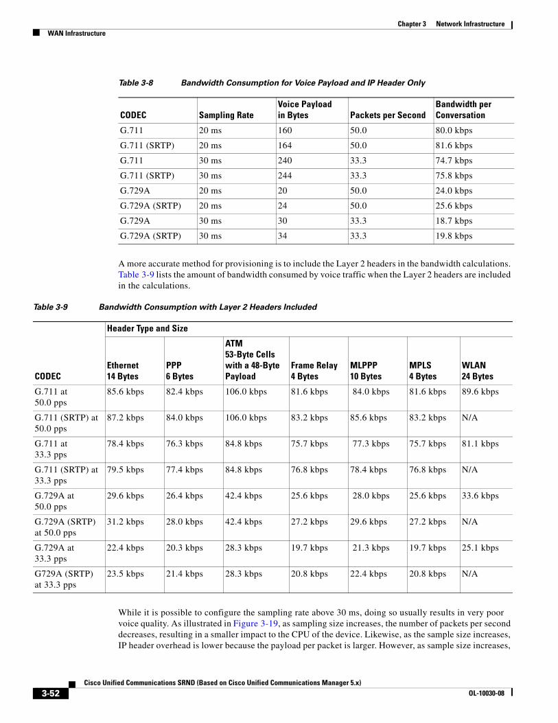
Chapter 3 Network InfrastructureWAN Infrastructure
A more accurate method for provisioning is to include the Layer 2 headers in the bandwidth calculations. Table 3-9 lists the amount of bandwidth consumed by voice traffic when the Layer 2 headers are included in the calculations.
While it is possible to configure the sampling rate above 30 ms, doing so usually results in very poor voice quality. As illustrated in Figure 3-19, as sampling size increases, the number of packets per second decreases, resulting in a smaller impact to the CPU of the device. Likewise, as the sample size increases, IP header overhead is lower because the payload per packet is larger. However, as sample size increases,
Table 3-8 Bandwidth Consumption for Voice Payload and IP Header Only
CODEC Sampling RateVoice Payload in Bytes Packets per Second
Bandwidth per Conversation
G.711 20 ms 160 50.0 80.0 kbps
G.711 (SRTP) 20 ms 164 50.0 81.6 kbps
G.711 30 ms 240 33.3 74.7 kbps
G.711 (SRTP) 30 ms 244 33.3 75.8 kbps
G.729A 20 ms 20 50.0 24.0 kbps
G.729A (SRTP) 20 ms 24 50.0 25.6 kbps
G.729A 30 ms 30 33.3 18.7 kbps
G.729A (SRTP) 30 ms 34 33.3 19.8 kbps
Table 3-9 Bandwidth Consumption with Layer 2 Headers Included
CODEC
Header Type and Size
Ethernet14 Bytes
PPP6 Bytes
ATM53-Byte Cells with a 48-Byte Payload
Frame Relay4 Bytes
MLPPP10 Bytes
MPLS4 Bytes
WLAN24 Bytes
G.711 at 50.0 pps
85.6 kbps 82.4 kbps 106.0 kbps 81.6 kbps 84.0 kbps 81.6 kbps 89.6 kbps
G.711 (SRTP) at 50.0 pps
87.2 kbps 84.0 kbps 106.0 kbps 83.2 kbps 85.6 kbps 83.2 kbps N/A
G.711 at 33.3 pps
78.4 kbps 76.3 kbps 84.8 kbps 75.7 kbps 77.3 kbps 75.7 kbps 81.1 kbps
G.711 (SRTP) at 33.3 pps
79.5 kbps 77.4 kbps 84.8 kbps 76.8 kbps 78.4 kbps 76.8 kbps N/A
G.729A at 50.0 pps
29.6 kbps 26.4 kbps 42.4 kbps 25.6 kbps 28.0 kbps 25.6 kbps 33.6 kbps
G.729A (SRTP) at 50.0 pps
31.2 kbps 28.0 kbps 42.4 kbps 27.2 kbps 29.6 kbps 27.2 kbps N/A
G.729A at 33.3 pps
22.4 kbps 20.3 kbps 28.3 kbps 19.7 kbps 21.3 kbps 19.7 kbps 25.1 kbps
G729A (SRTP) at 33.3 pps
23.5 kbps 21.4 kbps 28.3 kbps 20.8 kbps 22.4 kbps 20.8 kbps N/A
3-52Cisco Unified Communications SRND (Based on Cisco Unified Communications Manager 5.x)
OL-10030-08
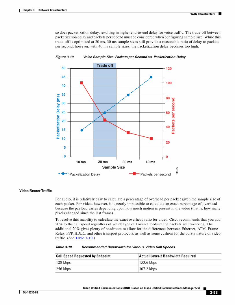
Chapter 3 Network InfrastructureWAN Infrastructure
so does packetization delay, resulting in higher end-to-end delay for voice traffic. The trade-off between packetization delay and packets per second must be considered when configuring sample size. While this trade-off is optimized at 20 ms, 30 ms sample sizes still provide a reasonable ratio of delay to packets per second; however, with 40 ms sample sizes, the packetization delay becomes too high.
Figure 3-19 Voice Sample Size: Packets per Second vs. Packetization Delay
Video Bearer Traffic
For audio, it is relatively easy to calculate a percentage of overhead per packet given the sample size of each packet. For video, however, it is nearly impossible to calculate an exact percentage of overhead because the payload varies depending upon how much motion is present in the video (that is, how many pixels changed since the last frame).
To resolve this inability to calculate the exact overhead ratio for video, Cisco recommends that you add 20% to the call speed regardless of which type of Layer-2 medium the packets are traversing. The additional 20% gives plenty of headroom to allow for the differences between Ethernet, ATM, Frame Relay, PPP, HDLC, and other transport protocols, as well as some cushion for the bursty nature of video traffic. (See Table 3-10.)
1144
70
Trade off
0
5
10
15
20
25
30
35
40
45
50
10 ms 20 ms 30 ms 40 ms
Sample Size
Pac
ketiz
atio
n D
elay
(ms)
0
20
40
60
80
100
120
Pac
kets
per
sec
on
dPacketization Delay Packets per second
Table 3-10 Recommended Bandwidth for Various Video Call Speeds
Call Speed Requested by Endpoint Actual Layer-2 Bandwidth Required
128 kbps 153.6 kbps
256 kbps 307.2 kbps
3-53Cisco Unified Communications SRND (Based on Cisco Unified Communications Manager 5.x)
OL-10030-08
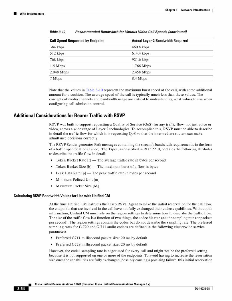
Chapter 3 Network InfrastructureWAN Infrastructure
Note that the values in Table 3-10 represent the maximum burst speed of the call, with some additional amount for a cushion. The average speed of the call is typically much less than these values. The concepts of media channels and bandwidth usage are critical to understanding what values to use when configuring call admission control.
Additional Considerations for Bearer Traffic with RSVP
RSVP was built to support requesting a Quality of Service (QoS) for any traffic flow, not just voice or video, across a wide range of Layer 2 technologies. To accomplish this, RSVP must be able to describe in detail the traffic flow for which it is requesting QoS so that the intermediate routers can make admittance decisions correctly.
The RSVP Sender generates Path messages containing the stream’s bandwidth requirements, in the form of a traffic specification (Tspec). The Tspec, as described in RFC 2210, contains the following attributes to describe the traffic flow in detail:
• Token Bucket Rate [r] — The average traffic rate in bytes per second
• Token Bucket Size [b] — The maximum burst of a flow in bytes
• Peak Data Rate [p] — The peak traffic rate in bytes per second
• Minimum Policed Unit [m]
• Maximum Packet Size [M]
Calculating RSVP Bandwidth Values for Use with Unified CM
At the time Unified CM instructs the Cisco RSVP Agent to make the initial reservation for the call flow, the endpoints that are involved in the call have not fully exchanged their codec capabilities. Without this information, Unified CM must rely on the region settings to determine how to describe the traffic flow. The size of the traffic flow is a function of two things, the codec bit-rate and the sampling rate (or packets per second). The region settings contain the codec but do not describe the sampling rate. The preferred sampling rates for G.729 and G.711 audio codecs are defined in the following clusterwide service parameters:
• Preferred G711 millisecond packet size: 20 ms by default
• Preferred G729 millisecond packet size: 20 ms by default
However, the codec sampling rate is negotiated for every call and might not be the preferred setting because it is not supported on one or more of the endpoints. To avoid having to increase the reservation size once the capabilities are fully exchanged, possibly causing a post-ring failure, this initial reservation
384 kbps 460.8 kbps
512 kbps 614.4 kbps
768 kbps 921.6 kbps
1.5 Mbps 1.766 Mbps
2.048 Mbps 2.458 Mbps
7 Mbps 8.4 Mbps
Table 3-10 Recommended Bandwidth for Various Video Call Speeds (continued)
Call Speed Requested by Endpoint Actual Layer-2 Bandwidth Required
3-54Cisco Unified Communications SRND (Based on Cisco Unified Communications Manager 5.x)
OL-10030-08
Chapter 3 Network InfrastructureWAN Infrastructure
is for the worst-case scenario, or the smallest packet size, of that codec. Once media capabilities have been exchanged between the endpoints, then the reservation is revised to the correct bandwidth allocation. In most cases, the default sampling rate is used, resulting in the reservation being reduced.
Note Unified CM does not include SRTP overhead or the Layer 2 overhead in the RSVP Reservation. When compared to the RSVP bandwidth value, the priority queue must be over-provisioned. (See Table 3-9 and Table 3-10.)
Voice Bearer Traffic
Inter-region call with audio codec set to G729:
• Initial request: 40 kbps, using a 10 ms worst-case scenario
• Updated request: 24 kbps, using the preferred sample size of 20 ms
Inter-region call with audio codec set to G711:
• Initial request: 96 kbps, using a 10 ms worst-case scenario
• Updated request: 80 kbps, using the preferred sample size of 20 ms
Video Bearer Traffic
As with the audio stream, the initial reservation for the video stream will rely on the region settings because the endpoint codec capabilities will not be fully negotiated at the time of the reservation. The region settings for video calls include the bandwidth for the audio stream. (See IP Video Telephony, page 16-1, for more information.) Because the audio stream has its own reservation, the final reservation for the video stream will be the region setting minus the audio codec bit-rate. However, because these codecs have not been fully negotiated, the video stream reservation will be for the worst-case scenario, which assumes no audio stream. Once media capabilities have been exchanged between the endpoints, then the reservation will be revised to the correct bandwidth allocation.
Because video is inherently bursty, it is necessary to add some overhead to the stream requirements. (See Video Bearer Traffic, page 3-53, for more information.) Unified CM uses the stream bandwidth to determine how to calculate the overhead, as follows:
• If the stream is < 256 kbps, then the overhead will be 20%
• If the stream is >= 256 kbps, then the overhead will be 7%
Inter-region video call, with G.729 audio codec and video setting of 384 kbps:
• Initial request: 384 ∗ 1.07 = 410 kbps
• Updated request: (384 - 8) ∗ 1.07 = 402 kbps
Inter-region video call, with G.711 audio codec and video setting of 384 kbps:
• Initial request: 384 ∗ 1.07 = 410 kbps
• Updated request: (384 - 64) ∗ 1.07 = 342 kbps
Configuration Recommendation
Because the initial reservation will be larger than the actual packet flow, over-provisioning the RSVP and LLQ bandwidth is required to ensure that the desired number of calls can complete.
When provisioning the RSVP bandwidth value for N calls, Cisco recommends that the Nth value be the worst-case bandwidth to ensure that the Nth call gets admitted.
3-55Cisco Unified Communications SRND (Based on Cisco Unified Communications Manager 5.x)
OL-10030-08
Chapter 3 Network InfrastructureWAN Infrastructure
For example:
• To provision four G.729 streams:
(3 ∗ 24) + 40 = 112 kbps
• To provision four G.711 streams:
(3 ∗ 80) + 96 = 336 kbps
• To provision four 384 kbps video streams (G.729 audio)
(3 ∗ (384 - 8) + 384) ∗ 1.07 = 1618 kbps
• To provision four 384 kbps video streams (G.711 audio)
(3 ∗ (384 - 64) + 384) ∗ 1.07 = 1438 kbps
Configuring Cisco IOS Application ID Support
RSVP Application ID feature support was introduced in Cisco IOS Release 12.4(6)T, and that is the minimum release required for the following examples.
Combined Priority Queue
To utilize the functionality allowed in Unified CM’s implementation of Application ID support (that is, allowing voice calls to consume all the bandwidth available in the priority queue), we must modify the previous recommendations that voice and video priority queues be kept separate. (See Application ID Call Admission Control Model, page 3-48.) To use this functionality, you should combine both the voice and video match criteria into one class-map. Because the requirements are to match either voice traffic or video traffic, be sure to make the class-map match criteria match-any instead of match-all, as follows:
class-map match-any IPC-RTP match ip dscp ef match ip dscp af41 af42
Configure the priority queue to support both the voice and video traffic. The following example configuration allocates 33% of the link bandwidth to the priority queue:
policy-map Voice-Policy class IPC-RTP priority percent 33
Mapping Application ID to RSVP Policy Identities
The RSVP Local Policy provides the mechanism for controlling a reservation based on an Application ID. Application IDs are mapped to RSVP Local Policies through the ip rsvp policy identity command. RSVP Local Policy identities are defined globally and are available to each interface for policy enforcement. Each identity can have one policy locator defined to match an Application ID.
To give the user as much flexibility as possible in matching application policy locators to local policies, the RSVP local policy command line interface (CLI) accepts application ID match criteria in the form of Unix-style regular expressions for the policy locator. Regular expressions are already used in the CLI for existing Cisco IOS components such as Border Gateway Protocol (BGP). Refer to the follow documentation for more information on how regular expressions are used in Cisco IOS:
• Access and Communication Servers Command Reference
http://www.cisco.com/en/US/docs/ios/11_0/access/command/reference/arbook.html
3-56Cisco Unified Communications SRND (Based on Cisco Unified Communications Manager 5.x)
OL-10030-08
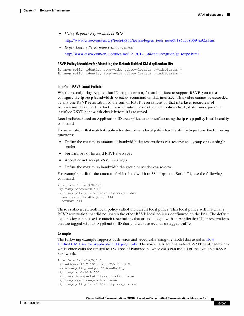
Chapter 3 Network InfrastructureWAN Infrastructure
• Using Regular Expressions in BGP
http://www.cisco.com/en/US/tech/tk365/technologies_tech_note09186a0080094a92.shtml
• Regex Engine Performance Enhancement
http://www.cisco.com/en/US/docs/ios/12_3t/12_3t4/feature/guide/gt_rexpe.html
RSVP Policy Identities for Matching the Default Unified CM Application IDsip rsvp policy identity rsvp-video policy-locator .*VideoStream.*ip rsvp policy identity rsvp-voice policy-locator .*AudioStream.*
Interface RSVP Local Policies
Whether configuring Application ID support or not, for an interface to support RSVP, you must configure the ip rsvp bandwidth <value> command on that interface. This value cannot be exceeded by any one RSVP reservation or the sum of RSVP reservations on that interface, regardless of Application ID support. In fact, if a reservation passes the local policy check, it still must pass the interface RSVP bandwidth check before it is reserved.
Local policies based on Application ID are applied to an interface using the ip rsvp policy local identity command.
For reservations that match its policy locator value, a local policy has the ability to perform the following functions:
• Define the maximum amount of bandwidth the reservations can reserve as a group or as a single sender
• Forward or not forward RSVP messages
• Accept or not accept RSVP messages
• Define the maximum bandwidth the group or sender can reserve
For example, to limit the amount of video bandwidth to 384 kbps on a Serial T1, use the following commands:
interface Serial0/0/1:0 ip rsvp bandwidth 506 ip rsvp policy local identity rsvp-video maximum bandwidth group 384 forward all
There is also a catch-all local policy called the default local policy. This local policy will match any RSVP reservation that did not match the other RSVP local policies configured on the link. The default local policy can be used to match reservations that are not tagged with an Application ID or reservations that are tagged with an Application ID that you want to treat as untagged traffic.
Example
The following example supports both voice and video calls using the model discussed in How Unified CM Uses the Application ID, page 3-48. The voice calls are guaranteed 352 kbps of bandwidth while video calls are limited to 154 kbps of bandwidth. Voice calls can use all of the available RSVP bandwidth.
interface Serial0/0/1:0 ip address 10.2.101.5 255.255.255.252 service-policy output Voice-Policy ip rsvp bandwidth 506 ip rsvp data-packet classification none ip rsvp resource-provider none ip rsvp policy local identity rsvp-voice
3-57Cisco Unified Communications SRND (Based on Cisco Unified Communications Manager 5.x)
OL-10030-08
Chapter 3 Network InfrastructureWAN Infrastructure
maximum bandwidth group 506 forward all ip rsvp policy local identity rsvp-video maximum bandwidth group 154 forward all ip rsvp policy local default no accept all ! Will not show in the configuration no forward all! Will not show in the configuration
In this example, if an RSVP reservation is received that does not have an Application ID or its Application ID does not match the two configured options, the reservation will fail. This configuration works if RSVP traffic originates only from Cisco RSVP Agents controlled by Unified CM. However, if there is intercluster RSVP traffic via an IP-IP gateway or if RSVP messages from a controller other than Unified CM are traversing this link, then the default local policy should be configured to accept and forward the reservations and a maximum bandwidth value should be configured on the policy. Note that it is possible to oversubscribe the RSVP bandwidth via the use of multiple RSVP local policies (if the sum of the policies is greater than the RSVP interface bandwidth), but reservations then become first-come, first-serve.
Provisioning for Call Control Traffic with Centralized Call Processing
In a centralized call processing deployment, the Unified CM cluster and the applications (such as voicemail) are located at the central site, while several remote sites are connected through an IP WAN. The remote sites rely on the centralized Unified CMs to handle their call processing.
The following considerations apply to this deployment model:
• Each time a remote branch phone places a call, the control traffic traverses the IP WAN to reach the Unified CM at the central site, even if the call is local to the branch.
• The signaling protocols that may traverse the IP WAN in this deployment model are SCCP (encrypted and non-encrypted), SIP (encrypted and non-encrypted), H.323, MGCP, and CTI-QBE. All the control traffic is exchanged between a Unified CM at the central site and endpoints or gateways at the remote branches.
• If RSVP is deployed within the cluster, the control traffic between the Unified CM cluster at the central site and the Cisco RSVP Agents at the remote sites uses the SCCP protocol.
As a consequence, the area where you must provision bandwidth for control traffic lies between the branch routers and the WAN aggregation router at the central site.
The control traffic that traverses the WAN in this scenario can be split into two categories:
• Quiescent traffic, which consists of keep-alive messages periodically exchanged between the branch endpoints (phones, gateways, and Cisco RSVP Agents) and Unified CM, regardless of call activity. This traffic is a function of the quantity of endpoints.
• Call-related traffic, which consists of signaling messages exchanged between the branch endpoints and the Unified CM at the central site when a call needs to be set up, torn down, forwarded, and so forth. This traffic is a function of the quantity of endpoints and their associated call volume.
To obtain an estimate of the generated call control traffic, it is therefore necessary to make some assumptions regarding the average number of calls per hour made by each branch IP phone. In the interest of simplicity, the calculations in this section assume an average of 10 calls per hour per phone.
Note If this average number does not satisfy the needs of your specific deployment, you can calculate the recommended bandwidth by using the advanced formulas provided in Advanced Formulas, page 3-60.
3-58Cisco Unified Communications SRND (Based on Cisco Unified Communications Manager 5.x)
OL-10030-08
Chapter 3 Network InfrastructureWAN Infrastructure
Given the assumptions made, and initially considering the case of a remote branch with no signaling encryption configured, the recommended bandwidth needed for call control traffic can be obtained from the following formula:
Equation 1A: Recommended Bandwidth Needed for SCCP Control Traffic without Signaling Encryption.
Bandwidth (bps) = 265 ∗ (Number of IP phones and gateways in the branch)
Equation 1B: Recommended Bandwidth Needed for SIP Control Traffic without Signaling Encryption.
Bandwidth (bps) = 538 ∗ (Number of IP phones and gateways in the branch)
If a site features a mix of SCCP and SIP endpoints, the two equations above should be employed separately for the quantity of each type of phone used, and the results added.
Equation 1 and all other formulas within this section include a 25% over-provisioning factor. Control traffic has a bursty nature, with peaks of high activity followed by periods of low activity. For this reason, assigning just the minimum bandwidth required to a control traffic queue can result in undesired effects such as buffering delays and, potentially, packet drops during periods of high activity. The default queue depth for a Class-Based Weighted Fair Queuing (CBWFQ) queue in Cisco IOS equals 64 packets. The bandwidth assigned to this queue determines its servicing rate. Assuming that the bandwidth configured is the average bandwidth consumed by this type of traffic, it is clear that, during the periods of high activity, the servicing rate will not be sufficient to "drain" all the incoming packets out of the queue, thus causing them to be buffered. Note that, if the 64-packet limit is reached, any subsequent packets are either assigned to the best-effort queue or are dropped. It is therefore advisable to introduce this 25% over-provisioning factor to absorb and smooth the variations in the traffic pattern and to minimize the risk of a temporary buffer overrun. This is equivalent to increasing the servicing rate of the queue.
If encryption is configured, the recommended bandwidth is affected because encryption increases the size of signaling packets exchanged between Unified CM and the endpoints. The following formula takes into account the impact of signaling encryption:
Equation 2A: Recommended Bandwidth Needed for SCCP Control Traffic with Signaling Encryption.
Bandwidth with signaling encryption (bps) = 415 ∗ (Number of IP phones and gateways in the branch)
Equation 2B: Recommended Bandwidth Needed for SIP Control Traffic with Signaling Encryption.
Bandwidth with signaling encryption (bps) = 619 ∗ (Number of IP phones and gateways in the branch)
If we now take into account the fact that the smallest bandwidth that can be assigned to a queue on a Cisco IOS router is 8 kbps, we can summarize the values of minimum and recommended bandwidth for various branch office sizes, as shown in Table 3-11.
3-59Cisco Unified Communications SRND (Based on Cisco Unified Communications Manager 5.x)
OL-10030-08
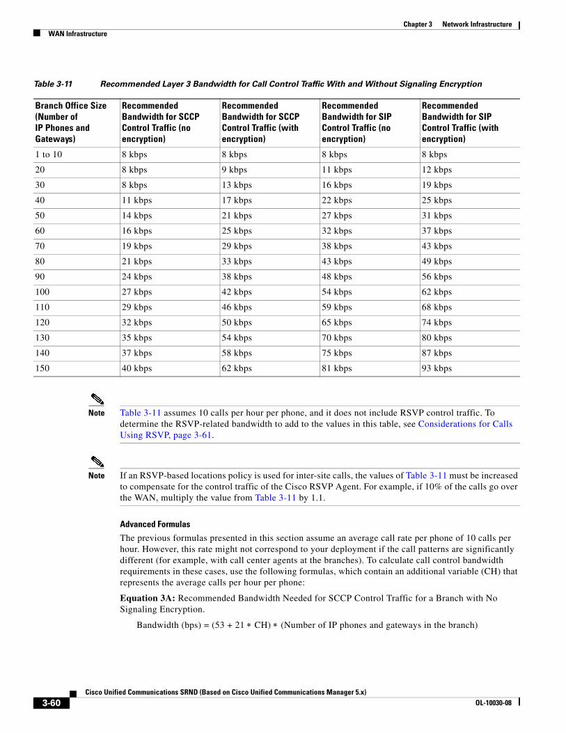
Chapter 3 Network InfrastructureWAN Infrastructure
Note Table 3-11 assumes 10 calls per hour per phone, and it does not include RSVP control traffic. To determine the RSVP-related bandwidth to add to the values in this table, see Considerations for Calls Using RSVP, page 3-61.
Note If an RSVP-based locations policy is used for inter-site calls, the values of Table 3-11 must be increased to compensate for the control traffic of the Cisco RSVP Agent. For example, if 10% of the calls go over the WAN, multiply the value from Table 3-11 by 1.1.
Advanced Formulas
The previous formulas presented in this section assume an average call rate per phone of 10 calls per hour. However, this rate might not correspond to your deployment if the call patterns are significantly different (for example, with call center agents at the branches). To calculate call control bandwidth requirements in these cases, use the following formulas, which contain an additional variable (CH) that represents the average calls per hour per phone:
Equation 3A: Recommended Bandwidth Needed for SCCP Control Traffic for a Branch with No Signaling Encryption.
Bandwidth (bps) = (53 + 21 ∗ CH) ∗ (Number of IP phones and gateways in the branch)
Table 3-11 Recommended Layer 3 Bandwidth for Call Control Traffic With and Without Signaling Encryption
Branch Office Size (Number of IP Phones and Gateways)
Recommended Bandwidth for SCCP Control Traffic (no encryption)
Recommended Bandwidth for SCCP Control Traffic (with encryption)
Recommended Bandwidth for SIP Control Traffic (no encryption)
Recommended Bandwidth for SIP Control Traffic (with encryption)
1 to 10 8 kbps 8 kbps 8 kbps 8 kbps
20 8 kbps 9 kbps 11 kbps 12 kbps
30 8 kbps 13 kbps 16 kbps 19 kbps
40 11 kbps 17 kbps 22 kbps 25 kbps
50 14 kbps 21 kbps 27 kbps 31 kbps
60 16 kbps 25 kbps 32 kbps 37 kbps
70 19 kbps 29 kbps 38 kbps 43 kbps
80 21 kbps 33 kbps 43 kbps 49 kbps
90 24 kbps 38 kbps 48 kbps 56 kbps
100 27 kbps 42 kbps 54 kbps 62 kbps
110 29 kbps 46 kbps 59 kbps 68 kbps
120 32 kbps 50 kbps 65 kbps 74 kbps
130 35 kbps 54 kbps 70 kbps 80 kbps
140 37 kbps 58 kbps 75 kbps 87 kbps
150 40 kbps 62 kbps 81 kbps 93 kbps
3-60Cisco Unified Communications SRND (Based on Cisco Unified Communications Manager 5.x)
OL-10030-08
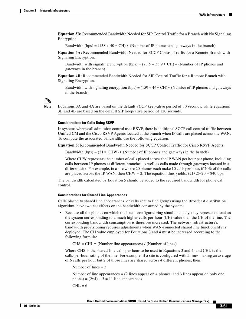
Chapter 3 Network InfrastructureWAN Infrastructure
Equation 3B: Recommended Bandwidth Needed for SIP Control Traffic for a Branch with No Signaling Encryption.
Bandwidth (bps) = (138 + 40 ∗ CH) ∗ (Number of IP phones and gateways in the branch)
Equation 4A: Recommended Bandwidth Needed for SCCP Control Traffic for a Remote Branch with Signaling Encryption.
Bandwidth with signaling encryption (bps) = (73.5 + 33.9 ∗ CH) ∗ (Number of IP phones and gateways in the branch)
Equation 4B: Recommended Bandwidth Needed for SIP Control Traffic for a Remote Branch with Signaling Encryption.
Bandwidth with signaling encryption (bps) = (159 + 46 ∗ CH) ∗ (Number of IP phones and gateways in the branch)
Note Equations 3A and 4A are based on the default SCCP keep-alive period of 30 seconds, while equations 3B and 4B are based on the default SIP keep-alive period of 120 seconds.
Considerations for Calls Using RSVP
In systems where call admission control uses RSVP, there is additional SCCP call control traffic between Unified CM and the Cisco RSVP Agents located at the branch when IP calls are placed across the WAN. To compute the associated bandwidth, use the following equation:
Equation 5: Recommended Bandwidth Needed for SCCP Control Traffic for Cisco RSVP Agents.
Bandwidth (bps) = (21 ∗ CHW) ∗ (Number of IP phones and gateways in the branch)
Where CHW represents the number of calls placed across the IP WAN per hour per phone, including calls between IP phones at different branches as well as calls made through gateways located in a different site. For example, in a site where 20 phones each make 10 calls per hour, if 20% of the calls are placed across the IP WAN, then CHW = 2. The equation thus yields: (21∗2)∗20 = 840 bps.
The bandwidth calculated by Equation 5 should be added to the required bandwidth for phone call control.
Considerations for Shared Line Appearances
Calls placed to shared line appearances, or calls sent to line groups using the Broadcast distribution algorithm, have two net effects on the bandwidth consumed by the system:
• Because all the phones on which the line is configured ring simultaneously, they represent a load on the system corresponding to a much higher calls-per-hour (CH) value than the CH of the line. The corresponding bandwidth consumption is therefore increased. The network infrastructure's bandwidth provisioning requires adjustments when WAN-connected shared line functionality is deployed. The CH value employed for Equations 3 and 4 must be increased according to the following formula:
CHS = CHL ∗ (Number line appearances) / (Number of lines)
Where CHS is the shared-line calls per hour to be used in Equations 3 and 4, and CHL is the calls-per-hour rating of the line. For example, if a site is configured with 5 lines making an average of 6 calls per hour but 2 of those lines are shared across 4 different phones, then:
Number of lines = 5
Number of line appearances = (2 lines appear on 4 phones, and 3 lines appear on only one phone) = (2∗4) + 3 = 11 line appearances
CHL = 6
3-61Cisco Unified Communications SRND (Based on Cisco Unified Communications Manager 5.x)
OL-10030-08
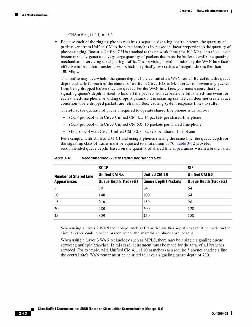
Chapter 3 Network InfrastructureWAN Infrastructure
CHS = 6 ∗ (11 / 5) = 13.2
• Because each of the ringing phones requires a separate signaling control stream, the quantity of packets sent from Unified CM to the same branch is increased in linear proportion to the quantity of phones ringing. Because Unified CM is attached to the network through a 100 Mbps interface, it can instantaneously generate a very large quantity of packets that must be buffered while the queuing mechanism is servicing the signaling traffic. The servicing speed is limited by the WAN interface's effective information transfer speed, which is typically two orders of magnitude smaller than 100 Mbps.
This traffic may overwhelm the queue depth of the central site's WAN router. By default, the queue depth available for each of the classes of traffic in Cisco IOS is 64. In order to prevent any packets from being dropped before they are queued for the WAN interface, you must ensure that the signaling queue's depth is sized to hold all the packets from at least one full shared-line event for each shared-line phone. Avoiding drops is paramount in ensuring that the call does not create a race condition where dropped packets are retransmitted, causing system response times to suffer.
Therefore, the quantity of packets required to operate shared-line phones is as follows:
– SCCP protocol with Cisco Unified CM 4.x: 14 packets per shared-line phone
– SCCP protocol with Cisco Unified CM 5.0: 10 packets per shared-line phone
– SIP protocol with Cisco Unified CM 5.0: 6 packets per shared-line phone
For example, with Unified CM 4.1 and using 5 phones sharing the same line, the queue depth for the signaling class of traffic must be adjusted to a minimum of 70. Table 3-12 provides recommended queue depths based on the quantity of shared line appearances within a branch site.
When using a Layer 2 WAN technology such as Frame Relay, this adjustment must be made on the circuit corresponding to the branch where the shared-line phones are located.
When using a Layer 3 WAN technology such as MPLS, there may be a single signaling queue servicing multiple branches. In this case, adjustment must be made for the total of all branches serviced. For example, with Unified CM 4.1, if 10 branches each require 5 phones sharing a line, the central site's WAN router must be adjusted to have a signaling queue depth of 700.
Table 3-12 Recommended Queue Depth per Branch Site
Number of Shared Line Appearances
SCCP SIP
Unified CM 4.x Unified CM 5.0 Unified CM 5.0
Queue Depth (Packets) Queue Depth (Packets) Queue Depth (Packets)
5 70 64 64
10 140 100 64
15 210 150 90
20 280 200 120
25 350 250 150
3-62Cisco Unified Communications SRND (Based on Cisco Unified Communications Manager 5.x)
OL-10030-08
Chapter 3 Network InfrastructureWireless LAN Infrastructure
Provisioning for Call Control Traffic with Distributed Call Processing
In distributed call processing deployments, several sites are connected through an IP WAN. Each site contains a Unified CM cluster and can follow either the single-site model or the centralized call processing model. A gatekeeper may be used for call admission control between sites.
The following considerations apply to this deployment model:
• The signaling protocol used to place a call across the WAN is H.323 or SIP.
• Control traffic is exchanged between the Cisco IOS gatekeeper and the Unified CM clusters at each site, as well as between the Unified CM clusters themselves.
Therefore, bandwidth for control traffic must be provisioned on the WAN links between Unified CMs as well as between each Unified CM and the gatekeeper. Because the topology is limited to hub-and-spoke, with the gatekeeper typically located at the hub, the WAN link that connects each site to the other sites usually coincides with the link that connects the site to the gatekeeper.
The control traffic that traverses the WAN belongs to one of the following categories:
• Quiescent traffic, which consists of registration messages periodically exchanged between each Unified CM and the gatekeeper
• Call-related traffic, which in turn consists of two types of traffic:
– Call admission control traffic, exchanged between the Unified CMs and the infrastructure control point (such as a gatekeeper or Cisco RSVP Agent) before a call can be set up and after it has been torn down.
– Signaling traffic associated with a media stream, exchanged over an intercluster trunk when a call needs to be set up, torn down, forwarded, and so on.
Because the total amount of control traffic depends on the number of calls that are set up and torn down at any given time, it is necessary to make some assumptions about the call patterns and the link utilization. The WAN links that connect each of the spoke sites to the hub site are normally provisioned to accommodate different types of traffic (for example, data, voice, and video). Using a traditional telephony analogy, we can view the portion of the WAN link that has been provisioned for voice as a number of virtual tie lines.
Assuming an average call duration of 2 minutes and 100 percent utilization of each virtual tie line, we can derive that each tie line carries a volume of 30 calls per hour. This assumption allows us to obtain the following formula that expresses the recommended bandwidth for call control traffic as a function of the number of virtual tie lines.
Equation 5: Recommended Bandwidth Based on Number of Virtual Tie Lines.
Recommended Bandwidth (bps) = 116 ∗ (Number of virtual tie lines)
If we take into account the fact that 8 kbps is the smallest bandwidth that can be assigned to a queue on a Cisco IOS router, we can deduce that a minimum queue size of 8 kbps can accommodate the call control traffic generated by up to 70 virtual tie lines. This amount should be sufficient for most large enterprise deployments.
Wireless LAN InfrastructureWireless LAN infrastructure design becomes important when IP telephony is added to the wireless LAN (WLAN) portions of a converged network. With the addition of wireless IP telephony endpoints such as the Cisco Unified Wireless IP Phones 7920 and 7921G, voice traffic has moved onto the WLAN and is now converged with the existing data traffic there. Just as with wired LAN and wired WAN
3-63Cisco Unified Communications SRND (Based on Cisco Unified Communications Manager 5.x)
OL-10030-08
Chapter 3 Network InfrastructureWireless LAN Infrastructure
infrastructure, the addition of voice in the WLAN requires following basic configuration and design best-practices for deploying a highly available network. In addition, proper WLAN infrastructure design requires understanding and deploying QoS on the wireless network to ensure end-to-end voice quality on the entire network. The following sections discuss these requirements:
• WLAN Design and Configuration, page 3-64
• WLAN Quality of Service (QoS), page 3-70
For more information about WLAN and Voice over WLAN (VoWLAN) design, refer to the latest version of the Enterprise Mobility Design Guide, available at
http://www.cisco.com/go/designzone
WLAN Design and ConfigurationProperly designing a WLAN requires, first and foremost, ensuring that the existing wired network is deployed in a highly available, fault-tolerant and redundant manner. Next, an understanding of wireless technology is required. Finally, by configuring and deploying wireless access points (APs) and wireless telephony endpoints in an effective way, you can build a flexible, secure, redundant, and highly scalable network.
The following sections examine the WLAN infrastructure layers and network services:
• Wireless Infrastructure Considerations, page 3-64
• Wireless AP Configuration and Design, page 3-67
• Wireless Security, page 3-68
Wireless Infrastructure Considerations
The following sections provide guidelines and best practices for designing the WLAN infrastructure:
• VLANs, page 3-64
• Roaming, page 3-65
• Wireless Channels, page 3-65
• Wireless Interference, page 3-66
• Multicast on the WLAN, page 3-66
VLANs
Just as with a wired LAN infrastructure, when deploying voice in a wireless LAN, you should enable at least two virtual LANs (VLANs) at the Access Layer. The Access Layer in a wireless LAN environment includes the access point (AP) and the first-hop access switch. On the AP and access switch, you should configure both a native VLAN for data traffic and a voice VLAN (under Cisco IOS) or Auxiliary VLAN (under CatOS) for voice traffic. This voice/auxiliary VLAN should be separate from all the other wired voice VLANs in the network. In addition, as with voice endpoints on wired LANs, wireless voice endpoints should be addressed using RFC 1918 private subnet addresses. When deploying a wireless infrastructure, Cisco also recommends configuring a separate management VLAN for the management of WLAN APs. This management VLAN should not have a WLAN appearance; that is, it should not have an associated service set identifier (SSID) and it should not be directly accessible from the WLAN.
3-64Cisco Unified Communications SRND (Based on Cisco Unified Communications Manager 5.x)
OL-10030-08
Chapter 3 Network InfrastructureWireless LAN Infrastructure
Roaming
When devices roam at Layer 3, they move from one AP to another AP across native VLAN boundaries. When the WLAN network infrastructure consists of autonomous APs, the Cisco Catalyst 6500 Series Wireless LAN Services Module (WLSM) allows the Cisco Unified Wireless IP Phone to keep its IP address and roam at Layer 3 while still maintaining an active call. Seamless Layer 3 roaming occurs only when the client is roaming within the same mobility group. For details about the Cisco WLSM and Layer 3 roaming, refer to the Cisco WLSM product documentation available at
http://www.cisco.com
Seamless Layer 3 roaming for clients across a lightweight access point infrastructure is accomplished by WLAN controllers that use dynamic interface tunneling. Cisco Unified Wireless IP Phones that roam across WLAN controllers and VLANs can keep their IP address when using the same SSID and therefore can maintain an active call.
Note In dual-band WLANs (those with 2.4 GHz and 5 GHz bands), it is possible to roam between 802.11b/g and 802.11a with the same SSID, provided the client is capable of supporting both bands. However, this can cause gaps in the voice path. In order to avoid these gaps, use only one band for voice.
Note If Cisco Catalyst 4000 Series switches are used as Layer 3 devices at the distribution layer, a minimum of a Supervisor Engine 2+ (SUP2+) or Supervisor Engine 3 (SUP3) module is required. The Supervisor Engine 1 or 2 (SUP1 or SUP2) modules can cause roaming delays. The Cisco Catalyst 2948G, 2948G-GE-TX, 2980G, 2980G-A, and 4912 switches are also known to introduce roaming delays. Cisco does not recommend using these switches in a wireless voice network.
Wireless Channels
Wireless endpoints and APs communicate via radios on particular channels. When communicating on one channel, wireless endpoints typically are unaware of traffic and communication occurring on other non-overlapping channels.
Optimal channel configuration for 2.4 GHz 802.11b and 802.11g requires a minimum of five-channel separation between configured channels to prevent interference or overlap between channels. In North America, with allowable channels of 1 to 11, channels 1, 6, and 11 are the three usable non-overlapping channels for APs and wireless endpoint devices. However, in Europe where the allowable channels are 1 to 13, multiple combinations of five-channel separation are possible. Multiple combinations of five-channel separation are also possible in Japan, where the allowable channels are 1 to 14.
Optimal channel configuration for 5 GHz 802.11a requires a minimum of one-channel separation to prevent interference or overlap between channels. In North America, there are 20 possible non-overlapping channels: 36, 40, 44, 48, 52, 56, 60, 64, 100, 104, 108, 112, 116, 132, 136, 140, 149, 153, 157, and 161. In Europe, the same non-overlapping channels are allowed. However, many countries do not support the use of channel 40, so there are only 19 possible overlapping channels. In Japan, only 8 non-overlapping channels are supported: 36, 40, 44, 48, 52, 56, 60, and 64. Because of the larger set of non-overlapping channels, 802.11a allows for more densely deployed WLANs.
Note that the 802.11a band does require support for Dynamic Frequency Selection (DFS) and Transmit Power Control (TPC) on some channels in order to avoid interference with radar (military, satellite, and weather). Regulations require that channels 52 to 64, 100 to 116, and 132 to 140 support DFS and TPC. TPC ensures that transmissions on these channels are not powerful enough to cause interference. DFC monitors channels for radar pulses and, when it detects a radar pulse, DFC stops transmission on the channel and switches to a new channel.
3-65Cisco Unified Communications SRND (Based on Cisco Unified Communications Manager 5.x)
OL-10030-08
Chapter 3 Network InfrastructureWireless LAN Infrastructure
AP coverage should be deployed so that no (or minimal) overlap occurs between APs configured with the same channel. Same channel overlap should typically occur at 19 dBm separation. However, proper AP deployment and coverage on non-overlapping channels require a minimum overlap of 20%. This amount of overlap ensures smooth roaming for wireless endpoints as they move between AP coverage cells. Overlap of less than 20% can result in slower roaming times and poor voice quality.
Deploying wireless devices in a multi-story building such as an office high-rise or hospital introduces a third dimension to wireless AP and channel coverage planning. Both the 2.4 GHz and 5.0 GHz wave forms of 802.11 can pass through floors and ceilings as well as walls. For this reason, not only is it important to consider overlapping cells or channels on the same floor, but it is also necessary to consider channel overlap between adjacent floors. With only three channels, proper overlap can be achieved only through careful three-dimensional planning.
Note Careful deployment of APs and channel configuration within the wireless infrastructure are imperative for proper wireless network operation. For this reason, Cisco requires that a complete and thorough site survey be conducted before deploying wireless networks in a production environment. The survey should include verifying non-overlapping channel configurations, AP coverage, and required data and traffic rates; eliminating rogue APs; and identifying and mitigating the impact of potential interference sources.
Wireless Interference
Interference sources within a wireless environment can severely limit endpoint connectivity and channel coverage. In addition, objects and obstructions can cause signal reflection and multipath distortion. Multipath distortion occurs when traffic or signaling travels in more than one direction from the source to the destination. Typically, some of the traffic arrives at the destination before the rest of the traffic, which can result in delay and bit errors in some cases. You can reduce the affects of multipath distortion by eliminating or reducing interference sources and obstructions, and by using diversity antennas so that only a single antenna is receiving traffic at any one time. Interference sources should be identified during the site survey and, if possible, eliminated. At the very least, interference impact should be alleviated by proper AP placement and the use of location-appropriate directional or omni-directional diversity radio antennas.
Possible interference sources include:
• Other APs on overlapping channels
• Other 2.4 GHz appliances, such as 2.4 GHz cordless phones, personal wireless network devices, sulphur plasma lighting systems, microwave ovens, rogue APs, and other WLAN equipment that takes advantage of the license-free operation of the 2.4 GHz band
• Metal equipment, structures, and other metal or reflective surfaces such as metal I-beams, filing cabinets, equipment racks, wire mesh or metallic walls, fire doors and fire walls, concrete, and heating and air conditioning ducts
• High-power electrical devices such as transformers, heavy-duty electric motors, refrigerators, elevators, and elevator equipment
Multicast on the WLAN
By design, multicast does not have the acknowledgement level of unicast. According to 802.11 specifications, the access point must buffer all multicast packets until the next Delivery Traffic Indicator Message (DTIM) period is met. The DTIM period is a multiple of the beacon period. If the beacon period is 100 ms (typical default) and the DTIM value is 2, then the access point must wait up to 200 ms before transmitting a single buffered multicast packet. The time period between beacons (as a product of the DTIM setting) is used by battery-powered devices to go into power save mode temporarily. This power save mode helps the device conserve battery power.
3-66Cisco Unified Communications SRND (Based on Cisco Unified Communications Manager 5.x)
OL-10030-08
Chapter 3 Network InfrastructureWireless LAN Infrastructure
Multicast on WLAN presents a twofold problem in which administrators must weigh multicast traffic quality requirements against battery life requirements. First, delaying multicast packets will negatively affect multicast traffic quality, especially for applications that multicast real-time traffic such as voice. In order to limit the delay of multicast traffic, DTIM periods should typically be set to a value of 1 so that the amount of time multicast packets are buffered is low enough to eliminate any perceptible delay in multicast traffic delivery. However, by setting the DTIM period to a value of 1, the amount of time that battery-powered WLAN devices are able to go into power save mode is shortened, and therefore battery life is shortened. In order to conserve battery power and lengthen battery life, DTIM periods should typically be set to a value of 2 or more.
For WLAN networks with no multicast applications or traffic, the DTIM period should be set to a value of 2 or higher. For WLAN networks where multicast applications are present, the DTIM period should be set to a value of 2 whenever possible; however, if multicast traffic quality suffers or if unacceptable delay occurs, then the DTIM value should be lowered to 1. If the DTIM value is set to 1, administrators must keep in mind that battery life of battery-operated devices will be significantly shortened.
Before enabling multicast applications on the wireless network, Cisco recommends testing these applications to ensure that performance and behavior are acceptable.
For additional considerations with multicast traffic, see Music on Hold, page 7-1.
Wireless AP Configuration and Design
Proper AP selection, deployment, and configuration are essential to ensure that the wireless network handles voice traffic in a way that provides high-quality voice to the end users.
AP Selection
Cisco recommends the following APs for deploying wireless voice:
• Aironet 350 Series AP
• Aironet 1000 Series Lightweight AP
• Aironet 1100 Series AP
• Aironet 1130AG Series AP
• Aironet 1200 Series AP
• Aironet 1230AG Series AP
• Aironet 1240AG Series AP
• Aironet 1300 Series AP
• Aironet 1500 Series AP
For these APs, Cisco IOS Release 12.3(4) JA or later is recommended.
AP Deployment
When you use Cisco access points (APs) for voice deployments, Cisco recommends that you do not associate more than 15 to 25 devices to a single 802.11b or 802.11b/g AP at any given time. For 802.11a or 802.11a/g APs, Cisco recommends that you do not associate more than 45 to 50 devices to a single AP. These numbers will vary depending on usage profiles and the enabled data rates. The number of devices on an AP affects the amount of time each device has access to the medium. As the number of devices increases, the traffic contention increases. Associating more devices than specified above can result in poor AP performance and slower response times for associated devices.
3-67Cisco Unified Communications SRND (Based on Cisco Unified Communications Manager 5.x)
OL-10030-08
Chapter 3 Network InfrastructureWireless LAN Infrastructure
While there is no specific mechanism to ensure that only a limited number of devices are associated to a single AP, system administrators can manage device-to-AP ratios by conducting periodic site surveys and analyzing user and device traffic patterns. If additional devices and users are added to the network in a particular area, additional site surveys should be conducted to determine whether additional APs are required to handle the number of endpoints that need to access the network.
AP Configuration
When deploying wireless voice, observe the following specific AP configuration requirements:
• Enable Address Resolution Protocol (ARP) caching.
ARP caching is required on the AP because it enables the AP to answer ARP requests for the wireless endpoint devices without requiring the endpoint to leave power-save or idle mode. This feature results in extended battery life for the wireless endpoint devices.
• Enable Dynamic Transmit Power Control (DTPC) on the AP.
This ensures that the transmit power on the AP and on the voice endpoints match. Matching transmit power helps eliminate the possibility of one-way audio traffic. Voice endpoints adjust their transmit power based on the Limit Client Power (mW) setting of the AP to which they are associated.
• Assign a Service Set Identifier (SSID) to each VLAN configured on the AP.
SSIDs enable endpoints to select the wireless VLAN they will use for sending and receiving traffic. These wireless VLANs and SSIDs map to wired VLANs. For voice endpoints, this mapping ensures priority queuing treatment and access to the voice VLAN on the wired network.
• Enable QoS Element for Wireless Phones on the AP.
This feature ensures that the AP will provide QoS Basic Service Set (QBSS) information elements in beacons. The QBSS element provides an estimate of the channel utilization on the AP, and Cisco wireless voice devices use it to help make roaming decisions and to reject call attempts when loads are too high. Beginning with Cisco IOS Release 12.3(7)JA, the AP also provides 802.11e clear channel assessment (CCA) QBSS in beacons. The CCA-based QBSS values reflect true channel utilization.
• Configure two QoS policies on the AP, and apply them to the VLANs and interfaces.
Configure a voice policy and a data policy with default classifications for the respective VLANs to ensure that voice traffic is given priority queuing treatment. (See Interface Queuing, page 3-71, for more information).
Wireless Security
Another important consideration for a wireless infrastructure is security. Wireless endpoints, including wireless phones, can connect to the wireless network using one of the following security mechanisms:
• Extensible Authentication Protocol-Flexible Authentication via Secure Tunneling (EAP-FAST)
A standards-based security protocol that first requires the establishment of an authenticated tunnel between the wireless client and an Authentication, Authorization, and Accounting (AAA) server using a Protected Access Credential (PAC). Next the wireless endpoint authenticates across the tunnel using a user name and password to authenticate with the network via 802.1X. Once this authentication occurs, traffic to and from the wireless device is encrypted using TKIP or WEP. Using the 802.1X authentication method requires an EAP-compliant Remote Authentication Dial-In User Service (RADIUS) authentication server such as the Cisco Secure Access Control Server (ACS), which provides access to a user database for authenticating the wireless devices.
3-68Cisco Unified Communications SRND (Based on Cisco Unified Communications Manager 5.x)
OL-10030-08
Chapter 3 Network InfrastructureWireless LAN Infrastructure
• Wi-Fi Protected Access (WPA)
A standards-based security protocol requires the wireless endpoint to provide a user name and password to authenticate with the network. Once this authentication occurs using either 802.1X or WPA Pre-Shared Key (WPA-PSK), traffic to and from the wireless device is encrypted using Temporal Key Integrity Protocol (TKIP). Using the 802.1X authentication method requires an EAP-compliant Remote Authentication Dial-In User Service (RADIUS) authentication server such as the Cisco Secure Access Control Server (ACS), which provides access to a user database for authenticating the wireless devices.
• Wi-Fi Protected Access 2 (WPA2)
This is the 802.11i enhanced version of WPA. It is a standards-based security protocol that requires the wireless endpoint to provide a user name and password to authenticate with the network. Once this authentication occurs using either 802.1X or Pre-Shared Key (WPA2-PSK), traffic to and from the wireless device is encrypted using Advanced Encryption Standards (AES). Using the 802.1X authentication method requires an EAP-compliant Remote Authentication Dial-In User Service (RADIUS) authentication server such as the Cisco Secure Access Control Server (ACS), which provides access to a user database for authenticating the wireless devices.
• Cisco LEAP
Cisco LEAP requires the wireless endpoint to provide a user name and password to authenticate with the network. Once this authentication occurs, a dynamic key is generated, and traffic to and from the wireless device is encrypted. This method requires an EAP-compliant Remote Authentication Dial-In User Service (RADIUS) authentication server such as the Cisco Secure Access Control Server (ACS), which provides access to a user database for authenticating the wireless devices.
• Static Wired Equivalent Privacy (WEP)
Static WEP requires the exchange of a statically configured 40-bit or 128-bit character key between the wireless endpoint and the AP. If the keys match, the wireless device is given access to the network. Be aware that there are known weaknesses in the WEP encryption algorithm. These weaknesses, coupled with the complexity of configuring and maintaining static keys, can make this security mechanism undesirable in many cases.
Authentication and ACS Deployment Models
Extensible Authentication Protocol (EAP) is the preferred method of wireless device authentication (especially voice devices) because it provides the most secure and robust mechanism for access to the network and voice VLAN(s). Because an EAP-compliant RADIUS server is required, Cisco recommends the use of Cisco Secure ACS for Windows Server Version 3.1 or later.
When deploying EAP-FAST, WPA, or Cisco LEAP for wireless authentication and encryption, carefully consider the placement of the ACS within the network, and select one of the following ACS deployment models:
• Centralized ACS
ACS server or servers are located in a centralized place within the network and are used to authenticate all wireless devices and users within the network.
• Remote ACS
In networks where remote locations are separated from the central site by low-speed or congested WAN links, an ACS server can be located at the remote site and remote wireless devices or users can be authenticated by this server locally, thus eliminating the potential for delayed authentication via a centralized ACS across the WAN link.
3-69Cisco Unified Communications SRND (Based on Cisco Unified Communications Manager 5.x)
OL-10030-08
Chapter 3 Network InfrastructureWireless LAN Infrastructure
• Local and fallback RADIUS server on the Cisco AP
In networks where remote locations are separated from a central site by low-speed WAN links, local wireless devices can authenticate against local Cisco IOS APs. APs running Cisco IOS Release 12.2(11)JA or later can authenticate users and devices locally without relying on an external ACS. A single AP can support up to 50 users with this functionality. This feature can be used in lieu of a centralized or local ACS, or in the case of a WAN or ACS failure in which the remote site users are unable to contact a local ACS or the central site ACS.
When choosing a deployment model for the ACS, it is imperative to make authentication services redundant so that the ACS does not become a single point of failure when wireless devices attempt to access the network. For this reason, each ACS server should replicate its database to a secondary server. Furthermore, it is always a good idea to provide a local ACS or an on-AP RADIUS server at remote sites to ensure that remote wireless devices can still authenticate in the event of a WAN failure.
In addition to ACS server placement, it is also important to consider the implications of user database location in relation to the ACS server. Because the ACS server must access the user database to authenticate wireless devices, the location of the user database affects the amount of time the authentication will take. If the user database is a Microsoft Active Directory (AD) server located on the network, the ACS must send an authentication request to the AD server and wait for a response. To ensure the fastest response times for wireless voice endpoints attempting to authenticate to the network, Cisco recommends defining users locally on the ACS server. Remote databases have unknown response times and can adversely affect authentication times.
WLAN Quality of Service (QoS)Just as QoS is necessary for LAN and WAN wired network infrastructure in order to ensure high voice quality, QoS is also require for wireless LAN infrastructure. Because of the bursty nature of data traffic and the fact that real-time traffic such as voice is sensitive to packet loss and delay, QoS tools are required to manage wireless LAN buffers, limit radio contention, and minimize packet loss, delay, and delay variation.
However, unlike most wired networks, wireless networks are a shared medium, and wireless endpoints do not have dedicated bandwidth for sending and receiving traffic. While wireless endpoints can mark traffic with 802.1p CoS, DSCP, and PHB, the shared nature of the wireless network means limited admission control and access to the network for these endpoints.
Wireless QoS involves the following main areas of configuration:
• Traffic Classification, page 3-70
• Interface Queuing, page 3-71
• Bandwidth Provisioning, page 3-71
Traffic Classification
As with wired network infrastructure, it is important to classify or mark pertinent wireless traffic as close to the edge of the network as possible. Because traffic marking is an entrance criterion for queuing schemes throughout the wired and wireless network, marking should be done at the wireless endpoint device whenever possible. Marking or classification by wireless network devices should be identical to that for wired network devices, as indicated in Table 3-5.
In accordance with traffic classification guidelines for wired networks, the Cisco Wireless IP Phone 7920 marks voice media traffic or RTP traffic with DSCP 46 (or PHB EF) and voice signaling traffic (SCCP) with DSCP 24 (or PHB CS3). Once this traffic is marked, it can be given priority or better than
3-70Cisco Unified Communications SRND (Based on Cisco Unified Communications Manager 5.x)
OL-10030-08
Chapter 3 Network InfrastructureWireless LAN Infrastructure
best-effort treatment and queuing throughout the network. All wireless voice devices should be capable of marking traffic in this manner. All other traffic on the wireless network should be marked as best-effort or with some intermediary classification as outlined in wired network marking guidelines.
Interface Queuing
Once traffic marking has occurred, it is necessary to enable the wired network APs and devices to provide QoS queuing so that voice traffic types are given separate queues to reduce the chances of this traffic being dropped or delayed as it traversed the wireless LAN. Queuing on the wireless network occurs in two directions, upstream and downstream. Upstream queuing concerns traffic traveling from the wireless endpoint up to the AP and from the AP up to the wired network. Downstream queuing concerns traffic traveling from the wired network to the AP and down to the wireless endpoint.
For upstream queuing, devices that support Wi-Fi Multimedia (WMM) are able to take advantage of queueing mechanisms, including priority queueing. However, devices that do not support WMM are unable to take advantage of this queueing mechanism. The Cisco Wireless IP Phone 7921G does support WMM. The Cisco Wireless IP Phone 7920 does not support WMM; however, it can provide queuing upstream as the packets leave the device, but there is no mechanism in place to provide queuing among all clients on the wireless LAN because wireless networks are a shared medium.
As for downstream QoS, Cisco APs currently provide up to eight queues for downstream traffic being sent to wireless clients. The entrance criterion for these queues can be based on a number of factors including DSCP, access control lists (ACLs), and VLAN. Although eight queues are available, Cisco recommends using only two queues when deploying wireless voice. All voice media and signaling traffic should be placed in the highest-priority queue, and all other traffic should be placed in the best-effort queue. This ensures the best possible queuing treatment for voice traffic.
In order to set up this two-queue configuration for autonomous APs, create two QoS policies on the AP. Name one policy Voice, and configure it with the class of service Voice < 10 ms Latency (6) as the Default Classification for all packets on the VLAN. Name the other policy Data, and configure it with the class of service Best Effort (0) as the Default Classification for all packets on the VLAN. Then assign the Data policy to the incoming and outgoing radio interface for the data VLAN(s), and assign the Voice policy to the incoming and outgoing radio interfaces for the voice VLAN(s). With the QoS policies applied at the VLAN level, the AP is not forced to examine every packet coming in or going out to determine the type of queuing the packet should receive.
For lightweight APs, the WLAN controller has built-in QoS profiles that can provide the same queuing policy. Voice VLAN or voice traffic is configured to use the Platinum policy, which sets priority queueing for the voice queue. Data VLAN or data traffic is configured to use the Silver policy, which sets best-effort queuing for the Data queue. These policies are then assigned to the incoming and outgoing radio interfaces based on the VLAN.
The above configurations ensure that all voice media and signaling are given priority queuing treatment in a downstream direction.
Bandwidth Provisioning
Based on wireless voice network testing, Cisco has determined that an 802.11b-only AP with 802.11b clients and a data rate of 11 Mbps can support a maximum of seven active G.711 voice streams or eight G.729 streams. AP rates set lower than 11 Mbps will result in a lower call capacity per AP.
With 802.11a at a data rate of 54 Mbps, the maximum number of active voice streams increases to between 14 and 18 per AP.
3-71Cisco Unified Communications SRND (Based on Cisco Unified Communications Manager 5.x)
OL-10030-08
Chapter 3 Network InfrastructureWireless LAN Infrastructure
For 802.11g environments with a data rate of 54 Mbps, in theory the maximum number of active voice streams also increases to between 14 and 18 per AP. However, because most 802.11g environments are mixed and include 802.11b clients (and therefore 11 Mbps data rates) as well as 802.11g clients, capacity is typically significantly lower, with a maximum of 8 to 12 active voice streams per AP.
Note A call between two phones associated to the same AP counts as two active voice streams.
To prevent these limits from being exceeded, some form of call admission control is required. Cisco APs and wireless voice clients have two mechanisms that are used for call admission control:
• QoS Basic Service Set (QBSS)
QBSS is the beacon information element that enables the AP to communicate channel utilization information to the wireless IP phone. This QBSS value helps wireless phones to determine whether they should roam to another AP. A lower QBSS value indicates that the AP is a good candidate to roam to, while a higher QBSS value indicates that the device should not roam to this AP. While this QBSS information is useful, it is not a true call admission control mechanism because it does not guarantee that calls will retain proper QoS or that there is enough bandwidth to handle the call. When a Cisco Unified Wireless IP Phone is associated to an AP with a high QBSS, the AP will prevent a call from being initiated or received by rejecting the call setup and sending a Network Busy message to the initiating device. However, once a call is set up between a wireless IP phone and another endpoint, the phone may roam and associate with an AP with a high QBSS, thus resulting in oversubscription of the available bandwidth on that AP.
• Wi-Fi Multimedia Traffic Specification (WMM TSPEC)
WMM TSPEC is the QoS mechanism that enables WLAN clients to provide an indication of their bandwidth and QoS requirements so that APs can react to those requirements. When a client is preparing to make a call, it sends an Add Traffic Stream (ADDTS) message to the AP with which it is associated, indicating the TSPEC. The AP can then accept or reject the ADDTS request based on whether bandwidth and priority treatment are available. If the call is rejected, the phone will receive a Network Busy message. When roaming, mid-call clients supporting TSPEC will send a ADDTS message to the new AP as part of the association process to ensure that there is available bandwidth for priority treatment. If there is not enough bandwidth, the roam can be load-balanced to a neighboring AP if one is available.
The Cisco Unified Wireless IP Phone 7920 supports only QBSS, so this is the only mechanism that can be used for call admission control with these devices. However, the Cisco Unified Wireless IP Phone 7921G supports both QBSS and TSPEC. (TSPEC takes precedence over QBSS.) Therefore call admission control with the Cisco Unified Wireless IP Phone 7921G, when using TSPEC, is more accurate and eliminates the possibility of exceeding AP call capacities.
Note Beginning with Cisco IOS Release 12.3(7)JA, the AP sends 802.11e CCA-based QBSS. These QBSS values represent true channel utilization for a particular AP.
The QBSS information element is sent by the AP only if QoS Element for Wireless Phones has been enable on the AP. (Refer to Wireless AP Configuration and Design, page 3-67.)
3-72Cisco Unified Communications SRND (Based on Cisco Unified Communications Manager 5.x)
OL-10030-08