network management security guidance at-a-glance...network management is the process of monitoring...
TRANSCRIPT

UNCLASSIFIED
UNCLASSIFIED
NETWORK MANAGEMENT SECURITY GUIDANCE AT-A-GLANCE
Version 9, Release 1
24 August 2017
Developed by DISA for the DoD

UNCLASSIFIED Network Management Security Guidance At-a-Glance, V9R1 DISA 24 August 2017 Developed by DISA for the DoD
ii UNCLASSIFIED
TABLE OF CONTENTS
Page
1. INTRODUCTION .................................................................................................................... 1 2. MANAGEMENT NETWORK ............................................................................................... 2
2.1 Network Element Access for OAM&P .............................................................................. 2 2.2 Out-of-Band Management Network .................................................................................. 3
2.2.1 Dedicated OOBM Infrastructure ................................................................................. 3 2.2.2 Virtual OOBM Backbone ........................................................................................... 4 2.2.3 Non-Dedicated OOBM Gateway Routers – Dedicated OOBM Backbone ................ 4 2.2.4 Non-Dedicated OOBM Gateway Routers – Virtual OOBM Backbone ..................... 5 2.2.5 Non-Dedicated OOBM LAN Infrastructure ............................................................... 6 2.2.6 OOBM Interface ......................................................................................................... 7
2.3 In-Band Management Network .......................................................................................... 7 2.3.1 Physical Management LAN ........................................................................................ 8 2.3.2 Management VLAN .................................................................................................... 9 2.3.3 NOC Connectivity ...................................................................................................... 9 2.3.4 Management Traffic Quality of Service ................................................................... 10
2.4 SNMP ............................................................................................................................... 10
3. NETWORK MANAGEMENT AUXILIARY COMPONENTS ....................................... 12
3.1 Syslog Server ................................................................................................................... 12 3.2 Communications Servers ................................................................................................. 13 3.3 AAA Server ...................................................................................................................... 13 3.4 NTP Client and Server ..................................................................................................... 14
4. LOGISTICS: IMAGE AND CONFIGURATION STORAGE ......................................... 16

UNCLASSIFIED Network Management Security Guidance At-a-Glance, V9R1 DISA 24 August 2017 Developed by DISA for the DoD
iii UNCLASSIFIED
LIST OF TABLES
Page
Table 1: Icons Used In This Document .......................................................................................... 1 Table 2: Log Severity Levels ........................................................................................................ 12

UNCLASSIFIED Network Management Security Guidance At-a-Glance, V9R1 DISA 24 August 2017 Developed by DISA for the DoD
iv UNCLASSIFIED
LIST OF FIGURES
Page
Figure 1: OOBM Access to the Managed Network ........................................................................ 3 Figure 2: Remote Site OOBM Connectivity via GRE/IPsec .......................................................... 4 Figure 3: Non-Dedicated OOBM Gateway with Dedicated OOB Backbone ................................. 5 Figure 4: Non-Dedicated OOBM Gateway – Connectivity via GRE over IPsec ........................... 6 Figure 5: Non-Dedicated OOBM LAN Infrastructure .................................................................... 7 Figure 6: Physical Management LAN ............................................................................................ 8 Figure 7: Management VLAN Separation ...................................................................................... 9 Figure 8: In-Band Management Traffic Separation ...................................................................... 10

UNCLASSIFIED Network Management Security Guidance At-a-Glance, V9R1 DISA 24 August 2017 Developed by DISA for the DoD
1 UNCLASSIFIED
1. INTRODUCTION Network management is the process of monitoring network elements, configuring network elements to turn up and disable network services, and the collection of state information and other relevant data about each element to ensure availability and that services are being delivered to meet or exceed service level agreements. Network management processes can be performed on-site by the local network administrators and engineers or remotely at a Network Operations Center (NOC). Whether a production network is being managed locally or from a NOC, achieving network management objectives depends on comprehensive and reliable network management solutions. These solutions provide monitoring of network behavior, performance thresholds, and network element configuration. Equally important is the ability to quickly detect and troubleshoot network events such as a service outage, link down, node down, and high utilization of both network elements and bandwidth. The intent of this document is to discuss the best network management practices that should be implemented and to provide easy-to-follow guidance to securely manage networks. A large portion of the guidance found in Section 2, Management Network, will be dependent on both the physical and logical network topology, as well as the specific network management deployment based on various out-of-band (OOB) and in-band management paradigms.
Table 1: Icons Used In This Document
Router
Access Switch
Multi-Layer Switch
Terminal Server
IDS/IPS
Firewall
Network
Secured Modem
GRE/IPsec Tunnel
802.1Q Trunk Link
Desktop
Server

UNCLASSIFIED Network Management Security Guidance At-a-Glance, V9R1 DISA 24 August 2017 Developed by DISA for the DoD
2 UNCLASSIFIED
2. MANAGEMENT NETWORK Management systems provide the network operator the facility to manage the network and all of its components. They are both the platforms and the applications that interact with the managed network elements to provide the NOC with a framework to facilitate operation, administration, maintenance, and provisioning (OAM&P) tasks. OAM&P is a group of management functions that enables system or network fault indication, diagnostics, performance monitoring, security management, configuration management, and service provisioning. Management systems and managed network elements need to be interconnected. The facility that provides this connection is referred to as the “management network”. To be managed, a network element provides a management interface through which a management system can communicate. Hence, the management system is the reason for the management network to exist. The management network is composed of network management workstations, authentication servers, syslog servers, time servers, communications servers, NetFlow collector, an Operations Support System (OSS), and a network for transporting management traffic. While the Network Infrastructure STIGs and SRGs provide guidance for securing a network and the network elements, this document will discuss the management connectivity models used to access the network being managed, as well as all of the management network components, the vulnerabilities they introduce, and the security measurements that must be taken to mitigate these risks.
2.1 Network Element Access for OAM&P Securing the network infrastructure is critical to overall network security. A key element is the security of management access to the network elements. If device access is compromised, the security end of the entire network cam be compromised. To provide management access, network elements support direct serial connections, out-of-band connections, and in-band connections. The direct serial interface is typically referred to as the craft port or console port. There may also be an auxiliary port. This interface is intended to be an access port through which local operation control and configuration management can take place. In-band or out-of-band connections can be used to transport network management messages between the managed network elements and the management systems used for providing OAM&P functions. In either case, the same access services, such as Secure Shell (SSH), Transport Layer Security (TLS), Secure Sockets Layer (SSL), HyperText Transfer Protocol over TLS or SSL (HTTPS), and Simple Network Management Protocol (SNMP), are used to access a managed network element. Out-of-band and in-band management implementations will be discussed in Sections 2.2 and 2.3 respectively. The auxiliary port, console port, and any slow-speed async serial port with an analog modem connected to it provides the capability for direct dial-up administrative access. If dial-up capability is provided, a secured modem and connection must be used as specified in Section 3.2.
UNCLASSIFIED Network Management Security Guidance At-a-Glance, V9R1 DISA 24 August 2017 Developed by DISA for the DoD
3 UNCLASSIFIED
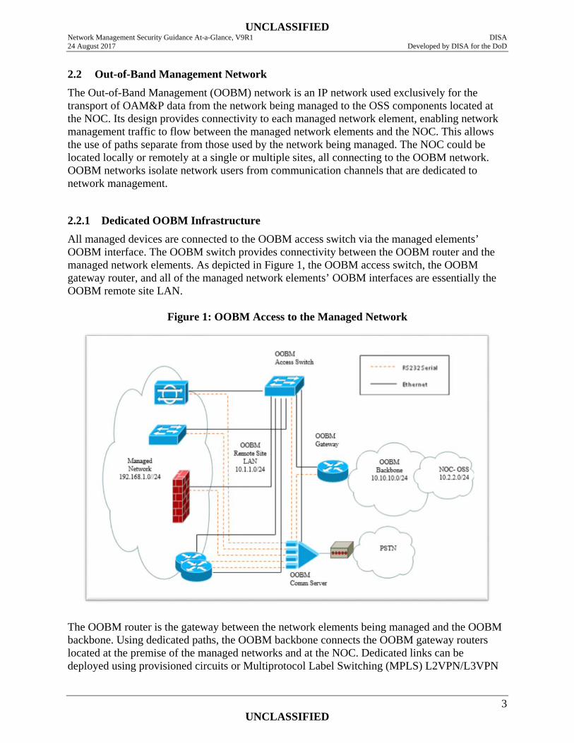
2.2 Out-of-Band Management Network The Out-of-Band Management (OOBM) network is an IP network used exclusively for the transport of OAM&P data from the network being managed to the OSS components located at the NOC. Its design provides connectivity to each managed network element, enabling network management traffic to flow between the managed network elements and the NOC. This allows the use of paths separate from those used by the network being managed. The NOC could be located locally or remotely at a single or multiple sites, all connecting to the OOBM network. OOBM networks isolate network users from communication channels that are dedicated to network management.
2.2.1 Dedicated OOBM Infrastructure All managed devices are connected to the OOBM access switch via the managed elements’ OOBM interface. The OOBM switch provides connectivity between the OOBM router and the managed network elements. As depicted in Figure 1, the OOBM access switch, the OOBM gateway router, and all of the managed network elements’ OOBM interfaces are essentially the OOBM remote site LAN.
Figure 1: OOBM Access to the Managed Network
The OOBM router is the gateway between the network elements being managed and the OOBM backbone. Using dedicated paths, the OOBM backbone connects the OOBM gateway routers located at the premise of the managed networks and at the NOC. Dedicated links can be deployed using provisioned circuits or Multiprotocol Label Switching (MPLS) L2VPN/L3VPN

UNCLASSIFIED Network Management Security Guidance At-a-Glance, V9R1 DISA 24 August 2017 Developed by DISA for the DoD
4 UNCLASSIFIED
services. An alternative is implementing a secured path via IPsec tunnels connecting the OOBM gateway routers.
2.2.2 Virtual OOBM Backbone In deployments lacking dedicated OOBM links, the NOC must connect to the OOBM remote site LAN via shared network infrastructure such as the NIPRNet. Figure 2 illustrates a topology with the NOC and the OOBM remote site LAN securely connected via GRE over IPsec tunnels between the OOBM gateway routers. The GRE tunnel ensures that both the management and control plane traffic will be logically separated from any other traffic traversing the same physical path. This deployment is implemented by establishing a GRE tunnel between the two gateways. Interior gateway protocol (IGP) routing protocol adjacencies will form over the GRE tunnel end points. The GRE tunnel should be encrypted by IPsec to provide privacy for both the management and control plane traffic.
Figure 2: Remote Site OOBM Connectivity via GRE/IPsec
2.2.3 Non-Dedicated OOBM Gateway Routers – Dedicated OOBM Backbone If the gateway router is not a device dedicated for the OOBM network (i.e., may be the managed network’s premise router), several safeguards must be implemented for traffic containment and separation. Management traffic must not leak into the managed network, and traffic from the managed network must not leak into the management network.

UNCLASSIFIED Network Management Security Guidance At-a-Glance, V9R1 DISA 24 August 2017 Developed by DISA for the DoD
5 UNCLASSIFIED
Since the managed network and the management network are separate routing domains as shown in Figure 3, separate IGP routing instances must be configured on the router—that is, one for the managed network and one for the OOBM network. In addition, this shared router must be configured to ensure that control plane traffic is not redistributed between the two routing domains. Implementing Virtual Routing and Forward (VRF) on the interfaces connecting the OOBM backbone and the OOBM remote site LAN can provide additional segregation by creating a separate OOBM routing table. This implementation does not require Multiprotocol Label Switching (MPLS); hence, it is commonly referred to as VRF-lite. A VRF instance could also be created for the managed network, or simply allow it to use the global route table.
Figure 3: Non-Dedicated OOBM Gateway with Dedicated OOB Backbone
2.2.4 Non-Dedicated OOBM Gateway Routers – Virtual OOBM Backbone As previously discussed, for OOBM deployments lacking dedicated OOB links, secured paths can be deployed using IPsec tunnels between the gateways. If static routing is used, implementing IPsec tunnel between the non-dedicated OOBM gateway and the OOBM gateway at the NOC to transport management traffic is a simple and secured deployment. However, since static routes do not scale well, dynamic routing may be required. Hence, control plane traffic must be able to traverse the same secured path as the management traffic. This deployment is implemented by establishing a GRE tunnel between the two gateways. IGP routing protocol adjacencies will form over the GRE tunnel end points. The GRE tunnel will be encrypted by IPsec to provide privacy for the control plane payload as illustrated in Figure 4.

UNCLASSIFIED Network Management Security Guidance At-a-Glance, V9R1 DISA 24 August 2017 Developed by DISA for the DoD
6 UNCLASSIFIED
Figure 4: Non-Dedicated OOBM Gateway – Connectivity via GRE over IPsec
2.2.5 Non-Dedicated OOBM LAN Infrastructure For OOBM deployments lacking dedicated Layer 2 and Layer 3 infrastructure, both VRF-lite and 802.1q technologies can be used to provide the separation of management and production traffic. As depicted in Figure 5, VRF_OOBM and VRF_PROD is used to create separate routing tables for the OOBM network and the managed network respectively. Where Ethernet Layer 3 interfaces must be shared, 802.1q tagging can be deployed to provide the separation, thereby creating logical or sub interfaces. The VRFs would be configured and bound to the appropriate physical or logical Layer 3 interfaces. For simplicity, the VRFs are only called out on R1’s logical interfaces (802.1q) in Figure 5 but would exist on the two physical interfaces between the Premise Router and R1, the Premise Router and R2, and the two logical interfaces between R1 and R2. When access switches must be shared between domains, 802.1q tagging can be used to create VLANs for management as well as production domains. As shown in Figure 5, VLAN 10 and VLAN 20 have been deployed to provide separate Layer 2 domains for the OOBM network and the managed network respectively. In this illustration, the VLAN numbers are only significant within each Layer 2 domain. Using the same VLAN numbers also makes it easier to identify the ownership of the sub-interfaces on the routers.

UNCLASSIFIED Network Management Security Guidance At-a-Glance, V9R1 DISA 24 August 2017 Developed by DISA for the DoD
7 UNCLASSIFIED
Figure 5: Non-Dedicated OOBM LAN Infrastructure
2.2.6 OOBM Interface The OOBM access switch will connect to the management interface of the managed network elements. The management interface can be a true OOBM interface or a standard interface functioning as the management interface. In either case, the management interface of the managed network element will be directly connected to the OOBM access switch. An OOBM interface does not forward transit traffic, thereby providing complete separation of production and management traffic. Since all management traffic is immediately forwarded into the management network, it is not exposed to possible tampering. The separation also ensures that congestion or failures in the managed network do not affect the management of the device. If the managed network element does not have an OOBM interface, the interface functioning as the management interface must be configured so that management traffic and production traffic do not leak into the management network.
2.3 In-Band Management Network The in-band management paradigm exists when the management traffic takes the same path as operational or production traffic, thereby using the same Layer 3 interface of the managed network element. Management plane traffic shares the same path as the control plane and forwarding plane. Henceforth, network management traffic is intermixed with user traffic using the same physical or logical interfaces of the network elements being managed.

UNCLASSIFIED Network Management Security Guidance At-a-Glance, V9R1 DISA 24 August 2017 Developed by DISA for the DoD
8 UNCLASSIFIED
A dedicated in-band management network enables the enclave or enterprise to control, monitor, and restrict management plane traffic. Since all management services must be deployed within the management network, all managed devices can be configured to only permit management plane traffic from the management network IP address space. It is also easier to construct appropriate filters since management plane traffic sourced from the managed devices must be destined to the management network IP address space. Unlike out-of-band implementation, the configured IP address of the interfaces used to access the managed elements belong to address space of the managed network. Using a loopback address as the source address provides security, scalability, and manageability of all routers and switches. It is easier to construct appropriate ingress filters for management plane traffic destined to the network management subnet since the source addresses will be from the range used for loopback interfaces to the larger range used for physical interfaces. Log information recorded by authentication and syslog servers will record the router’s loopback address instead of the numerous physical interface addresses. Messages sent to the following servers should also use the loopback address as the source address: Syslog, TACACS+, RADIUS, NTP, SNMP, NetFlow Collector, TFTP, and FTP.
2.3.1 Physical Management LAN As illustrated in Figure 6, the management network must still have its own subnet in order to enforce control and access boundaries provided by Layer 3 network nodes such as routers and firewalls. Management traffic between the managed network elements and the management network is routed via the same links and nodes as that used for production or operational traffic. Safeguards must be implemented to ensure the management traffic does not leak past the managed network’s premise equipment.
Figure 6: Physical Management LAN

UNCLASSIFIED Network Management Security Guidance At-a-Glance, V9R1 DISA 24 August 2017 Developed by DISA for the DoD
9 UNCLASSIFIED
2.3.2 Management VLAN If the management systems reside within the same Layer 2 domain as the managed network elements, separate VLANs will be deployed to provide separation at that level. In this case, the management network will have its own subnet and be provisioned with a unique VLAN. As illustrated in Figure 7, inter-VLAN routing or the routing of traffic between nodes residing in different subnets requires a router or multi-layer switch (MLS). Access control lists must be used to enforce the boundaries between the management network and the network being managed. All physical, logical, and virtual (i.e., switch virtual interface) Layer 3 interfaces must be configured with ACLs to prevent the leaking of unauthorized traffic from one network to the other.
Figure 7: Management VLAN Separation
2.3.3 NOC Connectivity Similar to the OOBM model, when the production network is managed in-band, the management network could also be housed at a NOC that is located locally or remotely at a single or multiple interconnected sites. NOC interconnectivity, as well as connectivity between the NOC and the managed networks’ premise routers, would be enabled using either provisioned circuits or VPN technologies such as IPsec tunnels or MPLS L2VPN/L3VPN services. The topology shown in Figure 8 depicts all management traffic between the NOC sites and the managed network encapsulated within IPsec tunnels traversing the NIPRNet.

UNCLASSIFIED Network Management Security Guidance At-a-Glance, V9R1 DISA 24 August 2017 Developed by DISA for the DoD
10 UNCLASSIFIED
Figure 8: In-Band Management Traffic Separation
2.3.4 Management Traffic Quality of Service Quality of Service (QoS) implementation categorizes network traffic, prioritizes it according to its relative importance, and ensures bandwidth is reserved for important traffic when there is congestion. Implementing QoS within the network makes network performance more predictable and bandwidth utilization more effective. Most important, since the same bandwidth is being used to manage the network, it provides some assurance that there will be bandwidth available to troubleshoot outages and restore availability when needed. When management traffic must traverse several nodes to reach the management network, management traffic should be classified and marked at the nearest upstream multi-layer switch or router. In addition, all core routers within the managed network must be configured to provide preferred treatment based on the QoS markings. This will ensure that management traffic receives preferred treatment (per-hop behavior) at each forwarding device along the path to the management network.
2.4 SNMP SNMP enables network administrators to manage network performance, troubleshoot network problems, and plan for network growth. An SNMP-managed network consists of three key components: managed devices, agents, and managers, which are commonly referred to as

UNCLASSIFIED Network Management Security Guidance At-a-Glance, V9R1 DISA 24 August 2017 Developed by DISA for the DoD
11 UNCLASSIFIED
network-management systems (NMSs). A managed device is a network node that resides on a managed network. An SNMP agent is a software module that resides in a managed device. SNMP agents collect and store management information and make this information available to the NMS. The SNMP manager provides the interface between the network management personnel and the managed network. The SNMP agent provides the interface between the SNMP manager and the device being managed. The manager is the collector of alarm information via SNMP notifications (i.e., traps and informs) as well as statistical and historical management information retrieved by polling the agents within the managed network. This information is vital for real-time monitoring and alarm management as well as for strategic planning and performance management. IA measures must be implemented to mitigate the risk of the SNMP manager being compromised. To provide security through separation and isolation, the SNMP manager must reside within the management network. This enables the SNMP manager to provide management services to the managed devices using a secured as well as a preferred path. SNMP version 3 provides secure exchanges of management data between network devices and network management systems. The encryption and authentication features in SNMPv3 ensure high security in transporting packets to a network management station. SNMPv3 employs the User-Based Security Model (USM) to provide cryptographic services. The USM uses either HMAC-MD5 or HMAC-SHA message digests to ensure message authenticity and integrity and DES-CBC, 3DES, or AES encryption to ensure message privacy. These features are used to provide three distinct levels of security:
1. No authentication with no privacy 2. Authentication with no privacy 3. Authentication with privacy
To reduce the risk of a managed network element being breached via rogue SNMP manager, best practice is to authenticate all SNMP messages using HMAC-SHA and encrypt the payload using AES cryptographic algorithm using the largest key size supported.

UNCLASSIFIED Network Management Security Guidance At-a-Glance, V9R1 DISA 24 August 2017 Developed by DISA for the DoD
12 UNCLASSIFIED
3. NETWORK MANAGEMENT AUXILIARY COMPONENTS The network management auxiliary components are used to provide capabilities to enable both management and security functionality for the managed network. These components are being secured as a result of the IA requirements that have been defined based on the topology—that is, whether they are residing within a dedicated OOB network infrastructure or connected to an in-band network. Nevertheless, since they do have sessions with elements in the managed network that could be compromised, additional IA measures must be followed to reduce the risk of these components also being compromised.
3.1 Syslog Server Logging is a key component of any security architecture and is a critical part of network element security. It is essential that security personnel know what is being done, what was attempted, and by whom to compile an accurate risk assessment. It is also imperative that all configuration changes to network elements are logged on a per-session and per-user basis. Maintaining an audit trail of system activity logs can help identify configuration errors, understand past intrusions, troubleshoot service disruptions, and react to probes and scans of the network. Log severity levels 0–6 are the levels required to collect the necessary information to help in the recovery process.
Table 2: Log Severity Levels
Level Level Name Description Example 0 Emergencies Router becoming unusable IOS could not load
1 Alerts Immediate action needed Temperature too high
2 Critical Critical condition Unable to allocate memory
3 Errors Error condition Invalid memory size
4 Warnings Warning condition Crypto operation failed
5 Notifications Normal but important event
Interface changed state, up or down
6 Informational Information message Packet denied by access list
7 Debugging Debug message Appears only when debugging is enabled A syslog server provides the network administrator with the ability to configure all of the communication devices on a network to send log messages to a centralized host for review, correlation, reporting, and storage. This implementation provides for easier management of network events and is an effective facility for monitoring and the automatic generation of alert notification. The repository of messages facilitates troubleshooting when problems are encountered and can assist in performing root cause analysis. Syslog files can also be parsed in real time to identify suspicious behavior or be archived for review at a later time for research and analysis.

UNCLASSIFIED Network Management Security Guidance At-a-Glance, V9R1 DISA 24 August 2017 Developed by DISA for the DoD
13 UNCLASSIFIED
3.2 Communications Servers A communications server, also known as a terminal server, can be used to provide connectivity among all managed network elements and the OOBM gateway router for administrative access to the device’s console port. In the event the OOBM network is not able to provide connectivity due to an outage, the communications server can provide a dial-up Point-to-Point Protocol (PPP) connection to access a network element. PPP provides two options that must be used to help secure the connection at the link layer: authentication and callback. The communication server and remote client negotiate these options during connection establishment by the Link Control Protocol (LCP)—a PPP sub-layer. PPP enables authentication between remote clients and access servers using either Password Authentication Protocol (PAP) or Challenge Handshake Authentication Protocol (CHAP). PAP provides a simple way for the remote client to establish its identity with an authenticator: a two-way handshake after the initial PPP link establishment. A username/password pair is sent by the remote client to the access server until authentication is acknowledged or the connection is terminated. CHAP is a stronger authentication method than PAP and therefore is the preferred implementation. CHAP creates a unique challenge phrase (a randomly generated string) for each authentication. The challenge phrase is combined with device host names using one-way hashing functions to authenticate. Hence, no static secret information is ever transmitted. CHAP can also be set up to do repeated mid-session authentications. This is useful for dial-up PPP sessions where a port may be left open even though the remote device has disconnected. In this case, it is possible for someone else to pick up the connection mid-session simply by establishing connectivity. Callback increases the level of security by allowing connection only to authorized telephone numbers. When callback is enabled, a user calls the access server. After successfully authenticating the call, the access server notifies the user that the user will be called back. The server hangs up immediately and calls back using a preconfigured number. Modems can also provide the call-back capability. The auxiliary port, console port, and any slow-speed async serial port with an analog modem connected to the managed device also provides the capability for direct dial-up administrative access for infrastructures that do not have a communications server for management access. The modems providing the end-to-end connection between the network administrator and the communication server or the managed device must establish a secured link using a FIPS 140-2 encryption algorithm.
3.3 AAA Server An authentication, authorization, and accounting (AAA) server is used for access control to managed network elements. Using standardized authentication protocols such as RADIUS and TACACS+, an AAA server provides centralized authentication services for the management of network elements. Authentication identifies the user while authorization implements policies that

UNCLASSIFIED Network Management Security Guidance At-a-Glance, V9R1 DISA 24 August 2017 Developed by DISA for the DoD
14 UNCLASSIFIED
determine which resources and services the authenticated user may access. Accounting can be used to track what commands and configuration tasks the authorized user has performed and can also keep track of time and data resources used for billing and analysis. An authentication server is very scalable as it supports many user accounts and authentication sessions with the network components. It allows for the construction of roles or groups that are given authorization for specific tasks and access to specific resources. Users are given an account assigned to a role or group that has been defined in the authentication server. Two-factor authentication is a security process that confirms user identities using two of the following distinctive factors: something they have, something they know, or something they are. Two-factor authentication does not rely exclusively on something known by a user, but it adds something that they must have such as a smart token, smart card, or password token that generates a one-time-password. By requiring two different forms of identification, the risk of fraud can be reduced. It is imperative that the AAA server is secured and should reside within the management network. Access to it and the information contained within must be restricted. If an authentication server were compromised in any way, account and resource access authorization information would be exposed. This could enable an attacker to gain complete access to all of the available resources and could also enable the attacker to create a denial of service masquerading as authorized users. If the AAA server is a host-based solution, it is critical that the host is secured by maintaining compliance with the appropriate OS STIG and by implementing a host-based intrusion detection system (HIDS). Unique keys should be configured for all authentication servers for communication between the managed network elements and each AAA server. Requiring a unique key for each AAA server will ensure that if a key is exposed, only one of the servers could be compromised. This will enable operations to bring that server offline to configure a new key without disrupting authentication services.
3.4 NTP Client and Server NTP provides an efficient and scalable method for network elements to synchronize to an accurate time source referred to as the reference clock or stratum-0 server. The reference clock synchronizes to the Coordinated Universal Time (UTC) derived from a set of atomic clocks using GPS, CDMA, or other time signals such as Irig-B, WWV, and DCF77. A stratum-0 server cannot be connected to a network. Instead, it is directly connected to an IP network-enabled host, which then operates as a stratum-1 NTP server. NTP time distribution is based on a loop-free topology with the stratum-1 server as the root of the tree. This includes NTP servers with built-in stratum-0 components. NTP updates can be sent as unicast, multicast, or broadcast. The latter methods enable a server to synchronize multiple hosts in an unsolicited mode. Two NTP-enabled devices can communicate in either client-server mode or peer-to-peer mode (i.e., symmetric mode). The peering mode is configured manually on the device and indicated in the outgoing NTP packets. The fundamental difference is the synchronization behavior: An NTP server can synchronize to a peer provided that it is at a lower stratum level, whereas it will never
UNCLASSIFIED Network Management Security Guidance At-a-Glance, V9R1 DISA 24 August 2017 Developed by DISA for the DoD
15 UNCLASSIFIED
synchronize to its client regardless of the client’s stratum level. From a protocol perspective, NTP clients are no different from the NTP servers. The NTP client can synchronize to multiple NTP servers, select the best server and synchronize with it, or synchronize to the averaged value returned by the servers. Any NTP-enabled device that receives and accepts time from a stratum-n server can become a stratum-n+1 server. However, an NTP-enabled device will not accept time updates from an NTP server at a higher stratum, thereby enforcing a tree-level hierarchy of client-server relationships and preventing time synchronization loops. An NTP topology should be designed to easily scale by creating a stratum hierarchy of servers to accommodate the workload. The width (number of servers at same stratum level) and depth (number of stratum levels or tiers) of the hierarchy is dependent on the number of NTP clients as well as the amount of redundancy that is required. With this implementation, an NTP client can also become an NTP server, providing time to downstream clients at a higher stratum level and with decreasing accuracy than its upstream server. To increase availability, NTP peering can be used between NTP servers. In the event the device loses connectivity to it upstream NTP server, it will be able to choose time from one of its peers. It is vital for network operations to prevent unauthorized time sources from altering or interfering with time synchronization within the managed network. Depending on vendor implementation, NTP-enabled network devices will accept any node as their peer. Hence, a rouge device could pose as an NTP peer and begin sending false time to a router. To ensure that managed devices do not receive time from imposters, they must be configured with access control lists to restrict by IP address which servers and peers a device will accept NTP update messages from.
To launch an attack on the NTP infrastructure, a hacker could inject time that would be accepted by NTP clients by spoofing the IP address of a valid NTP server. To mitigate this risk, the time messages must be authenticated by the client before accepting them as a time source. The NTP authentication model is opposite of the typical client-server authentication model. NTP authentication enables an NTP client or peer to authenticate time received from their servers and peers. It is not used to authenticate NTP clients because NTP servers do not care about the authenticity of their clients, as they never accept any time from them.
Ensuring that NTP servers are always available to provide time is critical. It is imperative that all single points of failure for the NTP infrastructure are eliminated. Network nodes synchronizing to UTC are crucial for network operations as well as for security management (forensics, auditing, certificate expirations, time-based access control, etc.). Compromising an NTP server opens the door to more sophisticated attacks that include NTP poisoning, replay attacks, and denial of service. To provide security through separation and isolation, the NTP server should only be connected to the management network. This enables the NTP server to provide time to the managed devices using a secured as well as a preferred path. If the NTP server is a host-based solution, it is critical that the host is secured by maintaining compliance with the appropriate OS STIG and implementing an HIDS.

UNCLASSIFIED Network Management Security Guidance At-a-Glance, V9R1 DISA 24 August 2017 Developed by DISA for the DoD
16 UNCLASSIFIED
4. LOGISTICS: IMAGE AND CONFIGURATION STORAGE It is important to keep the running configuration and the startup configuration synchronized so that if a power failure or some other problem forces the device to restart, the managed router or switch will load the correct configuration. If there is a need to roll back to an older configuration, it should be stored offline on an FTP or TFTP server. Images installed on the devices’ flash memory can become corrupt. Hence, it is imperative to retain a copy of the current production images on some form of offline media or file server. Both prior and new image versions should also be kept in the event regression occurs or for planned upgrade migrations respectively. With the image and configuration files stored offline, the files must be transferred to and from the switch or router in a secure method. FTP is preferred over TFTP, provided that the FTP server requires client authentication. Following are some alternative approaches that are more secure than using FTP:
• Copies of the device configuration can be archived on the devices’ flash or hard drive if the media is available.
• If the router or switch is equipped with a PCMCIA flash memory card, images as well as configurations can be copied unto the card and stored offline for backup purposes.
• Copy and paste output of a displayed configuration while in an SSH session or HyperTerminal console connection. The file can then be saved onto a disk and stored in a secure location.
• Use Secure Copy Protocol (SCP), which requires that authentication, authorization, and accounting (AAA) be configured in order for the router or switch to determine whether the user has the correct privilege level.