network security via reverse engineering of tcp code
TRANSCRIPT
Network Security Via Reverse Engineering of TCP Code:
Vulnerability Analysis and Proposed Solutions�
Biswaroop Guha and Biswanath Mukherjee
Department of Computer Science
University of California
Davis, CA 95616, U.S.A.
fguha, [email protected]
Tel: +1-916-f785-5863, 752-4826gFax: +1-916-752-4767
Corresponding Author: Biswanath Mukherjee
November 7, 1995
Abstract
The Transmission Control Protocol/Internet Protocol (TCP/IP) [1] suite is a very widelyused technique that is employed to interconnect computing facilities in modern network envi-ronments. However, there exist several security vulnerabilities in the TCP speci�cation andadditional weaknesses in a number of widely-available implementations of TCP. These vulner-abilities may enable an intruder to \attack" TCP-based systems, enabling him/her to \hijack"a TCP connection or cause denial of service to legitimate users. We analyze TCP code via a\reverse engineering" technique called \slicing" to identify several of these vulnerabilities, espe-cially those that are related to the TCP state-transition diagram. We discuss many of the awspresent in the TCP implementation of many widely used operating systems, such as SUNOS4.1.3, SVR4, and ULTRIX 4.3. We describe the corresponding TCP attack \signatures" (in-cluding the well-known 1994 Christmas Day Mitnick Attack) and provide recommendations toimprove the security state of a TCP-based system, e.g., incorporation of a \timer escape route"from every TCP state.
Keywords and Phrases: Network Security, TCP, IP, Reverse Engineering, Slicing, Vulnerability
Analysis, State Transitions, Timer Escape Route.
�This work has been supported by the Advanced Research Projects Agency (ARPA) under Contract No.DOD/DABT63-93-C-0045. A short, summarized version of this paper will appear in the Proceedings of the IEEEInfocom '96 Conference.
1
1 Introduction
Internetworking is an approach that allows dissimilar computers on dissimilar networks to com-
municate with one another in a seamless fashion by hiding the details of the underlying network
hardware. The most widely used form of internetworking is provided by the Transmission Control
Protocol/Internet Protocol (TCP/IP) suite.
There are some inherent security problems in the TCP/IP suite [7] which makes the situation
conducive to intruders. TCP sequence number prediction, IP address spoo�ng [9], misuse of IP's
source routing principle, use of Internet Control Message Protocol (ICMP) messages for denial of
service, etc. are somemethods to exploit the network's vulnerabilities. Considering the fact that most
important application programs such as Simple Mail Transfer Protocol (SMTP), telnet, r-commands
(rlogin, rsh, etc), File Transfer Protocol (FTP), etc. have TCP as their transport layer, security aws
in TCP can prove to be very hazardous for the network.
The objectives of this paper are to identify and analyze the vulnerabilities of TCP/IP and to
develop security enhancements to overcome these aws. Our work is based on analyzing the state-
transition diagram of TCP and determining the security relevance of some of the \improperly-de�ned"
transitions between di�erent states in the state-transition diagram of many widely used TCP code im-
plementations. Also, we determine the importance of timers in di�erent states and security problems
associated with them if a state does not have the necessary timer-backup or escape route.
We analyze the TCP state-transition diagram using a \reverse engineering" technique called slic-
ing [13]. Program slicing is an abstraction mechanism in which code that might in uence the value
of a given variable at a location is extracted from the full source code of the program. We employ
slicing to �lter out the relevant state-transition information from the TCP source code. In partic-
ular, using the slicing techniques discussed later in the paper, a 1700 line C �le implementation of
state-transitions in TCP along with all the header �le de�nitions has been reduced to a very small
and manageable size of approximately 180 lines of sliced code, which contains only the relevant
state-transition information. This process aids in abandoning unnecessary information and simpli-
fying the code. In this process, we have been able to locate extraneous state-transitions present in
some implementations of TCP. In other words, using the method of slicing, we have determined the
2
presence of several spurious state-transitions in a number of TCP implementations such as SUNOS
4.1.3, SVR4, and ULTRIX 4.3; these transitions are not de�ned in the TCP protocol speci�cation.
Using our approach, we can identify various sequences of packets in the network which can be po-
tentially hazardous to the security state of the system. These \attack signatures" represent TCP
vulnerabilities, which can possibly be exploited by an intruder. Any \network-sni�er" will be able to
determine these signatures and inform the system's security administrator of the intrusion. We also
provide several recommendations to enhance the security state of a TCP-based system.
The paper is organized as follows. Section 2 provides an overview of TCP with special emphasis
on its state-transition diagram. Section 3 discusses di�erent scenarios having security relevance to
the TCP/IP suite. Section 4 discusses our slicing approach to identify extraneous state-transitions
in TCP's state-transition diagram. Section 5 provides information on our analytic approach, and
the results we have obtained after employing slicing techniques on the TCP source code. Section 6
discusses the attack \signatures", the test-bed which we have developed to test the vulnerabilities of
TCP code in various implementations, and various recommendations to enhance the security state
of a system. Section 7 concludes the paper including future research directions.
2 Basics of TCP/IP
2.1 Networking with TCP/IP
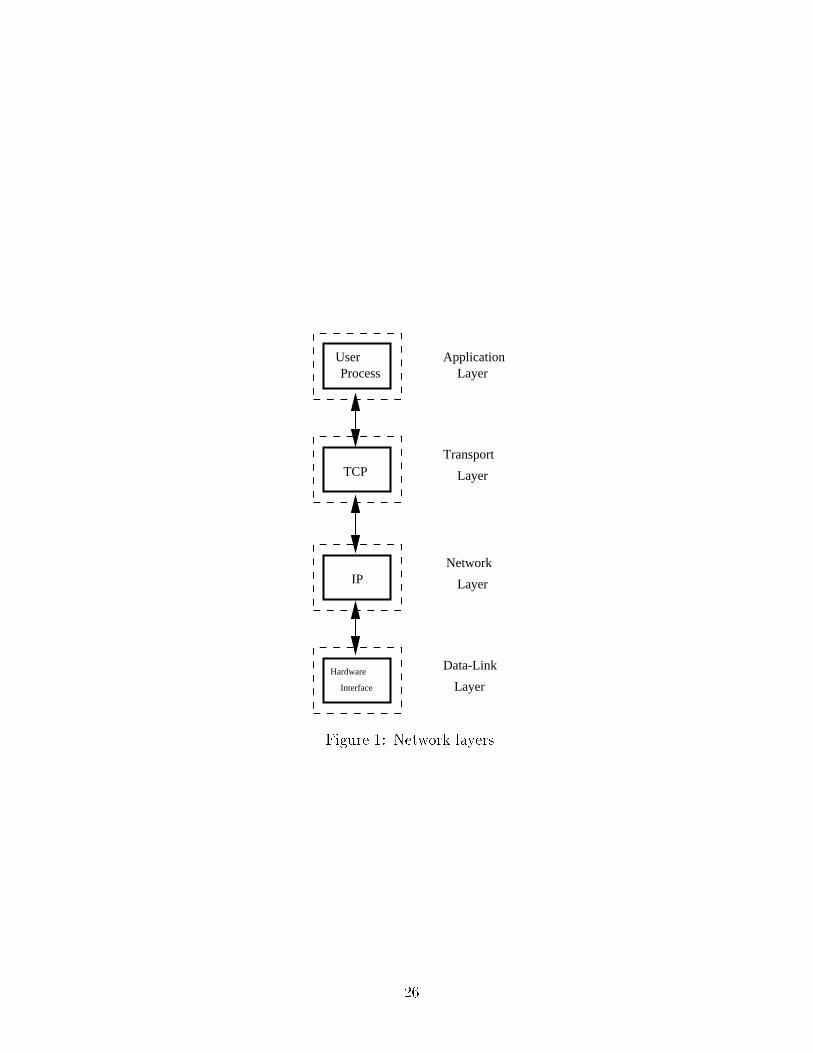
Network protocols employ a structured and layered approach, with each layer performing a separate
function. This approach helps in developing individual layers without modifying other adjacent
layers. Networking using the TCP/IP suite can be viewed as a combination of four layers as shown
in Fig. 1. Note the correspondence between these layers and those of the International Standard
Organization (ISO) seven-layer model: Layers 1 and 2 of the ISO model are combined into the lowest
layer of the model in Fig. 1, while ISO Layers 5-7 are merged into the top-most layer in Fig. 1.
The responsibilities of the di�erent layers of the model in Fig. 1 are well-de�ned.
� The lowest layer, the data-link layer,contains the network interface layer, connecting the
system with the physical media. It includes device drivers in the operating system and network
3
interface cards connected to the cable. Data-link layers of di�erent systems exchange data
packets.
� The next layer is the internet layer or the network layer. It assists with the movement (rout-
ing) of packets in the network. Internet Protocol (IP) provides a best-e�ort, connectionless,
and unreliable packet delivery service for the higher layer.
� User processes interact with the network layer through the transport layer. The Trans-
mission Control Protocol (TCP) is the most common transport layer used in modern
networking environments. TCP provides reliable data transfer between di�erent application
processes over the network. TCP provides ow control and congestion control as well.
� The Application layer handles the details of a particular application. This layer interacts
with the user, gets data from the user, and sends the bu�ered data to the transport layer. At
the same time, this layer gets data from transport layer and conveys it to the corresponding
application. The application layer shields the user from the details of the transport layer.
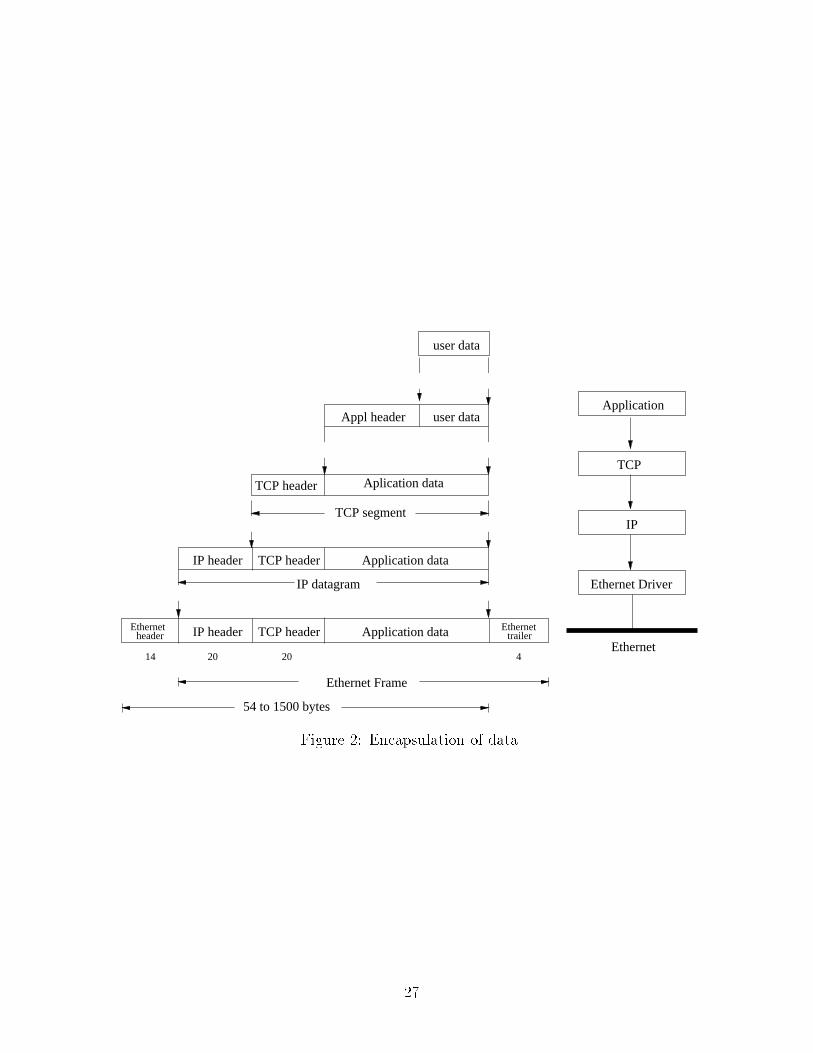
When data is sent from the application layer down to the machine hardware, it moves through
the di�erent layers and each lower layer adds a header to the data it receives from the previous upper
layer. This process of encapsulation enables a layer to easily interpret and parse the data that
it receives from a lower layer and it has to pass on to the upper layer. Fig. 2 [3] illustrates the
encapsulation process that occurs in the TCP/IP suite, assuming an Ethernet physical network.
2.2 Transport Layer
Among all of the transport layers, TCP is the most popular. Below, we examine the details of the
header format of TCP along with the TCP state-transition diagram and TCP timers.
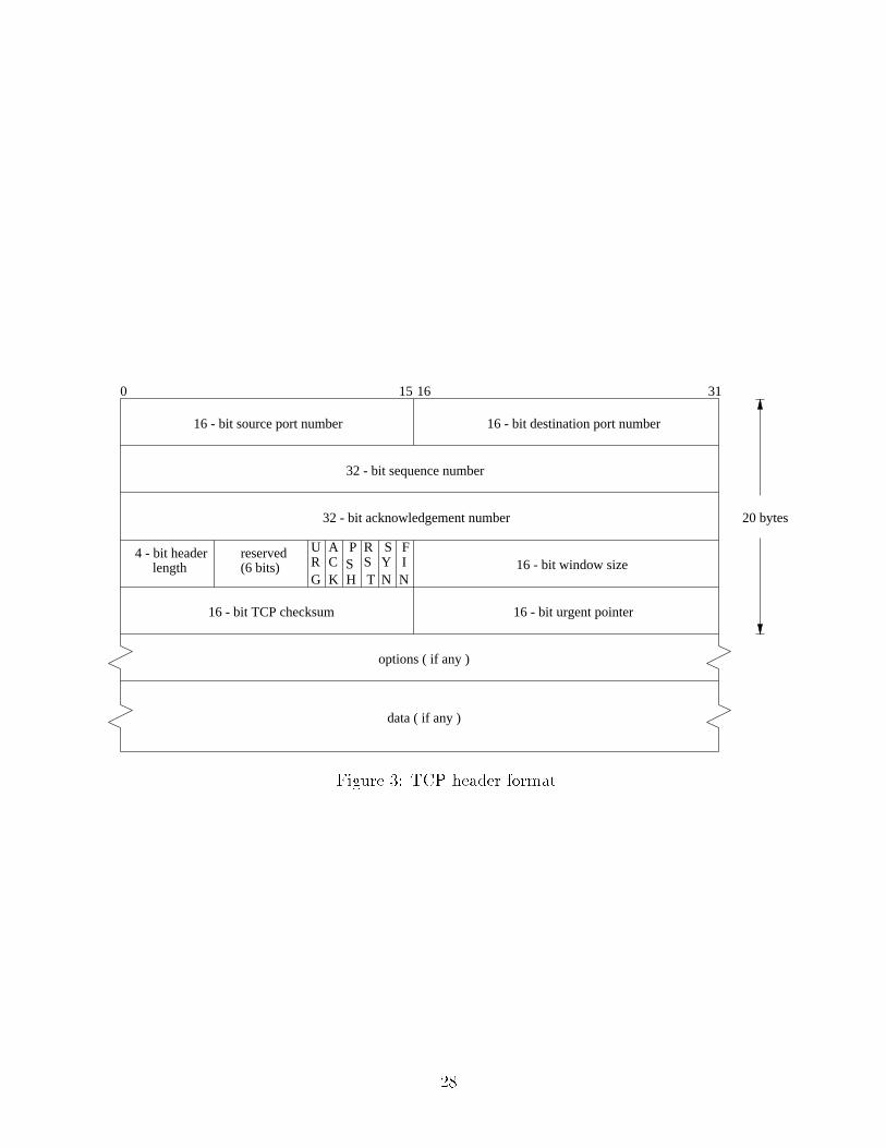
2.2.1 TCP Header
The size of the TCP header is 20 bytes, without counting its options, as we observe in Fig. 3 [3].
Each TCP segment contains the source and destination port number to identify the sending and
receiving application programs, respectively. The sequence number is essential to maintain the bytes
4
of data from the sender to the receiver in proper order. By communicating the sequence number
and the corresponding acknowledgment number, the sender and the receiver can determine lost or
retransmitted data in the connection. There are six ag bits in the TCP header, namely URG, ACK,
PSH, RST, SYN and FIN. At any given time, one or more of these ag bits can be set.
TCP provides ow control by advertising the window size. The checksum covers TCP header and
TCP data and assists in determining any error in transmission of TCP header or data. TCP's urgent
mode is a method for the sender to transmit emergency/urgent data. The urgent pointer is valid
only if the URG ag is set in the header. It helps to locate the sequence number of the last byte of
urgent data. There is an optional options �eld as well, taking care of vendor speci�c information.
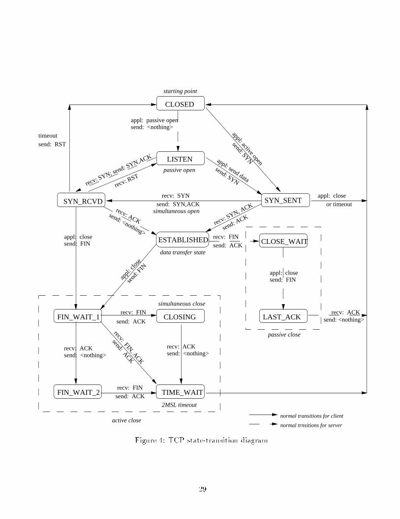
2.2.2 TCP State-Transition Diagram
Initiation, establishment, and termination of a connection is governed by the TCP state-transition
diagram, which consists of well-de�ned states and transition arcs between these states (see Fig. 4)
[4].
2.2.3 TCP Timers
The TCP state-transition diagram is very closely associated with timers. There are various timers
associated with connection establishment or termination, ow control, and retransmission of data.
� A connection-establishment timer is set when the SYN packet is sent during the connection-
establishment phase. If a response is not received within 75 seconds (in most TCP implemen-
tations), the connection establishment is aborted.
� A FIN WAIT 2 timer is set to 10 minutes when a connection moves from the FIN WAIT 1
state to the FIN WAIT 21 state [4]. If the connection does not receive a TCP packet with the
FIN bit set within the stipulated time, the timer expires and is set to 75 seconds. If no FIN
packet arrives within this time, the connection is dropped.
1These are some of the states that TCP uses to successfully terminate a connection.
5

� There is a TIME WAIT timer, often called a 2 MSL (Maximum Segment Lifetime)2 timer. It
is set when a connection enters the TIME WAIT state. When the timer expires, the kernel
data-blocks related to that particular connection are deleted, and the connection is terminated.
� A keepalive timer can be set which periodically checks whether the other end of the connection
is still active. If the SO KEEPALIVE socket option is set, and if the TCP state is either
ESTABLISHED or CLOSE WAIT, and the connection is idle, then probes are sent to the
other end of the connection once every two hours. If the other end does not respond to a �xed
number of these probes, the connection is terminated.
� Additional TCP timers such as persist timer, delayed ACK timer, and retransmission timer are
not relevant for our purposes here and, hence, are not discussed. Interested readers may refer
to [2] [3] for more information on these timers.
3 Example Attack Scenarios
3.1 IP Spoo�ng
3.1.1 Instances
The concept of attacks on TCP/IP such as TCP sequence-number guessing (to do IP-spoo�ng) was
�rst brought to light by Morris [9]. The Computer Emergency Response Team (CERT) Coordination
Center received reports of attacks in which intruders created packets with spoofed source IP addresses
[10]. These attacks exploit applications that use authentication based on IP addresses. Intruder
activity in spoo�ng IP addresses can lead to unauthorized remote root access to systems behind a
�ltering-router �rewall [10]. We examine one such attack below.
On Christmas Day, 1994, Kevin Mitnick broke into the computer of Tsutomu Shimomura, a com-
putational physicist at the San Diego Supercomputer Center. Prior to this attack, Mitnick had found
his way into the Well, a small network used mainly by an eclectic group of about 11,000 computer
users in the San Francisco Bay Area [11]. Mitnick had been reading electronic mail of the Well's
subscribers and using Well accounts for remote attacks on computers across the Internet. During the
2Common implementation values for 2MSL are 1 minute or 2 minutes.
6
attack on Shimomura's machine, two di�erent intrusion mechanisms were employed [12]. IP source
address spoo�ng and TCP sequence-number prediction were used to gain initial access to a diskless
workstation, being used mostly as an X terminal. After obtaining root access, Mitnick \hijacked" an
existing connection to another system by means of a loadable kernel STREAMS module3 [12].
3.1.2 Methodology
Let us assume that there are three hosts, host A, host B, and the intruder-controlled host X. Let
us assume that B grants A some special privileges, and thus A can get some actions performed by
B. The goal of X is to get the same action done by B for itself. In order to achieve this goal, X has
to perform two operations: �rst, establish a forged connection with B, and second, prevent A from
informing B of any malfunction of the network authentication system. Host X has to spoof the IP
address of A in order to make B believe that the packets from X are actually being sent by A.
Let us also assume that the hosts A and B communicate with one another by following the
three-way handshake mechanism of TCP/IP. The handshake method is depicted below.
A --> B : SYN (Seq. no. = M)
B --> A : SYN (Seq. no. = N), ACK (Ack. no. = M+1)
A --> B : ACK (Ack. no. = N+1)
Host X does the following to perform IP spoo�ng. First, it sends a SYN packet to host B with
some random sequence number, posing as host A. Host B responds to it by sending a SYN+ACK
packet back to host A with an acknowledgment number which is equal to one added to the original
sequence number. At the same time, host B generates its own sequence number and sends it along
with the acknowledgment number. In order to complete the three-way handshake, host X should
send an ACK packet back to host B with an acknowledgment number which is equal to one added
to the sequence number sent by host B to host A. If we assume that the host X is not present in the
same subnet as A or B so that it cannot \sni�" B's packets, host X has to �gure out B's sequence
number in order to create the TCP connection. These steps are described below [7].
3A kernel module named \tap-2.01" was compiled and installed on the system. This is a kernel STREAMS modulewhich can be pushed onto an existing STREAMS stack and used to take control of a tty device [12].
7
X --> B : SYN (Seq. no. = M), SRC = A
B --> A : SYN (Seq. no. = N), ACK (Ack. no. = M+1)
X --> B : ACK (Ack. no. = N+1), SRC = A
At the same time, host X should take away host A's ability to respond to the packets of host B.
To achieve this, X may either wait for host A to go down (for some reason), or block the protocol
part of the operating system so that it does not respond back to host B, for example, by ooding B
with incomplete connections. We shall discuss this in more details in next subsection.
3.1.3 The Attack
During the Christmas Day, 1994, attack, Shimomura observed a sequence of packets that were gener-
ated to perform IP spoo�ng [12]. Let us continue with the previous example with X as the intruder-
controlled system and observe the actions performed by the intruder.
1. X sends a number of probe packets to B and A, trying to determine whether there exists any
kind of trust relationship among hosts A and B. Commands such as showmount, rpcinfo, and
�nger [18] were utilized for this purpose.
2. X sends a number of TCP SYN packets, i.e., packets containing the SYN ag set with some
arbitrary initial sequence numbers to host A. However, the source IP address of these packets
have been forged, so that they appear to be coming from some host which does not exist in the
network. Host A responds to these packets by sending corresponding SYN-ACK packets to the
non-existent host. As there are no corresponding ACK packets to the packets sent by A, the
three-way handshake is never complete. The connection queue for port 513 (the login port) of
A are �lled up with connection-setup requests; thus, the port will not be able to generate RST
packets in response to unexpected SYN-ACK packets.
3. X sends a number of connection-request packets (SYN packets) to host B.When host B responds
to them by sending corresponding SYN-ACK packets to X, X sends RST packets to B. Thus,
the three-way handshake is not completed and TCP connections are never established between
B and X. The purpose of this step is to determine the behavior of B's TCP sequence-number
8
generator. The sequence numbers obtained from B for each new connection are analyzed by X.
The periodicity of these numbers is determined, and this data will be used by X in the next
step to generate and send a forged packet to B with a forged sequence number.
4. X creates a forged SYN packet with the source IP address same as that of host A. X sends this
packet to B. B sends a corresponding SYN-ACK packet to A. However, A is ignoring all of the
new packets coming to its login port; it will not send any RST packet to B in response to the
unexpected SYN-ACK packets from B.
5. X does not receive the SYN-ACK packet sent by B to A (assuming X is present in a di�erent
subnet). However, X is in a position to predict the sequence number present in B's SYN-ACK
packet. X generates and sends a forged ACK packet to B with the source host address same
as that of A and an acknowledgment number corresponding to the sequence number in B's
SYN-ACK packet. B assumes that the three-way handshake is successfully performed. Hence,
there is a one-way TCP connection established from X to B.
Host X is now in a position to send commands to B. B will perform these commands, assuming
that they are being sent by the trusted host A.
3.2 Problems with TCP State Transitions
Let us take a closer look at Step 2 of Section 3.1.3. The intruder-controlled host X is able to stall the
login-port of host A by sending a series of SYN packets but not sending ACK packets corresponding
to the SYN-ACK packets from A to X. As we have observed before, TCP maintains a connection-
establishment timer. If a connection does not get established within a stipulated time (typically
75 seconds), TCP resets the connection. Thus, in our previous example, the server port will not be
able to respond for a duration of 75 seconds.
3.2.1 Extraneous State Transitions
Consider a sequence of packets between hosts X and A. X sends a packet to A, with both SYN and
FIN ags set. A responds by sending an ACK packet back to X, as illustrated below.
9
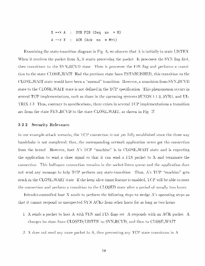
X --> A : SYN FIN (Seq. no. = M)
A --> X : ACK (Ack. no. = M+1)
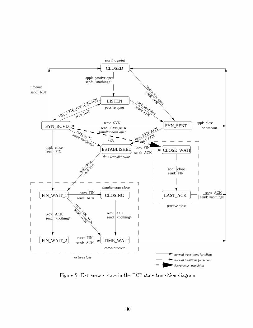
Examining the state-transition diagram in Fig. 5, we observe that A is initially in state LISTEN.
When it receives the packet from X, it starts processing the packet. It processes the SYN ag �rst,
then transitions to the SYN RCVD state. Then it processes the FIN ag and performs a transi-
tion to the state CLOSE WAIT. Had the previous state been ESTABLISHED, this transition to the
CLOSE WAIT state would have been a \normal" transition. However, a transition from SYN RCVD
state to the CLOSE WAIT state is not de�ned in the TCP speci�cation. This phenomenon occurs in
several TCP implementations, such as those in the operating systems SUNOS 4.1.3, SVR4, and UL-
TRIX 4.3. Thus, contrary to speci�cations, there exists in several TCP implementations a transition
arc from the state SYN RCVD to the state CLOSE WAIT, as shown in Fig. 5!
3.2.2 Security Relevance
In our example attack scenario, the TCP connection is not yet fully established since the three-way
handshake is not completed; thus, the corresponding network application never got the connection
from the kernel. However, host A's TCP \machine" is in CLOSE WAIT state and is expecting
the application to send a close signal so that it can send a FIN packet to X and terminate the
connection. This half-open connection remains in the socket-listen queue and the application does
not send any message to help TCP perform any state-transition. Thus, A's TCP \machine" gets
stuck in the CLOSE WAIT state. If the keep-alive timer feature is enabled, TCP will be able to reset
the connection and perform a transition to the CLOSED state after a period of usually two hours.
Intruder-controlled host X needs to perform the following steps to wedge A's operating steps so
that it cannot respond to unexpected SYN-ACKs from other hosts for as long as two hours.
1. X sends a packet to host A with SYN and FIN ags set. A responds with an ACK packet. A
changes its state from CLOSED/LISTEN to SYN RCVD, and then to CLOSE WAIT.
2. X does not send any more packet to A, thus preventing any TCP state-transitions in A.
10

Thus, we observe that extraneous state-transitions exist in several implementations of TCP and
these may lead to severe security violations of the system.
3.3 Problem with Timers
As we have discussed before, whenever the process of connection setup is in progress, a connection-
establishment timer is turned on. If the connection does not get established within a stipulated time,
TCP reverts back to the CLOSED state.
3.3.1 Simultaneous Open
During establishment of a simultaneous open connection between two hosts, we have found that
the connection-establishment timer behaves in a di�erent way.4 Let us consider our example of hosts
A and X. Host A sends a SYN packet to X, expecting a SYN-ACK packet back in response. Let us
assume that, almost at the same time, host X wants to start a connection with A and sends a SYN
packet to A. Both A and X send a SYN-ACK packet to each other when they receive the SYN packet
from the other party. When each receives the SYN-ACK packet from the other party, it assumes
that the connection is established. In this scenario, the connection-establishment timer is switched
o� when the host receives the SYN packet from the other host [4], as shown below.
X --> A : SYN (Seq. no. = M)
A --> X : SYN (Seq. no. = N)
X --> A : SYN (Seq. no. = M), ACK (Ack. no. = N+1)
A --> X : SYN (Seq. no. = N), ACK (Ack. no. = M+1),
3.3.2 Security Relevance
Let us consider the sequence of steps followed by an intruder-controlled host X and host A.
4The connection-establishment timer is turned o� when the TCP connection is fully established, i.e., the TCP\machine" does a state-transition to the ESTABLISHED state and both the hosts have the ACK packets from thepeer hosts.
11
1. Host X sends a FTP request to host A. A TCP connection is established between X and A to
transfer control signals. Host A sends a SYN packet to X in order to start a TCP connection
for data-transfer and performs a state-transition to the state SYN SENT.
2. When X receives the SYN packet from A, it sends a SYN packet back in response.
3. When host A receives this packet, it assumes that a simultaneous open connection is in progress;
it sends out a SYN-ACK packet to X and at the same time switches o� the connection-
establishment timer and makes a state-transition to state SYN RCVD.
4. Host X receives the SYN-ACK packet from A but does not send back any packet.
5. Host A is expecting a SYN-ACK from the host X. Since X does not send back any packet, A
gets stalled in the state SYN RCVD.
Thus, X is successfully able to stall a port of host A. This is clearly a denial-of-service attack.
In the following section, we shall discuss our approach to single out extraneous state-transitions
in the TCP state-transition diagram using the slicing method.
4 Slicing
Program slicing [13] produces a bona-�de program|a subset of the original program|that behaves
exactly the same with respect to the computation of a designated property [15]. In the following
subsections, we shall examine the basic idea behind program slicing, the meaning of slicing criteria,
and some example slicing applications.
4.1 Overview
Program slicing is an abstraction mechanism in which code that might in uence the value of a given
variable or a set of variables at a location is extracted from the full source code of the program [14].
Weiser [13] originally implemented slicing for FORTRAN programs. Automatic slicing requires that
the behavior of interest be expressed in a certain way. If this behavior can be communicated as
12
values of some set of variables at some set of statements, then the speci�cation is said to be slicing
criterion [13].
The concept of breaking down a large program into smaller and simpler modules for analysis is
observed in [16]. Zislis de�nes \busy variables" as variables that will be used later in the program.
He employed these variables as the criteria to group related program statements and form a program
slice. Weiser [13] used data-dependence to group statements together. There are several other ways
to slice a program, namely backward data- ow slicing, forward data- ow slicing, control- ow slicing,
etc. There are two essential properties of a program slice [14], as follows.
1. The program slice must be executable.
2. For the same input values, the variables must have identical values at the corresponding lo-
cations both in the slice and the original program. This assists in maintaining the semantic
meaning of the program.
Finding the exact and smallest program slice from a given program is an undecidable problem.
However, data- ow analysis can determine an approximate program slice by �nding all of the program
code that might have in uenced the speci�ed behavior. A simple approach would have been to delete
source statements; but this will lead to ungrammatical program slices. For example, removing
the THEN clause from an IF-THEN-ELSE statement leaves an ungrammatical program fragment,
assuming that a \null" statement is not allowed between THEN and ELSE. A more e�cient but
elaborate method will be to translate the input program into an intermediate form, apply program
slicing to it, and then reconstruct the slice into a complete program.
Slicing is a valuable tool in debugging, testing, and maintenance of software when only a portion
of a program's behavior is to be examined. It identi�es the portion of the program that a�ects the
speci�ed behavior and produces slices that are signi�cantly simpler, and smaller, than the original
program.
4.2 Slicing Criteria
As we mentioned before, slicing is carried out with respect to a slicing criterion. In the simplest form,
a criterion is a variable, and/or a location in the program. More complex criteria involve multiple
13
variables, multiple locations, and more complex program analysis.
A program slice is represented by a set of nodes. Anything that can be described in terms of
nodes in a data ow graph can serve as a slicing criterion [14]. At the same time, it is possible to
combine the e�ects of di�erent slicing methods using di�erent criteria by simply manipulating the
sets of nodes. Features such as set-union, set-di�erences, etc. can be accomplished on these set of
nodes. This approach facilitates better analysis of a given program using multiple slicing criteria.
There exist a number of di�erent techniques to slice a given program, the most common being
the backward slice approach. A basic backward slice of a program is produced by �rst generating
a combined control and data ow graph of the program, based upon the parse tree of the program.
Nodes that correspond to the slicing criteria form the basis of the slice. A node is added to the slice
if it is a de�nition of the value of a node in the slice, if it is used in a computation of a node in the
slice, or if it is a part of a control point which dominates a node in the slice [14]. The �nal slice is
the subset of the nodes of the ow graph which have been identi�ed by the above procedure.
The forward slice technique works forward through the parse tree. It traces the fan-out e�ect
of a ow node. Combination of backward and forward slicing techniques can produce slices which
characterize the behavior of a program in a more lucid way.
4.3 Example
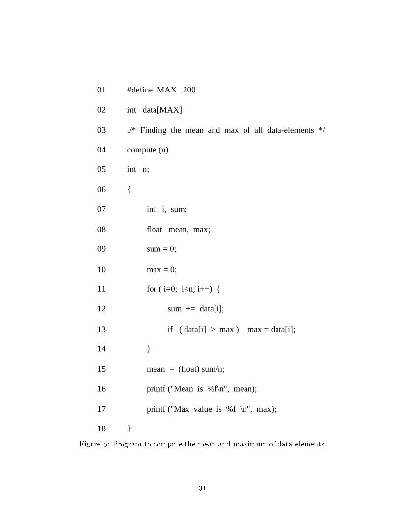
Let us examine the program in Fig. 6. It computes the mean and the maximum value of all the data
elements in the array data[]. We want to retain the part of the program that computes the mean
of all the data elements. Hence, we slice this program with respect to the variable \mean". The
program slicer computes the control and data dependence and creates the slice. In order to compute
the value of mean in line 15, the slicer needs the values of the variables sum and n. Data- ow analysis
tells the slicer to use the values of the variable sum de�ned in lines 07, 09, and 12. Similarly, the
program slicer will examine the lines 04, 05, and 11 for the variable n. Continuing in this fashion,
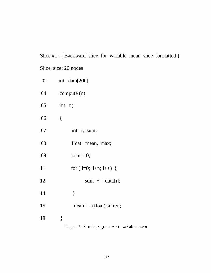
the �nal program slice looks as shown in Fig. 7.
Thus, from the original program, we obtain a subprogram which is functionally complete, and
which focuses on the variable mean and the way it is referred to and computed in the program.
14
4.4 TCP State-Transition Diagram
The TCP/IP protocol stack is implemented in the kernel space for most commercial implementation
of UNIX systems. The TCP part of the code usually consists of six C �les and seven header �les. Out
of these �les, the �le \tcp input.c" contains the implementation of the TCP state-transition diagram.
This �le handles most of the state transitions de�ned in the protocol implementation. However, it
incorporates other features of TCP such as retransmission of data packets, timer controls, ow control,
etc. Since we are most interested in analyzing the state-transition diagram, we slice this program
with respect to the \TCP state variable" called \t state" and obtain a simpli�ed program slice. The
result and its security relevance will be discussed in the following sections.
5 Analysis
5.1 The Slicer
In order to analyze the TCP source code for spurious state-transitions, we have employed the slicer
Tester's Assistant (TA), version 0.7 [14]. TA has been developed in part by the Software Testing
Research Laboratory at University of California, Davis. In order to slice a C �le using TA, we
�rst pass the program through a C preprocessor and feed it to the slicer. After computing some
initial node-analysis, TA responds with a prompt and accepts commands such as \back" (subsequent
slices will be backward slices), \forward" (subsequent slices will be forward slices), \prog" (print
out original code), \summary" (print out a description of previous slice commands), \var var" (slice
program with respect to the variable var), \func func" (slice program with respect to the function
\func"), \union num1 num2" (perform the union of two previous slices num1 and num2), etc. One
limitation of the slicer is that it does not handle pointer aliasing properly yet. However, for our
current TCP code analysis, this limitation does not create any problem.
5.2 Slicing Criteria
As we have mentioned earlier, TCP code consists of a number of C �les, each implementing some
aspect of the protocol. Since we are more concerned with the state-transitions, we slice the �le
tcp input.c, which contains the relevant state-transition information. We obtain this �le from
15

NetBSD source code, released on June 29, 1994. This �le deals with validating the input segment
obtained from the IP layer, processing the segment with respect to the ags, and the present state
of the TCP \machine", sending ACK or FIN packets to the IP layer, initializing timers for various
TCP functionalities, updating the timer values for round-trip delay, etc. We are interested in the
state-transitions of TCP and hence we choose our slicing criteria to be the variable \t state" which
stores the state information. Slicing with respect to this variable enables us to obtain only those
parts of the code that are relevant to state-transitions.
5.3 Result
We �rst passed the input program through a C preprocessor and then fed it to the slicer. It took
around 65 seconds on an unloaded SUN Sparc 5 machine, running Solaris 1.1.1, to perform the initial
node computation. The combined size of the data and stack segment of the program was around 42
Mbytes. We then performed forward and backward slicing on the program; however, we obtained a
smaller and more meaningful slice from the backward slice. We analyzed the output of the slice for
state-transitions. For each state i, we searched for the assignment of a value to the variable \t state"
and when we obtain such an assignment (j), we marked a state-transition between the states i and
j. Proceeding in this fashion, we have been able to build almost5 the entire state-transition diagram
implemented by the code.
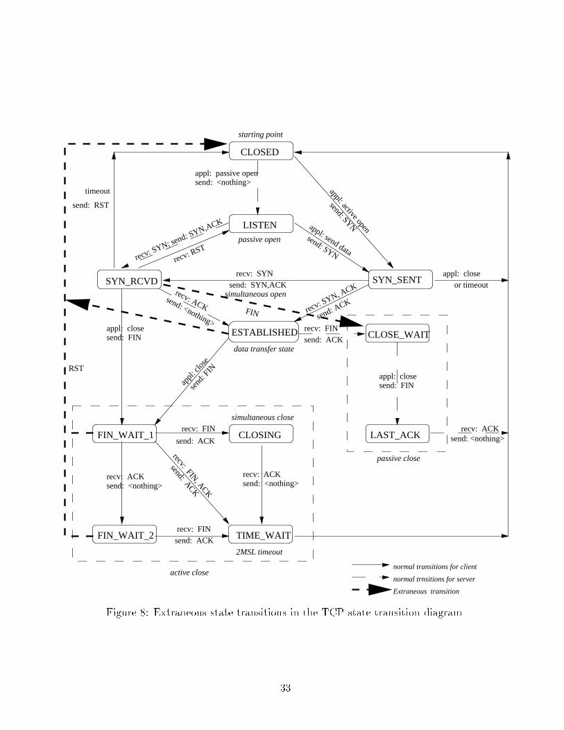
We obtain some transitions in the code which are not present in the speci�cation of the TCP
state-transition diagram [4]. The state-transitions marked in dashed lines in Fig. 8 are the \new"
transitions that we obtained after analyzing our slice output.
Let us analyze the security relevance of the \new" state-transitions.
� As we have discussed before, the transition from the state SYN RCVD to the state CLOSE -
WAIT can be utilized by an intruder to stall the TCP \machine" of the host computer for a
particular port. The host, being present in the CLOSE WAIT state, expects a signal from the
application program, so that it can send a FIN segment and performs a transition to the state
LAST ACK. However, as the TCP connection has not been established yet, the application is
5Several state-transitions occur when the function \tcp close()" is invoked. The transitions in this case are wellde�ned and we did not analyze them.
16
not in a position to send a \close" signal to the TCP. Thus, TCP remains stalled until the keep-
alive timer resets the connection back to the CLOSED state. This approach can be e�ectively
utilized by an intruder to start the process of IP spoo�ng, as we have examined before (recall
Mitnick's Christmas Day Attack).
� The transitions from the ESTABLISHED, FIN WAIT 1, and FIN WAIT 2 states to the CLOSED
state occur when the TCP \machine" receives a RST segment from the peer host. These tran-
sitions are important, since they reset the TCP \machine", and drop the network connection.
However, since the incoming data segment is authenticated only with respect to the source IP
address, an intruder performing IP spoo�ng can pose as one of the hosts of a valid connection
already in progress and send a RST segment to the other host, thus terminating the connection!
The following section deals with attack \signatures", our test-bed that tests the TCP implemen-
tation of several well-known operating systems for some of the TCP aws that we have identi�ed
and discussed, and recommendations to improve the security state of a system from these aws.
6 Attack \Signatures", Test-Bed, and Recommendations
6.1 Attack \Signatures"
We have discussed some example \attacks" that exploit various aws in TCP and its implementation.
In those examples, we noticed that the intruder has to follow a speci�c sequence of steps in order
to achieve his/her goal of creating a network intrusion. We refer to such a sequence of steps as an
attack \signature", which is a tell-tale sign of an attack. If we install a network \sni�er"6 in a
local-area network, we shall be able to monitor these \signatures", and if one is found, take necessary
security measures to maintain the system's integrity. In the following subsections, we shall discuss
some of these \signatures".
6A sni�er is a software component that gathers all network packets transmitted on a given local-area network,�lters those packets with respect to some previously-de�ned criteria, and displays the packets to the system's securityadministrator.
17
6.1.1 IP Spoo�ng
If an IP-spoo�ng attack occurs over a network which has a \sni�er" installed on it, we may observe the
following sequence of packets. (Assume that the attack is being initiated from an intruder machine
X to another machine B, after temporarily stalling the network port of a server machine A.)
� Initially, the \sni�er" will observe a urry of TCP SYN packets from some host to the login
port of host A. In response, host A will send corresponding SYN-ACK packets. The purpose of
the SYN packets is to create a number of half-open TCP connections with host A, thus �lling
the connection queue of its login port.
� A number of TCP SYN packets from host X to host B will pass through the network. This will
generate SYN-ACK packets from host B to host X. Then, host X will respond back by RST
packets. This sequence of SYN/SYN-ACK/RST packets enables the intruder to understand
the behavior of TCP sequence-number generator of host B.
� A SYN packet arrives at host B from host A. In reality, this is a \forged" packet being sent by
host X. This packet is followed by a corresponding SYN-ACK packet from host B back to A,
and an ACK packet from host A (actually from X) to B. Using this step, the intruder is able
to establish a one-way TCP connection with host B.
6.1.2 Spurious State Transitions
When an intruder attempts to stall a network port of a server for a considerably long time duration,
using the state-transition from state SYN RCVD to the state CLOSE WAIT, the following attack
\signature"can be observed.
� A TCP packet, with both SYN and FIN ags set, arrives from host X to host B.
� Host B �rst processes the SYN ag, generates a packet with the corresponding ACK ag set, and
performs a state-transition to the state SYN RCVD. Then it processes the FIN ag, performs
a transition to the state CLOSE WAIT, and sends the ACK packet back to X.
18
� Host X does NOT send any other packet to B. TCP \machine" of host B is in the CLOSE WAIT
state, waiting for a close signal from the corresponding application program. Because of lack
of response from any such program, host B gets stuck in this state until the keep-alive timer
resets it back to the CLOSED state.
Thus, if the \sni�er" �nds a sequence of SYN-FIN/ACK packets, it can conclude that the process
of stalling a port of host B is in progress.
6.1.3 Timer Problems
If an intruder attempts to disable the connection-establishment timer without actually setting up the
connection, we observe the following sequence of packets.
� Host X receives a TCP SYN packet from host B.
� Host X sends a SYN packet back to host B.
� Assuming that the ongoing connection establishment is actually a simultaneous connection
setup in progress, host B responds with a SYN-ACK packet. At this time, B has disabled its
connection establishment timer and waits for an ACK from the host X.
Host X does not send any ACK back to host B; thus, B gets stalled in the SYN RCVD state.
This is a denial-of-service attack in which the network port of host B is prevented from responding
to new connections from other client hosts.
6.2 Test-Bed
In order to test and verify the responses of TCP in di�erent machines, for some given input sequence,
we have developed a test-bed on an isolated network in our Computer Security Research Laboratory
at UC Davis. One of the machines (X) in the test-bed has been con�gured to act as an \intruder"
machine. X sends varieties of TCP packets to other hosts in the network and checks their responses.
19
6.2.1 Setup
A device driver is a software component that provides an interface between the operating system
and a device [5]. The driver controls the device in response to requests from the kernel. This device
may be a physical device, such as a disk, in which case the driver is termed as a hardware driver.
A software driver, also called a pseudo driver, controls software, which in turn may interface with
a hardware device or another software device. In our experiment, we con�gured a SUN SPARC 5,
running the Solaris 2.4 operating system, as our \intruder" machine. We performed the following
tasks to set up our machine.
� We obtained the source code for Solaris 2.4 operating system.
� We manipulated the tcp device driver code. We modi�ed some portions of the code so that the
\tcp device" responds to incoming TCP packets in a \di�erent" way.
� We compiled the code with the -D KERNEL option set, such that the executable, so generated,
can be installed in the kernel.
� We installed the driver code in the kernel, and rebooted the machine.
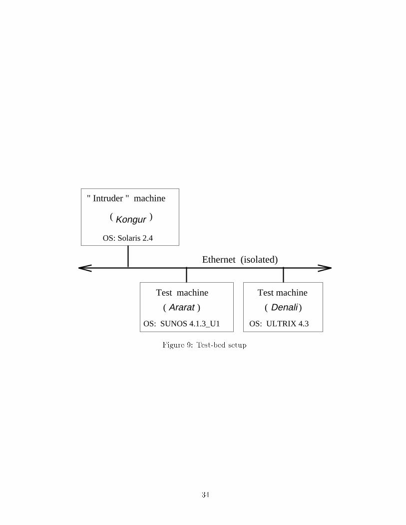
We installed the \intruder" machine on an isolated subnet. We installed two other machines on
the subnet, one running SUNOS 4.1.3 U1 operating system called Ararat, and the other running
ULTRIX 4.3 operating system called Denali as we observe in Fig. 9.
6.2.2 Experiments and Results
1. Stalling a Port :
� A ftp connection is initialized from the \intruder" machine Kongur to Ararat.
� The tcp device of Kongur sends a SYN packet to Ararat. Ararat responds by sending a
SYN-ACK packet, and performs a state-transition to the SYN RCVD state.
� Kongur does not send any other packet to Ararat. Ararat remains in the SYN RCVD
state until the connection-establishment timer expires.
20

The sequence of packets, as observed by the output of tcpdump [18] is as follows.
23:26:51.475103 Kongur.32781 > Ararat.ftp:
S 4188491776:4188491776(0) win 8760 <mss 1460> (DF)
23:26:51.477716 Ararat.ftp > Kongur2.32781:
S 1382592000:1382592000(0) ack 4188491777 win 4096 <mss 1460>
We observe that port 32781 of Kongur sends a SYN packet to the \ftp" port of Ararat
with an initial sequence number of 4188491776, initial window advertisement of 8760 at time
23:26:51.475103. Ararat, in turn, responds back with a SYN-ACK packet, with an initial se-
quence number of 1382592000 and an acknowledgement number of 4188491777 at time 23:26:51.477716.
However, Kongur did not send any other packet and so Ararat gets stuck in the SYN RCVD
state for around 75 seconds (until the connection-establishment timer expires) .
We obtain similar result with TCP implementation of ULTRIX 4.3 OS (Denali) as well.
2. Spurious State-Transition
To generate the spurious state-transition from the SYN RCVD state to the CLOSE WAIT
state, we employed the following steps.
� We start a ftp connection from Kongur to Ararat.
� In order to start the connection, Kongur sends a SYN-FIN TCP packet to Ararat7.
� Ararat responds back with an ACK packet.
� Kongur does not send any other packet to Ararat.
Using tcpdump, we observed the following sequence of packets in the network.
21:41:05.177249 Kongur.32780 > Ararat.ftp:
SF 1550373888:1550373888(0) win 8760 <mss 1460> (DF)
21:41:05.177606 Ararat.ftp > Kongur.32780:
. ack 1550373890 win 4096
7In normal circumstances, Kongur would have sent just a SYN packet to Ararat.
21
Had there been no spurious state-transition from SYN RCVD to the CLOSE WAIT state in
TCP implementation in the OS of Ararat, the TCP \machine" of Ararat would have waited in
the SYN RCVD state until the connection-establishment expired. However, netstat command
in Ararat gave us the following output.
tcp 0 0 Ararat.ftp Kongur.32780 CLOSE_WAIT
This clearly indicates that there exists a TCP connection between the \ftp" port of Ararat and
port 32780 of Kongur, and the connection exists in the CLOSE WAIT state. The connection
remains in this state in Ararat long after the peer host closed the connection on its side.
We obtain similar result with TCP implementation of ULTRIX 4.3 OS (Denali) as well.
3. Timer Problem
To demonstrate the problem of premature resetting of the TCP connection-establishment timer
in the SYN SENT state, we performed the following steps.
� We start a ftp connection from Ararat to Kongur.
� Ararat sends a SYN packet to Kongur to start the process of connection establishment.
� Instead of replying back with the usual sequence of SYN-ACK, Kongur responds back
with a SYN packet.
� When Ararat receives a packet containing only SYN but no ACK, the TCP \machine" of
Ararat assumes it is a simultaneous-open connection in progress. The connection estab-
lishment timer is switched o� and a state-transition to the state SYN RCVD is performed.
At the same time, a SYN-ACK packet is sent to Kongur.
� Kongur does not send any more packet to Ararat.
Using tcpdump, we observe the following sequence of packets in the network.
01:24:46.523156 Ararat.3632 > Kongur.ftp:
22

S 166336000:166336000(0) win 4096 <mss 1460>
01:24:46.526057 Kongur.ftp > Ararat.3632:
S 3891665408:3891665408(0) win 8760 <mss 1460> (DF)
01:24:46.526333 Ararat.3632 > Kongur.ftp:
S 166336000:166336000(0) ack 3891665409 win 4096 <mss 1460>
Netstat command in Ararat gave us the following output.
tcp 0 0 Ararat.3632 Kongur.ftp SYN_RCVD
We obtain similar result with TCP implementation of ULTRIX 4.3 OS (Denali) as well.
6.3 Recommendations
� There is no way easy way to prevent IP spoo�ng. We may perform the following tasks to
protect our systems from this sort of attack. First, we may con�gure the routers and the
gateways in our networks such that they do not allow connections from outside with a source
IP address the same as that of any of the systems within the local subnet. Also, they should
not route packets from a host in the local subnet to the outside when the source IP address
of the packet is something not present in the local subnet. Second, encrypt the packets before
sending them to the network. Though this process requires extensive change in the present
networking environment, it will ensure the integrity and authenticity of data.
� To prevent the spurious state-transition from SYN RCVD state to CLOSE WAIT state, we
should request the OS vendors to modify the relevant part of the source code in their TCP
implementation. In other words, when the TCP \machine" is in SYN RCVD state, it should
neglect any FIN packets that it might receive from a peer host.
� The connection-establishment timer should be disabled only when the connection is established.
In other words, during the simultaneous open connection setup, the timer should be disabled
when the host has received an ACK and performed a state-transition to the state ESTAB-
LISHED. Also, for each state in the state-transition diagram, there should be a timer \escape
23
route". Presently, we have observed that only a few states such as CLOSING does not have
any timer associated with it. It may be possible for an intruder machine to force the host TCP
\machine" to perform a state-transition to this state. Since the state does not have any timer
backo�, if the intruder does not send proper packets, the host may get stalled in this state.
7 Conclusion
The main objective of this paper was to identify and analyze some new vulnerabilities of TCP/IP. We
have discussed di�erent attacks that can be launched by an intruder who manipulates the security
aws in the TCP/IP speci�cation as well as its implementations. We have analyzed the TCP source
code and identi�ed spurious state-transitions present in the implementation of TCP in several oper-
ating systems. Using our test-bed, we have analyzed how TCP behaves for various combination of
input packets. Finally, we provide several recommendations to plug some of these aws in TCP and
its implementations. In future, we would like to improve the TA (Tester's Assistant). We would also
like to detect more vulnerabilities in the TCP. We would also like to investigate automated detection
of vulnerabilities in privileged programs using TCP as their transport layer [17].
References
[1] J. Postel, Transmission Control Protocol, RFC 793, 1981.
[2] D. E. Comer, Internetworking with TCP/IP: Vol. I - Principles, Protocols, and Architecture,
Third Edition, Prentice Hall, 1995.
[3] W. R. Stevens, TCP/IP Illustrated Vol. 1 - The Protocols, Addison-Wesley, 1994.
[4] W. R. Stevens and G. R. Wright, TCP/IP Illustrated Vol. 2 - The Implementation, Addison-
Wesley, 1995.
[5] STREAMS Programmer's Guide - Solaris 2.4, SunSoft, Sun Microsystem, Inc., 1994.
[6] S. M Bellovin, \There be dragons," Proceedings of 1992 USENIX Security Symposium, pp. 1-16,
September 1992.
[7] S. M Bellovin, \Security Problems in the TCP/IP Protocol Suite," Computer Communications
Review, Vol. 19, No. 2, pp. 32-48, April 1989.
24
[8] B. Cheswick, \An evening with Berferd: In which a cracker is lured, endured and studied,"
Proceedings of the Winter USENIX Conference, January 1992.
[9] R. T. Morris, \A Weakness in the 4.2BSD UNIX TCP/IP Software," Computing Science Tech-
nical Report No. 117, AT&T Bell Laboratories, Murray Hill, New Jersey.
[10] \IP Spoo�ng Attacks and Hijacked Terminal Connections," CERT Advisory, CA-95:01, Jan. 23,
1995.
[11] J. Marko�, New York Times, \Thief took bite out of security; hacker's breach shows vulnerability
of computer networks," Nation, Jan. 1995.
[12] T. Shimomura, \Technical details of the attack described by Marko� in NYT," Usenix news-
groups: comp.protocols.tcp-ip, comp.security.misc, Jan. 25, 1995.
[13] M. Weiser, \Program Slicing," IEEE Transactions on Software Engineering, Vol. SE-10, pp.
352-375, July 1984.
[14] G. Fink and K. Levitt, \Property-based testing of privileged programs," Proc., Computer Secu-
rity Applications Conference, pp. 154-163, Dec. 1994.
[15] R. W. Lo, Static Analysis of Programs with Application to Malicious Code Detection, PhD
Dissertation, University of California, Davis, 1992.
[16] P. M. Zislis, \Semantic Decomposition of Computer Programs: An Aid to Program Testing,"
Acta Informatica, pp. 245-269, 1975.
[17] C. Ko, G. Fink, K. Levitt, \Automated detection of vulnerabilities in privileged programs by
execution monitoring," Proc., Computer Security Applications Conference, pp. 134-144, Dec.
1994.
[18] SUN MICROSYSTEMS INC., SunOS 5.4 Reference Manual, Mountain View, CA, 1994.
25
UserProcess
Data-Link
ApplicationLayer
TCPTransport
Layer
IPNetwork
Layer
Hardware
Interface Layer
Figure 1: Network layers.
26
54 to 1500 bytes
TCP header
Ethernet Ethernet
user data
user dataAppl header
Application data trailerheader IP header TCP header
20 42014
IP datagram
TCP segment
Ethernet Frame
Ethernet Driver
IP
TCP
Application
Ethernet
Application dataTCP headerIP header
Aplication data
Figure 2: Encapsulation of data.
27
S
31 16150
U PRG
C S YK H T N
options ( if any )
data ( if any )
16 - bit TCP checksum 16 - bit urgent pointer
16 - bit window size
16 - bit destination port number16 - bit source port number
32 - bit sequence number
32 - bit acknowledgement number
reserved(6 bits)
4 - bit headerlength
20 bytes
IFSRA
N
Figure 3: TCP header format.
28
starting point
TIME_WAITFIN_WAIT_2
FIN_WAIT_1
CLOSE_WAIT
CLOSING LAST_ACK
CLOSED
LISTEN
normal transitions for client
SYN_SENT
ESTABLISHED
data transfer state
simultaneous open
passive close
simultaneous close
2MSL timeout
timeout
passive open
or timeout
send: <nothing>
recv: SYNsend: SYN,ACK
send: ACK
send: ACK
send: ACK
appl: close
send: RST
appl: closesend: FIN
appl: closesend: FIN
appl: passive opensend: <nothing>
send: <nothing>
active close
recv: FIN
recv: ACKrecv: FIN
recv: ACK
recv: FIN
recv: ACK
send
: FIN
send: <nothing>
recv: ACK
send: ACK
recv: FIN, ACK
appl:
clos
e
recv: RSTrecv: SYN; send: SYN,ACK
recv: SYN, ACK
send: ACK
appl: send data
send: SYN
appl: active open
send: SYN
send: <nothing>
SYN_RCVD
normal trnsitions for server
Figure 4: TCP state-transition diagram.
29
starting point
TIME_WAITFIN_WAIT_2
FIN_WAIT_1
CLOSE_WAIT
CLOSING LAST_ACK
CLOSED
LISTEN
FIN
SYN_SENT
ESTABLISHED
data transfer state
simultaneous open
passive close
simultaneous close
2MSL timeout
timeout
passive open
or timeout
send: <nothing>
recv: SYNsend: SYN,ACK
send: ACK
send: ACK
send: ACK
appl: close
send: RST
appl: closesend: FIN
appl: closesend: FIN
appl: passive opensend: <nothing>
send: <nothing>
active close
recv: FIN
recv: ACKrecv: FIN
recv: ACK
recv: FIN
recv: ACK
send
: FIN
send: <nothing>
recv: ACK
send: ACK
recv: FIN, ACK
appl:
clos
e
recv: RSTrecv: SYN; send: SYN,ACK
recv: SYN, ACK
send: ACK
appl: send data
send: SYN
appl: active open
send: SYN
send: <nothing>
SYN_RCVD
normal trnsitions for server
normal transitions for client
Extraneous transition
Figure 5: Extraneous state in the TCP state-transition diagram.
30
#define MAX 200
02 int data[MAX]
03 ./* Finding the mean and max of all data-elements */
04 compute (n)
05 int n;
06 {
07
08 float mean, max;
09 sum = 0;
10
01
max = 0;
int i, sum;
11 for ( i=0; i<n; i++) {
12 sum += data[i];
13 if ( data[i] > max ) max = data[i];
14 }
15 mean = (float) sum/n;
16 printf ("Mean is %f\n", mean);
17 printf ("Max value is %f \n", max);
18 }
Figure 6: Program to compute the mean and maximum of data elements.
31
compute (n)
05 int n;
06 {
07
08 float mean, max;
09 sum = 0;
int i, sum;
11
04
for ( i=0; i<n; i++) {
Slice #1 : ( Backward slice for variable mean slice formatted )
sum += data[i];12
14 }
mean = (float) sum/n;15
18 }
int data[200]02
Slice size: 20 nodes
Figure 7: Sliced program w.r.t. variable mean.
32
starting point
TIME_WAITFIN_WAIT_2
FIN_WAIT_1
CLOSE_WAIT
CLOSING LAST_ACK
CLOSED
timeout
LISTEN
SYN_SENT
ESTABLISHED
data transfer state
simultaneous open
passive close
simultaneous close
2MSL timeout
passive open
or timeout
send: <nothing>
recv: SYNsend: SYN,ACK
send: ACK
send: ACK
send: ACK
appl: close
send: RST
appl: closesend: FIN
appl: closesend: FIN
appl: passive opensend: <nothing>
send: <nothing>
active close
recv: FIN
recv: ACKrecv: FIN
recv: ACK
recv: FIN
recv: ACK
send
: FIN
send: <nothing>
recv: ACK
send: ACK
recv: FIN, ACK
appl:
clos
e
recv: RSTrecv: SYN; send: SYN,ACK
recv: SYN, ACK
send: ACK
appl: send data
send: SYN
appl: active open
send: SYN
send: <nothing>
SYN_RCVD
normal trnsitions for server
normal transitions for client
Extraneous transition
RST
FIN
Figure 8: Extraneous state transitions in the TCP state-transition diagram.
33
Kongur
OS: Solaris 2.4
( )
" Intruder " machine
Test machine
Ararat
OS: SUNOS 4.1.3_U1
( )
Test machine
OS: ULTRIX 4.3
( Denali )
Ethernet (isolated)
Figure 9: Test-bed setup.
34