networked embedded programming 2006 lecture 2 …
TRANSCRIPT

PROGRAMMING NETWORKED EMBEDDED SYSTEMS
Networked Embedded Programming 2006 – Lecture 2

Overview
• Toolchain– Program loading– Program execution
• Embedded programs– HW initialization– Interrupts
• OS Services– Ressource management– Tasking and Scheduling
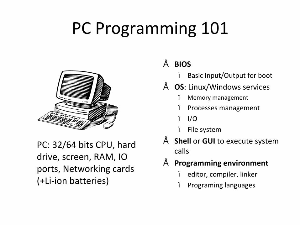
PC Programming 101
PC: 32/64 bits CPU, hard drive, screen, RAM, IO ports, Networking cards (+Li-ion batteries)
• BIOS– Basic Input/Output for boot
• OS: Linux/Windows services– Memory management
– Processes management
– I/O
– File system
• Shell or GUI to execute system calls
• Programming environment– editor, compiler, linker
– Programing languages
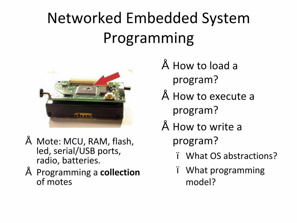
Networked Embedded System Programming
• Mote: MCU, RAM, flash, led, serial/USB ports, radio, batteries.
• Programming a collectionof motes
• How to load a program?
• How to execute a program?
• How to write a program?– What OS abstractions?
– What programming model?

Program Loading (on 1 node)
Compiler Linker
Linker scripts- memory mapping
Flash, RAM, registers- placement
program, data, stack
bootloader 1
2bootloader
program
programmingmode
executionmode
Host
Mote
Flash
Assembly codeObject file
Executable file
HLLsource

High-Level Code (C)
• Predictability is key– Code size, Speed
– What does the optimizer do?• Check out: Freescale TF slides (home page)
– Data types (one byte is best)
– NEAR variables
– Pointers to functions

Object file
• Multiple sections– Code
– Data
– BSS (uninitialized variables)
• Relocation information
• Symbolic information
Description code bss dataSupport & TinyOS core 1180UART 0 & Interrupts 346 4
UART1 & Interrupts 292 5
hciPacket0 604 155
hciPacket1 588 155
hciCore0 1624 159
hciCore1 1590 159
Assembly Component 4796 1021 16
Total 11020 1658 16
TinyOS Btstack code analysis

Linker Script
SECTIONSRAM = READ_WRITE 0x0080 TO 0x0FFF;STACK = READ_WRITE 0x1000 TO 0x107F;ROMLOW = READ_ONLY 0x1080 TO 0x17FF;ROM = READ_ONLY 0x182C TO 0xFEFF;
END
PLACEMENT.text INTO ROM;.data INTO RAM;.stack INTO STACK;
END
STACKSIZE 0x080
// reset vector: this is the default entry point // for a C/C++ application.VECTOR 0 _TinyOSStartup

Executable file (s19)• S19 file records are a text representation of Hexadecimal coded binary data.• Each line in a Motorola S19 file is called a 'record'. Records always begin with
a the letter 'S', followed by a '1' if the record contains data, or a '9' if this is the last record in the file.
• The next byte represents the number of bytes in this record, including the starting address, data bytes, and the checksum.
• The next pair of numbers represent the 16-bit starting address of the data in the record. This is the absolute location in the EPROM.
• Following the address are the hex representations of the data to be stored. • The last byte is an eight-bit one's-complement checksum of all of the bytes in
the record (not including the S1). Note that this value is derived from the binary values of the bytes, not the ASCII representation.
• A standard CR/LF pair (carriage return/linefeed, $0D $0A) terminates each line.
S00A00006170702E65786544S123182C8B899EFE05F6AF019EFF05888A81A7FCC618B14C95E701C618B04CF73218B22020S123184C1F898BF687E6024C9EE706E603EE018A4C20037FAF014BFB9E6B05F78A88AF04F9S123186C9E6B02DD9E6B01D93218B4898BADB1974C9EE703ADAA4C9EE7044A2603510018AAS123188CAD9E878AAD9A972005AD95F7AF019E6B04F79E6B03F320D5A7068145108094ADB4S12318AC8DCC1CE8000118B62F80008000C7A673C718026E404D6E024CCC18A7A7FEA10F65S12318CC2208CD2AFFA60195F765957FF6A70281A7F895F76F01CD199E95E704C600B226CFS12318EC43C600B1CB00AF87C600B0C900AE8795E601AE329EE7028A86CD258C8C979EE691
http://www.x-ways.net/winhex/kb/ff/Motorola-S3.txt

Program Loading in Practise
1 node at a time• Programming board
– Binary file uploaded by prog. board onto 1 mote flash via a serial connection from host to prog. board and from prog. board to sensor node
• Embedded bootloader– Binary file uploaded
USB/serial connection from host directly to 1 sensor node
Many nodes at a time
• Network program loading– Binary file transmitted over
the network to possibly many sensor nodes
– Mechanism to deal with multiple programs

Program Execution
• Once a program is loaded it is executed on reset– Hardware reset (power on
/ timer / reset button)
– Software reset
• If a program crashes then hardware reboot is the only solution – Hardware watchdog to
detect a crash

Overview
• Toolchain– Program loading– Program execution
• Embedded programs– HW initialization– Interrupts
• OS Services– Ressource management– Tasking and Scheduling

What is an Embedded Program?
A program embedded on a mote:– Initializes the hardware– Sleeps – Processes events (radio, sensor or serial/USB)

Hardware Initialization (SPI Example)
#define HC08_REGISTER(type,addr) (*((type*)(addr)))
enum { SPIC1_Addr = 0x28 };
typedef struct{
uint8_t LSBFE : 1;uint8_t SSOE : 1;uint8_t CPHA : 1;uint8_t CPOL : 1;uint8_t MSTR : 1;uint8_t SPTIE : 1;uint8_t SPE : 1;uint8_t SPIE : 1;
} SPIC1_t;
#define SPIC1 HC08_REGISTER(uint8_t,SPIC1_Addr)
hcs08reg.h
// SPIC1// bit 7: SPI Interrupt Enable (0)// bit 6: SPI System Enable (1)// bit 5: SPI Transmit Interrupt Enable (0)// bit 4: Master/Slave Mode Select (1 = Master)// bit 3: Clock Polarity (0 = Active-high SPI clock)// bit 2: Clock Phase (0)// bit 1: Slave Select Output Enable (0)// bit 0: LSB First (0 = MSB first)
SPIC1 = 0x50; // Init SPI WAS:0x50
Spi driver excerpt

Interrupt Service Routine
• Save the CPU registers on the stack• Set the I bit in the CCR to mask further
interrupts• Fetch the interrupt vector for the highest-
priority interrupt that is currently pending
• Fill the instruction queue with the first three bytes of program information starting from the address fetched from the interrupt vector locations (interrupt handler)

Interrupt Handler
• Disable interrupts• Determine cause of interrupt• Hardware service
– Clear error condition• Non reentrant code
– Alter global variables• Enable interrupts• Reentrant code
– Run a task (see OS services)• Return from interrupt

Issues with Interrupts
• Latency– How is an interrupt presented to the processor?
– Minimize time when interrupts are disabled
• Completion– How do you manipulate a global 16 bit variable?
• Stack corruption
• Reentrancy– Use static variables with care (vs. automatic)

Debugging an Embedded Program
• Simulation– Discrete Event simulations
• Generic (NS2), dedicated to a specific system (TOSSIM)• Possibly coupled with actual nodes (Emstar)
– Generating network topology and physical world events
• Instrumentation– In simulation or on actual nodes– Console– Packet sniffer (dedicated nodes or specific hardware)– Generating a timestamped execution trace
• Power estimation

Overview
• Toolchain– Program loading– Program execution
• Embedded programs– HW initialization– Interrupts
• OS Services– Ressource management– Tasking and Scheduling

OS Services
• Ressource management– Wrapper around HW initialization
– HW independant abstractions• Memory and flash
• UART, SPI, I2C
• Timer
• Execution model– Tasking and scheduling

Memory Management
• No virtual memory• No secondary storage• CPU can read/write from RAM
– Static vs. dynamic memory allocation: Static memory allocation is less complex (no heap management, memory usage known when loading a program). It is up to the application to manage the statically allocated buffers.
• CPU can read/write from Flash– Reading is straightforward– Writing is a bit more complex
• The unit of data written to flash is a page (e.g., 128 bytes)• Need for simple form of buffer management• Each page can only be written a limited number of times (~10000): wear levelling
techniques needed to distributed the writes throughout the flash• Need for simple form of garbage collection
Timer
• SW abstractions for:– Counters with multiple witdth / precision /
accuracy
– Compare registers for each counter, which can trigger interrupts, changes to output pins and changes to the counter value
– Capture of the time of input pin changes
Execution Model
• Hardware interfaces are asynchronous– Split-phase commands (e.g., serial I/O)
• Command is sent
• Interrupt raised when command is executed
– Event notification through hardware interrupts
• Tasks– Logically complete program
– Calls services from other tasks
– Calls OS services
– Tasks run concurrently and compete for CPU time
Execution Model
• Managing Concurrency– Stack based context switches vs. Event-based transitions in a
finite state machine– Synchronization primitives
• Semaphore, monitor, locks
• CPU Scheduling– Interrupts can by definition happen at any time– Preemptive vs. Non preemptive scheduling– Scheduling algorithms
• First come, first serve• Static (RMS) vs dynamic (EDF) algorithms to integrate real time
constraints

Summary
• Toolchain– From source code to executable file
– Predicatability is key
• Embedded programs– Interrupt handlers
• Reentrancy and latency are of the essence
• OS services– Tasking and scheduling to manage concurrency