networking for home and small businesses: ccna - pearsoncmg
TRANSCRIPT


Networking for Home and Small Businesses
CCNA Discovery Learning Guide
Allan Reid
Jim Lorenz
Cisco Press
800 East 96th Street
Indianapolis, Indiana 46240 USA

ii Networking for Home and Small Businesses, CCNA Discovery Learning Guide
Networking for Home and Small
Businesses
CCNA Discovery Learning GuideAllan Reid • Jim Lorenz
Copyright © 2008 Cisco Systems, Inc.
Cisco Press logo is a trademark of Cisco Systems, Inc.
Published by:Cisco Press800 East 96th Street Indianapolis, IN 46240 USA
All rights reserved. No part of this book may be reproduced or transmitted in anyform or by any means, electronic or mechanical, including photocopying, record-ing, or by any information storage and retrieval system, without written permissionfrom the publisher, except for the inclusion of brief quotations in a review.
Printed in the United States of America
First Printing December 2007
Library of Congress Cataloging-in-Publication data is on file.
ISBN-13: 978-1-58713-209-4
ISBN-10: 1-58713-209-5
Warning and Disclaimer
This book is designed to provide information about the Cisco Networking forHome and Small Businesses CCNA Discovery course. Every effort has been madeto make this book as complete and as accurate as possible, but no warranty or fit-ness is implied.
The information is provided on an “as is” basis. The authors, Cisco Press, andCisco Systems, Inc., shall have neither liability nor responsibility to any person orentity with respect to any loss or damages arising from the information containedin this book or from the use of the discs or programs that may accompany it.
The opinions expressed in this book belong to the authors and are not necessarilythose of Cisco Systems, Inc.
Publisher
Paul Boger
Associate Publisher
Dave Dusthimer
Cisco Representative
Anthony Wolfenden
Cisco Press Program Manager
Jeff Brady
Executive Editor
Mary Beth Ray
Managing Editor
Patrick Kanouse
Development Editors
Dayna Isley, Drew Cupp
Project Editor
Seth Kerney
Copy Editor
Paula Lowell
Technical Editors
Nolan Fretz, Charles Hannon, Bill Shurbert, Matt Swinford,Michael Duane Taylor
Editorial Assistant
Vanessa Evans
Book and Cover Designer
Louisa Adair
Composition
Bronkella Publishing
Indexer
Heather McNeill
Proofreader
Mike Henry

iii
Trademark Acknowledgments
All terms mentioned in this book that are known to be trademarks or service marks have been appro-priately capitalized. Cisco Press or Cisco Systems, Inc., cannot attest to the accuracy of this informa-tion. Use of a term in this book should not be regarded as affecting the validity of any trademark orservice mark.
Corporate and Government Sales
The publisher offers excellent discounts on this book when ordered in quantity for bulk purchases orspecial sales, which may include electronic versions and/or custom covers and content particular toyour business, training goals, marketing focus, and branding interests. For more information, pleasecontact: U.S. Corporate and Government Sales 1-800-382-3419 [email protected]
For sales outside the United States please contact: International Sales [email protected]
Feedback Information
At Cisco Press, our goal is to create in-depth technical books of the highest quality and value. Eachbook is crafted with care and precision, undergoing rigorous development that involves the uniqueexpertise of members from the professional technical community.
Readers’ feedback is a natural continuation of this process. If you have any comments regarding howwe could improve the quality of this book, or otherwise alter it to better suit your needs, you can con-tact us through e-mail at [email protected]. Please make sure to include the book title andISBN in your message.
We greatly appreciate your assistance.
About the Authors
Allan Reid is the curriculum lead and a CCNA/CCNP instructor at the Centennial College CATC inToronto, Canada. Allan is a professor in the Information and Communications EngineeringTechnology department and an instructor and program supervisor for the School of ContinuingEducation at Centennial College. He has developed and taught networking courses for both privateand public organizations and has been instrumental in the development and implementation of numer-ous certificate, diploma, and degree programs in networking. Allan is also a curriculum developer forthe Cisco Networking Academy. Outside of his academic responsibilities, he has been active in thecomputer and networking fields for more than 25 years and is currently a principal in a company spe-cializing in the design, management, and security of network solutions for small and medium-sizedcompanies. Allan authored the first edition of WAN Technologies CCNA 4 Companion Guide (CiscoPress, ISBN: 1-58713-172-2) and Using a Networker’s Journal, which is a supplement to ANetworker’s Journal (Cisco Press, ISBN: 1-58713-158-7). Most recently, Allan co-authored theCCNA Discovery online academy courses “Networking for Home and Small Businesses” and“Introducing Routing and Switching in the Enterprise” with Jim Lorenz.
Jim Lorenz is an instructor and curriculum developer for the Cisco Networking Academy. Jim co-authored several Cisco Press titles including Fundamentals of UNIX Companion Guide, SecondEdition (ISBN 1-58713-140-4), Fundamentals of UNIX Lab Companion, Second Edition (ISBN 1-58713-139-0), and the third editions of the CCNA Lab Companions. He has more than 20 years’experience in information systems ranging from programming and database administration to networkdesign and project management. Jim has developed and taught computer and networking courses forboth public and private institutions. As the Cisco Academy Manager at Chandler-Gilbert CommunityCollege in Arizona, he was instrumental in starting the Information Technology Institute (ITI) anddeveloped a number of certificates and degree programs. Most recently, Jim co-authored the CCNADiscovery online academy courses “Networking for Home and Small Businesses” and “IntroducingRouting and Switching in the Enterprise” with Allan Reid.
iv Networking for Home and Small Businesses, CCNA Discovery Learning Guide

About the Technical Reviewers
Nolan Fretz is currently a college professor in network and telecommunications engineering technology at Okanagan College in Kelowna, British Columbia. He has almost 20 years of experiencein implementing and maintaining IP networks and has been sharing his experiences by educating stu-dents in computer networking for the past nine years. He holds a master’s degree in information tech-nology.
Charles Hannon is an assistant professor of network design and administration at SouthwesternIllinois College. He has been a Cisco Certified Academy Instructor (CCAI) since 1998. Charles has amaster of arts in education from Maryville University, St. Louis, Missouri, currently holds a validCCNA certification, and has eight years’ experience in Management of Information Systems.Charles’ priority is to empower students to become successful and compassionate lifelong learners.
Bill Shurbert is a professor of information technology at New Hampshire Technical Institute, inConcord, New Hampshire. Bill holds a bachelor’s degree in technical management from SouthernNew Hampshire University. He enjoys teaching Cisco CCNA, Wireless, and IT Essentials classes. Inhis off time, you can find Bill and Joanne, his wife of 25+ years, sailing the waters of LakeWinnipesaukee.
Matt Swinford, associate professor of network design and administration at Southwestern IllinoisCollege, has been an active Cisco Certified Academy Instructor (CCAI) since 1999. Matt is dedicatedto fostering a learning environment that produces certified students and quality IT professionals. Matthas a masters of business administration from Southern Illinois University at Edwardsville,Edwardsville, Illinois and currently holds valid CCNP, A+, and Microsoft Certifications.
Michael Duane Taylor is department head of computer information sciences at the Raleigh Campusof ECPI College of Technology. He has more than seven years’ experience teaching introductory net-working and CCNA-level curriculum and was awarded the Instructor of the Year Award. Previously,Michael was a lab supervisor with Global Knowledge working with router hardware configuration andrepair. He holds a bachelor’s degree in business administration from the University of North Carolinaat Chapel Hill and a masters of science in industrial technology/computer network management fromEast Carolina University. His certifications include CCNA, CCNP-router, and MCSE.
v

Acknowledgments
From Allan and Jim:
We want to thank Mary Beth Ray, Dayna Isley, and Drew Cupp with Cisco Press for their help andguidance in putting this book together. We also want to thank the technical editors, Mike Taylor, BillShurbert, Nolan Fretz, Charlie Hannon, and Matt Swinford. Their attention to detail and suggestionsmade a significant contribution to the accuracy and clarity of the content.
We would also like to acknowledge the entire CCNA Discovery development team from CiscoSystems, especially Carole Knieriem and Amy Gerrie for their input, support, and cooperation in thedevelopment of the book.
vi Networking for Home and Small Businesses, CCNA Discovery Learning Guide

Dedications
This book is dedicated to my children: Andrew, Philip, Amanda, Christopher, and Shaun. You are myinspiration, and you make it all worthwhile. Thank you for your patience and support.
— Allan Reid
To the three most important people in my life: my wife Mary, and my daughters, Jessica and Natasha.Thanks for your patience and support.
— Jim Lorenz
vii

Contents at a Glance
Introduction xxvi
Part I: Concepts
Chapter 1 Personal Computer Hardware 3
Chapter 2 Operating Systems 41
Chapter 3 Connecting to the Network 61
Chapter 4 Connecting to the Internet Through an ISP 129
Chapter 5 Network Addressing 171
Chapter 6 Network Services 201
Chapter 7 Wireless Technologies 231
Chapter 8 Basic Security 265
Chapter 9 Troubleshooting Your Network 295
Chapter 10 Putting It All Together 325
Appendix Check Your Understanding and Challenge Questions Answer Key 327
Part II: Labs
Chapter 1 Labs: Personal Computer Hardware 343
Chapter 2 Labs: Operating Systems 361
Chapter 3 Labs: Connecting to the Network 369
Chapter 4 Labs: Connecting to the Internet Through an ISP 295
Chapter 5 Labs: Network Addressing 415
Chapter 6 Labs: Network Services 429
Chapter 7 Labs: Wireless Technologies 439
Chapter 8 Labs: Basic Security 461
Chapter 9 Labs: Troubleshooting Your Network 475
Chapter 10 Capstone Project: Putting It All Together 489
Glossary 507
Index 535
viii Networking for Home and Small Businesses, CCNA Discovery Learning Guide

ix
Contents
Introduction xxvi
PART I
Part I Concepts
Chapter 1 Personal Computer Hardware 3
Objectives 3
Key Terms 3
Personal Computers and Applications 5
How and Where Computers Are Used 5
Types of Computer Applications 6
Types of Computers 7
Classes of Computers 7
Servers, Desktops, and Workstations 8Servers 8Desktops 9Workstations 9
Portable Devices 10Laptops 10Tablet PC 11Pocket PC 11PDA 11Game Device 12Cell Phone 12
Binary Representation of Data 12
Representing Information Digitally 12
Measuring Storage Capacity 13
Measuring Speed, Resolution, and Frequency 14File Transfer Time 15Computer Screen Resolution 15Analog Frequencies 16
Computer Components and Peripherals 16
Computer Systems 16
Motherboard, CPU, and RAM 17Motherboard 17Central Processing Unit (CPU) 18Random-Access Memory (RAM) 19
Adapter Cards 20Video Cards 21Sound Cards 21Network Interface Cards (NICs) 21Modems 22Controller Cards 22

x Networking for Home and Small Businesses, CCNA Discovery Learning Guide
Storage Devices 22Magnetic Storage 22Optical Storage 23Static Memory and Memory Sticks 24
Peripheral Devices 24
Cases and Power Supplies 26Surge Suppressors 26Uninterruptible Power Supplies 27
Computer System Components 28
Safety and Best Practices 28
Installing Components and Verifying Operation 30
Installing Peripherals and Verifying Operation 31
Summary 35
Activities and Labs 35
Check Your Understanding 36
Challenge Questions and Activities 39
Chapter 2 Operating Systems 41
Objectives 41
Key Terms 41
Choosing the Operating System 42
Purpose of an Operating System 42
Operating System Requirements 46
Operating System Selection 48
Installing the Operating System 50
OS Installation Methods 50
Preparing for OS Installation 50
Configuring a Computer for the Network 52
Computer Naming 53
Network Name and Address Planning 54
Maintaining the Operating System 54
Why and When to Apply Patches 55
Applying OS Patches 55
Application Patches and Updates 56
Summary 58
Activities and Labs 58
Check Your Understanding 59
Chapter 3 Connecting to the Network 61
Objectives 61
Key Terms 61

Contents xi
Introduction to Networking 63
What Is a Network? 63
Benefits of Networking 65
Basic Network Components 65
Computer Roles in a Network 67
Peer-to-Peer Networks 69
Network Topologies 71
Principles of Communication 73
Source, Channel, and Destination 73
Rules of Communication 74
Message Encoding 76
Message Formatting 77
Message Size 79
Message Timing 80Access Method 80Flow Control 80Response Timeout 81
Message Patterns 81Unicast 81Multicast 82Broadcast 82
Communicating on a Wired Local Network 84
Importance of Protocols 84
Standardization of Protocols 85
Physical Addressing 87
Ethernet Communication 88
Hierarchical Design of Ethernet Networks 90
Logical Addressing 91
Access, Distribution, and Core Layers and Devices 92
Building the Access Layer of an Ethernet Network 94
Access Layer 94
Function of Hubs 95
Function of Switches 96
Broadcast Messaging 99
MAC and IP Addresses 101
Address Resolution Protocol (ARP) 101
Building the Distribution Layer of a Network 103
Distribution Layer 103
Function of Routers 105
Default Gateway 107
Tables Maintained by Routers 108
Local-Area Network (LAN) 112
Adding Hosts to Local and Remote Networks 114

xii Networking for Home and Small Businesses, CCNA Discovery Learning Guide
Plan and Connect a Local Network 115
Plan and Document an Ethernet Network 115
Prototypes 116
Multi-function Device 117
Connecting the Linksys Router 119
Sharing Resources 121
Summary 122
Activities and Labs 123
Check Your Understanding 124
Challenge Questions and Activities 127
Chapter 4 Connecting to the Internet Through an ISP 129
Objectives 129
Key Terms 129
The Internet and How We Connect To It 130
Explain What the Internet Is 130
Internet Service Providers (ISP) 131
The ISP’s Relationship with the Internet 132
Options for Connecting to the ISP 133
ISP Levels of Service 135
Sending Information Across the Internet 138
Importance of the Internet Protocol (IP) 138
How ISPs Handle Packets 139
Forwarding Packets Across the Internet 141
Networking Devices in a NOC 142
Internet Cloud 142
Devices in Internet Cloud 142
Physical and Environmental Requirements 145
Cables and Connectors 146
Common Network Cables 147
Twisted-Pair Cables 148
Coaxial Cable 151
Fiber-Optic Cables 152Multimode Fiber 153Single-Mode Fiber 154
Working with Twisted-Pair Cabling 154
Cabling Standards 154
UTP Cables 155Unlike Devices 157Like Devices 157
UTP Cable Termination 158
Terminating UTP at Patch Panels and Wall Jacks 159

Cable Testing 160Attenuation 161Crosstalk 162
Cabling Best Practices 162
Summary 165
Activities and Labs 166
Check Your Understanding 167
Challenge Questions and Activities 170
Chapter 5 Network Addressing 171
Objectives 171
Key Terms 171
IP Addresses and Subnet Masks 172
Purpose of an IP Address 172
IP Address Structure 172
Parts of an IP Address 174
How IP Addresses and Subnet Masks Interact 175
Types of IP Addresses 177
IP Address Classes and Default Subnet Masks 177
Public and Private IP Addresses 179
Unicast, Broadcast, and Multicast Addresses 180Unicast 181Broadcast 181Multicast 182
How IP Addresses Are Obtained 184
Static and Dynamic Address Assignment 184Static 184Dynamic 184
DHCP Servers 185
Configuring DHCP 186
Address Management 188
Network Boundaries and Address Space 188
Address Assignment 189
Network Address Translation 190
Summary 195
Activities and Labs 195
Check Your Understanding 196
Challenge Questions and Activities 199
Chapter 6 Network Services 201
Objectives 201
Key Terms 201
Contents xiii

Clients/Servers and Their Interaction 202
Client/Server Relationship 202
Role of Protocols in Client/Server Communication 204Application Protocol 204Transport Protocol 205Internetwork Protocol 205Network Access Protocols 206
TCP and UDP Transport Protocols 206Using TCP 206Using UDP 208
TCP/IP Port Numbers 208Destination Port 208Source Port 208
Application Protocols and Services 209
Domain Name Service 209
Web Clients and Servers 211
FTP Clients and Servers 212
E-mail Clients and Servers 213
IM Clients and Servers 215
Voice Clients and Servers 216
Port Numbers 217
Layered Model and Protocols 218
Protocol Interaction 218
Protocol Operation of Sending and Receiving a Message 219
Open System Interconnection Model 221
Summary 225
Activities and Labs 226
Check Your Understanding 227
Challenge Questions and Activities 229
Chapter 7 Wireless Technologies 231
Objectives 231
Key Terms 231
Wireless Technology 233
Wireless Technologies and Devices 233Infrared 233Radio Frequency (RF) 234
Benefits and Limitations of Wireless Technology 235
Types of Wireless Networks and Their Boundaries 236WPAN 236WLAN 236WWAN 236
Wireless LANs 237
Wireless LAN Standards 237
Wireless LAN Components 238
xiv Networking for Home and Small Businesses, CCNA Discovery Learning Guide

WLANs and the SSID 240Ad-hoc 240Infrastructure Mode 240
Wireless Channels 242
Configuring the Access Point 244Wireless Mode 244SSID 245Wireless Channel 246
Configuring the Wireless Client 246Integrated Wireless Utility Software 246Standalone Wireless Utility Software 247
Security Considerations on a Wireless LAN 248
Why People Attack WLANs 248
MAC Address Filtering 250
Authentication on a WLAN 251Open Authentication 251Pre-shared keys (PSK) 251Extensible Authentication Protocol (EAP) 252
Encryption on a WLAN 253Wired Equivalency Protocol (WEP) 253Wi-Fi Protected Access (WPA) 254
Traffic Filtering on a WAN 254
Configuring an Integrated AP and Wireless Client 255
Planning the WLAN 255Wireless Standards 255Installation of Wireless Devices 256
Installing and Securing the AP 257
Backing Up and Restoring Configuration Files 257
Updating the Firmware 258
Summary 260
Activities and Labs 261
Check Your Understanding 262
Challenge Questions and Activities 263
Chapter 8 Basic Security 265
Objectives 265
Key Terms 265
Networking Threats 266
Risks of Networking Intrusion 266
Sources of Network Intrusion 267External Threats 267Internal Threats 267
Social Engineering and Phishing 268Pretexting 268Phishing 269Vishing 269
Contents xv

Methods of Attack 269
Viruses, Worms, and Trojan Horses 270Viruses 270Worms 270Trojan Horses 271
Denial of Service and Brute Force Attacks 271Denial of Service Attack 271Distributed Denial of Service Attack 272Brute-Force Attack 272
Spyware, Tracking Cookies, Adware, and Pop-Ups 273Spyware 273Tracking Cookies 274Adware 274Pop-Ups and Pop-Unders 275
Spam 275
Security Policy 276
Common Security Measures 276
Updates and Patches 278
Anti-virus Software 278
Anti-spam 280
Anti-spyware 282
Using Firewalls 283
What Is a Firewall? 283
Using a Firewall 284Single-Firewall Configuration 285Two-Firewall Configuration 286Home Networking Device Firewalls 286
Vulnerability Analysis 287
Best Practices 288
Summary 290
Activities and Labs 291
Check Your Understanding 291
Challenge Questions and Activities 294
Chapter 9 Troubleshooting Your Network 295
Objectives 295
Key Terms 295
Troubleshooting Process 296
Gathering Information 297
Approaches to Troubleshooting 298Top-Down 298Bottom-Up 298Divide-and-Conquer 300Trial-and-Error 301Substitution 301
xvi Networking for Home and Small Businesses, CCNA Discovery Learning Guide

Using Utilities to Troubleshoot Connectivity Issues 301
Detecting Physical Problems 301Vision 302Smell 302Touch 302Hearing 302
Software Utilities for Troubleshooting Connectivity 302Troubleshooting Using ipconfig 303Troubleshooting Using ping 304Troubleshooting Using tracert 306Troubleshooting Using netstat 307Troubleshooting Using nslookup 308
Common Networking Issues 309
Connectivity Issues 309
LED Indicators 310Power LED 311Status LED 311Activity LED 311
Wired Connectivity Problems 311
Connectivity Problems in a WLAN 312SSID 313Authentication 313Encryption 313
DHCP Issues 314
Troubleshooting the Wireless Router to ISP Connection 315
Troubleshooting and the Help Desk 316
Documentation 317
Using Outside Sources of Help 317
Using the Help Desk 318
Summary 320
Activities and Labs 321
Check Your Understanding 321
Challenge Questions and Activities 323
Chapter 10 Putting It All Together 325
Summary Activity 325
Activities and Labs 325
Appendix Check Your Understanding and Challenge Questions
Answer Key 327
Chapter 1 327
Check Your Understanding 327
Challenge Questions and Activities 328
Chapter 2 328
Check Your Understanding 328
Contents xvii

Chapter 3 329
Check Your Understanding 329
Challenge Questions and Activities 330
Chapter 4 331
Check Your Understanding 331
Challenge Questions and Activities 332
Chapter 5 333
Check Your Understanding 333
Challenge Questions and Activities 334
Chapter 6 335
Check Your Understanding 335
Challenge Questions and Activities 336
Chapter 7 336
Check Your Understanding 336
Challenge Questions and Activities 337
Chapter 8 337
Check Your Understanding 337
Challenge Questions and Activities 338
Chapter 9 339
Check Your Understanding 339
Challenge Questions and Activities 339
Part II Labs
Chapter 1 Labs: Personal Computer Hardware 343
Lab 1-1: Determining Data Storage Capacity (1.3.2.2) 343
Task 1: Identify the Amount of RAM in a Computer 343
Task 2: Determine the Size of the Hard Disk Drive 344
Task 3: Determine the Free Space and Used Space on the Hard Drive 345
Task 4: Check for Other Storage Devices 346
Task 5: Reflection 347
Lab 1-2: Determining the Screen Resolution of a Computer (1.3.3.4) 348
Task 1: Determine the Current Screen Resolution 348
Task 2: Determine the Maximum Resolution for the Highest Color Quality 349
Task 3: Calculate the Pixels for Current and Maximum Resolution Settings 349
Task 4: Identify the Type of Graphics Card Installed 350
Task 5: Identify the Type of Monitor and Available Refresh Rates 350
Lab 1-3: Installing a Printer and Verifying Its Operation (1.5.3.4) 352
Task 1: Add a Printer 352
Task 2: Verify the Printer Installation 355
Task 3: Download and Install an Updated Printer Driver 356
Task 4: Verify the New Driver Installation 360
xviii Networking for Home and Small Businesses, CCNA Discovery Learning Guide

Chapter 2 Labs: Operating Systems 361
Lab 2-1: Examining Operating System and Application
Versions (2.3.3.2) 361
Task 1: Determine the Windows XP Version and Revision Number 361
Task 2: Configure Windows XP for Updates 362
Task 3: Determine an Application Version 363
Task 4: Reflection 363
Challenge Lab 2-2: Evaluating an OS Upgrade 363
Task 1: Locate Minimum Requirements for Windows Vista 364
Task 2: Determine the Hardware Information for the Computer Usingwinmsd.exe 365
Task 3: Determine CPU Type and Amount of RAM Using System Properties 365
Task 4: Determine Hard Disk Capacity and Amount of Free Disk Space UsingMy Computer Properties 365
Task 5: Check for Other Drives (Floppy, CD-ROM, DVD) 366
Task 6: Verify the Monitor and Graphics Capabilities 366
Task 7: Download and Run Windows Vista Upgrade Advisor 366
Task 8: Reflection 367
Chapter 3 Labs: Connecting to the Network 369
Lab 3-1: Building a Peer-to-Peer Network (3.1.5.3) 369
Task 1: Diagram the Network 369
Task 2: Document the PCs 370
Task 3: Connect the Ethernet Cable 371
Task 4: Verify Physical Connectivity 371
Task 5: Configure IP Settings 371
Task 6: Verify IP Connectivity Between the Two PCs 372
Task 7: Verify Connectivity Using My Network Places 373
Task 8: (Optional) Re-enable the Firewall 373
Lab 3-2: Determine the MAC Address of a Host (3.3.3.2) 373
Task 1: Open a Windows Command Prompt Window 374
Task 2: Use the ipconfig /all Command 374
Task 3: Locate the MAC (Physical) Address(es) in the Output from the ipconfig/all Command 375
Task 4: Reflection 375
Lab 3-3: Determine the IP Address of a Computer (3.3.6.2) 376
Task 1: Determine the IP Address of the Computer 376
Lab 3-4: IP Addresses and Network Communication (3.5.2.2) 378
Task 1: Connect the PCs to Create a Peer-to-Peer Network 378
Task 2: Verify Physical Connectivity 378
Task 3: Configure IP Settings for the Two PCs 379
Task 4: Verify IP Connectivity Between the Two PCs 379
Task 5: Change IP Address for PC2 380
Contents xix

Task 6: Test Network Connectivity Between the Two PCs 381
Task 7: Change IP Address for PC1 381
Task 8: Test Network Connectivity Between the Two PCs 382
Task 9: (Optional) Re-enable the Firewall 382
Lab 3-5: Connect and Configure Hosts (3.6.4.3) 383
Task 1: Identify Ethernet Ports 383
Task 2: Connect the Cable Between the PC and the Router 384
Task 3: Assign the PCs an IP Address and Default Gateway 384
Task 4: Verify the IP Address Configuration 385
Task 5: Test Connectivity Between the Two PCs 386
Task 6: Configure the NetBIOS Name 386
Task 7: Verify Configuration 387
Task 8: (Optional) Re-enable the Firewall 388
Task 9: Return IP Address and NetBIOS Name to Original Values 388
Task 10: Reflection 389
Lab 3-6: Sharing Resources (3.6.5.3) 390
Task 1: Share a Folder 390
Task 2: Map Network Drives to Provide Quick and Easy Access to SharedFolders 392
Task 3: Verify Work 393
Task 4: Reflection 393
Chapter 4 Labs: Connecting to the Internet Through an ISP 395
Lab 4-1: Tracing Internet Connectivity (4.2.3.3) 395
Task 1: (Optional) Download and Install a Free Program 395
Task 2: Locate Websites 396
Task 3: (Optional) Use Downloaded Visual Trace Route Tool 396
Task 4: Use the tracert Command 397
Task 5: Use the pathping Command 398
Task 6: (Optional) Use the whois Function 398
Task 7: Reflection 399
Lab 4-2: Building Straight-Through and Crossover UTP Cables (4.5.3.2) 400
Part A: Build and Test an Ethernet Straight-Through Patch Cable 401Task A1: Obtain and Prepare the Cable 401Task A2: Prepare and Insert the Wires 401Task A3: Inspect, Crimp, and Reinspect 402Task A4: Terminate the Other Cable End 403Task A5: Test the Cable 403
Part B: Build and Test an Ethernet Crossover Cable 403Task B1: Obtain and Prepare the Cable 403Task B2: Prepare and Insert the T568A Wires 403Task B3: Inspect, Crimp, and Reinspect 404Task B4: Terminate the T568B Cable End 404Task B5: Test the Cable 404Task B6: Reflection 405
xx Networking for Home and Small Businesses, CCNA Discovery Learning Guide

Lab 4-3: Terminating UTP Cables (4.5.4.4) 406
Task 1: Strip the Sheath 406
Task 2: Position Wires in Data Jack 406
Task 3: Punch Down the Data Jack 407
Task 4: Punch Down the Patch Panel 407
Task 5: Test the Data Jack and Patch Panel Terminations with a Basic CableTester (Optional) 408
Task 6: Reflection (Optional) 408
Lab 4-4: Testing UTP Cables (4.5.5.4) 409
Task 1: Set Up the Fluke 620 LAN CableMeter 410
Task 2: Test Cabling Procedure 410
Task 3: Use the Wire Map Meter Function 411
Task 4: Use the Length Meter Function 412
Task 5: Test Data Jack and Patch Panel Terminations for Wire Map, Length, andMiswire (Optional) 412
Task 6: Set Up and Test a Cable Using the Fluke MicroScanner 412
Task 7: Reflection 413
Chapter 5 Labs: Network Addressing 415
Lab 5-1: Using the Windows Calculator with Network
Addresses (5.1.4.3) 415
Task 1: Access Windows Calculator and Determine Mode of Operation 416
Task 2: Convert Between Number Systems 416
Task 3: Convert Host IP Addresses 418
Task 4: Convert Host IP Subnet Masks 418
Task 5: Convert Broadcast Addresses 419
Task 6: Convert IP and MAC Addresses for a Host 420
Task 7: Manipulate Powers of 2 to Determine the Number of Hosts on aNetwork 421
Task 8: (Optional) Determine the Network Number and Number of Hosts Basedon Subnet Mask 421
Task 9: Reflection 422
Challenge Lab 5-2: Exploring IP Address Functions on an Multi-function
Device 423
Task 1: View Current IP Settings 423
Task 2: Configure TCP/IP Settings for DHCP 424
Task 3: Connect PCs to the Multi-function Device 424
Task 4: Verify the Physical Connection 424
Task 5: Access the Command Prompt on a Client PC 424
Task 6: Access the Multi-function Device Configuration Through a WebBrowser 425
Task 7: Examine the Multi-function Device Configuration 425
Task 8: Connect the Multi-function Device to the Internet 425
Task 9: Verify Connectivity Using the ping Command 426
Contents xxi

Task 10: Verify Connectivity Using the tracert Command 427
Task 11: Verify Internet Connectivity 427
Task 12: Determine the Network Boundaries 428
Task 13: Restore All Original Network Connections 428
Task 14: Reflection 428
Chapter 6 Labs: Network Services 429
Lab 6-1: Observing DNS Name Resolution (6.2.1.3) 429
Task 1: Observe DNS Conversion 429
Task 2: Verify DNS Operation Using the nslookup Command 430
Task 3: Identify Mail Servers Using the nslookup Command 431
Task 4: Reflection 432
Lab 6-2: Exploring FTP (6.2.3.3) 433
Task 1: Examine FTP from the Command Prompt 433
Task 2: Use a GUI FTP Client or Web Browser 434
Task 3: (Optional) Use Both an FTP Server and Client 435
Lab 6-3: Configuring an E-mail Client (6.2.4.4) 436
Task 1: Open Microsoft Outlook 436
Task 2: Set Up an E-mail Account 436
Task 3: Enter POP3 E-mail Account Information 436
Task 4: (Optional) Add Another Account or Change an Account 437
Task 5: Reflection 437
Chapter 7 Labs: Wireless Technology 439
Lab 7-1: Configuring a Wireless Access Point (7.2.5.3) 439
Task 1: Verify Connectivity Between the Computer and the Multi-functionDevice 439
Task 2: Log In to the Multi-function Device and Configure the WirelessNetwork 440
Task 3: Reflection 441
Lab 7-2: Configuring a Wireless Client (7.2.6.4) 442
Task 1: Install the Wireless NIC Driver 442
Task 2: Connect the Wireless NIC 443
Task 3: Attach to the Wireless Network 443
Task 4: Determine the NIC Driver Version 445
Task 5: Determine If the NIC Driver Is the Most Current 445
Task 6: Verify Connectivity 446
Task 7: Reflection 446
Lab 7-3: Configuring Wireless Security (7.3.5.2) 448
Task 1: Plan the Security for Your Home Network 448
Task 2: Connect a Computer to the Multi-function Device and Log In to theWeb-Based Utility 449
Task 3: Change the Linksys Device Password 450
xxii Networking for Home and Small Businesses, CCNA Discovery Learning Guide

Task 4: Configure the Wireless Security Settings 451
Task 5: Configure Encryption and Authentication 452
Task 6: Configure MAC Address Filtering 454
Task 7: Reflection 455
Challenge Lab 7-4: Planning the Home or Small Business WLAN 456
Task 1: Plan the WLAN 456
Task 2: Use Internet for Research 458
Task 3: Document Your Findings 459
Task 4: Reflection 459
Chapter 8 Labs: Basic Security 461
Lab 8-1: Configuring Access Policies and DMZ Settings (8.4.2.4) 461
Part A: Configuring Access Policies 462Task 1: Build the Network and Configure the Hosts 462Task 2: Log In to the User Interface 463Task 3: View Multi-function Device Firewall Settings 463Task 4: Set Up Internet Access Restrictions Based on IP Address 464Task 5: Set Up an Internet Access Policy Based on an Application 465
Part B: Configuring a DMZ on the Multi-function Device 466Task 1: Set Up a Simple DMZ 466Task 2: Set Up a Host with Single Port Forwarding 467Task 3: Restore the Multi-function Device to Its Default Settings 468
Lab 8-2: Performing a Vulnerability Analysis (8.4.3.2) 469
Task 1: Download and Install MBSA 470
Task 2: Build the Network and Configure the Hosts 470
Task 3: Run MBSA on a Host 471
Task 4: Select a Computer to Scan 471
Task 5: View Security Update Scan Results 471
Task 6: View Windows Scan Results in the Security Report 472
Task 7: View Desktop Application Scan Results in the Security Report 472
Task 8: Scan a Server, If Available 472
Task 9: Uninstall MBSA Using Control Panel Add/Remove Programs 473
Task 10: Reflection 473
Chapter 9 Labs: Troubleshooting Your Network 475
Lab 9-1: Troubleshooting Using Network Utilities (9.2.7.2) 475
Task 1: Build the Network and Configure the Hosts 476
Task 2: Record the Baseline IP Address Information for Computers and WirelessRouter 476
Task 3: Scenario 1—Diagnose Web Server Access 478
Task 4: Scenario 2—Diagnose Web Server Access 479
Task 5: Scenario 3—Diagnose FTP Server Access 480
Task 6: Scenario 4—Diagnose FTP Server Access 480
Task 7: Scenario 5—Diagnose Telnet Server Access Problem 481
Contents xxiii
Task 8: Scenario 6—Analyze TCP Connections to Host-A 482
Task 9: Reflection 483
Lab 9-2: Troubleshooting Physical Connectivity (9.3.3.2) 484
Task 1: Build the Network and Configure the Hosts 485
Task 2: Record the Correct Cable Types Used Between Devices 485
Task 3: Record the IP Address Information for the Computers 485
Task 4: Scenario 1 486
Task 5: Scenario 2 486
Task 6: Scenario 3 487
Task 7: Scenario 4 488
Task 8: Reflection 488
Chapter 10 Capstone Project: Putting It All Together 489
Task 1: Gather Information and Determine Customer Requirements 490
AnyCompany Corporation Information Summary 491
Office Floor Plan 493
Interview with the Administrative Manager 494
Task 2: Select the Appropriate Services and Equipment 496
Task 3: Plan the Installation 500
Task 4: Prepare and Present the Proposal 503
Task 5: Install and Configure the Network 503
Task 6: Test and Troubleshoot 505
Task 7: Document and Sign-Off 506
Task 8: Support 506
Glossary 507
Index 535
xxiv Networking for Home and Small Businesses, CCNA Discovery Learning Guide

Icons Used in This Book
Command Syntax Conventions xxv
Router
Hub
Gateway
Workgroup Switch
ISDN Switch
MultilayerSwitch
Bridge
LaptopPrinter
Modem
FirewallFile Server IP Phone
Network Cloud
WorkstationMainframe
IntegratedRouter
Handheld
Route/SwitchProcessor
WirelessAccess Point
WirelessBridge
WirelessMedia
WAN MediaLAN Media
Command Syntax Conventions
The conventions used to present command syntax in this book are the same conventions used in theIOS Command Reference. The Command Reference describes these conventions as follows:
■ Boldface indicates commands and keywords that are entered literally as shown. In actual con-figuration examples and output (not general command syntax), boldface indicates commandsthat are manually input by the user (such as a show command).
■ Italics indicate arguments for which you supply actual values.
■ Vertical bars (|) separate alternative, mutually exclusive elements.
■ Square brackets [ ] indicate optional elements.
■ Braces { } indicate a required choice.
■ Braces within brackets [{ }] indicate a required choice within an optional element.

Introduction
Cisco Networking Academy is a comprehensive e-learning program that delivers information technol-ogy skills to students around the world. The Cisco CCNA Discovery curriculum consists of fourcourses that provide a comprehensive overview of networking, from fundamentals to advanced appli-cations and services. The curriculum emphasizes real-world practical application, while providingopportunities for you to gain the skills and hands-on experience needed to design, install, operate, andmaintain networks in small to medium-sized businesses, as well as enterprise and service providerenvironments. The Networking for Home and Small Businesses course is the first course in the cur-riculum.
Networking for Home and Small Businesses, CCNA Discovery Learning Guide is the official supple-mental textbook for the first course in v4.x of the CCNA Discovery online curriculum of theNetworking Academy. As a textbook, this book provides a ready reference to explain the same networking concepts, technologies, protocols, and devices as the online curriculum. In addition, itcontains all the interactive activities, Packet Tracer activities, and hands-on labs from the online curriculum as well as bonus labs.
This book emphasizes key topics, terms, and activities and provides many alternative explanations andexamples as compared with the course. You can use the online curriculum as directed by your instruc-tor and then also use this Learning Guide’s study tools to help solidify your understanding of all thetopics. In addition, the book includes
■ Expanded coverage of CCENT/CCNA exam material
■ Additional key glossary terms
■ Bonus labs
■ Additional Check Your Understanding and Challenge questions
■ Interactive activities and Packet Tracer activities on the CD-ROM
Goal of This Book
First and foremost, by providing a fresh, complementary perspective of the online content, this bookhelps you learn all the required materials of the first course in the Networking Academy CCNADiscovery curriculum. As a secondary goal, individuals who do not always have Internet access canuse this text as a mobile replacement for the online curriculum. In those cases, you can read theappropriate sections of this book, as directed by your instructor, and learn the topics that appear in theonline curriculum. Another secondary goal of this book is to serve as your offline study material tohelp prepare you for the CCENT and CCNA exams.
Audience for This Book
This book’s main audience is anyone taking the first CCNA Discovery course of the NetworkingAcademy curriculum. Many Networking Academies use this textbook as a required tool in the course,while other Networking Academies recommend the Learning Guides as an additional source of studyand practice materials.
xxvi Networking for Home and Small Businesses, CCNA Discovery Learning Guide

Book Features
The educational features of this book focus on supporting topic coverage, readability, and practice ofthe course material to facilitate your full understanding of the course material.
Topic Coverage
The following features give you a thorough overview of the topics covered in each chapter so that youcan make constructive use of your study time:
■ Objectives: Listed at the beginning of each chapter, the objectives reference the core conceptscovered in the chapter. The objectives match the objectives stated in the corresponding chaptersof the online curriculum; however, the question format in the Learning Guide encourages youto think about finding the answers as you read the chapter.
■ “How-to” feature: When this book covers a set of steps that you need to perform for certaintasks, the text lists the steps as a how-to list. When you are studying, the icon helps you easilyrefer to this feature as you skim through the book.
■ Notes, tips, cautions, and warnings: These are short sidebars that point out interesting facts,timesaving methods, and important safety issues.
■ Chapter summaries: At the end of each chapter is a summary of the chapter’s key concepts. Itprovides a synopsis of the chapter and serves as a study aid.
Readability
The authors have compiled, edited, and in some cases rewritten the material so that it has a more con-versational tone that follows a consistent and accessible reading level. In addition, the following fea-tures have been updated to assist your understanding of the networking vocabulary:
■ Key terms: Each chapter begins with a list of key terms, along with a page-number referencefrom inside the chapter. The terms are listed in the order in which they are explained in thechapter. This handy reference allows you to find a term, flip to the page where the termappears, and see the term used in context. The Glossary defines all the key terms.
■ Glossary: This book contains an all-new Glossary with more than 350 computer and network-ing terms.
Practice
Practice makes perfect. This new Learning Guide offers you ample opportunities to put what youlearn to practice. You will find the following features valuable and effective in reinforcing the instruc-tion that you receive:
■ Check Your Understanding questions and answer key: Updated review questions are pre-sented at the end of each chapter as a self-assessment tool. These questions match the style ofquestions that you see in the online course. Appendix A, “Check Your Understanding andChallenge Questions Answer Key,” provides an answer key to all the questions and includes anexplanation of each answer.
■ (NEW) Challenge questions and activities: Additional, and more challenging, review ques-tions and activities are presented at the end of chapters. These questions are purposefullydesigned to be similar to the more complex styles of questions you might see on the CCNAexam. This section might also include activities to help prepare you for the exams. Appendix Aprovides the answers.
Introduction xxvii
How To

■ Packet Tracer activities: Interspersed throughout the chapters you’ll find many activities towork with the Cisco Packet Tracer tool. Packet Tracer allows you to create networks, visualizehow packets flow in the network, and use basic testing tools to determine whether the networkwould work. When you see this icon, you can use Packet Tracer with the listed file to perform atask suggested in this book. The activity files are available on this book’s CD-ROM; PacketTracer software, however, is available through the Academy Connection website. Ask yourinstructor for access to Packet Tracer.
■ Interactive activities: These activities provide an interactive learning experience to reinforcethe material presented in the chapter.
■ Labs: This book contains all the hands-on labs from the curriculum plus additional challengelabs for further practice. Part I includes references to the hands-on labs, as denoted by the labicon, and Part II of the book contains each lab in full. You may perform each lab as you seeeach lab referenced in the chapter or wait until you have completed the chapter.
A Word About Packet Tracer Software and Activities
Packet Tracer is a self-paced, visual, interactive teaching and learning tool developed by Cisco. Labactivities are an important part of networking education. However, lab equipment can be a scarceresource. Packet Tracer provides a visual simulation of equipment and network processes to offset thechallenge of limited equipment. Students can spend as much time as they like completing standard labexercises through Packet Tracer, and have the option to work from home. Although Packet Tracer isnot a substitute for real equipment, it allows students to practice using a command-line interface. This“e-doing” capability is a fundamental component of learning how to configure routers and switchesfrom the command line.
Packet Tracer v4.x is available only to Cisco Networking Academies through the AcademyConnection website. Ask your instructor for access to Packet Tracer.
A Word About the Discovery Server CD
The CCNA Discovery series of courses is designed to provide a hands-on learning approach to net-working. Many of the CCNA Discovery labs are based on Internet services. Because it is not alwayspossible to allow students access to these services on a live network, the Discovery Server has beendeveloped to provide them.
The Discovery Server CD is a bootable CD developed by Cisco that transforms a regular PC into aLinux server running several preconfigured services for use with the CCNA Discovery labs. TheDiscovery Server is available from the Academy Connection website only. Your instructor can down-load the CD files from the Instructor Tools section of the Academy Connection website, burn a CD,and show you how to make use of the Server. Hands-on labs that make use of the Discovery Serverare identified within the labs themselves.
Once booted, the server provides many services to clients including
■ Domain Name Services
■ Web Services
■ FTP
xxviii Networking for Home and Small Businesses, CCNA Discovery Learning Guide
Packet Tracer Activity

■ TFTP
■ Telnet
■ SSH
■ DHCP
■ Streaming Video
■ VPN Termination
How This Book Is Organized
This book covers the major topics in the same sequence as the online curriculum for the CCNADiscovery Networking for Home and Small Businesses course. The online curriculum has 10 chaptersfor this course, so this book has 10 chapters with the same names and numbers as the online coursechapters.
To make it easier to use this book as a companion to the course, the major topic headings in eachchapter match, with just a few exceptions, the major sections of the online course chapters. However,the Learning Guide presents many topics in slightly different order inside each major heading.Additionally, the book occasionally uses different examples than the course. As a result, students getmore detailed explanations, a second set of examples, and different sequences of individual topics, allto aid the learning process. This new design, based on research into the needs of the NetworkingAcademies, helps typical students lock in their understanding of all the course topics.
Chapters and Topics
Part I of this book has 10 chapters, as follows:
■ Chapter 1, “Personal Computer Hardware,” discusses different types of personal computers,how they are used, and the difference between local and network applications. This chapterdescribes how data is represented and manipulated in a computer system. Also covered is therole of the various computer components and peripherals and the proper way to install and testthem.
■ Chapter 2, “Operating Systems,” introduces the OS, its key components, and user interfacesas well as some of the more common operating systems. It provides an overview of the com-mercial and GPL software licensing schemes. This chapter presents different options for OSinstallation and describes the process for upgrading and maintaining the OS. It covers the com-mon types of file systems used with PCs and hard disk partitioning. You will also learn the IPparameters that must be configured to prepare a computer to participate on the network.
■ Chapter 3, “Connecting to the Network,” introduces communications protocols and describeshow communication occurs on an Ethernet network. The main components of an informationnetwork are explored as are the roles clients and servers play. In this chapter you will build apeer-to-peer computer network and verify it is functioning. Logical and physical topologies arecompared and the layered networking model is introduced. You will learn how hubs, switches,and routers function. Also covered are broadcast and collision domains, ARP, default gateways,and prototyping.
■ Chapter 4, “Connecting to the Internet Through an ISP,” introduces ISP services, optionsfor connecting to the Internet, and components of an ISP Network Operations Center (NOC).This chapter discusses the Internet Protocol (IP) and how information is sent across the Internet
Introduction xxix

through an ISP. Other major areas covered by this chapter are the cabling and connectors usedfor connecting network devices, with focus on Ethernet UTP cables and how they are construct-ed. You will build Ethernet cables and test them.
■ Chapter 5, “Network Addressing,” examines the IP address and subnet mask and how theyare used on a network. Unicast, multicast, and broadcast IP addresses are introduced as well asthe three classes of assignable IP addresses. This chapter covers how IP addresses are obtained,the differences between public and a private addresses, and how network address translation(NAT) functions.
■ Chapter 6, “Network Services,” builds on the client/server model as it relates to common net-work services. This chapter describes the TCP and UDP transport protocols, the function ofport numbers, and the protocols and applications that use them. Focus is on major Internet serv-ices, applications, and protocols including DNS, e-mail, WWW, FTP, and IM. The concept of aprotocol stack and how protocols interact on a host when sending and receiving a message areintroduced. The purpose of a layered networking model is discussed as are the two major mod-els in use, the Open Systems Interconnect (OSI) and the TCP/IP model.
■ Chapter 7, “Wireless Technologies,” explores the benefits and limitations of wireless technol-ogy and where it is used. This chapter compares the wireless personal-area network (WPAN),wireless local-area network (WLAN), and wireless wide-area network (WWAN). It describescomponents required to build a WLAN and their functions as well as the current standards forWLANs and how they compare. In this chapter, you will configure parameters on a wirelessaccess point (AP) to allow a wireless client to access network resources. You will also exploretechniques available to help secure the WLAN.
■ Chapter 8, “Basic Security,” introduces networking threats, their characteristics, and differentmethods of attack. This chapter also describes security procedures and applications that canhelp prevent attacks and focuses on firewalls, their capabilities, and how a DMZ is structured.You will configure a DMZ and port forwarding with an integrated router device. You will alsolearn about vulnerability analysis software and how can it help to prevent attacks.
■ Chapter 9, “Troubleshooting Your Network,” identifies the steps involved in the trou-bleshooting process and some of the common troubleshooting techniques. Utilities available fortroubleshooting connectivity issues are explored. This chapter also covers some of the morecommon issues with wired and wireless LANs and suggests some possible sources of helpwhen troubleshooting.
■ Chapter 10, “Putting It All Together.” In this summary activity, you use what you havelearned about computer hardware and software, wired and wireless networking components,protocols and applications, and techniques for securing a network to plan and implement atechnical solution for a small business.
Part II of this book includes the labs that correspond to each chapter.
This book also includes the following:
■ An appendix, “Check Your Understanding and Challenge Questions Answer Key,” pro-vides the answers to the Check Your Understanding questions that you find at the end of eachchapter. It also includes answers for the Challenge questions and activities that conclude mostchapters.
■ The Glossary provides a compiled list of all the key terms that appear throughout this bookplus additional computer and networking terms.
xxx Networking for Home and Small Businesses, CCNA Discovery Learning Guide
About the CD-ROM
The CD-ROM included with this book provides many useful tools and information to support youreducation:
■ Packet Tracer Activity files: These are files to work through the Packet Tracer activities thatare referenced throughout the book, as indicated by the Packet Tracer activity icon.
■ Interactive Activities: The CD-ROM contains the interactive activities referenced throughoutthe book.
■ OSI Model Overview: The CD-ROM also contains a brief overview of the OSI model for yourreference.
■ Taking Notes: This section includes a .txt file of the chapter objectives to serve as a generaloutline of the key topics of which you need to take note. The practice of taking clear, consistentnotes is an important skill for not only learning and studying the material but for on-the-jobsuccess as well. Also included in this section is “A Guide to Using a Networker’s Journal”; aPDF booklet providing important insight into the value of the practice of using a journal, howto organize a professional journal, and some best practices on what, and what not, to take noteof in your journal.
■ IT Career Information: This section includes a Student Guide to applying the toolkitapproach to your career development. Learn more about entering the world of InformationTechnology as a career by reading two informational chapters excerpted from The IT CareerBuilder’s Toolkit: “Information Technology: A Great Career” and “Breaking into IT.”
■ Lifelong Learning in Networking: As you embark on a technology career, you will notice thatit is ever-changing and evolving. This career path provides new and exciting opportunities tolearn new technologies and their applications. Cisco Press is one of the key resources to pluginto on your quest for knowledge. This section of the CD-ROM provides an orientation to theinformation available to you and tips on how to tap into these resources for lifelong learning.
Introduction xxxi
Packet Tracer Activity

This page intentionally left blank

PART I
Concepts
Chapter 1 Personal Computer Hardware 3
Chapter 2 Operating Systems 41
Chapter 3 Connecting to the Network 61
Chapter 4 Connecting to the Internet
Through an ISP 129
Chapter 5 Network Addressing 171
Chapter 6 Network Services 201
Chapter 7 Wireless Technologies 231
Chapter 8 Basic Security 265
Chapter 9 Troubleshooting Your Network 295
Chapter 10 Putting It All Together 325
Check Your Understanding and Challenge Questions
Answer Key 327

This page intentionally left blank

CHAPTER 1
Personal Computer Hardware
Objectives
Upon completion of this chapter, you will be able to answer the following questions:
■ Where are personal computers found and whatuse do they serve?
■ What is the difference between a local applica-tion and a network application?
■ What are some types of computing devices andwhat are their main applications?
■ How is data represented and manipulated in acomputer system?
■ What is the role of the various computer compo-nents and peripherals?
■ What is the proper way to install and test com-puter components and peripherals?
Key Terms
This chapter uses the following key terms. You can find the definitions in the Glossary.
hardware page 5
application software page 5
basic input output system (BIOS) page 6
firmware page 6
local application page 6
network application page 6
Internet page 6
mainframe page 8
server page 8
services page 8
client page 8
personal computer (PC) page 9
workstation page 9
laptop page 10
notebook page 10
Tablet PC page 11
Pocket PC page 11
personal digital assistant (PDA) page 11
cellular phone page 12
binary page 12
bit page 12
American Standard Code for InformationInterchange (ASCII) page 12
byte page 12
modem page 14
pixel page 15
hertz page 16
motherboard page 17
central processing unit (CPU) page 18
random-access memory (RAM) page 19
adapter cards page 20
Accelerated Graphic Port (AGP) page 21
hard disk drive (HDD) page 22
floppy disk drive (FDD) page 23
tape drive page 23
Blu-ray page 23
static memory page 24
USB memory keys page 24

flash drives page 24
peripheral page 24
case page 26
power supply page 26
surge suppressor page 26
uninterruptible power supply (UPS) page 27
hot-swappable page 28
electrostatic discharge (ESD) page 28
catastrophic failures page 28
grounding strap page 28
driver page 30
system resources page 31
Universal Serial Bus (USB) page 33
Plug-and-Play (PnP) page 33
4 Networking for Home and Small Businesses, CCNA Discovery Learning Guide

Computers provide us with a gateway to a world of information. They allow us to connect from any-where at any time to share information and collaborate with others in the human network. This chap-ter introduces the different types of computers and the applications that make them useful. Part II ofthis book includes the corresponding labs for this chapter.
Personal Computers and Applications
Computers have become an almost indispensable part of everyday life. They help control power grids,telecommunications and financial networks, and even traffic-flow patterns in most major cities. Weinteract with these systems every day without even considering the role that computers are playing. Inaddition to these major systems, we interact with many other types of computers on a regular basis, asdescribed in this section.
How and Where Computers Are Used
Computers are used all over the world and in all types of environments. They are used in businesses,manufacturing environments, homes, government offices, and non-profit organizations. Schools usecomputers for instruction and for maintaining student records. Hospitals use computers to maintainpatient records and to provide medical care.
In addition to these types of computers, there are also many customized computers designed for spe-cific purposes. These computers can be integrated into devices such as televisions, cash registers,sound systems, and other electronic devices. They can even be found embedded in appliances such asstoves and refrigerators and used in automobiles and aircraft. Think about being able to call yourhome refrigerator to see whether you have the ingredients for your favorite dinner or being able toadjust the temperature in your house before you come home from a day at school or work.
Computers are used for many reasons and in many different places. They may be of different sizesand processing power, but all computers have some features in common that allow them to do theirjob. For most computers to perform useful functions, three components have to work together:
■ Hardware
■ Operating system
■ Application software
Hardware consists of the physical components, both internal and external, that make up a computer.Some common examples of computer hardware include disk drives, memory, monitors, and mother-boards.
The operating system is a set of computer programs that manages the hardware of a computer. Anoperating system controls the resources on a computer, including memory and disk storage, and pro-vides a mechanism for the application software to make use of the underlying hardware. Examples ofcommon operating systems include Windows XP, Windows Vista, and Linux.
Application software is any program loaded on the computer to perform a specific function. Theseprograms work between the operating system and the user. The user interacts with the applicationsoftware, which in turn communicates with the underlying operating system to gain access to thehardware resources. An example of application software is a word processor or a computer game.
Without software, the computer is merely a collection of hardware components. The software mustdirect the hardware in order for the computer to be of any use. Both operating system and applicationsoftware programs are large in size and normally stored on a physical medium such as a hard disk.
Chapter 1: Personal Computer Hardware 5

Before the computer can make use of the software, the information must be moved from the physicalstorage medium into the machine’s electronic memory. This requires that a basic set of instructions beavailable to perform hardware functionality tests and then find and load the operating system. Theseinstructions are known as the basic input output system (BIOS) and are stored in a memory chip inthe computer. BIOS instructions run automatically whenever the computer is started. Because theseinstructions (software) are permanently stored in a memory chip (hardware) they are often referred toas firmware.
Types of Computer Applications
The computer is only as useful as the program or application running on it. Applications can be divid-ed into two general categories, as shown in Figure 1-1:
■ Business/industry software: Software that is designed for use by a specific industry or market.Examples include medical practice management tools, educational tools, and programs designedfor use by the law profession.
■ General-use software: Software that has been designed for use by a wide range of organizationsand home users for various purposes. These applications can be used by any business or individual.
Figure 1-1 Industry-Specific and General-Use Applications
6 Networking for Home and Small Businesses, CCNA Discovery Learning Guide
General Use AccountingWord Processor
Spreadsheet
Business/Industry CAD
Medical
Educational
One of the most common general-use application software packages encountered is known as anoffice suite. This software includes such applications as word processing, spreadsheet, database, pres-entation, and contact management software all integrated into a single application package. All ofthese applications are designed to work together and allow information to be quickly moved from oneapplication to another. For example, financial information from a spreadsheet program can be quicklyconverted into a graphical representation and then inserted into a word processing document.
Other popular applications include graphics editing software and multimedia authoring applications.These tools allow users to manipulate photos as well as create rich media presentations that use voice,video, and graphics.
In addition to business/industry and general-use software, an application can be classified as eitherlocal or network, as shown in Figure 1-2. A local application is a program, such as a word processor,that is stored on the hard disk of the computer. The application runs only on that computer. A networkapplication is one that is designed to run over a network, such as the Internet. A network applicationhas two components, one that runs on the local computer and one that runs on a remote computer. E-mail is a common example of a network application.

Figure 1-2 Local and Network-Based Applications
Chapter 1: Personal Computer Hardware 7
Local Applications Network-Based Applications
Most computers have a combination of local and network applications installed. For example, consid-er the use of a home computer system. It is commonly used for local applications such as word pro-cessing and maintaining spreadsheets but may also be used to surf the Internet and exchange e-mail,which are activities that use network applications.
Interactive Activity 1-1: Classification of Applications (1.1.2.3)
In this interactive activity you will classify applications as either business/industry or general use andalso either local or network. Use file ia-1123 on the CD-ROM that accompanies this book to performthis interactive activity.
Types of Computers
With all the different tasks that computers are designed to do, it is understandable that no one type ofcomputer can handle all applications and roles efficiently. Many different types of computers havebeen designed, each with a specific role or application in mind.
Classes of Computers
Some of the different classes of computers include the following:
■ Mainframes
■ Servers
■ Desktops
■ Workstations
■ Laptops
■ Handheld portable devices
The icons used to represent these types of computers are shown in Figure 1-3.

Figure 1-3 Icons for Various Types of Computers
8 Networking for Home and Small Businesses, CCNA Discovery Learning Guide
Mainframe Server Desktop Workstation HandheldLaptop
Each type of computer has been designed with a particular purpose in mind, such as portable accessto information, processing of detailed graphics, and so on. The most common types of computers usedin homes and businesses are servers, workstations, desktops, laptops, and other portable devices.Mainframes, on the other hand, are large centralized computers found in sizeable enterprises and pur-chased through specialized resellers.
Servers, Desktops, and Workstations
Servers, desktops, and workstations are all similar in size and appearance but each has specific fea-tures that make it more suited to a specific task or environment. For example, it is not uncommon fora desktop computer to be used as a server for less demanding applications. This practice is very dan-gerous because desktop computers lack many of the features built into servers that are designed toprotect data from loss or corruption.
ServersServers are high-performance computers used in businesses and other organizations to provide services to many end users or clients. Server hardware is optimized for quick response time to multi-ple network requests. They often have multiple central processing units (CPU), large amounts ofrandom-access memory (RAM), and multiple high-capacity disk drives that provide very fast informa-tion retrieval. More recently servers are being equipped with multi-core processors and are runningadvanced software that allows the resources to be shared efficiently between multiple applications.
Servers are designed to provide services to end users and devices. Common services found on a serverinclude file and e-mail storage, web pages, and print sharing. In addition they normally provide serv-ices, such as name resolution and addressing, that are critical to the efficient operation of a network.
The services provided by a server are often important and might need to be available to users at alltimes. This type of service is referred to as business critical and depending on the business, the costassociated with the loss of these services can be enormous. Servers, therefore, often contain duplicate,or redundant, parts to prevent them from failing. They are often configured in such a way that if onehardware component fails, another will automatically take over, giving the technician time to makerepairs without encountering any downtime. Servers are usually kept in secure areas where access iscontrolled and are administered by knowledgeable individuals. Because servers can often containlarge amounts of user data, automatic and manual backups are usually done on a regular basis.
Servers can be one of three types, as shown in Figure 1-4:
■ Standalone: Standalone servers offer great flexibility in selection of internal components but takeup quite bit of floor space.
■ Rack-mounted: Rack-mounted servers save floor space when racks are available.
■ Blade: Blade servers provide the highest concentration of computing power in the smallestamount of space.

Figure 1-4 Types of Servers
Chapter 1: Personal Computer Hardware 9
Blade Server Rack Mount Server Standalone Server
Because a server is typically used as a storage point and not a day-to-day end-user device, it may nothave a monitor or keyboard, or it may share a monitor and keyboard with other devices.
DesktopsDesktop computers, also commonly termed personal computers (PC) or simply PCs, are designed asend-user devices. They support many options and capabilities and can be customized depending onthe requirements of the user. A wide variety of cases, power supplies, hard drives, video cards, moni-tors, and other components are available. Desktop computers can have many different connectiontypes, video options, and a wide array of supported peripherals.
Desktop computers are commonly used to run applications such as word processors, spreadsheets, andnetwork applications such as e-mail and web browsing. They do not normally have redundant compo-nents as are found in servers. They are housed in the normal work environment and normally supportonly a single individual at any one time. A desktop computer is shown in Figure 1-5.
Figure 1-5 Desktop Computers
WorkstationsAnother end-user computing device that is very similar to the desktop computer is the workstation.Although similar to a desktop computer in appearance, workstations are usually high-poweredmachines designed for specialized, high-end applications. Some of the application programs that nor-mally run on workstations include various engineering programs such as CAD (Computer-AidedDesign), 3-D modeling and graphics design, video animation, and virtual reality simulation.
Workstations can also be used as management stations for telecommunications or medical equipment.As with servers, workstations typically have multiple CPUs, large amounts of RAM, and multiplehigh-capacity disk drives that are very fast. Workstations usually have very powerful graphics capabil-ities and a large monitor or multiple monitors, as shown in Figure 1-6.

Figure 1-6 Computer Workstation with Multiple Monitors
10 Networking for Home and Small Businesses, CCNA Discovery Learning Guide
Interactive Activity 1-2: Function of a Computer (1.2.2.4)
In this interactive activity you will determine whether a computer is acting as a server, workstation, ordesktop in a given scenario. Use file ia-1224 on the CD-ROM that accompanies this book to performthis interactive activity.
Portable Devices
Servers, desktops, and workstations are all designed as stationary devices. In addition to these varioustypes of stationary computers, many different portable electronic devices are available.
Portable computing devices allow an individual to have access to high-power computing wherever andwhenever necessary. These devices vary in size, power, and graphics capability and include the fol-lowing:
■ Laptop or notebook PC
■ Tablet PC
■ Pocket PC
■ Personal Digital Assistant (PDA)
■ Gaming device
■ Cell phones
Figure 1-7 shows examples of each device.
The key advantage of portable computers is that they allow information and services to be accessedimmediately from almost anywhere. For example, most mobile phones have built-in address books forcontact names and telephone numbers. PDAs are available with built-in telephone, web browser, e-mail, and other software. This section introduces the features of each type of portable device.
LaptopsLaptops, also called notebooks, are comparable to desktops in usage and processing capability; how-ever, they are portable devices built to be lightweight and use less power. These computers often comewith a built-in mouse, monitor, and keyboard. Laptops can also be attached to a docking station thatallows the user to utilize a larger monitor, mouse, full-sized keyboard, and other external deviceswhen at home or in the office. Laptop computers normally have a limited number of configurationsavailable and are not as easily upgradeable as desktop computers.

Tablet PCA specialized form of the notebook computer is known as a Tablet PC. It is typically a wireless devicewith an LCD touch screen that allows a user to write on it using a special stylus-type pen. The notesor handwritten text can be digitized using built-in handwriting recognition software. Tablet PCs canhave comparable power and functionality to desktops and laptops. A Tablet PC can have a convertiblescreen that allows it to function like a laptop or the screen can be rotated and folded down over theintegrated keyboard. The “slate” type of Tablet PC is a one-piece design that uses a stylus and on-screen keyboard. Tablet PCs run a special OS such as Microsoft’s Windows XP Tablet Edition.
Other portable devices, such as Pocket PCs, Personal Digital Assistants (PDAs), game devices, andcell phones usually have less powerful CPUs and less RAM than a conventional notebook computer.They have small screens with limited display capabilities and may have either a small input keyboardor no keyboard at all.
Pocket PCA Pocket PC is a scaled-down version of a laptop, with a less powerful CPU, less RAM, and no harddisk. Most Pocket PCs have small QWERTY-style keyboards and color display screens with fairlygood resolution. They use memory cards to store user documents and photographs and run a specialOS such as Microsoft Mobile. They are typically about the size of a candy bar and weigh less than 7ounces. Features can include mini-applications such as PowerPoint viewer and Mobile Excel, cellularphone, wireless networking, non-volatile storage, memory card storage, touch screen, mega-pixelcamera, camcorder, voice recorder, and high-speed Internet capability.
PDAPersonal digital assistants (PDAs) are also known as handhelds or palmtops. These generic terms areapplied to any small portable device that provides storage for personal information, such as calendarsand contacts. They use primarily touch screen technology although some also have a small keyboard.The distinction between these devices and the Pocket PC is blurred. PDAs are increasingly being com-bined with cell phones and PC-like functionality. Some PDAs use Microsoft Windows CE and othersuse a proprietary OS such as Palm OS or Blackberry OS.
Chapter 1: Personal Computer Hardware 11
Tablet PC Pocket PC PDA
Laptop Game Device Cell Phone
Figure 1-7 Portable Devices

Game DevicePortable gaming devices are small computers that are dedicated to playing various computer games.They have good quality displays and are increasing more powerful. Some include wireless capabilitiesto allow multiperson gaming. Examples include Sony PlayStation Portable (PSP) and Nintendo DS(dual screen). Gaming devices run a proprietary OS and games are written to run on a specific OS ordevice. Many of these gaming devices also allow the user to connect to the Internet to browse onlinecontent, read e-mail, and download files.
Cell PhoneCellular phones (commonly called cell phones or mobile phones) are pervasive and are replacing reg-ular land-line phones in some areas. Newer cell phones have many features of handheld PDAs andpocket PCs, including calendars, contact information, memory card storage, digital camera, cam-corder, MP3 player, games, wireless networking capabilities, and Internet access.
Binary Representation of Data
Humans have the ability to interpret a wide variety of inputs by internally processing the input as elec-trical impulses in the nerves and brain. Similarly, computers process inputs as electrical signals; how-ever, computers represent that information digitally. This section describes how computers representinformation using binary format and also describes how to measure data capacity, speed, resolution,and frequency.
Representing Information Digitally
Within a computer, information is represented, stored, and processed in binary format. In the binarysystem only two values exist: a binary zero and a binary one. The term bit is an abbreviation of binarydigit and represents the smallest piece of data that can be manipulated. Humans interpret words andpictures; computers interpret only patterns of bits.
Because a bit can have only two possible values, a one digit (1) or a zero digit (0), it can only be usedto represent one of two states. For example, a light switch can be either on or off; in binary represen-tation, these states would correspond to 1 and 0, respectively.
Computers use bit patterns to represent and interpret letters, numbers, and special characters. Bit pat-terns or codes can be used to represent almost any type of information digitally: computer data, graph-ics, photos, voice, video, and music. A commonly used code is the American Standard Code forInformation Interchange (ASCII). With ASCII, each character is represented by a string of sevenbits. This allows for a total of 128 different characters to be represented. Extended ASCII uses eightbits per character allowing representation of 256 different characters. Each group of eight bits isreferred to as a byte and each byte is used to represent a single character using extended ASCII. Forexample, the uppercase letter A is represented by the bit pattern 0100 0001, the number 9 is represent-ed by the pattern 0011 1001, and the # symbol is represented by 0010 0011. These strings of bits canbe stored and manipulated by the computer at great speeds.
Interactive Activity 1-3: ASCII Digital Translator (1.3.1.1)
In this interactive activity you will use a translator to convert ASCII characters into their digital repre-sentation. Use file ia-1311 on the CD-ROM that accompanies this book to perform this interactiveactivity.
12 Networking for Home and Small Businesses, CCNA Discovery Learning Guide

Measuring Storage Capacity
Although a bit is the smallest representation of data, the most basic unit of digital storage is the byte.As previously stated, a byte is a collection of 8 bits and is the smallest unit of measure (UOM) used torepresent digital data storage capacity.
Because a single byte can only be used to represent a single character, it is necessary to collect multi-ple bytes together to allow storage of large amounts of information. When referring to storage space,we use the terms byte (B), kilobyte (KB), megabyte (MB), gigabyte (GB), and terabyte (TB).Examples of components and devices that use byte storage include RAM, hard disk drive space, CDs,DVDs, and MP3 players.
One kilobyte is a little more than 1000 bytes, specifically 1024. A megabyte represents more than amillion bytes, or 1,048,576 to be exact. A gigabyte is 1,073,741,824 bytes and a terabyte is1,099,511,627,776 bytes. The exact number is calculated by taking 2n power, for example, KB = 210;MB = 220; GB = 230; TB = 240. Note that these values are all multiples of 2 unlike in the InternationalSystem of Units (SI) where the units are multiples of 10. This is because every bit can have only oneof two values in the binary number system (base 2) whereas SI uses the decimal (base 10) numberingsystem.
TIP
The difference between the meaning of the prefixes in the binary and decimal numbering systems is often anarea of confusion. The unit “kilo” if represented with a lowercase k refers to the base 10 system and means times1000. The same term, if represented by an uppercase K implies the binary number system and means times1024. For example, 64 kbytes implies 64 x 1000 or 64,000 bytes whereas 64 Kbytes implies 64 x 1024 or 65,536bytes. For units of measure greater than kilo, usually no distinction is made between the binary and decimal pre-fixes. It is important to understand the context of the term to know which should be used.
In general, when information is represented digitally, the greater the detail, the greater the number ofbits needed to represent it. A low-resolution picture from a digital camera might only use around 360KB to store the image whereas a high-resolution picture of the same scene could use 2 MB or more,as shown in Figure 1-8.
Figure 1-8 High- and Low-Resolution Images
Chapter 1: Personal Computer Hardware 13
High Resolution Low Resolution
Lab 1-1: Determining Data Storage Capacity (1.3.2.2)
In this lab you will determine the amount of RAM available in a PC as well as the total size of thehard disk and how much space is remaining. You will also explore other storage devices on the PC.
Interactive Activity 1-4: Byte Conversion Calculator (1.3.2.3)
In this interactive activity you will convert between common units of measure for digital storagecapacity. Use file ia-1323 on the CD-ROM that accompanies this book to perform this interactiveactivity.

Measuring Speed, Resolution, and Frequency
One of the advantages of digital information is that it can be transmitted over long distances withoutits quality becoming degraded. A modem is commonly used to convert the binary information into aform suitable for transmitting through the medium. At the source, modems encode digital informationonto an analog carrier signal for transfer across the media. They also decode the binary informationfrom the analog carrier signal at the destination. Many different types of media are available to carrythis digital information. A description of some of the more commonly employed media is given inTable 1-1.
Table 1-1 Commonly Employed Networking Media
Media Description
Metallic cables Usually made out of copper but aluminum cables are also used in some instances.Metallic cables carry digital information in the form of electromagnetic waves.
Fiber-optic cables Can be made from either glass or plastic and carry the digital information in theform of light pulses.
Wireless Uses pulses of low-power radio waves or infrared (IR) light to carry the informa-tion between source and destination.
Metallic cables carry information in the form of electromagnetic waves that travel through the wire.Fiber-optic cables carry the same information using pulses of light. Wireless communication normallyrelies on radio waves or infrared light to carry the information. Figure 1-9 illustrates how informationcan be transferred between source and destination.
Figure 1-9 Transmission of Digital Data
14 Networking for Home and Small Businesses, CCNA Discovery Learning Guide
Pulses of Electricity
PC1
PC2
Pulses of Light
PC1
PC2
Radio Waves
PC1
PC2
There are two measures for the size of a file: bits (b) and bytes (B). Communication engineers thinkin terms of transferring bits, whereas computer users think in terms of file sizes, which are usuallymeasured in bytes (such as kilobytes, megabytes, and so on). There are eight bits to one byte.
Computer systems are compared based on many different criteria. Among these are the length of timethat it takes to transfer a file; the screen resolution; and the speed of various system components.Generally, the faster the files transfer, the higher the resolution, and the faster the component speed,the better the computer system.

File Transfer TimeThe data rate determines how long it takes to transfer a file between source and destination. Largefiles contain more information than small files and therefore take longer to transfer. Data transfer ratesare measured in thousands of bits per second (kbps) or millions of bits per second (Mbps). Notice thatin the kbps acronym, a lowercase k is used instead of the uppercase K. This is because when talkingabout the transfer of data, most engineers round the number down. So a kbps actually refers to thetransfer of 1000 bits of information in 1 second, whereas a Kbps refers to the transfer of 1024 bits ofinformation in 1 second. A DSL or a cable modem can operate in ranges of 512 kbps, 2 Mbps, orhigher depending on the technology being used.
TIP
Be careful about the units used to represent data transfer rate. A lowercase b represents a single bit of informa-tion but an uppercase B represents a byte or collection of 8 bits. When calculating download time it is importantto work with the same unit.
Calculated download times are theoretical and depend on cable connection (see Figure 1-10), comput-er processor speed, and other overheads. To obtain an estimate of the length of time it takes to down-load a file, divide the file size by the data rate.
Figure 1-10 Download Times
Chapter 1: Personal Computer Hardware 15
High-speed Internet access canrange from 512 kbps to 6 Mbps
with DSL and cable.
Download times, such as how longit will take to download a song, willvary based on the size of the file.
For example, to determine how long it will take to transfer a low-resolution digital photo of 256 KBvia a 512 kbps cable connection, follow these steps:
Step 1. Convert the file size into bits. Because the size of the file is represented in KB and thetransfer speed is given in kbps, you must convert the size of the file to bits. In this case 256KB equals 2,097,152 bits (256 KB x 1024 bytes/Kbyte x 8 bits/byte).
Step 2. Convert the file size in bits to kilobits. To convert the file size in bits to kilobits, simplydivide by 1000. In this example 2,097,152 bits would equal approximately 2097 kb(2,097,152 bits / 1000).
Step 3. Divide the file size in kilobits by the transfer rate in kilobits per second. In this example2097 kb divided by 512 kbps equates to approximately 4 seconds. It would take approxi-mately 4 seconds to download a 256 KB file at a speed of 512 kbps.
In addition to storage capacity and data transfer speed, there are other units of measure when workingwith computers.
Computer Screen ResolutionGraphics resolution is measured in pixels. A pixel is a distinct point of light displayed on a monitor orcaptured by a digital camera. The quality of a computer screen is defined by the number of horizontaland vertical pixels that can be displayed. For example a widescreen monitor may be able to display1280 x 1024 pixels with millions of colors, as shown in Figure 1-11. In digital cameras, image resolu-tion is measured by the number of pixels that can be captured in a photograph. Because this number isusually very high it is represented as millions of pixels, or megapixels.
How To

Figure 1-11 Computer Screen Resolution
16 Networking for Home and Small Businesses, CCNA Discovery Learning Guide
1280
1024
Monitor ResolutionMeasured in Pixels
NOTE
The term pixel is derived from the words picture element. The more elements that make up a picture, the higherthe resolution, and the better the image quality will be.
Lab 1-2: Determining the Screen Resolution of a Computer (1.3.3.4)
In this lab you will identify the graphics card and monitor installed on a PC. You will also determineboth the current and maximum possible resolution supported by the card and monitor.
Analog FrequenciesHertz is a measurement of how fast something cycles or refreshes. One hertz represents one cycle persecond. In computers, the speed of the computer processor is measured by how fast it can cycle inorder to execute instructions, measured in hertz. For example, a processor that runs at 1.8 GHz (giga-hertz) executes 1800 million cycles per second. The radio frequencies used in wireless communica-tions are also measured in hertz.
Computer Components and Peripherals
Many types of computers exist. What makes one computer better suited to play a new game or play anew audio file over another? The answer is the components and peripherals that make up the comput-er system. The requirements for a machine dedicated mainly to word processing are very differentfrom one designed mainly for graphics applications or gaming. It is important to determine the intend-ed uses for a computer system before deciding on the type of computer and components to purchase.
Computer Systems
Many manufacturers mass-produce computer systems and sell them either through direct marketing orretail chains. These computer systems are designed to function well for a variety of tasks but are notoptimized for a single one.
In addition to mass-produced systems, a number of vendors can custom-assemble computer systemsto the end user’s specifications. The advantages and disadvantages for both are shown in Table 1–2.

Table 1-2 Advantages and Disadvantages of Computer Purchase Options
Advantages Disadvantages
Preassembled Lower cost Typically used by less-knowledgeablecomputer Adequate to perform consumers who do not require special
most applications needsNo waiting period for Often lack the performance level that canassembly be obtained from custom-built computers
Custom-built The end user can specify exact Generally more costly than a computer components that meet user needs preassembled device
Generally support higher performance Longer waiting periods for assemblyapplications such as graphics, gaming, and server applications
Purchasing the individual parts and components of a computer and building it yourself is also possi-ble. Regardless of the decision to buy a preassembled or custom-built system or build it yourself, thefinal product must match the requirements of the end user. When purchasing a computer system, youmust consider the motherboard, processor, RAM, storage, adapter cards, and the case and power supply.
Motherboard, CPU, and RAM
Regardless of whether you decide to purchase a prebuilt system, have one built to match a specificapplication, or build your own, you must pay attention to the choice of the motherboard, CPU, andsystem RAM.
MotherboardThe motherboard is a large circuit board used to connect the electronics and circuitry required for thecomputer to function. Motherboards contain much of the electronics used to interconnect various com-ponents and also contain connectors that allow major system components such as the CPU and RAMto attach to the board. The motherboard moves data between the various connections and system com-ponents. A typical motherboard is shown in Figure 1-12.
A motherboard can also contain connector slots for network, video, and sound cards. However, manymotherboards now come equipped with these features as integrated components. The differencebetween the two is how they are upgraded. When using connectors on the motherboard, system com-ponents are easily unplugged and changed or upgraded as technology advances. When upgrading orreplacing an on-board feature, you cannot remove it from the motherboard. Therefore, disabling theon-board functionality and adding an additional dedicated card using a connector is often necessary.
Remember that the motherboard not only controls the flow of information between the various systemcomponents but also provides the connection point for these components. Not paying attention to theselection of the motherboard can have a serious negative impact on the performance of the final com-puter system. The motherboard must meet the following criteria:
■ Support the selected CPU type and speed
■ Support the amount and type of system RAM required by the applications
■ Have sufficient slots of the correct type to accept all required interface cards
■ Have sufficient interfaces of the correct type
Chapter 1: Personal Computer Hardware 17

Figure 1-12 A Typical Motherboard
18 Networking for Home and Small Businesses, CCNA Discovery Learning Guide
Top View
Side View
Central Processing Unit (CPU)The central processing unit (CPU), or processor, is the nerve center of the computer system. It is thecomponent that processes all the data within the machine. The type of CPU should be the first deci-sion made when building or updating a computer system. Important factors when selecting a CPUinclude the processor and bus speed as well as the number of cores. Many modern CPUs have multi-ple cores, or processing entities, on a single chip. This setup is similar to having multiple CPUs in themachine. Figure 1-13 shows a CPU attached to a motherboard.
Figure 1-13 CPU on a Motherboard
CPU

Processor speed measures how fast a CPU cycles information. It is normally measured in MHz orGHz. In general terms, the higher the CPU speed the better the performance. Faster processors con-sume more power and create more heat than their slower counterparts. For this reason, mobile devices,such as laptop computers, typically use processors that are slower and have been specifically designedto consume less power in order to extend the time they can operate using batteries.
A CPU must transfer data between various types of memory on the system board during its operation.The pathway for this movement of data is called the bus. In general, the faster the bus, the faster thecomputer will be. There are many different types of busses in a computer system. When selecting aCPU you may encounter the terms front-side bus (FSB) and back-side bus (BSB). The FSB is alsoknown as the system bus and is used to carry data between the CPU, the system RAM, and the vari-ous other secondary data busses. The BSB is used to move data between the CPU and high-speedcache memory.
A recent trend in CPUs is to include more than one processing core in a single processor. The termsdual-core and quad-core are now quite common. Essentially this setup is the same as running multipleCPUs in a single machine. Most modern operating systems support these newer CPUs and massiveimprovements in system performance can be obtained with very little additional cost.
NOTE
A multicore processor is different from a multiprocessor system. In a multiprocessor system, there are separateCPUs each with its own resources. In a multicore processor, resources are shared and the cores reside on thesame chip. A multiprocessor system is generally faster than a system with a multicore processor, whereas a mul-ticore system is normally faster than a single-core system.
When selecting a CPU, keep in mind that applications continue to evolve. Purchasing a CPU of mod-erate speed may satisfy current requirements. Future applications, however, may be more complicatedand require more resources. If the purchased CPU is not sufficiently fast, the overall performance,measured in terms of response time, will be reduced. Thorough research must be conducted beforepurchasing a CPU to ensure that it will function reliably with the desired applications.
The CPU is mounted through a socket on the motherboard and is normally the largest component onthe board. The motherboard must be equipped with a compatible socket to accept the selected CPU. Inaddition the chipset on the motherboard must be able to support the processor and all of its capabili-ties.
Random-Access Memory (RAM)Random-access memory (RAM) is a type of data storage medium used in computers. It is used tostore programs and data while they are being processed by the CPU. The information stored in RAMis accessed in any order, or at random, as needed. All computer programs run from RAM. Many dif-ferent types of RAM are available and it must be matched to both the CPU and the capabilities of themotherboard. Besides the CPU, the amount and type of RAM is the most important factor in computerperformance. Figure 1-14 shows RAM attached to a motherboard.
Every operating system requires a minimal amount of RAM in order for the OS to function. Mostmodern computers are often used to run multiple applications simultaneously, or to multitask. Forexample, many users run e-mail programs and Instant Messenger clients as well as anti-virus tools orfirewall software. All of these applications require memory. The more applications that need to runsimultaneously, the more RAM is required.
Chapter 1: Personal Computer Hardware 19

Figure 1-14 RAM on a Motherboard
20 Networking for Home and Small Businesses, CCNA Discovery Learning Guide
RAM
More RAM is also recommended for computer systems with multiple processors or multicore proces-sors. Additionally, as the speed of the CPU and the bus increase, so must the speed of the memory itaccesses. The amount and type of RAM that can be installed on a system is dictated by the mother-board.
CAUTION
System RAM is connected to the FSB of the CPU. As CPU speeds continue to increase, so must the speed thatthe data can be written to and read from the connected memory. If the RAM is of the wrong type or speed, theCPU will not be able to use it and the computer will be rendered non-operational. Because of this, it is advisableto buy as much RAM as possible when purchasing or building the computer. Doing so helps ensure that thememory chips are compatible. Memory from different manufacturers or even different batches from the samemanufacturer may not function together.
Adapter Cards
Adapter cards add enhanced functionality to a computer system. They are designed to be plugged intoa connector or slot on the motherboard and, once this is done, become part of the system. Many mod-ern motherboards are designed to incorporate the functionality of many of the basic adapter cards onthe motherboard itself thus removing the necessity to purchase and install separate cards. Althoughthis does provide basic functionality, the addition of dedicated adapter cards can often provide anenhanced level of performance.
Some of the more common adapter cards include the following:
■ Video cards
■ Sound cards
■ Network interface cards
■ Modems
■ Controller cards

Video CardsVideo cards, also commonly referred to as graphics cards, accept information from the computer andtranslate it into a format that can be displayed on a monitor screen. Most current video cards containlarge amounts of RAM and dedicated processor chips for manipulating video content. Figure 1-15shows a video card.
Figure 1-15 Video Card
Chapter 1: Personal Computer Hardware 21
Most motherboards have a specialized, high-speed port that has been designed to allow the video cardto exchange information with the system bus at extremely fast rates. This specialized bus is known asthe Accelerated Graphic Port (AGP). The choice of video card is made based on the video speed, res-olution, and price. Graphic artists and gamers require faster speed and higher-resolution cards thanthose individuals concerned mainly with text. The video card output must match the capabilities of theconnected monitor both in resolution and signal type. Some video cards output a digital signal butothers output an analog one. Some video cards are capable of running multiple monitors for special-ized applications.
Sound CardsA sound card, as shown in Figure 1-16, accepts digital information from the system and converts itinto a signal that is transmitted to a speaker to produce an audio output. Some sound cards also acceptanalog input and sample the sound to produce a file that can be stored and manipulated digitally.Current sound cards can produce an audio output that rivals some of the best stereo equipment avail-able.
Figure 1-16 Sound Card
Network Interface Cards (NICs)A network interface card (NIC), as shown in Figure 1-17, enables a computer system to exchangeinformation with other systems on a local network. The speed of the network and the type of technol-ogy help determine what type of NIC is required. The most common networking technology is cur-rently Ethernet. This type of NIC normally has an RJ-45 type connector to allow it to connect into thelocal network.
Figure 1-17 Network Interface Card

ModemsModems enable computer systems to connect to remote networks such as the Internet. Figure 1-18shows a modem. At the source, modems encode digital information onto an analog carrier signal thatis carried across analog networks such as the public telephone network. At the receiving end, modemsremove the encoded information from the carrier and pass the digital signal to the receiving device.Modems allow digital devices to communicate over analog networks such as the public telephone net-work, as well as DSL and cable networks. Each type of network requires a different type of modem.
Figure 1-18 Modem
22 Networking for Home and Small Businesses, CCNA Discovery Learning Guide
Controller CardsController cards are a large group of adapter cards that add additional interfaces or act as controllersfor specialized hardware devices such as an external hard disk drive or tape drive. These cards areusually specific to a single device or group of devices and format the information in a manner specificto the end device. Specialized controller cards are less common now that most devices use standardinterfaces. The most common controller card encountered is the small computer systems interface(SCSI) card used to connect a wide range of devices from printers to hard drives and other storagedevices. Figure 1-19 shows an example of a controller card.
Figure 1-19 Controller Card
Storage Devices
When power is removed from the computer, any data stored in RAM is lost. Programs and user datamust be stored in a form that will not disappear when the power is removed. This is known as non-volatile storage. Many types of non-volatile storage are available for computer systems including thefollowing:
■ Magnetic storage devices
■ Optical storage devices
■ Static memory (flash) drives
Magnetic StorageMagnetic storage devices are the most common form found in computers. These devices store infor-mation in the form of magnetic fields. The following three main types of magnetic storage, shown inFigure 1-20, are found in many computer systems:
■ Hard disk drive (HDD): Also known simply as hard drives, HDDs are the main storage mediumfound in almost all computers including servers, desktops, and laptops. Hard drives are typicallyinternal components attached to the motherboard, although external hard drives can be connectedto the computer via a USB, FireWire, or hard disk controller card. The cost of hard disk drives is

rapidly falling and the available capacity is increasing. Hard disks of 500 GB or more are nowcommon in most home computers.
■ Floppy disk drive (FDD): FDDs, or simply floppy drives, can store 1.44 MB of data on a remov-able plastic disk. Floppy disks are becoming quite rare, and are being replaced by static memorydevices, which offer higher storage capacities at lower prices. Most new computer systems do notinclude a FDD.
■ Tape drive: Tape drives are used to back up information for archival or disaster recovery purpos-es. They are often found on file servers but are not normally found on home computers.
Figure 1-20 Common Magnetic Media Devices
Chapter 1: Personal Computer Hardware 23
Hard Disk Drive Floppy Disks
Tape Drive
TIP
All magnetic media can be affected by storage conditions such as humidity and stray magnetic fields. Datastored on tapes or floppy disks should not be considered permanent. This information should be refreshed on aregular basis to ensure that it is still readable. For critical data it is wise to keep multiple copies in different loca-tions or to consider optical storage devices.
Optical StorageOptical storage devices use laser beams to record information by creating differences in optical densi-ty. These devices include both compact discs (CD) and digital versatile/video discs (DVD). Both CDsand DVDs come in three different formats:
■ Read only: CD, DVD
■ Write once: CD-Recordable (CD-R), DVD-Recordable (DVD-R)
■ Write many: CD-Read/Write (CD-RW), DVD-Read/Write (DVD-RW)
The prices of these devices continue to fall and most computers now incorporate DVD-RW drives thatcan store approximately 4.7 GB of data on a single disc. Compact disc (CD) devices have a muchlower storage capacity than DVDs and are therefore becoming less common. Another form of DVDdrive, called Blu-ray, is also available. It uses a different type of laser to read and write data. Thecolor of the laser used to store this information is blue-violet. For this reason, disks are called Blu-ray,to distinguish them from conventional DVDs, which use a red laser. Blu-ray disks have storage capac-ities of 25 GB and more. A typical optical drive and disc are shown in Figure 1-21.

Figure 1-21 A Typical Optical Drive and Disc
24 Networking for Home and Small Businesses, CCNA Discovery Learning Guide
Static Memory and Memory SticksStatic memory devices use memory chips to store information. This information is retained even afterthe power is turned off. They connect to a USB port on the computer and offer capacities of 8 GB ormore. Due to their size and shape, these devices are known as USB memory keys or flash drives andhave widely replaced floppy disks for transportation of files between systems.
The cost of these devices is rapidly decreasing as the maximum available capacity continues toincrease. Larger capacity static memory storage units are available for use in portable devices wherethe weight and susceptibility to vibration of a conventional hard drive are limiting factors. Manyportable and handheld devices rely entirely on static memory for storage. In addition, many network-ing devices rely on flash memory to store the operating system and retain user configurations.
TIP
When purchasing storage for a computer system, it is generally good practice to have a mix of magnetic storage,optical drives, and static memory available. When determining storage requirements, be sure to allow for growth.Anticipating just how much storage is enough is difficult but a good general rule is to purchase the largest stor-age devices that you can afford.
Peripheral Devices
A peripheral is a device that is added to the computer to expand its capabilities. These devices areoptional in nature and are not required for the basic functioning of the computer. Instead they are usedto increase the usefulness of the machine. Peripheral devices are connected externally to the computerusing a specialized cable or wireless connection.
Peripheral devices can fit into one of four categories, as follows:
■ Input: Trackball, joystick, scanner, digital camera, digitizer, barcode reader, microphone
■ Output: Printer, plotter, speakers, headphones
■ Storage: Secondary hard drive, external CD/DVD devices, flash drives
■ Network: External modems, external NIC
Figure 1-22 shows examples of common peripherals, and Table 1–3 describes each device.

Figure 1-22 Common Peripheral Devices
Chapter 1: Personal Computer Hardware 25
Disk Drive Scanner Mouse
Flash Drive Network Interface Card
Modem
Printer
Table 1-3 Common Peripherals
Device Type Description
Disk drive Storage and Allows a user to easily increase the available storage capacity of a input/output (I/O) computer and also move large amounts of data between different
computers. A disk drive that is external to a computer and is notrequired for the computer to function is considered a peripheraldevice. Different types of disk drives exist including FDDs, HDDs,CD drives, and DVD drives.
Scanner Input Enables the user to convert printed pages, handwriting, diagrams,and pictures into digital format for storage on a computer.
Mouse Input Enables the user to select items displayed on the monitor.
Flash drive Storage and I/O Connects to the USB interface and allows files to be saved andmoved between computers. Functions similarly to an external floppydisk drive.
Network Network and I/O Allows communications between computers. Not required for theInterface individual computer to function; therefore, it is considered a Card (NIC) peripheral device.
Printer Output Converts the digital information stored in a computer to a printedpage. Many different types of printers exist and can have eithermonochrome or color output.
Monitor Output Used to visually display output from the computer.
Keyboard Input Enables the end user to enter information into the computer.
Modem Network and I/O Allows communication between digital devices over an analog medi-um. At the source, modems encode digital information onto an ana-log carrier signal for transfer across the media. At the destination, thedigital information is removed from the analog carrier signal.

Cases and Power Supplies
Once all internal components and connections are determined, the case and power supply is the nextconsideration. The case holds and protects the internal computer components whereas the power sup-ply converts the wall outlet power source to the low voltage required by the components.
Some cases are designed to sit on top of the user’s desk whereas other cases sit below the desk.Computers designed to sit on the desk provide easy access to interfaces and drives but occupy valu-able desk space. A tower or mini-tower type case can either be used on the desk or beneath the table.Whatever the case’s style, select one that has enough space for all the components. Typical computercases and power supply are shown in Figure 1-23.
Figure 1-23 Computer Cases and Power Supply
26 Networking for Home and Small Businesses, CCNA Discovery Learning Guide
Power Supply
Mini-Tower Case Desktop Case
Power Connectors
The case and power supply are usually sold together as a unit. The power supply must be sufficient topower the system. It is a good idea to always overestimate the requirement for a computer power sup-ply to allow for the later addition of larger or additional hard disk drives, DVD and tape drives, andadditional system RAM.
TIP
Many power supplies that come shipped with computer cases are severely under-rated for today’s powerful com-puter systems. If the computer behaves erratically, locks up unexpectedly, or fails to start reliably, it may be dueto faulty power.
Computer systems require a steady supply of continuous power. The power from many electricity sup-ply companies is subject to voltage reductions and cuts. A poor supply can affect the performance ofcomputer hardware and possibly damage it. These power issues can also corrupt software and data. Inorder to help protect the computer system from these power problems, devices such as surge suppres-sors and uninterruptible power supplies (UPS) have been developed.
Surge SuppressorsA surge suppressor, as shown in Figure 1-24, is designed to remove voltage spikes and surges fromthe power line and prevent them from damaging a computer system. They are relatively inexpensiveand easy to install. Generally the surge suppressor is plugged into the power outlet and the computersystem is plugged into the surge suppressor. Many surge suppressors also have connectors for phonelines to protect modems from damage due to voltage surges that may be carried through the telephonelines. It is important to purchase a surge suppressor with a sufficient rating to protect both the maincomputer system and any connected peripherals.

Figure 1-24 Surge Suppressor
Chapter 1: Personal Computer Hardware 27
Uninterruptible Power SuppliesAn uninterruptible power supply (UPS), as shown in Figure 1-25, is a device that continually moni-tors the power to a computer system and maintains the charge on an internal battery. If the power isinterrupted, the UPS provides backup power to the system without interruption. The backup powercomes from a battery inside the UPS and can power the computer system for only a short period oftime. A UPS is designed to provide the end user with sufficient time to properly shut down a comput-er system should the main power fail. An in-line UPS can provide an even flow of power to the com-puter and prevent damage caused by voltage surges. Some low-end UPSs act only as a backup powersupply. These do not adequately protect the computer system and should be avoided if possible.
Figure 1-25 Uninterruptible Power Supply (UPS)
UPSs suitable for home and small business use are relatively inexpensive and often incorporate surgesuppressors and other functionality to stabilize the power supplied by the utility company. It is highlyrecommended that all computers be protected by a UPS regardless of their functionality or location.

Computer System Components
Computers are a collection of very complex components and peripherals, all working together toaccomplish a task. Occasionally one of these components fails or needs to be upgraded to improve thefunctionality of the system. Sometimes a new peripheral must be added to enhance the machine’sfunctionality. When adding, upgrading, or replacing system components and peripherals, it is impor-tant to follow proper safety precautions and procedures to help ensure success.
Adherence to best practices and proper safety precautions when working on computer systems isextremely important. These practices and procedures are designed to help protect both the componentsand devices being installed and the technician doing the installation. Computer systems pose threatsfrom high voltage, sharp edges, and small components. Great care must be taken when upgrading orrepairing computer systems to avoid these dangers.
Safety and Best Practices
Computer systems and monitors can be very heavy and should be lifted with caution. Before openinga computer system, be sure to have a proper work area. The work area should be a clean flat surface,strong enough to support the weight of heavy equipment. It should be well organized, free from clutterand distractions, and adequately lit to prevent eye strain. Proper eye protection must be worn to pre-vent accumulated dust, small screws, and components from causing damage to the eyes.
Caution
Most computer systems accumulate dust. A technician encountering a significant amount of dust when opening acomputer case is not uncommon. Stirring up old, stale dust can be a health concern for people with asthma-likesymptoms. Proper use of a small vacuum for removal of this dust is more appropriate than the use of compressedgas, which simply redistributes the dust into the surrounding air.
Before the computer case is opened, make sure the computer is switched off and the power cable isunplugged. Most components function at only a few volts, but power supplies and monitors operate atdangerously high voltages and should be opened only by individuals with special training.
When working inside a computer case, it is important to keep precautions in mind to prevent damageto the system components as well as harm to the technician. When opening a computer case, be awarethat there are sharp edges usually on the inside of the case that should be avoided.
Some computer systems are specially designed to enable components to be hot-swapped, meaning thatturning off the computer before adding or removing components is not necessary. This feature allowsthe system to remain operational during repairs or upgrades and is usually found in high-performanceservers. Unless you are sure that the system is hot-swappable, turn it off before opening the case orremoving components. Inserting or removing components with the power on, in a system that is nothot-swappable, can cause permanent and serious damage to the system and technician.
Internal system components are especially sensitive to static electricity. Electrostatic discharge (ESD)is static electricity that can be transferred from your body to electronic components in the computer.The static electricity doesn’t have to be felt by you in order to occur. If the discharge is felt more than3000 volts has moved from your body to the object.
ESD can cause catastrophic failures in components, making them nonfunctional. ESD can also causeintermittent faults that are very difficult to isolate. For this reason, proper grounding is essential. Aspecial wrist grounding strap, shown in Figure 1-26, is used to connect the technician to the computercase. Grounding ensures that they both reach the same voltage potential and ESD is prevented.
28 Networking for Home and Small Businesses, CCNA Discovery Learning Guide
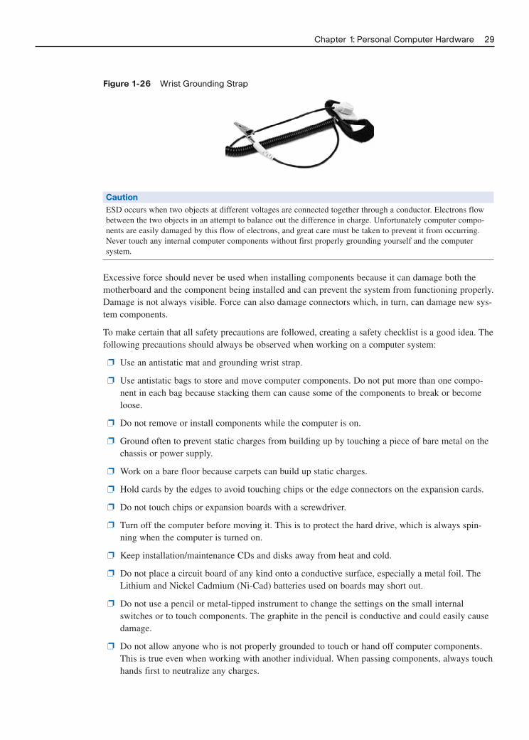
Figure 1-26 Wrist Grounding Strap
Chapter 1: Personal Computer Hardware 29
Caution
ESD occurs when two objects at different voltages are connected together through a conductor. Electrons flowbetween the two objects in an attempt to balance out the difference in charge. Unfortunately computer compo-nents are easily damaged by this flow of electrons, and great care must be taken to prevent it from occurring.Never touch any internal computer components without first properly grounding yourself and the computer system.
Excessive force should never be used when installing components because it can damage both themotherboard and the component being installed and can prevent the system from functioning properly.Damage is not always visible. Force can also damage connectors which, in turn, can damage new sys-tem components.
To make certain that all safety precautions are followed, creating a safety checklist is a good idea. Thefollowing precautions should always be observed when working on a computer system:
❐ Use an antistatic mat and grounding wrist strap.
❐ Use antistatic bags to store and move computer components. Do not put more than one compo-nent in each bag because stacking them can cause some of the components to break or becomeloose.
❐ Do not remove or install components while the computer is on.
❐ Ground often to prevent static charges from building up by touching a piece of bare metal on thechassis or power supply.
❐ Work on a bare floor because carpets can build up static charges.
❐ Hold cards by the edges to avoid touching chips or the edge connectors on the expansion cards.
❐ Do not touch chips or expansion boards with a screwdriver.
❐ Turn off the computer before moving it. This is to protect the hard drive, which is always spin-ning when the computer is turned on.
❐ Keep installation/maintenance CDs and disks away from heat and cold.
❐ Do not place a circuit board of any kind onto a conductive surface, especially a metal foil. TheLithium and Nickel Cadmium (Ni-Cad) batteries used on boards may short out.
❐ Do not use a pencil or metal-tipped instrument to change the settings on the small internalswitches or to touch components. The graphite in the pencil is conductive and could easily causedamage.
❐ Do not allow anyone who is not properly grounded to touch or hand off computer components.This is true even when working with another individual. When passing components, always touchhands first to neutralize any charges.

Installing Components and Verifying Operation
When installing or upgrading components be certain to follow all safety precautions. The followingprocedures apply to most system components.
Step 1. Determine whether the computer component is hot-swappable. If not, or if in doubt, unplugthe system unit before opening the case.
Step 2. Attach a grounding strap from your body to the system framework, or chassis, to preventany damage that could be caused by ESD.
Step 3. If replacing a component, remove the old component. Components are often held into thesystem with small screws or clips. When removing screws, do not let them drop on the sys-tem motherboard. Also, be careful not to break any plastic clips.
Step 4. Check the connection type on the new component. Each card is designed to work only witha certain type of connector and should not be forced when inserting or removing the card.
Step 5. Place the new component in the correct connection slot, with the correct orientation, care-fully following all installation instructions that may have accompanied the component.
Step 6. After the component has been added or upgraded, close the case and reconnect the powerand other cables.
Step 7. Switch on the system and watch for any messages that may appear on the screen. If thesystem fails to start, disconnect all cables and verify that the component was properlyinstalled.
If the system still will not start with the new component installed, remove it and try to start the sys-tem. If the system starts without the new component, the component may not be compatible with thecurrent hardware and software and additional research into the problem is required. Figure 1-27 illus-trates the process of installing a memory in a computer.
Figure 1-27 Installing Memory in a Computer System
30 Networking for Home and Small Businesses, CCNA Discovery Learning Guide
How To
Certain components require the addition of a specialized piece of software, or driver, to function. Forcommonly encountered components the drivers are usually contained in the operating system itself,but for more specialized components the driver must be added separately. Newer operating systemswill usually prompt for the addition of any required drivers. Drivers are continually updated toimprove efficiency and functionality. The most current driver can be obtained from the manufacturer’swebsite and should normally be used. Always read any documentation that accompanies the driversoftware for potential problems and the proper installation procedure.

TIP
Always make certain that the driver installed is the correct one for the operating system. Using the wrong drivercan cause unexpected results. The newest driver may not be the best. Problems with drivers often take some timeto surface and using the newest release of a driver may cause unknown problems. If the component fails to func-tion as expected after you upgrade the driver for a component, try rolling back the driver to a previous version.
After installation, the component should be tested for complete functionality. Components aredesigned to make use of specific sets of system resources as shown in Figure 1-28. If two componentstry to use the same resources, one, or both, will fail. The solution is to change the resources used byone of the devices. Newer components and operating systems are able to dynamically assign systemresources but older devices must have the resources set manually or through software configuration.
Figure 1-28 System Resource Utilization
Chapter 1: Personal Computer Hardware 31
If the device fails to function properly, verify that the correct and most recent driver is installed. Alsocheck that the operating system has correctly detected and identified the device. If this fails to correctthe problem, power down the system, carefully reseat the component, and verify that all connectionsare correct. Check the component documentation for the correct settings. If the device continues to benonfunctional, it is possible that the component is defective and it should be returned to the vendor.
Installing Peripherals and Verifying Operation
Peripheral devices, unlike internal components, do not require the computer case to be opened forinstallation. Peripherals connect to an interface on the outside of the case with a wired or wirelesslink. Historically, peripherals were designed to function when connected to a specific type of port. Forexample, PC printers were designed to connect to a parallel port, which transferred data from thecomputer to the printer in a specific format. Figure 1-29 shows some of the more common ports avail-able on a computer system, and Table 1-4 provides a brief description of these ports.

Figure 1-29 Common Ports on a Personal Computer
32 Networking for Home and Small Businesses, CCNA Discovery Learning Guide
PS/2
USB
Serial Parallel VGA
RJ-11
RJ-45
Table 1-4 Common Ports Found on a PC
Port Description
PS/2 These connectors are commonly used for both the keyboard and the mouse. They havea very compact design and are keyed to allow the plugs to be inserted in the correctorientation only. The functionality of these ports is replaced by USB on many newcomputer systems.
USB The Universal Serial Bus allows the connection of many different devices and supportshot-swapping and Plug-and-Play (PnP) technology. PnP allows the operating system toautomatically detect and configure devices plugged into the USB port. An increasingnumber of USB devices are becoming available. These devices now include mice, key-boards, sound cards, speakers, NICs, modems, and external storage devices.
Serial Serial ports were originally designed as a 25-pin male connector (DB25) but only ninewires were actually used. The original DB25 connector took up quite a bit of spaceand has been widely replaced by a more compact 9-pin connector (DB9). Both DB25and DB9 connectors can be found on modern computers and are used to connectdevices such as modems. They may also be used to connect a printer or mouse but thisis becoming less common. This port can also be used to connect two computers totransfer data between them. The functionality of these ports is replaced by USB onmany new computer systems.
Parallel The parallel port was designed to connect a printer to the PC. It is a 25-pin connectorbut has a female gender. Parallel ports are also commonly used to connect printers,external tape drives, and CD or DVD drives to the host computer. This port can also beused to connect two computers to transfer data between them. The functionality ofthese ports is replaced by USB on many new computer systems.
VGA The 15-pin video connector is standard on most personal computers. It is designed toconnect to either VGA or super-VGA monitors. Most PCs use a DB15HD connector,which has three rows of five pins.
RJ-11 The RJ-11 connector is the connector used by telephone companies in many areas ofthe world. This connector is usually found on a modem and is used to connect thecomputer to the telephone network.

Port Description
RJ-45 The RJ-45 connector is the standard connector used for Ethernet networks. This con-nector is used to connect the computer into a local-area network (LAN) or to connectit to an external modem such as those provided by cable and DSL companies for high-speed Internet access.
FireWire The FireWire port provides a high-speed connection into the computer system. It can (not pictured) support up to 63 peripherals and allows them to communicate without the intervention
of the CPU or system memory. FireWire supports PnP and hot-swapping. It is normal-ly used to connect digital video devices to a computer.
More recently the development of the Universal Serial Bus (USB) interface has greatly simplified theconnection of peripheral devices that use wires. USB devices require no complex configurations andcan merely be plugged into an appropriate interface, assuming that the proper driver has beeninstalled. There have also been an increasing number of peripheral devices that connect to the hostcomputer through wireless technology.
The installation of a peripheral device requires several steps. The order and detail of these steps variesdepending on the type of physical connection and whether or not the peripheral is a Plug-and-Play(PnP) device. The steps include the following:
Step 1. Connect the peripheral to the host using the appropriate cable or wireless connection.
Step 2. Connect the peripheral to a power source.
Step 3. Install the appropriate driver.
Some old peripheral devices, called legacy devices, are not PnP enabled. For these, driver installationoccurs after the device has been connected to the computer and powered up. For PnP-enabled USBdevices, the driver is preinstalled on the system. In this case, when the PnP device is connected andpowered on, the operating system recognizes the device and installs the appropriate driver. Installationof outdated or incorrect drivers can cause a peripheral device to behave unpredictably. For this reason,installing the most current drivers available is necessary.
If the peripheral device does not function after it is connected and installed, verify that all cables havebeen properly connected and that the device is powered up. Many devices, such as printers, offer atesting functionality on the device directly, and not through the computer. This is shown in Figure 1-30. Use this feature to verify that the device itself is functioning properly.
If the device is operational, but not connecting to the computer system, the problem could be with thecable connection. If the cable is suspected, swap it with a known good one. If this fails to solve theproblem, the next step is to verify that the port the peripheral device is connected to is recognized bythe operating system.
If everything appears to be functioning properly, the device may not be compatible with the currenthardware or operating system and requires more research to solve the problem.
After installation, the full functionality of the peripheral device must be tested. If only partial func-tionality is available, the most likely cause is an outdated driver. This is easily remedied by download-ing and installing the most current driver from the manufacturer’s website.
Chapter 1: Personal Computer Hardware 33
How To

Lab 1-3: Installing a Printer and Verifying Its Operation (1.5.3.4)
In this lab you will manually install a printer using the default Windows XP driver and verify printerfunctionality. You will then download and install the latest printer driver from the manufacturer’s web-site and compare functionality.
34 Networking for Home and Small Businesses, CCNA Discovery Learning Guide
Figure 1-30 Printer Test Function

Chapter 1: Personal Computer Hardware 35
Summary
This chapter has introduced computers and their applications. Highly specialized computers are inte-grated into many common items, including automobiles, refrigerators, televisions, and other electronicdevices. The hardware, operating system, and application program all work together to accomplishspecific tasks.
Application programs may either be business/industry-specific such as software used to manage amedical office, or may be more generalized and designed to be used across many different industries.A common example of a generalized application is the office suite.
Applications may also be designed to run only on a local machine or may be designed to work in anetwork environment. Network-based applications require that client software be installed on the localmachine and that the remote machine is running server software. The client software communicateswith the server software to carry out a task. A common network application is e-mail.
Many different types of computers exist, each designed for a specific task or application. Mainframesand servers are designed to service multiple clients at the same time and have built-in redundancy toensure their continued operation. PCs and laptops are designed to be used by only a single person atany one time and often lack the redundant hardware found in servers. Some computers are designed toremain stationary whereas others, such as laptops and PDAs, are powered by batteries and designed tobe portable.
Computers may be highly specialized and designed to run only one or two applications or may bevery generic in nature. Workstations are computers that have been optimized to run engineering andgraphics-intensive programs such as CAD and virtual reality software. Portable gaming devices aresmaller computers but have been optimized to play games that have been specially designed to run onthe device. Many devices, such as cellular phones, are now integrating multiple functions into a smallportable device. These often incorporate a digital camera, PDA, and audio/video player in addition tothe basic phone capabilities.
All information within a computer system is represented digitally by a series of 1s and 0s known asbits. While the computer is processing data, these bits are stored in RAM, moved through the variouscomputer buses, and manipulated by the CPU. In addition, this digital information can be stored onoptical, magnetic, or solid-state memory chips for archival and transportation purposes. All of thesedevices are usually located inside the computer case and are known as components. Most componentsconnect directly to the motherboard, which houses most of the electronics required to make the com-puter function.
Peripherals are devices located outside of the case and are designed to enhance system functionality.Peripherals are not required for the normal operation of the computer system but provide additionalservices. Printers and scanners are common examples of a computer peripheral.
Activities and Labs
This summary outlines the activities and labs you can perform to help reinforce important conceptsdescribed in this chapter. You can find the activity files on the CD-ROM accompanying this book. Thecomplete hands-on labs appear in Part II.

36 Networking for Home and Small Businesses, CCNA Discovery Learning Guide
Interactive Activities on the CD-ROM:
Interactive Activity 1-1: Classification of Applications (1.1.2.3)
Interactive Activity 1-2: Function of a Computer (1.2.2.4)
Interactive Activity 1-3: ASCII Digital Translator (1.3.1.1)
Interactive Activity 1-4: Byte Conversion Calculator (1.3.2.3)
Hands-on Labs in Part II of This Book:
Lab 1-1: Determining Data Storage Capacity (1.3.2.2)
Lab 1-2: Determining the Screen Resolution of a Computer (1.3.3.4)
Lab 1-3: Installing a Printer and Verifying Its Operation (1.5.3.4)
Check Your Understanding
Complete all the review questions listed here to test your understanding of the topics and concepts inthis chapter. The “Check Your Understanding and Challenge Questions Answer Key” appendix liststhe answers.
1. Which of the following would be classified as an application program? (Choose all that apply.)
A. Spreadsheet
B. Windows Vista
C. Linux
D. Word Processor
E. Windows XP
F. Database
2. What allows a computer to locate and load an operating system when it is first powered on?
A. Application program
B. Operating system
C. Hard disk drive
D. BIOS
E. Hardware
3. Which of the following is considered a network application?
A. E-mail
B. Spreadsheet
C. Word processor
D. Database

Chapter 1: Personal Computer Hardware 37
4. Which type of computer is normally a large centralized computer found in enterprise environ-ments?
A. Mainframe
B. Server
C. Desktop
D. Workstation
E. Laptop
5. Which type of computer is normally designed to run high-end graphics and engineering applica-tions such as CAD?
A. Mainframe
B. Server
C. Desktop
D. Workstation
E. Laptop
6. Which types of computers are designed to be used by a single end user? (Choose two.)
A. Mainframe
B. Server
C. Desktop
D. Workstation
7. How long would it take to download a 600 KB file from the Internet with a 256 kbps connection?
A. 2 seconds
B. 19 seconds
C. 2343 seconds
D. 2400 seconds
8. What is the unit used to measure the resolution of a computer monitor?
A. gigahertz
B. KB
C. pixel
D. kbps
9. What are some advantages of purchasing a prebuilt computer over having one custom built?(Choose two.)
A. Ability to specify exactly which parts are used in the system
B. Ability to optimize system performance for a specific application
C. Less expensive than building your own computer with the same components
D. No waiting period
E. Better system performance

38 Networking for Home and Small Businesses, CCNA Discovery Learning Guide
10. What should be the first step when upgrading a computer with an on-board NIC to one that plugsinto an expansion slot?
A. Install the correct driver for the new NIC.
B. Disable the on-board NIC.
C. Update the operating system.
D. Upgrade the system BIOS.
11. When selecting a new motherboard, which of the following factors should you consider? (Chooseall that apply.)
A. Support for the selected CPU type and speed
B. Support for the amount and type of system RAM required by the applications
C. Sufficient slots of the correct type to accept all required interface cards
D. Sufficient interfaces of the correct type
12. When building your own computer system, what is the first component that should be decidedupon?
A. CPU
B. RAM
C. HDD
D. Motherboard
13. From where is an application program normally run?
A. HDD
B. FDD
C. RAM
D. BIOS
14. Which of the following peripherals are considered input devices? (Choose all that apply.)
A. Scanner
B. Digital camera
C. Mouse
D. Keyboard
E. Microphone
15. What is the first step when upgrading an internal video card in a computer system?
A. Reformat the hard disk drive.
B. Upgrade the system BIOS.
C. Unplug the computer.
D. Remove the old video card.

Chapter 1: Personal Computer Hardware 39
16. Before passing a CPU or a piece of memory to another individual, what should you do?
A. Touch hands first to equalize charges.
B. Place the component on a plastic table and then allow the other person to pick it up.
C. Touch the component to a grounding plate to remove any excess charge.
D. No precautions are necessary.
17. What is the sequence of steps required to install and verify a USB printer under Windows XP?
1. Physically connect the printer to the computer.
2. Power up the printer.
3. Install the driver.
4. Power up the computer.
5. Generate a test print.
A. 1, 2, 4, 3, 5
B. 4, 3, 1, 2, 5
C. 1, 2, 4, 3, 5
D. 4, 1, 2, 3, 5
E. 4, 2, 3, 1, 5
F. 4, 2, 1, 3, 5
Challenge Questions and Activities
These questions require a deeper application of the concepts covered in this chapter. You can find theanswers in the appendix.
1. Charlene must upgrade the memory in her new laptop computer by installing a single 2 GB stick.She quickly unscrews the door on the bottom of the computer and snaps the new stick into anempty connector. She then powers up the machine only to see that the new memory is not recog-nized by the computer. Checking the manual for the computer, she verifies that the memory typeand capacity should be recognized. What is the problem and how would you correct it?
2. Juri has just installed a new PnP printer on his home computer system using the drivers on theWindows XP CD. The advertisement stated that the printer could print high-resolution pictures onvarious types of paper. Unfortunately Juri cannot see how to set this information. What advicewould you give to Juri?

This page intentionally left blank

CHAPTER 2
Operating Systems
Objectives
Upon completion of this chapter, you will able to answer the following questions:
■ What is the purpose of an OS?
■ What role do the shell and kernel play?
■ What is the difference between a CLI and GUIinterface?
■ What is a network redirector?
■ What are some of the common operating sys-tems available?
■ What is the difference between commercial andGPL software licensing?
■ What are the different options for OS installa-tion?
■ What is an OS upgrade and how is it performed?
■ What is a file system and what types are usedwith PCs?
■ What IP parameters must be configured to pre-pare a computer to participate on the network?
■ How are operating systems maintained?
Key Terms
This chapter uses the following key terms. You can find the definitions in the Glossary.
operating system (OS) page 42
kernel page 43
shell page 43
command-line interface (CLI) page 43
graphical user interface (GUI) page 43
K Desktop Environment (KDE) page 44
multitasking page 44
network client page 45
network operating system (NOS) page 46
GNU Public License (GPL) page 46
UNIX page 46
Linux page 46
total cost of ownership (TCO) page 49
upgrade page 50
virtual machine page 50
file system page 51
File Allocation Table (FAT) 16/32 page 51
New Technology File System (NTFS) page 51
ext2 page 52
ext3 page 52
data loss page 52
network interface card (NIC) page 52
Internet Protocol (IP) page 52
IP address page 52
computer name page 53
patch page 55

How we interact with our computer, and what applications it can run, affects our ability to communi-cate with others. Computer operating systems enable us to use application software, store information,and join the network. The operating system is the most important program running on a computer.Without it the other programs and features will not operate. In this chapter you will learn about themost popular operating systems, and how to choose the one that will be right for your computer. PartII of this book includes the corresponding labs for this chapter.
Choosing the Operating System
There are a number of operating systems in use with modern computers. Most client computers pur-chased in a retail outlet come with the operating system preloaded. If a computer is ordered from anonline retail output, the purchaser frequently has a choice of which OS is installed. Business environ-ments often need to consider other options depending on the intended function of the computer. Theymay even build their own computers and install the desired OS.
Purpose of an Operating System
System components and peripherals, by themselves, are nothing more than a collection of electronicsand mechanical parts. To get these parts to work together to perform a specific task, a special type ofcomputer program, known as an operating system (OS), is required.
Suppose that a user wants to write a report and print it out on an attached printer. A word processingapplication is required to accomplish this task. Information is entered from the keyboard, displayed onthe monitor, saved on the disk drive, and then finally sent to the printer.
In order for the word processing program to accomplish all of this, it must work with the OS, whichcontrols input and output functions. The OS uses specialized software programs known as drivers tointeract with the various hardware components. Every major electronic component inside the comput-er or attached to it requires a driver. These drivers might be integrated into the OS or standalone soft-ware modules used by the OS. The OS and its drivers are what accepts the information entered fromthe keyboard, displays it on the monitor, saves it to disk, and sends the document to the printer. Asshown in Figure 2-1, the keyboard, mouse, and disk drivers are typically integrated into the OS where-as video and printer drivers are typically external software modules. The entered data is manipulatedinside of the computer, stored in RAM, and processed by the CPU. This internal manipulation andprocessing is also controlled by the OS. All computerized devices, such as servers, desktops, laptops,or handhelds, require an OS in order to function.
Figure 2-1 Computer Components and OS Drivers
42 Networking for Home and Small Businesses, CCNA Discovery Learning Guide
MouseDriver
KeyboardDriver
DiskDriver
VideoDriver
PrinterDriver
InternalDrivers
ExternalDrivers
Operating System

The OS acts like a translator between user applications and the hardware. A user interacts with thecomputer system through an application, such as a word processor, spreadsheet, or computer game.Application programs are designed for a specific purpose, such as word processing, and know nothingof the underlying electronics. For example, the application is not concerned with how information isentered into the application from the keyboard. The operating system is responsible for the communi-cation between the application and the hardware.
When a computer is powered on, it loads the OS, normally from a permanent storage device, such as ahard disk drive, into RAM. The portion of the OS code that interacts directly with the computer hard-ware is known as the kernel. The portion that interfaces with the applications and user is known as theshell. The user can interact with the shell using either the command line interface (CLI) or graphicaluser interface (GUI). Figure 2-2 shows the relationship between the OS shell, the kernel, and thecomputer hardware.
Figure 2-2 OS Shell, Kernel, and Hardware Relationship
Chapter 2: Operating Systems 43
Kernel
Shell
Drivers
Hardware
User Interface
When using the CLI, the user interacts directly with the system in a text-based environment by enter-ing commands on the keyboard at a command prompt. The system executes the command, often pro-viding textual output on the monitor. Figure 2-3 shows the Windows CLI interface command promptscreen with a directory of drive C:\ displayed using the dir command.
Figure 2-3 Directory of Drive C:\ Using the Windows CLI Command Prompt Window

The GUI allows the user to interact with the system in an environment that uses graphical images,multimedia, and text. Actions are performed by interacting with the images onscreen. GUI is moreuser friendly than CLI and requires less knowledge of the command structure to utilize the system.For this reason, many individuals rely on the GUI environments. Most operating systems offer bothGUI and CLI. Although the GUI is more user friendly, knowing how to work with the CLI is still use-ful. The GUI depends on the graphics subsystems of the computer to display the high-resolution, mul-ticolor images. If a problem occurs with the graphics hardware or drivers, the CLI might be the onlyinterface available to the user for troubleshooting. Figure 2-4 shows the Windows Explorer GUI inter-face screen with a directory of drive C:\ displayed by clicking with the mouse.
Figure 2-4 Directory of Drive C:\ Using the Windows Explorer GUI
44 Networking for Home and Small Businesses, CCNA Discovery Learning Guide
Figure 2-5 shows a Linux CLI terminal window for entering commands. The structure of the file sys-tem is displayed using the ls –l UNIX command, which is similar to the Windows dir command. Thels –l command lists directories (also called folders) and files, using the –l or “long” option. Thisoption provides additional information for each file and directory. Without the –l option, only thedirectory and filenames would be displayed. With this listing, the name of the directory (or file) is thelast entry in blue.
Figure 2-6 shows a Linux GUI window for displaying and managing directories and files. The struc-ture of the file system is displayed using the K Desktop Environment (KDE) File Browser applica-tion. KDE File Browser is similar to the Windows Explorer application. Notice that directories arereferred to as folders in the GUI screen.
Operating systems have complete control of local hardware resources. They are designed to work withone user at a time. They enable the user to do more than one thing at a time using multiple applica-tions. This capability is known as multitasking. The operating system keeps track of which resourcesare used by which application. A single processor can only manipulate memory to give the impressionof multitasking. The CPU is actually giving each application a portion or slice of its processing time.The more applications the system is running, the smaller the time slice for each application.Multiprocessor systems can have multiple independent CPU chips or multiple CPUs on one chip (forexample, dual-core). These systems can actually perform multiple tasks simultaneously.

Figure 2-5 Display of File System Directories Using the Linux CLI Terminal Window
Chapter 2: Operating Systems 45
Figure 2-6 Display of File System Directories Using the Linux KDE File Browser GUI
In order to work with resources that are not directly connected to the computer system, a special pieceof software called a redirector must be added. Redirectors make it possible to reroute a data requestfrom the OS out of the local machine onto the network to a remote resource. The redirector can eitherbe an integral part of the OS or can be installed separately. With a redirector, the local PC can accessremote resources as a network client. With a redirector installed, the operating system acquires someof the characteristics of a network operating system (NOS). Figure 2-7 shows the use of the OS redi-rector when a host needs access to a remote resource on the network. The document being retrievedmight appear to the user that it is on the local machine. However, the redirector must send the requestout the network interface card (NIC) to contact the remote server and actually retrieve the document.

Figure 2-7 Accessing Remote Network Resources with the Redirector
46 Networking for Home and Small Businesses, CCNA Discovery Learning Guide
RemoteServer
That’s a networkresource, I’ll takecare of that.
Redirector
I need to access adocument on aremote server.
An operating system that is specifically designed for a network is referred to as a network operatingsystem (NOS). A NOS includes features that allow management of network resources like files, print-ers, LAN users, and security, and is typically installed on a server. Most network resources appear tothe end users as if they were on their local machine, when in reality the NOS is providing the resourceto the PC. A true NOS offers complex scheduling and user management software that allows a serverto share resources between many users and resources. The client OS with a redirector can access theserver NOS resources as if they were directly connected.
Operating System Requirements
Many different operating systems are available. The major groupings are listed here with some exam-ples. Most of these are proprietary commercial offerings.
■ Microsoft Windows: XP, Vista, and 2003 Server
■ UNIX-Based: IBM AIX, Hewlett Packard HPUX, and Sun Solaris
■ BSD: Free BSD
■ Linux-Based: Many varieties
■ Macintosh OS X
■ Non-UNIX Proprietary: IBM OS/400, z/OS
Although most of these operating systems require the user to purchase and agree to a commerciallicense, several operating systems are released under a different type of licensing scheme known asthe GNU Public License (GPL).
Commercial licenses usually deny end users the ability to modify the program in any way. WindowsXP, Mac OS X, and UNIX are all examples of commercial OS software.
In contrast, the GPL allows end users to modify and enhance the code, if they desire, to better suittheir environment. Some common operating systems released under the GPL include Linux and BSD.Refer to Table 2-1 for a comparison of commercially licensed operating systems and those releasedunder GPL.

Table 2-1 Commercial and GPL License Comparison
Criteria Commercial License GNU Public License (GPL)
Access Restrictive in nature and limits what the Ensures everyone has full access to the user can do with the code. source code and can participate in
enhancement of the product.
Cost Often very expensive depending on Often released free-of-charge (for deployment (for example, a Windows XP example, Linux can be freely installed on license must normally be purchased for as many machines as desired). However, every client machine on a network). the cost of retraining for a GPL product
might exceed the discounted cost of acommercial license.
Development Very structured development cycle and Development cycle is less structured and Cycle changes not quickly available. changes are more quickly implemented.
Support Structured support available for a fee. Less of a structured support arrangement,often relying on community (user-based)support. Some companies that distributeGPL products provide fee- based support.
Operating systems require a certain amount of hardware resources. These resources are specified bythe manufacturer and include such things as
■ Amount of RAM
■ Hard disk space required
■ Processor type and speed
■ Video resolution
Manufacturers often specify both a minimum and recommended level of hardware resources. Systemperformance at the minimum specified hardware configuration is usually poor and only sufficient tosupport the OS and little other functionality. The recommended configuration is usually the betteroption and is more likely to support standard additional applications and resources. Adding hardwareover that recommended, such as another CPU and more RAM, can further improve system perform-ance, but at a significant cost.
To take advantage of all the features provided by an operating system and installed applications, hard-ware resources such as sound cards, NICs, modems, microphones, and speakers are generallyrequired. Many of the OS developers test various hardware devices and certify that they are compati-ble with the operating system. Always confirm that the hardware has been certified to work with theoperating system before purchasing and installing it. Table 2-2 shows a sample comparison of theminimum amount of hardware needed and the recommended hardware necessary to get the most outof the OS and applications running on the computer.
Chapter 2: Operating Systems 47

Table 2-2 Minimum and Recommended OS Requirements
Minimum Recommended
CPU 512 Megahertz 1 Gigahertz
RAM 256 Megabytes 1 Gigabyte
Hard drive 40 Gigabytes 80 Gigabytes
Graphics card 800 x 600 pixels 1024 x 768 pixels
Optical drive CD-ROM DVD
Interactive Activity 2-1: Software Licensing Scenarios (2.1.2.3)
In this interactive activity, you determine the appropriate type of software licensing for a scenario. Usefile ia-2123 on the CD-ROM that accompanies this book to perform this interactive activity.
Operating System Selection
You need to consider many factors before deciding on which OS to use in a given environment.
The first step in selecting an OS is to ensure that the OS being considered fully supports the require-ments of the end user. Does the OS support the applications that will be run? Is the security and func-tionality sufficient for the needs of the users?
Next, conduct research to make sure that sufficient hardware resources are available to support theOS. This includes such basic items as memory, processors, and disk space, as well as peripheraldevices such as scanners, sound cards, NICs, and removable storage.
Another consideration is the level of human resources needed to support the OS. In a business envi-ronment, a company might limit support to one or two operating systems and discourage, or even dis-allow, the installation of any other OS. In the home environment, the ready availability of technicalsupport for an OS might be a determining factor. The following are some of the factors that should beconsidered when selecting an OS:
■ Security
■ Support
■ Politics
■ Cost
■ Availability
48 Networking for Home and Small Businesses, CCNA Discovery Learning Guide

■ Resources
■ Platform
■ Use
When implementing an OS, you should consider total cost of ownership (TCO) of the OS in the decision-making process. This not only includes the costs of obtaining and installing the OS, but alsoall costs associated with supporting it.
Another factor that might come into play in the decision-making process is the availability of theoperating system. Some countries and/or businesses have made decisions to support a specific type ofOS or might have restrictions barring individuals from obtaining certain types of technologies. In thistype of environment, considering a particular OS, regardless of its suitability to the task, might not bepossible.
The process for selecting an operating system, as shown in Figure 2-8, must take all of these factorsinto account.
Figure 2-8 Considerations and Requirements for Selecting an Operating System Process
Chapter 2: Operating Systems 49
Determine End-User Requirements
Determine Choices and Select OS
Implement Selected OS
FinancialResourcesAvailable?
OtherRestrictions or
Factors?
Yes
No
No
No
Yes
Yes
TechnicalResourcesAvailable?

Installing the Operating System
Most operating systems are installed on a clean hard drive by the manufacturer of the computer sys-tem. However, several other options are available depending on the existing operating system installedand the circumstances and goals of the user.
OS Installation Methods
An OS is installed in a defined section of the hard disk, called a disk partition. Various methods existfor installing an OS. The method selected for installation is based on the system hardware, the OSbeing installed, and user requirements. Four basic options are available for the installation of a new OS:
■ Clean install: A clean install is done on a new system or in cases where no upgrade path existsbetween the current OS and the one being installed. It deletes all data on the partition where theOS is installed and requires application software to be reinstalled. A new computer systemrequires a clean install. A clean install is also performed when the existing OS installation hasbecome damaged in some way.
■ Upgrade: If you are staying with the same OS platform, doing an upgrade is often possible. Withan upgrade, system configuration settings, applications, and data are preserved. It simply replacesthe old OS files with the new OS files.
■ Multiboot: Installing more than one OS on a computer to create a multiboot system is possible.Each OS is contained within its own partition and can have its own files and configuration set-tings. On startup, the user is presented with a menu to select the desired OS. Only one OS can runat a time and it has full control of the hardware. As an example of multiboot, it is possible toinstall Windows XP, Windows Server, and Linux all on the same system. This setup can be usefulin a test environment where only one PC is available but there is a need to test several differentOS and applications.
■ Virtualization: Virtualization is a technique that is often deployed on servers. It enables multiplecopies of an OS to be run on a single set of hardware, thus creating many virtual machines. Eachvirtual machine can be treated as a separate computer. This enables a single physical resource toappear to function as multiple logical resources. This type of approach generally demands morephysical resources such as CPU processing and RAM because multiple OSs are running on thesame machine.
Interactive Activity 2-2: Operating System Installation Scenarios (2.2.1.2)
In this interactive activity, you determine the appropriate operating system installation technique foreach scenario. Use file ia-2212 on the CD-ROM that accompanies this book to perform this interactiveactivity.
Preparing for OS Installation
A pre-installation checklist helps ensure that the installation process is successful:
Step 1. Verify that all hardware is certified to work with the selected OS. Experienced users canmonitor tech blogs to see what problems are being experienced on specific machines/moth-erboards and so on. This can save the installer time and potential problems.
50 Networking for Home and Small Businesses, CCNA Discovery Learning Guide
How To

Step 2. Verify that the hardware resources meet or exceed the published minimum requirements.
Step 3. Confirm that the appropriate installation medium is available. Due to the file size of currentoperating systems, they are usually available on both CD and DVD media.
Step 4. If the OS is to be installed on a system that already contains data:
a. Use system diagnostic tools and utilities to ensure that the current OS installation isin good condition, free of malicious or damaging files and codes.
b. Complete a full backup of all important files.
Step 5. If performing a clean install, verify that all application software is available for installation.
Step 6. If connecting the computer to a network at this time, verify that the network configurationinformation is available.
Step 7. If this is an end-user computer and a different OS is to be installed, verify that the user hasadequate training in the use of the new OS.
Before starting the installation, determining the partition structure that best meets user requirements isnecessary. Figure 2-9 depicts hard disk partitioning.
Figure 2-9 Hard Disk Partitioning
Chapter 2: Operating Systems 51
Applications
User DataOperating System
One of the techniques available to help protect data is to divide the hard drive into multiple partitions.With a clean install, many technicians prefer to create one partition for data and a separate partitionfor the OS. This technique enables an OS to be upgraded without the risk of losing data. It also sim-plifies backup and recovery of data files. Applications might be installed on yet another partition.With all data files on a single partition, backing up only that partition is necessary. The OS and appli-cations can be reinstalled in the event of a system failure.
When installing an OS, determining the type of file system to use is also necessary. A file system isthe method the OS uses to keep track of the files. Many different file system types exist. Each OS isdesigned to work with one or more of these file system types and each file system type offers specificadvantages:
■ File Allocation Table (FAT) 16/32: 16- and 32-bit file systems are common with the earlier homeversions of Windows OS but do not provide file security. Proprietary.
■ New Technology File System (NTFS): Developed with Windows NT. A more robust and securefile system available with some newer home versions of Windows such as XP and Vista, and theprofessional and server version of other Windows OSs. Provide journaling of file system changes.Proprietary.
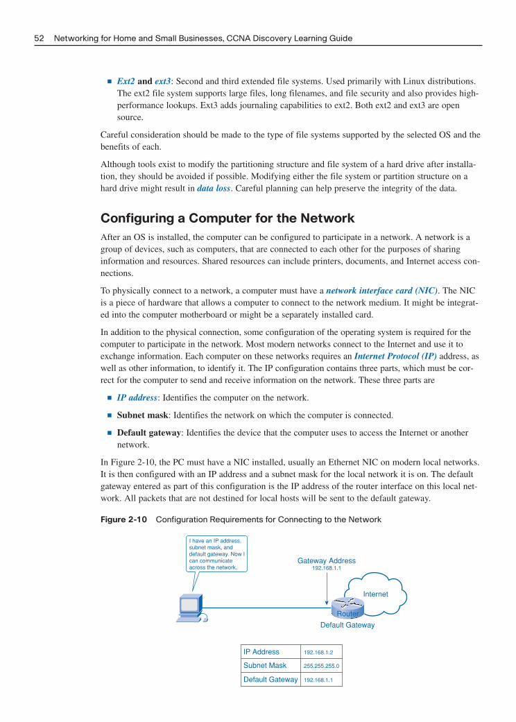
■ Ext2 and ext3: Second and third extended file systems. Used primarily with Linux distributions.The ext2 file system supports large files, long filenames, and file security and also provides high-performance lookups. Ext3 adds journaling capabilities to ext2. Both ext2 and ext3 are opensource.
Careful consideration should be made to the type of file systems supported by the selected OS and thebenefits of each.
Although tools exist to modify the partitioning structure and file system of a hard drive after installa-tion, they should be avoided if possible. Modifying either the file system or partition structure on ahard drive might result in data loss. Careful planning can help preserve the integrity of the data.
Configuring a Computer for the Network
After an OS is installed, the computer can be configured to participate in a network. A network is agroup of devices, such as computers, that are connected to each other for the purposes of sharinginformation and resources. Shared resources can include printers, documents, and Internet access con-nections.
To physically connect to a network, a computer must have a network interface card (NIC). The NICis a piece of hardware that allows a computer to connect to the network medium. It might be integrat-ed into the computer motherboard or might be a separately installed card.
In addition to the physical connection, some configuration of the operating system is required for thecomputer to participate in the network. Most modern networks connect to the Internet and use it toexchange information. Each computer on these networks requires an Internet Protocol (IP) address, aswell as other information, to identify it. The IP configuration contains three parts, which must be cor-rect for the computer to send and receive information on the network. These three parts are
■ IP address: Identifies the computer on the network.
■ Subnet mask: Identifies the network on which the computer is connected.
■ Default gateway: Identifies the device that the computer uses to access the Internet or anothernetwork.
In Figure 2-10, the PC must have a NIC installed, usually an Ethernet NIC on modern local networks.It is then configured with an IP address and a subnet mask for the local network it is on. The defaultgateway entered as part of this configuration is the IP address of the router interface on this local net-work. All packets that are not destined for local hosts will be sent to the default gateway.
Figure 2-10 Configuration Requirements for Connecting to the Network
52 Networking for Home and Small Businesses, CCNA Discovery Learning Guide
Router
Internet
Gateway Address192.168.1.1
I have an IP address,subnet mask, anddefault gateway. Now Ican communicateacross the network.
Default Gateway
192.168.1.1
255.255.255.0
IP Address 192.168.1.2
Subnet Mask
Default Gateway

A computer IP address can be configured manually or assigned automatically by another device, asshown in Figure 2-11.
Figure 2-11 Manual and Dynamic IP Configuration
Chapter 2: Operating Systems 53
Server
Dynamic IPConfiguration
Manual IPConfiguration
Host
I will assign the IPconfiguration.
NetworkAdministrator
I will assign the IPconfiguration.
• IP Address• Subnet Mask• Default Gateway
With manual configuration, the required values are entered into the computer via the keyboard, typi-cally by a network administrator. The IP address entered is referred to as a static address and is per-manently assigned to that computer.
Computers can be set up to receive their network configuration dynamically. This feature allows acomputer to request an address from a pool of addresses assigned by another device within the net-work. When the computer is finished with the address it is returned to the pool for assignment toanother computer.
Computer Naming
In addition to the IP address, some network operating systems make use of computer names. In thisenvironment each individual system must have a unique name assigned to it.
A computer name provides a user-friendly way to identify a computer, making it easier for users toconnect to shared resources such as folders and printers on other computers.
The network administrator should determine a logical naming scheme that helps to identify a device’stype and/or its location. For example, the name PRT-CL-Eng-01 could represent the first network-attached color laser printer in the Engineering Department.
These names are manually assigned to each device, although some tools do exist to help automate thenaming process. A computer description can also be entered when assigning a name to provide addi-tional information on the location or function of the device. Figure 2-12 shows the use of WindowsSystem Properties to enter a computer name.

Figure 2-12 Using Windows System Properties to Name a Computer
54 Networking for Home and Small Businesses, CCNA Discovery Learning Guide
Network Name and Address Planning
As a network grows in size and complexity, ensuring that it is well planned, logically organized, andwell documented becomes increasingly important.
Many organizations develop conventions for the naming and addressing of computers. These conven-tions provide guidelines and rules that network support personnel can use when performing thesetasks. Computer names must be unique and should have a consistent format that conveys meaningfulinformation. This method can help to determine device type, function, location, and sequence numberbased on the device name. IP addresses must also be unique to each device.
The use of logical device naming and addressing conventions that are well documented can greatlysimplify the tasks of training and network management and can help with troubleshooting when prob-lems arise. Figure 2-13 illustrates a logical naming scheme that can assist the network administrationstaff.
Figure 2-13 Computer Naming Conventions
My name is C234-01 and I amin building C, room 34. My IPaddress is 192.168.3.1. They
know where to find me ifthere’s a problem!
Maintaining the Operating System
As operating systems and applications software continue to evolve, users need to keep their systemsup to date to ensure they have the latest features and that their systems operate efficiently and are pro-tected against attacks.

Why and When to Apply Patches
After an OS or application is installed, keeping it up to date with the latest patches is important.
A patch is a piece of program code that can correct a problem or enhance the functionality of anapplication program or OS. It is usually provided by the manufacturer to repair a known vulnerabilityor reported problem. In most cases a patched OS results in a healthier, more stable computer, asshown in Figure 2-14.
Figure 2-14 Operating System Patches
Chapter 2: Operating Systems 55
Computers should be continually updated with the latest patches unless a good reason exists not to doso. Sometimes patches negatively impact the operation of another system feature. The impact of thepatch should be clearly understood before it is applied. The software manufacturer’s website usuallyprovides this information.
Applying OS Patches
Patches to operating systems can be installed in different ways, depending on the OS and the needs ofthe user. Options for downloading and installing updates include the following:
■ Automatic installation: The OS can be configured to connect to the manufacturer’s website andthen download and install minor updates without any user intervention. Updates can be scheduledto occur during times when the computer is on, but not in use.
■ Prompt for permission: Some users want to have control over which patches are applied. Thischoice is often the one for users who understand what impact a patch can have on system per-formance. The system can be configured to notify the end user when a patch is available. Theuser must then decide whether to download and install the patch.
■ Manual: Updates that require major pieces of code to be replaced on a system should be runmanually. These major updates are often called service packs and are designed to correct prob-lems with an application or OS, and sometimes to add functionality. These service packs usuallyrequire the end user to manually connect to a website, download files, and install the update.They can also be installed from a CD available from the manufacturer.
Figure 2-15 shows the Automatic Updates options in Windows System Properties.
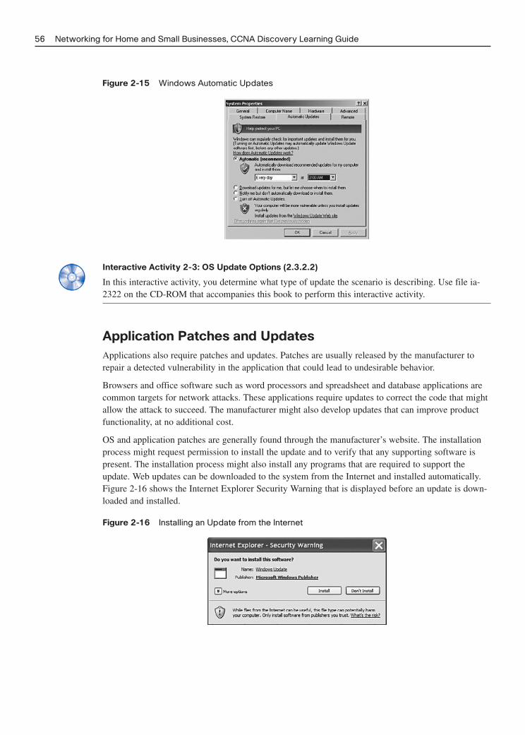
Figure 2-15 Windows Automatic Updates
56 Networking for Home and Small Businesses, CCNA Discovery Learning Guide
Interactive Activity 2-3: OS Update Options (2.3.2.2)
In this interactive activity, you determine what type of update the scenario is describing. Use file ia-2322 on the CD-ROM that accompanies this book to perform this interactive activity.
Application Patches and Updates
Applications also require patches and updates. Patches are usually released by the manufacturer torepair a detected vulnerability in the application that could lead to undesirable behavior.
Browsers and office software such as word processors and spreadsheet and database applications arecommon targets for network attacks. These applications require updates to correct the code that mightallow the attack to succeed. The manufacturer might also develop updates that can improve productfunctionality, at no additional cost.
OS and application patches are generally found through the manufacturer’s website. The installationprocess might request permission to install the update and to verify that any supporting software ispresent. The installation process might also install any programs that are required to support theupdate. Web updates can be downloaded to the system from the Internet and installed automatically.Figure 2-16 shows the Internet Explorer Security Warning that is displayed before an update is down-loaded and installed.
Figure 2-16 Installing an Update from the Internet

Lab 2-1: Examining Operating System and Application Versions (2.3.3.2)
In this lab you will examine the current version of OS and installed applications and determinewhether additional patches or updates are available. Refer to the Hands-on lab in Part II of thisLearning Guide. You may perform this lab now or wait until the end of the chapter.
Challenge Lab 2-2: Evaluating an OS Upgrade
In this lab you will evaluate the existing hardware of a Windows XP computer and determine whetherit can support an upgrade to Windows Vista. Refer to the Hands-on lab in Part II of this LearningGuide. You may perform this lab now or wait until the end of the chapter.
Chapter 2: Operating Systems 57

58 Networking for Home and Small Businesses, CCNA Discovery Learning Guide
Summary
An operating system (OS) is the most important software in a PC. It is responsible for making all thehardware components and software applications work together. An OS can be installed by the manu-facturer, an end user, or a network administrator.
The OS is comprised of a kernel, a shell, and device drivers. The kernel is the main OS program andinteracts directly with the hardware through the use of device drivers. The shell interacts with theapplications and the user. The user interacts with the shell through the command-line interface (CLI)or a graphical user interface (GUI).
A network operating system (NOS) is a sophisticated OS that allows a computer to share resourcesamong many users and to treat networked resources as if they are directly connected. A NOS includesfeatures that allow management of network resources such as files, printers, LAN users, and security,and is typically installed on a server.
Performing a pre-installation checklist before installing any new OS is important. An OS is installedin a disk partition, which is a defined section of the hard disk. Decide on partition schemes beforeinstalling the OS.
Operating systems use various file systems. The most common file systems are Windows FAT 16/32and NTFS. For Linux they are ext2 and ext3.
To participate in a network, a computer requires a network interface card (NIC) configured with an IPaddress, subnet mask, and default gateway. The network should be well planned, logically organized,and well documented using standard addressing and naming conventions.
Keeping OS and application software up to date with the latest revisions, upgrades, or patches isimportant. A patch is a piece of program code that corrects a problem or enhances the functionality ofan OS. An OS can be configured to connect automatically to the manufacturer’s website and down-load and install minor updates without any user intervention. Service packs are major updates to anOS or software application. Application software can also require patches and updates to repair adetected vulnerability in the application. Applications patches are generally found through the manu-facturer’s website.
Part II of this book includes the corresponding labs for this chapter.
Activities and Labs
This summary outlines the activities and labs you can perform to help reinforce important conceptsdescribed in this chapter. You can find the activity and Packet Tracer files on the CD-ROM accompa-nying this book. The complete hands-on labs appear in Part II.
Interactive Activities on the CD-ROM:
Interactive Activity 2-1: Software Licensing Scenarios (2.1.2.3)
Interactive Activity 2-2: Operating System Installation Scenarios (2.2.1.2)
Interactive Activity 2-3: OS Update Options (2.3.2.2)

Chapter 2: Operating Systems 59
Labs in Part II of This Book:
Lab 2-1: Examining Operating System and Application Versions (2.3.3.2)
Challenge Lab 2-2: Evaluating an OS Upgrade
Check Your Understanding
Complete all the review questions listed here to test your understanding of the topics and concepts inthis chapter. The “Check Your Understanding and Challenge Questions Answer Key” appendix liststhe answers.
1. A network technician is installing the Linux OS on a computer. What are the most likely file sys-tems she will select from?
2. A network technician needs to install a new operating system on a computer. In order to preservethe data, application, and configuration settings as well as the partitioning already present, whichinstallation method should be used?
A. Clean install
B. Upgrade
C. Multiboot
D. Virtualization
3. Allan just purchased a new PC for attachment to an Ethernet local network. What three basic stat-ic IP configuration parameters will he need to enter to allow this PC to participate on the net-work?
4. When developing a naming scheme for a network, which two pieces of information are most ben-eficial when determining a computer name? (Choose two.)
A. Device type
B. Location
C. Year purchased
D. Operating system
E. Software installed
5. What is the term used to describe the software added to an OS that allows a user to access remotenetwork resources as if they were local?
6. What portion of operating system code interacts directly with computer hardware?
7. Which two operating systems issued under the GPL allow end users to modify and enhance code?(Choose two.)
A. Windows XP
B. Mac OS X
C. Linux
D. BSD
E. UNIX

60 Networking for Home and Small Businesses, CCNA Discovery Learning Guide
8. What three factors need to be considered when choosing an operating system? (Choose three.)
A. The operating system has limited availability.
B. The operating system supports end-user requirements.
C. Sufficient hardware resources are available.
D. Users can provide training on the new software without help.
E. Human resources exist to support the product.
F. The operating system is backward compatible with MS-DOS.
9. Jessica’s home computer is currently running Windows 98. She wants to convert to WindowsVista but wants to keep her data and applications. She checks the Microsoft website and finds thatthere is no upgrade path from Windows 98 to Vista. What steps should she take to convert toVista? (Choose all that apply.)
A. Back up her data
B. Verify her hardware has enough resources to support Vista
C. Reinstall her applications
D. Perform a clean install of Vista
10. A network administrator wants to set up the OS update options on the Windows PCs in his net-work so that he is made aware of updates when they are available but has the opportunity tocheck what changes the updates contain before downloading and installing them. Which updateoption does he need to use?
A. Prompt for permission
B. Automatic installation
C. Manual installation

CHAPTER 3
Connecting to the Network
Objectives
Upon completion of this chapter, you will able to answer the following questions:
■ What is meant by the term network and what aresome of the more common networks we use ineveryday life?
■ What are communication protocols?
■ How does communication occur across a localEthernet network?
■ What are the main high-level components of aninformation network?
■ When does a computer play the role of a client,server, or both on a network?
■ How do you build a computer peer-to-peer net-work and verify it is functioning?
■ How are networks graphically represented andwhat is the difference between logical and physi-cal network topologies?
■ What is the purpose of the access and distribu-tion layers and what devices does each normallycontain?
■ How do hubs, switches, and routers function?
■ What are a broadcast domain and a collisiondomain and why are they important?
■ What is ARP and how does it function?
■ What is the importance of a default gateway?
■ What is prototyping?
Key Terms
This chapter uses the following key terms. You can find the definitions in the Glossary.
converged network page 64
small office/home office (SOHO) network page 65
host page 65
peripheral page 65
networking device page 65
media page 65
daemon page 68
peer-to-peer network page 69
server-based network page 69
physical topology page 71
topology page 71
logical topology page 71
source page 74
destination page 74
channel page 74
frame page 78
access method page 80
unicast page 81
multicast page 82
broadcast page 82
de facto standard page 85
Institute of Electrical and Electronic Engineers(IEEE) page 85
baseband page 85
shared Ethernet page 86
Carrier Sense, Multiple Access with CollisionDetection (CSMA-CD) page 86
transmission page 86
switched Ethernet page 86
local-area network (LAN) switch page 86
switch page 86
Media Access Control (MAC) address page 87
protocol data unit (PDU) page 88

physical address page 91
logical address page 91
access layer page 94
hub page 95
collision domain page 95
MAC address table page 96
flooding page 97
local network page 99
hexadecimal page 99
broadcast domain page 99
Address Resolution Protocol (ARP) tablepage 101
Address Resolution Protocol (ARP) page 101
distribution layer page 103
router page 105
routing page 105
default gateway page 108
routing table page 108
default route page 109
local-area network (LAN) page 112
prototype page 116
multi-function device page 117
integrated services router (ISR) page 119
light-emitting diode (LED) page 119
baseline page 120
62 Networking for Home and Small Businesses, CCNA Discovery Learning Guide

More and more often, networks connect us. People communicate online from everywhere.Conversations in coffeehouses carry over into chat rooms. Online debates continue at school.Efficient, reliable technology enables networks to be available whenever and wherever we need them.In this chapter, you learn how communication occurs over a network. You also learn about the manydifferent components that need to operate together to make it work.
Part II of this book includes the corresponding labs for this chapter.
Introduction to Networking
An awareness of the components that make up a network and their roles is critical to understandinghow networks function. This section provides an overview of different types of networks, includingmodern converged information networks. It describes the benefits of networking and the differentroles computers can play. Basic network components, such as hosts, network devices, and media arediscussed. This chapter compares peer-to-peer networks to server-based networks and introduces net-work topology maps.
What Is a Network?
Many types of networks provide different kinds of services. In the course of a day, a person mightmake a phone call, watch a television show, listen to the radio, look up something on the Internet, oreven play a video game with someone in another country. All of these activities depend on robust,reliable networks. Networks provide the ability to connect people and equipment no matter where theyare in the world. People use networks without thinking about how they work or what it would be likeif the networks did not exist.
Figure 3-1 is a picture of an airport and people using various types of networks to share information,use resources, and communicate with others. This scene shows multiple types of networks. Can youidentify some of the networks in the picture?
Figure 3-1 Common Types of Networks
Chapter 3: Connecting to the Network 63
A close examination of Figure 3-1 reveals several different types of networks, many of which we useevery day:
■ Power network: Distributes electrical power to homes and businesses via the power grid.
■ Mobile phone network: Connects mobile callers to voice, text, and Internet via the mobile phonesystem.

■ Telephone network: Connects callers and allows modem connections via traditional land lines.
■ Television network: Provides regular and high-definition broadcasts over the air, via cable andsatellite networks.
■ Computer network: Provides communications between computer users via copper, fiber-optic,and wireless connections.
Other types of networks can include a network of personal or business contacts, water distribution net-works, and radio networks.
Communication technology in the 1990s and before required separate, dedicated networks for voice,video, and computer data communications. Each of these networks required a different type of devicein order to access the network. Telephones, televisions, and computers used specific technologies anddifferent dedicated network structures to communicate. Accessing all of these network services at thesame time, possibly using a single device, required a new type of network.
Unlike dedicated networks, these new networks are capable of delivering voice, video, and data serv-ices over the same communication channel or network structure. They are frequently referred to asconverged networks, meaning that networks that were previously independent have come together orconverged and become one.
New products are coming to market that take advantage of the capabilities of converged informationnetworks. People can now watch live video broadcasts on their computers, make a telephone call overthe Internet, or search the Internet using a television.
In this book, the term network refers to these new multipurpose, converged information networks,shown in Figure 3-2. Many of today’s service providers now offer telephone service, high-speedInternet access, and television broadcasts over the same network.
Figure 3-2 Converged Information Networks
64 Networking for Home and Small Businesses, CCNA Discovery Learning Guide
Voice Network
Computer Network
Video Network
Converged Information Network
Separate Voice, Computer, and Video Networks

Benefits of Networking
Networks come in all sizes. The simplest possible network consists of just two computers, but largecomplex networks can connect millions of devices. Networks installed in small offices, homes, andhome offices are referred to as small office/home office (SOHO) networks. SOHO networks enablesharing of resources, such as printers, documents, pictures, and music, among a few local computers.
In business, large networks can be used to advertise and sell products, order supplies, and communi-cate with customers. Communication over a network is usually more efficient and less expensive thantraditional forms of communication, such as regular mail or long distance phone calls. Networks allowfor rapid communication such as e-mail and instant messaging, and provide consolidation of, storageof, and access to information on network servers.
Business and SOHO networks usually provide a shared connection to the Internet. The Internet is con-sidered a “network of networks” because it is literally made up of thousands of networks that are con-nected to each other.
Here are some other uses of a network and the Internet:
■ Sharing music and video files
■ Research and online learning
■ Chatting with friends
■ Planning vacations
■ Purchasing gifts and supplies
■ Keeping track of your favorite sports teams
■ Investing and banking
Figure 3-3 shows how networks can be defined by their size and area they serve. Small home net-works connect a few computers to each other and the Internet. Small business networks enable computers within a home office or a remote office to connect to a corporate network for access to centralized, shared resources. Medium to large networks, such as those used by major corporationsand schools, can have many locations with hundreds or thousands of interconnected computers. TheInternet is a network of networks that connects hundreds of millions of computers worldwide.
Basic Network Components
Many components can be part of a network, such as personal computers, servers, networking devices,and cabling. These components can be grouped into four main categories:
■ Hosts: Hosts send and receive user information traffic. A host is a generic name for most end-user devices. A host has an Internet Protocol (IP) network address. Examples of hosts are person-al computers, servers, and network-attached printers.
■ Peripherals: Peripheral devices do not communicate directly on the network. Instead, peripheralsrely on their connected host to perform all network operations. Examples of shared peripheralsare scanners, locally attached printers, and fax machines.
■ Networking devices: Networking devices connect other devices, mainly hosts. These devicesmove and control network traffic. Examples of network devices include hubs, switches, androuters.
■ Media: Media provide connections between hosts and network devices. Media can be wired, suchas copper and fiber optic, or use wireless technologies.
Chapter 3: Connecting to the Network 65

The network components that people are most familiar with are hosts and shared peripherals. Hostsare devices that send and receive messages directly across the network. Shared peripherals are notdirectly connected to the network, but instead are connected to hosts. The host is then responsible forsharing the peripheral across the network. The user of a computer can choose whether to share aperipheral attached to his or her computer. When a peripheral is shared, other users have access to it.Hosts have computer software configured to enable people on the network to use the attached periph-eral devices.
The network devices, as well as networking media (cabling), are used to interconnect hosts. With thesimplest possible network, where two computers are directly connected, only a single cable or wire-less connection is required. All other networks require cabling as well as some sort of interconnectingdevice.
Some types of devices can play more than one role, depending on how they are connected. For exam-ple, a printer directly connected to a host (local printer) is a peripheral. A printer directly connected toa network device and participating directly in network communications is a host.
Figure 3-4 shows a small network with various typical components. All four categories are represent-ed including hosts, peripherals, networking devices, and media.
66 Networking for Home and Small Businesses, CCNA Discovery Learning Guide
Small Home Networks
World Wide NetworksMedium to Large Networks
Small Business Network
Figure 3-3 Networks Vary in Size

Figure 3-4 Basic Network Components
Chapter 3: Connecting to the Network 67
Local Printer Network Printer
PC
PC
Scanner
Laptop
Hub
Server
Switch
WebCam
D HD
H
H
HH
M
M
M M
M
M
P
P
P
Network Device (D) Network Media (M)Peripheral (P) Host (H)
In Figure 3-4, the desktop PCs, laptop, server, and network printer are all considered hosts and willnormally be assigned IP addresses. Notice that hosts are connected directly to a networking device suchas a hub or switch and can communicate directly with other hosts. The local printer, scanner, and webcam are peripherals. The printer and scanner could be shared for use by other hosts if desired. The huband switch are networking devices and the cabling between hosts and networking devices is the media.Note that the cabling from a host to a peripheral is not considered part of the network media.
Look around the classroom or your home network and identify various network components. Themain factor that determines the category for a device (peripheral, host, or network) is how the compo-nent is connected and how it is used.
Interactive Activity 3-1: Identifying Network Components (3.1.3.2)
In this interactive activity, you identify network components. Use file ia-3132 on the CD-ROM thataccompanies this book to perform this interactive activity.
Computer Roles in a Network
All computers connected to a network that participate directly in network communication are classi-fied as hosts. Hosts can send and receive messages on the network. In modern networks, a computer

host can act as a client, a server, or both. The software installed on the computer determines whichrole the computer plays.
Servers are hosts that have software installed that enable them to provide information, like e-mail orweb pages, to other hosts on the network. Each service requires separate server software. For example,a host requires web server software in order to provide web services to the network. Server softwarerunning on UNIX and Linux hosts is usually referred to as a daemon. A service or daemon is softwarethat is normally loaded on a server and running, waiting for clients to request its services.
Clients are computer hosts that have software installed that enable them to request and display theinformation obtained from the server. An example of client software is a web browser, such as InternetExplorer. Figure 3-5 shows some examples of the client/server relationship:
■ E-mail: The e-mail server runs server software such as Microsoft Exchange, and clients use mailclient software, such as Microsoft Outlook, to access e-mail on the server.
■ Web pages: The web server runs server software such as Apache, and clients use browser soft-ware, such as Windows Internet Explorer or Firefox, to access web pages on the server.
■ File sharing: The file server stores the file or folder, and the client device accesses the file withclient software such as Windows Explorer.
Figure 3-5 Client/Server Relationships
68 Networking for Home and Small Businesses, CCNA Discovery Learning Guide
Switch
Web Server
File Access Client File Server
E-mail Server
Browser Client
E-mail Client
A computer with server software can provide services simultaneously to one or many clients.Additionally, a single computer can run multiple types of server software. In a home or small busi-ness, one computer might need to act as a file server, a web server, and an e-mail server.
A single computer can also run multiple types of client software. Client software must exist for everyservice required. With multiple clients installed, a host can connect to multiple servers at the sametime. For example, a user can check e-mail and view a web page while instant messaging a friend anddownloading a file. Figure 3-6 shows a single computer performing multiple server roles and clientswith multiple types of client software accessing the server.

Figure 3-6 Supporting Multiple Clients Simultaneously
Chapter 3: Connecting to the Network 69
E-Mail ServerWeb ServerFile Server
File Access Client
Web BrowserE-Mail Client
Web BrowserFile Access Client
Web BrowserE-Mail Client
File Access Client
Interactive Activity 3-2: Matching Client and Server Capabilities (3.1.4.3)
In this interactive activity, you match the client capabilities to the appropriate server. Use file ia-3143on the CD-ROM that accompanies this book to perform this interactive activity.
Peer-to-Peer Networks
Client and server software usually run on separate computers, but having one computer carry out bothroles at the same time is also possible. In small businesses and homes, many computers function asthe servers and clients on the network. This type of network is called a peer-to-peer network.
The simplest peer-to-peer network consists of two directly connected computers using a wired orwireless connection. Multiple PCs can also be connected to create a larger peer-to-peer network but itrequires a network device, such as a hub, to interconnect the computers. The main disadvantage of apeer-to-peer environment is that the performance of a host can be slowed down if it is acting as both aclient and a server at the same time.
In larger businesses, due to the potential for high amounts of network traffic, having dedicated serversto support the number of service requests is often necessary. They are referred to as server-based net-works.
Peer-to-peer networking has the following characteristics and advantages:
■ Easy to set up: In most cases peer computers can be connected to a hub or switch and resourcescan be shared quickly and easily.
■ Used for simple tasks: The most common tasks include transferring files and sharing printers. Ifthe networking needs are basic, a simple peer-to-peer network can be a good choice.
■ Lower cost: Network devices and dedicated servers might not be required. In general, when net-work devices are required they are simpler and less expensive than those required for server-based networks.
■ Less complexity: There are generally fewer components than with server-based networks and noserver setup is required.
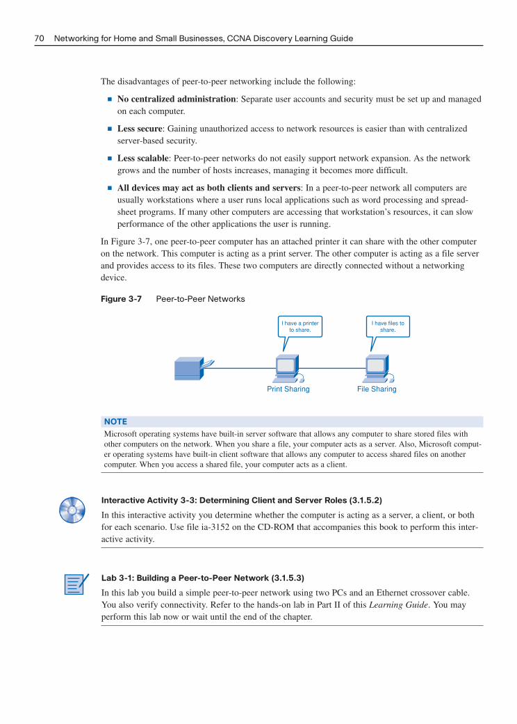
The disadvantages of peer-to-peer networking include the following:
■ No centralized administration: Separate user accounts and security must be set up and managedon each computer.
■ Less secure: Gaining unauthorized access to network resources is easier than with centralizedserver-based security.
■ Less scalable: Peer-to-peer networks do not easily support network expansion. As the networkgrows and the number of hosts increases, managing it becomes more difficult.
■ All devices may act as both clients and servers: In a peer-to-peer network all computers areusually workstations where a user runs local applications such as word processing and spread-sheet programs. If many other computers are accessing that workstation’s resources, it can slowperformance of the other applications the user is running.
In Figure 3-7, one peer-to-peer computer has an attached printer it can share with the other computeron the network. This computer is acting as a print server. The other computer is acting as a file serverand provides access to its files. These two computers are directly connected without a networkingdevice.
Figure 3-7 Peer-to-Peer Networks
70 Networking for Home and Small Businesses, CCNA Discovery Learning Guide
Print Sharing File Sharing
I have a printerto share.
I have files toshare.
NOTE
Microsoft operating systems have built-in server software that allows any computer to share stored files withother computers on the network. When you share a file, your computer acts as a server. Also, Microsoft comput-er operating systems have built-in client software that allows any computer to access shared files on anothercomputer. When you access a shared file, your computer acts as a client.
Interactive Activity 3-3: Determining Client and Server Roles (3.1.5.2)
In this interactive activity you determine whether the computer is acting as a server, a client, or bothfor each scenario. Use file ia-3152 on the CD-ROM that accompanies this book to perform this inter-active activity.
Lab 3-1: Building a Peer-to-Peer Network (3.1.5.3)
In this lab you build a simple peer-to-peer network using two PCs and an Ethernet crossover cable.You also verify connectivity. Refer to the hands-on lab in Part II of this Learning Guide. You mayperform this lab now or wait until the end of the chapter.

Network Topologies
In a simple network consisting of a few computers, visualizing how all the various components con-nect is easy. As networks grow, keeping track of the location of each component, and how each isconnected to the network becomes more difficult. Large wired networks can require considerablecabling and many network devices to provide connectivity for all network hosts.
When networks are installed, a physical topology map is created to record where each host is locatedand how it is connected to the network. The physical topology map also shows where the wiring isinstalled, the location of wiring closets, and the locations of the networking devices that connect thehosts. The physical topology map is usually based on a building floorplan diagram, as shown in Figure3-8. Icons represent the actual physical devices within the topology map. Maintaining and updatingphysical topology maps is very important to aid future installation and troubleshooting efforts.
Figure 3-8 Physical Topology
Chapter 3: Connecting to the Network 71
EthernetSwitch
Switch
AdminHub
Admin Office
MailServer
WebServer
FileServer Classroom 3
ClassroomHub
ClassroomHub
Classroom 1
Classroom 2
ClassroomHub
Router
In addition to the physical topology map, having a logical view of the network topology is also some-times necessary. A logical topology map groups hosts by how they use the network, no matter wherethey are physically located. Host names, addresses, group information, and applications can be record-ed on the logical topology map, as shown in Figure 3-9. Logical topology maps usually hide thedetails of the cabling and networking devices that actually interconnect host computers. In the logicaltopology map, a group of host computers might be represented by a single icon.
The number and types of devices that you must go through to get to a server can vary from just one ortwo for local servers to hundreds for remote servers on the other side of the world, which can createvery large and complex topologies. Imagine the connections and devices involved in getting to a serv-er in the classroom, across the campus, or around the world.

Figure 3-9 Logical Topology
72 Networking for Home and Small Businesses, CCNA Discovery Learning Guide
Mail Server192.168.2.1
Web Server192.168.2.2
File Server192.168.2.3
192.168.2.4192.168.2.5192.168.2.6
DepartmentServer
AdminGroup
Ethernet192.168.2.0
Ethernet192.168.1.0
Router-Firewall
192.168.1.1192.168.1.2192.168.1.3
Classroom 1
192.168.1.4192.168.1.5192.168.1.6
Classroom 2
192.168.1.7192.168.1.8
Printer192.168.1.9
Classroom 3
The network physical topology defines the structure of the network; that is, the actual layout of thewire or media. The following are the physical topologies used in networking:
■ Bus topology: Uses a single backbone cable that is terminated at both ends. All the hosts connectdirectly to this backbone. Early Ethernet networks employed a bus topology using a commoncoaxial cable to connect hosts. Modern cable TV networks also use a variation of the bus topology.
■ Ring topology: Connects one host to the next and the last host to the first, creating a physicalring of cable. Token ring local-area networks employ a ring topology, although it is physicallywired as a star. Other networking technologies that are based on a ring topology include FiberDistributed Data Interface (FDDI) and Synchronous Optical Network (SONET).
■ Star topology: Connects all hosts to a central point. All modern Ethernet local area networks usethe star topology. Some larger networks that have geographically separated locations might alsoemploy the star design, also known as a hub-and-spoke network. With these networks, all theremote sites are connected to a single central site.
■ Extended star topology: Links individual stars together by connecting the hubs or switches.Networks that use the star topology can usually be expanded using extended star topology.
■ Hierarchical topology: Similar to an extended star. However, with a LAN, instead of linking thehubs or switches together, they are linked to a networking device. This device is usually a routerthat controls the traffic on the topology.
■ Mesh topology: Provides redundant connections between network devices and/or locations. Afull mesh is implemented to provide as much protection as possible from interruption of service.For example, a nuclear power plant might use a mesh topology in the networked control systems.

A variation of the full mesh is known as a partial mesh, where not all sites have multiple connec-tions to all others, providing some redundancy. With a full mesh, each site location has its ownconnections to all sites. Although the Internet has multiple paths to any one location, it does notadopt the full mesh topology.
Refer to Figure 3-10 to see how these physical topologies are connected.
Figure 3-10 Network Topologies
Chapter 3: Connecting to the Network 73
BusTopology
Physical Topologies
Ring Topology
Star Topology
Extended StarTopology
HierarchicalTopology
Mesh Topology
Principles of Communication
Computer communications on a network are similar in many ways to human communication. Anappreciation of these similarities will help develop a good foundation on which to build further stud-ies. This section provides an overview of the components, message types, and rules necessary forhuman and computer communication.
Source, Channel, and Destination
The primary purpose of any network is to provide a method to communicate information. From thevery earliest primitive humans to the most advanced scientists of today, sharing information with oth-ers is crucial for human advancement.
All communication begins with a message, or information, that must be sent from one individual ordevice to another. The methods used to send, receive, and interpret messages change over time astechnology advances.

All communication methods have three elements in common. The first of these elements is the mes-sage source, or sender. Message sources are people, or electronic devices, that need to communicate amessage to other individuals or devices. The second element of communication is the destination, orreceiver, of the message. The destination receives the message and interprets it. A third element,called a channel, provides the pathway over which the message can travel from source to destination.
Figure 3-11 shows human communication with a message source, a transmission medium (channel),and a receiver. These same basic components are required with computer communications, as shownin Figure 3-12.
Figure 3-11 Human Communication
74 Networking for Home and Small Businesses, CCNA Discovery Learning Guide
TransmissionMedium
MessageSource
Transmitter
Source
MessageDestinationReceiver
DestinationChannel
Rules of Communication
In any conversation between two people, they must follow many rules, or protocols, in order for themessage to be successfully delivered and understood. Among the protocols for successful humancommunication are
■ Identification of sender and receiver
■ Agreed-upon medium or channel (face-to-face, telephone, letter, or photograph)
■ Appropriate communication mode (spoken, written, illustrated, interactive, or one-way)
■ Common language
■ Grammar and sentence structure
■ Speed and timing of delivery

Figure 3-12 Computer Communication
Chapter 3: Connecting to the Network 75
TransmissionMedium
MessageSource
Transmitter
Source
MessageDestinationReceiver
DestinationChannel
Imagine what would happen if no protocols or rules existed to govern how people communicate witheach other. Would you be able to understand them? In Figure 3-13, compare the top paragraph to thebottom paragraph. Are you able to read the top paragraph? Notice that it seems to follow no rules orstructure. It does not follow commonly accepted protocols.
Figure 3-13 Communication With and Without Protocols
Communication Without Proper Protocols
humans communications between govern rules.Itisverydifficulttounderstandmessagesthatarenotcorrectlyformattedanddonotfollowtheestablishedrulesandprotocols. A estrutura da gramatica, da lingua, dapontuacao e do sentance faz a configuracao humana compreensivel por muitosindividuos diferentes.
Communication with Proper Protocols
Rules govern communications between humans. It is very difficult to understandmessages that are not correctly formatted and do not follow the established rulesand protocols. The structure of the grammar, the language, the punctuation andthe sentence make the configuration humanly understandable for many differentindividuals.
Translation
Protocols are specific to the characteristics of the source, channel, and destination of the message. Therules used to communicate over one medium, like a telephone call, are not necessarily the same ascommunication using another medium, such as a letter.
Protocols define the details of how the message is transmitted and delivered. This includes issues of
■ Message format
■ Message size
■ Timing
■ Encapsulation

■ Encoding
■ Standard message pattern
Many of the concepts and rules that make human communication reliable and understandable alsoapply to computer communication. In many ways, computer communications are similar to humancommunications. Figure 3-14 illustrates the main characteristics that must be defined for protocols tofacilitate communication.
Figure 3-14 Main Protocol Characteristics
76 Networking for Home and Small Businesses, CCNA Discovery Learning Guide
Protocols
Timing
Formatting
EncapsulationEncoding
Unit SizeMessage
Message Encoding
One of the first steps to sending a message is encoding it. Written words, pictures, and spoken lan-guages each use a unique set of codes, sounds, gestures, and symbols to represent the thoughts beingshared. Encoding is the process of converting thoughts into the language, symbols, or sounds fortransmission. Decoding reverses this process in order to interpret the thought.
Imagine a person watching a sunset and then calling someone else to talk about how beautiful thesunset looks. To communicate the message, the sender must first convert, or encode, her thoughts andperceptions about the sunset into words. The words are spoken into the telephone using the soundsand inflections of spoken language that convey the message. On the other end, the person listening tothe description receives and decodes the sounds in order to visualize the image of the sunset describedby the sender. This concept is illustrated in Figure 3-15, where the human communication is depictedby a person who encodes a concept using words spoken over airwaves.
Encoding also occurs in computer communication. Encoding between hosts must be in an appropriateform for the medium. Messages sent across the network are first converted into bits by the source.Each bit is encoded into a pattern using light waves, electrical impulses, or electromagnetic waves,depending on the network media over which the bits are transmitted. The destination receives anddecodes the signals in order to interpret the message. In Figure 3-15, the source host computer cap-tures an image of a sunset and then encodes it using electrical bit patterns. These signals are then sentto the destination host through a physical cable. The destination host receives the encoded bits anddecodes them in order to display the image on its monitor.

Figure 3-15 Human and Computer Message Encoding and Decoding
Chapter 3: Connecting to the Network 77
MessageSource
MessageDestination
Encoder TransmiterTransmission
Medium“The Channel”
ReceiverDecoderMessage Signal
Message Signal
1 0 1 0 0 1 1 1 0 0 1
SourceEncoded
DestinationDecoded
Message Formatting
When a message is sent from source to destination, it must use a specific format or structure. Messageformats depend on the type of message and the channel that is used to deliver the message.
Letter writing is one of the most common forms of written human communication. For centuries, theagreed format for personal letters has not changed. In many cultures, a personal letter contains the fol-lowing elements:
■ An identifier of the recipient
■ A salutation or greeting
■ The message content
■ A closing phrase
■ An identifier of the sender
In addition to having the correct format, most personal letters must also be enclosed, or encapsulated,in an envelope for delivery. The envelope has the address of the sender and receiver on it, each locatedat the proper place on the envelope. If the destination address and formatting are not correct, the letteris not delivered.
The process of placing one message format (the letter) inside another message format (the envelope)is called encapsulation. De-encapsulation occurs when the process is reversed by the recipient and theletter is removed from the envelope. In Figure 3-16, the envelope has a commonly accepted address-ing format as does the letter it encapsulates. Most letters conform to a format similar to this.

Figure 3-16 Message Formatting: Human Letter Encapsulation
78 Networking for Home and Small Businesses, CCNA Discovery Learning Guide
Recipient(Destination)LocationAddress
1400 MainStreetCanton, Ohio44203
4085 SE PineStreetOcala, Florida34471
Dear Jane I just returnedfrom my trip. Ithought youmight like tosee mypictures.
John
Envelope Addressing Encapsulated Letter
Recipient(Destination)Identifier
Content ofLetter(EncapsulatedData)
Sender(Source)LocationAddress
Sender(Source)Identifier
End ofFrame (Endof MessageIndicator)
Salutation(Start ofMessageIndicator)
Sender:4085 SE Pine StreetOcala, Florida 34471
Recipient:1400 Main StreetCanton, Ohio 44203
Dear Jane
I Just returned from my trip. I thought youmight like to see my pictures.
John
A letter writer uses an accepted format to ensure that the letter is delivered and understood by therecipient. In the same way, a message that is sent over a computer network follows specific formatrules for it to be delivered and processed. Just as a letter is encapsulated in an envelope for delivery,so computer messages are encapsulated. Each computer message is encapsulated in a specific format,called a frame, before it is sent over the network. A frame acts like an envelope; it provides theaddress of the intended destination and the address of the source host.
The format and contents of a frame are determined by the type of message being sent and the channelover which it is communicated. Messages that are not correctly formatted are not successfully deliv-ered to or processed by the destination host. Figure 3-17 shows a computer message with the frameaddressing performing a function similar to the addresses on an envelope. The message encapsulatedinside the frame contains information similar to that of a written letter.
Figure 3-17 Message Formatting: Computer Frame Encapsulation
Destination(Physical/HardwareAddress)
Frame Addressing Encapsulated Message
Source(Physical/HardwareAddress)
Start Flag(Start ofMessageIndicator)
Recipient(DestinationIdentifier)
Sender(SourceIdentifier)
EncapsulatedData (Bits)
End of Frame(End ofMessageIndicator)

Chapter 3: Connecting to the Network 79
Interactive Activity 3-4: Placing Communications Components (3.2.4.3)
In this interactive activity you place the components of a voice message into the proper location with-in a frame. Use file ia-3243 on the CD-ROM that accompanies this book to perform this interactiveactivity.
Message Size
Imagine what it would be like to read this book if all the text appeared as one long sentence; it wouldnot be easy to read and comprehend. When people communicate with each other, the messages thatthey send are usually broken into smaller parts or sentences. These sentences are limited in size towhat the receiving person can process at one time. An individual conversation is made up of manysmaller sentences to ensure that each part of the message is received and understood. Figure 3-18shows what can happen when a person speaks in run-on sentences and does not pause to break up themessage into understandable pieces.
Figure 3-18 Message Size: Human Communication
I cannotunderstand
you.
??
??
??
??
“youshouldseethisbeautifulsunsetthecolorsareamazing”
Likewise, when a long message is sent from one host to another over a network, breaking the messageinto smaller pieces is necessary. The rules that govern the size of the pieces, or frames, communicatedacross the network are very strict. They can also be different, depending on the channel used. Framesthat are too long or too short are not delivered.
The size restrictions of frames require the source host to break a long message into individual piecesthat meet both the minimum and maximum size requirements. Each piece is encapsulated in a sepa-rate frame with the address information and is sent over the network. At the receiving host, the mes-sages are de-encapsulated and put back together to be processed and interpreted. The host computer in

the top portion of Figure 3-19 is sending frames that are too short or too long and the receiving com-puter cannot interpret them. This situation can happen when frames collide and also when the networkinterface card (NIC) is malfunctioning. The computer in the lower portion of Figure 3-19 is breakingup the message into appropriate-sized pieces so that the receiving computer can understand them.
Figure 3-19 Message Size: Computer Communication
80 Networking for Home and Small Businesses, CCNA Discovery Learning Guide
Message Timing
Another major factor that affects how well a message is received and understood is timing. People usetiming to determine when to speak (access method), how fast or slow to talk (flow control), and howlong to wait for a response (response timeout). These rules of engagement apply to both human andcomputer communications.
Access MethodAn access method determines when someone is able to send a message. These timing rules are basedon the environment. For example, if a person has something to say, he normally waits until no oneelse is talking before speaking. If two people talk at the same time, a collision of information occurs,and the two people need to back off and start again. These rules ensure that communication is suc-cessful.
In Figure 3-20, both people started talking at the same time and their messages interfered with eachother, resulting in neither person understanding the other. Computers must also deal with this sametype of communication issue. Computers need to have an access method in order to know when tobegin sending messages and how to respond when errors occur.
Flow ControlTiming also affects how much information can be sent and the speed that it can be delivered. If oneperson speaks too quickly, it is difficult for the other person to hear and understand the message. Thereceiving person must ask the sender to slow down.
In network communication, a sending host can transmit messages at a faster rate than the destinationhost can receive and process. Source and destination hosts use flow control to negotiate correct timingfor successful communication.

Figure 3-20 Message Timing
Chapter 3: Connecting to the Network 81
What time is the movie? Sorry,I was talking. What did you say?
When are we meetingfor dinner?
Response TimeoutIf a person asks a question and does not hear a response within an acceptable amount of time, the per-son assumes that no answer is coming and reacts accordingly. The person might repeat the question,or might go on with the conversation. Hosts on the network also have rules that specify how long towait for responses and what action to take if a response timeout occurs.
Message Patterns
Sometimes, a person wants to communicate information to a single individual. At other times, the per-son might need to send information to a group of people at the same time, or even to all people in thesame area. A conversation between two people is an example of a one-to-one pattern of communica-tion. When a group of recipients needs to receive the same message simultaneously, a one-to-many orone-to-all message pattern is necessary.
Times also occur when the sender of a message needs to be sure that the message is delivered suc-cessfully to the destination. In these cases, the recipient needs to return an acknowledgement to thesender. If no acknowledgement is required, the message pattern is referred to as unacknowledged.Hosts on a network use similar message patterns to communicate. Humans and computers use theconcepts of unicast, multicast, and broadcast to accomplish various types of communications.
Unicast A one-to-one message pattern is referred to as a unicast, meaning that only a single destination existsfor the message. Figure 3-21 illustrates a human unicast where one individual is communicatingdirectly with another individual. The computer equivalent is one host communicating directly withanother, to transfer a file, for example. This type of communication is usually acknowledged.

Figure 3-21 Unicast (Human and Computer)
82 Networking for Home and Small Businesses, CCNA Discovery Learning Guide
Source
Source
Destination
Destination
Multicast When a host needs to send messages using a one-to-many pattern, it is referred to as a multicast.Multicasting is the delivery of the same message to a specific group of host destinations simultaneous-ly. Figure 3-22 illustrates a human multicast where one individual communicates directly with severalother individuals simultaneously. An example of this is when a teacher needs to communicate with themembers of the math club in a classroom at school. Only the students in the math club need to listento the communication. The computer equivalent is one host communicating with several other hosts.For example, a video server might send a video training session to only those computers whose userswant to see it. This type of communication is usually unacknowledged because the sender does notneed to be told specifically that everyone on the multicast group heard the message.
Broadcast If all hosts on the network need to receive the message at the same time, a broadcast is used.Broadcasting represents a one-to-all message pattern. Additionally, hosts have requirements foracknowledged versus unacknowledged messages. Figure 3-23 illustrates a human broadcast where oneindividual communicates with all individuals in the classroom at the same time. An example of this iswhen a teacher introduces herself and tells the entire class her name. All students need to listen to thecommunication.

Figure 3-22 Multicast (Human and Computer)
Chapter 3: Connecting to the Network 83
Source
Destination
Source
Destination
Destination
Figure 3-23 Broadcast (Human and Computer)
Source
Destination
Source
Destination
Destination
Destination
Destination
The computer equivalent of a broadcast is one host communicating with all other hosts on a local net-work to let them know what its name is. This type of communication is usually unacknowledgedbecause the sender does not need to be told specifically that everyone on the local network heard themessage.
Interactive Activity 3-5: Determining Communications Problems (3.2.8.2)
In this interactive activity you determine whether the communication problem described deals withencoding, message format, timing, unit size, or message pattern. Use file ia-3282 on the CD-ROMthat accompanies this book to perform this interactive activity.
Communicating on a Wired Local Network
Most network users connect to a local network to share resources and connect to the Internet. Thissection introduces the concept of protocols to allow computers to communicate on a local network.This section covers the evolution and characteristics of Ethernet, the most widely used local-area net-work protocol. It also introduces the physical and logical addressing required to deliver messages on aLAN as well as the hierarchical nature of today’s networks.
Importance of Protocols
Computers, just like humans, use rules, or protocols, in order to communicate. Protocols are especial-ly important on a local network. In a wired environment, a local network is defined as an area whereall hosts must “speak the same language” or in computer terms “share a common protocol.” The mostcommon set of protocols used on local wired networks is Ethernet. The Ethernet protocol definesmany aspects of communication over the local network, including message format, message size, tim-ing, encoding, and message patterns.
If everyone in the same room spoke a different language, they would not be able to communicate.Likewise, if devices in a local network did not use the same protocols, they would not be able to com-municate. For example, consider a group of people speaking the same language, in this case Japanese.If a person comes into the room who does not speak Japanese, that person would not be able to talkwith the others. Similarly, consider a group of computers on a local network communicating withEthernet. If a computer is attached to the local network that is not using the Ethernet protocol, itwould not be able to communicate with the other computers.
In the early days of networking, each vendor used its own, proprietary methods of interconnecting net-work devices and networking protocols. Equipment from one vendor could not communicate withequipment from another. Examples of proprietary protocols include those from IBM, NCR, DEC, andothers.
As networks became more widespread, standards were developed that defined rules by which networkequipment from different vendors operated. Several standard protocols evolved in more recent years,including Ethernet, ARCnet, and Token Ring. Standards are beneficial to networking in many ways:
■ Facilitate design
■ Simplify product development
■ Promote competition
■ Provide consistent interconnections
84 Networking for Home and Small Businesses, CCNA Discovery Learning Guide

■ Facilitate training
■ Provide more vendor choices for customers
There is no official local networking standard protocol, but over time, one technology, Ethernet, hasbecome more common than the others. It has become a de facto standard. This means that althoughother local network protocols exist, most local networks use Ethernet. Figure 3-24 shows how stan-dards have evolved over time from proprietary ones to the primary one used today, which is Ethernet.
Figure 3-24 Network Protocol Standards Evolution
Chapter 3: Connecting to the Network 85
Proprietary VendorProtocols (1970s)
Limited Number ofStandards (1980s and1990s)
And the Winner Is
IBMEthernet(IEEE 802.3)
ARCnet(IEEE 802.4)
Token Ring(IEEE 802.5)
NCR
Xerox
DEC
HP
Ethernet(2000)
Standardization of Protocols
The Institute of Electrical and Electronic Engineers (IEEE), pronounced eye-triple-e, maintains anumber of local networking standards, including Ethernet and wireless standards. IEEE committeesare responsible for approving and maintaining the standards for connections, media requirements, andcommunications protocols. Each technology standard is assigned a number that refers to the commit-tee that is responsible for approving and maintaining the standard. The committee responsible for theEthernet standards is 802.3. IEEE is headquartered in the United States although much of the commit-tee work is done by volunteers from all over the world.
Since the creation of Ethernet in 1973, standards have evolved for specifying faster and more flexibleversions of the Ethernet technology. This ability for Ethernet to improve over time is one of the mainreasons that it has become so popular. Each version of Ethernet has an associated standard. For exam-ple, 802.3 100BaseT represents 100 Megabit per second (Mbps) Ethernet using the twisted-pair cablestandard. The standard notation translates as follows:
■ 100 is the speed in Mbps
■ Base stands for baseband transmission
■ T stands for the type of cable; in this case, it refers to twisted pair. The letter F would indicatefiber-optic cable.

Early versions of Ethernet were relatively slow at only 10 Mbps. The latest versions of Ethernet oper-ate at 10 Gigabits per second and faster. This is a 1,000 times increase in speed.
Earlier versions of Ethernet used a shared medium where all hosts were connected to a common cableor a hub. With shared Ethernet networks, any host could begin transmitting at any time and collisionsoften occurred. The more hosts and traffic on the network, the greater the number of collisions. Theseversions of the Ethernet protocol depended on an access method known as Carrier Sense, MultipleAccess with Collision Detection (CSMA-CD). This means that multiple hosts are sensing (listening)to the carrier (cable) for a transmission from another host and if none is detected, they can begintransmitting. If two hosts transmit at the same time, a collision occurs and the hosts are able to detectthe collision and stop transmitting. Each host waits a random period of time before retransmitting. Asyou can imagine, all of this collision detection and retransmission takes time and slows down the net-work.
Newer versions of Ethernet use “switched” network device connection technologies. The older sharedEthernet technologies, using a common cable or hub to connect hosts, allowed collisions to occur andcorrected the problem after the fact. Switched Ethernet uses a network device known as a local-areanetwork (LAN) switch to provide a dedicated circuit between any two hosts that need to communi-cate, thus preventing the collisions from occurring in the first place. Although the CSMA-CD accessmethod is still supported with switched Ethernet, it is no longer required because each host is normal-ly connected directly to a switch port, eliminating the possibility of collisions.
Switched versions of Ethernet can provide full speed in both directions (send and receive) simultane-ously, thus greatly increasing network performance over the older shared Ethernet versions. As anexample, a 10 Mbps Ethernet network with hosts connected to a shared hub might provide only 5Mbps total throughput for network traffic. The actual throughput would depend on the amount of traf-fic and number of collisions. A 10 Mbps Ethernet network with hosts connected to a switch can pro-vide 10 Mbps in both directions between any two hosts, resulting in a potential increase in speed up to20 Mbps depending on the technology used.
Ethernet has come a long way since its early days. Table 3-1 summarizes the major improvements andevolution in the Ethernet standards over time.
Table 3-1 Ethernet Evolution and Standards Development
Year Standard Description
1973 Ethernet invented Ethernet invented by Dr. Robert Metcalf of Xerox Corp.
1980 DIX standard Digital Equipment Corp, Intel, and Xerox (DIX) release a standard for 10Mbps Ethernet over coaxial cable.
1983 IEEE 802.3 10 Mbps Ethernet over thick coaxial cable.10Base5
1985 IEEE 802.3a 10 Mbps Ethernet over thin coaxial cable.10Base2
1990 IEEE 802.3i 10 Mbps Ethernet over unshielded twisted pair (UTP).10BaseT
1993 IEEE 802.3j 10 Mbps Ethernet over fiber optic.10BaseF
1995 IEEE 802.3u Fast Ethernet – 100 Mbps Ethernet over UTP and fiber (various 100Base-xx standards).
86 Networking for Home and Small Businesses, CCNA Discovery Learning Guide

Year Standard Description
1998 IEEE 802.3z Gigabit Ethernet over fiber optic.1000BaseX
1999 IEEE 802.3ab Gigabit Ethernet over twisted pair.1000BaseT
2002 IEEE 802.3ae 10 Gigabit Ethernet over fiber (various standards).10GBase-xx
2006 IEEE 802.3an 10 Gigabit Ethernet over UTP.10GBaseT
Physical Addressing
All communication requires a way to identify the source and destination. The source and destinationin human communication are represented by names. When a name is called, the person with that namelistens to the message and responds. Other people in the room might hear the message, but they ignoreit because it is not addressed to them.
On Ethernet networks, a similar method exists for identifying source and destination hosts. Each hostconnected to an Ethernet network is assigned a physical address that serves to identify the host on thenetwork.
Every Ethernet network interface has a physical address assigned to it when it is manufactured. Thisaddress is known as the Media Access Control (MAC) address. The MAC address identifies eachsource and destination host on the local network. The MAC address is a 48-bit address that is normal-ly represented as 12 hexadecimal (hex) characters of 4 bits each. An example of a MAC address is 00-1B-53-8A-4E-01. The first six hex characters (24 bits) represent the manufacturer of the Ethernetinterface and are known as the Organizational Unique Identifier (OUI). The last 24 bits identify a par-ticular interface or NIC from that manufacturer. The OUI is assigned to an organization by the IEEEto ensure that MAC addresses are not duplicated. In the example 00-1B-53-8A-4E-01, 00-1B-53 indi-cates that this Ethernet interface was manufactured by Cisco. In this case the interface is on a Ciscorouter. Cisco devices display the MAC address using the format 001B.538A.4E01. The MAC addressis the same in either case, just a different display format.
Ethernet networks are cable based, meaning that a copper or fiber-optic cable connects hosts and net-working devices. This is the channel used for communications between the hosts.
When a host on an Ethernet network communicates, it sends frames containing its own MAC addressas the source and the MAC address of the intended recipient. Any hosts that receive the frame willdecode the frame and read the destination MAC address. If the destination MAC address matches theaddress configured on the NIC, it will process the message and store it for the host application to use.If the destination MAC address does not match the host MAC address, the NIC will ignore the mes-sage. Figure 3-25 shows a host sending a frame out on an Ethernet network. Although other hostsmight see the frame, only the host to which it is addressed will accept it.
The newer Windows operating systems provide a method of displaying the host’s MAC address usinga GUI Network Connection application. You may also use the command line ipconfig command. TheUNIX and Linux operating systems can also use GUI applications to view computer addresses but usethe ifconfig command, instead, from the command line.
Chapter 3: Connecting to the Network 87

Figure 3-25 Computer Communication Using Physical Addresses
88 Networking for Home and Small Businesses, CCNA Discovery Learning Guide
H3H2
H1 H4
Destination Address
CC:CC:CC:CC:CC:CC
DD:DD:DD:DD:DD:DD
Destination:CC:CC:CC:CC:CC:CC
BB:BB:BB:BB:BB:BB
Frame Addressing
AA:AA:AA:AA:AA:AA
Source:AA:AA:AA:AA:AA:AA
Encapsulated Data
Source Address DATA
This is mine.
This is not addressedto me. I shall ignore it.
This is not addressedto me. I shall ignore it.
I just sent apacket to H3.
Lab 3-2: Determine the MAC Address of a Host (3.3.3.2)
In this lab you use the ipconfig /all command to determine the MAC address of your computer. Referto the hands-on lab in Part II of this Learning Guide. You may perform this lab now or wait until theend of the chapter.
Ethernet Communication
Ethernet protocol standards define many aspects of network communication including frame format,frame size, timing, and encoding.
When messages are sent between hosts on an Ethernet network, the hosts format the messages intothe frame layout that is specified by the standards. Frames are one type of data grouping in a familyreferred to as protocol data units (PDU).
The format for Ethernet frames specifies the location of the destination and source MAC addresses,and additional information including
■ Preamble for sequencing and timing
■ Start of frame delimiter
■ Length and type of frame
■ Frame check sequence to detect transmission errors
Figure 3-26 shows the structure of a standard IEEE 802.3 frame. Note that the maximum amount ofdata that the frame can contain is 1500 bytes.

Figure 3-26 Structure of the Ethernet Frame
Chapter 3: Connecting to the Network 89
Preamble
7 1 6 6 2 46 to 1500 4
SFD DestinationMAC Address
Source MACAddress
Length/Type
EncapsulatedData
FCS
Table 3-2 lists the main components of the Ethernet frame and provides a brief description of theirpurpose or function.
Table 3-2 Fields in an Ethernet Frame
Frame Field Bytes Description / Contents
Preamble 7 Used to announce data transmission.
Start of Frame Delimiter (SFD) 1 Marks the end of the timing information and start of theframe.
Destination MAC Address 6 Contains the destination MAC address (receiver). The desti-nation MAC address can be unicast (a specific host), multi-cast (a group of hosts), or broadcast (all hosts on the localnetwork).
Source MAC Address 6 Contains the source MAC address (sender). This is the uni-cast address of the Ethernet node that transmitted the frame.
Length/Type 2 Supports two different uses. A type value indicates whichprotocol will receive the data. The length indicates the num-ber of bytes of data that follows this field.
Encapsulated Data 46 to Contains the packet of information being sent. Ethernet 1500 requires each frame to be between 64 and 1518 bytes.
Frame Check Sequence (FCS) 4 Contains a 4-byte value that is created by the device thatsends data and is recalculated by the destination device tocheck for damaged frames.
The size of Ethernet frames is limited to a maximum of 1518 bytes and a minimum size of 64 bytes.Frames that do not fall within these limits are not processed by the receiving hosts. By adding thenumber of bytes for the data (1500 bytes), destination MAC address (6 bytes), source MAC address (6bytes), length/type (2 bytes), and the FCS (4 bytes) we arrive at the maximum Ethernet frame size of1518 bytes. The preamble and the SFD are not counted in the total frame size because they are onlythere for timing and to indicate where the frame begins.
In addition to the frame format, size, and timing, Ethernet standards define how the bits making upthe frames are encoded onto the channel. Bits are transmitted as either electrical impulses over coppercable or as light impulses over fiber-optic cable.
Interactive Activity 3-6: Building an Ethernet Frame (3.3.4.2)
In this interactive activity you build a standard IEEE 802.3 Ethernet frame based on the source andthe destination device. Use file ia-3342 on the CD-ROM that accompanies this book to perform thisinteractive activity.

Hierarchical Design of Ethernet Networks
Imagine how difficult communication would be if the only way to send a message to someone was touse the person’s name. If there were no street addresses, cities, towns, or country boundaries, deliver-ing a message to a specific person across the world would be nearly impossible. Figure 3-27 showsthe hierarchy of land boundaries that allow the delivery of mail to a person living in a particular citybased on knowing where that city is located in the world.
Figure 3-27 Continent, Country, Province, and City Boundary Hierarchy
90 Networking for Home and Small Businesses, CCNA Discovery Learning Guide
North America
1 2
3 4
Canada
Nova ScotiaHalifax
A. Person101 Hollis StreetHalifax, Nova ScotiaCanada
On an Ethernet network, the host MAC address is similar to a person’s name. A MAC address indi-cates the individual identity of a specific host, but it does not indicate where on the network the hostis located. If all hosts on the Internet (more than 400 million of them) were each identified by onlytheir unique MAC address, imagine how difficult locating a single one would be.
Additionally, Ethernet technology generates a large amount of broadcast traffic in order for hosts tocommunicate. Broadcasts are sent to all hosts within a single network. Broadcasts consume bandwidthand slow network performance. Imagine what would happen if the millions of hosts attached to theInternet were all in one Ethernet network and were using broadcasts. Communication would be nearlyimpossible.
Another way to understand the concept of Ethernet broadcasts is with a phone analogy. What if theprocess of answering the phone involved having everyone’s phone ring every time anyone wanted tomake a call to anyone else? Everyone has to answer the phone but unless they hear their name beingcalled from the other end, they hang up. Even in a small town this broadcast behavior would be over-whelming, not just to the system, but to everyone on the system trying to answer all those rings.
For these reasons, large Ethernet networks consisting of many hosts are not efficient. Dividing largernetworks into smaller, more manageable pieces is better. One way to divide larger networks is to use ahierarchical design model.

In networking, hierarchical design is used to group devices into multiple networks that are organizedin a layered approach. It consists of smaller, more manageable groups that allow local traffic to remainlocal. Only traffic that is destined for other networks is moved to a higher layer.
A hierarchical, layered design provides increased efficiency, optimization of function, and increasedspeed. It allows the network to scale or grow as required because additional local networks can beadded without impacting the performance of the existing ones.
The hierarchical design has three basic layers:
■ Access layer: To provide connections to hosts in a local Ethernet network
■ Distribution layer: To interconnect the smaller local networks
■ Core layer: High-speed connections between distribution layer devices
With this new hierarchical design comes a need for a logical addressing scheme that can identify thelocation of a host. This is the Internet Protocol (IP) addressing scheme. Figure 3-28 shows how net-works can also be hierarchical in nature.
To expand the telephone analogy, the telephone network is an extremely large physical network but itis divided logically using a phone number addressing scheme. To properly route a call, a phone num-ber consists of a hierarchy structured using prefixes (local access networks), area codes (distributionnetworks), and country codes (core networks). If you make a long-distance call, you must include thearea code in the number you dial. Doing so ensures that the telephone system knows to route your callto the right area. This analogy illustrates a logical division of a physical network.
Logical Addressing
A person’s given name usually does not change. A person’s address, on the other hand, relates towhere they live and can change. On a host, the MAC address, also known as the physical or hardwareaddress, does not change; it is physically assigned to the host NIC. The physical address remains thesame regardless of where the host is placed on the network.
The IP address is similar to the mailing address of a person. It is known as a logical address becauseit is assigned logically based on where the host is located. A network administrator assigns the IPaddress to each host based on the local network where it resides. Both the physical MAC and logicalIP addresses are required for a computer to communicate on a hierarchical network, just as both thename and address of a person are required to deliver a letter.
IP addresses contain two parts: the local network and the host. The network portion of the IP addresswill be the same for all hosts connected to the same local network. The second part of the IP addressidentifies the individual host. Within the same local network, the host portion of the IP address isunique to each host.
In Figure 3-29, host H3 is on network 192.168.200 and the individual host portion of the address onthat network is .3. Hosts H1, H2, and H4 are also on the 192.168.200 network. Host H8 is on the192.168.1 network and its host address is .4. Note that the host portion of the address for host H4 (.4)is the same as for host H8 (.4). This is not a problem because they live on different networks using ahierarchical network design where a two-part address is employed. When a packet is sent to H4’s IPaddress, it is sent to 192.168.200.4. When a packet is sent to H8’s IP address, it is sent to 192.168.1.4.
Chapter 3: Connecting to the Network 91

Figure 3-28 Core, Distribution, and Access Layer Network Hierarchy
92 Networking for Home and Small Businesses, CCNA Discovery Learning Guide
Access Layer
Distribution Layer
Core Layer
IP IP IP
Lab 3-3: Determine the IP Address of a Computer (3.3.6.2)
In this lab you use the ipconfig /all command to display the IP address of your computer. Refer to thehands-on lab in Part II of this Learning Guide. You may perform this lab now or wait until the end ofthe chapter.
Access, Distribution, and Core Layers and Devices
IP traffic is managed based on the characteristics and devices associated with each of the three layers:access, distribution, and core. The IP address is used to determine whether traffic should remain localor be moved up through the layers of the hierarchical network.
The access layer provides a connection point to the network for end-user devices and allows multiplehosts to connect to other hosts through a network device. Typically, all devices within a single accesslayer area will have the same network portion of the IP address.
If a message is destined for a local host, based on the network portion of the IP address, the messageremains local. If it is destined for a different network, it is passed up to the distribution layer. Hubsand switches provide the connection to the distribution layer devices, usually a router.
The distribution layer provides a connection point for separate local networks and controls the flow ofinformation between the networks. It typically contains more powerful switches than the access layeras well as routers for routing between networks. In a three-layer design, distribution layer devices alsocontrol the type and amount of traffic that flows from the access layer to the core layer.

Figure 3-29 Network Address and Host Address
Chapter 3: Connecting to the Network 93
H1
H2
H3
H4
H7
H6
H5
192.168.1.4 192.168.1.3
192.168.1.2
192.168.1.1
Network192.168.1.0
Network192.168.200.0
192.168.200.1
192.168.200.2
192.168.200.3
192.168.200.4
Two Parts of the IP Address
Network Host
192.168.1 .4
H8
Two Parts of the IP Address
Network Host
192.168..200 .3
The core layer is a high-speed backbone layer with redundant (backup) connections. It is responsiblefor transporting large amounts of data between multiple end networks. Core layer devices typicallyinclude very powerful, high-speed switches and routers. The main goal of the core layer is to transportdata quickly. Hubs, switches, and routers are discussed in more detail in the next two sections“Building the Access Layer of an Ethernet Network” and “Building the Distribution Layer of aNetwork.”
Figure 3-30 shows a conceptual diagram of the three-layer network design and also provides photo-graphs of the type of devices that represent the icons shown.
Interactive Activity 3-7: Working with Addresses, Network Components, and Layers (3.3.7.2)
In this interactive activity you determine which addresses, network components, and layers are neces-sary to accomplish each task. Use file ia-3372 on the CD-ROM that accompanies this book to performthis interactive activity.
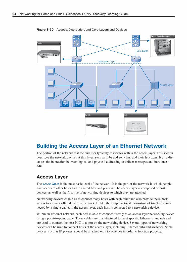
Figure 3-30 Access, Distribution, and Core Layers and Devices
94 Networking for Home and Small Businesses, CCNA Discovery Learning Guide
Access Layer
Distribution Layer
Core Layer
IP IP IP
Building the Access Layer of an Ethernet Network
The portion of the network that the end user typically associates with is the access layer. This sectiondescribes the network devices at this layer, such as hubs and switches, and their functions. It also dis-cusses the interaction between logical and physical addressing to deliver messages and introducesARP.
Access Layer
The access layer is the most basic level of the network. It is the part of the network in which peoplegain access to other hosts and to shared files and printers. The access layer is composed of hostdevices, as well as the first line of networking devices to which they are attached.
Networking devices enable us to connect many hosts with each other and also provide these hostsaccess to services offered over the network. Unlike the simple network consisting of two hosts con-nected by a single cable, in the access layer, each host is connected to a networking device.
Within an Ethernet network, each host is able to connect directly to an access layer networking deviceusing a point-to-point cable. These cables are manufactured to meet specific Ethernet standards andare used to connect the host NIC to a port on the networking device. Several types of networkingdevices can be used to connect hosts at the access layer, including Ethernet hubs and switches. Somedevices, such as IP phones, should be attached only to switches in order to function properly.

An increasing number of business and home users are installing wireless access to allow users to con-nect without the requirement for cumbersome wires. This wireless connectivity functions at the accesslayer, and the access points used to allow the end users to connect are access layer devices.
Function of Hubs
A hub is one type of networking device that is installed at the access layer of an Ethernet network.Hubs contain multiple ports that are used to connect hosts to the network. They are simple networkingdevices that do not have the necessary electronics to decode the messages sent between hosts andtherefore cannot determine which host should get any particular message. A hub simply accepts elec-tronic signals from one port and regenerates (or repeats) the same message out of all the other ports.
Recall that the NIC on a host accepts messages only addressed to the correct MAC address. Hostsignore messages that are not addressed to them. Only the host specified in the destination MACaddress of the frame processes the message and responds to the sender. Although all hosts receive themessage, only the one that it is destined for accepts and processes it, as shown in Figure 3-31.
Figure 3-31 Message Delivery in a Hub-Based Network
Chapter 3: Connecting to the Network 95
Hub
H1
H2
H4
H6
H7
H8
H5Source
H3
Destination
All the ports on the Ethernet hub connect to the same channel to send and receive messages. Becauseall hosts must share the bandwidth available on that channel, a hub is referred to as a shared-bandwidth device.
Because an Ethernet hub consists of a single channel, only one message can be sent through the hubat a time. If two or more hosts connected to a hub attempt to send a message at the same time, theelectronic signals that make up the messages collide with each other on the channel.
A collision causes the messages to become garbled and unreadable by the hosts. A hub does notdecode the messages; therefore it does not detect that the message is garbled and repeats it out all theports, wasting valuable bandwidth. The area of the network where a host can receive a garbled mes-sage resulting from a collision is known as a collision domain. Figure 3-32 illustrates such a collisiondomain.

Figure 3-32 Collision Domain
96 Networking for Home and Small Businesses, CCNA Discovery Learning Guide
Hub
H1
H2
H4
H6
H7
H8
H5
Source
H3Source
Collision Domain
Inside a collision domain, when a host receives a garbled message, it detects that a collision hasoccurred. When this occurs, each sending host waits a short amount of time and then attempts to send,or retransmit, the message again. As the number of hosts connected to the hub increases, so does thechance of collisions. More collisions cause more retransmissions. Excessive retransmissions can clogthe network and slow down network traffic. For this reason, limiting the number of hosts within a sin-gle collision domain is necessary.
Interactive Activity 3-8: Data Flow in a Hubbed Network (3.4.2.3)
In this interactive activity you practice identifying which hosts will receive a message on a hub-basednetwork. Use file ia-3423 on the CD-ROM that accompanies this book to perform this interactiveactivity.
Function of Switches
Because of the problems associated with being a shared bandwidth device, hubs are no longer com-monly deployed at the access layer. Most modern Ethernet networks employ a device known as anEthernet switch to connect hosts into the network. Like a hub, a switch connects multiple hosts to thenetwork. Unlike a hub, a switch can make decisions based on the information contained within theEthernet frame and can forward a message to a specific host. When a host sends a message to anotherhost on the switch, the switch accepts and decodes the frames to read the physical (MAC) addressportion of the message.
A table on the switch, called a MAC address table, contains a list of all the active ports and the hostMAC addresses that are attached to them. When a message is sent between hosts, the switch checks to see whether the destination MAC address is in this table. If it is, the switch builds a temporary connection, called a circuit, between the source and destination ports. This new circuit provides a

dedicated channel over which the two hosts can communicate. Other hosts attached to the switch donot share the bandwidth on this channel and do not receive messages that are not addressed to them. Anew circuit is built for every new conversation between hosts. These separate circuits allow many con-versations to take place at the same time, without collisions occurring.
In Figure 3-33 host H3 is connected to fast Ethernet port fa0/3. H3, with a MAC address of00E0:FE00:3333, and is sending a frame to host H7 that is connected to port fa0/7 at MAC address00E0:FE00:7777. The MAC address table for the switch is shown in Table 3-3. Please note that theMAC addresses shown are for illustration only. The MAC addresses in the table are the MAC addressesof the connected device and are not related to the switch port number. Because the destination MACaddress is already in the MAC address table, the switch forwards the message to the correct destination.
Table 3-3 A MAC Address Table
Switch Port Device MAC Address
fa 0/1 00E0:FE00:1111
fa 0/2 00E0:FE00:2222
fa 0/3 00E0:FE00:3333
fa 0/4 00E0:FE00:4444
fa 0/5 00E0:FE00:5555
fa 0/6 00E0:FE00:6666
fa 0/7 00E0:FE00:7777
fa 0/8 00E0:FE00:8888
If the destination MAC address is not in the table, the switch does not have the necessary informationto create an individual circuit. When the switch cannot determine where the destination host is locat-ed, it uses a process called flooding to forward the message out to all attached hosts. Each host com-pares the destination MAC address in the message to its own MAC address, but only the host with thecorrect destination address processes the message and responds to the sender.
Figure 3-33 Message Delivery in a Switched Network
Chapter 3: Connecting to the Network 97
Switch
H1
H2
H4
H3 H6
H7
H8
H5Source
Destination

98 Networking for Home and Small Businesses, CCNA Discovery Learning Guide
A switch builds the MAC address table by examining the source MAC address of each frame that issent between hosts. When a new host sends a message or responds to a flooded message, the switchimmediately learns its MAC address and the port to which it is connected. The table is dynamicallyupdated each time a new source MAC address is read by the switch. In this way, a switch quicklylearns the MAC addresses of all attached hosts.
In this case the destination MAC address is not in the MAC address table and the message must beflooded out all ports except the one that the message was received on. When H7 responds to the origi-nal message, the switch updates its MAC address table with the MAC address of H7 and associates itwith the inbound port, fa0/7. These entries are not normally permanent and expire after a certain peri-od of time. This reduces the chance that the switch will have a stale entry in the MAC address table,which could cause it to send frames out the wrong port.
Sometimes, connecting another networking device, such as a hub, to a switch port is necessary. Doingso increases the number of hosts that can be connected to the network. When a hub is connected to aswitch port, the switch associates the MAC addresses of all hosts connected to that hub with the sin-gle port on the switch. Occasionally, one host on the attached hub sends a message to another hostattached to the same hub. In this case, the switch receives the frame and checks the table to see wherethe destination host is located. If both the source and destination hosts are located on the same port,the switch does not forward or flood the message out any other port.
When a hub is connected to a switch port, collisions can occur. If this happens, the hub forwards thedamaged message, resulting from the collision, to all ports. The switch receives the garbled message,but, unlike a hub, a switch does not forward the damaged messages. As a result, every switch port cre-ates a separate collision domain. This is shown in Figure 3-34. The creation of multiple collisiondomains is good because it limits the number of hosts contained in each. The fewer hosts contained ina collision domain, the less likely it is that a collision will occur.
Figure 3-34 Collision Domains in a Switched Network
Collision Domains
In most modern Ethernet networks, only a single host device is connected to each switch port. In thiscase it is not possible for collisions to occur.
Interactive Activity 3-9: Data Flow in a Network Using Hubs and Switches (3.4.3.4)
In this interactive activity you practice identifying which hosts will receive a message on a hub andswitch-based network. Use file ia-3434 on the CD-ROM that accompanies this book to perform thisinteractive activity.

Broadcast Messaging
When hosts are connected using a hub or a switch, a single local network is created. Within the localnetwork often one host needs to be able to send messages to all the other hosts at the same time. It canperform this task using a broadcast message. Broadcasts are useful when a host needs to find informa-tion without knowing exactly which other host can supply the information. Broadcasts are also used tosend information to all hosts on a network.
A message can contain only one destination MAC address. So, how is it possible for a host to contactevery other host on the local network without sending out a separate message to each individualMAC? To solve this problem, broadcast messages are sent to a unique MAC address that is recog-nized by all hosts. The broadcast MAC address is a 48-bit address made up of all 1s. Because of theirlength, MAC addresses are usually represented in hexadecimal notation. The broadcast MAC addressin hexadecimal notation is FFFF.FFFF.FFFF. Each F in the hexadecimal notation represents four ones(1111) in the binary address. Figure 3-35 shows a new host using broadcast messaging to announce itspresence on the network.
Figure 3-35 Sending a Broadcast Message
Chapter 3: Connecting to the Network 99
H3H2
H7H6
H1 H4
H5 H8
I am new here. I want everyoneto know my name. I’ll send abroadcast to announce myself.
When a host receives a message addressed to the broadcast address, it accepts and processes the mes-sage as if the message were addressed directly to it, as shown in Figure 3-36.
When a host sends a broadcast message, hubs and switches forward the message to every connectedhost within the same local network. For this reason, a local network is also referred to as a broadcastdomain.

Figure 3-36 Replying to a Broadcast Message
100 Networking for Home and Small Businesses, CCNA Discovery Learning Guide
H3H2
H7H6
H1 H4
H5 H8
Hi H1!
Hi H1!
Hi H1! Hi H1!
Hi H1!
Hi H1!
Hi H1!
If too many hosts are connected to the same broadcast domain, broadcast traffic can become exces-sive. The number of hosts and the amount of network traffic that can be supported on the local net-work is limited by the capabilities of the hubs and switches used to connect them. As a local networkgrows and more hosts are added, network traffic, including broadcast traffic, increases. Dividing onelocal network, or broadcast domain, into multiple networks is often necessary to improve perform-ance. Figure 3-37 shows a large network broken up into multiple broadcast domains.
Interactive Activity 3-10: Switch Behavior (3.4.5.1)
In this interactive activity you determine how a switch forwards frames based on a scenario. Use fileia-3451 on the CD-ROM that accompanies this book to perform this interactive activity.

Figure 3-37 Broadcast Domains
Chapter 3: Connecting to the Network 101
Broadcast Domain
Production
Broadcast Domain
Sales
Broadcast Domain
Marketing
MAC and IP Addresses
On a local Ethernet network, a NIC accepts a frame only if the destination address is either the broad-cast MAC address or corresponds to the MAC address of the NIC itself. Most network applications,however, rely on the logical destination IP address to identify the location of the servers and clients.
Each Ethernet interface builds a table that contains the IP address and corresponding MAC address ofall hosts that are active on the same local network. This table is known as the Address ResolutionProtocol (ARP) table. The information in this table is used to encapsulate data before sending it outonto the network. This table is stored in RAM and the information it contains has a limited lifetime.
If the sending host knows the logical IP address of the destination host but not the MAC address, itmust determine the MAC address before any communication between the source and destination hostcan occur. The sending host can use an IP protocol called Address Resolution Protocol (ARP) to dis-cover the MAC address of any host on the same local network.
Address Resolution Protocol (ARP)
Address Resolution Protocol (ARP) uses a three-step process to discover and store the MAC addressof a host on the local network when only the IP address of the host is known.
1. The sending host creates and sends a frame addressed to a broadcast MAC address. Contained inthe frame is a message with the IP address of the intended destination host, as shown in Figure 3-38.

Figure 3-38 ARP Request
102 Networking for Home and Small Businesses, CCNA Discovery Learning Guide
I must send out an ARP request tolearn the MAC address of the hostwith the IP address of 192.168.1.7.
192.168.1.5 192.168.1.8
H1 H3
192.168.1.7
H4
192.168.1.6
H2
2. Each host on the network receives the broadcast frame and compares the IP address inside themessage with its configured IP address. The host with the matching IP address sends its MACaddress back to the original sending host, as shown in Figure 3-39.
Figure 3-39 ARP Reply
192.168.1.7
H4
192.168.1.6
H2
This is me, I will sendback my MAC address.
This isn’t me.
This isn’t me.
192.168.1.5 192.168.1.8
H1 H3

3. The sending host receives the message and stores the MAC address and IP address information ina table called an ARP table. After the sending host has the MAC address of the destination host inits ARP table, it can send frames directly to the destination without first having to send an ARPrequest, as shown in Figure 3-40.
Figure 3-40 Updated ARP Information
Chapter 3: Connecting to the Network 103
192.168.1.7
H4
192.168.1.6
H2
This is me, I will sendback my MAC address.
Now I have the MAC so I canforward my information.
192.168.1.5 192.168.1.8
H1 H3
All hosts that hear the broadcast ARP request use this information to update their ARP tables with thesender’s information.
Building the Distribution Layer of a Network
To interconnect multiple local networks, a distribution layer is required. This section describes thepurpose of the distribution layer and the network devices that operate there. It also describes theprocess of sending packets outside the local network using the router as a default gateway.
Distribution Layer
As networks grow, dividing one local network into multiple access layer networks is often necessary.Many ways exist for dividing networks based on different criteria, including the following:
■ Physical location
■ Logical function
■ Security requirements
■ Application requirements
The distribution layer connects these independent local networks and controls the traffic flowingbetween them. It is responsible for ensuring that traffic between hosts on the local network stays local.

Only traffic that is destined for other networks is passed on. The distribution layer can also filterincoming and outgoing traffic for security and traffic management.
Networking devices that make up the distribution layer are designed to interconnect networks, notindividual hosts. Individual hosts are connected to the network via access layer devices, such as hubsand switches. The access layer devices in each network are in turn connected to each other via a dis-tribution layer device, such as a router.
Routers in the distribution layer serve many purposes, as shown in Figure 3-41. These include the fol-lowing:
■ Broadcast containment: Routers contain broadcasts in the local network where they must beheard. Although broadcasts are a required part of network communication, too many broadcastscan have a serious impact on network performance.
■ Security: Routers provide a certain level of security by separating and protecting groups of com-puters where confidential information might reside. Routers can also hide the addresses of inter-nal computers from the outside world to help prevent attacks and control who can get into or outof the local network.
■ Locations: Routers can be used to interconnect local networks at various locations of an organi-zation that are geographically separated.
■ Logical grouping: Routers can be used to logically group users, such as departments within acompany, who have common needs or for access to resources.
Figure 3-41 The Purpose of Routers in the Distribution Layer
104 Networking for Home and Small Businesses, CCNA Discovery Learning Guide
Engineering Accounting
Access
Locations
Site A Site B
Distribution
Access
LogicalGrouping
AccessAccess Access
SecurityDistributionDistribution
BroadcastContainment

Function of Routers
A router is a networking device that connects a local network to other local networks. At the distribu-tion layer of the network, routers direct traffic and perform other functions critical to efficient networkoperation. Routers, like switches, are able to decode and read the messages that are sent to them.Unlike switches, which only decode (unencapsulate) the frame containing the MAC address informa-tion, routers decode the packet that is encapsulated within the frame.
The packet contains the IP addresses of the destination and source hosts, as well as the actual messagedata being sent between them. Figure 3-42 shows the structure of a frame and the IP packet that itcontains. The router reads the network portion of the destination IP address and uses it to find whichone of the attached networks is the best way to forward the message to the destination.
Figure 3-42 IP Datagram
Chapter 3: Connecting to the Network 105
Destination MACAddressBB:BB:BB:BB:BB:BB
Source MAC AddressAA:AA:AA:AA:AA:AA
Destination IPAddress192.168.1.5
Source IPAddress10.0.0.1
Data Trailer
Destination MACAddressBB:BB:BB:BB:BB:BB
Source MAC AddressAA:AA:AA:AA:AA:AA
Destination IPAddress192.168.1.5
Source IPAddress10.0.0.1
Data Trailer
A switch examines MAC addresses.
A router examines IP addresses.
Network Portion Host Portion
192.168.1.5
Anytime the network portion of the IP addresses of the source and destination hosts do not match, arouter must be used to forward the message. For example, if a host located on network 1.1.1.0 needsto send a message to a host on network 5.5.5.0, the host will forward the message to the router. Therouter receives the message and unencapsulates it to read the destination IP address to determinewhich network it needs to be sent to. The router then determines how to forward the message to thatnetwork through one of its network interfaces. It re-encapsulates the packet back into a frame and for-wards the frame on to its destination.
Each port, or interface, on a router connects to a different network. Every router contains a table of alllocally connected networks and the interfaces that connect to them. These routing tables can also con-tain information about the routes, or paths, that the router can use to reach other remote networks thatare not locally attached.
When a host sends a message to another host on the same local network, the destination host receivesthe message because it is connected to the same medium. If a message is sent to a host on a differentnetwork, as shown in Figure 3-43, the message must be sent to a router for processing.
When a router receives a frame, it decodes the frame to get to the packet containing the destination IPaddress. It matches the network portion of the destination address to all the networks that are con-tained in the routing table as shown in Figure 3-44. If the destination network address is in the table,the router encapsulates the packet in a new frame in order to send it out. It forwards the new frameout of the interface associated with the path and to the destination network, as shown in Figure 3-45.The process of forwarding the packets toward their final destination network is called routing.

Figure 3-43 Sending a Message to a Host on a Different Network
106 Networking for Home and Small Businesses, CCNA Discovery Learning Guide
H3
10.0.0.3
H1
10.0.0.1
H4
192.168.1.2
H2
10.0.0.2
Fa0/0
Fa0/2
Destination IP 192.168.1.2
H6
172.16.0.1
H5
172.16.0.2
Figure 3-44 Consulting the Routing Table
H5 H6
H4
H2
H1 H3
10.0.0.2
10.0.0.1 10.0.0.3
Fa0/0
Fa0/2
172.16.0.1
192.168.1.2
172.16.0.2
I need to forward thispacket to the
192.168.1.0 network.
Network 10.0.0.0Network 172.16.0.0Network 192.168.1.0
Routing Table
Fa0/0Fa0/1Fa0/2

Figure 3-45 Routing the Packet
Chapter 3: Connecting to the Network 107
H3
10.0.0.3
H1
10.0.0.1
H4
192.168.1.2
H2
10.0.0.2
Fa0/0
Fa0/2
H6
172.16.0.1
H5
172.16.0.2
Router interfaces do not forward messages that are addressed to the broadcast MAC address. As aresult, local network broadcasts are not sent across routers to other local networks.
Lab 3-4: IP Addresses and Network Communication (3.5.2.2)
In this lab you build a simple network and work with host IP addresses to see the effect on networkcommunication. Refer to the hands-on lab in Part II of this Learning Guide. You may perform this labnow or wait until the end of the chapter.
Default Gateway
The method that a host uses to send messages to a destination on a remote network differs from theway a host sends a message to another host on the same local network. When a host needs to send amessage to another host located on the same network, it will forward the message directly. A hostuses ARP to discover the MAC address of the destination host. Once the MAC address of the destina-tion host is known, the sending host includes the destination IP address within the packet and encap-sulates the packet into a frame containing the MAC address of the destination. This frame is then forwarded out onto the network.
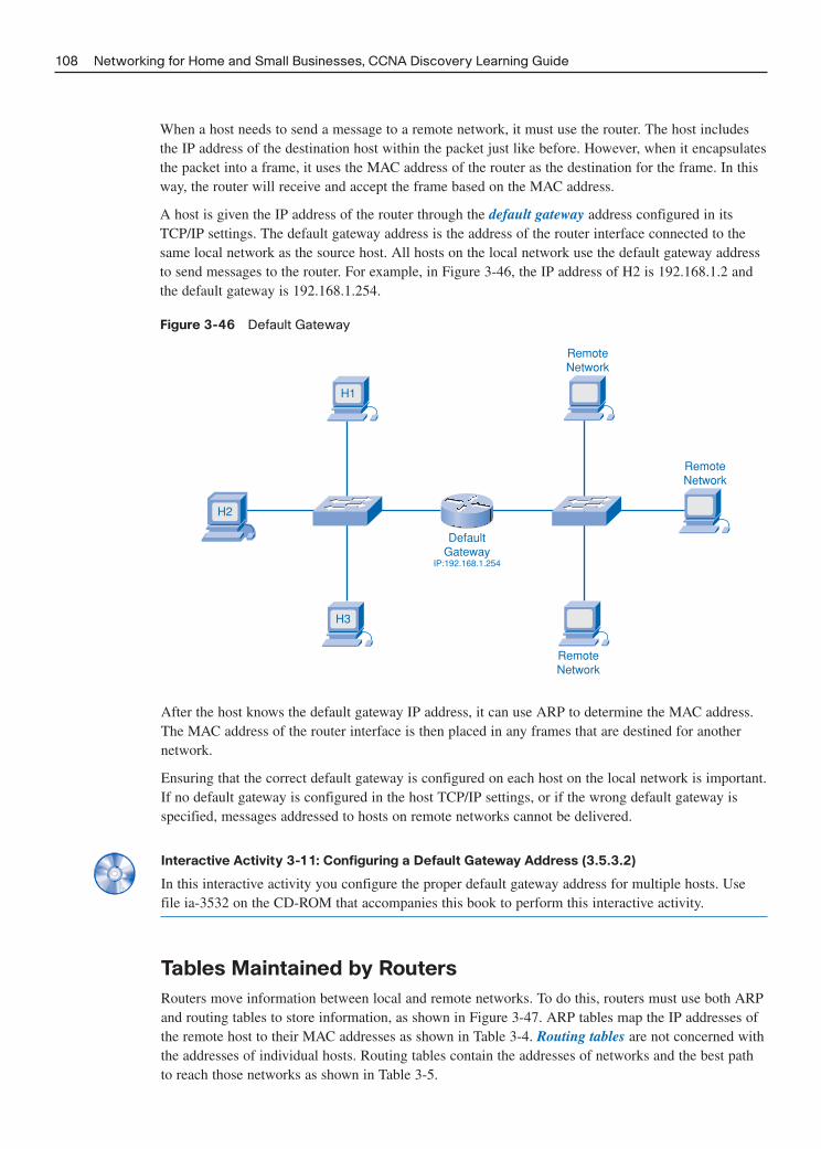
When a host needs to send a message to a remote network, it must use the router. The host includesthe IP address of the destination host within the packet just like before. However, when it encapsulatesthe packet into a frame, it uses the MAC address of the router as the destination for the frame. In thisway, the router will receive and accept the frame based on the MAC address.
A host is given the IP address of the router through the default gateway address configured in itsTCP/IP settings. The default gateway address is the address of the router interface connected to thesame local network as the source host. All hosts on the local network use the default gateway addressto send messages to the router. For example, in Figure 3-46, the IP address of H2 is 192.168.1.2 andthe default gateway is 192.168.1.254.
Figure 3-46 Default Gateway
108 Networking for Home and Small Businesses, CCNA Discovery Learning Guide
DefaultGateway
IP:192.168.1.254
H3
H1
H2
RemoteNetwork
RemoteNetwork
RemoteNetwork
After the host knows the default gateway IP address, it can use ARP to determine the MAC address.The MAC address of the router interface is then placed in any frames that are destined for anothernetwork.
Ensuring that the correct default gateway is configured on each host on the local network is important.If no default gateway is configured in the host TCP/IP settings, or if the wrong default gateway isspecified, messages addressed to hosts on remote networks cannot be delivered.
Interactive Activity 3-11: Configuring a Default Gateway Address (3.5.3.2)
In this interactive activity you configure the proper default gateway address for multiple hosts. Usefile ia-3532 on the CD-ROM that accompanies this book to perform this interactive activity.
Tables Maintained by Routers
Routers move information between local and remote networks. To do this, routers must use both ARPand routing tables to store information, as shown in Figure 3-47. ARP tables map the IP addresses ofthe remote host to their MAC addresses as shown in Table 3-4. Routing tables are not concerned withthe addresses of individual hosts. Routing tables contain the addresses of networks and the best pathto reach those networks as shown in Table 3-5.

Figure 3-47 ARP and Routing Tables
Chapter 3: Connecting to the Network 109
FastEthernet0/0
10.1.21.1
H1
10.1.21.2
H2
10.1.21.3
H3
10.1.21.4
H4
FastEthernet0/1
172.16.1.3
H5
172.16.1.4
H6
172.16.1.5
H7
172.16.1.6
H8
Table 3-4 ARP Table Information
IP Address MAC Address Interface
10.1.21.1 0072.5e34.6bd2 FastEthernet 0/0
10.1.21.2 0b76.ac13.a132 FastEthernet 0/0
10.1.21.3 00c0.dee5.7ec3 FastEthernet 0/0
10.1.21.4 Oaac.de43.0013 FastEthernet 0/0
172.16.1.3 00c3.cd45.00c3 FastEthernet 0/1
172.16.1.4 0d01.cde2.456e FastEthernet 0/1
172.16.1.5 000e.456d.435c FastEthernet 0/1
172.16.1.6 0124.54cd.ae56 FastEthernet 0/1
Table 3-5 Routing Table Information
Type Network Port
C 10.0.0.0/8 FastEthernet 0/0
C 172.16.0.0/16 FastEthernet 0/1
Entries can be made to the routing table in two ways:
■ Dynamically updated by information received from other routers in the network
■ Manually entered by a network administrator
Routers use the routing tables to determine which interface to use to forward a message to its intend-ed destination. If the router cannot determine where to forward a message, it will drop it. To preventthis from occurring, network administrators usually configure a default route in the routing table. Adefault route is the interface through which the router forwards a packet containing an unknown des-tination IP network address. This default route usually connects to another router that can forward thepacket toward its final destination network.
A router forwards a frame to one of two places:
■ A directly connected network containing the actual destination host
■ Another router on the path to reach the destination host

When a router encapsulates the frame to forward it onto a directly connected Ethernet network, itmust include a destination MAC address. This is the MAC address of the actual destination host, if thedestination host is part of a network locally connected to the router. Routers obtain these MACaddresses from ARP tables.
In Figure 3-48, host 1 is sending a message to a host that is not on the same network. Because theMAC address of the remote host is not known, the sending host sends the message to the default gate-way, as shown in Figure 3-49, for delivery by the router. The default gateway is part of the same localnetwork, so the sending host consults its ARP table for the correct information.
Figure 3-48 Message Destined for a Host on Another Network
110 Networking for Home and Small Businesses, CCNA Discovery Learning Guide
H4 H6
H8
H7
H2
H1 H3
H9
H5
Switch2
Switch3
Switch1
Router1
net 192.168.1.0
net 192.168.3.0
net 192.168.2.0
I need to send a packet to IP
address192.168.2.1. That IP
is not in my local network.
After the router has the packet, it must decide what to do with it. The router examines the packetheader to gather the IP information. When the router determines the network that the remote host ison, it checks to see whether it has information on how to deliver the message. In Figure 3-50, theremote host is part of a network that is directly connected to the router. Because the host is directlyconnected, the router consults its ARP table and encapsulates the data with the destination IP andMAC address then forwards the message to the remote host.

Figure 3-49 Sending the Message to the Default Gateway for Delivery
Chapter 3: Connecting to the Network 111
H4 H6
H8
H7
H2
H1 H3
H9
H5
Switch2
Switch3
Switch1
Router1
net 192.168.1.0
net 192.168.3.0
net 192.168.2.0
This packet must be sent tomy default gateway forforwarding. I have the
default gateway IP and MAC address in my ARP table.
H4 H6
H8
H7
H2
H1 H3
H9
H5
Switch2
Switch3
Switch1
Router1
net 192.168.1.0
net 192.168.3.0
net 192.168.2.0
This host is on a network directly connected on one of
my other interfaces. I will checkmy ARP table. There he is.
Now I can forward the packet.
Figure 3-50 Forwarding the Message to the Remote Host

If the remote host is not on a directly connected network, the router will pass the message to anotherrouter that is closer to the final destination.
Each router interface is part of the local network to which it is attached and maintains its own ARPtable for that network. The ARP tables contain the MAC addresses and IP addresses of all the individ-ual hosts on that network.
Each entry in the ARP table contains several pieces of information including the following:
■ Protocol: On a TCP/IP network this will be “Internet” for IP
■ Address: The logical IP address
■ Age (min): How long the entry has been in the ARP table
■ Hardware Addr: The physical MAC address
■ Type: Encapsulation used for the frame (ARPA on an Ethernet network)
■ Interface: Physical interface that connects to the local network
Interactive Activity 3-12: Determining How a Router Forwards Packets (3.5.4.3)
In this interactive activity you determine how a router forwards packets based on source and destina-tion addresses. Use file ia-3543 on the CD-ROM that accompanies this book to perform this interac-tive activity.
Local-Area Network (LAN)
The term local-area network (LAN) refers to a local network or a group of interconnected local net-works that are under the same administrative control. In the early days of networking, LANs weredefined as small networks that existed in a single physical location. Although LANs can be a singlelocal network installed in a home or small office, the definition of LAN has evolved to include inter-connected local networks consisting of many hundreds of hosts, installed in multiple buildings andlocations. Figure 3-51 shows a LAN with a single local network.
Figure 3-52 shows the same network with a router breaking up the network into three separate localnetworks.
The important point to remember is that all the local networks within a LAN are under one adminis-trative control. Other common characteristics of LANs are that they typically use Ethernet or wirelessprotocols, and they support high data rates.
The term intranet is often used to refer to a private LAN that belongs to an organization and isdesigned to be accessible by only the organization’s members, employees, or others with authoriza-tion. Intranets use technology normally found on the Internet to deliver information on a private net-work. This can include such things as web servers accessible only to employees.
Interactive Activity 3-13: Determining the Local Networks Within a LAN (3.5.5.2)
In this interactive activity you determine the number of local networks within a LAN. Use file ia-3552on the CD-ROM that accompanies this book to perform this interactive activity.
112 Networking for Home and Small Businesses, CCNA Discovery Learning Guide

Figure 3-51 LAN with a Single Local Network
Chapter 3: Connecting to the Network 113
H4 H6
H8
H7
H2
H1 H3
H9
H5
Switch2
Switch3
Switch1
net 192.168.1.0
H4 H6
H8
H7
H2
H1 H3
H9
H5
Switch2
Switch3
Switch1
Router1
net 192.168.1.0
net 192.168.3.0
net 192.168.2.0
Figure 3-52 LAN with Multiple Local Networks

Adding Hosts to Local and Remote Networks
Within a LAN, placing all hosts on a single local network or dividing them up between multiple net-works using a router at the distribution layer is possible, as shown in Figure 3-53. The choice dependson the desired results. Placing all hosts on a single local network allows them to be seen by all otherhosts. This is because there is one broadcast domain, and hosts use ARP to find each other.Unfortunately, this setup can also lead to excessive broadcast traffic and degraded network perform-ance.
Figure 3-53 Placement of Hosts Within a LAN
114 Networking for Home and Small Businesses, CCNA Discovery Learning Guide
H5 H11
H4
H6
H10
H12
10.1.2.0 10.1.4.0
Switch1 Switch2Router1
H3 H8
H2
H1
H5
H6
H10
H4
H7
H9
192.168.1.0
Switch1 Switch2
In a simple network design, keeping all hosts within a single local network might be beneficial.However, as networks grow in size, increased traffic will decrease network performance and speed. Inthis case, moving some hosts onto a remote network might be beneficial.
Placing additional hosts on a remote network decreases the impact of traffic demands. However, hostson one network cannot communicate with hosts on the other without the use of routing. Routersincrease the cost and complexity of the network configuration and can introduce latency, or timedelay, on packets sent from one local network to the other.
Table 3-6 outlines the advantages and disadvantages of placing all hosts on a single local network ver-sus placing them in remote network segments.

Table 3-6 Placing Hosts on the Network
Placing All Hosts on Placing Hosts in
One Local Network Remote Network Segments
Advantages Appropriate for simpler More appropriate for larger, more networks. complex networks.
Less complexity and lower network Splits up broadcast domains andcost. decreases traffic.
Allows devices to be “seen” by Can improve performance on each other devices. segment.
Faster data transfer; more direct Makes the machines invisible to those communication. on other local network segments.
Ease of device access. Can provide increased security.
Can improve network organization.
Disadvantages All hosts are in one broadcast domain, Requires the use of routing (distribution which causes more traffic on the layer).segment and might slow network Router can slow traffic between segments.performance. More complexity and expense (requires
router).
Plan and Connect a Local Network
You have seen the components of a local network and how they function together; now you learn howto plan, design, and build a simple Ethernet network using a multifunction device, which can include arouter, a multiport switch, and wireless capability.
Plan and Document an Ethernet Network
Most local networks are based on Ethernet technology. This technology is both fast and efficient whenused in a properly designed and constructed network. The key to installing a good network is properplanning before the network is actually built.
A network plan starts with the gathering of information about how the network will be used. Thisinformation includes
■ The number and type of hosts to be connected to the network: Where are the end users locat-ed? What type of hardware are they using? Where are the servers, printers, and other networkdevices located?
■ The applications to be used: What type of applications are running on the network?
■ Sharing requirements: Who requires access to which files and network resources such as printers?
Chapter 3: Connecting to the Network 115

■ Internet connectivity requirements: What is acceptable bandwidth (speed) for the end users?Do all users require the same throughput? What affect will the applications have on the through-put? Is a lower upload speed than download speed acceptable?
■ Security and privacy considerations: Is the data being moved on the network of a personal orsensitive nature? Could unauthorized access to this information cause harm to anyone?
■ Reliability and uptime expectations: How important is the network? Does it need to be avail-able 100% of the time (this is known as uptime)? How much downtime can be tolerated?
■ Connectivity requirements including, wired and wireless: Do any or all of the end usersrequire wireless connectivity?
When planning for a network installation, you also need to design and document the logical and phys-ical topology of the network before you purchase networking equipment and connect hosts.
When planning the physical and logical topologies, consider the following points:
■ Physical environment where the network will be installed, including the following:
■ Temperature control (because all devices have specific ranges of temperature and humidityrequirements for proper operation)
■ Need for power protection on network devices
■ Availability and placement of power outlets
■ Physical configuration of the network, including the following:
■ Physical location of devices such as routers, switches, and hosts
■ How all devices are interconnected
■ Location and length of all cable runs
■ Hardware configuration of end devices such as hosts and servers
■ Logical configuration of the network:
■ Location and size of broadcast and collision domains
■ IP addressing scheme
■ Naming scheme
■ Sharing configuration
■ Permissions
Prototypes
After you document the network requirements and create the physical and logical topology maps, thenext step in the implementation process is to test the network design. One of the ways to test a net-work design is to create a working model, or prototype, of the network.
Prototyping is essential as networks grow in size and complexity. A prototype allows a networkadministrator to test whether the planned network will operate as expected, before money is spent onequipment and installation. You should maintain documentation on all aspects of the prototypingprocess.
116 Networking for Home and Small Businesses, CCNA Discovery Learning Guide

Various tools and techniques are available for network prototyping, including real equipment set up ina lab environment as well as modeling and simulation tools. Cisco’s Packet Tracer is one example of asimulation and modeling tool that you can use for prototyping. Figure 3-54 shows a sample prototypeusing Cisco Packet Tracer.
Figure 3-54 Prototyping Using Cisco Packet Tracer
Chapter 3: Connecting to the Network 117
Learn to Use Packet Tracer (3.5.7.2)
In this Packet Tracer activity you familiarize yourself with the user interface of the Packet Tracergraphical network simulation tool. Use file d1-3572.pka on the CD-ROM that accompanies this bookto perform this activity using Packet Tracer.
Interactive Activity 3-14: Prototyping with Packet Tracer (Demonstration) (3.6.2.2)
In this interactive activity you see a demonstration of how to prototype a network using Packet Tracer.Use file ia-3622 on the CD-ROM that accompanies this book to perform this interactive activity.
Prototyping a Network (3.6.2.3)
In this Packet Tracer activity you use Packet Tracer to prototype a simple network. Use file d1-3623.pka on the CD-ROM that accompanies this book to perform this activity using Packet Tracer.
Multi-function Device
Most home and small business networks do not require the high-volume devices used in large busi-ness environments; smaller scale devices might well be suitable. However, the same functionality ofrouting and switching is required. This need has led to the development of products that have thefunctionality of multiple network devices, such as a router with switching functionality and a wirelessaccess point. These devices go by many different names but can be referred to generically as multi-function devices or integrated routers. Integrated routers can range from small devices, designed forhome and small business applications, to more powerful devices that can support enterprise branchoffices.
Packet Tracer Activity
Packet Tracer Activity

An integrated router is like having several different devices connected together. For example, the con-nection between the switch and the router still occurs, but it occurs internally, as shown in Figure3-55. When a broadcast is received on a switch port, the integrated switch forwards the broadcast toall ports including the internal router connection. The router portion of the integrated router stops thebroadcasts from going any further.
Figure 3-55 Internal Components of a Multi-function Device
118 Networking for Home and Small Businesses, CCNA Discovery Learning Guide
Many low-cost multi-function devices are available for home and small business networks that offerintegrated routing, switching, wireless, and security capabilities. An example of this type of integrateddevice is a Linksys wireless router as shown in Figure 3-56. These devices are simple in design anddo not typically have separate components. In the event of a failure, replacing any single failed com-ponent is not possible. As such, they create a single point of failure, and are not optimized for any onefunction.
Figure 3-56 Linksys WRT300N Wireless Router

Another example of an integrated router is the Cisco integrated services router (ISR). The Cisco ISRproduct family offers a wide range of products, including those designed for small office and homeoffice environments as well as those designed for larger networks. Many of the ISRs offer modularityand have separate components for each function. For example, adding a switching module to theCisco 1841 ISR can eliminate the requirements for a separate standalone switch for smaller compa-nies. This enables individual components to be added, replaced, and upgraded as necessary.
Connecting the Linksys Router
Linksys multi-function devices have two kinds of ports: switch ports and network ports. Ensuring thatlocal devices are connected only to the switch ports is important. The connection to the Internet oranother network must be made via the Internet port. The Internet port represents the router portion ofthe device. Figure 3-57 shows the ports on the Linksys WRT300N.
Figure 3-57 Linksys WRT300N Ports
Chapter 3: Connecting to the Network 119
Internet Port
Switch Ports
Multiple switch ports are connected to the internal switch portion of the multi-function device. Theseports are often labeled “Ethernet” and all devices connected to these Ethernet ports are on the samelocal network. The switch portion of the multi-function device is connected internally to the routerportion.
These multi-function devices usually contain a single port for connecting the device to an externalnetwork or Internet. This port is often labeled “Internet.” The router portion of the multi-functiondevice maintains routing tables and has an internal connection to the switch portion of the local net-work.
The condition of the multi-function device and the connection status of each port are shown by light-emitting diodes (LED) as shown in Figure 3-58. These LEDs can either change color or flash toindicate operational or connection status. Although their meaning can differ between devices manu-factured by different vendors, some commonality usually exists. The following LED status states andmeanings are fairly universal:
■ A solid green LED indicates a connection is made with an end device.
■ A blinking LED indicates activity on the port.
■ A red or yellow LED usually indicates a problem with the connection.
■ An illuminated power LED indicates the presence of power to the device.

Figure 3-58 Linksys WRT300N Indicator LEDs
120 Networking for Home and Small Businesses, CCNA Discovery Learning Guide
Indicator LEDs
All devices connected to the switch ports should be in the same broadcast domain. This means that alldevices must have an IP address from the same network. Any devices that have a different networkportion within their IP address will not be able to communicate.
Additionally, Microsoft Windows makes use of computer names to identify other devices on the net-work. Using these names as well as all IP address information in the planning and documentation isimportant to assist in future troubleshooting. Figure 3-59 shows the default gateway configuration onWindows hosts.
Figure 3-59 Default Gateway Configuration
To display the current IP configuration in Microsoft Windows, use the command ipconfig. Moredetailed information, including host name, is available with the ipconfig / all command. Be certain todocument all information from the connection and configuration process.
After hosts are communicating across the network, documenting network performance is important.This task is known as determining the baseline for the network and is used as an indication of normaloperations. Comparing future network performance against this baseline can indicate whether possibleissues exist.

Lab 3-5: Connect and Configure Hosts (3.6.4.3)
In this lab you connect hosts to the multi-function device and configure IP addressing. You also con-figure NetBIOS names and verify connectivity. Refer to the hands-on lab in Part II of this LearningGuide. You may perform this lab now or wait until the end of the chapter.
Sharing Resources
One of the most common purposes of networking is to share resources such as files and printers.Windows XP enables remote users to access a local machine and its resources through sharing. Whenplanning a network, considering security issues and assigning specific permissions to shared resourcesis important.
By default, Windows XP uses a process known as Simple File Sharing. With Simple File Sharing,specific users and groups cannot be prevented from accessing shared files.
You can disable Simple File Sharing to assign more specific security access levels. When this is done,the following permissions are available to assign to resources:
■ Full Control
■ Modify
■ Read and Execute
■ List Folder Contents
■ Read
■ Write
When a user accesses a file on a remote device, Windows Explorer allows the user to map a drive to aremote folder or resource. This maps a specific drive letter, for example, M:, to the remote resourceand allows the user to treat the resource as if it were locally connected.
Interactive Activity 3-15: Sharing Resources (Demonstration) (3.6.5.2)
In this interactive activity you see a demonstration of how to share resources on a network. Use file ia-3652 on the CD-ROM that accompanies this book to perform this interactive activity.
Lab 3-6: Sharing Resources (3.6.5.3)
In this lab you map a network drive and share files across the network. Refer to the hands-on lab inPart II of this Learning Guide. You may perform this lab now or wait until the end of the chapter.
Chapter 3: Connecting to the Network 121

122 Networking for Home and Small Businesses, CCNA Discovery Learning Guide
Summary
This chapter introduced many of the basic networking concepts that will be built upon in this andfuture studies. In general, networks have many characteristics.
Information networks carry many different types of traffic, including voice, video, and data. They con-sist of hosts, peripherals, network devices, and media and have both a physical and a logical topology.Hosts on a network can take on the role of a client, a server, or both.
The role of any network is to allow the sharing of information and resources. Providing a mechanismfor communication to occur, consisting of a source, a destination, and a channel, accomplishes thisgoal. Computer communication operates under a set of special rules called protocols that define thecharacteristics of a message, including encoding, formatting, encapsulation, size, timing, and patterns.Ethernet has become the most common protocol in use on local networks.
As networks grow in size and complexity, breaking them up into smaller, more manageable onesthrough a hierarchical network design is common. The most common hierarchical network designmodel is the three-layer design, consisting of the access, distribution, and core layers.
The access layer has the following traits:
■ First point of entry into the network for all hosts.
■ Hosts are normally connected to an access layer device such as a hub or switch, through the useof Ethernet technology.
■ Both MAC and IP addresses are used to identify individual hosts.
The distribution layer has the following traits:
■ Connects independent local networks and controls the flow of data between them.
■ Uses routers and IP addresses to move information between networks.
■ Does not concern itself with individual hosts.
The core layer has the following traits:
■ Concerned with the high-speed delivery of information between locations.
■ Built using high-speed switches and routers.
■ Does not have any knowledge of individual hosts.
Local networks normally use Ethernet technology. To communicate between hosts on the same localnetwork, both the IP address and the MAC address must be known. A process known as ARP is usedto resolve an IP address to a MAC address for local delivery.
Moving information from one host to a host on a remote network requires routing. Routers moveinformation between local networks. Routers know only about networks and do not concern them-selves with individual hosts. An exception to this is that routers do build up ARP tables of any directlyconnected hosts and will use this information for final delivery.
Proper planning is the first step in any network development, beginning with determining the end useof the network. The types of information to gather include the following:
■ Number and types of hosts to be connected to the network
■ Applications to be used
■ Sharing and Internet connectivity options

Chapter 3: Connecting to the Network 123
■ Security and privacy considerations
■ Reliability and uptime expectations
■ Connectivity requirements including wired and wireless
The current trend for both home and small business networks is the use of multi-function devices thatincorporate the functionality of switches, routers, wireless access points, and security appliances into asingle unit. These multi-function devices can either be units designed for small, low-volume networksor devices with the capability of handling many more hosts and providing more advanced capabilitiesand reliability. The Linksys WRT300N integrated router is an example of a device designed for thesmall business and home markets whereas the Cisco Integrated Services Router (ISR) family of prod-ucts are designed for larger, more demanding environments.
Activities and Labs
This summary outlines the activities and labs you can perform to help reinforce important conceptsdescribed in this chapter. You can find the activity and Packet Tracer files on the CD-ROM accompa-nying this book. The complete hands-on labs appear in Part II.
Interactive Activities on the CD:
Interactive Activity 3-1: Identifying Network Components (3.1.3.2)
Interactive Activity 3-2: Matching Client and Server Capabilities (3.1.4.3)
Interactive Activity 3–3: Determining Client and Server Roles (3.1.5.2)
Interactive Activity 3–4: Placing Voice Message Components in a Frame (3.2.4.3)
Interactive Activity 3–5: Classifying Communication Problems (3.2.8.2)
Interactive Activity 3-6: Building a Standard IEEE 802.3 Ethernet Frame (3.3.4.2)
Interactive Activity 3–7: Using Addresses, Network Components, and Layers (3.3.7.2)
Interactive Activity 3-8: Data Flow on a Hubbed Network (3.4.2.3)
Interactive Activity 3-9: Data Flow in a Network Using Hubs and Switches (3.4.3.4)
Interactive Activity 3–10: Switch Behavior (3.4.5.1)
Interactive Activity 3–11: Configuring a Default Gateway Address (3.5.3.2)
Interactive Activity 3–12: Determining How a Router Forwards Packets (3.5.4.3)
Interactive Activity 3–13: Determining the Local Networks Within a LAN (3.5.5.2)
Interactive Activity 3–14: Prototyping with Packet Tracer (Demonstration) (3.6.2.2)
Interactive Activity 3–15: Sharing Resources (Demonstration) (3.6.5.2)
Packet Tracer Activities on the CD:
Learn to Use Packet Tracer GUI (3.5.7.2)
Prototyping a Network (3.6.2.3)
Packet Tracer Activity

124 Networking for Home and Small Businesses, CCNA Discovery Learning Guide
Labs in Part II of This Book:
Lab 3-1: Building a Peer-to-Peer Network (3.1.5.3)
Lab 3-2: Determine the MAC Address of a Host (3.3.3.2)
Lab 3-3: Determine the IP address of a Computer (3.3.6.2)
Lab 3-4: IP Addresses and Network Communication (3.5.2.2)
Lab 3-5: Connect and Configure Hosts (3.6.4.3)
Lab 3-6: Sharing Resources (3.6.5.3)
Check Your Understanding
Complete all the review questions listed here to test your understanding of the topics and concepts inthis chapter. The “Check Your Understanding and Challenge Questions Answer Key” appendix liststhe answers.
1. Of the following types of networking components, which are considered peripherals? (Choosetwo.)
A. A printer attached to a network device
B. A web camera attached to a PC
C. A printer attached to a PC for personal use
D. A PC attached to a network device
E. An IP phone attached to a network device
2. Of the following networking components, which are considered hosts? (Choose three.)
A. A flat-screen monitor attached to a PC
B. A printer attached to a hub
C. A printer attached to a PC for personal use
D. A server attached to a switch
E. An IP phone attached to a switch
3. What are the major advantages of a peer-to-peer network? (Choose two.)
A. Simple to set up
B. Scale easily
C. Sophisticated security capabilities
D. Less expensive
E. Centralized administration
4. Which statements apply to a logical network topology map? (Choose two.)
A. Usually shows details of cabling runs
B. Can provide IP addressing and computer naming information
C. Normally includes the location of all wiring closets
D. Shows all servers, switches, and routers
E. Groups hosts by how they use the network

Chapter 3: Connecting to the Network 125
5. What is it called when a computer needs to send a message to a selected group of computers?
A. Unicast
B. Broadcast
C. Simulcast
D. Multicast
6. Jim is browsing the Internet with his computer and reading his e-mail. What role is his computercurrently playing?
A. Server
B. Client
C. Master
D. Both client and server
7. Allan is sharing a folder for other users to access on his home network and reading his e-mail.What role is his computer currently playing?
A. Server
B. Client
C. Master
D. Both client and server
8. What is the process of a placing a message inside a frame so it can be transmitted on the medium?
A. Encoding
B. Access insertion
C. Unicasting
D. Encapsulation
E. Injection
9. What Windows command can you use to display the IP address and MAC address of a computer?
A. maconfig /a
B. ipconfig /all
C. tcpconfig /all
D. pcconfig /a
10. How many collision domains are associated with a 24-port switch?
A. 0
B. 1
C. 24
D. Depends on which devices are connected to the switch
11. Which devices can you use to limit the size of a collision domain?
A. NIC
B. Hub
C. Switch
D. Router

126 Networking for Home and Small Businesses, CCNA Discovery Learning Guide
12. What does a switch do with a frame addressed to a MAC address that is not in its MAC addresstable?
A. Drops the frame
B. Forwards the frame
C. Floods the frame
D. Issues a MAC request message
13. Which hosts will hear an ARP request? Choose the best answer.
A. All devices connected to the LAN
B. All devices in the broadcast domain
C. All devices in the collision domain
D. Only the device to which the request is addressed
14. Which hosts will hear an ARP reply?
A. All devices connected to the LAN
B. All devices in the broadcast domain
C. All devices in the collision domain
D. Only the device to which the reply is addressed
15. Which are good criteria to break a large network into multiple access layer networks?
A. Logical grouping
B. Physical location
C. Application usage
D. Security
16. Which device is normally found in the distribution layer?
A. NIC
B. Hub
C. Switch
D. Router
17. What does a router normally do when it receives a broadcast?
A. Drops the frame
B. Forwards the frame
C. Floods the frame
18. Which definition best defines LAN?
A. A LAN is a single local network under the control of a single administrative entity.
B. A LAN is one or more connected local networks under the control of a single administrativeentity.
C. A LAN is a collection of local and remote networks under the control of a single administra-tive entity.
D. A LAN is a collection of remote networks that might be under the control of multiple adminis-trators.

Chapter 3: Connecting to the Network 127
19. Which of the following would be recorded as part of the physical topology of a network?
A. Permissions
B. Addressing scheme
C. Naming scheme
D. Location of cable runs
20. What are the two types of addresses required to deliver a message to a host in an Ethernet localnetwork?
A. MAC address and NIC address
B. MAC address and IP address
C. Protocol address and physical device name
D. Logical devices name and IP address
21. When is a default gateway required?
22. What problem might you encounter when adding hosts to a single switched local network?
Challenge Questions and Activities
These questions require a deeper application of the concepts covered in this chapter. You can find theanswers in the appendix.
1. Tebuc has brought a new laptop computer home from school to complete an overdue assignment.He plugs the computer into his home multi-function device but is unable to connect to theInternet. His desktop computer is connected to the same multi-function device and can connectwithout problem. At school, the laptop functioned properly. What is the most probable cause, andhow should Tebuc correct the problem?
2. A small graphics design company has just acquired a contract with the local government. In orderto handle the increased work, the company increased the number of employees from 11 to 46. Allemployees are now complaining that the network is slow. What is the most probable cause of thisproblem, and how would you correct it? All computers are directly connected to a single largeswitch.

This page intentionally left blank

CHAPTER 4
Connecting to the Internet Through an ISP
Objectives
Upon completion of this chapter, you will able to answer the following questions:
■ What is the Internet?
■ What is an Internet service provider (ISP) andwhat services can it provide?
■ What are the options for connecting to theInternet using an ISP?
■ How is the Internet Protocol (IP) used in sendingmessages across the Internet?
■ How is information sent across the Internetthrough an ISP?
■ What are the primary components of an ISPNetwork Operations Center (NOC)?
■ What are the environmental requirements of ahome/small business network as compared tothose of an ISP NOC?
■ What different types of cables and connectorsare used for connecting the devices in a NOC?
■ What are the two main Ethernet unshieldedtwisted-pair (UTP) cable wiring standards?
■ What is the difference between a straight-through and crossover cable and where are theyused in an Ethernet local network?
■ How are UTP cables constructed and terminatedto provide a reliable connection?
■ What are UTP cabling best practices?
Key Terms
This chapter uses the following key terms. You can find the definitions in the Glossary.
Internet service provider (ISP) page 131
web hosting page 131
point of presence (POP) page 132
Internet Exchange Point (IXP) page 132
dial-up page 133
satellite page 133
broadband page 133
always-on page 133
telco page 134
service-level agreement (SLA) page 135
header page 139
datagram page 139
regional Internet registry (RIR) page 139
Network Operations Center (NOC) page 139
cloud page 142
DSL Access Multiplexer (DSLAM) page 142
Cable Modem Termination System (CMTS) page 142
electromagnetic interference (EMI) page 148
radio frequency interference (RFI) page 148
straight-through cable page 156
crossover cable page 156
punchdown tool page 159
insulation displacement connector (IDC) page 159
continuity page 161
open page 161
short page 161
attenuation page 161
crosstalk page 162
near-end crosstalk (NEXT) page 162
far-end crosstalk (FEXT) page 162

Every day new people come online and join the human network. From the most remote areas inAfrica to metropolitan London, we need to be able to connect and communicate. Internet serviceproviders (ISP) are the links to the Internet. The web of interconnected ISPs makes the Internet acces-sible to everyone. In this chapter you will learn why ISPs are necessary and about the NetworkOperations Centers that are crucial to the function of the Internet. Part II of this book includes the cor-responding labs for this chapter.
The Internet and How We Connect To It
The Internet has become an integral part of our lives. An understanding of what the Internet is, how itis constructed, and how we connect to it helps us appreciate the capabilities of the world’s largest net-work.
Explain What the Internet Is
Every day millions of people exchange information through the Internet, but what exactly is theInternet? The Internet is a worldwide collection of computer networks, cooperating with each other toexchange information using common standards. Through telephone wires, fiber-optic cables, wirelesstransmissions, and satellite links, Internet users can exchange information in a variety of forms.
The Internet is a network of networks that connects users in every country in the world. There are cur-rently more than one billion Internet users worldwide. Figure 4-1 depicts the use of the Internet toconnect users on every continent.
Figure 4-1 The Internet Connects People Around the Globe
130 Networking for Home and Small Businesses, CCNA Discovery Learning Guide
Previously, the networks we have discussed have been controlled by one individual or organization.The Internet is a conglomerate of networks and is owned by no one individual or group. However,several major international organizations exist that help manage the Internet so that everyone uses thesame rules.
The Internet Society (ISOC) provides leadership in addressing issues that confront the future of theInternet. It is the home for the groups responsible for Internet infrastructure standards, including theInternet Engineering Task Force (IETF) and the Internet Architecture Board (IAB).

Some of the main organizations that help manage and develop the Internet are
■ Internet Society (ISOC): http://www.isoc.org/isoc/
■ Internet Architecture Board (IAB): http://www.iab.org/
■ Internet Engineering Task Force (IETF): http://www.ietf.org/
■ Internet Research Task Force (IRTF): http://www.irtf.org/
■ Internet Assigned Numbers Authority (IANA): http://www.iana.org/
NOTE
The Infoplease website is a good source of Internet usage statistics and resources:http://www.infoplease.com/ipa/A0873826.html
Internet Service Providers (ISP)
Any home, business, or organization that connects to the Internet must use an Internet serviceprovider (ISP), as shown in Figure 4-2. An ISP is a company that provides the connections and sup-port to access the Internet. It can also provide additional services such as e-mail and web hosting.
Figure 4-2 All Home Users and Organizations Connect to the Internet Through an ISP
Chapter 4: Connecting to the Internet Through an ISP 131
UNIVERSITYUNIVERSITY
Internet
Government Home LargeCorporations
SmallBusiness
EducationalInstitution
ISP
ISPs are essential to gaining access to the Internet. No one gets on the Internet without a host comput-er, and no one gets on the Internet without going through an ISP.
ISPs range in size from small to very large and differ in terms of the area they service. ISPs mightprovide limited services to a small geographical area or can have a wide variety of services and sup-port entire countries with millions of customers. ISPs also differ in the types of connection technolo-gies and speeds they offer. Examples of well-known ISPs include AOL, EarthLink, and Roadrunner.Do you have Internet access? Who is your ISP?

The ISP’s Relationship with the Internet
Individual computers and local networks connect to the ISP at a point of presence (POP). A POP is abuilding or facility that provides a connection point between the ISP’s network and the particular geo-graphical region that the POP is servicing.
An ISP might have many POPs depending on its size and the area it services. Within an ISP, a net-work of high-speed routers and switches move data between the various POPs. Multiple links inter-connect the POPs to provide alternative routes for the data should one link fail or become overloadedwith traffic and congested.
ISPs connect to other ISPs in order to send information beyond the boundaries of their own network.The Internet is made up of very high-speed data links that interconnect ISP POPs and ISPs to eachother. Figure 4-3 shows two ISPs connected so that their users can communicate.
Figure 4-3 Multiple ISPs Link Users Through POPs
132 Networking for Home and Small Businesses, CCNA Discovery Learning Guide
POP
POP
POPPOP
ISP1
Business LAN User
IndividualHome User
IndividualHome User
POP
POP
POPPOP
ISP2
The Internet
The Internet has thousands of interconnected ISPs. To avoid having every ISP connect to every otherISP directly, Internet Exchange Points (IXP) provide a common location where multiple ISPs canconnect to other ISPs. These interconnections are part of the very large, high-capacity network knownas the Internet backbone. Figure 4-4 shows some of the Internet backbone connections between majorcities worldwide.
Connecting to the ISP at the POP provides users with access to the ISP’s services and the Internet.

Figure 4-4 Major Internet Backbone Connections
Chapter 4: Connecting to the Internet Through an ISP 133
Options for Connecting to the ISP
ISPs provide a variety of ways to connect to the Internet, depending on location and desired connec-tion speed.
Major cities typically have more choices for ISPs and more connection options than rural areas. Forexample, cable Internet access is available only in certain metropolitan areas where cable TV serviceis available. Remote areas might have access only via dial-up or satellite.
Each Internet access technology uses a network access device, such as a modem, in order to connectto the ISP. It can be built-in to a computer or can be provided by the ISP.
The simplest arrangement is a modem that provides a direct connection between a computer and theISP. However, if multiple computers connect through a single ISP connection, additional networkingdevices are needed. This includes a hub or switch to connect multiple hosts on a local network, and arouter to move packets from your local network to the ISP network. A home networking device, suchas an integrated router, can provide these functions, as well as wireless capability, in a single package.
Figure 4-5 shows a single PC directly connected through a modem to the ISP. Also shown is a groupof PCs in a small network that can all share a single Internet connection using an integrated routerdevice. The individual PCs connect to a switch contained in the device and the router portion of thedevice connects to the ISP through the modem. The modem is required in either case and can be pur-chased from the ISP or leased.
The choice of Internet access technologies depends on availability, cost, access device used, mediaused, and the speed of the connection.
Most of the technologies shown in Figure 4-6 are used for both home and small business. Leased linesare typically used for business and large organizations, but can be used to provide high-speed connec-tivity in areas where cable or DSL are not available. With the exception of dial-up and cell modem,the other connection technologies listed are generally referred to as broadband and always-on con-nections. There are various definitions of broadband, but it generally refers to technologies withdownload speeds of 500 Kbps or greater. A dial-up connection can provide actual download speeds ofabout 30 Kbps.

Figure 4-6 ISP Connection Options
134 Networking for Home and Small Businesses, CCNA Discovery Learning Guide
ISP
ModemSingle PC with
Direct Connection
Multiple PCs withLAN Connection
IntegratedRouter
Modem
Figure 4-5 Single PC and LAN Connections to ISP
Dial-up Cell Modem Digital Subscriber Line (DSL)
Cable Modem Leased Lines Satellite
The ISP connections options include the following:
■ Dial-up: The slowest and most widely available service. Dial-up uses regular voice-grade tele-phone lines. It is the least expensive connection technology. Dial-up takes time to establish theconnection to the ISP. It can also present problems if someone needs to make a call. Requires ananalog modem, either one built-in to the computer or standalone.
■ Cell modem: Cellular service is available through cellular telephone providers. It provides rela-tively slow access speeds but is becoming more popular and speeds are increasing as the technol-ogy evolves. It allows Internet access when mobile, such as driving a car. Access speeds might behigher in metropolitan areas. Requires a special cell modem or the modem might be built in tothe cell phone.
■ Digital subscriber line (DSL): A relatively high-speed service available from most telephonecompanies (telco). DSL provides a high-speed digital connection over regular telephone lines.DSL availability and speeds are based on the distance from a telco office that has a DSL switch.Users that are close might receive very high speeds; users beyond a certain distance might not beable to get the service at all. Requires a special DSL modem.

■ Cable modem: A service available from most cable companies. Provides high-speed connectionover the cable TV network. If cable TV service is available, cable Internet access is also likely tobe available. Requires a special cable modem.
■ Leased lines: Service available from most telephone companies. Provides high-speed connectionover dedicated digital data lines. The most common example of a leased line is a T1. Leased linesare primarily for business-class service. Requires a special type of modem known as a CSU/DSU.
■ Satellite: Two-way satellite service is available from Internet dish satellite companies. Providesmedium speeds via satellite. Satellite might be the only choice faster than dial-up in some ruralareas. Requires a special modem similar to cable.
ISP Levels of Service
Depending on the ISP and the connection technology, various services are available such as virusscanning, video on demand, and file storage. The contract with the ISP determines the type and levelof services that are available. Most ISPs offer two different contract levels: home service or business-class service.
Home service is normally less expensive than business services, and generally provides scaled-downservices such as slower connection speed, reduced web space storage, and fewer e-mail accounts. Atypical home account might include a minimum of five e-mail addresses with additional addressesbeing available for a fee.
Business-class service is more expensive but provides faster connection speeds and additional webspace and e-mail accounts. A business-class service might include 20, 50, or more e-mail addresses.Business service also includes agreements between the ISP and the customer specifying items such asnetwork availability and service response time. These are known as service-level agreements (SLA).Services available vary from one ISP to the next. Figure 4-7 shows some of the main services avail-able from a major ISP, and they are described here.
The following list describes these services in more detail:
■ Connection speed: Download speeds can vary from 56 Kbps for dial-up to 1.5 Mbps or higher fortechnologies such as DSL and cable modem. A high-speed connection is recommended for indi-viduals who download a lot of large programs or video, perform gaming, or run their own servers.
■ E-mail accounts: ISPs generally provide multiple user e-mail addresses on one account. These e-mail addresses can be distributed among individuals or used to separate business mail from per-sonal mail. Web mail allows users to access their e-mail accounts from any computer connectedto the Internet.
■ Personal home pages: Personal web page space is frequently provided with service. Usually boththe size of the web space and the traffic generated are limited. Design and maintenance of thewebsite is maintained by the individual author.
■ Web hosting services: Organizations that do not have web servers can use the ISP’s servers fortheir website. This often comes with design and maintenance services. Web hosting services areusually purchased based on the size of the website and the anticipated monthly volume.
■ File storage: Organizations can use the ISP’s online storage and file management systems to pro-vide 24/7 access to important files. File storage can range from a few megabytes (millions) to ter-abytes (trillions) of online storage. Online file storage is usually password protected.
Chapter 4: Connecting to the Internet Through an ISP 135

Figure 4-7 ISP Services
136 Networking for Home and Small Businesses, CCNA Discovery Learning Guide
ISP Services
PersonalHome Pages
Web HostingServices
IP Telephone
Content Filtering
Virus Scanning
ConnectionSpeed
Video on Demand
File Storage
Files
E-Mail Accounts
IP
■ IP telephone: ISPs might provide IP telephone services that allow users to make and receivevoice calls over the Internet. When using the Internet, regular long-distance tolls do not normallyapply.
■ Virus scanning: ISPs often include virus scanning and anti-spam services as part of their connec-tion package. Most ISPs scan for malicious code both on files that have been uploaded from theend user and those arriving for delivery to the end user.
■ Content filtering: ISPs can provide software that prevents specific material from being down-loaded, based on user specifications. This software is often used to block objectionable and/oroffensive websites.
■ Video on demand: Real-time downloading of movies allows users to watch movies over theInternet. This is known as streaming video.
When data is transferred, it is either uploaded or downloaded. Downloading refers to informationcoming from the Internet to your computer, whereas uploading indicates the reverse path, from yourcomputer to the Internet. When the download transfer rate is different from the upload transfer rate, itis called asymmetric. When the transfer rate is the same in both directions, it is called symmetric.ISPs can offer both asymmetric and symmetric services, as shown in Figure 4-8.

Figure 4-8 Asymmetric and Symmetric Service
Chapter 4: Connecting to the Internet Through an ISP 137
Internet
Asymmetric
Internet
Symmetric
The following is a summary of asymmetric service:
■ Most commonly used for the home.
■ Download speeds are faster than upload speeds.
■ Necessary for users who download significantly more than they upload.
■ Most Internet users, especially those who use graphics or multimedia-intensive web data, needlots of download bandwidth.
■ DSL and cable modem are typically considered asymmetric services, although they can be sym-metric.
The following is a summary of symmetric service:
■ Most commonly used for business or individuals hosting servers on the Internet.
■ Used when necessary to upload large amounts of traffic such as intensive graphics, multimedia,or video.
■ Can carry large amounts of data in both directions at equal rates.
■ ISP leased lines, such as T1, are symmetric services.

Interactive Activity 4-1: Analyze ISP and End User Requirements (4.1.5.3)
In this interactive activity, you analyze the information provided for three ISPs and match the require-ments of an end user to the ISP. Use file ia-4153 on the CD-ROM that accompanies this book to per-form this interactive activity.
Sending Information Across the Internet
The Internet uses several important protocols that are critical to our ability to connect and communi-cate. ISPs make use of these and routing technologies to transmit data from one host to another,regardless of their location in the world.
Importance of the Internet Protocol (IP)
For hosts to communicate on the Internet, they must be running Internet Protocol (IP) software andhave an ISP connection, as shown in Figure 4-9. IP is one of a group of protocols that are collectivelyreferred to as Transmission Control Protocol/Internet Protocol (TCP/IP). The Internet Protocol usespackets to carry data. Whether you are playing an Internet video game, chatting with a friend, sendinge-mail or searching the Web, the information you are sending or receiving is carried in the form of IPpackets.
Figure 4-9 Basic Requirements for Internet Connectivity
138 Networking for Home and Small Businesses, CCNA Discovery Learning Guide
PC ISP
Hardware Software Connectivity
+ + =IP
Internet
Each IP packet must contain a valid source and destination IP address. Without valid address informa-tion, packets sent will not reach the destination host. Return packets will not make it back to the origi-nal source.
IP defines the structure of the source and destination IP addresses. It specifies how these addresses areused in routing of packets from one host or network to another.
All protocols that operate on the Internet, including IP, are defined in numbered standards documentscalled Request For Comments (RFC).
RFCs
RFCs are numbered documents that define protocols and other standards that determine how theInternet functions. The higher the number, the newer the RFC. RFCs are submitted to the IETF andgo through a review process. As they are reviewed, they go through the following stages:
1. Proposed (entry level)
2. Draft (initial testing)
3. Standard (fully adopted)
You can view the IETF RFC website at http://www.ietf.org/rfc.html.

An IP packet has a header at the beginning that contains the source and destination IP addresses, asshown in Figure 4-10. The header also contains control information that describes the packet to net-work devices, such as routers, it passes through and also helps to control its behavior on the network.The IP packet is sometimes referred to as a datagram. The packet actually contains 0s and 1s in theform of bits in the proper sequence. The sending and receiving hosts and the network devices inbetween interpret these bits to direct traffic and deliver messages.
Figure 4-10 Sending an IP Packet from Source to Destination
Chapter 4: Connecting to the Internet Through an ISP 139
0110110010110
DataH
IP Packet
Header Datagram
H2H1
SourceDestination
IP addresses must be unique on the Internet. Organizations exist that are responsible for controllingthe distribution of IP addresses so that no duplication occurs. ISPs obtain blocks of IP addresses froma local, national, or regional Internet registry (RIR). It is the responsibility of the ISPs to managethese addresses and assign them to organizations and end users.
Computers in homes, small businesses, and other organizations obtain their IP configuration fromtheir ISP. Typically, this configuration is obtained automatically when the user connects to the ISP forInternet access.
How ISPs Handle Packets
Before being sent on the Internet, messages are divided into packets. IP packet size is between 64 to1500 bytes for Ethernet networks and contains mostly user data. Downloading a single 1 MB songrequires more than 600 packets of 1500 bytes. Each individual packet must have a source and destina-tion IP address.
When a packet is sent across the Internet, the ISP determines whether the packet is destined for alocal service located on the ISP network or a remote service located on a different network.
Every ISP has a control facility for its network, known as the Network Operations Center (NOC).The NOC usually controls traffic flow and houses services such as e-mail and web hosting. The NOCmight be located at one of the POPs or at a completely separate facility within the ISP network.Packets looking for local services are usually forwarded to the NOC and never need to go to anotherISP network on the way to the server that provides the local service, as shown in Figure 4-11.

Figure 4-11 Packets Destined for Local Server in the ISP1 NOC
140 Networking for Home and Small Businesses, CCNA Discovery Learning Guide
Web Server(Local Server)
POP
POP
NOCPOP
POP
ISP1
E-Mail Server
Routers in each of the ISP POPs use the destination address of the IP packets to choose the best paththrough the Internet. The packets you send to the ISP POP are forwarded by routers through the ISP’snetwork and then through the networks of other ISPs. They pass from router to router until they reachtheir final destination. Figure 4-12 shows packets from an ISP1 user destined for the web server in theremote ISP2 network.
Figure 4-12 Packets from an ISP1 User Destined for the Web Server in the ISP2 Network
POP
POP
NOCPOP
POP
ISP1
E-MailServer
POP
NOCPOP
POP
ISP2
The Internet
Web Server
Web Server

Forwarding Packets Across the Internet
Network utilities are available that test connectivity to the destination device. The ping utility testsend-to-end connectivity between source and destination. It measures the time that it takes for testpackets to make a round trip from the source to the destination and whether the transmission is suc-cessful. However, if the packet does not reach the destination, or if delays are encountered along theway, no way exists for determining where the problem is located.
The traceroute utility traces the route from source to destination. Unlike ping, it can determine whichrouters the packets have passed through and detect the problem areas in the path. Each router throughwhich the packets travel is referred to as a hop. Look at the network in Figure 4-13 as an example.The traceroute output from Example 4-1 displays each hop along the way and the time it takes foreach one. If a problem occurs, the display of the time and the route that the packet traveled can help todetermine where the packet was lost or delayed. When working with the UNIX or Linux OS andCisco routers and switches, the command you issue at the command line is traceroute. The traceroute utility is called tracert in the Windows environment.
Figure 4-13 Tracing a Packet Through the Internet
Chapter 4: Connecting to the Internet Through an ISP 141
Internet
York
London209.165.201.1
255.255.255.224
Rome209.165.200.225255.255.255.224
Paris209.165.202.129255.255.255.224
Example 4-1 Sample traceroute OutputYork# traceroute Rome
Type escape to abort.
Tracing the route to Rome (209.165.200.225)
1. London (209.165.201.1) 8 msec 8 msec 4 msec
2. Paris (209.165.202.129) 9 msec 9 msec 7 msec
3. Rome (209.165.200.225) 7 msec 8 msec 5 msec
A number of GUI-based traceroute programs are also available that can provide a graphical displayof the route that a packet takes. These programs can also provide other useful information such asownership of Internet nodes. Examples include VisualRoute, PingPlotter, and 3d Traceroute.
Observing Packets Across the Network (4.2.3.2)
In this Packet Tracer activity you use ping and traceroute to check connectivity and learn more abouthow packets travel through the Internet. Use file d1-4232.pka on the CD-ROM that accompanies thisbook to perform this activity using Packet Tracer.
Packet Tracer Activity
Lab 4-1: Tracing Internet Connectivity (4.2.3.3)
In this lab you use ping and traceroute to check connectivity and learn more about how packets trav-el through the Internet. Refer to the hands-on lab in Part II of this Learning Guide. You may performthis lab now or wait until the end of the chapter.
Networking Devices in a NOC
The device requirements for home and small businesses often differ from the device requirements oflarger enterprise networks. This section begins by explaining the representation of network devicesand interconnections in diagrams. This section then contrasts the networking equipment necessary inlarge networks as compared to home and small businesses. You then learn about the different physicaland environmental requirements for home and enterprise networks.
Internet Cloud
When packets travel across the Internet, they pass through many network devices. You can think of theInternet as a network of routers, interconnected with one another. Very often, alternative routes existbetween routers, and packets can take different paths between source and destination. If a problem withtraffic flow occurs at any point in the network, packets automatically take an alternative route.
A diagram that shows all network devices and their interconnections would be very complex.Additionally, the final routing path between source and destination is not usually important, only thatthe source is able to communicate with the destination. Therefore, in network diagrams a cloud isoften used to represent the Internet or any other complex network, without showing the details of theconnections. The cloud allows for simple diagrams that focus on source and destination only, eventhough many devices might be linked between.
Figure 4-14 shows a map of the United States with two possible routes a packet may take, depending onnetwork conditions. In the figure, Internet backbone routes connect major cities. Part 1 shows one route apacket might take from a user PC in Los Angeles destined for a server in New York City. In this case atraceroute would show the packet going through Rialto, Austell, Washington D.C., and West Orange.Part 2 of the figure shows an alternative route from Los Angeles to New York City. If a problem occurswith the link between Los Angeles and Rialto, the next series of packets from the same host in LosAngeles might travel through San Francisco, Denver, and West Orange to reach the New York City server.
Devices in Internet Cloud
Routers are neither the only devices found in the Internet cloud nor are they the only devices found atan ISP. The ISP must be able to accept and deliver information to the end user as well as participate inthe Internet.
Devices that provide connectivity to end users must match the technology used by the end user to con-nect to the ISP. For example, if the end user is using DSL modem technology to connect, the ISP musthave a DSL Access Multiplexer (DSLAM) to accept these connections. For cable modems to connect,the ISP must have a Cable Modem Termination System (CMTS). Figure 4-15 shows a home andbusiness customer for both a DSL and cable ISP. Note that, with the cable ISP, both customers con-nect to a common cable bus network that goes back to the CMTS. With the DSL ISP each customerhas a separate telephone line to the DSLAM. Some ISPs still accept analog calls through voicemodems and have banks of corresponding modems to support these users. ISPs that provide wirelessaccess have wireless bridging equipment.
142 Networking for Home and Small Businesses, CCNA Discovery Learning Guide

Chapter 4: Connecting to the Internet Through an ISP 143
Part I
Part II
Home 1Integrated
RouterCable
Modem
Business 1Integrated
RouterCable
Modem
Home 2Integrated
RouterDSL
Modem
Business 2Integrated
RouterDSL
Modem
CMTS
Cable Provider
DSL Provider
DSLAM
Cable TVSystem
Voice PhoneSystem
Cisco CMTS
Cisco DSLAM
ISPInternet
ISPInternet
Figure 4-15 CMTS and DSLAM ISP Equipment in the Cloud
Figure 4-14 Packets from Source to Destination Can Take Multiple Paths Through the Internet

The ISP must also be able to connect to and transfer data with other ISPs. A variety of technologiesare used to accomplish this, each requiring specialized equipment and configurations in order to func-tion.
The type of equipment found in an ISP equipment room depends on the technology of the networks inwhich it is participating. Routers and switches make up most of this equipment. But these devices arevery different from the ones found in the home or small business environment.
Networking devices used by the ISP handle extremely large volumes of traffic very quickly. Theymust function at near 100% uptime because the failure of a key piece of equipment at an ISP can havedisastrous effects on network traffic and affect thousands of users. For this reason, the equipment usedby ISPs is high-end, high-speed devices with redundancy.
In contrast, network devices used in the home or small business environment are lower-end, lower-speed devices that are not capable of handling large volumes of traffic. Figure 4-16 shows examples ofdevices that might be found in a home/small business network, such as integrated routers, as well asthat found in an enterprise network.
Figure 4-16 Types of Equipment for the Home/Small Business Network and for the EnterpriseNetwork
144 Networking for Home and Small Businesses, CCNA Discovery Learning Guide
Equipment for the Home/Small Business Network
Linksys WRT300N Cisco 1800 Series ISR
Cisco 6513 Chassis Bundle
Equipment for the Enterprise Network
Cisco 7204 - VXR Router
Integrated routers can perform several functions, including
■ Wireless LAN access point
■ Switching
■ Routing
■ Security firewall
■ Automated addressing
Interactive Activity 4-2: Match the NOC Equipment to Requirements (4.3.2.3)
In this interactive activity, you match the NOC equipment room device to the requirements indicated.Use file ia-4323 on the CD-ROM that accompanies this book to perform this interactive activity.

Physical and Environmental Requirements
The network installation located at an ISP versus that of a home or small business is very different.
The home or small business network provides a limited number of services for relatively few users.Internet connectivity is purchased from an ISP. The volume of traffic is small, and no transport servic-es are provided.
The ISP provides transport and other services to a large number of users. A number of differentdevices are required to accept input from end users. To participate in a transport network, it must beable to connect to other ISPs. It handles large volumes of traffic and requires very reliable equipmentin order to handle the load.
Even though these two networks appear very different, they both require an environment where theequipment can function reliably and without interruption. The requirements are the same, but the scaleof operation is different: At home, a single power outlet will suffice, whereas at an ISP the powerrequirements need to be planned out ahead of time and installed. Figure 4-17 shows a simple homenetworking integrated router compared to an aisle of servers and other networking devices that mightbe found at an ISP.
Figure 4-17 Home versus Enterprise Networking Equipment Environmental Requirements
Chapter 4: Connecting to the Internet Through an ISP 145
Home Enterprise
One major difference between an ISP and a home or small business network is the inclusion ofservers. Most home users do not run servers, and small businesses usually have a few. They rely onthe services offered by the ISP for such things as e-mail, address assignment, and web space. An ISPmust consider the physical requirements of not only the networking equipment, but also the servers ithouses.
One of the main considerations for electronic equipment is a reliable supply of stable power.Unfortunately the supply of power is not always reliable, which can lead to problems for networkdevices. ISPs install power conditioning equipment with substantial battery backup to maintain conti-nuity of supply should the main power grid fail. For the home or small business, inexpensive uninter-ruptible power supplies (UPS) and battery backup units are usually sufficient for the relatively smallamount of equipment they use. Figure 4-18 shows several small home or small business UPSs com-pared to larger ones that might be found in an enterprise or ISP.
Environmental factors, such as heat and humidity, must also be considered when planning a networkinstallation. However, because of the volume of equipment and the amount of power consumed in anISP, high-end air conditioning units are necessary to maintain controlled temperatures. For the homeor small business, ordinary air conditioning, heating, and humidity controls are usually sufficient. Inaddition, the enterprise and ISP will require sophisticated fire suppression systems.

All of these factors, namely power supply, environment, and cable management, must be consideredwhen setting up a network of any size. There is a big variation in size and therefore requirements foran ISP and a home network. Most networks fall somewhere between these two extremes. Figure 4-19shows the cabling complexity of an enterprise-level network.
Figure 4-19 Enterprise Network Patch Panels and Cable Management
146 Networking for Home and Small Businesses, CCNA Discovery Learning Guide
Cables and Connectors
The physical cabling of a network is the most critical component and the most common source ofproblems. The use of quality cabling and connectors wired to industry standards helps to ensure a sta-ble network and minimize link failures.
Enterprise UPS Home and Small Business UPS
Cable management is another area of concern for both the home or small business network and the ISP.Cables must be protected from physical damage and organized in a manner that will aid in the trou-bleshooting process. Small networks have only a few cables, but in ISP networks, thousands of cablesmust be managed. This can include not only copper data cables but also fiber-optic and power cables.
Figure 4-18 Enterprise UPS and Home or Small Business UPS

Common Network Cables
In order for communication to occur, a source, destination, and some sort of channel must be present.A channel, or medium, provides a path over which the information is sent, as shown in Figure 4-20. Inthe networked world, the medium is usually some sort of physical cable. It might also be electromag-netic radiation, in the case of wireless networking. The connection between the source and destinationcan either be direct or indirect, and can span multiple media types.
Figure 4-20 Channel from Source to Destination
Chapter 4: Connecting to the Internet Through an ISP 147
Source
Channel
Destination
Different types of cables exist to interconnect the various devices in a NOC or local network.
There are two general categories of physical cable, metal and fiber-optic. Metal cables, usually cop-per, have electrical impulses applied to them to convey information. Twisted-pair and coaxial cableare in this category. Fiber-optic cables, made of glass or plastic, use flashes of light to convey infor-mation.
Figure 4-21 shows the primary types of cabling used in today’s networks: twisted pair, coaxial, andfiber-optic.
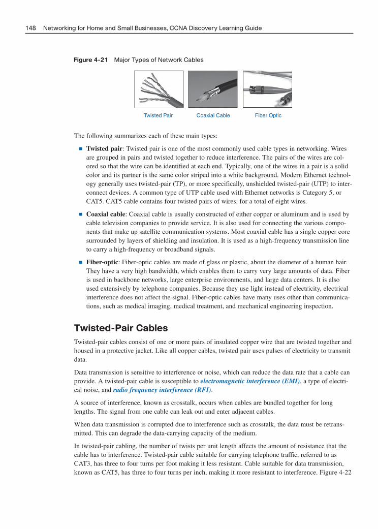
Figure 4-21 Major Types of Network Cables
148 Networking for Home and Small Businesses, CCNA Discovery Learning Guide
Twisted Pair Coaxial Cable Fiber Optic
The following summarizes each of these main types:
■ Twisted pair: Twisted pair is one of the most commonly used cable types in networking. Wiresare grouped in pairs and twisted together to reduce interference. The pairs of the wires are col-ored so that the wire can be identified at each end. Typically, one of the wires in a pair is a solidcolor and its partner is the same color striped into a white background. Modern Ethernet technol-ogy generally uses twisted-pair (TP), or more specifically, unshielded twisted-pair (UTP) to inter-connect devices. A common type of UTP cable used with Ethernet networks is Category 5, orCAT5. CAT5 cable contains four twisted pairs of wires, for a total of eight wires.
■ Coaxial cable: Coaxial cable is usually constructed of either copper or aluminum and is used bycable television companies to provide service. It is also used for connecting the various compo-nents that make up satellite communication systems. Most coaxial cable has a single copper coresurrounded by layers of shielding and insulation. It is used as a high-frequency transmission lineto carry a high-frequency or broadband signals.
■ Fiber-optic: Fiber-optic cables are made of glass or plastic, about the diameter of a human hair.They have a very high bandwidth, which enables them to carry very large amounts of data. Fiberis used in backbone networks, large enterprise environments, and large data centers. It is alsoused extensively by telephone companies. Because they use light instead of electricity, electricalinterference does not affect the signal. Fiber-optic cables have many uses other than communica-tions, such as medical imaging, medical treatment, and mechanical engineering inspection.
Twisted-Pair Cables
Twisted-pair cables consist of one or more pairs of insulated copper wire that are twisted together andhoused in a protective jacket. Like all copper cables, twisted pair uses pulses of electricity to transmitdata.
Data transmission is sensitive to interference or noise, which can reduce the data rate that a cable canprovide. A twisted-pair cable is susceptible to electromagnetic interference (EMI), a type of electri-cal noise, and radio frequency interference (RFI).
A source of interference, known as crosstalk, occurs when cables are bundled together for longlengths. The signal from one cable can leak out and enter adjacent cables.
When data transmission is corrupted due to interference such as crosstalk, the data must be retrans-mitted. This can degrade the data-carrying capacity of the medium.
In twisted-pair cabling, the number of twists per unit length affects the amount of resistance that thecable has to interference. Twisted-pair cable suitable for carrying telephone traffic, referred to asCAT3, has three to four turns per foot making it less resistant. Cable suitable for data transmission,known as CAT5, has three to four turns per inch, making it more resistant to interference. Figure 4-22

shows how interference or noise can affect data transmission. In the figure, an original pure data sig-nal represents a specific bit pattern. Nearby electrical noise creates an interface signal on the samewire. The noise combines with the original signal and results in a corrupted or changed signal beingreceived by the destination computer.
Figure 4-22 How Data Transmission Is Affected by Interference
Chapter 4: Connecting to the Internet Through an ISP 149
1 0 1 1 0 0 1 0 0 1 1 0 1
Time Time
Time
Digital Signal with Interference
Pure Digital Signal Interference Signal
What the Computer Reads
1 0 1 1 0 0 1 0 0 1 1 0 1
1 0 1 1 0 0 1 0
Changed Signal
1 1 1 0 1
6
3
0
Vol
tage
6
3
0
Vol
tage
Vol
tage
6
3
0
6
3
0
Vol
tage
The three types of twisted-pair cable are unshielded twisted-pair, shielded twisted-pair, and screenedtwisted-pair.
Unshielded twisted-pair (UTP) is the most commonly encountered type of network cable in NorthAmerica and many other areas. Shielded cables (ScTP and F-UTP) are used almost exclusively inEuropean countries.
UTP cable is inexpensive, offers a high bandwidth, and is easy to install. This type of cable is used toconnect workstations, hosts, and network devices. It can come with many different numbers of pairsinside the jacket, but the most common number of pairs is four. Each pair is identified by a specificcolor code.
Many different categories of UTP cables have been developed over time. Each category of cable wasdeveloped to support a specific technology and most are no longer encountered in homes or offices.The cable types that are still commonly found include Categories 3, 5, 5e, and 6. Some electrical envi-ronments exist in which EMI and RFI are so strong that shielding is a requirement to make communi-cation possible, such as in a noisy factory. In this instance, using a cable that contains shielding, suchas shielded twisted-pair (STP) and screened twisted-pair (ScTP) might be necessary. Unfortunatelyboth STP and ScTP are very expensive, not as flexible, and have additional requirements due to theshielding that make them difficult to work with.

All categories of data-grade UTP cable are traditionally terminated into an RJ-45 connector. Figure 4-23 shows various types of twisted-pair cabling.
Figure 4-23 Categories of UTP
150 Networking for Home and Small Businesses, CCNA Discovery Learning Guide
Category 3 Cable(UTP)
Category 5 and 5eCable (UTP)
Category 6 Cable(UTP)
Category 7 Cable(ScTP)
The following are characteristics of Category 3 cable:
■ Used for voice communication
■ Most often used for phone lines
The following are characteristics of Category 5 and 5e cable:
■ Used for data transmission.
■ Cat 5 supports 100 Mbps and can support 1000 Mbps (Gigabit) but it is not recommended.
■ Cat 5e supports 1000 Mbps (Gigabit).
■ Defined in 568 standard.
The following are characteristics of Category 6 cable:
■ Used for data transmission.
■ An added separator is between each pair of wires allowing it to function at higher speeds.
■ Supports 1000 Mbps (Gigabit) to 10 Gbps although 10 Gbps is not recommended.
■ Defined in 568 standard.
The following are characteristics of Category 7 cable (ScTP):
■ Used for data transmission.
■ Individual pairs are wrapped in a shield and then the entire four pairs wrapped in another shield.

■ Supports 1000 Mbps to 10 Gbps, although 10 Gbps is not recommended.
■ Not currently defined in 568 standard.
Coaxial Cable
Like twisted pair, coaxial cable (or coax) also carries data in the form of electrical signals. It providesimproved shielding compared to UTP, so has a lower signal-to-noise ratio and can therefore carrymore data. It is most often used to connect a TV set to the signal source, be it a cable TV outlet, satel-lite TV, or conventional antenna. It is also used at NOCs to connect to the cable modem terminationsystem (CMTS) and to connect to some high-speed device interfaces.
Although it employs the same basic construction as that used by early shared Ethernet networks, thecoaxial cable used in cable TV networks is a different type. The modern communications technologiesused with it support high-speed Internet, phone service, and television over the same coax cable.
Although coax has improved data-carrying characteristics, most local area networking uses twistedpair because coax is physically harder to install and is more expensive. As a result, current Ethernetstandards no longer support the use of coax as a cabling medium. In addition, manufacturers of NICsand other networking devices no longer include coax connectors on their equipment.
Coax consists of a single center conductor, most often made of copper, although aluminum can be usedas well. The center conductor is then surrounded by an insulator, such as polythene, which in turn is sur-rounded by a metallic braid made of aluminum or foil. The foil shields against EMI. The entire cable isthen enclosed by a jacket for protection. Figure 4-24 shows the components of a typical coaxial cable.
Figure 4-24 Coaxial Cable Components
Chapter 4: Connecting to the Internet Through an ISP 151
Jacket
Braid ConductorInsulator
Termination
The following explains each of these components of a typical coaxial cable:
■ Termination: Coax is normally terminated with a BNC or F-series connector. BNC is a crimped-down connector and is typically considered a stronger connection. An F-series connector is ascrew-on connector.
■ Braid: A metallic braid made of aluminum or foil helps to shield against EMI.

■ Insulator: An insulator usually made of polythene, which provides strength to the cable, allows itto be more pliable.
■ Conductor: A single center conductor, most often made of copper, although aluminum can beused as well.
Fiber-Optic Cables
Unlike TP and coax, fiber-optic cables transmit data using pulses of light. Although not normallyfound in home or small business environments, fiber-optic cabling is widely used in enterprise envi-ronments and large data centers.
Fiber-optic cable is constructed of either glass or plastic, neither of which conducts electricity. Thismeans that it is immune to EMI and is suitable for installation in environments where interference is aproblem.
In addition to its resistance to EMI, fiber-optic cables support a large amount of bandwidth makingthem ideally suited for high-speed data backbones. Fiber-optic backbones are found in many corpora-tions and are also used to connect ISPs on the Internet.
Each fiber-optic circuit is actually two fiber cables. One is used to transmit data; the other is used toreceive data. Figure 4-25 shows a fiber-optic cable with transmit (Tx) on one end and receive (Rx) onthe other of each fiber.
Figure 4-25 Fiber-Optic Cable with Separate Transmit (Tx) and Receive (Rx) Fibers
152 Networking for Home and Small Businesses, CCNA Discovery Learning Guide
Tx
TxRx
Rx
Figure 4-26 shows components of a typical fiber cable.
The following explains each of these components of a typical fiber cable:
■ Jacket: Added to protect the fiber against abrasion, solvents, and other contaminants. This outerjacket composition can vary depending on the cable usage.
■ Strengthening material: Surrounds the buffer and prevents the fiber cable from being stretchedwhen it is being pulled. The material used is often the same material used to produce bulletproofvests.
■ Buffer: Used to help shield the core and cladding from damage.
■ Cladding: Made from slightly different chemicals than those used to create the core. It tends toact like a mirror by reflecting light back into the core of the fiber. This keeps light in the core asit travels down the fiber.
■ Core: The core is actually the light transmission element at the center of the optical fiber. Thiscore is typically silica, or glass. Light pulses from LEDs or lasers travel through the fiber core.

Figure 4-26 Fiber Cable Construction
Chapter 4: Connecting to the Internet Through an ISP 153
StrengtheningMaterial
Buffer
Cladding
Core
Jacket
There are two forms of fiber-optic cable: multimode and single mode. Figure 4-27 shows acomparison of their construction.
Figure 4-27 Multimode and Single-Mode Fiber Cable Construction
Single Mode
Produces SingleStraight Path for Light
Polymeric Coating
Glass Cladding 125Microns Diameter
Glass Core = 9 Microns
Multimode
Allows MultiplePath for Light
Coating
Glass Cladding 125Microns Diameter
Glass Core = 50/62.5Microns
Multimode FiberOf the two forms of fiber optic, multimode is the less expensive and more widely used. The lightsource that produces the pulses of light is usually a light-emitting diode (LED). It is referred to asmultimode because multiple rays of light, each carrying data, are transmitted through the cable simul-taneously. Each ray of light takes a separate path through the multimode core. Multimode fiber-opticcables are generally suitable for links of up to 2000 meters. However, improvements in technology arecontinually improving this distance.
The characteristics and use of multimode fiber can be summarized as follows:
■ Larger core than single-mode cable
■ Permits greater dispersion and, therefore, loss of signal
■ Suited for longer distances than UTP but shorter than single mode
■ Uses LEDs as the light source
■ Commonly used with LANs or distances of a couple hundred meters within a campus network

Single-Mode FiberSingle-mode fiber-optic cables are constructed in such a way that light can follow only a single paththrough the fiber. The light source for single-mode fiber-optic cables is usually a light-emitting diode(LED) laser, which is significantly more expensive and intense than ordinary LEDs. Due to the inten-sity of the LED laser, much higher data rates and longer ranges can be obtained. Single-mode fiberscan transmit data for approximately 3000 meters and is used for backbone cabling, including the inter-connection of various NOCs. Again, advancements in technology are continually improving this dis-tance.
The characteristics and use of single-mode fiber can be summarized as follows:
■ Small core
■ Less dispersion
■ Suited for long-distance applications
■ Uses lasers as light source
■ Commonly used with campus backbones and distances of several thousand meters
Interactive Activity 4-3: Determine Whether Fiber Is the Best Solution (4.4.4.3)
In this interactive activity, you decide whether fiber is the best solution to a cabling requirement. Usefile ia-4443 on the CD-ROM that accompanies this book to perform this interactive activity.
Working with Twisted-Pair Cabling
Twisted-pair (UTP) cabling is, by far, the most common type found in local networks. It is critical thata network technician understands the various standards for construction and installation of UTP. He orshe must be able to recognize, construct, and test the different types of cables used in Ethernet net-works.
Cabling Standards
Cabling is an integral part of building any network. When installing cabling, it is important to followcabling standards, which have been developed to ensure that data networks operate to agreed levels ofperformance.
Cabling standards are a set of specifications for the installation and testing of cables. Standards speci-fy types of cables to use in specific environments, conductor materials, pinouts, wire sizes, shielding,maximum cable lengths, connector types, and performance limits. As an example, standards specifythat the maximum distance for Category 5e cable, from a host (workstation or server) to a switch is100 meters (approximately 328 feet).
Many different organizations are involved in the creation of cabling standards. Although some of theseorganizations have only local jurisdiction, many offer standards that are adopted around the world.
Figure 4-28 shows some of the global organizations and the areas that they manage.
154 Networking for Home and Small Businesses, CCNA Discovery Learning Guide

Figure 4-28 Global Cabling Standards Organizations
Chapter 4: Connecting to the Internet Through an ISP 155
CEN/CENELEC
CanadianStandardsAssociation
(CSA)
IEEE
ANSI / TIA / EIA
ANSI / TIA / EIA(de facto) AS / NZS
(ACA)
JapaneseStandardsAssociation
NationalQuality
TechnologyBureau andConstructionDepartment
GB /T
ITU (InternationalTelecommunication
Union)British Standards
Power over Ethernet (PoE)
In 1999, IEEE began developing the standard for delivering power over Ethernet using structuredcabling. Today that standard is known as IEEE 802.3af-2003. It is used to provide 48 volts DC alongwith Ethernet data on UTP or STP cable.
PoE allows network engineers to have flexibility in the placement of endpoint devices, such as wire-less access points, video cameras, and IP telephones, because an electrical power outlet does notneed to be near the device.
UTP Cables
Twisted-pair cable is most commonly used in network installations. The TIA/EIA organization definestwo different patterns, or wiring schemes, called T568A and T568B. Each wiring scheme defines thepinout, or order of wire connections, on the end of the cable.
The two schemes are similar except two of the four pairs are reversed in the termination order. Figure4-29 shows how the two pairs are reversed.
Figure 4-29 T568A and T568B UTP Termination Standards
Pair 2
Pair 3 Pair 1 Pair 4
1 2 3 4 5 6 7 8
T568A
Pair 3
Pair 2 Pair 1 Pair 4
1 2 3 4 5 6 7 8
T568B

The actual cables have a different color coding than is shown in Table 4-1. When either standard isused with 10 Mbps or 100 Mbps Ethernet, data is carried on pairs 2 and 3. Notice that with both stan-dards the wires for either pair 2 or pair 3 are separated. This helps reduce crosstalk between the wirepairs.
Table 4-1 T568 UTP Wiring Standards
Wire Pair Wire Colors T568A Standard T568B Standard
Pair 1 Solid blue and blue with white stripe Pins 4 and 5 Pins 4 and 5
Pair 2 Solid orange and orange with white stripe Pins 3 and 6 Pins 1 and 2
Pair 3 Green with white stripe and solid green Pins 1 and 2 Pins 3 and 6
Pair 4 Brown with white stripe and solid brown Pins 7 and 8 Pins 7 and 8
On a network installation, one of the two wiring schemes (T568A or T568B) should be chosen andfollowed. Ensuring that the same wiring scheme is used for every termination in that project is impor-tant. If working on an existing network, use the wiring scheme already employed.
Using the T568A and T568B wiring standards, two types of cables can be created: a straight-throughcable and a crossover cable. These two types of cable are found in data installations.
A straight-through cable is the most common cable type. It maps a wire to the same pins on bothends of the cable. In other words, if T568A is on one end of the cable, T568A is also on the other. IfT568B is on one end of the cable, T568B is on the other. This means that the order of connections(the pinout) for each color is the same on both ends.
It is the type of straight-through cable (T568A or T568B) used on the network that defines the wiringscheme for the network.
A crossover cable uses both wiring schemes. T568A is on one end of the cable and T568B is on theother end of the same cable. This means that the order of connection on one end of the cable does notmatch the order of connections on the other.
The straight-through and crossover cables each have a specific use on the network. The type of cableneeded to connect two devices depends on which wire pairs the devices use to transmit and receivedata. Figure 4-30 shows the wire pairs of an unterminated UTP cable. The way in which the cableends are terminated determine whether the cable will be T568A straight-through, a T568B straight-through cable, or a crossover cable with T568A on one end and T568B on the other.
Figure 4-30 Unterminated Unshielded Twisted-Pair (UTP) Cable
156 Networking for Home and Small Businesses, CCNA Discovery Learning Guide
Specific pins on the connector are associated with a transmit function and a receive function. Thetransmit pin versus the receive pin is determined based on the device.
Two devices directly connected and using different pins for transmit and receive are known as unlikedevices. They require a straight-through cable to exchange data. Devices that are directly connectedand use the same pins for transmit and receive are known as like devices. They require the use of acrossover cable to exchange data.

Unlike DevicesThe pins on the RJ-45 data connector of a PC have pins 1 and 2 as transmit and pins 3 and 6 asreceive, as shown in Figure 4-31. The pins on the data connector of a switch have pins 1 and 2 asreceive and pins 3 and 6 as transmit. The pins used for transmit on the PC correspond to those usedfor receive on the switch. Therefore, a straight-through cable is necessary.
Figure 4-31 TIA/EIA Straight-Through UTP Wiring—Unlike Devices
Chapter 4: Connecting to the Internet Through an ISP 157
Transmit 1Transmit 2Receive 3 3 Transmit
456 Transmit78
1 Receive2 Receive
45
Receive 678
PCSwitch
The wire connected to pin 1 (transmit pin) on the PC on one end of the cable is connected to pin 1(receive pin) on the switch on the other end of the cable.
Other examples of unlike devices that require a straight-through cable include switch port to routerport and hub port to PC.
Like DevicesIf a PC is directly connected to another PC, pins 1 and 2 on both devices are transmit pins and pins 3and 6 are receive pins. A crossover cable would ensure that the green wire connected to pins 1 and 2(transmit pins) on one PC connect to pins 3 and 6 (receive pins) on the other PC, as shown in Figure4-32.
Figure 4-32 TIA/EIA Crossover UTP Wiring—Like Devices
Transmit 1Transmit 2Receive 3 3 Receive
456 Receive78
1 Transmit2 Transmit
45
Receive 678
PC PC
If a straight-through cable were used, the wire connected to pin 1, the transmit pin, on PC1 would beconnected to pin 1, the transmit pin, on PC2. Receiving data on a transmit pin is not possible. It iseasy to see why two PCs or two switches would be considered like devices, but why are a PC and arouter like devices? The reason is that both the PC and the router have an Ethernet NIC (interface)and either one would normally be connected to a hub or switch so that they could communicate.When connecting a PC directly to a router, you must use a crossover cable.
Other examples of like devices that require a crossover cable include
■ Switch port to switch port
■ Switch port to hub port
■ Hub port to hub port

■ Router interface to router interface
■ PC to router interface
■ PC to PC
If the incorrect cable type is used, the connection between network devices will not function.
Some devices can automatically sense which pins are used for transmit and receive and will adjusttheir internal connections accordingly.
TIP
A 10BASE-T straight-through or crossover cable only uses the wires on pins 1, 2, 3, and 6. If constructing acable to function at speeds above 10 Mbps it is important to terminate all wires. Failure to connect all the wiresmight result in the cable not functioning or the connection speed dropping back to 10 Mbps depending on thenetwork interface cards in use. Cat 6 cable and Gigabit Ethernet require all eight wires to be terminated.
UTP Cable Termination
UTP and STP cable is usually terminated into an RJ-45 connector. The RJ-45 connector is considereda male component, which is crimped to the end of the cable. When a male connector is viewed fromthe front with the metal contacts facing up, the pin locations are numbered from 8 on the left to 1 onthe right.
The jack is considered the female component and is located in networking devices, wall outlets, orpatch panels. The RJ-45 connector on the wire plugs into the jack.
You can purchase cables that are pre-terminated with RJ-45 connectors. You can also manually termi-nate them, onsite, using a crimping tool. When manually terminating UTP cable into an RJ-45 con-nector, untwist only a small amount of wire to minimize crosstalk. Also be sure that the wires arepushed all the way into the end of the connector and that the RJ-45 connector is crimped onto the wirejacket. This ensures good electrical contact and provides strength to the wire connection. Figure 4-33shows an RJ-45 wall jack and a UTP cable with an RJ-45 connector.
Figure 4-33 RJ-45 Jack and RJ-45 Cable Connector
158 Networking for Home and Small Businesses, CCNA Discovery Learning Guide
RJ-45 Wall Jack
Clip
RJ-45 Connector (Front and Back)

Lab 4-2: Building Straight-Through and Crossover UTP Cables (4.5.3.2)
In this lab you construct both straight-through and crossover UTP cables. Refer to the hands-on lab inPart II of this Learning Guide. You may perform this lab now or wait until the end of the chapter.
Terminating UTP at Patch Panels and Wall Jacks
In a NOC, network devices are usually connected to patch panels. Patch panels act like switchboardsthat connect workstations cables to other devices. The use of patch panels enables the physical cablingof the network to be quickly rearranged as equipment is added or replaced. These patch panels use RJ-45 jacks for quick connection on the front, but require the cables to be punched down on the reverseside of the RJ-45 jack.
Patch panels are no longer confined to enterprise network installations. They can be found in manysmall businesses and even homes where they provide a central connection point for data, telephone,and even audio systems. Figure 4-34 shows a patch panel and a punchdown tool for attaching wires to it.
Figure 4-34 Front and Rear of RJ-45 Patch Panel and Punchdown Tool
Chapter 4: Connecting to the Internet Through an ISP 159
Front of Patch Panel
Close Up of Patch Panel
Rear of Patch Panel
Punchdown Tool
The RJ-45 jack has eight conductors and is wired according to either T568A or T568B. At the patchpanel a device known as a punchdown tool is required to push the wires into the connector. The wiresshould be matched up to the appropriate insulation displacement connector (IDC) by color beforepunching them down. The punchdown tool also cuts off any excess wire.
A punchdown tool is not required to terminate most wall jacks. To terminate these connectors, thecables are untwisted and placed into the appropriate IDC. Placing the cap on the jack pushes thecables into the IDC and cuts through the insulation on the wires. Most of these connectors thenrequire the installer to manually trim away excess cable.
In all cases, untwisting more cable than is necessary increases the amount of crosstalk and degradesoverall network performance. Figure 4-35 shows a wall jack and the surface-mount wall enclosure inwhich it is to be inserted. Wall enclosures can contain two, four, or more RJ-45 jacks. The wall enclo-sure can also be of the flush-mounted design, which is inserted into a wall.

Figure 4-35 RJ-45 Wall Jacks and Multireceptacle Enclosure
160 Networking for Home and Small Businesses, CCNA Discovery Learning Guide
Surface Mount Box with 4 RJ-45 Jacks Installed
Modular RJ-45 Jacks
Interactive Activity 4-4: Observe UTP Cable and Wall Jack Termination (4.5.4.3)
In this interactive activity you observe the correct procedure for punching down UTP cable and termi-nating RJ-45 wall jacks. Use file ia-4543 on the CD-ROM that accompanies this book to perform thisinteractive activity.
Lab 4-3: Terminating UTP Cables (4.5.4.4)
In this lab you use a punchdown tool to terminate a UTP cable into an IDC and terminate a UTPcable into an RJ-45 jack. Refer to the hands-on lab in Part II of this Learning Guide. You may per-form this lab now or wait until the end of the chapter.
Cable Testing
When a new or repaired cable run is terminated, verifying that the cable operates correctly and meetsconnectivity standards is important. This can be done through a series of tests.
The first test is a visual inspection, which verifies that all wires are connected according to T568A or B.
In addition to visual examination, check the cable electrically in order to determine problems or flawsin a network cabling installation. The following are tools that you can use for cable diagnostics (seeFigure 4-36):
■ Cable testers: Cable testers test cables for various wiring faults such as a wires accidentally map-ping to the wrong pin, or shorts or opens. They are frequently used to check patch cables andentire cable runs. Testing a newly constructed cable before putting it into service is a good idea.The cost of a sophisticated cable tester with an LCD screen can be relatively high. Simple cabletesters with LED indicators can be very inexpensive.
■ Cable certifiers: A cable certification tester determines the precise performance of a cable, andthen records it in graphical form for the customer records. Cable certifiers are frequently used toconfirm that new UTP and fiber cable installations will perform up to standards. If a particularcable run does not meet standards, the installer must troubleshoot the problem and correct it.Cable certifier is the most sophisticated cable testing device and can be very expensive.

■ Multimeters: Multimeters are a type of general-use electrical test equipment. They can measureAC/DC voltage, current, and resistance. For example, a multimeter could be used to verify the ACvoltage coming from an electrical outlet or to test the resistance of a wire. Multimeter cost canvary from expensive to relatively inexpensive depending on accuracy, capabilities, and type ofscreen. Their use in cable testing is limited.
Figure 4-36 Cable Tester, Cable Certifier, and Multimeter
Chapter 4: Connecting to the Internet Through an ISP 161
Cable Tester Cable Certifier Multimeter
The cable tester is used to perform initial diagnostics. The first test usually is called a continuity testand it verifies that there is end-to-end connectivity. It can also detect common cabling faults such asopens and shorts.
An open is an error in wiring that is caused by a break in the continuity of a circuit. An open circuitoccurs when the wire is not properly pushed into the connector and there is no electrical contact. Anopen can also occur if there is a break in the wire.
A short occurs when the copper conductors touch each other. As the electric pulse travels down thewire, it will cross onto the touching wire. This creates an unintended path in the flow of the signal toits destination.
A cable tester can also create wire maps that will verify that the cable is terminated correctly. A wiremap shows which wire pairs connect to which pins on the connectors and jacks. The wire map testverifies that all eight wires are connected to the correct pins and indicates whether cabling faults suchas split pairs or reversals are present.
If any of these faults are detected, the easiest way to correct them is to reterminate the cable.
The reversed-pair fault occurs when a wire pair is correctly installed on one connector, but reversedon the other connector. If the white/orange wire is terminated on pin 1 and the orange wire is termi-nated on pin 2 at one end of a cable, but reversed at the other end, then the cable has a reversed-pairfault.
A split-pair fault occurs when one wire from one pair is switched with one wire from a different pairat both ends. Look carefully at the pin numbers in Figure 4-37 to detect the wiring fault. A split paircreates two transmit or receive pairs each with two wires that are not twisted together. This mixinghampers the cross-cancellation process and makes the cable more susceptible to crosstalk and interfer-ence.
Specialized cable testers provide additional information, such as the level of attenuation and crosstalk.
AttenuationAttenuation, also commonly referred to as insertion loss, is a general term that refers to the reductionin the strength of a signal. Attenuation is a natural consequence of signal transmission over any medi-um. Electrical resistance in copper and impurities in fiber-optic cable contribute to attenuation.Attenuation limits the length of network cabling over which a message can be sent. A cable certifiermeasures attenuation by injecting a signal in one end and then measuring its strength at the other end.

Figure 4-38 shows the use of a repeater (in this case a hub) in a local network to increase the strengthof a signal that has attenuated. Without the repeater the signal would be unreadable when it reachedits destination. Copper and fiber-optic repeaters are also used in all long-distance data transmission toboost signal strength in order to overcome the problem of attenuation.
Figure 4-37 Reversed Pair, Split Pair, Open, and Short
162 Networking for Home and Small Businesses, CCNA Discovery Learning Guide
12365478
12365478
Reversed Pair Split Pair
Short
12
12
Open
12
12
12365478
12365478
Figure 4-38 Attenuation—Loss of Signal Strength
H1 H2
Hub
I just barely got the signal.I will strengthen it and send it to H2.
CrosstalkCrosstalk is the leakage of signals between pairs. If this is measured near the transmitting end, it istermed near-end crosstalk (NEXT). If measured at the receiving end of the cable it is termed far-endcrosstalk (FEXT). Both forms of crosstalk degrade network performance and are often caused byuntwisting too much cable when terminating. If high crosstalk values are detected, the best thing to dois check the cable terminations and reterminate as necessary.
Lab 4-4: Testing UTP Cables (4.5.5.4)
In this lab you test the cable created in a previous lab session. Refer to the hands-on lab in Part II ofthis Learning Guide. You may perform this lab now or wait until the end of the chapter.
Cabling Best Practices
The following best practices help to ensure that cable termination is successful:
■ Ensuring that the type of cables and components used on a network adhere to the standardsrequired for that network is important. Modern converged networks carry voice, video, and datatraffic on the same wires; therefore, the cables used on converged networks must be able to sup-port all these applications.

■ Cable standards specify maximum lengths for different types of cables. Always adhere to thelength restrictions for the type of cable being installed.
■ UTP, like all copper cable, is susceptible to EMI and RFI. Installing cable away from sources ofinterference, such as high-voltage cables and fluorescent lighting, is important. Televisions, com-puter monitors, and microwaves are other possible sources of interference. In some environmentsinstalling data cables in conduit to protect them from EMI and RFI might be necessary.
■ Improper termination and the use of low-quality cables and connectors can degrade the signal-carrying capacity of the cable. Always follow the rules for cable termination and test to verifythat the termination has been done properly.
■ Test all cable installations to ensure proper connectivity and operation. Figure 4-39 shows a net-work technician checking a cabling installation.
Figure 4-39 Checking Cabling
Chapter 4: Connecting to the Internet Through an ISP 163
■ Label all cables as they are installed, and record the location of cables in network documentation.
■ In homes and small offices one might be tempted to cut corners. Avoid installing cables external-ly where they might become a lightning rod because this could both damage equipment as well asbecome a safety hazard to users.
Structured cabling is a method for creating an organized cabling system that can be easily understoodby installers, network administrators, and any other technicians who deal with cables. One componentof structured cabling is cable management. With the quantity of cabling shown previously in Figure 4-19, one can easily see why structured cabling and cable management is important.
Cable management serves multiple purposes. First, it presents a neat and organized system, whichaids in the isolation of cabling problems. Second, by following cable management best practices, thecables are protected from physical damage, which greatly reduces the number of problems experi-enced.
Cables should be considered a long-term investment. What is sufficient now might not be in the nearfuture. Always plan for the future by complying with all current standards. Remember that standardshelp to ensure that the cables will be able to deliver acceptable performance as the technologyevolves.

Observing cabling best practices in all environments is important. Strict adherence to these practices,in home and business environments, helps reduce the number of potential problems. It will save agreat amount of time, money, and frustration.
Interactive Activity 4-5: Determine Cabling Best Practices (4.5.6.3)
In this interactive activity, decide whether an operation is a cabling best practice or not. Use file ia-4563 on the CD-ROM that accompanies this book to perform this interactive activity.
164 Networking for Home and Small Businesses, CCNA Discovery Learning Guide

Chapter 4: Connecting to the Internet Through an ISP 165
Summary
This chapter described the Internet as a worldwide collection of computer networks, cooperating witheach other to exchange information using common standards. In order to access the Internet you mustconnect through an ISP.
An ISP is a company that provides the connections and support to access the Internet. ISPs supportsmall to large geographic areas and provide services such as e-mail, web pages, IP telephony, andDNS.
Individual computers and local networks connect to the ISP at a point of presence (POP) using tech-nologies such as dial-up, DSL, cable, wireless, or satellite.
The most important protocol of the Internet is IP. The Internet Protocol formats data into packets thatare from 64 to 1518 bytes in length and that must contain a valid source and destination IP addressthat must be unique on the Internet.
Every ISP has a control facility for its network, known as the Network Operations Center (NOC),which usually controls traffic flow and houses services such as e-mail and web hosting.
On network diagrams, a cloud is often used to represent the Internet without showing the details of thedevices and connections. In the Internet cloud, routers are used to interconnect ISPs and can providealternative paths from source to destination. ping and tracert are utilities that test connectivity to adestination device such as a router.
ISPs must be able to accept and deliver information to end users and other ISPs using a variety oftechnologies. Networking devices used in ISPs are high-end, high-speed devices with redundancy. AnISP must consider the physical requirements, such as power and air conditioning, of the networkingequipment and the servers it houses.
For communication to occur, a channel must be present to carry the signals. In the networked world,the medium is usually a physical cable. Network cables are grouped into two categories: copper cablesthat carry electrical signals and fiber cables that carry light waves.
Copper wire, such as UTP and coaxial cable, is extremely vulnerable to both electromagnetic (EMI)and radio frequency interference (RFI). Fiber-optic cable is made of glass or plastic and is immune toEMI and RFI.
Unshielded twisted-pair (UTP) cable is used on most Ethernet networks whereas coaxial cable is usedfrequently for cable TV and Internet and has an extremely large bandwidth capacity that allows manysignals to be combined or multiplexed together. Fiber-optic cable can provide a tremendous amount ofbandwidth and is suitable for use as backbone cables.
Cabling standards are guidelines for the installation and testing of cables to ensure acceptable per-formance as technology evolves. TIA/EIA twisted pair termination standards are 568A and 568B.Different types of cables have different wiring schemes. Common UTP cable types are straight-through and crossover.

166 Networking for Home and Small Businesses, CCNA Discovery Learning Guide
Activities and Labs
This summary outlines the activities and labs you can perform to help reinforce important conceptsdescribed in this chapter. You can find the activity and Packet Tracer files on the CD-ROM accompa-nying this book. The complete hands-on labs appear in Part II.
Interactive Activities on the CD:
Interactive Activity 4-1: Analyze ISP and End User Requirements (4.1.5.3)
Interactive Activity 4-2: Match the NOC Equipment to Requirements (4.3.2.3)
Interactive Activity 4-3: Determine Whether Fiber Is the Best Solution (4.4.4.3)
Interactive Activity 4-4: Observe UTP Cable and Wall Jack Termination (4.5.4.3)
Interactive Activity 4-5: Determine Cabling Best Practices (4.5.6.3)
Packet Tracer Activities on the CD:
Observing Packets Across the Network (4.2.3.2)
Labs in Part II of This Book:
Lab 4-1: Tracing Internet Connectivity (4.2.3.3)
Lab 4-2: Building Straight-Through and Crossover UTP Cables (4.5.3.2)
Lab 4-3: Terminating UTP Cables (4.5.4.4)
Lab 4-4: Testing UTP Cables (4.5.5.4)
Packet Tracer Activity

Chapter 4: Connecting to the Internet Through an ISP 167
Check Your Understanding
Complete all the review questions listed here to test your understanding of the topics and concepts inthis chapter. The “Check Your Understanding and Challenge Questions Answer Key” appendix liststhe answers.
1. Which two statements are true regarding IP packets?
A. They are also called frames.
B. They are also called segments.
C. They are also called datagrams.
D. They have a header that contains IP addresses.
E. They are addressed using a source and destination MAC address.
2. Select the true statement regarding the ping and tracert commands.
A. tracert shows each hop, whereas ping shows a destination reply only.
B. tracert uses IP addresses; ping does not.
C. Both ping and tracert can show results in a graphical display.
D. ping shows whether the transmission is successful; tracert does not.
3. Connect the cabling term on the left to the correct definition on the right.
EMI
Coax cable
ScTP
Fiber-optic circuit
Cladding
Crosstalk
Attenuation
Uses a BNC or F-series connector
Used inside fiber-optic cabling to reflect light
Uses two fibers: one to transmit, one to receive
Signal from one cable interferes with another
Noise created by an electrical environment
Signal weakening over distance after it is transmitted
Expensive type of twisted-pair cabling
4. Where do ISPs get the public addresses that they assign to end users?
A. ISPs create the addresses themselves.
B. ISPs are assigned addresses through the RFC.
C. ISPs obtain their addresses automatically.
D. ISPs obtain address blocks from registry organizations.
5. Which of these statements regarding fiber-optic network cabling are true? (Choose 3.)
A. Uses light to transmit data
B. Uses eight wires
C. Used by cable TV providers to connect to the customer’s modem
D. Used for long distances at high speeds
E. Commonly used between buildings

168 Networking for Home and Small Businesses, CCNA Discovery Learning Guide
6. Which of these statements regarding UTP network cabling are true? (Choose three.)
A. Uses light to transmit data.
B. Susceptible to EMI and RFI.
C. Commonly used between buildings.
D. Most difficult type of networking cable to install.
E. Most commonly used type of networking cable.
F. It provides four pairs of wire.
7. Which of the following statements apply to an ISP? (Choose 3.)
A. Provides transport services to a large number of users
B. Provides minimal services to a couple of users
C. Contains many different networking devices
D. Contains few devices
E. Requires robust equipment
F. Purchases access connectivity from end users
8. Which of the following statements regarding cabling are false? (Choose 2.)
A. Coax is easier to install than UTP.
B. Category 5 is commonly used for UTP data connectivity.
C. Multimode is a type of fiber network cable.
D. Fiber connectivity is common in home networking.
E. Category 6 can support Gigabit speeds with Ethernet.
9. What are the two most common high-speed Internet access technologies for home users?
10. An integrated home networking device that connects to local computers and to the ISP modemcan include which of the following functions? (Choose one or more answers.)
A. Switching.
B. Routing.
C. Wireless communication.
D. Automated addressing.
E. Firewall service.
F. All of these options are correct.
11. Home and small business networks frequently employ what type of Internet service: symmetric orasymmetric?
12. Which of the following is not an appropriate use of a crossover cable when connecting devices inan Ethernet network?
A. Switch to switch
B. PC to PC
C. Switch to hub
D. PC to router
E. PC to switch

Chapter 4: Connecting to the Internet Through an ISP 169
13. What is the purpose of a CMTS in an ISP’s POP?
A. To support DSL customers
B. To support dial-up customers
C. To support cellular customers
D. To support cable modem customers
E. To support T1 customers
14. Which of the following is not an example of a wiring problem that can occur with UTP?
A. Open
B. Short
C. Close
D. Reversed pair
E. Split pair
15. When terminating an Ethernet UTP cable, which type of connector is normally used?
A. BNC
B. RJ-11
C. RJ-45
D. F-Series
E. ST-45
16. What are two of the main problems that can occur with a UTP cable when transmitting data?
A. Crossfire
B. Crosstalk
C. Overload
D. Attenuation
E. Aggregation
17. A user is sending a message from a PC on her home network that uses a Linksys integratedrouter, to a server at the ISP’s POP. She has DSL service with the ISP. Based on the devices listedhere, what is the proper sequence of devices the message will go through?
A. PC → Linksys → cable modem → ISP CMTS at POP → server
B. PC → DSL modem → ISP DSLAM at POP → Linksys → server
C. PC → Linksys → DSL modem → ISP DSLAM at POP → server
D. PC → ISP CMTS at POP → cable modem → Linksys → server
18. When tracing the route a packet takes through the Internet, what term refers to each router apacket goes through from source to destination?
A. Port
B. Interface
C. NOC
D. IXP
E. Hop

170 Networking for Home and Small Businesses, CCNA Discovery Learning Guide
19. The header of an Internet protocol datagram contains (choose 3)
A. Control information
B. Source IP address
C. Destination IP address
D. All intermediate router IP addresses
E. The street address of the ISPs headquarters
Challenge Questions and Activities
These questions require a deeper application of the concepts covered in this chapter. You can find theanswers in the appendix.
1. You have purchased a new home and desire to have high-speed Internet access as well as phoneservice and television service. Assuming that you live in a metropolitan area where most servicesare available, what are some options that you might consider to obtain these services? Would youobtain them from independent providers or from a single provider and why?
CHAPTER 5
Network Addressing
Objectives
Upon completion of this chapter, you will be able to answer the following questions:
■ What is the purpose of an IP address and subnetmask and how are they used on the Internet?
■ What is the difference between a unicast, multi-cast, and broadcast IP address?
■ What are the three classes of assignable IPaddresses and what are their ranges?
■ How are IP addresses obtained?
■ What is the difference between a public and aprivate IP address and when is each used?
■ What is RFC 1918 address space?
■ How does NAT function?
Key Terms
This chapter uses the following key terms. You can find the definitions in the Glossary.
logical network address page 172
source page 172
binary digit page 172
octet page 172
dotted-decimal notation page 172
IP version 4 (IPv4) page 174
IP version 6 (IPv6) page 174
hierarchical page 174
subnet mask page 175
network number page 177
Class A page 177
Class B page 177
Class C page 177
Class D page 177
Class E page 177
classful page 177
classless page 177
classless interdomain routing (CIDR) page 177
public IP address page 179
RFC 1918 page 179
private IP address page 179
loopback address page 180
Automatic Private IP Addressing (APIPA) page 180
Dynamic Host Configuration Protocol (DHCP)page 184
DHCP client page 185
DHCP server page 185
DHCP Discover page 187
DHCP Offer page 187
DHCP Request page 187
DHCP Acknowledgement page 187
DHCP range page 187
lease time page 187
Network Address Translation (NAT) page 191
local address page 191
global address page 191
Overloaded NAT page 191
Port Address Translation (PAT) page 191
inside local address page 192
inside global address page 192

In order to establish reliable communications channels, a global addressing scheme is required. Thisaddressing scheme must be both flexible and dynamic. IP addresses have become the standard for net-work communications around the world. This chapter examines IP addresses and how unique IPaddresses can be provided to host devices. It also explains the concept of private address space and therole of NAT. Part II of this book includes the corresponding labs for this chapter.
IP Addresses and Subnet Masks
The requirement for a simple, yet effective, global addressing system has been fulfilled by the IPaddressing scheme. This system allows each host to be provided with a unique address but also allowsthese addresses to be grouped together into logical networks.
Purpose of an IP Address
In order to participate in communication on an IP network such as the Internet, a host needs an IPaddress. The IP address is a logical network address that identifies a particular host. It must be prop-erly configured and unique in order to allow a device to communicate with other devices on theInternet.
An IP address is assigned to the network interface connection for a host. This connection is usually anetwork interface card (NIC) installed in the device. These NICs can be designed to participate ineither a wired or a wireless network. Examples of end-user devices with network interfaces includeworkstations, servers, network printers, and IP phones. Some servers can have more than one NIC andeach of these has its own IP address. Router interfaces that provide connections to an IP network alsohave an IP address because they behave as a host on the network.
Every packet sent across the Internet has both a source and destination IP address. This information isrequired by networking devices to ensure that the information gets to the destination and any repliescan be returned to the source. Figure 5-1 shows this process.
Connecting to a Web Server Using IP (5.1.1.2)
In this Packet Tracer activity you observe how packets are sent across the Internet using IP addresses.Use file d1-5112.pka on the CD-ROM that accompanies this book to perform this activity usingPacket Tracer.
IP Address Structure
An IP address is simply a series of 32 binary digits. Although machines have no difficulty accuratelyreading these longs strings of ones and zeros, reading an IP address in binary IP form is very difficultfor humans. For this reason, the 32 bits are grouped into four 8-bit bytes called octets. Even with thisgrouping, it is still hard for humans to read, write, and remember these addresses. To make theaddresses easier to understand, each octet is presented as its decimal value, separated by a decimalpoint or period. This is referred to as dotted-decimal notation and is the usual way that humans workwith IP addresses.
172 Networking for Home and Small Businesses, CCNA Discovery Learning Guide
Packet Tracer Activity

When a host is configured with an IP address, as shown in Figure 5-2, it is entered as a dotted-decimalnumber such as 192.168.1.5. Imagine if you had to enter the 32-bit binary equivalent of this:11000000101010000000000100000101. If you mistyped just one bit, the address would be differentand the host would not be able to communicate on the network.
Figure 5-2 Configuring an IP Address on a Host
Chapter 5: Network Addressing 173
192.168.200.8
WWW.CISCO.COM192.168.5.100
Business A172.16.30.5
Business B10.5.105.50
Internet
192.168.200.8
WWW.CISCO.COM192.168.5.100
Business A172.16.30.5
Internet
(c) Result
Business B10.5.105.50
WWW.CISCO.COM192.168.5.100
Business A172.16.30.5
Business B10.5.105.50
Internet
(a) Request (b) Reply
192.168.200.8
192.168.5.100
Figure 5-1 Purpose of a Host IP Address
I see you have assigned mean IP address of
11000000101010000000000100000101. Now other
hosts can find me.

174 Networking for Home and Small Businesses, CCNA Discovery Learning Guide
The 32-bit IP address is defined with IP version 4 (IPv4) and is currently the most common form ofIP address on the Internet. More than 4 billion IP addresses are possible using a 32-bit addressingscheme.
TIP
Although IPv4 is still the most common addressing scheme in common use, these addresses are quickly becom-ing exhausted due to the increasing number of devices that require them. For this reason a newer version of IPaddressing has been developed, known as IP version 6 (IPv6). IPv6 uses 128 bits to represent hosts instead ofthe 32 used by IPv4. This feature greatly increases the number of available hosts (2128 addresses or roughly 5 ×1028 addresses for every person alive today) and will alleviate the problem of scarce addresses.
When a host receives an IP address, it looks at all 32 bits as they are received by the NIC. Humans,on the other hand, need to convert those 32 bits into the dotted-decimal equivalent. Each octet is madeup of 8 bits and each bit has a value. Each octet is treated separately from the others and is convertedindependently. The rightmost bit in an octet has a value of 1 and the values of the remaining bits,from right to left, are 2, 4, 8, 16, 32, 64, and 128.
The value of an octet is determined by adding the values of positions wherever there is a binary 1present. If a 0 is in a position then the value is not added in. For example, if the binary octet was rep-resented by 1001 0011, the decimal equivalent would be 128 + 16 + 2 + 1 or 147. If all 8 bits in anoctet are 0 then the value of that octet is 0. If all the bits are 1 then the value of the octet is 255 (128 +64 + 32 + 16 + 8 + 4 + 2 + 1). The values for each octet range from 0 to 255, as illustrated in Figure 5-3.
Interactive Activity 5-1: Binary Game (5.1.2.3)
In this interactive activity you practice your binary-to-decimal conversion skills. Use file ia-5123 onthe CD-ROM that accompanies this book to perform this interactive activity.
Figure 5-3 Decimal Equivalent of a Binary IP Address
32-Bit IP Address
Octet 1
128 64 32 16 8 4 2 1 128 64 32 16 8 4 2 1 128 64 32 16 8 4 2 1 128 64 32 16 8 4 2 1
1 1 0 0 0 0 0 0 1 0 1 0 1 0 0 0 0 0 0 0 0 0 0 1 0 0 0 0 0 1 0 1
128 64 0 0 0 0 0 0 128 0 32 0 8 0 0 0 0 0 0 0 0 0 0 1 0 0 0 0 0 4 0 1
Octet 2 Octet 3 Octet 4
Octet BitValues
BinaryBit Values
Add the binarybit values.
128 + 64 = 192 128 + 32 + 8 = 168 1 = 1 4 + 1 = 5
BinaryAddress
192.168.1.5
Dotted Decimal Address
Parts of an IP Address
The logical 32-bit IP address is hierarchical and is made up of two parts, as shown in Figure 5-4. Thefirst part identifies the network and the second part identifies a host on that network. Both parts arerequired in an IP address.

Chapter 5: Network Addressing 175
As an example, if a host has IP address 192.168.18.57, the first three octets, 192.168.18, identify thenetwork portion of the address, and the last octet, 57 identifies the host. This is known as hierarchicaladdressing because the network portion indicates the network on which each unique host address islocated. Routers only need to know how to reach each network, rather than needing to know the loca-tion of each individual host.
Figure 5-4 Parts of an IP Address
192.168.18.99
192.168.18.0
Network
192.168.18.33
192.168.18.22
192.168.18.11
192.168.5.99
192.168.5.0
Network
192.168.5.33
192.168.5.22
192.168.5.11
NetworkNumber
Host Number
Another example of a hierarchical network is the telephone system. In a telephone number, the coun-try code, area code, and exchange or prefix represent the network address, and the remaining digitsrepresent a local phone number.
Interactive Activity 5-2: Identifying the Network Portion of an IP Address (5.1.3.2)
In this interactive activity you sort specific host IP addresses into the correct network containers. Usefile ia-5132 on the CD-ROM that accompanies this book to perform this interactive activity.
How IP Addresses and Subnet Masks Interact
Every IP address is made up of two parts. How do hosts know which portion is the network andwhich is the host? This is the job of the subnet mask. When an IP host is configured, a subnet mask isassigned along with an IP address. Like the IP address, the subnet mask is 32 bits long. The subnetmask signifies which part of the IP address is network and which part is host. It acts like a filter toblock out the host portion of the IP address to reveal the network portion.
The subnet mask is compared to the IP address from left to right, bit for bit. The 1s in the subnetmask represent the network portion; the 0s represent the host portion. In the example shown in Figure5-5, the first three octets are the network, and the last octet represents the host.
When a host sends a packet, it compares its subnet mask to its own IP address and the destination IPaddress. If the network bits match, both the source and destination host are on the same network andthe packet can be delivered locally. If they do not match, the sending host forwards the packet to thelocal router interface to be sent on to the other network. The local router interface is known as thedefault gateway to the host machine.

The subnet masks we see most often with home and small business networking are 255.0.0.0 (8 bits),255.255.0.0 (16 bits), and 255.255.255.0 (24 bits). A subnet mask of 255.255.255.0 (decimal) or11111111.11111111.1111111.00000000 (binary) uses 24 bits to identify the network number, whichleaves 8 bits to number the hosts on that network, as shown in Figure 5-6.
Figure 5-5 Determining Whether Hosts Are on the Same Network
176 Networking for Home and Small Businesses, CCNA Discovery Learning Guide
11000000.10101000.00000001.00101100
11111111.11111111.11111111.00000000
11000000.10101000.00000001.00000000
11111111.11111111.11111111.00000000
255 . 255 . 255 . 0192 . 168 . 1 . 44
192 . 168 . 1 . 0 Network
192 . 168 . 1 . 0 Network
192.168.1.66255.255.255.0
192.168.1.44255.255.255.0
192 . 168 . 1 . 66
11000000.10101000.00000001.01000010
11111111.11111111.11111111.00000000
11000000.10101000.00000001.00000000
11111111.11111111.11111111.00000000
255 . 255 . 255 . 0
H1
H2
With 8 hosts bits, there are254 host addresses
possible.
Network Address Mask (24 Bits)
11111111 11111111 11111111 00000000
Host (8 Bits)
Figure 5-6 Number of Possible Hosts with Eight Host Bits

Chapter 5: Network Addressing 177
To calculate the number of hosts that can be on that network, take the number 2 to the power of thenumber of host bits (28= 256). We do this because each bit can have one of two values, either a zeroor a one. From this number, we must subtract 2 (256 – 2 = 254). The reason we subtract 2 is becausewe cannot assign an IP address that has either all 0s or all 1s in the host portion. An IP address withall 1s within the host portion is a broadcast address for that network and an address with all 0s withinthe host portion indicates the network number. Powers of 2 can be calculated easily with the calcula-tor that comes with any Windows operating system.
Another way to determine the number of hosts available is to add up the values of the available hostbits (128 + 64 + 32 + 16 + 8 + 4 + 2 + 1 = 255). From this number, subtract 1 (255 – 1 = 254),because the host bits cannot be all 1s. Subtracting 2 is not necessary because the value of all 0s is 0and is not included in the addition.
With a 16-bit mask, there are 16 bits (two octets) for host addresses, and a host address could have all1s (255) in one of the octets. This address might appear to be a broadcast but as long as the other octetis not all 1s, it is a valid host address. Remember that the host looks at all host bits together, not atoctet values.
Lab 5-1: Using the Windows Calculator with Network Addresses (5.1.4.3)
In this lab you use the Windows calculator to work with binary and decimal representations of the IPaddress and binary and hexadecimal representations of the MAC address. Refer to the lab in Part II ofthis Learning Guide. You may perform this lab now or wait until the end of the chapter.
Types of IP Addresses
Many different types of IP addresses are available. Some addresses indicate a special form of commu-nication should occur whereas others are designed to provide adequate address space for use inside acompany or organization. Some are routable on the Internet whereas others are not. The pattern of bitswithin the IP address tells the network devices how the packet should be treated.
IP Address Classes and Default Subnet Masks
The IP address and subnet mask work together to determine which portion of the IP address repre-sents the network address and which portion represents the host address. IP addresses are grouped intofive classes. Class A, Class B, and Class C are commercial addresses and are assigned to hosts. ClassD is reserved for multicast use and Class E is for experimental use. These last two classes of address-es are not normally assigned to any one organization.
NOTE
The classful system of IP addressing breaks up the available address space into five distinct classes. Anothersystem that exists, the classless system, does not rely on class boundaries but instead treats all address space asbeing equal. Any number of bits can be assigned to represent the network portion of an address leaving the restto represent hosts. This also introduces a new nomenclature for specifying the subnet mask. Subnet masks in theclassless system are represented by a slash followed by the number of bits used by the network portion. Forexample, the network address 192.168.1.2 with a subnet mask of 255.255.255.0 would be written as192.168.1.2/24. This notation is referred to as classless interdomain routing (CIDR).

178 Networking for Home and Small Businesses, CCNA Discovery Learning Guide
Class C address:
■ Addresses have three octets for the network portion and one for the hosts
■ Default subnet mask is 24 bits (255.255.255.0)
■ Usually assigned to small networks
Class B address:
■ Addresses have two octets to represent the network portion and two for the hosts
■ Default subnet mask is 16 bits (255.255.0.0)
■ Typically used for medium-sized networks
Class A address:
■ Addresses have only one octet to represent the network portion and three to represent the hosts
■ Default subnet mask is 8 bits (255.0.0.0)
■ Typically assigned to large organizations
The class of an address can be determined by the value of the first octet. For example, if the first octetof an IP address has a value in the range 192 to 223, it is classified as a Class C address. As an exam-ple, 200.14.193.67 is a Class C address. Table 5-1 shows the ranges for the three assignable classes.
Table 5-1 IP Address Classes
Address First First Octet Network (N) Default Subnet Number of
Class Octet Bits and Host (H) Mask (Decimal Possible
Range (Highlighted Portions of and Binary) Networks
(Decimal) Bits Do Not an Address and Hosts
Change) Per Network
A 1 – 127 00000000 – N.H.H.H 11111111.00000000. 254 nets (28 – 2)01111111 00000000.00000000 16.777.214 hosts
255.0.0.0 per net (224 – 2)
B 128 – 191 10000000 – N.N.H.H 11111111.11111111. 65,534 nets (216 – 2)10111111 00000000.00000000 65,534 hosts per net
255.255.0.0 (216 – 2)
C 192 – 223 11000000 – N.N.N.H 11111111.11111111. 16,777,214 nets (224– 2) 11011111 11111111.00000000 254 hosts per net
255.255.255.0 (28 – 2)
D 224 – 239 11100000 – Not for 11101111 commercial
use as a host
E 240 – 255 11110000 – Not for 11111111 commercial
use as a host

Chapter 5: Network Addressing 179
TIP
The router reads the bits from the most significant bit (leftmost)to the least significant (rightmost). The values ofthe first several bits can tell the router what class address it is dealing with. For a Class A address the bit patternstarts as “0,” for a class B it is “10,” for a class C it is “110,” and for a class D the pattern is “1110.” Class Eaddresses are the remainder of the available values.
Interactive Activity 5-3: Subnet Mask Game (5.2.1.2)
In this interactive activity you must select the proper default subnet mask for an IP address. Use fileia-5212 on the CD-ROM that accompanies this book to perform this interactive activity.
Public and Private IP Addresses
All hosts that connect directly to the Internet require a unique public IP address. Because of the finitenumber of 32-bit addresses available, there is a risk of running out of IP addresses. One solution tothis problem was to reserve some private addresses for use exclusively inside an organization. Thisallows hosts within an organization to communicate with one another without the need of a uniquepublic IP address.
RFC 1918 is a standard that reserves several ranges of private IP addresses within each of the classesA, B, and C. As shown in Table 5-2, these private address ranges consist of a single Class A network,16 Class B networks, and 256 Class C networks, which gives a network administrator considerableflexibility in assigning internal addresses.
Table 5-2 RFC 1918 Private Address Space
Address
Class Number of Network Numbers Reserved Network Addresses
A 1 10.0.0.0
B 16 172.16.0.0 – 172.31.0.0
C 256 192.168.0.0 – 192.168.255.0
A very large network can use the Class A private network, which allows for more than 16 million pri-vate addresses. On medium-size networks, a Class B private network could be used, which providesmore than 65,000 addresses. Home and small business networks typically use a single Class C privateaddress, which allows up to 254 hosts.
The Class A network, the 16 Class B networks, or the 256 Class C networks, as defined by RFC 1918,can be used within any size organization. Typically many organizations use the Class A private net-work because it provides enough addresses to allow for easy organization of the internal hosts.
Hosts can use private addresses internally in an organization as long as they do not connect directly tothe Internet. Therefore, the same set of private addresses can be used by multiple organizations.Private addresses are not routed on the Internet and will be quickly blocked by an ISP router, asshown in Figure 5-7.

180 Networking for Home and Small Businesses, CCNA Discovery Learning Guide
Figure 5-7 Using Private Address Space on a Network
Internet
172.16.0.2 172.16.0.3 172.16.0.5
172.16.0.1
172.16.0.6
172.16.0.7
172.16.0.4
192.168.1.1
192.168.1.2
192.168.1.3
10.0.0.4
10.0.0.3
10.0.0.2
10.0.0.1
10.0.0.5 10.0.0.6
10.0.0.9
10.0.0.8
10.0.0.7
10.0.0.10
172.16.0.0
Class B Private Net192.168.1.0
Class C Private Net
10.0.0.0
Class A Private Net
The use of private addresses can provide a measure of security because they are only visible on thelocal network, and outsiders cannot gain direct access to the private IP addresses.
There are also private addresses that can be used for the diagnostic testing of devices. One such pri-vate address is known as a loopback address. The Class A 127.0.0.0 network is reserved for loopbackaddresses. Another address range has been reserved by Microsoft for use with Automatic Private IPAddressing (APIPA). With APIPA, a DHCP client automatically self-configures an IP address andsubnet mask when a DHCP server is not available. The IP address range used for APIPA is169.254.0.1 through 169.254.255.254. The client configures itself with an address from this range anda default Class B subnet mask of 255.255.0.0. A client uses the self-configured IP address until aDHCP server becomes available.
Interactive Activity 5-4: Address Blocker Game (5.2.2.3)
In this interactive activity you must decide to permit or deny an IP packet access to the Internet basedon whether it is a private or public source IP address. Use file ia-5223 on the CD-ROM that accompa-nies this book to perform this interactive activity.
Unicast, Broadcast, and Multicast Addresses
In addition to address classes, we also categorize IP addresses as unicast, broadcast, or multicastdepending on the nature of the message they carry. Hosts can use IP addresses to communicate one-to-one (unicast), one-to-many (multicast), or one-to-all (broadcast).

Chapter 5: Network Addressing 181
UnicastA unicast address is the most common type on an IP network. A packet with a unicast destinationaddress is intended for a specific host. An example is a host with IP address 192.168.1.5 (source)requesting a web page from a server at IP address 192.168.1.200 (destination), as shown in Figure 5-8.
Figure 5-8 Unicast IP Packet
Source HostIP: 192.168.1.5
MAC: 00-07-E9-63-CE-53
DestinationIP: 192.168.1.200
MAC: 00-07-E9-42-AC-28
I need to sendthis frame to H2.
00-07-E9-63-CE-5300-07-E9-42-AC-28 192.168.1.200 192.168.1.5 User Data Trailer
Destination MAC Source MAC
H1H2
Source IP
IP Packet
Destination IP
Unicast IP and MAC destinationaddresses combine to deliver
packet frame.
Ethernet Frame
For a unicast packet to be sent and received, a destination IP address must be in the IP packet header.A corresponding destination MAC address must also be present in the Ethernet frame header. The IPaddress and MAC address combine to deliver data to one specific destination host.
TIP
If the destination IP address is on another network, the initial destination MAC address used in the frame is thatof the router interface on the same network as the source IP.
BroadcastWith a broadcast, the packet contains a destination IP address with all ones (1s) in the host portion.This means that all hosts on that local network (broadcast domain) will receive and look at the packet.Many network protocols, such as ARP and DHCP, use broadcasts.

182 Networking for Home and Small Businesses, CCNA Discovery Learning Guide
00-07-E9-63-CE-53FF-FF-FF-FF-FF-FF 192.168.1.255 192.168.1.5 User Data Trailer
Source HostIP: 192.168.1.5
MAC: 00-07-E9-63-CE-53
Destination MAC Source MAC Source IP
IP Packet
Destination IP
Broadcast IP and MAC destinationaddresses deliver packet/frame to
all hosts.
I need to sendthis frame to
all hosts.
Ethernet Frame
For example
■ A Class C network 192.168.1.0 with a default subnet mask of 255.255.255.0 has a broadcastaddress of 192.168.1.255. The host portion is decimal 255 or binary 11111111 (all 1s).
■ A Class B network of 172.16.0.0 with a default mask of 255.255.0.0 has a broadcast of172.16.255.255.
■ A Class A network of 10.0.0.0 with a default mask of 255.0.0.0 has a broadcast of10.255.255.255.
A broadcast IP address for a network needs a corresponding broadcast MAC address in the Ethernetframe. On Ethernet networks, the broadcast MAC address is 48 ones displayed as hexadecimal FF-FF-FF-FF-FF-FF. Figure 5-9 shows a broadcast packet.
Figure 5-9 A Broadcast IP Packet
MulticastMulticast addresses allow a source device to send a packet to a group of devices. Devices that belongto a multicast group are assigned a multicast group IP address. The range of multicast addresses isfrom 224.0.0.0 to 239.255.255.255. Because multicast addresses represent a group of addresses

Chapter 5: Network Addressing 183
(sometimes called a host group), they can only be used as the destination of a packet. The source willalways have a unicast address.
One example of where multicast addresses are used is in remote gaming, where many players are con-nected remotely but playing the same game. Another example is distance learning through video con-ferencing, where many students are connected to the same class. A third is in hard drive imagingapplications used to restore the contents of many hard drives at the same time.
As with a unicast or broadcast address, multicast IP addresses need a corresponding multicast MACaddress to actually deliver frames on a local network. The multicast MAC address is a special valuethat begins with 01-00-5E in hexadecimal. The value ends by converting the lower 23 bits of the IPmulticast group address into the remaining 6 hexadecimal characters of the Ethernet address. Anexample, as shown in Figure 5-10, is hexadecimal 01-00-5E-0F-64-C5. Each hexadecimal character isfour binary bits.
Figure 5-10 A Multicast IP Packet
Member ofMulticast
Group
Member ofMulticast
Group
Member ofMulticast
Group
00-07-E9-63-CE-5301-00-5E-0F-64-C5 224.15.100.197 192.168.1.5 User Data Trailer
Source HostIP: 192.168.1.5
MAC: 00-07-E9-63-CE-53
Destination MAC Source MAC Source IP
IP Packet
Destination IP
Multicast IP and MAC destinationaddresses deliver packet/frame tospecific group of member hosts.
I need to sendthis frame to agroup of hosts.
Ethernet Frame
184 Networking for Home and Small Businesses, CCNA Discovery Learning Guide
Interactive Activity 5-5: Who Will Receive the Message? Game (5.2.3.4)
In this interactive activity you determine which hosts will receive a message based on the destinationIP address. Use file ia-5234 on the CD-ROM that accompanies this book to perform this interactiveactivity.
How IP Addresses Are Obtained
Because each host must be assigned a unique IP address, the management of IP addresses on a largenetwork can be quite time-consuming if done manually. Luckily more automated methods of assign-ing IP addresses to hosts are available that relieve the network administrator from some of the burden.
Static and Dynamic Address Assignment
IP addresses can be assigned either statically or dynamically. Dynamic allocation allows the reuse ofIP addresses and allows hosts to be configured without administrator intervention. Static assignmentof host IP addresses is more labor intensive but also provides the network administrator with muchmore control over the flow of information on the network.
StaticWith a static assignment, the network administrator must manually configure the network informationfor a host. At a minimum, this includes the host IP address, subnet mask, and default gateway.
Static addresses have some advantages. For example, they are useful for printers, servers, and othernetworking devices that need to be accessible to clients on the network. If hosts normally access aserver at a particular IP address, it would not be good if that address changed.
Static assignment of addressing information can provide increased control of network resources, butentering the information on each host can be time-consuming. When you enter IP addresses statically,the host only performs basic error checks on the IP address. Therefore, errors are more likely to occur.
When using static IP addressing, maintaining an accurate list of which IP addresses are assigned towhich devices is important. Additionally, these addresses are permanent and are not normally reused.Figure 5-11 shows the static assignment of IP information to a Windows machine.
DynamicOn local networks it is often the case that the user population changes frequently. New users arrivewith laptops and need a connection. Others have new workstations that need to be connected. Ratherthan have the network administrator assign IP addresses for each workstation, having IP addressesassigned automatically is easier. This is done using a protocol known as Dynamic HostConfiguration Protocol (DHCP).
DHCP provides a mechanism for the automatic assignment of addressing information such as IPaddress, subnet mask, default gateway, and other configuration information. DHCP is generally thepreferred method of assigning IP addresses to hosts on large networks because it reduces the burdenon network support staff and virtually eliminates entry errors. It is also the preferred method for manyhome and small business users who may lack the knowledge necessary to properly configure the IPsettings manually. Figure 5-12 shows how to configure a Windows machine to obtain an address auto-matically from a DHCP server.

Chapter 5: Network Addressing 185
Figure 5-11 Static Assignment of IP Address Information
Figure 5-12 Dynamic Assignment of IP Address Information
Another benefit of DHCP is that an address is not permanently assigned to a host but is only leasedfor a period of time. If the host is powered down or taken off the network, the address is returned tothe pool for reuse. This feature is especially helpful with mobile users that come and go on a network.
DHCP Servers
If you enter a wireless hotspot at an airport or coffee shop, DHCP makes accessing the Internet possi-ble for you. As you enter the area, your laptop DHCP client contacts the local DHCP server via awireless connection. The DHCP server assigns an IP address to your laptop.
If hosts are going to obtain IP addresses dynamically, a DHCP server needs to be configured on thenetwork. Various types of devices can be DHCP servers as long as they are running DHCP service

186 Networking for Home and Small Businesses, CCNA Discovery Learning Guide
DHCP Clients
DHCPClients
Single Home PC
DHCPClient
Home/Small Business Network
CorporateNetwork
Internet
ISP1
ISP DHCPServer
DHCPServer
Router DHCPServer
Local DHCPServer
ISP2
ISP3
Configuring DHCP
When a host is first configured as a DHCP client, it does not have an IP address, subnet mask, ordefault gateway. It obtains this information from a DHCP server, either on the local network or onelocated at the ISP. The DHCP server is configured with a range, or pool, of IP addresses that can beassigned to DHCP clients.
software. With most medium to large networks, the DHCP server is usually a local dedicated PC-based server. With home networks, the DHCP server is usually located at the ISP, and a host on thehome network receives its IP configuration directly from the ISP.
Many home networks and small businesses use an integrated router to connect to the ISP modem. Inthis case, the integrated router is both a DHCP client and a server. The integrated router acts as aclient to receive its IP configuration from the ISP and then acts as a DHCP server for internal hosts onthe local network. In addition to PC-based servers and integrated routers, other types of networkingdevices such as dedicated routers can provide DHCP services to clients, although this is not as com-mon. Figure 5-13 shows an example of the distribution of DHCP servers.
Figure 5-13 Placement of DHCP Servers

A client that needs an IP address will send a DHCP Discover message to try and locate a DHCP serv-er that is capable of providing it with the required information. The DHCP Discover is a broadcastmessage with a destination IP address of 255.255.255.255 (32 ones) and a destination MAC addressof FF-FF-FF-FF-FF-FF (48 ones). All hosts on the network will receive this broadcast DHCP frame,but only a DHCP server will reply. These DHCP messages are sent to port 67. Only DHCP servers areconfigured to listen on port 67. The server will respond with a DHCP Offer, suggesting an IP addressfor the client. The host then sends a DHCP Request to that server asking to use the suggested IPaddress. The server responds with a DHCP Acknowledgment that informs the client that it has per-mission to start using the offered IP configuration information. Figure 5-14 shows this process.
Figure 5-14 DHCP Process
DHCP Acknowledge
DHCP Request
DHCP Offer
DHCP Discover
DHCP Client DHCP Server
For most home and small business networks, a multi-function device provides DHCP services to thelocal network clients. Most of these home devices are configured through a graphical interface that isaccessed using a web browser. For example, to connect to the Linksys multi-function device, open aweb browser and enter the default IP address of 192.168.1.1 in the Address area. After you are con-nected, you can navigate to the screen that shows the DHCP server configuration.
The IP address of 192.168.1.1 and subnet mask of 255.255.255.0 are the defaults for the internalrouter interface on the Linksys device. This is the default gateway for all hosts on the local networkand also the internal DHCP server IP address. Most Linksys wireless routers and other home integrat-ed routers have DHCP Server enabled by default.
On the DHCP configuration screen, a default DHCP range is available or you can specify a startingaddress for the DHCP range and the number of addresses to be assigned. You can also modify thelease time (default is 24 hours). The DHCP configuration feature on most multi-function devicesgives information about connected hosts and IP addresses, their associated MAC address, and leasetimes, as shown in Figure 5-15.
Figure 5-15 DHCP Server Configuration on a Multi-Function Device
Chapter 5: Network Addressing 187

188 Networking for Home and Small Businesses, CCNA Discovery Learning Guide
TIP
When configuring the starting address for the DHCP pool, be sure not to include the default gateway address.
The DHCP service maintains a list of all connected clients. The DHCP Client Table shows the clientname and whether it is connected via the Ethernet or wireless Interface.
Configuring DHCP on a Multi-Function Device (5.3.3.3)
In this Packet Tracer activity you configure both a DHCP server and a DHCP client. Use file d1-5333.pka on the CD-ROM that accompanies this book to perform this activity using Packet Tracer.
Address Management
IP addresses on a network must be carefully managed. Care must be taken to allow only DHCPservers to provide address information to local hosts. Private addresses must not be allowed to exit theinternal network but the traffic carried in these packets must often be passed to the external network.Even though this task might seem difficult to accomplish, it is, in reality, quite simple.
Network Boundaries and Address Space
The router provides a gateway through which hosts on one network can communicate with hosts ondifferent networks. Each interface on a router is connected to a separate network. The IP addressassigned to the interface identifies which local network is connected directly to it.
Every host on a network must use the router as a gateway to other networks. Therefore, each hostmust know the IP address of the router interface connected to the network where the host is attached.This address is known as the default gateway address and can be either statically configured on thehost or received dynamically by DHCP. This clearly establishes the edge of the network for address-ing purposes. Figure 5-16 shows the network boundary.
TIP
Even though allowing the default gateway to receive its address via DHCP is possible, management is much eas-ier if all network devices are assigned static addresses based on predefined criteria. For example, best practiceoften dictates that the default gateway be assigned either the first or last available host address on a network.
When an integrated router is configured to be a DHCP server for the local network, it automaticallysends the correct interface IP address to the hosts as the default gateway address. In this manner, allhosts on the network can use that IP address to forward messages to hosts located at the ISP and gainaccess to hosts on the Internet. Integrated routers are usually set to be DHCP servers by default.
When an integrated router is configured as a DHCP server, it provides its own internal IP address asthe default gateway to DHCP clients. It also provides them with their respective IP address and subnetmask.
Packet Tracer Activity

Chapter 5: Network Addressing 189
Address Assignment
The integrated router acts as a DHCP server for all local hosts attached to it, either by Ethernet cableor wirelessly. These local hosts are referred to as being located on an internal, or inside, network.Most DHCP servers are configured to assign private addresses to the hosts on the internal network,rather than Internet routable public addresses. This ensures that, by default, the internal network is notdirectly accessible from the Internet.
TIP
By default routers do not pass broadcast traffic. Because the first step in the DHCP process is a broadcast DHCPDiscover, this message cannot normally pass through the router; therefore, only DHCP servers on the local net-work are able to respond to requests for IP address information. You can configure routers to pass this informa-tion to allow DHCP servers on other network segments to respond.
The default IP address configured on the local integrated router interface is usually a private Class Caddress. Internal hosts must be assigned addresses within the same network as the integrated router,either statically configured, or through DHCP. When configured as a DHCP server, the integratedrouter provides addresses in this range. It also provides the subnet mask information and its own inter-face IP address as the default gateway.
Many ISPs also use DHCP servers to provide IP addresses to the Internet side of the integrated routerinstalled at their customer sites. The network assigned to the Internet side of the integrated router isreferred to as the external, or outside, network.
When an integrated router is connected to the ISP, it acts like a DHCP client to receive the correctexternal network IP address for the Internet interface. ISPs usually provide an Internet-routableaddress, which enables hosts connected to the integrated router to have access to the Internet. The
Internet
DefaultGateway
Local Network Host
Network Boundary
DHCPClient
DHCP Server
Internal Gateway Address: 192.168.1.1
Subnet Mask: 255.255.255.0
IP Address: 192.168.1.101
Subnet Mask: 255.255.255.0
Default Gateway: 192.168.1.1
Figure 5-16 Network Boundaries
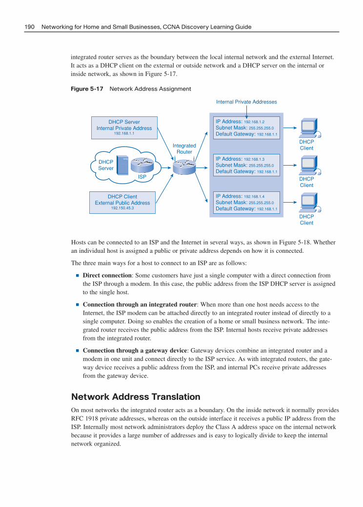
190 Networking for Home and Small Businesses, CCNA Discovery Learning Guide
integrated router serves as the boundary between the local internal network and the external Internet.It acts as a DHCP client on the external or outside network and a DHCP server on the internal orinside network, as shown in Figure 5-17.
Figure 5-17 Network Address Assignment
DHCP ServerInternal Private Address
192.168.1.1
IP Address: 192.168.1.2
Subnet Mask: 255.255.255.0
Default Gateway: 192.168.1.1
IP Address: 192.168.1.3
Subnet Mask: 255.255.255.0
Default Gateway: 192.168.1.1
IP Address: 192.168.1.4
Subnet Mask: 255.255.255.0
Default Gateway: 192.168.1.1
DHCP ClientExternal Public Address
192.150.45.3
DHCPServer
DHCPClient
DHCPClient
DHCPClient
IntegratedRouter
ISP
Internal Private Addresses
Hosts can be connected to an ISP and the Internet in several ways, as shown in Figure 5-18. Whetheran individual host is assigned a public or private address depends on how it is connected.
The three main ways for a host to connect to an ISP are as follows:
■ Direct connection: Some customers have just a single computer with a direct connection fromthe ISP through a modem. In this case, the public address from the ISP DHCP server is assignedto the single host.
■ Connection through an integrated router: When more than one host needs access to theInternet, the ISP modem can be attached directly to an integrated router instead of directly to asingle computer. Doing so enables the creation of a home or small business network. The inte-grated router receives the public address from the ISP. Internal hosts receive private addressesfrom the integrated router.
■ Connection through a gateway device: Gateway devices combine an integrated router and amodem in one unit and connect directly to the ISP service. As with integrated routers, the gate-way device receives a public address from the ISP, and internal PCs receive private addressesfrom the gateway device.
Network Address Translation
On most networks the integrated router acts as a boundary. On the inside network it normally providesRFC 1918 private addresses, whereas on the outside interface it receives a public IP address from theISP. Internally most network administrators deploy the Class A address space on the internal networkbecause it provides a large number of addresses and is easy to logically divide to keep the internalnetwork organized.

Chapter 5: Network Addressing 191
Figure 5-18 Host Connection to an ISP
Any PCs connected to thegateway device receive IP
address information from thegateway device.
A gateway device directlyconnected to the ISP receivespublic IP address information
from the ISP.
IP
IP
IPGateway Device(Modem Built-In)
IP
IP
IP
IP
IP
Any PCs connected to theswitch ports of the integrated
router receive IP addressinformation from the
integrated router.
Any PCs directly connectedto the ISP modem receive
public IP address informationfrom the ISP.
IntegratedRouter
Modem
Modem
An integrated router directlyconnected to the ISP
receives public IP addressinformation from the ISP.
DHCPServer
ISP
IP
Direct Connection
Connection Throughan Integrated Router
Connection Througha Gateway Device
Because private addresses are not allowed on the Internet, a process is needed for translating privateaddresses into unique public addresses to allow local clients to communicate on the Internet. Theprocess used to convert private addresses to Internet-routable addresses is called Network AddressTranslation (NAT). With NAT, a private source IP address (local address) is translated to a publicaddress (global address). The process is reversed for incoming packets. The integrated router is ableto translate many internal IP addresses to the same public address by using NAT.
TIP
The process of many internal IP addresses being converted to a single external IP address is known asOverloaded NAT or Port Address Translation (PAT). This specialized form of NAT is the most commonlydeployed and is the form that is used on most home networking devices, which only obtain a single, routable IPaddress from the ISP.
Only packets destined for other networks need to be translated. These packets must pass through thegateway, where the integrated router replaces the source host’s private IP address with its own publicIP address. This process is reversed when replies are sent back to the source. The NAT process isillustrated in Figures 5-19 through 5-23. As the packet moves through the NAT device, the source IP

192 Networking for Home and Small Businesses, CCNA Discovery Learning Guide
As the packet passes through the NAT device, the header is rewritten. The inside source address isreplaced with a new address that is routable on the external network. The inside address as seen byanother host on the inside network is known as the inside local address. The translated address is howa host on the outside network sees the inside host. This translated address is referred to as the insideglobal address. The NAT device builds a table to keep track of the NAT translations, as shown inFigure 5-20.
Figure 5-20 Network Address Translation Process–Outbound NAT
192.168.1.2
192.168.1.4
Default Gateway PrivateAddress 192.168.1.1
Global Public Address200.100.50.2
Web Server200.100.75.99
Linksys Router
192.168.1.3
Source IP
Inside Local Host Address
Address Translation Table
Source IP Source IPDestination Port
192.168.1.2 200.100.50.237654 46623
Destination Port
Inside Global Host Address
200.100.50.2 200.100.75.99
Destination IP
address in the header is rewritten with a routable one before the packet is placed on the external net-work. When a reply is sent back to the NAT device, the routable IP address is replaced with the origi-nal private IP address before being placed on the internal network. The device that is responsible forcarrying out the NAT function is responsible for maintaining a list of the active translations.
The packet is formed and placed on the internal network as shown in Figure 5-19. The source addressis the address of the device that generated the packet and the destination address is the final destina-tion for the packet. Because the destination address is not on the same local network, the packet trav-els to the default gateway, which is configured for NAT.
Figure 5-19 Network Address Translation Process—Packet Generation
192.168.1.2
192.168.1.4
Default Gateway PrivateAddress 192.168.1.1
Global Public Address200.100.50.2
Web Server200.100.75.99
Linksys Router
192.168.1.3
Source IP
192.168.1.2 200.100.75.99
Destination IP
Inside Local Host Address
Address Translation Table
Source IP Source IPDestination Port
192.168.1.2 37654
Destination Port
Inside Global Host Address

The packet now travels across the external network to the destination device. The destination deviceaccepts the packet and replies to the inside global address as shown in Figure 5-21. The reply packetis placed back on the external network and finds its way back to the device that did the original NATtranslation.
Figure 5-21 Network Address Translation Process–Destination Reply
192.168.1.2
192.168.1.4
Default Gateway PrivateAddress 192.168.1.1
Global Public Address200.100.50.2
Web Server200.100.75.99
Linksys Router
192.168.1.3
Source IP
Inside Local Host Address
Address Translation Table
Source IP Source IPDestination Port
192.168.1.2 200.100.50.237654 46623
Destination Port
Inside Global Host Address
200.100.75.99 200.100.50.2
Destination IP
When the packet reaches the device that did the outbound NAT translation, it checks the translationtable and replaces the inside global address with the inside local address, as shown in Figure 5-22.
Figure 5-22 Network Address Translation Process—Inbound NAT
Chapter 5: Network Addressing 193
192.168.1.2
192.168.1.4
Default Gateway PrivateAddress 192.168.1.1
Global Public Address200.100.50.2
Web Server200.100.75.99
Linksys Router
192.168.1.3
Source IP
200.100.75.99 192.168.1.2
Destination IP
Inside Local Host Address
Address Translation Table
Source IP Source IPDestination Port
192.168.1.2 37654 200.100.50.2 46623
Destination Port
Inside Global Host Address
This packet is then placed on the inside network where it finds its way to the device that generated theoriginal packet, as shown in Figure 5-23.
Although each host on the internal network has a unique private IP address assigned to it, the hostsmust usually share the single Internet-routable address assigned to the integrated router’s Internetinterface. This is accomplished by adding an extra piece of information into the header. This extrainformation is a port number that is used to identify the individual conversation.

194 Networking for Home and Small Businesses, CCNA Discovery Learning Guide
Figure 5-23 Network Address Translation Process–Back at Source
192.168.1.2
192.168.1.4
Default Gateway PrivateAddress 192.168.1.1
Global Public Address200.100.50.2 Web Server
200.100.75.99
Linksys Router
192.168.1.3
Source IP
Inside Local Host Address
Address Translation Table
Source IP Source IPDestination Port
192.168.1.2 200.100.50.237654 46623
Destination Port
Inside Global Host Address
200.100.75.99 192.168.1.2
Destination IP
Examining NAT on a Multi-Function Device (5.4.3.2)
In this Packet Tracer activity you examine the NAT configuration settings in the Linksys GUI andexamine the traffic that crosses the network using NAT. Use file d1-5432.pka on the CD-ROM thataccompanies this book to perform this activity using Packet Tracer.
Challenge Lab 5-2: Exploring IP Address Functions on a Multi-Function Device
In this lab you create and test a simple DHCP server/client network using four PCs and a multi-function device. Refer to the lab in Part II of this Learning Guide. You may perform this lab now orwait until the end of the chapter.
Packet Tracer Activity

Chapter 5: Network Addressing 195
Summary
This chapter discussed the fact that a unique IP address is required in order to allow a network host tocommunicate with other hosts. The common IPv4 address is a 32-bit-long logical address that isdivided into two parts: the network ID and the unique host ID. The subnet mask dictates which por-tion of the IP address represents the network and which portion represents the host. For easier read-ability the IP address is divided into four groups of 8 bits, each called an octet, and then each octet isconverted to decimal and separated by periods. This human-readable form is known as dotted-decimalnotation.
IP addresses are divided into five classes. The first three (A, B, and C) are normally assigned to com-panies and organizations whereas Class D is reserved for multicast use and Class E is for experimentaluse. Each class of addresses has its own default subnet mask.
Addresses can be classified as either private or public. Private address space is defined by RFC 1918and is normally used on internal networks. Private addresses are not routable on the Internet and willquickly be removed by network routers. Public addresses are routable on the Internet.
Three types of messages are possible with IP addresses. A unicast is one-to-one communication, mul-ticast is one-to-many, and a broadcast is one-to-all. Each type of IP address has a corresponding MACaddress.
IP addresses can either be assigned statically by the network administrator or obtained dynamicallythrough DHCP. Dynamic allocation of IP addresses is the preferred method. The multi-function devicefound in home and small business networks can act as both a DHCP server and a DHCP client. Itobtains an external routable address from the ISP and then provides private addresses for internalhosts.
Routers provide a boundary between the internal and external networks. As traffic moves across thisboundary the source IP must be rewritten. This process is known as Network Address Translation(NAT). When traffic moves from the internal network to the external network, the private source IPaddress is replaced with a public-routable one. When replies are received to the message, the routableaddress is replaced by the original private address before being placed on the internal network. Thedevice responsible for the NAT process maintains a table of address translations to allow this to happen.
Activities and Labs
This summary outlines the activities and labs you can perform to help reinforce important conceptsdescribed in this chapter. You can find the activity and Packet Tracer files on the CD-ROM accompa-nying this book. The complete hands-on labs appear in Part II.
Interactive Activities on the CD:
Interactive Activity 5-1: Binary Game (5.1.2.3)
Interactive Activity 5-2: Identifying the Network Portion of an IP Address (5.1.3.2)
Interactive Activity 5-3: Subnet Mask Game (5.2.1.2)
Interactive Activity 5-4: Address Blocker Game (5.2.2.3)
Interactive Activity 5-5: Who Will Receive the Message? Game (5.2.3.4)

196 Networking for Home and Small Businesses, CCNA Discovery Learning Guide
Packet Tracer Activities on the CD:
Connecting to a Web Server Using IP (5.1.1.2)
Configuring DHCP on a Multi-Function Device (5.3.3.3)
Examining NAT on a Multi-Function Device (5.4.3.2)
Labs in Part II of This Book:
Lab 5-1: Using the Windows Calculator with Network Addresses (5.1.4.3)
Challenge Lab 5-2: Exploring IP Addressing Functions on a Multi-Function Device
Check Your Understanding
Complete all the review questions listed here to test your understanding of the topics and concepts inthis chapter. The “Check Your Understanding and Challenge Questions Answer Key” appendix liststhe answers.
1. What is the decimal number 37 in binary?
A. 0001 1001
B. 0010 0101
C. 0011 0001
D. 0101 0001
E. 0011 0011
2. What is the binary number 0011 0010 in decimal?
A. 26
B. 27
C. 50
D. 98
3. What is the network number for the host with an IP address of 172.16.25.14 and a subnet mast of255.255.0.0?
A. 172.0.0.0
B. 172.16.0.0
C. 172.16.25.0
D. 0.16.25.14
E. 0.0.25.14
F. 0.0.0.14
Packet Tracer Activity

Chapter 5: Network Addressing 197
4. What is the host number for the IP address 129.17.63.4 assuming a default subnet mask?
A. 129
B. 129.17
C. 129.17.63
D. 17.63.4
E. 63.4
F. 4
5. What is the maximum number of usable hosts that can be created if six host bits are available?
A. 6
B. 14
C. 30
D. 62
E. 126
6. Which of the following hosts have the same network number?
A. IP 137.17.3.4 SM 255.255.255.0
B. IP 137.16.3.4 SM 255.255.0.0
C. IP 137.16.7.1 SM 255.255.0.0
D. IP 137.17.3.4 SM 255.255.0.0
E. IP 137.17.3.4 SM 255.0.0.0
7. Which of the following are valid Class B host IP addresses?
A. 177.16.0.0
B. 177.16.255.255
C. 123.14.2.1
D. 193.16.4.0
E. 163.15.17.2
8. Which of the following addresses are considered private IP addresses?
A. 10.18.22.3
B. 10.0.0.1
C. 172.27.20.10
D. 192.168.1.1
E. 23.14.72.6
9. What is the default subnet mask for a public Class B network?
A. 255.0.0.0
B. 255.255.0.0
C. 255.255.255.0
D. 255.255.255.255

198 Networking for Home and Small Businesses, CCNA Discovery Learning Guide
10. What is the MAC broadcast address?
A. 0.0.0.0
B. 255.255.255.255
C. 00:00:00:00:00:00
D. FF:FF:FF:FF:FF:FF
11. Which type of IP address allows a host to send a message to a group of hosts?
A. Unicast
B. Multicast
C. Broadcast
12. Which of the following would be considered multicast MAC addresses?
A. 00:00:00:2E:3F:6D
B. 01:00:5E:AA:23:6D
C. 01:5E:00:CA:2F:3C
D. FF:FF:FF:00:3C:2F
13. What are some advantages of using DHCP to assign addresses within an organization?
A. Lower administrative costs
B. Works only with private address space
C. Allows addresses to be shared between machines
D. Ability to reuse addresses
14. What is the correct sequence of steps in the DHCP process?
A. Discover, offer, request, acknowledge
B. Discover, request, offer, acknowledge
C. Request, discover, offer, acknowledge
D. Request, offer, discover, acknowledge
15. When a host is looking for a DHCP server it issues a DHCP Discover. What type of message isthe DHCP Discover?
A. Unicast
B. Multicast
C. Broadcast
16. Which feature on the multi-function device can be used to display the client name and whetherthe host is connected via the wired or wireless interface?
A. DHCP Client Table
B. DHCP Connections Table
C. Interface Connections Table
D. Device Hosts Table
Chapter 5: Network Addressing 199
17. An integrated router is connected to an ISP and then internal hosts are connected to the integratedrouter. What role in the DHCP process is the integrated router taking?
A. DHCP client only
B. DHCP server only
C. Both a DHCP client and a DHCP server
D. Neither a DHCP client nor a DHCP server
18. What is the purpose of NAT in the home network?
A. It is not used in the home network environment.
B. It is used to allow traffic from a host with a private IP address to send information to theInternet.
C. It allows one internal host to send information to another internal host.
D. It converts private IP addresses to public address as information moves from the Internet to aprivate network.
19. How is DHCP used in most small home networks?
20. What is the purpose of APIPA?
Challenge Questions and Activities
These questions require a deeper application of the concepts covered in this chapter. You can find theanswers in the appendix.
1. You have just set up a new server and assigned it the address 172.27.16.3 with a subnet mask of255.255.255.0. The DHCP server is used to provide host addresses on the same network. TheDHCP server has been configured to provide addresses in the range 172.27.17.50 to172.27.17.100 with a subnet mask of 255.255.255.0. Unfortunately, none of the hosts on the net-work can connect to the server. Why is this happening and what would you do to fix the problem?
2. You have a small home network established with three hosts plugged into a multi-function devicethat is in turn connected to the Internet. You are experiencing a problem where you can connectto other hosts on your internal network but are unable to connect to any hosts on the Internet. Acolleague tells you that the problem is that you must configure NAT. Explain how NAT wouldhelp solve this problem.

This page intentionally left blank

CHAPTER 6
Network Services
Objectives
After completing this chapter, you will be able to answer the following questions:
■ What are the roles of a client and server andhow do they interact over the network?
■ What are some common network services avail-able that operate in a client/server relationship?
■ How do TCP and UDP transport protocols com-pare?
■ What is the function of a port?
■ What are well-known port numbers and the protocols/applications that use them?
■ What is Domain Name System (DNS) and itspurpose?
■ How do various types of Internet applications,such as e-mail, World Wide Web, FTP (FileTransfer Protocol), IM (instant messaging), andvoice interact?
■ How does a protocol stack interact on a hostwhen sending and receiving a message?
■ What is the purpose of a layered networkingmodel?
■ What is the Open Systems Interconnect (OSI)layered network model?
Key Terms
This chapter uses the following key terms. You can find the definitions in the Glossary.
Telnet page 203
File Transfer Protocol (FTP) page 204
Hypertext Transfer Protocol (HTTP) page 204
Transmission Control Protocol (TCP) page 205
segment page 207
Domain Name System (DNS) page 209
Hypertext Markup Language (HTML) page 211
Simple Mail Transfer Protocol (SMTP) page 213
Post Office Protocol (POP3) page 214
Internet Message Access Protocol (IMAP4)page 214
Voice over IP (VoIP) page 216
public switched telephone network (PSTN)page 216
Internet Corporation for Assigned Names andNumbers (ICANN) page 217
TCP/IP model page 219
header page 220
trailer page 220

Networks are facing new challenges and must offer more services than ever before. Video, music, andpictures are shared from large servers all over the world. Television, movies, and voice conversationscan be streamed over the network, connecting to remote locations in ways never imagined. Even smallbusinesses can reach customers at any time, in any place. In this chapter you learn how these popularservices are delivered. Part II of this book includes the corresponding labs for this chapter.
Clients/Servers and Their Interaction
The Internet and most modern network applications utilize a client/server relationship. This distributedarchitecture is the basis for nearly all user interaction with the Internet. This section describes theclient/server relationship and the roles that computers can play.
Client/Server Relationship
Every day, people use the services available over networks and the Internet to communicate with oth-ers and to perform routine tasks. We rarely think of the servers, clients, and networking devices thatare necessary in order for us to receive an e-mail, enter information into a blog, or shop for the bestbargains in an online store. Most of the commonly used Internet applications rely on complicatedinteractions between various different servers and clients.
The term server refers to a computer or other networking device running a software application thatprovides information or services to other hosts connected to the network. A well-known example ofan application is a web server, shown in Figure 6-1. Millions of servers are connected to the Internet,providing services such as websites, e-mail, financial transactions, music downloads, and so on. Afactor that is crucial to enabling these complex interactions to function is that they all use agreed stan-dards and protocols.
Figure 6-1 Accessing a Web Server
202 Networking for Home and Small Businesses, CCNA Discovery Learning Guide
Web Server
ISP2
ISP1
Internet

To request and view a web page, a person uses a device that is running web client software. Client isthe name given to a computer application that someone uses to access information held on a server. Aweb browser is a good example of a client. Figure 6-2 shows a client displaying a page from a webserver. This process has three steps:
1. The client first requests the page using the server IP address.
2. The server responds by sending the page to the client IP address.
3. The web client software formats and displays the page for the user.
Figure 6-2 Web Client Displaying a Web Page from a Server Request
Chapter 6: Network Services 203
I received the response.Now I can display
the page.
Web Server
ISP2
ISP1
Internet
The key characteristic of a client/server system is that the client sends a request to a server, and theserver responds by carrying out a function, such as sending information back to the client. The combi-nation of a web browser and a web server is perhaps the most commonly used instance of a client/serv-er system. The servers shown in Figure 6-3 are providing the most common services found in privatenetworks and on the Internet. The following is a brief description of the services each provides:
■ Domain Name System (DNS) server: Service that provides the IP address of a website ordomain name so that a host can connect to it.
■ Telnet server: Service that provides access to remote hosts as if they were connected locally.
■ E-mail server: E-mail uses several services including Simple Mail Transfer Protocol (SMTP),Post Office Protocol (POP3), and Internet Message Access Protocol (IMAP4). SMTP is used tosend e-mail messages from clients to servers over the Internet. Recipients are specified using [email protected] format. POP3 and IMAP are used to store and forward e-mailbetween servers and clients.

■ Dynamic Host Configuration Protocol (DHCP) server: Service that assigns IP address, subnetmask, default gateway, and other information to clients.
■ Web server: Web services use Hypertext Transfer Protocol (HTTP) to transfer informationbetween web clients and web servers. Most web pages are accessed using HTTP.
■ File Transfer Protocol (FTP) server: Service that allows for the download and upload of filesbetween a client and server.
Figure 6-3 Server Farm with Various Servers
204 Networking for Home and Small Businesses, CCNA Discovery Learning Guide
DNSServer
TelnetServer
E-MailServer
DHCPServer
WebServer
FTPServer
Interactive Activity 6-1: Determine the Correct Service for a Client Request (6.1.1.4)
In this interactive activity, you match the service to the client’s request. Use file ia-6114 on the CD-ROM that accompanies this book to perform this interactive activity.
Role of Protocols in Client/Server Communication
A web server and a web client use specific protocols and standards in the process of exchanging infor-mation to ensure that the messages are received and understood. These protocols include those thatoperate at the application, transport, internetwork, and network access layers.
Application ProtocolHypertext Transfer Protocol (HTTP) is the application protocol that governs the way that a web serv-er and a web client interact. HTTP defines the format of the requests and responses exchangedbetween the client and server. HTTP relies on other protocols to govern how the messages are trans-ported between client and server.

Transport ProtocolTransmission Control Protocol (TCP) is the transport protocol that manages the individual conversa-tions between web servers and web clients. TCP formats the HTTP messages into segments to be sentto the destination host. It also provides flow control and acknowledgement of packets exchangedbetween hosts.
Internetwork ProtocolThe most common internetwork protocol is Internet Protocol (IP). IP is responsible for taking the for-matted segments from TCP, assigning the logical addressing, and encapsulating them into packets forrouting to the destination host.
HTTP, TCP, and IP are the key protocols required to download a web page from an Internet server, asshown in Figure 6-4.
Figure 6-4 HTTP, TCP, and IP Used to Access a Web Server
Chapter 6: Network Services 205
HTTP: Specifies the format of the web page request (from client) and response (from server).
TCP: Determines the flow control and acknowledgements of packet exchange.
IP: Identifies the source and destination as packets are sent across the network.
Web Server
ISP2
ISP1
Internet

Network Access ProtocolsEthernet is the most commonly used protocol for local networks. Network access protocols performtwo primary functions:
■ Data link management
■ Physical network transmissions
Data link management protocols take the packets from IP and encapsulate them into the appropriateframe format for the local network. These protocols assign the physical addresses to the frames andprepare them to be transmitted over the network.
The standards and protocols for the physical media govern how the bits are represented on the media,how the signals are sent over the media, and how they are interpreted by the receiving hosts. Networkinterface cards (NIC) implement the appropriate protocols for the media that is being used. Figure 6-5shows an Ethernet cable plugged into a built-in NIC on the back of a computer.
Figure 6-5 Ethernet Cable and Built-in NIC
206 Networking for Home and Small Businesses, CCNA Discovery Learning Guide
TCP and UDP Transport Protocols
Each service available over the network has its own application layer protocols that are implementedin the server and client software. In addition to the application protocols, all the common Internetservices use IP to address and route messages between source and destination hosts.
IP is concerned only with the structure, addressing, and routing of packets. IP does not specify howthe delivery or transportation of the packets takes place. Transport protocols specify how to transfermessages between hosts. The two most common transport protocols are Transmission ControlProtocol (TCP) and User Datagram Protocol (UDP). The IP protocol uses these transport protocols toenable hosts to communicate and transfer data.
Figure 6-6 shows IP as the basic foundation protocol of the Internet, with all other protocols depend-ing on it. The TCP and UDP transport protocols ride on top of IP, and the application protocols, suchas HTTP and FTP, ride on top of either TCP or UDP. IP is the native network protocol of the Internet.
Using TCPWhen an application requires acknowledgment that a message is delivered, it uses TCP. This processis similar to sending a registered letter through the postal system, where the recipient must sign forthe letter to acknowledge its receipt.

Figure 6-6 Application Layer Protocols Depend on IP and Either TCP or UDP
Chapter 6: Network Services 207
Application Layer Protocols
Transport Layer Protocols
Internetwork Layer Protocol IP
TCP UDP
HTTP FTPDNS SMTP
Telnet DHCP
TCP breaks up a message into small pieces known as segments. Each segment is numbered insequence and passed to the IP process for assembly into packets. TCP keeps track of the number ofsegments that have been sent to a specific host from a specific application. TCP is also responsible forsending acknowledgments to ensure that packets are received. If the sender does not receive anacknowledgement within a certain period of time, it assumes that the segments were lost and retrans-mits them. Only the portion of the message that is lost is resent, not the entire message.
On the receiving host, TCP is responsible for reassembling the message segments and passing them tothe application.
FTP and HTTP are examples of protocols that use TCP to ensure delivery of data. In Figure 6-7, theuser is sending a file to the FTP server using an FTP client application, which makes use of TCP tohelp guarantee delivery.
Figure 6-7 FTP Depends on TCP to Provide Reliable Delivery
I am sending this filewith FTP. TCP will
make sure it is received.
Web Server
ISP2
ISP1
Internet

Using UDPIn some cases, the TCP acknowledgment protocol is not required and actually slows down informa-tion transfer. In those cases, UDP can be a more appropriate transport protocol.
UDP is a best-effort delivery system that does not require acknowledgment of receipt. This process issimilar to sending a standard letter through the postal system. The letter is not guaranteed to bereceived, but delivery is expected.
UDP is preferable with applications such as streaming audio, video, and Voice over IP (VoIP).Acknowledgments would slow down delivery and retransmissions are undesirable.
An example of an application that uses UDP is Internet radio, which uses streaming audio technology.If some of the message is lost during its journey over the network, it is not retransmitted. If a fewpackets are missed, the listener might hear a slight break in the sound. If TCP were used and the lostpackets were resent, the transmission would pause to receive them and the disruption would be morenoticeable.
Interactive Activity 6-2: Match the Correct Transport Protocol to the Characteristics
Described (6.1.3.4)
In this interactive activity, you match the correct transport protocol to the characteristic described. Usefile ia-6134 on the CD-ROM that accompanies this book to perform this interactive activity.
TCP/IP Port Numbers
When a message is delivered using either TCP or UDP, the protocols and services requested are iden-tified by a port number. A port is a numeric identifier within each segment that is used to keep trackof specific conversations and destination services requested. Every message that a host sends containsboth a source and destination port.
Destination PortThe client places a destination port number in the segment to tell the destination server what service isbeing requested. For example, port 80 refers to HTTP or web service. When a client specifies port 80in the destination port, the server that receives the message knows that web services are being request-ed. A server can offer more than one service simultaneously. For example, a server can offer webservices on port 80 at the same time that it offers FTP connection establishment on port 21.
Source PortThe source port number is randomly generated by the sending device to identify a conversationbetween two devices. This allows multiple conversations to occur simultaneously. In other words,multiple devices can request HTTP service from a web server at the same time. The separate conver-sations are tracked based on the source ports.
The source and destination ports are placed within the segment. The segments are then encapsulatedwithin an IP packet. The IP packet contains the IP addresses of the source and destination hosts. Thecombination of the source and destination IP address and the source and destination port number isknown as a socket. The socket is used to identify the server and service being requested by the client.Every day thousands of hosts communicate with thousands of different servers. Those communica-tions are identified by the sockets. In Figure 6-8, the source computer is making an FTP (port 21) andweb connection (port 80) to the same server simultaneously.
208 Networking for Home and Small Businesses, CCNA Discovery Learning Guide
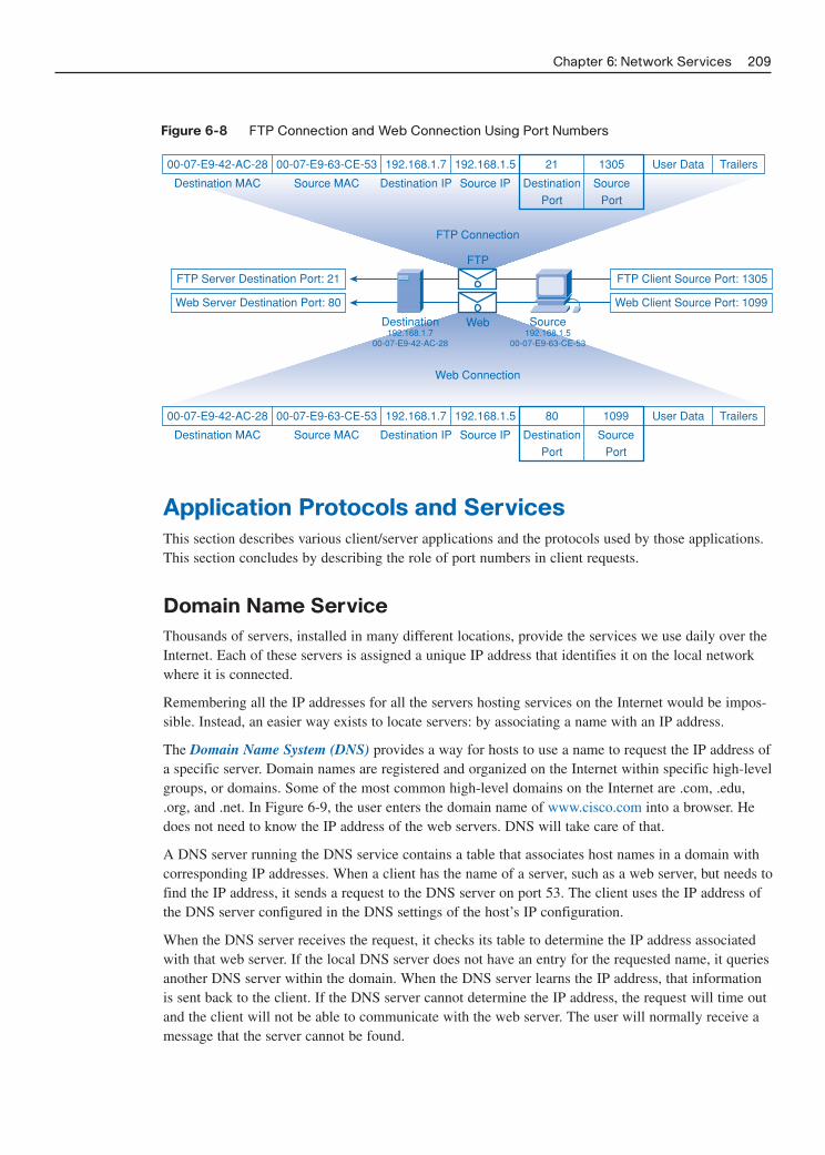
Figure 6-8 FTP Connection and Web Connection Using Port Numbers
Chapter 6: Network Services 209
FTP
FTP Connection
Web Connection
Web
00-07-E9-42-AC-28 00-07-E9-63-CE-53 192.168.1.7 192.168.1.5 21 1305
Destination
Port
Source
Port
User Data Trailers
Destination MAC Source MAC Destination IP Source IP
00-07-E9-42-AC-28 00-07-E9-63-CE-53 192.168.1.7 192.168.1.5 80 1099
Destination
Port
Source
Port
User Data Trailers
Destination MAC Source MAC Destination IP Source IP
FTP Server Destination Port: 21
Web Server Destination Port: 80
FTP Client Source Port: 1305
Web Client Source Port: 1099
Source192.168.1.5
00-07-E9-63-CE-53
Destination192.168.1.7
00-07-E9-42-AC-28
Application Protocols and Services
This section describes various client/server applications and the protocols used by those applications.This section concludes by describing the role of port numbers in client requests.
Domain Name Service
Thousands of servers, installed in many different locations, provide the services we use daily over theInternet. Each of these servers is assigned a unique IP address that identifies it on the local networkwhere it is connected.
Remembering all the IP addresses for all the servers hosting services on the Internet would be impos-sible. Instead, an easier way exists to locate servers: by associating a name with an IP address.
The Domain Name System (DNS) provides a way for hosts to use a name to request the IP address ofa specific server. Domain names are registered and organized on the Internet within specific high-levelgroups, or domains. Some of the most common high-level domains on the Internet are .com, .edu,.org, and .net. In Figure 6-9, the user enters the domain name of www.cisco.com into a browser. Hedoes not need to know the IP address of the web servers. DNS will take care of that.
A DNS server running the DNS service contains a table that associates host names in a domain withcorresponding IP addresses. When a client has the name of a server, such as a web server, but needs tofind the IP address, it sends a request to the DNS server on port 53. The client uses the IP address ofthe DNS server configured in the DNS settings of the host’s IP configuration.
When the DNS server receives the request, it checks its table to determine the IP address associatedwith that web server. If the local DNS server does not have an entry for the requested name, it queriesanother DNS server within the domain. When the DNS server learns the IP address, that informationis sent back to the client. If the DNS server cannot determine the IP address, the request will time outand the client will not be able to communicate with the web server. The user will normally receive amessage that the server cannot be found.

Client software works with the DNS protocol to obtain IP addresses in a way that is transparent to theuser. In Figure 6-10, the user enters the http://www.cisco.com website in the web client browser andthe server responds with the IP address.
Figure 6-10 Using DNS to Resolve a Domain to an IP Address
210 Networking for Home and Small Businesses, CCNA Discovery Learning Guide
Figure 6-9 Using a Domain Name with a Browser
DNSServer
Namewww.cisco.com
Address198.133.219.25
ISP1
Thanks I got it. NowI can contact the
web server.I found the IP
address ofwww.cisco.com
Lab 6-1: Observing DNS Name Resolution (6.2.1.3)
In this lab you use the ping command, a browser, and nslookup to observe the relationship betweendomain names and IP addresses. Refer to the hands-on lab in Part II of this Learning Guide. You mayperform this lab now or wait until the end of the chapter.

Web Clients and Servers
When a web client receives the IP address of a web server, the client browser uses that IP address andport 80 to request web services. This request is sent to the server using HTTP.
When the server receives a port 80 request, the server responds to the client request and sends the webpage to the client. The information content of a web page is encoded using specialized “markup” lan-guages. Hypertext Markup Language (HTML) is the most commonly used markup language, butothers, such as Extensible Markup Language (XML) and Extensible HTML (XHTML), are gainingpopularity.
HTTP is not a secure protocol; information could easily be intercepted by other users as it is sent overthe network. In order to provide security for the data, a secure version of HTTP known as HTTPS canbe used for data transmission. Requests for HTTPS are sent to port 443. These requests require theuse of https: rather than http: in the site address in the browser.
Many different web services and web clients are available on the market. HTTP and HTML make itpossible for these servers and clients from many different manufacturers to work together seamlessly.
When a web client requests the IP address of http://www.cisco.com from the ISP1 DNS server, theserver responds to the client with the IP address of the website. It is not until the client computer hasthe web server’s IP address that it can actually contact the http://www.cisco.com web server to requesta web page. Figure 6-11 shows the client computer sending an HTTP request to port 80 on the desti-nation web server in the cisco.com domain. The client knows how to contact the ISP1 DNS serverbecause the IP address of the DNS server is part of the IP configuration of the client. The client’s IPaddress, subnet mask, and default gateway, as well as the IP addresses of a primary and secondaryDNS server, are provided to the client by ISP1 using DHCP.
Figure 6-11 Sending an HTTP Request to Port 80 on the Web Server
Chapter 6: Network Services 211
Web Server
Cisco Network
ISP2
DNS Server
Internet
ISP1

Observing Web Requests (6.2.2.2)
In this Packet Tracer activity, you observe traffic requests when a client browser requests web pagesfrom a server. Use file d1-6222.pka on the CD-ROM that accompanies this book to perform this inter-active activity.
FTP Clients and Servers
In addition to web services, another common service used across the Internet is one that allows usersto transfer files. FTP provides an easy method for transferring files from one computer to another. Ahost running FTP client software can access an FTP server to perform various file management func-tions including file uploads and downloads.
An e-mail client can be used to send files as attachments, but ISPs and mail server administratorsmight limit attachment file size. FTP can be used to send and receive multiple files that are much larg-er than those allowed by e-mail. The FTP server can also act as a centralized file storage location foraccess by different people working on the same project.
The FTP server enables a user running FTP client software to exchange files between devices. It alsoenables the user to manage files remotely by sending file management commands such as delete orrename. To accomplish these tasks, the FTP service uses two different ports to communicate betweenclient and server. Requests to begin an FTP session are sent to the server using destination port 21.After the session is opened, the server will change to port 20 to transfer the data files.
FTP client software is built into computer operating systems and into most web browsers. Figure 6-12shows the Windows command prompt window as the CLI (command-line interface) FTP client isstarted. When the FTP client is started, the Windows command prompt changes to an FTP prompt thatcan interpret FTP commands such as GET and PUT. Standalone FTP clients offer many options in aneasy-to-use GUI-based interface.
Figure 6-12 Using FTP from the Command Line
212 Networking for Home and Small Businesses, CCNA Discovery Learning Guide
Packet Tracer Activity
Interactive Activity 6-3: Demonstration of GUI FTP Client Use (6.2.3.2)
In this interactive activity, you view the use of a GUI FTP client. Use file ia-6232 on the CD-ROMthat accompanies this book to perform this interactive activity.

Lab 6-2: Exploring FTP (6.2.3.3)
In this lab you use an FTP client to transfer files from an FTP server. Refer to the hands-on lab in PartII of this Learning Guide. You may perform this lab now or wait until the end of the chapter.
E-mail Clients and Servers
E-mail is one of the most popular client/server applications on the Internet. E-mail servers run serversoftware that enables them to interact with e-mail clients and with other e-mail servers over the net-work. In addition to using e-mail client software such as Microsoft Outlook to access e-mail, someISPs also offer web-based e-mail.
Each mail server receives and stores mail for users who have mailboxes configured on the mail server.Each user with a mailbox must then use an e-mail client to access the mail server and read these mes-sages.
Mail servers are also used to send mail addressed to local mailboxes or mailboxes located on other e-mail servers.
Mailboxes are identified by the following format:
Figure 6-13 shows an e-mail message being composing using the Windows Outlook e-mail client.
Figure 6-13 E-mail Client: Composing an E-mail Message
Chapter 6: Network Services 213
Various application protocols used in processing e-mail include the following:
■ Simple Mail Transfer Protocol (SMTP): SMTP is used by an e-mail client to send messages toits local e-mail server. The local server then decides whether the message is destined for a localmailbox or whether the message is addressed to a mailbox on another server.
If the server has to send the message to a different server, SMTP is used between the two serversas well. SMTP requests are sent to port 25.

■ Post Office Protocol (POP3): A server that supports POP3 clients receives and stores messagesaddressed to its users. When the client connects to the e-mail server, the messages are down-loaded to the client. By default, messages are not kept on the server after they have been accessedby the client. With most POP3 clients, the user can choose to keep mail on the server if desired.Clients contact POP3 servers on port 110.
■ Internet Message Access Protocol (IMAP4): A server that supports IMAP clients also receivesand stores messages addressed to its users. However, it keeps the messages in the mailboxes onthe server unless they are deleted by the user. The most current version of IMAP is IMAP4,which listens for client requests on port 143.
Many different e-mail servers exist for the various network operating system platforms. The top por-tion of Figure 6-14 shows a POP3 client downloading e-mail from the POP3 server. The bottom por-tion of the figure shows an IMAP4 client reading e-mail while it is still on the IMAP4 server. Bothclients use SMTP to send mail to the POP3 and the IMAP4 servers. In addition to POP3 and IMAP4,each of the servers might have an SMTP server running to accept the e-mail being sent.
Figure 6-14 POP3 and IMAP4 Charts
214 Networking for Home and Small Businesses, CCNA Discovery Learning Guide
Download Mail
Send Mail
POP3 Server Destination Port: 110
SMTP Server Destination Port: 25
POP3 Client
SMTP Client
POP3/SMTP E-Mail Client and Server
POP3: Used by the client to contact the server and download mail. Mail is deleted off the server.
SMTP: Used by the client to forward mail to the server. Server accepts and stores the mail in the proper queue.
Read Mail
Send Mail
IMAP4 Server Destination Port: 143
SMTP Server Destination Port: 25
IMAP4 Client
SMTP Client
IMAP4/SMTP E-Mail Client and Server
IMAP4: Used by the client to contact the server and access mail. Mail is maintained on the server.
SMTP: Used by the client to forward mail to the server. Server accepts and stores the mail in the proper queue.
An e-mail client connects to the e-mail server to download and view messages. Most e-mail clientscan be configured to use either POP3 or IMAP4 depending on the e-mail server where the mailbox islocated. E-mail clients must also be able to send e-mail to the server using SMTP.
Different e-mail servers can be configured for incoming and outgoing mail.
The following are typical entries when configuring an e-mail client:
■ POP3 or IMAP4 server name
■ SMTP server name
■ Username
■ User password
■ Spam and virus filters

Figure 6-15 shows the basic setup of a POP3 and SMTP e-mail account using Microsoft Outlook.Note that the incoming server is POP3 and the outgoing server is SMTP. Downloaded e-mail isreceived from the POP3 server and newly created or forwarded e-mail is sent to the SMTP server.
Figure 6-15 Microsoft Outlook E-mail Account Setup
Chapter 6: Network Services 215
Lab 6-3: Configuring an E-mail Client (6.2.4.4)
In this lab you configure an e-mail client to access an e-mail server and send and receive e-mail. Referto the hands-on lab in Part II of this Learning Guide. You may perform this lab now or wait until theend of the chapter.
IM Clients and Servers
Instant messaging (IM) is one of the most popular communication tools in use today. IM software isrun locally on each computer and allows users to communicate or chat over the Internet in real time.Many different IM applications are available from various companies. Each instant messaging servicecan use a different protocol and destination port, so two hosts must have compatible IM softwareinstalled for them to communicate.
IM applications require minimal configuration to operate. After the client is downloaded, all that isrequired is to enter username and password information. This allows the IM client to authenticate tothe IM network. Once logged into the server, clients can send messages to other clients in real-time ina peer-to-peer fashion. In addition to text messages, IM supports the transfer of video, music, andspeech files. IM clients might have a telephony feature, which allows users to make phone calls overthe Internet. Additional configuration can be done to customize the IM client with “buddy lists” and apersonal look and feel.
IM client software can be downloaded and used on all types of hosts, including computers, PDAs, andcell phones. In Figure 6-16, John and Sarah are using an IM server to communicate in real time.

Figure 6-16 IM Conversation
216 Networking for Home and Small Businesses, CCNA Discovery Learning Guide
Internet
Instant MessengerServer
Voice Clients and Servers
Making phone calls over the Internet is becoming increasingly popular. An Internet telephony clientuses peer-to-peer technology similar to that used by instant messaging. IP telephony makes use ofVoice over IP (VoIP) technology, which uses IP packets to carry digitized voice as data.
To start using an Internet telephone, download the client software from one of the companies that pro-vides the service. Rates for Internet telephone services can vary greatly between regions andproviders.
When the software has been installed, the user selects a unique name. This is so that calls can bereceived from other users. Speakers and a microphone, built-in or separate, are required. A headset isfrequently plugged into the computer to serve as a phone.
Calls are made to other users of the same service on the Internet, by selecting the username from alist. A call to a regular telephone (land line or cell phone) requires the use of a gateway to access thepublic switched telephone network (PSTN). Although it has evolved over the years, the PSTN is thetraditional phone system originally developed by the Bell companies.
The protocols and destination ports used by Internet telephony applications vary based on the soft-ware. Figure 6-17 shows one voice client that uses a headset and another that uses a regular telephoneconnected to a PC.

Figure 6-17 Voice Clients and Voice Server
Chapter 6: Network Services 217
Voice Client Voice Client
Voice Server(CallManager)
Internet
Port Numbers
DNS, web, e-mail, FTP, IM, and VoIP are just some of the many services provided by client/serversystems over the Internet. These services might be provided by a single server or by several servers.In either case, it is necessary for a server to know which service is being requested by a client. Clientrequests can be identified because the request is made to a specific destination port. Clients are pre-configured to use a destination port that is registered on the Internet for each service.
Ports are assigned and managed by an organization known as the Internet Corporation for AssignedNames and Numbers (ICANN) http://www.icann.org/. Ports are broken into three categories andrange in number from 1 to 65535:
■ Well-known ports: Destination ports that are associated with common network applications areidentified as well-known ports. These ports are in the range of 0 to 1023.
■ Registered ports: Ports 1024 through 49151 can be used as either source or destination ports.Organizations can use them to register specific applications such as IM software.
■ Private ports: Ports 49152 through 65535 are often used as source ports. Any application canuse these ports.
Table 6-1 shows some of the more common well-known ports.
Table 6-1 Common Well-Known TCP/UDP Port Numbers
Destination
Port Number Abbreviation Acronym Definition
20 FTP Data File Transfer Protocol (for data transfer).
21 FTP Control File Transfer Protocol (to establish connection).
23 TELNET TELetype NETwork.
25 SMTP Simple Mail Transfer Protocol.
53 DNS Domain Name Service.
67 DHCP v4 Client Dynamic Host Configuration Protocol (Client). Originally devel-oped as Bootstrap Protocol.
68 DHCP v4 Server Dynamic Host Configuration Protocol (Server). Originally devel-oped as Bootstrap Protocol.
69 TFTP Trivial File Transfer Protocol.
continued

Table 6-1 Common Well-Known TCP/UDP Port Numbers continued
Destination
Port Number Abbreviation Acronym Definition
80 HTTP Hypertext Transfer Protocol.
110 POP3 Post Office Protocol version 3.
137 NBNS NetBIOS Name Service (Microsoft).
143 IMAP4 Internet Message Access Protocol (version 4).
161 SNMP Simple Network Management Protocol.
443 HTTPS Hypertext Transfer Protocol Secure.
Interactive Activity 6-4: Match the Protocol Name to the Destination Port Number in the TCP
Segment (6.2.7.2)
In this interactive activity, you match the protocol name to the destination port number in the TCPsegment. Use file ia-6272 on the CD-ROM that accompanies this book to perform this interactiveactivity.
Layered Model and Protocols
Many protocols have been developed as the Internet has evolved. These protocols do not operate inde-pendently but work together in a layered sequence or protocol stack. This section describes two mainlayered models used in networking and how protocols interact to enable messages to be sent andreceived.
Protocol Interaction
Successful communication between hosts requires interaction between several protocols. These proto-cols are implemented in software and hardware that is loaded on each host and network device.
The interaction between protocols can be depicted as a protocol stack. It shows the protocols as a lay-ered hierarchy, with each higher-level protocol depending on the services of the protocols shown inthe lower levels.
Figure 6-18 shows a protocol stack with the primary protocols necessary to access a web server on anEthernet LAN. The lower layers of the stack are concerned with moving data over the network andproviding services to the upper layers. The upper layers are focused more on the content of the mes-sage being sent and the user interface. The basic protocol stack is running on the web server and theweb clients.
To visualize the interaction between various protocols, it is common to use a layered model. A layeredmodel depicts the operation of the protocols occurring within each layer, as well as the interactionwith the layers above and below it.
218 Networking for Home and Small Businesses, CCNA Discovery Learning Guide

Figure 6-18 Web Server Protocol Stack
Chapter 6: Network Services 219
Hypertext Transfer Protocol (HTTP)
Transmission Control Protocol (TCP)
Internet Protocol (IP)
Ethernet ProtocolWeb
Server
Protocol Stack
The layered model has many benefits:
■ Assists in protocol design because protocols that operate at a specific layer have defined informa-tion that they act on and a defined interface to the layers above and below.
■ Fosters competition because products from different vendors can work together.
■ Prevents technology or capability changes in one layer from affecting other layers above andbelow.
■ Provides a common language to describe networking functions and capabilities.
The first layered reference model for internetwork communications was created in the early 1970s andis referred to as the Internet model. It defines four categories of functions that must occur for commu-nications to be successful. The architecture of the TCP/IP protocols follows the structure of thismodel. Because of this, the Internet model is commonly referred to as the TCP/IP model. Figure 6-19shows the four-layer TCP/IP model.
Figure 6-19 TCP/IP Protocol Layer Interaction
Application LayerConsists of Applications and Processes that Use the Network
Transport LayerProvides End-to-End Data Delivery Services
Internet LayerDefines the Datagram and Handles the Routing of Data
Network Access LayerProcesses Routines for Accessing Physical Media
3
2
4
1
Protocol Operation of Sending and Receiving a Message
When sending messages on a network, the protocol stack on a host operates from top to bottom. Inthe web server example, a browser on the client requests a web page from a web server on destinationport 80. This starts the process of sending the web page to the client.
As the web server replies with the requested page, the data moves down through the web server proto-col stack; the application data is broken into TCP segments. Each TCP segment is given a header con-taining a source and destination port. Many segments are required to send an entire web page.

The TCP segment encapsulates HTTP and web page HTML user data and sends it down to the nextprotocol layer, which is IP. Here the TCP segment is encapsulated within an IP packet, which adds anIP header. The IP header contains source and destination IP addresses.
Next, the IP packet is sent to the Ethernet protocol where it is encapsulated in a frame header andtrailer. Each Ethernet frame header contains a source and destination MAC address. The trailer con-tains error-checking information. Finally, the bits are encoded onto the Ethernet media (copper orfiber-optic cable) by the server NIC.
Figure 6-20 shows a web server sending a web page to a web client. Before putting any bits on thewire, the server breaks up the web page into chunks of data. Each chunk of data is encapsulated witha TCP header and numbered. The TCP header and data are then encapsulated with an IP header andfinally the IP header, TCP header, and data are encapsulated within an Ethernet frame. The frame isthen sent, as bits, out onto the wire toward the requesting host. The server continues sending framesuntil all the data in the web page has been sent to the client. This might require thousands of framesfor a web page with lots of graphics.
Figure 6-20 Web Server Encapsulating Web Page Data to Send to Client
220 Networking for Home and Small Businesses, CCNA Discovery Learning Guide
Data TCP IP
Data TCP IP
Data TCP
Data
Ethernet
Data TCP IP Ethernet
Ethernet Frame
IP Packet
TCP Segment
UserData
Protocol Encapsulation Terms
Web Server Web Client
When messages are received from the network, the protocol stack on a host operates from bottom totop. Previously, we saw the process of encapsulation at each layer when the web server sent the webpage to the client. The process of receiving the web page starts the unencapsulation of the message bythe client.
As the bits are received by the client NIC, they are decoded and the destination MAC address is rec-ognized by the client as its own.
The frame is sent up the web client protocol stack where the Ethernet header (source and destinationMAC addresses) and trailer are removed (de-encapsulated). The remaining IP packet and contents arepassed up to the IP layer.
At the IP layer, the IP header (source and destination IP addresses) is removed and the contentspassed up to the TCP layer.

At the TCP layer, the TCP header (source and destination ports) is removed and the web page userdata contents are passed up to the browser application using HTTP. As TCP segments are receivedthey are reassembled to create the web page.
Figure 6-21 shows the web client receiving a web page from a web server. When the frame isreceived, the host strips off the Ethernet frame and then the IP header, and finally the TCP header toget to the data inside. The data is passed on to the web browser application via HTTP. After many ofthese frames are received and de-encapsulated, the web page sent by the server can be displayed.
Figure 6-21 Web Client De-encapsulating Web Page Data from Server
Chapter 6: Network Services 221
Data TCP IP
Data TCP
TCP
IP
Data TCP
Data
Ethernet
Data TCP IP Ethernet
Ethernet Frame
IP Packet
TCP Segment
UserData
Protocol Encapsulation Terms
Web Client
Web Server
Interactive Activity 6-5: Match Networking Term with Protocol and TCP/IP Layer (6.3.2.3)
In this interactive activity, you match the host, protocol, and encapsulation terminology with the prop-er protocol or layer. Use file ia-6323 on the CD-ROM that accompanies this book to perform thisinteractive activity.
Open System Interconnection Model
The Open System Interconnection (OSI) model was developed by the International Organization forStandardization (ISO) in 1984. Unlike the TCP/IP model, it does not specify the interaction of anyspecific protocols. It was created as architecture for developers to follow to design protocols for net-work communications. Although very few protocol stacks exactly implement the seven layers of theOSI model, it is now considered the primary reference model for intercomputer communications.
NOTE
The International Organization for Standardization’s name, ISO, is not an acronym or abbreviation. It is basedon the Greek word ISOS, which means equal.
The OSI model includes all functions, or tasks, associated with internetwork communications, not justthose related to the TCP/IP protocols. Compared to the TCP/IP model, which only has four layers, the

OSI model organizes the tasks into seven more specific groups. A task, or group of tasks, is thenassigned to each of the seven OSI layers. The seven layers of the OSI model are shown in Figure 6-22.
Figure 6-22 OSI Model Layers
222 Networking for Home and Small Businesses, CCNA Discovery Learning Guide
PCPC
Application Layer
Presentation Layer
Session Layer
Transport Layer
Network Layer
Data Link Layer
Physical Layer
Application Layer
Presentation Layer
Session Layer
Transport Layer
Network Layer
Data Link Layer
Physical Layer
The TCP/IP model originally had four layers with layer 1 being the physical access layer. A revisedversion splits this layer into two, resulting in five layers. The lower layers of the revised TCP/IPmodel map closely to those of the OSI, as shown in Table 6-2. Basically, the TCP/IP model groupsthe three upper layers of the OSI model into one application layer.
Table 6-2 OSI and TCP/IP Model Layers
OSI Layer OSI Layer TCP/IP TCP/IP Associated Protocols
Number Name Layer Number Name (5 layer) and Media
7 Application 5 Application HTTP, FTP, Telnet
6 Presentation 5 Application
5 Session 5 Application
4 Transport 4 Transport TCP and UDP
3 Network 3 Internetwork IP
2 Data Link 2 Data Link Ethernet, HDLC, PPP, Frame Relay
1 Physical 1 Physical Media (cabling) Copper, Fiber, Wireless
The essence of protocol stacks is the separation and organization of distinct functions. The separationof functions enables each layer in the stack to operate independently of others. For example, accessinga website is feasible from a laptop computer connected to a cable modem at home, from a laptopusing wireless, or from a web-enabled mobile phone. The application layer operates seamlessly,regardless of the way the lower layers are operating.
In the same way, the lower layers operate seamlessly. For example, an Internet connection functionssatisfactorily when a variety of applications are running at the same time, such as e-mail, web brows-ing, IM, and music download.

The Packet Tracer program graphical interface allows the viewing of simulated data being transmittedbetween two hosts. It uses protocol data units (PDUs) to represent network traffic frames and displaysprotocol stack information at the appropriate layers of the OSI model.
In Figure 6-23, the request from the web client is being received by the Ethernet NIC in the web serv-er. The following information is shown in OSI layers 1 through 4:
■ Layer 4 (Transport): TCP port numbers
■ Layer 3 (Network): IP addresses
■ Layer 2 (Data Link): Ethernet MAC addresses
■ Layer 1 (Physical): Fast Ethernet port
Figure 6-23 Packet Tracer PDU Information at Various OSI Layers
Chapter 6: Network Services 223
Interactive Activity 6-6: Match the Header, Address, Protocol, or Term with the Proper OSI
Layer (6.3.3.3)
In this interactive activity, you match the header, address, protocol, or term to the proper layer in thenetwork model. Use file ia-6333 on the CD-ROM that accompanies this book to perform this interac-tive activity.
Interactive Activity 6-7: Build an Ethernet Frame with Proper Components and Send It to Its
Destination (6.3.3.4)
In this interactive activity, you build an Ethernet frame with proper components and send it to its des-tination. Use file ia-6334 on the CD-ROM that accompanies this book to perform this interactiveactivity.

View PDU Information Being Sent Between a Client and a Server (6.3.3.5)
In this Packet Tracer activity, you use Packet Tracer to view PDU information being sent between aclient and server. Use file d1-6335.pka on the CD-ROM that accompanies this book to perform thisinteractive activity.
224 Networking for Home and Small Businesses, CCNA Discovery Learning Guide
Packet Tracer Activity

Chapter 6: Network Services 225
Summary
This chapter discussed the client/server relationship for common network services such as HTTP, FTP,DNS, DHCP, and e-mail.
Servers are hosts that run software to enable them to provide services to other hosts over the network.Clients run software that enables them to access server services.
Protocols are divided into four main groups: applications (HTTP, FTP, Telnet, and so on); transport(TCP and UDP); Internet Protocol (IP); and network access protocols such as Ethernet, HDLC, and PPP.
DNS provides the IP address of a website URL or domain name so that a host can connect to a webserver. DNS names are registered and organized on the Internet within specific high-level groups, ordomains.
DHCP is a service that assigns the IP address, subnet mask, default gateway, and other information toclients.
FTP is a service that allows for the download and upload of files between a client and server.
E-mail servers use SMTP to send mail, and clients use POP3 or IMAP4 to retrieve mail. Recipientsare specified using the [email protected] format.
Web services transfer information between web clients and web servers. Most web pages are accessedusing HTTP from servers using port 80. HTTP is not a secure service. Requests for secure HTTP aresent to port 443. These requests require the use of HTTPS.
Telnet is a service that allows administrators to log in to a host from a remote location and control thehost as if they were logged in locally.
An Internet telephony client uses peer-to-peer technology similar to that used by instant messaging. IPtelephony makes use of Voice over IP (VoIP) technology, which uses IP packets to carry digitizedvoice as data.
A protocol stack organizes the protocols as a layered hierarchy, with each higher-level protocoldepending on the services of the protocols in the lower levels. Using a layered approach has manybenefits.
When sending messages, the protocol stack on a host operates from top to bottom. Each layer encap-sulates information and passes it to the layer below. The process is reversed on the receiving host.
Two hierarchical network models are the OSI model (seven layers) and the TCP/IP model (four or fivelayers). The OSI model includes all functions, or tasks, associated with internetwork communications,not just those related to the TCP/IP protocols. The OSI model is considered the primary referencemodel for intercomputer communications.

226 Networking for Home and Small Businesses, CCNA Discovery Learning Guide
Activities and Labs
This summary outlines the activities and labs you can perform to help reinforce important conceptsdescribed in this chapter. You can find the activity and Packet Tracer files on the CD-ROM accompa-nying this book. The complete hands-on labs appear in Part II.
Interactive Activities on the CD-ROM:
Interactive Activity 6-1: Determine the Correct Service for a Client Request (6.1.1.4)
Interactive Activity 6-2: Match the Correct Transport Protocol to the Characteristics Described(6.1.3.4)
Interactive Activity 6-3: Demonstration of GUI FTP Client Use (6.2.3.2)
Interactive Activity 6-4: Match the Protocol Name to the Destination Port Number in the TCPSegment (6.2.7.2)
Interactive Activity 6-5: Match Networking Term with Protocol and TCP/IP Layer (6.3.2.3)
Interactive Activity 6-6: Match the Header, Address, Protocol, or Term with the Proper OSI Layer(6.3.3.3)
Interactive Activity 6-7: Build an Ethernet Frame with Proper Components and Send It to ItsDestination (6.3.3.4)
Packet Tracer Activities on the CD-ROM:
Observing Web Requests (6.2.2.2)
View PDU Information Being Sent Between a Client and a Server (6.3.3.5)
Labs in Part II of This Book:
Lab 6-1: Observing DNS Name Resolution (6.2.1.3)
Lab 6-2: Exploring FTP (6.2.3.3)
Lab 6-3: Configuring an E-mail Client (6.2.4.4)
Packet Tracer Activity

Chapter 6: Network Services 227
Check Your Understanding
Complete all the review questions listed here to test your understanding of the topics and concepts inthis chapter. The “Check Your Understanding and Challenge Questions Answer Key” appendix liststhe answers.
1. What happens when part of a message using TCP is not delivered to the destination host?
A. The sender resends the entire message.
B. The sender sends a request to find out what happened.
C. Nothing. TCP does not check for errors and missing data.
D. The part of the message that is missing is retransmitted.
2. A user uploads large new files to his or her website. What service is this user likely using to copythe files to the website?
3. A workstation gets its IP address, subnet mask, and default gateway automatically. What serviceis being employed?
4. What three main protocols do e-mail users and servers normally use to process e-mail?
A. DHCP
B. SMTP
C. IMAP4
D. DNS
E. POP3
5. Which protocol allows you to enter www.cisco.com instead of an IP address to open the webpage?
6. Match the term on the left to the definition on the right.
HTML
HTTP
HTTPS
Web server
Web client
Hosts a web page
Requests a web page
Used to create web pages
Secure protocol that uses port 443
Protocol commonly used by a web browser
7. What acronym is associated with making a phone call using the Internet?
A. IM
B. HTML
C. HTTP
D. SNMP
E. VoIP

228 Networking for Home and Small Businesses, CCNA Discovery Learning Guide
8. Match the port number on the left to the associated protocol on the right.
Port Numbers Protocols
68
21
23
25
53
20
80
110
161
443
FTP Data
HTTP
SNMP
DNS
FTP Control
POP3
Telnet
HTTPS
SMTP
DHCP
9. Select three protocols that operate at the application layer on the OSI model.
A. ARP
B. TCP
C. DSL
D. FTP
E. POP3
F. HTTP
10. As an Ethernet frame enters the NIC of a destination host, in what order do the headers (and trailersif applicable) get removed to de-encapsulate the frame and pass the user data to the application?
A. IP, Ethernet, TCP
B. Ethernet, TCP, IP
C. Ethernet, IP, TCP
D. TCP, IP, Ethernet
E. IP, TCP, Ethernet
11. Which of the following TCP/IP protocols is matched to the correct layer of the OSI model?(Choose all that apply.)
A. IP, Network
B. UDP, Network
C. TCP, Application
D. HTTP, Application
E. TCP, Transport
12. What allows an FTP server to keep track of connections from multiple clients to the FTP service?
A. The frame header source and destination MAC address
B. The packet header destination IP and MAC addresses
C. The packet header source IP address and TCP header source port number
D. The TCP destination port number and the frame header source MAC address

Chapter 6: Network Services 229
13. A frame from a client comes into a server with a destination port of 80 in the TCP segment. Whatservice will receive that segment on the server?
14. A UTP cable has a poorly terminated connector. With what layer of the OSI model is this prob-lem associated?
A. Layer 7, application
B. Layer 3, network
C. Layer 4, transport
D. Layer 1, physical
E. Layer 5, session
15. Which of the following can be contained in an Ethernet frame? (Choose all that apply.)
A. Source and destination MAC addresses
B. Source and destination ID numbers
C. Source and destination port numbers
D. Source and destination IP addresses
E. Source and destination serial numbers
16. VoIP applications are sensitive to delay. What transport protocol is better suited to voice applica-tions?
A. IP
B. UDP
C. TCP
D. FTP
E. DHCP
17. When transferring a file using FTP, what is the order of protocols from the upper layers of theTCP/IP model to the lower layers?
A. TCP uses FTP, which uses IP
B. FTP uses TCP, which uses IP
C. IP uses FTP, which uses TCP
D. FTP uses UDP, which uses IP
E. FTP uses IP, which uses UDP
Challenge Questions and Activities
These questions and activities require a deeper application of the concepts covered in this chapter. Youcan find the answers in the appendix.
1. Which layers of the TCP/IP model have corresponding layers in the OSI model? What is the layernumber and name of the corresponding OSI layer?
2. A network user reports that she cannot access a website. The support technician can ping theserver by its IP address but cannot connect when entering the website address in the browser.Which protocol or service is most likely to be the source of the problem?

This page intentionally left blank

CHAPTER 7
Wireless Technologies
Objectives
Upon completion of this chapter, you will be able to answer the following questions:
■ What are benefits and limitations of wirelesstechnology?
■ Where are wireless technologies commonlyused?
■ How does a wireless personal-area network(WPAN) compare to a wireless local-area net-work (WLAN) and a wireless wide-area network(WWAN)?
■ What components are required to build a WLANand what are their functions?
■ What are the current standards for WLANs andhow do they compare?
■ What parameters must be configured to allow awireless client to access network resources?
■ What techniques are available to help secure theWLAN?
■ How is an access point and wireless client con-figured to allow communication to occur?
Key Terms
This chapter uses the following key terms. You can find the definitions in the Glossary.
electromagnetic wave page 233
wavelength page 233
spectrum page 233
infrared (IR) page 233
Infrared Direct Access (IrDA) page 233
radio frequency (RF) page 234
Industrial, Scientific, and Medical (ISM) bandspage 234
Unlicensed National Information Infrastructure(UNII) bands page 234
Bluetooth page 234
hotspot page 235
wireless personal-area networks (WPAN) page 236
wireless local-area networks (WLAN) page 236
wireless wide-area networks (WWAN) page 236
Code Division Multiple Access (CDMA) page 236
Global System for Mobile Communication (GSM)page 236
802.11a page 237
802.11b page 237
802.11g page 237
802.11n page 237
Wireless-Fidelity (Wi-Fi) page 237
multiple-input, multiple-output (MIMO) page 237
wireless client page 239
STA page 239
access point (AP) page 239
wireless bridge page 239
antenna page 239
Service Set Identifier (SSID) page 240
ad-hoc page 240
Independent Basic Service Set (IBSS) page 240
infrastructure mode page 240
Basic Service Set (BSS) page 240
cell page 240

Extended Service Set (ESS) page 240
wireless channels page 242
Carrier Sense Multiple Access with CollisionAvoidance (CSMA/CA) page 243
Request to Send (RTS) page 243
Clear to Send (CTS) page 243
acknowledgement (ACK) page 244
authentication page 251
open authentication page 251
pre-shared keys (PSK) page 251
Extensible Authentication Protocol (EAP)page 252
Remote Authentication Dial-in User Service(RADIUS) page 252
association page 252
encryption page 253
Wired Equivalency Protocol (WEP) page 253
passphrase page 253
Wi-Fi Protected Access page 254
site survey page 256
232 Networking for Home and Small Businesses, CCNA Discovery Learning Guide

This chapter introduces wireless technologies, including infrared and radio frequency, and the benefitsand limitations of each. You also learn about wireless technologies, with emphasis given to wirelesslocal-area networks, also called wireless LANs (WLANs), and considerations for planning, configur-ing, and securing these networks. Part II of this book includes all the curriculum labs for this chapterplus an additional challenge lab.
Wireless Technology
In addition to the wired network commonly found in most LAN environments, various technologiesexist that allow the transmission of information between hosts without cables. These technologies arecollectively referred to as wireless.
Wireless Technologies and Devices
Wireless technologies use electromagnetic waves to carry information between devices. An electro-magnetic wave is the same medium that carries radio signals from the broadcasting station to a receiver or supplies light from a light bulb.
The electromagnetic spectrum includes radio and television broadcast bands, visible light, x-rays, andgamma rays. Each of these has a specific range of wavelengths and associated energies as shown inFigure 7-1.
Figure 7-1 Electromagnetic Spectrum
Chapter 7: Wireless Technologies 233
Some types of electromagnetic waves are not suitable for carrying data. Much of the electromagneticspectrum is regulated by governments and licensed to various organizations for specific applications.In most countries, specific areas of the electromagnetic spectrum have been set aside to allow publicuse without the restriction of having to apply for special permits. The most common wavelengths usedfor public, unlicensed, wireless communications include the infrared and parts of the radio frequency(RF) band.
InfraredInfrared (IR) is relatively low energy and cannot penetrate through walls or other obstacles. It is com-monly used to connect and move data between devices such as personal digital assistants (PDA) andPCs or cell phones and PCs. A specialized communication port known as an Infrared Direct Access(IrDA) port uses IR to exchange information between devices. IR only allows a one-to-one type ofconnection.

NOTE
IrDA also stands for the Infrared Data Association. The goal of this nonprofit organization is to develop globallyadopted specifications for infrared wireless communications.
IR is commonly used for remote control devices, wireless mice, and wireless keyboards. It is general-ly used for short-range, line-of-sight communications. However, reflecting the IR signal off objects toextend the range is possible. For greater ranges, higher frequencies of electromagnetic waves arerequired.
Radio Frequency (RF)Radio frequency (RF) waves have a much higher energy than IR and can penetrate through walls andother obstacles, allowing RF to travel further. Even though RF can penetrate materials better than IR, it is still stopped by many materials and also affected by environmental conditions such as highhumidity.
Certain areas of the RF bands have been set aside for use by unlicensed devices such as wirelessLANs, cordless phones, and computer peripherals. This includes the 900 MHz, 2.4 GHz, and the 5GHz frequency ranges. The 900 MHz and 2.4 GHz ranges are known as the Industrial, Scientific,and Medical (ISM) bands and can be used with very few restrictions. The 5 GHz bands most com-monly used for WLAN communication are the Unlicensed National Information Infrastructure(UNII) bands. This is shown in Figure 7-2.
Figure 7-2 ISM and UNII Bands Used for WLAN Communication
234 Networking for Home and Small Businesses, CCNA Discovery Learning Guide
ISM902 – 928 MHzCordless Phones
ISM2.400 – 2.4835 GHzIEEE 802.11 b / g / n
UNII 1 5.15–5.25 GHzUNII 2 5.25–5.35 GHzUNII 3 5.725–5.825 GHzIEEE 802.11a
Bluetooth is a technology that makes use of the 2.4 GHz band. It uses a low output power and istherefore limited to low-speed, short-range communications. The advantage that Bluetooth has overIR is that it allows communication with many devices at the same time. This one-to-many communi-cation has made Bluetooth technology the preferred method over IR for connecting computer periph-erals such as mice, keyboards, and printers.
Other technologies that make use of the 2.4 GHz and 5 GHz bands are the modern wireless LANtechnologies that conform to the various IEEE 802.11 standards. These technologies use a much high-er output power than Bluetooth, which gives them a significantly greater range.
Interactive Activity 7-1: Selecting the Wireless Technology (7.1.1.4)
In this interactive activity you select the wireless technology associated with the given scenario. Usefile ia-7114 on the CD-ROM that accompanies this book to perform this interactive activity.
Benefits and Limitations of Wireless Technology
Wireless technology offers many advantages compared to traditional wired networks. One of the mainadvantages is the capability to provide anytime, anywhere connectivity for mobile users. These usersinclude salespeople and consultants who spend much of their time away from the office as well asanyone else who must remain in contact while away from their home network. The widespread imple-mentation of wireless in public locations, known as hotspots, allows people to easily connect to theInternet to download information and exchange e-mails and files.
Wireless technology is fairly easy and inexpensive to install. The cost of home and business wirelessdevices continues to decrease. Yet, despite the decrease in cost, the data rate and capabilities of thesedevices have increased, allowing faster, more reliable, and secure wireless connections.
Wireless technology enables networks to be easily expanded, without the limitations of cabled con-nections. This greatly reduces costs and increases their flexibility. For example, a company that hasvariations in the number of employees during different times of the year need not spend the money toinstall wired networking capabilities for these seasonal employees. These employees can make use ofa wireless connection to share the company resources. In addition, new or visiting users can also usethe wireless network without any additional costs.
Some of the benefits of wireless LANs include the following:
■ Mobility: Wireless allows for easy connection of both stationary and mobile clients.
■ Scalability: Wireless can be easily expanded to allow more users to connect or to increase cover-age area.
■ Flexibility: Wireless provides anytime, anywhere connectivity.
■ Cost savings: Equipment costs continue to fall as the technology matures.
■ Reduced installation time: Installation of a single piece of equipment can provide connectivityfor a large number of individuals.
■ Reliability in harsh environments: Wireless is easy to install in emergency or environmentallyunfriendly locations.
Despite the flexibility and benefits of wireless, some limitations and risks exist. First, wireless LAN(WLAN) technologies make use of the unlicensed regions of the RF spectrum. Because these regionsare unregulated, many different devices make use of them. As a result, these regions are extremelycongested and signals from different devices often interfere with each other. In addition, many devicessuch as microwave ovens and cordless phones also use these frequencies and can interfere withWLAN communications.
Chapter 7: Wireless Technologies 235

A second major concern with wireless is the lack of inherent security. Wireless was designed to pro-vide ease of access to users. It does this by announcing its presence and broadcasting data in a mannerthat allows anyone the ability to access it. This same feature limits the amount of protection wirelesscan provide for the data. It allows anyone to intercept the communication stream, even unintendedrecipients. To address these security concerns, techniques such as authentication and encryption havebeen developed to help secure wireless transmissions.
Some of the limitations of wireless LANs include the following:
■ Interference: Wireless technology is susceptible to interference from other devices that produceelectromagnetic energies. This includes cordless phones, microwaves, televisions, and other wire-less LAN implementations.
■ Network and data security: Wireless LAN technology is designed to provide access to the databeing transmitted, not security of the data. Additionally, it can provide unprotected access into thewired network.
■ Technology: Wireless LAN technology continues to evolve. Wireless LAN technology does notcurrently provide the speed or reliability of wired LANs.
Types of Wireless Networks and Their Boundaries
Wireless networks are grouped into three major categories: wireless personal-area networks (WPAN),wireless local-area networks (WLAN), and wireless wide-area networks (WWAN).
Despite these distinct categories, placing boundary limitations on a wireless network is difficult. Thisis because, unlike a wired network, a wireless network does not have precisely defined boundaries.The range of wireless transmissions can vary due to many factors. The range of wireless networks canbe affected by natural and man-made interference, fluctuation in environmental conditions, as well asthe composition and placement of obstacles within the wireless coverage area.
WPANA WPAN is the smallest wireless network used to connect various peripheral devices such as mice,keyboards, and PDAs to a computer. All of these devices are dedicated to a single host and usuallyuse IR or Bluetooth technology.
WLANWLAN is typically used to extend the boundaries of the local wired network (LAN). WLANs use RFtechnology and conform to the various IEEE 802.11 standards. They allow many users to connect to awired network through a device known as an access point (AP), which acts as a connection betweenthe wireless network and the Ethernet wired network.
WWANWWAN networks provide coverage over extremely large areas. A good example of a WWAN is thecell phone network. These networks use technologies such as Code Division Multiple Access(CDMA) or Global System for Mobile Communication (GSM) and are often regulated by govern-ment agencies.
236 Networking for Home and Small Businesses, CCNA Discovery Learning Guide

Interactive Activity 7-2: Selecting the Type of Wireless Network (7.1.3.3)
In this interactive activity you select the type of wireless network being used in a given scenario. Usefile ia-7133 on the CD-ROM that accompanies this book to perform this interactive activity.
Wireless LANs
Wireless LANs can make use of many different components and technologies. Various standards havebeen developed to help ensure interoperability between different vendors’ equipment and to helpensure the best possible performance from the WLAN.
Wireless LAN Standards
The main organization responsible for the creation of wireless technical standards is the Institute ofElectrical and Electronics Engineers (IEEE). The IEEE has developed a number of standards to ensurethat wireless LAN devices can communicate with each other. These standards specify the portion ofthe RF spectrum used, data rates, how the information is transmitted, and more.
The IEEE 802.11 standard governs the WLAN environment. There are currently four main amend-ments to the IEEE 802.11 standard that describe different characteristics for wireless communications.The currently available amendments are 802.11a, 802.11b, 802.11g, and 802.11n. The 802.11namendment is not ratified at the time of this writing. Ratification is expected in late 2008. Collectivelythese technologies are referred to as Wireless Fidelity (Wi-Fi). Table 7-1 provides a brief comparisonof the current WLAN standards and their technology.
Table 7-1 Current WLAN Standards
Standard Characteristics
802.11a Uses 5 GHz RF spectrum.
Maximum data rate of 54 Mbps.
Not compatible with 2.4 GHz spectrum; that is, 802.11b/g/n devices.
Range is approximately 33 percent that of the 802.11 b/g.
Relatively expensive to implement compared to other technologies.
Increasingly difficult to find 802.11a-compliant equipment.
802.11b First of the 2.4 GHz technologies.
Maximum data rate of 11 Mbps.
Range of approximately 150 feet (46 m) indoors/300 feet (96 m) outdoors.
802.11g Uses the 2.4 GHz RF band.
Maximum data rate of 54 Mbps.
Backward compatible with 802.11b.
802.11n Newest standard still in development. Expected ratification date late 2008.
Specifies support for both 2.4 GHz and 5 GHz technologies.
Extends the range and data throughput.
Uses multiple antennas, wide channels, and multiple-input, multiple-output (MIMO)technology.
Designed to be backward compatible with existing 802.11a, 802.11b, and 802.11g equipment.
Chapter 7: Wireless Technologies 237
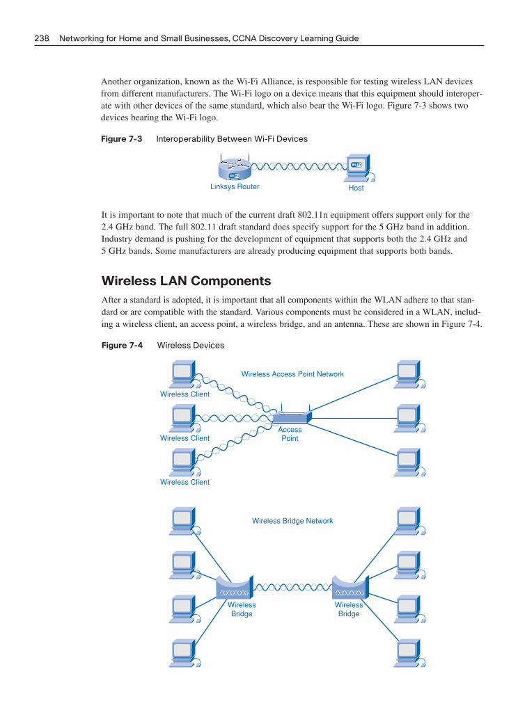
Another organization, known as the Wi-Fi Alliance, is responsible for testing wireless LAN devicesfrom different manufacturers. The Wi-Fi logo on a device means that this equipment should interoper-ate with other devices of the same standard, which also bear the Wi-Fi logo. Figure 7-3 shows twodevices bearing the Wi-Fi logo.
Figure 7-3 Interoperability Between Wi-Fi Devices
238 Networking for Home and Small Businesses, CCNA Discovery Learning Guide
Linksys Router Host
It is important to note that much of the current draft 802.11n equipment offers support only for the 2.4 GHz band. The full 802.11 draft standard does specify support for the 5 GHz band in addition.Industry demand is pushing for the development of equipment that supports both the 2.4 GHz and 5 GHz bands. Some manufacturers are already producing equipment that supports both bands.
Wireless LAN Components
After a standard is adopted, it is important that all components within the WLAN adhere to that stan-dard or are compatible with the standard. Various components must be considered in a WLAN, includ-ing a wireless client, an access point, a wireless bridge, and an antenna. These are shown in Figure 7-4.
Figure 7-4 Wireless Devices
Wireless Client
Wireless Client
Wireless Client
WirelessBridge
WirelessBridge
Wireless Access Point Network
Wireless Bridge Network
AccessPoint
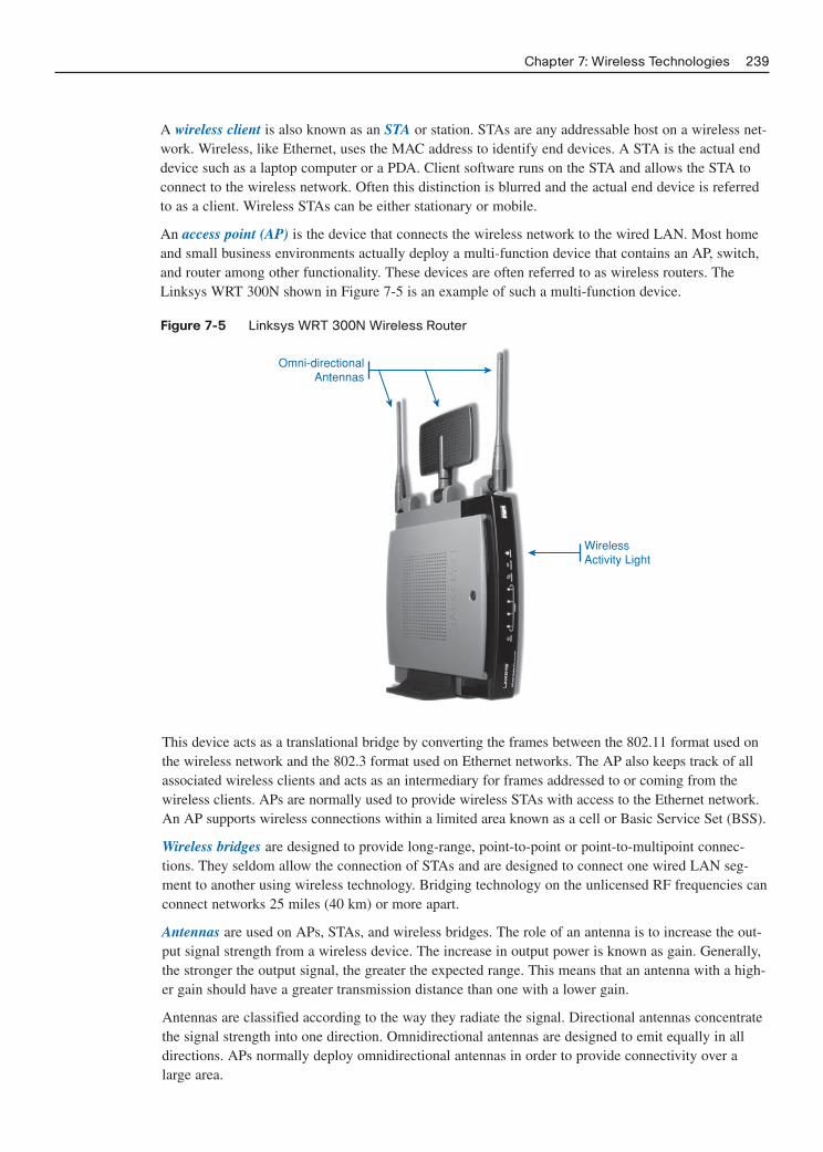
A wireless client is also known as an STA or station. STAs are any addressable host on a wireless net-work. Wireless, like Ethernet, uses the MAC address to identify end devices. A STA is the actual enddevice such as a laptop computer or a PDA. Client software runs on the STA and allows the STA toconnect to the wireless network. Often this distinction is blurred and the actual end device is referredto as a client. Wireless STAs can be either stationary or mobile.
An access point (AP) is the device that connects the wireless network to the wired LAN. Most homeand small business environments actually deploy a multi-function device that contains an AP, switch,and router among other functionality. These devices are often referred to as wireless routers. TheLinksys WRT 300N shown in Figure 7-5 is an example of such a multi-function device.
Figure 7-5 Linksys WRT 300N Wireless Router
Chapter 7: Wireless Technologies 239
Omni-directionalAntennas
WirelessActivity Light
This device acts as a translational bridge by converting the frames between the 802.11 format used onthe wireless network and the 802.3 format used on Ethernet networks. The AP also keeps track of allassociated wireless clients and acts as an intermediary for frames addressed to or coming from thewireless clients. APs are normally used to provide wireless STAs with access to the Ethernet network.An AP supports wireless connections within a limited area known as a cell or Basic Service Set (BSS).
Wireless bridges are designed to provide long-range, point-to-point or point-to-multipoint connec-tions. They seldom allow the connection of STAs and are designed to connect one wired LAN seg-ment to another using wireless technology. Bridging technology on the unlicensed RF frequencies canconnect networks 25 miles (40 km) or more apart.
Antennas are used on APs, STAs, and wireless bridges. The role of an antenna is to increase the out-put signal strength from a wireless device. The increase in output power is known as gain. Generally,the stronger the output signal, the greater the expected range. This means that an antenna with a high-er gain should have a greater transmission distance than one with a lower gain.
Antennas are classified according to the way they radiate the signal. Directional antennas concentratethe signal strength into one direction. Omnidirectional antennas are designed to emit equally in alldirections. APs normally deploy omnidirectional antennas in order to provide connectivity over alarge area.

By concentrating all the signal strength into one direction, directional antennas can achieve greattransmission distances. Directional antennas are normally used in point-to-point bridging applicationswhere two sites must be connected together over a long distance.
Interactive Activity 7-3: Wireless Components (7.2.2.3)
In this interactive activity you match the wireless component to the appropriate description. Use fileia-7223 on the CD-ROM that accompanies this book to perform this interactive activity.
WLANs and the SSID
When building a wireless network, ensuring that the wireless components connect to the appropriateWLAN is important. This is done using a Service Set Identifier (SSID). The SSID is a case-sensitive,alphanumeric string that is up to 32 characters in length. It is sent in the header of all frames transmit-ted over the WLAN and is used to tell wireless devices which WLAN they belong to and with whichother devices they can communicate. Regardless of the type of WLAN installation, all wirelessdevices in a WLAN must be configured with the same SSID in order to communicate.
The two basic forms of WLAN installations are ad-hoc and infrastructure mode.
Ad-hocThe simplest form of a wireless network is created by connecting two or more wireless clients togeth-er in a peer-to-peer network. A wireless network established in this manner is known as an ad-hocnetwork and does not include an AP. All clients within an ad-hoc network are equal. The area coveredby this network is known as an Independent Basic Service Set (IBSS). A simple ad-hoc network canbe used to exchange files and information between devices without the expense and complexity ofpurchasing and configuring an AP.
Infrastructure ModeAlthough an ad-hoc arrangement might be good for small networks, larger networks require a singledevice that controls communications in the wireless cell. If present, an AP will take over this role andcontrol who can talk and when. When an AP is in charge of communications in a cell it is referred toas infrastructure mode. Infrastructure mode is the mode of wireless communication most often usedin home and business environments. In this form of WLAN, individual STAs cannot communicatedirectly with each other. To communicate, each device must obtain permission from the AP. The APcontrols all communications and ensures that all STAs have equal access to the medium. The areacovered by a single AP is known as a Basic Service Set (BSS) or cell as shown in Figure 7-6.
Figure 7-7 shows the difference between an IBSS and a BSS. In a BSS the AP is in charge and con-trols all communication, whereas in an IBSS there is no AP to take charge.
The BSS is the smallest building block of a WLAN. Because the area of coverage of a single AP islimited, multiple BSSs are often connected together to form an Extended Service Set (ESS). An ESSconsists of multiple BSSs connected together through a distribution system (DS). An ESS uses multi-ple APs and each AP is in a separate BSS. Although there are separate BSSs, the SSID is commonthroughout the entire ESS.
240 Networking for Home and Small Businesses, CCNA Discovery Learning Guide

Figure 7-7 IBSS and BSS
Chapter 7: Wireless Technologies 241
Access Point
Wireless Clients(STA)
Wireless Cell
Figure 7-6 A Wireless Cell or Basic Service Set (BSS)
Wireless Clients(STA)
Wireless Clients(STA)
Channel 6
Independent Basic Service Set (IBSS) Basic Service Set (BSS)
Access Point
In order to allow a client to move between the cells without the loss of signal, BSSs must overlap byapproximately 10 percent, as shown in Figure 7-8. This allows the client to connect to the second APbefore disconnecting from the first AP.

Figure 7-8 Overlapping BSSs to Provide Seamless Roaming
242 Networking for Home and Small Businesses, CCNA Discovery Learning Guide
STA
Wireless Cell
Access Point
Wireless Cell
Access Point
STA
STA
10%-15%
STASTA
LAN Backbone(Distribution System)
Most home and small business environments consist of a single BSS. However, as the required cover-age area and number of hosts needing to connect increases, creating an ESS becomes necessary.
Interactive Activity 7-4: Linksys GUI: Setting the SSID (7.2.3.4)
In this interactive activity you configure the SSID using the Linksys GUI interface. Use file ia-7234on the CD-ROM that accompanies this book to perform this interactive activity.
Wireless Channels
Regardless of whether the wireless clients are communicating within an IBSS, BSS, or ESS, the con-versation between sender and receiver must be controlled. One way to accomplish this control isthrough the use of wireless channels.
Channels are created by dividing the available RF spectrum. Each channel is capable of carrying adifferent conversation. This is similar to the way that multiple television channels are transmittedacross a single medium. Multiple APs can function in close proximity to one another as long as theyuse different channels for communication.
Unfortunately, the frequencies used by some channels overlap with those used by others. Differentconversations must be carried on non-overlapping channels. The number and distribution of channelsvary by region and technology. If using the 2.4 GHz spectrum in North America, there are three non-overlapping channels: 1, 6, and 11. In this spectral range, channels must be at least five apart to avoidoverlap. In North America, the 5 GHz range uses three different UNII bands, each with four non-overlapping channels. When creating an ESS, ensuring that adjacent cells are using non-overlappingchannels for communication is important, as shown in Figure 7-9.

Figure 7-9 Channel Assignment in an ESS
Chapter 7: Wireless Technologies 243
STA
Wireless Cell
Access Point
Wireless Cell
Channel 1 Channel 6
Access Point
STA
STA STASTA
LAN Backbone(Distribution System)
You can manually or automatically set the channel selection used for a specific conversation, based onfactors such as current usage and available throughput. Normally each wireless conversation makesuse of a separate channel. IEEE 802.11n combines multiple channels to create a single wide channel,which provides more bandwidth and increases the data rate.
Within a WLAN, the lack of well-defined boundaries makes detecting whether collisions occur duringtransmission impossible. Therefore, using an access method on a wireless network that ensures colli-sions do not occur is necessary. Wireless technology uses an access method called Carrier SenseMultiple Access with Collision Avoidance (CSMA/CA). With CSMA/CA, stations listen to the chan-nel to see whether it is free; if it is they start to transmit after a random period of time.
CSMA/CA creates a reservation on the channel for use by a specific conversation. While a reservationis in place, no other device may transmit on the channel, thus possible collisions are avoided. Whenthe conversation is complete, the reservation is released and made available for others. When one sta-tion starts to send, all other stations detect the transmission and delay their transmissions for a periodto allow the conversation to complete.
In some circumstances, stations might not be within range of the transmitting station and are not ableto detect the transmission. In cases such as this, RTS/CTS comes into play. With RTS/CTS, a devicethat requires use of a specific communication channel in a BSS asks permission from the AP. This isknown as a Request to Send (RTS). If the channel is available, the AP will respond to the device witha Clear to Send (CTS) message indicating that the device may transmit on the channel. A CTS isbroadcast to all devices within the BSS. Therefore, all devices in the BSS know that the requestedchannel is now in use and wait for the conversation to complete before transmitting. RTS/CTS is notnormally used in small wireless networks such as those encountered in homes and small businesses.This is because the chances of a station being unable to detect the transmissions of another station in asmall network are slim and the overhead associated with CTS/RTS would actually slow down the net-work performance.

When the AP receives the packet correctly, the conversation is complete. At this point, the AP issuesan acknowledgement (ACK). This message is broadcast to all devices on the WLAN. All deviceswithin the BSS receive the ACK and know that the channel is once again available, as illustrated inFigure 7-10.
Figure 7-10 Media Access in a BSS
244 Networking for Home and Small Businesses, CCNA Discovery Learning Guide
Access Point
H1
SourceRequest to Send (RTS)
Clear to Send (CTS)
DATA
ACK
Interactive Activity 7-5: Linksys GUI: Setting the Channel (7.2.4.3)
In this interactive activity you configure the channel using the Linksys GUI interface. Use file ia-7243on the CD-ROM that accompanies this book to perform this interactive activity.
Configuring the Access Point
The first step in any wireless network deployment is careful planning done in consultation with all thestakeholders, including anyone who will use, manage, or support the network. This step helps deter-mine the standard to use, equipment required, network layout, and channel assignment. After thesefactors have been determined the next step is to configure the AP.
Most integrated routers offer both wired and wireless connectivity and serve as the AP in the wirelessnetwork. Basic configuration settings such as passwords, IP addresses, and DHCP settings are thesame whether the device is being used to connect wired or wireless hosts. Basic configuration tasks,such as changing the default password, should be conducted before the AP is connected to a live network.
When using the wireless functionality of an integrated router, additional configuration parameters arerequired, such as setting the wireless mode, SSID, and wireless channel to be used.
Wireless ModeMost home AP devices can support various modes, mainly 802.11b, 802.11g, and 802.11n. Althoughthese all use the 2.4 GHz range, each uses a different technology to obtain its maximum throughput.The type of mode enabled on the AP depends on the type of host connecting to it. If only one type ofhost connects to the AP device, set the mode to support it. If multiple types of hosts will connect,

select mixed mode. Each mode includes a certain amount of overhead. By enabling mixed mode, net-work performance will decrease due to the overhead incurred in supporting all modes. Figure 7-11illustrates the different modes available on a Linksys wireless router.
Figure 7-11 Wireless Modes in a Linksys Wireless Router
Chapter 7: Wireless Technologies 245
SSIDThe SSID, as shown in Figure 7-12, is used to identify the WLAN. All devices that want to partici-pate in the WLAN must use the same SSID. To allow easy detection of the WLAN by clients, theSSID is normally broadcast. It is possible to disable the broadcast feature of the SSID. If the SSID isnot broadcast, wireless clients will need to have this value manually configured. Although it makesdetecting a WLAN more difficult, disabling the SSID broadcast should not be considered a securityfeature.
Figure 7-12 SSID and Wireless Channel

Wireless ChannelThe choice of channel for an AP must be made relative to the other wireless networks around it.Adjacent BSSs must use non-overlapping channels in order to optimize throughput. Most APs nowoffer a choice to manually configure the channel, or allow the AP to automatically locate the leastcongested channel or locate the one that offers maximum throughput. The 802.11n technology alsooffers the ability to fuse channels together to create a wide channel that is capable of carrying data ata higher transfer rate than a standard channel.
Lab 7-1: Configuring a Wireless Access Point (7.2.5.3)
In this lab you configure an access point to allow clients to associate to. Refer to the hands-on lab inPart II of this Learning Guide. You may perform this lab now or wait until the end of the chapter.
Configuring the Wireless Client
A wireless host, or STA, is defined as any device that contains a wireless NIC and runs wireless clientsoftware. This client software allows the hardware to participate in the WLAN. PDAs, laptops, desk-top PCs, printers, projectors, and Wi-Fi phones are all common examples of STAs. Figure 7-13 showssome wireless-enabled devices.
Figure 7-13 Wireless-Enabled Devices
246 Networking for Home and Small Businesses, CCNA Discovery Learning Guide
Cell Phone PDA
Desktop Computer Laptop Computer
In order for a STA to connect to the WLAN, the client configuration must match that of the AP. Thisincludes the SSID, any security settings, and the wireless channel information if it was manually seton the AP. These settings are specified in the client software that manages the client connection.
The wireless client software used can be software integrated into the device operating system, or canbe standalone, downloadable, wireless utility software specifically designed to interact with the spe-cific wireless NIC.
Integrated Wireless Utility SoftwareThe Windows XP wireless client software is an example of a popular wireless client utility that isincluded as part of the device OS. This client software can control most basic wireless client configu-rations but is not optimized for any specific wireless NIC. It is user friendly and offers a simple con-nection process.

Standalone Wireless Utility SoftwareWireless utility software is usually supplied with the wireless NIC and is designed to work with thatspecific NIC. It usually offers enhanced functionality over the Windows XP wireless utility software.It normally includes features such as
■ Link information: Displays the current strength and quality of a wireless signal
■ Profiles: Allows configuration options such as channel and SSID to be specified for each wirelessnetwork
■ Site survey: Enables the detection of all wireless networks in the vicinity
Allowing both the wireless utility software and Windows XP client software to manage the wirelessconnection at the same time is not possible. For most situations the Windows XP wireless client soft-ware is sufficient. However, if multiple profiles must be created for each wireless network or advancedconfigurations settings are necessary, using the utility supplied with the NIC might be better.
Lab 7-2: Configuring a Wireless Client (7.2.6.4)
In this lab you configure a wireless client to associate to a previously configured AP. Refer to thehands-on lab in Part II of this Learning Guide. You may perform this lab now or wait until the end ofthe chapter.
After you configure the client software, you should verify the link between the client and the AP. Todo so, open the wireless link information screen to display information such as the connection datarate, connection status, and wireless channel used. Figure 7-14 shows an example of typical link infor-mation. It shows the quality of the wireless signal and the current signal strength.
Figure 7-14 Linksys Wireless Client
Chapter 7: Wireless Technologies 247
In addition to verifying the wireless connection status, verify that data can actually be transmitted.One of the most common tests for verifying successful data transmission is a simple ping. If the pingis successful, physical connectivity is present and data transmission is usually possible. If the ping isunsuccessful from source to destination, ping the AP from the wireless client to ensure that wirelessconnectivity is available. If this fails as well, the issue is between the wireless client and the AP, asshown in Figure 7-15. In this case, check the settings on both the client and the AP and try to reestab-lish connectivity.

Figure 7-15 Misconfiguration of the Wireless Client
248 Networking for Home and Small Businesses, CCNA Discovery Learning Guide
Internet
Your configuration is notcorrect; access denied.
If the wireless client can successfully connect to the AP, check the connectivity from the AP to thenext hop on the path to the destination. If the connection is successful, the problem is most likely notwith the AP configuration, but may be an issue with another device on the path to the destination orthe destination device itself.
Security Considerations on a Wireless LAN
One of the primary benefits of wireless networking is the convenience of connecting devices withoutthe restrictions imposed by wires. Unfortunately, that ease of connectivity and the fact that the infor-mation is transmitted through the air also makes wireless technology vulnerable to interception andattacks.
Why People Attack WLANs
With wireless connectivity, the attacker does not require a physical connection to the network or net-worked devices to launch an attack. The possibility exists for an attacker to tune into wireless signalsemanating from the network, much like tuning into a radio station. The attacker can access the net-work from any location the wireless signal reaches. After an attacker has access to the network he hasaccess to all the information it contains as well as the resources it provides. For example, an intrudercan use the company’s Internet connection to launch attacks against other networks or to carry outother illegal activities. The wireless network can also provide access to the wired network whereintruders can damage files or steal personal and private information.
The vulnerabilities in wireless networking require special security features and implementation meth-ods to help protect the WLAN from attack. This includes steps to secure the wireless device, such asimplementing secure passwords and changing all default settings, as well as more advanced securityconfigurations such as data encryption.

War Driving and War Walking
War driving is the process of driving around an area searching for wireless LANs. When discovered,the location of the WLAN is logged and shared. The goal of war driving is to bring attention to thefact that most wireless networks are insecure and also to show the widespread acceptance and use ofwireless LAN technology.
A similar process to war driving is known as war walking, in which the person walks around an areato discover wireless access. Once access is discovered, a chalk mark is placed in front of the locationto indicate the status of the wireless connection. This mark allows others to easily identify openWLANs, which can be exploited.
The SSID provides a convenient way for users to gain entry into a WLAN. All computers connectingto a wireless network must know the SSID before they are able to connect. By default, wirelessrouters and access points announce the presence of the WLAN by broadcasting the SSID to all com-puters within range. With SSID broadcast activated, as shown in Figure 7-16, any wireless client candetect the network and connect to it, if no other security features are in place.
Figure 7-16 SSID and SSID Broadcast Settings
Chapter 7: Wireless Technologies 249
Both SSID and SSID broadcast are at their default values
The SSID broadcast feature can be turned off. When it is turned off, the fact that the network is thereis no longer made public. This does not provide any real level of security but does make connectingmore difficult for a client. Any computer trying to connect to the network must be manually config-ured with the SSID. Easily obtainable tools do exist that allow someone wanting to gain access to thewireless network to actively determine the network SSID.
Additionally, changing all default settings is important. Wireless devices are usually shipped precon-figured with settings such as SSIDs, passwords, and IP addresses in place. These default settings arepublic knowledge and make identifying and infiltrating a network easy for an attacker. Default infor-mation should be changed to something secure and unique before the wireless device is connected toa live network.
Even with SSID broadcasting disabled, the possibility exists for someone to gain access to a WLANusing the well-known default SSID. Additionally, if other default settings such as passwords and IP

addresses are not changed, attackers can access an AP and make changes themselves by either lockingout legitimate users or providing themselves and others with unauthorized access. Changing thesedefaults will decrease the chance of unauthorized access to the WLAN.
Disabling SSID broadcast and changing default settings, by themselves, will not protect the network.For example, SSIDs are transmitted in clear text in every 802.11 frame. Software is readily availablethat will allow a device to intercept wireless signals and read the SSID. Even with SSID broadcastturned off and default values changed, attackers can learn the name of a wireless network through theuse of these devices. Many different techniques must be deployed to help secure a WLAN, includingfiltering, authentication, and encryption.
MAC Address Filtering
One way to limit access to wireless networks is to control exactly which devices can connect to thenetwork through the filtering of the MAC address, as shown in Figure 7-17. MAC address filteringuses the MAC address embedded in every frame to identify which devices are allowed to connect tothe wireless network. When a wireless client attempts to connect, or associate, with an AP it sends itsMAC address information. If MAC address filtering is enabled, the wireless router or AP will look upthis MAC address in a preconfigured list. Only devices whose MAC addresses have been prerecordedin the router’s database are allowed to associate with the network. Frames with MAC addresses notfound in the database are dropped by the AP.
Figure 7-17 MAC Address Filtering
250 Networking for Home and Small Businesses, CCNA Discovery Learning Guide
MAC Address Filtering
00.09.6F.57.01.62
10.8A.41.2E.AD.75
45.B9.31.B1.5C.22
MAC Address Filter ListEnter MAC Address in this format XXXXXXXXX
Wireless Client MAC List
MAC Address 1-20
MAC 01:
MAC 02:
MAC 03:
MAC 11:
MAC 12:
MAC 13:
00.09.6F.57.01.62
45.B9.31.B1.5C.22
Several issues exist with MAC address filtering that hinders its usefulness. For example, it requiresthe MAC addresses of all devices that should have access to the network to be included in the data-base before connection attempts occur. A device that is not identified in the database will not be ableto connect. For large, dynamic networks the administration of MAC addresses can become quite atask. Additionally, the possibility exists for an attacker to capture frames from the WLAN and thenclone the address of a device that does have permission to use the network. This method is nowextremely easy to do with tools that are freely available for download from the Internet.

Authentication on a WLAN
Another way to control who can connect to the WLAN is to implement authentication. Authen-tication is the process of permitting entry to a network based on a set of credentials. It is used to veri-fy that the person or device attempting to connect to the network is who they claim to be.
The use of a username and password is the most common form of authentication. In a wireless envi-ronment, authentication ensures that the connected host is verified. Client authentication, if enabled,must occur before it is allowed to associate to the WLAN. Association is the point when the APagrees to handle data to and from the wireless host. The three types of wireless authentication meth-ods are open authentication, pre-shared keys (PSK), and Extensible Authentication Protocol (EAP).
Open AuthenticationBy default, wireless devices do not require authentication. Any and all clients are able to associateregardless of who they are. This is referred to as open authentication, which really means no authen-tication at all, as shown in Figure 7-18. Open authentication should be used only on public wirelessnetworks such as those found in many schools and restaurants. It can also be used on networks whereauthentication will be done by other means once connected to the network.
Figure 7-18 Open Authentication
Chapter 7: Wireless Technologies 251
Hi, I know yourname. Can Iconnect?
Sure...accessgranted.
Pre-shared keys (PSK)With pre-shared keys (PSK) both the AP and client must be configured with the same key or secretword, as shown in Figure 7-19. The AP sends a random string of bytes to the client. The clientaccepts the string and encrypts or scrambles it based on the key and an encryption algorithm. Theencrypted string is then sent back to the AP. The AP also carries out the encryption process locallyusing the same algorithm and the same shared secret word. If the encrypted string received by the APfrom the client is the same as the one generated by the client, authentication is successful and theclient is allowed to connect.
One of the problems with PSK is the authentication is only one way. The host authenticates to the AP.PSK does not authenticate the AP to the host, nor does it authenticate the actual user of the host. Inorder to obtain mutual authentication between the user and the AP you must use ExtensibleAuthentication Protocol (EAP).

Figure 7-19 Authentication Using Pre-shared keys
252 Networking for Home and Small Businesses, CCNA Discovery Learning Guide
Hi, Iʼd like toconnect.
You canconnect, but
only if you knowthe secret key.
Extensible Authentication Protocol (EAP)Extensible Authentication Protocol (EAP) provides mutual, or two-way, authentication as well asuser authentication, as illustrated in Figure 7-20. When EAP software is installed on the client, theclient communicates with a back-end authentication server such as Remote Authentication Dial-inUser Service (RADIUS). This back-end server functions separately from the AP and maintains a data-base of valid users who can access the network. When using EAP, the user, not just the host, mustprovide a username and password, which is checked against the RADIUS database for validity. Ifvalid, the user is authenticated and allowed to make use of the network services.
Figure 7-20 User Authentication Using EAP
User. xyzpassword: cisco
connect toRouter A is
verified.
Hi, Iʼm user. xyzpassword: cisco
and Iʼd like toconnect.
Router ARADIUS
Iʻll forward yourrequest.
After authentication is enabled, regardless of the method used, the client must successfully passauthentication before it can associate with the AP. If both authentication and MAC address filteringare enabled, authentication occurs first. When authentication is successful, the AP then checks theMAC address against the MAC address table, as shown in Figure 7-21. When verified, the AP addsthe host MAC address into its host table. The association of the client with the AP allows the client toconnect to the network.
EAP frames are considered upper-level data by the MAC layer, so the STA must be authenticated andassociated with the AP before it can commence network authentication via RADIUS. For this reason,open authentication is the normal setting when EAP is used.

Figure 7-21 Authentication and Association
Chapter 7: Wireless Technologies 253
Attempt to Connect
Response to Challenge
Attempt to Associate
Challenge (Request for Key)
Authentication
Check MAC Filter and Associate
Encryption on a WLAN
Authentication and MAC filtering might stop an attacker from connecting to a wireless network but itwill not prevent the attacker from being able to intercept transmitted data. Because a wireless networkdoes not have distinct boundaries and all traffic is transmitted through the air, intercepting, or sniffing,the wireless frames is easy for an attacker. Encryption is the process of transforming data so that evenif it is intercepted it is unusable. This process is shown in Figure 7-22.
Figure 7-22 Encryption of Wireless Data
Hosts Need theRight Key
Hosts Need theRight Key
56cde.dca211a001ab0ab
Wired Equivalency Protocol (WEP)Wired Equivalency Protocol (WEP) is a security feature that encrypts network traffic before it istransmitted. WEP uses preconfigured keys to encrypt and decrypt data.
A WEP key is entered as a string of numbers and letters and is generally 64 bits or 128 bits long. Insome cases, WEP supports 256 bit keys as well. To simplify creating and entering these keys, manydevices include a passphrase option. The passphrase is an easy way to remember the word or phraseused to automatically generate a key.
In order for WEP to function, the AP, as well as every wireless device allowed to access the network,must have the same WEP key entered. Without this key, devices will not be able to understand thewireless transmissions.
WEP makes being able to use intercepted data difficult for attackers. However, there are weaknesseswithin WEP, including the use of a static key on all WEP-enabled devices. If a device containing theWEP key is lost or stolen, it can be used to gain access to the network. In addition, applications areavailable to attackers that they can use to discover the WEP key, as illustrated in Figure 7-23. Theseapplications are readily available on the Internet and require little knowledge to use. After the attackerhas extracted the key, he has complete access to all transmitted information. For these reasons WEP isno longer recommended unless the devices are unable to support Wi-Fi Protected Access (WPA).

Figure 7-23 Cracking the WEP Key
254 Networking for Home and Small Businesses, CCNA Discovery Learning Guide
AC323CB86993DEB758BC737D892
Success
AC323CB86993DEB758BC737D892
Wireless sniffer running WEPcracking tool.
AC323CB86993DEB758BC737D892
AC323CB86993DEB758BC737D892
One way to overcome this vulnerability is to change the key frequently. Another way is to use a moreadvanced and secure form of encryption known as Wi-Fi Protected Access.
Wi-Fi Protected Access (WPA)Wi-Fi Protected Access (WPA) uses encryption keys from 64 bits up to 256 bits. However, WPA,unlike WEP, generates new, dynamic keys each time a client establishes a connection with the AP. Forthis reason, WPA is considered more secure than WEP because it is significantly more difficult tocrack.
Interactive Activity 7-6: Linksys GUI: Configuring Encryption (7.3.4.3)
In this interactive activity, you configure encryption using the Linksys GUI interface. Use file ia-7343on the CD-ROM that accompanies this book to perform this interactive activity.
Traffic Filtering on a WAN
In addition to controlling who can gain access to the WLAN and who can make use of transmitteddata, controlling the types of traffic transmitted across a WLAN is also worthwhile. This task isaccomplished using traffic filtering.
Traffic filtering blocks undesirable traffic from entering or leaving the wireless network. Filtering isdone by the AP as traffic passes through it. It can be used to remove traffic from, or destined to, a spe-cific MAC or IP address. It can also block certain applications by port numbers. By removing unwant-ed, undesirable, and suspicious traffic from the network, more bandwidth is devoted to the movementof important traffic, which improves the performance of the WLAN. For example, traffic filtering canbe used to block all Telnet traffic destined for a specific machine, such as an authentication server.Any attempts to telnet into the authentication server would be considered suspicious and blocked.Figure 7-24 shows the MAC filtering capabilities on a Linksys wireless router.

Figure 7-24 MAC Filtering on a Linksys Wireless Router
Chapter 7: Wireless Technologies 255
Lab 7-3: Configuring Wireless Security (7.3.5.2)
In this interactive lab you apply security measures to the WLAN to prevent unauthorized access totransmitted information. Refer to the hands-on lab in Part II of this Learning Guide. You may performthis lab now or wait until the end of the chapter.
Configuring an Integrated AP and Wireless Client
Before any configuration of network devices can occur, the wireless network must be carefullyplanned. Time spent in planning will save a great deal of time, frustration, and money later on.
Planning the WLAN
When implementing a wireless network solution, planning before performing any installation isimportant. This includes
■ Determining the type of wireless standard to use
■ Determining the most efficient layout of devices
■ Devising an installation and security plan
■ Documenting a strategy for backing up and updating the firmware of the wireless devices
Wireless StandardsWhen determining which WLAN standard to use, you must consider several factors. The most com-mon factors include
■ Bandwidth requirements
■ Coverage areas
■ Existing implementations
■ Cost

You gather this information by determining end-user requirements. The best way to learn end-userrequirements is to ask questions. Some of the key questions that must be answered before proceedingare
■ What throughput is actually required by the applications running on the network?
■ How many users will access the WLAN?
■ What is the necessary coverage area?
■ What is the existing network structure?
■ What is the budget?
The bandwidth available in a BSS is shared between all the users in that BSS. Even if individualapplications do not require a high-speed connection, one of the higher-speed wireless technologiesmight be necessary if multiple users are connecting at the same time or multiple applications are beingrun at the same time.
Different standards support different coverage areas. The 2.4 GHz signal, used in 802.11 b/g/n tech-nologies, travels a greater distance than does the 5 GHz signal used in 802.11a technologies. Thus802.11 b/g/n supports a larger BSS, which translates into less equipment and a lower cost of imple-mentation.
The existing network affects new implementation of WLAN standards. To provide the best cost recovery, new equipment must be backward compatible with the existing network infrastructure. Forexample, if the existing network has been developed around the 5 GHz technologies then any newtechnology considered must also use these frequencies. Some of the current draft 802.11n equipmentonly operates at 2.4 GHz and is therefore backward compatible with 802.11g and 802.11b but notwith 802.11a. Remember that the full 802.11n standard supports both 2.4 GHz and 5 GHz but not allequipment is fully compatible at the time of this writing.
Cost is also a factor. When considering cost, consider Total Cost of Ownership (TCO), which includesthe purchase of the equipment as well as installation and support costs. In a medium to large businessenvironment, TCO has a greater impact on the WLAN standard chosen than in the home or smallbusiness environment. This is because in the medium to large business, more equipment is necessaryand sophisticated installation and support plans are required, increasing cost.
Installation of Wireless DevicesFor home or small business environments, the installation usually consists of a limited amount ofequipment, which can be easily relocated to provide optimum coverage and throughput. In the enter-prise environment, equipment cannot be easily relocated and coverage must be complete. Determiningthe optimum number and placement of APs to provide this coverage at the least amount of cost isimportant.
In order to accomplish this task, a site survey is usually conducted. The organization or departmentresponsible for the site survey must be knowledgeable in WLAN design and equipped with sophisti-cated equipment for measuring signal strengths and interference. Depending on the size of the WLANimplementation, this process can be very expensive. For small installations a simple site survey is usu-ally conducted using wireless STAs and the utility programs packaged with most wireless NICs. Sitesurvey modeling software is available and has improved to the point that only the most challengingenterprise environments now require detailed on-site surveys. In all cases, considering known sourcesof interference, such as high-voltage wires, motors, and other wireless devices, when determining theplacement of WLAN equipment is necessary.
256 Networking for Home and Small Businesses, CCNA Discovery Learning Guide

Installing and Securing the AP
After the best technology and placement of the AP are determined, install the WLAN device and con-figure the AP with security measures. Security measures should be planned and configured beforeconnecting the AP to the network or ISP.
Some of the more basic security measures include
■ Change default values for the SSID, usernames, and passwords.
■ Disable remote management to prevent access from external networks.
■ Allow connections to the device only through secure protocols such as HTTPS.
■ Disable broadcast SSID.
■ Configure MAC address filtering.
Some more advanced security measures include
■ Configure encryption using WEP or WPA.
■ Configure authentication.
■ Configure traffic filtering.
Keep in mind that no single security measure will keep your wireless network completely secure.Combining multiple techniques strengthens the integrity of your security plan but cannot guaranteethat the integrity of the network will never be compromised. Security merely decreases the likelihoodthat this might happen.
When configuring the clients, ensuring that the SSID matches the SSID configured on the AP isessential. Additionally, encryption keys and authentication keys must also match. Remember that theSSID and keys are case sensitive. If the SSIDs do not match, the client will not associate with the AP.If the authentication keys do not match, the client will also be unable to associate. Mismatchedencryption keys do not normally prevent association but do render the data transferred unreadable.Many devices use the same key for both authentication and encryption purposes. In this case mis-matched keys will prevent association.
Challenge Lab 7-4: Planning the Home or Small Business WLAN
In this lab you plan a WLAN installation for a home or small business. Refer to the hands-on lab inPart II of this Learning Guide. You may perform this lab now or wait until the end of the chapter.
Backing Up and Restoring Configuration Files
After the wireless network is properly configured and traffic is moving, a full configuration backupshould be performed on wireless access points and bridges. This step is especially important if a greatdeal of customization has been done to the configuration.
With most integrated routers designed for the home and small business markets, performing this taskis simply a matter of selecting the Backup Configurations option from the appropriate menu andspecifying the location where the file should be saved. The integrated router provides a default namefor the configuration file, which can be changed if desired. The restore process is just as simple.Select the Restore Configurations option. Then simply browse to the location where the configura-tion file was previously saved and select the file. After selecting the file, click Start to Restore toload the configuration file.
Chapter 7: Wireless Technologies 257

Sometimes returning the setting to the factory default conditions might be necessary. To accomplishthis task select either the Restore Factory Defaults option from the appropriate menu or press andhold the Reset button for 30 seconds. The latter technique is especially useful if you are unable toconnect to the AP of the integrated router through the network but have physical access to the device.
Interactive Activity 7-7: Linksys GUI: Backing Up and Restoring a Configuration File (7.4.3.2)
In this interactive activity you use the Linksys GUI interface to back up and restore configuration fileson the wireless router. Use file ia-7432 on the CD-ROM that accompanies this book to perform thisinteractive activity.
Updating the Firmware
The operating system on most integrated routers is stored in firmware. As new features are developedor problems with the existing firmware are discovered, updating the firmware on the device mightbecome necessary.
The process for updating firmware on an integrated router, such as the Linksys wireless router, is sim-ple. However, not interrupting the process once it is started is important. If the update process is inter-rupted before completion, the device might be rendered inoperable.
Before attempting an update of the firmware, determine the version of the firmware currently installedon the device. This information is usually displayed on the configuration screen or the connection sta-tus screen. Next, search the manufacturer’s website and related newsgroups on the Internet to discoverthe firmware feature set, issues that might warrant an upgrade, and whether updates are available.
Download the updated version of the firmware and store it on the hard drive of a device that can bedirectly connected to the integrated router. Using a machine that is directly connected to the integratedrouter with a cable to prevent any interruption in the update process caused by a wireless connectionis best.
Select the Firmware Upgrade feature in the GUI as shown in Figure 7-25. Browse to the appropriatefile on the directly connected device and start the upgrade.
Figure 7-25 Upgrading the Linksys Wireless Router Firmware
258 Networking for Home and Small Businesses, CCNA Discovery Learning Guide

Interactive Activity 7-8: Linksys GUI: Updating the Firmware (7.4.4.2)
In this interactive activity you use the Linksys GUI interface to update the firmware on the wirelessrouter. Use file ia-7442 on the CD-ROM that accompanies this book to perform this interactive activity.
Chapter 7: Wireless Technologies 259

260 Networking for Home and Small Businesses, CCNA Discovery Learning Guide
Summary
This chapter described the various technologies that allow the transmission of information betweenhosts without the use of cables. It described the benefits and limitations of these technologies andsome of the devices that use them.
Wireless technologies use electromagnetic waves such as infrared (IR) and radio frequency (RF) radi-ation to carry information between devices. IR is generally used for short range one-to-one communi-cation whereas RF is used for longer range or one-to-many communications.
Wireless networks are grouped into three major categories: wireless personal-area networks (WPAN),wireless local-area networks (WLAN), and wireless wide-area networks (WWAN).
The main organization responsible for the creation of wireless technical standards is the IEEE.Standards that govern the WLAN environment include 802.11a, 802.11b, 802.11g, and 802.11n andare known as WiFi standards.
WLAN devices include wireless clients, access points, wireless bridges, and antennas. Wireless clientsare also known as STAs and are the end, network addressable, device. APs allow wireless clients in alimited area to connect to the wired network by translating between the IEEE 802.11 wireless frameformat and the standard 802.3 Ethernet frame format. Wireless bridges provide a mechanism for theconnection of wired networks through wireless technology. Wireless devices use antennas to transmitand receive information. The two types of antennas are directional and omnidirectional.
WLANs are divided into two types. A small peer-to-peer network is known as an ad-hoc network anddoes not include an AP. A wireless network that has an AP is termed an infrastructure network. Thearea controlled by the AP is referred to as a cell or Basic Service Set (BSS). Many BSSs can be con-nected together through a Distribution System (DS) to create an Extended Service Set (ESS). EachESS is identified by a Service Set Identifier (SSID). All wireless devices in a WLAN must be config-ured with the same SSID and operate using the same standards in order to communicate.
To separate conversations in a cell, the RF spectrum is divided into different channels. APs and clientsuses an access method called Carrier Sense Multiple Access with Collision Avoidance (CSMA/CA)that creates a reservation on the channel for use by a specific conversation.
Because wireless technology transmits information through the open space, wireless networks aremore susceptible to attacks than wired networks. An attacker can access a wireless network from anylocation the wireless signal reaches. Once connected, attackers can use your Internet services for freeor damage files and steal private information from your network.
By combining various basic and advanced security techniques, reducing the risk of attack is possible.Some of the basic security measures include
■ Change default values for the SSID, usernames, and passwords.
■ Disable broadcast SSID.
■ Configure MAC address filtering.
More advanced security measures include
■ Configure encryption using WEP or WPA.
■ Configure authentication.
■ Configure traffic filtering.

Chapter 7: Wireless Technologies 261
Before installing a wireless network, an installation plan should be created that includes the standardsto be used, the location of devices, a security plan, and a strategy for backing up configurations. Inorder to carry out this plan, the following steps are needed:
■ Gather user requirements to determine the appropriate standard to use, bandwidth requirements,coverage areas, existing implementations, and cost.
■ Perform a site survey to determine the optimum number and location of APs.
■ Combine multiple security techniques to strengthen the integrity of the wireless network.
■ Perform a full configuration backup of wireless devices to provide a stored copy in case of devicefailure.
■ Upgrade the firmware, if necessary, to take advantage of enhancements to the operating system.
Activities and Labs
This summary outlines the activities and labs you can perform to help reinforce important conceptsdescribed in this chapter. You can find the activity files on the CD-ROM accompanying this book. Thecomplete hands-on labs appear in Part II.
Interactive Activities on the CD:
Interactive Activity 7-1: Selecting the Wireless Technology (7.1.1.4)
Interactive Activity 7-2: Selecting the Type of Wireless Network (7.1.3.3)
Interactive Activity 7-3: Wireless Components (7.2.2.3)
Interactive Activity 7-4: Linksys GUI: Setting the SSID (7.2.3.4)
Interactive Activity 7-5: Linksys GUI: Setting the Channel (7.2.4.3)
Interactive Activity 7-6: Linksys GUI: Configuring Encryption (7.3.4.3)
Interactive Activity 7-7: Linksys GUI: Backing Up and Restoring a Configuration File (7.4.3.2)
Interactive Activity 7-8: Linksys GUI: Updating the Firmware (7.4.4.2)
Labs in Part II of This Book:
Lab 7-1: Configuring a Wireless Access Point (7.2.5.3)
Lab 7-2: Configuring a Wireless Client (7.2.6.4)
Lab 7-3: Configuring Wireless Security (7.3.5.2)
Challenge Lab 7-4: Planning the Home or Small Business WLAN

262 Networking for Home and Small Businesses, CCNA Discovery Learning Guide
Check Your Understanding
Complete all the review questions listed here to test your understanding of the topics and concepts inthis chapter. The “Check Your Understanding and Challenge Questions Answer Key” appendix liststhe answers.
1. Which devices commonly make use of wireless technology? (Choose all that apply.)
A. Television remote control
B. IrDA-equipped PDA
C. Bluetooth-enabled headphone
D. Cellular phone
E. Satellite radio receiver
2. Which is true of wireless technology?
A. Wireless provides sharply defined network boundaries.
B. Wireless is inherently a very secure technology.
C. Wireless technology is easily scaled to provide increased coverage.
D. Wireless technology is immune to outside sources of interference.
3. Which WLAN standard amendments use the 2.4 GHz frequency range? (Choose all that apply.)
A. 801.11a
B. 802.11b
C. 802.11g
D. 802.11n
4. Which IEEE standard applies to WLANs?
A. 802.3
B. 802.5
C. 802.11
D. 802.15
5. What is the main purpose of an SSID?
A. Data encryption
B. User authentication
C. WLAN identification
D. Secure key exchange
6. What name is given to a small wireless network that does not contain an AP?
A. Infrastructure
B. Ad-hoc
C. BSS
D. ESS
E. IBSS

Chapter 7: Wireless Technologies 263
7. What is the name given to the smallest coverage area in an infrastructure WLAN? (Choose two.)
A. Cell
B. IBSS
C. BSS
D. ESS
E. DS
8. Which occurs first in a WLAN, association or authentication?
9. What is the default authentication type on most WLAN devices?
10. Which security precautions should be implemented on a wireless AP? (Choose all that apply.)
A. Change all default settings.
B. Disable SSID broadcast.
C. Encrypt data using WPA.
D. Change the WEP key regularly.
E. Configure security settings before connecting to a live network.
Challenge Questions and Activities
These questions require a deeper application of the concepts covered in this chapter. You can find theanswers in the appendix.
1. You have just configured a WLAN for a small accounting company. The company intends to useits network to allow temporary employees to work on clients’ tax returns during the peak season.The manager has asked you whether WEP will protect the clients’ confidential information frombeing intercepted by unauthorized individuals. What would be your response?
2. A colleague has asked you why they lose wireless connectivity on their home network every time they answer their cordless phone. How would you answer this? What solution would yousuggest?

This page intentionally left blank

CHAPTER 8
Basic Security
Objectives
Upon completion of this chapter, you will able to answer the following questions:
■ What are the main networking threats and theircharacteristics?
■ What are the different methods of attack?
■ What security procedures and applications existto help prevent attacks?
■ What is a firewall and how is it used to protectagainst an attack?
■ What is a DMZ and how is basic DMZ architec-ture structured?
■ How do you configure a DMZ and port forward-ing with an integrated router device?
■ What is vulnerability analysis software and howcan it help prevent attacks?
Key Terms
This chapter uses the following key terms. You can find the definitions in the Glossary.
hacker page 266
social engineering page 268
pretexting page 268
phishing page 269
vishing page 269
virus page 270
worm page 270
Trojan horse page 271
Denial of Service (DoS) page 271
SYN (synchronous) flood page 271
ping of death page 272
Distributed Denial of Service (DDoS) page 272
brute force page 272
spyware page 273
adware page 274
security policy page 276
firewall page 283
URL page 283
stateful packet inspection (SPI) page 283
network address translation (NAT) page 283
intranet page 284
demilitarized zone (DMZ) page 284
static IP address page 286
port forwarding page 287

All over the world, people use networks to exchange sensitive information with each other. Peoplepurchase products and do their banking over the Internet. We rely on networks to be secure and toprotect our identities and private information. Network security is a shared responsibility that eachperson must accept when he or she connects to the network. In this chapter you will learn about the threats that exist on the network and how you can do your part to protect your computers andinformation.
Networking Threats
Every day, home and organizational networks come under attack from inside and outside intruders.The attackers have various motivations and the attacks can take many different forms. This sectiondescribes types of attackers, the damage they can cause, and intrusion techniques.
Risks of Networking Intrusion
Whether wired or wireless, computer networks are quickly becoming essential to everyday activities.Individuals and organizations alike depend on their computers and networks for functions such as e-mail, accounting, organization, and file management. Intrusion by an unauthorized person can resultin costly network outages and loss of work. Attacks on a network can be devastating and can result ina loss of time and money due to damage or theft of important information or assets.
Intruders can gain access to a network through software vulnerabilities, hardware attacks, or eventhrough less high-tech methods, such as guessing someone’s username and password. Intruders whogain access by modifying software or exploiting software vulnerabilities are often called hackers.
After the hacker gains access to the network, four types of threats, shown in Figure 8-1, might arise:
■ Information theft: Breaking into a computer to obtain confidential information. Information canbe used or sold for various purposes. An example is stealing an organization’s proprietary infor-mation, such as research and development information. A hacker who has gained access to thenetwork might also obtain information by intercepting data as it is transmitted.
■ Identity theft: A form of information theft where personal information is stolen for the purposeof taking over someone’s identity. Using this information, an individual can obtain legal docu-ments, apply for credit, and make unauthorized online purchases. Identity theft is a growing prob-lem costing billions of dollars per year.
■ Data loss/manipulation: Breaking into a computer to destroy or alter data records. An exampleof data loss is a virus that reformats a computer’s hard drive. An example of data manipulation isbreaking into a records system to change information, such as the price of an item.
■ Disruption of service: Preventing legitimate users from accessing services to which they shouldbe entitled. Examples include Denial of Service (DoS) attacks to servers, network devices, or net-work communications links.
Interactive Activity 8-1: Identifying Security Threats (8.1.1.2)
In this interactive activity you identify the type of security threat described. Use file ia-8112 on theCD-ROM that accompanies this book to perform this interactive activity.
266 Networking for Home and Small Businesses, CCNA Discovery Learning Guide

Figure 8-1 Types of Networking Threats
Chapter 8: Basic Security 267
Information Theft Data Loss andManipulation
Identity Theft Disruption of Service
404 pagenot found
Sources of Network Intrusion
Security threats from network intruders can come from both internal and external sources, as shown inFigure 8-2.
Figure 8-2 External and Internal Attacks
Internet
Hacker
Hacker
Anycompany1 InternalNetwork
Top Secret
Internal AttackExternal Attack
www.anycompany1.com
Web server is down!
External ThreatsExternal threats arise from individuals working outside of an organization. They do not have author-ized access to the computer systems or network. External attackers work their way into a networkmainly from the Internet, wireless links, or dial-up access servers.
Internal ThreatsInternal threats occur when someone has either authorized access to the network through a useraccount or has physical access to the network equipment. The internal attacker knows the internal pol-itics and people. This person often knows what information is both valuable and vulnerable and howto get to it.

However, not all internal attacks are intentional. In some cases, an internal threat can come from atrustworthy employee who picks up a virus or security threat while outside the company and unknow-ingly brings it into the internal network. Legitimate network users and administrators can inadvertent-ly disrupt network operations and corrupt data.
Most companies spend considerable resources defending against external attacks; however, mostthreats are from internal sources. According to the FBI, internal access and misuse of computer sys-tems account for approximately 70 percent of reported incidents of security breaches.
Social Engineering and Phishing
One of the easiest ways for an intruder to gain access, either internal or external, is by exploitinghuman behavior. One of the more common methods of exploiting human weaknesses is called socialengineering.
Social engineering refers to the ability of something or someone to influence the behavior of a groupof people. In the context of computer and network security, social engineering refers to a collection oftechniques used to deceive internal users into performing specific actions or revealing confidentialinformation. Figure 8-3 shows an internal hacker posing as a help desk person to obtain user ID andpassword information.
Figure 8-3 Social Engineer and Unsuspecting Employee
268 Networking for Home and Small Businesses, CCNA Discovery Learning Guide
Hi this is Amy from the help desk. Weneed to upgrade the software on yourcomputer after work hours. What is youruser ID and password? You can changethe password tomorrow when you log in.
Ok, my user ID andpassword are...
Social Engineer Unsuspecting Employeeat Anycompany1
With these techniques, the attacker takes advantage of unsuspecting legitimate users to gain access tointernal resources and private information, such as bank account numbers or passwords.
Social engineering attacks exploit the fact that users are generally considered one of the weakest linksin security. Social engineers can be internal or external to the organization, but most often do notcome face-to-face with their victims.
Three of the most commonly used techniques in social engineering are pretexting, phishing, and vishing.
PretextingPretexting is a form of social engineering where an invented scenario (the pretext) is used on a victimin order to get the victim to release information or perform an action. The target is typically contactedover the telephone. For pretexting to be effective, the attacker must be able to establish legitimacywith the intended target, or victim. This often requires some prior knowledge or research on the part

of the attacker. For example, if an attacker knows the target’s Social Security number, he or she mightuse that information to gain the trust of the target. The target is then more likely to release furtherinformation.
PhishingPhishing is a form of social engineering where the phisher pretends to represent a legitimate outsideorganization. A phisher typically contacts the target individual (the phishee) via e-mail. The phishermight ask for verification of information, such as password or username, in order to prevent some ter-rible consequence from occurring.
Figure 8-4 shows an example of phishing, where an e-mail is received that appears to be from the cus-tomer’s bank. When the customer clicks on the link, it redirects the person to the phisher’s websitewhere bank account information can be entered. Legitimate banking institutions do not send thesetypes of e-mails to customers. If you receive an e-mail such as this, read it carefully. They are fre-quently translated from one language to another and might have spelling or grammar errors. If youclick the link, do not enter any information but take note of the URL you are redirected to. It will usu-ally be from another country or domain.
Figure 8-4 Phisher and Phishee
Chapter 8: Basic Security 269
Internet
Phishing
Unsuspecting Customer
Banco Official:Please click on the linkbelow and verify your
checking account numberand access code for our
records.www.bancobogus.com
VishingVishing, or phone phishing, is a new form of social engineering that uses Voice over IP (VoIP). Withvishing, an unsuspecting user is sent a voice mail instructing him or her to call a number that appearsto be a legitimate telephone-banking service. The call might be intercepted by a thief or the numberdialed might actually be the thief’s number. Bank account numbers or passwords entered over thephone for verification are then stolen.
Methods of Attack
Hackers use various tools to do damage to their target networks. Some of these deliver relativelybenign local threats and others can bring down a large network. Attackers might use a combination of

techniques to achieve their goals. This section describes the main types of invading software and theirdelivery methods.
Viruses, Worms, and Trojan Horses
Social engineering is a common security threat that preys upon human weakness to obtain desiredresults.
In addition to social engineering, other types of attacks exist that exploit vulnerabilities in computersoftware. Examples of these attack techniques include viruses, worms, and Trojan horses. All of theseare types of malicious software introduced onto a host. They can damage a system and destroy data,as well as deny access to networks, systems, or services. They can also forward data and personaldetails from unsuspecting PC users to criminals. In many cases, they can replicate themselves andspread to other hosts connected to the network.
Sometimes these techniques are used in combination with social engineering to trick an unsuspectinguser into executing the attack. Figure 8-5 illustrates several software attack methods.
Figure 8-5 Software Attack Methods
270 Networking for Home and Small Businesses, CCNA Discovery Learning Guide
Viruses
Trojan HorseWorms
VirusesA virus is a program that runs and spreads by modifying other programs or files. A virus cannot startby itself; it needs to be activated. Once activated, a virus might do nothing more than replicate itselfand spread. Although simple, even this type of virus is dangerous because it can quickly consume allavailable memory and bring a system to a halt. A more serious virus might be programmed to deleteor corrupt specific files before spreading. Viruses can be transmitted via e-mail attachments, down-loaded files, instant messages, or any type of removable media such as diskettes, CDs, and USBdevices.
WormsA worm is similar to a virus but, unlike a virus, does not need to attach itself to an existing program.A worm uses the network to send copies of itself to any connected hosts. Worms can run independent-ly and spread quickly. They do not necessarily require activation or human intervention. Self-spread-ing network worms can have a much greater impact than a single virus. They infect local networksand large parts of the Internet quickly.

Trojan HorsesA Trojan horse is a non–self-replicating program that is written to appear like a legitimate program,when in fact it is an attack tool. A Trojan horse relies upon its legitimate appearance to deceive thevictim into initiating the program. It might be relatively harmless or can contain code that can damagethe contents of the computer’s hard drive. Trojans can also create a back door into a system, allowinghackers to gain access. Figure 8-6 shows a relatively innocent-looking screen that invites the user todownload and run a potentially fun computer game. If the user does this he might be downloading aTrojan or other virus that can do damage to his computer.
Figure 8-6 Space Wars 3000 Game Trojan Horse
Chapter 8: Basic Security 271
Space Wars 3000The Ultimate
Intergalactic Game
Click the Play button to download Space Wars.
Interactive Activity 8-2: Determine the Effects of a Virus, Worm, or Trojan Horse (8.2.1.3)
In this interactive activity, you determine whether the user has been infected by a virus, worm, orTrojan horse. Use file ia-8213 on the CD-ROM that accompanies this book to perform this interactiveactivity.
Denial of Service and Brute Force Attacks
Sometimes the goal of an attacker is to shut down the normal operations of a network. This type ofattack is usually carried out with the intent to disrupt the functions of an organization.
Denial of Service AttackDenial of Service (DoS) attacks are aggressive attacks on an individual computer or groups of com-puters with the intent to deny services to intended users. DoS attacks can target end-user systems,servers, routers, and network links.
In general, DoS attacks seek to
■ Flood a system or network with traffic to prevent legitimate network traffic from flowing
■ Disrupt connections between a client and server to prevent access to a service
Several types of DoS attacks exist. Security administrators need to be aware of the types of DoSattacks that can occur and ensure that their networks are protected. Two common DoS attacks are
■ SYN (synchronous) flood: A flood of packets is sent to a server requesting a client connection.The packets contain invalid source IP addresses. The server becomes occupied trying to respondto these fake requests from the SYN flood and therefore cannot respond to legitimate ones.

■ Ping of death: Ping is a network connectivity testing tool used to determine whether a host isreachable. By default, a normal ping is only 32 bytes but can be set to be much larger. With theping of death, a packet that is greater in size than the maximum allowed by IP (65,535 bytes) issent to a device, which can cause the receiving system to crash. Figure 8-7 illustrates the ping ofdeath DoS attack.
Figure 8-7 Ping of Death DoS Attack
272 Networking for Home and Small Businesses, CCNA Discovery Learning Guide
www.anycompany1.comWeb Server
Internet
This website isvery slow today!
Iʻll send so manyoversized pings that
the server canʼtrespond to anyone else.
Help, I canʼtaccomplish any work!
DoS Attacker
Ping
Ping
Ping Ping
Distributed Denial of Service AttackA Distributed Denial of Service (DDoS) attack is a more sophisticated and potentially damaging formof the DoS attack. It is designed to saturate and overwhelm network links with useless data. DDoSattacks operate on a much larger scale than DoS attacks. Typically hundreds or thousands of attackpoints attempt to overwhelm a target simultaneously. The attack points might be unsuspecting com-puters that have been previously infected by the DDoS code. The systems that are infected with theDDoS code attack the target site when invoked. Figure 8-8 illustrates a DDoS attack. An interestingcase of a DDoS attack is a worm designed to exploit a vulnerability in an office software product. Apatch that could prevent the attack was available on the publisher’s website but so many peopleattempted to download the fix that they overloaded the web server, causing an unintentional DDoSattack on it.
Brute-Force AttackNot all attacks that cause network outages are specifically DoS attacks. A brute-force attack is anothertype of attack that can result in denial of services.
With brute-force attacks, a fast computer is used to try to guess passwords or to decipher an encryp-tion code. The attacker tries a large number of possibilities in rapid succession to gain access or crackthe code. Brute-force attacks can cause a denial of service due to excessive traffic to a specificresource or by locking out user accounts.

Figure 8-8 DDoS Attack
Chapter 8: Basic Security 273
DDoSAttacker
www.anycompany1.com
Internet
DDoS code activated. DDoS code activated.
I am overloaded withtoo much traffic.
I have infected computersacross the Internet with the
DDoS code and justactivated them all.
Interactive Activity 8-3: Establish a Server Connection During a DoS Attack (8.2.2.3)
In this interactive activity you attempt to establish a TCP connection to the web server during aDenial of Service (DoS) attack. Use file ia-8223 on the CD-ROM that accompanies this book to per-form this interactive activity.
Spyware, Tracking Cookies, Adware, and Pop-Ups
Not all attacks do damage or prevent legitimate users from having access to resources. Many threatsare designed to collect user information that can be used for advertising, marketing, and research.They can also be used for illegal purposes. These include spyware, tracking cookies, adware, and pop-ups. Although these types of software might not damage a computer, they invade privacy and can beannoying.
SpywareSpyware is any program that gathers personal information from your computer without your permis-sion or knowledge. This information is sent to advertisers or others on the Internet and can includepasswords and account numbers.
Spyware is usually installed unknowingly when a user downloads a file, installs another program, orclicks a pop-up. It can slow down a computer and make changes to internal settings, creating morevulnerabilities for other threats. In addition, spyware can be very difficult to remove.

Tracking CookiesCookies are a form of spyware but are not always bad. They are used to record information aboutInternet users when they visit websites. Cookies can be useful or desirable by allowing personalizationand other time-saving techniques. Many websites require that cookies be enabled in order to allow theuser to connect or access the full functionality of the site. Figure 8-9 illustrates the difference betweencookies and spyware.
Figure 8-9 Cookies and Spyware
274 Networking for Home and Small Businesses, CCNA Discovery Learning Guide
Internet Internet
• IP Address• Computer Name• User Names• Websites Visited• Financial Accounts• Passwords
Hi Allan,Welcome back to ourwebsite! Here are ourspecial sale items for
today.
Spyware Cookies
AdwareAdware is a form of spyware used to collect information about a user based on websites the user vis-its. That information is then used for targeted advertising. Adware is commonly installed by a user inexchange for a “free” product. When a user opens a browser window, adware can start new browserinstances that attempt to advertise products or services based on a user’s surfing practices. Theunwanted browser windows can open repeatedly, and can make surfing the Internet very difficult,especially with slow Internet connections. These browser windows are not pop-ups and take muchmore time to open.
Adware can be very difficult to uninstall. Some adware companies are actually malware (bad software)disguised as anti-spyware (good software) and might ask money for ways to remove them from yourcomputer. If you have a computer that is infected with adware, you can sometimes remove it with ananti-spyware program. You can also search the Internet for the name of the adware and obtain informa-tion on how to remove it. A frustrated user with adware on his computer is shown in Figure 8-10.

Figure 8-10 Multiple Adware Windows
Chapter 8: Basic Security 275
This adware is taking me toso many websites I canʼtget to the ones I want!
Pop-Ups and Pop-UndersPop-ups and pop-unders are additional advertising windows that display when visiting a website.Unlike adware, pop-ups and pop-unders are not intended to collect information about the user and aretypically associated only with the website being visited.
■ Pop-ups open in front of the current browser window.
■ Pop-unders open behind the current browser window.
They can be annoying and usually advertise products or services that are undesirable.
Spam
Another annoying by-product of our increasing reliance on electronic communications is unwantedbulk e-mail. Sometimes merchants do not want to bother with targeted marketing. They want to sendtheir e-mail advertising to as many end users as possible, hoping that someone is interested in theirproduct or service. This widely distributed approach to marketing on the Internet is called spam.
Spam is a serious network threat that can overload ISPs, e-mail servers, and individual end-user sys-tems. A person or organization responsible for sending spam is called a spammer. Spammers oftenmake use of unsecured e-mail servers to forward e-mail. Spammers can use hacking techniques, suchas viruses, worms, and Trojan horses, to take control of home computers. These computers are thenused to send spam without the owner’s knowledge. Spam can be sent via e-mail or more recently viainstant messaging software.
It is estimated that every user on the Internet receives more than 3000 spam e-mails in a year. Spamconsumes large amounts of Internet bandwidth and is a serious enough problem that many countriesnow have laws governing spam use. Figure 8-11 shows how an open relay mail server can be used toforward spam.

Figure 8-11 Spam Sent Through an Open Relay Mail Server
276 Networking for Home and Small Businesses, CCNA Discovery Learning Guide
Spam
Spam Spam Spam
Spam
Spam Spam
Spam Spam Spam Spam Spam
Open RelayMail Server
Security Policy
To help protect the network and resources, most organizations develop a security policy that providesguidelines and measures that can be taken to prevent or reduce the effects of attacks. This sectiondescribes the content of a typical security policy. It also identifies some of the more common meas-ures that can be taken to reduce security risks, including the installation of Anti-X software and theuse of firewalls. Anti-X refers to the many software packages that combat viruses, spyware and spam,and so on.
Common Security Measures
Security risks cannot be eliminated or prevented completely. However, effective risk management andassessment can significantly minimize the existing security risks. To minimize the amount of risk, it isimportant to understand that no single product can make an organization secure. True network securi-ty comes from a combination of products and services, combined with a thorough security policy anda commitment to adhere to that policy.
A security policy is a formal statement of the rules that users must adhere to when accessing technol-ogy and information assets. It can be as simple as an acceptable use policy, or it can be several hun-dred pages in length and detail every aspect of user connectivity and network usage procedures.

A security policy should be the central point for how a network is secured, monitored, tested, andimproved upon. A key goal of the security policy is the reduction of the human factor in networksecurity. Social engineering works only on humans and most users do not intentionally mean to harmthe network. The security policy addresses the poor security habits of users because many do not real-ize the consequences of their actions.
Although most home users do not have a formal written security policy, as a network grows in sizeand scope, the importance of a defined security policy for all users increases drastically. Some thingsto include in a security policy are
■ Identification and authentication policies: Specify authorized persons who can have access tonetwork resources and how they are verified. This includes physical access to wiring closets andcritical network resources such as servers, switches, routers, and access points.
■ Password policies: Ensure that passwords meet minimum requirements and are changed regularly.
■ Acceptable use policies: Identify network applications and usages that are and are not acceptable.
■ Remote access policies: Identify how remote users can access a network and what is and is notaccessible via remote connectivity.
■ Incident handling procedures: Describe how security incidents will be handled.
When a security policy is developed, all users of the network need to support and follow the securitypolicy in order for it to be effective.
Security procedures implement security policies. Procedures define configuration, login, audit, andmaintenance processes for hosts and network devices. They include the use of both preventative meas-ures to reduce risk, as well as active measures for how to handle known security threats. Security pro-cedures can range from simple, inexpensive tasks, such as maintaining up-to-date software releases, tocomplex implementations of firewalls and intrusion-detection systems.
Some of the security tools and applications used in securing a network include
■ Software patches and updates: Software applied to an OS or application to correct a knownsecurity vulnerability or add functionality
■ Virus protection: Software installed on an end-user workstation or server to detect and removeviruses, worms, and Trojan horses from files and e-mail
■ Spyware protection: Software installed on an end-user workstation to detect and remove spy-ware and adware
■ Spam blockers: Software installed on an end-user workstation or server to identify and removeunwanted e-mails
■ Pop-up blockers: Software installed on an end-user workstation to prevent pop-up and pop-underadvertisement windows from displaying
■ Firewalls: A security tool that controls traffic to and from a network
Figure 8-12 illustrates several security tools and applications that are available.
Chapter 8: Basic Security 277

Figure 8-12 Security Tools and Applications
278 Networking for Home and Small Businesses, CCNA Discovery Learning Guide
SPAM
Firewall Spam Filter Patches andUpdates
Anti-VirusPop-up BlockerAnti-Spyware
Updates and Patches
One of the most common methods that a hacker uses to gain access to hosts and/or networks isthrough software vulnerabilities. Keeping software applications up-to-date with the latest securitypatches and doing updates to help deter threats is important. A patch is a small piece of code thatfixes a specific software problem or “bug.” An update, on the other hand, might include additionalfunctionality to the software package as well as patches for specific issues.
OS (operating system, such as Linux, Windows, and so on) and application vendors continuously pro-vide updates and security patches that can correct known vulnerabilities in the software. In addition,vendors often release collections of patches and updates called service packs. Fortunately, many oper-ating systems offer an automatic update feature that allows OS and application updates to be automat-ically downloaded and installed on a host. The Windows XP Automatic Updates screen is shown inFigure 8-13.
Figure 8-13 Windows Automatic Updates
Anti-virus Software
Even when the OS and applications have all the current patches and updates, they might still be sus-ceptible to attack. Any device that is connected to a network is susceptible to viruses, worms, andTrojan horses. These threats might be used to corrupt OS code, affect computer performance, alterapplications, and destroy data.

Some of the signs that a virus, worm, or Trojan horse might be present include
■ Computer starts acting abnormally
■ Program does not respond to mouse and keystrokes
■ Programs starting or shutting down on their own
■ E-mail program begins sending out large quantities of e-mail
■ CPU usage is very high
■ Unidentifiable, or a large number of, processes are running
■ Computer slows down significantly or crashes
Figure 8-14 shows the Windows Fatal Exception Error screen that can result from corrupted code andother problems.
Figure 8-14 Windows Fatal Exception Screen
Chapter 8: Basic Security 279
Anti-virus software can be used as both a preventative tool and as a reactive tool. It prevents infectionand detects and removes viruses, worms, and Trojan horses. Anti-virus software should be installed onall computers connected to the network. Many anti-virus programs are available.
Some of the features that can be included in anti-virus programs are
■ E-mail checking: Scans incoming and outgoing e-mails and identifies suspicious attachments.
■ Resident dynamic scanning: Loads a memory-resident scanning program that automaticallychecks executable files and documents when they are accessed and warns the user.
■ Scheduled scans: Virus scans can be scheduled to run at regular intervals and check specificdrives or the entire computer.
■ Automatic Updates: Checks for, and downloads, known virus characteristics and patterns. Theseprograms can be scheduled to check for updates on a regular basis.
Anti-virus software relies on knowledge of the virus to remove it. Therefore, when a virus is identi-fied, it is important to report it or any virus-like behavior to the network administrator. This step isnormally done by submitting an incident report according to the company’s network security policy.

Network administrators can also report new instances of threats to the local governmental agency thathandles security problems. For example, one such agency in the United States, US-Cert, has a page athttps://forms.us-cert.gov/report/. This agency is responsible for developing countermeasures to newvirus threats as well as ensuring that those measures are available to the various anti-virus softwaredevelopers. Figure 8-15 shows an anti-virus program’s Security Status window and the various com-ponents that are activated by the product. These include a memory-resident shield that scans all exe-cutable files before running them, and an e-mail scanner that scans e-mails as they are received andnotifies the user of any problems with an attachment. It also indicates that the internal virus databaseis up-to-date and when the next virus scan is scheduled to run.
Figure 8-15 Anti-virus Program Security Status Window
280 Networking for Home and Small Businesses, CCNA Discovery Learning Guide
Anti-spam
Spam is not only annoying, but it can also overload e-mail servers and potentially carry viruses andother security threats. Additionally, spammers take control of a host by planting code on it in the formof a virus or a Trojan horse. The host is then used to send spam mail without the user’s knowledge. Acomputer infected this way is known as a spam mill. Anti-spam software protects hosts by identifyingspam and performing an action, such as placing it into a junk folder or deleting it. It can be loaded ona machine locally, but can also be loaded on an e-mail server, as shown in Figure 8-16. Many ISPsalso offer spam filters. Anti-spam software does not recognize all spam, so it is important to open e-mail carefully. It might also accidentally identify wanted e-mail as spam and treat it as such. SomeISPs, such as EarthLink, offer a service that controls spam by monitoring e-mail received and auto-matically sends a response to unknown senders. They allow incoming messages only from sendersthat the recipient has approved beforehand. To be added to the legitimate sender list, the sender mustclick on a link and enter some basic information, including a code. The recipient has the option ofapproving the sender or not. If approved, the original message will be sent to the recipient’s inbox andall future messages from that sender will be forwarded directly. This feature is a minor inconveniencefor the sender but is very effective in blocking spam.

Figure 8-16 Server-Based Spam Blocker
Chapter 8: Basic Security 281
Spam Blocker Mail Server
Spam
In addition to using spam blockers, other preventative actions to prevent the spread of spam include
■ Apply OS and application updates when available.
■ Run an anti-virus program regularly and keep it up-to-date.
■ Do not forward suspect e-mails.
■ Do not open e-mail attachments, especially from people you do not know.
■ Set up rules in your e-mail to delete spam that bypasses the anti-spam software.
■ Identify sources of spam and report these sources to a network administrator so that they can beblocked.
■ Report incidents to the governmental agency that deals with spam abuse.
One of the most common types of spam forwarded is virus warnings. Although some virus warningssent via e-mail are true, a large number of them are hoaxes and do not really exist. This type of spamcan create problems because people warn others of the impending disaster and so flood the e-mailsystem. In addition, network administrators might overreact and waste time investigating a problemthat does not exist. Finally, many of these e-mails can actually contribute to the spread of viruses,worms, and Trojan horses. Before forwarding virus warning e-mails, check to see whether the virus isa hoax at a trusted source such as http://vil.mcafee.com/hoax.asp or http://hoaxbusters.ciac.org/.
Many people forward hoax e-mails because they are afraid not to. The user receiving the hoax e-mailin Figure 8-17 might think that if he does not forward the warning, coworkers will have their comput-er systems compromised.

Figure 8-17 Virus E-mail Hoax
282 Networking for Home and Small Businesses, CCNA Discovery Learning Guide
E-mailFrom: IvanTo: Huge Number of People
Warning! A terrible virus will attackon Friday and will reformat your harddrive. Please backup all of yourdata to be safe and forward thise-mail to everyone you know.
Anti-spyware
Spyware and adware can also cause virus-like symptoms. In addition to collecting unauthorized infor-mation, they can use important computer resources and affect performance. Anti-spyware softwaredetects and deletes spyware applications, as well as prevents future installations from occurring. Manyanti-spyware applications also include detection and deletion of cookies and adware. Some anti-viruspackages include anti-spyware functionality.
Pop-up stopper software can be installed to prevent pop-ups and pop-unders. Many web browsersinclude a pop-up blocker feature by default. Note that some programs and web pages create necessaryand desirable pop-ups. Most pop-up blockers offer an override feature for this purpose, such as press-ing the Alt key to allow the pop-up.
Figure 8-18 shows an anti-spyware scanner after the system has been scanned and no threats werefound. Although running multiple virus scanners is not recommended, you can run multiple anti-spyware scanners and one might find spyware that another does not.
Figure 8-18 Anti-spyware Scanner

Interactive Activity 8-4: Identify the Purpose of Security Tools (8.3.5.2)
In this interactive activity, you identify the purpose of each security tool. Use file ia-8352 on the CD-ROM that accompanies this book to perform this interactive activity.
Using Firewalls
This section introduces firewalls, including common configurations in small and home networks. Youalso learn about vulnerability analysis and best practices to mitigate security vulnerabilities.
What Is a Firewall?
In addition to protecting individual computers and servers attached to the network, controlling traffictraveling to and from the network is important.
A firewall is one of the most effective security tools available for protecting internal network usersfrom external threats. A firewall can permit some traffic while denying others, as shown in Figure 8-19.
Figure 8-19 Firewall Permits Some Traffic and Denies Other Traffic
Chapter 8: Basic Security 283
A firewall resides between two or more networks and controls the traffic between them, helping toprevent unauthorized access. Firewall products use various techniques for determining what is permit-ted or denied access to a network:
■ Packet filtering: Prevents or allows access based on IP and/or MAC addresses.
■ Application/website filtering: Prevents or allows access based on the application. Websites canbe blocked by specifying a website URL address or keywords.
■ Stateful packet inspection (SPI): Incoming packets must be legitimate responses to requests frominternal hosts. Incoming unsolicited packets are blocked unless permitted specifically. SPI canalso include the capability to recognize and filter out specific types of attacks such as DoS.
Firewall products might support one or more of these filtering capabilities. Additionally, firewallsoften perform network address translation (NAT). NAT translates an internal address or group ofaddresses into an outside, public address that is sent across the network. This feature allows internalIP addresses to be concealed from outside users.
Firewall products come packaged in various forms, as illustrated in Figure 8-20:
■ Appliance-based firewalls: An appliance-based firewall is a firewall that is built into a dedicatedhardware device known as a security appliance. Dedicated firewall devices are specialized com-puters that do not have peripherals or hard drives. Appliance-based firewalls can inspect traffic

very fast and are less prone to failure. They frequently come preconfigured to recognize specifictypes of attacks and can be tailored to the organization’s needs. Dedicated devices tend to bemore expensive than the other types of firewall listed here.
■ Server-based firewalls: A server-based firewall consists of a firewall application that runs on anetwork operating system (NOS) such as Linux, UNIX, Windows, or Novell Netware. Firewallapplications generally provide a solution that combines an SPI firewall and access control basedon IP address or application. Server-based firewalls can be less secure than dedicated, appliance-based firewalls because of the security weaknesses of the general purpose OS on which they run.
■ Integrated firewalls: An integrated firewall is implemented by adding firewall functionality to anexisting device, such as a router. Most home integrated routers have built-in basic firewall capa-bilities that support packet, application, and website filtering. Higher-end routers that run special-ized operating systems such as Cisco IOS Software also have firewall capabilities that can be configured by a network administrator. Configuring these requires knowledge of the traffic to befiltered and of the IOS commands required.
■ Personal firewalls: Personal firewalls reside on host computers and are not designed for LANimplementations. They might be available by default from the OS or might be installed from anoutside vendor. Client-side firewalls typically filter using SPI. The user might be prompted toallow certain applications to connect or might define a list of automatic exceptions. Personal fire-walls are often used when a host device is connected directly to an ISP modem. It might interferewith Internet access if not properly configured. Using more than one personal firewall at a time isnot recommended because they can conflict with one another. Free and low-cost personal fire-walls are available for download on the Internet. They are easy to install in their default configu-ration and can be tuned to filter specific types of traffic if desired.
Figure 8-20 Different Types of Firewalls
284 Networking for Home and Small Businesses, CCNA Discovery Learning Guide
Cisco Security Appliances Server-Based Firewall
Linksys Wireless Routerwith Integrated Firewall
Personal Firewall
Using a Firewall
By placing the firewall between the internal network (intranet) and the Internet as a border device, alltraffic to and from the Internet can be monitored and controlled. This firewall creates a clear line ofdefense between the internal and external network. However, in situations where some external cus-tomers require access to internal resources, a demilitarized zone (DMZ) can be configured to accom-modate them.
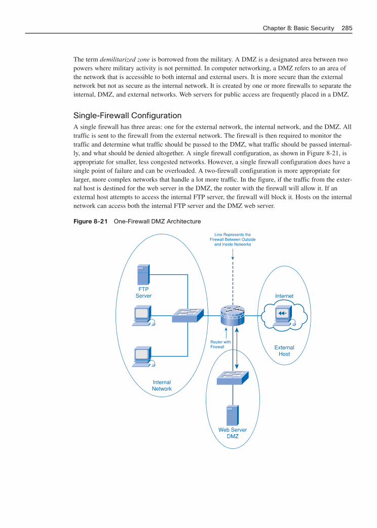
The term demilitarized zone is borrowed from the military. A DMZ is a designated area between twopowers where military activity is not permitted. In computer networking, a DMZ refers to an area ofthe network that is accessible to both internal and external users. It is more secure than the externalnetwork but not as secure as the internal network. It is created by one or more firewalls to separate theinternal, DMZ, and external networks. Web servers for public access are frequently placed in a DMZ.
Single-Firewall ConfigurationA single firewall has three areas: one for the external network, the internal network, and the DMZ. Alltraffic is sent to the firewall from the external network. The firewall is then required to monitor thetraffic and determine what traffic should be passed to the DMZ, what traffic should be passed internal-ly, and what should be denied altogether. A single firewall configuration, as shown in Figure 8-21, isappropriate for smaller, less congested networks. However, a single firewall configuration does have asingle point of failure and can be overloaded. A two-firewall configuration is more appropriate forlarger, more complex networks that handle a lot more traffic. In the figure, if the traffic from the exter-nal host is destined for the web server in the DMZ, the router with the firewall will allow it. If anexternal host attempts to access the internal FTP server, the firewall will block it. Hosts on the internalnetwork can access both the internal FTP server and the DMZ web server.
Figure 8-21 One-Firewall DMZ Architecture
Chapter 8: Basic Security 285
Router withFirewall
FTPServer
InternalNetwork
Line Represents theFirewall Between Outside
and Inside Networks
Internet
ExternalHost
Web ServerDMZ

Two-Firewall ConfigurationFigure 8-22 shows a typical multi-firewall DMZ setup. A two-firewall configuration has an internaland external firewall with the DMZ located between them. The external firewall is less restrictive andallows an Internet user access to the services in the DMZ. It also allows any traffic from an internaluser to an outside resource, such as an external web or FTP server, to pass through. The internal fire-wall is more restrictive and protects the internal network from unauthorized access.
Figure 8-22 Two-Firewall DMZ Architecture
286 Networking for Home and Small Businesses, CCNA Discovery Learning Guide
WebServer
Internet
Routerwith Firewall
Routerwith Firewall
FTPServer
InternalNetwork
DMZ
ExternalNetwork
Lines Represent Firewalls Between Outside and Inside Networks and DMZ
In this example, the two-firewall arrangement serves essentially the same function as the single fire-wall but can provide more control and better scalability. If the traffic from the external host is destinedfor the web server in the DMZ, the router with the firewall will allow it. If an external host attempts toaccess the internal FTP server, the firewall will block it. Hosts on the internal network can access boththe internal FTP server and the DMZ web server.
In Figure 8-22, the PC on the external network (the Internet) is allowed access to the web server in theDMZ by the external firewall. Internal network users can access this web server in the DMZ and theFTP server on the internal network. If the external user attempts to access the internal FTP server, theinternal firewall will block her. If it is necessary to give external users access to the FTP server, it canbe put in the DMZ with the web server. Then both internal and external users can access it.
Home Networking Device FirewallsMany home network devices, such as integrated routers, frequently include multi-function firewallsoftware. This single firewall setup typically provides NAT and SPI, as well as IP, application, andwebsite filtering capabilities. It also provides basic DMZ support capabilities.
With the integrated router, a simple DMZ can be set up that allows an internal server to be accessibleby outside hosts. To accomplish this, you must specify the static IP address of the server in the DMZconfiguration. If the server already has a dynamic address assigned, it can be reserved and made per-manent. The integrated router isolates traffic destined to the IP address specified. This traffic is then

forwarded only to the switch port where the server is connected. All other hosts are still protected bythe firewall. The Linksys WRT300N can provide this function, which is illustrated in Figure 8-23.
Figure 8-23 Linksys Integrated Firewall
Chapter 8: Basic Security 287
Internal Components
Ethernet Switch(Connects AllWired Hosts)
Internal Firewall(Protects Hosts
H1 and H2)
Internal Router(Routes Packets
for All Hosts)
Integrated Router
External Network
Internet
DMZ
Web Server
Internal Network
H2
H1
H3
When the DMZ is enabled, in its simplest form, outside hosts can access all ports on the server, suchas 80 (HTTP), 21 (FTP), and 110 (E-mail POP3). A more restrictive DMZ can be set up using theport forwarding capability. With port forwarding, ports that should be accessible on the server arespecified. In this case, only traffic destined for those port(s) is allowed or forwarded; all other trafficis excluded.
The wireless access point within the integrated router is considered part of the internal network. It isimportant to realize that if the wireless access point is unsecured, anyone who connects to it is withinthe protected part of the internal network and is behind the firewall. Hackers can use this to gainaccess to the internal network and completely bypass any firewall security.
Lab 8-1: Configuring Access Policies and DMZ Settings (8.4.2.4)
In this lab you configure firewall settings and create a DMZ using the Linksys GUI. Refer to thehands-on lab in Part II of this Learning Guide. You may perform this lab now or wait until the end ofthe chapter.
Vulnerability Analysis
Many vulnerability analysis tools are available for testing host and network security. These tools areknown as security scanners, and they can help identify areas where attacks might occur and offerguidance on steps that you can take. Although the capabilities of the vulnerability analysis tools canvary based on manufacturer, some of the more common features include determining the following:
■ Number of hosts available on a network: Identifies the active hosts on the network that haveservices to offer. The number of hosts offering service should be limited to only those that needto advertise services. Hosts advertising services can be identified by attackers.

■ The services hosts are offering: Indicates what services hosts are advertising. For example, ahost might have the Telnet service activated and could be a target for outside attackers. Unneededservices should be disabled.
■ The operating system and versions on the hosts: Identifies hosts with older OS versions andoutdated patches. Vulnerabilities in these older unpatched OSs can be exploited by attackers.
■ Packet filters and firewalls in use: Provides an inventory of hosts that are running filters andwhat they are blocking. This feature can be useful in determining whether the proper access con-trols are in place.
■ Applications software updates required: Provides an analysis of applications software runningon hosts and can identify those that might allow attacks. These applications can be patched tocorrect the security vulnerability.
Lab 8-2: Performing a Vulnerability Analysis (8.4.3.2)
In this lab you research, download, and install a security vulnerability tester and use it to determineweaknesses in a host and the network. Refer to the hands-on lab in Part II of this Learning Guide. Youmay perform this lab now or wait until the end of the chapter.
Best Practices
Several recommended practices can help mitigate security threats and the risks they pose, includingthe following:
■ Define security policies
■ Physically secure servers and network equipment
■ Set login and file access permissions
■ Update OS and applications
■ Change permissive default network device and host settings
■ Run anti-virus and anti-spyware
■ Update anti-virus software files
■ Activate browser tools—pop-up stoppers, anti-phishing, plug-in monitors
■ Use a firewall
The first step towards securing a network is to understand how traffic moves across the network andthe different threats and vulnerabilities that exist. After security measures are implemented, a trulysecure network needs to be monitored constantly. Security procedures and tools need to be reviewedin order to stay ahead of evolving threats. Figure 8-24 reviews the main forms of security that can beemployed to help protect against computer and network attacks.
288 Networking for Home and Small Businesses, CCNA Discovery Learning Guide

Figure 8-24 Types of Security
Chapter 8: Basic Security 289
SPAM
Firewall Spam Filter Patches andUpdates
Anti-VirusPop-up BlockerAnti-Spyware

290 Networking for Home and Small Businesses, CCNA Discovery Learning Guide
Summary
This chapter discussed various networking threats such as information theft, identity theft, data lossand manipulation, and disruption of service.
Hackers are intruders who gain access to a network through software vulnerabilities, hardware attacks,or through the carelessness of network users. Attacks can come from both internal and externalsources. Internal attacks account for 70 percent of security incidents.
Social engineering is a group of techniques used to deceive internal users into performing specificactions or revealing confidential information. Three types of social engineering attacks are pretexting,phishing, and vishing.
Other threats to the security of networks and computers, in addition to social engineering attacks,include viruses, worms, and Trojan horses. Viruses are programs that when activated spread by modi-fying other programs or files, causing damage to files, or erasing them completely. A worm is similarto a virus except it runs independently and spreads by resending itself as an e-mail attachment or partof a network message. A Trojan horse is a program that appears legitimate, but when initiated, candamage a hard drive or create a back door into a system, allowing hackers to gain access.
Effective network security comes from a combination of products and services combined with a thor-ough security policy and a commitment to adhere to that policy. A security policy should includeidentification and authentication policies, password policies, acceptable use policies, remote accesspolicies, and incident-handling procedures. All users of the network must support and follow the secu-rity policy in order for it to be effective.
Tools and applications used in securing a network include software patches and updates, virus protec-tion, spam blockers, pop-up blockers, and firewalls. Keep software applications up-to-date with thelatest security patches and updates to help deter threats. Anti-virus software, installed on every com-puter, detects and removes known viruses, worms, and Trojan horses. Anti-spam software identifiesspam and places it into a junk folder or deletes it.
A firewall controls the traffic between networks and helps prevent unauthorized access. Firewall prod-ucts use various techniques for determining what is permitted or denied access to a network. Firewallsperform packet filtering, which controls access based on IP or MAC addresses. They can performapplication/website filtering based on the application. Firewalls also provide SPI, which ensures thatincoming packets are legitimate responses to requests from internal hosts. SPI can recognize and filterout attacks such as DoS.
A DMZ is an area of the network that is accessible to both internal and external users. If the wirelessaccess point is unsecured, anyone who connects to it is considered part of the internal network and ison the internal protected side of the firewall.
Vulnerability analysis tools (security scanners) help identify areas where attacks might occur and offerguidance on steps that can be taken.

Chapter 8: Basic Security 291
Activities and Labs
This summary outlines the activities and labs you can perform to help reinforce important conceptsdescribed in this chapter. You can find the activity files on the CD-ROM accompanying this book. Thecomplete hands-on labs appear in Part II.
Interactive Activities on the CD:
Interactive Activity 8-1: Identify Security Threats (8.1.1.2)
Interactive Activity 8-2: Determine the Effects of a Virus, Worm, or Trojan Horse (8.2.1.3)
Interactive Activity 8-3: Establish a Server Connection During a DoS Attack (8.2.2.3)
Interactive Activity 8-4: Identify the Purpose of Security Tools (8.3.5.2)
Labs in Part II of This Book:
Lab 8-1: Configuring Access Policies and DMZ Settings (8.4.2.4)
Lab 8-2: Performing a Vulnerability Analysis (8.4.3.2)
Check Your Understanding
Complete all the review questions listed here to test your understanding of the topics and concepts inthis chapter. The “Check Your Understanding and Challenge Questions Answer Key” appendix liststhe answers.
1. A hacker breaks into a server and obtains a list of users and their personal data. Using this infor-mation, the hacker applies for a credit card. What type of network threat does this represent?
A. Data loss
B. Identity theft
C. Data manipulation
D. Disruption of service
2. How does a phisher typically contact a victim?
3. A user opens an e-mail file attachment. After the user opens the attachment, her computer harddrive crashes and all information on the computer is lost. What type of attack most likelyoccurred?
A. Worm
B. Virus
C. Trojan horse
D. Denial of Service
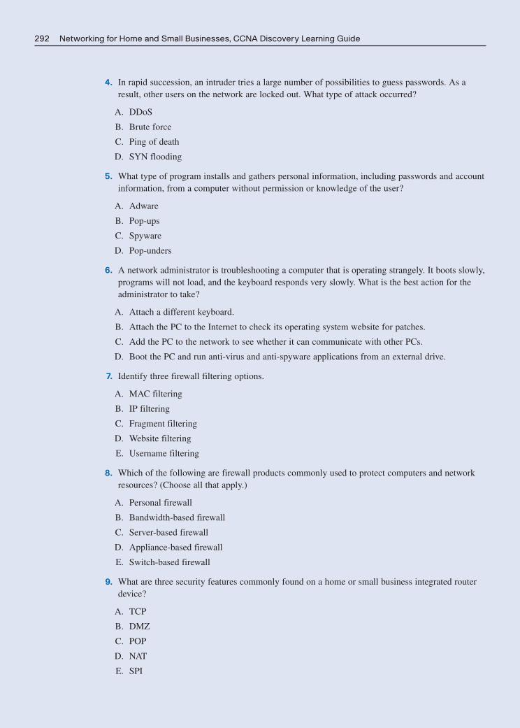
292 Networking for Home and Small Businesses, CCNA Discovery Learning Guide
4. In rapid succession, an intruder tries a large number of possibilities to guess passwords. As aresult, other users on the network are locked out. What type of attack occurred?
A. DDoS
B. Brute force
C. Ping of death
D. SYN flooding
5. What type of program installs and gathers personal information, including passwords and accountinformation, from a computer without permission or knowledge of the user?
A. Adware
B. Pop-ups
C. Spyware
D. Pop-unders
6. A network administrator is troubleshooting a computer that is operating strangely. It boots slowly,programs will not load, and the keyboard responds very slowly. What is the best action for theadministrator to take?
A. Attach a different keyboard.
B. Attach the PC to the Internet to check its operating system website for patches.
C. Add the PC to the network to see whether it can communicate with other PCs.
D. Boot the PC and run anti-virus and anti-spyware applications from an external drive.
7. Identify three firewall filtering options.
A. MAC filtering
B. IP filtering
C. Fragment filtering
D. Website filtering
E. Username filtering
8. Which of the following are firewall products commonly used to protect computers and networkresources? (Choose all that apply.)
A. Personal firewall
B. Bandwidth-based firewall
C. Server-based firewall
D. Appliance-based firewall
E. Switch-based firewall
9. What are three security features commonly found on a home or small business integrated routerdevice?
A. TCP
B. DMZ
C. POP
D. NAT
E. SPI

Chapter 8: Basic Security 293
10. What two statements are true regarding a multi-firewall DMZ?
A. The internal firewall is typically less restrictive and the external firewall is more restrictive.
B. Servers to be accessed by external users need to be behind the internal firewall.
C. Servers accessible by internal users can be internal, in the DMZ, or external to the network.
D. The internal firewall is typically more restrictive and the external firewall is less restrictive.
E. The internal firewall allows all types of external traffic to pass.
11. A user visits a website and downloads what he thinks is a free computer game. When the userbegins playing the game, the computer begins acting strangely. What type of attack most likelyoccurred?
12. What specific type of security software can remove adware?
A. Pop-up stoppers
B. Anti-virus
C. Anti-spyware
D. Firewall
E. Anti-spam
13. The features of anti-virus software can include all the following except:
A. Automatic checking of virus database updates
B. Resident shield to check executables
C. Automatic removal of unknown viruses
D. Scheduler to run scans on a regular basis
E. E-mail scanner
14. What are three techniques used in social engineering?
A. Pretexting
B. Vishing
C. Phishing
D. Frying
E. Spamming
15. What type of security attack takes advantage of software vulnerabilities and can rapidly spreadacross a network?
16. A hacker on the Internet sends millions of packets with invalid source IP addresses to a server.The server becomes overloaded attempting to respond to these packets. What type of attack isthis?
A. Ping of death
B. Trojan horse
C. SYN flooding
D. Brute force

294 Networking for Home and Small Businesses, CCNA Discovery Learning Guide
17. When working with a Linksys home networking device you configure it to allow external trafficto a specific server for FTP and HTTP. All other traffic is blocked. What statements are trueregarding this scenario? (Choose two.)
A. The server can only have a dynamic address assigned.
B. The server must have a permanent static address.
C. This is known as a simple basic DMZ.
D. This is known as port forwarding.
18. Why is it a concern if a hacker connects to the wireless AP of a home networking device that isconnected to an ISP? (Choose all that apply.)
A. The hacker will have free access to the Internet.
B. The hacker might be able to change configuration settings on the device.
C. The hacker will be given the administrator password.
D. The hacker is on the internal network behind the firewall.
Challenge Questions and Activities
This question require a deeper application of the concepts covered in this chapter. You can find theanswers in the appendix.
1. You have just built a new home PC and will be connecting directly to your ISP through a DSLmodem. You do not have a router with a firewall. What types of security software could youinstall and what other measures could you take to help secure your computer and protect it frommalicious attacks or malware?

CHAPTER 9
Troubleshooting Your Network
Objectives
Upon completion of this chapter you will be able to answer the following questions:
■ What are the steps involved in the troubleshoot-ing process?
■ What are some of the common troubleshootingtechniques and when is it appropriate to useeach?
■ How can the senses be used to troubleshoot net-work issues?
■ What utilities are available for troubleshootingconnectivity issues?
■ What are some of the more common issues withwired networks?
■ What are some of the common issues related toWLANs?
■ What are some possible sources of help whentroubleshooting?
Key Terms
This chapter uses the following key terms. You can find the definitions in the Glossary.
troubleshooting page 296
network monitoring tools page 297
top-down troubleshooting page 298
bottom-up troubleshooting page 298
divide-and-conquer troubleshooting page 300
trial-and-error troubleshooting page 301
substitution troubleshooting page 301
lease page 303
echo request page 305
echo reply page 305
hop page 306
DHCP server page 314
Frequently Asked Questions (FAQ) page 317
help desk page 318

This chapter examines the art of troubleshooting and the procedures and processes that make trou-bleshooting easier and more successful. It is not meant to be an exhaustive guide to troubleshooting PCand network problems but rather an introduction with specific examples. This chapter relies on thecomplete understanding of all the topics and concepts presented thus far. If a concept or solution is notunderstood as presented, review the supporting materials covered in previous chapters of this book.
Most network troubleshooting is done based on the OSI model. This model has been introduced inthis course and will be discussed in more detail in subsequent CCNA Discovery courses. Additionalinformation on the OSI model is provided on the CD-ROM accompanying this book. Part II of thisbook includes the corresponding labs for this chapter.
Troubleshooting Process
Regardless of the amount of time spent designing and installing a network, problems do occur. Whenfaced with a malfunctioning network, it is important to face the problem in a very structured manner.Troubleshooting is the process of identifying, locating, and correcting problems that occur.Experienced individuals often rely on instinct to troubleshoot. However, structured techniques can beused to determine the most probable cause and solution. Regardless of the approach taken, certainsteps should always be followed:
Step 1. Define the problem: At this step the problem is defined in terms of the observed symp-toms and associated causes.
Step 2. Gather facts: Fact gathering is done by questioning the affected users and administrators,and using tools such as protocol analyzers to learn as much about the problem as possible.
Step 3. Consider the possibilities: Systematic reasoning and diagnostic methods are used at thisstep to narrow down the possible causes.
Step 4. Create an action plan: Based on the list of possible problems, create an action plan totroubleshoot the problem.
Step 5. Implement the action plan: When you implement the action plan, be certain to documentall steps. Documentation is important to provide a back-out plan in case the actions do notproduce the desired result or have a negative impact on the network or device.
Step 6. Observe the results: Verify that the action plan had the desired results. If not, undo anychanges that were made.
Step 7. Repeat the problem-solving process: If the action plan did not work repeat the problem-solving process. Troubleshooting is often an iterative process; you get closer to the actualproblem with each iteration.
Step 8. Document facts: The final stage of problem solving is to document the process.Documentation should actually be maintained throughout the entire process.
Documenting all steps taken during troubleshooting, even the ones that did not solve the issue, is impor-tant. Documentation becomes a valuable reference should the same or similar problem occur again. It cansometimes point to the correct solution for the problem or at least eliminate wasting time by repeatingfailed attempts. This documentation should include as much information as possible about the following:
■ The problem encountered
■ Steps taken to determine the cause of the problem
■ Steps to correct the problem and ensure that it will not reoccur
This section introduces the different approaches to troubleshooting.
296 Networking for Home and Small Businesses, CCNA Discovery Learning Guide
How To

Gathering Information
When a problem is reported, verify it and determine the extent of its impact. Verifying the problemreported is important because many issues are not exactly as reported by the end users. After the prob-lem is confirmed, the first step in troubleshooting is to gather as much information about the problemas possible. One of the first places to gather information is to question the individual who reported theproblem as well as any other affected users. Information gathered from the end user can include
■ End-user experiences
■ Observed symptoms
■ Error messages
■ Information about recent configuration changes to devices or applications
Next, collect information about any equipment that might be affected. You can gather this informationfrom existing documentation, which should include current configurations. A copy of all log files anda listing of any recent changes made to equipment configurations are also necessary. Other informa-tion on the equipment includes the manufacturer, make, and model of devices affected, as well asownership and warranty information. The version of any firmware or software on the device is alsoimportant because compatibility problems might exist with particular hardware platforms.
You can gather information about the network using network monitoring tools. Network monitoringtools are complex applications often used on large networks to continually gather information aboutthe state of the network and network devices. These tools might not be available for smaller networks.
A checklist is beneficial to ensure that all the required information has been collected. The types ofinformation that you should gather before starting the troubleshooting process include the following:
❐ Nature of the problem
■ End-user reports
■ Problem verification reports
❐ Equipment
■ Manufacturer
■ Make/model
■ Firmware version
■ Operating system version
■ Ownership/warranty information
❐ Configuration and topology
■ Physical and logical topology
■ Configuration files
■ Log files
❐ Previous troubleshooting, including steps and results
Chapter 9: Troubleshooting Your Network 297

Approaches to Troubleshooting
After all necessary information is gathered it is time to start the troubleshooting process. The exacttechnique deployed will depend on the problem and the experience level of the technician.
Inexperienced individuals should follow one of the more structured approaches but experienced indi-viduals often prefer to rely on their knowledge and instincts and take a less structured approach.Several different structured troubleshooting techniques are available, including
■ Top-down
■ Bottom-up
■ Divide-and-conquer
All of these structured approaches assume a layered concept of networking. An example of a layeredapproach is the OSI model, in which every function of communication is broken down into seven distinct layers. Using this model, a troubleshooter can verify all functionality at each layer until theproblem is located and isolated. The TCP/IP model is also a layered model often used in the trou-bleshooting process.
The structure of these approaches makes them ideally suited for the novice troubleshooter. More expe-rienced individuals often bypass structured approaches and rely on instinct and experience. Theymight use less structured techniques such as trial-and-error or substitution.
A structured approach to troubleshooting often detects problems that an unstructured method mightoverlook. Early detection and correction of these problems can prevent future problems with the net-work. For this reason, troubleshooters are encouraged to use structured approaches whenever possible.
Top-DownThe top-down troubleshooting approach, as shown in Figure 9-1, starts with the application layer andworks down toward the physical layer. It looks at the problem from the point of view of the user andthe application.
If the problem appears to be isolated to a single workstation or application, this technique is suitable.For example, if the user can access various websites on the Internet but is unable to retrieve e-mail,the top-down approach is appropriate.
Bottom-UpThe bottom-up troubleshooting approach, as shown in Figure 9-2, starts with the physical layer andworks up toward the application layer. The physical layer is concerned with hardware and wire con-nections. Check to determine whether cables have been pulled out of their sockets. If the equipmenthas indicator lights, check to see whether they are on or off. If they are off, check the power to thedevices and physical connectivity. Many network problems can be attributed to the physical layer, sothis is often a good model to follow.
298 Networking for Home and Small Businesses, CCNA Discovery Learning Guide

Figure 9-2 Bottom-Up Troubleshooting
Chapter 9: Troubleshooting Your Network 299
Application(Application, Presentation,
Session)
Transport
Network
Data Link
Physical
Figure 9-1 Top-Down Troubleshooting
Application(Application, Presentation,
Session)
Transport
Network
Data Link
Physical

Divide-and-ConquerThe divide-and-conquer troubleshooting approach can begin troubleshooting at any layer, as shownin Figure 9-3, and work up or down from there. For example, the troubleshooter might begin at thenetwork layer by verifying IP configuration information, and then decide to work upward toward theapplication layer or downward toward the physical layer depending on what was observed. Anotherexample is splitting up a network and isolating a problem on one specific segment.
Figure 9-3 Divide-and-Conquer Troubleshooting
300 Networking for Home and Small Businesses, CCNA Discovery Learning Guide
Application(Application, Presentation,
Session)
Transport
Network
Data Link
Physical
Table 9-1 provides a comparison of the three methods of structured troubleshooting.
Table 9-1 Structured Troubleshooting Methodologies
Troubleshooting How It When It Is Advantages/
Approach Operates Suitable Disadvantages
Top-down Always starts at the Suitable for use when the Fast if the problem is application layer and problem is suspected to be related to the upper works its way toward the with an application/user or layers, but can waste a physical layer until it upper layers. lot of time if problem finds the problem. occurs at lower layers.
Divide-and- Based on the reported Suitable when the problem One of the fastest conquer problem and the trouble- has specific symptoms and troubleshooting
shooter’s experience, the troubleshooter has some approaches, but requires troubleshooting can begin experience. experience to use at any layer and work up efficiently.or down.
Bottom-up Always starts at the Suitable for complex Slow, but solid approach physical layer and works problems. to troubleshooting. Can its way toward the waste a lot of time if application layer until the problem is related to problem is located. upper layers.

Trial-and-ErrorTrial-and-error troubleshooting relies on individual knowledge to determine the most probable causeof a problem. A troubleshooter makes an educated guess on the most likely solution based on pastexperience and knowledge of the network structure. After the solution is implemented, if it does notwork, the troubleshooter uses this information to help determine the next most likely cause. Thisprocess is repeated until the problem is isolated and solved.
Although the trial-and-error approach has the potential to be extremely fast, it relies on the abilitiesand experiences of the troubleshooter and can result in incorrect assumptions and overlooking simplesolutions. If the trial-and error approach does not determine the problem in the first few attempts, theexperienced troubleshooter normally switches to a more structured approach. This technique is used insituations where downtime is extremely expensive and the goal is to re-establish connectivity and notjust determine the underlying problem.
SubstitutionWith substitution troubleshooting, the problem is assumed to be caused by a specific hardware com-ponent or a configuration file. The defective part or code is replaced by a known good device or file.Although it does not necessarily locate the problem, this technique can save time and quickly restorenetwork functionality. This method relies on the availability of substitute parts, components, and back-up configuration files, which can be very expensive to maintain.
An example of a substitution technique is when an ISP replaces a possible broken end-user devicerather than send a technician out to troubleshoot and locate a specific issue. This technique is alsooften used for inexpensive parts such as network interface cards and patch cables.
Interactive Activity 9-1: Determining the Troubleshooting Technique (9.1.3.3)
In this interactive activity you determine the best troubleshooting technique used to solve a problem.Use file ia-9133 on the CD-ROM that accompanies this book to perform this interactive activity.
Using Utilities to Troubleshoot Connectivity Issues
A large number of tools, both software and hardware based, exist to help isolate connectivity prob-lems in wired and wireless networks. These range from simple visual inspection to complex diagnos-tic hardware devices.
Detecting Physical Problems
A large proportion of networking problems are related to physical components or problems with thephysical layer. Physical problems are concerned mainly with the hardware aspects of computers andnetworking devices and the cables that interconnect them. They do not consider the logical (software)configuration of devices.
Physical problems can occur in both wired and wireless networks. One of the best detection methodsfor physical problems is the use of the senses: vision, smell, touch, and hearing. Quite often, the sens-es can quickly pinpoint a devastating problem.
Chapter 9: Troubleshooting Your Network 301

VisionVision can detect cabling problems such as the following:
■ Cables that are not connected
■ Cables connected to the wrong port
■ Loose cable connections
■ Damaged cables and connectors
■ Wrong type of cable
Vision also allows troubleshooters to use the cues provided by LEDs about the condition and functionof various networking devices. In many environments, parts of the network are covered for their pro-tection. A simple visual inspection can often prevent unforeseen problems from occurring.
SmellSmell can alert troubleshooters to components that are overheating. The smell of burning insulation orcomponents is very distinct and is a sure sign that something is seriously wrong.
TouchTroubleshooters can use touch to feel for overheated components as well as to detect mechanicalproblems with devices such as laptops and switches that include cooling fans. These fans usually cre-ate a small vibration in the component that you can detect using touch. The absence of this vibrationor the presence of excessive amounts of vibration can indicate that the cooling fan has failed or isabout to do so.
HearingHearing can detect major problems such as electrical arcing and the proper operation of cooling fansand disk drives. All devices have characteristic sounds and any changes from the normal sounds usu-ally indicate a problem of some sort. An experienced network technician gets accustomed to thesounds produced by the network and can quickly identify potential problems by deviations from thenormal sound pattern.
Software Utilities for Troubleshooting Connectivity
A number of software utility programs are available that can help identify network problems. Thefunctionality of all of these commands is available in all current operating systems, although the syn-tax might vary between operating systems. Most of these commands are command-line interface(CLI) utilities and include the following:
■ ipconfig: Displays IP configuration information
■ ping: Tests connections to other IP hosts
■ tracert: Displays route taken to destination
■ netstat: Displays network connections
■ nslookup: Directly queries the name server for information on a destination domain
302 Networking for Home and Small Businesses, CCNA Discovery Learning Guide

Troubleshooting Using ipconfig
The ipconfig command displays the current IP configuration information for a host. Issuing this com-mand from the command prompt displays the basic configuration information, including IP address,subnet mask, and default gateway.
The command ipconfig /all displays additional information including the MAC address, IP addressesof the default gateway, and the DNS servers. It also indicates whether DHCP is enabled, the DHCPserver address, and lease information. A sample output from the command is shown in Example 9-1.
Chapter 9: Troubleshooting Your Network 303
Example 9-1 Output of the ipconfig /all CommandC:\>ipconfig /all
Windows IP Configuration
Host Name . . . . . . . . . . . . : host-a
Primary Dns Suffix . . . . . . . : cisco.com
Node Type . . . . . . . . . . . . : Hybrid
IP Routing Enabled. . . . . . . . : No
WINS Proxy Enabled. . . . . . . . : No
DNS Suffix Search List. . . . . . : cisco.com
Ethernet adapter Local Area Connection:
Connection-specific DNS Suffix . : cisco.com
Description . . . . . . . . . . . : NVIDIA nForce Networking Controller
Physical Address. . . . . . . . . : 00-15-58-55-FF-F8
Dhcp Enabled. . . . . . . . . . . : Yes
Autoconfiguration Enabled . . . . : Yes
IP Address. . . . . . . . . . . . : 192.168.1.100
Subnet Mask . . . . . . . . . . . : 255.255.255.0
Default Gateway . . . . . . . . . : 192.168.1.1
DHCP Server . . . . . . . . . . . : 192.168.1.1
DNS Servers . . . . . . . . . . . : 172.27.20.10
172.27.20.11
Lease Obtained. . . . . . . . . . : Thursday, October 11, 2007 3:07:16 PM
Lease Expires . . . . . . . . . . : Friday, October 12, 2007 3:07:16 PM
This utility can help determine improper or incomplete addressing information, which can preventnetwork communications. Without an appropriate IP configuration, a host cannot participate in com-munications on a network. In addition, if the host does not know the correct location of the DNSservers it cannot translate names into IP addresses and communications using domain names is impossible.
If IP addressing information is assigned dynamically, you can use the command ipconfig /release torelease the current DHCP bindings. You use the ipconfig /renew command to request fresh configura-tion information from the DHCP server. A host might contain faulty or outdated IP configurationinformation and a simple renewal of this information is all that is required to regain connectivity.

If, after releasing the IP configuration, the host is unable to obtain fresh information from the DHCPserver, the problem could be that there is no network connectivity. Verify that the NIC has an illumi-nated link light, indicating that it has a physical connection to the network. If the link light is lit, andthe host is still unable to obtain addressing information from the DHCP server, the problem might bean issue with the DHCP server or network connections to the DCHP server. Also, verify that theaddress has not been statically assigned to the adapter.
Packet Tracer Activity Using the ipconfig Command (9.2.3.2)
In this Packet Tracer activity you determine the IP addressing information with the ipconfig com-mand. Use file d1-9232.pka on the CD-ROM that accompanies this book to perform this activity usingPacket Tracer.
Troubleshooting Using ping
If the IP configuration appears to be correctly configured on the local host, a good next step is to testnetwork connectivity by using the ping command. The ping command is used to test whether a desti-nation host is reachable. The ping command can be followed by either an IP address or the name of adestination host, as shown in Example 9-2.
304 Networking for Home and Small Businesses, CCNA Discovery Learning Guide
Packet Tracer Activity
Example 9-2 Output of the ping CommandC:\>ping cisco.netacad.net
Pinging cisco.netacad.net [128.107.229.50] with 32 bytes of data:
Reply from 128.107.229.50: bytes=32 time=71ms TTL=113
Reply from 128.107.229.50: bytes=32 time=71ms TTL=113
Reply from 128.107.229.50: bytes=32 time=72ms TTL=113
Reply from 128.107.229.50: bytes=32 time=72ms TTL=113
Ping statistics for 128.107.229.50:
Packets: Sent = 4, Received = 4, Lost = 0 (0% loss),
Approximate round trip times in milli-seconds:
Minimum = 71ms, Maximum = 72ms, Average = 71ms
C:\>ping 128.107.229.50
Pinging 128.107.229.50 with 32 bytes of data:
Reply from 128.107.229.50: bytes=32 time=72ms TTL=113
Reply from 128.107.229.50: bytes=32 time=72ms TTL=113
Reply from 128.107.229.50: bytes=32 time=72ms TTL=113
Reply from 128.107.229.50: bytes=32 time=71ms TTL=113
Ping statistics for 128.107.229.50:
Packets: Sent = 4, Received = 4, Lost = 0 (0% loss),
Approximate round trip times in milli-seconds:
Minimum = 71ms, Maximum = 72ms, Average = 71ms

When a ping is sent to an IP address, a packet known as an echo request is sent across the network tothe IP address specified. If the destination host receives the echo request, it responds with a packetknown as an echo reply. If the source receives the echo reply, connectivity is verified. The basic pingcommand usually issues four echoes and waits for the replies to each one. It can, however, be modi-fied to increase its usefulness. Example 9-3 shows some of the more advanced features of the pingcommand.
Chapter 9: Troubleshooting Your Network 305
Example 9-3 Advanced Features of ping
C:\>ping
Usage: ping [-t] [-a] [-n count] [-l size] [-f] [-i TTL] [-v TOS]
[-r count] [-s count] [[-j host-list] | [-k host-list]]
[-w timeout] target_name
Options:
-t Ping the specified host until stopped.
To see statistics and continue - type Control-Break;
To stop - type Control-C.
-a Resolve addresses to hostnames.
-n count Number of echo requests to send.
-l size Send buffer size.
-f Set Don’t Fragment flag in packet.
-i TTL Time To Live.
-v TOS Type Of Service.
-r count Record route for count hops.
-s count Timestamp for count hops.
-j host-list Loose source route along host-list.
-k host-list Strict source route along host-list.
-w timeout Timeout in milliseconds to wait for each reply.
If a ping is sent to a name, such as www.cisco.com, a packet is first sent to a DNS server to resolvethe name to an IP address. After the IP address is obtained, the echo request is forwarded to the IPaddress and the process proceeds. If a ping to the IP address succeeds, but a ping to the name doesnot, most likely a problem exists with DNS.
If pings to both the name and IP address are successful, but the user is still unable to access the appli-cation, the problem most likely resides in the application on the destination host. For example, itmight be that the requested service is not running.
If neither ping is successful, network connectivity along the path to the destination is most likely theproblem. If this occurs, the common practice is to ping the default gateway. If the ping to the defaultgateway is successful, the problem is not local. If the ping to the default gateway fails, the problemresides on the local network.
Using the ping Command (9.2.4.3)
In this Packet Tracer activity you examine end-to-end connectivity using the ping command. Use filed1-9243.pka on the CD-ROM that accompanies this book to perform this activity using Packet Tracer.
Packet Tracer Activity

Troubleshooting Using tracert
The ping utility can only verify connectivity between end devices. However, if a problem exists andthe device cannot ping the destination, the ping utility does not always indicate where the problemresides. If a router along the path drops the connection it will include the router’s IP address in thedestination unreachable message that is returned. Unfortunately, this occurs only if the router actuallydrops the packet—not if the echo request or echo reply is lost in transit. To determine the locationwhere packets are being lost, another utility known as tracert is used.
The tracert utility output, pictured in Example 9-4, provides connectivity information about the patha packet takes to reach the destination and about every router, or hop, along the way. It also indicateshow long a packet takes to get from source to each hop and back (round trip time). tracert can helpidentify where a packet might have been lost or delayed due to bottlenecks or slowdowns in the net-work.
306 Networking for Home and Small Businesses, CCNA Discovery Learning Guide
Example 9-4 The tracert CommandC:\>tracert
Usage: tracert [-d] [-h maximum_hops] [-j host-list] [-w timeout] target_name
Options:
-d Do not resolve addresses to hostnames.
-h maximum_hops Maximum number of hops to search for target.
-j host-list Loose source route along host-list.
-w timeout Wait timeout milliseconds for each reply.
C:\>tracert cisco.netacad.net
Tracing route to cisco.netacad.net [128.107.229.50]
over a maximum of 30 hops:
1 1 ms <1 ms <1 ms 192.168.1.1
2 8 ms 8 ms 9 ms bas1-toronto46_lo0_SYMP.net.bell.ca [64.230.197.216]
3 6 ms 7 ms 7 ms dis7-toronto01_Vlan147.net.bell.ca [64.230.202.105]
4 7 ms 7 ms 6 ms core2-toronto01_GE11-2.net.bell.ca [64.230.204.141]
5 7 ms 6 ms 6 ms core4-toronto63_POS13-1.net.bell.ca [64.230.233.93]
6 17 ms 17 ms 17 ms core1-chicago23_pos12-0-0.net.bell.ca [64.230.147.14]
7 18 ms 18 ms 17 ms bx2-chicagodt_so-2-0-0-0.net.bell.ca [64.230.203.146]
8 18 ms 17 ms 18 ms 151.164.250.241
9 70 ms 70 ms 70 ms ded4-g8-3-0.sntc01.pbi.net [151.164.41.165]
10 72 ms 71 ms 71 ms Cisco-Systems-1152786.cust-rtr.pacbell.net [64.161.0.62]
11 70 ms 70 ms 70 ms sjc5-dmzbb-gw1.cisco.com [128.107.224.105]
12 71 ms 71 ms 71 ms sjc12-dmzdc-gw1-gig1-1.cisco.com [128.107.224.14]
13 72 ms 71 ms 71 ms cna-prod-nv.cisco.com [128.107.229.50]
Trace complete.

The tracert command can be followed by either an IP address or the name of a destination host. If aname is used a DNS lookup must be conducted just as with ping.
The basic tracert utility only allows up to 30 hops between a source and destination device before itassumes that the destination is unreachable. This number is adjustable by using the –h parameter.Other modifiers are also available.
Troubleshooting Using netstat
Sometimes you need to know which active TCP connections are open and running on a networkedhost. netstat, shown in Example 9-5, is an important network utility that you can use to verify thoseconnections. netstat lists the protocol in use, the local address and port number, the foreign addressand port number, and the state of the connection.
Chapter 9: Troubleshooting Your Network 307
Example 9-5 The netstat CommandC:\>netstat -a
Active Connections
Proto Local Address Foreign Address State
TCP host-a:epmap host-a:0 LISTENING
TCP host-a:microsoft-ds host-a:0 LISTENING
TCP host-a:2869 host-a:0 LISTENING
TCP host-a:25111 host-a:0 LISTENING
TCP host-a:25112 host-a:0 LISTENING
TCP host-a:1025 host-a:0 LISTENING
TCP host-a:1035 localhost:1036 ESTABLISHED
TCP host-a:1036 localhost:1035 ESTABLISHED
TCP host-a:1057 localhost:27015 ESTABLISHED
TCP host-a:4664 host-a:0 LISTENING
TCP host-a:11500 host-a:0 LISTENING
TCP host-a:11526 host-a:0 LISTENING
TCP host-a:11526 localhost:1102 TIME_WAIT
TCP host-a:11526 localhost:1103 TIME_WAIT
TCP host-a:11526 localhost:1104 TIME_WAIT
TCP host-a:11526 localhost:1105 TIME_WAIT
TCP host-a:11527 host-a:0 LISTENING
TCP host-a:11528 host-a:0 LISTENING
TCP host-a:11529 host-a:0 LISTENING
TCP host-a:11530 host-a:0 LISTENING
TCP host-a:11531 host-a:0 LISTENING
TCP host-a:11532 host-a:0 LISTENING
TCP host-a:11533 host-a:0 LISTENING
TCP host-a:27015 host-a:0 LISTENING
TCP host-a:27015 localhost:1057 ESTABLISHED
TCP host-a:62514 host-a:0 LISTENING
TCP host-a:netbios-ssn host-a:0 LISTENING
TCP host-a:1059 twweb5.gocyberlink.com:http ESTABLISHED
TCP host-a:1061 kdc.uas.aol.com:https ESTABLISHED
TCP host-a:1063 twweb4.gocyberlink.com:http CLOSE_WAIT
TCP host-a:1065 64.12.24.9:https ESTABLISHED

Unexplained TCP connections can pose a major security threat because they can indicate that some-thing or someone is connected to the local host. Additionally, unnecessary TCP connections can con-sume valuable system resources thus slowing down the host’s performance. Use netstat to examinethe open connections on a host when performance appears to be compromised.
Many useful options are available for the netstat command. Detailed help on the netstat command isavailable via the help feature with the command, netstat –h.
Troubleshooting Using nslookup
When accessing applications or services across the network, humans usually rely on the DNS nameinstead of the IP address. When a request is sent to that name, the host must first contact the DNSserver to resolve the name to the corresponding IP address. The host then uses the IP to package theinformation for delivery.
The nslookup utility allows an end user to look up information about a particular DNS name in theDNS server. When the nslookup utility is issued, the information returned includes the IP address ofthe DNS server being used as well as the IP address of the name specified. nslookup is often used as atroubleshooting tool for determining whether the DNS server is performing name resolution as expect-ed. Example 9-6 shows the output of the nslookup command for the query shown in Figure 9-4.
308 Networking for Home and Small Businesses, CCNA Discovery Learning Guide
TCP host-a:1078 aimtoday-chi02.evip.aol.com:http TIME_WAIT
TCP host-a:1101 ats-ddb.dial.aol.com:5190 ESTABLISHED
TCP host-a:2869 192.168.1.1:2448 CLOSE_WAIT
TCP host-a:2869 192.168.1.1:2449 TIME_WAIT
UDP host-a:microsoft-ds *:*
UDP host-a:1031 *:*
UDP host-a:1041 *:*
UDP host-a:1042 *:*
UDP host-a:1045 *:*
UDP host-a:3776 *:*
UDP host-a:ntp *:*
UDP host-a:1060 *:*
UDP host-a:1062 *:*
UDP host-a:1066 *:*
UDP host-a:1074 *:*
UDP host-a:1900 *:*
UDP host-a:62514 *:*
UDP host-a:ntp *:*
UDP host-a:netbios-ns *:*
UDP host-a:netbios-dgm *:*
UDP host-a:1900 *:*
Example 9-6 The nslookup CommandC:\>nslookup cisco.netacad.net
Server: DNSTEST.svr.example.com
Address: 192.168.254.32
Non-authoratative answer:
Name: cisco.netacad.net
Address: 209.165.200.224

Figure 9-4 DNS Lookup Process
Chapter 9: Troubleshooting Your Network 309
Internet
Local Client cisco.netacad.net209.165.200.224
DNS Querycisco.netacad.net
DNSTEST.svr.example.com192.168.254.32
DNS Response209.165.200.224
Lab 9-1: Troubleshooting Using Network Utilities (9.2.7.2)
In this lab you use various network utilities to help solve connectivity issues. Refer to the lab in PartII of this Learning Guide. You may perform this lab now or wait until the end of the chapter.
Common Networking Issues
Although the number of potential problems with network connectivity is almost limitless, some aremore common than others. Having a good understanding of the most likely problems can save a greatdeal of time and frustration.
Connectivity Issues
Connectivity problems occur on wireless networks, wired networks, and networks that use both, asillustrated in Figure 9-5. When troubleshooting a network with both wired and wireless connections,troubleshooting using a divide-and-conquer approach to isolate the problem to either the wired orwireless network is often best. The easiest way to determine whether the problem is with the wired orthe wireless network is to perform the following steps:
Step 1. Ping from a wireless client to the wireless router: This verifies whether the wirelessclient is connecting as expected.
Step 2. Ping from a wired client to the wireless router: This verifies whether the wired client isconnecting as expected.
Step 3. Ping from the wireless client to a wired client: This verifies whether the wireless routeris functioning as expected.
How To

Figure 9-5 Network with Both Wired and Wireless Components
310 Networking for Home and Small Businesses, CCNA Discovery Learning Guide
IntegratedRouter
Cable or DSLModem
Internet ServiceProvider
LED Indicators
Regardless of whether the fault is present on the wireless or wired network, one of the first steps oftroubleshooting should be to examine the LEDs, which indicate the current state or activity of a pieceof equipment or connection. LEDs might change color or flash to convey information. The exact con-figuration and meaning of LEDs varies among manufacturers and devices.
Figure 9-6 shows the LEDs on a Linksys wireless router. Three types of LEDs are commonly foundon devices: power, status, and activity. On some devices a single LED might convey multiple piecesof information depending on the current status of the device. Checking the equipment documentationfor the exact meaning of all indicators is important but some commonality does exist. If this docu-mentation is misplaced it is normally available online at the manufacturer’s website.
Figure 9-6 LED on a Linksys Wireless Router
Security LED
Power LED
Wireless Activity LEDInternet Activity LED
Ethernet Activity LED
Inactive LEDs might be an indication of a device failure, port failure, or cabling issues. Possibly thedevice is nonfunctional due to faulty hardware. The port itself might also have become faulty due tohardware failure or improperly configured software. Regardless of whether the network is wired orwireless, verify that the device and ports are up and functional before spending large amounts of timetrying to troubleshoot other issues.
Power LEDThe power LED is usually a solid green color indicating that the device is being supplied with power.No light indicates a problem with the power. In this case, check the power connections and/or theposition of the power switch, if present.
Status LEDThe status LED indicates the current condition of the device and can change color or flash. It is alsoused during device self-diagnostic testing to indicate the stage of completion.
When self-diagnostics are completed the color indicates status as follows:
■ Solid green indicates the device is functioning properly.
■ Amber can indicate that an error has been encountered that is correctable, such as a missing ordamaged operating system.
■ Red can indicate that the device has experienced a major hardware problem that will require service.
Activity LEDThe activity LED is also referred to as the link light. This LED is normally associated with a specificport; under normal conditions the link light flashes, indicating that traffic is flowing through the port.The rate of flash might indicate the speed at which the port is functioning.
The link light has these indicators:
■ Solid green indicates that a device is plugged into the port but no traffic is flowing.
■ Amber indicates the device is making adjustments to the way the port is operating.
■ No light indicates that nothing is plugged into the port, or that an issue exists with the port, trans-mitting device, or cable.
On wireless devices the activity light can indicate status of the radio connection; the flash rate differsdepending on whether the clients are associated or searching for an association.
Wired Connectivity Problems
If the wired client is unable to connect to the wireless router, check the physical connectivity andcabling. Cabling is the central nervous system of wired networks and one of the most common issueswhen experiencing inactivity.
There are several issues to watch for in cabling:
■ Correct type of cable for the application. Two types of UTP cables are commonly encountered innetworking: straight-through cables and crossover cables. Using the wrong type of cable mightprevent connectivity.
■ Improper cable termination is one of the main problems encountered in networks. To avoid this,cables should be properly terminated according to standards.
■ Cables should be constructed according to standards. Terminate cables via the 568A or 568B ter-mination standard.
■ Avoid untwisting too much cable during termination. This can cause crosstalk and severelydegrade network performance.
Chapter 9: Troubleshooting Your Network 311

■ Crimp connectors on the cable jacket to provide strain relief.
■ Maximum cable run lengths exist based on characteristics of the different cables. The attenuation caused by exceeding these run lengths can have a serious negative impact on network performance.
■ If connectivity is a problem, verify that the correct ports are being used between the networkingdevices.
■ Protect cables and connectors from physical damage. Support cables to prevent strain on connec-tors and run cable through areas that will not be in the way. Damage to the cable sheath mightindicate internal damage to the cable.
Lab 9-2: Troubleshooting Physical Connectivity (9.3.3.2)
In this lab you examine and correct various physical connectivity issues. Refer to the lab in Part II ofthis Learning Guide. You may perform this lab now or wait until the end of the chapter.
Connectivity Problems in a WLAN
If the wireless client is unable to connect to the network, it might be because of wireless connectivityproblems. Wireless communications rely on radio frequency signals (RF) to carry data. Many factorscan affect the capability to connect hosts using RF.
The strength of an RF signal decreases with distance. If the signal strength is too low devices will beunable to reliably associate and move data. If the client cannot associate with the access point (AP),no communication can occur. The NIC client utility can be used to display the signal strength andconnection quality.
RF signals are also susceptible to interference from outside sources, including other devices function-ing on the same frequency. Environmental issues can also decrease the RF signal strength and limitconnectivity. Factors such as high humidity, plant growth, and relocation of furniture can greatly affectthe RF signal quality. A thorough site survey should be conducted before the installation of a WLANand again if connectivity problems are encountered. The survey should scan for interference on thesame frequencies as are being used by the WLAN as well as coverage patterns.
APs share the available bandwidth between devices. As more devices associate with the AP, the band-width for each individual device decreases, causing network performance problems such as applica-tion timeouts and slow downloads. The solution is to reduce the number of wireless clients using eachchannel.
Not all wireless standards are compatible. The 802.11a (5 GHz band) is not compatible with the802.11b/g standards (2.4 GHz band). The 802.11n draft standard currently specifies operation in bothfrequency ranges although most current draft 802.11n equipment functions only in the 2.4 GHz range.Within the 2.4 GHz band, each standard uses different technology. Unless specifically configured,equipment that conforms to one standard might not function properly with equipment that conforms toanother standard even if they both use the same frequency band.
Each wireless conversation must occur on a separate, non-overlapping channel. Some AP devices canbe configured to select the least congested or highest throughput channel. Although automatic settingswork, manual setting of the AP channel provides greater control and might be necessary in some envi-ronments.
312 Networking for Home and Small Businesses, CCNA Discovery Learning Guide
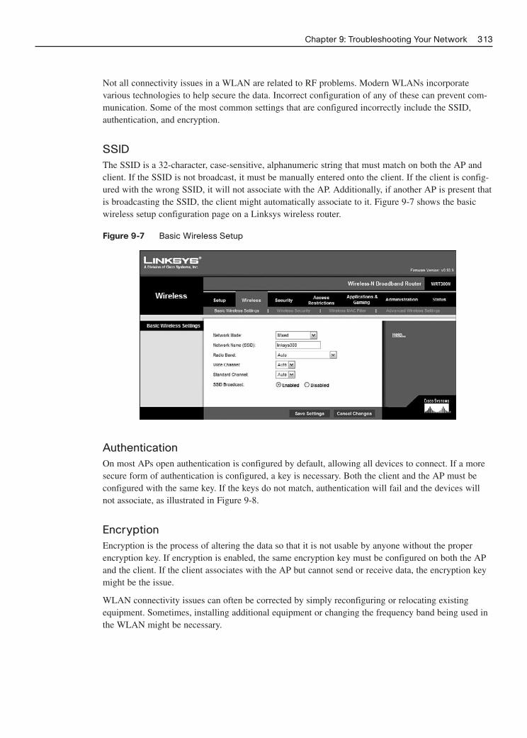
Not all connectivity issues in a WLAN are related to RF problems. Modern WLANs incorporate various technologies to help secure the data. Incorrect configuration of any of these can prevent com-munication. Some of the most common settings that are configured incorrectly include the SSID,authentication, and encryption.
SSIDThe SSID is a 32-character, case-sensitive, alphanumeric string that must match on both the AP andclient. If the SSID is not broadcast, it must be manually entered onto the client. If the client is config-ured with the wrong SSID, it will not associate with the AP. Additionally, if another AP is present thatis broadcasting the SSID, the client might automatically associate to it. Figure 9-7 shows the basicwireless setup configuration page on a Linksys wireless router.
Figure 9-7 Basic Wireless Setup
Chapter 9: Troubleshooting Your Network 313
AuthenticationOn most APs open authentication is configured by default, allowing all devices to connect. If a moresecure form of authentication is configured, a key is necessary. Both the client and the AP must beconfigured with the same key. If the keys do not match, authentication will fail and the devices willnot associate, as illustrated in Figure 9-8.
EncryptionEncryption is the process of altering the data so that it is not usable by anyone without the properencryption key. If encryption is enabled, the same encryption key must be configured on both the APand the client. If the client associates with the AP but cannot send or receive data, the encryption keymight be the issue.
WLAN connectivity issues can often be corrected by simply reconfiguring or relocating existingequipment. Sometimes, installing additional equipment or changing the frequency band being used inthe WLAN might be necessary.

Figure 9-8 Association Failure
314 Networking for Home and Small Businesses, CCNA Discovery Learning Guide
Sorry, that is not the correctkey so I am not going to
allow you to connect.
I sent you the key.Why can I not connect?
Interactive Activity 9-2: Effect of Channel Assignment on Throughput (9.3.4.2)
In this interactive activity you construct a Basic Set Service (BSS) to examine the effect of channelassignment on throughput. Use file ia-9342 on the CD-ROM that accompanies this book to performthis interactive activity.
Troubleshooting WLAN Connectivity Issues (9.3.5.2)
In this Packet Tracer activity you determine reasons why a wireless STA is unable to connect and thencorrect the problem. Use file d1-9352.pka on the CD-ROM that accompanies this book to perform thisactivity using Packet Tracer.
DHCP Issues
If the physical connection of the wired or wireless host appears to be correct, the next step is to checkthe IP configuration of the client. The IP configuration can have a major impact on the capability of ahost to connect to the network. The ISR or wireless router often acts as a DHCP server for localwired and wireless clients. It provides them with all the IP configuration information required to par-ticipate on the network, including IP address, subnet mask, default gateway, and possibly even IPaddresses of DNS servers. The DHCP server binds the IP address to a client’s MAC address andstores that information in a client table. On the home wireless router, this table can be examinedthrough the Status | Local Network page in the GUI, as shown in Figure 9-9.
The DHCP client table information should match the local host information, which can be obtainedfrom the ipconfig /all command. Additionally, the IP address on the client must be on the same net-work as the LAN interface of the wireless router. The wireless router’s LAN interface should be set asthe default gateway. If the client configuration information does not agree with information in theclient table, the address should be released (ipconfig /release) and renewed (ipconfig /renew) to forma new binding.
Packet Tracer Activity

Figure 9-9 DHCP Settings on a Wireless Router
Chapter 9: Troubleshooting Your Network 315
Troubleshooting the Wireless Router to ISP Connection
If both the wired and wireless clients are obtaining the correct IP configuration and can connect to thewireless router, but are unable to ping each other, the problem is most likely occurring on the wirelessrouter. Check all configurations to ensure that no security restrictions could be causing the issue.
If hosts on the wired and wireless local network can connect to the wireless router and with otherhosts on the local network, but not to the Internet, the problem might be in the connection betweenthe wireless router and the ISP. Example 9-7 shows the output from the ping command for Figure 9-10 when the Internet is not reachable.
Figure 9-10 Inability to Connect to the Internet
IntegratedRouter
LocalClient
DSL Modem
ISP
File Server IP10.18.32.12
Example 9-7 Network UnreachableC:\>ping 10.18.32.12
Pinging 10.18.32.12 with 32 bytes of data:
Request timed out.
Request timed out.
Request timed out.
Request timed out.
Ping statistics for 10.18.32.12:
Packets: Sent = 4, Received = 0, Lost = 4 (100% loss),

Many ways exist to verify connectivity between the wireless router and the ISP. One way is to checkthe router status page in the wireless router configuration. This should indicate that the connection isgood. It should also show the IP address assigned to the wireless router from the ISP.
If this page shows no connection, the wireless router might not be connected. Check all physical con-nections and LED indicators on the wireless router. If the DSL or cable modem is a separate device,check those connections and indicators as well. If the ISP requires a login name and password, checkthat they are properly configured. They are normally located on the Setup configuration page. Next,try to re-establish connectivity by clicking the Connect, or IP Address Renew, button on the Statuspage. If the wireless router will still not connect, contact the ISP to see whether the issue is occurringfrom its end.
If the status page on the wireless router shows that the connection is up, but a ping to an Internet sitefails, the individual site might be down. Try pinging another site to see whether that is successful. If itis not, check for security measures that are enabled that might be creating the issue, such as port filter-ing. Figure 9-11 shows the Status screen of a wireless router that is connected to the ISP.
Figure 9-11 Inability to Connect to the Internet
316 Networking for Home and Small Businesses, CCNA Discovery Learning Guide
Interactive Activity 9-3: Determining Where a Problem Exists (9.3.6.2)
In this interactive activity you determine the area of a network where a problem could exist. Use fileia-9362 on the CD-ROM that accompanies this book to perform this interactive activity.
Troubleshooting and the Help Desk
Following a structured troubleshooting process can help to quickly and accurately locate and isolateissues. Networks continue to grow and technology evolves rapidly. It is impossible for any one indi-vidual to be an expert on all the technologies and equipment that make up the modern network. In

addition, networks are becoming increasingly interconnected and issues on one network might affectusers on another. For these reasons, outside sources of help are often required during the troubleshoot-ing process.
Documentation
Network documentation is an important part of any troubleshooting process. Network documentationshould include a normal or baseline measurement of network performance against which potentialproblems can be judged.
The performance baseline can include the types of traffic normally expected, as well as the volume oftraffic to and from servers and network devices. The baseline should be documented just after the net-work is installed, when it is running optimally. Baseline performance should be re-established afterany major changes to the network are implemented.
Additionally, documentation such as topology maps, network diagrams, and addressing schemes canprovide valuable information when a troubleshooter is trying to understand the physical layout of thenetwork and the logical flow of information.
Documentation should be maintained during the troubleshooting process. This documentation can be avaluable reference and can be used when future issues arise. Good troubleshooting documentationshould include
■ Initial problem
■ Steps taken to isolate the problem
■ Results of all steps taken, both successful and unsuccessful
■ Final determined cause of the problem
■ Final problem resolution
■ Preventative measures
Using Outside Sources of Help
If, during the troubleshooting process, the troubleshooter is unable to determine the problem and itsresolution, obtaining assistance from outside sources might be necessary. Some of the most commonsources for help include
■ Previously kept documentation
■ Online frequently asked questions (FAQ)
■ Colleagues and other network professionals
■ Internet forums
Good documentation can save a great deal of time and effort by directing the troubleshooter to themost likely cause of the problem. It can also provide the technical information required to isolate, ver-ify, and correct the issue. Documentation provided with many networking devices, however, oftendoes not provide sufficient information to troubleshoot anything except the most basic issues.
Chapter 9: Troubleshooting Your Network 317

Most manufacturers provide a series of FAQs about their product or technology on their website.These FAQs are usually based on previous requests for help. FAQs are a good source of current infor-mation and should be consulted whenever possible.
Colleagues and forums often provide a wealth of information; there is no substitute for troubleshoot-ing experience. These individuals might be within the company or people who share the same inter-ests and responsibilities. With the increased availability of the Internet and the development of supportforums, troubleshooters can now obtain assistance from people around the world in real time.
Using the Help Desk
Although many sources of help are available, the help desk is often the end user’s first stop for timelyassistance. The help desk is a group of individuals with the knowledge and tools required to help diag-nose and correct common problems. This group provides assistance for the end user to determinewhether a problem exists, the nature of the problem, and the problem resolution.
Many companies and ISPs establish help desks to assist their users with networking problems. Mostlarge IT companies run help desks for their individual products or technologies. For example, Ciscooffers help desk assistance for problems integrating Cisco equipment into a network, or problems thatmight occur after installation. Some help desk support is offered free of charge but an increasing num-ber of sites charge for this service.
Many ways exist for contacting a help desk, including e-mail, live chat, and phone. Although e-mail isgood for non-urgent problems, phone or live chat is better for network emergencies. This availabilityis especially important in organizations such as banks where small amounts of downtime can costlarge amounts of money. Unfortunately, with more companies switching to VoIP, outages in the net-work can prevent voice communications with the help desk. For this reason many companies retain aregular phone line into their IT area.
If necessary, the help desk can take control of a local host through remote access software. This capa-bility allows help desk technicians to run diagnostic programs and interact with the host and networkwithout having to physically travel to a job site. This greatly reduces the wait time for problem resolu-tion and allows the help desk to assist more users.
As an end user, giving the help desk as much information as possible is important. The help desk willrequire information on any service or support plans that are in place along with specific details of theaffected equipment. This can include make, model, and serial number along with the version offirmware or operating system running on the device. The help desk might also require the IP andMAC address of the malfunctioning device. The help desk will require information specific to theproblem, including the following:
■ Symptoms encountered
■ Who encountered the problem
■ When the problem manifests
■ Steps taken to identify the problem
■ Results of steps taken
For a follow-up call, be prepared to provide the date and time of the previous call, the ticket number,and name of the technician who handled the initial call. Be at the affected equipment, and be preparedto provide the help desk staff with access to the equipment if requested.
318 Networking for Home and Small Businesses, CCNA Discovery Learning Guide

A help desk is generally organized in a series of levels of experience and knowledge. If the first-levelhelp desk staff is unable to solve the problem they might escalate the problem to a higher level.Higher-level staff are generally more knowledgeable and have access to resources and tools that thefirst-level help desk staff does not.
Record all information regarding the interaction with the help desk, such as
■ Time/date of call
■ Name/ID of technician
■ Problem reported
■ Course of action taken
■ Resolution/escalation
■ Next steps (followup)
By working together with the help desk, most problems can be resolved quickly and easily. When it isresolved, be sure to update all documentation accordingly for future reference.
Chapter 9: Troubleshooting Your Network 319

320 Networking for Home and Small Businesses, CCNA Discovery Learning Guide
Summary
This chapter examined what to do when things go wrong in a network. It outlined the process of iden-tifying, locating, and isolating problems that occur. Regardless of the troubleshooting techniquedeployed, the first step in the troubleshooting process is the collection of information from varioussources.
After sufficient information is gathered, various troubleshooting techniques can be deployed. Some ofthese, such as the top-down, bottom-up. and divide-and-conquer techniques are very structured. Some,such as substitution and trial-and-error, are much less structured but can be faster depending on theexperience level of the troubleshooter. More experienced troubleshooters often use less structuredapproaches, relying more on their experience and knowledge level to quickly determine the cause of aproblem and make the necessary corrections.
Many connectivity problems can be attributed to the physical layer. Problems at this layer involvehardware devices and cabling only and do not extend to logical configurations. Different senses can beused to help locate and diagnose these physical layer problems.
A number of software utilities exist to assist in troubleshooting connectivity problems. These utilitiesallow the logical configuration of the host to be examined as well as trace the path that data takesbetween source and destination. These utilities include ipconfig, ping, tracert, netstat, and nslookup.
LED indicators can be used to visually determine the state of a connection or hardware device. Theyalso provide information about connection speed and the association of wireless clients to APs.
For wired clients many problems can be traced to improper or defective cabling, including connectingthe cable to the wrong port. For wireless clients the major issues are misconfiguration of SSID andencryption or authentication keys, incompatible standards, wrong or overused channels, and RF issuessuch as interference and signal strength.
Many sources of help are available to assist with the troubleshooting process. These include documen-tation, FAQs, online forums, and colleagues. Most large companies and equipment manufacturers alsoprovide a help desk to assist clients with issues.
Help desks are normally structured with different levels of technical expertise and access to informa-tion. If the first-level techs are unable to assist, the problem is escalated to second-level techs; if theyare unable to assist the problem might be escalated to the top level of technical support. When inter-acting with the help desk, having as much information available on the problem and equipment aspossible is important. By fully using the resources available, most problems can be remedied quickly.

Chapter 9: Troubleshooting Your Network 321
Activities and Labs
This summary outlines the activities and labs you can perform to help reinforce important conceptsdescribed in this chapter. You can find the activity and Packet Tracer files on the CD-ROM accompa-nying this book. The complete hands-on labs appear in Part II.
Interactive Activities on the CD-ROM:
Interactive Activity 9-1: Determining the Troubleshooting Technique (9.1.3.3)
Interactive Activity 9-2: Effect of Channel Assignment on Throughput (9.3.4.2)
Interactive Activity 9-3: Determining Where a Problem Exists (9.3.6.2)
Packet Tracer Activities on the CD-ROM:
Using the ipconfig Command (9.2.3.2)
Using the ping Command (9.2.4.3)
Troubleshooting WLAN Connectivity Issues (9.3.5.2)
Labs in Part II of This Book:
Lab 9-1: Troubleshooting Using Network Utilities (9.2.7.2)
Lab 9-2: Troubleshooting Physical Connectivity (9.3.3.2)
Check Your Understanding
Complete all the review questions listed here to test your understanding of the topics and concepts inthis chapter. The “Check Your Understanding and Challenge Questions Answer Key” appendix liststhe answers.
1. A secretary calls to report that she cannot access a shared directory on the network and desperate-ly requires a document in that directory. What is the first step that should be taken?
A. Collect additional information on the problem from the secretary.
B. Tell the secretary to use a backup copy of the file.
C. Copy the file to a USB memory key and deliver it to the secretary.
D. Tell the secretary that you will investigate the issue and get back to her.
2. Which troubleshooting technique would an experienced network technician most likely use first?
A. Top-down
B. Bottom-up
C. Divide-and-conquer
D. Trial-and-error
Packet Tracer Activity

322 Networking for Home and Small Businesses, CCNA Discovery Learning Guide
3. An employee is experiencing problems with printing from a word processing application. Thetechnician first checks that the printer is connected to the network and powered up. He next veri-fies that he is able to ping the printer from the workstation and then finally checks that the wordprocessing software is properly installed and configured. What troubleshooting technique wasused?
A. Top-down
B. Bottom-up
C. Divide-and-conquer
D. Trial-and-error
4. A technician suspects that the reason a colleague cannot connect to the Internet is because of mis-configured IP address settings. The technician checks the settings and makes the appropriate cor-rections. What troubleshooting technique was used?
A. Top-down
B. Bottom-up
C. Divide-and-conquer
D. Trial-and-error
5. A technician checks the settings on a desktop and notices that the IP address on the machine isdifferent from that listed in the DHCP bindings table on the DHCP server. What step should thetechnician take to correct the issue?
A. Test network connectivity with tracert.
B. Test network connectivity with ping.
C. Release and renew the IP address with ipconfig.
D. Assign the machine a manual IP address.
6. A technician attempts to connect to a web page using the DNS name of the site. This connectionfails, but when the IP address is substituted, the page is displayed. What utility could the techni-cian use to verify the IP address being supplied by the DNS process?
A. ping
B. tracert
C. netstat
D. ipconfig
E. nslookup
7. Users are complaining that connecting to a certain website is extremely slow. You verify thatnobody is having any issues with any other sites and that the complaint is valid. What utilitywould be appropriate to determine whether a problem does exist?
A. ping
B. tracert
C. netstat
D. ipconfig
E. nslookup

Chapter 9: Troubleshooting Your Network 323
8. What does a flashing green port activity LED normally indicate?
A. There is an error on the network port.
B. The port is functioning normally but there is a problem with the connected host.
D. The port is functioning normally but there is no data moving through the port.
E. The device is functioning normally and data is moving through the port.
9. Which parameter(s), if misconfigured, will prevent an STA from associating with an AP? (Chooseall that apply.)
A. SSID
B. Authentication key
C. Encryption key
D. Association key
10. Which are possible sources of help when troubleshooting? (Choose all that apply.)
A. Colleagues
B. Internet
C. Help desk
D. Documentation
E. FAQs
Challenge Questions and Activities
These questions require a deeper application of the concepts covered in this chapter. You can find theanswers in the appendix.
1. AnyCompany has just rearranged its office environment with the addition of many new plants andlarge metal filing cabinets. Users of the WLAN are now complaining that they no longer haveaccess at their desks, but the manager is not convinced because the company did not alter theWLAN structure. What steps would you take to isolate and correct the problem? Which trou-bleshooting technique is most appropriate?
2. A friend calls you and says that he can no longer connect to the Internet from his home office.Knowing that you are a very good troubleshooter he asks you what he should do. What wouldyou tell him?

This page intentionally left blank

CHAPTER 10
Putting It All Together
Networking is an exciting and dynamic career choice. Business requirements continue to change and informa-tion technology must evolve to support these needs. New technologies and services are continually developedand existing ones refined to support the enterprise.
This course and Learning Guide have provided the skills and information necessary to understand the basics ofnetworking technology and apply it to solutions for the home and small business environments. Large organi-zations and service providers expand on this basic technology and provide a wide range of services not only tothe home and small business user, but also to enterprise-level customers.
Regardless of the career path you choose, exposure to these new and evolving technologies and services occursdaily. This is only the beginning in the discovery of the power of the network.
Summary Activity
Throughout this course, you have learned about computer hardware and software, wired and wireless network-ing components, protocols and applications, and techniques for securing a network.
In this summary activity, use the knowledge you have gained to plan and implement a technical solution for asmall business. Your solution should be based on the needs and requirements of the business environment.
Activities and Labs
This chapter does not include Interactive and Packet Tracer activities. The complete hands-on Lab appears inPart II.
Labs in Part II of This Book:
Lab 10-1: Capstone Project—Putting It All Together

This page intentionally left blank

APPENDIX
Check Your Understanding and ChallengeQuestions Answer Key
Chapter 1
Check Your Understanding
1. A, D, F. Spreadsheet, word processing, and database programs are all application programs designed toaccomplish a specific task. Windows XP, Windows Vista, and Linux are all operating systems.
2. D. Basic input output system (BIOS) is the instructions used to test the hardware and load the OS whenthe machine is first powered on. The BIOS code is stored in a memory chip and is therefore known asfirmware. BIOS is only one type of firmware.
3. A. Network applications have two portions. One portion runs on the local machine while the other portionruns on a remote machine. Spreadsheet, word processing, and database software normally run on a localmachine while e-mail runs as a client on the local machine and connects to a remote server, making it anetwork application.
4. A. The mainframe computer is normally a large centralized computer found in enterprise environments.Servers can also perform some of the same functions as mainframes but are normally not large and areoften distributed around the enterprise.
5. D. Workstations are high-end machines designed to run graphics and engineering type applications.
6. C, D. Both workstations and desktop computers are normally used by a single individual. Mainframes andservers are designed to provide services to multiple individuals at any given time.
7. B. Estimated download time is calculated as follows: (600 KB × 1024 B/KB × 8 b/B)/(1000 b/kb × 256kbps) = 19.2 seconds.
8. C. A pixel is the unit of measure for a computer monitor. It is an abbreviation of the term picture elementand indicates the number of distinct points that make up the image. Gigahertz is a measure of analog fre-quency, KB is a measure of storage capacity, and kbps is a measure of data transfer rate.
9. C, D. Pre-built machines offer adequate performance at a reasonable price. The end user has no controlover the components used to assemble the machine and cannot optimize its performance for any one application.
10. B. Before upgrading any components that are located on-board with expansion cards, it is necessary to dis-able the onboard component to avoid conflict.
11. A, B, C, D. All the stated factors are important criteria when selecting a motherboard.
12. A. The CPU should be the first component selected based on its speed and structure. Once the CPU isselected then the motherboard can be picked to support the CPU. RAM and HDD are secondary considera-tions once the motherboard and CPU are selected.
13. C. All programs must be run from system memory (RAM). The program may be stored on a HDD but itmust first be moved from the HDD to RAM before the CPU can communicate with it.

14. A, B, C, D, E. All of these devices are considered input devices because they accept informationand convert it into a form that can be used by the computer.
15. C. Before working on any system components always unplug the computer and properly groundit and yourself.
16. A. By touching hands, the charges on both individuals become the same and no charge will passthrough the component. All other mentioned techniques would be ineffective in equalizing thecharges and allow a charge to move from one individual to the other through the component, pos-sibly causing damage to it.
17. B. With PnP-compliant devices the driver is installed before the device is connected to the com-puter and powered on. When the printer is powered on, the computer detects the device and fin-ishes the installation.
Challenge Questions and Activities
1. In her haste Charlene did not take proper precautions against ESD. While inserting the memory, astatic discharge could have occurred rendering the memory inoperable. The only recourseCharlene has is to replace the memory and adhere to best practices for the prevention of ESDwhen she installs the new memory.
2. These advanced features may be available only with the latest driver. You should advise Juri to goto the manufacture’s website to download and install the latest driver. These features should thenbe available.
Chapter 2
Check Your Understanding
1. ext2 and ext3. Modern versions of Linux will use the ext2 file system for a basic installation andext3 if file system journaling is required.
2. B. An upgrade will replace the old OS files with the new and leave applications and data intact. Aclean install would overlay applications and data. Multiboot would install a new OS to anotherpartition, making applications and data in another unavailable. Virtualization is not appropriatefor this task.
3. IP address, subnet mask, and default gateway address. The three basic IP parameters needed arethe IP address for the computer, a subnet mask to go with it, and the IP address of the defaultgateway (router interface on the local network).
4. A and B. Device type and location are most useful because they provide information that a net-work admin can use to troubleshoot problems.
5. Redirector. The redirector takes requests for remote resources and sends them out onto the net-work through the computer NIC so that they can reach the server that has the resources.
6. Kernel. The kernel and its drivers deal with hardware and translate requests made by the shell andapplications into language the computer components can understand.
328 Networking for Home and Small Businesses, CCNA Discovery Learning Guide
7. C and D. Linux and BSD are open source OSs released under the GPL. Windows, Mac OS, andUNIX are commercial OSs that are proprietary and do not allow users to modify code.
8. B, C, and E. The OS selected must be able to support the desired user applications. The computerhardware must support the OS, and knowledgeable support staff is needed.
9. All the answers are correct. If there is no upgrade path, she must do all the answer items to con-vert to Vista while retaining her data and applications.
10. A. Prompt for permission allows the admin to be notified either before the updates are down-loaded or after they have been downloaded but before they are installed. Automatic installationdownloads them and installs them without user intervention, and manual installation requires theadmin to identify the updates desired and download them and install them manually.
Chapter 3
Check Your Understanding
1. B, C. The web camera and printer attached to a PC are considered peripherals. Componentsattached to network devices, such as hubs and switches, are normally considered hosts.
2. B, D, E. The printer attached to a hub and the server and IP phone attached to a switch are hosts.Components attached to network devices, such as hubs and switches, are normally consideredhosts.
3. A, D. Peer-to-peer networks are easy to set up and generally cost less than server-based networksbut do not scale well or provide centralized security and administration.
4. B, E. Logical topology maps do not show details of hardware location or cabling runs. They areintended to show higher-level information such IP addresses, naming, and network applications.
5. D. A unicast is sending to a single host, a multicast is sending to multiple hosts, and a broadcastis sending to all hosts. A simulcast is not a form of computer messaging.
6. B. The web browser and e-mail reader are both only client applications.
7. D. The e-mail reader is a client application. When sharing a folder, the computer acts as a server,so it is playing both roles.
8. D. Encapsulation on an Ethernet network involves placing an IP packet inside an Ethernet frame.
9. B. The Windows ipconfig /all command displays the IP address, subnet mask, default gateway,and MAC address, as well as the IP address of DNS and DHCP servers. The other commands arenot valid.
10. C. Switches do not pass collision fragments, so each port on a switch is considered a separate col-lision domain.
11. C, D. Both switches and routers examine the transmitted information and can determine whetherthe message has been damaged by a collision. Neither of these devices will forward a collisionfragment, thus limiting the size of the collision domain.
12. C. When a frame is to be delivered to a MAC address that is not in the switch’s MAC addresstable, the switch will flood the frame out all ports in an attempt to deliver it.
Appendix: Check Your Understanding and Challenge Questions Answer Key 329

13. B. ARP requests are sent out to a broadcast MAC address (FFFF:FFFF:FFFF). All devices in thebroadcast domain will hear this request but only the device to which the request is addressed inthe segment will respond.
14. D. ARP replies are sent as a unicast to the device making the request. Only the requesting devicehears this reply.
15. A, B, C, and D. All the answers are criteria that can be used to break up a network into multipleaccess layer networks.
16. D. The distribution layer connects multiple access layer networks. Routers are the most commondevice found in the distribution layer.
17. A. Routers do not pass broadcasts unless specifically configured to do so. This keeps broadcasttraffic local to where it is generated and improves overall network performance.
18. B. A LAN is either a single local network or a group of interconnected local networks under thecontrol of a single administrator.
19. D. The physical topology is concerned only with the physical layout of the network and devices.It is not concerned with the flow of information that is recorded as the logical configuration.
20. B. The physical MAC address, also known as the hardware address, identifies the NIC of a spe-cific host. The logical IP address also identifies a host but includes information that indicates thenetwork on which the host resides. Both are required to deliver a message in an Ethernet/IP localnetwork.
21. A default gateway is used when information must be sent to a host on another network. The mes-sage is sent to the router using the default gateway address. After the router has the message itcan examine the destination IP address to determine how to forward the message toward the host.
22. A switch is not a shared-bandwidth device and provides a dedicated circuit for communicationbetween hosts. Switches will not forward collision fragments but will pass broadcasts. Becausehosts generate broadcasts as part of their activity, adding more hosts will increase the number ofbroadcasts and degrade network performance.
Challenge Questions and Activities
1. Because the desktop computer is able to connect to the Internet, the home network appears to befunctioning properly. The difference between the school and home networks is the networkaddress. It is likely that the laptop has a static IP address configured that places it on the school’snetwork. To allow it to function in Tebuc’s home network it would have to be configured with thenetwork address in use on that network. Configuring the laptop to acquire an address via DHCPor setting a static address on the home network should correct the problem.
2. The increased numbers of computers are generating more broadcasts. Because the computers areall connected to a single access layer device these broadcasts are not contained and are consum-ing valuable bandwidth. The simplest solution would be to segment the network using a router tocontain broadcast traffic.
330 Networking for Home and Small Businesses, CCNA Discovery Learning Guide

Chapter 4
Check Your Understanding
1. C, D. IP packets are also called datagrams and they have a header that contains IP addresses. Aframe contains an additional header with MAC addresses and encapsulates a packet. Packets cancontain segments, which is a term for a piece of TCP data. Packets (datagrams) do not have MACaddresses in them, only a frame does.
2. A. Only tracert (and traceroute with UNIX/Linux) shows hops and it also shows successfultransmission. Some graphical tracert and ping utilities are available but the basic CLI commandsdisplay only textual output.
3. Correct answers are as follows:
EMI: Noise created by an electrical environment
Coax cable: Uses a BNC or F-series connector
ScTP: Expensive type of twisted-pair cabling
Fiber-optic circuit: Uses two fibers: one to transmit, one to receive
Cladding: Used inside fiber-optic cabling to reflect light
Crosstalk: Signal from one cable interferes with another
Attenuation: Signal weakening over distance after it is transmitted
4. D. ISPs obtain address blocks from local, national, or regional Internet registries. The ISP is thenresponsible for assigning these addresses to their customers.
5. A, D, E. Fiber-optic cabling uses light to transmit data over long distances and is commonly usedbetween buildings because it is immune to EMI and RFI. Nearby lightning strikes and voltagedifferentials between buildings do not affect it. It uses only two conductors and is not used toconnect to the customer’s cable modem.
6. B, E, F. UTP uses electrical pulses to transmit data. It is unshielded and highly susceptible tointerference and so is not suitable for use between buildings. It is very easy to work with and isby far the most common type of network cabling.
7. A, C, E. ISPs support large numbers of users and provide transport connections from customersand to other ISPs. ISP POPs and NOCs contain many different types of robust equipment. Theydo not purchase access connectivity from end users.
8. A, D. Coax is heavier, stiffer, and more difficult to install than UTP. Fiber connectivity in homenetworking is not unheard of, but is not common. Category 5 (and 5e) is commonly used for UTPdata connectivity. Multimode and single mode are types of fiber network cable, and Category 6can support Gigabit speeds with Ethernet. In fact, Cat 5 can also support Gigabit speeds.
9. DSL and cable modem are by far the most common types of high-speed service for home users.T1 is a business class service. Dial-up is quite common but is not high-speed. The same is true ofcellular modem. Satellite provides moderate speeds but is not nearly as widely used as DSL andcable.
10. F. All of these are correct. A Linksys WRT300N integrated router provides all of these functions.
Appendix: Check Your Understanding and Challenge Questions Answer Key 331

11. Asymmetric service provides higher download speeds than upload speeds and is primarily forhome and small business. Symmetric service provides equal download speeds and upload speedsand is common in larger businesses or those where users from the Internet will be accessing inter-nal servers.
12. E. Connections between like devices require a crossover cable. Of the possible answers, only thePC-to-switch connection is between unlike devices and would use a straight-through cable.
13. D. A Cable Modem Termination System (CMTS) is a service provider device that combines thesignals from the cable modems of many customers. It does not relate to the other technologieslisted.
14. C. Open, short, reversed, and split pairs are all wiring problems that can occur with UTP. Close isnot.
15. C. The RJ-45 (8-wire) connector is used with Ethernet UTP. BNC and F-Series are used withcoax and RJ-11 (four-wire) is used with telephone systems. ST-45 does not exist.
16. B, D. Crosstalk is when the signal from one wire bleeds into an adjacent wire. Attenuation is thedegradation of a signal as it moves along a conductor. Crossfire, overload, and aggregation are notUTP data transmission problems.
17. C. The data must travel from the PC to the Linksys integrated router (switch portion) and then tothe DSL modem (unless the DSL modem is integrated into the Linksys). From there it travelsthrough the phone line to the ISP POP (to a DSLAM) and then to the server (probably through anEthernet switch). Any answer referring to cable or CMTS is wrong because the user has DSLservice.
18. E. Each router that a packet passes through is considered a hop. A port or interface is a connec-tion point on a switch or router. There is usually only one NOC per ISP, and IXP is an InternetExchange Point where ISPs connect.
19. A, B, C. An IP packet header contains control information, source IP address, and destination IPaddress. It cannot contain all intermediate router IP addresses. The street address of the ISPsheadquarters would not help the packet reach its destination.
Challenge Questions and Activities
1. Answers will vary and will be localized. Services could be obtained from multiple independentproviders or from a single provider.
Phone service options:
Land line or cell service from a local telco
Cell service from a national provider
Satellite phone from national provider
Cable phone service from a cable provider
TV service options:
Off-air broadcast TV reception (via antenna)
Television service from a local telco
Satellite TV from a national provider
Cable TV from a cable provider
332 Networking for Home and Small Businesses, CCNA Discovery Learning Guide
Internet service options:
Dial-up service from local telco
DSL service from a local or other telco
Cell Internet from a national provider
Satellite Internet from a national provider
Cable Internet from a cable provider
Chapter 5
Check Your Understanding
1. B. The decimal value of 37 is actually 32 + 4 + 1. To represent the number in binary format thesevalues are turned on and all others are turned off resulting in a binary value of 0010 0101.
2. C. The bit values from most significant to least significant are 128, 64, 32, 16, 8, 4, 2, and 1. Inthis example the bits that are turned on are the 32, 16, and 2 bits. 32 + 16 + 2 = 50.
3. B. The subnet mask is all ones in the first and second octet indicating that these octets make upthe network portion of the address. To find the network number turn all host bits off. This resultsin a value of 172.16.0.0.
4. B. Because the IP address starts with a value of 129 we know it is a Class B address. In a Class Baddress the first two octets represent the network portion and the last two represent the host portion.
5. D. To calculate the number of hosts possible use 2 raised to the number of host bits. In this exam-ple we would have 26 = 64 possible hosts. Because we cannot use either the first or last address inthe range we must subtract 2 leaving 62 usable hosts.
6. B and C. The bits that are on in the subnet mask indicate which bits represent the network portionof the address. Only 137.16.3.4 and 137.16.7.1 have the same network address portion.
7. E. Class B addresses start with an octet value from 128 to 191 and in this range the first twooctets represent the network portion and the last two octets represent the host portion. For a validIP address the host bits cannot be all zeros or all ones because these would represent the networknumber and network broadcast address respectively. The only address that meets all of theserequirements is 163.15.17.2.
8. A, B, C, and D. The RFC 1918 private address space includes all addresses in the networks10.0.0.0, 172.16.0.0 to 172.31.0.0, and 192.168.0.0 to 192.168.255.0. All the addresses, with theexception of 23.14.2.6 fall into these ranges.
9. B. The default subnet masks for the Class A, B, and C networks are 255.0.0.0, 255.255.0.0, and255.255.255.0, respectively.
10. D. The MAC broadcast address achieved by turning on all 48 bits. Because Mac addresses arenormally represented in hexadecimal format this would be FF:FF:FF:FF:FF:FF
11. B. Unicast messages are one-to-one, multicast are one-to-many, and broadcast are one-to-all.
12. B. MAC multicast addresses start with the pattern 01:00:5E.
Appendix: Check Your Understanding and Challenge Questions Answer Key 333

13. A and D. DHCP relieves the network administrator from the tedious task of manually configuringIP addresses. It also allows IP addresses to be reused but does not allow addresses to be sharedbetween machines. Each machine still requires a separate and unique IP address. DHCP willwork with any type of IP address, private or public.
14. A. The correct sequence is the host must first discover a DHCP server. Once the server is discov-ered it makes an offer to the host of an available IP address. If the host decides it would like touse the offered address it must request the address for the server. If this address is still availablethe server binds it to the host’s IP address and then acknowledges that the host can now use thataddress.
15. C. Because the host does not know where the server is, it sends out a broadcast message.
16. A. The DHCP Client Table supplies the requested information.
17. C. Because the router would receive an address on its WAN interface from the ISP it is acting asa DHCP client. Because it will also provide IP addressing information to the internal hosts it isalso acting as a DHCP server.
18. B. NAT is used in both the home/small business worlds as well as the enterprise environment toallow internal hosts to be configured with a private IP address and at the same time be able toreach destinations on the Internet. NAT normally converts internal private addresses to publicaddresses as the traffic moves out of the network.
19. DHCP provides a mechanism for the automatic assignment of IP address information. In mostsmall home networks the multi-function unit receives IP addressing information from the ISPwhich puts the outside or Internet interface on the ISP’s network. The multi-function device thenacts as a DHCP server to provide IP addressing information to internal hosts.
20. APIPA provides a mechanism for the automatic configuration of IP addresses on an interface ifthe DHCP server is not reachable. The configured addresses are on the same network and there-fore allow APIPA configured devices to communicate. APIPA is used by newer Microsoft operat-ing systems.
Challenge Questions and Activities
1. The problem is that the server and the hosts are on different networks. Because the subnet maskused is 255.255.255.0, the first three octets are being used to indicate the network address. Theserver is on the 172.27.16.0 network, whereas the hosts all reside on the 172.27.17.0 network.The easiest way to remedy the problem is to change the IP address of the server to put it on thesame network as the hosts. Care must be used to assign an address that is not part of the DHCPpool or a conflict will result.
2. NAT is network address translation and is normally used to convert private address space used oninternal networks to public addresses that can be routed on the Internet. If NAT is not functioningon the multi-function device this translation is not occurring and the private addresses are beingblocked from traveling on the Internet. Because all hosts on the internal network are using privateaddresses they are able to communicate.
334 Networking for Home and Small Businesses, CCNA Discovery Learning Guide

Chapter 6
Check Your Understanding
1. D. The sending host receives acknowledgments from the destination host to determine if the des-tination host has received all segments. Unacknowledged segments are re-transmitted.
2. File Transfer Protocol (FTP) is normally used to transfer large files.
3. DHCP is used to automatically configure IP hosts. DNS translates a domain name to an IP address.
4. B, C, E. SMTP is a mail-sending protocol and POP3 and IMPA4 are mail server protocols. DHCPis used to automatically configure IP hosts. DNS translates a domain name to an IP address.
5. DNS translates a domain name to an IP address.
6. Explanation:
Appendix: Check Your Understanding and Challenge Questions Answer Key 335
HTML
HTTP
HTTPS
Web server
Web client
Used to create web pages
Protocol commonly used by a web browser
Secure protocol that uses port 443
Hosts a web page
Requests a web page
7. E. Voice over IP (VoIP) allows voice phone calls to be carried over the Internet. IM is an instant-messaging application. HTML is used to compose web pages. HTTP is used to request web pagesand DNS translates a domain name to an IP address. SNMP is Simple Network ManagementProtocol.
8. Explanation:
Port Numbers Protocols
20
21
23
25
53
68
80
110
161
443
FTP Data
FTP Control
Telnet
SMTP
DNS
DHCP
HTTP
POP3
SNMP
HTTPS

9. D, E, F. FTP, POP3, and HTTP operate at the application layer (layer 7). ARP is AddressResolution Protocol and operates at the network layer (layer 3). TCP operates at the transportlayer (layer 4). Digital subscriber line (DSL) operates primarily at the physical layer (layer 1).
10. C. The Ethernet frame header and trailer are removed first, and then the IP header, and finally theTCP header.
11. A, D, E. UDP and TCP are transport layer protocols, not network or application. IP is networkand HTTP is application layer.
12. C. The incoming packet source IP address and the source port number from the client create asocket for the server to keep track of.
13. Web service or HTTP (port 80).
14. D. Cable-related issues are associated with OSI layer 1, physical. The other layers have nothing todo with cabling.
15. A, C, D. Source and destination MAC addresses, source and destination IP addresses, and sourceand destination port numbers are all part of an Ethernet frame. Source and destination ID num-bers and source and destination serial numbers are bogus.
16. B. The only transport protocols here are TCP and UDP. UDP does not use acknowledgments asTCP does and so it is better suited to voice.
17. B. FTP rides on top of TCP, which rides on top of IP, the foundation of the Internet.
Challenge Questions and Activities
1. The TCP/IP network access layer 1 is comparable to the OSI physical and data link layers 1 and2. The TCP/IP Internet layer 2 is comparable to OSI network layer 3. TCP/IP transport layer 3 iscomparable to OSI transport layer 4. TCP/IP application 4 is comparable to OSI layer 7. TheTCP/IP model does not have a session (OSI layer 5) or presentation (OSI layer 6) layer.
2. DNS translates a domain name to an IP address. If you can ping a server by its IP address but notits domain name, the problem may be that the DNS server is down or unreachable and cannottranslate the name to an IP address.
Chapter 7
Check Your Understanding
1. A, B, C, D, E. All the stated devices make use of different types of wireless technology.
2. C. Wireless scales easily. Wireless network boundaries vary with conditions such as temperatureand humidity. They are not sharply defined. Wireless is sensitive to sources of interference and isinherently insecure.
3. B, C, D. IEEE 802.11b, g, and n all use the 2.4 GHz range. In addition, 802.1n also provides forcompatibility with the 802.11a technology at 5 GHz.
4. C. 802.11 applies to WLANs. IEEE 802.3 is Ethernet, 802.5 is Token Ring, and 802.15 is WPAN.
5. C. The Service Set Identifier (SSID) is used to identify the wireless LAN.
336 Networking for Home and Small Businesses, CCNA Discovery Learning Guide

6. B. A wireless network without an AP is known as an ad-hoc network. When the AP is present thenetwork is referred to as an infrastructure network. IBSS, BSS, and ESS are all coverage areas inan infrastructure network.
7. A, C. The cell or Basic Service Set (BSS) is the smallest area covered by a single AP. AnIndependent Basic Service Set (IBSS) is the area coverage area in an ad-hoc network. TheExtended Service Set (ESS) is a collection of BSSs linked together through a Distribution System(DS).
8. Authentication. Authentication verifies client credentials to ensure that they are who they claim tobe. After a client is authenticated it is allowed to associate with the WLAN. The process occurs inthis order to prevent unauthorized clients from associating with the AP. Once the client is associ-ated, additional authentication techniques may be used to authenticate the user.
9. Open is the default authentication method and allows all clients to authenticate.
10. A, B, C, D, E. All are valid precautions when working with an AP. Not all of these precautionswould be implemented in every installation.
Challenge Questions and Activities
1. WEP does not stop the data from being intercepted but does encrypt the data to make it unusableif it is intercepted. Unfortunately, WEP is not a secure technology and various tools can be easilydownloaded from the Internet that will extract the WEP key from the data stream. When the WEPkey is known, all data can be read. For security purposes the accounting firm should use WPA,which provides a stronger (longer) key and a more robust encryption algorithm.
2. Both cordless phones and WLAN technology use the same radio frequencies to carry information.When the cordless phone is used, its signal interferes with the WLAN and causes the signal to beunusable. When the call is completed the interference stops and wireless NIC is able to reconnectto the network. The best solution would be to change the frequency of either the cordless phoneor the WLAN. If they are both operating at 2.4 GHz, one should be changed to the 5 GHz range.
Chapter 8
Check Your Understanding
1. B. By stealing personal user data a thief can impersonate another and apply for credit or makeillegal purchases.
2. E-mail. Phishers attempt to trick email recipients into divulging personal information.
3. B. This is most likely a virus because it activates when opened and did not attempt to trick theuser or propagate itself.
4. B. Using a powerful computer and software to determine a password or crack a code is known asbrute force.
5. C. Spyware gathers personal information without permission or knowledge of the user.
6. D. The problems described are symptoms of an infected computer. Booting the PC and runninganti-virus and anti-spyware applications from an external drive is the safest way to detect and cor-rect problems.
Appendix: Check Your Understanding and Challenge Questions Answer Key 337

7. A, B, D. Most firewalls can filter based on the source IP and MAC address as well as specificwebsite URLs or domains. Fragment filtering and user name filtering are not firewall features.
8. A, C, D. Personal firewalls are common on home PCs; Server-based and appliance-based fire-walls are common in larger organizations. Bandwidth-based do not exist and while switch-basedfirewalls are possible, they are not common.
9. B, D, E. Demilitarized zones (DMZ), network address translation (NAT), and stateful packetinspection (SPI) are common firewall features on a home or small business integrated routerdevice. TCP is a transport protocol and POP is Post Office Protocol.
10. C, D. Internal users can typically access internal servers as well as those in the DMZ or externalones. The internal firewall is typically more restrictive and the external firewall is less restrictivebecause it must allow external users to access DMZ resources.
11. Trojan or Trojan horse. When a program is masquerading as something else and does damage tothe computer it is most likely a Trojan horse.
12. C. Adware is a form of spyware and can be detected and removed by an anti-spyware program.
13. C. All of these are features of anti-virus software except automatic removal of unknown viruses.A virus that is unknown may not be detectable and most will likely not be removed. This is whyit is so important to download the latest virus signature database for the anti-virus software beingused.
14. A, B, C. Pretexting, vishing, and phishing are all forms of social engineering. Frying is not atechniques used in social engineering and spamming is sending large quantities of unsolicitedemail.
15. Worm. A worm can self propagate and spread quickly to many computers, rapidly infecting largeparts of the Internet.
16. C. This is an example of SYN flooding where many packets with invalid source IP addresses aresent to a server.
17. B, D. When the ports to which packets will be forwarded are limited to one or more specific ones,this is known as port forwarding. The server can start with a dynamic address but it must then bereserved to make it static. It does not require a dynamic address. The server must have a perma-nent static address. A basic simple DMZ will forward all ports to the server, not just specificones.
18. A, B, and D. A wireless user that can gain access to an unprotected AP will have free access tothe Internet. If the owner of the AP has not changed the ID and password from the default, thehacker may be able to change configuration settings on the device. The hacker is on the internalnetwork behind the firewall and will potentially have access to all internal hosts. The hacker willnot be given the administrator password. He must know it already or be able to guess it.
Challenge Questions and Activities
1. Answers will vary but could include: Install a personal firewall, anti-virus, anti-spyware and anti-pop-up software (or packages that contain a combination of these). Set up a user login accountwith a password. Ensure that you have the latest OS and application software updates. Run asecurity scanner to help identify potential vulnerabilities.
338 Networking for Home and Small Businesses, CCNA Discovery Learning Guide

Chapter 9
Check Your Understanding
1. A. The first step is to gather as much information on the problem as possible. The other items aresteps that may be taken but only after appropriate information is gathered.
2. D. Experienced troubleshooters often use less structured troubleshooting techniques relying moreon their experience. Trial-and-error is the only unstructured technique listed.
3. B. This is an example of a bottom-up approach starting at the physical layer and then moving tothe network and finally application layers.
4. D. This is an example of trial-and-error. The technician relied on previous knowledge and experi-ence to guess at the problem.
5. C. The most appropriate course of action is to release and renew the IP address, forcing themachine to obtain a new address from the DHCP server.
6. E. The nslookup utility is used to directly query the DNS server.
7. B. The most appropriate utility would be tracert. Because the site does load it must be accessibleand because users are not experiencing problems with any other sites the problem cannot be inter-nal to the organization. tracert will provide information as to where the slowdown in the networkconnectivity is located.
8. E. A flashing green activity LED indicated that everything is normal and data is moving throughthe port. If the LED was off, amber or red it would indicate problems. A solid green light indi-cates all is well but there is no data flowing through the port.
9. A, B. The SSID and authentication key must be properly configured for association to occur. Amisconfigured encryption key will not prevent associate but will prevent meaningful communica-tions. There is no such thing as an association key.
10. A, B, C, D, E. All of these are possible sources of help during the troubleshooting process.
Challenge Questions and Activities
1. The first step would be to gather as much information from the end users as possible. When arethey unable to connect? Can they connect to local resources but not remote ones? If they cannotconnect to either local or remote resources then it would be appropriate to connect one of theirmachines directly to the wired network to see if the problems persisted (divide-and-conquerapproach). If the problems persist, the issue is not with the WLAN. If connectivity is fine fromthe wired network but not from the WLAN then the WLAN is suspect and must be investigated.
The WLAN uses RF to move information. RF can be absorbed by plants due to their high watercontent. In addition the metal filing cabinets will absorb, reflect, and possibly scatter the RF ener-gy completely changing the coverage pattern in the office. A site survey would have to be con-ducted and WLAN equipment rearranged to compensate for the new office geometry.
Appendix: Check Your Understanding and Challenge Questions Answer Key 339

2. The first step is to collect as much information about the problem as possible. You might ask thefollowing questions:
■ What sites did he try to connect to?
■ Is it affecting just web or is other traffic such as email and FTP also affected?
■ When did this happen?
■ What changes did he make before the problem occurred?
From this information you could deduce the most probably cause. Have the user ping the Internetand the gateway to try and determine if the problem is with the home network or the ISP. Checkthe network address information on the computer to verify that it is correct for the network.Release and renew the IP address if it is obtained dynamically. Also check the address settings onthe home networking device and possibly renew them as well. If all else fails call the ISP and askif there is a possible outage in the area.
340 Networking for Home and Small Businesses, CCNA Discovery Learning Guide

PART II
Labs
Chapter 1 Labs: Personal Computer Hardware 343
Chapter 2 Labs: Operating Systems 361
Chapter 3 Labs: Connecting to the Network 369
Chapter 4 Labs: Connecting to the Internet
Through an ISP 395
Chapter 5 Labs: Network Addressing 415
Chapter 6 Labs: Network Services 429
Chapter 7 Labs: Wireless Technology 439
Chapter 8 Labs: Basic Security 461
Chapter 9 Labs: Troubleshooting Your Network 475
Chapter 10 Capstone Project: Putting It
All Together 489

This page intentionally left blank

CHAPTER 1
Labs: Personal Computer Hardware
The lab exercises included in this chapter cover all the Chapter 1 online curriculum labs to ensure that youhave mastered the practical, hands-on skills needed to understand the basics of computer hardware and storage.As you work through these labs, use Chapter 1 in Part I of this book or use the corresponding Chapter 1 in theNetworking for Home and Small Businesses course of the CCNA Discovery online curriculum for assistance.
Lab 1-1: Determining Data Storage Capacity (1.3.2.2)
Objectives
■ Determine the amount of RAM (in MB) installed in a PC.
■ Determine the size of the hard disk drive (in GB) installed in a PC.
■ Determine the used and available space on the hard disk drive (in GB).
■ Check other types of storage devices (floppy, CD-ROM, DVD).
Background/Preparation
The storage capacity of many PC components is measured in megabytes (MB) and gigabytes (GB). Thesecomponents include RAM, hard disk drives, and optical media, such as CDs and DVDs. In this lab, you deter-mine the capacity and space available for various computer components.
To perform this lab, you need to use a computer with Windows XP installed.
Task 1: Identify the Amount of RAM in a Computer
Step 1. Windows XP offers two ways to view control panels: Classic View and Category View. The optionsavailable depend on which one of these two views you are using. If you see the Switch to CategoryView option on the left, you are currently in the Classic View mode. If Switch to Classic View isdisplayed, you are currently in Category View mode. For this task, be sure that you are in ClassicView mode, shown in Figure 1-1.
Figure 1-1 Control Panel Category and Classic Views
Classic View Category View

Step 2. From the Start menu, select Control Panel. In the Control Panel, choose System to openthe System Properties dialog box. Alternatively, you can get this information by clickingthe Start button and right-clicking the My Computer icon. Next, choose Propertiesfrom the drop-down menu.
Note that if you are using Windows XP in Classic View, you need to select Settings fromthe Start menu and then Control Panel. To switch to the standard XP view, right-click theStart button and select Properties. Select Start Menu and then click OK.
The computer operating system and service pack information are listed in the upper part ofthe dialog box. The computer processor type, speed, and memory are listed in the lowerportion, as shown in Figure 1-2.
Figure 1-2 My Computer Information Screen
344 Networking for Home and Small Businesses, CCNA Discovery Learning Guide
Computer Processor Type,Speed, and Memory
Computer OperatingSystem and ServicePack Information
In Figure 1-2, the computer processor is an AMD Athlon 64 processor with a clock speedof 986 megahertz (MHz). Clock speed is a measurement of the number of cycles per sec-ond that a processor is capable of doing. The number of cycles impacts the number ofinstructions per second that the CPU can process. A higher clock speed generally meansthat a processor is capable of executing more instructions per second.
The computer has 1.87 GB of RAM available for the CPU.
Step 3. Check your computer and determine the amount of RAM available to the CPU. Howmuch RAM is in your computer?
_________________________________________________________________________
Task 2: Determine the Size of the Hard Disk Drive
Step 1. Double-click the My Computer icon on your computer desktop. If you do not have a MyComputer icon, click Start and choose My Computer.
Step 2. Right-click the local disk drive under the Hard Disk Drives section (which is usually the Cdrive), and select Properties. The Local Disk Properties dialog box opens. The totalcapacity of the hard drive is shown above the Drive C icon, as illustrated in Figure 1-3.

Figure 1-3 Hard Disk Drive Capacity
Chapter 1: Labs: Personal Computer Hardware 345
Step 3. Determine the size of the hard drive on your computer. What is the total size of the harddrive in GB?
_________________________________________________________________________
Step 4. Keep the Local Disk Properties dialog box open for Task 3.
Task 3: Determine the Free Space and Used Space on the
Hard Drive
In the Local Disk Properties dialog box, the used and free space are shown in both bytes and GBabove the capacity information, as shown in Figure 1-4.
Figure 1-4 Hard Disk Free Space
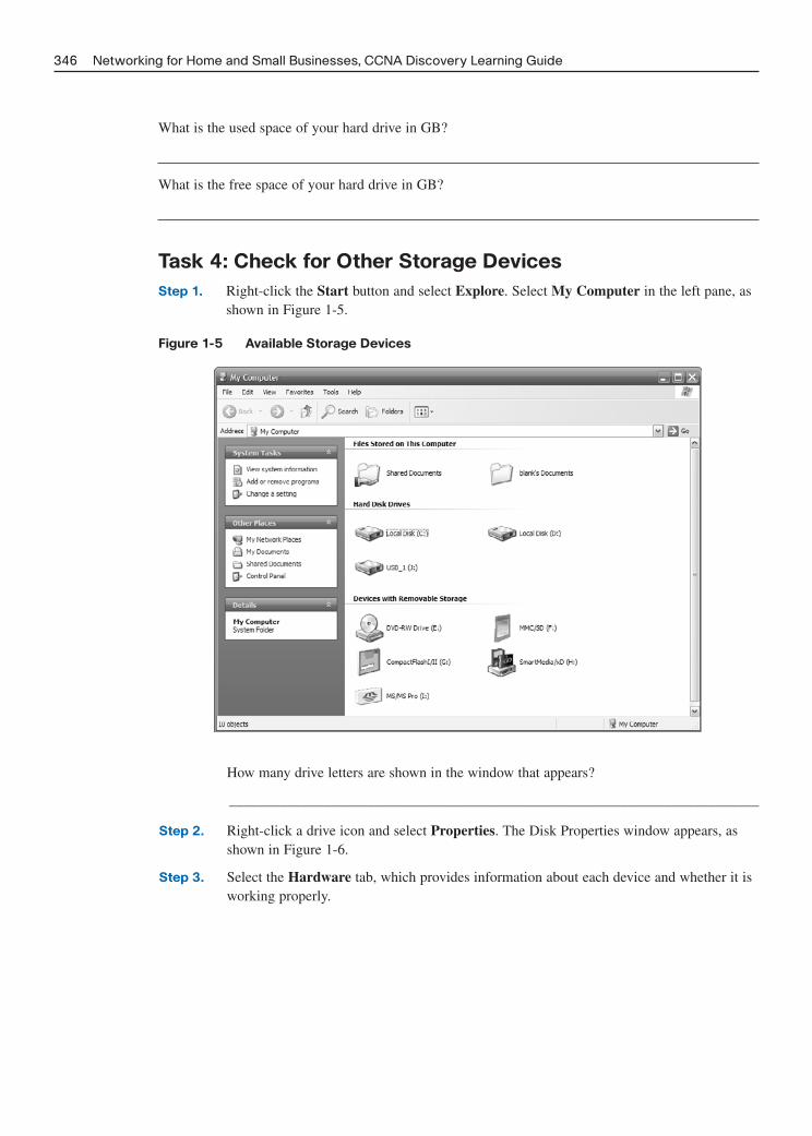
What is the used space of your hard drive in GB?
What is the free space of your hard drive in GB?
Task 4: Check for Other Storage Devices
Step 1. Right-click the Start button and select Explore. Select My Computer in the left pane, asshown in Figure 1-5.
Figure 1-5 Available Storage Devices
346 Networking for Home and Small Businesses, CCNA Discovery Learning Guide
How many drive letters are shown in the window that appears?
_________________________________________________________________________
Step 2. Right-click a drive icon and select Properties. The Disk Properties window appears, asshown in Figure 1-6.
Step 3. Select the Hardware tab, which provides information about each device and whether it isworking properly.

Figure 1-6 Disk Properties
Chapter 1: Labs: Personal Computer Hardware 347
Task 5: Reflection
1. Why is it important to know the amount of RAM in your computer?
___________________________________________________________________________
___________________________________________________________________________
___________________________________________________________________________
___________________________________________________________________________
2. Why is it important to know the size of a hard drive as well as the space being used?
___________________________________________________________________________
___________________________________________________________________________
___________________________________________________________________________
___________________________________________________________________________

Lab 1-2: Determining the Screen Resolution of a
Computer (1.3.3.4)
Objectives
■ Determine the current screen resolution of a PC monitor.
■ Determine the maximum resolution for the highest color quality.
■ Calculate the number of pixels needed for resolution settings.
■ Identify the type of monitor and graphics display adapter installed.
Background/Preparation
The resolution of a monitor determines the quality of the screen display. The resolution is determinedby the number of horizontal and vertical picture elements (pixels) that are used to produce the imageon the monitor. The number of pixels is typically predefined by the manufacturers of graphics cardsand PC monitors. The highest number of pixels that a monitor and graphics card can support isreferred to as maximum resolution. An example of maximum resolution is 1280 x 1024, which meansthe display is composed of 1280 horizontal pixels and 1024 vertical pixels. The higher the resolutionis set, the sharper the display image. Two factors determine the maximum resolution of a PC monitorand the number of colors the monitor can display:
■ Capability of the monitor
■ Capability of the graphics card, especially the amount of onboard memory
To perform this lab, you need to use a computer with Windows XP installed.
Task 1: Determine the Current Screen Resolution
Step 1. To view the current screen resolution and color quality settings, right-click any emptyspace on the desktop and select Properties from the context menu. In the DisplayProperties window, click the Settings tab.
You can also access Display Properties by opening the Control Panel and clicking theDisplay icon.
Figure 1-7 shows the Display Properties window.
Step 2. Use the Display Properties Settings tab to record the current settings on your PC:
The screen resolution is______________________
The horizontal resolution is___________________________
The vertical resolution is ___________________________
The color quality value is ____________________________
Step 3. Keep the Display Properties Settings dialog box open for Task 2.
348 Networking for Home and Small Businesses, CCNA Discovery Learning Guide
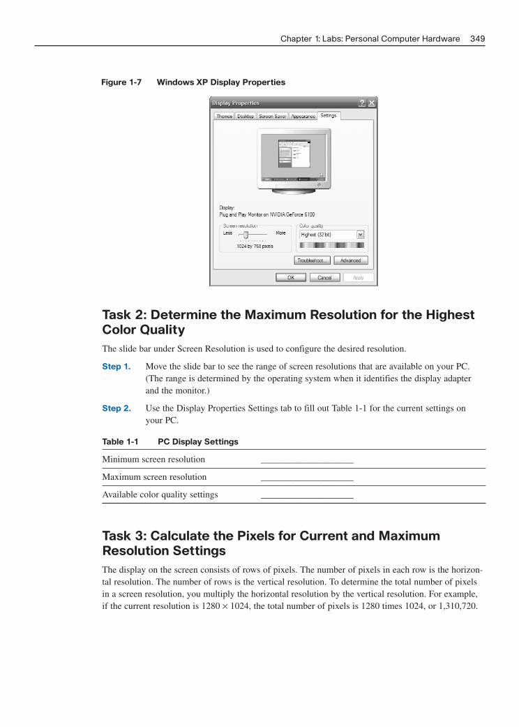
Figure 1-7 Windows XP Display Properties
Chapter 1: Labs: Personal Computer Hardware 349
Task 2: Determine the Maximum Resolution for the Highest
Color Quality
The slide bar under Screen Resolution is used to configure the desired resolution.
Step 1. Move the slide bar to see the range of screen resolutions that are available on your PC.(The range is determined by the operating system when it identifies the display adapterand the monitor.)
Step 2. Use the Display Properties Settings tab to fill out Table 1-1 for the current settings on your PC.
Table 1-1 PC Display Settings
Minimum screen resolution ____________________
Maximum screen resolution ____________________
Available color quality settings ____________________
Task 3: Calculate the Pixels for Current and Maximum
Resolution Settings
The display on the screen consists of rows of pixels. The number of pixels in each row is the horizon-tal resolution. The number of rows is the vertical resolution. To determine the total number of pixelsin a screen resolution, you multiply the horizontal resolution by the vertical resolution. For example,if the current resolution is 1280 × 1024, the total number of pixels is 1280 times 1024, or 1,310,720.

Step 1. Calculate the total number of pixels for the lowest resolution:
Step 2. Calculate the total number of pixels for the maximum resolution:
Task 4: Identify the Type of Graphics Card Installed
You can get detailed information about the graphics card (also called the display adapter) in theDisplay Properties screen.
Step 1. In the Display Properties screen, click the Advanced button.
Step 2. Select the Adapter tab, as shown in Figure 1-8.
Figure 1-8 Windows XP Advanced Adapter Properties
350 Networking for Home and Small Businesses, CCNA Discovery Learning Guide
Step 3. Use the information found in the Adapter tab to complete Table 1-2.
Table 1-2 Graphics Card Information
Graphics card manufacturer and model (Adapter Type) ____________________
Graphics memory on card (Memory Size) ____________________
Task 5: Identify the Type of Monitor and Available Refresh
Rates
You can get detailed information about the monitor in the Display Properties screen. The screenrefresh rate determines the number of times per second the screen is illuminated or redrawn. A refreshrate of 60 hertz means the screen is illuminated 60 times per second. Higher refresh rates provide less

screen flicker, which reduces eye strain, but may adversely affect the monitor. You should set therefresh rate to the highest level the monitor can safely support.
Step 1. Click the Monitor tab to see the monitor type and current refresh rate, as shown in Figure 1-9.
Figure 1-9 Windows XP Monitor Properties
Chapter 1: Labs: Personal Computer Hardware 351
Step 2. Use the information found in the Monitor tab to complete Table 1-3.
Table 1-3 PC Monitor Information
Monitor type ____________________
Supported refresh rates ____________________
What can occur if you select a refresh rate that is higher than what the monitor can safelydisplay? Do not actually change the refresh rate.
_________________________________________________________________________
_________________________________________________________________________
_________________________________________________________________________

Lab 1-3: Installing a Printer and Verifying Its
Operation (1.5.3.4)
Objectives
■ Manually install a printer using the default Windows XP driver.
■ Verify printer and driver installation and troubleshoot any problems.
■ Download and install the most recent driver from the printer manufacturer.
Background/Preparation
Many home and small office printers are Plug-and-Play, which means that Windows XP automaticallydiscovers the printer and installs a functional driver. However, if you know the process for manuallyinstalling a printer and updating the printer driver, you have the knowledge to troubleshoot many typesof printer problems.
In this lab, you install a virtual printer on a Windows XP workstation. You also compare the featuresavailable with the Windows default printer driver with those available with the latest driver availablefrom the manufacturer.
This lab is designed to work without an actual printer, but most steps are exactly the same for con-necting a physical printer.
The following resources are required:
■ Computer with Window XP installed
■ Internet connection
Task 1: Add a Printer
Step 1. From the Start menu, select Control Panel. If working in Classic view, select Settings andthen Control Panel. Double-click the Printers and Faxes icon. If this icon is not shown,click Switch to Classic View in the left pane.
Step 2. In the Printers and Faxes window, click the Add Printer icon to open the Add PrinterWizard, shown in Figure 1-10. Click Next.
Figure 1-10 Windows Add Printer Wizard
352 Networking for Home and Small Businesses, CCNA Discovery Learning Guide

Step 3. In the Local or Network Printer window shown in Figure 1-11, click the Local printerattached to this computer radio button and uncheck Automatically detect and installmy Plug and Play printer. Click Next.
Figure 1-11 Windows Local or Network Printer Selection
Chapter 1: Labs: Personal Computer Hardware 353
Step 4. In the Select a Printer Port window shown in Figure 1-12, click the Use the followingport radio button and choose LPT1: (Recommended Printer Port). Click Next.
Figure 1-12 Windows Printer Port Selection
Step 5. Note: In this step, you choose a driver provided by Windows XP for an HP LaserJet 2200,a common home or small office, black-and-white laser printer. You do not have to physi-cally have the printer to do these steps. However, if you are installing a printer that is actu-ally attached to your computer, choose the manufacturer and printer model correspondingto your printer instead of the HP LaserJet 2200.
In the Install Printer Software window shown in Figure 1-13, select HP from theManufacturer list. In the Printers list, locate HP LaserJet 2200 Series PCL and click toselect it. Click Next.

Figure 1-13 Selecting a Printer to Install
354 Networking for Home and Small Businesses, CCNA Discovery Learning Guide
Step 6. In the Name Your Printer window shown in Figure 1-14, choose a descriptive name for theprinter. In an environment like a large office that has several printers of the same make andmodel, giving each printer a unique name so that it can easily be identified is helpful.Click No under Do You Want to Use This Printer as the Default Printer? (If you are con-necting an actual printer, click Yes if you want Windows applications to use this printer bydefault.) Click Next.
Figure 1-14 Entering a Printer Name
Step 7. In the Printer Sharing window, click Next to accept the default option to not share thisprinter.
Step 8. If you are actually installing a printer, click Next in the Print Test Page window to print atest page. If you are installing a virtual HP LaserJet 2200, click the No radio button beforeclicking Next.
Step 9. In the Completing the Add Printer Wizard window shown in Figure 1-15, review the printer settings and then click Finish.

Figure 1-15 Completing the Add Printer Wizard
Chapter 1: Labs: Personal Computer Hardware 355
Task 2: Verify the Printer Installation
Step 1. Select Printers and Faxes in the Control Panel and check to see that the printer youinstalled and named is shown. If it is not shown, repeat Task 1.
Step 2. Right-click the icon for the new printer (HPLJ 2200 Series PCL Virtual) and then clickProperties. The dialog box shown in Figure 1-16 opens.
Figure 1-16 Viewing Printer Properties
Step 3. Click the Advanced tab and record the name of the driver shown in the Driver text box.
_________________________________________________________________________
Step 4. Click the Device Settings tab and examine the available options for the printer using thisdriver, as shown in Figure 1-17. To close the window, click Cancel.

Figure 1-17 Printer Device Settings
356 Networking for Home and Small Businesses, CCNA Discovery Learning Guide
Task 3: Download and Install an Updated Printer Driver
When you use the Add Printer Wizard to manually install a printer, the driver that is installed by defaultallows the device to function, but the Windows-installed driver does not always allow all features of thedevice to be used. The most full-featured drivers are usually those provided by the device manufacturer.
Updating a printer driver is one of the best ways to troubleshoot problems and to increase printer func-tionality. Most manufacturers continue to update drivers to improve compatibility with operating sys-tems, so periodically checking for driver updates and installing them if they are available is a good idea.
In this Task, you go to the Hewlett-Packard website to obtain an updated driver for the HP LaserJet2200. If you have installed a different printer, modify these instructions as needed.
Step 1. Open a web browser and go to http://www.hp.com.
Step 2. Click the Software and Driver Downloads link.
NOTE: Many manufacturers have a support link on their home page that leads to drivers and otherdownloads.
Step 3. Click the Download drivers and software (and firmware) radio button. Enter the printermodel in the For Product text box and click the double-arrow link to the right of the textbox, as shown in Figure 1-18.
Figure 1-18 Searching for Updated Drivers

Step 4. The search displays the available products, as shown in Figure 1-19. Click HP LaserJet2200 Printer or the model of the printer for which you are downloading a driver.
Figure 1-19 Selecting the Correct Printer
Chapter 1: Labs: Personal Computer Hardware 357
Step 5. Click Microsoft Windows XP in the list of operating systems. In the list of driversshown, click Download for the HP LaserJet 2200 PCL6 driver option shown in Figure 1-20.
Figure 1-20 Downloading an Updated Driver
Step 6. In the download dialog box shown in Figure 1-21, click Save.
Figure 1-21 Saving the Updated Driver
Step 7. In the Save As dialog box, click the Desktop icon in the left pane to save the driver instal-lation file to your desktop. You can save the file anywhere, but it is important that youknow where you have saved it.

Step 8. Write the name of the file:
_________________________________________________________________________
Step 9. Click the Save button. Close the browser and any other open applications.
Step 10. Navigate to the location where you downloaded the driver. Double-click the icon for thedownloaded file, as shown in Figure 1-22.
Figure 1-22 Starting the Installation
358 Networking for Home and Small Businesses, CCNA Discovery Learning Guide
NOTE: You might not see the filename extension (.exe). File extensions are visible only if you dis-able the default Hide extensions for known file types from Windows Explorer.
Step 11. When prompted, click Run. Enter the location where you want the files to be extracted toand click Unzip to unpack the files, as shown in Figure 1-23. If you selected the defaultlocation, the files are now stored in c:\lj2200. Click Close to finish the WinZip self-extractor.
Figure 1-23 Extracting and Saving the Installation Files
Step 12. Repeat Task 2, Steps 1 and 2, to open the Properties page of the new printer. Click theAdvanced tab. Click the New Driver button and then click Next to begin the Add PrinterDriver Wizard.
Step 13. Click Have Disk in the Printer Driver Selection window shown in Figure 1-24.

Figure 1-24 Selecting the Printer to Install
Chapter 1: Labs: Personal Computer Hardware 359
Step 14. In the Install From Disk window shown in Figure 1-25, click Browse and locate the foldercreated earlier in this task by navigating to My Computer > Local Disk(C:) > lj2200.Click Open, and you return to the Install From Disk window. Click OK.
Figure 1-25 Installing the Printer
Step 15. In the Printer Driver Selection window shown in Figure 1-26, select HP LaserJet 2200Series PCL 6 and then click Next. Click Finish in the window that follows.
Figure 1-26 Selecting the Printer Model

Step 16. When the process is finished, return to the properties window of the printer (refer to Task2), click the Apply button, and then click OK.
Task 4: Verify the New Driver Installation
In this Task, you compare the Windows default driver installed in the first Task to the newly installeddriver from the manufacturer website.
Step 1. In the properties window of the new printer, verify that the Apply button is dimmed.
Step 2. Click the Advanced tab. What is the name of the driver?
_________________________________________________________________________
Step 3. Click the Configure tab. The window for the HP LaserJet 2200 is shown in Figure 1-27.
Figure 1-27 Printer Properties
360 Networking for Home and Small Businesses, CCNA Discovery Learning Guide
Step 4. Compare the Configure tab to the Device Settings tab in Step 4 of Task 2. What are thedifferences?
_________________________________________________________________________
_________________________________________________________________________
_________________________________________________________________________
_________________________________________________________________________
_________________________________________________________________________
_________________________________________________________________________
_________________________________________________________________________
Step 5. Click some of the other tabs in the properties window to compare the new and old drivers.Record some of the differences here.
_________________________________________________________________________
_________________________________________________________________________

CHAPTER 2
Labs: Operating Systems
The lab exercises included in this chapter include the Chapter 2 online curriculum lab and a challenge lab toensure that you have mastered the practical, hands-on skills needed to determine the OS and application ver-sion and potential for an OS upgrade. As you work through these labs, use Chapter 2 in Part I of this book oruse the corresponding Chapter 2 in the Networking for Home and Small Businesses course of the CCNADiscovery online curriculum for assistance.
Lab 2-1: Examining Operating System and Application
Versions (2.3.3.2)
Objectives
■ Determine the operating system (OS) version and revision.
■ Examine the method used for configuring Windows XP updates.
■ Determine the revision number of a particular application.
Background/Preparation
Keeping operating systems and applications up to date to ensure stable operation and to address security vul-nerabilities is important. These updates are called revisions, updates, patches, or hot fixes. The three ways toupdate the Windows XP operating system are automatic updating, downloading patches automatically andmanually determining when they are installed, or manually downloading and installing the patches.
This lab can be done individually, in pairs, or in teams. To perform this lab, you need to use a computer withWindows XP and an application such as Microsoft Word installed.
Task 1: Determine the Windows XP Version and Revision Number
Step 1. Click Start > All Programs > Accessories > Windows Explorer. Alternatively, right-click Startand select Explore.
Step 2. From the Help menu, choose About Windows.
Which version of Windows XP and service pack is installed on your computer?
_______________________________________________________________________________
How much physical memory (RAM) is available to Windows XP?
_______________________________________________________________________________
Why is memory important to an operating system?
_______________________________________________________________________________
_______________________________________________________________________________
_______________________________________________________________________________
_______________________________________________________________________________

Step 3. Click the End-User License Agreement link on the About Windows screen. According tothe license agreement, how many backup copies of Windows XP can you legally make?
_________________________________________________________________________
Step 4. According to the license agreement, what is the maximum number of devices you can con-nect to this workstation to use file or print services?
_________________________________________________________________________
Step 5. Close the end-user license agreement window. Close the About Windows window.
Task 2: Configure Windows XP for Updates
Step 1. Click the Start button and select the Control Panel option. If using the Classic Startmenu, choose Start > Settings > Control Panel.
Step 2. If the right window pane shows Pick a Category, select the Switch to Classic View link inthe left pane. Double-click the Automatic Updates icon.
Which four options are available for automatic updates?
_________________________________________________________________________
_________________________________________________________________________
Step 3. Click the How Does Automatic Updates Work? link. Expand the How Are UpdatesDownloaded? section by clicking the + (plus sign) beside the option.
Based on the information presented, what happens if you are using your computer, updatesare being downloaded, and you disconnect from the Internet?
_________________________________________________________________________
Step 4. Expand the How Are Updates Installed? section. Based on the output shown, what is thedefault time for when updates are installed?
_________________________________________________________________________
Step 5. Close the How Does Automatic Updates Work? window and return to the AutomaticUpdates window.
What is the current setting for automatic updates, and why do you think the person whoset up the computer chose this option?
_________________________________________________________________________
_________________________________________________________________________
_________________________________________________________________________
Step 6. Close the Automatic Updates window.
Step 7. Another way of configuring a system for automatic updates is through the System icon inControl Panel. Click the Start > Control Panel, and double-click the System icon. TheSystem Properties window opens. Click the Automatic Updates tab.
Are the options the same as before?
_________________________________________________________________________
Step 8. Close the System Properties window.
362 Networking for Home and Small Businesses, CCNA Discovery Learning Guide

Task 3: Determine an Application Version
Step 1. Open any Windows-based application such as Microsoft Word.
Step 2. From the application Help menu option, choose the About option.
What is the application version?
_________________________________________________________________________
Step 3. If this is a Microsoft application, you might see a System Info button. If there is a button,click it. If there is no button, skip to the next step. Explore the different options availableunder System Info, including information related to your specific application. System Infoprovides similar information to that provided by winmsd.exe.
Step 4. Click the Help menu again. If there are double down arrows at the bottom of the menu,click them to show all the menu options. Some applications have a Check for Updatesoption. Does the application have this option?
_________________________________________________________________________
Do you think that Internet access is required for an application that has a Check forUpdates option? Why or why not?
_________________________________________________________________________
_________________________________________________________________________
_________________________________________________________________________
Step 5. Close the application.
Task 4: Reflection
When is it important to get an update for an application or an operating system?
List one instance when you might need to know which version of the operating system or applicationis being used.
Challenge Lab 2-2: Evaluating an OS Upgrade
Objectives
■ Inspect the hardware installed in a computer using the Control Panel and the winmsd.exe utility.
■ Determine whether a computer can accommodate a specific OS.
Chapter 2: Labs: Operating Systems 363

Background/Preparation
As an OS evolves, it typically requires additional system resources to support new capabilities and fea-tures. In this lab, you use the Microsoft website to look up the minimum requirements of the WindowsVista Home Basic edition. You also evaluate the existing hardware of a Windows XP computer anddetermine whether it can support an upgrade to Windows Vista.
The minimum requirements address CPU type and speed, the amount of RAM and hard disk spaceneeded, graphics capabilities, and other items. The minimum hardware requirements for an OS allowthe system to boot and function and are not necessarily the recommended requirements. Ensuring thatthe system on which the OS is to be installed or upgraded has resources over the minimum for it to per-form at a level that is satisfactory to the end user is important.
Regardless of the hardware platform, not all existing Microsoft OSs can be upgraded to Windows Vista.Some, such as Windows 2000, require a clean install. In this case, all data must be backed up, andapplications must be reinstalled after the new OS is installed. For a list of the Windows versions thatcan be upgraded to Windows Vista, go tohttp://www.microsoft.com/windows/products/windowsvista/buyorupgrade/upgradepaths.mspx.
To perform this lab, you need a computer with Windows XP installed, access to the command prompt,and Internet connectivity.
Task 1: Locate Minimum Requirements for Windows Vista
Step 1. Open a web browser and go to http://www.microsoft.com.
In the search text box, which words do you think would give you the best result if you aresearching for the requirements for installing Windows Vista?
__________________________________________________________________________
__________________________________________________________________________
Step 2. Locate the link that describes the specific minimum hardware requirements to installWindows Vista Home Basic edition.
NOTE: The requirements for Windows Vista Home Basic edition are significantly less than those forWindows Vista Home Premium, Windows Vista Business, Windows Vista Enterprise, and Windows VistaUltimate. You might want to use the requirements for these other versions as your minimum requirements.
List the minimum hardware requirements: ______________________________________
Processor type/speed (in MHz): ______________________________________________
System memory (RAM): ____________________________________________________
Graphics card: ____________________________________________________________
Graphics memory: ________________________________________________________
Hard disk size: ____________________________________________________________
Hard disk free space: ______________________________________________________
Optical drive:______________________________________________________________
364 Networking for Home and Small Businesses, CCNA Discovery Learning Guide

Task 2: Determine the Hardware Information for the
Computer Using winmsd.exe
One way to determine system information is with the winmsd.exe utility. You must have access to therun command to use it. Winmsd is an abbreviation for Windows Microsoft Diagnostics. The utilityprovides a considerable amount of information, but it is not always easy to interpret. Microsoft sup-port personnel use winmsd to diagnose problems with the Windows OS because it centralizes all sys-tem information.
Step 1. Click Start > Run.
Step 2. Type winmsd.exe in the Open box, and then click OK.
Step 3. In the System Information window, compare your computer against the minimum hard-ware requirements for Windows Vista Home Basic edition or one of the other Vistaeditions.
Task 3: Determine CPU Type and Amount of RAM Using
System Properties
Another way to determine system information is to use the individual Windows GUI utilities, such asthe System Properties window.
Click Start > Control Panel, and double-click the System icon.
In the System Properties dialog box, OS and service pack information are listed in the upper part ofthe General tab. The computer processor type, speed, and memory are listed in the lower portion.
How much RAM does your computer contain? Does it meet the minimum requirements for WindowsVista?
Check the processor. Does it meet the minimum requirements for Windows Vista?
Task 4: Determine Hard Disk Capacity and Amount of Free
Disk Space Using My Computer Properties
Step 1. Double-click the My Computer icon on your computer desktop. If there is no MyComputer icon, click Start > My Computer.
Step 2. Right-click the local disk drive under the Hard Disk Drives section (usually the C drive)and select Properties. In the General tab, Capacity lists the total capacity of the harddrive.
What is the total size in GB of the hard drive on your computer?
_________________________________________________________________________
Will the hard disk capacity meet the minimum requirements to install Windows Vista?
_________________________________________________________________________
In the Local Disk Properties dialog box, the used and free space is shown in both bytesand GB above Capacity.
Chapter 2: Labs: Operating Systems 365

What is the used space of your hard drive in GB?
_________________________________________________________________________
What is the free space of your hard drive in GB?
_________________________________________________________________________
Will the amount of space available meet the minimum requirements to install WindowsVista?
_________________________________________________________________________
Task 5: Check for Other Drives (Floppy, CD-ROM, DVD)
Right-click the Start button and select Explore. Click the + (plus sign) to expand the My Computerfolder and – (minus sign) to contract the Local Disk (C:) folder if necessary to see the drive lettersand icons more easily.
How many drive letters are shown in the window that appears?
Does the computer have a DVD-ROM drive?
Task 6: Verify the Monitor and Graphics Capabilities
Step 1. Click Start > Control Panel and double-click the Display icon.
Step 2. Click the Settings tab in the Display Properties dialog box.
Step 3. Examine the information for Screen Resolution to see whether the resolution of at least800 x 600 is an option. If so, this meets SVGA standards. Does the monitor meet the mini-mum requirements to install Windows Vista?
_________________________________________________________________________
Task 7: Download and Run Windows Vista Upgrade Advisor
Step 1. If your current OS is Windows XP with Service Pack 2, you can use the Windows VistaUpgrade Advisor to help you to determine whether you can run Windows Vista and whicheditions can be supported. To download and run the Upgrade Advisor, go to the Microsoftwebsite at the following URL. When the download is complete, run the installation pro-gram and allow the program icon to be placed on your desktop.
http://www.microsoft.com/windows/products/windowsvista/buyorupgrade/upgradeadvisor.mspx
Step 2. Click Run when the installation is complete or click the icon on the desktop to start theapplication. Click Start Scan to check your computer system for Windows Vista compati-bility.
366 Networking for Home and Small Businesses, CCNA Discovery Learning Guide

Step 3. When the scan is complete, click the See Details button and then click the version ofWindows Vista you are considering installing. The Upgrade Advisor program examinesthree categories: System Requirements, Devices, and Programs. Click the Details buttonfor each of these categories to see the issues identified.
Task 8: Reflection
Why is it important to verify that the hardware meets the minimum requirements of the operating sys-tem before you try to install a new version?
Chapter 2: Labs: Operating Systems 367

This page intentionally left blank

CHAPTER 3
Labs: Connecting to the Network
The lab exercises included in this chapter cover all the Chapter 3 online curriculum labs to ensure that you havemastered the practical, hands-on skills needed to build a simple network, examine network addressing, and shareresources. As you work through these labs, use Chapter 3 in Part I of this book or use the corresponding Chapter 3in the Networking for Home and Small Businesses course of the CCNA Discovery online curriculum for assistance.
Lab 3-1: Building a Peer-to-Peer Network (3.1.5.3)
Objectives
■ Design and build a simple peer-to-peer network using a crossover cable supplied by the instructor.
■ Verify connectivity between the peers using the ping command.
Background/Preparation
In this hands-on lab, you plan and build a simple peer-to-peer network using two PCs and an Ethernetcrossover cable.
The following resources are required:
■ Two Windows XP Professional PCs, each with an installed and functional network interface card (NIC)
■ An Ethernet crossover cable
Task 1: Diagram the Network
Step 1. A network diagram is a map of the logical topology of the network. In the following space, sketcha simple peer-to-peer network connecting two PCs. Label one PC with IP address 192.168.1.1 andthe other PC with IP address 192.168.1.2. Use labels to indicate connecting media and any neces-sary network devices.
Step 2. A simple network like the one you designed can use a hub or switch as a central connecting device,or the PCs can be directly connected. Which type of cable is required for a direct Ethernet connec-tion between the two PCs?
_______________________________________________________________________________
_______________________________________________________________________________
_______________________________________________________________________________
_______________________________________________________________________________

370 Networking for the Home and Small Businesses, CCNA Discovery Learning Guide
Task 2: Document the PCs
Step 1. Check the computer name settings for each PC and make adjustments as necessary. Foreach PC, click Start > Control Panel. Double-click the System icon, and then click theComputer Name tab, as shown in Figure 3-1. Alternatively, right-click My Computerand click Properties. In Table 3-1, write down the computer name that is displayed fol-lowing Full Computer Name.
Figure 3-1 Computer Name in Windows XP
Table 3-1 Computer Names
Computer Computer Name
PC1
PC2
Step 2. Check to see whether the two PCs have the same name. If they do, change the name ofone PC by clicking the Change button, typing a new name in the Computer name field,and then clicking OK.
Step 3. Click OK to close the System Properties window.
Why is it important that each PC on a network have a unique name?
_________________________________________________________________________
_________________________________________________________________________
_________________________________________________________________________
_________________________________________________________________________

Task 3: Connect the Ethernet Cable
Step 1. Use the Ethernet crossover cable provided by the instructor. Plug one end of the cable intothe Ethernet NIC of PC1.
Step 2. Plug the other end of the cable into the Ethernet NIC of PC2. As you insert the cable, youshould hear a click, which indicates that the cable connector is properly inserted into theport. If you do not hear or feel a click, pull lightly on the cable. If it comes out too easily,the clip might need to be carefully bent slightly outward to provide resistance so that itwill not come out of the port on the NIC. If the clip is broken off, the cable should bereplaced.
Task 4: Verify Physical Connectivity
Step 1. After the Ethernet crossover cable is connected to both PCs, take a close look at eachEthernet port. A light (usually green or amber) indicates that physical connectivity hasbeen established between the two NICs. Try unplugging the cable from one PC and thenreconnecting it to verify that the light goes off then back on.
Step 2. Click Start > Control Panel, double-click the Network Connections icon, and confirmthat the local area connection is established. If physical connectivity problems exist, youwill see a red X over the Local Area Connection icon with the words “Network cableunplugged.”
Step 3. If the local area connection does not indicate that it is connected, troubleshoot by repeat-ing Tasks 3 and 4. You might also want to ask your instructor to confirm that you areusing an Ethernet crossover cable.
Task 5: Configure IP Settings
Step 1. Configure the logical addresses for the two PCs so that they are able to communicateusing TCP/IP. On one of the PCs, click Start > Control Panel, double-click the NetworkConnections icon, and then right-click the connected Local Area Connection icon.Choose Properties from the drop-down menu.
Step 2. Using the scroll bar in the Local Area Connection Properties window, scroll down to high-light Internet Protocol (TCP/IP). Click the Properties button to open the window shownin Figure 3-2.
Step 3. Select the Use the following IP address radio button and enter the following informationfor PC1:
IP Address: 192.168.1.1
Subnet Mask: 255.255.255.0
Step 4. Click OK, which closes the Internet Protocol (TCP/IP) Properties window. Click the Closebutton to exit the Local Area Connection Properties window.
Step 5. Repeat Steps 1–4 for PC2 using the following information:
IP Address: 192.168.1.2
Subnet Mask: 255.255.255.0
Chapter 3: Labs: Connecting to the Network 371

Task 6: Verify IP Connectivity Between the Two PCs
To test TCP/IP connectivity between the PCs, you must disable Windows Firewall temporarily on bothPCs. Be sure to re-enable Windows Firewall after you complete the tests.
Step 1. On PC1, on the Windows XP desktop, click Start > Control Panel, and double-clickNetwork Connections.
Step 2. Right-click the Local Area Connection icon and select Properties. Click the Advancedtab. Locate and click the Settings button.
Step 3. Make a note of whether the firewall settings are Enabled (On) for the Ethernet port orDisabled (Off) for the Ethernet port.
_________________________________________________________________________
Step 4. If the firewall settings are enabled, click the Off (not recommended) radio button to dis-able the firewall. You will re-enable the setting in a later Task. Click OK in this dialog boxand the following one to apply this setting.
Step 5. Now that the two PCs are physically connected and configured correctly with IP address-es, you need to make sure they communicate with each other. The ping command is a sim-ple way to accomplish this task. The ping command is included with the Windows XPoperating system.
Step 6. Repeat Steps 1–4 on the second PC. The second PC will ping 192.168.1.1.
Step 7. On PC1, click Start > Run. Enter cmd, and then click OK. A Windows command promptwindow appears.
Step 8. At the prompt, enter ping 192.168.1.2 and press Enter. A successful ping will verify theIP connectivity. It should produce results similar to those shown in Example 3-1.
372 Networking for the Home and Small Businesses, CCNA Discovery Learning Guide
Figure 3-2 Windows XP TCP/IP Properties

Example 3-1: Successful ping Output C:\>ping 192.168.1.2
Pinging 192.168.1.2 with 32 bytes of data:
Reply from 192.168.1.2: bytes=32 time<1ms TTL=64
Reply from 192.168.1.2: bytes=32 time<1ms TTL=64
Reply from 192.168.1.2: bytes=32 time<1ms TTL=64
Reply from 192.168.1.2: bytes=32 time<1ms TTL=64
Ping statistics for 192.168.1.2:
Packets: Sent = 4, Received = 4, Lost = 0 (0% loss),
Approximate round trip times in milli-seconds:
Minimum = 0ms, Maximum = 0ms, Average = 0ms
Step 9. Close the Windows command prompt window on both PCs.
Task 7: Verify Connectivity Using My Network Places
Step 1. A PC can share its resources with other PCs on the network. PCs with shared resourcesshould be visible through My Network Places. On PC1, click Start > My Network Placesand then click View workgroup computers in the left panel.
Do you see an icon for the other PC in your peer-to-peer network?
_________________________________________________________________________
What is the name of the other PC?
_________________________________________________________________________
Is it the same name you recorded in Task 2?
_________________________________________________________________________
Step 2. Repeat Step 1 on the second PC.
Step 3. Close any open windows.
Task 8: (Optional) Re-enable the Firewall
Perform this task only if the firewall was originally enabled.
Step 1. If you disabled Windows Firewall in Task 6, click Start > Control Panel, and open theNetwork Connections control panel.
Step 2. Right-click the Ethernet network connection icon and select Properties. Click theAdvanced tab. Locate and click Settings.
Step 3. If the firewall settings are disabled (and they were enabled before this lab began), click theOn radio button to enable the firewall. Click OK in this dialog box and the following oneto apply this setting.
Chapter 3: Labs: Connecting to the Network 373

Lab 3-2: Determine the MAC Address of a Host
(3.3.3.2)
Objective
■ Determine the MAC address of a Windows XP computer on an Ethernet network using theipconfig /all command.
Background/Preparation
Every computer on an Ethernet local network has a Media Access Control (MAC) address that isburned into the NIC. Computer MAC addresses are usually displayed as six sets of two hexadecimalnumbers separated by dashes or colons (for example, 15-EF-A3-45-9B-57). The ipconfig /all com-mand displays the computer MAC address. You may work individually or in teams.
The following resources are required:
■ Windows XP workstation with at least one Ethernet NIC.
■ Access to the Run command.
Task 1: Open a Windows Command Prompt Window
Step 1. From the Windows XP desktop, click Start > Run.
Step 2. Enter cmd in the Run dialog box then click OK.
Task 2: Use the ipconfig /all Command
Enter the ipconfig /all command at the command prompt and press Enter. (Typical results are shownin Example 3-2, but your computer will display different information.)
Example 3-2 ipconfig /all Command OutputC:\>ipconfig /all
Windows IP Configuration
Host Name . . . . . . . . . . . . : Computer1
Primary Dns Suffix . . . . . . . :
Node Type . . . . . . . . . . . . : Hybrid
IP Routing Enabled. . . . . . . . : No
WINS Proxy Enabled. . . . . . . . : No
DNS Suffix Search List. . . . . . : cisco.com
Ethernet adapter Local Area Connection:
Connection-specific DNS Suffix . : cisco.com
Description . . . . . . . . . . . : Intel(R) PRO/100 VE Network Connection
Physical Address. . . . . . . . . : 00-07-E9-63-CE-53
Dhcp Enabled. . . . . . . . . . . : Yes
Autoconfiguration Enabled . . . . : Yes
IP Address. . . . . . . . . . . . : 192.168.1.103
374 Networking for the Home and Small Businesses, CCNA Discovery Learning Guide

Chapter 3: Labs: Connecting to the Network 375
Subnet Mask . . . . . . . . . . . : 255.255.255.0
Default Gateway . . . . . . . . . : 192.168.1.1
DHCP Server . . . . . . . . . . . : 192.168.1.1
DNS Servers . . . . . . . . . . . : 172.16.7.3
172.16.7.6
Lease Obtained. . . . . . . . . . : Tuesday, September 25, 2007 1:40:58 PM
Lease Expires . . . . . . . . . . : Wednesday, September 26, 2007 1:40:58 PM
Task 3: Locate the MAC (Physical) Address(es) in the Output
from the ipconfig /all Command
Use Table 3-2 to fill in the description of the Ethernet adapter and the physical (MAC) address.
Table 3-2 Ethernet MAC Address(es)
Description Physical Address
Example: VIA Rhine II Fast Ethernet Adapter Example: 00-50-2C-A5-F5-73
Task 4: Reflection
Why might a computer have more than one MAC address?
The sample output from the ipconfig /all command shown previously in Example 3-2 had only oneMAC address. Suppose that the output was from a computer that also had wireless Ethernet capability.How might the output change?
Try disconnecting the cable(s) to your network adapter(s) and use the ipconfig /all command again.What changes do you see? Does the MAC address still display? Will the MAC address ever change?
What are other names for the MAC address?

Lab 3-3: Determine the IP Address of a Computer
(3.3.6.2)
Objective
■ Use the ipconfig /all command to determine the IP address of a Windows XP host on anEthernet network.
Background/Preparation
Every computer connected to the Internet has a unique identifier, called an IP address. IP addressesare displayed as four numbers, known as octets, separated by periods (for example, 192.168.1.4). Theipconfig /all command displays your computer’s IP address and information about the network. Thefollowing resources are required:
■ A workstation that is attached to the local network and that has its IP address already config-ured
■ Access to the Run command
In this lab you locate your computer’s IP address to discover its unique number.
Task 1: Determine the IP Address of the Computer
Step 1. From the Windows XP desktop, click Start > Run.
Step 2. In the Run dialog box, enter cmd then click the OK button.
Step 3. At the command prompt, enter ipconfig /all and press Enter.
The ipconfig /all command then displays a list of information about your computer’s IPconfiguration, as shown in Example 3-3. The information displayed for your computer willbe different.
Example 3-3 Sample ipconfig /all OutputC:\>ipconfig /all
Windows IP Configuration
Host Name . . . . . . . . . . . . : Computer1
Primary Dns Suffix . . . . . . . :
Node Type . . . . . . . . . . . . : Hybrid
IP Routing Enabled. . . . . . . . : No
WINS Proxy Enabled. . . . . . . . : No
DNS Suffix Search List. . . . . . : cisco.com
Ethernet adapter Local Area Connection:
Connection-specific DNS Suffix . : cisco.com
Description . . . . . . . . . . . : Intel(R) PRO/100 VE Network Connection
Physical Address. . . . . . . . . : 00-07-E9-63-CE-53
Dhcp Enabled. . . . . . . . . . . : Yes
Autoconfiguration Enabled . . . . : Yes
376 Networking for the Home and Small Businesses, CCNA Discovery Learning Guide

IP Address. . . . . . . . . . . . : 192.168.1.103
Subnet Mask . . . . . . . . . . . : 255.255.255.0
Default Gateway . . . . . . . . . : 192.168.1.1
DHCP Server . . . . . . . . . . . : 192.168.1.1
DNS Servers . . . . . . . . . . . : 172.16.7.3
172.16.7.6
Lease Obtained. . . . . . . . . . : Tuesday, September 25, 2007 1:40:58 PM
Lease Expires . . . . . . . . . . : Wednesday, September 26, 2007 1:40:58 PM
Step 4. Locate the IP address and record the finding.
IP address _____________________________________
Why is it important that a computer get an IP address?
__________________________________________________________________________
__________________________________________________________________________
Chapter 3: Labs: Connecting to the Network 377

Lab 3-4: IP Addresses and Network Communication
(3.5.2.2)
Figure 3-3 A Simple Peer-to-Peer Network
378 Networking for the Home and Small Businesses, CCNA Discovery Learning Guide
PC1 PC2
Objectives
■ Build a simple peer-to-peer network and verify physical connectivity.
■ Assign various IP addresses to hosts and observe the effects on network communication.
Background/Preparation
In this lab, you build a simple peer-to-peer network using two PCs and an Ethernet crossover cable.You also assign various compatible and non-compatible IP addresses to the hosts and determine theeffects on their capability to communicate.
NOTE: You may use the small peer-to-peer network that was built in Lab 3-1.
The following resources are required:
■ Two Windows XP Professional PCs, each with an installed and functional NIC
■ An Ethernet crossover cable to connect the PCs (provided by instructor)
■ (Optional lab setup) A hub or switch and two straight-through cables to connect the PCs (pro-vided by instructor)
Task 1: Connect the PCs to Create a Peer-to-Peer Network
Step 1. Obtain an Ethernet crossover cable provided by the instructor to connect the two PCs.
NOTE: (Optional lab setup.) The PCs may be connected to a hub (or switch) using two straight-through cables. The following instructions assume you are using a crossover cable.
Step 2. Plug one end of the cable into the Ethernet NIC of PC1. Plug the other end of the cableinto the Ethernet NIC of PC2. As you insert the cable, you should hear a click, which indi-cates that the cable connector is properly inserted into the port.
Task 2: Verify Physical Connectivity
Step 1. After the Ethernet crossover cable is connected to both PCs, take a close look at eachEthernet port. A link light (usually green or amber) indicates that physical connectivityhas been established between the two NICs. Try unplugging the cable from one PC andthen reconnecting it to verify that the light goes off then back on.
Step 2. Click Start > Control Panel, double-click the Network Connections icon, and confirmthat the local area connection is established. If physical connectivity problems exist, youwill see a red X over the Local Area Connection icon with the words “Network cableunplugged.”

Step 3. If the local area connection does not indicate that it is connected, troubleshoot by repeat-ing Tasks 1 and 2. You might also want to ask your instructor to confirm that you areusing an Ethernet crossover cable.
Task 3: Configure IP Settings for the Two PCs
Step 1. Configure the logical IP addresses for the two PCs so that they are able to communicateusing TCP/IP. On PC1, go to the Control Panel, double-click the Network Connectionsicon, and then right-click the connected Local Area Connection icon. Choose Propertiesfrom the drop-down menu.
Step 2. Using the scroll bar in the Local Area Connection Properties window, scroll down to high-light Internet Protocol (TCP/IP). Click the Properties button.
Step 3. Select the Use the following IP address radio button and enter an IP address of192.168.1.1 and a subnet mask of 255.255.255.0, as shown in Figure 3-4. With this IPaddress and subnet mask, the network number the host is on is 192.168.1.0 and192.168.1.1 is the first host on the 192.168.1.0 network.
Figure 3-4 Internet Protocol Properties for PC1
Chapter 3: Labs: Connecting to the Network 379
Step 4. Click OK, which closes the Internet Protocol (TCP/IP) Properties window. Click theClose button to exit the Local Area Connection Properties window.
Step 5. Repeat Steps 1–4 for PC2 using an IP address of 192.168.1.2 and a subnet mask of255.255.255.0. The network number this PC is on is 192.168.1.0, and 192.168.1.2 is thesecond host on the 192.168.1.0 network.
Task 4: Verify IP Connectivity Between the Two PCs
To test TCP/IP connectivity between the PCs, you must temporarily disable Windows Firewall onboth PCs. Windows Firewall should be re-enabled after the tests have been completed.
Step 1. On each PC, on the Windows XP desktop, click Start > Control Panel and double-clickNetwork Connections.

Step 2. Right-click the Local Area Connection icon and select Properties. Click the Advancedtab. Locate and click the Settings button.
Step 3. Make a note of whether the firewall settings are Enabled (On) for the Ethernet port orDisabled (Off) for the Ethernet port.
_________________________________________________________________________
Step 4. If the firewall settings are enabled, click the Off (not recommended) radio button to dis-able the firewall. The setting will be re-enabled in a later Task. Click OK in this dialogbox and the following one to apply this setting. Repeat Steps 1–4 on the second PC.
Step 5. Now that the two PCs are physically connected and configured correctly with IP address-es, you need to make sure they communicate with each other. The ping command is asimple way to accomplish this task. The ping command is included with the Windows XPoperating system.
Step 6. Repeat this procedure for PC2.
Step 7. On PC1, click Start > Run. Enter cmd, and then click OK.
Step 8. At the prompt, enter ping 192.168.1.2 and press Enter. A successful ping will verify theIP connectivity. It should produce results similar to those shown in Example 3-4.
Example 3-4 Successful ping OutputC:\>ping 192.168.1.2
Pinging 192.168.1.2 with 32 bytes of data:
Reply from 192.168.1.2: bytes=32 time<1ms TTL=64
Reply from 192.168.1.2: bytes=32 time<1ms TTL=64
Reply from 192.168.1.2: bytes=32 time<1ms TTL=64
Reply from 192.168.1.2: bytes=32 time<1ms TTL=64
Ping statistics for 192.168.1.2:
Packets: Sent = 4, Received = 4, Lost = 0 (0% loss),
Approximate round trip times in milli-seconds:
Minimum = 0ms, Maximum = 0ms, Average = 0ms
Step 9. Close the Windows command prompt window on both PCs.
Task 5: Change IP Address for PC2
Step 1. On PC2, click Start > Control Panel, double-click the Network Connections icon, andthen right-click the connected Local Area Connection icon. Choose Properties from thedrop-down menu.
Step 2. Using the scroll bar in the Local Area Connection Properties window, scroll down to high-light Internet Protocol (TCP/IP). Click the Properties button.
380 Networking for the Home and Small Businesses, CCNA Discovery Learning Guide

Step 3. Change the logical IP address for PC2 from 192.168.1.2 to 192.168.2.2 and leave the sub-net mask set to 255.255.255.0. On what network is PC2 now?
_________________________________________________________________________
Step 4. Click OK, which closes the Internet Protocol (TCP/IP) Properties window. Click theClose button to exit the Local Area Connection Properties window.
Step 5. Refer back to Task 3. On what network is PC1?
_________________________________________________________________________
The two PCs are still on the same physical Ethernet network. Are they on the same logicalIP network?
_________________________________________________________________________
Task 6: Test Network Connectivity Between the Two PCs
Step 1. On PC1, click Start > Run. Enter cmd, and then click OK. A Windows commandprompt window appears.
Step 2. At the prompt, enter ping 192.168.2.2 and press Enter. An unsuccessful ping is shown inExample 3-5.
Example 3-5 Unsuccessful ping OutputC:\>ping 192.168.2.2
Pinging 192.168.2.2 with 32 bytes of data:
Request timed out.
Request timed out.
Request timed out.
Request timed out.
Ping statistics for 192.168.2.2:
Packets: Sent = 4, Received = 0, Lost = 4 (100% loss),
Why was the ping not successful?
_________________________________________________________________________
What type of networking device would allow the PCs to communicate?
_________________________________________________________________________
Task 7: Change IP Address for PC1
Step 1. Using the procedure described in Task 5, change the logical IP address for PC1 from192.168.1.1 to 192.168.2.99 and leave the subnet mask set to 255.255.255.0. On what net-work is PC1 now?
_________________________________________________________________________
Chapter 3: Labs: Connecting to the Network 381

Step 2. Click OK, which closes the Internet Protocol (TCP/IP) Properties window. Click theClose button to exit the Local Area Connection Properties window.
The two PCs are still on the same physical Ethernet network. Are they on the same logicalIP network now?
_________________________________________________________________________
Task 8: Test Network Connectivity Between the Two PCs
Step 1. On PC2, click Start > Run. Enter cmd, and then click OK. A command prompt windowappears.
Step 2. At the prompt, enter ping 192.168.2.99 and press Enter. Was it successful? Why or whynot?
_________________________________________________________________________
Task 9: (Optional) Re-enable the Firewall
Perform this task only if the firewall was originally enabled.
Step 1. If you disabled Windows Firewall in Task 4, click Start > Control Panel and double-clickNetwork Connections.
Step 2. Right-click the Ethernet network connection icon and select Properties. Click theAdvanced tab. Locate and click Settings.
Step 3. If the firewall settings are disabled (and they were enabled before this lab began), click theOn radio button to enable the firewall. Click OK in this dialog box and the following oneto apply this setting.
382 Networking for the Home and Small Businesses, CCNA Discovery Learning Guide

Lab 3-5: Connect and Configure Hosts (3.6.4.3)
Objectives
■ Connect a PC to a router using a straight-through cable.
■ Configure the PC with an appropriate IP address.
■ Configure the PC with a NetBIOS computer name.
■ Verify the PC configuration using Windows XP and through a command prompt.
Background/Preparation
In order for the PC to participate in the local network and the Internet, it must be connected to a net-work device. The following resources will be required:
■ Linksys Model WRT300N wireless router or equivalent SOHO router
■ Two computers with Ethernet NICs and Windows XP Professional installed on both
■ Two straight-through cables
Task 1: Identify Ethernet Ports
Step 1. On the Linksys router, locate the Ethernet LAN (Local Area Network) ports. The EthernetLAN ports connect your network hosts and devices. The four LAN ports are groupedtogether in the center of the router as shown in Figure 3-5.
Figure 3-5 Linksys Router LAN Ports
Chapter 3: Labs: Connecting to the Network 383
Ethernet Switch LAN Ports
Step 2. On the PC, locate the Ethernet NIC port. The port could be integrated into the mother-board or it could be an adapter. In either case, the port will be an RJ-45 connector. Figure3-6 shows an Ethernet port on an adapter.

Figure 3-6 PCI Ethernet Adapter
384 Networking for the Home and Small Businesses, CCNA Discovery Learning Guide
Task 2: Connect the Cable Between the PC and the Router
Step 1. Connect one end of the straight-through Ethernet cable to an Ethernet LAN port on therouter. These ports are also referred to as switch ports to differentiate them from theInternet port, which is connected to the router portion of the wireless router.
Step 2. Connect the other end of the cable to the PC Ethernet port.
Step 3. Repeat this procedure for the second PC.
Task 3: Assign the PCs an IP Address and Default Gateway
Step 1. In order to assign an IP address and default gateway to a Windows XP host, click Start >Control Panel.
Step 2. There are two ways to view Control Panels: Classic View and Category View. The optionsavailable depend on which one of these two views you are using. If you see the Switch toCategory View option on the left, you are currently in the Classic view mode. If you seethe Switch to Classic View option on the left, you are currently in Category view mode.Ensure that you are in Classic View mode.
Step 3. Locate and double-click the Network Connections control panel icon.
Step 4. Right-click the Local Area Connection icon that represents your NIC and click theProperties menu option.
Step 5. In the middle window, scroll down until you see and can click the Internet Protocol(TCP/IP) option.
Step 6. Click the Properties button; the Internet Protocol (TCP/IP) Properties window appears.Next, click the Use the following IP address button, which activates the IP address, sub-net mask, and default gateway text boxes.
Step 7. In the IP address field, enter 192.168.1.2. Configure the subnet mask to 255.255.255.0.Configure the default gateway to 192.168.1.1. Figure 3-7 shows these settings. (DNS serv-er information is not necessary at this time, so you do not need to fill out the fields underUse the Following DNS Server Addresses.) When finished, click OK.

Figure 3-7 Internet Protocol Properties
Chapter 3: Labs: Connecting to the Network 385
Step 8. From the Internet Protocol (TCP/IP) Properties window, click OK to apply the changes.Be patient because this step might take some time. After the changes are applied, you arereturned to the Network Connections window.
Step 9. Because the two computers are on the same network, their IP addresses will be similar,their subnet masks will be identical, and their default gateways will be identical. Performthe same procedures on the second PC to assign an IP address, subnet mask, and defaultgateway using the following information:
IP address: 192.168.1.3
Subnet mask: 255.255.255.0
Default gateway: 192.168.1.1
Why do you think the IP addresses are different, but the subnet masks and default gate-ways are the same?
_________________________________________________________________________
_________________________________________________________________________
_________________________________________________________________________
_________________________________________________________________________
_________________________________________________________________________
Task 4: Verify the IP Address Configuration
Step 1. On the Windows XP desktop, click Start > Run.
Step 2. In the Open text box, enter cmd and press Enter.

Step 3. In the command-line prompt, enter ipconfig /all. Verify that the IP address and the defaultgateway are the values that you entered in the earlier Tasks. If they are incorrect, repeatTasks 3 and 4.
Are the IP address, subnet mask, and default gateway correct for the first PC?
_________________________________________________________________________
Step 4. Perform the same configuration check on the second PC. If the values are incorrect, repeatTasks 3 and 4.
Are the IP address, subnet mask, and default gateway correct for the second PC?
_________________________________________________________________________
Task 5: Test Connectivity Between the Two PCs
To test TCP/IP connectivity between the PCs, Windows Firewall must be disabled temporarily on bothPCs. Windows Firewall should be re-enabled after the tests have been completed.
Step 1. On PC1, on the Windows XP desktop, click Start > Control Panel and double-clickNetwork Connections.
Step 2. Right-click the Local Area Connection icon and select Properties. Click the Advancedtab. Locate and click the Settings button.
Step 3. Make a note of whether the firewall settings are Enabled (On) for the Ethernet port orDisabled (Off) for the Ethernet port.
_________________________________________________________________________
Step 4. If the firewall settings are enabled, click the Off (not recommended) radio button to dis-able the firewall. You re-enable the setting in a later Task. Click OK in this dialog box andthe following one to apply this setting. Use the same process on PC2 to disable the fire-wall if necessary.
Step 5. From the same command prompt on the first PC, enter ping 192.168.1.3 to test connectivi-ty with the second PC.
Step 6. If the ping is not successful, perform the appropriate troubleshooting steps such as check-ing the cabling and checking your IP address, subnet mask, and default gateway assign-ments.
Step 7. From the command prompt on the second PC, enter ping 192.168.1.2 to check connectivi-ty to the first PC. The ping should succeed.
Task 6: Configure the NetBIOS Name
Step 1. Right-click Start and choose the Explore option.
How many drive letters are shown in the window that appears?
_________________________________________________________________________
_________________________________________________________________________
386 Networking for the Home and Small Businesses, CCNA Discovery Learning Guide

Which drive letters are shown?
_________________________________________________________________________
_________________________________________________________________________
Step 2. Right-click the My Computer icon on your Windows XP desktop and choose theProperties option. The System Properties window appears.
NOTE: If the My Computer icon does not appear on the desktop, click Start, right-click MyComputer, and select the Properties option.
Step 3. Click the Computer Name tab.
Step 4. Click Change. Make a note of the current computer name.
_________________________________________________________________________
Step 5. In the Computer Name text box, enter PC1. Ensure that the Member of radio button orfield is set to Workgroup.
Step 6. Make a note of the Workgroup name.
_________________________________________________________________________
Step 7. Click OK. If prompted to restart the computer, click OK to restart and follow the direc-tions on the screen.
Step 8. Use the same process to name the second computer PC2. Also ensure that the Workgroupname is set to the same value as PC1.
Task 7: Verify Configuration
Step 1. To verify the new configuration, open a command prompt on each computer. If you forgothow, refer to Task 4, Steps 1–3.
Step 2. Use the nbtstat command to view and gather information about remote computers. At thecommand prompt, enter nbtstat and press Enter. The letters shown are options calledswitches that you can use with the nbtstat command.
Step 3. On PC1, enter nbtstat –n and press Enter to see the local NetBIOS name of PC1.
Step 4. On PC2, enter the same command to verify the NetBIOS name is set to PC2.
Step 5. The nbtstat –a command can be used to look at a remote computer’s name table. Enternbtstat again from the command prompt. Notice in the output that when you use the –aswitch, you have to put a space and then enter a remote computer’s name (RemoteName).
Step 6. From PC1, enter nbtstat –a PC2 and press Enter. The nbtstat information for PC2 showson PC1’s monitor.
What command would you use from the command prompt on PC2 to view informationabout PC1?
_________________________________________________________________________
Step 7. From PC2, enter the appropriate command to view PC1’s nbtstat information.
Chapter 3: Labs: Connecting to the Network 387

Step 8. The nbtstat –A (notice that the switch is a capital A this time) can be used to view thesame information using an IP address rather than a name. If you enter nbtstat again, youcan see that the command syntax tells you that you use –A followed by an IP address. TheIP address is that of the remote computer.
From PC1, enter nbtstat –A 192.168.1.3 to see the same information that was returned bythe nbtstat –a PC2 command.
Write the command that you would type on PC2 to view information about PC1, using theIP address of PC1 instead of the NetBIOS name.
_________________________________________________________________________
Step 9. From PC1, you can use the ping command to verify connectivity. However, instead ofusing an IP address, you can use the NetBIOS name. From the PC1 command prompt,enter ping PC2 (notice the capitalization). The result should be successful.
Step 10. From PC1, enter ping pc2 (notice the capitalization).
Does the ping succeed using lowercase letters?
_________________________________________________________________________
Step 11. You can use the nbtstat –r command to see NetBIOS names that have been resolved (theyare known). From the PC1 and PC2 command prompts, enter nbtstat –r to see that theremote computer is known using NetBIOS.
Step 12. Close the command prompt window.
Task 8: (Optional) Re-enable the Firewall
Perform this task only if the firewall was originally enabled.
Step 1. If the answer to Task 5, Step 3 was On or Enabled on PC1, click Start > Control Panel,and open the Network Connections control panel.
Step 2. Right-click the Ethernet network connection icon and select Properties. Click theAdvanced tab. Locate and click Settings.
Step 3. If the firewall settings are disabled (and they were enabled before this lab began), click theOn radio button to disable the firewall. Click OK in this dialog box and the following oneto apply this setting.
Task 9: Return IP Address and NetBIOS Name to Original
Values
Step 1. Return to Task 3 to change the IP address back to the original.
Step 2. Return to Task 6, Step 5 to change the NetBIOS name back to the original.
388 Networking for the Home and Small Businesses, CCNA Discovery Learning Guide

Task 10: Reflection
Check two or three computers in your lab at school. Complete Table 3-3.
Table 3-3 Computer Information
Computer Name IP Address and Subnet Mask Default Gateway
1
2
3
Share this information with a classmate.
In your opinion, are the names descriptive?
Are all the computers in the classroom part of the same local network? How could you prove that?
Chapter 3: Labs: Connecting to the Network 389

Lab 3-6: Sharing Resources (3.6.5.3)
Objectives
Use Windows XP to complete the following tasks:
■ Share files and folders.
■ Map network drives.
Background/Preparation
One of the key benefits of having PCs networked together is that it provides access for sharing infor-mation with other connected users. Whether it is a song, a proposal, or your holiday pictures, there aremany situations where you need to share data with friends or business colleagues.
Mapping drives goes hand-in-hand with sharing folders because drive mappings provide quick accessto commonly used folders. They also provide an easier way for users to navigate and find the filesand/or folders they are looking for. Drive mappings redirect a local resource (drive letter) to a sharednetwork resource (hard drive or folder on the network).
This task requires two configured Windows XP Professional workstations connected via a local net-work. Note: Use the previously configured network from Lab 3-5.
Task 1: Share a Folder
Step 1. Click Start > All Programs > Accessories > Windows Explorer.
Step 2. In the Folders pane, click the + ( plus sign ) beside My Computer. Click the C drive.Choose File > New, and select the Folder option. Enter Share as the name of the folder.(See Figure 3-8.)
Figure 3-8 Windows Explorer
390 Networking for the Home and Small Businesses, CCNA Discovery Learning Guide

Step 3. Right-click the new Share folder and choose Properties.
NOTE: The Sharing option is not available for the Documents and Settings, Program Files, andWindows system folders.
Step 4. Click the Sharing tab, as shown in Figure 3-9. In the Share Properties dialog box, clickthe Share this folder radio button to share the folder with other users on your network.The default name for the shared folder is the same name as the original folder name.
NOTE: To change the name of the folder on the network, enter a new name for the folder in theShare name text box. This will not change the name of the folder on your computer.
Figure 3-9 Sharing a Folder in Windows
Chapter 3: Labs: Connecting to the Network 391
Step 5. Click Apply and then OK.
Step 6. Create a text file using Notepad and save it to the Share folder. On the Windows XP desk-top, click Start > All Programs > Accessories > Notepad.
In the Notepad application, enter the message Hello World!.
Choose File > Save. In the File name field, enter Test message. Click the icon with thefolder and up arrow.
Step 7. Double-click My Computer, and then double-click drive C:. Locate and double-click theShare folder, and then click Save.
Step 8. Close the Notepad application.
Step 9. Repeat Steps 1–5 for the second Windows XP Professional machine with the followingexceptions:
Share name: Share2
Text file contents: Hello planet!
Text filename: Test Message 2

Task 2: Map Network Drives to Provide Quick and Easy
Access to Shared Folders
Step 1. On the first Windows XP workstation, click Start > All Programs > Accessories >Windows Explorer.
Step 2. In the Folders pane, click My Computer. Choose Tools > Map Network Drive.
Step 3. In the Drive text box, select an unused drive letter using the drop-down menu.
What drive letter did you choose?
_________________________________________________________________________
Step 4. In the Folder field, enter the IP address of the remote PC and the name of the remoteshare using the format \\ip_address\sharename.
Figure 3-10 shows an example.
Figure 3-10 Mapping a Network Drive in Windows
392 Networking for the Home and Small Businesses, CCNA Discovery Learning Guide
Step 5. Click Finish.
A window appears with the message Attempting to connect to \\192.168.1.3\share2. Awindow opens to display the contents of the shared folder called Share2 that has now beenassigned a drive letter.
NOTE: The IP address can be replaced by the computer name.
Step 6. Double-click the Test Message 2 text document. Add the words Techs rule to the docu-ment. Choose File > Save.
What message is displayed? Why do you think this happened?
_________________________________________________________________________
_________________________________________________________________________
Step 7. The files within a shared folder are automatically protected in the Windows XPProfessional version. Click OK in the message box. Click Cancel, and then click Closefor the Test Message 2 document.

Step 8. In the message box, click No to close the document without saving the changes.
Step 9. Repeat Steps 1–5 in Task 2 to map a drive on the second Windows XP workstation. Thisdrive should be mapped to the share you configured in Task 1.
Task 3: Verify Work
Step 1. From the first Windows XP Professional machine, click Start > All Programs >Accessories > Windows Explorer.
Step 2. Expand My Computer by clicking on the + (plus sign) beside the option.
The Windows Explorer list should display a drive with the drive letter label that you chosefor the remote share.
Step 3. Repeat Steps 1 and 2 for the second Windows XP Professional machine.
If the drive letter appears on both computers, the folders are shared and drives are mappedproperly on both Windows XP workstations. You can perform the same steps on any fold-er. When a drive is properly mapped to shared folders, all files and folders within theshared folder will be accessible from the workstations.
Task 4: Reflection
What are some of the benefits of mapped drives and shared folders in a home or small office network?
Which folders cannot be shared? Can you think of reasons why an operating system might not allowcertain types of folders to be shared?
A mapped drive provides a pointer to a network resource, but mapped drive letters are said to be local-ly significant only. What do you think is meant by locally significant?
Chapter 3: Labs: Connecting to the Network 393

This page intentionally left blank

CHAPTER 4
Labs: Connecting to the Internet Through an ISP
The lab exercises included in this chapter include all the Chapter 4 online curriculum labs to ensure that youhave mastered the practical, hands-on skills needed to use a traceroute utility and to build and test Ethernetcables. As you work through these labs, use Chapter 4 in Part I of this book or use the corresponding Chapter4 in the Networking for Home and Small Businesses course of the CCNA Discovery online curriculum forassistance.
Lab 4-1: Tracing Internet Connectivity (4.2.3.3)
Objectives
■ Use software that shows how data travels through the Internet.
■ Use the ping utility to test connectivity to a remote network.
■ Construct a visual map of connectivity from your network to a remote network.
Background/Preparation
In order to perform this lab, Internet connectivity is required. On a PC, open a web browser to ensure that con-nectivity exists before beginning this lab.
This lab has an optional first step of downloading and installing a free program that can be used to determinethe path a packet takes through the Internet. This program might be free, but it also might be copyrighted.Also, you may not be permitted to download and install software on a campus computer. Check with theinstructor or student assistant if you are unsure.
The following resources will be required:
■ Windows-based computer with Internet connectivity
■ Ability to download and install freeware software (optional)
■ Access to the Run command and/or the command prompt
Task 1: (Optional) Download and Install a Free Program
Step 1. Open a search engine such as Google (http://www.google.com), Yahoo! (http://www.yahoo.com),or Search (http://search.com).
Which words do you think would give you the best result if you are searching for a visual programthat allows you to trace how data (a packet) travels through the Internet? Write your search words.
_______________________________________________________________________________
_______________________________________________________________________________

Step 2. Enter the words you chose in the search field. Locate and download the software andinstall it. Usually, the website has a link to the download site or you can click the wordsDownload or Download Now. When you download any freeware, remember the locationon the hard drive, flash drive, or disk media where you saved the program. Write downwhere the download is saved:
_________________________________________________________________________
What is the name of the program you installed?
_________________________________________________________________________
_________________________________________________________________________
_________________________________________________________________________
Task 2: Locate Websites
Step 1. Using the search engine again, locate five businesses with a web server located in a coun-try different from your own.
_________________________________________________________________________
_________________________________________________________________________
Write the names of the five business websites.
_________________________________________________________________________
_________________________________________________________________________
_________________________________________________________________________
_________________________________________________________________________
Step 2. Using the search engine again, locate a business in your own country that has a websitethat is accessible.
Write the URL of the website. An example URL is http://www.cisco.com.
_________________________________________________________________________
Task 3: (Optional) Use Downloaded Visual Trace Route Tool
Step 1. Using the software you have downloaded and installed, determine the path the packettakes to reach one of the remote country destinations. Each tool normally allows you toenter a URL. The program should either list or visually display the path taken by the packet.
How many hops does the packet take to get from your computer to the destination com-puter?
_________________________________________________________________________
If your tool also provides time information, write down how long it took for the packet toreach the first hop:
_________________________________________________________________________
396 Networking for Home and Small Businesses, CCNA Discovery Learning Guide

Step 2. Use the tool to determine the path to another foreign country site.
How many hops does the packet take to get from your computer to the destination com-puter?
_________________________________________________________________________
Step 3. Use the tool to determine the path to a website in your own country.
Was the time it took to reach a website in your own country shorter or longer?
_________________________________________________________________________
Write down an instance where the time it takes to reach a web server in your own countrywould be longer than it takes to reach another country’s web server.
_________________________________________________________________________
_________________________________________________________________________
_________________________________________________________________________
_________________________________________________________________________
Task 4: Use the tracert Command
The Windows tracert command is issued from the command prompt and provides textual output ofeach hop of the route taken by the packets.
Step 1. Click Start > Run, enter cmd in the Open text box, and press Enter. An alternative wayto get to the command prompt is to click Start > All Programs > Accessories >Command Prompt.
Step 2. From the command prompt, enter tracert and press Enter. Options that can be used withthe tracert command are shown. Items shown in square brackets [ ] are optional. Forexample, the first option that can be used with the tracert command is –d. Entering tracert –d www.cisco.com issues the command to the computer to trace the route tohttp://www.cisco.com, but do not try to resolve IP addresses to names. The target_nameparameter is mandatory (it does not have brackets around it) and it is replaced with thedestination network. In the previous example of tracert –d www.cisco.com,www.cisco.com is the target_name.
Which tracert option would be used to designate that only five hops could be used tosearch for the device address on the destination network?
_________________________________________________________________________
Write the full command for tracing a route to http://www.cisco.com, instructing the com-puter to not search for it after seven hops.
_________________________________________________________________________
Step 3. Using one of the remote country destination addresses (use the same address as the oneyou used with the visual tool if possible), use the tracert command to determine howmany hops it takes to reach the remote web server. Write the number of hops and the des-tination:
_________________________________________________________________________
Chapter 4: Labs: Connecting to the Internet Through an ISP 397

The tracert command uses Internet Control Message Protocol (ICMP) echo request mes-sages to determine the path to the final destination. The path displayed is a list of IPaddresses assigned to routers that connect to one another to form the path. The ICMPpackets contain a value called a Time To Live (TTL). The TTL value is 30 by default on aMicrosoft-based PCs, and each router through which the packet passes decrements thatvalue by 1 before sending the packet on to the next router in the path. When the TTLvalue reaches 0, the router that has the packet sends an ICMP time exceeded message backto the source.
The tracert command determines the path by sending the first ICMP echo request mes-sage with a TTL of 1 and then increases that TTL value by 1 until the target responds orthe maximum number of hops is reached. The path is determined by examining the ICMPtime exceeded messages that are sent back by routers along the way and by the ICMPecho reply message that is returned from the destination. Routers that do not return theICMP time exceeded messages are shown by a row of asterisks (*).
Step 4. Perform another tracert to one of the websites used earlier. How many hops does yourtracert command show that the packet went through?
_________________________________________________________________________
Task 5: Use the pathping Command
Another route-tracing command that can be used on a Windows XP computer is pathping. This com-mand combines the abilities of the tracert command with the ping command. From the commandprompt, use the pathping command to determine the IP addresses of the routers used to create thepacket path to another foreign country address. An example of the pathping command used to tracethe path to Cisco is pathping www.cisco.com.
How many hops did the pathping command display to your remote destination?
When do you think that you would ever use commands like pathping or tracert?
Task 6: (Optional) Use the whois Function
Some of the freeware route-tracing tools include an option to perform a whois function. whois is aseparate program, or it might be integrated with a tool similar to tracert or pathping. It displays (andsometimes has a link to) who owns the web link of either the destination URL (such ashttp://www.cisco.com) or any of the links along the path. Explore the freeware tool that you havedownloaded and installed and determine whether it has a whois function. If it does, use it to determinewho owns the domain name of one of the previous destinations used.
398 Networking for Home and Small Businesses, CCNA Discovery Learning Guide

Why would you want to use the whois function?
Task 7: Reflection
With a classmate, compare all the commands used in this lab. Describe the purpose and benefit ofeach one. Which do you think is the most useful command?
Chapter 4: Labs: Connecting to the Internet Through an ISP 399
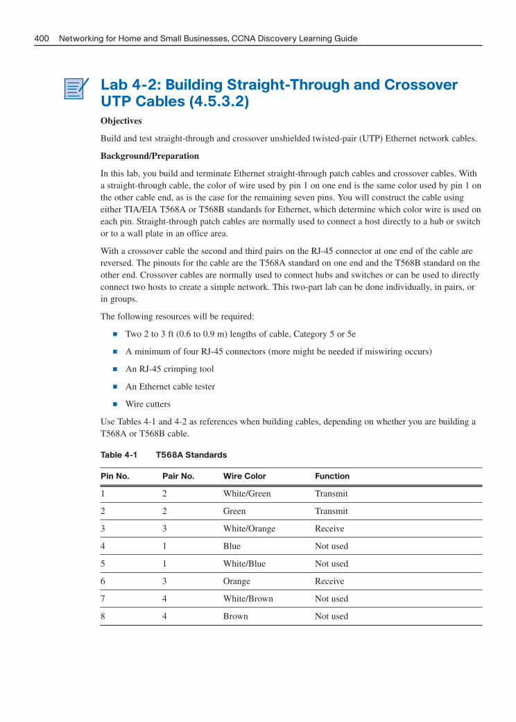
Lab 4-2: Building Straight-Through and Crossover
UTP Cables (4.5.3.2)
Objectives
Build and test straight-through and crossover unshielded twisted-pair (UTP) Ethernet network cables.
Background/Preparation
In this lab, you build and terminate Ethernet straight-through patch cables and crossover cables. Witha straight-through cable, the color of wire used by pin 1 on one end is the same color used by pin 1 onthe other cable end, as is the case for the remaining seven pins. You will construct the cable usingeither TIA/EIA T568A or T568B standards for Ethernet, which determine which color wire is used oneach pin. Straight-through patch cables are normally used to connect a host directly to a hub or switchor to a wall plate in an office area.
With a crossover cable the second and third pairs on the RJ-45 connector at one end of the cable arereversed. The pinouts for the cable are the T568A standard on one end and the T568B standard on theother end. Crossover cables are normally used to connect hubs and switches or can be used to directlyconnect two hosts to create a simple network. This two-part lab can be done individually, in pairs, orin groups.
The following resources will be required:
■ Two 2 to 3 ft (0.6 to 0.9 m) lengths of cable, Category 5 or 5e
■ A minimum of four RJ-45 connectors (more might be needed if miswiring occurs)
■ An RJ-45 crimping tool
■ An Ethernet cable tester
■ Wire cutters
Use Tables 4-1 and 4-2 as references when building cables, depending on whether you are building aT568A or T568B cable.
Table 4-1 T568A Standards
Pin No. Pair No. Wire Color Function
1 2 White/Green Transmit
2 2 Green Transmit
3 3 White/Orange Receive
4 1 Blue Not used
5 1 White/Blue Not used
6 3 Orange Receive
7 4 White/Brown Not used
8 4 Brown Not used
400 Networking for Home and Small Businesses, CCNA Discovery Learning Guide

Table 4-2 T568B Standards
Pin No. Pair No. Wire Color Function
1 2 White/Orange Transmit
2 2 Orange Transmit
3 3 White/Green Receive
4 1 Blue Not used
5 1 White/Blue Not used
6 3 Green Receive
7 4 White/Brown Not used
8 4 Brown Not used
Part A: Build and Test an Ethernet Straight-Through Patch
Cable
In this part of the lab, you build a straight-through Ethernet patch cable. Patch cables are normallyused to connect workstations and servers to an RJ-45 jack in a work area or directly to a hub or switchin some cases. They are also used to connect a router to a hub or switch.
Task A1: Obtain and Prepare the Cable
Step 1. Determine the length of cable required. This measurement could be that from a devicesuch as a computer to the device to which it connects (such as a hub or switch) or betweena device and an RJ-45 outlet jack. Add at least 12 inches (30.48 cm) to the distance. TheTIA/EIA standard states the maximum length for a patch cable is 16.4 feet (5 m). StandardEthernet cable lengths are usually 2 feet (.6 m), 6 feet (1.83 m), or 10 feet (3.05 m).
Which length of cable did you choose and why did you choose this length?
_________________________________________________________________________
Step 2. Cut a piece of cable to the desired length. Stranded UTP cable is commonly used for patchcables (the cables between an end network device such as a PC and an RJ-45 connector)because it is more durable when bent repeatedly. It is called stranded because each of thewires within the cable is made up of many strands of fine copper wire, rather than a singlesolid wire. Solid wire is used for cable runs that are between the RJ-45 jack and a punch-down block.
Step 3. Using wire strippers, remove 2 inches (5.08 cm) of the cable jacket from both ends of thecable.
Task A2: Prepare and Insert the Wires
Step 1. Determine which wiring standard will be used. Circle the standard.
[T568A | T568B]
Step 2. Use either Table 4-1 or 4-2, depending on the wiring standard to be used.
Chapter 4: Labs: Connecting to the Internet Through an ISP 401

Step 3. Spread the cable pairs and arrange them roughly in the desired order based on the standardchosen.
Step 4. Untwist a short length of the pairs and arrange them in the exact order needed by the stan-dard. It is very important to untwist as little as possible. The twists are important becausethey provide noise cancellation.
Step 5. Straighten and flatten the wires between your thumb and forefinger.
Step 6. Ensure that the cable wires are still in the correct order as the standard.
Step 7. Cut the cable in a straight line to within 1/2 to 3/4 inches (1.25 to 1.9 cm) from the edgeof the cable jacket. If it is longer than this, the cable will be susceptible to crosstalk (theinterference of bits from one wire with an adjacent wire).
Step 8. The tang (the prong that sticks out from the RJ-45 connector) should be on the undersidepointing downward when you insert the wires. Making sure that pin 1 (wire 1) is on theleft, insert the wires firmly into the RJ-45 connector until all wires are pushed as far aspossible into the connector.
Task A3: Inspect, Crimp, and Reinspect
Step 1. Visually inspect the cable and ensure that the right color codes are connected to the correctpin numbers.
Step 2. Visually inspect the end of the connector. The eight wires should be pressed firmly againstthe end of the RJ-45 connector. Some of the cable jacket should be inside the first portionof the connector. This provides strain relief for the cable. If the cable jacket is not farenough inside the connector, it might eventually cause the cable to fail.
Step 3. If everything is correctly aligned and inserted properly, place the RJ-45 connector andcable into the crimper. The crimper will push plungers down on the RJ-45 connector, asshown in Figure 4-1. The rear plunger pushes into the cable sheathing to prevent it frompulling out and leaving the wires exposed. This also helps to provide stress relief for thewires inside the sheathing. The front plunger pushes the copper connector blades into theeight wires to make electrical contact.
Figure 4-1 Crimper Plungers Attach Connector to Cable
402 Networking for Home and Small Businesses, CCNA Discovery Learning Guide
Step 4. Visually reinspect the connector. If it’s improperly installed, cut the end off and repeat theprocess.

Task A4: Terminate the Other Cable End
Step 1. Use the steps in Task A3 to attach an RJ-45 connector to the other end of the cable.
Step 2. Visually reinspect the connector. If it is improperly installed, cut the end off and repeat theprocess.
Step 3. Which standard is used for patch cables in your school?
[T568A | T568B]
_________________________________________________________________________
Task A5: Test the Cable
Step 1. Using a cable tester, test the straight-through cable for functionality. If it fails, repeat the lab.
Step 2. (Optional) Use the cable to connect a PC to a network.
Step 3. (Optional) Click Start > Run.
Step 4. (Optional) Enter cmd in the Open text box and press Enter.
Step 5. (Optional) From the command prompt, enter ipconfig.
Step 6. (Optional) Write down the default gateway IP address.
_________________________________________________________________________
Step 7. (Optional) From the command prompt, enter ping followed by the default gateway IPaddress. If the cable is functional, the ping should be successful (provided that no othernetwork problem exists and the default gateway router is connected and functional).
Part B: Build and Test an Ethernet Crossover Cable
In this part of the lab, you build a crossover Ethernet cable. Crossover cables are normally used toconnect like devices, such as switch to switch or hub to switch. The use of a crossover cable can savetime and equipment in a testing environment. If using a crossover cable to connect one workstation toanother or a PC to a router, you do not need a hub or switch.
Task B1: Obtain and Prepare the Cable
Step 1. Determine the length of cable required. This measurement could be that from a hub to ahub, a hub to a switch, a switch to a switch, a computer to a router, or from one computerto another computer. Add at least 12 inches (30.48 cm) to the distance. Which length ofcable did you choose and why did you choose this length?
_________________________________________________________________________
Step 2. Cut a piece of cable to the desired length and, using wire strippers, remove 2 inches (5.08cm) of the cable jacket from both ends of the cable.
Task B2: Prepare and Insert the T568A Wires
Step 1. Locate the T568A table (Table 4-1) at the beginning of this lab.
Step 2. Spread the cable pairs and arrange them roughly in the desired order based on the T568Astandard.
Chapter 4: Labs: Connecting to the Internet Through an ISP 403

Step 3. Untwist a short length of the pairs and arrange them in the exact order needed by the stan-dard. It is very important to untwist as little as possible. Twists are important because theyprovide noise cancellation.
Step 4. Straighten and flatten the wires between your thumb and forefinger.
Step 5. Ensure the cable wires are in the correct order based on the standard.
Step 6. Cut the cable in a straight line to within 1/2 to 3/4 inches (1.25 to 1.9 cm) from the edgeof the cable jacket. If it is longer than this, the cable will be susceptible to crosstalk (theinterference of bits from one wire with an adjacent wire).
Step 7. The tang (the prong that sticks out from the RJ-45 connector) should be on the undersidepointing downward when you insert the wires. Insert the wires firmly into the RJ-45 con-nector until all wires are pushed as far as possible into the connector.
Task B3: Inspect, Crimp, and Reinspect
Step 1. Visually inspect the cable and ensure the right color codes are connected to the correct pinnumbers.
Step 2. Visually inspect the end of the connector. The eight wires should be pressed firmly againstthe RJ-45 connector. Some of the cable jacket should be inside the first portion of the con-nector. This provides for cable strain relief, which can eventually cause the cable to fail.
Step 3. If everything is correctly aligned and inserted properly, place the RJ-45 connector andcable into the crimper. The crimper will push plungers down on the RJ-45 connector.
Step 4. Visually reinspect the connector. If it is improperly installed, cut the end off and repeat theprocess.
Task B4: Terminate the T568B Cable End
Step 1. On the other end, use the steps in Tasks B2 and B3 (but use the T568B table [Table 4-2]and standard) to attach an RJ-45 connector to the cable.
Step 2. Visually reinspect the connector. If it is improperly installed, cut the end off and repeat theprocess.
Step 3. Which standard would you rather use at home if you have or would like to have a homenetwork?
[T568A | T568B]
_________________________________________________________________________
_________________________________________________________________________
Task B5: Test the Cable
Step 1. Using a cable tester, test the crossover cable for functionality. If it fails, repeat the lab.
Step 2. Use the cable to connect two PCs.
Step 3. On both computers, click Start > Run.
404 Networking for Home and Small Businesses, CCNA Discovery Learning Guide

Note: If the Run command is unavailable on your PC, visually check the LED status lights on theNIC card. If they are on (usually green or amber), the cable is functional.
Step 4. On both computers, enter cmd and press Enter.
Step 5. On both computers from the command prompt, enter ipconfig.
Step 6. Write down the IP address of both computers. The IP addresses should be on the samenetwork and have the same subnet mask.
Computer 1:
_________________________________________________________________________
Computer 2:
_________________________________________________________________________
Step 7. From the command prompt of one computer, enter ping followed by the IP address of theother computer. If the cable is functional, the ping should be successful. Do the ping onthe other computer as well.
Note: Windows Firewall on the target computer must be temporarily disabled for the ping to besuccessful. Refer to Lab 3.1.5.3 if you need help with this. If you disable the firewall, be sure to re-enable it.
Task B6: Reflection
Which part of making these cables did you find the most difficult? Compare your views with a class-mate.
Are all four pairs of cables twisted the same amount? Discuss the reasons why or why not.
Ask a local business or check a site such as http://www.workopolis.com/ to see how much a beginningcable installer earns and what criteria employers look for in a cable installer. Write down the informa-tion you discover in the space provided.
Many technicians keep a crossover cable in their toolkit. When do you think that you would use acrossover cable and when do you think a network technician would use this cable?
Chapter 4: Labs: Connecting to the Internet Through an ISP 405

Lab 4-3: Terminating UTP Cables (4.5.4.4)
Objectives
■ Use a punchdown tool to terminate an RJ-45 wall jack.
■ Install an RJ-45 jack in a wall plate.
■ Use a punchdown tool to terminate a UTP cable at a patch panel.
Background/Preparation
In this lab, you wire an RJ-45 data jack for installation in a wall plate using a punchdown tool. Thistask is done frequently when installing cabling in an office environment. The punchdown tool is alsoused to terminate the other end of the cable at a patch panel punchdown block. The punchdown tooluses spring-loaded action to push wires between metal pins, while at the same time skinning thesheath away from the wire. This ensures that the wire makes a good electrical connection with thepins inside the jack. The punchdown tool also cuts off any extra wire.
A Category 5/5e straight-through patch cable with an RJ-45 connector normally plugs into a data jackor outlet to connect a PC to the network. It is important to use Category 5- or 5e-rated jacks and patchpanels with Category 5 or 5e cabling in order to support Fast Ethernet (100 Mbps) and GigabitEthernet (1000 Mbps). The process of punching down wires into a data jack in an office area is thesame as punching them down at a patch panel in a wiring closet. This lab can be performed individu-ally, in pairs, or in groups.
The following resources are required:
■ 2 to 3 feet (60 to 90 cm) length of cable, either Category 5 or 5e.
■ RJ-45 data jack. If RJ-45 data jacks are installed on both ends of the cable, two jacks will beneeded and the installation can be tested by inserting cable with RJ-45 connectors and a simplecable continuity tester. More jacks might also be needed if errors are made.
■ Category 5/5e wall plate.
■ Patch panel.
■ Punchdown tool, type 110.
■ UTP cable stripper.
■ Wire cutters.
■ Two known-good straight-through patch cables for testing (optional).
Task 1: Strip the Sheath
Remove the cable sheath 1 inch (2.54 cm) from the end of the cable.
Task 2: Position Wires in Data Jack
Step 1. Position wires in the proper channels on the RJ-45 jack maintaining the twists as close tothe jack as possible.
Step 2. A number of different types of jacks are available. Most jacks have the channels color-coded to indicate where the wires go. Make sure that the colors on the wires match thecolors on jack. The jack in Figure 4-2 shows one model. Jacks are typically stamped toindicate whether they are T568A or T568B.
406 Networking for Home and Small Businesses, CCNA Discovery Learning Guide

Figure 4-2 RJ-45 Jack
Chapter 4: Labs: Connecting to the Internet Through an ISP 407
Task 3: Punch Down the Data Jack
Step 1. Use the punchdown tool, similar to the one shown in Figure 4-3, to push conductors intothe channels. Make sure to position the cutting side of the punchdown tool so that it facesthe outside of the jack. Not doing so will cause the tool to cut the wire being punched. Trytilting the handle of the punchdown tool a little to the outside, so it will cut better.
Figure 4-3 Punchdown Tool
Step 2. If any wire remains attached after you use the punchdown tool, simply twist the ends gen-tly to remove them. Then place the clips on the jack and tighten them. Make sure that nomore than 1/2 inch (1.27 cm) of untwisted wire is between the end of the cable jacket andthe channels on the jack. Attach the faceplate.
Step 3. Snap the jack into the faceplate by pushing it from the back side. Make sure when you dothis that the jack is right-side up so the clip faces down when the wall plate is mounted.
Step 4. Use the screws to attach the faceplate to either the box or to the bracket. Keep in mind thata surface-mounted box might hold 1 to 2 feet (30 to 60 cm) of excess cable, in which caseit will be necessary to either slide the cable through the tie-wraps, or pull back the race-way that covers it, in order to push the excess cable back into the wall. For a flush-mounted jack, all that is needed is to push the excess cable back into the wall.
Task 4: Punch Down the Patch Panel
Step 1. On the opposite end of the cabling, remove the sheath 1 inch (2.54 cm) from the cable.
Step 2. Lay the wires down in the patch panel so that the colors of the wires correspond exactly tothe colors indicated on the pin locations in the same manner as the data jack was puncheddown.
Step 3. Keep the sheath within 1/4 inch (.64 cm) of where the wires begin branching out to theirpin locations.

Step 4. Do not untwist the wires more than necessary to lay them down at the pin locations, asshown in Figure 4-4. A good way to keep from untwisting too much is to hold down thewires next to the patch panel with one finger while using the other hand to pull apart eachend as you lay it across the connector.
Figure 4-4 Patch Panel Connector
408 Networking for Home and Small Businesses, CCNA Discovery Learning Guide
Figure 4-5 shows a large punchdown patch panel with carefully routed cabling.
Figure 4-5 Large Punch Down Patch Panel with Cabling
Task 5: Test the Data Jack and Patch Panel Terminations
with a Basic Cable Tester (Optional)
Step 1. Obtain two straight-through Ethernet patch cables and verify they both function properlyusing a simple cable tester.
Step 2. Connect one end of one of the straight-through Ethernet patch cables to the data jack outletand one end of the other straight-through cable to the jack at the patch panel.
Step 3. Insert the opposite ends of the two cables into a simple cable tester and check for continu-ity from end to end through both patch cables, the data jack, and the patch panel. Did thecable run test good from end to end?
_________________________________________________________________________
_________________________________________________________________________
Task 6: Reflection (Optional)
Take a tour of a wiring closet that contains patch panels and punchdown blocks. Were there any other typesof devices that might use similar techniques to attach wires? What do you think attaches to these cables?
What do you think are some of the drawbacks and advantages of having a job installing network cabling?

Lab 4-4: Testing UTP Cables (4.5.5.4)
Objectives
Explore the wire-mapping features of the Fluke 620 LAN CableMeter, Fluke MicroScanner, or equiv-alent. Figure 4-6 shows a picture of a cable meter.
Figure 4-6 Cable Meter
Chapter 4: Labs: Connecting to the Internet Through an ISP 409
■ Explore the Cable Test feature: the Pass/Fail features of the Fluke 620 LAN CableMeter orequivalent.
■ Explore the Cable Length feature of the Fluke 620 LAN CableMeter or equivalent.
■ Use a cable tester to check for the proper installation of unshielded twisted-pair (UTP)Category 5/5e according to TIA/EIA-568 cabling standards in an Ethernet network.
Background/Preparation
Wire maps can be very helpful in troubleshooting cabling problems with UTP cable. A wire mapallows the network technician to verify which pins on one end of the cable are connected to whichpins on the other end.
Basic cable tests can be very helpful in troubleshooting cabling problems with UTP. The cablinginfrastructure or cable plant in a building is expected to last at least ten years. Cable-related problemsare one of the most common causes of network failure. The quality of cabling components used, therouting and installation of the cable, and the quality of the connector terminations will be the mainfactors in determining how trouble-free the cabling will be.
This lab can be performed individually, in pairs, or in groups.
The following resources are required:
■ Good Category 5 straight-through cables of different colors
■ Good Category 5 crossover cables (T568A on one end and T568B on the other end)

■ Category 5 straight-through cables of different colors and different lengths with open connec-tions in the middle, or one or more conductors shorted at one end
■ Category 5 straight-through cable with a split pair miswire
■ Fluke 620 LAN CableMeter or similar instrument to test cable length, continuity, and wire map
Task 1: Set Up the Fluke 620 LAN CableMeter
Step 1. On the Fluke 620 meter, turn the rotary switch selector on the tester to the WIRE MAPposition.
Note: If you are using the Fluke MicroScanner, which is the current recommended replacement forthe recently retired 620 LAN CableMeter, go to Task 6.
Step 2. Press the SETUP button to enter the setup mode and observe the LCD screen on the tester.Press the UP or DOWN arrow buttons until the desired cable type of UTP is selected.Press ENTER to accept that setting and go to the next one. Continue pressing the UP andDOWN arrows and pressing ENTER until the tester is set to the cabling characteristics inTable 4-3.
Table 4-3 Cable Meter Setup Options
Tester Option Desired Setting - UTP
CABLE: UTP
WIRING: 10BASE-T OR EIA/TIA 4PR
CATEGORY: CATEGORY 5
WIRE SIZE: AWG 24
CAL TO CABLE? NO
BEEPING: ON or OFF
LCD CONTRAST: From 1 through 10 (brightest)
Step 3. After the meter is set up, press the SETUP button to exit setup mode.
Task 2: Test Cabling Procedure
For each cable to be tested use the following procedure:
Step 1. Place one end of the cable into the RJ-45 jack labeled UTP/FTP on the tester.
Step 2. Place the other end of the cable into the RJ-45 female coupler, and then insert the cableidentifier into the other side of the coupler. The coupler and the cable identifier, shown inFigure 4-7, are accessories that come with the Fluke 620 LAN CableMeter.
410 Networking for Home and Small Businesses, CCNA Discovery Learning Guide

Figure 4-7 Cable Identifier and Coupler
Chapter 4: Labs: Connecting to the Internet Through an ISP 411
Task 3: Use the Wire Map Meter Function
The Wire Map function and a Cable ID Unit can be used to determine the wiring of both the near andfar end of the cable. The top set of numbers displayed on the LCD screen is the near end, and the bot-tom set is the far end. Perform a Wire Map test on each of the cables provided. Fill in Table 4-4 basedon the testing results for each Category 5 cable. For each cable, write down the identifying number ofthe cable and the cable color. Also write down whether the cable is straight-through or crossover, thetester screen test results, and a description of the problem.
Table 4-4 Cable Wire Map Test Results
Displayed Test Results
(Note: Refer to the Meter
Manual for Detailed
Cable Cable Straight-through Descriptions of Test Results
No. Color or Crossover for the Wire Map Test.) Problem/Description
Top:
Bot:
Top:
Bot:
Top:
Bot:
Top:
Bot:
Top:
Bot:

Task 4: Use the Length Meter Function
Using the tester LENGTH function, perform a basic cable test on the same cables used previously.Fill in Table 4-5 with the additional information for each cable.
Table 4-5 Cable Length Test Results
Cable No. Cable Length Tester Test Results (Pass/Fail)
Task 5: Test Data Jack and Patch Panel Terminations for
Wire Map, Length, and Miswire (Optional)
Step 1. Using the data jack and patch panel cable from Lab 4-3, connect one end of one of thestraight-through Ethernet patch cables to the data jack outlet and one end of the otherstraight-through cable to the jack at the patch panel.
Step 2. Insert the opposite end of one of the cables into the Fluke 620 and the other into the cou-pler and cable identifier. Check for wire map, length, and miswire from end to end throughthe patch cables, the data jack, and the patch panel. Did the cable run test good from endto end? What were the results?
Wire map:
_________________________________________________________________________
Total cable run length:
_________________________________________________________________________
Any miswires?
_________________________________________________________________________
If there are problems, analyze where the problem is by testing each component and thenrepeat the connections if possible.
Task 6: Set Up and Test a Cable Using the Fluke
MicroScanner
Step 1. Turn on the MicroScanner using the green power button on the right lower portion of theface plate.
Step 2. Remove the blue cap to expose the RJ-45 test ports. There will be one attached to the baseunit and one inside the removable cap, which is known as the remote wiremap adapter.
412 Networking for Home and Small Businesses, CCNA Discovery Learning Guide

Step 3. Insert one end of the Cat5 cable’s RJ-45 connector into the base unit and the other end intothe remote wiremap adapter port inside the removable blue cap.
Step 4. You might have to press the port button to select the RJ-45 adapter port instead of the Ftype port for coax.
The MicroScanner does the rest for you. It displays the wiremap and length. By default, ifthe wiremap fails to appear for a particular wire pair, continuity has failed, and theMicroScanner might report the distance to the fault in some circumstances. It also reportsshorts and splits.
Although the MicroScanner is capable of other functions, this concludes the instructionsfor this particular lab.
Task 7: Reflection
If you were on a job and did not have a cable meter to test, what other methods could you use?
Chapter 4: Labs: Connecting to the Internet Through an ISP 413

This page intentionally left blank

CHAPTER 5
Labs: Network Addressing
The lab exercises included in this chapter cover the Chapter 5 online curriculum lab and a challenge lab toensure that you have mastered the practical, hands-on skills needed to understand the basics of networkaddressing. As you work through these labs, use Chapter 5 in Part I of this book or use the correspondingChapter 5 in the Networking for Home and Small Businesses course of the CCNA Discovery online curricu-lum for assistance.
Lab 5-1: Using the Windows Calculator with Network
Addresses (5.1.4.3)
Objectives
■ Switch between the two Windows Calculator modes.
■ Use the Windows Calculator to convert between decimal, binary, and hexadecimal.
■ Use the Windows Calculator to determine the number of hosts in a network with powers of 2.
Figure 5-1 shows the Windows Calculator.
Figure 5-1 Windows Calculator
Background/Preparation
Network technicians work with binary, decimal, and hexadecimal numbers with computers and net-working devices. In this lab, you use the Windows Calculator application to convert between the bina-ry, decimal, and hexadecimal number systems. You also use the powers function to determine thenumber of hosts that can be addressed based on the number of bits available.
A PC with Windows XP installed and functional is the required resource for this lab.

Task 1: Access Windows Calculator and Determine Mode of
Operation
Step 1. Click Start > All Programs > Accessories, and click Calculator. An alternative methodof starting the Calculator application is to click Start > Run, type calc in the Open textbox, and press Enter. Try both methods.
Step 2. When the Calculator application opens, select the View menu option.
Which mode is currently active?
[Standard | Scientific]
_________________________________________________________________________
Step 3. Select the standard mode, which is a basic mode for simple calculations. How many math-ematical functions are available in this mode?
_________________________________________________________________________
Step 4. From the View menu option, select the scientific calculator mode.
How many mathematical functions are available in this mode?
_________________________________________________________________________
Task 2: Convert Between Number Systems
Step 1. Access scientific mode. Notice the number system modes available: Hex (Hexadecimal),Dec (Decimal), Oct (Octal), and Bin (Binary).
Which number system is currently active?
_________________________________________________________________________
Which numbers on the number pad are active in decimal mode?
_________________________________________________________________________
Step 2. Click the Bin (binary mode) radio button. Which numbers on the number pad are nowactive?
_________________________________________________________________________
Why do you think the other numbers are dimmed?
_________________________________________________________________________
Step 3. Click the Hex (hexadecimal mode) radio button.
Which characters on the number pad are now activated?
_________________________________________________________________________
Step 4. Click the Dec radio button. Using your mouse, click the number 1 followed by the number5 on the number pad. The decimal number 15 has now been entered. Click the Bin radiobutton.
What happened to the number 15 listed in the text box at the top of the window?
_________________________________________________________________________
416 Networking for Home and Small Businesses, CCNA Discovery Learning Guide

Step 5. By selecting different modes, numbers are converted from one number system to another.Select Dec mode again. The number in the window converts back to decimal. Select theHex mode.
Which hexadecimal character (0 through 9 or A through F) represents decimal 15?
_________________________________________________________________________
Step 6. Clear the number 15 in the window. Select Dec again. Not only can the mouse be used toenter numbers, but the numerical keypad on the keyboard as well as numbers on the key-board can also be used. Using the numerical keypad to the right of the Enter key, enter 22.Note that if the number does not enter into the calculator, press the Num Lock key toenable the numeric keypad. While the number 22 is showing in the calculator, use thenumber keys across the top of the keyboard to add a 0 to the number 22. (220 should nowbe on the calculator.) Select Bin.
What is the binary equivalent of 220?
_________________________________________________________________________
Step 7. Clear the number 220 in the window. From binary mode, enter the following binary num-ber: 11001100. Select the Dec radio button.
What is the decimal equivalent to the binary number of 11011100?
_________________________________________________________________________
Step 8. Convert the decimal numbers in Table 5-1 to binary.
Table 5-1 Decimal to Binary Conversions
Decimal Binary
86 __________________
175 __________________
204 __________________
19 __________________
Step 9. Convert the binary numbers in Table 5-2 to decimal.
Table 5-2 Binary to Decimal Conversions
Binary Decimal
11000011 __________________
101010 __________________
111000 __________________
10010011 __________________
Chapter 5: Labs: Network Addressing 417

Task 3: Convert Host IP Addresses
Step 1. Computer hosts usually have two addresses: an Internet Protocol (IP) address and anEthernet Media Access Control (MAC) address. For the benefit of humans, the IP addressis normally represented as a dotted-decimal notation, such as 135.15.227.68. Each of thedecimal octets in the address or a mask can be converted to 8 binary bits. Remember thatthe computer understands only binary bits. If all four octets were converted to binary, howmany bits would there be?
_________________________________________________________________________
Step 2. IP addresses are normally shown with four decimal numbers ranging from 0 to 255 andseparated by a period. In Table 5-3, convert the four parts of the IP address 192.168.10.2to binary using the Windows Calculator.
Table 5-3 Binary Conversion of an IP Address
Decimal Binary
192 __________________
168 __________________
10 __________________
2 __________________
Notice how the 10 converted to only four digits and the number 2 converted to only twodigits when using the Windows Calculator. When IP addresses can have any number from0 to 255 in each position, eight digits are normally used to represent each number. In theprevious example, eight digits were needed to convert 192 and 168 to binary, but 10 and 2did not need as many digits. Normally 0s are added to the left of the digits to have eightdigits in binary for each IP address number. The number 10 would be shown as 00001010.Four extra zeros are added to the front of the other four binary digits.
Step 3. On the calculator in binary mode, enter the digits 00001010 and select the Dec radiobutton.
Which decimal number is equivalent to 00001010?
_________________________________________________________________________
Did adding “leading” zeros affect the number?
_________________________________________________________________________
What would the number 2 (in the previous example) be if you were to make it eight digits?
_________________________________________________________________________
Task 4: Convert Host IP Subnet Masks
Step 1. Subnet masks, such as 255.255.255.0, are also represented as dotted decimal. A subnetmask will always consist of four 8-bit octets, each one represented as a decimal number.With the exception of decimal 0 (all eight binary zeros) and decimal 255 (all eight binaryones), each octet will have some number of ones on the left and some number of zeros onthe right. Convert the nine possible decimal subnet octet values in Table 5-4 to binary.
418 Networking for Home and Small Businesses, CCNA Discovery Learning Guide

Table 5-4 Binary Conversion of Decimal Subnet Values
Decimal Binary
0 __________________
128 __________________
192 __________________
224 __________________
240 __________________
248 __________________
252 __________________
254 __________________
255 __________________
Step 2. Convert the four parts of the subnet mask 255.255.255.0 in Table 5-5 to binary.
Table 5-5 Binary Conversion of Subnet Mask
Decimal Binary
255 __________________
255 __________________
255 __________________
0 __________________
Task 5: Convert Broadcast Addresses
Computer hosts and network devices use broadcast addresses to send messages to all hosts. Convertthe broadcast addresses in Table 5-6 to binary.
Table 5-6 Binary Conversion of Broadcast Address
Address Binary
IP broadcast255.255.255.255 __________________ __________________
MAC broadcastFF:FF:FF:FF:FF:FF __________________ __________________
Chapter 5: Labs: Network Addressing 419

Task 6: Convert IP and MAC Addresses for a Host
Step 1. Click Start > Run, enter cmd, and press Enter. From the command prompt, enter ipcon-fig /all.
Step 2. Make a note of the IP address and physical address (also known as a MAC address).
IP address: __________________________________________
MAC address: ________________________________________
Step 3. Using the calculator, convert the four numbers contained in the IP address to binary andrecord them in Table 5-7.
Table 5-7 Binary Conversion of an IP Address
Decimal Binary
__________________
__________________
__________________
__________________
Step 4. The MAC or physical address is normally represented as 12 hexadecimal characters,grouped in pairs and separated by dashes (-). Physical addresses on a Windows-basedcomputer are shown in a format of xx-xx-xx-xx-xx-xx, where each x is a number from 0to 9 or a letter from a to f. Each of the hex characters in the address can be converted tofour binary bits which is what the computer understands. If all 12 hex characters wereconverted to binary, how many bits would there be?
_________________________________________________________________________
Convert each of the hexadecimal pairs to binary in Table 5-8. For example, if the numberCC-12-DE-4A-BD-88-34 was the physical address, convert the hexadecimal number CCto binary (11001100). Then convert the hexadecimal number 12 to binary (00010010) andso on. Be sure to add the leading zeros for a total of eight binary digits per pair of hex digits.
Table 5-8 Binary Conversion of a MAC Address
Hexadecimal Binary
__________________
__________________
__________________
__________________
__________________
__________________
420 Networking for Home and Small Businesses, CCNA Discovery Learning Guide

Task 7: Manipulate Powers of 2 to Determine the Number of
Hosts on a Network
Binary numbers use two digits: 0 and 1. When you calculate how many hosts can be on a subnetwork,you use powers of 2 because binary is being used. As an example, we have a subnet mask that leavessix bits in the host portion of the IP address. In this case, the number of hosts on that network is 2 tothe 6th power minus 2 (because you need a number to represent the network and a number that can beused to reach all the hosts—the broadcast address). The number 2 is always used because we areworking in binary. The number 6 is the number of bits that are used for the host bits.
Step 1. On the calculator, in Dec mode, input the number 2. Select the xy key, the key that raises anumber to a power. Input the number 6. Click the = key, press Enter on the keyboard, orpress the = key on the keyboard—all give the total. The number 64 appears in the output.To subtract two, click the minus (-) key and then the 2 key followed by the = key. Thenumber 62 appears in the output. This means 62 hosts could be utilized.
Step 2. Using the previously described process, determine the number of hosts using the numberof bits used for hosts in the four examples in Table 5-9.
Table 5-9 Determining Possible Number of Hosts
No. of Bits Used for Hosts No. of Hosts
5 __________________
14 __________________
24 __________________
10 __________________
Step 3. Using a techniques similar to Step 1, determine what 10 to the 4th power equals.
_________________________________________________________________________
Step 4. Close the Windows Calculator application.
Task 8: (Optional) Determine the Network Number and
Number of Hosts Based on Subnet Mask
Given the IP network address of 172.16.203.56 and a subnet mask of 255.255.248.0, determine thenetwork portion of the address and calculate how many hosts can be created from host bits left usingthese steps:
Step 1. Start by converting the four octets of the decimal IP address to binary, and then convert thedecimal subnet mask to binary. Remember to include leading zeros when converting tobinary in order to make a total of eight bits per octet. Write your answers in Table 5-10.
Table 5-10 Binary Conversion of IP Address and Subnet Mask
Decimal IP Address and Subnet Mask Binary IP Address and Subnet Mask
172.16.203.56 ____________________________________
255.255.248.0 ____________________________________
Chapter 5: Labs: Network Addressing 421

Step 2. Align the 32 bits of the subnet mask to the 32 bits of the IP address and compare them.The bits in the IP address that align with the ones bits in the subnet mask represent thenetwork number. What is the binary and decimal network number for this IP address?Determine the binary address first (include all 32 bits) and then convert it to decimal.
Binary network address: ________________________________
_________________________________________________________________________
Decimal network address: _______________________________
_________________________________________________________________________
How many ones bits are in the subnet mask?
_________________________________________________________________________
How many bits are left for host bits?
_________________________________________________________________________
How many hosts can be created with the bits left?
_________________________________________________________________________
Task 9: Reflection
List one other thing for which you might use the Windows Calculator scientific mode. It does nothave to be related to networking.
_________________________________________________________________________
_________________________________________________________________________
_________________________________________________________________________
_________________________________________________________________________
_________________________________________________________________________
422 Networking for Home and Small Businesses, CCNA Discovery Learning Guide

Challenge Lab 5-2: Exploring IP Address Functions
on an Multi-function Device
Objectives
■ Create a simple DHCP server/client network using four PCs and a multi-function device.
■ Access and observe automatic IP addressing through the management GUI on a multi-functiondevice.
■ Test connectivity using the ping and tracert commands.
■ Determine and describe the boundaries of private and public IP addresses in the network.
Background/Preparation
The design of the network determines which device(s) provide IP addresses to hosts. Although themulti-function device provides automatic IP addressing to its attached clients, its default gateway IPcan be assigned automatically by the ISP. NAT can be employed by the multi-function device or theISP in order to route private addresses on the Internet.
The following resources will be required:
■ Linksys Model WRT300N wireless router or equivalent SOHO router
■ A network jack with Internet access or that is connected to a configured DHCP server
■ Four computers with Ethernet NICs and either Windows 2000 or Windows XP installed onthem
Task 1: View Current IP Settings
Be sure to write down existing IP settings so that they can be restored at the end of the lab. These set-tings include IP address, subnet mask, default gateway, and DNS servers. If the workstation is aDHCP client, it is not necessary to record the settings.
Windows 2000 users should do the following:
Step 1. Click Start > Settings > Control Panel and then open the Network and Dial-upConnections folder.
Step 2. Click and open the Local Area Connection icon.
Step 3. Select the TCP/IP protocol icon that is associated with the NIC in this PC.
Step 4. Click Properties and view the existing IP configuration.
Windows XP users should do the following:
Step 1. Click Start > Settings > Control Panel and then click the Network Connection icon.
Step 2. Select the Local Area Network Connection and then click Properties.
Step 3. Select the TCP/IP protocol icon that is associated with the NIC in this PC.
Step 4. Click Properties and view the existing IP configuration.
Chapter 5: Labs: Network Addressing 423

Task 2: Configure TCP/IP Settings for DHCP
Step 1. In the TCP/IP protocol Properties window, select Obtain an IP address automaticallyand Obtain DNS server address automatically.
Step 2. Click OK.
Step 3. Click OK on the Local Area Network Connection screen.
Task 3: Connect PCs to the Multi-function Device
Step 1. Plug in the multi-function device power supply.
Step 2. Check the LEDs on the front of the multi-function device to verify that the power is on.
Step 3. Connect the PCs to the Ethernet ports on the back of the multi-function device usingstraight-through cables.
Step 4. Reboot each of the host PCs.
Task 4: Verify the Physical Connection
Are link lights lit for each PC on the front of the multi-function device?
Task 5: Access the Command Prompt on a Client PC
Step 1. Click Start > Programs > Accessories > Command Prompt.
What command will display the IP configuration, including DHCP and DNS servers, forthe host PC?
_________________________________________________________________________
Step 2. Record the following information from the output of the command used:
IP address: ____________________________________________
Subnet mask: __________________________________________
Default gateway: ________________________________________
DHCP server: ___________________________________________
DNS servers: ___________________________________________
Date/time lease obtained: __________________________________
Date/time lease expires: ___________________________________
Where did the PC get its IP configuration?
_________________________________________________________________________
What IP address would you expect to find associated with the switch ports on the multi-function device?
_________________________________________________________________________
424 Networking for Home and Small Businesses, CCNA Discovery Learning Guide

Task 6: Access the Multi-function Device Configuration
Through a Web Browser
Step 1. Open a web browser on the PC.
Note: Internet Explorer users should choose Tools > Internet Options > LAN Settings, and verifythat Use a proxy server for your LAN is unchecked.
Step 2. Enter http:// followed by the IP address of the default gateway in the browser addressblock.
Step 3. Click Go.
Step 4. Log in using no username and the password admin.
Check the local IP address displayed. This is the address associated with the internal net-work. Was your last answer in the previous task correct?
_________________________________________________________________________
Task 7: Examine the Multi-function Device Configuration
What is the range of addresses the multi-function device can assign to DHCP clients?
What is the first IP address that can be assigned by DHCP?
Compare the IP addresses assigned to the four client PCs. Were they assigned randomly within therange, or is there a pattern to the assignments?
Click the Status menu button. What information appears under Internet Connection?
Why is the Internet Connection showing these values?
Task 8: Connect the Multi-function Device to the Internet
Step 1. Use a straight-through cable to connect one end to the Internet port on the back of themulti-function device, and the other end to a network jack with Internet access.
Step 2. Click the Status menu button.
Step 3. Click Refresh.
Chapter 5: Labs: Network Addressing 425

Step 4. Record the information that appears next to Internet Connection:
Connection type: ____________________________________
Internet IP address: ________________________________
Subnet mask: ________________________________________
Default gateway: ____________________________________
DNS 1: ______________________________________________
DNS 2: ______________________________________________
Has the information changed?
_________________________________________________________________________
Where did the multi-function device get this configuration?
_________________________________________________________________________
Task 9: Verify Connectivity Using the ping Command
Step 1. Click the Administration menu button on the multi-function device screen.
Step 2. Click Diagnostics under the main menu bar.
Step 3. Enter the IP address of one of the attached PCs next to Ping Test.
Step 4. Click Start to Ping.
Was the ping successful?
_________________________________________________________________________
Step 5. Close the Ping Test window.
Step 6. Access the command prompt on one of the attached PCs.
Step 7. Enter ping followed by the IP address of the multi-function device.
Was the ping successful?
_________________________________________________________________________
Step 8. On the multi-function device, enter www.cisco.com next to Ping Test.
Step 9. Click Start to Ping.
Was the ping successful?
_________________________________________________________________________
_________________________________________________________________________
_________________________________________________________________________
Step 10. Close the Ping Test window.
Step 11. If the ping to the Cisco site was not successful, explain why.
_________________________________________________________________________
_________________________________________________________________________
_________________________________________________________________________
426 Networking for Home and Small Businesses, CCNA Discovery Learning Guide

Task 10: Verify Connectivity Using the tracert Command
Step 1. On the multi-function device’s Diagnostics screen, enter the IP address of one of theattached PCs next to Traceroute Test.
Step 2. Click Start to begin the traceroute.
Was the traceroute successful?
_________________________________________________________________________
Step 3. Close the traceroute window.
Step 4. Access the command prompt on one of the attached PCs.
Step 5. Enter tracert followed by the IP address of the multi-function device.
Was the traceroute successful?
_________________________________________________________________________
Step 6. On the multi-function device, enter www.cisco.com next to Traceroute test.
Step 7. Click Start to begin the traceroute.
Was the traceroute successful?
_________________________________________________________________________
_________________________________________________________________________
_________________________________________________________________________
Step 8. Close the Traceroute window.
Step 9. If the traceroute to the Cisco site was not successful, explain why.
_________________________________________________________________________
_________________________________________________________________________
_________________________________________________________________________
Why would most networks be set up to block ping and traceroute from getting out of thelocal network?
_________________________________________________________________________
_________________________________________________________________________
Task 11: Verify Internet Connectivity
Step 1. Open a browser window on a PC attached to the multi-function device.
Step 2. Enter http://www.cisco.com in the address block and click Go.
Does the page load?
_________________________________________________________________________
Why did the web page load, whereas the ping and traceroute failed?
_________________________________________________________________________
_________________________________________________________________________
Chapter 5: Labs: Network Addressing 427

Task 12: Determine the Network Boundaries
Are the IP addresses assigned to the client PCs routable on the Internet?
Is the IP address assigned to the multi-function device Internet interface routable on the Internet?
How did your network obtain a routable IP address in order to load the Cisco web page?
Where did the packet get a routable IP address?
Task 13: Restore All Original Network Connections
Return all PCs to their original network connections and IP configurations.
Task 14: Reflection
How do DHCP and NAT work together to protect network security?
React to this statement: Without DHCP and NAT, the Internet would have collapsed long ago.
428 Networking for Home and Small Businesses, CCNA Discovery Learning Guide

CHAPTER 6
Labs: Network Services
The lab exercises included in this chapter cover all the Chapter 6 online curriculum labs to ensure that youhave mastered the practical, hands-on skills needed to work with DNS, FTP, and e-mail clients. As you workthrough these labs, use Chapter 6 in Part I of this book or use the corresponding Chapter 6 in Networking forHome and Small Businesses course of the CCNA Discovery curriculum for assistance.
Lab 6-1: Observing DNS Name Resolution (6.2.1.3)
Objectives
■ Observe the conversion of a URL to an IP address.
■ Observe DNS lookup using the nslookup command.
Background/Preparation
Domain Name System (DNS) is invoked when you type a Uniform Resource Locator (URL), such ashttp://www.cisco.com, into a web browser. The first part of the URL describes which protocol is being used.Common protocols are Hypertext Transfer Protocol (HTTP), Hypertext Transfer Protocol over Secure SocketLayer (HTTPS), and File Transfer Protocol (FTP).
DNS translates the domain name, which in this example is www.cisco.com, to an IP address in order to allowthe source host to reach the destination host. Work in pairs to complete this lab.
The following resources are required:
■ Windows-based computer with Internet connectivity
■ Access to the Run command or command prompt
Task 1: Observe DNS Conversion
Step 1. Click the Start button, select Run, enter cmd, and then click OK. The command prompt windowappears.
Step 2. At the command prompt, enter ping www.cisco.com. The computer needs to translatewww.cisco.com into an IP address so that it knows where to send the Internet Control MessageProtocol (ICMP) packets. Ping is a type of ICMP packet.
Step 3. The first line of the output shows www.cisco.com converted to an IP address by DNS. You shouldbe able to see the effect of DNS even if your school has a firewall that prevents pinging, or ifCisco has prevented people from pinging its web server.
Example 6-1 ping OutputC:\>ping www.cisco.com
Pinging www.cisco.com [198.133.219.25] with 32 bytes of data:
Request timed out.
Request timed out.

Request timed out.
Request timed out.
Ping statistics for 198.133.219.25:
Packets: Sent = 4, Received = 0, Lost = 4 (100% loss),
Which IP address is shown on the screen?
_________________________________________________________________________
Work together with another student and discuss one or two other instances (besides theping command) in which the computer would use DNS.
_________________________________________________________________________
_________________________________________________________________________
_________________________________________________________________________
_________________________________________________________________________
Task 2: Verify DNS Operation Using the nslookup Command
Step 1. At the command prompt, enter the nslookup command, as shown in Example 6-2.
Example 6-2 The nslookup CommandC:\>nslookup
Default Server: dns001.cisco.com
Address: 172.27.234.17
>
What is the default DNS server being used?
_________________________________________________________________________
Notice how the command prompt changed. This is the NSLOOKUP prompt. From thisprompt, you can enter commands related to DNS.
Step 2. At the prompt, enter ? to see a list of all the available commands that you can use inNSLOOKUP mode.
What are three commands that you can use with NSLOOKUP?
_________________________________________________________________________
_________________________________________________________________________
430 Networking for Home and Small Businesses, CCNA Discovery Learning Guide
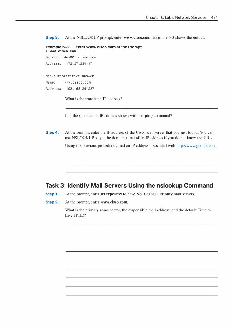
Chapter 6: Labs: Network Services 431
Step 3. At the NSLOOKUP prompt, enter www.cisco.com. Example 6-3 shows the output.
Example 6-3 Enter www.cisco.com at the Prompt> www.cisco.com
Server: dns001.cisco.com
Address: 172.27.234.17
Non-authoritative answer:
Name: www.cisco.com
Address: 192.168.26.227
What is the translated IP address?
_________________________________________________________________________
Is it the same as the IP address shown with the ping command?
_________________________________________________________________________
Step 4. At the prompt, enter the IP address of the Cisco web server that you just found. You canuse NSLOOKUP to get the domain name of an IP address if you do not know the URL.
Using the previous procedures, find an IP address associated with http://www.google.com.
_________________________________________________________________________
_________________________________________________________________________
_________________________________________________________________________
Task 3: Identify Mail Servers Using the nslookup Command
Step 1. At the prompt, enter set type=mx to have NSLOOKUP identify mail servers.
Step 2. At the prompt, enter www.cisco.com.
What is the primary name server, the responsible mail address, and the default Time toLive (TTL)?
_________________________________________________________________________
_________________________________________________________________________
_________________________________________________________________________
_________________________________________________________________________
_________________________________________________________________________
_________________________________________________________________________
_________________________________________________________________________
_________________________________________________________________________
_________________________________________________________________________

Step 3. At the prompt, enter exit to return to the regular command prompt.
Step 4. At the prompt, enter ipconfig /all.
Write the IP addresses of all the DNS servers that your school uses, or those assigned bythe ISP if your school does not have a local DNS server.
_________________________________________________________________________
Step 5. Enter exit to close the command prompt window.
Task 4: Reflection
If your school did not have a local DNS server and was using one from the ISP, what effect would thishave on name/address resolution response time?
Some companies do not dedicate a single server for DNS. Instead, the DNS server provides otherfunctions as well. Which functions do you think might be included on a DNS server? Use the ipconfig/all command to help with this.
432 Networking for Home and Small Businesses, CCNA Discovery Learning Guide

Lab 6-2: Exploring FTP (6.2.3.3)
Objectives
Demonstrate how to use FTP from the command prompt and GUI.
Background/Preparation
File Transfer Protocol (FTP) is part of the TCP/IP suite. FTP is used to transfer files from one net-work device to another network device. Windows includes an FTP application that you can executefrom the command prompt. Many free GUI versions of FTP software are also available that you candownload. The GUI versions are easier to use than entering text from a command prompt.
When using FTP, one computer is normally the server and the other computer is the client. Whenaccessing the server from the client, you need to provide a username and password. Some FTP servershave a user ID named anonymous. You can access these types of sites by simply entering anonymousfor the user ID, without a password. Usually, the site administrator has files that can be copied butdoes not allow files to be posted with the anonymous user ID.
If your class does not have an FTP server available, you can download and install a freeware version,such as Home FTP Server or Cerberus FTP server. The FTP server on a computer running the CCNADiscovery Live CD can also be used, if available. Another computer will act as the FTP client byusing FTP from the command line or a web browser, or you can download a freeware version of anFTP client, such as SmartFTP Client or Core FTP LE client. Work in teams of two to complete thislab.
The following resources are required:
■ Windows-based computer with an FTP client
■ Access to the Run command or command prompt
■ FTP server (existing FTP server, downloaded freeware, or use Live CD)
Task 1: Examine FTP from the Command Prompt
Step 1. Click the Start button, select Run, enter cmd on the command line, and then click OK.
Step 2. At the prompt, enter ftp to start the FTP application. The prompt changes.
Step 3. From the ftp prompt, enter ? to see a list of the commands that can be used in this mode.
List three FTP commands.
_________________________________________________________________________
_________________________________________________________________________
_________________________________________________________________________
_________________________________________________________________________
Step 4. At the prompt, enter help put (or ? put) to see a short description of the put command.
What is the purpose of the put command?
_________________________________________________________________________
Chapter 6: Labs: Network Services 433

Step 5. Use the help command again to find the purpose of the get, send, and recv commands.Write down your findings.
_________________________________________________________________________
_________________________________________________________________________
_________________________________________________________________________
_________________________________________________________________________
_________________________________________________________________________
_________________________________________________________________________
_________________________________________________________________________
_________________________________________________________________________
_________________________________________________________________________
_________________________________________________________________________
Step 6. Partner with another student. If you installed FTP server software on one PC and an FTPGUI client on the other, write down the names and IP addresses of your computer andyour partner’s computer. If using the FTP server on a computer running the CCNADiscovery Live CD, contact your instructor for the server name and IP address. Getting thenames and IP addresses correct is very important. Some FTP applications allow you to useeither the IP address or the computer name.
_________________________________________________________________________
_________________________________________________________________________
Task 2: Use a GUI FTP Client or Web Browser
Step 1. If you are using a web browser as the FTP client, open the web browser and enterftp://ip_address_of_FTP_server (using the IP address previously recorded). If the FTPserver is configured to use an anonymous user ID, connect directly to the FTP server.Using the FTP client, download an available file from the server.
Step 2. If you are using a GUI FTP client, open the application. For most FTP clients, you mustconfigure a new connection by giving it a name, the IP address of the FTP server, and ausername and password. You might have to enter anonymous if the FTP server allows thistype of connection. Some applications have a check box that allows an anonymous login.When you have configured the connection, connect to the FTP server and download a file.
What is the name of the file you downloaded from the FTP server?
_________________________________________________________________________
434 Networking for Home and Small Businesses, CCNA Discovery Learning Guide

List one example of when FTP might be beneficial to a computer technician.
_________________________________________________________________________
_________________________________________________________________________
_________________________________________________________________________
_________________________________________________________________________
Task 3: (Optional) Use Both an FTP Server and Client
Step 1. If you control both the FTP server and client, practice sending files to and getting filesfrom the client and the server.
Step 2. Show your transferred files to another group of students.
Step 3. Close the FTP server and client applications.
Chapter 6: Labs: Network Services 435

Lab 6-3: Configuring an E-mail Client (6.2.4.4)
Objectives
■ Set up an e-mail client.
■ Send and receive mail from a mail server.
■ Add an e-mail account or change an existing one.
Background/Preparation
An e-mail application gives the user the ability to send and receive messages from another user locat-ed on the same local network or on the Internet. The messages are sent by the sending client andstored on an e-mail server. Another e-mail client with a mailbox on the server can then access theserver at any time to receive stored messages that are destined for that client.
The following resources are required:
■ Windows-based computer with Internet connectivity
■ Microsoft Outlook or other e-mail client software
Task 1: Open Microsoft Outlook
Step 1. From the Start menu, select All Programs. Locate the Microsoft Office software.
Step 2. Select Microsoft Office Outlook as the e-mail program. If your computer does not havethe Microsoft Office software, many free e-mail software packages are available on theInternet for both the Linux and Windows OS. Search the Internet to find a free e-mailclient that can be installed on your computer. The following instructions might varydepending on your e-mail client.
Task 2: Set Up an E-mail Account
Step 1. When you first start Microsoft Outlook, a screen appears with E-mail Upgrade Options.You can choose to import e-mail messages or address books from another account.Because this is your first e-mail account, click the Do Not Upgrade button.
Step 2. Next, the E-mail Accounts screen asks whether you want to configure an e-mail account.Click Yes.
Step 3. If Outlook has already been installed and set up for e-mail previously, you can start theOutlook application and choose Tools, E-Mail Accounts and then select View or changeexisting e-mail account to see how the existing account is set up.
Task 3: Enter POP3 E-mail Account Information
Step 1. The next screen requires the user of the new account to fill in information. If you areestablishing a real new e-mail account, enter your name and e-mail address. You can getyour e-mail address from your ISP.
NOTE: If you are not creating a real ISP e-mail account, you can treat this step as a simulation. Justenter the information requested to become familiar with the process of creating an e-mail account.
436 Networking for Home and Small Businesses, CCNA Discovery Learning Guide

Step 2. Enter your server information. Contact your Internet provider to locate the server informa-tion for the incoming and outgoing mail servers. Usually, Internet providers put this infor-mation on their website in their help section.
What is your incoming (POP3) mail server?
_________________________________________________________________________
What is your outgoing (SMTP) mail server?
_________________________________________________________________________
Step 3. Enter your username and password. Do not check the box to remember your password.This option is used when only one person uses the computer. If anyone else were to usethe computer, that person could easily gain access to all the information in your e-mail.
Step 4. Click the Test Account Settings button. If everything is correct, the screen displays thatthe test was successful. If it is not, correct your information and try again.
NOTE: If this is a simulation, the test will not be successful and you can go to Tasks 4 and 5.
Step 5. Test your new account by sending an e-mail to a friend in class.
Task 4: (Optional) Add Another Account or Change an
Account
Open Microsoft Outlook. Choose Tools, E-mail Accounts. In the screen that appears, you can addanother e-mail account or change information in an existing account.
Task 5: Reflection
What are the advantages or disadvantages of using e-mail instead of regular postal mail?
What are the advantages or disadvantages of using e-mail instead of an instant messaging program?
Chapter 6: Labs: Network Services 437

With a partner, discuss five recommendations for e-mail etiquette that should be considered when e-mailing friends and business colleagues.
■ ____________________________________________________________________________
■ ____________________________________________________________________________
■ ____________________________________________________________________________
■ ____________________________________________________________________________
■ ____________________________________________________________________________
438 Networking for Home and Small Businesses, CCNA Discovery Learning Guide

CHAPTER 7
Labs: Wireless Technologies
The lab exercises included in this chapter cover all the Chapter 7 online curriculum labs plus an additionalchallenge lab, “Planning the Home or Small Business WLAN.” Complete these labs to ensure that you havemastered the practical, hands-on skills needed to understand the basics of wireless networking. As you workthrough these labs, use Chapter 7 in Part I of this book or use the corresponding Chapter 7 in the Networkingfor Home and Small Businesses course of the CCNA Discovery online curriculum for assistance.
Lab 7-1: Configuring a Wireless Access Point (7.2.5.3)
Objective
Configure the wireless access point (AP) portion of a multi-function device to allow access to a wireless client.
Background/Preparation
The Linksys WRT300N includes an integrated four-port switch, a router, and a wireless AP. In this lab, youconfigure the AP component of the multi-function device to allow access for wireless clients. The basic wire-less capabilities of the multi-function device will be configured but this wireless network will not be secure.Setting up a secure wireless network is covered in Lab 7-3, “Configuring Wireless Security.”
The following resources are required:
■ Windows XP–based computer
■ Straight-through UTP cables
■ Linksys WRT300N with default settings
Task 1: Verify Connectivity Between the Computer and the
Multi-function Device
Step 1. The computer used to configure the AP should be attached to one of the multi-function device’sswitch ports.
Step 2. On the computer, click the Start button and select Run. Enter cmd and click OK or press Enter.
Step 3. At the command prompt, ping the multi-function device using the default IP address 192.168.1.1or the IP that has been configured on the multi-function device’s port. Do not proceed until theping succeeds.
Write down the command used to ping the multi-function device.
_______________________________________________________________________________
If the ping is not successful, try these troubleshooting options:
■ Check whether the multi-function device has power.
■ Make sure that the cable is a known-good straight-through cable. Test to verify.
■ Verify that the link light for the port where the computer is attached is lit.

■ Verify that the Linksys multi-function device has been reset to the default settings. Usethe reset button to restore factory defaults.
■ Check to make sure that the IP address of the computer is on the 192.168.1.0 network.The computer must be on the same logical network as the multi-function device to beable to ping it. The DHCP service of the multi-function device is enabled by default.If the computer is configured as a DHCP client it should have a valid IP address andsubnet mask. If the computer has a static IP address, it must be on the 192.168.1.0 net-work and the subnet mask must be 255.255.255.0.
If none of these steps correct the problem, check with your instructor.
Task 2: Log In to the Multi-function Device and Configure the
Wireless Network
Step 1. Open a web browser. In the address line, enter http://ip_address, where ip_address is theIP address of the wireless router (the default is 192.168.1.1). If the IP address has beenchanged from the default setting, use the address that worked in Task 1, Step 3. Once con-nected, you will be prompted for a username and password. At the prompt, leave the user-name text box empty, but enter the password assigned to the router. The default passwordis admin. Click OK.
Step 2. In the main menu, click the Wireless tab.
Step 3. In the Basic Wireless Settings window, shown in Figure 7-1, the Network Mode drop-down shows Mixed by default, because the AP supports 802.11b, g, and n wirelessdevices. You can use any of these standards to connect to the AP. If the wireless portion ofthe multi-function device is not being used, the network mode would be set to Disabled.Leave the default of Mixed selected.
Figure 7-1 Basic Wireless Settings
440 Networking for Home and Small Businesses, CCNA Discovery Learning Guide
Step 4. Delete the default SSID (linksys) in the Network Name (SSID) text box. Enter a newSSID using your last name or name chosen by your instructor. SSIDs are case sensitive.

Step 5. Write down the exact SSID name that you are using.
_________________________________________________________________________
Step 6. Click the Radio Band drop-down menu and write down the two options.
_________________________________________________________________________
Step 7. For a wireless network that can use 802.11b, g, or n client devices, the default is Auto.Auto allows the Wide Channel option to be chosen and gives the best performance. TheStandard Channel option is used if the wireless client devices are 802.11b or g, or both band g. The Wide Channel option is used if only 802.11n client devices are being used.Leave the default of Auto selected. SSID Broadcast is set to Enabled by default, whichenables the AP to periodically send out the SSID using the wireless antenna. Any wirelessdevices in the area can detect this broadcast. This is how clients detect nearby wirelessnetworks.
Step 8. Click the Save Settings button. When the settings have been successfully saved, clickContinue.
The AP is now configured for a wireless network with the name (SSID) that you gave it.
Task 3: Reflection
How many wireless networks do you think could be configured in one classroom? What would limitthis?
What do you see as a potential security problem when you broadcast your SSID from the AP?
Chapter 7: Labs: Wireless Technologies 441

Lab 7-2: Configuring a Wireless Client (7.2.6.4)
Objectives
■ Install and configure a driver for a wireless USB NIC for a wireless client computer.
■ Determine the version of the driver installed and check the Internet for updates.
Background/Preparation
In this lab you install a driver for a wireless USB NIC in a computer. The driver is a type of softwarethat controls the wireless NIC. The driver comes on a CD with the NIC or can be downloaded fromthe Internet. Many manufacturers require that the driver be installed before the adapter is connected.The procedure described in this lab is for a Linksys USB 802.11g wireless NIC, but it is similar to theprocedures for other wireless NICs. You should always follow the procedure recommended by thewireless NIC manufacturer.
The following resources are required:
■ Windows XP–based computer with an available USB port
■ Wireless USB NIC and associated driver
■ Administrator rights to install the driver
■ Linksys WRT300N with wireless access configured from Lab 7-1
Task 1: Install the Wireless NIC Driver
Insert the CD that contains the wireless NIC driver into the CD/DVD drive and install the driveraccording to the manufacturer’s recommendations. Most USB devices require that the driver beinstalled before the device is physically attached. Note that you may do part of the installation processnow and part of it after the wireless NIC is installed. Figure 7-2 shows the Wireless NIC Setup wizard.
Figure 7-2 Wireless NIC Setup Wizard
442 Networking for Home and Small Businesses, CCNA Discovery Learning Guide

Who is the manufacturer of the wireless NIC?
Describe how you installed the wireless NIC driver.
Task 2: Connect the Wireless NIC
When prompted, connect the cable from the USB NIC to an available USB port, as shown in Figure7-3. Click Next to continue.
Figure 7-3 Connecting the USB Wireless NIC
Chapter 7: Labs: Wireless Technologies 443
Task 3: Attach to the Wireless Network
Step 1. Most wireless NIC adapters have client software to control the NIC. The software showsany wireless networks that are discovered, as shown in Figure 7-4. Select the SSID of thewireless network that you configured on the AP in Lab 7-1.
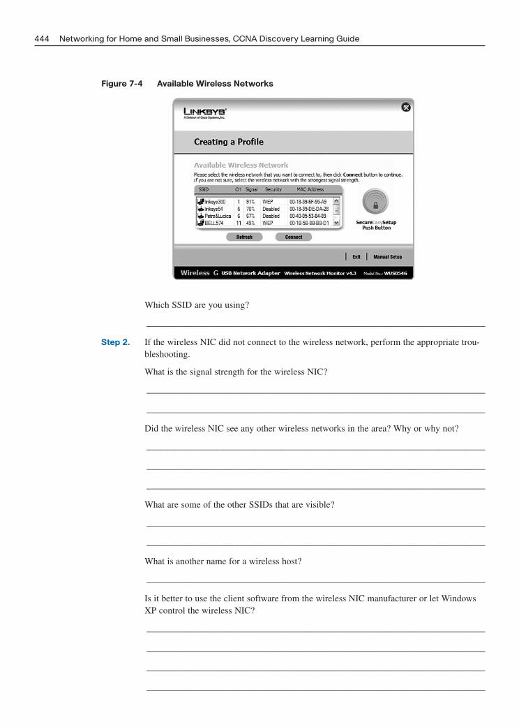
Which SSID are you using?
_________________________________________________________________________
Step 2. If the wireless NIC did not connect to the wireless network, perform the appropriate trou-bleshooting.
What is the signal strength for the wireless NIC?
_________________________________________________________________________
_________________________________________________________________________
Did the wireless NIC see any other wireless networks in the area? Why or why not?
_________________________________________________________________________
_________________________________________________________________________
_________________________________________________________________________
What are some of the other SSIDs that are visible?
_________________________________________________________________________
_________________________________________________________________________
What is another name for a wireless host?
_________________________________________________________________________
Is it better to use the client software from the wireless NIC manufacturer or let WindowsXP control the wireless NIC?
_________________________________________________________________________
_________________________________________________________________________
_________________________________________________________________________
_________________________________________________________________________
444 Networking for Home and Small Businesses, CCNA Discovery Learning Guide
Figure 7-4 Available Wireless Networks

Task 4: Determine the NIC Driver Version
Hardware manufacturers continually update drivers. The driver that ships with a NIC or other piece ofhardware might not be the most current.
To check the driver version for the NIC you installed, click Start, select Control Panel and thenNetwork Connections. Right-click the wireless connection and select Properties. Click theConfigure button for the NIC and then click the Driver tab, as shown in Figure 7-5.
Figure 7-5 Checking the Driver Version
Chapter 7: Labs: Wireless Technologies 445
What is the name and version of the driver you installed?
Task 5: Determine If the NIC Driver Is the Most Current
Search the NIC manufacturer website for drivers that support the wirelss NIC you installed. Are theremore current ones available?
What is the most current driver listed?
If there is a more current driver, how would you apply it?
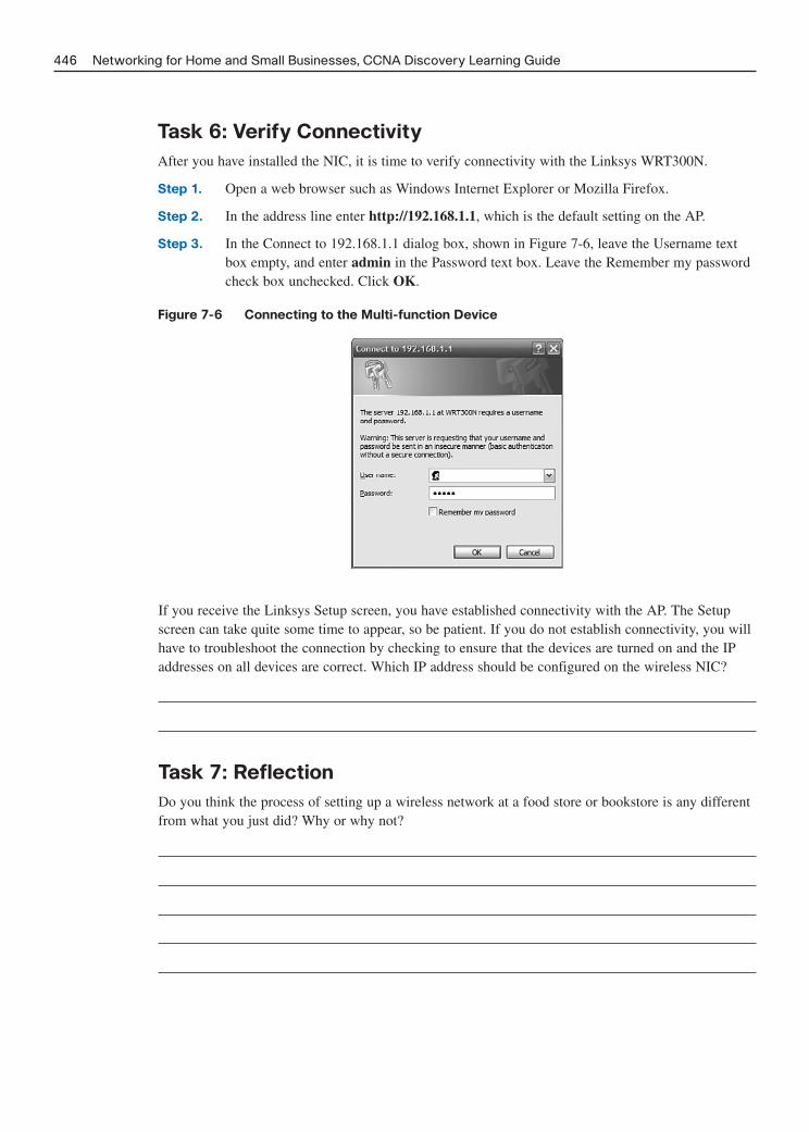
Task 6: Verify Connectivity
After you have installed the NIC, it is time to verify connectivity with the Linksys WRT300N.
Step 1. Open a web browser such as Windows Internet Explorer or Mozilla Firefox.
Step 2. In the address line enter http://192.168.1.1, which is the default setting on the AP.
Step 3. In the Connect to 192.168.1.1 dialog box, shown in Figure 7-6, leave the Username textbox empty, and enter admin in the Password text box. Leave the Remember my passwordcheck box unchecked. Click OK.
Figure 7-6 Connecting to the Multi-function Device
446 Networking for Home and Small Businesses, CCNA Discovery Learning Guide
If you receive the Linksys Setup screen, you have established connectivity with the AP. The Setupscreen can take quite some time to appear, so be patient. If you do not establish connectivity, you willhave to troubleshoot the connection by checking to ensure that the devices are turned on and the IPaddresses on all devices are correct. Which IP address should be configured on the wireless NIC?
Task 7: Reflection
Do you think the process of setting up a wireless network at a food store or bookstore is any differentfrom what you just did? Why or why not?

Do you think the AP model that you are using would be sufficient for your nearest grocery store?Why or why not?
Chapter 7: Labs: Wireless Technologies 447

Lab 7-3: Configuring Wireless Security (7.3.5.2)
Objectives
■ Create a security plan for a home or small business network.
■ Configure the wireless access point (AP) portion of a multi-function device using security bestpractices.
Background/Preparation
A well-planned security implementation is critical to the safety of a wireless network. This labreviews the steps that you must take to ensure the safety of the network using the following scenario.
You have just purchased a Linksys WRT300N wireless router, and you want to set up a small networkin your home. You selected this router because the IEEE 802.11n specification claims that it has 12times the speed of an 802.11g and 4 times the range. Because the 802.11n uses 2.4 GHz, it is back-ward compatible with both the 802.11b and 802.11g and uses multiple-in, multiple-out (MIMO) tech-nology.
You should enable security mechanisms before connecting your multi-function device to the Internetor any wired network. You should also change the default values provided because they are well-known values that are easily obtainable on the Internet.
The following resources are required:
■ Windows-based computer
■ Linksys WRT300N
■ Straight-through Ethernet cable
Task 1: Plan the Security for Your Home Network
List at least six security best practices that you should implement to secure your multi-function deviceand wireless network.
448 Networking for Home and Small Businesses, CCNA Discovery Learning Guide

Describe what the security risk is for each best practice.
Task 2: Connect a Computer to the Multi-function Device
and Log In to the Web-Based Utility
Step 1. Connect your computer (Ethernet NIC) to the multi-function device (port 1 on the LinksysWRT300N) by using a straight-through cable.
Step 2. The default IP address of the Linksys WRT300N is 192.168.1.1, and the default subnetmask is 255.255.255.0. The computer and Linksys device must be on the same network tocommunicate with each other. Change the IP address of the computer to 192.168.1.2, andverify that the subnet mask is 255.255.255.0. Enter the internal address of the Linksysdevice (192.168.1.1) as the default gateway. Do this by clicking Start > Control Panel >Network Connections. Right-click the wireless connection and choose Properties. Selectthe Internet Protocol (TCP/IP) and enter the addresses, as shown in Figure 7-7.
Figure 7-7 Setting the IP Address on the Computer
Chapter 7: Labs: Wireless Technologies 449

Step 3. Open a web browser, such as Internet Explorer, Netscape, or Firefox and enter the IPaddress of the Linksys device (192.168.1.1 if reset to defaults) into the address field andpress Enter.
A screen appears, requesting your username and password, as shown in Figure 7-8.
Figure 7-8 Connecting to the Linksys WRTG300N
450 Networking for Home and Small Businesses, CCNA Discovery Learning Guide
Step 4. Leave the Username field blank and enter admin for the password. It is the default pass-word on the Linksys device. Click OK. Remember that passwords are case sensitive.
NOTE: As you make the necessary changes on the Linksys device, click Save Settings on each screen to save thechanges or click Cancel Changes to keep the default settings.
Task 3: Change the Linksys Device Password
Once authenticated, the initial screen displayed is the Setup > Basic Setup screen, as shown in Figure 7-9.
Figure 7-9 Linksys WRTG300N Basic Setup Screen
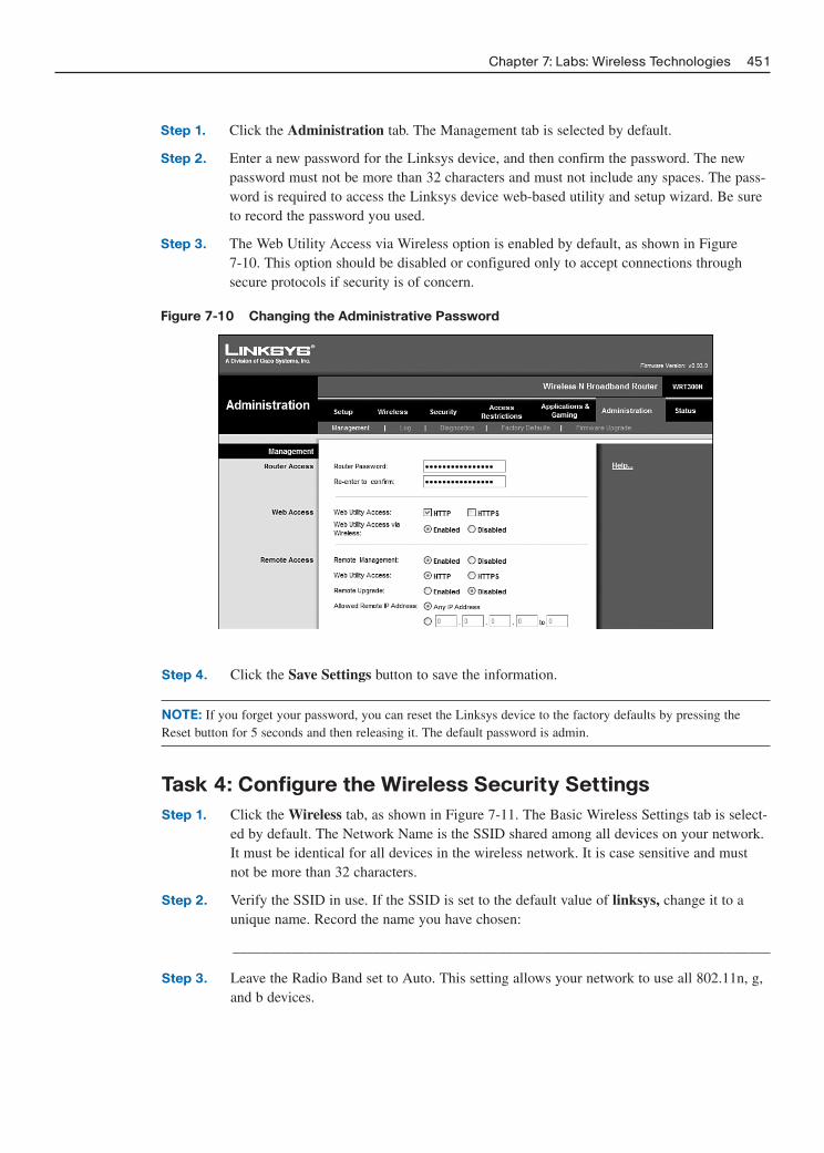
Step 1. Click the Administration tab. The Management tab is selected by default.
Step 2. Enter a new password for the Linksys device, and then confirm the password. The newpassword must not be more than 32 characters and must not include any spaces. The pass-word is required to access the Linksys device web-based utility and setup wizard. Be sureto record the password you used.
Step 3. The Web Utility Access via Wireless option is enabled by default, as shown in Figure 7-10. This option should be disabled or configured only to accept connections throughsecure protocols if security is of concern.
Figure 7-10 Changing the Administrative Password
Chapter 7: Labs: Wireless Technologies 451
Step 4. Click the Save Settings button to save the information.
NOTE: If you forget your password, you can reset the Linksys device to the factory defaults by pressing theReset button for 5 seconds and then releasing it. The default password is admin.
Task 4: Configure the Wireless Security Settings
Step 1. Click the Wireless tab, as shown in Figure 7-11. The Basic Wireless Settings tab is select-ed by default. The Network Name is the SSID shared among all devices on your network.It must be identical for all devices in the wireless network. It is case sensitive and mustnot be more than 32 characters.
Step 2. Verify the SSID in use. If the SSID is set to the default value of linksys, change it to aunique name. Record the name you have chosen:
_________________________________________________________________________
Step 3. Leave the Radio Band set to Auto. This setting allows your network to use all 802.11n, g,and b devices.

Figure 7-11 Basic Wireless Settings
452 Networking for Home and Small Businesses, CCNA Discovery Learning Guide
Step 4. For SSID Broadcast, click the Disabled button to disable the SSID broadcast. Wirelessclients survey the area for networks to associate with and will detect the SSID broadcastsent by the Linksys device. For added security, do not broadcast the SSID. Please note thatthere are utilities and techniques to discover the SSID even if it is not broadcast. Thisshould be used in conjunction with other security measures.
Step 5. Save your settings before going to the next task.
Task 5: Configure Encryption and Authentication
Step 1. Click the Wireless Security tab on the Wireless screen.
This router supports four types of security mode settings:
■ Wired Equivalent Privacy (WEP)
■ Wi-Fi Protected Access (WPA) Personal, which uses a pre-shared key (PSK)
■ WPA2 Personal
■ WPA Enterprise, which uses Remote Access Dial-In User Service (RADIUS)
■ WPA2 Enterprise
■ RADIUS
WPA is based on a draft version of IEEE 802.11i and offers a subset of the features finallycontained in the approved version. WPA2 is based on the approved version of IEE802.11iand offers improved performance and many advanced features.
Step 2. Select WPA Personal in the Security Mode drop-down menu, as shown in Figure 7-12.
Step 3. On the next screen, shown in Figure 7-13, choose an encryption algorithm.

Chapter 7: Labs: Wireless Technologies 453
To secure a network, use the highest level of encryption possible within the SelectedSecurity mode. The following security modes and encryption levels are listed from leastsecure (WEP) to most secure (WPA2 with AES):
■ WEP
■ WPA, including Temporal Key Integrity Protocol (TKIP) and Advanced EncryptionSystem (AES)
■ WPA2, including TKIP and AES
AES is supported only by newer devices that contain a co-processor. To ensure compati-bility with all devices, select TKIP.
Step 4. For authentication, enter a pre-shared key between 8 and 63 characters. This key is sharedby the Linksys device and all connected devices. Record the pre-shared key that you used.
Step 5. Choose a key renewal period between 600 and 7200 seconds. The renewal period is howoften the Linksys device changes the encryption key. The shorter the key renewal period,the more secure the connection. Unfortunately, shorter key renewal periods also increasethe network overhead.
Step 6. Save your settings before exiting the screen.
Figure 7-12 Setting the Wireless Security Mode
Figure 7-13 Selecting the Wireless Encryption Algorithm

454 Networking for Home and Small Businesses, CCNA Discovery Learning Guide
Task 6: Configure MAC Address Filtering
Step 1. Click the Wireless MAC Filter tab on the Wireless screen.
Step 2. MAC address filtering allows only selected wireless client MAC addresses to have accessto your network. Select the Permit PCs listed below to access the wireless networkradio button. Click the Wireless Client List button to display a list of all wireless clientcomputers on your network, as shown in Figure 7-14.
Figure 7-14 MAC Address Filtering
Step 3. The next screen, shown in Figure 7-15, allows you to identify which MAC addresses canhave access to the wireless network. Check the Save to MAC Address Filter List checkbox for any client device you want to add, and then click the Add button. Any wirelessclients, other than those in the list, will be prevented from accessing your wireless net-work. Save your settings before exiting the screen.
Figure 7-15 Selecting the MAC Addresses to Filter

Task 7: Reflection
Which feature that you configured on the Linksys WRT300N makes you feel the most secure andwhy?
Make a list of other items that you could do to make your network even more secure.
Chapter 7: Labs: Wireless Technologies 455

Challenge Lab 7-4: Planning the Home or Small
Business WLAN
Objectives
■ Evaluate user needs
■ Use a WLAN implementation checklist
■ Conduct a mini-site survey
■ Plan WLAN implementation
Background/Preparation
Various wireless technologies exist each with specific characteristics. Before you can determine themost appropriate technology and WLAN implementation strategy, having a good understanding ofend-user requirements as well as the physical environment where the network is to be installed is nec-essary. For a large-scale implementation a thorough site survey must be conducted. This requires agood understanding of radio frequency (RF) technology and access to equipment such as spectrumanalyzers.
For the home and small business environments, a formal site survey is impractical. In these environ-ments a very simplified process is often sufficient to determine which equipment should be installedand where. This process consists of an implementation checklist as well as a mini-site survey.
In this lab your friend needs to implement a home wireless network with four computers. He has cho-sen you to perform a mini-site survey of his home because he knows you are a student in theNetworking Academy and have a good understanding of WLANs. Use the implementation checklistand site survey documents to help you plan the home network.
Find a friend in class to become your partner. Interview this person to plan and implement the homenetwork.
Requirements for this lab include the following:
■ Windows-based computer with Internet connectivity
■ Linksys 300N broadband router
■ Implementation checklist
■ Site survey document
Task 1: Plan the WLAN
Step 1. Use the following implementation checklist to interview your friend and find out the nec-essary information needed to plan the WLAN.
456 Networking for Home and Small Businesses, CCNA Discovery Learning Guide

Implementation Checklist
❐ Determine end-user requirements. Talk with users and determine what applications are being usedor will be used. Also speak with managers and any technical support people who might be pres-ent. Determine the following information:
■ Number of users
■ User locations
■ Applications being used
■ Required speed: 11 Mbps, 54 Mbps, or more
■ Whether all end users require the same throughput
■ What level of security is acceptable
❐ Determine and rank possible choices based on the following factors:
■ Sources of interference
■ Cost of possible solutions
■ Technical support staff, if needed
❐ Determine availability of financial resources. Are the financial resources available to implementthe preferred solution? If not, one of the less preferred solutions might have to be considered.
❐ Determine whether human, technical, and financial resources are available to install and maintainselected wireless technology. Include the following:
■ Integration with existing wired or wireless network, if present. Can the planned wirelessnetwork be used with the existing network and resources?
■ Technical support staff, if needed.
Step 2. List any items that you feel should be added to or deleted from this checklist. Justify youropinions.
_________________________________________________________________________
_________________________________________________________________________
_________________________________________________________________________
_________________________________________________________________________
_________________________________________________________________________
Step 3. Record and keep all the information in notes.
Step 4. Use the following mini-site survey document to find out the necessary information to planthe implementation of the WLAN.
Chapter 7: Labs: Wireless Technologies 457

Mini-Site Survey
1. Make a diagram of the site. The diagram should show the floor plan that depicts walls, doors,furniture, electrical outlets, and so on. The diagram should also include any existing wired orwireless network components and be drawn to scale. The more information that is containedthe better.
2. Visually inspect the facility. A visual inspection will uncover obstacles such as metal racks andfreezers already installed in the home.
3. Identify user areas. Mark fixed and mobile users.
4. Determine preliminary access point locations. Consider the location of wireless users and rangeestimations of the wireless LAN product you are using.
5. Identify the best locations for access point placement so that the network can provide optimalwireless coverage and maximum performance.
6. Document findings. Once you are satisfied that the planned location of access points will pro-vide adequate coverage, identify them on the diagram.
Step 5. List any items that you feel should be added to or deleted from this survey. Justify youropinions.
_________________________________________________________________________
_________________________________________________________________________
_________________________________________________________________________
_________________________________________________________________________
_________________________________________________________________________
Task 2: Use Internet for Research
Step 1. Use the Internet to do any research required to help you implement the network. Thismight include specific information on wireless standards, network design best practices,signal absorption in different materials, and possible sources of interference.
Step 2. Write down any websites you used to help you in this project. Record any sites visited andthe information that you found.
_________________________________________________________________________
_________________________________________________________________________
_________________________________________________________________________
_________________________________________________________________________
_________________________________________________________________________
458 Networking for Home and Small Businesses, CCNA Discovery Learning Guide

Step 3. If you did not use any websites, did you use your engineering journal or the curriculum toguide you in the process?
_________________________________________________________________________
_________________________________________________________________________
_________________________________________________________________________
_________________________________________________________________________
_________________________________________________________________________
Task 3: Document Your Findings
Use a software program such as Microsoft Office or Visio to prepare a report of your findings. Includea diagram of the proposed network, including the location of any wireless devices. Add it to the origi-nal site survey diagram. The report should be specific enough that someone else could use it to installthe proposed network.
Task 4: Reflection
Find a classmate to discuss your report. Based on your classmate’s feedback, write down at least twothings that might have been completed differently during the installation of the WLAN.
Chapter 7: Labs: Wireless Technologies 459

This page intentionally left blank

CHAPTER 8
Labs: Basic Security
The lab exercises in this chapter include the Chapter 8 online curriculum labs to ensure that you have masteredthe practical, hands-on skills needed to set up a demilitarized zone (DMZ) on a Linksys multi-function deviceand use vulnerability analysis tools. As you work through these labs, use Chapter 8 in Part I of this book oruse the corresponding Chapter 8 in the Networking for Home and Small Businesses course of the CCNADiscovery online curriculum for assistance.
Lab 8-1: Configuring Access Policies and DMZ Settings
(8.4.2.4)
Figure 8-1 Lab 8-1 Topology
ExternalServer
HTTP, DHCP, andTelnet Services
InternetPort
Linksys WRT300NMulti-Function Device
EthernetSwitch Ports
Host A
Host B/DMZServer
HTTP andTelnet Services
Objectives
■ Log in to a multi-function device and view security settings.
■ Set up Internet access policies based on IP address and application.
■ Set up a DMZ for an open access server with a static IP address.
■ Set up port forwarding to limit port accessibility to only HTTP.
■ Use the Linksys WRT300N Help features.
Background/Preparation
This lab provides instructions for configuring security settings for the Linksys WRT300N. The Linksys pro-vides a software-based firewall to protect internal, local-network clients from attack by external hosts.Connections from internal hosts to external destinations can be filtered based on the IP address, destinationwebsite, and application. The Linksys can also be configured to create a DMZ to control access to a serverfrom external hosts. This lab is done in teams of two, and two teams can work together to test each other’saccess restrictions and DMZ functionality. The lab is divided into two parts:
■ Part A: Configuring Access Policies
■ Part B: Configuring a DMZ on the Multi-function Device

The following resources are required:
■ Linksys WRT300N or other multi-function device with the default configuration
NOTE: If you are unsure of whether the device is in the default configuration, ask your instructor or perform thesteps in Part B, Task 3 (“Restore the Multi-function Device to Its Default Settings”) before beginning.
■ User ID and password for the Linksys device if different from the default
■ Computer running Windows XP Professional to access the Linksys GUI
■ Internal PC to act as a server in the DMZ with HTTP and Telnet servers installed (preconfig-ured or Discovery Live CD server)
■ External server to represent the ISP and Internet (with preconfigured DHCP, HTTP, and Telnetservers running [real server with services installed or Discovery Live CD server])
■ Cabling to connect the PC hosts, Linksys WRT300N, or multi-function device, and switches
Part A: Configuring Access Policies
In this part of the lab, you work through the process of configuring access policies.
Task 1: Build the Network and Configure the Hosts
Step 1. Connect the host computers to switch ports on the multi-function device as shown in thetopology diagram. Host-A is the console and is used to access the Linksys GUI. Host-B isinitially a test machine but later becomes the DMZ server.
Step 2. Configure the IP settings for both hosts using Windows XP Network Connections andTCP/IP properties. Verify that Host-A is configured as a DHCP client. Assign a static IPaddress to Host-B in the 192.168.1.x range with a subnet mask of 255.255.255.0. Thedefault gateway should be the internal local network address of the Linksys device.
NOTE: If Host-B is already a DHCP client, you can reserve its current address and make it static using theDHCP Reservation feature on the Linksys Basic Setup screen.
Step 3. Use the ipconfig command to display the IP address, subnet mask, and default gateway forHost-A and Host-B and record them in Table 8-1. Obtain the IP address and subnet maskof the external server from the instructor and record it in the table.
Table 8-1 Host IP Address Information
Host IP Address Subnet Mask Default Gateway
Host-A
Host-B/DMZ Server
External Server
462 Networking for Home and Small Businesses, CCNA Discovery Learning Guide

Task 2: Log In to the User Interface
Step 1. To access the Linksys or multi-function device web-based GUI, open a browser on Host-Aand enter the default internal IP address for the device; normally, 192.168.1.1.
Step 2. Log in using the default user ID (no user ID entered) and password (admin), or checkwith the instructor if they are different. Figure 8-2 shows the Linksys login screen.
Figure 8-2 Linksys Login Screen
Chapter 8: Labs: Basic Security 463
The multi-function device should be configured to obtain an IP address from the externalDHCP server. After logging in to the Linksys device, the default screen displayed is Setup> Basic Setup. What is the Internet connection type?
_________________________________________________________________________
What is the default router (internal) IP address and subnet mask for the multi-functiondevice?
_________________________________________________________________________
Step 3. Verify that the multi-function device has received an external IP address from the DHCPserver by clicking the Status > Router tab.
What is the external IP address and subnet mask assigned to the multi-function device?
_________________________________________________________________________
_________________________________________________________________________
Task 3: View Multi-function Device Firewall Settings
The Linksys WRT300N provides a basic firewall that uses network address translation (NAT). Inaddition, it provides additional firewall functionality using stateful packet inspection (SPI) to detectand block unsolicited traffic from the Internet.
Step 1. From the main screen, click the Security tab to view the firewall and Internet filter status.Figure 8-3 shows the Security tab window in a default configuration.

Figure 8-3 Security Tab Window
464 Networking for Home and Small Businesses, CCNA Discovery Learning Guide
What is the status of SPI firewall protection?
_________________________________________________________________________
_________________________________________________________________________
Which Internet filter check boxes are selected?
_________________________________________________________________________
_________________________________________________________________________
Step 2. Click Help to learn more about these settings. What benefits does filtering IDENT pro-vide?
_________________________________________________________________________
_________________________________________________________________________
Task 4: Set Up Internet Access Restrictions Based on IP Address
In Lab 7-3 you saw that wireless security features can control which wireless client computers canaccess the multi-function device, based on MAC address. This prevents unauthorized external comput-ers from connecting to the wireless access point (AP) and gaining access to the internal local networkand the Internet.
The Linksys multi-function device can also control which internal users can get out to the Internetfrom the local network. You can create an Internet access policy to deny or allow specific internalcomputers access to the Internet based on the IP address, MAC address, and other criteria.
Step 1. From the main multi-function device screen, click the Access Restrictions tab to defineAccess Policy 1.

Step 2. Enter Block-IP as the policy name. Select Enabled to enable the policy, and then selectDeny to prevent Internet access from a specified IP address.
Step 3. Click the Edit List button and enter the IP address of Host-B. Click Save Settings andthen Close. Click Save Settings to save Internet Access Policy 1 – Block-IP.
Step 4. Test the policy by attempting to access the external web server from Host-B. Open abrowser and enter the IP address of the external server in the address area. Are you able toaccess the server?
_________________________________________________________________________
Step 5. Change the status of the block-IP policy to Disabled and click Save Settings. Are youable to access the server now?
_________________________________________________________________________
What other ways can access policies be used to block Internet access?
_________________________________________________________________________
_________________________________________________________________________
Task 5: Set Up an Internet Access Policy Based on an Application
You can create an Internet access policy to block specific computers from using certain Internet appli-cations or protocols on the Internet.
Step 1. From the main Linksys GUI screen, click the Access Restrictions tab to define an Internetaccess policy.
Step 2. Enter Block-Telnet as the policy name. Select Enabled to enable the policy, and thenclick Allow to permit Internet access from a specified IP address as long as it is not one ofthe applications that is blocked.
Step 3. Click the Edit List button and enter the IP address of Host-B. Click Save Settings andthen Close.
What other Internet applications and protocols can be blocked?
_________________________________________________________________________
Step 4. Select the Telnet application from the list of applications that can be blocked and thenclick the double right arrow to add it to the Blocked List. Click Save Settings.
Step 5. Test the policy by opening a command prompt; click Start > All Programs > Accessories> Command Prompt.
Ping the IP address of the external server from Host-B using the ping command.
Are you able to ping the server?
_________________________________________________________________________
Step 6. Telnet to the IP address of the external server from Host-B using the command telnetA.B.C.D (where A.B.C.D is the IP address of the external server).
Chapter 8: Labs: Basic Security 465

Are you able to telnet to the server?
_________________________________________________________________________
If you are not going to perform Part B at this time, skip to “Task 3: Restore the Multi-function Device to Its Default Settings” of Part B so that it is ready for the next student.
Part B: Configuring a DMZ on the Multi-function Device
In Part B of this lab you work with the DMZ capabilities of the Linksys multi-function device. Firstyou set up a simple DMZ that allows access to any service that is running on the DMZ server. Nextyou limit access to the server to specific services using port forwarding.
Task 1: Set Up a Simple DMZ
Allowing access to a computer from the Internet while still protecting the other, internal local networkcomputers is sometimes necessary. To accomplish this, you can set up a demilitarized zone (DMZ)that allows open access to any ports and services running on the specified server. Any requests madefor services to the outside address of the multi-function device will be redirected to the server speci-fied.
Step 1. Host-B will act as the DMZ server and should be running HTTP and Telnet servers. Verifythat Host-B has a static IP address or, if Host-B is a DHCP client, you can reserve its cur-rent address and make it static using the DHCP Reservation feature on the Linksys deviceBasic Setup screen.
Step 2. From the main Linksys GUI screen, click the Applications & Gaming tab and then clickDMZ.
Step 3. Click Help to learn more about the DMZ. For what other reasons might you want to set upa host in the DMZ?
_________________________________________________________________________
Step 4. The DMZ feature is disabled by default. Select Enabled to enable the DMZ. Leave theSource IP Address selected as Any IP Address, and enter the IP address of Host-B inDestination IP address. Click Save Settings and click Continue when prompted.
Note: Any requests (for example, web or Telnet) sent from an outside host (the external server) tothe external interface of the Linksys will be directed to the DMZ server.
Step 5. Test basic access to the DMZ server by pinging from the external server to the outsideaddress of the multi-function device. Open a command prompt by clicking Start > AllPrograms > Accessories > Command Prompt and use the ping –a command to verifythat what is responding is actually the DMZ server and not the multi-function device. Areyou able to ping the DMZ server?
_________________________________________________________________________
466 Networking for Home and Small Businesses, CCNA Discovery Learning Guide

Step 6. Test HTTP access to the DMZ server by opening a browser on the external server andpointing to the external IP address of the multi-function device. Try the same thing from abrowser on Host-A to Host-B using the internal addresses of the DMZ server (Host-B). AnHTTP request to the external interface of the multi-function device from outside the net-work should be redirected to the DMZ server providing web services. A web request frominternal Host-A to the DMZ server (Host-B) can be made directly to the internal DMZserver’s address because Host-A is behind the firewall.
Are you able to access the web page?
_________________________________________________________________________
Step 7. Test Telnet access to the DMZ server from the external server by opening a commandprompt at Start > All Programs > Accessories > Command Prompt. Telnet to the out-side IP address of the multi-function device using the command telnet A.B.C.D (whereA.B.C.D is the outside address of the multi-function device). A Telnet request to the exter-nal interface of the multi-function device from outside the network should be redirected tothe DMZ server providing Telnet services.
Are you able to telnet to the DMZ server?
_________________________________________________________________________
Step 8. Test Telnet access to internal Host-A from the external server by opening a commandprompt at Start > All Programs > Accessories > Command Prompt. Telnet to the insideIP address of Host-A using the command telnet A.B.C.D (where A.B.C.D is the insideaddress of Host-A).
Are you able to telnet to internal Host-A?
_________________________________________________________________________
_________________________________________________________________________
Task 2: Set Up a Host with Single Port Forwarding
The basic DMZ hosting set up in Task 1, Step 4 allows open access to all ports and services runningon the server, such as HTTP, FTP, and Telnet. If a host is to be used for a particular function, such asFTP or web services, access should be limited to the type of services provided. Single port forwardingcan accomplish this and is more secure than the basic DMZ, because it only opens the ports needed.Before completing this step, disable the DMZ settings from Task 1.
Host-B is the server to which ports are forwarded, but access is limited to only HTTP (web).
Step 1. From the main screen, click the Applications & Gaming tab, and then click Single PortForwarding to specify applications and port numbers.
Step 2. Click the pull-down menu for the first entry under Application Name and select HTTP.This is the web server protocol port 80.
Step 3. In the first To IP Address field, enter the IP address of Host-B and select Enabled. ClickSave Settings.
Step 4. Test HTTP access to the DMZ host by opening a browser on the external server and point-ing to the outside address of the multi-function device. Try the same thing from a browseron Host-A to Host-B.
Chapter 8: Labs: Basic Security 467

Are you able to access the web page?
_________________________________________________________________________
Step 5. Test Telnet access to the DMZ server by opening a command prompt on the external serv-er. Attempt to telnet to the outside IP address of the multi-function device using the com-mand telnet A.B.C.D (where A.B.C.D is the outside IP address of the multi-functiondevice).
Are you able to telnet to the DMZ server?
_________________________________________________________________________
Task 3: Restore the Multi-function Device to Its Default Settings
Step 1. To restore the Linksys to its factory default settings, click the Administration > FactoryDefaults tab.
Step 2. Click the Restore Factory Defaults button. Any entries or changes to settings will be lost.
NOTE: The current settings can be saved and restored at a later time using the Administration >Management tab and the Backup Configuration and Restore Configuration buttons.
468 Networking for Home and Small Businesses, CCNA Discovery Learning Guide

Lab 8-2: Performing a Vulnerability Analysis (8.4.3.2)
Caution: The procedures in this lab might violate legal and organizational security policies if performed on alive network. The security analyzer downloaded in this lab should only be used for instructional purposes in a labenvironment. Before using a security analyzer on a live network, check with your instructor and network adminis-tration staff regarding internal policies concerning the use of these tools.
Figure 8-4 Lab 8-2 Topology
Chapter 8: Labs: Basic Security 469
Integrated Router
Hub/Switch
Host A
Server(Optional)
or
Objectives
■ Download and install security analyzer software.
■ Test a host to determine potential security vulnerabilities.
Background/Preparation
Security analyzers are valuable tools used by network administrators and auditors to identify networkand host vulnerabilities. Many vulnerability analysis tools, also known as security scanners, are avail-able to test host and network security. In this lab, you download and install the Microsoft BaselineSecurity Analyzer (MBSA). MBSA is designed to identify potential security issues related specifical-ly to Microsoft operating systems, updates, and applications. It also identifies unnecessary servicesthat might be running, as well as any open ports.
MBSA runs on Windows Server and Windows XP systems and scans for common security misconfig-urations and missing security updates for the operating system as well as most versions of InternetInformation Server (IIS), SQL Server, Internet Explorer (IE), and Office products. MBSA offers spe-cific recommendations to correct potential problems.
This lab can be done individually or in teams of two.
The following resources are required:
■ Computer running Windows XP Professional to act as the test station.
■ High-speed Internet connection for downloading MBSA (unless pre-installed).
■ Computer must be attached to the integrated router switch or a standalone hub or switch.
■ Optionally, you can have a server running a combination of DHCP, HTTP, FTP, and Telnet(preconfigured).

Task 1: Download and Install MBSA
Step 1. Open a browser and go to the MBSA web page at http://www.microsoft.com/technet/security/tools/mbsa2/default.mspx.
What is the latest version of MBSA available?
_________________________________________________________________________
What are some of the features MBSA provides?
_________________________________________________________________________
_________________________________________________________________________
Step 2. Scroll down the page and select the desired language to begin the download process.
Step 3. Click Continue to validate the copy of Microsoft Windows you are running.
Step 4. Click Download Files below and select the file you want to download. (The English setupfile is MBSASetup-EN.msi.) Click the Download button on the right of this file. Howmany megabytes is the file to download?
_________________________________________________________________________
Step 5. When the File Download – Security Warning dialog box displays, click Save and down-load the file to a specified folder or the desktop. You can also run it from the downloadwebsite.
Step 6. After the download is complete, make sure that all other applications are closed. Double-click the downloaded file. Click Run to start the Setup program, and then click Run if youare prompted with a security warning. Click Next on the MBSA Setup screen.
Step 7. Select the radio button to accept the license agreement and click Next. Accept the defaultsas the install progresses, and then click Finish. Click OK on the final MBSA Setupscreen, and close the folder to return to the Windows desktop.
Task 2: Build the Network and Configure the Hosts
Step 1. Connect the host computer(s) to the integrated router, a hub, or a switch as shown in thetopology diagram. Host-A is the test station where MBSA will be installed. The server isoptional.
Step 2. Set the IP configuration for the host(s) using Windows XP Network Connections andTCP/IP properties. If the host is connected to the integrated router, configure it as a DHCPclient; otherwise go to Step 3.
Step 3. If the host is connected to a hub or switch and a DHCP server is not available, manuallyassign the host a static IP address.
Which IP address and subnet mask does Host-A and the server (optional) have?
_________________________________________________________________________
_________________________________________________________________________
_________________________________________________________________________
470 Networking for Home and Small Businesses, CCNA Discovery Learning Guide

Task 3: Run MBSA on a Host
Double-click the desktop icon for MBSA or run it from Start > All Programs. Figure 8-5 shows thewelcome screen.
Figure 8-5 Baseline Security Analyzer Welcome Screen
Chapter 8: Labs: Basic Security 471
When the main screen displays, which options are available?
Task 4: Select a Computer to Scan
Step 1. On the left side of the screen, click Pick a computer to scan. The computer shown as thedefault is the one on which MBSA is installed.
What are the two ways to specify a computer to be scanned?
_________________________________________________________________________
Step 2. Accept the default computer to be scanned. Deselect checking for IIS and SQL adminis-trative vulnerabilities because these services are not likely to be installed on the computerbeing scanned. Click Start Scan.
Task 5: View Security Update Scan Results
Step 1. View the security report. What are the results of the security update scan?
_________________________________________________________________________
_________________________________________________________________________

Step 2. If there are any red or yellow Xs, click How to correct this. Which solution is recom-mended?
_________________________________________________________________________
_________________________________________________________________________
Task 6: View Windows Scan Results in the Security Report
Step 1. Scroll down to view the second section of the report that shows Windows Scan Results.Were there any administrative vulnerabilities identified?
_________________________________________________________________________
Step 2. In the Additional System Information section of the screen, in the Issue column forServices, click What was scanned, and click Result details to get a description of thecheck that was run. What did you find? When finished, close both pop-up windows toreturn to the security report.
_________________________________________________________________________
_________________________________________________________________________
Task 7: View Desktop Application Scan Results in theSecurity Report
Scroll down to view the last section of the report that shows Desktop Applications Scan Results.Were there any administrative vulnerabilities identified?
How many Microsoft Office products are installed?
Were there any security issues with macro security for any of them?
Task 8: Scan a Server, If Available
If a server with various services is available, click Pick a computer to scan from the main MBSAscreen, enter the IP address of the server, and then click Start Scan. Which security vulnerabilitieswere identified?
Were there any potentially unnecessary services installed? Which port numbers were they on?
472 Networking for Home and Small Businesses, CCNA Discovery Learning Guide

Task 9: Uninstall MBSA Using Control Panel Add/Remove
Programs
This step is optional, depending on whether the host will be automatically restored later by a networkprocess.
To uninstall MBSA, click Start > Control Panel > Add/Remove Programs. Locate the MBSAapplication and uninstall it. It should be listed as Microsoft Baseline Security Analyzer 2.0.1. ClickRemove, and then click Yes to confirm removal of the MBSA application. When finished, close allwindows to return to the desktop.
Task 10: Reflection
The MBSA tool is designed to identify vulnerabilities for Windows-based computers. Search theInternet for other tools that might exist. List some of the tools discovered.
Which tools might there be for non-Windows computers? Search the Internet for other tools thatmight exist and list some of them here.
Which other steps could you take to help secure a computer against Internet attacks?
Chapter 8: Labs: Basic Security 473

This page intentionally left blank

CHAPTER 9
Labs: Troubleshooting Your Network
The lab exercises in this chapter include the Chapter 9 online curriculum labs. Complete these labs to ensurethat you have mastered the practical, hands-on skills needed to understand the basics of network troubleshoot-ing. As you work through these labs, use Chapter 9 in Part I of this book or use the corresponding Chapter 9 inthe Networking for Home and Small Businesses course of the CCNA Discovery online curriculum for assis-tance.
Lab 9-1: Troubleshooting Using Network Utilities (9.2.7.2)
Objectives
■ Use network utilities and the wireless router GUI to determine device configurations.
■ Select the appropriate network utilities to help troubleshoot connectivity problems.
■ Diagnose accessibility problems with web, FTP, Telnet, and DNS servers.
■ Identify and correct physical problems related to cable types and connections.
Background/Preparation
In this lab, you use the browser and various troubleshooting utilities, such as ipconfig, ping, tracert, netstat,and nslookup to diagnose and correct connectivity problems. These command-line interface (CLI) utilities areavailable on most current operating systems, although the exact command and syntax might vary. Windows XPcommands and syntax are used in this lab.
Your instructor will set up a network topology similar to the one shown in Figure 9-1 and will preconfigure theclient computer, wireless router, server, and external router for each scenario in the lab. Various software andhardware connectivity problems will be introduced, and you will diagnose the cause from the client computer.
Figure 9-1 Lab 9-1 Setup
Wireless RouterInternet Port
Hub/SwitchRouterServer WirelessRouter
Host A
There are six scenarios. Work in teams of three, with each person taking the lead in two of the scenarios, andthe other team members assisting.
The following resources are required:
■ Computer running Windows XP Professional with web, FTP, and Telnet clients (CLI or GUI). This isHost-A.

■ Server running a combination of DNS, HTTP, FTP, and Telnet services (preconfigured). Thisserver will simulate Internet connections and can be a server with these services actuallyinstalled and running or a server running the Discovery Server Live CD.
■ Wireless router configured as a DHCP server and client (default configuration).
■ Router with two Ethernet interfaces configured as a DHCP server to a wireless router (precon-figured).
■ Ethernet Cat-5 (minimum) straight and crossover cabling to connect hosts and network devices.
■ Hub/switch for connecting the router to the wireless router.
Task 1: Build the Network and Configure the Hosts
Step 1. Have your instructor set up a network topology similar to the one shown in Figure 9-1with the Host-A client computer, wireless router, server, and router preconfigured.
Step 2. Work from Host-A to issue commands to troubleshoot problems introduced by the instructor.
Step 3. All commands are issued from a command prompt window. Open a command promptwindow by clicking Start > All Programs > Accessories > Command Prompt. Keep thewindow open for the duration of the lab.
Task 2: Record the Baseline IP Address Information for
Computers and Wireless Router
Note: Perform this task before the instructor introduces problems.
Step 1. Host-A configuration: Issue the command that displays the IP address information forHost-A, including the DNS server, and record the information. Which command did youuse?
_________________________________________________________________________
IP address:
_________________________________________________________________________
Subnet mask:
_________________________________________________________________________
Default gateway IP address:
_________________________________________________________________________
476 Networking for Home and Small Businesses, CCNA Discovery Learning Guide

DNS server IP address:
_________________________________________________________________________
DHCP server IP address:
_________________________________________________________________________
How did Host-A obtain its IP address?
_________________________________________________________________________
Step 2. Wireless router configuration: From Host-A, open a browser and go to the wireless routerGUI by entering 192.168.1.1 as the URL address. Log in to the wireless router using thedefault user ID and password (check with your instructor if necessary). Check the internaland external IP address information and record it.
Internal IP address:
_________________________________________________________________________
Subnet mask:
_________________________________________________________________________
Is the DHCP server enabled?
_________________________________________________________________________
External (Internet) IP address:
_________________________________________________________________________
Subnet mask:
_________________________________________________________________________
Default gateway IP address:
_________________________________________________________________________
DNS server IP address:
_________________________________________________________________________
Step 3. Server configuration: Obtain the server IP configuration from your instructor and recordthe information.
IP address:
_________________________________________________________________________
Subnet mask:
_________________________________________________________________________
Chapter 9: Labs: Troubleshooting Your Network 477

Default gateway IP address:
_________________________________________________________________________
Web Server 1 protocol and name:
_________________________________________________________________________
Web Server 2 protocol and name:
_________________________________________________________________________
FTP Server 1 protocol and name:
_________________________________________________________________________
FTP Server 2 protocol and name:
_________________________________________________________________________
Task 3: Scenario 1—Diagnose Web Server Access
After your instructor sets up the problem for this scenario, use various utilities to diagnose the problem.
Step 1. Open your browser and enter the name of Web Server 1 from Task 2. What happened?
_________________________________________________________________________
Step 2. Try pinging the server using the name. Was it successful?
_________________________________________________________________________
Step 3. Report the problem or suspected problem to the instructor. What was the problem? Includeyour reasoning.
_________________________________________________________________________
_________________________________________________________________________
_________________________________________________________________________
Step 4. What did you do to correct the problem, if anything?
_________________________________________________________________________
_________________________________________________________________________
Step 5. You might need to contact the instructor to correct the problem. When the problem is cor-rected, retest and verify access to the server.
478 Networking for Home and Small Businesses, CCNA Discovery Learning Guide

Task 4: Scenario 2—Diagnose Web Server Access
After your instructor sets up the problem for this scenario, use various utilities to diagnose the problem.
Step 1. Open your browser and enter the name of Web Server 2 from Task 2. (If the DiscoveryServer Live CD is being used this will be http://server-2.discovery.ccna.) What happened?
_________________________________________________________________________
Step 2. Try browsing to the IP address of the web server. If the Discovery Server Live CD is beingused this will be http://172.17.1.1.
_________________________________________________________________________
Step 3. Ping the web server using the name. If the Discovery Server Live CD is being used thiswill be ping server-2.discovery.ccna. Try pinging the server by the IP address. Was theping successful?
_________________________________________________________________________
Step 4. The nslookup utility allows you to determine the IP address that DNS is providing for aspecific name. Use the nslookup utility to query the IP address for the web server. If theDiscovery Server Live CD is being used the command is nslookup server-2.discovery.ccna. What did this command reveal?
_________________________________________________________________________
_________________________________________________________________________
Step 5. Report the problem or suspected problem to the instructor. What was the problem? Howdid you determine this?
_________________________________________________________________________
_________________________________________________________________________
_________________________________________________________________________
_________________________________________________________________________
_________________________________________________________________________
Step 6. What did you do to correct the problem, if anything?
_________________________________________________________________________
_________________________________________________________________________
_________________________________________________________________________
_________________________________________________________________________
_________________________________________________________________________
Chapter 9: Labs: Troubleshooting Your Network 479

Step 7. You might need to contact the instructor to correct the problem. When the problem is cor-rected, retest and verify access to the server.
Task 5: Scenario 3—Diagnose FTP Server Access
After your instructor sets up the problem for this scenario, use various utilities to diagnose the problem.
Step 1. Use your FTP client (CLI or GUI) to connect to FTP Server 1 from Task 2. If theDiscovery Server Live CD is being used the command is ftp://server-1.discovery.ccna.Were you able to connect?
_________________________________________________________________________
Step 2. Use FTP, ping, nslookup, ipcconfig, tracert, and visual inspection to determine the prob-lem. What was the result of each of these actions?
_________________________________________________________________________
_________________________________________________________________________
_________________________________________________________________________
_________________________________________________________________________
Step 3. Report the problem or suspected problem to the instructor. What was the problem and howdid you reason this out?
_________________________________________________________________________
_________________________________________________________________________
_________________________________________________________________________
_________________________________________________________________________
Step 4. What did you do to correct the problem, if anything?
_________________________________________________________________________
Step 5. You might need to contact the instructor to correct the problem. When the problem is cor-rected, retest and verify access to the server.
Task 6: Scenario 4—Diagnose FTP Server Access
After your instructor sets up the problem for this scenario, use various utilities to diagnose the problem.
Step 1. Use your FTP client (CLI or GUI) to connect to FTP Server 2 from Task 2. If theDiscovery Server Live CD is being used, this will be server-2.discovery.ccna. What hap-pened?
_________________________________________________________________________
480 Networking for Home and Small Businesses, CCNA Discovery Learning Guide

Step 2. Use FTP, ping, nslookup, ipcconfig, tracert and visual inspection to determine the prob-lem. What was the result of each of these actions?
_________________________________________________________________________
_________________________________________________________________________
_________________________________________________________________________
_________________________________________________________________________
Step 3. Report the problem or suspected problem to the instructor. What was the problem and howdid you determine it?
_________________________________________________________________________
_________________________________________________________________________
_________________________________________________________________________
_________________________________________________________________________
Step 4. What did you do to correct the problem, if anything?
_________________________________________________________________________
Step 5. You might need to contact the instructor to correct the problem. When the problem is cor-rected, retest and verify access to the server.
Task 7: Scenario 5—Diagnose Telnet Server Access
Problem
After your instructor sets up the problem for this scenario, use various utilities to diagnose the problem.
Step 1. Use a Telnet client (CLI or GUI) to connect to the name of Server 1 identified in Task 2. Ifthe Discovery Server Live CD is being used this will be server-1.discovery.ccna. Whathappened?
_________________________________________________________________________
Step 2. Which commands and tools will help you diagnose this problem? Try the commands,recording what information they supply.
_________________________________________________________________________
_________________________________________________________________________
_________________________________________________________________________
_________________________________________________________________________
Chapter 9: Labs: Troubleshooting Your Network 481

Step 3. Report the problem or suspected problem to the instructor. What was the problem and howdid you determine it?
_________________________________________________________________________
_________________________________________________________________________
_________________________________________________________________________
_________________________________________________________________________
_________________________________________________________________________
_________________________________________________________________________
_________________________________________________________________________
Step 4. What did you do to correct the problem, if anything?
_________________________________________________________________________
_________________________________________________________________________
Step 5. You might need to contact the instructor to correct the problem. When the problem is cor-rected, retest and verify access to the server.
Task 8: Scenario 6—Analyze TCP Connections to Host-A
Step 1. Ask your instructor to verify that all problems introduced with the lab setup have beencorrected. Using the appropriate clients, connect to the web, FTP, and Telnet serverssimultaneously from Host-A. Use the server-1.discovery.ccna address for all connections.
Step 2. From the command line, issue a command to display the current active TCP connectionsto Host-A with the names of the servers and protocols. Which command did you use?
_________________________________________________________________________
Step 3. Which named connections did you see?
_________________________________________________________________________
Step 4. From the command line, issue a command to display the current active TCP connectionsto Host-A with IP addresses and protocol port numbers. Which command did you use?
_________________________________________________________________________
Step 5. Which IP addresses and port numbers did you see?
_________________________________________________________________________
_________________________________________________________________________
Step 6. From the command line, issue a command to display the current active TCP connectionsto Host-A, along with the program that created the connection. Which command did youuse?
_________________________________________________________________________
482 Networking for Home and Small Businesses, CCNA Discovery Learning Guide

Which program executable (filename with an .exe extension) is listed for each of the con-nections?
_________________________________________________________________________
_________________________________________________________________________
Task 9: Reflection
When troubleshooting the problem scenarios during this lab, which troubleshooting technique did youuse in each scenario (top-down, bottom-up, or divide and conquer)? Was this technique appropriate?Why or why not?
Which utility or command do you feel was the most useful for network troubleshooting? Why?
Chapter 9: Labs: Troubleshooting Your Network 483

Lab 9-2: Troubleshooting Physical Connectivity
(9.3.3.2)
Objectives
■ Examine device LEDs to determine proper Ethernet connectivity.
■ Select the correct Ethernet cable for use between various types of devices.
■ Visually inspect cables for potential problems.
■ Use a cable tester to help identify cabling problems.
Background/Preparation
Physical cabling is one of the most common sources of network problems. This lab focuses on con-nectivity issues related to network cabling. You will visually inspect cabling and LED link lights toevaluate physical connections and to determine whether the correct type of cable is being used basedon the devices they interconnect. You will also use a cable tester to identify problems with cables.
The instructor will set up a network topology similar to the one in Figure 9-2 and will preconfigure thehosts and network devices. The instructor will introduce various connectivity problems, and you willdiagnose the cause of these problems by inspecting link lights and testing cables between devices.Various cable types, both good and bad, will be used to interconnect devices for each scenario in the lab.
Figure 9-2 Lab Setup
484 Networking for Home and Small Businesses, CCNA Discovery Learning Guide
Wireless RouterInternet Port
Hub/SwitchRouterServer WirelessRouter
Host A
Work in teams of two, with each person taking the lead in half of the problem scenarios.
The following resources are required:
■ Computer running Windows XP Professional (preconfigured)
■ Server (preconfigured with the Discovery Server Live CD)
■ Wireless router configured as a DHCP server and client (default configuration)
■ Router with two Ethernet interfaces configured as the DHCP server to the wireless router (pre-configured)
■ Hub/switch for connecting the router to the wireless router
■ Mix of Ethernet Cat-5 (minimum) straight-through and crossover cabling, both good and bad,to connect hosts and network devices
■ Basic Cat-5 Ethernet cable tester (RJ-45 pin-to-pin continuity checker)
■ Advanced cable tester (optional), such as Fluke 620 (or similar)

Task 1: Build the Network and Configure the Hosts
Ask your instructor to set up a network topology similar to the one shown in Figure 9-2 with a pre-configured Host-A client computer, wireless router, server, and router. Initially, correct and properlyfunctioning cabling is used so that end-to-end connectivity can be verified. The instructor then intro-duces cabling problems in each scenario.
Problems can consist of using the wrong type of cable between two devices (straight-through orcrossover) or using a defective cable (miswired or improperly terminated). Observe device interfacelink lights, visually inspect cables, and use a cable tester to determine the problems.
Complete Tasks 2 and 3 of this lab before the instructor introduces problems.
Task 2: Record the Correct Cable Types Used Between
Devices
Refer to the topology in Figure 9-2 and record the cable type that should be used (straight-through orcrossover) based on the devices being connected. Have your instructor verify this information beforeproceeding.
Which type of cable should be used from Host-A to Wireless Router?
Which type of cable should be used from Wireless Router (router portion) to Hub/Switch?
Which type of cable should be used from Hub/Switch to Router?
Which type of cable should be used from Router to Server?
Task 3: Record the IP Address Information for the
Computers
Step 1. Use the ipconfig command, or obtain the IP address of Host-A from your instructor, andrecord it here.
Host-A IP address:
_________________________________________________________________________
Step 2. Obtain the server IP address from your instructor and record it here.
Server IP address:
_________________________________________________________________________
Step 3. Before starting on problem scenarios, verify end-to-end connectivity by pinging fromHost-A to the server. If you do not get a reply from the server, check with your instructor.There may be a problem with the initial hardware or software setup.
Chapter 9: Labs: Troubleshooting Your Network 485

Task 4: Scenario 1
After your instructor sets up the problem, use utilities, visual inspection, and a cable tester to isolatethe problem.
Step 1. Ping from Host-A to Server. What happened?
_________________________________________________________________________
Step 2. Check the LED link lights on the various device interfaces. Write down any that are notlit.
_________________________________________________________________________
_________________________________________________________________________
Step 3. Disconnect and inspect the cable connecting the network interfaces that were not lit.Describe the problem and how you were able to identify it.
_________________________________________________________________________
_________________________________________________________________________
_________________________________________________________________________
_________________________________________________________________________
_________________________________________________________________________
_________________________________________________________________________
Step 4. What did you do to correct the problem?
_________________________________________________________________________
Step 5. When the problem is corrected, retest and verify end-to-end connectivity by pinging fromHost-A to the server. Was the ping successful?
_________________________________________________________________________
Task 5: Scenario 2
After your instructor sets up the problem, use utilities, visual inspection, and a cable tester to isolatethe problem.
Step 1. Ping from Host-A to Server. What happened?
_________________________________________________________________________
Step 2. Check the LED link lights on the various device interfaces. Write down any that are not lit.
_________________________________________________________________________
486 Networking for Home and Small Businesses, CCNA Discovery Learning Guide
Step 3. Disconnect and inspect the cable connecting the network interfaces that were not lit.Describe the problem and how you were able to identify it.
_________________________________________________________________________
_________________________________________________________________________
_________________________________________________________________________
_________________________________________________________________________
_________________________________________________________________________
_________________________________________________________________________
Step 4. What did you do to correct the problem?
_________________________________________________________________________
Step 5. When the problem is corrected, retest and verify end-to-end connectivity by pinging fromHost-A to Server. Was the ping successful?
_________________________________________________________________________
Task 6: Scenario 3
After your instructor sets up the problem, use utilities, visual inspection, and a cable tester to isolatethe problem.
Step 1. Ping from Host-A to Server. What happened?
_________________________________________________________________________
Step 2. Check the LED link lights on the various device interfaces. Write down any that are not lit.
_________________________________________________________________________
Step 3. Disconnect and inspect the cable connecting the network interfaces that were not lit.Describe the problem and how you were able to identify it.
_________________________________________________________________________
_________________________________________________________________________
_________________________________________________________________________
_________________________________________________________________________
_________________________________________________________________________
_________________________________________________________________________
Step 4. What did you do to correct the problem?
_________________________________________________________________________
Step 5. When the problem is corrected, retest and verify end-to-end connectivity by pinging fromHost-A to Server. Was the ping successful?
_________________________________________________________________________
Chapter 9: Labs: Troubleshooting Your Network 487
Task 7: Scenario 4
After your instructor sets up the problem, use utilities, visual inspection, and a cable tester to isolatethe problem.
Step 1. Ping from Host-A to Server. What happened?
_________________________________________________________________________
Step 2. Check the LED link lights on the various device interfaces. Write down any that are not lit.
_________________________________________________________________________
_________________________________________________________________________
Step 3. Disconnect and inspect the cable connecting the network interfaces that were not lit.Describe the problem and how you were able to identify it.
_________________________________________________________________________
_________________________________________________________________________
_________________________________________________________________________
_________________________________________________________________________
_________________________________________________________________________
_________________________________________________________________________
Step 4. What did you do to correct the problem?
_________________________________________________________________________
Step 5. When the problem is corrected, retest and verify end-to-end connectivity by pinging fromHost-A to the server. Was the ping successful?
_________________________________________________________________________
Task 8: Reflection
What are some general rules to help you determine which type of Ethernet cable (straight-through orcrossover) to use to connect different types of network hosts and devices?
Which types of problems can a cable tester detect that might not be determined by visual inspection?
488 Networking for Home and Small Businesses, CCNA Discovery Learning Guide

CHAPTER 10
Capstone Project: Putting It All Together
This lab is a final summative exercise based on the concepts and tools you have learned throughout this book.Complete this lab to ensure that you have mastered the practical, hands-on skills presented in the Networkingfor Home and Small Businesses course of the CCNA Discovery curriculum.
Objectives
■ Understand the steps involved in planning and implementing a technical solution for a small business.
■ Gather relevant information to help devise a technical solution to a problem.
■ Devise a technical solution for a small office environment.
■ Prototype a proposed technical solution using Packet Tracer 4.1.
■ Plan the installation of a technical solution for a small business environment.
■ Prepare and present a technical report to a diverse group.
■ Configure a wireless router to support the requirements of a small business environment.
Background/Preparation
You have just successfully completed the first course in the CCNA Discovery curriculum and have obtained acontract position at a small advertising company called AnyCompany Corporation to help it update its ITresources. The company originally started with two partners who produced print flyers for local businesses.The company’s list of customers has greatly expanded, and its customers are demanding more interactiveadvertising media, including video presentations. The partners recognize the business potential in this newmarket and have hired you to review their existing IT resources and produce a proposal that allows the compa-ny to take advantage of this new market. The partners have stated that if the proposal meets their requirements,they might hire you full-time to implement and manage these new resources.
The following resources are required to complete this project:
■ Access to the Internet and course curriculum for research
■ Office application suite for the preparation and presentation of the report
■ Packet Tracer 4.1 for prototyping
■ Linksys WRT300N wireless router or equivalent
■ A Windows XP computer to act as wired host
■ A Windows XP computer to act as wireless host
■ Straight-through and crossover Category 5 Ethernet cables for testing (quantity variable)

Task 1: Gather Information and Determine Customer
Requirements
You now have an idea of the scope of the project that you have undertaken, but do not have all theinformation required to proceed. The first step in any IT project is to gather information. You need tobe able to answer the following questions:
■ What is really required?
■ What are the budget and the time frame to complete this project?
■ What restrictions, if any, are there in equipment and resource selection?
■ What resources are currently in place?
The more information that you gather at the beginning of any project, the better.
A good way to start the information-gathering process is to conduct interviews with the key individu-als within the company, who are usually divided into three main groups: managers, end users, and ITsupport. Each group can provide valuable information.
Managers can answer questions regarding budget, expectations, and future plans. Any IT solutionmust take into account the plans that the company might have for growth, either in the number ofemployees or the technology being deployed. Managers can also provide you with information regard-ing company policies that might affect the proposed solution. Policies could include access, security,and privacy requirements.
The following information is normally gathered from managers:
■ Budget
■ Requirements and expectations
■ Restrictions
■ Staffing
■ Future growth
End users are the people directly affected by the solution you design. Although managers are also endusers, their requirements might differ drastically from the majority of the employees. Talking to asmany employees from as many departments or work areas as possible to determine their requirementsin speed, accessibility, and reliability is important. Determining the actual, rather than perceived,requirements is also important. From a customer service perspective, including employees in the ini-tial discussions improves their buy-in and acceptance of the final solution.
The following information is normally gathered from end users:
■ Requirements and expectations
■ Current perceived performance of the equipment
■ Applications used
■ Work patterns
Most small businesses do not have an IT department and responsibilities might fall on one or moreindividuals, depending on their job role and expertise. Larger businesses might have a separate IT
490 Networking for Home and Small Businesses, CCNA Discovery Learning Guide

department. Those individuals who handle the IT can provide you with more technical information.For example, an end user might complain that an existing network has become slow, but an IT personcan provide the technical information to determine whether performance has been degraded.
The following information is normally gathered from IT:
■ Applications used
■ Work patterns
■ Hardware resources
■ Network infrastructure (physical and logical topology)
■ Network performance and issues
AnyCompany Corporation has provided a written summary, a floor plan, and a verbal interview with acompany manager. For this task, gather as much information as possible from these three sources tohelp you plan a technical solution for AnyCompany Corporation.
AnyCompany Corporation Information Summary
Because AnyCompany Corporation is a very small business, it has no IT department. All employeeshave taken care of their own equipment and software. If they could not fix the problem, they wouldcall in an outside service technician.
The machines are connected together through a 10 Mbps hub using Category 3 cable. The two part-ners and the secretary all have P2-300 MHz machines with 256 MB of RAM and 13 GB hard diskdrives. The systems are all running Windows 98SE, and each has a low-capacity, monochrome laserprinter attached. These machines are not capable of running the software required for video develop-ment.
What important information have you learned about the company’s existing computer hardware andsupport mechanism?
The office will be reorganized, and additional employees will be hired to handle the new video pro-duction work. The company will have the following employees:
■ Administrative manager (currently the secretary): Duties include scheduling work, hiringand managing part-time workers, weekly payroll, and project tracking. The administrative manager uses spreadsheet and database software and must be able to use web-based e-mail pro-vided by the ISP. The manager uses file sharing to allow employees to access important infor-mation. The administrative manager is also responsible for the final delivery of videos to theend user and maintains copies of all production videos for archival purposes.
Chapter 10: Capstone Project: Putting It All Together 491

What information does this provide you with regarding the hardware and software required bythe administrative manager?
_____________________________________________________________________________
_____________________________________________________________________________
_____________________________________________________________________________
■ Film and graphics production editor (one of the partners): Requires special editing softwarethat uses very high-resolution graphics and requires at least 2 GB of memory to run effectively.The software also interfaces with a video capture interface board that uses a PCI-e slot in thecomputer. This specialized software only works in a Windows XP environment. Ensuring thatthe computer purchased for this position supports high-resolution video and has enough memo-ry and a fast CPU to enable the editor to work quickly is important. The production editor pro-duces the final copies of the films and works within very tight deadlines. The editor must alsobe able to use web-based e-mail provided by the ISP.
What type of computer is appropriate for the production editor?
_____________________________________________________________________________
_____________________________________________________________________________
_____________________________________________________________________________
_____________________________________________________________________________
■ Film crew: The other six employees are mobile workers, consisting of two production assis-tants, two camera people, a production manager (one of the partners), and a film director. Theyare in the office an average of two days per week. The rest of the time is spent either at cus-tomer sites or on film locations.
Because all the mobile workers are required to have access to e-mail and production schedules,both at the office and while on location, it is important for them to be able to connect to themain office from anywhere. They have no special software requirements, but they do need alarge hard drive to store the film files for review. The mobile workers must work at variouslocations and might not always be able to plug into a data port. Ensuring that they are able toconnect to the internal network wirelessly is important.
What type of machine would be appropriate for these workers? Do these workers require anyspecialized computer hardware or software?
_____________________________________________________________________________
_____________________________________________________________________________
_____________________________________________________________________________
Because of the sensitive nature of some of the documents and records required by the adminis-trative manager, a private color laser printer must be installed in the manager’s office. A combi-nation color copier/printer and high-resolution scanner must also be purchased and sharedamong all employees.
492 Networking for Home and Small Businesses, CCNA Discovery Learning Guide

What type of interface would be appropriate for the private color laser printer and the sharedcopier/printer? Why?
_____________________________________________________________________________
_____________________________________________________________________________
_____________________________________________________________________________
_____________________________________________________________________________
For the purposes of training and compatibility, all the computers should use the same operatingsystem and applications, if possible.
Which operating system should be used in the company? Why?
_____________________________________________________________________________
No budget has yet been established for the completion of this project. The company is movinginto this area to prevent bankruptcy, so it is important that the project be completed with thelowest possible expenditures.
_____________________________________________________________________________
_____________________________________________________________________________
Office Floor Plan
Figure 10-1 presents the floor plan for AnyCompany Corporation.
Figure 10-1 Office Floor Plan
Chapter 10: Capstone Project: Putting It All Together 493
AdministrativeManager
0
48
1216
2024
2832
4 8 12 16 20 24 28 32 36 40
TemporaryWorker
Film EditorOffice Areafor MobileWorkers
Office Areafor MobileWorkers
Conference/Lounge Area
Closet

What information does the floor plan provide? What can it be used for?
Interview with the Administrative Manager
After reviewing all the provided information speaking with an informed individual to clear up any out-standing issues or expectations is important. Susan Roberts, the new administrative manager, hasagreed to meet with you for this purpose. A transcript of the interview follows:
Susan Roberts: I am the new administrative manager for AnyCompany Corporation. I am very gladthat we have hired you to help us plan our IT requirements and would like to discuss them with you. Iunderstand that you have already been supplied with a list of our planned staff and some informationabout how they use their computers. I have some details that might be important as you select equip-ment and media for our new facilities.
You: It is nice to meet you, Susan. Yes, I received a letter that listed the numbers and types ofemployees working at the redesigned office. It is my understanding that there will be eight employees:two office employees and six mobile workers. Any information you can provide about how theseworkers will use the network can help me prepare the proposal for your local network.
Roberts: Both Fred Michaels, the film and graphics production editor, and I are in our offices duringregular business hours. We need access to e-mail, which we currently get from our ISP. The e-mailsystem that they provide uses a web client that we can access over the Internet. We are also able toaccess this e-mail from our home computers.
It is necessary for both of us to share files between ourselves and also with the mobile workers. Thesefiles are usually spreadsheets and documents, but sometimes, when we are close to deadlines, we haveto send large film files back and forth between the mobile workers and the office. Files must be avail-able for download during the day, and also at night, when we are away from the office. These filmfiles are usually between 512 MB and 2 GB in size.
You: The information I received also indicated that you require a shared printer. How do you plan onusing this printer?
494 Networking for Home and Small Businesses, CCNA Discovery Learning Guide

Roberts: We want to have a color printer that is also capable of making copies. Because we expectthis printer to be expensive, it is necessary for everyone to be able to print to it when they are in theoffice. Some of our storyboard documents are more than 100 pages, with lots of graphics.
You: How often are the mobile workers in the office? What do they need access to when they are inthe office?
Roberts: Our mobile workers can be in the office anytime, day or night. They usually work out oftheir homes or on location, but when we are near a deadline, they can be in the office for 24 hours at atime. When they are in the office, they need to be able to use the printer and scanner. I do not want tokeep files that the mobile workers need to use on my computer because they might need them at timeswhen I am not in the office, and the computer is not turned on. I also need to share files with Fredwhile we are working in the office. These files can be kept on my computer or his.
You: I understand that your e-mail accounts are provided over the Web by your ISP. Do you see aneed for locally hosted web or e-mail accounts?
Roberts: We also employ temporary, part-time employees when we need them. We want to be able toset up e-mail accounts for them to use while they are working with us. We usually don’t have morethan five or six temporary employees at any one time. All of them work from their homes and usetheir own computers.
You: Thank you for your time. I think I have enough information to get started. Are you the contactperson if I have any further questions?
Roberts: Yes, please call me if you need more information. Thank you.
What information has this interview provided?
Chapter 10: Capstone Project: Putting It All Together 495

At this point, reviewing the notes and information that you have gathered and clearly summarizing therequirements is a good idea. If something is not clear, go back to the information-gathering task. Donot guess or assume anything because mistakes can be very costly.
Task 2: Select the Appropriate Services and
Equipment
After you have gathered all the appropriate information, it is time to do some research. You must nowuse your knowledge and research skills to propose an appropriate technical solution for this compa-ny’s limited budget and time requirements. Proposing a solution that is beyond the financial capabili-ties is of no benefit. However, it can be helpful to propose a solution within the current budget, andoffer suggestions that would improve network performance or productivity if additional fundingbecomes available. If you can justify these extra expenditures, the company might consider them forlater implementation or might even find the extra funding needed.
When developing a plan, starting at the end user and then working back toward the network and anyshared resources, and then finally toward any external connections to the Internet or other networks isoften the easiest. This allows the planner to develop a plan from the perspective of the data. Many dif-ferent forms have been developed to help with planning and equipment selection. Using one of theseforms or designing your own to keep everything organized is a good idea.
You have been asked to plan the network for AnyCompany Corporation from a user-centric perspective.
Step 1. Use the Computer System Planning form to develop a proposed computer system for eachof the employees at AnyCompany Corporation. Search the Internet or local sources foravailability and pricing information. Use the same form to propose a server that can sup-port their e-mail and FTP requirements.
496 Networking for Home and Small Businesses, CCNA Discovery Learning Guide

Computer System Planning Form
Job Role:
Location:
Component Recommendation
Processor(manufacturer/model/speed)
Memory(type, amount)
Hard drive(type, capacity)
CD-ROM/DVD(R, R/W, speed)
USB ports(number, location)
Video card(manufacturer, model, video RAM)
Sound card(manufacture, model)
Modem(internal/external, speed, standard)
Network card(s)(Ethernet: speed, wireless, standard)
Operating system(manufacturer, version, compatibility)
Monitor(size, resolution, refresh)
Printer(manufacturer, model, type, speed)
Speakers(manufacturer, model, type)
Internet connection(USB/Ethernet/wireless)
Chapter 10: Capstone Project: Putting It All Together 497

After the required hardware is determined the company must decide whether the systemsshould be built in-house or whether an outside company should be contracted to build thesystem. If an outside company is used, who is responsible for system maintenance? Whatare the terms and duration of the warrantee period? In addition, what is the final cost ofthe system delivered and installed at the end user site? Record this information below.
Step 2. Using the Internet and locally available resources, select a high-speed, color copier/printerfor the AnyCompany Corporation office. Document your selection including costs, specifi-cations, and warranty.
Step 3. Propose a network layout for AnyCompany Corporation. Because the company has limitedfunds available for this project, using only equipment designed for the small business andhome markets is important.
498 Networking for Home and Small Businesses, CCNA Discovery Learning Guide

Step 4. Planning the Internet connectivity, including which services are provided by the ISP andwhich services must be provided in-house, is important. Larger companies usually provideservices in-house whereas small businesses and individuals normally rely on an ISP toprovide these services. Most ISPs offer a variety of services and service levels. Selectingan ISP is complicated, and not all technologies and services are available in all regions ofthe world. A number of excellent online tools are available to assist in the selectionprocess. One such tool has been produced by the Australian government and is available athttp://toolkit.acma.gov.au/internet/form.asp.
Using the curriculum and other available resources, select a local ISP to provide connec-tivity for AnyCompany Corporation. It will rely upon this ISP for DNS and web mail, andalso needs the ISP to provide 99.999% uptime for access to the internal FTP/e-mail server.Because you are the only IT person at AnyCompany Corporation, ensuring that the ISPprovides a high level of technical support is also important. Create a comparison work-sheet for several local ISPs, including costing. Obtain as much information as possible.
Which internal services must be offered by AnyCompany Corporation, and which devicesprovide these services?
Chapter 10: Capstone Project: Putting It All Together 499

Step 5. Complete the following network planning form as it relates to the proposed AnyCompanyCorporation network.
Feature Details
Are wired connections required? Number:
Are wireless connections required? Number:
Wireless standard Choice of a/b/g/n
Firewall required? Yes/No
ISP connectivity required? Yes/No
Type of ISP connectivity Choice of DSL, cable, serial, dialup
Internal or external modem required? Yes/No (if Yes, then type of modem)
Cables required? Yes/No (if Yes, then type of cable)
Battery backup required? Yes/No
Task 3: Plan the Installation
After the equipment has been selected and the required services planned, the physical and logicalinstallation is planned out. Physical installation includes the location of equipment and devices, alongwith how and when these devices are to be installed. In the business environment, minimizing disrup-tion of the normal work processes is important. Therefore, most installations, changes, and upgradesare done during hours of minimal business activity. For the home, this is less important but should stillbe considered. Physical installation should also consider such things as adequate power outlets andventilation, as well as the location of any necessary data drops.
You must now plan the installation of the AnyCompany network, taking care to minimize disruptionto the normal business operations.
500 Networking for Home and Small Businesses, CCNA Discovery Learning Guide

Step 1. Using the provided floor plan and other appropriate information, plan the physical layoutof all equipment data drops and power outlets. In addition, devise an implementationschedule that takes into account the work practices within AnyCompany Corporation.
Chapter 10: Capstone Project: Putting It All Together 501

Step 2. Equally as important as planning the physical layout of the network and equipment isplanning the logical layout. This includes such things as addressing, naming, data flow,and security measures. Servers and network devices are assigned static IP addresses toallow them to be easily identified on the network and to also provide a mechanism forcontrolling access to these devices. Most other devices can be assigned addresses usingDHCP.
Devise an addressing scheme for AnyCompany Corporation. The scheme must provide allnetwork devices and servers with a static address and allow all other hosts to be config-ured via DHCP. Assign all devices an appropriate name. Record as much information onthe floor plan from Step 1 as possible.
Step 3. AnyCompany Corporation is concerned that its files and resources might be vulnerablethrough the wireless network. Provide a security plan that allows only AnyCompanyCorporation employees to connect to the wireless network and gain access to companyinformation and resources.
502 Networking for Home and Small Businesses, CCNA Discovery Learning Guide

Step 4. After the network is planned, verifying that it works as expected is important. This is theprototyping stage and is not normally done for home or small business installations. Manydifferent prototyping tools exist in the enterprise world.
Use Packet Tracer to prototype the planned network. Test various scenarios such as trafficcoming from the Internet to the internal servers and host traffic moving to the Internet.Also confirm that the wireless network behaves as expected. Not all features of thedesigned network will be able to be tested using Packet Tracer.
Task 4: Prepare and Present the Proposal
All the gathered information and the proposed technical solution must be assembled into a format thatmakes sense to the company or individual who has asked you to provide a solution. In the small busi-ness and home markets, this might be simply a summary report that lists the key points in a mannerthat is easily understood. In the enterprise market, this process becomes much more structured andformal. The formal report usually contains many different sections, including
■ Cover letter
■ Title page and table of contents
■ Executive summary
■ Project proposal, comprising needs statement, goals and objectives, methodology and timetable,evaluation, budget summary, detailed budget, future funding plans
■ Appended information
The report is often presented to various groups for approval. When presenting the report, present it ina confident, professional, and enthusiastic manner. This includes dressing appropriately for the targetaudience. The report and presentation must be technically accurate and free from spelling and gram-matical errors. Always proofread your report and presentation before delivery. Have it reviewed bypeers as well. A good technical solution does not overcome a bad proposal or presentation.
Prepare a proposal for AnyCompany Corporation that includes all the components listed earlier. Besure to include all cost information and network diagrams. After preparing the report, have it reviewedby a peer. When you are confident in the proposal, present it to the class for consideration.
Task 5: Install and Configure the Network
AnyCompany Corporation has decided to accept your proposal for the installation of its new network.All the recommended equipment is on order and scheduled for delivery within a month. Planning isimportant for the installation stage. Preconfiguring and testing devices before installation saves a greatdeal of time and frustration.
Create a series of checklists for the installation and configuration the AnyCompany network. Oncedone, configure the multifunction device to support the planned network.
Chapter 10: Capstone Project: Putting It All Together 503

Step 1. Create the necessary checklists, as follows:
■ Create a checklist for the installation of the PCs at the customer site. This checklistshould include all steps and items that must be checked, connected, or configuredbefore the machine is ready for the end user.
______________________________________________________________________
______________________________________________________________________
______________________________________________________________________
______________________________________________________________________
______________________________________________________________________
______________________________________________________________________
______________________________________________________________________
______________________________________________________________________
______________________________________________________________________
■ Create a checklist for the configuration and installation of the network equipment atthe customer site. This checklist should include all steps and items that must bechecked, connected, or configured before the network device is considered fully func-tional.
______________________________________________________________________
______________________________________________________________________
______________________________________________________________________
______________________________________________________________________
______________________________________________________________________
______________________________________________________________________
______________________________________________________________________
______________________________________________________________________
______________________________________________________________________
504 Networking for Home and Small Businesses, CCNA Discovery Learning Guide

■ Create a checklist for the implementation of the standard security necessary at a smallbusiness. This will be different for all devices but should include a list of all securitymeasures on a device.
______________________________________________________________________
______________________________________________________________________
______________________________________________________________________
______________________________________________________________________
______________________________________________________________________
______________________________________________________________________
______________________________________________________________________
______________________________________________________________________
Step 2. Configure the multifunction device per the proposed plan.
_________________________________________________________________________
_________________________________________________________________________
_________________________________________________________________________
_________________________________________________________________________
Task 6: Test and Troubleshoot
During the installation, testing the network under as many diverse situations as possible is important.Use the various troubleshooting tools available in most operating systems and network devices toensure that the network behaves as expected under the normal workflow that it will be exposed to.Document all tests.
For this task, test all aspects of the wireless router configuration and document your results. Test asmuch of the functionality as possible. Record your results in the following space. Show the results toyour instructor before moving on. The instructor might ask you to demonstrate additional functionality.
Chapter 10: Capstone Project: Putting It All Together 505

Task 7: Document and Sign-Off
Sign-off is when the customer indicates satisfaction that the solution performs as promised. This isusually the point that payment is made. Many internal IT departments also request sign-off when a jobis completed to the end users’ satisfaction.
When sign-off occurs, printed copies of the performance and testing reports are delivered, along withthe configuration information. For larger networks, much more information is required at sign-off,including physical and logical topology maps.
For this task, prepare documentation for sign-off from the manager at AnyCompany Corporation. Inlarge installations, it can amount to several hundred pages of technical information and performancedata. This includes the testing and performance documentation generated, along with any other pre-pared documentation.
For the purpose of this task, the required documentation is minimal. Prepare a cover page for signa-tures from AnyCompany stating that it agrees the network is performing at an acceptable level and itis now willing to accept responsibility for it. Attach this page to the network diagram and your testresults. Have this information reviewed by a peer and then submit it to your instructor for final sign-off.
Task 8: Support
The final task in any solution is the provision of ongoing technical support. This requires a thoroughunderstanding of the solution, technology, and customer requirements. The more thorough the docu-mentation, the easier this stage is. Equally as important at this stage is an excellent grasp of customerservice skills.
For this task, take turns playing the technical support and customer roles. The customer contacts thetechnical support person and reports a problem with the newly implemented AnyCompanyCorporation network. The problem should be realistic. The support person tries to determine the prob-lem by interacting with the customer.
506 Networking for Home and Small Businesses, CCNA Discovery Learning Guide

Glossary
802.11a IEEE standard for wireless LANs that operate in 5 GHz band; uses 52-subcarrier orthogonal frequency-division multiplexing (OFDM) with a maximum raw data rate of 54 Mbps.
802.11b The first widely accepted IEEE wireless networking standard. Because it operates in the 2.4 GHzband, other devices that operate in the same band can cause interference.
802.11g An extension of the IEEE 802.11 standard. 802.11g applies to wireless LANs and provides up to 54Mbps. Because it operates in the 2.4 GHz band, other devices that operate in the same band can cause interfer-ence.
802.11n A proposed new extension to the IEEE 802.11 standard. 802.11n applies to wireless LANs and pro-vides up to 540 Mbps in the 2.4 or 5 GHz band.
A
Accelerated Graphics Port (AGP) Dedicated high-speed bus that supports the high demands of graphical soft-ware. This slot is reserved for video cards only.
access layer The first point of entry into the network for all hosts. The access layer provides a physical con-nection to the network, as well as authentication and traffic control. A component of the Cisco three-layer net-work design approach that also includes a distribution layer and a core layer. The access layer provides entry tothe network closest to end users.
access method A set of rules used by LAN hardware to direct traffic on the network. It determines whichhost or device uses the LAN next.
access point (AP) Wireless LAN transmitter/receiver that acts as a connection between wireless clients andwired networks.
Acknowledgement (ACK) A transmission control character (or a transmission frame) that confirms a trans-mitted message was received uncorrupted or without errors or that the receiving station is ready to accept trans-missions.
adapter card A circuit board installed in a computer or networking device that provides an interface to anoth-er device or network. Common examples include a video adapter or network interface card (NIC).
Address Resolution Protocol (ARP) A TCP/IP Layer 3 protocol that allows a host that knows another IPaddress on the same LAN to dynamically discover that other host’s MAC address.
Address Resolution Protocol (ARP) table A logical storage area in a host’s RAM to store ARP entries. Alsoknown as ARP cache.
ad-hoc A Latin phrase that means “for this purpose.” It refers to a custom designed or one-of-a-kind solution.Ad-hoc also means a peer-to-peer network in wireless LANs.

Advanced Encryption Standard (AES) A symmetric 128-bit block cipher that replaces DES as acryptographic standard. The algorithm must be used with key sizes of 128 bits, 192 bits, or 256 bits,depending on the application security requirement.
Advanced Interactive eXecutive (AIX) An operating system based on UNIX. Recent versions ofAIX can support up to 64 central processing units and two terabytes of random access memory. AIXis a propriety operating system developed by IBM.
adware A software program that, once installed, automatically displays advertising material on acomputer.
always-on Term used to describe an Internet access service that does not require a number to bedialed. Examples include DSL and cable modem.
American Standard Code for Information Interchange (ASCII) 8-bit code for character representa-tion (7 bits plus parity). Each letter of the alphabet is assigned a number from 0 to 127.
antenna A device for transmitting or receiving a radio frequency (RF). Antennas are designed forspecific and relatively tightly defined frequencies and are quite varied in design.
AOL instant messenger (AIM) Instant message service that supports text chat, photo sharing, onlinegaming, and computer-to-computer voice using OSCAR instant message protocol and the TOC protocol.
Apache web server A public-domain, open-source web server developed by the Apache SoftwareFoundation for various operating systems such as UNIX, Linux, Microsoft Windows, Novell NetWare,and other operating systems.
application software A software program designed to perform a specific task or group of tasks.
application layer Layer 7 of the OSI model. It interfaces directly to and performs common applica-tion services for the application processes. It also issues requests to the presentation layer (layer 6).
association The point when a wireless access point (AP) agrees to handle data to and from the wire-less host.
asynchronous Without respect to time. In terms of data transmission, asynchronous means that noclock or timing source is needed to keep both the sender and the receiver synchronized.
attenuation The reduction of signal energy during transmission.
authentication A process implemented on a network to verify the identity of a user.
Automatic Private IP Addressing (APIPA) With APIPA, a DHCP client automatically self-configures an IP address and subnet mask when a DHCP server is not available. The IP address rangeused for APIPA is 169.254.0.1 through 169.254.255.254. The client configures itself with an addressfrom this range and a default Class B subnet mask of 255.255.0.0. A client uses the self-configured IPaddress until a DHCP server becomes available.
Automatic Update A software update service for Microsoft Windows operating systems located onthe Microsoft website. The types of software updates available include critical system componentupdates, service packs, security fixes, patches, and free upgrades to Windows components. TheAutomatic Update service automatically detects the type of existing hardware.
508 Advanced Encryption Standard (AES)

B
backup A copy of data saved onto storage media for the purpose of restoring the data and computeroperations in case of data loss. Types of backup include full, incremental, and differential. A backupshould be physically removed from the source data.
baseband Characteristic of a network technology where only one carrier frequency is used. Ethernetis an example of a baseband network. Also called narrowband.
baseline A quantitative expression of planned costs, schedules, and technical requirements for adefined project. A baseline is established to describe the “normal” status of network or computer sys-tem performance. The status can then be compared with the baseline at any point to measure the vari-ation from the “normal” operation condition.
basic input/output system (BIOS) Program stored in a ROM chip in the computer that provides thebasic code to control the computer’s hardware and to perform diagnostics on it. The BIOS preparesthe computer to load the operating system.
Basic Service Set (BSS) A group of 802.11 devices connected to an access point.
binary Digital signals that are typically expressed as 1 or 0. A numbering system used in computersthat is based on two values (0 and 1).
binary digit A digit with only 1 and 0 as possible values; 1 = on and 0 = off.
bit The smallest unit of data in a computer. A bit can take the value of either 1 or 0. A bit is thebinary format in which data is processed by computers. A bit is also known as a binary digit.
bits per second (bps) Unit of measure used to express data transfer rate of bits.
blade A server component or individual port card that can be added to a network router or switch foradditional connectivity.
blaster worm Also known as Lovsan or Lovesan. A Distributed Denial of Service (DDoS) worm thatspread during August 2003 on computers running the Microsoft Windows 2000/XP operating system.
blog A web page that serves as a publicly accessible personal journal for an individual.
Bluetooth Wireless industry standard that uses an unlicensed radio frequency for short-range com-munication enabling portable devices to communicate over short distances.
Blu-ray High-density optical disc format used to store digital media, such as high-definition video.
boot sector A sector of a data storage device, typically the hard drive, that contains code for bootingthe operating system when starting the computer.
botnet Refers to any group of bots. Typically a collection of compromised machines that distributeworms, Trojan horses, or backdoor viruses.
bots Software applications that run automated, simple and repetitive tasks over the Internet.
bottom-up troubleshooting A troubleshooting technique in a layered concept of networking thatstarts with the physical or lowest layer and works up.
broadband Transmission system that multiplexes multiple independent signals onto one cable. InInternet terminology a broadband connection generally refers to access technologies with downloadspeeds of 500 Kbps or greater.
broadband 509

broadcast A method for sending data packets to all devices on a network. Broadcasts are identifiedby a broadcast address and rely on routers to keep broadcasts from being sent to other networks.
broadcast domain Devices within a group that receive the same broadcast frame originating fromone of the devices. Broadcast domains are typically bounded by routers because routers do not for-ward broadcast frames.
broadcast MAC address Hardware address reserved for frames that are intended for all hosts on alocal network segment. Generally, a broadcast address is a MAC destination address of all 1s. Abroadcast MAC address has the hexadecimal form of FF:FF:FF:FF:FF:FF.
browser GUI-based hypertext client application used to access hypertext documents and other serv-ices located on innumerable remote servers throughout the Web and Internet.
brute force A method used to gain access to a network or decrypt a message by systematically enter-ing all possible combinations.
business software An application designed for use in specific industries or markets.
byte A unit of measure that describes the size of a data file, the amount of space on a disk or otherstorage medium, or the amount of data being sent over a network. One byte consists of 8 bits of data.
C
Cable Modem Termination System (CMTS) A component located at the local cable television com-pany that exchanges digital signals with cable modems on a cable network.
Carrier Sense Multiple Access with Collision Avoidance (CSMA/CA) Basic media access methodfor 802.11 wireless networks.
Carrier Sense Multiple Access with Collision Detection (CSMA/CD) Basic access method forEthernet networks.
case Container in which a PC or other networking device is enclosed.
catastrophic failure In computer and networking device components, a failure that makes them non-functional.
cell With wireless local networks, area controlled by the AP is referred to as a cell or Basic ServiceSet (BSS).
cellular phone Telephone that uses cellular wireless technologies to communicate.
central processing unit (CPU) Chip contained on a single integrated circuit, called the microproces-sor, which interprets and processes software instructions and data. The CPU contains two basic com-ponents, a control unit and an Arithmetic/Logic Unit (ALU).
channel Provides the pathway over which the message can travel from source to destination. In net-working a channel can be a physical medium or a frequency.
chipset Integrated circuits on a motherboard that enable the CPU to communicate and interact withthe other components of the computer.
circuit The communication path between two or more points that a current or data transmission follows.
510 broadcast

Class A A Class A address has four octets. The first octet is between 1 and 127, although 127 isreserved for loopback testing. The other three octets are used for host addressing. A Class A networkcan have 16,777,214 hosts.
Class B A Class B address has four octets. The first octet is between 128 and 191. The first twooctets identify the network. The last two octets are for host addressing. A Class B network can have16,384 networks and 65,534 hosts.
Class C A Class C address has four octets. The first octet is between 192 and 223. The first threeoctets identify the network. The last octet is for host addressing. A Class C network can have2,097,152 networks and 254 hosts.
Class D A Class D address has four octets. The first octet is between 224 and 239. Class D is usedfor multicasting.
Class E A Class E address has four octets. The first octet is between 240 and 255. Class E IPaddressing is reserved.
classful The division of IP addresses into five classes: A, B, C, D, and E. A fixed number of net-works and hosts is associated with each class.
classless System of IP addressing that does not rely on class boundaries but instead treats all addressspace as being equal. Any number of bits can be assigned to represent the network portion of anaddress, leaving the rest to represent hosts.
classless interdomain routing (CIDR) Technique supported by border gateway protocols and basedon route aggregation. CIDR allows routers to group routes together to reduce the quantity of routinginformation carried by the core routers. With CIDR, several IP networks appear to networks outsidethe group as a single, larger entity. With CIDR, IP addresses and their subnet masks are written asfour octets, separated by periods, followed by a forward slash and a two-digit number that representsthe subnet mask.
Clear to Send (CTS) Along with request to send (RTS), CTS is used by the 802.11 wireless net-working protocol to reduce frame collisions introduced by the hidden terminal problem and exposednode problem.
client A network device that participates in a client/server relationship by requesting a service froma server. When a computer is used to access the Internet, the computer is the client and the website isthe service requested from the server.
cloud A symbol that refers to connections in service provider networks.
Code Division Multiple Access (CDMA) A communication channel access method that uses spread-spectrum technology and a special coding scheme. Cell phones and wide area wireless networks usetechnologies such as CDMA.
collaboration suite Applications designed to allow the sharing of resources and information withinand between organizations.
collision In Ethernet, the result of two or more devices transmitting simultaneously. The frame fromeach device is damaged when they meet on the physical media. All computer networks require amechanism to prevent collisions or to recover quickly when they occur.
collision domain In Ethernet, the network area where data that is being transmitted simultaneouslyfrom two or more computers could collide. Repeaters and hubs propagate collisions; LAN switches,bridges, and routers do not.
collision domain 511
command-line interface (CLI) User interface to a computer operating system or application thatdepends on textual commands being entered by the user.
command.com Command-line interpreter for DOS and 16/32-bit versions of Windows (95/98/98SE/Me). command.com is the first program run after boot and sets up the system by running theautoexec.bat configuration file.
compact disc An optical disk that uses a laser to record and retrieve information. Used primarily forsound or data recording.
components Elements that make up a system such as a computer system or network.
computer Electrical machine that can execute a list of instructions and perform calculations based onthose instructions.
computer name Identity of a computer on a wired or wireless network.
connection-oriented Protocol to establish an end-to-end connection before data is sent so that dataarrives in the proper sequence. TCP is a connection-oriented protocol.
content filtering Blocking specific types of web content using content-control or spam-blockingsolutions.
continuity State or quality of being continuous or unbroken. End-to-end continuity tests on cablemedia can verify that there are no opens or shorts.
controller card A board that interfaces between the motherboard and a peripheral.
converged network A network capable of carrying voice, video, and digital data.
convergence Speed and capability of a group of internetworking devices running a specific routingprotocol to agree on the topology of an internetwork after a change in that topology.
core layer One of three basic layers in the hierarchical design of Ethernet networks. The core layeris a high-speed backbone layer designed to move large amounts of data quickly. High-speed switchesor routers are examples of core layer devices.
cracker A person who creates or modifies computer software or hardware with the intent to causeharm.
crossover cable A cable that reverses the send and receive pairs from one end to the other. Used toconnect similar networking device interfaces, such as two hubs, two switches, or a PC and a router.
crosstalk Source of interference that occurs when cables are bundled together for long lengths. Thesignal from one cable can leak out and enter adjacent cables.
Customer Premises Equipment (CPE) Terminating equipment, such as terminals, telephones, andmodems, supplied by the telephone company, installed at customer sites, and connected to the tele-phone company network.
cuteFTP Series of FTP client applications, developed by GlobalSCAPE, which provide a simple filetransfer interface for Windows-based or Mac-based systems.
D
daemon Software that is normally loaded on a server and running, waiting for clients to request itsservices.
512 command-line interface (CLI)

data loss The accidental or willful destruction of information on a hard disk or any other storagemedium.
datagram Another term for an IP packet containing user data.
de facto standard An unoffical standard that evolves over time to become more common than theothers. Ethernet is an example of a de facto standard.
default gateway The default gateway address is the address of the router interface connected to thesame local network as a source host. All hosts on the local network use the default gateway address asa means of sending data outside the LAN.
default route The interface through which the router forwards a packet containing an unknown desti-nation IP network address. The default route usually connects to another router that can forward thepacket toward its final destination network.
demilitarized zone (DMZ) This term is borrowed from the military. A DMZ is a designated areabetween two powers where military activity is not permitted. In computer networking, a DMZ refersto an area of the network that is accessible to both internal and external users. It is more secure thanthe external network but not as secure as the internal network. It is created by one or more firewalls toseparate the internal, DMZ, and external networks. Web servers for public access are frequentlyplaced in a DMZ.
Denial of Service (DoS) An attack by a single system on a network that floods the bandwidth orresources of the targeted system, such as a web server, with the purpose of shutting it down.
destination The target host for a message. Ethernet/IP frames contain a destination MAC and IPaddress.
DHCP Dynamic Host Configuration Protocol requests and assigns an IP address, default gateway,and DNS server address to a network host automatically.
DHCP Acknowledgement The server response to a DHCP request from a client. This informs theclient that it has permission to start using the offered IP configuration information.
DHCP client A host that receives its IP configuration dynamically from a DHCP server.
DHCP Discover A client that needs an IP address will send a DHCP Discover message to try andlocate a DHCP server. This is a broadcast message sent to all hosts on the network, but only a DHCPserver will reply. These DHCP messages are sent to port 67. Only DHCP servers are configured to lis-ten on port 67.
DHCP Offer The server response to a DHCP Discover issued by a client, suggesting an IP addressfor the client.
DHCP range The group of IP addresses that a DHCP server can provide to DHCP clients.
DHCP Request The response from a host to the offer by a server, asking to use the suggested IPaddress.
DHCP server A server that listens on port 67 for client DHCP Discover messages and provides IPconfiguration dynamically to clients. Configuration information can include IP address, subnet mask,default gateway, DNS servers, and more.
dial-up Internet access technology that uses a dial-up analog modem and a conventional phone lineto contact the ISP using the public switched telephone network (PSTN).
dial-up 513

digital subscriber line (DSL) Public network technology that delivers high bandwidth over conven-tional copper wiring at limited distances. Always-on technology that allows users to connect to theInternet.
DSL Access Multiplexer (DSLAM) A device that allows two or more data sources to share a com-mon transmission medium. DSLAM separates DSL phone and data signals and directs them onto net-works. A DSLAM contains a bank of DSL modems to accept the connections from DSL customers.
Digital Video Disc (DVD) Optical digital disc that stores data. Also called digital versatile disc.
Digital Video Disc-Recordable (DVDr) Technology that allows a DVD to be written to once.
Digital Video Disc-Rewritable (DVDrw) Technology that allows the media to be recorded multipletimes.
DIP switch Dual in-line package. Electrical switch for a dual in-line package used on a printed cir-cuit board.
disk storage Space on a hard disk or magnetic storage media disk to store data.
Distributed Denial of Service (DDoS) A type of DoS attack designed to saturate and overwhelm net-work links with useless data. DDoS attacks operate on a much larger scale than DoS attacks. Typicallyhundreds or thousands of attack points attempt to overwhelm a target simultaneously. The attackpoints might be unsuspecting computers that have been previously infected by the DDoS code.
distribution layer The distribution layer provides a connection point for separate local networks andcontrols the flow of information between the networks. It typically contains more powerful switchesthan the access layer as well as routers for routing between networks. In a three-layer design, distribu-tion layer devices also control the type and amount of traffic that flows from the access layer to thecore layer.
distribution system Network that interconnects multiple BSSs to form an ESS in a wireless LAN.For the most part, a distribution system is a wired Ethernet network.
divide-and-conquer troubleshooting A troubleshooting technique in a layered concept of networkingthat can start at any layer and work up or down depending on the outcome.
DNS name A name assigned to a device within a DNS domain that identifies the device. DNSnames are usually of the format servername.domainname.domaintype. As an example, www.cisco.comidentifies a web server in the cisco.com domain.
DNS server A local or remote server that resolves a DNS name to an IP address for hosts on a network.
docking station Device that attaches a laptop to AC power and desktop peripherals.
Domain Name System (DNS) System that provides a way to map host names, or URLs, to IPaddresses.
dotted-decimal notation A method of common notation for IP addresses in the form <a.b.c.d> whereeach number a represents, in decimal, 1 byte of the 4-byte IP address. Also called dot address.
driver Specialized software that interprets the output of a device so that it can be understood byother devices.
dual core CPU Two cores inside a single CPU chip that can be used together to increase speed, orused in two locations at the same time.
514 digital subscriber line (DSL)

dynamic and private ports TCP or UDP ports in the range of 49152–65535 that are not used by anydefined application.
Dynamic Host Configuration Protocol (DHCP) A client/server-based network protocol that requestsand assigns an IP address, default gateway, and DNS server address to a network host automatically.
E
echo reply The ICMP response from a destination host to a ping or echo request from a source host.
echo request The ICMP or ping request sent to a target host from the source host to determine net-work connectivity.
e-learning Type of educational instruction using electronic delivery methods such as CD-ROMs,video conferencing, websites, and e-mail.
electromagnetic interference (EMI) Interference by electromagnetic signals that can cause reduceddata integrity and increased error rates on transmission channels. Also referred to as noise.
electromagnetic wave A self-propagating wave in space with electric and magnetic components clas-sified in order of increasing frequency; radio waves, microwaves, terahertz radiation, infrared radia-tion, visible light, ultraviolet radiation, x-rays, and gamma rays.
Electronic Industries Alliance (EIA) A trade association that establishes standards for electrical andelectronics products.
Electrostatic Discharge (ESD) Discharge of static electricity from one conductor to another conduc-tor of a different potential.
e-mail Ability for users to communicate over a computer network. Exchange of computer-storedmessages by network communication.
encryption The application of a specific algorithm to data so as to alter the appearance of the datamaking it incomprehensible to those who are not authorized to see the information.
Ethernet crossover cable Network cable that reverses the transmit and receive pairs from one end tothe other. Used to connect similar networking device interfaces, such as two hubs, two switches or aPC and a router.
expansion slot Location in a computer where a PC card can be inserted to add capabilities, such asgraphics or other device support, to the computer.
ext2 Second extended file system. File system for the Linux kernel designed to reduce internal frag-mentation and minimize searching by dividing the space into blocks.
ext3 Third extended file system. A journaled file system for the Linux operating system.
Extended Service Set (ESS) A collection of BSSs that communicate with one another through thedistribution system (usually the wired Ethernet port on an access point).
Extensible Authentication Protocol (EAP) Authentication framework, not a specific authenticationmechanism. Most commonly used in wireless LANs, EAP provides common functions and a negotia-tion of the desired authentication mechanism.
extranet Network designed to provide access to specific information or operations of an organizationto suppliers, vendors, partners, customers, or other businesses.
extranet 515

F
far-end crosstalk (FEXT) A measurement of crosstalk between pairs of wires used when testingCategory 5E or Category 6 cabling. FEXT is measured at the receiving end of the cable.
FAT16/32 Non-secure file systems used by Microsoft operating systems.
fiber optics The transmission of light pulses containing data along glass or plastic wire or fiber.Optical fiber carries more information than conventional copper wire and is not susceptible to electro-magnetic interference.
File Allocation Table (FAT) A table of records that the operation system uses to store informationabout the location of every directory, subdirectory, and file on the hard drive. FAT is stored in track 0on the hard drive.
file system A method used by the operating system to store and organize files. Types of file systemsinclude FAT32, NTFS, HPFS, ext2, and ext3.
File Transfer Protocol (FTP) Application protocol that is part of the TCP/IP protocol stack, used fortransferring files between network devices.
firewall A device or application installed on a network to protect it from unauthorized users andmalicious attacks.
firmware Software embedded in a hardware device; typically provided on flash ROMs or as a binaryimage file that can be uploaded onto existing hardware by a user.
flash drive A portable USB storage device that uses flash memory and can take the place of othertypes of removable media, such as a floppy disk.
flooding With an Ethernet LAN switch, the process of sending frames to all ports except the incom-ing port when the destination MAC address in a frame is not known.
floppy disk A removable magnetic storage device that uses a flexible recording media. Most floppydisks can store 1.44 MB of data.
floppy disk drive (FDD) Device that spins a magnetically coated floppy disk to read data from andwrite data to it.
frame Logical grouping of information sent over a transmission medium as a data link layer unit.Often refers to the header and trailer, used for synchronization and error control, that surround theuser data contained in the unit.
Frequently Asked Questions (FAQ) The group of questions that most customers ask. FAQs are usu-ally posted by a company on the Internet to assist with common questions and problem resolution.
frontside bus A bidirectional bus that carries electronic signals between the central processing unitand other devices, such as RAM and hard disks.
full duplex Data transmission that can go two ways at the same time. An Internet connection usingDSL service is an example of full duplex.
516 far-end crosstalk (FEXT)

G
gaming device Powerful computer with higher quality displays used for the purpose of playing videogames designed for a particular operating system.
gateway A device that converts protocols from one interface to another. With a local network, thegateway is normally a router that provides access to another network or the Internet.
General (GNU) Public License (GPL) A license for free and open-source operating system software.In contrast to commercial operating system software such as Windows XP, a GPL allows the operatingsystem software, such as Linux and BSD, to be modified. Also called GNU general public license.
general use software An application that is found on most home or business computers, such asMicrosoft Word.
gigabyte (GB) One billion bytes.
gigahertz (GHz) Common measurement of a processor equal to one billion cycles per second.
global address A public IP address that is routable on the Internet.
Global System for Mobile Communication (GSM) An international standard for cellular phones.
GNU An operating system that functions using only free software.
graphical user interface (GUI) User-friendly interface that uses graphical images and widgets, alongwith text, to indicate the information and actions available to a user when interacting with a computer.
grounding strap A strap worn by a technician when working on electronic equipment to help dis-charge potentially damaging static electricity. The other end attaches to a grounded station.
H
hacker Term used to describe a person who creates or modifies computer software or hardware withthe intent to test network security or to cause harm.
half duplex Data transmission that can go two ways, but not at the same time. Two-way radios andearly shared Ethernet networks are examples of half duplex.
handheld Small computing device with input and output capabilities, such as a touch screen orminiature keyboard and display screen.
hard disk Primary storage medium on a computer.
hard disk drive Typically, a fixed magnetic storage device that uses one or more rigid disks asrecording media.
hardware Physical electronic components that make up a computer system.
hardware platform Computer hardware components that use the same unique binary-coded machinelanguage to communicate.
header Control information placed before data when encapsulating that data for network transmis-sion.
help desk A person or department in an organization that provides computer and network assistanceto end users.
help desk 517

hertz (Hz) A unit of frequency measurement. It is the rate of change in the state, or cycle, in a soundwave, alternating current, or other cyclical waveform. Hertz is synonymous with cycles per second,and it describes the speed of a computer microprocessor.
Hewlett-Packard UNIX (HP-UX) A modified version of UNIX used on proprietary Hewlett-Packardoperating systems. HP-UX uses clustering technology, kernel-based intrusion detection, and varioustypes of system partitioning.
hexadecimal Using a base 16 number system. The system uses the numbers 0 through 9, with theirusual meaning, plus the letters A through F to represent hexadecimal digits with values of 10 to 15.The rightmost digit represents ones (160), the next represents multiples of 16 (161), then 162=256, andso on.
hierarchical Using a tiered structure with multiple levels. The IP address is hierarchical (two parts).The use of core, distribution, and access layers in network design is also hierarchical.
High-Performance File System (HPFS) A file system that is able to handle 2TB-volume or 2GB-filedisks, and 256-byte filenames.
hop A router or layer 3 device that a packet passes through on its way to a destination.
horizontal application Software that can be used across a broad range of the market, such as anoffice suite.
host 1) In an IP network, any device with an IP address. A host can be a PC, server, printer, orrouter interface. 2) A device that directly participates in network communication. A host can use net-work resources that are available and/or provide network resources to other hosts on the network.
hotspot A location where wireless Internet access is available.
hot-swappable Ability to remove, replace, and add peripherals while a system is running.
HTTP cookie Small packet of data created by a server and sent to a user’s browser and back to theserver for authenticating, tracking, and maintaining specific user information, such as site preferences.
hub A device that serves as the central point of connection for the devices on a LAN.
Hypertext Markup Language (HTML) Coding language used to create documents for the Web.
Hypertext Transfer Protocol (HTTP) A method used to transfer or convey information on the Web.
I
identity theft Personal information stolen for fraudulent purposes.
ifconfig A UNIX/Linux command that displays the Internet Protocol address, subnet mask, anddefault gateway configured.
impedance Measurement of the opposition to the flow of alternating current. Impedance is measuredin ohms.
Independent Basic Service Set (IBSS) An 802.11 network comprised of a collection of stations thatcommunicate with each other, but not with a network infrastructure.
518 hertz (Hz)

Industrial, Scientific, and Medical (ISM) bands Radio bands that are defined by the ITU-R in 5.138and 5.150 of the Radio Regulations and shared with license-free, error-tolerant communications appli-cations such as wireless LANs and Bluetooth.
infrared (IR) Electromagnetic waves with a frequency range above that of microwaves, but belowthat of the visible spectrum. LAN systems based on this technology represent an emerging technology.
Infrared Data Association (IrDA) Defines protocol standards for the short-range exchange of dataover infrared light for uses such as PANs.
infrastructure mode In wireless LANs, the use of an access point to communicate.
infrastructure wireless network Uses spread-spectrum technology, based on radio waves, to enablecommunication between devices in a limited area, also known as the BSS, with at least one wirelessstation and an AP.
Initialization Vector (IV) A data type that executes an algorithm for a unique encryption stream.
input device A device that transfers data into the computer. This includes the keyboard, mouse, scan-ner, and so on.
inside global address With NAT, the public address of the router, normally assigned to the externalinterface connected to the ISP.
inside local address With NAT, the private address of an internal host that will be translated to theinside global (public) address.
instant messaging A real-time text-based method of communication conducted over a networkbetween two or more users.
Institute of Electrical and Electrical and Electronics Engineers (IEEE) A professional organizationwhose activities include the development of communications and network standards. IEEE LAN stan-dards are the predominant LAN standards today.
insulation displacement connector (IDC) A connector that pierces the insulation on a wire to makethe connection, removing the need to strip the wire before connecting. Used with UTP cables and RJ-45 jacks.
integrated application Commonly used applications combined into a single package, such as anoffice suite.
integrated services router Device that forwards packets from one network to another based on net-work layer information. An integrated service router provides secure Internet and intranet access.Normally used in home and small office environments.
interface 1) The connection between two systems or devices. 2) In routing terminology, a networkconnection. 3) In telephony, a shared boundary defined by common physical interconnection charac-teristics, signal characteristics, and meanings of interchanged signals. 4) The boundary between adja-cent layers of the OSI model.
International Organization for Standardization (ISO) Group of representatives from 158 countries,responsible for worldwide industrial and commercial standards.
Internet Largest global internetwork that connects tens of thousands of networks worldwide.
Internet Assigned Numbers Authority (IANA) Internet body that oversees global IP address alloca-tion, DNS root zone management, and other Internet protocol assignments.
Internet Assigned Numbers Authority (IANA) 519

Internet backbone Networks with national access points that transport Internet traffic. An Internetservice provider uses a router to connect to the backbone.
Internet Corporation for Assigned Names and Numbers (ICANN) ICANN is responsible for theglobal coordination of the Internet’s system of unique identifiers. These include domain names (like.org, .com, .museum, and country codes like .UK), as well as the addresses used in a variety ofInternet protocols.
Internet Exchange Point (IXP) Physical locations and equipment where multiple ISPs can exchangetraffic between their networks.
Internet Explorer (IE) Proprietary web browser developed by Microsoft.
Internet Information Services (IIS) Set of Internet-based services for servers using MicrosoftWindows.
Internet Message Access Protocol (IMAP4) An application layer Internet protocol that allows a localclient to access e-mail on a remote server.
Internet Protocol (IP) The network layer protocol in the TCP/IP stack that offers internetwork serv-ice. IP provides features for addressing, type-of-service specification, fragmentation and reassembly,and security.
Internet Protocol Television (IPTV) Method to transmit video using Internet Protocol packets.Instead of cable or air, IPTV uses the transport protocol of the Internet to deliver video.
Internet Protocol version 4 (IPv4) The current Internet Protocol version.
Internet Protocol version 6 (IPv6) The next generation of Internet Protocol.
Internet service provider (ISP) Company that provides Internet access to individuals and organiza-tions. ISPs can provide services and equipment.
intranet Network designed to be accessible only to internal employees of an organization.
intrusion detection system (IDS) A combination of a sensor, console, and central engine in a singledevice installed on a network to protect against the attacks a conventional firewall can miss.
Intrusion Prevention System (IPS) An extension of IDS. Based on application content, IPS enhancesaccess control to protect computers from exploitation.
IP address Internet Protocol address. A 32-bit binary number that is divided into four groups of 8bits, known as octets. IP addressing is a logical addressing scheme that provides source and destina-tion addressing and, in conjunction with routing protocols, packet forwarding from one network toanother toward a destination.
ipconfig A DOS command that displays the Internet Protocol address, subnet mask, and defaultgateway configured on a Windows PC.
IPtel Internet Protocol telephony. Method to transmit telephone calls over the Internet using packet-switched technology. Also called voice over IP (VoIP).
J–K
jumper A pair of prongs that are electrical contact points set into the computer motherboard or anadapter card.
K Desktop Environment (KDE) A GUI desktop used with many Linux OS distributions.
520 Internet backbone

kernel The main module of the operating system responsible for managing the system resources andthe communication between hardware and software components.
kilobit (kb) 1024, or approximately 1000, bits.
kilobits per second (kbps) A measurement of the amount of data that is transferred over a connec-tion such as a network connection. A data transfer rate of 1 kbps is a rate of approximately 1000 bitsper second.
kilobyte 1024, or approximately 1000, bytes.
L
laptop Small form factor computer designed to be mobile, but operates much the same as a desktopcomputer. Laptop hardware is proprietary and usually more expensive than desktop hardware.
laser Light amplification by stimulated emission of radiation. Analog transmission device in which asuitable active material is excited by an external stimulus to produce a narrow beam of coherent lightthat can be modulated into pulses to carry data.
lease The assignment of an IP address to a DHCP client by a DHCP server.
lease time The length of time the DHCP client is allowed to keep an IP address, as dictated by theDHCP server, before being required to renew it.
light-emitting diode (LED) Type of computer display that illuminates display screen positions basedon the voltages at different grid intersections. Also called a status indicator, an LED indicates whethercomponents inside the computer are on or working.
Linux Open-source operating system that can be run on various computer platforms.
local address The address assigned to a host in order to communicate with other hosts on the samelocal network.
local application A software program that is installed and executed on a single computer.
local network A group of hosts in a bounded area that share a common broadcast domain. Hosts inthe local network are normally connected by a hub or switch.
local-area network (LAN) A single or group of local networks in a common geographical area orcampus. The LAN can be made up of multiple broadcast domains and can include VPN access users.
local-area network (LAN) switch A network connection device that provides a dedicated virtual con-nection between any two connected users. Most common example is an Ethernet switch.
logical network address The network layer address that refers to a logical, rather than a physical,network device. IP address 192.168.150.43 is an example of a network address.
logical topology A logical topology groups hosts by how they use the network, no matter where theyare physically located. Host names, addresses, group information, and applications can be recorded onthe logical topology map.
loopback address An IP address assigned to the local host that allows the protocol stack and NIC tobe tested. The IP loopback address is 127.x.x.x, although normally 127.0.0.1 is used.
Lotus Notes A client/server, collaborative application that provides integrated desktop client optionprimarily for accessing business e-mail, calendars, and applications on an IBM Lotus Domino server.
Lotus Notes 521

M
MAC filtering Access control method that permits and denies network access based on MACaddresses to specific devices through the use of blacklists and whitelists.
mainframe A powerful machine that consists of centralized computers that are usually housed insecure, climate-controlled rooms. End users interface with the computers through dumb terminals.
manual IP address A IP address that is not obtained automatically, but is manually configured on acomputer by the system administrator or user. Also called a static IP address.
media Material or component used to transmit or store information. Examples include UTP cable,fiber optic, or DVDs.
Media Access Control (MAC) address A standardized data link address that is required for everypoint or device that connects to a LAN. Other devices in the network use MAC addresses to locatespecific ports in the network and to create and update routing tables and data structures. In theEthernet standard, MAC addresses are 6 bytes along.
Media Access Control (MAC) address table Table containing MAC addresses associated with partic-ular ports that is used by a switch to identify the destination MAC address.
megabit (Mb) 1,048,576 bits (1 kilobit × 1 kilobit = 1024 × 1024), or approximately 1 million bits.
megabyte (MB) 1,048,576 bytes (1 Kilobyte × 1 Kilobyte = 1024 × 1024), or approximately 1 mil-lion bytes.
megahertz (MHz) A unit of frequency that equals at one million cycles per second. This is a com-mon measurement of the speed of a processing chip.
megapixel One million pixels. Image resolution is calculated by multiplying the number or horizon-tal pixels by the number of vertical pixels resulting in x number of megapixels.
memory The electronic circuit-based physical internal storage medium that holds the data.
memory key A USB flash drive.
Microsoft Exchange Server A messaging and collaborative software with e-mail, shared calendarsand tasks, support for mobile and web-based access to information, and support for large amounts ofdata storage.
Microsoft Outlook Information manager in the Microsoft Office suite providing an e-mail applica-tion, calendar, task and contact management, note taking, and journal.
modem Modulator-demodulator. Device that modulates or converts digital computer signals into aformat that is sent and received over an analog telephone line. The receiving modem demodulates theanalog signal, converting it back to digital for the receiving computer.
Morse code A coding system that expresses alphabetical characters as pulses of different durations.
motherboard The main circuit board in a computer. The motherboard connects all the hardware inthe computer.
MSN Messenger Instant messaging client developed and distributed for computers running theMicrosoft Windows operating system.
multiboot An open standard configuration on a partitioned hard drive where each partition has anoperating system, files, and configuration settings.
522 MAC filtering

multicast Sending a message to selected hosts that are part of a group.
multi-function device A device that combines several capabilities into one, such as a switch, router,and wireless in one package.
multiple-input, multiple-output (MIMO) A wireless technology that uses multiple antennas both atthe transmitter and receiver to improve the performance of radio communication systems. The IEEE802.11n LAN standard uses MIMO.
multitasking The practice of running two or more applications at the same time.
mutual authentication Also known as two-way authentication. Refers to a user or client computeridentifying itself to a server and the server identifying itself to the user or client computer so that bothare verified.
N
near-end crosstalk (NEXT) A measurement of crosstalk between pairs of wires. NEXT is measurednear the transmitting end of the cable.
netstat A command-line tool that displays incoming and outgoing network connection, routingtables, and various network interface statistics on UNIX and Windows operating systems.
network A collection of computers, printers, routers, switches, or other devices that are able to com-municate with each other over some transmission medium.
Network Access Point (NAP) The point at which access providers are interconnected.
network address The network layer address that refers to a logical, rather than a physical, networkdevice. All network devices must have a unique address. An IP address is an example of a networkaddress.
Network Address Translation (NAT) The process of rewriting the source or destination address of IPpackets as they pass through a router or firewall so that multiple hosts on a private network can accessthe Internet using a single public IP address.
network application Software installed on a network server that is accessible to multiple users.
network client A node or software program that requests services from a server.
network interface card (NIC) The interface between the computer and the LAN, typically insertedinto an expansion slot in a computer and connects to the network medium.
network layer Layer 3 of the OSI model. It responds to service requests from the transport layer andissues service requests to the data link layer.
network monitoring tools Complex applications often used on large networks to continually gatherinformation about the state of the network and network devices. These tools might not be available forsmaller networks.
network number The portion of an IP address that indicates the local network on which the hostresides.
network operating system (NOS) An operating system designed to track networks consisting of mul-tiple users and programs that controls packet traffic and file access, and provides data security. Typesof NOS include Novell NetWare, Sun Solaris, and Windows Server 2003.
network operating system (NOS) 523

Network Operations Center (NOC) An organization responsible for monitoring and maintaining anetwork.
networking device A computer, peripheral, or other related communication equipment attached to anetwork.
New Technology File System (NTFS) A Windows high-performance network file system that hasthe benefit of providing security over the FAT file systems.
nonprofit organization A business entity that might offer products and service, but not for the pur-pose of earning a profit.
nonvolatile memory Memory that retains content, such as configuration information, when a deviceis powered off.
notebook A type of small laptop type computer that usually has many of the same capabilities as adesktop computer.
nslookup A command in UNIX and Windows used to find host information in Internet domainname servers.
O
octet A decimal number in the range of 0 to 255 that represents 8 bits.
open Impedance that prevents electricity from traveling from one location to another.
open authentication With wireless devices, the absence of authentication. Any and all clients areable to associate regardless of who they are.
open mail relay An SMTP server configured to allow anyone on the Internet to relay or send e-mail.
operating system (OS) Software program that performs general system tasks, such as controllingRAM, prioritizing the processing, controlling input and output devices, and managing files.
OS/400 Operating system for the AS/400 series of IBM computers. AS/400 is now System i, andOS/400 has been renamed i5/OS.
output device A device that displays or prints data that is processed by the computer.
overloaded NAT The translation of multiple internal private IP addresses to a single external publicIP address, usually for communication on the Internet. Also called Port Address Translation or PAT.
P–Q
packet A logical grouping of information that includes a header that contains control informationand usually user data. Packets are most often used to refer to network layer units of data.
Palm OS Palm Source Inc. operating system. The operating system for various brands of personaldigital assistants.
partition To divide memory or mass storage into isolated or logical sections. After a disk is parti-tioned, each partition will behave like a separate hard drive.
passphrase A combination of characters entered at login that is used for authentication purposes.Also called a password.
524 Network Operations Center (NOC)

patch Software provided by the developer to update an application and improve usability or per-formance or to fix a problem.
payload The portion of a frame that contains upper-layer information, such as the user data component.
peer-to-peer network A small local network where hosts can play the role of client and/or server.
peripheral A device that is external but attached to the main computer system unit. Examplesinclude keyboard, printer, web cam, or external hard drive.
Peripheral Component Interconnect (PCI) A 32-bit local bus slot that allows the bus direct access tothe CPU for devices such as expansion boards and allows the CPU to automatically configure thedevice using information that is contained on the device.
peripheral device A device that is external to the computer system and that is not part of the corecomputer system.
personal computer (PC) Generic term for any computer used by a single user. Also refers to IBM-compatible, Windows-based computer.
personal digital assistant (PDA) Standalone, handheld device with computing and communicatingabilities.
phishing Fraudulent acquisition of sensitive information through the impersonation of a trustworthysource.
physical address The address burned into the NIC of a host by the NIC manufacturer. Also calledMAC address or hardware address.
physical topology Diagram created to record where each host is located and how it is connected tothe network. The physical topology map also shows where the wiring is installed, the location ofwiring closets, and the locations of the networking devices that connect the hosts. The physical topol-ogy map is usually based on a building floorplan diagram.
ping A troubleshooting tool used to verify network connectivity by sending a packet to a specific IPaddress and waiting for the reply.
ping of death An attack that sends malformed, malicious, or large pings with the intent of crashingthe target computer. This type of attack is not effective on current computer systems.
pixel Picture element. An element that is the smallest part of a graphic image, usually placed closetogether to make up the image on the computer monitor. Common abbreviation for picture element.
Plug-and-Play (PnP) Technology that allows a computer to automatically configure the devices thatconnect to it.
pocket PC Small PC that can perform many functions of regular PC. Usually includes a keyboard,display, and RAM, but no disk storage.
point of presence (POP) Point of interconnection between the communication facilities provided bythe telephone company and the main distribution facility of the building. Also, a point of connectionbetween an Internet user location and the ISP.
pop-under A variation of the pop-up window advertisement where a new browser window is openedbehind the active window making the detection and source more difficult to determine.
pop-up A form of online advertising designed to increase web traffic or capture e-mail addressesthat displays when a user opens certain websites or clicks on specific links.
pop-up 525

pop-up blocker Software installed on a computer to block advertisements from displaying.
Port Address Translation (PAT) The translation of multiple internal private IP address to a singleexternal public IP address using port number to distinguish individual conversations. Also called NAToverload.
port forwarding DMZ option, used with a multi-function device, which allows only traffic destinedfor specific ports on a specific host to be forwarded.
Post Office Protocol (POP3) Protocol used when retrieving e-mail messages from a server.
power spike Sudden increase in voltage that is usually caused by lightning strikes.
power supply Component that converts Alternating Current (AC) current to Direct Current (DC) cur-rent used by a computer.
power surge Increase in voltage significantly above the designated level in a flow of electricity.
presentation layer Layer 6 of the OSI model. The presentation layer responds to service requestsfrom the application layer and issues service requests to the session layer.
pre-shared key (PSK) A secret password or key shared between the wireless AP and a client to con-trol access on a network.
pretexting Fraudulent acquisition of sensitive information, primarily over the telephone, where aninvented scenario persuades a target of legitimacy.
Print Service Network service provided for clients that allows access to networked printers.
printer Output device that produces a paper copy of the information that you create using the com-puter.
private IP address IP address that is reserved for internal network use only and cannot be routed onthe Internet. The ranges for IP addresses are 10.0.0.0 to 10.255.255.255, 172.16.0.0 to172.31.255.255, and 192.168.0.0 to 192.168.255.255.
protocol stack Software implementation of a computer networking protocol suite.
protocol data unit (PDU) A message passed between the layers of a networking model. On anEthernet network, the hosts format the messages into frames, which are also referred to as protocoldata units.
prototype The process of putting together a working model to test design aspects, demonstrate fea-tures, and gather feedback, which can help reduce project risk and cost.
public IP address All IP addresses except those reserved for private IP addresses.
public switched telephone network (PSTN) Wired network that allows telephone calls to be madethrough both wired and wireless technologies and provides access to the Internet.
punchdown tool A spring-loaded tool used to cut and connect wires in a jack or on a patch panel.
R
rack server Server designed to be installed in an equipment rack.
radio frequency (RF) Electromagnetic waves generated by AC and sent to an antenna within theelectromagnetic spectrum.
526 pop-up blocker

Radio Frequency Interference (RFI) Frequencies that create spikes or noise that interferes withinformation being transmitted across unshielded copper cabling.
random access memory (RAM) Volatile system memory for the operating software, application pro-grams, and data in current use so that it can be quickly accessed by the processor.
real time Online at the same time or processed during actual time, not at a later time or date.
receiver The intended destination for a message through a communication channel. An electronicdevice that decodes signals sent from a transmitter.
redirector An operating system driver that intercepts requests for resources within a computer andanalyzes them for remote access requirements. If remote access is required to satisfy the request, theredirector forms a remote-procedure call (RPC) and sends the RPC to lower-layer protocol softwarefor transmission through the network to the node that can satisfy the request.
regional Internet registry (RIR) One of several international organizations that control the assign-ment of blocks of IP addresses to ISPs.
registered ports TCP and UDP ports in the range of 1024–49151.
Remote Authentication Dial-in User Service (RADIUS) An AAA (authentication, authorization, andaccounting) protocol used for security applications, such as network access or Internet Protocol mobil-ity. RADIUS authenticates users and machines in both local and remote situations.
Request for Comments (RFC) A document series used as the primary means to communicate infor-mation about the Internet. An RFC documents protocol specifications such as Telnet and File TransferProtocol (FTP), but some are humorous or historical. RFCs are available online from numeroussources.
Request to Send (RTS) Along with clear to send, is used by the 802.11 wireless networking protocolto reduce frame collisions introduced by the hidden terminal problem and exposed node problem.
RFC 1918 An IETF standard that defines private address ranges for use in IP networks. Theseaddresses are not routable on the Internet. They include 10.0.0.0/8, 172.16.0.0/12, and 192.168.0.0/24.
router A device that uses Layer 3 network addressing to direct packets through a network.
routing A process to find a path to a destination host. Routing is very complex in large networksbecause of the many potential intermediate destinations a packet might traverse before reaching itsdestination host.
routing table A table stored in router memory, or another internetworking device, that tracks theroutes to particular network destinations and, in some cases, metrics associated with those routes todetermine where to send data.
S
satellite A form of Internet access that uses a cable type modem to send to and receive signals froma geosynchronous satellite orbiting the earth.
security agent Software installed on servers and desktop computers that provides threat protectioncapabilities.
security appliance Hardware device designed to provide one or more security measures on a net-work, such as a firewall, intrusion detection and prevention, and VPN services.
security appliance 527

security policy Documentation that details system, physical, and behavioral constraints in an organi-zation.
segment In a computer network, a portion separated by a computer networking device such as arepeater, bridge, or router. In the OSI model, a PDU at the transport layer.
sender The source of a transfer of data to a receiver.
Serial ATA (SATA) A computer bus technology designed for data transfer to and from hard disksand optical drives.
server A computer or device on a network used for network resources and managed by an adminis-trator.
server-based network A local network that uses servers to manage network access and centralizednetwork resources.
service-level agreement (SLA) Contract that defines expectations between an organization and theservice vendor to provide an agreed-upon level of support.
service pack A collection of updates, fixes, or enhancements to a software program delivered as asingle installable package.
Service Set Identifier (SSID) The code assigned to a packet that designates that the communicationis part of a wireless network.
services Software running in the background that provides information and resources to clients.
session layer Layer 5 of the OSI model. It responds to service requests from the presentation layerand issues service requests to the transport layer.
shared Ethernet An early form of Ethernet that uses a common bus architecture where all hosts sharethe medium and bandwidth. Shared Ethernet can operate only in half-duplex mode because only onehost can transmit at a time. Hubs are an example of shared Ethernet technology.
shell Software that creates a user interface that provides the user access to the services of the operat-ing system and to web browsers and e-mail clients.
short An error in a cable caused by low resistance.
Simple Mail Transfer Protocol (SMTP) Protocol that allows e-mail to be transmitted over theInternet.
site survey The process of evaluating a network solution to deliver the required coverage, data rates,network capacity, roaming capability, and Quality of Service.
slammer A virus that targets SQL servers. Also known as W32.SQLExp.Worm,DDOS.SQLP1434.A, the Sapphire Worm, SQL_HEL, W32/SQLSlammer, and Helkern.
small office/home office (SOHO) network Term used to describe small networks used to do busi-ness. Can be an individual working out of the home or a remote office with a few employees.
smurf attack A DoS attack that uses spoofed broadcast ping messages to flood a target computer ornetwork.
social engineering Techniques used by an attacker to manipulate unsuspecting people into providinginformation or computer system access.
sound card Computer expansion card that enables the input and output sound under control of com-puter programs.
528 security policy

source The point at which communication starts. An Ethernet host has two source addresses: theMAC address and its assigned IP address.
spam Unsolicited or junk e-mail messages sent to multiple recipients for either legitimate or fraudu-lent purposes.
spam filter Software configured to capture suspicious e-mails before they are sent to a user’s inbox.
spectrum The range of light waves from ultraviolet to infrared.
spoofing Similar to phishing, a person or program that masquerades as another to gain access to dataand the network.
spreadsheet A table of values arranged in rows and columns of cells used to organize data and calcu-late formulas.
spyware A malicious program, typically installed without a user’s knowledge or permission,designed to perform tasks such as capture keystrokes, for the benefit of the originator of the program.
spyware protection A computer application designed to detect and remove spyware.
stacheldraht Malware for Linux and Solaris systems that acts as a DDoS agent to detect and auto-matically enable source address forgery.
stateful packet inspection (SPI) A function of a stateful firewall that distinguishes legitimate packetsand allows only those packets that match assigned attributes.
static IP address An IP address that is not obtained automatically, but is manually configured on acomputer.
static memory Refers to the type of memory found in flash or USB drives.
STA Short for station, a term used to describe a basic terminal network device. Normally associatedwith a wireless client.
storage device Hardware component, such as a hard drive, CD drive, DVD drive, or tape drive, usedto permanently save data.
straight-through cable A type of Ethernet cable where the wires on the pins on one end connect tothe same pins on the opposite end. Used to connect dissimilar devices such as a host and a switch.
streaming audio Audio content that is continuously received by the end user.
streaming video Video content that is continuously received by, and normally displayed to, the enduser.
structured cabling system A uniform cabling system with standards defining the actual cable,cabling distances, type of cable, and type of terminating devices.
subnet mask A 32-bit address mask used in IP to indicate the bits of an IP address that are beingused to identify the network or subnet address.
substitution troubleshooting A troubleshooting technique where the technician replaces a componentwith a known good to determine whether it is the problem.
surge protector Device used to regulate the supplied voltage by blocking or shorting to ground thevoltage above a safe threshold.
surge suppressor A device that can protect network equipment by removing voltage surges on thepower line.
surge suppressor 529

switch A networking device that allows for connection of multiple end devices and that creates vir-tual circuits between end points that need to communicate.
switched Ethernet Newer form of Ethernet where each pair of hosts connected to the switch has adedicated circuit to every other host and multiple hosts can communicate simultaneously. SwitchedEthernet is required for full-duplex operation.
SYN (synchronous) flood A form of network attack where a flood of packets is sent to a serverrequesting a client connection. The packets contain invalid source IP addresses. The server becomesoccupied trying to respond to these fake requests from the SYN flood and therefore cannot respond tolegitimate ones.
system requirements Guidelines that should be met for a computer system to perform effectively.
system resources Components such as system memory, cache memory, hard disk space, IRQs, andDMA channels used to manage applications.
T
tablet PC A type of notebook computer with both a keyboard and an interactive LCD screen able toconvert handwritten text into digitized text.
tape drive A computer peripheral commonly used for high-volume data backup. Tape drives usemagnetic tape to store and retrieve data sequentially.
TCP/IP model A layered description for communications and computer network protocol designbased on the TCP/IP protocols.
telco Abbreviation for the telephone company. Usually refers to the company that provides landlines to customers as part of the PSTN.
Telecommunications Industry Association (TIA) An organization that develops standards that relateto telecommunications technologies. Together, the TIA and the Electronic Industries Alliance (EIA)have formalized standards, such as EIA/TIA-232, for the electrical characteristics of data transmis-sion.
Telnet Network protocol used on the Internet or a LAN to connect to remote devices for manage-ment and for troubleshooting.
terabyte (TB) Equal to 1,000 gigabytes.
thick Ethernet An early form of coaxial cable using 10BASE5 for networking. Thick Ethernet wasonce desirable because it could carry signals up to 1640 feet (500 m). Also called thicknet.
thin Ethernet A simple, thin, coaxial network cable for the 10BASE2 system. Thin Ethernet cancarry a signal only 607 feet (185 m), but is much easier to work with than thicknet. Also called thin-net.
throughput The rate at which a computer or network sends or receives data measured in bits per sec-ond (bps).
top-down troubleshooting A troubleshooting technique in a layered concept of networking that startswith the application or highest layer and works down.
topology The arrangement of networking components or nodes. Examples include star, extendedstar, ring, and mesh.
530 switch

total cost of ownership (TCO) Costs related to the purchase and all aspects of the use and mainte-nance of a networking device or computer hardware and software.
traceroute UNIX/Linux utility that traces the route that a packet takes from source computer to des-tination host. The equivalent Windows utility is tracert.
trailer The control information appended to data when data is encapsulated for network transmis-sion.
transmission The sending of information from source to destination through a channel.
Transmission Control Protocol (TCP) Primary Internet protocol for the delivery of data. TCPincludes facilities for end-to-end connection establishment, error detection and recovery, and meteringthe rate of data flow into the network. Many standard applications, such as e-mail, web browsers, filetransfer, and Telnet, depend on the services of TCP.
transmitter A device used to connect the transmit cable to the network. The transmitter is used tobroadcast electromagnetic signals such as radio and television.
transport layer Layer 4 of the OSI model. Responds to service requests from the session layer andissues service requests to the network layer.
transport protocol Protocol on the transport layer of the OSI model and TCP/IP reference modelused to transfer data on a network.
trial-and-error troubleshooting A non-systematic troubleshooting technique where the techniciantries things randomly and hopes to hit upon the solution.
Tribe Flood Network (TFN) A set of computer programs that conduct various DDoS attacks such asICMP flood, SYN flood, UDP flood, and smurf attack.
Trojan horse A program that appears harmless, but might actually allow hackers to gain access tothe computer. Some types of Trojan horses might convince the user to run programs that are damagingto data on the computer.
troubleshooting A systematic process of eliminating potential causes of a problem used to fix a com-puter or network.
U
unicast A message sent to a single network destination.
URL (Uniform Resource Locator) An alphanumeric string in a specific format that represents adevice, file, or web page located on the Internet.
uninterruptible power supply (UPS) Backup device designed to provide an uninterrupted powersource in the event of a power failure, commonly installed on all file servers.
Universal Serial Bus (USB) An external serial bus interface standard for the connection of multipleperipheral devices. USB can connect up to 127 USB devices at transfer rates of up to 480 Mbps, andcan provide DC power to connected devices.
UNIX A multiuser, multitasking operating system originally developed in the 1960s and 1970s atBell Labs. It is one of the most common operating systems for servers on the Internet.
UNIX 531

Unlicensed National Information Infrastructure (UNII) bands Certain areas of the RF bands thathave been set aside for use by unlicensed devices such as wireless LANs, cordless phones, and com-puter peripherals. This includes the 900 MHz, 2.4 GHz, and the 5 GHz frequency ranges. The 900MHz and 2.4 GHz ranges are known as the Industrial Scientific and Medical (ISM) bands and can beused with very few restrictions. The 5 GHz bands most commonly used for WLAN communicationare the Unlicensed National Information Infrastructure (UNII) bands.
UOM Unit of measurement.
upgrade The replacement of hardware or software on a computer system with newer hardware orsoftware.
USB memory key A portable USB storage device that uses flash memory and can take the place ofother type of removable media, such as a floppy disk. Also called a flash drive.
V
vertical application An application program supporting one specific business process, such as pay-roll systems or CAD.
video card A circuit board plugged into a computer to provide display capabilities.
Video On Demand (VOD) A system enabling a user to watch video on a network.
virtual machine Technique deployed on servers to enable multiple copies of an operating system torun on a single set of hardware, thus creating many virtual machines, each one treated as a separatecomputer. This enables a single physical resource to appear to function as multiple logical resources.
virtual reality Technology in which a user interacts with a computer-generated environment.
virtualization A process that implements a network based on virtual network segments. Devices areconnected to virtual segments independent of their physical location and their physical connection tothe network.
virus A self-replicating computer program that spreads by inserting copies of itself into other exe-cutable code or documents.
virus scan Utility that checks all hard drives and memory for viruses.
vishing Fraudulent acquisition of sensitive information through VoIP that terminates in a computer.
Voice over Internet Protocol (VoIP) Technology that provides voice over the Internet.
W
war driving The act of physically using a vehicle to search for Wi-Fi networks with a laptop or PDAequipped with detection software.
wavelength The distance between two waves in a repeating pattern.
web hosting Type of Internet hosting service that includes limited space on a server, used to postwebsites on the Web.
well-known ports TCP and UDP ports in the range of 0–1023.
532 Unlicensed National Information Infrastructure (UNII) bands

Wi-Fi Protected Access (WPA) Developed to address security issues in Wired Equivalent Privacy.Provides higher level of security in a wireless network.
WiMAX Worldwide Interoperability for Microwave Access. A standards-based technology enablingthe delivery of last mile wireless broadband access as an alternative to cable and digital subscriberlines.
Windows CE A version of the Microsoft Windows operating system designed for products such ashandheld PCs and other consumer and commercial electronic devices.
Windows Mobile A compact operating system based on the Microsoft Win32 API that includes asuite of applications designed for mobile devices.
Windows Server Computer that runs a version of the Microsoft Windows Server operating system.
Windows Vista The Microsoft operating system after Windows XP, with upgraded security features.The GUI and visual style in Windows Vista are called Windows Aero.
Windows XP Windows eXPerience. Microsoft operating system that was designed with more stabil-ity and user-friendly functionality than previous versions of Windows.
WINS Windows Internet Naming Service. Microsoft resolution protocol that converts NetBIOSnames to Internet Protocol addresses.
Wired Equivalent Privacy (WEP) Part of the IEEE 802.11 wireless networking standard that pro-vides a low level of security.
wireless bridge Device that connects two or more network segments using the 802.11 standard wire-less technology in a point-to-point or point-to-multipoint implementation.
wireless channels Wireless channels are created by dividing up the available RF spectrum. Eachchannel is capable of carrying a different conversation. Multiple APs can function in close proximityto one another as long as they use different channels for communication.
wireless client Any host device that can connect to a wireless network.
wireless local-area network (WLAN) Two or more computers or devices equipped to use spread-spectrum technology based on radio waves for communication within a limited area.
wireless personal-area network (WPAN) A network of devices that use low-power frequencies tocommunicate over very short ranges. Examples include Bluetooth pocket PC, small printers, headset,and so on. It is the smallest wireless network used to connect various peripheral devices such as mice,keyboards, and PDAs to a computer. All of these devices are dedicated to a single host and usuallyuse IR or Bluetooth technology.
wireless wide-area network (WWAN) WWAN networks provide coverage over extremely largeareas. A good example of a WWAN is the cell phone network. These networks use technologies suchas Code Division Multiple Access (CDMA) or Global System for Mobile Communication (GSM) andare often regulated by government agencies.
Wireless-Fidelity (Wi-Fi) Brand originally licensed by the Wi-Fi Alliance to define the embeddedtechnology of a wireless network, and is based on the IEEE 802.11 specifications.
word processor An application to enable word processing functions, such as page setup and para-graph and text formatting.
workstation A PC that is participating in a networked environment. The term has also been used torefer to high-end computer systems for end users. For example, a CAD workstation is typically a pow-erful computer system with a large monitor suitable for graphics-intensive applications, such as CAD,GIS, and so on.
workstation 533
World Wide Web (WWW) A large network of Internet servers that provide hypertext and other serv-ices to terminals that run client applications such as a web browser.
worm A worm is similar to a virus, but unlike a virus does not need to attach itself to an existingprogram. A worm uses the network to send copies of itself to any connected hosts. Worms can runindependently and spread quickly. They do not necessarily require activation or human intervention.Self-spreading network worms can have a much greater impact than a single virus. They infect localnetworks and large parts of the Internet quickly.
Y–Z
Yahoo! Internet-based company that provides a search engine, free e-mail, access to news, and linksto shopping.
z/OS Secure IBM 64-bit server operating system that is designed for continuous, high-volume use.z/OS runs Java, supports UNIX, and uses TCP/IP.
ZigBee A suite of high-level communication protocols using small, low-power digital radios basedon the IEEE 802.15.4 standard for WPANs. ZigBee operates in ISM radio bands: 868 MHz in Europe,915 MHz in the United States, and 2.4 GHz worldwide.
534 World Wide Web (WWW)
Numbers8-bit bytes, 172
8-bit masks, 176
10BASE-T cables, 158
16-bit masks, 177
802.11a standard, 237
802.11b standard, 237
802.11g standard, 237
802.11n standard, 237
AAccelerated Graphic Port (AGP), 21
acceptable use policies, 277
access
commercial versus GPL licenses, 47
remote resources, 45
servers, 202
access layer (Ethernet), 92, 96-98
ARP, 101-103
broadcast messages, 99-100
hubs, 95-96
IP addresses, 101
MAC addresses, 101
messages, 80
switches, 96-98
access points. See APs
Acknowledgment (DHCP), 187
ACKs (acknowledgments), 244
activity LEDs, 311
ad-hoc networks, 240
adapter cards, 20
controller cards, 22
modems, 22
NICs, 21, 25, 52
sound, 21
video, 21
Address Resolution Protocol (ARP), 101-103
addresses
default gateway, 107-108, 188
inside global, 192
inside local, 192
IP
assigning, 184-190
broadcast, 181-182
classes, 177-179
configuring, 53, 173
decimal equivalent, 174
dotted-decimal notation, 172
dynamic assignment, 184-185
function, 172
hierarchy, 174-175
host connections, 190
IPv4, 174
local Ethernet networks, 101
multicast, 182-183
NAT, 190-193
network boundaries, 188
network connections, 52
private, 179-180
public, 179
structure, 172-174
subnet masks interaction, 175-177
unicast, 181
uniqueness, 139
logical, 91
MAC, 87
filtering, 250
hexadecimal notation, 99
local Ethernet networks, 101
tables, 96-97
physical addressing, 87-88
adware, 274
AGP (Accelerated Graphic Port), 21
Index

American Standard Code for InformationInterchange (ASCII), 12
analog frequencies, 16
antennas (WLANs), 239
anti-spam software, 280-281
anti-spyware, 282
anti-virus software, 278-280
APIPA (Automatic Private IP Addressing), 180
appliance-based firewalls, 283
application protocols
client/server systems, 204
DNS, 209-210
e-mail clients/servers, 213-215
FTP clients/servers, 212
IM clients/servers, 215
port numbers, 217-218
VoIP clients/servers, 216
web clients/servers, 211
applications. See software; utilities
applying patches, 55
approaches to troubleshooting, 298
bottom-up, 298
divide-and-conquer, 300
substitution, 301
top-down, 298
trial-and-error, 301
APs (access points), 239
client associations, 252
configuring, 244
channels, 246
SSIDs, 245
wireless modes, 244
WLANs, 239, 257
ARP (Address Resolution Protocol), 101-103
ASCII (American Standard Code for InformationInterchange), 12
assigning
channels (WLANs), 242
IP addresses, 184-190
DHCP configuring, 186-188
DHCP servers, 185-186
dynamic, 184-185
static, 184
asymmetric services, 136-137
attacks (security)
normal operations, 271
brute-force, 272
Denial of Service, 271-272
Distributed Denial of Service, 272
risks, 266
social engineering, 268-269
software, 270
signs, 279
Trojan horses, 271
viruses, 270
worms, 270
sources, 267-268
spam, 275
types of threats, 266
user information collection, 273
adware, 274
cookies, 274
pop-ups/pop-unders, 275
spyware, 273
WLANs, 248-250
attenuation, 161
authentication
policies, 277
troubleshooting, 313
WLANs, 251
EAP, 252
open, 251
pre-shared keys, 251
Automatic Private IP Addressing (APIPA), 180
availability of operating systems, 49
Bback-side bus (BSB), 19
backbone connections, 132
536 American Standard Code for Information Interchange (ASCII)
backing up configuration files, 257-258
bandwidth
fiber-optic cables, support, 152
WLANs, 256
baseband transmission, 85
baseline Linksys router, 120
Basic Service Sets (BSSs), 239
binary digits, 172
binary format, 12
BIOS (basic input output system), 6
bits, 12
blade servers, 8
Blu-ray disks, 23
Bluetooth, 234
bottom-up troubleshooting, 298
boundaries (network), 188
braids (coax), 151
bridges, 239
broadband, 133
broadcasts
addresses, 181-182
domains, 99
Ethernet, 90
local networks, 99-100
messages, 82-84
replying, 99
sending, 99
brute-force attacks, 272
BSB (back-side bus), 19
BSD operating system, 46
BSSs (Basic Service Sets), 239
buffers (fiber-optic cables), 152
bus topologies, 72
business class ISP service, 135
businesses
critical services, 8
software, 6
requirements, 325
busses, 19-21
bytes, 12
CCable Modem Termination System (CMTS), 142
cable modems, 135
cables
10BASE-T, 158
best practices, 162-164
Category 3, 148-150
Category 5, 150
Category 6, 150
Category 7, 150
certifiers, 160
coaxial, 148, 151-152
common, 147-148
crossover, 156
fiber-optic, 14, 147-148
bandwidth support, 152
buffers, 152
circuits, 152
cladding, 152
components, 152
core, 152
jackets, 152
multimode, 153
single-mode, 154
strengthening material, 152
managing, 163
metal, 14, 147
shorts, 161
straight-through, 156
structured, 163
successful termination, 162-163
testing, 160-163
attenuation, 161
continuity, 161
crosstalk, 162
opens, 161
reversed-pair faults, 161
shorts, 161
split-pair faults, 161
tools, 160-161
troubleshooting, 311-312
cables 537

twisted pair, 148-151
like devices, 157-158
standards, 154-155
T568A/T568B wiring schemes, 155-156
termination, 158-159
unlike devices, 157
careers in networking, 325
Carrier Sense, Multiple Access with CollisionAvoidance (CSMA/CA), 243
Carrier Sense, Multiple Access with CollisionDetection (CSMA-CD), 86
cases (computers), 26
catastrophic failures, 28
Category 3 cables, 148-150
Category 5 cables, 148-150
Category 6 cables, 150
Category 7 cables, 150
CDMA (Code Division Multiple Access), 236
CD-Rs (CD-Recordable), 23
CD-RWs (CD-Read/Write), 23
CDs (compact discs), 23
cell modem ISPs, 134
cell phones, 12
cells (WLANs), 239
central processing units (CPUs), 8, 18-19
channels
communication, 74
wireless APs, 246
WLANs, 242-244
ACKs, 244
assigning, 242
CSMA/CA, 243
RTS/CTS, 243
choosing
operating systems, 48-49
storage devices, 24
Cisco ISR (integrated services router), 119
cladding (fiber-optic cables), 152
Class A addresses, 178
Class B addresses, 178
Class C addresses, 178
Class D addresses, 178
Class E addresses, 178
classes
computers, 7-8
IP addresses, 177-179
classless systems (IP addresses), 177
clean installs, 50
cleaning computers, 28
Clear to Send (CTS), 243
CLI (command-line interface), 43-44
client/server systems
Domain Name Service, 209-210
e-mail clients/servers, 213-215
client configuration, 214
composing messages, 213
Outlook, configuring, 215
POP3/IMAP4 charts, 214
FTP clients/servers, 212
IM clients/servers, 215
port numbers, 217-218
protocols, 204
application, 204
internetwork, 205
network access, 206
transport, 205-208
relationships, 202-203
services, 203
TCP/IP port numbers, 208
VoIP clients/servers, 216
web browser/web server example, 203
web clients/servers, 211
clients
associations with APs, 252
e-mail, 213-215
composing messages, 213
configuring, 214
Outlook, configuring, 215
POP3/IMAP4 charts, 214
FTP, 212
as hosts, 68
IM, 215
538 cables

multiple, supporting, 68
server relationships, 68
VoIP, 216
web, 211
web pages, displaying, 203
wireless, configuring, 239, 246
integrated software, 246
standalone software, 247-248
clouds (Internet), 142
physical/environmental requirements, 145-146
sdevic, 142-144
CMTS (Cable Modem Termination System), 142
coaxial cables, 148, 151-152
Code Division Multiple Access (CDMA), 236
collision domains
hubs, 95
switches, 98
command-line interface (CLI), 43-44
commercial OS licenses, 46-47
communication
channels, 74
computers, 75
destinations, 74
Ethernet, 88-89
human, 74
Internet, 138-141
messages
encapsulation, 77-78
encoding, 76
flow control, 80
formatting, 77-78
patterns, 81-84
size, 79-80
timing, 80-81
physical addressing, 87-88
protocols, 75-76
rules, 74-76
sources, 74
compact discs (CDs), 23
components
coaxial cables, 151
computers
adapter cards, 20-22
catastrophic failures, 28
CPUs, 18-19
drivers, 30
hot-swapping, 28
installing, 29-31
motherboards, 17-20
RAM, 19-20
static electricity, 28-29
storage devices, 22-24
fiber-optic cables, 152
integrated routers, 118
networks, 65-67
hosts, 65-66
media, 65
networking devices, 65-66
peripherals, 65
WLANs, 238-240
composing e-mail messages, 213
computers
adapter cards, 20
controller cards, 22
modems, 22
NICs, 21
sound, 21
video, 21
application software, 5
cases, 26
catastrophic failures, 28
cleaning, 28
communication, 75
components, installing, 29-31
CPUs, 18-19
customizing, 5, 16-17
data
digital information, 12
storage capacities, 13
transmission, 14-16
drivers, 30
computers 539

dust, 28
firmware, 6
functions, 5
hardware, 5
as hosts, 68
hot-swappable components, 28
mass-produced, 16-17
motherboards, 17-20
multiple clients, supporting, 68
naming, 53-54
network configuration, 52-53
operating systems, 5
applications and hardware communication, 43
availability, 49
BSD, 46
choosing, 48-49
CLI, 43-44
defined, 5
drivers, 42
function, 42
GUI, 44
hardware certification, 47
hardware resources, controlling, 44
kernel, 43
licensing, 46-47
Linux, 44-46, 68
Mac, 46
Microsoft, 70
multitasking, 44
non-UNIX proprietary, 46
NOS, 46
patches, 55
redirectors, 45
requirements, 10-13, 46-48
shell, 43
total cost of ownership, 49
UNIX, 46, 68
Windows, 46
peripherals, 24-25
functionality, 33
installing, 31-33
legacy, 33
power supplies
surge suppressors, 26
uninterruptible, 27
RAM, 19-20
safety precautions, 29
static electricity, 28-29
storage devices
choosing, 24
magnetic, 22-23
optical, 23
static memory, 24
types
classes, 7-8
desktops, 9
mainframes, 8
portable, 10-12
servers, 8-9
workstations, 9
work areas, 28
working inside, 28
conductors (coax), 152
configuration files, 257-258
configuring
APs, 244
channels, 246
SSIDs, 245
wireless modes, 244
computers for networks, 52-53
DHCP, 186-188
e-mail clients, 214
firewalls
home networking devices, 286-287
multi, 286
single, 285
IP addresses, 53, 173
Outlook, 215
wireless clients
integrated software, 246
standalone software, 247-248
connections
hosts to IP addresses, 190
Internet backbone, 132
540 computers

ISPs
broadband, 133
cable modems, 135
cell modems, 134
leased lines, 133
speeds, 135
Linksys integrated routers, 119-120
troubleshooting, 309
Internet, 315-316
ipconfig, 303-304
netstat, 307-308
nslookup, 308-309
physical problems, 301-302
ping, 304-305
software utilities, 302
tracert, 306-307
wired networks, 311-312
WLANs, 312-314
content filtering (ISPs), 136
continuity tests, 161
controller cards, 22
converged networks, 64
cookies, 274
core (fiber-optic cables), 152
core layer (Ethernet), 93
costs
CD/DVD devices, 23
commercial versus GPL licenses, 47
total cost of ownership, 49
wireless devices, 235
WLANs, 256
CPUs (central processing units), 8, 18-19
crossover cables, 156
crosstalk, 148, 162
CSMA/CA (Carrier Sense Multiple Access withCollision Avoidance), 243
CSMA-CD (Carrier Sense, Multiple Access withCollision Detection), 86
CTS (Clear to Send), 243
customizing computers, 5, 16-17
Ddaemons, 68
data
digital representation, 12
loss/manipulation threats, 52, 266
storage. See also RAM
capacities, 13
choosing, 24
magnetic, 22-23
optical, 23
static memory, 24
transmission, 14
analog frequencies, 16
file size, 14
interference, 149
media, 14
resolution, 15
transfer time, 15
units of measure, 15
datagrams
forwarding, 141
handling, 139-140
headers, 139
importance, 138-139
RFCs, 138
routing, 105
size, 139
tracing, 141
DDoS (Distributed Denial of Service) attacks, 272
de facto standard, 85
dedicated networks, 64
default gateways, 107-108, 188
default routes, 109
demilitarized zone (DMZ), 284
Denial of Service (DoS) attacks, 271-272
desktop computers, 9
destinations
communication, 74
port numbers, 208
DHCP (Dynamic Host Configuration Protocol), 184
acknowledgment, 187
configuring, 186-188
DHCP (Dynamic Host Configuration Protocol) 541

Discover message, 187
offers, 187
ranges, 187
requests, 187
servers, 185-186, 204
troubleshooting, 314
dial-up ISPs, 134
digital subscriber line (DSL), 134
digital versatile/video discs (DVDs), 23
disks
Blu-ray, 23
CDs, 23
drives, 25
DVDs, 23
floppy, 23
hard drives, 22
partitions, 50
disruption of service threats, 266
Distributed Denial of Service (DDoS) attacks, 272
distribution layers (Ethernet), 92, 103-104
default gateway, 107-108
hosts, adding, 114-115
LANs, 112
routers, 105-107
routing tables, 108-112
divide-and-conquer troubleshooting, 300
DMZ (demilitarized zone), 284
DNS (Domain Name Service), 209-210
documentation for troubleshooting, 317
domains, 209
broadcast, 99
collision
hubs, 95
switches, 98
DoS (Denial of Service) attacks, 271-272
dotted-decimal notation, 172
drivers
installing, 30
operating systems, 42
drives
disks, 25
flash, 24-25
floppy, 23
hard, 22, 51
optical, 48
tape, 23
DSL (digital subscriber line), 134
DSLAM (DSL Access Multiplexer), 142
dual-core processors, 19
dust, 28
DVD-Rs (DVD-Recordable), 23
DVD-RWs (DVD-Read/Write), 23
DVDs (digital versatile/video discs), 23
Dynamic Host Configuration Protocol. See DHCP
dynamic IP addresses, 184-185
EEAP (Extensible Authentication Protocol), 252
echo replies, 305
echo requests, 305
electromagnetic waves, 233
electromagnetic interference (EMI), 148
electromagnetic spectrum, 233
electrostatic discharge (ESD), 28-29
accounts, 135
clients
composing messages, 213
configuring, 214
Outlook, configuring, 215
POP3/IMAP4 charts, 214
servers, 203, 213-215
spam, 275
virus hoax, 281
EMI (electromagnetic interference), 148
encapsulation, 77-78
encoding messages, 76
encryption
troubleshooting, 313
WLANs, 253-254
environmental requirements, 145-146
ESD (electrostatic discharge), 28-29
542 DHCP (Dynamic Host Configuration Protocol)

ESSs (Extended Service Sets), 240
Ethernet
access layer, 92-95
ARP, 101-103
broadcast messages, 99-100
hubs, 95-96
IP addresses, 101
MAC addresses, 101
switches, 96-98
broadcasts, 90
communication, 88-89
core layer, 93
distribution layer, 92, 103-104
default gateway, 107-108
hosts, adding, 114-115
LANs, 112
routers, 105-107
routing tables, 108-112
evolution, 86-87
frames, 88-89
hierarchical design, 90-91
integrated routers, 117-119
Cisco ISR, 119
components, 118
Linksys, 119-120
IP traffic, managing, 92-93
logical addressing, 91
physical addressing, 87-88
planning, 115-116
protocol
local networks, 84-85
standardization, 85-87
prototyping, 116-117
resources, sharing, 121
shared Ethernet networks, 86
speeds, 86
switched, 86
ext2/ext3 file systems, 52
Extended Service Sets (ESSs), 240
extended star topologies, 72
Extensible Authentication Protocol (EAP), 252
Extensible HTML (XHTML), 211
Extensible Markup Language (XML), 211
external security threats, 267
Ffailures, catastrophic, 28
FAT (File Allocation Table) 16/32, 51
FDDs (floppy drives), 23
FEXT (far-end crosstalk), 162
fiber-optic cables, 14, 147-148
bandwidth support, 152
buffers, 152
circuits, 152
cladding, 152
components, 152
core, 152
jackets, 152
multimode, 153
single-mode, 154
strengthening material, 152
fields (Ethernet frames), 89
File Allocation Table (FAT) 16/32, 51
file system types, 51-52
File Transfer Protocol (FTP), 204
clients, 212
servers, 204, 212
files
configuring, 257-258
size, 14
storage, 135
transfer time, 15
filtering
applications, 283
content, 136
MAC addresses, 250
packets, 283
traffic, 254
websites, 283
firewalls, 283
appliance-based, 283
application/website filtering, 283
DMZ, 284
home networking devices, 286-287
integrated, 284
intranets, 284
firewalls 543

multi-configuration, 286
NAT, 283
overview, 283-284
packet filtering, 283
personal, 284
server-based, 284
single configuration, 285
stateful packet inspection, 283
vulnerability analysis, 287-288
FireWire, 33
firmware
defined, 6
updates, 258
flash drives, 24-25
floppy drives, 23
flow control (messages), 80
formatting messages, 77-78
forwarding IP packets, 141
frames (Ethernet), 78, 88-89
FSB (front-side bus), 19
FTP (File Transfer Protocol), 204
clients, 212
servers, 204, 212
functionality
components, testing, 31
computers, 5
hubs, 95-96
IP addresses, 172
networks, 65
operating systems, 42
peripherals, 33
routers, 105-107
switches, 96-98
collision domains, 98
MAC address table, 96-97
F-UTP (shielded cables), 149
Ggaming devices, 12
gateways (default), 107-108
GB (gigabytes), 13
general-use software, 6
Global System for Mobile Communication (GSM),236
GPL (GNU Public License), 46-47
graphic cards, 21
graphical user interface (GUI), 43-44
graphics resolution, 15
grounding straps, 28
GSM (Global System for Mobile Communication, 236
GUI (graphical user interface), 43-44
Hhackers, 266
handling IP packets, 139-140
hard drives, 22, 51
hardware
adapter cards, 20
controller cards, 22
modems, 22
NICs, 21, 25, 52
sound, 21
video, 21
application communication, 43
cables, 147-148
10BASE-T, 158
best practices, 162-164
Category 3, 148-150
Category 5, 150
Category 6, 150
Category 7, 150
coaxial, 148-152
common, 147-148
crossover, 156
fiber-optic. See fiber-optic cables
managing, 163
metal, 14, 147
shorts, 161
straight-through, 156
structured, 163
successful termination, 162-163
544 firewalls

testing, 160-163
troubleshooting, 311-312
twisted pair. See twisted pair cables
certification, 47
CPUs, 18-19
defined, 5
Internet clouds, 142-144
motherboards, 17
CPUs, 18-19
RAM, 19-20
peripheral devices, 24-25
physical/environmental requirements, 145-146
RAM, 19-20
installing, 30
requirements, 19
system, 20
resources
controlling, 44
required, 47
servers, 8
storage devices, 22
choosing, 24
magnetic, 22-23
optical, 23
static memory, 24
wireless
infrared, 233-234
radio frequency, 234-235
WLANs, installing, 256
HDDs (hard disk drives), 22, 51
headers (IP), 139, 220
help desk, 318-319
hertz, 16
hexadecimal notation, 99
hierarchy
Ethernet, 90-91
IP addresses, 174-175
protocols, 218
topologies, 72
Hoaxbusters website, 281
hoaxes, 281
home networks
Internet cloud hardware, 142-144
ISP service, 135
physical/environmental requirements, 145-146
hosts, 65-66
availability, calculating, 177
clients, 68
computers, 68
IP address connections, 190
local/remote networks, 114-115
servers, 68
hot-swapping components, 28
hotspots, 235
HTML (Hypertext Markup Language), 211
HTTP (Hypertext Transfer Protocol), 204, 211
HTTPS (secure HTTP), 211
hubs
collision domains, 95
functions, 95-96
switches, compared, 96
human communication, 74
IIAB (Internet Architecture Board), 131
IANA (Internet Assigned Numbers Authority), 131
IBSS (Independent Basic Service Set), 240
ICANN (Internet Corporation for Assigned Namesand Numbers), 217
IDCs (insulation displacement connectors), 159
identification policies, 277
identity thefts, 266
IEEE (Institute of Electrical and ElectronicEngineer), 85
IETF (Internet Engineering Task Force), 131
IM (instant messaging), 215
IMAP (Internet Message Access Protocol), 214
IMAP4 (Internet Message Access Protocol version 4),214
inbound NAT, 193
incident handling procedures, 277
Independent Basic Service Set (IBSS), 240
Independent Basic Service Set (IBSS) 545

Industrial, Scientific, and Medical (ISM) bands, 234
industry software, 6
Infoplease website, 131
information thefts, 266
infrared (IR) technology, 233
Infrared Direct Access (IrDA), 233
infrastructure mode (WLANs), 240-242
input peripherals, 24
inside global addresses, 192
inside local addresses, 192
installing
APs, 257
components, 29-31
drivers, 30
operating systems, 50
clean, 50
file system types, determining, 51-52
multiboot, 50
pre-installation checklists, 50-51
upgrades, 50
virtualization, 50
peripherals, 31-33
legacy, 33
ports, 32-33
steps, 33
RAM, 30
wireless hardware, 256
instant messaging (IM), 215
Institute of Electrical and Electronic Engineers(IEEE), 85
insulation displacement connectors (IDCs), 159
insulators (coax), 152
integrated firewalls, 284
integrated routers, 117
Cisco ISR, 119
components, 118
Linksys, 119-120
local networks, 118-119
integrated services router (ISR), 119
integrated wireless utility software, 246
interference
data transmission, 149
twisted-pair cables, 148
internal security threats, 267
International Organization for Standardization (ISO),221
Internet
backbone connections, 132
broadband, 133
clouds, 142-144
connectivity, troubleshooting, 315-316
development/management websites, 131
IAB, 131
IANA, 131
IETF, 131
Internet Society (ISOC), 130-131
IP packets
forwarding, 141
handling, 139-140
headers, 139
importance, 138-139
RFCs, 138
size, 139
tracing, 141
IRTF, 131
ISPs, 131
broadband, 133
cable modems, 135
cell modems, 134
connection options, 133-135
connectivity, troubleshooting, 315-316
dial-up, 134
DSL, 134
Internet backbone connections, 132
IXPs, 132
leased lines, 133-135
levels of service, 135-137
modems, 133
POPs, 132
satellite, 135
overview, 130
physical/environmental requirements, 145-146
Internet Architecture Board (IAB), 131
546 Industrial, Scientific, and Medical (ISM) bands

Internet Assigned Numbers Authority (IANA), 131
Internet Corporation for Assigned Names andNumbers (ICANN), 217
Internet Engineering Task Force (IETF), 131
Internet Exchange Points (IXPs), 132
Internet Message Access Protocol (IMAP), 214
Internet Message Access Protocol version 4 (IMAP4),214
Internet Protocol. See IP
Internet Research Task Force (IRTF), 131
Internet service providers. See ISPs
internetwork protocol, 205
interoperability of Wi-Fi, 238
intranet firewalls, 284
intrusion threats
risks, 266
social engineering, 268
phishing, 269
pretexting, 268
vishing, 269
sources, 267-268
types, 266
IP (Internet Protocol), 52, 138, 205
addresses. See IP addresses
client/server systems, 205
datagram, 105
headers, 220
packets
forwarding, 141
handling, 139-140
headers, 139
importance, 138-139
RFCs, 138
routing, 105
size, 139
tracing, 141
telephone, 136
traffic, 92-93
version 4 (IPv4), 174
version 6 (IPv6), 174
IP addresses
assigning
DHCP configuration, 186-188
DHCP servers, 185-186
dynamic, 184-185
static, 184
broadcast, 181-182
classes, 177-179
configuring, 53, 173
decimal equivalent, 174
dotted-decimal notation, 172
function, 172
hierarchy, 174-175
host connections, 190
IPv4, 174
local Ethernet networks, 101
multicast, 182-183
NAT, 190-193
back at source, 193
destination replies, 193
inbound, 193
outbound NAT, 192
overloaded, 191
packet generation, 192
network boundaries, 188
network connections, 52
private, 179-180
public, 179
structure, 172-174
subnet masks interaction, 175-177
unicast, 181
uniqueness, 139
ipconfig utility, 303-304
IPv4 (IP version 4), 174
IPv6 (IP version 6), 174
IR (infrared) technology, 233
IrDA (Infrared Direct Access), 233
IRTF (Internet Research Task Force), 131
ISM (Industrial, Scientific, and Medical) bands, 234
ISO (International Organization for Standardization),221
ISOC (Internet Society), 130-131
ISOC (Internet Society) 547

ISPs (Internet service providers), 131
broadband, 133
cable modems, 135
cell modems, 134
connections
options, 133-135
troubleshooting, 315-316
dial-up, 134
DSL, 134
Internet backbone connections, 132
IXPs, 132
leased lines, 133-135
levels of service, 135-137
modems, 133
POPs, 132
satellite, 135
IXPs (Internet Exchange Points), 132
J – Kjackets (fiber-optic cables), 152
KB (kilobytes), 13
kbps (thousands of bits per second), 15
kernel, 43
keyboards, 25
kilo, 13
LLANs (local-area networks), 112
Ethernet, 84-85
broadcasts, 90
communication, 88-89
frames, 88-89
hierarchical designs, 90-91
IP traffic, managing, 92-93
layers. See layers (Ethernet)
logical addressing, 91
physical addressing, 87-88
standardization, 85-87
hosts, adding, 114-115
integrated routers, 117-119
Cisco ISR, 119
components, 118
Linksys, 119-120
local Ethernet network, 112
planning, 115-116
protocols
importance, 84-85
standardization, 85-87
prototyping, 116-117
resources, sharing, 121
switches, 86
wireless
APs, configuring, 244-246
authentication, 251-252
bandwidth, 256
channels, 242-244
clients, configuring, 246-248
connectivity, troubleshooting, 313-314
costs, 256
encryption, 253-254
MAC address filtering, 250
planning, 255-258
security attacks, 248-250
traffic filtering, 254
war driving, 249
war walking, 249
laptops, 10
layered models
OSI, 221-223
protocols, 218-219
TCP/IP, 219-221
layers (Ethernet)
access, 92-95
ARP, 101-103
broadcast messages, 99-100
hubs, 95-96
IP addresses, 101
MAC addresses, 101
switches, 96-98
548 ISPs (Internet service providers)

core, 93
distribution, 92, 103-104
default gateway, 107-108
hosts, adding, 114-115
LANs, 112
routers, 105-107
routing tables, 108-112
leased lines (ISPs), 133-135
LEDs (light-emitting diodes), 119, 310-311
legacy devices, 33
levels of service (ISPs), 135-137
licensing (operating systems), 46-47
light-emitting diodes (LEDs), 119
Linksys integrated routers, 119-120
Linux, 46
CLI Terminal Window, 44
daemons, 68
local applications, 6-7
local-area networks. See LANs
logical addressing (Ethernet), 91
logical topologies, 71
loopback addresses, 180
losing data, 52
MMAC (Media Access Control) addresses, 87
filtering, 250
hexadecimal notation, 99
local Ethernet networks, 101
tables, 96-97
Mac operating systems, 46
magnetic storage devices, 22-23
mainframes, 8
maintenance
applications, 56
operating systems, 55
managing
cables, 163
IP traffic, 92-93
mass-produced computer systems, 16-17
MB (megabytes), 13
Mbps (millions of bits per second), 15
McAfee Virus Hoaxes website, 281
measuring storage capacities, 13
Media Access Control. See MAC addresses
media, 65
megabytes (MB), 13
memory. See RAM
mesh topologies, 72
messages
broadcast, 99-100
encapsulation, 77-78
encoding, 76
formatting, 77-78
patterns, 81
broadcast, 82-84
multicast, 82
unicast, 81
sending/receiving, 219-221
size, 79-80
timing, 80
access method, 80
flow control, 80
responses, 81
metal cables, 14, 147
Microsoft
operating systems, 70
Outlook, configuring, 215
Windows, 46
millions of bits per second (Mbps), 15
mobile phone networks, 63
mobility of WLANs, 235
modems, 25
defined, 14
ISPs, 133
overview, 22
monitors, 25
motherboards, 17
CPUs, 18-19
RAM, 19-20
mounting CPUs, 19
mouse, 25
multiboot installations, 50
multiboot installations 549

multicast addresses, 182-183
multicasting (communication), 82
multicore processors, 19
multi-function devices. See integrated routers
multimeters, 161
multimode fiber, 153
multiprocessor systems, 19
multitasking, 44
Nnames
computers, 53-54
domains, 209
NAT (Network Address Translation), 190-192
back at source, 193
destination replies, 193
firewalls, 283
inbound, 193
IP addresses, 193
outbound NAT, 192
overloaded, 191
packet generation, 192
near-end crosstalk (NEXT), 162
netstat utility, 307-308
network access protocols, 206
Network Address Translation. See NAT
network applications, 6-7
network interface cards (NICs), 21, 25, 52
network numbers, 177
network operating system (NOS), 46
Network Operations Center (NOC), 139
networks
advantages, 65
components, 65-67
hosts, 65-66
media, 65
networking devices, 65-66
peripherals, 65
computers, configuring, 52-53
converged, 64
dedicated, 64
defined, 63
devices, 65-66
functions, 65
monitoring tools, 297
peripherals, 24
topologies, 71-73
types, 63
New Technology File System (NTFS), 51
NEXT (near-end crosstalk), 162
NICs (network interface cards), 21, 25, 52
NOC (Network Operations Center), 139
non-UNIX proprietary operating systems, 46
non-volatile storage, 22
magnetic, 22-23
optical, 23
static memory devices, 24
NOS (network operating system), 46
notebooks, 10
nslookup utility, 308-309
NTFS (New Technology File System), 51
Ooctets, 172
offers (DHCP), 187
office suites, 6
open authentication (WLANs), 251
Open System Interconnection (OSI), 221-223
opens, 161
operating systems
applications and hardware communication, 43
availability, 49
BSD, 46
choosing, 48-49
CLI, 43-44
defined, 5
drivers, 42
function, 42
GUI, 44
hardware
certification, 47
resources, controlling, 44
550 multicast addresses

installing, 50
clean, 50
file system types, determining, 51-52
multiboot, 50
pre-installation checklists, 50-51
upgrades, 50
virtualization, 50
kernel, 43
licensing, 46-47
Linux, 44-46, 68
Mac, 46
Microsoft, 70
multitasking, 44
non-UNIX proprietary, 46
NOS, 46
patches, 55
redirectors, 45
requirements, 10-13, 46-48
shell, 43
total cost of ownership, 49
UNIX, 46, 68
Windows, 46
optical storage devices, 23, 48
OSI (Open System Interconnection), 221-223
outbound NAT, 192
Outlook, configuring, 215
output peripherals, 24
outside sources of help, 317-318
overloaded NAT, 191
Ppackets
broadcast, 181
echo replies, 305
echo requests, 305
filtering, 283
IP
forwarding, 141
handling, 139-140
headers, 139
importance, 138-139
RFCs, 138
routing, 105
size, 139
tracing, 141
NAT
back at source, 193
destination replies, 193
inbound NAT, 193
outbound NAT, 192
packet generation, 192
stateful inspection, 283
unicast, 181
parallel ports, 32
partitioning
disks, 50
hard drives, 51
passphrases (WEP), 253
password policies, 277
PAT (Port Address Translation), 191
patches
applications, 56
operating systems, 55
panels, 159
security policies, 278
patterns (messages), 81
broadcast, 82-84
multicast, 82
unicast, 81
PCs (personal computers), 9
PDAs (personal digital assistants), 11
PDUs (protocol data units), 88
peer-to-peer networks, 69-70
peripherals, 24-25, 65
functionality, 33
installing, 31
legacy, 33
ports, 32-33
steps, 33
personal computers (PCs), 9
personal digital assistants (PDAs), 11
personal firewalls, 284
personal home pages, 135
phishing, 269
physical addressing, 87-88
physical addressing 551

physical connectivity problems, 301-302
physical requirements, 145-146
physical topologies, 71-73
picture element (pixels), 15-16
ping of death, 272
ping utility, 141, 304-305
pixels, 15-16
planning
local networks, 115-116
WLANs, 255
APs installation/security, 257
configuration backup, 257-258
firmware updates, 258
hardware installations, 256
standards, 255-256
Pocket PCs, 11
PoE (Power over Ethernet), 155
points of presence (POPs), 132
policies (security), 276
acceptable use, 277
anti-spam, 280-281
anti-spyware, 282
anti-virus software, 278-280
goals, 277
identification/authentication, 277
incident handling procedures, 277
passwords, 277
procedures, 277
remote access, 277
tools/applications, 277
updates/patches, 278
POP3 (Post Office Protocol), 214
POPs (points of presence), 132
pop-unders, 275
pop-ups, 275
Port Address Translation (PAT), 191
portable computing devices, 10
cell phones, 12
gaming devices, 12
laptops, 10
PDAs, 11
Pocket PCs, 11
Tablet PCs, 11
ports
AGP, 21
FireWire, 33
forwarding, 287
numbers
client/server systems, 217-218
TCP/IP, 208
parallel, 32
peripheral installations, 32-33
private, 217
PS/2, 32
registered, 217
RJ-11, 32
RJ-45, 33
serial, 32
USB, 32
VGA, 32
well-known, 217
Post Office Protocol (POP3), 214
power LEDs, 311
power networks, 63
Power over Ethernet (PoE), 155
power supplies (computers), 26
surge suppressors, 26
uninterruptible, 27
pre-installation checklists, 50-51
pre-shared keys (PSKs), 251
pretexting, 268
printers, 25
private IP addresses, 179-180. See also NAT
private ports, 217
procedures (security), 277
processing cores (CPUs), 19
protocol data units (PDUs), 88
protocols
application
clients/servers, 204
DNS, 209-210
e-mail clients/servers, 213-215
FTP clients/servers, 212
IM clients/servers, 215
port numbers, 217-218
552 physical connectivity problems

VoIP clients/servers, 216
web clients/servers, 211
ARP, 101-103
client/server systems, 204
application, 204
internetwork, 205
network access, 206
transport, 205-208
communication, 75-76
DHCP, 184
Acknowledgment, 187
configuring, 186-188
Discover message, 187
offers, 187
ranges, 187
requests, 187
EAP, 252
Ethernet
broadcasts, 90
communication, 88-89
evolution, 86-87
frames, 88-89
hierarchical design, 90-91
integrated routers, 117-120
IP traffic, managing, 92-93
layers. See layers (Ethernet)
local networks, 84-85
logical addressing, 91
physical addressing, 87-88
planning, 115-116
prototyping, 116-117
resources, sharing, 121
shared Ethernet networks, 86
speeds, 86
standardization, 85-87
switched, 86
hierarchy, 218
HTTP, 204, 211
HTTPS, 211
IMAP, 214
IMAP4, 214
interaction in layered models, 218-219
IP, 52, 138, 205
addresses. See IP addresses
client/server systems, 205
datagram, 105
headers, 220
packets, 138-141
telephone, 136
traffic, 92-93
version 4 (IPv4), 174
version 6 (IPv6), 174
local networks
importance, 84-85
standardization, 85-87
OSI model, 221-223
POP3, 214
SMTP, 213
TCP, 205
client/server systems, 206-207
port numbers, 217-218
TCP/IP, 208, 219-221
UDP
client/server systems, 206-208
port numbers, 217-218
web server stack, 218
WEP, 253
WPA, 254
prototyping local networks, 116-117
PS/2 ports, 32
PSKs (pre-shared keys), 251
PSTN (public switched telephone network), 216
public IP addresses, 179
public switched telephone network (PSTN), 216
Q – Rquad-core processors, 19
rack-mounted servers, 8
radio frequency (RF), 234-235
radio frequency interference (RFI), 148
RADIUS (Remote Authentication Dial-in UserService), 252
RADIUS (Remote Authentication Dial-in User Service) 553

RAM (random-access memory), 8, 19-20
installing, 30
requirements, 19
system, 20
ranges (DHCP), 187
receiving messages, 219-221
redirectors, 45
regional Internet registry (RIR), 139
registered ports, 217
reliability (WLANs), 235
remote access policies, 277
Remote Authentication Dial-in User Service(RADIUS), 252
remote network hosts, adding, 114-115
remote resources, accessing, 45
replying, broadcast messages, 99
Request for Comments (RFCs), 138
1918 private address space, 179
website, 138
RFI (radio frequency interference), 148
Request to Send (RTS), 243
requests (DHCP), 187
requirements
business, 325
operating systems, 10-13, 46-48
optical drives, 48
physical/environmental, 145-146
RAM, 19
resources
hardware
controlling, 44
required, 47
remote, 45
sharing, 121
responses (messages), 81
restoring configuration files, 257-258
reversed-pair faults, 161
RF (radio frequency), 234-235
RFCs (Request for Comments), 138
1918 private address space, 179
website, 138
RFI (radio frequency interference), 148
ring topologies, 72
RIR (regional Internet registry), 139
RJ-11 ports, 32
RJ-45 ports, 33
routers, 105
functionality, 105-107
integrated, 117
Cisco ISR, 119
components, 118
Linksys, 119-120
local networks, 118-119
interfaces, 112
routing tables
default routes, 109
forwarding messages to remote hosts, 110
local Ethernet network, 108-112
sending messages to default gateway, 111
sending messages to hosts on another network, 110
wireless modes, 244
routing tables
default routes, 109
forwarding messages to remote hosts, 110
local Ethernet network, 108-112
sending messages
default gateway, 111
hosts on another network, 110
RTS (Request to Send), 243
rules of communication, 74-76
Ssafety precautions, 29
satellite ISPs, 135
scalability (WLANs), 235
scanners, 25
ScTP (screened twisted-pair), 149
ScTP (shielded cables), 149
security
APs, 257
brute-force, 272
Denial of Service, 271-272
Distributed Denial of Service, 272
firewalls, 283
appliance-based, 283
application/website filtering, 283
554 RAM (random-access memory)

DMZ, 284
home networking devices, 286-287
integrated, 284
intranets, 284
multi-configuration, 286
NAT, 283
overview, 283-284
packet filtering, 283
personal, 284
server-based, 284
single configuration, 285
stateful packet inspection, 283
vulnerability analysis, 287-288
policies, 276
acceptable use, 277
anti-spam, 280-281
anti-spyware, 282
anti-virus software, 278-280
goals, 277
identification/authentication, 277
incident handling procedures, 277
passwords, 277
procedures, 277
remote access, 277
tools/applications, 277
updates/patches, 278
recommended practices, 288
software attacks, 270
signs, 279
Trojan horses, 271
viruses, 270
worms, 270
spam, 275
threats
risks, 266
social engineering, 268-269
sources, 267-268
types, 266
user information collection, 273
adware, 274
cookies, 274
pop-ups/pop-unders, 275
spyware, 273
WLANs, 236
attacks, 248-250
authentication, 251-252
encryption, 253-254
MAC address filtering, 250
traffic filtering, 254
war driving, 249
war walking, 249
segments, 207
selecting. See choosing
sending messages, 99, 219-221
serial ports, 32
server-based firewalls, 284
server-based networks, 69
servers, 8-9
accessing, 202
blade, 8
browser relationships, 203
client relationships, 68
DHCP, 204
configuring, 187
IP addresses, assigning, 185-186
troubleshooting, 314
DNS, 209-210
e-mail, 203, 213-215
FTP, 204, 212
hardware, 8
as hosts, 68
IM, 215
overview, 8
rack-mounted, 8
services, 8
spam blockers, 280
standalone, 8
Telnet, 203
VoIP, 216
web, 204, 211, 218
Service Set Identifiers. See SSIDs
service-level agreements (SLAs), 135
services
asymmetric, 136-137
business critical, 8
client/server systems, 203
services 555

ISPs, 135-137
servers, 8
symmetric, 136-137
web hosting, 135
sharing
bandwidth, 95
Ethernet networks, 86
resources, 121
shell, 43
shielded cables, 149
shorts, 161
Simple File Sharing, 121
Simple Mail Transfer Protocol (SMTP), 213
single-mode fiber, 154
site surveys (WLANs), 256
size
Ethernet frames, 89
files, 14
IP packets, 139
messages, 79-80
SLAs (service-level agreements), 135
small business networks
Internet cloud hardware, 142-144
physical/environmental requirements, 145-146
small office/home office (SOHO) networks, 65
SMTP (Simple Mail Transfer Protocol), 213
social engineering, 268
phishing, 269
pretexting, 268
vishing, 269
software. See also utilities
anti-spam, 280-281
anti-spyware, 282
anti-virus, 278-280
application, 5
attacks, 270
signs, 279
Trojan horses, 271
viruses, 270
worms, 270
business/industry, 6
connectivity, troubleshooting, 302
ipconfig, 303-304
netstat, 307-308
nslookup, 308-309
ping, 304-305
tracert, 306-307
filtering, 283
general-use, 6
hardware, communicating, 43
integrated wireless utility, 246
local, 6-7
network, 6-7
office suites, 6
patches, 56
security, 277
standalone wireless utility, 247-248
SOHO (small office/home office) networks, 65
sound cards, 21
sources
communication, 74
intrusion threats, 267-268
port numbers, 208
spam, 275, 280-281
speed
CPUs, 19
Ethernet, 86
file transfers, 15
ISPs, 135
SPI (stateful packet inspection), 283
split-pair faults, 161
spyware, 273, 282
SSIDs (Service Set Identifiers), 240
APs, configuring, 245
broadcast feature, 249
security attacks, 249
troubleshooting, 313
WLANs, 240-242
standalone servers, 8
standalone wireless utility software, 247-248
standards
protocols, 85-87
twisted pair cables, 154-155
WLANs, 237-238, 255-256
556 services

star topologies, 72
STAs, 239
stateful packet inspection (SPI), 283
static electricity, 28-29
static IP addresses, 184
static memory devices, 24
status LEDs, 311
storage
capacities, 13
devices, 22
choosing, 24
magnetic, 22-23
optical, 23
static memory, 24
files, 135
peripherals, 24
STP (shielded twisted-pair), 149
straight-through cables, 156
strengthening material (fiber-optic cables), 152
structure, 172-174
cables, 163
troubleshooting, 300
subnet masks
8-bit masks, 176
16-bit masks, 177
host availability, calculating, 177
IP addresses
classes, 177-179
interaction, 175-177
substitution troubleshooting, 301
support
commercial versus GPL licenses, 47
multiple clients, 68
surge suppressors, 26
switches
collision domains, 98
Ethernet, 86
functions, 96-98
hubs, compared, 96
LANs, 86
MAC address table, 96-97
symmetric services, 136-137
synchronous floods, 271
systems
custom-assembled, 16-17
mass-produced, 16-17
RAM, 20
resources, 31
TT568A/T568B wiring scheme, 155-156
tables
ARP, 101-103
routing
default routes, 109
forwarding messages to remote hosts, 110
local Ethernet network, 108-112
sending messages to default gateway, 111
sending messages to hosts on another network, 110
Tablet PCs, 11
tape drives, 23
TB (terabytes), 13
TCO (total cost of ownership), 49
TCP (Transmission Control Protocol), 205
client/server systems, 206-207
layered model, 219-221
port numbers, 217-218
TCP/IP (Transmission Control Protocol/InternetProtocol)
layered model, 219-221
port numbers, 208
technologies (wireless), 233
benefits, 235
infrared, 233-234
limitations, 235-236
radio frequency, 234-235
security, 236
telephone networks, 64
television networks, 64
Telnet servers, 203
terabytes (TB), 13
terabytes (TB) 557

termination of cables, 162-163
coax, 151
UTP, 158-159
testing
cables, 160-163
attenuation, 161
continuity, 161
crosstalk, 162
opens, 161
reversed-pair faults, 161
shorts, 161
split-pair faults, 161
tools, 160-161
components, 31
peripherals, 33
thousands of bits per second (kbps), 15
threats (security)
brute-force, 272
Denial of Service, 271-272
Distributed Denial of Service, 272
normal operations, 271
risks, 266
social engineering, 268
phishing, 269
pretexting, 268
vishing, 269
software attacks, 270
signs, 279
Trojan horses, 271
viruses, 270
worms, 270
sources, 267-268
spam, 275
types, 266
user information collection, 273
adware, 274
cookies, 274
pop-ups/pop-unders, 275
spyware, 273
timing messages, 80
access method, 80
flow control, 80
responses, 81
tools
cable testing, 160-161
networking monitoring, 297
ping utility, 141
security, 277
traceroute utility, 141
top-down troubleshooting, 298
topologies, 71-73
total cost of ownership (TCO), 49
traceroute utility, 141
tracert utility, 306-307
tracing IP packets, 141
traffic
filtering, 254
IP, 92-93
trailers, 220
Transmission Control Protocol. See TCP
Transmission Control Protocol/Internet Protocol. SeeTCP/IP
transmitting data, 14, 86
analog frequencies, 16
file size, 14
interference, 149
media, 14
resolution, 15
transfer time, 15
units of measure, 15
transport protocols, client/server systems, 205-208
trial-and-error troubleshooting, 301
Trojan horses, 271
troubleshooting
approaches, 298
bottom-up, 298
divide-and-conquer, 300
substitution, 301
top-down, 298
trial-and-error, 301
connectivity, 309
Internet, 315-316
ipconfig, 303-304
netstat, 307-308
558 termination of cables

nslookup, 308-309
physical problems, 301-302
ping, 304-305
software utilities, 302
tracert, 306-307
wired networks, 311-312
WLANs, 312-314
documentation, 317
help desk, 318-319
information, gathering, 297
LEDs, 310-311
outside sources of help, 317-318
overview, 296
steps, 296
structured, 300
twisted pair cables, 148-151
like devices, 157-158
standards, 154-155
T568A/T568B wiring schemes, 155-156
termination, 158-159
unlike devices, 157
types
busses, 19
computers
classes, 7-8
desktops, 9
mainframes, 8
portable, 10-12
servers, 8-9
workstations, 9
file systems, 51-52
intrusion threats, 266
networks, 63
wireless networks, 236
UUDP
client/server systems, 206-208
port numbers, 217-218
unicast addresses, 81, 181
UNII (Unlicensed National InformationInfrastructure) bands, 234
uninterruptible power supplies (UPSs), 27
unit of measure (UOM), 13
UNIX, 46, 68
unshielded twisted-pair (UTP), 149-150
unterminated UTP cable, 156
UOM (unit of measure), 13
updates
firmware, 258
operating systems, 50
security policies, 278
UPSs (uninterruptible power supplies), 27
USB memory keys, 24
USB ports, 32
US-Cert website, 280
utilities. See also software
connectivity, troubleshooting, 302
ipconfig, 303-304
netstat, 307-308
nslookup, 308-309
ping, 141, 304-305
traceroute, 141
tracert, 306-307
UTP (unshielded twisted-pair), 149-150
like devices, 157-158
T568A/T568B, 155-156
termination, 158-159
unlike devices, 157
unterminated, 156
VVGA ports, 32
video cards, 21
video on demand, 136
virtual machines, 50
virtualization (operating systems), 50
viruses, 270
anti-virus software, 278-280
hoaxes, 281
ISPs, scanning, 136
vishing, 269
VoIP (Voice over IP), 216
VoIP (Voice over IP) 559

Wwall jacks, 159
war driving, 249
war walking, 249
wavelengths, 233
web browsers, 203
web clients, 211
web hosting services (ISPs), 135
web servers, 204, 211
protocol stack, 218
web browser relationships, 203
websites
filtering, 283
Hoaxbusters, 281
IAB, 131
IANA, 131
ICANN, 217
IETF, 131
Infoplease, 131
Internet management/development, 131
IRTF, 131
ISOC, 131
McAfee Virus Hoaxes, 281
RFCs, 138
US-Cert, 280
well-known ports, 217
WEP (Wired Equivalency Protocol), 253
Wi-Fi (Wireless Fidelity), 237
Alliance, 238
Protected Access (WPA), 254
Windows
CLI, 43
Explorer GUI, 44
operating systems, 46
Simple File Sharing, 121
wire maps, 161
Wired Equivalency Protocol (WEP), 253
wired network connectivity, troubleshooting, 311-312
wireless clients, 239
Wireless Fidelity. See Wi-Fi
wireless networks
benefits, 235
LANs. See WLANs
limitations, 235-236
media, 14
security, 236
technologies
infrared, 233-234
radio frequency, 234-235
technologies, 233
types, 236
wireless personal-area networks (WPANs), 236
wireless wide-area networks (WWANs), 236
WLANs (wireless LANs)
APs, configuring, 244
channels, 246
SSIDs, 245
wireless modes, 244
bandwidth, 256
channels, 242-244
ACKs, 244
assigning, 242
CSMA/CA, 243
RTS/CTS, 243
clients, configuring, 246
integrated software, 246
standalone software, 247-248
components, 238-240
connectivity, troubleshooting, 313-314
costs, 256
planning, 255
APs installation/security, 257
configuration backup, 257-258
firmware updates, 258
hardware installations, 256
standards, 255-256
security
attacks, 248-250
authentication, 251-252
encryption, 253-254
MAC address filtering, 250
traffic filtering, 254
war driving, 249
war walking, 249
site surveys, 256
560 wall jacks

SSIDs, 240
ad-hoc, 240
infrastructure mode, 240-242
standards, 237-238
work areas, 28
working inside computers, 28
workstations, 9
worms, 270
WPA (Wi-Fi Protected Access), 254
WPANs (wireless personal-area networks), 236
wrist grounding straps, 28
WWANs (wireless wide-area networks), 236
XXHTML (Extensible HTML), 211
XML (Extensible Markup Language), 211
XML (Extensible Markup Language) 561

Notes

Notes

Notes

Notes

Notes

Notes

Notes