networkit tcpaccess 5.2 planning guide - workers.com.br · networkittm tcpaccess planning guide ......
TRANSCRIPT

1HWZRUN,7
� 7&3DFFHVV����
3ODQQLQJ�*XLGH
TM

e ore
2.227-ns.
New
This documentation and related computer software program (hereinafter referred to as the "Documentation") is for the end user’s informational purposes only and is subject to changwithdrawal by Computer Associates International, Inc. ("CA") at any time.
THIS DOCUMENTATION MAY NOT BE COPIED, TRANSFERRED, REPRODUCED, DISCLOSED OR DUPLICATED, IN WHOLE OR IN PART, WITHOUT THE PRIOR WRITTENCONSENT OF CA. THIS DOCUMENTATION IS PROPRIETARY INFORMATION OF CA AND PROTECTED BY THE COPYRIGHT LAWS OF THE UNITED STATES AND INTERNATIONAL TREATIES.
TO THE EXTENT PERMITTED BY APPLICABLE LAW, CA PROVIDES THIS DOCUMENTATION "AS IS" WITHOUT WARRANTY OF ANY KIND, INCLUDING WITHOUT LIMITATION, ANY IMPLIED WARRANTIES OF MERCHANTABILITY, FITNESS FOR A PARTICULAR PURPOSE OR NON INFRINGEMENT. IN NO EVENT WILLCA BE LIABLE TO THE END USER OR ANY THIRD PARTY FOR ANY LOSS OR DAMAGE,DIRECT OR INDIRECT, FROM THE USE OF THIS DOCUMENTATION, INCLUDING WITHOUT LIMITATION, LOST PROFITS, BUSINESS INTERRUPTION, GOODWILL OR LOST DATA, EVEN IF CA IS EXPRESSLY ADVISED OF SUCH LOSS OR DAMAGE.
THE USE OF ANY PRODUCT REFERENCED IN THIS DOCUMENTATION AND THIS DOCUMENTATION IS GOVERNED BY THE END USER’S APPLICABLE LICENSE AGREEMENT.
The manufacturer of this documentation is Computer Associates International, Inc.
Provided with "Restricted Rights" as set forth in 48 C.F.R. Section 12.212, 48 C.F.R Sections 519(c)(1) and (2) or DFARS Sections 252.227.7013(c)(1)(ii) or applicable successor provisio
© 2000 Computer Associates International, Inc. One Computer Associates Plaza, Islandia,York 11788-7000. All rights reserved.
All product names referenced herein belong to their respective companies.

NetworkITTM TCPaccess Planning Guide
Table of Contents
Chapter 1 TCPaccess ArchitectureOverview . . . . . . . . . . . . . . . . . . . . . . . . . . . . . . . . . . . . . . . . . . . . . . . . . . . . . . . . . . . . . . . . . . . . . . . 1 - 2
System Architecture. . . . . . . . . . . . . . . . . . . . . . . . . . . . . . . . . . . . . . . . . . . . . . . . . . . . . . . . . . . . . . . 1 - 2
TCP/IP Stack . . . . . . . . . . . . . . . . . . . . . . . . . . . . . . . . . . . . . . . . . . . . . . . . . . . . . . . . . . . . . . . . . . . . 1 - 3
Transport Providers . . . . . . . . . . . . . . . . . . . . . . . . . . . . . . . . . . . . . . . . . . . . . . . . . . . . . . . . . . . . . . . 1 - 4
IFS Services . . . . . . . . . . . . . . . . . . . . . . . . . . . . . . . . . . . . . . . . . . . . . . . . . . . . . . . . . . . . . . . . . . . . 1 - 5
Network Features . . . . . . . . . . . . . . . . . . . . . . . . . . . . . . . . . . . . . . . . . . . . . . . . . . . . . . . . . . . . . . . . 1 - 6
Protocol Features . . . . . . . . . . . . . . . . . . . . . . . . . . . . . . . . . . . . . . . . . . . . . . . . . . . . . . . . . . . . . . . . 1 - 6
Chapter 2 Preparing for TCPaccess InstallationPre-Installation Information . . . . . . . . . . . . . . . . . . . . . . . . . . . . . . . . . . . . . . . . . . . . . . . . . . . . . . . . . 2 - 2
Obtaining a Component Authorization Key . . . . . . . . . . . . . . . . . . . . . . . . . . . . . . . . . . . . . . . . . . . . . 2 - 2
Determining the MVS Subsystem ID . . . . . . . . . . . . . . . . . . . . . . . . . . . . . . . . . . . . . . . . . . . . . . . . . . 2 - 2
Customizing the Security Interface . . . . . . . . . . . . . . . . . . . . . . . . . . . . . . . . . . . . . . . . . . . . . . . . . . . 2 - 3
Making OS PL/I Transient Library Available . . . . . . . . . . . . . . . . . . . . . . . . . . . . . . . . . . . . . . . . . . . . 2 - 3
Authorizing Client Commands . . . . . . . . . . . . . . . . . . . . . . . . . . . . . . . . . . . . . . . . . . . . . . . . . . . . . . . 2 - 4
Setting APF Authorization for Common Load Data Sets . . . . . . . . . . . . . . . . . . . . . . . . . . . . . . . . . . . 2 - 5
Modifying SYS1.PARMLIB(IEAAPFxx) . . . . . . . . . . . . . . . . . . . . . . . . . . . . . . . . . . . . . . . . . . . 2 - 5
Updating the MVS Link List and Procedure Libraries . . . . . . . . . . . . . . . . . . . . . . . . . . . . . . . . . . . . . 2 - 6
FTP3 . . . . . . . . . . . . . . . . . . . . . . . . . . . . . . . . . . . . . . . . . . . . . . . . . . . . . . . . . . . . . . . . . . . . . 2 - 6
Modifying SYS1.PARMLIB(LNKLSTxx) . . . . . . . . . . . . . . . . . . . . . . . . . . . . . . . . . . . . . . . . . . 2 - 6
Edit the LNKLSTxx Member . . . . . . . . . . . . . . . . . . . . . . . . . . . . . . . . . . . . . . . . . . . . . 2 - 7
Testing the Link Data Set . . . . . . . . . . . . . . . . . . . . . . . . . . . . . . . . . . . . . . . . . . . . . . . 2 - 7
Modifying Batch Jobs . . . . . . . . . . . . . . . . . . . . . . . . . . . . . . . . . . . . . . . . . . . . . . . . . . . . . . . . 2 - 7
Modifying TSO Procedures . . . . . . . . . . . . . . . . . . . . . . . . . . . . . . . . . . . . . . . . . . . . . . . . . . . . 2 - 8
Contents – 3

Chapter 3 Customizing System SecurityOverview . . . . . . . . . . . . . . . . . . . . . . . . . . . . . . . . . . . . . . . . . . . . . . . . . . . . . . . . . . . . . . . . . . . . . . . 3 - 2
Security Information in the Log File . . . . . . . . . . . . . . . . . . . . . . . . . . . . . . . . . . . . . . . . . . . . . . . . . . . 3 - 3
Configuring TCPaccess Terminal Security . . . . . . . . . . . . . . . . . . . . . . . . . . . . . . . . . . . . . . . . . . . . . 3 - 4
TCPaccess Terminal Security Configuration . . . . . . . . . . . . . . . . . . . . . . . . . . . . . . . . . . . . . . 3 - 4
Telnet Signon Checking . . . . . . . . . . . . . . . . . . . . . . . . . . . . . . . . . . . . . . . . . . . . . . . . . . . . . . 3 - 4
TCPaccess Terminal Security Settings . . . . . . . . . . . . . . . . . . . . . . . . . . . . . . . . . . . . . . . . . . . 3 - 5
Terminal Security Activation . . . . . . . . . . . . . . . . . . . . . . . . . . . . . . . . . . . . . . . . . . . . . 3 - 5
Terminal Security Deactivation . . . . . . . . . . . . . . . . . . . . . . . . . . . . . . . . . . . . . . . . . . . 3 - 5
CA-ACF2 Options . . . . . . . . . . . . . . . . . . . . . . . . . . . . . . . . . . . . . . . . . . . . . . . . . . . . . . . . . . . . . . . . 3 - 6
Types of CA-ACF2 Security . . . . . . . . . . . . . . . . . . . . . . . . . . . . . . . . . . . . . . . . . . . . . . . . . . . 3 - 6
Customizing CA-ACF2 Version 5.2 or Earlier . . . . . . . . . . . . . . . . . . . . . . . . . . . . . . . . . . . . . 3 - 6
Customizing CA-ACF2 Version 6 or Later . . . . . . . . . . . . . . . . . . . . . . . . . . . . . . . . . . . . . . . 3 - 10
CA-TOP SECRET Options . . . . . . . . . . . . . . . . . . . . . . . . . . . . . . . . . . . . . . . . . . . . . . . . . . . . . . . . 3 - 17
Types of CA-TOP SECRET Security . . . . . . . . . . . . . . . . . . . . . . . . . . . . . . . . . . . . . . . . . . . 3 - 17
CA-TOP SECRET Customization . . . . . . . . . . . . . . . . . . . . . . . . . . . . . . . . . . . . . . . . . . . . . . 3 - 17
RACF Options . . . . . . . . . . . . . . . . . . . . . . . . . . . . . . . . . . . . . . . . . . . . . . . . . . . . . . . . . . . . . . . . . . 3 - 23
Types of RACF Security . . . . . . . . . . . . . . . . . . . . . . . . . . . . . . . . . . . . . . . . . . . . . . . . . . . . . 3 - 23
Customizing Command Security with RACF . . . . . . . . . . . . . . . . . . . . . . . . . . . . . . . . . . . . . 3 - 23
RACF: Using The Terminal Security Class Within TCPaccess . . . . . . . . . . . . . . . . . . . . . . . 3 - 26
Chapter 4 OpenEdition (UNIX System Services) SupportTCPaccess Support. . . . . . . . . . . . . . . . . . . . . . . . . . . . . . . . . . . . . . . . . . . . . . . . . . . . . . . . . . . . . . . 4 - 2
Using the TCPaccess Stack Alone . . . . . . . . . . . . . . . . . . . . . . . . . . . . . . . . . . . . . . . . . . . . . . 4 - 2
Common Inet Support . . . . . . . . . . . . . . . . . . . . . . . . . . . . . . . . . . . . . . . . . . . . . . . . . . . . . . . . . . . . . 4 - 4
Startup Configuration. . . . . . . . . . . . . . . . . . . . . . . . . . . . . . . . . . . . . . . . . . . . . . . . . . . . . . . . . . . . . . 4 - 6
APPCFGxx Configuration for OpenEdition (UNIX System Services) . . . . . . . . . . . . . . . . . . . . . . . . . 4 - 6
Host Name/Address Resolution . . . . . . . . . . . . . . . . . . . . . . . . . . . . . . . . . . . . . . . . . . . . . . . . 4 - 6
Chapter 5 User ExitsOverview . . . . . . . . . . . . . . . . . . . . . . . . . . . . . . . . . . . . . . . . . . . . . . . . . . . . . . . . . . . . . . . . . . . . . . . 5 - 2
Parameters . . . . . . . . . . . . . . . . . . . . . . . . . . . . . . . . . . . . . . . . . . . . . . . . . . . . . . . . . . . . . . . . 5 - 3
Exit Point ID . . . . . . . . . . . . . . . . . . . . . . . . . . . . . . . . . . . . . . . . . . . . . . . . . . . . . . . . . . . . . . . 5 - 3
Issuing Messages From Exits . . . . . . . . . . . . . . . . . . . . . . . . . . . . . . . . . . . . . . . . . . . . . . . . . . 5 - 4
Exit Context . . . . . . . . . . . . . . . . . . . . . . . . . . . . . . . . . . . . . . . . . . . . . . . . . . . . . . . . . . . . . . . . 5 - 4
Return Codes . . . . . . . . . . . . . . . . . . . . . . . . . . . . . . . . . . . . . . . . . . . . . . . . . . . . . . . . . . . . . . 5 - 4
Exit Work Area . . . . . . . . . . . . . . . . . . . . . . . . . . . . . . . . . . . . . . . . . . . . . . . . . . . . . . . . . . . . . 5 - 5
Exit Recovery Routine . . . . . . . . . . . . . . . . . . . . . . . . . . . . . . . . . . . . . . . . . . . . . . . . . . . . . . . 5 - 6
Contents – 4 Network IT™ TCPaccess Planning Guide

Recovery Exit . . . . . . . . . . . . . . . . . . . . . . . . . . . . . . . . . . . . . . . . . . . . . . . . . . . . . . . . 5 - 6
Exit Parameter List Mapping Macro - T00DEXPL . . . . . . . . . . . . . . . . . . . . . . . . . . . . . 5 - 6
Using the IEFUSI Sample Exit . . . . . . . . . . . . . . . . . . . . . . . . . . . . . . . . . . . . . . . . . . . . . . . . . 5 - 7
The Exits . . . . . . . . . . . . . . . . . . . . . . . . . . . . . . . . . . . . . . . . . . . . . . . . . . . . . . . . . . . . . . . . . . . . . . . 5 - 8
INIT Exit . . . . . . . . . . . . . . . . . . . . . . . . . . . . . . . . . . . . . . . . . . . . . . . . . . . . . . . . . . . . . . . . . . 5 - 8
SMF exit . . . . . . . . . . . . . . . . . . . . . . . . . . . . . . . . . . . . . . . . . . . . . . . . . . . . . . . . . . . . . . . . . 5 - 11
TERM Exit . . . . . . . . . . . . . . . . . . . . . . . . . . . . . . . . . . . . . . . . . . . . . . . . . . . . . . . . . . . . . . . . 5 - 12
LOG Exit . . . . . . . . . . . . . . . . . . . . . . . . . . . . . . . . . . . . . . . . . . . . . . . . . . . . . . . . . . . . . . . . . 5 - 13
VTAMBIND Exit . . . . . . . . . . . . . . . . . . . . . . . . . . . . . . . . . . . . . . . . . . . . . . . . . . . . . . . . . . . 5 - 15
Stack Exits . . . . . . . . . . . . . . . . . . . . . . . . . . . . . . . . . . . . . . . . . . . . . . . . . . . . . . . . . . . . . . . 5 - 17
TCPBIND Exit . . . . . . . . . . . . . . . . . . . . . . . . . . . . . . . . . . . . . . . . . . . . . . . . . . . . . . . 5 - 18
SYNRCVD Exit . . . . . . . . . . . . . . . . . . . . . . . . . . . . . . . . . . . . . . . . . . . . . . . . . . . . . . 5 - 19
SENDSYN Exit . . . . . . . . . . . . . . . . . . . . . . . . . . . . . . . . . . . . . . . . . . . . . . . . . . . . . . 5 - 20
TCPESTAB Exit . . . . . . . . . . . . . . . . . . . . . . . . . . . . . . . . . . . . . . . . . . . . . . . . . . . . . 5 - 21
TCPCLOSE Exit . . . . . . . . . . . . . . . . . . . . . . . . . . . . . . . . . . . . . . . . . . . . . . . . . . . . . 5 - 22
UDPBIND Exit . . . . . . . . . . . . . . . . . . . . . . . . . . . . . . . . . . . . . . . . . . . . . . . . . . . . . . . 5 - 23
UDPSEND Exit . . . . . . . . . . . . . . . . . . . . . . . . . . . . . . . . . . . . . . . . . . . . . . . . . . . . . . 5 - 24
UDPRECV Exit . . . . . . . . . . . . . . . . . . . . . . . . . . . . . . . . . . . . . . . . . . . . . . . . . . . . . . 5 - 25
RAWSOCK Exit . . . . . . . . . . . . . . . . . . . . . . . . . . . . . . . . . . . . . . . . . . . . . . . . . . . . . . 5 - 26
RAWSEND Exit . . . . . . . . . . . . . . . . . . . . . . . . . . . . . . . . . . . . . . . . . . . . . . . . . . . . . . 5 - 27
RAWRECV Exit . . . . . . . . . . . . . . . . . . . . . . . . . . . . . . . . . . . . . . . . . . . . . . . . . . . . . . 5 - 29
FTP Exits . . . . . . . . . . . . . . . . . . . . . . . . . . . . . . . . . . . . . . . . . . . . . . . . . . . . . . . . . . . . . . . . 5 - 30
FTPCMND Exit . . . . . . . . . . . . . . . . . . . . . . . . . . . . . . . . . . . . . . . . . . . . . . . . . . . . . . 5 - 30
FTPLOGIN Exit . . . . . . . . . . . . . . . . . . . . . . . . . . . . . . . . . . . . . . . . . . . . . . . . . . . . . . 5 - 32
FTPRSRCE Exit . . . . . . . . . . . . . . . . . . . . . . . . . . . . . . . . . . . . . . . . . . . . . . . . . . . . . 5 - 33
Converting from TCPX0001 and TCPX0002 . . . . . . . . . . . . . . . . . . . . . . . . . . . . . . . . . . . . . . . . . . . 5 - 35
Programming Limitations . . . . . . . . . . . . . . . . . . . . . . . . . . . . . . . . . . . . . . . . . . . . . . . . . . . . 5 - 35
Exit Parameter List . . . . . . . . . . . . . . . . . . . . . . . . . . . . . . . . . . . . . . . . . . . . . . . . . . . . . . . . . 5 - 35
Program Entry . . . . . . . . . . . . . . . . . . . . . . . . . . . . . . . . . . . . . . . . . . . . . . . . . . . . . . . . . . . . . 5 - 35
Program Exit . . . . . . . . . . . . . . . . . . . . . . . . . . . . . . . . . . . . . . . . . . . . . . . . . . . . . . . . . . . . . . 5 - 35
Obtaining Storage . . . . . . . . . . . . . . . . . . . . . . . . . . . . . . . . . . . . . . . . . . . . . . . . . . . . . . . . . . 5 - 35
Writing Messages . . . . . . . . . . . . . . . . . . . . . . . . . . . . . . . . . . . . . . . . . . . . . . . . . . . . . . . . . . 5 - 36
Tracing . . . . . . . . . . . . . . . . . . . . . . . . . . . . . . . . . . . . . . . . . . . . . . . . . . . . . . . . . . . . . . . . . . 5 - 36
Setting Return Values . . . . . . . . . . . . . . . . . . . . . . . . . . . . . . . . . . . . . . . . . . . . . . . . . . . . . . . 5 - 36
Exit Naming Conventions . . . . . . . . . . . . . . . . . . . . . . . . . . . . . . . . . . . . . . . . . . . . . . . . . . . . 5 - 36
Dependencies Between Exits . . . . . . . . . . . . . . . . . . . . . . . . . . . . . . . . . . . . . . . . . . . . . . . . . 5 - 36
NetworkIT™ TCPaccess Planning Guide Contents – 5

Appendix A Editing Tools For InstallationSetting Up the SMP Environment . . . . . . . . . . . . . . . . . . . . . . . . . . . . . . . . . . . . . . . . . . . . . . . . . . . . A - 2
Making Global Changes with the ISPF Editor . . . . . . . . . . . . . . . . . . . . . . . . . . . . . . . . . . . . . . . . . . . A - 2
Updating the TCPNAMES ISPF Edit Clist . . . . . . . . . . . . . . . . . . . . . . . . . . . . . . . . . . . . . . . . . . . . . . A - 3
Appendix B Configuring TCPaccess for Cisco RoutersOverview . . . . . . . . . . . . . . . . . . . . . . . . . . . . . . . . . . . . . . . . . . . . . . . . . . . . . . . . . . . . . . . . . . . . . . . B - 2
Additional References . . . . . . . . . . . . . . . . . . . . . . . . . . . . . . . . . . . . . . . . . . . . . . . . . . . . . . . . B - 2
IOGEN Information . . . . . . . . . . . . . . . . . . . . . . . . . . . . . . . . . . . . . . . . . . . . . . . . . . . . . . . . . . . . . . . B - 3
Parallel Channel-attached Routers . . . . . . . . . . . . . . . . . . . . . . . . . . . . . . . . . . . . . . . . . . . . . . B - 3
MVSCP for Parallel Channel CIPs . . . . . . . . . . . . . . . . . . . . . . . . . . . . . . . . . . . . . . . . B - 3
IOCP for Parallel Channel CIPs . . . . . . . . . . . . . . . . . . . . . . . . . . . . . . . . . . . . . . . . . . B - 4
ESCON-attached Routers . . . . . . . . . . . . . . . . . . . . . . . . . . . . . . . . . . . . . . . . . . . . . . . . . . . . . B - 4
MVSCP for ESCON CIPs . . . . . . . . . . . . . . . . . . . . . . . . . . . . . . . . . . . . . . . . . . . . . . . B - 4
IOCP for ESCON CIPs . . . . . . . . . . . . . . . . . . . . . . . . . . . . . . . . . . . . . . . . . . . . . . . . . B - 5
Configuring the Interface . . . . . . . . . . . . . . . . . . . . . . . . . . . . . . . . . . . . . . . . . . . . . . . . . . . . . . . . . . . B - 6
Defining the CIP Interface . . . . . . . . . . . . . . . . . . . . . . . . . . . . . . . . . . . . . . . . . . . . . . . . . . . . . B - 6
MEDIA Statement . . . . . . . . . . . . . . . . . . . . . . . . . . . . . . . . . . . . . . . . . . . . . . . . . . . . . . . . . . . B - 6
NETWORK Statement . . . . . . . . . . . . . . . . . . . . . . . . . . . . . . . . . . . . . . . . . . . . . . . . . . . . . . . B - 7
CLAW Statement . . . . . . . . . . . . . . . . . . . . . . . . . . . . . . . . . . . . . . . . . . . . . . . . . . . . . . . . . . . B - 8
Defining Multiple CIP Interfaces . . . . . . . . . . . . . . . . . . . . . . . . . . . . . . . . . . . . . . . . . . . . . . . . B - 9
Configuring the Router. . . . . . . . . . . . . . . . . . . . . . . . . . . . . . . . . . . . . . . . . . . . . . . . . . . . . . . . . . . . B - 10
Configuring the CIP Interface . . . . . . . . . . . . . . . . . . . . . . . . . . . . . . . . . . . . . . . . . . . . . . . . . B - 10
IP ADDRESS Command . . . . . . . . . . . . . . . . . . . . . . . . . . . . . . . . . . . . . . . . . . . . . . . B - 10
CLAW Command . . . . . . . . . . . . . . . . . . . . . . . . . . . . . . . . . . . . . . . . . . . . . . . . . . . . B - 10
channel-protocol Command . . . . . . . . . . . . . . . . . . . . . . . . . . . . . . . . . . . . . . . . . . . . B - 12
Other Suggested Commands . . . . . . . . . . . . . . . . . . . . . . . . . . . . . . . . . . . . . . . . . . . B - 12
Fault Tolerant Considerations . . . . . . . . . . . . . . . . . . . . . . . . . . . . . . . . . . . . . . . . . . . . . . . . . . . . . . B - 13
GateD Interface . . . . . . . . . . . . . . . . . . . . . . . . . . . . . . . . . . . . . . . . . . . . . . . . . . . . . . . . . . . . B - 13
IP Statement . . . . . . . . . . . . . . . . . . . . . . . . . . . . . . . . . . . . . . . . . . . . . . . . . . . . . . . . B - 13
Configuring GateD . . . . . . . . . . . . . . . . . . . . . . . . . . . . . . . . . . . . . . . . . . . . . . . . . . . B - 14
RIP/OSPF Changes for the CIP Router. . . . . . . . . . . . . . . . . . . . . . . . . . . . . . . . . . . . . . . . . . . . . . . B - 17
Configuring for OSPF . . . . . . . . . . . . . . . . . . . . . . . . . . . . . . . . . . . . . . . . . . . . . . . . . . . . . . . B - 17
router ospf Command . . . . . . . . . . . . . . . . . . . . . . . . . . . . . . . . . . . . . . . . . . . . . . . . . B - 17
network area Command . . . . . . . . . . . . . . . . . . . . . . . . . . . . . . . . . . . . . . . . . . . . . . . B - 17
passive-interface Command . . . . . . . . . . . . . . . . . . . . . . . . . . . . . . . . . . . . . . . . . . . . B - 17
ip ospf network Command . . . . . . . . . . . . . . . . . . . . . . . . . . . . . . . . . . . . . . . . . . . . . B - 18
ip ospf hello-interval Command . . . . . . . . . . . . . . . . . . . . . . . . . . . . . . . . . . . . . . . . . . B - 18
Contents – 6 Network IT™ TCPaccess Planning Guide

ip ospf dead-interval Command . . . . . . . . . . . . . . . . . . . . . . . . . . . . . . . . . . . . . . . . . B - 18
Configuring for RIP . . . . . . . . . . . . . . . . . . . . . . . . . . . . . . . . . . . . . . . . . . . . . . . . . . . . . . . . . B - 18
router rip Command . . . . . . . . . . . . . . . . . . . . . . . . . . . . . . . . . . . . . . . . . . . . . . . . . . B - 18
network Command . . . . . . . . . . . . . . . . . . . . . . . . . . . . . . . . . . . . . . . . . . . . . . . . . . . B - 18
version Command . . . . . . . . . . . . . . . . . . . . . . . . . . . . . . . . . . . . . . . . . . . . . . . . . . . . B - 18
ip rip send version Command . . . . . . . . . . . . . . . . . . . . . . . . . . . . . . . . . . . . . . . . . . . B - 19
ip rip receive version Command . . . . . . . . . . . . . . . . . . . . . . . . . . . . . . . . . . . . . . . . . B - 19
GateD Fault Tolerant With VIPA . . . . . . . . . . . . . . . . . . . . . . . . . . . . . . . . . . . . . . . . . . . . . . . . . . . . B - 20
Example. . . . . . . . . . . . . . . . . . . . . . . . . . . . . . . . . . . . . . . . . . . . . . . . . . . . . . . . . . . . . . . . . . . . . . . B - 21
System Diagram . . . . . . . . . . . . . . . . . . . . . . . . . . . . . . . . . . . . . . . . . . . . . . . . . . . . . . . . . . . B - 21
GTDCFGxx Configuration Example . . . . . . . . . . . . . . . . . . . . . . . . . . . . . . . . . . . . . . . . . . . . B - 23
Cisco CIP Configuration . . . . . . . . . . . . . . . . . . . . . . . . . . . . . . . . . . . . . . . . . . . . . . . . . . . . . B - 24
CIP A Configuration . . . . . . . . . . . . . . . . . . . . . . . . . . . . . . . . . . . . . . . . . . . . . . . . . . B - 24
CIP B Configuration . . . . . . . . . . . . . . . . . . . . . . . . . . . . . . . . . . . . . . . . . . . . . . . . . . B - 25
Appendix C Using A CDLC DriverRelated References . . . . . . . . . . . . . . . . . . . . . . . . . . . . . . . . . . . . . . . . . . . . . . . . . . . . . . . . .C - 1
System and Maintenance-Level Requirements . . . . . . . . . . . . . . . . . . . . . . . . . . . . . . . . . . . .C - 2
Callable System Services Library . . . . . . . . . . . . . . . . . . . . . . . . . . . . . . . . . . . . . . . . . . . . . . .C - 2
Index
NetworkIT™ TCPaccess Planning Guide Contents – 7

Contents – 8 Network IT™ TCPaccess Planning Guide

1TCPaccess Architecture
This chapter describes the architecture of TCPaccess. It includes the following sections:
• “Overview” on page 1-2
An overview of the architecture of TCPaccess.
• “System Architecture” on page 1-2
Describes the architecture of the system, including interaction with other systems.
• “TCP/IP Stack” on page 1-3
Describes the layers of the TCP/IP stack.
• “Transport Providers” on page 1-4
Describes the access methods and transport providers supported by TCPaccess.
• “IFS Services” on page 1-5
Describes the IFS services in TCPaccess, including dump & recovery, messages, SMF, latch, timing, tracing, and operator interface.
• “Network Features” on page 1-6
Describes the network features of TCPaccess.
• “Protocol Features” on page 1-6
Describes the protocol features of TCPaccess.
TCPaccess Architecture 1 – 1

Overview
Overview
TCPaccess responds to the need of IBM mainframes to communicate with client systems on various platforms. TCPaccess is a comprehensive software package providing resources and capabilities of IBM MVS mainframes to non-IBM hosts and workstations using Transmission Control Protocol and Internet Protocol (TCP/IP).
“Network Features” on page 1-6 provides functions such as file transfer between an MVS host and nodes on a TCP/IP network (FTP client and server), electronic mail exchange (SMTP), bi-directional terminal emulation for VT terminals (Telnet with TN3270), access to IBM printers (LPR server), domain name resolution, and network management (SNMP agent).
The TCPaccess application runs on IBM System/370 and System/390 mainframes running MVS/XA or MVS/ESA. Also required are OS PL/1 Transient Library version 1.5 (or later) or LE/370, ACF/VTAM version 3 (or later), and TSO/E.
System Architecture
TCPaccess runs as an MVS subsystem in its own address space under OS/390 with no operating system modifications. Interfaces to the external system security facility are implemented for sign-on, data set, and command access security using the MVS SAF router. Inter-process and inter address space communication is accomplished using cross-memory services, ESA access registers, VTAM, and JES2/JES3. TCPaccess is installed and maintained using SMP/E.
TCPaccess runs within a run-time environment called the Infrastructure (IFS). IFS is a generic, multitasking, run-time environment for MVS system application address space that provides basic services such as cross-memory communications and storage management. A system using the infrastructure is an authorized, operator-started task or job that runs as a subsystem.
1 – 2 Network IT™ TCPaccess Planning Guide

TCP/IP Stack
TCP/IP Stack
The TCP/IP stack is a layered set of routines which implement the various protocols to communicate on the Internet and Intranet. The layers within the TCP/IP stack are:
– Transport Layer – consists of the protocol routines that implement a particular IP protocol. This layer contains the TCP protocol modules, the UDP protocol modules and the RAW modules. Although ICMP is one of the IP protocols, for this discussion, it is considered part of the Internet Layer.
– Internet Layer – consists of the protocol routines to implement the IP and ICMP protocols. Some of the functions included at this layer include choosing routes, creating IP protocol headers in outbound packets, processing and removing IP protocol headers from inbound packets, and generating / processing of ICMP protocol messages.
– Link Layer – consists of the device drivers. The drivers are responsible for the sending and receiving of data to the physical network controllers. They additionally build / process the media layer headers within each packet and generate and respond to address resolution messages from other hosts. Currently the drivers support Ethernet, Token Ring, FDDI ring, CLAW, Hyperchannel and Loopback type controllers.
TCPaccess Architecture 1 – 3

Transport Providers
Transport Providers
TCPaccess supports three access methods via three transport providers. The transport providers support access via the Transport Layer Interface (TLI), OpenEdition (UNIX System Services) MVS sockets, and IUCV sockets. All three transport providers use a common interface to the transport layer called the Socket API.
• The Socket API is a set of routines that logically sits above the Transport Layer to implement native sockets. It consists of:
– Function Processing Routines that are called directly from various transport providers such as the Open Edition PFS Transport Provider and implement native sockets logic. These routines generally run under the control of the application address space.
– Transport Layer Exit Routines that are called as exits from the TCP/IP stack. These routines perform processing for events such as write completion, new data received, connection and confirmation indications, etc.
• The Assembler API is a set of routines that logically sits above the Transport Layer to implement a variation of the AT&T Transport Layer Interface (TLI). It consists of:
– Function Processing Routines that are called directly from various transport providers such as the Open Edition PFS Transport Provider and implement native sockets logic. These routines generally run under the control of the application address space.
– Transport Layer Exit Routines that are called as exits from the TCP/IP stack. These routines perform processing for events such as write completion, new data received, connection and confirmation indications, etc.
• Open Edition Transport Provider – is a set of routines that logically is located above the Socket API and provides cross memory access from Open Edition MVS sockets applications to TCPaccess. It consists of:
– Function Processing Routines that are called directly from various transport providers such as the Open Edition PFS Transport Provider and implement native sockets logic. These routines generally run under the control of the application address space.
– Transport Layer Exit Routines that are called as exits from the TCP/IP stack. These routines perform processing for events such as write completion, new data received, connection and confirmation indications, etc.
• IUCV Transport Provider is a set of routines that logically is located above the Socket API and provides cross memory access from sockets applications to TCPaccess via program calls that emulate the IUCV facility of VM. It consists of:
– Function Processing Routines that are called directly from various transport providers such as the Open Edition PFS Transport Provider and implement native sockets logic. These routines generally run under the control of the application address space.
– Transport Layer Exit Routines that are called as exits from the TCP/IP stack. These routines perform processing for events such as write completion, new data received, connection and confirmation indications, etc.
1 – 4 Network IT™ TCPaccess Planning Guide

IFS Services
IFS Services
• Dump and Recovery Services include routines to capture dumps of TCPaccess and any other involved address spaces (such as an application address space or OpenEdition—UNIX System Services—MVS) and provide recovery.
• Message Services include routines that write to the operator console or sysout data sets. Messages can be filtered by component and severity, either through product configuration, or an operator command.
• SMF Services includes a standard interface to write records to the SMF data set. SMF data is captured for numerous events, including FTP data transfer, Telnet session end, transport provider events, and protocol layer events. SMF Services can also be configured to capture data at a desired interval. Link layer device driver statistics and virtual storage statistics can be captured at intervals.
• Latch Services are a set of IFS routines that provide resource serialization at a level more granular than an address space. This serialization mechanism is referred to as IFS Latches, or Ilatches.
• Timing Services include routines which measure time intervals for various processes.
• Tracing services include routines and macros that keep track of the events which have occurred within the TCPaccess address space. Tracing is done using the IFS internal trace table, the system trace table, through GTF and TCPEEP.
• Operator Interface is a set of various routines that allow significant operational control of the TCPaccess address space and the TCP/IP stack.
TCPaccess Architecture 1 – 5
Network Features
Network Features
The network features are:
• Software interfaces for Ethernet, Token Ring, FDDI, and Hyperchannel networks.
• Support for IBM Continuously Executing Transfer Interface (CETI) and Common Link Access to Workstation (CLAW) interface for high speed network I/O.
• Support for multi-homing with a virtually unlimited number of network segments.
• Support for a wide variety of IBM channel-to-LAN controllers.
Protocol Features
The protocol features are:
• Implementation of TCP and User Datagram Protocol (UDP) in accordance with MIL-STD 1778 and RFCs 768 and 793.
• Implementation of IP and Internet Control Message Protocol (ICMP) in accordance with MIL-STD 1777 and RFCs 791 and 792.
• Support of subnets in accordance with RFC 950.
• Implementation of Server and Client Telnet Network Virtual Terminal (NVT) protocol in accordance with MIL-STD 1782 and RFCs 854 and 855 plus selected Telnet negotiated options:
– Access to VTAM applications, such as TSO, CICS, and IMS from remote Telnet clients.
– Compatibility with UNIX, Macintosh, PC/DOS, Windows (95 and NT), OpenVMS, and OS/2 implementations of TN3270.
– Support of LU2 and LU0 3270 SNA protocols.
– Provision for Telnet server LU name support (LU security) that associates user ID and terminal access security to an individual Telnet user to useTCPaccess in secure environments.
1 – 6 Network IT™ TCPaccess Planning Guide

2Preparing for TCPaccess Installation
Before you install the TCPaccess software, you must prepare your MVS system to accept the product. This chapter provides an overview of the major tasks required to modify the MVS operating system prior to installing TCPaccess. These preliminary tasks are described in these sections:
• “Pre-Installation Information” on page 2-2
Identifies defining the hardware interface as a pre-installation step and refers you to the detailed instructions for configuring I/O devices to support TCPaccess.
• “Obtaining a Component Authorization Key” on page 2-2
Describes how to obtain the component authorization key.
• “Determining the MVS Subsystem ID” on page 2-2
Describes how to determine the TCPaccess MVS subsystem ID.
• “Customizing the Security Interface” on page 2-3
Identifies some considerations for customizing the security interface for RACF, ACF2, or CA-TOP SECRET.
• “Making OS PL/I Transient Library Available” on page 2-3
Describes the requirement for OS PL/I transient library availability.
• “Authorizing Client Commands” on page 2-4
Describes the process for authorizing client commands TCPEEP and ACCFTP2 to run as MVS programs.
• “Setting APF Authorization for Common Load Data Sets” on page 2-5
Describes the process for authorizing common load data sets for TCPaccess.
• “Updating the MVS Link List and Procedure Libraries” on page 2-6
Describes two processes used for updating the Link List.
Preparing for TCPaccess Installation 2 – 1

Pre-Installation Information
Pre-Installation Information
You must define the I/O devices used by TCPaccess to gain access to the network. See the TCPaccess Release Notes for current required levels of microcode and other requirements.
Obtain any additional information about the network interface devices directly from the network interface supplier.
Obtaining a Component Authorization Key
To run TCPaccess, you must have a component authorization key and know your customer number. The component authorization key indicates which TCPaccess components are authorized for your installation. If you do not have a component authorization form containing the key for your installation, or if you do not know your customer number, call Customer Support for assistance.
Determining the MVS Subsystem ID
During the initialization process, TCPaccess attempts to locate the subsystem control blocks it needs. It looks for the subsystem name in the control blocks. The default name of the subsystem is ACSS. You can override the default by changing the SSN=symbolic parameter in the RUNTCP JCL stream.
If the required subsystem control blocks cannot be located, TCPaccess builds them dynamically and places them on the MVS subsystem control block chain. TCPaccess does not use the subsystem control blocks if they are in use by another address space.
Dynamic allocation of the subsystem control blocks is recommended. No IPL or maintenance of SYS1.PARMLIB is necessary.
If you prefer to permanently define the subsystem control blocks in your installation, add an entry for the subsystem name in member IEFSSNxx in SYS1.PARMLIB. If you do not want to use the default name (ACSS), override the subsystem name on the SSN= parameter in the RUNTCP job stream. You must perform an IPL in order for the change to IEFSSNxx to take effect.
2 – 2 Network IT™ TCPaccess Planning Guide

Customizing the Security Interface
Customizing the Security Interface
In installations using external security systems, there may be data-access restrictions. The security administrator must ensure that a TCP/IP implementation does not circumvent any restrictions in place.
The SAF router provides access between TCPaccess and the MVS security system, enabling TCPaccess to perform functions included in FTP, FTP2, FTP3, and Telnet.
If you are using ACF2, all access is denied until explicitly permitted, requiring a series of steps to be taken prior to starting TCPaccess.
You must complete security customization before you run the installation verification procedures (IVPs) described in the TCPaccess 5.2 Release Notes.
If RACF, ACF2, or CA-TOP SECRET is installed, perform at least the basic system security customization according to the steps described in the chapter “Customizing System Security.”
Making OS PL/I Transient Library Available
The OS PL/I Transient Library Release 1.5 or later is required to execute the TSO commands provided with TCPaccess. The commands requiring this library are TELNET, FTP, and FTP2.
Note: The PL/I Transient Library Release 1.5 consists of only one library, PLILINK. Releases later than Release 1.5 have PLILINK and SIBMLINK.
The specific transient libraries needed are PLILINK and SIBMLINK. PLILINK contains the PL/I-specific transient routines; SIBMLINK contains the common library transient routines. You need both PLILINK and SIBMLINK available via LNKLSTnn or STEPLIB, JOBLIB, or TASKLIB to run PL/I applications.
Read the IBM manual OS PL/I Version 2 Installation and Customization under MVS Release 3.
Preparing for TCPaccess Installation 2 – 3

Authorizing Client Commands
Authorizing Client Commands
These TCPaccess client commands and their aliases may or may not be run as authorized MVS programs and commands:
• ACCFTP2 (alias FTP2)
• FTP3
• TCPEEP
When these commands run authorized, they extract encrypted passwords, groups, and TSO user IDs. The extracted information is used to sign on to the TCPaccess address space on the local host.
The authorized versions significantly reduce the number of times a TSO user is prompted for an MVS user ID and password. Neither plain-text MVS passwords nor their associated TSO user IDs are sent across the TCP/IP network when the automatic signon feature of the authorized programs is used.
The automatic signon feature provides the additional benefit of not having to leave a TSO user ID and password in plain text in the batch input to these programs stored on DASD.
1. Add the command module names and their aliases to the AUTHCMD, AUTHPGM, and AUTHTSF sections of member IKJTSOxx.
2. Follow your installation's procedures for updating SYS1.PARMLIB members as shown in this example.
AUTHCMD NAMES(FTPFTP2FTP3TCPEEPACCFTP2 )
AUTHPGM NAMES(FTPFTP2FTP3TCPEEPACCFTP2 )
AUTHTSF NAMES(FTPFTP2FTP3TCPEEPACCFTP2 )
3. The FTP3 authorized TSO command is in the FTPLOAD data set; all authorized TSO commands are included in the TCPaccess LINK data set. Follow installation procedures at your site to provide access to these modules under TSO.
2 – 4 Network IT™ TCPaccess Planning Guide

Setting APF Authorization for Common Load Data Sets Modifying SYS1.PARMLIB(IEAAPFxx)
Setting APF Authorization for Common Load Data Sets
TCPaccess LOAD, LINK, and FTPLOAD data sets require APF authorization. In order to set authorization for these common load data sets, modify the IEAAPFxx member of the SYS1.PARMLIB data set.
Modifying SYS1.PARMLIB(IEAAPFxx)
If you do not have a procedure in place for modifying PARMLIB members, use the following steps to update the SYS1.PARMLIB member IEAAPFxx:
1. Verify the target name and volume serial of these data sets before proceeding.
2. If you have a procedure in place for modifying PARMLIB members, follow that procedure; if you do not have a procedure in place, proceed with Step 3.
3. Create a full-back member by renaming the current IEAAPFxx member and giving it a backup suffix. Copy the renamed member and give it the current suffix. This will provide you with a full-back member in the event an error is made during the editing process.
4. Edit the APF authorization member IEAAPFxx (or PROGxx for ESA Version 4.3 or higher) in SYS1.PARMLIB (where xx is the suffix of your member).
5. If you are using OpenEdition (UNIX System Services), also authorize the TCPaccess PFSLOAD data set.
PFSLOAD is a proprietary data set. Refer to the TCPaccess Release Notes for more information about PFSLOAD.
6. You must perform an IPL in order for the changes to take effect.
Note: Some MVS monitoring packages and newer versions of MVS/ESA allow dynamic APF authorization of data sets while the MVS system is running. If you dynamically authorize APF data sets, you must still change the IEAAPFxx member or authorization will be lost at the next IPL.
If you are not familiar with changing the IEAAPFxx member in SYS1.PARMLIB, consult the MVS Initialization and Tuning Guide.
CAUTION ! Whenever you make changes to any SYS1.PARMLIB member, be sure you can perform an IPL of your system using an alternate IPL volume or an alternate SYS1.PARMLIB member. Typographical errors can cause catastrophic errors during system initialization, leaving your MVS system in an unusable state.
Preparing for TCPaccess Installation 2 – 5

FTP3 Updating the MVS Link List and Procedure Libraries
Updating the MVS Link List and Procedure Libraries
TCPaccess software user interface programs can be executed from both batch and TSO address spaces. The following user interface programs and client commands are located in the TCPaccess LINK/FTPLOAD library:
• FTP
• FTP2
• FTP3
• PING
• REMCMND
• TCPEEP
• TELNET
• TRACERT
To execute these programs, the LINK library must be available to batch jobs and TSO users for execution. These user interface programs also require that SAS 6.00 and the OS PL/I Transient Libraries (Release 1.5 or later) be available for execution to the batch jobs and TSO users.
If you decide to place the LINK data set in the MVS Link List, the LINK data set must be cataloged in your master catalog. Therefore, the LNKINDX (LINK data set high-level index) must not start with a qualifier that is defined as an alias in your master catalog.
You can make the user interface programs available by modifying one of the following:
• SYS1.PARMLIB
• Batch jobs
• TSO procedures
If you are familiar with the process of updating the Link List and your LINK library and PL/I Transient Libraries are already available in the Link List, skip the rest of this section and continue with the chapter “Customizing System Security”.
FTP3
The FTPLOAD library contains the FTP3 client, with an alias of FTP. FTP3 is more user-friendly and offers more functionality than the original FTP client found in the LINK library. If you prefer to use FTP3 as your default FTP client, place FTPLOAD ahead of the LINK library in the linklist. You will still be able to use the old FTP client under the name FTP1.
Modifying SYS1.PARMLIB(LNKLSTxx)
The most reliable way to ensure availability of the user interface programs is to make the LINK data set and the OS PL/I Transient Libraries available for execution globally. Make sure you are familiar with any policies your site may have in place regarding use of the LINK data set before proceeding with this method.
2 – 6 Network IT™ TCPaccess Planning Guide

Updating the MVS Link List and Procedure Libraries Edit the LNKLSTxx Member
Edit the LNKLSTxx Member
If you do not have a procedure in place for modifying PARMLIB members, use the following steps to update the SYS1.PARMLIB member LNKLSTxx:
1. Create a full-back member by renaming the current LNKLSTxx member and giving it a backup suffix. Copy the renamed member and give it the current suffix. This will provide you with a full-back member in the event an error is made during the editing process.
2. Edit the LNKLSTxx (where xx is your local suffix) member in SYS1.PARMLIB.
For example, if your HLQ is SYS1.T01TCP for the LINK data set and PLI.V2R2M1 for the two OS PL/I Version 2 transient libraries, add these lines to LINKLSTxx:
SYS1.T01TCP.Vxxx.LINK,PLI.V2R2M1.PLILINK,PLI.V2R2M1.SIBMLINK,
CAUTION ! The LOAD data set must never be added to the Link List. The TCPaccess element names are not unique and therefore could affect the operation of other software. The LOAD data set should always be referenced through a STEPLIB or JOBLIB statement.
If you are not familiar with changing the LNKLSTxx member in SYS1.PARMLIB, seek assistance from someone who is familiar with the process and/or consult the MVS Initialization and Tuning Guide.
3. Perform the IPL for the changes to take effect. If you do not plan to perform an IPL right away, you can change STEPLIB or JOBLIB DD statements to make the programs available for execution until the next time the IPL is done.
CAUTION ! Whenever you make changes to any SYS1.PARMLIB member, be sure you can perform the IPL of your system using an alternate IPL volume or an alternate SYS1.PARMLIB member. Typographical errors can cause catastrophic errors during system initialization, leaving your MVS system in an unusable state.
Testing the Link Data Set
If you have already modified LNKLSTxx to add the LINK data set from a previous release of TCPaccess, do not replace that entry with the new LINK data set until you are satisfied with the testing of the new release and are ready for migration. During testing, use JOBLIB or STEPLIB DD statements in TSO procedures, batch jobs, and the TCPaccess job to reference the LINK data set for the new release.
Modifying Batch Jobs
You can make user interface programs available for execution by modifying the batch jobs or TSO procedures that use them. To do so, add STEPLIB or JOBLIB DD statements for the LINK data set and each of the OS PL/I Transient Libraries to each batch job or TSO procedure that needs to execute them.
If the LINK data set and the OS PL/I Transient Libraries are not available the client commands will not work properly.
Preparing for TCPaccess Installation 2 – 7

Modifying TSO Procedures Updating the MVS Link List and Procedure Libraries
Modifying TSO Procedures
Several user interface programs can be executed from TSO address spaces. Some user interface programs have TSO help members that let the users find information on the use and format of each program. Any TSO users who need to reference these TSO help members must have their TSO procedures updated.
Edit any TSO procedures that require access to TSO help members by concatenating a DD statement to SYSHELP. If TRGINDX is specified as T01TCP.V5R2, add the following DD statement to SYSHELP:
// DD DSN=T01TCP.V5R2.HELP,DISP=SHR
2 – 8 Network IT™ TCPaccess Planning Guide

3Customizing System Security
System security is an important consideration in data processing. Products like Access Control Facility 2 (CA-ACF2), CA-TOP SECRET, or Resource Access Control Facility (RACF) help many installations protect valuable data and preserve system integrity.
The following sections describe the security configuration procedures, as required by several security products.
Note: The examples use default class and profile names for illustration only; alternate name selection is possible. Read the description of the SECURITY statement in the IJTCFGxx member for details.
• “Overview” on page 3-2
Describes the security options available to TCPaccess users.
• “Security Information in the Log File” on page 3-3
Describes a parameter used to display information about the user signon.
• “Configuring TCPaccess Terminal Security” on page 3-4
Describes the parameters that support the security products for the TCPaccess Terminal security or Source security feature.
• “CA-ACF2 Options” on page 3-6
Describes the CA-ACF2 security options.
• “CA-TOP SECRET Options” on page 3-17
Describes the CA-TOP SECRET security options.
• “RACF Options” on page 3-23
Describes the RACF security options.
Customizing System Security 3 – 1

Overview
Overview
In installations using external security systems, the security administrator usually establishes data access restrictions. The security administrator must ensure that TCPaccess does not circumvent these restrictions.
TCPaccess interfaces to the MVS security system, via the SAF router, to perform these functions:
• User ID and password validation
The user ID and password are validated when sent to TCPaccess. Validation occurs at these points:
– direct signons through VTAM to TCPaccess
– interface calls to the ACTEST debugging service through the VTAM interface by entering:
;VTAMTEST
– after connecting to FTP
– the first time a user tries to use Server Telnet commands that are protected by external security
– calls to the trace program TCPEEP
• User privileges verification
FTP uses the validated user security authority to determine if the user is permitted access to specific data sets. Access to data sets is determined by the security information associated with the user, not the security information for the job.
• User authority verification to run ACTEST
TCPaccess validates a user's authority to execute the ACTEST debugging service through the VTAM interface.
At CA-ACF2, RACF, and CA-TOP SECRET sites, the user ID associated with the TCPaccess job needs no special privileges assigned, such as NON-CNCL, OPERATIONS, or DASDVOL authority, or PPTNOPAS specified in the Program Properties Table. Also, the TCPaccess user ID does not need access to user data sets for FTP to function properly.
The user ID associated with a TCPaccess job or started task is not allowed access to any services of TCPaccess.
3 – 2 Network IT™ TCPaccess Planning Guide

Security Information in the Log File
Security Information in the Log File
Security activity can be monitored by activating appropriate options, either at startup or dynamically via ACTEST. Several categories of security related events can be displayed at execution via messages T00IF070 through T00IF088. Many of these events are frequent occurrences and may quickly flood a log file.
The security categories eligible for monitoring can be initially activated via the XSEC keyword of the SECURITY statement in the IJTCFGxx member and can later be enabled or disabled via the ACTEST XSEC command.
The following events are eligible for monitoring:
• ACSECPC — all security calls
• COMMAND — command authorization calls (for example, ACTEST)
• DATASET — data set authorization calls
• LOGON — System entry attempts
• LOGOFF — System departures
• ACEE — All ACEE-associated activity
Two other global options are also in effect and are capable of totally disabling either ALL security calls, or just command authorization calls. If security functions are disabled at a global level, monitoring cannot be done. See your system administrator about selective security activation.
For example, you may need to monitor signons, signoffs, and filename accesses for a period of time. If the startup IJTCFGxx SECURITY statement contains XSEC(LOGON LOGOFF DATASET), then ACTEST can be executed with XSEC(LOGON LOGOFF DATASET OFF) after the monitoring period is over.
Alternatively, no change needs to be made to IJTCFGxx at startup, but ACTEST can be run specifying XSEC(LOGON LOGOFF DATASET ON). After the monitoring period, ACTEST can be again executed with the OFF option.
Customizing System Security 3 – 3

TCPaccess Terminal Security Configuration Configuring TCPaccess Terminal Security
Configuring TCPaccess Terminal Security
This section describes the parameters to support the TCPaccess Terminal security or Source security feature.
TCPaccess Terminal Security Configuration
The following parameters of the XSEC parameter on the SECURITY statement in IJTCFGxx member are:
• TERMID causes the TCPaccess security interface to place a terminal ID into the Terminal field of the signon parameter list for any user attempting a signon to TCPaccess. The terminal ID passed during signon attempts is either the remote IP address of the originating host for the user or a VTAM APPL LU name.
• NOTERMID causes the TCPaccess security interface to not use the Terminal field in the signon parameter list during signon attempts.
TCPaccess defaults to NOTERMID.
Note: In order to create separate VTAM resources for FTP, define an LUPOOL for FTP usage separate from the one used for Telnet. This allows different security rules to be defined for each set of LU names. See the TCPaccess Customization Guide for more information.
Telnet Signon Checking
Normally, the user ID of a Telnet user is not validated at signon because the service being accessed (typically, TSO) does validation. Sensitive commands, such as ACTEST and SYSSTAT, are validated. The following technique enables signon checking for general user access.
Add the CPASSWORD option to all SERVICE statements in the APPCFGxx member for Telnet ports (typically, 23,1023). Users are prompted for a user ID and password prior to the display of the “Enter command or Help” message or display of the USSTAB panel.
3 – 4 Network IT™ TCPaccess Planning Guide

Configuring TCPaccess Terminal Security TCPaccess Terminal Security Settings
TCPaccess Terminal Security Settings
Under ACTEST the XSEC command accepts a new parameter called TERMID. The command XSEC TERMID ON|OFF used under ACTEST is used to dynamically alter the passing of Terminal IDs in the signon parameter list during signon attempts in an active TCPaccess address space.
Terminal Security Activation
When an ACTEST user enters the following command, the TCPaccess security interface places a terminal ID into the Terminal field of the signon parameter list for any user attempting a signon to TCPaccess:
XSEC TERMID ON
The terminal ID passed during signon attempts is either the remote IP address of the originating host for the user or a VTAM APPL LU name. Then the XSEC command prints its global external security block and the following setting displays on Line 2 of the output:
TERMINAL SEC ACTIVE: YES
This is equivalent to specifying TERMID in the IJTCFGxx member.
Terminal Security Deactivation
When an ACTEST user enters the following command, the TCPaccess security interface does not use the Terminal field in the signon parameter list during signon attempts:
XSEC TERMID OFF
The XSEC command prints its global external security block and the following setting displays on Line 2 of the output:
TERMINAL SEC ACTIVE: NO
This is equivalent to specifying NOTERMID in the IJTCFGxx member.
Customizing System Security 3 – 5

Types of CA-ACF2 Security CA-ACF2 Options
CA-ACF2 Options
This section describes the CA-ACF2 security options. Refer to the appropriate CA-ACF2 procedures in the following sections, according to the version you are running.
• “Customizing CA-ACF2 Version 5.2 or Earlier” on page 3-6
• “Customizing CA-ACF2 Version 6 or Later” on page 3-10
Types of CA-ACF2 Security
TCPaccess uses these types of security with CA-ACF2:
• Signon security
All user ID and password combinations are validated by CA-ACF2
• Data set security
All FTP file transfers are validated by CA-ACF2
• Command security
Restricts service to SYSSTAT, ACTEST, and TCPEEP
• Source level security for FTP IP addresses, VTAM LUs, and Telnet services
The command security interface restricts access to application segment services. By default, the ACTEST, SYSTAT and TCPEEP are restricted under command security.
To maintain system security, only system programmers and operations personnel should have access to these services. Inexperienced users can cause serious damage to system performance and reliability through the ACTEST, SYSTAT, and TCPEEP services.
Because CA-ACF2 denies all access until permitted, additional steps are required to bring up TCPaccess at a site where CA-ACF2 is installed.
Customizing CA-ACF2 Version 5.2 or Earlier
1. Create a logon ID (LID) record to associate with the TCPaccess address space.
Follow the installation procedures of your site to create an LID record; make sure the following parameters are set in the Privileges Section - Group 2:
MUSASS
NONO-SAF
NO-INH
BDT
Read the CA-ACF2 Administrator’s Guide for help on creating the LID record.Place the LID in the USER field of the start-up JCL job card.You may have to set the NON-CNCL attribute in the LID record to be associated with the TCPaccess job. If your site runs CA-ACF2 version 5.2 with APAR TW95626, it is not necessary to place NON-CNCL
3 – 6 Network IT™ TCPaccess Planning Guide

CA-ACF2 Options Customizing CA-ACF2 Version 5.2 or Earlier
in the TCPaccess LID record. If your site runs CA-ACF2 version 5.2 without APAR TW95626 you need to place NON-CNCL on the LID record.
Note: To prevent unauthorized users from attempting to use the production user ID for TCPaccess, the TCP base product rejects all logon attempts to TCPaccess from programs like FTP and ACTEST that use this ID.
2. Update the GSO records to allow SAF Processing.
Use the following commands to check the CA-ACF2 GSO record to see if SAF processing is allowed:
ACF
SET CONTROL( GSO )
LIST OPTS
If the output does not indicate that SAF is allowed, enter these commands:
CHANGE OPTS SAF REP
END
3. Update the SAFMAPS records to let TCPaccess use SAF.
The TCPaccess command class is AC#CMD. TCPaccess uses the SAF interface for general resource class checking. Use the following commands to check the SAFMAPS GSO records in the CA-ACF2 GSO record to see if SAF processing is allowed:
ACF
SET CONTROL( GSO )
LIST SAFMAPS
If the output does not indicate that SAF processing is allowed (SAF/-), enter these commands:
INSERT MAPS( SAF/AC#CMD )
END
4. Follow these guidelines to set up the SAFPROT records to intercept TCPaccess calls to SAF:
– Enter the SAFPROT records exactly as shown.
– Do not change the SUBSYS(SNSTCP) in the first SAFPROT record.
– SNSTCP in the SUBSYS parameter relates to parameters on the SAF security calls, not the CA-ACF2 LID chosen by the site.
To make sure that SAF calls from TCPaccess are processed by CA-ACF2, use the following commands to update the SAFPROT records in the GSO record:
ACFSET CONTROL( GSO )INSERT SAFPROT.AC#CMD CLASS( - ) REP CNTLPTS( ACSECPC ) SUBSYS( SNSTCP )INSERT SAFPROT.ACCPEEP CLASS( - ) REP CNTLPTS( ACCPEEP ) SUBSYS(-)INSERT SAFPROT.FTP CLASS( - ) REP CNTLPTS( FTP ) SUBSYS( - )INSERT SAFPROT.FTP2 CLASS( - ) REP CNTLPTS( FTP2 ) SUBSYS( - )INSERT SAFPROT.ACCFTP2 CLASS( - ) REP CNTLPTS( ACCFTP2 ) SUBSYS( -)INSERT SAFPROT.FTP3 CLASS( - ) REP CNTLPTS( FTP3 ) SUBSYS( - )END
5. Set proper authority over mail data sets for the TCPaccess LID.
The LID associated with the TCPaccess job must have allocation access authority to the HLQ(s) on the
Customizing System Security 3 – 7

Customizing CA-ACF2 Version 5.2 or Earlier CA-ACF2 Options
PATH parameter of the SMTP statement in member APPCFGxx. When you set the rules for the LID, set the ALLOC parameter to ALLOC(A).The PATH parameter of the SMTP statement specifies the HLQ(s) for mail DASD data set names. SMTP requires that a data set naming convention be established for outgoing mail data sets. The HLQ(s) for mail should be unique. For example, if the HLQ for TCPaccess data sets is TCPACCES, you could use a two-level qualifier and define the HLQ for mail as PATH(TCPACCES.EMAIL). If you specify PATH(TCPACCES) on the SMTP statement, the client mail handler will attempt to send all the TCPaccess system data sets as mail data sets.If the PATH parameter on the SMTP statement contains PATH(TCPACCES.EMAIL) and the TCPaccess LID is TCPACCES, use the following CA-ACF2 commands to permit the TCPACCES and SYS1 LIDs alter authority:
ACF
SET RULE
COMPILE
$KEY( TCPACCES )
$OWNER(‘Production TCPACCES’)
- UID( TCPACCES ) READ( A ) WRITE( A ) ALLOC( A ) EXEC( A )
- UID( SYS1- ) READ( A ) WRITE( A ) ALLOC( A ) EXEC( A )
- UID( - ) READ( A )
EMAIL.- UID( TCPACCES ) READ( A ) WRITE( A ) ALLOC( A ) EXEC( A )
EMAIL.- UID( SYS1- ) READ( A ) WRITE( A ) ALLOC( A ) EXECA( A )
EMAIL.- UID( - ) READ( A )
END
STORE
END
Adjust the UID to the installation’s naming conventions.To avoid data set enqueue conflicts, choose a unique PATH name for every TCPaccess address space running at a site. PATH names of TCPACCES.EMAIL and TCPACCES.EMAIL2 are valid for separate TCPaccess address spaces because the second level in the name is unique. The names TCPACCES.EMAIL and TCPACCES.EMAIL.A are not recommended as the second PATH name is a subset of the first.
6. User validation is required for access to TCPaccess to internal debugging services ACTEST and SYSSTAT; validation occurs by checking resource name SYSTRAN in the SAF Resource Rule Entry.
Users are prompted for a user ID and password when they invoke ACTEST or SYSSTAT. The user ID and password are validated by the CA-ACF2 security system. If the user ID and password are valid according to the LID record, the security system also checks to see if the user is authorized to access the resource name SYSTRAN in the SAF Resource Rule Entry. If the user is not authorized for a minimum of read access to the SYSTRAN resource name in the SAF Resource Rule Entry, then access to ACTEST or SYSSTAT is denied.In this example, user ID USER01 will be the only user ID that will have access to the TCPaccess debugging services. You should replace the user ID USER01 with the user ID of your local TCPaccess systems programmer.Use these commands to define the SAF Resource Rule Entry for resource name SYSTRAN:
3 – 8 Network IT™ TCPaccess Planning Guide

CA-ACF2 Options Customizing CA-ACF2 Version 5.2 or Earlier
ACF
SET RESOURCE( SAF )
COMPILE STORE
$KEY( SYSTRAN ) TYPE( SAF )
UID( USER01 ) ALLOW SERVICE( READ )
Note: If the resource name SYSTRAN in the SAF Resource Rule Entry does not exist, user access to the TCPaccess internal debugging services TCPEEP, ACTEST, and SYSSTAT is denied automatically by CA-ACF2.
7. Activate Resource Rule Entry for TCPaccess application services.
You can use command security to limit access to the TCPaccess application with an APPL statement in member APPCFGxx. Set the SECURITY parameter to something other than the default of SECURITY(NO). The Telnet commands ACTEST and SYSSTAT use the SYSTRAN resource name in the SAF Resource Rule Entry. To change the SYSTRAN resource name or to add security to other commands, use the SECURITY parameter of the APPL statement in member APPCFGxx. Read the TCPaccess Customization Guide for more information.Whenever an application defaults to or sets APPL SECURITY(NO) in member APPCFGxx, TCPaccess allows universal access to the service.Define a NETSTAT application service in member APPCFGxx as follows:
APPL NAME( NETSTAT ) SECURITY( YES )
Provide a valid user ID and password combination to TCPaccess that has been authorized for access to the NETSTAT resource name in the SAF Resource Rule Entry to use the NETSTAT command. The NETSTAT resource name in the SAF Resource Rule Entry should be the same as its service NAME (in this case, NETSTAT) with SECURITY(YES) specified on an APPL statement. TCPaccess checks the NETSTAT resource name in the SAF Resource Rule Entry for command security authorization before allowing a user ID access to the NETSTAT command. Use this command to define the NETSTAT resource name in the SAF Resource Rule Entry:
ACF
SET RESOURCE( SAF )
COMPILE STORE
$KEY( NETSTAT ) TYPE( SAF )
UID( USER01 ) ALLOW SERVICE( READ )
Define a NETSTAT application service in member APPCFGxx as follows:
APPL NAME( NETSTAT ) SECURITY( SYSTEM )
Provide a valid user ID and password combination to TCPaccess that has been authorized for access to the SYSTEM resource name in the SAF Resource Rule Entry to use the NETSTAT command. TCPaccess checks the SYSTEM resource name in the SAF Resource Rule Entry (as specified on the SECURITY parameter) for command security authorization before allowing a user ID access to the NETSTAT command. Issue these commands to define the SYSTEM resource name in the SAF Resource Rule Entry:
ACF
SET RESOURCE( SAF )
Customizing System Security 3 – 9

Customizing CA-ACF2 Version 6 or Later CA-ACF2 Options
COMPILE STORE
$KEY( SYSTEM ) TYPE( SAF )
UID( USER01 ) ALLOW SERVICE( READ )
8. To activate the changes in numbers 2 through 7, perform an IPL or issue a GSO console operator refresh. Use this command for the refresh:.
F ACF2,REFRESH( ALL )
Customizing CA-ACF2 Version 6 or Later
1. Create a logon ID (LID) record to associate with the startup JCL.
Follow the installation procedures of your site to create an LID record; make sure these parameters are set in the Privileges Section - Group 2:
MUSASS
NO-INH
BDT
Read the CA-ACF2 Administrator’s Guide for instructions on creating LIDs.Place the LID in the USER field of the start-up JCL job card.If your site runs CA-ACF2 6.0 or higher, it is not necessary to set NON-CNCL in the TCPaccess LID record.
Note: To prevent unauthorized users from attempting to use the production user ID for TCPaccess, the TCP base product rejects all logon attempts to TCPaccess from programs like FTP and ACTEST that use this ID.
2. Update GSO records for TCPaccess.
Enter all commands exactly as shown. Do not change the SUBSYS=SNSTCP in the first SAFDEF record. SNSTCP in the SUBSYS parameter relates to parameters on the SAF security calls (not the LID chosen by the site).
3 – 10 Network IT™ TCPaccess Planning Guide

CA-ACF2 Options Customizing CA-ACF2 Version 6 or Later
ACFSET CONTROL(GSO)INSERT CLASMAP.AC#CMD RESOURCE(AC#CMD) RSRCTYPE(SAF) ENTITYLN(8) CHANGE INFODIR TYPES(D-RSAF)INSERT SAFDEF.ACSECPC1 ID(ACSECPC) MODE(GLOBAL) REP
PROGRAM(BYPASS#1) RACROUTE(SUBSYS=SNSTCP,REQSTOR=ACSECPC)INSERT SAFDEF.ACSECPC2 ID(ACSECPC) MODE(GLOBAL) REP
PROGRAM(BYPASS#2) RACROUTE(SUBSYS=SNSTCP,REQSTOR=ACSECPC)INSERT SAFDEF.ACSECPC3 ID(ACSECPC) MODE(GLOBAL) REP
PROGRAM(BYPASS#3) RACROUTE(SUBSYS=SNSTCP,REQSTOR=ACSECPC)INSERT SAFDEF.ACSECPC4 ID(ACSECPC) MODE(GLOBAL) REP
PROGRAM(BYPASS#4) RACROUTE(SUBSYS=SNSTCP,REQSTOR=ACSECPC)INSERT SAFDEF.ACCFTP2 ID(ACCFTP2) MODE(GLOBAL) REP
PROGRAM(ACCFPT2) RACROUTE(REQUEST=EXTRACT)INSERT SAFDEF.FTP ID(FTP) MODE(GLOBAL)
PROGRAM(FPT) RACROUTE(REQUEST=EXTRACT)INSERT SAFDEF.FTP2 ID(FTP2) MODE(GLOBAL)
PROGRAM(FPT2) RACROUTE(REQUEST=EXTRACT)INSERT SAFDEF.FTP3 ID(FTP3) MODE(GLOBAL)
PROGRAM(FPT3) RACROUTE(REQUEST=EXTRACT)
3. Use this command to build the INFODIR SAF records for TCPaccess:
F ACF2,REBUILD( SAF ),CLASS( R )
4. Update GSO records to allow password extraction for TCPEEP and FTP2.
Certain TCPaccess programs can extract encrypted passwords. The encrypted passwords can be used to sign a user on to the TCPaccess address space. CA-ACF2 6.0 (and higher) systems can globally enable or disable password extraction. On systems running CA-ACF2 6.0, use these commands to see if password extraction is globally enabled or disabled:
ACF
SET CONTROL(GSO)
SHOW STATE
If NOPSWDXTR is indicated, encrypted password gathering has been globally disabled at the CA-ACF2 6.0 level. Use these commands on systems running CA-ACF2 6.1 or higher, to see if password extraction is globally enabled or disabled:
ACF
SET CONTROL(GSO)
LIST PSWD
If NOPSWDXTR is indicated, encrypted password gathering has been globally disabled. To globally enable encrypted password gathering (on systems running CA-ACF2 6.0 or higher) issue these commands:
ACF
SET CONTROL(GSO)
CHANGE PSWD PSWDXTR
Use this operator command to activate the change to the GSO record:
Customizing System Security 3 – 11

Customizing CA-ACF2 Version 6 or Later CA-ACF2 Options
F ACF2,REFRESH(PSWD)
Before an CA-ACF2 LID record that has the NOPSWD-XTR field set can use the changes described here for PSWDXTR, these steps must occur:
– The NOPSWD-XTR field in the LID record must be changed to PSWD-XTR.
– The user ID must be signed on to MVS and its password must be changed so the updated password can be stored in the CA-ACF2 data base in a way that encrypted password signons can be used.
Note: You cannot use the ACF CHANGE command to turn on or off password extraction for individual LID records. The PSWD-XTR field cannot be set directly in the LID record (as it depends on the GSO option and the expiration of passwords). Read the PSWD section in the GSO records chapter of the CA-ACF2 6.X MVS Administrator Guide for information about how to change PSWD-XTR for the user community.
5. Set proper authority over mail data sets in the TCPaccess LID record.
The LID associated with the TCPaccess job must have allocation access authority to the HLQ(s) on the PATH parameter of the SMTP statement in member APPCFGxx. When you set the rules for the LID, set the ALLOC parameter to ALLOC(A).The PATH parameter of the SMTP statement specifies the HLQ(s) for mail DASD data set names. SMTP requires that a data set naming convention be established for outgoing mail. The HLQ(s) for mail should be unique. If the HLQ for TCPaccess data sets is TCPACCES, consider defining the HLQ for E-mail as PATH(TCPACCES.EMAIL). If you assign PATH(TCPACCES) as the HLQ, the client mail handler tries to send all the TCPaccess system data sets as mail data sets.If the PATH parameter on the SMTP statement contains PATH(TCPACCES.EMAIL) and the TCPaccess LID is TCPACCES, use the following CA-ACF2 commands to permit the TCPACCES and SYS1 LIDs alter authority:
ACF
SET RULE
COMPILE
$KEY(TCPACCES)
$OWNER(‘Production TCPACCES’)
- UID(TCPACCES) READ (A) WRITE(A) ALLOC(A) EXEC(A)
- UID(SYS1-) READ (A) WRITE(A) ALLOC(A) EXEC(A)
- UID(-) READ(A)
EMAIL.- UID(TCPACCES) READ(A) WRITE(A) ALLOC(A) EXEC(A)
EMAIL.- UID(SYS1-) READ(A) WRITE(A) ALLOC(A) EXECA(A)
EMAIL.- UID(-) READ(A)
END
STORE
END
Adjust the user ID to the naming conventions of the installation site.To avoid data set enqueue conflicts, choose a unique PATH name for every TCPaccess address space running at a site. PATH names of TCPACCES.EMAIL and TCPACCES.EMAIL2 are valid for separate TCPaccess address spaces because the second level in the name is unique. The names TCPACCES.EMAIL and TCPACCES.EMAIL.A are not recommended because the second PATH name
3 – 12 Network IT™ TCPaccess Planning Guide

CA-ACF2 Options Customizing CA-ACF2 Version 6 or Later
is a subset of the first.
6. Protecting packet trace programs from unauthorized use.
Packet tracing programs must be protected from unauthorized usage. Program T03PTCPE, and its alias TCPEEP, traces packets in and out of the network. Logon IDs, passwords, and perhaps proprietary installation data, can be seen with the packet trace programs.Resource rules at the program level is the mechanism within CA-ACF2 to protect programs. The following commands can be used to protect program T03PTCPE and its alias, TCPEEP, in library TCPACCES.LINKLIB where UIDs beginning with SYS1 are granted access:
ACF
SET RULE
COMPILE
$KEY(TCPACCES)
$OWNER(‘Production TCPacces’)
LINKLIB UID(SYS1-) PGM(T03PTCPE) EXEC(A) READ(A) WRITE(A) ALLOC(A)
LINKLIB UID(SYS1-) PGM(TCPEEP) EXEC(A) READ(A) WRITE(A) ALLOC(A)
LINKLIB UID(-) EXEC(A) READ(A)
END
STORE
END
7. User validation is required for access to TCPaccess internal debugging services ACTEST and SYSSTAT; validation is performed by checking resource name SYSTRAN in the SAF Resource Rule Entry.
Users are prompted for a user ID and password when they invoke ACTEST or SYSSTAT. The user ID and password are validated by the CA-ACF2 security system. If the user ID and password are valid, the security system also checks to see if the user is authorized to access the resource name SYSTRAN in the SAF Resource Rule Entry. If the user ID is not authorized for a minimum of read access to the SYSTRAN resource name in the SAF Resource Rule Entry, then access to ACTEST or SYSSTAT is denied.In this example, user ID USER01 will be the only user ID that will have access to the TCPaccess debugging services. Replace user ID USER01 with the user ID of your local TCPaccess systems programmer.Use these commands to define the SAF Resource Rule Entry for resource name SYSTRAN:
ACF
SET RESOURCE( SAF )
COMPILE STORE
$KEY( SYSTRAN ) TYPE( SAF )
UID( USER01 ) ALLOW SERVICE( READ )
Note: If the resource name SYSTRAN in the SAF Resource Rule Entry does not exist user access is automatically denied by CA-ACF2 to the TCPaccess internal debugging services ACTEST and SYSSTAT.
Customizing System Security 3 – 13

Customizing CA-ACF2 Version 6 or Later CA-ACF2 Options
8. Activate Resource Rule Entry for TCPaccess application services.
You can use TCPaccess command security to limit access to an application for any APPL statement in member APPCFGxx. Set the SECURITY parameter to something other than the default of SECURITY(NO). The Telnet commands ACTEST and SYSSTAT use the SYSTRAN resource name in the SAF Resource Rule Entry. To change the SYSTRAN resource name or to add security to other commands, use the SECURITY parameter of the APPL statement in member APPCFGxx. Read the TCPaccess Customization Guide for more information.Whenever an application defaults to, or sets, APPL SECURITY(NO) in member APPCFGxx, TCPaccess allows universal access to the service.Define a NETSTAT application service in member APPCFGxx as follows:
APPL NAME(NETSTAT) SECURITY(YES)
Provide a valid user ID and password combination to TCPaccess that has been authorized for access to the NETSTAT resource name in the SAF Resource Rule Entry to use the NETSTAT command. The NETSTAT resource name in the SAF Resource Rule Entry name would be same as its service NAME (in this case NETSTAT) with SECURITY(YES) specified on an APPL statement. TCPaccess checks the NETSTAT resource name in the SAF Resource Rule Entry for command security authorization before allowing a user ID access to the NETSTAT command. Issue this command to define the NETSTAT resource name in the SAF Resource Rule Entry:
ACF
SET RESOURCE( SAF )
COMPILE STORE
$KEY( NETSTAT ) TYPE( SAF )
UID( USER01 ) ALLOW SERVICE( READ )
Define a NETSTAT application service in member APPCFGxx as follows:
APPL NAME( NETSTAT ) SECURITY( SYSTEM )
Provide a valid user ID and password combination to TCPaccess that has been authorized for access to the SYSTEM resource name in the SAF Resource Rule Entry to use the NETSTAT command. TCPaccess checks the SYSTEM resource name in the SAF Resource Rule Entry (as specified on the SECURITY parameter) for command security authorization before allowing a user ID access to the NETSTAT command. Use this command to define the SYSTEM resource name in the SAF Resource Rule Entry:
ACF
SET RESOURCE( SAF )
COMPILE STORE
$KEY( SYSTEM ) TYPE( SAF )
UID( USER01 ) ALLOW SERVICE( READ )
9. CA-ACF2: Using The Source Security Within TCPaccess
TCPaccess has the ability to pass a Source terminal ID to CA-ACF2 during signon attempts. TCPaccess passes either the remote IP address or the actual VTAM terminal ID in the Terminal field during signon attempts. Source security customization is an optional feature. Any site that does not currently implement Source
3 – 14 Network IT™ TCPaccess Planning Guide

CA-ACF2 Options Customizing CA-ACF2 Version 6 or Later
security can skip this step.For more detailed information about Source security for terminals, see the CA-ACF2 MVS Administrator Guide.To use the Source security within TCPaccess, follow these steps:
Step 1. SAMP member A03ACCES shows the VTAM APPL names beginning with A03VLT. This member is a model to use or modify for local use.
The CA-ACF2 security administrator should group all the VTAM APPL names associated with TCPaccess into an X-SGP source record. Currently, there is no mechanism within TCPaccess to map VTAM LU usage to specific logon IDs at the VTAM logon points. You do not know which LU will be allocated at these logon points. The LUs used at VTAM logon points within TCPaccess are allocated by ACCPOOL. Do not confuse the LUPOOL capability to map IP addresses to logon IDs with ACCPOOL LU customization. All logon ID records that need access to TCPaccess through VTAM can then have the new source group added to their source GROUP records.The CA-ACF2 security administrator can create X-SGP source records for the A03ACCES SAMP member by issuing these commands for VTAM usage:
SET ACF
SET X(SGP)
INSERT A03VLT SOURCE INCLUDE(A03VLT-) ADD
The CA-ACF2 security administrator should check with both the TCPaccess and VTAM systems programmers to identify which VTAM LUs are being used by the site for access within TCPaccess.
Step 2. All logon IDs who want to sign on to TCPaccess must be permitted Source authority to the TCPaccess IP address(es) as specified on the IP address parameter for every NETWORK statement in TCPCFGxx member.
A sample NETWORK statement in member TCPCFGxx may begin like this:NETWORK IPADDRESS(138.42.224.15)
The security system accepts source IDs only in hexadecimal form, so the above IP address must be converted. IP address 138.42.224.15 would use a terminal ID of 8A2AE00F (where 138 = 8A, 42 = 2A, 224 = E0, and 15 = 0F). Use these commands to create an X-SGP Source record at a site to sign on to TCPaccess using its default IP address of 138.42.224.15 for source 8A2AE00F:
SET ACF
SET X(SGP)
INSERT 8A2AE00F SOURCE INCLUDE(8A2AE00F) ADD
All logon ID records that need access to TCPaccess must then have the new source entry 8A2AE00F added to their source GROUP records.
Step 3. Any individual logon ID that uses authorized Telnet commands or FTP from a remote site needs READ access authority for the terminal IP address of the remote site. The originating remote IP address is used for all signon attempts.
To create an X-SGP Source record at a site to sign on to TCPaccess using its host IP address 138.42.224.250 for source 8A2AE0FA, issue the following commands:
SET ACF
SET X( SGP )
INSERT 8A2AE0FA SOURCE INCLUDE( 8A2AE0FA ) ADD
This X-SGP source record can now be placed in the source group record for any logon IDs coming in from host 138.42.224.250.
Step 4. A CA-ACF2 administrator can create a generic X-SGP Source record for 8A2AE0- for the local network of 138.42.220 with the following commands:
Customizing System Security 3 – 15

Customizing CA-ACF2 Version 6 or Later CA-ACF2 Options
SET ACF
SET X( SGP )
INSERT 8A2AE0 SOURCE INCLUDE( 8A2AE0** ) ADD
This X-SGP source record can now be placed in the source group record for any logon IDs coming in from the local network.
Step 5. Activate the X-SGP records with these CA-ACF2 operator console command:
F ACF2,NEWXREF,TYPE( SGP )
Step 6. Configure TCPaccess to place the terminal ID on all security parameter lists passed to CA-ACF2 for all signon attempts to TCPaccess. If you place TERMID into the XSEC parameter list on the SECURITY statement in the IJTCFGxx member, this happens automatically. By default, terminal IDs are not passed on any signon call.
To activate passing Source terminal IDs on the security parameter list to CA-ACF2 for an active TCPaccess address space, issue the following command under ACTEST:
XSEC TERMID ON
To deactivate passing Source terminal IDs on the security parameter list to CA-ACF2 for an active TCPaccess address space, use this command under ACTEST:
XSEC TERMID OFF
Step 7. To enable signon checking for Telnet users, add the CPASSWORD option to the Telnet related SERVICE statement(s) in APPCFGxx for Telnet ports (typically, 23,1023).
CAUTION ! Activate Source security checking only after all CA-ACF2 customization for TCPaccess has been completed. CA-ACF2 Source security can prevent anyone from signing on to MVS, as well as TCPaccess, if the customization is performed incorrectly.
Jobs submitted by TERMID checked logon IDs will fail security unless explicit user IDs and passwords are given when NO-INH is associated with the logon ID of the submitter.
10. To activate the changes in numbers 2 through 8, perform an IPL or issue a GSO console operator refresh. Use this command for the refresh:
F ACF2,REFRESH( ALL )
3 – 16 Network IT™ TCPaccess Planning Guide

CA-TOP SECRET Options Types of CA-TOP SECRET Security
CA-TOP SECRET Options
This section describes the types of security options available to sites running CA-TOP SECRET.
Types of CA-TOP SECRET Security
TCPaccess uses these types of security with CA-TOP SECRET:
• Signon Security
All user ID/password combinations are validated by CA-TOP SECRET
• Data set Security
All file transfers under FTP are validated by CA-TOP SECRET
• Resource Security
Restricts service in the Server Telnet control table.
• Source level security for FTP IP addresses, VTAM LUs, and Telnet services
The TCPaccess command security interface restricts access to services in the Server Telnet control table. ACTEST and SYSSTAT services should be protected with resource security
To maintain system security, restrict access to system programmers and operations personnel. Inexperienced users can cause serious damage to system performance and reliability through the ACTEST and SYSSTAT services.
CA-TOP SECRET Customization
The TCPaccess address space functions as a true FACILITY to CA-TOP SECRET. Use this setup to enable TCPaccess with CA-TOP SECRET:
1. Set up a TCPaccess FACILITY entry with CA-TOP SECRET options as shown in this example:
FAC( USERx=NAME=TCPACCES )FAC( TCPACCES=PGM=BYP )FAC( TCPACCES=ACTIVE,NOABEND,NOASUBM,NOAUDIT,AUTHINIT,ID=c )FAC( TCPACCES=NOINSTDATA,KEY=8,LCFCMD,LOCKTIME=0,NOLUMSG,LOG( NONE ) )FAC( TCPACCES=NOMRO,MULTIUSER,NOPSEUDO,NORNDPW,RES,SIGN( M ) )FAC( TCPACCES=SHRPRF,NOSTMSG,TENV,NOTSOC,WARNPW,NOXDEF )
In the above example, the TCPaccess FACILITY is named TCPACCES. You can use any name up to eight bytes in length. If another name is used, it must be substituted in the setup examples.USERx can be any user-defined resource type available at the installation and the x value can be any keyboard character.For ID=c, c is equal to a single alphanumeric that represents the FACILITY for reporting purposes (see FACILITY under CA-TOP SECRET control options).RNDPW (RaNDomPassWords, or return expired new random passwords) can be set on the TCP base product FACILITY. However, only FTP will return all the messages from CA-TOP SECRET when the password expires. When RNDPW is placed on your FACILITY definition in a CA-TOP SECRET
Customizing System Security 3 – 17

CA-TOP SECRET Customization CA-TOP SECRET Options
environment, CA-TOP SECRET returns a new randomly generated password when an expired password associated with an ACcessor ID (ACID) has been correctly presented during signon.
Note: Do not place operands NOPSEUDO, NOMRO, and TENV on the FACILITY definition under CA-TOP SECRET 4.3 or above; these operands are no longer supported.
2. Give ACIDs access to the TCPaccess FACILITY.
To permit ACID USER01 access to the TCPaccess FACILITY (TCPACCES), the security administrator must issue this command:
TSS ADD( USER01 ) FAC( TCPACCES )
3. Create the TCPaccess ACID.
Build the ACID for the TCPaccess address space with the TSS CREATE command. The following command creates ACID TCPACCESA to run as a started task:
TSS CREATE( TCPACCSA ) NAME( ’TCPACCES ACID’ ) FAC( STC ) TYPE( USER )
PASS( NOPW ) DEPT( dept_name ) MASTFAC( TCPACCES )
Note: To prevent unauthorized users from attempting to use the production ACID for TCPaccess, the TCP base product rejects all logon attempts to TCPaccess from programs like FTP and ACTEST that use this ACID.
4. The TCPaccess ACID must have authority to access the data sets it needs to function in the customer’s environment.
If you unloaded all the TCPaccess data sets with the HLQ TCPACCES and the TCPaccess ACID is TCPACCSA, then the security administrator can grant access to the TCPaccess ACID TCPACCSA by issuing this command:
TSS PERMIT( TCPACCSA ) DSN( TCPACCES ) ACCESS( UPDATE )
5. Protecting packet trace programs from unauthorized use.
Packet tracing programs must be protected from unauthorized usage. Program T03PTCPE, and its alias TCPEEP, traces packets in and out of the network. ACIDs, passwords, and perhaps proprietary installation data, can be seen with the packet trace programs.Resource rules at the program level is the mechanism within CA-Top Secret to protect programs. The following commands can be used to protect program T03PTCPE and its alias, TCPEEP, where department SYKSDEPT owns the programs and ACID SYSUSER has access:
TSS ADD( SYSDEPT ) PROG( T03PTCPE )
TSS ADD( SYSDEPT ) PROG( TCPEEP )
TSS PER( SYSUSER ) PROG( T03PTCPE )
TSS PER( SYSUSER ) PROG( TCPEEP )
6. Set up TCPaccess as a started task.
If TCPaccess runs as a started task, the relationship also must be established in the CA-TOP SECRET STC record. The following TSS ADDTO command connects the started task with the ACID defined by the TSS CREATE command. This example assumes that the TCPaccess PROC name is SWPROC and the ACID defined for use by the TCPaccess Task is TCPACCSA:
TSS ADDTO( STC ) PROC( SWPROC ) ACID( TCPACCSA )
3 – 18 Network IT™ TCPaccess Planning Guide

CA-TOP SECRET Options CA-TOP SECRET Customization
7. Set up TCPaccess as a batch job.
If TCPaccess is run as a batch job, the relationship is established by the USER= value coded on the job card. In this example, the TCPaccess job must be coded with USER=TCPACCSA.
8. If the SMTP E-mail services are being used, that is, the PATH parameter of the SMTP statement in member APPCFGxx is specified, then the ACID associated with the TCPaccess job or started task must have CREATE and SCRATCH access to the HLQ specified on the PATH parameter.
If the PATH parameter is specified as PATH(TCPACCES.EMAIL) and the ACID associated with the TCPaccess job or started task is TCPACCSA, then the security administrator can allow access by issuing this command:
TSS PER( TCPACCSA ) DSN( TCPACCES.EMAIL.% ) ACCESS( CREATE )
To avoid data set enqueue conflicts, choose a unique PATH name for every TCPaccess address space running at a site. PATH names of TCPACCES.EMAIL and TCPACCES.EMAIL2 are valid for separate TCPaccess address spaces because the second level in the name is unique. The names TCPACCES.EMAIL and TCPACCES.EMAIL.A are not recommended because the second PATH name is a subset of the first.If you assign PATH(TCPACCES) as the HLQ, the client mail handler tries to send all the TCPaccess system data sets as mail data sets.
9. User validation is required for access to TCPaccess internal debugging services ACTEST and SYSSTAT; validation is performed by checking to see if an ACID has access to entry SYSTRAN in CA-TOP SECRET’s User Resource Class UR1.
Users are prompted for an ACID and password when they invoke ACTEST or SYSSTAT. The ACID and password are validated by the security system and if valid, the security system also validates the user ID for authority to access the SYSTRAN entry in CA-TOP SECRET’s User Resource Class UR1. If the user is not permitted a minimum of read access to the SYSTRAN entry in the User Resource Class UR1, access to ACTEST and SYSSTAT is denied.Use the following CA-TOP SECRET command to find the resource entry names being used:
TSS WHOOWNS UR1( * )
Use the following command to define TCPaccess entry SYSTRAN in User Resource Class UR1 owned by user USER01:
TSS ADDTO( USER01 ) UR1( SYSTRAN )
The security administrator can now permit user USER02 to use the SYSTRAN entry in class UR1 with this command:
TSS PERMIT( USER02 ) UR1( SYSTRAN ) ACCESS( READ )
This permits user USER02 access to the ACTEST and SYSSTAT debugging services.
Note: If the TCPaccess entry SYSTRAN in User Resource Class UR1 does not exist, user access is denied by CA-Top Secret to the TCPaccess internal debugging services ACTEST and SYSSTAT.
10. You can use command security to limit access to any application with an APPL statement in member APPCFGxx. Set the SECURITY parameter to something other than the default of SECURITY(NO).
The Telnet commands ACTEST and SYSSTAT use the entry SYSTRAN in User Resource Class UR1. To change the SYSTRAN entry or to add security to other commands, use the SECURITY parameter of the APPL statement in member APPCFGxx. Read the TCPaccess Customization Guide for more
Customizing System Security 3 – 19

CA-TOP SECRET Customization CA-TOP SECRET Options
information.Whenever an application defaults to, or sets, APPL SECURITY(NO) in member APPCFGxx, TCPaccess allows universal access to that particular application.Use the following command to define a NETSTAT application service in member APPCFGxx as:
APPL NAME(NETSTAT) SECURITY(YES)
Provide a valid ACID password combination to TCPaccess that has access to the NETSTAT entry in the User Resource Class UR1 to use the NETSTAT command. The NETSTAT entry in the User Resource Class UR1 should be same as its service NAME (in this case NETSTAT) with SECURITY(YES) specified on an APPL statement. TCPaccess checks the NETSTAT entry in the User Resource Class UR1 for command security authorization before allowing an ACID access to the NETSTAT command. Use the following command to define the NETSTAT entry in the User Resource Class UR1:
TSS ADDTO( USER01 ) UR1( NETSTAT )
TSS PERMIT( USER02 ) UR1( SYSTRAN ) ACCESS( READ )
In the above example the NETSTAT entry in User Resource Class UR1 is owned by ACID USER01. ACID USER02 has authority to issue the NETSTAT command.Define a NETSTAT application service in member APPCFGxx as follows:
APPL NAME( NETSTAT ) SECURITY( SYSTEM )
Provide a valid ACID password combination to TCPaccess that has access to the SYSTEM entry in the SAF Resource Rule Entry to use the NETSTAT command. TCPaccess checks the SYSTEM entry in User Resource Class UR1 (as specified on the SECURITY parameter above) for command security authorization before allowing an ACID access to the NETSTAT command.Use the following command to define the SYSTEM entry in the User Resource Class UR1:
TSS ADDTO( USER01 ) UR1( SYSTEM )
TSS PERMIT( USER02 ) UR1( SYSTEM ) ACCESS( READ )
In the above example the SYSTEM entry in User Resource Class UR1 is owned by ACID USER01. ACID USER02 has authority to issue the NETSTAT command.
11. CA-TOP SECRET: Using The Terminal Security Class Within TCPaccess
Terminal security customization is an optional feature. Any site that currently does not implement Terminal security may skip this step.
Step 1. TCPaccess can pass a terminal ID to CA-TOP SECRET during signon attempts. TCPaccess passes either the remote IP address or the actual VTAM terminal ID in the Terminal field during signon attempts.
To use the Terminal security class within TCPaccess, follow these steps:Step 2. Read the CA-TOP SECRET Implementation: General Guide for information on Terminal security.
Be careful when activating Terminal security for the first time. If done incorrectly, no one will be able to sign on to either MVS or TCPaccess.
Research these sample commands for turning on Terminal security:
TSS LIST( RDT ) RESCLASS( TERMINAL )
TSS REPLACE( RDT ) ATTR( GENERIC,NODEFPROT ) DEFACC( READ )
Issuing the following CA-TOP SECRET command prevents all undefined terminals from signing on to an address space using Terminal security access to your site. This can be very useful in
3 – 20 Network IT™ TCPaccess Planning Guide

CA-TOP SECRET Options CA-TOP SECRET Customization
restricting access to TCPaccess via IP addresses. Undefined IP addresses will not be permitted to sign on to TCPaccess.
TSS REPLACE( RDT ) ATTR( GENERIC,DEFPROT ) DEFACC( NONE )
Step 3. All ACIDs must be permitted READ access authority to the VTAM Terminal APPL names (not ACBNAMEs) that need to access TCPaccess through VTAM logon points. There is no current mechanism within TCPaccess to map VTAM LU usage to specific ACIDs at the VTAM logon points. You do not know which LU will be allocated at these logon points. The LUs used at VTAM logon points within TCPaccess are allocated by ACCPOOL. Do not confuse the LUPOOL capability to map IP addresses to an ACID with ACCPOOL LU customization.
SAMP member A03ACCES shows VTAM APPL names beginning with A03VLT. This member is a model to use or modify for local use.The CA-TOP SECRET security administrator can use the following CA-TOP SECRET commands to define the terminals and designate which ACID can access TCPaccess via VTAM utilizing the A03VLTxx VTAM APPLs:
TSS ADD( acid ) TERM( A03VLT )
TSS PER( acid ) TERM( A03VLT ) ACCESS( READ )
If the CA-TOP SECRET system administrator gives access to TCPaccess via the VTAM interfaces only to departments SYS1 and ENG, the terminals can be protected as defined in A03ACCES with the following CA-TOP SECRET commands:
TSS ADD( SYS1 ) TERM( A03VLT )
TSS PER( ENG ) TERM( A03VLT ) ACCESS( READ )
The CA-TOP SECRET security administrator should check with both the TCPaccess and VTAM system’s programmers to identify which VTAM LUs are being used by the site for access within TCPaccess.
Step 4. All ACIDs wanting to sign on to TCPaccess must be permitted READ access authority to the TCPaccess IP address(es) as specified on the IP address parameter for every NETWORK statement in the TCPCFGxx member.
A sample NETWORK statement in member TCPCFGxx may begin like this:NETWORK IPADDRESS(138.42.224.15)
The security system accepts terminal IDs only in hexadecimal form, so the above IP address must be converted. IP address 138.42.224.15 uses a terminal ID of 8A2AE00F (where 138 = 8A, 42 = 2A, 224 = E0, and 15 = 0F). To allow all ACIDs at a site to sign on to TCPaccess for a default IP address of 138.42.224.15 with terminal 8A2AE00F, issue these commands:
TSS ADD(acid) TERM(8A2AE00F)
TSS PER(ALL) TERM(8A2AE00F) ACCESS(READ)
If you replace ACCESS(READ) on the above command with ACCESS(NONE), the CA-TOP SECRET security administrator must use the CA-TOP SECRET PERMIT command to allow READ access to all ACIDs or departments that need to sign on to TCPaccess.
Step 5. Any individual ACID using authorized Telnet commands or FTP from a remote site into TCPaccess must have READ access authority for the terminal that represents the IP address of the remote site. The originating remote IP address is used for all signon attempts to TCPaccess once a connection to TCPaccess is made.
If local ACID USER01 comes off the local network from host 138.42.224.250, then this ACID needs to be permitted access to this IP address via terminal 8A2AE0FA. This can be done with the following commands:
TSS ADD(acid) TERM(8A2AE0FA)
TSS PER(USER01) TERM(8A2AE0FA) ACCESS(READ)
Customizing System Security 3 – 21

CA-TOP SECRET Customization CA-TOP SECRET Options
A CA-TOP SECRET administrator can allow everyone on his local network (138.42.224) access to TCPaccess with the following CA-TOP SECRET commands:
TSS ADD(acid) TERM(8A2AE0)
TSS PER(ALL) TERM(8A2AE0) ACCESS(READ)
Step 6. Configure TCPaccess to place the terminal ID on all security parameter lists passed to CA-TOP SECRET for all signon attempts to TCPaccess. If you place TERMID into the XSEC parameter list on the SECURITY statement in the IJTCFGxx member, this happens automatically. By default, TCPaccess does not place the terminal ID on any signon call.
To activate passing terminal IDs on the security parameter list to CA-TOP SECRET for an active TCPaccess address space, use the following command under ACTEST:
XSEC TERMID ON
You can deactivate passing terminal IDs on the security parameter list to CA-TOP SECRET for an active TCPaccess address space by issuing the following command under ACTEST:
XSEC TERMID OFF
Step 7. To enable signon checking for Telnet users, add the CPASSWORD option to the SERVICE statement in the APPCFGxx member for Telnet ports (typically, 23,1023).
3 – 22 Network IT™ TCPaccess Planning Guide

RACF Options Types of RACF Security
RACF Options
If a computer site runs RACF, the TCPaccess RACF interface automatically becomes active upon installation. This section describes the types of security options available to sites running RACF and how to customize security for TCPaccess.
Types of RACF Security
With RACF, these types of security are active in TCPaccess:
• Signon security
All user ID/password combinations are validated by RACF
• Data set security
All file transfers under FTP are validated by RACF
• Source level security for FTP IP addresses, VTAM LUs, and Telnet services
In addition to automatic data set and signon security, TCPaccess provides command security. Read “Customizing Command Security with RACF” on page 3-23 for instructions on customizing security.
The TCPaccess security interface for commands restricts access to application segment services defined in member APPCFGxx. TCPaccess command security protects the following:
• ACTEST
• SYSSTAT
To maintain a high level of system security, only system programmers and operations personnel should have access to these services. Inexperienced users can cause serious damage to system performance and reliability through the ACTEST and SYSSTAT services.
Customizing Command Security with RACF
TCPaccess uses the local installation-defined resource classes of RACF to implement command security. Refer to IBM document SPL: RACF SC28-1343 for additional information regarding the macros and tables described in this section.
1. Modify the installation local class descriptor table.
Place member ICHERCDE in the SAMP data set in your installation source of ICHRRCDE (local class descriptor table). Follow your site’s installation procedures to update the local class descriptor table ICHERCDE.Member ICHRRCDE in the SAMP data set is an example of the general resource class AC#CMD of TCPaccess. The TCPaccess general resource class description must be used as shown except for the ID, OPER, and POSIT parameters:
Customizing System Security 3 – 23

Customizing Command Security with RACF RACF Options
AC#CMD ICHERCDE CLASS=AC#CMD, class name; do not change.
ID=128, Unique ID between 128-255.
MAXLNTH=8, Up to 8 character profile name.
FIRST=ALPHA, First character is alphabetic.
OPER=YES, Allow operations people free reign.
OTHER=ALPHANUM,
POSIT=25, Must be in range 25-55.
DFTUACC=NONE Must be NONE.
Note: The first four characters of each resource class name must be different from the first four characters of all other class names. One of the four characters should be a national or numeric character to avoid inadvertently choosing a future IBM class name.
2. Modify the local installation-defined router table.
Member ICHRFRTB in the SAMP data set is an example of the TCPaccess router entry. Add the following line from member ICHRFRTB in the SAMP data set into your installation source of ICHRFR01 (local router table) exactly as shown. Do not modify any of its parameters.
AC#CMD ICHRFRTB CLASS=AC#CMD,ACTION=RACF
Follow the installation procedures of your site to update the local router table ICHRFR01.
3. Perform an IPL on the system with a CLPA to activate the local installation router and class descriptor tables.
4. Activate the AC#CMD resource class with the following command:
SETROPTS CLASSACT(AC#CMD)
5. Follow the installation procedures of your site to create a user ID associated with the TCPaccess job or started task.
This sample ADDUSER command creates user ID TCPACCES associated with TCPaccess in group PROD:
ADDUSER TCPACCES OWNER(PROD) DFLTGRP(PROD)
NAME(’TCPACCESACCESS’) DATA(’production job’)
6. If your site is running TCPaccess as a started task, update member ICHRIN03.
Note: To prevent unauthorized users from attempting to use the production user ID for TCPaccess, the TCP base product rejects all logon attempts to TCPaccess from programs like FTP and ACTEST that use this ID.
7. Give the TCPaccess user ID proper authority over mail data sets.
The user ID associated with the TCPaccess job must have an access level of ALTER for the high-level qualifier (HLQ) on the PATH parameter on the SMTP statement in member APPCFGxx. The PATH parameter of the SMTP statement specifies the HLQ for mail DASD data set names. SMTP requires that a data set naming convention be established for outgoing mail data sets. The HLQ for mail must be unique. For example, if the HLQ for TCPaccess data sets is TCPACCES, define the E-mail HLQ as two levels, such as in PATH(TCPACCES.EMAIL). If the HLQ for E-mail is not unique, the client mail handler will attempt to send all the TCPaccess system data sets as mail data sets. If the PATH parameter on the SMTP statement contains PATH(TCPACCES.EMAIL) and TCPaccess
3 – 24 Network IT™ TCPaccess Planning Guide

RACF Options Customizing Command Security with RACF
user is TCPACCES, the security administrator could use these RACF commands to permit alter authority for the TCPACCES user ID:
ADDSD ’TCPACCES.EMAIL.*’ UACC( NONE ) OWNER( TCPACCES )
DATA( ’TCPACCES MAIL DATA SET ’)
PERMIT ’TCPACCES.EMAIL.*’ ID( TCPACCES ) ACCESS( ALTER )
To avoid data set enqueue conflicts, choose a unique PATH name for every TCPaccess address space running at a site. PATH names of TCPACCES.EMAIL and TCPACCES.EMAIL2 would be valid for separate TCPaccess address spaces because the second level in the name is unique. The names TCPACCES.EMAIL and TCPACCES.EMAIL.A are not recommended because the second PATH name is a subset of the first.
8. Protecting packet trace programs from unauthorized use.
Packet tracing programs must be protected from unauthorized usage. Program T03PTCPE, and its alias TCPEEP, traces packets in and out of the network. User IDs, passwords, and perhaps proprietary installation data, can be seen with the packet trace programs.Program control is a mechanism within RACF to protect programs. The following command turns on program control within RACF:
SETROPTS WHEN(PROGRAM)
The LINKLIB data set should contain programs T03PTCPE and its alias, TCPEEP. To protect these programs from unauthorized usage in library TCPACCES.LINK on VOLSER SYS001 where user SYSUSER can execute these unauthorized programs, issue the following commands:
ADDSD ‘TCPACCES.LINK’ UACC(EXECUTE)
RDEFINE PROGRAM T03PTCPE
ADDMEM(‘TCPACCES.LINK’/SYS001K/PADCHKK) UACC(NONE)
RDEFINE PROGRAM TCPEEP
ADDMEM(‘TCPACCES.LINK’/SYS001/PADCHK) UACC(NONE)
PERMIT T03PTCPE ID(SYSUSER) ACCESS(EXECUTE)
PERMIT TCPEEP ID(SYSUER) ACCESS(EXECUTE)
SETROPTS WHEN(PROGRAM) REFRESH
9. User validation is required for access to the TCPaccess internal debugging services ACTEST and SYSSTAT.
Users are prompted for a user ID and password when they invoke ACTEST and SYSSTAT. The user ID and password are validated by the security system. If the user ID and password are valid, the security system also checks to see if the user is authorized to access the SYSTRAN resource profile in the AC#CMD resource class. If the user is not authorized for a minimum of read access to the SYSTRAN resource profile, then access to ACTEST or SYSSTAT is denied.Use the following command to define the TCPaccess profile SYSTRAN in resource class AC#CMD:
RDEFINE AC#CMD ( SYSTRAN ) UACC( NONE )
Use the following command to permit group SYS1 and user USER01 to use the SYSTRAN profile in class AC#CMD:
PERMIT SYSTRAN CLASS( AC#CMD ) ID( SYS1,USER01 ) ACCESS( READ )
This gives group SYS1 and user USER01 access to the ACTEST and SYSTAT debugging services.
Customizing System Security 3 – 25

RACF: Using The Terminal Security Class Within TCPaccess RACF Options
Note: If the RACF profile SYSTRAN does not exist or if the AC#CMD resource class is not defined and activated, user access is automatically allowed to the service.
10. Activate profiles for TCPaccess application services.
You can use command security to limit access to any application with an APPL statement in member APPCFGxx. Set the SECURITY parameter to something other than the default of SECURITY(NO) and use the SYSTRAN profile. To change the profile or to add security to other commands, use the SECURITY parameter of the APPL statement in member APPCFGxx. Read the TCPaccess Customization Guide for more information.Whenever an application defaults to or sets APPL SECURITY(NO) in member APPCFGxx, TCPaccess allows universal access to the service.Define a NETSTAT application service in member APPCFGxx as follows
APPL NAME( NETSTAT ) SECURITY( YES )
Provide a valid user ID and password combination to TCPaccess that has been authorized for access to the NETSTAT profile. SECURITY(YES) tells TCPaccess to make command security calls using the service name for the profile name. In this example the NETSTAT profile name is NETSTAT. Use the following command to define the NETSTAT profile in class AC#CMD:
RDEFINE AC#CMD ( NETSTAT ) UACC( NONE )
Use the following command to give group SYS1 and user ID USER01 permission to use the NETSTAT profile in class AC#CMD:
PERMIT NETSTAT CLASS( AC#CMD ) ID( SYS1,USER01 ) ACCESS( READ )
Define a NETSTAT application service in member APPCFGxx as follows:
APPL NAME( NETSTAT ) SECURITY( SYSTEM )
Provide a valid user ID and password combination to TCPaccess that has been authorized for access to the SYSTEM profile to use the NETSTAT command. In this example the NETSTAT profile name is SYSTEM, as specified on the SECURITY parameter. Use the following command to define the SYSTEM profile in class AC#CMD:
RDEFINE AC#CMD ( SYSTEM ) UACC( NONE )
Use the command to permit group SYS1 and user ID USER01 to use the SYSTEM profile in class AC#CMD:
PERMIT SYSTEM CLASS( AC#CMD ) ID( SYS1,USER01 ) ACCESS( READ )
Note: Any new user ID defined to RACF while the TCPaccess address space is actively running, will not be allowed access to resources protected by command security (ACTEST SYSTAT) or any protected application services. Once the TCPaccess address space has been brought down and restarted, the new user ID will be allowed access to these services.
RACF: Using The Terminal Security Class Within TCPaccess
TCPaccess has the ability to pass a terminal ID to RACF during signon attempts. TCPaccess passes either the remote IP address or the actual VTAM terminal ID in the Terminal field during signon attempts.
3 – 26 Network IT™ TCPaccess Planning Guide

RACF Options RACF: Using The Terminal Security Class Within TCPaccess
Terminal security customization is an optional feature. Any site that currently does not implement Terminal security may skip this step.
To use the Terminal security class within TCPaccess, follow these steps:
1. Read the RACF Security Administrator’s Guide (SC23-3726) for information on Terminal security.
Be very careful when activating Terminal security for the first time. If done incorrectly, no one will be able to sign on to either MVS or TCPaccess. Research these sample commands for turning on Terminal security:
SETROPTS TERMINAL(READ)
SETROPTS CLASSACT(TERMINAL) RACLIST(TERMINAL)
Issuing the RACF command SETROPTS TERMINAL(NONE) prevents all undefined terminals from signing on to an address space using Terminal security. This can be useful in restricting access to TCPaccess via IP addresses. Undefined IP addresses will not be permitted to sign on to TCPaccess.
2. All users that need to access TCPaccess through VTAM logon points must be permitted READ access authority to the VTAM Terminal APPL names (not ACBNAMEs). Currently, there is no mechanism within TCPaccess to map VTAM LU usage to specific user IDs at the VTAM logon points. You do not know which LU will be allocated at these logon points. The LUs used at VTAM logon points within TCPaccess are allocated by ACCPOOL. Do not confuse the LUPOOL capability to map IP address to user IDs with ACCPOOL LU customization.
SAMP member A03ACCES shows VTAM APPL names beginning with A03VLT. This member is a model to use or modify for local use.The RACF security administrator can use the RDEFINE TERMINAL... and the PERMIT RACF commands to designate which users can access TCPaccess via VTAM using the A03VLTxx VTAM APPLs.If the RACF system administrator decides to allow access to TCPaccess via the VTAM interfaces only to groups SYS1 and ENG, the terminals can be protected as defined in the SAMP member A03ACCES with the following RACF commands:
RDEFINE TERMINAL A03VLT* UACC(NONE)
PERMIT A03VLT* CLASS(TERMINAL) ID(SYS1,ENG) ACCESS(READ)
The RACF security administrator should check with both the TCPaccess and VTAM systems programmers to identify which VTAM LUs are being used by the site for access within TCPaccess.
3. All users who want to sign on to TCPaccess must have READ access authority to the TCPaccess IP address(es) as specified on the IP address parameter for every NETWORK statement in the TCPCFGxx member.
A sample NETWORK statement in member TCPCFGxx may begin like this:NETWORK IPADDRESS(138.42.224.15)
The security system accepts terminal IDs only in hexadecimal form, so the above IP address must be converted. IP address 138.42.224.15 would use a terminal ID of 8A2AE00F (where 138 = 8A, 42 = 2A, 224 = E0, and 15 = 0F). To allow all users at a site to sign on to TCPaccess for a default IP address of 138.42.224.15 with terminal 8A2AE00F, issue the following command:
RDEFINE TERMINAL 8A2AE00F UACC(READ)
If you replace UACC(READ) on the above command with UACC(NONE), the RACF security administrator must use the RACF PERMIT command to allow READ access to all users or groups that
Customizing System Security 3 – 27

RACF: Using The Terminal Security Class Within TCPaccess RACF Options
need to sign on to TCPaccess.
4. Individual users must be permitted to use their own IP addresses. If local user USER01 comes off the local network from host 138.42.224.250, this user must be permitted access to this IP address via terminal 8A2AE0FA. This can be done with the following commands:
RDEFINE TERMINAL 8A2AE0FA UACC(NONE)
PERMIT 8A2AE0FA CLASS(TERMINAL) ID(USER01) ACCESS(READ)
A RACF administrator could allow everyone on his local network (138.42.224) access to TCPaccess with the following RACF command:
RDEFINE TERMINAL 8A2AE0* UACC(READ)
5. Configure TCPaccess to place the terminal ID on all security parameter lists passed to RACF for all signon attempts to TCPaccess. If you use the TERMID option on the XSEC parameter of the SECURITY statement in the IJTCFGxx member, this happens automatically. By default, TCPaccess does not place the terminal ID on any signon call.
To activate passing terminal IDs on the security parameter list to RACF for an active TCPaccess address space, issue the following command under ACTEST:
XSEC TERMID ON
You can deactivate passing terminal IDs on the security parameter list to RACF for an active TCPaccess address space by issuing the following command under ACTEST:
XSEC TERMID OFF
6. To enable signon checking for Telnet users, add the CPASSWORD option to the Telnet related SERVICE statement(s) in the APPCFGxx member for Telnet ports (typically, 23,1023).
CAUTION ! Activate Terminal security checking only after all RACF customization for TCPaccess has been completed and the RACLIST profiles have been refreshed (SETROPTS REFRESH TERMINAL). RACF Terminal security can prevent signon to MVS, as well as TCPaccess, if the customization is performed incorrectly.
3 – 28 Network IT™ TCPaccess Planning Guide

4OpenEdition (UNIX System Services) Support
This chapter describes configuration information for using TCPaccess with IBM OpenEdition (UNIX System Services) for MVS and provides minimal configuration information for TCPaccess OpenEdition Converged socket support. For complete information on configuring and using TCPaccess OpenEdition Converged Socket support, read TCPaccess C/Socket Programmer’s Reference and the IBM document MVS/ESA: Planning Open Edition MVS, BPXB2 MO4/5 SC23-3015-01/02 .
This chapter includes these sections:
• “TCPaccess Support” on page 4-2
Describes changes required in the MVS OpenEdition (UNIX System Services) configuration member to support TCPaccess OpenEdition sockets.
• “Common Inet Support” on page 4-4
Describes changes required in the MVS OpenEdition configuration member to support more than one AF_INET physical file system.
• “Startup Configuration” on page 4-6
Describes changes required in the STEPLIB DD statement in order to execute T010PFS.
• “APPCFGxx Configuration for OpenEdition (UNIX System Services)” on page 4-6
Describes changes that may be needed in the TCPaccess configuration member for upgrades to TCPaccess 5.2 from a previous release of TCPaccess.
OpenEdition (UNIX System Services) Support 4 – 1

Using the TCPaccess Stack Alone TCPaccess Support
TCPaccess Support
To use TCPaccess OpenEdition (UNIX System Services) sockets, you must edit the configuration member for OpenEdition MVS, BPXPRMxx, in the MVS/ESA system configuration data set, SYS1.PARMLIB.
For detailed information regarding the OpenEdition MVS PARMLIB member, read the IBM document MVS/ESA: Planning Open Edition MVS, BPXB2 MO4/5 SC23-3015-01/02. The format of this member changes in version 5.2.2 of OpenEdition.
You can configure your OpenEdition support either by using the TCPaccess stack alone, or by configuring it to use common Inet support (more than one physical file system).
Using the TCPaccess Stack Alone
This section describes statements you must change in BPXPRMxx to use only the TCPaccess stack.
FILESYSTYPE
To identify the TCPaccess Physical File System (PFS) to OpenEdition MVS, change or add the FILESSYSTYPE statement in BPXPRMxx:
FILESYSTYPE TYPE ( filesysname ) ENTRYPOINT ( T010PFS )
[ PARM ( ‘SYSID ( xxxx )’ )
Syntax Description
NETWORK Statement
To assign socket domains or address families to the TCPaccess PFS, you must change or add the NETWORK statement in BPXPRMxx.
NETWORK TYPE( filesysname )
DOMAINNAME( AF_INET )
DOMAINNUMBER( domain_num )
MAXSOCKETS( num_sockets )
TYPE( filesysname ) Specifies the name of the PFS. This name can be configured and can be from 1 to 8 characters. Specify this name on the NETWORK statement (read “NETWORK Statement” on page 4-2).
ENTRYPOINT( T010PFS ) Specifies the load module entry point for initialization; use T010PFS.
PARM( ‘SYSID( xxxx )’ ) Specifies the subsystem ID of TCPaccess (xxxx). Default: ACSS
4 – 2 Network IT™ TCPaccess Planning Guide

TCPaccess Support Using the TCPaccess Stack Alone
Syntax Description
TYPE( filesysname ) PFS name, which must match the TYPE operand used on the FILESYSTYPE statement that defined the PFS (see “FILESYSTYPE” on page 4-2, above).
DOMAINNAME( AF_INET ) Specifies the domain, or address family.
DOMAINNUMBER( 2 ) Specifies the numeric value of the domain passed by programs that call socket(). Use the value 2, as certain name resolution functions will not work if DOMAINNUMBER(2) is not defined.• DOMAINNUMBER(2) specifies the AF_INET.
MAXSOCKETS( num_sockets ) Specifies the maximum number of currently active sockets supported.
OpenEdition (UNIX System Services) Support 4 – 3

Using the TCPaccess Stack Alone Common Inet Support
Common Inet Support
This section describes the changes required in BPXPRMxx to support more than one AF_INET PFS.
CAUTION ! There are performance considerations when using common Inet support; therefore, it is not recommended.
For more information on common Inet support, read the IBM document MVS/ESA: Planning Open Edition MVS, BPXB2 MO4/5 SC23-3015-01/02.
FILESYSTYPE Statement
To use common Inet support, add the following statement to BPXPRMxx:
FILESYSTYPE TYPE( filesysname ) ENTRYPOINT( BPXTCINT )
Syntax Description
SUBFILESYSTYPE Statement
To use common Inet support, add the following statement to BPXPRMxx for each PFS you want to use:
SUBFILESYSTYPE NAME ( TCPPFS1 ) TYPE ( CINET ) ENTRYPOINT( T010PFSA )
[ PARM ( SYSID ( xxxx ) ) ]
Syntax Description
NETWORK Statement
The following NETWORK statement is for common Inet support only.
DOMAINNAME( AF_INET )
MAXSOCKETS( 4096 )
NETWORK TYPE( CINET )
INADDRANYPORT( 4096 )
INADDRANYCOUNT( 512 )
TYPE( filesysname ) Specifies the name of the PFS. This name can be configured and can be from 1 to 8 characters long. For common Inet support, set this to CINET.
ENTRYPOINT( BPXTCINT ) Specifies the load module entry point for initialization.
NAME( TCPPFS ) Specifies the name of the PFS.
TYPE( CINET ) Specifies to use common Inet support. TYPE names must match on all FILESYSTYPE and SUBFILESYSTYPE statements.
ENTRYPOINT( T010PFSA ) Specifies the load module entry point for initialization. You must use T010PFSA for Asynchronous Socket support.
PARM( SYSID( xxxx ) ) Specifies the subsystem ID (xxxx).
4 – 4 Network IT™ TCPaccess Planning Guide

Common Inet Support Using the TCPaccess Stack Alone
Syntax Description
DOMAINNAME( AF_INET ) Specifies the domain, or address family.
DOMAINNUMBER( 2 ) Specifies the domain, or address family.
MAXSOCKETS( 4096 ) Specifies the maximum number of currently active sockets that are supported.
NETWORK TYPE( CINET ) Specifies common Inet support.
INADDRANYPORT( 4096 ) Specifies the starting port number for a range of ports that an application can use. You must also specify PORTUSE in your TCP and UDP statements in the APPCFGxx PARM member (Default: 1:4095).
INADDRANYCOUNT( 512 ) Specifies the number of ports to reserve. You must also specify PORTASGN in your TCP and UDP statements in the APPCFGxx PARM member (Default: 4096:65535).
OpenEdition (UNIX System Services) Support 4 – 5

Host Name/Address Resolution Startup Configuration
Startup Configuration
OpenEdition (UNIX System Services) must be configured to execute program T010PFS at startup. To do this, add the PFSLOAD data set to the STEPLIB DD statement in the OMVS cataloged procedure. Read the section “TCPaccess Support” on page 4-2 for details on configuring OpenEdition.
When TCPaccess has successfully connected to OpenEdition, the T01OE004I message displays:
T01OE004I Connection To OpenEdition Established - Provider pppppppp
Note: A cross-memory connection has been established between the APP task group and the OpenEdition address space to support Socket API functions. The name of the TCPaccess PFS provider in the OpenEdition address space is pppppppp.
APPCFGxx Configuration for OpenEdition (UNIX System Services)
The TCPaccess configuration member, APPCFGxx, may also need to be modified if you are trying to upgrade to this version TCPaccess from a previous release of TCPaccess for OpenEdition.
You must consider changes to the TCP statement in your APPCFGxx PARM member of the PARM data set. Read TCPaccess C/Socket Programmer’s Reference for more information.
Host Name/Address Resolution
If you will be using TCPaccess OpenEdition sockets, the method used to resolve host names and addresses is different than that used for the TCPaccess socket API. OpenEdition MVS Version 1.2 uses the LE/370 Version 1.3 and 1.4 runtime libraries to perform certain socket related functions such as gethostbyname(), and getprotobyname(). The LE/370 runtime library (RTL) reads specific MVS data sets to map services to names and to obtain domain name resolution configuration information.
The LE/370 Version 1.5 runtime library uses members in the /etc directory under OMVS to perform these functions. This is similar to UNIX configurations.
Read TCPaccess C/Socket Programmer’s Reference for a complete description of the method and the data set members you will need to perform these socket functions.
4 – 6 Network IT™ TCPaccess Planning Guide

5User Exits
This chapter provides information about writing exit routines for TCPaccess. It includes these sections:
• “Overview” on page 5-2
Provides a brief overview of the exit routines.
• “The Exits” on page 5-8
Defines data areas, macro instructions, and coding conventions and restrictions that apply to all user exit routines in TCPaccess.
• “Converting from TCPX0001 and TCPX0002” on page 5-35
Describes how to use the SYNRCVD and SENDSYN exit points in TCPaccess 5.2 to control inbound and outbound TCP connection requests if you have exits TCPX0001 and TCPX0002 coded in prior releases of TCPaccess.
User Exits 5 – 1

Overview
Overview
The TCPaccess exit facility lets users write exit routines to handle certain specialized requirements within their installation.
Various user exit points are defined within TCPaccess to allow the product to be customized. Multiple exit programs can be configured for the various exit points. An exit program can communicate with itself across various exit point invocations by establishing an exit context. Exit programs can issue messages, accept or reject various requests, and change or reroute messages. Exit points are defined in message services, at various points in the TCP/IP stack, and in FTP.
The user exit points listed in the following table are defined. These exits are configured in the IJTCFGxx member of the PARM data set. See the TCPaccess Customization Guide for details on configuring the exit points.
Table 5-1 Defined User Exit Points
Exit Point When Invoked Function
FTPCMND An FTP command is received The exit can reject the command
FTPLOGIN An FTP login is received The exit can reject the request
FTPRSRCE An FTP command has been received which will cause a dataset allocation
The exit can reject the request
INIT Startup Initialize the exit environment
LOG A message is formatted The exit can change the message text, reroute the message, or suppress the message
RAWRECV A RAW IP datagram is received The exit can reject the datagram
RAWSEND A RAW send request is received The exit can reject the request
RAWSOCK A RAW socket is created The exit can reject the request
SENDSYN A TCP syn packet is about to be sent The exit can reject the request
SMFEXIT An SMF record is about to be written The exit can reject the writing of the record
SYNRCVD A TCP syn packet is received The exit can reject the connection
TCPBIND A TCP bind request is received The exit can reject the request
TCPCLOSE A TCP connection is closed Information only
TCPESTAB A new TCP connection is established Information only
TERM Shutdown Terminate the exit environment
UDPBIND A UDP bind request is received The exit can reject the request
UDPRECV A UDP datagram is received The exit can reject the datagram
UDPSEND A UDP send request is received The exit can reject the request
VTAMBIND When a BIND RU is received by the TN3270E server
Allow or reject the BIND request.
5 – 2 Network IT™ TCPaccess Planning Guide

Overview Parameters
Parameters
Except where noted in the following discussion, parameter lists and the data areas they point to should be left unchanged by the exit program. Changes to other fields will be ignored and will not be made effective.
Exit Point ID
Each exit will be passed a parameter list pointed to by R1, which will include a fullword identifying the exit point. The first word of the parameter list will be one of the following:
F’0’ INIT exit
F’1’ TERM exit
F’2’ LOG exit
F’3’ TCPBIND exit
F’4’ SYNRCVD exit
F’5’ SENDSYN exit
F’6’ TCPESTAB exit
F’7’ TCPCLOSE exit
F’8’ UDPBIND exit
F’9’ UDPSEND exit
F’10’ UDPRECV exit
F’11’ RAWSOCK exit
F’12’ RAWSEND exit
F’13’ RAWRECV exit
F’14’ FTPLOGIN exit
F’15’ FTPRSRCE exit
F’16’ FTPCMND exit
F’21’ VTAMBIND exit
F’22’ SMFEXIT exit
User Exits 5 – 3

Issuing Messages From Exits Overview
Issuing Messages From Exits
Each exit except the LOG exit will be passed the address of a routine which can be invoked in order to write a message to the log or to the operator. When calling this routine, the following must be provided:
The message will be prefixed by the exit facility with a standard TCPaccess message ID (T00EX004) and the exit program name.
Exit Context
At each exit point except INIT, the program will be passed a fullword of context. This context word is provided by the program at the INIT exit point, and can be used by the exit program to communicate across exit points.
Return Codes
There are two return codes defined for exits. The first, Return Code 1, is returned by the exit in R15 when returning to the exit facility. This return code determines whether the next configured exit program will be called for this exit point, if multiple exits are configured. This return code should normally be set to zero to allow subsequent exit programs to be invoked. A non-zero value will cause the exit facility to bypass calling any subsequent exit programs configured at that exit point. (Return code 1 does not apply to the INIT and TERM exits. Register 15 should be set to zero when returning from these exit points.)
The second return code, Return Code 2, is part of the parameter list provided on entry to the exit. The exit can set this return code, when appropriate, to reject the current request. For instance, the SYNRCVD exit can set a non-zero value in this word to reject the connection request. If multiple exit programs are configured at an exit point, the Return Code 2 value is passed from one exit program to the next. The value in Return Code 2 after the last exit is called is the value that will be returned to the caller of the exit facility (such as TCP). An exit program, therefore, should not change the Return Code 2 value, and, in particular, should not change it from a non-zero to a zero value, unless there is a compelling reason.
Care should be used when setting return codes and when configuring exits. The exit programs will be invoked in the same order in which they are configured. A subsequent program can change the Return Code 2 setting from an earlier exit program. An earlier exit program can prevent a subsequent exit program from being called by using Return Code 1.
R00 Must contain the value of R13 on entry to the exit program.
R01 Must point to a one-byte message type, followed by eighty bytes of message text. For a description of the message types, see the TCPaccess Customization Guide.
R13 Must point to a standard 72-byte register save area.
R14 Must contain the return address.
5 – 4 Network IT™ TCPaccess Planning Guide

Overview Exit Work Area
Exit Work Area
If requested, the exit facility provides a work area to the exit program upon each invocation, except the INIT exit point. Request the work area with the EWALENGTH parameter of the EXIT statement in member IJTCFGxx, or with a parameter returned by the program at the INIT exit point (the program parameter taking precedence).
The Exit Work Area (EWA) addressed will be passed to the exit program at each exit point as the fifth parameter, following the address of the message-writing routine. The following entry will be added to each exit parameter list table:
The EWA size can be from 1 to 65532 bytes. It is taken from pooled storage; the smallest pool that will satisfy the requested size will be used. Pool usage can be monitored via the IFS POOL command. One of the following pools will be used:
Table 5-2 EWA Pools
Note: These figures are provided to allow the exit program designer to make efficient use of the EWA buffers. It is important that the exit use only the size requested on the EWALENGTH parameter, or by the INIT exit. The exit facility monitors the exit program’s use of the EWA, and will force an ABEND if an overrun is detected, even if space remains in the buffer.
+16 04 var Address of the Exit Work Area (or zero).
Pool Name EWA Size
256B 1-252
512B 253-508
01KB 509-1020
04KB 1021-4092
08KB 4093-8188
16KB 8189-65532
User Exits 5 – 5

Exit Recovery Routine Overview
Exit Recovery Routine
The exit program can supply the address of a recovery routine via a parameter returned at the INIT exit point. The exit facility calls this routine in the event of an ABEND in the exit program. The recovery routine is called in the same mode as the ABENDing exit program, and is passed the System Diagnostic Work Area (SDWA) address and the EWA address (if any). Since the exit’s recovery routine is called after the system’s Recovery and Termination Manager (RTM) has finished processing the ABEND, it should perform only local clean-up functions. Any updates to the SDWA are ignored. The recovery routine should not attempt to free the SDWA, since this will be done by the exit facility.
Recovery Exit
Exit Point: When an ABEND has occurred in an exit program.
Function: Perform clean-up associated with the exit program.
Dispatchable Unit: Identical with the ABENDing exit program.
Register contents are shown in the following table.
Table 5-3 Recovery Exit Register Contents
On return from the recovery exit, R13 must be restored.
Exit Parameter List Mapping Macro - T00DEXPL
A new macro, T00DEXPL, is supplied to map the parameter lists to the exit program at the various exit points. The macro is distributed in the SAMP library.
Register Contents on Entry
R00 SDWA (if processing under an SRB, a copy of the SDWA)
R01 Exit Work Area address (if applicable)
R02-R12 Zeros
R13 Save area address
R14 Return address
R15 Entry point address
5 – 6 Network IT™ TCPaccess Planning Guide

Overview Using the IEFUSI Sample Exit
Using the IEFUSI Sample Exit
When a single TCPaccess region is to service many application users, it may require virtual storage beyond the default provided in most installations. Specifying a private area REGION size greater than 16 MB, however, can cause storage allocation problems for system resources below the 16 MB line. In these instances it may be necessary to implement a user exit, such as IEFUSI, to ensure that adequate region values are supplied for TCPaccess operation. Source for a sample IEFUSI exit is provided in the TCPSAMP distribution data set.
Note: This is a sample only. The region values should be modified to fit your installation’s requirements.
User Exits 5 – 7

INIT Exit The Exits
The Exits
This section describes the individual exits.
There is a sample EXIT program in the HLQ.SAMP data set.
INIT Exit
Exit Point: TCPaccess startup.
Function: The exit is called synchronously at startup, during parsing of the configuration statements in the IJTCFG00 configuration member. It can be used to create an exit context which will be passed to the exit program at subsequent exit points. It can also issue messages.
Addressing Mode: 31
Dispatchable Unit: Task mode (TCB)
Restriction: The exit should not block indefinitely.
Register Contents at Entry:
Register Contents on Return:
00 Exit point ID
R01 Parameter list address
R02-R12 Zeros
R13 Save area address
R14 Return address
R15 Entry point address
R00-R12 Undefined
R13 Restored
R14 Undefined
R15 Zero
5 – 8 Network IT™ TCPaccess Planning Guide
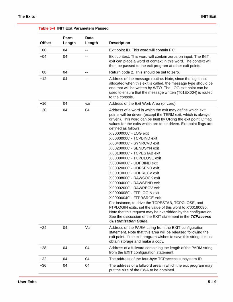
The Exits INIT Exit
Table 5-4 INIT Exit Parameters Passed
OffsetParm Length
Data Length Description
+00 04 -- Exit point ID. This word will contain F’0’.
+04 04 -- Exit context. This word will contain zeros on input. The INIT exit can place a word of context in this word. The context will then be passed to the exit program at other exit points.
+08 04 -- Return code 2. This should be set to zero.
+12 04 -- Address of the message routine. Note, since the log is not allocated when this exit is called, the message type should be one that will be written by WTO. The LOG exit point can be used to ensure that the message written (T01EX004) is routed to the console.
+16 04 var Address of the Exit Work Area (or zero).
+20 04 04 Address of a word in which the exit may define which exit points will be driven (except the TERM exit, which is always driven). This word can be built by ORing the exit point ID flag values for the exits which are to be driven. Exit point flags are defined as follows:X'80000000‘ - LOG exitX'00800000' - TCPBIND exitX'00400000' - SYNRCVD exitX'00200000' - SENDSYN exitX'00100000' - TCPESTAB exitX'00080000' - TCPCLOSE exitX'00040000' - UDPBIND exitX'00020000' - UDPSEND exitX'00010000' - UDPRECV exitX'00008000' - RAWSOCK exitX'00004000' - RAWSEND exitX'00002000' - RAWRECV exitX'00000080' - FTPLOGIN exitX'00000040' - FTPRSRCE exitFor instance, to drive the TCPESTAB, TCPCLOSE, and FTPLOGIN exits, set the value of this word to X'00180080'. Note that this request may be overridden by the configuration. See the discussion of the EXIT statement in the TCPaccess Customization Guide.
+24 04 Var Address of the PARM string from the EXIT configuration statement. Note that this area will be released following the exit point. If the exit program wishes to save this string, it must obtain storage and make a copy.
+28 04 04 Address of a fullword containing the length of the PARM string from the EXIT configuration statement.
+32 04 04 The address of the four-byte TCPaccess subsystem ID.
+36 04 04 The address of a fullword area in which the exit program may put the size of the EWA to be obtained.
User Exits 5 – 9

INIT Exit The Exits
+40 04 04 The address of a fullword area in which the exit program may put the address of a recovery routine to be called in the event the exit program ABENDs at a subsequent entry point.
+44 04 04 Four-byte product version in C’0v0r’ format. For example, Release 5.2 would be x’F0F5F0F2’
+48 04 32 MF subtype mask. Each bit in the mask corresponds to an SMF record subtype 0-255. If the SMF exit point is requested, the exit can turn on those bits corresponding to the SMF record subtypes for which it wishes to gain control. The SMF exit point will be called for these subtypes, in addition to any SMF subtypes configured on the SMF statement in IJTCFGxx. Turning on a bit will only cause the exit point to be driven; it will not affect whether the record will be written to the SMF data set.
OffsetParm Length
Data Length Description
5 – 10 Network IT™ TCPaccess Planning Guide

The Exits SMF exit
SMF exit
Exit point: When an SMF record is about to be written.
Function: Allow or suppress writing the record.
Addressing Mode: 31
Dispatchable Unit: Task mode or SRB mode.
Restrictions: Normal restrictions for SRB-mode processing. No SVCs may be issued.
Register Contents at Entry:
Register Contents on Return:
SMFEXIT Exit Parameters Passed:
R00 Exit point Id
R01 Parameter list address
R02-R12 Zeros
R13 Save area address
R14 Return address
R15 Entry point address
R00-R12 Undefined
R13 Restored
R14 Undefined
R15 Return Code 1
Offset Parm Length
Data Length
Description
+00 04 -- Exit point Id. This word will contain F’22’.
+04 04 -- Exit context.
+08 04 -- Return code 2. This should be set to one of the following:00 - Write the record04 - Do not write the record.
+12 04 -- Address of the message routine.
+16 04 -- Address of the exit work area
+20 04 08 Address of the SMF record
User Exits 5 – 11

TERM Exit The Exits
TERM Exit
Exit Point: TCPaccess shutdown.
Function: The exit is called synchronously at shutdown. It can be used to terminate the exit environment and clean up.
Addressing Mode: 31
Dispatchable Unit: Task mode (TCB)
Restrictions: The exit should not block indefinitely.
Register Contents at Entry:
Register Contents on Return:
Table 5-5 TERM Exit Parameters Passed
R00 Exit point ID
R01 Parameter list address
R02-R12 Zeros
R13 Save area address
R14 Return address
R15 Entry point address
R00-R12 Undefined
R13 Restored
R14 Undefined
R15 Zero
OffsetParm Length
Data Length Description
+00 04 -- Exit point ID. This word will contain F’1’.
+04 04 -- Exit context.
+08 04 -- Return code 2. This should be left unchanged.
+12 04 -- Address of the message routine.
+16 04 var Address of the Exit Work Area (or zero)
5 – 12 Network IT™ TCPaccess Planning Guide
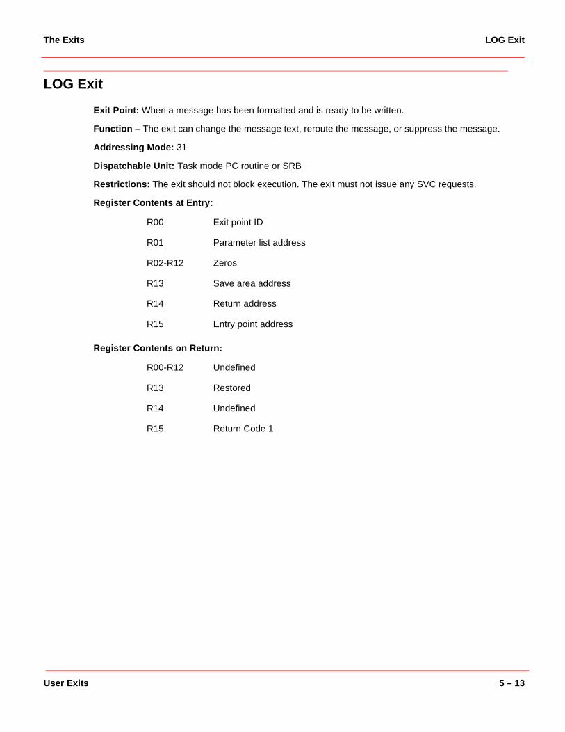
The Exits LOG Exit
LOG Exit
Exit Point: When a message has been formatted and is ready to be written.
Function – The exit can change the message text, reroute the message, or suppress the message.
Addressing Mode: 31
Dispatchable Unit: Task mode PC routine or SRB
Restrictions: The exit should not block execution. The exit must not issue any SVC requests.
Register Contents at Entry:
Register Contents on Return:
R00 Exit point ID
R01 Parameter list address
R02-R12 Zeros
R13 Save area address
R14 Return address
R15 Entry point address
R00-R12 Undefined
R13 Restored
R14 Undefined
R15 Return Code 1
User Exits 5 – 13

LOG Exit The Exits
Table 5-6 LOG Exit Parameters Passed
OffsetParm Length
Data Length Description
+00 04 -- Exit point ID. This word will contain F’2’.
+04 04 -- Exit context.
+08 04 -- Return code 2. This should be left unchanged. To suppress the message, set the message routing code to zero (see below).
+12 04 -- Zeroes.
+16 04 var Address of the Exit Work Area (or zero).
+20 04 var Address of the message text. The text may be changed by the exit.
+24 04 04 Address of a word containing the message buffer length. (This value should not be changed; the message cannot be made any longer than this length. To shorten the message, pad to the right with blanks.)
+28 04 04 Address of a word containing a message routing code:X'00000000' = Do not issue messageX'00000004' = Write message to logX'00000008' = Write message to the operator console (WTO) X'0000000C' = Write to log and console. This word may be changed by the exit to change the routing for the message. To suppress the message, set this word to zero.
5 – 14 Network IT™ TCPaccess Planning Guide

The Exits VTAMBIND Exit
VTAMBIND Exit
Exit point: When a BIND RU is received by the TN3270E server.
Function: Allow or reject the BIND request.
Addressing Mode: 31
Dispatchable Unit: SRB mode (the VTAM SCIP exit).
Restrictions: Normal restrictions for SRB-mode processing. No SVCs may be issued.
Register Contents at Entry:
Register Contents on Return:
R00 Exit point Id
R01 Parameter list address
R02-R12 Zeros
R13 Save area address
R14 Return address
R15 Entry point address
R00-R12 Undefined
R13 Restored
R14 Undefined
R15 Return Code 1
User Exits 5 – 15

VTAMBIND Exit The Exits
Table 5-7 VTAMBIND Exit Parameters Passed
OffsetParm Length
Data Length Description
+00 04 -- Exit point ID. This word will contain F’21’.
+04 04 -- Exit context.
+08 04 -- Return code 2. This should be set to one of the following:00 – Accept the BIND04 – Reject the BIND.
+12 04 -- Address of the message routine.
+16 04 08 Address of the local host AF_Inet
+20 04 08 Address of the remote host AF_Inet
+24 04 08 Address of the User ID.
+28 04 04 Address of the TCP session number.
+32 04 08 Addres of the SLU name.
+36 04 08 Address of the PLU name.
+40 04 08 Address of the requested application.
+44 04 36 Address of the first 36 bytes of the BIND image (mapped by ISTDBIND).
5 – 16 Network IT™ TCPaccess Planning Guide

The Exits Stack Exits
Stack Exits
This section describes the stack exits. These are exit points in TCP, UDP, and RAW IP processing. These exits can be called in SRB mode or in cross-memory PC mode, and must not issue any SVCs. No assumptions should be made about the cross- memory environment. Home, primary, and secondary address spaces may all differ.
In most cases, these exits can reject a request. All can issue a message, and all have access to the exit context.
The parameter list in each case is similar. In each case, the addresses of the local host address and the remote host address is provided. This will be eight bytes, in standard AF_Inet form:
Not all of these fields will be filled in for every exit point. For instance, at the bind exit point, only the local port number will be filled in.
Each stack exit will also be passed the address of a 24-byte user identification area. This area identifies the cross-memory TLI, OpenEdition (UNIX System Services), or IUCV user. The format will be as follows:
Offset Length Field
00 02 Address Family
02 02 Port number (hexadecimal)
04 04 IP address (hexadecimal)
Offset Length Field
00 08 Jobname
08 08 Stepname
16 08 Procstepname
User Exits 5 – 17

TCPBIND Exit The Exits
TCPBIND Exit
Exit Point: When a TCP bind request is received.
Function: This exit can accept or reject the request.
Addressing Mode: 31.
Dispatchable Unit: Task mode PC or SRB mode.
Restrictions: The exit should not block execution. The exit must not issue any SVC requests.
Register Contents at Entry:
Register Contents on Return:
Table 5-8 TCPBIND Exit Parameters Passed
R00 Exit point ID
R01 Parameter list address
R02-R12 Zeros
R13 Save area address
R14 Return address
R15 Entry point address
R00-R12 Undefined
R13 Restored
R14 Undefined
R15 Return Code 1
OffsetParm Length
Data Length Description
+00 04 -- Exit point ID. This word will contain F’3’.
+04 04 -- Exit context.
+08 04 -- Return code 2.
+12 04 -- Address of the message routine.
+16 04 var Address of the Exit Work Area (or zero).
+20 04 08 Address of the local host AF_Inet.
+24 04 08 Address of the remote host AF_Inet.
+28 04 24 Address of the User Identification.
5 – 18 Network IT™ TCPaccess Planning Guide

The Exits SYNRCVD Exit
SYNRCVD Exit
Exit point: When a TCP connection request (syn packet) is received.
Function: This exit can accept or reject the request.
Addressing Mode: 31
Dispatchable Unit: Task mode PC or SRB mode.
Restrictions: The exit should not block execution. The exit must not issue any SVC requests.
Register Contents at Entry:
Register Contents on Return:
Table 5-9 SYNRCVD Exit Parameters Passed
R00 Exit point ID
R01 Parameter list address
R02-R12 Zeros
R13 Save area address
R14 Return address
R15 Entry point address
R00-R12 Undefined
R13 Restored
R14 Undefined
R15 Return Code 1
OffsetParm Length
Data Length Description
+00 04 -- Exit point ID. This word will contain F’4’.
+04 04 -- Exit context.
+08 04 -- Return code 2.
+12 04 -- Address of the message routine.
+16 04 var Address of the Exit Work Area (or zero).
+20 04 08 Address of the local host AF_Inet.
+24 04 08 Address of the remote host AF_Inet.
+28 04 24 Address of the User Identification.
User Exits 5 – 19

SENDSYN Exit The Exits
SENDSYN Exit
Exit Point: When a TCP connection request (syn packet) is about to be sent to a remote host.
Function: This exit can accept or reject the request.
Addressing Mode: 31
Dispatchable Unit: Task mode PC or SRB mode.
Restrictions: The exit should not block execution. The exit must not issue any SVC requests.
Register Contents at Entry:
Register Contents on Return:
Table 5-10 SENDSYN Exit Parameters Passed
R00 Exit point ID
R01 Parameter list address
R02-R12 Zeros
R13 Save area address
R14 Return address
R15 Entry point address
R00-R12 Undefined
R13 Restored
R14 Undefined
R15 Return Code 1
OffsetParm Length
Data Length Description
+00 04 -- Exit point ID. This word will contain F’5’.
+04 04 -- Exit context.
+08 04 -- Return code 2.
+12 04 -- Address of the message routine.
+16 04 var Address of the Exit Work Area (or zero).
+20 04 08 Address of the local host AF_Inet.
+24 04 08 Address of the remote host AF_Inet.
+28 04 24 Address of the User Identification.
5 – 20 Network IT™ TCPaccess Planning Guide

The Exits TCPESTAB Exit
TCPESTAB Exit
Exit Point: When a new TCP connection is fully established.
Function: This exit point is intended for information only. The exit cannot reject the connection at this point.
Addressing Mode: 31
Dispatchable Unit: Task mode or SRB mode.
Restrictions: The exit should not block execution. The exit must not issue any SVC requests.
Register Contents at Entry:
Register Contents on Return:
Table 5-11 TCPESTAB Exit Parameters Passed
R00 Exit point
R01 Parameter list address
R02-R12 Zeros
R13 Save area address
R14 Return address
R15 Entry point address
R00-R12 Undefined
R13 Restored
R14 Undefined
R15 Return Code 1
OffsetParm length
Data length Description
+00 04 -- Exit point ID. This word will contain F’6’.
+04 04 -- Exit context.
+08 04 -- Return code 2.
+12 04 -- Address of the message routine.
+16 04 var Address of the Exit Work Area (or zero).
+20 04 08 Address of the local host AF_Inet.
+24 04 08 Address of the remote host AF_Inet.
+28 04 24 Address of the User Identification.
User Exits 5 – 21

TCPCLOSE Exit The Exits
TCPCLOSE Exit
Exit Point: When a TCP connection is closed. This exit will be called when a partly- or fully-established TCP connection is closed. It is not called when a listening TCP endpoint is closed. If a connection request (syn) has been received, or a connection request has been sent, the TCPCLOSE exit will be called when the connection is closed. Either the SYNRCVD or SENDSYN exit will have been called. The TCPESTAB exit may or may not have been called for the connection.
Function: This exit point is intended for information only. The exit cannot reject the connection at this point.
Addressing Mode: 31
Dispatchable Unit: Task mode or SRB mode.
Restrictions: The exit should not block execution. The exit must not issue any SVC requests.
Register Contents at Entry:
Register Contents on Return:
Table 5-12 TCPCLOSE Exit Parameters Passed
R00 Exit point
R01 Parameter list address
R02-R12 Zeros
R13 Save area address
R14 Return address
R15 Entry point address
R00-R12 Undefined
R13 Restored
R14 Undefined
R15 Return Code 1
OffsetParm length
Data length Description
+00 04 -- Exit point ID. This word will contain F’7’.
+04 04 -- Exit context.
+08 04 -- Return code 2.
+12 04 -- Address of the message routine.
+16 04 var Address of the Exit Work Area (or zero).
+20 04 08 Address of the local host AF_Inet.
+24 04 08 Address of the remote host AF_Inet.
+28 04 24 Address of the User Identification.
5 – 22 Network IT™ TCPaccess Planning Guide

The Exits UDPBIND Exit
UDPBIND Exit
Exit Point: When a UDP bind request is received.
Function: This exit can accept or reject the request.
Addressing Mode: 31.
Dispatchable Unit: Task mode PC or SRB mode.
Restrictions: The exit should not block execution. The exit must not issue any SVC requests.
Register Contents at Entry:
Register Contents on Return:
Table 5-13 UDPBIND Exit Parameters Passed
R00 Exit point ID
R01 Parameter list address
R02-R12 Zeros
R13 Save area address
R14 Return address
R15 Entry point address
R00-R12 Undefined
R13 Restored
R14 Undefined
R15 Return Code 1
OffsetParm Length
Data Length Description
+00 04 -- Exit point ID. This word will contain F’8’.
+04 04 -- Exit context.
+08 04 -- Return code 2.
+12 04 -- Address of the message routine.
+16 04 var Address of the Exit Work Area (or zero).
+20 04 08 Address of the local host AF_Inet.
+24 04 08 Address of the remote host AF_Inet.
+28 04 24 Address of the User Identification.
User Exits 5 – 23

UDPSEND Exit The Exits
UDPSEND Exit
Exit Point: When a UDP datagram is about to be sent.
Function: This exit can accept or reject the request.
Addressing Mode: 31
Dispatchable Unit: Task mode PC or SRB mode.
Restrictions: The exit should not block execution. The exit must not issue any SVC requests.
Register Contents at Entry:
Register Contents on Return:
Table 5-14 UDPSEND Exit Parameters Passed
R00 Exit point ID
R01 Parameter list address
R02-R12 Zeros
R13 Save area address
R14 Return address
R15 Entry point address
R00-R12 Undefined
R13 Restored
R14 Undefined
R15 Return Code 1
OffsetParm Length
Data Length Description
+00 04 -- Exit point ID. This word will contain F’9’.
+04 04 -- Exit context.
+08 04 -- Return code 2. The exit can set this word to a non-zero value to abort the send.
+12 04 -- Address of the message routine.
+16 04 var Address of the Exit Work Area (or zero).
+20 04 08 Address of the local host AF_Inet.
+24 04 08 Address of the remote host AF_Inet.
+28 04 24 Address of the User Identification.
5 – 24 Network IT™ TCPaccess Planning Guide

The Exits UDPRECV Exit
UDPRECV Exit
Exit Point: When a UDP datagram has been received.
Function: This exit can accept or reject the request.
Addressing Mode: 31
Dispatchable Unit: Task mode PC or SRB mode.
Restrictions: The exit should not block execution. The exit must not issue any SVC requests.
Register Contents at Entry:
Register Contents on Return:
Table 5-15 UDPRECV Exit Parameters Passed
R00 Exit point ID
R01 Parameter list address
R02-R12 Zeros
R13 Save area address
R14 Return address
R15 Entry point address
R00-R12 Undefined
R13 Restored
R14 Undefined
R15 Return Code 1
OffsetParm Length
Data Length Description
+00 04 -- Exit point ID. This word will contain F’10’.
+04 04 -- Exit context.
+08 04 -- Return code 2. The exit can set this word to a non-zero value to reject the datagram.
+12 04 -- Address of the message routine.
+16 04 var Address of the Exit Work Area (or zero).
+20 04 08 Address of the local host AF_Inet.
+24 04 08 Address of the remote host AF_Inet.
+28 04 24 Address of the User Identification.
User Exits 5 – 25

RAWSOCK Exit The Exits
RAWSOCK Exit
Exit Point: When a RAW socket request has been received.
Function: This exit can accept or reject the request.
Addressing Mode: 31
Dispatchable Unit: Task mode PC or SRB mode.
Restrictions: The exit should not block execution. The exit must not issue any SVC requests.
Register Contents at Entry:
Register Contents on Return:
Table 5-16 RAWSOCK Exit Parameters Passed
R00 Exit point ID
R01 Parameter list address
R02-R12 Zeros
R13 Save area address
R14 Return address
R15 Entry point address
R00-R12 Undefined
R13 Restored
R14 Undefined
R15 Return Code 1
OffsetParm Length
Data Length Description
+00 04 -- Exit point ID. This word will contain F’11’.
+04 04 -- Exit context.
+08 04 -- Return code 2. The exit can set this word to a non-zero value to reject the request.
+12 04 -- Address of the message routine.
+16 04 var Address of the Exit Work Area (or zero).
+20 04 08 Address of the local host AF_Inet.
+24 04 08 Address of the remote host AF_Inet.
+28 04 24 Address of the User Identification.
5 – 26 Network IT™ TCPaccess Planning Guide

The Exits RAWSEND Exit
RAWSEND Exit
Exit Point: When a RAW IP datagram is about to be sent.
Function: This exit can accept or reject the request.
Addressing Mode: 31
Dispatchable Unit: Task mode PC or SRB mode.
Restrictions: The exit should not block execution. The exit must not issue any SVC requests.
Register Contents at Entry:
Register Contents on Return:
R00 Exit point ID
R01 Parameter list address
R02-R12 Zeros
R13 Save area address
R14 Return address
R15 Entry point address
R00-R12 Undefined
R13 Restored
R14 Undefined
R15 Return Code 1
User Exits 5 – 27

RAWSEND Exit The Exits
Table 5-17 RAWSEND Exit Parameters Passed
Note: If you need additional information, refer to the mapping macro in the SAMP library.
OffsetParm Length
Data Length Description
+00 04 -- Exit point ID. This word will contain F’12’.
+04 04 -- Exit context.
+08 04 -- Return code 2. The exit can set this word to a non-zero value to abort the send.
+12 04 -- Address of the message routine.
+16 04 var Address of the Exit Work Area (or zero).
+20 04 08 Address of the local host AF_Inet.
+24 04 08 Address of the remote host AF_Inet.
+28 04 24 Address of the User Identification.
5 – 28 Network IT™ TCPaccess Planning Guide

The Exits RAWRECV Exit
RAWRECV Exit
Exit Point: When a RAW IP datagram has been received.
Function: This exit can accept or reject the datagram.
Addressing Mode: 31
Dispatchable Unit: Task mode PC or SRB mode.
Restrictions: The exit should not block execution. The exit must not issue any SVC requests.
Register Contents at Entry:
Register Contents on Return:
Table 5-18 RAWRECV Exit Parameters Passed
R00 Exit point ID
R01 Parameter list address
R02-R12 Zeros
R13 Save area address
R14 Return address
R15 Entry point address
R00-R12 Undefined
R13 Restored
R14 Undefined
R15 Return Code 1
OffsetParm Length
Data Length Description
+00 04 -- Exit point ID. This word will contain F’13’.
+04 04 -- Exit context.
+08 04 -- Return code 2. The exit can set this word to a non-zero value to reject the datagram.
+12 04 -- Address of the message routine.
+16 04 var Address of the Exit Work Area (or zero).
+20 04 08 Address of the local host AF_Inet.
+24 04 08 Address of the remote host AF_Inet.
+28 04 24 Address of the User Identification.
User Exits 5 – 29

FTP Exits The Exits
FTP Exits
Following are the FTP exit points. These exits are invoked in task mode, but MUST NOT block execution on the TCB.
These exits can be used to issue a message or reject an access request.
Note: The SMFEXIT should be used in place of an FTP termination exit. The SMF exit is called just before an SMF record is written for an FTP session that is ending. Read “SMF exit” on page 5-11 for more information.
FTPCMND Exit
Exit Point: When an FTP command is received by the FTP server.
Function:At this exit point, the exit program can accept or reject the command. If the command is rejected, an FTP error reply will be sent.
Addressing Mode: 31
Dispatchable Unit: Task mode.
Restrictions: The exit program must not block execution.
Register Contents at Entry:
Register Contents on Return:
R00 Exit point
R01 Parameter list address
R02-R12 Zeros
R13 Save area address
R14 Return address
R15 Entry point address
R00-R12 Undefined
R13 Restored
R14 Undefined
R15 Return Code 1
5 – 30 Network IT™ TCPaccess Planning Guide

The Exits FTPCMND Exit
Table 5-19 FTPCMND Exit Parameters Passed
OffsetParm Length
Data Length Description
+00 04 -- Exit point ID. This word will contain F’16’.
+04 04 -- Exit context.
+08 04 -- Return code 2. The exit can set this word to a non-zero value to reject the command.
+12 04 -- Address of the message routine.
+16 04 Variable Address of the Exit Work Area
+20 04 08 Address of the local host AF_Inet value.
+24 04 08 Address of the remote host AF_Inet value.
+28 04 08 Address of the User ID.
+32 04 08 Address of the 8-byte userid of the user logged in.
+36 04 08 Address of the 8-byte command received by the FTP server.
+40 04 80 Address of an 80-byte area in which the exit program may optionally place the halfword length (maximum 78 bytes) of the reply text, followed by the text. If the command is rejected by the exit, and the reply text length is non-zero upon return from the exit, the FTP server will append the text provided to an FTP error reply. Otherwise, the reply will be “500 xxxx command rejected by user exit”.
User Exits 5 – 31

FTPLOGIN Exit The Exits
FTPLOGIN Exit
Exit Point: When an FTP user is logging in (when the PASS or ACCT command is received). The exit is called before the SAF router is called to log the user on.
Function: This exit can accept or reject the request.
Addressing Mode: 31
Dispatchable Unit: Task mode.
Restrictions: The exit must not block execution.
Register Contents at Entry:
Register Contents on Return:
Table 5-20 FTPLOGIN Exit Parameters Passed
R00 Exit point
R01 Parameter list address
R02-R12 Zeros
R13 Save area address
R14 Return address
R15 Entry point address
R00-R12 Undefined
R13 Restored
R14 Undefined
R15 Return Code 1
OffsetParm Length
Data Length Description
+00 04 -- Exit point ID. This word will contain F’14’.
+04 04 -- Exit context.
+08 04 -- Return code 2. The exit can set this word to a non-zero value to reject the login.
+12 04 -- Address of the message routine.
+16 04 var Address of the Exit Work Area (or zero).
+20 04 08 Address of the local host AF_Inet.
+24 04 08 Address of the remote host AF_Inet.
+28 04 08 Address of the User ID.
5 – 32 Network IT™ TCPaccess Planning Guide

The Exits FTPRSRCE Exit
FTPRSRCE Exit
Exit Point: When an FTP user has requested an operation which will result in a data set resource allocation. This exit is called before the SAF router is invoked to verify the user’s access authority.
Function: This exit can accept or reject the request.
Addressing Mode: 31
Dispatchable Unit: Task mode.
Restrictions: The exit must not block execution.
Register Contents at Entry:
Register Contents on Return:
R00 Exit point ID
R01 Parameter list address
R02-R12 Zeros
R13 Save area address
R14 Return address
R15 Entry point address
R00-R12 Undefined
R13 Restored
R14 Undefined
R15 Return Code 1
User Exits 5 – 33

FTPRSRCE Exit The Exits
Table 5-21 FTPRSRCE Exit Parameters Passed
Note: See the mapping macro in the SAMP library for additional information.
OffsetParm Length
Data Length Description
+00 04 -- Exit point ID. This word will contain F’15’.
+04 04 -- Exit context.
+08 04 -- Return code 2. The exit can set this word to a non-zero value to reject the request.
+12 04 -- Address of the message routine.
+16 04 var Address of the Exit Work Area (or zero).
+20 04 08 Address of the local host AF_Inet.
+24 04
04
52
1024
MVS: Address of the 44-byte dataset name, followed by an 8-byte member name (or blanks).HFS: Address of the file name (1024 bytes, padded on the right with blanks).
+28 04 52 Address of the 44-byte dataset name, followed by an eight-byte member name (or blanks).
+32 04 06 Address of the volume serial number, or blanks.
+36 04 01 Address of a one-byte field identifying the authorization request type:X'40' - ReadX'20' - WriteX'10' - Alter
+40 04 02 Address of a two-byte field identifying the FTP operation type:X'8000' - HELP commandX'4000' - STAT command (Statistics)X'2000' - STOR command (Store)X'1000' - APPE command (Append)X'0800' - RETR command (Retrieve)X'2400' - STOU command (Store Unique)X'0200' - LIST command (Directory list)X'0100' - NLST command (Directory list)X'0080' - RNTO command (Rename)X'0040' - DELE command (Delete)X'0020' - Special PDS directory allocation for LIST/NLST.X'0010' - MKD command (Make Directory)
+44 04 var Address of the ACEE. The ACEE is mapped by macro IHAACEE. Its length is in the ACEELEN field.
5 – 34 Network IT™ TCPaccess Planning Guide

Converting from TCPX0001 and TCPX0002 Programming Limitations
Converting from TCPX0001 and TCPX0002
Users of prior releases of TCPaccess who have coded exits TCPX0001 and TCPX0002 to control inbound and outbound TCP connection requests, can use the SYNRCVD and SENDSYN exit points in this release of TCPaccess to accomplish the same purpose. The exit programs will have to be modified to conform to the new exit facility.
The following is a brief guide to help you modifying exits TCPX0001 and TCPS0002.
Programming Limitations
The SYNRCVD and SENDSYN exits will be called in either SRB mode or cross-memory stacking PC mode, and are subject to the restrictions imposed by those environments. Supervisor calls (SVCs) are not allowed.
Exit Parameter List
The XITDEPL macro is not supported. The exit parameter lists vary among exit points. Use the T00DEXPL macro to map the parameter lists.
Program Entry
The XITMENT macro is not supported. Instead, use standard linkage conventions for saving registers and establishing addressability. General register 13 will contain the address of an 18 fullword register save area on entry to all exit points. Registers 14 and 15 contain the return address and entry point address of the exit program. The exit program may use all registers; it is not necessary to maintain the contents of any register during execution.
Program Exit
The XITMRET macro is not supported. Use standard linkage conventions to return to the exit facility. It is not necessary to restore any registers except register 13 before return to the exit facility. Place the return code in register 15 before returning.
Obtaining Storage
The XITMFUNC GETMEM and FREEMEM services are not supported. Use STORAGE OBTAIN/RELEASE to obtain and release storage. Do not use GETMAIN/FREEMAIN, as these macros generate SVC calls.
User Exits 5 – 35

Writing Messages Converting from TCPX0001 and TCPX0002
Writing Messages
The XITMFUNC WRITELOG function is not supported. Instead, the address of a message service routine is passed to the exit as part of the parameter list. To issue a message, call this routine using standard linkage conventions. Provide in register 1 the address of an 81-byte field in the form:
CL1’message_severity’,CL80’message_text’
See the “Overview of Messages” chapter in the TCPaccess Prefixed Messages manual for a list of the message severities.
Tracing
The XITMFUNC TRACE function is not supported. A trace entry is written at entry to and return from each exit program. No facility exists for exit programs to write trace entries to the TCPaccess internal trace table.
Setting Return Values
The XITMSET macro is not supported. Where appropriate, the exit parameter lists can be updated directly by the exit program. It is important to note that, unlike TCPX0001 and TCPX0002, multiple exit programs can be run at each exit point. The value returned in general register 15 (return code 1) determines whether subsequent exit(s) will be called at that entry point. The value returned in the return code field in the parameter list (return code 2) determines whether the request is allowed or rejected. Set this field to a non-zero value to cause the request to be rejected.
Note: If the return code 2 value is non-zero on entry to the exit, it indicates that another exit program at that exit point determined to reject the request. Setting the return code 2 field from a non-zero value to a zero will effectively reverse the decision of a previous exit. Use care in setting the return code 2 value.
Exit Naming Conventions
There is no restriction placed on the name of the exit program(s).
Dependencies Between Exits
As with TCPX0001 and TCPX0002, exit programs should not assume that an earlier exit point was called, or that it was successful. The exit context word is provided at each exit point to allow the exit program to communicate across exit points.
5 – 36 Network IT™ TCPaccess Planning Guide
AEditing Tools For Installation
This chapter describes the some edits you must make before installing sc and how to use the tools necessary for these editions.
It covers the following subjects:
• “Setting Up the SMP Environment” on page A-2
Describes how to allocate common load data sets.
• “Making Global Changes with the ISPF Editor” on page A-2
Describes how to use the ISPF editor to edit the ALLOCSMP job.
• “Updating the TCPNAMES ISPF Edit Clist” on page A-3
Describes how to edit the TCPNAMES member in the CNTL data set to globally change strings used by the ALLOCxxx job streams.
Editing Tools For Installation A – 1

Setting Up the SMP Environment
Setting Up the SMP Environment
The first time you install TCPaccess, you must set up the SMP environment. To do this, you must edit some of the members to allocate common load data sets.
There are two ways to allocate the common data sets:
• Use the OpenEdition change command in the ISPF editor
• Invoke the TCPNAMES Clist
Globally edit the following symbols using values appropriate for your system configuration:
All TCPaccess software products require that a common environment be established for their installation. The process comprises these tasks:
• Allocating and initializing the SMP and common data sets for TCPaccess
• Allocating product-dependent data sets for optional products
Making Global Changes with the ISPF Editor
This is the format of the global change command if you are using the ISPF editor to edit the ALLOCSMP job:
c ‘old_string’ ‘new_string’ all
To change the string SMPINDX to TCPACSS, enter this command:
c ‘SMPINDX’ ‘TCPACSS’ all
If you are changing the HOLDCL symbol to an asterisk in order to use the same SYSOUT class as specified on the JOB statement MSGCLASS parameter, make sure the asterisk is enclosed in single quotes in your global change command, as this command illustrates:
c ‘HOLDCL’ ‘*’ all
CAUTION ! Do not modify job ALLOCSMP to use a predefined Consolidated Software Inventory (CSI) in which other software products are installed. That is, TCPaccess software products must be installed in their own target and distribution zones.
Note: Expect return code 0 from each step of ALLOCSMP.
HOLDCL DSTINDX DSTUNIT
DSTVOL LNKINDX SMPINDX
SMPUNIT SMPVOL TLBUNIT
TLBVOL TRGINDX TRGUNIT
TRGVOL
A – 2 Network IT™ TCPaccess Planning Guide

Updating the TCPNAMES ISPF Edit Clist
Updating the TCPNAMES ISPF Edit Clist
TCPNAMES is an ISPF Edit Clist in the CNTL data set. TCPNAMES globally changes all the strings used by the ALLOCxxx job streams. TCPNAMES inserts a jobcard and updates the job with your local variables.
The TCPNAMES Clist requires ISPF Version 2 or higher. If the TCPNAMES Clist is used as distributed, all data sets must have the same high-level qualifier except for the LINK data set, which is prefixed by SYS1. plus the high-level qualifier used for the other data sets.
1. Edit the JOBCARD member in the CNTL data set, changing the JOB statement to match your site’s requirements.
2. Copy member TCPNAMES to a fixed length record format Clist data set that is in your TSO SYSPROC DD concatenation.
3. As you edit the ALLOCxxx and other installation members, update the variables in the ALLOCxxx job with the parameters passed through this TCPNAMES command:
The syntax is:
TCPNAMES high_level disk_vol disk_unit tape_vol tape_unit
Usage Notes:
Always run the Clist TCPNAMES from the command line of the member for every job prior to submitting the job.
If the high-level qualifier you are using is TCPACSS, the disk volume serial number is MVS001, the disk unit type is 3390, the tape volume serial number is TCPACSS, and the tape unit is TAPE, then use this primary line command to update variables:
TCPNAMES TCPACSS.Vxxx MVS001 3390 TAPE
This changes all the strings that need to be changed in the job and replaces the JOB statement with the one in the JOBCARD member.
Note: To run the ALLOCxxx jobs, it is not necessary to substitute variables for the tape_vol or tape_unit parameters. They are used in INSTSMPE.
CAUTION ! Whenever you make changes to any SYS1.PARMLIB member, make sure you can perform an IPL on your system using an alternate IPL volume or an alternate SYS1.PARMLIB member. Typographical errors can cause catastrophic errors during system initialization, leaving your MVS system in an unusable state.
TCPNAMES Is the command to use to edit the TCPNAMES Clist.
high_level Indicates the data set high-level qualifier.
disk_vol Specifies the disk volume where the data sets are to be created.
disk_unit Indicates the disk unit type of the volume.
tape_vol Specifies the volume serial number of the installation tape.
tape_unit Indicates the address of the tape unit to which the installation tape will be assigned.
Editing Tools For Installation A – 3

Updating the TCPNAMES ISPF Edit Clist
A – 4 Network IT™ TCPaccess Planning Guide

BConfiguring TCPaccess for Cisco Routers
This guide provides information to help you with the setup and configuration of TCPaccess with Cisco 7000 and 7500 routers. It also includes the steps necessary to configure the software for use with GateD Fault Tolerant and Virtual IP Addressing (VIPA).
The following sections are included.
• “Overview” on page B-2
A brief description of the configuration of TCPaccess with Cisco routers.
• “IOGEN Information” on page B-3
Describes the configuration statements to define your Cisco 7000/7500 series router to MVS.
• “Configuring the Interface” on page B-6
Describes the configuration changes to define your Cisco 7000/7500 series router to work with TCPaccess.
• “Configuring the Router” on page B-10
Describes the configuration changes to define your Cisco 7000/7500 series router to work with TCPaccess.
• “Fault Tolerant Considerations” on page B-13
Describes the configuration changes to enable the GateD Fault Tolerant feature of TCPaccess.
• “RIP/OSPF Changes for the CIP Router” on page B-17
Describes the configuration changes to make your Cisco 7000/7500 series router work in the GateD Fault Tolerant environment with TCPaccess.
• “GateD Fault Tolerant With VIPA” on page B-20
Describes the configuration changes to enable the VIPA feature to work with GateD.
• “Example” on page B-21
Provides examples of some of the configurations described in this document.
Configuring TCPaccess for Cisco Routers B – 1

Additional References Overview
Overview
TCPaccess communicates with Cisco 7000 and 7500 series routers using the Common Link Access to Workstation (CLAW) channel protocol through either an Enterprise Systems Connection (ESCON) or Parallel Channel connected to a CIP card that is installed in the router.
Once a physical connection has been established, MVS must be configured to recognize the CIP and to define a series of subchannels on which the CLAW protocol is used to communicate between TCPaccess and the Cisco 7000/7500 series router. This configuration is performed by adding statements to your MVS input/output configuration program (IOCP) as described in the “IOGEN Information” on page B-3 section of this manual.
In addition to MVS configuration, both TCPaccess and the Cisco 7000/7500 router must also be configured. The configuration for TCPaccess is performed by adding statements to your TCP configuration member as described in the “Configuring the Interface” on page B-6 section of this manual. This configuration defines the association between MVS and TCPaccess, giving it access to the physical device.
The configuration for the Cisco 7000/7500 router is performed by issuing configuration commands to the router as described in the “Configuring the Router” on page B-10 section of this manual. These commands provide the final configuration necessary to complete the communications path between TCPaccess and the Cisco 7000/7500 router.
This guide includes information for the following configurations:
• Single Channel Interface Processor (CIP) interface
• Multiple CIP Interfaces
• Multiple CIP interfaces with GateD Fault Tolerant
• Multiple CIP interfaces with GateD Fault Tolerant and VIPA
The steps provided in this guide assume the following:
• Cisco 7000 or 7500 series routers are installed and integrated into the current network.
• CIP cards are already installed, but the MVS input/output generation (IOGEN) has not been completed.
• TCPaccess is installed and set up to work in loopback.
Additional References
For additional information, read the following documents:
• TCPaccess Customization Guide
• Bridging and IBM Networking Configuration Guide
• Bridging and IBM Networking Command Reference
• Network Protocols Command Reference, Part 1
• Network Protocols Configuration Guide, Part 1
B – 2 Network IT™ TCPaccess Planning Guide

IOGEN Information Parallel Channel-attached Routers
IOGEN Information
This section describes the configuration statements necessary to define Cisco 7000 and 7500 series routers to MVS.
Before you install TCPaccess, you must define the hardware interfaces needed to support the product. The I/O and IOCP generations define the devices used by TCPaccess to access the network.
Note: TCPaccess communicates with a CIP using the CLAW channel protocol. Each CLAW connection requires two adjacent subchannel addresses.
Parallel Channel-attached Routers
This section describes the MVS definition instructions for Cisco 7000 and 7500 routers that are connected to the mainframe via parallel channel CIPs. It defines all parallel channel interfaces for TCPaccess running the CLAW protocol.
MVSCP for Parallel Channel CIPs
Use the following statement to define the parallel channel-attached Cisco 7000 and 7500 series router for system generation for the Multiple Virtual System Configuration Program (MVSCP):
IODEVICE UNIT=CTC,ADDRESS=(aaa,n)
Syntax Description
aaa Base address.
n Number of subchannel addresses to be defined. Refer to the appropriate IBM system generation manual for more information.
Configuring TCPaccess for Cisco Routers B – 3

IOCP for Parallel Channel CIPs IOGEN Information
IOCP for Parallel Channel CIPs
Use the following statements to define the parallel channel-attached Cisco 7000 and 7500 series router for IOCP generation:
CHPID PATH=(pp),TYPE=CTC
CNTLUNIT CUNUMBER=number,PATH=(pp),UNIT=3088,
UNITADD=(aa,n),PROTOCOL=pr
IODEVICE CUNUMBER=number,ADDRESS=(aaa,2)
UNIT=CTC,UNITADD=aa
Syntax Description
ESCON-attached Routers
This section describes the MVS definition instructions for Cisco 7000 and 7500 series routers attached to the mainframe through ESCON, but not under the control of an Enterprise System Connection Director (ESCD) service. If you are defining the device under the control of an ESCD, refer to the appropriate IBM documentation.
MVSCP for ESCON CIPs
Use the following statement to define the ESCON-attached Cisco 7000 and 7500 series router for MVS system generation:
IODEVICE UNIT=SCTC,ADDRESS=(aaa,n)
Syntax Description
pp Channel path address.
number Unit number.
aaa or aa Base unit address.
n Number of subchannel addresses to be defined.
pr One of these values:S – 3.0MB data streaming modeS4 – 4.5MB data streaming mode
aaa Base address.
n Number of subchannel addresses to be defined. Refer to the appropriate IBM system generation manual for more information.
B – 4 Network IT™ TCPaccess Planning Guide

IOGEN Information IOCP for ESCON CIPs
IOCP for ESCON CIPs
Use the following statements to define the ESCON channel-attached Cisco 7000 and 7500 series router for IOCP generation:
CHPID PATH=(pp),TYPE=CNC
CNTLUNIT CUNUMBER=number,PATH=(pp),UNIT=SCTC,
UNITADD=(aa,n),CUADD=c
IODEVICE CUNUMBER=number,ADDRESS=(aaa,2),
UNIT=SCTC,UNITADD=aa
Syntax Description
pp Channel path address.
number Unit number.
aaa or aa Base unit address.
n Number of subchannel addresses to be defined. Refer to the appropriate IBM system generation manual for more information.
c Control Unit Address; Can Be 0 - F.
Configuring TCPaccess for Cisco Routers B – 5

Defining the CIP Interface Configuring the Interface
Configuring the Interface
This section describes the configuration changes you must make to define Cisco 7000 and 7500 series routers to work with TCPaccess.
Defining the CIP Interface
This section describes the changes you must make to the TCPCFGxx member and the Cisco 7000 and 7500 series routers to define a CIP interface to TCPaccess.
Note: TCPCFGxx is the main TCP/IP configuration member for TCPaccess that controls communication with the network.
The TCPCFGxx member statements are described in the TCPaccess Customization Guide.
The MEDIA, NETWORK, and CLAW statements control access to the MVS host. Minimal updates are required in order to establish communication.
These are the steps necessary to configure TCPaccess:
• Define a MEDIA statement in the TCPCFGxx member. This is shown in the “MEDIA Statement” on page B-6 section, later in this manual.
• Define a NETWORK statement in the TCPCFGxx member. This is shown in the “NETWORK Statement” on page B-7 section, later in this manual.
• Define a CLAW statement in the TCPCFGxx member. This is shown in the “CLAW Statement” on page B-8 section, later in this manual.
• Add the CLAW command at the Cisco router configuration prompt for the appropriate CIP. This is described in the “CLAW Command” on page B-10 section of this manual.
MEDIA Statement
The MEDIA statement defines a physical medium for TCPaccess. You must define a CLAW network medium for TCPaccess to communicate to a channel interface on a Cisco 7000 or Cisco 7500 series router. You must also specify a name to be associated with this media.
If you intend to use the TCP Assist feature, you must also code ASSIST on the MEDIA statement. The default is NOASSIST.
Note: Verify that your router supports ChecksumAssist. If you code the ASSIST parameter and your Cisco router does not support this feature, you will receive the following message:
T01LL193E Device dev_name: checksum Assist feature is not supported
This message indicates that the CLAW link is unable to connect; it does not specify the reason for the failure. If your router does not support the ChecksumAssist feature, do not code ASSIST on the MEDIA statement.
B – 6 Network IT™ TCPaccess Planning Guide

Configuring the Interface NETWORK Statement
MEDIA NAME ( media_name )
[ ARPTIMEOUT ( router_time host_time ) ]
[ ETHERNET | VIRTUAL | TOKEN4 | TOKEN16 | FDDI | HYPERCHANNEL |
CLAW | CDLC ]
[ CHECKSUM | NOCHECKSUM | HOSTCKSUM | OFFLOADCKSUM | NOASSIST | ASSIST ]
[ IDLENET ( sec count ) ]
[ MSSDEF ( mss_value ) ]
[ MSSOPT ( ALWAYS | NET | NEVER | SUBNET ]
[ MTU ( mtu_size ) ]
The MEDIA statement is described in the “Network Configuration” chapter of the TCPaccess Customization Guide.
NETWORK Statement
The NETWORK statement defines the IP addressing of the media.
You must define the host IP address on the NETWORK statement. This IP address will correspond to the CLAW definition for the channel interface in the Cisco 7000 or Cisco 7500 series router.
Note: The NETWORK statement must follow the MEDIA statement or the MEDIANAME keyword must be coded to reference the desired MEDIA statement.
The DEST parameter specifies the remote IP address for point-to-point links. SUBNET specifies the subnet mask in standard dot notation (for example, 255.255.255.0).
NETWORK IPADDRESS ( ip_address )
DEST ( destination )
[ MEDIANAME ( media_name ) ]
[ METRIC ( metric ) ]
[ NETMASK ( net_mask ) ]
[ SUBNETMASK ( subnet_mask ) ]
The NETWORK statement is described in the “Network Configuration” chapter of the TCPaccess Customization Guide.
Configuring TCPaccess for Cisco Routers B – 7

CLAW Statement Configuring the Interface
CLAW Statement
The CLAW statement specifies configuration parameters for an interface running the CLAW protocol. You must code a CLAW statement with the starting device subchannel address for the Cisco 7000 or 7500 series router in the DEVADDR parameter of this statement. This starting subchannel address corresponds to the CLAW definition for the channel interface of the Cisco router. Additionally, the HOSTNAME and WSNAME parameters on this statement must reflect the host name and workstation name set by the CLAW definition in the router.
If you intend to use the CLAW Packing feature, you must also code PACKED on the CLAW statement. The default is UNPACKED. The CLAW definition for the channel interface in the Cisco router must also be set up for the PACKED feature (see the section “Configuring the Router” on page B-10, later in this document).
Note: Verify that your router supports and is set up for CLAW packing. If you code PACKED and your router does not support, or is not set up correctly for, this feature, this message displays:
T01LL194E Device dev_name : packetizing feature is not supported.
This indicates that the CLAW link is unable to connect; it does not specify the reason for the failure. If your router does not support CLAW packing, do not code PACKED on the CLAW statement.
If the router is set up for a PACKED channel and you do not configure TCPaccess for CLAW packing, this message displays:
T01LL198# Device dev_name : the CLAW statement does not reflect the controller
configuration PACKED option
This message also indicates that the CLAW link is unable to connect. If your router is set up for the CLAW packing feature, then you must code PACKED on the CLAW statement.
Note: The CLAW statement must follow the MEDIA statement or the MEDIANAME keyword must be coded to reference the desired MEDIA statement.
CLAW DEVADDR ( ccuu )
[ BUFSIZE ( 1024 | 2048 | 3072 | 4096 | 8192 | 12288 | 16384 | 20480 | 24576 | 28672 |
32768 | 36864 | 40960 | 45056 | 49152 | 53248 | 57334 | 61440 | 65535) ]
[ CHARSET ( charset ) ]
[ HOSTNAME ( hostname ) ]
[ IBUF ( bufsize each ) ]
[ MEDIANAME ( name ) ]
[ OBUF ( outputbuffercount ) ][ PACKED | UNPACKED ]
[ RESTART ( restarttime ) ]
[ SINGLENOOP | DOUBLENOOP ]
B – 8 Network IT™ TCPaccess Planning Guide

Configuring the Interface Defining Multiple CIP Interfaces
[ START | NOSTART | AUTOSTART | NOAUTOSTART ]
[ WSNAME ( workstation_name ) ]
The CLAW statement is described in the “Network Configuration” chapter of the TCPaccess Customization Guide.
Defining Multiple CIP Interfaces
If you have more than one CIP interface, you must define MEDIA, NETWORK and CLAW statements in the TCPCFGxx member for each interface (as described in the “MEDIA Statement” on page B-6, “NETWORK Statement” on page B-7, and “CLAW Statement” on page B-8 sections of this manual), and add the corresponding CLAW command (as described in the “CLAW Command” on page B-10 section of this manual).
Although there is no relationship between NETWORK and driver statements (CLAW statements), you must consider the organization of these statements under the MEDIA statement(s) for point-to-point type links such as CLAW. Cisco Claw devices have a one-to-one correspondence between the host IP address and a subchannel address pair. Once you establish a MEDIA and NETWORK statement pair, the CLAW statement of the device corresponding to the NETWORK IP address in the Cisco router must follow immediately or the MEDIANAME keyword must be coded. For ease of organization and readability, it is recommended that you code the MEDIA, NETWORK, and CLAW statements, in that order.
If you use Fault Tolerant with your Cisco routers, you must define at least two MEDIA, NETWORK, and CLAW statements that correspond to separate CIP interfaces.
Configuring TCPaccess for Cisco Routers B – 9

Configuring the CIP Interface Configuring the Router
Configuring the Router
This section describes the configuration changes necessary to make your Cisco 7000 and 7500 series routers to work with TCPaccess.
Configuring the CIP Interface
This section describes the configuration commands necessary to complete the communications between z and the Cisco 7000/7500 router. See your Cisco IOS Configuration documentation for more details on how to configure your Cisco 7000/7500 router.
In addition to CLAW configuration commands specific to a particular CLAW connection, each CIP must also receive some basic configuration. This includes a subnet and IP address for each CIP interface, as well as other basic interface configuration commands that are desirable or required for the CIP to operate correctly.
CIP interface configuration commands are to be entered at the interface configuration prompt for the corresponding physical channel connection.
For more details on configuring the CIP, refer to Bridging and IBM Networking Configuration Guide for your version of TCPaccess.
IP ADDRESS Command
The IP ADDRESS command assigns an IP address and associated subnet mask for a given channel interface. The IP address chosen should be within the same subnet as defined by the NETWORK statement in the TCPCFGxx member. Additionally, the mask specified on the IP ADDRESS command must match that specified in the NETWORK statement.
ip address address mask
For more information on the IP ADDRESS command, see the “IP Commands” chapter of the Network Protocols Command Reference, Part 1.
CLAW Command
The CLAW command specifies the configuration TCPaccess needs to communicate with the CIP. It provides configuration information necessary to communicate through MVS and to TCPaccess.
The parameters associated with communicating through MVS include the channel path and device address that correspond to the CTLUNIT and IODEVICE statements (described in the “IOGEN Information” on page B-3 section of this manual) in your IOCP.
claw path dev_addr ip_addr host_name dev_name host_app ws_app[ broadcast ]
B – 10 Network IT™ TCPaccess Planning Guide

Configuring the Router CLAW Command
Syntax Description
For more information on the CLAW command, see Bridging and IBM Networking Command Reference.
path This hexadecimal value specifies the data path and consists of two digits for the physical connection, one digit for the control unit logical address, and one digit for the channel logical address. For configuring the CLAW statement in TCPaccess, use the form XXHC, where: XX – For ESCON point-to-point or Bus and Tag, this is 01; for switch point-to-point configuration, it is the ESCD port number that the host channel is plugged into. H – For ESCON, this specifies the host partition number if channel path identifier (CHPID) is shared; for Bus and Tag, or non-shared ESCON CHPIDs, it is 0. C– For ESCON-defined control units, this matches the CUADD parameter of the CNTLUNIT macro in the IOCP.
dev_addr Unit address associated with the control unit number and path as specified in the host IOCP file. In this case, it corresponds to the UNITADD field of the CNTLUNIT macro of the IOCP.
ip_addr IP address in the HOME statement of the host TCP/IP application configuration file. In this case, it must match the IP address specified in the corresponding TCPCFGxx member NETWORK statement
host_name Host name in the device statement in the host TCP/IP application configuration file. In this case, it must match the HOSTNAME(name) parameter of the corresponding TCPCFGxx member CLAW statement
dev_name CLAW workstation name in the device statement in the host TCP/IP application configuration file. In this case, it must match the WSNAME( name ) parameter of the corresponding TCPCFGxx member CLAW statement. This is an optional parameter and should be coded only if broadcast traffic is to be sent to the mainframe (in other words, the gateway dæmon (GateD) is running on the host).
host_app Name of the host application for the CLAW IP link. It will be one of the following:• TCPIP—for normal channel mode• PACKED—for PACKED channel mode
ws_app Name of the workstation application for the CLAW IP link. It will be one of the following:• TCPIP—for normal channel mode• PACKED—for PACKED channel mode
broadcast Enable broadcast processing for the subchannel.
Configuring TCPaccess for Cisco Routers B – 11

channel-protocol Command Configuring the Router
channel-protocol Command
The channel-protocol command defines the data rate for a Parallel Channel interface.
The value for this command corresponds to the PROTOCOL=pr parameter on the CNTLUNIT statement in the IOCP input deck (see the “IOCP for Parallel Channel CIPs” on page B-4 section of this manual).
Note: For ESCON-attached CIPs, you need not add the channel-protocol command.
channel-protocol [s | s4]
Other Suggested Commands
The following commands are suggested. For more details on their purpose see Network Protocols Command Reference, Part 1. Additional information can also be found in Bridging and IBM Networking Configuration Guide.
ip route-cache same-interface
no ip redirects
B – 12 Network IT™ TCPaccess Planning Guide

Fault Tolerant Considerations GateD Interface
Fault Tolerant Considerations
This section describes the configuration changes you must make to enable the GateD Fault Tolerant feature of TCPaccess.
The GateD routing protocol lets TCPaccess perform some of the functions of a router in a multi-homed environment. Specify configuration parameters for GateD in the GTDCFGxx member.
To use Fault Tolerant GateD you must have at least two CIP interfaces and you must have an equal number of NETWORK and CLAW statements defined in the TCPCFGxx member. If you did not define a MEDIA statement for LOOPBACK, then you should also have the same number of MEDIA statements as NETWORK and CLAW statements.
These are the steps necessary to configure TCPaccess for GateD Fault Tolerant:
• Create a GTDCFGxx member. Activate GateD by specifying GATED on the IP statement in member TCPCFGxx. This is shown in the “GateD Interface” on page B-13 section of this manual.
• Configure the routing protocol on the Cisco 7000 or 7500 router. This is shown in the “RIP/OSPF Changes for the CIP Router” on page B-17 section of this manual.
• Remove the DEST parameter on all of the NETWORK statements.
Note: Leaving the DEST parameter coded on the NETWORK statement while using GateD may cause unpredictable results.
These statements and members are described in the “Network Configuration” chapter of the TCPaccess Customization Guide.
To use fault tolerant facilities with TCPaccess, you must have at least two CIP interfaces. Within this configuration both the CIP and the MVS host could run the recommended open shortest path first (OSPF) or the Routing Information Protocol (RIP) routing protocol. If correctly configured, this ensures timely recovery in the event of a network outage.
GateD Interface
The IP statement controls the operation of the Internet layer. To activate GateD, you must define an IP statement with the GATED parameter specifying the GTDCFGxx member. You must also code FORWARD to allow hosts on one local interface to forward to hosts on another local interface.
IP Statement
IP [ FORWARD | NOFORWARD ]
[ GATED ( gated_config ) | NOGATED ]
[ REASSEMBLYTIMEOUT ( timeout ) ]
[ TIMETOLIVE ( number ) ]
[ TYPEOFSERVICE ( number ) ]
Configuring TCPaccess for Cisco Routers B – 13

Configuring GateD Fault Tolerant Considerations
Configuring GateD
Use the GTDCFGxx member to specify configuration parameters for the GateD routing protocol.
The GateD configuration member is very different from most other configuration files for TCPaccess. It consists of a sequence of statements, each terminated by a semi-colon (;). Statements are composed of tokens separated by white space (any combination of blanks, tabs, and new lines). Comments use the C style comment, which begins with a “/*” and ends with “*/”.
GateD relies heavily on functions and features native to UNIX operating systems. These functions and features are emulated on MVS by TCPaccess or by the SAS/C runtime library. References to the UNIX kernel in this section refer to TCPaccess and not the MVS operating system.
For information about various function routines generally native to UNIX, read the following:
• TCPaccess C/Socket Programmer’ Reference
• TCPaccess RPC/XDR Programmer’s Reference
• SAS/C Library Reference, Second Edition, Volumes 1 and 2
• The man pages on UNIX. Note that the man pages are UNIX system dependent and may not be the same under all UNIX implementations.
For information about initial configuration, read the “Network Customization” chapter in the TCPaccess Customization Guide.
Traceoptions Statement
The traceoptions statement controls tracing options for GateD.
traceoptions traceoption [ traceoption [ ...] ]
[ except traceoption [ traceoption [... ] ] ];
If none is the only option specified, tracing is turned off. If except is specified, flags listed before it are turned on and flags listed after it are turned off. Use this to turn on all but a few flags.
Interfaces Statement
The interfaces statement lets you specify interface options in the GTDCFGxx member.
interfaces {
options [ strictifs ] [ scaninterval time ] ;
interface interface_list interface_options ;
define address [ broadcast broadaddr | pointopoint lcladdr ]
[ netmask netmask ] [multicast]; } ;
Options Statement
The options statement allows specification of global GateD options.
options [ option_list ];
OSPF Protocol Configuration
The ospf statement lets you configure GateD for the OSPF protocol. If the OSPF clause is not specified, the default is ospf off. OSPF is the recommended protocol.
B – 14 Network IT™ TCPaccess Planning Guide

Fault Tolerant Considerations Configuring GateD
ospf yes | no | on | off [ {
[ defaults {
preference preference ;cost cost ;tag [ tag | as [ as_tag ] ] ;type 1|2 ;
} ] ;[ exportlimit routes ; ][ exportinterval time ; ][ traceoptions traceoptions ; ][ monitorauthkey authkey ; ][ area area | backbone
{authtype 0 | 1 | none | simple ;stub [ cost cost ];networks { network [ mask mask ] ; } ;stubhosts { host cost cost ; } ;interface interface [ cost cost ] {
[ enable | disable ] ;retransmitinterval time ;transitdelay time ;priority priority ;hellointerval time ;routerdeadinterval time ;authkey auth_key ;
} ;interface interface nonbroadcast [ cost cost ] {
pollinterval time ;routers { gateway [ eligible ] ... } ;[ enable | disable ] ;retransmitinterval time ;transitdelay time ;priority priority ;hellointerval time ;routerdeadinterval time ;authkey auth_key ;
} ; } ; ]
virtuallink neighborid routerid transitarea area {
[ enable | disable ] ;retransmitinterval time ;transitdelay time ;priority priority ;hellointerval time ;routerdeadinterval time ;authkey auth_key ;
} ; . . .} ] ;
Configuring TCPaccess for Cisco Routers B – 15

Configuring GateD Fault Tolerant Considerations
RIP Protocol
This is an example of how to configure GateD for RIP (Routing Information Protocol). If the RIP clause is not specified, the default is rip on.
rip yes | no | on | off [ {
broadcast;nobroadcast;nocheckzero;preference preference;defaultmetric metric;interface interface_list [noripin] [noripout]
[metricin metric] [metricout metric][version 1]|[version 2 broadcast][authentication [none|password]];
...trustedgateways gateway_list;sourcegateways gateway_list;traceoptions traceoptions;
} ] ;
B – 16 Network IT™ TCPaccess Planning Guide

RIP/OSPF Changes for the CIP Router Configuring for OSPF
RIP/OSPF Changes for the CIP Router
This section describes the configuration changes to make your Cisco 7000/7500 series router work in the GateD Fault Tolerant environment with TCPaccess. One change that is independent of whether you plan to run OSPF or RIP on the mainframe is that the broadcast parameter must be specified on the CLAW statement defining each host link used for propagating routing updates. All other parameters are specific to the routing protocol and will be described in this section.
Configuring for OSPF
This section gives a brief description of configuring OSPF for your Cisco 7000/7500 series router. For more detail, or to configure your router for OSPF beyond what is needed for Fault Tolerance CIP support, read the Network Protocols Configuration Guide, from Cisco, for your version of IOS.
router ospf Command
The router ospf command enables OSPF routing on your router. More specific OSPF commands will follow.
router ospf process_id
This router ospf command will be followed by more specific commands describing your OSPF network. These include the network area command, the passive-interface command, and several others, depending on the specifics of your network.
network area Command
The network area command defines which interfaces are to participate in OSPF routing and the OSPF area that they are in.
network address wildcard_mask area area_id
passive-interface Command
The passive-interface command suppresses the sending of hello packets through the specified interface. This is often used when running multiple routing protocols on the same router to keep the hello packets from being sent across the wrong interfaces.
passive-interface type number
If you plan to run multiple routing protocols in the same router, you should also consider using the DEFAULT-INFORMATION ORIGINATE and REDISTRIBUTE routing commands. These are described in the Network Protocols Configuration Guide, from Cisco, for your version of IOS. OSPF commands also need to be added to the CIP interfaces of your Cisco 7000/7500 routers.
Configuring TCPaccess for Cisco Routers B – 17

ip ospf network Command RIP/OSPF Changes for the CIP Router
ip ospf network Command
The ip ospf network command configures the OSPF network type for this interface. For the CIP, this should always be non-broadcast.
ip ospf network non-broadcast
ip ospf hello-interval Command
The ip ospf hello-interval command specifies the length of time, in seconds, between the OSPF hello packets sent out of this interface.
ip ospf hello-interval seconds
ip ospf dead-interval Command
The ip ospf dead-interval command specifies the length of time, in seconds, that the hello packets for a device must not have been seen before its neighbors declare the router down.
ip ospf dead-interval seconds
Configuring for RIP
This section gives a brief description of configuring RIP for your Cisco 7000/7500 series router.
router rip Command
The router rip command enables RIP routing on your router. Specific RIP commands follow.
router rip
network Command
The network command associates a network with a RIP routing process.
network network_number
version Command
The version command tells the router the default version of RIP packets to send and receive from the router. This can be overridden on the interface.
version 1|2
On each interface supporting RIP, you can tell the router the version of RIP supported. This allows multiple levels to be run on the router at the same time.
B – 18 Network IT™ TCPaccess Planning Guide

RIP/OSPF Changes for the CIP Router ip rip send version Command
ip rip send version Command
The ip rip send version command configures an interface to send either RIP1, RIP2, or both types of update packets.
ip rip send version 1|2|12
ip rip receive version Command
The ip rip receive version command configures an interface to receive either RIP1, RIP2, or both types of update packets.
ip rip send version 1|2|12
As with OSPF, if you are planning to run multiple routing protocols in the router, consider the redistribute and passive-interface routing commands. For more information on these, refer to the Network Protocols Configuration Guide, from Cisco, for your version of TCPaccess.
Configuring TCPaccess for Cisco Routers B – 19

ip rip receive version Command GateD Fault Tolerant With VIPA
GateD Fault Tolerant With VIPA
This section describes the configuration changes you must make to enable the VIPA feature to work with GateD.
In addition to the previous configuration, users can make use of the VIPA facility to give complete and constant access to their host data. This configuration does require that a separate subnet be defined to the CIP and in the TCPCFGxx member. Since this subnet is virtual, if a route to a real interface goes down, you do not lose access to the host if using the virtual addressing described here.
At this point, you should have a fully configured multihomed TCPaccess system with GateD Fault Tolerant.
These are the steps necessary to configure TCPaccess for GateD Fault Tolerant:
• Define MEDIA and NETWORK statements for the VIPA.
Read the sections “MEDIA Statement” on page B-6 and “NETWORK Statement” on page B-7 in this manual. The VIPA must be on an unused subnet and it must follow the MEDIA statement for the VIRTUAL IP address.
• Add the vr0 interface in the GateD configuration member.
In the GTDCFGxx member that you are using for GateD Fault Tolerant, code the following:
interfaces
{
interface
vr0 passive;
};
If you are using the recommended OSPF protocol, you should also add a vr0 interface definition to the OSPF backbone.
interface vr0 nonbroadcast
If you are using the RIP protocol, code the vr0 interface with the noripout option.
rip yes
{
interface vr0 noripout ;
} ;
Note: Always remove the DEST parameter on all NETWORK statements or unpredictable results may occur.
B – 20 Network IT™ TCPaccess Planning Guide

Example System Diagram
Example
This example demonstrates the features of VIPA and GateD with OSPF, providing a fault tolerant environment. Two Cisco 7000 series routers with CIPs provide the network-to-host connections.
For this example, the following are true:
• The CIP cards are ESCON-attached; they are not under the control of an ESCD service
• Addressing is set to Class B
• The 070 channel address range is defined on CHPID ‘10’
• The 090 channel address range is defined on CHPID ‘20’
System Diagram
This diagram illustrates the TCPaccess Fault Tolerant example with VIPA and GateD running OSPF using 2 Cisco 7000 series routers with CIPs described in this section.
Figure B-1 Sample Fault Tolerance Configuration
TCPaccess
VIPA170.202.1.1
Host1170.202.10.65
Host2170.202.11.129
170.202.11.190
Router #2
170.202.92.251
MVS Mainframe
Unit Address 090Unit Address 070
CIP B
FDDI
170.202.10.126
Router #1
170.202.92.252
CIP A
FDDI
170.202.92.0 FDDI
Configuring TCPaccess for Cisco Routers B – 21

System Diagram Example
VIPA
MEDIA VIRTUALMTU(4096)NAME(VIRTUAL)
NETWORK IPPADDRESS(170.202.1.1)SUBNET(255.255.255.0)
CIP A
MEDIA CLAWNAME(CLAW1)MTU(4096)MSSDEF(4096)MSSOPT(ALWAYS)ASSIST
NETWORK IPADDRESS(170.202.10.65)SUBNET(255.255.255.0)MEDIANAME(CLAW1)
CLAW DEVADDR(070)BUFSIZE(4096)IBUF(26)OBUF(26)HOSTNAME(HOSTTCPA)WSNAME(CIPTCPA)PACKEDMEDIANAME(CLAW1)
CIP B
MEDIA CLAWNAME(CLAW2)MTU(4096)MSSDEF(4096)MSSOPT(ALWAYS)ASSIST
NETWORK IPADDRESS(170.202.11.129)SUBNET(255.255.255.0)MEDIANAME(CLAW2)
CLAW DEVADDR(090)BUFSIZE(4096)8BUF(26)OBUF(26)HOSTNAME(HOSTTCPB)WSNAME(CIPTCPB)PACKEDMEDIANAME(CLAW2)
B – 22 Network IT™ TCPaccess Planning Guide

Example GTDCFGxx Configuration Example
GTDCFGxx Configuration Example
This is an example of GTDCFGxx configuration for the “System Diagram” on page B-21:
traceoptions general mark protocol update;options noresolv;interfaces {interface vr0 passive;};routerid 170.202.1.1;ospf yes {
backbone {
networks {
170.202.1.0 mask 255.255.255.0 ;170.202.10.0 mask 255.255.255.0 ;170.202.11.0 mask 255.255.255.0 ;170.202.0.0 mask 255.255.0.0 ;
};
authtype 0;
interface vr0 nonbroadcast cost 1 {
retransmitinterval 5;hellointerval 6;pollinterval 6;routerdeadinterval 24;
};
interface cl0 nonbroadcast cost 1 {
retransmitinterval 5;hellointerval 6;pollinterval 6;routerdeadinterval 24;routers {170.202.10.126 eligible ; };
};
interface cl1 nonbroadcast cost 1 {
retransmitinterval 5;hellointerval 6;pollinterval 6;routerdeadinterval 24;routers {170.202.11.190 eligible ; };
};};
};
Configuring TCPaccess for Cisco Routers B – 23

Cisco CIP Configuration Example
Cisco CIP Configuration
These are examples of the CIP configuration.
CIP A Configuration
CIPA!version 11.2service password-encryptionservice udp-small-serversservice tcp-small-servers!hostname COMPANY-CIPA!boot system flash slot0:rsp-k-mz_260-4.binenable password 7 1315991059EA062B25!interface Fddi2/0
ip address 170.202.92.252 255.255.255.0no ip redirectsno ip mroute-cache
!interface Channel3/0
ip address 170.202.10.126 255.255.255.0no ip redirectsip ospf network non-broadcastip ospf hello-interval 6no keepalive
Connectivity to Router
claw 0100 70 170.202.10.65 HOSTTCPA CIPTCPA PACKED PACKED broadcast!
Set up OSPF Globally
router ospf 1network 170.202.0.0 0.0.255.255 area 0network 190.202.0.0default-metric 56 2000 255 255 4096neighbor 170.202.1.65 priority 1 poll-interval 6
!ip domain-name company.com!line con 0
loginline aux 0
logintransport input all
line vty 0 4login
!end
B – 24 Network IT™ TCPaccess Planning Guide

Example CIP B Configuration
CIP B Configuration
CIPB!
! No configuration change since last restart!
version 11.2service password-encryptionservice udp-small-serversservice tcp-small-servers!
hostname COMPANY-CIPB!
boot system flash slot0:rsp-k-mz-260-4.binenable password 7 131549101AE1972B25!
interface Fddi0/0ip address 170.202.92.251 255.255.255.0no ip redirects
!
interface Channel1/0ip address 170.202.11.190 255.255.255.0no ip redirectsip ospf network non-broadcastip ospf hello-interval 6 no keepalive
Connectivity to router
claw 0100 90 170.202.11.129 HOSTTCPB CIPTCPB PACKED PACKED broadcast!!
Configuring TCPaccess for Cisco Routers B – 25

CIP B Configuration Example
Set up OSPF globally
router ospf 1network 170.202.0.0 0.0.255.255 area 0network 170.202.0.0
default-metric 56 2000 255 255 4096neighbor 170.202.11.129 priority 1 poll-interval 6
!
ip domain-name company.com!
line con 0login
line aux 0logintransport input all
line vty 0 4login
!end
B – 26 Network IT™ TCPaccess Planning Guide

CUsing A CDLC Driver
TCPaccess customers can use a 3745 front end processor (FEP) to attach channel interfaces directly to an IP network. The channel interface in this situation is configured in the Network Control Program (NCP) as a native IP element. The IP channel interface does not fall under control of VTAM.
TCPaccess uses the IBM CDLC protocol to implement support for the IP channel attachment capability. The 3745 FEP appears as a single device, operating in half-duplex mode. The CDLC protocol uses a single subchannel in half-duplex mode.
IP datagrams are passed from an MVS-based IP application over bus-and-tag or ESCON channels to a 3745 FEP. To TCPaccess, the channel-attached NCP running native IP support looks like a channel-attached router.
The 3745 FEP cannot share the same bus-and-tag interface between SNA and IP traffic to the mainframe. The native IP attachment requires a dedicated 3745 channel adapter. If you are using ESCON with the 3746-900 frame, IP and SNA traffic can flow over the same channel connection if you create a separate NCP link station for the IP traffic.
Related References
The IBM references listed here provide additional information about the 3745 IP-Over-Channel feature.
• G023601 WSC Flash
• Item FN00276 in IBMLINK
• SG24-2592 NCP Version 7 Release 3 New Functions
• http://www.raleigh.ibm.com/tcm/tcmprod.html
Using A CDLC Driver C – 1

System and Maintenance-Level Requirements
System and Maintenance-Level Requirements
Verify that your hardware and software are at the current levels and that all necessary maintenance has been applied.
This CDLC driver support assumes that you have either an Ethernet or a Token-Ring adapter installed in your FEP. This table lists the IBM software and hardware requirements. If you do not meet these levels you must check with IBM.
Table C-1 Release Levels and Other Requirements
Callable System Services Library
Users must have the Callable System Services library, SYS1.CSSLIB, available for the installation. Modules from this library are linked with TCPaccess for CDLC driver support. This library is distributed with MVS/ESA. If you do not have this library available, CDLC driver support will not function properly.
Software / Hardware Component
Minimum Release Level
Additional Requirements, including APARs and PTFs
ACF/NCP Version 7 Release 3 IR30290, IR30569, IR30374, IR30430
ACF/SSP Version 4 Release 3 IR30035, IR30113, IR30588, IR30729, IR30732
ACF/VTAM Version 3 Release 3 OY64723
3745 Dedicated type 6 or type 7 channel adapter for the IP traffic
3746-900 Microcode EC D22510K (ECA 142)
3746-950 The 3746-950 has its own control program. Configuration is done through a GUI, not through an NCP system generation.
C – 2 Network IT™ TCPaccess Planning Guide

A B C D E GF H I J L PO R T V X YN Q S U W ZMK
Index
Numerics
3745 FEP, attaching channel interfaces C - 1
A
ACCFTP2, client command 2 - 4ACTEST, authority to run 3 - 2authorization key, See component authorization
keyauthorizing common load data sets 2 - 5
B
batch job 3 - 19bus-and-tag C - 1
C
CA-ACF25.2 or earlier, customization 3 - 6activating changes 3 - 10, 3 - 16allocation access authority 3 - 12allowing SAF processing 3 - 7command security 3 - 6customization, Version 6 or later 3 - 10data set security 3 - 6GSO records 3 - 7, 3 - 10, 3 - 11INFODIR SAF Records 3 - 11logon ID (LID) records
forTCPaccess mail authority 3 - 12TCPaccess startup JCL 3 - 10
for mail data sets 3 - 7for TCPaccess address space 3 - 6
password encryption 3 - 11Resource Rule Entries 3 - 9, 3 - 14SAF
processing 3 - 7security 3 - 10
SAFPROT records 3 - 7security types 3 - 6
command 3 - 6data set 3 - 6signon 3 - 6source level 3 - 6
signon security 3 - 6SMTP statement 3 - 8source level security 3 - 6user ID validation 3 - 8, 3 - 9, 3 - 13, 3 - 14
CA-TOP SECRETACID 3 - 18customization 3 - 17
PGM=BYP 3 - 17data set security 3 - 17FACILITY 3 - 17resource security 3 - 17security types
data set 3 - 17resource 3 - 17signon 3 - 17source level 3 - 17
signon security 3 - 17source level security 3 - 17user ID validation 3 - 19User Resource Class 3 - 19
CDLC driver
NetworkIT™ TCPaccess Planning Guide Index – 1

A B C D E GF H I J L PO R T V X YN Q S U W ZMK
configuring in the NCP C - 1overview of C - 1SNA traffic C - 1CDLC protocol C - 1channel attachment
bus-and-tag C - 1ESCON C - 1
channel-protocol command, for Cisco routers B - 12
CIP interface, configuring for Cisco routers B - 6, B - 10
Cisco routerschannel-protocol command B - 12Cisco CIP configuration example B - 24configuring B - 10configuring CLAW command B - 10configuring for, overview B - 2configuring GTDCFGxx member for B - 14configuring interface for B - 6configuring ip rip receive version command B -
19configuring ip rip send version command B - 19configuring network command B - 18configuring RIP B - 18configuring router rip command B - 18configuring the CIP interface B - 10configuring version command B - 18defining DEST parameter for B - 7defining MEDIA statement for B - 6defining multiple CIP interfaces B - 9defining NETWORK statement for B - 7ESCON-attached B - 4fault tolerant considerations B - 13fault tolerant with VIPA B - 20interfaces statement B - 14IOCP for ESCON CIPs B - 5IOCP parallel channel CIPs B - 4IOGEN information B - 3IP ADDRESS command B - 10MVSCP for ESCON CIPs B - 4MVSCP for parallel channel CIPs B - 3options statement B - 14OSPF protocol B - 14parallel channel-attached B - 3RIP protocol B - 16RIP/OSPF changes B - 17
traceoptions statement B - 14CLAW command for Cisco routers B - 10client commands
ACCFTP2 2 - 4FTP 2 - 6FTP2 2 - 6FTP3 2 - 6PING 2 - 6REMCMND 2 - 6TCPEEP 2 - 4, 2 - 6TELNET 2 - 6Telnet 2 - 6TRACERT 2 - 6
command security 3 - 23CA-ACF2 3 - 6CA-TOP SECRET 3 - 19RACF 3 - 23
commands, global change A - 2common load data sets
allocating A - 2editing A - 2See also data sets
component authorization key 2 - 2configuring for Cisco routers
channel-protocol command B - 12Cisco CIP configuration example B - 24configuring CLAW command B - 10configuring RIP B - 18configuring the CIP interface B - 10configuring the router B - 10defining DEST parameter B - 7defining MEDIA statement B - 6defining NETWORK statement B - 7defining the CIP interface B - 6ESCON-attached routers B - 4example B - 21fault tolerant considerations B - 13fault tolerant with VIPA B - 20GTDCFGxx member B - 14interfaces statement B - 14IOCP for ESCON CIPs B - 5IOCP for parallel channel CIPS B - 4IOGEN information B - 3IP ADDRESS command B - 10ip rip receive version command B - 19ip rip send version command B - 19
Index – 2 Network IT™ TCPaccess Planning Guide

A B C D E GF H I J L PO R T V X YN Q S U W ZMK
multiple CIP interfaces B - 9MVSCP for ESCON CIPs B - 4MVSCP for parallel channel CIPs B - 3network command B - 18options statement B - 14OSPF protocol B - 14overview B - 2parallel channel-attached routers B - 3RIP protocol B - 16RIP/OSPF changes for CIP router B - 17router rip command B - 18traceoptions statement B - 14version command B - 18configuring for OSPFip ospf command B - 18ip ospf dead-interval command B - 18ip ospf hello command B - 18network area command B - 17passive-interface command B - 17router ospf command B - 17
D
data set securityCA-ACF2 3 - 6CA-TOP SECRET 3 - 17RACF 3 - 23
data setsAPF authorization for 2 - 5common load 2 - 5, A - 2common load, authorizing 2 - 5E-mail 3 - 7, 3 - 12LINK 2 - 5LOAD 2 - 5, 2 - 7testing LINKLSTxx 2 - 7
DEST parameter, defining for Cisco routers B - 7
E
editingISPF editor A - 2TCPNAMES Clist A - 2
E-mail, authority over 3 - 7
E-mail, data sets 3 - 12encrypted passwords 3 - 12ESCON
3746-900 frame, with C - 1channel attachment C - 1
ESCON-attached routers B - 4examples
Cisco CIP configuration B - 24configuring for Cisco routers B - 21GTDCFGxx configuration B - 23
ExitFTP SMF 5 - 11
exit context 5 - 4exit IEFUSI 5 - 7exit point ID 5 - 3exit routines, overview 5 - 2Exit Work Area 5 - 5Exits
Exit Work Area 5 - 5exits
FTP 5 - 30FTPCMND 5 - 30FTPLOGIN 5 - 32FTPRSRCE 5 - 33INIT 5 - 8issuing messages 5 - 4LOG 5 - 13RAWRECV 5 - 29RAWSEND 5 - 27RAWSOCK 5 - 26return codes 5 - 4SENDSYN 5 - 20stack 5 - 17SYNRCVD 5 - 19TCPBIND 5 - 18TCPCLOSE 5 - 22TCPESTAB 5 - 21TERM 5 - 12UDPBIND 5 - 23UDPRECV 5 - 25UDPSEND 5 - 24
external security systemsACF2 2 - 3CA-TOP SECRET 2 - 3RACF 2 - 3See also ACF2, RACF, and CA-TOP SECRET
NetworkIT™ TCPaccess Planning Guide Index – 3

A B C D E GF H I J L PO R T V X YN Q S U W ZMK
F
fault tolerant for Cisco routers B - 13FILESYSTYPE, BPXPRMxx parameter 4 - 2FTP
client command 2 - 6exits 5 - 30
FTP SMF Exit 5 - 11FTP2
alias for ACCFTP2 client command 2 - 4client command 2 - 6
FTP3client command 2 - 6
FTPCMND exit 5 - 30FTPLOGIN exit 5 - 32FTPRSRCE exit 5 - 33
G
GateD configuration B - 14global change command A - 2global changes A - 2, A - 3GSO records 3 - 7, 3 - 11
for password encryption 3 - 12updating 3 - 10
GTDCFGxxconfiguration example B - 23member, configuring for Cisco routers B - 14
H
hardware requirements C - 2high-level qualifier 3 - 8
I
IEFUSI sample exit 5 - 7INIT exit 5 - 8installation
distribution zones A - 2target zones A - 2
interfaces statement, for Cisco routers B - 14IOCP
for ESCON CIPs B - 5for parallel channel CIPS B - 4
IOGEN information, for configuring Cisco routers B - 3
IPdatagrams C - 1protocol C - 1traffic to the mainframe C - 1
IP ADDRESS command, for Cisco routers B - 10ip ospf command B - 18ip ospf dead-interval command B - 18ip ospf hello command B - 18ip rip receive version command B - 19ip rip send version command B - 19IPL, from an alternate IPL volume 2 - 7IP-over-channel, references C - 1ISPF editor A - 2
K
key, See component authorization key
L
LINK data set 2 - 5testing 2 - 7
Link ListLOAD data set caution 2 - 7updating 2 - 6
LOAD data set 2 - 5, 2 - 7locating subsystem control blocks 2 - 2LOG exit 5 - 13logon ID (LID) records
CA-ACF2 3 - 6E-mail authority 3 - 12
Index – 4 Network IT™ TCPaccess Planning Guide

A B C D E GF H I J L PO R T V X YN Q S U W ZMK
M
making global changes A - 3MEDIA statement
defining for Cisco routers B - 6messages, issuing from exits 5 - 4Modifying SYS1.PARMLIB(IEAAPFxx)
PROGxx 2 - 5modifying TSO procedures 2 - 8multiple CIP interfaces for Cisco routers B - 9MVS security system 3 - 2MVS subsystem ID 2 - 2MVSCP
for ESCON CIPs B - 4for parallel channel CIPS B - 3
N
NCP link C - 1network area command B - 17network command B - 18Network Control Program, See NCPNETWORK statement
BPXPRMxx parameter 4 - 2defining for Cisco routers B - 7
O
OE, See UNIX System Services.OpenEdition, See UNIX System Services.options statement, for Cisco routers B - 14OS PL/I Transient Libraries 2 - 3OSPF
changes for Cisco RIP router B - 17configuring ip ospf command B - 18configuring ip ospf dead-interval command B -
18configuring ip ospf hello command B - 18configuring network are command B - 17configuring passive-interface command B - 17
configuring router ospf command B - 17protocol for Cisco routers B - 14
P
parallel channel-attached routers, configuring B - 3passive-interface command B - 17password encryption 3 - 11
globally disabled 3 - 11password validation 3 - 2PFS
assigning docket domains or address families 4 - 2
identifying to OpenEdition 4 - 2PING, client command 2 - 6
R
RACFcommand security 3 - 23data set security 3 - 23signon security 3 - 23source level security 3 - 23types of security 3 - 23
data set 3 - 23signon 3 - 23source level 3 - 23
user ID validation 3 - 25RAWRECV exit 5 - 29RAWSEND exit 5 - 27RAWSOCK exit 5 - 26references, IBM C - 1REGION size 5 - 7REMCMND, client command 2 - 6requirements
callable system services library C - 2hardware C - 2other C - 2
Resource Rule Entries 3 - 14resource security, CA-TOP SECRET 3 - 17return codes, exit 5 - 4RIP
NetworkIT™ TCPaccess Planning Guide Index – 5

A B C D E GF H I J L PO R T V X YN Q S U W ZMK
changes for Cisco CIP router B - 17configuring for Cisco routers B - 18protocol for Cisco routers B - 16router ospf command B - 17router rip command B - 18
S
SAF 3 - 2processing 3 - 7security 3 - 10
SAFPROT records 3 - 7security
CA-ACF2changes 3 - 10logon ID (LID) records 3 - 10logon ID (LID) records for 3 - 7Resource Rule Entries 3 - 9, 3 - 14user ID vaidation 3 - 13user ID validation 3 - 14Version 6 or later 3 - 10
CA-TOP SECRET 3 - 17command
CA-ACF2 3 - 6CA-TOP SECRET 3 - 19RACF 3 - 23
data setCA-ACF2 3 - 6CA-TOP SECRET 3 - 17RACF 3 - 23
RACF 3 - 23resource, CA-TOP SECRET 3 - 17signon
CA-ACF2 3 - 6CA-TOP SECRET 3 - 17RACF 3 - 23
source level 3 - 17CA-ACF2 3 - 6CA-TOP SECRET 3 - 17RACF 3 - 23
user ID validation 3 - 19SENDSYN exit 5 - 20signon security
CA-ACF2 3 - 6
CA-TOP SECRET 3 - 17RACF 3 - 23
SMF Exit 5 - 11SMFEXIT 5 - 2SMP, setting up A - 2SMTP
E-mail services 3 - 19statement 3 - 8
SNA traffic C - 1software key, See component authorization keysource level security
CA-ACF2 3 - 6CA-TOP SECRET 3 - 17RACF 3 - 23
stack exits 5 - 17subchannel
for CDLC C - 1in half-duplex mode C - 1
subsystem control blocksdynamic allocation of 2 - 2locating 2 - 2permanent, defining 2 - 2
SYNRCVD exit 5 - 19SYS1.PARMLIB member
editing LINKLSTxx 2 - 7warning A - 3
SYS1.PARMLIB, MVS/ESA configuration data set 4 - 2
system securityCA-ACF2 3 - 6
Version 6 or later 3 - 10CA-TOP SECRET 3 - 17RACF 3 - 23user ID validation in CA-ACF2 environments 3
- 8
Index – 6 Network IT™ TCPaccess Planning Guide

A B C D E GF H I J L PO R T V X YN Q S U W ZMK
T
TCPBIND exit 5 - 18TCPCLOSE exit 5 - 22TCPEEP, client command 2 - 6TCPESTAB exit 5 - 21TCPNAMES Clist A - 2, A - 3TELNET
client command 2 - 6TERM exit 5 - 123745 FEP C - 13746-900 frame C - 1traceoptions statement, for Cisco routers B - 14TRACERT
client command 2 - 6TSO, modifying procedures 2 - 8
U
UDPBIND exit 5 - 23UDPRECV exit 5 - 25UDPSEND exit 5 - 24UNIX System Services
common Inet support 4 - 4using more than one AF_INET PFS 4 - 4using only TCPaccess 4 - 2
updatingGSO records 3 - 7, 3 - 10the Link List 2 - 6
user authority to run ACTEST 3 - 2user ID validation 3 - 2, 3 - 8, 3 - 9, 3 - 13
CA-ACF2 3 - 14CA-TOP SECRET 3 - 19RACF 3 - 25
user interface programs, ensuring availabilitythrough modifying batch jobs 2 - 7through modifying SYS1.PARMLIB 2 - 6through modifying TSP procedures 2 - 8
user privileges,verifying 3 - 2
V
verifying user authority to run ACTEST 3 - 2version command B - 18VIPA, fault tolerant for Cisco routers B - 20virtual storage usage 5 - 7
NetworkIT™ TCPaccess Planning Guide Index – 7

A B C D E GF H I J L PO R T V X YN Q S U W ZMK
Index – 8 Network IT™ TCPaccess Planning Guide