neutral earthing
DESCRIPTION
Power Systems Neutral Grounding.TRANSCRIPT
Copyright © Siemens AG 2008. All rights reserved.
Sector Energy PTI NCTheodor Connor
Neutral Grounding
Page 1 01.2008For internal use only. / Copyright © Siemens AG 2008. All rights reserved.
PTD SE PTITh. Connor
Topics
Introduction
Theoretical background
Methods applied for neutral grounding
Practical aspects
Page 2 01.2008For internal use only. / Copyright © Siemens AG 2008. All rights reserved.
PTD SE PTITh. Connor
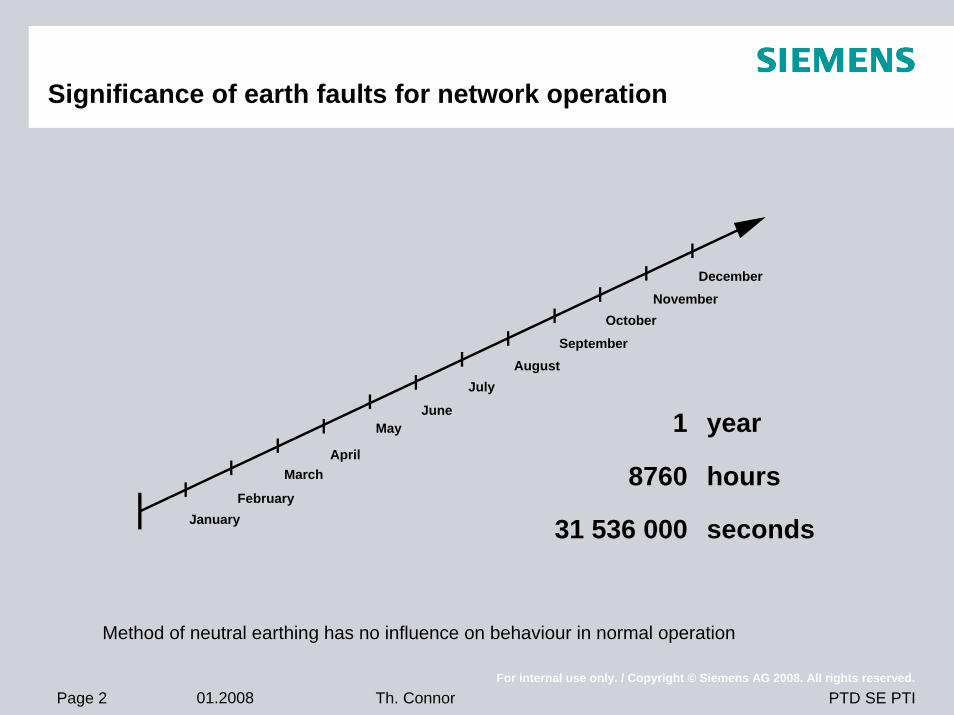
Significance of earth faults for network operation
JanuaryFebruary
MarchApril
MayJune
JulyAugust
SeptemberOctober
NovemberDecember
1
8760
31 536 000
year
hours
seconds
Method of neutral earthing has no influence on behaviour in normal operation
Page 3 01.2008For internal use only. / Copyright © Siemens AG 2008. All rights reserved.
PTD SE PTITh. Connor
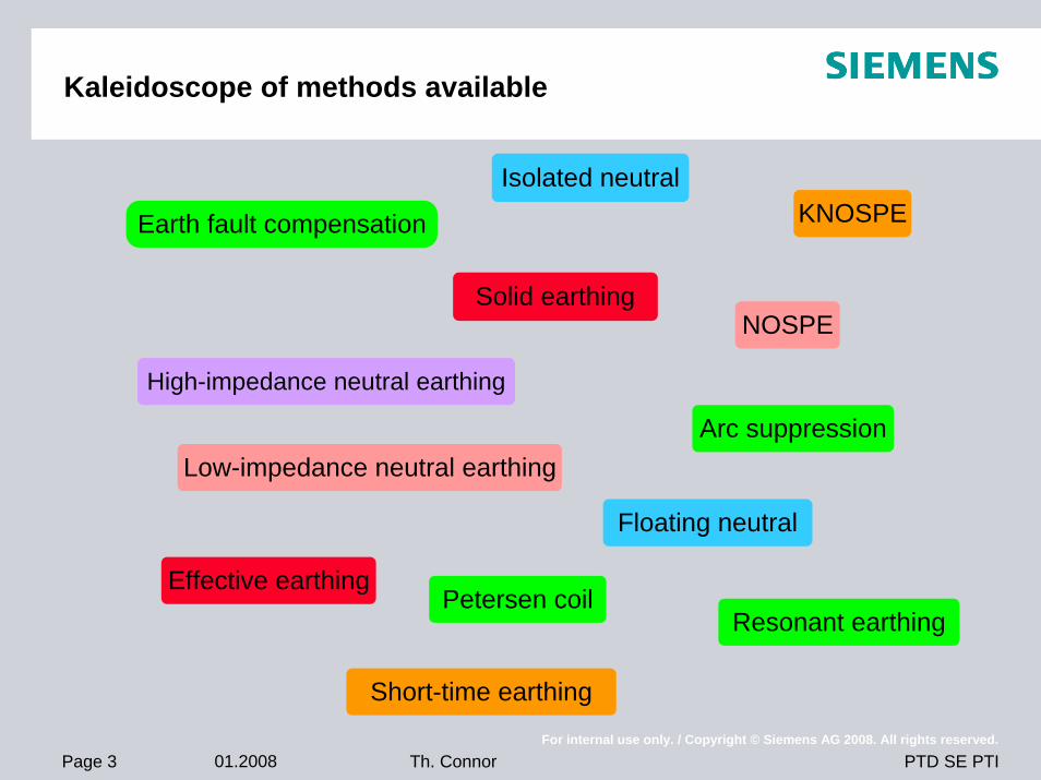
Kaleidoscope of methods available
Isolated neutral
Earth fault compensation
High-impedance neutral earthing
Low-impedance neutral earthing
Solid earthing
Effective earthing
Short-time earthing
Floating neutral
Arc suppression
Resonant earthing
NOSPE
KNOSPE
Petersen coil
Page 4 01.2008For internal use only. / Copyright © Siemens AG 2008. All rights reserved.
PTD SE PTITh. Connor
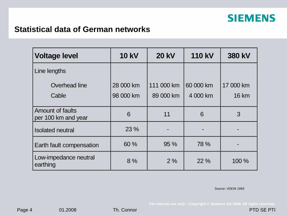
Statistical data of German networks
Voltage level 10 kV 20 kV 110 kV 380 kV
Line lengths
Overhead line 28 000 km 111 000 km 60 000 km 17 000 km
Cable 98 000 km 89 000 km 4 000 km 16 km
Amount of faults per 100 km and year 6 11 6 3
Isolated neutral 23 % - - -
Earth fault compensation 60 % 95 % 78 % -
Low-impedance neutral earthing 8 % 2 % 22 % 100 %
Source: VDEW 1993
Page 5 01.2008For internal use only. / Copyright © Siemens AG 2008. All rights reserved.
PTD SE PTITh. Connor
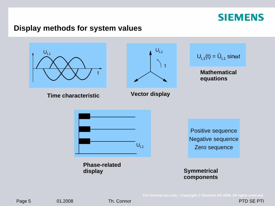
Display methods for system values
Positive sequenceNegative sequence
Zero sequence
UL1(t) = ÛL1 sinωtUL1
t
Vector display
Mathematicalequations
t
UL1
Time characteristic
Symmetrical components
Phase-related display
UL1
Page 6 01.2008For internal use only. / Copyright © Siemens AG 2008. All rights reserved.
PTD SE PTITh. Connor
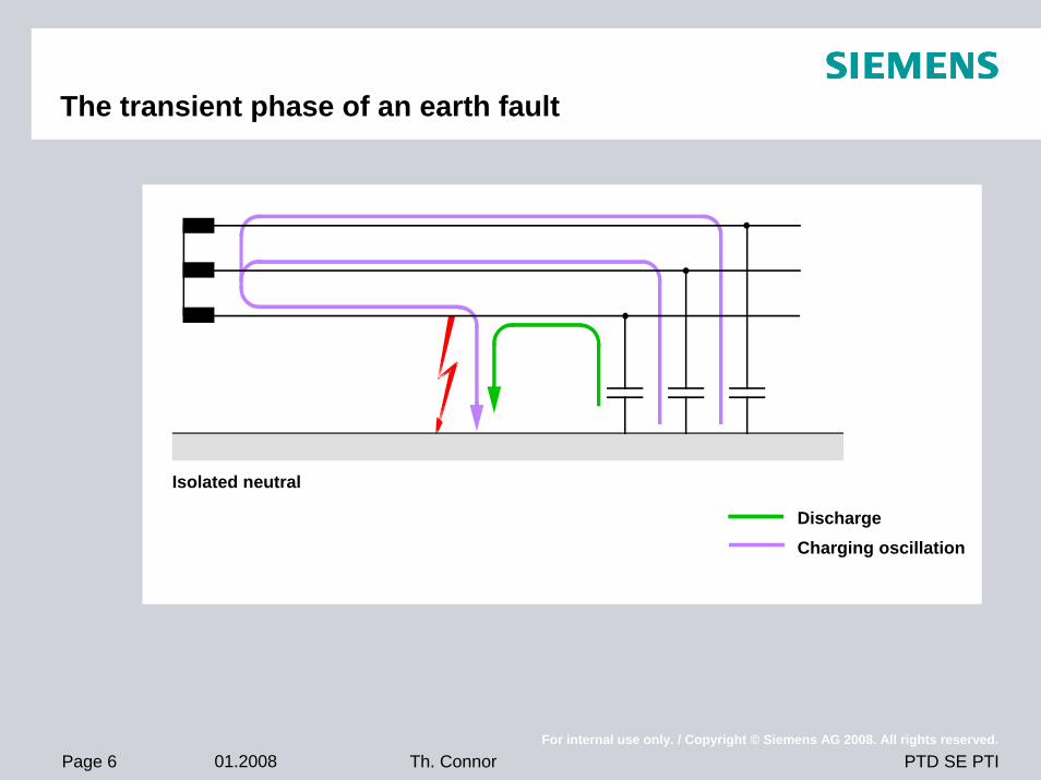
The transient phase of an earth fault
Isolated neutral
DischargeCharging oscillation
Page 7 01.2008For internal use only. / Copyright © Siemens AG 2008. All rights reserved.
PTD SE PTITh. Connor
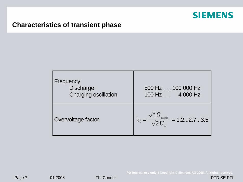
Frequency Discharge Charging oscillation
500 Hz . . . 100 000 Hz 100 Hz . . . 4 000 Hz
Overvoltage factor kt = b
LE
UÛ2
3 max = 1.2...2.7...3.5
Characteristics of transient phase
Page 8 01.2008For internal use only. / Copyright © Siemens AG 2008. All rights reserved.
PTD SE PTITh. Connor
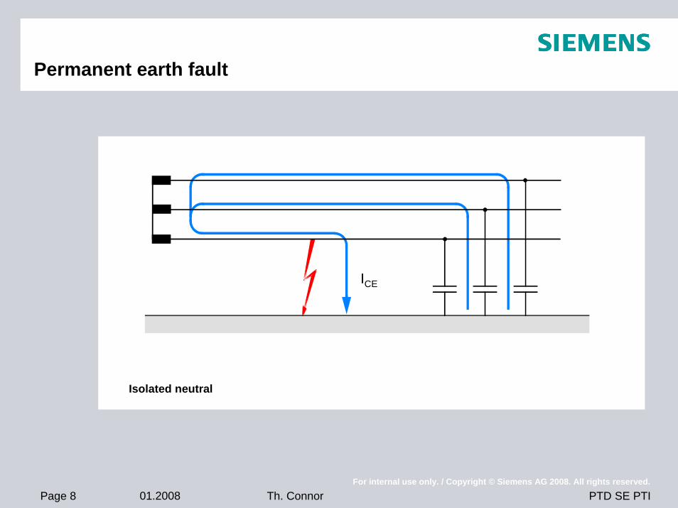
Permanent earth fault
Isolated neutral
ICE
Page 9 01.2008For internal use only. / Copyright © Siemens AG 2008. All rights reserved.
PTD SE PTITh. Connor
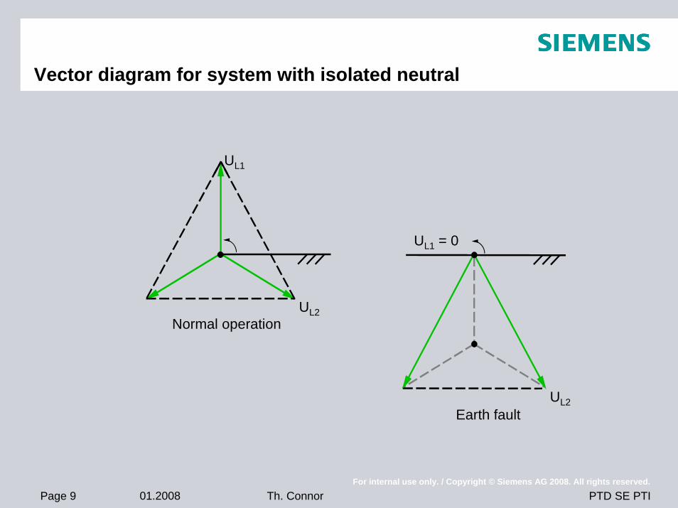
Vector diagram for system with isolated neutral
Normal operation
UL1
UL2
Earth fault
UL1 = 0
UL2
Page 10 01.2008For internal use only. / Copyright © Siemens AG 2008. All rights reserved.
PTD SE PTITh. Connor
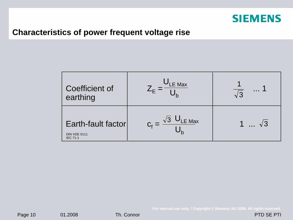
Characteristics of power frequent voltage rise
Coefficient of ZE = ... 1earthing
Earth-fault factor cf = 1 ... 3
13
ULE Max
Ub
Ub
ULE Max
3DIN VDE 0111IEC 71-1
Page 11 01.2008For internal use only. / Copyright © Siemens AG 2008. All rights reserved.
PTD SE PTITh. Connor
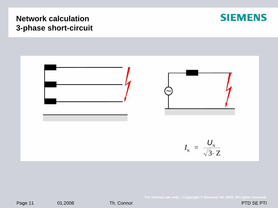
Network calculation3-phase short-circuit
~
IKN =
3 ZU
⋅
Page 12 01.2008For internal use only. / Copyright © Siemens AG 2008. All rights reserved.
PTD SE PTITh. Connor
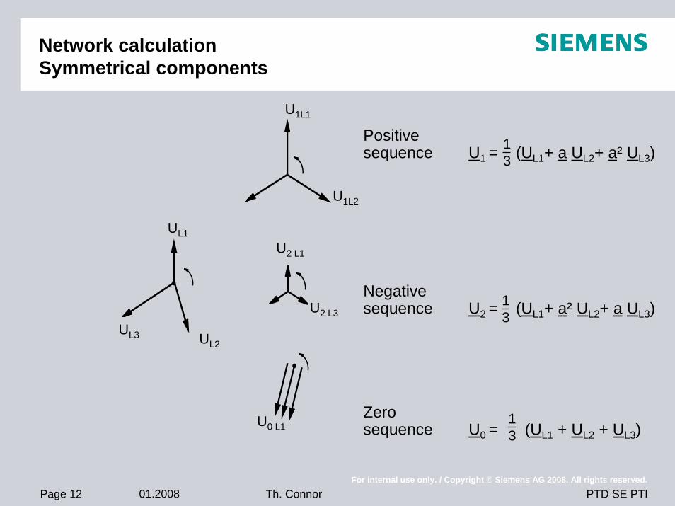
Network calculationSymmetrical components
UL1
UL2UL3
U1L1
U1L2
U2 L1
U2 L3
U0 L1
Positivesequence U1 = (UL1+ a UL2+ a² UL3)
Negativesequence U2 = (UL1+ a² UL2+ a UL3)
Zerosequence U0 = (UL1 + UL2 + UL3)
13
13
13
Page 13 01.2008For internal use only. / Copyright © Siemens AG 2008. All rights reserved.
PTD SE PTITh. Connor
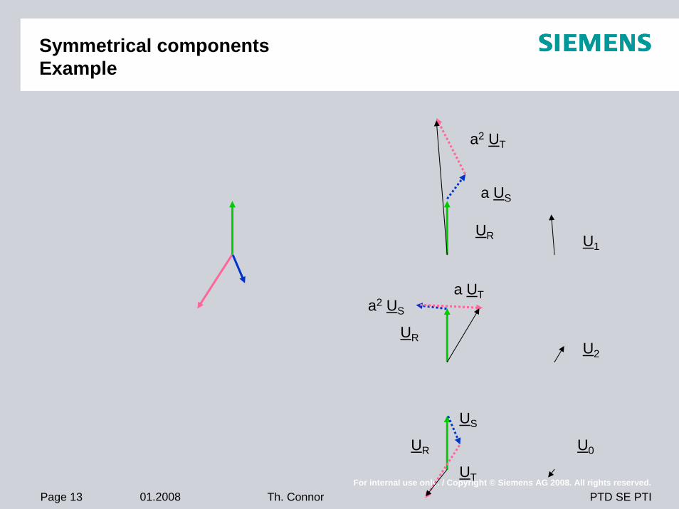
Symmetrical componentsExample
U1
a US
a2 UT
UR
U2
U0UR
UR
a2 US
a UT
UT
US
Page 14 01.2008For internal use only. / Copyright © Siemens AG 2008. All rights reserved.
PTD SE PTITh. Connor
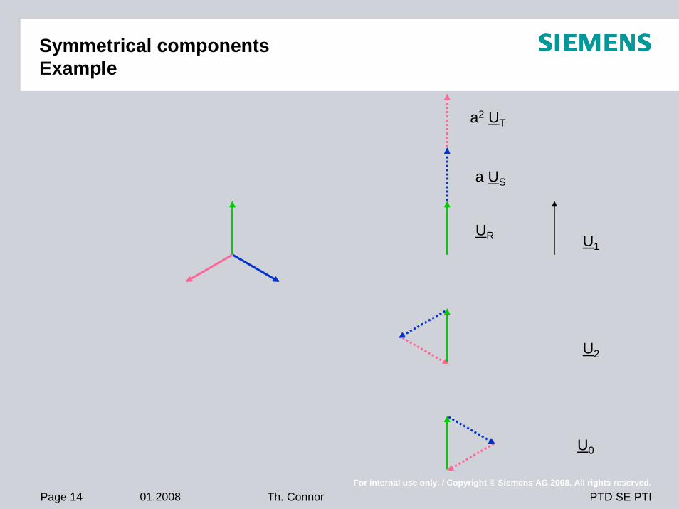
Symmetrical componentsExample
U1
a US
a2 UT
UR
U2
U0
Page 15 01.2008For internal use only. / Copyright © Siemens AG 2008. All rights reserved.
PTD SE PTITh. Connor
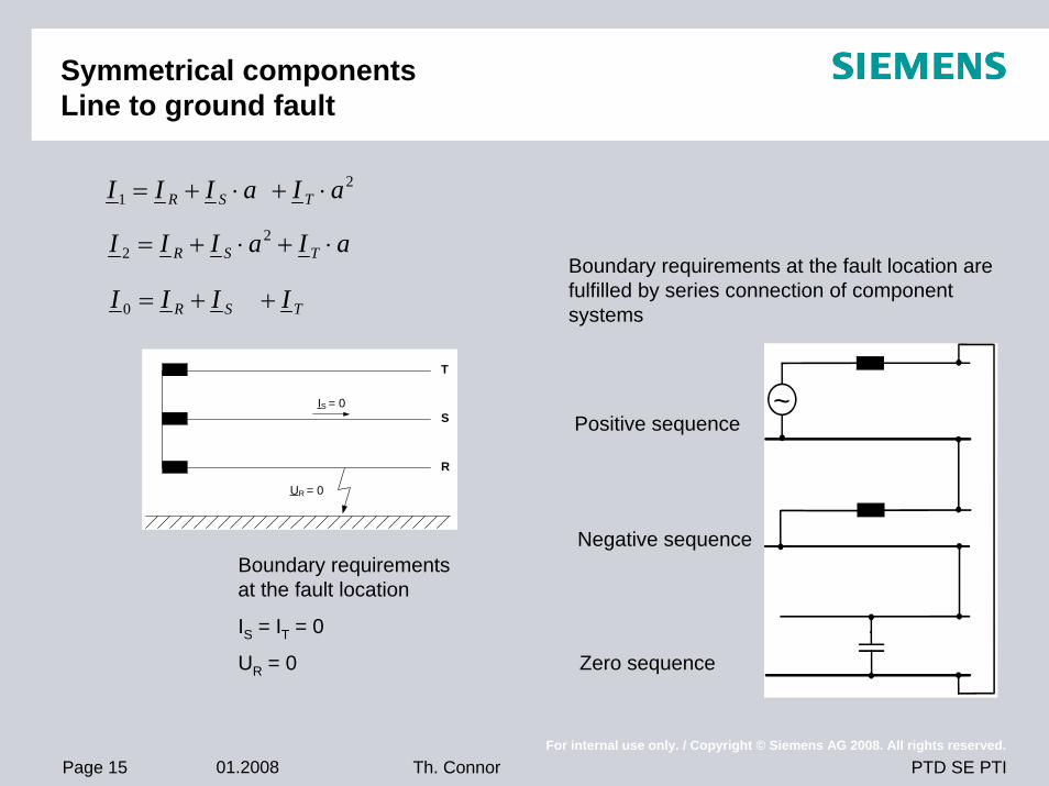
Symmetrical componentsLine to ground fault
T
S
R
UR = 0
IS = 0
21 aIaIII TSR ⋅+⋅+=
aIaIII TSR ⋅+⋅+= 22
TSR IIII ++=0
~
Boundary requirements at the fault location
IS = IT = 0
UR = 0
Positive sequence
Negative sequence
Zero sequence
Boundary requirements at the fault location are fulfilled by series connection of component systems
Page 16 01.2008For internal use only. / Copyright © Siemens AG 2008. All rights reserved.
PTD SE PTITh. Connor
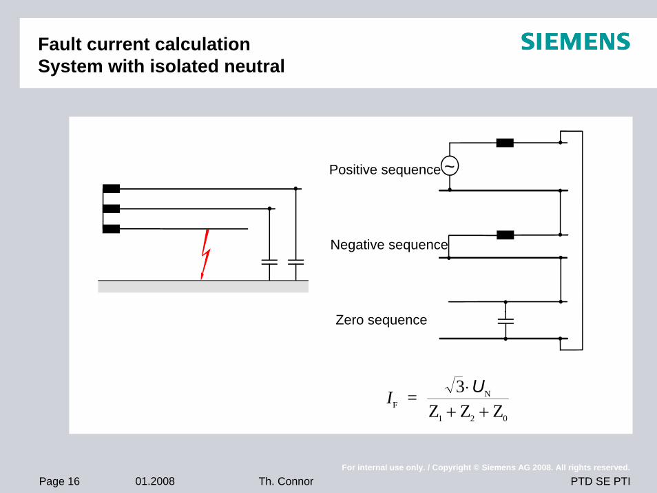
Fault current calculationSystem with isolated neutral
~Positive sequence
Negative sequence
Zero sequence
IFN
1 2 0
= 3Z Z Z
⋅+ +
U
Page 17 01.2008For internal use only. / Copyright © Siemens AG 2008. All rights reserved.
PTD SE PTITh. Connor
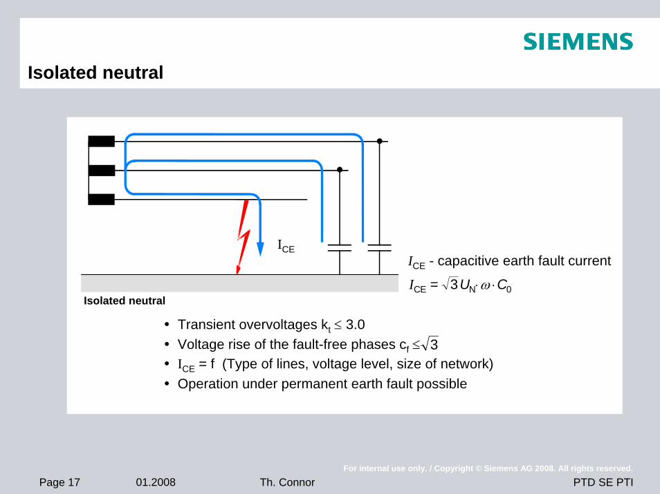
Isolated neutral
ICEICE - capacitive earth fault current
Transient overvoltages kt ≤ 3.0Voltage rise of the fault-free phases cf ≤ ICE = f (Type of lines, voltage level, size of network)Operation under permanent earth fault possible
3
Isolated neutralICE N 0= 3U C⋅ ⋅ω
Page 18 01.2008For internal use only. / Copyright © Siemens AG 2008. All rights reserved.
PTD SE PTITh. Connor
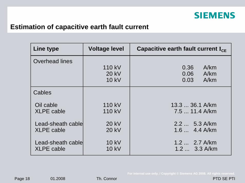
Estimation of capacitive earth fault current
Line type Voltage level Capacitive earth fault current ICE
Overhead lines110 kV 0.36 A/km
20 kV 0.06 A/km10 kV 0.03 A/km
Cables
Oil cable 110 kV 13.3 ... 36.1 A/kmXLPE cable 110 kV 7.5 ... 11.4 A/km
Lead-sheath cable 20 kV 2.2 ... 5.3 A/kmXLPE cable 20 kV 1.6 ... 4.4 A/km
Lead-sheath cable 10 kV 1.2 ... 2.7 A/kmXLPE cable 10 kV 1.2 ... 3.3 A/km
Page 19 01.2008For internal use only. / Copyright © Siemens AG 2008. All rights reserved.
PTD SE PTITh. Connor
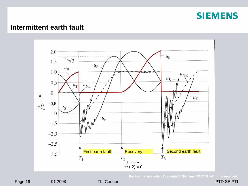
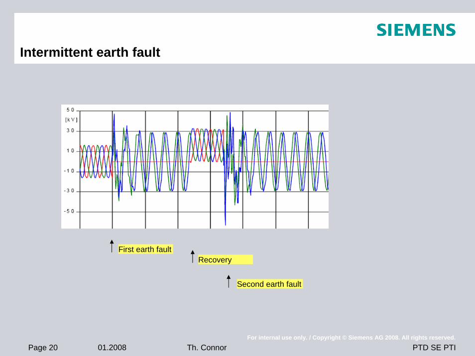
Intermittent earth fault
First earth fault Second earth faultRecovery
-0,5
Ice (t2) = 0
Page 20 01.2008For internal use only. / Copyright © Siemens AG 2008. All rights reserved.
PTD SE PTITh. Connor
Intermittent earth fault
First earth fault
Second earth fault
Recovery
Page 21 01.2008For internal use only. / Copyright © Siemens AG 2008. All rights reserved.
PTD SE PTITh. Connor
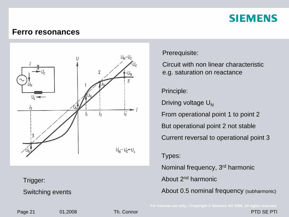
Ferro resonances
Prerequisite:
Circuit with non linear characteristic e.g. saturation on reactance
Principle:
Driving voltage UN
From operational point 1 to point 2
But operational point 2 not stable
Current reversal to operational point 3
Types:
Nominal frequency, 3rd harmonic
About 2nd harmonic
About 0.5 nominal frequency (subharmonic)
Trigger:
Switching events
Page 22 01.2008For internal use only. / Copyright © Siemens AG 2008. All rights reserved.
PTD SE PTITh. Connor
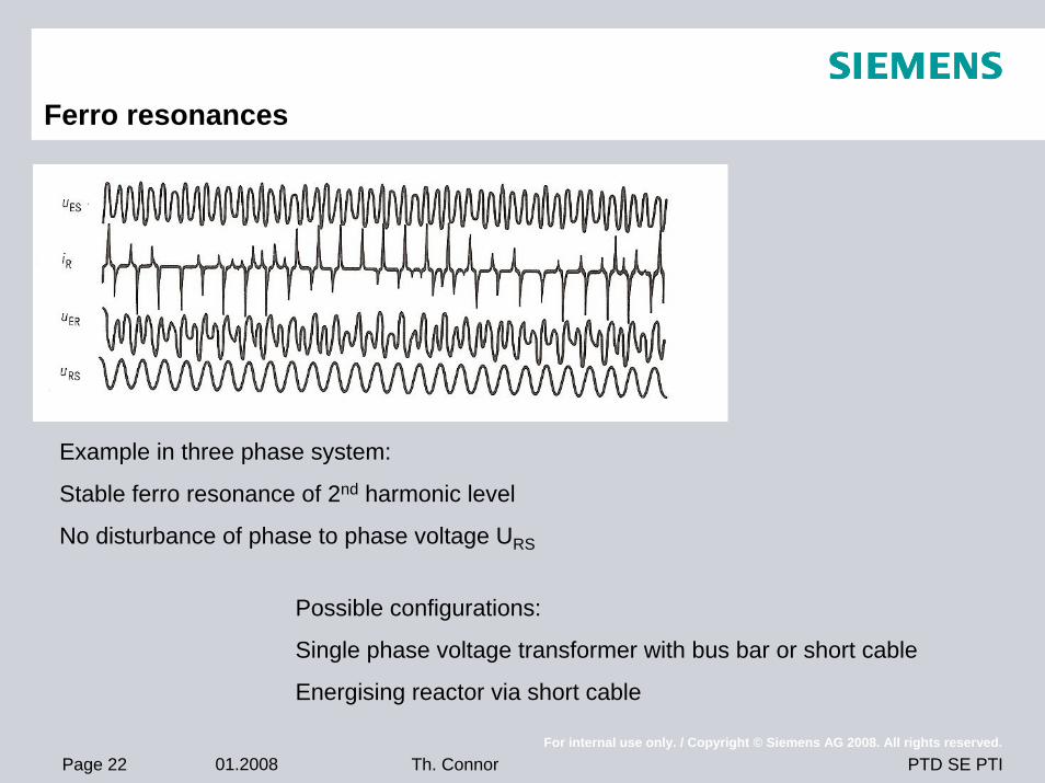
Ferro resonances
Example in three phase system:
Stable ferro resonance of 2nd harmonic level
No disturbance of phase to phase voltage URS
Possible configurations:
Single phase voltage transformer with bus bar or short cable
Energising reactor via short cable
Page 23 01.2008For internal use only. / Copyright © Siemens AG 2008. All rights reserved.
PTD SE PTITh. Connor
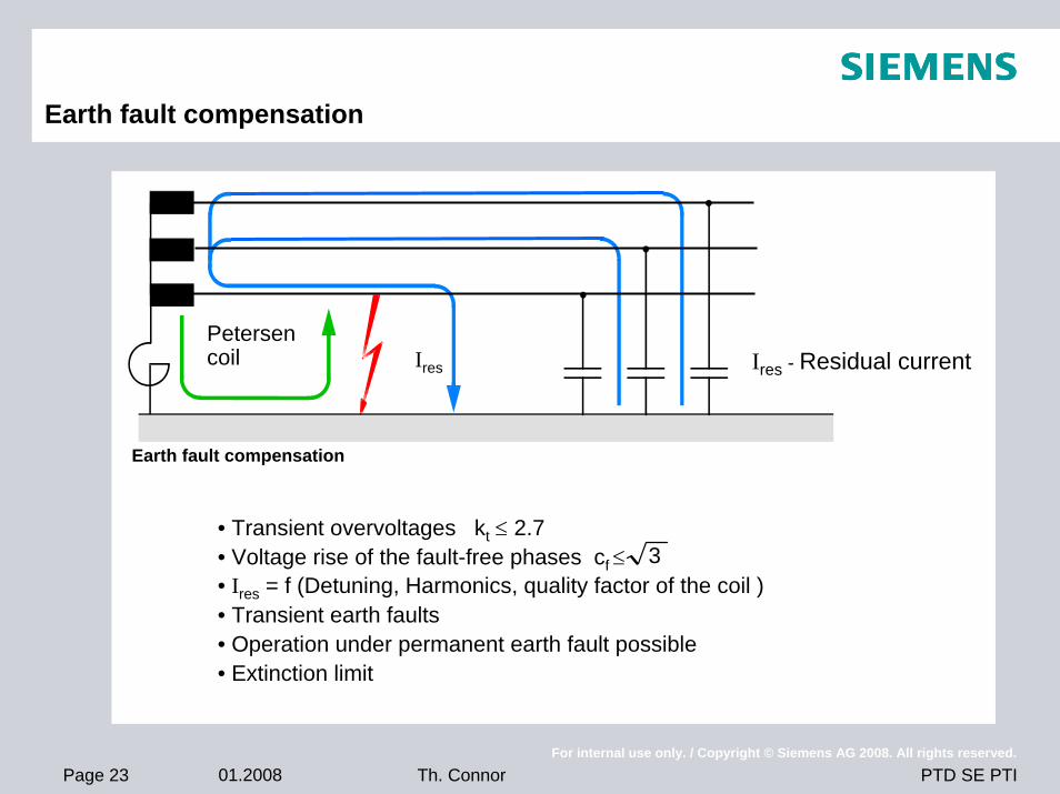
Earth fault compensation
Petersencoil Ires
Earth fault compensation
• Transient overvoltages kt ≤ 2.7• Voltage rise of the fault-free phases cf ≤ • Ires = f (Detuning, Harmonics, quality factor of the coil )• Transient earth faults• Operation under permanent earth fault possible• Extinction limit
3
Ires - Residual current
Page 24 01.2008For internal use only. / Copyright © Siemens AG 2008. All rights reserved.
PTD SE PTITh. Connor
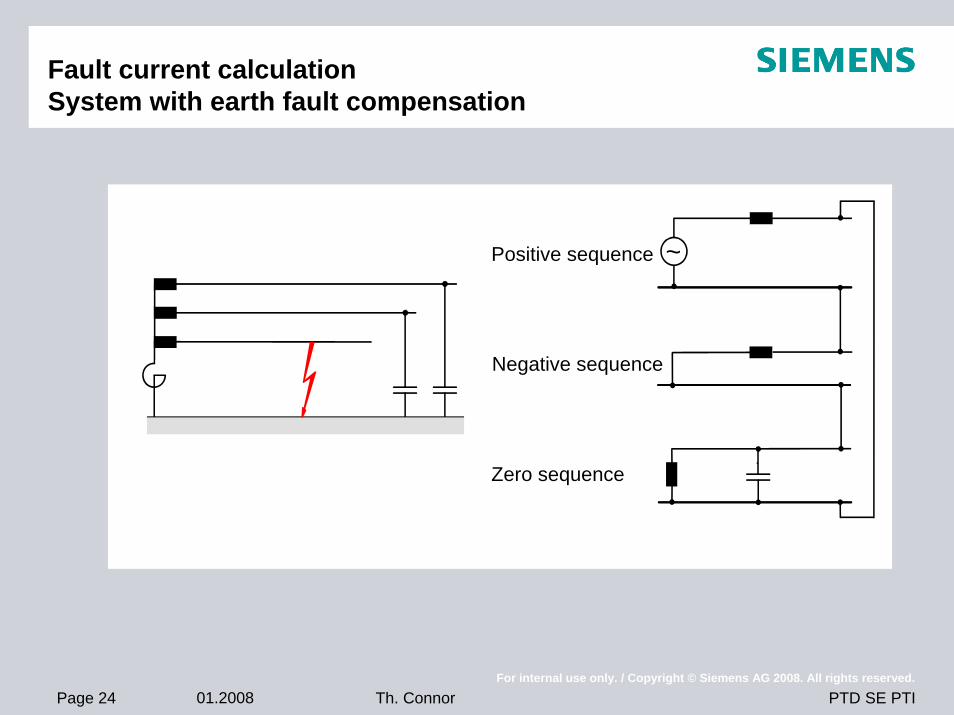
Fault current calculationSystem with earth fault compensation
~Positive sequence
Negative sequence
Zero sequence
Page 25 01.2008For internal use only. / Copyright © Siemens AG 2008. All rights reserved.
PTD SE PTITh. Connor
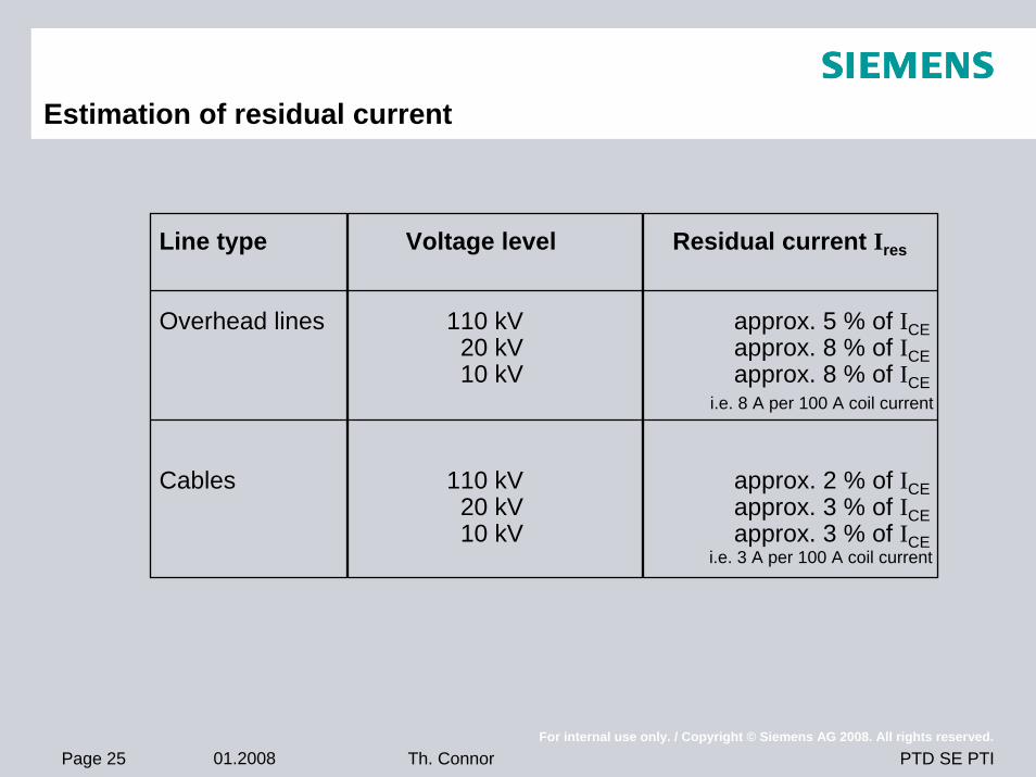
Estimation of residual current
Line type Voltage level Residual current Ires
Overhead lines 110 kV approx. 5 % of ICE20 kV approx. 8 % of ICE10 kV approx. 8 % of ICE
i.e. 8 A per 100 A coil current
Cables 110 kV approx. 2 % of ICE20 kV approx. 3 % of ICE10 kV approx. 3 % of ICE
i.e. 3 A per 100 A coil current
Page 26 01.2008For internal use only. / Copyright © Siemens AG 2008. All rights reserved.
PTD SE PTITh. Connor
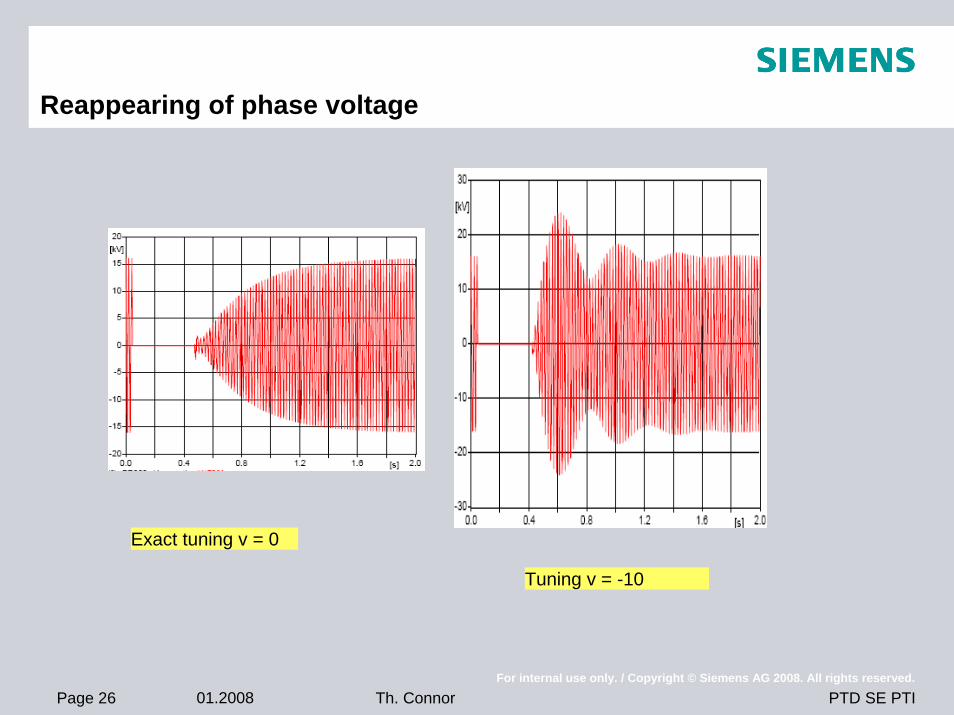
Reappearing of phase voltage
Exact tuning v = 0
Tuning v = -10
Page 27 01.2008For internal use only. / Copyright © Siemens AG 2008. All rights reserved.
PTD SE PTITh. Connor
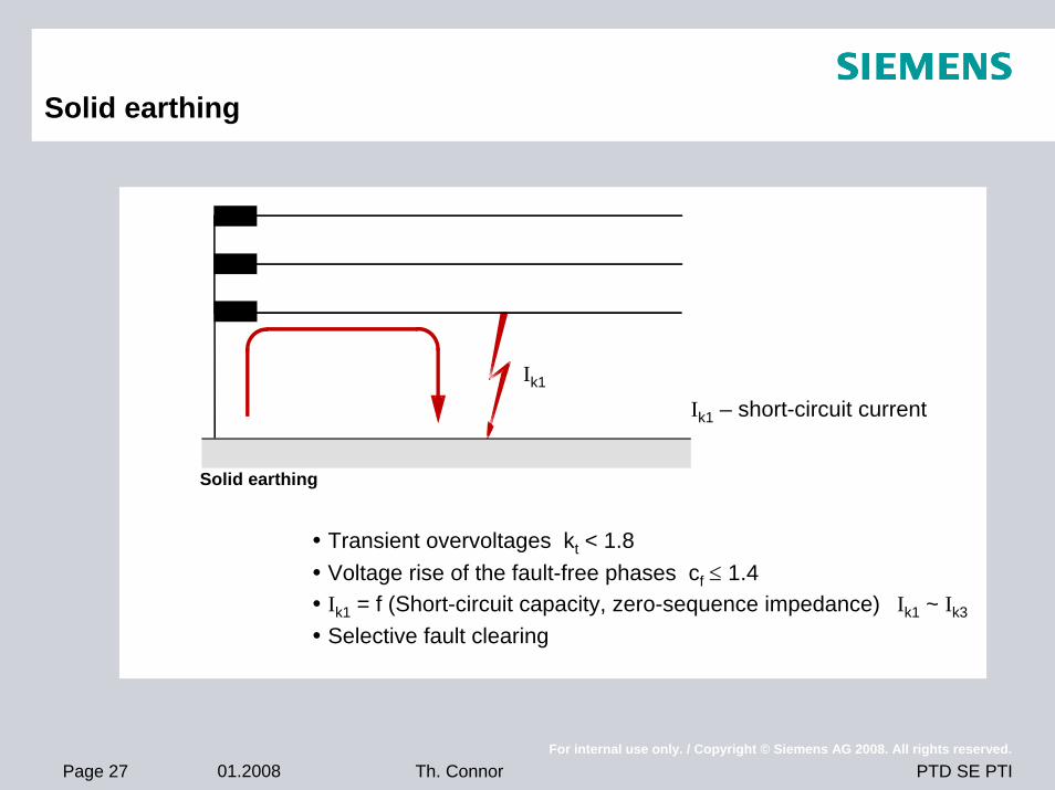
Solid earthing
Transient overvoltages kt < 1.8Voltage rise of the fault-free phases cf ≤ 1.4Ik1 = f (Short-circuit capacity, zero-sequence impedance) Ik1 ~ Ik3
Selective fault clearing
Ik1 – short-circuit currentIk1
Solid earthing
Page 28 01.2008For internal use only. / Copyright © Siemens AG 2008. All rights reserved.
PTD SE PTITh. Connor
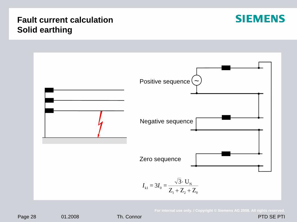
Fault current calculation Solid earthing
~Positive sequence
Negative sequence
Zero sequence
I Ik1 0N
1 2 0
= 3 = 3 UZ Z Z
⋅+ +
Page 29 01.2008For internal use only. / Copyright © Siemens AG 2008. All rights reserved.
PTD SE PTITh. Connor
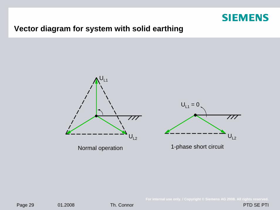
Vector diagram for system with solid earthing
UL1
Normal operation 1-phase short circuit
UL1 = 0
UL2UL2
Page 30 01.2008For internal use only. / Copyright © Siemens AG 2008. All rights reserved.
PTD SE PTITh. Connor
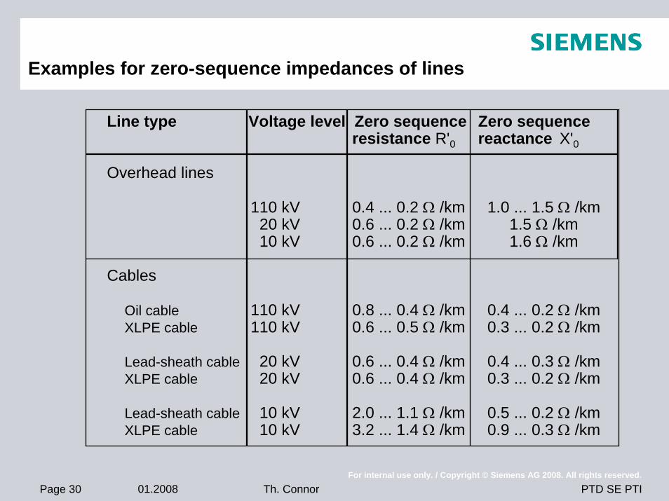
Examples for zero-sequence impedances of lines
Line type Voltage level Zero sequence Zero sequenceresistance R'0 reactance X'0
Overhead lines
110 kV 0.4 ... 0.2 Ω /km 1.0 ... 1.5 Ω /km20 kV 0.6 ... 0.2 Ω /km 1.5 Ω /km10 kV 0.6 ... 0.2 Ω /km 1.6 Ω /km
Cables
Oil cable 110 kV 0.8 ... 0.4 Ω /km 0.4 ... 0.2 Ω /km XLPE cable 110 kV 0.6 ... 0.5 Ω /km 0.3 ... 0.2 Ω /km
Lead-sheath cable 20 kV 0.6 ... 0.4 Ω /km 0.4 ... 0.3 Ω /km XLPE cable 20 kV 0.6 ... 0.4 Ω /km 0.3 ... 0.2 Ω /km
Lead-sheath cable 10 kV 2.0 ... 1.1 Ω /km 0.5 ... 0.2 Ω /km XLPE cable 10 kV 3.2 ... 1.4 Ω /km 0.9 ... 0.3 Ω /km
Page 31 01.2008For internal use only. / Copyright © Siemens AG 2008. All rights reserved.
PTD SE PTITh. Connor
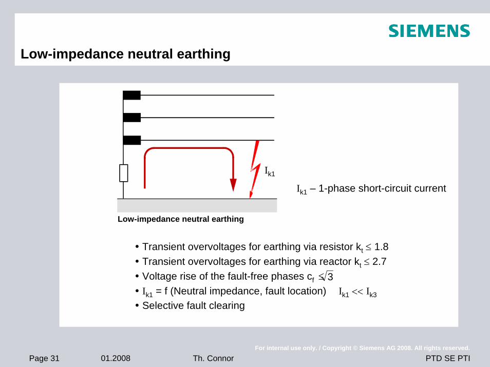
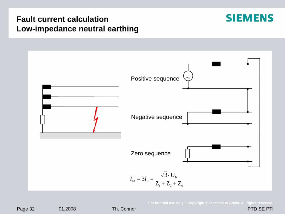
Low-impedance neutral earthing
Transient overvoltages for earthing via resistor kt ≤ 1.8 Transient overvoltages for earthing via reactor kt ≤ 2.7 Voltage rise of the fault-free phases cf ≤Ik1 = f (Neutral impedance, fault location) Ik1 << Ik3
Selective fault clearing
Ik1 – 1-phase short-circuit current
Ik1
3
Low-impedance neutral earthing
Page 32 01.2008For internal use only. / Copyright © Siemens AG 2008. All rights reserved.
PTD SE PTITh. Connor
Fault current calculation Low-impedance neutral earthing
~Positive sequence
Negative sequence
Zero sequence
I Ik1 0N
1 2 0
= 3 = 3 UZ Z Z
⋅+ +
Page 33 01.2008For internal use only. / Copyright © Siemens AG 2008. All rights reserved.
PTD SE PTITh. Connor
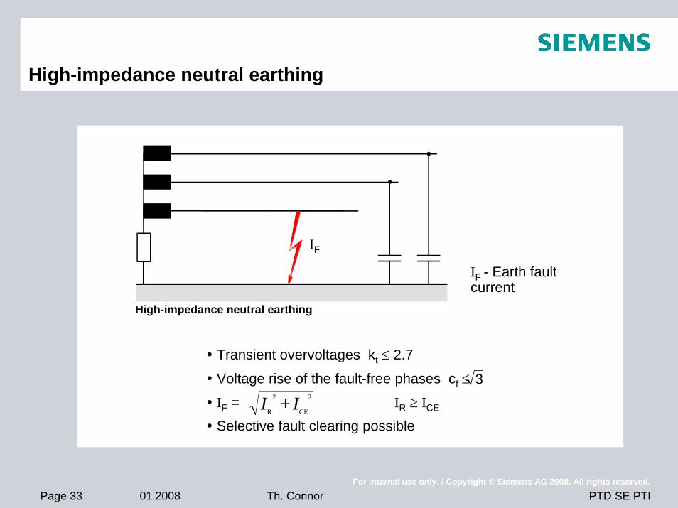
High-impedance neutral earthing
Transient overvoltages kt ≤ 2.7
Voltage rise of the fault-free phases cf ≤
IF = IR ≥ ICE
Selective fault clearing possible
32
CE
2
R + II
IF
High-impedance neutral earthing
IF - Earth fault current
Page 34 01.2008For internal use only. / Copyright © Siemens AG 2008. All rights reserved.
PTD SE PTITh. Connor
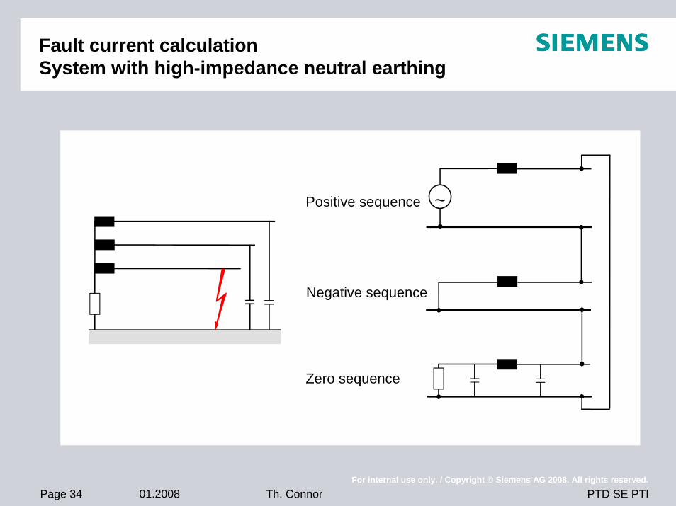
Fault current calculationSystem with high-impedance neutral earthing
~Positive sequence
Negative sequence
Zero sequence
Page 35 01.2008For internal use only. / Copyright © Siemens AG 2008. All rights reserved.
PTD SE PTITh. Connor
Practical aspects
Methods applied
Criteria for comparison
High voltage systems
Medium voltage systemsIsolated neutralResonant groundingLow impedance neutral grounding
Page 36 01.2008For internal use only. / Copyright © Siemens AG 2008. All rights reserved.
PTD SE PTITh. Connor
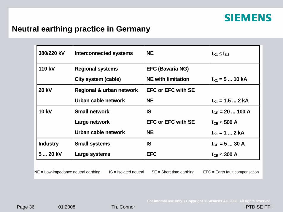
Neutral earthing practice in Germany
380/220 kV Interconnected systems NE IK1 ≤ IK3
110 kV Regional systems
City system (cable) EFC (Bavaria NG)
NE with limitation
IK1 = 5 ... 10 kA 20 kV Regional & urban network
Urban cable network EFC or EFC with SE
NE
IK1 = 1.5 ... 2 kA 10 kV Small network
Large network
Urban cable network
IS
EFC or EFC with SE
NE
ICE = 20 ... 100 A
ICE ≤ 500 A
IK1 = 1 ... 2 kA Industry
5 ... 20 kV Small systems
Large systems IS
EFC ICE = 5 ... 30 A
ICE ≤ 300 A
NE = Low-impedance neutral earthing IS = Isolated neutral SE = Short time earthing EFC = Earth fault compensation
Page 37 01.2008For internal use only. / Copyright © Siemens AG 2008. All rights reserved.
PTD SE PTITh. Connor
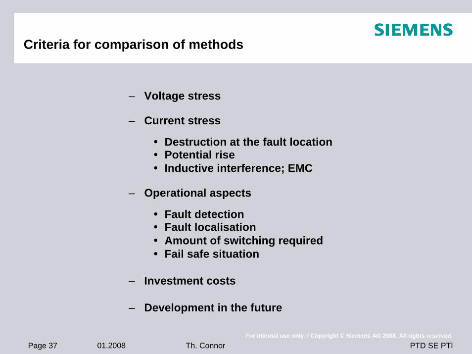
Criteria for comparison of methods
– Voltage stress
– Current stress
Destruction at the fault locationPotential riseInductive interference; EMC
– Operational aspects
Fault detectionFault localisationAmount of switching requiredFail safe situation
– Investment costs
– Development in the future
Page 38 01.2008For internal use only. / Copyright © Siemens AG 2008. All rights reserved.
PTD SE PTITh. Connor
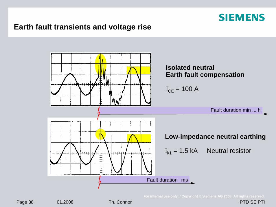
Earth fault transients and voltage rise
Isolated neutralEarth fault compensation
ICE = 100 A
Low-impedance neutral earthing
Ik1 = 1.5 kA Neutral resistor
Fault duration min ... h
Fault duration ms
Page 39 01.2008For internal use only. / Copyright © Siemens AG 2008. All rights reserved.
PTD SE PTITh. Connor
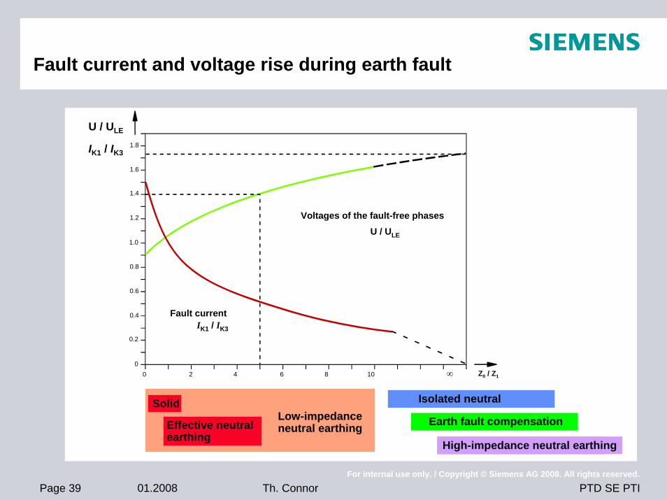
Fault current and voltage rise during earth fault
0 2 4 6 8 10 ∞0
0.2
0.4
0.6
0.8
1.0
1.2
1.4
1.6
1.8 3
Solid
Effective neutralearthing
Low-impedanceneutral earthing
Isolated neutral
Earth fault compensation
High-impedance neutral earthing
Z0 / Z1
U / ULE
IK1 / IK3
Voltages of the fault-free phasesU / ULE
Fault currentIK1 / IK3
Page 40 01.2008For internal use only. / Copyright © Siemens AG 2008. All rights reserved.
PTD SE PTITh. Connor
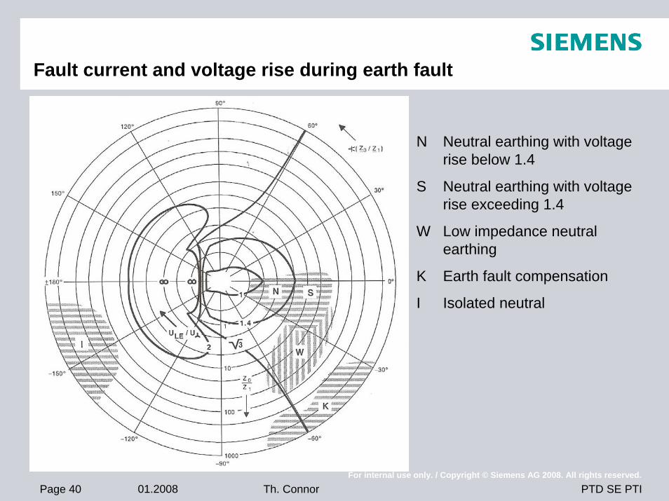
Fault current and voltage rise during earth fault
N Neutral earthing with voltage rise below 1.4
S Neutral earthing with voltage rise exceeding 1.4
W Low impedance neutral earthing
K Earth fault compensation
I Isolated neutral
Page 41 01.2008For internal use only. / Copyright © Siemens AG 2008. All rights reserved.
PTD SE PTITh. Connor
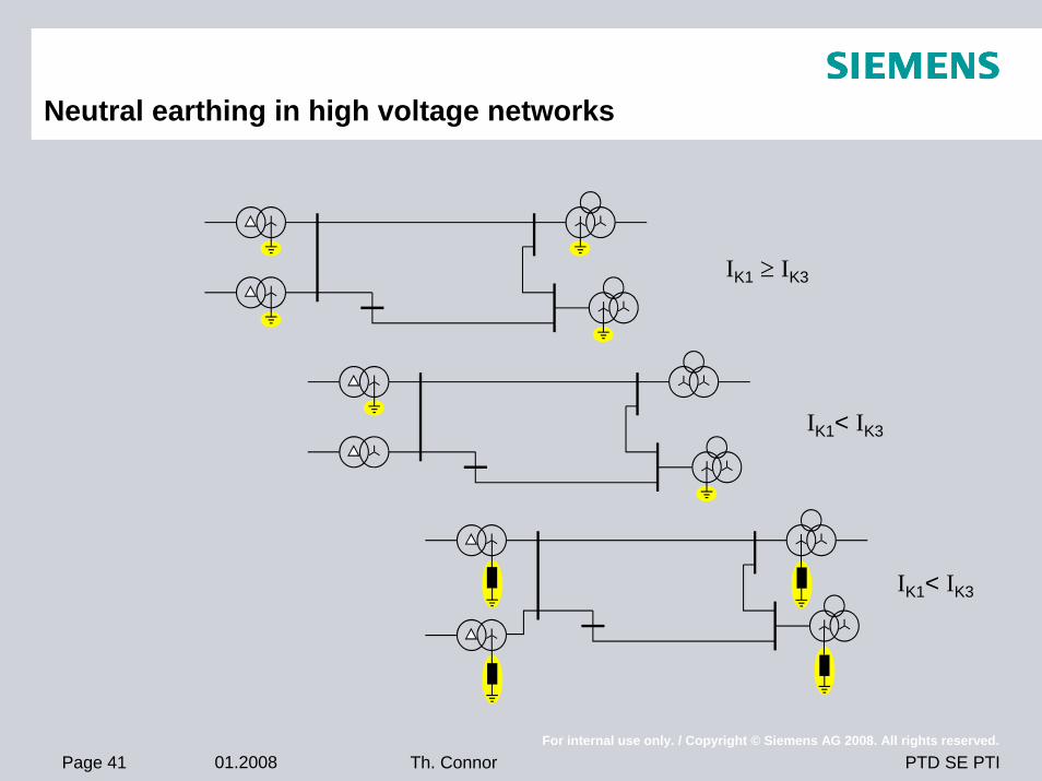
Neutral earthing in high voltage networks
IK1 ≥ IK3
IK1< IK3
IK1< IK3
Page 42 01.2008For internal use only. / Copyright © Siemens AG 2008. All rights reserved.
PTD SE PTITh. Connor
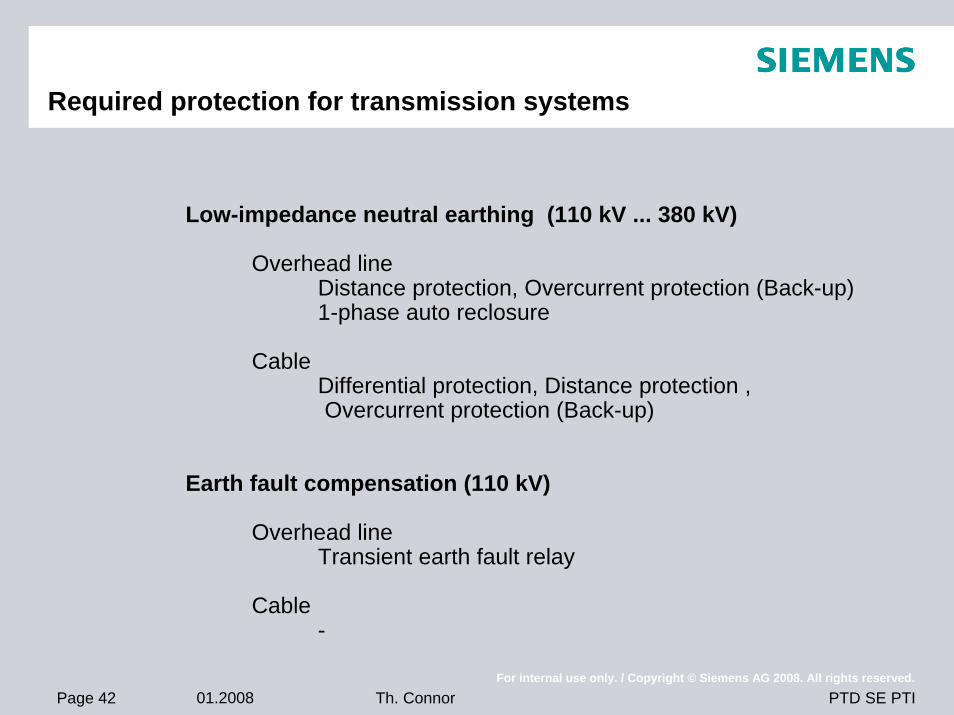
Required protection for transmission systems
Low-impedance neutral earthing (110 kV ... 380 kV)
Overhead lineDistance protection, Overcurrent protection (Back-up)1-phase auto reclosure
CableDifferential protection, Distance protection ,Overcurrent protection (Back-up)
Earth fault compensation (110 kV)
Overhead lineTransient earth fault relay
Cable-
Page 43 01.2008For internal use only. / Copyright © Siemens AG 2008. All rights reserved.
PTD SE PTITh. Connor
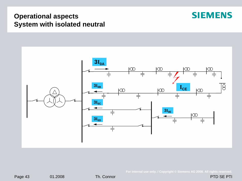
Operational aspectsSystem with isolated neutral
3I0A
3I0B
3I0C
3I0D
3I0E
ICE
Page 44 01.2008For internal use only. / Copyright © Siemens AG 2008. All rights reserved.
PTD SE PTITh. Connor
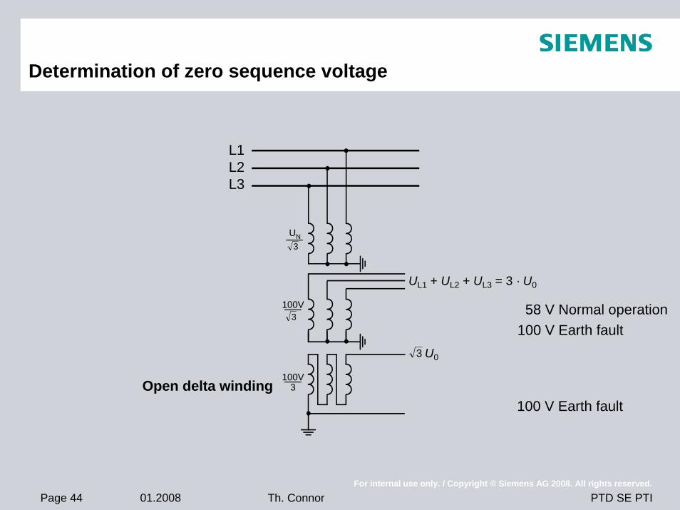
Determination of zero sequence voltage
Open delta winding
L1L2L3
UL1 + UL2 + UL3 = 3 · U0
3
100V3
100V3
UN3
58 V Normal operation100 V Earth fault
100 V Earth fault
U0
Page 45 01.2008For internal use only. / Copyright © Siemens AG 2008. All rights reserved.
PTD SE PTITh. Connor
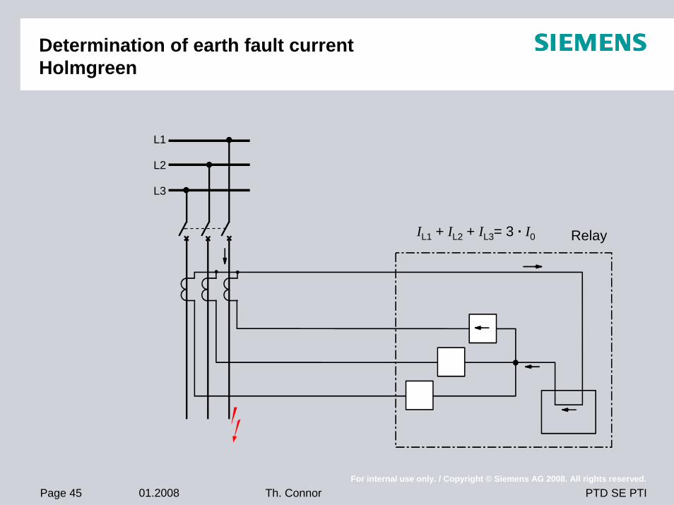
Determination of earth fault currentHolmgreen
L1
L2
L3
IL1 + IL2 + IL3= 3 · I0 Relay
Page 46 01.2008For internal use only. / Copyright © Siemens AG 2008. All rights reserved.
PTD SE PTITh. Connor
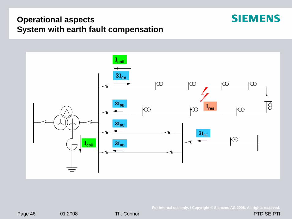
Operational aspectsSystem with earth fault compensation
3I0A
3I0B
3I0C
3I0D
3I0E
Ires
Icoil
Icoil
Page 47 01.2008For internal use only. / Copyright © Siemens AG 2008. All rights reserved.
PTD SE PTITh. Connor
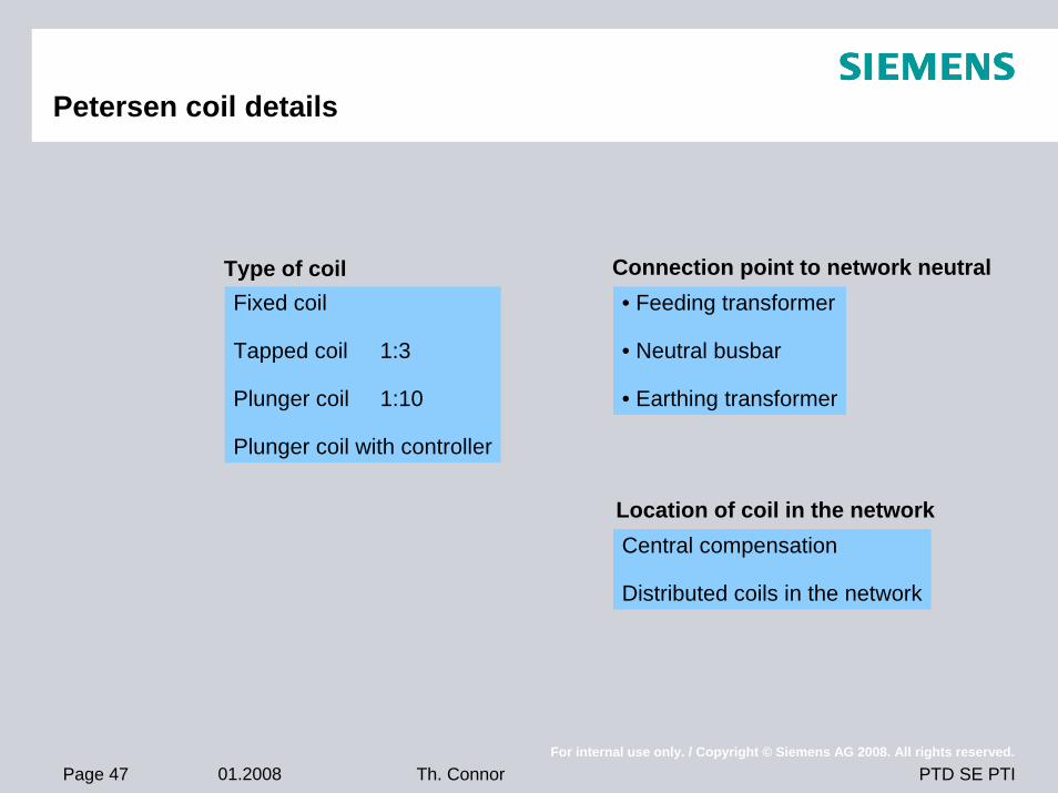
Petersen coil details
Type of coilFixed coil
Tapped coil 1:3
Plunger coil 1:10
Plunger coil with controller
Connection point to network neutral• Feeding transformer
• Neutral busbar
• Earthing transformer
Location of coil in the networkCentral compensation
Distributed coils in the network
Page 48 01.2008For internal use only. / Copyright © Siemens AG 2008. All rights reserved.
PTD SE PTITh. Connor
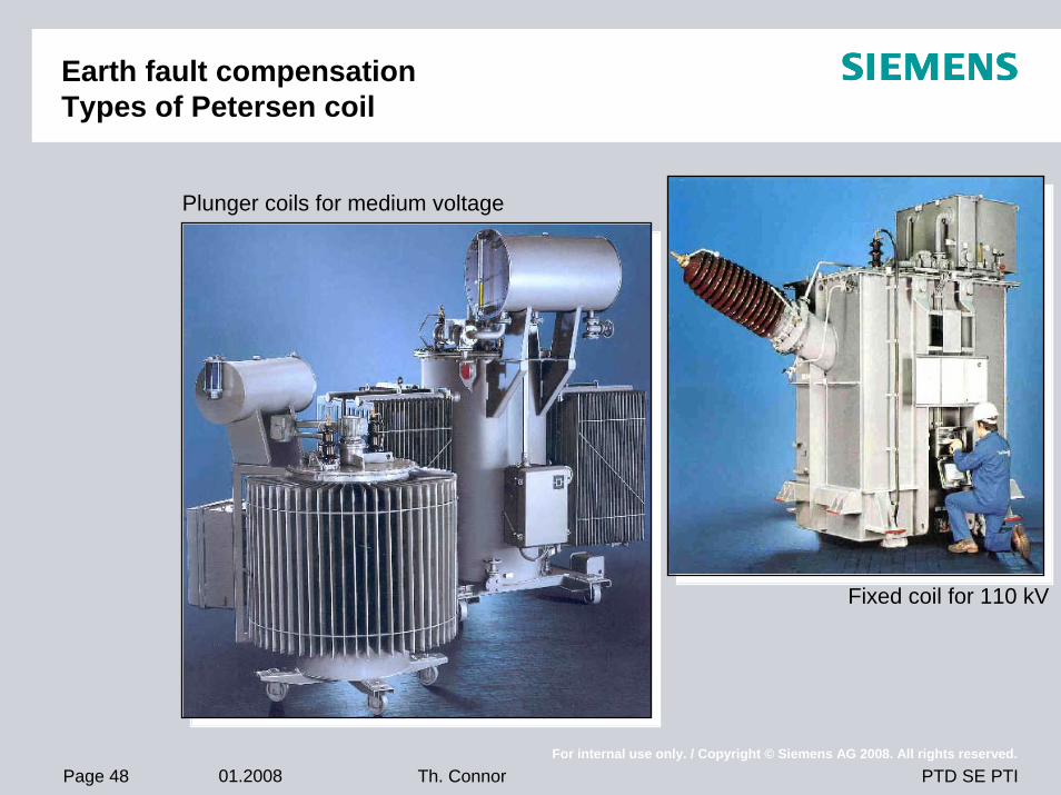
Earth fault compensationTypes of Petersen coil
Plunger coils for medium voltage
Fixed coil for 110 kV
Page 49 01.2008For internal use only. / Copyright © Siemens AG 2008. All rights reserved.
PTD SE PTITh. Connor
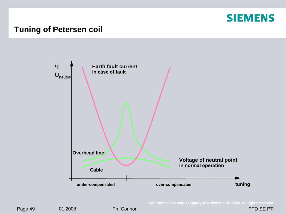
Tuning of Petersen coil
Earth fault currentin case of fault
Voltage of neutral pointin normal operation
Overhead line
Cable
under-compensated over-compensated tuning
IE
Uneutral
Page 50 01.2008For internal use only. / Copyright © Siemens AG 2008. All rights reserved.
PTD SE PTITh. Connor
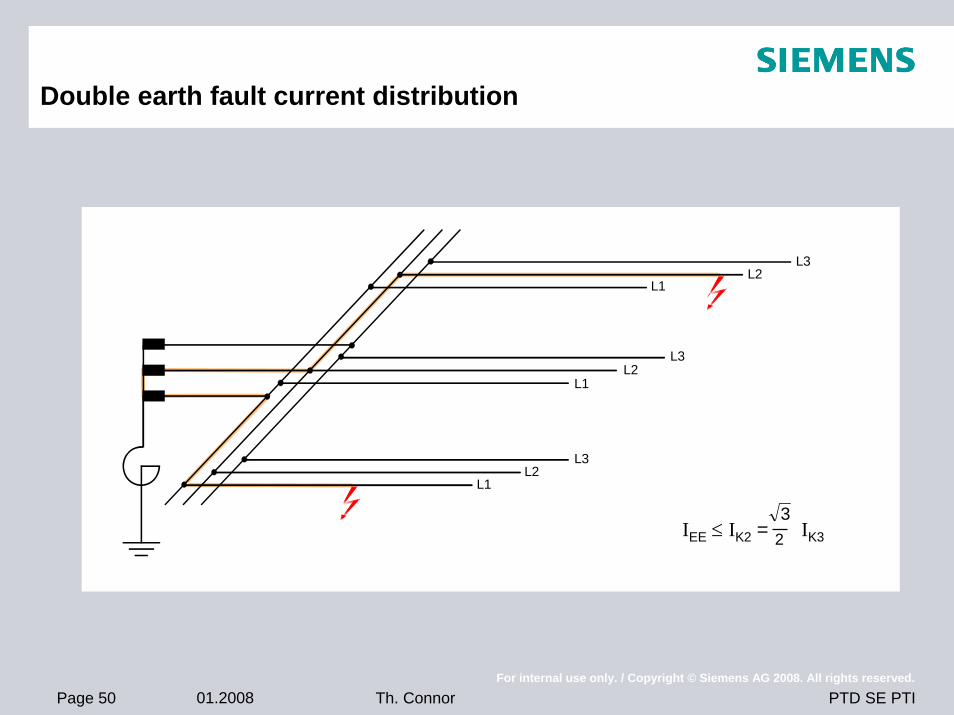
Double earth fault current distribution
L3L2
L1
L3L2
L1
L3L2
L1
3IEE ≤ IK2 = IK32
Page 51 01.2008For internal use only. / Copyright © Siemens AG 2008. All rights reserved.
PTD SE PTITh. Connor
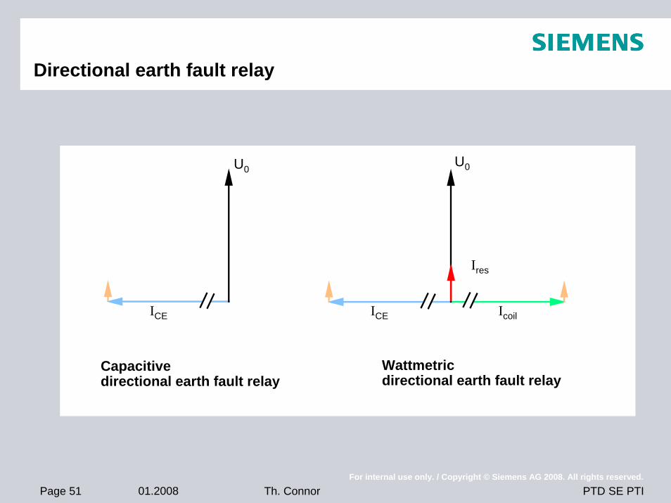
Directional earth fault relay
Capacitivedirectional earth fault relay
Wattmetricdirectional earth fault relay
U0
ICE
U0
ICE
Ires
Icoil
Page 52 01.2008For internal use only. / Copyright © Siemens AG 2008. All rights reserved.
PTD SE PTITh. Connor
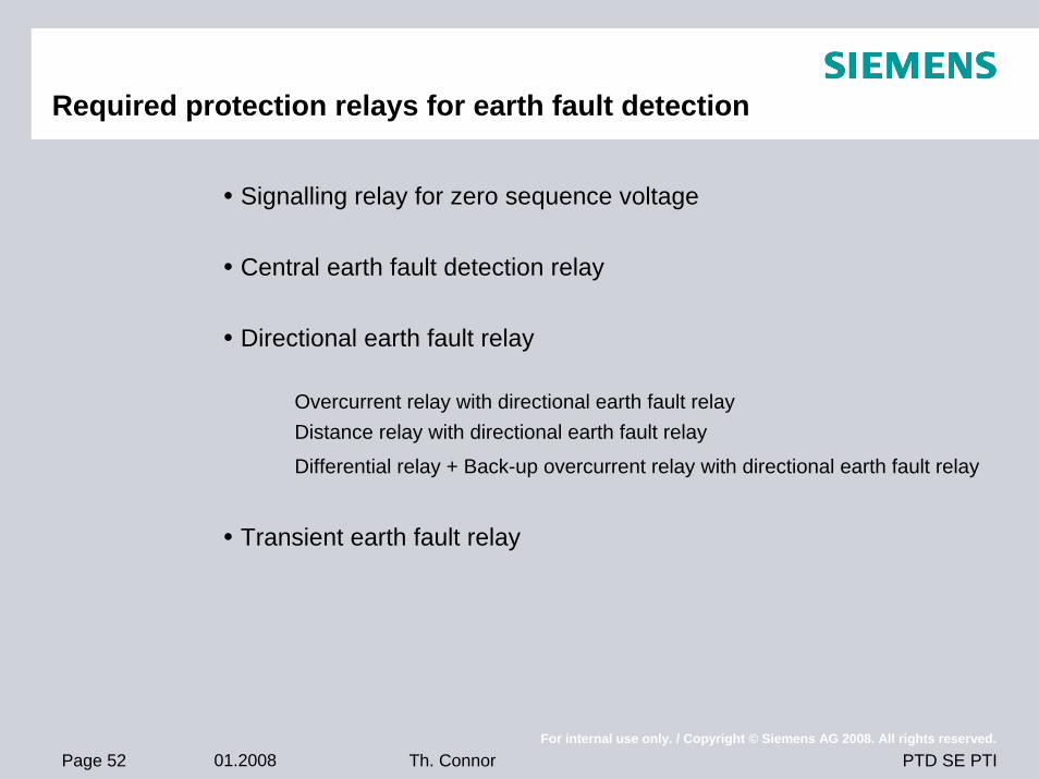
Required protection relays for earth fault detection
Signalling relay for zero sequence voltage
Central earth fault detection relay
Directional earth fault relay
Overcurrent relay with directional earth fault relayDistance relay with directional earth fault relay
Differential relay + Back-up overcurrent relay with directional earth fault relay
Transient earth fault relay
Page 53 01.2008For internal use only. / Copyright © Siemens AG 2008. All rights reserved.
PTD SE PTITh. Connor
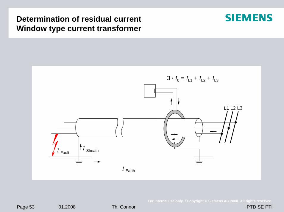
Determination of residual currentWindow type current transformer
L1
3 · I0 = IL1 + IL2 + IL3
L2 L3
I Earth
I SheathI Fault
Page 54 01.2008For internal use only. / Copyright © Siemens AG 2008. All rights reserved.
PTD SE PTITh. Connor
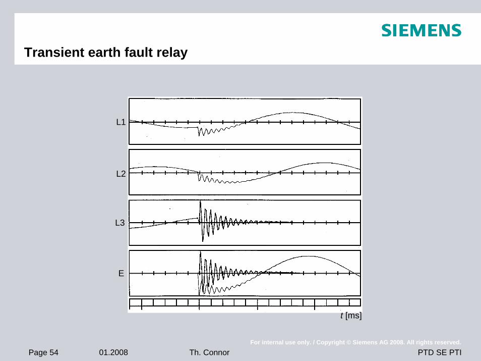
Transient earth fault relay
L1
L2
L3
E
t [ms]
Page 55 01.2008For internal use only. / Copyright © Siemens AG 2008. All rights reserved.
PTD SE PTITh. Connor
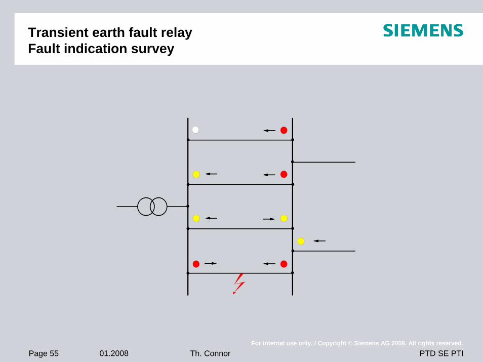
Transient earth fault relayFault indication survey
Page 56 01.2008For internal use only. / Copyright © Siemens AG 2008. All rights reserved.
PTD SE PTITh. Connor
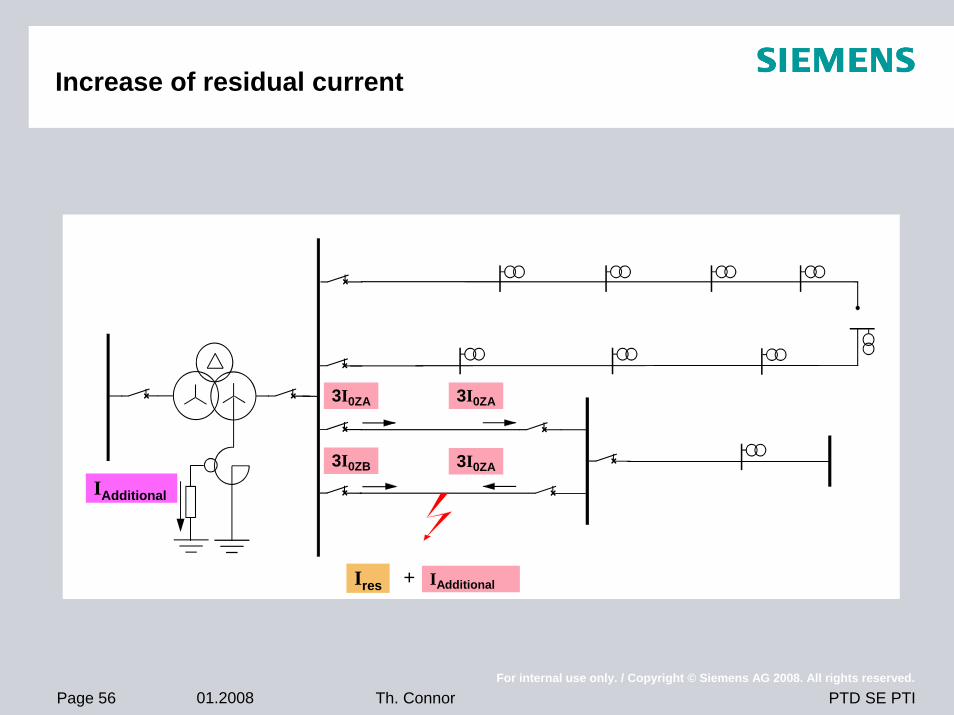
Increase of residual current
3I0ZA
3I0ZB 3I0ZA
IAdditionalIres
IAdditional
+
3I0ZA
Page 57 01.2008For internal use only. / Copyright © Siemens AG 2008. All rights reserved.
PTD SE PTITh. Connor
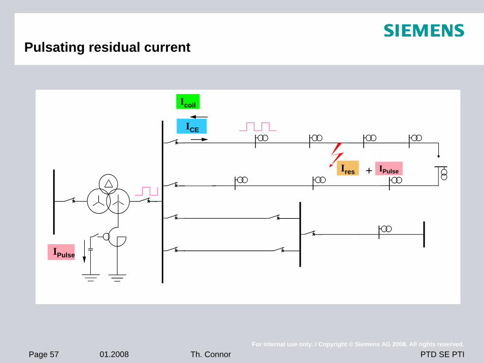
Pulsating residual current
IPulse
IPulseIres +
Icoil
ICE
Page 58 01.2008For internal use only. / Copyright © Siemens AG 2008. All rights reserved.
PTD SE PTITh. Connor
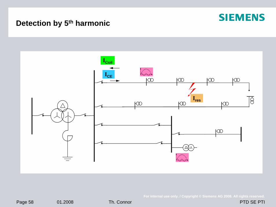
Detection by 5th harmonic
Ires
ICoil
ICE
Page 59 01.2008For internal use only. / Copyright © Siemens AG 2008. All rights reserved.
PTD SE PTITh. Connor
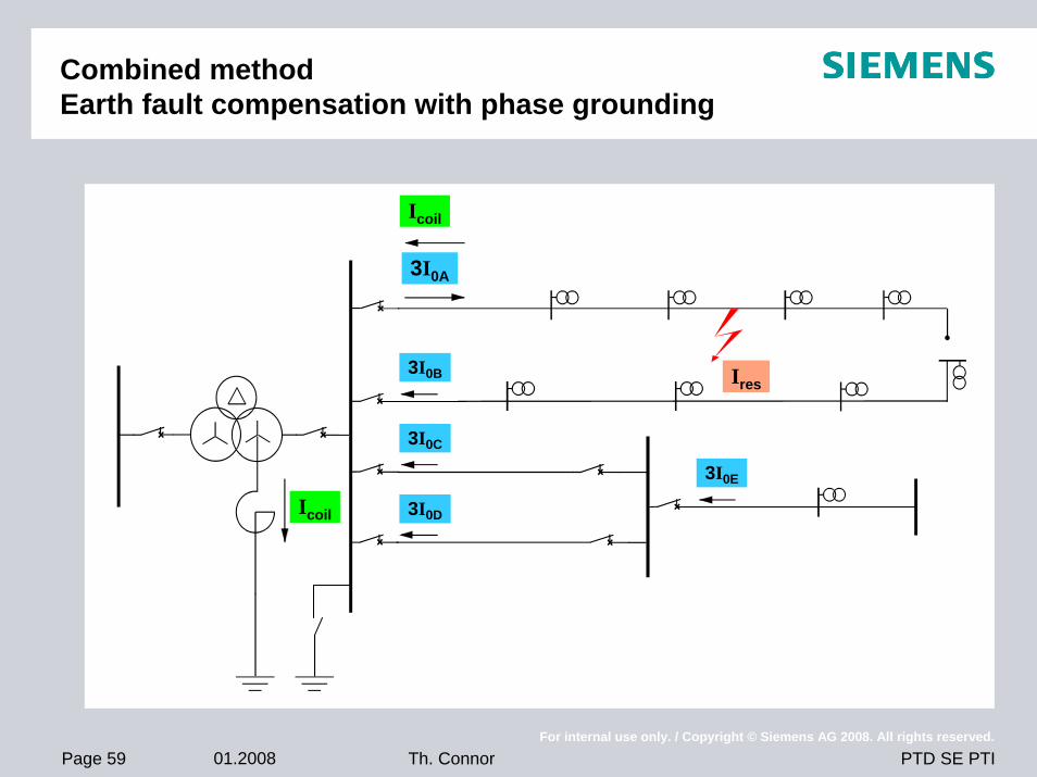
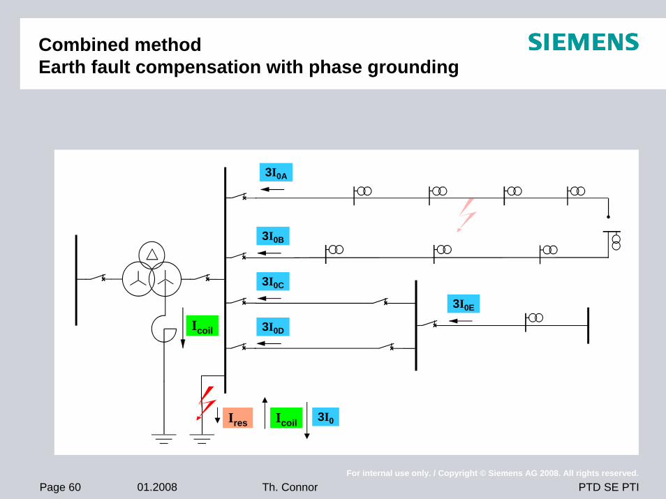
Combined methodEarth fault compensation with phase grounding
3I0A
3I0B
3I0C
3I0D
3I0E
Ires
Icoil
Icoil
Page 60 01.2008For internal use only. / Copyright © Siemens AG 2008. All rights reserved.
PTD SE PTITh. Connor
Combined methodEarth fault compensation with phase grounding
3I0B
3I0C
3I0D
3I0E
Ires
Icoil
3I0A
Icoil 3I0
Page 61 01.2008For internal use only. / Copyright © Siemens AG 2008. All rights reserved.
PTD SE PTITh. Connor
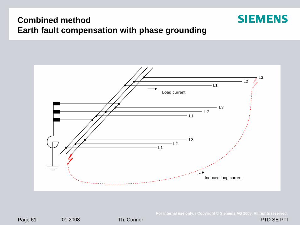
Combined methodEarth fault compensation with phase grounding
L3L2
L1
L3L2
L1
L3L2
L1
Load current
Induced loop current
Page 62 01.2008For internal use only. / Copyright © Siemens AG 2008. All rights reserved.
PTD SE PTITh. Connor
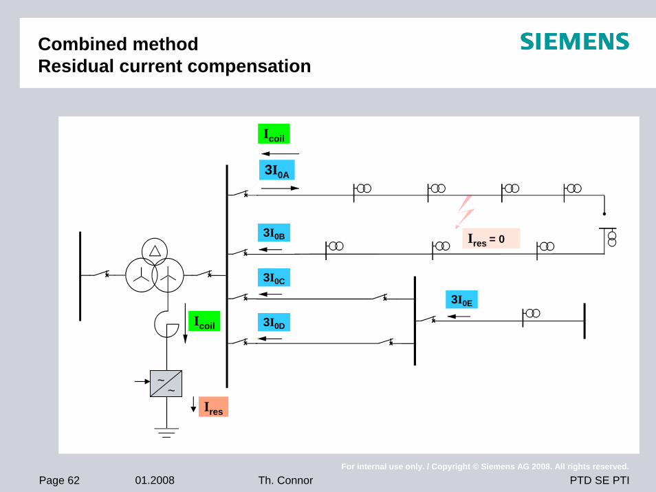
Combined methodResidual current compensation
3I0A
3I0B
3I0C
3I0D
3I0E
Ires = 0
Icoil
Icoil
Ires
~~
Page 63 01.2008For internal use only. / Copyright © Siemens AG 2008. All rights reserved.
PTD SE PTITh. Connor
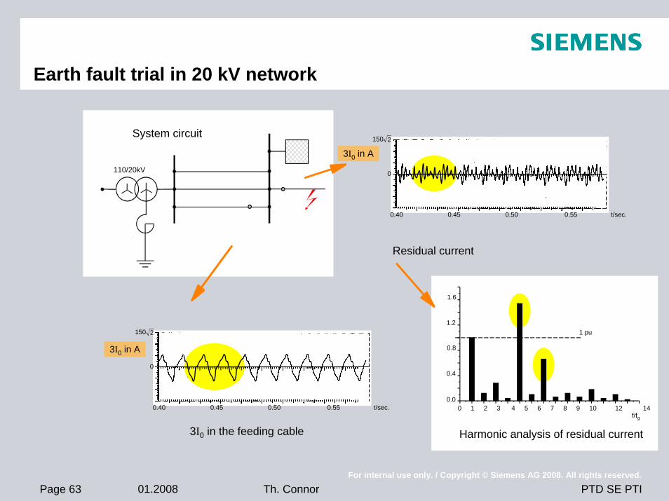
Earth fault trial in 20 kV network
Harmonic analysis of residual current
0.0
0.4
0.8
1.2
1.6
0 1 2 3 4 5 6 7 8 9 10 12 14
1 pu
f/fg
Residual current
3I0 in the feeding cable
0.40 0.45 0.50 0.55 t/sec.
0
150 2
0.40 0.45 0.50 0.55 t/sec.
0
150 2System circuit
3I0 in A
3I0 in A
110/20kV

Page 64 01.2008For internal use only. / Copyright © Siemens AG 2008. All rights reserved.
PTD SE PTITh. Connor
Earth fault trial in compensated networkVoltages and current at the fault location
20 kV
110 kV
t [ms]
Ires [A]
t [ms]
t [ms]
U [kV]
Ires
Ires [A]
Page 65 01.2008For internal use only. / Copyright © Siemens AG 2008. All rights reserved.
PTD SE PTITh. Connor
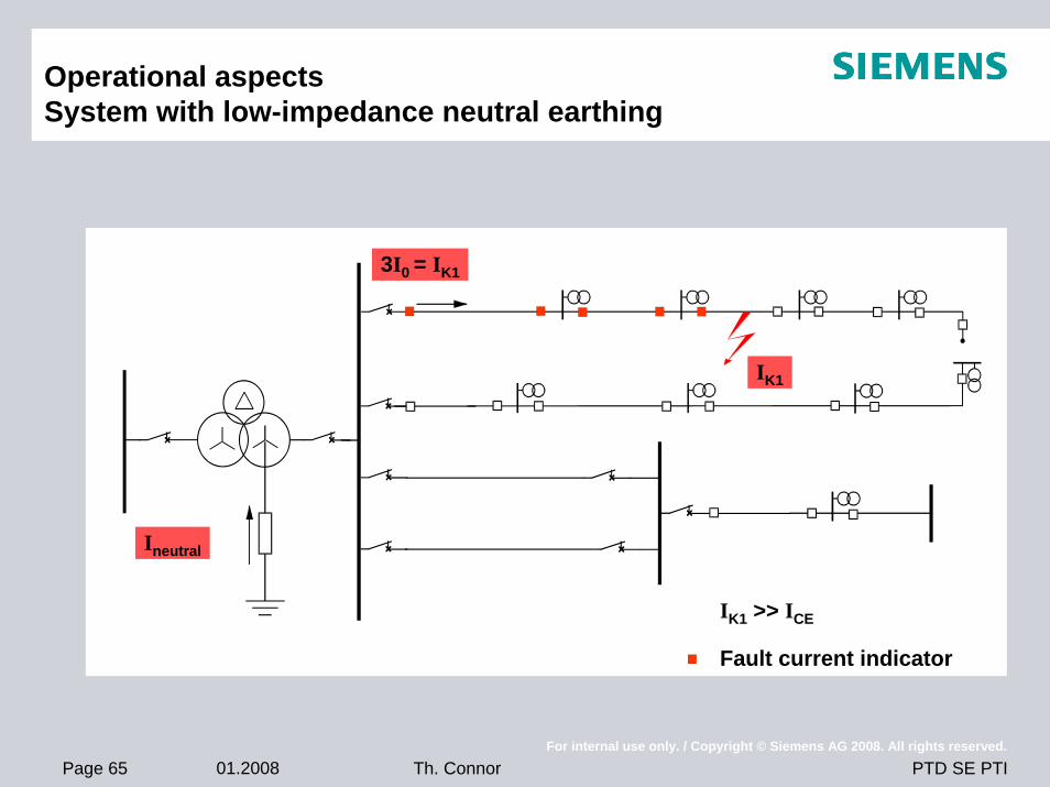
Operational aspectsSystem with low-impedance neutral earthing
3I0 = IK1
Ineutral
IK1
IK1 >> ICE
Fault current indicator
Page 66 01.2008For internal use only. / Copyright © Siemens AG 2008. All rights reserved.
PTD SE PTITh. Connor
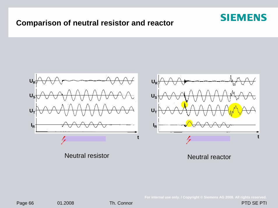
Comparison of neutral resistor and reactor
Neutral resistor Neutral reactor
t
UR
US
UT
IR
t
UR
US
UT
IR
Page 67 01.2008For internal use only. / Copyright © Siemens AG 2008. All rights reserved.
PTD SE PTITh. Connor
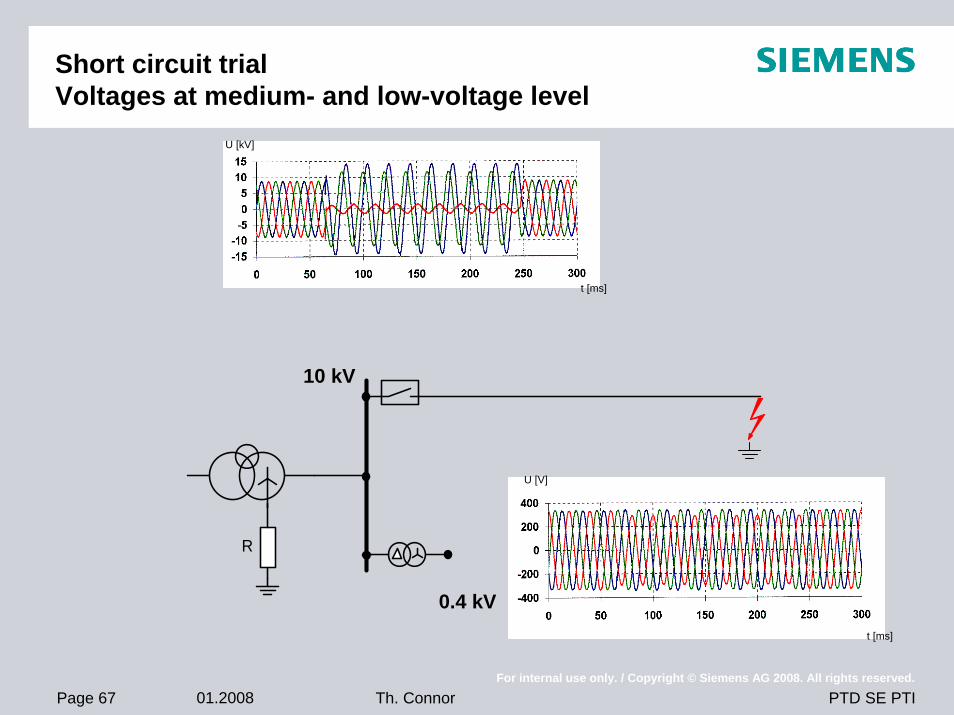
Short circuit trialVoltages at medium- and low-voltage level
R
10 kV
0.4 kV
U [kV]
t [ms]
U [V]
t [ms]
Page 68 01.2008For internal use only. / Copyright © Siemens AG 2008. All rights reserved.
PTD SE PTITh. Connor
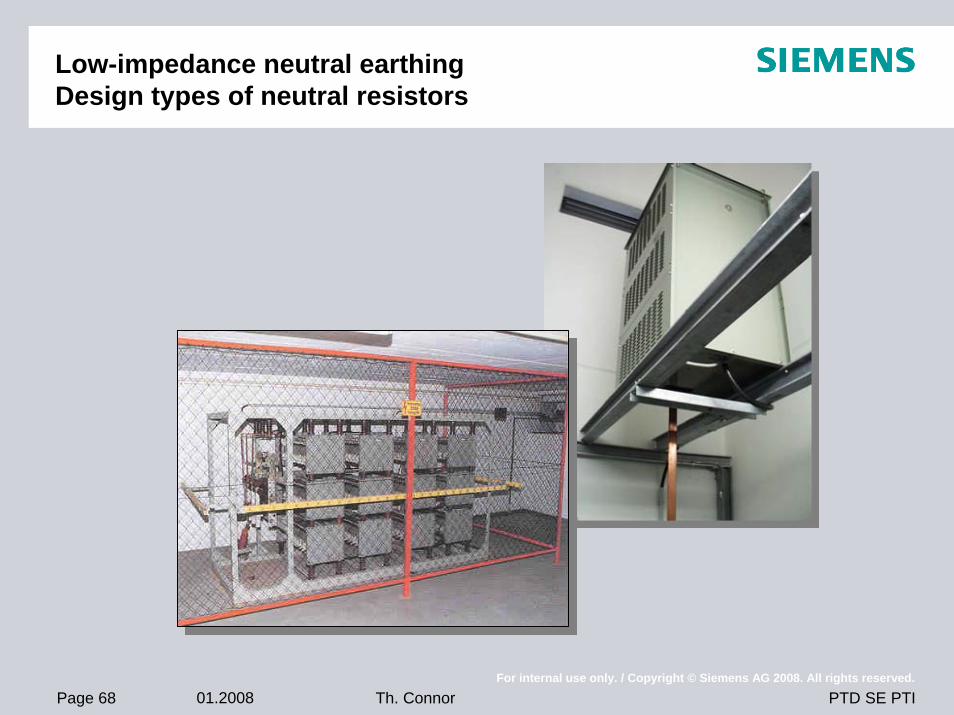
Low-impedance neutral earthingDesign types of neutral resistors
Page 69 01.2008For internal use only. / Copyright © Siemens AG 2008. All rights reserved.
PTD SE PTITh. Connor
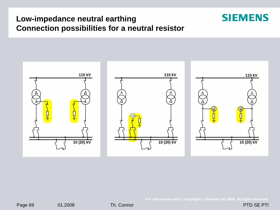
Low-impedance neutral earthingConnection possibilities for a neutral resistor
110 kV
10 (20) kV
110 kV
10 (20) kV
110 kV
10 (20) kV
Page 70 01.2008For internal use only. / Copyright © Siemens AG 2008. All rights reserved.
PTD SE PTITh. Connor
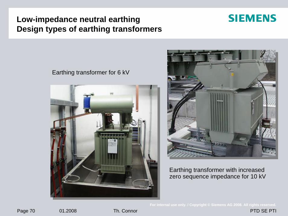
Low-impedance neutral earthingDesign types of earthing transformers
Earthing transformer for 6 kV
Earthing transformer with increased zero sequence impedance for 10 kV
Page 71 01.2008For internal use only. / Copyright © Siemens AG 2008. All rights reserved.
PTD SE PTITh. Connor
Required protection for low-impedance neutral earthing
3phase protection equipment necessary
• Overcurrent relaysensitive earth fault detection 0.1 IN
• Distance protectionOvercurrent pick-up
Earth fault for loop selectionImpedance pick-up
in meshed networks
Transformer differential protectionSuppression of neutral current
Page 72 01.2008For internal use only. / Copyright © Siemens AG 2008. All rights reserved.
PTD SE PTITh. Connor
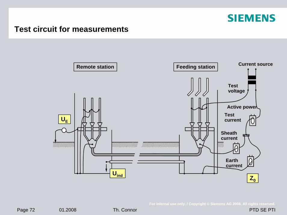
Test circuit for measurements
Remote station Feeding station Current source
Test voltage
Active powerTestcurrent
Sheathcurrent
Earthcurrent
Z0
UE
V
Uind
Page 73 01.2008For internal use only. / Copyright © Siemens AG 2008. All rights reserved.
PTD SE PTITh. Connor
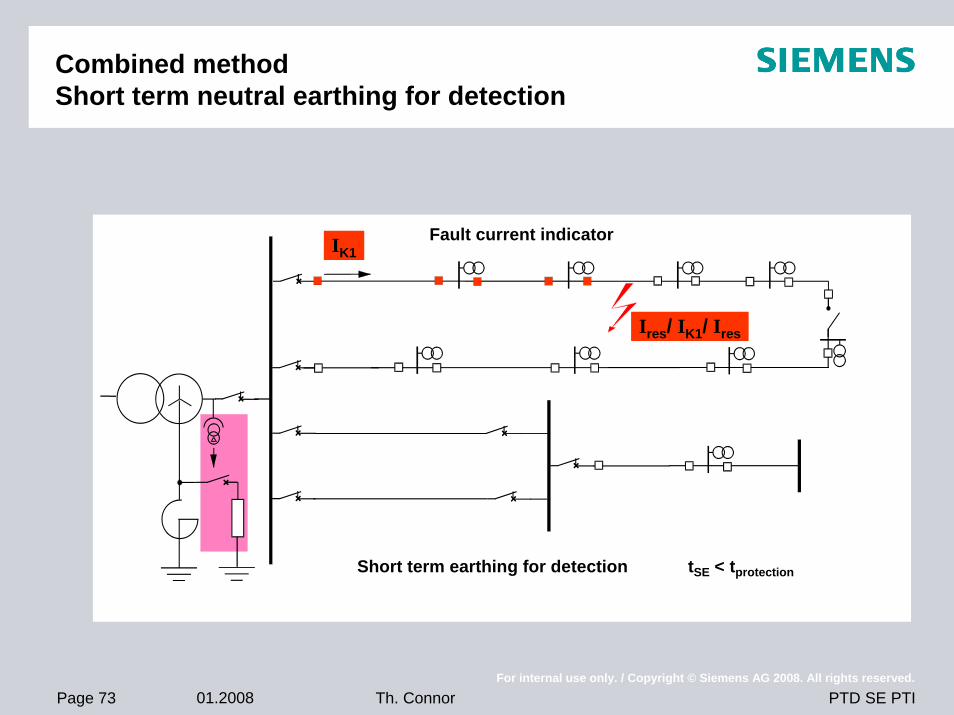
Combined methodShort term neutral earthing for detection
IK1
Ires/ IK1/ Ires
Fault current indicator
Short term earthing for detection tSE < tprotection
Page 74 01.2008For internal use only. / Copyright © Siemens AG 2008. All rights reserved.
PTD SE PTITh. Connor
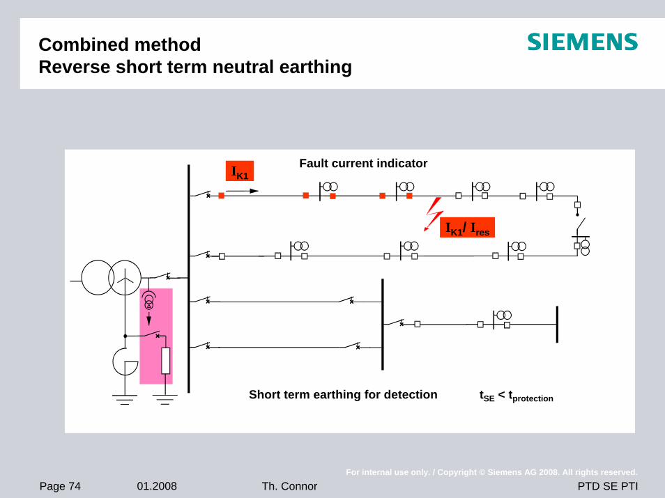
Combined methodReverse short term neutral earthing
IK1
IK1/ Ires
Fault current indicator
Short term earthing for detection tSE < tprotection
Page 75 01.2008For internal use only. / Copyright © Siemens AG 2008. All rights reserved.
PTD SE PTITh. Connor
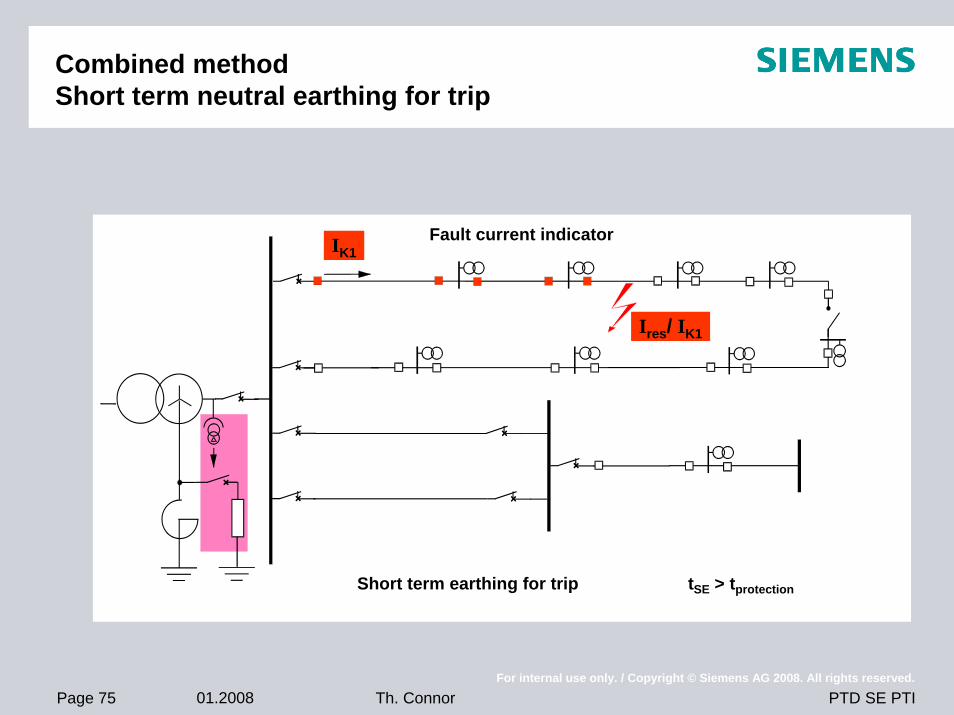
Combined methodShort term neutral earthing for trip
IK1
Ires/ IK1
Fault current indicator
Short term earthing for trip tSE > tprotection
Page 76 01.2008For internal use only. / Copyright © Siemens AG 2008. All rights reserved.
PTD SE PTITh. Connor
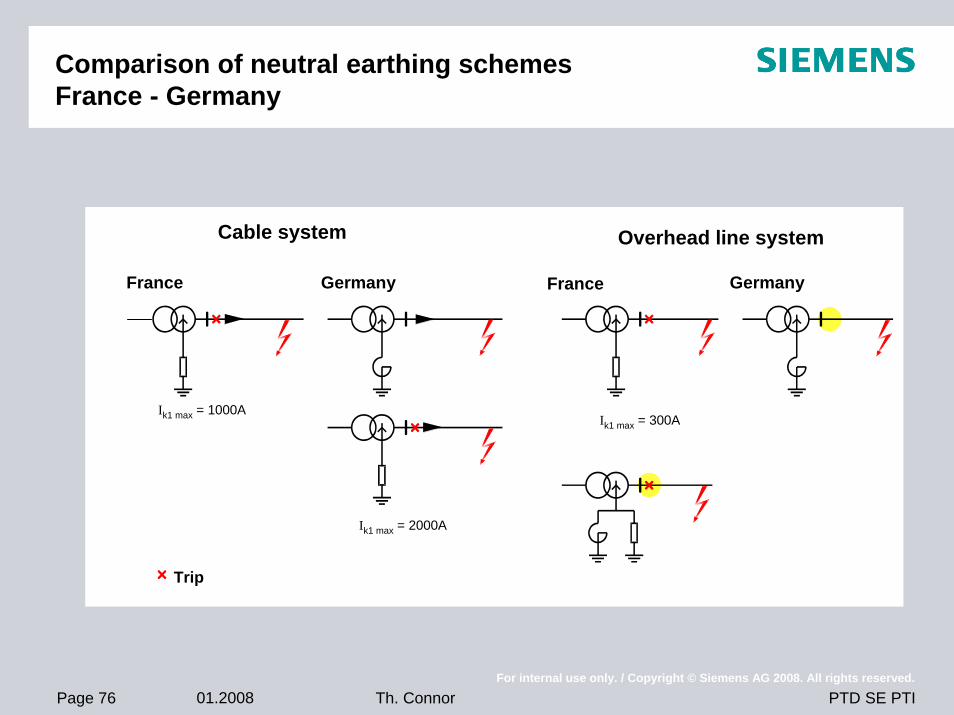
Comparison of neutral earthing schemesFrance - Germany
Cable system Overhead line system
France FranceGermany Germany
Ik1 max = 1000A
Ik1 max = 2000A
Ik1 max = 300A
Trip