new approach to arc resistance calculation
TRANSCRIPT

7/23/2019 New Approach to Arc Resistance Calculation
http://slidepdf.com/reader/full/new-approach-to-arc-resistance-calculation 1/7
NewApproach
V.V. Terzija, Member, IEEE
Saarland University
Saarbriicken, Germany
to Arc Resistance Calculation
H.-J. Koglin
Saarland University
Saarbrticken, Germany
Abstract An important macroscopic arc parameter, describing its
complex nature is
arc resistance.
As known, the fault arc
resistance can be calculated by the Warrington formula. Authors
investigated the results of Warrington’s tests. Warrington derived
a relation for the arc voltage by using the measured arc voltage
gradient and arc current as input data. By analyzing these
measurements and by taking into account the conditions under
which they are obtained (inaccurate measurement devices), it is
unquestionable that the results are highly empirical and not
accurate and general enough, Laboratory testing, provided in the
high power test laboratory FGH-Mannheim (Germany), in which
long high current arcs are initiated, was the base for the research
results presented. In this paper a new approach to ruc resistance
calculation is given. Two independent approaches delivered the
same equation, Both approaches are based on a suitable and a
simple arc model assuming the rectrmguhm wave form of the arc
voltage, which is in phase with the arc current wave form The
new formula for arc resistance is compared with the Warrington
formula. The influences of arc elongation are investigated, too.
Keywords: Long arc in still air, arc resistance, Wamington
formula, laboratory testing, new arc resistance formula.
I. INTRODUCTION
Arc discharge is encountered in the everyday use of
power equipment. Permanent faults in a transformer,
machine, cable, or transmission line always involve an arc.
Whenever a circuit breaker is opened while currying a
current, an arc strikes between its separating contacts. In
Fig. 1, an example of a three-phase arcing fault on a 20 kV
overhead transmission line is presented [1]. The arc
existing at the fault point is a high ~wer long arc in still
air. It has not the same properties as the much more
shorter arc existing in circuit breakers. All arcs posses a
highly complex nonlinear nature, influenced by a number
of factors. An arc can be considered as an element of
electrical power system having a resistive nature, i.e. as a
pure resistance. The length variation is an important factor
in describing the arc behavior and arc resistance. The
nature of arc elongation effects are difiicult and extremely
Fig 1: Three-phase arcing fau lt on a 20 kV overhead transmission l ine.
non-stationary, so they are not simple to be modeled.
In the case of short-circuits occurring on lines within
medium- and high-voltage networks, distance protection
has to locate precisely the fault point for a selective
interruption of the fault. In most cases (over 90Yo) short
circuits in a network are followed with an arc (arcing
faults), so an impedance evaluation, i.e. fault location, is
disturbed by the arc voltage arising at the fault point. In
other words, arc is the source of errors, if it is not taken
into the consideration when locating the fault. To avoid
these errors, the well known Warrington formula [2] for
arc resistance calculation is used.
Empirically obtained results play an important role in
investigating the nature of electrical arc. One of the
earliest experimental studies considering the long arc in
still air are presented in [2,3,4]. Nowadays modern
transient recorders with fast A/D converters are available.
In this paper the results derived by Barrington [2] are
investigated and compared with the results obtained from
laboratory tests provided in a high power test laboratory
FGH-Mannheim (Germany). It is concluded that
Warrington formula is not quite correct, so the new
formula for arc resistance calculation is derived and
compared with the 014 Barrington formula.
Two independent approaches delivered the same new
equation for arc resistance. In the first, definition of
resistance in a-c circuits was the starting point for the
formula derivation, whereas in the second, the spectral
analysis approach is used. Obvious absolute relative
differences between the formulae, in particular for the wide
range of currents, are noticed. The results obtained are
discussed.
0-7803-6672-7/01/$10.00 (C) 2001 IEEE 781

7/23/2019 New Approach to Arc Resistance Calculation
http://slidepdf.com/reader/full/new-approach-to-arc-resistance-calculation 2/7
In this paper, first Warrington results are teste~ judge~
discussed and criticized. Secon4 the results obtained in
FGH-Mannheim are presented and a new “macroscopic arc
model” is derived. Thir& a new formula for arc resistance
is derived. Two independent approaches delivered the
same formula. Fourth, the new formula is compared with
the Warrington formula. Before concluding remarks, the
aspects of arc elongation effects and its influences to arc
resistance are investigated.
II. DISCUSSION ON WARRINGTON FORMULA
In [2] Warrington presented his remarkable results of
field tests on the high-voltage systems of the New England
and the Tennessee Electric Power Company. Through
these tests he investigated the influence of arc resistance on
protective devices and derived his well known and widely
applied general formula for arc resistance calculation:
Ua=Ea L=~L
In
(1)
where U, is arc voltage (V), E. is arc voltage gradient
(V/ft, or V/m), 1 m = 0.3048 ft, L is arc length (ft, m), 1
is arc RMS current (A) and K and n are the unknown
constants. The unknown parameters K and n are estimated
from measurements. In [2] Warrington expressed the arc
length in feet @).
In Fig. 2 the third Fig. from [2], scanned and
incorporated into this paper, is presented. In this figure the
measured arc voltage gradient, E, expressed in (kV/ft), is
presented over currents in amperes. Only the selected
measurement set is depicted. Bad measurements are
omitted. In [2] it is not explained how the measurements
are omitted. In the same figure, a curve defining the
relationship between E. and current is plotted. The curve is
obtained using the following parameters included in (1 ):
K=8750, n=0.4, ~=2.5
n
Parameters are valid if length is expressed in (fI). In Fig. 2,
in the Warrington formula given below the graph, the arc
voltage is expressed in (kV). In other words, from the
selected measurement set, Warrington determined
parameters K and n, and by using (1) obtained the curve
showing the relationship between arc voltage gradient and
arc current. By including K and n into (l), one obtains the
following formula for the arc voltage:
8750
~L [V/ft] = 28~~~”5 L [V/m]
‘a = z.fi L = ~o.4
(2)
From (2) the next equation for arc resistance follows:
Ra = . 28’88”5L [Q/m]
I
~1.4
(3)
where voltage is in volts (V), current is in amperes (A) and
arc length in meters (m).
0
200 AM 600 800 &w9
Amp-s F%hmaryWwmi
Fig, %.-~esrs produce characrmisdc equation
,. 8,?50 L
voltage 1 ~
Fig. 2: The orig ina l measurements aud resul ts obtaiued by Barrington [2].
In [2] a table with all measurements obtained by
Warrington are given. Based on the fill measurement set
from [2], in this paper parameters K and n are estimated
and new estimated curves E. over i, are derived. In Fig. 3
both the full measurement set and the estimated curve for
arc voltage gradient are presented. Parameters estimated in
this case are:
K = 3460.49, n = 0.225333, ~ = 4.437877
n
Both parameters are essentially different from the
parameters obtained by Warrington.
2000
. . . . . . . . ..{ . . . . .. . . . . .. . . . . .. . . . . .
1500 -
. . . . . . . . . . . . . . . . . . . . . . . . . . . . . . . . . . . . . . . . . . . . . . . . . . . . . . . . . .
. . . . . . . . ..+ . . . . . .. . .-.. \- -- -- -- --- --
L . . . . . . .. . . . . ... . . . . . .. . . . . . ,. . . . . . . . . . . .
...:......:.*g...:..... : :
. . . . . . . . . . .i . . . . . . .. -.. - -. .. - -. ... .* .
250 -.-.:. ----+ ----{ ---; : - ;.; .;...;.
o
1 1 1
I
1 I 1
1 1
0 1002C03X14CK15CX3 &X17CX38CX)9CKI ICMl
I (A)
Fig. 3: Ful l measurement set and estimated arc vokage gradient curve.
0-7803-6672-7/01/$10.00 (C) 2001 IEEE 782

7/23/2019 New Approach to Arc Resistance Calculation
http://slidepdf.com/reader/full/new-approach-to-arc-resistance-calculation 3/7
By observing Fig. 3, it is obvious that for one current
follow several various values for arc voltage gradient. This
variety is probably the consequence of arc elongation
occurring during the tests?
Under the assumption that some measurements were not
correct, i.e. that some of them could be treated as bad data,
in this paper a reduced measurement set is selected and
presented in Fig. 4. From the reduced measurement set the
following unknown parameters are estimated:
K = 11387.4, n = 0.427663, ~ = 2.338289
n
The new curve for E. is depicted in the same plot.
Fig. 4: Reduced measurcmmt set aud estimated arc voltage gradient curve.
In Fig. 5 the full measurement set from [2] and three arc
voltage gradient curves (the Warrington, the full and the
reduced measurement set curves) are presented.
g-
“ml”~..i...?....
.l.. . . . . . . . . . . . . . . . . . . . . .
o}
I 1 I I
I
o 2C0 400 8CKI 800 IU30
I (A)
Fig . 5: Ful l measurements~ from [2] aud three arc vol tage gradient curves.
It is obvious that two new independent and different
equations for arc voltage resistance calculation are
obtained. From the above results, the following general
observations regarding Warrington field tests are
formulated
1. Measurement devices used during Warrington testing
were relatively inaccurate, so the conclusions derived
are not rel iable enough.
2. During the arc life the arc length is changed. These
changes are not considered when Warrington formula
is derived.
3.
4.
5.
6.
A criterion used in [2] by which some bad data are
rejecte~ i.e. omitted from the consideration, is not
described. It seems that the selection of the
measurements processed is provided quite arbitrarily.
This task should be solved by using the known
standard robust estimators, not sensitive to bad data
(outliers).
The method how Warrington formula is derived is not
mentioned in the text.
The range of arc currents observed is rather small
(< 1 kA).
Warrington formula can not be accepted as absolute
correct,- so the new formulae sho~d be derived,
compared with it and applied.
The 6-th observation that Barrington formula is not
absolute correct, as well as the fact that the formula is not
derived by analyzing a wide range of currents (the
expected short circuit currents are reaching today values
over 50 kA), motivated authors to investigate the
possibilities for deriving a new formula for arc resistance.
The new formula should be used as an alternative to the
Warrington one. The response of the international
scientific society to the new approach, which will be
presented, should judge it and investigate if it is suitable
for the practical applications.
III. LABORATORY TESTING AND MODELING OF
LONG ARC IN STILL AIR
The nature of long arc in still air is investigated in the
high power test laboratory FGH-Mannheim (Germany), in
which a series of laboratory tests are provided. Voltage
u t ,
urrent i(t) and arc voltage u,(t) are digitized fkom the
laboratory test circuit depicted in Fig. 6. Arcs between
arcing horns of vertical and horizontal insulator chains are
initiated by means of a fise wire, when switch S in Fig. 6
is closed. The distance between electrodes is changed in
the range of 0.17-2 m. The range of arc currents varied
between 2 and 12 kA.
i(rj
R L
4
s
U(lj
-IT
~ (q
I
arc
J
I
~J
Fig. 6: Laboratory test circuit.
In Fig. 7 the recorded arc voltage u,(t), current i(t),
which is at the same time the arc current is(t) and the
recalculated instantaneous electrical power of arc are
0-7803-6672-7/01/$10.00 (C) 2001 IEEE 783

7/23/2019 New Approach to Arc Resistance Calculation
http://slidepdf.com/reader/full/new-approach-to-arc-resistance-calculation 4/7
plotted. Arc voltage and arc current are in phase,
confirming the resistive arc nature. The wave form of arc
power is distorted and from the amplitude point of view,
proportional to arc current. The long high current a-c arc
voltage amplitude is proportional to arc voltage length.
Here the coefficient of proportionality is arc voltage
gradient E.. It is almost independent from the arc current,
so the voltage amplitudes of long high current arcs are
determined by the arc length L. Over the range of currents,
100 A to 20 ~ the average arc voltage gradient lies
between 1.2 and 1.5 kV/m [4,5,6]. In [3] it is shown that
for long arcs almost all the total arc voltage appears across
arc column.
0.14 0.15 0.16 0.17 0.18
t (s)
Fig . 7: Recorded arc wave forms.
The quantitative expression of signal distortion is the
total distortion factor THD, calculated as follows:
where Ua(t) and ia (t) are voltage and current of an arc
having the constant length L and U, is the amplitude of the
rectangular signal. In (5), sgn is a sign fimction defined as:
sgn(x) = 1 ifx20 and sgn(x) = -1 ifx<O and ~(t) is zero-
mean Gaussian noise. The value of U, can be obtained as
the product of arc-voltage gradient E. and the actual arc
length, L.
The arc voltage model (5) has been already successfully
used for the purpose of overhead lines protection (see Lit.
[9, 10]). In this paper, it will be the starting point for the
derivation of the new formula for arc resistance
calculation. In Fig. 8, the simulated arc voltage (eq. (5))
and current from the circuit depicted in Fig. 6, as well as
the recalculated instantaneous electrical power of arc are
presented. Simulation is provided using a software package
presented in [1 1].
—
3“ -lo r
I I I
1
0.04 O.ffl 0.06 0.07
0.06
t (s)
Fig. 8: Simulated arc wave f-.
(4)
where & (h= l,..., M ) is the amplitude of the lr-th
harmonic. Spectral analysis of arc voltages and currents is
provided through the application of Fast Fourier Transform
(FFT). From the calculated amplitude spectra, the
corresponding THD factors for arc voltage and current are
calculated. The average THD factors for arc voltage and
current are approximately 30 and 2
0/0,
respectively.
It can be concluded that arc voltage is a distorted wave
form, whereas arc current is not. Thereby, arc current can
be modeled as a pure sine wave, whereas arc voltage must
be modeled in a such a way that its distortions are
realistically enough taken into account.
By observing the arc voltage and current waveforms
plotted in Fig. 7, one concludes that the voltage signal has
a distorted rectangular form. Additionally, it is in phase
with arc current. Thus, an arc can be represented through
the following equation, modeling the arc voltage [7,8]:
(5)
IV. NEW FORMULA FOR ARC RESISTANCE
In this Section a new formula for arc resistance
calculation is derived. One formula is derived in two
independent ways: a) by using the classical definition of
electrical resistance in a-c circuits and b) by using the
spectral domain analyzes approach.
A. Derivation Using the Classical Resistance Definition
Let us assume that arc voltage u t and current i(t) are
modeled as follows:
u(t)= U.sgn[i(t)]
(6)
i(f) = JZI sin cot
(7)
The resistance R of an element belonging to an a-c circuit
is defined as:
RZ2 = P = -jp(t)dt = (t~(t)dt
o 0
(8)
0-7803-6672-7/01/$10.00 (C) 2001 IEEE 784

7/23/2019 New Approach to Arc Resistance Calculation
http://slidepdf.com/reader/full/new-approach-to-arc-resistance-calculation 5/7
where 1 is the RMS of current and p(t) is the instantaneous
maximal and RMS values of the h-th harmonics can be
power. By including (6) and (7) into (8), one obtains:
respectively calculated by using the following formulae:
RI’
. Tp t)dt
T
o
Since
’12
’12
ji(t)dt=fil J’sincotdt=*
o 0
(9)
Hence, for the first harmonic, one obtains:
(lo)
equation (9) becomes:
By defining the arc resistance as:
(11)
From (11) follows the explicit expression for the arc
resistance:
Suppose that there exists a linear relationship between arc
voltage magnitude and arc voltage gradient:
U. =E~L
(13)
Hence
(14)
Equation (14) is the new formula for arc resistance
calculation. It requires a suitable selection of the
value/expression for the arc voltage gradient Ea.
B. Derivation Using Spectral Domain Analyzes Approach
A pure square wave (eq. (6)) can be expressed by Fourier
series containing odd sine components only, as follows:
where h = 1, 3, 5, 7, ... is the harmonics order, ~ is the
phase angle of the fimdamental harmonic and o is the
fimdamental angular frequency. From (15) follows that the
u’
R=~
11
a, m
and by including (18) into (19), one obtains:
a,rms. k : ‘“ _ 2&Ja
1
R=—
11
a, m
I-xI
(16)
(17)
(18)
(19)
(20)
Finally, by including (13) into (20), follows the same
formula for arc resistance, derived by using the classical
arc definition (eq. (14)):
C. Arc Voltage Gradient Selection
(21)
As already mentione& in the new formula for arc
resistance a suitable value/expression for the arc voltage
gradient should be included. From the electrical properties
of an arc under steady conditions (u-i characteristic) point
of view, a number of equations are derived from the
experimental studies. The first and best known is [3]:
(22)
If in (22) L is made sufficiently large, the terms involving
parameters A and C may be neglectet and the
characteristic equation becomes approximately:
)
.= B+; L
(23)
0-7803-6672-7/01/$10.00 (C) 2001 IEEE 785
7/23/2019 New Approach to Arc Resistance Calculation
http://slidepdf.com/reader/full/new-approach-to-arc-resistance-calculation 6/7
If in (23) current is sufficiently large, the arc voltage
becomes a fimction only of the arc length, according to the
equation
U. = BL
(24)
Parameter B represents the voltage gradient E. in the arc
column. The arcs occurring on the fault point can be
treated as long high current arcs, so the aforementioned
discussion holds. In the open literature the following
values/expressions for E, calculation are used:
1. in accordance with (24) and from Lit.
E. = (1200+-1500) (V/m)
2. in accordance with (23) and from Lit.
EQ = 950+5000/1 (V/m)
4,5,6]:
(25)
12]:
(26)
In (26)1 is expressed in amperes (A). Equations (25) and
(26) can be now included in (21), so the following two new
equations follows:
RI= (1080.4 +1350.5);
(27)
)
= 855.3+ 4501.6 ~
2
I
I=
(28)
In (27), constant 1080.4 follows if E. = 1200 V/m, whereas
constant 1350.5 follows if E. = 1500 V/m.
In the next Section formulae (27) and (28) will be
compared with Warrington formula:
(29)
Comparison will be provided by comparing the values for a
wide range of currents.
V. COMPARISON BETWEEN WARRINGTON AND
NEW FORMULA
Three formulae: the Warrington formula (29) and two
new formulae (27) and (28), derived in this paper, are
compared by changing the RMS values of arc current in
the expressions for arc resistances, for the in advance
assumed arc length. Here it is assumed that an 1 m long
arc is analyzed (L = 1 m). The current RMS values are
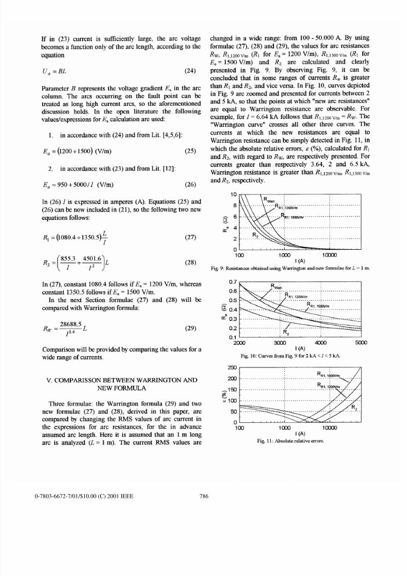
changed in a wide range: from 100-50.000 A. By using
formulae (27), (28) and (29), the values for arc resistances
Rw, R1,12001~ (Rl for E,= 1200 V/m), R1,15001~ (Rl for
E.= 1500 V/m) and Rz are calculated and clearly
presented in Fig. 9. By observing Fig. 9, it can be
concluded that in some ranges of currents RW is greater
than RI and Rz, and vice versa. In Fig. 10, curves depicted
in Fig. 9 are zoomed and presented for currents between 2
and 5 m so that the points at which “new arc resistances”
are equal to Warrington resistance are observable. For
example, for 1 = 6.64 ld follows that R1,1200/m =
Rw.
The
“Warrington curve”
crosses all other three curves. The
currents at which the new resistances are equal to
Warrington resistance can be simply detected in Fig. 11, in
which the absolute relative errors, s (Yo), calculated for RI
and Rz, with regard to Rw, are respectively presented. For
currents greater than respectively 3.64, 2 and 6.5 kA,
Warrington resistance is greater than R1,lzoowm, RI,1soowm
and Rz, respectively.
10
8
g
6
u? 4
2
0
100
ICKJO
Im
I (A)
Fig. 9: Resistances obtained using Barrington and new formulae for L = 1m.
0.7
0.6
0.5
0.2
0.1 1
I
‘
1
I
2(X)O
3mo 4mo
5a30
I (A)
Fig. 10: Curves from Fig. 9for2kA<I<5kA-
I
00 -- -- -- -- -- --- -- -- -
.
R:
RI, l XIV/m
/1
..\...
I XY
1(X)O
lmoo
I (A)
Fig 11: Absolute relat ive errors.
0-7803-6672-7/01/$10.00 (C) 2001 IEEE 786

7/23/2019 New Approach to Arc Resistance Calculation
http://slidepdf.com/reader/full/new-approach-to-arc-resistance-calculation 7/7
VI. EXTENTION OF ARC RESISTANCE EQUATION
WITH THE ARC ELONGATION MODEL
VIII. REFERENCES
As a matter of fact, arcs length is changing during the
arc life. The elongation of the long arc is determined by the
magnetic forces produced by the supply current, the
convection of the plasma and the surrounding air, the
atmospheric effects (win~ humidity, pressure), i.e. the
medium in which arc is initiate~ etc.
Arc model (5) does not model the arc elongation effects.
Generally speaking, the arc elongation can be involved
into the model (5) by multiplying it with a suitable selected
arc elongation function L(t). The same is valid for the arc
resistance.
Since the elongation effects are not
deterministic, but extremely stochastic, it is relatively
difficult to model all effects exactly. For example, the
elongation fi.mction L(t) can be selected in the form of an
exponential fimction and in this form included in the arc
resistance formula, as follows:
R@(t)=
ao(t)~+aefl@Ti) h(t - ~)] (30)
where
Rao
is the initial arc resistance, Ti is the inception of
arc ignition, h(t) is Heaviside fimction and a and p are
parameters defining the arc elongation dynamics.
Naturally, some other “elongation functions” can be used
for modeling elongation effects of an arc, as well.
VI. CONCLUSION
Through the investigation of Warrington results it is
concluded that his well known formula for arc resistance
calculation is not absolutely correct. Based on experimental
testing in FGH-Mannheim (Germany), a new formula for
arc resistance is derived. Two independent procedures of
its development are presented. New formula requires a
suitable selection of arc voltage gradient value. Two
approaches for arc voltage gradient are presente~ so that
two new formulae are derived. New formula is compared
by Warrington formula. Obvious differences are observed.
Authors are now expecting the response of scientific
audience to the results presented.
VII. ACKNOWLEDGEMENT
[1] D. Oedin& R. Spech, “Test einea “Digitalen Distanz.schutzrelais” im 20-
kV-Netz”, etzArchiv 5, pp. 171-173, 1983.
[2] AR. Van C. Warrington, “Rcactancc Relays Negligibly AtWtcd by Arc
Impedance”, Electr ical World, S@ember, 19, pp. 502-505, 1931.
[3] H. Ayrton, “The Electric Arc”, The Electrkkm, London, 1902.
[4] AP. Strom, “Long 60-cycle Arc iu Air”, Trans. Am. Inst. Elec. Eng, 65,
pp.113-117, 1946.
[5] T.E. Browne, Jr .,
“The Electric Arc as a Circuit Element”, Journal of
Electrochem. Sot. Vol. 102 No. 1,pp. 27-37, 1955,
[6] A.S. Maikapar, “Extinction of an open electric arc,” Elektrk-heetvo, Vol.
4, pp. 64-69, April 1960,
[7] V. Terzija, H.-J. Koglin, “Long Arc In Free Air: Testing Modelling And
Parameter Est imat ion: Paf i 1”, Proceedings of the UPEC 2000 Conference,
Belfast, w 6-8. Sep. 2000.
[8] V. Terzija, H.-J. Koglin, “Long Arc In Free Air: Testing Modelling And
Parameter Est imat ion: Part 2“, Proceedings of the UPEC 2000 Conference,
Bel fast , UK 6-8. Sep. 2000.
[9] M. Djuri6, V. Terzija, “Anew approach to the arcing faults detection for
autoreclosure in transmission systems,” IEEE Tram. on Power Dehvey,
Vol. 10, NO 4, October 1995, pp. 1793-1798.
[10] Z.M. Radojevic, V.V. Terzija, M.B. Djuri6, “Multipmpose Overhead
Lines Protection Algorithm”, IEE Proc.-Genm,Transm Distrib., Vol. 146,
No. 5, PP.441-445, Sqrtembtx 1999.
[11] D. Ldnar& R. Simon, V. Terzija, “Simulation von Netzmodelkm mit
zweiseitiger Einspeisung mm Test v.. Netzwhutzeinrichtungen,” TB-
157/92 Univ. Kaiserslautem, July 1992,
[12] Y. Goda at all, “Arc Vottage Characteristics of High Current Fault Arcs
in Long Gaps”, IEEE Paper No. PE-186PRD.
IX. BIOGRAPHIES
Vladimir V. Terzija was born in Donji Bara6i
(Bosnia and Herzegovina) in 1962. He
received his B.SC., M. SC.and Ph.D. degrees m
Eltirical Power Engineering tiom
Department
of Electrical Engineerin&
University of Belgrade, Yugoslavia, in 1988,
1993 and 1997, respectively. In 1988 he
joined University of Belgrade, where he is
now an assistant prof=sor teaching coursee in
Electric Power Quality, and Power System
Control. At present he is a Research Fellow at
Institute of Power Entieering University of
Saarkm~ granted by Alexander VO. Humboldt Fo-&lati~. His area_s of
scient if ic intereat are power system protcci ion and control, electr ical power
quality and DSP appl ications in power systems.
Hans-Jtirgen Koglin was born in 1937. He
received his Dipl .- Ing. degree in 1964 and his
Dr.-Ing. degree in 1972 from the Technical
Universi ty Darnrstadt, Germany. From 1973
to 1983 he was a professor at the same
university. Since 1983 he is a f ill profeesor at
Saarland University in
Saarbrocken,
Germany. His main areas of scientific
interests are planing and operat ion of power
systems and specially optimal MV- and LV-
networks. v isibili ty of overbead lines. state
.
estimat ion, rel iabi li ty , corrt iive switching protection and f iel cel ls
The authors gratefully acknowledge to Alexander von
Humboldt Foundation for supporting this research and to
high power test laboratory FGH Mannheim (Germany) for
providing the authors with the laboratory data records.
0-7803-6672-7/01/$10.00 (C) 2001 IEEE 787