new arc resistant, compact metal clad switchgear: … arc resistant, compact metal clad switchgear:...
TRANSCRIPT
New Arc Resistant, Compact Metal Clad Switchgear: Meeting ANSI / UL Design Challenges Rev 2010-0 Page 1 of 12
New Arc Resistant, Compact Metal Clad Switchgear: Meeting ANSI / UL Design Challenges
By Ashok Kulkarni and Predrag Milovac
Industrial Electric Mfg.™
New Arc Resistant, Compact Metal Clad Switchgear: Meeting ANSI / UL Design Challenges Rev 2010-0 Page 2 of 12
Executive Summary
There is an unfilled market need for a medium voltage (5 kV – 15 kV), arc resistant, compact metal clad switchgear for a variety of applications such as data center, marine and critical health care facilities, etc. However, meeting the ANSI/IEEE/UL design challenges to come up with such compact, front accessible switchgear has been very difficult so far. This white paper discusses the ANSI/IEEE Standards and explores the design challenges to find a solution to the multi-dimensional optimization problem. Analysis and simulation methods to find an optimal design solution are explained. Some of the testing methods used by UL to test arc resistant switchgear are highlighted. An example of IEM Vesta metal clad switchgear is used to illustrate the test results.
Industrial Electric Mfg.™
New Arc Resistant, Compact Metal Clad Switchgear: Meeting ANSI / UL Design Challenges Rev 2010-0 Page 3 of 12
Medium Voltage Metal Clad, Arc Resistant Switchgear – Need for a Compact Assembly Medium voltage switchgear houses electrical components, for example, circuit breakers, potential
transformers, current transformers, control power transformers, etc. The medium voltage switchgear
typically occupies a large space. As such, maintenance and space considerations are driving factors in
the design of new medium voltage switchgear. Furthermore, a certain amount of space is essential
between adjacent equipment and structures such as walls and the switchgear as per the national electric
code (NEC) and other local codes. An entire room is typically allocated for the medium voltage
switchgear. Space is a critical factor in industrial applications, data center facilities and marine equipment.
Allocation of an entire room for the medium voltage switchgear would constitute undesirable and
inefficient use of a significant amount of valuable floor space.
Switchgear, particularly medium voltage switchgear, suffers from damage due to arcing. An explosion due
to arcing, occurring within switchgear causes significant amount of economic loss due to interruptions of
energy distribution and results in destruction of the switchgear and the components or equipment
accommodated in the switchgear assembly. Furthermore, maintenance personnel inspecting and
servicing the switchgear cabinets have to wear bulky and expensive protective gear. Typical arc resistant
switchgear cabinets tend to be very large, for example, cabinets are 36 inches wide and 90 inches deep
and often have heavy sheet metal enclosures. Such configurations require enormous space. Some
switchgear cabinets employ an external arcing chamber which limits the configuration of components,
equipment, etc. within the switchgear.
There is a need for constructing a switchgear assembly that makes efficient use of the available floor
space and minimizes the time required for inspection, repair and maintenance of equipment
accommodated in the switchgear. However, a design of compact, arc resistant metal clad switchgear at
15 kV that meets North American standards is quite challenging.
Medium Voltage Switchgear Standards World-wide and ANSI Design Challenges
Medium voltage switchgear cabinets available in markets such as Europe and Asia are built according to
the International Electro-technical Commission (IEC) standards. However, these switchgear cabinets
have cable connection in the rear making it very difficult to install and service such equipment. In addition,
this switchgear utilizes “bar” type current transformers that are mounted in the rear making it impossible to
replace in the field if they fail. And per IEC standards, barriers between compartments are not a
requirement so cooling the circuit breaker is much easier.
Industrial Electric Mfg.™
New Arc Resistant, Compact Metal Clad Switchgear: Meeting ANSI / UL Design Challenges Rev 2010-0 Page 4 of 12
Medium voltage, metal clad switchgear for the North American market need to meet stringent
requirements of Institute of Electrical and Electronics Engineers (IEEE) and American National Standards
Institute (ANSI). As per these standards (UL testing is done to meet this standard), the circuit breaker is
tested inside the switchgear with very limited cooling and therefore limiting temperature rise becomes a
major challenge. IEC designed equipment would have to be derated significantly if no changes are made
to adequately cool the breaker. In addition, IEEE / ANSI designed equipment requires the bus bars to be
insulated, making it more difficult to cool the critical current-carrying bus bars in certain compartments of
the switchgear housing the circuit breaker. Alternatively, expensive heat sinks have to be employed to
limit temperature rise. The addition of heat sinks is a difficult task in the compact space and poses
significant challenges to pass the required lightning impulse test due to space limitations and the shape of
the heat sink. The shape of the heat sink can pose a threat to the space limit, as sharp edges of the heat
sinks will require large spacings and creepage distances. Compact switchgear also limits the space
between phase-to-phase and phase-to-ground which poses significant challenges to pass the required
lightning impulse test at 95 kV.
Arc Resistant, Metal Clad Switchgear – ANSI / IEEE Standards
Arc resistant switchgear provides a means for improving the safety of the operator by providing an
efficient method of redirecting the energy caused by an arcing fault away from the operator. Some of the
characteristics of an arcing event are the following:
Temperatures can reach 35,000oF which causes severe burns.
Copper expands by a factor of 67,000 when it turns from solid to vapor instantly.
This creates high pressure, sound and shrapnel.
The pressure can easily exceed hundreds of pounds per square inch which can easily destroy
doors and walls of a switchgear enclosure if they are not well designed.
Sounds from the resulting high pressure can exceed 160 dB which causes ruptured ear drums.
High pressure also causes collapsed lungs.
Material and molten metal is expelled away from the arc at speeds exceeding 700 mph, fast
enough for the shrapnel to completely penetrate the human body.
In order to define and standardize metal clad switchgear construction and testing to deal with the
enormous energy of an arc fault, the following standards were created by IEEE / ANSI / NEMA:
ANSI / IEEE C37.20.2-1999: Standard for Metal Clad Switchgear.
ANSI/IEEE C37.55-2002: Metal-Clad Switchgear Assemblies – Conformance Test Procedures
ANSI/IEEE Standard C37.54-2002: Standard for High Voltage AC Circuit Breakers –Conformance Test
Procedures.
Industrial Electric Mfg.™
New Arc Resistant, Compact Metal Clad Switchgear: Meeting ANSI / UL Design Challenges Rev 2010-0 Page 5 of 12
ANSI/IEEE C37.09-1999: Standard Test Procedure for High Voltage AC Circuit Breakers
ANSI / IEEE Standard C37.20.7-2007: IEEE Guide for testing of Metal Clad Switchgear Rated up to 38
kV for Internal Arcing Faults (this standard replaces EEMAC G14-1987 and CSA C22.2 No. 261 adopts
much of the language from IEEE C37.20.7-2007).
CSA/CAN C22.2 No 31 -04 -2009: CSA Standard for Switchgear Assemblies.
In addition, we have NFPA guide and IEC standard (for reference only) below.
NFPA 70E-2009: Handbook for Electrical Safety in the Work Place.
IEC 62271-200: Standards for High Voltage Switchgear and Controlgear.
Arc Rating for Metal Clad Switchgear
There are two basic types of arc ratings.
Type 1: Switchgear with arc resistant designs or features at the freely accessible front of the equipment
only.
Type 2: Switchgear with arc resistant designs or features at the freely accessible exterior (front, back and
sides) of the equipment only.
The Vacuum Circuit Breakers: Recent Advances in Materials and Technology
The performance and reliability of a vacuum circuit breaker has been enhanced by recent advances in
vacuum interrupter technology. New vacuum interrupters incorporate better contact materials such as
chrome-copper, and use axial magnetic field (AMF) or radial magnetic (RMF) field contact systems. In
addition, these breakers are magnetically actuated (with a solenoid) incorporating built-in capacitors that
store the operating energy, and electronic trip units. These breakers have fewer moving parts compared
to mechanically (spring) operated breakers and have proven to be much more reliable in enhanced life-
cycle (torture) tests and in installations world-wide. ABB VM1 and Eaton VCP-TL are examples of such
magnetically actuated breakers. These breakers are designed to perform 100,000 operations without
failure due to much lower number of moving parts. These breakers almost look like low voltage breakers
and if the ANSI/UL design challenges are met, a 15 kV metal clad switchgear’s foot print would be about
25% lower than that of low voltage switchgear handling equivalent power. The reliability of such medium
voltage switchgear would also be substantially higher. Such a product would offer substantial space
saving for mission critical data center, marine and other applications.
Industrial Electric Mfg.™
New Arc Resistant, Compact Metal Clad Switchgear: Meeting ANSI / UL Design Challenges Rev 2010-0 Page 6 of 12
Front Accessible, Arc Resistant Metal Clad Switchgear: Target Parameters
The following parameters were considered when designing new metal clad switchgear:
Front accessible
Target Size: 24”W x 60”D x 96”H
Arc resistant, class 2A
IR viewing ports and viewing windows
Front accessible 600V CTs and front connected cables
Draw-out Breaker (magnetically operated VM1), PT and CPT
Insulated Bus
UL and cUL listed per ANSI / IEEE standards (metal clad and arc resistance)
Design Challenges
The compact foot-print posed significant design challenges to be able to accommodate conflicting
requirements. For example, lightning impulse tests at 95 kV required larger phase-to-phase and phase-to-
ground spacings that compact foot-prints did not allow. Also, providing adequate cooling at rated currents
required larger space and better air circulation that was not possible in a compact design. Adding to the
design challenge was the fact that the switchgear had to meet arc testing requirements which dictated
that the switchgear was efficient in the way the arc was exhausted.
Design Solution through Extensive Simulation
Based on experience, it became clear to us that extensive simulation would be the best approach to
come up with a suitable solution to such a multi-dimensional optimization problem. IEM did extensive
mathematical analysis of the following: (1) thermal characteristics of the switchgear to study the
temperature rise and hot spots at rated currents, (2) electromagnetic force analysis of the switchgear
during faulted conditions such as short circuits, (3) dielectric analysis during lightning impulse tests and
(4) analysis of propagation of arc and gases and resulting pressure build up in various switchgear
compartments during an arcing fault. The benefit of this extensive simulation enabled us to define our
initial solution that was then used to build prototype units for testing. Without the benefit of extensive
analysis, a solution would have required extensive testing by trial and error, requiring a large number of
samples and very expensive testing costs. Also, the trial and error testing approach would have taken an
Industrial Electric Mfg.™
New Arc Resistant, Compact Metal Clad Switchgear: Meeting ANSI / UL Design Challenges Rev 2010-0 Page 7 of 12
enormous amount of time without a guaranteed arrival at an optimal solution. We worked closely with
ABB design engineers in Dalmine, Italy throughout this project. Without ABB’s help and guidance, this
project would not have been completed in such a short time. The arc testing is discussed in more detail in
the following section to highlight the benefits of a good design and to highlight some of the test methods
used to ensure the safety of the operating personnel working on “arc resistant” switchgear.
Arc Testing – Cotton indicators
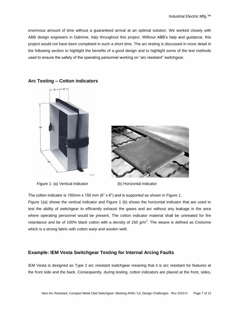
Figure 1: (a) Vertical indicator (b) Horizontal indicator
The cotton indicator is 150mm x 150 mm (6” x 6”) and is supported as shown in Figure 1.
Figure 1(a) shows the vertical indicator and Figure 1 (b) shows the horizontal indicator that are used to
test the ability of switchgear to efficiently exhaust the gases and arc without any leakage in the area
where operating personnel would be present. The cotton indicator material shall be untreated for fire
retardance and be of 100% black cotton with a density of 150 g/m2. The weave is defined as Cretonne
which is a strong fabric with cotton warp and woolen weft.
Example: IEM Vesta Switchgear Testing for Internal Arcing Faults
IEM Vesta is designed as Type 2 arc resistant switchgear meaning that it is arc resistant for features at
the front side and the back. Consequently, during testing, cotton indicators are placed at the front, sides,
Industrial Electric Mfg.™
New Arc Resistant, Compact Metal Clad Switchgear: Meeting ANSI / UL Design Challenges Rev 2010-0 Page 8 of 12
and back as well as below the plenum, to make sure that the operator working on any of the sides of
Vesta switchgear is safe.
Arc Resistant Design Considerations
In order to be thoroughly arc resistant, metal clad switchgear must be safe for the operator when there is
an arc in any of its compartments.
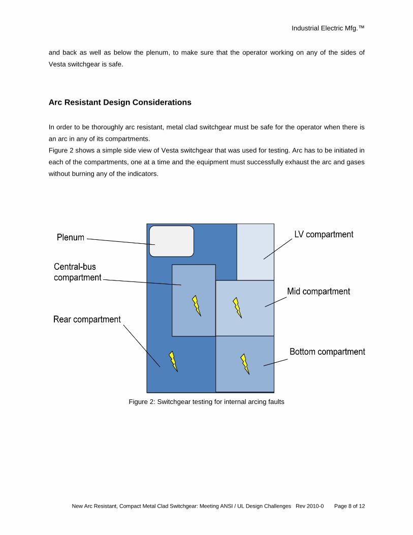
Figure 2 shows a simple side view of Vesta switchgear that was used for testing. Arc has to be initiated in
each of the compartments, one at a time and the equipment must successfully exhaust the arc and gases
without burning any of the indicators.
Figure 2: Switchgear testing for internal arcing faults
Industrial Electric Mfg.™
New Arc Resistant, Compact Metal Clad Switchgear: Meeting ANSI / UL Design Challenges Rev 2010-0 Page 9 of 12
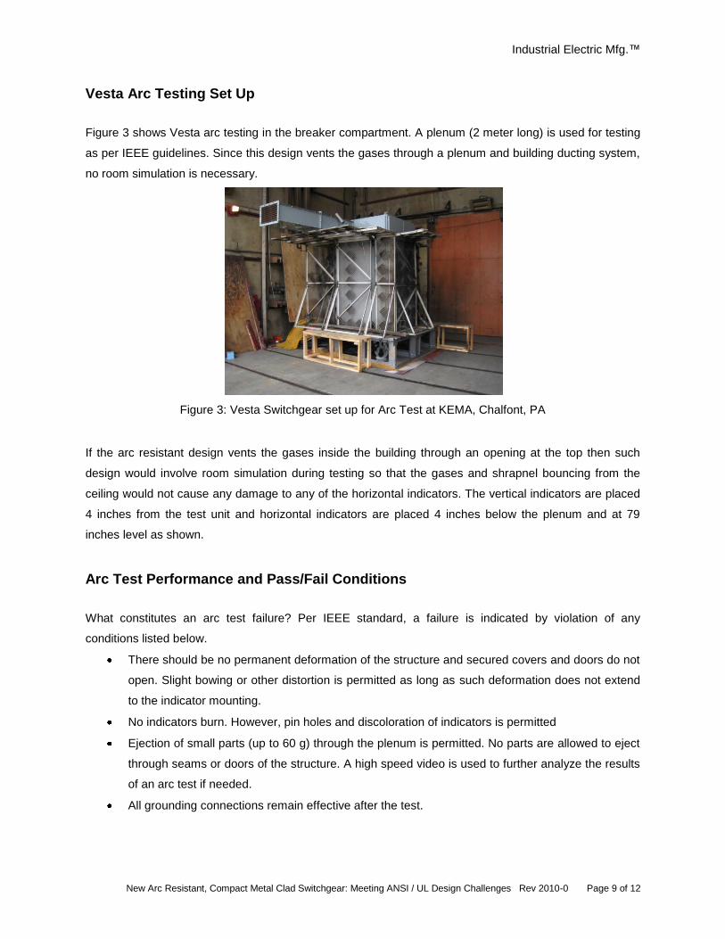
Vesta Arc Testing Set Up
Figure 3 shows Vesta arc testing in the breaker compartment. A plenum (2 meter long) is used for testing
as per IEEE guidelines. Since this design vents the gases through a plenum and building ducting system,
no room simulation is necessary.
Figure 3: Vesta Switchgear set up for Arc Test at KEMA, Chalfont, PA
If the arc resistant design vents the gases inside the building through an opening at the top then such
design would involve room simulation during testing so that the gases and shrapnel bouncing from the
ceiling would not cause any damage to any of the horizontal indicators. The vertical indicators are placed
4 inches from the test unit and horizontal indicators are placed 4 inches below the plenum and at 79
inches level as shown.
Arc Test Performance and Pass/Fail Conditions
What constitutes an arc test failure? Per IEEE standard, a failure is indicated by violation of any
conditions listed below.
There should be no permanent deformation of the structure and secured covers and doors do not
open. Slight bowing or other distortion is permitted as long as such deformation does not extend
to the indicator mounting.
No indicators burn. However, pin holes and discoloration of indicators is permitted
Ejection of small parts (up to 60 g) through the plenum is permitted. No parts are allowed to eject
through seams or doors of the structure. A high speed video is used to further analyze the results
of an arc test if needed.
All grounding connections remain effective after the test.
Industrial Electric Mfg.™
New Arc Resistant, Compact Metal Clad Switchgear: Meeting ANSI / UL Design Challenges Rev 2010-0 Page 10 of 12
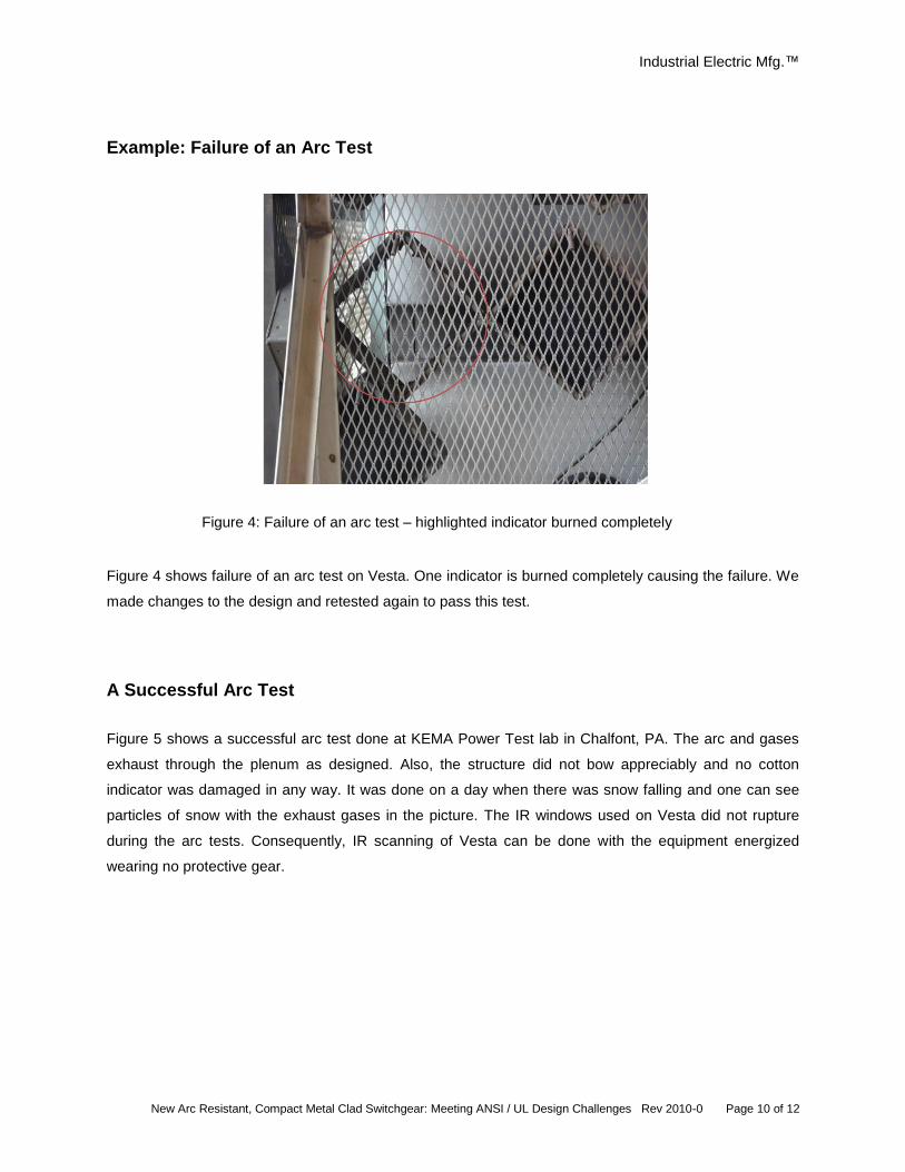
Example: Failure of an Arc Test
Figure 4: Failure of an arc test – highlighted indicator burned completely
Figure 4 shows failure of an arc test on Vesta. One indicator is burned completely causing the failure. We
made changes to the design and retested again to pass this test.
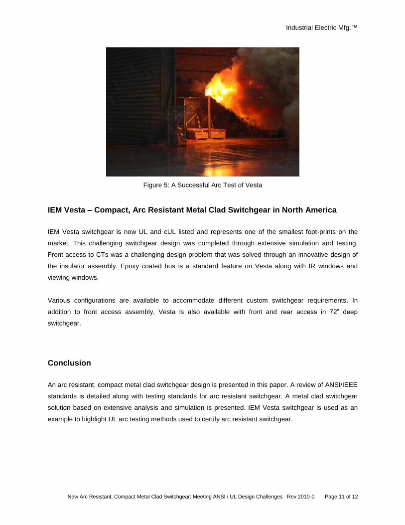
A Successful Arc Test
Figure 5 shows a successful arc test done at KEMA Power Test lab in Chalfont, PA. The arc and gases
exhaust through the plenum as designed. Also, the structure did not bow appreciably and no cotton
indicator was damaged in any way. It was done on a day when there was snow falling and one can see
particles of snow with the exhaust gases in the picture. The IR windows used on Vesta did not rupture
during the arc tests. Consequently, IR scanning of Vesta can be done with the equipment energized
wearing no protective gear.
Industrial Electric Mfg.™
New Arc Resistant, Compact Metal Clad Switchgear: Meeting ANSI / UL Design Challenges Rev 2010-0 Page 11 of 12
Figure 5: A Successful Arc Test of Vesta
IEM Vesta – Compact, Arc Resistant Metal Clad Switchgear in North America
IEM Vesta switchgear is now UL and cUL listed and represents one of the smallest foot-prints on the
market. This challenging switchgear design was completed through extensive simulation and testing.
Front access to CTs was a challenging design problem that was solved through an innovative design of
the insulator assembly. Epoxy coated bus is a standard feature on Vesta along with IR windows and
viewing windows.
Various configurations are available to accommodate different custom switchgear requirements. In
addition to front access assembly, Vesta is also available with front and rear access in 72” deep
switchgear.
Conclusion
An arc resistant, compact metal clad switchgear design is presented in this paper. A review of ANSI/IEEE
standards is detailed along with testing standards for arc resistant switchgear. A metal clad switchgear
solution based on extensive analysis and simulation is presented. IEM Vesta switchgear is used as an
example to highlight UL arc testing methods used to certify arc resistant switchgear.
Industrial Electric Mfg.™
New Arc Resistant, Compact Metal Clad Switchgear: Meeting ANSI / UL Design Challenges Rev 2010-0 Page 12 of 12
References
[1] H. Fink, M. Heimbach and W. Shang, “Vacuum Interrupters with Axial Magnetic Field
Contacts,” ABB Technology Review, Jan 2000, pp. 59-64.
[2] H. Fink, M. Heimbach and W. Shang, “A New Contact Design Based on a Quadrupolar
Axial Magnetic Field and its Characteristics,” European Transactions on Electrical Power,
Vol. 10, No. 2, March/April 2000, pp. 75-80.
[3] Mike Mosman and John Mayan, “Correcting False Perceptions of Medium Voltage Data
Centers,” Data Center Dynamics, April 2009.
[4] IEEE 1584-2002: IEEE Guide for Performing Arc-Flash Hazard Calculations and
IEEE 1584a-2004: IEEE Guide for Performing Arc-Flash Hazard Calculations –
Amendment1.
[5] VM1 – Medium Voltage Vacuum Circuit Breakers with Magnetic Drive, ABB Catalog,
2009.
Authors Ashok Kulkarni is vice president of engineering at IEM, overseeing the development of new products and customer solutions, product testing, IEM processes, and agency certifications. Kulkarni obtained a PhD in Electrical Engineering from Texas A&M University. Predrag Milovac is design development manager at IEM responsible for the research, development and execution of IEM’s new arc resistant switchgear. Milovac earned a Master of Science degree from Purdue University.