new aurora g2 controller board with external keypad - corr science
TRANSCRIPT
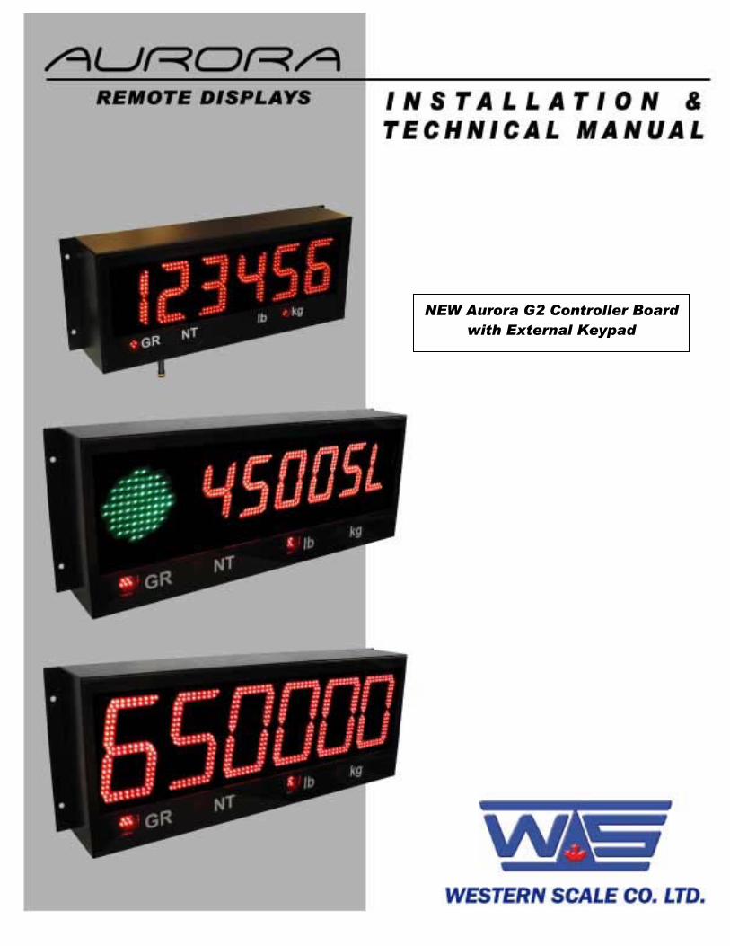
NEW Aurora G2 Controller Board with External Keypad

AURORA 45 - AURORA 65 - AURORA 45 SL L.E.D. REMOTE WEIGHT DISPLAYS INSTALLATION & TECHNICAL MANUAL SOFTWARE RELEASE 4-00, 06/2008 Copyright © 2005 - 2008 Western Scale Co. Limited. All rights reserved. Published by: Western Scale Co. Limited. Information in this Installation / Technical Manual is subject to change without notice due to correction or enhancement. The information described in this manual is the property of Western Scale Co. Ltd. No part of this manual may be reproduced or retransmitted in any form, without the expressed written permission of Western Scale Co. Ltd. Western Scale Co. Limited 1670 Kingsway Avenue Port Coquitlam, B.C. Canada V3C 3Y9 Tel: (604) 941-3474 Fax: (604) 941-4020 www.westernscale.ca [email protected]
FOR TECHNICAL SUPPORT REGARDING THIS PRODUCT, PLEASE CALL
YOUR AUTHORIZED WESTERN DEALER:

1
TABLE OF CONTENTS INTRODUCTION ................................................................................................................................................................... 2
SAFETY............................................................................................................................................................................ 2 AURORA FEATURES...................................................................................................................................................... 3 DISPLAY .......................................................................................................................................................................... 4 KEYPAD........................................................................................................................................................................... 4 OPENING THE AURORA 45 / 45 SL / 65 ENCLOSURE ................................................................................................ 5
INSTALLATION..................................................................................................................................................................... 6
PRE-INSTALLATION ....................................................................................................................................................... 6 MOUNTING INSTRUCTIONS.......................................................................................................................................... 6 LOWERING THE ELECTRONICS PLATE....................................................................................................................... 7 COMMUNICATIONS WIRING.......................................................................................................................................... 8
START-UP........................................................................................................................................................................... 10
POWER ON/OFF ........................................................................................................................................................... 10 RESET BUTTON............................................................................................................................................................ 10 AUTO-LEARN ................................................................................................................................................................ 10 LEARN BUTTON............................................................................................................................................................ 10 DIAGNOSTIC INDICATOR LIGHTS .............................................................................................................................. 11
CONFIGURATION MODE................................................................................................................................................... 12
ENTERING CONFIGURATION MODE.......................................................................................................................... 12 NAVIGATING CONFIGURATION PARAMETERS ........................................................................................................ 12 EDITING CONFIGURATION PARAMETERS................................................................................................................ 12 EXIT & SAVE CONFIGURATION .................................................................................................................................. 12 CONFIGURATION PARAMETERS................................................................................................................................ 13
Parameter 1.0: Daytime Brightness Level ............................................................................................................... 13 Parameter 1.1: Nighttime Brightness Level ............................................................................................................. 13 Parameter 1.2: Power-Save Mode........................................................................................................................... 13 Parameter 1.3: Mirror Display Mode ........................................................................................................................ 13 Parameter 1.4: Multi-Drop ID ................................................................................................................................... 14 Parameter 1.5: Radio Channel Select ..................................................................................................................... 14 Parameter 1.6: Utility Program Select...................................................................................................................... 14
AUTO-LEARN PARAMETERS....................................................................................................................................... 15 Parameter 2.0: Manual Learn (Assisted Learn) ....................................................................................................... 15 Parameter 2.1: Start-up Auto-Learn......................................................................................................................... 15 Parameter 2.2: Leading Zero Suppression .............................................................................................................. 15 Parameter 2.3: Set Scale Over ................................................................................................................................ 16 Parameter 2.4: Lock Units........................................................................................................................................ 16 Parameter 2.5: Lock Weighing Mode....................................................................................................................... 16 Parameter 2.6: Lock Traffic Light ............................................................................................................................. 16
TIME / DATE / TEMP PARAMETERS............................................................................................................................ 17 Parameter 3.0: Time Display.................................................................................................................................... 17 Parameter 3.1: Date Display.................................................................................................................................... 17 Parameter 3.2: Reserved for future use................................................................................................................... 17 Parameter 3.3: Weight Display ................................................................................................................................ 17 Parameter 3.4: Time Threshold ............................................................................................................................... 17
DIAGNOSTIC PARAMETERS ....................................................................................................................................... 18 Parameter 9.0: Com Port ......................................................................................................................................... 18 Parameter 9.1: String Counter ................................................................................................................................. 18 Parameter 9.2: Baud Rate ....................................................................................................................................... 18 Parameter 9.3: Configuration Lockout ..................................................................................................................... 18 Parameter 9.4: Number Counter.............................................................................................................................. 18 Parameter 9.8: Test Display..................................................................................................................................... 18 Parameter 9.9: Reset Defaults................................................................................................................................. 18
UTILITY PROGRAMS ......................................................................................................................................................... 19
WIRELESS SET-UP............................................................................................................................................................ 24 AURORA 45 SL TRAFFIC LIGHT CONTROL.................................................................................................................... 26 TIME & DATE...................................................................................................................................................................... 27
TROUBLESHOOTING & ERROR MESSAGES ................................................................................................................. 28

2
INSTALLATION & TECHNICAL MANUAL
INTRODUCTION The Aurora Remote Display Series incorporates the highest performance standards and the most features of any weighing display, making them the best choice for remote viewing applications. The new G2 Controller board incorporates an external keypad to access many new and improved features such as standard time and date. Like all Western products, Aurora Remote Displays are designed with durability, functionality, and versatility in mind. Western: Engineered for the diversity of the weighing industry. The following information is for the exclusive use of WESTERN Dealers and Customers. SAFETY Installation, configuration, and servicing are only to be done by qualified service personnel. Power must be disconnected before servicing the unit. Disconnection from the line voltage is done by disconnecting the mains plug. This equipment must be connected to a socket-outlet with a protective earthing connection. The socket outlet shall be installed near the equipment, and shall be easily accessible. The fuse for models Aurora 45, Aurora 45 SL and Aurora 65 should only be replaced by a 5A, 250V slow-blow fuse. This equipment is intended for connection to multiple RATED VOLTAGES or FREQUENCIES. The switchover to the corresponding voltage is done automatically by the equipment.
Scale Service Technicians handling Aurora PCBs must observe proper electrostatic discharge (ESD) handling procedures.
ATTENTION! Unauthorized installation and service of this unit may void the warranty.
CAUTION! HIGH VOLTAGES are present inside the Aurora enclosure.

3
AURORA FEATURES
HIGH VISIBILITY
• A bigger, brighter display (4.5 or 6.5 inches high) makes the Aurora display easy to read over wide viewing angles and any lighting conditions.
EASY TO INSTALL & USE
• Auto-Learn Technology interprets the data format and output string of any
scale indicator, reducing set-up time. • The Drop-down electronics carriage makes installation and service quick and
easy.
• 3 button keypad to access features and diagnostics without opening the enclosure.
WIRELESS COMMUNICATIONS
• Go wireless. Make installation easy and use remote displays where you never
thought possible.
• The integrated radio option allows communications over several thousand feet.
• No external housings or radio knowledge required.
SAVE ENERGY
• Ultra-efficient LED technology is the smart choice for power conscious users.
• The photo sensor automatically adjusts LED intensity for ambient lighting conditions.
• Power Save Mode reduces power consumption during long periods of inactivity.
MORE…
• A ready to use, built-in traffic light (Aurora 45 SL model only).
• Selectable brightness levels.
• Built-in utility programs for axle weighing, traffic light control, freeze weight, etc.
• Mirrored Display Mode.
• Multi-drop communications.
• Time & Date.

4
INSTALLATION & TECHNICAL MANUAL
DISPLAY WEIGHT DISPLAY: 6 LED digits (7 segments). Up to 2 decimal places. ANNUNCIATORS: GR = Gross Weighing Mode lb = Pounds NT = Net Weighing Mode kg = Kilograms KEYPAD The membrane keypad features an integrated light sensor window to detect changing ambient light conditions and 3 tactile push buttons used to set time and date (page 27) as well as access Configuration Mode (page 12). The keypad connects to J10 on the Controller Board.
Fig. 1: Aurora 45 Example
Fig. 2: Aurora Keypad
WEIGHT DISPLAY
ANNUNCIATORS

5
OPENING THE AURORA 45 / 45 SL / 65 ENCLOSURE
1. Make sure the unit is disconnected from power.
2. Remove the captive screws from the bottom of the enclosure.
3. Slowly, guide the Electronics Carriage out of the Main Enclosure, being careful to avoid bending any LED leads. Each LED is mounted very close to the PCB to help prevent bending.
4. The Electronics Carriage has tabs on either end that allow it to rest on the
Main Enclosure flange when mounted (As seen in Fig. 3 & 4).
MAIN ENCLOSURE
BOTTOM COVER/ELECTRONICS
CARRIAGE
DISPLAY BOARDS (2)
CONTROLLERBOARDPOWER SUPPLY
BOARD
Fig. 3: Front View
Fig. 4: Back View

6
INSTALLATION & TECHNICAL MANUAL
INSTALLATION PRE-INSTALLATION (Receiving Inspection) It is always good practice to verify that the Aurora Remote Display is complete and undamaged upon receipt.
• Check over packaging for any signs of damage.
• Remove the Aurora Remote Display from its protective packaging and check for damage.
• Verify that the shipment includes:
o Aurora Remote Display (complete and intact) o Aurora Installation / Technical Manual
MOUNTING INSTRUCTIONS Mounting-hole patterns for the Aurora Remote Displays are given in the diagram below:
Aurora 45:
Aurora 65 & Aurora 45 SL:
23 inches
31 inches
6inches
7 ¾ inches
Hole: 3/8 inch
Hole: 3/8 inch
Fig. 5: Hole Patterns

7
1. Inspect the installation site for properly grounded power. The socket-outlet shall be installed near the equipment and shall be easily accessible.
2. Ensure that mounting structures will bear the weight of the display (Aurora 45: 20
lbs, Aurora 65 & 45SL: 32 lbs). 3. Allow proper clearance for lowering and removing the Electronics Carriage. 4. Use proper hardware, including wall anchors, where necessary, when mounting
the enclosure. The Hex cap bolt length is specified as minimum. The appropriate length must be determined specifically for each application.
Imperial: 5/16-18 UNC Hex Cap Bolts - 4pcs/unit (min. 1" long) 5/16 Steel Flat Washer - 4pcs/unit Metric: M8x1.25 Hex Cap Bolts - 4pcs/unit (min. 25mm long) M8 Steel Flat Washer - 4pcs/unit
5. Run communication cables into the enclosure via strain reliefs (as required). LOWERING THE ELECTRONICS PLATE
1. Remove the two (2) captive screws holding the Electronics Plate to the Electronics Carriage.
2. Slowly, allow the Electronics Plate to swing down, making access easier for
wiring and service (As seen in Fig. 6).
Fig. 6: Side View
CAPTIVE SCREWS
NOTE: The Electronics Carriage may be removed to reduce weight when installing.

8
INSTALLATION & TECHNICAL MANUAL
COMMUNICATIONS WIRING All communications wiring terminates at the Controller board. Communications should be wired before applying power to the unit. RS 232 Wiring
Terminate the indicator’s communication wires at the RS 232 terminal (J3). See Fig. 7 & table below:
INDICATOR AURORA REMOTE DISPLAY
TRANSMIT (TX) RECEIVE (RCX) SIGNAL GROUND (GND) SIGNAL GROUND (GND)
RS 232 Daisy Chain / Multi-Drop Wiring
INDICATOR AURORA #1 AURORA #2 AURORA #3TX RCX RCX RCX GND GND GND GND RX TRX TRX TRX
RS 485 / 422 Wiring
Terminate the indicator’s communication wires at the RS 485 terminal (J4). See Fig. 7 & table below:
INDICATOR AURORA REMOTE DISPLAY TRANSMIT A (TX A) RECEIVE A (RX A) TRANSMIT B (TX B) RECEIVE B (RX B) SIGNAL GROUND (GND) SIGNAL GROUND (GND)
Fig. 7: Communication Terminals
J3 J4 J5
20 mA Mode Switch (SW10)

9
Passive
SW10
SW10
Active
RS 485 Daisy Chain / Multi-Drop Wiring
Parallel Wiring
INDICATOR AURORA #1 AURORA #2 AURORA #3TX A RX A RX A RX A TX B RX B RX B RX B
Split Wiring TO AURORA #1
RX A SCALE CONTROLLER RX B
TX A TX B TO AURORA #2
RX A RX B
20 mA Current Loop Wiring
Terminate the indicator’s communication wires at the 20 mA Current Loop terminal (J5). See Fig. 7 & table below:
INDICATOR AURORA REMOTE DISPLAY
20 mA TX + RECEIVE POSITIVE (RX +) 20 mA TX - RECEIVE NEGATIVE (RX -)
20 mA Current Loop Mode Switch
• After the current loop is wired, ACTIVE or PASSIVE mode must be selected via the switch on the Controller board (SW 10).
• Select ACTIVE if the Aurora is required to supply the 20
mA current to the communicating device (indicator).
• Select PASSIVE if the communicating device (indicator) supplies the current to the Aurora display. If unsure of these requirements, check the device’s manual.
NOTE: For more information regarding RS 485 Multi-Drop and setting Multi-Drop Addresses, see page 22.
Fig. 8: 20 mA Mode Switch

10
INSTALLATION & TECHNICAL MANUAL
START-UP POWER ON/OFF
• The Aurora has no ON/OFF button or switch. Plugging the unit into AC power will turn the unit ON. Disconnecting AC power will turn the unit OFF.
• Once power is applied, the Aurora performs a self test by counting up 1 to 9,
flashing annunciators and decimals, and displaying the software revision number (Ex. 4-00).
RESET BUTTON
• The RESET button on the Controller board allows Technicians to cycle power on the unit without disconnecting/connecting AC power.
AUTO-LEARN
• On power up, the Aurora automatically enters Auto-Learn Mode, analyzing the serial communications settings and incoming data from the indicator.
• The output string must contain number characters. An STX character (ASCII 02)
and/or CR character (ASCII 13) must also be included.
• Once Auto-Learn is successful (about 10 seconds after power up) the current weight is displayed.
LEARN BUTTON
• If Automatic Start-up Auto-Learn is disabled, the LEARN button on the Controller board must be pressed to enter Auto-Learn Mode.
NOTE: Automatic Start-up Auto-Learn may be disabled for custom applications. Please see Auto-Learn Parameters (page 15).

11
DIAGNOSTIC INDICATOR LIGHTS The Aurora has 7 diagnostic indicator lights located on the Controller board. 3.3V Light:
• Turns ON when voltage is supplied to the Controller board. 12V Light:
• Turns ON when voltage is supplied to the Display boards. STATUS Light:
• The Aurora’s “heartbeat”. BLINKS when the processor is running.
• Rapid blinking (3 times per second) indicates that the Aurora is in Auto-Learn Mode, attempting to interpret a data string.
• Regular blinking (Once per second) indicates that the Aurora has successfully
learned a data string and is running properly. RS232 Light:
• FLASHES ON each time the Aurora receives a character through the RS232 com port.
RS485 Light:
• FLASHES ON each time the Aurora receives a character through the RS485 com port.
20mA Light:
• FLASHES ON each time the Aurora receives a character through the 20 mA Current Loop port.
RADIO Light:
• FLASHES ON when the Aurora’s Radio Module receives data.
• This light will only illuminate if the Radio Module is installed.
12
INSTALLATION & TECHNICAL MANUAL
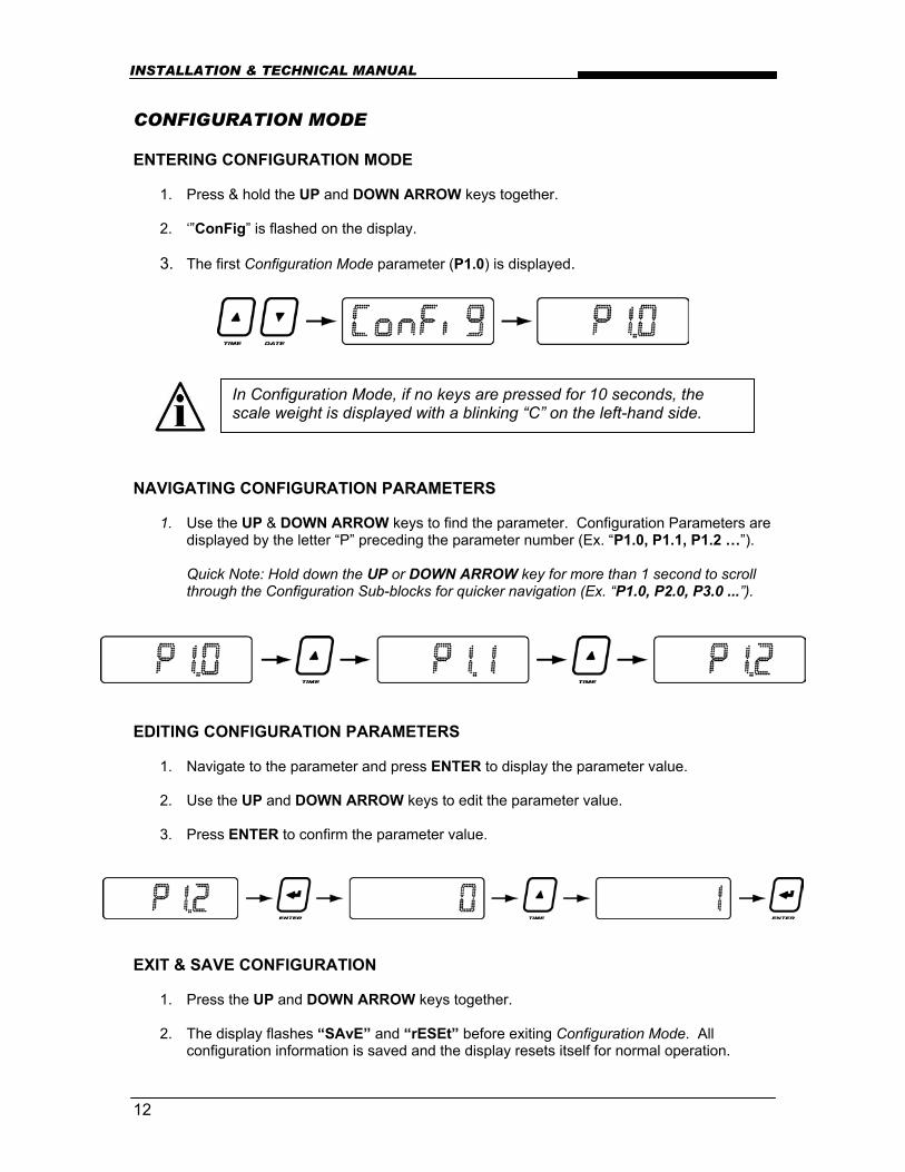
CONFIGURATION MODE ENTERING CONFIGURATION MODE
1. Press & hold the UP and DOWN ARROW keys together.
2. ‘”ConFig” is flashed on the display.
3. The first Configuration Mode parameter (P1.0) is displayed. NAVIGATING CONFIGURATION PARAMETERS
1. Use the UP & DOWN ARROW keys to find the parameter. Configuration Parameters are displayed by the letter “P” preceding the parameter number (Ex. “P1.0, P1.1, P1.2 …”).
Quick Note: Hold down the UP or DOWN ARROW key for more than 1 second to scroll through the Configuration Sub-blocks for quicker navigation (Ex. “P1.0, P2.0, P3.0 ...”).
EDITING CONFIGURATION PARAMETERS
1. Navigate to the parameter and press ENTER to display the parameter value. 2. Use the UP and DOWN ARROW keys to edit the parameter value. 3. Press ENTER to confirm the parameter value.
EXIT & SAVE CONFIGURATION
1. Press the UP and DOWN ARROW keys together.
2. The display flashes “SAvE” and “rESEt” before exiting Configuration Mode. All configuration information is saved and the display resets itself for normal operation.
In Configuration Mode, if no keys are pressed for 10 seconds, the scale weight is displayed with a blinking “C” on the left-hand side.

13
CONFIGURATION PARAMETERS Parameter 1.0: Daytime Brightness Level Value Description 0 = Low 1 = Med Low 2 = Med High 3 = High <
Set the brightness of the display for daytime viewing. The built-in light sensor automatically detects daylight conditions and sets the display brightness to this level.
Parameter 1.1: Nighttime Brightness Level Value Description 0 = Low < 1 = Med Low 2 = Med High 3 = High
Set the brightness of the display for nighttime viewing. The built-in light sensor automatically detects night conditions and sets the display brightness to this level.
Parameter 1.2: Power-Save Mode Value Description 0 = OFF 1 = ON <
Automatically dims display brightness one level below the selected brightness level (day or night, as applicable) if there is no activity on the scale for 10 minutes. Brightness levels are restored when motion is detected on the scale. This feature saves power and increases LED longevity.
Parameter 1.3: Mirror Display Mode Value Description 0 = OFF < 1 = Mirror 2 = Cycle
Mirror display for viewing from a vehicle’s rear-view or side-view mirrors. When “Cycle” is selected, the display will cycle between Normal and Mirror Display Modes every 5 seconds.
NOTE: Lowering the brightness level at night helps reduce nighttime glare and energy costs. Passing headlights, spotlights, etc. will NOT activate the daytime brightness level.

14
INSTALLATION & TECHNICAL MANUAL
Parameter 1.4: Multi-Drop ID Value Description 0= ID 0 < 1= ID 1 2= ID 2 3= ID 3 Etc.
Sets the unit ID if multiple remote displays are networked together. Up to four (4) Aurora displays can be networked on a single serial or radio connection. Messages are sent to individual displays using control codes and these IDs. For Multi-Drop instructions, see page 22.
Parameter 1.5: Radio Channel Select Value Description 0 = Ch 0 < 1 = Ch 1 2 = Ch 2 3 = Ch 3 4 = Ch 4 5 = Ch 5
Sets the radio frequency channel (0-5) for the optional Integrated Wireless Module. If there are multiple scale/remote display installations at a given site, each installation must have its own unique radio channel selected to prevent interference.
Parameter 1.6: Utility Program Select Value Description 0 = OFF < 1 = Pgm1 - Green light at 0 2 = Pgm2 - Red light on motion 3 = Pgm3 - Normal w/ Cmds 4 = Pgm4 - Freeze Weight 5 = Pgm5 - Command Mode-G2 Etc.
Several Utility Programs are pre-installed in the Aurora remote display. For a complete list of programs and descriptions, see page 19.
NOTE: If Multi-Drop is not being used, it is very important that the Multi-Drop ID be set to 0.
NOTE: The Aurora Remote Display must be set to the same radio channel as the scale indicator’s wireless transceiver.
NOTE: If the wireless connection experiences interference problems from another radio site, switching radio channels will most likely correct the problem.

15
AUTO-LEARN PARAMETERS Parameter 2.0: Manual Learn (Assisted Learn) Value Description Lxxxxx
Manual Learn activates Auto-Learn Mode from inside Configuration Mode. The remote display will analyze and attempt to learn the string. The message “LEARN” will be displayed. When the remote display is successful, the weight will be shown on the display. A blinking L will be displayed in the left hand corner to indicate you are still in learning mode. To lock in the learned string’s settings, press ENTER.
Parameter 2.1: Start-up Auto-Learn Value Description 0 = OFF 1 = ON <
The Aurora automatically enters Auto-Learn Mode on start up. If OFF, the display will startup using settings stored in memory from the last learn. Parameter 2.0 must be activated or the LEARN button on the Controller board must be pressed before the Aurora will go into Auto-Learn Mode again.
Parameter 2.2: Leading Zero Suppression Value Description 0 = OFF < 1 = ON
In some cases, the scale indicator may transmit leading zeros in the output string. If leading zeros are NOT required, they may be suppressed. The Aurora will automatically remove the leading zeros and replace them with blank spaces on the display.
NOTE: Leading Zeros may also be disabled using the scale indicator (if possible).

16
INSTALLATION & TECHNICAL MANUAL
Parameter 2.3: Set Scale Over Value Description 0 = Auto < Value for scale over target weight.
If there is no scale over status character in the weight string, or the indicator continues to transmit past maximum capacity, the unit can be set to blank the display when the weight goes past a preset weight value. Use the UP/DOWN keys to set the weight threshold and press ENTER. Holding the keys down will cause the weight threshold to change in steps of 10000. Single key presses will cause the weight threshold to change in steps of 100.
Parameter 2.4: Lock Units Value Description 0 = Auto < 1 = lb ON (or t) 2 = kg ON 3 = Both OFF
Weight Units (lb, kg, and t) are automatically displayed from the indicator’s output string. The Units annunciators may be locked on or off as required. On European models the lb enunciator is replaced with t.
Parameter 2.5: Lock Weighing Mode Value Description 0 = Auto < 1 = Gross ON 2 = Net ON 3 = Both OFF
Weighing Mode (Gross/Net) is automatically displayed from the indicator’s output string. The Mode annunciators may be locked on or off as required.
Parameter 2.6: Lock Traffic Light Value Description 0 = Auto < 1 = RED 2 = GREEN 3 = OFF
The Traffic Light (Aurora 45 SL) display may be locked RED, GREEN or OFF as required.

17
TIME / DATE / TEMP PARAMETERS The Aurora remote display can cycle between displaying weight, time and date every 5 seconds when: a) the weight display is at zero AND; b) there is no activity on the scale for the selected time period. Parameter 3.0: Time Display Value Description 0 = OFF < 1 = Time (AM/PM) 2 = Military (24 Hour)
Activates the TIME function in 12 hour or 24 hour clock formats.
Parameter 3.1: Date Display Value Description 0 = OFF < 1= MMDDYY (US Format) 2 = YYMMDD (International) 3 = DDMMYY (UK)
Activates the DATE function in US, ISO or UK format.
Parameter 3.2: Reserved for future use Value Description
Not available at this time
Parameter 3.3: Weight Display Value Description 0 = OFF 1 = Cycle 2 = No Cycle <
OFF: Weight will NOT BE DISPLAYED at all. ON: Weight is displayed in the “Time/Date/Temp/Weight Cycle”. No Cycle: Weight is NOT in the “Time/Date/Temp/Weight Cycle”.
Parameter 3.4: Time Threshold Value Description 1 to 20 min. 1 min <
Selects the number of minutes that the scale must be at zero before the “Time/Date/Temp/Weight Cycle” is displayed.

18
INSTALLATION & TECHNICAL MANUAL
DIAGNOSTIC PARAMETERS Parameter 9.0: Com Port Value Description 0 = RS232 1 = RADIO 2 = 20mA 3 = RS485
Displays the currently active Com Port.
Parameter 9.1: String Counter Value Description 0 to 65535
Counter indicates the number of characters received. Counter rolls over after 65535.
Parameter 9.2: Baud Rate Value Description 300 600 1200 4800 9600 19200
Displays the baud rate currently being utilized for serial communications.
Parameter 9.3: Configuration Lockout Value Description 0 = Disabled < 1 = Enabled
When enabled, no configuration parameters can be changed. Disable this parameter to restore user changes.
Parameter 9.4: Number Counter Value Description 0 to 65535
Counter indicates the number of numeric characters received. Counter rolls over after 65535.
Parameter 9.8: Test Display Value Description N/A Cycles through time, digits, annunciators & decimal characters.
Parameter 9.9: Reset Defaults Value Description 0 = Do Not Reset 1 = RESET
Resets Configuration Parameters to factory defaults.

19
UTILITY PROGRAMS The Aurora displays have several auxiliary functions that may be activated via Parameter 1.6 in Configuration Mode. PROGRAM 0: NORMAL OPERATION
• No Utility Program is selected. PROGRAM 1: SIMPLE TRAFFIC LIGHT
• Traffic light is GREEN on zero; • Otherwise, traffic light is RED.
PROGRAM 2: MOTION TRAFFIC LIGHT
• Traffic light is RED when scale motion is detected; • Otherwise, traffic light is GREEN.
PROGRAM 3: NORMAL OPERATION WITH TRAFFIC LIGHT COMMANDS
• The display accepts a continuous data stream from the indicator; • The continuous stream may be interrupted by control commands used to switch
the traffic light.
CONTROL COMMAND ASCII DEC RED light Aurora 45 SL only &<CR> 38, 13 GREEN light Aurora 45 SL only *<CR> 42, 13
PROGRAM 4: FREEZE WEIGHT (CAPTURE PRINT STRING)
• This program is useful for cattle auctions and other applications where a weight value must be displayed regardless of what is happening on the scale.
• A weigh ticket (using ASCII characters) must be created on the scale indicator
that sends the scale weight and a <CR> character to the Aurora display with a button press.
Example: 123456 lb g<CR>
• When the Aurora receives the ticket, it displays the weight and keeps displaying
it until the next weigh ticket is received.
NOTE: This application assumes a legal-for-trade indicator is used to send the weigh ticket. Please review local Weights and Measures requirements.

20
INSTALLATION & TECHNICAL MANUAL
PROGRAM 5: COMMAND MODE (G2) All Aurora displays can be setup to receive commands directly from the scale system or PC. Supported commands include transmitting weights, basic alphanumeric messaging, traffic light control, and additional display functions. Command Mode disables Auto-Learn and fixes communications at 9600-N-8-1. The Aurora looks only for specific commands sent by the indicator or scale controller. Activating Command Mode
1. To enable Command Mode for Aurora 45 / 45 SL / 65, set Parameter 1.6 in Configuration Mode to 5.
Transmit a Weight String Use numeric ASCII characters followed by a <CR> character. Example:
• To display “1000”, transmit: 1000<CR> Transmit Status Characters Status characters may be embedded anywhere in the weight string to control the annunciator lights. Status characters may be upper or lowercase, and in any order, before or after the weight.
STATUS COMMAND ASCII DEC GROSS weight G or g 71 or 103 NET weight N or n 78 or 110 POUNDS L or l 76 or 108 KILOGRAMS K or k 75 or 107
Example:
• To display 1000 lb gross, transmit: 1000LG<CR> -or- gl1000<CR>
NOTE: If no gross/net character is sent to the Aurora, the “GR” annunciator will illuminate by default.
NOTE: This improved Command Mode is for the G2 Controller board. Use Legacy Command Mode (Pgrm 12) when replacing older Controller boards.

21
Alphanumeric messaging to the scoreboard All Aurora models can display alphanumeric messages within the limitations of a 7 segment digit. Text and numbers sent as a message must be preceded by the @ character (decimal 64) and followed by a Carriage Return <CR> character (decimal 13). All characters in the data string are then treated as an alphanumeric message, and not a weight value. Alphanumeric messages are displayed from left to right. Control Commands
Control commands are single ASCII characters (preceded by @ and followed by <CR>) that are transmitted to the Aurora to control additional features such as the built-in traffic light (Aurora 45 SL).
CONTROL COMMAND ASCII DEC
RED light Aurora 45 SL only & 38 GREEN light Aurora 45 SL only * 42 Light OFF Aurora 45 SL only % 37 Turn ON flashing display ( 40 Turn OFF flashing display ) 41 FLASH display 3 times ! 33
Sample Command Mode Data Strings
DATA STRING DISPLAY 0<CR> “0” gross 1000 <CR> “1000” gross LN 1234 <CR> “1234” lb net 1234 GK <CR> “1234” kg gross 1234 L g <CR> “1234” lb gross @hello<CR> “hELLo” @*<CR> Aurora 45 SL only GREEN light @stop &<CR> Aurora 45 SL only “StoP ”, RED light
NOTE: Do not transmit Control Commands within a WEIGHT data string. Control Commands must be transmitted alone or in conjunction with an Alphanumeric message data string.

22
INSTALLATION & TECHNICAL MANUAL
Multi-Drop IDs & Networking Aurora displays using Multi-Drop networking must be in Command Mode. The Multi-drop ID (0 to 3) must also be set (Configuration Mode Parameter 1.4, page 14). When using Multi-drop, the Aurora will only respond after it has been selected. To select a display, transmit a # character (ASCII 35) followed by the correct ID number and a <CR> character (ASCII 13). Once this command is executed, control codes, alphanumeric messages and weight strings can be transmitted to the selected display as described in Command Mode (page 20). An Aurora will remain selected until it receives a command containing a different ID. Examples:
1. Select Multi-drop ID 1:
Transmitting “#1<CR>” selects the display with ID #1.
2. Select Multi-drop ID 3 and send a weight of 1000lb gross:
“#3<CR>” “1000LG<CR> The ID number may also be embedded with the weight string: “#3 1000LG<CR>
3. Send 3 different weights to 3 different scoreboards:
“#0 2000LG<CR>#1 3000LG<CR>#2 5000LG<CR>“
4. Send the text “hello” to scoreboard ID 3.
“#3@HELLO<CR>

23
PROGRAM 6: AXLE WEIGHING WITH TOTAL - For use with axle scales only! • Scale at zero – GREEN light.
• Truck drives its first axle on the scale, after motion stops – RED light. The
Aurora displays the axle weight and axle number (A1).
• GREEN light – Ready for the next axle. The next axle is driven onto the scale. After motion stops – RED light. The Aurora displays the axle weight and axle number (A2). Repeat for each remaining axle.
• After the last axle (weight at or near ZERO) – RED light. The truck’s total axle
weight is displayed for 10 seconds (flashing).
• Scale at or near ZERO – GREEN light. Ready for the next truck. PROGRAM 7: AXLE WEIGHING (DRIVING ON) - For axle weighing on regular vehicle scales.
• Scale at zero – GREEN light.
• Truck drives its first axle on the scale, after motion stops – RED light. The Aurora displays the axle number (A1), then the axle weight – GREEN light.
• The next axle is driven onto the scale. After motion stops – RED light. The
Aurora displays the axle number (A2), then the axle weight – GREEN light.
• This is repeated until all axles are on the scale. After motion stops – RED light. The Aurora displays the axle number (An), then the final axle weight – GREEN light.
• If there is no motion or significant weight change for 12 seconds, the truck’s total
scale weight is displayed and the truck can drive off the scale. PROGRAM 8: AXLE WEIGHING (DRIVING OFF)
• Reverse of Program 7: Axle Weighing (Driving On)
• Truck drives on scale, Aurora displays total weight.
• Truck drives its first axle on the scale, after motion stops – RED light. The Aurora displays the axle number (A1), then the axle weight – GREEN light.
• This is repeated until all axles are off the scale.
PROGRAM 12: LEGACY COMMAND MODE
• Command Mode from previous generation Controller board;
• Used when interfacing a new scoreboard to an older installation.

24
INSTALLATION & TECHNICAL MANUAL
WIRELESS SET-UP AURORA INTEGRATED WIRELESS INSTALLATION
1. The Integrated Wireless Kit includes: • Radio Module • External Antenna • Internal Antenna Cable • FCC/Industry Canada Sticker
2. Ensure the Aurora display is disconnected from power and open the enclosure.
3. Place the Radio Module in the “Radio Module Option” terminals on the Controller Board.
4. Connect the Internal Antenna Cable to the threaded SMA terminal on the Radio Module. 5. Remove the rubber plug in the bottom of the Aurora enclosure 6. Remove the nut and lock washer from the threaded SMA terminal on the Internal
Antenna Cable. Run the threaded SMA terminal through the hole in the bottom of the Aurora enclosure. Use the lock washer and nut to secure the SMA terminal.
7. Connect the External Antenna to the SMA connector on the bottom of the enclosure.
8. Power up the Aurora. The Aurora is ready to receive radio signals.
Fig. 10: Wireless Kit Installation
Fig. 9: Radio Module on Controller board

25
INDICATOR & WIRELESS TRANSCEIVER
1. Wire the ScaleLink Transceiver to the indicator (or other communicating device).
INDICATOR SCALELINK TRANSCEIVER TRANSMIT (TX) RECEIVE (RCX) SIGNAL GROUND (GND) SIGNAL GROUND (GND) 2. Verify communication settings between the ScaleLink and the indicator (or other
communicating device). The ScaleLink’s default communication settings are:
Baud Rate 9600 Data Bits 8 Parity None Stop Bits 1
3. Ensure the indicator is set-up to output CONTINUOUSLY. 4. Power up the Indicator and Transceiver together to transmit radio signals.
WIRELESS CONNECTION TEST
1. Verify that both the Wireless Transceiver and the Aurora Remote Display are set to the same radio channel.
2. Verify that the Wireless Transceiver is ON and transmitting. 3. Verify that the Radio LED on the Aurora Controller board is FLASHING. 4. Add weight to the scale.
5. Verify that the Aurora is correctly displaying Weight, Measurement Units (kg, lb),
and Weighing Mode (GR, NT) as shown on the scale indicator.
NOTE: The indicator and ScaleLink’s communication settings must match. If adjustments are required, see the ScaleLink Wireless Transceiver Manual or Indicator Manual.
NOTE: If the Aurora’s readings are incorrect, erratic, or very slow, a different radio channel may need to be selected.
NOTE: Aurora Radio Module Field Installation kits are available. Please contact the factory for more information.

26
INSTALLATION & TECHNICAL MANUAL
AURORA 45 SL TRAFFIC LIGHT CONTROL The built-in traffic light may be controlled by remote switch, serial commands or the pre-installed utility programs.
Remote Switch
1. Wire a dry contact, push-to-make switch to the Stop Light Remote Switch terminal (J23) on the Controller board. DO NOT supply any external power to this terminal.
2. The default condition (switch contact open) is GREEN. When the switch contact
is closed, the light turns RED.
Serial Commands
When the Aurora display is set to Program 3: Normal Operation with Traffic Light Commands or Program 5: Command Mode, it will accept serial commands to switch the built-in traffic light. For more information and a list of serial control commands and examples, see Utility Program descriptions, page 19.
PRG 3 CONTROL COMMAND ASCII DEC
RED light & <CR> 38, 13 GREEN light * <CR> 42, 13
PRG 5 CONTROL COMMAND ASCII DEC
RED light @ & <CR> 64, 38, 13 GREEN light @ * <CR> 64, 42, 13
Pre-Installed Utility Programs
Some of the Aurora’s pre-installed utility programs are designed to control the built-in traffic light. For program overviews, see page 19.
NOTE: The remote switch will be disabled if the built-in traffic light is locked GREEN, RED or OFF in Configuration Mode, Parameter 2.6.
NOTE: The remote switch will be disabled if the Aurora has a traffic light controlling Utility Program selected.
Fig. 11: Stop Light Terminal Wiring

27
TIME & DATE The Aurora remote display has a precision time clock that compensates for variable temperature conditions. The battery on the Controller board (J22) provides back-up power for this clock. SET TIME & DATE Adjust Time
1. Make sure Time is enabled in Configuration Mode (Parameter 3.0)
2. Press and hold the UP/TIME key.
3. Use the UP and DOWN ARROW keys to select the correct hour and press ENTER.
4. Repeat for minutes and AM/PM if enabled (12 hour clock).
Adjust Date
1. Make sure Date is enabled in Configuration Mode (Parameter 3.1)
2. Press the DOWN/DATE key.
3. Use the UP and DOWN ARROW keys to select the correct year/month/day (International) or month/day/year (USA) and press ENTER.
BATTERY / BATTERY REPLACEMENT The Aurora displays use a 3 Volt lithium battery. Power is drawn from the battery only when the unit is disconnected from AC power. If time and date are lost when the unit is disconnected from AC power, the battery likely needs replacement.
1. Remove the old battery from the J22 terminal on the Controller board by hand.
2. Observe proper battery polarity before inserting new battery.
3. Ensure the battery is seated correctly in the J22 terminal.
CAUTION! Risk of explosion if battery is replaced by an incorrect type. Dispose of used batteries according to their instructions.
CAUTION! Never use metal objects such as screwdrivers to remove batteries! This may result in personal injury or damage to the unit.

28
INSTALLATION & TECHNICAL MANUAL
TROUBLESHOOTING & ERROR MESSAGES
• Verify AC power source (Outlets, breakers, etc.)
• Check power cord connections to Terminal Block and Ground Posts inside the Main Enclosure.
• Verify internal power wiring from Terminal Block to
the Power Supply board and Power Supply board to the Controller board.
Unit won’t power up:
• Check fuses on Power Supply board and Controller board.
• Verify Ribbon Cable connections from Controller
board to the 2 Display boards.
• Check 12V light and fuse on Controller board.
Unit has power, but there is no display.
• If the unit is in COMMAND mode, the display will remain blank until data is received.
• Baud Rate Auto-Learn has failed. • Verify the correct terminal (RS 232, 485, 20 mA) is
being used. • Verify cable to indicator.
Display reads “Err 1”.
• Verify that data is being transmitted to the Aurora from the indicator and that the data string contains numeric characters.
• Data String Auto-Learn has failed or Radio not
receiving. • Verify the correct terminal (RS 232, 485, 20 mA) is
being used. • Verify cable or radio connection to indicator.
Display reads “Err 2”.
• Verify that a data string is being sent to the Aurora from the indicator and that the data string contains either an STX character (ASCII 02) or a CR character (ASCII 13).
Display reads “Err 3” • The Aurora is receiving data on multiple
communications ports.

29
• Communications have failed. • Verify the correct terminal (RS 232, 485, 20 mA) is
being used. • Verify cable or radio connection to indicator.
Dashes across the display.
• Verify indicator serial port function.
STATUS light NOT blinking (OFF)
• Verify that unit has power. When powered, if the Status light remains OFF, the processor is not running.
STATUS light blinking fast (3/second) for longer than 1 minute:
• The Aurora is not able to Auto-Learn the data string or baud rate. See Error Messages “Err 1” and “Err 2”.
• Verify the RS232 terminal is being used and check
communications wiring at the indicator.
RS232 light not flashing:
• Verify that data is being sent to the Aurora from the indicator and that the data string contains numeric characters.
• Verify the RS485 terminal is being used and check
communications wiring at the indicator.
RS485 light not flashing:
• Verify that data is being sent to the Aurora from the indicator and that the data string contains numeric characters.
• Verify the 20mA terminal is being used and check
communications wiring at the indicator. • Verify that data is being sent to the Aurora from the
indicator and that the data string contains numeric characters.
20mA light not flashing:
• Make sure the correct mode (ACTIVE or PASSIVE) is selected on the Controller board (SW10).
• Check that the Radio Module is properly installed.
Ensure that the internal antenna cable is connected to the Radio Module and the external antenna.
RADIO light not flashing:
• No data is being sent from the Wireless Transceiver connected to the scale indicator.