new design guidelines for anaerobic ponds - australian...
TRANSCRIPT

NEW DESIGN GUIDELINES FOR ANAEROBIC PONDS 1
2015
AUSTRALIAN PORK LIMITED
New Design Guidelines for Anaerobic Ponds

PROJECT TITLE:
Demonstrations of How to Achieve Best Management Practices – Environmental Management
PROJECT NUMBER:
2013/031
RESEARCH ORGANISATION:
FSA Consulting
PRINCIPAL INVESTIGATOR:
Ms Robyn Tucker, FSA Consulting, Private Bag 260, Horsham Vic 3401
DISCLAIMER
The opinions, advice and information contained in this publication have not been provided at the request of any person but are offered by Australian Pork Limited (APL) solely for informational purposes. While APL has no reason to believe that the information contained in this publication is inaccurate, APL is unable to guarantee the accuracy of the information and, subject to any terms implied by law which cannot be excluded, accepts no responsibility for loss suffered as a result of any party’s reliance on the accuracy or currency of the content of this publication. The information contained in this publication should not be relied upon for any purpose, including as a substitute for professional advice. Nothing within the publication constitutes an express or implied warranty, or representation, with respect to the accuracy or currency of the publication, any future matter or as to the value of or demand for any good.
This document should be cited as follows:
Project 2013/031 New Design Guidelines for Anaerobic Ponds (2015), Australian Pork Ltd, Barton, ACT, 2600

NEW DESIGN GUIDELINES FOR ANAEROBIC PONDS 1
INTRODUCTIONThe main objective of effluent treatment is to remove organic matter and nutrients from raw piggery effluent. Most primary effluent treatment ponds at piggeries are anaerobic, because the high organic loading that they experience consumes any dissolved oxygen to exhaustion. Anaerobic ponds are a popular treatment option as they are simple to build and operate, and provide for effluent and sludge storage. Well-designed, properly-managed anaerobic ponds also provide good effluent treatment without odour nuisance or adverse impacts to water resources.
Until fairly recently, most anaerobic ponds at Australian piggeries were designed using the Rational Design Standard (RDS) by Barth (1985). The RDS leads to conservative large pond volumes which are effective at removing organic matter and nutrients from the effluent (Photograph 1). However, large ponds have major drawbacks; they occupy significant land areas with high costs of construction, have large surface areas that release odour and greenhouse gases (GHG) and can be difficult to desludge.
Photograph 1 Very large ponds are designed when using the Rational Design Standard (RDS) by Barth (1985)
Over the past 10 years, Australian Pork Limited (APL) has heavily invested in the development of alternative design and management solutions to overcome these challenges. This booklet provides design guidelines for heavily loaded anaerobic (HLA) ponds.

NEW DESIGN GUIDELINES FOR ANAEROBIC PONDS2
Principles of Anaerobic DigestionAnaerobic decomposition is a three-stage natural biological process by which manure is progressively broken down by different micro-organisms in each stage. Firstly, enzymes produced by bacteria break down manure solids into simpler dissolved organics. Secondly, the dissolved organics are fermented into volatile fatty acids (VFAs). Thirdly these are broken down into acetate, hydrogen and carbon dioxide. Finally these are converted into methane and carbon dioxide. The methane forming micro-organisms (methanogens) responsible for the final stage are slow-growing. Methanogens are also most prone to being inhibited by pH changes, chemicals/additives in the piggery effluent or other unfavourable conditions in the anaerobic pond. This is important, because a number of conditions (sudden increase in manure load or too short a hydraulic retention time) can cause an imbalance with too few methanogens and too many fermenting bacteria, which in severe cases lead to pond failure and substantial odour. For this reason, it is important to design and manage ponds to facilitate a balanced microbial community and in this way ensure good treatment of piggery effluent.
A New Design Concept: Heavily Loaded Anaerobic PondsHeavily loaded anaerobic (HLA) ponds (Photograph 2) are ponds which have a treatment volume that is about one-tenth to one-sixth the size of RDS-sized ponds, and thus experience a 6-10 times higher volumetric load. For many years, Australian pork producers have suggested that HLA ponds can perform just as well as larger RDS-sized ponds, providing adequate treatment of piggery effluent. For example, in a series of trials, Skerman et al. (2008) investigated the performance of HLA ponds by loading an anaerobic pond at a commercial piggery and a settling tank at a research piggery at 6-10 times the RDS-calculated organic loading rate. They found that HLA ponds:
» achieved similar volatile solids (VS) removal rates than RDS-sized ponds, removing at least 70% of VS
» accumulated sludge at lower rates than what was suggested by Barth (1985)
» developed heavy surface crusts if loading rates exceeded about 600 g VS/m3/d (but this can assist with odour mitigation)
» emitted lower levels of offensive odour than RDS-sized ponds because of the reduced surface area and the surface crusting.
Photograph 2 HLA pond
NEW DESIGN GUIDELINES FOR ANAEROBIC PONDS 3
Potential advantages of HLA ponds include:
» reduced earthworks costs due to smaller volume, and
» smaller footprint, so
» less expensive and easier to line for groundwater protection, or to cover for biogas capture (if this is desired)
» simpler and cheaper to desludge of sludge
» lower odour emissions
» potential to expand the piggery or develop at sites limited by separation distances to areas of sensitive land use (Tucker et al., 2010).
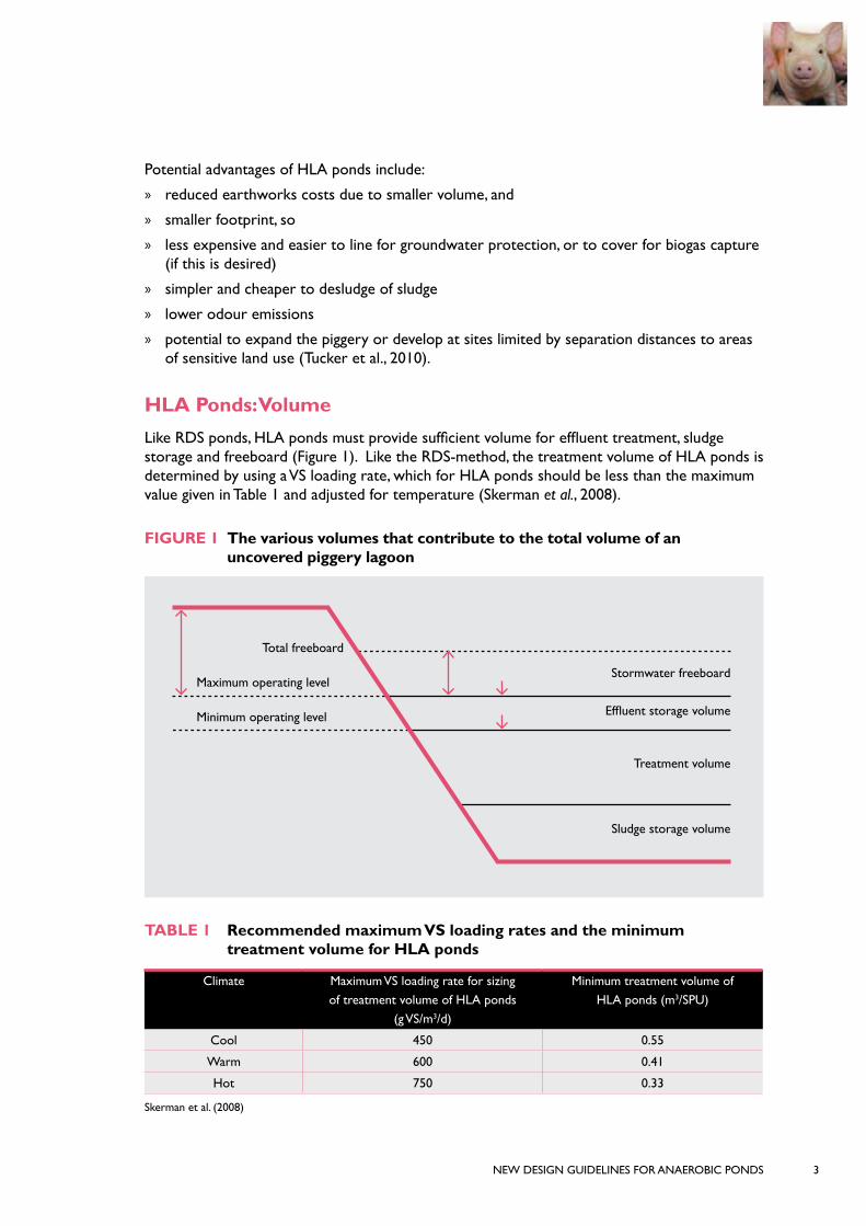
HLA Ponds: VolumeLike RDS ponds, HLA ponds must provide sufficient volume for effluent treatment, sludge storage and freeboard (Figure 1). Like the RDS-method, the treatment volume of HLA ponds is determined by using a VS loading rate, which for HLA ponds should be less than the maximum value given in Table 1 and adjusted for temperature (Skerman et al., 2008).
FIGURE 1 The various volumes that contribute to the total volume of an uncovered piggery lagoon
TABLE 1 Recommended maximum VS loading rates and the minimum treatment volume for HLA ponds
Climate Maximum VS loading rate for sizing of treatment volume of HLA ponds
(g VS/m3/d)
Minimum treatment volume of HLA ponds (m3/SPU)
Cool 450 0.55
Warm 600 0.41
Hot 750 0.33
Skerman et al. (2008)
Total freeboard
Maximum operating level
Minimum operating level
Stormwater freeboard
Treatment volume
Sludge storage volume
Effluent storage volume
NEW DESIGN GUIDELINES FOR ANAEROBIC PONDS4
From the maximum loading rates, the smallest viable HLA pond volume can be determined. This is done by considering that one standard pig unit (SPU) excretes about 90 kg VS/yr as manure and waste feed (Tucker et al. 2010). So, as an example, the minimum treatment volume (to be added to sludge accumulation volume and required freeboard) at 450 g VS/m3/d, would be:
= ((90 kg VS/SPU/yr/365 days)/(450 g VS/SPU/d /1000) = 0.55 m3/SPU (as in Table 1)
Using the maximum VS loading rate to size an anaerobic pond produces the smallest viable treatment volume. Extra volume is needed for sludge storage and to provide for management flexibility.
Sludge storage volume is estimated by multiplying a sludge accumulation factor by the number of years between planned sludge removals. The American standard ASABE (2011) includes a sludge accumulation factor of 0.00137 m3/kg TS added to the pond. From this factor, the sludge storage volume can be calculated. One SPU excretes about 108 kg TS/yr which will flow into the pond.
So, as an example, the sludge storage volume for a 5-year desludging cycle would be:
= 108 kg TS/yr × 0.00137 m3/kg TS ×5 years= 0.74 m3/SPU
A HLA pond for a 10,000 SPU piggery in a warm climate would need a minimum HLA pond volume of 5,600 m3 (5.6 ML) consisting of 4,100 m3 of treatment volume and 1,480 m3 of sludge storage volume (assuming annual desludging). Additional capacity may be needed to cater for wet weather storage, changing effluent flows and additional freeboard.
Providing for a greater sludge storage volume to enable less frequent desludging, also has drawbacks in that:
» it requires bigger ponds with higher construction costs
» it increases the pond footprint
» it may make desludging more difficult, because older sludge may settle in more compacted layers with very high solids concentration which may be very difficult to pump. Such a pond may need to be taken off-line for sludge removal using earthmoving or dredging equipment.
» it may result in bigger pond surface areas with greater odour emissions.
Pond sludge is a valuable nutrient resource, being rich in phosphorus and other nutrients. It is common practice to desludge when sludge nutrients are to be spread to crop land. It is recommended that ponds be sized with no less than 12 months of sludge accumulation volume, because an active sludge layer is always required in a pond to treat manure effectively. Any additional sludge volume allowance can improve management flexibility.

NEW DESIGN GUIDELINES FOR ANAEROBIC PONDS 5
As well as treating the effluent and storing sludge, the pond system must provide adequate wet weather storage. The latest version of the National Environmental Guidelines for Piggeries sets a maximum overtopping (spill) frequency of once every ten years on average. A holding pond will generally be needed to meet this criterion.
The total pond volume (Figure 1) is then calculated as liquid treatment volume + sludge accumulation volume + effluent storage volume + stormwater storage freeboard
Table 2 provides an example.
HLA Ponds: DimensionsThe footprint of a HLA pond depends on:
» total volume (see above)
» total depth
» batter of internal walls and external banks (batter is the slope of a wall or bank expressed as a ratio of horizontal to vertical distance)
» length-to-width ratio
» freeboard.
Deep anaerobic ponds can be preferred as a deep profile:
» minimises the pond surface area. For uncovered ponds this reduces odour emissions and heat losses, and minimises the rainfall volume to be managed and reduces evaporation which unfortunately concentrates salts. For covered anaerobic ponds (CAPs) it reduces the size and cost of a cover and the cover surface area for which stormwater is to be managed
» provides a more stable pond temperature, which can improve digestion performance
» usually ensures there is adequate depth for the treatment volume. Hamilton (2007) recommends maintaining at least 2 m of treatment depth above the design sludge volume.
However, it is important to ensure that:
» the pond base is 2 m or more above the highest seasonal groundwater table
» the depth of the pond is practical for desludging.
Steep internal wall batters minimise the pond surface area for a given pond volume. Relatively steep batters are usually possible for plastic-lined ponds. Ponds that are pumped out will be more prone to bank collapse and generally need flatter batters than ponds that are kept full. Skerman et al. (2008) suggests a batter slope no steeper than 2 horizontal to 1 vertical on the internal walls, with some soils needing more gradual batters to ensure structural stability. The batter slope may also be limited by the safe operation of machinery during pond construction, and possibly for later desludging. Batters on the ends of the internal walls should be at least 4 horizontal to 1 vertical to provide for safe access by maintenance machinery.
Photograph 3 shows a lined pond with steep batters on the long sides and flatter batters on the ends.

NEW DESIGN GUIDELINES FOR ANAEROBIC PONDS6
Pond walls must be structurally stable and provide for safe access during construction and maintenance. When deciding on internal and external batters, consider the physical properties of the soils at the pond site and the machinery that will be used to build and maintain the pond.
Photo 3 Plastic lined trapezoidal pond with steep batters on long sides and flatter batters on ends
Long, narrow and deep ponds provide good solids settling for treatment and minimise short-circuiting of the influent flow. Minimum pond length-to-width ratios of 3 – 4:1 are often recommended in effluent pond design manuals to improve contact between the treatment bacteria and the fresh effluent (ASABE 2011, Shilton and Harrison 2003). Desludging will also be much easier and less disruptive if the pond is narrow enough to remove solids from a bank using a pump, vacuum tanker or long reach excavator. Long reach excavators have a maximum range of around 18 m, which limits the maximum pond width at crest to about 30 m.
The pond width at top water level is determined by the base width, the internal batters and the depth. The minimum base width will generally match the width of the construction equipment (typically ~3 m). Example dimensions for a HLA pond for a 10,000 SPU unit with top water level depths of 4, 4.5 and 5 m are provided in Table 2. Figure 2 shows the dimensions schematically.
Freeboard is the height from the top water level of the pond to the bank crest. It is provided to protect the bank from wave action and to allow for imperfections in crest height. A minimum freeboard of 0.5 m is specified in the latest version of the National Environmental Guidelines for Piggeries, although some states may require larger freeboard depths.
“Incorporate sludge removal pipework in the pond during construction.”
Producer VIC

NEW DESIGN GUIDELINES FOR ANAEROBIC PONDS 7
TABLE 2 Example dimensions for HLA ponds for a 10,000 SCU piggery in a warm climate - three top water level (TWL) depths
Typical design criteria – all ponds (may vary with specific site requirements)
Treatment and effluent storage volume (m3) 4100
Sludge storage volume (annual desludging) (m3) 1480
Total water volume (m3) 5580
Freeboard (F) (m) 0.5
Batter on width (H:V) 4:1
Batter on length (H:V) 2:1
Dimension
TWL Depth (D) 4 m
TWL Depth (D) 4.5 m
TWL Depth (D) 5 m
Width at base (WB) (m) 3 3 3
Width at top water level (WTWL) (m) 35 39 43
Width at inside crest (WC) 39 43 47
Length at base (LB) (m) 63 64 65
Length at TWL (LTWL) (m) 79 82 85
Length at inside crest (LC) (m) 81 84 87
Batter on length (H:V) 2:1 2:1 2:1
FIGURE 2 Schematic diagram showing dimensions of HLA pond as given in Table 2
(Skerman et al. 2008) * FSL = full supply level
Following is a simple method to estimate the dimensions of a trapezoidal pond (i.e. a pond with a rectangular base and surface area) with a required volume and water depth.
Pond Base
Bank Crest
F
1
Top Water Level (TWL)
LFSL x WTWL
LB x WB
LC x WC
Length-wise Batter ZL Width-wise Batter Zw
D

NEW DESIGN GUIDELINES FOR ANAEROBIC PONDS8
Find the dimensions of a pond with a required volume and water depth
A worked example for a pond with a volume of 20 ML, a water depth of 5 m, freeboard of 0.5 m and internal banks with a slope ratio of 3:1 (horizontal to vertical) follows.
To calculate top water level (TWL) length and width:
1. Calculate mid-depth surface area (m2)
= volume (m3) / depth (m) = 20,000 m3 /5 m = 4000 m²
2. Work out some suitable dimensions for this mid-depth surface area. e.g. 100 m X 40 m
3. Calculate the top water level (TWL) length and width:
TWL length (m) = mid-depth length (m) + ( 2 X (slope ratio x ½ water depth)) = 100 m + (2 X (3 x 2.5 m) = 115 m
TWL width (m) = mid-depth width (m) + ( 2 X (slope ratio X ½ water depth)) = 40 m + (2 X (3 X 2.5 m ) = 55 m
To calculate base and crest dimensions:
4. Calculate the base length and width:
Base length (m) = mid-depth length (m) - ( 2 X (slope ratio X ½ water depth)) = 100 m - (2 X (3 X 2.5 m) = 85 m
Base width (m) = mid-depth width (m) - ( 2 X (slope ratio X ½ water depth)) = 40 m - (2 X (3 X 2.5 m) = 25 m
5. Calculate the crest length and width:
Crest length (m) = TWL length + (2 X (slope ratio X freeboard depth (m)) = 115 m + (2 X (3 X 0. 5 m)) = 118
Crest width (m) = TWL width + (2 X slope ratio X freeboard depth (m)) = 55 m + (2 X (3 X 0.5 m) = 58 m
“Using settling ponds allows for greater solids retrieval for reuse in cropping systems.”
Producer NSW
NEW DESIGN GUIDELINES FOR ANAEROBIC PONDS 9
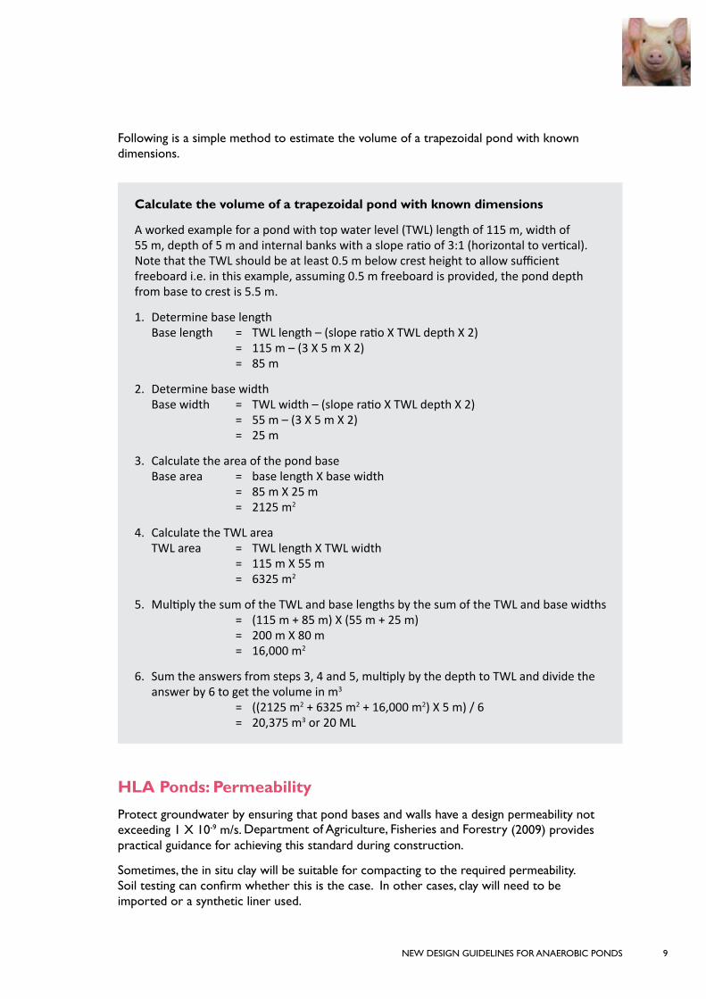
Following is a simple method to estimate the volume of a trapezoidal pond with known dimensions.
Calculate the volume of a trapezoidal pond with known dimensions
A worked example for a pond with top water level (TWL) length of 115 m, width of 55 m, depth of 5 m and internal banks with a slope ratio of 3:1 (horizontal to vertical). Note that the TWL should be at least 0.5 m below crest height to allow sufficient freeboard i.e. in this example, assuming 0.5 m freeboard is provided, the pond depth from base to crest is 5.5 m.
1. Determine base length Base length = TWL length – (slope ratio X TWL depth X 2) = 115 m – (3 X 5 m X 2) = 85 m
2. Determine base width Base width = TWL width – (slope ratio X TWL depth X 2) = 55 m – (3 X 5 m X 2) = 25 m
3. Calculate the area of the pond base Base area = base length X base width = 85 m X 25 m = 2125 m2
4. Calculate the TWL area TWL area = TWL length X TWL width = 115 m X 55 m = 6325 m2
5. Multiply the sum of the TWL and base lengths by the sum of the TWL and base widths = (115 m + 85 m) X (55 m + 25 m) = 200 m X 80 m = 16,000 m2
6. Sum the answers from steps 3, 4 and 5, multiply by the depth to TWL and divide the answer by 6 to get the volume in m3 = ((2125 m2 + 6325 m2 + 16,000 m2) X 5 m) / 6 = 20,375 m3 or 20 ML
HLA Ponds: PermeabilityProtect groundwater by ensuring that pond bases and walls have a design permeability not exceeding 1 X 10⁻⁹ m/s. Department of Agriculture, Fisheries and Forestry (2009) provides practical guidance for achieving this standard during construction.
Sometimes, the in situ clay will be suitable for compacting to the required permeability. Soil testing can confirm whether this is the case. In other cases, clay will need to be imported or a synthetic liner used.

NEW DESIGN GUIDELINES FOR ANAEROBIC PONDS10
Photograph 3 shows a pond with a synthetic liner. Suitable lining materials include high density polyethylene (HDPE) with a thickness of 1.5-2 mm, or 1-2 mm thick polypropylene (PP) in cases where the effluent does not contain large quantities of fats or oils. Liners can easily be damaged by livestock and machinery movements and bush fires and need to be protected; consider fencing the pond to exclude livestock and wildlife, use equipment carefully, and keep vegetative fuel down near the pond.
HLA Ponds: BanksTo provide for safe access, bank crests must be structurally stable, ideally at least 2.5 m but preferably at least 4 m wide, or 6 m for a covered pond, and flat on top with a slight downward slope towards the outer wall to direct stormwater runoff away from the pond.
Batters of at least 4 horizontal to 1 vertical are recommended for external banks. Earthen ramps, with gradients of 10 horizontal to 1 vertical, on the external end banks, provide safer access.
Grass, compacted gravel or geotextile on a crest or bank can help to minimise erosion. Trees should never be planted on the banks or near a pond. Uncontrolled vegetation in close vicinity to a plastic-lined or covered pond can encourage vermin or have increased fire risks. Topsoil over the crest and outer bank can help prepare for grassing. Ramps should be protected with a layer of compacted gravel.
HLA Ponds: Inlets and OutletsEffluent may be pumped through pipes to HLA ponds, or may enter under gravity flow via channels or pipes. Table 3 provides guidance on minimum grades for gravity flow inlet pipes of different diameters. Larger diameter pipelines will discharge more quickly and are less likely to block.
Providing multiple inlet points disperses the effluent within the pond which may enhance treatment and allow sludge to deposit more evenly within the pond. All inlet pipes should be well separated from the outlet pipe.
TABLE 3 Minimum slopes for gravity pipes conveying untreated effluent
Inside diameter (mm) Minimum slope (%) Velocity at full flow (m/s)
75 3.3 1
100 2.5 1
125 2.0 1
150 1.7 1
(Birchall et al. 2008).
Since thick crusts may form over HLA ponds, inlet and outlet pipes need to be carefully positioned to prevent blockages. In most cases the ends of the inlet pipes sit above the expected top water level and crust level, and beyond the bank providing for free outfall into the pond (Photograph 4). However, pipes can also be positioned to discharge under the expected minimum liquid levels.

NEW DESIGN GUIDELINES FOR ANAEROBIC PONDS 11
Treated effluent may be removed from the pond using a pipe, a weir or by pumping. If an outlet pipe is used, a tee fitting will exclude the floating crust (see Photograph 5). The base of the vertical pipe should be well below the crust and top water level but above the maximum sludge storage level to ensure only liquid is being extracted. The bottom of the overflow pipeline sits at top water level height with a downwards slope towards the wet weather pond. This keeps the effluent volume in the HLA pond relatively constant and prevents spills.
Photograph 4 Effluent pond inlet pipe discharging above top water level
Photograph 5 Tee on overflow pipeline from HLA pond to wet weather pond (Photo courtesy of Alan Skerman)
If a weir will be used, an adjustable type should be considered with horizontal plates placed in a slotted opening. The plates can be inserted or removed to control the overflow level, thus improving management flexibility.
Pipelines for pumping treated effluent for reuse, should have a minimum internal diameter of 75 mm, or larger if the pumping distance exceeds 100 m or there is greater static head or a flatter slope. Table 4 provides diameter-slope recommendations for outlet pipes with different diameters.
Flow Direction
Pond TWL
Dia 225mm PVC Overflow pipeline

NEW DESIGN GUIDELINES FOR ANAEROBIC PONDS12
TABLE 4 Minimum slopes for gravity pipes conveying treated effluent
Inside diameter (mm) Minimum slope (%) Velocity at full flow (m/s)
75 0.2 0.29
100 0.1 0.25
125 0.07 0.24
150 0.05 0.23
(Birchall et al. 2008).
Since effluent can be corrosive, sulphate-resistant concrete, unplasticised polyvinyl chloride (uPVC) or HDPE piping is recommended for channels or pipes. Sewer-class pipes should be used to transport effluent under gravity. Rubber-ring-jointed PVC pipe is recommended. HDPE is better able to withstand water hammer than uPVC and may be better for conveying treated effluent to reuse areas (Bradshaw 2002). Seek professional advice during pipe selection.
Trenches for underground pipes should be excavated to provide sufficient cover depth to protect the pipe from stock, vehicles and/or heavy machinery movements. Larger pipes need a greater cover depth. Seek advice on cover depths from the pipe supplier.
HLA Ponds – Sludge removal pipeworkHLA ponds may need frequent desludging. Desludging activities can be made simpler by the installation of appropriate extraction pipework. Using a pump or vacuum tanker, or a dredge, allows pond function to be maintained during desludging. While a pond can be desludged using a pump or vacuum tanker fitted with a single pipe over the wall of a pond, good results may be obtained by installing multiple sludge extraction ports along the length of the pond through the pond bank (Photograph 6). Sludge extraction ports typically consist of 300+ mm poly or uPVC pipes permanently installed through the bank. Ports spaced every 10-15 m along the pond length are suggested. Installing these at a 45 degree angle can provide for a better reach.
Where a vacuum tanker is connected directly to the sludge extraction pipework, the pipework will experience a large suction vacuum that it must be able to withstand; for this reason poly pipe may be preferred. Such sludge extraction ports can also provide a guide for a 200 mm pipe attached to a pump or vacuum tanker to be threaded through the port for sludge removal (Photograph 7).
HLA Ponds – SafetyAll effluent treatment ponds should be fenced to exclude children and stock. Signs should warn of deep water that may be hidden by a surface crust or cover. Where a significant drowning risk still prevails, a floating device or float-and-retrieval ring should always be available.

NEW DESIGN GUIDELINES FOR ANAEROBIC PONDS 13
Photograph 6 Sludge extraction ports being installed along outer wall of new CAP (Photo courtesy of Tom Smith)
Photograph 7 Pipe threaded through sludge extraction port
“We build 10 year ponds but desludge every 2 years using in-situ pipes.”
Producer WA

NEW DESIGN GUIDELINES FOR ANAEROBIC PONDS14
Notes

NEW DESIGN GUIDELINES FOR ANAEROBIC PONDS 15
Notes

NEW DESIGN GUIDELINES FOR ANAEROBIC PONDS16
ReferencesASABE Standards, 2011, ANSI/ASBE EP403.4, FEB2011, Design of Anaerobic Lagoons for Animal Waste Management, ASABE, St Joseph, MI, USA.
ASABE Standards, 2004, ANSI/ASBE EP403, FEB04, Design of Anaerobic Lagoons for Animal Waste Management, ASABE, St Joseph, MI, USA.
Barth CL, 1985, The Rational Design Standard for Anaerobic Livestock Waste Lagoons, in Agricultural Waste Utilization and Management, Proceedings of the 5th International Symposium on Agricultural Wastes, pp 638-647, ASABE, St Joseph, MI, USA.
Bradshaw B, 2002, Dairy Effluent Pond Construction, AG0425, www.depi.vic.gov.au/agriculture-and-food/dairy/managing-effluent/dairy-effluent-pond-construction, viewed 20 June 2014, Department of Primary Industries, Melbourne.
Birchall S, Dillon C and Wrigley R, 2008, Effluent and Manure Management Database for the Australian Dairy Industry, Dairy Australia, Melbourne.
Department of Agriculture, Fisheries and Forestry, Toowoomba, 2009, Constructing Effluent Ponds, Department of Agriculture, Fisheries and Forestry, Toowoomba, Queensland, www.daff.qld.gov.au/environment/intensive-livestock/piggeries/managing-environmental-impacts/constructing-effluent-ponds, accessed 5 May 2014.
Hamilton DW, 2007, The Rational Design Standard for Anaerobic Lagoons – Twenty Years Later, Proceedings of the International Symposium on Air Quality and Waste Management for Agriculture, 16-19 September 2007, ASABE Publication No. 701P0907cd, Broomfield, CO, USA.
Shilton A and Harrison J 2003, Guidelines for the Hydraulic Design of Waste Stabilisation Ponds, Institute of Technology and Engineering, Massey University, Palmerston North, New Zealand.
Skerman A, Collman G, Duperouzel D, Sohn J, Atzeni M and Kelly A, 2008, Improved Piggery Effluent Management Systems Incorporating Highly Loaded Primary Ponds, Final report for Australian Pork Ltd Project No. 2108, Department of Primary Industries and Fisheries, Toowoomba, QueenslandTucker RW, McGahan, EJ, Galloway, JL, & O’Keefe, MF 2010, National Environmental Guidlines for Piggeries 2nd Edition Revised, Australian Pork Limited, Canberra
Tucker RW, 2015, Piggery Manure and Effuent Management and Reuse Guidelines 2015
CitationThis publication should be referenced as follows:Project 2013/031 New Design Guidelines for Anaerobic Ponds (2015), Australian Pork Ltd, Barton, ACT, 2600
Acknowledgment The contributions of Janine Price (Australian Pork Ltd), Eugene McGahan (FSA Consulting) and Alan Skerman (Department of Agriculture, Fisheries and Forestry) in reviewing this publication is gratefully acknowledged.
Disclaimer: The opinions, advice and information contained in this publication have not been provided at the request of any person but are offered by Australian Pork Limited (APL) solely for informational purposes. While APL has no reason to believe that the information contained in this publication is inaccurate, APL is unable to guarantee the accuracy of the information and, subject to any terms implied by law which cannot be excluded, accepts no responsibility for loss suffered as a result of any party’s reliance on the accuracy or currency of the content of this publication. The information contained in this publication should not be relied upon for any purpose, including as a substitute for professional advice. Nothing within the publication constitutes an express or implied warranty, or representation, with respect to the accuracy or currency of the publication, any future matter or as to the value of or demand for any good.

“I should have made the primary pond longer and narrower.”
Producer QLD

AUSTRALIAN PORK LIMITED
ABN 83 092 783 728
Level 2, 2 Brisbane Avenue Barton ACT 2600 PO Box 4746 Kingston ACT 2604 Australia
P: 02 6285 2200 F: 02 6285 2288 E: [email protected]
www.australianpork.com.au