new devices & instrument improvements provide even faster
TRANSCRIPT
1
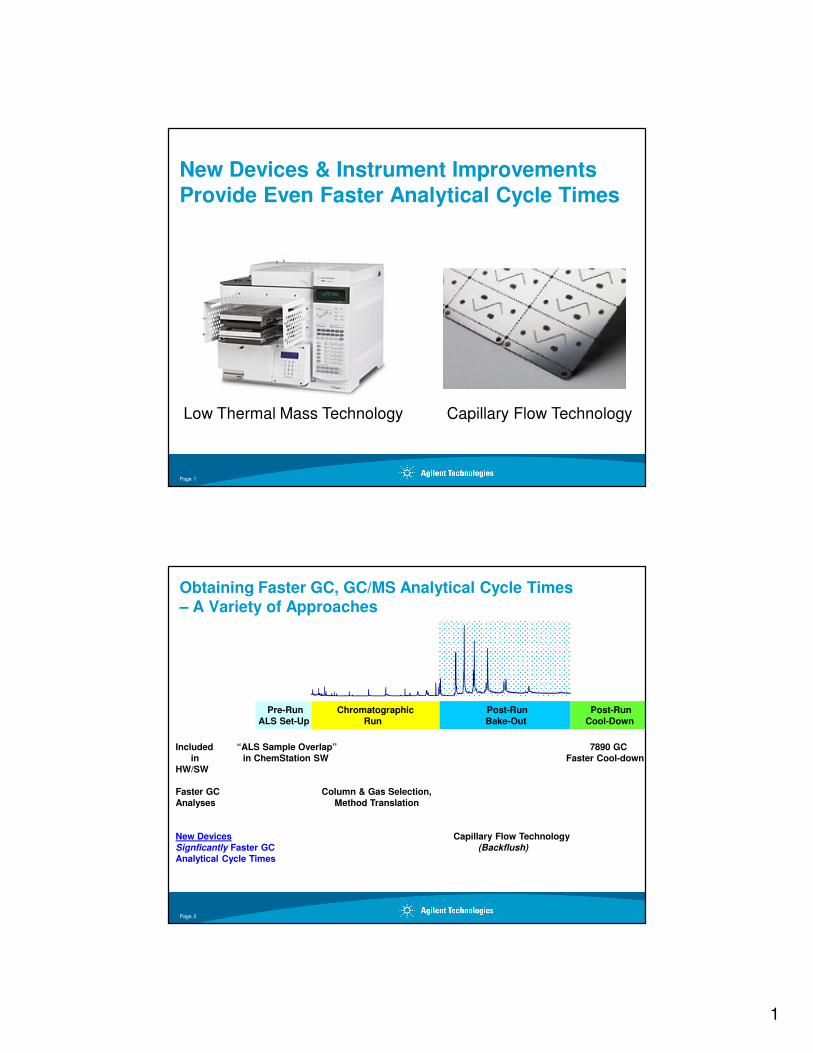
New Devices & Instrument Improvements Provide Even Faster Analytical Cycle Times
Low Thermal Mass Technology Capillary Flow Technology
Page 1
Obtaining Faster GC, GC/MS Analytical Cycle Times – A Variety of Approaches
Post-Run
Bake-Out
Chromatographic
Run
Post-Run
Cool-Down
Pre-Run
ALS Set-Up
Included “ALS Sample Overlap” 7890 GC
in in ChemStation SW Faster Cool-down
HW/SW
Faster GC Column & Gas Selection,
Analyses Method Translation
New Devices Capillary Flow Technology
Signficantly Faster GC (Backflush)
Analytical Cycle Times
Page 2
2
5 10 15 20 25 30 35 40 45 50 55 60 65 70
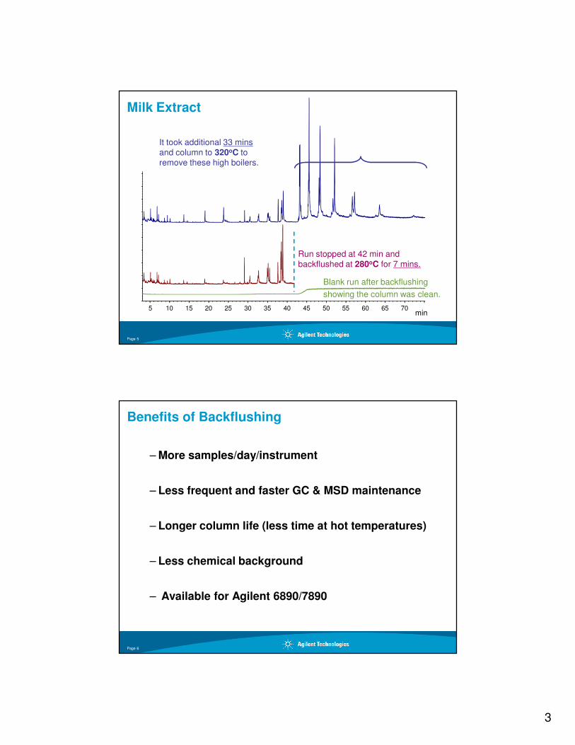
It took additional 33 minsand column to 320oC to remove these high boilers.
min
Milk Extract
Page 3
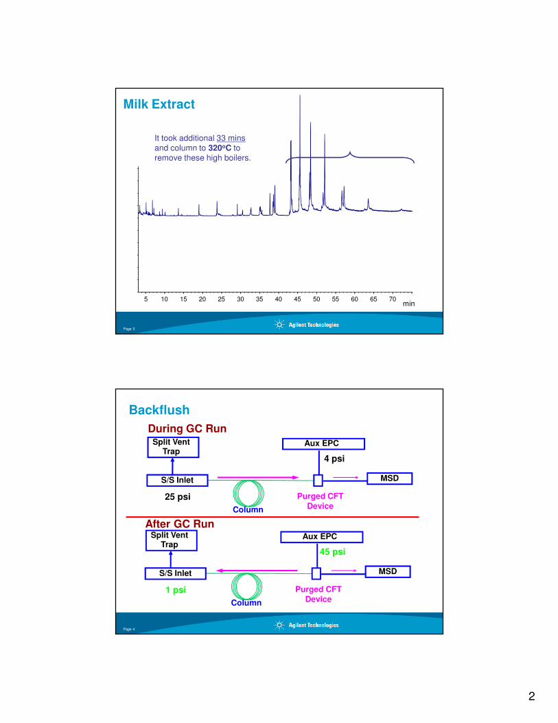
Backflush
S/S Inlet
Purged CFTDeviceColumn
1 psi
45 psi
MSD
Aux EPCSplit Vent Trap
During GC Run
After GC Run
S/S Inlet
Purged CFTDeviceColumn
25 psi
4 psi
MSD
Aux EPCSplit Vent Trap
Page 4
3
5 10 15 20 25 30 35 40 45 50 55 60 65 70
Run stopped at 42 min and backflushed at 280oC for 7 mins.
It took additional 33 minsand column to 320oC to remove these high boilers.
Blank run after backflushing
min
showing the column was clean.
Milk Extract
Page 5
Benefits of Backflushing
– More samples/day/instrument
– Less frequent and faster GC & MSD maintenance
– Longer column life (less time at hot temperatures)
– Less chemical background
– Available for Agilent 6890/7890
Page 6
4
Page 7
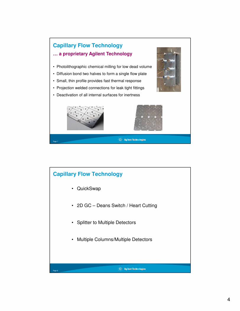
Capillary Flow Technology
• Photolithographic chemical milling for low dead volume
• Diffusion bond two halves to form a single flow plate
• Small, thin profile provides fast thermal response
• Projection welded connections for leak tight fittings
• Deactivation of all internal surfaces for inertness
… a proprietary Agilent Technology
Capillary Flow Technology
• QuickSwap
• 2D GC – Deans Switch / Heart Cutting
• Splitter to Multiple Detectors
• Multiple Columns/Multiple Detectors
Page 8
5
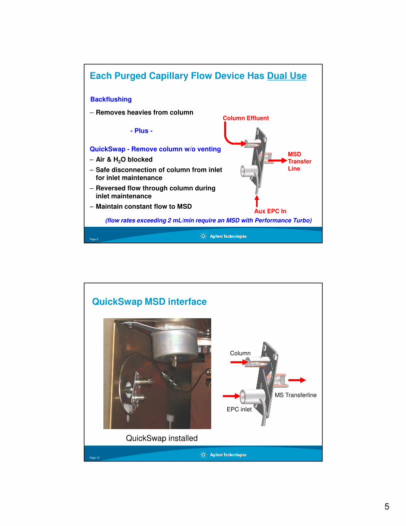
Each Purged Capillary Flow Device Has Dual Use
Backflushing
– Removes heavies from column
- Plus -
QuickSwap - Remove column w/o venting
– Air & H2O blocked
– Safe disconnection of column from inlet for inlet maintenance
– Reversed flow through column during inlet maintenance
– Maintain constant flow to MSD
(flow rates exceeding 2 mL/min require an MSD with Performance Turbo)
MSD TransferLine
Aux EPC In
Column Effluent
Page 9
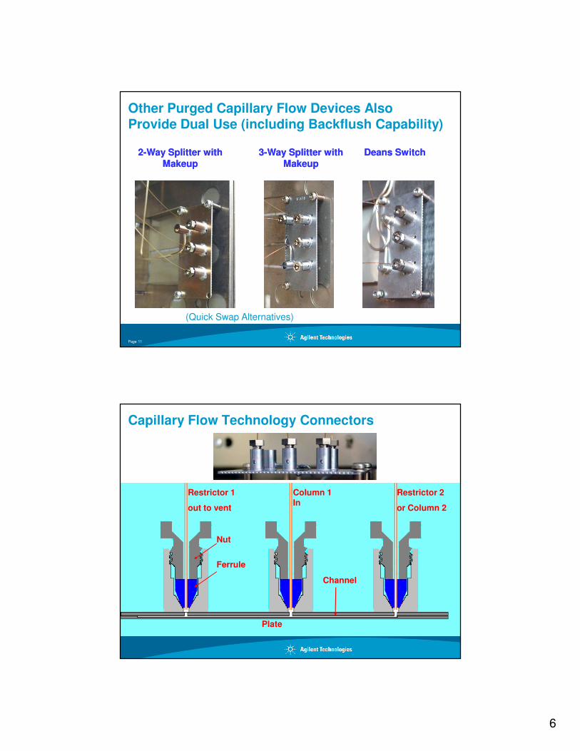
MS Transferline
Column
EPC inlet
QuickSwap installed
QuickSwap MSD interface
Page 10
6
Other Purged Capillary Flow Devices AlsoProvide Dual Use (including Backflush Capability)
22--Way Splitter with Way Splitter with MakeupMakeup
33--Way Splitter with Way Splitter with MakeupMakeup
Deans SwitchDeans Switch
Page 11
(Quick Swap Alternatives)
Capillary Flow Technology Connectors
Column 1 In
Restrictor 1
out to vent
Plate
Ferrule
Nut
Restrictor 2
or Column 2
Channel
7
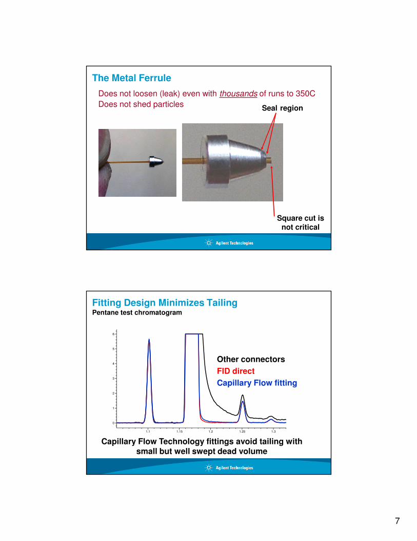
The Metal Ferrule
Square cut is not critical
Seal region
Does not loosen (leak) even with thousands of runs to 350C
Does not shed particles
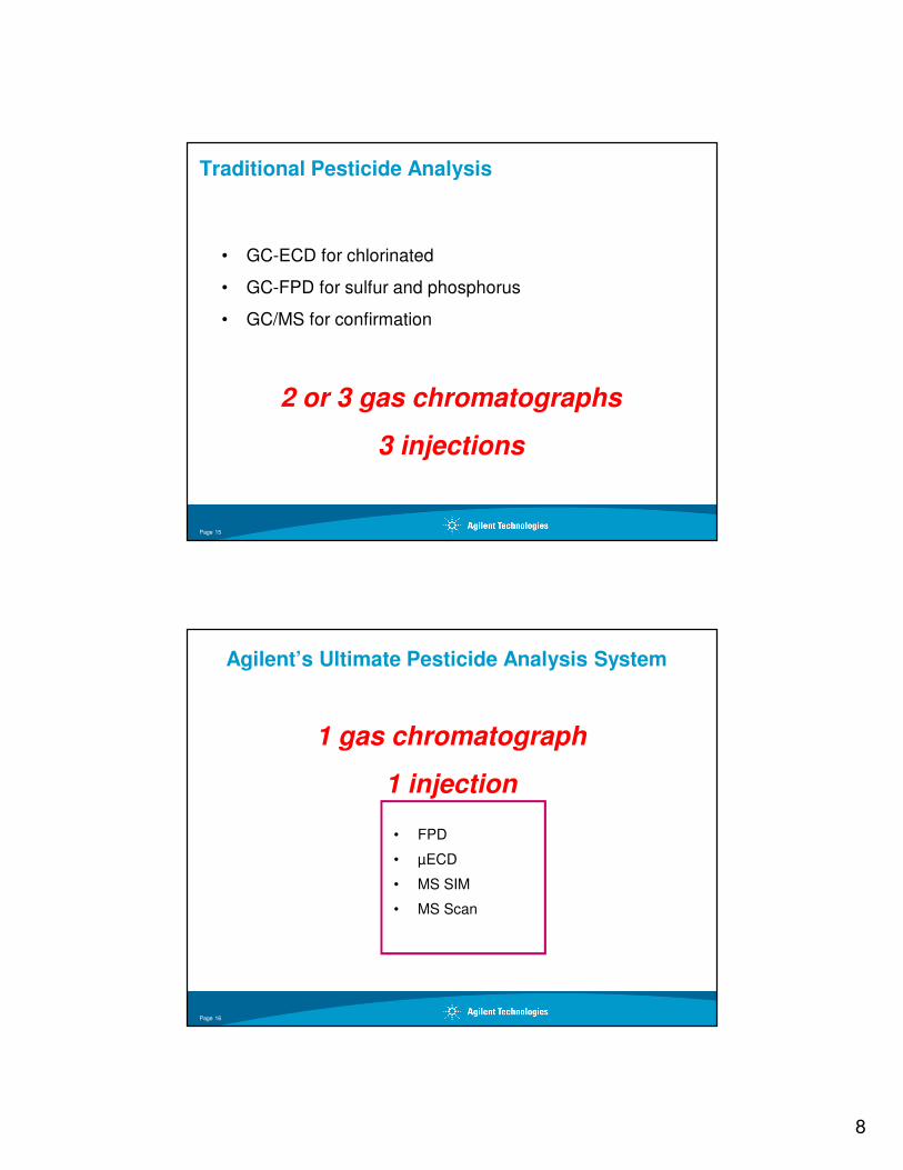
Other connectors
FID direct
Capillary Flow fitting
Capillary Flow Technology fittings avoid tailing with small but well swept dead volume
1.1 1.15 1.2 1.25 1.3
0
1
2
3
4
5
6
Pentane test chromatogram
Fitting Design Minimizes Tailing
8
Traditional Pesticide Analysis
• GC-ECD for chlorinated
• GC-FPD for sulfur and phosphorus
• GC/MS for confirmation
2 or 3 gas chromatographs
3 injections
Page 15
Agilent’s Ultimate Pesticide Analysis System
• FPD
• µECD
• MS SIM
• MS Scan
1 gas chromatograph
1 injection
Page 16
9
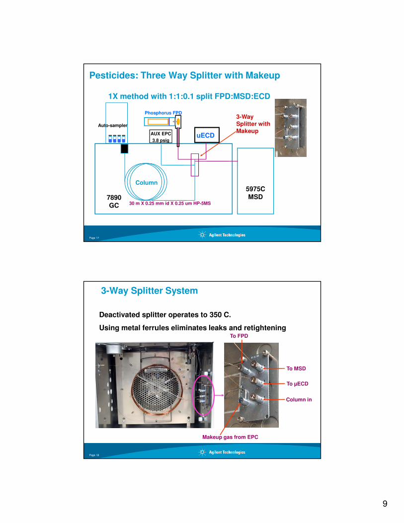
Pesticides: Three Way Splitter with Makeup
1X method with 1:1:0.1 split FPD:MSD:ECD
3-Way Splitter with Makeup
Auto-sampler
7890GC
Column
Phosphorus FPD
30 m X 0.25 mm id X 0.25 um HP-5MS
5975C MSD
uECDAUX EPC
3.8 psig
Page 17
3-Way Splitter System
Deactivated splitter operates to 350 C.
Using metal ferrules eliminates leaks and retightening
To µECD
Column in
Makeup gas from EPC
To MSD
To FPD
Page 18
10
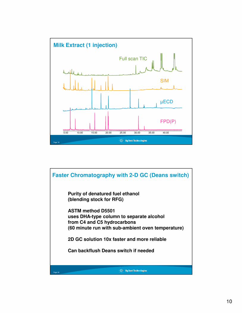
Full scan TIC
SIM
µECD
5.00 10.00 15.00 20.00 25.00 30.00 35.00 40.00
FPD(P)
Milk Extract (1 injection)
Page 19
Faster Chromatography with 2-D GC (Deans switch)
Purity of denatured fuel ethanol(blending stock for RFG)
ASTM method D5501 uses DHA-type column to separate alcohol from C4 and C5 hydrocarbons (60 minute run with sub-ambient oven temperature)
2D GC solution 10x faster and more reliable
Can backflush Deans switch if needed
Page 20
11
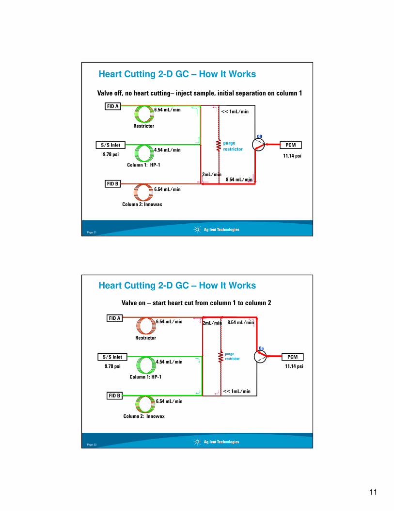
9.78 psi 11.14 psi
FID A
S/S Inlet
FID B
PCM
Restrictor
6.54 mL/min
4.54 mL/min
<< 1mL/min
2mL/min
purge
restrictor
8.54 mL/min
Off
6.54 mL/min
Column 1: HP-1
Column 2: Innowax
Heart Cutting 2-D GC – How It Works
Valve off, no heart cutting– inject sample, initial separation on column 1
Page 21
FID A
S/S Inlet
FID B
PCM
On
6.54 mL/min
4.54 mL/min
6.54 mL/min
purge
restrictor
2mL/min 8.54 mL/min
<< 1mL/min
9.78 psi 11.14 psi
Restrictor
Column 1: HP-1
Column 2: Innowax
Heart Cutting 2-D GC – How It Works
Valve on – start heart cut from column 1 to column 2
Page 22
12
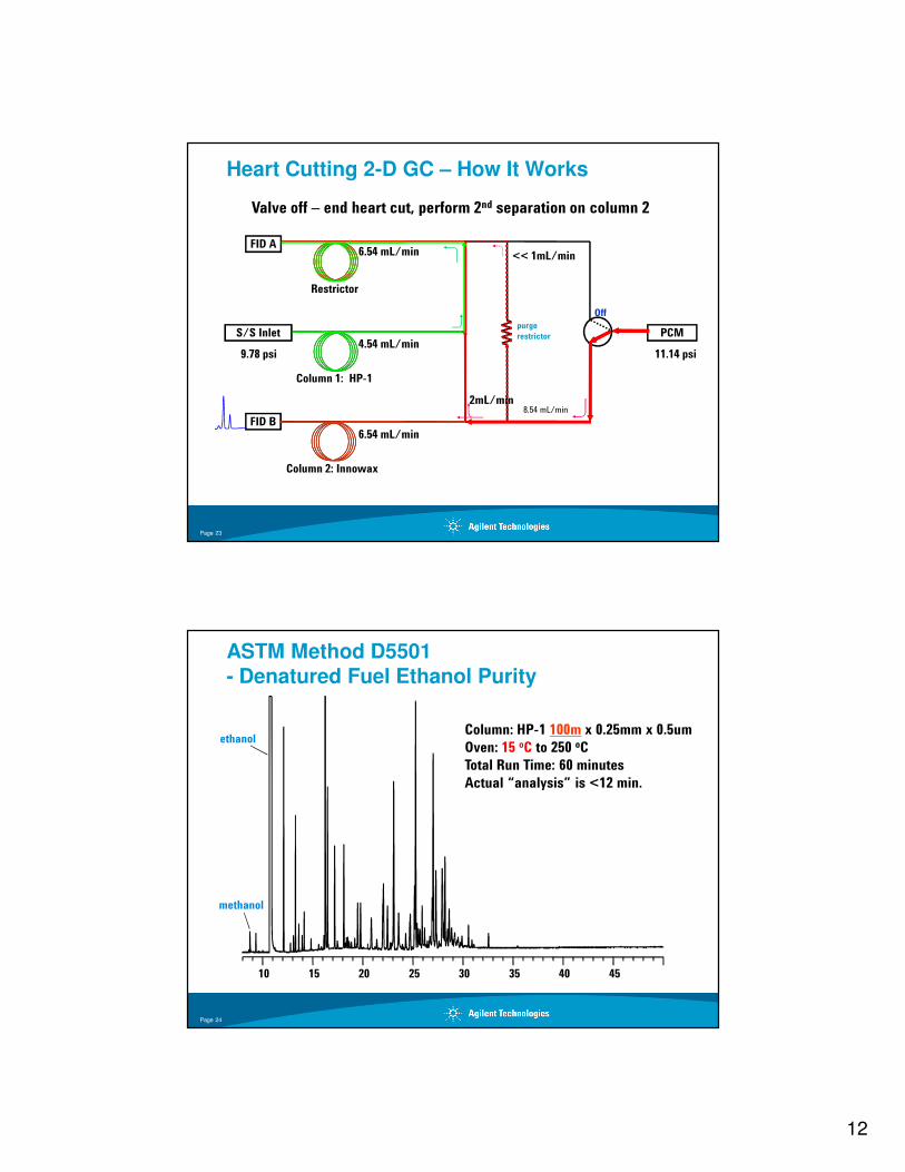
FID A
S/S Inlet
FID B
PCM
6.54 mL/min
4.54 mL/min
<< 1mL/min
9.78 psi 11.14 psi
2mL/min
purge
restrictor
8.54 mL/min
Off
6.54 mL/min
BP>Benzene
Restrictor
Column 1: HP-1
Column 2: Innowax
Heart Cutting 2-D GC – How It Works
Valve off – end heart cut, perform 2nd separation on column 2
Page 23
ASTM Method D5501 - Denatured Fuel Ethanol Purity
10 15 20 25 30 35 40 45
methanol
ethanolColumn: HP-1 100m x 0.25mm x 0.5um
Oven: 15 oC to 250 oC
Total Run Time: 60 minutes
Actual “analysis” is <12 min.
Page 24
13
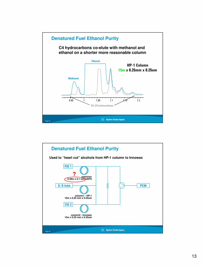
0.95 1 1.05 1.1 1.15 1.2
Methanol
Ethanol
C4, C5 hydrocarbons
C4 hydrocarbons co-elute with methanol and ethanol on a shorter more reasonable column
HP-1 Column
15m x 0.25mm x 0.25um
Denatured Fuel Ethanol Purity
Page 25
Used to “heart cut” alcohols from HP-1 column to Innowax
FID 1
S/S Inlet
FID 2
PCM
Denatured Fuel Ethanol Purity
restrictor0.38m x 0.1 mm UDFS
column1 - HP-115m x 0.25 mm x 0.25um
column2 - Innowax15m x 0.25 mm x 0.25um
?
Page 26
14
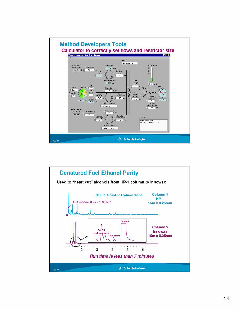
Calculator to correctly set flows and restrictor size
Method Developers Tools
Page 27
Used to “heart cut” alcohols from HP-1 column to Innowax
2 3 4 5 6
Natural Gasoline Hydrocarbons
Cut window 0.97 - 1.10 min
Ethanol
C4, C5 hydrocarbons
Methanol
Column 1HP-1
15m x 0.25mm
Column 2Innowax
15m x 0.25mm
Run time is less than 7 minutes
Denatured Fuel Ethanol Purity
Page 28
15
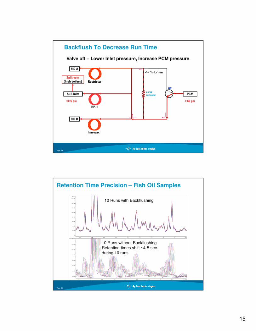
FID A
S/S Inlet
FID B
PCM
<< 1mL/min
purge
restrictor
OffHigh boilers
Restrictor
HP-1
Innowax
Backflush To Decrease Run Time
Valve off – Lower Inlet pressure, Increase PCM pressure
Split vent
(high boilers)
11.14 psi9.78 psi<0.5 psi >60 psi
Page 29
Retention Time Precision – Fish Oil Samples
m in5 .3 5 .4 5 .5 5 .6 5 .7 5 .8 5 .9 6 6 . 1
N or m .
0
2 0 0 0
4 0 0 0
6 0 0 0
8 0 0 0
1 0 0 0 0
1 2 0 0 0
1 4 0 0 0
1 6 0 0 0
m in5 .3 5 .4 5 .5 5 . 6 5 .7 5 .8 5 .9 6 6 .1 6 .2
N or m .
2 0 0 0
4 0 0 0
6 0 0 0
8 0 0 0
1 0 0 0 0
1 2 0 0 0
1 4 0 0 0
10 Runs with Backflushing
10 Runs without Backflushing
Retention times shift ~4-5 sec
during 10 runs
Page 30
16
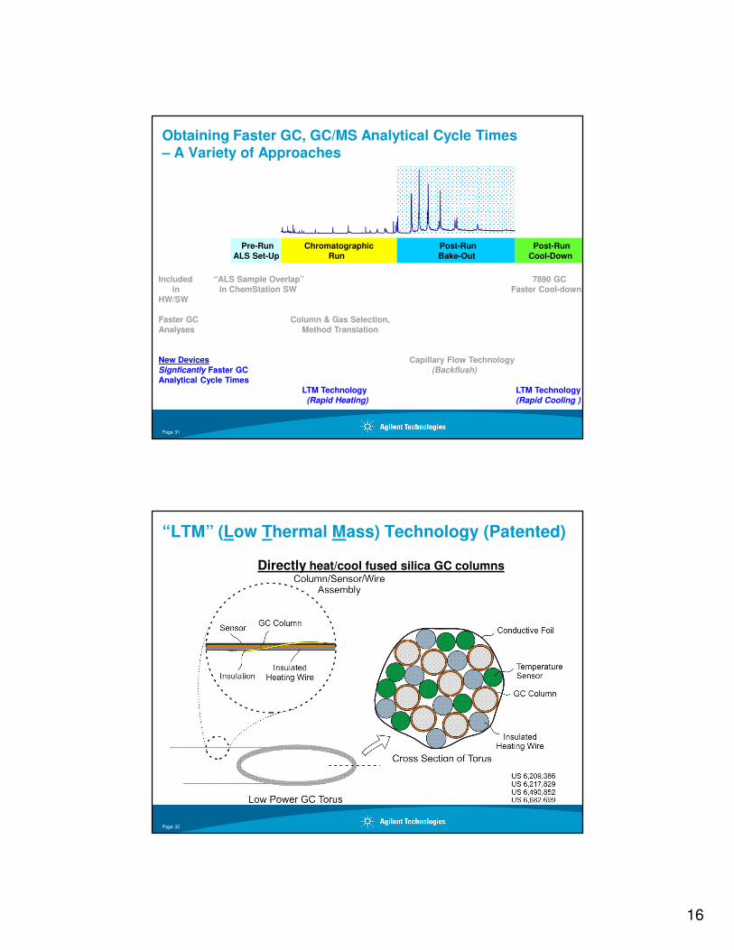
Obtaining Faster GC, GC/MS Analytical Cycle Times – A Variety of Approaches
Post-Run
Bake-Out
Chromatographic
Run
Post-Run
Cool-Down
Pre-Run
ALS Set-Up
Included “ALS Sample Overlap” 7890 GC
in in ChemStation SW Faster Cool-down
HW/SW
Faster GC Column & Gas Selection,
Analyses Method Translation
New Devices Capillary Flow Technology
Signficantly Faster GC (Backflush)
Analytical Cycle Times
LTM Technology LTM Technology
(Rapid Heating) (Rapid Cooling )
Page 31
“LTM” (Low Thermal Mass) Technology (Patented)
Directly heat/cool fused silica GC columns
Page 32
17
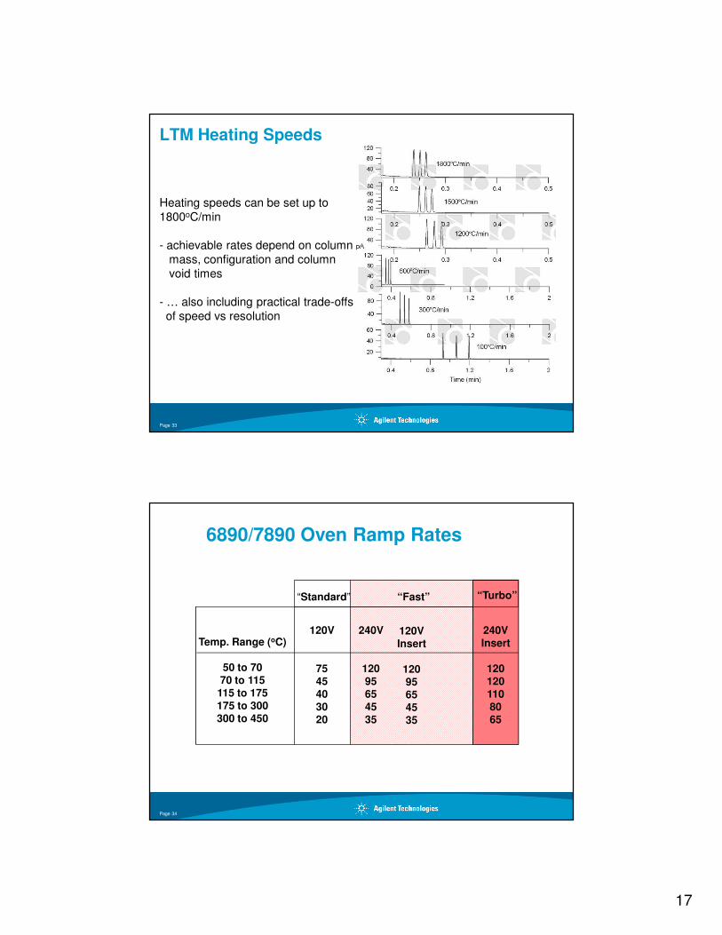
LTM Heating Speeds
Heating speeds can be set up to
1800oC/min
- achievable rates depend on column
mass, configuration and column
void times
- … also including practical trade-offs
of speed vs resolution
Page 33
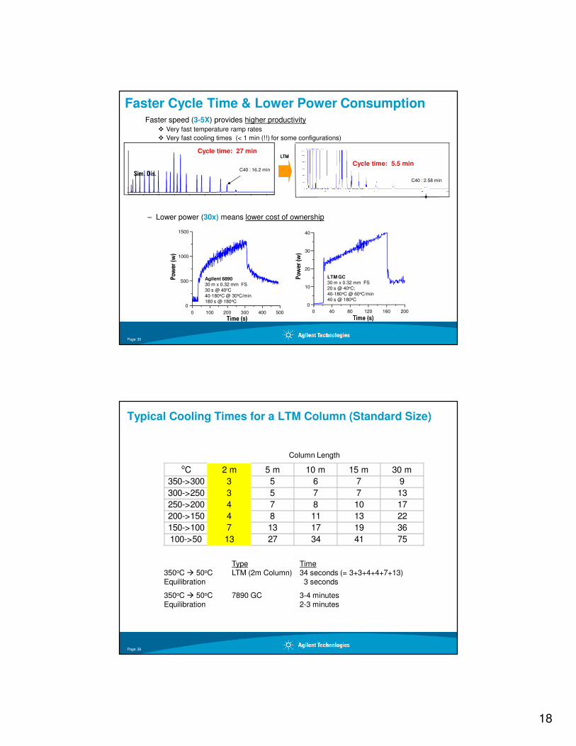
240V
12095654535
120VInsert
12095654535
“Fast”
120V
7545403020
“Standard”
Temp. Range (oC)
50 to 7070 to 115
115 to 175175 to 300300 to 450
240VInsert
1201201108065
“Turbo”
6890/7890 Oven Ramp Rates
Page 34
18
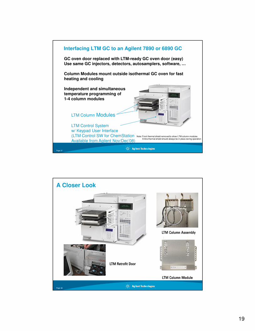
Faster Cycle Time & Lower Power ConsumptionFaster speed (3-5X) provides higher productivity
� Very fast temperature ramp rates
� Very fast cooling times (< 1 min (!!) for some configurations)
C40 : 2.58 min
Cycle time: 5.5 minC40 : 16.2 min
Cycle time: 27 minLTMLTM
Sim. Dis.Sim. Dis.
Agilent 689030 m x 0.32 mm FS30 s @ 40oC40-180oC @ 30oC/min180 s @ 180oC
0 100 200 300 400 500
0
500
1000
1500
Power (w
)Power (w
)
Time (s)Time (s)
LTM GC30 m x 0.32 mm FS20 s @ 40oC;40-180oC @ 60oC/min40 s @ 180oC
0 40 80 120 160 200
0
10
20
30
40
Power (w
)Power (w
)
Time (s)Time (s)
– Lower power (30x) means lower cost of ownership
Page 35
Typical Cooling Times for a LTM Column (Standard Size)
oC 2 m 5 m 10 m 15 m 30 m
350->300 3 5 6 7 9
300->250 3 5 7 7 13
250->200 4 7 8 10 17
200->150 4 8 11 13 22
150->100 7 13 17 19 36
100->50 13 27 34 41 75
Column Length
Type Time350oC � 50oC LTM (2m Column) 34 seconds (= 3+3+4+4+7+13)Equilibration 3 seconds
350oC � 50oC 7890 GC 3-4 minutesEquilibration 2-3 minutes
Page 36
19
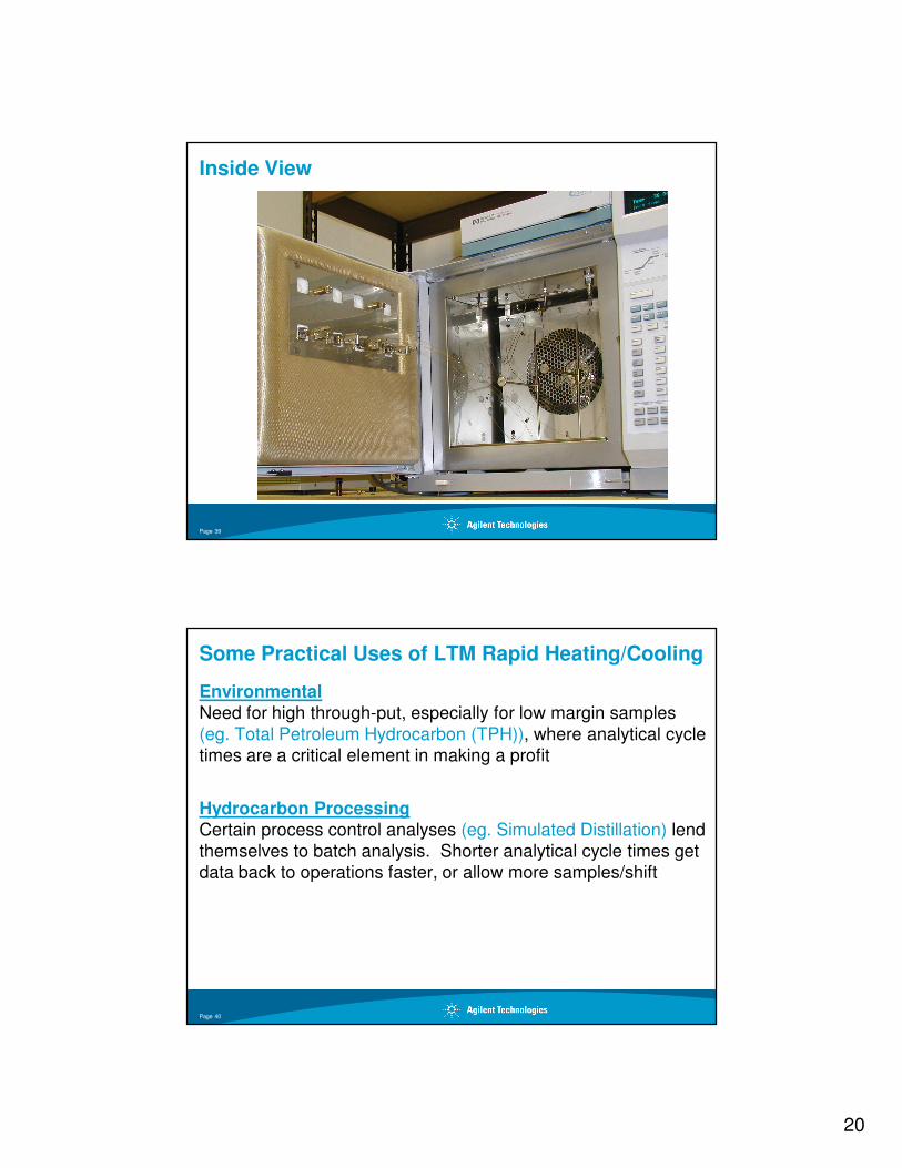
Interfacing LTM GC to an Agilent 7890 or 6890 GC
GC oven door replaced with LTM-ready GC oven door (easy) Use same GC injectors, detectors, autosamplers, software, …
Column Modules mount outside isothermal GC oven for fast heating and cooling
Independent and simultaneous temperature programming of 1-4 column modules
Note: Front thermal shield removed to show LTM column modulesEntire thermal shield should always be in place during operation
LTM Column Modules
LTM Control System
w/ Keypad User Interface
(LTM Control SW for ChemStation
Available from Agilent Nov/Dec’08)
Page 37
A Closer Look
LTM Column ModuleLTM Column Module
LTM Column AssemblyLTM Column Assembly
LTM Retrofit DoorLTM Retrofit Door
Page 38
20
Inside View
Page 39
Some Practical Uses of LTM Rapid Heating/Cooling
EnvironmentalNeed for high through-put, especially for low margin samples (eg. Total Petroleum Hydrocarbon (TPH)), where analytical cycle times are a critical element in making a profit
Hydrocarbon ProcessingCertain process control analyses (eg. Simulated Distillation) lend themselves to batch analysis. Shorter analytical cycle times get data back to operations faster, or allow more samples/shift
Page 40
21
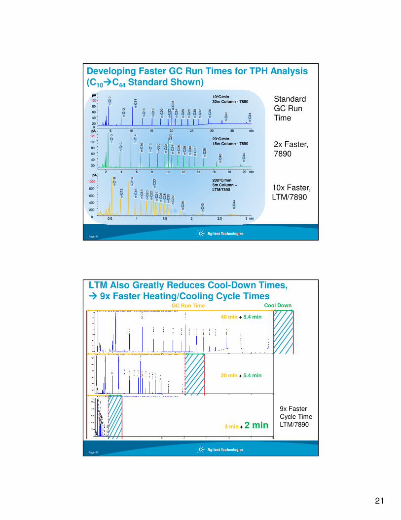
Developing Faster GC Run Times for TPH Analysis(C10����C44 Standard Shown)
2x Faster,7890
min5 10 15 20 25 30 35
pApApApA
020
40
60
80
100
n-C
10
n-C
12
n-C
14
n-C
16
n-C
18
n-C
20
n-C
22 n
-C23
n-C
24
n-C
26
n-C
28
n-C
30
n-C
32
n-C
36
n-C
40
n-C
44
min2 4 6 8 10 12 14 16 18 20
pApApApA
20
40
60
80
100
120
n-C
10
n-C
12 n
-C14
n-C
16
n-C
18
n-C
20
n-C
22
n-C
23
n-C
24
n-C
26
n-C
28
n-C
30
n-C
32
n-C
36
n-C
40
n-C
44
min0.5 1 1.5 2 2.5 3
pApApApA
0
200
400
600
800
1000
n-C
10
n-C
12
n-C
14
n-C
16
n-C
18
n-C
20
n-C
22
n-C
23
n-C
24
n-C
26
n-C
28
n-C
30
n-C
32
n-C
36
n-C
40
n-C
44
10oC/min30m Column - 7890
20oC/min15m Column - 7890
200oC/min5m Column –LTM/7890 10x Faster,
LTM/7890
StandardGC RunTime
Page 41
LTM Also Greatly Reduces Cool-Down Times,���� 9x Faster Heating/Cooling Cycle Times
40 min + 5.4 min
20 min + 5.4 min
3 min + 2 min
GC Run Time Cool Down
9x Faster
Cycle Time
LTM/7890
Page 42
22
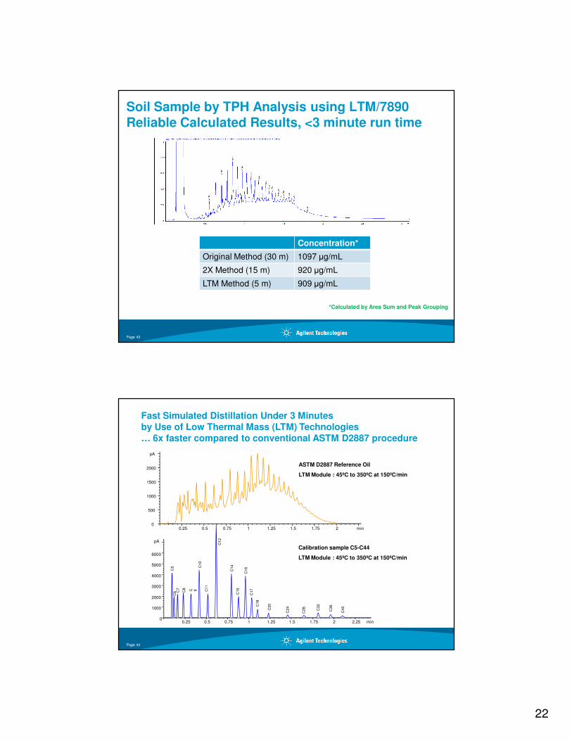
Soil Sample by TPH Analysis using LTM/7890Reliable Calculated Results, <3 minute run time
Concentration*
Original Method (30 m) 1097 µg/mL
2X Method (15 m) 920 µg/mL
LTM Method (5 m) 909 µg/mL
*Calculated by Area Sum and Peak Grouping
Page 43
pA
0
1000
2000
3000
4000
5000
6000
min0.25 0.5 0.75 1 1.25 1.5 1.75 2 2.25
C5
C6 C
7
C8 C 9
C10
C11
C12
C14
C15
C16
C17
C18
C20
C24
C28
C32
C36
C40
pA
min0.25 0.5 0.75 1 1.25 1.5 1.75 20
500
1000
1500
2000
Fast Simulated Distillation Under 3 Minutes by Use of Low Thermal Mass (LTM) Technologies… 6x faster compared to conventional ASTM D2887 procedure
ASTM D2887 Reference Oil
LTM Module : 45ºC to 350ºC at 150ºC/min
Calibration sample C5-C44
LTM Module : 45ºC to 350ºC at 150ºC/min
Page 44
23
min0 0 .5 1 1 .5 2 2 .5
pA
0
1 0 0
2 0 0
3 0 0
4 0 0
5 0 0
6 0 0
7 0 0
8 0 0
9 0 0
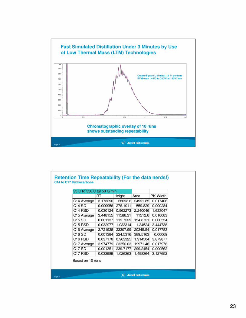
Chromatographic overlay of 10 runs Chromatographic overlay of 10 runs shows outstanding repeatabilityshows outstanding repeatability
Fast Simulated Distillation Under 3 Minutes by Use of Low Thermal Mass (LTM) Technologies
Creaked gas oil, diluted 1:3 in pentaneRVM oven : 45ºC to 350ºC at 150ºC/min
Page 45
Retention Time Repeatability (For the data nerds!)C14 to C17 Hydrocarbons
35 C to 350 C @ 50 C/min.
RT Height Area PK Width
C14 Average 3.173296 28692.6 24991.85 0.017406
C14 SD 0.000956 276.1011 559.829 0.000284
C14 RSD 0.030124 0.962273 2.240046 1.633047
C15 Average 3.448155 11586.31 11512.6 0.016083
C15 SD 0.001137 119.7229 154.8721 0.000554
C15 RSD 0.032977 1.033314 1.34524 3.444738
C16 Average 3.721938 23307.99 20345.54 0.017783
C16 SD 0.001384 224.5316 389.5163 0.00069
C16 RSD 0.037178 0.963325 1.914504 3.879877
C17 Average 3.974779 23356.03 19971.48 0.017978
C17 SD 0.001351 239.7177 299.2454 0.000562
C17 RSD 0.033989 1.026363 1.498364 3.127652
Based on 10 runs
Page 46
24
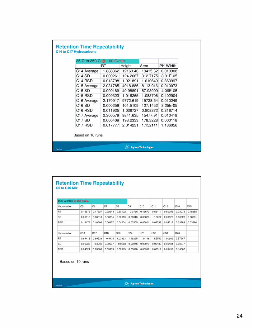
Retention Time Repeatability C14 to C17 Hydrocarbons
35 C to 350 C @ 100 C/min.
RT Height Area PK Width
C14 Average 1.888362 12160.46 19415.62 0.010308
C14 SD 0.000261 124.2667 312.7175 8.91E-05
C14 RSD 0.013798 1.021891 1.610649 0.863997
C15 Average 2.031785 4918.886 8113.916 0.010073
C15 SD 0.000189 49.98891 87.93099 4.06E-05
C15 RSD 0.009323 1.016265 1.083706 0.402904
C16 Average 2.170917 9772.619 15728.54 0.010249
C16 SD 0.000259 101.5109 127.1452 3.25E-05
C16 RSD 0.011925 1.038727 0.808372 0.316714
C17 Average 2.300579 9841.635 15477.91 0.010418
C17 SD 0.000409 198.2333 178.3228 0.000118
C17 RSD 0.017777 2.014231 1.152111 1.136056
Based on 10 runs
Page 47
Retention Time RepeatabilityC5 to C40 Mix
Based on 10 runs
45 C to 350 C @ 250 C/min
Hydrocarbon C5 C6 C7 C8 C9 C10 C11 C12 C14 C15
RT 0.13676 0.17327 0.22944 0.30102 0.3786 0.45672 0.53111 0.60298 0.73073 0.78855
SD 0.00018 0.00018 0.00015 0.00013 0.00013 0.00026 0.0002 0.00027 0.00028 0.00031
RSD 0.13178 0.10606 0.06457 0.04204 0.03505 0.05801 0.03798 0.04518 0.03889 0.03894
Hydrocarbon C16 C17 C18 C20 C24 C28 C32 C36 C40
RT 0.84418 0.89529 0.9439 1.03433 1.19225 1.34146 1.5513 1.90969 2.57287
SD 0.00036 0.0003 0.00037 0.0003 0.00046 0.00079 0.00132 0.00181 0.00377
RSD 0.04321 0.03306 0.03939 0.02915 0.03828 0.05917 0.08512 0.09457 0.14667
Page 48
25
LTM System Technology - Summary
• High efficiency temperature programmingfast heatingfast cooling (< 1 min in some configurations)high throughputfast method development
• High performance chromatographyutilize commercially available columns (up to 30m length)very good retention time repeatability
• Easily integrates with conventional Agilent GC utilize existing injectors, detectors
• Multicolumn temperature control (1-4 modules)simultaneous, independent operation multidimensional GChigh throughput parallel systemsstrong synergy with Agilent’s Capillary Flow Technology
• Available for Agilent 6890/7890
Page 49