new digital crack monitoring system for measuring … · 1 new digital crack monitoring system for...
TRANSCRIPT
1
NEW DIGITAL CRACK MONITORING SYSTEM FOR MEASURING AND DOCUMENTATION OF WIDTH OF CRACKS IN
CONCRETE STRUCTURES
Wolfgang NIEMEIER1, Björn RIEDEL1, Clive FRASER2, Helmut NEUSS3, Rafael STRATMANN3 and Eberhard ZIEM3
1 Technische Universität Braunschweig, Germany 2 Melbourne University, Australia
3 City of Düsseldorf, Germany
Abstract: The width of cracks is one of the major sources of information for civil engineers for stability assessment and damage detection of concrete structures. Here a new, digital sys-tem is presented to record and analyse cracks. It uses a standard digital camera embedded into a calibrated, cylindrical attachment. Crack parameters like medium width, width variation and width profiles are recorded and analysed with a newly developed software. Applications in the laboratory and for real structures illustrate handling, achieved precision and data content in comparison to standard methods.
1. INTRODUCTION
The actual tendency in civil engineering is to extend the live-cycle of large scale structures. Due to limited or even reduced resources for new constructions it is necessary to use and rely on existing structures, which in many countries are coming to age. This tendency has two consequences : i) More frequent and more rigorous monitoring is required and ii) Concepts and strategies to maintain and to improve existing structures have to be developed.
One of the main sources of information in monitoring concrete structures are cracks, indicat-ing weak zones and acting forces. But up to now there is no system available which allows to measure and analyse cracks objective, precise and repeatable (Stratmann et. al. 2008).
One has to be aware that cracks are quite normal in each structure, and the safety is not criti-cal in general, if cracks are found. But in Germany concrete structures with cracks with a width of more than 0,2 mm have to be analysed in detail; if the width is larger, even adequate counteraction has to defined and initiated.
In a collaboration between civil engineers and geodetic engineers during the last years the so-called DRS (Digitales Rissmess-System = Digital Crack Monitoring System) was developed, consisting of a specific camera devise and a newly developed software, which can serve for the here defined tasks.
2
2. OBJECTIVES OF THE NEW SOLUTION
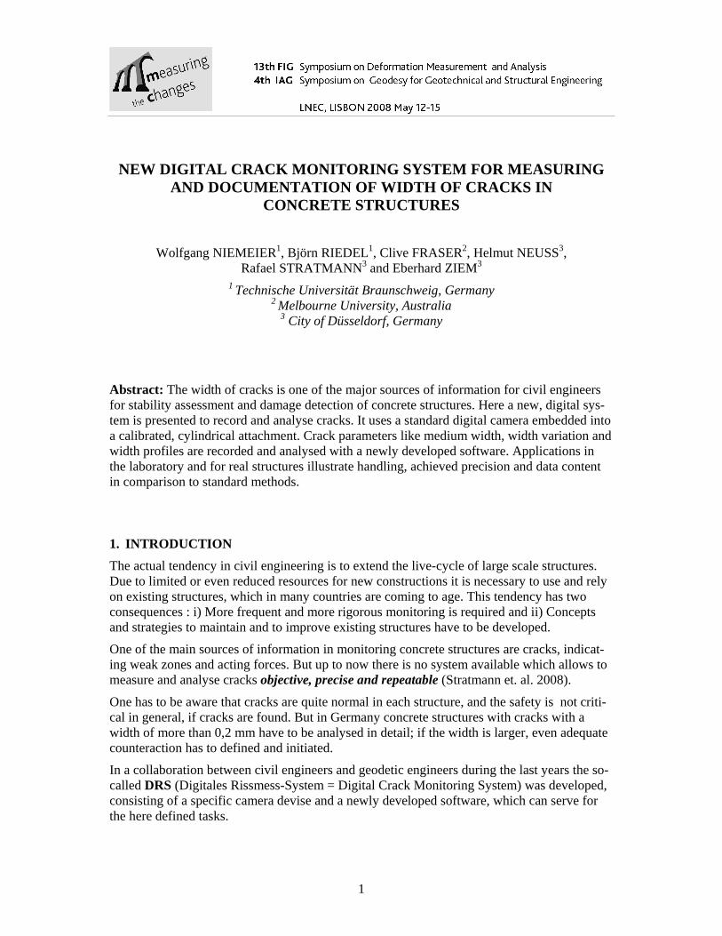
Up to now very simple devices are used for recording and analysing the width of cracks, e.g. crack templates and line counter (crack oculars), as depicted in Fig. 1. The main shortage of these devices are their lack of any type of documentation and the subjective estimation of width parameters by one person, without being reproducible.
Figure 1 - Crack Template and Line Counter as classical devices for monitoring cracks
Analysing the real requirement for the determination of crack parameters, the following ob-jectives for a new crack monitoring device could be defined : - Objective and robust crack capture: each inspector gets the same results, independent from environmental conditions - Documentation of the situation in situ: the image documents the cracks within its surrounding - Objective, repeatable calculation of width parameters: calculation of width parameters can be repeated, if required - Geo-referencing of crack location: unique definition of crack location by 3D-coordinates - Applicability for different types of cracks, surfaces and materials: different types and roughness of materials and surfaces has not to effect the measurements
3. DIGITAL CRACK MONITORING DEVICE
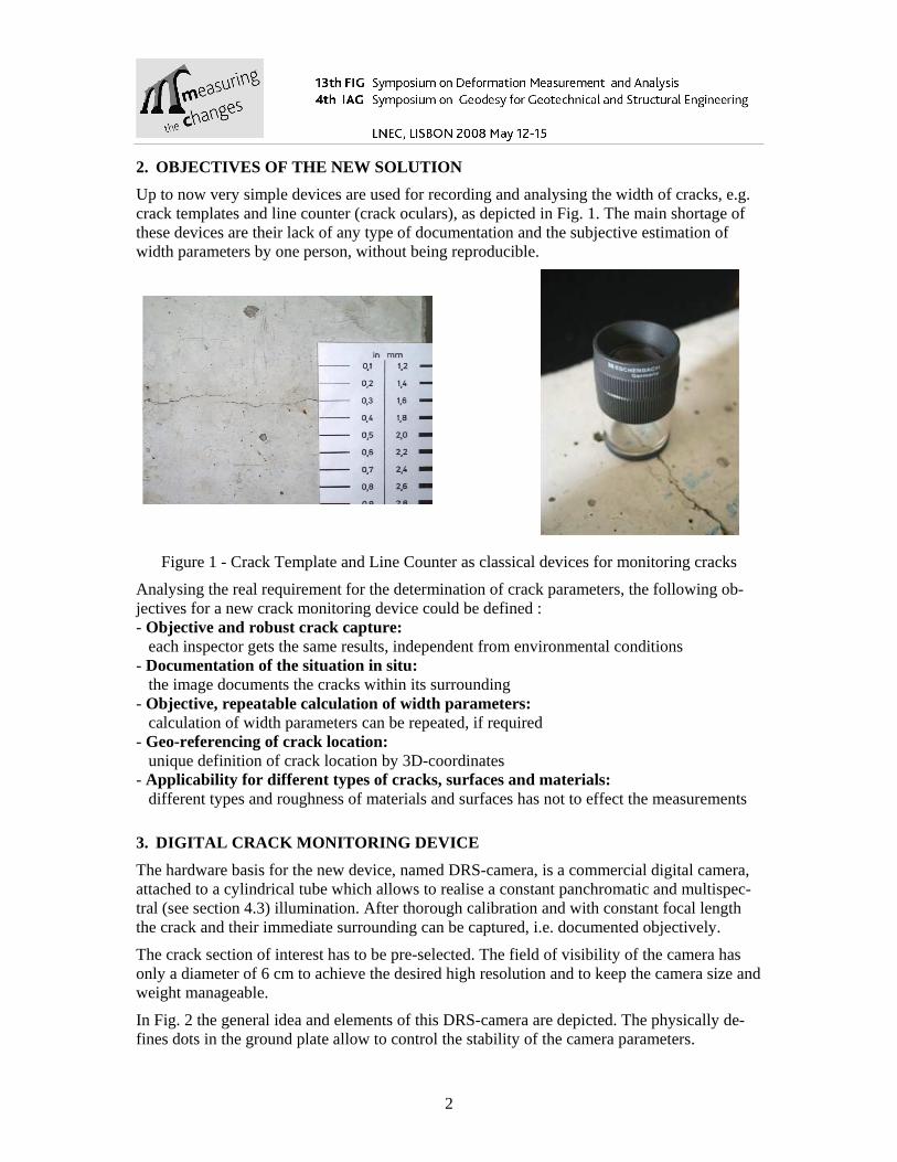
The hardware basis for the new device, named DRS-camera, is a commercial digital camera, attached to a cylindrical tube which allows to realise a constant panchromatic and multispec-tral (see section 4.3) illumination. After thorough calibration and with constant focal length the crack and their immediate surrounding can be captured, i.e. documented objectively.
The crack section of interest has to be pre-selected. The field of visibility of the camera has only a diameter of 6 cm to achieve the desired high resolution and to keep the camera size and weight manageable.
In Fig. 2 the general idea and elements of this DRS-camera are depicted. The physically de-fines dots in the ground plate allow to control the stability of the camera parameters.
3
Figure 2 - New digital crack monitoring device, named “DRS camera”
4. DRS SOFTWARE
For practical applications, the processing, analysis and storage of the images has to be per-formed in the laboratory, in the field and back in the office. To study the development of cracks over years, a comparison of the crack parameters in consequent monitoring periods is necessary. Therefore the images and the results of the first processing and analysis have to be stored in a data base system.
As the cracks are not unique in size and form (surface differences and border erosion) and as the DRS-system is designed to account for a lot of different situations, three approaches are developed within the DRS-software to determine crack parameters:
- Modified Fly-Fisher algorithm to follow the crack progress and measure the width in numerous cross sections automatically
- Manual measuring of the width at a pre-selected location with the possibility to ana-lyse the width profile
- A correlative concept to find best coincidence between the crack borders. Here the automatic realisation still is under development.
4
4.1. Polyline-Fly-Fisher Algorithm
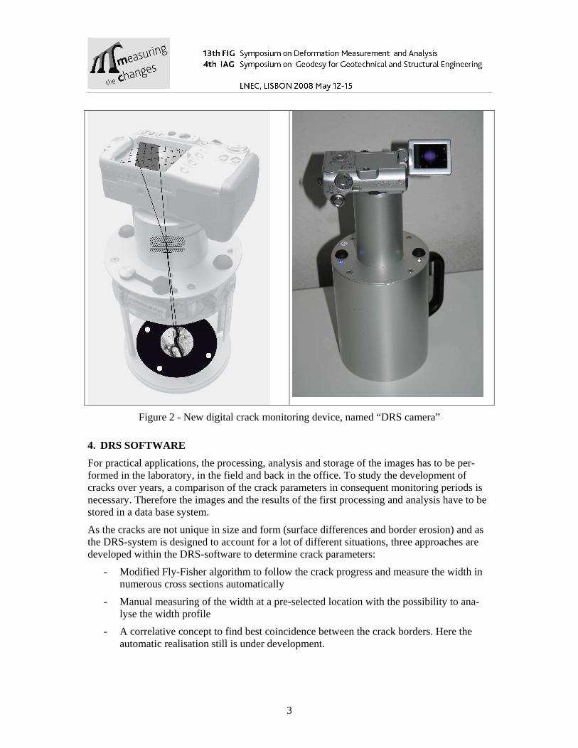
The computational approach using the Polyline-Fly-Fisher Algorithm (Dare et. al. 2002, Riedel et. al. 2003) is as follows, see as additional information Fig. 3:
-Select manually, i.e. by a mouse-click, start and end point of the cracks section, for which the width parameters has to be estimated. This is necessary, as in an image sometimes more than one crack appears. - Start the Polyline-Fly-Fisher Approach, which follows the crack automatically and deter-mines a dense series of crack profiles, normally with more than 100 values. -Start the processing software to analyses these grey-value profiles, to eliminate outliers and to determine the mean crack width. - The image and this first computational result are stored in a data base system, completed by additional information to identify the location of the crack, the date and time of the measure-ments.
Figure 3 - Polyline-Fly-Fisher Algorithm (Dare et. al. 2002)
4.2. Manual Measurements
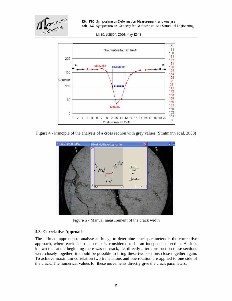
As alternative possibility a so-called manual approach is realized. Here at a pre-selected loca-tion just one cross-section is determined, i.e. with panchromatic illumination the grey values of this profile are determined. As given in Fig. 4 these grey values allow for a reliable estima-tion of the parameters width and profile, as the pixel distances are known as metric quantities due to the a priori calibration.
This approach is mainly applicable for greater/broader cracks, where the information at one position is representative for a complete crack section. Due to often find obstacles within the opening of wider cracks it is difficult to decide, what are the crack borders. Therefore here automatic approaches are limited.
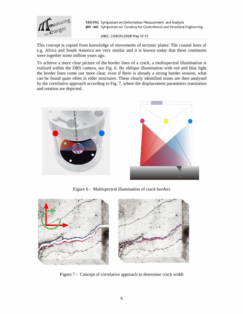
In Figure 5 a real example is depicted, where this manual measurement of the crack width is performed with the DRS software.
5
Figure 4 - Principle of the analysis of a cross section with grey values (Stratmann et al. 2008)
Figure 5 - Manual measurement of the crack width
4.3. Correlative Approach
The ultimate approach to analyse an image to determine crack parameters is the correlative approach, where each side of a crack is considered to be an independent section. As it is known that at the beginning there was no crack, i.e. directly after construction these sections were closely together, it should be possible to bring these two sections close together again. To achieve maximum correlation two translations and one rotation are applied to one side of the crack. The numerical values for these movements directly give the crack parameters.
6
This concept is copied from knowledge of movements of tectonic plates: The coastal lines of e.g. Africa and South America are very similar and it is known today that these continents were together some million years ago.
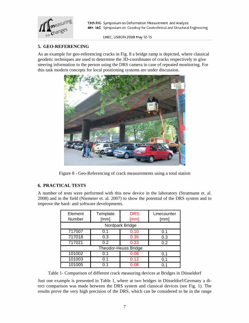
To achieve a more clear picture of the border lines of a crack, a multispectral illumination is realized within the DRS camera, see Fig. 6. By oblique illumination with red and blue light the border lines come out more clear, even if there is already a strong border erosion, what can be found quite often in elder structures. These clearly identified zones are then analysed by the correlative approach according to Fig. 7, where the displacement parameters translation and rotation are depicted.
Figure 6 - Multispectral illumination of crack borders
Figure 7 - Concept of correlative approach to determine crack width
7
5. GEO-REFERENCING
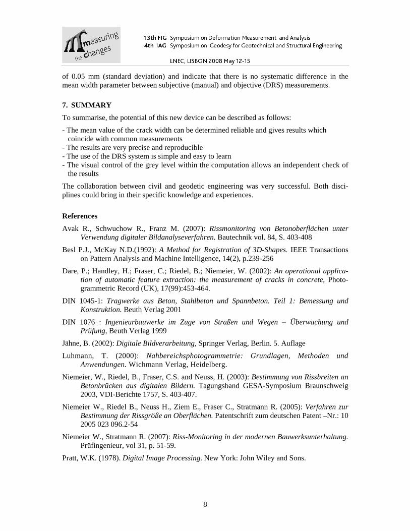
As an example for geo-referencing cracks in Fig. 8 a bridge ramp is depicted, where classical geodetic techniques are used to determine the 3D-coordinates of cracks respectively to give steering information to the person using the DRS camera in case of repeated monitoring. For this task modern concepts for local positioning systems are under discussion.
Figure 8 - Geo-Referencing of crack measurements using a total station
6. PRACTICAL TESTS
A number of tests were performed with this new device in the laboratory (Stratmann et. al. 2008) and in the field (Niemeier et. al. 2007) to show the potential of the DRS system and to improve the hard- and software developments.
Table 1- Comparison of different crack measuring devices at Bridges in Düsseldorf
Just one example is presented in Table 1, where at two bridges in Düsseldorf/Germany a di-rect comparison was made between the DRS system and classical devices (see Fig. 1). The results prove the very high precision of the DRS, which can be considered to be in the range
Element Number
Template [mm]
DRS [mm]
Linecounter [mm]
717007 0.1 0.10 0.1717018 0.3 0.35 0.3717021 0.2 0.23 0.2
101002 0.1 0.08 0,1101003 0.1 0.12 0,1101005 0.1 0.08 0,1
Nordpark Bridge
Theodor-Heuss Bridge
8
of 0.05 mm (standard deviation) and indicate that there is no systematic difference in the mean width parameter between subjective (manual) and objective (DRS) measurements.
7. SUMMARY
To summarise, the potential of this new device can be described as follows:
- The mean value of the crack width can be determined reliable and gives results which coincide with common measurements - The results are very precise and reproducible - The use of the DRS system is simple and easy to learn - The visual control of the grey level within the computation allows an independent check of the results
The collaboration between civil and geodetic engineering was very successful. Both disci-plines could bring in their specific knowledge and experiences.
References
Avak R., Schwuchow R., Franz M. (2007): Rissmonitoring von Betonoberflächen unter Verwendung digitaler Bildanalyseverfahren. Bautechnik vol. 84, S. 403-408
Besl P.J., McKay N.D.(1992): A Method for Registration of 3D-Shapes. IEEE Transactions on Pattern Analysis and Machine Intelligence, 14(2), p.239-256
Dare, P.; Handley, H.; Fraser, C.; Riedel, B.; Niemeier, W. (2002): An operational applica-tion of automatic feature extraction: the measurement of cracks in concrete, Photo-grammetric Record (UK), 17(99):453-464.
DIN 1045-1: Tragwerke aus Beton, Stahlbeton und Spannbeton. Teil 1: Bemessung und Konstruktion. Beuth Verlag 2001
DIN 1076 : Ingenieurbauwerke im Zuge von Straßen und Wegen – Überwachung und Prüfung, Beuth Verlag 1999
Jähne, B. (2002): Digitale Bildverarbeitung, Springer Verlag, Berlin. 5. Auflage
Luhmann, T. (2000): Nahbereichsphotogrammetrie: Grundlagen, Methoden und Anwendungen. Wichmann Verlag, Heidelberg.
Niemeier, W., Riedel, B., Fraser, C.S. and Neuss, H. (2003): Bestimmung von Rissbreiten an Betonbrücken aus digitalen Bildern. Tagungsband GESA-Symposium Braunschweig 2003, VDI-Berichte 1757, S. 403-407.
Niemeier W., Riedel B., Neuss H., Ziem E., Fraser C., Stratmann R. (2005): Verfahren zur Bestimmung der Rissgröße an Oberflächen. Patentschrift zum deutschen Patent –Nr.: 10 2005 023 096.2-54
Niemeier W., Stratmann R. (2007): Riss-Monitoring in der modernen Bauwerksunterhaltung. Prüfingenieur, vol 31, p. 51-59.
Pratt, W.K. (1978). Digital Image Processing. New York: John Wiley and Sons.
9
Riedel B., Niemeier W., Fraser C., Dare, P., Cronk S. (2003): Development of an imaging sys-tem for monitoring cracks in concrete structures. In Grün, A.; Kahmen, H.(Eds.): 6th Conference on Optical 3-D Measurement Techniques, ETH Zürich.
RI-EBW-PRÜF: Richtlinien zur einheitlichen Erfassung, Bewertung, Aufzeichnung und Auswertung von Ergebnissen der Bauwerksprüfungen nach DIN 1076. Verlag / Verkehrsblatt-Verlag, Dortmund
Stratmann R, Birtel V., Mark P., Neuss H., Niemeier W., Riedel B. (2008): Digitale Erfassung und Bewertung von Rissen. Accepted for: Journal of Stahl- und Spannbeton, Ernst&Sohn Verlag
Vollrath F., Tathoff H. (2002): Handbuch der Brückeninstandhaltung. Vbt Verlag Bau und Technik. 2. Auflage
Corresponding author contacts Wolfgang NIEMEIER
[email protected] Institute of Geodesy and Photogrammetry, Technische University Braunschweig Germany