new energy technologies issue 07
TRANSCRIPT


NEW ENERGY TECHNOLOGIES #7
1. Gravitonics is Electronics of the XXI Century, Spartak M. Poliakov, Oleg S. Poliakov 2. Experimental Research on Gravitational Propulsion System. Review 3. Beamship Technology: A Re-working of Early 20th century Discoveries, Russell
Anderson 4. Commercial Antigravity, Tim Ventura 5. Action without Reaction. New Gravidynamic Paradox, Yuri N. Ivanov 6. New Possibilities of Vortex Electric Power Devices, Stanislav A. Lisnyak 7. Investigation of Electric Energy Transmission Processes in non-Metallic Conducting
Channels, D.S. Strebkov, A.I. Nekrasov, S.V. Avraamenko 8. Microcosm – Universe - Life, Alexey G. Shlienov, Ernest L. Petrov 9. Hypothesis of a Theory of Everything, Jack P. Gibson 10. The Charge and Mass of a Photon, Dzabrail Kh. Baziev 11. The Homopolar Motor: A True Relativistic Engine, Jorge Guala-Valverde, Pedro
Mazzoni, Ricardo Achilles 12. Weight Reductions Generated by Bucking-Field Permanent Magnets, William C.
Simpson 13. Advanced Nuclear Waste Decontamination Technologies, Mark Porringa 14. Experimental Investigations of the Radioactive Isotope Half-Value Period Changing in
the Local Volume ofCause-Effect Relations, Igor A. Melnik 15. Tilley Electric Vehicle 16. The Problem of Time: Force as the Cause of Change in the Course of Time, Valentin P.
Oleinik 17. Time and its Physical Relationships, Andrew Michrowski 18. Time as Phenomenon of the Expanding Universe, Michael H. Shulman 19. The Experiments on Thermo-Gravitation. Review 20. Letters to the Editor from Hector D. Perez Torrez
2 New Energy Technologis Issue #4 (7) July-August 2002
Gravitonics is Electronicsof the XXI Century
Hypothesizes, Conclusions, Speculations
Spartak M. Poliakov,Oleg S. Poliakov
60-let SSSR str., 1-167, Friazino,Moscow area, 141120, Russia
Tel: (096) 564-65-67
(This article was published in “ELECTRONICS: Science,Technology, Business” magazine 5/2000 p. 8-13)
Today we can easily insist that ways to solve maingravitonics problems are already defined, at that thepractical realization of any of them will mean the breakthrough in engineering. So, what successes has theRussian science already achieved in the area ofgravitonics, and what priorities can we lose here in thenearest future?
Introduction to Gravitonics
The electronics of the “past century” uses electron asa ball, which has weight, radius, electric charge andmagnetic moment. These very parameters defineelectron behavior in the electrostatic, magnetostatic andelectromagnetic fields. But electron abilities are notlimited by it; electron spin and internal microstructurefeatures remain unaccounted and unclaimed. Evenlyspeaking, General Theory of Relativity (GTR) of Einsteinwas a power impulse for mathematical physicsdevelopment and gave birth to many productive ideas.But the main problem, that is the secret of gravitation,remains undisclosed… In works of K.P. Stanjukovich [1]and A.Z. Petrov [2], who carefully followed GTR, it wasshown that this theory described neither energy, norimpulse of gravitational radiation, i.e. it can not explaingravitation. About 20 years ago V.B. Braginsky, today’sRAS Corresponding Member, came up with an idea: “ifthe propagation speed of gravitational signal is higherthan the velocity of light, there will be already anothertheory, not GTR!” Maybe, the reason is the postulationof equality of gravitational and electromagneticradiation velocities?…
Today the approximate theory of gravitational radiationsources can be built on the basis of the following simpleconsiderations: if during annihilation of “electron-positron” pair there creates the pair of gamma-quantums with energy about 0.511 MeV, then the pairof back gamma-quantums with the energy about0.511 MeV, could create “electron-positron” pair. Is itpossible to assume, that electron, positron and gamma-quantum with the energy about 0.511 MeV are just threestages of one and the same object?! If it is possible,then for the rational description of the given object wewill have to suppose the existence of subparticles,named by us uniquantums [3], or named by otherauthors microleptons [4].
On the basis of Heisenberg uncertainty relationconformably to the energy and duration of quantum ofelectromagnetic radiation, measured by laboratorymeans, it is possible to calculate the minimal “electricallength” of photon (i.e. quantum geometrical extensionin free space in wave-length units), which is equal to137λ, and in the uniquantum theory it is equal to 137uniquantum-antiuniquantum pairs. On the basis ofthese conceptions it is possible to construct the spatialmicrostructure model of electron. So, what kind is it?
We think, that electron can be represented as thin-walled spheroid, walls of which are two light (C)barriers, separating the “internal” part of electron fromthe “external” one. From the traditional physics pointof view “over-barrier” space is an “imaginary” one. Thisvery space can contain the gravitational mass ofelectron. The radius of the gravitational spheroid isequal to the half of the classic electron radius, and itsimaginary weight is 137 times more than the rest massof electron. Being “cut” off by the double light C-barrier,uniquantums of the spheroid internal part are as if non-existent for the outer world, and the rest mass of electronis formed by magnetic energy of three uniquantums onthe external orbit with the classic electron radius. Thisvery spheroid, rotating with the tangential velocity C,let us get the precise value of the electron spin.
The study of presented model shows, that:
• The “electromagnetic” rest mass of electron is“magnetostatic”;
• The gravitational mass of electron is an imaginaryvalue and it is 137 times more than the rest massof electron;
• The gravitational radius of electron is two timesless than the “classical” one;
• The “internal” gravitational radius of electron is45.7 times more than the external one, i.e. theinternal space is compressed per 45.7 times (!);
• The spin is equal to the classical one, but this valueis imaginary one (!);
• The value of the “effective” electron charge is threetimes more than the classical tabulated value;
• The native magnetic field of electron is equal to8,9⋅1013 Oersted;
• The gravitational constant is equal to 1033 cm3/g.s2,i.e. it is about 1040 more than the “world”gravitational constant of the Earth;
• The gravitational energy of electron is equal to137⋅0.511 MeV, i.e. 137 times more than theequivalent energy of the rest mass of electron.
The model is paradoxical. But it can be testedexperimentally! Comparing “electromagnetic” restmass of electron with the relation of electromagneticenergy to gravitational one, it is possible to determinethe connection between magnetostatic andgravitational energy of electron, and, therefore, withenergy of the magnetized ferromagnetic.

3New Energy Technologis Issue #4 (7) July-August 2002
Gravitational constants of the Earth and of the electrondiffer in about 1040 and can be described by the samesimple equation:
2/302 ωγγ ⋅= kloc ,
where k - is a parameter of the gyroscope shape, 0γ -is absolute universal constant, equal to 1/137 and ω -is native rotation frequency of the gyroscope.
Let us assume, that gravitational constants of all objectsshould be described by this equation. By substitutionof the new gravitational constant into the known
equation of the gravitational energy rmW /2γ= wewill get the equation of the gravitational energy ofrotating gyroscope with any size (from electron up tothe Galaxy!). Thus, the main point of the “non-Einsteinian” theory of gravitational energy sourcescomes to the thing that any rotating object and anymagnetized ferromagnetic have their own gravitationalenergy, and the sources of gravitational radiation canbe only nonlinearly moved objects, or objects which arein the state of change of phase (for example, permanentmagnet during its demagnetization). It is thegravitational theory and explanation of “strong” and“weak” interactions!
Laboratory test of the equations
Magnetostriction
J.P. Joule found the effect of change of ferromagneticlinear sizes and volume during magnetization as earlyas 1842. Magnetostriction is widely used in moderntechnique, but in the physical encyclopedia of 1963there is the following honest acknowledgement: “Forthe most ferrites both longitudinal and transversemagnetostriction is negative; the reason of it is stillunclear.”
In the scientific literature magnetostriction is usuallydefined as λ=∆L/L. However, during the change ofexternal field to some arbitrary and enough small value∆H, it is advisable to define magnetostriction asλ=1/L⋅∆L/∆H, since in magnetostriction experiments
the value ∆L/∆H (or HL ∂∂ / ) is changed. By means ofthe suggested equation W=137(BHV)=BHV/α, whichconnects magnetic energy with the gravitational one,it is possible to get enough simple equation for themagnetostriction:
( ) HHHBkHLL s ∂∂⋅⋅⋅⋅=∂∂⋅= ////1 2 µαλwhere (B⋅H)s/α - is the density of gravitational energyin the point of magnetic saturation, k – is the parameterof share of gravitational field in the magnetostrictioneffect, H - is magnetic bias, H∂∂ /µ - is differentialmagnetic conductivity.
The new equation qualitatively corresponds to fourknown features of magnetostriction [5], namely:
• The magnetostriction sign is defined by the sign ofH∂∂ /µ , i.e. by the course of the magnetization curve,
measured in the direction of calculated component ofthe linear magnetostriction;
• Graphical sum of three linear components ofmagnetostriction, calculated by three main axes of theanisotropy form of the model, is always negative andnumerically close to the value of the volumemagnetostriction;• Magnetostriction is an even effect, since the equationincludes squared value of the external magnetic field;• Dependence of magnetic conductivity µ from thefiled H and hence dependence H∂∂ /µ has a hysteresisnature. Therefore, the magnetostriction is a hysteresisphenomenon too.
So we have the right to “close” the question of physicalencyclopedia on the cause of magnetostriction.Magnetostriction is the secondary gravitational effectof ferromagnetic “self-constriction” in its owngravitational field.
Gravitational-optic effects of GTR
Distortion of the light beam, passing near the Sun andthe photon frequency bias in the field of terrestrialgravity (the Nobel experiment of Paunda and Rebki) arethe main arguments in favor of GTR canonization. It isvery attractive to repeat these experiments in laboratoryconditions, basing on our conception of the origin ofgravitational field.
The acceleration of gravity, used in experiments withferromagnetic, reached the value 4.72⋅1015cm/s2, i.e.about 4.8⋅1012g. At such values of acceleration there isno necessity to introduce a definition “space masses”.In these experiments there was used the opticallytransparent ferromagnetic, which was the saturatedsolution of manganese chloride in water at roomtemperature. The experiment on the beam distortionwas made in 1975 [7]. It was shown, that this effect isthe result of two simultaneous processes. The first isan intense drift of magnetic ions, which forms thegradient of index coefficient that causes the light beamdistortion. Another process is a relatively weakgravitational beam distortion, for which, nevertheless,the relation of deviation angle to the track length (thelength of the dish is about 100 mm) is turned out to beabout 1010 more than in “Einsteinian” gravitational-opticexperiments.
The experiment on bias of the optic radiation frequency[8] was made in 1978-1980 and was repeated in 1983.With use of heterodyne and interferometrical methodsof measurement we were succeeded to observe effectsof “red” and “blue” frequency biases in the non-uniformly magnetized ferromagnetic by means of simpledisplacement of the working dish (with the length about40 mm) from one side of the magnet gap to another.The maximum displacement is about 10-5, that is about1010 more than in the experiment of Paunda and Rebki.
Problem of the propagation speed of gravitationalradiation
There are still only few publications about suchfundamental parameter as the propagation speed of

4 New Energy Technologis Issue #4 (7) July-August 2002
gravitational radiation; it is able to speak only aboutpages, or even lines! Let us refer to major sources:
I. Newton: “The propagation speed of gravitationalinteraction is equal to infinity.” It is an argument,because otherwise we would have to bring the “delay”parameter ∆t into the Law of Gravity, what is not noticedin real conditions of star observations [9].
P.S. Laplace in 1787, taking into account observationerrors of that time, showed, that gravitationalinteraction speed was about 50⋅106 times more than thelight propagation speed, i.e. it was about 1,5⋅1018 cm/s[10].
A. Einstein: “The propagation speed (of gravitationalinteraction) is equal to the light velocity”. This statementis postulated.
Even during the change of propagation speed ofgravitational radiation between the Earth and the Moonit is impossible to define the signal delay about 10-11 s,i.e. we cannot measure directly the propagation speedof gravitational radiation (supposing that we have bothgenerators of the gravitational radiation and receiversof it). But this speed can be estimated by the reflectionimpulse, what exactly was made in 1987 [3]. And itsvalue is about 9⋅1020 cm/s!
On the basis of conservation law of impulse ofunidirectional radiator with arbitrary energy type wecan get a simple equation:
( ) 24 /10// CVdtdWF ⋅≅ [g/Wt]
where V – is the speed of radiation propagation, F – istractive force in grams, dW/d t – is power of radiationin Watts and C – is velocity of light.
For making the experiment there were constructed,produced and adjusted: sensible scales with one degreeof freedom (sensitivity of balance is about 1g at theoscillator mass together with the moving element ofscales which is about 50kg); the indication system ofsmall mass changes (phase-meter receiver); gyroscopicsystem, changing the mass in the dynamic mode (thereare 16 possible operating modes – from the rotation withsteady and variable angular speed up to the forcedprecession with the variable angle of precession, withthe “right” and “left” rotation of all load-bearingselements at option); power sources and commutationautomated system. The period from idea up to itsrealization took about two years (1985-1987) [3]. Takinginto account the real parameters of the system, theprogram of calculation was drawn and propulsive burnswere calculated. The results of machine computationcan be compared with real impulses, demonstrated onthe screen of the oscilloscope.
If strange speed value 177 C2 is discarded, then themiddle speed value is close to C2, i.e. to9⋅1020 cm/s! Of course, we would like to think that thisis the second fundamental matter speed of our world,which we has approached experimentally …
Gravitational receiver
During the creation of gravitational antennas andreceivers there appear almost insuperable difficultiesfrom the modern fundamental science point of view.That is why it is advisable to look at this problem fromanother side. At first, it is necessary to considergravitational radiation interaction not with the mass,which it goes through without losses, but with thegravitational field of independently gravitating mass,when the interaction must be the most effective becauseof the principle of physical processes reversibility. Atsecond, it is necessary to choose some criticalparameter of auto-gravitating receiver as a value, whichis directly measurable by gravitational detector. Forexample, angular velocity of free rotation of thin diskwith big diameter, the frequency of magnetizationprecession during NMR (nuclear-magnetic resonance)or NFMR (non-linear ferromagnetic resonance) etc. canbe chosen as such a value.
In 1987 there was the first successful attempt to receivethe gravitational impulse. The source of external signalwas gyroscopic precessing system with the variableangle of precession (the propagation speed ofgravitational radiation was measured by it). Doublegyroscope, setting in motion by one electric motor, butwith the opposite directions of rotation, was used as adetector. Between disks there was placed the source oflight, impulses of which, passing through disksopenings, were registered by photodiodes. Their signalcame into differential circuit of data processing. Thememory oscilloscope reproduced impulses ofgravitational radiation. At that radiating system andmemory oscilloscope was started up simultaneously.During the work process there appeared a problem ofexciting of slow auto-oscillations of gyroscope-detector.This problem together with the low frequency of auto-oscillations of mechanical system led to a conclusionthat this research direction is not very promising.However, the fact of detection was proved!
Gravitational engine of continuous action
Only about nine years passed since the appearance ofthe idea about engine up to its realization! In 1997 theengine was produced and tested. The engine withweight about 28 kg was made “weightless” on themagnetic hanger, and longitudinal draft, appearing inaccordance with the impulse conservation law, wasmeasured by micrometer detector of longitudinal shifts(sensitivity is about 50g/point). Such engine could bebuilt still in the beginning of the last century… However,it has a secret that is a gyroscope with the variableradius, working in the continuous mode.
The engine power is defined by the formula
dt
dr
r
mk
dt
dW ⋅
=
2
22/3
05 ωγ
In June of 2000 there were made experiments with themodel of gravitational engine, which represents a

5New Energy Technologis Issue #4 (7) July-August 2002
gyroscope with the variable radius (see photo on the1st cover page). The mercury was used as rotating fluid.Tests were made in the Research Institute of SpaceSystems named by Krunichev. In three experiments, ata certain speed of rotating fluid there was fixed adecreasing of the engine weight (38,5 kg) up to 1.0-1.5kg (2-3%). The specific impulse of the engine was equalto 2.5-3.0 kg per kilowatt of electric power. Analysisshows, that the increasing of propulsion force is possibleat optimization of design and operating modes.
Some preliminary resume
In the magazine “Foreign Literature” #1, 1967 the article“For hundred years forward…” by Jack Marabini waspublished. There were made some conclusions aboutprognostic work of firm Rand Corp., including the areaof gravitational technique. Namely:
• Development of communication facilities ongravitational waves in 2000;
• Creation of spaceships with antigravityengines in 2050;
• Transformation of gravitational energy intoelectric one in 2100.
In the article it was noted, that the most “fantastic”predictions of this firm, as a rule, come true passingahead.
According to our crude estimations, the propagationspeed of gravitational radiation is “C” times as muchthan the velocity of light, but we know neither laws ofattenuation and propagation of gravitational waves, norlaws of their reflection and refraction, nor laws of theirinteraction with the substance… The large routine workis expected: making of measurements andinvestigations, tabulating of obtained data, publishingand society familiarization of the results, their“popularization”. It is necessary to learn to usegravitational radiation and to protect oneself from itsaccidental influences, to design standards anddosimeters, etc., i.e. to repeat the way of radioengineering and nuclear physics comprehension.
For that we need generators and receivers ofgravitational radiation. It means that the financialsupport is necessary. And engineers are sure to be readyto pay the highest price for the chance to give to theMankind spaceships, systems of instanteneouscommunication with them and real perspectives for thevery long history.
Conclusion
We have already passed the long way, if not in space,then in time. We have made:
• Gravitational engines of continuous action withthe specific impulse about 2.5 kg/kWt [11];
• Transformers of gravitational energy intothermal and electrical ones [12];
• Communication system based on gravitationalwaves [13];
• Receivers of gravitational (microlepton)radiation of biological and mineral objects [5];
• Devices for control of “laboratory time” flow(time machine) [14].
The main goals of the authors were to attract readers’attention to the problems, which demand an urgentsolution. Some questions were decided, and evenseemed to be clear. It also seems to be clear what to dofurther. And what do you think about it?
References
1. Stanjukovich K.P. Dr. Phys.-Math. Sc. CTR and gravitation //Seminar of the Moscow nature investigators society. //
M. – 1966.2. Petrov A.Z. Some peculiarities of CTR // Seminar of gravitational
chair of Kazansky SU. (Preprint / Ukraine Academy of Science)// Kiev – 1971.
3. Poliakov S.M., Poliakov O.S. Introduction into experimentalgravitonics. // M.: Prometey – 1991.
4. Patent #2113000 RF. Method to search minerals by their ownradiation, device for its realization and microlepton detector // Ohatrin A.F., Ohatrin A.A., Sizov V.S. Priority from 21.07.1997.
5. Kirensky L.V. Magnetism. // M. Nauka – 1967, p.141.6. Vonsovsky S.V. Magnetism // M. Nauka – 1971, p.404.7. Poliakov S.M., Martynov V.F. Method of deflection and focusing
of optic radiation. A.n. #2187534, 10.11.1975.8. Poliakov S. M., Olihov I. M. Dorofeev V. A. and others.
Displacement of optic radiation frequency in non-uniformlymagnetized ferromagnetic // Proceedings of the MoldovaAcademy of Science. Series of Physicotechnical andmathematical sciences. // Kishinev – 1983, #2, p. 57-59.
9. Isaac Newton. Mathematical beginning of Natural Philosophy// Transl. Moscow-Leningrad – 1936.
10. Laplace P. S. Statement of the world system. // Leningrad,Nauka, vol. 4, p. 197-198.
11. Poliakov S.M., Poliakov O.S. The beginnings of experimentalgravitonics // In: Proc. of Int. Conference “New Ideas in NaturalScience” // S.P. – 1996, p. 529-536.
12. Potapov Ju.S., Fominsky L.P. Eddy energy // Cherkassy, KishinevOKO-Plus – 2000, p. 387.
13. Akimov A.E, Shipov G.I. Torsion fields and their experimentalmanifestations // Proc. of Int. Conference “New Ideas in NaturalScience” // S.P. – 1996, p.22-225.
14. Chernobrov V.A. Secrets of time // M., AST – 1999.
About the authors:
Spartak M. Poliakov. Graduated from Kishinev State University. Profession is physicist-experimenter. He works inelectronic industry for about 47 years. S. M. Poliakov is the author of more than 50 scientific works. One of his latestbooks is “Introduction into experimental gravitonics”. Interests: microwave engineering, gravitational electronics,faster-than-light communication transformation of gravitational energy into electric one.
Oleg S. Poliakov. Graduated from Moscow Institute of Electronics. Profession is “Semi-conductor electronics”.Interests: computer engineering, industrial gravitonics. He is a co-author of “Introduction into experimentalgravitonics” and “Self-tutorial of computer work”.
○ ○ ○ ○ ○ ○ ○ ○ ○ ○ ○ ○ ○ ○ ○ ○ ○ ○ ○ ○ ○ ○ ○ ○ ○ ○ ○ ○ ○ ○ ○ ○ ○ ○ ○ ○ ○ ○ ○ ○ ○ ○ ○ ○ ○ ○ ○ ○ ○ ○ ○ ○ ○ ○ ○ ○ ○ ○ ○ ○ ○ ○ ○ ○

6 New Energy Technologis Issue #4 (7) July-August 2002
Experimental Researchon Gravitational Propulsion
SystemEditor’s: It is a review of the article by V. A. Menchikov,the Director of Research Institute of Space Systems,named by Krunichev, Russia. The article was publishedin”Polyet” magazine #10,2001, p.38-39, Russia. Itscrutinizes the matters on development of propulsionsystems based on the unconventional approach to theproblem of gravity, i.e. gravitational engines. It also citesthe results of the gravitational engine model researchmade by means of the experimental facility, created inthe Khrunichev Research Institute of Space Systems.
The device, transforming rotary motion intounidirectional motion, looks like S.M. Poliakov’s one. Italso operates with rotation of liquid, which causes thepropulsive force. Truly speaking, Poliakov had anagreement with Research Institute of Space Systemsnamed by Khrunichev in 2001. Some funds were assignedto develop the device, however the project, into whichPoliakov had put a lot of work, still remains unrealized.Besides, the scientist’s name is not even mentioned inthe patent.
***Scientific and technological advance opens to mankindmore and more wide abilities to use space for thesolution of global problems. In many respects thecomplete realization of these abilities will be definedby the developement of means used for delivery ofpayloads into the space. In the XXI century thedominating use of reactive chemical and electricalpropulsion systems in rocket-space technique as wellas low application level of engines with other physicalprinciples can be the factor of an “inhibitory” influencefor the development of such techniques. It is caused bythe fact that created rockets practically do notcorrespond to noticeably increased standards of safety,operating costs, costs for transport operations executionand ecological influence on the environment.
Thus, there becomes to be urgent the problem ofdevelopment of alternative approaches towards thecreation of propulsion systems, made for the rocket-space technique on the base of unconventional ideasand engineering solutions. A rather old-established ideaof creation of gravitational engine should be concernedas one of such ideas. It is based on the unconventionalapproach to the problem of gravity. Nowadays manycountries take part in solution of the gravitationalproblem, namely Russia, USA, Japan, etc., and if tillrecently only some scientists and inventors showed theinterest to this problem, then now it arouses interest ofresearch-and-production majors. Unfortunately, now itis not possible to speak about sufficient theoretical orpractical development of this idea. However, the interestis so considerable, that practically separate experimentson this subject were made earlier and they are still made
nowadays. After all, stakes are very high and aredefined by applied nature of the problem (the ability tocreate qualitatively new engines for the rocket-spacetechnique), as well as by its scientific significance.
One of the directions to solve the problem of the creationof gravitational propulsion systems is the realization ofassociated theoretical and experimental methods of thesearch of physical processes, leading to the antigravityeffects appearance, which cannot be adequatelydescribed by existed theoretical conceptions.V. Shauberger’s patent, based on the postulate ofgravitational energy radiation by “disturbed rotatingmass” can be considered as an example of suchpractical realization. Taking into account a number ofknown experimental results, a model of gravitationalengine and experimental system for estimation of thismodel parameters were made in Research Institute ofSpace Systems named by Khrunichev to provide thepractical realization of Shauberger idea (Fig.1). It is themetal construction, which provides the modeldisplacement in upward direction with the ability of itsrotation around vertical axis.
Fig.1Schematic circuit of the experimental system
Later, to increase the system sensitivity it was improvedand the block system of suspension was replaced bythe lever frame.
Turning angle of the stand frame, where the model ofgravitational engine is suspended, depends on thefollowing: weight and geometry characteristics of theframe; weight characteristics of the engine (ofcounterweight); engine propulsion and frictional forcesin bearings. Laser indicator of frame turning angle andvertical ruler let increase the gauge of lifting height of
The direction of the inside
frame motion
Force of friction
Propulsion
Engine model
Rider
Ways
Inside frame
Bed frame

7New Energy Technologis Issue #4 (7) July-August 2002
the gravitational engine model proportionally to the armof light beam.
On using this system there was made a wide cycle oftests, which qualitatively confirmed the presence ofpropulsion force. Tests were recorded by video. Theanalysis of experimental results shows, that acting timeof propulsion was about 12 s at each switching. Duringrepeated switching of the gravitational engine modelin different conditions it is able to create the propulsion,the value of which at 40…50 s of operation can be about3 standard units of propulsion force (1 standard unit ofthrust is about 10gs), and while using the powerfulelectromotor it can be about 80 standard units ofpropulsion at the intervals up to 4 s.
Research Institute of Space Systems named byKhrunichev, works on automation of experimental
researches and on development of laboratory resourcesfor factor analysis of appearance of the propulsion vectorwith the usage of the described model of gravitationalengine.
Patent
The patent was published in the Bulletin of PatentInformation in 2001.(11) 20946(51) 7 F 16 H 27/00(21) 2001121237/20(24) 01.08.2001
Editorial: V.A. Menchikov together with A.F. Akimov,A.A. Kachegan and V.A. Svetlichnyi have got this patent.Dr. Spartak M. Poliakov, being the author of the principle,is not mentioned at all in the patent.
NEWS REVIEW
Boeing Tries to Defy GravityAccording to Jane’s Defence Weekly (UK),http://www.janes.com, Boeing, the world’s largestaircraft manufacturer, has admitted it is working onexperimental antigravity projects. These projects areable to overturn a century of conventional aerospacepropulsion technology and alter the entire aerospacebusiness. Boeing uses researchers by YevgenyPodkletnov, who claims to have developed a device,which can shield objects from the Earth’s gravity. Manyconventional scientists, who have not been able toreproduce Dr Podkletnov’s results, view his project,named «GRASP» (Gravity Research for Advanced SpacePropulsion) with suspicion.
Dr Podkletnov claims to have countered the effects ofgravity in an experiment at the Tampere University ofTechnology in Finland in 1992. The scientist says hefound that objects above a superconducting ceramicdisc rotating over powerful electromagnets lost weight.The researches have shown that the reduction in gravitywas small, about 2%, but the implications - for example,in terms of cutting the energy needed for a plane tofly - were immense.
His devise, named “impulse gravity generator” iscapable to produce a beam of “gravity-like” energy thatcan exert an instantaneous force of 1,000g on anyobject – enough, in principle, to vaporize it, especiallyif the object is moving at high speed. Laboratoryinstallation has already demonstrated the 4in (10cm)wide beam’s ability to repel objects a kilometer awayand that it exhibits negligible power loss at distancesof up to 200km.
Applications of the device can include space launchsystems, artificial gravity on spacecraft, aircraft
propulsion and “fuel-less” electricity generation (“freeenergy”). However, observers say that Podkletnov’sdevice could be engineered into a radical new weapon,for example, adapted for use as an anti-satellite weaponor a ballistic missile shield.
Documents, obtained by reliable sources, show thatBoeing is taking Dr Podkletnov’s research seriously. Itis also possible, Boeing admits, that “classifiedactivities in gravity modification may exist”. The paperpoints out that Podkletnov is strongly antimilitary andwill only provide assistance if the research is carriedout in the “white world” of open development.
Boeing is the latest in a series of high-profile institutionstrying to replicate Dr Podkletnov’s experiment. Themilitary wing of the UK hi-tech group BAE Systems isworking on an anti-gravity programme, dubbed ProjectGreenglow. The US space agency, Nasa, is alsoattempting to reproduce Dr Podkletnov’s findings, buta preliminary report indicates the effect does not exist.
1. Solenoids create magnetic field2. Spinning, super-conducting ceramic ring3. Liquid Nitrogen acts as coolant
1 2
3
41 kg

8 New Energy Technologis Issue #4 (7) July-August 2002
Beamship Technology:a Re-working of Early 20th century Discoveries
Russell Anderson
Applied Electrogravitics 377 Avon Rd., Ste. D-119Devon, PA 19333 [email protected]
484-255-1072
Some Basic Background
The concept of an electric aero-spacecraft with nomoving parts was initiated by the Yugoslavian electricalwizard Nikola Tesla, who lit the entire world 100 yearsago, at the turn of another century, with hisrevolutionary AC electric current. In 1916-17, Dr. FrancisNiepher performed meticulous mass-deflectionexperiments under rigorous scientific conditions withlead spheres suspended by wires with shielded andunshielded containers. An accounting of this importantseries of experiments is in TRANSACTIONS OF THEACADEMY OF SCIENCE OF ST. LOUIS VOL.23, 1916and 1917. Related article is in THE ELECTRICALEXPERIMENTER, March 1918.
Before 1905, George S. Piggot was routinelysuspending small silver balls to water globules, corks,wood, using the electrostatic field from a speciallydesigned Wimshurst machine in a glass container underseveral atmospheres of pressure to raise the currentlevel. Output voltage was typically 500KV. The field waspropagated by a charged sphere. A small curvedconducting plate on the floor acted as a ground. Heobserved unusual patterns of blue dots with filamentsover the suspended objects, sometimes with ananomalous 1/2 cm “dark band” on the suspendedobjects. Piggot states, “It is my firm conviction that thatsomewhere on the outer confines of our planet thereexists a similar contracting belt thru which naught butthe gravitational vibrations of the sun penetrate, andthese vibrations absolutely annihilate or absorb all otherless powerful ones”. If the force was Coulombic innature, objects would be first attracted, and thenstrongly repelled by the charged metal sphere. Afterthe objects were suspended, Piggot found he couldremove the conducting ground plate, and the objectsstill floated, suspended. The phenomenon of levitationwas accompanied by “luminous halos”.
In 1925-27, Albert Einstein released his scientific“gem”, his “zur Einheitlichten Feldtherie”, or the UnifiedField Theory for Gravitation and Electricity, to the pressand the scientific community. It combines electricity,magnetism, and gravitation into a single mathematicalexpression, showing how High-Voltage/Low Currentelectricity (Electrogravity) -and conversely Low-Voltage/High-current (magnetogravity) “acceleration-fields” (G-field) could be produced using then-available
relatively LOW-technology. Indeed, a very simpletechnology. The unifying field is the electrical field(because it can produce gravitation and repulsion fields,as well as magnetism). His Crowning work wasreleased with much press write-ups and fanfare, thenit was quickly forgotten as if the scientific communityand the world had suffered some kind of collectiveamnesia!
All of the readers of this magazine need no introductionto the pioneering work of American Scientist ThomasTownsend Brown, who was playing around with an X-ray tube around the same year as Einstein’s UnifiedField Theory was released. He filed his first patent forthis newly and accidentally discovered“electrogravitational-effect” which causes motion in ahigh-voltage condensor or capacitor configuration. Hewas only 17 at that time. The discovery that high-voltage/low amperage electrostatic potentials appliedto an object causes motion in the direction of the positivepole, and electrical charges naturally move to theOUTER surface of an enclosed charge-conductor, heldstrong prospects for what Brown would later name the“space-car”, and wrote an article “HOW I CONTROLGRAVITATION”. His pioneering work, anddemonstration of devices in Hawaii during World WarII, drew attention from the department of NavalIntelligence. He was invited to work on “Project-Rainbow” (the Philadelphia Experiment forElectromagnetic Stealth) because of his pioneering workon what was starting to be understood very covertlyas a true WARP DRIVE. Experiments with certain newand classified arc-welding apparatus at thePhiladelphia Navy Yards to weld armor-plate forbattleships was (by use of banks of primitive butpowerful avalanche-discharge capacitors) producinganomalous and unexplained effects, such asdisappearing tools and other apparatus in the heavilyshielded welding chamber. These strange effects wereaccompanied by a strange “blackout -zone” which, likePiggot’s early work, was not optical in nature. TTBrown’s devices in his AH Bahnson Labs home movieslift more than their own weight and move inside vacuumchambers in these films. TT Brown later founded NICAPin 1956, which became the most respected UFO datagathering and hard scientific organization in the world,besides the US department of Naval Intelligence itself,and the Foreign Technology Division at Wright-PattersonAir Force base in Ohio.

9New Energy Technologis Issue #4 (7) July-August 2002
My background and work
I primarily have a background and degree in computerprogramming, electronics, most fields of science, FlyingSaucer Technology research (almost 30 years worth),Radio/Control fixed and rotary-wing aircraft since 1972.I have been experimenting and working with high-energy and electrogravitic devices and systems since1987. I built my first small High-Voltage generatorsstarting around this time. I built kits from Informationunlimited and elsewhere.
In late January 1990 I built my first working 2-foot flyingdiscs, which were a direct replication of ThomasTownsend Brown’s most important representation of hiselectrogravity-propelled scale-model vehicular concept,from US Patent #2,949,550. In January 1992, I built a120KV high-voltage/low-current electrostatic generatorfrom an Information Unlimited kit, primarily for force-field propulsion research.
In June 1999, I built a tower and rotor apparatus tocomplete the experiment, and I powered it with theoutput from a 100KV generator I built from anInformation Unlimited Kit. The results were spectacular,and taught me a great deal about what was involved inproducing and maximizing the Biefeld-Brown Electro-gravitational effect. I suspected from my research, andmy experiments, that the basic effect was not due tocurrent-flow and resulting ion-wind. When there wascurrent-flow, the effect is attenuated, powerconsumption goes up, and thrust goes DOWN. In lateJune of 2000, I presented this working TT BrownElectrokinetic Apparatus with larger 1-meter discs atthe 2nd Antigravity Conference in Reno, NV, hosted byJim Cox. A VHS videotape of this working andspectacular presentation at the first part of theconference is available from www.soundphotosynthesis.com
Now that I had mastered producing horizontal thrust,vertical thrust, or antigravity, was the next goal. Aboutthis same time, there was buzz all over the Internetabout claims of two or three individuals who soundedcredible at the time who had successfully replicatedthe many multi-layered “gravity-warp capacitor” or“electric rocket”. Oddly, these claims could not beverified, and the individuals making the claimsdisappeared back into the woodwork. Such actions arebizarre and hinder the progress of true science, whichis undergoing a shift in paradigms right now, if not achange in dogma.
I spent months die-cutting hundreds to thousands oftinfoil and aluminum-foil circular-notched conductorplates and wax paper and mylar rings. I did some initialtesting with a Tin and wax-paper 400-layer gravitywarp-capacitor heap, according to plans I had acquiredfrom H & A Industries in 1992, and what was on BillBeatty’s amateur science site. No one else has comeforward with positive results on this tedious and time-consuming device. So much work for so little effect! And,
if you short out the stack with too much power, youmust tediously and laboriously search thru hundreds oflayers to find the dielectric layers with the telltalecarbonized holes. The Electric rocket has been recentlysuccessfully replicated and tested in hard vacuum andpatented recently by Hector Serrano. The Serrano effectis identical to the so-called Biefeld-BrownElectrogravitational effect. They are one in the samething. I may dust off my completed 400-layer grav-cap,but I hardly find it worth the time and effort, because ofmy recent work starting in early October 2001.
The Lifter and The Evolution to Beamship ModelFlying Craft
Although I had attempted a few small “Hagen” patent-type antigravity (VTOL) models in the early 90s, I foundtheir performance poor at best and their powerconsumption high. In late summer, 2001, someone, Iforget who, on the JLN’s lab list of researchers andanomalous science-experiment and technologyenthusiasts ran across a website owned byTransdimensional Technologies, of Huntsville, Alabama(famous for NASA research facilities, the late Dr. RolfSchaffranke, author of the important ETHERTECHNOLOGY, under the pseudonym “Rho Sigma”, andDr. Tom Bearden) had produced a hovering device. Frommy previous work, I recognized it immediately as TTBrown’s Electrokinetic Apparatus that I hadsuccessfully replicated and demonstrated before a liveaudience years earlier. I noticed the capacitors weremade from Aluminum FOIL, not the thin-but-heavyAluminum sheet stock from Home Depot that I had beenusing for years, (I had assumed that to make my 3-footdiscs hover and ascend vertically, I would have to usevoltages in the hundreds of kilovolt range, and generatehigh x-ray, UV, and possibly gamma-ray emissions as aby-product, in other words, a typical flying saucer withall the associated radiological effects that have beendocumented for over half a century) so they could lifttheir own weight. The result matches almost exactlythe simplest graphical representations of TT Brown’spatent from 1960, and De Seversky’s Ionocraft patentfrom 1964, which was a thin foil cathode plate with athin anode wire separated from the cathode by stand-off insulator posts. I was eager to reproduce thesedevices (I don‘t know how I overlooked this simplesolution, it was all sitting in those old 1960s Brown andDe Seversky patents I have studied for 15 yearspreviously) and many people around the world,especially the webmaster of the JLN Lab’s site Frenchresearcher Jean-Louis Naudin, who began replicatingmany different types of larger and more sophisticateddevices, some of which resembled model spacecraft,and began amassing tables of very useful data, thatresearchers could use as basic guidelines to follow. Ireplicated the first hovering device, the “Lifter” (so-called by Transdimensional Technologies) as a 1-foottriangle, with 2-inch foil cathode and #42 enameledcopper magnet wire. To energize it I used a commercialpower supply from Gamma High-Voltage Research thatI had acquired from Ebay some years ago. It was perfect

10 New Energy Technologis Issue #4 (7) July-August 2002
for antigravity research, having full metering, andvariable voltage from 0 to 40KV, and current limitingfrom 0 to 1.5 milli Amperes of current. The heavy 1-meterdiscs of the Electrokinetic Apparatus were too heavyand the rotor-friction to great for this low-powereddevice (60 Watts, maximum), but for the lifter, it provedideal.
My first “lifter” antigravity device worked, but itsperformance was less than ideal. It had to be strippedof its lower balsa-wood frame and some of its foil beforeit would degravitate (counterbary), and it “maxed-out”the current-limited power supply at 33KV I 1.5mA, for astable hover (actually this is an upward flightconfiguration, because the device is tethered to the labtable with 3 sewing threads). That is 49 Watts. Theconcept of a hovering TT Brown ElectrokineticApparatus had been proven to my satisfaction, however,and I initiated more research into past works andpatents to raise efficiency to workable levels. Theperformance was slightly better than my early 1990s“wire-grid” type devices. I found this slightlyencouraging.
After a couple months reading and research (why re-invent the wheel, its all been done before), I started toreplicate larger models in February and March 2002,but kept coming up against a size-barrier with the Multi-cellular (grid) approach that many researchers hadassumed would raise thrust, and efficiency. Thisapproach obviously did neither, as no one seemed tobe able to produce hovering devices above a certainsize, the current consumed (adding to total wattageconsumed) was prohibitive with the low-powered (stillhigh-voltage, low-current) devices that most of themostly amateur researchers were using. Researchersaround the world started to replicate different versionsof the basic lifter 1 (an 6 to 12-inch equilateral triangle).The lifters are always tethered to the testing surfacewith 3 strings to keep them from going dangerouslyunstable and possibly short-circuit when they reach thelimit of the umbilical supplying power to the device.
From my previous Biefeld-Brown effect replicationsyears earlier, and from carefully reading Brown’s EKApparatus patent, I knew that increasing the diameterof the wire would reduce leakage current created bycoronal discharge, mostly coming from the forwardelectrode, which in the 2 and 3-foot saucers consistedof an arc of copper tubing in the front quadrant of thesaucer, or disc. Corona robs power (amperage) from thedisc that otherwise would be used to “propel” the disc.Increasing the diameter of the copper tubing, as perBrown’s patent if the effect was due primarily to ion-wind, more current and current flow between theelectrodes would be desired to effect more airmovement. But this is not what I saw in the saucers.There was apparently another, far more powerful butsubtle force effecting silent propulsion of the saucersthat had nothing to do with charge-transfer and ion-momentum.
In February of this year, I undertook an effort to replicateand improve performance and reduce powerconsumption of the lifter device, based on data frommy electrogravitic work of years past. I started by usingthicker diameter enameled copper magnet wire, #35to #30 diameters. I first built a 1-foot equilateraltriangular basic “Lifter-1”, weighing only 3.5 grams. OnMarch 16th, I built a lifter with the thicker #35 enameledcopper wire.
I made the three sides 1-foot long and exactly 2-incheshigh. After experimentation, I found the optimum sparkgap for my High-Voltage power supply (Gamma HighVoltage Research 40KV with current limiting to 1.5mA).The small silver-colored device leapt off the test tableand pulled violently against its anchor strings to adistance of about a foot. This seemed like a great dealof force for such low power. The large discs of my TTBrown EK apparatus required a good deal higher voltageto initiate motion in the direction of the anode. Thedevice consumed 26KV I 0.56mA DC, which calculatesout to 14.56 Watts. I was getting more excited, becausethis was the best efficiency seen of any result yetposted.
On March 19th, I tested 2 lifters glued together in a“diamond” shaped configuration.
This 2-foot device weighed 6.0 grams, with the same#35 wire and a 2 and 5/8" air gap. It took 25KV to nullifythe weight of the device, and it achieved a stable hoverat 35KV I 0.8mA. That is 28 Watts. This is about what Ihad initially expected, double the power for double theWatts. Still, this was far less overall power going intothe device to achieve a stable hover than my firstprimitive and radically shorn and trimmed device. Afterlift off to the extent of the anchors, I found I could reducepower slightly and maintain a stable hover. On march22nd at 3:49 pm I got the diamond lifter to achieve astable hover with a 2 and 5/8" air gap at 29.5 KV I0.32mA. This was only 9 Watts! This was unheard-ofefficiency. I was further encouraged to build and testlarger hovering devices to see how large I could getthem with my low-powered commercial power supply.
I then built a “lifter-2”, which consists of three 1-foottriangular capacitor cells taped together. It weighs 11.4grams. March 30th at 3:22 pm, the device achieved astable hover at 38KV I 0.57mA for 19.76 Watts totalpower. The larger device was more energy efficient thana device 1/3 the size. I wanted to see how far this couldgo, so I added three more lifter cells to make a 6-celldevice, 3 feet on each of its three sides. I was eager tocheck the performance of this fairly large device. Thiswas the diameter of my horizontally propelled TT BrownDiscs.
This device weighed 21.6 grams. I kept the spark gapthe same distance on this device. However this devicefailed to achieve counterbary (lift). It just sat on thetest table, filling the air with the smell of ozone and

11New Energy Technologis Issue #4 (7) July-August 2002
making a sizzling sound (corona noise). I noticed thatthe current maxed-out on the power supply at a fairlylow voltage and would not go any higher.
I concluded in my disappointment that all that wire fromall the inter-connections to the cells was causing coronaleakage and robbing current, which otherwise wouldbe used by the device for propulsion.
The idea then hit me that perhaps I could make a devicewith the same outer diameter as the 3-foot device, buthave greater efficiency because of a much shorter lengthof wire. I built basically a 3-foot (1-meter) version of thefirst 1-foot device. This device weighed 16 grams. Itlifted off the table with amazing force and hoveredstably with I 52mA 30KV which is 15.6 Watts. Not onlyhad I achieved a larger-size device, but far better powerefficiency for a much larger and heavier device. I wasoverjoyed! I saw that I had a great deal of lifting forceto spare. I had not even come near the limit of my powersupply. I added extra bracing at the corners and extrabalsa and a triangular paper “payload -tray” in thecenter of the device, supported by three 1/16"x1/16-inchbalsa stock. The extra bracing and payload area addedapproximately 2 more grams. With a 5 gram payload,the device consumed 39.9 KV I 0.99mA, for total powerconsumption of 39.5 Watts. I was really encouraged atthat point, because I knew that these results wereunheard-of, in terms of energy efficiency. I had solvedthe problem of decreasing efficiency by dispensing witha “grid-based” device. Increasing the area of thecapacitor plate was one of the factors that increasedperformance and efficiency, lessening the input powerrequirements with increasing size. Now the Biefeld-Brown effect could be properly studied, now that mostof the ion-flux had been eliminated, resultingconservation of energy by the device, and resulting ingreatly increased propulsive force.
Since I now knew the limit of payload for the device atthe power level I was using, I added a balsa frameworkthat approximated a central cabin area, and three smallstyro-foam spheres on the center of the straight sideson short lengths of balsa. The device no longer lookedlike a test device, but now looked like a scale modelspacecraft. I remembered the Edouard “Billy” MeierUFO contact case, and knew that all his originalphotographs and movie footage of extraterrestrialspaceships the extraterrestrials themselves called“beamships” (there are several styles and variations,all with different specific functions and capabilities,some manned, some remote-controlled “telemeterdiscs” that had a tri-hemispherical undercarriage thatI knew from past research were propulsion condensors)and that the original un-tampered photos all passedrigorous analysis using the latest and mostsophisticated computer and other equipment, casedetractors not withstanding. Also the spiritualmessages of these genetic brothers of Man and theiraccounting of humankind’s history and origins from faracross space rang true and struck a chord with me.
I decided to name this new 1-meter model spacecraftBeamship Variation I. The three sides of the deviceperformed the same function on this device that thethree spherical or hemispherical capacitors often seenon the underside of full-size “beamships” (Daylight-disc-type UFOs), which illustrates a similar if notidentical propulsion methodology to full-size 3 to 7 meterand larger “off-Earth-built” aero-spacecraft. Clearly thepropulsion methodologies were exactly the same in themodel as in the full-size flight device.
I immediately built a 4-foot diameter model with a fullcabin framework and internal payload area andachieved even greater performance and efficiency. I wasecstatic. This 4-foot device I dubbed BeamshipVariation II. I received a suggestion from Mr. Tim Venturaof American Antigravity that performance could beincreased by using small diameter stainless-steel wire.It seemed unlikely to me that smaller diameter wirewould increase performance, it contradicted Brown’spatent, and my own past research with largeelectrogravitic discs. But Stainless steel has a highnumber of free electrons in the outer valence atomicshells (electron orbits).
So I obtained some #40 stainless locally and the resultsconfirmed Mr. Ventura’s suggestion. Corona noise washeard at a much higher power level, and was greatlyattenuated in volume. Leakage current was less, andthe two Beamships now had more thrust with lesspower input. They even carried more payload at lesspower input. Variation II weighs 21 grams and loft apayload of 6 grams at 40KV I 1mA for 40 Watts totalpower. Again, this was unheard-of efficiency. Theanode wires sang a strange harmony as the Beamshipsfloated in the air, stably at any altitude, from floor toceiling, without any fuel or visible means of support.This was very Beamship-like.
I thought that now since corona discharge on the anodewire was less, I could decrease the spark-gap distancewithout creating a spark (which kills lift). Thrust seemedinitially to increase, but efficiency went down becausethere was current-flow now, and current consumptionwent way up. The supply would now max-out at37KV I 1.5mA and would not increase because of thecurrent limiting. The Beamships now were noisy, as thefoils chattered loudly because of all the ion-wind thatwas now rushing downward along and past the foils. Iused a concert fog machine to observe the ion-fluxvector, and filmed it digitally with my Logitech web-cam, and with VHS analog video.
Analysis of the fog -tests showed a circular vortex ofair surrounding the anode wire that flared out into adownwash of air below the Beamship. I wasdisappointed, because I thought then that the thrustaction of the device was due to simple ion-transfer. Auseful-enough effect, but of questionable use in thevacuum of space without an ionizing medium.

12 New Energy Technologis Issue #4 (7) July-August 2002
Beamship Variation III
I reasoned I had just about enough power in the supplyto build and fly a 6-foot (2-meters) Beamship. Since thebalsa came in 3-foot lengths, this was simple. As withall the lifter devices and the more evolved and efficientBeamship-series model aircraft, constructiontechniques are extremely simple and require little skillto assemble. Weight of the Beamship Variation III is42 grams, with 6-feet of length on its 3 sides. Height ofthe foils was still 2". Full frame and cabin, with Searl“IGV”-type landing legs, to support the weight of thisheavy and very large device. I set the spark gap at 2and 1/2 inches. At 12:15pm EDT, May 12th, 2002 theBeamship was weightless at 32KV with current maxed-out at 1.5mA.
The device barely lifted off, and “hopped”, across thefloor once or twice at full power. It had the same loudrattling of the foils due to the terrific downwash ofelectrified air. I needed to raise the power level. Iincreased the distance of the spark gap to 2 and 3/4".Now the Beamship took off straight up with power tospare, as if it was one of the smaller craft. BeamshipVariation III is weightless at 30KV I 0.85mA (25.5 Watts),and airborne into a stable hover at 35KV I 1.35mA. Thatis only 47.25 Watts. It can carry a payload of 5 grams, or5 grams worth of additional framework and structure,to the limit of the power supply, which is 60 Watts(40KV I 1.5mA).
The 42-gram, six-foot model aero-spacecraft onlyconsumes 47.25 Watts at hover, but my first small andtrimmed device ate up 49 Watts! Clearly, using thesingle-cell Beamship methodology had a hugeadvantage over the “multi-cellular” design that otherresearchers had built and tested, seemingly reachingan impasse in terms of size and efficiency, which mylarge single-cell Beamship technique had seeminglysolved. In early April my 1-meter Beamship, weighing22 grams including 5-gram payload, consumed39.6 Watts. So the 42-gram, 6-foot Beamship used only7.65 Watts more total input power at stable hover thatthe 1-meter Beamship. Power-to-weight ratio for the2-meter Beamship V. III works out to 1.125 Watts to lift1 gram stably of scale model electric spacecraft. Withlittle to no ion wind, the Beamship had plenty of upwardforce and achieved stable counterbary at greaterefficiency than I had ever heard or read about. Also, Iwas not aware of any devices in scientific history thathas achieved this type of counterbary for this little inputpower and this colossal size. I performed additional fog-tests with two red semiconductor-emitted laser beamsin the plane of one side of the device, one above thewire, one below the foil. The Beamship without all theion-wind was nearly silent again, except for “singing”and softly “thrumming” anode wires. These laser-beamtests further confirmed the marked absence of ion-windwith a larger spark gap.
At 1.125 Watts-per gram at 57KV I 1.4mA (78.8 Watts)would lift 89.775 grams worth of electric spacecraft. So
not only is the larger size in a single cell far more efficientthat the “grid” design, in thrust and powerconsumption, but the reduction in current fromincreasing the spark gap raised power level to thedevice, while dropping power consumption of thedevice. My initial suspicion of ion-wind producing mostof the thrust in the Biefeld-Brown effect had been dis-proven also because of the great weight of the device. Inever would have discovered this important fact if I hadstayed with smaller devices, trying to raise theirefficiency. And I never would have discovered theefficacy of the Biefeld-Brown effect if I had stayed withthe multi-cellular “lifter” methodology. One of thefactors that raises the level of propulsive force (if“propulsion” is the right word) is increasing the area ofthe plate, according to TT Brown’s patents. So the largersize single-cell capacitor’s ability to reduce powerconsumption and effect greater propulsive force andupward acceleration, was easily explained by theBiefeld-Brown Effect. Brown had been vindicated. Mygut feeling had seemingly been confirmed: this was ourfirst warp-drive (reaction-less drive).
My experiments had yielded greater efficiency, andgreater size and weight of VTOL hovering models thanany that I had ever heard or read about. I still am havingdifficulty taking in these facts; and it is very awe-inspiring to see such a large device de-gravitate andhover stably at any altitude, from floor to ceiling.
Next for me is a higher-powered supply (60KV), movingup to a three-meter Beamship Variation IV,improvements to the cathode such as a thin,symmetrical airfoil shape, as Brown suggests in hispatents, tungsten wire, and then carbon-wire for theanode, and full heat-shrink coverings on the frames,running lights, onboard lasers, onboard digital/proportional Radio/Control, and now that we know thepower requirements, and have a good handle onefficiency, onboard power generation. I have alreadybegun designing with my associates our own custom-made outboard and inboard battery-powered powersupplies, and finally will cut the power umbilical to themodel electric spacecraft permanently, and Beamshiptechnology advances further. If the on/off duty cycle ispulsed at a low frequency, power input can be reducedby two-thirds, at least. Experiments conducted by Jean-Louis Naudin last fall (2001) confirm this phenomenon,suggested by Brown and De Seversky in their patents.Clearly, onboard power can easily be effected, usingmodern miniaturization and circuitry. Pitch and rollvector control can be achieved by electrically isolatingthe anode wires on the three sides of the ship, andvarying pulses to these three wires. Yaw control can beachieved by simply installing a horizontal-double sidedcapacitor inside the ship near one corner. Simple full 4-channel flight control is thus achieved.
The Beamship series aircraft are fascinating researchand entertainment devices (see cover page), and arethe vanguard of a whole new generation of radio/controlled antigravity model aircraft with no moving

13New Energy Technologis Issue #4 (7) July-August 2002
parts and dead silent propulsion. But they are more thanthat. The Beamships, if allowed, could probably riseup at any speed thru the atmosphere, right up to near-Earth-orbit, and probably keep on going out intolimitless space. No need to achieve ballistic escapevelocities of miles-per-second. This is non-ballisticflight. They even have a certain amount of windresistance outdoors and indoors because the electricalfield causes air to flow AROUND the model flying craft,not into it. This is such a safer, environmentally cleaner,vibration and nearly silent and more pleasant methodof aero- space travel than carrying tons of explosivereaction mass, which can and does explode. No moreuse of heat energy to effect transportation.
The 21st century has begun in earnest!
Beamship series aircraft are available for sale forresearch and hobby/entertainment use right nowthrough the American Antigravity website:www.americanantigravity.com. Look for the AppliedElectrogravitics antigravity technology website latespring, 2002. You can contact me, Russell Andersonfor details on pricing, and new and improved variations,and power supplies for outboard and onboard drive,which are currently in design stages.
Editor’s note: More ideas on development of T.T. Brown’spatents are on our web site: http://www.faraday.ru.Read about T-capacitor!
References
1. Ether Technology, by Rho Sigma,
2. Lost Science, by Gerry Vassilatos,
3. The Philadelphia Experiment, by William Moore,
4. High Energy Electrostatic Research Vol. 1, Antigravity andUFOs, by Raymond A. Nelli, Homemade Lightning, by R.A.Ford,
5. Antigravity – the Dream Made Reality, by John Searl, TheLaw of the Squares Book 4, by John Searl,
6. The Antigravity Handbook, compiled by D.H. Childress,
7. The Coming Energy Revolution, by Jeanne Manning,
8. Agnew H. Bahnson Labs home movies (1957-60), JLN labswebsite, Bill Beatty’s “weird-science” website, AmericanAntigravity website (www.amercanantigravity.com).
Patent references
1. A.H. Bahnson, Jr. Electrical Thrust Producing Device, USP# 2,958.790, filed May 12,1958, granted Nov. 1, 1960.
2. Marcel Jean-Joseph Pages (France), # 1,253,902 Petit-Viton, filed Jan 5, 1960, granted January 9th, 1961
3. G.E. Hagen, Flying Apparatus, #3,120,363, filed Sept.11th, 1958, granted Feb. 4th, 1964
4. T.T. Brown, Electrokinetic Apparatus, #2,949,550, filedJuly 3rd, 1957, granted Aug. 16th, 1960
5. T.T. Brown, Electrokinetic Generator, #3,022,430, filed July3rd, 1957, granted Feb. 20th, 1962
6. A.P. De Seversky, Ionocraft, # 3,130,945, filed Aug. 31st,1959, granted April 28th, 1964
7. V. Gradecek, Electric Aerospace Propulsion System, #3,177,654 filed Sept. 26th 1961, granted April 13th, 1965
Data Table 1
Antigravity Weight Wire type Voltage/current Total Payload Payload/power device of device Watts
1-foot “Flyer-1” 3.2 grams #42 enameled 33KV I 1.5mA 49 None ————— copper
1-foot “lifter-1” 3.5 grams #35 enameled 26KV I 0.56mA 14.56 None ————— copper
2-foot “diamond- 6.0 grams #35 enameled 29.5KV I 0.32mA 9 None —————lifter” copper
2-foot, 3-cell 11.4 grams #35 enameled 38KV I 0.57mA 19.76 None —————“lifter-2” copper
3-foot, single-cell 16 grams #35 enameled 30KV I 0.52mA 15.6 None —————“Beamship copperVariation I”
Beamship Variation 18.5 grams #35 enameled ————— 39.5 5 grams 39.9KV I-fully-rigged copper I 0.99mA
4-foot “Beamship 21 grams #40 stainless- ————— 40 6 grams 40KVVariation II” steel I 1mA
6-foot “Beamship 42 grams #40 stainless- 35KV I 1.35mA 47.25 None —————Variation III” steel

14 New Energy Technologis Issue #4 (7) July-August 2002
Commercial AntigravityTim Ventura
Introduction
Let me begin by posing a simple question that I wouldlike the reader to keep in mind throughout this article:How far away is commercial antigravity? I’m not talkingabout a laboratory experiment where a giant magnet isused to levitate a frog, or secret UFO experiments thatthe government isn’t sharing with the business world,but a real, viable antigravity solution to what I considerto be the most pressing issue facing the world today –transportation.
Who can answer a question like that? How far away iscommercial antigravity? The author has read numerousscientific texts on the subject, and is familiar enoughwith contemporary theories of gravity, antigravity, andelectromagnetism to suggest that most scientistsbelieve that commercial antigravity is at least 100 yearsaway from existence. But the author believes that mostscientists are wrong.
Defining terms
Any article about antigravity would not be completewithout properly defining the terms to be used. In thisarticle, antigravity is not used in the strict sense of theword. The author’s intent is to discuss a method ofpropulsion, which for all intents and purposes can beconsidered antigravity, and may include antigravity –but also may include several other forms of similarpropulsion. The reasoning behind this is that experiencehas shown that the majority of people in the world don’tcare how something works – they care what it can dofor them. This article is about the effect of Antigravity –not the cause.
Real Antigravity would consist of an apparatus used toeither reduce the apparent mass of an object or reducethe effects of gravitational attraction between the Earthand an object. An example of an apparatus that may infact do this is the Podkletnov superconductor apparatuscurrently being tested by NASA.
This Podkletnov device essentially consists of a spinningsuperconductor that self-levitates above a pool of liquidnitrogen and supposedly creates a “beam” or “shaft”of antigravity (or reduced gravity) directly above it as itoperates. The levitation of the superconductor itself isnot antigravity – it is a well-known side effect ofceramic-superconductors called the “Meissner Effect”.The Meissner effect is simply a side effect of thesuperconductor’s interaction with the Earth’s magneticfield, and is easily explained by physics.
Podkletnov claims that when he worked with a team ofresearchers investigating superconductors in Russia
around 1991, the smoke from the tobacco pipe of a fellowresearcher began to climb steeply in a column directlyabove the superconductor. The researchers began tothink that they were on to something, and Podkletnovsubsequently performed several follow-up experimentsthat led him to the conclusion that the levitatingsuperconductor produced a shielding effect betweenthe Earth and anything positioned directly above thesuperconductor. He reasoned that gravitationalshielding would provide a “column” of reduced gravityabove the superconductor that should extend up andaway from the Earth indefinitely. Podkletnov calculatedthat with a rapidly spinning levitating superconductorhe had achieved a 2% loss in weight for anything directlyover the superconductor.
Podkletnov’s research is interesting and compelling, andit would fall into the category of “real” antigravity –but I am writing about Podklentov’s type of research aswell as enormous amount of research and theoryavailable on electromagnetic propulsion systems. Thesecan be considered “effective” antigravity.
The Harrier jet fighter can swivel its engine exhaust-nossels to create vertical lift, which resemblesantigravity in that it is VTOL takeoff. However, theHarrier does not use effective antigravity because it hasall of the functionality and side effects of an aircraft. Ahelium blimp would be a closer example to “effective”antigravity, but it too is not – because it works on basicaerodynamic principles.
Aerodynamics is not effectively antigravity –aerodynamics is instead expensive, difficult tomanufacture, prone to explosive failure, and highlyunreliable. This is not to suggest that a jet aircraft isunreliable, because it has a variety of backup systems,but that the technology itself is unreliable in that a jetis adversely effected by the medium that it uses topropel itself. Air pressure, humidity, temperature, andstrong winds all cause a degree of unreliability. Inaddition, turbine engines stretch the limit of whatmechanical engineering can achieve – which is whythey are prone to break if even something as small as abird gets sucked in during flight.
Antigravity is not about moving the air around — it isabout a medium-agnostic means of air transportationthat produces vertical and/or directional lift withoutrelying on air-pressure like a wing or blimp. Antigravityis an electromagnetic or electrogravitic system forreducing the weight of an apparatus to allow it to liftmore easily. Antigravity is pushing a button and havingyour vehicle take off without runways, noisy engines,minimum flight-speeds, propellers, or any of the otherdrawbacks that limit conventional aircraft fromachieving popularity similar to what an automobilemight have.
The author’s definition of Antigravity for the purposesof this article is confined to electromagnetic orelectrogravitic devices that reduce the weight of an

15New Energy Technologis Issue #4 (7) July-August 2002
object to enable it to take off without conventionalthrust-producing apparatus. This definition might alsofit many of the classical characteristics known at onetime as “the electric spacecraft”.
1. Business Analysis versus Scientific AnalysisThe author disagrees with the majority of scientists asto when commercial antigravity will become possiblefor some very basic and obvious reasons. To begin with,the majority of credentialed physics-related scientistscome from a theoretical school of thought, which tendsto limit their world-view to only contain those thingsthat are currently or potentially explained by theory.The author, however, comes from an experimentalschool of thought that seeks to capitalize on existingobservational data without the rigorous need to explainevery last detail of its functionality. The author is anengineer, not a scientist – and engineers don’t need tototally understand how something works in order tomake it better.
This difference between the engineering point of viewand the physicists is also different in the manner inwhich they seek out observational data. A physicistlooks towards naturally observable data, and in theevent that none exists they look towards currenttheories to explain potential future observations. Theengineer is more open to ideas that are less rigorouslytested from the perspective of scientific method, butare currently observed as potential solutions to real-world problems.
2. Potential Technologies OverivewPhycists currently tend to dismiss the entire concept ofElectrogravity, and the reasoning behind their logic isvery sound. To begin with, Electrogravity is notobservable in nature. In addition, many of the claimsby those persons who submit Electrogravity andantigravity devices for public review are faked,exaggerated, or just plain wrong.
Physicists are responsible for maintaining a workingbody of theoretical knowledge, and if they were to admitresults such as Schnurer’s without skeptical scrutiny itwould undermine the very fabric of technology itself. Ifthe Podekletnov results were to be accepted as fact atface value without rigorous prrof, imagine the amountof money that would be wasted in attempts to buildenormous Antigravity vehicles based on this theory.
In the middle of the spectrum lies the concept of Maglev,which is mentioned here only for the purpose ofspecifying that Maglev is not commercial antigravity.It has been mistakenly thought of as antigravity bymany because it utilizes a magnetically-levitated trainto improve the velocity of the train and reduce transittime between stops. In reality, Maglev is not really avehicle at all.
The definition of a vehicle would be a device thattransports itself as well as its passengers and cargobetween two points. This is why an automobile is
considered a vehicle but an escalator or elevator is not– the automobile transports its entire propulsiveapparatus to another location, but an escalator orelevator does not move – it merely repositions its cargobetween points. The Maglev train is not really a vehicleat all – it is actually a very long electromagneticarmature that transports people and cargo between itsends at high speed. While it may serve a commercialneed, it is not to be confused with Antigravity.
On the opposite end of the spectrum is the author ofthis article – who has built and successfully tested over30 electromagnetic “Lifters” at the time of this writing.The Lifter is a device based on research byTransdimensional Technologies and related to researchby Thomas Townsend Brown that demonstrates anantigravity effect when a High-voltage DC current isapplied to it.
Currently, the exact method of propulsion for the Lifteris being debated. It is thought to be one of two things –either an effective form of “ion-wind” propulsion, or elsea form of field-effect propulsion based on an as-yetunknown force. While the debate about the exact natureof this propulsion is important with regard to futureresearch, in reality it does not change the observationaldata that demonstrate that this technology worksperfectly, consistently, and reliably.
The Lifter design was demonstrated by the author in acontinuous mode of operation for over 7 hours straighton Sunday, April 21st, 2002, at the Seattle Center“EarthDay and Renewable Energy Exhibition”. Duringthis seven hour period of time, the author’s Lifterhovered at a tethered height of 12 inches from thesurface of the table, powered by a 30 watt load from asimple computer monitor.
This article is not meant to get into the details ofmethods of antigravity, only to suggest that it alreadyexists in the form of electromagnetic propulsion systemsif nothing else. The author is confident that in timephysicists will find a theoretical reason for why the Lifteroperates as it does, but for the time being the fact of itsoperation overshadows the method of its operation.
3. Market NeedsCommercial Antigravity doesn’t require a 2% loss inweight to operate – it will require something akin to a200% loss in weight. A commercial antigravity devicewill have to demonstrate exceptional performance togain market acceptance, but not for the reasons thatmight immediately come to mind.
One might believe that skepticism from the scientificcommunity would prevent antigravity technology fromgaining the scientific acceptance needed to become acommercially accepted engineering discipline. The longterm view, however, shows that this is not the case –engineering and market forces drive innovation, andformal science plays a supporting role in explaining and

16 New Energy Technologis Issue #4 (7) July-August 2002
quantifying the innovations that engineers have alreadycommercially qualified as valid.
The real roadblock to success for commercial antigravityis market acceptance. The author’s demonstration ofthe Lifter technology at the Renewable EnergyExhibition helped him to realize that the vast majorityof consumers have no idea what antigravity technologycould be used for, much less what they themselvescould use it for. The same thinking was apparent at thedawn of the age of personal computing, when the ideaof having a computer in the home was a completelyforeign concept.
So in brief, a market does not exist for antigravitytechnology, which is why inventors working with thistechnology have been unable to find appreciablesupport for their work. Many inventors look at thistechnology and ask, “how could the public notunderstand how valuable a technology like this is?” –but that isn’t the problem. The problem is that mostinnovators with an interest in antigravity are so closelytied to the science behind the technology that they failto review and address the business needs that drivethe market acceptance of a new technology. In otherwords, people don’t buy antigravity – they buysolutions. People don’t buy cars to simply have a car –they buy cars because people need transportationneeds that they have to fulfill. People don’t buycomputers because they want to have a computer –they buy computers because they want to share andprocess information and communications.
Marketing Requirements
How will antigravity technology gain the marketacceptance to become a commercially viabletechnology? There are a variety of ways in thatantigravity technologies will become commerciallyviable, but only after antigravity is no longer sold asantigravity – it needs to be sold as a personal orbusiness solution.
The solutions that antigravity technologies are bestprepared to provide at the moment are in the realm oftransportation technology. This includes moving peopleand cargo to destinations in a similar manner toconventional transportation technologies such asaircraft or automobiles.
With regard to providing transportation solutions,antigravity has the ability to incorporate the bestfeatures of both contemporary automotive andaerospace technologies into a single technology thatwill serve point-to-point transportation needs betterthan either of the two aforementioned technologiescould by itself.
For a moment, assume that a person wants to travelfrom Los Angeles to New York in a short period of time.Currently, the most convenient method of transportationto accomplish this would require the person to take anautomobile to the airport, and from there take an aircraftfrom the Los Angeles airport to the New York airport.
After departing at the New York airport, the passengermust then take another vehicle to their intendeddestination.
Commercial antigravity technology could serve a dual-purpose short and long-range transportation role, takingon the aspects of both ground transport as well as airtransport.
Product Delivery Requirements
In order to deliver commercial antigravity as a viablesolution to business needs, a variety of work will needto be completed on the various component systems ofthis technology to turn it from what is currently a “proofof concept” into a commercial reality.
Let us assume for a moment that we have developed aworking device based on Antigravity or some methodof Field-Effect Propulsion. While this is the criticalstepping stone to success, this is by no means the endal be all of the development cycle.
To begin with, the technology must be perfected to thepoint of being both economical and reliable. As it standsnow, the market already has technologies in place thatfulfill some or all of the requirements for the technologythat Antigravity is being developed to replace. In orderto serve as an effective replacement for thesetechnologies, antigravity technology must thendemonstrate that it both costs less in terms of operationand manufacture, as well as being more reliable thanconventional air-transportation solutions.
I mention reliability in light of the recent negative mediaattention surrounding several recent commercial airlinecrashes. From a marketing perspective, air-traveldisasters provide a great deal of negative publicity forthe airline industry. Since the airline industry has amostly successful track record of delivering passengersand cargo, people are for the most part willing to forgivethe occasional air-disaster. However, with a newtechnology such as antigravity-based air-transport,there is not a long enough track record to permit publicacceptance of air-disasters. One substantial disaster inthe early days of antigravity could serve to foreverdamage the credibility of this new technology.
With regard to being economical, any type of antigravitysystem that intends to surpass existing methods of air-transport must be able to do so at a less-expensive rateto own and operate, and must have a vehicular lifespanat the very least similar to conventional air-transportdevices. This would allow the total cost of ownership(TCO) to be less for an antigravity vehicle than it wouldotherwise be for a conventional craft.
There is one caveat to acceptance of antigravitytechnology as compared to conventional aircraft, whichis simply that if antigravity vehicles are able to operatein an environment or manner that precludesconventional aircraft, then they should be able to gaina market niche without immediately having to surpassconventional aircraft in the area of TCO.
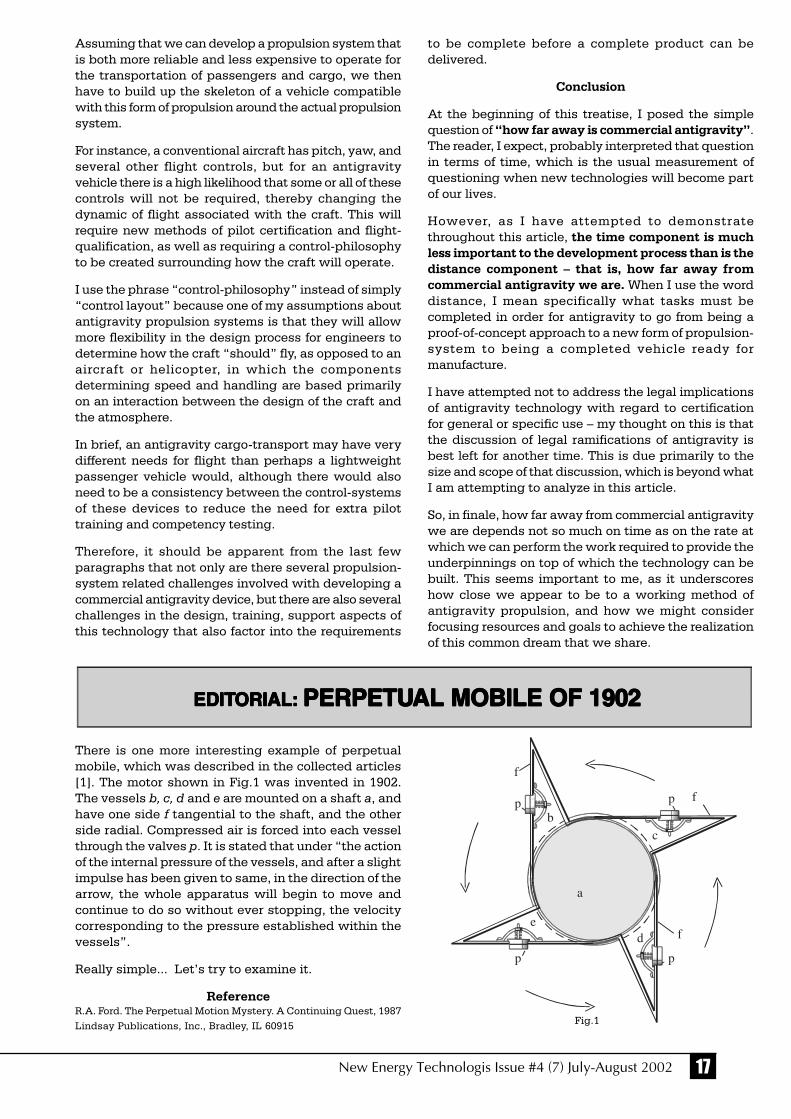
17New Energy Technologis Issue #4 (7) July-August 2002
Assuming that we can develop a propulsion system thatis both more reliable and less expensive to operate forthe transportation of passengers and cargo, we thenhave to build up the skeleton of a vehicle compatiblewith this form of propulsion around the actual propulsionsystem.
For instance, a conventional aircraft has pitch, yaw, andseveral other flight controls, but for an antigravityvehicle there is a high likelihood that some or all of thesecontrols will not be required, thereby changing thedynamic of flight associated with the craft. This willrequire new methods of pilot certification and flight-qualification, as well as requiring a control-philosophyto be created surrounding how the craft will operate.
I use the phrase “control-philosophy” instead of simply“control layout” because one of my assumptions aboutantigravity propulsion systems is that they will allowmore flexibility in the design process for engineers todetermine how the craft “should” fly, as opposed to anaircraft or helicopter, in which the componentsdetermining speed and handling are based primarilyon an interaction between the design of the craft andthe atmosphere.
In brief, an antigravity cargo-transport may have verydifferent needs for flight than perhaps a lightweightpassenger vehicle would, although there would alsoneed to be a consistency between the control-systemsof these devices to reduce the need for extra pilottraining and competency testing.
Therefore, it should be apparent from the last fewparagraphs that not only are there several propulsion-system related challenges involved with developing acommercial antigravity device, but there are also severalchallenges in the design, training, support aspects ofthis technology that also factor into the requirements
to be complete before a complete product can bedelivered.
Conclusion
At the beginning of this treatise, I posed the simplequestion of “how far away is commercial antigravity”.The reader, I expect, probably interpreted that questionin terms of time, which is the usual measurement ofquestioning when new technologies will become partof our lives.
However, as I have attempted to demonstratethroughout this article, the time component is muchless important to the development process than is thedistance component – that is, how far away fromcommercial antigravity we are. When I use the worddistance, I mean specifically what tasks must becompleted in order for antigravity to go from being aproof-of-concept approach to a new form of propulsion-system to being a completed vehicle ready formanufacture.
I have attempted not to address the legal implicationsof antigravity technology with regard to certificationfor general or specific use – my thought on this is thatthe discussion of legal ramifications of antigravity isbest left for another time. This is due primarily to thesize and scope of that discussion, which is beyond whatI am attempting to analyze in this article.
So, in finale, how far away from commercial antigravitywe are depends not so much on time as on the rate atwhich we can perform the work required to provide theunderpinnings on top of which the technology can bebuilt. This seems important to me, as it underscoreshow close we appear to be to a working method ofantigravity propulsion, and how we might considerfocusing resources and goals to achieve the realizationof this common dream that we share.
EDITEDITEDITEDITEDITORIAL:ORIAL:ORIAL:ORIAL:ORIAL: PERPETUPERPETUPERPETUPERPETUPERPETUAL MOBILE OF 1902AL MOBILE OF 1902AL MOBILE OF 1902AL MOBILE OF 1902AL MOBILE OF 1902
There is one more interesting example of perpetualmobile, which was described in the collected articles[1]. The motor shown in Fig.1 was invented in 1902.The vessels b, c, d and e are mounted on a shaft a, andhave one side f tangential to the shaft, and the otherside radial. Compressed air is forced into each vesselthrough the valves p. It is stated that under “the actionof the internal pressure of the vessels, and after a slightimpulse has been given to same, in the direction of thearrow, the whole apparatus will begin to move andcontinue to do so without ever stopping, the velocitycorresponding to the pressure established within thevessels”.
Really simple... Let’s try to examine it.
ReferenceR.A. Ford. The Perpetual Motion Mystery. A Continuing Quest, 1987Lindsay Publications, Inc., Bradley, IL 60915 Fig.1
f
b
a
fp
c
p
fd
pp
e

18 New Energy Technologis Issue #4 (7) July-August 2002
We must note, that the third Newton law is valid onlyfor systems with 100% feedback, appeared in theinteraction period. For example, during the magnetinfluence on the iron object it is revealed, that this objectalso starts to influence upon the magnet, i.e. to attractit with the same force. It happens because in the periodof action of magnetic field the iron object itself becomesthe source of magnetic field (Fig.1). Here the magneticfield, as an especial environmental condition, acts as amediator, i.e. exists by itself in the interval betweenobject and magnet .
Fig. 1
Interaction of magnet and metal body M. Here the action is equalto reaction, i.e. the third Newton law is valid.
It is considered to be that magnetic field, created byelectric current, spreads with the velocity of light. Ifcurrent impulse is short, then the magnetic field spreadsindependently from the conductor and no matter if thereis current in the conductor at present, or not. If thedistance up to the object is big, then the magnetic fieldremains between source and object for some time, andhas no influence upon the object. In this sense theportion of magnetic field, placed on the path betweensource and body, can be considered as movingindependent “entity”, i.e. the space by means of itselfcarries its changed state (magnetic properties) from oneplace to another. In this period magnetic properties inthe form of quantum can influence neither on the source,from which the magnetic quantum is already detached,nor on the object, which the magnetic quantum stilldoes not reach.
But having reached the object, magnetic field changesthe state of this object. If as the result of influence theobject becomes a source of magnetic field, then the partof the field is reradiated in the direction of source, i.e.the object itself becomes the source for some time, andby this it is able to influence on the first primary source.In this situation the principle of action and reactionworks, because the feedback takes place.
If the feedback does not appear during the period ofinfluence of one body to another, then the action andreaction law is not valid in the system. Let’sdemonstrate it by the example of the mechanicalexperiments, in which there is a feedback betweenobjects.
Action without ReactionNew Gravidynamic Paradox
Yu. N. IvanovAcademician of Russian Academy
of Natural Sciences
Saikina, 11/2, app.4, Moscow, RussiaTel: (095) 277-33-76/276-50-39
[email protected]://www.mirit.org
Editorial: Yu.N. Ivanov discovered a new unusualphysical phenomenon that is a gravidynamic paradox.The sense of the paradox is the existence of the situation,which is not forbidden by physical laws and whichallows any man (even a child) easily hold suspended orcarry things with 100kg or more weight by means ofsome simple device. This phenomenon is just a part ofthe significant applied topic and a demonstration of thepossibility to cancel weight characteristics of anymaterial object. Per se it is a work on the obtaining ofthe methods to eliminate aircrafts weight.
We can use only resistant things as a support!
Galilee-Newton’s Laws are in the basis of classicalmechanics. Thought concerned fundamental, theselaws do not explain the main thing, i.e. the internalprocessual essence of the phenomena, described bythem. There is another scientific line – the quantummechanics, which tries to discover the essence of deepprocesses. There is no connection between these lines,therefore they as if exist independently. There are alsolong-time conversations about necessity to combine thequantum and the classical approaches. We suppose,that practically the combining has already happened,since thanks to rhythmodynamics, there appearedphase, frequency and velocity of light in formulae ofclassical mechanics (without these attributes thequantum mechanics is impossible). It was revealed, thatphase-frequency method of late mechanics formulaepresentation gives a real physical sense both toformulae themselves, and to concepts which seemedvague before (namely: cause of motion, force, velocity,inertiality, gravitation). In this sense, the upcomingrhythmodynamics fills up the gap between the mainphysical lines and draws them together. But let’schange the vector, since the subject of the given articleis to concern cases in which the third Newton law isnot directly valid.
Newton formulated the third law in the following way:
“Action always has equal and opposite interaction, inother words, actions of two bodies on each other areequal and directed in opposite sides”.
This law represents the fact that one-way action of onebody to another cannot exist in nature, but there is onlyan interaction between them, i.e. there is no actionwithout reaction [1].

19New Energy Technologis Issue #4 (7) July-August 2002
Let there is a device (Fig. 2), which throws off two water(air) streams in the opposite directions in such a way,that reactive forces completely compensate each other.At that the thrown down stream compensates thegravity too. In this case the device will fly withoutfalling, i.e. it will have zero weight.
Fig. 2
The ball, suspended in the water stream, does not put pressureon the source. It happens because there is no feedbackbetween the ball and the source. If you have such a device,then, lifting the ball by means of it, you will not feel the weightof the ball. The reason: the ball hangs due to the kinetic energy,which the stream passes to it and and this ball can notinfluence on the source through the water stream.
The appearance of the ball with the weight Pb does notinfluence on the weight Pn of the device. And even in the caseif we press the ball down, i.e. essentially displace its locationin the stream, the device will feel nothing.
The absence of device weight is evident for us; thereforewe can easily move the device if its original (vertical)orientation remains unchanged.
Let’s change the situation and place the ball (body withthe shape, which is steady for hanging) in the upperstream. This ball with the weight about 10 kg is placedin a way to be kept by this stream at some distance, forexample at 0.5 m. Will the device react on the changedsituation, i.e. on the ball appearance? Will the weightof the ball, hanging in the stream, be added to zeroweight of the device (0 + 10 kg)?
The calculation shows that it will not: ΣP=0+10= 0 [kg].There is only an illusion that the ball is supported bythe stream and that it is a part of the system. As a matterof fact, the ball is detached from the system and hangsdue to the water kinetic energy. It is easy to check it bymaking an experiment in a bathroom: “Remove thedouche sprayer, then direct the stream up and holdingit by the one hand with the aim of weighting, try toinfluence on the source by the other hand through thestream. You will be surprised to feel that the hand, whichis supported by the stream or any object, which ishanged in the stream, does not influence on the source”.
At first sight the situation seems to be a paradox,however it very illustrates the possibility of the force
action without reaction. So, the action can be one-way,i.e. calling no reply reaction in the form of pressure onthe action source.
In such an unusual way it is possible to keep the ball ofbigger weight (100 kg and more), at that to move iteasily by means of the device and at the same time notto feel the presence of additional weight in the stream.It is possible only in the case when there is nofeedback between body and source, i.e. the body,hanged in the stream, has no ability to act on the forcesource. Thus, we can both hold and move the heavyball without additional efforts, and also lift it up to anyheight (for example, 100 m). As a matter of fact, wedeal with the new gravidynamic paradox.
It is interesting then, how to solve the task of thefollowing type: “Let the body with 100 kg weight ishanged in the water (air) stream in such a way, that itdoes not change the velocity and direction of liquidoutflow from the source nozzle. How much energy theoperator must spend to lift this body to the height about10 m?” (Here it means that the operator must take thedevice, which supports the ball, and, moving upstairs,lift the body, which hangs in the stream, by means ofthis device to the height about 10 m). If to solve thisproblem correctly (the condition is that the operator liftshimself together with the device and the ball), we willfind out, that operator’s energy is spent only for liftingof the device, which creates water streams. Theoperator, lifting together with the device, will not evennotice that in the stream there is a body with about100 kg weight (this is the sense of the paradox).
The situation only seems to be absurd, and evenparadoxical for theorists, but it is not a hopeless one.
We can also observe the effect of action without reactionin ultrasonic field of the source. If the source is fixed onscales (Fig.3) and body is hanged, as it was made inthe stream, the scales will show only the precise weightof the source and will not react on the weight of thehanged body, no matter how heavy it is.
Fig. 3
The ball, made of the special absorbentmaterial, hanged in the powerfulultrasonic field, does not put pressure onthe scales. It happens because of theabsence of feedback between the ball,which has changed its state, and theradiation source. If you have suchultrasonic device in your hands, thenlifting the ball by means of this deviceyou will not feel the ball weight.
20 New Energy Technologis Issue #4 (7) July-August 2002
The experiment of such type was made in one of thesecret institutes. Water was used as an acousticenvironment. The heavy ball easily floated up from thevessel bottom i.e. it behaved as if it had no weight.
The similar phenomena but such of the otherorganizational level, sometimes become apparent innature. The phenomenon has its very name becausethe event happens unexpectedly and is not analyzablethrough laboratory research [3].
“A spherical ball lightning about the size of a footballball flew over a village Galtsovka of Altaisky Krai at aheight of twenty to thirty meters. The first shed in itsway, with ferroconcrete poles, was crushed andcollapsed. Flying over a slated house, the ball lightningtore away the roofing slate together with nails, raisedit into air and pulled it along, scattering its parts allover the village. Flying over a tractor station, the balllightning crushed a frame, welded of metal angles andcovered with tarpaulin. On the approaching of the balllightning to another frame, it was at first dragged alongthe ground, and after the ball lightning had passed it,the frame was lifted and carried at a distance of300 meters. The weight of the frame was no less than100 kg”.
Further the author analyzes the situation from point ofview of the known physical laws: “The frame ofhundreds kilograms weight was carried by fields of theflying ball lightning. However, for some reason the balllightning kept on flying straight and did not note thatsome metal frame was caught to it. If the ball lightning,as it is usually considered, has a density of air and it isa weightless formation, then why the frame with theweight not less than 100 kg could not change its flighttrajectory even in some extent?”
It draws attention that in some cases the ball lightningfield pushed objects away, and in other cases itattracted them. It can be explained only by fact that ineach case the ball lightning field specifically influencedon internal properties of objects, and then objectsthemselves somehow reacted on their new state (theychanged their motion) . The feedback absence (in otherway it happens between magnet and iron object) allowsthe ball lightning not react upon the things, which takeplace in its field. If these objects themselves becamesources of similar field, i.e. reradiated it, they wouldinfluence on the ball lightning trajectory. Most likely,in the given case, there was realized the situationwhen action caused no reaction.
Conclusions
In the context of known physical laws the particularproblem of direct action without feedback wasformulated and solved. The solution of this problemprovides deep understanding of how to control weightcharacteristics of material objects in open systems. Asit was shown by the example with water (which is onlyan illustration of more fundamental processes) we can
“deceive” the nature, but only through the deepunderstanding of the processual character of theconcerned events.
By the example of ultrasound we show, that in principlethere can exist such field flows, which are able toinfluence on bodies without the feedback effect. Therewere defined some conditions and criteria of bodies andmethods of influence, at which the third Newton law isnot directly valid (it is not published in this article).
The described type of influence can be called aspressure. But during consideration of processes atatomic or deeper level, i.e. from the position ofrhythmodynamics, we find out something of anotherkind, that is phase-frequency one. It prompts to us, whatkind of technologies will exist and how our aircraftswill look in nearest future. But not everyone is able tounderstand it at once.
Moscow 15.05.2002
For sponsors: [email protected] website: http://www.mirit.org
References
1. Physics textbook for the 9th class of secondary school //M., Prosveschenie, 1982
2. Ju.N. Ivanov, Rhythmodynamics // M., Noviy Tcentr, 1997
3. G.V. Nikolaev, Scientific vacuum // Tomsk, Kursiv, 1999
Comment
In the gravitation field we have a balanced open system,in which appearance of the new body at first sight mustcause this system reaction such as weight increase.However, this is not the case.
The given problem is solved in two independent steps:
1) examination of interaction between water source andwater (reactive effect, which is compensated by counterflow);
2) examination of interaction between water, detachedfrom the source, and the body (unit time impulse perunit area).
It is impossible to examine the interaction between thesource and the body because water has no rigidity.There are no means to influence on the source throughthe intermediate stream, therefore the principle of actionand reaction is valid for each step individually, but notfor both! But in this case the third Newton law must bedeveloped as following: “If there is a 100% feedbackbetween two bodies, their interactions are equal andinversely directed. And if there is no feedback, the actionof one body to another causes no reaction, i.e. the actionis not equal to reaction”. And this is already anotherlaw!

21New Energy Technologis Issue #4 (7) July-August 2002
New Possibilities of VortexElectric Power Devices
Stanislav A. Lisnyak
Prospect Stoletiya Vladivostoka, 112-37690069, Vladivostok, Russia
Tel/Fax: (7-4232)310-554Email: [email protected]
The earlier published article [1] was devoted to theexplanation of the excess energy output at the rotationof flow medium in vortex tube (VT). The researches onVT demonstrated by the real examples that the excessenergy output is a real fact, which is determined bynatural physical processes. These processes take placein the fluid at its vortex (rotational) motion in the closedvolume by means of phase transformations (skips) ofthe fluid state. However, the practice shows that forobtaining of patents and benefits for the real vortexdevices, which are made for heat generation, it isnecessary to write a little about their real technicalcharacteristics, though technical and constructivepossibilities of vortex devices can be much better.Temperature of water of these devices could not behigher than 120°C, and value of fluid pressure isconfined within 5…6 kg/cm2. Circulation pumps ofpressure over 6 kg/cm2 are used to increase thermalpower output of vortex heat generators (VHG). It causesthe discredit of VHG since at such a method theirgenerative possibilities reduces to 100% value and less!We set a problem to discover the ways and engineeringsolutions for the essential increase of the coefficient ofVHG energy conversion to not less than 200% value.
Our experience in development and exploitation ofdeep-sea physical devices has given some engineeringsolutions in this way. Actually, we have the opportunityto use the generally applicable circulation pumps,which have pressure not more than 4.0 kg/sm2. At thesame time we can raise the temperature of the heatcarrier to 300°C and higher! and the pressure can beincreased to 1000kg/sm2! Such fluid parameters allowto use this fluid as a heat carrier in powerful hot-watergenerators of steam engines, turbines etc. By the way,this method allows to make the value of temperatureof water enough to supply its PYROLESIS! The mainpoint of the method is the following: all the closedsystem of water-filled VHG works at pressure with thevalue under 1000kg/sm2. It is provided by means of thespecial device, the so-called automaticpneumohydraulic block (APHB). This lets to raise the
5 6
8
10
9
7
5
3
4
1
2
temperature of working fluid to 1000°C with no changein its aggregative state. The practical functional schemeof such a device is shown in Fig.1.
Fig. 1
1 – vortex tube; 2 – entry vortex chamber; 3 – by-pass;4 – upstream end; 5 – circulation pump; 6 – heat-exchangers;
7 – APHB; 8 – volume of fluid leakage compensation;9 - compressed-air flask; 10 - gas pressure regulator
The device works in the following way. The wholedevice is filled with working fluid without entrappedgas. At the operation of the circulation pump (5), fluidthrough the upstream end (4), placing in the entry vortexchamber (2), swirls, accelerates and gets into the vortextube (1), where its “energy saturation” is realized. Thenheated fluid gets into the heat-exchangers (6) forheating or for other purposes. After passing throughthe heat-exchangers, fluid gets into thepneumohydraulic device (7), where there is kept up theproper level of fluid pressure in the whole system. Toprevent the system breakdown at the accidental fluidleakage, there is a device (8), which compensates suchleakages. Compressed-air flask (9), with the volumeunder 1000kg/cm2, and gas pressure regulator (10) keepup the selected level of the pressure in the system. Theuse of blocks (7,8,9,10) excludes evaporation in thesystem and prevents the breakdown of the circulationpump (5).
This VHG scheme allows to double the effectiveness ofYUSMAR devices [2] only at the expense of rise inworking fluid temperature in 2…3 times.
Observation of any fluid swirls and film documents ofwindspouts arrive to conclusion that all vortexstructures are rotation bodies, created by the lines ofthe second order: Y=aX2. In other words, as a result ofthe rotation in the swirl, air or fluid mass gets theacceleration of the second order. Taking into accountthe aforesaid, it is evident that in order to form theclassical swirl in the VT, the very VT should be a tubularbody of rotation. This body is created by the curve (seebelow Fig.2).
In YUSMAR and similar devices the vortex fluid motiontake place in straight cylinder and 1/3 of this area isused for fluid deceleration that causes vortex flew

22 New Energy Technologis Issue #4 (7) July-August 2002
disruption. This results in the impossibility to increaseadditional heat in the straight tube in more than 1.54times. It is caused by the fact that the main vortexformation takes place only in the vortex chamber andthe flows separation does in the tube itself. Then, thisvortex formation is right away disrupted by differentplate brakes! It suggests itself that output part of VTshould be made in the spiral form, expanding at theflow passage.
Fig. 2Generatrix of the wall of vortex tube
Fig. 3Upper part of the tube
Such section, made on the outlet of the vortex tube,helps to slow down the flow avoiding its disruption,since axial-cold flow, placed along the tube axis, shouldstay intact. Two of such engineering solutions allowraising the level of the additional VHG energy up to180…200%.
YSMAR devices are designed for one tube with theassigned heat output. However, if to take intoconsideration and to use the aforesaid conclusions, thenwe can raise energy conversion coefficient (ECC) above200% at the series connection of two and more VT. Thescheme of such a device is shown in Fig. 4.
Fig. 4
Where: 1 – the first VT; 2 – the second VT; 3 – circulationpump; 4 – heat exchanger
According to Fig.4, the total energy output of thepresented device is:
Q=K2
Where: Q is the total output of the device; K is energyconversion coefficient of one VT; 2 – quantity of seriallyconnected VT; P – the assigned power of the circulationpump.
In our earlier article [1], concerning VT application, wesupposed that there is a straight transformation ofvortex motion of ionized fluid into electric current. Understudying of many articles, devoted to the methods ofwater ionization, we discovered a significant one. Itdemonstrates that at the determined temperature, purewater increases its ionization capacity up to 3 orderswithout changing in the aggregative state [3]. Thediagram in Fig.5 shows such dependence.
Fig.5Diagram of the dependence of pure water ionization from
temperature
The diagram demonstrates that water at 300°Ctemperature increase the quantity of ions in 4000 timesas compared to 0°C and in 40 times as compared to 20°C.If to take into consideration that first experiments onVHG modernization help us to find the ways of fluidheating up to the practically any temperature withoutchanging of its phase state, then on using thedependences (see Fig.5) it seems possible to createvortex fluid electric generators of the forwardtransformation. The aforesaid pneumohydraulic block,which is used for VHG functioning, allows to keep upwater temperature at 300°C and pressure at about90kg/cm2 without threat of water evaporation! Presenceof any rotation of fluid medium always causesappearance of two vortex flows. These flows alwaysmove and rotate in opposite directions and if we donot put obstacles for their motion then they transforminto each other and can exist without energy supplyfor an indefinite period of time.
The presented VT form (see Fig.6) provides theproducing of two fluid flows in the tube. These flowsdo not influence to each other and there is only theirreciprocal overflow without disruption of the flows inthe central part of VT. The tube presents a tubular bodyof rotation, which is created by hyperbola. There ispositive angular acceleration of fluid in the lower part
1
2
4
3
0
Y
X
y=ax
2
4 0 0 0
1 0 0
2 0 3 0 0 4 0 0
T C
Ionization

23New Energy Technologis Issue #4 (7) July-August 2002
Fig.7Scheme of vortex electric generator
In the presented scheme of electric generator the entryand outlet vortex chambers are made of dielectricmaterial in the spiral form. This material certainlyshould withstand not less then 300°C of fluidtemperature and about 100kg/sm2 of pressure.Fluoroplastic or ceramic can be used as such a material.
From aforesaid it seems to be possible to submit thenew scheme of electric generator for readers’consideration (see Fig.8).
Fig.8Generalized scheme of vortex electric generator
1 – vortex tubes; 2 – circulation pump; 3 – heat exchanger; 4 –automatic pneumohydraulic block; 5 - compressed-air flask
Actually we could finish the article if it were nodisputes about excess energy, which is released atvortex motion of fluid in tubes. Having used a simpleexperiment, which any inquisitive person can repeat,we found the positive solution (see the scheme of theexperiment in Fig. 9).
Fig.9Demonstration of energy increase of fluid, rotating in vortex tube
of the tube; maximum speed of rotation of the axial andperipheral flows is in the middle part and negativeangular acceleration, i.e. deceleration and transfer ofkinetic energy into heat energy, is in the upper part ofVT.
Fig.6
The maximum heating of fluid and its polarization is inthe point Y=0. The polarization potential in the pointcan reach 10.000 V at 5m/sec flow speed for 10 cmdiameter in the point. The cold flow, which comes alongVT axis, is opposite to the peripheral hot flow. Theseflows close into one system in lower and upperchambers of VT. Thus, the presented VT classicallymodeled “rolling” and “unrolling” of water area.
There are no single vortexes in nature. Two vortexes,rotating in opposite directions, always appear whilefluid mediums rotation! Science is not still able todescribe energy overflows from one vortex center to thecenter of another one by means of mathematics.However we believe that this moment is close. Thereare maximum energy transformations of rotating waterin the point Y=0.
The potential of the inner flow is equal to the outer flowby its value but is opposite by its sign. Potentialdifference is maximum in the point Y=0, in whichremoval of electric charges is the most effective.
It is appropriate mention here the name of Romanianengineer and researcher Henry Koanda, who in 20th ofthe last century discovered the so-called “Koandaeffect” (attachment of fluid jet to the surface of usualkettle at pouring of it out the cups). Basing on this effecthe suggested to make new type of aircrafts, which couldhave advanced bearing capacity and maneuverability.Unfortunately, money and conservatism of aircraft-industrialists did not allow realization of theseengineering solutions.
At the same time, Koanda charged his disciple PatrickFlanagan with the job to research all water properties.The result was amazing! It was turned out that wateractually has infinitely many phase states and when itis moving, then it can trap energy from the environmentby some way. The publications on the point appearedin our press in the early eighties, late nineties of thelast century. Most likely, they had become the basis ofthe invention, made by Potapov, i.e. vortex tubes forwater!
0 X
Y
VT
ENTRANCE
OUTLET
ELECTRODEOUTLET VORTEX CHAMBER
dielectric
VORTEX TUBEMETAL
ENTRY CHAMBERdielectric
+
1
2
3
4
5
1
TO THE INVERTER
∆H
H
fountain
water-filledvessel
vortex pipe
swirler

24 New Energy Technologis Issue #4 (7) July-August 2002
Investigation of Electric EnergyTransmission Processes
in non-Metallic ConductingChannels
D.S. Strebkov, A.I. Nekrasov, S.V. Avraamenko
All-Russian scientific Research Institute of Electrificationof Agricultural Economy
2 Vishnyakovsky passage, 1 Moscow, 109456, Russia,[email protected]
Transmitted power, as well as for traditional three phaselines, is limited by natural power of the transmissionline and line capacity may reach at high voltage andpulse and operation modes the value 109 Wtt.
Introduction
The well-known methods of electric power transmissionare based on transmission of active energy by means ofconductivity currents in closed circuit. Electromagneticenergy spreads along power transmission lines (PTL)as progressing waves of electromagnetic field or fieldof charge [1]. Line wires made of aluminum or copperare conductive (guide) channels. Electromagneticenergy stream moves along these channels fromgenerator to energy receiver and backwards to thegenerator. Maximum transmission possibility of 3-phasePTLs is limited by losses on the line resistance, by peakvoltage (which is determined by electric strength of theinsulation) and by electromagnetic stability of the line.
The modern approach to provide the electromagneticstability consists in rigid regulation of line parametersby means of high-speed shunt reactor and consequencecapacitive compensation for the purpose to exceptchanges of electromagnetic power flows and tosuppress resonant properties of a line [2].
In Tesla works [3] and in the researches of Russianscientists [4] a method of active power transfer wasoffered. This method supposes to transfer active powerby means of electromagnetic capacitive currentassisting with resonant properties of a single-wire line(SWL), made of a metal conductor. The purpose of thepresent work is a research of an opportunity to use non-metal conducting mediums for transmission of electricenergy.
(Editor’s notes by Alexander V. Frolov)
It has been found that at low frequency (1-25 kHz andhigher) electric power can be transmitted with lowlosses from generator to receiver along single channelmade of non-metallic conductive media such as waterin plastic tube carbon thread, layer of damp soil, ITOfilms on glass substrate, laser and electronic beams.
D.S. Strebkov
A pipe with not less than 60 cm length and about1-inch diameter is placed in a reservoir with not lessthan 50 cm depth. The lower part of the pipe is formedas an arm circular generator with about 15...17cmdiameter. The gap width is about 2 cm. If we place thepipe with closed top end, which then will be open, intothe reservoir, then water is splashed out above 20 cmof the reservoir level. Thus at the least 20% energyincrease of energy mgH is observed.
By the way, we suggest orthodoxies of physics andother who have doubts to make one more simpleexperiment. Try to boil water in a can. When waterstarts to boil, swirl it with a spoon to the right or to theleft. Then you will suddenly discover that all watersurface is calm and only in the center of the can thereis a water-steam mixture, which is about 20% higherthan the level of water surface. You will also see thatwater is absolutely calm at walls of the can. This
experiment can be reproduced anytime and anywhere,even in space, since it is a demonstration of vortexfluid motion and its actual influence on everything,which is around!
All presented engineering solutions are practicallyreproducible in any laboratory. The authors of the articlewould welcome the opportunity to co-operate withscience and industry representatives for realization ofthe ideas in real serial production devices.
References
1. O.V. Gritskevitch, S.A. Lisnyak, On possibilitiesof vortex energetics //New EnergyTechnologies. 2002, #1(4), p.2-3
2. Patent RF #2045715, 1993
3. Chemical and Engineering News. 2000 #1, p.26

25New Energy Technologis Issue #4 (7) July-August 2002
channel. The increase of water temperature did notresult in decrease of transmitted power. Water PHreduction from neutral value up to 4 was detected.
The increase of sea salt concentration in water up tothe level of 5-7 g/l did not increase transmitted powerin comparison with tap water. However the replacementof tap water to dionized water with 16 MOhmresistances resulted in 100 % decrease of transmittedpower.
Thus, it is experimentally shown, that conductingchannels, produced from non-metal materials, havequasisuper-conductive properties in SWES atresonant mode. Possible explanation of this effect isthe absence of active conduction current in the channeland the dominant role in the process of energy transferbelongs to displacement current, for which Joule Lentzlaw is not valid [11]. In the supply circuit of Teslatransformer current is practically reactive, and inresonance conditions active values of inductive andcapacitive currents are equal. Vectors of these currentsare opposite in their phases. Current of the high-frequency converter is spent for losses (component lessthan 2 %) in supply circuit wires and in the core of Teslatransformer and also for creation of reactive current inthe conducting channel. In the mode of voltageresonance we have measured voltage active values ofhigh-voltage inductance windings and conductingchannel, interturn capacitance of windings and thecapacities of the conducting channel. We havediscovered that they were equal and their phaseswere opposite to each other. Losses from transmissionof capacitive current through active resistance of theconducting channel are insignificantly small. Coronadischarged losses and leakage current could bedecreased by isolation of conducting channel. In thiscase active current and magnetic field of the line areequal to zero. Electric field of the line has maximumvalue. As well as in usual PTLs, maximum transferredpower is limited by charge power of the line. Anglebetween vectors of voltage is equal to zero in thebeginning and at the end of a line. Quality factor ofSWES at frequency 5 kHz is in 100 times above thanusual PTLs at frequency 50 kHz. In the conditions ofresonance it leads to the significant increase of voltagealong the conducting channel and it also leads totransmission power.
In usual PTLs voltage changes along the line areinsignificant. The angle between vectors of voltage inthe beginning and in the end of PTL constitutes thevalue, which is proportional to the wavelength of line.
On the basis of the researches the methods and devicesare offered for transmission of electrical energy throughplastic water guide, electro-insulated from ground,through irrigational channels and through isolatedpipelines, which are used for gas, oil, hot and cold watertransportation. Also the energy can be transferredthrough fiber-optic cable with conducting film on thesurface, through all-carbon composite cable and
Methods
For realization of the experiments a single-wire energysystem (SWES) was used. Its electric circuit is shownin Fig. 1 a,b. SWES consists of the following parts: high-frequency generator (1) of 28V voltage AC and 1 kWttpower; transmitting (2) and receiving (3) Teslatransformer with conductive channel (4) between them;rectifier (5) and electric load (7) as an incandescentlamp or electric motor (220V, 1 kWtt power). High-voltage winding of Tesla transformer is made in the formof cylindrical winding on the ferrite core with 50-100mmin diameter, 4000-6000 turns. The internal end of a high-voltage winding is connected to the conductingchannel, and the external end is not connected at all(free end). A low-voltage winding that consists of 40-60 turns provides power supply of Tesla transformer.At the submission of electric power from the high-frequency generator to the winding of power supplyzero potential appears on the free end of the high-voltage winding, and voltage with corresponding to thegenerator 1-25 kHz frequency is formed on theconducting channel. Besides, Tesla transformer as thespiral antenna generates electromagnetic waves of 5-10 cm length , which corresponds to the turn length ofa high-voltage winding. Current resonance mode isformed in a supply circuit of Tesla transformer. At thesame time, voltage resonance mode (of frequency equalto the generator frequency) is formed both in thereception and transmitting circuit of high-voltagewindings and in the conducting channel (1).
The following materials were used as the conductingchannels: filled with water or sea water polythene tubeswith 10 mm diameter and 1,5 m long; plastic tray withsoil layer of 150×10×400mm; film of tin dioxide – indiumoxide (ITO) on 0,3 micrometer thick and 300 Ohmresistant glass substrate; graphite thread of 0,1 mmdiameter, 500 mm long and with 100 Ohm resistance.For comparison steel and copper wire of 0,1 mmdiameter and 5 m long was used also.
The voltage on the conducting channel changed in limits1-10 kV, generator frequency changed from 1 up to25 kHz. Voltage, current and capacity were measuredon SWES output and on the load by standard electricmeasurement equipment.
Results and discussion
The replacement of the metal conductive channel to thechannel made of non-metallic conductive materials doesnot effect to any reduction of possibilities of transmittingSWES or heating of a material of conducting channels.The consecutive connection of the channels did notresulted in reduction of transmitted power. Circuitsbreak in the conducting water channel by the creationof an air gap led to the occurrence of arc discharge ofreactive capacitor current. However this discharge didnot cause increase of water temperature at transmittedpower 300 Wtt and voltage 4,5 kV within 1 hour, thatconfirms the absence of energy losses in the conducting

26 New Energy Technologis Issue #4 (7) July-August 2002
through electro-insulated part of a ground and watersurface, including highway parts. There are alsomethods and devices, designed for the followingtransmissions. These methods can be applied fortransfer of power to stationary and mobile units. Thereare also generated requirements to electrical safety andto restriction of use of drinking and hot water frompipelines, which are under electrical voltage. Theserequirements and restrictions are generally thegrounding of pipeline parts, which are located on certaindistance from the generator. This distance is equal tothe whole number of half-waves and for it SWES voltageis equal to zero. In the case of a side pipeline it isnecessary to ground the parts of the pipeline that areplaced on the distance of odd number of quarter-wavelength from the main pipeline. For 5kHz frequencythe quarter-wavelength is equal to 15000 m.
N. Tesla grounded one end of high-voltage windings ofhis transformer on the receiving and on the transmittingend of SWES. Tesla considered this condition as thenecessary one for the transfer of power along the Earth.The results of our researchers demonstrate that it is notnecessary to use metal self-closed conductor (andcurrent lines in the Earth) for transmission of electricenergy on low frequency (1-25 kHz).
For this frequency energy could be transferred from thegenerator to the receiver if we have single-wire guidesystem created as non-metal conducting channel. Bythe similar way electromagnetic energy is transferredby laser beam or microwave-beam. But in our case wecan obtain high degree of efficiency that is caused byslight losses on energy absorption and energyemanation. Thus one of the ends of high-voltagewinding at the energy generator will have zero potentialand remain free. The symmetric end of a high-voltagewinding on the reception end should be connected tosome natural capacity 6 (Fig. a), which can representthe case of a balloon or frame of a tractor. In ourexperiments we used metallic safe-box as such naturalcapacity.
Editor’s note: In 1887, October 11, the famous Russianscientist Pavel Yablotchkov got the France Patent#120684, which described the method to increaseefficiency of electrical circuit by means of “atmosphereelectricity”. It was confirmed in many experiments thatoutput power can be twice more than power providedfor the circuit from primary electric generator. For thatit is necessary to use a single-plate capacitor. The specialfeature by Yablotchkov, that provides maximumefficiency, is the high degree of air ionization. For thisYablotchkov proposed to use the special capacitor, whichconsists of a big number of metallic needles. By its viewthis construction reminds of a hedgehog. Thus we canassumed; that above described natural capacity (balloonor frame of a tractor) serves as a collector of free electrons.By Yablotchkov the efficiency of such systems can beincreased by means of maximization of ionizationprocess. It will not lead to the increase of losses if thesecond end of the high-voltage winding is not grounded.
In the other method of energy transfer, a condenser-diode block 8 was connected to the conducting channelon the receiver end. This block is one of the knowncircuit of voltage doubling, Fig.1 (b). On the condenser8 electric energy is transferred through electronic switch9 to load 7. In this case the entire length of conductingchannel 4 and Tesla transformer winding 2 at generatormust be equal to odd number of quarter wave-lengths.
Non-metal conducting channel (for instance, fiber-opticor coal-plastic cable) can be used for transfer of electricenergy not only along but also as perpendicular to theEarth (for example, to relay aerostat or soundingballoon).
SWES conducting channel can be also created byionization of air ions with laser beam [13]. Neodymiumlaser with double frequency and with energy 1 Joule inimpulse is able to create 1015 cm -3 ion concentration inair. This concentration is sufficient for streamer initiationand for transfer of electric energy through theconducting channel. Ionization potential, time of ionexistence and of excited molecule state, coefficient ofmultiquantum absorption, all these determine thelimiting length of conducting channel in atmospherethat is equal to 300 km and its wave resistance at 200-400 Ohm. Voltage which is necessary for SWES comesto the quantity 0,5 MV – 15 MV, that depends on thelength of a channel.
We suggest to use relativistic electron bunches of highenergy as the conducting channel out of the atmosphere.As distinct from laser bunches they do not havedivergency. In this connection the Moon or artificialconducting body, where the energy receiver is placed,can be used as natural capacity 6. Whereas energygenerator can be installed on the Earth or on its satellite.Transmission range of electric energy is determined bythe length of the generated conducting channel. Theentire length of the conducting channel in the beginningand in the end must be equal to the whole number ofhalf-waves. Here the length of high-voltage windingsof two Tesla transformers must be taken inconsiderations. Electric energy, transmitting throughthe conducting channel, can exceed the energy ofelectron and laser beams generators in 10-100 thousandtimes. These generators play the role of a directingsystem (of usual SWEG wires), along which the transferof electric energy proceeds.
It was offered to use colliding and crossing electron andlaser beams with conducting transitional bodies asconducting channels for transfer of energy from theSpace to the Earth and back. On the heights up to30 km compositional coaly and fiber-optic cables canbe used. To create the global energy system of the Earthit was also suggested to apply single-wire energysystem and conducting layers of the Earth ionosphereas the conducting spherical channel [14].
Thus for electric energy transfer at the frequency1-25 kHz and higher in the resonance mode a single-wire channel from the following non-metal conducting

27New Energy Technologis Issue #4 (7) July-August 2002
mediums can be used: water, damp soil, coal-plastic,oxide film, ionized air channels, that are created by laserbeams in the atmosphere, ionosphere conducting layers,and also beams of relativistic electrons out of theatmosphere. These non-metal conducting channels inthe resonance mode have negligibly small resistancelosses especially if to be compared with metalconductors, which are used in the known non-resonancemethods of energy transfer by means of activeconduction currents in the closed circuit. Electric energyin the resonance mode can be transferred with smalllosses from the generator to the receiver along thesingle-wire channel, made of non-metal conductingmaterials. The transfer can be realized at the frequency1-25 kHz and higher, to any distance and to any directionrelatively to the Earth. The transmission capacity islimited by charge power of a line as well as in the usualPTL. At high voltage the transmission capacity canreach the quantity from 10 Wtt to 109 Wtt in the pulseand streaming modes.
Fig. 1Electric circuit of single-wire energetic system
with non-metal conducting channela) SWES with symmetric array of Tesla generators
b) SWES with diode-capacitor block in the endof conducting channel
References
1. A.M.Kalashnikov, Ya.V Stepuk. Bases of radioengineering and radiolocation. Oscillatingsystems. M: Department of USSR Defense 1965,- p.127-158.
2. G.N.Alexandrov, S.V. Smolovic, Flexible lines forelectric energy transmission over longdistances. V Symposium “ElectricalEngineering-2010”, October 12-22, 1999,Moscow Region P., 35-42.
3. N.Tesla Apparatus for transmission of electricalenergy. US Pat #349621, 15.05.1900.
4. S.V. Avraamenko Mode of electric devicessupply and device for its realization. Pat. RF#210649 11.04.1995. Publ. 10.04.1998. Bulletin#10.
5. D.S.Strebkov, S.V.Avraamenko, A.I. NekrasovDevice for power supply of mobile electricalaggregation. Pat. RF #2158206, 15.04.1999.Publ. 27.10.2000. Bulletin #30.
6. D.S.Strebkov, S.V.Avraamenko, A.I. NekrasovMode of supply of electric transport devicesand device for its realization. Pat. RF #2136515,26.08.1998. Publ. 10.09.1999. Bulletin #25.
7. D.S.Strebkov, S.V.Avraamenko, A.I. NekrasovOne-trolley system of power supply of mobileelectrical aggregations. Materials of theinternational scientific and technicalconference on automation of agriculturalmanufacture. Minsk 6-8 July 2000, - p. 65-66.
8. D.S.Strebkov, S.V.Avraamenko, A.I. NekrasovResearch on single-wire system of electricenergy transmission. International conferenceEcology and agriculture. Technique. – Saint-Petersburg, 2000, - p.50-55.
9. D.S. Strebkov, S.V. Avraamenko, A.I. Nekrasov.Single-wire electric system for renewable-based electric grid. Third European SolarCongress “Eurosun 2000”, June 19-22, 2000,Copenhagen, Denmark p., 10.
10. D.S. Strebkov, S.V. Avraamenko, A.I. Nekrasov.SWEPS – a novel electric power transmissiontechnology. Planetary Association for CleanEnergy Newsletter, 2001. – vol. 11, - 3, - p. 7-11.
11. I.E. Tamm. Bases of electricity theory. –M.Science, 1976. – p. 133, 397-400.
12. D.S. Strebkov, S.V. Avraamenko, A.I. Nekrasov.Mode and device for electric powertransmission. Pat. RF #2172546, 24.01.2000.Publ. 20.08.2001. Bulletin #23.
13. D.S. Strebkov, S.V. Avraamenko, A.I. Nekrasov.Mode and device for electric powertransmission. Pat. RF #2143775, 25.03.1999.Publ. 27.12.1999. Bulletin #36.
14. D.S. Strebkov, S.V. Avraamenko, A.I. Nekrasov.Mode and device for electric powertransmission. Pat. RF #2161850, 14.07.1999.Publ. 10.01.2001. Bulletin #1.
5
42
1
a)
24
8
1
b)
3
1
9
7

28 New Energy Technologis Issue #4 (7) July-August 2002
transformation (as well as matter transformation) occursin the Stable Universe.
The 3rd edition is devoted to the description of 6 WorldSystems (Table 1), at that the 6th System is based onUnified Field Theory, which is developed by the authors,and proceeds from the following:
(Editor’s: The understanding of the energytransformation mechanism allows to develop new fuel-less energy sources based of mutual transformations:longitudinal photons< >transverse photons).
Microcosm, Universe, Life
The authors of this article have prepared the 3rd editionof the book “Microcosm, Universe, Life” and now theyare looking for a publisher to edit Russian and Englishversion. In particular, the mechanism of energytransformation in the Universe (Fig.1) is described inthe book. Matter radiates energy in the form of photons(as well as neutrinos). In general this energy is observedin the form of Cosmic Microwave Background Radiation(CMBR). Photons and neutrinos transfer the most ofenergy to de Broglie longitudinal photons. Matterabsorbs energy mainly in the form of longitudinalphotons. Thus, a cycling process of energy
1. For theoretical results, which agree with the facts,it is necessary to use assigned inertial system (asLorentz did), which, as we have known, is connectedwith CMBR. Obtained by this way decisions can beapplied to the other systems, in particular, with use ofLorentz transformation for mass, energy, momentum,time and length.
2. Theory must agree with the whole knowncollection of facts, starting with such established
empirical generalizations as basic principles of Naturalscience (Giordano Bruno, Lyell) and conservation laws(Mayer, Joule, Helmholtz, Faraday, Newton, Huygens,Vernadsky).
3. All physical objects could be presented as thesystems, consisting of quanta of positive electric charge(protons), quanta of negative electric charge (electronsin fermions or boson states, which are part of neutrons
Alexey G. ShlienovBudapeshtskaya, 66-1-77,Saint Petersburg, 192286 Russia
Ernest L. PetrovMarshala Zaharova, 50-809, Saint Petersburg, 198330 Russia,
Fax.: (812) 587-9349
Table 1
System Principal Ideas
The 1st – Geocentric (Ptolemaic system) Geocentrism and Anthropocentrism
The 2nd – Classic (Copernicus – Newton’s system) Description of the Universe on basis of Newton’sLaw of Gravity
The 3rd – Compromise (Tycho Brahe’s system) The compromises between two first systems
The 4th – Fractal (Charlie’s system) Non-heterogeneity of Large-Scale distribution ofmatter in the Universe
The 5th – Relativistic (Einsteinian system) Description of the Universe on basis of gravitationalfield equations. Anthrop principle
The 6th – based on Unified Field Theory Electromagnetic nature of all physical interactions.Irreversibility of all elementary micro-processes incombination with circular character oftransformations in Large Scale of space (c/H=Rorder) and time (tH=I/H order).
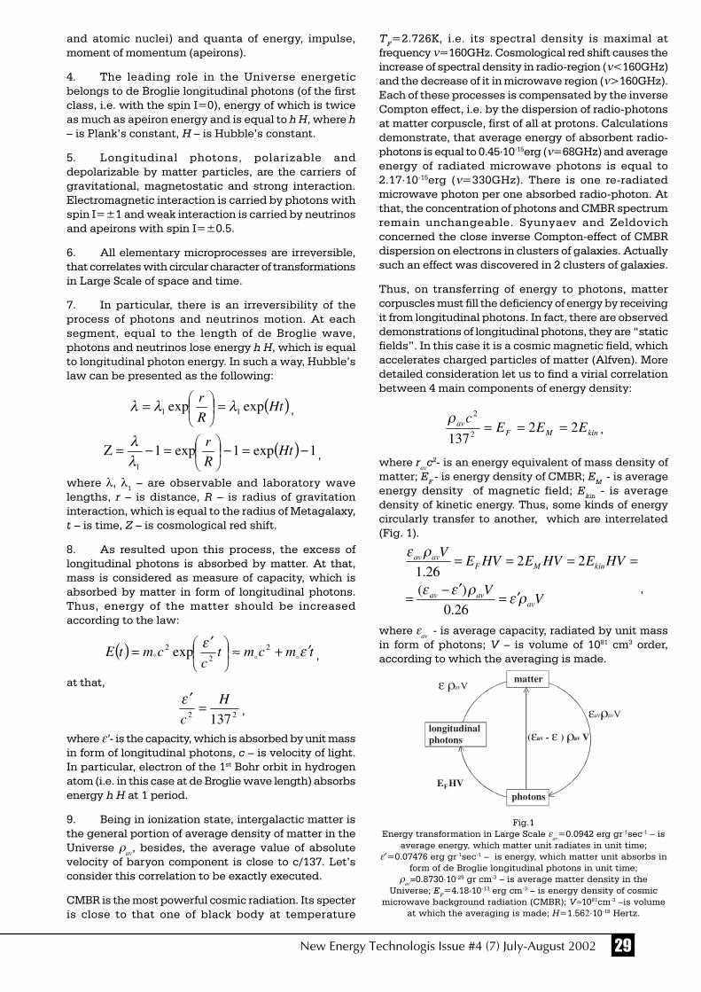
29New Energy Technologis Issue #4 (7) July-August 2002
TF=2.726K, i.e. its spectral density is maximal atfrequency ν=160GHz. Cosmological red shift causes theincrease of spectral density in radio-region (ν<160GHz)and the decrease of it in microwave region (ν>160GHz).Each of these processes is compensated by the inverseCompton effect, i.e. by the dispersion of radio-photonsat matter corpuscle, first of all at protons. Calculationsdemonstrate, that average energy of absorbent radio-photons is equal to 0.45⋅10-15erg (ν=68GHz) and averageenergy of radiated microwave photons is equal to2.17⋅10-15erg (ν=330GHz). There is one re-radiatedmicrowave photon per one absorbed radio-photon. Atthat, the concentration of photons and CMBR spectrumremain unchangeable. Syunyaev and Zeldovichconcerned the close inverse Compton-effect of CMBRdispersion on electrons in clusters of galaxies. Actuallysuch an effect was discovered in 2 clusters of galaxies.
Thus, on transferring of energy to photons, mattercorpuscles must fill the deficiency of energy by receivingit from longitudinal photons. In fact, there are observeddemonstrations of longitudinal photons, they are “staticfields”. In this case it is a cosmic magnetic field, whichaccelerates charged particles of matter (Alfven). Moredetailed consideration let us to find a virial correlationbetween 4 main components of energy density:
kinMFav EEE
c22
1372
2
===ρ
,
where rav
c2- is an energy equivalent of mass density ofmatter; EF - is energy density of CMBR; EM - is averageenergy density of magnetic field; Ekin - is averagedensity of kinetic energy. Thus, some kinds of energycircularly transfer to another, which are interrelated(Fig. 1).
VV
HVEHVEHVEV
avavav
kinMFavav
ρερεε
ρε
′=′−=
====
26.0
)(
2226.1
,
where εav - is average capacity, radiated by unit mass
in form of photons; V – is volume of 1081 cm3 order,according to which the averaging is made.
and atomic nuclei) and quanta of energy, impulse,moment of momentum (apeirons).
4. The leading role in the Universe energeticbelongs to de Broglie longitudinal photons (of the firstclass, i.e. with the spin I=0), energy of which is twiceas much as apeiron energy and is equal to h H, where h– is Plank’s constant, H – is Hubble’s constant.
5. Longitudinal photons, polarizable anddepolarizable by matter particles, are the carriers ofgravitational, magnetostatic and strong interaction.Electromagnetic interaction is carried by photons withspin I=±1 and weak interaction is carried by neutrinosand apeirons with spin I=±0.5.
6. All elementary microprocesses are irreversible,that correlates with circular character of transformationsin Large Scale of space and time.
7. In particular, there is an irreversibility of theprocess of photons and neutrinos motion. At eachsegment, equal to the length of de Broglie wave,photons and neutrinos lose energy h H, which is equalto longitudinal photon energy. In such a way, Hubble’slaw can be presented as the following:
( )HtR
rexpexp 11 λλλ =
= ,
( ) 1exp1exp11
−=−
=−=Ζ Ht
R
r
λλ
,
where λ, λ1 – are observable and laboratory wavelengths, r – is distance, R – is radius of gravitationinteraction, which is equal to the radius of Metagalaxy,t – is time, Z – is cosmological red shift.
8. As resulted upon this process, the excess oflongitudinal photons is absorbed by matter. At that,mass is considered as measure of capacity, which isabsorbed by matter in form of longitudinal photons.Thus, energy of the matter should be increasedaccording to the law:
( ) tmcmtc
cmtE εε ′+≈
′
= ° oo2
22 exp ,
at that,
22 137
H
c=
′ε,
where ε’- is the capacity, which is absorbed by unit massin form of longitudinal photons, c – is velocity of light.In particular, electron of the 1st Bohr orbit in hydrogenatom (i.e. in this case at de Broglie wave length) absorbsenergy h H at 1 period.
9. Being in ionization state, intergalactic matter isthe general portion of average density of matter in theUniverse ρ
av, besides, the average value of absolute
velocity of baryon component is close to c/137. Let’sconsider this correlation to be exactly executed.
CMBR is the most powerful cosmic radiation. Its specteris close to that one of black body at temperature
Fig.1Energy transformation in Large Scale ε
av=0.0942 erg gr-1sec-1 – is
average energy, which matter unit radiates in unit time;ε′=0.07476 erg gr-1sec-1 – is energy, which matter unit absorbs in
form of de Broglie longitudinal photons in unit time;ρ
av=0.8730⋅10-29 gr cm-3 – is average matter density in the
Universe; EF=4.18⋅10-13 erg cm-3 – is energy density of cosmic
microwave background radiation (CMBR); V≈1081cm-3 –is volumeat which the averaging is made; H=1.562⋅10-18 Hertz.
matter
photons
longitudinalphotons
E HV
( - ) Vε ε ρav av
εav avρ V
ε ρ Vav
F

30 New Energy Technologis Issue #4 (7) July-August 2002
10. These correlations include pressures, densitiesand temperature TF, i.e. we have the equation of thestate of intergalactic matter, and thus of Metagalaxyand the Universe. Let us present this equation in simpleform:
c
R
c
RE avavav
F
ρερε≈
′=
and let us compare it with correlation for density ofradiant energy on surface of a star * or of star system
c
R
c
RE ******
* 3
ρερε ≈= .
It is an especially amazing analogy betweenMetagalaxy (and the Universe) and large-scale cosmicsystem g, for which
c
RE ggg
g
ρε≈ ,
at that ,Fg EE ≈ εεε ′≈≈ avg .
This equation agrees with the whole observed data ofglobular clusters, galaxies, groups and clusters ofgalaxies, in particular, with empirical correlations,which are magnitude - angular diameter.
11. The stated approach lets to determine the valuesof many fundamental constants by different ways. As acase in point, the results of definite values ε
av and ε′ , ergg-1 c-1 are presented in the Table 2.
12. Uncontradictory description of Microcosm andthe Universe promotes the better understanding of Life,which is inseparably unified with them. The statisticaldata manipulation of more than 100 catalogues ofmicrophysics and cosmic objects let us to get more than1000 empirical correlations and diagrams, and todetermine, that they agree with theoretical correlations,which were received according to the ideas on circularcharacter of energy transformations (Fig. 1) and ofmatter in the Universe.
The Russian edition of the book is mailed out: the 1st
edition (1995) at the cost of $3; the 2nd edition (1998) atthe cost of $6.
The authors are thankful for valuablediscussions to Yaroslav G. Klyushinand to Alexander V. Frolov.
Table 2
# Data εav
ε′
1. The boarder between two parts of the Main of 0.1 order of 0.1 orderSequence of stars
2. The results of recalculation of observed star of 0.1 order of 0.1 ordercharacteristics as respects to their centers
3. The local minimum of star luminosity function of 0.1 order of 0.1 ordernear the Sun (according to G.A. Starikova’s data)
4. The correlation: mass - luminosity of white of 0.1 order of 0.1 orderdwarf stars
5. The correlation: mass - luminosity of neutron stars of 0.1 order of 0.1 order
6. The correlation: mass - luminosity of globular clusters less than 0.5 less than 0.5
7. The correlation: mass - lumonosity of elliptic galaxies more than 0.06 more than 0.06
8. The correlation: mass - luminosity of spiral galaxies less than 0.5 less than 0.5and irregular galaxies Ir I
9. The correlation: mass - luminosity of galaxies as of 0.1 order of 0.1 ordera whole
10. The correlation: mass – luminosity of clusters of of 0.1 order of 0.1 ordergalaxies
11. Empiric values of H, ρav
, EF constants of 0.1 order of 0.1 order
12. The most exact values of h, e, G, EF constants 0.0942 0.07476

31New Energy Technologis Issue #4 (7) July-August 2002
HYPOTHESIS OF ATHEORY OF
EVERYTHINGJack P. Gibson
This work grew out of an interest in curious occurrences,physical, mathematical and metaphysical. Many thingsjust do not fit normal knowledge or are of unknownorigin. Items such as gravity, time, mathematicalequations of higher order, ghosts, e.s.p., etc. After anumber of years, the problem began to appear to benot of this physical dimension but of a grander scale. Amulti-dimensional space-time format seems to offersolutions to understanding most of the problems. In thefollowing hypothesis all known physics andmathematics are considered to be valid. Metaphysicalaspects, while not accounted for by physics andmathematics, are considered to be present in nature,either real or as a defect in physical processes, simplybecause they are experienced by so many people. Thehypothesis will be kept simple because the detailsrequire the work of many specialists beyond my abilitiesand there is an endless list of speculative problems towhich the hypothesis could be applied. To save timeand distractions to the reader the following is stated asfact, knowing full well it may not be so, in order topresent the most concise statement of the hypothesis.
The Universe, from the smallest to largest unit, is aquantum probability based fractal illusion. All matterexists in three-dimensional space, both internal andexternal. Any grouping can be considered a fractalspace. It is both real and imaginary at the same timeacting according to Eulers equation:
(e^(i*Pi))+1=0
more useful in this instance is the general form:
e^ix = -1=cos x + i sin x = -tan 45 deg
which allows use of a variable where Pi , a constant, isused in the original. The key to understanding of multi-dimensional space time is the realization that Pi is avariable! As we know Pi is the lock on three-dimensionalspace. Because of its mathematical nature it can neithergrow nor diminish, thereby locking in the threedimensional form of the fractal unit under consideration.Such a fractal unit is considered to be at rest. ButEinstein’s equation E=mc2 includes speed ormovement. When objects are moving relative to a fixedpoint, the moving object is foreshortened in the directionof movement. A circle becomes an ellipse and Pibecomes indeterminate letting the circumferencefluctuate, according to its relative speed, between twoand Pi in a circle of unit diameter. If one goes beyondthe value Pi the Universe grows out of bounds without
limit becoming unstable. If the value goes below twothen the Universe blinks out. I.e., one has exceeded thevalue of the constant c. Since all matter moves relativeto a fixed fractal point and there are infinitely manypoints in the Universe of constantly changing velocities,the Universe is constantly adjusting its reality to therelative speeds of its components. Thus you get at timessome weird things. Since not only time changes butthe structure and observable mass also, one finds suchthings a matter appearing and disappearing as thesmall units of chaos move through the Universe.Changes in the local probability structure cause matteror reality to change in the image structure of theUniverse.
To delve further into the aspects of what is happening,let us consider the following. Einstein’s familiar formulagives the relationships for our three-dimensional fractalspace. The inverse of the formula gives the speed withwhich any fractal space can change, including theUniverse. There is both a positive and negativecomponent to the change. If we consider our fractalspace to be positive then we may consider any otherpoint to be negative. There are an infinite number ofsuch points and while the effect on our space may besmall from any one point; the effect adds up. Any movingor changing of mass must effect the entire Universe.Mass and inertia are tied together in such a system.Measured mass is the attempt of the mass to return tozero relative speed in its associated fractal spaceaccording to the laws of physics, i.e. return to its lowestenergy state. Inertia is the same effect of the changingstate of the mass from one-dimensional state to another.Both are the result of efforts to change the dimensionalstate of mass. The positive aspect of the square root ofthe ratio of energy/mass is the view we behold fromour position in space while the negative is the viewfrom the opposite position.
In addition to the view of the Universe as being madeup as fractal space, all moving at different relativespeeds to any other fractal space, one must considerthe make up of space having at the same timedimensional space, according to Euler’s formula givenabove. There are at any moment an infinite number ofspatial dimensions, defined by the relative speed of thefractal units involved, extending throughout theUniverse. Each fractal unit is constantly changing itsposition in dimensional space. There are thus constantlychanging energy states throughout the Universe bothin relative position in real space and in dimensionalspace. While on one hand the distances across theUniverse are immense in relative space, many pointsacross the Universe are present in the same dimensionat the same moment, possibly allowing for instancetravel across space without the time penalty. Thisresults in what might be considered a tuned circuit forthe Universe or its components.
If we consider the structure of the relative Universe tobe stored energy analogous to magnetic fields and thedimensional fields to be capacitive, then we can plotthe results on a conventional two-dimensional chart

32 New Energy Technologis Issue #4 (7) July-August 2002
where x is the horizontal axis and the vertical is theimaginary axis. A well-known construction in electricalphysics and which is known to very often followrelativity closely. That throws the negative side of i intothe second quadrant and the positive into the fourthquadrant, if we consider the Universe to be reflectiveand x to be negative when i is positive. Euler’s equationdoes not reflect a totally positive or negative result. Onewonders at this point as to other equations where unityis set to one or higher dimensional equations where thethree dimensional components are factored out leavinganother component. The fourth is considered to be timebut how do the remaining fit into a Universe as thishypothesis describes? The line of thought can befollowed further into electrical analogy, which I leaveto the reader. The important result is that there shouldbe a resultant Q, figure of merit, of the Universe resultingin nodes, or peaks, of probability. The resultant tunedfrequencies of the Universe can be calculated fromknown factors of the Universe. Such an effect shouldshow nodes of reality where matter occurs.
Properly applied the above hypothesis gives speculativeanswers to most of the problems facing science today.Questions such as:
Is the Universe open or closed?
Both. At each fractal component of the Universe thereis a separate universe each reaching limits beyondwhich it cannot exist. At the same time there issomewhere a top Universe that must ever remain open.
What is the structure of time?
Time results from the ever changing fractal Universeand goes forward because all justification of theUniverse causes a corresponding change in reality. Timemoves slower at higher relative speeds and as all timeis perceived to be slower in other fractal units, changesin our time are perceived to always go forward.
What are such phenomena as ghosts, spirits,apparitions, etc?
Events such as these are fragments of probability leftbehind due to sudden changes in the probability of theillusion we perceive to be reality. Having little energythey are perceived but are not able to interact with themore forceful real reality. They float free in probabilityspace interacting at random intervals with the moreforceful realities of the real world.
Where is the missing matter of the Universe?
There may be clouds of matter floating about in deepspace, however, most of the approximately 90% ofmatter missing will be found in the layers of dimensionsmaking up space and which, though interacting, do notappear in our reality. Calculations show only about tendimensions are active in any one reality. The rest curlup in a ball or knot. While an essential part of space orreality they are not perceivable from the fractal Universeof which they are a part.
Parapsychology?
Events of this type can be attributed to interconnectionson the dimensional, or imaginary, level where there canbe interactions between fractal units though not directlyassociated with each other in relative space. Themanifestation varies or is temporary due to theconstantly changing and adjusting due to interactionsof the probabilities of the Universe. Due to the innateprobabilities of each individual, one may be moresusceptible or sensitive than other individuals.
Bible, prophesies, angels, demons, aliens, etc.
If one takes the Bible at face value, with some leewayfor it’s age and many translations, it pretty welldescribes what it purports to describe. Historicpredictions and conditions of today. If we assume thishypothesis has any value then the passage in whichGod says “Let us make man in our image.” takes onnew meaning. If we assume the probability basis of theUniverse and the constant changing due to justificationof reality and time then the miracles listed do not seemso in violation of the physical world. The miracles onlyrequire some ability to control reality. Certainly wellwithin the providence of a creator. It speaks of heavenlybeings capable of traveling through the Universe in realtime and some who interfered with mankind on theEarth and that they are still doing so today. If thishypothesis is correct then it is readily seen how suchevents could occur. Creation events closely comparewith the way todays computers are made andorganized. If man can do it, why could not the originalcreator? If one ignores a creator, then one is hard pressedfor an answer as to how the Universe was created.
UFOs
If one accepts any part of the above then the functioningof UFOs begins to be understandable. They movethrough space by making spatial jumps through fractalnodes. Their appearing around magnetic and electricalsources maybe due to some, on our part unrealized, easyentry and exit to other space at those points. They areable to make right angle turns at high speeds becausethe speed is only from our viewpoint. From the viewpointof the craft it is simply changing locations in space.The turning on edge may be only a different orientationof space at that point.
Particles “Out of the Vacuum”
As we shoot atomic matter at higher and higher speedsinto nuclei we are able to fracture the construction ofthe building blocks of matter. The high speed fractalconstruction of probabilities of the unit used smashesinto the target with enough speed to mix theprobabilities resulting in new nodes from the totalprobabilities present. Various probabilities are ejectedresulting in short lived particles in unstable nodes. Attimes fragments of probabilities appear out of nowhereas they form up to combine into larger nodes. Traveldistance and speed observed may give a clue to thebasic frequency of the Universe.

33New Energy Technologis Issue #4 (7) July-August 2002
Black Holes
The midpoint of the tuned circuit of the relativestructure and dimensional structure of the Universe.As matter spirals in, from the relative structure, to betorn apart into its basic probabilities it passes throughto the dimensional structure of space which holds 90%of the matter. There it is available for recollection anduse by the relative space.
Probability. Basic structure of the energy of space.
Everything operates at random but within preferredpatterns set by the frequencies involved. If you look longenough anything can be found. As a result we find oddbones of prehistoric creatures that may have neverexisted. Weird things can happen. Odd pieces ofstructure can occur such as metaphysical events. TheQ of space is sometimes sharp and sometimes rounded,spreading out to include things not really meant to bein the overall scheme of the Universe. Christ said “Ifyou had the faith of a mustard seed, you could say tothe mountain move and the mountain would move”. (Forthose not of the Christian faith, this may be considerednot as any proof but as a representative statement ofthe meaning of this paragraph.) That is in keeping withthe quantum statements that nothing exists until it isseen and that we have some control over theprobabilities. If the structure of space is based onprobability then the next important question is ‘Whatis a probability’. We look to probability as a simplemathematical work. But, what makes probability work?
The entire Universe is based on mathematics but wehave no idea what is underneath the mathematics. Aredimensional planes perhaps better represented by othernumber bases? Are some of the unsolvablemathematical problems solvable in other numberbases?
Gravity
All forces in the Universe are the same. Gravity happensto be the one that works on our fractal space. Others,molecular, atomic, and nuclear are the same but workin different fractal space. All are the result of mattertrying to reach its lowest potential.
The above are only random questions chosen withoutany order. Most other problems can in some way beanswered in line with the hypothesis, if not in detail.Too many questions can be fitted to the hypothesis notto take a serious look at it even though it may seem alittle far out. The number of answers from one simplestatement of the structure of the Universe defends theidea better than details.
One possible proof, and a relatively simple one, occursto mind. Einstein’s theory of relativity was proved whenNASA flew a clock in space and then determined thattime did slow down. To test the above hypothesis Iwould like to see four clocks used in the followingmanner.
Four atomic clocks in sets of two each. Two to be lefton the Earth and two to be placed in space for anappropriate time. At the end of that time one of theclocks on the Earth to be taken into space and comparedto the two already in space. Bring one of the clocks inspace down to the Earth and compare to the clock lefton the Earth.
The clock taken to space should read slower comparedto the clocks in space because the ones in space wereat rest compared to the one on the Earth.
The clock brought back from space should read slower,the same as the first one flown by NASA, because theclock on the Earth was at rest compared with the onein space.
The two clocks left in space should be returned afteran appropriate time and compared to the ones on theEarth. The original in space should now be slower thanthe original on the Earth and its mate from space. Thefourth clock is unpredictable.
The author apologizes for any errors in theory,mathematics, etc. There was no one to consult on thehypothesis which is an original work of my own anddrawn on many references of others from the past If ithas any value I am indebted to the work of all the otherswhose work I relied on. Any errors are entirely my ownand not attributable to others. This work is freelypublished in the public domain to be used by any andall who wish to do so. It is not to be copyrighted orpatented in any manner so as to restrict others rightsto the hypothesis or it’s use.
○ ○ ○ ○ ○ ○ ○ ○ ○ ○ ○ ○ ○ ○ ○ ○ ○ ○ ○ ○ ○ ○ ○ ○ ○ ○ ○ ○ ○ ○ ○
JACK P. GIBSON
EDUCATION: University of North Carolina at Raleigh(Nuclear & Electrical Engineering), Air University, GunterAir Force Base (Radio Fundamentals, Motorized Equipment)Western Electric Co Engineering Center
About the Author:
34 New Energy Technologis Issue #4 (7) July-August 2002
The Charge and Massof a Photon
Dzabrail Kh. Baziev
Sirenevy blv., 65 building 4, apt.55105484, Moscow, Russia
(095) 461-9398, (866-22)-5-10-11
Abstract
The discovery of true elementary particle namedelectrino, which has a constant mass and constantpositive charge and which is a material carrier ofmagnetic field, electric current and all kinds ofemanation, was firstly practically applied at themodernization of wireless telephone. In the reviewV. Anpilogov writes: “The question on the influence oflow intensity microwave radiation on human health stillremains open for discussion for more than 50 years”[3]. Discussion on this question has been alreadyinappropriate still it was definitely proved in the patentapplication “Device, which is made to put away thecharged particles flux from the head of the user of mobilewireless phone”. During the talk on mobilewirelessphone 2,6⋅1022 particle/sec pass through user’sbrain, whereas their energy is 7,65⋅10-19 Joule, and theenergy of binding of molecules in protein polymersranges at 4,3-7,6⋅10-19 Joule according to L. Poling. Fromthat we can conclude that microwave radiation of theradiotelephone with top antenna leads to thedestruction of user’s brain tissue. The author of thepatent application D. Baziev (#2001105456, 28.02.01.in Russia and #PCT/RU02/00054 of the internationalapplication) offers to fix the antenna on the low part ofthe radiotelephone and to produce radiotelephones withminimal length within 10 cm. In this case the diagramof the directional radiation pattern is on the level of theuser’s chin and the brain is out of the direct exposurearea. This harmless of the microwave radiation couldnot be proved before the discovery of “electrino”.
Introduction
A systems analysis of all experimental and observationmaterial gathered in physics, astronomy, andastrophysics from the times of Galileo let us reveal thefollowing:
1. Experimental materials do not agree with theexisting physical theory.2. There is a certain fundamental disadvantage ofthe experimental material, which prevents to build aconsistent theory.3. This fundamental disadvantage consists in theabsence of a charge antipode of electron, which is inthe form of a true elementary particle with a positivecharge and finite mass.4. The proton and positron are not true elementaryparticles and neither of them can be a charge antipodeof the electron because they are subjected to splitting.
5. Discovery of the second true elementary particlewith a positive charge could restore the chargesymmetry in physics, thus leading to a radical revisionof the existing theoretical physics and resolving itscurrent crisis state.
Searching for this particle required to ascertain physicalnature of Planck’s constant. This became possible onlyafter the structure of a light beam had been understood.Namely, it was the photon sector velocity, known asMillikan constant µ, rather than the speed of light c,that proved to be a constant, viz.:
constant,/sm916984.119 22 === iiνλµ (1)
where λi and νi are the wavelength and frequency ofthe ion monochromatic beam in the light beam.
This new quantity elucidated the physical nature ofPlanck’s constant:
constant,/smkg106262681.6
2
3/4
234
3
=⋅=
==
−
πµεmh (2)
where mε is the mass of the second (after electron) trueelementary particle to be called “electrino”. From thisexpression we have
constant.kg1038557572996.6
3/4
2
36
3
=⋅=
==
−
πµεh
m
(3)
The electrino has a positive charge ε determined by
C,1019876443167.1
106578584539.1
10982295266090.3
27
27
54
−
−
−
⋅=
=⋅
⋅−=−
=eeu mnm
enm εεε (4)
where mu =1.66057 × 1 0-27 kg is the mass of anelementary atom accepted as a mass equivalent of oneatomic unit; ne = 3 is the number of electrons in oneelementary atom; e = 1.6021892 × 1 0-19 C is the chargeof an electron; me = 9.038487 × 10⁻³¹ kg is an improvedvalue of electron mass; nε = 2.418198867 × 1 08 is thenumber of electrinos in an elementary atom.
Thus, it is obvious that Planck’s constant is the angularmomentum of the electrino. Moreover, it was Planck’sconstant that concealed the second true elementaryparticle, which is the charge antipode of the electrondiscovered by J.J. Thompson as far back as in 1897.
The solution of Planck’s constant has become a basisfor the synthesis of the new theory of physics [1]. Thistheory in particular shows that the electrino is thecarrier of the magnetic field and electrical current. It isa photon of radiation of all ranges, and serves as auniversal carrier of energy and information. The electrinoplays the role of a neutrino in moving along the firstorder trajectories.

35New Energy Technologis Issue #4 (7) July-August 2002
The first experiment
An extraordinary importance and novelty of the newtheory required an experimental proof of the electrino.For that several experiments were made in the Instituteof General and Inorganic Chemistry, Moscow. Theexperiment was based on the following effectspredicted by the theory.
1. If assume that electrino exists and that light beam isa flux of particles having positive charge and finitemass [1] we can conclude the following. At thedischarge of the dc source through an incandescentlamp in which the current is converted to light andirreversibly emitted, the source weight in chargedstate must differ from its weight in discharged state.If we prove this difference experimentally we maysay that light does consist of material particles offinite mass and a dc charge carried away by light ispositive because an incandescent lamp (W=15 Wtt)does not emit electrons, which are the carriers ofnegative charge.
2. The second effect to prove was that the weight of adischarging dc source is increasing whereas itsweight when charged is decreasing.
To prove the validity of these predictions, several sealedcontainers with different dc sources inside werefabricated. The electrodes were brought out throughglass insulators. The batteries were discharged throughan electric lamp radiating in the visual and infraredranges. The weight of containers was measured beforeand after discharge process with accuracy∆W=±0,02 mg; balance error was equal to∆ = ± 0,05 mg the standard deviation of themeasurements was within σ =±0,03 mg; the buoyancywas calculated for each measurement of weight. In thispaper, we present test results of only one container withfour generally marketed GP rechargeable cellsconnected in series. The total battery voltage reached5400 mV at 6000 mA/h charge capacity. The dischargewas interrupted when the voltage dropped to 4000 mV,the duration of the discharge was measured accurateto one second. Two series of experiments were run: onein air, the other, under argon. Each series had ten charge-discharge cycles (Table 1 and Fig. 1). The total amountof the experiments and detailed discussion of resultshave been summarized in a recently published brochure[2].
The results of the above tests allow us to make thefollowing conclusions:
1. Both galvanic and rechargeable cells during adischarge through an electric lamp show sufficientchanges in their weight and charge thus proving thatphotons have a finite mass and a positive electriccharge.
2. A new elementary particle, named electrino, derivedfrom Planck’s constant in August 1982, andpublished in May 1994, thus gets a complete andabsolute experimental confirmation.
The second experiment
One of the concepts of the new theory is that the speedof light in vacuum is a function of photon frequencyalong the beam axis, according to the proportions:
],m/s[iic µν= (5)
].s[/ -12ii λµν = (6)
According to the new theory, for the velocity ofmonochromatic light (solar light or mercury-dischargelamp, but not a laser) with a wavelength ofλr=6.8×10⁻⁷ m (mid-point of the red spectral line), wehave
,s1059336038.2/ -1142rr ⋅== λµν (7)
,m/s1027634850588.1 8rr ⋅== µνc (8)
which is 58.823% of the speed cv = 2.9979246×10⁸ m/sof a violet beam with a wavelength of 4 × 1 0-7 m.
We have to account that, according to this theory, thelaser beam is not a true light beam though it is createdof electrinos. The speed of laser beam is equal to thespeed of beam plus the speed of current in theconductor, viz.,
constsm/108992629.2 80 =⋅=ν (9)
If we select a monochromatic beam of ultra-violet lightwith a wavelength of λ1 =4 ⋅ 10 -8 m then its velocitywill be c1=10 C:
sec/109979246,2
104
sec/916984,119/
9
8
2
11
m
m
mc
⋅=
=⋅
== −λµ
116216211 sec104948115,71016// −− ⋅=⋅== mµλµν
0 5 10 15 20 25 30 35 40 45 50
4000
4130
4260
4390
4520
4650
4780
4910
5040
5170
5300
0
0,108
0,216
0,324
0,432
0,54
0,648
0,756
0,864
τ, min
0,972
1,08
∆W, mg
1
2
Fig. 1Voltage drop [mV] of a battery and (2) weight increment [mg] of
container #6 in an argon atmosphere during the seconddischarge cycle [minutes]. X-direction – is spark duration in
minutes; Y-direction – is voltage of a battery;auxiliary Y-direction – is weight incensement (mg).

36 New Energy Technologis Issue #4 (7) July-August 2002
sec/109979246,2/10987551907,8 9221811 mcmc ⋅=⋅=⋅= νµ
This experiment has been run yet, and it is offered for experimental verification with further publication ofexperimental results.
References
1. D.K. Basiev, Osnovy obyedinyonnoy teorii fiziki (Foundations of Unified Theory of Physics), Pedagogika, Moscow, 19942. D.K. Basiev, Zaryad i massa fotona (The charge and mass of a photon), Pedagogika, Moscow, 20013. V.P. Anpilogov, “The century of quality”, #3, 2001, p.60
About the Author
When a child Dzabrail Kh. Baziev became a political exile along with allBalkarian people; in 1956 he was rehabilitated and in 1957 graduated fromthe secondary school with steady purpose to become an outstandingchemist. His first higher education is biological and chemical (two-profiledepartment of Kabardino-Balkarian State University). In 1965 Baziev alsocompleted his post-graduate study in Biological Department of MoscowState University.
At 1979 Dz.Kh. Baziev had published 25 scientific articles on ornithologyand ecology, however, this period became a sudden turn in his scientificwork. In order to elaborate the basis of theoretical biology, he came to theconclusion that biological process could not be described withoutunderstanding of its physical essence. On the other hand, it had becomeevident that there was no any solution for physical phenomenon, which isthe basis of biological process.
In 1983 the scientist gave descriptions of his first fundamental discoveries.He found the solution of the physical essence of Plank’s constant andpioneered the use of it in gases analysis. It was a revolutionary step inscience since the synthesis of science was realized at the fundamentallevel for the first time.
As the result of this considerable work there was a new interdisciplinarytheory of physics. The author created new thermodynamics of real gases and new electrodynamics, which differs frommaxwellian one and it considers electrino as the carrier of magnetic field and electric current.
Dzabrail Kh. Baziev has succeeded in the systematic analysis of the vast experimental material and discovered that electrino,as the true elementary particle with positive charge, is able to provide the connection of physics with biology, chemistryand other parts of the fundamental science. Thus it leads us to the radical reconsideration of all conceptions, existing innatural science.
○ ○ ○ ○ ○ ○ ○ ○ ○ ○ ○ ○ ○ ○ ○ ○ ○ ○ ○ ○ ○ ○ ○ ○ ○ ○ ○ ○ ○ ○ ○ ○ ○ ○ ○ ○ ○ ○ ○ ○ ○ ○ ○ ○ ○ ○ ○ ○ ○ ○ ○ ○ ○ ○ ○ ○ ○ ○ ○ ○ ○ ○ ○ ○
Table 1
Weight of container #6 (under argon) in charge-discharge experiments
Charged battery Discharged battery Charge
Run Measured Buoyancy Real weight Measured Buoyancy Real weight weight value Gmg W0=W+G value Gmg W1=W+G ∆Wz = W1-W0, W ±σ, mg W ± σ, mg mg
1 126825.13±0,02 85.031 126910.166 ±.0.02 126825.901 ±0.01 85.002 12691.903 ±0.01 0.737
2 126825.107±0.02 86.572 126911.679 ±0.02 126826.221 ±0.01 86.538 126912.759 ±0.01 1.080
3 126825.21±0.01 86.782 126911.992 ±0.01 126826.279 ±0.01 86.560 126912.839 ±0.01 0.847
4 126825.187±0.01 86.563 126911.749 ±0.01 126826.493 ±0.02 86.385 126912.878 ±0.02 1.128
5 126825. 65±0,04 86.290 126911.941 ±0.04 126826.65 ±0.01 85.836 126912.941 ±0.04 0.770
6 126827.28±0.00 85.187 126912.467 ±0.00 126827.990 ±0.01 85.204 126913.194 ±0.01 0.727
7 --- --- --- --- --- --- ---
8 126826.98±0.00 86.182 126913.162 ±0.00 12682 7.897 ±0.02 86.308 126914.205 ±0.02 1.042
9 126826.95±0.00 86.307 126913.257 ±0.00 126827.757 ±0.01 86.402 126914.159 ±0.01 0.902
10 126827.25±0.00 86.294 126913.544 ±0.00 126828.35 ±0.00 85.729 126914.079 ±0.00 0.535
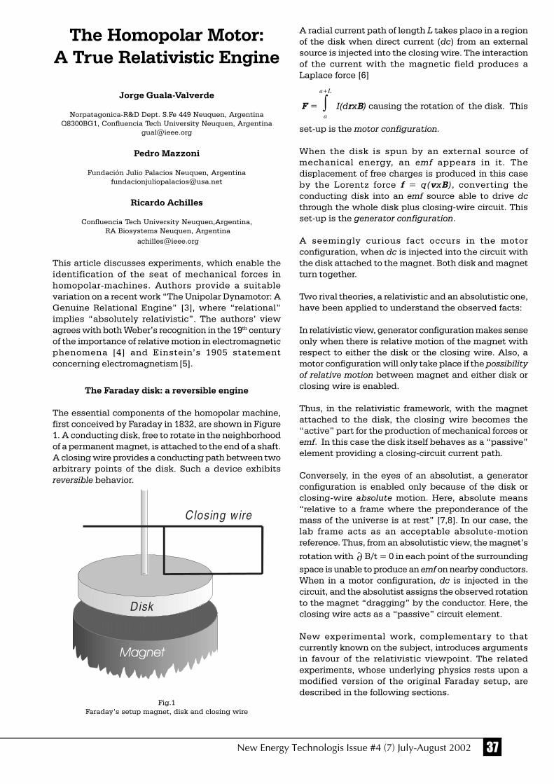
37New Energy Technologis Issue #4 (7) July-August 2002
The Homopolar Motor:A True Relativistic Engine
Jorge Guala-Valverde
Norpatagonica-R&D Dept. S.Fe 449 Neuquen, ArgentinaQ8300BG1, Confluencia Tech University Neuquen, Argentina
Pedro Mazzoni
Fundación Julio Palacios Neuquen, [email protected]
Ricardo Achilles
Confluencia Tech University Neuquen,Argentina, RA Biosystems Neuquen, Argentina
This article discusses experiments, which enable theidentification of the seat of mechanical forces inhomopolar-machines. Authors provide a suitablevariation on a recent work “The Unipolar Dynamotor: AGenuine Relational Engine” [3], where “relational”implies “absolutely relativistic”. The authors’ viewagrees with both Weber’s recognition in the 19th centuryof the importance of relative motion in electromagneticphenomena [4] and Einstein’s 1905 statementconcerning electromagnetism [5].
The Faraday disk: a reversible engine
The essential components of the homopolar machine,first conceived by Faraday in 1832, are shown in Figure1. A conducting disk, free to rotate in the neighborhoodof a permanent magnet, is attached to the end of a shaft.A closing wire provides a conducting path between twoarbitrary points of the disk. Such a device exhibitsreversible behavior.
Fig.1Faraday’s setup magnet, disk and closing wire
A radial current path of length L takes place in a regionof the disk when direct current (dc) from an externalsource is injected into the closing wire. The interactionof the current with the magnetic field produces aLaplace force [6]
F = ∫+La
a
I(drxB) causing the rotation of the disk. This
set-up is the motor configuration.
When the disk is spun by an external source ofmechanical energy, an emf appears in it. Thedisplacement of free charges is produced in this caseby the Lorentz force f = q(vxB), converting theconducting disk into an emf source able to drive dcthrough the whole disk plus closing-wire circuit. Thisset-up is the generator configuration.
A seemingly curious fact occurs in the motorconfiguration, when dc is injected into the circuit withthe disk attached to the magnet. Both disk and magnetturn together.
Two rival theories, a relativistic and an absolutistic one,have been applied to understand the observed facts:
In relativistic view, generator configuration makes senseonly when there is relative motion of the magnet withrespect to either the disk or the closing wire. Also, amotor configuration will only take place if the possibilityof relative motion between magnet and either disk orclosing wire is enabled.
Thus, in the relativistic framework, with the magnetattached to the disk, the closing wire becomes the“active” part for the production of mechanical forces oremf. In this case the disk itself behaves as a “passive”element providing a closing-circuit current path.
Conversely, in the eyes of an absolutist, a generatorconfiguration is enabled only because of the disk orclosing-wire absolute motion. Here, absolute means“relative to a frame where the preponderance of themass of the universe is at rest” [7,8]. In our case, thelab frame acts as an acceptable absolute-motionreference. Thus, from an absolutistic view, the magnet’s
rotation with ∂ B/t = 0 in each point of the surroundingspace is unable to produce an emf on nearby conductors.When in a motor configuration, dc is injected in thecircuit, and the absolutist assigns the observed rotationto the magnet “dragging” by the conductor. Here, theclosing wire acts as a “passive” circuit element.
New experimental work, complementary to thatcurrently known on the subject, introduces argumentsin favour of the relativistic viewpoint. The relatedexperiments, whose underlying physics rests upon amodified version of the original Faraday setup, aredescribed in the following sections.
Magnet
Disk
Closing wire

38 New Energy Technologis Issue #4 (7) July-August 2002
The asymmetrical rotor
Figure 2 shows the disk-shaped ceramic permanentmagnet creating the axial magnetic field B. The removalof a 12° sector introduces a field-reversion region.Outgoing and ingoing B field lines are represented bythe and symbols, respectively.
Fig.2Layout of the Asymmetrical Rotor applied to the experiments
Two mercury collector rings are embedded in a woodcylinder. One is located close to the hollow-disk magnetinner rim and the other in the proximity of the outerrim. The magnet’s inner and outer radii are 25 and 75mm, respectively, and its height 25 mm. Its average fluxdensity 2 mm above the magnet has been estimated tobe 0.05 T based on a generator experiment with arotating copper disk. The magnet-and-wood-cylinderbody (the asymmetrical rotor from here on) is firmlyanchored to a vertical shaft terminated in sharp pointsat both ends. While the lower one lays on a hard-polished surface, a conical bearing, enabling its almostfrictionless rotation, centers the upper one.
Unlike the series-connected conductors diametricallyanchored to the shaft in the Guala-Valverde case [3],only one radial conductor wire, a probe located 2 mmabove the magnet’s face, was considered. By mountingit on a bearing, its free rotation is permitted with itsends remaining in contact with both collector rings. A12V lead-acid battery applied to the closing wire feedsthe probe through the collector rings. In the first fourexperimental cases presented the closing wire remainsfirmly anchored to the lab. In two complementaryexperiments, rotation of the closing wire mounted ontwo shaft-centered bearings is allowed. Its behavior as
a probe occurs by the injection of dc from an additionalclosing-circuit wire anchored to the lab.
Experimental
Six experiments performed are described below:
1. Rotor anchored to the lab, probe free to rotateabove the magnet’s upward magnetic-field region:A radially-ingoing injected dc in the 0.2 A rangewas enough to overcome conductor-bearing andmercury-wire contact friction. A netcounterclockwise rotation of the probe took place.
2. Probe anchored to the rotor above the magnet’supward magnetic-field region, with both free torotate: A radially-ingoing injected dc in the 5 Arange was enough to overcome conductor-plus-rotor inertia and friction. A net counterclockwiserotation of the probe took place.
3. Rotor anchored to the lab, probe free to rotateabove the magnet’s downward magnetic-fieldregion: A radially-ingoing injected dc in the 0.2 Arange was enough to overcome conductor-bearingand mercury-wire contacts friction. A net clockwiserotation of the probe took place.
4. Probe anchored to the rotor above the magnet’sdownward magnetic-field region, both free torotate: A radially-ingoing injected dc in the 5 Arange was enough to overcome conductor-plus-rotor inertia and friction. A net counterclockwiserotation of the probe took place.
5. Rotor anchored to the lab, closing wire free torotate above the magnet’s upward magnetic-fieldregion: A 0.4 A dc injected in the inner collectorring was enough to overcome conductor-bearingand mercury-wire contacts friction. A net clockwiserotation of the closing-wire took place.
6. Rotor anchored to the lab, closing wire free to rotateabove the magnet’s downward magnetic-fieldregion: A 0.4 A dc injected in the inner collectorring was enough to overcome conductor-bearingand mercury-wire contacts friction. A net clockwiserotation of the closing-wire took place.
Discussion of results
Experiments (1) and (3) can be explained using eitherabsolutist or relativistic viewpoints because of thecoincidence of the probe motion relative to the lab withthe probe motion relative to the magnet.
Experiment (2) can be explained by a trivial absolutistargument founded on a hypothetic probe “draggingeffect” on the magnet. A relativistic viewpointrecognizes the “active” rotational torque on the closingwire rather than on the probe where, hinging onNewton’s third law, the whole action may be split intwo:
M e rcu ryc ollec to rring s
B ea ringM a gn et
Power source
Shaft
Probe
Closing w ire
P ow e r s o u rce
C lo s in g w ireP ro be

39New Energy Technologis Issue #4 (7) July-August 2002
Magnet-probe. The magnet produces acounterclockwise torque on the probe, and theprobe exerts an equal but opposite torque on themagnet.
Magnet-closing wire. The magnet exerts aclockwise torque on the closing wire, and the wirean equal but opposite torque on the magnet.
With the probe attached to the magnet, there is nochance for relative motion between them. Consequently,due to the action-reaction cancellation, rotation isforbidden. Conversely, with the closing wiremechanically decoupled from the magnet, relativemotion of the latter is permitted. The torque exerted bythe closing wire on the magnet is responsible for theobserved rotation.
Experiment (4): Due to its similarity with (2) a trivialrelativistic explanation is applicable to thecounterclockwise torque exerted by the closing wireon the magnet. There is no known plausible absolutisticexplanation for it. As quoted above, the hypotheticaldragging effect would produce a clockwise rotation inthis case. The consideration of the experiments (2) and(4) suffices to reject the dragging hypothesis.
Complementary experiments (5) and (6) confirm theshort-range extension of the field-reversion regionfounded on the closing-wire clockwise rotation (6).Briefly speaking, the closing wire is not sensitive to thefield reversion and the magnet’s counterclockwisereaction explains at once the outcome of (4). Clearly,experiments (5) and (6) show that the torque on theclosing wire is independent of its location on themagnet.
Figure 3 depicts the two rotational torques involved in(2) and (4).
Fig.3Rotational torques acting on the magnet and
on the closing wire
Topological and miscellaneous considerations
One of the keys to the success of the above describedexperiments lies in the dynamotor’s magnet design (seeFig.4). The short-range field reversion region allows theinversion of the Laplace force on the probe, making theforce on the closing wire insensitive to that B-fieldreversion.
Fig. 4The magnet’s field-revision region
In all the above cases the electromagnetic forcesbetween probe and closing wire were neglectedbecause of its small magnitude compared to thepredominant magnet-wire interaction forces.
The observed torques became, in all the experiments,independent of the location of the contact pointsbetween closing wire and collector rings. Also, theclosing wire shape exhibited no noticeable influenceon torques. These observations can be easily explainedusing the divB = 0 fundamental law, Laplace force, andsome elementary topological considerations.
Kennard [1], Bartlett [1], Panosky [7,8], Muller [9], Wesley[10] and some of this article’s authors took absolutisticviewpoints when dealing with homopolar phenomena[11,12]. On the contrary, Weber [4], Assis [13], and Kelly[14] adopted a relativistic framework on the issue fromthe beginning.
By attaching the magnet to the disk in the originalFaraday setup, the relative rotation between disk andclosing wire remains unchanged. Therefore, in agenerator configuration, the disk plus magnet rotationat with the closing wire at rest in the lab is entirelyequivalent to the closing-wire rotation at – with the diskplus magnet at rest. This fact introduced a correct butphysically “colorless” weak relativism to the homopolargenerator description: the “unipolar generator really hasthree components, the magnet, the cylinder and themeter (including the contacts). A relative motion of thelast two, not the first two, is required” [1].
A growing interest in basic electromagnetism [15,27]can not be ignored, and from time to time some authors,attempting to catch “free energy” from the space, have

40 New Energy Technologis Issue #4 (7) July-August 2002
claimed the design of homopolar engines with efficiencygreater than unity, as can be checked by searching forhomopolar motor on the Internet. The strict applicationof Newton’s third law precludes the above non-physicalpossibility.
It is worthwhile to stress that the homopolar machineis a famous example where Faraday’s flux rule fails.This fact worried Faraday himself and is clearlydiscussed by Feynman [28] who emphasized that thecorrect physics is always given by the Lorentz forcelaw and the Maxwell fundamental equationcurl E = -B/t. Homopolar induction is fully understoodusing only the Lorentz force. Our experimentsenhance the relativistic structure of the Lorentz forcebecause the only relevant velocity is the velocity ofthe conductor relative to the magnet.
Acknowledgments: To Profs. C.N. Gagliardo and A.Ipohorski-Lenkiewicz for the conceptual comments onthis development.
References
1. J. Guala-Valverde and P. Mazzoni, “The principle ofrelativity as applied to motional electromagneticinduction”. Am. J. Phys 63, 228-229 (1995).
2. J. Guala - Valverde, P. Mazzoni and Ro Blas, Thequasilinear generator and = 0". Am. J. Phys. 65, 147-148 (1997).
3. J. Guala-Valverde and P. Mazzoni, “The unipolardynamotor: a genuine relational engine”. Apeiron 8, 41-52 (2001).
4. A.K.T. Assis, Weber Electrodynamics (Kluwer, Dordrecht,1994).
5. A. Einstein, “Zur elektrodynamik bewegter körper”.Annalen der Physik 17, 891-921 (1905). See also ThePrinciple of Relativity. A.Einstein, H.A. Lorentz, H. Weiland H. Minkowsky, pp. 35-65 (Dover, New York, 1952).
6. G. Cavalleri et al. “Experimental proof of standardelectrodynamics by measuring the self-force on a partof a current loop”. Phys. Rev. E 58, 2505-2517 (1998).
7. W. K. H. Panofsky. Private communication (letter toJ.Guala-Valverde, dated Jan 30, 1995).
8. W. K. H. Panofsky and M. Phillips, Classical Electricityand Magnetism. (Addisson Wesley, NY, 1955).
9. F. Müller, “Unipolar induction experiments andrelativistic electrodynamics”. Galilean Electrodynamics1, N°3, 27-31 (1990).
10. J.P. Wesley. Private communication (letter to J.GualaValverde dated Nov 01, 2001). See also “Progress inSpace-Time Physics”, Benjamin Wesley, Blumberg(1987).
11. J.Guala-Valverde and P. Mazzoni, “The motionalelectromagnetic induction revisited”. Russian Academyof Sciences, 3rd Conference, pp.186-188. St. Petersburg(1995).
12. J. Guala-Valverde and P. Mazzoni, “The unipolar Faradaygenerator revisited”. Galilean Electrodynamics, 4, 107-108 (1993).
13. A.K.T. Assis and D.S. Thober, “Unipolar induction andWeber’s electrodynamics”. Frontiers of FundamentalPhysics, Plenum Press, NY, pp. 409-414 (1994).
14. A.G. Kelly, “Experiments on unipolar induction”. PhysicsEssays 12, 372-382 (1999).
15. A.E. Robson and J.D. Sethian, “Railgun recoil, Amperetension, and the laws of electrodynamics”. Am. J. Phys.60, 1111-1117 (1992).
16. A.K.T. Assis, Relational Mechanics (Apeiron, Montreal,1999).
17. P. Graneau, “Electromagnetic jet-propulsion in thedirection of current flow”. Nature 295, 311-312 (1992).
18. T. E. Phipps and T.E. Phipps Jr., “Observation of Ampereforces in mercury”. Phys. Lett. A 146, 6-14 (1990).
19. P.Graneau and N. Graneau, Newtonian Electrodynamics(World Scientific, Singapore, 1996).
20. V.F. Mikhailov, “The action of an electrostatic potentialon the electron mass”. Annales de la Fondation Louisde Broglie 24, 161-169 (1999); 26, 33-38 (2001).
21. A.K.T. Assis, “Comment on experimental proof ofstandard electrodynamics by measuring the self-forceon a part of a current loop”. Phys. Rev. E 62, 7544 (2000).
22. P. Graneau and N. Graneau, “Electrodynamic force lawcontroversy”. Phys. Rev.E 63, 058601-2 (2001).
23. T.E.Phipps and J. Guala-Valverde, “Simulation ofamperian current elements by magnetic toroids”. 21st
Century Science & Technology 11, 55-65 (1998).
24. M. Bueno and A.K.T. Assis, Inductance and ForceCalculations in Electrical Circuits (Nova SciencePublishers, Huntington, N.Y. 2001).
25. H. Aspden, “Anomalous electrodynamic explosions inliquids”. IEEE Trans. on Plasma. Sc. 14, 282-285 (1986).
26. G.M. Graham & D.G. Lahoz, “Observation of staticelectromagnetic angular momentum in vacuo”. Nature285, 154-155.
27. V. Dvoeglazov, “Essay on the nonmaxwellian theories ofelectromagne-Tism”. Hadronic Journal Suppl. 12, 241-245 (1997).
28. R. Feynman, The Feynman Lectures on Physics, II.(Addisson Wesley,NY, 1964).
4 1New Energy Technologis Issue #4 (7) July�August 2002
Experiments conducted by:William C. Simpson
New Horizons Research 600 Meridian Street Extension,#302 Groton, CT 06340Tel. (860) 405-1157
The following experiments were conducted at theCoastal Environmental Laboratory (CEL) at Avery Point,Groton, Connecticut. (41o 19‘ 0.17" N. latitude x 72o 3‘50.27" W. longitude x 35 feet elevation above mean sealevel) I wish to thank the personnelat the CEL for theirgenerosity for providing the use of their Mettler Toledo®
Model AG104 electronic scale for the measurementstaken in the proceeding experiments. The AG104electronic scale is an enclosed pan unit with a maximummass range of 101-grams with 0.0001-gram readability.
Weight Reductions Generated by Bucking-Field Permanent Magnets
LAB REPORT ON SmCo RING MAGNETEXPERIMENTS
The purpose of these experiments was to see if there isany detectable weight change when permanentmagnets are forced together with their like-poles facingeach other. The magnets were weighed individually, inboth directions, with their field poles oriented vertically.The sums of the two individual magnet weights (magnet#1 and magnet #2) in each vertical orientation werecompared to the weight measurements taken when theywere assembled using the nylon bolt and wing nutdepicted in DIAGRAM 1. The specifications for the twoSamarium Cobalt magnets used in the followingexperiments are shown in DIAGRAM 1.
The first set of experiments with the SmCo Ringmagnets were conducted January 14, 2002. An invertedpaper cup was used to raise the test sample magnets2.75" above the AG104 electronic scale pan in order tominimize possible magnetic interaction with the scale-sensing element, as depicted in DIAGRAM 2. The tareadjustment was used to set the scale readout to0.0000-gram with the cup in place. The magnets wereweighed individually. Magnet #1 weighed 9.9450-gramwith the N pole facing up and 9.9397-gram with the Spole facing up. Magnet #2 weighed 9.9520-gram withthe N pole facing up and 9.9443-gram with the S polefacing up.
The second set of experiments with the SmCo Ringmagnets were conducted February 4, 2002. Theseexperiments were shielded with Mu 80 magnetic
Editorial: This article is one morelink between magnetizm andtheory of aether, to my mind. It ispossible to assume that in hisexperiments the author createssmall but detectable changes indensity of aether, thatdemonstrates itself as the weightchanges.Alexander V. Frolov.

4 2 New Energy Technologis Issue #4 (7) July�August 2002
shielding material as depicted in DIAGRAM 3. Thescale was tare adjusted to 0.0000-gram with the entireset of Mu 80 shield pieces in place. Then the magnetswere weighed individually. Magnet #1 weighed 9.9483-gram with the N pole facing up and 9.9486-gram withthe S pole facing up. Magnet #2 weighed 9.9527-gramwith the N pole facing up and 9.9542-gram with the Spole facing up. The Nylon bolt and wing nut wereplaced in the Mu 80 shield can (without the magnets)and the scale was tare adjusted to 0.0000-gram.Therefore, the readouts would only be reading theweight of the bucking magnets.
The first column in TABLE 1, the vertical measurements,is the distance of separation d, or air gap, of themagnets. The second column shows the January 14,2002 weight measurements of the two magnets, asshown in DIAGRAM A. The third column shows theJanuary 14, 2002 weight measurements of the twomagnets, as shown in DIAGRAM B. The fourth column
shows the February 4, 2002 weight measurements ofthe two magnets, as shown in DIAGRAM C. The fifthcolumn shows the February 4, 2002 weightmeasurements of the two magnets, as shown inDIAGRAM D.
The horizontal measurement, as depicted in TABLE 2,TABLE 3, TABLE 4 and TABLE 5, are through the fourbasic magnetic compass headings; North, East, South,and West respectively. They are referenced toDIAGRAM E and DIAGRAM F for the January 14, 2002experiments and DIAGRAM G and DIAGRAM H for theFebruary 4, 2002 experiments. The correspondinggraphs of the force change plots, GRAPH 1, GRAPH 2,GRAPH 3, GRAPH 4, and GRAPH 5 accompany eachtable. The forces were converted from the massreadings, which are a scalar measurement, to dynes.The convention used for the force vector was chosen asplus (+) for up, or a weight reduction, and minus (-) fora weight increase.

4 3New Energy Technologis Issue #4 (7) July�August 2002
ELEVATION VIEW OF THEVERTICAL EXPERIMENTS
NOTE:
January 14, 2002 Experiments: Starttime: 13:27 hours EST, End time: 15:40hours EST.
February 4, 2002 Experiments: Starttime: 13:18 hours EST, End time: 14:50hours EST.
TABLE 1:
01/14/2002 EXPERIMENTS 02/04/2002 EXPERIMENTS OPEN, WITH PAPER CUP WITH MU 80 SHIELDING
Air gap Diagram A Diagram B Diagram C Diagram D d N to N vertical S to S vertical N to N vertical S to S vertical 19.8893-gram 19.8917-gram 19.9025-gram 19.9013-gram (Sum of 1 & 2)* (Sum of 1 & 2)* (Sum of 1 & 2)* (Sum of 1 & 2)*
0.0 19.8759-gram 19.8757-gram 19.8760-gram 19.8758-gram Inch 0.0134-gram weight 0.0160-gram weight 0.0265-gram weight 0.0255-gram weight
reduction (0.06737%) reduction(0.08045%) reduction(0.13324%) reduction(0.12821%)
1/8 19.8761-gram 19.8751-gram 19.8760-gram 19.8763-gram Inch 0.0132-gram weight 0.0166-gram weight 0.0265-gram weight 0.0250-gram weight reduction(0.06637%) reduction(0.08346%) reduction(0.13324%) reduction(0.12570%)
1/4 19.8763-gram 19.8748-gram 19.8760-gram 19.8768-gram Inch 0.0130-gram weight 0.0169-gram weight 0.0265-gram weight 0.0245-gram weight reduction(0.06536%) reduction(0.08497%) reduction(0.13324%) reduction(0.12318%)
3/8 19.8765-gram 19.8753-gram 19.8760-gram 19.8777-gram Inch 0.0128-gram weight 0.0164-gram weight 0.0265-gram weight 0.0236-gram weight
reduction(0.06436%) reduction(0.08246%) reduction(0.13324%) reduction(0.11866%)
1/2 19.8774-gram 19.8753-gram 19.8757-gram 19.8809-gram Inch 0.0119-gram weight 0.0164-gram weight 0.0268-gram weight 0.0204-gram weight
reduction(0.05983%) reduction(0.08246%) reduction(0.13475%) reduction(0.10257%)
5/8 19.8776-gram 19.8754-gram 19.8779-gram 19.8806-gram Inch 0.0117-gram weight 0.0163-gram weight 0.0246-gram weight 0.0207-gram weight reduction(0.05883%) reduction(0.08195%) reduction(0.12368%) reduction(0.10408%)
11/16 19.8777-gram 19.8748-gram 19.8773-gram 19.8832-gram Inch 0.0116-gram weight 0.0169-gram weight 0.0252-gram weight 0.0181-gram weight
reduction(0.05832%) reduction(0.08497%) reduction(0.12670%) reduction(0.09100%)

4 4 New Energy Technologis Issue #4 (7) July�August 2002
ISOMETRIC AND ELEVATION VIEW OF THE HORIZONTAL EXPERIMENTS
NNshield p,1 = ∆mass x g
for N-to-N pole facings shielded with Mu 80 shielding.
SSshield p,1 = ∆mass x g
for S-to-S pole facings shielded with Mu 80 shielding. Inthe subscripts, n and p refers to the respective number ofdata points per plot. The subscript 1 refers to the verticalchange in force (weight change) axis and 0 refers to thehorizontal distance d axis. In GRAPH 1, n = p.
GRAPH 1:
* Magnets #1 and #2 were individually weighed inthe orientation used in each experiment and theirseparate weights were added together.
The following equation was used to calculate theweight changes, in dynes, in the proceeding graphs.
wherek = 980.665 x dyne x gm-1
and
g = 9.80665 m x sec-2
which is the local rate of gravitational acceleration.
The product of the measured changes in mass, ∆mass,and g is denoted as follows on the graphs:
NNopen n,1 = ∆mass x g
for N-to-N pole facings in the open (or unshielded).
SSopen n,1 = ∆mass x g
for S-to-S pole facings in the open (or unshielded).

4 5New Energy Technologis Issue #4 (7) July�August 2002
MAGNETIC DECLINATION FROM THE LOCAL TOPOLOGICAL MAP:
# Compass Heading is approximate* Magnets #1 and #2 were individually weighed with pole faces oriented vertically, with N up then with S up,and the results were averaged and added.** Due to time constraints, these measurements were not taken.
TABLE 2
North # 01/14/2002 EXPERIMENTS 02/04/2002 EXPERIMENTS Heading OPEN, WITH PAPER CUP WITH MU 80 SHIELDING
Air gap Diagram E Diagram F Diagram G Diagram H d N to N horizontal S to S horizontal N to N horizontal S to S horizontal
19.8905-gram 19.8905-gram 19.9019-gram 19.9019-gram(Sum of 1 & 2)* (Sum of 1 & 2)* (Sum of 1 & 2)* (Sum of 1 & 2)*
0.0 19.8735-gram 19.8778-gram 19.8890-gram 19.8810-gramInch 0.0170-gram weight 0.0127-gram weight 0.0129-gram weight 0.0209-gram weight
reduction (0.08547%) reduction(0.06385%) reduction(0.06479%) reduction(0.10497%)
1/8 19.8728-gram 19.8790-gram N/A ** N/A **Inch 0.0177-gram weight 0.0115-gram weight
reduction(0.08899%) reduction(0.05782%)
1/4 19.8721-gram 19.8798-gram N/A ** N/A **Inch 0.0184-gram weight 0.0107-gram weight
reduction(0.09251%) reduction(0.05379%)
3/8 19.8705-gram 19.8800-gram N/A ** N/A **Inch 0.0200-gram weight 0.0105-gram weight
reduction(0.10055%) reduction(0.05279%)
1/2 19.8698-gram 19.8811-gram N/A ** N/A **Inch 0.0207-gram weight 0.0094-gram weight
reduction(0.10407%) reduction(0.04726%)
5/8 19.8693-gram 19.8818-gram N/A ** N/A **Inch 0.0212-gram weight 0.0087-gram weigh
reduction(0.10658%) t reduction(0.04374%)
11/16 19.8696-gram 19.8827-gram 19.9190-gram 19.9029-gramInch 0.0209-gram weight 0.0078-gram weight 0.0171-gram weight 0.0010-gram weight
reduction(0.10508%) reduction(0.03921%) increase(0.08588%) increase(0.00502%)

4 6 New Energy Technologis Issue #4 (7) July�August 2002
GRAPH 2:
NOTE:The calculated mass of each magnet was determined by thefollowing formula based upon the manufacturer’s dimensionsand density value.
volume = 1.214963 cm3
density = 8.7·gm·cm-3
mass = density·volume
mass = 10.570177 gm.This is higher than the magnetized mass of eachmagnet.
However, some tables give a lower density forthe SmCo magnet, 0.300lb/in3, which equals:
density = 8.303971·gm·cm-3
mass = 10.089017 gm. .
This is still higher than the magnetized mass ofeach magnet. Does the SmCo material becomeslightly lighter in weight when it is magnetized?
TABLE 3
East # 01/14/2002 EXPERIMENTS 02/04/2002 EXPERIMENTS Heading OPEN, WITH PAPER CUP WITH MU 80 SHIELDING
Air gap Diagram E Diagram F Diagram G Diagram HD N to N horizontal S to S horizontal N to N horizontal S to S horizontal
19.8905-gram 19.8905-gram 19.9019-gram 19.9019-gram(Sum of 1 & 2)* (Sum of 1 & 2)* (Sum of 1 & 2)* (Sum of 1 & 2)*
0.0 19.8763-gram 19.8755-gram 19.8928-gram 19.8731-gramInch 0.0142-gram weight 0.0150-gram weight 0.0091-gram weight 0.0288-gram weight
reduction (0.07139%) reduction(0.07541%) reduction(0.04570%) reduction(0.14464%)
1/8 19.8777-gram 19.8750-gram N/A ** N/A **Inch 0.0128-gram weight 0.0155-gram weight
reduction(0.06435%) reduction(0.07793%)
1/4 19.8782-gram 19.8743-gram N/A ** N/A **Inch 0.0123-gram weight 0.0162-gram weight
reduction(0.06184%) reduction(0.08145%)
3/8 19.8779-gram 19.8722-gram N/A ** N/A **Inch 0.0126-gram weight 0.0183-gram weight
reduction(0.06335%) reduction(0.09200%)
1/2 19.8792-gram 19.8715-gram N/A ** N/A **Inch 0.0113-gram weight 0.0190-gram weight
reduction(0.05681%) reduction(0.09552%)
5/8 19.8814-gram 19.8712-gram N/A ** N/A **Inch 0.0091-gram weight 0.0193-gram weight
reduction(0.04575%) reduction(0.09703%)
11/16 19.8815-gram 19.8720-gram 19.9338-gram 19.9030-gramInch 0.0090-gram weight 0.0185-gram weight 0.0319-gram weight 0.0011-gram weight
reduction(0.04525%) reduction(0.09301%) increase(0.16021%) increase(0.00552%)
# Compass Heading is approximate* Magnets #1 and #2 were individually weighed with pole faces oriented vertically, with N up then with S up,and the results were averaged and added.** Due to time constraints, these measurements were not taken.

4 7New Energy Technologis Issue #4 (7) July�August 2002
GRAPH 3:
# Compass Heading is approximate* Magnets #1 and #2 were individually weighed with pole faces oriented vertically, with N up then with S up,and the results were averaged and added.** Due to time constraints, these measurements were not taken.
TABLE 4
East # 01/14/2002 EXPERIMENTS 02/04/2002 EXPERIMENTS Heading OPEN, WITH PAPER CUP WITH MU 80 SHIELDING
Air gap Diagram E Diagram F Diagram G Diagram HD N to N horizontal S to S horizontal N to N horizontal S to S horizontal
19.8905-gram 19.8905-gram 19.9019-gram 19.9019-gram(Sum of 1 & 2)* (Sum of 1 & 2)* (Sum of 1 & 2)* (Sum of 1 & 2)*
0.0 19.8746-gram 19.8769-gram 19.8896-gram 19.8660-gramInch 0.0159-gram weight 0.0136-gram weight 0.0123-gram weight 0.0359-gram weight
reduction (0.07994%) reduction(0.06837%) reduction(0.06178%) reduction(0.18030%)
1/8 19.8720-gram 19.8788-gram N/A ** N/A **Inch 0.0185-gram weight 0.0117-gram weight
reduction(0.09301%) reduction(0.05882%)
1/4 19.8709-gram 19.8797-gram N/A ** N/A **Inch 0.0196-gram weight 0.0108-gram weight
reduction(0.09854%) reduction(0.05430%)
3/8 19.8704-gram 19.8803-gram N/A ** N/A **Inch 0.0201-gram weight 0.0102-gram weight
reduction(0.10105%) reduction(0.05128%)
1/2 19.8711-gram 19.8814-gram N/A ** N/A **Inch 0.0194-gram weight 0.0091-gram weight
reduction(0.09753%) reduction(0.04575%)
5/8 19.8698-gram 19.8825-gram N/A ** N/A **Inch 0.0207-gram weight 0.0080-gram weight
reduction(0.10407%) reduction(0.04022%)
11/16 19.8703-gram 19.8817-gram 19.9423-gram 19.8810-gramInch 0.0202-gram weight 0.0088-gram weight 0.0404-gram weight 0.0209-gram weight
reduction(0.10156%) reduction(0.04424%) increase(0.20290%) reduction(0.10497%)

4 8 New Energy Technologis Issue #4 (7) July�August 2002
GRAPH 4:
# Compass Heading is approximate* Magnets #1 and #2 were individually weighed with pole faces oriented vertically, with N up then with S up, and the resultswere averaged and added.** Due to time constraints, these measurements were not taken.
TABLE 5
West # 01/14/2002 EXPERIMENTS 02/04/2002 EXPERIMENTS Heading OPEN, WITH PAPER CUP WITH MU 80 SHIELDING
Air gap Diagram E Diagram F Diagram G Diagram HD N to N horizontal S to S horizontal N to N horizontal S to S horizontal
19.8905-gram 19.8905-gram 19.9019-gram 19.9019-gram(Sum of 1 & 2)* (Sum of 1 & 2)* (Sum of 1 & 2)* (Sum of 1 & 2)*
0.0 19.8777-gram 19.8748-gram 19.8933-gram 19.8724-gramInch 0.0128-gram weight 0.0157-gram weight 0.0086-gram weight 0.0295-gram weight
reduction (0.06787%) reduction(0.07893%) reduction(0.04319%) reduction(0.14816%)
1/8 19.8767-gram 19.8737-gram N/A ** N/A **Inch 0.0138-gram weight 0.0168-gram weight
reduction(0.06938%) reduction(0.08446%)
1/4 19.8777-gram 19.8733-gram N/A ** N/A **Inch 0.0128-gram weight 0.0172-gram weight
reduction(0.06435%) reduction(0.08647%)
3/8 19.8783-gram 19.8727-gram N/A ** N/A **Inch 0.0122-gram weight 0.0178-gram weight
reduction(0.06134%) reduction(0.08949%)
1/2 19.8806-gram 19.8722-gram N/A ** N/A **Inch 0.0099-gram weight 0.0183-gram weight
reduction(0.04977%) reduction(0.09200%)
5/8 19.8811-gram 19.8715-gram N/A ** N/A **Inch 0.0094-gram weight 0.0190-gram weight
reduction(0.04726%) reduction(0.09552%)
11/16 19.8803-gram 19.8723-gram 19.9427-gram 19.8976-gramInch 0.0102-gram weight 0.0182-gram weight 0.0408-gram weight 0.0043-gram weight
reduction(0.05128%) reduction(0.09150%) increase(0.20491%) reduction(0.02160%)

4 9New Energy Technologis Issue #4 (7) July�August 2002
THREE RIVERS COMMUNITY COLLEGE, THAMES VALLEY CAMPUS
LAB REPORT ON SmCo RING MAGNETEXPERIMENTS
The following experiments were conducted at theThames Valley Campus (TVC) of the Three RiversCommunity College, Room #207 Chemistry Laboratory,in Norwich, Connecticut on March 8, 2002. (41o 30’ 34.62"N. latitude x 72o 6’ 13.63" W. longitude x 115 feetelevation above mean sea level) I wish to thank theinstructors at Three Rivers for their generosity forproviding the use of their Sartorius® Model # 2442analytical balance for the measurements taken in the
GRAPH 5:
RING MAGNET #1, N UP: 9.9483-gramsRING MAGNET #2, N UP: +9.9527-gramsTOTAL WEIGHT: 19.9010-gramsWEIGHT INCREASE WITH OPPOSITE POLES ATTRACTING, AS DEPICTED IN DIAGRAM I, IN MU 80 SHIELDwhere 19.9861-grams was the measured value:19.9861-grams – 19.9010-grams = 0.0851-gram weight increase.
proceeding experiments. The Sartorius Model # 2442analytical balance is an enclosed pan unit with amaximum mass range of 200-grams with 0.0001-grammicrometer readability and a precision of 0.05-mgstandard deviation.
The purpose of these experiments was to compare theAvery Point vertical measurements conducted on theMettler Toledo® Model AG104 electronic scale, inTABLE 1, with the Sartorius Model # 2442 analyticalbalance measurements recorded in TABLE 6. The sametwo Samarium Cobalt magnets (magnet #1 and magnet#2) weighed individually in each vertical orientationwere compared to the weight measurements takenwhen they were assembled using the nylon bolt andwing nut depicted in DIAGRAM 1. The specificationsfor the two Samarium Cobalt magnets used in thefollowing experiments are shown in DIAGRAM 1.
The first column in TABLE 6, the vertical measurements,is the distance of separation d, or air gap, of themagnets. The second column shows the weightmeasurements of the two magnets, as shown inDIAGRAM A. The third column shows the weightmeasurements of the two magnets, as shown inDIAGRAM B. An inverted paper cup was used to raisethe test sample magnets 2.75" above the SartoriusModel # 2442 balance scale pan in order to minimizepossible magnetic interaction with the balance, asdepicted in DIAGRAM 2. The fourth column shows theweight measurements of the two magnets, as shownin DIAGRAM C. The fifth column shows the weightmeasurements of the two magnets, as shown inDIAGRAM D. These experiments were shielded with
DIAGRAM I

5 0 New Energy Technologis Issue #4 (7) July�August 2002
* Magnets #1 and #2 were individually weighed in the orientation used in each experiment and their separateweights were added together.
NOTE:March 8, 2002 Experiments: Start time: 12:12 hours EST, End time: 13:47 hours EST.
Mu 80 magnetic shielding material as depicted inDIAGRAM 3. The resultant data of TABLE 6 is plottedon GRAPH 6. The results of the previous experimentsat Avery Point, from GRAPH 1, and the recent ThamesValley experiments, from GRAPH 6, are plotted onGRAPH 7 for comparison. The Mu 80 magneticallyshielded experiments on the Sartorius Model # 2442analytical balance at Thames Valley are in closeagreement with the data collected with the AG104electronic scale at Avery Point. However, the ThamesValley data collected for the unshielded experiments issomewhat smaller in weight reduction. I attribute thisto external interference. The Thames Valley setup
TABLE 6
03/08/2002 TRCC EXPERIMENTS, 03/08/2002 TRCC EXPERIMENTS, @ TVC: OPEN, WITH PAPER CUP @ TVC: WITH MU 80 SHIELDING
Air gap Diagram A Diagram B Diagram C Diagram Dd N to N vertical S to S vertical N to N vertical S to S vertical
19.8734-gram 19.8726-gram 19.8912-gram 19.8929-gram(Sum of 1 & 2)* (Sum of 1 & 2)* (Sum of 1 & 2)* (Sum of 1 & 2)*
0.0 19.8699-gram 19.8696-gram 19.8691-gram 19.8706-gramInch 0.0035-gram weight 0.0030-gram weight 0.0221-gram weight 0.0223-gram weight
reduction (0.01761%) reduction(0.01510%) reduction(0.11110%) reduction(0.11210%)
1/8 19.8699-gram 19.8699-gram 19.8688-gram 19.8707-gramInch 0.0035-gram weight 0.0027-gram weight 0.0224-gram weight 0.0222-gram weight
reduction(0.01761%) reduction(0.01359%) reduction(0.11261%) reduction(0.11160%)
1/4 19.8695-gram 19.8695-gram 19.8687-gram 19.8712-gramInch 0.0039-gram weight 0.0031-gram weight 0.0225-gram weight 0.0217-gram weight
reduction(0.01962%) reduction(0.01560%) reduction(0.11312%) reduction(0.10908%)
3/8 19.8695-gram 19.8699-gram 19.8692-gram 19.8730-gramInch 0.0039-gram weight 0.0027-gram weight 0.0220-gram weight 0.0199-gram weight
reduction(0.01962%) reduction(0.01359%) reduction(0.11060%) reduction(0.10004%)
1/2 19.8689-gram 19.8699-gram 19.8695-gram 19.8738-gramInch 0.0045-gram weight 0.0027-gram weight 0.0217-gram weight 0.0191-gram weight
reduction(0.02264%) reduction(0.01359%) reduction(0.10909%) reduction(0.09601%)
5/8 19.8686-gram 19.8699-gram 19.8702-gram 19.8746-gramInch 0.0048-gram weight 0.0027-gram weight 0.0210-gram weight 0.0183-gram weight
reduction(0.02415%) reduction(0.01359%) reduction(0.10557%) reduction(0.09199%)
11/16 19.8680-gram 19.8699-gram 19.8707-gram 19.8756-gramInch 0.0054-gram weight 0.0027-gram weight 0.0205-gram weight 0.0173-gram weight
reduction(0.02717%) reduction(0.01359%) reduction(0.10306%) reduction(0.08697%)
included a nonferrous tabletop, as did the Avery Pointsetup. However, the Thames Valley balance tableconsisted of a steel frame and legs, which may havealtered the readings. The Mu 80 shielding provided amore intrinsic method for accurate data collection.
The horizontal measurements were not taken in this setof experiments due to time constraints. A finalexperiment was attempted to replicate the relativeweight increase with the opposite poles of the ringmagnets “stuck” together, as depicted in DIAGRAM I;however, the magnets shattered during assembly!

5 1New Energy Technologis Issue #4 (7) July�August 2002
GRAPH 6:
GRAPH 7:
KEY TO GRAPH 7:
For N-to-N pole facings in the open (or unshielded) at Avery Point (AP):NNopenAPFor S-to-S pole facings in the open (or unshielded) at Avery Point (AP):SSopenAPFor N-to-N pole facings shielded with Mu 80 shielding at Avery Point (AP):NNshieldAPFor S-to-S pole facings shielded with Mu 80 shielding at Avery Point (AP):SSshieldAPFor N-to-N pole facings in the open (or unshielded) at Thames Valley (TV):NNopenTVFor S-to-S pole facings in the open (or unshielded) at Thames Valley (TV):SSopenTVFor N-to-N pole facings shielded with Mu 80 shielding at Thames Valley (TV):NNshieldTVFor S-to-S pole facings shielded with Mu 80 shielding at Thames Valley (TV):SSshieldTV
The subscripts for the data points n =
p =
q =
r = 7 are all the same value in GRAPH 7.
MAGNETIC DECLINATION FROM THE LOCALTOPOLOGICAL MAP

52 New Energy Technologis Issue #4 (7) July-August 2002
Mark Porringa
Zeropoint Techtonix Inc, 430 Bass Lake Road, R R # 1,Deep River, Ontario K0J 1P0, Canada
(613) 584-2960 fax: (613) 584-4616 [email protected]
It is a review of nine alternative, peer-reviewed techniques as candidates for the global clean-up of nuclear waste.
Advanced Nuclear Waste DecontaminationTechnologies
The following is a reasonably comprehensive list ofpotentially effective nuclear waste treatment methodsthat might be employed to treat the entire range ofradioactive wastes that have proven to be such adaunting and horrendously expensive problem for thenuclear industry (in all its forms) with major, long termimplications for the environment.
A wide variety of methods will probably be required toaccommodate the many different radioactive wastesources including high and low level, solids, liquids andgases. Process names used here are in some cases justconvenient labels used to categorize and set them apartfrom each other.
Theories on several of these processes are still quitespeculative and solid evidence that would passconventional peer review is still lacking. This is afterall a very new field of science.
Some of these technologies are already well protectedby international or national patents, with additional USand international patents pending, and further patentsmay be obtained on new developments as they aremade.
The Brown’s Gas-Metal Matrix Process:
The BG-MMX process utilizes a patented electrolysiscell of the Australian Prof. Yull Brown’s design that issaid to produce a stoichiometric mixture of monatomichydrogen and oxygen or possibly a quasi-stable watermolecule raised to a high-energy state. This gas hassome very peculiar properties including the ability tosublimate tungsten (6000oC) with an implosive flamethat burns cool in air with a temperature of only 130oC.
The gas is used to heat a proprietary mixture of metalsand/or metal oxides including the radwaste to beneutralized. A highly exothermic radiant reactionappears to result in the immediate reduction ofradioactivity approaching 95% of the original levelsjudging from preliminary tests, within seconds oftreatment. The process is conjectured to be effectivewith high level solid wastes and possibly gasses, butprobably not liquids. The high temperatures involvedmay also preclude the processing of more volatilewastes.
Since 1991, this technology has been successfullydemonstrated, on a small scale, at least 50 times to US,Chinese, Japanese and United Kingdom officials on avariety of nuclear waste products including Americium,Cobalt, Uranium, and Plutonium. The technique can beapplied for the immediate decontamination of stockpilesof nuclear waste materials being held near nuclearpower plants. The process is very simple, safe, andinexpensive to develop further into robotics applicationfor on-site treatment with no foreseen environmentaleffects.
Photoremediation
The Photoremediation process of the American Dr. PaulBrown is essentially conventional physics, albeitapplied in a new and novel way. The process involvesthe use of a high-energy electron beam impinged on atarget, which in turn produces a monochromatic gammaradiation that is tuned to induce Photofission andPhotoneutron reactions in the target material causingrapid neutralization of radioactive isotopes. Theefficiency claimed exceeds 500% due to the high cross-section reactions in the Giant Dipole Resonance region.The 10 MeV electron beam produces typical fissionreactions in the 200MeV range effectively turning highlevel solid wastes such as spent fuel into an energysource. The process is apparently intended for on-sitetreatment with some waste-partitioning required, anaspect which may not be desirable in certain countries.
While this idea is similar in topology to a system beingdeveloped by Los Alamos National Labs, Dr. PaulBrown’s approach offers several advantages: no needfor extensive chemical pre-processing and the energyrequired to effect transmutation is greatly reduced. Nonew technology needs to be developed, yet theengineering of such a photon reactor must be completedand it could itself become a practical method forgenerating power.
ZIPP Fusion
The ZIPP fusion process, identified by Mark Porringa,induces a wide variety of fusion reactions, resulting fromthe radial compression of individual diatomic and othersimple molecules dissolved or suspended in a light

53New Energy Technologis Issue #4 (7) July-August 2002
water, carbon arc electrolysis cell. A variety of othercell configurations are envisioned.
The process appears to produce only stable isotopes,which should therefore make it capable of stabilizing awide variety of radioactive waste materials. The theoryon the process draws from Condensed Chargephenomena, Brown’s Gas implosion, cavitation bubblecollapse and sonoluminesence - all variations of theCasimir effect - which is believed to cohere the Zero-point energy of Quantum Vacuum Fluctuations.Transmutations using variations of this basic processmay be applicable to a wide variety of nuclear wastesand appears capable of operating with an efficiencyexceeding 100%.
A major implication of this process is that the Strongforce of the nucleus is understood as an ultra close rangeCasimir effect. Oakridge Nuclear Laboratories in theUS in conjunction with several internationalcollaborators have just (this month, in fact) announceda deuterium cold fusion process based on the essentialelements of the ZIPP Fusion process first reported in1998. The process is very simple and inexpensive todevelop.
RIPPLE Fission
The RIPPLE Fission process is an adaptation of existingpotential technology utilizing a supersonic ionized gasto aerosol a counter flow heat exchanger that envelopesthe radioactive waste aerosol in a vacuum inducedplasma vortex which appears to disrupt the matterstabilizing influence of the Quantum Vacuumfluctuations resulting in “gentle” low recoil fissionreactions which produce only stable fission products,with excess neutrons being prompt converted toprotons via quenched Beta emissions. The process isapparently proven with conventional non-radioactivewastes and is believed applicable to the entire spectrumof radwaste without the need for waste partitioning.This process is also conjectured to operate with over-unity efficiency.
The LENTEC Processes
The Low Energy Nuclear Transmutation ElectrolyticCells of the Cincinnati group produce a variety oftransmutation reactions using a variety of exoticelectrolysis cell designs that generally producecondensed charge clusters composed primarily of upto 1011 electrons each. These electron charge clustersproduced with the use of special electrodes canpenetrate the nuclei of larger atoms in solution andtransmute these atoms into stable elements.
The range of design and operating protocols andpotential applications are essentially limitless providedfor the waste that is dispersed in the electrolyte. Thereported transmutation of thorium to stable titaniumand copper by the Cincinnati Group and by the SaltLake City group is one of the most dramatic examples
of this type of treatment process. Application to otherhigh-level liquid transuranic fissionable wastes suchas surplus Plutonium seems likely. The glaring absenceof normal fission yield energies is perplexing butprobably explicable as another form of low recoil fissionreaction, similar to RIPPLE fission.
The Plasma Induced/Injected Transmutation - PITProcesses (also known as HDCC)
Plasma Induced/Injected Transmutation processes runinclude a gamut from recent achievements dating backto the Oshawa-Kushi cold plasma transmutationsreported in 1964. The patented high-density chargecluster process (HDCC) was first discovered by KennethShoulders and added on to by Harold E. Puthoff. Later,the late Stan Gleeson discovered HDCC in properlyprocessed solutions. Still later, Alexander Ilyanok ofBelarus discovered HDCC, followed by VasiliyBaraboskin in Russia.
The production of Condensed Charge Clusters andvarious plasma glow discharge phenomena in a varietyof gaseous atmospheres is again implicated as theunderlying cause with what should be by now anobvious connection with the coherence of Zero-pointenergy from the Quantum or Stochastic vacuum.
Desk-top high energy particle accelerators have alsobeen envisioned, based on the “piggy back” principle,in which the clusters permit acceleration of “piggy-backed” heaver +ions to extremely high energiescapable of causing fusion and transmutations in targetmaterials including those in solution and the materialsof which the electrodes are composed. Brown’s Gasimplosion and cavitation bubble collapse reactions arealso believed to be prevalent in these types of cells dueto the prevalence of electrolysis.
A high-density charge cluster technology wasdiscovered and used by Stan Gleeson to stabilizeradioactive liquid wastes and has been developedfurther in the last 4 years by a group led by S-X Jin andHal Fox. Best results for radioactive liquids have beendemonstrated in the processing of thorium for a 30-minute period and achieving a reduction of radioactivityof about 90% from a liquid sample.
Kervran Reactions
The very compelling evidence compiled by French NobelCandidate Dr. Louis Kervran has identified a widerange of nuclear transmutations in biological systemsthat have not been adequately explained. Coherenceof Zero-point energy via Casimir effects within theSomatid particles identified by the Canadian GastonNaessens is implicated as a possible cause. A widevariety of in vitro and in vivo reactions are believed tobe possible as proven in nature and numerousexperiments typically involving a reaction mediumcomposed of a dielectric fluid such as water. Highlyradiation resistant microorganisms have been found

54 New Energy Technologis Issue #4 (7) July-August 2002
thriving in the core of nuclear reactors indicating thepossibility of microorganisms being capable oftransmuting some bioactive nuclear wastes in thecourse of the normal metabolism of such organisms.
The Monti Process
The Italian Roberto A. Monti’s process involvesconfined explosions involving proprietary mixtures ofmaterials that include radioactive waste. Ignition ofsuch mixtures causes nuclear transmutations resultingin reduced radioactivity (to near-background levels)following combustion, gradually over 1 to 4 days.
This technique has been confirmed by the Italian ENEAand is supported by the French CEA scientists as aserious candidate for treatment of waste stockpiles. Thesystem, as currently designed, required waste to beinserted into a chamber.
Higher group symmetry electrodynamics
Extremely weak, non-classical, higher group symmetryelectromagnetic fields were found during a 1991experiment made by Glen Rein to alter significantly thelevel of radioactivity in materials, even those in theenvironment. The experiments suggest that highergroup symmetry electrodynamics modulate thequantitative and /or qualitative properties of radioactivespecies. If the non-classical fields directly affect theradioactive species, it is likely that the appropriate fieldparameters will be discovered to neutralize radioactiveemissions. In 1999, a theoretical basis for thephenomenon was developed by the Welsh physicist,M. W. Evans, with the participation of Lt. Col. (retired)Thomas E. Bearden.
The technology is extremely simple and could beapplied with minimum logistics for treating massivestructures, in-to outdoors, such as the Chernobyldisaster site.
Psitronics Group Systems, InternationalRobert “Paul” LeBreton, 2901 Hwy. 6, HC 77 Box 42, Laguna, NM 87026 USA
E-mail: [email protected] Phone:1-(505)-836-7534 Psi/Group’s Magnetic Motor - Funding for New Prototype Sought:
As the engineer who designed the self-sustaining magnetic motor being advertisedby Psitronics Group Systems, International. Itperhaps falls upon me to explain (as well as Iam able) the methods used by me in thismotor’s design:
The actual “picture” description is totallyIntellectual Property; Protected as a TradeSecret.
However: This magnetic motor is a“perpetually imbalanced configuration” ofpermanent magnets; an unequal number ofmagnets on the rotor & stator; that revolvesin a “self-sustaining” manner as the magnetsseek balance… There are no electricalcomponents in the design unless one wishedto insert alternator windings in the stator toprovide an electrical output…
We have discovered: through a priorunsuccessful prototype that using a para-magnetic material (we used aluminum) for therotor & stator was self-defeating; as with thepowerful rare earth magnets used in thedesign aluminum destroyed the magnetic
fields… On further analysis of the failedprototype it was deduced that a “latch up”condition would occur between rotor & statormagnets; unless the rotor magnets werecanted or skewed at an angle from the statormagnets… The plastic prototypecontemplated corrects both of theseproblems….
We are seeking an investor willing to put up$4000 (DUS) for the prototype and who canoffer $40,000 return on investment “if it provessuccessful” …We have a Global Distribution‘ready to go” as well as a pledge of $ Millionstowards Manufacturing & Marketing fromEarthTech, International on submission of arunning motor…
Very Respectfully Yours,Paul LeBreton
http://home.earthlink.net/~wizzard9(Psi/Group Website)
Inquiries should be emailed to:[email protected]

55New Energy Technologis Issue #4 (7) July-August 2002
Experimental Investigationsof the Radioactive Isotope Half-Value Period Changing
in the Local Volume of Cause-Effect Relations
Igor A. Melnik
Pr.Frunze 232, Tomsk, 634021, Russia, Ph. (3822) [email protected]
Nuclear-design methods of the elemental analysis arebased on the property of the radioactive isotope decayrate constant. Half period as a constant quantity isdefined by the time feature (the time flow is uniform inthe every space point). The given postulate is confirmedby the long-term results and raised no doubts. But inlast years some researches, investigating enough fineeffects by change of the registered radiation intensivity,came to the conclusion about influence of space cycleson the time flow [1]. In his turn, N. A. Kozyrevduring the investigation of active physical propertiesof time came to the conclusion about violation of itsuniform flow in the local volume of the cause-effectrelations, created by the cyclic motion (rotation,oscillation) of bodies [2,3,4].
Thus, the author get an idea to use a radioactive isotopecezium-137 as a “sensor”, measuring the changes oftime flow uniformity in the certain local volume ofcause-effect relations. In basis there are followingarguments: owing to a conception of time uniformityand considerable cezium-137 half-value period, thesource activity must be permanent during theexperiment time. By the time flow (period) change, i.e.changes of uniformity in the local volume of cause-effectrelations, the half-value period – T is changing in thedirect proportion. Source activity, respectively, ischanging in the inverse proportion according to the lawexp (1/T) in relation to the external space volume.Hence, registered gamma-quantum intension(amplitude impulse distribution) in the absence of thecause-effect relations is proportional to the functionN0~ exp (ln2/T0). Then the proportion N0/∆N, where∆N=N0-N is made, and by means of it a half-value perioddifference is defined by the formula
1/∆T=|1/T0+ln (∆N/N0)/ln2| (1)
N0 – selective average amplitudes of impulses at thecase of static liquid (in the absence of the cause-effectrelations);N - selective average amplitudes of impulses at the caseof rotation of liquid.
In this case, there were investigations of thedetermination of the gamma-quantum intension change(i.e. change of a half-value period) dependence on theangular velocity of the activator rotation, and also onthe coordinates location and amount of cause-effectrelations (Fig. 1).
Fig.1
The following devices were used as measurementequipment: semi-conducting detector (SCD-63V) (1),preamplifier (PAG-2K), amplifier (BAI-3K) and analyzer(AMA-02F1). Energy gamma-line of 662 KeV wasmeasured with the resolution 4 KeV. The gamma-quantum source was glued to the detector housingat the distance of 100 mm from its surface; so, anyspatial change through coordinate axes was executedtogether with the detector to avoid even a tiny changeof the source-detector geometry.
The vessel with a liquid (2) was placed above the source(6), vortex fluid motion was created by an activator (5),placed on the rod of electric motor (3). The glass with aliquid, connected with the motor and frame (4), wasdisplaced regarding to the center of the revolvedactivator, what was the reason of the glass vibration inhorizontal line, and, hence, one of frame sides vibrationin vertical line (v). In its base, the frame was a squarewith the side of 200 mm. To assign the direction of thespace cause-effect relations, one of frame sides wasvibrating, and the opposite one (on the X axis) was fixedon the table (7). An experiment was made in such away, that vibrating parts did not adjoin with thedetector. The radius of glass is 50 mm, the distance fromcentral axis up to the vibrating frame part is 100 mm.N-selection of the every value on the diagram (Fig. 2)corresponded to twenty measurements, roots from theaverage variance of numbers distribution D ≈ 160impulses.
3
4
2
1
5
B6 7
XZ

56 New Energy Technologis Issue #4 (7) July-August 2002
Fig. 2Dependence of photopeak-N area from the angular velocity of
rotation – W, where 1 – is photopeak area at static liquid, 2 – isphotopeak area at clockwise rotation, 3 – is photopeak area at
anticlockwise rotation
During two months eighteen experiments were made(at the one geometry) of the given effect fluctuationstudy, and there were no considerable deviation. Aneffect of the time deceleration always appeared at theangular speed of the activator rotation W=3780 r/min(during the vibration of the whole perimeter of the framebase). If there was a vibration on the only one side ofthe frame base (on the X axis), then this effect appearedat the higher speed of rotation. Unfortunately, themaximum motor speed of rotation Wmax=4880 r/min didnot let to define the precise position for the next rotationpoint. During the experimental results extrapolationW2≈5930 r/min (W2≈πW/2) was obtained.
In the table there are selective middle amplitudes ofimpulses -N=∑Nn/n roots from the numbers distributionaverage variance D, dispersion of the simple average Gat the different directions of the liquid rotation (for therotation point W=3780 r/min). The half period isestimated by the equation (1) and formula T=T0+∆Twhere T0=30.2 year (the cezium-137 half-value period).
Liquid motion N, imp. D G T, year
Static liquid 16304.0 160.7 35.9 30.200
Clockwise 15696.0 162.0 36.2 30.412
Anticlockwise 15553.0 165.0 36.9 30.423
During the investigation of the activator angular speedof rotation dependence on the registered gamma-
quantum intension, there was discovered the timedeceleration effect in the fixed point of ambient spaceof the glass with the liquid. The effect was versatile,during the further study of the reasons of the effectdisappearance, the following regularities were found:
1. Intension change appeared only at the case ofasymmetrically fixed glass, when thereappeared horizontal oscillations, transmitted tothe vertical oscillations of the frame;
2. An effect disappeared, if the gamma-quantumsource was placed in the glass center(~ 2 ÷ 3 mm down from the glass bottom);
3. At the same speed of rotation but withoutliquid, with an eccentric activator, the timedeceleration effect disappeared.
Will consider the system with liquid, its internal chainconsisted of three cause-effect relations:
1. Activator-liquid;2. Liquid-glass (frame);3. Frame-table.
Glass oscillations were transmitted to the frame throughthe hard cohesion. There was only one cause-effectrelation – an activator (a frame) – a table. Thus,amplitude of the time flow changing was, most likely,influenced on by the amount of cause-effect relation,and also, there was observed a quantum effect,dependent on the activator and liquid rotationfrequency.
The time deceleration maximum amplitude appearedduring the source displacement from the central axis ofglass along the X coordinate to the distance ~ 5 mm.There appeared the necessity to check the given effecton space points along the all coordinate axes in theradius R ≈ 100 mm from the central point of the glassbottom (an extreme vibration point along the X axis wasplaced on this distance).
On this purpose there were made some experiments,results of which are shown on the (Fig. 3), (Fig. 4).
Fig. 3Dependence of the increase of photopeak -∆N area from the spatial interval in Cause-Effect Relations by X and Z coordinates,
where XcZc – is clockwise rotation, XacZac – is anticlockwise rotation
57New Energy Technologis Issue #4 (7) July-August 2002
Fig. 4Dependence of the increase of photopeak -∆N area from the spatial interval in Cause-Effect Relations by X and Y coordinates,
where XcYc – is clockwise rotation, XacYac – is anticlockwise rotation
Let us suppose that positive axis Z is directed from theglass bottom center to the ground and axis X – from thecentral axis of glass to the vibrated part of the frame(North-West), in this case Y is directed to the North-East. Along the all coordinates, in every adjusted spacepoints on the distance Ri from the glass bottom center(Ri = 5; 50; 70; 100; 115 mm), there were fortymeasurements. At that in every point after tenmeasurements connected with the rotation there weremeasurements at the static liquid. It was made to avoidany systematic errors. The amplitude of the sampleaverage impulses at the static liquid - N0=10550 imp.In this case the root from the dispersion ∆=120,dispersion of the simple average G=19. Amplitudeincrement was calculated by the formula ∆N=|N0-N|.Following regularities were found:
1. If considering the difference of impulseamplitude (in the positive coordinate space) inthe first cause-effect relation evidence(activator-liquid), i.e., to put the differencebetween the initial (5 mm) and final (50 mm)points of amplitude registration (their middleevidence between “clockwise” and“anticlockwise”) ∆N5
50=|N5-N50| into theformula (1), then relations ∆TZ/∆TX=∆TX/∆TY≈1.11 (π/2√2≈1.11)
2. Change of impulse amplitude difference alongX is the antiphase of changes along Z and Y;
3. At the rotation clockwise and anticlockwisethere takes place a periodical inversion ofamplitudes difference relation;
4. At the liquid rotation clockwise andanticlockwise, there appears an obviousdistinction in evidences of the increment ∆N innegative region of coordinate axes;
5. Along Y and Z-axes in points (5; 100 mm) thereis observed insignificant time acceleration.
The whole cause-effect relation system was defined asan internal (activator-table), as an external one (ground- system center of gravity). In the internal space volumetime at the certain conditions breaks its ownuniformity, at that the time period change is nonlinearand is defined by its quantum nature. Therefore,standard clocks in causal relations must be consideredregarding to the center of gravity and location of themeasurement point in the internal system space.
References
1. Shnol S.E., Zenchenko T.A., Zenchenko K.I.,PozharskyE.V., Kolombet V.A., Konradov A.A.Regular change of the statistical distributionsthin structure as a result of cosmophysicalcauses. Kushnirenko E.A., Pogozhev I.B.Comment to the article of Shnol S.E. and Co.Progress of physical sciences. Vol. 170, #2,p.213-218, 2000.
2. Kozyrev N.A. Causal or asymmetric mechanicsin the linear approximation. Pulkovo, 1958,
p. 90.
3. Kozyrev N. A. Astronomic observations bymeans of time physical properties. Symposiumtransactions, Erevan, 1977, p. 209-227.
4. Kozyrev N.A. About possibility of bodies massand weight under the influence of time activeproperties. Eganova I.A. Analytical survey ofmodern time-keeping ideas and experiments.Novosibirsk, 1984, p. 92-98.
5. Melnik I.A. Experimental researches of the timeflow local deceleration. VINITI 5.02.92,
N1032-mg92, #4, p.70.

58 New Energy Technologis Issue #4 (7) July-August 2002
UP-TO-DATE INVENTION
TILLEY ELECTRIC VEHICLE
Tilley Foundation, Inc.131 Hiwassee Road
Lebanon, TN 37087, USA615-443-5315
E-mail: [email protected]
Nowadays there stays urgent the development oftechnologies, which could possibly be combined intoa reliable, commercially successful advanced selfpowered vehicle with additional desirable but currentlycommercially unavailable features.
The advantages of electric vehicles seem to beevident – they are clean, quiet, powerful, require muchless maintenance than gasoline or diesel-fueledvehicles, and are inherently much simpler and easierto manufacture. Their drawbacks have been a shortrange, long battery recharging time, and a heavy, bulkybattery pack.
After several years of personal accomplishments in thealternative energy industry, Carl B. Tilley, the inventorfrom USA, was convinced that it was possible to buildan electric car that could be powered without the helpof external power to keep the battery charged.
The concept to produce a useful electric performancecar that would last more than a few hours and wouldbe economical to run, safe to drive around town oracross the United States and never use a drop of fuelchallenges the future of transportation as we know ittoday.
With the establishment of the Tilley Foundation, Inc.,in the year 2001, Carl Tilley set out to prove it could bedone. It was an ambitious project and it broke groundon the facility in Tennessee that would build the firstself-generating electric car.
Construction of a 1,800 square foot building, that waspowered with another recently developed electricdevice, began in the year 2002. Electricity for this caris provided from a different energy invention, whichwas void of any outside power supply. It is ironic thatone alternative energy device actually built theinvention to power and build the electric car.
The Tilley Electric Vehicle (TEV), converted from a1981 DeLorean, energizes the imagination and defieswhat has been accepted as a standard in the area oftransportation for years.
From the selection of the proper car to be converted, tothe advanced technology, which is on board, the TEVperforms comparably to gasoline-powered vehicles.Thedifference is you have no need for fuel and you do nothave to stop the vehicle to charge it after driving. Thereis no pollution and you can cruise the highways at thesame speed as any other vehicle.
There is a new car on the road today. A car built withtechnology that defies the concept of fossil fuelpowered cars, and can run coast to coast without everrelying on the battery being charged from an outsidesource.
The long awaited transportation revolution and the endof our reliance on fossil fuel has now begun ….the TilleyElectric Vehicle.
The demonstration of a DeLorean powered by anelectric motor and 12-volt standard car batteries issupposed to be on September 7, 2002, at the NashvilleSuperspeedway, USA. The battery bank is kept in acharged condition by the “on board” charger which isthe device invented by Carl B. Tilley. Racing legendBobby Allison is one of the guest drivers for thisdemonstration.
Details and results of thedemonstration read in
our next issue
59New Energy Technologis Issue #4 (7) July-August 2002
The Problem of Time:Force as the Cause of Change
of the Course of Time
Valentin P. Oleinik
Department of General and Theoretical Physics,National Technical University of Ukraine “Kiev Polytechnic
Institute”, Prospect Pobedy 37, Kiev, 03056, Ukraine;e-mail: [email protected]
Internet: http://temporology.bio.msu.ru/OLEINIK/oleinik.htm.
Abstract
Material processes occurring in a physical system underthe action of a force field necessarily influence the courseof time along the trajectory of motion of particle. Ageneral relationship is obtained which relates the courseof time on one path section of a particle when moving ina force field to that on the other path section in the sameinertial reference frame. According to the resultsobtained, the force in relativistic mechanics is not onlythe cause of acceleration of particle relative to an inertialframe of reference, but also the cause of change in thecourse of time along the particle’s trajectory. Thereinlies the physical content of the dynamical principleunderlying the special theory of relativity (relativisticmechanics). The applications of the theory developedto homogeneous fields - to the field of gravity andelectromagnetic field, and to the gravitational fieldproduced by a point mass particle are considered.Physical properties of the state of imponderability ofparticle in an external force field are investigated. It isnoted that the change in the course of time in a forcefield is in no way connected with the change in space-time metric and is a direct consequence of the causalityprinciple of relativistic mechanics. The existence ofdependence of the course of time on the state ofmotion of particle in a force field points to thefeasibility of controlling the course of time using forcefields.
Time is among the most common concepts, which areused constantly both in everyday life and in science.This is because all the events and material processesin the world happen in space and develop in time and,hence, the laws that govern space-time connections arethe most general and hold for all the forms of matter.Nevertheless, time remains one of the most mysteriousconcepts of physics; its physical essence is notadequately revealed up till now [1-4]. The concept oftime with difficulty yields to logical analysis.
From the point of view of common sense the essence oftime is that time characterizes the duration of eventsand processes, indicates their natural sequence, atwhich the present, going away to the past, gives placeto the future.
Isaac Newton gave a clear-cut characteristic of theconcept of time, to which the majority of physicists
adheres: “The absolute, true, and mathematical timein itself and by virtue of its nature flows uniformly andregardless to any other object”. Though, according toNewton, time flows equally and uniformly and does notdepend on the processes, occurring in the world, thedaily experience speaks in favour of the fact that thecourse of time is not uniform. Depending oncircumstances in our history, it seems to us that timeeither flies swiftly or hangs heavy on our hands;sometimes it even changes suddenly, by leaps. Inconnection with these speculations the question arisesof whether the subjective sensations of non-uniformityin the course of time familiar to everyone have anobjective basis.
In Newtonian mechanics time is of an absolutecharacter, it does not change as one passes from oneinertial reference frame to another and representsmerely a parameter, whose change at the will of explorerresults in the change of state of a mechanical system inaccordance with the equation of motion.
In relativistic mechanics time remains a parameterdescribing the development of system. But now timeand space are intimately linked with each other to forma single system, i.e. the 4-dimensional space-time. Ingoing from one inertial frame of reference to anothertime gets entangled with spatial coordinates, so thattime in one reference frame represents a “mixture” oftime and coordinates in the other. Time ceases to beuniversal, the same in all inertial reference frames; ittakes on a relative character.
The indissoluble association of time and space takeson special importance in the light of the concept ofphysical field, which was called by Einstein the mostimportant discovery in physics after Newton. Accordingto this concept, the occurrence in space of a force fieldmeans that space turns into a physical environment,which is capable to interact directly with other bodiesand gains, thus, physical properties, becoming an activeparticipant of physical processes. In view of the factthat space and time are indissolubly related to eachother, the presence of a force field in some area ofspace must necessarily result in the appearance ofphysical properties of time caused by the motion ofbody in this area.
Thus, from the synthesis of the notion of space-time andof the idea of physical field it follows with necessitythat the course of time in a given region of spaceshould depend on physical processes in this region,i.e. time, as well as space, should have physicalproperties [5-8].
It should be emphasized that in special theory ofrelativity (STR) time and spatial coordinates areindependent and formally equal in rights quantities,which determine the position of elementary events inspace-time. On the other hand, time stands out inrelation to spatial coordinates. The special role of timeis due, from the viewpoint of geometry, to the

60 New Energy Technologis Issue #4 (7) July-August 2002
pseudoeuclidity of geometry of the 4-dimensional space.From the physical point of view, it is associated withthe dynamical principle (causality principle), accordingto which the state of motion of a physical system at aninstant of time t uniquely defines its behaviour at the
next instant of time 0+t . The significance of dynamicalprinciple lies in the fact that it relates the temporalevolution of system to the physical processes causedby force fields and in doing so it allows one to determinethe course of time in the system, its possibledependence upon the character of physical processes,and not just the sequence of events and their duration.
The idea about the existence of the physical propertiesof time belongs to N. Kozyrev [9]. By introducing intomechanics an additional parameter taking into accountthe directivity of the course of time, Kozyrev hasformulated causal (asymmetrical) mechanics fromwhich it follows that time has physical properties.According to the results of theoretical and experimentalinvestigations conducted by Kozyrev and his followers[9-13], events can proceed not only in time, but alsowith the help of time, information being transmittednot through force fields, but via a temporal channel,and the transfer of information happensinstantaneously. The appearance of additional forces,associated with the physical properties of time andcapable to fulfill work, testifies that time can serveas a power source.
In the papers by I. Eganova [12] and M. Lavrent’ev andI. Eganova [13] it is stated the problem of directexperimental research of the physical properties of timeto ascertain the relations of a new type betweenphenomena and to discover new methods to changethe state of substance. In [14] O. Jefimenko investigatedthe dynamical effect of the slowing-down of time.
According to [6-8], the conclusion that physicalproperties of time exist follows strictly from relativisticmechanics, without introducing any additionalhypotheses. The physical properties of time are of purelydynamical nature: their existence results from dynamicalprinciple. The availability of physical properties oftime is manifested in that time has a localinhomogeneity: its course along the trajectory ofmotion of a point particle in a force field iscontinuously changed, and this change in the courseof time is a result of the action upon the particle of aforce field in the inertial reference frame, in whichthe motion is considered.
Editor’s note: The author gives a detailed considerationof the physical content of the local dynamicalinhomogeneity of time. Considering the motion of aclassical point particle under the action of a force fieldin the inertial reference frames, that moves relatively toeach other, Valentin P. Oleinik derives 73 equations, thathelp him to obtain the following conclusion(mathematical details and physical reasoning may befound inhttp://temporology.bio.msu.ru/OLEINIK/oleinik.htm.)
The elucidation of the physical nature of time is one ofthe most important problems of theoretical physics. Thepurpose of research on the problem of time is to studythe physical properties of time, i.e. to ascertain thepossible interrelation between time and materialprocesses. In particular, it is of interest to find out
• whether the flow of time depends upon physicalprocesses and whether the back influenceexists (i.e influence of the change of the timecourse on physical processes);
• what mechanisms of the change of the courseof time are available;
• what factors are capable to speed up or to slowdown the flow of time.
In papers [5-8] on the basis of Lorentz transformationsrelating to coordinates of points, lying on the trajectoryof motion of particle in a force field, the phenomenon oflocal dynamical inhomogeneity of time is predicted. Themain result consists in the proof that material processesoccurring in a physical system under the action of aforce field necessarily influence the course of time alongthe trajectory of motion of particle. The case in point isthe change of the course of time along particle’strajectory in one inertial reference frame as comparedwith that in the other.
In this paper the next step is made: the relationship isobtained which relates the course of time on one pathsection of a particle when moving in a force field to thaton the other path section in the same inertial referenceframe. The main idea underlying the approachdeveloped results from the analysis of Lorentztransformations and consists in that the course of timeof a particle moving by inertia, i.e. of a particle beingnot exposed to force, should be uniform.
As is well known [17,18], the existence of dependenceof the course of time upon the gravitational fieldpotential is predicted with the general theory ofrelativity (GTR). According to GTR ([17], p.303), timeflows differently at the different points of space in oneand the same reference frame. Since “gravitational fieldis nothing more nor less than a change of the space-time metric” ([17], p.313), one can assert, apparently,that the change in the course of time is due, in the viewof GTR, to the change of the 4-space metric. It shouldbe emphasized that in the present paper gravitationalfield is considered as an ordinary force field, and theparticle motion is supposed to occur in pseudo-Euclidian space-time. The main formulas of the article,(22) and (25), describe the change in the course of timein an arbitrary force field at different spatial points inone and the same inertial reference frame. As is seenfrom the results received, the change in the course oftime in a force field is in no way connected with thechange of space-time metric. It is conditioned by theforce field action on particle in inertial reference frameand is a direct consequence of the dynamical principleunderlying relativistic mechanics.
61New Energy Technologis Issue #4 (7) July-August 2002
It should be emphasized that the existence ofdependence of the course of time on the state ofmotion of particle in a force field points to thefeasibility of controlling the course of time using forcefields.
Note an important peculiarity of the non-inertialreference frame, in which the imponderability state ofa particle is attained: there is such a space-time regionin which the reference frame at hand can beapproximately considered as inertial. In connectionwith the fact that such reference frames (it is natural tocall them quasiinertial in contradistinction to the trueinertial reference frames) are, generally speaking, notequivalent to each other (see previous section), thederivation of a rigorous criterion for inertial referenceframe acquires especial significance. The dynamicalcriteria for defining the inertial and non-inertial statesare considered in the papers by B. I. Peschevitsky [19].The heliocentric reference frame seems to be amongthe quasiinertial reference frames, being inertial withadequate accuracy only in a restricted region of space(for example, within the limits of our Galaxy) [16].
The author is grateful to Yu.D. Arepjev for his interestto the paper and stimulating discussions.
References
1. Blokhintsev D.I. Space and Time in the Microworld (Nauka,M., 1970) (in Russian).
2. Prigogine I. From Being to Becoming: Time and Complexity inthe Physical Sciences (W. H. Freeman & Co., San Francisco,1980).
3. Prigogine I. and Stengers I. Order Out of Chaos (Bantam Books,New York, 1983).
4. Logunov A.A. Lectures on the Theory of Relativity andGravitation: Modern Analysis of the Problem (Nauka, M., 1987)(in Russian).
5. Oleinik V.P. The Newest Development of QuantumElectrodynamics: Self-Organizing Electron, SuperluminalSignals, Dynamical Inhomogeneity of Time, Physical Vacuumand Nature, 4, 3-17 (2000).
6. Oleinik V.P., Borimsky Ju.C., Arepjev Ju.D. New Ideas inElectrodynamics: Physical Properties of Time. SemiconductorPhysics, Quantum Electronics & Optoelectronics, 3, #4, 558-565 (2000). E-print: quant-ph/0010027.
7. Oleinik V.P. Superluminal Signals, Physical Properties of Time,and Principle of Self-Organization, Physics of Consciousnessand Life, Cosmology and Astrophysics, 1, 68-76, (2001);Borimsky Yu.C., Oleinik V.P. The Course of Time in Classicaland Quantum Systems and Dynamical Principle, PhysicalVacuum and Nature, 6, (2001) (in print).
8. Oleinik V.P. The Problem of Electron and Superluminal Signals.(Contemporary Fundamental Physics) (Nova SciencePublishers, Inc., Huntington, New York, 2001).
9. Kozyrev N.A. Selected Transactions (Leningrad UniversityPress, Leningrad, 1991) (in Russian).
10. Lavrent’ev M.M., Eganova I.A., Medvedev V.G., Olejnik V.K.,and Fominykh S.F. On Scanning of Celestial Sphere by Kozyrev’sSensor, Doklady AN SSSR, 323(4), 649-652 (1992) (in Russian).
11. Akimov A.E., Kovaltchuk G.U., Medvedev B.P., Oleinik V.K.,Pugatch A.F. Preliminary Results of As-tronomic Observationsof Sky by the Kozyrev Procedure. Academy of Sciences ofUkraine, Central Astronomic Observatory. Preprint CAO-92-5P, 1992, p.16 (in Russian.).
12. Eganova I.A. The World of Events Reality: InstantaneousAction as a Connection of Events through Time, InstantaneousAction-at-a-Distance in Modern Physics (Nova SciencePublishers, Inc., New York, 1999).
13. Lavrent’ev M.M. and Eganova I.A. Physical PhenomenaPredicted and Revealed by N.A.Kozyrev, in the Light ofAdequacy of Space-Time to Physical Reality, Phylosophy ofScience, 1(3), 34-43 (1997) (in Russian).
14. Jefimenko O.D. Electromagnetic Retardation and Theory ofRelativity (Electret Scientific Company, Star City, 1997).
15. Khaikin S.E. Forces of Inertia and Imponderability (Nauka, M.,1967).
16. Sivukhin D.V. The General Course of Physics. Mechanics(Nauka, M., 1979).
17. Landau L.D. and Lifshits E.M. The Classical Theory of Field(Pergamon Press, Oxford. 1985).
18. Pauli W. Theory of Relativity (Nauka, M., 1983).
19. Peschevitsky B.I. Dynamical Criteria for Inertial and NoninertialStates, p.1 and 2. Phylosophy of Science, 1(7), 79-84 (2000);1(9), 99-109 (2001) (in Russian).
Raum&Zeit EhlersVerlag GmbH, Geltinger Str.
14e, 82515 Wolfratshausen Telefon: 08171/41 84-76, 08171/41 84-66
Internet: http://www.raum-und-zeit.com
Institut für Raum-Energie-Forschung (IREF)i.m. Leonard Euler
Global Scaling TheoryGravitation theoryMathematic BiologyGravitation energeticsHydrogen-Helium EnergeticInformation technologiesTelecommunication technologiesTransport technologies
EAGLE-RESEARCHEnergy Solutions
since 1984 A Research Organization
that Develops & DistributesPractical Energy-Saving
Methods & Devices
4 Energy Way, P.O. Box 118Porthill, Idaho 83853FAX: 250/492-7480
Technical questions to:[email protected]

62 New Energy Technologis Issue #4 (7) July-August 2002
Time and its PhTime and its PhTime and its PhTime and its PhTime and its PhysicalysicalysicalysicalysicalRelationshipsRelationshipsRelationshipsRelationshipsRelationships
Andrew Michrowski
President, The Planetary Association for Clean Energy, Inc., 100Bronson Avenue, # 1001, Ottawa, Ontario K1R 6G8 Canada.
(613) 236-6265; fax: (613) 235-5876 [email protected]
Time cannot be absolutely defined, and there isno inseparable relation between time and signal velocity.
Albert Einstein [1]
Time does not exist by itself
The phenomenon of time emerges in relationships – asan expression of properties of physical bodies andchanges that occur to them.
Time is a factor of energy. Time has to do with theincrease and decrease of energy. For example, as energyis brought down to a “zero level”, time is “eliminated”,so in a sense, time cannot be “compressed” - onlyeliminated. In the zero-energy level, electrons occupyingthis level in unlimited numbers are available throughstate transitions for the building of matter and thevacuum [2]. So it is the extent and the nature of energyflow that determines the characteristics of time.
How do we know all this?
In his seminal foundations of physics work of the early1900s, Sir Edmund T. Whittaker demonstrated bycanonical quantization that there exist physical, time-like and longitudinal photons in vacuo [3,4,5]. The 2scalar potential functions, F and G which completelycharacterize an electrodynamic field due to electronsin the ether are:
F (x, y, z, t) = ∑ π4
esinh-1 ( ) ( ){ } 2/122 ’’
’
yyxx
zz
−+−
−
G (x, y, z, t) = ∑ π4
e tan –1
xx
yy
−−’
’
In these equations, for the fundamental case in whicha field is due to any number of electrons moving in anyway, we observe that time emerges only through thedisplacement of energy. Another way of putting it wouldbe that time emerges through change in energy.
These photons have an independent physical existence.Whittaker himself observed, after computation that the“total disturbance at any point, due to this system ofwaves, is independent of the time, and is everywhereproportional to the gravitational potential due to theparticle at the point” [6]. A. D. Sakarov admitted that
the gravitational field is a “conglomerate of loose thingsand not a fundamental field of nature at all [7].
Everything electromagnetic, and probably gravitational,starts from these potentials, not fields, and under certaincircumstances, there may exist photons without fieldsbeing present at all. In the vacuo, the longitudinal lightphoton travels in the direction of the beam, like anenergy capsule, as a scalar four-potential-functionenergy standing-wave field, with many differentfrequencies, with an internal symmetry based oncircular polarization [8,9], an energy field or nexus that“has an end, but no beginning”. The time-like andspace-like parts of the four potential are photons withspin –1, 0 and +1 that are longitudinally directed, andwhich are observed in the Compton and thephotoelectric effect [10].
Movement of light affects time
Philip S. Callahan designed an elegant experiment thatshows how variations in the movement of light affecttime [11]. Changes in exposure settings of photographsof same objects, including coherent light laser spotsresults in shift of position of images. The more coherentthe light, the less apparent is a shift in time. Hesuggested that time is neither absolute nor independentof photon activity of space.
We can also state, as a corollary, that the movement oflight generates time. After all, the electrodynamics isassociated with photons. This is particularly significantin time engineering, as will be seen later.
Time and life
Now, it is well known that the ability of cells to sensethe presence of light is a primary function of life itself.If a cell can sense light, it is alive; if it cannot, it is dead[12]. Callahan was able to observe that time incrementswere detected on light-detecting surfaces of livingorganisms such as the cuticles of leaves.
The Russian time researcher, Nikolay A. Kozyrevconsidered that living systems “consume” time for theirlife-energy [13]. Velimir Abramovich suggests thatliving organisms are naturally-driven “time machines”.They each have an inbuilt time that serves as a “code”to structure their own physical totality and to regulatetheir own functioning. Thus their “local time” acts as a“time operator” (“time condition”) frequency [14]. Thenature and level of electromagnetic fields in livingsystems could therefore be considered as indicators oftheir “energy level” and how it affects and adjusts theinherent rate of time-flow.
Time and consciousness
We append to these statements the notion that, yes,time is “consumed” by living organisms – but only ifthey are conscious. Essentially, time can be perceivedby measurement, which always requires a consciousobserver.

63New Energy Technologis Issue #4 (7) July-August 2002
When we measure, we observe the differentials ofenergy flow. It is the measurement of these differentials- as we note from the Whittaker equations of scalarfluxes - that allows us to the measure the equivalenceof time. When we measure differentials, we areeffectively creating our notion of time.
It is difficult for humans to conceive that time does notexist when humans think about it. Saint Augustinespeaks for all humans with his observation:
While I do not think about time, I know that time exists.When I begin to think about it, I stop understanding
what it is.
With such conditioning, humans cannot come to gripswith the notion that the Universe has no beginning andno end. It is like the paradigm of absolute nothingness– people cannot deal with the concept of no timebecause, effectively, consciousness, like life, consumestime. One could advance the notion that thought itselfis time in motion. When we think, we are creating time.Life is movement – and the brain registers energydifferentials and their associated fluxes of scalarpotentials.
Time and causal mechanics
Since time is the result of movement of energy (andaccordingly, light), then time is associated with thecause-effect processes linked to a first position of energyto the next. In other words, time is innate to causalmechanics.
Variations in energy flow, logically, lead to variations inthe characteristics of time. They also permit variationsin causality.
Conversely, changes in time lead to changes in physicalstructure [15]. This phenomenon was proven by Kozyrevand has been labelled as the Kozyrev effect [16]. Hedemonstrated that changes in the course of time affectthe performance of electronic components. Figurativelyspeaking, a transistor is like a corral in which lightbehaves in a certain way. By changing the way thatlight behaves, a transistor becomes valueless.
To create an extra-temporal causality (with linkages toanother level/dimension) one must change the lightmovement. Changing the light patterns meanschanging the behaviour of a wave, and its concordantphotonic reality. By altering the photons, we make themgo to another dimension.
Changes in time can effect change in living systems[17]. The engineering of “time-polarized” waves has thepromise to target and amplify natural healing processionin living organisms. It is these natural activities thatwould restore diseased cells to their original and healthycondition [18]. Such time engineering may also includethe reversal of the effects of AIDS, smallpox, anthrax,and most bio warfare agents, with treatment times ofonly a few minutes per week, with no more than 3
treatments required in all. Eventually it may also bepossible to reverse the effects of genetic disorders, effectlimb regeneration, and cure spinal cord injuries [19].
Engineering causality
Variation in the density of energy determines variationin the “the course of time”. By the “speed of course oftime” is meant the rate of causal transformation andthe input of additional forces into systems (includingmechanical tensions). According to Russian scientists[20, 21,22] there are interesting possibilities in deployingengineering for causal mechanics.
In preventive time engineering, one could delay theapproach of a known cause and to artificially close theconsequence loop, and thereby annulling it from everachieving an effect. In other words, one can make theeffect “happen” before its normal time, disrupting spacestructure with its related “speed of the course of time”.One can also make it “happen” after its expecteddeadline. This technology could have interestingimplication in strategic situations (preventing a extra-planetary body from attaining a collision course).
According to the Russian experience, when the spatialstructure is disrupted by time-engineered causalmechanics, the affected region undergoes relativegreater entropy (or, less order). The volume of space isforced out to somewhere else, generating torsion fields,much like a balloon will drift away from denser air. Asimilar phenomenon occurs when the velocity of a massincreases, the force emerges against it, called “inertia”[23]. Now, to increase velocity, the energy of the massincreases. In the case of time, as the movement of energyincreases, interaction or reaction with anotherdimension ensues to compensate for that primarychange [24].
The boundary layer between the two states of spacecan then act as a mirror and the approaching agent maybe reflected back to its source. For example, a light beammay be reflected back to its emitter, in full, or in part,depending on the engineering.
With space-time engineering, we could developteleportation systems [25]. The course of time goes fromthe past to the future, in the direction of greater disorder.Going back to the past represents deceleration. Theetheric continuum is perceived by Kozyrev is containingvariations of “density” of structural elements. The“denser” the etheric region, the slower is the course oftime. A zone of accelerated time course would be forcedout into “rarefied” ether. A zone of slowed time wouldbe forced into denser ether, hence the basis for ateleportation technique.
In vivo experiments with a Time Machine
For over 15 years, a Russian association of scientistshas conducted experiments with acceleration anddeceleration of time with 4 prototypes of time machines

64 New Energy Technologis Issue #4 (7) July-August 2002
[26]. Light-heartedly, the units are called “muskrattraps” since the experiments conducted in remote forestwere disguised as a high-tech electromagnetictechnology for trapping muskrats. The time machineunits are spheres ranging in diameters of 30cm, 1 meterand 2.1-meter. The shells are encased with coilsdesigned to produce convergent waves.
Team leader Vadim A. Chernobrov describesconverging electromagnetic waves as moving from aperiphery to a central point. They are observed when ahoop is thrown into the water and inside the hoop thewaves converge. If a potential is applied to do workand to initiate the energy differential process, the otherreverse direction scalar (the reverse-time energy flow)must react. Thus, compensation of time - in the form ofthe deceleration or acceleration of the rate of time - cantake place [27].
The first trials involved mice, in which most (25 out of31) died. Eventually, there were successful 2-hours runsof time travel. An experiment with a dog that was clearlyfrightened also showed no ill effects. This led toexperiment with humans, the first being Ivan Konovwho, on August 26, 2001 decelerated into the past by3% of planetary time during a half-hour trial. Dozens ofothers have experienced the phenomenon and reportsuch sensations as: quicker pulse, giddiness, itchingskin, body twisting, numbness at extremities and a caseof an out-of-body experience. Harmful effects on livingsystems do not appear to be linked to the change of therate of time, but rather to the variations of the time ratevalue among regions of a living organism.
Some individuals reported visual experiences such as“starry sky”, “luminous vortices” and colour spots.Individuals observing outside of the time travel machinenoted headaches. The most interesting phenomenaoccurred just before the start-up: significant presenceof ozone for several hundreds of meters around themachine, which was located in a forest. Also noted werestrange lighting effects in the sky above the apparatus,accompanied by sounds that inexplicably appeared togenerated from inside.
Factors affecting the rate of time
The experiments yielded interesting observations: thephenomenon of the rate of change of time variesaccording to the hour of the day and according to thelunar phase. The rate can be influenced by a variety ofexternal inputs, including mechanical vibration.
The transition into the future differs from than into thepast. It is like movement from any point in a tree – wheredownwards represents past time. There are many pathspossible towards the future – upwards, along thebranches, but only one towards the past – downwardsto the trunk. The return from the past time is possibleonly if the time traveler does not interfere with occurringevents – or the possibility of returning to another branchof the tree. However, a return move from any variant of
future time is possible regardless of the behaviour ofthe traveller.
The Russian time-travel experiments point to arelationship between inertia and time. In changes ofrates of time, the region adjacent to the spheresdevelops a boundary layer effect, appearing as an auraof “white mist”. The greater the time differential, thedenser is the mist.
A similar phenomenon has been observed, and capturedon film, with some experiments conducted by JohnHutchison involving remote-controlled lifting anddisruption of objects [28,29]. It may be that theHutchison effect involves causal mechanics.
Time and frequency
Time may be viewed as a process – or “change-of-space” in any direction that does not exist in ourdimension [30,31,32]. In physics, new properties arecommonly acquired as the result of change in someproperty: charge, current, induced magnetic field, etc.Here, the new property becomes a new dimension.For the frequency of oscillations, the formula isf = 3/λ [l/s], where λ is wavelength in [m]. Here, thevelocity of light is equal to 3 (the 108 mathematicaldegree is omitted since it is a question of scale ofmeasurement only).
Therefore, the analogy between our dimension andfrequency gives us a new notion, which iscurvature ρ: ρ=3/r [l/m] and f = 3/λ [l/s]. The 3-dimensional radius is represented by R=λ/ρ= r/3 [m]and time as a period of oscillation has the relationship:T = λ/f [s]. Time can be considered to be equivalentto the radius of curvature ρρρρρ if the linear radius r andthe wavelength λλλλλ are the same. This is a conditionfor the spatial resonance effect. Note that in thisanalysis, “m” and “s” are unlike when length ismeasured in meters in our dimension. However, for anew dimension it is possible to use equal units for (m)of 4th dimension and conventional “second”.Furthermore, light (photons) is possible in our dimensiononly as a process in such a spatial resonator.
Experiencing time dilation
Based on the above discussion, it is proposed that weexperience changes in rate of time in our daily life.During sleep, as our energy level decreases, so it canbe argued that time decreases and we “go” into anotherdimension. Aspects of what is observed during thedream-state do not obey the rules of our familiarity ofphysical existence, and conventional causality -because the rate of time is different. As we start ourdreaming, and as we emerge from dreaming, therecalled experiences resemble more our regularexperiences. Before and after sleep, our brain frequencytends to resemble the daytime’s. In effect,understanding our dream state’s sense of time may bea reference key to comprehending the physics andcausality mechanics of time engineering.

65New Energy Technologis Issue #4 (7) July-August 2002
Time and planetary gravity
The Earth’s mass appears to be in continual growth.250 to 350 million years ago, our globe may have beenhalf size - with all of the continents as one landmass[33]. In ancient sediments, the natural angles of slopein sand beaches greatly exceeded those of today,indicating that gravity has on our planetary surface hasincreased 8-fold, several times, during the last 1.5 billionyears. Yet the planet’s average density may not havechanged – only the acceleration of free fall [34,35].
There could also be another explanation possible forthe change of slope of beaches. The pull of the moonmay have been different in the past.
Also, the planetary magnetic fields could haveincreased over the millions of years, through interactionswith the solar flux of hydrogen atoms. The sun is inconstant explosion – production of energy differential.Earth and other planets could be responding withharmonics to compensate for the solar activity, leadingto an overall increase in magnetic fields. Such aphenomenon may give the illusion that the physicalbody is growing larger. In other words, with time, theforce of gravity would alter planetary mass and energy.
Assuming that the Earth’s density has not increased, itis possible account for, mathematically, the relativeincrease – growth processes - of the nuclei of terrestrialatoms, including the doubling of mass of nucleons andof electrons [36]. Such calculation also accounts for theemission of 2 different photons by hydrogen atoms (alsoknown as the “red shift” described by E. Hubble).
The phenomenon can be explained with the time-likeand longitudinal photons described by the bi-directional2 scalar potential functions [37,38]. Could it besuggested that matter is gravity minus time? In otherwords, gravity is related to accumulation of energydifferential (time) in mass.
The value of gravity varies throughout the planet, inpart because of the poles and in part due to local densityof matter. Kirill P. Butusov has noted a correlationbetween places of civilization and regions of greatergravity. A faster rate of evolution may be associatedwith such gravity zones. In these zones there would bea greater influx of scalar potentials. Time would be more“authenticated” by these energy flows into consciousbeings. Butusov reminds us that time has a “positiveenergy” and flowing into nuclei of atoms or a “negativeenergy” flowing out of the nuclei of atoms [39].
The outflow would be representative of gravitationalenergy. Longitudinal waves are known to be able toenter and to leave nuclei. Such flows of time must comefrom other dimensions. After all, the surface of anyelementary particle separates our dimension fromanother. This leads to an interesting possibility in whichall time-associated processes between dimensions aresynchronized.
Time reconsidered
Arguments have been laid that suggest that time isequal to energy differential (including movement oflight). Living systems “consume” time as part of theirconsciousness and measuring processes.
It is possible to engineer causality. An understandingof higher-order electrodynamics is required. Techniquesexist for the generation of scalar potentials. Causalitytechnology has many applications. They include:therapeutics, energy generation, consciousnesstechnology, inter-dimensionality, defence systems,teleportation, and of course, “time travel”.
Appreciation is expressed for guidance in thisdiscussion by Thomas E. Bearden and
Bernard de Montréal.
References
1. Einstein, Albert. How I created the theory of relativity.[Translation by Yoshimara A. Ono.] /Physics Today.Volume 35 (8), August, 1982. p. 45-7. [Lecture given byEinstein in Japan, on learning of his Nobel Prize.]
2. Phipps, Jr. Thomas E. Heretical Verities: mathematicalthemes in physical description. /Classic Non-FictionLibrary, Urbana, 1986. p. 397-405
3. Whittaker, Edmund T. On the partial differential equationsof mathematical physics. /Mathematische Annalen.Volume 57, 1903. p. 333-355.
4. Whittaker, Edmund T. On an expression of theelectromagnetic field due to electrons by means of twoscalar potential functions./ Proceedings of the LondonMathematical Society. Volume 1, 1904. p. 362-372.
5. Whittaker, Edmund T. A history of the theories of aetherand electricity. Volume 1 and 2. London: Thomas Nelson& Sons, 1953.
6. Whittaker, Edmund T. On the partial differential equationsof mathematical physics. /Mathematische Annalen.Volume 57, 1903. p. 354.
7. Sakarov, A. D., Vacuum fluctuations in curved space andthe theory of gravitation. /Soviet Physics Doklady. Vol.12, 1968. p. 1040-1. [English translation.] Original in:Doklady Akad. Nauk. USSR, Vol. 177, 1967. p. 70-1.
8. Evans, Myron W., Physica B. Volume 182, 1992. p. 2279. Evans, Myron W., and S. Kielich (editors). Modern
nonlinear optics. [Special topical issue of Ilya Prigogineand Stuart A. Rice: Advances in Chemical Physics. Wiley,New York 1992, 1993, 1997, and 2001] Volume 85 (2).
10. Institute for Advanced Study (Budapest). On Whittaker’sF and G fluxes, Part III: the existence of physicallongitudinal and time-like photons. // Higher symmetryelectrodynamics: a collection of AIAS papers. [SpecialIssue. Journal of New Energy.] 2000. p. 7-1 – 7-5.
11. Callahan, Philip S. and Kevin. Sinewaves of spacetime. /Newsletter of the Planetary Association for Clean Energy.Volume 9(2&3), April 1997. p. 8-9.
12. Jibu, et al. Evanesecent (tunnelling) photon and cellular“vision”. /Biosystems. Vol. 43, 1997. p. 65-73.
13. Kozyrev, Nikolay. A. Selected works. University of St.Petersburg. 1991. [In Russian]. Also: On the way tounderstanding the time phenomenon: Construction oftime. A. P. Levich, editor. World Scientific Press. 1995.
14. Abramovich, Velimir. Experimenting with Time. /NewEnergy Technologies. Volume 3, November-December,2001. p. 13-5
15. Frolov, Alexander V. Practical application of time ratecontrol (TRC) theory. /New Energy Technologies. Volume3, November-December, 2001. p. 15-18.
16. Kozyrev, Nikolay A. The possibility of experimental studyof the properties of time. /National Technical Service, US

66 New Energy Technologis Issue #4 (7) July-August 2002
Department of Commerce, Springfield, Virginia. (JPRS45238). [Undated.]
17. Bearden, Thomas E. Renaissance healing, a conceptwhose time has come. /Proceedings of the United StatesPsychotronics Association. Volume 9, 2000. p. 1-2.
18. Bearden, Thomas E. Vacuum engines and Prioré’smethodology: the true science of energy-medicine. I andII, /Explore! For the Professional. Volumes 6 (1), and (2)1995.
19. Bearden, Thomas E. Private communication. February2002.
20. Frolov, Alexander V. Practical application of time ratecontrol (TRC) theory. /New Energy Technologies. Volume3, November-December, 2001 p 15-8.
21. Kozyrev, Nikolay. A. Selected works. University of St.Petersburg. 1991. [In Russian]. Also: On the way tounderstanding the time phenomenon: construction oftime. A. P. Levich, editor. World Scientific Press. 1995.
22. Kozyrev, Nikolay A. and V. V. Nasonov. On some propertiesof time found by means of astronomical observations. /Collection: Problems of research of the universe. VolumeIX, M-L, 1980.
23. Puthoff, Harold E. The energetic vacuum: implications forenergy research. /Speculation in science and technology.Volume 13 (3). p. 247.
24. Frolov, Alexander V. Trilateral spacetime effect. /Newsletter of the Planetary Association for Clean Energy.Volume 9(2&3), April 1997. p. 10-13.
25. Frolov, Alexander V. Practical application of time ratecontrol (TRC) theory. /New Energy Technologies. Volume3, November-December, 2001 p 15-8.
26. Chernobrov, Vadim. Experiments with a man in the TimeMachine. /New Energy Technologies. Volume 3,November-December, 2001 p. 6-8.
27. Frolov, Alexander V. Trilateral spacetime effect. /Newsletter of the Planetary Association for Clean Energy.Volume 9(2&3), April 1997. p. 10-13.
New Energy TechnologiesPRINT EDITION ADVERTIZING RATES
Ask about discounts for multiple ads
New Energy Technologies is distributed to scientific laboratories in 20 countriesaround the world.
To advertise contact us: Faraday Labs Ltd, Phone/fax 7-812-3806564,
http://www.faraday.ru, [email protected]
28. Calante, Pelayo and Andrew Michrowski (compilers). TheHutchison File. The Planetary Association for CleanEnergy, 1996. p. 16-7.
29. Hathaway, George D. The Hutchison effect – a lift anddisruption system. /New Energy Technology. ThePlanetary Association for Clean Energy, 1990. p. 77-103.
30. Frolov, Alexander V. Trilateral spacetime effect. /Newsletter of the Planetary Association for Clean Energy.Volume 9(2&3), April 1997. p. 10-13.
31. Ouspensky, Pavel D. A new model of the universe. NewYork, 1971.
32. Frolov, Alexander V. The application of potential energyfor the creation of power./ New Energy News. Volume2(1), May, 1994.
33. Kirilov, I. V. Increase in volume of rocks is one of thereasons of tectonic deformations. /Academy of Scienceof the USSR Geologist. Volume 1, 1963.
34. Smirnov, L. S. and Ju. N. Lubina. On the possibility ofstudying the change in gravity together with geologicaltime. /Reports of the USSR Academy of Science. Volume187, Number 4. 1964.
35. Maxlow, James. Earth expansion – the definitive proof. /Nexus. Volume 8 (3), May 2001. p. 47-51.
36. Butusov, Kirill P. Time is a physical substance. /NewEnergy Technologies. Volume 3, November-December,2001. p. 8-13.
37. Bjerknes, K. A. Vorlesungen ueber hydrodinamischefernkraefte. Leipzig, 1900-2.
38. Yarkovsky, I. O. Universal gravitation as a result offormation of ponderable matter inside heavenly bodies.Moscow, 1889.
39. Butusov, Kirill P. Time is a physical substance. /NewEnergy Technologies. Volume 3, November-December,2001. p. 8-13.
Full Page Ad
B/W - $400
Color - $800
Half PageAd
B/W -$200
Color -$400
QuarterPage Ad
B/W -$100Color- $200

67New Energy Technologis Issue #4 (7) July-August 2002
However, the third way (inverse to the first one) ispossible and forms the basis of this paper. A startingpoint of this way is the following question: “Does anyuniversal process exist which could generate physicaltime?”
(Editor’s note: The same question was formulated andthe answer was proposed by Alexander V. Frolov in 1996,report “Matter as process”, Scientific congress “NewIdeas in Natural Sciences”. It was assumed that similarprocess can be produced by special technical methodsalso.)
Such fundamental cosmic process really exists and it iswell known in the modern science. It presents theUniverse expansion and was opened at the first thirdof the 20th Century by the American astrophysicistE. Hubble and others [4]. It means the general increaseof distances between all 3D-bodies. The samescattering of two-dimensional-figures happens on thesurface of some spherical balloon during air incoming.The centre of this sphere does not belong to the surface;all points of the sphere (the Universe) are equivalent.
Some time earlier the theoretical physics had come tothe same results. As it is well known, the Einstein’s GRwas published in the 1916. After that Friedmann (1922)proposed the concept of the expanding Universe. Forexample, in the book [5] a description of the basic cosmicmodel is given. Hereinafter this model is called“Einstein-Friedman model”, or “EF-model”. In thismodel the Universe is presented as 3D- hyper surfaceof a 4D- sphere with increasing radius. Of course, thecurvature of the 3D-hyper surface increases with timetoo.
Basic hypothesis relative to time nature
Some simple and pictorial views consist a basis of thenew concept. Hereinafter it is called briefly as “TheSpherical Expanding Universe Theory (SEUT)”.
In the SEUT, as well as in the EF-model, in every timethe Universe represents the 3D-hyper surface of a 4D-sphere. However, there is one very important difference.In the Einstein’s theory the spatial components of themetric tensor are opposite in sign to the time’s one. Forexample, we may consider time as imaginary quantity,then spatial coordinate as a real one. On the contrary,in the SEUT the 4D-continuum is considered as purely
Time as Phenomenonof the Expanding Universe
Michael H. Shulman
7 (095) 357-80-33, 7 (095) 421-11-31E-mail: [email protected]
Preface
In 1992 the author of this words, having been stimulatedby Kozyrev’s book [1], started to reflect on Time meaningand Time and Space asymmetric roles during theUniverse Expanding. The development of these ideashas led to the work [2], it is available now (the Russianversion only) on the website of the Institute of timenature explorations (grant #00-07-90211 of the Russianfund of basic research).
I would like to thank the Chairman of the RussianInterdisciplinary Temporology Seminar Dr. A. Levichfrom Moscow State University for his constant supportand friendly interest. Also I would like to thankA. Moskowsky for the 20-year discussion of the physicshistory and philosophy.
The said work [2] pretends to revise radically a numberof basic physical concepts of the Space - Time, Motionand Energy nature. It includes a detail analysis andmathematical calculations. Only a brief account of themain part of this work is presented below.
Introduction
The nature of time is not yet enough clear for naturalscience. In Newton mechanics time was presented assome universal formal parameter. Its value rises steadilyat every point of the Universe by unknown for us reason.Each physical process occurs in space incorrespondence with the time course.
In the Special Relativity (SR) time and space areintegrated to the common 4D-continuum. However, inthis theory the time component having imaginary factorseems also to be “exotic”. In this concept the increaseof time is also implied in each reference frame.
The General Relativity (GR) allowed linking the timeproperties with gravitational fields and the spacegeometry. The time currency started to be associatedwith a spatial expansion of the Universe.
The theoretical physics traditional approach to theprocess description is based upon the considering oftime course as primary (original) one. There are also inthe modern physics [3] several attempts to deduce thetime concept as secondary one from differentfundamental (microscopic) concepts.

68 New Energy Technologis Issue #4 (7) July-August 2002
Euclidean, all the four coordinates are real quantities.The usual spherical geometry can be used on a surfaceof the 4D-sphere.
As it is well known, in the GR the Age of the Universecan be calculated using the EF-model or a similar one.Usually, the radius-age dependence is not a directproportionality in such GR models. However this resultmay be deduced if to neglect the global pressure ofmatter that fills the Universe. In [2] it is demonstrated,that an account of the static pressure of matter followsto the Universe radius linear dependence on its age (seebelow).
On the contrary, in the SEUT the time universal courseis manifested. The Universe age is identified with acurrent Universe radius divided by the velocity oflight. Numerous important consequences may bededuced from this statement. On the other hand, itallows avoiding many other arbitrary postulates in themodel.
Mechanical motion and maximum velocity in theSEUT
The SEUT states, there is no unlimited set ofindependent mechanical motions. Only world lines ofmoving bodies exist. Each of them has some inclinationrelative to the time line, which presents a normal to thehypersurface of the 4D-sphere. It is an inclination anglethat defines the spatial motion velocity. At the increaseof sphere radius the intersection point of word line andcurrent hypersurface “moves” with exactcorrespondance with a modern physics prediction.
In particular, immovable objects (stars) have zeroinclination, their world line are normal to thehypersurface. Hence they “scatter” according to theHubble law, their mutual velocity is proportional tomutual distance. If a body world line has someinclination relative to normal, the angle is more thanzero. But it can’t exceed 90°, therefore maximummechanical motion velocity appears naturally, it is equalto the velocity of light.
Let us consider three variants of motion (see Fig.1).
Fig. 1 Phenomenon of a “motion” of point on a sphere surface for
immovable (at the left), uniformly moving (at the centre) andnon-uniformly moving (at the right)
The left picture illustrates the Hubble effect. The rightpicture presents a general case of motion withacceleration. The central picture corresponds with aninertial motion; its world line is direct. In this case themoving body displacement increases proportionally to
the Universe radius increment. So, inertial motion is notpostulated in the SEUT, it appears as natural modelconsequence.
At a large 4-sphere radius values all the relationshipsof SR and usual mechanics laws are applicableapproximately in the SEUT. A Special Relativity lightcone transforms to all the hyper surface of the 4D-sphere. But the analogy is not complete, because anabsolute remote SR area degenerates to this 3D- hypersurface in the SEUT (see Fig. 2).
Fig. 2.4D- continuum areas in the SR (at the left) and in the SEUT
(at the right)
SEUT and Minkowski geometry
Let us consider small increments of time and spacecoordinates along body world lines during the Universeexpanding. It is enough to consider a small area of theUniverse, so we can neglect its curvature. Then it isacceptably to replace approximately concentric hypersurfaces (“isochrones”) by parallel hyper planes. Thespace-hold corresponds with a representative point“drift” perpendicularly to isochrones, an inertial motioncorresponds with displacement along inclined directlines between isochrones.
At each time the Universe is represented by a certainisochrone that contains all the real spatial points. Letus accept that 4D-sphere radius increment divided byvelocity of light presents invariant measure of (absolute)time increment. We will also state that this quantityhas the same value in each inertial reference frame, i.e.at a motion along each direct world line.
Let the angles of world line inclinations from normaldirection are enough small. Then metric relationshipslike Minkowski geometry ones appears in our purelyEuclidean 4D-continuum. In particular, well knownrelationship
c2 ds2 = c2 dt2 - dr2
can be deduced from the Pythagorean theorem. Itconnects a spatial component dr with a time componentdt (at moving reference frame) through velocity of lightc. Here ds is an absolute time interval (between two4D-events at a immovable reference frame). Hence, ifvelocities aren’t very high, the Lorentz transform iscorrect in different inertial reference frames.
t
X
absolute future
absolute future
absolute future
absolute remote
area
absolute remote
area
absolute past
absolute past

69New Energy Technologis Issue #4 (7) July-August 2002
held view preceding to Relativity. They thought thatthe light presented ether oscillations occupying wholethe Universe. They thought also that a reference frameconnected with ether was preferable, or selected. Theytried to detect the Earth motion relative to ether. Weknow that these experiments gave the negative result:any ether doesn’t exist. But the Universe evolutionfollows that when CMBR is observed (and only in thiscase!), the selected reference frame (called sometime“new ether”) appears. The new ether or CMBR justrealises the motion according to Hubble’s law.
The modern NASA’s data allows to put the relation ofthe Solar system velocity to the velocity of light equalto 0,15%. It is enough small value justified SpecialRelativity and Minkowski geometry relationshipsapplication. But can we believe this phenomenon to bean exhaustive proof of the SEUT accuracy?
To test it we propose a not complicated observationalexperiment. If the CMBR anisotropy is due to the realselected frame existence, then it may be detected forany electromagnetic radiation. In particular, ananisotropy of solar radiation has to exist at the differentyear periods. It has to be detectable in August, whenthe both solar radiation and CMBR come to the Earthfrom the Lion costellation side (see Fig. 4). In Februarythese sourses are opposite in disposition relative to theEarth, therefore the solar radiation anisotropy directionhas to be opposite. The expected effect value (withaccount of the Lion constellation straight ascendancyand obliquity of the ecliptic) is approximately equal to300 km/s, i.e. nearly 0,1% of the velocity of light. InNovember and May the anysotropy has to be practicallyabsent.
Fig. 4The Sun and Lion constellation disposition relative to the Earth
Probably, an analogous SEUT test in a laboratry isrealizable with help of artificial radiation sources.
Particle mass, energy and impulse
So, we consider the Universe as expanding 3D-hypersurface of a 4D-sphere. Mass localisation placesin the Universe present the points of the hypersurfaceintersection by world lines. So, these world lines havea real physical meaning, not abstract illustrative thisone. We may expect this physical meaning to be moreessential than simple word expression.
Particularly, while the Universe global analysis ismaking, we may suppose that such fundamental
S un
D e c e m b e r, 2 2
S ep te m b e r, 2 3M ars , 2 1
L ion C on s te lla t io n
On the Einstein’s relativity principle
If the world lines inclinations from exact normaldirection cannot be accepted as small, then Minkowskigeometry relationships are correct approximately only.It means that Einstein’s relativity principle is correct(in the SEUT) only for reference frames that move withvelocities enough small relative to selected referenceframe. Such reference frame is linked hardly with a bodyat (absolute) rest, i.e. drifting along radial world line.
The selected reference frame existing reminds of oldether theories that contradict to the Special Relativitiyviews. It seems, these theories became a thing of thepast irretrievably. In fact, the velocity of light in vacuumis constant everywhere and everywhen. However, thereference frame existing can be detected in principleas a light signal frequency bias, i.e. with the help ofDoppler effect. Well, this phenomenon is really detectedby the modern astrophysics!
The temperature diagram of the Cosmic MicrowaveBackground Radiation (CMBR) coming to the Solarsystem from all the sides of the Universe is presentedon Fig.3. The data was registrated during 4 years bythe Cosmic Background Explorer (COBE) satellite(NASA Goddard Flight Centre, COBE Science WorkingGroup).
Fig. 3 The anisotropy of the Cosmic Microwave Background
Radiation (CMBR)
The well-known Russian scientist J.B. Zeldovitch in theEditorial Addition to [6] in connection with earlierexperiments notes that careful measurements allowedto find out some anisotropy of CMBR. An antennaoriented to the Lion constellation detects that theradiation temperature is 0.013% more, than meantemperature. The radiation temperature in the oppositedirection is 0.013% less, than mean. Generally, atemperature varies continuously between these twovalues. The isotropy presents only for some imaginaryobserver. The Solar system, Earth move to the Lionconstellation relative to this observer having velocity390 ± 60 km/s. Hence, as a result of the Doppler effect,a incoming radiation seems to be more hot, and anovertaking radiation seems to be more cold. Thisexample shows that for observer of any point of theUniverse this CMBR is isotropic. We may consider thisobserver and the connected reference frame as selectedone. The selected reference frame existence at theUniverse every point looks like the physicists commonly

70 New Energy Technologis Issue #4 (7) July-August 2002
Local gravitational fields of particles
What does the SEUT talk about body gravitationalfields? Let us imagine all the bodies as immovable anddrifting exactly along the radial world lines. If there isa mutual gravity attraction effect between two bodiesin such Universe, an observer will detect some curvatureof their world lines. They will seem to be bending oneto another instead of a radial divergence. In essence, inthis case we may replace a world line by a gravitationalfield line. Then the analogy allows us to identify anUniverse isochronous intersection with an equalpotential surface that these field lines have to be normalto this surface. So, we arrive to a presentation that aUniverse isochronous intersection is not strictlyconcentric hypersurface. It is perturbed by some kindof craters (see Fig.5), that centres correspond withgravitating bodies.
Fig. 5 Local body gravitation field
The inclination angle of a crater profile relative to non-perturbed sphere hypersurface is equal exactly to theinclination angle of a normal relative to strict radialdirection. Hence, a local gravitation field intencitymeasure agrees practically in each point with bodyvelocity measure that we used earlier. It authorizesenergy concept using for both mechanical motion andgravitation phenomenon.
SEUT and General Relativity
Let us discuss some GR’s aspects. Is it acceptable toneglect pressure of matter? When Einstein searched forhis early cosmological static model solution, he had tointroduce a cosmic constant in his equation. Thisconstant answered a negative matter pressure, thatEinstein could not determine a meaning. In a non-stationary model a solution exists independently oncosmic constant presence, therefore it may be put oftenas zero. As rule, bodies’ velocities may be put as zerotoo; therefore (dynamic) pressure is usually neglected.
However, we insist on necessity to account a staticpressure of gravitating matter. Really, it can be ignoredin the case when Einstein’s relativity principle isapplicable. Accordingly with it a gravitation field canbe always replaced by reference accelerated frame. Inthis case a purely kinematical side is only accounted.However, not every field may be considered (evenlocally) as uniform one (see Fig. 6). Let the radius of afield source (or a probe particle) have the same orderthat the mutual distance. Then the Einstein’s equationconnecting space geometry with matter physicalfeatures seems to be incomplete. More precisely, it isincorrect to put exactly equal to zero a static pressure
particle feature as its mass at rest presents some relativevalue. Such relation (some kind of a quantum number)may include, for example, 4D-sphere (the Universe)diameter and some characteristic size like de Brogliewave period that is inversely proportional to the mass.This hypothesis may make clear inertia nature as twocharacteristic times relation. It may also explain the rest-energy notion.
Meanwhile, the Universe radius increases with time.Well, what happens to mass? If a de Broglie wave periodincreased proportionally to time, we couldn’t generallydetect the Universe expansion, including famous “redshift”. But if particle wave periods are constant, thenmatter mass has to rise proportionally to the Universeage and size.
In the Relativity (like Minkowski geometry) we usevectors having imaginary projection to time axis andreal projections to space ones. Particularly, it is true forvelocity, acceleration, and energy-impulse 4-vectors. Asagainst, vectors having all the real components are onlyused in the SEUT. At that, a 4-interval value (length inpseudo-Euclidean space) of some relativistic vectoranswers the absolute time axis projection of acorresponding SEUT-vector, and imaginary componentof a relativistic vector (time of motion) answers thecorresponding vector length in purely Euclideancontinuum of the SEUT. For example, the energy-impulsevector module presents such quantity. Its projection toabsolute time axis is energy at rest divided by velocityof light, and its projections to spatial axis are impulsecomponents. This quantity is constant while the particlemovement is inertial one.
A jump to non-inertial motion in the SEUT is connectedwith a corresponding state vector changement law. So,if particle motion velocity changes, its energy at restdoesn’t change, therefore full acceleration at a timeinterval can be calculated using the difference betweennew and old impulse values. Thus, the non-uniformmotion equation in the SEUT can be found like SR astime derivative of an impulse expression.
The force-acceleration relation depends on a mutualorientation of force and velocity vectors in the both SRand SEUT. But in Relativity a reference frame velocitycan be choised arbitrary, for example it can be zero,then the relation will be equal to one.
On the contrary, in the SEUT an absolute velocity ispresented, it is defined by the world line inclinationrelative to the normal. Let the Earth move with anyvelocity relative to the immovable (selected) referenceframe. Then we will be able to detect the absolutevelocity using two measurements, the first one alongthe world line, and the second one in a perpendiculardirection.
If this absolute velocity is really defined by directionand value following from CMBR anisotropy effect, thenwe can expect a relative difference near 2,25 · 10-6
between longitudinal acceleration and transversal one.

71New Energy Technologis Issue #4 (7) July-August 2002
in the matter density tensor, it is necessary to introduceits (unknown, calculable) value accounting thecontinuum deformation energy.
Fig. 6 At the left a locally uniform gravitation field is presented,
the right field can’t be considered as uniform one even locally
Are the proposed amendments important? Specialistsknow, that the Metagalaxy gravitation radius is in factcomparable with its real size. In [2] we have showedthat the Universe radius was less than its gravitationradius.
It is shown also in the same work [2], that a resultinggravitational pressure in the Universe is negative andit is responsible for the Einstein’s cosmic constant. Thisfact seems to be evident because a gravitation forceaims to gripe any matter accumulation. But it is possibleto conclude it by a non-trivial way. Let us consider amatter pressure as a reactive force operating within auniform sphere of incompressible liquid. A pressuredependence on internal density is presented in [7]. Wecan see [2], that if the sphere gravitation radiusexceeds its geometric radius not more thanapproximately 1% (or it is still less), then a suddennegative change of the pressure appears at theinternal abroad. This phenomenon may be explainedas a volume “expansion” due to a metricsperturbation.
The consideration of static pressure allows not only tofind out a new (linear in time) cosmologic solution, butalso to calculate a dependence of the Universegravitational pressure on the radius of the Universe. Thisnegative value has the representation like that one fora non-relativistic sphere (a star or a planet, for example).Also we would like to note, the formulation of density-Universe radius in the SEUT is exactly the same thatthe formulation of so-called critical density in the EF-model.
Two very important circumstances are clarified for allthat. First, the Universe mass was turned out aslinearly increasing function of the 4D-sphere radius,and it is not a constant. A famous Einstein’sprogramme is realized unexpectedly in the SEUT: amatter features (density) are reduced to a spacefeatures (curvature). In other words, a necessity tointroduce a mass distribution in the equations externally(“by hands”) is eliminated in the SEUT. This operationis need in the GR to find out a spatial metricschangement law.
Secondly, the seeming paradoxicality of University mass(and energy!) non-conservation make us to reflect onconditions that the accomplishment allows to the energyconservation law correctness (see Fig.7).
Fig. 7 If space features do not depend on time, then the closed system
energy is constant (at the left). But if space features evolve intime, then the isolated system energy have not to be constant.
It is evident, we believe, that the energy can be exactlyconstant only in such physical system (or in whole theUniverse) for which space features (in particular, acurvature) are strictly constant in time also. However,the both modern physics and SEUT issue from theopposite concept. Hence, this state can only beaccomplished approximately, moderately of a bit of themodern rate of a relative space curvature evolution.This rate has order 10-10 per year for the modernUniverse.
N.A.Kozyrev [1] basing on astrophysical observationsstated the common star radiation origin that has tobe due to the time-energy transformation. Accordinlywith the SEUT, the relative increment of star mass (andits rest energy) is equal to the Universe age relativeincrement. It is interesting that the Sun mass relativelost due to the radiation consists in 10-15 per year, i.e.five orders less than mentioned above energyincrement.
Universe origin and closed geometry
The cosmological EF-model could not say anything onthe Universe origin. On the contrary, the work [2]approach allows an obvious way to study the problem.
As it is noted in [7], the metrics of any sphere areahaving a non-zero density is perturbed relative toEuclidean one, its geometry agrees with 4D-spherehypersurface geometry. For non-collapsing sphere itsgravitation potential relief is like a very small “pit” thatgravitation radius is much less than its geometric size.However, when the density rises, the metrics perturbsmore and more, and the pit transforms to some kind of“crater”. The crater is connected with the externalsurface by a narrow neck. Only this neck or its part isvisible for an external observer, and the gravitationinsurmountable barrier transmutes an object centralarea into “a lost world”.
From the point of view of the external world, the centralarea presents a “black hole” absorbing irreversibly allthe matter and radiation. On the other hand, for ourUniverse inhabitant the “navel-string” connecting withthe external world has to seem a spherical “white hole”,to which a matter and radiation are coming continuously(and, may be, carry out an information on the externalworld features). There is an old Russian fiction sciencebook called “Sannikov Land”, where an internal gigantic
X
T
X
T

72 New Energy Technologis Issue #4 (7) July-August 2002
Infinite Energy Magazine Cold Fusion New Energy
New Science New Technology
Subscriptions, 6 Issues Per Year $29.95 North America
$49.95 Foreign
Single Sample Copy$5.95 North America, $10.00 Foreign
Infinite Energy MagazineP.O. Box 2816-FV
Concord, NH 03302-2816Phone: 603-228-4516 Fax: 603-224-5975
http://www.infinite-energy.com
trench concerning central small star is described. Ourmodel seems to be like this picture.
Is it possible that we live in such a black hole? Thepresent hypothesis answers affirmatively thisquestion. The negative sign of the matter pressuredue to continuously increasing of our world sizeallows to such conclusion. And the University self-closing can be physically explained by the way.
On the other hand, as it is shown in [2], in spite of matteraverage density negligibly small, the Universegravitation radius is more than its geometrical radius;hence, it presents a black hole. This conditionaccomplishment agrees the Universe self-closing, theboundary absence in spite of its finite volume. Also,this fact confirms our assumption that the Universe restenergy localisation area does not exceed the gravityoperation area.
A specific model of star collapse is created in the modernGeneral Relativity. In general, it can study in threedifferent reference frames. As a rule, the “point mass”models are used. The first model is linked with anexternal observer; the second one accompanies a matterfalling to the black hole. The third model presents aninternal reference frame, i.e. an observer withincollapsing object.
From an external observer’s point of view the matterfalling time to the black hole is infinitely large. However,in an accompanying reference frame it is finite. Since inthe accompanying reference frame time and spacecoordinates are expressed through the both types ofexternal reference frame coordinates. What is more, inthe internal reference frame the time and spacecoordinates quite trade places, the metrics tensorcomponents are depending on time. Further, any matterpoint history in this accompanying reference framestarts at the zero moment and finishes after sameuniversal time period in a special (singular) point, afterwhich nothing exists (“time barrier”).
As we believe, another lacing between internal andexternal collapse pictures will be possible, if weconsider a non-point collapsing object. Nobody wondersnow at a situation, when a time period can be finite inone reference frame and infinite in another one.Therefore, we can believe, unlimited black holecollapse in the external Super-Universe may seem topresent unlimited expansion of our Universeobserving inside. This expansion seems to start from asingular point, and the same point is the history end ofall the matter of the external Super-Universe that fall tothe black hole. I would like to note especially, it doesnot mean that internal time pass in opposite to externalone. Rather, it is possible to state, time within a blackhole passes ortogonally to external one.
References
1. Kozyrev N.A. Selected works. - Leningrad University, 1991.2. Shulman N.H. Site of the Institute of time nature exploration
(Russian-language version): www.chronos.msu.ru , Project ofChair-laboratory of time as phenomenon of expansion, 2001.
3. Vladimirov Yu. S. Relational theory of space-time andinteractions. Part 2. Theory of physical ineractions. Moscowuniversity, 1998.
4. Sharov A.S., Novikov I.D. A man, who discovered the Univerceexplosion. Edvin Hubbl’s life and work. Moscow, Science, 1989.
5. Einstein A. The essence of Relativity. Moscow, IL, 1955.6. Wineberg S. First three minutes. The modern approach to the
Univerce origin. Moscow, Energoizdat, 1981.7. Tholmen R. Relativity, thermodynamics and cosmology. Moscow,
Science, 1974.
Institute for Planetary Synthesis
P.O. Box 128, CH-1211 Geneva 20,Switzerland
Tel. 41-022-733.88.76, Fax 41-022-733.66.49E-mail: [email protected]
website: http://www.ipsgeneva.com
an online and published magazine about Electric,Hybrid, Fuel Cell Vehicles, advanced batteries, ultra
capacitors, fuel cells, microturbines, free energysystems, events and exhibitions worldwide
63600 Deschutes Mkt Rd, Bend Oregon, 97701541-388-1908, fax 541-388-2750
[email protected] $13/3 issues

73New Energy Technologis Issue #4 (7) July-August 2002
The Experiments onThermo-Gravitation
This review of the article by Alexander P. Schegolev, thescientist from Saint Petersburg, was received by NETeditors from our reader [email protected] and presentshis own view about Schegolev’s experiment [1]. Theopinion of our editorial board is not fully in agreementwith the author’s conclusion. Also we have noinformation who is [email protected].
It is known from the science history that the veryexperiment gives a push to revising of old knowledge;it also checks the new designs and conclusions. Theknowledge of physical theories is based on theexperiment; the experiment confirms hypothesizes orrefuses them. Making experiments, we ask questionsto the nature. And it always answers us on the clearpointed question. However…
Michael Faraday was trying in vain to find out therelationship between gravitation and electricity. Theseexperiments were repeated on the modern level.Further, there was made an attempt to screen gravityforce, the influence of environment on gravity was alsotrying to be researched. Many efforts were spent onfinding out of the gravitational radiation falling to theEarth from depths of the Universe, as well as artificialgeneration of gravitational waves.
The experimental studies of weight change must beunder attention. In particular, the attempt to find thedifferences in weight after sharp turning of body fromthe quiescent state into the state of rotation around itsown axis was undertaken. The experiments of theinfluence of strong magnetic field and temperature onthe weight of a body were made.
But alas! No changes of weight were discovered inprevious experiment (Editorial: Perhaps, the author hasno information about sucessful results. We reportedabout such results in our magazine). Analyzing theseexperiments and theoretical premises, the author of thegiven article has made an unusual experiment imitatingthe heat motion in the Earth from core to peripheries.For that experiment there was used the steel ball with100 mm diameter. The cone hole was made in the ballup to its center. The ball was installed by the holeupwards on laboratory scales with 50 mg scale factorand laser beam was directed inside (into the hole). Thedirected heat flow outgoing from the center of the ballwas created by this way. While the surface temperatureincreasing, the arrow of scales became to be rejectedaside weight decrease. The temperature was measuredby the contact thermocouple. After an hour and half,approximately, when the temperature was 300 degreesCelsius the laser was switched off. The difference (thedecrease) in weight against initial value (in the coldstate) was four grams per 4200 grams of the test body.
Further, the ball was getting cold slowly on the scalesand its arrow was creeping to the initial position. Foracceleration of this process, the ball was periodically
blown on by pressure air. Itwas the check, if the air(heated by the ball)influences on scales or not.The stability of its dataindependently on actions ofpressure air streamexcludes such suggestion.When the temperature ofthe ball became the samewith room temperature, itsweight return to the value
nearly initial. However it is necessary to add, that this“nearly” is about 200 mg. This confirms that the changeof the weight was not occurred because of theevaporations of metal from action of laser beam, andwe were the witnesses of absolutely unusualphenomenon. (Editorial: Perhaps, it is necessary to takeinto account the deformation).
That is all concerning the question, which was givento nature by the author of the given article. However,one more doubt remains: did the heat radiation (comingfrom the ball) affect on mechanism of scales? To checkthis, the control experiment was made, under whichthe same ball was heated by usual way in the electricalfurnace. In spite of its temperature was about 600degrees Celsius and the ball was placed on scales for along time (until full cooling down), the arrow did notmove from the initial position. Thus, we have reallyturned out face to face with a phenomenon requiringan explanation.
If the weight change in this experiment has happenedin consequence of gravitational interaction, then,therefore we must revise some fundamental concepts.Today it is difficult even to assume the consequences.The only thing, which is possible to say certainly, isthat divergent on radius uni-directional (single-vector) heat flow is the object for observation,absolutely unknown to us or unnoticed before, whichholds the ensemble of surprises. Up to now, we havedealt only with chaotic heat motion, which wasresearched by the thermodynamics and heattransmission.
For analogy, it is possible to give the example of theelectric current arising, which is possible to get onlyunder directed electrons moving. In general, more thanten experiments were made, and all of them have giventhe same result: the weight of the body was decreased.Who will solve this enigma?
Editor’s note: The question is presented above. Theanswer is the aetherodynamics theory. Any directed(unidirectional) heat flow is also a flow of aether. Themass changes are the demonstration of naturalmechanism of existence of this mass as aether vortex(Alexander V. Frolov).
References
1. Collected reports “Untraditional scientific ideas about natureand its phenomena”, #1, club FENID, Gomel, 1991.
Fig. 1The ball with cone hollow
Force F

74 New Energy Technologis Issue #4 (7) July-August 2002
Editor’s: The description of this invention was receivedfrom Hector D. Perez Torrez, designer of the “RV”Rotoverter and TV transverter OU “transformation” devices.
Here is the first prototype, used to test a 3PH generator.Light bulb was a 100W 120V, AC generator required380W for excitation to 120VAC plus the light bulb loadfor a total of 480W. Input to rotoverter was 240W for atotal of 200% efficiency from the prime mover. Frictionloss and prime mover loss was not calculated, PF unity,120VAC unto a purely resistive load excitation pureDC120VDC3.1666667A (380W) + 100W = 480W. -240W=240 excess.
UP-TO-DATE INVENTION
The RotoVerter from arkresearch
It is a common 3PH dual winding 230/460V motor wiredto 480V run at 120v as a ROTOPHASE converter. That’sthe beauty of it, OFF the shelve components preferablytotally enclosed motors (so fan can be removed) lowfriction bearings, from 3HP to 7.5HP. Re-rating hp canbe from 1/7 to 1/3 the original HP (some motors can runup to 1/2 HP capacity but will require extreme care andcooling.... and exact tuning to load).
System requires starting and running capacitance; theperfect starting capacitance is the one that gives sameplate current value as 480V but running at 120V. Thebest running capacitance is the one that gives thelowest Amperage reading at programmed load. (ALLcapacitors are AC 370V OIL “no electrolytic”).
Some motors are better than others; also for generatoruse you must choose the over-unity generator and motorcombination to obtain OU. It looks easy to gain it, butrequires quite a good choice of items and commonsense. In this Research we have found even a few turnsor a run weld in stator can change drastically theresults. Up to date best performance has being obtainedfrom US (motors 7.5 HP, BALDOR 3,5, HP, GE 3HP totallyenclosed, dual winding 230/460V). Higher HP willrequire professional expertise in industrial electricityand power eng. (not recommended for amateurexperimenter). Anyone engaged in this experimentsmust be familiar with safety procedures and basicelectric and mechanic knowledge. Voltages androtating machinery must be handled with great care.SEE basic diagram and connection.
Fig. 1

75New Energy Technologis Issue #4 (7) July-August 2002
Latest UPDATE BELOW 7-01-02
Fig.2
Subject: RV Basic level 1 Full MODEL Disclosure (Public domain)
This is the RV (Level 1) plan of a full looped RV system:
Battery provides primary power for 12VDC to 120VAC. As to run prime mover (Roto-converter), second motoracts as ansquirrel cage self-exited generator, a triple flux-capacitor LC tank tuned to best Standing wave conditionas to create standing wave current node internally in battery at 0 voltage to battery “negative resistor”. At 0volts “voltage” a negative current is created as to maintain a reverse flow (charge) to battery exceeding theforward drain of the inverter demand, detuning system with a forward charge at 10 amperes with a voltage riseof approximately 0.83333 V over the battery. Voltage charge produces OU transform from the 0 point standingwave component. System gains energy from stochastic resonance within the LC tank components drainingenergy from “thermal” signature of the Aether and K thermodynamic-thermoelectric ambient heat (Electronspin). This is a full disclosure of an operational and tested device. System is made of standard off shelve items.Tuning is made by changing capacitor values and the proper selection of standard items for its construction,3PH motors, 10:1 12V or 5:1 24V transformers with the proper core and winding values (standard) off shelve,diode bridges capacitor (all standard).
Warning: System opens (NON standard) space-time anomaly as time is reversed due to aether energy transform....Extreme warning: Do not exceed 10KW Nor use of trans-uranic elements near unit as they may reach criticalmass by regressive “inversed” decay. PB 206, U235, U238 must be maintained as far as possible from unit. Extreme Warning: Dangerous Toy, Eldridge, Event horizon and hell raiser effects may be created by protoplasmicfields at extreme potentials PK. Use wisely. You Can create Paradise or open the gates to Armageddon.
The choice is yours now....
Hector D Perez Torrez