new fiat ducato 2016 - chrysler flotillas | sitio oficial chrysler … · 2017-12-08 · and not...
TRANSCRIPT

1Overview
1.1
New Fiat Ducato 2016Converters’ and Upfi tters’ Manual
2Overview
1.1
FOREWORD
This publication gives the information, features and instructions for vehicle fi tting out and conversion and is addressed to qualifi ed, specialist personnel.The coach builder is responsible for the fi tting-out or conversion project and its execu-tion, and must guarantee compliance with standards given in this publication in addition to all other applicable standards.Before undertaking any works, make certain to have the publication on the vehicle mod-el on which the works are to be done, as well as all the required accident prevention equipment, which, for information, includes goggles, hard hat, safety shoes, etc., in addition to all necessary tools, lifting and transport gear, etc. The equipment and tools must all be available and effi cient, and the vehicle itself must be in condition to permit safe execution of the works.When carrying out the works the coach builder must strictly adhere to the instructions given in the publication, using the components described, and guarantee that the works carried out are technically correct.
Any modifi cation, conversion or other operation not foreseen in the manual, and not explicitly authorised by FIAT CHRYSLER AUTOMOBILES S.p.A. in writ-ing shall relieve FIAT of any liability, and specifi cally, if the vehicle is covered by warranty, this shall be immediately forfeit.
FIAT CHRYSLER AUTOMOBILES S.p.A. is available to provide any clarifi cation necessary for execution of the works, as well as instructions for any cases or situations not specifi -cally foreseen in this publication.The functional, effi ciency and safety conditions foreseen by FIAT CHRYSLER AUTOMO-BILES S.p.A. must be restored immediately after any conversion works. Contact the FIAT CHRYSLER AUTOMOBILES S.p.A. network for any necessary vehicle tuning.FIAT CHRYSLER AUTOMOBILES S.p.A. shall not be held liable for the effective execution of the conversion or fi ttingout works.The data and information contained in this publication may not be up to date as a result of the alterations that FIAT CHRYSLER AUTOMOBILES S.p.A. reserves the right to make at any time for technical or commercial reasons, or for the need to adapt the vehicle to the requirements of specifi c local laws.
In case of discrepancy between the contents of this publication and the effective condition of the vehicle, please contact FIAT CHRYSLER AUTOMOBILES S.p.A. before proceeding with any works.
Symbols - Warnings
Hazard to personal safetySerious hazard to personal safety in case of failure to fully comply with these in-structions.
Risk of damage to vehicleSerious risk of vehicle damage, warranty forfeit, in case of failure to fully comply with these instructions.
General hazardCombines the risks of the two symbols described above.
3Overview
1.1
1.2
Respect the environmentIndicates behaviour code for use of the vehicle in the most environmentally friendly manner possible.
NOTE: Provides any necessary additional information.
AUTHORISATION
Observance of the instructions contained in this manual does not oblige the manufactur-er to grant authorisation.The conversion coach builder must ask the manufacturer for authorisation by sending the appropriate documentation (see sections below) to the following address:- FIAT CHRYSLER AUTOMOBILES S.p.A.- FIAT PROFESSIONAL- MERCATO ITALIA - SERVIZIO ALLESTITORI (Italian Market - Coach-builders Service) Corso Agnelli 200 1° piano uffi cio B56 (1st fl oor, offi ce B56)In order to grant authorisation, the manufacturer reserves the right to demand that the conversion coach builder carry out any test or verifi cation considered necessary.
AUTHORISATION “NULLA OSTA”
Compliance with the indications contained in this manual does not oblige the Manufac-turer to grant authorisation.The Manufacturer reserves the right to ask the Converter to carry out the tests and trials deemed needed for obtaining authorisation.
DOCUMENTS NEEDED FOR AUTHORISATION
List of documents needed to obtain authorisation:
Documents for the Local Motor Vehicle Registration Offi ce for test request.
The amount of copies to be sent to us (two copies if on paper, one copy if electronic) and the amount of copies needed by the Registration Offi ce.
a. Sketch of the converted vehicle with indication of main dimensions (height, length, width, wheelbase, overhangs, empty vehicle ground clearance). The converted vehi-cle drawing must include four views on one sheet, normally on 1:20 scale (without indications of structures or calculations checks). Drawings on different scales may be accepted providing they are specifi cally requested by the Local Vehicle Registration Offi ce in charge of the following testing.b. Technical report to be submitted to the Local Vehicle Registration Offi ce (this docu-ment must clearly and exhaustively illustrate all the changes made to the vehicle).
4Overview
c. Accurate vehicle type indication. This information must be taken from the vehicle registration document if the converted vehicle was previously registered (in this case, submit a copy of the vehicle registration document) or declaration of conformity or certifi cate of origin if the vehicle was converted prior to registration.
D.G.M.: Refer to the D.G.M. datasheets at http://www.fi atprofessional-converters.com.
Integrative documents needed by Fiat Chrysler Automobiles for evaluating con-version for authorisation purposes
d. Detailed drawings stamped by an authorised professional engineer of:- connection system between additional superstructure and basic vehicle;- any changes to the basic vehicle body (opening of windows, doors, cuts etc.);- any changes to mechanical parts and/or electric system;- any wiring diagram of conversion and interfacing with basic vehicle;- additional structures integrating basic vehicle structure (mandatory for interventions
on “chassis cab with load platform”).
e. Calculation of weights respecting basic vehicle type-approval values with determi-nation of gross vehicle weights and capacities in the various conditions of use.
f. Type of mission for which the vehicle is intended (prevalent/exceptional loads, routes, environment conditions etc.).
g. Document releasing Fiat Chrysler Automobiles of liability with regards to faults or failures occurring on the vehicle and related in any manner to its conversion.
GUIDELINES FOR GOOD OPERATION AND ACCESSIBILITY OF VEHICLECOMPONENTS
Special care must be adopted during conversions to prevent altering performance and functional features of original parts in any manner.Specifi cally:
- Ensure accessibility to all points which need to be inspected and serviced.
- Do not alter the possibility of disassembling mechanical assemblies.
- Maintain the original engine cooling and intake conditions (radiator, air ducts, cooling lines).
- Maintain adequate brake ventilation.
- Ensure free rear wheel shaking and position the wheel arches appropriately.
- Ensure correct headlight adjustment.
1.3
5Generalità
TECHNICAL APPROVAL FOR MULTISTAGE CONTRACT (2007/46/EC)
The Manufacturer reserves the right to ask the upfi tterto carry out the tests and trials deemed necessary with a view to obtainingTechnical Approval.
TECHNICAL APPROVAL DOCUMENTATION
List of documents required for Technical Approval:The number of copies to be sent to Fiat Chrysler Automobiles(two copies if in print form, one copy if digital).a) Detailed technical report (this document must clearly and exhaustively illustrate all
the changes made to the vehicle).b) Sketch of the converted vehicle with indication of main dimensions (height, length,
width, wheelbase, overhangs, unladen vehicle ground clearance). The converted vehicle drawing must include four views on one sheet, normally on 1:20 scale (without indications of structures or calculations checks)
d. Detailed drawings, stamped by a professional engineer, of:- connection system between additional superstructure and base vehicle;- any changes to the base vehicle body (opening of windows, doors, cuts etc.);- any changes to mechanical parts and/or electric system;- any wiring diagram of conversion and interfacing with base vehicle;- additional structures integrating base vehicle structure (mandatory for interventions on
“chassis cab with load platform”).d) List of parts removed and modifi ed of the original vehiclee) List of additional partsf) Calculation of weights respecting basic vehicle type-approval values with
determination of gross vehicle weights and capacities in the various conditions of use.g) The vehicle’s mission profi le (prevalent/exceptional loads, routes, environment
conditions etc.).h) Accurate vehicle type indication. This information must be taken from the vehicle
registration document if the converted vehicle was previously registered (in this case, submit a copy of the vehicle registration document) or declaration of conformity or certifi cate of origin if the vehicle was converted prior to registration.
i) Copy of reports of any tests carried out at recognised technical centresj) Copy of reports of any structural calculations carried out on the conversion or on its
componentsk) Description of the production process leading to vehicle conversion.l) Document releasing Fiat Chrysler Automobiles from liability with regards to faults or
failures occurring on the vehicle and related in any manner to its conversion.
D.G.M.: Refer to the D.G.M. datasheets at
http://www.fi atprofessional-converters.com
6Overview
OverviewBodywork and chassis Electrical systemMain dimensions
CONTENTS
1.62.13.14.1
1.5
7Overview
1.6
Purpose of coach builders instructionsFIAT CHRYSLER AUTOMOBILES S.p.A. approvalof conversions and fi tting-outLiabilityWarrantyApplication for approvalMarkings and logosLegal requirementsSeat belt anchor pointsSeatsInterior shelvesOperations on vehicle structure and fl oorAmbulancesAccident preventionChoice of materials: Environment – RecyclingVehicle hand-overVehicle management in compoundsPresentation of the range
1.7
1.71.71.81.81.81.91.91.91.91.9
1.101.101.101.111.121.14
OVERVIEW
8Overview
Purpose of coach builder’s instructions
This document provides instructions about how to make modifi cations and/or fi t-out original FIAT CHRYSLER AUTOMOBILES S.p.A. vehicles while maintaining the correct function, safety and reliability of the vehicle itself and its component parts.
FIAT CHRYSLER AUTOMOBILES S.p.A. approval for conversions and fi tting-out
Modifi cations must be made according to the criteria given below.
Liability
The approval given by FIAT CHRYSLER AUTOMOBILES S.p.A. only concerns the techni-cal/ conceptual feasibility of the modifi cation and/or fi tting-out to apply to an original FIAT vehicle.The coach-builder is therefore liable for:- The design of the modifi cation and/or fi tting;- The choice of specifi cations of the products/materials used;- The execution of the modifi cation or fi tting-out;- Compliance of the design and realisation with all instructions provided by FIAT CHRYS-
LER AUTOMOBILES S.p.A.;- Compliance of the design and realisation with all standards in force in the country in
which the vehicle is registered;- The function, safety and reliability and, in general, effi cient performance of the vehicle,
as well as the effects that the modifi cation or fi tting-out may have on the performance and characteristics of the vehicle.
1.7
9Overview
Warranty
The coach-builder responsible for building the superstructure or making modifi cations to the chassis must guarantee that the works have been carried out in a workmanlike manner and in full compliance with the instructions given in this publication. The warranty given by FIAT CHRYSLER AUTOMOBILES S.p.A. on the vehicle shall be forfeit if:- The instructions given are not followed, or the conversion/fi tting-out is not authorised;- The conversion is carried out on a chassis not suitable for the foreseen use;- The specifi cations and instructions that FIAT CHRYSLER AUTOMOBILES S.p.A. makes
available for the correct execution of certain kinds of conversion are not followed;- The original parts and components that FIAT CHRYSLER AUTOMOBILES S.p.A.
manufactures for certain types of conversions are not used.
Application for approval
Applications for approval or assistance in the realisation of conversion works must be sent to the pertinent FIAT CHRYSLER AUTOMOBILES S.p.A. market agents.To obtain approval the coach-builder must provide suffi cient documentation illustrating the foreseen conversion, type of use and use conditions for the vehicle. All drawings must clearly show any differences to the instructions provided.The coach-builder shall be responsible for obtaining approval by the competent Authori-ties of the conversion and/or fi tting-out.
Markings and logos
Factory markings, logos and names must not be altered or moved in relation to their original positions; the validity of the vehicle’s image must also be upheld.
The application of conversion or fi tting/out trademarks or logos must be authorised by FIAT CHRYSLER AUTOMOBILES S.p.A. These must be placed in the immediate vicinity of the existing FIAT CHRYSLER AUTOMOBILES S.p.A. trademarks and logos.
FIAT CHRYSLER AUTOMOBILES S.p.A. reserves the right to remove its trademark or logo if the fi tting-out or conversion has any features not in compliance with its requirements; in such cases the coach-builder shall be totally liable for the entire vehicle.
1.8
10Overview
Legal requirements
With the vehicle completed, the coach-builder must verify that all works done (modifi ca-tions, structural applications.) comply with all legal requirements of the country in which the vehicle is registered (i.e. weight, dimensions, braking capacity, emissions, noise levels).
The vehicles described in this manual comply with EU Directives. This compliance must be maintained even after conversion and/or fi tting-out. Possible exceptions to this re-quirement may include cases in which it is possible to obtain local approval, different to that of the EU.
Seat belt anchor points
Works undertaken on zones in the vicinity of seat belt anchor points may alter their compliance with EU certifi cation and therefore the coachbuilder must always check com-pliance with legal standards.
Seats
The seat fl oor anchors are realised in compliance with legal standards on retainer sys-tems.
If they are moved from the original position, passenger safety may not be assured, nor the quality of the conversion works. It is therefore forbidden.
Altering the confi guration of the cabin seats (number of places) is also forbidden.
Interior shelving
These structures must be designed and realised to be self-supporting and suffi ciently rigid.The internal fastening must be to the fl oor supporting structure (cross and side mem-bers) and mealised such as to distribute the load evenly.Anchors to side structures, realised without creating any pre-stress, may be fastened to:- the boxed pillar structure, where specifi c holes and anchor points are already provided (see paragraph – LOADS ON SIDES)- the upper side connector members.
Operations on vehicle structure and fl oor
Following the instructions and precaustions already described in the previous paragraph.In particular, note that:- when perforating non-structural box sections, avoid zones where stress is more con-centrated- holes for fl oor anchors must be protected and sealed against water, gas and dust infi l-tration.
1.9
11Overview
1.10
Ambulances
We advise special attention in:- connection of the side panelling and under-roof, using the anchor zones and holes al-
ready present on the body shell, both on cross and side members, avoiding any cutting that may weaken the structure.
- checking to verify that the application and use of medical equipment does not interfere with the basic vehicle electrical/electronic systems.
Accident prevention
The structures and systems applied to the vehicles must comply with all accident prevention and safety standards in force in the individual countries to which the vehicles are destined.
All precautions dictated by technical knowledge and common sense must also be taken to prevent breakdowns or functional defects.The manufacturer of the applied structure or system is obliged to comply with these re-quirements.
Choice of materials: Environment - Recycling
During the design phase, an increasing amount of attention must be paid to the choice of materials to use, in particular as regards aspects associated with the environment and recycling, and especially in the light of continually changing national and international standards governing waste disposal.Here are a few guidelines:- It is forbidden to use materials that are harmful to human health, or that may present
a potential hazard, such as those containing asbestos, lead, halogen additives, fl uoro-carbons, cadmium, mercury, hexavalent chromium, etc.
- Always use materials that produce a minimal amount of waste when processed, and that permit easy recycling after fi rst use.
- With composite type synthetic materials, use components that are compatible with each other, envisaging their possible use even combined with other recovered or recy-cled materials. Always apply markings in compliance with standards in force.
12Overview
Vehicle hand-over
Before handing-over the vehicle, the coach builder must:- Make certain that the conversion and/or fi tting-out has been correctly realised;- Fully tune the vehicle and/or fi tting-out applied;- Check vehicle and/or fi tting-out function and safety;- Prepare and hand-over to the end user all the necessary instructions for operating and
maintaining the vehicle version and any additional systems fi tted;- Include all new data on specifi c information plates on the vehicle;- Provide confi rmation that the works carried out comply with the instructions given by
the vehicle Manufacturer and all legal requirements;- Issue a warranty for the modifi cations made to the vehicle.The vehicle leaves the factory with “Logistic Mode” (LM) function on.By deactivating some electric loads, such as radio, roof lights, main beam headlights, etc., this function preserves the battery charge while the vehicle is on stock.The battery warning light blinks on the instrument panel when the LM function is on.The correct instrument (EXAMINER or RD 380) is needed for deactivating the function if the outfi tter fi nds loads deactivated by the LM function during conversion.The LM function must be activated again after vehicle conversion.WYTECH Plus: the diagnosis equipment used in all FGA authorised workshops for running diagnosis on vehicles and for deactivating the Logistic Mode function.
Supplier: ACTIA ITALIA S.r.l. (After-Sales Division)Via Europa, 31-20010 PREGNANA MILANESE (MI) Fax: +39 02 93 59 50 40 Web site: www.actiaitalia.com – www.wytechplus.comEmail: [email protected]
RD380: Instrument which rapidly allows the activation and deactivation of Logistic Mode. It has no other functions.
Supplier:SIX TAU S.p.A.Via Guglielmo Marconi, 810040 DRUENTO (TO) Ph. +39 011 994 08 24 Fax +39 011 994 04 08 Web site: www.sixtau.comEmail: [email protected]
1.11
13Overview
1.12
Vehicle management in compounds
Subject of the document This procedure is a set of mandatory regulations for vehicles on compounds aimed at preserving the original quality of the product and avoiding malfunctions for the end cus-tomers.
Area of applicationThis procedure described applies to all vehicles parked at compounds.
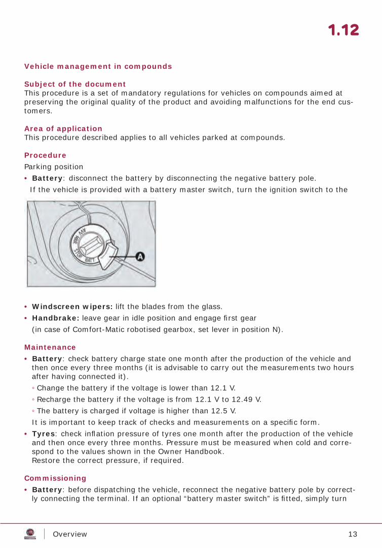
ProcedureParking position • Battery: disconnect the battery by disconnecting the negative battery pole.
If the vehicle is provided with a battery master switch, turn the ignition switch to the “BATT” position.
• Windscreen wipers: lift the blades from the glass. • Handbrake: leave gear in idle position and engage fi rst gear
(in case of Comfort-Matic robotised gearbox, set lever in position N).
Maintenance• Battery: check battery charge state one month after the production of the vehicle and
then once every three months (it is advisable to carry out the measurements two hours after having connected it). ◦ Change the battery if the voltage is lower than 12.1 V. ◦ Recharge the battery if the voltage is from 12.1 V to 12.49 V. ◦ The battery is charged if voltage is higher than 12.5 V.It is important to keep track of checks and measurements on a specifi c form.
• Tyres: check infl ation pressure of tyres one month after the production of the vehicle and then once every three months. Pressure must be measured when cold and corre-spond to the values shown in the Owner Handbook.Restore the correct pressure, if required.
Commissioning• Battery: before dispatching the vehicle, reconnect the negative battery pole by correct-
ly connecting the terminal. If an optional “battery master switch” is fi tted, simply turn
14Overview
1.13
the key to the “MAR” position. • Tyres: re-establish correct pressure.• Fuel: for storage over three months, pour antibacterial protection in the tank
(e.g. Petronas “Tutela Professional Diesel TMF PLUS”).
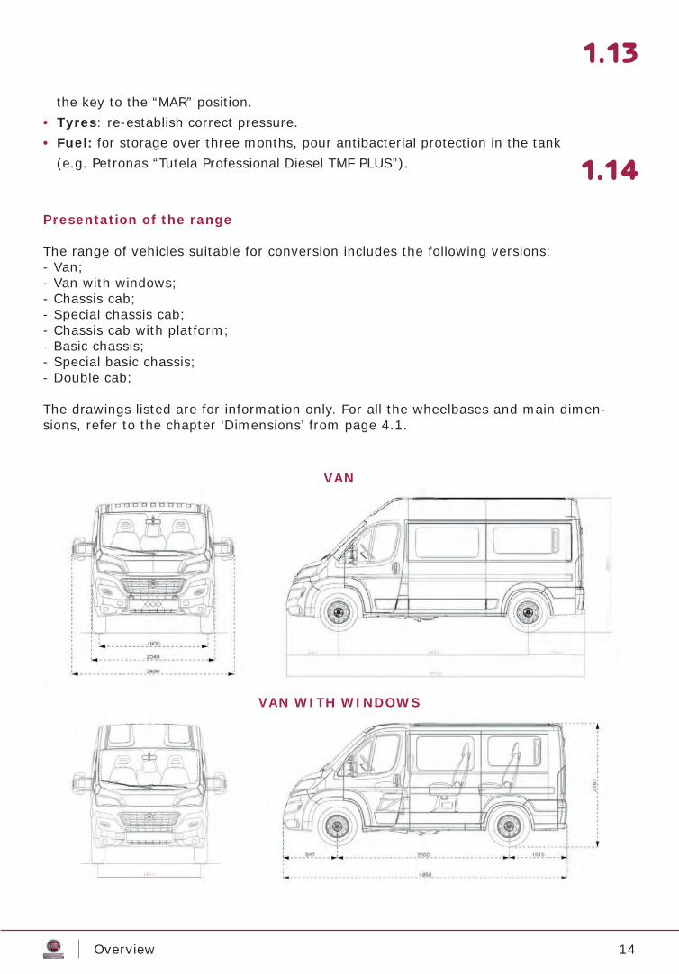
Presentation of the range
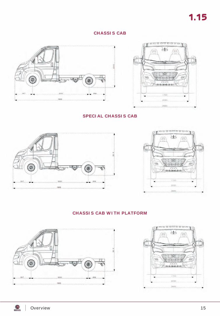
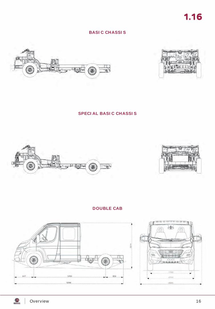
The range of vehicles suitable for conversion includes the following versions:- Van;- Van with windows;- Chassis cab;- Special chassis cab;- Chassis cab with platform;- Basic chassis;- Special basic chassis;- Double cab;
The drawings listed are for information only. For all the wheelbases and main dimen-sions, refer to the chapter ‘Dimensions’ from page 4.1.
1.14
VAN
VAN WITH WINDOWS
15Overview
1.15
SPECIAL CHASSIS CAB
CHASSIS CAB WITH PLATFORM
CHASSIS CAB
16Overview
1.16
SPECIAL BASIC CHASSIS
DOUBLE CAB
BASIC CHASSIS
17Bodywork and Chassis
2.1
Maximum permitted weightsTowing capacityCentre of gravityProfi le limitsModifying rear overhangChassis cab lengthening limitsOverhang lengthening methodsTow hookAttachment pre-fi ttingsFinishing elementsIndications for modifying frontModifi cations to the roofWheel arch dimensionsWheels and suspensionCab habitability diagram (van version)Spare wheelRelocation of spare wheel for chassis cab and basic chassis versionsIndications for connecting superstructuresFitting the counterframePlan and reference holes for superstructure application(Camping Car)Side load retentionInstructions for eliminating ‘Crash box’ cross membersFuel supply systemPiping technical specifi cationsFitting a roof rackSections of roof rack attachment pointsPositioning attachmentsOpening of a hatch in the roofMaking a window in the sideInstalling heaterFittings for supplementary heater/air-conditionerAir suspensionChanges to the wheelbaseESC system
2.22.42.52.62.72.8
2.102.122.132.142.152.162.182.192.202.212.222.232.24
2.252.332.372.382.392.402.412.442.452.462.472.482.502.532.54
BODYWORK AND CHASSIS
18Bodywork and Chassis
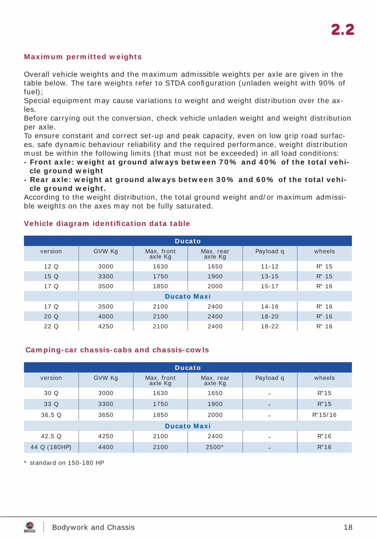
Maximum permitted weights
Overall vehicle weights and the maximum admissible weights per axle are given in the table below. The tare weights refer to STDA confi guration (unladen weight with 90% of fuel); Special equipment may cause variations to weight and weight distribution over the ax-les.Before carrying out the conversion, check vehicle unladen weight and weight distribution per axle.To ensure constant and correct set-up and peak capacity, even on low grip road surfac-es, safe dynamic behaviour reliability and the required performance, weight distribution must be within the following limits (that must not be exceeded) in all load conditions:- Front axle: weight at ground always between 70% and 40% of the total vehi-
cle ground weight- Rear axle: weight at ground always between 30% and 60% of the total vehi-
cle ground weight.According to the weight distribution, the total ground weight and/or maximum admissi-ble weights on the axes may not be fully saturated.
Vehicle diagram identifi cation data table
2.2
Ducatoversion GVW Kg Max. front
axle KgMax. rear axle Kg
Payload q wheels
12 Q 3000 1630 1650 11-12 R” 1515 Q 3300 1750 1900 13-15 R” 1517 Q 3500 1850 2000 15-17 R” 16
Ducato Maxi17 Q 3500 2100 2400 14-16 R” 1620 Q 4000 2100 2400 18-20 R” 1622 Q 4250 2100 2400 18-22 R” 16
Camping-car chassis-cabs and chassis-cowls
* standard on 150-180 HP
Ducatoversion GVW Kg Max. front
axle KgMax. rear axle Kg
Payload q wheels
30 Q 3000 1630 1650 - R”15
33 Q 3300 1750 1900 - R”15
36,5 Q 3650 1850 2000 - R”15/16
Ducato Maxi42,5 Q 4250 2100 2400 - R”16
44 Q (180HP) 4400 2100 2500* - R”16
19Bodywork and Chassis
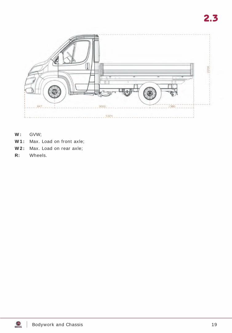
W: GVW;W1: Max. Load on front axle;W2: Max. Load on rear axle;R: Wheels.
2.3
LLLLLLLLLLLL
20Bodywork and Chassis
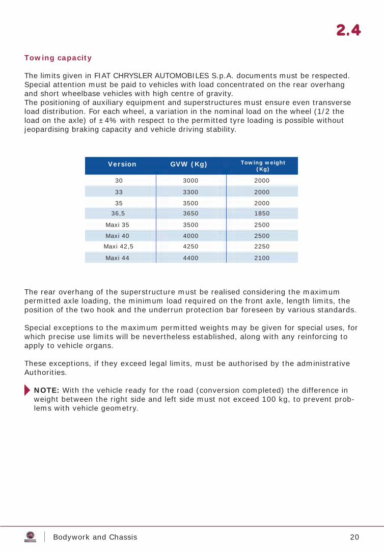
Towing capacity
The limits given in FIAT CHRYSLER AUTOMOBILES S.p.A. documents must be respected.Special attention must be paid to vehicles with load concentrated on the rear overhang and short wheelbase vehicles with high centre of gravity.The positioning of auxiliary equipment and superstructures must ensure even transverse load distribution. For each wheel, a variation in the nominal load on the wheel (1/2 the load on the axle) of ±4% with respect to the permitted tyre loading is possible without jeopardising braking capacity and vehicle driving stability.
The rear overhang of the superstructure must be realised considering the maximum permitted axle loading, the minimum load required on the front axle, length limits, the position of the two hook and the underrun protection bar foreseen by various standards.
Special exceptions to the maximum permitted weights may be given for special uses, for which precise use limits will be nevertheless established, along with any reinforcing to apply to vehicle organs.
These exceptions, if they exceed legal limits, must be authorised by the administrative Authorities.
NOTE: With the vehicle ready for the road (conversion completed) the difference in weight between the right side and left side must not exceed 100 kg, to prevent prob-lems with vehicle geometry.
2.4
GVW (Kg)Version Towing weight(Kg)
30 3000 2000
33 3300 2000
35 3500 200036,5 3650 1850
Maxi 35 3500 2500
Maxi 40 4000 2500
Maxi 42,5 4250 2250
Maxi 44 4400 2100
21Bodywork and Chassis
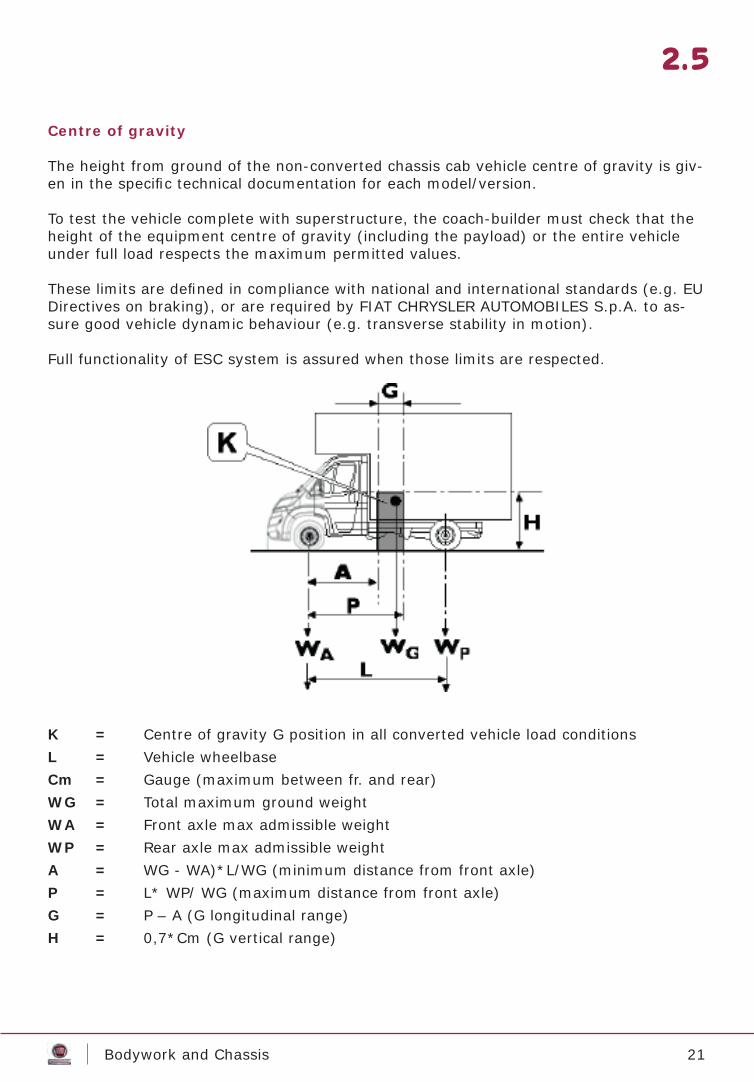
Centre of gravity
The height from ground of the non-converted chassis cab vehicle centre of gravity is giv-en in the specifi c technical documentation for each model/version.
To test the vehicle complete with superstructure, the coach-builder must check that the height of the equipment centre of gravity (including the payload) or the entire vehicle under full load respects the maximum permitted values.
These limits are defi ned in compliance with national and international standards (e.g. EU Directives on braking), or are required by FIAT CHRYSLER AUTOMOBILES S.p.A. to as-sure good vehicle dynamic behaviour (e.g. transverse stability in motion).
Full functionality of ESC system is assured when those limits are respected.
K = Centre of gravity G position in all converted vehicle load conditionsL = Vehicle wheelbaseCm = Gauge (maximum between fr. and rear)WG = Total maximum ground weightWA = Front axle max admissible weightWP = Rear axle max admissible weightA = WG - WA)*L/WG (minimum distance from front axle)P = L* WP/ WG (maximum distance from front axle)G = P – A (G longitudinal range)H = 0,7*Cm (G vertical range)
2.5
22Bodywork and Chassis
In version where the payload can shift sideways (e.g. suspended loads, transport of fl uids, etc.), higher dynamic loads may be generated when turning, resulting in re-duced vehicle stability. This must be considered in the vehicle operating instructions, or for any reductions to centre of gravity height.
Particular attention must be given to ensuring compliance with the weight limits es-tablished for the individual axles and the overall weight limit, also considering the foreseen number of passengers and a suffi cient margin for the loads that may be transported with them, such as:- luggage, tents, sports equipment;- water tank capacity, toilets;- gas bottles, etc.
2.6
23Bodywork and Chassis
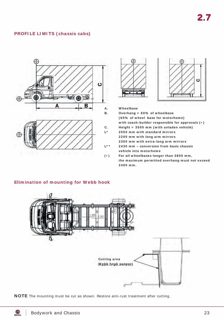
PROFILE LIMITS (chassis cabs)
Elimination of mounting for Webb hook
NOTE The mounting must be cut as shown. Restore anti-rust treatment after cutting.
2.7
A. WheelbaseB. Overhang = 60% of wheelbase (65% of wheel base for motorhome) with coach-builder responsible for approvals (•)C. Height = 3500 mm (with unladen vehicle)L* 2050 mm with standard mirrors 2200 mm with long arm mirrors 2350 mm with extra-long arm mirrorsL** 2430 mm – conversion from basic chassis vehicle into motorhome(•) For all wheelbases longer than 3800 mm, the maximum permitted overhang must not exceed 2400 mm.
Cutting areaWebb hook support
24Bodywork and Chassis
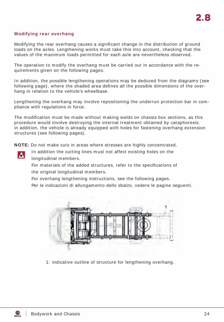
Modifying rear overhang
Modifying the rear overhang causes a signifi cant change in the distribution of ground loads on the axles. Lengthening works must take this into account, checking that the values of the maximum loads permitted for each axle are nevertheless observed.
The operation to modify the overhang must be carried out in accordance with the re-quirements given on the following pages.
In addition, the possible lengthening operations may be deduced from the diagrams (see following page), where the shaded area defi nes all the possible dimensions of the over-hang in relation to the vehicle’s wheelbase.
Lengthening the overhang may involve repositioning the underrun protection bar in com-pliance with regulations in force.
The modifi cation must be made without making welds on chassis box sections, as this procedure would involve destroying the internal treatment obtained by cataphoresis; in addition, the vehicle is already equipped with holes for fastening overhang extension structures (see following pages).
NOTE: Do not make cuts in areas where stresses are highly concentrated. In addition the cutting lines must not affect existing holes on the longitudinal members. For materials of the added structures, refer to the specifi cations of the original longitudinal members. For overhang lengthening instructions, see the following pages. Per le indicazioni di allungamento dello sbalzo, vedere le pagine seguenti.
1: indicative outline of structure for lengthening overhang.
2.8
25Bodywork and Chassis
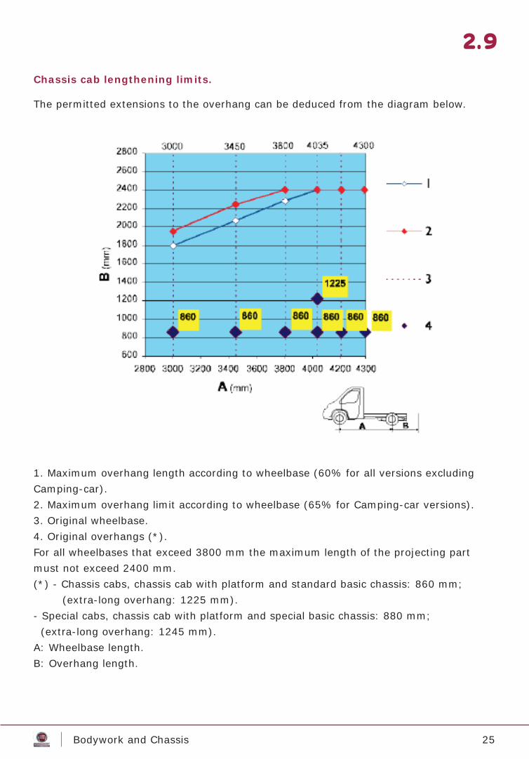
Chassis cab lengthening limits.
The permitted extensions to the overhang can be deduced from the diagram below.
1. Maximum overhang length according to wheelbase (60% for all versions excluding Camping-car).2. Maximum overhang limit according to wheelbase (65% for Camping-car versions).3. Original wheelbase.4. Original overhangs (*).For all wheelbases that exceed 3800 mm the maximum length of the projecting partmust not exceed 2400 mm.(*) - Chassis cabs, chassis cab with platform and standard basic chassis: 860 mm; (extra-long overhang: 1225 mm).- Special cabs, chassis cab with platform and special basic chassis: 880 mm; (extra-long overhang: 1245 mm).A: Wheelbase length.B: Overhang length.
2.9
26Bodywork and Chassis
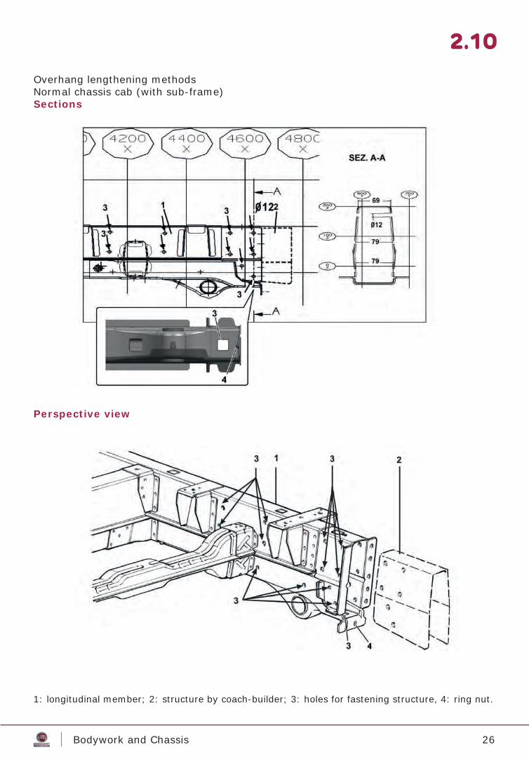
Overhang lengthening methodsNormal chassis cab (with sub-frame)Sections
Perspective view
1: longitudinal member; 2: structure by coach-builder; 3: holes for fastening structure, 4: ring nut.
2.10
27Bodywork and Chassis
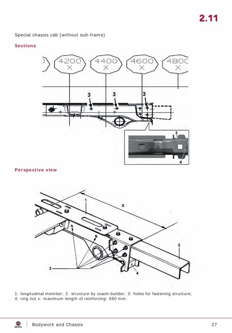
Special chassis cab (without sub-frame)
Sections
Perspective view
2.11
1: longitudinal member; 2: structure by coach-builder; 3: holes for fastening structure;4: ring nut x: maximum length of reinforcing: 560 mm.
28Bodywork and Chassis
Towing hook
OverviewA towing hook can be applied without requesting authorisation to FIAT CHRYSLER AU-TOMOBILES S.p.A. only on the specifi c cross-member provided and only on vehicles that FIAT CHRYSLER AUTOMOBILES S.p.A. has declared suitable for towing trailers.Installation of towing hooks on vehicles for which towing is not originally foreseen must be authorised by FIAT CHRYSLER AUTOMOBILES S.p.A..
NOTE: Since tow bars are an important element for vehicle driving safety, all limita-tions imposed by standards in force must be respected, such as minimum space for braking and electrical system connections, minimum distance between axles, towing pin and rear edge of superstructure.
In the case the dimension of the hook attachment fl ange does not coincide with the ex-isting holes on the vehicle transom bar, modifi cations can be authorised if suitable rein-forcing is applied.
2.12
29Bodywork and Chassis
2.13
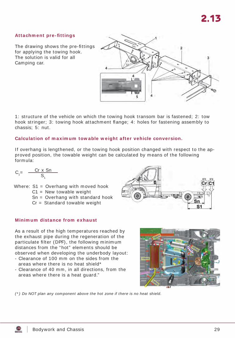
Attachment pre-fi ttings
The drawing shows the pre-fi ttings for applying the towing hook.The solution is valid for all Camping car.
Minimum distance from exhaust
As a result of the high temperatures reached by the exhaust pipe during the regeneration of the particulate fi lter (DPF), the following minimum distances from the “hot” elements should be observed when developing the underbody layout:- Clearance of 100 mm on the sides from the
areas where there is no heat shield*- Clearance of 40 mm, in all directions, from the
areas where there is a heat guard.”
1: structure of the vehicle on which the towing hook transom bar is fastened; 2: tow hook stringer; 3: towing hook attachment fl ange; 4: holes for fastening assembly to chassis; 5: nut.
Calculation of maximum towable weight after vehicle conversion.
If overhang is lengthened, or the towing hook position changed with respect to the ap-proved position, the towable weight can be calculated by means of the followingformula:
Cr x SnS1
Where: S1 = Overhang with moved hook C1 = New towable weight Sn = Overhang with standard hook Cr = Standard towable weight
Cr x SnS1
C1=
(*) Do NOT plan any component above the hot zone if there is no heat shield.
30Bodywork and Chassis
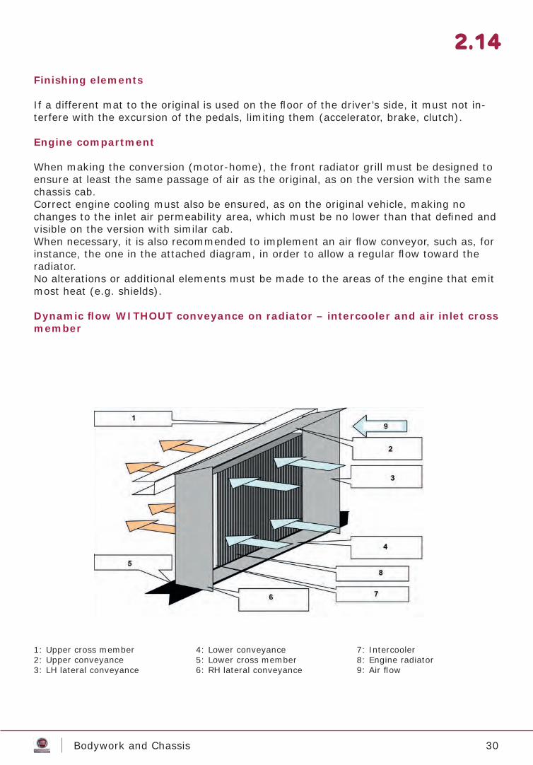
Finishing elements
If a different mat to the original is used on the fl oor of the driver’s side, it must not in-terfere with the excursion of the pedals, limiting them (accelerator, brake, clutch).
Engine compartment
When making the conversion (motor-home), the front radiator grill must be designed to ensure at least the same passage of air as the original, as on the version with the same chassis cab.Correct engine cooling must also be ensured, as on the original vehicle, making no changes to the inlet air permeability area, which must be no lower than that defi ned and visible on the version with similar cab.When necessary, it is also recommended to implement an air fl ow conveyor, such as, for instance, the one in the attached diagram, in order to allow a regular fl ow toward the radiator.No alterations or additional elements must be made to the areas of the engine that emit most heat (e.g. shields).
Dynamic fl ow WITHOUT conveyance on radiator – intercooler and air inlet cross member
1: Upper cross member2: Upper conveyance3: LH lateral conveyance
4: Lower conveyance5: Lower cross member6: RH lateral conveyance
7: Intercooler8: Engine radiator9: Air fl ow
2.14
31Bodywork and Chassis
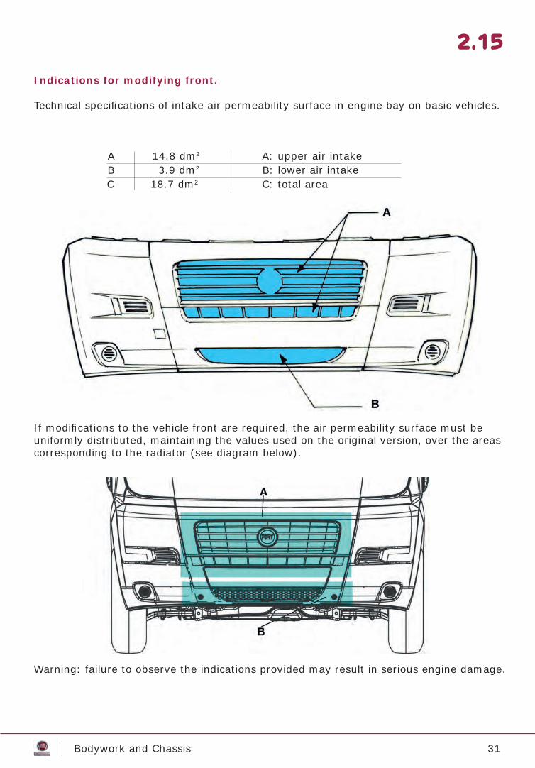
Indications for modifying front.
Technical specifi cations of intake air permeability surface in engine bay on basic vehicles.
If modifi cations to the vehicle front are required, the air permeability surface must be uniformly distributed, maintaining the values used on the original version, over the areas corresponding to the radiator (see diagram below).
Warning: failure to observe the indications provided may result in serious engine damage.
2.15
A 14.8 dm2 A: upper air intakeB 3.9 dm2 B: lower air intakeC 18.7 dm2 C: total area
32Bodywork and Chassis
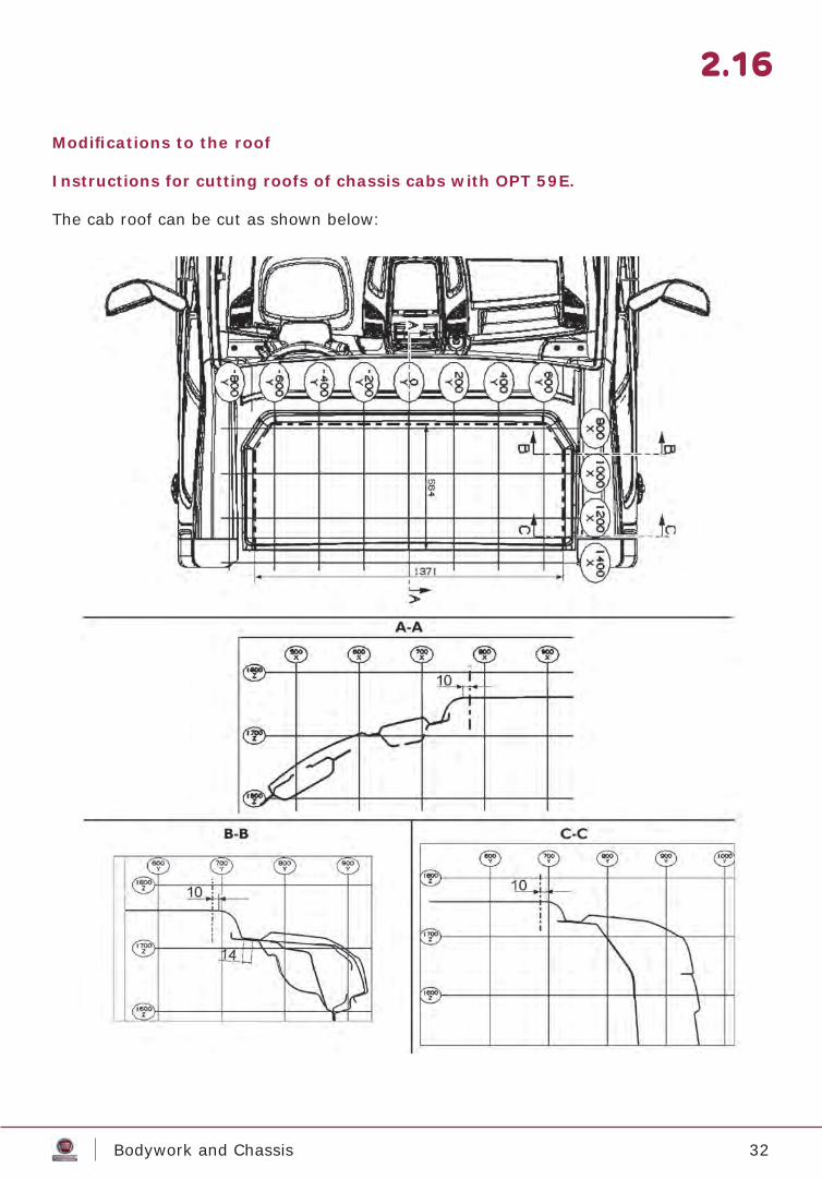
Modifi cations to the roof
Instructions for cutting roofs of chassis cabs with OPT 59E.
The cab roof can be cut as shown below:
2.16
33Bodywork and Chassis
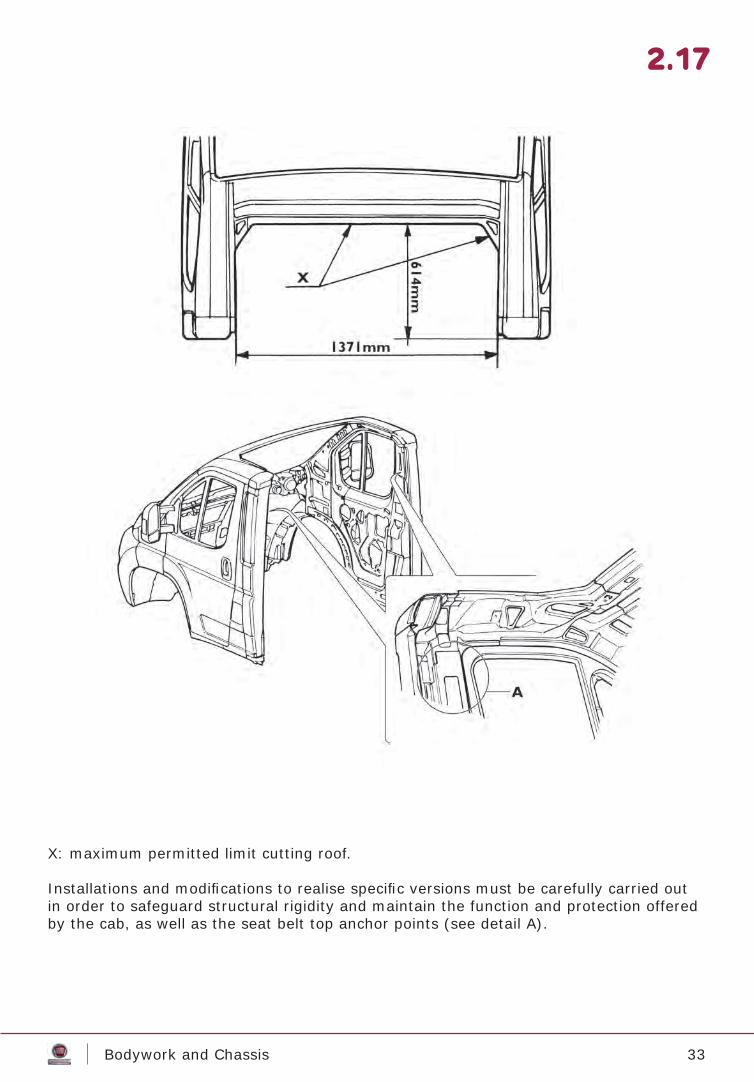
X: maximum permitted limit cutting roof.
Installations and modifi cations to realise specifi c versions must be carefully carried out in order to safeguard structural rigidity and maintain the function and protection offered by the cab, as well as the seat belt top anchor points (see detail A).
2.17
34Bodywork and Chassis
2.18
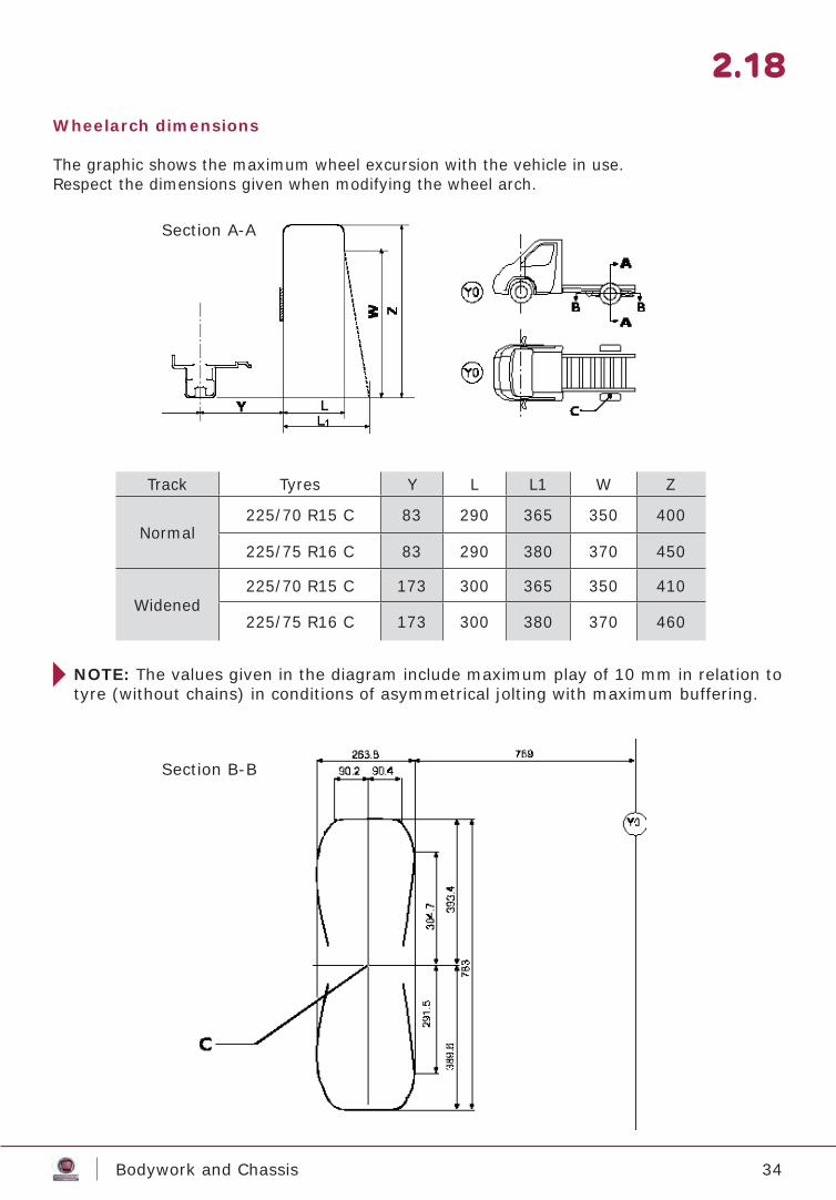
Wheelarch dimensions
The graphic shows the maximum wheel excursion with the vehicle in use.Respect the dimensions given when modifying the wheel arch.
NOTE: The values given in the diagram include maximum play of 10 mm in relation to tyre (without chains) in conditions of asymmetrical jolting with maximum buffering.
Section A-A
Section B-B
Track Tyres Y L L1 W Z
Normal225/70 R15 C 83 290 365 350 400
225/75 R16 C 83 290 380 370 450
Widened225/70 R15 C 173 300 365 350 410
225/75 R16 C 173 300 380 370 460
35Bodywork and Chassis
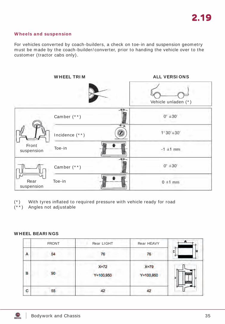
Wheels and suspension
For vehicles converted by coach-builders, a check on toe-in and suspension geometry must be made by the coach-builder/converter, prior to handing the vehicle over to the customer (tractor cabs only).
2.19
WHEEL TRIM
WHEEL BEARINGS
ALL VERSIONS
Camber (**)
Vehicle unladen (*)
Incidence (**)
Toe-in
Camber (**)
Toe-in
Frontsuspension
Rear suspension
(*) With tyres infl ated to required pressure with vehicle ready for road(**) Angles not adjustable
FRONT Rear LIGHT Rear HEAVY
36Bodywork and Chassis
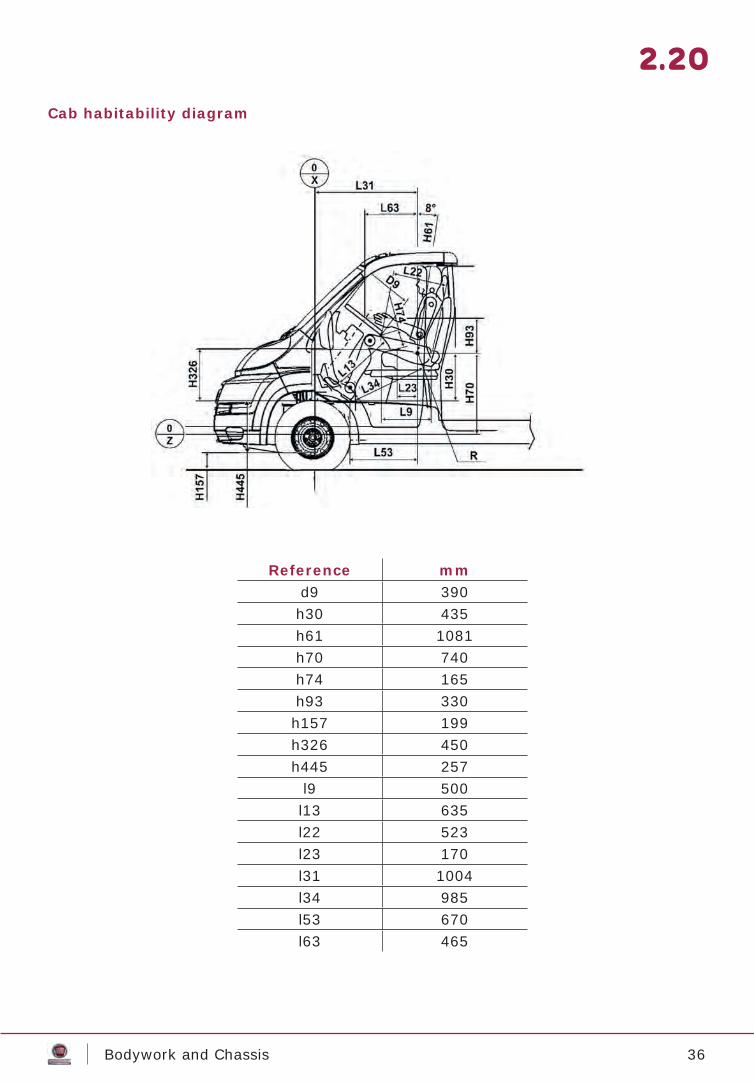
Cab habitability diagram
2.20
Reference mmd9 390h30 435h61 1081h70 740h74 165h93 330h157 199h326 450h445 257
l9 500l13 635l22 523l23 170l31 1004l34 985l53 670l63 465
37Bodywork and Chassis
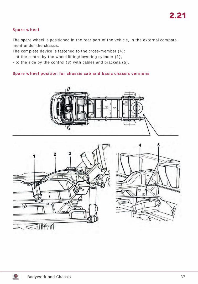
Spare wheel
The spare wheel is positioned in the rear part of the vehicle, in the external compart-ment under the chassis.The complete device is fastened to the cross-member (4):- at the centre by the wheel lifting/lowering cylinder (1),- to the side by the control (3) with cables and brackets (5).
Spare wheel position for chassis cab and basic chassis versions
2.21
38Bodywork and Chassis
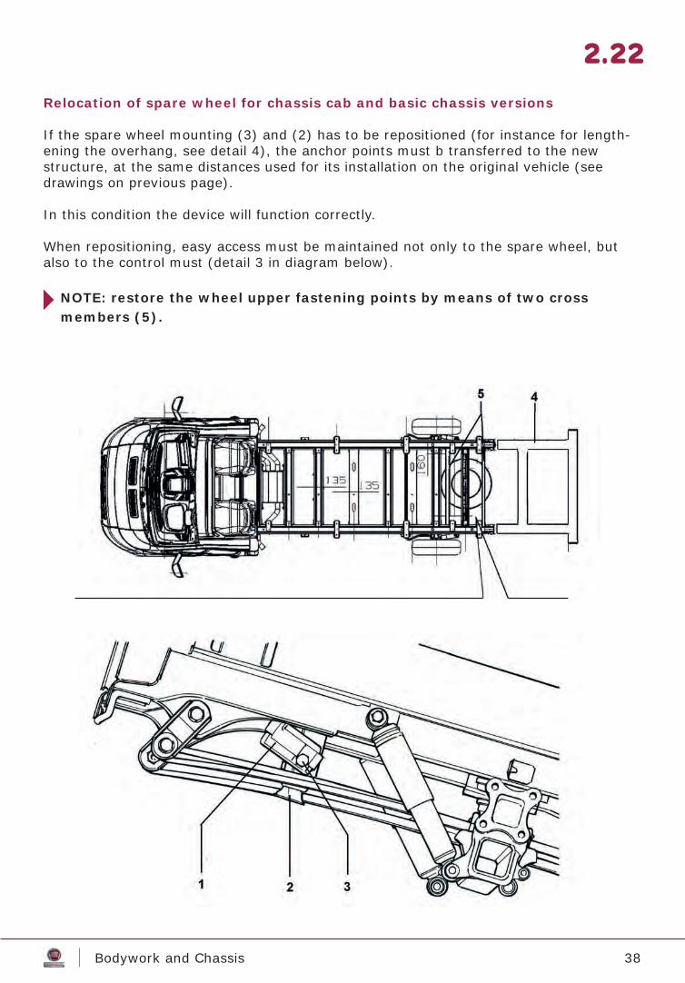
Relocation of spare wheel for chassis cab and basic chassis versions
If the spare wheel mounting (3) and (2) has to be repositioned (for instance for length-ening the overhang, see detail 4), the anchor points must b transferred to the new structure, at the same distances used for its installation on the original vehicle (see drawings on previous page).
In this condition the device will function correctly.
When repositioning, easy access must be maintained not only to the spare wheel, but also to the control must (detail 3 in diagram below).
NOTE: restore the wheel upper fastening points by means of two crossmembers (5).
2.22
39Bodywork and Chassis
Indications for connecting superstructures
Drilling holes in the chassis
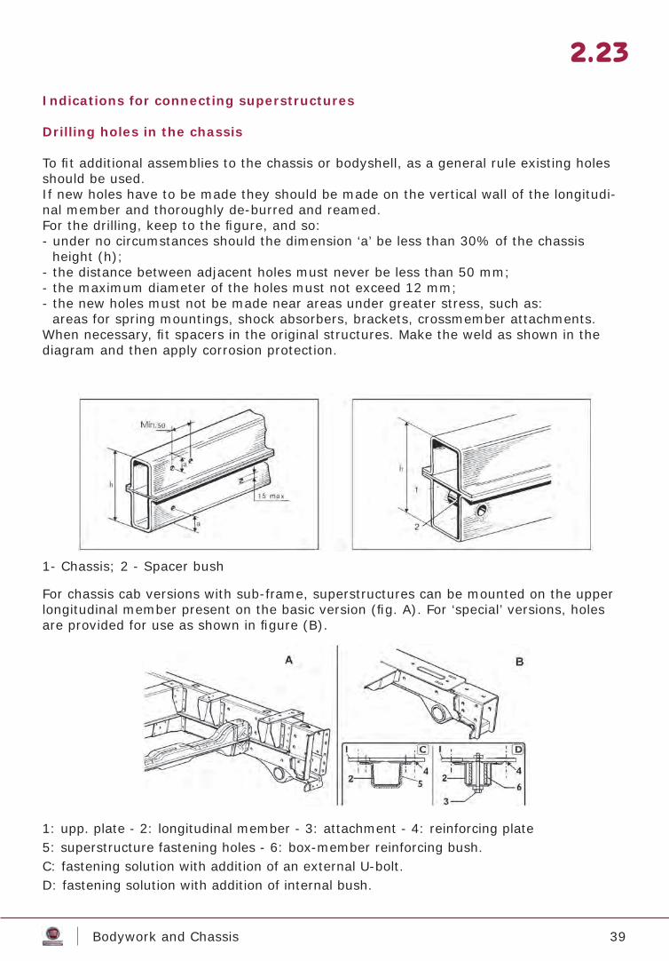
To fi t additional assemblies to the chassis or bodyshell, as a general rule existing holes should be used.If new holes have to be made they should be made on the vertical wall of the longitudi-nal member and thoroughly de-burred and reamed.For the drilling, keep to the fi gure, and so:- under no circumstances should the dimension ‘a’ be less than 30% of the chassis
height (h);- the distance between adjacent holes must never be less than 50 mm;- the maximum diameter of the holes must not exceed 12 mm;- the new holes must not be made near areas under greater stress, such as:
areas for spring mountings, shock absorbers, brackets, crossmember attachments.When necessary, fi t spacers in the original structures. Make the weld as shown in the diagram and then apply corrosion protection.
For chassis cab versions with sub-frame, superstructures can be mounted on the upper longitudinal member present on the basic version (fi g. A). For ‘special’ versions, holes are provided for use as shown in fi gure (B).
1: upp. plate - 2: longitudinal member - 3: attachment - 4: reinforcing plate5: superstructure fastening holes - 6: box-member reinforcing bush.C: fastening solution with addition of an external U-bolt.D: fastening solution with addition of internal bush.
1- Chassis; 2 - Spacer bush
2.23
40Bodywork and Chassis
Fitting the counterframe
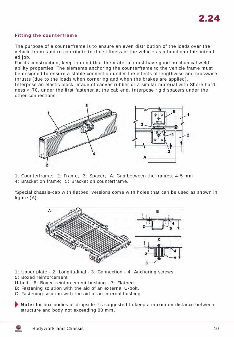
The purpose of a counterframe is to ensure an even distribution of the loads over the vehicle frame and to contribute to the stiffness of the vehicle as a function of its intend-ed job.For its construction, keep in mind that the material must have good mechanical weld-ability properties. The elements anchoring the counterframe to the vehicle frame must be designed to ensure a stable connection under the effects of lengthwise and crosswise thrusts (due to the loads when cornering and when the brakes are applied).Interpose an elastic block, made of canvas rubber or a similar material with Shore hard-ness < 70, under the fi rst fastener at the cab end. Interpose rigid spacers under the other connections.
1: Counterframe; 2: Frame; 3: Spacer; A: Gap between the frames: 4-5 mm.4: Bracket on frame; 5: Bracket on counterframe.
‘Special chassis-cab with fl atbed’ versions come with holes that can be used as shown in fi gure (A).
1: Upper plate - 2: Longitudinal - 3: Connection - 4: Anchoring screws5: Boxed reinforcement U-bolt - 6: Boxed reinforcement bushing - 7: Flatbed.B: Fastening solution with the aid of an external U-bolt.C: Fastening solution with the aid of an internal bushing.
Note: for box-bodies or dropside it’s suggested to keep a maximum distance between structure and body not exceeding 80 mm.
2.24
41Bodywork and Chassis
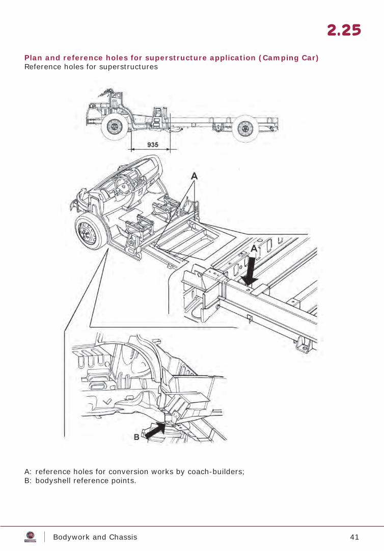
Plan and reference holes for superstructure application (Camping Car)Reference holes for superstructures
A: reference holes for conversion works by coach-builders;B: bodyshell reference points.
2.25

42Bodywork and Chassis
Cab interface for application of superstructure (Camping Car)
1: structural reinforcement; 2: recommended interface area; 3: direction of travel.
In the ‘cut roof’ chassis cab version the angular structure of the side/rear wall, has rein-forcement (1).If it is considered necessary to interface a new structure with the cab of the basic vehi-cle, we recommend using the reinforcement (1) as anchor point in the indicated position (�).The confi guration of the basic vehicle structure, shown in section A-A, is the same along the entire area indicated in the drawing by (2).The drawing shows the recommended distances between the various interface points between the structures.
2.26
43Bodywork and Chassis
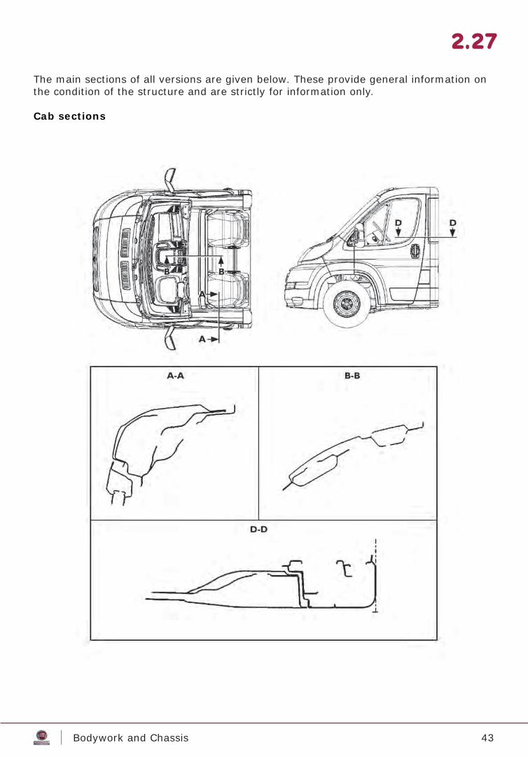
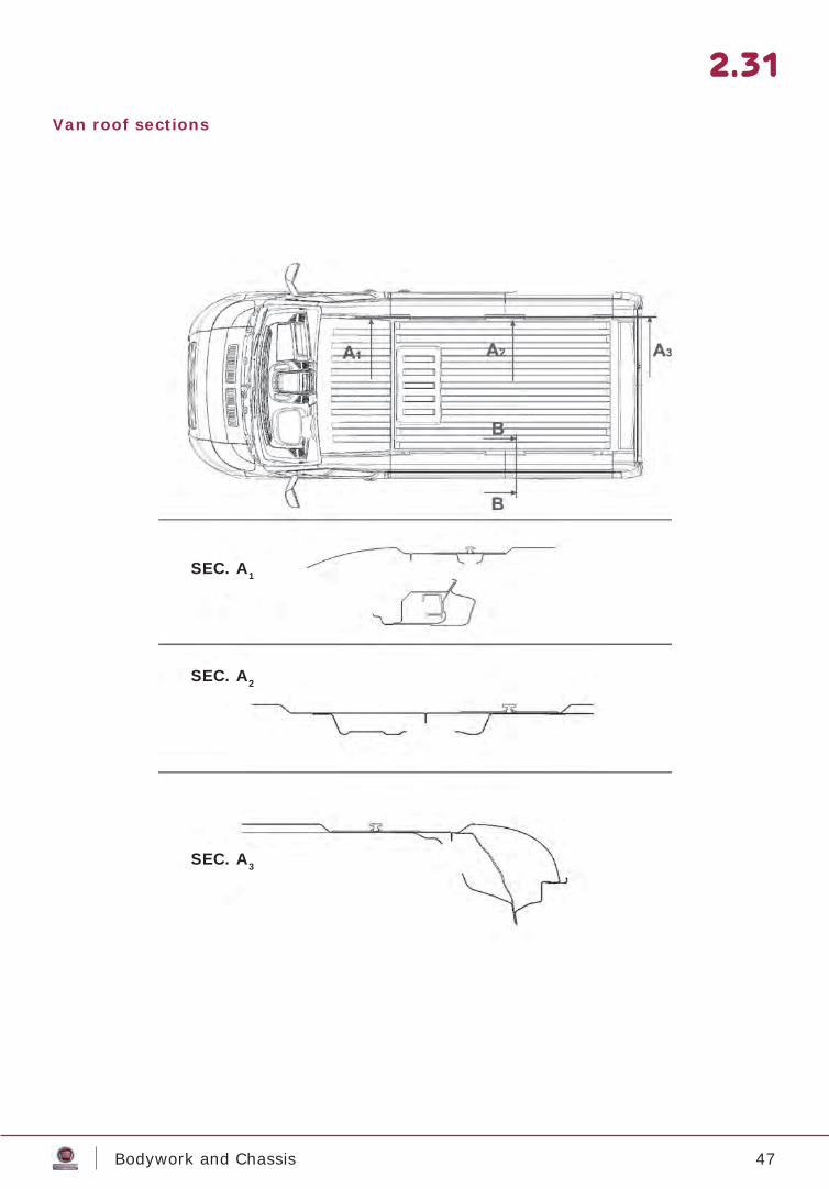
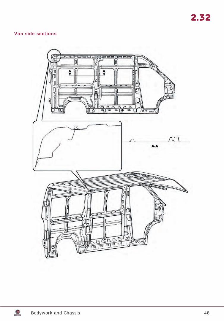
The main sections of all versions are given below. These provide general information on the condition of the structure and are strictly for information only.
Cab sections
2.27
44Bodywork and Chassis
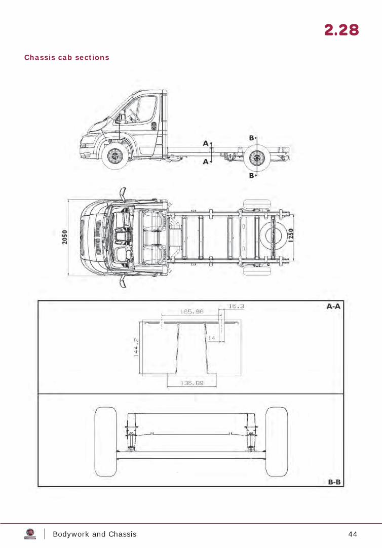
Chassis cab sections
2.28
45Bodywork and Chassis
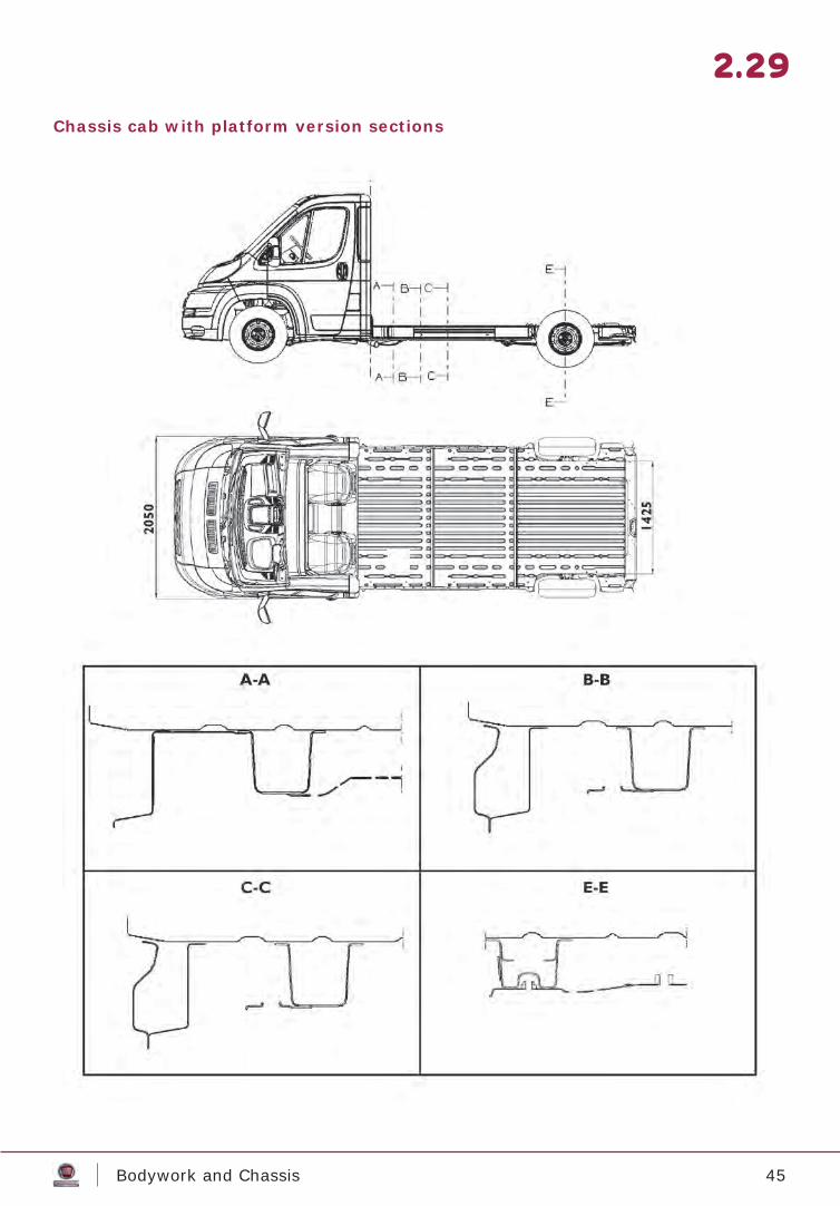
Chassis cab with platform version sections
2.29
46Bodywork and Chassis
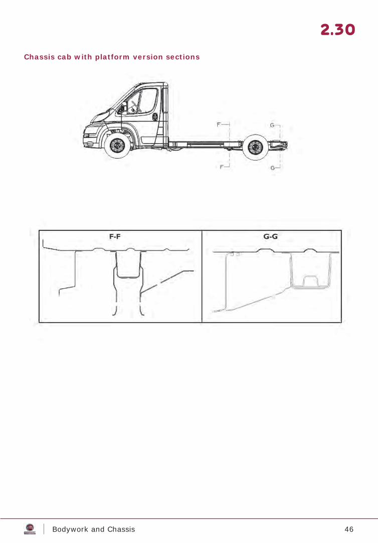
Chassis cab with platform version sections
2.30
47Bodywork and Chassis
Van roof sections
2.31
SEC. A1
SEC. A2
SEC. A3
48Bodywork and Chassis
Van side sections
2.32
49Bodywork and Chassis
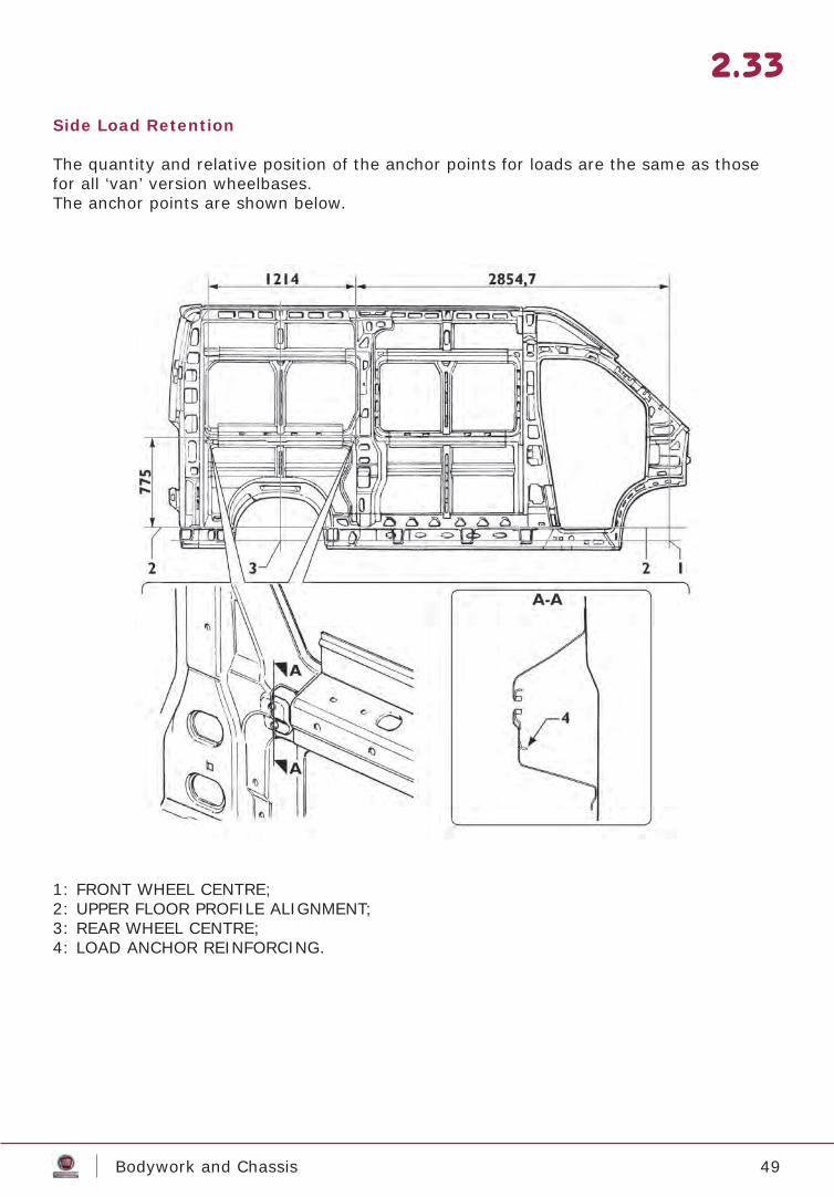
Side Load Retention
The quantity and relative position of the anchor points for loads are the same as those for all ‘van’ version wheelbases.The anchor points are shown below.
1: FRONT WHEEL CENTRE;2: UPPER FLOOR PROFILE ALIGNMENT;3: REAR WHEEL CENTRE;4: LOAD ANCHOR REINFORCING.
2.33
50Bodywork and Chassis
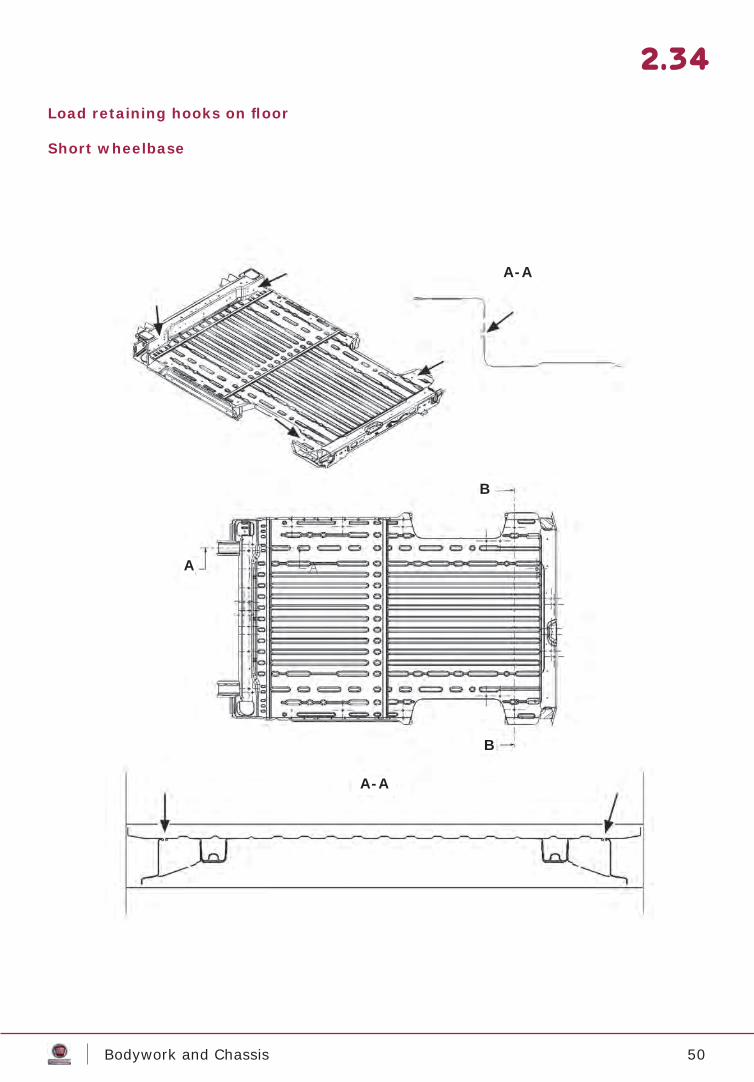
Load retaining hooks on fl oor
Short wheelbase
2.34
A-A
B
B
A
A-A
51Bodywork and Chassis
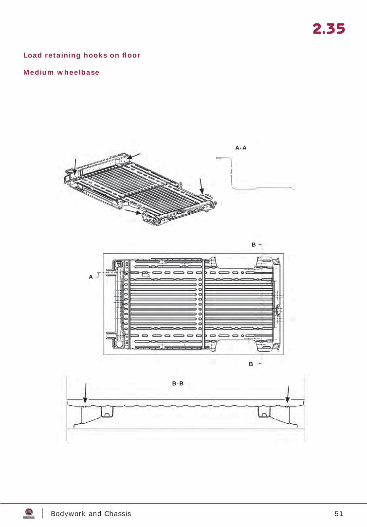
Load retaining hooks on fl oor
Medium wheelbase
2.35
A-A
B
B
B-B
A
52Bodywork and Chassis
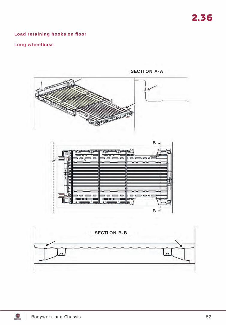
Load retaining hooks on fl oor
Long wheelbase
2.36
SECTION A-A
SECTION B-B
B
B
53Bodywork and Chassis
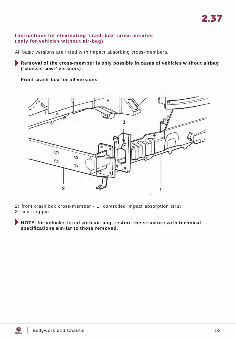
Instructions for eliminating ‘crash box’ cross member(only for vehicles without air-bag)
All basic versions are fi tted with impact absorbing cross-members.
Removal of the cross-member is only possible in cases of vehicles without airbag (‘chassis-cowl’ versions).
Front crash-box for all versions
2: front crash box cross-member - 1: controlled impact absorption strut3: centring pin.
NOTE: for vehicles fi tted with air-bag, restore the structure with technicalspecifi cations similar to those removed.
2.37
54Bodywork and Chassis
2.38
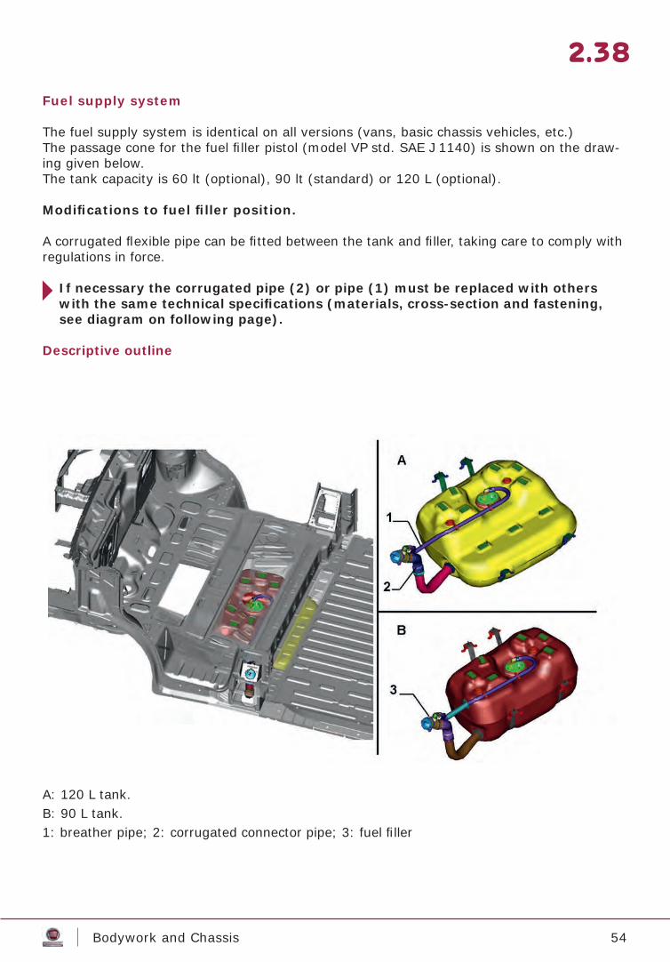
Fuel supply system
The fuel supply system is identical on all versions (vans, basic chassis vehicles, etc.)The passage cone for the fuel fi ller pistol (model VP std. SAE J 1140) is shown on the draw-ing given below.The tank capacity is 60 lt (optional), 90 lt (standard) or 120 L (optional).
Modifi cations to fuel fi ller position.
A corrugated fl exible pipe can be fi tted between the tank and fi ller, taking care to comply with regulations in force.
If necessary the corrugated pipe (2) or pipe (1) must be replaced with others with the same technical specifi cations (materials, cross-section and fastening, see diagram on following page).
Descriptive outline
A: 120 L tank.B: 90 L tank.1: breather pipe; 2: corrugated connector pipe; 3: fuel fi ller
55Bodywork and Chassis
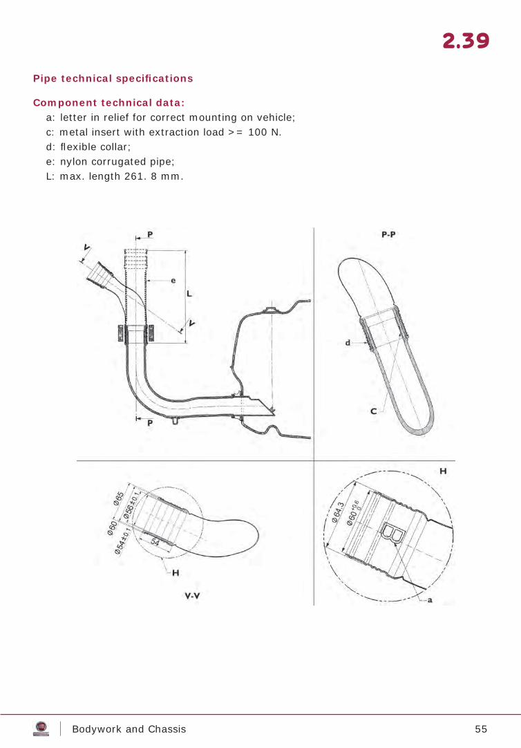
Pipe technical specifi cations
Component technical data:a: letter in relief for correct mounting on vehicle;c: metal insert with extraction load >= 100 N.d: fl exible collar;e: nylon corrugated pipe;L: max. length 261. 8 mm.
2.39
56Bodywork and Chassis
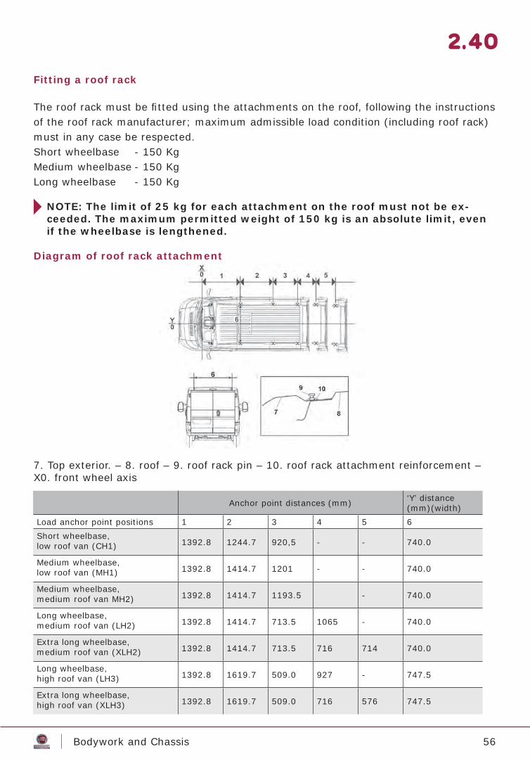
Fitting a roof rack
The roof rack must be fi tted using the attachments on the roof, following the instructions of the roof rack manufacturer; maximum admissible load condition (including roof rack) must in any case be respected.Short wheelbase - 150 Kg Medium wheelbase - 150 Kg Long wheelbase - 150 Kg
NOTE: The limit of 25 kg for each attachment on the roof must not be ex-ceeded. The maximum permitted weight of 150 kg is an absolute limit, even if the wheelbase is lengthened.
Diagram of roof rack attachment
7. Top exterior. – 8. roof – 9. roof rack pin – 10. roof rack attachment reinforcement – X0. front wheel axis
2.40
Anchor point distances (mm) ‘Y’ distance(mm)(width)
Load anchor point positions 1 2 3 4 5 6Short wheelbase,low roof van (CH1) 1392.8 1244.7 920,5 - - 740.0
Medium wheelbase,low roof van (MH1) 1392.8 1414.7 1201 - - 740.0
Medium wheelbase,medium roof van MH2) 1392.8 1414.7 1193.5 - 740.0
Long wheelbase,medium roof van (LH2) 1392.8 1414.7 713.5 1065 - 740.0
Extra long wheelbase,medium roof van (XLH2) 1392.8 1414.7 713.5 716 714 740.0
Long wheelbase,high roof van (LH3) 1392.8 1619.7 509.0 927 - 747.5
Extra long wheelbase,high roof van (XLH3) 1392.8 1619.7 509.0 716 576 747.5
57Bodywork and Chassis
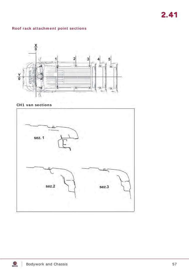
Roof rack attachment point sections
2.41
CH1 van sections

58Bodywork and Chassis
Roof rack attachment point sections
2.42
MH2 - LH2MH2 – LH2 van sections
sec. 1
sec. 2
sec. 3
59Bodywork and Chassis
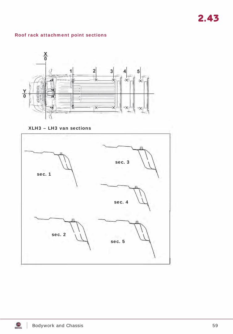
Roof rack attachment point sections
2.43
XLH3 - LH3XLH3 – LH3 van sections
sec. 1
sec. 2
sec. 3
sec. 4
sec. 5
60Bodywork and Chassis
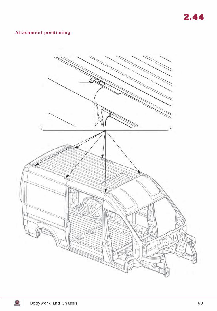
Attachment positioning
2.44
61Bodywork and Chassis
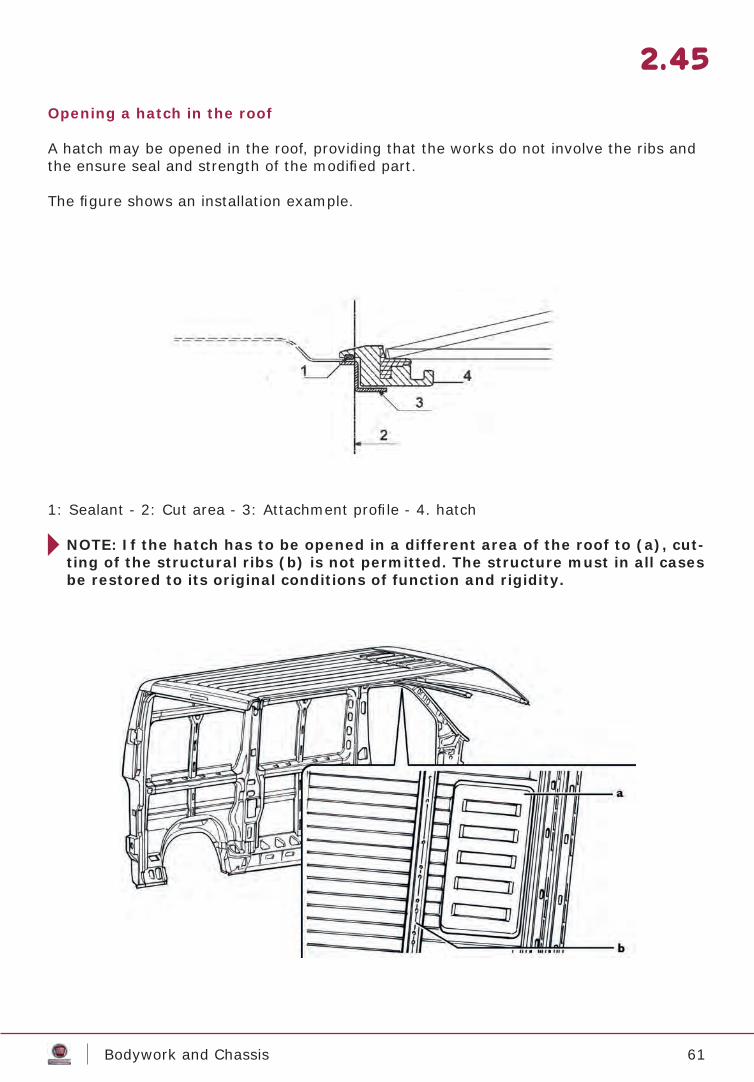
Opening a hatch in the roof
A hatch may be opened in the roof, providing that the works do not involve the ribs and the ensure seal and strength of the modifi ed part.
The fi gure shows an installation example.
1: Sealant - 2: Cut area - 3: Attachment profi le - 4. hatch
NOTE: If the hatch has to be opened in a different area of the roof to (a), cut-ting of the structural ribs (b) is not permitted. The structure must in all cases be restored to its original conditions of function and rigidity.
2.45
62Bodywork and Chassis
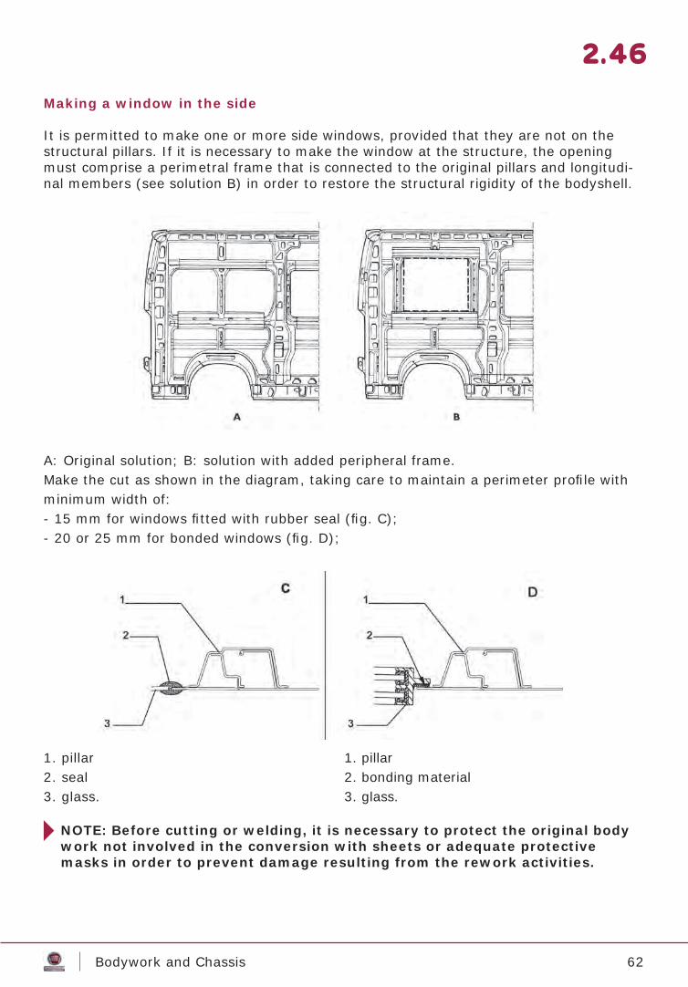
Making a window in the side
It is permitted to make one or more side windows, provided that they are not on the structural pillars. If it is necessary to make the window at the structure, the opening must comprise a perimetral frame that is connected to the original pillars and longitudi-nal members (see solution B) in order to restore the structural rigidity of the bodyshell.
A: Original solution; B: solution with added peripheral frame.Make the cut as shown in the diagram, taking care to maintain a perimeter profi le with minimum width of:- 15 mm for windows fi tted with rubber seal (fi g. C);- 20 or 25 mm for bonded windows (fi g. D);
1. pillar2. seal3. glass.
1. pillar2. bonding material3. glass.
2.46
NOTE: Before cutting or welding, it is necessary to protect the original body work not involved in the conversion with sheets or adequate protective masks in order to prevent damage resulting from the rework activities.
63Bodywork and Chassis
Heater installation
If a supplementary heater is required, it is advisable to use only the types foreseen by FIAT CHRYSLER AUTOMOBILES S.p.A.For vehicles on which FIAT CHRYSLER AUTOMOBILES S.p.A. has not foreseen supplementary heaters, these must be installed according to the heater Manufacturer’s instructions (i.e. boiler, piping, electrical system arrangement etc.) and as per the instructions given below.All pertinent national regulations must be respected (i.e. testing, special versions for hazardous goods transport, etc.). The supplementary heater must not use vehicle systems subject to homologation, if their use may negatively alter performance.
In addition:- the correct function of vehicle components and systems must be safeguarded
(i.e. engine cooling);
- for the electrical system, check that battery capacity and alternator power aresuffi cient for the increased power absorption (see ELECTRICAL SYS. SECTION).Fit the new circuit with a fuse;
- for fuel supply, connect the supply system to an auxiliary fuel tank connected to the return pipe from the engine. Direct connection to the engine fuel tank is only permitted if this is independent to the engine supply lines and the new circuit has a hermetic seal;
- defi ne the routes of pipes and electrical cables, arrangement of brackets and fl exible joints, taking into account their dimensions and the affect of heat from the various components on the chassis. Avoid passages and arrangements with exposure that could present a hazard when travelling, adopting covers or guards wherever necessary;
- for water heaters, when the original vehicle heater and engine cooling circuits are involved, in order to obtain correct system function and ensure the original safety level:- defi ne the connection points between the supplementary system and the original
with special attention, if necessary in agreement with FIAT CHRYSLER AUTOMOBILES S.p.A.;
- arrange piping rationally, avoiding kinks and siphon sections;- apply breather valves to ensure correct system fi lling;- ensure the possibility of complete system drain, fi tting any additional plugs required;- adopt, where necessary, adequate protection to limit heat loss.
- In air heaters and in cases in which the heater is installed directly in the cabin, special attention must be given to the fl u (to prevent combustion gases accumulating in the interior) and the correct distribution of hot air, to avoid direct fl ows;
- The entire system must be installed to permit good accessibility and ensure rapid maintenance.
2.47
64Bodywork and Chassis
2.48
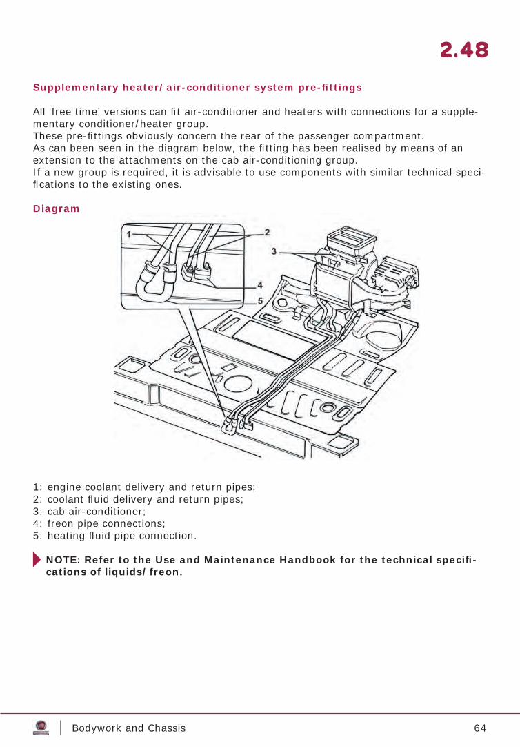
1: engine coolant delivery and return pipes;2: coolant fl uid delivery and return pipes;3: cab air-conditioner;4: freon pipe connections;5: heating fl uid pipe connection.
NOTE: Refer to the Use and Maintenance Handbook for the technical specifi -cations of liquids/freon.
Supplementary heater/air-conditioner system pre-fi ttings
All ‘free time’ versions can fi t air-conditioner and heaters with connections for a supple-mentary conditioner/heater group.These pre-fi ttings obviously concern the rear of the passenger compartment.As can been seen in the diagram below, the fi tting has been realised by means of an extension to the attachments on the cab air-conditioning group.If a new group is required, it is advisable to use components with similar technical speci-fi cations to the existing ones.
Diagram
65Bodywork and Chassis
2.49
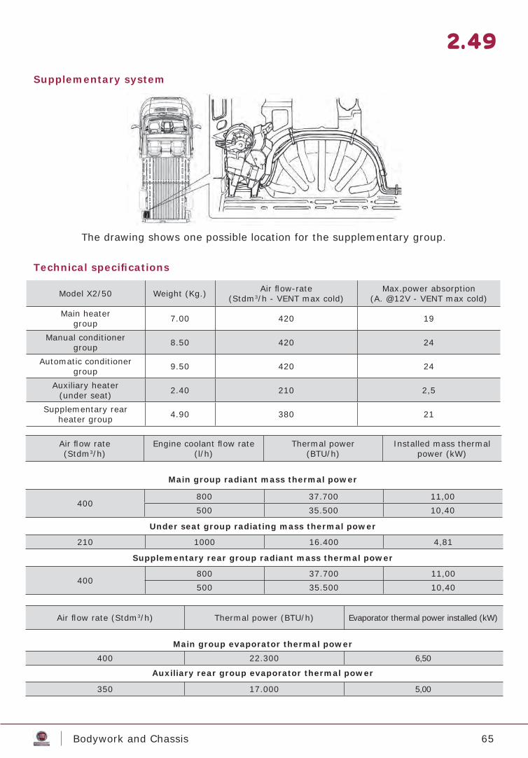
Supplementary system
Technical specifi cations
Main group radiant mass thermal power
Under seat group radiating mass thermal power
Supplementary rear group radiant mass thermal power
Main group evaporator thermal power
Auxiliary rear group evaporator thermal power
The drawing shows one possible location for the supplementary group.
Model X2/50 Weight (Kg.) Air fl ow-rate(Stdm3/h - VENT max cold)
Max.power absorption(A. @12V - VENT max cold)
Main heatergroup 7.00 420 19
Manual conditionergroup 8.50 420 24
Automatic conditioner group 9.50 420 24
Auxiliary heater(under seat) 2.40 210 2,5
Supplementary rearheater group 4.90 380 21
Air fl ow rate (Stdm3/h)
Engine coolant fl ow rate (l/h)
Thermal power(BTU/h)
Installed mass thermal power (kW)
400800 37.700 11,00500 35.500 10,40
210 1000 16.400 4,81
400800 37.700 11,00500 35.500 10,40
Air fl ow rate (Stdm3/h) Thermal power (BTU/h) Evaporator thermal power installed (kW)
400 22.300 6,50
350 17.000 5,00
66Bodywork and Chassis
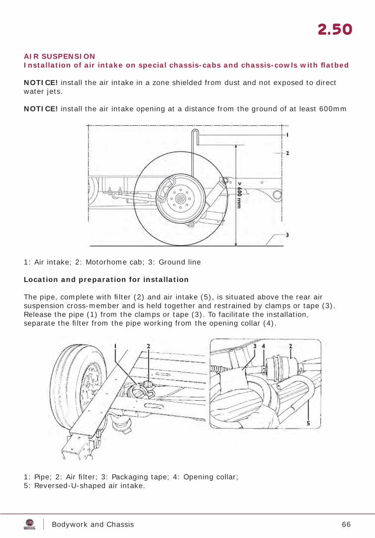
AIR SUSPENSIONInstallation of air intake on special chassis-cabs and chassis-cowls with fl atbed
NOTICE! install the air intake in a zone shielded from dust and not exposed to direct water jets.
NOTICE! install the air intake opening at a distance from the ground of at least 600mm
2.50
1: Air intake; 2: Motorhome cab; 3: Ground line
Location and preparation for installation
The pipe, complete with fi lter (2) and air intake (5), is situated above the rear airsuspension cross-member and is held together and restrained by clamps or tape (3).Release the pipe (1) from the clamps or tape (3). To facilitate the installation,separate the fi lter from the pipe working from the opening collar (4).
1: Pipe; 2: Air fi lter; 3: Packaging tape; 4: Opening collar;5: Reversed-U-shaped air intake.

67Bodywork and Chassis
2.51
Installation
In the fi gures below you will fi nd the indications on how to fi t the rubber pipe.
Drill a hole (3), of appropriate size for the passage of the rubber pipe, in the cab fl oor in the proximity of the left side wall and the rear suspension, as shown in the fi gure.
Introduce the reversed-U-shaped part (1) through the hole (3). Anchor it to the inner side of the left wall by means of a small bracket (2) and the relative fasteners.
Extend the pipe towards the inner part of the frame through the hole (4) in the longitu-dinal, which is not used due to the absence of the rear bushing for the connection of the mechanical suspension.
NOTICE! To ensure a suffi cient fl ow of air to the compressor, do not perforate the pipe and do reduce its cross-sectional area; the fl ow of intake air to the compressor must be in accordance with the specifi cations. - It is important that the end part of the pipe (1) retains the reversed U shape in order
to prevent the penetration of dust and water. The air intake (1) anchoring point must be positioned at a suffi cient distance from the ground, at least 600mm, in a dried, shielded area.
68Bodywork and Chassis
2.52
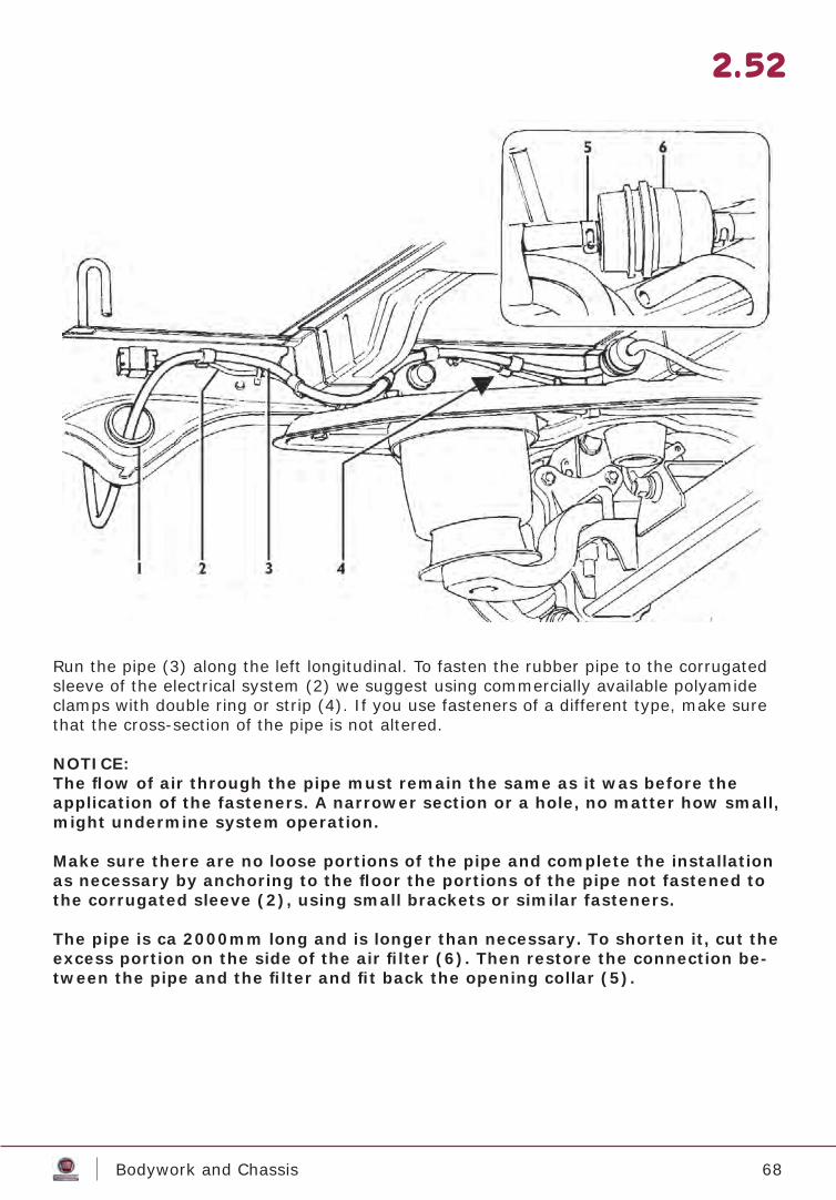
Run the pipe (3) along the left longitudinal. To fasten the rubber pipe to the corrugated sleeve of the electrical system (2) we suggest using commercially available polyamide clamps with double ring or strip (4). If you use fasteners of a different type, make sure that the cross-section of the pipe is not altered.
NOTICE:The fl ow of air through the pipe must remain the same as it was before the application of the fasteners. A narrower section or a hole, no matter how small, might undermine system operation.
Make sure there are no loose portions of the pipe and complete the installation as necessary by anchoring to the fl oor the portions of the pipe not fastened to the corrugated sleeve (2), using small brackets or similar fasteners.
The pipe is ca 2000mm long and is longer than necessary. To shorten it, cut the excess portion on the side of the air fi lter (6). Then restore the connection be-tween the pipe and the fi lter and fi t back the opening collar (5).
69Bodywork and Chassis
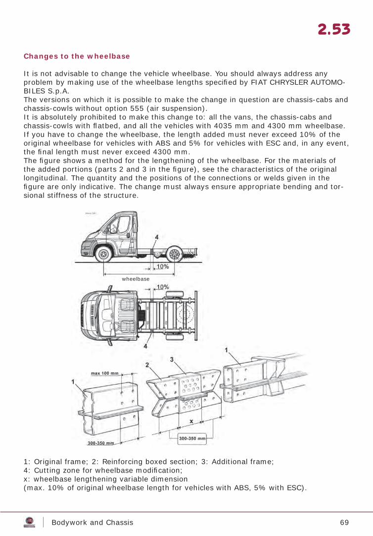
Changes to the wheelbase
It is not advisable to change the vehicle wheelbase. You should always address any problem by making use of the wheelbase lengths specifi ed by FIAT CHRYSLER AUTOMO-BILES S.p.A. The versions on which it is possible to make the change in question are chassis-cabs and chassis-cowls without option 555 (air suspension). It is absolutely prohibited to make this change to: all the vans, the chassis-cabs and chassis-cowls with fl atbed, and all the vehicles with 4035 mm and 4300 mm wheelbase.If you have to change the wheelbase, the length added must never exceed 10% of the original wheelbase for vehicles with ABS and 5% for vehicles with ESC and, in any event, the fi nal length must never exceed 4300 mm.The fi gure shows a method for the lengthening of the wheelbase. For the materials of the added portions (parts 2 and 3 in the fi gure), see the characteristics of the original longitudinal. The quantity and the positions of the connections or welds given in the fi gure are only indicative. The change must always ensure appropriate bending and tor-sional stiffness of the structure.
1: Original frame; 2: Reinforcing boxed section; 3: Additional frame;4: Cutting zone for wheelbase modifi cation;x: wheelbase lengthening variable dimension(max. 10% of original wheelbase length for vehicles with ABS, 5% with ESC).
2.53
wheelbase

70Bodywork and Chassis
2.54
ESC system – Electronic Stability Control
ESC system was developed considering the weight of a completely upfi tted vehicle in the respect of the limits indicated in this manual.When and only if the vehicles does respect the limits indicated at pag. 2.5 for weight distribution and positioning of the centre-of-mass, the full ESC system functionality is ensured, without needing further testing.

71Electrical system
ELECTRICAL SYSTEM
3.1
72Electrical system
3.2
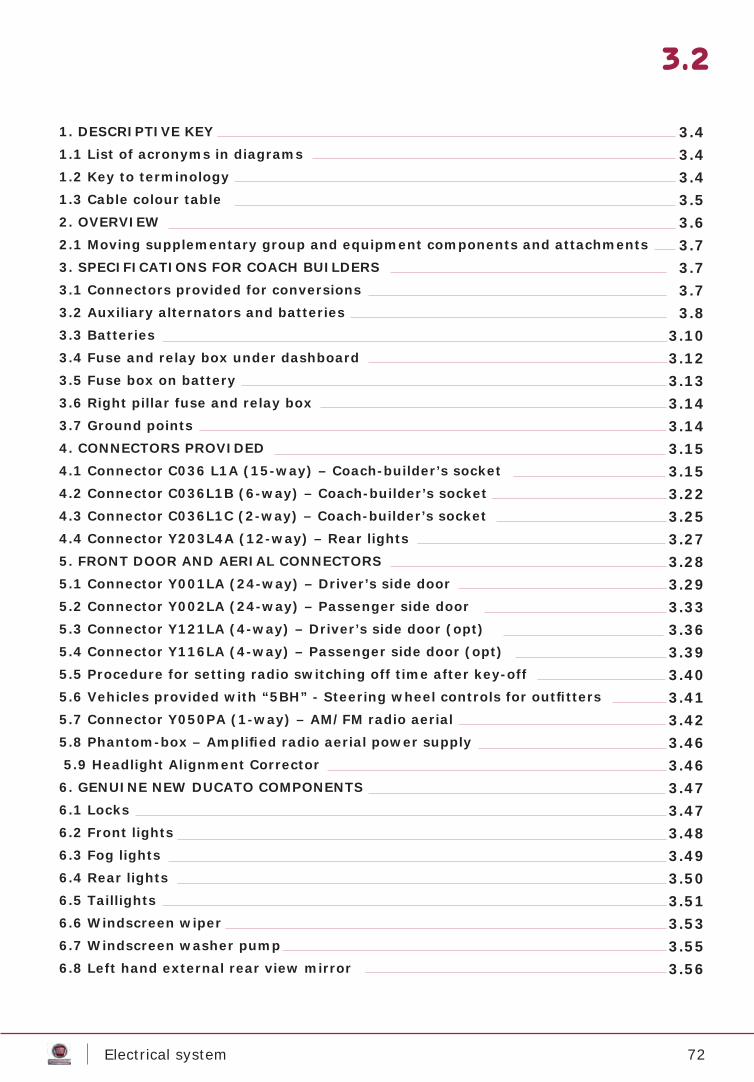
1. DESCRIPTIVE KEY1.1 List of acronyms in diagrams1.2 Key to terminology1.3 Cable colour table2. OVERVIEW2.1 Moving supplementary group and equipment components and attachments3. SPECIFICATIONS FOR COACH BUILDERS3.1 Connectors provided for conversions3.2 Auxiliary alternators and batteries3.3 Batteries3.4 Fuse and relay box under dashboard3.5 Fuse box on battery3.6 Right pillar fuse and relay box3.7 Ground points4. CONNECTORS PROVIDED4.1 Connector C036 L1A (15-way) – Coach-builder’s socket4.2 Connector C036L1B (6-way) – Coach-builder’s socket4.3 Connector C036L1C (2-way) – Coach-builder’s socket4.4 Connector Y203L4A (12-way) – Rear lights5. FRONT DOOR AND AERIAL CONNECTORS5.1 Connector Y001LA (24-way) – Driver’s side door5.2 Connector Y002LA (24-way) – Passenger side door5.3 Connector Y121LA (4-way) – Driver’s side door (opt)5.4 Connector Y116LA (4-way) – Passenger side door (opt)5.5 Procedure for setting radio switching off time after key-off5.6 Vehicles provided with “5BH” - Steering wheel controls for outfi tters5.7 Connector Y050PA (1-way) – AM/FM radio aerial5.8 Phantom-box – Amplifi ed radio aerial power supply 5.9 Headlight Alignment Corrector6. GENUINE NEW DUCATO COMPONENTS6.1 Locks6.2 Front lights6.3 Fog lights6.4 Rear lights6.5 Taillights6.6 Windscreen wiper6.7 Windscreen washer pump6.8 Left hand external rear view mirror
3.43.43.43.53.63.73.73.73.8
3.103.123.133.143.143.153.153.223.253.273.283.293.333.363.393.403.413.423.46
3.463.473.473.483.493.503.513.533.553.56
73Electrical system
3.3
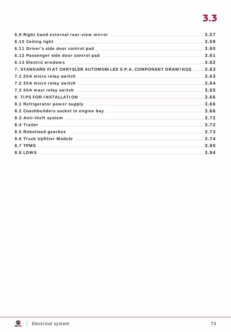
6.9 Right hand external rear-view mirror6.10 Ceiling light6.11 Driver’s side door control pad6.12 Passenger side door control pad6.13 Electric windows7. STANDARD FIAT CHRYSLER AUTOMOBILES S.P.A. COMPONENT DRAWINGS7.1 20A micro relay switch7.2 30A micro relay switch7.3 50A maxi relay switch8. TIPS FOR INSTALLATION8.1 Refrigerator power supply8.2 Coachbuilders socket in engine bay8.3 Anti-theft system8.4 Trailer8.5 Robotised gearbox8.6 Truck Upfi tter Module8.7 TPMS8.8 LDWS
3.573.593.603.613.623.633.633.643.653.663.663.663.723.723.733.743.903.94

74Electrical system
Descriptive key
List of acronyms in diagrams
Key to terminology:
+30: permanent +12V vehicle power supply
+KEY: signal active at +12V vehicle when ignition switch is in position (MAR)
+LIGHTS: signal active at +12V when position lights are on.
BATT. AUX: auxiliary batteryinstalled by coach-builder.
P.M. connector: connectorsuitable for receiving maleterminals
P.F. connector: connectorsuitable for receiving femaleterminals
3.4
ACM Automatic Climate ModuleAHCU Additional Heater Control UnitASM Air Suspension ModuleASS Auxiliary Stack SwitchesASU Alarm Siren UnitBCM Body Computer ModuleBSM Brake System ModuleCDC Co-Driver Door CommandCSM Column Switch ModuleCSS Central Stack SwitchesCTCU Chrono Tachograph Control UnitCTM Convergence Telematic ModuleDDC Driver Door CommandDSHS Driver Seat Heater SystemECM Engine Control ModuleFCLU Front Ceiling Light UnitGPCU Glow Plug Control UnitIBS Intelligent Battery SensorIPC Instrument Panel ClusterLDWS Lane Departure Warning SystemLSS Left Stack SwitchesMCD Manual Climate DeviceMTA Manual Transmission AutomatedPAM Parking Aid ModulePSHS Passenger Seat Heater SystemRLS Rain Light SensorRMCD Rear Manual Climate DeviceRRM Radio Receiver ModuleSAS Steering Angle SensorSDM Sensing and Diagnostic ModuleSLU Shift Lever UnitSSCU Servo Steering Control UnitSWC Steering Wheel CommandTPMS Tire Pressure Monitoring SystemTUM Truck Upfi tter ModuleVPAS Video Parking Aid SystemVSU Voltage Stabilizer Unit
75Electrical system
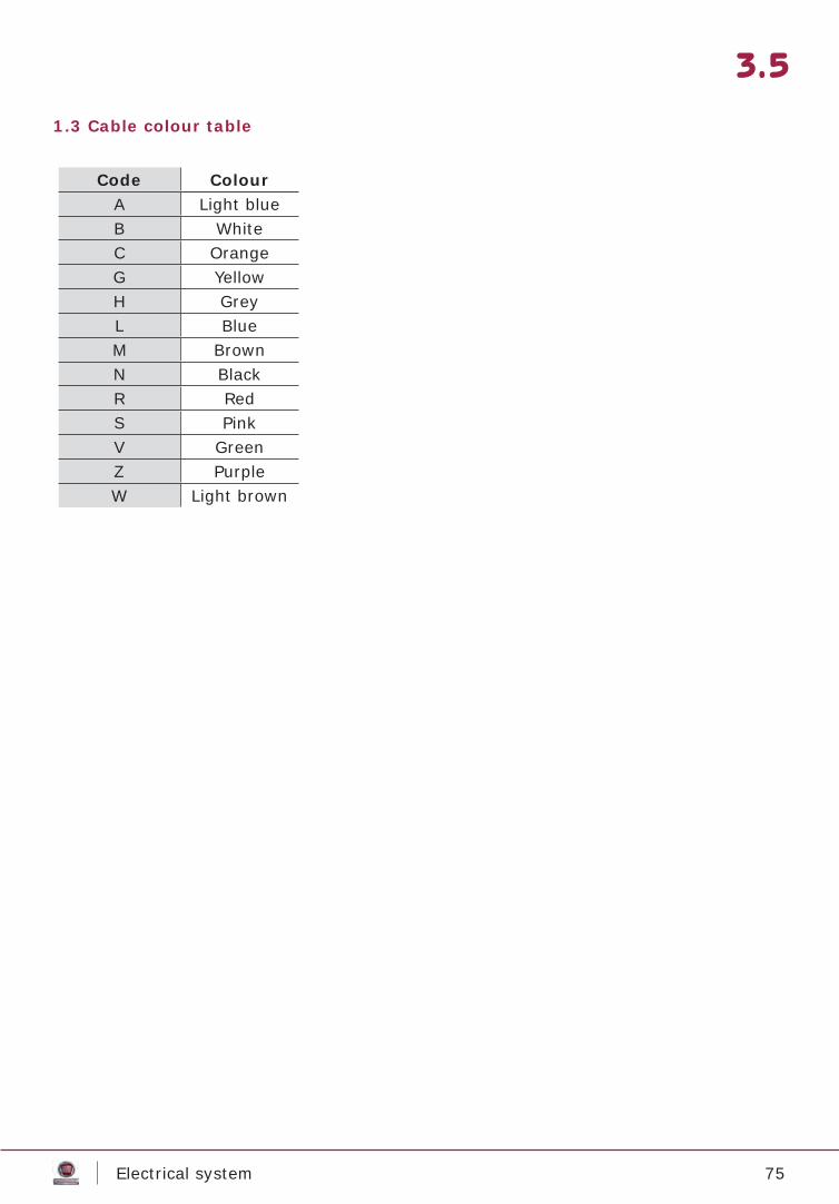
1.3 Cable colour table
3.5
Code ColourA Light blueB WhiteC OrangeG YellowH GreyL BlueM BrownN BlackR RedS PinkV GreenZ PurpleW Light brown
76Electrical system
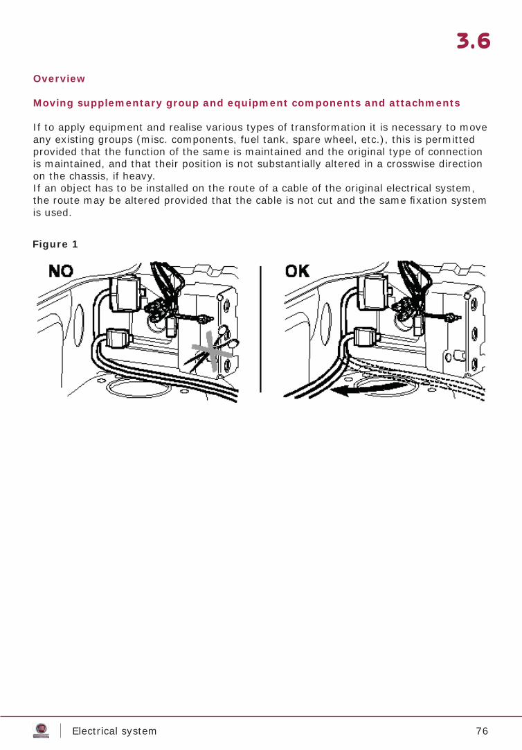
Overview
Moving supplementary group and equipment components and attachments
If to apply equipment and realise various types of transformation it is necessary to move any existing groups (misc. components, fuel tank, spare wheel, etc.), this is permitted provided that the function of the same is maintained and the original type of connection is maintained, and that their position is not substantially altered in a crosswise direction on the chassis, if heavy.If an object has to be installed on the route of a cable of the original electrical system, the route may be altered provided that the cable is not cut and the same fi xation system is used.
3.6
Figure 1
77Electrical system
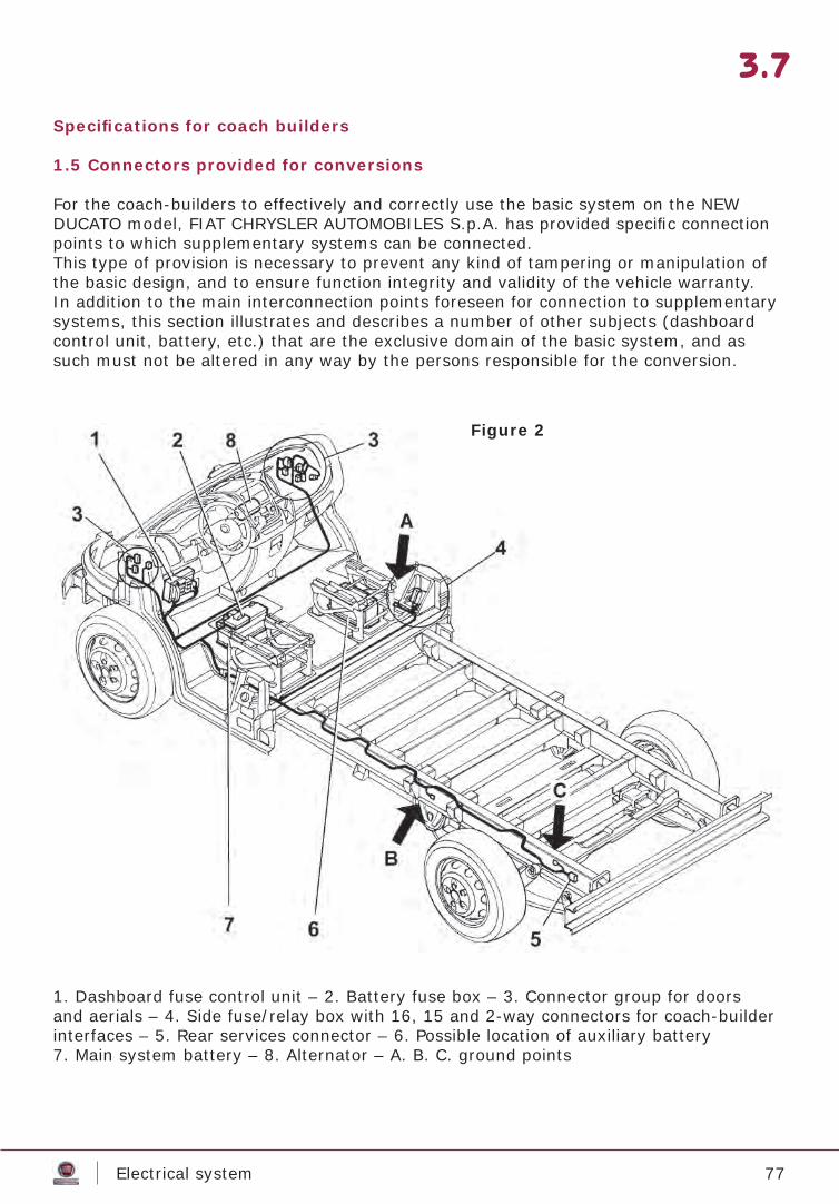
Specifi cations for coach builders
1.5 Connectors provided for conversions
For the coach-builders to effectively and correctly use the basic system on the NEW DUCATO model, FIAT CHRYSLER AUTOMOBILES S.p.A. has provided specifi c connection points to which supplementary systems can be connected.This type of provision is necessary to prevent any kind of tampering or manipulation of the basic design, and to ensure function integrity and validity of the vehicle warranty.In addition to the main interconnection points foreseen for connection to supplementary systems, this section illustrates and describes a number of other subjects (dashboard control unit, battery, etc.) that are the exclusive domain of the basic system, and as such must not be altered in any way by the persons responsible for the conversion.
1. Dashboard fuse control unit – 2. Battery fuse box – 3. Connector group for doors and aerials – 4. Side fuse/relay box with 16, 15 and 2-way connectors for coach-builder interfaces – 5. Rear services connector – 6. Possible location of auxiliary battery7. Main system battery – 8. Alternator – A. B. C. ground points
3.7
Figure 2
78Electrical system
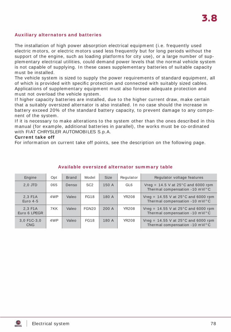
Auxiliary alternators and batteries
The installation of high power absorption electrical equipment (i.e. frequently used electric motors, or electric motors used less frequently but for long periods without the support of the engine, such as loading platforms for city use), or a large number of sup-plementary electrical utilities, could demand power levels that the normal vehicle system is not capable of supplying. In these cases supplementary batteries of suitable capacity must be installed.The vehicle system is sized to supply the power requirements of standard equipment, all of which is provided with specifi c protection and connected with suitably sized cables.Applications of supplementary equipment must also foresee adequate protection and must not overload the vehicle system.If higher capacity batteries are installed, due to the higher current draw, make certain that a suitably oversized alternator is also installed. In no case should the increase in battery exceed 20% of the standard battery capacity, to prevent damage to any compo-nent of the system.If it is necessary to make alterations to the system other than the ones described in this manual (for example, additional batteries in parallel), the works must be co-ordinated with FIAT CHRYSLER AUTOMOBILES S.p.A.Current take offFor information on current take off points, see the description on the following page.
Available oversized alternator summary table
3.8
Engine Opt Brand Model Size Regulator Regulator voltage features
2,0 JTD 065 Denso SC2 150 A GL6 Vreg = 14.5 V at 25°C and 6000 rpmThermal compensation -10 mV/°C
2,3 F1A Euro 4-5
4WP Valeo FG18 180 A YR208 Vreg = 14.55 V at 25°C and 6000 rpmThermal compensation -10 mV/°C
2,3 F1A Euro 6 LPEGR
7KK Valeo FGN20 200 A YR208 Vreg = 14.55 V at 25°C and 6000 rpmThermal compensation -10 mV/°C
3,0 F1C-3,0 CNG
4WP Valeo FG18 180 A YR208 Vreg = 14.55 V at 25°C and 6000 rpmThermal compensation -10 mV/°C
79Electrical system
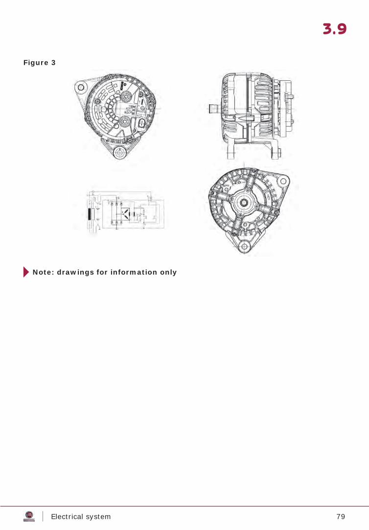
Note: drawings for information only
3.9
Figure 3
80Electrical system
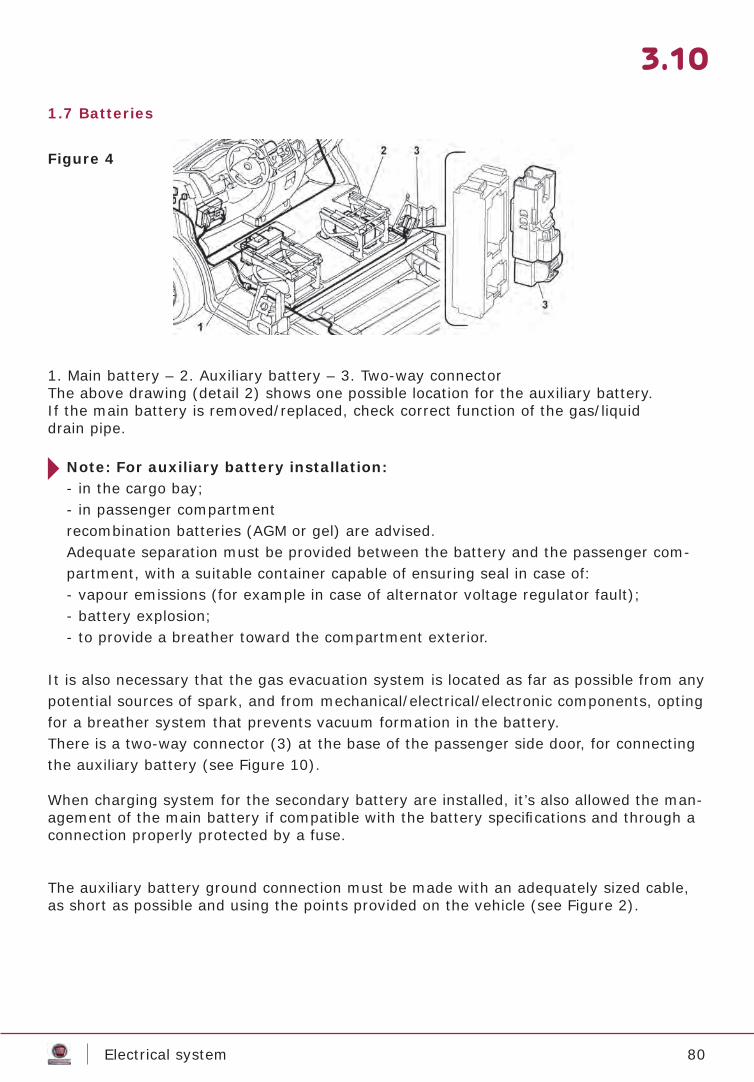
1.7 Batteries
1. Main battery – 2. Auxiliary battery – 3. Two-way connectorThe above drawing (detail 2) shows one possible location for the auxiliary battery.If the main battery is removed/replaced, check correct function of the gas/liquiddrain pipe.
Note: For auxiliary battery installation:- in the cargo bay;- in passenger compartmentrecombination batteries (AGM or gel) are advised.Adequate separation must be provided between the battery and the passenger com-partment, with a suitable container capable of ensuring seal in case of:- vapour emissions (for example in case of alternator voltage regulator fault);- battery explosion;- to provide a breather toward the compartment exterior.
It is also necessary that the gas evacuation system is located as far as possible from any potential sources of spark, and from mechanical/electrical/electronic components, opting for a breather system that prevents vacuum formation in the battery.There is a two-way connector (3) at the base of the passenger side door, for connecting the auxiliary battery (see Figure 10).
When charging system for the secondary battery are installed, it’s also allowed the man-agement of the main battery if compatible with the battery specifi cations and through a connection properly protected by a fuse.
The auxiliary battery ground connection must be made with an adequately sized cable, as short as possible and using the points provided on the vehicle (see Figure 2).
3.10
Figure 4
81Electrical system
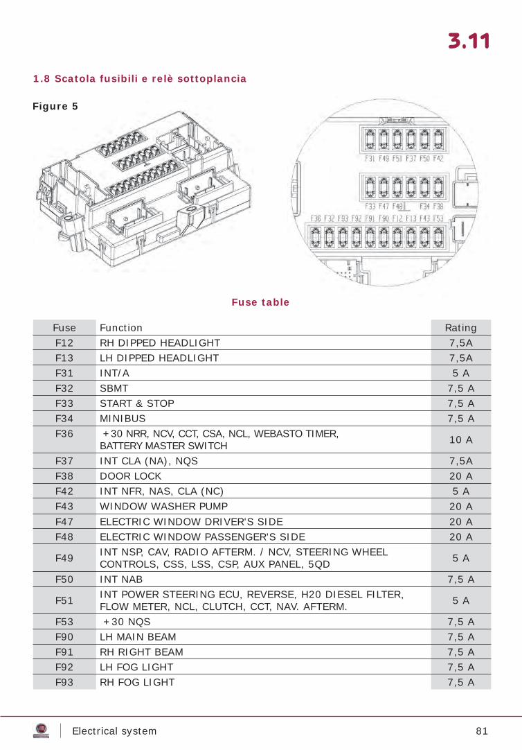
1.8 Scatola fusibili e relè sottoplancia
3.11
Fuse Function RatingF12 RH DIPPED HEADLIGHT 7,5AF13 LH DIPPED HEADLIGHT 7,5AF31 INT/A 5 AF32 SBMT 7,5 AF33 START & STOP 7,5 AF34 MINIBUS 7,5 AF36 +30 NRR, NCV, CCT, CSA, NCL, WEBASTO TIMER,
BATTERY MASTER SWITCH 10 A
F37 INT CLA (NA), NQS 7,5AF38 DOOR LOCK 20 AF42 INT NFR, NAS, CLA (NC) 5 AF43 WINDOW WASHER PUMP 20 AF47 ELECTRIC WINDOW DRIVER'S SIDE 20 AF48 ELECTRIC WINDOW PASSENGER'S SIDE 20 A
F49 INT NSP, CAV, RADIO AFTERM. / NCV, STEERING WHEELCONTROLS, CSS, LSS, CSP, AUX PANEL, 5QD 5 A
F50 INT NAB 7,5 A
F51 INT POWER STEERING ECU, REVERSE, H20 DIESEL FILTER, FLOW METER, NCL, CLUTCH, CCT, NAV. AFTERM. 5 A
F53 +30 NQS 7,5 AF90 LH MAIN BEAM 7,5 AF91 RH RIGHT BEAM 7,5 AF92 LH FOG LIGHT 7,5 AF93 RH FOG LIGHT 7,5 A
Figure 5
Fuse table
82Electrical system
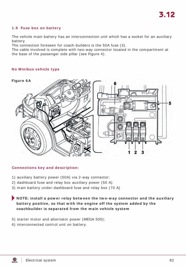
1.9 Fuse box on battery
The vehicle main battery has an interconnection unit which has a socket for an auxiliary battery.The connection foreseen for coach-builders is the 50A fuse (3).The cable involved is complete with two-way connector located in the compartment at the base of the passenger side pillar (see Figure 4).
Connections key and description:
1) auxiliary battery power (50A) via 2-way connector:2) dashboard fuse and relay box auxiliary power (50 A)3) main battery under-dashboard fuse and relay box (70 A)
NOTE: install a power relay between the two-way connector and the auxiliary battery positive, so that with the engine off the system added by the coachbuilder is separated from the main vehicle system
5) starter motor and alternator power (MEGA 500);6) interconnected control unit on battery.
3.12
Figure 6A
No Minibus vehicle type
83Electrical system
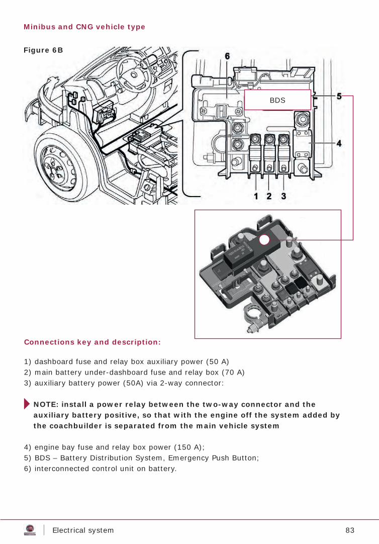
Connections key and description:
1) dashboard fuse and relay box auxiliary power (50 A)2) main battery under-dashboard fuse and relay box (70 A)3) auxiliary battery power (50A) via 2-way connector:
NOTE: install a power relay between the two-way connector and the auxiliary battery positive, so that with the engine off the system added by the coachbuilder is separated from the main vehicle system
4) engine bay fuse and relay box power (150 A);5) BDS – Battery Distribution System, Emergency Push Button;6) interconnected control unit on battery.
Figure 6B
Minibus and CNG vehicle type
BDS
84Electrical system
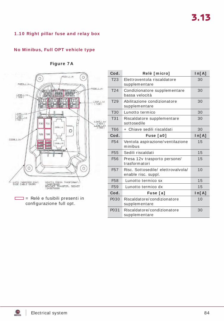
1.10 Right pillar fuse and relay box
3.13
Figure 7A
No Minibus, Full OPT vehicle type
Cod. Relè [micro] In[A] T23 Elettroventola riscaldatore
supplementare30
T24 Condizionatore supplementare bassa velocità
30
T29 Abilitazione condizionatore supplementare
30
T30 Lunotto termico 30T31 Riscaldatore supplementare
sottosedile30
T66 + Chiave sedili riscaldati 30Cod. Fuse [a0] In[A] F54 Ventola aspirazione/ventilazione
minibus15
F55 Sedili riscaldati 15F56 Presa 12v trasporto persone/
trasformatori 15
F57 Risc. Sottosedile/ elettrovalvola/ enable risc. suppl.
10
F58 Lunotto termico sx 15F59 Lunotto termico dx 15Cod. Fuse [a] In[A] P030 Riscaldatore/condizionatore
supplementare10
P031 Riscaldatore/condizionatore supplementare
30
= Relè e fusibili presenti in confi gurazione full opt.
85Electrical system
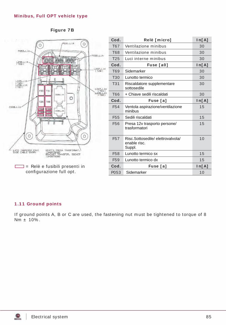
Figure 7B
Minibus, Full OPT vehicle type
Cod. Relè [micro] In[A] T67 Ventilazione minibus 30T68 Ventilazione minibus 30T25 Luci interne minibus 30Cod. Fuse [a0] In[A] T69 Sidemarker 30T30 Lunotto termico 30T31 Riscaldatore supplementare
sottosedile30
T66 + Chiave sedili riscaldati 30Cod. Fuse [a] In[A] F54 Ventola aspirazione/ventilazione
minibus15
F55 Sedili riscaldati 15F56 Presa 12v trasporto persone/
trasformatori 15
F57 Risc.Sottosedile/ elettrovalvola/enable risc. Suppl.
10
F58 Lunotto termico sx 15F59 Lunotto termico dx 15Cod. Fuse [a] In[A] P053 Sidemarker 10
= Relè e fusibili presenti in confi gurazione full opt.
1.11 Ground points
If ground points A, B or C are used, the fastening nut must be tightened to torque of 8 Nm ± 10%.

86Electrical system
Connectors provided
Connector C036 L1A (15-way) – Coach-builder’s socket3D view of connector
3.14
Figure 8
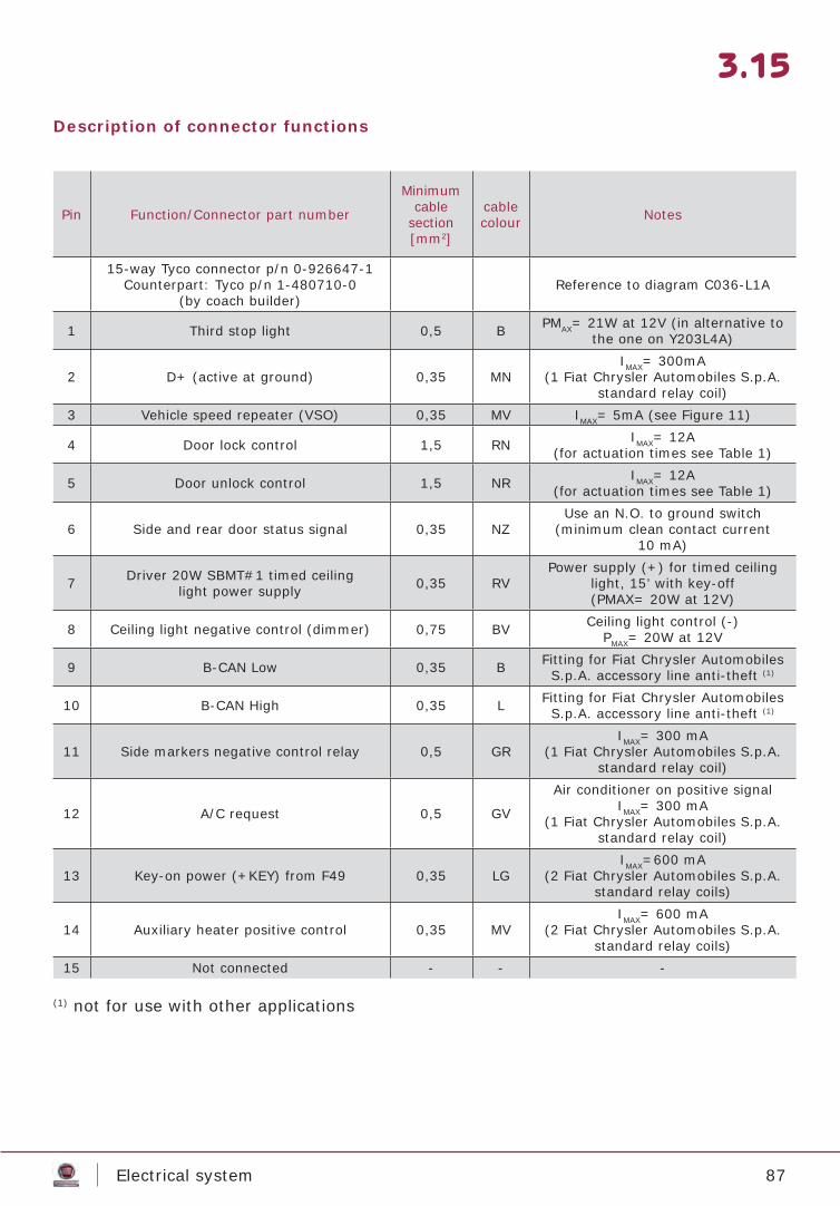
87Electrical system
Pin Function/Connector part number
Minimum cable
section [mm2]
cable colour Notes
15-way Tyco connector p/n 0-926647-1Counterpart: Tyco p/n 1-480710-0
(by coach builder)Reference to diagram C036-L1A
1 Third stop light 0,5 B PMAX= 21W at 12V (in alternative to the one on Y203L4A)
2 D+ (active at ground) 0,35 MNIMAX= 300mA
(1 Fiat Chrysler Automobiles S.p.A. standard relay coil)
3 Vehicle speed repeater (VSO) 0,35 MV IMAX= 5mA (see Figure 11)
4 Door lock control 1,5 RN IMAX= 12A(for actuation times see Table 1)
5 Door unlock control 1,5 NR IMAX= 12A(for actuation times see Table 1)
6 Side and rear door status signal 0,35 NZUse an N.O. to ground switch
(minimum clean contact current10 mA)
7 Driver 20W SBMT#1 timed ceilinglight power supply 0,35 RV
Power supply (+) for timed ceiling light, 15’ with key-off(PMAX= 20W at 12V)
8 Ceiling light negative control (dimmer) 0,75 BV Ceiling light control (-)PMAX= 20W at 12V
9 B-CAN Low 0,35 B Fitting for Fiat Chrysler Automobiles S.p.A. accessory line anti-theft (1)
10 B-CAN High 0,35 L Fitting for Fiat Chrysler Automobiles S.p.A. accessory line anti-theft (1)
11 Side markers negative control relay 0,5 GRIMAX= 300 mA
(1 Fiat Chrysler Automobiles S.p.A. standard relay coil)
12 A/C request 0,5 GV
Air conditioner on positive signalIMAX= 300 mA
(1 Fiat Chrysler Automobiles S.p.A. standard relay coil)
13 Key-on power (+KEY) from F49 0,35 LGIMAX=600 mA
(2 Fiat Chrysler Automobiles S.p.A. standard relay coils)
14 Auxiliary heater positive control 0,35 MVIMAX= 600 mA
(2 Fiat Chrysler Automobiles S.p.A. standard relay coils)
15 Not connected - - -
3.15
(1) not for use with other applications
Description of connector functions
88Electrical system
3.16
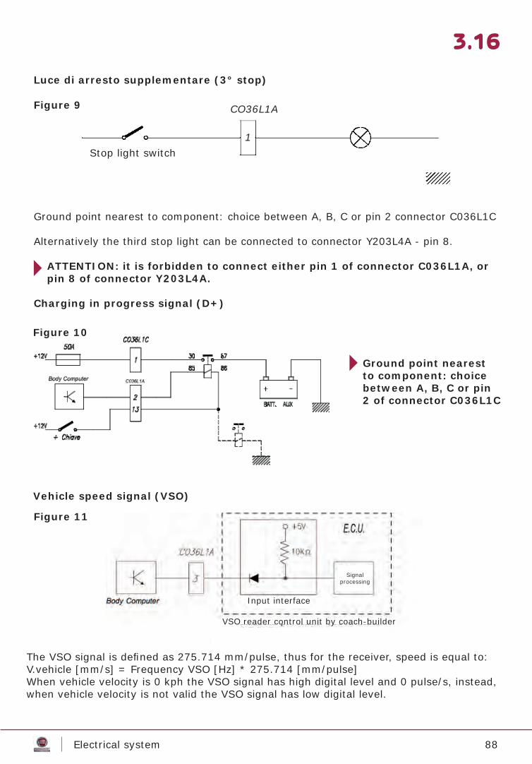
Luce di arresto supplementare (3° stop)
Vehicle speed signal (VSO)
Ground point nearest to component: choice between A, B, C or pin 2 connector C036L1C
Alternatively the third stop light can be connected to connector Y203L4A - pin 8.
ATTENTION: it is forbidden to connect either pin 1 of connector C036L1A, or pin 8 of connector Y203L4A.
Charging in progress signal (D+)
Ground point nearest to component: choice between A, B, C or pin2 of connector C036L1C
CO36L1A
1Stop light switch
VSO reader control unit by coach-builder
The VSO signal is defi ned as 275.714 mm/pulse, thus for the receiver, speed is equal to:V.vehicle [mm/s] = Frequency VSO [Hz] * 275.714 [mm/pulse]When vehicle velocity is 0 kph the VSO signal has high digital level and 0 pulse/s, instead, when vehicle velocity is not valid the VSO signal has low digital level.
Figure 9
Figure 10
Figure 11
Input interface
Signalprocessing

89Electrical system
Rear locks and ceiling light control
Note (1): In the absence of door open switch (if original Fiat Chrysler Auto-mobiles S.p.A. locks are not used, see chapter 6) pin 6 of connector C036L1A can be left disconnected.Attention: in this case the rear lock/s may be locked even with the door/s open. The instrument panel will not indicate door status and the rear ceiling light/s will not be commanded.It is therefore the responsibility of the coach builder to illustrate the differ-ence in function to that described in the use and Maintenance Handbook.
Note (2): pin 7 of connector C036L1A provides +12V for 15 minutes after the key is removed(+KEY = off), after which time the rear ceiling light will not be usable until the next rear door open switch status change (where present), otherwise until the door is unlocked or the key turned (+KEY = on).
• Function with 2 key remote control: releases the two driver cab locks and turns on the in-cab light fi xture.
• Function with 3 key remote control: separate front/rear unlock and separate switch on of corresponding interior lights.
3.17
DOOR OPEN SWITCHN.O. With closed doorN.C. With open door
Ground point nearest component: choice between A, B, C or pin2 of connector C036L1C
Max 12A @ 13,5VUNLOCKLOCK
C036L1A
(1)(1)
Figure 12
90Electrical system
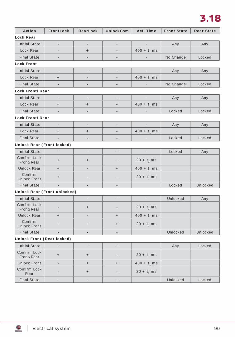
3.18Action FrontLock RearLock UnlockCom Act. Time Front State Rear State
Initial State - - - - Any Any
Lock Rear - + - 400 + t1 ms
Final State - - - - No Change Locked
Initial State - - - - Any Any
Lock Rear + - - 400 + t1 ms
Final State - - - - No Change Locked
Initial State - - - - Any Any
Lock Rear + + - 400 + t1 ms
Final State - - - - Locked Locked
Initial State - - - - Any Any
Lock Rear + + - 400 + t1 ms
Final State - - - - Locked Locked
Lock Rear
Lock Front
Lock Front/Rear
Lock Front/Rear
Unlock Rear (Front locked)
Unlock Rear (Front unlocked)
Unlock Front (Rear locked)
Initial State - - - - Locked AnyConfi rm Lock Front/Rear + + - 20 + t2 ms
Unlock Rear + - + 400 + t1 msConfi rm
Unlock Front + - - 20 + t2 ms
Final State - - - Locked Unlocked
Initial State - - - - Unlocked AnyConfi rm Lock Front/Rear - + - 20 + t2 ms
Unlock Rear + - + 400 + t1 msConfi rm
Unlock Front - - + 20 + t2 ms
Final State - - - Unlocked Unlocked
Initial State - - - Any Locked
Confi rm Lock Front/Rear + + - 20 + t2 ms
Unlock Front - + + 400 + t1 msConfi rm Lock
Rear - + - 20 + t2 ms
Final State - - - Unlocked Locked

91Electrical system
Side marker lights
Ground point nearest to component: choice between A, B, C or pin 2 of connector C036L1C
Rear heater enable control
Conditioner on signal
3.19
Unlock Front (Rear unlocked)
Unlock Front/Rear
Initial State - - - Any Unlocked
Confi rm Lock Front + - - 20 + t2 ms
Unlock Rear - + + 400 + t1 msConfi rm
Unlock Front - - + 20 + t2 ms
Final State - - - Unlocked Unlocked
Initial State - - - Any Any
Confi rm Lock Front/Rear + + - 20 + t2 ms
Unlock Front/Rear - - + 400 + t1 ms
Final State - - - Unlocked Unlocked
Tollerances 0<t1<10% 0<t2<10ms
Ground point nearest to component: choice be-tween: A, B, C or pin 2 connector C036L1C
Ground point nearest to component: choice be-tween A, B, C or pin 2 of connector C036L1C
AUXILIARY CONDITIONER
C036L1A
Figure 13
Figure 14
Figure 15CONDITIONERCONTROL
REARHEATER
REAR HEATERCONTROL
ELECTROVALVE
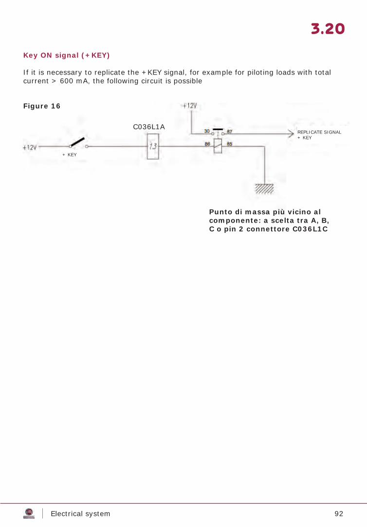
92Electrical system
Key ON signal (+KEY)
If it is necessary to replicate the +KEY signal, for example for piloting loads with total current > 600 mA, the following circuit is possible
3.20
C036L1A
Punto di massa più vicino al componente: a scelta tra A, B, C o pin 2 connettore C036L1C
Figure 16
REPLICATE SIGNAL+ KEY
+ KEY
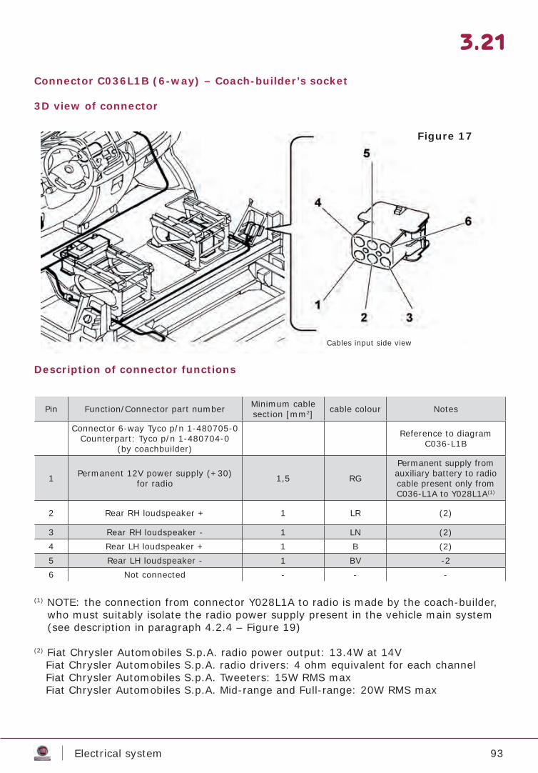
93Electrical system
Connector C036L1B (6-way) – Coach-builder’s socket
3D view of connector
Description of connector functions
(1) NOTE: the connection from connector Y028L1A to radio is made by the coach-builder, who must suitably isolate the radio power supply present in the vehicle main system (see description in paragraph 4.2.4 – Figure 19)
(2) Fiat Chrysler Automobiles S.p.A. radio power output: 13.4W at 14V Fiat Chrysler Automobiles S.p.A. radio drivers: 4 ohm equivalent for each channel Fiat Chrysler Automobiles S.p.A. Tweeters: 15W RMS max Fiat Chrysler Automobiles S.p.A. Mid-range and Full-range: 20W RMS max
3.21
Pin Function/Connector part number Minimum cable section [mm2] cable colour Notes
Connector 6-way Tyco p/n 1-480705-0Counterpart: Tyco p/n 1-480704-0
(by coachbuilder)
Reference to diagram C036-L1B
1 Permanent 12V power supply (+30) for radio 1,5 RG
Permanent supply from auxiliary battery to radio cable present only from C036-L1A to Y028L1A(1)
2 Rear RH loudspeaker + 1 LR (2)
3 Rear RH loudspeaker - 1 LN (2)4 Rear LH loudspeaker + 1 B (2)5 Rear LH loudspeaker - 1 BV -26 Not connected - - -
Figure 17
Cables input side view
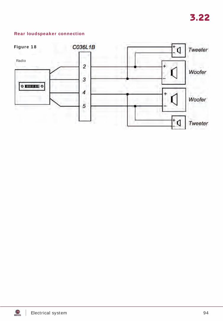
94Electrical system
Rear loudspeaker connection
3.22
Figure 18
Radio
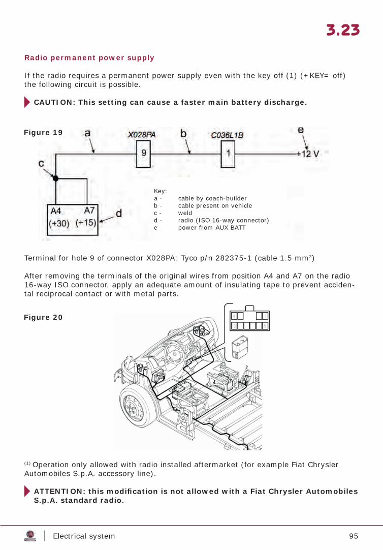
95Electrical system
Radio permanent power supply
If the radio requires a permanent power supply even with the key off (1) (+KEY= off) the following circuit is possible.
CAUTION: This setting can cause a faster main battery discharge.
Terminal for hole 9 of connector X028PA: Tyco p/n 282375-1 (cable 1.5 mm2)
After removing the terminals of the original wires from position A4 and A7 on the radio 16-way ISO connector, apply an adequate amount of insulating tape to prevent acciden-tal reciprocal contact or with metal parts.
3.23
(1) Operation only allowed with radio installed aftermarket (for example Fiat Chrysler Automobiles S.p.A. accessory line).
ATTENTION: this modifi cation is not allowed with a Fiat Chrysler Automobiles S.p.A. standard radio.
Figure 19
Figure 20
Key:a - cable by coach-builderb - cable present on vehiclec - weldd - radio (ISO 16-way connector)e - power from AUX BATT
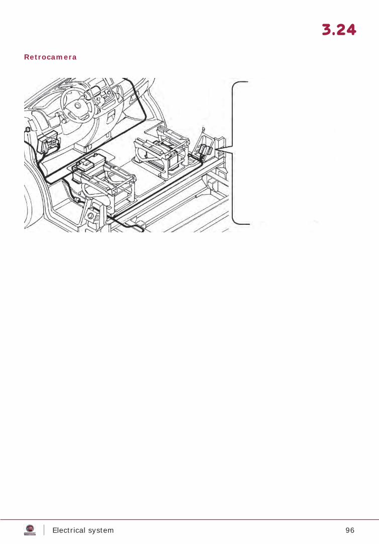
96Electrical system
Retrocamera
3.24
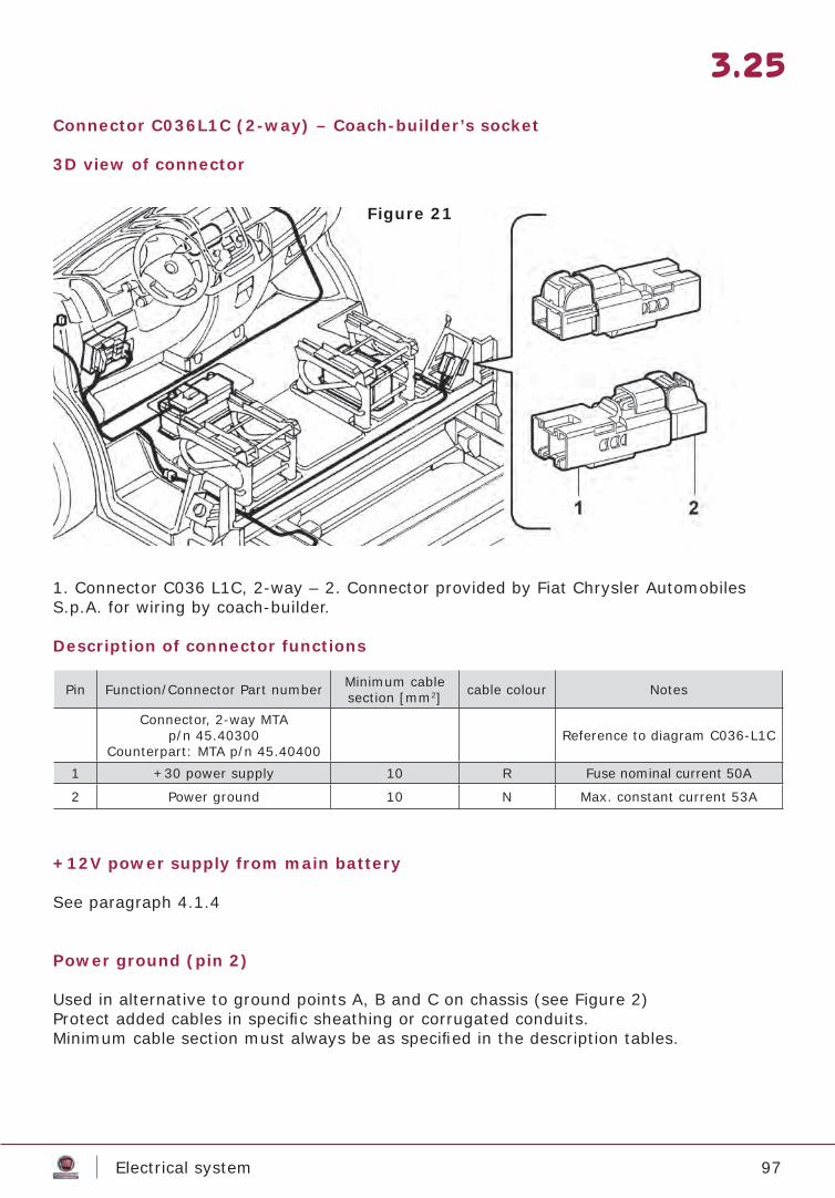
97Electrical system
Connector C036L1C (2-way) – Coach-builder’s socket
3D view of connector
1. Connector C036 L1C, 2-way – 2. Connector provided by Fiat Chrysler Automobiles S.p.A. for wiring by coach-builder.
Description of connector functions
+12V power supply from main battery
See paragraph 4.1.4
Power ground (pin 2)
Used in alternative to ground points A, B and C on chassis (see Figure 2)Protect added cables in specifi c sheathing or corrugated conduits.Minimum cable section must always be as specifi ed in the description tables.
3.25
Pin Function/Connector Part number Minimum cable section [mm2] cable colour Notes
Connector, 2-way MTAp/n 45.40300
Counterpart: MTA p/n 45.40400Reference to diagram C036-L1C
1 +30 power supply 10 R Fuse nominal current 50A
2 Power ground 10 N Max. constant current 53A
Figure 21
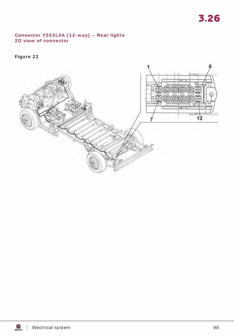
98Electrical system
3.26
Connector Y203L4A (12-way) – Rear lights2D view of connector
Figure 22
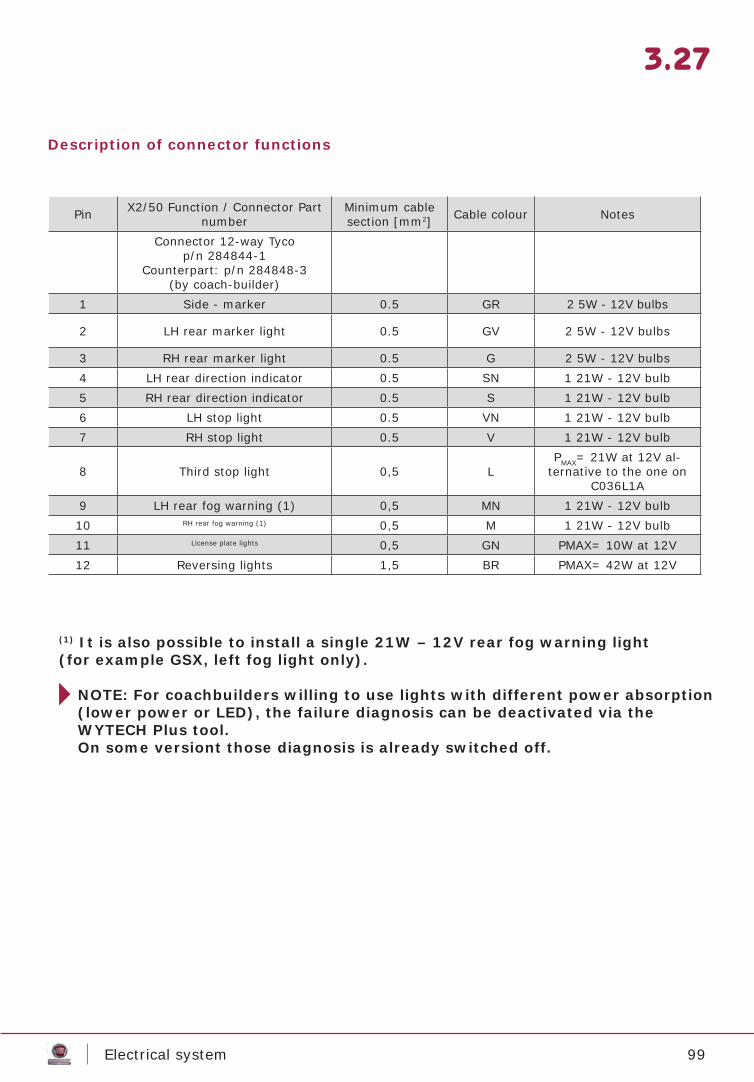
99Electrical system
3.27
(1) It is also possible to install a single 21W – 12V rear fog warning light(for example GSX, left fog light only).
NOTE: For coachbuilders willing to use lights with different power absorption (lower power or LED), the failure diagnosis can be deactivated via the WYTECH Plus tool.On some versiont those diagnosis is already switched off.
Description of connector functions
Pin X2/50 Function / Connector Part number
Minimum cable section [mm2] Cable colour Notes
Connector 12-way Tycop/n 284844-1
Counterpart: p/n 284848-3(by coach-builder)
1 Side - marker 0.5 GR 2 5W - 12V bulbs
2 LH rear marker light 0.5 GV 2 5W - 12V bulbs
3 RH rear marker light 0.5 G 2 5W - 12V bulbs4 LH rear direction indicator 0.5 SN 1 21W - 12V bulb5 RH rear direction indicator 0.5 S 1 21W - 12V bulb6 LH stop light 0.5 VN 1 21W - 12V bulb7 RH stop light 0.5 V 1 21W - 12V bulb
8 Third stop light 0,5 LPMAX= 21W at 12V al-
ternative to the one on C036L1A
9 LH rear fog warning (1) 0,5 MN 1 21W - 12V bulb10 RH rear fog warning (1) 0,5 M 1 21W - 12V bulb11 License plate lights 0,5 GN PMAX= 10W at 12V12 Reversing lights 1,5 BR PMAX= 42W at 12V
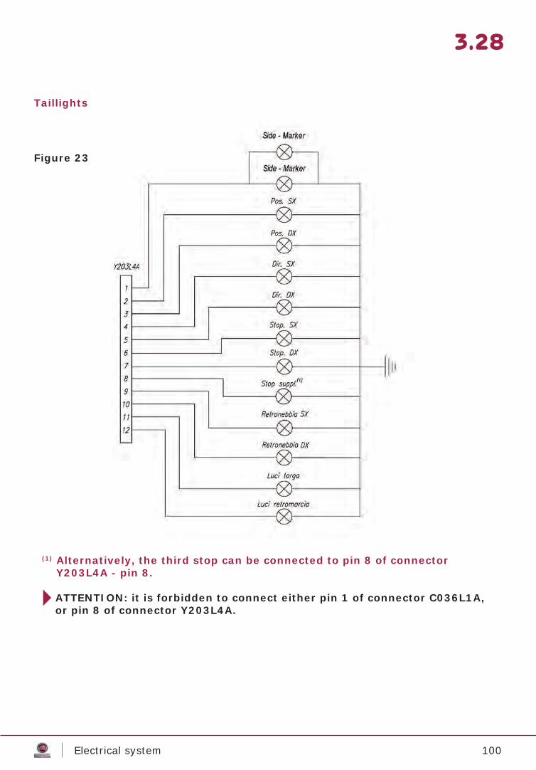
100Electrical system
3.28
(1) Alternatively, the third stop can be connected to pin 8 of connector Y203L4A - pin 8.
ATTENTION: it is forbidden to connect either pin 1 of connector C036L1A,or pin 8 of connector Y203L4A.
Taillights
Figure 23
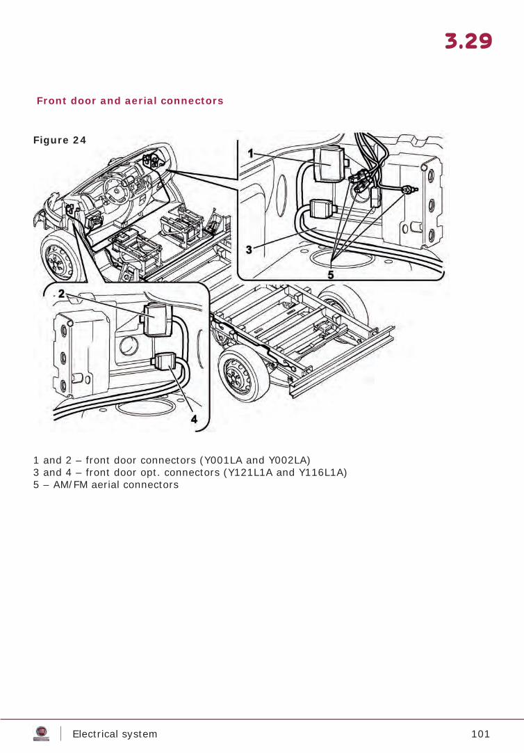
101Electrical system
3.29
Front door and aerial connectors
1 and 2 – front door connectors (Y001LA and Y002LA)3 and 4 – front door opt. connectors (Y121L1A and Y116L1A)5 – AM/FM aerial connectors
Figure 24
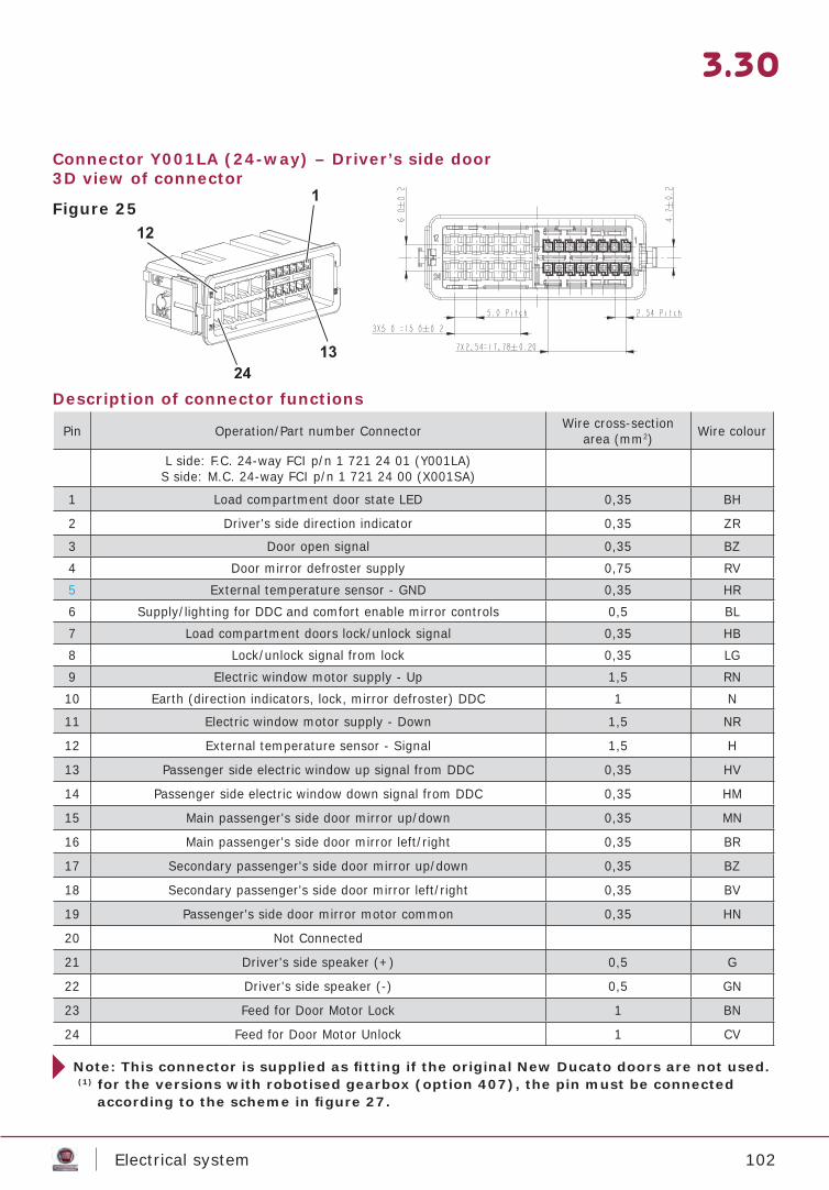
102Electrical system
3.30
Connector Y001LA (24-way) – Driver’s side door3D view of connector
Description of connector functions
Pin Operation/Part number Connector Wire cross-section area (mm2) Wire colour
L side: F.C. 24-way FCI p/n 1 721 24 01 (Y001LA)S side: M.C. 24-way FCI p/n 1 721 24 00 (X001SA)
1 Load compartment door state LED 0,35 BH
2 Driver's side direction indicator 0,35 ZR
3 Door open signal 0,35 BZ4 Door mirror defroster supply 0,75 RV5 External temperature sensor - GND 0,35 HR6 Supply/lighting for DDC and comfort enable mirror controls 0,5 BL7 Load compartment doors lock/unlock signal 0,35 HB8 Lock/unlock signal from lock 0,35 LG9 Electric window motor supply - Up 1,5 RN10 Earth (direction indicators, lock, mirror defroster) DDC 1 N
11 Electric window motor supply - Down 1,5 NR
12 External temperature sensor - Signal 1,5 H
13 Passenger side electric window up signal from DDC 0,35 HV
14 Passenger side electric window down signal from DDC 0,35 HM
15 Main passenger's side door mirror up/down 0,35 MN
16 Main passenger's side door mirror left/right 0,35 BR
17 Secondary passenger's side door mirror up/down 0,35 BZ
18 Secondary passenger's side door mirror left/right 0,35 BV
19 Passenger's side door mirror motor common 0,35 HN
20 Not Connected
21 Driver's side speaker (+) 0,5 G
22 Driver's side speaker (-) 0,5 GN
23 Feed for Door Motor Lock 1 BN
24 Feed for Door Motor Unlock 1 CV
Note: This connector is supplied as fi tting if the original New Ducato doors are not used. (1) for the versions with robotised gearbox (option 407), the pin must be connected according to the scheme in fi gure 27.
Figure 25
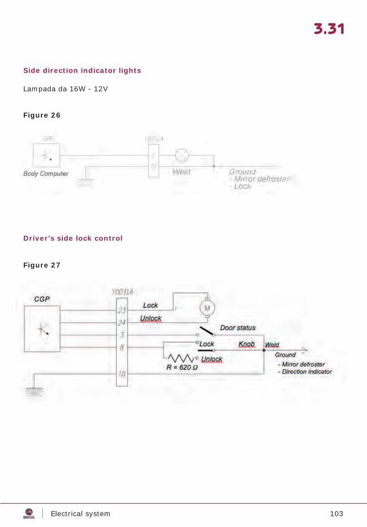
103Electrical system
3.31
Side direction indicator lights
Driver’s side lock control
Lampada da 16W - 12V
Figure 26
Figure 27
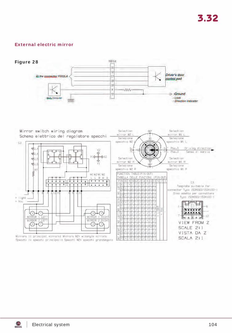
104Electrical system
3.32
External electric mirror
Figure 28
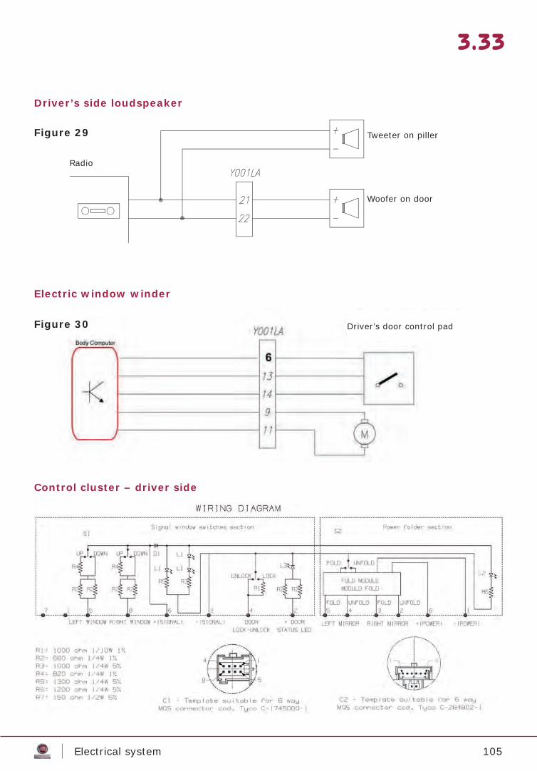
105Electrical system
3.33
Driver’s side loudspeaker
Electric window winder
Control cluster – driver side
Woofer su porta
Figure 29
Figure 30
Tweeter on piller
Woofer on door
Radio
Driver’s door control pad
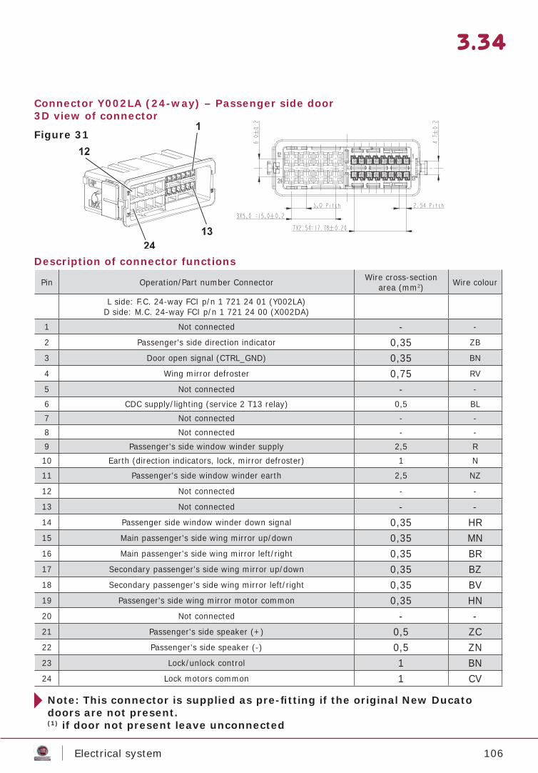
106Electrical system
3.34
Connector Y002LA (24-way) – Passenger side door3D view of connector
Description of connector functions
Pin Operation/Part number Connector Wire cross-section area (mm2) Wire colour
L side: F.C. 24-way FCI p/n 1 721 24 01 (Y002LA)D side: M.C. 24-way FCI p/n 1 721 24 00 (X002DA)
1 Not connected - -
2 Passenger's side direction indicator 0,35 ZB
3 Door open signal (CTRL_GND) 0,35 BN
4 Wing mirror defroster 0,75 RV
5 Not connected - -
6 CDC supply/lighting (service 2 T13 relay) 0,5 BL7 Not connected - -8 Not connected - -9 Passenger's side window winder supply 2,5 R10 Earth (direction indicators, lock, mirror defroster) 1 N
11 Passenger's side window winder earth 2,5 NZ
12 Not connected - -
13 Not connected - -14 Passenger side window winder down signal 0,35 HR15 Main passenger's side wing mirror up/down 0,35 MN16 Main passenger's side wing mirror left/right 0,35 BR17 Secondary passenger's side wing mirror up/down 0,35 BZ18 Secondary passenger's side wing mirror left/right 0,35 BV19 Passenger's side wing mirror motor common 0,35 HN20 Not connected - -21 Passenger's side speaker (+) 0,5 ZC22 Passenger's side speaker (-) 0,5 ZN23 Lock/unlock control 1 BN24 Lock motors common 1 CV
Note: This connector is supplied as pre-fi tting if the original New Ducatodoors are not present.(1) if door not present leave unconnected
Figure 31

107Electrical system
3.35
Side direction indicator light
Passenger side door control
Electric external mirror
Stato porta
Saldatura
MASSA - Serratura - Luce di direzione
Figure 32
Figure 33
Figure 34
Lock
Unlock
Door status
Weld Ground- Mirror defroster- Direction indicator
Electric external mirror on passenger side
At theconnectorY001LA
Weld
Ground- Lock- Direction indicator
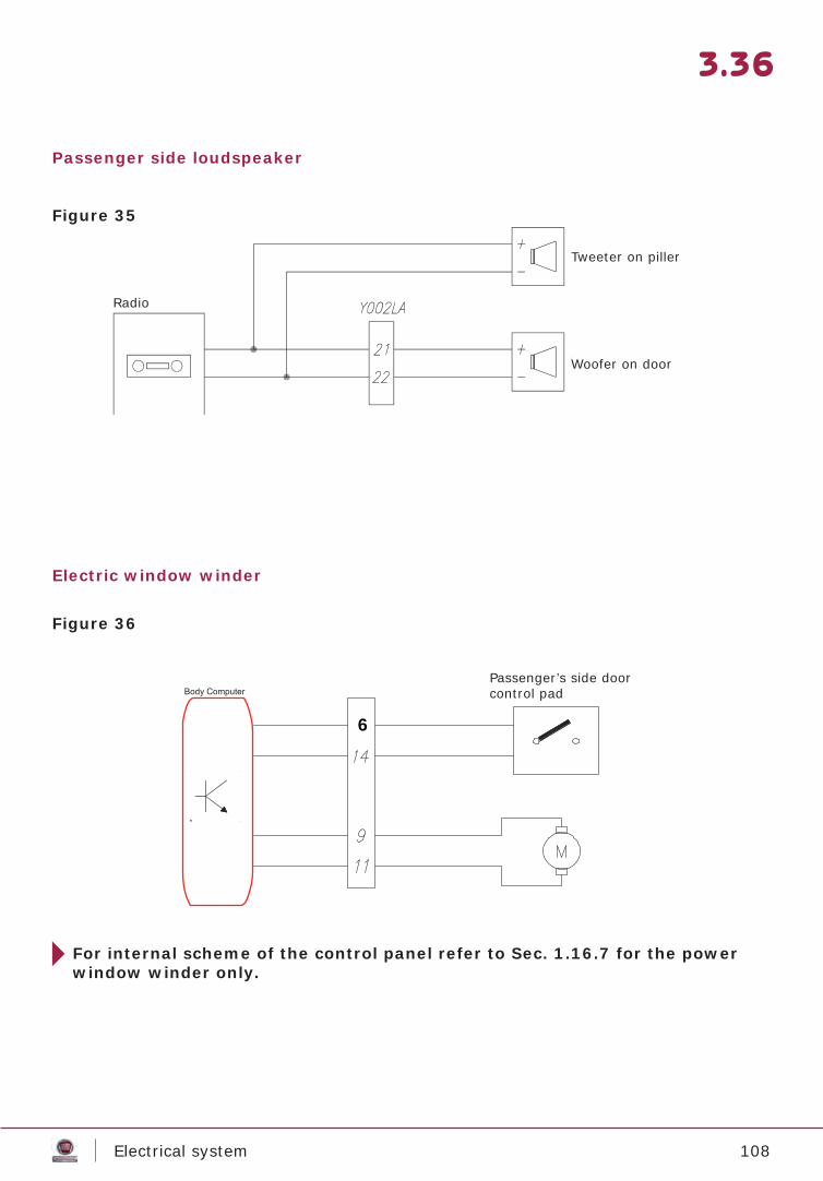
108Electrical system
3.36
Passenger side loudspeaker
Electric window winder
For internal scheme of the control panel refer to Sec. 1.16.7 for the power window winder only.
Woofer su porta
6
Figure 35
Figure 36
Tweeter on piller
Woofer on door
Radio
Passenger’s side doorcontrol pad
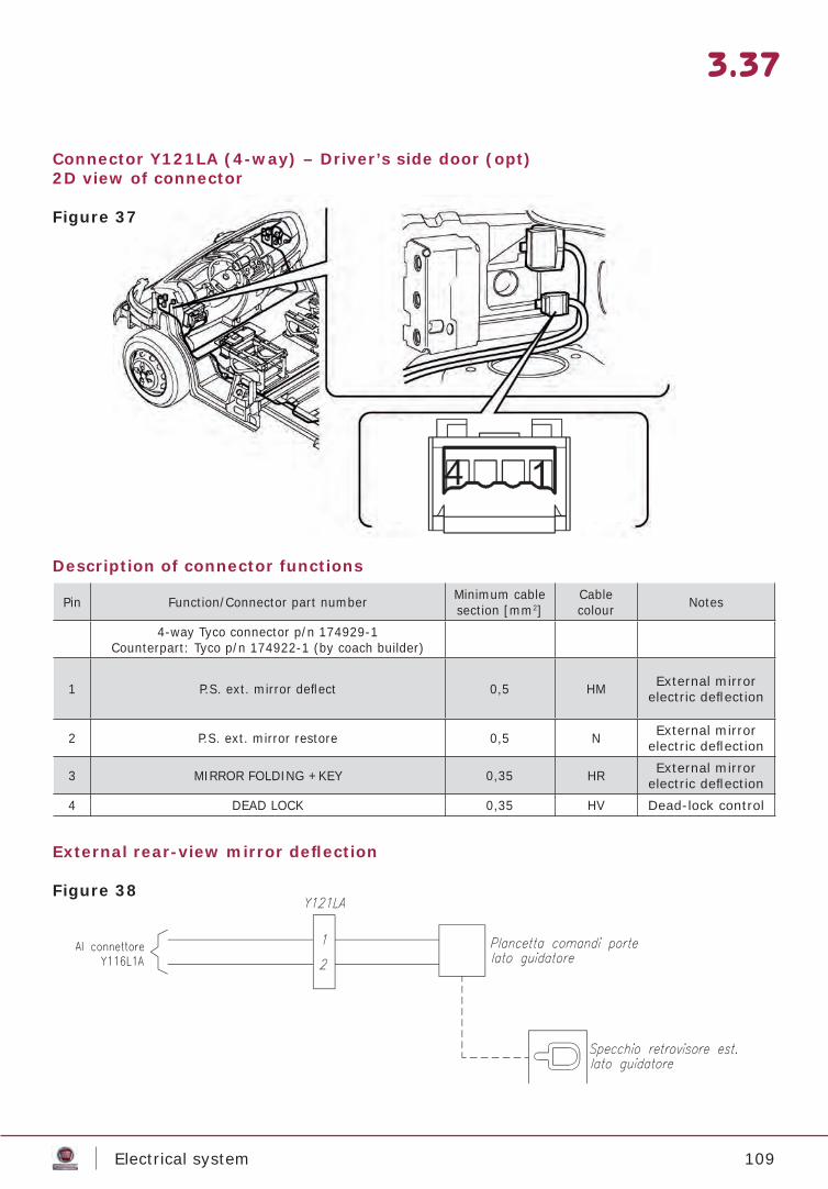
109Electrical system
3.37
Connector Y121LA (4-way) – Driver’s side door (opt)2D view of connector
Description of connector functions
External rear-view mirror defl ection
Pin Function/Connector part number Minimum cable section [mm2]
Cablecolour Notes
4-way Tyco connector p/n 174929-1Counterpart: Tyco p/n 174922-1 (by coach builder)
1 P.S. ext. mirror defl ect 0,5 HM External mirror electric defl ection
2 P.S. ext. mirror restore 0,5 N External mirror electric defl ection
3 MIRROR FOLDING +KEY 0,35 HR External mirror electric defl ection
4 DEAD LOCK 0,35 HV Dead-lock control
Figure 37
Figure 38
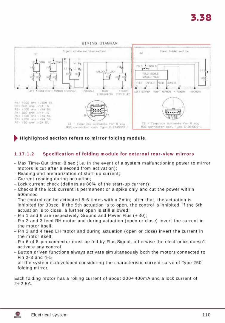
110Electrical system
3.38
1.17.1.2 Specifi cation of folding module for external rear-view mirrors
Highlighted section refers to mirror folding module.
- Max Time-Out time: 8 sec (i.e. in the event of a system malfunctioning power to mirror motors is cut after 8 second from activation);
- Reading and memorization of start-up current;- Current reading during actuation;- Lock current check (defi nes as 80% of the start-up current);- Checks if the lock current is permanent or a spike only and cut the power within
500msec;- The control can be activated 5-6 times within 2min; after that, the actuation is
inhibited for 30sec; if the 5th actuation is to open, the control is inhibited, if the 5th actuation is to close, a further open is still allowed;
- Pin 1 and 6 are respectively Ground and Power Plus (+30);- Pin 2 and 3 feed RH motor and during actuation (open or close) invert the current in
the motor itself;- Pin 3 and 4 feed LH motor and during actuation (open or close) invert the current in
the motor itself;- Pin 6 of 8-pin connector must be fed by Plus Signal, otherwise the electronics doesn’t
activate any control- Button driven functions always activate simultaneously both the motors connected to
Pin 2-3 and 4-5- all the system is developed considering the characteristic current curve of Type 250
folding mirror.
Each folding motor has a rolling current of about 200÷400mA and a lock current of 2÷2,5A.
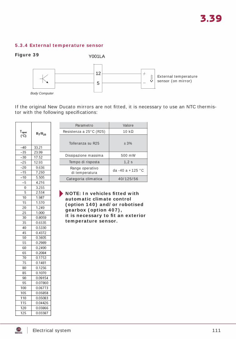
111Electrical system
3.39
5.3.4 External temperature sensor
Body Computer
12
5
Y001LA
If the original New Ducato mirrors are not fi tted, it is necessary to use an NTC thermis-tor with the following specifi cations:
NOTE: In vehicles fi tted with automatic climate control (option 140) and/or robotised gearbox (option 407), it is necessary to fi t an exterior temperature sensor.
Figure 39
Parametro ValoreResistenza a 25°C (R25) 10 kΩ
Tolleranza su R25 ±3%
Dissipazione massima 500 mW
Tempo di risposta 1,2 sRange operativodi temperatura da -40 a +125 °C
Categoria climatica 40/125/56
External temperaturesensor (on mirror)
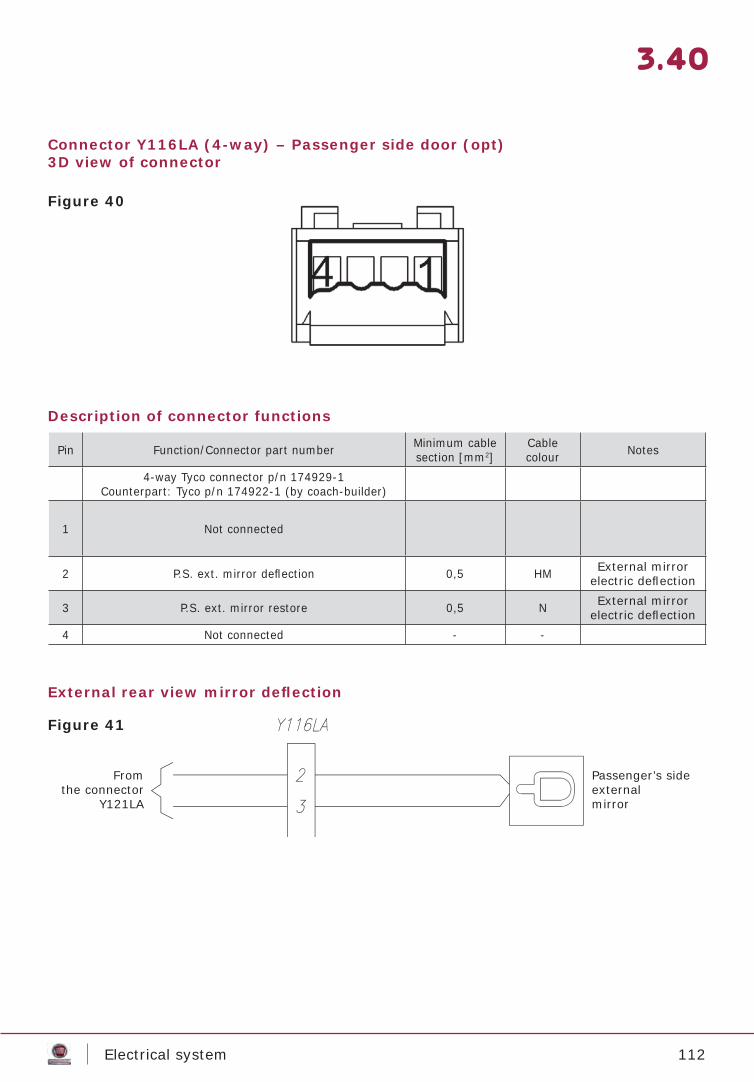
112Electrical system
3.40
Connector Y116LA (4-way) – Passenger side door (opt)3D view of connector
Description of connector functions
External rear view mirror defl ection
Pin Function/Connector part number Minimum cable section [mm2]
Cablecolour Notes
4-way Tyco connector p/n 174929-1Counterpart: Tyco p/n 174922-1 (by coach-builder)
1 Not connected
2 P.S. ext. mirror defl ection 0,5 HM External mirror electric defl ection
3 P.S. ext. mirror restore 0,5 N External mirror electric defl ection
4 Not connected - -
Figure 40
Figure 41
Passenger’s sideexternalmirror
Fromthe connector
Y121LA
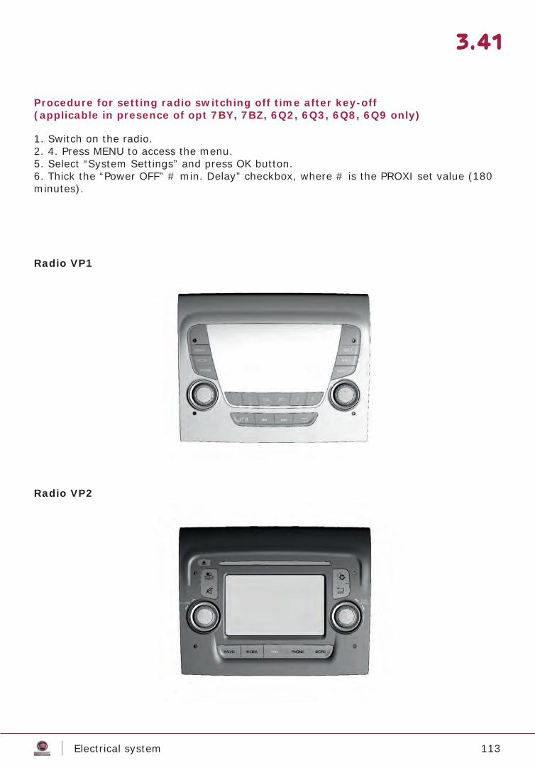
113Electrical system
3.41
Procedure for setting radio switching off time after key-off (applicable in presence of opt 7BY, 7BZ, 6Q2, 6Q3, 6Q8, 6Q9 only)
Radio VP1
Radio VP2
1. Switch on the radio. 2. 4. Press MENU to access the menu. 5. Select “System Settings” and press OK button.6. Thick the “Power OFF” # min. Delay” checkbox, where # is the PROXI set value (180 minutes).
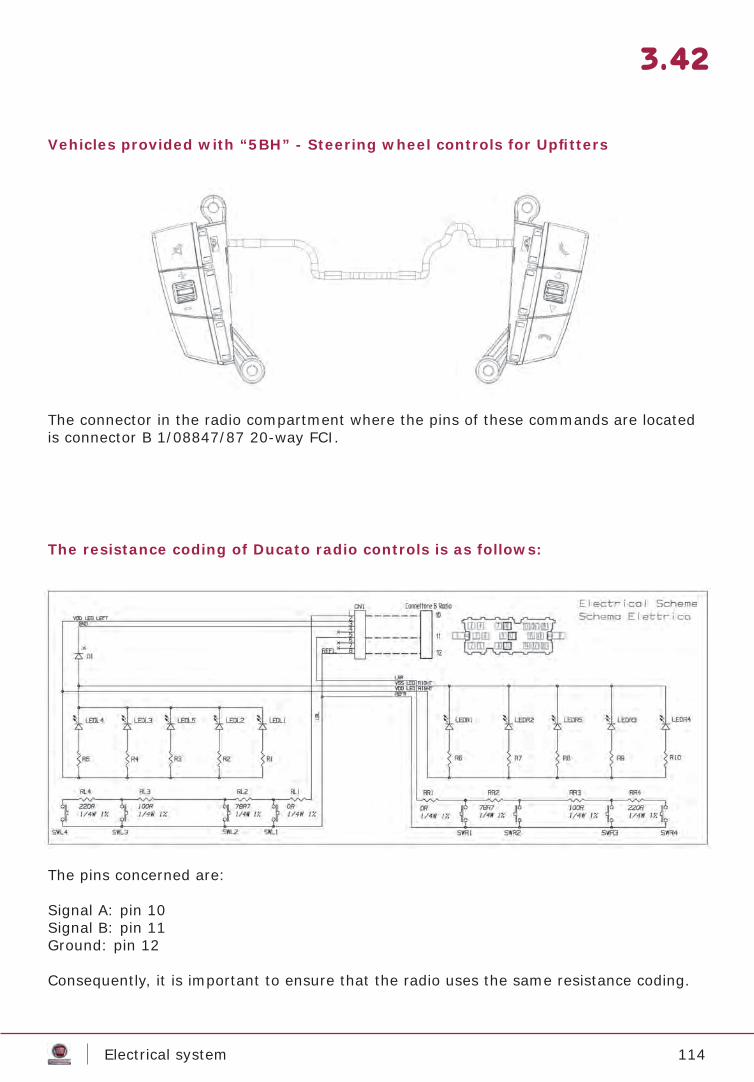
114Electrical system
3.42
Vehicles provided with “5BH” - Steering wheel controls for Upfi tters
The resistance coding of Ducato radio controls is as follows:
The connector in the radio compartment where the pins of these commands are located is connector B 1/08847/87 20-way FCI.
The pins concerned are:
Signal A: pin 10Signal B: pin 11Ground: pin 12
Consequently, it is important to ensure that the radio uses the same resistance coding.
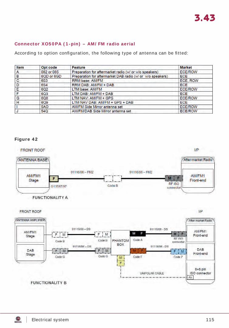
115Electrical system
3.43
Connector XO50PA (1-pin) – AM/FM radio aerial
According to option confi guration, the following type of antenna can be fi tted:
Figure 42
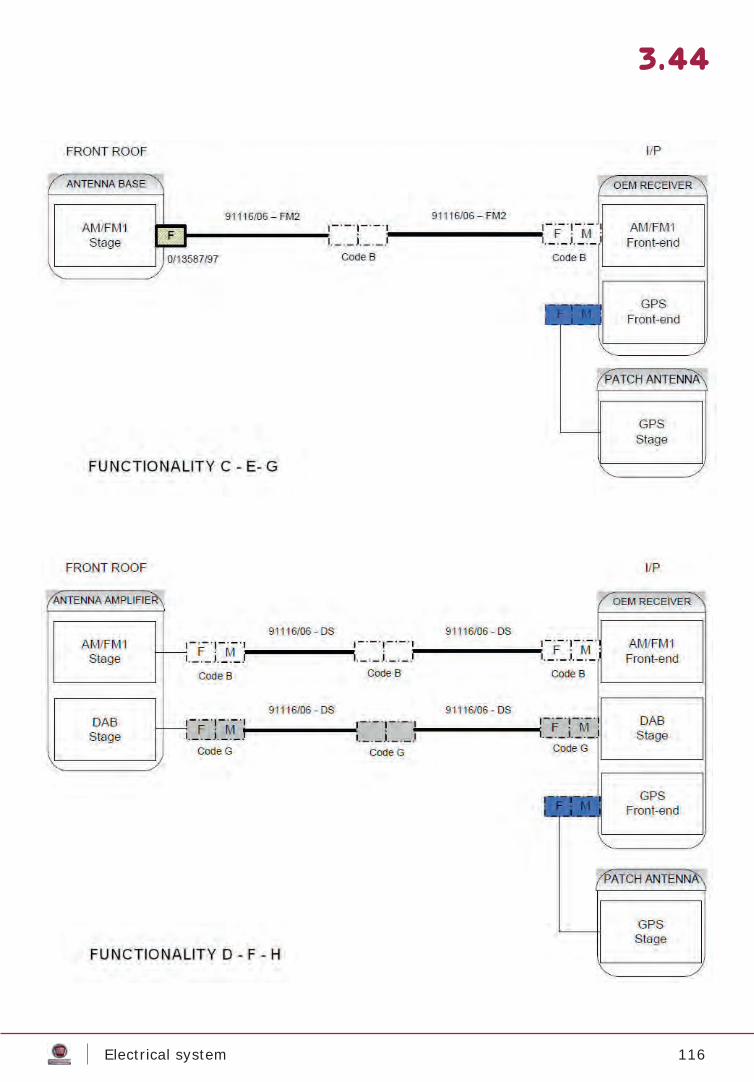
116Electrical system
3.44
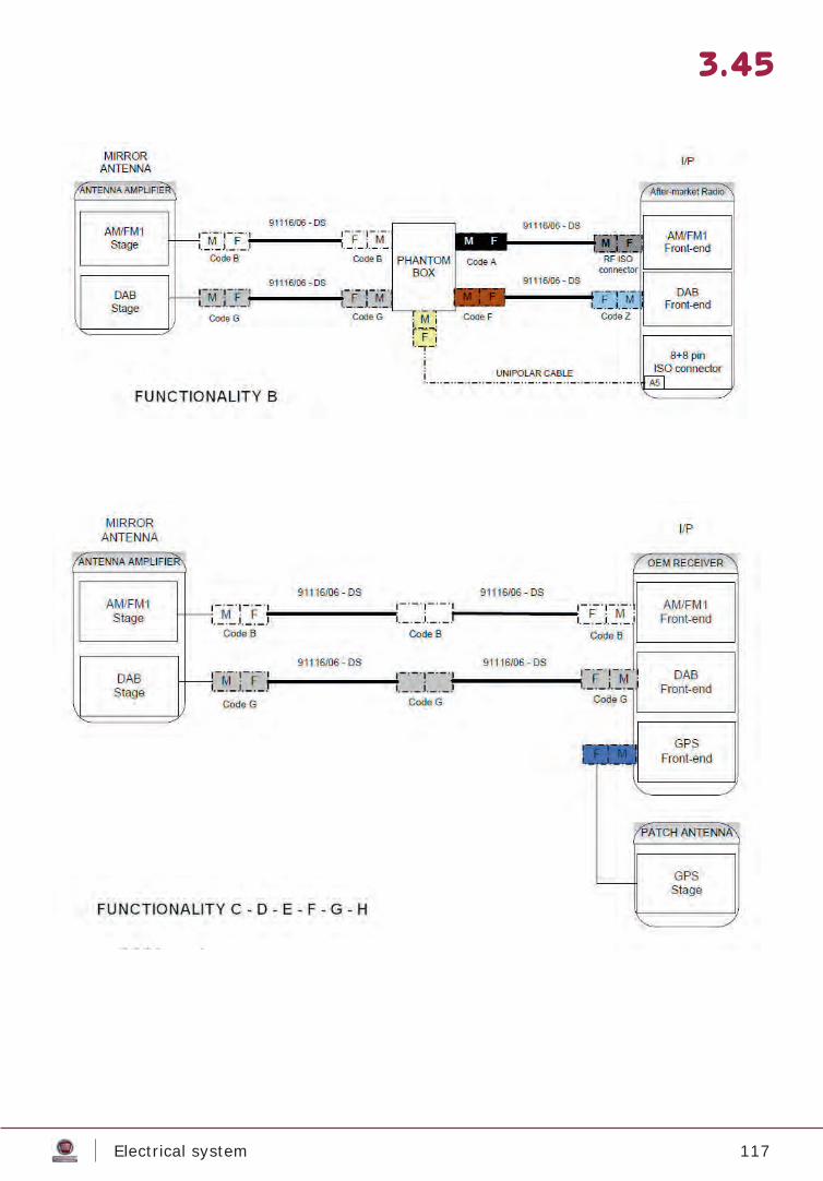
117Electrical system
3.45
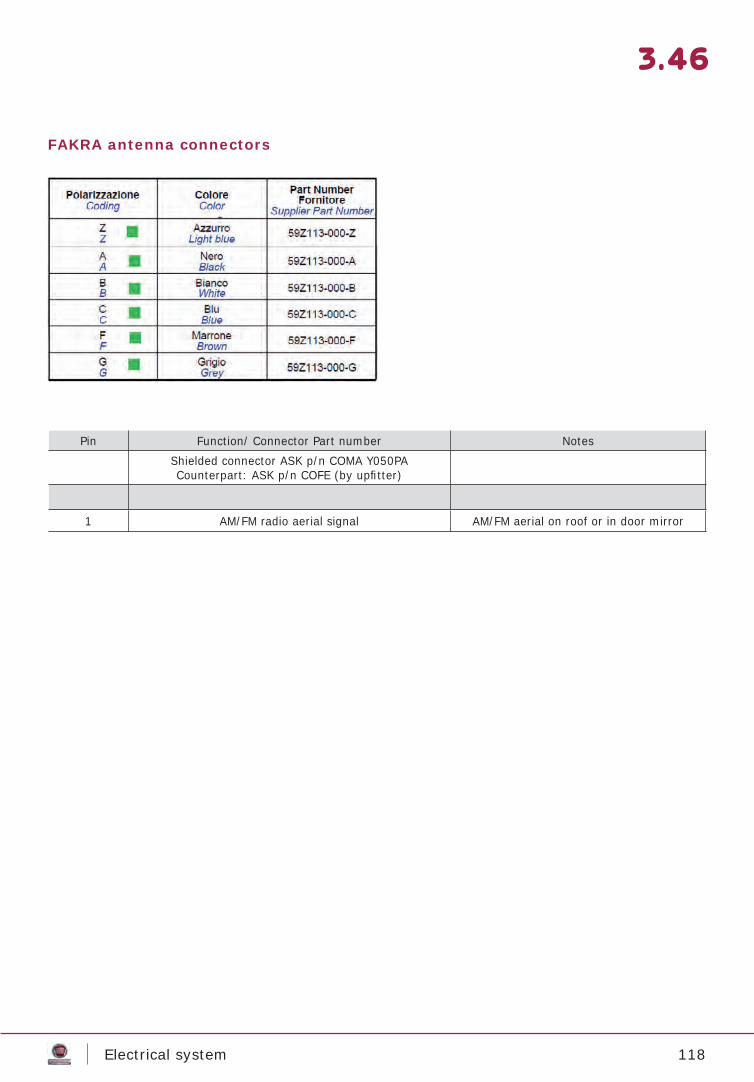
118Electrical system
3.46
FAKRA antenna connectors
Pin Function/ Connector Part number NotesShielded connector ASK p/n COMA Y050PACounterpart: ASK p/n COFE (by upfi tter)
1 AM/FM radio aerial signal AM/FM aerial on roof or in door mirror
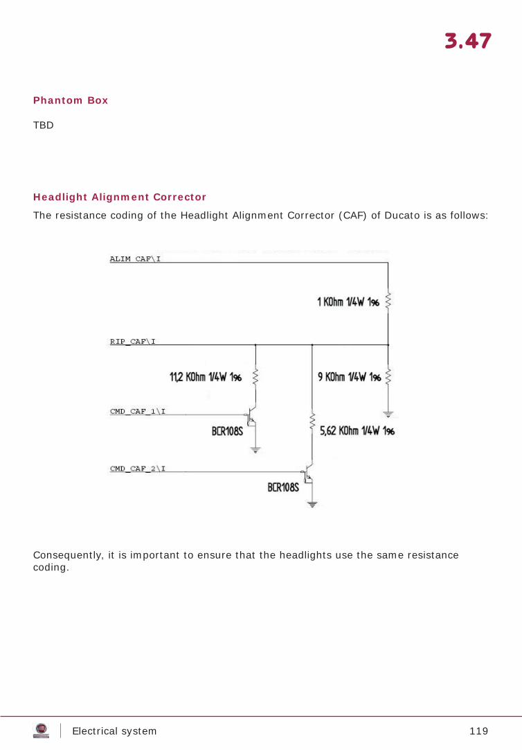
119Electrical system
3.47
Phantom Box
Headlight Alignment Corrector
TBD
The resistance coding of the Headlight Alignment Corrector (CAF) of Ducato is as follows:
Consequently, it is important to ensure that the headlights use the same resistancecoding.
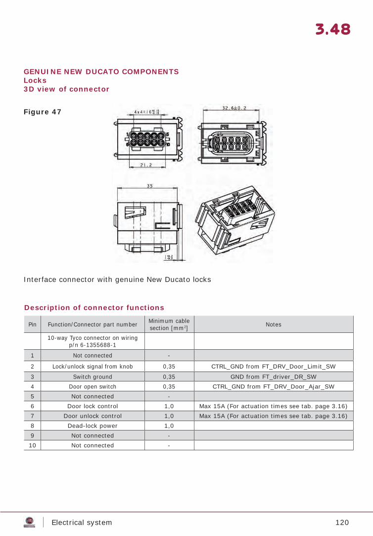
120Electrical system
3.48
GENUINE NEW DUCATO COMPONENTSLocks3D view of connector
Description of connector functions
Interface connector with genuine New Ducato locks
Pin Function/Connector part number Minimum cablesection [mm2] Notes
10-way Tyco connector on wiring p/n 6-1355688-1
1 Not connected -
2 Lock/unlock signal from knob 0,35 CTRL_GND from FT_DRV_Door_Limit_SW
3 Switch ground 0,35 GND from FT_driver_DR_SW4 Door open switch 0,35 CTRL_GND from FT_DRV_Door_Ajar_SW5 Not connected -6 Door lock control 1,0 Max 15A (For actuation times see tab. page 3.16)7 Door unlock control 1,0 Max 15A (For actuation times see tab. page 3.16)8 Dead-lock power 1,09 Not connected -10 Not connected -
Figure 47
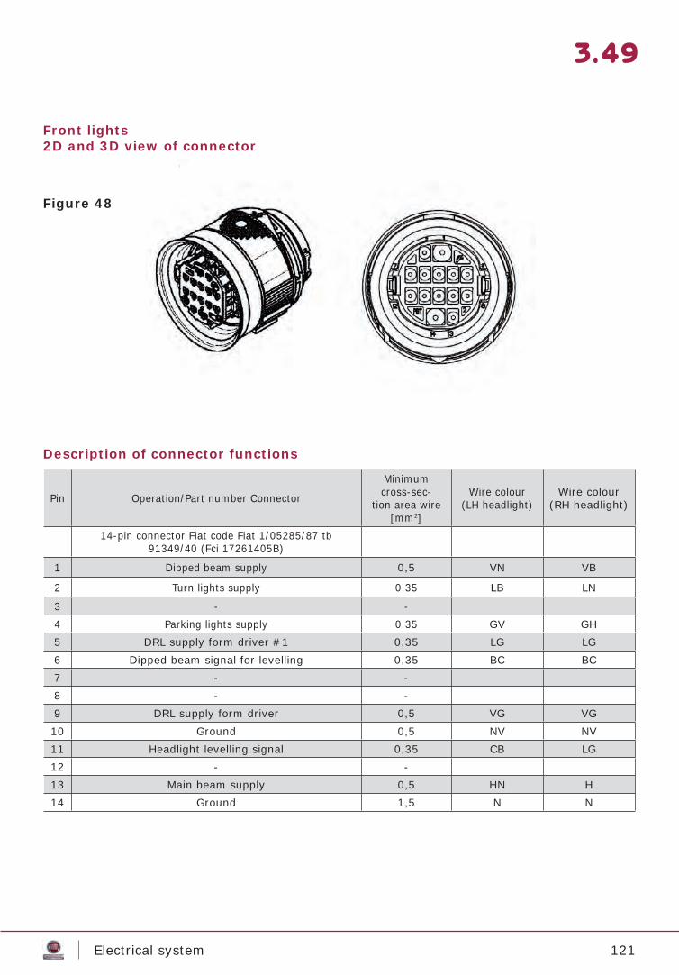
121Electrical system
3.49
Front lights2D and 3D view of connector
Description of connector functions
Pin Operation/Part number Connector
Minimum cross-sec-
tion area wire [mm2]
Wire colour(LH headlight)
Wire colour (RH headlight)
14-pin connector Fiat code Fiat 1/05285/87 tb 91349/40 (Fci 17261405B)
1 Dipped beam supply 0,5 VN VB
2 Turn lights supply 0,35 LB LN
3 - -4 Parking lights supply 0,35 GV GH5 DRL supply form driver #1 0,35 LG LG6 Dipped beam signal for levelling 0,35 BC BC7 - -8 - -9 DRL supply form driver 0,5 VG VG10 Ground 0,5 NV NV11 Headlight levelling signal 0,35 CB LG12 - -13 Main beam supply 0,5 HN H14 Ground 1,5 N N
Figure 48
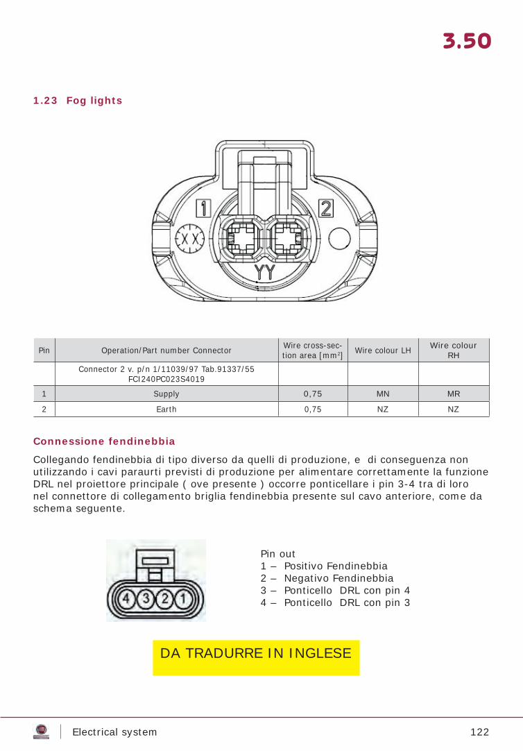
122Electrical system
3.50
1.23 Fog lights
Pin Operation/Part number Connector Wire cross-sec-tion area [mm2] Wire colour LH Wire colour
RH
Connector 2 v. p/n 1/11039/97 Tab.91337/55 FCI240PC023S4019
1 Supply 0,75 MN MR
2 Earth 0,75 NZ NZ
Connessione fendinebbia
Collegando fendinebbia di tipo diverso da quelli di produzione, e di conseguenza non utilizzando i cavi paraurti previsti di produzione per alimentare correttamente la funzione DRL nel proiettore principale ( ove presente ) occorre ponticellare i pin 3-4 tra di loro nel connettore di collegamento briglia fendinebbia presente sul cavo anteriore, come da schema seguente.
Pin out1 – Positivo Fendinebbia2 – Negativo Fendinebbia3 – Ponticello DRL con pin 44 – Ponticello DRL con pin 3
DA TRADURRE IN INGLESE
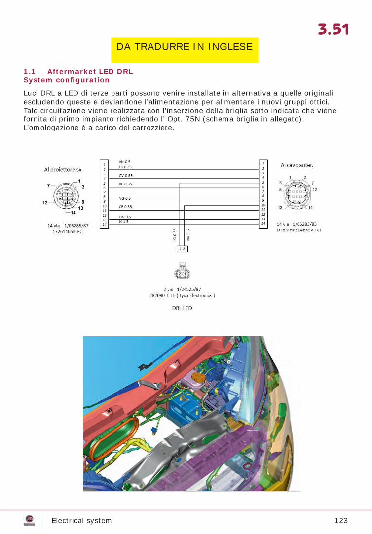
123Electrical system
3.51
1.1 Aftermarket LED DRL System confi guration
Luci DRL a LED di terze parti possono venire installate in alternativa a quelle originali escludendo queste e deviandone l’alimentazione per alimentare i nuovi gruppi ottici.Tale circuitazione viene realizzata con l’inserzione della briglia sotto indicata che viene fornita di primo impianto richiedendo l’ Opt. 75N (schema briglia in allegato).L’omologazione è a carico del carrozziere.
DA TRADURRE IN INGLESE

124Electrical system
3.52
1.25 Taillights for chassis-cabs/cowls 2D view of connector
6.4.2 Description of connector functions
Pin Function/Connector part number NotesLH light – 7-way Tyco connector on wiring p/n 967650-1
1 Bulb ground 1
2 Rear fog warning light 0,5
3 Stop light 0,54 Direction indicator 0,55 Not connected -6 Side marker light 0,57 Not connected - RH light – 7-way Tyco connector p/n 967650-1 1 Bulb ground 12 Not connected -3 Stop light 0,54 Direction indicator 0,55 Reversing light 16 Side marker light 0,57 Not connected -
Figure 49
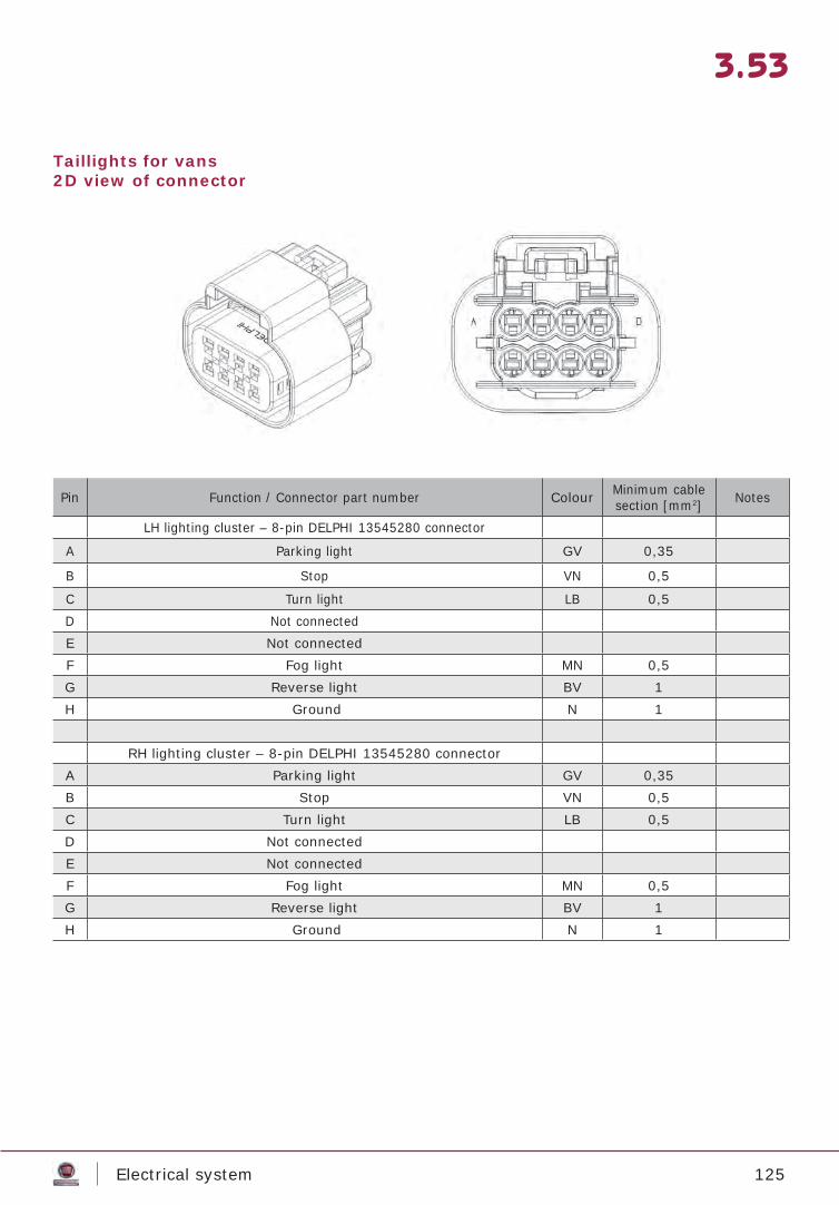
125Electrical system
3.53
Taillights for vans2D view of connector
Pin Function / Connector part number Colour Minimum cable section [mm2] Notes
LH lighting cluster – 8-pin DELPHI 13545280 connector
A Parking light GV 0,35
B Stop VN 0,5
C Turn light LB 0,5D Not connectedE Not connectedF Fog light MN 0,5G Reverse light BV 1H Ground N 1
RH lighting cluster – 8-pin DELPHI 13545280 connector A Parking light GV 0,35B Stop VN 0,5C Turn light LB 0,5D Not connectedE Not connectedF Fog light MN 0,5G Reverse light BV 1H Ground N 1
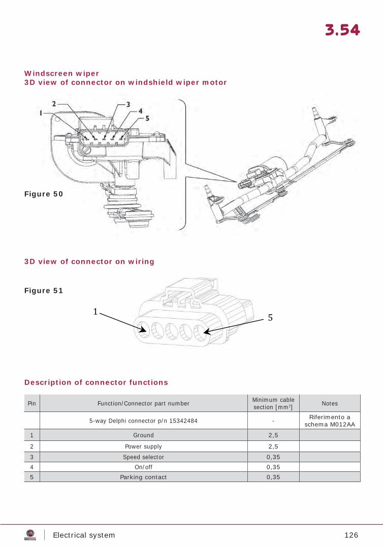
126Electrical system
3.54
Windscreen wiper3D view of connector on windshield wiper motor
3D view of connector on wiring
Description of connector functions
Pin Function/Connector part number Minimum cable section [mm2] Notes
5-way Delphi connector p/n 15342484 - Riferimento a schema M012AA
1 Ground 2,5
2 Power supply 2,5
3 Speed selector 0,354 On/off 0,355 Parking contact 0,35
Figure 50
Figure 51
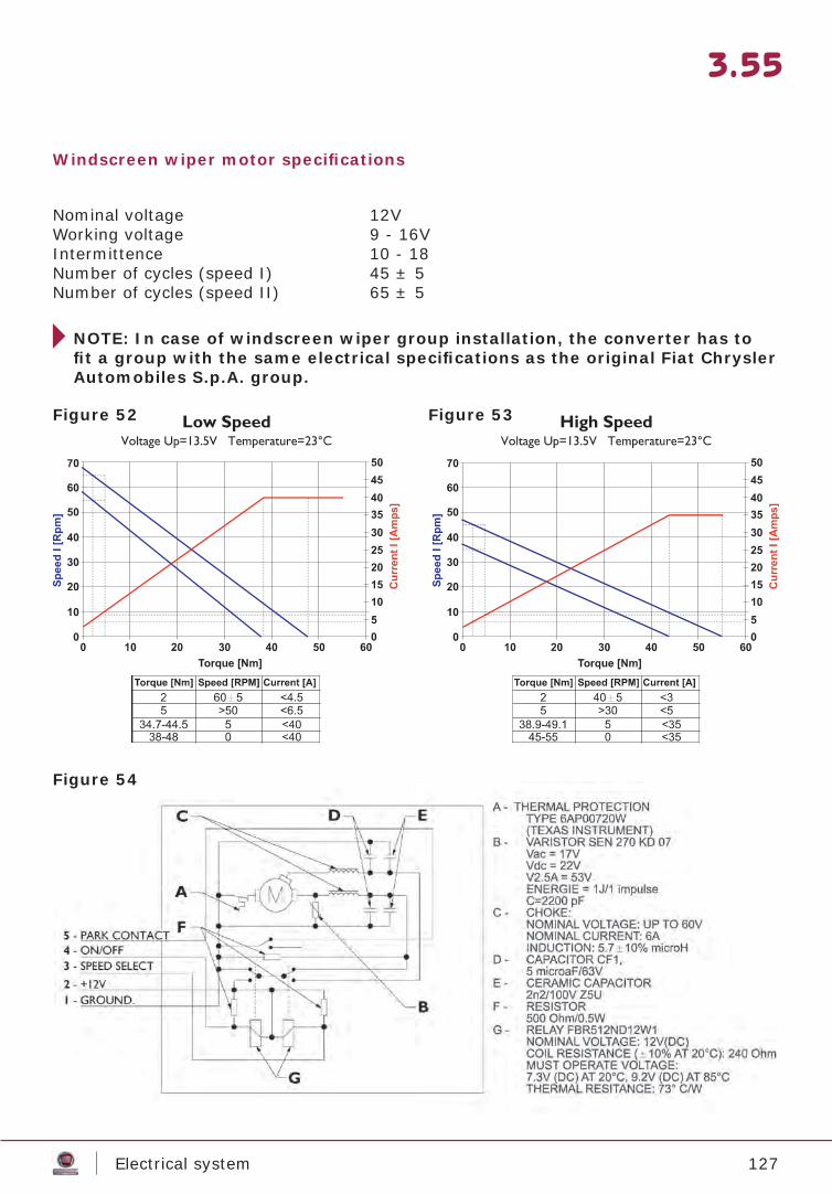
127Electrical system
3.55
Windscreen wiper motor specifi cations
Nominal voltage 12VWorking voltage 9 - 16VIntermittence 10 - 18Number of cycles (speed I) 45 ± 5Number of cycles (speed II) 65 ± 5
NOTE: In case of windscreen wiper group installation, the converter has to fi t a group with the same electrical specifi cations as the original Fiat Chrysler Automobiles S.p.A. group.
Figure 52 Figure 53
Figure 54
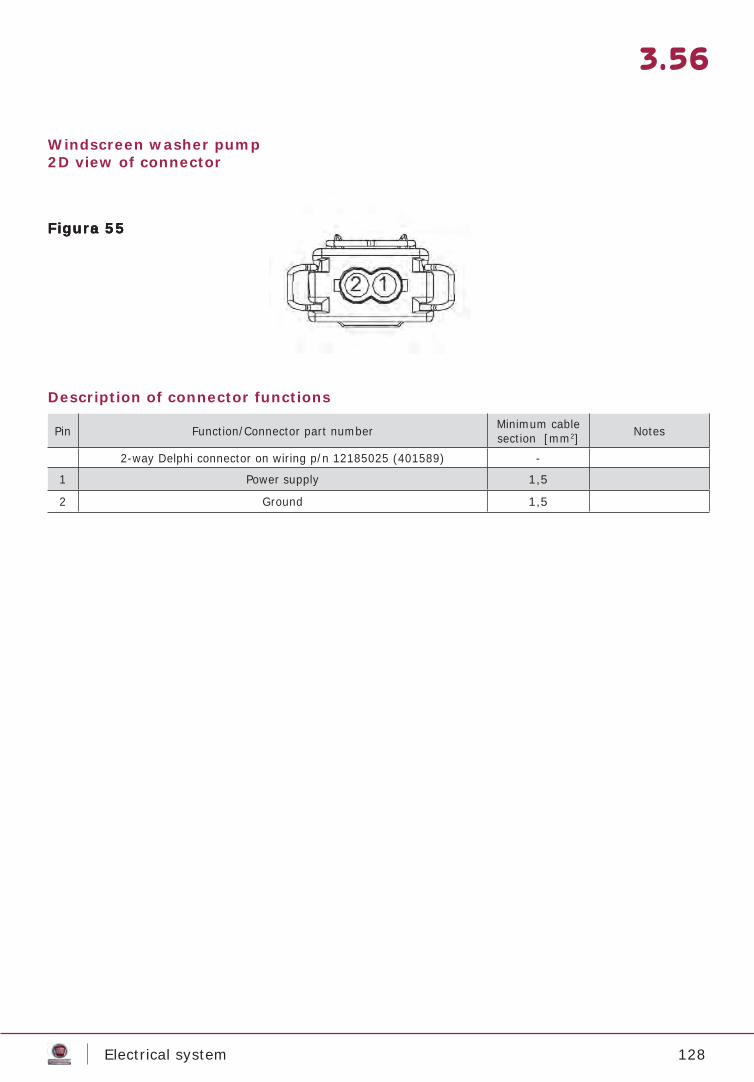
128Electrical system
3.56
Windscreen washer pump2D view of connector
Description of connector functions
Pin Function/Connector part number Minimum cable section [mm2] Notes
2-way Delphi connector on wiring p/n 12185025 (401589) -
1 Power supply 1,5
2 Ground 1,5
Figura 55Figura 55Figure 55
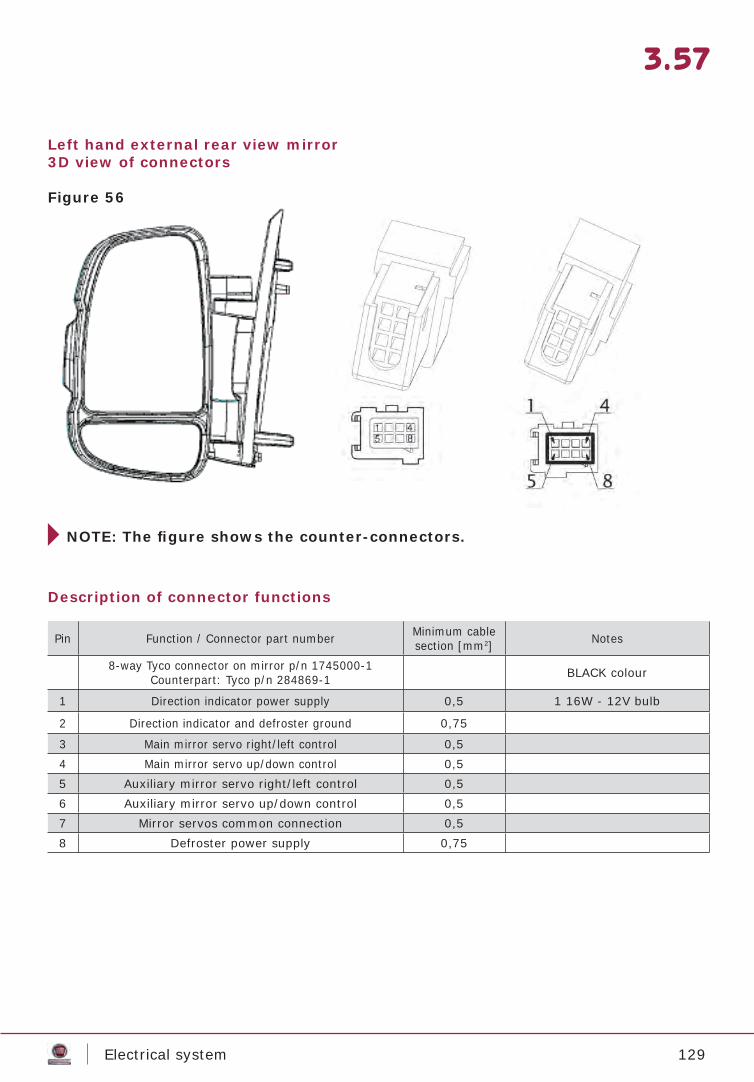
129Electrical system
3.57
Left hand external rear view mirror3D view of connectors
NOTE: The fi gure shows the counter-connectors.
Description of connector functions
Pin Function / Connector part number Minimum cable section [mm2] Notes
8-way Tyco connector on mirror p/n 1745000-1Counterpart: Tyco p/n 284869-1 BLACK colour
1 Direction indicator power supply 0,5 1 16W - 12V bulb
2 Direction indicator and defroster ground 0,75
3 Main mirror servo right/left control 0,54 Main mirror servo up/down control 0,55 Auxiliary mirror servo right/left control 0,56 Auxiliary mirror servo up/down control 0,57 Mirror servos common connection 0,58 Defroster power supply 0,75
Figure 56
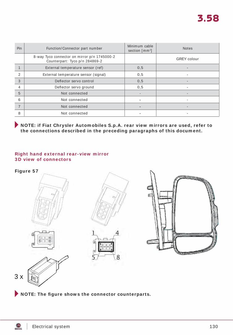
130Electrical system
3.58
Pin Function/Connector part number Minimum cable section [mm2] Notes
8-way Tyco connector on mirror p/n 1745000-2Counterpart: Tyco p/n 284869-2 GREY colour
1 External temperature sensor (ref) 0,5 -
2 External temperature sensor (signal) 0,5 -
3 Defl ector servo control 0,5 -4 Defl ector servo ground 0,5 -5 Not connected - -
6 Not connected - -
7 Not connected - -
8 Not connected - -
NOTE: if Fiat Chrysler Automobiles S.p.A. rear view mirrors are used, refer to the connections described in the preceding paragraphs of this document.
Right hand external rear-view mirror3D view of connectors
3 x
NOTE: The fi gure shows the connector counterparts.
Figure 57
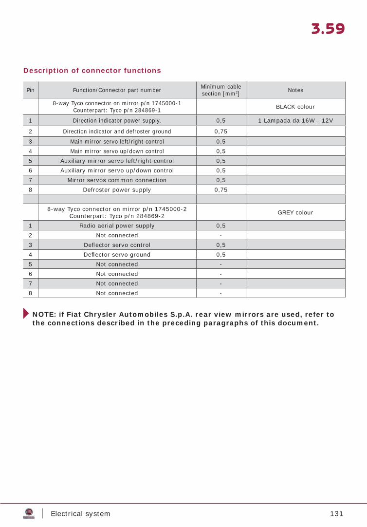
131Electrical system
3.59
Description of connector functions
Pin Function/Connector part number Minimum cable section [mm2] Notes
8-way Tyco connector on mirror p/n 1745000-1Counterpart: Tyco p/n 284869-1 BLACK colour
1 Direction indicator power supply. 0,5 1 Lampada da 16W - 12V
2 Direction indicator and defroster ground 0,75
3 Main mirror servo left/right control 0,54 Main mirror servo up/down control 0,55 Auxiliary mirror servo left/right control 0,56 Auxiliary mirror servo up/down control 0,57 Mirror servos common connection 0,58 Defroster power supply 0,75
8-way Tyco connector on mirror p/n 1745000-2Counterpart: Tyco p/n 284869-2 GREY colour
1 Radio aerial power supply 0,52 Not connected -3 Defl ector servo control 0,54 Defl ector servo ground 0,55 Not connected -6 Not connected -7 Not connected -8 Not connected -
NOTE: if Fiat Chrysler Automobiles S.p.A. rear view mirrors are used, refer to the connections described in the preceding paragraphs of this document.
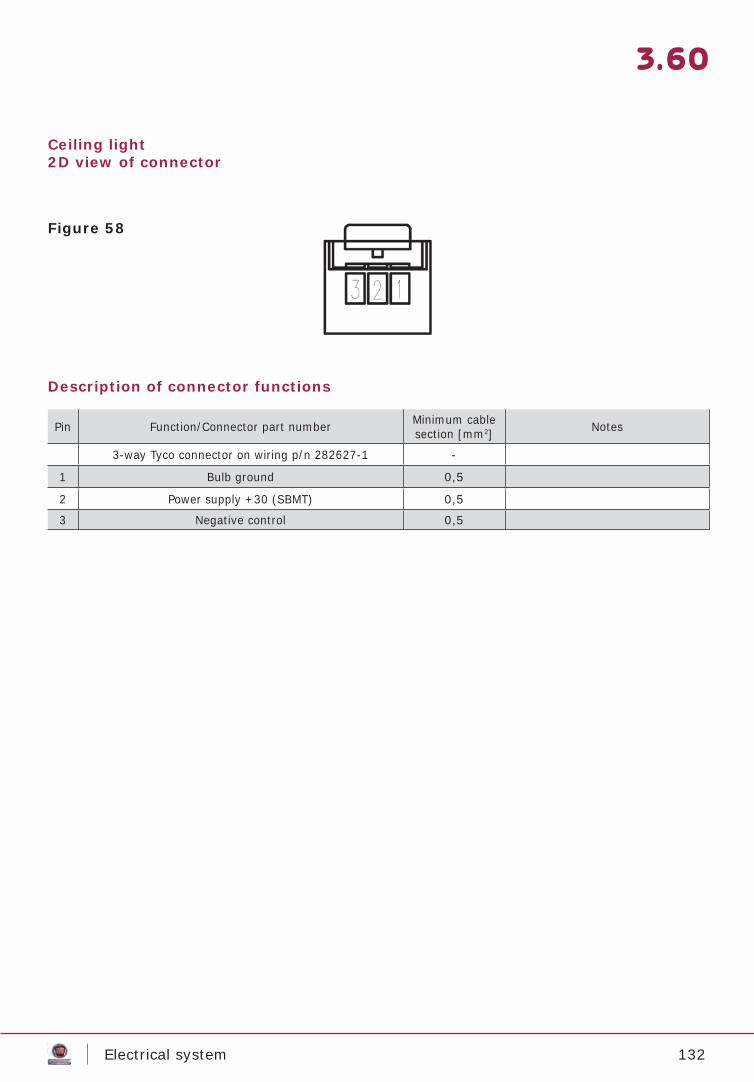
132Electrical system
3.60
Ceiling light2D view of connector
Description of connector functions
Pin Function/Connector part number Minimum cable section [mm2] Notes
3-way Tyco connector on wiring p/n 282627-1 -
1 Bulb ground 0,5
2 Power supply +30 (SBMT) 0,5
3 Negative control 0,5
Figure 58
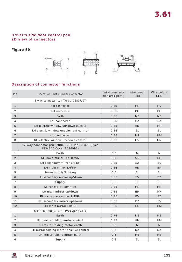
133Electrical system
3.61
Driver’s side door control pad2D view of connectors
Description of connector functions
Pin Operation/Part number Connector Wire cross-sec-tion area [mm2]
Wire colour LHD
Wire colour RHD
8-way connector p/n Tyco 1/08807/97 -
1 not connected 0,35 HN HV
2 not connected 0,35 BH BH
3 Earth 0,35 NZ NZ4 not connected 0,35 SZ SZ5 LH electric window up/down control 0,35 HM HR6 LH electric window enablement control 0,35 BL BL7 not connected 0,35 HR HM8 RH electric window up/down control 0,35 HV HN
12-way connector p/n 1/08402/07 Tab. 91300 (Tyco 1534100 Cover 1534093) -
1 Earth 0,5 N N2 RH main mirror UP/DOWN 0,35 MN BH3 LH secondary mirror LH/RH 0,35 SZ BV4 LH main mirror LH/RH 0,35 HM BR5 Power supply/lighting 0,5 BL BL6 LH secondary mirror up/down 0,35 SV BZ7 Supply 0,5 BL BL8 Mirror motor common 0,35 HN HN9 LH main mirror up/down 0,35 BH MN10 RH secondary mirror LH/RH 0,35 BV SZ11 RH secondary mirror up/down 0,35 BZ SV12 RH main mirror LH/RH 0,35 BR HM 6 pin connector p/n Tyco 284802-1 - 1 Earth 0,75 NS NS2 RH mirror folding motor control 0,75 HM HM3 RH mirror folding motor earth 0,5 N N4 LH mirror folding motor positive control 0,5 NZ NZ5 LH mirror folding motor earth 0,5 HB HB6 Supply 0,5 BL BL
Figure 59
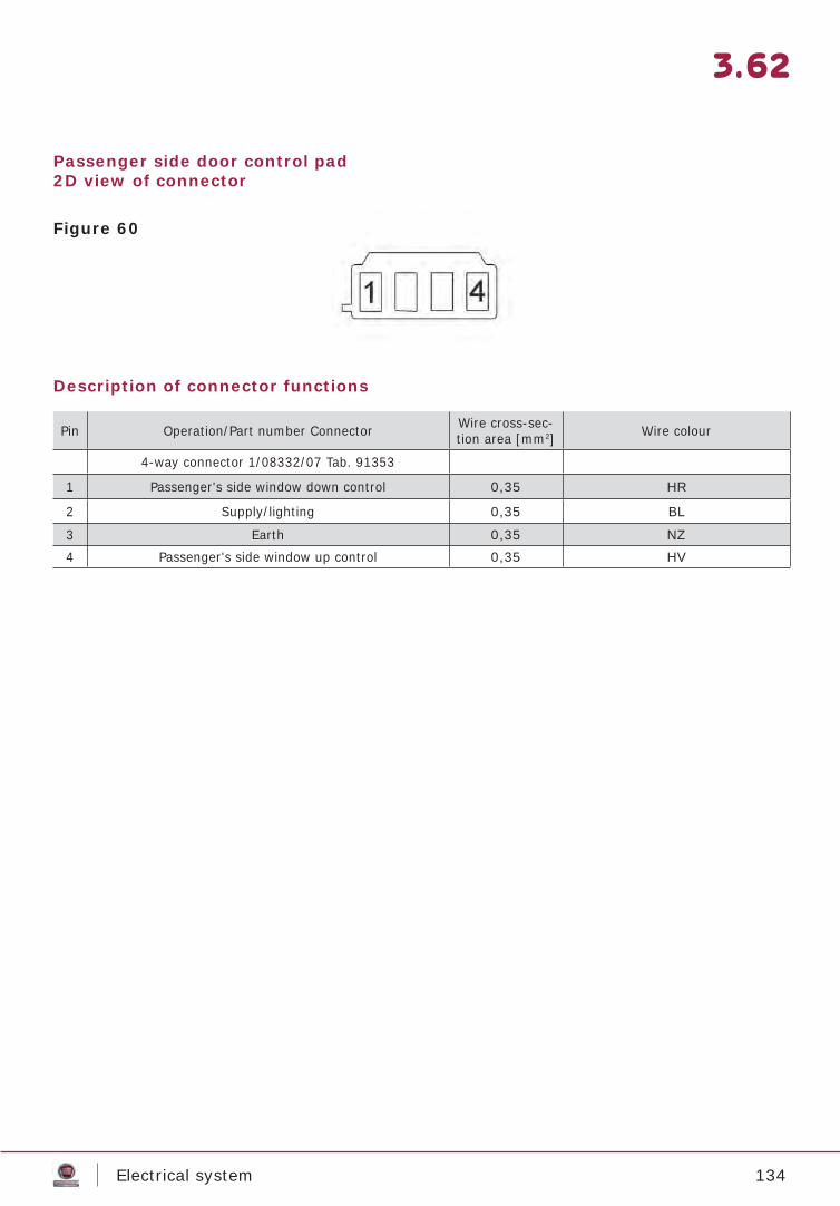
134Electrical system
3.62
Passenger side door control pad2D view of connector
Description of connector functions
Pin Operation/Part number Connector Wire cross-sec-tion area [mm2] Wire colour
4-way connector 1/08332/07 Tab. 91353
1 Passenger's side window down control 0,35 HR
2 Supply/lighting 0,35 BL
3 Earth 0,35 NZ4 Passenger's side window up control 0,35 HV
Figure 60
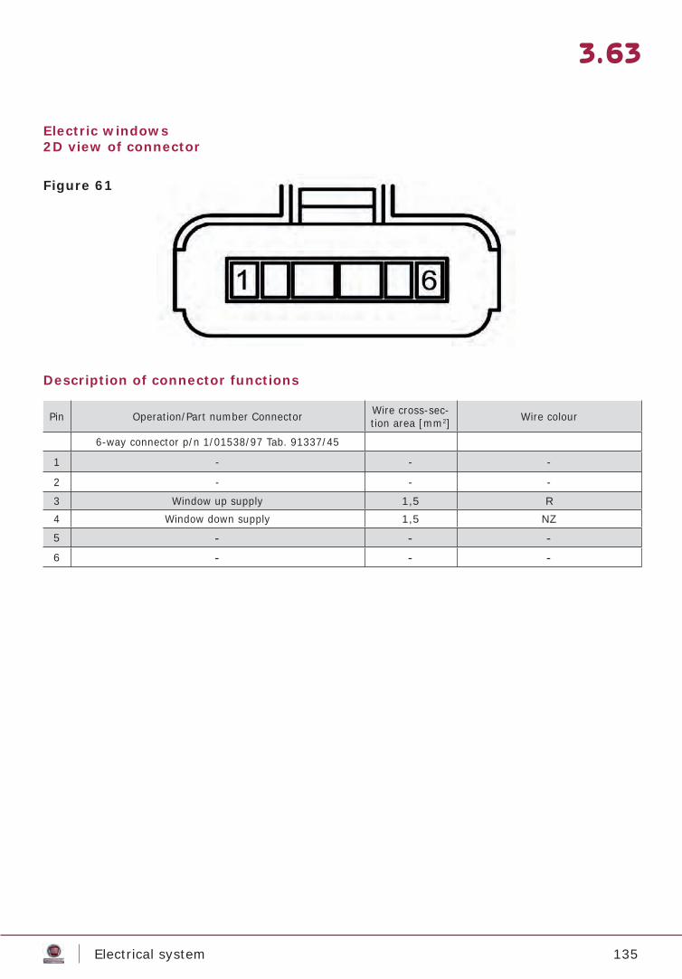
135Electrical system
3.63
Electric windows2D view of connector
Description of connector functions
Pin Operation/Part number Connector Wire cross-sec-tion area [mm2] Wire colour
6-way connector p/n 1/01538/97 Tab. 91337/45 1 - - -
2 - - -
3 Window up supply 1,5 R4 Window down supply 1,5 NZ
5 - - -6 - - -
Figure 61
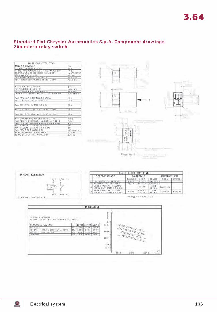
136Electrical system
3.64
Standard Fiat Chrysler Automobiles S.p.A. Component drawings20a micro relay switch
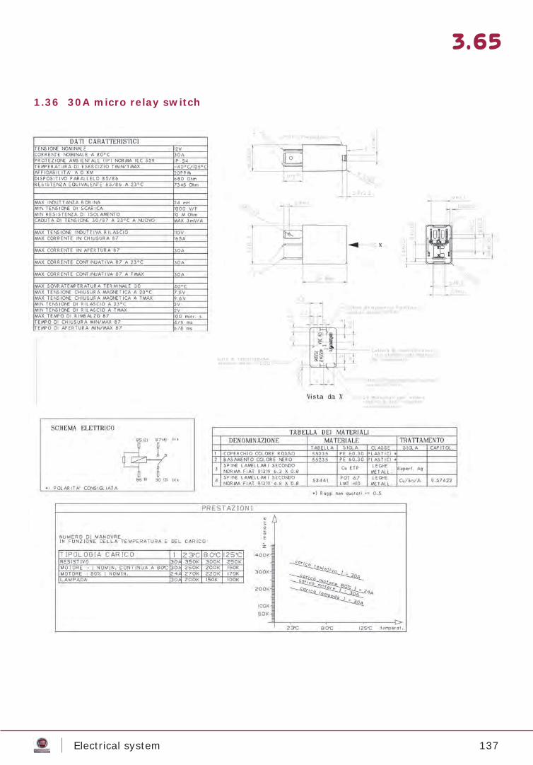
137Electrical system
3.65
1.36 30A micro relay switch
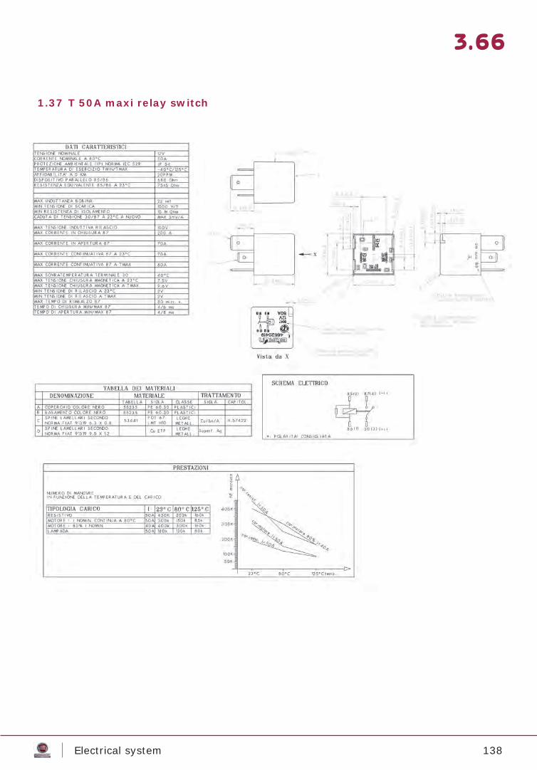
138Electrical system
3.66
1.37 T 50A maxi relay switch
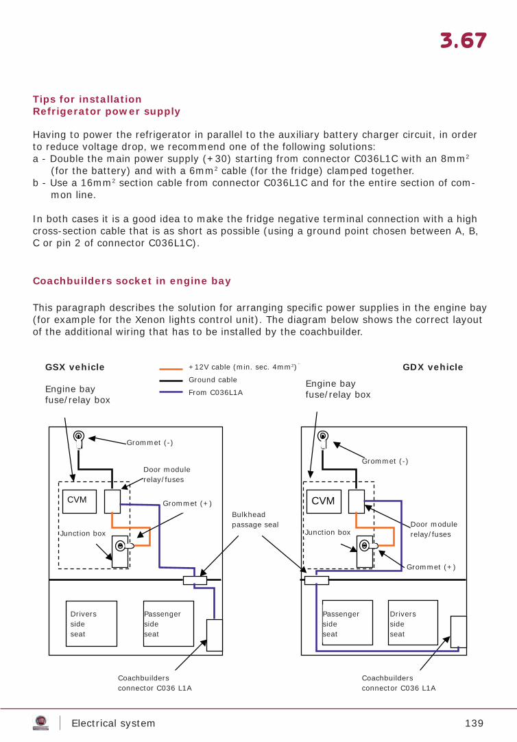
139Electrical system
3.67
Tips for installationRefrigerator power supply
Coachbuilders socket in engine bay
Having to power the refrigerator in parallel to the auxiliary battery charger circuit, in order to reduce voltage drop, we recommend one of the following solutions:a - Double the main power supply (+30) starting from connector C036L1C with an 8mm2
(for the battery) and with a 6mm2 cable (for the fridge) clamped together.b - Use a 16mm2 section cable from connector C036L1C and for the entire section of com-
mon line.
In both cases it is a good idea to make the fridge negative terminal connection with a high cross-section cable that is as short as possible (using a ground point chosen between A, B, C or pin 2 of connector C036L1C).
This paragraph describes the solution for arranging specifi c power supplies in the engine bay (for example for the Xenon lights control unit). The diagram below shows the correct layout of the additional wiring that has to be installed by the coachbuilder.
CVM
Nodo di derivazione
Modulo porta relè/fusibili
Guarnizione passa-parete
Presa Carrozzieri Connettore C036 L1A
Sedile Lato
Guida
Occhiello (-)
Sedile Lato
Passeggero
Cavo +12V (sez. min. 4mm2) Cavo Massa Cavi da C036L1A Scatola
fusibili/relè vano motore
Occhiello (+)
Veicolo GSX
CVM
Nodo di derivazione
Modulo porta relè/fusibili
Presa Carrozzieri Connettore C036 L1A
Sedile Lato
Passeggero
Occhiello (-)
Sedile Lato
Guida
Scatola fusibili/relè vano motore
Occhiello (+)
Veicolo GDX GSX vehicle
Engine bayfuse/relay box
+12V cable (min. sec. 4mm2)
Ground cable
From C036L1AEngine bayfuse/relay box
GDX vehicle
Grommet (-)
Door modulerelay/fuses
Grommet (+)
Junction box
Driversside seat
Passengerside seat
Passengerside seat
Driversside seat
Coachbuildersconnector C036 L1A
Coachbuildersconnector C036 L1A
Bulkheadpassage seal
Junction box
Grommet (-)
Door modulerelay/fuses
Grommet (+)

140Electrical system
3.68
List of materials:
• Door module relay/fuse box: MTA p/n 03.01560• Module mounting bracket: MTA p/n 03.00475• Bulkhead passage seal: SUMITOMO drawing number 1334413080• Grommet (+): MTA p/n 17.06711 (M8 hole)• Grommet (-): M8 hole
(for cable sections from 1 to 2.5 mm2 recommended MTA p/n 17.06731)• M8 nut: M8 hexagonal nut with nylon ring
Description of installation procedure:• Remove the relay/fuse box cover in the engine bay by removing the nuts.• Unscrew the nut from the junction box pin (see fi gure 62), overlay the grommet (+)
on the one already present (ATTENTION, vice-versa not permitted), then re-tighten the nut to torque of 15Nm ± 10%.
• Connect the grommet (-) to the ground pin present in the frontal area (see fi gure 63), after which apply an M8 nut, tightening it to torque of 15Nm ± 10%.
• Insert the door module relay/fuse box in the seat in the box in the engine bay.
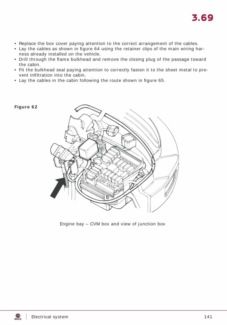
141Electrical system
3.69
• Replace the box cover paying attention to the correct arrangement of the cables.• Lay the cables as shown in fi gure 64 using the retainer clips of the main wiring har-
ness already installed on the vehicle.• Drill through the fl ame bulkhead and remove the closing plug of the passage toward
the cabin.• Fit the bulkhead seal paying attention to correctly fasten it to the sheet metal to pre-
vent infi ltration into the cabin.• Lay the cables in the cabin following the route shown in fi gure 65.
Engine bay – CVM box and view of junction box
Figure 62
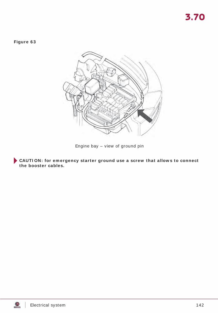
142Electrical system
3.70
Figure 63
Engine bay – view of ground pin
CAUTION: for emergency starter ground use a screw that allows to connect the booster cables.
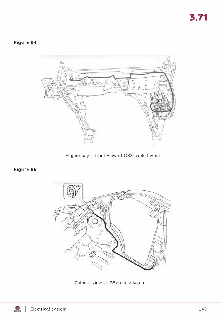
143Electrical system
3.71
Figure 64
Figure 65
Engine bay – front view of GSX cable layout
Cabin – view of GSX cable layout
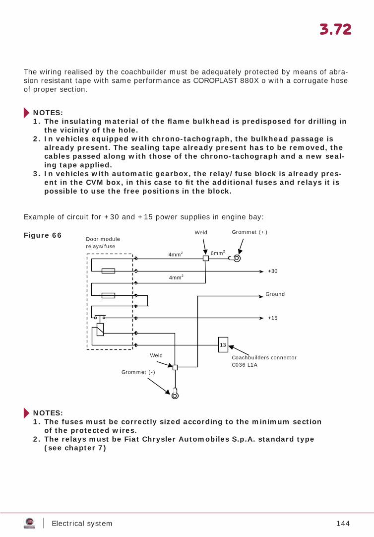
144Electrical system
3.72
The wiring realised by the coachbuilder must be adequately protected by means of abra-sion resistant tape with same performance as COROPLAST 880X o with a corrugate hose of proper section.
NOTES: 1. The insulating material of the fl ame bulkhead is predisposed for drilling in
the vicinity of the hole.2. In vehicles equipped with chrono-tachograph, the bulkhead passage is
already present. The sealing tape already present has to be removed, the cables passed along with those of the chrono-tachograph and a new seal-ing tape applied.
3. In vehicles with automatic gearbox, the relay/fuse block is already pres-ent in the CVM box, in this case to fi t the additional fuses and relays it is possible to use the free positions in the block.
NOTES:1. The fuses must be correctly sized according to the minimum section
of the protected wires.2. The relays must be Fiat Chrysler Automobiles S.p.A. standard type
(see chapter 7)
Example of circuit for +30 and +15 power supplies in engine bay:
Figure 66
Modulo porta relè/fusibili
Presa Carrozzieri Connettore C036 L1A
Occhiello (-)
Occhiello (+) Saldatura
+30
+15
4mm2
4mm2
6mm2
Massa
Saldatura
13
Door modulerelays/fuse
Weld Grommet (+)
Ground
Coachbuilders connectorC036 L1A
Weld
Grommet (-)
145Electrical system
3.73
Anti-theft system
Trailer
Metasystem S.p.A.
Westfalia-Automotive GmbH & Co. KG
If an anti-theft system has to be installed, we recommend using the original kit p/n 50926750 by the Accessories Line, made by an offi cial Fiat Chrysler Automobiles S.p.A. supplier:
Insertion of non-conforming control units into the main circuit of the New Ducato to con-trol additional lights may cause a malfunction in the vehicle electrical/electronic system, for this reason Fiat Chrysler Automobiles S.p.A. recommends using original Accessory Line components. Any customisation can be agreed with the offi cial suppliers of the com-ponent (see list below).
Via Galimberti, n°842100 Reggio Emilia (Italy)TelephoneSwitchboard: +39 0522 364 111FaxSwitchboard: +39 0522 364 150WebInformation at: [email protected] site: www.metasystem.it
Am Sandberg 45Postfatch 26 4033354 Rheda WiedenbrückTelephoneSwitchboard: +49 5242 907 0FaxSwitchboard: +49 5242 907 195WebWeb site: www.westfalia-automotive.de
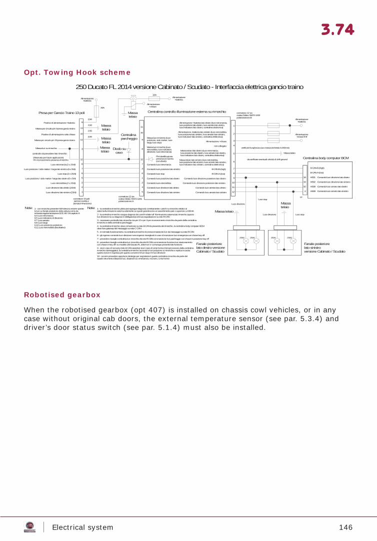
146Electrical system
3.74
Opt. Towing Hook scheme
Centralina controllo illuminazione esterna su rimorchio connettore 12 viecodice Molex 33472-1202polarizzazione B
Alimentazione +chiave 3
Alimentazione +batteria lato destro (luce retromarcia,luce posizione lato destro, luce arresto lato destro,luce indicatore lato destro, centralina elettronica)
1
Alimentazione +batteria lato sinistro (luce retronebbia,luce posizione lato sinistro, luce arresto lato sinistro,luce indicatore lato sinistro, centralina elettronica)
2
4non collegato
Massa telaio lato destro (luce retromarcia,luce posizione lato destro, luce arresto lato destro,luce indicatore lato destro, centralina elettronica)
5
Massa telaio lato sinistro (luce retronebbia,luce posizione lato sinistro, luce arresto lato sinistro,luce indicatore lato sinistro, centralina elettronica)
6
7B CAN B (high)
8B CAN A (low)
9Comando luce direzione posteriore lato destro
10Comando luce direzione posteriore lato sinistro
11Comando luce arresto lato destro
12Comando luce arresto lato sinistro
250 Ducato FL 2014 versione Cabinato / Scudato - Interfaccia elettrica gancio traino
Alimentazione +batteria
Alimentazione +chiave INT
Massa telaio
Centralina body computer BCM
B CAN B (high)
B CAN A (low)
Comando luce direzione lato destro
Comando luce direzione lato sinistro
Comando luce arresto lato destro
Comando luce arresto lato sinistro
HS01
HS02
HS08
HS09
18
19
32
2
21W21W
Luce direzione
Fanale posteriorelato sinistroversione Cabinato / Scudato
21W21W
Fanale posteriorelato destro versioneCabinato / Scudato
Luce stop
Massatelaio
Massa telaio
8
11
10
9
7
3
6
1
2
4
Comando luce direzione lato sinistro5
Luce direzione
Comando luce direzione lato destro
3
11
12
8
7
6
5
2
4
1
connettore 13 poli std ISO 11446-2(tenuta immersione)
Presa per Gancio Traino 13 poli
Luce direzione lato sinistro (21W)
Luce direzione lato destro (21W)
LF
Comando luce retronebbiaLuce retronebbia (2 x 21W)
Comando luce posizione lato destroLuce posizione / side marker / targa lato destro (6 x 5W)
Comando luce stopLuce stop (2 x 21W)
Comando luce posizione lato sinistroLuce posizione / side marker / targa lato sinistro (6 x 5W)
Comando luce retromarciaLuce retromarcia (2 x 21W)
12
Massa luci rimorchio (luceretronebbia, luce indicatoredirezione, luce retromarcia)
Massa luci rimorchio (luceposizione, side marker, lucetarga, luce stop)
Massa luci su rimorchio
10Positivo di alimentazione sotto chiave
Massa per circuito pin 10 presa gancio traino
13Massa per circuito pin 9 presa gancio traino
9Positivo di alimentazione +batteriaMassa telaio
Alimentazione +batteria
Luce stop
Alimentazione +chiave
Massa telaio
Alimentazione +batteria
20A
connettore 12 viecodice Molex 33472-1201polarizzazione A
Massa telaio
20A
2,50
2,50
2,50
2,50
verificare lunghezza cavo massa (richiesto l=150mm)
Centralinaparcheggio
Diodo su cavo
(Riservato per future applicazioni)Pin riconoscimento presenza rimorchio
3 - necessario ponticello lato rimorchio tra pin 12 e pin 3 per riconoscimento rimorchio da parte della centralinarimorchio e della centralina parcheggio
Note:
4 - la centralina rimorchio deve comunicare su rete B CAN la presenza del rimorchio, la centralina body computer BCMdeve fare gateway del messaggio su rete C CAN
1 - con rimorchio presente NON devono essere spentele luci su fanale posteriore della vettura come darichiesta regolamentazione ECE 48 / 04 capitolo 66.4 Luce retromarcia6.5 Luce indicatore di direzione6.7 Luce arresto6.8 Luce targa6.10 Luce posizione posteriore6.11 Luce retronebbia (facoltativo)
Note:
5 - in normale funzionamento, la centralina rimorchio riconosce inserzione luci da messaggio su rete B CAN
1 - la centralina rimorchio pilota (ed egsegue diagnosi) correttamente i carichi su rimorchio relativi alsistema illuminazione esterna solamente se questi garantiscono un assorbimento pari o superiore a 100mA
6 - gli ingressi comando luce direzione sono ingressi risveglianti in caso di inserzione luci emergenza con chiave key off
2 - la centralina rimorchio esegue diagnosi dei carichi relativi all' illuminazione esterna lato rimorchio (specieluci direzione la cui diagnosi è obbligatoria) ed invia segnalazione su rete B CAN
Massa telaio
ponticello da prevedere lato rimorchioPin identificazionepresenza rimorchio(con diodo)
da verificare eventuali criticità di shift ground
9 - sia in caso di recovery (rete B CAN assente) sia in caso di Limp home (microprocessore della centralinarimorchio danneggiato), la centralina rimorchio accende le luci posizione su rimorchio e replica in uscitaquanto riceve in ingresso per quanto concerne le luci stop e le luci direzione
10 - occorre prevedere opportune strategie per segnalazioni guasto centralina rimorchio da parte delquadro strumento (diagnosi luci, diagnosi luci emergenza, recovery, Limp home)
7 - prevedere risveglio centralina luci rimorchio da rete B CAN con inserzione luci parcheggio con chiave in posizione key off
8 - prevedere risveglio centralina luci rimorchio da rete B CAN con inserzione funzione luci stazionamentocon chiave in key off: su modello 250 Ducato FL 2014 non e' comunque presente tale funzione
Robotised gearbox
When the robotised gearbox (opt 407) is installed on chassis cowl vehicles, or in any case without original cab doors, the external temperature sensor (see par. 5.3.4) and driver’s door status switch (see par. 5.1.4) must also be installed.
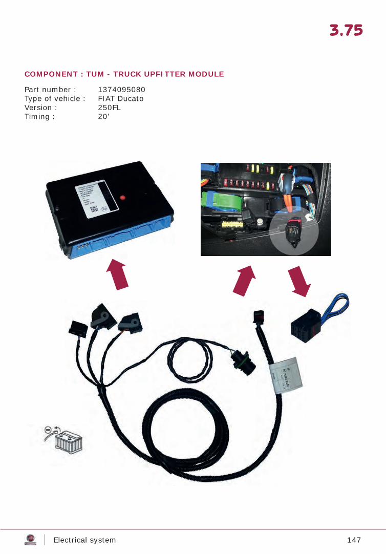
147Electrical system
3.75
Part number : 1374095080Type of vehicle : FIAT DucatoVersion : 250FLTiming : 20’
COMPONENT : TUM - TRUCK UPFITTER MODULE
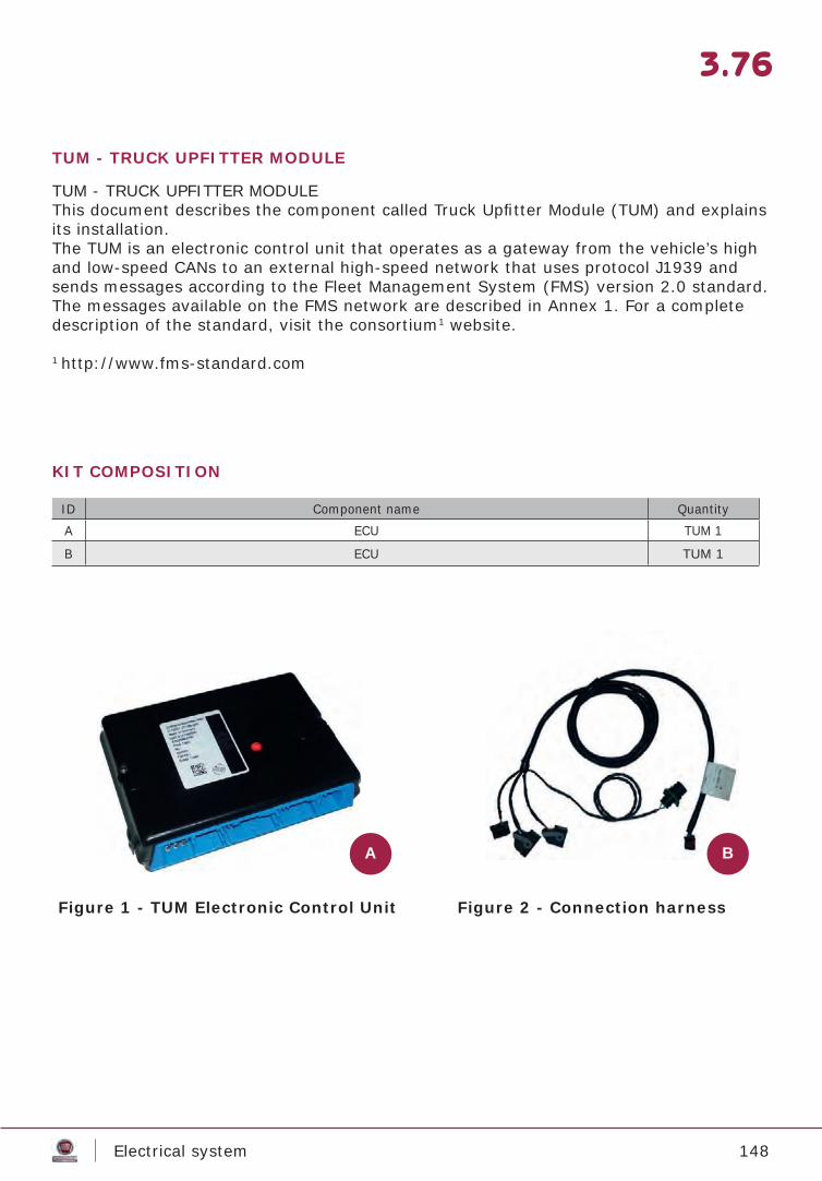
148Electrical system
3.76
TUM - TRUCK UPFITTER MODULE
TUM - TRUCK UPFITTER MODULEThis document describes the component called Truck Upfi tter Module (TUM) and explains its installation.The TUM is an electronic control unit that operates as a gateway from the vehicle’s high and low-speed CANs to an external high-speed network that uses protocol J1939 and sends messages according to the Fleet Management System (FMS) version 2.0 standard. The messages available on the FMS network are described in Annex 1. For a complete description of the standard, visit the consortium1 website.
1 http://www.fms-standard.com
KIT COMPOSITION
ID Component name QuantityA ECU TUM 1
B ECU TUM 1
Figure 1 - TUM Electronic Control Unit Figure 2 - Connection harness
A B
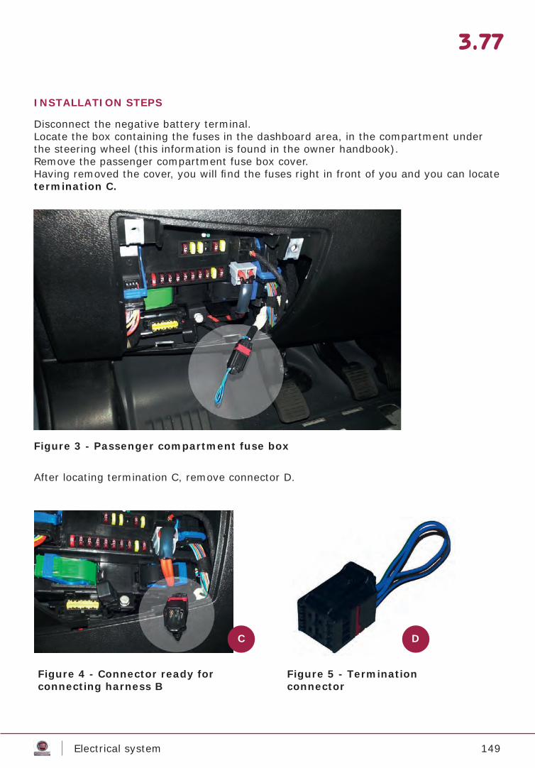
149Electrical system
3.77
INSTALLATION STEPS
Disconnect the negative battery terminal.Locate the box containing the fuses in the dashboard area, in the compartment under the steering wheel (this information is found in the owner handbook).Remove the passenger compartment fuse box cover.Having removed the cover, you will fi nd the fuses right in front of you and you can locate termination C.
Figure 3 - Passenger compartment fuse box
After locating termination C, remove connector D.
Figure 4 - Connector ready forconnecting harness B
Figure 5 - Terminationconnector
C D
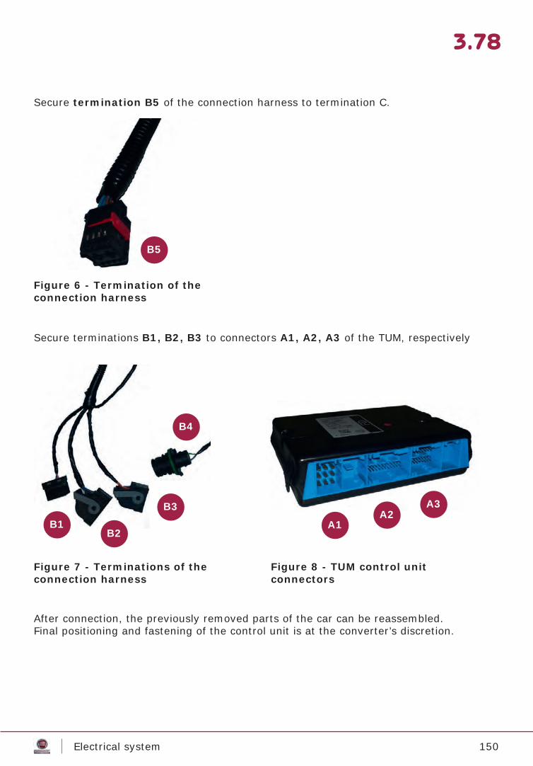
150Electrical system
3.78
Secure termination B5 of the connection harness to termination C.
After connection, the previously removed parts of the car can be reassembled.Final positioning and fastening of the control unit is at the converter’s discretion.
Secure terminations B1, B2, B3 to connectors A1, A2, A3 of the TUM, respectively
Figure 6 - Termination of theconnection harness
Figure 7 - Terminations of theconnection harness
Figure 8 - TUM control unit connectors
B5
B1B2
B3
B4
A1A2
A3
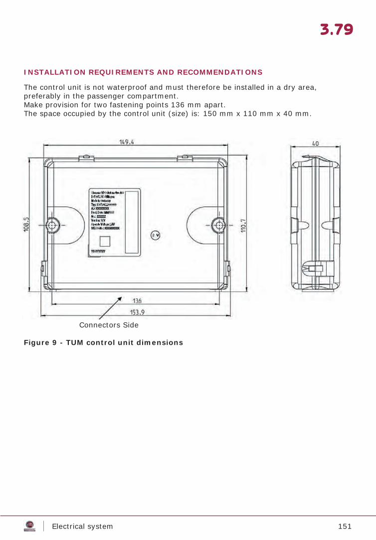
151Electrical system
3.79
INSTALLATION REQUIREMENTS AND RECOMMENDATIONS
The control unit is not waterproof and must therefore be installed in a dry area,preferably in the passenger compartment.Make provision for two fastening points 136 mm apart.The space occupied by the control unit (size) is: 150 mm x 110 mm x 40 mm.
Connectors Side
Figure 9 - TUM control unit dimensions
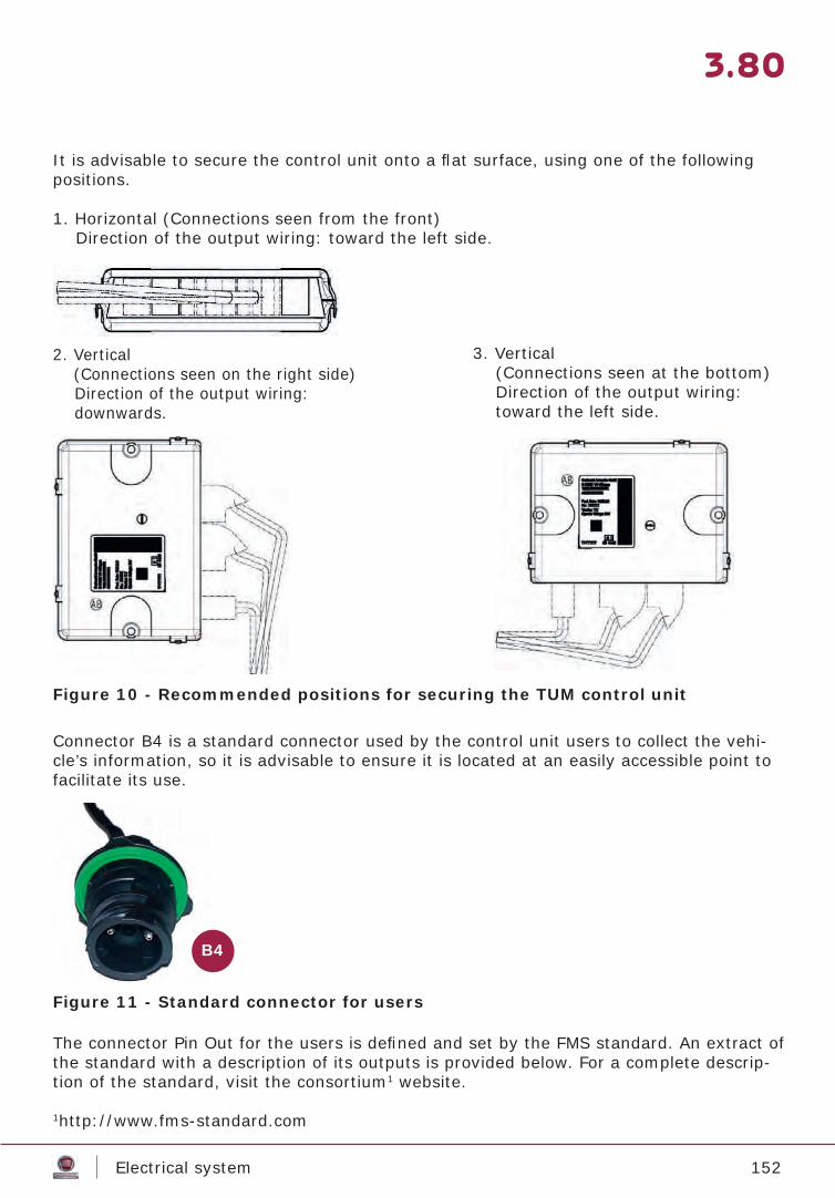
152Electrical system
3.80
It is advisable to secure the control unit onto a fl at surface, using one of the following positions.
Figure 10 - Recommended positions for securing the TUM control unit
Figure 11 - Standard connector for users
Connector B4 is a standard connector used by the control unit users to collect the vehi-cle’s information, so it is advisable to ensure it is located at an easily accessible point to facilitate its use.
The connector Pin Out for the users is defi ned and set by the FMS standard. An extract of the standard with a description of its outputs is provided below. For a complete descrip-tion of the standard, visit the consortium1 website.
1http://www.fms-standard.com
1. Horizontal (Connections seen from the front) Direction of the output wiring: toward the left side.
3. Vertical (Connections seen at the bottom) Direction of the output wiring: toward the left side.
2. Vertical(Connections seen on the right side)
Direction of the output wiring: downwards.
B4
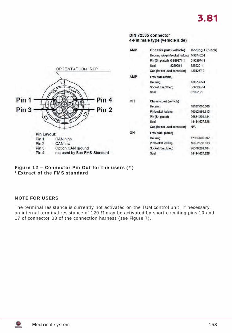
153Electrical system
3.81
NOTE FOR USERS
The terminal resistance is currently not activated on the TUM control unit. If necessary, an internal terminal resistance of 120 Ω may be activated by short circuiting pins 10 and 17 of connector B3 of the connection harness (see Figure 7).
Figure 12 – Connector Pin Out for the users (*)*Extract of the FMS standard
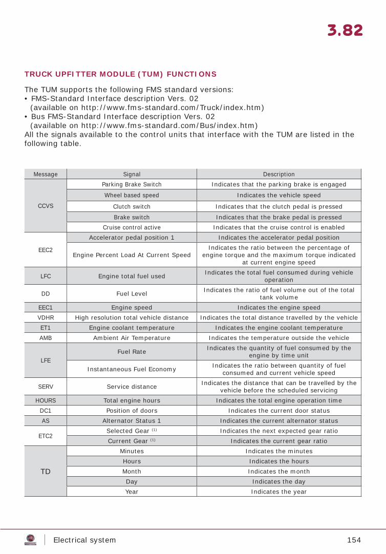
154Electrical system
3.82
TRUCK UPFITTER MODULE (TUM) FUNCTIONS
The TUM supports the following FMS standard versions:• FMS-Standard Interface description Vers. 02
(available on http://www.fms-standard.com/Truck/index.htm)• Bus FMS-Standard Interface description Vers. 02
(available on http://www.fms-standard.com/Bus/index.htm)All the signals available to the control units that interface with the TUM are listed in the following table.
Message Signal Description
CCVS
Parking Brake Switch Indicates that the parking brake is engaged
Wheel based speed Indicates the vehicle speed
Clutch switch Indicates that the clutch pedal is pressed
Brake switch Indicates that the brake pedal is pressedCruise control active Indicates that the cruise control is enabled
EEC2
Accelerator pedal position 1 Indicates the accelerator pedal position
Engine Percent Load At Current SpeedIndicates the ratio between the percentage of
engine torque and the maximum torque indicated at current engine speed
LFC Engine total fuel used Indicates the total fuel consumed during vehicle operation
DD Fuel Level Indicates the ratio of fuel volume out of the total tank volume
EEC1 Engine speed Indicates the engine speedVDHR High resolution total vehicle distance Indicates the total distance travelled by the vehicleET1 Engine coolant temperature Indicates the engine coolant temperatureAMB Ambient Air Temperature Indicates the temperature outside the vehicle
LFEFuel Rate Indicates the quantity of fuel consumed by the
engine by time unit
Instantaneous Fuel Economy Indicates the ratio between quantity of fuel consumed and current vehicle speed
SERV Service distance Indicates the distance that can be travelled by the vehicle before the scheduled servicing
HOURS Total engine hours Indicates the total engine operation timeDC1 Position of doors Indicates the current door statusAS Alternator Status 1 Indicates the current alternator status
ETC2Selected Gear (1) Indicates the next expected gear ratioCurrent Gear (1) Indicates the current gear ratio
TD
Minutes Indicates the minutesHours Indicates the hoursMonth Indicates the monthDay Indicates the dayYear Indicates the year
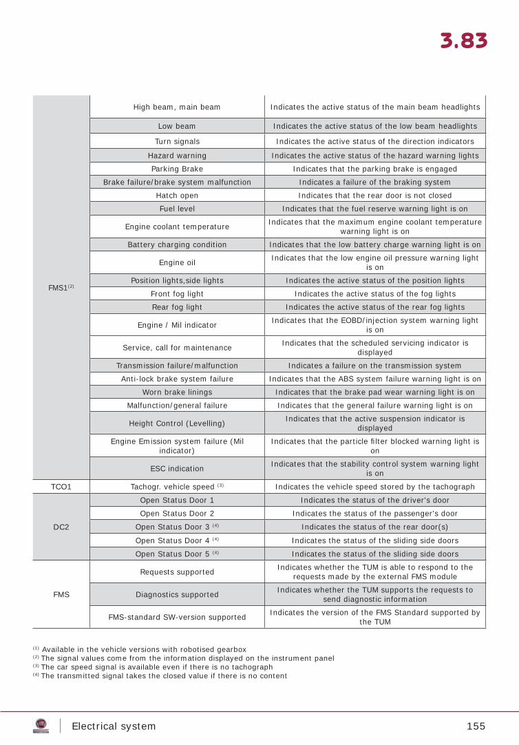
155Electrical system
3.83
FMS1(2)
High beam, main beam Indicates the active status of the main beam headlights
Low beam Indicates the active status of the low beam headlights
Turn signals Indicates the active status of the direction indicators
Hazard warning Indicates the active status of the hazard warning lights
Parking Brake Indicates that the parking brake is engaged
Brake failure/brake system malfunction Indicates a failure of the braking system
Hatch open Indicates that the rear door is not closed
Fuel level Indicates that the fuel reserve warning light is on
Engine coolant temperature Indicates that the maximum engine coolant temperature warning light is on
Battery charging condition Indicates that the low battery charge warning light is on
Engine oil Indicates that the low engine oil pressure warning light is on
Position lights,side lights Indicates the active status of the position lights
Front fog light Indicates the active status of the fog lights
Rear fog light Indicates the active status of the rear fog lights
Engine / Mil indicator Indicates that the EOBD/injection system warning light is on
Service, call for maintenance Indicates that the scheduled servicing indicator is displayed
Transmission failure/malfunction Indicates a failure on the transmission system
Anti-lock brake system failure Indicates that the ABS system failure warning light is on
Worn brake linings Indicates that the brake pad wear warning light is on
Malfunction/general failure Indicates that the general failure warning light is on
Height Control (Levelling) Indicates that the active suspension indicator is displayed
Engine Emission system failure (Mil indicator)
Indicates that the particle fi lter blocked warning light is on
ESC indication Indicates that the stability control system warning light is on
TCO1 Tachogr. vehicle speed (3) Indicates the vehicle speed stored by the tachograph
DC2
Open Status Door 1 Indicates the status of the driver's door
Open Status Door 2 Indicates the status of the passenger's door
Open Status Door 3 (4) Indicates the status of the rear door(s)
Open Status Door 4 (4) Indicates the status of the sliding side doors
Open Status Door 5 (4) Indicates the status of the sliding side doors
FMS
Requests supported Indicates whether the TUM is able to respond to the requests made by the external FMS module
Diagnostics supported Indicates whether the TUM supports the requests to send diagnostic information
FMS-standard SW-version supported Indicates the version of the FMS Standard supported by the TUM
(1) Available in the vehicle versions with robotised gearbox(2) The signal values come from the information displayed on the instrument panel(3) The car speed signal is available even if there is no tachograph(4) The transmitted signal takes the closed value if there is no content
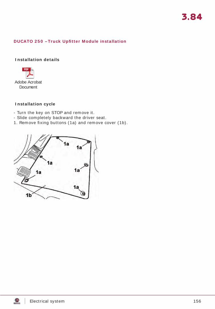
156Electrical system
3.84
DUCATO 250 –Truck Upfi tter Module installation
Installation details
Adobe Acrobat Document
Installation cycle
- Turn the key on STOP and remove it.- Slide completely backward the driver seat. 1. Remove fi xing buttons (1a) and remove cover (1b).

157Electrical system
3.85
1. Rotate the lever (1a) as illustrated and disconnect the negative terminal (1b) from the battery.
2. Undo the fi xing screws.(1).3. Remove the fuse access cover (2).
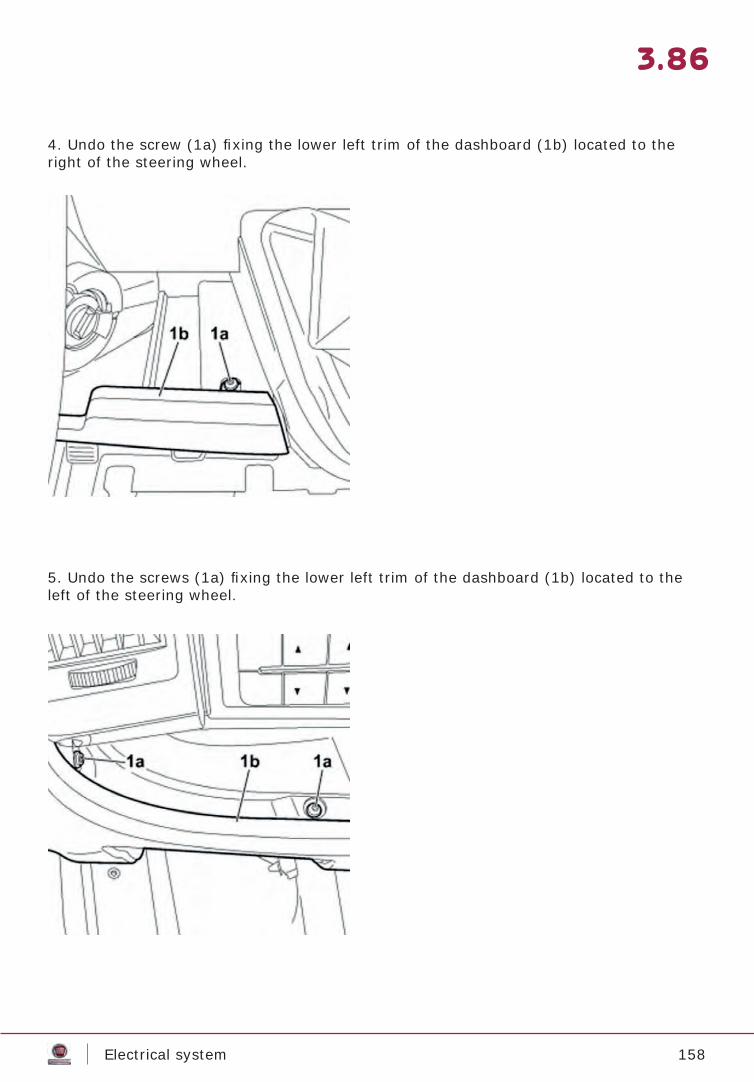
158Electrical system
3.86
4. Undo the screw (1a) fi xing the lower left trim of the dashboard (1b) located to the right of the steering wheel.
5. Undo the screws (1a) fi xing the lower left trim of the dashboard (1b) located to the left of the steering wheel.

159Electrical system
3.87
6. Remove the lower left trim of the dashboard from the vehicle.
7. Undo the fi xing screws (1a) for the centre pillar trim lower element (1b).
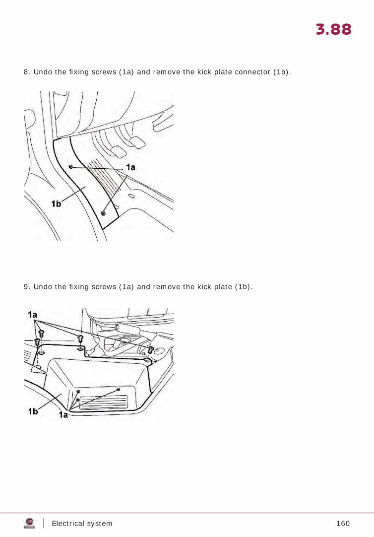
160Electrical system
3.88
8. Undo the fi xing screws (1a) and remove the kick plate connector (1b).
9. Undo the fi xing screws (1a) and remove the kick plate (1b).

161Electrical system
3.89
10. Remove the wiring retaining button and move it to the side (1).
11. Thoroughly grease the rear surface of the control unit (1a) with heptane (or isopro-pyl alcohol) and apply a Velcro cutting (1b) of a size that ensures that the control unit remains secured.
1
1b
1a
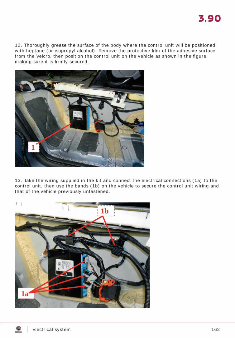
162Electrical system
3.90
12. Thoroughly grease the surface of the body where the control unit will be positioned with heptane (or isopropyl alcohol). Remove the protective fi lm of the adhesive surface from the Velcro, then position the control unit on the vehicle as shown in the fi gure, making sure it is fi rmly secured.
13. Take the wiring supplied in the kit and connect the electrical connections (1a) to the control unit, then use the bands (1b) on the vehicle to secure the control unit wiring and that of the vehicle previously unfastened.
1
1a
1b

163Electrical system
3.91
14. Place the wiring (1a) of the control unit inside the cable duct (1b) positioned on the ve-hicle, then secure using the clips provided.
15. Place the wiring (1a) of the control unit inside the retaining clips (1b) of the vehicle wiring.
1b
1a
1a
1b
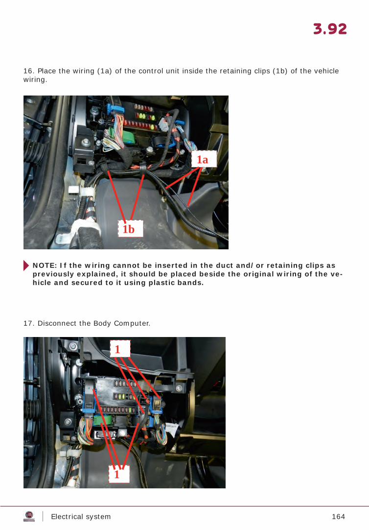
164Electrical system
3.92
16. Place the wiring (1a) of the control unit inside the retaining clips (1b) of the vehicle wiring.
17. Disconnect the Body Computer.
NOTE: If the wiring cannot be inserted in the duct and/or retaining clips as previously explained, it should be placed beside the original wiring of the ve-hicle and secured to it using plastic bands.
1a
1b
1
1
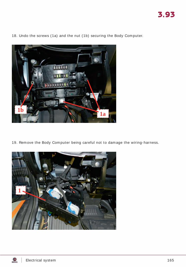
165Electrical system
3.93
18. Undo the screws (1a) and the nut (1b) securing the Body Computer.
19. Remove the Body Computer being careful not to damage the wiring-harness.
1a 1b
1

166Electrical system
3.94
20. Press the retaining clip (1a), then disconnect and remove the short circuit connector (1b).
21. Connect the electrical connection of the control unit wiring, and position the wiring in the lower part of the Body Computer mounting bracket.
1a
1b
1
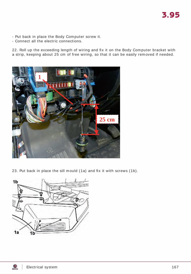
167Electrical system
3.95
- Put back in place the Body Computer screw it.- Connect all the electric connections.
22. Roll up the exceeding length of wiring and fi x it on the Body Computer bracket with a strip, keeping about 25 cm of free wiring, so that it can be easily removed if needed.
23. Put back in place the sill mould (1a) and fi x it with screws (1b).
1
25 cm
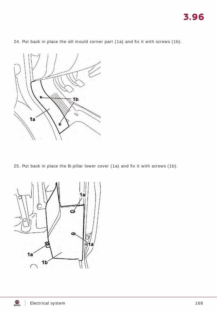
168Electrical system
3.96
24. Put back in place the sill mould corner part (1a) and fi x it with screws (1b).
25. Put back in place the B-pillar lower cover (1a) and fi x it with screws (1b).
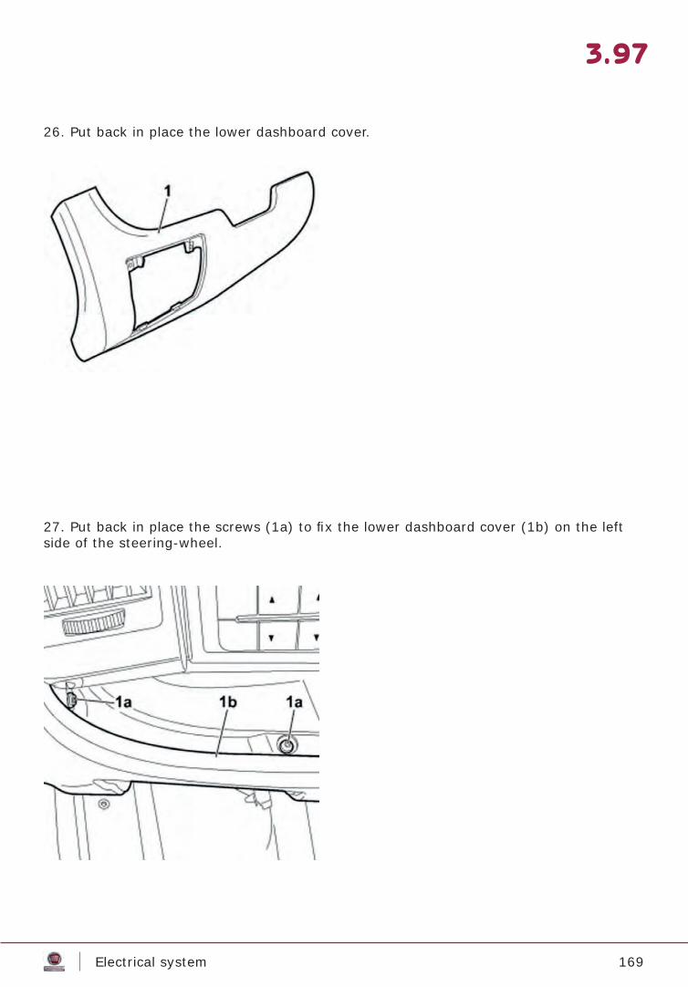
169Electrical system
3.97
26. Put back in place the lower dashboard cover.
27. Put back in place the screws (1a) to fi x the lower dashboard cover (1b) on the left side of the steering-wheel.
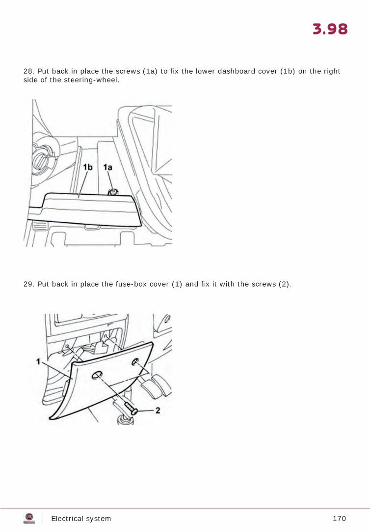
170Electrical system
3.98
28. Put back in place the screws (1a) to fi x the lower dashboard cover (1b) on the right side of the steering-wheel.
29. Put back in place the fuse-box cover (1) and fi x it with the screws (2).
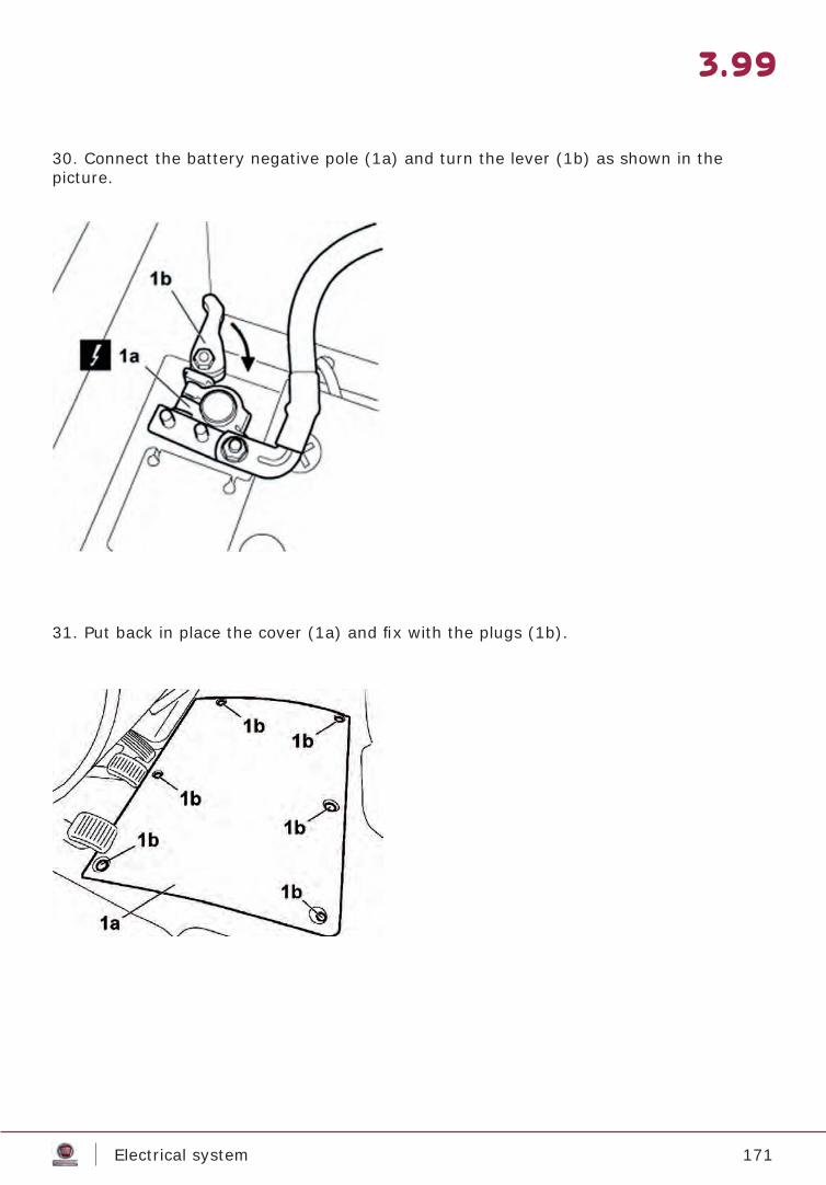
171Electrical system
3.99
30. Connect the battery negative pole (1a) and turn the lever (1b) as shown in thepicture.
31. Put back in place the cover (1a) and fi x with the plugs (1b).
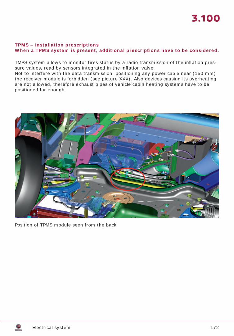
172Electrical system
3.100
TPMS – installation prescriptionsWhen a TPMS system is present, additional prescriptions have to be considered.
TMPS system allows to monitor tires status by a radio transmission of the infl ation pres-sure values, read by sensors integrated in the infl ation valve.Not to interfere with the data transmission, positioning any power cable near (150 mm) the receiver module is forbidden (see picture XXX). Also devices causing its overheating are not allowed, therefore exhaust pipes of vehicle cabin heating systems have to be positioned far enough.
Position of TPMS module seen from the back
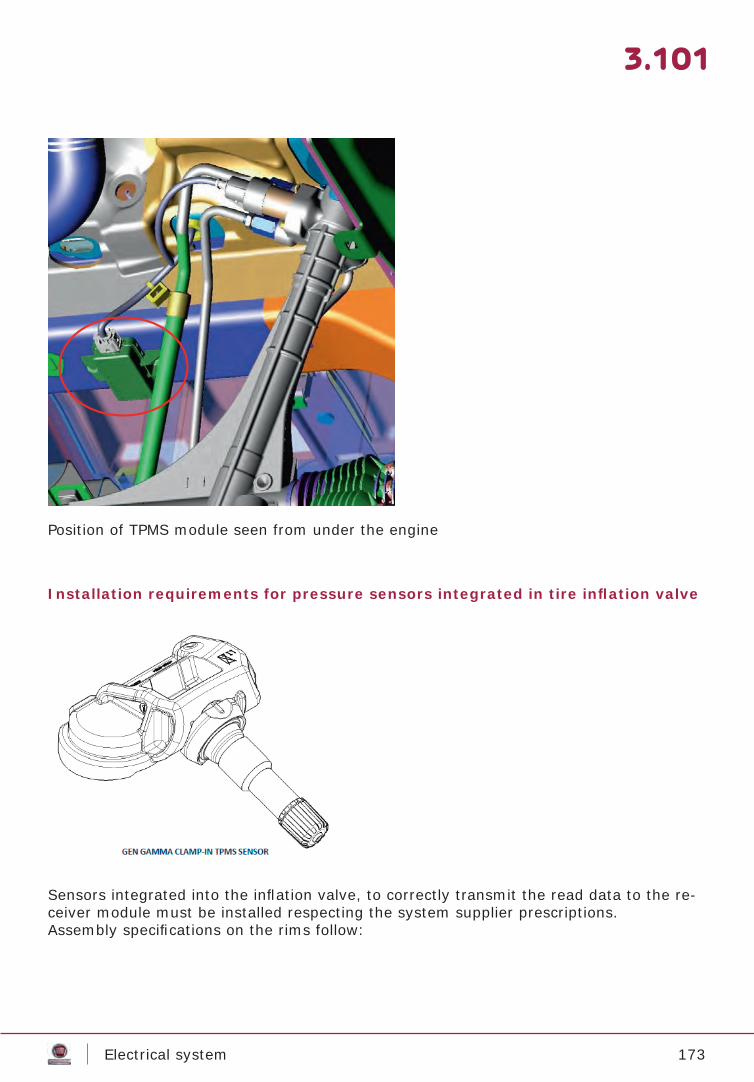
173Electrical system
3.101
Position of TPMS module seen from under the engine
Installation requirements for pressure sensors integrated in tire infl ation valve
Sensors integrated into the infl ation valve, to correctly transmit the read data to the re-ceiver module must be installed respecting the system supplier prescriptions.Assembly specifi cations on the rims follow:
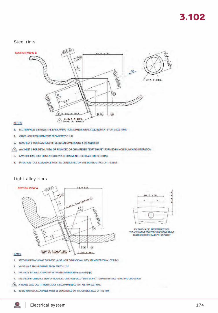
174Electrical system
3.102
Steel rims
Light-alloy rims
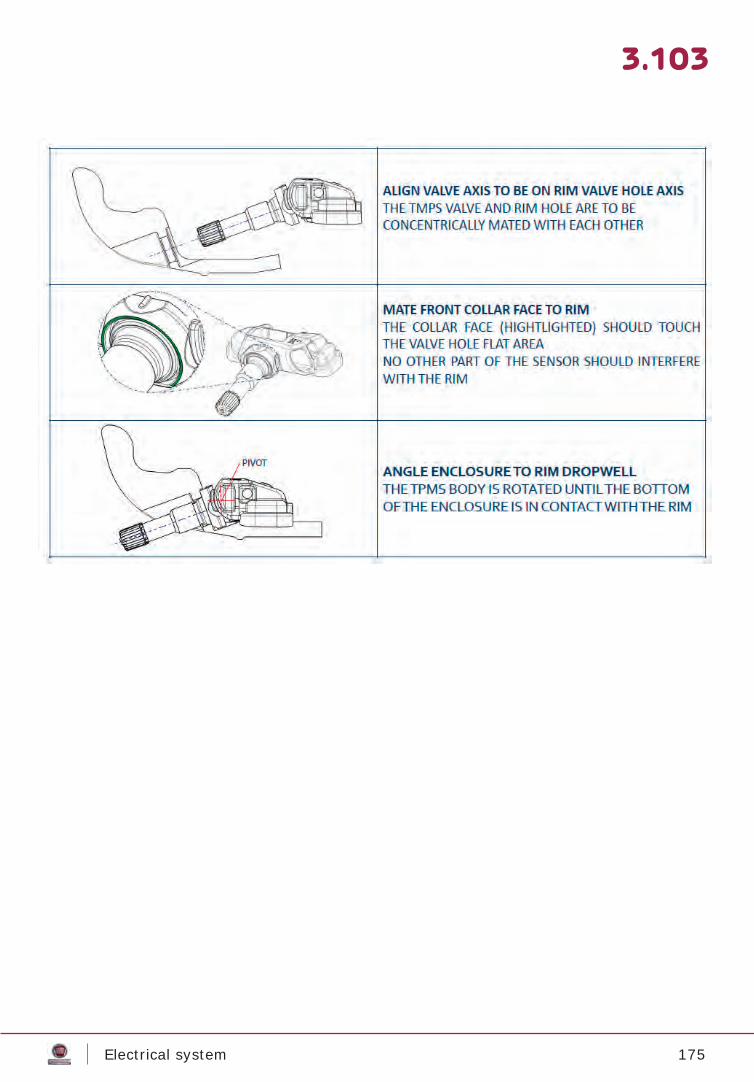
175Electrical system
3.103
176Electrical system
3.104
LDWS – installation prescriptionsLDWS system - overview
Prescriptions for vehicles with LDWS system – camera calibration
• LDW (Lane Departing Warning): • Is activated by a button on the central control panel, with an ON / OFF telltale light • Once active, the system works over 60 Km/h. Between 0 and 60 Km/h it’s inhibited
and shows it’s not functioning keeping on two yellow light in the instrument cluster; once reached 60 Km/h the lights switch off and only work switching on left or right one to warn a deviation from road stripes.
• HBC (automatic main light dipping) with light sensor:• Is activated by the column stalk ring, setting it on AUTO; it switches on both HBC
and light sensor.
• HBC without light sensor: • Is activated when parking, by the vehicle menu setting.
• TSR (Traffi c Signal Recognition)• Is activated when parking, by the vehicle menu setting.
Due to the wide angle that the suspension geometry can have on the Ducato (different weight distribution according to upfi tting needs), the standard calibration done in the production factory can be not enough, therefore the system has a self-calibration func-tion that allows it to memorize the correct calibration while running. This function is acti-vated when a change in the geometry moves the camera outside its working angle (e.g. when a chassis-cab is converted in a camping-car).Re-calibration phase last about 2 min, if the system fi nds the required conditions (almost straight road, with only wide bends, and good weather and visibility), going on for up to one hour if the process fails. During calibration phase the system is inhibited and the driver is warned by the two yellow lights in the instrument cluster.
Not to void the system functionality, obstructions must not be present in the camera view angle.
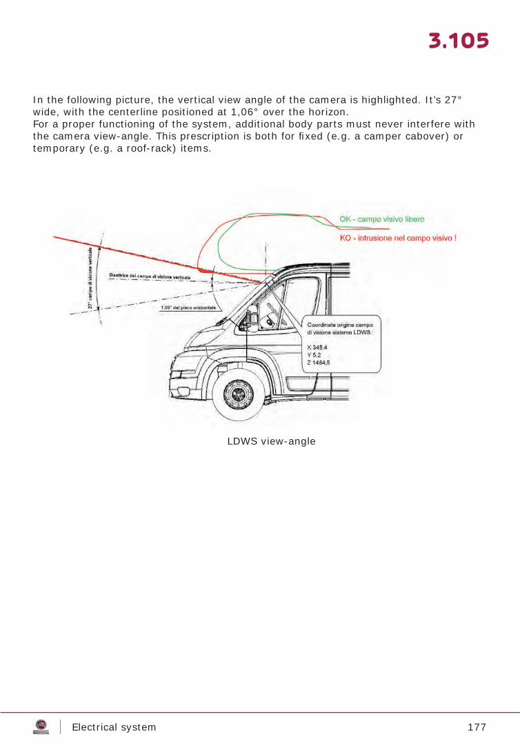
177Electrical system
3.105
In the following picture, the vertical view angle of the camera is highlighted. It’s 27° wide, with the centerline positioned at 1,06° over the horizon.For a proper functioning of the system, additional body parts must never interfere with the camera view-angle. This prescription is both for fi xed (e.g. a camper cabover) or temporary (e.g. a roof-rack) items.
LDWS view-angle
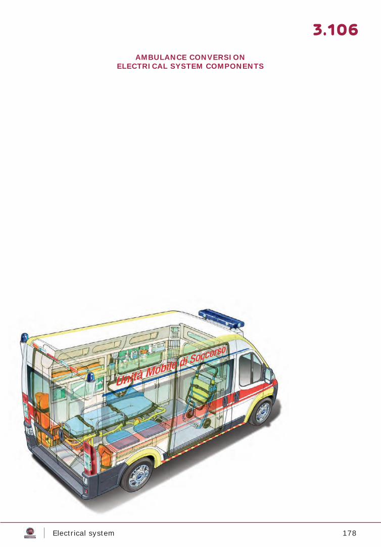
178Electrical system
3.106
AMBULANCE CONVERSIONELECTRICAL SYSTEM COMPONENTS
179Electrical system
3.107
1 AMBULANCE CIRCUITRY1.1 20-pin connector C036 AD1.1.1 View and position of connector1.1.2 Functions of the connector1.1.3 Engine starting inhibition circuit1.1.4 Flasher power supply1.1.5 Siren power supply1.1.6 High beam lights On signal1.1.7 Horn control1.1.8 Reverse gear engaged signal1.2 Fiat Chrysler Automobiles S.p.A. Ambulance Control Panel
3.1083.1083.1083.1093.1103.1103.1113.1123.1123.1133.114
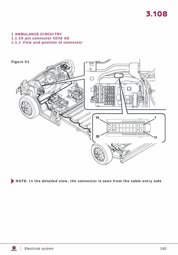
180Electrical system
3.108
1 AMBULANCE CIRCUITRY1.1 20-pin connector C036 AD1.1.1 View and position of connector
Figura 66
Figure 01
NOTE: In the detailed view, the connector is seen from the cable entry side
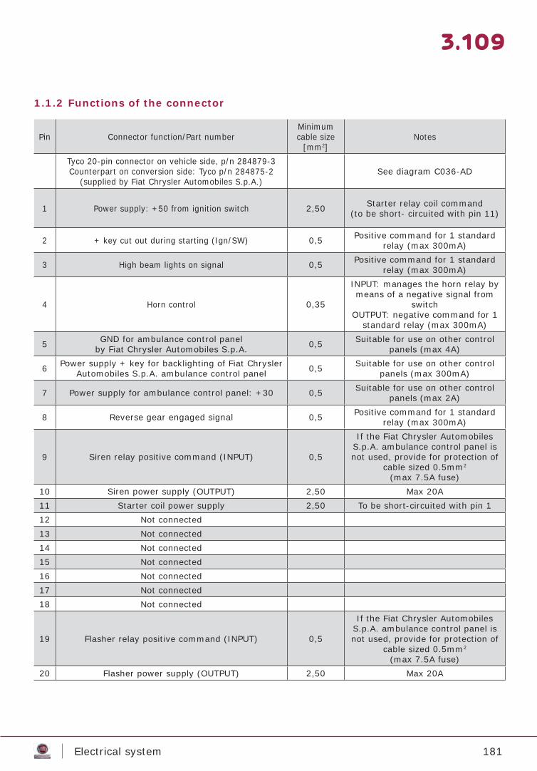
181Electrical system
3.109
1.1.2 Functions of the connector
Pin Connector function/Part numberMinimum cable size
[mm2]Notes
Tyco 20-pin connector on vehicle side, p/n 284879-3Counterpart on conversion side: Tyco p/n 284875-2
(supplied by Fiat Chrysler Automobiles S.p.A.)See diagram C036-AD
1 Power supply: +50 from ignition switch 2,50 Starter relay coil command(to be short- circuited with pin 11)
2 + key cut out during starting (Ign/SW) 0,5 Positive command for 1 standard relay (max 300mA)
3 High beam lights on signal 0,5 Positive command for 1 standard relay (max 300mA)
4 Horn control 0,35
INPUT: manages the horn relay by means of a negative signal from
switchOUTPUT: negative command for 1
standard relay (max 300mA)
5 GND for ambulance control panelby Fiat Chrysler Automobiles S.p.A. 0,5 Suitable for use on other control
panels (max 4A)
6 Power supply + key for backlighting of Fiat Chrysler Automobiles S.p.A. ambulance control panel 0,5 Suitable for use on other control
panels (max 300mA)
7 Power supply for ambulance control panel: +30 0,5 Suitable for use on other control panels (max 2A)
8 Reverse gear engaged signal 0,5 Positive command for 1 standard relay (max 300mA)
9 Siren relay positive command (INPUT) 0,5
If the Fiat Chrysler Automobiles S.p.A. ambulance control panel is not used, provide for protection of
cable sized 0.5mm2
(max 7.5A fuse)10 Siren power supply (OUTPUT) 2,50 Max 20A11 Starter coil power supply 2,50 To be short-circuited with pin 112 Not connected13 Not connected14 Not connected15 Not connected16 Not connected17 Not connected18 Not connected
19 Flasher relay positive command (INPUT) 0,5
If the Fiat Chrysler Automobiles S.p.A. ambulance control panel is not used, provide for protection of
cable sized 0.5mm2
(max 7.5A fuse)20 Flasher power supply (OUTPUT) 2,50 Max 20A
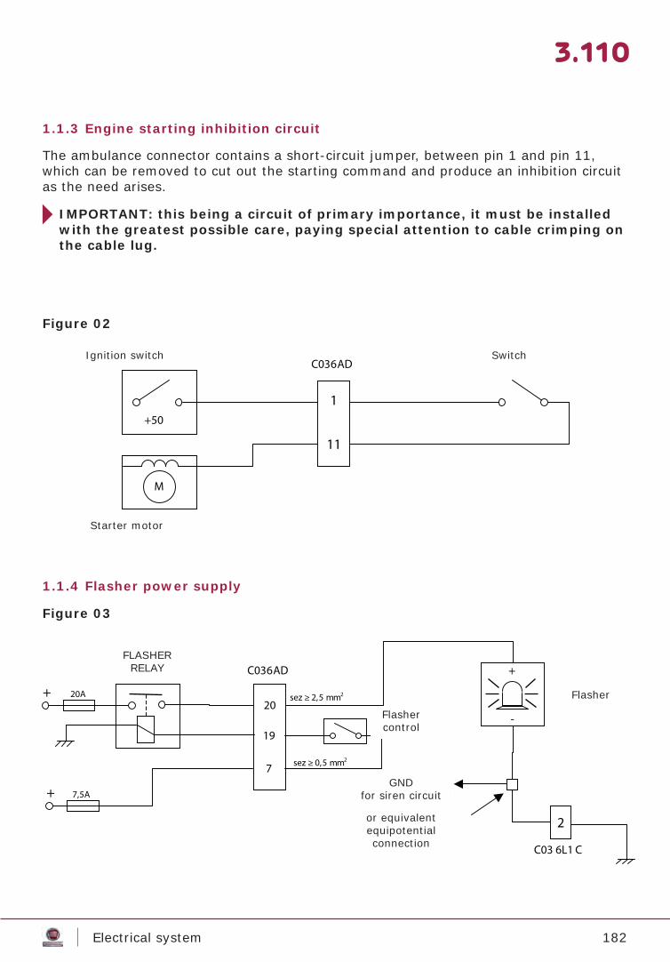
182Electrical system
3.110
1.1.3 Engine starting inhibition circuit
1.1.4 Flasher power supply
The ambulance connector contains a short-circuit jumper, between pin 1 and pin 11, which can be removed to cut out the starting command and produce an inhibition circuit as the need arises.
IMPORTANT: this being a circuit of primary importance, it must be installed with the greatest possible care, paying special attention to cable crimping on the cable lug.
Figure 02
Figure 03
Ignition switch Switch
Starter motor
FLASHERRELAY
Flashercontrol
Flasher
GNDfor siren circuit
or equivalentequipotentialconnection
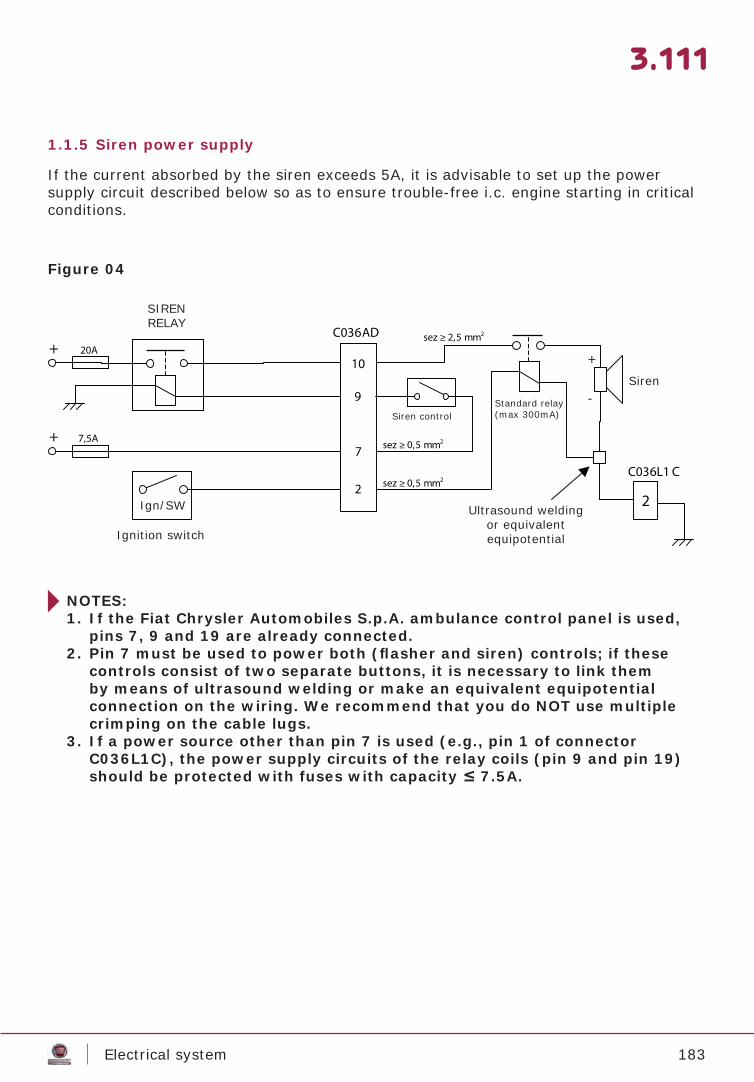
183Electrical system
3.111
1.1.5 Siren power supply
If the current absorbed by the siren exceeds 5A, it is advisable to set up the power supply circuit described below so as to ensure trouble-free i.c. engine starting in critical conditions.
Figure 04
NOTES:1. If the Fiat Chrysler Automobiles S.p.A. ambulance control panel is used,
pins 7, 9 and 19 are already connected.2. Pin 7 must be used to power both (fl asher and siren) controls; if these
controls consist of two separate buttons, it is necessary to link them by means of ultrasound welding or make an equivalent equipotential connection on the wiring. We recommend that you do NOT use multiple crimping on the cable lugs.
3. If a power source other than pin 7 is used (e.g., pin 1 of connector C036L1C), the power supply circuits of the relay coils (pin 9 and pin 19) should be protected with fuses with capacity ≤ 7.5A.
SIREN RELAY
Ignition switch
Ign/SW Ultrasound weldingor equivalentequipotential
Siren
Standard relay(max 300mA)Siren control
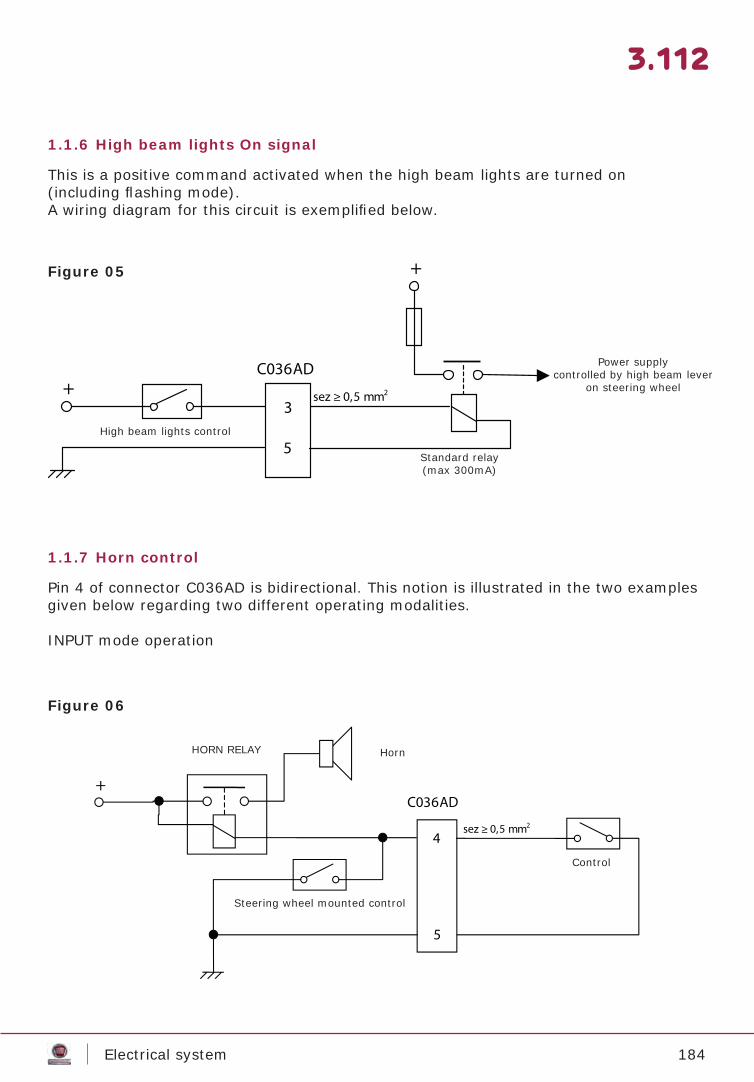
184Electrical system
3.112
1.1.6 High beam lights On signal
1.1.7 Horn control
This is a positive command activated when the high beam lights are turned on(including fl ashing mode).A wiring diagram for this circuit is exemplifi ed below.
Pin 4 of connector C036AD is bidirectional. This notion is illustrated in the two examples given below regarding two different operating modalities.
INPUT mode operation
Figure 05
Figure 06
High beam lights control
Standard relay(max 300mA)
Power supplycontrolled by high beam lever
on steering wheel
HORN RELAY Horn
Steering wheel mounted control
Control
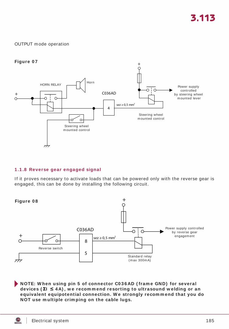
185Electrical system
3.113
OUTPUT mode operation
Figure 07
1.1.8 Reverse gear engaged signal
If it proves necessary to activate loads that can be powered only with the reverse gear is engaged, this can be done by installing the following circuit.
Figure 08
NOTE: When using pin 5 of connector C036AD (frame GND) for several devices (ΣI ≤ 4A), we recommend resorting to ultrasound welding or an equivalent equipotential connection. We strongly recommend that you do NOT use multiple crimping on the cable lugs.
HORN RELAYHorn
Steering wheel mounted control
Steering wheel mounted control
Power supply controlled
by steering wheel mounted lever
Reverse switch
Standard relay(max 300mA)
Power supply controlled by reverse gear
engagement
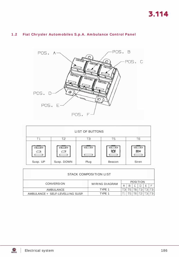
186Electrical system
3.114
1.2 Fiat Chrysler Automobiles S.p.A. Ambulance Control Panel
LIST OF BUTTONS
STACK COMPOSITION LIST
CONVERSION
AMBULANCEAMBULANCE + SELF-LEVELLING SUSP.
WIRING DIAGRAM
TYPE 1TYPE 1
POSITION
Susp. UP Susp. DOWN Plug Beacon Siren
187Main dimensions
MAIN DIMENSIONS
4.1
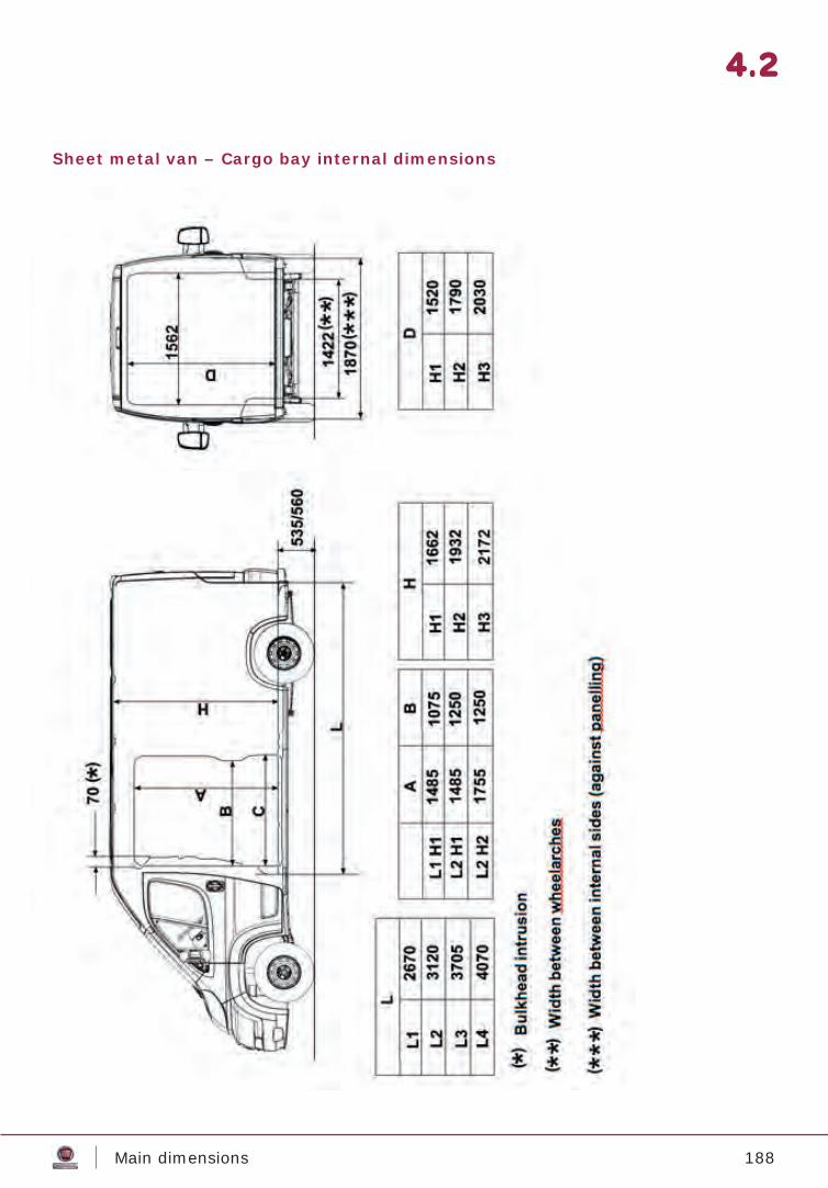
188Main dimensions
4.2
Sheet metal van – Cargo bay internal dimensions
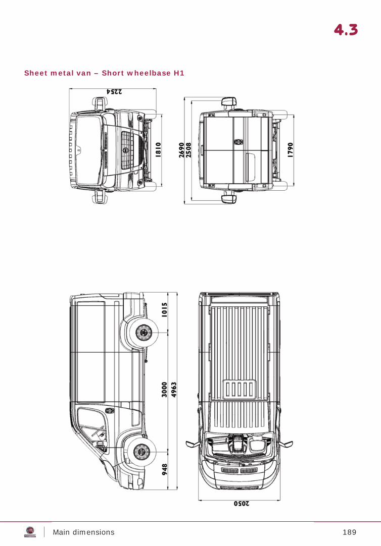
189Main dimensions
4.3
Sheet metal van – Short wheelbase H1
Main dimensions
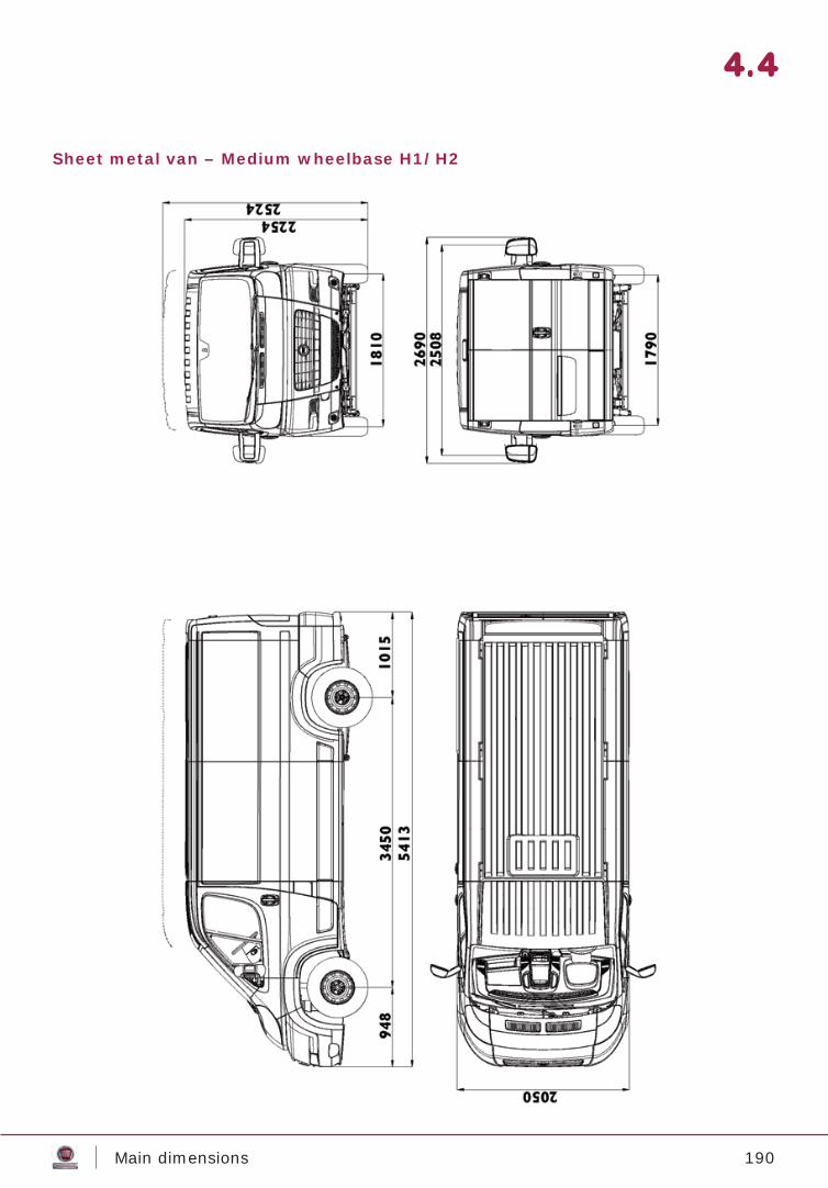
190Main dimensions
4.4
Sheet metal van – Medium wheelbase H1/H2
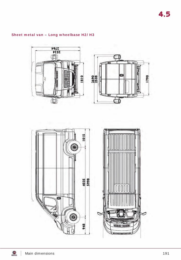
191Main dimensions
4.5
Sheet metal van – Long wheelbase H2/H3
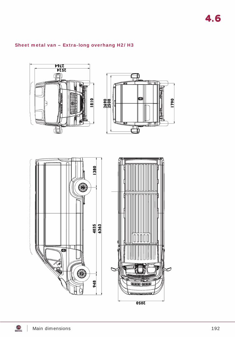
192Main dimensions
4.6
Sheet metal van – Extra-long overhang H2/H3
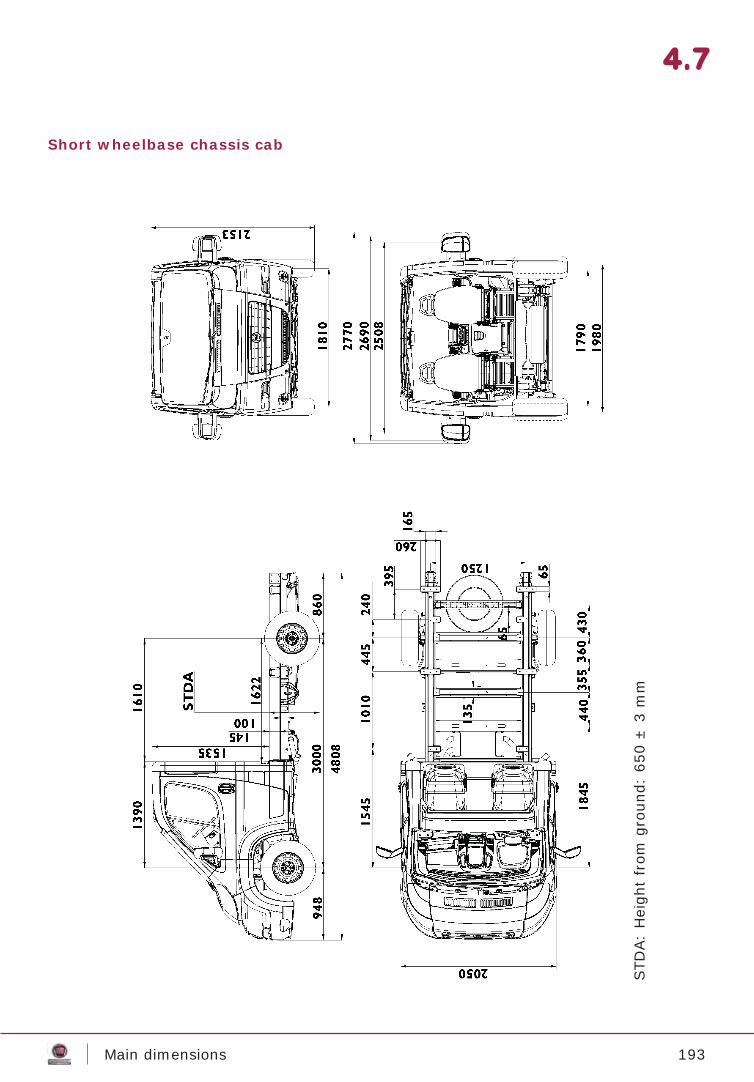
193Main dimensions
4.7
Short wheelbase chassis cab
STD
A:
Hei
ght
from
gro
und:
650
± 3
mm

194Main dimensions
4.8
Medium wheelbase chassis cab
STD
A:
Hei
ght
from
gro
und:
646
± 3
mm
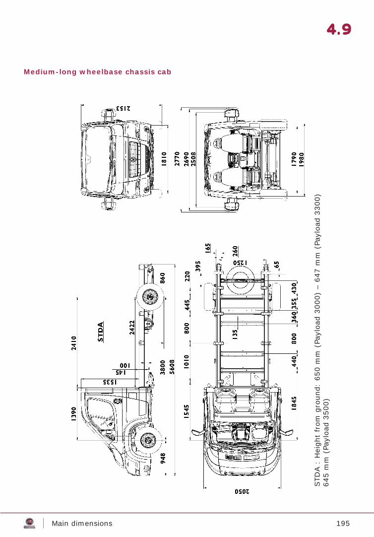
195Main dimensions
4.9
Medium-long wheelbase chassis cab
STD
A :
Hei
ght
from
gro
und:
650
mm
(Pa
yloa
d 30
00)
– 64
7 m
m (
Payl
oad
3300
)64
5 m
m (
Payl
oad
3500
)
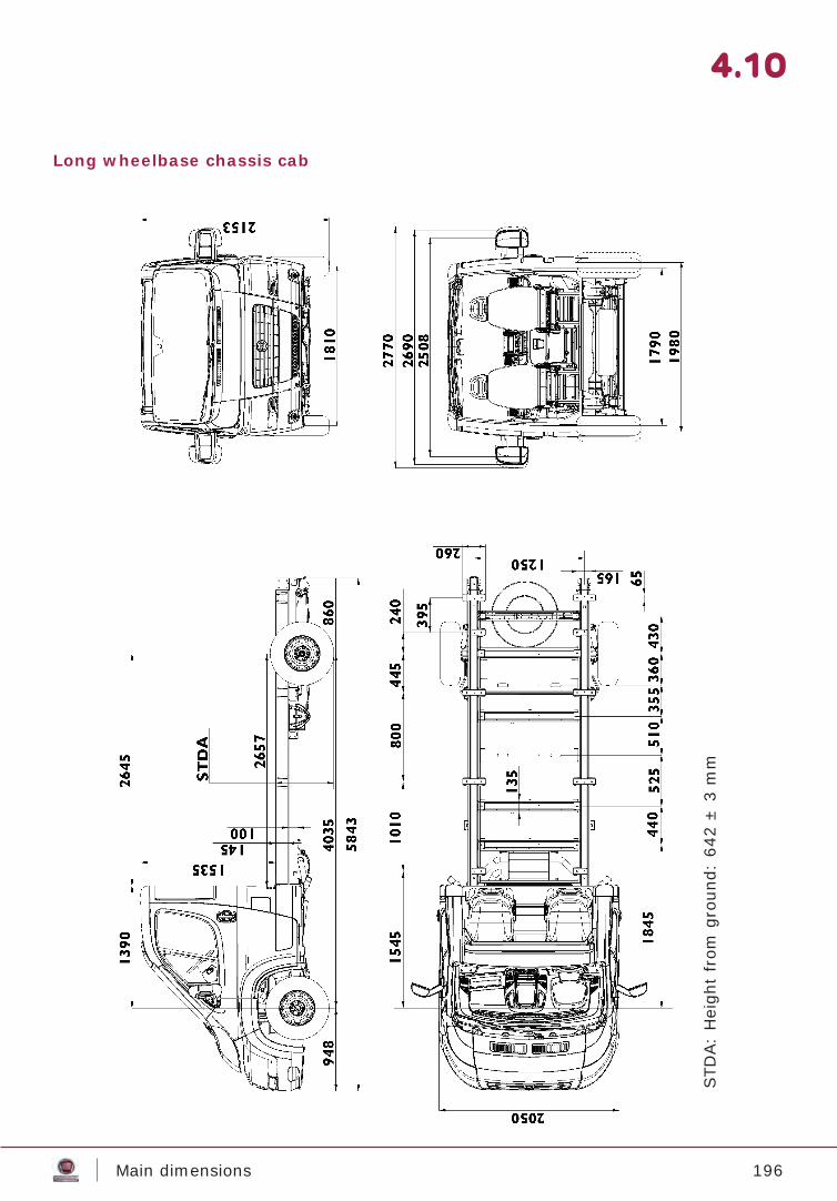
196Main dimensions
4.10
Long wheelbase chassis cab
STD
A:
Hei
ght
from
gro
und:
642
± 3
mm
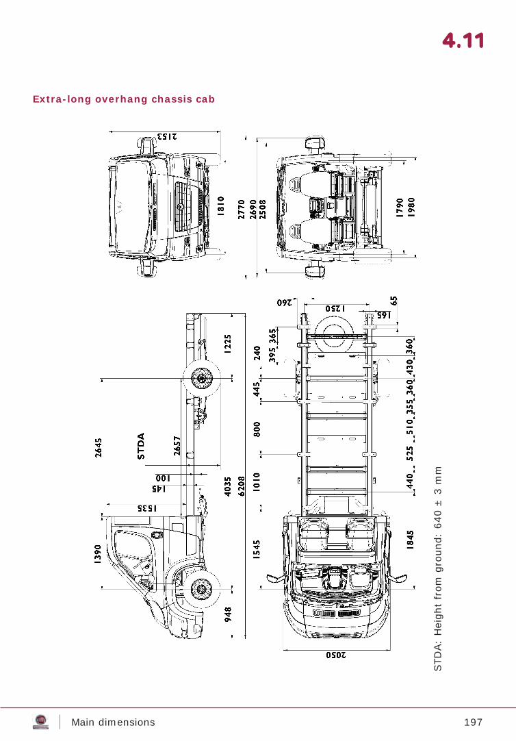
197Main dimensions
4.11
Extra-long overhang chassis cab
STD
A:
Hei
ght
from
gro
und:
640
± 3
mm
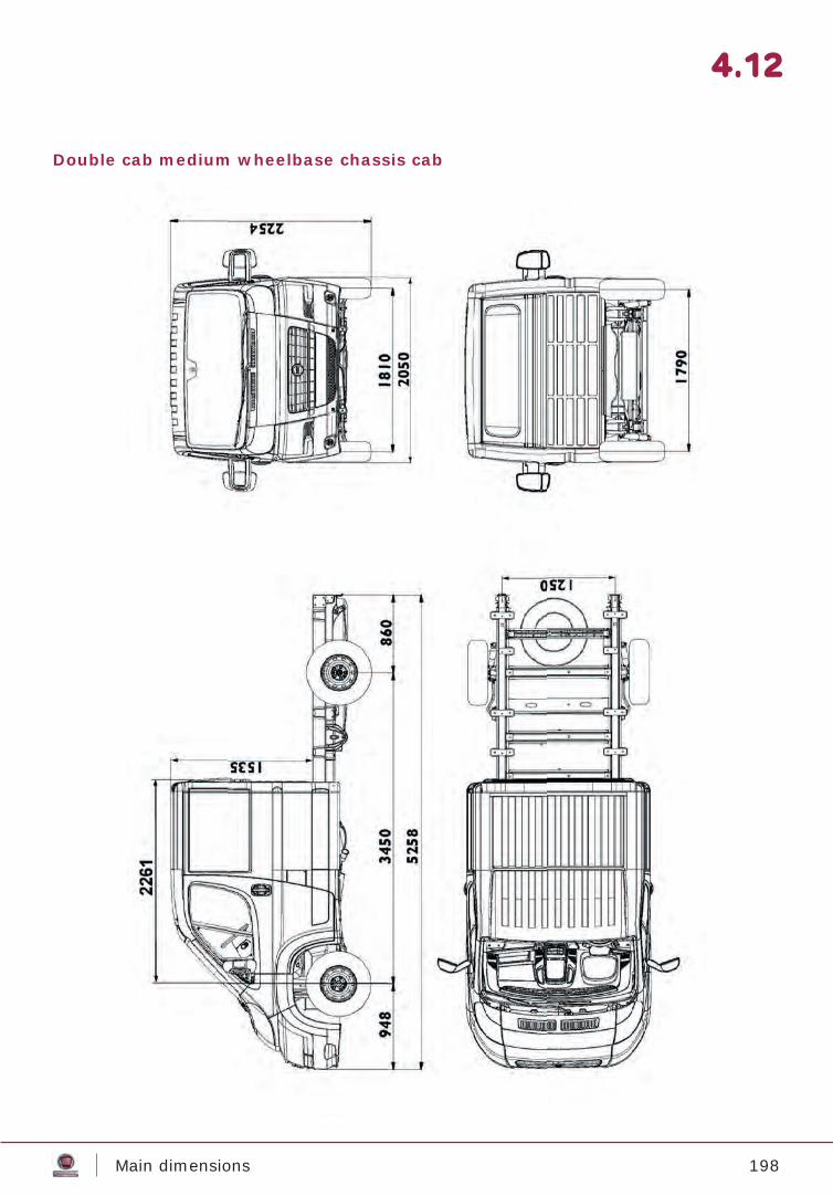
198Main dimensions
4.12
Double cab medium wheelbase chassis cab
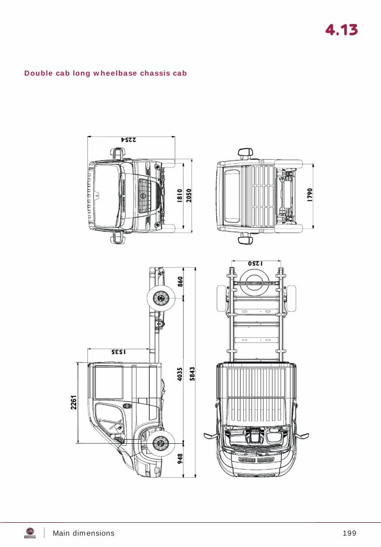
199Main dimensions
4.13
Double cab long wheelbase chassis cab
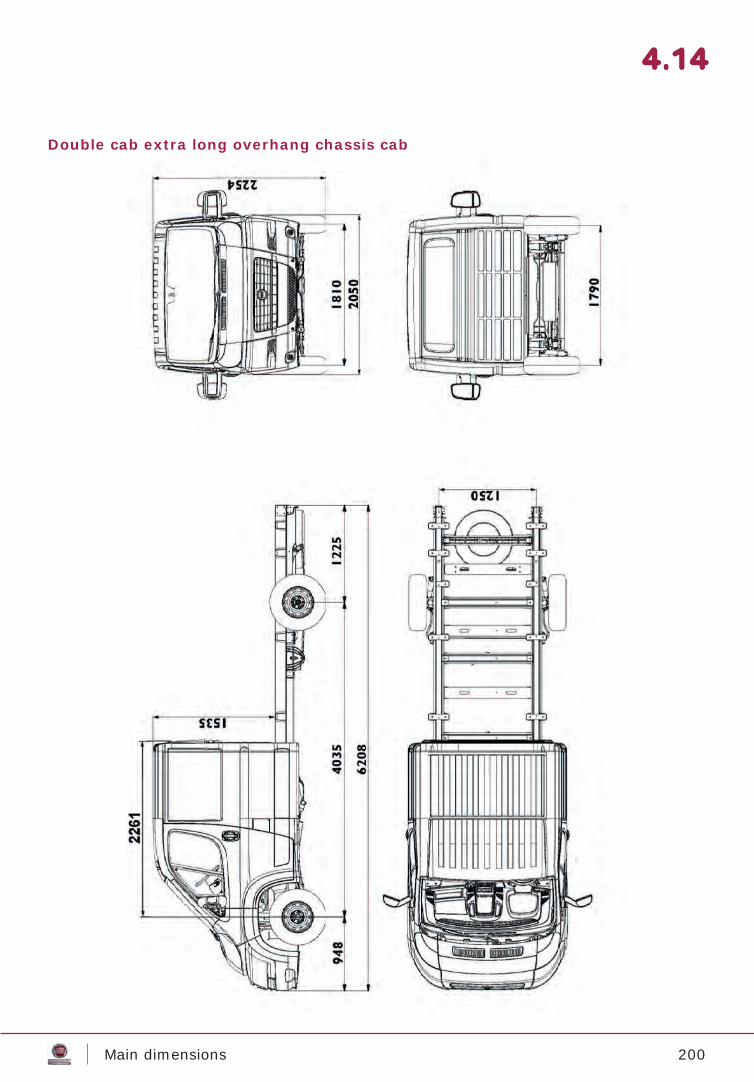
200Main dimensions
4.14
Double cab extra long overhang chassis cab
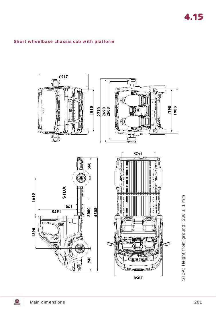
201Main dimensions
4.15
Short wheelbase chassis cab with platform
STD
A:
Hei
ght
from
gro
und:
536
± 1
mm
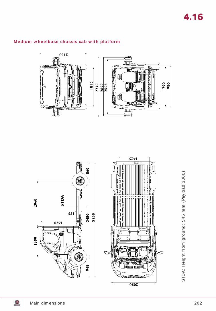
202Main dimensions
4.16
Medium wheelbase chassis cab with platform
STD
A:
Hei
ght
from
gro
und:
545
mm
(Pa
yloa
d 30
00)
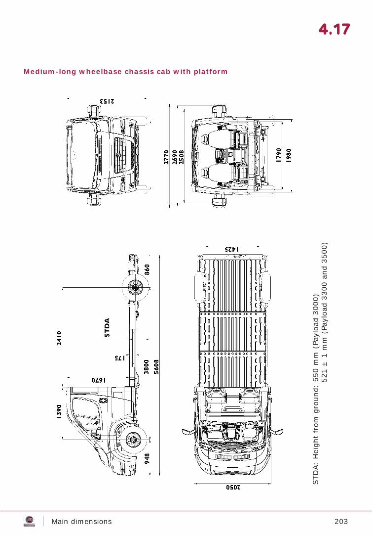
203Main dimensions
4.17
Medium-long wheelbase chassis cab with platform
STD
A:
Hei
ght
from
gro
und:
550
mm
(Pa
yloa
d 30
00)
5
21 ±
1 m
m (
Payl
oad
3300
and
350
0)
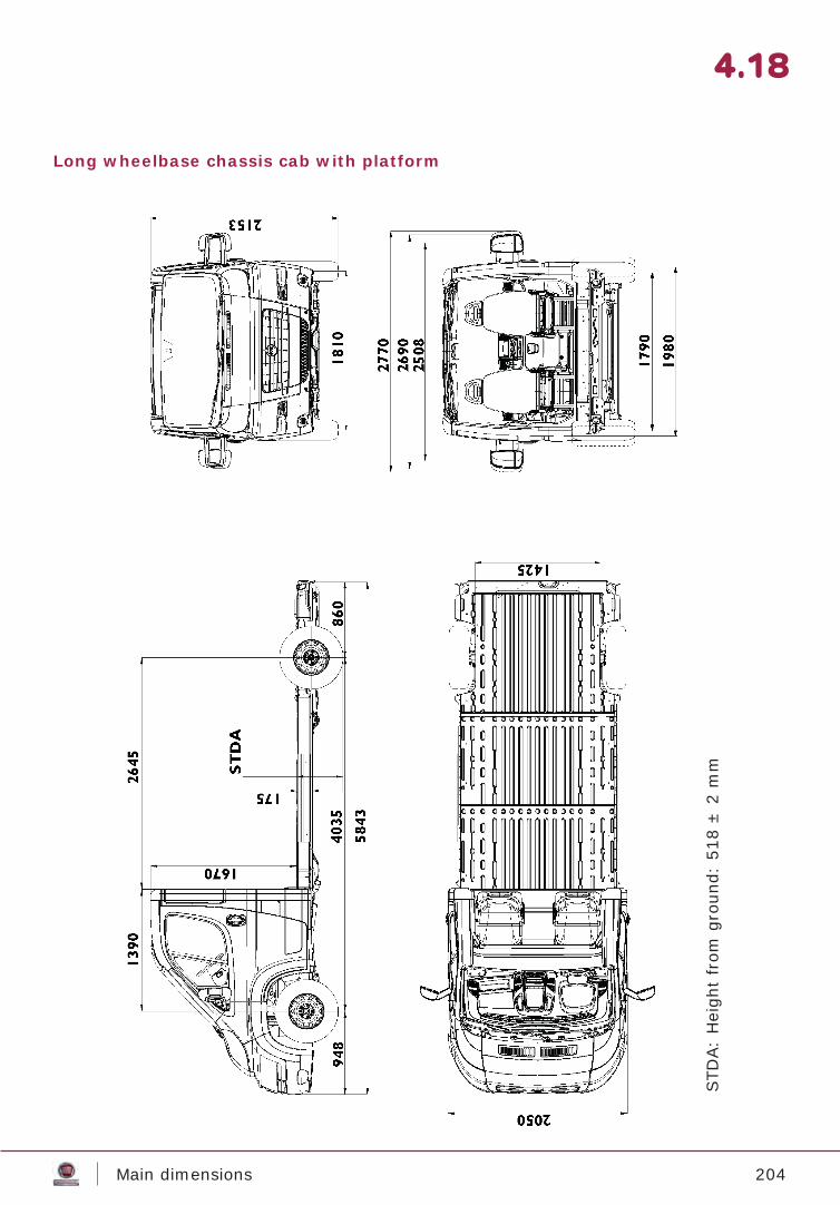
204Main dimensions
4.18
Long wheelbase chassis cab with platform
STD
A:
Hei
ght
from
gro
und:
518
± 2
mm
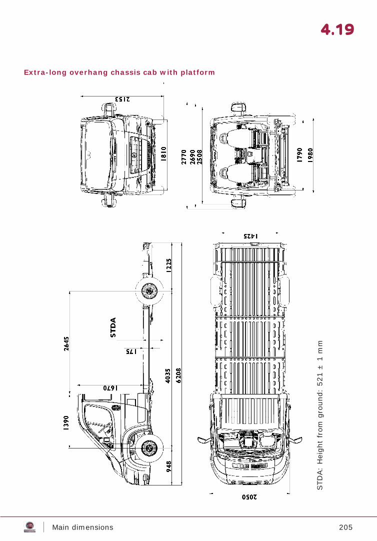
205Main dimensions
4.19
Extra-long overhang chassis cab with platform
STD
A:
Hei
ght
from
gro
und:
521
± 1
mm
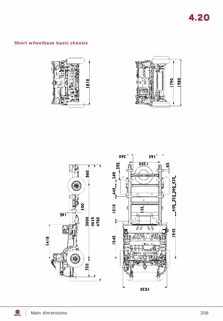
206Main dimensions
4.20
Short wheelbase basic chassis
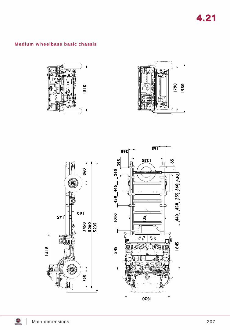
207Main dimensions
4.21
Medium wheelbase basic chassis
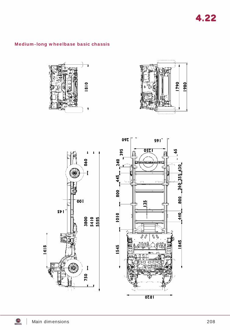
208Main dimensions
4.22
Medium-long wheelbase basic chassis
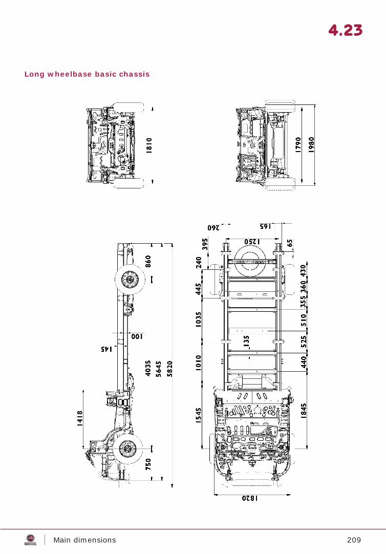
209Main dimensions
4.23
Long wheelbase basic chassis
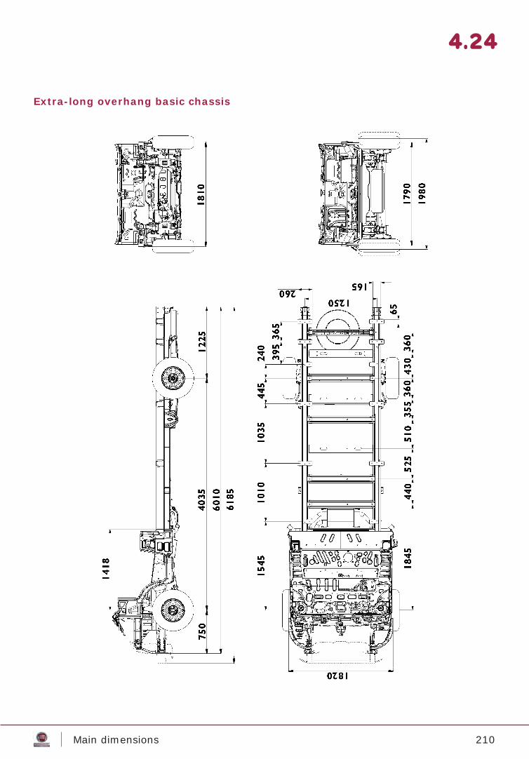
210Main dimensions
4.24
Extra-long overhang basic chassis
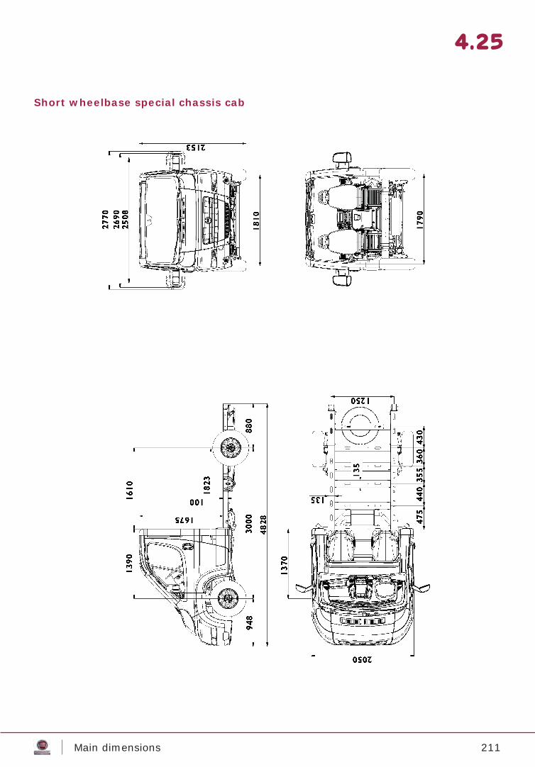
211Main dimensions
4.25
Short wheelbase special chassis cab
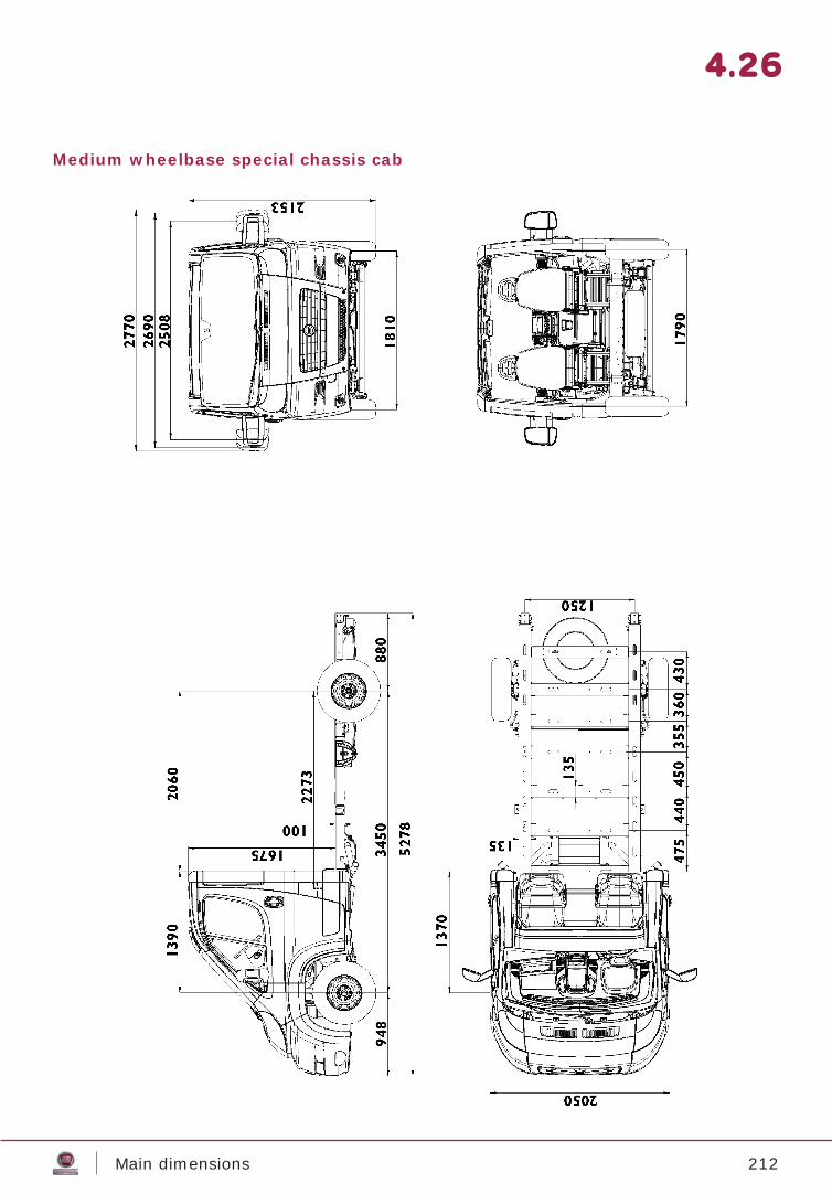
212Main dimensions
4.26
Medium wheelbase special chassis cab
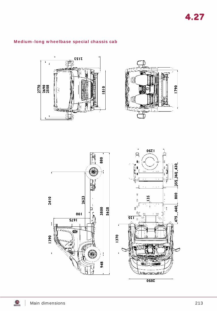
213Main dimensions
4.27
Medium-long wheelbase special chassis cab
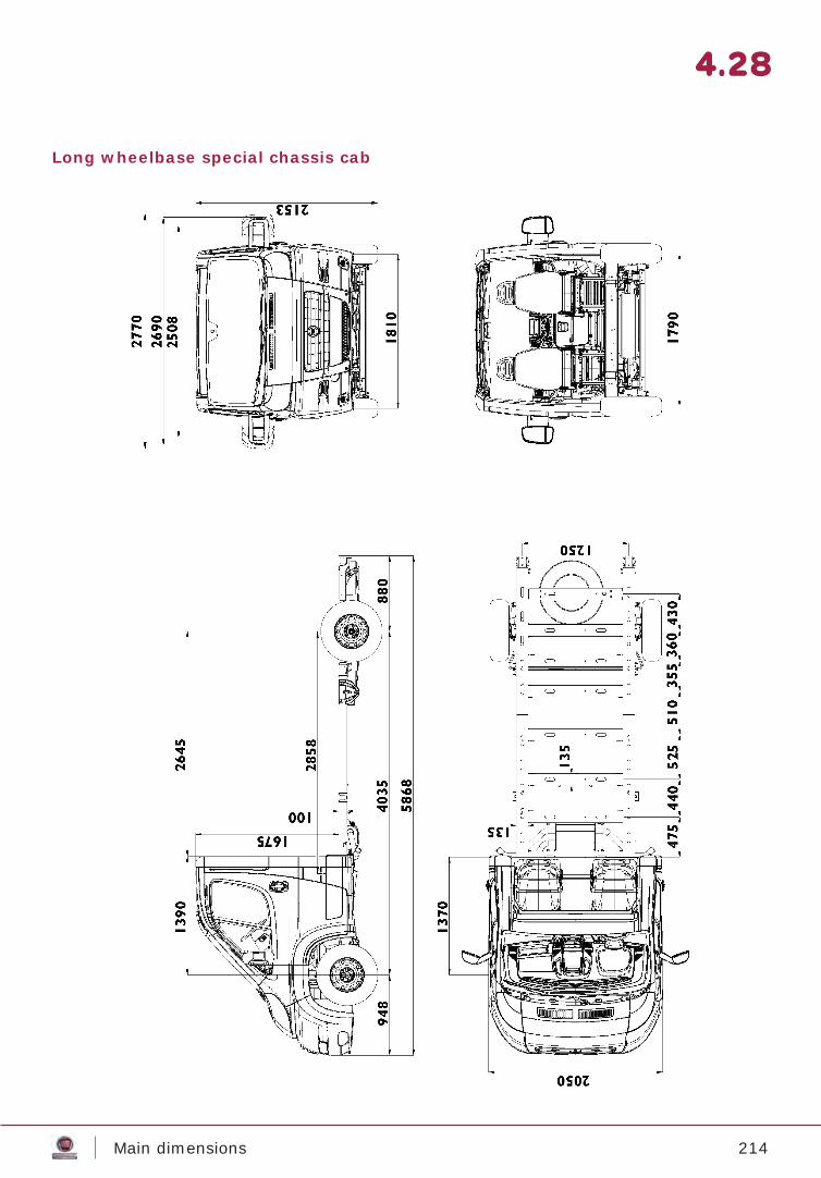
214Main dimensions
4.28
Long wheelbase special chassis cab
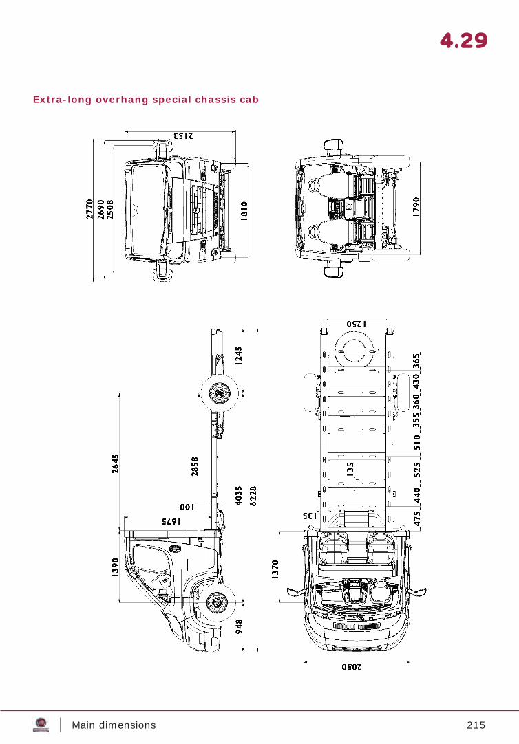
215Main dimensions
4.29
Extra-long overhang special chassis cab
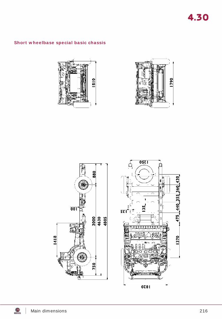
216Main dimensions
4.30
Short wheelbase special basic chassis
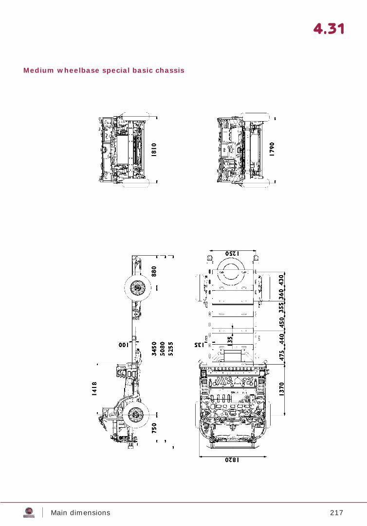
217Main dimensions
4.31
Medium wheelbase special basic chassis
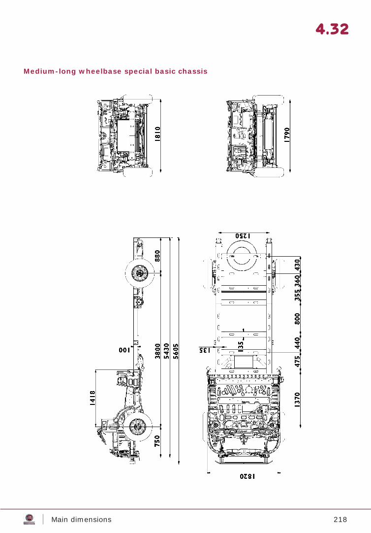
218Main dimensions
4.32
Medium-long wheelbase special basic chassis
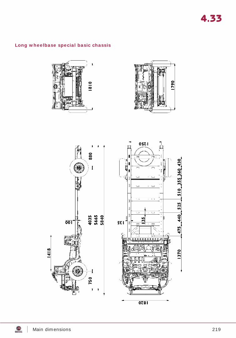
219Main dimensions
4.33
Long wheelbase special basic chassis
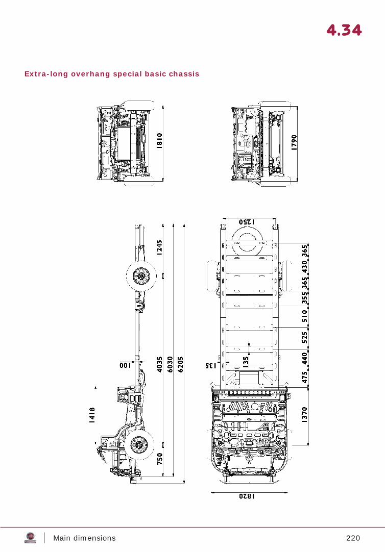
220Main dimensions
4.34
Extra-long overhang special basic chassis