new journal of physics - rensselaer polytechnic...
TRANSCRIPT

T h e o p e n – a c c e s s j o u r n a l f o r p h y s i c s
New Journal of Physics
Notes on conformal invisibility devices
Ulf LeonhardtSchool of Physics and Astronomy, University of St. Andrews, North Haugh,St. Andrews KY16 9SS, UKE-mail: [email protected]
New Journal of Physics 8 (2006) 118Received 26 May 2006Published 31 July 2006Online at http://www.njp.org/doi:10.1088/1367-2630/8/7/118
Abstract. As a consequence of the wave nature of light, invisibility devicesbased on isotropic media cannot be perfect. The principal distortions of invisibilityare due to reflections and time delays. Reflections can be made exponentially smallfor devices that are large in comparison with the wavelength of light. Time delaysare unavoidable and will result in wave-front dislocations. This paper considersinvisibility devices based on optical conformal mapping. The paper shows that thetime delays do not depend on the directions and impact parameters of incident lightrays, although the refractive-index profile of any conformal invisibility deviceis necessarily asymmetric. The distortions of images are thus uniform, whichreduces the risk of detection. The paper also shows how the ideas of invisibilitydevices are connected to the transmutation of force, the stereographic projectionand Escheresque tilings of the plane.
Contents
1. Introduction 22. Theory 23. Time delay 64. Examples 8
4.1. Hooke’s force . . . . . . . . . . . . . . . . . . . . . . . . . . . . . . . . . . . 84.2. Newton’s force . . . . . . . . . . . . . . . . . . . . . . . . . . . . . . . . . . 104.3. Maxwell’s fish eye. . . . . . . . . . . . . . . . . . . . . . . . . . . . . . . . . 11
5. Conclusions 13Acknowledgments 13Appendix 13References 15
New Journal of Physics 8 (2006) 118 PII: S1367-2630(06)25618-01367-2630/06/010118+16$30.00 © IOP Publishing Ltd and Deutsche Physikalische Gesellschaft
2 Institute of Physics �DEUTSCHE PHYSIKALISCHE GESELLSCHAFT
1. Introduction
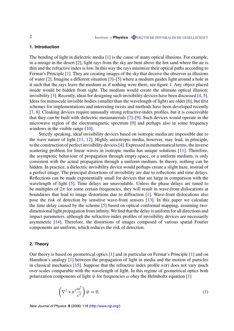
The bending of light in dielectric media [1] is the cause of many optical illusions. For example,in a mirage in the desert [2], light rays from the sky are bent above the hot sand where the air isthin and the refractive index is low. In this way the rays minimize their optical paths according toFermat’s Principle [1]. They are creating images of the sky that deceive the observer as illusionsof water [2]. Imagine a different situation [3]–[5] where a medium guides light around a hole init such that the rays leave the medium as if nothing were there, see figure 1. Any object placedinside would be hidden from sight. The medium would create the ultimate optical illusion:invisibility [3]. Recently, ideas for designing such invisibility devices have been discussed [4, 5].Ideas for minuscule invisible bodies (smaller than the wavelength of light) are older [6], but firstschemes for implementations and interesting twists and methods have been developed recently[7, 8]. Cloaking devices require unusually strong refractive-index profiles, but it is conceivablethat they can be built with dielectric metamaterials [7]–[9]. Such devices would operate in themicrowave region of the electromagnetic spectrum [9] and perhaps also in some frequencywindows in the visible range [10].
Strictly speaking, ideal invisibility devices based on isotropic media are impossible due tothe wave nature of light [11, 12]. Highly anisotropic media, however, may lead, in principle,to the construction of perfect invisibility devices [4]. Expressed in mathematical terms, the inversescattering problem for linear waves in isotropic media has unique solutions [11]. Therefore,the asymptotic behaviour of propagation through empty space, or a uniform medium, is onlyconsistent with the actual propagation through a uniform medium. In theory, nothing can behidden. In practice, a dielectric invisibility device would perhaps create a slight haze, instead ofa perfect image. The principal distortions of invisibility are due to reflections and time delays.Reflections can be made exponentially small for devices that are large in comparison with thewavelength of light [5]. Time delays are unavoidable. Unless the phase delays are tuned tobe multiples of 2π for some certain frequencies, they will result in wave-front dislocations atboundaries that lead to image distortions due to diffraction [1]. Wave-front dislocations alsopose the risk of detection by sensitive wave-front sensors [13]. In this paper we calculatethe time delay caused by the scheme [5] based on optical conformal mapping, assuming two-dimensional light propagation from infinity. We find that the delay is uniform for all directions andimpact parameters, although the refractive-index profiles of invisibility devices are necessarilyasymmetric [14]. Therefore, the distortions of images composed of various spatial Fouriercomponents are uniform, which reduces the risk of detection.
2. Theory
Our theory is based on geometrical optics [1] and in particular on Fermat’s Principle [1] and onHamilton’s analogy [1] between the propagation of light in media and the motion of particlesin classical mechanics [15]. Suppose that the refractive index profile n(r) does not vary muchover scales comparable with the wavelength of light. In this regime of geometrical optics bothpolarization components of light ψ for frequencies ω obey the Helmholtz equation [1]
(∇2 + n2 ω2
c2
)ψ = 0, (1)
New Journal of Physics 8 (2006) 118 (http://www.njp.org/)

3 Institute of Physics �DEUTSCHE PHYSIKALISCHE GESELLSCHAFT
Figure 1. Light propagation in a conformal invisibility device. The light rays areshown in red. The brightness of the green background indicates the refractive-index profile. The device is based on the conformal map (A.3) and Maxwell’s fisheye (22) with r3 = 4r0 and n0 = 2 (further details are given in the appendix). Thedevice consists of an exterior and an interior layer with a clear boundary illustratedby the tiling in figure 3. The invisible region is shown in black. Anything couldbe placed there. The left figure illustrates how light is refracted at the boundarybetween the two layers and guided around the invisible region where it leaves thedevice as if nothing were there. In the right figure, light simply flows around theinterior layer.
where c denotes the speed of light in vacuum. The Helmholtz equation (1) is equivalent to thestationary Schrödinger equation with potential U and energy E such that [1]
U − E = −n2
2. (2)
Therefore we expect that Hamilton’s equations for light rays are equivalent to Newton’s equationsof mechanical particles1 moving in the potential (2). The frequency ω plays the role of theHamiltonian and the wavevector k corresponds to the canonical momentum,
ω = ck
n, k = |k|. (3)
Indeed, we obtain from Hamilton’s equations [15], the relations
drdt
= ∂ω
∂k= c
n
kk
= c
n2ωk,
dkdt
= −∂ω
∂r= ck
2n3∇n2 = ω
2n2∇n2 (4)
1 Light rays in moving media behave like particles in magnetic fields for low velocities [16, 17, 19] and like particlesin gravitational fields [18]–[20] in general.
New Journal of Physics 8 (2006) 118 (http://www.njp.org/)

4 Institute of Physics �DEUTSCHE PHYSIKALISCHE GESELLSCHAFT
that result in the equation of motion for light rays
n2
c
d
dt
n2
c
drdt
= ∇n2
2. (5)
We can express this equation as Newton’s second law
d2rdτ2
= ∇n2
2(6)
with the effective time increment dτ measured in spatial units and defined by
cdt = n2dτ. (7)
Equation (5) also reveals the connection to Fermat’s Principle [1]: light in media with refractiveindex n takes the shortest (or longest) optical path where the optical path length is defined, inCartesian coordinates, as
s =∫
n√
dx2 + dy2 + dz2. (8)
To see this we use the fact that the modulus of the Hamiltonian velocity v equals c/n, a simpleconsequence of Hamilton’s equations (4), and write
n
v
d
dt
n
v
drdt
= ∇n2
2. (9)
These are the Euler–Lagrange equations [15] for the effective Lagrangian nv. Hence theyminimize or maximize the integral of nv that is equal to the optical path length (8), whichproves Fermat’s Principle. The phase of a light ray is given by [1]
φ =∫
k · dr − ωt. (10)
Along a ray trajectory the phase φ is constant. Consequently, the phase delay∫
k · dr correspondsto ωt. Therefore, the Hamiltonian time t measures the true time delay of light caused by therefractive-index profile, whereas the Newtonian time τ serves as a convenient parameter tocharacterize the ray trajectories.
Another ingredient of our theory is optical conformal mapping [5]. Consider an effectivelytwo-dimensional case where the medium is uniform in one direction and the light propagates ina plane orthogonal to this axis. It is convenient to use complex numbers z = x + iy for describingthe Cartesian coordinates x and y in this plane. In complex notation, the Helmholtz equation (1)assumes the form
(4
∂2
∂z∗∂z+ n2 ω2
c2
)ψ = 0. (11)
Suppose that the complex z coordinates are transformed to new coordinates w with an analyticfunction w(z) that does not depend on the complex conjugate z∗ and hence satisfies the Cauchy–Riemann differential equations [21]. Such analytic functions define conformal mappings of
New Journal of Physics 8 (2006) 118 (http://www.njp.org/)
5 Institute of Physics �DEUTSCHE PHYSIKALISCHE GESELLSCHAFT
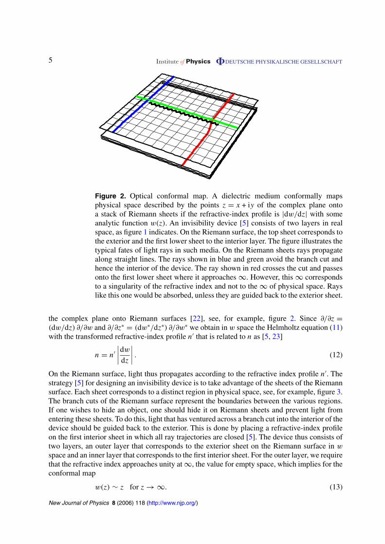
Figure 2. Optical conformal map. A dielectric medium conformally mapsphysical space described by the points z = x + iy of the complex plane ontoa stack of Riemann sheets if the refractive-index profile is |dw/dz| with someanalytic function w(z). An invisibility device [5] consists of two layers in realspace, as figure 1 indicates. On the Riemann surface, the top sheet corresponds tothe exterior and the first lower sheet to the interior layer. The figure illustrates thetypical fates of light rays in such media. On the Riemann sheets rays propagatealong straight lines. The rays shown in blue and green avoid the branch cut andhence the interior of the device. The ray shown in red crosses the cut and passesonto the first lower sheet where it approaches ∞. However, this ∞ correspondsto a singularity of the refractive index and not to the ∞ of physical space. Rayslike this one would be absorbed, unless they are guided back to the exterior sheet.
the complex plane onto Riemann surfaces [22], see, for example, figure 2. Since ∂/∂z =(dw/dz) ∂/∂w and ∂/∂z∗ = (dw∗/dz∗) ∂/∂w∗ we obtain in w space the Helmholtz equation (11)with the transformed refractive-index profile n′ that is related to n as [5, 23]
n = n′∣∣∣∣dw
dz
∣∣∣∣ . (12)
On the Riemann surface, light thus propagates according to the refractive index profile n′. Thestrategy [5] for designing an invisibility device is to take advantage of the sheets of the Riemannsurface. Each sheet corresponds to a distinct region in physical space, see, for example, figure 3.The branch cuts of the Riemann surface represent the boundaries between the various regions.If one wishes to hide an object, one should hide it on Riemann sheets and prevent light fromentering these sheets. To do this, light that has ventured across a branch cut into the interior of thedevice should be guided back to the exterior. This is done by placing a refractive-index profileon the first interior sheet in which all ray trajectories are closed [5]. The device thus consists oftwo layers, an outer layer that corresponds to the exterior sheet on the Riemann surface in w
space and an inner layer that corresponds to the first interior sheet. For the outer layer, we requirethat the refractive index approaches unity at ∞, the value for empty space, which implies for theconformal map
w(z) ∼ z for z → ∞. (13)
New Journal of Physics 8 (2006) 118 (http://www.njp.org/)

6 Institute of Physics �DEUTSCHE PHYSIKALISCHE GESELLSCHAFT
Figure 3. Riemann sheets are tiles. In optical conformal mapping, Riemannsheets represent regions of two-dimensional space, tiles of various forms [21, 22].The figure illustrates the tiling behind the light propagation of figure 1 (details aregiven in the appendix). The upper imaginary half-plane of each sheet correspondsto a grey tile and the lower half-plane to a white tile. The exterior and the interiorsheets of the invisibility device occupy two of such pairs of tiles and the hiddencore takes the rest.
At the boundary between the exterior and the first interior sheet, light is refracted [1] accordingto Snell’s law,2 unless it is totally reflected [1, 5]. Since refraction is reversible, the light raysare refracted back to the original direction of incidence when they leave the branch cut to theexterior sheet. Seen on the Riemann surface, light rays perform loops around a branch pointthat guide them back to the exterior sheet, the outside layer of the device. Seen in physicalspace, light is guided around the object and leaves the cloaking layers of the device as if nothingwere there.
3. Time delay
The time delay caused by an invisibility device depends of course on its spatial extension. Imaginethat the refractive-index profile n(r) is replaced by n(ξr) with the constant scale ξ. If r(t) andk(t) are solutions of Hamilton’s ray equations (4) then ξr and k are solutions, too, if t is replacedby ξt. This proves that the time delay is directly proportional to the spatial extension of therefractive-index profile, as one would expect.
Since the conformal mapping w(z) is simply a coordinate transformation, the time delaybetween two points in z space and the delay between the corresponding points in w space are
2 The law of refraction was discovered by the Arabian scientist Ibn Sahl more than a millennium ago [24].
New Journal of Physics 8 (2006) 118 (http://www.njp.org/)

7 Institute of Physics �DEUTSCHE PHYSIKALISCHE GESELLSCHAFT
identical. Therefore, the part of the refractive-index profile n in physical space that is due to theoptical conformal mapping does not influence the time delay at all. Delays are only caused bythe index profile in w space that serves to guide light around a branch cut on the first interiorsheet. For simplifying the notation, we denote this profile by n (dropping the prime).
Suppose that the transformed refractive-index profile n on the Riemann sheet is radiallysymmetric with respect to one branch point and designed such that all trajectories of light raysare closed curves around that point. The time delay t0 of the invisibility device is equal to thetime light takes to perform a loop around the branch point. A branch point where ν sheets meetrequires ν turns (ν is the winding number). To calculate the delay, we use polar coordinates r
and ϕ centred at the branch point. We obtain from the conservation law of energy [15] for theNewtonian dynamics (6) of light rays
(dr
dτ
)2
+ r2
(dϕ
dτ
)2
= 2 (E − U) = n2(r). (14)
As in the standard theory of motion in central potentials [15] we also use the conservation of theangular momentum,
b = r2 dϕ
dτ, (15)
written here in terms of the impact parameter b, and obtain from the conservation laws (14) and(15) the relation [23]
dϕ = bdr
r√
n2r2 − b2. (16)
To calculate the time delay, we express the Hamiltonian time increment (7) in terms of dϕ,utilizing the conservation of the angular momentum (15). Then we use the relation (16) to writethe time delay as an integral over the radial range of the trajectory. The range of r is bounded bythe radial turning points r± where dr/dϕ vanishes, which implies
n2(r±)r2± = b2. (17)
One trajectory between r− and r+ corresponds to half a turn around the branch point.Consequently,
ct0
2ν=
∫ r+
r−
n2r dr√n2r2 − b2
=∫ r+
r−
√n2r2 − b2
dr
r+ bϕ. (18)
In general, the time delay depends on the impact parameter. However, for closed loops, t0 turnsout to be independent of b. To see this, we differentiate the time delay (18) with respect to theimpact parameter b and obtain from equations (16) and (17)
cdt0
db= 2νb
dϕ
db= 0, (19)
because, when all loops around the branch point are closed, ϕ reaches π regardless of the valueof b. Consequently, the time delay does not depend on the impact parameter at which light hasentered the branch cut to the first interior sheet, i.e. the interior layer of the device. The invisibilitydevice causes a uniform time delay.
New Journal of Physics 8 (2006) 118 (http://www.njp.org/)

8 Institute of Physics �DEUTSCHE PHYSIKALISCHE GESELLSCHAFT
4. Examples
Reference [5] mentions two examples of refractive-index profiles on the interior sheet thatcan be used to circumnavigate the branch point such that all loops are closed, the harmonic-oscillator profile
n1 =√
1 − r2/r21 (20)
that is related to a Luneburg lens [23, 25] and the Kepler profile [23, 25]
n2 =√
r/r2 − 1 (21)
that is related to an Eaton lens [25]–[27]. Here r1 and r2 are constants that describe the boundariesof the refractive-index profiles where n vanishes. Seen on the Riemann surface, light cannotpenetrate the outside of circles of radii r1 and r2, respectively, because here the refractive indexwould be purely imaginary. The optical conformal mapping turns areas on the first interior sheetinside out [21, 22]. Therefore, the exterior of these circles corresponds to the invisible interiorof the device.
The harmonic-oscillator and the Kepler potential are the only spherically symmetricpotentials U where the trajectories for all bound-state energies E are closed [15]. However,what matters in the propagation of light rays is the difference (2) between U and E. Thereforeit is sufficient when for a specific value of E the trajectories for all angular-momenta b areclosed. A known example where this is the case is Maxwell’s fish eye [1, 23, 25, 28] with therefractive-index profile
n3 = n0
1 + (r/r3)2. (22)
The constant radius r3 characterizes the scale of the index profile, the radial halfpoint, and n0 is aparameter that defines the refractive index at the branch point. If Maxwell’s fish eye is employedto guide light back to the exterior Riemann sheet, the entire interior sheet is reached by theincident light. However, when the Riemann surface contains more sheets than the exterior andthe first interior sheet, all the remaining sheets are hidden. Anything placed there is invisible.
The Newtonian equation of motion for rays generated by the harmonic-oscillator profile(20) describes Hooke’s law of a force proportional to the distance, whereas the Kepler profile(21) generates Newton’s inverse-square law. In both cases, the trajectories form ellipses for allbound states, a fact that Newton found exceptionally remarkable [29, 30]. However, Hooke’s lawand Newton’s law can be transformed into each other3 by a transmutation of force according tothe Arnol’d–Kasner theorem [31]–[33].
4.1. Hooke’s force
In the case of the harmonic-oscillator profile (20), the ray trajectories are very simple [15]: theyform a set of ellipses centred at the origin (the branch point), see figure 4. To calculate the time
3 Ironically, despite Newton and Hooke reportedly having been bitter rivals, their most celebrated force laws areessentially identical [31]–[33].
New Journal of Physics 8 (2006) 118 (http://www.njp.org/)

9 Institute of Physics �DEUTSCHE PHYSIKALISCHE GESELLSCHAFT
Figure 4. Light guiding using Hooke’s law (similar to a Luneburg lens) with therefractive-index profile (20) in w space. The device guides light that has entered itsinterior layer back to the exterior, represented in the left figure using two Riemannsheets that correspond to the two layers, seen from above. The right figure showsthe corresponding ray propagation in physical space with the optical conformalmap (A.3) and r1 = 8r0. At the branch cut in the left figure, the thick black linebetween the two points, the branch points, light passes from the exterior to theinterior sheet. Here light is refracted according to Snell’s law, see equation (A.8) ofthe appendix. On the lower sheet, the refractive-index profile (20) guides the raysto the exterior sheet in elliptic orbits with one branch point in the centre. Finally,the rays are refracted back to their original directions and leave on the exteriorsheet as if nothing had happened. The dotted circle in the figure indicates themaximal elongations of the ellipses. This circle limits the region in the interior ofthe device that light does not enter. The outside of the circle and the other Riemannsheets of the map (A.3) correspond to the inside of the device in physical space,as the right figure shows. Anything inside this area is invisible.
spent along a given ellipse we use Cartesian coordinates x and y rotated such that they matchthe axes of this ellipse. We describe the ellipse as
x = a cos ξ, y = b sin ξ, ξ = τ/r1 (23)
with the constants a and b being the axis lengths. One easily verifies that the trajectory (23)solves the Newtonian equation of motion (6). The ray trajectory corresponds to the Newtonianenergy 1/2, which implies
2E =(
dx
dτ
)2
+
(dy
dτ
)2
+x2 + y2
r21
= a2 + b2
r21
= 1. (24)
New Journal of Physics 8 (2006) 118 (http://www.njp.org/)

10 Institute of Physics �DEUTSCHE PHYSIKALISCHE GESELLSCHAFT
Figure 5. Light guiding using Newton’s law (related to an Eaton lens) similar tofigure 4, with the refractive-index profile (21) in w space and the optical conformalmap (A.3) where r2 = 8r0. The left figure shows how light is guided on a Riemannsheet, whereas the right figures shows the ray propagation in physical space. Onthe Riemann sheet, light rays form elliptic orbits with one branch point in thefocal point, instead of the centre, as in Hooke’s case.
Consequently, we obtain for the time delay
ct0 =∮
n2 dτ = νr1
∫ 2π
0
(1 − a2
r21
cos2 ξ − b2
r21
sin2 ξ
)dξ = νπr1. (25)
In agreement with our general results, the time delay caused by the harmonic-oscillator profiledepends on the spatial extension r1 and is otherwise uniform.
4.2. Newton’s force
In order to calculate the time delay caused by the Kepler profile (21), see figure 5, we usethe transmutation of force [31]–[33] to the harmonic-oscillator profile, i.e. the transformationof Newton’s law into Hooke’s law that is also based on conformal mapping [22]. Considertrajectories in the complex plane, say the z plane, although in our case this plane is one of theRiemann sheets generated by the optical conformal mapping in the first place. Suppose that thetrajectories are conformally mapped by the analytic function w(z). We obtain from equations (2)and (12) the relations
U − E = −n2
2= −n′2
2
∣∣∣∣dw
dz
∣∣∣∣2
= (U ′ − E′)∣∣∣∣dw
dz
∣∣∣∣2
. (26)
New Journal of Physics 8 (2006) 118 (http://www.njp.org/)

11 Institute of Physics �DEUTSCHE PHYSIKALISCHE GESELLSCHAFT
Consequently, if the potential U can be written as the modulus square of an analytic function,the potential U ′ is proportional to the modulus square of the inverse of this function expressedin terms of the new coordinates,
U(z) = −E′∣∣∣∣dw(z)
dz
∣∣∣∣2
, U ′(w) = −E
∣∣∣∣dz(w)
dw
∣∣∣∣2
. (27)
The trajectories are mapped onto each other by the transformation w(z). The potentials U andU ′ are thus related to each other, generating dual forces [31]. Consider
w = z2
2r1, E′ = −1
2. (28)
The map w(z) corresponds to the Hooke potential (2) of the harmonic-oscillator profile (20) withenergy E = 1/2 and, in turn, w(z) generates the Kepler profile (21) that corresponds to Newton’sinverse square law with the parameter
r2 = r1
2. (29)
Since conformal mapping does not influence the time delay in light propagation, the delaygenerated by the Kepler profile (21) corresponds to that of the harmonic-oscillator profile (20),apart from one subtlety: already a half-ellipse of the harmonic-oscillator is mapped on to acomplete Kepler ellipse, because of the square map (28). Consequently, the time delay is
ct0 = ν
2πr1 = νπr2, (30)
in complete analogy to the result (25) for the harmonic-oscillator profile. The time delays arethus identical for identical ranges r1 and r2 of the refractive-index profiles.
4.3. Maxwell’s fish eye
Maxwell’s fish eye turns out to represent another classic conformal mapping [23], thestereographic projection discovered by Ptolemy and applied in the Mercator map projection.4
Figure 6 shows how the points on the surface of a sphere (X, Y, Z) are mapped on to a plane, saythe z plane, according to the formulae [21, 33]
z = x + iy = X + iY
1 − Z/r3, X2 + Y 2 + Z2 = r2
3 (31)
with the inverse
X + iY = 2z
1 + |r/r3|2 , Z = r3|r/r3|2 − 1
|r/r3|2 + 1, r2 = x2 + y2. (32)
4 The Mercator map projection is the logarithm of the stereographic projection [33].
New Journal of Physics 8 (2006) 118 (http://www.njp.org/)

12 Institute of Physics �DEUTSCHE PHYSIKALISCHE GESELLSCHAFT
Z
X x
Figure 6. Stereographic projection, mapping the (x, y) plane onto the (X, Y, Z)
surface of a sphere. A line drawn from the North Pole of the sphere to (x, y) cutsthe surface of the sphere at (X, Y, Z). Circles on the plane are mapped into circleson the sphere and vice versa [33].
Figure 7. Light guiding using Maxwell’s fish eye. The interior layer of theinvisibility device is represented by a sphere of radius r3 using the inversestereographic map (32). At the boundary, the branch cut, the light drops on to thesphere where it propagates in great circles. After jumping up to the exterior sheetthe light rays leave the device. This behaviour is generated by the refractive-indexprofile of Maxwell’s fish eye (22) that represents the stereographic projectionillustrated in figure 6 as an optical conformal mapping. The pictures illustrateslight propagation for angles of incidence of ±π/7.
We find that the square of the optical-length element (8) for Maxwell’s fish eye (22) is
ds2 = n20
dx2 + dy2
(1 + |r/r3|2)2= n2
0
4(dX2 + dY 2 + dZ2). (33)
Consequently, the light rays of the fish eye are mapped into rays on the surface of a sphere withradius r3 and uniform refractive index n0/2. According to Fermat’s Principle [1], the rays aregeodesics, lines of extremal optical path length, see figure 7. On a uniform sphere, the geodesicsare the great circles. Since they are closed curves on the sphere, the light rays are closed onthe plane as well, as we required. Furthermore, the stereographic projection maps circles on to
New Journal of Physics 8 (2006) 118 (http://www.njp.org/)

13 Institute of Physics �DEUTSCHE PHYSIKALISCHE GESELLSCHAFT
circles [33] and so the light rays in Maxwell’s fish eye (22) form circles in the plane [1, 23,25]. The calculation of the time delay of light circling in Maxwell’s fish eye is elementary now,because t0 does not depend on conformal transformations and in particular on the stereographicprojection (31); t0 simply is the time delay of light during ν loops on the surface of a sphere withradius r3 and refractive index n0/2, which gives
ct0 = νn0
22πr3 = νπr3n0. (34)
In agreement with our general results, the time delay is uniform and proportional to the lengthscale of the refractive-index profile.
5. Conclusions
In isotropic media, no illusion is perfect due to the wave nature of light [11]. Consequently,conformal invisibility devices [5] cannot be perfect; they cause reflections and time delays.However, the reflectivity can be made exponentially small for macroscopic devices and the timedelay is uniform for all directions and impact parameters. This is important, because imagesconsist of light propagating in a range of directions, having a range of spatial Fourier components.The time delay occurs when the light reaches the interior layer of the device. It will causewavefront dislocations at the two sides, unless the phase delay is tuned to be a multiple of 2π forsome certain frequencies. The diffraction of light will slightly blur the image [1], but the hazecaused is uniform.
Acknowledgments
Many people have contributed to my obsession with invisibility. I am particularly grateful to GregGbur for our discussions in Kiev on the impossibility of invisibility and for his exquisite reviewarticle, to Mark Dennis for introducing me to the transmutation of force and to Awatif Hindi forher advice on elliptic modular functions. My work has been supported by the Leverhulme Trustand the Engineering and Physical Sciences Research Council.
Appendix
Most pictures in this paper are based on a conformal map using elliptic modular functions[34]. These functions are connected to many branches of mathematics, including the proof ofFermat’s Last Theorem [35]. We adopt the notation of the Bateman Manuscript Project on HigherTranscendental Functions [34] (not Neharis notation5). We use the modular function J knownas the Klein invariant, illustrated in figure A.1, and expressed here in terms of the modularfunction λ as
J(z) = 4
27
(1 − λ + λ2)3
λ2(1 − λ)2, λ = 16q
( ∑∞m=0 qm(m+1)
1 + 2∑∞
m=1 qm2
)4
(A.1)
5 In Nehari’s book [22], λ(z) is denoted as J(z).
New Journal of Physics 8 (2006) 118 (http://www.njp.org/)

14 Institute of Physics �DEUTSCHE PHYSIKALISCHE GESELLSCHAFT
– 2 – 1 0 1 2
1
2
3
Figure A.1. The Klein invariant J(z) tiles the upper half z plane with an infinitesequence of circular arches. The arches continue near the real axis in an infinitelyintricate structure (not shown here). Identifying all horizontal strips of length 1and deforming the real axis to a circle leads to figure 3 that illustrates the tilingof the optical conformal map (A.3).
with
q = eiπz, |q| < 1, (A.2)
see equations (36)–(38) of [34]. Note that the expression for λ is rapidly converging and thereforewell suited for numerical computations. Consider the map
w = 4r0J
(− ln(432z/r0)
2πi
)− 31r0
18= 16r0
27
(1 − λ + λ2)3
λ2(1 − λ)2− 31r0
18(A.3)
with
q = 1√432z/r0
. (A.4)
The constant r0 characterizes the spatial scale of the optical conformal mapping. Far away fromthe device, light should propagate through empty space, which implies that w ∼ z for z → ∞.The map (A.3) is chosen such that this is the case. Indeed, we obtain from the representation(A.1) the first terms of the Laurent expansion
J ∼ 1
1728q2+
31
72+
1823
16q2 for q → 0, (A.5)
which implies, according to equations (A.3) and (A.4),
w ∼ z +1823
1728
r20
zfor z → ∞. (A.6)
In the exterior of the device, the map (A.3) approaches the simple example considered in [5],whereas in the interior the map (A.3) represents the infinitely more complicated Riemann surfaceillustrated in figures 3 and A.1. The Riemann surface contains three branch points [22, 34],w1 = (41/18)r0, w2 = −(31/18)r0 and w∞ = ∞ with winding numbers 1, 2 and ∞, apart fromthe exterior sheet with only w1 and w2 [22, 34].
New Journal of Physics 8 (2006) 118 (http://www.njp.org/)

15 Institute of Physics �DEUTSCHE PHYSIKALISCHE GESELLSCHAFT
In order to calculate the ray trajectories, we consider the ray dynamics in w space and thentransform w to the physical trajectories in z space. We describe both the ray trajectories w andthe wavevectors k by complex numbers. In the exterior sheet light propagates along straightlines. Given a point w on the exterior sheet, we numerically solve equation (A.3) for z using theinversion z(w) of the asymptotic map (A.6) as the starting value,
z ∼ 1
72
(36w +
√3(432w2 − 1823)
)(A.7)
for Im w � 0 and we use z∗(w∗) otherwise. At the branch cut between the exterior and the firstinterior sheet light is refracted according to Snell’s law [1, 24]. Since the modulus of k equalsn(ω/c), we obtain for a light ray incident at the angle ϕ Snell’s law in complex notation as
k = ω
c
(sin ϕ − i
√n2 − sin2 ϕ
). (A.8)
On the first interior sheet, we solve Hamilton’s equations for a radially symmetric index profilearound the branch point w1,
dw
dl= k
n(|w − w1|)|k| ,dk
dl= nr(|w − w1|)|k|
n2(|w − w1|)w
|w| , nr(r) = dn(r)
dr(A.9)
for the propagation distance l = ct and Maxwell’s fish eye (22) with n = n3, r3 = 4r0 and n0 = 2.The parameters are designed such that the refractive index on the Riemann structure reaches 1at the other branch point w2 and exceeds 1 along the branch cut. In this way, total reflectionis excluded for the lowest possible value of n0. To calculate z(w) on the first interior sheet weutilize the modular symmetry of the Klein invariant [34],
J(z′) = J(z) for z′ = −z−1, (A.10)
which leads to
z′ = r0
432exp
(4π2
ln(432z/r0)
)(A.11)
for the position z′ that shares the same numerical value of w as z, but corresponds to the firstinterior sheet. We follow the same procedure as for the exterior layer of the device to calculatez and then transform it into z′ to continue the trajectory in the interior layer.
References
[1] Born M and Wolf E 1999 Principles of Optics (Cambridge: Cambridge University Press)[2] Feynman R P, Leighton R B and Sands M 1983 The Feynman lectures on physics Mainly Mechanics, Radiation
and Heat (Reading, MA: Addison Wesley) chapter 26[3] Gbur G 2003 Prog. Opt. 45 273[4] Pendry J B, Schurig D and Smith D R 2006 Science 312 1780 (DOI: 10.1126/science.1125907) (in Science
Express Reports)[5] Leonhardt U 2006 Science 312 1777 (DOI: 10.1126/science.1126493) (in Science Express Reports)[6] Kerker M 1975 J. Opt. Soc. Am. 65 376[7] Alu A and Engheta N 2005 Phys. Rev. E 72 016623[8] Milton G W and Nicorovici N-A P 2006 Proc. R. Soc. Lond. A 462 1364[9] Smith D R, Pendry J B and Wiltshire M C K 2004 Science 305 788
New Journal of Physics 8 (2006) 118 (http://www.njp.org/)

16 Institute of Physics �DEUTSCHE PHYSIKALISCHE GESELLSCHAFT
[10] Grigorenko A N, Geim A K, Gleeson H F, Zhang Y, Firsov A A, Khrushchev I Y and Petrovic J 2005 Nature438 335
[11] Nachman A I 1988 Ann. Math. 128 531[12] Wolf E and Habashy T 1993 J. Mod. Opt. 40 785[13] Tyson R K 1991 Principles of Adaptive Optics (Boston, MA: Academic)[14] Hendi A, Henn J and Leonhardt U 2006 Preprint cond-mat/0605637[15] Landau L D and Lifshitz E M 1976 Mechanics (Oxford: Pergamon)[16] Hannay J H 1976 Cambridge University Hamilton Prize Essay (unpublished)[17] Cook R J, Fearn H and Milonni P W 1995 Am. J. Phys. 63 705[18] Gordon W 1923 Ann. Phys., Lpz. 72 421[19] Leonhardt U and Piwnicki P 1999 Phys. Rev. A 60 4301[20] Leonhardt U 2000 Phys. Rev. A 62 012111[21] Ablowitz M J and Fokas A S 1997 Complex Variables (Cambridge: Cambridge University Press)[22] Nehari Z 1952 Conformal Mapping (New York: McGraw-Hill)[23] Luneburg R K 1964 Mathematical Theory of Optics (Berkeley, CA: University of California Press)[24] Rashed R 1990 Isis 81 464[25] Kerker M 1969 The Scattering of Light (New York: Academic)[26] Eaton J E 1952 Trans. IRE Ant. Prop. 4 66[27] Hannay J H and Haeusser T M 1993 J. Mod. Opt. 40 1437[28] Maxwell J C 1854 Cambridge and Dublin Math. J. 8 188[29] Newton I 1687 Philosophiae Naturalis Principia Mathematica (Cambridge: Cambridge University Press)[30] Chandrasekhar S 1995 Newton’s Principia for the Common Reader (Oxford: Clarendon)[31] Arnol’d V I 1990 Huygens & Barrow, Newton & Hooke (Basel: Birkhäuser)[32] Needham T 1993 Am. Math. Mon. 100 119[33] Needham T 2002 Visual Complex Analysis (Oxford: Clarendon)[34] Erdelyi A, Magnus W, Oberhettinger F and Tricomi F G 1981 Higher Transcendental Functions vol III (New
York: McGraw-Hill) section 14.6[35] Wiles A 1995 Ann. Math. 141 443
New Journal of Physics 8 (2006) 118 (http://www.njp.org/)