new limitation change to - defense technical · pdf fileunclassified ad number ad058599 new...
TRANSCRIPT

UNCLASSIFIED
AD NUMBER
AD058599
NEW LIMITATION CHANGE
TOApproved for public release, distributionunlimited
FROMDistribution authorized to U.S. Gov't.agencies and their contractors;Administrative/Operational Use; Nov 1954.Other requests shall be referred toDirector, Wright Air Development Center,Wright-Patterson AFB, OH 45433.
AUTHORITY
AFAL ltr, 17 Aug 1979
THIS PAGE IS UNCLASSIFIED

C iJLOGED BY CWCOSI-3 '. ..9o,- --T-u qc/ Do OT D pýzoy
WADC TECHNICAL REPORT 5T-162 TEChCALUUCK•ENT
PART 2 wCOsiJSWCOSI-3
At 004 FILE COPY
ELECTRODEPOSITION OF TITANIUM
ALBERT W. SCHLECHTEN
MARTIN E. STRAUMANIS
C. BURROUGHS GILL
MISSOURI SCHOOL OF MINES AND METALLURGY
NOVEMBER 1954
PLoO3 76'1ZL2
Statement AApproved for Public Release
WRIGHT AIR DEVELOPMENT CENTER

NOTICE
When Government drawings, specifications, or other data areusedfor any purpose other than in connection with a definitely related Govern-ment procurement operation, the United States Government thereby in-curs no responsibility nor any obligation whatsoever; and the fact thatthe Government may have formulated, furnished, or in any way suppliedthe said drawings, specifications, or other data, is not to be regardedby implication or otherwise as in any manner licensing the holder orany other person or corporation, or conveying any rights or permissionto manufacture, use, or sell anypatented invention that may in any waybe related thereto.

WADC TECHNICAL REPORT 53-162
PART 2
ELECTRODEPOSITION OF TITANIUM
ALBERT W. SCHLECHTEN
MARTIN E. STRAUMANIS
C. BURROUGHS GILL
MISSOURI SCHOOL OF MINES AND METALLURGY
NOVEMBER 1954
MATERIALS LABORATORY
CONTRACT No. AF 33(616)-75
PROJECT No. 7312
TASK No. 78120
WRIGHT AIR DEVELOPMENT CENTER
AIR RESEARCH AND DEVELOPMENT COMMAND
UNITED STATES AIR FORCE
WRIGHT-PATTERSON AIR FORCE BASE, OHIO
Carpenter Litho & Prtg. Co., Springfield, 0.200 - 15 March 1955

FOREWORD
This report was prepared by the Missouri School of Mines andMetallurgy under USAF Contract No. iF 33(616)-75. The contractwas initiated under Project No. 7312, Finishes and Materials Pre-servation, Task No. 73120, Elactrodeposition and ElectrochemicalTreatments, formerly RDO No. 619-11 (HA), and was administeredunder the direction of the Materials Laboratory, Directorate ofResearch, Wright Air Development Center, with Mr. 0. 0. Srpacting as project engineer.
WADC TR 53-162 Pt 2

ABSTRACT
I process has been developed for obtaining a diffusion coating of titaniumon iron, mild steel, copper, and other metals. This coating is very high intitanium content and displays good corrosion resistance. Mavy of the variablesin the process have been investigated and awe reported. Data are also presentedon the corrosion of titanium in fused salts, the resulting products, and theprobable nehaniu..
PUBLICATION REVIEW
This report has been reviewed and is approved.
FOR THE OOMANDm:
Technical DirectorMaterials LaboratoryDirectorate of Research
WA=E TR 53-162 Pt 2 iii

TABLE (F CONTENTS
INTRODUCTION 1
SECTION I - DIFFLEION CQATIJW CF TITANIUM 2
Introduction 2Previous Work on Titanium Diffusion Coatings 2Background of M.S.M. Titanizing Process 4Experimental Procedure 5Metals That Can be Coated 7Arrangement of the Titanium Source and Object to be Plated 7Stirring and Ultrasonic Agitation of the Bath 8Composition of the Salt Bath 10Composition of the Titanium Source 12Relation of Bath Temperature to Coating Thickness 12Relation of Time of Treatment to Coating Thickness 13Composition of Titanium Diffusion Coatings on Iron 15Effect of Carbon in Steel Upon Titanium Diffusion Coatings 19Deterioration of Coating Bath and Use of Protective Atmosphere 24Conclusions 25
SECTION II - CORROSION OF TITANIUM IN FUSED SALTS AND IDENTIFICATION 26CF PRODUCTS
Introduction 26Experimental Procedure 26Analysis of the Corrosion Products 27Weight Loss of Titanium in Fused NaCl versus Time and Temperature 28Amount and Composition of Black Residue 28Amount and Composition of the Gray Residue and Yellow White 30ResidueInfluence of Alternating Current on Corrosion of Titanium in 31Fused SaltsDiscussion 32Conclusions 33
SECTION III - ELECIROCHENCAL BEHAVIOR OF A TITANIUM-FUSED SALT- 35PLATINUM CELL
Introduction 35Experimental Procedure 36The Electromotive Force of the Cell in Air 39The Electromotive Force of the Cell in Vacuum 40The Current Produced by the Cell 40Influence of Various Gases on Current Produced 42Discussion 45Conclusions 46
WADC TR 53-162 Pt 2 iv

TABLE OF CONTET (CONTI•,)
SECTION IV - HYDROGEN OVERVOLTAGE ON TITANIIUM 48
Introduction 48Conclusions from all Experiments on the Hydrogen Overvoltage 48on Titanium
BIBLIOGRAPHY 50
WA= T 53-162 Pt 2 v

LIST OF ILLUSTRATION
Page
FIGURE 1. Thickness of Titanium Diffusion Coatings on IronVersus Temperature.................................... 14
FIGURE 2. Thickness of Titanium Diffusion Coatings on IronVersus Deposition Time ..... ...... .................... 16
FIGURE 3. Titanium and Iron Contents of Titanium Coatings onIron Versus Coating Time............................ 17
FIGURE 4. Titanium and Iron Contents of Titanium Coatings onIron Versus Temperature........................... .... 18
FIGURE 5. Weight of Titanium Deposited on Steel Versus Carbon
Content.o .............. ...... •..........................21
FIGURE 6. Titanium Diffusion Coating on Ingot Iron.............. 22
FIGURE 7. Titanium Diffusion Coating on 0.18 Percent CarbonSteel ......................................... •.......22
FIGURE 8. Arrangement of the Ti/Salt/Pt Cell for emf andCurrent Measurements .... •..... 00• • •0• ••.......... •. 37
FIGURE 9. Arrangements of the Ti/Fused Salt/Pt Cell for emfand Current Measurements Under a Protective Atmos-
38
WADC TR 53-162 Pt 2 vi

ICTRODEPOSITION OF TITANIUM
INTRODUCTION
Our annual report of one year ago, dated July 1953, briefly
reviewed the desirability of developing a process for depositing
protective coatings of titanium on other metals. Attempts to
electrodeposit such coatings from aqueous or organic electrolytes
have met with little or no success as far as is known. Electro-
deposition from fused salts is possible, but it is not a simple
task, because the major part of the cathode product tends to be
in the form of powder or dendrites and only a relatively thin
layer adheres to the cathode. Furthermore, the successful electro-
lytic deposition of titanium requires most careful purification of
the salts for the bath and the use of a cell which can be operated
under a protective atmosphere.
This report describes a relatively simple procedure for ob-
taining a diffusion coating of titanium on other metals. As far
as can be determined from a literature search, the process is new,
and a patent application has been filed. The coatings obtained
are coherent, free from pits, and effectively protect the bare
metal from corrosion. The factors affecting the deposition are
described in detail in the report.
WA)C T 53-162 Pt 2 1

SECTION I
DIFFUSION COATINGS OF TITANIUM
(I-1) Introduction
Processes in which one metal is diffused into another are
widely used to obtain coatings that are corrosion resistant. Low
melting point metals can be applied by hot dipping, but high melt-
ing point metals require other methods, such as those used for
siliconizing or chromizing.
Diffusion coatings have some advantages over electrodeposited
coatings in that they are more adherent and not as likely to spall
at elevated temperatures. Furthermore, they are often more free
of holes and defects and hence more resistant to corrosion.
For these reasons, chromizing by diffusion is used commer-
cially in England and Germany to apply protective coatings to a
variety of objects. The coating is obtained either by cementation
with chromium metal powder, by immersion in salt baths containing
chromous chloride, or by bringing a chromium halide vapor in con-
tact with the surface to be plated. A considerable amount of re-
search has been done on chromizingy and the results are of value
in predicting the feasibility of titanium diffusion coatings.
(1-2) Previous Work on Titanium Diffusion Coatings
Very few references can be found in the literature to titanium
diffusion coatings. Laissus (1) in 1927 used a cementation tech-
WAflC 53-162 Pt 2 2

nique in which iron and steel specimens were imbedded in ferro-
titanium powder and heated at temperatures from 800 to 1100%
for times of 2.5 to 10 hours. The ferro-titanium powder contained
33% Ti and 8.37% C; although definite coatings were obtained, par-
ticularly on the electrolytic iron, the author found that the re-
sistance to attack was only slightly better than that of the un-
coated iron.
T. Kase (2) in 1936 used a similar method of heating iron
samples in powdered ferro-titanium at temperatures as high as
13000C. He reported that the cemented surfaces became harder, but
no more corrosion resistant.
Cornelius and Bollenrath (3) studied the diffusion of titanium
into steels and reported the effect of the carbon content of the
steel on the diffusion process. However, they did not test the
corrosion resistance of the cemented surfaces.
Alexander (4) and later, Chapin and Hayward (5) have described
a process of coating steels with a copper-titanium alloy ranging
from 5% to 37.5% Ti. These coatings were resistant to 10% NaCi
solutions, but presumably not to nitric acid.
Travers (6) found that iron cannot be coated by contact with
TiC14 vapors even at 1400 C. If carefully purified hydrogen was
also added with the TiCl 4 , a blackish gray coating was obtained
on the iron. This coating slightly retarded the corrosion of the
iron.
S. Kowal (7) heated mild steel specimens at a temperature
WADC T 53-162 Pt 2 3

8800C in a fused mixture of sodium carbonate and titanium dioxide.
He obtained a white layer on the steel which he estimated as con-
taining 5 percent Ti, although x-ray diffraction revealed no ti-
tanium or titanium compound.
It would appear that none of the procedures cited in the
literature yielded a coating of sufficiently high titanium content
to obtain the excellent corrosion resistance of titanium metal.
(1-3) Background of M.S.M. Titanizing Process
The process described in this paper was the outgrowth of pre-
vious experiments on corrosion (8) which shoved that titanium is
severely attacked when immersed in molten chlorides or fluorides
exposed to air. The corrosion products, particularly in chloride
baths, are to a great extent finely divided titanium and resemble
the "metal fogs" or "pyrosols" described by Lorenz and Eitel (9).
It was observed that the walls of the porcelain crucibles used
for the corrosion tests were covered below the salt level with a
layer which was largely titanium. A series of tests were made to
determine if such coatings could be obtained on other surfaces.
As a result of these experiments, it was discovered that ob-
jects of copper, iron, or other metals, immersed in the salt bath
where there was a high concentration of the titanium pyrosol, were
covered with a coating of high titanium content.
In order to achieve the necessary high pyrosol concentration,
the object to be plated was placed in close proximity to the ti-
WADO T 53-162 Pt 2 4

titanium source which was corroding, but preferably not in contact
with it. Thus, flat surfaces could be plated by placing them
parallel to sheets of titanium, and irregular objects could be
imbedded in titanium powder or cuttings, although this second
method tended to give a rougher coating because of some direct
cementation.
The resulting coatings formed a coherent layer that protected
the underlying metal from corrosion. For example, copper and iron
objects coated by this process were immersed in nitric acid solu-
tions with no evidence of attack.
Experiments are described which demonstrate the variation of
the coating process with time and temerature of treatment, com-
position of bath, and other factors.
(1-4) Experimental Procedure
Small disks of copper or iron about 2 cm. in diameter and
1 m. thick were fastened parallel to pieces of titanium sheet
which were slightly larger in diameter; pieces of 0.5 mm. wire
were used as spacers between the two metals. The assemblage was
placed in a porcelain crucible containing molten salt and heated
in a resistance muffle furnace for several hours at a temperature
above the melting point of the salt. After the desired heating
period, the crucible was removed from the furnace, allowed to
cool, and placed in a beaker of water which was heated to digest
the salt. In some experiments the salt was melted after the ob-
WAX M 53-162 Pt 2 5

ject to be plated and the titanium source were placed in the cruci-
ble. In other experiments, the assemblage was removed from the
molten salt as soon as the crucible was taken from the furnace;
there was enough salt adhering to the plated object to prevent
any appreciable oxidation of the titanium coating. These var-
iations in procedure had no detectable influence on the results.
After the salt had been dissolved, it was necessary to rub
or brush away the dark corrosion residue to expose the metallic
titanium coating on the disk.
The weight of the coating was calculated from the increase
of weight of the plated disk, or better yet, by dissolving the
iron or copper away from the coating, which could then be weighed.
The average thickness of the coating was calculated from the weight
and density of titanium, and was checked by measuring a cross-
section under the microscope.
A second method was to plate objects by imbedding them in
titanium powder or cuttings on the bottom of the crucible, fill-
ing up the crucible with salt, and proceeding as before; this was
better for irregular objects than the first method. Titanium
hydride powder was also successfully used in the same way as a
source of the titanium pyrosol. Powdered ferro-titanium was
tried, but did not give a coating.
A variation of the second method was to make a uniform mixture
of titanium powder and salt which was packed around the object.
WAM TR 53-162 Pt 2 6

A variety of salts were tried for the fused bath; and a number
of addition agents to regular NaCl or KCl baths were tested. The
effect of time and temperature were investigated, as well as the
influence of stirring the bath, or applying an external emf.
(1-5) Wtals That Can be Coated
Copper, iron, and low carbon steel, objects were plated in
most of the experiments, but it was found that nickel, cobalt,
and nickel-copper alloys were also readily coated with a titanium
layer. Medim and high carbon steels, as well as cast iron, were
coated only with difficulty and a relatively thin and patchy ti-
tanium layer was observed. In a later section quantitative data
are given for the relationship of the coating thickness and the
carbon content of the base metal. Aluminum could not be coated,
because it was badly corroded in the molten chloride bath.
(1-6) Arrangement of the Titanium Source and Object to be Plated
Flat surfaces to be plated were placed as close as possible
to the titanium sheet serving as a source without actually having
them touch; usually a 0.5 to 1 mm. diameter wire was used as a
spacer. It is not desirable to have the object and the titanium
touch, because at the points of contact actual cementation occurs,
and when the metals are separated the desired coating my be
broken at these points.
If titanium powder is packed around the object to be plated,
W= TR 53-162 Pt 2 7

some small particles of titanium will be cemented into the coating,
which will then be rougher than the coating obtained wholly from
the pyrosol. Coarse cuttings of titanium, such as come from a
hacksaw, will give better coatings than powder, because the cut-
tings will not stick to the plated surface as readily, and seem
to allow freer circulation of the pyrosol-bearing molten elect-
rolyte.
On the theory that plating from the pyrosol is most desirable
method., a piece of titanium metal was heated in a mixture of NaCl
and KCl at 8500C for four hours. The severely corroded metal was
then removed leaving the corrosion products, much of which was
the black pyrosol, in the salt in the crucible. Next, a piece of
copper was placed in the mixture in the crucible and heated. A
very thin and patchy coating was obtained on the copper indicating
that the effectiveness of the pyrosol degenerates rapidly if the
bath is exposed to the atmosphere.
(1-7) Stirring and Ultrasonic Agitation of the Bath
In an attempt to plate irregular objects and to get smoother
coatings, several experiments were made in which first a piece of
titanium acting as a source was slowly revolved in the bath with
the object to be coated held stationary; next the object was re-
volved with the titanium stationary; finally they were both re-
volved. Only fragmentary coatings were obtained, which demon-
strated that dispersal of the pyrosol by stirring so as to reduce
WAXC TR53-162 Pt 2

its concentration was undesirable.
As mentioned before, coatings obtained from titanium powder
are rough, so it was thought that stirring or agitation would be
beneficial. However, as the titanium powder partially sinters
and agglomerates in the salt bath, all attempts at stirring,
agitation, or tumbling of a closed container were failures. The
powder and the object all moved together as one piece.
Finally a number of experiments were made with ultrasonic
agitation using a Millard Ultrasonic Soldering Iron, Type E.7587
coupled to a Millard Power Unit Type E.7595M. An aluminum sleeve
was machined to fit the soldering iron tip and to hold a 1/4 inch
diameter rod extending vertically downward into the furnace and
into the crucible holding the bath. It is realized that this
probably was an inefficient method of introducing vibrations into
the bath and a more effective arrangement is now being assembled.
In the first ultrasonic agitation experiments the object and
a piece of titanium sheet, the two separated by a spacer, were
bolted to a rod extending from the ultrasonic soldering iron.
They were immersed in a fused salt and the ultrasonic agitation
was maintained for the entire plating time. The results indicated
in a qualitative way that the agitation was helpful.
Another series of tests were made to obtain quantitative
data. The procedure was to imbed a copper sample in a mixture of
titanium powder and salt contained in a porcelain crucible, heated
in a pot furnace. When the bath was fluid, the lower tip of the
WAX T 53-162 Pt2 9

rod attached to the ultrasonic soldering iron was dipped into the
bath Just above the sample.
To check on the benefits of agitation a second similar cru-
cible and contents were heated at the same time in the same furnace.
However vibrations were probably conducted through the furnace to
this crucible, so a third similar sample was run at a later time
under the same conditions but with no agitation.
The conditions and the results of the experiments are shown
in Table 1.
The results indicate a beneficial effect, so further experi-
ments will be made using a larger ultrasonic device and more
effective coupling.
(1-8) Composition of the Salt Bath
NaCl, KCl, LiCI, and mixtures of all proportions appear to
be equally effective as measured by the thickness of coating ob-
tained. Eutectic mixtures of NaCI and KCI had the advantage of
a lower melting point. The still lower melting mixtures (around
IWO°C) using LiCl were not warranted, because no coating could
be obtained at such low temperatures.
Thin unsatisfactory coatings were obtained in K2TiF6, NaOH,
and KOH. No coatings were obtained in NaCN, KCN, or a variety of
sulfates.
A number of experiments were made in which Nal, KI, NaBr,
KBr, K2 TiF6, or NaF, were added in amounts varying from 1 to 15
W= TR53-162 Pt 2 10

83 W q I 1 9 1
10
8H
r4
• ,-, ooil.
000
4) o O o Ho C C
r- 0 ,-4
00
P " + + 4) -+-
50 0 0 0 0 N 0 0
PI C4 PI PI P4 P 149 g9
vtk VX LK3 ý l n
W= m53-.62 F 2 H

percent to NaCI or KCM baths. It was thought that these additions
would hasten the corrosion of the titanium source and hence in-
crease the rate of plating. None of the additions were beneficial;
the plating obtained with these additions was less than that with
baths of only NaCI, KCl, or a mixture of the two. It is evident
that for plating purposes it is not only the amount but the nature
of the titanium corrosion products that must be considered.
(1-9) Composition of the Titanium Source
For the majority of the experiments described, titanium of
commercial purity was used as the source in the form of sheet,
plate, powder or cuttings. No difference was noted in the coat-
ing obtained from these various materials.
In a few experiments titanium hydride powder was used in
place of regular titanium powder; no particular advantage or
disadvantage could be observed.
Tests with a low carbon and a high carbon ferro-titanium,
assaying 24 percent and 34 percent Ti respectively, as a source
material gave no coating whatever.
(I-10) Relation of Bath Temperature to Coating Thickness
Disks of low carbon steel were plated on one side from ti-
tanium sheet using a bath of 50-50 mol percent of NaCl and KCl,
and 7 hours plating time. The iron was then dissolved by heating
the sample at 60-80oC in a saturated solution of ferric chloride.
WAI)C TR 53-162 Pt 2 12

Final traces of iron on the titanium were renmved with 1 to 4
nitric acid. The deposit was washed, dried, weighed, and analyzed
for iron and titanium.
Figure 1 shows how the thickness of the titanium coating in-
creases with the increased temperature of the bath. The thickness
was calculated from the weight, using the density of pure titanium.
It can be seen that increased temperatures greatly accelerate
the rate of deposition. From a practical standpoint this must be
balanced against the greater loss of salt by fuming, greater cor-
rosion of the container, and possible distortion of the object to
be coated.
The temperature range for coating copper is more limited.
Below Bo0C very little coating is obtainedy and the upper limit
is set by the copper-titanium eutectic temperature of about 878*C.
If this temperature is exceeded, the sample and the titanium
source form a molten alloy. Several tests were made to plate
titanium on copper in KCl-LiCl baths at temperatures lower than
those reported above. No coating was visible after 4 hours at
4500C and less than 0.0001 inch was obtained at 600eC and 4 hours
plating time.
(I-ll) Relation of Time of Treatment to Coating Thickness
Using a procedure similar to that described in the previous-
section, iron samples were coated in a KCl-NaCl bath at 900"C for
times varying from 1 to 16 hours. Subsequently the iron was dis-
WAX TR 53-162 Pt 2 13

.350 .014
.300 - .012
.250 .010
.200 .008
.150 .006
uz_z z
w .100 .00
z .050 .002 w
.000 .000800 850 900 950 1000 1050
TEMPERATURE IN °C
nsre 1. mdclun a =ri5twd., .us wrjon costiLq
am Iron vwem *-. Ts', I-*. (Seven b'ws depouLtiontimne 1 molten hcl-.E ).
WADC TR 53-162 Pt 2 14

solved, the coating weighed, and its thickness calculated by
assuming a density equal to that of titanium. The coatings were
so thin for times less than 4 hours that no attempt was made to
measure them. Figure 2 shows the results of this series of tests.
It can be seen that the thickness of the coating increases
with time, but that there is much variation. This lack of repro-
ducibility, especially when longer times are used, is related to
the deterioration of the plating power of the bath. Undoubtedly,
the pyrosol becomes oxidized in the open crucibles and loses its
ability to form a coating, and the rate of oxidation is not the
same in successive experiments. This raises the question of the
desirability of a protective atmosphere, which is discussed in a
later section of this report.
(1-12) Composition of Titanium Diffusion Coatings on Iron
The titanium coatings from the experiments reported in the
previous two sections were analyzed for titanium and iron by
colorimetric methods. The determination of titanium was made
using hydrogen peroxide as a reagent (Weller's Method); iron was
determined by the method of Moss and Mellon (10). The results
are shown in Figures 3 and 4.
It can be seen that there is no great variation of composition
with time of coating. The high iron content of the coatings from
the low plating times may be due to the difficulty of dissolving
all of the iron base metal from the very thin coating.
WADC TR 53-162 Pt 2 15

S3HONI NI SS3NUdDIHI0 0 0 0(0 It cm0,0 0
C!0
00
I')
0
0 H
00
- -0 0O
Sa 0
ri Y4 NI S93NAI)IH±
TRfl I53-162Ft 2 16

0ý0-ID- N
o _ _o
-*0 0
0~
0 0 0 0 00) CD N -•IrnNVJIJ. (NV NOVI PlN3: I3d
WADC TR53-162 Pt 2 17

9O
Z20
z
Ir
800 850 g00 950 1000 1050TEMPERATURE IN Oc
ftw 4. 2&Mwd= man I •m Co•x atT umm 0c...-rm wwm lwWatw. (01-3911 bfth for 7 bowrs)
AM TH 55-162 Pt2 28
Likewise, there is no really significant trend of composition
variation with temperature of deposition.
It should be pointed out that the coating which has been
weighed and analyzed is that part which was not soluble in ferric
chloride or the 1 to 4 nitric acid. Presumably the composition
of the coating varies from almost pure titanium on the very outer
surface to very low concentrations of titanium at the limits of
diffusion into the iron. When the base metal is dissolved, any
portion of the coating not sufficiently high in titanium to resist
the action of the reagent will also be eaten away.
Therefore, the reported analyses of the coatings which are
all close to 80 percent Ti, represent the average composition of
the corrosion resistant layer.
As a matter of comparison, Samuel and Lockington (ll) report
that the composition of chromized coatings vary between 18.5 to
22.8 percent Cr, and that this composition bears no relation to
temperature or time of deposition.
The sum of iron plus titanium in Figures 3 and 4 is in the
neighborhood of 95 percent for all samples; the remaining 5 per-
cent has not been identified. Spectrographic analysis shows no
concentration of metallic impurities in the coatings.
(1-13) Effect of Carbon in Steel upon Titanium Diffusion Coatings
A series of tests were made on iron and steel samples of the
following compositions.
WADO TR 53-162 Pt 2 19

Designation C Ma P(max.) S(max.)
Ingot iron 0.012 0.017 0.005 0.025C 1012 0. 10/0.15 0.30/o.60 o.o4o0 0.050C 1015 0.13/0.18 0.30/0.60 0.0oo0 0.050C 1036 0.30/0.37 1.20/1.50 0..0 4 0 0.050
Samples of the above were packed in titanium powder and heated
in molten sodium chloride at 950eC for six hours. After treatment
the samples were weighed to determine the increase in weight and
then were sectioned, polished, and etched so that the titanium
coating could be measured under the microscope. The results of
the thickness measurements are shown graphically in Figure 5; the
data on weight increase give an almost identical curve. All of
the data plus that for tests on samples of even higher carbon con-
tent are summarized in Table 2.
The influence of carbon content can be seen by comparing
Figure 6 and Figure 7 showing a titanium diffusion coating on
ingot iron as contrasted with one on a 0.18 percent carbon steel.
It appears that the effect of carbon is to form titanium
carbide which precipitates at the interface of the base metal and
the coating; this new phase retards severely the diffusion of the
titanium and hence the coating is much thinner.
Reference to the Ti-Fe-C ternary phase diagram shows that at
9500 C the TiC field will be entered at about 0.12 to 0.15 percent
carbon, so the results shown in Figure 5 are exactly those that
would be expected.
These results do not mean that it is entirely impossible to
WA•C TR 53-162 Pt 2 2D

0
to) 0
0 00
0;4
40-4
0 -a'
040
N 0'
9 W 3 VA38 v~4nNVJLI. SV40f17W4
XAOC TR53-162 Pt 2 21

7,
Figure 6. Titanium Diffusion Coating on I0.ot Peroent
Carbon Steel. (950*C for 2 1/2 hours., 500x., 5% NitalEtch.)
WADO TR 53-162 Pt 2 22

4) V4
.r 43 'o
,4 0
4-1
t) 4) 03 4_q C) CJ
4J
43)
r-4)
88to0 A ic0H%
"q OLH4 0 PO
o g 8 .0 gg O : L\L\4
' 0 '0 '0 '0 '0
4) \ 'E U r\ .
It.0
WAflC TR 53-162 Pt 2 23

coat steels of higher carbon content. The same problem is met in
chromizing and has been circumvented in the following ways.
1) Use of special steels containing elements which are carbon
stabilizers. These are known as IK steels in Germany.
2) Decarburization of a surface layer previous to coating.
3) Use of longer times and higher temperatures of coating.
4) Use of a carbide former such as vanadium chloride along
with the chromizing compound.
Similar techniques are being tested for titanizing.
(I-14) Deterioration of Coating Bath and Use of Protective Atmos-
phere
A series of plating experiments were made wherein an object
of mild steel was coated by being packed in titanium cuttings and
heated in a fused NaCl bath at 9000C for 7 hours. The bath was
cooled and then dissolved in water; the titanium cuttings thus
recovered were used again with fresh NaCI for further runs. It
was found that the second, third, and fourth use of the cuttings
gave progressively worse coatings. It is assumed that an oxide
coating forms on the titanium and prevents further pyrosol for-
mation.
Similar experiments using a deoxidized salt bath and a pro-
tective atmosphere of helium gave patchy and unsatisfactory coat-
ings. Thus the conclusion can be drawn that some oxygen is needed
for the process, but an excess is detrimental.
WADC 'T 53-162 Pt 2 24

(1-15) Conclusions
The procedure described in this section will successfully
form a diffusion coating of over 80 percent average titanium
content on iron. copper, and other metals. This coating has the
corrosion resistant properties of titanium in contrast to the
non-resistant coatings described previously in the literature.
The titanizing process requires relatively high temperatures,
but no more so than chromizing which is used commercially to a
considerable extent.
'4= T 53-162 Pt 2 25

SECTION II
CORROSION (F TITANIUM IN FUSED SALTS
AND IDENTIFICATION OF PRODUCTS
(II-l) Introduction
In the previous annual report (12) on this project and in a
more detailed article (8) by the present authors it has been
shown that metallic titanium is severely attacked in fused
chloride melts if oxygen is present.
This phenomenon is of interest not only as it applies to the
behavior of titanium in such circumstances, but because it has a
direct bearing on the procedure for obtaining titanium coatings
as described in the previous section.
The chief corrosion product formed when titanium is attacked
by fused chlorides is a finely divided solid of almost pure ti-
tanium, which can be called a "pyrosol" after the terminology of
Lorenz (9). Experience has shown that metallic objects immersed
in a high concentration of this pyrosol will be "titanized".
The effect of temperature and time on the extent of corrosion
and identification of the products is described in detail.
(11-2) Experimental Procedure
The titanium samples were made of Allegheny Ludlum Steel Corp.
titanium wire of 99+ percent purity. The wire was first cut into
pieces of about 30 cm. length and made into coils. These were
WADC TR 53-162 Pt 2 26

weighed and suspended in the molten salt bath, which consisted of
U. S. P. Grade-Granular NaCl, melted in a porcelain crucible heated
in a resistance furnace. The titanium sample was suspended on a
platinum hook, hanging from a porcelain rod resting across the
crucible top so that there would be no deposit formed on the
crucible during heating.
After being heated at a given temperature for the determined
length of time, the samples were taken from the molten bath. The
corroded samples were covered with a blue-black mass of salt and
residue. The material left inside of the crucible was grayish
white near the bottom with a yellowish white rim at the top
periphery of the bath.
The dark residual mass was dissolved in water and the black
residue obtained was decanted several times with hot water and then
dried. There was also a gray residue left when the salt remaining
in the crucible was dissolved in hot water; this gray residue was
treated in the same way as the black residue. The yellowish white
reaction product collected from the periphery of the dry salt bath
was washed with hot water, decanted, and dried. A yellowish white
residue was obtained. Since this residue and the gray one gave
nearly the same x-ray patterns, no further distinction was made
between them. All of these collected products were weighed, and
the loss of the titanium sample was also determined.
(11-3) Analysis of the Corrosion Products
The titanium content of the residues was determined by col-
WADC TR 53-162 Pt 2 27

lecting the hydrogen gas evolved from the dissolution of the dis-
persed metallic titanium in hydrofluoric acid. The composition
was also checked by x-ray diffraction methods.
The apparatus used for determination of titanium content in
the residues by measuring the hydrogen evolution consisted of
an Erlenmeyer flask to hold hydrofluoric acid, a spoon to hold the
sample for analysis, and a burette to collect the hydrogen gas
evolved. The lower portion of the flask was lined with paraffin
on the inside walls to protect the glass from reacting with the
hydrofluoric acid.
The method of analysis was checked by running samples of the
original titanium wire, and results of 99.1 to 99.8% Ti were ob-
tained.
(11-4) Weight Loss of Titanium in Fused NaCl versus Time and
Temperature
The actual weight loss of the titanium samples in fused NaCl
at various times and temperatures is shown in Table 3 and Table 4.
A plot of these data shousa straight line relationship for
loss of weight versus time and versus temperature.
(11-5) Amount and Composition of Black Residue
The black residue was a fine powder; under the microscope
the individual particles showed a bright metallic appearance.
The amount of this black residue recovered was fairly proportional
to the weight loss of the titanium sample, varying between 54 to
WADC TR 53-162 Pt 2 29
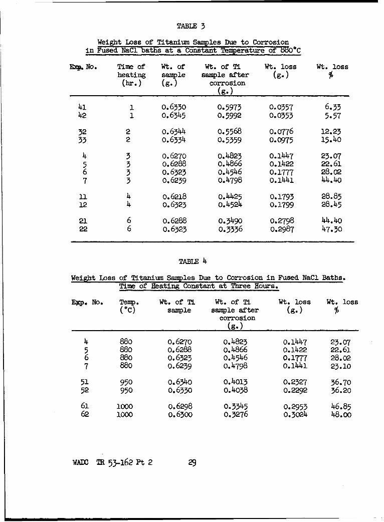
TABLE 3
Weight Loss of Titanium Samples Due to Corrosionin Fused NaCI baths at a Constant Temperature of t5OOC
EXP.No. Time of Wt. of Wt. of Ti Wt. loss Wt. lossheating sample sample after (g.) %
(br.) (g.) corrosion(g.)
41 1 0.6330 0.5973 0.0357 6.3342 1 o.6345 0.5992 0.0353 5.57
32 2 o.6344 0.5568 0.0776 12.2333 2 0.6334 0.5359 0.0975 15.40
4 3 o.6270 o.4823 0.1447 23.075 3 o.6288 o.4866 0.1422 22.616 3 0.6323 o.4546 0.1777 28.027 3 0.6239 0.4798 0.1441 44.40
ll 4 o.6218 0.4425 0.1793 28.8512 4 0. 6323 0.4524 0.1799 28.45
21 6 0.6288 0.3490 o.2798 44.4022 6 0.6323 0.3336 0.2987 47.30
TABLE 4
Weight Loss of Titanium Samples Due to Corrosion in Fused NaCl Baths.Time of Heating Constant at Three Hours.
pep. No. Temp. Wt. of Ti Wt. of Ti Wt. loss Wt. loss("C) sample sample after (g.) %
corrosion(g.)
4 880 o.627o 0.4823 0.1447 23.075 880 0.6288 o.4866 0.1422 22.616 880 0.6323 0.4546 0.1777 28.027 880 0.6239 0.4798 0.1441 23.10
51 950 o.634o 0.4013 0.2327 36.7052 950 0.6330 0.4038 0.2292 36.20
61 1000 0.6298 0.3345 0.2953 46.8562 1000 O.6300 0.3276 0.3024 48.00
wADC TR 53-162 Pt 2 29

80 percent, but usually between 60 and 70 percent. Thus the weight
of black residue was also proportional to the length of time and to
the temperature of the corrosion process.
Analysis by hydrogen evolution of the black residue indicated
that the metallic titanium content varied between 75.2 and 85.9
percent. No relation could be found between the percent metallic
titanium in the black residue and the temperature or time of the
corrosion process which formed the residue.
X-ray diffraction analysis of the black residue gave a value0
for c = 4.786 A and c/a = 1.610. Comparing these values with the
parameter values of titanium-oxygen alloys given by Bumps, Kesseler,
and Hansen (13) leads to the conclusion that the residue contains
from 8 to 12 percent oxygen.
(11-6) Amount and Composition of the Gray Residue and Yellow
White Residue
X-ray diffraction patterns of the gray and yellow white
residues showed that they were both Ti02 in the crystal form of
rutile; no difference could be detected in the patterns.
When these residues were placed in HF solutions, a slight
evolution of hydrogen was obtained from the gray residue.
This would indicate that the gray and white residues are
both formed from the oxidation of titanium and are identical ex-
cept for a very small amount of dispersed metallic titanium in
the gray residue.
The oxide residues vary from 37 to 77 percent of the weight
WADC TR 53-162 Pt 2 30

loss of the original titanium sample. Thus the Ti content of the
TiOC) residues is 22 to 46 percent of the weight loss.
(11-7) Influence of Alternating Current on Corrosion of Titanium
in Fused Salts
The work of Copson (14) showed that the passage of an alter-
nating current caused the rapid corrosion of nickel electrodes
submerged in molten chlorides. It was thought that this might be
a means of rapidly building up the concentration of titanium
pyrosol in the bath to be used subsequently for plating.
The titanium electrodes, which had an alternating current
passed through them in an attempt to speed up corrosion, were
riveted to the ends of copper lead wires and immersed in a NaCl bath at
850*C. The copper lead wires were protected from the severe attack of
the NaC1 fumes in the furnace by running them through a two holed,
porcelain, insulator, which protected them from below the liquid-air
interface to well above the top of the furnace. The 110 v. A.C.
supply was reduced to the voltage required by a variable transformer,
an ammeter was connected into one of the leads to a titanium elect-
rode, and a voltmeter connected across the leads to both electrodes.
The titanium electrodes were weighed, and the surface area
measured before immersion, and weighed again after the end of the
test to determine the loss in weight and corrosion rate at various
current densities.
A piece of asbestos paper at the top of the electrodes spread-
ing them apart assured a constant distance between the electrodes
during the duration of~the test, and removed any possibility of
W 53-162 Pt 2 31
the electrodes touching and short circuiting.
Current densities ranging from 1.86 to 10.66 amps per sq. in.
were tried and also at 9.72 amps per sq. in. with one percent
Na2O added to the NaCI bath, because Copson had found that Na2 O
increased the attack on nickel electrodes.
The results varying from 0.9 to 11.5 mg/cm?-hr. loss showed
no relation to the amperage imposed and were actually less than
the loss increased when no current was used. It can be concluded
that within the range of our experiment the use of alternating
current was not helpful.
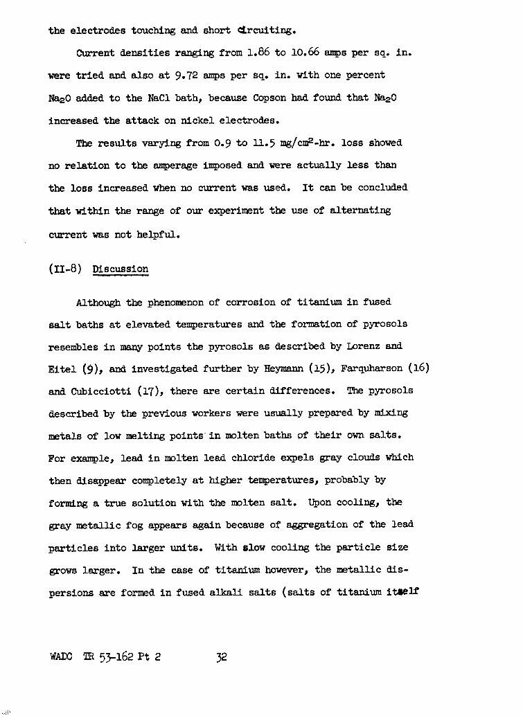
(11-8) Discussion
Although the phenomenon of corrosion of titanium in fused
salt baths at elevated temperatures and the formation of pyrosols
resembles in many points the pyrosols as described by Lorenz and
Eitel (9), and investigated further by Heymann (15), Farquharson (16)
and Cubicciotti (17), there are certain differences. The pyrosols
described by the previous workers were usually prepared by mixing
metals of low melting points in molten baths of their own salts.
For example, lead in molten lead chloride expels gray clouds which
then disappear completely at higher temperatures, probably by
forming a true solution with the molten salt. Upon cooling, the
gray metallic fog appears again because of aggregation of the lead
particles into larger units. With slow cooling the particle size
grows larger. In the case of titanium however, the metallic dis-
persions are formed in fused alkali salts (salts of titanium itself
WAXC TR 53-162 Pt 2 32

were not tried), at temperatures far below the melting point of the
metal itself. Furthermore, for formation of metallic titanium dis-
persions the presence of air (oxygen) is necessary, as the pyrosol
formation in vacuum or under inert gases occurred to a very limited
extent. Because of experimental difficulties, no attempt was made
to raise the temperatures of the melts above 1000C, or higher, in
order to check whether the metallic fog will dissolve completely
in the melts, and then crystallize out upon cooling. Nevertheless,
the cooled melts with the titanium dispersion resembled salts
colored by colloidally dispersed substances. The transparent salt
near the titanium appeared black to blue, but a part of the
metallic dispersion was in the form of coarse powder which settled
to the bottom of the crucible. Regardless of the grain size of
these metallic dispersions, the system, molten salt - dispersed
titanium, can be called a "pyrosol", and the observed corrosion
phenomena are to a great extent due to the pyrosol formation.
The reasons for this kind of corrosion are at present unknown; this
action seems to be not electrochemical in nature, but is related to
the partial oxidation of the titanium in the melt or in the salt fumes.
(11-9) Conclusions
Titanium metal is strongly attacked by fused NaCl baths in
the presence of oxygen or moisture. Within the limit of our ex-
periments, the weight loss of the samples is proportional to the
time of exposure and temperature of the bath.
The products of corrosion can be roughly divided into a black
WA1DC TR 53-162 Pt 2 33

residue and a combined gray-white residue. The black residue,
usually amounting to 60 or 70 percent of the weight loss, was a
finely divided material, which we have called a pyrosol. Measure-
ment of hydrogen evolution in HF indicates that the black residue
contains from 75 to 86 percent metallic titanium. X-ray diffrac-
tion patterns are similar to those of metallic titanium with
approximately 12 percent oxygen in solution.
The gray-white residue has the x-ray diffraction pattern of
rutile and contains 22 to 46 percent of the titanium corroded from
the sample.
WAD= TR 53-162 Pt 2 34

SECTION III
EIECTOCHEDCAL BEHAVIOR OF A
TITAXIM-FUSED SALT-PLATINUM CELL
(III-I) Introduction
It is well known that it is extremely difficult to deposit
titanium from molten salt baths with an external current; the
metal my be deposited under an inert atmosphere in the form of
powder, flakes, or as a very thin layer, but no deposition is
observed if air (oxygen) is present to any appreciable extent.
It would be of value to know the reasons for this behavior,
and to determine the action of air and moisture during electrolysis.
Such knowledge might furnish clues to the successful solution of
the problems of the electrodeposition of titanium.
One of the obstacles to the electrodeposition of titanium in
the presence of air is the high susceptibility of this metal to
oxidation, and to corrosion in molten salts at elevated tempera-
tures, as pointed out in the previous sections. Titanium, if
deposited on the cathode, may disperse in the molten salt because
of pyrosol formation, thus retarding the deposition process. How-
ever, it is doubtful if pyrosol formation alone is the chief deter-
rent to the deposition of the metal, especially if the cathode is
capable of forming a solid solution with titanium. The fact that
in the presence of air or moisture no titanium is cathodically de-
posited poivts towards other electrochemical or chemical events
AM T 53-162 Pt 2 35

which hamper the electrodeposition.
The behavior of the cell Ti/fused salt/Pt in various gases
and in the presence of water vapor gives some answers to the prob-
lems of deposition.
(111-2) Experimental Procedure
A preliminary experiment showed that a cell consisting of ti-
tanium and platinum electrodes immersed in molten sodium chloride
produced a fairly strong current if the electrodes were short cir-
cuited through a milliameter. The direction of the current in-
dicated that titanium went into solution acting as an anode with
the platinum as the cathode.
In order to explore this phenomenon in detail a cell was con-
structed which made it possible to accumulate separately the anodic
and cathodic reaction products for subsequent analysis. A copper
tubing was also provided for introducing gases and steam into the
cathodic compartment. The arrangement is shown in Figure 8. Air
had access to the crucible in the furnace, although a loose cover
was made from a piece of fire resistant brick.
To determine the influence of air (oxygen), an arrangement
was made so as to heat the crucible C (Fig. 8) in vacuum or in an
inert gas, and simultaneously to measure the emf of the open cell
or the current delivered by a chosed cell. This was accomplished
by placing the crucible together with the electrodes and salt in
a quartz glass tube, as shown in Fig. 9. The lower part, C, of
this apparatus was placed into the furnace (Fig. 8).
WAXD MR 53-162 Pt 2 36

D
F ©A M
71gwe 8.Aramn of the Tfi/Salt/ft cell for Ouand current )anns
A - Ti wire anode in a porous Algdb thi~ble with the topopen or clausA. B - Pt cathode (3 at'). C - Porcelaincrucible containing the alkali salt or umixture of salts.D - (Cppc tubing for gas infroduction. P - Resistancefurinace. N - )tlliaueter. P - Potentiomter. S - hivtch.I - Uinroivwle.
WAfl TR 53-162 Pt 2 37

A, 13 - Xds to the potentlamteror to the ndliamntwr. C - Caible with Malt ba~th. D - 2dbe of
**Iquiwtz glas. 2- Jbz. 7 - Cn'3' 0 ictian to vacman and gas supply*
-C
71ure 9. krmwpmnt-ils of the Ti/ifmm salt/Pt Con for sotand OW2rat -haswmut ItAer a Protective Atmopbere.
W=AD TR 53-162PFt2 3

The operating procedure was as follows: the temperature of
the furnace was raised to 8800C or higher to melt completely the
salts, and then lowered to the working temperature of 850 or 800BCO
which is above the melting point of the 50-50 mol percent KCl-NaCl
mixture. Some runs were made in pure sodium chloride and some in
pure potassium chloride. Measurements of the emf of the Ti/molten
salt/Pt cell were continued until this force became approximately
constant. Then the switch S (Fig. 8) was closed, and the current
produced by the cell was registered. After the cell had operated
for several hours, the circuit was disconnected, the thimble A
(anodic compartment, Fig. 8) removed from C, and the furnace cooled
down. The salts of the anodic and cathodic compartments were
separately dissolved in water and the solutions were analyzed as
to their content of acid and of base. Methyl orange was used as
indicator.
(111-3) The Electromotive Force of the Cell in Air
Measurements of the potential difference (emf ) of the cell
Ti/molten KCl/Pt were made in air and continued until this dif-
ference became approximately constant. Then the temperature was
changed in order to establish the relation between the emf and
the temperature. The cell generated an eaf of about 1.48 volts
at 900"C. The potential fluctuated during all of the experiments,
but finally a fairly constant value (actually slowly decreasing)
was established at a given temperature. There seems to be no re-
lation between temperature -and emf; usually the emf increased
WADC TR 53-162 Pt 2 39

slowly from the beginning of the experiment up to a maximum value
and then decreased slowly.
The values for the emf in a 50-50 tol percent mixture of
sodium and potassium chloride were approximately the same, reading
about 1.48 volts at 800C. In pure sodium chloride they were some-
what lower, approaching 1.46 volts at 950*C. All of these potential
measurements represent open circuit values. If a current was drawn
from the cell, the emf dropped immediately (measured after opening
the circuit), but started to increase slowly as long as the circuit
was open and the temperature was constant; finally in several hours
attaining the values mentioned above.
(III-4) The Electromotive Force of the Cell in Vacuum
The emf as developed by the cell in an inert atmosphere or
vacuum was much lower than that in air and fluctuated between .45
and .60 volts. The experiments in vacuum could not be continued
for very long, because the salt evaporated quickly from the cruci-
ble. Therefore the remaining experiments were made using nitrogen
under slight pressure (about 100 mm Hg), with the cell developing
approximately the same emft as under vacuum.
Replacing the nitrogen with helium or hydrogen gave essentially
the same results.
(111-5) The Current Produced by the Cell
As soon as the switch of the Ti/molten salt/Pt cell was closed,
such a strong current was developed in the first moments that it
WADC TR 5_-162 Pt 2 40

usually could not be measured by the instruments in the circuit.
In a few seconds the current dropped abruptly, and slowly approached
a fairly constant value, although it always fluctuated somewhat.
The sudden drop of the current is, of course, typical for a cell
displaying polarization phenomena at the electrodes.
After the cell had been operating for a certain time, the
circuit was opened and the furnace cooled. The salt from the
anodic and cathodic compartments was removed, and separately dis-
solved in water. Qualitative tests showed that the solution ob-
tained from the salt of the anodic compartment was strongly acidic,
while that of the cathodic compartment was basic. A series of
quantitative determinations was made in order to establish the
amount of acid and base produced by the working cell.
The number of milliampere minutes delivered by the cell were
determined and from this was calculated the equivalents of metal
going into solution in the anodic compartment as well as the de-
position on the cathodic compartment. Because the electrolyte was
usually a mixture of sodium and potassium chloride, only the
equivalents or milliequivalents produced could be calculated; (1608
milliampere minutes to correspond to one milliequivalent). The a-
mount of acid and base produced by the working cell was determined
by titration of the aqueous solutions of the salts of the separate
compartments, and was compared with the calculated results based
on the milliampere minutes which flowed through the circuit. The
results are summarized in Table 5.
wADC R 53-162 Pt 2 41

TABLE 5
Acid and Base Produced by the WorkingTi/Molten Salt/Pt Cell in Millieg uivalents.
Run Salt MI4lliequiv. calc. Acid in m.e.q. Base in m.e.q. Ratio of m.e.q. titratedNo. (from current) anodic comp. cathodic comp. to m.e.q. calculated
II NaCl-KCl 1.18 0.37 0.51 0.51/1.18 . o.44Ia NaCl-KCI 3.5 -- 1.76 0.50III NaCl-KCl 7.35 3.45 5.05 5.05/7.35 = 0.69IV NaCl-KC1 9.55 5.2416 6.0 6.0 /9.55 = 0.636 KC1 4.65 1.91 2.81 2.81/4.65 = 0.607 KCl 2.29 1.12 1.68 1.68/2.29 = 0.749 NaCi 3.14 o.87 1.46 1.46/3.14 = o.147
Table 5 shows clearly that acid and base are formed in ap-
preciable amounts in the anodic and cathodic compartments, varying
from 44 to 74 percent of the value as calculated from the current
by the cell. The fact that the base and acid generated is appreciably
lower than the theoretical value can be attributed to diffusion of
the reactions products through the porous alundum diaphragm so that
partial neutralization occurred, and as a consequence a smaller
amount of base and acid was titrated.
(III-6) Influence of Various Gases on Current Produced
A series of qualitative experiments were made to determine
the mechanism responsible for production of potential and current
in the cell. It was found that the magnitude of the current ob-
tained was dependent upon the presence of oxygen, similar to the
results obtained for the emf of the open circuit cell. At 800C
the cell delivered 35-40 milliamps; if the quartz tube containing
the cell was evacuated the current dropped to 0.27 milliamps or
less. Upon admission of air, again the current increased by a
WAX M 53-162 Pt 2 42

factor of 100 or more. This cycle could be repeated only a
limited number of times, because the salt evaporated from the
crucible when the vacuum was applied. However, alternate cycles
of air and nitrogen gave respectively high and low currents for
many repetitions. It seemed quite evident that oxygen acted as
a depolarizer, maintaining by its presence the emf of the working
cell. The action of other neutral gases was similar to that of
nitrogen; they all decreased the current produced by the cell as
soon as they displaced the air.
To check once more the depolarizing action of oxygen, it was
introduced through a quartz glass tube into the furnace so that
the gas stream impinged upon the platinum cathode. Immediately
a current was observed with up to 4 times the value observed in
air, indicating a pronounced depolarizing effect. Upon decreasing
the oxygen stream, the current decreased also. However, it was
necessary to prove whether the strong current observed on introduc-
ing oxygen was actually due to the depolarizing action at the
cathode, or simply the result of stirring the electrolyte with
the gas stream. If stirring caused the increase of current, then
it could be expected that a nitrogen stream introduced near the cathode
would also increase the strength of the current delivered by the cell.
However, a nitrogen stream on the cathode caused a decrease of the
current until it became even less than it was in air. Therefore,
the effect of stirring of the bath was far below the effect caused
by the chemical action of oxygen.
Water vapor was introduced into the crucible of Fig. 8 through
WAO TR 53-162 Pt 2 43

the tubing D. The effect of the water vapor was quite impressive
and resulted in currents which sometimes exceeded those generated
in the presence of oxygen. Water vapor acted as a strong depolarizer.
In all experiments in which the current produced by the cell
or the potential difference of the open cell was measured, it was
impossible to say where the polarization or depolarization of the
working cell occurred, whether on the anode or cathode, or on both
electrodes simultaneously. Because of experimental difficulties
and the lack of good reference electrodes for temperatures close
to 900"C, no attempts were made to measure the single potentials
of the electrodes. However, an attempt was made to get an answer
in an indirect way. For this purpose the titanium anode was com-
pletely encased in an alundum thimble by sealing its top with
alundum cement and asbestos wool. Thus, the oxygen access to the
anode was very limited. Oxygen, nitrogen, and steam were admitted
alternately into the furnace near the cathode and the milliammeter
readings were observed. The qualitative results obtained are shown
in Table 6. It should be remembered that in such an experiment the
current with admitted nitrogen never dropped to zero, because the
nitrogen only diluted the oxygen present in the furnace, as already
mentioned. Nevertheless, the experiment showed quite well the in-
fluence of the steam and oxygen. Table 6 shows that a remarkably
strong current can be drawn from the small cell for a period of
several hours. The effect of oxygen, steam, or nitrogen upon the
current is decisive and appears immdiately. Therefore, the polari-
WA TR 53-162 Pt 2

TABLE 6
Depolarizing Effect of Oxygen and Steam on the Ti/NaCI/Pt cell at 900*C(Ti anode was encased in a coarse grained alundum thimble. Time in-dicates the period after closing the circuit, and the moments at which
the operations indicated are performed.)
Time Gas Currentin min. admitted in m.amps.
20 Air 8525 N2 in 2527 N2 off 8530 02 in 15033 02 off 12039 N2 in 7541 N2 off 11045 02 in 15047 o2 off 12049 N2 in 9051 N2 8053 N2 off 10760 Steam in 17061 Steam off 150 to 13066 N2 in 10068 N2 off 13569 02 in 15070 02 off 12571 N2 in 9076 Steam in 150
and so on.
zation and depolarization occurred mainly on the platinum cathode.
(111-7) Discussion
There seems to be only one way to explain the behavior of the
Ti/fused salt/Pt cell without contradictions. It has to be assumed
that the titanium anode going into solution in the fused salt bath
in form of Ti 3 + or Ti 4+ ions (in the presence of oxygen at the
high temperature the oxidation of Ti+ to Ti4+ would occur anyway)
is the source of energy. Therefore, the anodic process is (4):
or (1O+) s oTio = Ti 4 + + 4e
WADC TR 53-162 Pt 2 45

The electrons liberated pass into the platinum cathode, and at-
tract the positive ions, which can only be the sodium or potassium
ions. However, these ions can be discharged only in a limited
amount to form a very thin alkali metal layer on the platinum
cathode, because the potential of the titanium is insufficient for
a continuous reduction of alkali ions. The formation of such lay-
ers has been discussed previously (18). Under these conditions,
only an insignificant emf is developed by the cell. The situation
changes as soon as oxygen has access to the cathode; the electrons
at the cathode can now be discharged at a fast rate by
4a + 4Na+= 4NaO (2)
because another cathodic energy delivering process is occurring:
4Na" + 20 = 2Na 2 o (3)
Sodium peroxide may be also formed. The final process occurring
in the cell during its operation is the sum of (1), (2), and (3):
Ti° + 4Na+ + 02 = Ti4+ + 2Na 2 0 or (4)Ti + 4NaCl + 02 = TiCI 4 + 2Na 2 O
Titanium displaces the sodium from the sodium chloride melt, and
the sodium is oxidized by the oxygen of the air. Of course, a
still better cathodic depolarizer is pure oxygen or water vapor;
the latter reacts violently with the sodium with liberation of
hydrogen.
(111-8) Conclusions
The experiments showed that in the presence of air, alkali
oxides were produced on the cathode of a galvanic cell Ti/fused
salt/Pt by the emf of the titanium itself. If the same cell is
ADC TR 53-162 Pt 2 46

now used for electrolysis by applying an external current and
with titanium as the anode, alkali oxides will be formed on the
cathode. This will happen even in the presence of titanium
cations, because the formation of alkali oxides occurs at a
lower potential tim required for the discharge of Ti4+, as shown
by the cell experiment. Hence no titanium can be deposited on
the cathode because of this reason (other reasons are mentioned
in the introduction).
The discharge of alkali cations on the cathode may also
occur under an inert gas atmosphere, especially when the concen-
tration of the titanium salt in the bath is low. Hence the dis-
charging alkali ions will hamper the deposition of titanium in
the regular growth of the deposit, and formation of titanium powder
will be favoured. Furthermore, it may be that the formation of
titanium powder is also due to the reduction of titanium ions by
the electrolytic alkali metal formed (19). The possibility that
titanium powder is formed through secondary reactions such as
Ti 4 + + 4Na = Ti° + 4Na+ is supported by observations on deposition
of aluminum from cryolyte baths where, if the current is too strong
(the voltage applied is too high, or the concentration of A12 0% in the
bath is too low), alkali metals are discharged together with aluminum.
If the concentration of metallic titanium particles in the
interface of the cathode during the electrolysis and the tempera-
ture is high enough, alloy formation with the cathode by direct
contact of the particles may occur.
WAIC TR 53-162 Pt 2 47

SECTION IV
HYDROGEN OVERVOLTAGE ON TITANIUM
(IV-I) Introduction
The previous annual report of this project gave the experi-
mental procedure and resulting data for a great many determinations
of the hydrogen overvoltage on titanium. One interesting feature
was that the hydrogen overvoltage versus current density relation-
ship did not follow Tafel's Law in hydrofluoric acid solutions.
Subsequently, experiments were made using basic solutions of
KOH and NaOH, and also solutions of organic acids.
From all of the experiments formed the following general con-
clusions can be drawn.
(IV-2) Conclusions from all Experiments on the Hydrogen Over-
voltage on Titanium
(1) The hydrogen overvoltage on titanium obeys Tafel's law
in acids such as H2SO4 , HCI, HBr, CHsCOOH, CF3 COOH, and also in
bases such as NaOH and KOH.
(2) Tafel's law does not hold in the case of hydrofluoric
acid. Instead of the usual semi-logarithmic relationship, there
is a linear relationship between overvoltage and current density.
(3) In hydrofluoric acid solution, the addition of ammonium,
potassium, or sodium fluoride increases the hydrogen overvoltage
considerably. Sodium fluoride is most effective in this respect.
WADC TR 53-162 Pt 2 49

With a larger amount of sodium fluoride added., above one third of
a mole, Tafel's law is found to be followed again.
(4) Addition of organic agents such as gum Arabic or agar-
agar also increases the hydrogen overvoltage in hydrofluoric acid.
(5) The presence of oxygen has the effect of shifting the
hydrogen overvoltage potential slightly in the less negative direc-
tion.
(6) From considerations of the hydrogen overvoltage alone,
it would seem that conditions are favorable for discharge of
titanium, but electrodeposition of titanium has not been achieved
from aqueous solutions.
WALC T 53-462 Ft 2 49

BIBLIOGRAPHY
1) Laissus, J., Contributions to the Study of Metallic Cementa-tion, Revue d9 tallurgie, 24-, 76 (1927).
2) Kase, T., Cementation of Some Metals by Means of Ferro-titanium Powder, Kinzoku No Kenlyu., 13_, 50 (193b).
3) Cornelius, H. and Bollenrath, F., The Effect of Carbon on theDiffusion of Some Elements in Steel, Arch. Eisenhittenw., 15,145 (1941).
4) Alexander, P. P., Coating Metal Articles, U. S. Pat. 2,351,798(1944).
5) Chapin, E. J. and Hayward, C. R., Coyper-Titanium Coatings onMild Steel, Trans. A.S.M., 38, 909 (177). "
6) Travers, A., Coating of Iron with Titanium, Chemie et Industrie,special number March 1932, p. 345.
7) Kowal, S., Inpregnation of Steel with Titanium etc., H. BrutcherTranslation No. 3152 (1955) from Prace Instytutow Mechaniki(Warsaw) No. 6, 5 (1953).
8) Gill, C. B., Straumanis, M. E., and Schlechten, A. W., Corrosionof Titanium in Fused Chlorides and the Formation of Pyrosols,Electrocbem. Soc. Paper, My U1954).
9) Lorenz, R. and Eitel, W., "P"rosole", Akademische Verlagsges.,Leipzig, (1926). See also R. Lorenz "Pyrosols" in J. Alex-ander's "Colloid Chemistry", Vol. I, pp.Yi_-706 , ReinholdPubl. Corp., New York (1926).
10) Moss., M. L. and Mellon, M. G., Colorimetric Determination ofIron, etc., Ind. and Eng. Chem. (Analyt. Ed.) 14, bc2 (1942).
11) Samuel, R. L. and Lockington, N. A., The Protection of MetallicSurfaces by Chromium Diffusion, Metal Treatment, L_, 354 (1951).
12) Schlechten, A. W., Straumanis, M. E. and Gill, C. B., Electro-deposition of Titanium, WADC Technical Report, No. 53-162,Pt. 1 (1953) "
WAIJ T 53-162 Pt 2 50

13) Bumps, E. S., Kesseler, H. D. and. Hansen, M., Phase Diagramsof the Ti-Al, Ti-Cr, Fe, and Ti-O Alloy Systems, Trans. A.SM..,
14) Copson, H. R., Corrosion of Heating Electrodes in MoltenChloride Baths, J. Electrochem. Soc., LO00, 257 (1955T.-
15) Heymann, E., Solutions of Metals in Molten Salts, Austral.Chem. Ind. Journ. and Proc. !t, Yd (1937).
16) Farquharson, J. and Heymann, E., ýýtic Proerties ofSolutions of Cadmium in Molten caoum chloride and ofMolten Calomel, Trans. Farad. Soc., 31, 1004 (1935).
17) Cubicciotti, D., Solutions of Metals in Fused Salts, J. ofMetalsp.5s 1106 (1953).
18) Straumanis, M. E. and Fang, C. C., The Structure of MetalDeposits Obtained by Electrochemical DisplacIement Gn Znnc,J. Electrochem. Soc., S, 9 (1951).
19) Drossbach,, P., The eposition of !ntan Ti.anium,. andSodium as Sodium-Lead Alloys from Fused Salt Mixtures, Zeit.fur Elektrochem., 27, 54d., 557, 55d (1955).
WADC M 53-162 Pt 2 51