new limitation change to - dtic login · new limitation change to approved for public release,...
TRANSCRIPT
UNCLASSIFIED
AD NUMBER
AD825206
NEW LIMITATION CHANGE
TOApproved for public release, distributionunlimited
FROMDistribution authorized to U.S. Gov't.agencies and their contractors;Administrative and Operational Use; Oct1967. Other requests shall be referred toAir Force Aero Propulsion Laboratory,Research and Technology Division, [AFSC],Wright-Patterson AFB, OH, 45433.
AUTHORITY
AFAPL ltr, 12 Apr 1972
THIS PAGE IS UNCLASSIFIED
AFAPL- TR-67- 123 (
DEVELOPMENT OF A HAZARDOUSVAPOR DETECTION SYSTEM FOR ADVANCED AIRCRAFT
Lester Seiden, Orlando Cucchiara and Philip Goodman
Panarnetrics, IncorporatedWaltham, Massachusetts
TECHNICAL REPORT AFAPL- TR- 67- 1Z3October 1967
Air Force Aero Propulsion Laboratory
Research and Technology DivisionAir Force Systems Command
Wright-Patterson Air Force Base, Ohio 908
THIS DOCUMENT IS SUBJECT TO SPECIAL EXPORT CONTROLSAND EACH TRANSMITTAL TO FOREIGN GOVERNMENTS ORFOREIGN NATIONALS MAY BE MADE ONLY WITH PRIOR APPROVALOF THE AIR FORCE AERO PROPULSION LABORATORY (APFL).
NOTICE
When Government drawings, specifications, or other data are
used for any purpose other than in connection with a definitely relatedGovernment procurement operation, the United States Government therebyincurs no responsibility nor any obligation whatsoever; and the fact thatthe Government may have formulated, furnished, or in any way suppliedthe said drawings, specifications, or other data, is not to be regarded byimplication or otherwise as in any manner licensing the holder or anyother person or corporation, or conveying any rights or permission tomanufacture, use, or sell any patented invention that may in any way berelated thereto.
-.-
Copies of this report should not be returned unless return is
required by security considerations, contractual obligations, or noticeon a specific document.
IT
DEVELOPMENT OF A HAZARDOUSVAPOR DETECTION SYSTEM FOR ADVANCED AIRCRAFT
Lester Seiden, Orlando Cucchiara and Philip Goodman
I.I2I
I
F•REJORD
K This report was prepared by Panametrics, Inc., Waltham,
Massachusetts, on Air Force Contract AF 33(615)-3 6 46 , "Develop-
ment of a Hazardous Vapor Detection System for Advanced Aircraft."
The contract was initiated under Project No. 6075, Task No. 607508.
The work was administered under the direction of Fuels, Lubrication,
and Hazards Branch, Support Technology Division, Air Force Aero
Propulsion Laboratory, Research and Technology Division. Mr. Jon
R. Manheim and Mr. Robert E. Cretcher served as project engineers
for the Laboratory.
"The studies presented here were conducted in the period
I March 1966 through I September 1967, by the Chemistry Depart-
ment of ianametrics, Inc., Dr. Philip Goodmz-, Director. Mr.
Orlando Cucchiara was the principal investigator.
This report was submitted by the authors September 1967.
This technical report has been reviewed and is approved.
Arthurm. Churchill, ChiefFuels, Lubrication, and Hazards BranchAF Aero Propulsion Laboratory
ii
I.,
ABSTRACT
A program was conducteu to evaluate, develop, and constructinstrunm.entation for the detection of hazardous vapors aboard advancedaircraft. Prototype detection systen.s were constructed both for moni-toring JP-6 fuel vapor in aircraft comp'irtments and for monitoringoxygen in the ullage space of fuel tanks. These systems will be furtherevalu2ted in flight tests.
Detection of both species is accomplished by the use of a catalyst-coated thermistor sensor. Catalytic oxidation occtirring at the catalystsurface liberates heat, which is sensed by the thermistor.
The JP-6 sensor consists of a sim-,ple probe which can be mounteddirectly in the space to be monitored. No samplin_ system is required.
The oxygen sensor is more complicated, necessitating flow con-nections to an external pump and gas supplies.
The instruments developed meet almost all of the desired goals.In a few instances, flexibility for installation in a variety of situations
and locations was retained at the sacrifice of some performance charac-teristics. Methods for achieving desired goals in specific installationsand operating modes are indicated and are relatively simple.
LtI-I
iii
TABLE OF CONTENTS
. INTRODUCTION 1
IL TECHNICAL DISCUSSION 2
A. Operating Principle 3
B, Investigation and Results 6
1. Establishment of Gas Mixtures 6
2. JP-6 Detection 8a. Operating Temperature 8b. Linearity 11c. Pressure Dependence 13d. Catalyst Poisoning 18
3. Oxygen Detection 18a. General 18b. Reaction of 02 With Isobutane 18c, Reaction of 02 With Other Hydrocarbons 19d. Reaction of O With JP- 6 22
C. Discussion 22
III. INSTRUMENT DESIGN 25
* A. General Considerations 25I. Thermistor Configuration 25
I' 2. Temperature Control 27
3. Thermistor Selection 314. Catalyst Coating 335. Bridge Circuit 34
B. Oxygen Detector 341. General 342. Condensation of JP-6 Vapors 343. Gas Flow and Component Placement 364. Isobutane Addition 39
C. Overall Instrument Description 40
IV. SYSTEM TESTS 43
A. Mechanical 4
B. Temperature Controllers 43C. Linearity 43D. Freon Cooler 43
PRECEDING VPAGE- BLNK
-.. - -- - _ ___ __
TABLE OF CONTENTS (continued)
V. SUMMARY AND RECOMMENDATIONS 44
A. Conformance with Target Requirements 441. Temperature Range 442. Sensitivity 443. Response and Recovery Times 444. Selectivity 45
5. Exposure to Liquid Fuel 456. Other Requirements 46
B. Recommendations 46
APPENDIX 49
A. Kryptonatej® 491. Operating Principle 49
2. Investigation and Results 493. Discussion 51
B. Aluninum Oxide Hygrometer 511. Operating Principle 512. Investigation and Results 523. Discussion 52
REFERENCES 53
vi
IQ
ILLU S TRA TIONS
Figure Page
1 Typical Thermistor "R" vs "TT" Characteristic
(Fenwal GA61MI 1) 5
2 Simple Wheatstone Bridge Circuit 4
3 Gas Mixing Manifold 7
4 Thermistor Resistance Measurement 8
5 Energy Release vs Temperature: JP-6 in Air 10
6 Constant Temperature Bridge 9
7 Signal vs JP-6 Concentration in Air 12
8 Low Pressure Test Chamber 14
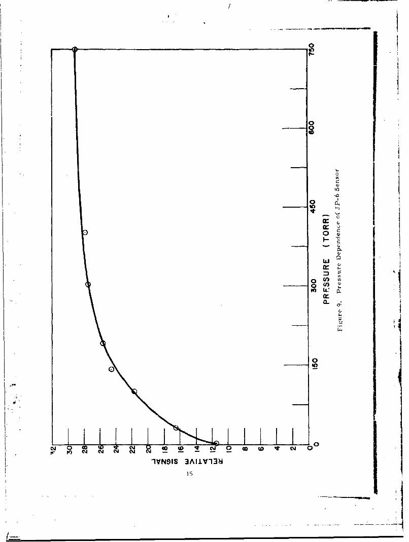
9 Pressure Dependence of JP-6 Sensor 15
10 Signal vs 02 Concentration: Isobutane in N2 20
11 Signal vs 0C Concentration: Propane in N2 21
12 Possible 02 Detector Configuration 24
13 High- Dis sipation Configuration 26
14 Typical High- Dissipation Mountings 28
15 Auxiliary Bridge Circuit 29
16 Final Sensor Configuration 30
17 Temperature Controller Circuit 32
18 Thermistor Construction 31
19 Instrument Bridge 35
20 0 Detector Assembly 37
Z1 Component Placement and Gas Flows - 0 Detector 38
22 Schematic Control Box 4123 Schematic Pump Circuitry d
vii
I_______
r I.
, ISECTION IIt
INTRODUCTION
The continuing progress made in the development of advanced air-breathing, hydrocarbon-fueled aircraft has brought with it ever increasingdifficulties in coping with fires and explosions. Leakage of combustible fuelor its vapors into various compartments of an advanced aircraft can rapidlylead to explosive fuel-air mixtures. Thus the reliable and rapid detectionof low fuel vapor concentrations in potentially hazardou~s locations within the
airframe is of extreme importance.
In addition to the leakage of combustible fuel vapors, there also existsa possible hazard due to the presence of oxygen in the ullage space uf the fueltanks. The fuel temperatuxe in such aircraft is often high enough to createlaxgc fuel vapor concentrations above the liquid. In such a situation, the
presence of oxygen in any appreciable quantity could present an extremelydangerous situation. This oxygen could arise from at least three sources:(a) outgassing of the fuel under high temperature-low pressure conditions;(b) "breathing" of the fuel tanks during descent of the aircraft; (c) leakage.
It is the purpose of this program to select appropriate state-of-the-arttechniques for the detection of both !P-6 vapors and oxygen in advanced air-
, craft, to construct prototype instruments b1ased on this selection, and toevaluate these instruments under simulated and actual flight conditions.
The state-of-the-art technique' studied included a radiochemicalexchange technique using Kryptonate ,f):, an aluminum oxide hygrometer
* technique, and a catalytic combustion technique using thermistors. The* Kryptonate technique proved to be satisfactory fur the detection of hydro-: carbon fuels; however, a suitable Kryptonate sensor for the detection of
oxygen could not be developed in the allotted time period. The hygromnetertechnique proved to be suitable for detecting both gases at normal ambienttemperatures; however, the aluminum oxide sensor could not be designedto withstand the high environmental temperatures expected for Mach 3 typeaircraft.
Catalytic thermal detection was the technique ultimately chosen for* both the JP-6 and the 02 sensors. Instruments based on this technique were
developed, constructed and tested in the laboratory. The instruments werefound to meet almost all of the desired program goals. The work performed
on this subject comprises the main body of the report. The other techniq'cs(Kryptonates and the aluminum oxide hygrometer) are described in the appeadix.
I�""'A registered trademark of Panametrics, Inc.
11
;. .
SECTION II
TECHNICAL DISCUSSION
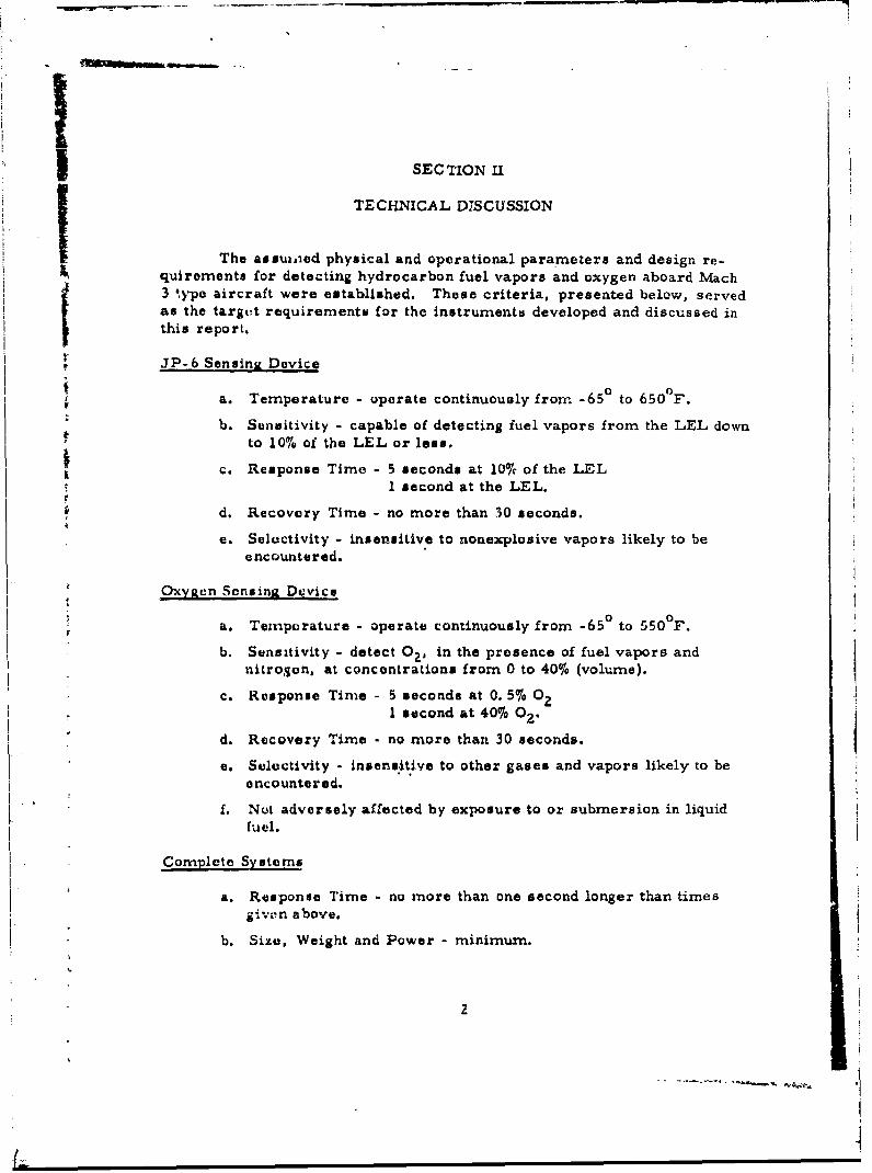
The assu ioed physical and operational parameters and design re-quirements for detecting hydrocarbon fuel vapors and oxygen aboard Mach3 type aircraft were established. These criteria, presented below, servedas the targut requiremento for the instruments developed and discussed inthis report.
JP-6 Sensing Device
a. Temperature - operate continuously from -650 to 650°F.
b. Sensitivity - capable of detecting fuel vapors from the LEL downto 10% of the LEL or less.
c. Response Time - 5 seconds at 100/c of the LEL1 second at the LEL.
d. Recovery Time - no more than 30 seconds.
e. Selectivity - insensitive to nonexplosive vapors likely to beencountered.
OxyRen Sensing Device
a. Temperature - operate continuously from -65° to 550°F.
b. Sensitivity - detect 0, in the presence of fuel vapors andnitrojon, at concentrations from 0 to 4016 (volume).
c. Response Time - 5 seconds at 0. 5% 02I second at 40%6 02.
d. Recovery Time - no more than 30 seconds.
e. Selectivity - insensitive to other gases and vapors likely to beencountered.
f. Not adversely affected by exposure to or submersion in liquidfuel.
Complete Systems
a. Response Time - no more than one second longer than timesI. givn abov.
b. Size, Weight and Power - minimum.
2

c. Operation - capable of continuous operL tion; built-in systemintegrity test capability; both set-point alarm and continuousrecording capability (alarm self-canceling).
d. Installation and Maintenance - simple in concept; highly reliable;easily maintained.
The technique which appeared to most nearly fulfill the above require-ments, viz., catalytic combustion, is discussed below. T'is technique was
selected on its ability to withstand the environmental conditions and stillprovide the necessary sensitivities, response times and other requirementsfor both JP-6 and oxygen detection. The other techniques investigated arediscussed in the appendix.
A. Operating Principle
The principle of operation of the catalytic thermal detection techniqueis quite straightforward. It has long been observed that certain solid mate-rials catalyze (i. e., increase the rate of) gas-phase reactions which, in theabsence of these materials, would proceed at extremely slow rates. Withoutgoing into the detailed mechanisms of such phenomena, one may say in gen-eral that such catalysts usually exert their effect by means of a selectiveadsorption process in which molecules of one or more of the gaseous speciesare held at particular sites on the catalytic surface in configurations (either
steric or electronic) which make them highly susceptible to reaction.
If such a reaction is exothermic, then heat will be liberated at thereaction site in proportion to the rate at which the reaction is taking place.If one can measure this liberated heat in some way, then it becomes possibleto estimate the relative rate of the reaction. It often happens, when one re-actant is present in excess, that this rate is directly proportional to thegas-phase concentration of the other.
Considering gaseous hydrocarbon-oxygen mixtures we find that, inthe absence of very high temperatures or of an initiation process, the oxida-tion rate of the hydrocarbon is usually quite low. If, however, this reactioncould be made to occur at a catalytic surface, a sizable amount of heat wouldbe liberated. Even seemingly very dilute hydrocarbon-oxygen mixtures con-tain surprisingly large amounts of available heat energy. If even a small
fraction of this heat could be released to a thermal detector in an appropriatemanner, there would be little problem in obtaining very high sensitivities.
For example, let us consider a small parcel of air (1 liter) at standardtemperature and pressure, containing JP-6 vapor at a concentratic n of 0. 01%by volume (well below the LEL). Assuming an "average" molecular weight
for JP-6 of about 150, c xe can calculate that there are 6 x I0"4 grams ofhyd ocarbon in this parcel. As the heat of combustion of JP-6 is about14Oc there are approximately 6 calories of thermochemical energy
3
~ ____
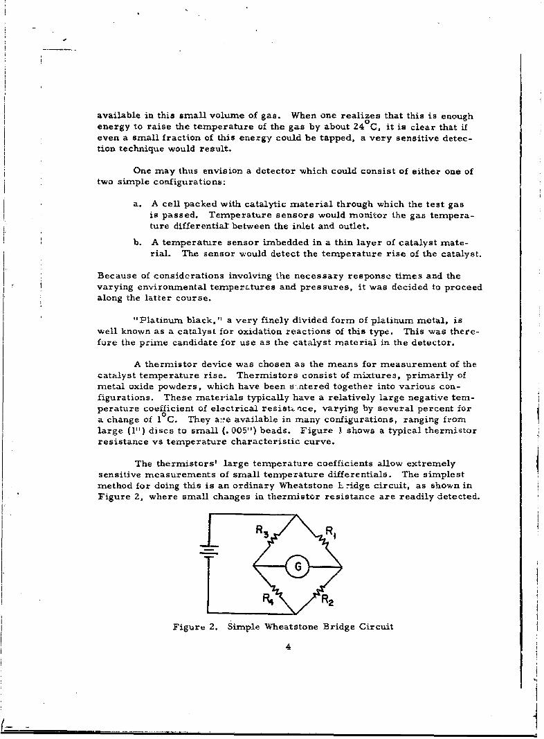
available in this small volume of gas. When one realizes that this is enough0energy to raise the temperature of the gas by about 24 C, it is clear that if
even a small fraction of this energy could be tapped, a very sensitive detec-tion technique would result.
One may thus envision a detector which could consist of either one of
two simple configurations:
a. A cell packed with catalytic material through which the test gasis passed. Temperature sensors would monitor the gas tempera-ture differential: between the inlet and outlet.
b. A temperature sensor imbedded in a thin layer of catalyst mate-rial. The sensor would detect the temperature rise of the catalyst.
Because of considerations involving the necessary response times and thevarying environmental temperztures and pressures, it was decided to proceedalong the latter course.
"Platinum black," a very finely divided form of platinum metal, iswell known as a catalyst for oxidation reactions of this type. This was there-fore the prime candidate for use as the catalyst material in the detector.
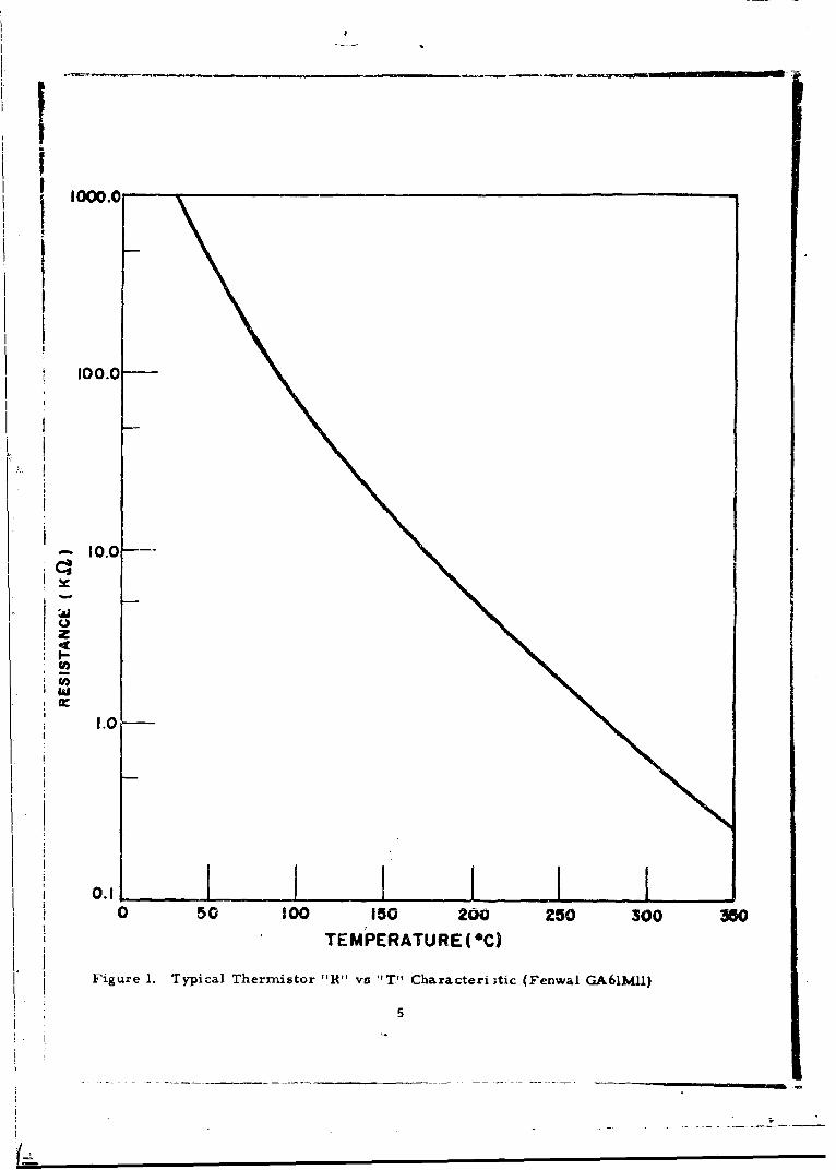
A thermistor device was chosen as the means for measurement of thecatalyst temperature rise. Thermistors consist of mixtures, primarily ofmetal oxide powders, which have been s ntered together into various con-figurations. These materials typically have a relatively large negative tem-perature coefficient of electrical resists rice, varying by several percent fora change of 10 C. They a::e available in many configurations, ranging fromlarge (1") discs to small (. 005") beads. Figure I shows a typical thermistorresistance vs temperature characteristic curve.
The thermistors' large temperature coefficients allow extremelysensitive measurements of small temperature differentials. The simplestmethod for doing this is an ordinary Wheatstone k ridge circuit, as shown inFigure 2, where small changes in thermistor resistance are readily detected.
Figure 2. Simple Wheatstone Bridge Circuit
4
| . .. . . . % - _
II
I00.0
1 0.0--
1W
1.0
I• o ,I I I I0 50 1^00 i50 200 250 300 350
TEMPERATURE (*C)
Figure 1. Typical Thermistor R"' vs 'T" Characteri;tic (Fenwal GA6IMII)
5
- '
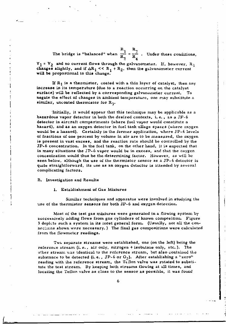
R RThe bridge is "balanced" when T- Y- . Under these conditions,
2 R4V1 = V2 and no current flows through the galvanometer. If, however, R 1changes slightly, and if AR, << R1 + RZ, then the galvanometer currentwill be proportional to this change.
If R1 is a thermistor, coated with a thin layer of catalyst, then anyincrease in its temperature (due to a reaction occurring on the catalystsurface) will be reflected by a corresponding galvanonieter current. Tonegate the effect of changes in ambient temperature, one may subsditute .similar, uncoated thermistor for R 3 .
"Initially, it would appear that this technique may be applicable as ahazardous vapor detector in both the desired contexts, i. e., as a JP-6detector in aircraft compartments (where fuel vapor would constitute ahazard), and as an oxygen detector in fuel tank ullage spaces (where oxygenwould be a hazard). Certainly in the iormer application, where JP-6 levelsof fractions of one percent by volume in air are to be measured, the oxygenis present in vast excess, and the reaction rate should be controlled by theJP-6 concentration. In the fuel tank, on the other hand, it is expected thatin many situations the JP-6 vapor would be in excess, and that the oxygenconcentration would thus be the/determining factor. However, as will beseen below, although the use of the thermistor sensor as a JP-6 detector isquite straightforward, its use as an oxygen detector is attended by severalcomplicating factors.
B. Investigation and Results
1. Establishment of Gas Mixtures
Similar techniques and apparatus were involved in studying theuse of the thermistor sensors for both JP-6 and oxygen detection.
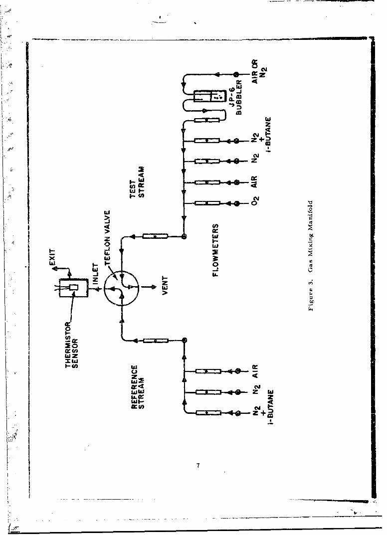
Most of the test gas mixtures were generated in a flowing system byi.ucceuively adding flows from gas cylinders of known composition. Figure3 depicts such a system in its most general form. (Usually, not all the con-nec-'cns shown were necessary. ) The final gas compositions were calculatedfrom the flowmeter readings.
Tw(. separate streams were established, one (on the left) being thereference stream (i. e., air only, nitrogen + isobutane only, etc. ). Theother stream ,.ras. ' identical to the reference streamn, but also contained thesubstance to be detected (i. e. , JP-6 or 0?). After establishing a "zero"reading with the reference stream, the Tt~lon valve was rotated to substi-tute the test stream. By keeping both streams flowing at all times, andlocating the Teflon valve as close to the sensor as possible, it was found
6
0**j
200
w z
4cJI
0Qww Z WU. clz
I~W a:wi-9
that much more rapid response times were obtained than in flow systemswhere reference and test gas streams were alternately passed through asingle flow line. The longer response times associated with the latterwere believed to be due to slow absorption and desorption of vapors on thewalls of the tubing, making it difficult to achieve a true "step-change" ingas composition when using a single flow line. Response times of about onesecond were readily obtained with the flow system shown.
It will be noted that JP-6 was supplied by a bubbler arrangementfrom which saturated JP-6 vapor was obtained. Unfortunately, becauseof its variable composition, it is not possible to assume a fixed vapor pres-sure for this material. It is possible to determine experimentally theconcentration by weight of JP-6 in the gas issuing from the bubbler, butbecause of its variable molecular weight, the volume percentage can onlybe estimated. As it is a mixture of hydrocarbons, even the weight percent-age will tend to vary with time as the JP-6 slowly fractionates, the lower-boiling components being vaporized first. Thus, it was found that freshsamples always yielded higher signals than those which had been in thebubbler for several days. As it was not deemed practical to muake continualdeterminations of the JP-6 concentration (the process being quite time-consuming) it was decided to assume a standard value of 0. 616 (wt) at roomtemperature, based on determinations done at the beginning of these studies,and to put fresh JP-6 in the bubbler every few days. If one assigns an"average" molecular weight of 150 to JP-6, then 0. 676 by weight correspondsto 0. 11% by volune.
2. JP-6 Detection
a. Operating Temperature
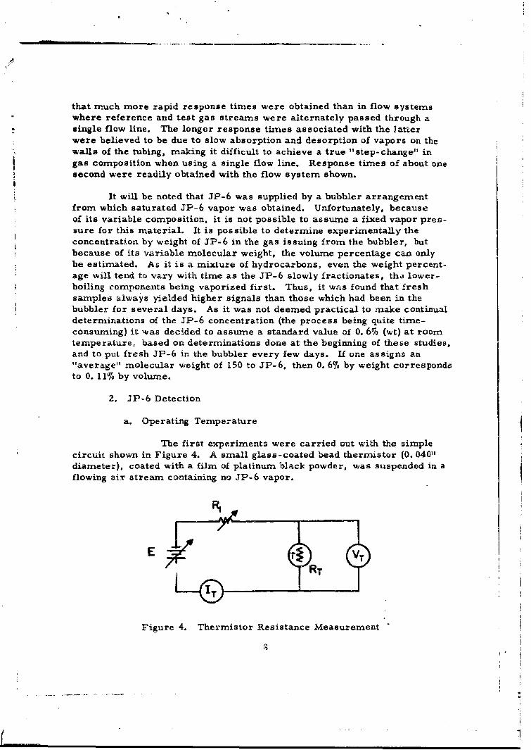
The first experiments were carried out with the simplecircuit shown in Figure 4. A small glass-coated bead thermistor (0. 040"diameter), coated with a film of platinum black powder, was suspended in aflowing air stream containing no JP-6 vapor.
E ~I~RT VT
Figure 4. Thermistor Resistance Measurement

-I.By varying E and R 1 enough current could be passed through the
thermistor (RT) to heat it resistively to various temperatures. At eachpoint, by measurivn the current and voltage as shown, both the thermistor
resistance, R = - , and the electrical power, W = V I being dis-T _T T T T'
sipated in it could be calculated. By reference to a standard chart of RT vstemperature, the thermistor temperature could be obtained. Thus, the powernecessary to keep the thermistor at various temperatures could be found.
The same procedure was then carried out with JP-6 vapors presentin the flowing air stream. This time, of course, in addition to the electricalenergy being put into the thermistor, chemical energy as well was being sup-plied by the reaction occurring at its surface. Therefore, with the samesettings of E and R 1 , the thermistor would come to a higher temperature thanbefore. Again, this new temperature ,-ould be calculated from the RT vs T
VTchart, and R = -- Thus, one could obtain: (a) the initial thermistor tem-
Tperature, (b) the temperature rise due to JP-6 vapor, and (c) the chemicalpower liberated by the oxidation reaction.
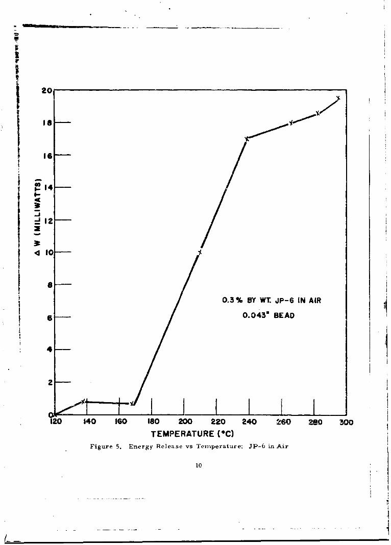
Although these experiments were relatively crude, one significantfeature emerged; the catalytic reaction appeared to have a "threshold tem-perature," below which the rate is quite low. This is illustrated in Figure5, which shows the net chemical power delivered to the coated thermistor asa function of its initial temperature. Note that below a thermistor tempera-ture of 160°C-180°C, the energy release rate is practically zero.
As the reaction appeared to be somewhat temperature-sensitive, evenin the "plateau" region above 240 C, and as the temperature rise experiencedby the thermistor was appreciable in many cases, it was decided to take fur-ther data in such a manner that the sensing thermistor would be at constanttemperature, both in the absence and presence of JP-6 vapors. This wasaccomplished by the test circuit shown in Figure 6.
II R, >
Figure 6. Constant Temperature Bridge9
---- " 7 •
j20
Is I
6
t 14 -
12-
10
0.3% BY WT JP-6 IN AIR
6 0.043" BEAD
4
2-
120 140 o60 ISO 200 220 240 260 280 3o
TEMPERATURE (*C)Figure 5. Energy Release vs Tenperature: JP-6 in Air
10
In this case, as before, the catalyst-coated thermistor was first
heated electrically to the desired temperature in the absence of JP-6 vapors. IAt this point, the bridge was put into balance by setting R3 so that the gal-vanometer was "nulled." The voltmeter and ammeter readings were thentaken, from which the electrical power being dissipated in the thermistor
could be calculated. The thermis"c:. vas then exposed to JP-6 vapor. Asits temperature rose, the corresponoing decreasa in its resistance caused
the bridge to go out of balance. The bridge supply voltage, E, was then de-
creased, (thus decreasing the electrical heating) until the bridge was again
in balance. When this condition %jas achieved, new readings of thermistor
voltage and current -,ere made. As bridge balance was maintained both in
the presence and absence of JP-6, the thermistor resistance (and thus the
thermistor temperature) remained constant. There.- re, the net decrease in
electrical, power necessary to maintain the thermistor at constant tern.pera-
ture could be equated directly to the chemical power delivered to the thermistor
by the catalytic reaction.
Experiments carried out with this circuitry confirmed the previous
temperature-dependence data. It was therefore apparent that the sensor must
be kept at a temperature of at least 200 0 C for effective operation. In view of
the fact that the expected maximum amnbient temperature could be even higher
than this, (340 C) it was anticipated that the final instrument would be de-
signed so t :at the catalytic sensor ->)ould always be operated at the highest
possible temperature. Ideally, one would desire thin temperature to be at
least 340GC. However, the thermistors which were available to us were only
rated for a maximum temperature of 3000C. Therefore, 300°C was picked
for the "standard" operating temperature, at which all further data would be
taken.
b. Linearity
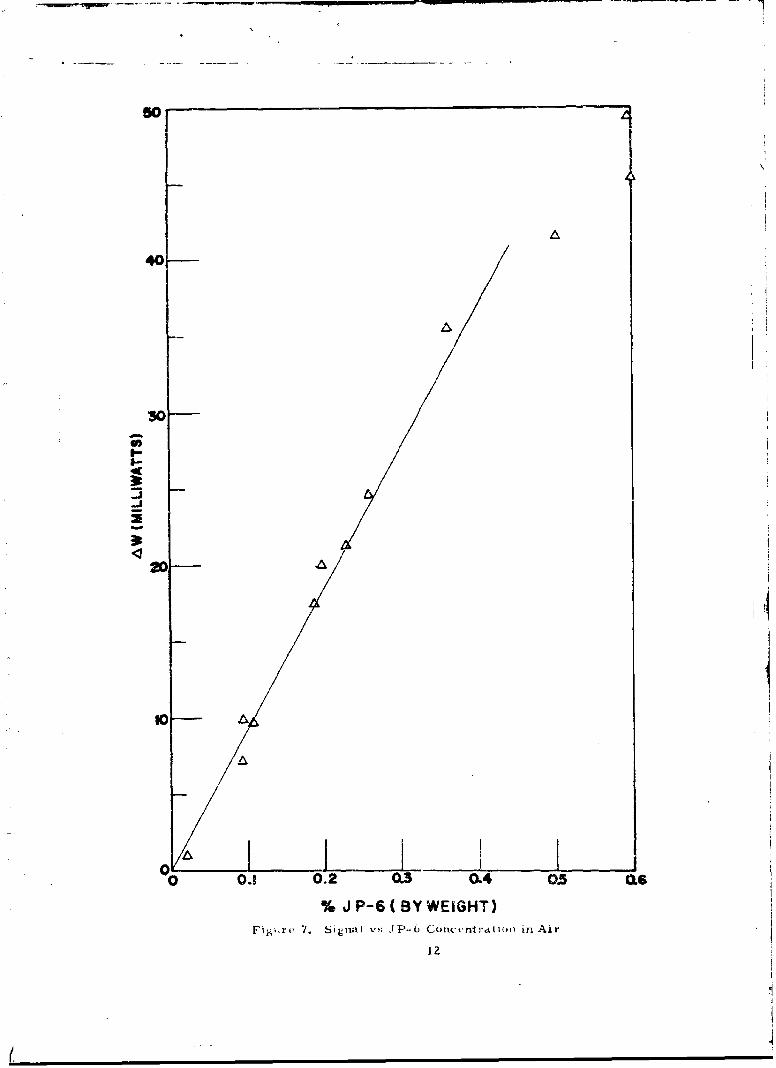
Further work amply demonstrated that, within experimental
error, there existecd a linear relationship between the JP-6 concentration and
the rate of energy release at the thermistor surface. Figure 7 illustrates
this data. While, as has been previously noted, the absolute JP-6 concentra-
ticns are only approximate, the relative concentrations, (obtained by succes-
sive dilutions of the saturated stream) are believed to be accurate. Assuming
a value of about 150 for the molecular weight of JP-6, then 0. 6% by weight
corresponds to about 0. 1% by volume (1/5 the LEL).
In order to work at higher JP-6 levels, it is necessary to beat the
entire apparatus, including the bubbler, the flow lines, and the detector
chamber to prevent condensation of JP-6. Several runs were performed
with the entire apparatus placed in a large oven, in order to verify that the
detector would operate at JP-6 levels up to and above the LEL.
Increasing signals as a function of oven temperatures were obtained
11
50
AA40
/
30
a-
to-
3z
10 AA
o•I I I0.1 0.2 0.3 0.4 05 .SJ
% J P-6 ( BY WEIGHT)Fi.,ýrv 7. Silual P,; J1P-6 Concunlr'atin in Air
12
0$
up to 150oF, corresponding to JP-6 levels of approximately 2 to 3 times theLELI. Experimental considerations made it impractical to attempt to mea-
sure the actual JP-6 concentrations being generated. However, the magni-tudes of the signals obtained at the high temperatures were consistent withthe increase in vapor pressure expected at these temperatures. The primaryinformation obtained by this experiment was that the sensor would indeedyield increasing signals up to the highest expected levels of JP-6 in air.
c. Pressure Dependence
To study the pressure dependence of the reaction, a testchamber was constructed (Figure 8) into which JP-6 air mixtures could beleaked at low pressure. In this apparatus, one could compare the relativcsignals obtained from a fixed JP-6 percentage as a function of total pressure.The procedure used was to generate a flowing JP-6 air stream at atmosphericpressure in the usual manner. A small portion of this mixture was continuous-ly bled into the test chamber through Valve A. By manipulation of Valves Aand B, it was possible to hold the chamber at any desired pressure.
Figure 9 ililustrates typical data obtained with this apparatus. It wasfound that the signal from a given JP-6 air mixture was relatively insensitiveto pressure over a wide range. This was surprising, in that at 1/2 atrnos-phere, for example, the absolute JP-6 concentration (i. e., gms/cm73 ), isonly half the original concentration at one atmosphere. One might, therefore,expect the signal to be only half as large.
An explanation for this behavior can be postulated in terms of thecatalytic reaction rate being controlled by gas phase diffusion of the reactantmolecules to the surface.
Thus as hydrocarbon is depleted by reaction in the immediate vicinityof the catalytic surface, a concentraLion gradient is established in the gasphase. Under the influence of this gradiett, hydrocarbon molecules are con-tinually replenished at the catalyst surface via diffusion inwards from moredistant areas of the gas. At equilibrium, a steady-state condition is attainedin which the net diffusive current is just equal to the rate of reaction, whichof course is proportional to the signal.
Letr = distance from center of "bead"
rs = radius of spherical catalytic "bead"c = hydrocarbon concentration at distance rc Z2= hydrocarbon concentration in bulk gas phase (at r 00)cs = hydrocarbon concentration at catalyst surface.
13
. . .

GAS AMIXTURE
MANNIFOLD
THERMISTORSENSOR
B3 VACUUMPUMP
Figtire 8. Low Presrn're Test Chamber
14
0
0)
I-- 1"
1-..0) a
LAJ .C
-, lillI11 *L
= _ O0
I. . . . . .. . .... . .-.
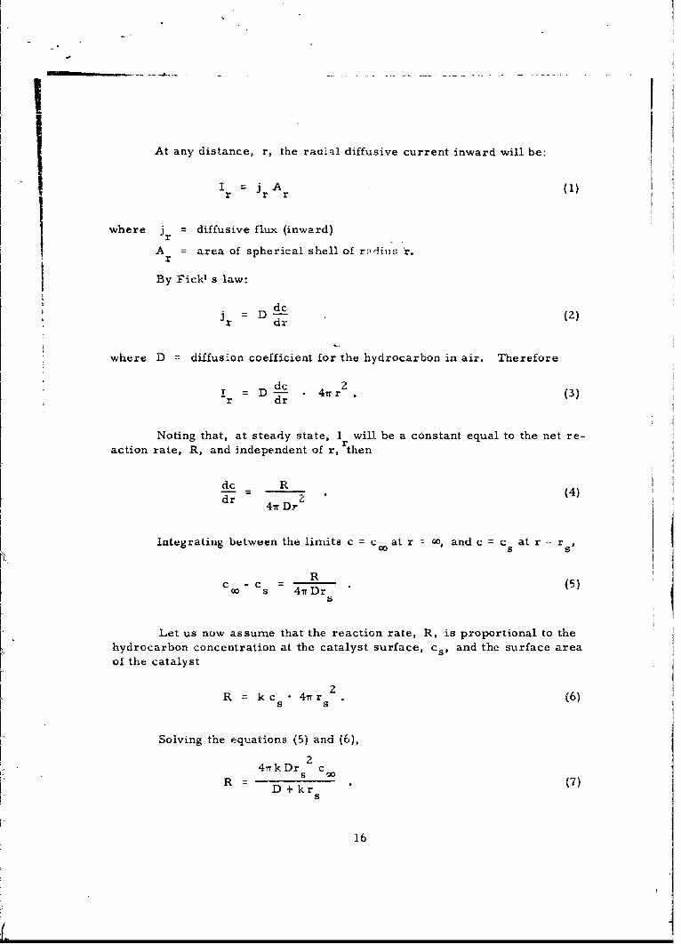
At any distance, r, the radial diffusive current inward will be:
Ir =j A (1)
where jr diffusive flux (inward)
A = area of spherical shell of radius 'r.
By Fick' s law:
dcJr = Dd- (2)r dr
where D = diffusion coefficient for the hydrocarbon in air. Therefore
D dc *4nr . (3)"r dr
Noting that, at steady state, I will be a constant equal to the net re-action rate, R, and independent of r, then
dc R
dr (4)dr 4Tr Dr2
Integrating between the limits c c at r 00, and c =c at r =r
Rc -o s 4t Dr (5)
Let us now assume that the reaction rate, R, is proportional to thehydrocarbon concentration at the catalyst surface, cs, and the surface area
of the catalyst
2R =: k c 4wr r (6)
S S
Solving the equations (5) and (6),
a4l kDr c
R s o (7)
S
16
iiI
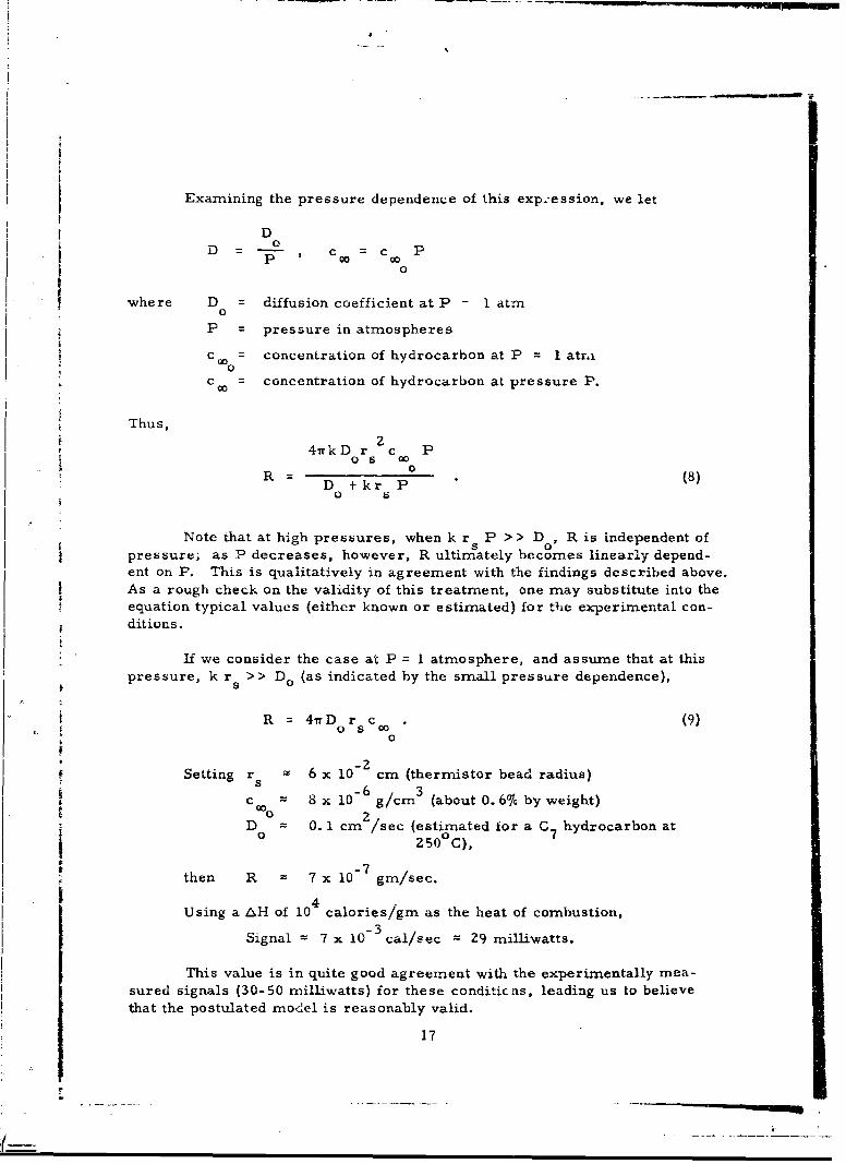
Examining the pressure dependence of this exp:ession, we let
DD = ,o = c PD - 00 90o
where D = diffusion coefficient at P 1 atmn0
P = pressure in atmospheres
c o concentration of hydrocarbon at P = 1 atr.i
c 0= concentration of hydrocarbon at pressure P.
Thus,S~z
4nkD r c P
D+kr P(80 s
Note that at high pressures, when k r P >> D , R is independent ofpressure; as P decreases, however, R ultimately becomes linearly depend-ent on P. This is qualitatively in agreement with the findings described above.As a rough check on the validity of this treatment, one may substitute into theequation typical values (either known or estimated) for the experimental con-ditions.
If we consider the case at P = 1 atmosphere, and assume that at thispressure, k r >> Do (as indicated by the small pressure dependence),
R = 4nrD r c (9)0 S0
0
Setting r 6 x 10- cm (thermistor bead radius)
c,00 8 x 10⁻⁶ g/cm3 (about 0.66% by weight)
D 0. 1 cm /sec (estimated for a C hydrocarbon ato sOc)0 ~250 0C),
then R 7 x 10- 7 gm/sec.
Using a AH of 10 calories/gnm as the heat of combustion,
Signal = 7 x 10⁻³ cal/sec = 29 millivatts.
This value is in quite good agreement with the experimentally mea-sured signals (30-50 mnilliwatts) for these conditicns, leading us to believethat the postulated model is reasonably valid.
17
d. Catalyst Poisoning
Many solid catalysts are known to lose their catalyticactivity when exposed to even small quantities of particular gaseous species("poisons"). This is usually due to the "poison' s" ability to disrupt the cata-lytic reaction mechanism, either by physically blocking the necessary adsorp-tion sites or by permanently changing the nature of the catalytic surface.Platinum catalysts are particularly susceptible to this sort of interference,usually by sulfur and nitrogen compounds. As compounds of this type couldeasily be present in the ambient atmospheres in which the sensors wutld haveto operate, there was some doubt as to whether the catalyst would be capableof reproducible, long-term operation.
To establish whether this would be a problem, high concentrations(> 90%) of H2 S, SOZ and NO? were passed over a coated thermistor forperiods of about five minutes each. None appeared to have any adverse effecton the catalytic activity of the coating. These experiments indicate thatpoisoning of the catalyst will not be a serious problem.
3. Oxygen Detection
a. General
The use of the coated thermistor probes for sensing oxygenin fuel tanks was investigated using essentially the same apparatus and tech-niques as for the JP-6 detector. As explained in Section A, it was expectedthat substantially the same type of sensor could serve to monitor oxygen (inthe presence of excess JP-6) as was shown to monitor JP-6 (in the presenceof excess oxygen).
Of course, it was clear that under certain of the expected conditionsexisting in the fuel tank, particularly at low temperatures, an excess of JP-6vapor would probably not be present. However, it was decided to investigatethis technique to define its operational limits, with the expectation that, ifthis were the only drawback, supplementary means (e. g. , heaters, etc. )could be incorporated for obtaining the necessary fuel vapor concentrations.
b. Reaction of 02 With Isobutane
The first experiments were performed to determine th#.response of the thermistor probe to various oxygen concentrations in thepresence of a simulant hydrocarbon. A simulant was used, rather than JP-6itself due to the practical difficulties involved in generating high concentrationsof JP-6 vapor. Because it was readily available, isobutane was chosen as thesimulant hydrocarbon.
Initial results indicated that, at a fixed isobutane concentration, sig-nals were usually obtained which were indeed proportional to the oxygen
18
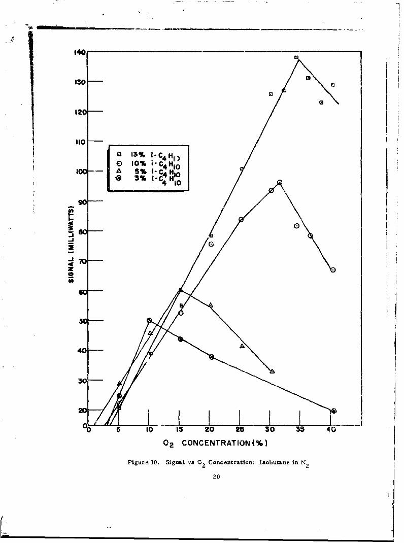
concentratioL-n. However, a major difficulty arose which had not been iore-seen. This was the appearance of a "quenching" phenomenon at high oxygenconcentrations. This is illustrated in Figure 10, which shows that as theoxygen concentration was increased the signal increased to a maximum.Past this point, the signal then decreased with increasing oxygen concentra-tion. Furthermore, the oxygen concentration at which quenching occurredwas a function of the isobutane concentration. There was also some evidence
* that it was a function of the particular experimental arrangement (i. e. , probeconfiguration and temperature, chamber geometry, etc. ) as well.
Ensuing experiments confirmed the fact that this phenomenon wasSinueed what it appeared to be, i. e., a decrease in the oxidation rate. (It
could have signified, for example, a large increase in rate, with expansionof the reaction zone into a flame front located away from the thermistor sur-face. This would have the effect, of course, of diminishing the surface re-action. ) The oxidation of hydrocarbons results in the formation of watervapor as a major product. Therefore, by monitoring the water vapor con-centration in the gas emerging from the sensor chamber, it is possible todetermine whether or not oxidation is occurring. An aluminum oxide hygrom-eter element (described in the Appendix) mounted downstream from the sensorchamber, definitely established that the reaction was truly being quenched, andthat no enhanced oxidation was occurring in the gas phase. High water vaporlevels were found when the thermistor signal was high, with a marked decreaseat the "quench point."
Thus far no detailed explanation of this phenomenon is available. Onepossibility is that at high oxygen levels, the reaction rate is being limited, notby the oxygen concentration, but by the isobutane concentration. This, how-ever, ought to result in a plateau in the signal vs 02 curve, and not a decreaseas is found. Similarly, an explanation based on the reaction being inhibitedby the buildup of excess product species on the catalyst surface does not ap-pear to accord with the ability of the quench point to shift as a function ofisobutane concentration. The most likely explanation appears to be one whichportrays the quenching as being due to some sort of "blockage" of hydrocarbonabsorption on the catalyst by oxygen molecules, the quench point being a func-tion of the relative gas-phase concentrations of isobutane and oxygen and theirrespective adsorption isotherms.
c. Reaction of 02 With Other Hydrocarbons
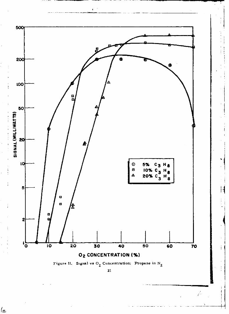
A study was undertaken to establish whether the quenchingeffect was unique to the isobutane-oxygen reaction or whether it existed withother hydrocarbons as well.
X-roparie and metha Were uXaiiud in a ,ixilar fLaLShio" , i thAD dis-
appointing results. Propane (Figure 11) showed a tendency toward quenching,although the signal maxima were higher and the decreases in signal were not
19
j ~1401
.•_/ II,130-0
12
jEl 13% J. C H,10% i-
i [ -- A 5% 1- C54 HO
l ~ 3% i-C H1O
* 90
Js
S70 -z
GO
/ Jr: ]i I 440 A
30-
20
0 5 10 15 20 25 30 35 0
02 CONCENTRATION (%)
Figure 10. Signal vs 0 Concentration: Isobutane in N 2
20
500
200
2-J
4
0
0 oE 5% C3 HS
I ' IO% C3 HA 20% c 3 H
33 .
2-
iO 20 30 40 50 60 TO
02 CONCENTRATION (%)
Figure 11. Signal vs 0 Concentration: Propane in N2
2I
*iI
as marked. However, the "unquenched" signals were not linear with oxygenconcentration. Methane, on the other hand, showed extrcmely poor sensi-tivity to oxygen. The signals obtained were so low that it was difficult to tellwhether or not quenching was taking place.
The varying behaviors of the three simulant hydrocarbons cast doubt
on the validity of using any of them to predict the behavior of like concentra-tions of JP-6.
d. Reaction of 0 2 Mth JP-6
Concurrent with the studies described above, which utilizedsimulant hydrocarbons, several attempts were made to achieve a means forsupplying a high JP-6 vapor pressure to the oxygen detector at all times,even at low ambient temperatures. At this time, it was still assumed thatvapors from the JP-6 in the fuel tank would ultimately serve to react with theoxygen at the catalytic surface. (It was expected that the simulant hydro-carbon studies would yield data as to the appropriate JP-6 levels which shouldbe maintained in order for the detector to afford good sensitivity for oxygen.)
Among the possible methods envisioned for accomplishing this pur-pose were such devices as a heated "wick" of absorbent material, whoselower end would be immersed in the JP-6. Another such device was a smallJP-6 "boiler" which would supply a jet of JP-6 vapor in the vicinity of thesensor. Results obtained using these devices in conjunction with the therm-istor probe were disappointing, the signals being very erratic and nonrepro-ducible. Even at oxygen levels which were low enough so that quenching (onthe basis of the isobutane date) should not take place, abrupt signal decreaseswere noted.
From indications obtained in these studies, it seemed likely that theerratic behavior of the sensor was due, in part at least, to the high (and attimes variable) JP-6 concentrations involved. If this were true, then theconcept of monitoring for oxygen by utilizing the excess JP-6 vapor presentin the fuel tank would be invalid.
C. Discussion
On the basis of the above results, use of the catalytic thermal detec-tor for measuring JP-6 in air appeared extremely promising. The sensorneed consist of nothing more than a simple probe suspended in the space tobe monitored, with appropriate electrical connections to the readout circuitry.
At the same time, it was quite clean that the detection of oxygen by1
means of a similar sensor would by no means be as straightforward as hadbeen expected. It was still felt, however, that in terms of engineering
* simplicity, it would be highly desirable to use the same type sensor for bothJP-6 and oxygen. On the basis of the data at hand, an alternative approach
_ _
- _- - - --|
'I
I

was taken which, although it promised to be relatively complex, would makeuse of the same basic principle.
It had been shown that oxygen levels could be monitored by hydrocar-bons such as propane and isobutane. Of the hydrocarbons tested, isobutaneappeared to yield linear signals as a function of oxygen concentration. Attoo high an oxygen level "quenching" occurred. Howev'-, it was possible tomeasure oxygen concentrations approaching 40% (the upper Lmit called for)by using a high enough (153%) isobutane concentration. It was also clearthat too high a JP-6 concentration led to erratic results when measuringoxygen. Therefore it was suggested that
a) a means be devised for eliminating the high JP-6 concentrations(that might occur in a hot fuel tank) from the gas sample.
b) then adding a large enough amount of isobutane, allowing theoxygen measurement to be made;
Such a device would, of course, necessitate a flow system such asis schematically illustrated in Figure 12. Gas from the ullage space is firstdrawn past a cold surface which maintains the JP-6 vapor pressure in the
stream at a low value by condensation. Immediately downstream a con-trolled leak of isobutane is mixed with the gas stream. The oxygen contentof the gas is then measured by the thermistor sensor.
23
• 1L ~...
j7--
000
Iw I
-J< z
000
Zoo
0)- 0) i
0
IL-
owo
:3 U)
24 4
SEC TION I.I
INSTRUMENT DESIGN
The final design for the prototype instruments was determined at atime when the particular aircraft in which flight tests would be performed
had not yet been determined. Indeed the installation location was not known.The instruments were therefore designed with the greatest possible flexibility.In certain instances this necessitated design compromises, some of which are
- discussed in Section V.
A. General Considerations
1. Thermistor Configuration
Most of the laboratory data had been taken with a coated therm-istor heated resistively, and suspended by its electrical leads in the gasstream. This configuration is the most sensitive thermally, i.e. , withrespect to the conversion of the chemical energy release on the coating intoa corresponding temperature rise of the thermistor. Another way of statingthis is that tiie "dissipation constant" of the thermistor (milliwatts/0 C) is low.As the thermal losses to the surroundings are small (conduction and convec-tion to the gas plus conduction through the very thin leads) most of the energydelivered to the catalytic coating is "seen" by the thermistor, and results in alarge temperature change.
The "nulling" circuit, described above (Figure 5), keeps the thermistortemperature constant while retaining the high sensitivity of the low-dissipationphysical configuration. In this circuit, the electrical heating power, W, isadjusted to maintain the thermistor temperature at a constant value (by main-taining bridge balance). Hence, the decrease in electrical power, Wo-W, isa measure of the added chemical power.
While useful for laboratory studies, this arrangement has severaldeficiencies when considered in the context of a final instrument. For ex-ample, there is no means of compensation for the effects of varying ambienttemperatures and pressures on W0 , the electrical power necessary to main-tain the thermistor at the proper temperature in the absence of reaction.(This is no drawback in the laboratory, where W. can be remeasured aftereach change in ambient conditions. I
An even more serious deficiency is the limited range of signals whichcan be accepted at higher ambient temperatures. This is because the only
way that one can hold the thermistor temperature constant as ambient tern-perature rises is to decrease the electrical power input. Thus, at an ambienttemperature of 25 C, it takes approximately 150 milliwatts to maintain the
25
thermistor at 300-C. Under these conditions a chemical reaction yielding 50milliwatts is qui*#e acceptable; to maintain the thermistor at constant tem-perature, the electrical power input is decreased to 100 milliwatts, and the"signal" is calculated to be Wo- W = 150- 100 = 50 milliwatts. If, however,
00the ambient temperature is 275 C, then W is only about 10 milliwatts.Obvious!y, in this case a chemical power input of 50 milliwatts cannot beconipensated even by decreasing the eiectrical power to zero, and the bridgecannot bL rebalanced.
Another undesizable fe.Ature of this technique is the method for heatingthe thermistors to opcrating temperature. Conversations with thermistormanuiacturers indicated that, although the thermistors are rated to withstandan ambient temperature of 300 C, heating them to this temperature resistivelyis undesirable. This is because the thermistors, being composed of sinteredparticles, are not necessarily homogeneous on a micro scale, and continuedpassage of large electrical currents through them might cause resistancechanges due to "hot spots," particularly at the thermistor-lead wire interface.
An alternative arrangement was therefore proposed, in which thecatalyst-coated thermistor would be heated to the proper temperature indir-ectly, e. g. , by mounting it in a heatod block. Separation of the functions ofheating the thermistor and sensing its resistance allows the use of a com-pensated high-sensitivity bridge circuit.
Figure 13 depicts this sort of r-nfiguration. It consists of t- om-atched thermistors, mounted in a ni;tal block; one is coated with catalyticmaterial, and the other with inert npterial. The block is heated electricallyto 3000C. In the absence of catalytic combustion, they both assume the blocktemperature, and the bridge is balanced. If reaction occurs at the catalyst,the liberated he-at changes the temperature of the sensing thermistor.
Electrically Heated Metal Block
Catalyst Inert Material
Ma tched
Thermistors
Figure 1 1. High-Dissipation Configuration
'7
The resulting change in resistance is read as a bridge imbalance signal.
Note that in this configuration the thermistor is in good therinal contact withthe block resulting in a high dissipation constant. Therefore even very large
I chemical power inputs will not change the temperature of the coating morethan a few degrees. This means that if the block temperature is held constantthe reaction will always be occurring at essentially the same temperature.
Although the maximum signal will correspond to only a few degrees differencE.
adequate sensitivity still ought to be available (precision thermistor bridges-. can readily measure AT' s of several millidegrees).
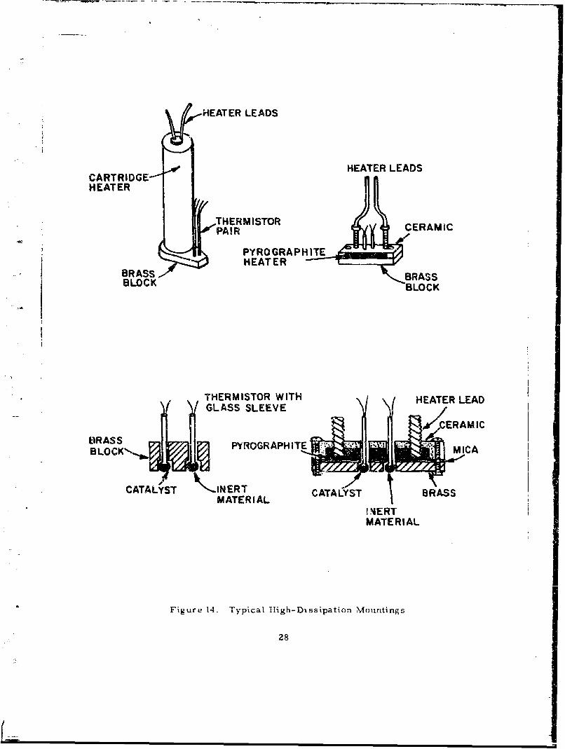
Results with this tonfiguration were very satisfactory. Figure 14depicts two early apuroarhe.s which were ýried. Ernphasis was put on makingthe sensor as small as possible, whilc at the same time. allowing reasonableease in assermbly.
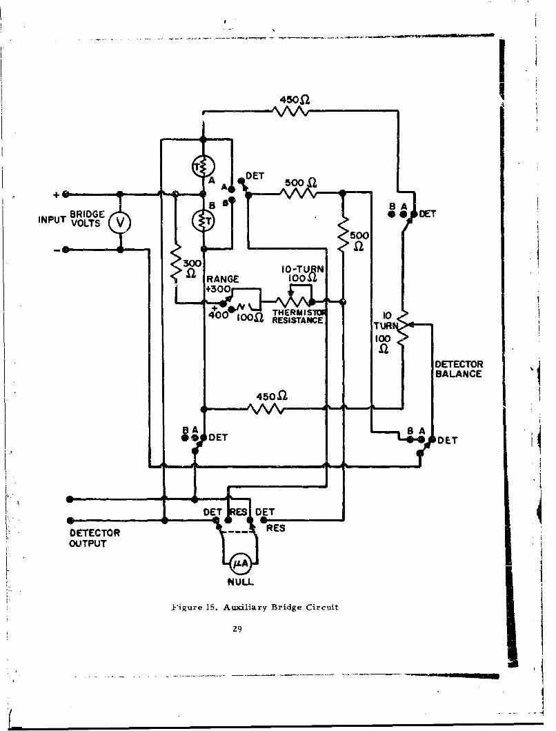
e iAs an aid in preliminary evaluation of heated-block detectors using
this configuration, a dual bridge circuit was construc:ted which enabled both(a) the detector output signal to be displayed, and (b) the resistance of eitherthermistor to be individually mneasured, at any time during the experinments.This circuit is shown in Figure 15. In the "Detector" mode' of operation, the
Sthermistor pair serves as two arnms of a Wheatstone bridge, which is "nulled"- using the Detector Balance potentiometer in the absence of hazardous vapor.
When reaction occurs at the coated thermistor, increasing its temperature,- the resulting bridge imbalance causes an output signal at the nicroanrnmeter.
In the "resistance measurement" mode either of the two thermistorscan be connected into a separate, equal-arm: Wheatstone bridge, whose vari-able arm is controlled by the thermirstor resistance potentiometer. Withthis control adjusted so as to null tha brvdge the thermistor resistance, RT,La read directly frorn its dial as shown, The circuit shown is for use withthermistors having resistances in the 300-500M2 region.
The physical configuration finally arrived at far the prototype instru-mnenrs is shown in Figurie 16. : consists of a small cartridge-type heater towhich a triangular brass block has neen soldered. The block is drilled and
countersunk as shown, and s.elected matched pairs of thermistors are placedI [. in the holes so that they are flush. The thermistors are cemented in place
using a mixture of "Saureisen" binder with finely powdered copper. Thismixture was chosen so as to withstand high temperatures and yet have ashigh a thernmal corn "-tivity as possible.
Teranperxture Control
In order to maintain the heated block at constant temperature
under varying ambient conditions, one must incorporate a means for con-I trolling the heater power. This is accomplished by the use of a third therm-
istor, also imbedded in the block, to sense any deviations in block tempera-ture from a preset value. This thermistor is connected into a proportional
27r
4p
HEATER LEADS
HEATER LEADSCARTRIDGE--HEATER
THERMISTORCEAIPAIR CERAMIC
"PYROGRAPHITE
BRASS BRASSBLOCK BLOCK
THERMISTOR WITH HEATER LEAD-( GLASS SLEEVE i• •CERAMIC
CATLYT BASBLOCK'~-.~ PYROGRAPHITE * -
14ERT
MATERIAL
Figure 14. Typical High-Dissipation Mountings
28
450n
I NPUT VOLTS V50
400GE REISTANC UI
+3000
DETECTOR
BALANCE
DETECTORREOUTPUT
E
N ULL
Figure 15. Auxiliary Bridge Circuit
29

H EATER LEADS
THERMISTORLEADS
SMALLCARTRIDGEH EAT ER
BRASS BLOCK
4THREE THERMISTORS(2 FOR DETECTOR
I FOR TEMPERATURE MONITOR)
Figure 16. Final Sensor Configuration
30
- S
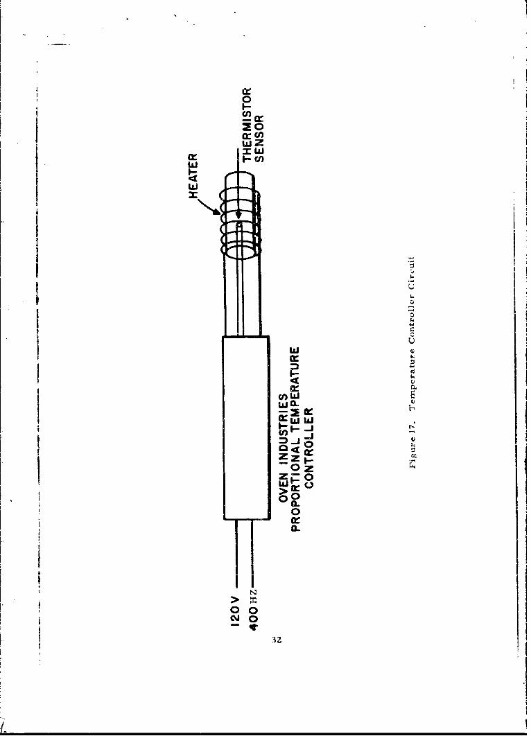
Icontroller, which automatically adjusts the heater power to maintain it at aconstant resistance (Figure 17). This temperature-monitorin•, ther.nistor ismounted in the third hole in the same manner as the matcheud pair.
3. Thermistor Selection
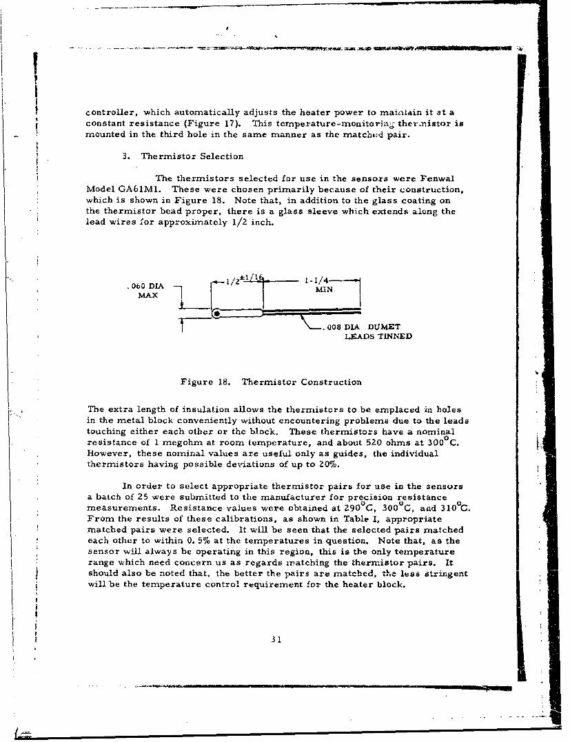
The thermistors selected for use in the sensors were FenwalModel GA61Ml. These were chosen primarily because of their construction,which is shown in Figure 18. Note that, in addition to the glass coating onthe thermistor bead proper, there is a glass sleeve which extends along thelead wires for approximately 1/2 inch.
.060/Z I/ MIN
ýýý=008 7DLA DUMETLEADS TINNED
Figure 18. Thermistor Construction
The extra length of insulation allows the thermistors to be emplaced in holesin the metal block conveniently without encountering problems due to the leadstouching either each other or the block. These thermistors have a nominalresistance of 1 megohm at room temperature, and about 520 ohms at 3000 C.However, these nominal values are useful only as guides, the individualthermistors having possible deviations of up to 20%.
In order to select appropriate thermistor pairs for use in the sensorsa batch of 25 were submitted to the manufacturer for precision resistancemeasurements. Resistance values were obtained at 290 0 C, 300 0 C, and 310 0C.From the results of these calibrations, as shown in Table I, appropriatematched pairs were selected. It will be seen that the selected pairs matchedeach other to within 0. 5% at the temperatures in question. Note that, as thesensor will always be operating in this region, this is the only temperaturerange which need concern us as regards matching the thermistor pairs. Itshould also be noted that, the better the pairs are matched, thless stringentwill be the temperature control requirement for the heater block.
S31
L=• l
w~~ Z-l
= II
cr..
~w O
coJ
a-2c
000
e~go(2
0*
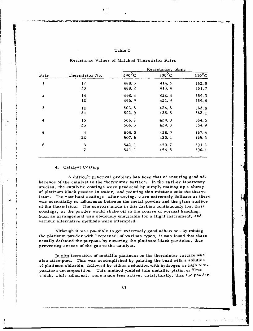
Table I
Resistance Values of Matched Thermistor Pairs
Resistance, ohmsPair Thermistor No. 290 0 C 300 0 C 310 0 C
1 17 488.3 414.5 352.523 488.2 413.4 351.7
2 14 498.4 422.4 359.312 496.9 421.9 359.8
3 11 503. 5 426.6 362.821 502. 9 425.8 362.1
4 15 506.2 429.0 364.6S25 506.3 429.3 364.9
5 4 508.0 430.9 367.522 507. 6 430.4 365.6
6 3 542. 1 459.7 391.27 541. 1 458.8 390.4
4. Catalyst Coating
A difficult practical problem has been that of ensuring good ad-herence of the catalyst to the thermistor surface. In the earlier laboratorystudies, the catalytic coatings were produced by simply making up a slurryof platinum black powder in water, and painting this mixture onto the ther-n-istor. The resultant coatings, after drying, v: -re extremely delicate as therewas essentially no adherence between the metal powder and the glass surfaceof the thermistor. The sensors made in this fashion continuously lost theircoatings, as the powder would shake off in the course of normal handling.Such an arrangement was obviously unsuitable for a flight instrument, andvariouc alternative methods were attempted.
Although it was poosible to get extremely good adherence by mixingthe platinum powder with "cements" of various types, it was found that theseusually defeated the purpose by covering the platinum black particles, thuspreventing access of the gas to the catalyst.
In situ formation of metallic platinum on the ther-sto .......also attempted. This was accomplished by painting the bead with a solutionof platinum chloride, followed by either reduction with hydrogen or high teni-perature decomposition. This method yielded thin metallic platinx.m filmswhich, while adherent, were much less active, catalytically, than the powder.
33
• • .Ia.L&C U.U4L1,,• 14 ULJIILCly founa to be most satisfactory, both interms of adherence and catalytic activity, was a mixture of equal parts plat-inum black and silica gel "G". The latter is a special silica gel formulation,for use in thin layer chromatography, which contains a small amount (5%) ofcalcium sulfate binder. A thick water slurry is made of the platinum black-silica gel mixture and then "painted" onto the thermistor. The corresponding"inert" coating on the compensating thermistor, is made from the silica gelalone. After air-drying, a reasonably adherent coating is produced. Al-though this coating will not shake off, it can be very easily rubbed off.Therefore, reasonable care in handling should be exercised. In the assen-i-bled sensor, the thermistors are protected by a metal shield which surroundsthe heater assembly.
5. Bridge Circuit
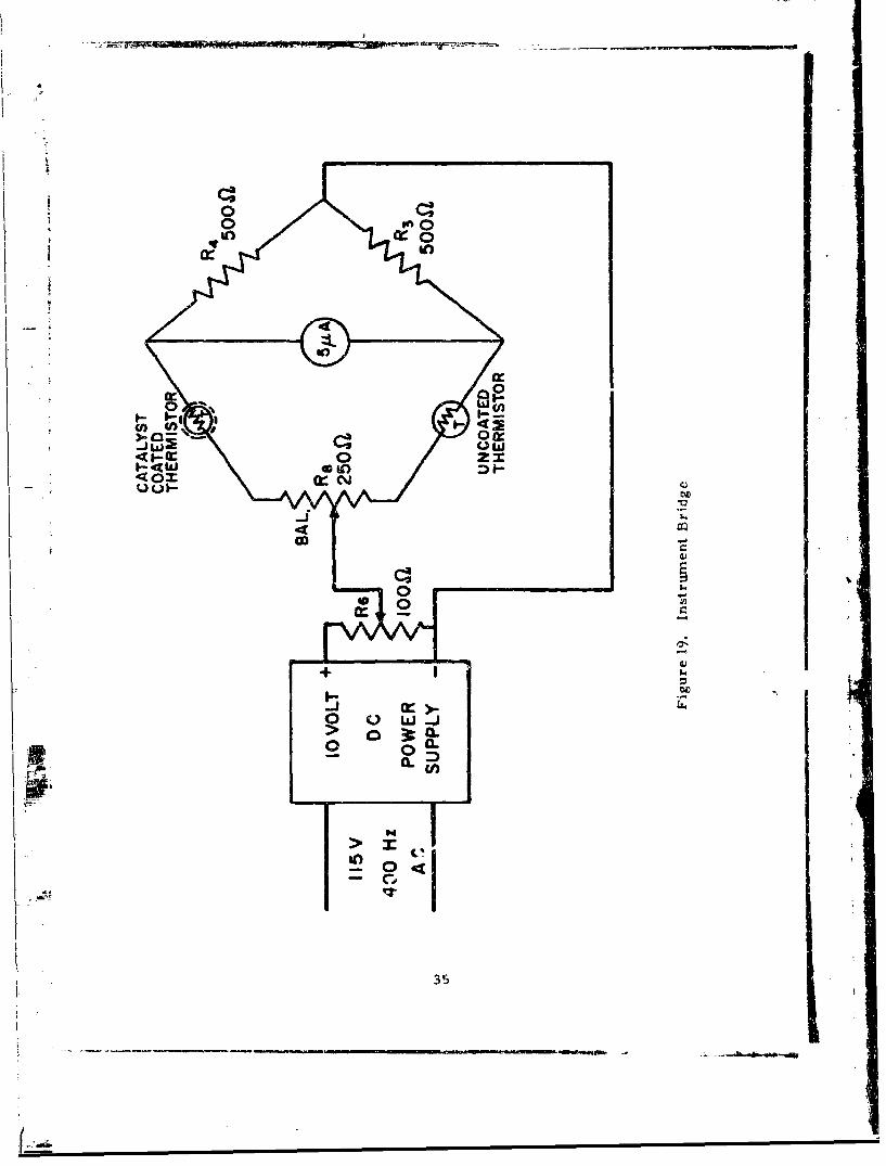
The Wheatstone bridge circuit used in the prototype instrumentis shown in Figure 19. The regulated power supply accepts a 115 volt 400Hz input, yielding a dc output of 10 volts. The instrument sensitivity is de-termined by the portion of this voltage which is applied to the bridge; this isadjustable by means of the potentionmeter R6. The bridge output signal isdisplayed on a 0-5 tia meter relay which can be used to operate an alarm.The voltage developed across the meter is also available as a recorder out-put. The impedance of the meter is 10, 000 ohms; therefore full scale (5 jL a)corresponds to a recorder output of 50 mv.
B. Oxygen Detector
1. General
The oxygen detector sensor assembly and bridge circuit areessentially identical with the JP-6 detector, described above. The detectorsdiffer significantly from each other primarily because of the ancillary equip-ment necessitated by the more complex detection scheme for oxygen. Thus,before contacting the oxygen sensor proper, the gas stream from the fueltank ullage space must be "processed" to remove excess JP-6 vapor and addisobutane vapor.
2. Condensation of JP-6 Vapors
Removal of JP-6 vapors from the gas stream by condensationwas felt to be the most practical method for ensuring against excess fuelconcentrations in the oxygen sensor. This could be accomplished by contact-
ing the gas sample with a cold surface. As the availability of refrigerantlines already present in the aircraft cannot be presvpposed, the prototype
" instrument nrust carry its own mteans for supplying the necessary low tem-peratures.
The simplest mechanism by which such a condensor can be cooled is
34
In CI
0'ticoin
c I-
o ow~,9
-0
-CL
Orn
35
- -- d-
via an evaporative process. In this technique, a liquefied refrigerant under
pressure is allowed to evaporate as it expands through a small orifice. Theliquid-gas transition is a heat-absorbing process, thus cooling the area inthe vicinity of the expansion ofifice.
To keep the apparatus as simple as possible, open-cycle operation ispreferred. That is, the gaseous refrigerant is not recovered, but is simplyvented to the atmosphere. While "wasteful" in terms of refrigerant, opera-tion in this manner elhninates the need for compressors, heat exchangers,etc.
Freon-114 (CCl 2 F 2 CCIZF 2 ) was selected as the refrigerant to be usedin this application. It is nonflammable and relaLively nontoxic; thus its releasein large amounts will present no appreciable hazard.
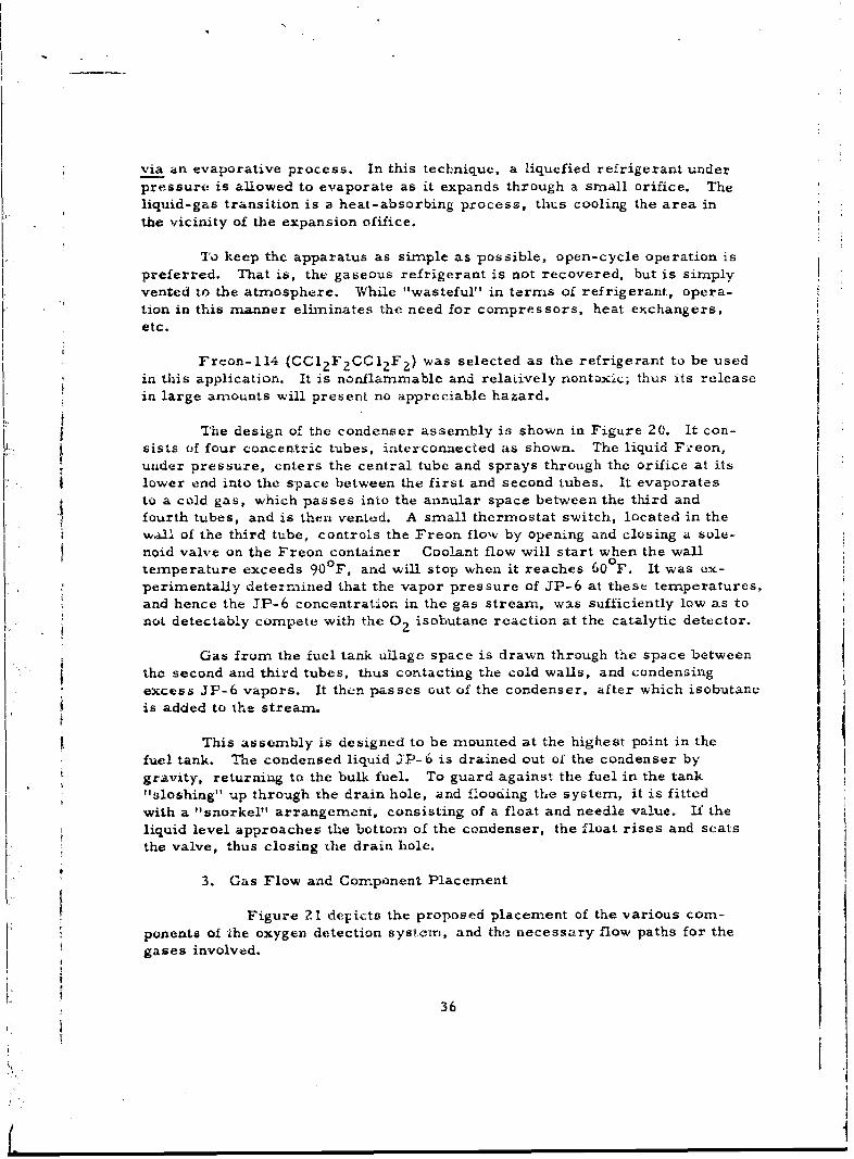
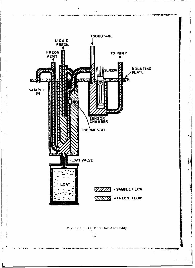
The design of the condenser assembly is shown in Figure 20. It con-it.sists of four concentric tubes, inaterconnected as shown. The liquid Freon,
under pressure, enters the central tube and sprays through the orifice at itslower end into the space between the first and second tubes. It evaporatesto a cold gas, which passes into the annular space between the third andfourth tubes, and is then vented. A small thermostat switch, located in the
wall of the third tube, controls the Freon flow by opening and closing a sole-noid valve on the Freon container Coolant flow will start when the walltemperature exceeds 90 F, and will stop when it reaches 60°F. It was ex-perimentally determined that the vapor pressure of JP-6 at these temperatures,and hence the JP-6 concentration in the gas stream, was sufficiently low as tonot detectably compete with the 02 isobutane reaction at the catalytic detector.
Gas from the fuel tank ullage space is drawn through the space between"the second and third tubes, thus contacting the cold walls, and condensingexcess JP-6 vapors. It then passes out of the condenser, after which isobutaneis added to the stream.
* This assembly is designed to be mounted at the highest point in the
fuel tank. The condensed liquid JP-6 is drained out of the condenser bygravity, returning to the bulk fuel. To guard against the fuel in the tank"sloshing" up through the drain hole, and flooding the system, it is fittedwith a "snorkel" arrangement, consisting of a float and needle value. If theliquid level approaches the bottom of the condenser, the float rises and seatsthe valve, thus closing the drain hole.F
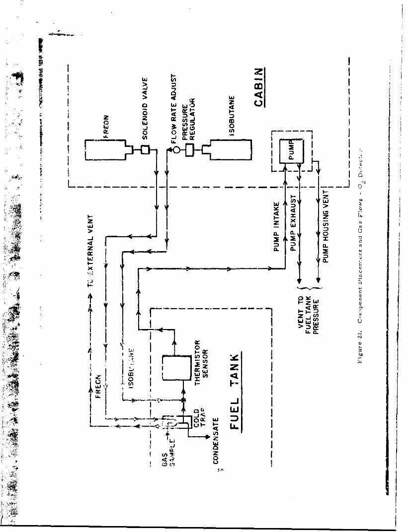
I'3. Gas Flow and Component Placement
SFigure 21 depicts the proposed placement of the various com-"ponents of the oxygen detection system1,, and the necessary flow paths for thegases involved.
36
tI
II
ISOBUTANELIQUIDFREON
FREON TO PUMPVENT
rSENSOR MOUNTINGPLATE
SA M PLEIN
SENSORCHAMBER
THERMOSTAT
_ FLOAT VALVE ,4
SFLOAT
x SAMPLE FLOW
______- • FREON FLOW
Figure 20. 0 Detector Assembly
37
M Iw MI
4w
-j CL 0
IfIJ >~47
> IL
w if CW
0
41L a..
zz
LU::T.;z:¶ Ii.---------IIC I
L) L-.
A1 41f
LLa
aI
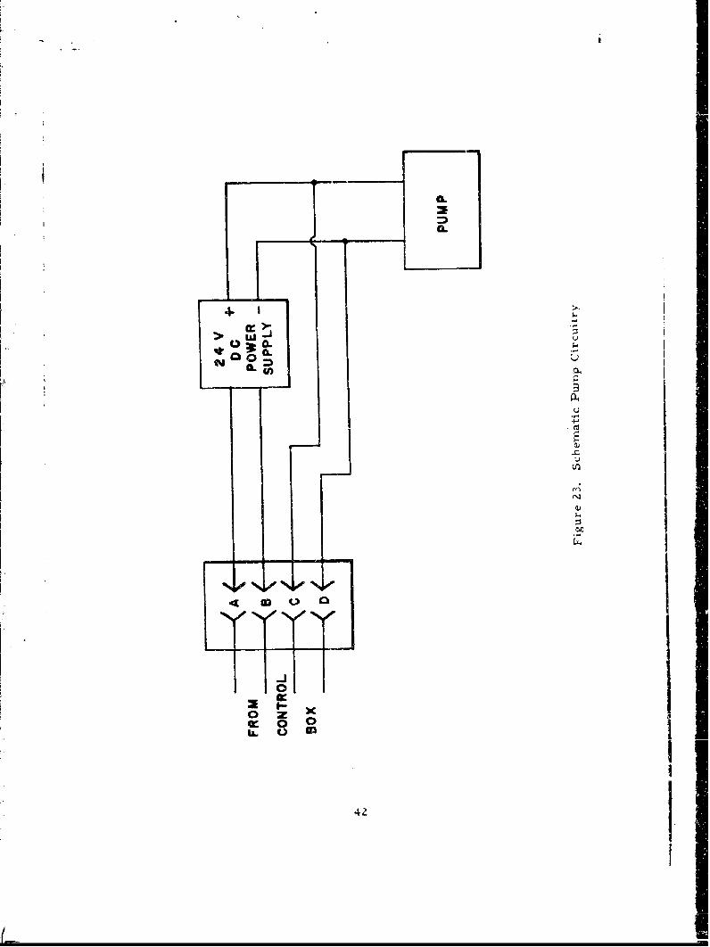
A miniature brushless dc diaphragm pump is used to move the gasthrough the sensor. The speed of this pump is approximately 3 liters/minute.In order to keep the pressure differential across the pump to a minimum, re-gardless of the fuel tank pressure, the sampled gas, after being pumped outof the fuel tank, will have to be returned from the pump to an area whosep•ressure is close to that in the tank. This could be either the fuel tank itselfor the outside of the aircraft (if the fuel tank is in pressure equilibrium withthe external air).
The maximumn operating temperature of the pump is only 90 0 C. Thismeans that it must be located either in the aircraft cabin or in some othertemperature-controlled space. The pump characteristics are such that, ifboth inlet and outlet are at low pressure, while at the same time atmosphericpressure surrounds the pump housing, the pump motor does not developenough torque to overcome the pressure on the (collapsed) diaphragm. There-fore, if the pump is located in the cabin area, it must be enclosed in a chamber"which is vented to a pressure comparable to that of the gas which it is puniping.
It should be noted that although the line from the pump to the fuel tankmnay be quite long, this has no bearing on the response tinme of the Instrument.
V Once the gas eaters the sensor chamber (which will be in the furl tanig). *Ieremaining length of line is immaterial.
4. Isobutane Addition
The isobutane is added to the g:zs stream after it has passedthrough the condenser, immediately before it passes into the oxygen sensorchamber. A final isobutane concentration in the range 10- 151o by volurne .
desirable if oxygen levels approaching 40% are to be measured, uthertisethe high oxygen concentration may cause "quenching. " The necessary flow _rate of isobutane will be a function of the flow rate of the sample gas streamn,and this, in turn, will be dependent on such parameters as the length anddiameter of the lines from the pumap chamber to the aensor location, themanner in which the pump exhaust and pump chamnber are vented, etc. Inaddition, of course, the dimensions and configuration of the line connectingthe isobutane supply with the sensor will affect the isobutane flow rate. Asall these factors will depend on the particular physical arrangements which
will be made at the time of installation in an aircraft, it was deemed advis-able to keep this part of the apparatus as flexible as possible. Therefore,at present, the isobutane flow rate has been left manually adjustable by meansof a needle valve located at the cylinder outlet. When installation of theprototype. is made, and thVe appropriate settings found, this valve can readilybe replaced by a fixed orifice having the same conductance.
l m m m m mI
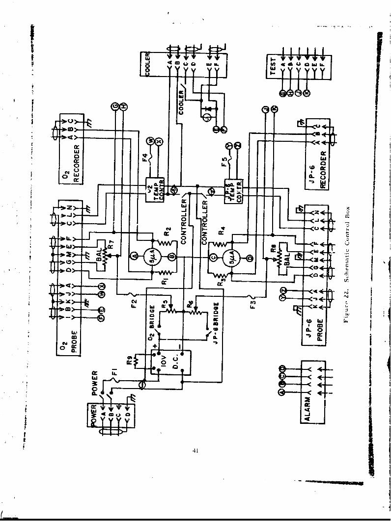
C. Overall Instrument Description
Figures 22 and 23 show the circuitry for a complete instrument. The
control box serves as a deal unit, containing the necessary circuitry andcontrols for operating both a JP-6 detector and an oxygen detector simulta-neously. The hox contains two identical bridge circuits and reidouts whic'operate, with individually adjustable input voltages, from a common dc powersupply. Similarly, there are individual heater controllers for the two sensors.
The JP-6 detector consists of simply a sensor probe, together withthe temperature control and bridge circuits in the control box. Additionalc~rccttry and componenis, however, are necessary for the oxygen detector.'Ahen the heater of the oxygen probe is turned on, power is also applied to a24-vdc sipplv. located in a separate gas-tight enclosure. This activates thePurnp, s:o r-, 'he enclosure, which draws the gas sample past the sensor,
, pply ,.'u Pruvideb the voltage necessary to operate the solenoid-. -:-.- relrigýranx sine (thro•3h the thermostat located in the condenser
.,ser: b., 1-ranrp on the control box indicates the state of the solenoid.
: .e .ntcgzr"% it, '- aiarni system can be ascertained by a "push-to-• (• •-•.... .ht":cn rQuces a large bridge imbalance by shunting one of
:.e... •r . *.a �,;Vsei the meter relay to go far up scale, resulting
40
i
W £I-L
LL , w
z Z
ca-
lop__ 4Iin!
Me0 qm
Cb 4CL
ICc2
410 (
0 0.
ca .
rn-u,
42.
SEC TION~N IV
SYSTEM TESTS
i A. Mechanical
Both the JP-6 sensor probes and the 02 sensor assemblies (includingcondensers and float valves) were vibration-tested according to MIL-STD810-A, Method 514. 1, Equipment Class 1, Curve D. The test V is performed
0at an ambient temperature of -65 F. It was not possil, to produce an ambi-0ent temerature of 650 F suzrounding t1 e vibration table, however, while in
TIPIthe -65 F ambient, three of the six sensors were run with their heaters "on",thus producing surface temperatures of 300 C. No evidence of damage to thecatalytic coatings was observed upon completion of the vibration tests. The
* only damage suffered by the unit:: vas the partial stripping of the threads 3nthe float valve assemblies of the oxygen sensors, at the point where theyscrew into the condenser drain holes (see Figure 20). This defect has beencorrected by modifying these assemblies so that they are permanently epoxied
*i into place.
B. Temperature Controllers
The temperature controllers were found to maintain the heaters at theappropriate temperature in ambients ranging from -55 0 C to +300°C. Thistest was performed by placing the probe in an environmental chamber whichcould be cycled between these temperature extremes; and observing the therm-
? istor resistances as a function of time. They remained constant.
C. Linearity
Linearity checks were performed on the instruments as part of theprocess of calibrating them. As expected, it was found that signals werelinear, both as a function of JP-6 and oxygen concentrations. The units havebeen preset to read full scale (5 jta) at 3% JP-6 (by weight) and 20% oxygen,respectively.
D. Freon Cooler
The operation of the Freon cooling system was examined bV mountingthe OZ sensor plate on a metal chamber heated to 300 0 C. With the thermostatand solenoid circuits activated, the system was easily able to maintain thecondenser at the set-point temperature (60-90°F) with the Freon "on" lessthan 10% of the time.
.4
S~43
SECTION V
SUMM-,ARY AND RECOMMENDATIONS
Prototype instruments for the detection of JP-6 fuel in engine com-partment.3 and oxygen in ullage spaces h, ve been developed, designed, a Idconstructed. Both instruments utilize the heat liberated during catalyticcombustion fo;" their detection principle. The JP-6 detector is simple inconcept requiring only a detecting probe and associated electronics. Theoxygen detector additionally requires a gaseous flow system, a trap to re-move JP-6 vapor and the introduction of isobutane as the conmbustion fuel.These instruments have performed satisfactorily and reliably during the
numerous laboratory experiments necessary for development, design, and
testing. Throughout the course of this experimentation involving widelyvarying temptraturs, pressures, and compositions of the hydrocarbon-oxygen mixtures, the catalytic probes were never found to 1e a safety hazardin themselves. Ignition was never observed.
A. Conformance with Target Requirements
1. Temperature Range
The requirement calls for the JP-6 sensing devite to operate
"continuously fromn -65 F to 6500 F, and the oxygen sensing device from-65 F to 550 0 F. The thermistors presently available, have a high-tempera-ture limit of 300°C (572oF), and this is the temperature at which the heateropt rates. Therefore, although the oxygen sensor meets the requirement,the JP-6 sensor falls short by about 75 F. Diamond and SiC thermistors haverec-tntly been announced and are suitable for use at nmuch higher ambient tem-
peratures. They are, howcver, either not yet thoroughly evaluated in ternmsof stability at the high ambient temperatures (SiC) or are not generally avail-able conmmercially (dianmond). Thus, although they are not available for thisinstrumnent developmen:it program, they could be substituted to achieve the
desired operating lunmperature range.
2. Sensitivity
The sensitivities of the prototype instruments have been shownto be nmore thdin adequate in terxns of the target requirements (10o of the,LEL for JP-6; 0-40% for 0?). The minimumn detectable quantities for theprototype instruments are estimated to be less than 2% of the LEL for JP-6,
and less than 0. 5% oxygen.
3. Response and Recovery Times
The desired respo-s, e times of the senctng devices . re 5 _-
ends at 10""(1 of the LEL (JP-6), or 0. 5% (O), and 1 second at the LEL (JP-6)
44
or 40% (02), with recovery times of less than 30 seconds. The response and
recovery timus of the present sensors are independent of concentraticn, andare less than 1 second.
I The target response time of the complete system, including electronics,is no more than I second longer than that for the sensing device. With therecorder output, this requirement is easily met. As has been noted abpxe,these instruments were designed to have maximum flexibilhty a•,,a therefor-ealso have panel mnter readouts which contain meter relays required to acti-vate an alarm system. The meters have a relatively high impedance (10, 000
ohms) largely because of their associated meter relays whereas the bridge
t impedance is only about 500 ohms. This mismatch results in a relativelyslow system response time (about 5 seconds) when either the meter or alarm
readout is used, but when the output signal is fed to a recorder the systemV response time will be only on the order of millisecords longer than the sensor
K response time.b
At the time of preparation of this report, it is planned to install theelectronics in the instrument bay of an aircraft and to feed only the alarmsignal to the cockpit. It is expected that the output will also be recorded.With this mode of installation, the readout meters becomU superfluous. Theycan be eliminated and the meter relays, with their inherently slow response,can be replaced by fast acting level sensors which monitor the voltage dropacross a sensing resistor located across the bridge circuit. These sensors
can be self-canceling, thereby eliminating the interrupter presently requiredby the mneter relays. The net result would be a simpler circuit and an alarmsystem which would respond well within the desired response time.
4. Selectivity
The instruments readily meet the target requirements of beinginsensitive to vapors other than the desired species. The nature of the tech-nique, of course, lictates that only/ those gases which will participate in acatalytic exothermnic reaction will be detected, and it is just these gaseswhich can constitute an explosivŽ, hazard.
5. Exposure to Liquid Fuel
A specific requirement for the oxygen sensor is that it not beadversely affected by exposure to or submersion in liquid fuel. In view ofthe relative case wit). which catalyst coa.ting can be "washed off' it was nec-essary to ensure again:;t liquid fuel entering the sensor chamber. This wasclone by mneans of the float valve device described above. This valve willfunction properly only when in a relatively vertical orientation with respectto the liquid fuel surface. It is expected to seat whenever the aircraft atti-tuU.de aters furom the vertical and the sensing charnber is in danger ot being
flooded. However, only flight experience will demonstrate whether this
45
seating occurs rapidly enough to prevent flooding of the sensor chamber.
6. Other Requirements
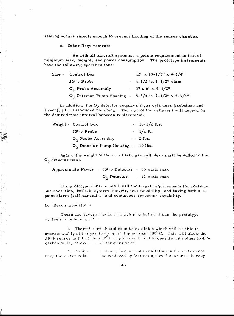
As with all aircraft systems, a prime requirement is that of
minimum size, weight, and power consumption. The prototype instrumentshave the following specifications;
Size - Control Box 12" x 10--1/2" x 9-1/4"
JP-6 Probe - 4- 1/2" x 1- 1/2" diam
0 Probe Assembly - 3" x 6" x 9-1/2"2
02 Detector Pump Housing - 5-3/4" x 7-1/2" x 5-3/4"
In addition, the 02 detector requires 2 gas cylinders (isobutane andFreon), pluz. associated plumbing. The -:ze of the cylinders will depend onthe desired time interval between replacement.
Weight - Control Box - 10-1/2 lbs.
JP-6 Probe - 1/4 lb.
0, Probe Assc-mbly - 2 lbs.
0 Detector Piump Tiousing - 10 lbs.
Again, the weight of the necessary gas cylinders must be added to the0. detector total.
Approximate Power - JP-6 Detector - 25 watts max
0 Detector - 31 watts max
The prototype instrumu,its fulfill the target requirements for continu-ous operation, built-in sy7ytem integrity test capability, and having both set-point alarm (self- canceling) and continuous re-orrding capability.
B. Recommendations
There are sever.-I .arýi:s ;n which it i.; bluicv- :.l thait tht_ prototype-y: terms rn,-y h, "Th7
1. Thertni .tr4 h-,tild soon he a vailahle which will be able tooperate .Aably at tQ-,in. ,ra•,A,?'-- Tniute: hIqher thian 300°C. This will allow the
JP-6 sensor to f, i11-! 01.! 1' requircif,.-nt, anw to operate . i h other hydro-carbon fu,.ls, at ev,-" K 'r t,,mpv'rituie-:.
.A ,di ... ....1 ... . , ,, c ,t inIZtallation in tl, . -i,-r inient
hay, thi' ý,i.ler reti', i'h rlt.iced by fast ''ling level sensors, flier-by
46
I
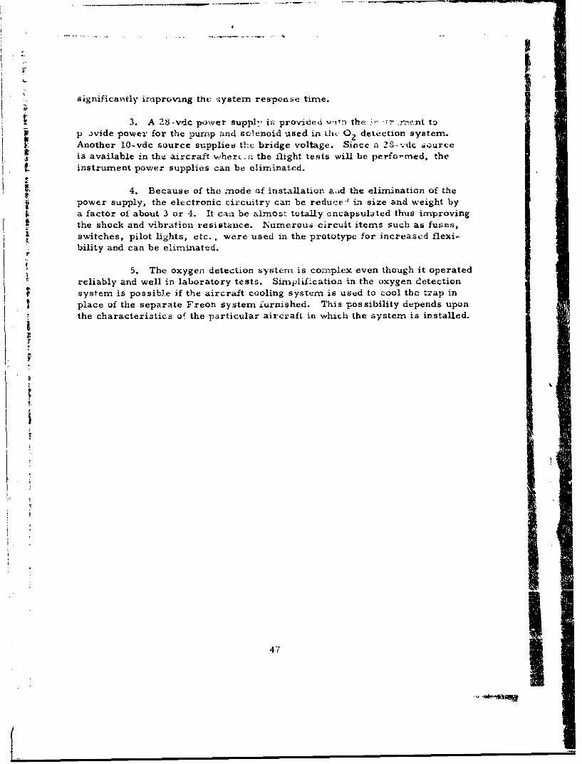
significantly improving the ,system response time.
1 3. A 28.-vdc power supply is provided wif-,t the 3'.r anent toj. p avide power for the pump and solenoid used in thu- 0 detection system.
r Another lO-vdc source supplies the bridge voltage. Since a 23-vdc source#Tj is available in the aircraft when( -n the flight tests will be perfor-med, thet instrument power supplies can be eliminated.
4. Because of the node of installation aid the elimination of the* power supply, the electronic circuitry car be reduce-' in size and weight by
a factor of about 3 or 4. It can be almost totally encapsulated thus improvingthe shock and vibration resistance. Numerous circuit items such as fuses,
Sswitches, pilot lights, etc., were used in the prototype for increased flexi-bility and can be eliminated.
r
5. The oxygen detection systemn is com.ýplex even though it operated
reliably and well in laboratory tests. Simplification in the oxygen detectionsystem is possible if the aircraft cooling system is used to cool the trap in
I place of the separate Freon system furnished. This possibility depends uponthe characteristics of the particular aircraft in which the system is installed.
itI
it
47

BLA.NK PAG
$1I
I I; APPENDIX
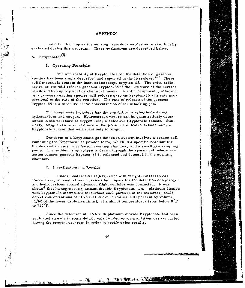
Two other techniques for sensing hazardous vapors were also brieflyevaluated during this program. These evaluations are described below.
t A. KryptonatesýY
1. Operating Principle
The, applicability of Kryptonates for the detection of gaseous'species has been amply described and reported in the literature.1-3 -Thesesolid materials contain the inert radioisotope krypton-85. The solid radio-act,.ve source will release gaseous krypton-85 if the structure of the surfaceis altered by any physical or chemical means. A solid Kryptonate, attackedby a gaseous reactiig species will release gaseous krypton-85 at a rate pro-portional to the rate of the reaction. The rate of release of the gaseouskrypton-85 is a measure of the concentration of tht attacking gas.
The Kryptonate technique has the capability to selectively detecthydrocarbons and oxygen. Hydrocarbon vapors can be quantitativaly deter-mined in the presence of oxygen using a selective Kryptonate sensor. Sim-ilarly, oxygen can be determinecd in the presence of hydrocarbons using aKryptonate sensor that will react only to oxygen.
One form of a Kryptonate gas detection system involves a sensor cellcontaining the Kryptonrite in powder form, which is a specific reactant forthe desired species, a radiation counting chamber, and a small gas samplingpump. The ambient atmosphere is drawn through the sensor cell where rc--action occurs; gaseous krypton-85 is released and detected in the countingchamber.
2. Investigalion and Results
Under Zontract AF33(615)-2477 with Wright-Patterson AirForce Base, an evaluation of various techniques for the detection of hydroge iand hydrocarbons aboard advanced flight vehicles was conducted. It wasshown 4 that homogeneous platinum dioxide Kryptanate, i. e. , platinum dioxidewith krypton-85 distributed throughout each particle of the material, coulddetect concentrations of JP-6 fuel in air as low as 0. 01 percent by volume(1/60 of the lower explosive limit), at ambient temperatures from below 0 Fto 750 F.
Since the detection of JP-6 with platinum dioxide Kryptonate had beenevalv.ted already in sorme detail, only limited experimentation was conductedduring the present proesram in order io verify prior results.
49
7 I_ _ I
-.-- -. ..---_Z_ M 7:
The major effort in the evaluation of the Kryptonate technique wasconcerned with the detection of oxygen. Under a program sponsored by theJet Propulsion Laboratory, an oxygen detector based on the Kryptonatetechnique was developed by Panametrics. 5 This detector was developed toultimately have the capability of detecting oxygen in the Martian atmosphere.The optimum material in terms of sensitivity and response was found to becopper Kry-ptonate. The final model developed was based on direct sourcecounting, utilizing a foil of copper Kryptonate. The rate of loss of krypton-85from the sample served as a meaEure of the oxygen concentration. However,this system was not continuous. Since the present program requires contin-uous monitoring over a large range of oxygen concentrations, it is apparentthat direct source counting would be inapplicable. In order to ineet thecriterion of continuous monitoring, it is necessary to prepare the Kryptonatesensor in the form o, a powder, and utilize an effluent counting system asdiscussed briefly above, and more extensively in prior reports.3,4
An investigation was conducted to determine if copper could be pre-pared as a homogeneous Kry-ptonate powder and to determine if it wouldrelease activity at a constant rate with constant oxygen concentration andoperating temperature. The results of this investigation were not satisfac-tory. Although high specific activity, as well as homogeneity of the copperKryptonate powder were attained, continuous release on reaction with oxygenwas not realized. Copper powder Kryptonate was operated at varying tem-0 0peratures from 200 F to 800 F with varying concentrations of oxygen passingthrough the sensor cell. Initial responses and sensitivities were excellent.However, after a few minutes operation, signals decreased rapidly. Sub-sequent analysis indicated that the decreasing signals were the result of aprotective oxide layer being formed on the surface of the copper. The melt-ing point of cuprous oxide is ZZ50 F. This oxide decomposes to the metal at3Z60 0 F. Hence, at reasonable operating temperatures the buildup of such anoxide layer retards further oxidation, and causes the release rate of krypton-
85 to decrease even though the concentration of oxygen remains constant.
Thus, it became apparent that copper or other materials which forma protective oxide layer on oxidation, i. e. , aluminum, zinc, etc. , would notbe suitable for continuous oxygen monitoring. Materials which will meet thiscriterion are those which forin volatile oxides or those which form a "flaky'oxi-e. Such oxide formation would allow oxygen to react at a constant rate,and would not impede the release of gaseous krypton-85.
Two materials which are known to form volatile oxides are carbonand boron. These elements were prepared as powdered Kryptonates andinvestigated. Although reproducible effluent release of gaseous krypton-85was observed for constant oxygen and temperature conditions, the tempera-tures required for sufficient reaction to occur were very high, and were notcompatible for usage aboard an aircraft. It was found that in order to mea-sure oxygen in the stipulated concentration range of 0-40% by volume, the
50
qr
operating temperatures required for both materials were in the 1400 F to1800 F range. Such high operating temperatures would obviously piesenta serious ignition hazard.
A more likely candidate material appears to be osmium Kryptonate.Osmium is a fairly hard metal with a melting point of 4900°F. Osmium(and ruthenium) alone among the platinum metals shows a readiness to com-bine with oxygen. Osmium will react with oxygen directly at 392°F to formthe oxide, osmium tetroxide, OSO4.6 This oxide is volatile at 214 F andhence, at the foamation temperature, osmium tetroxide would be continuouslyvaporized, leaving a clean metal osmium surface for further unimpeded re-action with oxygen.
Because of limited time (two to four weeks are required to preparehomogeneous Kryptonate samples) and funds (osmium costs approximately$500/ounce) consideration of an osmium Kryptonate oxygen detector wastemporarily suspended.
3. Discussion
The feasibility of a PtO2 Kryptonate detector for JP-6 seemswell established. However, at the time when a decision had to be made asto the detection systems to be used in the prototype instruments, no datawas available as to the ultimate feasibility of an osmium Kryptonate oxygendetector. Therefore, in view of the desirability of using a single detectionprinciple for both JP-6 and oxygen, Kryptonate systems did not appear asfavorable as the thermistor detectors described in the body of this report.In addition, at the time in question it appeared that the thermistor detectors,both for JP-6 and rxygen, would be capable of operation as simple probes,
without extensive "plumbing" connections. Kryptonate sensors, on the otherhand, would of necessity involve a pumping system to transport the releasedKr-85 to a counting chamber.
The thermistor oxygen sensor has become more complex than ori-ginally anticipated, however, and an osmium Kryptonate sensor might ulti-mately be more attractive. Supplementary funds have been allocated forfurther evaluation of this technique, and this is currently being performed.The results will be reported at a later date.
B. Aluminum Oxide Hygrometer
1. Operating Principle
Thle possible use of the aluminum oxide hygrometer,manutfac-
tured by Panarnetrics, Inc., for detection of hydrocarbon fuels has beendescribed in detail in a previous report.4 The essence of the technique restson the measurement of the water vapor formed upor oxidation of the hydro-carbon. This measurement is accomplished by means of an aluminum oxide
51
S. .. .. ..... . .. .. . . . .. ....,A
hygrometer, a relatively new sensing device which has demonstrated excel-
lent sensitivity, accuracy and rapidity in many similar applications. Thesensor can readily measure water vapor coricentrations ranging from lessthart . 01 4g H 2 0/liter to greater than 20, 000 ýtg HZO/liter.
The most obvious manner in which this device could be used to
monitor JP-6 in air would be to pass the air, first over a desiccant (to re-
move any ambient water vapor), thence through a heated catalyst cell (tooxidize the JP-6) and finally into a chamber containing the humidity sensor,where the water vapor formed in the oxidation reaction would be measured.
Alternatively, for monitoring oxygen in a fuel tank, the apparatuswould be virtually identical, ,xcept that the pre~iminary chemical reactionwould necessarily be a quantitative conversion of the oxygen to water vapor,either by reaction with fuel vapors or with a reducing agent present in the
cell.
Z. Investigation and Results
Previous work had already shown the basic technique to befeasible for detecting JP-6; however, the environmental temperaturespeci-fication of 650 F could not be met by the commercial form of the hygrometersensor. The sensor consists of a small strip of aluminum, which is anodizedto produce a porous aluminum oxide surface layer. A very thin coating of
gold is then evaporated over this structure, r.'tulting in a die••ctric "sand-wich" consisting of aluminum-aluminum oxide-gold. Ambient water vapordiffuses rapidly through the external gold layer, and interacts with the
alur.initm oxide matrix; the electrical properties of this "capacitor" are adirect function of the ambient water vapor pressure.
At the time the previous study was performed, the maximum operat-ing t,,mperature of the sensor was limited by the thermal degradation of apolymer used in insulating the electrical lead wires. The objective of thepresent work has been to investigate whether the sensor could be upgradedto withstand higher temperatures.
Several modified forms of the sensor were studied, including thosewith an inorganic (silicon monoxide) insulator, and those in which the insulat-
ing material had been eliminated completely. These changes resulted insensor" which could survive 650°F without catastrophic failure; however,the sensors did not operate properly at the elevateL. temperatures, and large
shifts in calibration were noted upon subsequent cooling.
3. Discussion
In light of the inability of the aluminum oxide sensor to with-
stand elevated temperatures, this line of approach was terminated.
52
I
REFERENCES
1. D. Chleck, R. Maehl and 0. Cucchiara, Krypton-85 as a UniversalTracer, NYO-Z757-5, USAEC Contract AT(30-i)-2757 (1964).
2. J. E. Carden, "Preparation, Properties and Uses of Kryptonates in
Chemical Analyses," Isotopes and Radiation Tachnology, Vol. 3,No. 4, (Summer 1966).
3. 0. Cucchiara, R. Rex and T. Donaghue, The Development of anInstrument for the Detection of Hazardous Vapors, Contract AF33(615)-
1473, AFAPL-TR-65-50 (1965).
4. 0. Cucchiara, L. Seiden and T. Donaghue, Investigation of HazardousVapor Detection for Advanced Flight Vehicles, Contract AF33(615)-2477,AFAPL-TR-66-71 (1966).
5. D. Chleck and 0. Cucchiara, "Radioactive Kryptonates-III. Applications.The Measurement of Oxygen in the Martian Atmosphere, " Int. J. Appl.Rad. Isotopes, Voi. 14, 599-610 (1963).
6. F. A. Cotton and G. Wilkensen, Advanced Inorganic Chemistry, Inter-science Publishers (1962).
5.
4
L
53
I .•
U:nca s s if ied
Secuntv ClassificationDOCUMENT CONTROL DATA -R&D
(Sec.,rly €8*4eeI!sf#l of 'ifle bod, of Abstract f d ands nlS annograIor, must tie entered whrv1 the overall rlpor; & .ri..,fe d)ORIGINATIN G Ac r1VI Y (Coq••.. -. 1)o2) RLPORtT SECURI iy I L ASSIIC& 10N
PANAMETRICS, ING. CUIY Lhi* OPANA~i'fICS IN(.t•Unclassifie;d
Z21 Crescent Street boRup
Waltham, Mass. 021543 REPORT TITLE
DEVELOPMENT OF A HAZARDOUS VAPOR DETECTION SYSTEM FORADVANCED AIRCRAFT
4. DESCRIPTIVE NOTES (Typ" of repout ad irclus-tt daet.)
Final Report - March 1966 - September 1967I AUTHOR(S) (Loot naime. firs nemsn. Initial)
Seiden, L., Cuechiara, 0., Goodman, P.
6 REPORT DATE 76 TOTAL NO. OF PAGES j 7b. N• OF REFS
March 1966-Sept. 1967 60 6fl CONT• ACT Il GZANT %O IB ORIGINATOR'IS RPORT NUMMREIR(S)
AF33(615)-3 46b. PRoJEcT4.o 6075 N/A
a. Task No. 607508 Sb. rw6T•,t o1NT NsOM (An.y oth.,numb.,o th.atin, b a...li.d
al- AFAPL-TR-67- 1Z30. A VA IL ASILITY/LIMITATION NOTICES
Qualified requesters may obtain copies of this report from DDC.Foreign announcement and dib*,o&.inatioi of this report by DDC iu not authorized.
It SUPPLEMENTARY NOTES 12. SPONSORING MILITARY ACTIVITY
Air Force Aero Propulsion LaboratoryResearch and Technology Division
_Air Force Systems Commandil AUSTRACT Wright-Patterson Air Force Base, Ohio
A program was conducted to evaluate, develop, and construct instrumentatiofor the detection of hazardous vapors aboard advanced aircraft. Prototype detectiosystems were constructed both for monitoring JP-6 fuel vapor in aircraft compart-ments and for monitoring oxygen in the ullage space of fuel tanks. These systemswill be further evaluated in flight tests.
Detection of both species is accomplished by the use of a catalyst-coated therm -istor sensor. Catalytic oxidation occurring at the catalyst surface liberates heat, F
which is sensed by the thermistor.The JP-6 sensor consists of a simple probe which can be mounted directly in
the space to be monitored. No eampling system is required.The oxygen sensor is more complicated, necessitating flow connections to an
external pump and gas supplies.The instruments developed meet almost all of the desired goals. In a few
instances, flexibility for installation in a variety of situations and locations wasretained at the sacrifice of some performance characteristics. Methods forachievinedete sacrif specific installations and optati.g modes are indicatedand are relatively simple.
DDJAN'5' 1473 UnclassifiedSecurity Cisssification

h'w urov n sh
A Ie
Dem --n i ifD."I ',Il"l1 I .'- i i-], I,: c-1 . M k ný t) , T rd
nu be A F** xt i piit-- 1; : , - -
i. )Iiij!.-FI I U-L ' fite i the it i omI-r-oilt# t P-hl ~u 'tr j
1 h:e. - .--rv..,, i .! -,m, -te- t - Iricfaldtit ,flt.5 It. jh . L 'l fc]1 t, O ft ) V a.-li-i-, . it' ,t othleri.di.i in( tt ut-aifiI) i.t iqIp
M"aalr '11iti.ilct dt iII4 Is-_Iji:
the p'in, tp.1 authon--Iii .ow-iiu-itr V iii,'>! rq it> ~a1) P ,10iA--ets ~ MaL IT k reT-Vest Ene thiriug otetEh Ti>,-litrta prijiJ. ofic aiit Armedaur I-unsvin '-Ipaltt)i iitul-i,
t4 5-ic- 011 Ohtil' -D A lv 0 F it -; p-: al J 1 ,fIn. rV-b id? a o''i-.V I -)-the --- war. . .and__ d vlim -ni n u ewdetirkitiy. liis-. br-eno h ysedar. ItmreO than ne~ cOt appear , *u S tltr aý,tC o> jtai 'pe fii
(m th rep-rt. se cnte f ati 1 r1.-BT-RAT: d irt-c Il n (toni r UI I Kit cinv q ualifie nd fasersA. ~ ~ ~ ~ ~ ~ ýrrl ,Iil) T tILL IKts, theen inditrupli it- rr 4 hi ruit!.- it ve' til!rruecth',g
7a.Titl Aletr, NUMB i-R inOf l- aiA-cs. shoul p'e Ir t1- J I 'b1i)tarriltedi.lf jý t ete h ic lrlitil r t 0- V onitif- l ti 1-viar -i t - pro, Ith- t'Ii-d ,I addrlnu :.ta ia s~te-- - - - -, Li - tn ui n h e h 1
1b NUMBERI' OF>! EnTS- i- tIr ic- t1ri.-rItln mlTi s jq ýd -j 1j thet rvf-i ali-- - - - -- 115ite t:1 i.v. 11-tttitn t e t-
4r- ,jifrttna. i r.] l it u t- rr-%'--,t1 a hs P -iri >riihr--f the ri st-
t- If t hb,1 I nd wi th-
- - - --ho i> aidi: cit aOI-A ,Pi it GRANI st%1HE If can -- h dt-e ,sie h. iniI e- it ar I J -- rit c- lansal-oifi,> pobi uf .h min.'-n-.-re-i, 'teI-it.-, - -nr, gtn ndrvh h ~ te lb,> atidese-rthie-prie lknte -us T ) S .).
Ife rpriltar , sh w reitt in.1 n--ric If si-n it-c- Thng- tlirit if, b t,,I., th In, ?k l auth. isOFC Nr , stilt ,r-iriir 11-t reituirericel. "'F SPOSRNC MILTAR ACTIITY lenter the namem of 24 od
milI thert en de¶itfj arton sur hti pnýe rolc ofic urI yt ttybli)itg';Ii~~~~~~~~~~~~~~ hI-tOt thATt Ertatedt tter--Iat a rsj-)ters r h ur t~ an deveupm r tt In'hde address. d
96rih yeGIar. or ' REonth. yrar.P(ý Ifle mule than md- dat 1 ti . flSSRA T Ene at litri I, gvr Key brif nd% faituaon the repItI, V-,ui dI e !,, lhvI ith ... .... i i t .s - ~ i 1I ,d s Ii !-, - u iý l - h l- srq it d n
-b)nras- ter-'-mrn nlctc oi) hr reprt. . ena , though
t). TOTil-k NUMBR I P N i tp The- : -tt pasrui it- as a 1s li ar- 1st--h.r i.n th b, .riB .-t lie tecnical r,-
sbriil I t -m'm r .1n ,aiilcr I.; iur-.is eie h ~ ~ Iadlttta ~lii eureacoliu~tf he hlnur-tier ~ ~ As I pgssirtnn tfI~ria it ,-atahd
rfcr-i iA 11c ir'.d In th .rit li un ri. ;ied Ts- 1h paarp of th Ibtr I hl -d t
Nw ONT AIK ORCR NT t~i~lk IIaupoliiat-- et r 'an un ~ifl 1 I, fit rta-y e> nit t asrufia/iu o th i